Embed Size (px)
Citation preview
Page 1 of 30
15C0233-00 Rev A SSC4500DX 9/23/2020
Operation and Maintenance Manual
Sterile Storage Cabinet
SSC4500DX 99C0177-00-Standard unit
94C0078-00 Ceiling Duct Kit 91C0191-00 0-10VDC Retransmit Kit 91C0192-00 UV-C Light Kit Air Side
7000 Performance Drive Syracuse, NY 13212
Phone (315) 452-7400 Fax (315) 452-7420
airinnovations.com
Page 2 of 30
15C0233-00 Rev A SSC4500DX 9/23/2020
Table of Contents 1.0 Sterile Storage Cabinet System Overview ................................................................ 3
2.0 Safety Precautions .................................................................................................... 6
3.0 Cabinet Storage ........................................................................................................ 7
4.0 Acceptance and Unpacking the SSC4500DX ........................................................... 8
5.0 Unit Views and Labels ............................................................................................. 11
6.0 Installation and Initial Startup .................................................................................. 13
7.0 User Interface, Displays and Alarms ...................................................................... 16
8.0 Keyless Lock .......................................................................................................... 18
9.0 Field Terminations ................................................................................................... 21
10.0 Maintenance ......................................................................................................... 22
11.0 Troubleshooting..................................................................................................... 29
12.0 Warranty ................................................................................................................ 30
Page 3 of 30
15C0233-00 Rev A SSC4500DX 9/23/2020
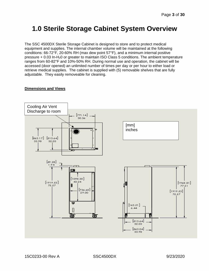
1.0 Sterile Storage Cabinet System Overview The SSC 4500DX Sterile Storage Cabinet is designed to store and to protect medical equipment and supplies. The internal chamber volume will be maintained at the following conditions: 66-72°F, 20-60% RH (max dew point 57°F), and a minimum internal positive pressure + 0.03 In-H20 or greater to maintain ISO Class 5 conditions. The ambient temperature ranges from 60-82°F and 10%-50% RH. During normal use and operation, the cabinet will be accessed (door opened) an unlimited number of times per day or per hour to either load or retrieve medical supplies. The cabinet is supplied with (5) removable shelves that are fully adjustable. They easily removeable for cleaning.
Dimensions and Views
[mm] inches
Cooling Air Vent Discharge to room
Page 4 of 30
15C0233-00 Rev A SSC4500DX 9/23/2020
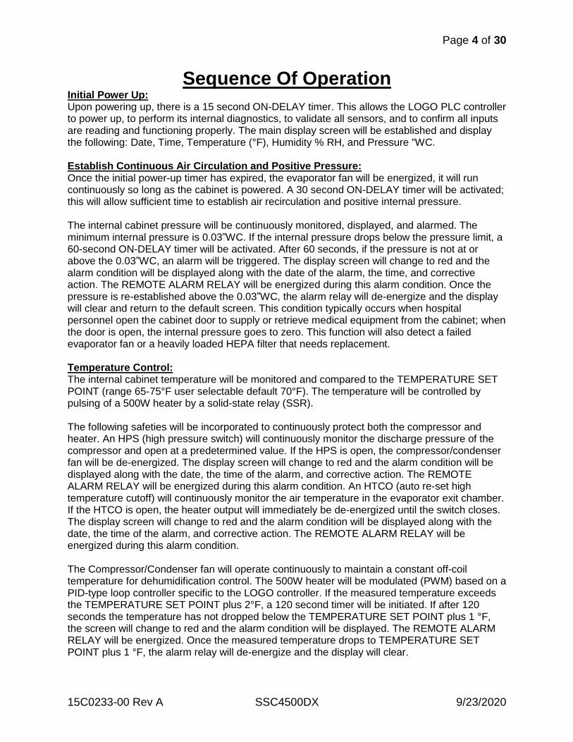
Sequence Of Operation Initial Power Up: Upon powering up, there is a 15 second ON-DELAY timer. This allows the LOGO PLC controller to power up, to perform its internal diagnostics, to validate all sensors, and to confirm all inputs are reading and functioning properly. The main display screen will be established and display the following: Date, Time, Temperature (°F), Humidity % RH, and Pressure “WC. Establish Continuous Air Circulation and Positive Pressure: Once the initial power-up timer has expired, the evaporator fan will be energized, it will run continuously so long as the cabinet is powered. A 30 second ON-DELAY timer will be activated; this will allow sufficient time to establish air recirculation and positive internal pressure. The internal cabinet pressure will be continuously monitored, displayed, and alarmed. The minimum internal pressure is 0.03”WC. If the internal pressure drops below the pressure limit, a 60-second ON-DELAY timer will be activated. After 60 seconds, if the pressure is not at or above the 0.03”WC, an alarm will be triggered. The display screen will change to red and the alarm condition will be displayed along with the date of the alarm, the time, and corrective action. The REMOTE ALARM RELAY will be energized during this alarm condition. Once the pressure is re-established above the 0.03”WC, the alarm relay will de-energize and the display will clear and return to the default screen. This condition typically occurs when hospital personnel open the cabinet door to supply or retrieve medical equipment from the cabinet; when the door is open, the internal pressure goes to zero. This function will also detect a failed evaporator fan or a heavily loaded HEPA filter that needs replacement. Temperature Control: The internal cabinet temperature will be monitored and compared to the TEMPERATURE SET POINT (range 65-75°F user selectable default 70°F). The temperature will be controlled by pulsing of a 500W heater by a solid-state relay (SSR). The following safeties will be incorporated to continuously protect both the compressor and heater. An HPS (high pressure switch) will continuously monitor the discharge pressure of the compressor and open at a predetermined value. If the HPS is open, the compressor/condenser fan will be de-energized. The display screen will change to red and the alarm condition will be displayed along with the date, the time of the alarm, and corrective action. The REMOTE ALARM RELAY will be energized during this alarm condition. An HTCO (auto re-set high temperature cutoff) will continuously monitor the air temperature in the evaporator exit chamber. If the HTCO is open, the heater output will immediately be de-energized until the switch closes. The display screen will change to red and the alarm condition will be displayed along with the date, the time of the alarm, and corrective action. The REMOTE ALARM RELAY will be energized during this alarm condition. The Compressor/Condenser fan will operate continuously to maintain a constant off-coil temperature for dehumidification control. The 500W heater will be modulated (PWM) based on a PID-type loop controller specific to the LOGO controller. If the measured temperature exceeds the TEMPERATURE SET POINT plus 2°F, a 120 second timer will be initiated. If after 120 seconds the temperature has not dropped below the TEMPERATURE SET POINT plus 1 °F, the screen will change to red and the alarm condition will be displayed. The REMOTE ALARM RELAY will be energized. Once the measured temperature drops to TEMPERATURE SET POINT plus 1 °F, the alarm relay will de-energize and the display will clear.
Page 5 of 30
15C0233-00 Rev A SSC4500DX 9/23/2020
Humidity Control: The internal humidity will be continuously monitored, displayed, and alarmed. The interior of the cabinet shall be maintained between a maximum of 60% RH and a minimum of 20% RH. There are typically (2) distinct processes involved in the control of RH. If the RH is high, dehumidification is required; if the RH is low, moisture is added to the airstream. The refrigeration cassette of the cabinet is designed to operate with a 55°F evaporator leaving-air temperature, IE a dew point temp or maximum RH of 60%. Therefore, from a control point of view, there is nothing to manipulate to lower the humidly by design. The humidity level of the cabinet has a minimum value of 20%. This is a user-defined value that ranges from 20% to 40% with a default value of 20%. If the RH is below the MIN RH VALUE SETPOINT, humidification is required. The physical hardware to raise the humidly involves several mechanical components: 1) A water tank with LOW LEVEL SWITCH, and WATER PUMP. 2) A condensate pan with HIGH LEVEL SWITCH, SOLENOID VALVE, and HEATER. If the measured RH value goes above 60% RH, the display screen will change to red and the alarm condition will be displayed along with the date of the alarm, the time, and corrective action. The REMOTE ALARM RELAY will be energized during this alarm condition. If the RH drops to an RH value that is below the MIN RH SETPOINT, the humidification will be automatically initiated to raise the internal RH value to the MIN RH SETPOINT plus 2%. The LOW LEVEL SWITCH in the water tank will be verified, a 10-minute ON-DELAY timer and the condensate pan HEATER will be activated to pre-heat the pan before water is added. Once the timer has expired, water can be added to the pan. The HIGH LEVEL SWITCH verifies that there is no excess water in the pan. Water can now be added to the pan. A PULSE RELAY is activated with an ON-TIME of 1-sec and an OFF-TIME of 10 min. During the 1-second on time, both the WATER PUMP and the SOLENOID VALVE are activated. This cycle will repeat until the internal cabinet RH is at the MIN RH VALUE plus 2%. Once this RH value is achieved, the PULSE RELAY will be stopped and a 15 min OFF-DELAY timer will be started to completely dry out the condensate pan so there is no standing water. The water level in the de-mineralized water storage tank is automatically verified prior to starting the humidification process. If the LOW LEVEL SWITCH is activated, the display screen will change to amber and the alarm condition will be displayed along with the date of the alarm, the time, and corrective action. The REMOTE ALARM RELAY will be energized during this alarm condition. The humidification process will be delayed until the water tank is refilled.
Page 6 of 30
15C0233-00 Rev A SSC4500DX 9/23/2020
2.0 Safety Precautions
To reduce the risk of fire, electric shock, and injury, basic safety precautions should always be followed when using electrical appliances. These precautions include the following: · Read all instructions before using the cabinet.
· To avoid potential fire or shock hazards, plug the cabinet directly into a 120V AC electrical outlet.
· Remove all packaging before use.
· Keep the cord out of heavy traffic areas to avoid potential fire hazard. NEVER put the cord under rugs, near heat registers, radiators, stoves, or heaters.
· To protect against electrical hazards, DO NOT immerse in water or other liquids.
· Close supervision is necessary when used by or near children.
· Always unplug before moving or cleaning the unit.
· To disconnect the unit, be sure to pull the plug and not the cord.
· NEVER drop or insert any objects into the openings of the unit.
· Do not operate with a damaged cord or plug. If the fan fails to operate or if the unit has been dropped or damaged in any manner, contact the manufacturer for examination and/or repair.
· This unit is to be used for its intended purpose only, as described in this manual. Any other use is not recommended by the manufacturer.
· NEVER place on a soft surface, as this could cause the unit to tip over.
· Keep unit away from heated surfaces and open flames.
· DO NOT attempt to repair or adjust any electrical or mechanical functions on this unit. Doing so may void the warranty.
· All servicing to be performed by qualified personnel only.
· NEVER use detergents, gasoline, furniture polish, paint thinner, or other household solvents to clean any part of the appliance. A damp cloth can be used.
· A static charge may be felt if the unit is not properly grounded. To avoid a static charge, plug the unit’s three-prong plug into a grounded outlet, or properly install a ground adapter (see PLUG SAFETY).
· This cabinet should be used only in an environmentally controlled room with temperatures between 65°F and 80°F.
· Cabinet should not be stored in a location below 32°F due to potential freezing & expansion of residual water within the cabinet.
PLUG SAFETY: To reduce the risk of electric shock, THE SSC4500DX IS EQUIPPED WITH A HOSPITAL GRADE 3-PRONG PLUG, a grounding type plug that has a third (grounding) pin.
Plug into any Standard Ground outlet or a Ground Fault Circuit Interrupter (GFCI) outlet. DO NOT remove the ground pole from plug or use an adapter for grounding! DO NOT ALTER PLUG OR CORD.
Page 7 of 30
15C0233-00 Rev A SSC4500DX 9/23/2020
3.0 Cabinet Storage If the cabinet is not going to be used or put in long term storage at any point in time the following preparations and conditions are required. 1) The cabinet should be stored in an environmentally controlled area with temperatures 40F or above. The cabinet require de-mineralized water for proper operation and there is residual water in the plumbing reservoir tubing and pump. This water will freeze and damage the cabinet. 2) If the cabinet has been in service it should be cleaned, dried and secured prior to storage.
Page 8 of 30
15C0233-00 Rev A SSC4500DX 9/23/2020
4.0 Acceptance and Unpacking the SSC4500DX
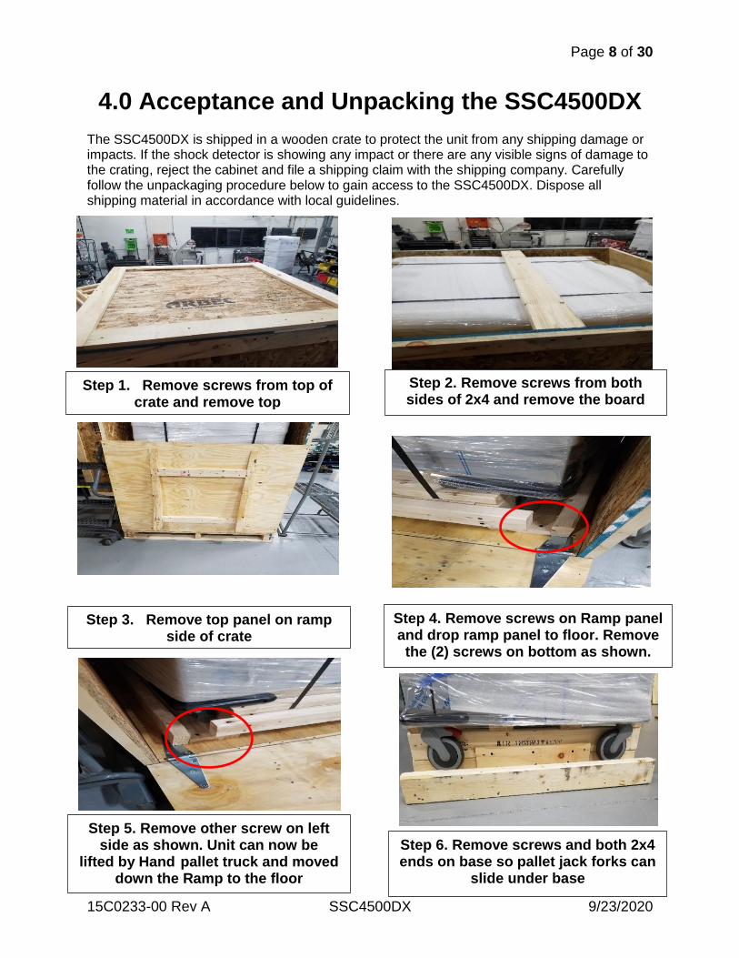
The SSC4500DX is shipped in a wooden crate to protect the unit from any shipping damage or impacts. If the shock detector is showing any impact or there are any visible signs of damage to the crating, reject the cabinet and file a shipping claim with the shipping company. Carefully follow the unpackaging procedure below to gain access to the SSC4500DX. Dispose all shipping material in accordance with local guidelines.
Step 1. Remove screws from top of crate and remove top
Step 2. Remove screws from both sides of 2x4 and remove the board
Step 3. Remove top panel on ramp side of crate
Step 4. Remove screws on Ramp panel and drop ramp panel to floor. Remove the (2) screws on bottom as shown.
Step 5. Remove other screw on left side as shown. Unit can now be
lifted by Hand pallet truck and moved down the Ramp to the floor
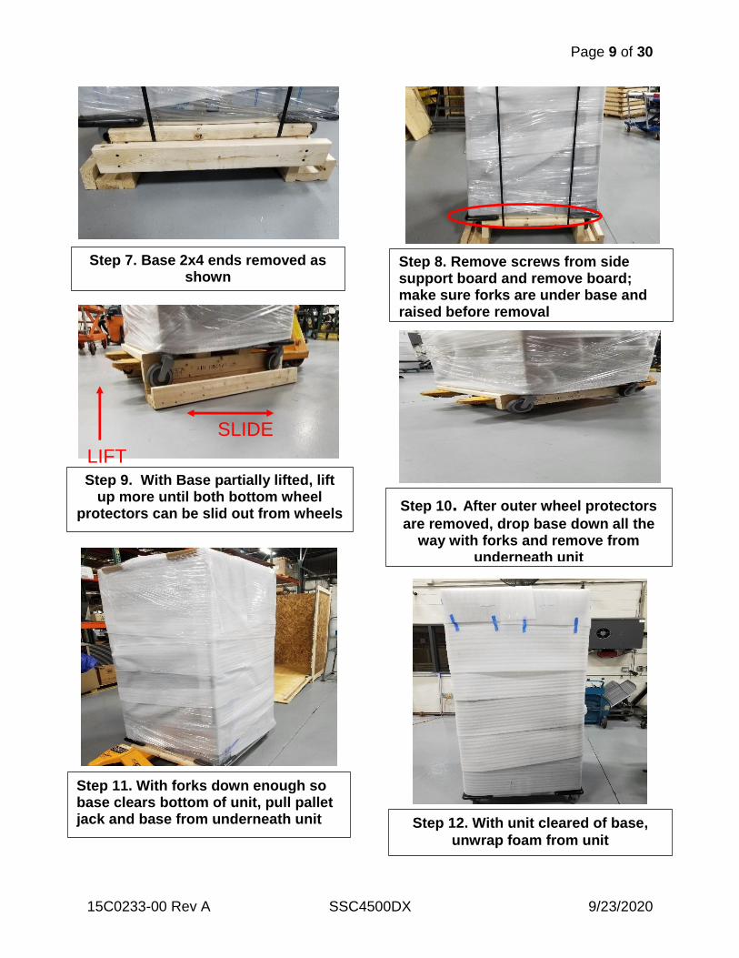
Step 6. Remove screws and both 2x4 ends on base so pallet jack forks can
slide under base
Page 9 of 30
15C0233-00 Rev A SSC4500DX 9/23/2020
Step 7. Base 2x4 ends removed as shown
Step 8. Remove screws from side support board and remove board; make sure forks are under base and raised before removal
Step 9. With Base partially lifted, lift up more until both bottom wheel
protectors can be slid out from wheels
Step 10. After outer wheel protectors
are removed, drop base down all the way with forks and remove from
underneath unit
Step 11. With forks down enough so base clears bottom of unit, pull pallet jack and base from underneath unit
Step 12. With unit cleared of base,
unwrap foam from unit
LIFT
SLIDE
Page 10 of 30
15C0233-00 Rev A SSC4500DX 9/23/2020
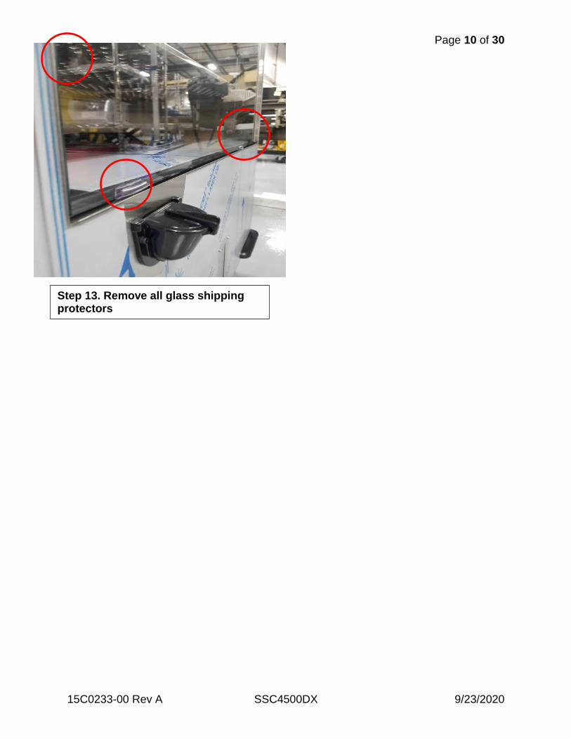
Step 13. Remove all glass shipping protectors
Page 11 of 30
15C0233-00 Rev A SSC4500DX 9/23/2020
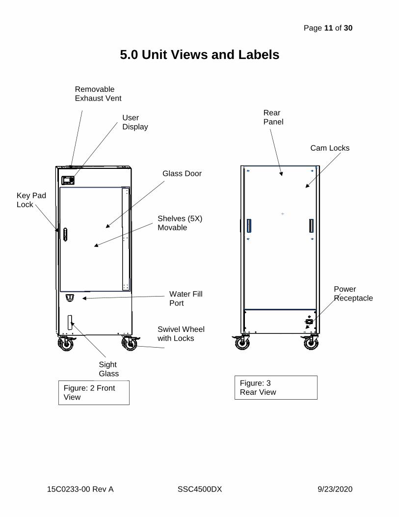
5.0 Unit Views and Labels
Figure: 3 Rear View
Rear Panel
Power Receptacle
Cam Locks
Figure: 2 Front View
User Display
Removable Exhaust Vent
Glass Door
Key Pad Lock
Water Fill Port
Sight Glass
Swivel Wheel with Locks
Shelves (5X) Movable
Page 12 of 30
15C0233-00 Rev A SSC4500DX 9/23/2020
`
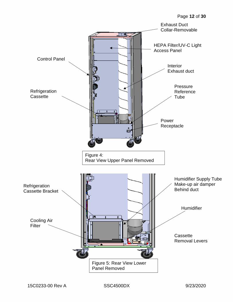
Humidifier
Cassette Removal Levers
Cooling Air Filter
Refrigeration Cassette Bracket
Humidifier Supply Tube Make-up air damper Behind duct
Figure 5: Rear View Lower Panel Removed
Interior Exhaust duct
Control Panel
Refrigeration Cassette
HEPA Filter/UV-C Light Access Panel
Exhaust Duct Collar-Removable
Figure 4: Rear View Upper Panel Removed
Power Receptacle
Pressure Reference Tube
Page 13 of 30
15C0233-00 Rev A SSC4500DX 9/23/2020
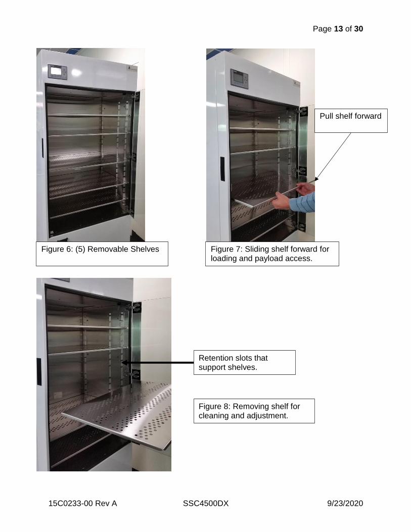
Figure 6: (5) Removable Shelves Figure 7: Sliding shelf forward for loading and payload access.
Pull shelf forward
Figure 8: Removing shelf for cleaning and adjustment.
Retention slots that support shelves.
Page 14 of 30
15C0233-00 Rev A SSC4500DX 9/23/2020
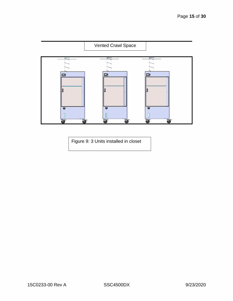
6.0 Installation and Initial Startup The Sterile Storage Cabinet is designed to be used in either an open exam room environment, utility closet, or alcove. The unit generates 120-130 cfm of 95-105°F air to maintain interior cabinet conditions, which is exhausted at the top surface of the unit. The cooling air intake vent is located on the bottom of the unit. Both areas should be clear and unobstructed always or the unit will fault on a high-pressure limit. The unit has an integrated steam humidifier that will add humidity to the cabinet if the RH falls below the humidity setpoint. The humidifier should never be run dry and there are safeties to protect against this condition. The onboard water bottle must be filled. To add water, simply slide the lock to the right and lift the cap. Fill carefully while monitoring the water level through the sight glass on the front of the unit. Once full, close the cap, dry any residual water in the fill port, close the lid, and lock. If any water has spilled on the front of the unit or floor, clean and dry immediately. The unit can be plugged into any 120VAC 15amp wall outlet. IMPORTANT: If plugging into a RED or backup circuit, consult with the facilities manager. The unit will power up and perform a self-diagnostic on the controls and sensors. After a 30-sec delay, the evaporator fan will start and provide air flow to the interior of the cabinet, establishing a positive pressure. The refrigeration system will energize 30 seconds later and start the process of conditioning the cabinet. The unit’s internal conditions are pre-set to nominal values. The unit must be run for 24hrs prior to loading any equipment or supplies. The cabinet must acclimate to the local conditions and thermally stabilize. The temperature and humidity will fluctuate during this 24-hour period. Utility Closet or Alcove Installation When the unit is installed in a utility closet or alcove, it is critical to have sufficient air flow to properly cool the unit. The space around the bottom of the unit must free and clear to allow room air to enter through the bottom of the unit. The utility closet or alcove must be vented to a large open-air space above the ceiling or other open space per facility guidelines. The optional Ceiling Exhaust Kit can be used. The exhaust vent on the top of the unit will accept standard 6” flex duct not to exceed 20 ft in length. It is critical to ensure there are no sharp bends, kinks or crushed duct, as this will affect the performance of the unit.
Page 15 of 30
15C0233-00 Rev A SSC4500DX 9/23/2020
Vented Crawl Space
Figure 9: 3 Units installed in closet
Page 16 of 30
15C0233-00 Rev A SSC4500DX 9/23/2020
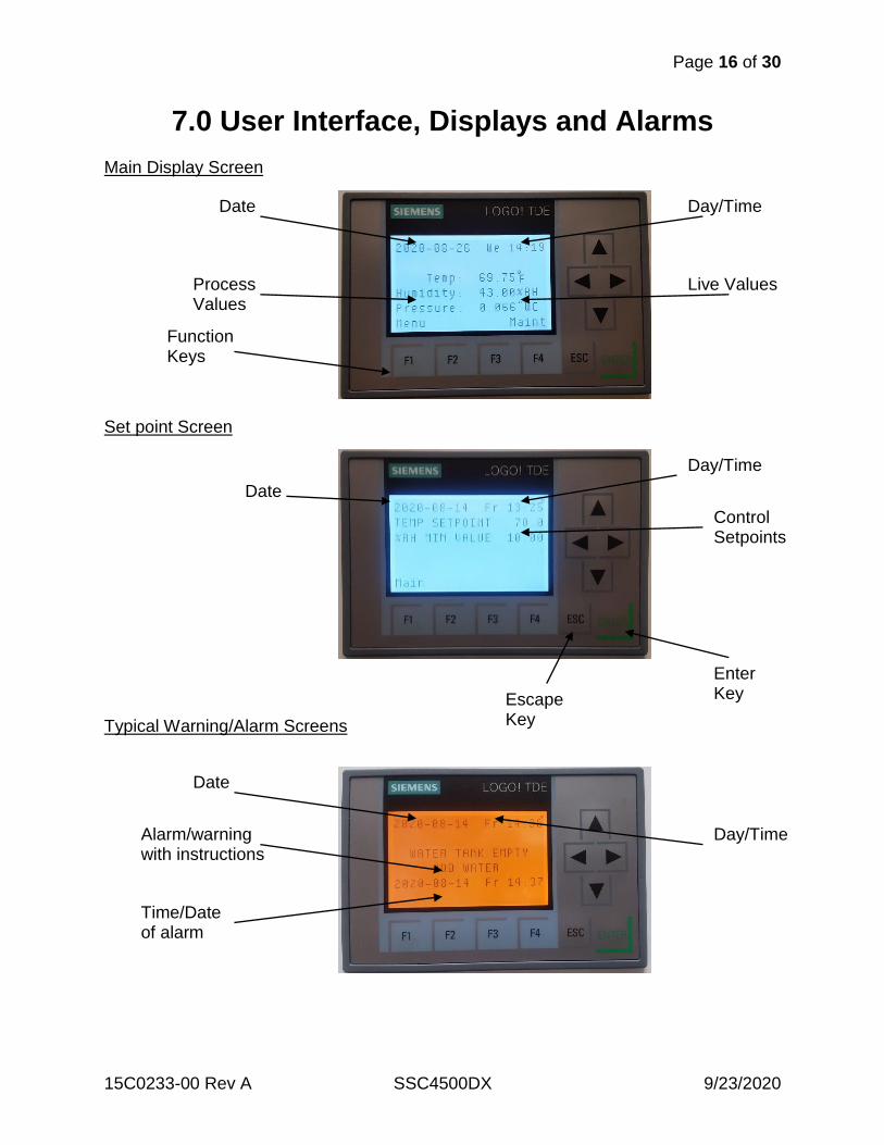
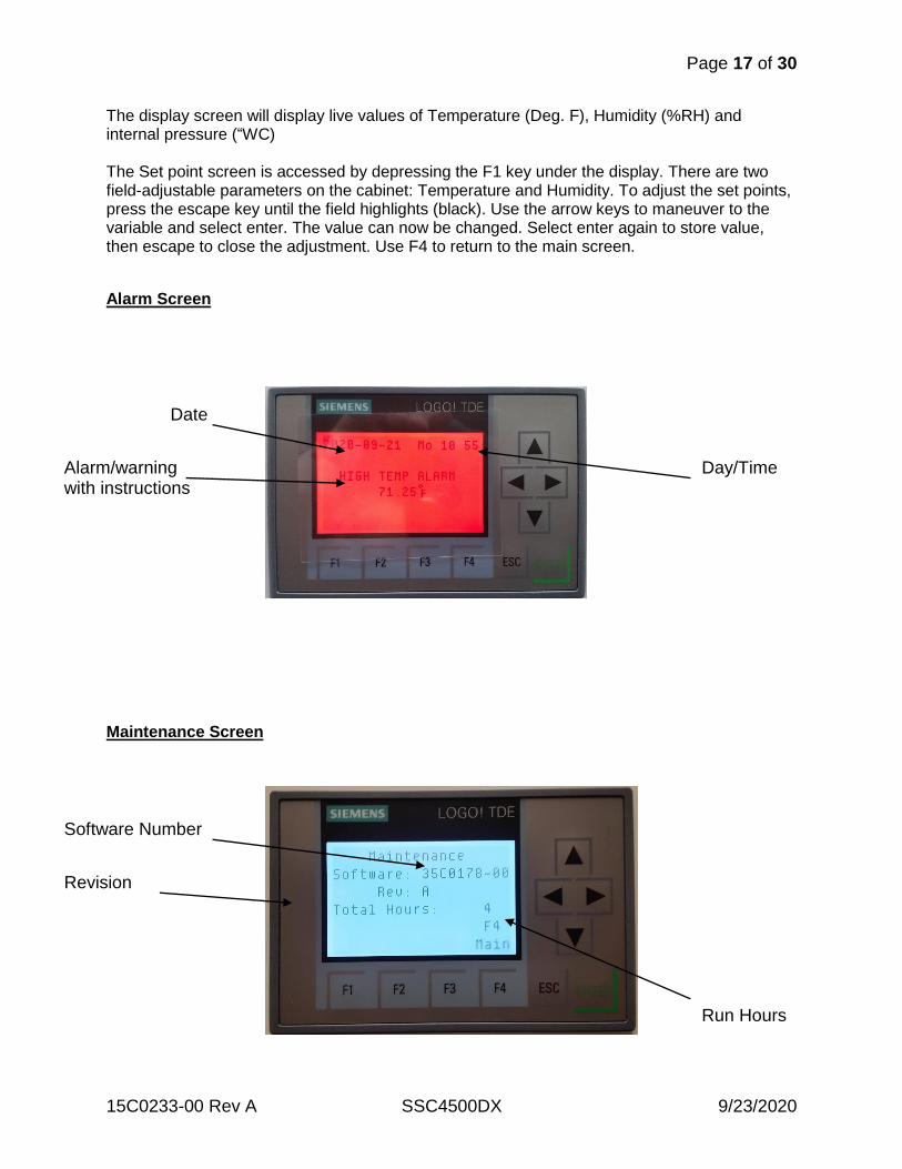
7.0 User Interface, Displays and Alarms Main Display Screen Set point Screen Typical Warning/Alarm Screens
Date Day/Time
Process Values
Live Values
Function Keys
Escape Key
Date
Day/Time
Control Setpoints
Enter Key
Date
Day/Time Alarm/warning with instructions
Time/Date of alarm
Page 17 of 30
15C0233-00 Rev A SSC4500DX 9/23/2020
The display screen will display live values of Temperature (Deg. F), Humidity (%RH) and internal pressure (“WC) The Set point screen is accessed by depressing the F1 key under the display. There are two field-adjustable parameters on the cabinet: Temperature and Humidity. To adjust the set points, press the escape key until the field highlights (black). Use the arrow keys to maneuver to the variable and select enter. The value can now be changed. Select enter again to store value, then escape to close the adjustment. Use F4 to return to the main screen.
Alarm Screen
Maintenance Screen
Software Number
Revision
Run Hours
Date
Day/Time Alarm/warning with instructions
Page 18 of 30
15C0233-00 Rev A SSC4500DX 9/23/2020
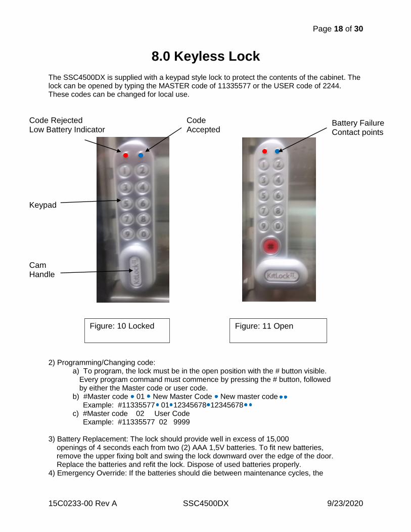
8.0 Keyless Lock The SSC4500DX is supplied with a keypad style lock to protect the contents of the cabinet. The lock can be opened by typing the MASTER code of 11335577 or the USER code of 2244. These codes can be changed for local use.
2) Programming/Changing code: a) To program, the lock must be in the open position with the # button visible. Every program command must commence by pressing the # button, followed by either the Master code or user code. b) #Master code 01 New Master Code New master code Example: #11335577 01 12345678 12345678 c) #Master code 02 User Code Example: #11335577 02 9999 3) Battery Replacement: The lock should provide well in excess of 15,000 openings of 4 seconds each from two (2) AAA 1,5V batteries. To fit new batteries, remove the upper fixing bolt and swing the lock downward over the edge of the door. Replace the batteries and refit the lock. Dispose of used batteries properly. 4) Emergency Override: If the batteries should die between maintenance cycles, the
Figure: 11 Open
Battery Failure Contact points
Figure: 10 Locked
Cam Handle
Keypad
Code Rejected Low Battery Indicator
Code Accepted
Page 19 of 30
15C0233-00 Rev A SSC4500DX 9/23/2020
lock can be overridden. a) Place the contact points of a 9Volt battery against the contact points surrounding the Blue and Red LED’s. b) Place the positive battery terminal against the RED led and the negative battery terminal against the BLUE led. c) Enter the master code. d) The motor will withdraw the locking pin, allowing the lock to be opened. e) Install new batteries. Dispose of used batteries properly.
IMPORTANT LOW BATTERY: When the battery power is low the RED LED will flash (3) times before the BLUE LED light, accepting the code. Replace batteries as soon as this happens. The lock will operate for 100 times with low battery.
Page 20 of 30
15C0233-00 Rev A SSC4500DX 9/23/2020
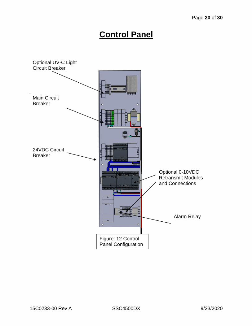
Control Panel
24VDC Circuit Breaker
Optional UV-C Light Circuit Breaker
Main Circuit Breaker
Optional 0-10VDC Retransmit Modules and Connections
Alarm Relay
Figure: 12 Control Panel Configuration
Page 21 of 30
15C0233-00 Rev A SSC4500DX 9/23/2020
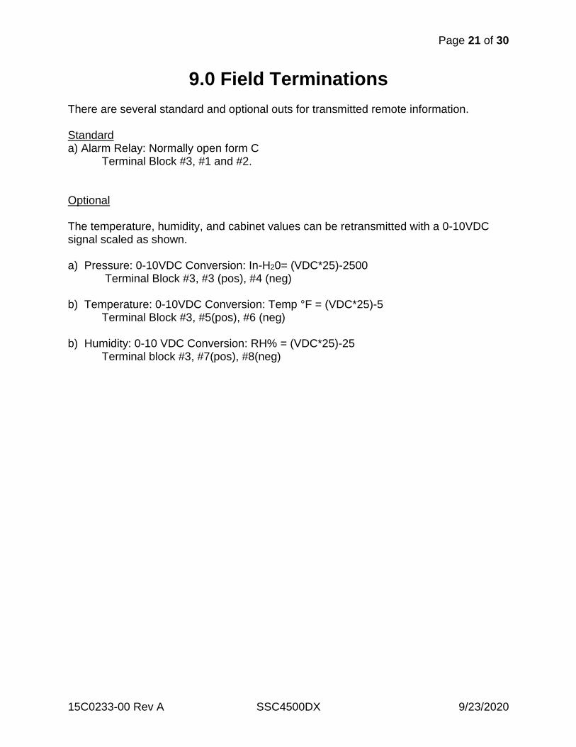
9.0 Field Terminations There are several standard and optional outs for transmitted remote information. Standard a) Alarm Relay: Normally open form C Terminal Block #3, #1 and #2. Optional The temperature, humidity, and cabinet values can be retransmitted with a 0-10VDC signal scaled as shown. a) Pressure: 0-10VDC Conversion: In-H20= (VDC*25)-2500 Terminal Block #3, #3 (pos), #4 (neg) b) Temperature: 0-10VDC Conversion: Temp °F = (VDC*25)-5 Terminal Block #3, #5(pos), #6 (neg) b) Humidity: 0-10 VDC Conversion: RH% = (VDC*25)-25 Terminal block #3, #7(pos), #8(neg)
Page 22 of 30
15C0233-00 Rev A SSC4500DX 9/23/2020
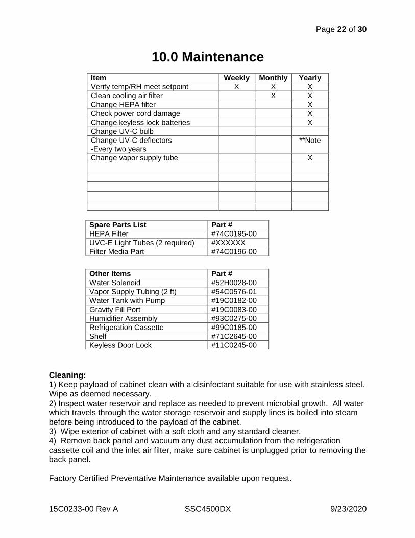
10.0 Maintenance
Item Weekly Monthly Yearly
Verify temp/RH meet setpoint X X X
Clean cooling air filter X X
Change HEPA filter X
Check power cord damage X
Change keyless lock batteries X
Change UV-C bulb
Change UV-C deflectors -Every two years
**Note
Change vapor supply tube X
Cleaning: 1) Keep payload of cabinet clean with a disinfectant suitable for use with stainless steel. Wipe as deemed necessary. 2) Inspect water reservoir and replace as needed to prevent microbial growth. All water which travels through the water storage reservoir and supply lines is boiled into steam before being introduced to the payload of the cabinet. 3) Wipe exterior of cabinet with a soft cloth and any standard cleaner. 4) Remove back panel and vacuum any dust accumulation from the refrigeration cassette coil and the inlet air filter, make sure cabinet is unplugged prior to removing the back panel. Factory Certified Preventative Maintenance available upon request.
Spare Parts List Part #
HEPA Filter #74C0195-00
UVC-E Light Tubes (2 required) #XXXXXX
Filter Media Part #74C0196-00
Other Items Part #
Water Solenoid #52H0028-00
Vapor Supply Tubing (2 ft) #54C0576-01
Water Tank with Pump #19C0182-00
Gravity Fill Port #19C0083-00
Humidifier Assembly #93C0275-00
Refrigeration Cassette #99C0185-00
Shelf #71C2645-00
Keyless Door Lock #11C0245-00
Page 23 of 30
15C0233-00 Rev A SSC4500DX 9/23/2020
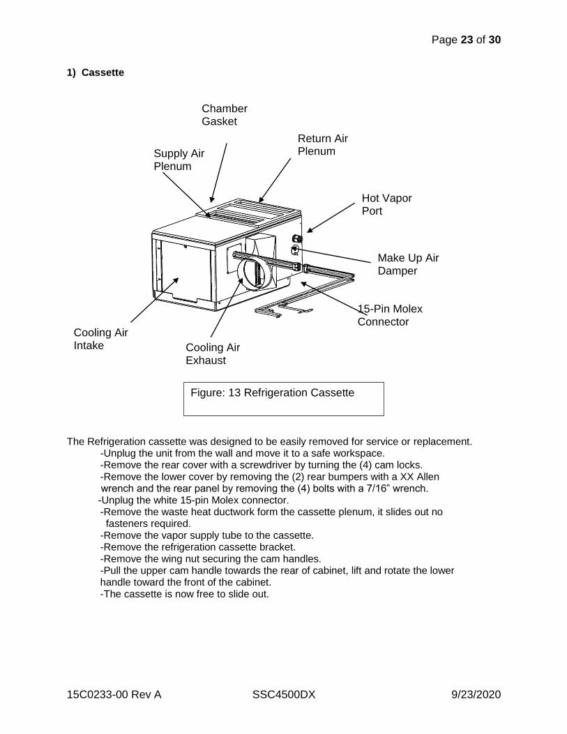
1) Cassette
The Refrigeration cassette was designed to be easily removed for service or replacement. -Unplug the unit from the wall and move it to a safe workspace. -Remove the rear cover with a screwdriver by turning the (4) cam locks. -Remove the lower cover by removing the (2) rear bumpers with a XX Allen wrench and the rear panel by removing the (4) bolts with a 7/16” wrench. -Unplug the white 15-pin Molex connector. -Remove the waste heat ductwork form the cassette plenum, it slides out no fasteners required. -Remove the vapor supply tube to the cassette. -Remove the refrigeration cassette bracket. -Remove the wing nut securing the cam handles. -Pull the upper cam handle towards the rear of cabinet, lift and rotate the lower handle toward the front of the cabinet. -The cassette is now free to slide out.
15-Pin Molex Connector
Make Up Air Damper
Hot Vapor Port
Return Air Plenum Supply Air
Plenum
Chamber Gasket
Cooling Air Intake Cooling Air
Exhaust
Figure: 13 Refrigeration Cassette
Page 24 of 30
15C0233-00 Rev A SSC4500DX 9/23/2020
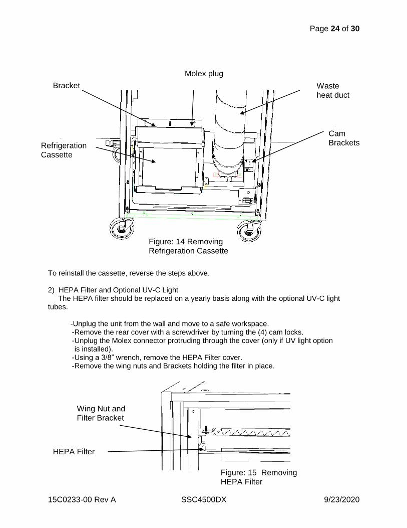
To reinstall the cassette, reverse the steps above. 2) HEPA Filter and Optional UV-C Light The HEPA filter should be replaced on a yearly basis along with the optional UV-C light tubes. -Unplug the unit from the wall and move to a safe workspace. -Remove the rear cover with a screwdriver by turning the (4) cam locks. -Unplug the Molex connector protruding through the cover (only if UV light option is installed). -Using a 3/8” wrench, remove the HEPA Filter cover. -Remove the wing nuts and Brackets holding the filter in place.
Wing Nut and Filter Bracket
HEPA Filter
Bracket
Molex plug
Waste heat duct
Cam Brackets Refrigeration
Cassette
Figure: 14 Removing Refrigeration Cassette
Figure: 15 Removing HEPA Filter
Page 25 of 30
15C0233-00 Rev A SSC4500DX 9/23/2020
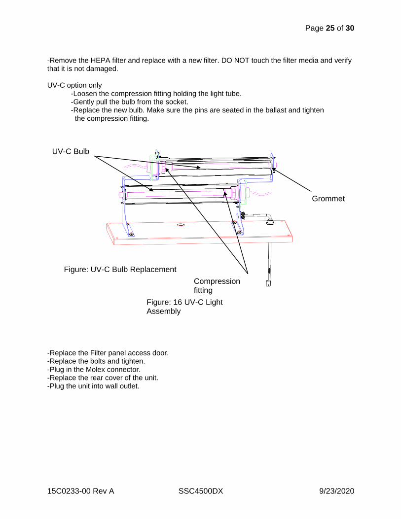
-Remove the HEPA filter and replace with a new filter. DO NOT touch the filter media and verify that it is not damaged. UV-C option only -Loosen the compression fitting holding the light tube. -Gently pull the bulb from the socket. -Replace the new bulb. Make sure the pins are seated in the ballast and tighten the compression fitting.
-Replace the Filter panel access door. -Replace the bolts and tighten. -Plug in the Molex connector. -Replace the rear cover of the unit. -Plug the unit into wall outlet.
UV-C Bulb
Compression fitting
Grommet
Figure: UV-C Bulb Replacement
Figure: 16 UV-C Light Assembly
Page 26 of 30
15C0233-00 Rev A SSC4500DX 9/23/2020
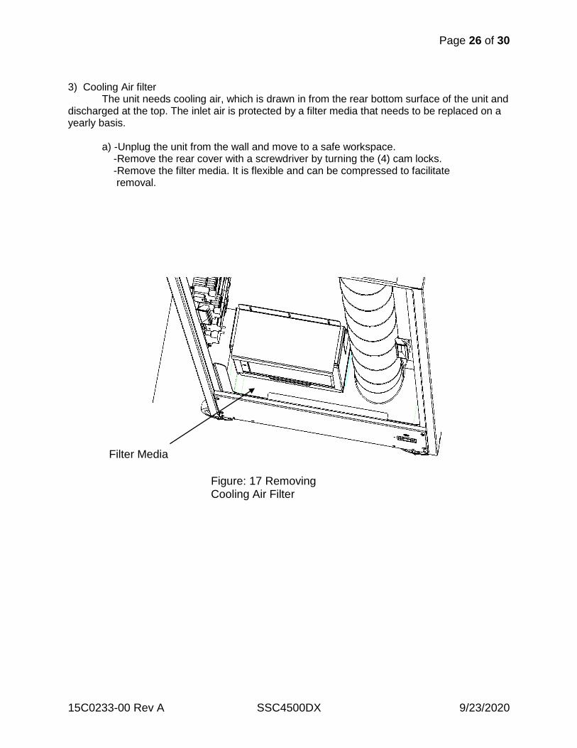
3) Cooling Air filter The unit needs cooling air, which is drawn in from the rear bottom surface of the unit and discharged at the top. The inlet air is protected by a filter media that needs to be replaced on a yearly basis. a) -Unplug the unit from the wall and move to a safe workspace. -Remove the rear cover with a screwdriver by turning the (4) cam locks. -Remove the filter media. It is flexible and can be compressed to facilitate removal.
Filter Media
Figure: 17 Removing Cooling Air Filter
Page 27 of 30
15C0233-00 Rev A SSC4500DX 9/23/2020
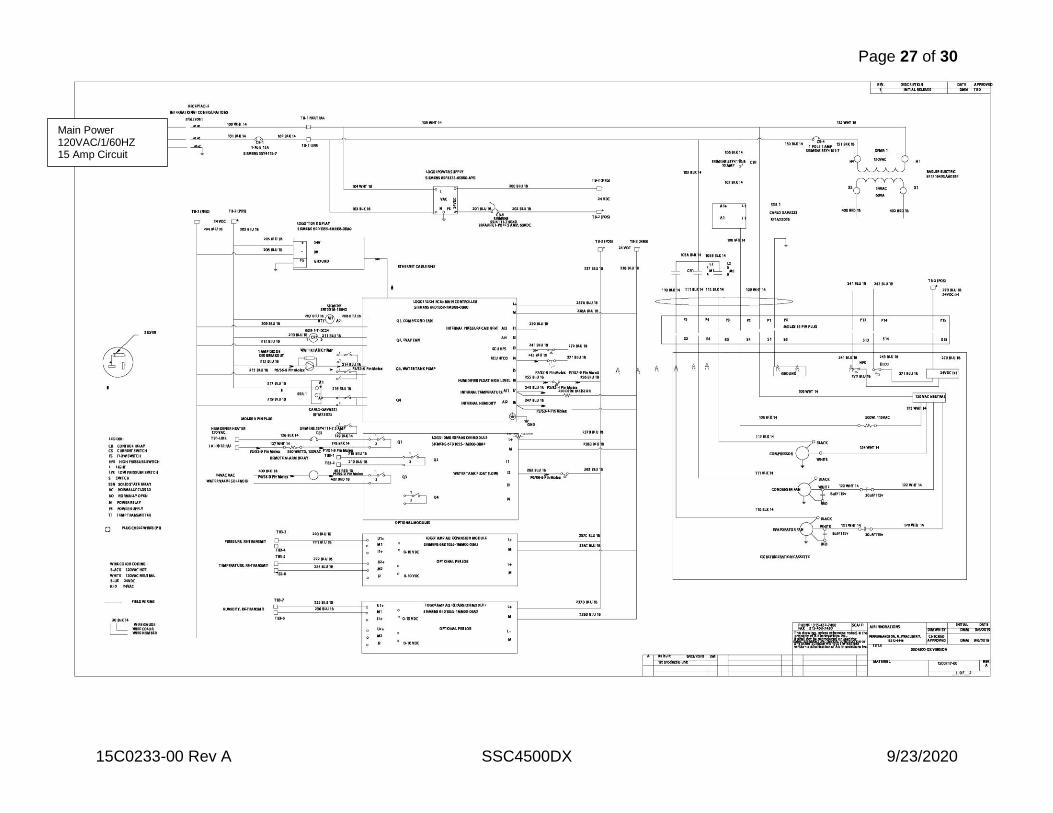
Main Power 120VAC/1/60HZ 15 Amp Circuit
Page 28 of 30
15C0233-00 Rev A SSC4500DX 9/23/2020
Page 29 of 30
15C0233-00 Rev A SSC4500DX 9/23/2020
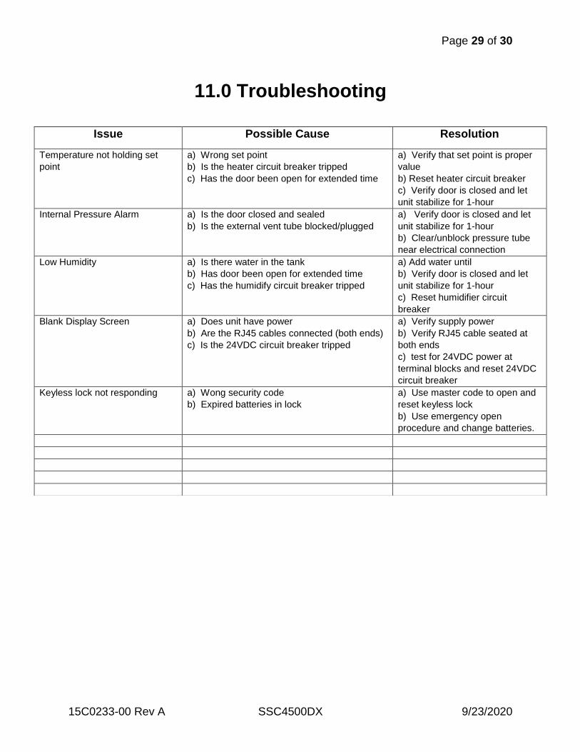
11.0 Troubleshooting
Issue Possible Cause Resolution
Temperature not holding set
point
a) Wrong set point
b) Is the heater circuit breaker tripped
c) Has the door been open for extended time
a) Verify that set point is proper
value
b) Reset heater circuit breaker
c) Verify door is closed and let
unit stabilize for 1-hour
Internal Pressure Alarm a) Is the door closed and sealed
b) Is the external vent tube blocked/plugged
a) Verify door is closed and let
unit stabilize for 1-hour
b) Clear/unblock pressure tube
near electrical connection
Low Humidity a) Is there water in the tank
b) Has door been open for extended time
c) Has the humidify circuit breaker tripped
a) Add water until
b) Verify door is closed and let
unit stabilize for 1-hour
c) Reset humidifier circuit
breaker
Blank Display Screen a) Does unit have power
b) Are the RJ45 cables connected (both ends)
c) Is the 24VDC circuit breaker tripped
a) Verify supply power
b) Verify RJ45 cable seated at
both ends
c) test for 24VDC power at
terminal blocks and reset 24VDC
circuit breaker
Keyless lock not responding a) Wong security code
b) Expired batteries in lock
a) Use master code to open and
reset keyless lock
b) Use emergency open
procedure and change batteries.
Page 30 of 30
15C0233-00 Rev A SSC4500DX 9/23/2020
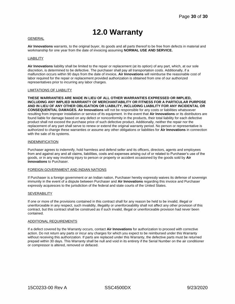
12.0 Warranty GENERAL Air Innovations warrants, to the original buyer, its goods and all parts thereof to be free from defects in material and workmanship for one year from the date of invoicing assuming NORMAL USE AND SERVICE.
LIABILITY Air Innovations liability shall be limited to the repair or replacement (at its option) of any part, which, at our sole
discretion, is determined to be defective. The purchaser shall pay all transportation costs. Additionally, if a malfunction occurs within 90 days from the date of invoice, Air Innovations will reimburse the reasonable cost of
labor required for the repair or replacement provided authorization is obtained from one of our authorized representatives prior to incurring any labor charges. LIMITATIONS OF LIABILITY THESE WARRANTIES ARE MADE IN LIEU OF ALL OTHER WARRANTIES EXPRESSED OR IMPLIED, INCLUDING ANY IMPLIED WARRANTY OF MERCHANTABILITY OR FITNESS FOR A PARTICULAR PURPOSE AND IN LIEU OF ANY OTHER OBLIGATION OR LIABILITY, INCLUDING LIABILITY FOR ANY INCIDENTAL OR CONSEQUENTIAL DAMAGES. Air Innovations will not be responsible for any costs or liabilities whatsoever resulting from improper installation or service of its equipment. In the event that Air Innovations or its distributors are
found liable for damage based on any defect or nonconformity in the products, their total liability for each defective product shall not exceed the purchase price of such defective product. Additionally, neither the repair nor the replacement of any part shall serve to renew or extend the original warranty period. No person or representative is authorized to change these warranties or assume any other obligations or liabilities for Air Innovations in connection
with the sale of its systems. INDEMNIFICATION Purchaser agrees to indemnify, hold harmless and defend seller and its officers, directors, agents and employees from and against any and all claims, liabilities, costs and expenses arising out of or related to Purchaser’s use of the goods, or in any way involving injury to person or property or accident occasioned by the goods sold by Air Innovations to Purchaser.
FOREIGN GOVERNMENT AND INDIAN NATIONS If Purchaser is a foreign government or an Indian nation, Purchaser hereby expressly waives its defense of sovereign immunity in the event of a dispute between Purchaser and Air Innovations regarding this invoice and Purchaser
expressly acquiesces to the jurisdiction of the federal and state courts of the United States. SEVERABILITY If one or more of the provisions contained in this contract shall for any reason be held to be invalid, illegal or unenforceable in any respect, such invalidity, illegality or unenforceability shall not affect any other provision of this contract, but this contract shall be construed as if such invalid, illegal or unenforceable provision had never been contained. ADDITIONAL REQUIREMENTS If a defect covered by the Warranty occurs, contact Air Innovations for authorization to proceed with corrective
action. Do not return any parts or incur any charges for which you expect to be reimbursed under this Warranty without receiving this authorization. If parts are replaced under this Warranty, the defective parts must be returned prepaid within 30 days. This Warranty shall be null and void in its entirety if the Serial Number on the air conditioner or compressor is altered, removed or defaced.


