Embed Size (px)
Citation preview

Structural composites with integrated electromagneticfunctionality
Syrus C. Nemat-Nasser, Alireza Vakil Amirkhizi, Thomas Plaisted,Jon Isaacs, and Sia Nemat-Nasser∗
ABSTRACT
We are studying the incorporation of electromagnetic effective media in the form of arrays of metal scattering elements,such as wires, into polymer-based or ceramic-based composites. In addition to desired structural properties, these electro-magnetic effective media can provide controlled response to electromagnetic radiation such as RF communication signals,radar, and/or infrared radiation. With the addition of dynamic components, these materials may be leveraged for activetasks such as filtering. The advantages of such hybrid composites include simplicity and weight savings by the combi-nation of electromagnetic functionality with necessary structural functionality. This integration of both electromagneticand structural functionality throughout the volume of the composite is the distinguishing feature of our approach. As anexample, we present a class of composites based on the integration of artificial plasmon media into polymer matrixes.Such composites can exhibit a broadband index of refraction substantially equal to unity at microwave frequencies andbelow.
1. INTRODUCTION
Our work on multifunctional structural composites targets the integration of electromagnetic functionality into lightweighthost structures and materials. Our goal is to develop practical models–analytical, computational and experimental–forthe design of structural composites with controlled electromagnetic properties. The host composites have advantageousphysical properties that we wish to retain while incorporating electromagnetic enhancements such as tunable index ofrefraction, RF absorption, and in the case of Left-handed materials,1 negative index of refraction. These electromagneticenhancements are produced by integrating periodic metal scattering structures witheffective mediumresponse propertiesat selectable RF frequencies. Controlled permittivity may be attained from the plasma-like response of periodic inductivestructures. The resulting frequency-dependent dielectric constant can be negative or positive. Negative permeability maybe attained from periodic arrays of magnetic dipole symmetry resonators such as Pendry’ssplit-ring resonators;2 theseresonators display a frequency-dependent magnetic response though they are constructed from non-magnetic conductorssuch as copper. Negative permeability from split-ring resonator arrays combined with negative permittivity from inductivewire arrays results in a negative index of refraction that occurs inleft-handed media.1,3,4 Left-handed media are currentlythe subject of intense study by our colleagues at UCSD and many others around the world. As a practical matter, thenegative refractive response is currently limited to small frequency bands with high RF losses. This manuscript addressesthe practical design of structural composites with controlledpositiveindex of refraction.
Structured conducting media referred to asartificial dielectricshave been studied since the 1950’s, and perhaps earlier,for modeling RF propagation in the ionosphere, and due to low their intrinsic losses, these media have also been consid-ered for use as microwave lenses.5,6 Many artificial dielectrics are plasma analogs that we refer to asartificial plasmonmedia. These example media share an interesting characteristic: they dramatically affect electromagnetic radiation whileoccupying a small, often negligible volume fraction. In fact, by themselves, the artificial media have little or no structuralintegrity and are typically held in low-density polystyrene or patterned onto thin plastic sheets, minimizing the contri-bution of the non-metal components. We are specifically interested in the case where such a medium is embedded in adielectric matrix with significant structural integrity, forming ahybrid materialsystem. Numerical simulations and exper-iments confirm that the dielectric properties of such hybrid composites do, in the absence of significant RF losses, followthe expected analytical form for the combination of a dilute plasma and an ordinary dielectric material. In particular, wefind that such a hybrid material can serve as an RF window (index of refractionn ≈ 1) over a large bandwidth withoutsignificantly altering its other (e.g. structural) properties.
∗ Email [email protected]; phone 858-534-4772; http://www-ceam.ucsd.edu; Center of Excellence for Advanced Materials, UCSan Diego, 9500 Gilman Drive, La Jolla, CA, USA, 92093-0416.

2. ARTIFICIAL PLASMON MEDIA
The ionosphere is a dilute plasma, and many artificial dielectrics are plasma analogs. In 1996, Pendry et al.7 presentedan artificial plasmon mediumcomposed of a periodic arrangement of very thin conducting wires, predicting a plasmafrequency in the microwave regime, below the diffraction limit. Recently, other researchers have presented examples ofartificial plasmon media at microwave frequencies.8 The dielectric constantκ of a dilute neutral plasma is given by
κ = 1−
(f2
p
f2
)(1)
wherefp is theplasma frequencyandf is the electromagnetic excitation frequency. Thus, a plasma has a dispersivedielectric response. The degree to which an artificial medium obeys Equation 1 must often be determined empiricallyand depends on the construction materials and on the geometric properties that determinefp relative to the inter-elementspacing of the metal scattering elements.
Figure 1. Three examples of artificial plasmon media composed of periodic arrangements of straight wires in a square lattice arrange-ment: (a) two-dimensional medium for electromagnetic radiation with linear polarization along the y-axis; (b) two-dimensional mediumfor electromagnetic radiation with wave vectork parallel to the x-axis and arbitrary polarization; and (c) three-dimensional medium forelectromagnetic radiation with arbitrary wave vector and arbitrary polarization. These configurations were considered by researchersin the 1950s5,6 and recently re-interpreted by Pendry et al.7 in the 1990s.
We have selected three classes of artificial plasmon media for our research program. We refer to these classes asthinwire media, loop-wire media, andcoil media. Thin-wire media, as illustrated in Figure 1, were re-introduced by Pendryet al.7 in the 1990s who demonstrated through theoretical analysis that these structures can be engineered with a plasmafrequencyfp in the microwave regime, below the diffraction limit. Pendry et al.9 provide the following prediction for theplasma frequency of a thin wire medium:
f2p =
12π
(c20/d2
ln(
dr
)− 1
2 (1 + lnπ)
)(2)
wherec0 is the speed of light in vacuum,d is the lattice spacing, andr is the wire diameter.† The length of the wires isassumed to be infinite and, in practice, a designer should assure thatl � d� r wherel is the wire length. Pendry et al.9
suggest a wire radius of approximately one micron for a lattice spacing of 1cm resulting in a ratio,d/r, on the order of orgreater than105.
Loop-wire media introduced by Smith et al.8 achieve a microwave frequency plasma frequency though constructed froma relatively thick wire. This is possible due to the observation by Smith that the large effective electron mass calculated
† We keep the additional numerical correction factor∆ = − 12(1 + ln π) that Pendry usually drops because we typically employ this
formula for values ofd andr that do not follow the assumption thatln(
dr
)� 1.
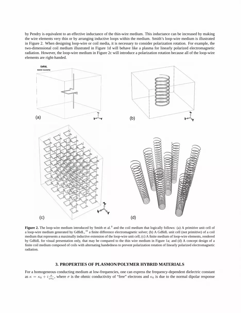
by Pendry is equivalent to an effective inductance of the thin-wire medium. This inductance can be increased by makingthe wire elements very thin or by arranging inductive loops within the medium. Smith’s loop-wire medium is illustratedin Figure 2. When designing loop-wire or coil media, it is necessary to consider polarization rotation. For example, thetwo-dimensional coil medium illustrated in Figure 1d will behave like a plasma for linearly polarized electromagneticradiation. However, the loop-wire medium in Figure 2c will introduce a polarization rotation because all of the loop-wireelements are right-handed.
(d)
(a) (b)
(c)
Figure 2. The loop-wire medium introduced by Smith et al.8 and the coil medium that logically follows: (a) A primitive unit cell ofa loop-wire medium generated by GdfidL,10 a finite difference electromagnetic solver; (b) A GdfidL unit cell (not primitive) of a coilmedium that represents a maximally inductive extension of the loop-wire unit cell; (c) A finite medium of loop-wire elements, renderedby GdfidL for visual presentation only, that may be compared to the thin wire medium in Figure 1a; and (d) A concept design of afinite coil medium composed of coils with alternating handedness to prevent polarization rotation of linearly polarized electromagneticradiation.
3. PROPERTIES OF PLASMON/POLYMER HYBRID MATERIALS
For a homogeneous conducting medium at low-frequencies, one can express the frequency-dependent dielectric constantasκ = κ0 + i σ
ωε0, whereσ is the ohmic conductivity of “free” electrons andκ0 is due to the normal dipolar response

of fixed charges.11 In the case of an ideal plasmon medium, the expression for the dielectric constant follows Equation1 when the normal dipolar response term is equal to 1 (κ0 = 1). In this case, the dielectric constantκ takes on negativevalues forf < fp and asymptotically approaches 1 asf → ∞. The presence of a dielectric matrix (into which theplasmon medium is embedded) will result in a polarization response that can be accounted for by introducingκ0 such that
κ = κ0 −
(f2
p
f2
). (3)
Now,κ is theeffective dielectric constantof an ideal plasmon/dielectric composite material. The dipolar response termκ0
is substantially equal to the effective dielectric constant of the polymer composite matrix in the absence of the integratedartificial plasmon medium when that medium closely obeys Equation 1 and also occupies a negligible volume fraction ofthe composite. With the addition of the dielectric host matrix, the dielectric constantκ takes a value of unity at a finitefrequencyf1 = fp/
√κ0 − 1. We will refer tof1 as thematch frequency, the frequency at whichκ = 1, the indexn = 1,
and there is no refraction at an interface between air and the ideal composite material. The frequency at whichκ = 0determines the onset of electromagnetic wave propagation. Thisturn-on frequencyis given byf0 = fp/
√κ0. Figure 3
illustrates the dependence off0 andf1 on the matrix dielectric constant.
1 2 3 4 5
Matrix Dielectric Constant
0.5
1
1.5
No
rmal
ized
Fre
qu
ency
1 2 3 4 5
Matrix Dielectric Constant
0
10
20
30
40
50
Per
cen
t "
Ban
dw
idth
"
Figure 3. Illustration of the dependence of the effective dielectric properties of plasmon/polymer hybrids on the host matrix dielectricconstant: [Left] Theturn-on frequencyf0 (dashed line) andmatch frequencyf1 (solid line) as a function of the matrix dielectricconstantκ0 where the normalized frequency is in units of the plasma frequencyfp; and [Right] A type ofbandwidthas a function ofthe matrix dielectric constantκ0. This percentbandwidthis defined as(fn=1.1 − fn=0.9)/f1. It illustrates the increased dispersionaroundn = 1 asκ0 increases.
4. COMPOSITES WITH INTEGRATED ARTIFICIAL PLASMON MEDIA
The conditions for an ideal plasmon/dielectric composite are that electromagnetic losses may be neglected and that theeffective medium approximation is valid. For this, the electromagnetic wavelengthλ must be much larger than thelattice spacing of the artificial plasmon medium. Because we are interested in index of refraction close to unity, we maycompare the free space wavelengthλ0 = c0/f to the scattering medium lattice spacing. Figure 4 presents three laboratoryprototypes of plasmon polymer hybrids. These include a loop-wire medium constructed on a two-dimensional array ofthreaded nylon rods; a thin wire medium in a block of Rexolite, a cross-linked polystyrene material with favorable RFproperties; and a coil medium held under tension within a two-dimensional array of holes in a polymer material.
Our first hybrid material prototype was actually a hybrid structure of threaded nylon rods that supported a loop-wireartificial plasmon medium; see Figure 4a. This structure was designed through numerical simulations of electromagneticwave propagation. These simulations were performed with GdfidL,10 an electromagnetic solver developed by Dr. WarnerBruns. The geometry represented in Figure 2a was used with the addition of a nylon rod component, representing thestructure shown in Figure 4a. To simplify the simulation, a square geometry, with equivalent cross-sectional areas, wasused for both the loop-wire element and the nylon rod. With GdfidL, we performed a finite difference frequency domain(FDFD) calculation of the dispersion for the nylon rod structure. The calculated dispersion provides the mode frequency

(a) (b) (c)
Figure 4. Laboratory scale prototypes of plasmon polymer hybrids: (a) A copper loop-wire medium (see Figure 2) incorporated intoa lattice of 6-32 threaded nylon rods. The threaded rods were scored along their length to provide a wire guide, and the threads wereused support and position the inductive loops; (b) A thin wire medium (see Figure 1a) of 50µm diameter copper wire integrated into atwo-dimensional square lattice of holes in a polymer material. This thin sample is designed to be placed between two metal plates thatmake electrical contact with each of the wires. The resulting configuration simulates an infinite material in the direction perpendicularto the plates. Such two-dimensional guided wave measurements are discussed by Shelby et al.4 and Smith et al.12; (c) A coil mediumwith coils of alternating sense (see Figure 2d) incorporated into a square array of holes in a polymer matrix. The coils are held intension and are mechanically adjustable by variation of their overall length.
as a function of phase advance across the unit cell in the direction of wave propagation, the x-direction in Figure 2a. Thewave numberk, the magnitude of the electromagnetic wave vectork, is directly related to the phase advanceφ, measuredin radians, and the size of the unit celld, ask = φ/d. The predicted index of refraction may thus be extracted from theGdfidL calculation as
n =kc0
2πf=
φc0
2πfd, (4)
wheref is the mode frequency of the GdfidL solution andc0 is the speed of light in vacuum. The results of the GdfidLcalculation and a confirming experiment are presented in Figure 5.
4 G 5 G 6 G 7 G 8 G 9 G
Frequency (Hz)
0
0.25
0.5
0.75
1
1.25
Ind
ex o
f R
efra
ctio
n
1 2 3 4 5 6 7 8 9 10
Frequency (GHz)
-15
-10
-5
0
Tra
nsm
itte
d P
ow
er (
dB
m)
Figure 5. Computational analysis and experimental confirmation of a loop-wire plasmon medium combined with a periodic lattice ofnylon rods as shown in Figure 4a. [Left] Predicted index of refraction from GdfidL simulations of an infinite medium based on the unitcell similar to Figure 2a. [Right] Results of power transmission measurements of a finite structure three rows thick with approximatedimensions of12 × 12 × 1in3. The sample filled an aperture in a wall of radar absorbing material (RAM) for the transmissionmeasurement (solid line), and a reference measurement (dashed line) was made through the empty aperture. The predicted turn-onfrequencyf0 from the simulation is approximately 4.3GHz and correlates well to the turn-on of propagation seen in the transmissionmeasurement. This measurement was performed for us by W. Massey and D. Hurdsman at the SPAWAR Systems Center San Diego.

Figure 6 illustrates a validation of Equation 2 for the plasma frequency and Equation 3 for the resulting effective dielectricconstant of a thin wire artificial plasmon medium embedded in a solid polymer matrix. Applying the prediction forfp andthe known dielectric constant of Rexoliteκ0 = 2.5 to Equation 3, we designed a plasmon polymer hybrid with a predictedturn-on frequencyf0 = 7.8GHz and a predicted match frequencyf1 = 10GHz. We characterized this sample withan angular resolved microwave transmission measurement developed by Richard Shelby in the laboratory of ProfessorS. Schultz at UCSD.4 This measurement employs a microwave beam guided between closely spaced metal plates; theelectric field of this guided beam is constrained by the geometry such that the electric field component is spatially uniformalong any perpendicular projection between these plates. For a plasmon sample such as our plasmon polymer hybrid, themeasurement requires electrical contact between the metal guide plates and each of the wires. In this measurement, thedistance between the sample and the microwave detector (see Figure 6a) was shorter than that required to avoid Fresneleffects. The lattice spacingd of the plasmon medium was approximately 5mm. Given the RF wavelengthλ = 3cm at10GHz, this hybrid was not an ideal example of a plasmon polymer hybrid because the wavelength to lattice spacing ratioλ/d = 6 was not sufficiently large. Despite these limitations, both the predicted turn-on frequencyf0 and the matchfrequencyf1 were remarkably consistent with the measurements.
8 10 12 14 16
Frequency (GHz)
0
0.5
1
1.5
Ind
ex o
f R
efra
ctio
n
7 G 8 G 9 G 10 G 11 G 12 G 13 G 14 G 15 G 16 G
Frequency (Hz)
-5
-4
-3
-2
-1
0
Rel
ativ
e P
ower
(dB
m)
(d)
(c)
(b)
(a)
Figure 6. Experimental confirmation of Equation 2 and Equation 3: (a) Schematic of measurement apparatus developed by R. Shelby[figure reproduced from Shelby et al.4] for confirmation of negative index of refraction. The refraction angleθ shown here indicates apositive index of refraction; (b) A polymer wedge-shaped sample with integrated thin wire plasmon medium made of 50µm diametercopper wire arranged in a square two-dimensional lattice with lattice spacingd ∼ 5mm (see Figure 1a). The polymer employed isRexolite, a cross-linked polystyrene material with dielectric constantκ0 ' 2.5 and very low dielectric loss tangent. Equation 2 wasused to predict the plasma frequencyfp for the thin wire medium; (c) The measured index of refraction (solid line with filled circles)along with the prediction that follows from Equation 3 (dashed line); (d) The relative transmitted power through the plasmon wedge asa function of frequency. The predicted turn-on frequency, indicated by an arrow, is 7.8GHz according to Equation 3.
To consider a better example of an ideal effective medium hybrid, we modeled a coil medium such as that shown in Figure2 with a plasma frequencyfp ∼ 1.4GHz corresponding to a free-space wavelengthλ = 21cm. With a lattice spacingof 1cm, this medium hasλ/d ∼ 20. We studied the validity of Equation 3 for this medium using a series of simulations

where the host matrix dielectric constantκ0 was varied. The results appear in Figure 7.
0 1 G 2 G 3 G 4 G 5 G 6 G 7 G 8 G 9 G 10 G
Frequency (Hz)
0
0.5
1
1.5
2
Ind
ex o
f R
efra
ctio
n
Figure 7. Computational confirmation of Equation 3 for a two-dimensional coil medium (see Figure 2) embedded in a host dielectricmatrix with dielectric constantκ0. [Left] GdfidL 10 unit cell for the simulation of RF propagation in an infinite two-dimensionalperiodic lattice. [Right] Simulated index of refraction versus frequency: Solid lines represent the theoretical prediction of Equation 3.The shapes represent GdfidL simulations of the index of refraction as a function of frequency forκ0 = 1 (filled circles),κ0 = 2 (filledsquares), andκ0 = 4 (filled triangles).
5. EFFECTIVE DIELECTRIC CONSTANT OF COMPOSITES
The artificial plasmon medium is embedded in a fiber reinforced composite host that is designed for optimal thermo-mechanical attributes to provide necessary stiffness, strength, toughness, and thermal management. The overall thermo-mechanical as well as electromagnetic properties of such a host composite can be estimated using various micro-mechanicalmodels; see Nemat-Nasser and Hori.13,14Here we focus on estimating the effective dielectric tensor,κ0, of the host com-posite, considering for illustration a two-phase material, e.g., polymer matrix phase (denoted by subscript 1) containingreinforcing fibers (denoted by subscript 2).
The effective dielectric constant of this two-phase composite can be expressed as13
κ0 = (1− c)κ1A1 + cκ2A2 (5)
whereκ1 andκ2 are the dielectric tensors of phase 1 and 2,A1 andA2 are the corresponding field concentration tensors,andc is the volume fraction of phase 2. The concentration tensors are defined by
< E1 >= A1E0, < E2 >= A2E0, (1− c)A1 + cA2 = I (6)
where< E > denotes the volume average ofE, E0 is the electric field applied at the boundary, andI is the second-orderunit tensor. If these concentration tensors are set equal to the unit tensor, then one obtains the results originally proposedby Voigt.15 It is clear that the effectiveness of the model depends on the effectiveness of the estimate of these concentrationtensors.
It is also possible to start with estimating the inverse of the electric permittivity,κ−10 = R0, in terms of the corresponding
constituent parameters asR0 = (1− c)R1B1 + cR2B2 (7)
whereB’s are now the concentration tensors. We shall not follow this line of calculation here and refer the reader toNemat-Nasser and Hori13 for details. Here, we use a simple model to calculate explicitly the concentration tensors,A1
andA2, adopting a special version of the double-inclusion model proposed by Nemat-Nasser and Hori.13 To this end,we assume that the average field,< E2 >, in phase 2, is equal to the average field in a single inclusion embedded in aninfinite homogeneous matrix subjected to an external field equal to the yet-unknown average field,< E1 >, in phase 1,
< E2 >= Adil2 < E1 >, Adil
2 = [I + Sκ−11 (κ2 − κ1)]−1, (8)

whereAdil is a concentration tensor for the dilute distribution of phase 2 inclusions (i.e., no interaction with otherinclusions), and can be determined, using Eshelby’s equivalent-inclusion concept,16 for an assumed inclusion geometry.In the second expression above,S is the dielectric Eshelby tensor. For example, with a spherical inclusion embedded inan isotropic matrix (Taya and Arsenault17), S11 = S22 = S33 = 1
3 . From the above expressions, we now obtain
A2 = Adil2 [(1− c)I + cAdil
2 ]−1. (9)
For spherical inclusions, in particular, we obtain, after some manipulation,
κ0 =κ1 + κ2 − c(κ1 − κ2)κ1 + κ2 + c(κ1 − κ2)
κ1 (10)
where the constituents and the resulting composite are assumed to be isotropic. Similar results can be obtained for othergeometries of the inclusions. Also, in many applications a periodic microstructure may better correspond to the actualfiber arrangement. Again, the concentration tensors can be calculated and the procedure remains the same. For thesecases as well as for finite composites, it is possible to obtain explicit lower and upper bounds on the effective electricpermittivity, as discussed in Nemat-Nasser and Hori.14
6. CONCLUSION
We have presented analytical and numerical models for the electromagnetic enhancement of structural composites. Thisenhancement, in the form of integrated conducting media such as artificial plasmon media, can be used to control RFproperties such as the index of refraction in a desired frequency band. Through computational analysis and experimentalcharacterization of laboratory-scale prototypes, we have demonstrated our capability to design hybrid composites basedon models such as those represented by Equations 2, 3, and 10.
Acknowledgments
The authors wish to thank Leo Christodoulou (DARPA) and John Venables (IDA) for their continued encouragement andmany stimulating discussions. We also thank: David R. Smith and Sheldon Schultz for useful conversations and accessto their microwave characterization facilities; Richard Shelby for help with microwave measurements of refractive index;W. Massey, J. Meloling, D. Hurdsman, and J. Rockway for microwave characterization measurements performed at theirexpense at the SPAWAR Systems Center San Diego . This research is supported by ARO DAAD19-00-1-0525 to theUniversity of California, San Diego.
References
1. D.R. Smith, W.J. Padilla, D.C. Vier, S.C. Nemat-Nasser, and S. Schultz. Composite medium with simultaneouslynegative permeability and permittivity.Physical Review Letters, 84(18):4184–7, 2000.
2. J.B. Pendry, A.J. Holden, D.J. Robbins, and W.J. Stewart. Magnetism from conductors and enhanced nonlinearphenomena.IEEE Transactions on Microwave Theory and Techniques, 1999.
3. R.A. Shelby, D.R. Smith, S.C. Nemat-Nasser, and S. Schultz. Microwave transmission through a two-dimensionalisotropic left-handed metamaterial.Applied Physics Letters, 78(4):489–491, 2001.
4. R.A Shelby, D.R. Smith, and S. Schultz. Experimental verification of a negative index of refraction.Science, 292(5514):77–9, April 2001.
5. R.N. Bracewell. Analogues of an ionized medium.Wireless Engineer, 31:320–6, December 1954.6. W. Rotman. Plasma simulation by artificial dielectrics and parallel-plate media.IRE Transactions on Antennas and
Propagation, pages 82–95, January 1962.7. J.B. Pendry, A.J. Holden, W.J. Stewart, and I. Youngs. Extremely low frequency plasmons in metallic mesostructures.
Physical Review Letters, 76(25):4773–6, 1996.8. D.R. Smith, D.C. Vier, W. Padilla, S.C. Nemat-Nasser, and S. Schultz. Loop-wire medium for investigating plasmons
at microwave frequencies.Applied Physics Letters, 75(10):1425–7, 1999.

9. J.B. Pendry, A.J. Holden, D.J. Robbins, and W.J. Stewart. Low frequency plasmons in thin-wire structure.J. Phys.:Condens. Matter, 10:4785–4809, 1998.
10. W. Bruns. Gdfidl: A finite difference program for arbi-trarily small perturbations in rectangular geometries.IEEETransactions on Magnetics, 32(3):1453–1456, May 1996.
11. J.D. Jackson.Classical Electrodynamics. Wiley, 1975.12. D.R. Smith, R. Dalichaouch, N. Kroll, S. Schultz, and P.M. McCall, S.L. an d Platzman. Photonic band structure and
defects in one and two dimensions.Journal of the Optical Society of America B, 10(2):314–21, 1993.13. S. Nemat-Nasser and M. Hori.Micromechanics: Overall Properties of Heterogeneous Materials, volume 37 of
North-Holland series in applied mathematics and mechanics. North-Holland, Amsterdam ; New York, first edition,1993.
14. S. Nemat-Nasser and M. Hori.Micromechanics: Overall Properties of Heterogeneous Materials. Elsevier, North-Holland, second revised edition, 1999.
15. W. Voigt. Lehrbuch der Kristallphysik. Teubner, Leipzig, 1889.16. J.D. Eshelby. The determination of the elastic field of an ellipsoidal inclusion and related problems.Proceedings of
the Royal Society of London, Series A, 241:376–396, 1957.17. M. Taya and R.J. Arsenault.Metal matrix composites : thermomechanical behavior. Pergamon Press, Oxford,
England; New York, 1989.


