Embed Size (px)
Citation preview

181
NATIONAL COOPERATIVE HICHWAV RESEARCH PROGRAM REPORT 181
SUBCRITICAL CRACK GROWTH AND FRACTURE OF BRIDGE STEELS
TRANSPORTATION RESEARCH BOARD NATIONAL RESEARCH COUNCIL

TRANSPORTATION RESEARCH BOARD 1977
Officers
ROBERT N. HUNTER, Chairman
SCHEFFER LANG, Vic Chairman
W. N. CAREY, JR., Executive Director
Executive Committee
HENRIK E. STAFSETH, Executive Director, American Assn. of State Highway and Transportation Officials (cx officio)
WILLIAM M. COX, Federal Highway Administrator, U.S. Department of Transportation (cx officio)
RICHARD S. PAGE, Urban Mass Transportation Administrator, U.S. Department of Transportation (cx officio)
JOHN M. SULLIVAN, Federal Railroad Administrator, U.S. Department of Transportation (cx officio)
HARVEY BROOKS, Chairman, Commission on Sociotechnical Systems, National Research Council (cx officio)
MILTON PIKARSKY, Chairman of the Board, Chicago Regional Transportation Authority (cx officio, Past Chairman 1975)
HAROLD L. MICHAEL, School of Civil Engineering, Purdue University (cx officio, Past Chairman 1976) WARREN E. ALBERTS, Vice President (Systems Operations Services), United Airlines
GEORGE H. ANDREWS, Vice President (Transportation Marketing), Sverdrztp and Parcel
GRANT BASTIAN, State Highway Engineer, Nevada Department of Highways
KURT W. BAUER, Executive Director, Southeastern Wisconsin Regional Planning Commission
MANUEL CARBALLO, Lecturer in Public Management, Harvard University
L. DEBERRY, Engineer-Director, Texas State Department of Highways and Public Transportation
LOUIS J. GAMBACCINI, Vice President and General Manager, Port Authority Trans-H udson Corporation
HOWARD L. GAUTHIER, Professor of Geography, Ohio State University FRANK C. HERRINGER, General Manager, San Francisco Bay Area Rapid Transit District
ARTHUR J. HOLLAND, Mayor, City of Trenton, N.J. ANNE R. HULL, Speaker Pro Tem, Maryland House of Delegates
ROBERT N. HUNTER, Chief Engineer, Missouri State Highway Department
PETER G. KOLTNOW, President, Highway Users Federation for Safety and Mobility
THOMAS J. LAMPHIER, President, Transportation Division, Burlington Northern, Inc.
A. SCHEFFER LANG, Assistant to the President, Association of American Railroads
DANIEL McFADDEN, Professor of Economics, University of California
ROBERT S. MICHAEL, Director of Aviation, City and County of Denver, Colorado
THOMAS D. MORELAND, Commissioner, Georgia Department of Transportation
GEORGE E. PAKE, Vice President, Xerox Corp.; Manager Xerox Palo Alto Research Center
DOUGLAS N. SCHNEIDER, JR., Director, District of Columbia Department of Transportation
WILLIAM K. SMITH, Vice President (Transportation), General Mills
JOHN P. WOODWARD, Director, Michigan Department of State Highways and Transportation
NATIONAL COOPERATIVE HIGHWAY RESEARCH PROGRAM
Transportation Research Board Executive Committee Subcommittee for the NCHRP
ROBERT N. HUNTER, Missouri State Highway Department (Chairman) A. SCHEFFER LANG, Association of American Railroads
HENRIK E. STAFSETH, Amer. Assn. of State Hwy. and Transp. Officials
WILLIAM M. COX, U.S. Department of Transportation HARVEY BROOKS, National Research Council HAROLD L. MICHAEL, Purdue University W. N. CAREY, JR., Transportation Research Board
General Field of Design
Area of Bridges Project Panel C12-14
A. L. ELLIOTT, Consultant (Chairman) L. ANDERSON, Kansas Department of Transportation R. SWANSON, Spar Aerospace Products, Ltd.
C. H. COOK, Alabama Highway Department J. W. FISHER, Lehigh University C. F. HARTBOWER, Federal Highway Administration
Program Stafi
KRIEGER W. HENDERSON, JR., Program Director DAVID K. WITHEFORD, Assistant Program Director LOUIS M. MACGREGOR, Administrative Engineer R. IAN KINGHAM, Projects Engineer ROBERT I. REILLY, Projects Engineer
L. HARTZELL, Armco Steel Corporation
T. ROLFE, University of Kansas
G. C. STROBEL, Nebraska Department of Roads
C. F. GALAMBOS, Federal Highway Administration
L. F. SPAINE, Transportation Research Board
HARRY A. SMITH, Projects Engineer
ROBERT E. SPICHER, Projects Engineer
HERBERT P. ORLAND, Editor
HELEN MACK, Associate Editor
EDYTHE T. CRUMP, Assistant Editor

NATIONAL COOPERATIVE HIGHWAY RESEARCH PROGRAM 1 81 REPORT
SUBCRITICAL CRACK GROWTH AND FRACTURE OF BRIDGE STEELS
J. M. BARSOM AND S. R. NOVAK
UNITED STATES STEEL CORPORATION
MONROEVILLE, PENNSYLVANIA
RESEARCH SPONSORED BY THE AMERICAN ASSOCIATION OF STATE HIGHWAY AND TRANSPORTATION OFFICIALS IN COOPERATION WITH THE FEDERAL HIGHWAY ADMINISTRATION
AREAS OF INTEREST:
BRIDGE DESIGN
GENERAL MATERIALS
GENERAL MAINTENANCE
RAIL TRANSPORT
TRANSPORTATION RESEARCH BOARD NATIONAL RESEARCH COUNCIL
WASHINGTON, D.C. 1977

NATIONAL COOPERATIVE HIGHWAY RESEARCH PROGRAM
Systematic, well-designed research provides the most ef-
fective approach to the solution of many problems facing highway administrators and engineers. Often, highway problems are of local interest and can best be studied by highway departments individually or in cooperation with their state universities and others. However, the accelerat-ing growth of highway transportation develops increasingly complex problems of wide interest to highway authorities. These problems are best studied through a coordinated program of cooperative research.
In recognition of these needs, the highway administrators of the American Association of State Highway and Trans-portation Officials initiated in 1962 an objective national highway research program employing modern scientific techniques. This program is supported on a continuing basis by funds from participating member states of the Association and it receives the full cooperation and support of the Federal Highway Administration, United States Department of Transportation.
The Transportation Research Board of the National Re-search Council was requested by the Association to admin-ister the research program because of the Board's recog-nized objectivity and understanding of modern research practices. The Board is uniquely suited for this purpose as: it maintains an extensive committee structure from which authorities on any highway transportation subject may be drawn; it possesses avenues of communications and
cooperation with federal, state, and local governmental agencies, universities, and industry; its relationship to its parent organization, the National Academy of Sciences, a private, nonprofit institution, is an insurance of objectivity; it maintains a full-time research correlation staff of special-ists in highway transportation matters to bring the findings of research directly to those who are in a position to use them.
The program is developed on the basis of research needs identified by chief administrators of the highway and trans-portation departments and by committees of AASHTO. Each year, specific areas of research needs to be included in the program are proposed to the Academy and the Board by the American Association of State Highway and Trans-portation Officials. Research projects to fulfill these needs are defined by the Board, and qualified research agencies are selected from those that have submitted proposals. Ad-ministration and surveillance of research contracts are responsibilities of the Academy and its Transportation Research Board.
The needs for highway research are many, and the National Cooperative Highway Research Program can make signifi-cant contributions to the solution of highway transportation problems of mutual concern to many responsible groups. The program, however, is intended to complement rather than to substitute for or duplicate other highway research programs.
NCHRP Report 181
Project 12-14 FY 73 ISBN 0-309-02755-I L. C. Catalog Card No. 77-95287
Price: $5.60
Notice
The project that is the subject of this report was a part of the National Cooperative Highway Research Program conducted by the Transportation Research Board with the approval of the Governing Board of the National Research Council, acting in behalf of the National Academy of Sciences. Such approval reflects the Governing Board's judgment that the program concerned is of national impor-tance and appropriate with respect to both the purposes and re-sources of the National Research Council. The members of the technical committee selected to monitor this project and to review this report were chosen for recognized scholarly competence and with due consideration for the balance of disciplines appropriate to the project. The opinions and con-clusions expressed or implied are those of the research agency that performed the research, and, while they have been accepted as appopriate by the technical committee, they are not necessarily those of the Transportation Research Board, the National Research Coun-cil, the National Academy of Sciences, or the program sponsors. Each report is reviewed and processed according to procedures established and monitored by the Report Review Committee of the National Academy of Sciences. Distribution of the report is ap-proved by the President of the Academy upon satisfactory comple-tion of the review process. The National Research Council is the principal operating agency of the National Academy of Sciences and the National Academy of Engineering, serving government and other organizations. The Transportation Research Board evolved from the 54-year-old High-way Research Board. The TRB incorporates all former 111kB activities but also performs additional functions under a broader scope involving all modes of transportation and the interactions of transportation with society.
Published reports of the
NATIONAL COOPERATIVE HIGHWAY RESEARCH PROGRAM
are available from:
Transportation Research Board National Academy of Sciences 2101 Constitution Avenue, N.W. Washington, D.C. 20418
Printed in the Uaited States of America.

FOREWORD This report contains the findings of an experimental study with the objective of developing information that will lead to prevention of unstable crack growth in
By Staff welded steel bridge members. The results describe the fatigue crack growth be-
Transportation havior, corrosion fatigue crack propagation, stress-corrosion cracking, and fracture
Research Board behavior of five grades of steel commonly used in bridges, under loadings such as occur in highway bridges. The findings from this research should be of value to structural engineers and others involved in the design, construction, and mainte-nance of steel bridges. -
Highway bridges are subjected to a variety of forces ranging from constant dead load plus slowly changing forces due to temperature differentials and mate-rial creep to an infinite variety of superimposed live loads caused by moving vehicles.
The life of a welded steel bridge member is determined by (1) the number of loading cycles necessary to initiate a crack in the member; (2) the size of the largest actively growing crack in the member that was not detected by inspection or was considered acceptable at the time of fabrication; (3) the effect of geometry of the welded details on the rate of stable fatigue or corrosion-fatigue crack growth;
the increase of fatigue crack growth rate due to an aggressive environment; the stress-corrosion-cracking behavior of the steel under static loading condi-
tions; and (6) the crack size that can initiate a rapid crack extension when the com-bined residual and applied stresses, crack size, and fracture toughness provide a critical condition. Some steel bridges have failed prematurely during the last 35
years because one or more of these factors were not considered properly in design or taken into account during maintenance inspections.
This study was intended to provide information relative to stress-corrosion cracking, fatigue and corrosion-fatigue crack growth rate behavior for bridge steels under constant- and variable-amplitude loadings such as occur in highway bridges. Also, the fracture-toughness behavior of these steels was investigated using standard Charpy V-notch specimens, dynamic tear specimens, and fracture-mechanics type specimens. Fracture toughness of bridge steels and fatigue of welded details have been and are being studied by a number of research agencies. However, little has been published on the effects of aggressive environment on the rate of fatigue crack growth for bridge steels. In addition, at the time of initiation of this project, no requirements had been established for fracture toughness levels for bridge steels, nor had fracture mechanics been applied to welded bridge details.
The long-range objective of this project was to develop information that can

be used to define material requirements and design specifications to avoid brittle fracture in steel bridges. The purpose of this research was:
To develop corrosion-fatigue data on bridge steels in distilled water and 3 percent sodium chloride solution under stress fluctuations such as occur in actual bridges.
To develop an analytical method for predicting the cyclic life of bridge components in distilled water and 3 percent sodium chloride solution under stress fluctuations such as occur in actual bridges.
To develop methods of utilizing the results for design and specifications purposes.
The steels studied were A36, A588 grades A and B, and A514 grades E and F. The longitudinal and transverse tensile properties at room temperature were established for each grade of steel. Fatigue tests, stress corrosion cracking tests, and corrosion-fatigue tests were all conducted in this study. Moreover, energy ab-sorption, lateral expansion, and percent shear were determined in the temperature range between - 1000 F and room temperature by using standard impact Charpy V-notch specimens. Additional studies of the type already described were also conducted and included in the study to provide statistical behavior for five different heats of A588 steel that would provide insight into the influence of heat-to-heat variations on structural performance.

CONTENTS
1 SUMMARY
PART I
2 CHAPTER ONE Introduction and Research Approach Description of the Problem Objectives and Scope Fracture Mechanics Methodology Materials Specimen Preparation and Experimental Procedure
11 CHAPTER TWO Findings Fracture Toughness Behavior Fatigue Crack Growth Behavior Fatigue Crack Growth in Various Bridge Steels Stress-Corrosion-Cracking Behavior Corrosion Fatigue, Crack Growth Behavior
34 CHAPTER THREE Interpretation of Appraisal of Findings Significance of Fracture Test Results Significance of Fatigue Test Results Significance of Stress Corrosion Test Results Significance of Corrosion Fatigue Test Results
40 CHAPTER FOUR Conclusions and Recommended Research Conclusions Recommendations for Further Research
41 REFERENCES
PART II 43 APPENDIX A Subcritical Crack Propagation Behavior 50 APPENDIX B Specimen Preparation and Experimental Proce-
dures for Fracture Mechanics Studies
53 APPENDIX C Charpy V-Notch and Dynamic Tear Data 60 APPENDIX II Fracture (K1) Behavior of Steels Investigated 67 APPENDIX E Fatigue Crack Growth Data 71 APPENDIX F Stress-Corrosion-Cracking (K1 ) Behavior of
Steels Investigated
71 APPENDIX 0 Corrosion Fatigue, Crack Growth Data

ACKNOWLEDGMENTS
The research reported herein was performed under NCHRP Project 12-14 by U. S. Steel Research, a division of United States Steel Corporation, Monroeville, Pa. J. M. Barsom, Associate Research Consultant, and S. R. Novak, Research Engineer, were both co-principal investigators for the project and the authors of the report.
Gratefully acknowledged is the invaluable assistance given the authors by their colleagues, E. J. Imhoff, Jr., and J. F. Sovak, in developing the experimental procedures, conducting the experimental work, and calculating the test data.

SUBCRITICAL CRACK GROWTH AND FRACTURE OF BRIDGE STEELS
SUMMARY Well-conceived procedures used to study the safety and reliability of structures recognize that the performance of a structure, or a structural component, is gov-erned not only by material properties, but also by the design, fabrication, inspec-tion, erection, and use of the structure. These parameters govern the initiation of subcritical cracks and their propagation to critical dimensions and, therefore, deter-mine the useful cyclic life of structural components subjected to load fluctuations.
The research described herein provides information on the fatigue crack growth behavior and the corrosion fatigue, crack propagation behavior of various bridge steels (A36, A588 Grade A, A588 Grade B, A514 Grade E, and A514 Grade F) under constant amplitude stress spectra and variable amplitude, random sequence stress spectra such as occur in actual bridges. Also included in the discussion are details concerning the chemical composition, tensile properties, fracture toughness, and stress-corrosion-cracking behavior of the steels investigated.
The data obtained for these steels showed that the average rate of fatigue crack growth, da/dN, under variable amplitude, random sequence load fluctuation and under constant amplitude load fluctuation agreed closely when da/dN is plotted as a function of the root mean square of the stress intensity factor range, Thus, within the limits of this investigation, the average rate of fatigue crack growth of various bridge steels subjected to variable amplitude, random sequence load fluctua-tions and to constant amplitude load fluctuations can be represented by the equation
da/dN=A (tSKrrn )
where LsKrms is the root mean square of the stress intensity factor fluctuation and A, nare material constants.
The corrosion fatigue data obtained for these steels at 60 cycles per minute (cpm) indicated that the rate of crack propagation was essentially the same for exposures in distilled water and in 3-percent solution of sodium chloride in distilled water, for stress ratios of 0.1 and 0.5 for sine-wave and square-wave cyclic stress forms, and for different heats of a given steel.
Corrosion fatigue, crack propagation rates for these steels at 12 cpm were equal to or slightly greater than the fatigue crack propagation rates in a room-temperature air environment. The corrosion fatigue, crack propagation threshold, AK,, (the value of the stress intensity factor fluctuation below which corrosion fatigue cracks do not propagate), of bridge steels subjected to a stress ratio of 0.1 and at 12 cpm was greater in the 3-percent solution of sodium chloride in distilled water than it was in a room-temperature air environment.
Corrosion fatigue, crack propagation rates were retarded significantly by alter-nate wet and dry environmental conditions. The corrosion fatigue, crack propaga-tion life of bridge-steel components under actual operating (wet and dry) condi-tions in the aqueous environments investigated was equal to or greater than their fatigue life in a room-temperature air environment.
Specifications for bridge details are currently based on fatigue data in air. The aqueous solutions used in these studies—distilled water and 3-percent solution of sodium chloride in distilled water—represent environmental conditions that are potentially more aggressive than that of air. However, no major effects of these aqueous environments were observed in this investigation to be related to the rate of propagation of fatigue crack. Additional research is needed to determine how actual bridge environments affect the rate of fatigue crack propagation.
CHAPTER ONE
INTRODUCTION AND RESEARCH APPROACH
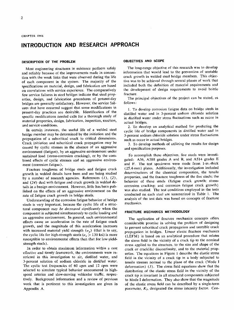
DESCRIPTION OF THE PROBLEM
Most engineering structures in existence perform safely and reliably because of the improvements made in connec- tion with the weak links that were observed during the life of each component in the system. The majority of the specifications on material, design, and fabrication are based on correlations with service experience. The comparatively few service failures in steel bridges indicate that steel prop-erties, design, and fabrication procedures of present-day bridges are generally satisfactory. However, the service fail-ures that have occurred suggest that some modifications in present-day practices are desirable. Identification of the specific modifications needed calls for a thorough study of material properties, design, fabrication, inspection, erection, and service conditions.
In certain instances, the useful life of a welded steel bridge member may be determined by the initiation and the propagation of a subcritical crack to critical dimensions. Crack initiation and subcritical crack propagation may be caused by cyclic stresses in the absence of an aggressive environment (fatigue), by an aggressive environment under sustained load (stress-corrosion cracking), or by the com. bined effects of cyclic stresses and an aggressive environ-ment (corrosion fatigue).
Fracture toughness of bridge steels and fatigue crack growth in welded details have been and are being studied by a number of research agencies. References (1), (2), and (24) deal with fatigue and crack growth in welded de-tails in a benign environment. However, little has been pub-lished on the effects of an aggressive environment on the rate of fatigue crack growth in bridge steels.
Understanding of the corrosion fatigue behavior of bridge steels is very important, because the cyclic life of a struc-tural component may be decreased significantly when the component is subjected simultaneously to cyclic loading and an aggressive environment. In general, such environmental effects cause an acceleration in the rate of fatigue crack growth, and the magnitude of this acceleration increases with increased material yield strength (o-) (that is to say, the cyclic life for high-strength steels (o-,, > 130 ksi) is more susceptible to environmental effects than that for low-yield-strength steels).
In order to obtain maximum information within a cost effective and timely framework, the environments were re-stricted in this investigation to air, distilled water, and 3-percent solution of sodium chloride in distilled water. The cyclic test frequencies of 60 cpm and 12 cpm were selected to simulate typical behavior encountered in high-speed arteries and slow-moving vehicular traffic, respec-tively. Background information and a review of previous work that is pertinent to this investigation are given in Appendix A.
OBJECTIVES AND SCOPE
The long-range objective of this research was to develop information that would lead to the prevention of unstable crack growth in welded steel bridge members. This objec-tive was to be achieved through several phases of work that included both the definition of material requirements and the development of design requirements to avoid brittle fracture.
The principal objectives of the project can be stated, as follows:
To develop corrosion fatigue data on bridge steels in distilled water and in 3-percent sodium chloride solution in distilled water under stress fluctuations such as occur in actual bridges.
To develop an analytical method for predicting the cyclic life of bridge components in distilled water and in 3-percent sodium chloride solution under stress fluctuations such as occur in actual bridges.
To develop methods of utilizing the results for design and specification purposes.
To accomplish these objectives, five steels were investi-gated: A36, A588 grades A and B, and A514 grades E and F. The test specimens were made from l-in.-thick (25.4-mm) plates. Additionally, the investigation included determinations of the chemical composition, the tensile properties, and the fracture toughness of the five steels; the behavior of these steels (fatigue crack growth; stress-corrosion cracking; and corrosion fatigue crack growth) was also studied. The test conditions employed in the tests conducted on each steel are summarized in Table 1. The analysis of the test data was based on concepts of fracture mechanics.
FRACTURE MECHANICS METHODOLOGY
The application of fracture mechanics concepts offers considerable promise in solving the problem of designing to prevent subcritical crack propagation and unstable crack propagation in bridges. Linear elastic fracture mechanics (LEFM) is based on an analytical procedure that relates the stress field in the vicinity of a crack tip to the nominal stress applied to the structure, to the size and shape of the crack or cracklike discontinuity, and to the material prop-erties. The equations in Figure 1 describe the elastic stress field in the vicinity of a crack tip in a body subjected to tensile stresses normal to the plane of the crack (Mode I deformation) (3). The stress field equations show that the distribution of the elastic stress field in the vicinity of the crack tip is invariant in all structural components subjected to Mode I deformation. They also show that the magnitude of the elastic stress field can be described by a single-term parameter, K1, designated the stress intensity factor. Con-

TABLE 1
SUMMARY OF RESEARCH WORK FOR EACH STEEL INVESTIGATED
Number Test Stress
Item of Temperature, Ratio, Wave Wave Frequency,
No. Type of Test Specimen Tests F R Form Amplitude cpm Environment
1 chemical Check analysis 1 - - - - - coitpcsition
2 Tensile properties 0.505(1)* 3 RT+ - - - - - 0.505(T)** 3 RT - - - - -
3 Dynamic fracture CVN(L) 20 -100 to RT - - - - - toughness cVN(T) 20 -100 to RT - - - - -
4 Dynamic fracture 5/8" DT(L) 15 -100 to RT - - - - - toughness 5/8" DT(T) 15 -100 to RT - - - - -
5 Static fracture 1-T WOL(L) 2 RT - - - - Air
toughness
6 Fatigue 1-T WOL(L) 2 IC
7 Fatigue l-T WOL(L) 2 RT
8 Stress corrosion Cantilever beam 8 RT
9 Corrosion fatigue 1-T WOL(L) 2 RT
l-T WOL(L) 2 RT
10 Corrosion fatigue 1-T WOL(L) 2 RT
11 Corrosion fatigue 1-T WOL(L) 1 IC
12 Corrosion fatigue 1-T WOL(L) 2 RT
13 Corrosion fatigue 1-T WOL(L) 5 IC
14 Corrosion fatigue l-T WOL(L) 1 RT
0.1 Sine Constant 300 Air
0.1 Sine Random 300 Air
- - Static - 3% NaCl load
0.1 Sine Random 60 Distilled water
0.1 Sine Random 60 3% NaCl
0.5 Sine Random 60 3% NaCl
0.1 Sine Constant 60 3% NaCl
0.1 Sine Constant 12 3% NaCl
0.1 Sine Constant 60 3% NaCl
0.1 Square Constant 60 More severe
* L = longitudinal. ** T = transverse.
+RT = room temperature. +i-This test was conducted on one of the five steels only. The five
specimens were obtained from various sources.
Conversion Factors:
1 inch = 25.4 mm C = 5/9(? - 32)
(.3

MAGNITUDE OF STRESS ,'ALONG X AXIS, Cry
1i
cry
NOMINAL
CRACK STRESS
TIP
MY
cx: K1
112 COSj-l I-SIN1SI N-38 j-)
K1 9 9 39 (2irr)2 COSj-(I+SINj-SIN -j-)
Figure 1. Schematic of the elastic stress field distribution near the tip of a fatigue crack (Mode I deformation).
sequently, the applied stress, the shape and size of the crack, and the structural configuration associated with structural components subjected to Mode I deformation affect the value of the stress intensity factor, but they do not alter the stress field distribution. Relationships between the stress intensity factor, crack sizes and shapes of various body con-figurations, and loading conditions have been published in Refs. (4) and (5).
One of the underlying principles of fracture mechanics is that unstable fracture occurs when the stress intensity fac-tor at the crack tip reaches a critical value, K 0. For Mode I deformation and for small crack-tip plastic deformation (plane-strain conditions), the critical stress intensity factor for fracture instability is designated K,0. The term K,0 rep-resents the inherent ability of a material to withstand a given stress field intensity at the tip of a crack and to resist progressive tensile crack extension. Thus, K,0 represents the fracture toughness of the material.
The critical stress intensity factor, K,0 (or K 0), repre-sents the terminal condition in the life of a structural com-ponent. The total useful life of the component is deter-mined by the time necessary to initiate a crack and to propagate the crack from subcritical dimensions to the criti-cal size, a0. The primary causes of crack initiation and sub-critical crack propagation may be attributed to cyclic stresses in the absence of an aggressive environment, to an aggressive environment under sustained load, or to the com-bined effects of cyclic stresses and an aggressive environ-
ment. Because these modes of subcritical crack propagation are localized phenomena that depend on the boundary con-ditions at the crack tip, it is logical to expect the subcritical crack propagation rate to depend on the stress intensity fac-tor, K,, which provides a single-term parameter representa-tive of the stress conditions in the vicinity of the crack tip. Sufficient data are available in support of this observation (6-11). Recent studies in which fracture mechanics pa-rameters have also been used show the effect of stress con-centration on the initiation of fatigue crack (12,13).
The life of a component can be prolonged by extending crack-initiation life and subcritical-crack propagation life. The latter may be accomplished by decelerating the rate of subcritical crack propagation and/or extending the size of the critical crack. Consequently, crack initiation, subcriti-cal crack propagation, and fracture characteristics of steels are primary considerations in the formulation of fracture-control guidelines for steel structures.
The rate of fatigue crack growth has been investigated in many materials and has been found to depend on the mag-nitude of the stress range, so-, the crack length, a, and the material properties. The stress range and crack length can be incorporated in a single-term parameter, zK,, which rep-resents the fluctuation of the stress intensity in the vicinity of the crack tip. Consequently, the rate of fatigue crack growth, da/dN, is related to zXK, by the empirical rela-tionship
da/dNA(lsK,)" (1)

where a is the crack length, N is the number of cycles, KI I 0 Z
0 Z
0 0 0
- 0
is the fluctuation of the stress intensity factor, and A, n are 041 :4
constants that reflect effects of material properties and en- • n N - vironments. Sufficient data obtained under constant ampli- 0 tude, cyclic load fluctuations are available in support of this 01 o observation (6-10, 14-16). Furthermore, Eq. 1 can be I o o a o o used to characterize the general behavior of certain classes I '
ZI 0 -
0 o o o of materials under specific test conditions. In particular, values of A and n in Eq. 1 for upper bound (conservative) I 0
.0 0 e 0
ni 0
en 0
(N 0
fatigue behavior in air are given by Eqs. A-S and A-6, re- 0<1 -
spectively, in Appendix A for martensitic steels and ferrite- - pearlite steels. The ability to formulate such general rela- I 0
to .-u o 0 0
0 0
0 0
0 0
tionships for fatigue behavior in air stems from the fact that -
i-c I 0 .
0 -
0 -
0 -
0
the corresponding crack growth rate, da/dn, in air is inde- I pendent of the frequency of cyclic load application. As dis- 0 1I 0 0 0 0 0
cussed in detail in Appendix A, this is generally not the case I 0 0 0 0 0
for corrosion fatigue behavior. in 0
in 0
UI 0
en 0
in 0
Fracture mechanics concepts also provide a means to .4 0 .
I
0 . 0 - 0 - 0 - study the stress-corrosion-cracking behavior of various ma- 0 0 0 0 0
terials. (17-21). Tests can be conducted in a specific envi- I en ni o ronment to determine a threshold stress intensity factor, I 0
I en 0
UI 0 O
in 0
K180 , value below which subcritical crack growth does not > o 0 0 z 0 occur for a material loaded statically in the aggressive V
environment. 01 0 0 0 in
MATERIALS I 0 0 0 0 0
Five types of steels were investigated in this project: ill
54' 0 N in
en '0 o
W to
A36, A588 grades A and B, and A514 grades E and F. I 0 0 0 1 0
Each steel was obtained in the form of a 1-in.-thick plate. (N
I 0 en 0 N
The chemical composition and mechanical properties of the 4 0 z I
z -
steels are given in Tables 2 and 3, respectively. H In addition to the aforementioned five steels, three other
a en 01 (N 01 heats of A588 Grade A steel were tested to determine pos- I o 0 0 0 0 sible variations in the corrosion fatigue behavior of a given i steel. The chemical composition and the mechanical prop- o I en (N N (N
erties of these three steels are given in Tables 4 and 5, o 0. 0 0 0 respectively. I en 0 en
z u)I 0 0 0 0 0 SPECIMEN PREPARATION AND EXPERIMENTAL VJ I o o 0 0 0 PROCEDURE
I Fracture Toughness Tests -
n. 0 I
j 0 0 .1.0
0 -
rI 0
- I 0 0 0 0 0 Fracture toughness tests were conducted by using Charpy
V-notch (CVN) specimens, dynamic tear (DT) specimens, W cantilever beam specimens, and wedge-opening-loading (WOL) specimens.
The CVN specimens (Type A of ASTM Standard E23- 1 0 0 0 0 0
72) are shown in Figure 2 (22). The specimens were machined from the midthickness plane of the 1-in-thick 41
0 zi
plates. The tests were conducted in temperatures ranging Z wI (N .11 10 0
en UI .4
0 0
N 0
from —180 F (-118 C) to room temperature. This tem- uI 01 o
01 UI N Cl
perature range was extended in some cases to obtain the upper energy shelf or the lower energy values. Sets of 20 0 .1
01 N longitudinal and 20 transverse specimens were used for each A. Z H 0 in
of the five steels investigated. The energy absorption, lateral '-' el U r, U N en U
expansion, and fibrous fracture behavior characteristics of o 01
ZI N N ID
'0 '0
0 Ii)
0 N
each steel were recorded. c-i < The DT specimens, shown in Figure 3, were prepared o
and tested in accordance with a method developed by the W ol w 4-fl en
o in
0 ill
H UI .4 in
Naval Research Laboratory (23). The specimens were <z p 'ol < cC cC cC 4
+

11
TABLE 3
MECHANICAL PROPERTIES 4 OF STEELS TESTED
Yield Strength Tensile Elongation Reduction Charpy V-Notch (0.2% offset), Strength, in 2 Inches, of Area, Energy Absorption
Steel Heat No. Plate No. ksi ksi % % at 72 F, ft-lb
Longitudinal
A36 74C515 195264 43.6 78.2 28.2 62.4 28
A588-A 67C611 193804 54.9 81.7 28.2 68.3 69
A588-B 6623487 551528 55.6 82.1 27.8 76.2 66
A514-E 50343 P70074 107.9 122.6 19.0 65.1 68
A514-F 70C125 79873A1 126.0 134.0 18.3 57.8 45
Transverse
A36 74C515 195264 43.9 78.6 25.3 57.4 26
A588-A 67c611 193804 54.6 81.3 24.2 54.0 31
A588-B 6623487 551528 55.8 82.7 24.2 60.5 29
A514-E 50343 P70074 106.1 123.1 17.3 55.5 43
A514-F 70C125 79873A1 126.0 134.0 18.3 58.0 32
* Teneion and impact specimens were taken in the longitudinal orientation from the midthicknees point of the plates, which were all 1 inch thick. Tenaion-test results are the average of three 0.505-inch-diameter tension specimens, and impact results are the average of two Charpy V-notch specimens. Conversion Factors:
1 inch = 25.4 mm 1 ksi 6.895 MN/n2
1 ft-lb = 1.36 3 C = 5/9(F - 32)
machined from the midthickness plane of the 1-in.-thick plates. The tests were conducted in temperature ranges similar to the Charpy V-notch test temperatures. In total, 15 longitudinal and 15 transverse specimens of each of the five steels investigated were tested, and the energy absorp-tion and fibrous fracture behavior Characteristics of each steel were recorded.
Two longitudinal orientation, cantilever beam specimens (see Fig. 4) and two longitudinal orientation, WOL speci-mens (see Fig. 5) were tested to fracture under a slow rate of loading to assess the fracture behavior of the five steels under "static" loading conditions. The nominal dimensions of these specimens are shown in Figures 4 and 5. Addi-tional information relating to the preparation of these speci-mens and to the experimental procedure is given in Appen-dix B.
Fatigue and Corrosion Fatigue Tests
All fatigue and corrosion fatigue, crack growth data were obtained by using 1-in-thick (iT), WOL specimens (Fig. 5). Details of the specimen preparation and ex-perimental procedure are reported in Appendix B.
Crack propagation tests were conducted at room tem-perature in air, in continuously aerated distilled water, and in 3-percent solution of sodium chloride in distilled water. The tests were conducted in 100- and 50-kip (444.8- and 222.4-kN) Materials Testing Systems (MTS) machines. The fatigue crack growth data in air were obtained at cyclic stress frequencies of 300 cpm. The corrosion fatigue, crack growth data were obtained at 60 and 12 cpm, as outlined
in Table 1. The specimens were tested under constant amplitude, sinusoidal or square-wave loading and under variable amplitude, random sequence loading (such as oc-curs in actual bridges) (24). In each test, the fatigue crack was initiated and propagated in tension-to-tension loading at a constant minimum load and at a constant amplitude or variable amplitude maximum load, under conditions which were controlled within ±1.0 percent. The crack was initiated and propagated from the notch root so that, at the time crack-length measurements were begun, the total crack length, a, was equal to about 1 in.
The fatigue crack growth rates were measured optically with a Type M-101 Gaertner microscope mounted in a micrometer slide. To improve the accuracy of measuring the rate of crack extension, a series of hardness indentations was made on the specimen surface along a line parallel to the plane of the initial crack and in the direction of ex-pected crack extension, as described in Appendix B.
The rate of corrosion fatigue crack growth was measured by using the same procedure as that used for fatigue crack growth except for the fact that the specimens were fully immersed in the environment (see Appendix B).
Stress spectra typical of bridge loadings can be defined in terms of a minimum stress, am, and parameters that define the frequency of occurrence of stress ranges, A7, at various magnitudes, as shown in Figure 6. The first step in deter-mining the frequency of occurrence of zo is to select a par-ticular type of distribution curve. In this investigation, a Rayleigh (skewed) distribution curve was used to represent bridge loadings (24). The exact shape of the Rayleigh curve can be varied by changing the standard deviation, 0rd,
7
and the curves can be shifted to higher or lower values of &r by changing the modal (peak) value of the distribution,
In Figure 6, distributions corresponding to three dif- ferent values of rd'r?fl (0, 0.5, and 1.0) are shown for a single value of n-,,,,. In Figure 7, distributions corresponding to two different values of o-,, are shown for a single value of n-ra"n-rn The same value of Uìj is used for all distribu- tions in both figures. A value of O'rd/O' equal to zero cor- responds to constant amplitude loadings.
In the crack growth tests, all variable amplitude loadings * I + followed a Rayleigh distribution curve, with the ratio of the *1
load-range deviation to the modal (peak) load, rd'rm, I equal to either 0 or 1.0. A block of 500 individual (usually
I o 0 0
*1 0 0 0
different) loads satisfying one of these distribution curves was repeated throughout each test. Within the block, the loads were arranged in random sequence.
-s
Although the cyclic loading spectrum was not changed during a test, the stress intensity factor range, àK, for suc- I H H H I 0 cessive blocks increases as the crack length increases. Thus, Z OHI 0
a single test gives crack growth rates for 'a range of ilK 94 A
values. The value of AK corresponding to a given crack length and loading was calculated from an available theo- oI n 0 retical analysis (25). Ld i z
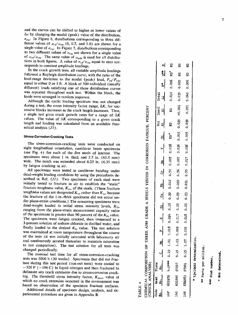
Stress-Corrosion.Cracking Tests a U'
I + o 0
The stress-corrosion-cracking tests were conducted on Z eight longitudinal orientation, cantilever beam specimens o i'i P1 P1
I (see Fig. 4) for each of the five steels of interest. The specimens were about I in. thick and 2.5 in. (63.5 mm) 94 wide. The notch was extended about 0.25 in. (6.35 mm) 0 by fatigue cracking in air. z
I 0 0 0
All specimens were tested in cantilever bending under it' in in dead-weight loading conditions by using the procedures de-
01 -
I 0 0 0 scribed in Ref. (21). Two specimens of each steel were F-
I ° initially tested to fracture in air to establish the "static" 1 H
fracture toughness value, K,7, of the steels. (These fracture ZI -
toughness values are designated K17 rather than K1 , because I o P1 the fracture of the l-in.-thick specimens did not occur un-
P1 oj P1 01 - o der plane-strain conditions.) The remaining specimens were
I a a
dead-weight loaded to initial stress intensity levels, K11, . CU CU wi
ranging from the plane-strain measurement capacity value I 0 0 0
of the specimens to greater than 90 percent of the K17 value. 94 I - The specimens were fatigue cracked, then immersed in a o I CU '-1H ° ° 0 0 - 3-percent solution of sodium chloride in distilled water, and I 0 0 0
finally loaded to the desired K11 value. The test solution I I 0
was maintained at room temperature throughout the course Ic 1 9 of the tests (it was initially saturated with laboratory air
I
and continuously aerated thereafter to maintain saturation H P1 0 0 to test completion). The test solution for all tests was "4 "4 H
changed periodically. Z The nominal test time for all stress-corrosion-cracking i d d
tests was 5000 h (30 weeks). Specimens that did not frac- a
tureduring this test period (run-out tests) were cooled to —320 F (-196 C) in liquid nitrogen and then fractured to
n.i o, CU 0 01
delineate any crack extension due to stress-corrosion crack- 0 ' ing. The threshold stress intensity factor, K,,,, value at Z
0< - 0' I which no crack extension occurred in the environment was O -I Vl CM H
based on observation of the specimen fracture surfaces. Ic o Additional details of specimen design, analysis, and ex- z
VI ' -1 o I perimental procedure are given in Appendix B. 0 Oi Ozu
I

8
TABLE S
MECHANICAL PROPERTIES * OF THREE A588 GRADE A STEELS TESTED
Yield Strength Tensile Elongation Reduction Charpy V-Notch
Code Heat plate (0.2% offset), Strength, in 2 Inches, of Area, Energy Absorption,
No. No. No. ksi ksi % % at 72 F, ft-lb
Longitudinal
14F 622976 4_2** 55.9 81.9 28.0 71.2 58
14G M31992 97007 54.4 80.1 29.0 74.0 89
14H 68E283 97001 53.7 83.0 27.2 69.2 45
Transverse
14F 622976 4-2 55.9 82.1 24.0 53.6 32
140 M31992 97007 50.8 75.9 26.5 60.4 33
1411 682283 97001 53.5 83.0 22.8 54.9 27
* Tension-test results are the average of three 0.505-inch-diameter tension specimens, and impact results are the average of three Charpy V-notch specimens. All plates were 1 inch thick.
Slab number.
Conversion Factors:
1 inch = 25.4 ian 1 ksi 6.895 MN/rn2
1 ft-lb = 1.36 S C = 5/9(F - 32)
RADIUS: 0.010±0.001
RADIUS STRIKER TUP
0.500 ±0.031 12.7 ±0.8 mm
I \\ 0.315±0.001
0.394± 0.001
- H 0.394±0.00
0.010 I
2.115±0.050
B
IN
0.500" ±0.031 12.7 ±0.8mm
6.500 ±0.031 165.0 ±0.8 mm
a
DIMENSIONS AND TOLERANCE FOR SPECIMEN BLANK
PARAMETER UNITS DIMENSION TOLERANCE
IN. 7.125 20.125 LENGTH • L MM 181.0 13.2
IN. 1.60 20.10 WIDTH ,W MM 38.0 12.5
IN. 0.625 ± 0.033 THICKNESS • 8 MM 15.8 10.8
DEGREES 90 ±2 ANGULARITY,O RAO n/a 10.034
DIMENSIONS IN INCHES I INCH: 25.4mm I DEGREE sO.OIlrad
Figure 2. Charpy V-notch test specimen.
Figure 3. Dynamic tear test specimen, anvil supports, and striker.

TOP VIEW
0.010 ± 0.001
SIDE NOTCH SIDE VIEW
I' I
EM NOTCH TIP / CLIP GAGE SLOT
A
0 555 SECTION AA
W : 2.50 I r0fM 00
I
0050 _
lB :1.00 SAWCUT 0.
I 0.90
I 0.60
0007 MAX RAO ALL DIMENSIONS IN INCHES
Figure 4. Fatigue-cracked cantilever-beam tesi specimen.
TYPE A
9
SPEC I B W C A C H 0 0 P
IT-A L000 2.550 3.200 '.763 0.767 2.460 .240 0.094 0.350
IF
IT-B 1.000 2.550 3.200 1.783 0.767 2.480 1.240 0.094 0-250
I IOCI, r25,4mm degree: 0,017 'd
Figure 5. Two types of IT and 2T WOL specimens.

10
a U
Urd/Utm OS Urd/O 1.0 0 rm1n O.50,m . 0rmin
m 0
Urmox20rm40rd to Crma3arm30rd (I,
Ca, LU '0 LU -
to max U,
0• t
Cr min. •arm a-, max • arm
'C a E
a-max 2 a-max
'C a
b
b f1hiOUllUUL E
Umin VARIES FOR EACH CYCLE
am in amin
FOO 50 0 tFIOO 50 0 t F 100 50 0
FREQUENCY TIME FREQUENCY TIME . FREQUENCY TIME OF OCCURRENCE OF OCCURRENCE OF OCCURRENCE OF a, VALUES, %, OF a VALUES, % OF a, VALUES, %
Figure 6. Stress spectra—constant e,.
a U
a . a- rd 1 rni'° 5 - at mm • 0.5 arm in 0rmin O-Sa-rm .g a-,max=2arm'4a-,d tO
LU Urmaxs2a-rm4ard U) Iii
Co
b
t N
I? _ 'C
amal H o I _ I a-mm ammn C
C E E - VARIES FOR b b EACH CYCLE
I I 11- t ___
I FIOO 50 0 F1 IOO 50 0
FREQUENCY TIME FREQUENCY TIME OF OCCURRENCE OF OCCURRENCE OF at VALUES. % OF at VALUES, %
Figure 7. Stress spectra—different o,,.

CHAPTER TWO
FINDINGS
1!
FRACTURE TOUGHNESS BEHAVIOR
The fracture toughness tests of the A36, A588 grades A and B, and A514 grades E and F steels were included in this study for background information and for possible future use. The fracture toughness characterization of these steels was done by conducting Charpy V-notch (CVN) tests, dynamic tear (DT) tests, and K1-type tests. Detailed documentation of the results obtained by testing CVN and DT specimens is given in Apepndix C (Figs. C-i through C-25).
The fracture toughness behavior obtained by testing 1-in.-thick WOL specimens and precracked cantilever beam specimens at room temperature resulted in extensive plas-tic deformation of the specimens prior to crack extension. This behavior represents high fracture resistance of the steels tested to crack extension under slow rates of loading. Details of the test results are given in Appendix D and are summarized in Table 6.
FATIGUE CRACK GROWTH BEHAVIOR
Most tests of fatigue crack growth are conducted by sub-jecting a fatigue-cracked specimen to constant amplitude, cyclic load fluctuations. Incremental increase of crack length is measured and the corresponding number of elapsed load cycles is recorded. The data are plotted in terms of crack length, a, versus total number of elapsed load cycles, N. Figures 8 and 9 show the effects on crack growth of specimens subjected to constant amplitude, cyclic load fluctuations. As shown in Figure 8, an increase in the magnitude of cyclic load fluctuation results in a decrease of fatigue life of specimens having identical geometry. Figure 9 shows that the fatigue life of specimens subjected to a fixed, constant amplitude, cyclic load fluctuation decreases as the length of the initial crack is increased. Consequently, various a-versus-N curves can be generated by varying the magnitude of the cyclic load fluctuation and/or the size of the initial crack. These curves reduce to a single curve when the data are represented in terms of crack growth rate per cycle of loading, da/dN, and the fluctuation of the stress intensity factor, aK,, because AK, is a single-term parame-ter that incorporates the effect of changing crack length and cyclic load magnitude.
Incremental increase of crack length and the correspond-ing number of elapsed load cycles can be measured under variable amplitude, random sequence load spectra. How-ever, unlike constant amplitude, cyclic load data, the magni-tude of AK, changes for each cycle. Reduction of data in terms of fracture mechanics concepts therefore requires
establishing a correlation parameter that incorporates the effects of crack length, cyclic load amplitude, and cyclic load sequence.
It is desirable to determine the magnitude of constant amplitude, cyclic load fluctuation that results in the same a-versus-N curve obtained under variable amplitude, cyclic load fluctuation when both spectra are applied to identical specimens (including initial crack length). In other words, the objective is to find a single stress intensity parameter—such as mean, modal, or root mean square—that can be used to define the crack growth rate under both constant amplitude and variable amplitude loadings. The a-versus-N curve obtained under constant amplitude, cyclic load fluc-tuation equal to the maximum cyclic load fluctuation of a variable amplitude load spectrum results in shorter fatigue life than that experienced under the variable amplitude spectrum. Similarly, a curve based on the minimum cyclic load fluctuation results in a longer life than that obtained under the variable amplitude load spectrum. The magni-tude of the correlating parameter is bounded by these ex-tremes. Moreover, the selected parameter must character-ize the distribution curve.
Fatigue crack propagation behavior under variable am-plitude, random sequence stress spectra such as occur in actual bridges has been investigated as part of NCHRP Project 12-12 (24, 26). The tests were conducted on A514 Grade B steel under variable amplitude, random sequence load spectra having rdrW values of 0.5 and 1.0; a typical portion of the 500-cycle loading block for each is shown in Figure 10. It is apparent from Figure 11 that the average rate of fatigue crack propagation under variable amplitude, random sequence and ordered sequence load fluctuations is approximately equal to the rate of fatigue crack propaga-tion under constant amplitude, cyclic load fluctuation equal to the root-mean-square value of the variable amplitude function. The root mean square is the square root of the mean of the squares of the individual load cycles in a spec-trum; it is related to the modal value of the spectrum, as shown in Figure 12. The average rate of fatigue crack propagation, da/dN, under variable amplitude, random load fluctuation and ordered load fluctuation and under constant amplitude load fluctuation was found to agree closely when da/dN was plotted as a function of the root mean square of the stress intensity factor range, AKr,ne (see Fig. 13). Thus, within the limits of the available experi-mental data, the average rate of fatigue crack growth per cycle, da/dN, under variable amplitude stress spectra typi-cal of spectra occurring in actual bridges can be represented by the equation

TABLE 6 SUMMARY OF FRACTURE BEHAVIOR FOR STEELS INVESTIGATED
Predicted Behaviors Estimated Be" for Bain for
1-T CantileverBeam pecImen Results Range of Througbthickcess Psrtial-Thickne ss 1-TVecim n Resuts
3(I,L g +
N.nex) (
3(Is ksi
Cracks. 0' nces
c), Cracks ( of r es 3(I Ljb~ °N.En
Inch /inc ksi Cflb K
KIjb hal /inch ksi Inch ksi inch .Gub Oys
Steel hat /inch kit
*36 21.6 37* 95 0.65 2.34 26.0 1.1 90 1.00 2.60 1 82 > 8.9 >17.8
*588-A 314.1 4 108 0.74 2.13 32.2 57 100 1.12 2.26 >120 >12.0 1214.0
A5&6-B 33.8 42* 122 0.79 2.41 32.4 54 104 1.05 2.37 '120 >11.7 >23.1.
A51.-E4. 67.8 101 166 1.00 1.63 66.4 no 146 1.05 1.68 15020a 14.85 9.70
A5l4-F'' 81.5 93 132 0.12 1.08 78.3 96.5 iol. 0.78 1.01. 125-10E) 2.1.5 14.90
* ,Lub - (/_)1'2 where I.Lub
• least-upper-bound for plane-strain fracture under IflN condition!.
of K - 5 percent secant intercept value from P versus V fracture test record.
° Kis a stress-intensity value at aaxiaa.1oad (P ) calculated on the basis of LEfl4 using the appropriate K, equation (VOL or cantilever-baa
specimens subjected to pure bending). MAX
+ X rub - a (_!_)1/2 . where K I,Gub - greatest-upper-bound for plane-strain fracture under LEPI4 conditions, and the interrelationship 75 1.
Kios - 1.58 RI.Lb applies.
.t a - value of the nina1 net-section stress at maximum bed (?mWM
) calculated using the following bean-theory equations;
Mc ? p + -
• B(W - •)2 11.V + 2.) for the VOL specimen
Mc 6PL and Op
- - - for the cantilever-beam specimen.
N

# Estimates of K1 based on concerts of the K1-Suppression Effect based on the following criteria:
No suppression - K C K crC )<0.63 Q I1 .ub K1 Cub
Moderate suppression - K11ub C K C KIoub or 0.63 C < 1.00
KQ Severe suppression - KQ > tç .., or ) , 1.00
I,Oub
H Bmin = minimum value of plate thickness and throughthickness crack size win) required for valid plane-strain (K10) fracture calculated on the basis of the nininur estimated value of F1 (preceding column) and actual yield strength, a (Table 3) as follows, ys
B. = 2.50 (KIc 2
) = a mm o mm ys
### B M., = minimum value of plate thicktess and partial-thicluiess crack (PTC) depth (a min ) required for valid plane-strain (K Ic ) fracture
calculated on the basis of the minimum estimated value of K_ (a preceding column) and actükl yield strength, C (Table 3) as follows, YS
B. = 5.00 (KIc)2 amin mm a 2
ys
Q K values for WOL specimens are low (less than corresponding KQ values obtained from cantilever-beam specimens) as a result of premature plastic bending of the WOL specimen arms.
6 Supplementary estimated Kic values calculated using the Charpy V-notch shelf correlation equation for Kic of high-strength martens•tic steels, = .._2. (CVN - ¶1!), and the appropriate mechanical properties (a1s and Cl/N, Table 3), are as follows: ys Cy5 20
ASlb-E steel - K1 = 154 ksi & (202 t.tn32), with B .= 7.25 inches for throughthickness cracks and B = 1+.5 inches for partial- thickness cracks ?PTC). '' i
A51-F steel - Ri = 156 ksi /inch (172 iqn_3/2),with Bmmn = 3.85 inches for throughthickness cracks and B min = 7.70 inches for partIal-thickness cracks (PTC).
ConversIon Factors:
1 ksi )iuch 1.099 m_312
1 inch = 2.54 cm

14
SINUSOIDAL STRESS -CONSTANT AMPLITUDE
Acr3> Ac2 >Au1 Au1 0
Ac2 0 0
So 0 0 0 0 0
Ac3 I '9 A
/
00 A A 0 A 0 0 A 0 A A 0 6 A 0 A
t 0
At 0 0 A 0
A 0 0 0 Iinch25.4mm o
S 0o 0, 0
I I I I A 4 5 6
NUMBER OF CYCLES, N x IO
Figure 8. Effect of cyclic stress range on crack growth.
I SINUSOI DAL
I I I STRESS -CONSTANT AMPLITUDE
I I
03 > 02 >0 03 02 01
A 0 0 - A 0 0
A A
.8— A A 0 A 0
a / S A 0
0 0 0 -
A 0 0 A 0 0
0 0
00 4— -
0 0
0 0
0 0 2— 0 0 - Iinch=25.4mm
0 0 0
0 0 I .0
0 I I I
2 3 4 5 6 7 8
NUMBER OF CYCLES, Nx105
Figure 9. Effect of initial crack length on crack growth.

15
4
(aJ —TIME '-
Prd —=1.0 Priti
i -TIME •
PS -Pta =0.5
Figure 10. Two variable amplitude, random sequence load fluctuations.
da/dNA(KTins' 111 (2) '
where A and ii are material constants. The root-mean-square value of the stress intensity factor
under constant amplitude, cyclic load fluctuation is equal to the stress intensity factor fluctuation. Consequently, the average rate of fatigue crack growth for variable amplitude loadings can be predicted from constant amplitude data by using Eq. 2.
FATIGUE CRACK GROWTH IN VARIOUS BRIDGE STEELS
The preceding results (Fig. 13) were obtained by testing A514 Grade B steel. Because several investigators (27-31) have noted that changes in cyclic load magnitude can lead to either accelerated or retarded rates of fatigue crack growth, the applicability of the RMS (root-mean-square) model for correlating crack growth rates under random loading must be established for bridge steels of various yield strengths. Consequently, the fatigue crack growth rates under constant amplitude load fluctuations and under vari-
able amplitude, random sequence load fluctuations were investigated in A36, A588 grades A and B, and A514 grades E and F steels. All loadings followed a Rayleigh distribution curve, with the ratio of the load-range devia-tion to the modal (peak) load, Td'TIIi' equal to either 0 or 1.0. Data on crack length and the corresponding num-ber of elapsed load cycles obtained by subjecting identical specimens of each steel to constant amplitude load spectra and to variable amplitude, random sequence load spectra are given in Appendix E (Figs. E-1 through E-7). The load range, zXp, for every cycle in the constant amplitude tests was equal to The results show that the fatigue life under constant amplitude, cyclic load fluctuations was longer than the fatigue life obtained under random se- quence load spectra having the same value of r)L• The data are plotted in Figures 14 through 18 in terms of crack growth rate, dadN, and the root mean square of the stress intensity factor range,
Figures 14 through 18 show that, within the limits of this experimental work, the average rate of fatigue crack


Cs
8
C- C--
Cn i'C, C 5
C-' r,rnn rr,] -i (C
H max 2 rrp 4Crd /C :0 F- Old riP
°irns 12070r-t
4 A
b\ k Cfl cmax:onax
o b
ç - ar UyI_ Cmin C amin
VARIES FOR EACH CYCLE
F io &oTh
I C
a
I, - 'flax 3Crry rd/rmO
- 1,414 a,, (0 LsJ
t I
r
0
-•
min - amin
p F 100500
.1111 I - 4514-B STEEL V -
ROOM-TEMPERATURE
- AIR ENVIRONMENT q# -
b -
.10
- I A
to •CONSTANTAMPLITIJDE - 0 ASCENDING ORDER -
- f a DESCENDING ORDER - - V ASCENDING-DESCENDING - S ORDER
- A RANDOM-SEQUENCE -
- I ksi./iiK= 1.0998 MN/rn312 - 4 Iir,ch:25.4rnrn
LI liT I I I all 6 810 ao 40 60 80 100
AKrrns, ksH/Thii
Figure 13. Summary of crack growth rate data under random se-quence and ordered sequence load fluctuations.
FREQU54-JC'f TIME
FREQUENCY TIME or occ'J
OF OCCURRENCE Cl Cr VAi. OF 0r VALUES. %
Figure 12. Stress spectra—constant if

£
RANDOM
A RANDOM
O CONSTANT
£ CONSTANT
1 (SI s/INCH 1.099 MN/rn312 1 INCH = 25.4 mm
0 S
[.1
2F
2
-5
8
6E
RANDOM
A RANDOM
V RANDOM
0 CONSTANT S CONSTANT
1 KSI ./INCH 1.099 MN/rn312 8
1 INCH 25.4 mm
6
10 20 30 40 50 60 80 100
ISKrms, ksi,'i}i
Figure 14. Crack growth rate as a function of the root mean square of the stress intensity factor for A36 steel.
AKrrns, ksi,Jinch
Figure 15. Crack growth rate as a function of the root mean square of the stress intensity factor for A588 Grade A steel.

1 (SI Vi?W = 1.099 MN/rn3t2
1 INCH = 25.4 mm
RANDOM
A RANDOM
0 CONSTANT
S CONSTANT
10 20 30 40 50 60 80 100
Krms, ksi/iiiE
Krms, ksi
Figure 16. Crack growth rate as a function of the Toot mean square of the stress
Figure 17. Crack growth Tate as a function of the root mean square of the stress intensity factor for A588 Grade B steel. intensity factor for A514 Grade E steel.
20
AKrms. ksi ,J1iE Figure 18. Crack growth rate as a function of the root mean square of the stress intensity factor for A514 Grade F steel.
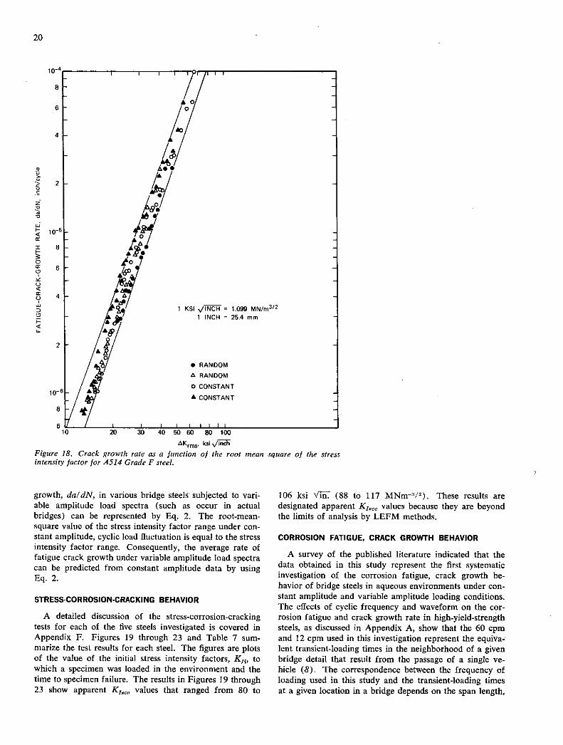
growth, da/dN, in various bridge steels subjected to vari-able amplitude load spectra (such as occur in actual bridges) can be represented by Eq. 2. The root-mean-square value of the stress intensity factor range under con-stant amplitude, cyclic load fluctuation is equal to the stress intensity factor range. Consequently, the average rate of fatigue crack growth under variable amplitude load spectra can be predicted from constant amplitude data by using Eq. 2.
STRESS-CORROSION-CRACKING BEHAVIOR
A detailed discussion of the stress-corrosion-cracking tests for each of the five steels investigated is covered in Appendix F. Figures 19 through 23 and Table 7 sum-marize the test results for each steel. The figures are plots of the value of the initial stress intensity factors, K11, to which a specimen was loaded in the environment and the time to specimen failure. The results in Figures 19 through 23 show apparent K180 values that ranged from 80 to
106 ksi v'lii (88 to 117 MNm/ 2). These results are designated apparent K18 values because they are beyond the limits of analysis by LEFM methods.
CORROSION FATIGUE, CRACK GROWTH BEHAVIOR
A survey of the published literature indicated that the data obtained in this study represent the first systematic investigation of the corrosion fatigue, crack growth be-havior of bridge steels in aqueous environments under con-stant amplitude and variable amplitude loading conditions. The effects of cyclic frequency and waveform on the cor-rosion fatigue and crack growth rate in high-yield-strength steels, as discussed in Appendix A, show that the 60 cpm and 12 cpm used in this investigation represent the equiva-lent transient-loading times in the neighborhood of a given bridge detail that result from the passage of a single ve-hicle (8). The correspondence between the frequency of loading used in this study and the transient-loading times at a given location in a bridge depends on the span length,

21
ISO
125
100
IC)
75 C,
H
SO
25
I ksiVl 1.099 MN/rn312 I FT-LB 36 J
Kin: 90 rinch
APPARENT ksiXnch
A36 HEAT NO. 74C515 -
KIGUB=4Ik5I/ PLATE NO. 195264 a-ysz 43.6 ksi CVN AT PT = 28 FT-LB -.- KILuB =26ksi -
141
iliileis
TIME TO FAILURE hours Figure 19. 1C1-stress corrosion results for A36 steel in aerated 3-percent solution of NaCl in distilled water.
the bridge design, and the speed of the vehicle. However, for a given bridge, the change from 60 to 12 cpm repre-sents a corresponding change in vehicle speed.
Corrosion Fatigue Behavior at 60 CPM
The corrosion fatigue data obtained by testing A36, A588 grades A and B, and A514 grades E and F steels in distilled water and in 3-percent solution of sodium chloride in dis-tilled water are discussed in Appendix U in terms of crack length, a, and the corresponding number of elapsed cycles, N. The data obtained by testing these steels at 60 cpm under constant amplitude loading and under variable am-plitude, random sequence loading are shown in Figures 24 through 28 in terms of crack growth rate per cycle, da/dN, and the root mean square of the stress intensity factor fluc-tuation, iXKrn,g. The curves plotted in each of these figures were obtained by testing duplicate specimens in distilled water under variable amplitude, random sequence loading; duplicate specimens in 3-percent solution of sodium chlo-ride in distilled water under variable amplitude, random sequence loading; a single specimen in the 3-perecnt sodium chloride solution under constant amplitude sinusoidal load-ing; and a single specimen in the 3-percent sodium chlo-ride solution under constant amplitude, square-wave load-ing. Superimposed on these figures are the upper and lower bounds of data scatter obtained by testing these steels un-
der constant amplitude loading and under variable ampli-tude, random sequence loading in a room-temperature air environment.
The results (Figs. 24 through 28) indicate that the addi-tion of 3-percent (by weight) sodium chloride to distilled water had no effect on the corrosion fatigue behavior of the bridge steels tested at 60 cpm under both constant ampli-tude loading and variable amplitude, random sequence load-ing. The data also show that the corrosion fatigue crack growth rate behavior at 60 cpm under sinusoidal loading and under square-wave loading is essentially identical. The scatter in the test results obtained in a single specimen under corrosion fatigue conditions was equal to or greater than that obtained under fatigue conditions. The increase in scatter, which decreased the accuracy in determining the exact location of the cracktip, was caused by the general corrosion of the specimen surfaces. On the basis of the scatter caused by the corrosion of the specimen surfaces and the inherent scatter observed in fatigue crack growth data, it was apparent that, at 60 cpm, the distilled water and the 3-percent solution of sodium chloride in distilled water had negligible effect on the rate of growth of fatigue cracks in the bridge steels investigated. This conclusion is sup-ported further by the fact that the rate of growth of cor-rosion fatigue crack under sinusoidal loading and the rate under square-wave loading were identical.

22
ISO
I I ksi%/ 1.099 MN/rn312 125 I FT-LB = 1.36 J
I =IOOksiAnch
LI uDO! -
75
k - APPARENT K14 = 80 ksi vmch
50 KIGUe5Iksi A588A HEAT NO. 67C611 PLATE NO, 193804
K1 Lue: 32 ksiv inch - ys =54.9 ksi
25— CVN AT RT=69 FT-LB -
01 I I iiiiiil I I iltilil 1 I iiiiiil I iii
I tO tOO 1000
TIME TO FAILURE • hours Figure 20. K r-stress corrosion results for A588 Grade A steel in aerated 3-percent solution of NaCl in distilled water.
ISO
I I ksi 1.099 MN/rn312
125 I FT-LB = 1.36 J
Kix = 104 ksiv ----------------------------------
Ic - U
75 I -APPARENT KI 5CC B5 ksi 4/
50 L. K1 GUS-5t ksi /'i A5885 HEAT NO. 662.1847 PLATE NO.551528
Kx,LUB :32ksi Vinch C 5 = 55.6 ksi
25— CVN AT RT :66 FT-LB
01- I I 1111111 I 11111111 I Il_I_,_LI_Ili I III
I 10 100 1000
TIME TO FAILURE • hours Figure 21. K,-stress corrosion results for A588 Grade B steel in aerated 3-percent solution of NaC1 in distilled water.

23
Kix ri4G ksi Vtch
P5
I,';
rJ.
KILUB:Seksi
* SUBCRITICAL CRACK EXTENSION
.—
A514E HEAT NO. 50343 PLATE NO. P70074 Uys :107.9 ksi CVN AT RT :68 FT-LB
I ksi'/ = 1.099 MN/rn312 IFT-LB :136J
I.
liii, 1sTtT. TIME TO FAILURE • hours
Figure 22. K,-stress corrosion results for A514 Grade E steel in aerated 3-percent solution of NaCl in distilled water.
150
lksi'Jh = 1.099 MN/rn3'2 125
E~K
Kx,GueI24 ksi Vl I FT-LB 1.36 J
O 4k&Vff
-
75
Kiue78kSi APPARENT K1 = 82ksIv'W .tz
50 - A514F HEAT NO. 70C125 PLATE NO. 79873A1
:126.0 ksi 25 -
CVN AT RT:45 FT-LB
01 I I 1111111 1 I 1111111 I I 1 1 1I II I
I 10 100 1000
TIME TO FAILURE • hours Figure 23. Ki-stress corrosion results for A514 Grade F steel in aerated 3-percent solution of NaCl in distilled water.

tJ a TABLE 7
SUMMARY OF STRESS.CORROSION-CRACJCING (SCC) BEHAVIOR OF STEELS INVESTIGATED *
Basic - Mechanical properties' Plane-Strain Limits" Apparent
Extent of
cvi at Type of suppression
Item Steel 72 F, 1,Lub' K I.C-Ub' x' 1 Iscc' Nscc' Apparent 1 Iscc Environmental on Apparent
No. Type ksi ft-lb ksi ,tinch ksi v'inch ksj /inch" ksi v'inch# ksi# Xix Behavior### KTSCC###
1 A36 43.6 28 26 hi 90 85 106 0.95 III Severe
2 A588-A 514.9 69 32 51 100 So 101 0.80 III Severe
3 A588-B 55.6 66 32 51 1014 85 108 0.82 III Severe
1 A5124-E 107.9 68 66 105 1146 io6 132 0.73 II Severe to Mode rate
5 A514-F 126.0 145 78 1214 1014 82 103 0.79 II Moderate
* See sussnary of specimen preparation and test conditions employed, Appendix Table F-I. NOtE: All specimens,inciuding both precracked cantilever-been specimens and mechanical-property specimens, were taken in the longitudinal (ET designation for notched specimens)
orientation. r r 1 '2 B ]./2j 1/2 !(B B l/2I
"K =0 I N' K =a I_N andV 158K
TI,Lub ys L 2.50 J I,Gub L 1.00 j 1,Oub I,Lub.
" K1 = stress-intensity value at maximum load (P max ) in a fracture test, calculated on the basis of the initial fatigue-crack length (a1)
ana LEFM concepts.
4' Apparent Kisco = value calculated on the basis of LEnt concepts (regardless of applicability) for threshold behavior observed under dead-weight- loading conditions (P = constant) and exposure to a continuously aerated solution of 3 percent NaCl(by weight) in distilled water at roon
temperature (72 F) for a nominal test period of 5000 hours. See Table F-1 for suritary of specimen preparation and test conditions employed.
ONscc = ¶M , calculated on the basis of apparent K1sce and average specimen dimensions for each steel.
(3 . B)1' (W - a)2
suppression effects reflected for each classification are as follows: #== :Te of envircnnental behavior and extent of K1-
Type I behavior - No suppression - for apparent Xiscc I KyLb Type II behavior - Moderate suppression - for K1 Lub < apparent Kiscc < KIGub•
Type III behavior - Severe suppression - for apparent Kiscc I KIoub.
NOTE: Calculations of critical-flaw-size values, acr, for Type III behavior are not admissible due to
gross underestimates of intrinsic acr.
Conversion Factors:
I ksi = 6.895 MN/rn2 = 6.895 N/nm? 1 ft-lb = 1.363 I ksi ,inch = 1.099 MNm_3h/2
C = 5/9(F - 3)

8 - SCATTER BAND CT—OF AIR DATA
6- IoI ,. - SI
4- DO
E
V "I - I V - 21-
: w I.-
I 10/ ci / r I— -I
10-5 - 0
0l I
I ksi 1.099 MN/rn312 8 / - I / I INCH25.4mrn
6- /
- f 60CPM AT RO.I 2 - I NO. / ENVIRONMENT LOAD OF TESTS
03% NaCI CONSTANT AMPLITUDE I SINE WAVE
3% NaCI CONSTANT AMPLITUDE I 2 - Iii SQUARE WAVE
0 3% NaCI VARIABLE AMPLITUDE 2 SINE WAVE
U DISTILLED VARIABLE AMPLITUDE 2 WATER SINE WAVE
I0 6 I IiII I 10 20 40 60 80 100 200 400
aK,ms, ksi
Figure 24. Corrosion fatigue, crack growth rate as a function of the root mean square of the stress intensity factor for 436 steel.
or I I I • I I '''H
g t3/ . SCATTER BAND
-g r C
OFAIRDATA
- 0 I cx
I I.- 5
I ksl 1099 MN/rn3t2
010 I- IINCH=25.4mm —3 -1 8-
p - 0 ___
6- 60CPM ATRO.I 0 - NO u ENVIRONMENT LOAD OF TESTS D 4- o IU 0 3% NaCI CONSTANT AMPLITUDE I
L SINE WAVE
o/% / • 3% NaCI CONSTANT AMPLITUDE I z SQUARE WAVE 0
2- 0 3% NaCl VARIABLE AMPLITUDE 2 - 0 SINE WAVE
0 U DISTILLED VARIABLE AMPLITUDE 2
6 10 ______ WATER
I I 111111 SINE WAVE Ii I 11111
10 20 40 60 100 200 400 600 1000 AKrrns, ksI%/Ti
Figure 25. Corrosion fatigue, crack growth rate as a function of the root mean square of the stress intensity factor for 4588 Grade A steel.

8
I— cx 4 La.
k 0 0 0
2 0
10-6
10
SCATTER BAND o/ OF AIR DATA
0 00
Io
8—
I • 6—
U - -
-c U C 43• 4—
0 0
Iii
cx
93 1W
0
I I ksi VITCH 1.099 MN/rn312 8 46 C 0 I INCH =25.4mm
o 0• w D o
0'
I 60CPMATRO.I
4 o NO. 0 ENVIRONMENT LOAD OF TESTS
z O 3% NaCI CONSTANT AMPLITUDE 0 SINE WAVE
0 3°/, NaCl ONSTANT AMPLITUDE
/ SQUARE WAVE
0 C, 0 3% NaCI VARIABLE AMPLITUDE 2
SINE WAVE
DISTILLED VARIABLE AMPLITUDE 2 / / WATER SINE WAVE
(16 II I I I 111111 10 20 40 60 80 100 200 400
AK,ms, ksi,ii
Figure 26. Corrosion fatigue, crack growth rate as a function of the root mean square of the stress intensity factor for A588 Grade B steel.
SCATTER BAND
/ 7 OF AIR DATA
I-
0
? I0' I ksi /iiii=I.O99 MN/rn3t2
I INCH =25.4mm
0
00 / NO. /ENVIRONMENT LOAD OF TESTS
A? /0 3% NaCI CONSTANT AMPLITUDE I S' • SINE WAVE o O / / 3% NaCI CONSTANT AMPLITUDE I
SQUARE WAVE
I I 3% NaCI VARIABLE AMPLITUDE 2 SINE WAVE
I I S DISTILLED VARIABLE AMPLITUDE 2 (I WATER SINE WAVE
10 20 40 60 SO 100 200 400
£Krrns. ksi'Jj
Figure 27. Corrosion fatigue, crack growth rate as a function of the root mean square of the stress intensity factor for A514 Grade E steel.

! 6
Ia 2 I.- C
27
66
- I I 11111 I I I 'I-
SCATTER BAND OF AIR DATA
- Iy.j -
I. I - CjIM -
I ksi ,/iW7 i.o9 MN/rn 3/2
I INCH25.4mrn
/ENVIRONMENT
60 CPM AT RO.I
NO. LOAD OF TESTS
0°/s Nod CONSTANT AMPLITUDE I
SINE WAVE obo • 3%NocI CONSTANT AMPLITUDE I /
0/ SQUARE WAVE - I.! -
o%oI 0 3%NoCI VARIABLE AMPLITUDE 2 SINE WAVE
• DISTILLED VARIABLE AMPLITUDE 2 -
7/ I I I I I
SINE WAVE
I I I 20 40 60 80 100 200 400 600
AKrms ksi/ii
Figure 28. Corrosion fatigue, crack growth rate as a function of the root mean square of the stress intensity factor for A514 Grade F steel.
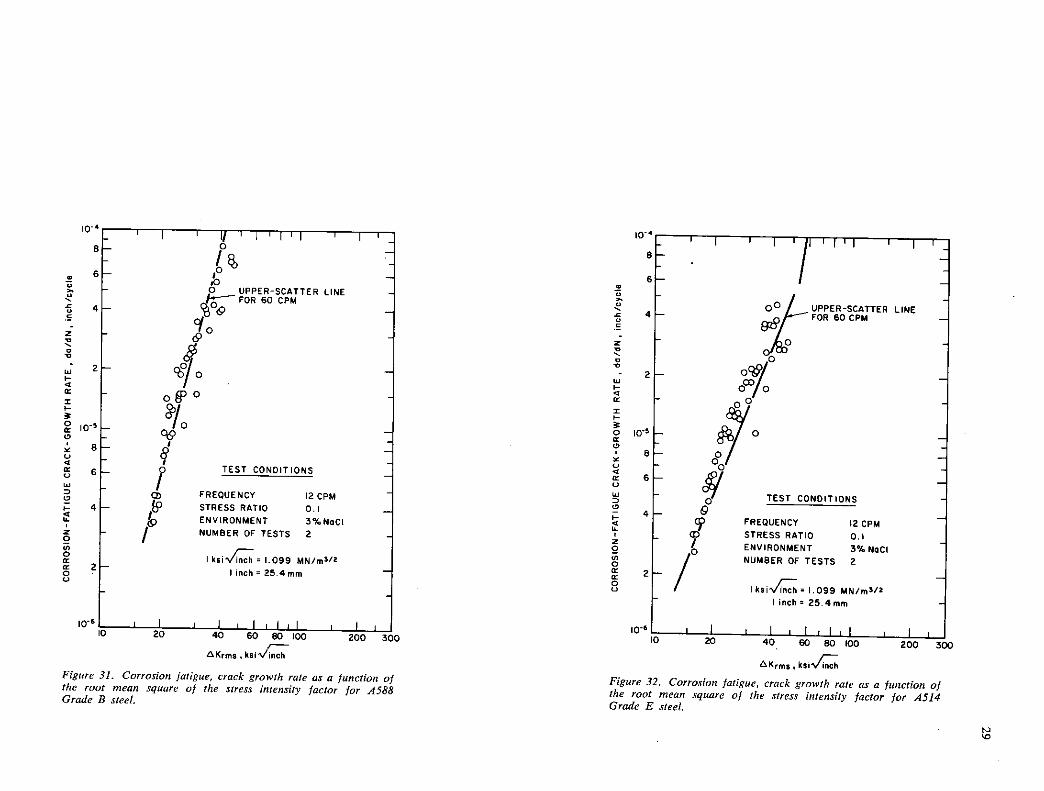
Corrosion Fatigue Behavior at 12 CPM
Details of the corrosion fatigue data obtained by testing A36, A588 grades A and B, and A514 grades E and F steels in 3-percent solution of sodium chloride in distilled water are given in Appendix 0 (Figs. 0-1 through 0-13) in terms of crack length, a, and the corresponding number of elapsed cycles, N. Figures 29 through 33 show the data obtained by testing duplicate specimens of these steels at 12 cpm under constant amplitude sinusoidal loading. Superimposed on these figures is the upper bound of data scatter obtained by testing these steels at 60 cpm under constant amplitude loading and under variable amplitude, random sequence loading in distilled water and in 3-percent solution of so-dium chloride. The time required to initiate and propagate a corrosion fatigue crack in some of the specimens tested at 12 cpm was 850 h. Consequently, the general corrosion of the surfaces of these specimens was more extensive than that observed on similar specimens tested at 60 cpm. This extensive surface corrosion resulted in greater data scatter than the scatter obtained in tests at 60 cpm. The corrosion fatigue data in Figures 29 through 33 show that the rate of crack growth for bridge steels tested at 12 cpm and at stress
intensity factor fluctuations greater than about IS ksi \hi (16.5 MNn 3/ 2 ) was equal to or slightly greater than the rate observed at 60 cpm.
Corrosion Fatigue Behavior at Low AK1 Values
The corrosion fatigue, crack growth data for A36 steel tested at 12 cpm indicated that the rate of crack growth decreased significantly at AK1 values less than 20 ksi V11 (22.0 MNm-3/ 2) (see Fig. 34). Similar behavior was ob-served.in the other steels tested. To verify this observation, one specimen of A514 Grade E steel and one specimen of A514 Grade F steel were tested at 12 cpm in 3-percent sodium chloride solution under cyclic load fluctuations cor-responding to AK 1 of about 11 ksi VE (12.1 MNm-3/ 2 ). The test results, shown in Figures 35 and 36, point out that a corrosion fatigue, crack gowth rate threshold, AK 4, does exist in A514 steels at a value of about 11 ksi v'm This
represents the value of the stress intensity factor fluc-tuation below which corrosion fatigue cracks do not propa-gate at 12 cpm in the environment-steel system tested. The value of AK in A514 steels tested at 12 cpm in 3-percent sodium chloride solution was twice as large as the value of 5.5 ksi VET (6.0 MNnr3/2 ) for room-temperature air (32).

10-'
8
C 6 o UPPER-SCATTER LINE
FOR GO CPM C
U
4 C
O 'UPPER-SCATTER LINE cQo FOR 60 CPM to
08 od
0
0/0 of
TEST CONDITIONS
FREQUENCY 12 CPM
STRESS RATIO 0.1
ENVIRONMENT 3% NoCI NUMBER OF TESTS 2
0 I ksi 1.099 MN/rn3'2
0 I inch: 25.4mm
2
8
6
4
2
106
TEST CONDITIONS
FREQUENCY I2CPM
STRESS RATIO 0.1
ENVIRONMENT 3%NoCI NUMBER OF TESTS 2
IksiVC 1.099 MN/rn312 inch: 25,4mm
10 S
8
6
4
2
10'
akrrns kSlVc
Figure 29. Corrosion fatigue, crack growth rate as a function of the root mean square of the stress intensity factor for A36 steel.
AK,ms ksiVC
Figure 30. Corrosion fatigue, crack growth rate as a function of the root mean square of the stress intensity factor for A588 Grade A steel.
- ' I 11 1 1 1 1 1 1 ' I
1% 6- -
- 0 UPPER-SCATTER LINE FOR 60 CPM
4- %00 Cto
2 4o
-
• -
S'I 8 § 6 - TEST CONDITIONS -
ci - FREQUENCY I2CPM - 4 - STRESS RATIO 0.1 -
ENVIRONMENT 3%NOCI
- / NUMBER OF TESTS 2
I ksi'A = 1.099 MN/rn3/2 - 11nch25.4mm -
I I I ililil I II 10 20 40 60 80 100 200 300
Akrms ksi'
Figure 31. Corrosion fatigue, crack growth rate as a function of
the root mean square of the stress intensity factor for A588 Grade B steel.
00 I UPPER-SCATTER LINE - ,,j.r FOR 60CPM
11
TEST CONDITIONS
FREQUENCY 12 CPM STRESS RATIO 0.1 - ENVIRONMENT 3% NOCI NUMBER OF TESTS 2
I ksiV= 1.099 MN/rn5'2 - I inch = 25.4mrn -
I I I nil I 20 40 60 80 100 200 'CV
AKrrns,
Figure 32. Corrosion fatigue, crack growth rate as a function of the root mean square of the stress intensity factor for A514 Grade E steel.
I0'

0
8
10' - I
8-
6-
4—
oO
2 00/
—
a
UPPER-SCATTER LINE FOR 60 CPM
O'o TEST CONDITIONS
00 FREQUENCY I2CPM STRESS RATIO 0.1 ENVIRONMENT 3% Nod NUMBER OF TESTS 2
I ksiVC: 1,099 MN/n5 '2
I incht25.4mm
0-61 I 1 I ' lii I I ii 10 20 40 60 80 100 200 300
Krms ,
Figure 33. Corrosion fatigue, crack growth rate as a function of the root mean square of the stress intensity factor for A514 Grade F steel.
TEST CONDITIONS
FREQUENCY 12 CPM STRESS RATIO 0.1 ENVIRONMENT 3% NoCI
I ksiV ' 1.099 MN/rn3/ 2
I inch a 25.4mm
10 6 I II iI I lilil I Iii 10 20 40 60 80 100 200 300
AK,m, , kSIN4ch
Figure 34. Corrosion fatigue, crack growth rate as a function of the root mean square of the stress intensity factor for A36 steel.
l0'
8
6
4
2

z - 14
31
I I I - - /&P
- to -
- -
- 0 -
1- -
TEST CONDITIONS
ENVIRONMENT 3% NaCI - FREQUENCY 12 CPM -
- STRESS RATIO 0.1 -
LOAD CONSTANT SINE WAVE
I ksi ' L099 MN/rn 312 - I Inch: 25.4rnrn
6
I 4
I I I 11111 10 20 40 60 80 100
4
2J- 2 C,
0 IO'j—
P o
6r CD
w L 70 - C 4— Cr /0
- r
! 0 2 /
o
—8
0' I TEST CONDITIONS ° I
9 Lj ENVIRONMENT 3°6 NaCI
6 H H FREQUENCY I2CPM
STRESS RATIO 0.1 p I 2 I LOAD CONSTANT 9 .0 SINE WAVE to I o It -I Cr
I
I ksjN/inch 1.099 MN/rn3'2 U
2 I inch' 25.4rnrn -
20 40 60 80 100 200 400 600
&(,rns ,
Figure 36. Corrosion fatigue, crack growth rate as a function of the root mean square of the stress intensity factor for A514 Grade F steel.
AKrms
Figure 35. Corrosion fatigue, crack growth rate as a function of the root mean square of the stress intensity factor for 4514 Grade E steel.
Bucci and Donald (33) observed that the environmental A' 1 in a 200-grade maraging steel forging was higher than the AK,, in air and that salt water appeared to produce an inhibitive effect on fatigue cracking at very low AK levels. Paris et al. (34) also observed that the threshold AK of ASTM A533 (Grade B Class 1) steel in distilled water was greater than that established in room-temperature air. These investigators noted the following:
Since the distilled water retardation of very low crack extension rates was a somewhat surprising result, an addi-tional specimen was tested for which a distilled water environment was provided to the crack tip and its sur-rounding only after an initial slow crack extension rate had been established in room air. Upon application of the distilled water, the rate of crack growth decreased from those initially obtained in air.
The observations by Bucci and Donald and by Paris et al. confirm the results of this investigation.
In an air environment, the fatigue AK, threshold, AK,,, in various steels tested at a stress ratio of 0.1 is independent
of cyclic load frequency and is equal to about 5.5 ksi Vhj Because hostile environmental effects decrease with in-creased cyclic load frequency, the corrosion fatigue K,1 at very high cyclic load frequencies would have a value close to that of fatigue in air. A K180 test can be con-sidered a corrosion fatigue test at extremely low cyclic load frequency. In such tests, the rate of crack growth at a stress intensity factor fluctuation that is slightly lower than K1200 is, by definition, equal to zero. Consequently, at very low cyclic load frequencies, AK,, is equal to K1800. Hence, the value of the environmental AK,, at intermediate cyclic load frequencies must be greater than 5.5 ksi VE and less than the value of K,200 for the environment-steel system under consideration. The test results show that, at 12 cpm, the environmental AKOh of A514 steels in 3-percent solution of sodium chloride in distilled water was equal to about 11 ksi VE Based on the preceding observations, a sche-matic representation of the corrosion fatigue behavior of bridge steels subjected to different cyclic load frequencies was constructed, as shown in Figure 37. This figure, which

32
CRITICAL FREQUENCY AT WHICH ENVIRONMENTAL EFFECTS ON CRACK PROPAGATION ARE MAXIMUM I
dry in room-temperature air. Finally, the specimen was replaced in 3-percent sodium chloride solution, and the cor-rosion fatigue, crack growth behavior was again measured at 12 cpm under full-immersion conditions and under the same load fluctuations applied prior to drying the specimen. Figure 38 shows the results obtained from this interrupted test. The data indicate the existence of nonsteady-state crack growth represented by a severe retardation of the rate of corrosion fatigue crack growth and a corresponding sub-stantial increase in the life of the specimen. The data also show that the life of the specimen was doubled, because 115,000 cycles were required to reestabilsh the steady state, crack growth rate behavior. Similar retardation behavior and a concomitant increase in the useful life of specimens tested under alternate wet and dry conditions were observed by Miller et al. (35) in AISI 4340 steel tempered at 200 F. (93 C), as shown in Figure 39.
DECREASING FREQUENCY
AK1 LOG SCALE
Figure 37. Schematic of idealized corrosion fatigue behavior as a function of cyclic load frequency.
is an oversimplification of a very Complex phenomenon, de-picts only the effects of cyclic load frequency on the Cor-rosion fatigue, crack growth rate behavior of bridge steels.
Corrosion Fatigue Behavior Under Alternate Wet and Dry Conditions
The foregoing discussion concerned the corrosion fatigue behavior of bridge steels under complete immersion condi-tions. Under actual operating conditions, bridges are sub-jected to benign environments (as in the case of painted bridges) or to alternate wet and dry environmental condi-tions (as in the case of unpainted bridges or improperly maintained bridges). The fatigue behavior of bridge steels in a benign environment (room-temperature air) is cov-ered in a preceding section and is also the subject of investi-gation in Refs. (1), (2), and (24). The fatigue behavior under alternate wet and dry conditions is described as follows.
The effects of alternate wet and dry environmental con-ditions on bridge steels were simulated in this study by using a specimen of A514 steel. First, the corrosion fatigue, crack growth rate in the specimen was established at 12 cpm under full-immersion conditions in 3-percent solution of sodium chloride in distilled water. The specimen was then removed from the environmental bath and left overnight to
Effect of Stress Ratio on the Corrosion Fatigue Behavior of Bridge Steels
The corrosion fatigue data obtained by testing A36, A588 grades A and B, and A514 grades E and F steels in 3-percent solution of sodium chloride in distilled water at a stress ratio, R, of 0.5 and at 60 cpm are given in Appendix 0 in terms of crack length, a, and the corresponding number of elapsed cycles, N. The data obtained by testing duplicate specimens of these steels at R = 0.5 under variable ampli-tude loading are shown in Figures 40 through 44 in terms of crack growth rate and the corresponding root mean square of the stress intensity factor fluctuation, AKrm,. Superimposed on these figures are the upper and lower bounds of corrosion fatigue data obtained at R = 0.1. It is obvious from these figures that a stress ratio of 0.5 had a negligible effect on the rate of corrosion fatigue crack growth in bridge steels.
Corrosion Fatigue Behavior of A588 Steel from Various Sources
Corrosion fatigue data of four heats of A588 Grade A steel and one heat of A588 Grade B steel were obtained at 60 cpm in 3-percent solution of sodium chloride in distilled water. These five steels (A588 grades A and B) were ob-tained from two suppliers (Bethlehem Steel Corp. and U.S. Steel Corp.) at three plant locations; the steels were melted by either of two melting processes (open-hearth and basic-oxygen process) over a span of 10 years' time (1964 to 1974). Furthermore, these five steels represent reasonable variation in chemical composition within the ASTM speci-fication (Tables II and TV), as well as reasonable variation in mechanical properties (Tables III and V). The corro-sion fatigue data are given in Appendix 0 in terms of crack length, a, and the corresponding number of elapsed cycles, N; the data shown in Figure 45 are in terms of daldN and AK1. This figure reveals that the rate of corrosion fatigue crack growth for one heat of the A588 steels tested was equal to the rate of growth for any of the other heats. Thus, despite the variations in melting history, chemical composition, and mechanical properties, the corrosion fa-tigue, crack growth rates for various A588 grades A and B steels were essentially identical.

33
I inch :25.4min
TEST STOPPED /
OVERNIG:)
0.0
OF-0 do
o'I t• • SIDE I
0 OSIDE2
SCATTER-BAND OF CORROSION-FATIGUE DATA AT R:0.I
TEST CONDITIONS
ENVIRONMENT 3% NoCI -
FREQUENCY 60 CPM STRESS RATIO 0.5
I I LOAD RANDOM SINE WAVE
I ksiVC. 1.099 MN/rn3'2 - I Inch :25.4mm
I 0 6 I I I 1111111 i II 0
0 20 40 60 AU IOU pelf, 'U
1,6
I inch = 25.4mm
I TEST STOPPED OVERNIGHT
115,000 CYCLE DELAY
I I I I On
0.95
0.85
0.75 'C U C
a 0.65
I- 0 a
0.55
Ic
0.45
0.35
0.25 0 oll
ELAPSED CYCLES, N x 103 NUMBER OF CYCLES
Figure 38. Retardation of corrosion fatigue, crack growth rate under Figure 39. Fatigue crack growth curve for AISI 4340 steel wet and dry environmental conditions for A514 Grade F steel, tempered at 200 F (93 C), showing nonsteady-state behavior
(from Ref. (35)).
10-6
/4AENVIRONMENT
TEST CONDITIONS
3%NoCI
FREQUENCY 60 CPM STRESS RATIO 0.5 LOAO RANDOM SINE
WAVE
I ksiV 1.099 MN/rn3 / 2
I inch = 25.4 mm
I I I I LIII D 20 40 60 AD IOU
SCATTER-SAND OF CORROSION-FATIGUE DATA AT R:O.I
AKrms , AKrms,
Figure 40. Corrosion fatigue, crack growth rate as a function of the Figure 41. Corrosion fatigue, crack growth rate as a function of the root mean square of the stress intensity factor for A36 steel, root mean square of the stress intensity factor for A588 Grade A steel.

- I
-
1 1 1 1 1 1 1 I
SCATTER BAND OF - - CORROSION-FATIGUE -
DATA AT R:O,I
Ail
/ TEST CONDITIONS -
ENVIRONMENT 3% Nod - 4 / FREQUENCY 60 CPM
STRESS RATIO 0.5 - I I LOAD RANDOM SINE
LIWAVE
I ksivinch 1.099 MN/rn3t2 -
I
Iinch25.4rnm -
I ililil Ii 10 20 40 60 80 100 200 300
c- 4
8
0 6 0
4
z C
Isi 2 C
=
0 10•'
8 C.) C
6 U 0 0
4
9- 0 0) 0
0 2
C.)
SCATTER-BAND OF CORROSION-FATIGUE DATA AT R:0.I
A
/ TEST CONDITIONS
II VA / ENVIRONMENT 3% NoCI
FREQUENCY 60CPM
/ STRESS RATIO 0.5
£ / LOAD RANDOM SINE
/ WAVE
7 I ksivCh 1.099 MN/m32 I inch 25,4mm
20 40 60 I0'
t 4
34
AKrms ,kSIVc
Figure 42. Corrosion fatigue, crack growth rate as a function of
the root mean square of the stress intensity factor for A588 Grade B steel.
aK,ms
Figure 43. Corrosion fatigue, crack growth rate as a function of the root mean square of the stress intensity factor for A514 Grade E steel.
CHAPTER THREE
INTERPRETATION OF APPRAISAL OF FINDINGS
SIGNIFICANCE OF FRACTURE TEST RESULTS
A summary of the results from the fracture tests con-ducted at 72 F (22 C) is given in Table 6. These results, discussed in detail in Appendix D, show that no valid K1, values Could be measured for any of the five steels tested. The inability to measure valid K1, values in the fracture tests was due to the Combined effects of both a high level of fracture toughness for each steel and the limitations im-posed by the size of the IT specimen. Because of these circumstances, high levels of plasticity were developed prior to fracture in all tests, thus precluding the direct application of LEFM concepts (at fracture).
Although quantitative assessments of fracture behavior for the steels tested can not be made on the basis of the present results, semiquantitative interpretations can be given
based on the Krsuppression effect concept (21, 36, 37). In particular, it has been shown that, when fracture test specimens that are too small are employed in fracture tests of high-toughness steels, the apparent K1, values (KQ val-ues) will be lower than the true K1, value. The systematic manner in which the KQ values decrease and further under-estimate the true K1, value as the test specimens are made smaller is known as the Krsuppression effect. When the specimen size for a proportional geometry specimen is only 10 percent of that required for a valid K1, result, the KQ value measured will be suppressed to less than half (0.50) of the true K1, value. The indexing point for the occur-rence of such behavior is when the observed K0 value is 60-percent higher than the valid plane-strain measurement capacity for the test conditions employed. (The K0 value is suppressed to less than one-half (0.50) of K1, when

35
(KQ/Kf flub) = 1.60, where K, flub = o, (B/2.50)1/2 and K, Lab is the plane-strain measurement capacity for the par- ticular combination of steel, o'y8, and specimen size, B, tested.) When the size of the fracture test specimen is only moderately inadequate to obtain a valid K,0 result, the cor-responding KQ value will be suppressed below the true K,0 value by only a moderate amount.
Because of the systematic nature of the K,-suppression effect, this concept can be used in a reverse manner to "cor- rect" the invalid K10 results. Although precise corrections are not possible at this time, meaningful approximations of the true K,0 behaviors can be made, particularly in relation to the indexing point described earlier.
Such estimates of the true K,0 behavior of the five steels of interest were made and are given in Table 6 together with the summary of actual test results. The estimates of K,0 behavior for the steels tested by using the K,-suppression effect are believed to be both conservative and realistic. Furthermore, such estimates are the best presently available without using elastic-plastic fracture analysis methods— J-integral (38, 39) and equivalent-energy methods (40, 41)—which are still under development and for which special test conditions must be provided (such as 6 speci-mens per evaluation, load-line measurement for V, and metallographic sectioning of specimens).
The realistic nature of the estimates of K10 behavior (Table 6) is given further credence when such results are compared with those obtained from other estimating tech-niques developed earlier (42, 43). In particular, it can be seen that the singular estimates of K,0 behavior made for the A514 grade E and A514 grade F steels, by using the Charpy V-notch specimen correlation for high-strength martensitic steels (42) (K,0 = 184 and 156 ksi VIE (202.2 and 171.4 MNrn-312), respectively), are contained within the corresponding ranges of K,0 behavior estimated by using the K,-suppression effect concept. Furthermore, the mini-mum values cited for the A588 Grade A and A588 Grade B steels are consistent with both actual K,0 results and results of behavior from more extensive studies of an A572 steel of similar strength (cr,,8 ) and mechanical properties (CVN) (37). An additional method is also available for estimating the K10-transition behavior of ferrite-pearlite steels, such as the A36 and A588 grades A and B steels (43). This tech-nique involves the use of CVN test results for predicting the interrelationship of K,0 with test temperature and strain rate. However, this approach is of limited applicability in the present discussion concerning the static K,0 behavior of the steels tested, because only the K,,, transitional behavior can be predicted, and, for the steels tested, this behavior will occur at temperatures well below the 72-F test tem-perature used in the bulk of the current study.
The results in Table 6 include the minimum thicknesses, Bmin, required for valid K,0 fracture of each material under two different conditions of crack orientation. For each steel, Bmin values are given for both through-thickness cracks and partial-thickness cracks (PTC) - These Bmin
values are calculated on the basis of the minimum estimates of K,0 behavior presently given for each steel. Calculations of the critical flaw size at fracture, a,,., under K,,, conditions are not applicable by using LEFM principles, unless the thicknesses used in the specific structural applications are
- I I 111111 I'.
- SCATTER-BAND OF -
I-T CORROSION-FATIGUE - DATA AT RO.I
TEST CONDITIONS
L * / ENVIRONMENT 3% NoCI -
' / FREQUENCY SOCPM STRESS RATIO 0.5 -
I LOAD RANDOM SINE
/ WAVE
I ksi 1.099 MN/rn3/2 -
- Iinch25.4mn -
I I I I IlIII Ii
10 20 40 60 80 100 200 301
AK, on , ksiVl
Figure 44. Corrosion fatigue, crack growth rate as a function of the root mean square of the stress intensity factor for A514 Grade F steel.
in excess of the cited Bmj,i values. Thus, as noted in the following discussion, the applicability of the present K,0 estimates for predicting actual structural behavior at frac-ture depends on the specific service application.
The preceding estimates of K,0 fracture behavior for the steels in Table 6 are largely academic for bridge construc-tion, because the structural members in such applications are generally fabricated from plates ranging in thickness from ½ to 11/2 in. (12.7 to 38.1 mm). Thicknesses greater than 11/2 inches are used only occasionally in routine bridge construction. However, even the 11/2 -in, plate thicknesses are still less (considerably less in most cases) than that re-quired (Bm jn) for plane-strain (K,0 ) fracture on the basis of the minimum estimated behavior for each steel (Table 6). Plates that are 11/2 in. or less in thickness would frac-ture under so-called plane-stress (K0) conditions. Because K, values are generally 2 to 5 times higher than correspond-ing K,0 values, each of the steels in this study would pos-sess extensive resistance to fracture in such bridge appli-cations and fracture would not be a major criterion of concern. (Although this statement is clearly applicable to all five of the steels tested, it is least applicable to the A514 Grade F steel because of its abnormally high strength (a,,, = 126 ksi, or 869 MN/m2 ). However, even for this A514-F steel, calculations show that relatively large flaws could be tolerated prior to fracture under normal design conditions. For example, for material behavior of K,0 = 125 VIE
10-'
I I-
0-' 0
8 C-, C
6 Ui
0
- 4
I 0 04, 0 Of 2 0 C.,
10"
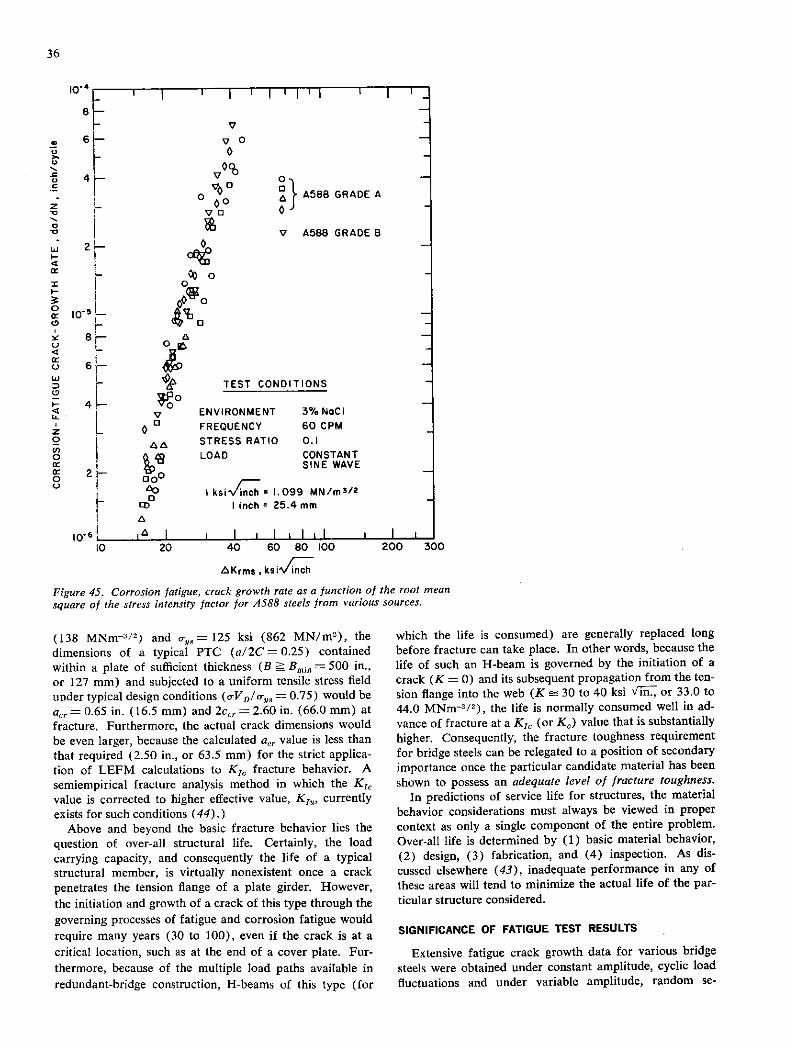
- I I 11111 1 1 I
- V -
- V0 - 0
0% - 0 -
00 0 A 4588 GRADEA -
vu 0
V 4588 GRADE B
Cet - 0 001,0 fl -
r - r -
£ - TEST CONDITIONS -
L - v ENVIRONMENT 3% Nod
L 0 a FREQUENCY 60 CPM -
STRESS RATIO 0.1
LOAD CONSTANT SINE WAVE
AD I ksiv1llh z 1.099 MN/rn3/2 ED Iinch = 25.4mm
iI I ililil I Ii In 20 40 60 80 100 200 3C
io
0.6
tsKrms ,
Figure 45. Corrosion fatigue, crack growth rate as a function of the root mean square of the stress intensity factor for 4588 steels from various sources.
(138 MNm/2 ) and o, = 125 ksi (862 MN/rn2), the dimensions of a typical PTC (a/2C = 0.25) contained within a plate of sufficient thickness (B = 500 in., or 127 mm) and subjected to a uniform tensile stress field under typical design conditions (o-V p/o-,, = 0.75) would be
acr = 0.65 in. (16.5 mm) and Zccr = 2.60 in. (66.0 mm) at fracture. Furthermore, the actual crack dimensions would be even larger, because the calculated aer value is less than that required (2.50 in., or 63.5 mm) for the strict applica-tion of LEFTY! calculations to K10 fracture behavior. A semiempirical fracture analysis method in which the K10 value is corrected to higher effective value, K1 , currently exists for such conditions (44).)
Above and beyond the basic fracture behavior lies the question of over-all structural life. Certainly, the load carrying capacity, and consequently the life of a typical structural member, is virtually nonexistent once a crack penetrates the tension flange of a plate girder. However, the initiation and growth of a crack of this type through the governing processes of fatigue and corrosion fatigue would require many years (30 to 100), even if the crack is at a critical location, such as at the end of a cover plate. Fur-thermore, because of the multiple load paths available in redundant-bridge construction, H-beams of this type (for
which the life is consumed) are generally replaced long before fracture can take place. In other words, because the life of such an H-beam is governed by the initiation of a crack (K = 0) and its subsequent propagation from the ten-sion flange into the web (K = 30 to 40 ksi VE or 33.0 to 44.0 MNm-3/ 2 ), the life is normally consumed well in ad-vance of fracture at a K10 (or K0) value that is substantially higher. Consequently, the fracture toughness requirement for bridge steels can be relegated to a position of secondary importance once the particular candidate material has been shown to possess an adequate level of fracture toughness.
In predictions of service life for structures, the material behavior considerations must always be viewed in proper context as only a single component of the entire problem. Over-all life is determined by (1) basic material behavior, (2) design, (3) fabrication, and (4) inspection. As dis-cussed elsewhere (43), inadequate performance in any of these areas will tend to minimize the actual life of the par-ticular structure considered.
SIGNIFICANCE OF FATIGUE TEST RESULTS
Extensive fatigue crack growth data for various bridge steels were obtained under constant amplitude, cyclic load fluctuations and under variable amplitude, random se-

37
quence, cyclic load fluctuations such as occur in actual bridges. The test results show that, for various bridge steels, a correlation exists between both the average rate of fatigue crack growth under constant amplitude, cyclic load-ing conditions and the average rate of fatigue crack growth under variable amplitude, cyclic loading conditions. The data obtained for A36, A588 grades A and B, and A514 grades E and F steels showed that the average rate of fa-tigue crack growth, daldN, under variable amplitude, cy-clic load fluctuations and under constant amplitude, cyclic load fluctuations agreed closely when da/dN was plotted as a function of the root mean square of the stress intensity factor fluctuation, Thus, the average rate of fatigue crack growth, da/dN, for various bridge steels subjected to variable amplitude and constant amplitude, cyclic load fluctuations can be represented by the equation
da/dN= A(Kr,ns )
where A and ii are material constants. This RMS model for fatigue crack growth is expected to have widespread application in the computation of the useful life of bridge components and other structures. The use of this model requires characterization of the cyclic stress distribution function for the structure of interest. Characterization of the cyclic stress distribution functions for bridges is under consideration in Ref. (24).
SIGNIFICANCE OF STRESS CORROSION TEST RESULTS
The results of the 5000-h (30-week) stress corrosion tests with precracked cantilever beam specimens are shown in Figures 19 through 23 and are discussed in detail in Appendix F. The sailent features of these results are summarized in Table 7.
It is apparent from these data that no valid K18 values were obtained for any of the five steels examined in this study. As described in Appendix F, the apparent K18 values measured for most of the steels correspond to con-ditions involving substantial crack-tip plasticity. Conse- quently, LEFM concepts can not be used for quantitative analysis of the respective stress-corrosion-cracking (SCC) behaviors (21). Furthermore, the apparent K18 values are suppressed to various degrees below the intrinsic K18 values for these steels in a manner similar to that described in the previous section on fracture (K1 ) behavior. In other words, the apparent values reflect behavior described by the Krsuppression effect concept because of both a high resistance to SCC for each steel and the limitations in analy-sis imposed by the size of the IT specimen.
For such cases the most important parameter for charac-terizing the SCC behavior is the ratio of the apparent threshold to the value at fracture obtained with an identi- cal size specimen (apparent K,8 /K1 ) (21). This ratio, known as the relative index of SCC susceptibility, can be used to quickly ascertain the degradation in fracture be-havior as a result of the test solution and the inherent SCC characteristics of each steel.
General experience with many steels and weldments, some of which are used successfully in long-time environ-mental service applications, dictates the following broad-based interpretation for assessing the relative SCC index:
(1) values ranging from 095 to 1.00 represent material behaviors that are immune to SCC; (2) values ranging from 0.80 to 0.95 represent material behaviors that either are moderately susceptible to SCC if the K18, value is valid, or are primarily the result of long-time creep that occurs at the crack tip (under the presence of intensely high stress levels) if the apparent value measured is not valid and high levels of crack-tip plasticity are involved; and (3) values less than 0.80 are generally the result of true susceptibility to SCC for steels, regardless of whether the apparent value is valid or not.
The relative index of SCC susceptibility for each of the five steels tested is contained in Table 7. These results show that each of these steels yielded relative SCC indices of 0.73 or higher for the 5000-h tests in continuously aerated 3-percent sodium chloride solution. In particular, a value of 0.95, representing essentially immune behavior, was found to occur for the A36 steel. Nearly identical values of 0.80 and 0.82 were measured for the A588 grades A and B steels, respectively. These latter values apparently repre-sent primary behavior associated with long-term creep un-der sustained conditions of high stress level at the crack tip. The two higher strength martensitic steels yielded slightly lower ratios, with specific values of 0.73 and 0.79 for the A514 grades E and F steels, respectively. Although both the fracture-toughness (K1 ) and SCC-threshold (apparent K, 0 ) values were higher for the A514 Grade E steel, the relative SCC index was somewhat lower. This difference in behavior of the two A514 steels is somewhat surprising and is illustrative of the complex nature of the SCC mechanism.
Reservations generally held relative to the analysis of SCC test results deal with the time factor. As discussed in more detail elsewhere (20, 21), questions often arise, in relation to predictions of long-term structural life (for ex-ample, 20 to 50 years), as to whether or not the 8CC-evaluation time period for generating baseline data is suf-ficient. The sigmoidal shapes in the K i versus log-time plots obtained for several of the steels tested (Figs. 19 through 23) indicate that the observed thresholds are real, and extrapolations of the same behavior for 1 or 2 addi-tional orders of magnitude (for example, 20 to 50 years) can be made with high levels of confidence. This appears to be particularly true for the A514 Grade F steel, which yielded a marginally invalid K13 threshold primarily as a result of its abnormally high strength level. It is of interest to note that the strength level for this steel (a-,, = 126 ksi, or 869 MN/m2; = 134 ksi, or 924 MN/m2 ) was near the specified upper limit of acceptable tensile strength (o- , = 115 to 135 ksi, or 793 to 931 MN/m2 ) for the 1-in, plate thickness tested (45). Despite this extreme in strength level, the A514 Grade F steel yielded satisfactory perfor-mance in the long-term SCC tests.
In summary, the present SCC results indicate a slight, but distinct, degradation in fracture behavior when the steels evaluated are subjected to long-term exposure in an SCC environment. However, both the relative and absolute SCC behaviors (apparent K13 /K1 and apparent values reflecting K1-suppression effects) are at such high levels for each steel that there would appear to be no major prob-lems related to SCC for the use of any of these steels in such long-term structural applications as in bridges. De-

38
spite the present inability to quantitatively characterize the results in terms of LEFM concepts, the safety and reliability of structures fabricated with any of the present steels would not be impaired due to intrinsic SCC behavior. The exist-ing successful service performance for bridges fabricated with A36 steel and, to a more limited degree, with the A588 grades of steel is, of course, consistent with such expecta-tions and would tend to further confirm the validity of such predictions. In addition, the same criteria described in the preceding section on fracture behaivor are equally appli-cable here in relation to SCC behavior. Considerations in-volving typical structural members of ½ to 11/2 in. in thick-ness for bridges resulting in plane-stress behavior (loss of through-thickness constraint) and the general over-all life of a structural member corresponding to the range of K5 = 0 to 30 ksi VIii (33 MNm-3 / 2 ) are both still equally valid - even if to a slightly lesser extent because of a token amount of degradation in behavior by SCC as a result of long-term environmental exposure.
It should be noted, in passing, that the 5000-h SCC tests with precracked specimens are among the longest conducted for any class of materials in general. Furthermore, the present results constitute the first such study of significance conducted on structural steels specifically.
SIGNIFICANCE OF CORROSION FATIGUE TEST RESULTS
The effects of variable amplitude loading on the fatigue crack propagation rates in benign environments for bridge steels can be studied by using the RMS model. Cons-quently, differences between the corrosion fatigue, crack growth rate and the fatigue crack growth rate that are analyzed by using the RMS model must be related, pri-marily, to environmental effects. The corrosion fatigue, crack growth rate data (Figs. 24 through 28) obtained by testing A36, A588 grades A and B, and A514 grades E and F steels at 60 cpm in distilled water and in 3-percent solu-tion of sodium chloride in distilled water are essentially identical to the data on the rate of fatigue crack growth in air for these steels. Thus, the data indicate that the effects of these more hostile environments on the rate of fatigue crack growth for bridge steels are negligible at 60 cpm. A corollary of this finding is that the addition of sodium
chloride to distilled water has negligible effect on the fatigue behavior of bridge steels. Moreover, corrosion fatigue data obtained at a stress ratio of 0.5 were identical to those ob-tained at 0.1, and corrosion fatigue data obtained for five different heats of A588 steel were also identical. Conse-quently, the corrosion fatigue data at 60 cpm show that specifications for bridge details that are based on fatigue data in benign environments are equally applicable to cor-rosion fatigue in distilled water and in 3-percent solution of sodium chloride in distilled water.
The corrosion fatigue, crack growth rate data for bridge steels tested at 12 cpm in 3-percent solution of sodium chloride in distilled water resulted in three observations that are of primary importance to the analysis of the corrosion fatigue life of bridge details. The first observation relates to the magnitude of the corrosion fatigue, crack propaga-tion threshold, AK,, (the value of the stress intensity factor fluctuation below which corrosion fatigue cracks do not propagate), at R = 0.1. The corrosion fatigue AK for
A36 steel tested at 12 cpm (Fig. 34) appears to be equal to about 15 ksi VIii (16.5 MNm-3 / 2 ). The corrosion fa-tigue AK, for A514 steels at 12 cpm (Figs. 35 and 36) appears to be equal to about 11 ksi v'iit (12.1 MNm-3/2). The value of AK,, for steels tested in a benign environment at R =0.1 is equal to 5.5 ksi VIij (6.0 MNm/ 2 ). These AK,, values suggest that the corrosion fatigue life of bridge details at low AK, values (AK, < 15 ksi VIE) and at low cyclic load frequencies (cpm 12) could be significantly greater than the corresponding fatigue life. This observa-tion is supported by data reported by Bucci and Donald (33) and by Paris et al. (34).
The second observation is related to the corrosion fatigue, crack propagation behavior of bridge steels at AK, values greater than about 15 ksi VIE and at 12 cpm (Figs. 29 through 33). The data show that the rate of crack growth for all the bridge steels tested under these conditions was equal to or slightly greater than that observed at 60 cpm in 3-percent sodium chloride solution or in room-tempera-ture air environments. This behavior suggests that the cor-rosion fatigue, crack propagation life for A36, A588 grades A and B, and A514 grades E and F steels at 12 cpm and at AK, levels greater than 15 ksi Viii? could be slightly less than the corresponding fatigue crack propagation life. The corrosion fatigue, crack growth rates at AK, values greater than 15 ksi Viii? and at 12 cpm for the five bridge steels investigated were essentially identical. For example, as shown in Figure 46, the superposition of the corrosion fa-tigue data for the A36 steel and the A514 Grade F steel, which had a tensile strength of 134 ksi (924 MN/m2 ) and a yield strength of 126 ksi (869 MN/m2 ), shows that the rates of corrosion fatigue crack growth at AK, greater than about 15 ksi Viii and at 12 cpm are essentially identical.
The third observation is related to the retardation of the corrosion fatigue crack propagation rate that is caused by alternate wet and dry environmental conditions. This tran-sient behavior of corrosion fatigue, crack propagation rates could have a substantial influence on the cyclic life of bridge components. For example, the corrosion fatigue life of an A514 Grade F steel specimen tested at 12 cpm in 3-percent solution of sodium chloride (Fig. 38) was doubled when it was removed once from the environment and permitted to dry overnight.
The test results in the transition region are shown in Figure 47 in terms of crack growth rate and the stress in-tensity factor fluctuation. The data show that the rate of growth was decreased by an order of magnitude from the steady state, corrosion fatigue behavior under full-immer-sion conditions and that the initial growth rates at the re-start of full-immersion testing were well below the rates of growth in room-temperature air environment.
The preceding discussion of the corrosion fatigue be-havior for bridge steels tested at 12 cpm in 3-percent solu-tion of sodium chloride indicates that (1) AK, in the solu-tion was greater than that in air; (2) corrosion fatigue, crack growth rates at AK, values greater than the environ-mental AK,,, were equal to or slightly higher than those in air; and (3) crack propagation life was significantly longer under alternate wet and dry environmental conditions than it was under conditions of full immersion in the solution or in air. The combined effects of these findings point out that

4
i0 6
a 0 436
0 A514 GRADE F
2 H
r
0-1- Br-
6L1 b
4H
2—
o 7 L
10
w
2
00 TEST C0NDITl0r5
DAD C FREQUENCY 12 CPM
STRESS RATIO 0.1 ENVIRONMENT 3% NaCI
8° 00 00 IksiVI.099 MN/rn312
I inch = 25.4mm
0 CD
---nfl. !J. - ---
AKrms,kSi4
Figure 46. Corrosion fatigue, crack growth rate a a junction of the root mean square of the stress intensity factor for .436 and .4514 Grade F steels.
SCATTER-BAND FOR UNINTERRUPTED TESTS
DATA OBTAINED BEFORE TEST WAS STOPPED OVERNIGHT
0 DATA OBTAINED AFTER TEST WAS STOPPED OVERNIGHT
TEST CONDITIONS
0 6 ENVIRONMENT 3% Nod
FREQUENCY I2CPM STRESS RATIO 0.1 LOAD CONSTANT
SINE WAVE
I ksi%1 1.099 MN/rn312 I inch r 25.4mm
10 20 40 60 80 100 200 300
tkrms ksiVC
Figure 47. Retardation of corrosion fatigue, crack growth rate under alternate wet and dry environmental conditions for A514 Grade F steel.

40
the corrosion fatigue aqueous life of steel bridges under actual operating (alternate wet and dry) conditions in the aqueous environments investigated should be equal to or greater than their fatigue life in air.
Specifications for bridge details are currently based on fatigue data in air. The aqueous solutions used in these studies—distilled water and 3-percent solution of sodium
chloride in distilled water—represent environmental condi-
tions that are potentially more aggressive than that of air.
However, no major effects of these aqueous environments
were found in relation to fatigue crack propagation rate.
Further work is needed to determine how actual bridge
environments affect fatigue crack propagation rate.
CHAPTER FOUR
CONCLUSIONS AND RECOMMENDED RESEARCH
CONCLUSIONS
The conclusions summarized in this chapter are based on the results of an investigation of subcritical crack growth in bridge steels subscribed by benign (air) and aqueous (distilled water and 3-percent solution of sodium chloride in distilled water) environmental conditions.
Fracture Behavior
Fracture toughness tests conducted at 72 F (22 C) with fatigue-precracked specimens under static loading con-ditions showed that no valid K1 values could be measured for any of the five steels tested.
Suppression-effect analysis of the fracture behavior under the test conditions studied indicated that each of the five steels tested would exhibit extensive resistance to frac-ture in typical structural components used in bridges and that brittle fracture should not be of primary concern in such applications.
Fatigue Behavior
The average rate of fatigue crack growth, da/dN, under variable amplitude, random sequence load fluctua-tions such as occur in actual bridges and under constant amplitude load fluctuations can be represented by the equation
da/dN = A (AKr,ns )"
where AKr,ns is the root mean square of the stress intensity factor range and A, ii are constants for a given material.
This relationship was found to be applicable to the following steels: A36, A588 grades A and B, and A514 grades E and F.
The average rate of fatigue crack growth, da/dN, of the various steels studied under variable amplitude, random sequence load fluctuations such as occur in actual bridges are equal to da/dN values obtained under constant ampli-tude load fluctuations when the stress intensity factor range, AK, under constant amplitude load fluctuation is equal
in magnitude to the AKrn, of the variable amplitude fluctuations.
Stress-Corrosion-Cracking Behavior
Stress-corrosion-cracking (SCC) tests conducted at 72 F with fatigue-precracked specimens in a 3-percent so-dium chloride solution for 5000 h showed that no valid K,8 ,, values could be measured for any of the five steels tested.
The SCC test results obtained showed a general de-crease in the relative susceptibility index (apparent K130/
K1 ) with increasing strength (ot), ranging from a value of 0.95 for A36 steel (representing immune behavior) to values of 0.73 and 0.79 for the A514 Grade B and A514 Grade F steels, respectively (representing slight to moder-ate SCC susceptibility). Assessments of such behavior indi-cated that the safety and reliability of typical bridges fabri-cated with such steels would not be impaired because of intrinsic SCC behavior.
Corrosion Fatigue Behavior
Corrosion fatigue, crack propagation rates for bridge steels at 60 cpm were identical in distilled water and in 3-percent solution of sodium chloride in distilled water.
Corrosion fatigue, crack propagation rates for bridge steels at 60 cpm in both distilled water and in 3-percent solution of sodium chloride in distilled water were essen-tially identical to the fatigue crack propagation rates in room-temperature air environment.
Corrosion fatigue, crack propagation rates for bridge steels were identical under constant amplitude, sine wave and square wave, cyclic load fluctuations of 60 cpm.
Corrosion fatigue, crack propagation rates for bridge steels were identical at stress ratios of 0.1 and 0.5.
Corrosion fatigue, crack propagation rates for A588 steels obtained from five sources were identical at 60 cpm in 3-percent solution of sodium chloride in distilled water.
Corrosion fatigue, crack propagation rates for bridge

41
steels at 12 cpm were equal to or slightly greater than the fatigue crack propagation rates in room-temperature air environment, as would be expected because of the high inherent resistance to 5CC for these steels.
The corrosion fatigue, crack propagation threshold, K 4 (the value of the stress intensity factor fluctuation be.
low which corrosion fatigue cracks do not propagate), for bridge steels subjected to a stress ratio of 0.1 and at 12 cpm appeared to be greater in 3-percent solution of sodium chloride in distilled water than it was in room-temperature air environment. The environmental IXK17g values appeared to be equal to 15 and!! ksi VEi (16.5 and 12.1 MNm 3I2 ) for A36 and A514 steels, respectively. The value of AK, at a stress ratio of 0.1 in room-temperature air environ-ment was 5.5 ksi viii (6.0 MNm-3/2 ) for both steels.
Corrosion fatigue, crack propagation rates were re-tarded significantly by alternate wet and dry environmental conditions. The corrosion fatigue life of an A514 Grade F steel specimen tested at 12 cpm in 3-percent solution of sodium chloride in distilled water was doubled when it was removed once from the environment and permitted to dry overnight.
The corrosion fatigue, crack propagation life of bridge-steel components under actual operating (wet and dry) conditions in the aqueous environments investigated should be equal to or greater than their fatigue life in room-temperature air environment.
Structural Behavior
I. Specifications for bridge details are currently based on fatigue data in air. The aqueous solutions used in the pres-ent studies—distilled water and 3-percent sodium chloride in distilled water—represent environmental conditions that are potentially more aggressive than that of air. However, no major effects of these aqueous environments were found in relation to fatigue crack propagation rate in this in-vestigation.
2. Further work is needed to determine how actual bridge environments affect fatigue crack propagation rate.
RECOMMENDATIONS FOR FURTHER RESEARCH
The fatigue crack propagation data for various bridge steels (A36, A588 grades A and B, and A514 grades E and F) showed that the average rate of fatigue crack growth, da/dN, under variable amplitude, random sequence load fluctuation and under constant amplitude load fluctuation agreed closely when dali/N was plotted as a function of the root mean square of the stress intensity factor range, AKrm,,. Thus, within the limits of the present investigation, the average rate of fatigue crack growth, daldN, of various bridge steels subjected to variable amplitude, random se-quence load fluctuations such as occur in actual bridges and to constant amplitude load fluctuations can be represented by the equation
da/dN=A(aK )' ring;
where IXKrms is the root mean square of the stress intensity factor fluctuation and A, n are material constants. The applicability of this RMS model for predicting the useful cyclic life of simulated bridge-steel components has been studied under NCHRP Project 12-12.
The corrosion fatigue, crack propagation data for these bridge steels indicated, however, that the corrosion fatigue, crack propagation life of bridge-steel components under actual operating (wet and dry) conditions in distilled water and in 3-percent solution of sodium chloride in distilled water is equal to or greater than their fatigue crack propa-gation life in room-temperature air environment. It is therefore recommended that consideration be given to a further study of the effect of alternate wet and dry environ-mental conditions on the life of laboratory specimens and simulated bridge details. It is also recommended that such tests be conducted at relatively low cyclic load frequency.
REFERENCES
FISHER, J. W., FRANK, K. H., HIRT, M. A., and MCNAMEE, B. M., "Effect of Weldments on the Fa-tigue Strength of Steel Beams." NCHRP Report 102,
114 pp. (1970). FISHER, J. W., ALBRECHT, P. A., YEN, B. T., KLINOER-MAN, D. S., and MCNAMEE, B. M., "Fatigue Strength of Steel Beams with Welded Stiffeners and Attach-
ments." NCHRP Report 147, 85 pp. (1974). Irtwi, G. R., "Analysis of Stresses and Strains Near the End of a Crack Traversing a Plate." J. App!.
Mech., Vol. 24 (1957). TADA, H., PARIS, P. C., and IRWIN, G. R., eds., Stress
Analysis of Cracks Handbook. Del Res. Corp., Heller-
town, Pa. (1973).
Sm, G. C., Handbook 01 Stress-Intensity Factors for Researchers and Engineers. Inst. of Fracture and Solid Mech., Lehigh Univ. (1973). PARIS, P. C., and ERDOGAN, F., "A Critical Analysis of Crack Propagation Laws." I. Basic Eng., Series D,
Vol. 85, No. 3 (1963). BARSOM, S. M., "Fatigue-Crack Propagation in Steels of Various Yield Strengths." J. Eng. Industry, Series B, Vol. 93, No.4 (Nov. 1971) pp. 1190-1 196. BARSOM, J. M., 'Effect of Cyclic-Stress Form on Corrosion-Fatigue Crack Propagation Below in
a High-Yield-Strength Steel." Corrosion Fatigue: Chemistry, Mechanics, and Microstructure, Inter-national Corrosion Conference Series, Vol. NACE-2
(1972) pp.424-436.

42
CLARK, W. G., JR., and TROUT, H. E., JR., "Influence
of Temperature and Section Size on Fatigue Crack Growth Behavior in Ni-Mo-V Alloy Steel." J. Eng. Fracture Mech., Vol. 2, No.2 (Nov. 1970). JOHNSON, H. H., and PARIS, P. C., "Sub-critical Flaw Growth." J. Eng. Fracture Mech., Vol. 1, No. 3 (June 1968). WEI, R. P., "Some Aspects of Environment-Enhanced Fatigue-Crack Growth." I. Eng. Fracture Mech., Vol. 1, No. 4 (Apr. 1970). BARSOM, J. M., and MCNIC0L, R. C., "Effect of Stress Concentration on Fatigue-Crack Initiation in HY-130 Steel." Proc. Seventh Annual Symposium on Fracture Mechanics, Univ. of Maryland (Aug. 1973). CLARK, W. G., JR., "An Evaluation of the Fatigue Crack Initiation Properties of Type 403 Stainless Steel in Air and Steam Environments." Proc. Seventh An-nual Symposium on Fracture Mechanics, Univ. of Maryland (Aug. 1973). CLARK, W. G., JR., "Effect of Temperature and Sec-tion Size on Fatigue Crack Growth in A533 Grade B, Class I Pressure Vessel Steel." I. Materials, Vol. 6, No. 1 (Mar. 1971). SHANINIAN, P., WATSON, H. E., and SMITH, H. H., "Fatigue Crack Growth in Selected Alloys for Reactor Applications." J. Materials, Vol. 7, No. 4 (1972). WEBER, J. H., and HERTZBERG, R. W., "Effect of Thermomechanical Processing on Fatigue Crack Propagation." Metallurgical Trans., Vol. 4 (Feb. 1973). BROWN, B. F., "A New Stress-Corrosion Cracking Test for High-Strength Alloys." Materials Res. and Stan-dards, Vol. 6, No. 3 (Mar. 1966). NOVAK, S. R., and ROLFE, S. T., "Modified WOL Specimen for Kj,ee Environmental Testing." J. Ma-terials, Vol. 4, No. 3 (Sept. 1969) pp. 701-728. WEI, R. P., and LANDES, J. D., "Correlation Between Sustained-Load and Fatigue-Crack Growth in High-Strength Steels." Materials Res. and Standards, Vol. 9, No.7 (July 1969). WEI, R. P., NOVAK, S. R., and WILLIAMS, D. P., "Some Tmportant Considerations in the Development of Stress Corrosion Cracking Test Methods." Materials Res. and Standards, Vol. 12, No. 9 (1972) p. 25. NOVAK, S. R., "Effect of Prior Uniform Plastic Strain on the of High-Strength Steels in Sea Water." Eng. Fracture Mech., Vol. 5 (1973) pp. 727-763. AMERICAN SOCIETY FOR TESTING AND MATEkIALS,
"Standard Methods for Notched-Bar Impact Testing of Metallic Materials." ASTM E23-72, Part 31 (1973). LANGE, E. A., PUZAK, P. P., and COOLEY, L. A., "Standard Method for the ¼-Inch Dynamic-Tear Test." NRL Report 7159, Naval Research Laboratory (Aug 27, 1970). "NCHRP Project 12-12: Interim Report," U.S. Steel Res. Lab. Rep. 76.019-001 (Oct. 1, 1972). WILSON, W. K., "Review of Analysis and Develop-ment of WOL Specimen." Westinghouse Res, Lab. Rep. 67-7D7-BTLPV-R] (Mar. 8, 1967). BARSOM, J. M., "Fatigue-Crack Growth Under Vari-able-Amplitude Loading in ASTM A514 Grade B
Steel." Progress in Flaw Growth and Fracture Tough- ness Testing, ASTM STP 536 (1973) pp. 147-167. HARUKAI H, II. P., and MCEvILY, A. T., "Engineering Aspects of Fatigue-Crack Propagation." Proc. Crack Propagation Symposium, Vol. 1, Cranfield, England (Oct. 1961). SCHIJVE, J., JACOBS, F. A., and TROMP, P. J., "Crack Propagation in Clad 2024-T3A1 Under Flight Simula-tion Loading. Effect of Truncating High Gust Loads." NLR TR-69050-U, National Lucht-En Ruimtevaart-Laboratorium (National Aerospace Laboratory NLR-The Netherlands) (June 1969). HUDSON, C. M., and HARDRATH, H. F., "Effects of Changing Stress Amplitude on the Rate of Fatigue-Crack Propagation of Two Aluminum Alloys." NASA Technical Note D-960 (Sept. 1961). MCMILLAN, J. C., and PELLOUX, R. M. N., "Fatigue-Crack Propagation Under Program and Random Loads." Fatigue-Crack Propagation, ASTM STP 415 (1967) p. 505. WHEELER, 0. E., "Spectrum Loading and Crack Growth." General Dynamics Rep. FZM-5602 (June 30, 1970). BARSOM, J .M., "Fatigue Behavior of Pressure-Vessel Steels." WRC Bulletin 194 (May 1974). BUCCI, R. J., and DONALD J. K., "Fatigue and Fracture Investigation of a 200 Grade Maraging Steel Forging." Del Res. Corp. Rep. (Oct. 1972). PARIS, P. C., BUCCI, R. J., WESSEL, E. T., CLARK,
W. G., and MAGER, T. It., "Extensive Study of Low Fatigue-Crack-Growth Rates in A533 and A508 Steels." Stress Analysis and Growth of Cracks, Proc. 1971 National Symposium on Fracture Mech., Part I; ASTM STP 513 (1972).
MILLER, G. A., HUDAK, S. J., and WEI, R. P., "The Influence of Loading Variables on Environment-Enhanced Fatigue-Crack Growth in High Strength Steels." J. Testing and Evaluation, Vol. 1, No. 6 (1973). BARSOM, J. M., SOvAK, J. F., and NOVAK, S. It., "AISI Project 168-Toughness Criteria for Structural Steels: Fracture Toughness of A36 Steel." U.S. Steel Res. Lab. Rep. 97.021-001(1) (May 1, 1972). BARSOM, J. M., SOVAK, J. F., and NOVAK, S. It., "AISI Project 168-Toughness Criteria for Structural Steels: Fracture Toughness of A572 Steels." U.S. Steel Res. Lab. Rep. 97.021-001 (2) (Dec. 29, 1972). LANDES, J. D., and BEGLEY, J. A., "The Effect of Specimen Geometry on J1 ." Fracture Toughness, Part II, ASTM STP 514 (Sept. 1972) pp. 24-40. BUCCI, R. J., PARIS, P. C., LANDES, J. D., and RICE,
J. It., "J-Integral Estimation Procedures." Fracture Toughness, Part 11, ASTM STP 514 (Sept. 1972) pp. 40-70. WITT, F. J., "The Equivalent Energy Method for Cal-culating Elastic-Plastic Fracture." Proc. 5th Annual Meeting of the Heavy Section Steel Technology Pro-gram, March 25-26, Oak Ridge National Laboratory, Oak Ridge, Tennessee (1971). WIn, F. J., "The Application of the Equivalent En-ergy Procedure for Predicting Fracture in Thick Pres-sure Vessels." Practical Application of Fracture Me-

43
chanics to Pressure Vessel Technology, The Institution of Mechanical Engineers (1971) pp. 163-168. ROLFE, S. T., and NOVAK, S. R., "Slow-Bend K10 Test-ing of Medium-Strength High-Toughness Steels." Re-view of Developments in Plane Strain Fracture Tough-ness Testing, ASTM STP 463 (1970) pp. 124-159. BARSOM, J. M., "AISI Project 168-Toughness Cri-teria for Structural Steels: Investigation of Toughness Criteria for Bridge Steels." U.S. Steel Res. Lab. Rep. 97.018-001 (5) (Feb. 8, 1973). ORANGE, T. W., "A Semiempirical Fracture Analysis for Small Surface Cracks." Eng. Fracture Mech., Vol. 3, No. 1 (July 1971) pp. 53-70. AMERICAN SOCIETY FOR TESTING AND MATERIALS, "Standard Specification for High-Yield-Strength, Quenched and Tempered Alloy Steel Plate, Suitable for Welding." ASTM A514-70, Annual Book of ASTM Standards (1972) pp. 575-579. BUCCI, R. J., CLARK, W. G., JR., and PARIS, P. C., "Fatigue-Crack-Propagation Growth Rates Under a Wide Variation of iK for an ASTM A517 Grade F (T-1) Steel." Stress Analysis and Growth of Cracks, ASTM STP 513 (1972). SCHMIDT, R. A., "A Threshold in Metal Fatigue." Master of Science thesis, Lehigh Univ. (1970). PARIS, P. C., "Testing for Very Slow Growth of Fa-tigue Cracks." MTS Closed Loop Magazine, Vol. 2, No.5 (1970). HARRISON, J. 0., "An Analysis of Data on Non-Propagating Fatigue Cracks on a Fracture Mechanics Basis." Brit. Welding J., Vol. 2, No. 3 (Mar. 1970). P00K, L. P., "Fatigue Crack Growth Data for Various Materials Deduced From the Fatigue Lives of Pre-cracked Plates." Stress Analysis and Growth of Cracks, Proc. 1971 National Symposium on Fracture Mech., Part I; ASTM STP 513 (1972). BARSOM, J. M., IMHOF, F. J., JR., and ROLFE, S. T., "Fatigue-Crack Propagation in High-Yield-Strength Steels." Eng. Fracture Mech., Vol. 2, No. 4 (June 1971). BARSOM, J. M., "The Dependence of Fatigue Crack Propagation on Strain Energy Release Rate and Crack
Opening Displacement." Damage Tolerance in Air-craft Structures, ASTM STP 486 (1971). CROOKER, T. W., "Crack Propagation in Aluminum Alloys Under High-Amplitude Cyclic Load." NRL Report 7286 (July 12, 1971). IMHOF, E. J., and BARSOM, I. M., "Fatigue and Cor-rosion-Fatigue Crack Growth of 4340 Steel at Various Yield Strengths." Progress in Flaw Growth and Frac-ture Toughness Testing, ASTM STP 536 (1973). PARIS, P. C., and Sm, G. C., "Stress Analysis of Cracks." Fracture Toughness Testing and Its Applica-tions, ASTM STP 381 (Apr. 1965) pp. 30-83. AMERICAN SOCIETY FOR TESTING AND MATERIALS, "Standard Method of Test for Plane-Strain Fracture Toughness of Metallic Materials." ASTM E-399-72, Annual Book of ASTM Standards, Part 31 (1973) pp. 960-980. NOVAK, S. R., and ROLFE, S. T., "Comparison of Fracture Mechanics and Nominal Stress Analyses in Stress Corrosion Cracking." Corrosion, Vol. 26, No. 4 (Apr. 1970) pp. 121-130. SCHILLING, C. G., KLIPPSTEIN, K. H., BLAKE, G. T., NOVAK, S. R., and BARSOM, J. M., "AISI Project 168-Toughness Criteria for Structural Steels: Low-Temperature Tests of Simulated Bridge Members." U.S. Steel Res. Lab. Rep. 97.021-001(3) (Dec. 31, 1972). WELLS, A. A., "Crack Opening Displacements from Elastic-Plastic Analyses of Externally Notched Ten-sion Bars." Eng. Fracture Mech., Vol. 1, No. 3 (Apr. 1969) pp. 399-410. MCCABE, D. E., and HEYER, R. H., "R-Curve Deter-mination Using a Crack-Line-Wedge-Loaded (CLWL) Specimen." Fracture Toughness Evaluation by R-Curve Methods, ASTM STP 527, pp. 17-35. NOVAK, S. R., "AISI Project 168-Toughness Criteria for Structural Steels: Resistance to Plane-Stress Frac-ture (R-Curve Behavior) of A572 Structural Steel." U.S. Steel Res. Lab. Rep. 97.018-001(4) (Sept. 27, 1973). BARSOM, J. M., and ROLFE, S. T., "K10 Transition-Temperature Behavior of A517-F Steel." Eng. Frac-ture Mech., Vol. 2(1971) pp. 341-357.
APPENDIX A
SUBCRITICAL CRACK PROPAGATION BEHAVIOR
INTRODUCTION
This appendix presents the general behavior of subcritical crack propagation in steels and the available literature in-formation that is pertinent to this investigation.
The behavior of subcritical crack propagation for steels subjected to cyclic load fluctuations can be divided into three regions, as shown in Figure A-i (8). The behavior in Region I exhibits a "fatigue threshold," cyclic, stress in-tensity factor fluctuation, K010, below which cracks do not propagate under cyclic stress fluctuations (46-50, 34). Re-
gion II represents the behavior of fatigue crack propagation above LXK I (7), which can be represented by the equation
da/dNzrA(AK)Th (A-l)
where a is the crack length, N is the number of cycles, uK is the stress intensity factor fluctuation, and A, n are constants.
In Region III, the fatigue crack growth per cycle is higher than that predicted by Eq. A-i. The data (7, 51-53) show that the rate of fatigue crack growth increases and that,

STE
Iinch25. EEL
/KFOR
A
EL A
6xIO 3 Inch
EL B I 1<2 I — < I.6x10 3 inch I E
REGION I REGION fl REGION
STRESS-INTENSITY-FACTOR RANGE, AK1, LOG SCALE
Figure A-I. Schematic representation of fatigue crack growth in steel.
under zero-to-tension loading (that is, £sK = Kmax ), this increase occurs at a stress intensity factor value, K, given by the equation
K 2/Eo-= 1.6 X 10-' in. (0.04 mm) (A-2)
where K is the value of the stress intensity factor range corresponding to the onset of acceleration in fatigue crack growth rates, E is Young's modulus, and o- , is yield strength (0.2 percent offset). (The available data indicate that the value of K, can be predicted more closely by using a flow stress, a_f, rather than °, where oj is the average of the yield and tensile strengths.)
Eq. A-2 is used to calculate the stress intensity factor value corresponding to the onset of fatigue-rate transition, /K (or K for zero-to-tension loading), which also cor-responds to the point of transition from Region II to Re-gion III in materials that have high fracture toughness (steel A in Figure A-I—that is, materials for which the critical stress intensity factor, K1 (or Kc), is higher than the K value calculated by using Eq. A-2). Acceleration in the rate of fatigue crack growth occurs at a stress intensity factor value slightly below the critical stress intensity fac-tor, K1, when the K1 (or K) of the material is less than K (steel Bin Figure A-l) (54). Furthermore, acceleration in the rate of fatigue crack growth in an aggressive environ-ment may occur at the threshold stress intensity factor, K18 , below which cracks do not propagate under sustained load in the environment of interest.
The effects of stress ratio (ratio of applied minimum stress to maximum applied stress) and aggressive environ-ments, as well as of other parameters, are observed as modi-fications of the basic behavior shown in Figure A-l.
NONPROPAGATING FATIGUE CRACKS (REGION I)
The fatigue crack propagation threshold, AKta, is the stress intensity factor range below which fatigue cracks do not propagate under cyclic loading. For steel specimens tested under tension-to-tension loading at a stress ratio R = 01 AK,, ' 6 ksi vT (6.6 MNm'/') (46-48).
An analysis of experimental results published in the lit-erature on nonpropagating fatigue cracks in various metals was conducted by Harrison (49). The fatigue crack propa-gation threshold for a number of materials was found to occur in the range
1.5 X 10' Vin. (LsKth/EC 1.8 X 10 Yin. (A-3)
where E is Young's modulus. Figure A-2 (32) shows data published by various in-
vestigators (46-50, 34) on fatigue-crack-propagation thresh-old values of steels. The data show that conservative esti-mates of AK4 for martensitic steels, ferrite-pearlite steels, and austenitic steels subjected to various fl values larger than +0.1 can be predicted from the equation
AK= 6.4 (t - 0.851?) (A-4)
where Kgh is in ksi Yin. The value of LKth for R <0.1 is a constant equal to 5.5 ksi Yin. (6 MNm'/').
Eq. A-4 indicates that the fatigue crack propagation threshold of steels is primarily a function of the stress ratio and is essentially independent of chemical composition or mechanical properties.
FATIGUE CRACK PROPAGATION (REGIONS II AND III)
Martensitic Steels
Extensive data on the rate of fatigue crack growth for various high-yield-strength (o-, greater than 80 ksi, or 552 MN/m') martensitic steels show that the primary parame-ter affecting growth rate in Region II is the range of fluctua-tion in the stress intensity factor and that the mechanical and metallurgical properties of these steels have negligible effects on the rate of fatigue crack growth in a room-temperature air environment (7, 51). The data for these steels fall within a single band, as shown in Figure A-3, and the upper bound of the scatter of the fatigue crack propaga-tion rate for martensitic steels in an air environment can be obtained from the equation
da/dN=0.66 >< 10-8 (aK1) 2 " (A-5)
where a is in inches and K1 is in kis V inch. The ap-plicability of Eq. A-S to martensitic steels ranging in yield strength from 80 to 300 ksi (552 to 2068 MN/rn2 )
has been established in Refs. (7), (32), and (51). Eq. A-S may be used to estimate the fatigue crack propa-
gation rate for martensitic steels in a benign environment in Region I! (Fig. A-i). However, the rate of fatigue crack growth increases markedly when the fluctuation of the stress
44
z
0
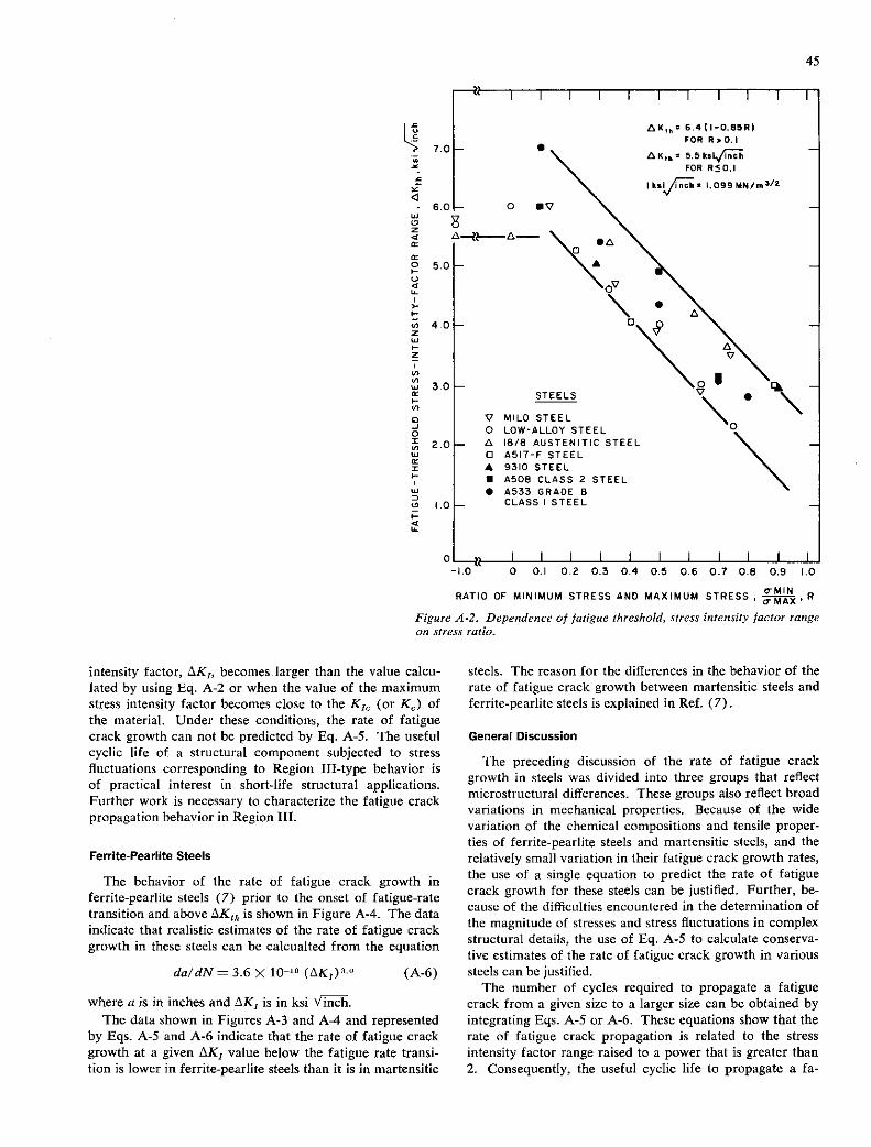
45
5.0
C La-
4.0 z w z
I I I I
6.4 (I-0.85R) FOR 11,0.1 - .
AK,bt 5.5k5I.fh - FOR RO.l
I ks/fh 2 1.099 MN/mhZ
- 0 •V
SAA----A---
CV
\. A
\ 1A V
STEELS V
V MILD STEEL - 0 LOW-ALLOY STEEL
- A IS/S AUSTENITIC STEEL o A5I7-F STEEL A 9310 STEEL IN ASOS CLASS 2 STEEL
A533 GRADE B - CLASS I STEEL -
I I I I I I I -'.0 0 0.1 0.? 0.3 0.4 0.5 0.5 0.1 0.8 0.9 1.0
RATIO OF MINIMUM STRESS AND MAXIMUM STRESS, OMIN• R aMAX
Figure A-2. Dependence of fatigue threshold, stress intensity factor range on stress ratio.
intensity factor, AK1, becomes.larger than the value calcu-lated by using Eq. A-2 or when the value of the maximum stress intensity factor becomes close to the K, (or K) of the material. Under these conditions, the rate of fatigue crack growth can not be predicted by Eq. A-S. The useful cyclic life of a structural component subjected to stress fluctuations corresponding to Region TJI-type behavior is of practical interest in short-life structural applications. Further work is necessary to characterize the fatigue crack propagation behavior in Region III.
Ferrite-Pearlite Steels
The behavior of the rate of fatigue crack growth in ferrite-pearlite steels (7) prior to the onset of fatigue-rate transition and above AK17 is shown in Figure A-4. The data indicate that realistic estimates of the rate of fatigue crack growth in these steels can be calcualted from the equation
dale/N = 3.6>( 10' (AK,)° (A-6)
where a is in inches and AK1 is in ksi Vinch. The data shown in Figures A-3 and A-4 and represented
by Eqs. A-S and A-6 indicate that the rate of fatigue crack growth at a given AK1 value below the fatigue rate transi-lion is lower in ferrite-pearlite steels than it is in martensitic
steels. The reason for the differences in the behavior of the rate of fatigue crack growth between martensitic steels and ferrite-pearlite steels is explained in Ref. (7).
General Discussion
The preceding discussion of the rate of fatigue crack growth in steels was divided into three groups that reflect microstructural differences. These groups also reflect broad variations in mechanical properties. Because of the wide variation of the chemical compositions and tensile proper-ties of ferrite-pearlite steels and martensitic steels, and the relatively small variation in their fatigue crack growth rates, the use of a single equation to predict the rate of fatigue crack growth for these steels can be justified. Further, be-cause of the difficulties encountered in the determination of the magnitude of stresses and stress fluctuations in complex structural details, the use of Eq. A-S to calculate conserva-tive estimates of the rate of fatigue crack growth in various steels can be justified.
The number of cycles required to propagate a fatigue crack from a given size to a larger size can be obtained by integrating Eqs. A-S or A-6. These equations show that the rate of fatigue crack propagation is related to the stress intensity factor range raised to a power that is greater than 2. Consequently, the useful cyclic life to propagate a fa-

46
... 'C. - 1
do = 0.66 x o (ax1) 2.25
WHERE aK1 IS IN ksi A/iliT
0-12 Ni STEEL
0-10 Ni STEEL
—HY-130 STEEL
—HY-80 STEEL
10-7 0-6 b_S 0"
CRACK-GROWTH RATE, da/dN, inch per cycle
Figure A-3. Summary of fatigue crack propagation data for martensitic steels.
io 3
ov - I I I I I - - A-436
SO - 0-ABS -C
0-4302-B 10 -
c-A 537-A
- 'p 00
8 Iinch:25.4mm
6 I 11111 I A C C in-S ,
do/dNa 3.6 ;10w
(AK1)3•°
FOR da/dn in inch/cycle
ax1 in ksi Vinch
I kslJ r I 099 MN/m3'2
I ii ilil I I I I & c n n-5 o a
0
'-4
CRACK-GROWTH RATE, do/dn, inch per cycle
Figure A-4. Summary of fatigue crack growth data for ferrite-pearlite steels.

47
tigue crack a given increment of length is much greater at low AK1 values than at high AK1 values. In other words, most of the useful cyclic life of structural components sub-jected to constant load fluctuations is expended in initiating and propagating fatigue cracks at AK1 levels less than
40 ksi 'Vhi. (44 MN/rn3!2 ) rather than at higher AK1 values.
CORROSION FATIGUE, CRACK PROPAGATION BEHAVIOR
Most corrosion fatigue, crack propagation investigations have been conducted on high-yield-strength steels (8, 35). The first systematic published investigation into the effect of environment on the rate of fatigue crack growth was con-ducted on 12Ni-5Cr-3Mo maraging steel (yield strength = 180 ksi) in 3-percent sodium chloride solution (8). The data showed that environmental acceleration of fatigue
6cpm--- 60cpm' 0
8 A 0'600cpm
6
0 /
i Pa t 'O A1 00 0
d I
/ AIR DATA AT /
2 &6 C?o 6$ cpm $600
I/o / 6°9'
0 / F
IO ' ED
/ F /
8I 60
_____ I I / 12N1-5Cr-3M0
6 /10
2 / 6o' STEEL
I/b AIR V / p
4 / 0 ---- 3%NoCI
& SOLUTION
I /
/ K,scc +
STRESS-INTENSITY-FACTOR RANGE,AK
Figure A-5. Corrosion fatigue, crack growth data as a function of test frequency.
crack growth does occur below K sc, (see Fig. A-5) and that the magnitude of this acceleration depends on the fre-quency of the cyclic stress fluctuations. Because these re-sults were obtained below K58 , Barsom (8) concluded that the corrosion fatigue, crack growth rate increases to a maxi-mum value and then decreases as the cyclic stress frequency decreases from 600 cpm to frequencies below 6 cpm. More-over, other published data (8, 35) indicate that the environ-mental effects on the rate of fatigue crack growth in corro-sion fatigue are highly dependent on the shape of the cyclic stress wave, as shown in Figure A-6 (8). Figure A-7 shows that the fatigue crack growth rates in room-temperature air environment were identical under the various stress fluctua-tions and are independent of frequency. However, in the sodium chloride solution (Fig. A-8), the crack growth rates per cycle under sinusoidal, triangular, and positive-sawtooth stress fluctuations were identical, but they were three times higher than the fatigue crack growth rate determined in air. Moreover, the data show that the corrosion fatigue, crack growth rates determined with the negative-sawtooth wave and with the square wave were the same as the rate of fatigue crack growth determined in air. Therefore, the negative-sawtooth type of loading and the square-wave type of loading had no corrosive effects.
SINUSOIDAL LOAD
POSITIVE- NEGATIVE- SAWTOOTH SAWTOOTH
TRIANGULAR LOAD LOAD LOAD
/\ //I N SKEWED-SQUARE LOAD
REDUCED REDUCED MIN. MAX.
SQUARE LOAD LOAD LOAD
rr Figure A-6. Various forms 01 cyclic stress fluctuations used for steel investigated.

48
6
5
4
2 a a
a C
3
2
IaJ I- 4
105 3
(p
6 C
U
4
3
0
- 0
- A 1
- t - C
C
- FATIGUE DATA IN AIR - AT 6 15 cpm :5 600
0 SINUSOIDAL LOAD
* A TRIANGULAR LOAD - 0 SQUARE LOAD
V POSITIVE -SAW TOOTH LOAD - t • NEGATIVE -SAW TOOTH LOAD
I I
I A
5 ,
- , SCATTER 8AND - IN AIR DATA
A
- ' I CORROSION-FATIGUE DATA
- / AT 6cpm
- / o SINUSOIDAL LOAD
- / A TRIANGULAR LOAD
I SQUARE LOAD - I V POSITIVE -SAW TOOTH LOAD - . NEGATIVE -SAW TOOTH LOAD
I I III 11111 10 20 30 40 50 60 80 100
STRESS -INTENSITY- FACTOR RANGE, AK 1, ksi iir Figure A-7. Fatigue crack growth rates in 12Ni-5Cr-3Mo steel under various cyclic stress fluctuations with different stress-time profiles.
The complexity of the corrosion fatigue behavior of high-yield-strength steels is evidenced in the foregoing discussion. Despite these complexities, the systematic study of this be-havior has been valuable in predicting the life of structural components subjected to cyclic loading in an aggressive en-vironment. The most important finding is that environmen-tal effects below K180 in corrosion fatigue of high-yield-strength steels subjected to constant amplitude or to random cyclic stress fluctuations occur only during the loading part of the transient tensile load in each cycle rather than by the time spent at peak load or during unloading.
STRESS-CORROSION-CRACKING BEHAVIOR
Stress-corrosion crack growth in a statically loaded struc-ture is caused by interaction between the chemical and mechanical processes at the crack tip. The highest stress intensity factor value at which subcritical crack growth does not occur in a material loaded statically in an aggressive environment is designated K180. The corrosion fatigue be-havior below K50 is of greatest practical interest in bridges. Consequently, to understand the corrosion fatigue behavior below K180 in an environmental-material system, the fatigue crack growth behavior of the material in a benign environ-
10 20 30 40 50 60 80 100
STRESS -INTENSITY -FACTOR RANGE, AK 1 , ksi /1V Figure A-8. Corrosion fatigue, crack growth rates in 12Ni-5Cr-3Mo steel in 3-percent solution of sodium chloride under various cyclic stress fluctuations with different stress-time profiles.
ment and the K18 for the environment-material systems should be established first as references.
The apparent K180 behavior measured in the laboratory was divided into three types, as shown in Figure A-9 (20,
21). The Type I, K180 (valid), behavior is that for which the conservative geometrical requirements necessary for en-suring plane-strain conditions in fracture testing (K50) are satisfied, LEFM principles are wholly applicable, and cor-responding a0, calculations are precise (see Table A-i). The Type TI, K180 (partially valid), behavior is that for which both environmental plane-strain conditions are satis-fied and LEFM principles are applicable to a currently un-known extent; furthermore, it is that for which correspond-ing acr calculations are only approximate because of the occurrence of moderate Krsuppression effects. The Type III, K1, (invalid), behavior is that corresponding to a non-planar stress state (neither plane strain nor plane stress) for which LEFM principles and a0, calculations are both totally inapplicable because of the occurrence of severe Krsup-pression effects. Despite the present shortcomings in analy-sis, this Type TI!, K1300 (invalid), behavior is the most desirable in SCC evaluations in the laboratory, because ex-treme environmental toughness is correspondingly indicated for the associated structural components in the field.

49
IC K1 cub
TYPE I Kj
.
BEHAVIOR . 1IIILp_1J
—LOG tir —*
U K1 cub
I TYPE U I K1 • PARTIALLY VALID BEHAVIOR1
UA K1 .Lub
—LOG $,—*
TYPEm tE --Kflfl
BEHAVIOR ---------- — I K1 tub
—LOG
Figure 4-9. Three basic types of apparent K11 behavior and classification.
TABLE A-I
ANALYSIS OF SCC SUSCEPTIBILITY IN TERMS OF GEOMETRY AND STRESS STATE
Extent of Applicability Extent of Environmental Plane-Strain of flacr * Suppression on
Behavior 5lscc Designation and Limits Validity Calculations Apparent Klscc
Type I R1scc(VALID) C KI,Lub 100% valid Precise None
Type II 5ILUb < Kiscc(PART. VALID) <KI,Gub Mixed validity Approximate Moderate
Type III 5IGub < <Iscc(hII0) 100% Invalid Inapplicable" Severe**
* acr = A cys
** Severe suppression effects reflected by grossly inadequate specimen dimensions of a proportional-geometry type (see Table III) and consequent gross underestimates of intrinsic acr.

50
APPENDIX B
SPECIMEN PREPARATION AND EXPERIMENTAL PROCEDURES FOR FRACTURE MECHANICS STUDIES
SPECIMEN TYPE AND ANALYSIS
WOL Specimens
With the exception of the tests conducted for K 13 , the specimen type used throughout the study for fracture me-chanics evaluation was the wedge-opening-loading (WOL) specimen. All such WOL specimens were 1-in, thick (iT). They were machined in the same manner (Type B), as shown in Figure 5, and in the same longitudinal crack orientation (RT designation) for each of the five steels investigated (A36, A588 grades A and B, and A514 grades E and F). All WOL specimens were prepared similarly in order to be used for investigation of three different types of material behavior for each of the five steels, including: (1) fracture behavior (static); (2) fatigue-crack-growth rate tests in air; and (3) corrosion fatigue, crack growth rate tests in both distilled water and 3-percent solution of sodium chloride in distilled water. The basic machining of these WOL specimens was the same in the sense that they were machined to ±0.002-in. (0.051-mm) tolerances and a 0.007—in—root-radius notch was employed using an elec-trical discharge machine (EDM) process in order to facili-tate fatigue precracking. Subsequent preparations of the specimens are described, as follows, in the appropriate descriptions of the experimental procedure for each type of evaluation.
The stress intensity, K1, at the crack tip was calculated using the following equation (18):
K1 = (B-i) B Va
where P is the applied load, B is the specimen thickness, a is crack length measured from the loading plane, and C3 is a function of the dimensionless crack length, a! W (see Fig. B-l), in which W is the specimen length measured from the loading plane. Expressed in a polynomial form, C, can be represented as:
C, (a/W) = [30.96 (aIW) —195.8 (aIW)' + 730.6 (aIW)' —1186.3 (a!W) 4 + 754.6 (a/W)'] (B-2)
In the range 0.25 <a! W < 0.75, the polynomial is accu-rate to within 0.5 percent of the experimental compliance.
Cantilever Beam Specimens
Single-edge notched specimens tested in cantilever bend-ing (so-called cantilever beam specimens) were prepared for each of the five steels. These specimens (Fig. 4) were used to evaluate both the resistance to fracture (K1 ) and
stress-corrosion cracking (K 130 ) for each of the five steels tested. In a manner similar to that for the WOL specimens, the crack orientation for all cantilever beam specimens was RT (longitudinal). The specimens were 1-in, thick (iT) and were machined to tolerances of ±0.005 in. In addition, an EDM notch starter (0.007-in, root radius) was used for these specimens in order to facilitate fatigue precracking. All specimens were face notched (V notched) 5 percent.
K1 values were calculated for the cantilever beam speci-mens by using the following equation, developed by Bueck-ner (55), for an edge crack in a strip subjected to in-plane bending and modified to account for reduction of thickness due to the face notches:
PLOAO
OtCRACK LENGTH
BTHIcKNEsS
K1 t cap
(EQUATION i)
o/W
Figure B-I. Relation between constant C, used in calculating K1 and a/K' ratio.
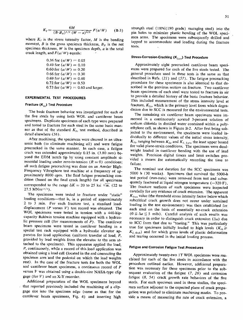
51
6M K1 = (BB) 172 (W - a)u/2
F(a/ W) (E-3)
where K1 is the stress intensity factor, M is the bending moment, B is the gross specimen thickness, BN is the net specimen thickness, W is the specimen depth, a is the total crack length, and F(a/ W) equals:
0.36 for (aIW) = 0.05 0.49 for (a/W) = 0.10 0.60 for (a! W) = 0.20 0.66 for (a/W) = 0.30 0.69 for (a! W) = 0.40 0.72 for (a! W) = 0.50 0.73 for (a/W) = 0.60 and larger.
EXPERIMENTAL TEST PROCEDURES
Fracture (K,) Test Procedure
The basic fracture behavior was investigated for each of the five steels by using both WOL and cantilever beam specimens. Duplicate specimens of each type were prepared and tested to fracture for each steel in the same basic man-ner as that of the standard K, test method, described in detail elsewhere (56).
After machining, the specimens were cleaned in an ultra-sonic bath (to eliminate machining oil) and were fatigue precracked in the same manner. In each case, a fatigue crack was extended approximately 0.1.5 in. (3.80 mm) be-yond the EDM notch tip by using constant amplitude si-nusoidal loading under zero-to-tension (R = 0) conditions; all such fatigue precracking was done on an Amsler High-Frequency Vibraphore test machine at a frequency of ap-proximately 8000 cpm. The final fatigue precracking con-dition (based on the final crack length) for all specimens corresponded to the range LsK = 20 to 25 ksi \ 7 in. (22 to 27.5 MNm/2).
The specimens were tested to fracture under "static" loading conditions—that is, in a period of approximately 2 to 3 mm. For each fracture test, a standard load-displacement (P versus V) test record was obtained. The WOL specimens were tested in tension with a 440-kip-capacity Baldwin tension machine equipped with a hydrau-lic pressure cell (for measurements of P). The cantilever beam specimens were tested in cantilever bending in a special test rack equipped with a hydraulic elevator ap-paratus for load application (uniform transfer of load, P, provided by lead weights from the elevator to the arm at-tached to the specimen). This apparatus applied the load, P, continuously, while a record of this load application was obtained using a load cell (located in the rod connecting the specimen arm and the pedestal on which the lead weights rest). In the case of the fracture tests for both the WOL and cantilever beam specimens, a continuous record of P versus V was obtained using a double-size NASA-type clip gage (for V) and an X-Y recorder.
Additional preparation of the WOL specimens beyond that reported previously included the machining of a clip-gage slot into the specimen edge (same as that for the cantilever beam specimens, Fig. 4) and inserting high
strength steel (18Ni(190 grade) maraging steel) into the pin holes to minimize plastic bending of the WOL speci-men arms. The specimens were subsequently drilled and tapped to accommodate stud loading during the fracture tests.
Stress-Corrosion-Cracking (K1,) Test Procedure
Approximately eight precracked cantilever beam speci-mens were prepared for each of the five steels tested. The general procedure used in these tests is the same as that described in Refs. (21) and (57). The fatigue precracking procedure for these specimens is also identical to that de- scribed in the previous section on fracture. Two cantilever beam specimens of each steel were tested to fracture in air to provide a detailed history of the basic fracture behavior. This included measurement of the stress intensity level at fracture, K1 , which is the primary level from which degra-dation due to SCC is measured for the environmental tests.
The remaining six cantilever beam specimens were im-mersed in a continuously aerated 3-percent solution of sodium chloride in distilled water contained within a poly-ethylene cell, as shown in Figure B-2. After first being sub-jected to the environment, the specimens were loaded in-dividually to different values of the initial stress intensity, K,, ranging between K1 and K1 Lth' the least upper bound for valid plane-strain conditions. The specimens were dead-weight loaded in cantilever bending with the use of lead weights. Precision digital timers and limit switches pro-vided a means for automatically recording the time to failure.
The nominal test duration for the SCC specimens was 5000 h (30 weeks). Specimens that survived the 5000-h test period (run-outs) were removed from test and subse-quently fractured at liquid nitrogen temperature (-320 F). Th fracture surfaces of such specimens were inspected carefully for any evidence of crack extension. The apparent KI MCC value (the threshold stress intensity factor below which subcritical crack growth does not occur under sustained loading in the test environment) was then established for each steel on the basis of essentially no-crack extension (0 tsa S mils). Careful analysis of such results was necessary in order to distinguish crack extension (Aa) due to SCC from that due to "tearing." This was particularly true for specimens initially loaded to high levels (K1 K1, cub) and for which gross levels of plastic deformation and tearing occurred in the initial loading process.
Fatigue and Corrosion Fatigue Test Procedures
Approximately twenty-two IT WOL specimens were ma-chined for each of the five steels in accordance with the procedure outlined earlier. However, additional prepara-tion was necessary for these specimens prior to the sub-sequent evaluation of the fatigue (7, 26) and corrosion fatigue (8, 54) crack growth rate behaviors of the five steels. For each specimen used in these studies, the speci-men surface adjacent to the expected plane of crack propa-gation was polished to eliminate machining marks. To pro-vide a means of measuring the rate of crack extension, a

52
AIR
rccIM GIAL GAGE
NOTCH OR MICROSWITCH
TEST FRAME - i I 'CORROSION CELL
DEAD WEIGHT
Figure B-2. Schematic drawing of fatigue cracked, cantilever beam test specimen and fixtu,es.
series of indentations was made on the specimen surface (with a Vickers Pyramid Hardness Testing Machine) along a line parallel to the plane of the initial crack and in the direction of expected crack extension, as shown in Figure B-3. To ensure that crack extension was not affected by the indentations, the distance between the line of indentations and the crack plane was about ½ in. The distance between neighboring indentations was 0.010 ± 0.0002 in. (0.25 ± 0.0051 mm). Each specimen in the crack growth studies was prepared using this procedure on one side (only). Fi-nally, the specimen was cleaned by immersion in an ultra-sonically agitated bath.
All crack propagation tests were conducted at room tem-perature either in air or in distilled water, or in a 3-percent solution of sodium chloride in distilled water, by using 100-, 50-, and 25-kip (444.8-. 222.4-, and 111.2-MN) Materials Testing Systems (MTS) machines. The fatigue crack growth data in air were obtained at cyclic stress fre- quencies primarily at 60 cpm (with one set of data for each steel), and additionally at 12 cpm to specifically study fre-quency effects. Alignment was achieved both by careful machining of specimens and other auxiliary parts and by loading the specimens through universal joints.
In most tests, the fatigue crack was initiated and propa-gated in the test environment under tension-to-tension sinus- oidal loading at a constant maximum load and constant minimum load, which were controlled within ±1.0 percent. Prior to making crack-length measurements, the fatigue cracks were extended in the test environment a distance of 0.25 in. (6.4 mm) from the notch root. Thus, at the time crack-length measurements were begun, the total crack length, a, was approximately equal to the specimen thick-ness (l.00 in., or 25.4mm).
Crack extension was measured optically at X17 magni-fication with an M-101 type Gaertner microscope mounted in a micrometer slide. The average crack extension be-tween consecutive measurements was less than 0.03 in. (0.76 mm).
The environmental bath was built of plexiglass and had a 5-gal (0.019-rn3 ) capacity to minimize temperature and pH fluctuations (see Fig. B-4). Periodic measurements of
Location of hardness identations. Xl.
Close—up of hardness identations. X25.
Figure B-3. Hardness indentations used to ,neasure crack length in WOL specimens.
ph I mid temperaturc were made to assure the stability of the hulk environment. All tests were conducted at 7.0 ± 0.5 pH and at 74 ± 2 F (23 ± I C). To minimize galvanic or crevice corrosion effects, the universal joints were coated with an epoxy enamel. For the corrosion fatigue tests the test solution was aerated continuously throughout the course of the tests.
Tests of fatigue crack growth rate in air were conducted for each steel under both constant amplitude, sinusoidal loading and variable amplitude, random sequence, sinus-oidal loading. All such tests in air were conducted at a frequency of 300 cprn and at a 10-percent stress ratio 0.10. For the constant amplitude, sinusoidal loading tests, the specimens were subjected to sinusoidal cyclic loads to 3200-lb (14.2-kN) constant maximum load and 200-lb 0.89-kN) constant minimum load. At the start of data recording (a B 1.00 in.), this condition corresponded
to an initial stress intensity AK 15.0 ksi Vin. (16.5
MNm-312 ). The stress intensity range gradually increased (and crack propagation rate was determined) as the crack grew to test termination under the prescribed (constant) cyclic loading conditions.
This same basic procedure was also applied for the variable amplitude, random sequence. sinusoidal loading tests conducted in air. However, in these tests, it was neces-sary to electronically couple an external unit to the MTS testing machines in order to provide the proper random

53
spectrum of variable amplitude, sinusoidal loading history. This was accomplished with the use of a Weston Instru-ment EMR 1611 Profiler (random function generator), which was programmed using a continuous loop of metal Mylai tape. The iiietal tape was piepuiiclied to siiiiulate
500-cycle block of val idUle aiiiplitude. siiiusoadtl luadiiig history under the appropriate random conditions. The spe-citic distribution function used to mathematically describe the frequency (of occurrence for each) of the variable amplitude. sinusoidal waveform cycles was the Rayleigh distribution function.
The corrosion fatigue, crack growth rate tests were con-ducted in a manner similar to that described for the fatigue-crack-growth rate tests in air. However, the test environ-ment for the corrosion fatigue tests was either distilled water or a 3-percent solution of sodium chloride in distilled water; the test frequency was somewhat slower, being either 60 or 12 cpm. These tests also included additional excur-sions to investigate the behavior of each of the five steels under both constant amplitude, square waveform conditions (at R = 0.10) and variable amplitude, sinusoidal waveform conditions (at 1? 0.50). Thcsc latter tests represent con- ditions more closely simulating actual material conditions for long-span bridges. The various primary test conditions have been described earlier and are summarized in Table 1, The Weston Instruments EMR 1641 Profiler and continu-ous Mylar tape system were both used to provide the pri-mary signals for all of the corrosion fatigue, crack growth rate tests conducted under both variable amplitude, sinus-oidal loading and constant amplitude, square wave loading.
41 L[ELI Figun 8-4. Experi,iu'ntal setup for co;; usisi; Jrstii;& tests.
APPENDIX C
CHARPY V-NOTCH AND DYNAMIC TEAR DATA
The results of fracture toughness tests for the five steels investigated (A36, A588 grades A and B, and A514 grades E and F) using Charpy V-notch and dynamic tear speci-
mens are summarized in the following Figures c-i through C-25.
80
60
I I I I
LONGITUDINAL S A TRANSVERSE
• A A
• A
A
A - A
•
Figure C-i. Clzarpv V-notch energy absorption for A 36 steel.
-150 -100 -50 0 50 100 150 200
TEMPERATURE F

'VI
LONGITUDINAL
A TRANSVERSE 50
I I
I S • 'I •
.
• ft ft
$
I I I I I I
LONGITUDINAL • A TRANSVERSE I
10- S -
10 A A - A 'a
'0- A - a A I I I
g 60
z 0 'a z
40 w
DO I I I I I A LONGITUDINAL
30 - A TRANSVERSE -
A.
GO- -
A A
40- - A
20- .1 - S
0 I I I I
a
01 -150 -100 -50 0 50 100 150 200
TEMPERATURE, F
Figure C-2. Charpy V-notch lateral expansion for A36 steel.
-150 -100 -50 0 50 IOU IOU 101)
TEMPERATURE. F
Figure C-3. Charpy V-notch fibrous fracture for A36 steel.
-150 -100 -50 0 50 100 150 10 TEMPERATURE F
Figure C-4. Charpy V-notch energy absorption for A588 Grade A steel.
-ISO -100 -50 0 50 IOU 10V CU
TEMPERATURE. F
Figure C-5. Charpy V-notch lateral expansion for A588 Grade A steel.

a E
IZU
100
DO 40
20ft - A
o I• * I I I I -150 -100 -50 0 50 100 150 200
TEMPERATURE, F
Figure C-6. Charpy V-notch fibrous fracture for A588 Grade A steel.
-150 -100 -50 0 50 100 150
TEMPERATURE, F
Figure C-S. Charpy V-notch lateral expansion for A588 Grade B steel.
201— A 'a -
AS
0 ! I
-150 -100 -50 0 50 100 150
TEMPERATURE , F
Figure C-?. Charpy V-notch energy absorption for A588 Grade B steel.
I I 100 -
LONGITUDINAL A TRANSVERSE
80- • c 'a U A a a
60 • •
I-U C
40 - 10
20-
I 46 0 I
-ISO -100 -50 0 50 100 ISO
TEMPERATURE, F
Figure C-9. Charpy V-notch fibrous fracture for A588 Grade B steel.

20
100
80
20
80
100
a
60
LONGITUDINAL
A TRANSVERSE
0I I I I I I
-200 -ISO -100 -50 0 50 100 ISO
TEMPERATURE • F
Figure C-Ill Charpy V-notch energy absorption for A514 Grade E steel.
S
$ $ S A
. S a
A
At
I I I I -ISO -100 -50 0 50 100 ISO
TEMPERATURE • F
Figure C-lI. Charpy V-notch lateral expansion for A514 Grade Estee!.
I I I I
S t
S LONGITUDINAL A A TRANSVERSE
A
& S
-200 -ISO -100 50 U CV 1W 1W
TEMPERATURE,F
Figure C-12. Charpy V-notch fibrous fracture for A514 Grade E steel.
LONGITUDINAL
A TRANSVERSE
- S • S
• S S
• A
• A ft ft
• A A
• A
A
Figure C-13. Charpy V-notch energy absorption for A514 Grade F steel.
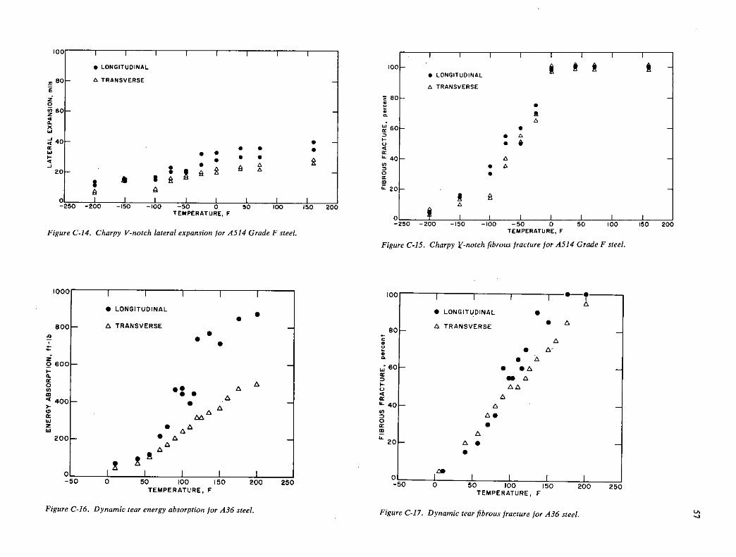
U-
LONGITUDINAL
A TRANSVERSE
S • S • . . S • •
A A A
$ A A
I 00 -150
I -100
I -50 0
I 50 100 150 20
TEMPERATURE. F
Figure C-14. Charpy V-notch lateral expansion for A514 Grade F steel.
00-
I I I I I I I I
S LONGITUDINAL
A TRANSVERSE
80- - S
A 60- 5 -
A Se
40- A - • A S
20-
S ft
0 I I I I I -250 -200 -150 -100 -50 0 50 100 150 200
TEMPERATURE, F
Figure C-IS. Charpy V-notch fibrous fracture for A514 Grade F steel.
LONGITUDINAL . •
800 - A TRANSVERSE - • • z 0600- -
a-
A A o .. <400— •
A -
A C, A w 2 • A Id A
A - 200-
0- -50
00 -
a -50 0 50 100 150 200 250
TEMPERATURE, F
Figure C-16. Dynamic tear energy absorption for A36 steel.
I I I A
LONGITUDINAL S
A TRANSVERSE A - - A
• S • 50— 5 •A -
a a AA
A A -
AS S
A 0— A. -
S
40 O I I I -50 0 50 100 150 200 250
ItMF'tHATURE, F
Figure C-17. Dynamic tear fibrous fracture for A36 steel. '-1

0 '0
TEMPERATURE F
Figure C-19. Dynamic tear fibrous fracture for A588 Grade A steel.
IN
80 S a
! : U- I
20H
S 0 I I I I I I I
-150 -100 50 0 50 100 150 200 250
TEMPERATURE, F
Figure C-21. Dynamic tear fibrous fracture for A588 Grade B steel.
U-
20
LONGITUDINAL 800
A TRANSVERSE LONGITUDINAL
A TRANSVERSE
z
2600— -
C
400
0, A -
..
SAa Ui
200- •• - a •
0 I I I I I -100 -50 0 50 100 150 20
TEMPERATURE, F
Figure C-18. Dynamic tear energy absorption for A588 Grade A steel.
- -150 -100 -50 0 50 100 150 200 250
TEMPERATURE • F
Figure C-20. Dynamic team energy absorption for A588 Grade B steel.
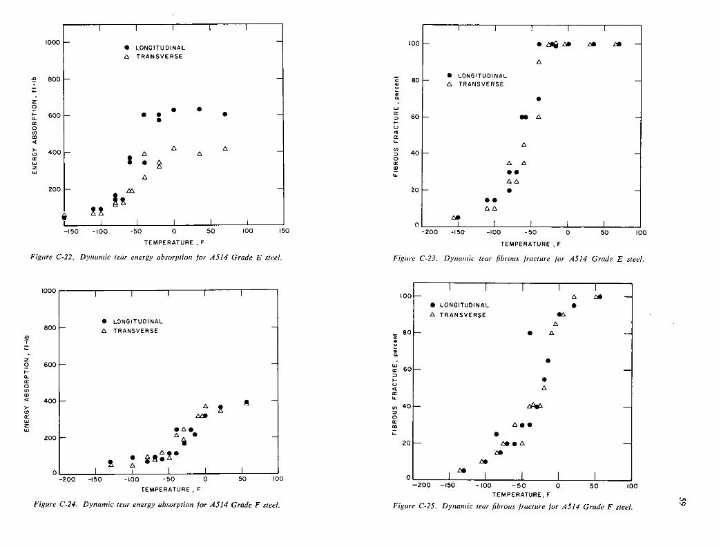
LONGITUDINAL A TRANSVERSE
S
fl A
A
A A .5 AA S
S. AA
a.
z 0
600 Cr 0 In In C
400 Cr IhJ z Lu
U-
20
C
1• LONGITUDINAL
A TRANSVERSE
SM']
TEMPERATURE F
Figure C-22. Dynamic tear energy absorption for A514 Grade E steel.
1000, 1 I
LONGITUDINAL A TRANSVERSE
z 2 600
0. Cr 0 (0 In
400 >- 0 Cr Li z Ui
ZOO
0 -200 -150 -100 -50 0 50 100
TEMPERATURE • F
Figure C-24. Dynamic tear energy absorption for A514 Grade F steel.
TEMPERATURE F
Figure C-23. Dynamic tear fibrous fracture for A514 Grade E steel.
I I I I I 0—
LONGITUDINAL S A TRANSVERSE
A '0—
S -
S A
0— —
ASS
S 0— SSA —
Es be
ES 0 I I 1 I I
Figure C-25. Dynamic tear fibrous fracture for A514 Grade F steel.

APPENDIX D
FRACTURE (K13 BEHAVIOR OF STEELS INVESTIGATED
The individual results of fracture toughness tests for the IT WOL specimen are given in Table D-1, and a corre-sponding photograph showing typical fracture surfaces for each steel is shown in Figure D-1. Similar results for the fracture tests conducted on these same steels in cantilever bending are given in Table D-2 and Figure D-2, respec-tively. The results for both types of tests (Tables 0-1 and 0-2) are characterized in terms of both the secant inter-cept, X, and the clip-gage displacement, V, at the onset of maximum load, P, as well as at complete fracture, P7, because the two events were generally not coincident. In most cases, complete (sudden) fracture occurred only after maximum load was attained and the applied load decreased due to stable crack extension.
The salient results from both types of specimen fracture tests are summarized in Table 6 using average values. These data are consistent in showing extensive resistance to frac-ture for each of the five steels tested. As expected, no valid Kie values were measured for any of the steels. This is apparent from the fact that the KQ values (5-percent secant intercept values) for all tests were above the respective K, Lui, values and, further, that the values at maximum load (K,) were all well in excess of the 1.10 KQ limit admissible for a valid K1 test (56). Thus, the KQ values occurred well in advance of the attainment of maximum load (K,.) and bear no relation to the intrinsic brittle fracture tendencies of the steels tested.
The true fracture characteristics of the steels tested are better characterized by the K,2 rather than the K0 values. All such K, values occurred under conditions of gross plastic deformation and are synonymous with ductile rather than brittle fracture behavior. The extent of plasticity at fracture is directly evident from the lateral contraction, shear-lip development, and large amounts of stable crack extension that occurred in the fracture process (Figs. 0-1 and D-2). Another measure of this plasticity can be seen in the high ratios of applied stress to the yield strength
(x mar/°y,) that occurred at maximum load for each of the steels tested (Table 6). In particular, it can be seen that this ratio was in the range 2.10 to 2.60 for each of the tests conducted on the A36, A588 Grade B steels with both specimen types. The corresponding ratios for the higher strength A514 Grade E and A514 Grade F steels were approximately 1.65 and 1.05, respectively. These latter values are somewhat lower and indicative of less plastic deformation at fracture, as might be expected, because of the higher strength.
From the preceding discussion it should be clear that LEFM concepts can not be used to quantitatively charac-
terize the brittle fracture characteristics of the steels investi-gated because of both the high inherent level of fracture toughness exhibited and the limitations imposed by the IT specimen size employed for all tests in this study. Such quantitative assessments of the true fracture behavior can only be obtained in the future with the J-integral (38, 39) and equivalent-energy (40, 41) methods of elastic-plastic fracture analysis. However, certain semiquantitative esti-mates of fracture behavior can be made on the basis of the results attained during this study by using the K1-suppression effect concept discussed in Part I of this report. Moreover, the fracture tests were conducted primarily to estabilsh the basic fracture level of each steel (in whatever terms are available) for purposes of assessing degradation in this level due to 8CC susceptibility. Because these objectives rely to some extent on the observed K0 and K,2 values, careful examination of these specific results is necessary.
In general, the K0 values obtained from both types of specimens were in relatively good agreement for each of the five steels tested (Table 6). The K0 values from the WOL specimens were generally only slightly lower than the cor-responding values obtained from the cantilever beam speci-mens. Although this was true for the A36, A514 Grade E, and A514 Grade F steels, the K0 values from the WOL specimens for the A588 Grade A and A588 Grade B steels (40 and 42 ksi v'Ei. (44 and 46 MNm_3/2), respectively) were somewhat lower than expected on the basis of the corresponding K0 values obtained from the cantilever beam specimens (57 and 54 ksi Vin. (63 and 59 MNm_3/2), re-spectively). These lower K0 values for the WOL specimens of the A588 Grade A and A588 Grade B steels, specifically, were apparently the result of premature yielding of the specimen arms (see Fig. 0-3). Figure D-4 shows that such behavior occurred despite attempts to prevent it by using high-strength steel pins that were drilled and tapped to accommodate loading by two studs in the fracture tests. Such plastic arm bending is an inherent weak link for the WOL specimen in the testing of high-toughness steels; gen-erally, and is the primary reason for the subsequent de-velopment and adoption of the stubbier compact tension (CT) specimen as a more rigid type of specimen for stan-dard K, tests (56). Thus, the K0 values obtained from the cantilever beam tests are more representative of the true behavior for the steels tested, particularly the A588 Grade A and A588 Grade B steels.
In contrast to that observed for the K0 values, the values at maximum load (K,2) were consistently higher for the WOL specimens than the corresponding values for the cantilever beam specimens for each steel (Table 6). This

A588-B No. 14C-6 --
ç':
Figure D-2. Typical f.acture surfaces from precracked cantilever beam specimens tested to fracture under static loading conditions in air at 72 F.
No. 14A-8 A588-A
No, 14B-8 A514-F
No. 14E-8
o 0 0 U y ..: . I:.. i... ••i ! .
flA588A} A588-BE F
No.14A41 No. 14B-3 No. 14C-6 No. 140-11 No. 14E-17
t ;A5 14 -
_____ •-
I- 1 1
.•'
Figure D-1. Typical fracture surfaces from IT WOL specimens tested o frac-ture under static loading conditions in air at 72 F.
Figure L-4. IT WOL ;pecimen of A588 Grade B steel ?xhibitip gross plastic c'eformation of the specimen arms (thereby preventing complete fracture and necessitating
saw cnt), despite the presence of high-strength steel pins tnade of I8Ni (180 Grade) maraging steel.
Figure D-3. Partially tested IT WOL specimen (pin-foaded) of A588 Grade B steel showing substantial arm bending and plas;icily prior to the use of high-strength steel pins and a stud loading procedure. C'

TABLE D-1
IT WOL SPECIMENS TESTED TO FRACTURE
Values of Parameters from Load versus COD fiecords Fatigue Cracking At a
Specimen Dimensions Parameters Secant At Maximum Load At Fracture Item Specimen V, B, a, dAft N. Kj, Kç11_ Fax. 0N,aax' 1Ix' V, x,, P, V:, Xc, No. Steel Code No. inches inch inches ksi .tinch" cycles" ksi ,"1nch ksi Jinch' pounds k s i+ ksi /i.nch' mi!s percentt4 pcwds all:; terc'nt
1 A36 114A-1r" 2.559 0.999 1.101 22.0 293,000 27.6 3'..6 16,loo 94.3 85.2 197 814.2 16,100 210 85.2 2 A36 14A-11Y 2.557 0.999 1.115 22.3 275,000 27.6 39.0 18,320 109.9 101.7 1177 >62.4 6,000 >>242 '191.5
3 A588-A 1143_37 2.556 0.966 1.1141 27.7 187,000 314.1 1.1.4 17,930 115.9 105.1 >208 >83.6 c 450 >6or >95. & 4 P.588-A 148-5 2.558 0.966 1.103 22.8 295.000 314.1 39,1 19,14140 118.2 110.14 >323 789.3 <12,76C >>s23 >>93.i
5 P.588-B i4C-6 2.556 0.925 1.109 23.9 116,000 33.8 39.8 20.590 132.3_ 123.3 '165 >77.2 20,590 >165 >77.2 6 P.558-B 1I4U-10' 2.559 0.925 1.065 28.8 184,000 33.8 37.3 >21,240' '127.2 k >121.9' 374 58.9;;; :40 ND ND 7 P.586-B 14C-20 2.553 0.9214 1.088 23.5 183,000 33.8 144.6 20,5140 128.3 121.O 505 91.2++ 20,400 8 P.588-8 14C-17 2.560 0.925 1.1469 143.4 2145,000 33.8 44. 11,830 141.6 1021T 207 79.0 11.830 208 79.1
9 £514-s 14D7# 2.554 0.988 1.086 20.3 3614,000 67.8 112.1. 30,120 175.2 165.1 127 57.6 -0 >656 >99.1 10 A511 -E 14D11 2,5514 0.988 1.091 21.5 649,000 67.8 101.7 30,120 176.6 166.3 >115 >53.7 0 >643 >99.1
11 A5144-F 14E_30 2.5514 0.999 1.050 20.5 627,000 81.5 90.6 22,970 125.2 120.6 87 56.9 1 3,260 >139 >146.0 12 P.514-F 145-171 2.5149 0.999 1.038 20.3 579.000 81.5 914.8 27,410 1147.5 1143.3 91 51.9 '0 >163 '97.9
a is the original crack length attained by fatigue cracking - 0.27 to 0.37 inch beyond a. Z 0.77 inch, the machined notch tip.
** 1 ' /k') where
f(aIW) is a function of the relative crack length; AKf is the maximwn AK1 reached during fatigue crack preparation, B is
KQ is the K1 value calculated from the load at a 5 percent secant on the load versus COD record, and Cxx is the value calculated from the rcaximuni load, All calculations were made using the length of the original fatigue crack, a.
*° N is the total number of cycles of constant eaplitude zero-to-tension (a Z a) sinusoidal loading required to extend a fatigue crack from aN to the final length, a.
1/2
1,Lub = ° 13
_o Note that h1 Cut = 1.56
+ C.. is the ncminal stress at the crack tip at maximum load (P = P ) as calculated from the relation. + = ,__ )2 flW + 2a) for
r.ax I P. B-a
a VOL specimen.
++ V is the value of the COD from the load versus COD records; V. is the value attained at zaxirnum load and V, is the value at gross fracture.

+++ I is the percent secant at any given point on the load versus COD record.
++t+ 136 specimen No. 14A17 exhibited an accelerated increase in COD for 6 mils at a constant load, P C P . This appears to be the effect of a short stable crack extension and/or discontinuous yielding which may be caused by the formation of fiflres (irternal shear lips) near the crack front,- the strain rated the stiffness of the test machine. The corresponding values of the various parameters at this point were P = 13,200 lb, K1 = 72 ksi /inch, V = 52 nils, and X = 51.6 percent. This phenomena, although not as pronounced, was also observed repeatedly later in the test and during the testing of other specimens.
These specimens were totally unloaded prior to fracture, at which time the maximum lateral contraction, ABmax, was measured. This value can be used to obtain, for the 1-inch-thick plates fron which these specimens were machined, an approxinate neasure of resistance to fracture under plane-stress conditions.This is accomplished by employing COS theory, setting 6 dBj (an empirical correlation given earlier, Reference 11) in the equation KR = /óEoys, where F is the modulus of elasticity of the material (I a 30 x 3M6 psi for steel). (KR C Kc, the plane-stress fracture toughness). ?.esults for the four specimens are as follows:
136 specimen No. 1141_11; dBma,c = 0.131 inch, KR = 413.9 ksi /inch, K1 = 78.6 ksi Vinch, P = 114,160 It (after Pnax), V >> 177 mils, X >> 82.14 percent
A588-A specimen No. 1.B-3; ABn =0.089 inch, KR = 382.9 ksi /inch,K1 = 96.8 ksi p = 16,510 lb (after Pmax), V > 208 mils, X > 83.6 percent.
1588-3 specimen No. 1140_10; dBmas = 0.053 inch, KR = 297.3 ksi v'i, K1 = 127.2 ksi V1, P = 21,21.0 lb (before m)' V = 3714 mils, X = 88.9 percent.
L. A588B specimen No. 11.C.-20; dBm> 0.013 inch, KR = 11.7.3 ksi /inch, K1 = 112.1. ksi /inch, P = 19,080 lb (before m)' V = 180.1. mils, X = 77.1 percent.
(See footnote below regarding V and X values for the last two specimens.)
fl 1588-A specimen No. 11.B-5 was not loaded to fracture.
The arms of A588-B speciren No. 11.c-:o and 11.0-20 deformed severely under load causing increased values of V(000) to be recorded and therefore increased the calculated values of X, the percent secant. In addition, one arm of specimen No. 1140-10 deformed to such an extert that the net section of the specimen was not subjected to the nazinum possib!e load and therefore was not fractured.
The Kix value for 1588-P specimen No. 14C_17 reflects greater Ki-Suppression Effects than nating specimens due to the longer crack length, a.
# A5114-.E specimens No. lhD..7 and hiD-il, and to a nuoh greater extent 15114-F specimens No. 114E-3 and 114E-17, exhibited a serrated load versus COD record consisting of discontinuous changes in slope and/or accelerated increases in COD at a constant load, P C Pmax. This appears to be the effect of short, stable crack extensions and/cr discontinuous yielding which may be caused by the formation of fissures (internal shear lips) near the crack front, the strain rate, and the stiffness of the test machine.
0 U,

TABLE D-2
PRECRACKED CANTILEVER BEAM SPECIMENS TESTED TO FRACTURE (IN AIR)
0\ a
Values of Parameters from Load versus COD Records
Fatigue Cracking At a 5$ Specimen Specimen Dimensions Parameters Sece.nt At Maximum load At Fracture
Item Coda V. B. a, N. KI,LUhL..... 'tQr.... 'n5x' 0N,max' KI .._ v, y, P. V. Xr, Steel Number incheg inch' inches" kei Inch" cycles" kai /inch+ ksi Iinch pounds+ ksi'4 - kni Iinch mils+4t4 percentt pounds++ mi1s+* percent
1 A36 14A-59 2.500 0.939 1.062 20.0 266.000 26.0 39.2 1058 109.8 81.9 1149 92.5 C 381'' 264## >96.5k hF 2 *36 l4A_1t0I 2.500 0.941 1.014 28.3 266,000 26.0 44.1. > 9I1t >102.21# >82. OAF## > list' >65.3110 C 969### 1260 195.4fl1
3 *36 14A-1. 2.499 0.939 1.100 29.2 231,000 26.0 40.7 1065 116.7 92.7 179 92.6 1062 183 92.8
4 *588-A 1145-1 2.1499 0.9111 1.062 27.5 222,000 32.2 524.6 1166 1214.9 100.3 98 86.7 c 879 >263 >96.0
5 *588-A 14a-8 2.496 0.913 1.043 27.0 207,000 32.2 6o.4 1173 123.0 99.0 131. 87.0 C 816 >263. >96.3
6 *588-B 140.-6 2.503 0.896 1.090 29.4 1243,000 32.4 56.3 1138 128.9 102.3 146 67.7 1138 46 67.7 I *588-B 14C-2 2.500 0.896 1.112 31.1 218,000 32.4 52.9 n46 1314.5 lo6.6 53 71.0 1146 52 11.0
8 A514-E 14D-8 11t 2.505 0.991 1.010 26.5 200,000 66.4 109.1 1869 182.1 146.1 29 32.0 C 218 >259 >99.1
9 A514-E 11.0_51'00 2.50. 0.996 1.02.6 25.6 236,000 66.4 110.8 1904 119.9 11.5.5 26 23.9 C 225 '152 >98.14
10 *514.-F l4E_21fl0 2.1.98 0.975 1.1111 26.2 >311,000 78.3 96.0 1206 129.5 102.6 16 12.7 - 0 >267 lCO 11 A51.-? 14E8' 2.497 0.915 1.063 214.9 311,000 78.3 97.0 1316 131.1 105.1 16 14.9 - 0 '151 100
Specimens were face notched to a depth. I, of 0.050 inch. BN - B - 21 - B - 0.100 in inchee.
60 £ is the original crack length attained by fatigue cracking - 0.24 to 0.36 inch beyond e i 0.80 inch, the machined notch tip.
" AKf is the raxin.a 6K1 reached during the 3-point bend fatigue cracking operation and is calculated from K • 1/2 3 2 where M is the
(BEN) V' calculated moment at the crack plane and B is a function of the relative crack length, a/V. (See "Stress-Intensity Factor for a Short Edge-Notched Specimen Subjected to Three-Point--Loading" by H. P. Akao and A. S. Kobayaahi • ASME publication 65-T-11$).
N is the total number of cycles of constant amplitude zero-to-ter.sion (R Z o) sinusoidal loading required to extend a fatigue crack from a,
to the final length, a.
+ KILUb = Oy. _)lI2 Note that X1 oa = 1.56
++ K = 6Mf(a/W) 3/2 where M is the calculated moment at the crack plane and f(a/W) is a function of the relative crack length; ¼ is the
(B BN) 1/2 (.i - a)
K1 value calculated from the load at a 5 percent secant on the lcmi versus COD record, and KIx is the value calculated from the naximum load, max All calculations were made using the length of the original fatigue crack, a.
+++ The load was applied at a lever arm length, L, of 30.0 inches from the crack plane.
Me 0N,irax is the nominal stress at the crack tip at maximum load (P = max) as calculated from the relation = Ga 2 for a certlever-
3N (V - a)
befir specimen. L ( 30 inches)is the distance from the applied load to the crack plane (the moment arm), and ½ is the net thickness of the
specimen as described above in the first footnote.
+++++ V is the value of the COD from the load versus COD record. V is the value attained at maximum load and V. is the value at gross fracture of
the specimen.
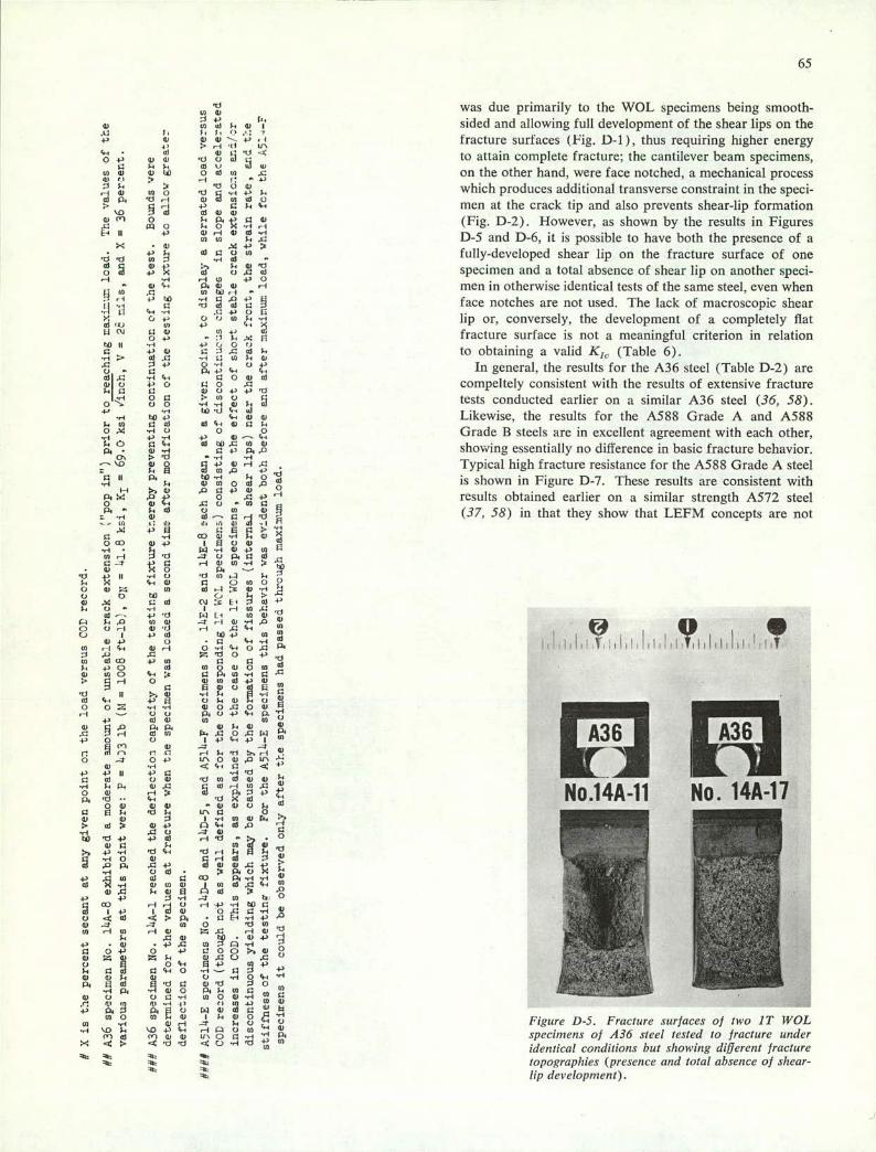
65
'0 0. 0 C)
4--I C) C)
10 was due primarily to the WOL specimens being smooth- 0)0) i 4-'
" 4) sided and allowing full development of the shear lips on the 0 '- 4-' . fracture surfaces (Fig. D-l), thus requiring higher energy
0-' 0)4) ,--4 Ci LV
0 .14-' '0 to attain complete fracture; the cantilever beam specimens,
a . i-. w u 0) w o o to o u' .0 on the other hand, were face notched, a mechanical process
which produces additional transverse constraint in the speci- '-.1 0) 44 0 '0 rI 4-' 4-, 0)p. 'Or-I )0)444-d0 + a 0. '.-. men at the crack tip and also prevents shear-lip formation 0) 'fl 0 0. ' ( Fig. D-2). However, as shown by the results in Figures .0 0 0,0 'Iri
II +' 0).-I 0)0)-.-i D-5 and D-6, it is possible to have both the presence of a
-< •0) 0) 0 0 w fully-developed shear lip on the fracture surface of one '('C)
U .04d specimen and a total absence of shear lip on another sped- ..4 r-iIfl 4-40 p, , , men in otherwise identical tests of the same steel, even when WtUiH
face notches are not used. The lack of macroscopic shear a .04,00 0 o lip or, conversely, the development of a completely flat 4fl 4) 0-I 0) 14 41 4, fracture surface is not a meaningful criterion in relation 0. .s li
0) 0 0) a a .0 4-. to obtaining a valid K1 . (Table 6). 0).0 .414(00.0)
.0 ., 0. 4-' In general, the results for the A36 steel (Table D-2) are ajC)
0 ., '.' c-.
I '. 0)1 0 o a 0 .0 compeltely consistent with the results of extensive fracture 0.10 14 0 0 U) u a 0 00 tests conducted earlier on a similar A36 steel (36, 58). ',-4.ri4)4-,41 41 "-4
14 to 4-' 4.0) Likewise, the results for the A588 Grade A and A588 0.40 00)0) ' ' 0)0 1-. 0 . '.4 0 0 0 Grade B steels are in excellent agreement with each other, "-4 -4 -4 4) 4)-'. 4-.O a'.
-4-, 0)0)).0C4 4)
p. . 4) ., ' P. showing essentially no difference in basic fracture behavior. '0 .,-4 0 0 +'0 H a Typical high fracture resistance for the A588 Grade A steel s-,E 0)u,,0
0 II P. to '. 4-' 0 is shown in Figure D-7. These results are consistent with 0)0)00),0 00
p. .o ' 0 .0 4-' results obtained earlier on a similar strength A572 steel 0 0)"- ,ao -0)0 P. 0-.0) v 0)
0) (37, 58) in that they show that LEFM concepts are not ri - - .: , .1, ,r ii .zI -.1
A: 4-'EI a ..-ICO 0) 0 CO 0) 4-' I flo0) "
.ri 0-. WH 'd 0) ?cO P. bo
4--, 0) 0 0 (4 0 P
o to(, 140)
0)4) 'O
4-0 04 0)0) 4, 10 41-4-' 0 •0
I i-'Ui l0)) 0.ri'.-. 050
Id
0 41 UiO 4-4 0) 0 0 4,0 0) 0)00)044 Cd COO '.- , 14 P.0)-ri
0 0)0)0)414) -. a flWoal4-i 0) .,-44-, - ' E 00.4) 00)
0. 4)05000) E 00 p.0+1'.- p."4
4-4 030) (4 (00 0)0.0) )
H 0) 0) 0..50050l.l 4-4- 0 0) I4''.,4' I 0 n36 n aC-ro 4) - 0)0 c'
3 04' L('0 0)U'' 0) .4 Ii 4,0 +40 0) 00) '00)0)0)0) 4-'
No.14A-11 No. 14A-17 0) H0 43 'd00)
04) 0) 0) Lrsa 0
0) i 0) 4 4043 4- 4-. Cd ,D
.00 .-0) '04' +1 0) .0 4-''ri -.-40 4) 04,0)
00)' p.o,0. - -
P. .0 4' (1 0) 0) .0
.040) 0) 0 CO P. -4
050 4-.0)E ,_.oi o .0 a-'
--.. 0
4-1 j'ri U) 4,4,0 H4-'..-4 toO - - - -
.;- 1+' i0)0 0500-.-4 )
0) p. • a 4-4 0) 0 '0 0)
CO ,-4{) Z.00 H0)'O 500) -'
4) . .0 0) 0 -4 - -- , - - -' - 04-' 0 4-'
0)50C) .00 0 0'.-, E4'(04.)
ad 04-.0 .ri-001 4' 0) o
"-404 ' 0)0 0.0.0)0 0)0. C) .,-.',-, 4'
E0) ..i0 0)'O 0
0 0 4-)-.-4 440 4) -,4 0 )(.Q 'U...4C (4444.) 0)4) P.P.10 N4)0)0 0) (00(40.0) I
-.4 4-. 0 '. Figure D-5. Fracture surfaces of two IT WOL '.0 0. '1041'.-, ("0 43 4-fl 0) 4) V\ 0 specimens of A36 steel tested to fracture under - '
identical conditions but s/lowing di/Jerent fracture topogra p/lies (presence and total absence of shear-lip development).

applicable for analysis of plane-strain fracture behavior tinder static loading conditions at 721 for the I ½ in. plate thickness tested. The results also show for static fracture at 72 F that nonlinear elastic-plastic methods (J-
J Integral (38, 39). Equivalent Energy (40, 41), and COS 00 00 (59. 60. 61) methods) must be used for quantitative char-
acterization of fracture behavior for plates ranging in thickness from ½ to 1 ½ in.
.,
Similar statements can also be made for the higher
- strength A514 steels. but to a lesser extent. In particular, the results given in Table 6 show a distinct difference in the fracture behaviors of these steels, with the A514 Grade E steel exhibiting higher fracture toughness than that of the
- ., .. A514 Grade F steel. However, this difference is primarily '. due to the untypically higher (but still acceptable) strength
level for the A514 Grade F steel (a-,,, - 126 ksi. or 870 MN/rn Table 3) as compared to a typical strength level
(a- , for the A514 Grade E steel 108 ksi or 740 MN/rn2; Table 3). In view of this strength differential, the observed
•
- - fracture results are about what would be expected prior to
- testing. Furthermore, the results for the typical strength .. t"
A514 Grade E steel are also in good agreement with the
- results from earlier fracture studies on a similar strength A517 Grade F steel (62). The high resistance to fracture for the A514 Grade E steel is illustrated by the partially tested WOL specimens shown in Figure D-8.
66
tz
- - - j•n•r1_. I
U
NEW-

APPENDIX E
FATIGUE CRACK GROWTH DATA
The following Figures E-1 through E-7 show fatigue tude load fluctuations for A36, A588 grades A and B, and
crack growth under constant amplitude and variable ampli- A514 grades E and F steels.
67
I I I I
ITWOL SPECIMEN
rnin 3 200 LB
AP —e. CONSTANT AMPLITUDE(,d AP, VARIABLE A -1.0
,,, MPLITUDE
I 1LB4.448N I IINCHt25.4mm
.6 L. AK IN 1(51
IKSIJiZW = 1.099 MN/rn312
rrn 2000 LB
/
. .
••/—
AKIT.6
AP z 2500 LB 0 0 0 0 8 0 0
0 0 0
0 0
00 0
0 0..— AKI7.3
0 0
0 .2— 0 • 0 • 0 • 0 • 0
t10 C I .0 I I I 0 50 100 150 200 250 300 350 400 450
ELAPSED CYCLES X I0 Figure E-1. Fatigue crack growth under constant amplitude and variable amplitude load fluctuations for A36 steel.

I rd yp—aI.0)
AP 3000 LB 0 0
APrm:3000LB 0
I 1.6- 1
/
•
'4— 1 / 1 0
/ 0
a .2 - Ie-AKI7.7 s o.- AK17.9
I 0 0
0 _______________________________ I I I I A cn Inn ISA 700
ELAPSED CYCLES X 103
Figure E-2. Fatigue crack growth under constant amplitude and variable amplitude load fluctuations for A36 steel.
IT WOL SPECIMEN I LB:4.448 N
min 200 LB I INCH: 25.4mm
.0 - AP -S-CONSTANT AMPLITUDE p4 10
AK IN KSI.JiiiEii
(r'rm - ) I KSI IiiCii' .099 MN/rn 3/2 APrm.w.VARIABLE AMPLITUDE
68
IT WOL SPECIMEN min 200 LB
AP - CONSTANT AMPLITUDE APrrn VARIABLE AMPLITUDE
ILB:4.448N I INCH :25.4mm
AK IN KSI
11(51 1.099 MN/rn312
AP 2500 LB 0 0-0
8 0 0 0 0 -
0 0
00
0 0
0.- AK: 17.3
AP3000 LB
.8- 0 APrmZOOOLB • •
APrmS3000LB 0.6
• .6- • 0 •
U A? t-a1KI7.6 0 S
1 0S 0 0 •
I AK.90 S
'AK
;
17 J 0s 0
0S 0
0 0
U U
-. .9 0 0
300 350 400 450 ELAPSED CYCLES z 10'
Figure E-3. Fatigue crack growth under constant amplitude and variable amplitude load fluctuations for A588 Grade A steel.

IT WOL SPECIMEN = 200 LB
.0 F- AP - CONSTANT AMPLITUDE
I APrm - VARIABLE AMPLITUDE
ILO z 4448N I INCH = 25.4mm
f rd - AKIN KSI vTiiW
-1.0) iicsi ,/1131 = 1.099 MN/rn312
69
13 AP = 3000 LB
- a a a a 6
- AP, 3OOOLB E 1 AP,
I a AK:17.8
. 0
—'I cP
I : 4" / . a
0 "
0
' 0 • 0° _.. a • 0
A P = 2500 LB
2000L8 8 0
; 0 0
I 0 0
o0 0
0._—AK = 17.6 0
1.2
17.9
LDM
ELAPSED CYCLES c 10
Figure E-4. Fatigue crack growth under constant amplitude and variable amplitude load fluctuations for A588 Grade B steel.
IT WOL SPECIMEN min 200 LB AP • 3000 LB
AP -S CONSTANT AMPLITUDE / ,d \ 0
APrm VARIABLE AMPLITUDE Pra,
- 1.0) a
AP,rn 3000 LB
1' AKI8.0
aKI8.0/ 'J0
a
I
0
8 a
0
CP
00 0
0 0
0 0 11-84.448N
0 IINCH25.4rnrn
AK IN KSI
I KSI ./iW = 1.099 MN/rn312
1.2
50 100 150 200 250 300 350
ELAPSED CYCLES X I0
I
Figure E-5. Fatigue crack growth under constant amplitude and variable amplitude load fluctuations for A514 Grade E steel.

IT WOL SPECIMEN rnin 200 LB
AP - CONSTANT AMPLITUDE ( 1
APrm AlLITUDE VARIABLE A Pr
AP,m 3000LB U U
U a 1 U
U U
AIcI7.8
.. U
AKIB.0
0 0 0 0 . U
. 0 U S
• 8 •o 00.1 I I
70
APrrn • 2000 LB .0 APrrn 2OOOLB -
I 0 0
1.8 1 1 I 0
0 0
1.6 AK 17.
8 ILB:4.448N
179 0 11NCH25.4rnm
0 AK INKSI.,'Tiii
cP II(S1 1.099 MN/rn312 - 4 •
0 S 0
0 0 IT WOL SPECIMEN 0 .2
0 0 PrninZOOLB - AP -.CONSTANT AMPLITUDE (Prd)
S 'rrn -VARIABLE AMPLITUDE p -
.o0 I I 1 I I I 0 2 4 6 9 10 12 14
IS
ELAPSED CYCLES xIO 3
FigureE-6. Fatigue crack growth under constant amplitude and variable amplitude load fluctuaTions for A514 Grade E steel.
AP = 3000LB AP2500LB
B - d \ - I.0)
g APrrn 2000L8 0 - 0
& AKI7B
/Y .S' . 02AIc=17.e -
0 0 ILB4448N
0 IINCI125.4rnm
AKINKSI/' Ei - I KSI 1.099 MN/rn 3 t2
0 50 100 150 200 250 300 350 400 ELAPSED CYCLES xIO3
Figure E-7. Fatigue crack growth under constant amplitude and variable amplitude load fluctuations for A514 Grade F steel.

APPENDIX F
STRESS-CORROSION-CRACKING (K1,J BEHAVIOR OF STEELS INVESTIGATED
71
A summary of the specimen preparation and test condi-tions employed in the precracked cantilever beam tests to evaluate K180 for each of the five steels is given in Table F-i. The results of these tests are shown in Figures 19 through 23. These figures show the value of the initial stress intensity to which a specimen was loaded, K1 , plotted against log time to failure. The detailed test results are also tabulated individually for each steel and are given in Tables F-2 through F-6.
Returning to Figures 19 through 23, it is noted that Figures 19, 20, and 21 show apparent K18 values for the A36, A588 Grade A and A588 Grade B steels of 85, 80, and 85 ksi VHi (94, 88, and 94 MNm-3/2 ), respectively. In the case of each of these three steels, the K18 , value is well above the corresponding K7 Cub value; this condition is indicative of Type III behavior (Fig. A-9 and Table A-i), the existence of severe K,-suppression effects in the ob-served result, and the general inapplicability of LEFM prin-ciples for quantitative characterization of SCC behavior for each of the three steels. However, in qualitative terms, it can be seen that there is essentially no difference in the ob-served SCC susceptibility for the A588 Grade A and A588 Grade B steels. Furthermore, although the apparent K18,,0
levels for each of the three steels are about the same, a slight degradation in behavior (relative to K,,,) can be seen for both the A588 Grade A and A588 Grade B steels, and essentially no degradation or a totally immune behavior for the A36 steel.
Figures 22 and 23 show that apparent K,90,, values for the higher strength A514 Grade F and A514 Grade F steels
were 106 and 82 ksi Yin. (117 and 90 MNm-V'), respec-tively. The result for the A514 Grade F steel exceeds the corresponding K7 Gui) value (105 ksi Viiun., or 116 MNm_3/2) by a slight margin. This result for the A514 Grade F steel represents Type III SCC behavior, similar to the lower strength steels discussed earlier, and is thus subject to the same type of interpretation and restriction (but to a lesser
degree). The result for the A514 Grade F steel is some-what lower than that of the A514 Grade E steel and can be seen to marginally exceed the corresponding K, Lub value (78 ksi Yin., or 86 MNm_/2) . Thus, the observed results for the A514 Grade F steel represent Type II SCC be-havior, with the existence of marginal to nonexistent K,-suppression effects and a corresponding degree of appli-cability of LEFM concepts for quantitative characterization of SCC behavior. This somewhat lower behavior for the A514 Grade F steel (relative to A514 Grade F steel) is about what would be expected because of the abnormally high strength for this steel.
Because LEFM concepts are fully applicable (or valid) for small-scale yielding, the extent of their applicability (or inapplicability) can be measured in relation to the degree of plasticity occurring at the tip of a crack. In turn, the degree of crack-tip plasticity can be measured qualitatively (for a given specimen size) by the deviation from linearity encountered in the load-versus-displacement (P-versus-V) test record. Thus, the relative extent of plasticity encoun-tered for each specimen in the SCC tests may be seen in perspective when the corresponding initial load level, K1,, is superimposed on a typical P-versus-V plot obtained in the measurement of K,,, for a specific steel.
Such results are shown for each of the steels tested in Figures F-1 through F-S. It should be noted for the higher strength A514 Grade £ and A514 Grade F steels (Figs. F-4 and F-5) that the displacement scale (V) differs from that for the lower strength A36 and A588 grades A and B steels. These results are self-evident in indicating further the high levels of net section stress, (relative to a- ) to which the individual test specimens were initially loaded in the SCC tests, as reported in Tables F-2 through F-6. Fur-thermore, these results also reinforce the conclusions reached concerning the general inapplicabiltiy of LEFM concepts for the quantitative characterization of both frac-ture (K,8 ) and SCC (apparent K,,,,,,) behaviors of the steels tested.
APPENDIX G
CORROSION FATIGUE, CRACK GROWTH DATA
Figures G-1 through G-13 show the results of corrosion A, A588 Grade B, A514 Grade F, and A514 Grade F steels
fatigue, crack growth tests performed on A36, A588 Grade in 3-percent solution of sodium chloride in distilled water.

TABLE F-i
SUMMARY OF DIMENSIONS AND TEST CONDITIONS EMPLOYED_PRECRACKED CANTILEVER-BEAM K,,,0 SPECIMEN
Number of Total Nutber Surviving Specimens
Total Number Test of Specimens Exhibiting
Item Steel W, 3, j, a;, N, a, of Specimens Duration, Surviving the Crack Extension
No. Type inches inch inch inch* cycles" inch* Tested hours+ Test Period++ due to SCC
I A36 2.50 0.94 o.84 O.SC 233,0CC 0.214 8 SECO 14 0
to 279 ,CC3
2 A588-A 2.50 0.91 0.81 0.8: 133,33 0.28 8 53CC 3 0
306,000
3 A588-B 2.50 0.90 0.80 0.75 173,000 0.31 8 5200 14 0
to 250,000
I A5114-E 2.50 1.00 0.90 0.80 192,003 Ic
0.214 8 5200 14 1
362,000
5 A5114-F 2.50 0.98 o.88 c.8o 18L,oco 0.27 8 5300 3 0
to 357,000
* Initial (stMight)nachimed-notch depth prior tc.fatigue precracking.
Number of cycles used utier nominal zero-to-tension loading ( 0) to propa€ate a fatigue crack from the machined notch (aN) to the avera ge
crack length (a).
Average fatigue-crack length.
+ Nominal test period for specimens tested in a continuously aerated solution of 3 percent NaCl (by weight) in distilled water at room temperature.
++ Specimens not failing in the test period indicated. Certain of these exhibited subcritical crack growth.
+++ Indicated are the rnznber of specimens for which crack extension due strictly to 8CC could be ascertained (ta > 5 to 10 mils)—negi.ecting both
crack extension due to "tearing" in the initial loading process for specimens loaded to high stress levels (1(1 > ICI,Gub) and apparent crack extension due to crevice corrosion behavior observed at all stress levels for the A5114-E steel (Table F-5). Evidence of crack extension on the specimen fracture surfaces was determined by fracturing the specimens after cooling to approximately -320 F in liquid nitrogen.

TABLE F-2
SUMMARY OF KrSTRESS CORROSION RESULTS ON A36 * STEEL
Time to Specimen W, B, BN, au AXf N, F, KI,Lu L_ 1CIj_ ONII Xii Aaf, <it, Failure,
No. inches inch inch inch** ksi v'inch*** cycles pounds" ksi /inch ksi lunch hal Xix inch ksi /itch' hours &rvironment
14A-6 2.500 0.939 0.839 1.062 28.0 266,000 1058 26.0 87.9'' 109.8 1:00 - - - Mr lloA-1 2.500 0.91.1 0.841 1.074 28.3 266,000 >1030' 26.0 '82.0' >108.4 1.00 - - - Air 11.A-. 2.1.99 0.939 0.839 1.100 29.2 231,000 1065 26.0 92.7'' 116.7 1.00 - - - AIr 14A-6 2.500 0.938 0.838 1.064 28.2 2614,000 1056 26.0 88.1 110.00.98 I - 0.4 3% NaCl 14a-5 2.499 0.939 0.839 1.044 27.4 230,000 966 26.0 78.9 97.9 0.87 0.060## 84.5### >5860.5#### 3% NaCl 14A-2 2.499 0.941 0.841 1.082 28.14 246,000 841. 26.0 71.7 90.0 0.79 0.010 72.6' >5860.5#### 3% aCl 14i-7 2.500 0.91.1 o.841 1.081 28.4 279,000 638 26.0 54.0 67.8 o.6o 0 54.0### >SSO?.O#flt' 3% :aca. 14A-3± 2.500 0.939 0.839 1.095 29.2 279,000 316 26.0 27.3 34.3 0.30 0 27.3### >527l.8' 3% llt,Cl
* oys = 43.6 ksi, CVN ener' absorption at 72 F = 28 ft-lb.
aj is the original crack length attained by fatigue cracking 0.26 to 0.30 inch beyond aN 0.80 inch, the machined notch tip. " tK f is the maximum AKI reached during fatigue crack preparation as calculated from 2MB 3/2 (see Reference in Table D-2).
°** Lever arm 30.0 inches. (BEN)
1/2 w
+ For specimens surviving for, the duration of the test, the total crack extension, daf , which can be due to initial tearing on loadir.n and/or stress corrosion cracking, was determined by fracturing the specimens after cooling to approximately -32C F in liquid nitrogen.
++ 1 if is the Ki level of the specimen at the comclueion of the test period adjusted to reflect any crack extension, M1, which may have occurred.
+++ Average ICI1 = 90.3 ksi lunch.
++++ Specimen No. 14A-1 reached the deflection capacity of the testing fixture.
indeterminate.
## Crack extension for these specimens was determined to be due solely to initial tearing on loading.
VW# K19 values were also calculated considering the reduction in section dueto general corrosion in adition to any crack extension, to1. These values•are as follows:
Specimen No. K, ksi linch
14A-5 87.5 1UA-2 75.0 14A-7 56.0 114A-3 28.3
#### No failure.
+ This specimen was sectioned.
NOTE: Refer to Table 0-2 for definitions of above variables. W
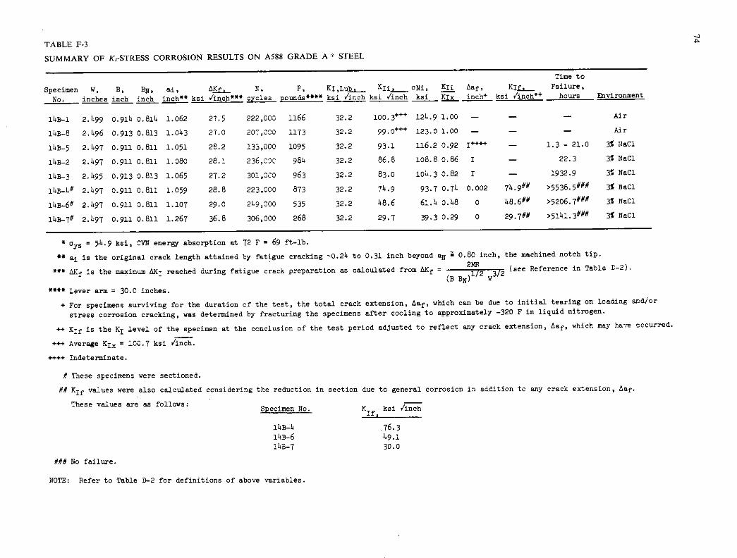
-1 a TABLE F-3
SUMMARY OF K,-STRESS CORROSION RESULTS ON A588 GRADE A * STEEL
Specimen No.
W, inches
B, inch
BN, inch
ai, inch** ksi -inch***
N, cycles
F, KI,Lu pounds" ksi /inch
KIi_.aNi, ksi /inch ksi
KJi Aaç, Klf, KIx inch' ksi /inch
Time to Failure, hours ivironaient
14B-1 2.499 0.915 o.814 1.062 27.5 222,003 1166 32.2 100.3 124.9 1.00 - - - Air
153-6 2.496 0.913 0.813 1.053 27.0 207,000 1173 32.2 99.0w 123.0 1.00 - - - Air
11.3-5 2.597 0.911 0.811 1.051 28.2 135,000 1095 32.2 93.1 116.2 0.92 - 1.3 - 21.0 3% NaCl
14B2 2.497 0.911 0.811 1.080 28.1 236,330 984 32.2 86.8 108.8 o.86 I - 22.3 3% NaCl
11.3-3 2.495 0.913 0.813 1.065 27.2 301,000 963 32.2 83.0 104.3 0.82 I - 1932.9 3% NaCl
14B_4# 2.497 0.911 0.811 1.059 28.8 223,000 873 32.2 75.9 93.7 0.74 0.002 74.9#4' >5538.5### 3% NaCl
11.B_6# 2.597 0.911 0.811 1.107 29.0 249,000 535 32.2 58.6 61.4 0.48 0 48.6## >52O6.7#4"# 3% NaCl
14B_7# 2.497 0.911 0.811 1.267 36.8 306,000 268 32.2 29.7 39.3 0.29 0 29.7## )5141.3 '# 3% NaCl
*oys = 54,9 ksi, CVN ener' absorption at 72 F = 69 ft-lb. ** ai is the original crack length attained by fatigue cracking 0.24 to 0.31 inch beyond a4 Z 0.80 inch, the machined notch tip.
AKf is the maximum MI reached during fatigue crack preparation as calculated from tkKf = 2}
3/2 (see Reference in Table 0-2).
w ' Lever arm = 30.0 inches.
+ For specimens surviving for the duration of the test, the total crack extension, Aaf, which can be due to initial tearing on loading and/or
stress corrosion cracking, was determined by fracturing the specimens after cooling to approximately -320 F in liquid nitrogen.
++ Klf is the K1 level of the specinen at the conclusion of the test period adjusted to reflect any crack extension, Aaf, which may have occurred.
+++ Average Kix = 100.7 ksi Jinch.
++++ Indeterminate.
# These specimens were sectioned.
## K 1 values were also calculated considering the reduction in section due to general corrosion in addition tc any crack extension, Aaf.
These values are as follows: . Specimen No.
76.3 1.9.1 30.0
### No failure.
NOTE: Refer to Table 0-2 for definitions of above variables.
n1f. ksiVSLJCLL

TABLE F-4
SUMMARY OF K1-STRESS CORROSION RESULTS ON A588 GRADE B * STEEL
Time to Specimen W, B, BN, aj, AKf N, P, KI,Lnh- KIj__ ONi, Eli Aaf, Ki_ Failure,
No. inches inch inch inch' ksi /inch*** cycles pounds**** ksi /inch ksi /inch ksi Kix inch ksi v'inch hours Environment
14c-6 2.503 0.896 0.796 1.090 29.14 1143,000 1138 32.14 102.3 128.9 1.00 - - - Air
140-2 2.500 0.896 0.796 1.112 31.1 218,000 11146 32.4 io6.6 134.5 1.00 - - - Air
140-8 2.501 0.895 0.795 1.073 29.8 173,000 1089 32.4 96.4 120.9 0.92 I' - 3632.7 3% NaCl
14C-.3 2.501 0.895 0.795 1.216 35.8 192,000 880 32.4 92.6 120.7 0.89 I - 4869.9 3% NaCl
14c-b 2.501 0.895 0.795 1.120 31.0 181,000 828 32.4 77.4 98.3 0.74 0 77,411 >5209.0## 3% NaCl
14C-1 2.501 0.895 0.795 1.076 29.0 216,000 677 32.4 6o.1 75.5 0.56 0 60.1# >5135.3## 3% NaCl
140-5 2.501 0.895 0.795 1.140 32.5 250,000 482 32.4 46.2 58.9 0.144 0 46.2# >5207.65## 3% 1;an
140-7 2.501 0.895 0.795 1.194 34.6 249,000 326 32.4 33.14 43.2 0.32 0 33.4# >5207.6 3% flaG
* 0y5 = 55.6 ksi, CVN enerr absorption at 72 F = 66 ft-lb.
" a is the original crack length obtained by fatigue cracking -0.32 to 0.47 inch beyond aN 1 0.75 inch, the machined notch tip.
° LK1 is the maximum dK1 reached during fatigue crack preparations calculated from AK1 2MR 3/2 (see Reference in Table D-2).
w Lever arm = 30.0 inches.
+ For specimens surviving for the duration of the test • the total crack extension, La1, was determined by fracturing the specimens after cooling to approximately -320 F in liquid nitrogen.
++ KTf is the K1 level of the specimen at the conclusion of the test period adjusted to reflect any crack extension, Laf, which may have occurred.
+++ Average K1 = 104.5 ksi /inch.
++++ Indeterminate.
# KIf values were also calculated considering the reduction in section due to general corrosion in addition to any crack extension, La1.
These values are as follows, - Specimen No. K1f. ksi /inch
14c-I+ 78.14
140-1 61.2
i4c-5 46.9
140-7 314.1
## No failure.
NOTE: Refer to Table D-2 for definitions of above variables. U,

TABLE F-S
SUMMARY OF K1-STRESS CORROSION RESULTS ON A514 GRADE E * STEEL
Specimen No.
W, inches
B, inch
BN. inch
ai, inch" ksi "inch"
N, cycles
F, KI,Lnh pounds" ksi 'inch
K_ ksi /inch
0N1, ksi
!2s KIx
Aaf, inch
Kj 3 _
ksi /inch++
Time to Failure,
hours Environment
14p-8 2.505 0.997 0.897 1.070 26.5 200,000 1869 66.4 146.1' 182.1 1.00 - - - Air
14D-5 2.504 0.996 0.896 1.046 25.6 236,000 1901+ 66.4 155.' 180.0 1.00 - - - Air
11.D-2 2.503 0.995 0.895 1.063 26.3 256,000 1772 66.4 136.3 171.9 0.95 I''' - 157.6 3% NaCl
11.D-7 2.503 0.991+ 0.891. 1.107 27.1. 192,000 1507 66.4 123.6 155.7 0.85 I - 1325.4 3% NaC1
14D_l# 2.503 0.991+0.895 1.052 25.9 281,000 1515 66.4 116.8 155.9 0.80 0.032 121.2 >5273.4### 3% NaCl
11.D_6# 2.503 0.991+ 0.895 1.039 25.1. 270,000 121.9 66.5 95.9 117.3 0.65 o.o16 96.8#*# >5206.5#fl 3% NaCl
14D_4# 2.503 0.994 0.891. 1.051 26.0 362,000 1022 66.5 78.6 97.6 0.54 0.013 80.0 >5188.9' 3% NaCl
14D_3# 2.503 0.994 0.891. 1.071 26.7 279,000 736 66.1. 58.0 72.3 0.1.0 o.008 58.5## >1+888.8fl4' 3% NaCl
= 107.9, CVN energy absorption at 72 F = 68 ft-lb.
ai is the original crack length obtained by fatigue cracking 0.21+ to 0.30 inch beyond 8N 0.80 inch, the machined notch tip.
" dKf is the maximum tIC1 reached during fatigue crack preparation as calculated from 6K1 = 3/2
(see Reference in Table D-2). (BBN)
1/2 w
" Lever arm = 30.0 inches.
+ For specimens surviving for the duration of the test, the total crack extension, Aaf, which can be due to initial tearing on loading and/or stress corrosion cracking, was determined by fracturing the specimens after cooling to approximately -320 F in liquid nitrogen.
++ K11 is the K1 level of the specimen at the conclusion of the test period adjusted to reflect any crack extension, Aaf, which may have occurred.
+++ Average Kix = 11.5.8 ksi /inch.
+-+++ Indeterminate.
# These speciens were sectioned.
## K1 values were also calculated considering the reduction in section due to general corrosion in addition to any crack extension, Aaf.
These values are as follows: Specimen No. K1f ksi Jinch
14D-1 135.7 14D-6 98.4 lbD-5 83.8 114D-3 65.2
### No failure.
NOTE: Refer to Table D-2 for definitions of above variables.

TABLE F-6
SUMMARY OF KSTRESS CORROSION RESULTS ON A514 GRADE F * STEEL
Time to Specimen W, B, BN, Si' N, F, KIL,th Kli, 0Ni. !!! taf, KJf, Failure,
No. inches inch inch inch** ksi /inch cycles pounds" ksi 1inch ksi /inch ksi !L inch ksi /inch++ hours &wironment
14E-2 2.498 0.975 0.675 1.1114 26.2 >311,000 1206 78.3 102.6' 129.5 1.00 - - - Air
14E-8 2.1497 0.975 0.675 1.063 214.9 311,000 1316 78.3 105.7" 131.7 1.00 - - - Air
14E-1 2.497 0.975 0.875 l.o84 25.14 353,000 1132 78.3 93.3 116.6 0.90 I' - 5.0 3% Nsa
14E-6 2.1*97 0.975 0.875 1.063 214.9 298,000 111*6 78.3 91.8 1114.6 o.88 I - 14.95 3% NaCl
14E-3 2.1*97 0.975 0.875 1.075 25.2 319,000 1057 78.3 86.4 107.5 0.83 I - 871.0 3% Nan
14E-7 2.497 0.975 0.675 1.137 27.0 227,000 853 78.3 714.7 94.9 0.72 0.002 75.0# >5514Q50 3% NaOl
14E-5 2.497 0.975 0.875 1.121 26.4 184,000 815 78.3 70.1 88.5 0.67 0.002 70.3# >5207.3## 3% NaCl
14E-.5 2.497 0.975 0.875 1.205 29.7 357.000 637 78.3 6o.6 78.5 0.58 0 60.6 >5206.0 3% NaCl
* ays = 126.0, CVN Enerr absorption at 72 F = 145 ft-lb.
° ai is the original crack length obtained by fatigue cracking 0.26 to 0.141 inch beyond a 0.80 inch, the machined notch tip.
M. is the maximum tic1 reached during fatigue crack preparation as calculated from LKf 214R
3/2 (see Reference in Table D-2). (BBN)
1/2 w
Lever arm = 30.0 inches.
+ For specimens survivir.g for the duration of the test, the total crack extension taf, which can be due to the initial tearing on loading and/or stress corrosion cracking, was determined by fracturing the specimens after cooling to approximately -320 F in liquid nitrogen.
++ 1If is the K1 level of the specimen at the conclusion of the test period adjusted to reflect any crack extension, Aaf, which may have occurred.
+++ Average Kix = 104.2 ksi /inch.
++++ Indeterminate.
ft Icf values were also calculated considering the reduction in section tue to general corrosion in addition, to any crack extension, ta1. These values are as follows:
Specimen No. KIf, ksi iinch
1l.E-7 77, 14E-5 72.6 14E-4 63.0
H No failure.
-1 -4 NOTE: Refer to :able D-2 for definitions of above variables.

78
200 — K DENOTES FRACTURE - 1200 K1, '100,3 k,IV,nch IAVERAOE K1I00k,i./iT
(SPEC NO. 148' I)
KIZ 927OiVCh IAVERAGEK119Ok,I c;j_
000 — K11 88 ks11h
APPARENT
Is"
1000 - ,Se-K11 '81 KIj 03 ksiv'i ----
85kSi 6 vh —A 79 kii,i K1; l —K11 • 75 ksi/1 k 00 /.iOch
800 - K11.72k,i4i - 800-
- --- ----PPARENT
- I ksiJ .1099 MN/rn3'2 - — I k.iJi '1.099 MN/rn312
0 600 - K11 .54 k.ifi I Ib 4.45N -
I mil'D.0254rnm
- 600
I Ib'4.45N - -_ Ki.8u6 I m rn iI'O.0254oi
I liii • 6.895 MN/rn2 " I ku 6.895 MN/rn2 K11 '49 kilvInch — Ift-Ib'I.36J — IfI-Ib'l.36J
-
-. K1
400- — 400-
27 ku .,/inch
BE __________
I4C515195264A-4
ku2811Ib
K1 LOS
30 ui A588A
HEAT NO. 67C611 PLATE NO.193804
CODE NO. 148-I 549 ku
CVN ATRT69II-Ib
DI I I 1 I I DI I I I I I I I I I
0 40 80 120 160 0 40 80 120 160
DISPLACEMENT .V OR COD • miii DISPLACEMENT ,V OR COD • mile
Figure F-I. Typical fracture test record (cantilever beam sped- Figure F-2. Typical fracture test record (cantilever beam speci- men) for A36 steel with superimposed values of the K,, levels men) for A588 Grade A steel with superimposed values of the K jj used and the apparent K,,,, result obtained in the SCC tests, levels used and the apparent K,,,, result obtained in the SCC tests.
I It I I I I
: 9 I I (0 -
Ix —eOw- w .-
II z e.-.2 0 2 I -
C 'c -— .Z
A. 10
-1:
Ih,:tI\ I I H 1414 1414 x xx xx
0 0
- t__ -H-- - xx.1
, 0 0 0 0 0 0 0 0 2 0 (0 Cd
qi ' d • OO1

F51 F O. 7OC 125NO. 79BT3A1O. 14E-8
oys 26.0 ksi RT '4511-lb
K1, GUS
l( ,.97.0 ksi.J'
(SPEC NO. 14E-8) AVERAGE KI;IO4ksi..iI
- K1u'93ksi./iW —K11'92ksi
—K1j 986
K1,LUB APPARENT Kiscc i K11 '75 liii fTiTh 8s' J; -
K11 '7OksiJii -
'Glksi
79
I I I AVERAGE K1 146k,. iflCicI
'145.5 ksi.i' (SPEC. NO. 14D-5)
-. 1A514-E HEAT NO.50343
---
/ / , K11 I38ksi.jT
- jPLATE NO. P10074 ICOOE NO. 14D-5
I I /,S—K11 '124 ksi -
cJ, '107.9 ksl It'd K 'II? ku [y AT RT'GOft-Ib II
APPARENT Kt,cc I06ks1_Ji;i'
Kious
- St. K11 '95ksi.ij
7 1000 K11 79 k si
C 0 -J
Lu,
58 ksi
1800
1400
600 I k,i./i7 9 1.099 MN/rn312
I Ib'4.45N I mil 90.0254rnrn I k,i'6.895 MN/rn2
I ft - lb • 1.36
I 'si ./Th''l.099 MN/ rn tt2
I lb '4.45N I rnil' 0.0254mrn I liii' 6.895 MN/rn 2
Ill - lb = 1.36
0
200
U 10 20 30 DISPLACEMENT ,V OR COD, rnil,
Figure F-4. Typical fracture test record (cantilever beam speci-men) for A514 Grade E steel with superimposed values of the K11 levels used and the apparent K, result obtained in the SCC tests.
DISPLACEMENT,V OR COD mils
Figure F-5. Typical fracture test record (cantilever beam speci-men) for A514 Grade F steel with superimposed values of the K11 levels used and the apparent result obtained in the 5CC tests,
2.0
I I
- I I I I
LOAD
I
ENVIRONMENT - CONSTANT AMPLITUDE 3% NoCI AP3000LB (13,344N)
1.8 0 - VARIABLE AMPLITUDE 3% NoCI
6PMAX'9000 LB (40,032N) - • VARIABLE AMPLITUDE DISTILLED t APMAX 9000LB(40,032N) WATER
IINCH'254mm
CP
1.2 0 -
1.01 I I I I 1 1 I 0 20 40 60 80 100 120 140 160
ELAPSED CYCLES .103
Figure G-1. Corrosion fatigue crack growth at 60 cpm for A36 steel.

2.
2.
1.2
1
2.
I I I I
LOAD
I
ENVIRONMENT
A CONSTANT AMPLITUDE - APO3000LB (13,344W) 3% Nod -
O VARIABLE AMPLITUDE APMAX -9000 LB (40.032W)
306 NoCI
S VARIABLE AMPLITUDE - A x 9000 LB (40,032
I INCH 0254mm
DISTILLED WATER
II - F
A A A
A A
A A
A
ii A
2-4P C
go
I I I I n 'In 4fl 60 80 100 120 140 IE
ELAPSED CYCLES K IC'
Figure G-2. Corrosion fatigue crack growth at 60 cprn for A588 Grade A steel.
- I INCHO25.4mm -
A A A A
- / I CHANGED APMAX TO
a 0 § II,800LB(52.486N)
: - CP LOAD
ENvIRONMENT.
AA • J o A CONSTANT AMPLITUDE 3% NQCI A S 0 0 AP3000LB (13,344N)
0 AAA SDSED 0 VARIABLE AMPLITUDE 3% NaCI
a - A APMax9000LB(40.032N)
A. D&o 0 S VARIABLE AMPLITUDE DISTILLED
t 0 APM. 9000 LB (40.032W) WATER
I I I I I I I
O 20 40 60 80 100 120 140 160 ISO
ELAPSED CYCLES .103
Figure G-4. Corrosion fatigue crack growth at 60 cpm for A514 Grade E steel.
2.0
A
A A A A A • A -
A
1 LOAD ENVIRONMENT
A A CONSTANT AMPLITUDE 3% NOCI
o A AP'3000LB (13,344W) C A 0 VARIABLE AMPLITUDE 3% NOCI • A AP_*0 9000 LB (40032 N)
All' S VARIABLE AMPLITUDE DISTILLED - APMAK 'SOOO LB (40,032W) WATER
I INCH = 25.4mm
I 20
I 40
I 60
I I 80 100 120
I I 140 160
ELAPSED CYCLES K 10'
Figure G-3. Corrosion fatigue crack growth at 60 cptn for A588 Grade B steel.
I I I
LOAD
I
ENVIRONMENT
A CONSTANT AMPLITUDE 3% NoCI AP3000LB (13.344W)
D VARIABLE AMPLITUDE 3% N0CI APMAX0000 LB (40,032W)
VARIABLE AMPLITUDE DISTILLED I - APu*x9000LB(40032 WATER
I INCH 25.4mm A A -
0
oj%/
A
A A
A A A A
A 100 A
A A A A
I I I I I I I
'n arl ALl 80 100 120 140 ISO
ELAPSED CYCLES K I0
Figure G-5. Corrosion fatigue crack growth at 60 cprn for A514 Grade F steel.

I
I Al I I I I I A
AP3000Ib(I3.344N)J 0
- £ 0 A 0 * 0
0 S
* 0 S op -
E U A a
- o
A 0 0 A
000 55
0 A 00
Is . - - a A 0 0-A36
a A A0 •5 A-A5SB GRADE A A A 0
A-A5SB GRADE B '3A • • 0-A514 GRADE E -
S S-A5I4 GRADE F
t I INCN25.4mm
I I I I I I I n 20 40 An An '(Ml In 140 IRfl IF
ELAPSED CYCLES x10 3
Figure G-6. Corrosion fatigue crack growth at 60 cpm under square-wave loading in 3-percent sodium chloride solution.
I I
0-436
I I I I I
A-A588 GRADE A 9 - A-A5$8 GRADE 8 0 -
0-4514 GRADE E 0
-A514 GRADE F 0 A 0 • cp A 05
.6— 0 J
4) ad. - A 05 A
A A
000 A A A A
— -
0 0 A AA on ci • TEST CONDITIONS
0 0 A A A ENVIRONMENT 3%NoCI A FREQUENCY 60CPM -
A STRESS RATIO 0.5 A A
A : LOAD RANDOM
IINCH=254mm SINE WAVE
IA I I I I I I I 0 20 40 60 60 100 120 140 160 ISO
ELAPSED CYCLES x IO
Figure G-7. Corrosion fatigue crack growth for five bridge steels.
2 I I I TEST CONDITIONS
I I I I VA a 0 -A588 GRADE A
ENVIRONMENT 3%NaCI 0 0 -A588 GRADE B 3 —FREQUENCY 6OCPM 0 -
STRESS RATIO 0.1 LOAD CONSTANT
AMPLITUDE 0 0 SINE WAVE A / 5— 0 A
- IINCH25.4mm 0 t
0 A A v
0 A A
- o
0 A 0077
0 0 AA 0
0 a - a— 00 0
0 0 0 0 90
I I I I
.6— 1
.4 - A
A A AA
A 1 A
AA A
I A TEST CONDITIONS
AP 3000 LB
Add" FREQUENCY I2CPM ENVIRONMENT; 3%NoCI
A AAA
A AA ILB4,448N
INCH 25.4mm
I ELAPSED CYCLES x 10
ELAPSED CYCLES x IO
Figure G-9. Corrosion fatigue crack growth under constant amplitude load fluctua- Figure G-8. Corrosion fatigue crack growth for A588 steels from various sources. tion for A36 steel. —

2.0 I I I I I I
1.8 - TEST CONDITIONS - A PmIn200LB
3000 LB FREQUENCY I2CPM ENVIR0NME 3NoCl
-
I 1.4 - / LB '4.448N -
£ I INCH 25.4mm LA
12 4? - a
a £
1.01
O 20 40 60 80 100 120 140 150 ISO
ELAPSED CYCLES x 10
Figure G-10. Corrosion fatigue crack growth under constant amplitude load fluctua-tion for A588 Grade A steel.
I LB'4.440N .8
- 3 I INCH '254mm
ft a ft &
£ I•6-
ft / , £
.4 - a £ TEST CONDITIONS a
a Pmin • 200 LB 11' AP = 3000 LB
at £ FREQUENCY = 12 CPM
1.2 - ZP £ £ ENVIRONMENT = 3% NaCI
£
LO t I I I I I I fl 20 40 60 80 100 120 140
ELAPSED CYCLES X 10'
Figure C-lI. Corrosion fatigue crack growth under constant amplitude load fluctuation for A588 Grade B steel.
2
0 2 III -J
U C C U
.OF
I LB '4.448N 1 £ I INCH =25.4mm £ .6- £
I L A
4- £ £ TEST CONDITIONS
a 4* aa £ Pmin 200 LB
£ aP3000L8 a FREQUENCY 12 CPM a £ ENVIRONMENT • 3% NOCI £
a £ A L
I I I .oL I I I fl 9fl dfl Rn Rn laO 120 140
ELAPSED CYCLES X 103
Figure C-fl. Corrosion fatigue crack growth under constant amplitude load fluctuation for ASH Grade E steel.
I I I I
.0— TEST CONDITIONS
Pmin = 200 L8 AP = 3000 LB FREQUENCY • 12 CPM
.8 - ENVIRONMENT • 3% NoCI -
a *
6- 1 * I LB = 4.446N
I INCH =25.4mm
-
.4- 1 £ £ A AA
TEST STOPPED OVERNIGHT £ £
£ £
A La*
La .oa I I I I I I I, An •fl 'fl IAn Pflfl 246 PAfl
ELAPSED CYCLES X 10 3
Figure G-13. Corrosion fatigue crack growth under constant amplitude load fluctuation for ASH Grade F steel.
THE TRANSPORTATION RESEARCH BOARD is an agency of the National Research Council, which serves the National Academy of Sciences and the National Academy of Engineering. The Board's purpose is to stimulate research concerning the nature and performance of transportation systems, to disseminate information that the research produces, and to encourage the application of appropriate research findings. The Board's program is carried out by more than 150 committees and task forces composed of more than 1,800 administrators, engineers, sociaL scientists, and educators who serve without compensation. The program is supported by state transportation and highway departments, the U.S. Department of Transportation, and other organizations interested in the development of transportation.
The Transportation Research Board operates within the Commission on Sociotech-nical Systems of the National Research Council. The Council was organized in 1916 at the request of President Woodrow Wilson as an agency of the National Academy of Sciences to enable the broad community of scientists and engineers to associate their efforts with those of the Academy membership. Members of the Council are appointed by the president of the Academy and are drawn from academic, industrial, and govern-mental organizations throughout the United States.
The National Academy of Sciences was established by a congressional act of incorpo-ration signed by President Abraham Lincoln on March 3, 1863, to further science and its use for the general welfare by bringing together the most qualified individuals to deal with scientific and technological problems of broad significance. It is a private, honorary organization of more than 1,000 scientists elected on the basis of outstanding contribu-tions to knowledge and is supported by private and public funds. Under the terms of its congressional charter, the Academy is called upon to act as an official—yet indepen-dent—advisor to the federal government in any matter of science and technology, although it is not a government agency and its activities are not limited to those on behalf of the government.
To share in the tasks of furthering science and engineering and of advising the federal government, the National Academy of Engineering was established on December 5, 1964, under the authority of the act of incorporation of the National Academy of Sciences. Its advisory activities are closely coordinated with those of the National Academy of Sciences, but it is independent and autonomous in its organization and election of members.

NON-PROFIT ORG. U.S. POSTAGE
PAID WASHINGTON, D.C. PERMIT NO. 42970
0 (il N
N-
en I
0 IL - 0 > 0
0- U-i 0
C.. _J QThJ
or ctr— o a: fl I—.x tt\ _...u, 000w
I OW I or cc— OC 00
to-,__—o.co
TRANSPORTATION RESEARCH BOARD Nationol Research Council
2101 Constitution Avenue, N.W. Washington, D.C. 20418
ADDRESS CORRECTION REQUESTED


