Embed Size (px)
Citation preview
2007
®
4
44DAB PUMPS LTD.Unit 4, Stortford Hall IndustrialPark Dunmow Road, Bishops Stortford, HertsCM23 5GZ - UKTel. +44 1279 652 776Fax +44 1279 657 727
DAB PUMPEN DEUTSCHLAND GmbHTackweg 11D - 47918 Tönisvorst - GermanyTel. +49 2151 82136-0 Fax +49 2151 82136-36
DAB PUMPS B.V.Albert Einsteinweg, 45151 DL Drunen - NederlandTel. +31 416 387280Fax +31 416 [email protected]
DAB PUMPS RUSSIA127247 Dmitovskoe sh., 100 bld. 3Moscow, Russiaòåë.: +7 095 485-1679
DAB PUMPS B.V.Brusselstraat 150B-1702 Groot-Bijgaarden - BelgiumTel. +32 2 4668353Fax +32 2 4669218
DAB PUMPS IBERICA S.L.Parque Empresarial San FernandoEdificio Italia Planta 1ª28830 - San Fernando De Henares - Madrid - SpainPh. +34 91 6569545Fax +34 91 6569676
PUMPS AMERICA, INC. DAB PUMPS DIVISION 3226 Benchmark DriveLadson, SC 29456 USAPh. 1-843-824-6332 Toll Free 1-866-896-4DAB (4322)Fax 1-843-797-3366
DAB PUMPS S.p.A.Via M. Polo, 14 - 35035 Mestrino (PD) - ItalyTel. +39 049 9048811 - Fax +39 049 9048847http://www.dabpumps.com
Vendite Italia: Tel. 049 9048873-75-76 049 9048950 Fax 049 9048888
Export Sales Dept: Ph. (+39) 049 9048895-96-97 049 9048964-996 Fax (+39) 049 9048900
Assistenza Tecnica Clienti:Customer Technical Assistance: Ph. (+39) 049 9048911 Fax (+39) 049 9048920
05/2
007
- 00
18 0
21 4
1
SU
BM
ER
SIB
LE A
ND
SU
BM
ER
GE
D P
UM
PS
SUBMERSIBLE ANDSUBMERGED PUMPS

TECHNICAL CATALOGUE SECTIONS:
1 WET ROTOR CIRCULATORS AND IN-LINE PUMPS
SELF-PRIMING AND MULTISTAGE CENTRIFUGAL PUMPS
CENTRIFUGAL PUMPS
SUBMERSIBLE AND SUBMERGED PUMPS
BOOSTER SETS
2
3
4
5

1®
DAB PUMPS reserve the right to make modifications without prior notice
INDEX
SUBMERSIBLE PUMPS
DRAINAGE STATIONS
NOVA - FEKAFEKA VS - FEKA VXDRENAG - FEKA - GRINDERPROTECTION AND CONTROL SYSTEMSINSTALLATION DIAGRAMS
NOVABOXFEKALIFTFEKABOXFEKAFOS
TURBINELCS4 - AS4 - S4MOTORS 4”PULSAR 5” - PULSAR DRYS6MOTORS 6”
page 3-47
page 48-70
SUBMERGED PUMPS
page 71-124

2®
DAB PUMPS reserve the right to make modifications without prior notice

3®
DAB PUMPS reserve the right to make modifications without prior notice
NOVA FEKA FEKA FEKA DRENAG DRENAG FEKA GRINDER FEKA NOVABOX FEKALIFT AQUAPROF FEKABOX FEKABOX FEKABOX FEKAFOS FEKAFOS FEKAFOS600 VS VX 900 2500/3000 30/300 100 200 280 200 280 550
4000/6000
DNA connections VARI 1” DN110 DN110 DN 110 DN110 DN110
DNM connections 11/4” G 11/4” G 2 ” F 2 ” F 11/2” G 2” G 2” G 2” G 11/4” G DN 25 1” 2” G 2” G 2” G 2” G 2” G 2” G
Flow rate Q (m3/h) 16 16 32 32 23 33 30 9 162 7,5 3,9 4,8 24 24 24 35 35 65
Head H (m) 10,2 7,4 14 14 14,5 21,5 15,5 26,5 40 6,9 6,9 4,1 9 9 9 9 26,5 26,5
Temperature t (°C) +50 +50 +50 +50 +50 +55 +55 +55 +55 +50 +60 +50 +50 +50 +50 +50 +55 +55
Ground-water ● ● ● ● ● ● ● ● ● ● ● ● ● ● ● ●
Rain water ● ● ● ● ● ● ● ● ● ● ● ● ● ● ● ●
Clean waste water ● ● ● ● ● ● ● ● ● ● ● ● ● ● ●
Dirty waste water ● ● ● ● ● ● ● ● ● ● ● ● ●
Fountain water ● ● ● ●
River or lake water ● ● ● ● ● ● ● ● ● ● ● ● ●
Sandy water ● ● ● ●
TABLE OF PERFORMANCE RANGES AND POSSIBLE APPLICATIONS
A Sewage containing,solids and ● ● ● ●
long fibres
DN 65DN 150
SUBMERSIBLE PUMPS
DN 28DN 40
DN 50DN 110

4®
DAB PUMPS reserve the right to make modifications without prior notice
PERFORMANCE RANGE SELECTION TABLEThe performance curves are based on the kinematic viscosity values = 1 mm2/s and density equal to 1000 Kg/m3. Curve tolerance according to ISO 9906.
Q m3/h0 20 40 60 80 100 120 140 160 180 200 300 400 500
0
0
Q IMP gpm
Q US gpm
Q l/s
Q l/min
0
4
8
12
16
20
24
28
32
36
40
0
Hm
PkPa
100 200 300 400 500 600 700 800 1000 1500
10 20 30 40 50 100
500 1000 1500 2000 2500 3000 4000 5000 6000 8000
40
80
120
160
200
240
280
320
360
400
0
20
40
60
80
100
120
Hft
FEKA 4000.4TFEKA 3000.4T
FEKA 2500.4T
FEKA 2500.2TFEKA 3000.2T
0 100 200 300 400 500 600 700 800 1000 1500
FEKA 2700.2T
FEKA 3500.2T
FEKA 3700.2T
FEKA 4100.2T
FEKA 4125.2T
FEKA 4150.2T
FEKA 4200.2T
FEKA 4100.4T
FEKA 6075.6T
FEKA 6100.6T
FEKA 6120.4TFEKA 6200.4T
FEKA 6250.4T
FEKA 6300.4T
Q m3/h
Q l/s Q l/min
Q IMP gpm Q US gpm
H m
H ft
P kPa
0 3 6 9 12 15 18 21 24 27 30 33 36
0
0
0 0
5
10
15
20
25
50
100
150
200
250
1 2 3 4 5 6 7 8 9 10
100 200 300 400 500 600
0
0 20 40 60 80 100 120 140
20 40 60 80 100 120
0
10
20
30
40
50
60
70
80
90
NOVA 180 NOVA 200
NOVA 300
FEKA 600
DRENAG 900
GRINDER 1400/1800
DRENAG 1400/1800
FEKA 1400/1800
FEKA VS-VX NOVA 600

5®
DAB PUMPS reserve the right to make modifications without prior notice
PERFORMANCE RANGE SELECTION TABLE
MODELP2
NOMINAL
kW HP
FEKA 2500.4 T
FEKA 2500.2 T
FEKA 2700.2 T
FEKA 3000.4 T
FEKA 3000.2 T
FEKA 3500.2 T
FEKA 3700.2 T
FEKA 4000.4 T
FEKA 4100.4 T
FEKA 4100.2 T
FEKA 4125.2 T
FEKA 4150.2 T
FEKA 4200.2 T
FEKA 6075.6 T
FEKA 6100.6 T
FEKA 6120.6 T
FEKA 6150.6 T
FEKA 6200.4 T
FEKA 6250.4 T
FEKA 6300.4 T
H(m)
Qm3/hl/min
00
350
6100
12200
18300
24400
36600
48800
601000
721200
841400
961600
1021700
1202000
1382300
1502500
1622700
1803000
2103500
2404000
2704500
3005000
3606000
4207000
5168800
1,8 2,5
1,8 2,5
2,2 3
3,7 5
3,7 5
4,4 6
5,5 7,5
6 8
7,5 10
7,5 10
9,2 12,5
11 15
15 20
5,5 7,5
7,5 10
8,8 12
11 15
15 20
18,5 25
22 30
9 8,85 8,75 8,4 17,8 7,2 5,4 2
15,5 15,3 14,9 13,6 11,9 10 5,9 3
18 17,6 17 15,6 14 12,2 8,3
9,5 8,9 8,5 8,2 7,4 6,5 5,6 4,6 3,6 2,4 1,8
18,7 17,5 16,6 15,4 12,6 9,5 6,4 4
22,3 20,4 19,1 17,9 15,2 12,8 10 7,5 5 2,5
25 24,1 23,4 22,6 21,9 20,2 18,5 16,5 14 10,8
15,3 14,3 13,7 12,9 12 11,2 10,3 9,3 8,8 7,1 5,5 4,3 3
17 16 15,2 14,7 13,8 12,8 11,8 10,6 10 8,3 6,5 5,2 4
24 20,4 18,2 16,1 14,3 12,3 10,2 8,4 7,6
27 25,3 24,3 23,5 21,3 19,5 17,3 15,3 13,5 11,8 10,9
31 29,3 28 26,8 25,8 23,8 22 20 18,2 16
40 38,5 37,8 36,6 34,3 32 29,8 27,6 25 22 20,6
13 9,5 9,0 8,8 8,2 7,8 7,6 7,4 7,1 6,4 6,0 5,2 4,8 2,2
15 13,5 13,0 12,8 11,8 11,2 10,4 10,2 9,5 8,2 7,8 6,8 6,5 5,0 3,5 2,5 1,2
14 12,5 11,8 12,5 11,2 10,8 10,4 10,2 10,0 9,4 8,8 8,4 8,1 6,9 5,0 3,2
17 15,8 15,2 15,2 14,2 13,8 13,6 13,4 12,4 11,8 11,2 10,4 10,0 8,7 7,7 5,8 4,8
20 17,5 16,8 16,5 15,2 14,8 14,4 14,2 13,5 12,8 12,4 11,8 11,0 10,7 9,5 8,0
31 28,0 27,0 26,5 25,4 24,6 24,0 23,8 23,0 21,6 20,6 20,0 20,0 18,5 16,5 15,0 12,5 10,5
34,3 29,8 28,2 27,9 26,2 25,0 24,0 23,8 23,0 21,6 20,6 20,0 19,5 18,0 17,1 16,0 15,0 12,3 10,0 4,8
* Available also with special stainless steel motor shaft version (SV).
MODEL
SINGLE-PHASE THREE-PHASE
P2NOMINAL
kW HP
Qm3/hl/min
00
116,6
233,3
350
4,575
583,3
6100
7116,6
7,5125
9150
10166,6
12200
15250
18300
24400
30500
36600
H(m)
NOVA 180 M-A * – 0,22 0,3 4,8 4,3 3,8 3 1,6
NOVA 180 M-NA * – 0,22 0,3 4,8 4,3 3,8 3 1,6
NOVA 200 M-NA * – 0,22 0,3 6,6 6,2 5,8 5,2 4,6 4,4 4 3,4 3,2 2,6 2,2
NOVA 300 M-A * – 0,22 0,3 6,8 6,4 6 5,6 5,1 4,9 4,6 4,2 4 3,4 3 2,2
NOVA 600 M-A * – 0,55 0,75 10,2 9,7 9,3 8,9 8,3 8,1 7,8 7,4 7,2 6,6 6,1 5 3,1
NOVA 600 M-NA * NOVA 600 T-NA * 0,55 0,75 10,2 9,7 9,3 8,9 8,3 8,1 7,8 7,4 7,2 6,6 6,1 5 3,1
FEKA 600 M-A * – 0,55 0,75 7,45 7,1 6,75 6,45 6,1 5,95 5,7 5,45 5,35 4,95 4,7 4,1 2,8
FEKA 600 M-NA * FEKA 600 T-NA * 0,55 0,75 7,45 7,1 6,75 6,45 6,1 5,95 5,7 5,45 5,35 4,95 4,7 4,1 2,8
FEKA VS-VX 550 M-A – 0,55 0,75 7,4 6,9 6,2 4,1 1,8
FEKA VS-VX 550 M-NA FEKA VS-VX 550 T-NA 0,55 0,75 7,4 6,9 6,2 4,1 1,8
FEKA VS-VX 750 M-A – 0,75 1 9,6 9,2 8,5 6,7 4,3 1,9
FEKA VS-VX 750 M-NA FEKA VS-VX 750 T-NA 0,75 1 9,6 9,2 8,5 6,7 4,3 1,9
FEKA VS-VX 1000 M-A – 1,00 1,36 11,8 11,3 10,5 9,0 6,8 4,1
FEKA VS-VX 1000 M-NA FEKA VS-VX 1000 T-NA 1,00 1,36 11,8 11,3 10,5 9,0 6,8 4,1
FEKA VS-VX 1200 M-A – 1,20 1,60 14 13,4 12,8 11,2 9,0 6,7
FEKA VS-VX 1200 M-NA FEKA VS-VX 1200 T-NA 1,20 1,60 14 13,4 12,8 11,2 9,0 6,7
DRENAG 900 M-A DRENAG 900 T-A 1 1,36 14,2 13,8 13,4 13 12,4 12,2 11,8 11,4 11,2 10,5 10 9 7,3 5,4
DRENAG 900 M-NA DRENAG 900 T-NA 1 1,36 14,2 13,8 13,4 13 12,4 12,2 11,8 11,4 11,2 10,5 10 9 7,3 5,4
DRENAG 1400 M – 1,1 1,5 19,2 17 16,5 16,3 15,9 15,6 14,6 13,5 12,1 9 5,5
– DRENAG 1800 T 1,5 2 21,5 20 19,8 19,6 19 18,9 18 16,5 15,2 12 8,5 4,5
FEKA 1400 M – 1,1 1,5 13,9 12 11,6 11,4 11 10,8 9,9 8,9 7,8 5,7 3,4
– FEKA 1800 T 1,5 2 15,5 13,7 13,3 13,1 12,8 12 11,8 10,7 9,7 7,3 4,5
GRINDER 1400 M – 1,1 1,5 24,5 23,8 22,8 22,3 20,8 20,6 19 17,4 16,8 14,1 13
– GRINDER 1800 T 1,52 26,5 25,3 25 24 22,9 22,3 21,6 20,3 19,9 17 16

6®
DAB PUMPS reserve the right to make modifications without prior notice
NOVA - FEKASUBMERSIBLE PUMPS FOR DRAINAGE AND WASTE WATERFOR DOMESTIC USE
GENERAL DATAApplicationsThe submersible pump from the NOVA series is designed mainly for automatically operated fixedapplications in domestic use, draining basements and garages which are subject to flooding.Thanks to its compact, easy to handle form, it may also be used as a portable pump for emergencies suchas lifting water from tanks or rivers, emptying swimming pools, fountains, excavations and underpasses. Itis also ideal for gardening and hobbies in general.The submersible pump from the FEKA series has been designed for lifting sewage from cesspools and iscapable of draining suspended solids with dimensions up to 25 mm.The level switch allows fixed installation and guarantees automatic pump operation.Available also with special stainless steel motor shaft version (SV).
Constructional features of the pumpWater-resistant technopolymer pump body, impeller, top body and suction grid.Stainless steel motor, rotor shaft and screws.Triple O-ring seals interposed with oil chamber.
Constructional features of the motorContinuous duty submersible induction motor. Stator fitted in an airtight stainless steel casing covered by atop body which contains the cabling, microswitch and capacitor. Rotor mounted on oversized greasedsealed-for-life ball bearings to ensure silent running and long life. Built-in thermal and current overloadprotection and a capacitor permanently in circuit in the single-phase version. Three-phase motors shouldbe protected with a suitable overload protection complying with the regulations in force.Manufactured according to CEI 2-3 and CEI 61-69 standards (EN 60335-2-41).Motor protection: IP68Insulation class: FStandard voltage: single-phase 220-240 V/50 Hz
three-phase 400 V/50 HzStandard cables for the single-phase version:
5 metres H05 RN-F NOVA 180 M-A - NOVA 300 M-A NOVA 600 M-A - FEKA 600 M-A
10 metres H05 RN-F NOVA 180 M-NA - NOVA 200 M-NA10 metres H07 RN-F NOVA 600 M-NA - FEKA 600 M-NA
Standard plug for the single-phase version: SCHUKO CEE 7 - VII - UNEL 47166-68Standard cables for the three-phase version: 5 metres H07 RN-F

7®
DAB PUMPS reserve the right to make modifications without prior notice
NOVA 600 - FEKA 600NOVA 180 - NOVA 300
- Operating range: from 1 to 16 m3/h with head up to 10,2 metres- Liquid quality requirements: NOVA cloudy water without fibres
FEKA sewage from cesspools- Free passage of solids through the suction grid: NOVA 180 - NOVA 200 5 mm
NOVA 300 - NOVA 600 10 mmFEKA 600 25 mm
- Minimum draught depth: NOVA 180 77 mmNOVA 200 - NOVA 180 NA 8 mmNOVA 300 85 mmNOVA 600 A - FEKA 600 A 175 mmNOVA 600 NA - FEKA 600 NA 48 mm
- Liquid temperature range: from 0°C to +35°C for domestic use (EN 60335-2-41)- Maximum immersion depth: 7 metres- Maximum dry running time: 1 minute- Installation: fixed or portable in a vertical position
TECHNICAL DATA
MODELNOVA 180NOVA 200NOVA 300NOVA 600FEKA 600
- Minimum pit dimensions for fixed installation with automatic operation:
WITH FLOAT (A)YESNOYESYESYES
WITHOUT FLOAT (NA)YESYESNOYESYES
29
54
78
1
83
4
32
79
N.14
293254
787983
PARTS*PUMP BODYIMPELLEROR GASKETSTOP RINGMOTOR: TOP BODY
ROTOR SHAFT
PRESSURE DISC (FOR NOVA)SUCTION GRIDFLOAT
MATERIALSTECHNOPOLYMERTECHNOPOLYMERNBR12E - UNI 7435 STAINLESSSTAINLESS STEEL AISI 304X5 CrNi 1810 - UNI 6900/71STAINLESS STEEL AISI 416X12 CrS13 - UNI 6900/71FOR SV SHAFT VERSIONSTAINLESS STEEL AISI 431TECHNOPOLYMERTECHNOPOLYMERTECHNOPOLYMER
* In contact with the liquid

8®
DAB PUMPS reserve the right to make modifications without prior notice
VOLTAGE50 Hz
1x220-240 V ∼ 190 0,20 0,28 0,9 5 450 H(m)
P1MAX
W
InA
P2NOMINAL
kW HP
CAPACITOR
µF Vc
Qm3/hl/min
4,8
Q00
4,2
Q1,220
3,5
Q2,440
2,4
Q3,660
1,4
Q4,880
MODEL
NOVA 180 M
ELECTRICAL DATA HYDRAULIC DATA (n ∼ 2850 1/min)
VOLTAGE50 Hz
1x220-240 V ∼ 350 0,22 0,3 1,5 8 450 H(m)
P1MAX
W
InA
P2NOMINAL
kW HP
CAPACITOR
µF Vc
Qm3/hl/min
6,6
Q00
5,2
Q350
4,6
Q4,575
4
Q6
100
3,2
Q7,5125
2,6
Q9
150
1,4
Q12200
MODEL
NOVA 200 M-NA
ELECTRICAL DATA HYDRAULIC DATA (n ∼ 2850 1/min)
The performance curves are based on the kinematic viscosity values = 1 mm2/s and density equal to 1000 Kg/m3. Curve tolerance according to ISO 9906.
NOVA 180
NOVA 200
A B C D E H H1 H2 LEV.MIN.
LEV.MAX DNM
181
148
235
148
46
46
296
–
82
82
253
253
345
–
38
38
77
–
277
–
11/4”G
11/4”G
287
287
202
202
320
320
0,019
0,019
4,6
4,5
MODEL
NOVA 180 M-A
NOVA 180 M-NA
PACKING DIMENSIONS
L/A L/B HVOLUME
m3WEIGHT
Kg
A
148
B
148
C
46
E
82
H
253
H2
38
DNM
11/4” G 4,50,019320202287
MODEL
NOVA 200 M-NA
PACKING DIMENSIONS
L/A L/B HWEIGHT
KgVOLUME
m3
Q m3/h0 2 4 6 8 10 120 0
4
8
12
16
18
0
0
0
Q l/s
Q l/min
Q IMP gpm
Q US gpm
0
0
1 2 3
40 80 120 160 200
Hm
Hft
PkPa
110
220
330
440
550
660
770
5 10 15 20 25 30 35 40 45 50
5 10 15 20 25 30 35 40 45
Q m3/h00 0
2
4
6
8
10
12
14
16
0
0
0 4 8 12 16 20
4 8 12 16
1 2 3 4 5
Q l/s
Q l/min
Q IMP gpm
Q US gpm
0
0 20 40 60 80
0,5 1 1,5
Hm
Hft
PkPa
110
220
330
440
550
* Available also with special stainless steel motor shaft version (SV).
* Available also with special stainless steel motor shaft version (SV).
NOVA 180
NOVA 200

9®
DAB PUMPS reserve the right to make modifications without prior notice
NOVA 600
VOLTAGE50 Hz
1x220-240 V ∼ 355 0,22 0,3 1,6 8 450 H(m)
P1MAX
W
InA
P2NOMINAL
kW HP
CAPACITOR
µF Vc
Qm3/hl/min
6,8
Q00
5,6
Q350
5,1
Q4,575
4,6
Q6
100
4
Q7,5125
3,4
Q9
150
2,7
Q10,8180
2,2
Q12200
1,7
Q13,02217
MODEL
NOVA 300 M-A
ELECTRICAL DATA HYDRAULIC DATA (n ∼ 2850 1/min)
VOLTAGE50 Hz
1x220-240 V ~
3x400 V ~
800
800
0,55
0,55
0,75
0,75
3,4
1,6
14
–
450
–
H(m)
P1MAX
W
InA
P2NOMINAL
kW HP
CAPACITOR
µF Vc
Qm3/hl/min
10,2 8,9 8,3 7,8 7,2 6,6 5 3,1 2,3
Q00
Q350
Q4,575
Q6
100
Q7,5125
Q9
150
Q12200
Q15250
Q16,2270
MODEL
NOVA 600 M
NOVA 600 T
ELECTRICAL DATA HYDRAULIC DATA (n ∼ 2850 1/min)
The performance curves are based on the kinematic viscosity values = 1 mm2/s and density equal to 1000 Kg/m3. Curve tolerance according to ISO 9906.
NOVA 300
A B C D E H H1 H2 LEV.MIN.
LEV.MAX DNM
181 235 46 296 82 262 354 47 85 285 11/4”G 287 202 320 0,019 4,6
MODEL
NOVA 300 M-A
PACKING DIMENSIONS
L/A L/B HVOLUME
m3WEIGHT
Kg
A B C D E H H1 H2 LEV.MIN.
LEV.MAX DNM
193
162
235
160
56
56
296
–
90
90
368
368
443
–
73
73
190
–
390
–
11/4”G
11/4”G
287
287
202
202
431
431
0,025
0,025
7
6,7
MODEL
NOVA 600 M-A
NOVA 600 (M-T)-NA
PACKING DIMENSIONS
L/A L/B HVOLUME
m3WEIGHT
Kg
B
E
DN
M
H2
A
C
H
Q m3/h0 2 4 6 8 10 12 14 160
2
4
6
8
10
0
5
10
15
20
25
30
0
00
Q l/sQ l/min
Q IMP gpmQ US gpm
0
0
1 2 3 4
50 100 150 200 250
Hm
Hft
PkPa
20
40
60
80
100
10 20 30 40 50 60 010 20 30 40 50
Q m3/h0 2 4 6 8 10 120 0
4
8
12
16
18
0
0
0
Q l/s
Q l/min
Q IMP gpm
Q US gpm
0
0
1 2 3
40 80 120 160 200
Hm
Hft
PkPa
110
220
330
440
550
660
770
5 10 15 20 25 30 35 40 45 50
5 10 15 20 25 30 35 40 45
* Available also with special stainless steel motor shaft version (SV).
* Available also with special stainless steel motor shaft version (SV).
NOVA 300
NOVA 600

10®
DAB PUMPS reserve the right to make modifications without prior notice
The performance curves are based on the kinematic viscosity values = 1 mm2/s and density equal to 1000 Kg/m3. Curve tolerance according to ISO 9906.
FEKA 600
VOLTAGE50 Hz
1x220-240 V ~
3x400 V ~
1000
970
0,55
0,55
0,75
0,75
4,3
1,7
14
–
450
–
H(m)
P1MAX
W
InA
P2NOMINAL
kW HP
CAPACITOR
µF Vc
Qm3/hl/min
7,45 6,45 6,1 5,7 5,35 4,95 4,1 2,8 2,2
Q00
Q350
Q4,575
Q6
100
Q7,5125
Q9
150
Q12200
Q15250
Q15,9265
MODEL
FEKA 600 M
FEKA 600 T
ELECTRICAL DATA HYDRAULIC DATA (n ∼ 2850 1/min)
A B C D E H H1 H2 LEV.MIN.
LEV.MAX DNM
193
162
235
160
56
56
296
–
90
90
368
368
443
–
73
73
190
–
390
–
11/4”G
11/4”G
287
287
202
202
431
431
0,025
0,025
7
6,7
MODEL
FEKA 600 M-A
FEKA 600 (M-T)-NA
PACKING DIMENSIONS
L/A L/B HVOLUME
m3WEIGHT
Kg
B
E
DN
M
H2
A
C
H
Q m3/h0 2 4 6 8 10 12 14 160
1
2
3
4
5
6
7
0
4
8
12
16
20
0
00
Q l/sQ l/min
Q IMP gpmQ US gpm
0
0
1 2 3 4
50 100 150 200 250
Hm
Hft
PkPa
10
20
30
40
50
60
70
10 20 30 40 50 60 010 20 30 40 50
* Available also with special stainless steel motor shaft version (SV).
FEKA 600

11®
DAB PUMPS reserve the right to make modifications without prior notice
FEKA VSSUBMERSIBLE CENTRIFUGAL PUMP
GENERAL DATAApplicationsStainless steel submersible centrifugal pump with precision cast steel liquid vortex impeller, suitable for pumpingsewer water and waste water in general containing solids up to a maximum size of 50 mm.
Constructional features of the pumpPump body, seal housing cover, motor casing, cap with handle made of stainless steel. Precision cast steelimpeller. Handle coated with insulating rubber. AISI 304 stainless steel motor shaft. Double mechanical seal withinterposed oil chamber (non-toxic oil), made of carbon/alumina on the motor side and silicon carbide/siliconcarbide on the pump side.
Constructional features of the motorDry, asynchronous, sealed and cooled by the pumped liquid.Rotor mounted on greased for-life ball bearings,oversized and selected to guarantee greater noise reduction and duration. Thermo-amperometric protection asstandard for single-phase version, and the user’s responsibility for the three-phase ver-sion. Constantly activecapacitor on the single-phase version. Construction in accordance with the IEC 2-3 IEC 61-69 (EN 60335-2-41)standards.Motor protection class: IP 68 - Insulation class: FStandard voltage: 220-240V 50Hz Single-phase - 400V 50Hz Three-phaseContinual running with liquid at 35 °C and pump completely submerged. The single-phase version can besupplied with float for automatic function. Power supply cable: 10 metres of H07RN-F cable with Shuko plug forthe single-phase version and 10 meters of H07RN-F cable for the three-phase version.
TECHNICAL DATA 120
1
4
54
16
7
36
N. PARTS* MATERIALS
1 PUMP BODY STAINLESS STEEL AISI 304
4
7
IMPELLER MICROCASTING STAINLESS STEEL
MOTOR SHAFT STAINLESS STEEL AISI 304
36 SEAL COVER STAINLESS STEEL AISI 304
54 MOTOR CASING STAINLESS STEEL AISI 304
16 MECHANICAL SEAL PUMP SIDEMOTOR SIDE
SILICON CARBIDE/SILICON CARBIDECARBON/ALLUMINA
* In contact with the liquid
120 HANDLE STAINLESS STEEL AISI 304WITH INSULATING RUBBER COVER

12®
DAB PUMPS reserve the right to make modifications without prior notice
- Operating range: from 0 a 32 m3/h with head up to 14 metres.- Pumped liquid: sewer water and waste water in general and non aggressive.- Liquid temperature range: - da 0°C a +35°C for domestic use (EN 60335-2-41)
- da 0°C a +50°C for other uses- Maximum ambient temperature for pump running with sub-merged motor: +40°C- Maximum immersion depth: 10 metri- Installation: fixed or portable, vertical
The performance curves are based on the kinematic viscosity values = 1 mm2/s and density equal to 1000 kg/m3. Curve tolerance according to ISO 9906.
FEKA VS 550
FEKA VS 1200
FEKA VS 750FEKA VS 1000
FEKA VS 550 203 170 172 492 98 2"F 240 600 240 0,034 16,3
FEKA VS 750 203 170 172 492 98 2"F 240 600 240 0,034 17,5
FEKA VS 1000 203 170 172 537 98 2"F 240 600 240 0,034 19,3
FEKA VS 1200 203 170 172 537 98 2"F 240 600 240 0,034 20,8
MODEL A B D H H1Ø
DNMPACKAGING DIM. VOL
m3
WEIGHTKgL/A L/B H
FEKA VS 550 M-NA1x220-240 V~ 927 0,55 0,75 4,2 20 20 450
H(m)
7,4 6,9 6,2 4,1 1,8 1,2 - - -FEKA VS 550 M-A
FEKA VS 550 T-NA 3x400 V~ 900 0,55 0,75 1,64 11 - -
FEKA VS 750 M-NA1x220-240 V~ 1111 0,75 1 5,13 20 20 450
9,6 9,2 8,5 6,7 4,3 3,5 1,9 - -FEKA VS 750 M-A
FEKA VS 750 T-NA 3x400 V~ 1038 0,75 1 1,94 11 - -
FEKA VS 1000 M-NA1x220-240 V~ 1469 1 1,36 6,63 31 25 450
11,8 11,3 10,5 9 6,8 6 4,1 2,7 -FEKA VS 1000 M-A
FEKA VS 1000 T-NA 3x400 V~ 1374 1 1,36 2,51 16 - -
FEKA VS 1200 M-NA1x220-240 V~ 1936 1,2 1,6 8,63 38 30 450
14 13,4 12,8 11,2 9 8,3 6,7 5,3 3FEKA VS 1200 M-A
FEKA VS 1200 T-NA 3x400 V~ 1865 1,2 1,6 3,44 22 - -
MODELVOLTAGE
50 HZ
ELECTRICAL DATA HYDRAULIC DATA (N�2800 1/min)
P1 maxW
P2 Nominal InA
IstA
CAPACITOR m3/h 0 3 6 12 18 20 24 27 32
kW HP µF VC l/min 0 50 100 200 300 333 400 450 533
Fixed installation
700 x 700
FEKA VS 550-750 ON 670 mm OFF 270 mmFEKA VS 1000-1200 ON 700 mm OFF 300 mm
ON
OFF

13®
DAB PUMPS reserve the right to make modifications without prior notice
FEKA VX SUBMERSIBLE CENTRIFUGAL PUMP
GENERAL DATAApplicationsStainless steel submersible centrifugal pump with technopolymer liquid vortex impeller, suitable for pumpingsewer water and waste water in general containing solids up to a maximum size of 50 mm.
Constructional features of the pumpPump body made of technopolymer, with threaded metal insert in the delivery port, seal housing cover,motor casing, cap with handle made of stainless steel. Technopolymer impeller.Handle coated with insulating rubber. AISI 304 stainless steel motor shaft. Double mechanical seal withinterposed oil chamber (non-toxic oil), made of carbon/alumina on the motor side and silicon carbide/siliconcarbide on the pump side.
Constructional features of the motorDry, asynchronous, sealed and cooled by the pumped liquid.Rotor mounted on greased for-life ball bearings,oversized and selected to guarantee greater noise reduction and duration. Thermo-amperometric protectionas standard for single-phase version, and the user’s responsibility for the three-phase version. Constantlyactive capacitor on the single-phase version. Construction in accordance with the IEC 2-3 IEC 61-69 (EN60335-2-41) standards.Motor protection class: IP 68 - Insulation class: FStandard voltage: 220-240V 50Hz Single-phase - 400V 50Hz Three-phaseContinual running with liquid at 35 °C and pump completely submerged. The single-phase version can besupplied with float for automatic function. Power supply cable: 10 metres of H07RN-F cable with Shuko plugfor the single-phase version and 10 meters of H07RN-F cable for the three-phase version.
120
1
4
54
16
7
36
TECHNICAL DATA
* In contact with the liquid
N. PARTS* MATERIALS
1 PUMP BODY TECHNOPOLYMER
4
7
IMPELLER TECHNOPOLYMER
MOTOR SHAFT STAINLESS STEEL AISI 304
36 SEAL COVER STAINLESS STEEL AISI 304
54 MOTOR CASING STAINLESS STEEL AISI 304
16MECHANICAL SEAL PUMP SIDE
MOTOR SIDESILICON CARBIDE/SILICON CARBIDECARBON/ALLUMINA
120 HANDLE STAINLESS STEEL AISI 304WITH INSULATING RUBBER COVER

14®
DAB PUMPS reserve the right to make modifications without prior notice
- Operating range: from 0 a 32 m3/h with head up to 14 metres.- Pumped liquid: sewer water and waste water in general and non aggressive.- Liquid temperature range: - da 0°C a +35°C for domestic use (EN 60335-2-41)
- da 0°C a +50°C for other uses- Maximum ambient temperature for pump running with sub-merged motor: +40°C- Maximum immersion depth: 10 metri- Installation: fixed or portable, vertical
FEKA VX 550 245 179 498 98 2"F 360 600 320 0,069 16,7
FEKA VX 750 245 179 498 98 2"F 360 600 320 0,069 17,9
FEKA VX 1000 245 179 543 98 2"F 360 600 320 0,069 19,6
FEKA VX 1200 245 179 543 98 2"F 360 600 320 0,069 21,1
MODEL A D H H1Ø
DNMPACKAGING DIM. VOL
m3
WEIGHTKgL/A L/B H
FEKA VX 550 M-NA1x220-240 V~ 927 0,55 0,75 4,2 20 20 450
H(m)
7,4 6,9 6,2 4,1 1,8 1,2 - - -FEKA VX 550 M-A
FEKA VX 550 T-NA 3x400 V~ 900 0,55 0,75 1,64 11 - -
FEKA VX 750 M-NA1x220-240 V~ 1111 0,75 1 5,13 20 20 450
9,6 9,2 8,5 6,7 4,3 3,5 1,9 - -FEKA VX 750 M-A
FEKA VX 750 T-NA 3x400 V~ 1038 0,75 1 1,94 11 - -
FEKA VX 1000 M-NA1x220-240 V~ 1469 1 1,36 6,63 31 25 450
11,8 11,3 10,5 9 6,8 6 4,1 2,7 -FEKA VX 1000 M-A
FEKA VX 1000 T-NA 3x400 V~ 1374 1 1,36 2,51 16 - -
FEKA VX 1200 M-NA1x220-240 V~ 1936 1,2 1,6 8,63 38 30 450
14 13,4 12,8 11,2 9 8,3 6,7 5,3 3FEKA VX 1200 M-A
FEKA VX 1200 T-NA 3x400 V~ 1865 1,2 1,6 3,44 22 - -
MODELVOLTAGE
50 HZ
ELECTRICAL DATA HYDRAULIC DATA (N�2800 1/min)
P1 maxW
P2 Nominal InA
IstA
CAPACITOR m3/h 0 3 6 12 18 20 24 27 32
kW HP µF VC l/min 0 50 100 200 300 333 400 450 533
The performance curves are based on the kinematic viscosity values = 1 mm2/s and density equal to 1000 kg/m3. Curve tolerance according to ISO 9906.
FEKA VX 550
FEKA VX 1200
FEKA VX 750FEKA VX 1000
Fixed installation
700 x 700
FEKA VX 550-750 ON 670 mm OFF 270 mmFEKA VX 1000-1200 ON 700 mm OFF 300 mm
ON
OFF

15®
DAB PUMPS reserve the right to make modifications without prior notice
DRENAG 900SUBMERSIBLE PUMPIN STAINLESS STEEL
GENERAL DATAApplicationsSubmersible centrifugal pump in stainless steel with adjustment ring impeller in micro cast steel, designedto drain clear waste water, sandy, slimy and muddy water, free from fibres, containing solids up to 12 mm.Suitable for domestic use and for building sites in fixed applications, with manual or automatic operation,for draining basements and garages which are subject to flooding, pumping drains, rainwater collectiontraps, etc.It may also be used as a portable pump for emergencies such as lifting water from tanks or rivers,emptying swimming pools, fountains, excavations and underpasses. It is also ideal for gardening andhobbies in general too.
Constructional features of the pumpStainless steel pump body, microcasting stainless steel impeller, motor flange, filter and filter cover, motorcasing, motor shaft, casing and handle, cable housing.Handle covered with insulating rubber.Double mechanical seal with interposed oil chamber (non-toxic oil) made of carbon/alumina on the motorside and silicon carbide/silicon carbide on the pump side. Supply vertical vent in stainless steel 1”1/2 Gmale.
Constructional features of the motorWatertight dry induction motor, cooled by the pumped liquid.Rotor mounted on oversized greased sealed-for-life ball bearings to ensure silent running and long life.Standard thermal and current overload protection.Capacitor permanently in circuit in the single-phase version.Manufactured according to CEI 2-3 and CEI 61-69 standards (EN 60335-2-41).Motor protection: IP68Insulation class: FStandard voltage: single-phase 220-240 V/50 Hz
three-phase 400 V/50 HzBoth versions may be supplied without a float or with float for automatic operation.Power cable: 10 metres H07 RN-F, with UNEL 47166-68 plug for the single-phase versionand EEC EN 60-309 plug for the three-phase version.

16®
DAB PUMPS reserve the right to make modifications without prior notice
- Operating range: from 3 to 23 m3/h with head up to 14,2 metres- Liquid quality requirements: rain water, ground water, sandy water from building sites and
clean waste water, always non aggressive- Liquid temperature range: from 0°C to +35°C for domestic use (EN 60335-2-41)
from 0°C to +50°C for other uses- Maximum ambient temperature: +40°C for pump operation with the motor emerging- Maximum immersion depth: 10 metres- Installation: fixed or portable in a vertical position
TECHNICAL DATA - DRENAG 900
A
219
B
62,5
C
166
D
95
H
486
H1
388
DNM
11/2” G 170,040307246522
MODEL
DRENAG 900
PACKING DIMENSIONS
L/A L/B HWEIGHT
KgVOLUME
m3
The performance curves are based on the kinematic viscosity values = 1 mm2/s and density equal to 1000 Kg/m3. Curve tolerance according to ISO 9906.
VOLTAGE50 Hz
1x220-240 V ~
3x400 V ~
1,38
1,37
1
1
1,36
1,36
6
2,5
25
–
450
–
H(m)
P1MAXKW
InA
P2NOMINAL
kW HP
CAPACITOR
µF Vc
Qm3/hl/min
14,2
Q00
13
Q350
11,8
Q6
100
10,5
Q9
150
9
Q12200
7,3
Q15250
5,4
Q18300
3,5
Q21350
MODEL
DRENAG 900 M
DRENAG 900 T
ELECTRICAL DATA HYDRAULIC DATA (n ∼ 2800 1/min)
Fixed installation
N. PARTS* MATERIALS
1 PUMP BODY STAINLESS STEEL AISI 304X5CrNi 1810 - UNI 6900/71
186 HEXAGONAL COLUMNS STAINLESS STEEL AISI 303X10CrNi 1810 - UNI 6900/71
120 MANIGLIA STAINLESS STEEL AISI 304X5CrNi 1810 - UNI 6900/71WITH INSULATING RUBBER COVER
4 IMPELLER MICROCASTING STAINLESS STEELAISI 304 X5CrNi 1810 - UNI 6900/71
7 MOTOR SHAFT MICROCASTING STAINLESS STEELAISI 316 X5CrNiMo 1712 - UNI 6900/71
28 OR GASKET NBR29 OR GASKET VITON36 SEAL COVER42 FILTER46 GASKET69 PUMP LINER77 PROTECTION COVER92 FILTER COVER
EPDM
STAINLESS STEEL AISI 304X5CrNi 1810 - UNI 6900/71
STAINLESS STEEL AISI 304X5CrNi 1810 - UNI 6900/71
16 MECHANICAL SEAL PUMP SIDEMOTOR SIDE
SILICON CARBIDE/SILICON CARBIDECARBON/ALLUMINA
* In contact with the liquid

17®
DAB PUMPS reserve the right to make modifications without prior notice
DRENAG 1400 - 1800SUBMERSIBLE PUMPFOR USE ON BUILDING SITES
GENERAL DATAApplicationsSubmersible cast iron pump for use on building sites with thrust ring pipe impeller, designed for draining,lifting or transfer or sandy, muddy or sludgy water, ground water, rain water, fountain water, clean wastewater, river or lake water containing solid bodies with maximum dimensions 12 mm.
Constructional features of the pumpCast iron pump body and motor casing.High-resistance cast iron thrust ring pipe impeller.Cast iron suction cover covered with abrasion-proof rubber.Stainless steel rotor shaft, handle, filter, filter cover and screws.Inspectable oil seal chamber.Silicon carbide mechanical seal.The supply vent of 2” threaded GAS is radial to facilitate assembly on the lifting devices (DSD 2).
Constructional features of the motorContinuous duty submersible induction motor, in a watertight casing.Rotor mounted on oversized greased sealed-for-life ball bearings.Thermal protection in the windings, to be connected to the control panel.In order to operate, the pumps must be equipped with a control and protection system, supplied separatelyand not connected to the electropumps.Supplied with 10 metres of neoprene rubber power cable 6x(4x1,5)+(2x0,5).Motor protection: IP68Insulation class: FManufactured according to CEI 2-3 standards.Standard voltage: single-phase 220-240 V/50 Hz
three-phase 400 V/50 Hz

18®
DAB PUMPS reserve the right to make modifications without prior notice
TECHNICAL DATA
- Operating range: from 6 to 33 m3/h with head up to 19,2 metres for thesingle-phase version and 21,5 metres for the three-phaseversion.
- Liquid quality requirements: sandy, muddy or sludgy water from building sites, cleanwaste water, rain water, ground water, fountain, river orlake water, always non aggressive
- Liquid temperature range: from 0°C to +55°C
- Free passage of solids through the suction grid: 12 mm
- Maximum immersion depth: 10 metres
- Installation: fixed or portable in a vertical position
- Special executions on request: other voltages and/or frequencies
N. PARTS* MATERIALS1 PUMP BODY CAST IRON 200 UNI ISO 1854 IMPELLER CAST IRON 200 UNI ISO 1857 MOTOR SHAFT STAINLESS STEEL AISI 416
X12CrS13 - UNI 6900/7110 MOTOR CASING CAST IRON 200 UNI ISO 18516 MECHANICAL SEAL SILICON CARBIDE28 OR GASKET VITON29 OR GASKET VITON3542
SUCTION COVER CAST IRON 200 UNI ISO 185
77 PROTECTION COVER CAST IRON 200 UNI ISO 185
STAINLESS STEEL AISI 304X5CrNi 1810 - UNI 6900/71
SUCTION FILTER
92 STAINLESS STEEL AISI 304X5CrNi 1810 - UNI 6900/71
FILTER COVER
120 STAINLESS STEEL AISI 304X5CrNi 1810 - UNI 6900/71
HANDLE
* In contact with the liquid

19®
DAB PUMPS reserve the right to make modifications without prior notice
The performance curves are based on the kinematic viscosity values = 1 mm2/s and density equal to 1000 Kg/m3. Curve tolerance according to ISO 9906.
Liquid temperature range: from 0°C to +55°
DRENAG 1400 - 1800
A
500
500
B
90
90
C
500x500min
500x500min
D
600min
600min
E
150
150
F Ø
219
219
DNM
2” G
2” G
H
584
584
H1
144
144
680
680
330
330
380
380
0,085
0,085
43,3
44,2
MODEL
DRENAG 1400 M
DRENAG 1800 T
PACKING DIMENSIONS
HL/BL/AVOLUME
m3WEIGHT
Kg
(A) minimum level for continuous duty(B) minimum residual level in manual operation(C) minimum dimension of borehole base(D) minimum borehole height
VOLTAGE50 Hz
1x220-240 V ~
3x400 V ~
2
2,3
1,1
1,5
1,5
2
9,2
4,4
40
–
450
–
H(m)
P1MAXkW
InA
P2NOMINAL
kW HP
CAPACITOR
µF Vc
Qm3/hl/min
19,2
21,5
Q00
17
20
Q6
100
14,6
18
Q12200
12,1
15,2
Q18300
9
12
Q24400
5,5
8,5
Q30500
–
4,5
Q36600
MODEL
DRENAG 1400
DRENAG 1800
ELECTRICAL DATA HYDRAULIC DATA (n ∼ 2800 1/min)
0 Q m3/h6 12 18 24 30 360
2
4
6
8
10
12
14
16
18
20
Hm
0
20
40
60
80
100
120
140
160
180
200
PkPa
0 100 200 300 400 500 600 Q l/min
0 2 4 6 8 10 Q l/s
0
10
20
30
40
50
60
H ft
0 20 40 60 80 100 120 140 160 Q US gpm
0 20 40 60 80 100 120 140 Q IMP gpm
DRENAG 1400 M
DRENAG 1800 T

20®
DAB PUMPS reserve the right to make modifications without prior notice
FEKA 1400 - 1800
SUBMERSIBLE PUMPSFOR CESSPOOLS
GENERAL DATAApplicationsSubmersible cast iron pump with vortex backflowing impeller for cesspools. Suitable for lifting or drainageinstallations for sewage from cesspools and for generally dirty water containing solids up to maximum 38mm diameter. Also suitable for ground water, rain water, clean and dirty waste water, river or lake water.
Constructional features of the pumpCast iron pump body, motor casing, suction cover and impeller.Stainless steel rotor, handle and screws.Inspectable oil seal chamber.Carbon/ceramic mechanical seal.The supply vent of 2” threaded GAS is radial to facilitate assembly on the lifting devices (DSD 2).
Constructional features of the motorContinuous duty submersible induction motor, in a watertight casing.Rotor mounted on oversized greased sealed-for-life ball bearings.Thermal protection in the windings, to be connected to the control panel.In order to operate, the pumps must be equipped with a control and protection system, supplied separatelyand not connected to the electropumps.Supplied with 10 metres of neoprene rubber power cable 6x(4x1,5)+(2x0,5).Motor protection: IP68Insulation class: FManufactured according to CEI 2-3 standards.Standard voltage: single-phase 220-240 V/50 Hz
three-phase 400 V/50 Hz

21®
DAB PUMPS reserve the right to make modifications without prior notice
TECHNICAL DATA
- Operating range: from 6 to 30 m3/h with head up to 14 metres for thesingle-phase version and 15,5 metres for the three-phaseversion.
- Liquid quality requirements: dirty waste water, untreated sewage containing solids, alwaysnon aggressive
- Liquid temperature range: from 0°C to +55°C
- Maximum ambient temperature for pumpoperation with the motor emerging: +40°C
- Free passage of solids: 38 mm
- Maximum immersion depth: 10 metres
- Installation: fixed or portable in a vertical position
- Special executions on request: other voltages and/or frequencies
N. PARTS* MATERIALS1 PUMP BODY CAST IRON 200 UNI ISO 1854 IMPELLER CAST IRON 200 UNI ISO 1857 MOTOR SHAFT STAINLESS STEEL AISI 416
X12CrS13 - UNI 6900/7110 MOTOR CASING CAST IRON 200 UNI ISO 18516 MECHANICAL SEAL CARBON/CERAMIC28 OR GASKET VITON29 OR GASKET VITON35 SUCTION COVER CAST IRON 200 UNI ISO 18577 PROTECTION COVER CAST IRON 200 UNI ISO 185
120 STAINLESS STEEL AISI 304X5CrNi 1810 - UNI 6900/71
HANDLE
* In contact with the liquid

22®
DAB PUMPS reserve the right to make modifications without prior notice
The performance curves are based on the kinematic viscosity values = 1 mm2/s and density equal to 1000 kg/m3. Curve tolerance according to ISO 9906.
Liquid temperature range: from 0°C to +55°C
FEKA 1400 - 1800
A
500
500
B
50
50
C
500x500min
500x500min
D
600min
600min
E
160
160
F Ø
200
200
DNM
2” G
2” G
H
583
583
H1
94
94
680
680
330
330
380
380
0,085
0,085
41,2
42,4
MODEL
FEKA 1400 M
FEKA 1800 T
PACKING DIMENSIONS
HL/BL/AVOLUME
m3WEIGHT
Kg
(A) minimum level for continuous duty(B) minimum residual level in manual operation(C) minimum dimension of borehole base(D) minimum borehole height
VOLTAGE50 Hz
1x220-240 V ~
3x400 V ~
1,8
1,9
1,1
1,5
1,5
2
8,5
3,7
40
–
450
–
H(m)
P1MAXkW
InA
P2NOMINAL
kW HP
CAPACITOR
µF Vc
Qm3/hl/min
13,9
15,5
Q00
12
13,7
Q6
100
9,9
11,8
Q12200
7,8
9,7
Q18300
5,7
7,3
Q24400
3,4
4,5
Q30500
MODEL
FEKA 1400 M
FEKA 1800 T
ELECTRICAL DATA HYDRAULIC DATA (n ∼ 2800 1/min)
0 Q m3/h6 12 18 24 30 360
2
4
6
8
10
12
14
Hm
0
20
40
60
80
100
120
140
PkPa
0 100 200 300 400 500 600 Q l/min
0 2 4 6 8 10 Q l/s
0
5
10
15
20
25
30
35
40
45
H ft
0 20 40 60 80 100 120 140 160 Q US gpm
0 20 40 60 80 100 120 140 Q IMP gpm
FEKA 1400 M
FEKA 1800 T

23®
DAB PUMPS reserve the right to make modifications without prior notice
GRINDER 1400 - 1800
SUBMERSIBLE PUMPSWITH TRITURATOR
GENERAL DATAApplicationsSubmersible cast iron pump with triturator suitable for lifting or drainage installations for civil and industrialsewage. Thanks to the grinding system, the material present in the sewage (organic waste, fabric, rubber,etc.) is reduced into small particles, allowing the liquid to be pumped without any risk of clogging orobstruction of the delivery pipes.
Constructional features of the pumpCast iron pump body, motor casing and suction cover.High-resistance cast iron thrust ring pipe impeller.Triturator device obtained by precision casting of extremely strong and durable materials.Stainless steel rotor shaft, handle and screws.Inspectable oil seal chamber.Silicon carbide mechanical seal.The supply vent of 2” threaded GAS is radial to facilitate assembly on the lifting devices (DSD 2).
Constructional features of the motorContinuous duty submersible induction motor, in a watertight casing.Rotor mounted on oversized greased sealed-for-life ball bearings.Thermal protection in the windings, to be connected to the control panel.In order to operate, the pumps must be equipped with a control and protection system, supplied separatelyand not connected to the electropumps.Supplied with 10 metres of neoprene rubber power cable 6x(4x1,5)+(2x0,5).Motor protection: IP68Insulation class: FManufactured according to CEI 2-3 standards.Standard voltage: single-phase 220-240 V/50 Hz
three-phase 400 V/50 Hz

24®
DAB PUMPS reserve the right to make modifications without prior notice
TECHNICAL DATA
- Operating range: from 2 to 9 m3/h with head up to 24,5 metres for thesingle-phase version and 26,5 metres for the three-phaseversion.
- Liquid quality requirements: dirty waste water, untreated sewage containing solidsand/or long fibres, always non aggressive
- Liquid temperature range: from 0°C to +55°C
- Maximum ambient temperature for pumpoperation with the motor emerging: +40°C
- Maximum immersion depth: 10 metres
- Installation: fixed or portable in a vertical position
- Special executions on request: other voltages and/or frequencies
N. PARTS* MATERIALS1 PUMP BODY CAST IRON 200 UNI ISO 1854 IMPELLER CAST IRON 200 UNI ISO 1857 MOTOR SHAFT STAINLESS STEEL AISI 416
X12CrS13 - UNI 6900/7110 MOTOR CASING CAST IRON 200 UNI ISO 18516 MECHANICAL SEAL SILICON CARBIDE28 OR GASKET VITON29 OR GASKET VITON35 SUCTION COVER CAST IRON 200 UNI ISO 18577 PROTECTION COVER CAST IRON 200 UNI ISO 185
147 HARDENED STEEL AISI 440TRITURATOR FIXED PARTFIXED PART
120 STAINLESS STEEL AISI 304X5CrNi 1810 - UNI 6900/71
HANDLE
148 HARDENED STEEL AISI 440TRITURATOR FIXED PARTROTARY PART
* In contact with the liquid

25®
DAB PUMPS reserve the right to make modifications without prior notice
The performance curves are based on the kinematic viscosity values = 1 mm2/s and density equal to 1000 kg/m3. Curve tolerance according to ISO 9906.
Liquid temperature range: from 0°C to +55°C
GRINDER 1400 - 1800
A
500
500
B
50
50
C
500x500min
500x500min
D
600min
600min
E
150
150
F Ø
219
219
DNM
2” G
2” G
H
549
549
H1
109
109
680
680
330
330
380
380
0,085
0,085
43,2
43,8
MODEL
GRINDER 1400 M
GRINDER 1800 T
PACKING DIMENSIONS
HL/BL/AVOLUME
m3WEIGHT
Kg
(A) minimum level for continuous duty(B) minimum residual level in manual operation(C) minimum dimension of borehole base(D) minimum borehole height
VOLTAGE50 Hz
1x220-240 V ~
3x400 V ~
1,95
2
1,1
1,5
1,5
2
8,7
3,8
40
–
450
–
H(m)
P1MAXkW
InA
P2NOMINAL
kW HP
CAPACITOR
µF Vc
Qm3/hl/min
24,5
26,5
Q00
22,8
25
Q2
33,3
21
23,5
Q4
66,6
19
21,6
Q6
100
16,2
18,8
Q8
133,3
14,1
17
Q9
150
MODEL
GRINDER 1400 M
GRINDER 1800 T
ELECTRICAL DATA HYDRAULIC DATA (n ∼ 2800 1/min)
0 1 2 3 4 5 6 7 8 9 Q m3/h0
4
8
12
16
20
24
28
Hm
0
40
80
120
160
200
240
280
PkPa
0 20 40 60 80 100 120 140 Q l/min
0 0,5 1 1,5 2 2,5 Q l/s
0
10
20
30
40
50
60
70
80
90
H ft
0 4 8 12 16 20 24 28 32 36 40 Q US gpm
0 4 8 12 16 20 24 28 32 Q IMP gpm
GRINDER 1400 M
GRINDER 1800 T

26®
DAB PUMPS reserve the right to make modifications without prior notice
FEKA 2500-3000-4000-6000SUBMERSIBLE PUMPSFOR CESSPOOLS
GENERAL DATAApplicationsSubmersible cast iron pump with vortex backflowing impeller for cesspools. Suitable for lifting or drainageinstallations for sewage from cesspools and for generally dirty water containing solids (see technicalparticulars). Also suitable for ground water, rain water, clean and dirty waste water, river or lake water.Constructional features of the pumpCast iron pump body, motor casing, suction cover and impeller.Stainless steel rotor and screws.Double mechanical seal with inspectable oil seal chamber.
The flanged supply vent: Ø 65 mm for FEKA 2500 - FEKA 2700Ø 80 mm for FEKA 3000 - FEKA 3500 - FEKA 3700Ø 100 mmfor FEKA 4000 - FEKA 4125 - FEKA 4150 - FEKA 4200Ø 150 mmfor FEKA 6075 - FEKA 6100 - FEKA 6120 - FEKA 6150
FEKA 6200 - FEKA 6250 - FEKA 6300 The pumps are supplied with threaded counter-flange (mass-produced).On request, lifting devices are available,they facilitate the pump’s descent in the cesspools and allow toexecute the maintenances without disassembling the
Constructional features of the motorContinuous duty submersible induction motor, in a watertight casing.Rotor mounted on oversized greased sealed-for-life ball bearings.Thermal protection in the windings, to be connected to the control panel.In order to operate, the pumps must be equipped with a control and protection system, supplied separatelyand not connected to the electropumps.Supplied with 10 metres of neoprene rubber power cable 6x(4x1.5)+(2x0.5).Motor protection: IP68Insulation class: FManufactured according to CEI 2-3 standards.Voltage: 3X400 V 50 Hz (fitted in Δ for Feka 4100.4T - 4100.2T - 4150.2T - 4125.2T - 4200.2T, Feka 6075.6T -Feka 6100.6T - Feka 6120.4T - Feka 6200.4T - Feka 6250.4T - Feka 6300.4T).Special executions on request: other voltages and/or frequencies, thermal protection in the windings and oilsensor (for all Feka 6000 models).
Y

27®
DAB PUMPS reserve the right to make modifications without prior notice
- Operating range: from 7 to 516 m3/h in continuous duty with head up to 40 m;
- Liquid quality requirements: waste water, water in general containing solid bodies (view free
passage in dimensions table), ground water, rain water, clean and
black waste water, river or lake water, always non aggressive;
- Liquid temperature range: from 0°C to +55°C
- Maximum immersion depth: 10 metres
- Installation: fixed or portable in a vertical position
TECHNICAL DATA77
29
10
7
16
1
35
36
28
4
N. PARTS* MATERIALS
1 PUMP BODY CAST IRON 200 UNI ISO 185
4 IMPELLER CAST IRON 200 UNI ISO 185
7 MOTOR SHAFT STAINLESS STEEL AISI 416X12CrS13 - UNI 6900/71
10 MOTOR CASING CAST IRON 200 UNI ISO 185
16 MECHANICAL SEAL SILICON CARBIDE
28 OR GASKET NBR
29 OR GASKET NBR
35 SUCTION COVER CAST IRON 200 UNI ISO 185
36
PROTECTION COVER
MECHANICAL SEAL CAST IRON 200 UNI ISO 185
CAST IRON 200 UNI ISO 18577* In contact with the liquid

28®
DAB PUMPS reserve the right to make modifications without prior notice
The performance curves are based on the kinematic viscosity values = 1 mm2/s and density equal to 1000 kg/m3. Curve tolerance according to ISO 9906.
Liquid temperature range: from 0°C to +55°C
FEKA 2500
A B
C
E
F
G P
O
N
L
H
M
0
0
0
0
8 16 24 32 40 48
0
Q m3/h
Q IMP gpm
Q US gpm
Q l/s
Q l/min
0
2
4
6
8
10
12
14
16
18
0
Hm
PkPa
2 4 6 8 10 12 14
200 400 600 800
20
40
60
80
100
120
140
160
180
0
10
20
30
40
50
60
Hft
40 80 120 160 200
40 80 120 160
FEKA 2500.4T (4 poli)
FEKA 2500.2T (2poli)
FEKA 2700.2T (2poli)
MODEL A B C D E F G H L M N O P
80 190 3/4” 2” 1/2 110 150 418 530 38 140 100 130 228
FEKA 2500.4T
FEKA 2500.2T
FEKA 2700.2T
MODEL VOLTAGE50 Hz
P2NOMINALkW HP
FEKA 2500.4T
FEKA 2500.2T
FEKA 2700.2T
3x400 V~
3x400 V~
3x400 V~
0 6 12 18 24 36 480 100 200 300 400 600 800
H(m)
Qm3/hLt./min.
lnA
RPM 1/min.
ELECTRICAL DATA HYDRAULIC DATA
MODELFREE PASSAGE
OF SOLIDSmm
WEIGHTKg
A B C D E G
515 273 158 90 62 2”1/2 62
FEKA 2500.4T
FEKA 2500.2T
FEKA 2700.2T
40
45
47
1400
2800
2840
4,6
4,8
5,4
1,8 2,5
1,8 2,5
2,2 3
Packing dimension of the pump
Dimensions with lifting device
9 8,75 8,4 7,8 7,2 5,4 2
15,5 14,9 13,6 11,9 10 5,9 3
18 17 15,6 14 12,2 8,3 3,9

29®
DAB PUMPS reserve the right to make modifications without prior notice
A D
F
P
B
C
Q
R
S
G
H
L
I
T
O
Hft
Q m3/h0 20 40 60 80 100
0
0
Q IMP gpm
Q US gpm
Q l/s
Q l/min
0
2
4
6
8
10
12
14
16
18
20
22
24
0
Hm
PkPa
5 10 15 20 25 30
400 800 1200 1600
40
80
120
160
200
240
0
10
20
30
40
50
60
0
FEKA 3000.4T (4 poli)
FEKA 3000.2T (2 poli)
0
0
50 100 150 200 250 300 350 400 450
50 100 150 200 250 300 350
FEKA 3500.2T (2 poli)
FEKA 3700.2T (2 poli)
The performance curves are based on the kinematic viscosity values = 1 mm2/s and density equal to 1000 kg/m3. Curve tolerance according to ISO 9906.
Liquid temperature range: from 0°C to +55°C
FEKA 3000
MODELFREE PASSAGE
OF SOLIDSmm
WEIGHTKg
A B C D E G
FEKA 3000.4T
FEKA 3000.2T
FEKA 3500.2T
FEKA 3700.2T
76
72
74
76
79
6867
50
3”620
MODEL A B C D F G H I L O P Q R S T
353 110 422 175 180 2” 700 480 375 240 150 390 638 220
FEKA 3000.4T
FEKA 3000.2T
FEKA 3500.2T
FEKA 3700.2T
MODEL VOLTAGE50 Hz
P2NOMINALkW HP
FEKA 3000.4T
FEKA 3000.2T
FEKA 3500.2T
FEKA 3700.2T
3x400 V~
3x400 V~
3x400 V~
3x400 V~
9,5 8,9 8,5 8,2 7,4 6,5 5,6 4,6 3,6 2,4 1,8
18,7 17,5 16,6 15,4 12,6 9,5 6,4 4
22,3 20,4 19,1 17,9 15,2 12,8 10 7,5 5 2,5
25 23,4 22,6 21,9 20,2 18,5 16,5 14 10,8
0 12 18 24 36 48 60 72 84 96 1020 200 300 400 600 800 1000 1200 1400 1600 1700
H(m)
Qm3/hLt./min.
lnA
RPM 1/min.
ELECTRICAL DATA HYDRAULIC DATA
1400
2800
2910
2900
7,8
9,8
10
12
3,6 5
3,7 5
4,4 6
5,5 7,5
Packing dimension of the pump
Dimensions with lifting device
330
315
365
315
203
185 82
125

30®
DAB PUMPS reserve the right to make modifications without prior notice
The performance curves are based on the kinematic viscosity values = 1 mm2/s and density equal to 1000 kg/m3. Curve tolerance according to ISO 9906.
Liquid temperature range: from 0°C to +55°C
FEKA 4000
Q m3/h
Hft
0 20 40 60 80 100 120 140 160 180
0
0
Q IMP gpm
Q US gpm
Q l/s
Q l/min
0
4
8
12
16
20
24
28
32
36
40
0
Hm
PkPa
100 200 300 400 500 600 700
10 20 30 40 50
500 1000 1500 2000 2500 3000
40
80
120
160
200
240
280
320
360
400
0
20
40
60
80
100
120
FEKA 4000.4T (4 poli)
FEKA 4100.2T (2 poli)
FEKA 4100.4T (4 poli)
0 100 200 300 400 500 600
FEKA 4125.2T (2 poli)
FEKA 4150.2T (2 poli)
FEKA 4200.2T (2 poli)
MODEL A B C D E F G H I L M N O P Q R S T U
355 110 520 774 547 227 410 185 225 300 200 ø 2” ø 4” – 420 180 280 460 730
FEKA 4000.4TFEKA 4100.4TFEKA 4100.2TFEKA 4125.2TFEKA 4150.2TFEKA 4200.2T
MODEL VOLTAGE50 Hz
P2NOMINALkW HP
FEKA 4000.4TFEKA 4100.4TFEKA 4100.2TFEKA 4125.2TFEKA 4150.2TFEKA 4200.2T
3x400 V~3x400 V~ ( /Δ)3x400 V~ ( /Δ)3x400 V~ ( /Δ)3x400 V~ ( /Δ)3x400 V~ ( /Δ)
YYYYY
15,3 14,3 13,7 12,9 12 11,2 10,3 9,3 8,8 7,1 5,5 4,3 317 16 15,2 14,7 13,8 12,8 11,8 10,6 10 8,3 6,5 5,2 424 20,4 18,2 16,1 14,3 12,3 10,2 8,4 7,627 23,5 21,3 19,5 17,3 15,3 13,5 10,931 25,8 23,8 22 20 18,2 1640 36,6 34,3 32 29,8 27,6 25 22 20,6
0 24 36 48 60 72 84 96 102 120 138 150 1620 400 600 800 1000 1200 1400 1600 1700 2000 2300 2500 2700
H(m)
Qm3/hLt./min.
lnA
RPM 1/min.
ELECTRICAL DATA HYDRAULIC DATA
140014002800293028902920
1520
22,5262331
6 87,5 107,5 109,2 12,511 1515 20
Packing dimension of the pump
Dimensions with lifting device
MODELFREE PASSAGE
OF SOLIDSmm
WEIGHTKg
A B C D E F G
410 366 227 225 100
149158142148160220
98
834”
FEKA 4000.4TFEKA 4100.4TFEKA 4100.2TFEKA 4125.2TFEKA 4150.2TFEKA 4200.2T
874
774

31®
DAB PUMPS reserve the right to make modifications without prior notice
The performance curves are based on the kinematic viscosity values = 1 mm2/s and density equal to 1000 kg/m3. Curve tolerance according to ISO 9906.
Liquid temperature range: from 0°C to +55°C
FEKA 6000
MODEL A B C D E F G H I L M N O P Q R
810 240 570 970 650 320 300 1100 70 ø 2” 229 DN 150 450 70 105 275871 271 600 1155 835 320 300 1174 70 ø 2” 229 DN 150 450 70 105 275810 240 570 970 650 320 300 1100 70 ø 2” 229 DN 150 450 70 105 275810 240 570 970 650 320 300 1100 70 ø 2" 229 DN150 450 70 105 275810 240 570 970 650 320 300 1100 70 ø 2” 229 DN 150 450 70 105 275871 271 600 1155 835 320 300 1174 70 ø 2” 229 DN 150 450 70 105 275871 271 600 1155 835 320 300 1174 70 ø 2” 229 DN 150 450 70 105 275
MODEL VOLTAGE50 Hz
P2NOMINALkW HP
0 36 48 60 72 84 96 102 120 138 150 162 180 210 240 270 300 360 420 5160 600 800 1000 1200 1400 1600 1700 2000 2300 2500 2700 3000 3500 4000 4500 5000 6000 7000 8600
H(m)
Qm3/h
Lt./min.lnA
RPM 1/min.
ELECTRICAL DATA HYDRAULIC DATA
950950
14501450145014501450
12192326313746
5,5 7,57,5 108,8 1211 1515 20
18,5 2522 30
Packing dimension of the pump
Dimensions with lifting device
MODELFREE PASSAGE
OF SOLIDSmm
WEIGHTKg
A B C D E F G H I
950 190 590 301 602 240 362 150 DN 1501150 190 590 317 657 271 386 150 DN 150950 190 590 301 602 240 362 150 DN 150950 190 590 301 602 240 362 150 DN 150950 190 590 301 602 240 362 150 DN 1501150 190 590 317 657 271 386 150 DN 1501150 190 590 317 657 271 386 150 DN 150
200300200212226330340
FEKA 6075.6TFEKA 6100.6TFEKA 6120.4TFEKA 6150.4TFEKA 6200.4TFEKA 6250.4TFEKA 6300.4T
95108959595
108108
FEKA 6075.6TFEKA 6100.6TFEKA 6120.4TFEKA 6150.4TFEKA 6200.4TFEKA 6250.4TFEKA 6300.4T
FEKA 6075.6TFEKA 6100.6TFEKA 6120.4TFEKA 6150.4TFEKA 6200.4TFEKA 6250.4TFEKA 6300.4T
3x400 V~ ( /Δ)3x400 V~ ( /Δ)3x400 V~ ( /Δ)3x400 V~ ( /Δ)3x400 V~ ( /Δ)3x400 V~ ( /Δ)3x400 V~ ( /Δ)
YYYYYYY
13 9,5 9,0 8,8 8,2 7,8 7,6 7,4 7,1 6,4 6,0 5,2 4,8 2,215 13,5 13,0 12,8 11,8 11,2 10,4 10,2 9,5 8,2 7,8 6,8 6,5 5,0 3,5 2,5 1,214 12,5 11,8 12,5 11,2 10,8 10,4 10,2 10,0 9,4 8,8 8,4 8,1 6,9 5,0 3,217 16 15,8 15,2 14,9 14,4 13,9 13,4 12,4 11,8 11,2 10,8 10,0 8,2 7,7 5,8 4,820 17,5 16,8 16,5 15,2 14,8 14,4 14,2 13,5 12,8 12,4 11,8 11,8 11,0 10,7 9,5 8,031 28,0 27,0 26,5 25,4 24,6 24,0 23,8 23,0 21,6 20,6 20,0 20,0 18,5 16,5 15,0 12,5 10,5
34,3 29,8 28,2 27,9 26,2 25,0 24,0 23,8 23,0 21,6 20,6 20,0 19,5 18,0 17,1 16,0 15,0 12,3 10,0 4,8

32®
DAB PUMPS reserve the right to make modifications without prior notice
PROTECTION AND CONTROL SYSTEMS
SINGLE-PHASE VERSION
MODEL MDN ED 1,3 M ED 3 M ED 3 M Hs E2D 2,6 M E2D 6 M
DRENAG 1400 MFEKA 1400 M
GRINDER 1400 M
FEKA 600 MFEKA VS MFEKA VX M
DRENAG 900 M
FEKA 600 MFEKA VS MFEKA VX M
DRENAG 900 M
DRENAG 1400 MFEKA 1400 M
DRENAG 1400 MFEKA 1400 MTYPE OF PUMP
N° pump to be connected 1 1 1 1 2 2
●
1 1 o 2 1 o 2 1 o 2 2 o 3 2 o 3
● ● ● ● ●
● ● ● ● ●
N° float to be connected*
Static torque increase
Remote operation ofluminous alarmsor float alarms
Man.-0-Auto. selector
THREE-PHASE VERSION
MODEL ED 1 T ED 1,5 T ED 2,5 T E2D 2 T E2D 3 T E2D 5 T
DRENAG 1800 TFEKA 1800 T
GRINDER 1800 TFEKA 2500.4 TFEKA 2500.2 TFEKA 2700.2 T
FEKA 600 TFEKA VS 550-750 TFEKA VX 550-750 T
FEKA VS 1000-1200 TFEKA VS 1000-1200 T
DRENAG 900 TFEKA VS 1000-1200 TFEKA VS 1000-1200 T
DRENAG 900 T
DRENAG 1800 TFEKA 1800 T
GRINDER 1800 TFEKA 2500.4 TFEKA 2500.2 TFEKA 2700.2 T
FEKA 600 TFEKA VS 550-750 TFEKA VX 550-750 T
TYPE OF PUMP
N° pump to be connected 1 1 1 2 2 2
1 o 2 1 o 2 1 o 2 2 o 3 2 o 3 2 o 3
● ● ● ● ● ●
● ● ● ● ● ●
N° float to be connected*
Remote operation ofluminous alarmsor float alarms
Man.-0-Auto. selector
* To be ordered separatly

33®
DAB PUMPS reserve the right to make modifications without prior notice
PROTECTION AND CONTROL SYSTEMS
THREE-PHASE VERSION
THREE-PHASE VERSION
MODEL E2D 8 T E2D 15 T E2D 16 T E2D 30 T E2D 40 T E2D 50 T E2D 60 T
TYPE OF PUMP
N° pump to be connected 2 2 2 2 2 2 2
2 o 3 2 o 3 2 o 3 2 o 3 2 o 3 2 o 3 2 o 3
● ● ● ● ● ● ●
● ● ● ● ● ● ●
● ● ● ● ●
N° float to be connected*
Remote operation ofluminous alarmsor float alarms
Man.-0-Auto. selector
MODEL ED 4 T ED 7,5 T ED 8 T ED 15 T ED 20 T ED 25 T ED 30 T
FEKA 4100.4 TFEKA 4100.2 TFEKA 4150.2 TFEKA 6100.6 TFEKA 6120.4 T
FEKA 4125.2 TFEKA 4200.2 TFEKA 6200.4 T
FEKA 6250.4 T FEKA 6300.4 T
FEKA 3000.2 TFEKA 3500.2 TFEKA 3700.2 TFEKA 6075.6 T
FEKA 4000.4 TFEKA 3000.4 TTYPE OF PUMP
N° pump to be connected
Star-delta starting
Star-delta starting
1 1 1 1 1 1 1
1 o 2 1 o 2 1 o 2 1 o 2 1 o 2 1 o 2 1 o 2
● ● ● ● ● ● ●
● ● ● ● ● ● ●
● ● ● ●
N° float to be connected*
Remote operation ofluminous alarmsor float alarms
Man.-0-Auto. selector
* To be ordered separatly
FEKA 4100.4 TFEKA 4100.2 TFEKA 4150.2 TFEKA 6100.6 TFEKA 6120.4 T
FEKA 4125.2 TFEKA 4200.2 TFEKA 6200.4 T
FEKA 6250.4 T FEKA 6300.4 T
FEKA 3000.2 TFEKA 3500.2 TFEKA 3700.2 TFEKA 6075.6 T
FEKA 4000.4 TFEKA 3000.4 T

34®
DAB PUMPS reserve the right to make modifications without prior notice
MODEL
MDN
WEIGHT(Kg)
2,1
A
225
B
168
C
198
E
148
DIMENSIONS (mm)
CONTROL MDN
GENERAL DATAApplicationsControl unit for the protection and automatic and manual operation of DRENAG 1400 M and FEKA 1400 Msingle-phase electropumps.To be connected to a wall socket 2P+ 16 Amp 220-240 V a.c. with a block switch and fuse-carrier, usingtype AM fuses, 10-12 Amp.
CharacteristicsSupplied in a self-extinguishing plastic box, fitted with a bracket for wall mounting.Complete with:- micro circuit breaker with manual reset for overload protection;- thermal protection with automatic reset;- 40 µF starting capacitor;- remote control switch to guarantee operation of an optional float (available on request);- terminal board for connecting the electropump and the float (if required, fed at 220-240V);- 1,5 m power cable H07RN-F 3G1,5 with EEC plug 17-2P+Earth (16A-220V);- plate showing the wiring diagram applied on the inside of the cover.
TECHNICAL DATA- Supply voltage 220 - 240 V- Phases 1- Frequency 50 Hz- Rated output power 1,1 kW - 1,5 HP- Max. rated using current 12 Amp- Starting capacitor 40 µF-450 V- Field of use environment temp. -10°C +40°C- Degree of protection IP55- Storage temperature -10°C +60°C- Relative humidity of the air MAX 95%- Electric construction EN 603204-1 and EN 60439-1- E.M.C. (emissions) EN 55014 - EN 61000-3-2-1

35®
DAB PUMPS reserve the right to make modifications without prior notice
MODEL
ED 1,3 M
ED 3 M
WEIGHT(Kg)
5,6
5,6
DIMENSIONS (mm)
A B C D E
350 245 270 300 190
350 245 270 300 190
ED 1,3 M - ED 3 M
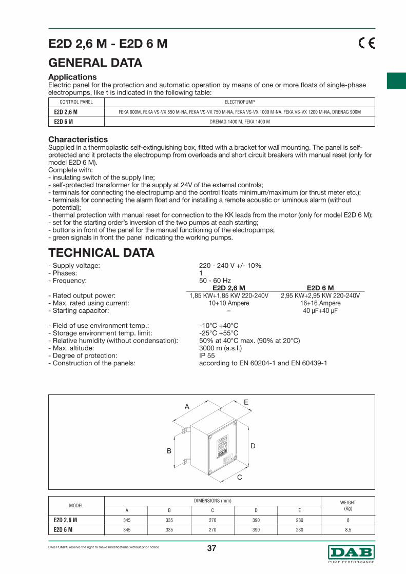
GENERAL DATAApplicationsElectric panel for the protection and automatic operation by means of one or more floats of single-phaseelectropumps, like t is indicated in the following table:
CharacteristicsSupplied in a thermoplastic self-extinguishing box, fitted with a bracket for wall mounting. The panel is self-protected and it protects the electropump from overloads and short circuit breakers with manual reset (only formodel ED 3 M). Complete with:- insulating switch of the supply line;- self-protected transformer for the supply at 24V of the external controls;- terminals for connecting the electropump and the control floats minimum/maximum ( or thrust meter etc.);- terminals for connecting the alarm float and for installing a remote acoustic or luminous alarm (without
potential);- thermal protection with manual reset for connection to the KK leads from the motor (only for model ED 3 M);- button in front of the panel for the manual functioning of the electropump;- green signal in front the panel indicating the working pump.
TECHNICAL DATA- Supply voltage: 220 - 240 V +/- 10%- Phases: 1- Frequency: 50 - 60 Hz
ED 1,3 M ED 3 M- Rated output power: 1,85 KW 220-240 V 2,95 KW 220-240 V- Max. rated using current: 10 Ampere 16 Ampere- Starting capacitor: – 40 µF
- Field of use environment temp.: -10°C +40°C- Storage environment temp. limit: -25°C +55°C- Relative humidity (without condensation): 50% at 40°C max. (90% at 20°C)- Max. altitude: 3000 m (a.s.l.)- Degree of protection: IP 55- Construction of the panels: according to EN 60204-1 and EN 60439-1
CONTROL PANEL
ED 1,3 M
ED 3 M
FEKA 600M, FEKA VS-VX 550 M-NA, FEKA VS-VX 750 M-NA, FEKA VS-VX 1000 M-NA, FEKA VS-VX 1200 M-NA, DRENAG 900M
DRENAG 1400 M, FEKA 1400 M
ELECTROPUMP

36®
DAB PUMPS reserve the right to make modifications without prior notice
MODEL
ED 3 M Hs
WEIGHT(Kg)
6,9
DIMENSIONS (mm)
A B C D E
350 335 270 390 190
ED 3 M Hs
GENERAL DATAApplicationsElectric panel for the protection and automatic operation by means of one or more floats of single-phaseelectropumps model GRINDER 1400 M in single installation.
CharacteristicsSupplied in a thermoplastic self-extinguishing box, fitted with a bracket for wall mounting. The panel is self-protected and it protects the electropump from overloads and short circuit breakers with manual reset. Complete with:- insulating switch of the supply line;- automatic device for increasing static torque when starting with the possibility of regulation from 0,5 to 4
seconds (set from the constructor during the taring at 2 seconds).- self-protected transformer for the supply at 24V of the external controls;- terminals for connecting the electropump and the control floats minimum/maximum (or thrust meter etc.);- terminals for connecting the alarm float and for installing a remote acoustic or luminous alarm (without
potential);- thermal protection with manual reset for connection to the KK leads from the motor;- button in front of the panel for the manual functioning of the electropump;- green signal in front the panel indicating the working pump.
TECHNICAL DATA- Supply voltage: 220 - 240 V +/- 10%- Phases: 1- Frequency: 50 - 60 Hz- Rated output power: 2,95 KW 220-240 V - Max. rated using current: 16 Ampere - Starting capacitor: 40 µF - 450 V- Starting capacitor: 200-250 µF - 320 V- Field of use environment temp.: -10°C +40°C- Storage environment temp. limit: -25°C +55°C- Relative humidity (without condensation): 50% at 40°C max. (90% at 20°C)- Max. altitude: 3000 m (a.s.l.)- Degree of protection: IP 55- Construction of the panels: according to EN 60204-1 and EN 60439-1
37®
DAB PUMPS reserve the right to make modifications without prior notice
MODEL
E2D 2,6 M
E2D 6 M
WEIGHT(Kg)
8
8,5
DIMENSIONS (mm)
A B C D E
345 335 270 390 230
345 335 270 390 230
E2D 2,6 M - E2D 6 M
GENERAL DATAApplicationsElectric panel for the protection and automatic operation by means of one or more floats of single-phaseelectropumps, like t is indicated in the following table:
CharacteristicsSupplied in a thermoplastic self-extinguishing box, fitted with a bracket for wall mounting. The panel is self-protected and it protects the electropump from overloads and short circuit breakers with manual reset (only formodel E2D 6 M). Complete with:- insulating switch of the supply line;- self-protected transformer for the supply at 24V of the external controls;- terminals for connecting the electropump and the control floats minimum/maximum (or thrust meter etc.);- terminals for connecting the alarm float and for installing a remote acoustic or luminous alarm (without
potential);- thermal protection with manual reset for connection to the KK leads from the motor (only for model E2D 6 M);- set for the starting order’s inversion of the two pumps at each starting;- buttons in front of the panel for the manual functioning of the electropumps;- green signals in front the panel indicating the working pumps.
TECHNICAL DATA- Supply voltage: 220 - 240 V +/- 10%- Phases: 1- Frequency: 50 - 60 Hz
E2D 2,6 M E2D 6 M- Rated output power: 1,85 KW+1,85 KW 220-240V 2,95 KW+2,95 KW 220-240V- Max. rated using current: 10+10 Ampere 16+16 Ampere- Starting capacitor: – 40 µF+40 µF
- Field of use environment temp.: -10°C +40°C- Storage environment temp. limit: -25°C +55°C- Relative humidity (without condensation): 50% at 40°C max. (90% at 20°C)- Max. altitude: 3000 m (a.s.l.)- Degree of protection: IP 55- Construction of the panels: according to EN 60204-1 and EN 60439-1
CONTROL PANEL
E2D 2,6 M
E2D 6 M
FEKA 600M, FEKA VS-VX 550 M-NA, FEKA VS-VX 750 M-NA, FEKA VS-VX 1000 M-NA, FEKA VS-VX 1200 M-NA, DRENAG 900M
DRENAG 1400 M, FEKA 1400 M
ELECTROPUMP

38®
DAB PUMPS reserve the right to make modifications without prior notice
ED 1 T - ED 1,5 T - ED 2,5 T
GENERAL DATAApplicationsElectric panels for the protection and automatic operation by means of one or more floats of single-phaseelectropumps, like t is indicated in the following table:
CharacteristicsSupplied in a thermoplastic self-extinguishing box, fitted with a bracket for wall mounting. The panel is self-protected and it protects the electropump from overloads and short circuit breakers with manual reset (only formodel ED 2,5 T paired off to Drenag/Feka/Grinder 1800). Complete with:- insulating switch of the supply line;- self-protected transformer for the supply at 24V of the external controls;- terminals for connecting the electropump and the control floats minimum/maximum (or thrust meter etc.);- terminals for connecting the alarm float and for installing a remote acoustic or luminous alarm (without
potential);- thermal protection with manual reset for connection to the KK leads from the motor (only for model ED 2,5 T,
fit a jumper when using it with Feka 2500.4 T - 2500.2 T - 2700.2 T);- switch in front the panel for the manual functioning - o - automatic of the electropump;- signalling in front the panel:
- luminous red signal which indicates the intervention of the amperometric protection;- luminous green signal which indicates that the pump is working;- luminous white signal which indicates the correct functioning of the auxiliaries circuits.
TECHNICAL DATA- Supply voltage: 400 V +/- 10%- Phases: 3- Frequency: 50 - 60 Hz
ED 1T ED 1,5 T ED 2,5 T- Rated output power: 1,38 KW 2,2 KW 3,5 KW- Max. rated using current: 2,5 A 4A 6,3A
- Field of use environment temp.: -10°C +40°C- Storage environment temp. limit: -25°C +55°C- Relative humidity (without condensation): 50% at 40°C max. (90% at 20°C)- Max. altitude: 3000 m (a.s.l.)- Degree of protection: IP 55- Construction of the panels: according to EN 60204-1 and EN 60439-1
MODEL
ED 1 T
ED 1,5 T
ED 2,5 T
WEIGHT(Kg)
5,6
5,6
5,6
DIMENSIONS (mm)
®
CONTROL PANEL
ED 1 T
ED 1,5 T
ED 2,5 T
FEKA 600 T, FEKA VS-VX 550 T-NA, FEKA VS-VX 750 T-NA
FEKA VS-VX 1000 T-NA, FEKA VS-VX 1200 T-NA, DRENAG 900 T
DRENAG 1800 T, FEKA 1800 T, GRINDER 1800 T, FEKA 2500.4 T, FEKA 2500.2 T, FEKA 2700.2 T
ELECTROPUMP
A B C D E
350 245 270 300 230
350 245 270 300 230
350 245 270 300 230

39®
DAB PUMPS reserve the right to make modifications without prior notice
ED 4 T - ED 7,5 T - ED 8 T - ED 15 T - ED 20 T - ED 25 T - ED 30 T
GENERAL DATAApplicationsElectrical panels for protection and automatic control using float/s for submersible three-phase electricpumps, installed singly, as shown in the following table:
CharacteristicsSupplied with cabinet in flame-proof, thermoplastic material, with brackets for wall-mounting.The panel is self-protected and protects the electric pump from overloading and short circuits, power failurewith a manually resettable device. Supplied complete with:- isolator for the power input line with padlockable door handle;- self-protected transformer for 24V powering of external commands;- terminals for connecting electric pump and min. and max. control float/s (or pressure switches, etc.);- terminals for connecting a remote acoustic or luminous alarm (without potential);- terminals for connecting temperature/oil sensors from the motor. Supplied with a jumper to be removed
when using it.- switch on the front of the panel for man - 0 - aut operation of the electric pump;- LED on the front of the panel:
- red LED indicating that the thermal-current protection device has cut in- green LED on the front of the panel indicating the pump is working- yellow LED indicating that the auxiliary circuits are working correctly
- Models ED 15 T and ED 20 T are provided with star-delta starting.
TECHNICAL DATA- Rated power input: 400V~ +/- 10%- Phases: 3- Frequency: 50-60 Hz
ED 4T ED 7,5 T ED 8 T ED 15 T ED 20 T ED 25 T ED 30 T- Rated input current (A): 6-10 9-14 13-18 20-25 24-32 25-40 40-63
- Operating temperature range: -10°C +40°C- Storage temperature range: -25°C + 55°C- Relative humidity (without condensation): 50% at 40°C MAX (90% at 20°C)- Max. altitude: 3000 m (a.s.l.)- Level of protection: IP55- The panels are built to EN 60204-1 and EN 60439-1 standards
MODELDIMENSIONS (mm)
®
A B C D E
350 245 270 300 230 8350 245 270 300 230 10350 335 270 390 230 10350 245 270 300 230 10,5350 335 270 300 230 16350 335 270 300 230 16350 335 270 300 230 18,4350 335 270 300 230 18,4
ED 4 TED 7,5 TED 7,5 T ( /Δ)ED 8 TED 15 T ( /Δ)ED 20 T ( /Δ)
ED 25 T ( /Δ)Y
YY
Y
WEIGHT(Kg)
CONTROL PANEL
FEKA 3000.4 TFEKA 3000.2 T, FEKA 3500.2 T, FEKA 3700.2 T
FEKA 6075.6 TFEKA 4000.4 T
FEKA 4100.4 T, FEKA 4100.2 T, FEKA 4150.2 T, FEKA 6100.6 T, FEKA 6120.4 TFEKA 4125.2 T, FEKA 4200.2 T, FEKA 6150.4 T
FEKA 6250.4 T, FEKA 6200.4 TFEKA 6300.4 T
ELECTROPUMP
ED 4 TED 7,5 TED 7,5 T ( /Δ)ED 8 TED 15 T ( /Δ)ED 20 T ( /Δ)ED 25 T ( /Δ)ED 30 T ( /Δ)
YYYY
Y

40®
DAB PUMPS reserve the right to make modifications without prior notice
E2D 2 T - E2D 3 T - E2D 5 T
GENERAL DATAApplicationsElectric panels for the protection and automatic operation by means of one or more floats of single-phaseelectropumps, like t is indicated in the following table:
CharacteristicsSupplied in a thermoplastic self-extinguishing box, fitted with brackets for wall mounting. The panel is self-protected and it protects the electropump from overloads and short circuit breakers with manual reset (only formodel ED 5 T). Complete with:- insulating switch of the supply line with block door-handle and lock;- self-protected transformer for the supply at 24V of the external controls;- terminals for connecting the electropump and the control floats minimum/maximum ( or thrust meter etc.);- terminals for connecting the alarm float and for installing a remote acoustic or luminous alarm (without potential);- thermal protection with manual reset for connection to the KK leads from the motor (only for model ED 5 T);- set for the starting order’s inversion of the two pumps at each starting, for the functioning simultaneously and for
the insertion of one of the two in case of damage of the other one;- switch in front the panel for the manual functioning - o - automatic of each electropump;- signalling in front the panel:
- luminous red signal which indicates the intervention of the amperometric protection for each electropump;- luminous green signals which indicate that the pumps are working;- luminous white signal which indicates the correct functioning of the auxiliaries circuits.
TECHNICAL DATA- Supply voltage: 400 V +/- 10%- Phases: 3- Frequency: 50 - 60 Hz
E2D 2 T E2D 3 T E2D 5 T- Rated output power: 1,38 +1,38 KW 2,2 +2,2 KW 3,5 +3,5 KW- Max. rated using current: 2,5 +2,5A 4+4A 6,3+6,3 A
- Field of use environment temp.: -10°C +40°C- Storage environment temp. limit: -25°C +55°C- Relative humidity (without condensation): 50% at 40°C max. (90% at 20°C)- Max. altitude: 3000 m (a.s.l.)- Degree of protection: IP 55- Construction of the panels: according to EN 60204-1 and EN 60439-1
MODEL
E2D 2 T
E2D 3 T
E2D 5 T
WEIGHT(Kg)
8
8
8,1
DIMENSIONS (mm)
®
A B C D E
345 335 270 390 230
345 335 270 390 230
345 335 270 390 230
CONTROL PANEL
E2D 2 T
E2D 3 T
E2D 5 T
FEKA 600 T, FEKA VS-VX 550 T-NA, FEKA VS-VX 750 T-NA
FEKA VS-VX 1000 T-NA, FEKA VS-VX 1200 T-NA, DRENAG 900 T
DRENAG 1800 T, FEKA 1800 T, GRINDER 1800 T, FEKA 2500.4 T, FEKA 2500.2 T, FEKA 2700.2 T
ELECTROPUMP

41®
DAB PUMPS reserve the right to make modifications without prior notice
E2D 8 T - E2D 15 T - E2D 16 T - E2D 30 T - E2D 40 T - E2D 50 T - E2D 60 TGENERAL DATAApplicationsElectrical panels for protection and automatic control using float/s for submersible three-phase electricpumps, twin installation, as shown in the following table:
CharacteristicsSupplied with cabinet in flame-proof, thermoplastic material, with brackets for wall-mounting.The panel is self-protected and protects the electric pump from overloads and short circuits with manual reset.Complete with: - modular isolator for the power input line with padlockable door handle; - self-protected transformer for 24V powering of external commands; - terminals for connecting the electric pump and min./max. control floats (or pressure switches, etc.);- terminals for connecting a remote acoustic or luminous alarm;
(without potential)- terminals for connecting temperature/oil sensors from the motor. Supplied with a jumper to be removed
when using it.- pre-set for inverting the starting order of the two pumps at every start up, for simultaneous operation and for
starting one of the two in case the other one breaks down;- switch on the front of the panel for manual – 0 – automatic electric pump operation; - indicators on the front of the panel:
- red LED indicating the current protection device has cut in; - green LED indicating the pump is working; - yellow LED indicating the auxiliary circuits are working properly.
- Models E2D 30 T and E2D 40 T are provided with star-delta starting.
TECHNICAL DATA- Rated power input: 400V~ +/- 10%- Phases: 3- Frequency: 50-60 Hz
E2D 8T E2D 15 T E2D 16 T E2D 30 T E2D 40 T E2D 50 T E2D 60 T- Rated input current (A): 6-10 9-14 13-18 20-25 24-32 25-40 40-63
- Operating temperature range: -10°C +40°C- Storage temperature range: -25°C + 55°C- Relative humidity (without condensation): 50% at 40°C MAX (90% at 20°C)- Max. altitude: 3000 m (a.s.l.)- Level of protection: IP55- The panels are built to EN 60204-1 and EN 60439-1 standards
®
CONTROL PANEL ELECTROPUMP
MODEL WEIGHT(Kg)
DIMENSIONS (mm)
A B C D E
345 335 270 390 230 8,3345 335 270 390 230 15514 335 540 390 230 15345 335 270 390 230 15514 335 270 390 230 15514 335 270 390 230 30514 335 270 390 230 37514 335 270 390 230 37
FEKA 3000.4 TFEKA 3000.2 T, FEKA 3500.2 T, FEKA 3700.2 T
FEKA 6075.6 TFEKA 4000.4 T
FEKA 4100.4 T, FEKA 4100.2 T, FEKA 4150.2 T, FEKA 6100.6 T, FEKA 6120.4 TFEKA 4125.2 T, FEKA 4200.2 T, FEKA 6150.4 T
FEKA 6250.4 T, FEKA 6200.4 TFEKA 6300.4 T
E2D 8 TE2D 15 TE2D 15 T ( /Δ)E2D 16 TE2D 30 T ( /Δ)E2D 40 T ( /Δ)E2D 50 T ( /Δ)E2D 60 T ( /Δ)
YYYY
Y
E2D 8 TE2D 15 TE2D 15 T ( /Δ)E2D 16 TE2D 30 T ( /Δ)E2D 40 T ( /Δ)E2D 50 T ( /Δ)E2D 60 T ( /Δ)
YYYY
Y

42®
DAB PUMPS reserve the right to make modifications without prior notice
INSTALLATION DIAGRAMS DRENAG
Fixed installation with 1 Drenag 1800 T pump, complete with ED 2,5 T control unit, with one MIN/MAX level control float and 1 alarm float.
Minimum dimensions of borehole cover for systems providedwith DSD2 (layout view).
* Technical data of control units from page 32
Fixed installation with 1 Drenag 1400 M pump with DSD2device, complete with ED 3 M control unit, with two minimumand maximum level control floats and one alarm float.

43®
DAB PUMPS reserve the right to make modifications without prior notice
INSTALLATION DIAGRAMS FEKA
Fixed installation with 1 Feka 1800 T pump, complete with ED 2,5 T control unit, with one MIN/MAX level control float and 1 alarm float.
Minimum dimensions of borehole cover for systemsprovided with DSD2 (layout view).
* Technical data of control units from page 32
Fixed installation with 1 Feka 1400 M pump with DSD2device, complete with ED 3 M control unit, with two minimumand maximum level control floats and one alarm float.

44®
DAB PUMPS reserve the right to make modifications without prior notice
INSTALLATION DIAGRAMS GRINDER
Fixed installation with 1 Grinder 1800 T pump, complete with ED 2,5 T control unit, with one MIN/MAX level control float and 1 alarm float.
Minimum dimensions of borehole cover for systemsprovided with DSD2 (layout view).
* Technical data of control units from page 32
Fixed installation with 1 Grinder 1400 M pump with DSD2device, complete with ED 3 M control unit, with two minimumand maximum level control floats and one alarm float.

45®
DAB PUMPS reserve the right to make modifications without prior notice
ACCESSORIES
FLOATS
KIT SUPPORT PLATE
LIFTING DEVICE
Comes with 5 or 10 meters of 3x1 H07 RN-F cable Bulb-type float
Supporting device for FEKA and GRINDER, complete with support disc,spacers and screws. Recommended for portable applications to prevent thepump from filling up with sand during operation.
DSD2 - FEKA VS-VX
Lifting device for 3/4" gaspipes, complete with:support foot, slide, pipefixing bracket, pipe guidecolumns, pump locking nut.
The DSD2-FEKA VS-VXinclude the bracket of fix thepump.
FEKA 2500 - 2,5" FEKA 3000/4000 FEKA 6075/6300
A
B
H
G
E
D
C
A
FCE
A
C
F
E
A
C
F
E
A Pipe holding bracket
B 3/4” pipes
C Sliding saddle
D Pipe guide columns
E Stand
F - H Bracket fastening screw and nut
G Anti-rotation bracket (only Feka VS and VX)

46®
DAB PUMPS reserve the right to make modifications without prior notice
N° Description Qty Materials1 CASING 1 PVC
2 BALL 1 Cast iron NBR
3 CAP 1 PVC
4 SEAL 1 NBR (nitrile)
Rif. DN A B C D Weight Kv3inch mm mm mm mm Kg m /H
5222 1"1/4 33/42 114,0 143,0 66,0 0,450 22,30 3,305223 1"1/2 40/49 160,0 257,0 89,0 1,010 57,80 1,205224 2" 50/60 160,0 179,0 89,0 0,810 68,30 2,10
Electronic control unit with alarm device for operation even in the absence of current bymeans of a 10-hour reserve charge provided by lead buffer batteries. Complete with 1.5m cable with EXPORT DIN 49441 R2 plug and one float with 10 m H07 RN-F cable, notconnected.Degree of protection: IP30 - Temp.: -10°C +40°C - Consumption: 7 VA 220-240V.Self-extinguishing thermoplastic box for wall mounting.Supplied with wall brackets, screws and a spare fuse.
VOLTAGE50-60 Hz
1x115 V ~
1x220-240 V ~
AUTONOMYCHARGE
10 HOURS
SOUNDVOLUME
95 dBdiscontinuous
WEIGHTKg
3,3
MODEL
Control AS1
Pump lifting device. Chain and clevis made of stainless steel AISI 316.Chain length 5 or 10 m on request.
Height adjustable float cable clamp secured to the motor jacket (fekabox version)
230Vac - 10W acoustic alarm
CABLE CLAMPS FOR FEKA VS and FEKA VX
CONTROL AS1
CLEVIS KIT
ACOUSTIC ALARM
NON-RETURNE VALVE
BALL CHECK VALVES, FLANGEDDN 65 - PN 10
DN 80 - PN 10
DN 100 - PN 10
DN 150 - PN 10

47®
DAB PUMPS reserve the right to make modifications without prior notice
Kit for installation in FEKABOX and FEKAFOX tanks.1 ball check valve, 1 2” ball on-off valve and 2 fittings. Integral 2” passage. Made in PVC.
AVAILABLE IN THREE DIFFERENT VERSIONS, DN 65 - DN 80 - DN 100.Adapter for lifting devices in existing installations, designed to adapt the system to the DAB pump.
300 G FLOAT COUNTERWEIGHT
ADAPTER FOR LIFTING DEVICES
STEP FOR FEKAFOS AND FEKABOX
REFLOW KIT
300mm step (up to 2 steps can be installed one on top of the other).
The counterweight is mounted directly onto the level regulator output cable.
WEIGHT Standard 200 g gr. 300
DIMENSIONS Ø 47X55 Ø 47X55
MATERIAL Shockproof polystyrene Shockproof polystyrene
FILLING MATERIAL sand + iron shot sand + iron shot
INSTALLATION METHODS
Piping
Clamps
Externalcounterweight

48®
DAB PUMPS reserve the right to make modifications without prior notice
NOVABOX 30/300.1
GENERAL DATAApplicationsAutomatic collecting and lifting station for domestic waste water from baths, wash-hand basins, showersand washing machines located in basements or anywhere under the sewer level.
Conveyable liquidsWaste water free from solids and/or fibrous substances.
Constructional features Hydraulic part1 NOVA 300 M-A submersible electropump with 5 metres of cable and a plug - 1 technopolymer containerwith capacity 30 litres - 1 non-return valve fitted on the delivery - technopolymer plumbing connections.
Electrical partThe NOVA 300 M-A pump fitted in the NOVABOX 30/300.1 has as standard features a built-in float, motorwith thermal and current overload protection and a capacitor permanently in circuit.
SupplyThe NOVABOX 30/300 collecting and lifting station is supplied complete with the pump.To avoid damagesduring the transport, the pump is placed inside the container with a proper packing that has to be removedbefore using it. The station is supplied in a sturdy cardboard package, complete with an instructions leafletfor installation and maintenance.The supply also includes a series of accessories which make the product particularly versatile with just afew simple adjustments.Alarm system (when it is requested), composed from a power-station and a probe. Installed on theNovabox’s top, it allows to check the maximum level inside the tank (acoustic signal).The system is able to function even in case there is a black-out for 10 hours. Beside the acoustic alarmincorporated, it is possible to send again at distance a luminous or acoustic alarm (not supplied).
Novabox 30/300.1 is in compliance with the norm En 12050-2.
STANDARD FLOATBREATHER GROUP / SAFETY VALVE FLOAT TYPE B “SHOWER”
139. PUMP100. TANK14. COVER109. GASKET229. CLOSER CLIP118. NIPPLES 1 1/4”161A. CURVE RUBBER HOLDER 1 1/4” X 3264A. GASKET Ø 1 1/4”64B. GASKET Ø 3/4”161B. RUBBER PIPE 3287. HOSE CLAMP Ø 44 137. NON-RETURNE VALVE 1 1/4”157. COLLAR 1 1/4”119A. RIGHT RUBBER HOLDER 3/4” X 25161. RIGHT RUBBER HOLDER 1 1/4” X 32
88. RUBBER CABLE GLAND119. ADAPTOR 50 x 40 x 1 1/4”157a. COLLAR 3/4”84. PIPE CLAMP Ø 30 mm83. FLOAT KIT
BREATHER GROUP / SAFETY VALVE49. FLOAT BALL16a. O RING Ø 15 mm180. VALVE SUPPORT95. ORING -3143 36,14 x 2,6226. BREATHER PLUG84a. PIPE CLAMP Ø 40 mm42. FILTER
DRAINAGE STATIONS

49®
DAB PUMPS reserve the right to make modifications without prior notice
- Operating range: from 1 to 7,2 m3/h with head up to 6,9 metres
- Liquid temperature range: +50°C90°C for a maximum time of 3 min.
- Pump motor protection: IP 68
- Motor Insulation class: F
- Pump manufactured according to standards: CEI 61-69 (EN 60335-2-41)
- Standard single-phase voltage: 220-240 V/50 Hz
TECHNICAL DATA
VOLTAGE50 Hz
1x220-240 V ∼ 290 0,22 0,3 1,3 8 450 H (m)
P1MAX
W
InA
P2NOMINAL
kW HP
CAPACITOR
µF Vc
Qm3/hl/min
6,9 5,3 3,2 2,2 1,2
Q00
Q2,440
Q4,880
Q6
100
Q7,2120
MODEL
NOVABOX 30/300.1
ELECTRICAL DATA HYDRAULIC DATA (n ∼ 2800 1/min)
A
407
B
309
C
94
D
204
E
314
F
72
H
360
H1
100
H2
254 9,20,056383345
MODEL
NOVABOX 30/300.1
PACKING DIMENSIONS
L/A L/B HWEIGHT
KgVOLUME
m3
MIN
130
D E
A B
C
F F
B
A
E
D
C
H1
H2
H1
H2
H
The performance curves are based on the kinematic viscosity values = 1 mm2/s and density equal to 1000 kg/m3. Curve tolerance according to ISO 9906.

50®
DAB PUMPS reserve the right to make modifications without prior notice
FEKALIFTLIFTING STATION
GENERAL DATAApplicationsSmall lifting stations for automatic collecting and pumping sewage. Its use is necessary whenever thewastewater cannot be expelled by gravity. The lifting station is mounted directly behind the WC and istherefore unaffected by the type of waste piping and unions.This lifting station can be used wherever an additional toilet is required during new building work,renovations and structural modifications. Depending on the model, a shower, bidet and washbasin can beconnected together with the WC.The inflow water from the sanitary ware connected to the system automatically turns on the Fekalift 50/150when there is an increase in the water level of approximately 8 cm and is automatically turned off when thelevel drops by approximately 3 cm. The solids and excrement that arrive from the toilet are chopped andforced into the general waste pipe through the pressure pipe. The Fekalift 50/150 can be connected to any European standards WC with horizontal waste. At least 6 litresof water must be available each time flushing is performed. Water saving push button flushes are advised. The appealing design, technical innovation and manufacturing quality make FEKALIFT an indispensableitem for the fitting of a supplementary toilet, above or below the backwater level (based on the DIN 1986standard). The Fekalift 50 and Fekalift 150 systems are suitable for water temperatures up to 35°C and are resistant toslightly acidic substances. Avoid the discharge of water containing greasy or oily substances into the Fekalift50 and Fekalift 150.
Constructional CharacteristicsThe motor, powerful yet noiseless, the pump and the grinding device are made of stainless steel. The integrated pump purifying system makes the station practically maintenance-free. Easy to install, it isalso designed for connection of a shower base with 12 cm drain height.The forced side duct with built-in no-return valve allows the cover to be removed without having to removethe delivery pipe.
BASIC

51®
DAB PUMPS reserve the right to make modifications without prior notice
- Power input: 1x230 V~ 50 Hz- Current: 2,1 A- Power: 450 W- Flow Q: 3 m3/h- Head H: 4,5 m- Max liquid temperature: 35°C- Insulation class: B- Speed of rotation: 2900 1/min.- Delivery union: DN 25- Operation: automatic- Capacity: Fekalift 50 9 lt.
Fekalift 150 12 lt.
TECHNICAL DATA
VOLTAGE50 Hz
1x230 V ∼ H (m)
InA
P2NOMINAL
kW HP
Qm3/hl/min
4,1 3,7 3,2 1,7 1,1
Q0,610
4,5
Q00
Q1,220
Q1,830
Q350
Q3,355
MODEL
FEKALIFT 50/150
ELECTRICAL DATA HYDRAULIC DATA (n ∼ 2800 1/min)
A B C D E F G Ø H Ø IMODEL
FEKALIFT 50
FEKALIFT 150
14
2
6
8
10
12
14
10
220
330
440
550
The performance curves are based on the kinematic viscosity values = 1 mm2/s and density equal to 1000 kg/m3. Curve tolerance according to ISO 9906.
0,45 0,61 2,1
PO ØNML
377 275 180 90 177 – – DN 28 200 70 – 188 – –
485 270 180 50 170 85 DN 40 DN 28 200 40 530 242,5 40 200

52®
DAB PUMPS reserve the right to make modifications without prior notice
FEKALIFTLIFTING STATION
GENERAL DATAApplicationsSmall lifting stations for automatic collecting and pumping sewage. Its use is necessary whenever thewastewater cannot be expelled by gravity. The lifting station is mounted directly behind the WC and istherefore unaffected by the type of waste piping and unions.This lifting station can be used wherever an additional toilet is required during new building work,renovations and structural modifications. Depending on the model, a shower, bidet and washbasin can beconnected together with the WC.The inflow water from the sanitary ware connected to the system automatically turns on the Fekalift 100/200when there is an increase in the water level of approximately 8 cm and is automatically turned off when thelevel drops by approximately 3 cm. The solids and excrement that arrive from the toilet are chopped andforced into the general waste pipe through the pressure pipe. The Fekalift 100/200 can be connected to any European standards WC with horizontal waste. At least 6litres of water must be available each time flushing is performed. Water saving push button flushes areadvised. The appealing design, technical innovation and manufacturing quality make FEKALIFT an indispensableitem for the fitting of a supplementary toilet, above or below the backwater level (based on the DIN 1986standard). The Fekalift 100 and Fekalift 200 systems are suitable for water temperatures up to 65°C and are resistantto slightly acidic substances. Avoid the discharge of water containing greasy or oily substances into theFekalift 100 and Fekalift 200.
Constructional CharacteristicsThe motor, powerful yet noiseless, the pump and the grinding device are made of stainless steel. The integrated pump purifying system makes the station practically maintenance-free. Easy to install, it isalso designed for connection of a shower base with 12 cm drain height.The forced side duct with built-in no-return valve allows the cover to be removed without having to removethe delivery pipe.
PROFESSIONAL

53®
DAB PUMPS reserve the right to make modifications without prior notice
- Power input: 1x230 V~ 50 Hz- Current: 2,1 A- Power: 650 W- Flow Q: 3,9 m3/h- Head H: 6,4 m high or 70 m length- Max liquid temperature: 60°C- Insulation class: B- Speed of rotation: 3000 1/min.- Delivery union: DN 25- Operation: automatic- Approval: VDE - GS- Built to: DIN 19762- Capacity: Fekalift 100 9 lt.
Fekalift 200 12 lt.
TECHNICAL DATA
VOLTAGE50 Hz
1x230 V ∼ H (m)
InA
P2NOMINAL
kW HP
Qm3/hl/min
5,6 4,7 3,9 3 1,9
Q0,610
6,4
Q00
Q1,220
Q1,830
Q350
Q3,965
MODEL
FEKALIFT 100/200
ELECTRICAL DATA HYDRAULIC DATA (n ∼ 2800 1/min)
A B C D E F G Ø H Ø IMODEL
FEKALIFT 100
FEKALIFT 200
The performance curves are based on the kinematic viscosity values = 1 mm2/s and density equal to 1000 kg/m3. Curve tolerance according to ISO 9906.
0,65 0,88 2,1
PO ØNML
377 275 180 90 177 – – DN 28 200 70 – 188 – –
485 270 180 50 170 85 DN 40 DN 28 200 40 530 242,5 40 200

54®
DAB PUMPS reserve the right to make modifications without prior notice
FEKALIFTLIFTING STATION
GENERAL DATAApplicationsLifting stations for automatic collecting and pumping sewage. Its use is necessary whenever the wastewatercannot be expelled by gravity.The lifting system, with FEKALIFT 300 VM wall-mounted installation, consistsof a tank made of synthetic, non-putrescible, impermeable, gas-proof and odourless material, with a single-stage centrifugal pump that starts up automatically when the water level rises to about 8 cm, and stopswhen it drops to about 4 cm. The integrated grinder minces all solid substances found in the wastewater, soas to enable their passage through pipes of small diameter (25 mm ID). The FEKALIFT 300 VM tank isequipped with a horizontal WC delivery pipe DN 100, a lateral wastewater delivery pipe DN 40 (optional)and a revolving delivery union DN 28 with integrated non-return valve. The non-return valve in the deliveryunion prevents backflow in the tank’s delivery pipe. Moreover, the cover of the lifting system is equipped witha ventilation and bleed device. This lifting station can be used wherever a toilet is required on the site of newinstallations, structural renovations and modifications. Depending on the model, a shower, bidet andwashbasin can be connected in addition to the WC.Fekalift 300 VM can be connected to any WC designed according to European standards, equipped withhorizontal outlet. The use of flush tanks equipped with water saving flush button is recommended. Theattractive design, innovative technique and quality of workmanship make FEKALIFT 300 VM anindispensable component when installing an additional toilet below or above the backwater level (accordingto DIN 1986). The Fekalift 300 VM system is suitable for water temperatures up to 65°C and is resistant tothe action of moderately acid substances. Do not allow wastewater containing greasy or oily substances toflow into the system.
Constructional CharacteristicsThe motor, powerful yet noiseless, the pump and the grinding device are made of stainless steel. The integrated pump purifying system makes the station practically maintenance-free. Easy to install, it isalso designed for connection of a shower base with 12 cm drain height.The forced side duct with built-in no-return valve allows the cover to be removed without having to removethe delivery pipe.
PROFESSIONAL
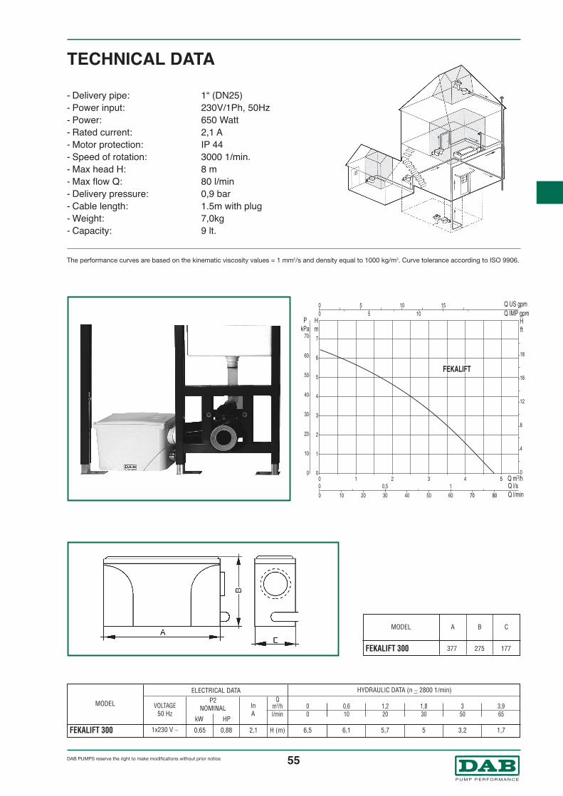
55®
DAB PUMPS reserve the right to make modifications without prior notice
- Delivery pipe: 1“ (DN25)- Power input: 230V/1Ph, 50Hz- Power: 650 Watt- Rated current: 2,1 A- Motor protection: IP 44- Speed of rotation: 3000 1/min.- Max head H: 8 m- Max flow Q: 80 l/min- Delivery pressure: 0,9 bar- Cable length: 1.5m with plug- Weight: 7,0kg- Capacity: 9 lt.
TECHNICAL DATA
VOLTAGE50 Hz
1x230 V ∼ H (m)
InA
P2NOMINAL
kW HP
Qm3/hl/min
6,1 5,7 5 3,2 1,7
Q0,610
6,5
Q00
Q1,220
Q1,830
Q350
Q3,965
MODEL
FEKALIFT 300
ELECTRICAL DATA HYDRAULIC DATA (n ∼ 2800 1/min)
70 80
5
The performance curves are based on the kinematic viscosity values = 1 mm2/s and density equal to 1000 kg/m3. Curve tolerance according to ISO 9906.
0,65 0,88 2,1
A B CMODEL
FEKALIFT 300 377 275 177

DAB PUMPS reserve the right to make modifications without prior notice56®
FEKABOX 100FITTED FORFEKA 600 MAFEKA VS 550-750 M-AFEKA VX 550-750 M-A
GENERAL DATA
ApplicationsAutomatic collection and lifting system, ideal for collecting and pumping black water and domestic/industrialwaste from basements located under the level of the drains into sewers.
Pumped liquidPhreatic water, rain water, clear waste water, black waste water and water from rivers and lakes.
TECHNICAL DATAFEKABOX 100 comprises a high density polyethylene tank with an effective capacity of 100 litres, supplied
with tank cover and technopolymer gasket. Fitted for operation with one automatic electric pump FEKA 600-
FEKA VS - FEKA VX to be ordered separately.
- Material: 5 mm thick propylene
- Tank inlet: DN50 - DN100 (male/female)
- Tank outlet: DN50 - 2”GAS (vertical or horizontal)
- Discharge: DN40
- Max liquid temperature: +50°C
- Supplied with anti floatation device (EN 12050-1 standard)

DAB PUMPS reserve the right to make modifications without prior notice 57®
The performance curves are based on the kinematic viscosity values = 1 mm2/s and density equal to 1000 kg/m3. Curve tolerance according to ISO 9906.
FEKABOX 100 700 190 70 120 380 115 135 270 100 15 85 30 50 130 8,5
A B C D E F G H H1 H2 H3 H4 H5 I WEIGHTKgMODEL
700380115 135 130
120
100
1527
0
500
8530 50
19070
IN DN50 M
IN DN110 M
IN DN110 M
FISSAGGIO CON STAFFASCARICO
IN DN110/50 F
OUT
PRESSACAVO
46 GASKET 78X58X4 (2”)92 TANK COVER118 SLEEVE 63X2”118a BAR WITH THREADED HOLES 2”X100119a RUBBER HOLDER124a GASKET COVER161 RUBBER PIPE 57X50 L=240204 CABLE CLAMP225 ADAPTER M-F 1 1/4" - 1 1/2”225a ADAPTER M-F 1 1/2” - 2”245 CABLE GLAND M20X1,5248 TE SCREW 10X40296 UNION 3 pcs WITH O-RING316 FASTENING BRACKET319a CABLE HOLDER380 TANK410 COLLAR 2” PP OR PVC412a BENT HOSE ADAPTER413 TUBE CLAMP Ø57
Bracket screw: not included
BRACKETFASTENING
CABLE GLAND
DISCHARGE

DAB PUMPS reserve the right to make modifications without prior notice58®
FEKABOX 200FITTED FORFEKA 600 MAFEKA VS 550-750 M-AFEKA VX 550-750 M-A
GENERAL DATA
ApplicationsAutomatic collection and lifting system, ideal for collecting and pumping black water and domestic/industrialwaste from basements located under the level of the drains into sewers.
Pumped liquidPhreatic water, rain water, clear waste water, black waste water and water from rivers and lakes.
Technical features Hydraulic partFEKABOX 200 comprises a high density polyethylene tank with an effective capacity of 200 litres, with asturdy gas and liquid proof sealed cover, stainless steel base plate and pipe fittings for connecting the pumpto the drains. Complete with: special cable holder, DN50 and DN110 suction manifolds and 2” deliverymanifolds. Complete with connector for DN50 vent tube. An alarm float can be used on request.
Fitted for operation with one automatic electric pump (see models in graph) to be ordered separately.
SupplyThe station is supplied on a pallet wrapped in a tough cardboard pack, complete with an installation andmaintenance instructions sheet.A float cable clamp kit is supplied (clamp fastened to the motor jacket, with height adjustment).
- Operating range: from 1 to 24 m3/h with head up to 9 metres
- Liquid temperature range: +50°C
TECHNICAL DATA

DAB PUMPS reserve the right to make modifications without prior notice 59®
The performance curves are based on the kinematic viscosity values = 1 mm2/s and density equal to 1000 kg/m3. Curve tolerance according to ISO 9906.
A
850
B
555
C D D1 E F G H H1 H2 I
85 DN 110 DN 50 100 140 2” 735 565 500 105 25
MODEL
FEKABOX 200
WEIGHTKg
H2
H
A
B
C
E
F
I
H1
14 TANK COVER83 “ALARM” FLOAT (not supplied)87 CABLE CLAMP87a TUBE CLAMP Ø57100 TANK118 SLEEVE 63X2”118a THREADED PIPE 100X2”118b ADAPTER M-F 1 1/4” - 11/2”118c ADAPTER M-F 11/2”- 2”119 UNION DN 110 (inlet)119a 45° ELBOW DN 50 (inlet - ventilation)139 PUMP149 CABLE HOLDER PG 11161 RUBBER PIPE 57X50 L=300161a BENT HOSE ADAPTER 2”X50161b UNION 3 pcs WITH O-RING (2”)204 CABLE CLAMP216 SPECIAL CABLE GLAND248b COVER SCREW253 PUMP POSITIONING PLATE319a CLAMP
SUPPLIED ONLY ON REQUEST

60®
DAB PUMPS reserve the right to make modifications without prior notice
FEKABOX 280FITTED FORFEKA 600 MAFEKA VS 550-750 M-AFEKA VX 550-750 M-A
GENERAL DATA
ApplicationsAutomatic collection and lifting system, ideal for collecting and pumping black water and domestic/industrialwaste from basements located under the level of the drains into sewers.
Pumped liquidPhreatic water, rain water, clear waste water, black waste water and water from rivers and lakes.
Technical features FEKABOX 280 comprises a high density polyethylene tank with an effective capacity of 280 litres, with asturdy gas and liquid proof sealed cover, a DSD-2 device complete with support, a slide, hose bracket andchute hoses, and pipe fittings for connecting the pump to the drains.
Complete with: special cable holder, DN50 and DN110 suction manifolds and 2” delivery manifolds.Complete with connector for DN50 vent tube. An alarm float can be used on request.Fitted for operation with one automatic electric pump (see models in graph) to be ordered separately.For use with VS or VX electric pump, the bracket for the DSD2 device must be ordered separately .
SupplyThe station is supplied on a pallet wrapped in a tough cardboard pack, complete with an installation andmaintenance instructions sheet.A float cable clamp kit is supplied (clamp fastened to the motor jacket, with height adjustment).
- Operating range: from 1 to 24 m3/h with head up to 9 metres
- Liquid temperature range: +50°C
TECHNICAL DATA

61®
DAB PUMPS reserve the right to make modifications without prior notice
The performance curves are based on the kinematic viscosity values = 1 mm2/s and density equal to 1000 Kg/m3. Curve tolerance according to ISO 9906.
A
800
B
640
C D D1 E F G H H1 I
145 DN 50 DN 110 165 130 2” 745 480 145 38
MODEL
FEKABOX 280
WEIGHTKg
3 ADAPTER 11/4” - 2”5 FIXED PART14 TANK83 “ALARM” FLOAT (not supplied)87 CABLE CLAMP100 TANK118 SLEEVE 63X2”119 UNION DN 110 (inlet)119a 45° ELBOW DN 50 (inlet - ventilation)126 OUTLET HOSE CLAMP139 PUMP149 CABLE HOLDER PG 11151 SLIDE MOBILE PART204 CABLE CLAMP216 SPECIAL CABLE GLAND248b COVER SCREW267a TCEI SCREW M10X25 UNI 5931268 PUMP FLANGE SCREW 315 GUIDE HOSES316 ANTI-ROTATION BRACKET319a CLAMP397c M10 NUT
SUPPLIED ONLY ON REQUEST

62®
DAB PUMPS reserve the right to make modifications without prior notice
FEKAFOS 200FITTED FORFEKA 600 NAFEKA VS/VX 550 M-NA/T-NAFEKA VS/VX 750 M-NA/T-NAFEKA VS/VX 1000 M-NA/T-NAFEKA VS/VX 1200 M-NA/T-NA
GENERAL DATAApplicationsAutomatic system for collecting, lifting and pumping black water and domestic/industrial waste frombasements located under the level of the drains into sewers.
Pumped liquidPhreatic water, rain water, clear waste water, black waste water and water from rivers and lakes.
Technical features FEKABOS 200 comprises a high density polyethylene tank with an effective capacity of 200 litres, with asturdy gas and liquid proof sealed cover, stainless steel base plate and pipe fittings for connecting the pumpto the drains. Complete with 2 bulb floats mounted on a stainless steel support, cable holder for connectingthe float and pump cables to the electrical panel (to order separately according to the table).Complete with DN50 and DN110 suction manifolds and 2” delivery manifolds.Complete with connector for DN50 vent tube.An alarm float can be used on request.Fitted for operation with one automatic electric pump (see models in graph) to be ordered separately.
161
87a
161a
118c
118b
253
14 TANK COVER
83 “ALARM” FLOAT(not supplied)
87 CABLE CLAMP87a TUBE CLAMP Ø57100 TANK118 SLEEVE 63X2”118a THREADED PIPE 100X2”118b ADAPTER M-F 11/4” - 11/2”118c ADAPTER M-F 11/2” - 2”
119 UNION DN 110(inlet)
119a 45° ELBOW DN 50(inlet - ventilation)
139 PUMP149 CABLE HOLDER PG 11161 RUBBER PIPE 57X50 =300161a CURVE RUBBER HOLDER 2”X50161b UNION 3 Pcs WITH O-RING (2”)248b COVER SCREW253 PUMP POSITIONING PLATE
SUPPLIED ONLY ON REQUEST

63®
DAB PUMPS reserve the right to make modifications without prior notice
- Operating range: from 1 to 35 m3/h with head up to 9 metres- Liquid temperature range: +50°C
TECHNICAL DATA
The performance curves are based on the kinematic viscosity values = 1 mm2/s and density equal to 1000 kg/m3. Curve tolerance according to ISO 9906.
CHOICE OF PUMP/ELECTRICAL PANEL
PUMP MODEL SINGLE-PHASE 230V~50 Hz
P2 NOMINALELECTRIC PUMP
kW HP
THREE-PHASE 400V~50 Hz
ED1 T
ED1 T
ED1 T
ED1,5 T
ED1,5 T
ED1,3 M
ED1,3 M
ED1,3 M
ED1,3 M
ED1,3 M
0,55 0,75
0,55 0,75
0,75 1
1 1,36
1,2 1,6
FEKA 600 NA
FEKA VS-VX 550 NA
FEKA VS-VX 750 NA
FEKA VS-VX 1000 NA
FEKA VS-VX 1200 NA
A
850
B
555
C D D1 E F G H H1 H2 I
85 DN 50 DN 110 100 140 2” 735 500 565 105 28
MODEL
FEKAFOS 200
WEIGHTKg

64®
DAB PUMPS reserve the right to make modifications without prior notice
FEKAFOS 280FITTED FORFEKA 600 NAFEKA VS/VX 550 M-NA/T-NAFEKA VS/VX 750 M-NA/T-NAFEKA VS/VX 1000 M-NA/T-NAFEKA VS/VX 1200 M-NA/T-NAFEKA/GRINDER 1400/1800
GENERAL DATAApplicationsAutomatic system for collecting, lifting and pumping black water and domestic/industrial waste frombasements located under the level of the drains into sewers.
Pumped liquidPhreatic water, rain water, clear waste water, black waste water and water from rivers and lakes.
Technical features FEKABOX 280 comprises a high density polyethylene tank with an effective capacity of 280 litres, with asturdy gas and liquid proof sealed cover, a DSD-2 device (to simplify pump maintenance) complete withsupport, a slide, hose bracket and chute hoses, and pipe fittings for connecting the pump to the drains.Fitted for one non-automatic electric pump (see models indicated above) to be ordered separately.Complete with: 2 bulb floats mounted on a stainless steel support, cable holder for connecting the float andpump cables to the electrical panel (to order separately according to the table). Complete with DN50 andDN110 suction manifolds and 2” delivery manifolds. Complete with connector for DN50 vent tube. An alarmfloat can be used on request.
SupplyThe station is supplied on a pallet wrapped in a tough cardboard pack, complete with an installation andmaintenance instructions sheet.
14
152315118
126
151
5
139
83
87
100
248b
119
14
149a
149
119
119a
149100
83
267
266
267
267
3
5 FIXED PART14 COVER83 “ALARM” FLOAT (not supplied)87 CABLE CLAMP100 TANK118 SLEEVE 63X2”119 UNION DN 110 (inlet)119a 45° ELBOW DN 50 (inlet - ventilation)119b 45° ELBOW DN 50 (inlet)126 OUTLET HOSE CLAMP139 PUMP149 CABLE HOLDER PG 11149a CABLE HOLDER PG 13,5151 SLIDE MOBILE PART152 FASTENING BRACKET248b COVER SCREW266 TCEI SCREW M10X16267 TCEI SCREW M10X60 UNI 5931267a TCEI SCREW M10X25 UNI 5931268 PUMP FLANGE SCREW 315 GUIDE HOSES 316 ANTI-ROTATION BRACKET397c M10 NUT

65®
DAB PUMPS reserve the right to make modifications without prior notice
- Operating range: from 1 to 35 m3/h with head up to 26,5 metres- Liquid temperature range: +55°C
TECHNICAL DATA
The performance curves are based on the kinematic viscosity values = 1 mm2/s and density equal to 1000 Kg/m3. Curve tolerance according to ISO 9906.
F
E
C
I
B
A
H
H1
CHOICE OF PUMP/ELECTRICAL PANEL
PUMP MODEL SINGLE-PHASE 230V~50 Hz
P2 NOMINALELECTRIC PUMP
kW HP
THREE-PHASE 400V~50 Hz
ED1 T
ED1 T
ED1 T
ED1,5 T
ED1,5 T
–
ED2,5 T
–
ED2,5 T
ED1,3 M
ED1,3 M
ED1,3 M
ED1,3 M
ED1,3 M
ED3 M
–
ED3 M Hs
–
0,55 0,75
0,55 0,75
0,75 1
1 1,36
1,2 1,6
1,1 1,5
1,5 2
1,1 1,5
1,5 2
FEKA 600 NA
FEKA VS-VX 550 NA
FEKA VS-VX 750 NA
FEKA VS-VX 1000 NA
FEKA VS-VX 1200 NA
FEKA 1400
FEKA 1800
GRINDER 1400
GRINDER 1800
A
800
B
640
C D D1 E F G H H1 I
145 DN 50 DN 110 165 130 2” 745 480 145 41
MODEL
FEKAFOS 280/...
WEIGHTKg

66®
DAB PUMPS reserve the right to make modifications without prior notice
FEKAFOS 280 DOUBLEFITTED FORFEKA 600 NAFEKA VS/VX 550 M-NA/T-NAFEKA VS/VX 750 M-NA/T-NAFEKA VS/VX 1000 M-NA/T-NAFEKA VS/VX 1200 M-NA/T-NA
GENERAL DATAApplicationsStation for the collecting, automatic lifting and pumping of sewage sludge and household/industrial wasteinto the drainage system from basement rooms that are below the drainage system.
Ductile liquidsGround water, rainwater, clear waste water, black waste water and water from rivers and lakes.
Constructional characteristics The FEKAFOS 280 DOUBLE is made of a high density polyethylene tank with an actual capacity of 280litres, with reinforced cover including seal that guarantees gas and liquid tightness, two DSD-2 devices (toease pump maintenance) together with supporting feet, sliding guides, tube guide brackets, slide tubes andpipe connector kit for the connection of the pump to the sewerage system. Designed for the functioning of 2non-automatic electric pumps (see models mentioned above) to be ordered separately. Complete with:3 bulb floats fitted to stainless steel supporting plate, cable holder for the connection of the float and pumpcables to the electrical panel (to be ordered separately according to the table). Including DN110 liquidinlet manifold and 2” outlet. Including DN50 breather pipe connector. The use of a warning float is availableon request.
267
3
5 FIXED PART 149a CABLE HOLDER PG 13,5
14 COVER 151 SLIDE MOBILE PART
83 “ALARM” FLOAT (not supplied) 152 FASTENING BRACKET
87 CABLE CLAMP 248b SCREW COVER
100 TANK 266 TCEI SCREW M10X16
118 SLEEVE 63X2” 267 TCEI SCREW M10X60 UNI 5931
119 UNION DN 110 (inlet) 267a TCEI SCREW M10X25 UNI 5931
119a 45° ELBOW DN 50 (inlet - ventilation) 268 PUMP FLANGE SCREW
119b 45° ELBOW DN 50 (inlet) 315 GUIDE HOSES
126 OUTLET HOSE CLAMP 316 ANTI-ROTATION BRACKET
139 PUMP 397c M10 NUT
149 CABLE HOLDER PG 11
SUPPLIED ONLY ON REQUEST

67®
DAB PUMPS reserve the right to make modifications without prior notice
- Operating range: from 1 to 35 m3/h with head up to 26,5 metres- Liquid temperature range: +55°C
TECHNICAL DATA
The performance curves are based on the kinematic viscosity values = 1 mm2/s and density equal to 1000 Kg/m3. Curve tolerance according to ISO 9906.
2"
D1
H1
A
H
B
I
C
D1
G
FE
D
CHOICE OF PUMP/ELECTRICAL PANEL
PUMP MODEL SINGLE-PHASE 230V~50 Hz
P2 NOMINALELECTRIC PUMP
kW HP
THREE-PHASE 400V~50 Hz
E2D2 T
E2D2T
E2D2T
E2D3T
E2D3T
E2D2,6 M
E2D 2,6 M
E2D 2,6 M
E2D 2,6 M
E2D 2,6 M
0,55 0,75
0,55 0,75
0,75 1
1 1,36
1,2 1,6
2FEKA 600 NA
2FEKA VS-VX 550 NA
2FEKA VS-VX 750 NA
2FEKA VS-VX 1000 NA
2FEKA VS-VX 1200 NA
A
800
B
640
C D D1 E F G H H1 I
145 DN 50 DN 110 130 130 2” 745 480 145 54
MODEL
FEKAFOS 280 DOUBLE/...
WEIGHTKg

68®
DAB PUMPS reserve the right to make modifications without prior notice
FEKAFOS 550FITTED FORFEKA 600 NAFEKA VS/VX 550 M-NA/T-NAFEKA VS/VX 750 M-NA/T-NAFEKA VS/VX 1000 M-NA/T-NAFEKA VS/VX 1200 M-NA/T-NAFEKA 1400/1800GRINDER 1800
GENERAL DATAApplicationsAutomatic system for collecting, lifting and pumping black water and domestic/industrial waste frombasements located under the level of the drains into sewers.
Pumped liquidPhreatic water, rain water, clear waste water, black waste water and water from rivers and lakes.
Technical features FEKABOX 550 comprises a high density polyethylene tank with an effective capacity of 550 litres, with 2sturdy gas and liquid proof sealed covers, 2 DSD-2 devices to simplify pump maintenance, supports, slides,hose brackets and chute hoses, and pipe fittings for connecting the two pumps to the drains. Fitted for twonon-automatic electric pump (see models indicated above) to be ordered separately. Complete with: 3 bulbfloats mounted on a stainless steel support, cable holder for connecting the float and pump cables to theelectrical panel (to order separately according to the table). Complete with DN110 suction manifolds and2” delivery manifolds. Complete with connector for DN50 vent tube. An alarm float can be used on request.
152315118
126
151
5
139
83
87
100
248b
119
267
266
267
3
248b149a
149
119
83
100
119b
5 FIXED PART 14 COVER83 “ALARM” FLOAT (not supplied)87 CABLE CLAMP100 TANK118 SLEEVE 63X2”119 UNION DN 110 (inlet)119b 45° ELBOW DN 50 (inlet)126 OUTLET HOSE CLAMP139 PUMP149 CABLE HOLDER PG 11149a CABLE HOLDER PG 13,5151 SLIDE MOBILE PART152 FASTENING BRACKET248b COVER SCREW266 TCEI SCREW M10X16267 TCEI SCREW M10X60 UNI 5931267a TCEI SCREW M10X25 UNI 5931268 PUMP FLANGE SCREW 315 GUIDE HOSES316 ANTI-ROTATION BRACKET397c M10 NUT

69DAB PUMPS reserve the right to make modifications without prior notice
®
- Operating range: from 1 to 65 m3/h with head up to 26,5 metres- Liquid temperature range: +55°C
TECHNICAL DATA
The performance curves are based on the kinematic viscosity values = 1 mm2/s and density equal to 1000 kg/m3. Curve tolerance according to ISO 9906.
Curves refer to two pumps in function.
H
A
C1
C2
C1
C2
E
E
F
F
B
H1
CHOICE OF PUMP/ELECTRICAL PANEL
PUMP MODEL SINGLE-PHASE 230V~50 Hz
P2 NOMINALELECTRIC PUMP
kW HP
THREE-PHASE 400V~50 Hz
E2D2 T
E2D2T
E2D2T
E2D3T
E2D3T
–
E2D5 T
E2D5 T
E2D2,6 M
E2D 2,6 M
E2D 2,6 M
E2D 2,6 M
E2D 2,6 M
E2D6 M
–
–
0,55 0,75
0,55 0,75
0,75 1
1 1,36
1,2 1,6
1,1 1,5
1,5 2
1,5 2
2FEKA 600 NA
2FEKA VS-VX 550 NA
2FEKA VS-VX 750 NA
2FEKA VS-VX 1000 NA
2FEKA VS-VX 1200 NA
2FEKA 1400
2FEKA 1800
2GRINDER 1800
A
920
B
1100
C1 C2 D1 E F G H H1
155 135 DN 110 170 200 2” 745 480 94
MODEL
FEKAFOS 550/...
WEIGHTKg

70®
DAB PUMPS reserve the right to make modifications without prior notice
EXAMPLES OF INSTALLATIONThe installation can be made either at surface level or underground whenever any ground obstacles must becrossed in order to join up to a remote sewer system. FEKAFOS can be installed in basements, garagesand underground pits.
1 1
325
4
77
6
2 3
1
74
5
6
FEKAFOS
FEKAFOS 500 - Feka 1400 FEKABOX 200 - Feka VX
1 - On-Off ball valve2 - Delivery3 - Siphon4 - Ventilation
05 - Power cable06 - Collection05 - Non-return valve
1 - On-Off ball valve2 - Delivery3 - Siphon4 - Ventilation
05 - Power cable06 - Collection05 - Non-return valve

71®
DAB PUMPS reserve the right to make modifications without prior notice
PERFORMANCE RANGE GRAPHIC SELECTION TABLEThe performance curves are based on the kinematic viscosity values = 1 mm2/s and density equal to 1000 kg/m3. Curve tolerance according to ISO 9906.
CS4D
PULSAR 80PULSAR DRY 80
1 2 3 4 5 6 7 8 9 10 20 30 40 50 60 Q m3/h
Q l/s
Q l/min50
1 3 5 10
100 200 300 400 500 700 1000
10
20
30
40
50
60
70
80
90
100
200
300
400
Q IMP gpm
Q US gpm
Hm
Hft
PkPa
5
5
100
200
300
400
500
1000
2000
3000
4000
50
100
200
300
500
1000
10 20 30 50 100 150
10 20 30 50 100 150
3020
TURBINEL
CS4A
S4AS4B
S4C S4D
S6B S6D
S6F
S6H
S6L
S4E
S4F
CS4B
CS4C
PULSAR 50
AS4AAS4B
AS4C AS4D
AS4E
AS4F
PULSAR DRY 50
SUBMERGED PUMPS

72®
DAB PUMPS reserve the right to make modifications without prior notice
PERFORMANCE RANGE CS4 - AS4 - S4 NUMERICAL SELECTION TABLE
MODEL
SINGLE-PHASE THREE-PHASE
P2NOMINAL
kW HP
H(m)
H(m)
Qm3/hl/min
–TURBINEL T
–CS4A-12 TCS4A-18 TCS4A-25 TCS4A-36 T
–CS4B-8 TCS4B-12 TCS4B-16 TCS4B-24 TCS4C-6 TCS4C-9 TCS4C-13 TCS4C-19 TCS4D-4 TCS4D-6 TCS4D-8 TCS4D-13 T
–AS4A/S4A-12 TAS4A/S4A-18 TAS4A/S4A-25 TAS4A/S4A-36 TAS4A/S4A-50 T
–AS4B/S4B-8 TAS4B/S4B-12 TAS4B/S4B-16 TAS4B/S4B-24 TAS4B/S4B-32 TAS4B/S4B-40 TAS4B/S4B-48 TAS4C/S4C-6 TAS4C/S4C-9 TAS4C/S4C-13 TAS4C/S4C-19 TAS4C/S4C-25 TAS4C/S4C-32 TAS4C/S4C-39 TAS4C/S4C-45 TAS4C/S4C-51 TAS4D/S4D-4 TAS4D/S4D-6 TAS4D/S4D-8 TAS4D/S4D-13 TAS4D/S4D-17 TAS4D/S4D-21 TAS4D/S4D-25 TAS4D/S4D-29 TAS4D/S4D-34 TAS4D/S4D-38 TAS4D/S4D-45 TAS4E/S4E-6 TAS4E/S4E-8 TAS4E/S4E-12 TAS4E/S4E-17 TAS4E/S4E-20 TAS4E/S4E-23 TAS4E/S4E-27 TAS4E/S4E-31 TAS4E/S4E-36 TAS4E/S4E-42 TAS4F/S4F-7 TAS4F/S4F-10 TAS4F/S4F-13 TAS4F/S4F-18 T
0,370,750,250,370,550,751,10,250,370,550,751,10,370,550,751,10,370,550,751,10,250,370,550,751,11,50,250,370,550,751,11,52,22,20,370,550,751,11,52,22,233
0,370,550,751,11,52,22,23344
0,751,11,52,23344
5,55,52,234
5,5
0,51
0,330,50,75
11,50,330,50,75
11,50,50,75
11,50,50,75
11,50,330,50,75
11,52
0,330,50,75
11,5233
0,50,75
11,523344
0,50,75
11,523344
5,55,51
1,52344
5,55,57,57,534
5,57,5
43 33,5 21,5 13,7 8,563 50 37 29 23 851 44,4 26,8 13,7
76,5 66,6 40,2 20,5114,8 99,8 60,3 30,8159,4 138,7 83,7 42,7229,5 200 120,6 61,6
31 30 26 22,6 19 1049,6 47,8 41,5 36,2 30,6 1674,4 71,8 62,3 54,4 45,8 2499,2 95,7 83 72,5 61 32148,8 143,5 124,6 108,7 91,7 48
33 31,8 30,7 29,4 26,4 22,7 13,249,5 47,7 46 44 39,6 34 19,871,5 68,9 66,4 63,7 57,2 49,2 28,6104,5 100,7 97 93 83,6 71,8 41,8
24 23 22 21,8 18 16,2 11,236 34,5 33 31,5 27 24,3 16,848 46 44 42 36 32,5 22,478 74,7 71,5 68,3 59 52,6 36,451 44,4 26,8 13,7
76,5 66,6 40,2 20,5114,8 99,8 60,3 30,8159,4 138,7 83,7 42,7229,5 200 120,6 61,6318,8 277,4 167,5 85,5
31 30 26 22,6 19 1049,6 47,8 41,5 36,2 30,6 1674,4 71,8 62,3 54,4 45,8 2499,2 95,7 83 72,5 61 32148,8 143,5 124,6 108,7 91,7 48198,4 191,4 166 144,9 122,2 64248 239,2 207,6 181,2 152,8 80
297,6 287,1 249,2 217,4 183,4 9633 31,8 30,7 29,4 26,4 22,7 13,2
49,5 47,7 46 44 39,6 34 19,871,5 68,9 66,4 63,7 57,2 49,2 28,6104,5 100,7 97 93 83,6 71,8 41,8137,5 132,5 128 122,5 110 94,5 55176 169,6 163 156,8 140,8 120,9 70,4
214,5 206,7 200 191,1 171,6 147,4 85,8247,5 238,5 229 220,5 198 170,1 99280,5 270,3 261 250 224,4 192,8 112,2
24 23 22 21,8 18 16,2 11,236 34,5 33 31,5 27 24,3 16,848 46 44 42 36 32,5 22,478 74,7 71,5 68,3 59 52,6 36,4102 98 93,5 89,5 77,5 68,8 47,6126 121 115,5 110 96 85 58,8150 144 137,5 132 114,5 101,2 70174 166 159,5 152 132 117,4 81,2204 196 187 179,5 155 137,7 95,2228 219 209 200 173 153,9 106,4270 259 247,5 237 205 182,2 12740,5 31,5 30 27 17,6 7,754 42 40 37 23,4 10,381 63 60 55 35,2 15,5
114,8 89,5 86 78 49,8 21,9135 105 101,5 91 58,6 25,7
155,4 120,5 117 104,5 67,4 29,6182,4 141,5 137 122,5 79,2 34,8209,4 162 156 140 90,9 39,9243,2 188 180 162 105,5 46,5283,7 220 211 189 123,2 5440,5 36 33 24 15 1158 50,8 47 34 22 1676 66 62 44,7 28 20
104,5 91 84 61,2 39 28
0 0,6 1,2 1,5 1,8 2,4 3 4,2 4,8 6 9 11,4 18 24 270 10 20 25 30 40 50 70 80 100 150 190 300 400 450
MINITURBINEL MTURBINEL MCS4A-8 MCS4A-12 MCS4A-18 MCS4A-25 MCS4A-36 MCS4B-5 MCS4B-8 MCS4B-12 MCS4B-16 MCS4B-24 MCS4C-6 MCS4C-9 MCS4C-13 MCS4C-19 MCS4D-4 MCS4D-6 MCS4D-8 MCS4D-13 MAS4A/S4A-8 MAS4A/S4A-12 MAS4A/S4A-18 MAS4A/S4A-25 MAS4A/S4A-36 MAS4A/S4A-50 MAS4B/S4B-5 MAS4B/S4B-8 MAS4B/S4B-12 MAS4B/S4B-16 MAS4B/S4B-24 MAS4B/S4B-32 MAS4B/S4B-40 MAS4B/S4B-48 MAS4C/S4C-6 MAS4C/S4C-9 MAS4C/S4C-13 MAS4C/S4C-19 MAS4C/S4C-25 MAS4C/S4C-32 MAS4C/S4C-39 M
––
AS4D/S4D-4 MAS4D/S4D-6 MAS4D/S4D-8 MAS4D/S4D-13 MAS4D/S4D-17 MAS4D/S4D-21 MAS4D/S4D-25 M
––––
AS4E/S4E-6 MAS4E/S4E-8 MAS4E/S4E-12 MAS4E/S4E-17 M
––––––
AS4F/S4F-7 M–––
H(m)

73®
DAB PUMPS reserve the right to make modifications without prior notice
PERFORMANCE RANGE PULSAR - PULSAR DRY - S6 NUMERICAL SELECTION TABLE
MODEL
SINGLE-PHASE THREE-PHASE
P2NOMINAL
kW HP
H(m)
H(m)
H(m)
Qm3/hl/min
PULSAR 30/50 MPULSAR 40/50 MPULSAR 50/50 MPULSAR 65/50 MPULSAR 30/80 MPULSAR 40/80 MPULSAR 50/80 MPULSAR DRY 20/50 MPULSAR DRY 30/50 MPULSAR DRY 40/50 MPULSAR DRY 50/50 MPULSAR DRY 65/50 MPULSAR DRY 30/80 MPULSAR DRY 40/80 MPULSAR DRY 50/80 M
–––––––––––––––––––––––––––––––––––––––––––––––
PULSAR 30/50 TPULSAR 40/50 TPULSAR 50/50 TPULSAR 65/50 TPULSAR 30/80 TPULSAR 40/80 TPULSAR 50/80 TPULSAR DRY 20/50 TPULSAR DRY 30/50 TPULSAR DRY 40/50 TPULSAR DRY 50/50 TPULSAR DRY 65/50 TPULSAR DRY 30/80 TPULSAR DRY 40/80 TPULSAR DRY 50/80 TS6B-9S6B-12S6B-15S6B-18S6B-21S6B-24S6B-28S6D-6S6D-7S6D-8S6D-9S6D-12S6D-15S6D-18S6D-21S6D-24S6D-30S6F-4S6F-6S6F-8S6F-10S6F-12S6F-14S6F-16S6F-20S6F-24S6H-3S6H-4S6H-5S6H-6S6H-8S6H-9S6H-10S6H-12S6H-15S6H-18S6H-20S6L-3S6L-4S6L-5S6L-6S6L-8S6L-9S6L-10S6L-12S6L-15S6L-18
0,550,75
11,20,75
11,20,550,550,75
11,20,75
11,24
5,57,59,29,211133,75,55,55,57,59,2111315
18,54
5,57,59,2111315
18,5224
5,57,59,2111315
18,52226305,57,59,2111315
18,5222630
0,751
1,361,61
1,361,60,750,75
11,361,61
1,361,65,57,510
12,512,515
17,55
7,57,57,510
12,515
17,520255
4,510
12,515
17,52025305,57,510
12,515
17,520253035407,510
12,515
17,52025303540
0 2,4 4,8 6 7,8 8,4 10,8 12 15 18 24 36 48 54 660 40 80 100 130 140 180 200 250 300 400 600 800 900 1100
42 33,8 13,556 45 1872 58 24,586 70 2951 44,8 39,4 23,564 56,8 41,5 30,577 68 50 3729 23,2 10,342 33,8 13,556 45 1872 58 24,586 70 2951 44,8 32,4 23,564 56,8 41,5 30,577 68 50 37147 125 120 114 96 85 46196 172 160 152 128 113 64224 216 198 190 160 141 80293 250 238 228 193 169 96342 291 278 266 225 197 112391 340 315 304 257 226 128446 400 370 354 300 263 14994 87 80 76 63 44109 101 93 89 74 51125 115 106 102 84 58140 130 120 114 95 66187 173 160 153 127 88234 216 201 191 158 110281 260 241 229 190 132328 304 281 267 222 154374 347 321 305 254 176468 464 401 381 317 22061 53 51 48 40 1591 80 76 71 59 22122 106 101 95 79 30152 133 126 119 99 37182 159 154 143 119 47213 186 178 167 139 56243 212 204 190 158 64304 265 255 238 198 80365 318 305 286 238 9648 42 39 30 1263 57 53 40 1678 71 66 50 2094 85 80 60 23126 114 106 80 31141 128 120 90 35157 142 133 100 39188 170 160 1200 47235 213 199 150 59283 256 239 180 71314 284 266 200 7840 28 22 18 752 38 29 23 965 48 36 29 1178 57 44 36 13
104 77 58 47 18118 86 66 53 20131 96 73 59 23158 114 88 71 27197 144 110 89 34236 173 130 106 41

74 DAB PUMPS reserve the right to make modifications without prior notice
®
MINITURBINELTURBINEL
(CONTROLBOX only for single-phase version)
GENERAL DATA
ApplicationsSubmerged single-impeller peripheral pump for wells and boreholes with a diameter of 4" or greater,capable of developing high heads with limited power. Suitable for lifting and distributing water in domesticinstallations, small-scale agriculture, pressurization of autoclave units and hobby applications.
Constructional features of the pumpBrass pump body, pressure disc and impeller.Cast iron motor support.Stainless steel rotor shaft extension and strainer.
Constructional features of the motorSubmersible two-pole induction motor, made completely of stainless steel, dry and cooled from the outsideby the pumped liquid.Squirrel cage rotor mounted on oversized greased sealed-for-life ball bearings to ensure reliability and longlife.Double mechanical seal in an oil bath with special protection against sand.Capacitor permanently in circuit and overload protection with manual reset located in the control boxsupplied as standard equipment with the single-phase version.The user is responsible for protection in the three-phase version.Motor protection: IP68Insulation class: FStandard voltage: single-phase 220-240 V/50 Hz
three-phase 400 V ( )/50 HzStandard power cable length 15 metres.All the pumps are supplied with a nylon rope 15 metres long.
Y

75®
DAB PUMPS reserve the right to make modifications without prior notice
- Operating range: from 0,6 to 2,4 m3/h with head up to 63 metres- Liquid quality requirements: clean, free from solids or abrasive substances, non viscous,
non aggressive, non crystallized, chemically neutral, closeto the characteristics of water.
- Liquid temperature range: from 0°C to +40°C- Maximum immersion: 10 m- Installation. in wells and boreholes with a diameter of 4" or greater,
tanks and cisterns, in a vertical position- Special executions on request: other voltages and/or frequencies- Accessories: see page 94-95- Power cable section: see table on page 95
The performance curves are based on the kinematic viscosity values = 1 mm2/s and density equal to 1000 kg/m3. Curve tolerance according to ISO 9906.
MINITURBINEL - TURBINEL
Ø H DNMMODEL
MINITURBINEL 95 290 1” G 440 206 245 0,022 10
TURBINEL 95 340 1” G 440 206 245 0,022 14,8
PACKING DIMENSIONS
HL/BL/AWEIGHT
KgVOLUME
m3
VOLTAGE50 Hz
1x220-240 V ~
1x220-240 V ~
3x400 V ~
0,66
1,16
1,1
0,37
0,75
0,75
0,5
1
1
3,3
5,7
2,1
14
16
–
450
450
–
P1MAXkW
InA
P2NOMINAL
kW HP
CAPACITOR
µF Vc
Qm3/hl/min
00
0,610
1,220
1,525
1,830
2,135
2,440
MODEL
MINITURBINEL M
TURBINEL M
TURBINEL T
ELECTRICAL DATA HYDRAULIC DATA (n ∼ 2800 1/min)
H(m) 50 37 29 23 17 8
21,5 15,5 8,5
* The data on the protections are on page 94-95
43
63
33,5
TECHNICAL DATAN. PARTS*
* In contact with the liquid
MATERIALS1
34
7
1642
54
78
PUMP BODY
SUPPORTIMPELLER
SHAFT WITH ROTOR
MECHANICAL SEALSTRAINER
MOTOR
PRESSURE DISC
BRASSPCuZn40Pb2 UNI 5705CAST IRON 200 UNI ISO 185BRASSPCuZn40Pb2 UNI 5705STAINLESS STEEL AISI 416X12 Cr5 13 UNI 6900/71CARBON/CERAMICSTAINLESS STEEL AISI 304X5 CrNi 1810 UNI 6900/71STAINLESS STEEL AISI 304X5 CrNi 1810 UNI 6900/71BRASSPCuZn40Pb2 UNI 5705

76 DAB PUMPS reserve the right to make modifications without prior notice
®
CS4
GENERAL DATAApplicationsBore hole pumps for 4” wells or greater capable of developing a wide range of flow rates and heads. Thesepumps can be used in a wide range of lifting, distributing and pressurising applications in civil and industrialsupplies, autoclaves and tanks, fire-fighting and washing installations, irrigation systems.
Construction features of pumpCentrifugal multi-stage pump with radial or semi-axial impellers. Pump and motor directly connected with arigid coupling. The technopolymer impeller with parts subject to wear in stainless steel, operating on floating adjustmentrings in abrasion-proof synthetic material and the technopolymer diffusers make the pump particularly hard-wearing. Pump liner, shaft with coupling, filter and cable sheath in stainless steel. Base (with incorporated filter) and upper head (with incorporated resin check valve) in technopolymer.Plastic cable sheaths. These pumps comply with Community Directives.
Construction features of motorAsynchronous 2-pole submerged motor totally built from AISI 304 stainless steel. Squirrel-cage rotormounted on a self-centring thrust block bearing suitable for withstanding axial loads. The bearings and thebushings are cooled by the water so as to prevent dangers of pollution. Stator encased in synthetic resin with high quality dielectric inserted in a stainless steel airtight casing.Capacitor and manually resettable overload cut-out located on the standard supplied electrical power panelfor the single-phase version.The user must provide overload protection for the three-phase version.Flanging to NEMA - 4” Protection level: IP58 Heat insulation class: B Input voltage: single-phase 220-230 V/50Hz
three-phase 400 V / 50Hz
(CONTROLBOX only for single-phase version)
RESISTANT
TO SAND

77®
DAB PUMPS reserve the right to make modifications without prior notice
- Operating range: from 0,24 to 6 m3/h with head up to 230 metres.
- Liquid quality requirements: clean, free from solids or abrasive substances, non viscous, nonaggressive, non crystallized, chemically neutral, close to thecharacteristics of water.
- Liquid temperature range: from 0°C to +40°C
- Installation: in wells and bore-holes with a diameter of 4" or greater,tanks and cisterns, in a vertical position.
- Starts/hour : max 20
- Cooling flow: 8 cm/sec.
- Maximum quantity of sand: 120 gr/m3
- Special versions on request: different voltages and/or frequencies.
- Length of power cable : 15 metres: CS4A-8 / CS4A-12 / CS4B-5 / CS4B-8 / CS4B-12CS4C-6 / CS4C-9 / CS4D-4 / CS4D-6 / CS4D-8
standard nylon: 30 metres long: CS4A-18 / CS4A-25 / CS4A-36 / CS4B-16CS4B-24 / CS4C-13 / CS4C-19 / CS4D-13
- Accessories: see pages 94-95.
- Power cable section: see page 95.
- CONTROL BOX HS for increasing static torque may be supplied for the single-phase version on request.
TECHNICAL DATA
CS4
49
57
18
69
7
98
6
55
54
3
4
39
192
191
270
117
N. PARTS*
BASE
IMPELLER
DIFFUSER
SHAFT WITH COUPLING
IMPELLER LOCK NUT
CABLE SHEATH
VALVE
MOTOR
SPACER
SUPPORT
PUMP LINING
DIFFUSER BODY
UPPER HEAD
FRONT ADJUSTMENT RING
REAR ADJUSTMENT RING
UPPER SHAFT GUIDE BUSHING
TECHNOPOLYMER A
TECHNOPOLYMER A
STAINLESS STEEL
PLASTIC
ACETAL RESIN
TECHNOPOLYMER A
TECHNOPOLYMER A
TECHNOPOLYMER A
TECHNOPOLYMER A
ABRASION-PROOF SYNTHETIC MATERIAL
ABRASION-PROOF SYNTHETIC MATERIAL
RUBBER
TECHNOPOLYMER A IN STAINLESS STEELINOX AISI 304 X5CrNi1810 - UNI 6900/71
STAINLESS STEEL AISI 304X5CrNi1810 - UNI 6900/71
STAINLESS STEEL AISI 304X5CrNi1810 - UNI 6900/71
STAINLESS STEEL AISI 304X5CrNi1810 - UNI 6900/71
3
4
6
7
18
39
49
54
55
57
69
98
117
191
192
270
MATERIALS
* In contact with the liquid

78®
DAB PUMPS reserve the right to make modifications without prior notice
The performance curves are based on the kinematic viscosity values = 1 mm2/s and density equal to 1000 kg/m3. Curve tolerance according to ISO 9906.
CS4ALiquid temperature range: from 0°C to +40°C
Ø(mm)
HFranklin motor
(mm)
HDab motor
(mm)DNMMODEL
PACKING DIMENSIONS (mm)
HL/BL/AWEIGHT
KgVOLUME
m3
VOLTAGE50 Hz
P2NOMINAL
kW HP
MODEL
ELECTRICAL DATA HYDRAULIC DATA (n ∼ 2850 1/min)
* 1x220-230 V ~ for Franklin motor.** 3x230 V ~ available on request.(1) Dab motor: P2(kW) = 0,37 and P2(HP) = 0,5
0 0,2 0,4 0,6 0,8 1 1,2 1,4 1,6 Q m3/h0
20
40
60
80
100
120
140
160
180
200
220
H�m
0
200
400
600
800
1000
1200
1400
1600
1800
2000
2200
P�kPa
0 5 10 15 20 25 Q l/min
0 0,1 0,2 0,3 0,4 Q l/s
0
100
200
300
400
500
600
700
H� ft
0 1 2 3 4 5 6 7 Q US gpm
0 1 2 3 4 5 � Q IMP gpm
CS4A-8
CS4A-12
CS4A-18
CS4A-25
CS4A-36
0 Q m3/h0,2 0,4 0,5 0,8 1 1,2 1,4 1,60
10
20
30
W
10
20
30
40
P η%
P2 stadio
η pompa
CS4A-8 MCS4A-12 MCS4A-12 TCS4A-18 MCS4A-18 TCS4A-25 MCS4A-25 TCS4A-36 MCS4A-36 T
97
97
97
97
97
97
97
97
97
577
677
657
825
797
993
965
1303
1245
571
671
650
820
791
981
960
1307
1233
1” 1/4 G
1” 1/4 G
1” 1/4 G
1” 1/4 G
1” 1/4 G
1” 1/4 G
1” 1/4 G
1” 1/4 G
1” 1/4 G
815
815
815
945
945
1145
1145
1375
1375
90
90
90
90
90
90
90
90
90
250
250
250
250
250
250
250
250
250
0,018
0,018
0,018
0,021
0,021
0,026
0,026
0,030
0,030
13,2
14,7
12,7
19,8
17,5
22
19,8
26,3
22,6
H(m)
Qm3/hl/min
CS4A-8 M (1)
CS4A-12 MCS4A-12 TCS4A-18 MCS4A-18 TCS4A-25 MCS4A-25 TCS4A-36 MCS4A-36 T
1x230 V ~*
1x230 V ~*
3x400 V ~**
1x230 V ~*
3x400 V ~**
1x230 V ~*
3x400 V ~**
1x230 V ~*
3x400 V ~**
0,25
0,37
0,37
0,55
0,55
0,75
0,75
1,1
1,1
0,33
0,5
0,5
0,75
0,75
1
1
1,5
1,5
51 48,6 44,4 37,3 26,8 13,7
76,5 72,9 66,6 55,9 40,2 20,5
76,5 72,9 66,6 55,9 40,2 20,5
114,8 109,3 99,8 84 60,3 30,8
114,8 109,3 99,8 84 60,3 30,8
159,4 151,8 138,7 116,5 83,7 42,7
159,4 151,8 138,7 116,5 83,7 42,7
229,5 218,6 200 167,8 120,6 61,6
229,5 218,6 200 167,8 120,6 61,6
0 0,3 0,6 0,9 1,2 1,5
0 5 10 15 20 25
P2 stage
� pump

79®
DAB PUMPS reserve the right to make modifications without prior notice
* 1x220-230 V ~ for Franklin motor.** 3x230 V ~ available on request.(1) Dab motor: P2(kW) = 0,37 and P2(HP) = 0,5
The performance curves are based on the kinematic viscosity values = 1 mm2/s and density equal to 1000 kg/m3. Curve tolerance according to ISO 9906.
CS4BLiquid temperature range: from 0°C to +40°C
Ø(mm)
HFranklin motor
(mm)
HDab motor
(mm)DNMMODEL
PACKING DIMENSIONS (mm)
HL/BL/AWEIGHT
KgVOLUME
m3
VOLTAGE50 Hz
P2NOMINAL
kW HP
MODEL
ELECTRICAL DATA HYDRAULIC DATA (n ∼ 2850 1/min)
0 0,4 0,8 1,2 1,6 2 2,4 Q m3/h0
20
40
60
80
100
120
140
H�m
0
200
400
600
800
1000
1200
1400
P�kPa
0 5 10 15 20 25 30 35 40 Q l/min
0 0,1 0,2 0,3 0,4 0,5 0,6 Q l/s
0
50
100
150
200
250
300
350
400
450
H� ft
0 1 2 3 4 5 6 7 8 9 10 Q US gpm
0 1 2 3 4 5 6 7 8 � Q IMP gpm
CS4B-5
CS4B-8
CS4B-12
CS4B-16
CS4B-24
0 Q m3/h0,4 0,8 1,2 1,5 2 2,410
20
30
40
W
10
20
30
40
P η%
P2 stadio
η pompa
CS4B-5 MCS4B-8 MCS4B-8 TCS4B-12 MCS4B-12 TCS4B-16 MCS4B-16 TCS4B-24 MCS4B-24 T
97
97
97
97
97
97
97
97
97
530
617
597
735
707
853
825
1090
1033
524
611
590
730
701
841
820
1094
1021
1” 1/4 G
1” 1/4 G
1” 1/4 G
1” 1/4 G
1” 1/4 G
1” 1/4 G
1” 1/4 G
1” 1/4 G
1” 1/4 G
815
815
815
815
815
945
945
1375
1145
90
90
90
90
90
90
90
90
90
250
250
250
250
250
250
250
250
250
0,018
0,018
0,018
0,018
0,018
0,021
0,021
0,030
0,026
12,9
14,3
12,3
16,1
13,8
21
18,8
25
21,1
H(m)
Qm3/hl/min
CS4B-5 M (1)
CS4B-8 MCS4B-8 TCS4B-12 MCS4B-12 TCS4B-16 MCS4B-16 TCS4B-24 MCS4B-24 T
1x230 V ~*
1x230 V ~*
3x400 V ~**
1x230 V ~*
3x400 V ~**
1x230 V ~*
3x400 V ~**
1x230 V ~*
3x400 V ~**
0,37
0,37
0,37
0,55
0,55
0,75
0,75
1,1
1,1
0,5
0,5
0,5
0,75
0,75
1
1
1,5
1,5
31 30 28,6 26 22,6 19 14,8 10
49,6 47,8 45,8 41,5 36,2 30,6 23,7 16
49,6 47,8 45,8 41,5 36,2 30,6 23,7 16
74,4 71,8 68,6 62,3 54,4 45,8 35,5 24
74,4 71,8 68,6 62,3 54,4 45,8 35,5 24
99,2 95,7 91,5 83 72,5 61 47,4 32
99,2 95,7 91,5 83 72,5 61 47,4 32
148,8 143,5 137,3 124,6 108,7 91,7 71 48
148,8 143,5 137,3 124,6 108,7 91,7 71 48
0 0,6 0,9 1,2 1,5 1,8 2,1 2,4
0 10 15 20 25 30 35 40
P2 stage

80®
DAB PUMPS reserve the right to make modifications without prior notice
The performance curves are based on the kinematic viscosity values = 1 mm2/s and density equal to 1000 Kg/m3. Curve tolerance according to ISO 9906.
CS4CLiquid temperature range: from 0°C to +40°C
Ø(mm)
HFranklin motor
(mm)
HDab motor
(mm)DNMMODEL
PACKING DIMENSIONS (mm)
HL/BL/AWEIGHT
KgVOLUME
m3
VOLTAGE50 Hz
P2NOMINAL
kW HP
MODEL
ELECTRICAL DATA HYDRAULIC DATA (n ∼ 2850 1/min)
0 0,8 1,6 2,4 3,2 4 Q m3/h0
10
20
30
40
50
60
70
80
90
100
H�m
0
100
200
300
400
500
600
700
800
900
1000
P�kPa
0 10 20 30 40 50 60 70 Q l/min
0 0,2 0,4 0,6 0,8 1 1,2 Q l/s
0
50
100
150
200
250
300
H� ft
0 2 4 6 8 10 12 14 16 18 Q US gpm
0 2 4 6 8 10 12 14 � Q IMP gpm
CS4C-6
CS4C-9
CS4C-13
CS4C-19
0 Q m3/h0,8 1,6 2,4 3,2 420
30
40
50
W
20
30
40
50
P η%
P2 stadio
η pompa
CS4C-6 MCS4C-6 TCS4C-9 MCS4C-9 TCS4C-13 MCS4C-13 TCS4 C-19 MCS4C-19 T
97
97
97
97
97
97
97
97
632
612
758
729
915
888
1168
1110
626
605
753
723
903
883
1172
1098
1” 1/4 G
1” 1/4 G
1” 1/4 G
1” 1/4 G
1” 1/4 G
1” 1/4 G
1” 1/4 G
1” 1/4 G
815
815
945
815
1145
1145
1375
1375
90
90
90
90
90
90
90
90
250
250
250
250
250
250
250
250
0,018
0,018
0,021
0,018
0,026
0,026
0,030
0,030
14,3
12,3
16,2
13,8
21,3
19,1
25,3
21,6
H(m)
Qm3/hl/min
CS4C-6 MCS4C-6 TCS4C-9 MCS4C-9 TCS4C-13 MCS4C-13 TCS4 C-19 MCS4C-19 T
1x230 V ~*
3x400 V ~**
1x230 V ~*
3x400 V ~**
1x230 V ~*
3x400 V ~**
1x230 V ~*
3x400 V ~**
0,37
0,37
0,55
0,55
0,75
0,75
1,1
1,1
0,5
0,5
0,75
0,75
1
1
1,5
1,5
33 31,8 30,7 29,4 27,5 26,4 22,7 18,5 13,2
33 31,8 30,7 29,4 27,5 26,4 22,7 18,5 13,2
49,5 47,7 46 44 41,5 39,6 34 27,5 19,8
49,5 47,7 46 44 41,5 39,6 34 27,5 19,8
71,5 68,9 66,4 63,7 60,5 57,2 49,2 40 28,6
71,5 68,9 66,4 63,7 60,5 57,2 49,2 40 28,6
104,5 100,7 97 93 87,8 83,6 71,8 58,5 41,8
104,5 100,7 97 93 87,8 83,6 71,8 58,5 41,8
0 1,2 1,5 1,8 2,1 2,4 3 3,6 4,2
0 20 25 30 35 40 50 60 70
* 1x220-230 V ~ for Franklin motor.** 3x230 V ~ available on request.
P2 stage

81®
DAB PUMPS reserve the right to make modifications without prior notice
The performance curves are based on the kinematic viscosity values = 1 mm2/s and density equal to 1000 Kg/m3. Curve tolerance according to ISO 9906.
CS4DLiquid temperature range: from 0°C to +40°C
Ø(mm)
HFranklin motor
(mm)
HDab motor
(mm)DNMMODEL
PACKING DIMENSIONS (mm)
HL/BL/AWEIGHT
KgVOLUME
m3
VOLTAGE50 Hz
P2NOMINAL
kW HP
MODEL
ELECTRICAL DATA HYDRAULIC DATA (n ∼ 2850 1/min)
0 1 2 3 4 5 6 Q m3/h0
10
20
30
40
50
60
70
80
90
H�m
0
100
200
300
400
500
600
700
800
900
P�kPa
0 10 20 30 40 50 60 70 80 90 100 Q l/min
0 0,4 0,8 1,2 1,6 Q l/s
0
5
10
15
20
25
30
H� ft
0 4 8 12 16 20 24 Q US gpm
0 4 8 12 16 20 � Q IMP gpm
CS4D-4
CS4D-6
CS4D-8
CS4D-13
0 Q m3/h1 2 3 4 5 640
50
60
70
80W
40
50
60
70
80
P η%
P2 stadio
η pompa
CS4D-4 MCS4D-4 TCS4D-6 MCS4D-6 TCS4D-8 MCS4D-8 TCS4D-13 MCS4D-13 T
97
97
97
97
97
97
97
97
567
547
660
632
753
725
973
915
561
540
655
626
741
720
977
903
1” 1/4 G
1” 1/4 G
1” 1/4 G
1” 1/4 G
1” 1/4 G
1” 1/4 G
1” 1/4 G
1” 1/4 G
815
815
815
815
945
815
1145
1145
90
90
90
90
90
90
90
90
250
250
250
250
250
250
250
250
0,018
0,018
0,018
0,018
0,021
0,018
0,026
0,026
14
12
15,6
13,3
17,3
15
24,1
20,4
H(m)
Qm3/hl/min
CS4D-4 MCS4D-4 TCS4D-6 MCS4D-6 TCS4D-8 MCS4D-8 TCS4D-13 MCS4D-13 T
1x230 V ~*
3x400 V ~**
1x230 V ~*
3x400 V ~**
1x230 V ~*
3x400 V ~**
1x230 V ~*
3x400 V ~**
0,37
0,37
0,55
0,55
0,75
0,75
1,1
1,1
0,5
0,5
0,75
0,75
1
1
1,5
1,5
24 23 22,5 22 21,8 19,9 18 16,2 11,2
24 23 22,5 22 21,8 19,9 18 16,2 11,2
36 34,5 33,7 33 31,5 29,8 27 24,3 16,8
36 34,5 33,7 33 31,5 29,8 27 24,3 16,8
48 46 45 44 42 40 36 32,5 22,4
48 46 45 44 42 40 36 32,5 22,4
78 74,7 73,2 71,5 68,3 64,6 59 52,6 36,4
78 74,7 73,2 71,5 68,3 64,6 59 52,6 36,4
0 1,8 2,1 2,4 3 3,6 4,2 4,8 6
0 30 35 40 50 60 70 80 100
* 1x220-230 V ~ per i motors Franklin.** 3x230 V ~ fornibile su richiesta.
P2 stage

82®
DAB PUMPS reserve the right to make modifications without prior notice
AS4
GENERAL DATAApplicationsBore hole pumps for 4” wells or greater capable of developing a wide range of flow rates and heads. Thesepumps can be used in a wide range of lifting, distributing and pressurising applications in civil and industrialsupplies, autoclaves and tanks, fire-fighting and washing installations, and irrigation systems.
Construction features of pump:Centrifugal multi-stage pump with radial or semi-axial impellers. Pump and motor directly connected with arigid coupling. The technopolymer impeller with parts subject to wear in stainless steel, operating on floating adjustmentrings in abrasion-proof synthetic material and the technopolymer diffusers make the pump particularly hard-wearing. Pump liner, shaft with coupling, filter and cable sheath in stainless steel. Base and upper head in precision-cast AISI 304 steel with steel check valve incorporated in the head. These pumps comply with Community Directives.
Construction features of motorAsynchronous 2-pole submerged motor totally built from AISI 304 stainless steel.Squirrel-cage rotormounted on a self-centring thrust block bearing suitable for withstanding axial loads. The bearing and thebushings are cooled by the water so as to prevent dangers of pollution. Stator encased in synthetic resinwith high quality dielectric inserted in a stainless steel airtight casing. Capacitor and manually resettableoverload cut-out located on the standard supplied electrical power panel for the single-phase version. Theuser must provide overload protection for the three-phase version. Flanging to NEMA - 4” Protection level: IP58 Heat insulation class: B Cooling flow: 8 cm/sec. Max. number of starts/hour: 20 Input voltage: single-phase 220-230 V/50Hz
three-phase 400 V/50Hz
SupplyControlbox (for the single-phase version) and motor to be ordered separately.
(CONTROLBOX only for single-phase version)
RESISTANT
TO SAND

83®
DAB PUMPS reserve the right to make modifications without prior notice
- Operating range: from 0,3 to 24 m3/h with head up to 320 metres;
- Liquid quality requirements: clean, free from solids or abrasive substances, non viscous,non aggressive, non crystallized, chemically neutral, close tothe characteristics of water.
- Liquid temperature range: from 0°C to +40°C
- Maximum quantity of sand: 120 gr/m3
- Installation: in wells and boreholes with a diameter of 4" or greater,tanks and cisterns, in a vertical position.
- Starts/hour: max. 20
- Special executions on request: other voltages and/or frequencies
- Accessories: see page 95-96.
- Power cable section: see table on page 96.
- On request, the CONTROL BOX HS for increasing the static torque may be supplied for the single-phaseversion.
TECHNICAL DATA
AS4
49
18
57
69
7
58
98
6
55
42
54
4
3
39
271
192
191
270
117
N. PARTS*
TECHNOPOLYMER A WITH STEEL SHIM STAINLESS STEEL AISI 304 X5CrNi1810 - UNI 6900/71
STAINLESS STEEL AISI 304X5CrNi1810 - UNI 6900/71
STAINLESS STEEL AISI 304X5CrNi1810 - UNI 6900/71
STAINLESS STEEL AISI 304X5CrNi1810 - UNI 6900/71STAINLESS STEEL AISI 304X5CrNi1810 - UNI 6900/71
STAINLESS STEEL AISI 304X5CrNi1810 - UNI 6900/71STAINLESS STEEL AISI 304X5CrNi1810 - UNI 6900/71
3
4
6
7
18
39
42
49
54
55
57
58
69
98
117
191
192
270
271
MATERIALS
* In contact with the liquid
SPECIAL BRONZE ALLOY
TECHNOPOLYMER A
STAINLESS STEEL
STAINLESS STEEL
TECHNOPOLYMER A
SPECIAL BRONZE ALLOY
TECHNOPOLYMER A
SPECIAL BRONZE ALLOY
ABRASION-PROOF SYNTHETIC MATERIAL
ABRASION-PROOF SYNTHETIC MATERIAL
RUBBER
ABRASION-PROOF SYNTHETIC MATERIAL
SUPPORT
IMPELLER
DIFFUSER
SHAFT WITH COUPLING
IMPELLER LOCK NUT
CABLE SHEATH
FILTER
VALVE
MOTOR
SPACER
SUPPORT
INTERMEDIATE BUSHING
PUMP LINING
DIFFUSER BODY
UPPER HEAD
FRONT ADJUSTMENT RING
REAR ADJUSTMENT RING
UPPER SHAFT GUIDE BUSHING
INTERMEDIATE SHAFT GUIDE BUSHING

84®
DAB PUMPS reserve the right to make modifications without prior notice
The performance curves are based on the kinematic viscosity values = 1 mm2/s and density equal to 1000 Kg/m3. Curve tolerance according to ISO 9906.
AS4ALiquid temperature range: from 0°C to +40°C
Ø(mm)
HEIGHT H Franklin motor HEIGHT H Dab motorM
single-phaseM
single-phaseM
single-phaseT
three-phaseT
three-phaseT
three-phaseDNMMODEL
PACKING DIMENSIONS (mm)
HL/BL/A
WEIGHT KgVOLUMEm3
VOLTAGE50 Hz
P2NOMINAL
kW HP
MODEL
ELECTRICAL DATA HYDRAULIC DATA (n ∼ 2850 1/min)
AS4A-8 MAS4A-12 M / AS4A-12 TAS4A-18 M / AS4A-18 TAS4A-25 M / AS4A-25 TAS4A-36 M / AS4A-36 TAS4A-50 M / AS4A-50 T
97
97
97
97
97
97
565
665
813
981
1291
1599
–
645
785
953
1233
1542
499
659
808
969
1295
1636
–
638
779
948
1221
1563
1” 1/4 G
1” 1/4 G
1” 1/4 G
1” 1/4 G
1” 1/4 G
1” 1/4 G
110
110
110
110
120
120
110
110
110
110
120
120
770
770
910
1080
1590
1920
0,010
0,010
0,011
0,013
0,023
0,028
11,4
13
15,2
17,4
21,9
24,8
–
12
13,9
16,2
19,2
22,5
H(m)
Qm3/hl/min
AS4A-8 M (1)
AS4A-12 MAS4A-12 TAS4A-18 MAS4A-18 TAS4A-25 MAS4A-25 TAS4A-36 MAS4A-36 TAS4A-50 MAS4A-50 T
1x230 V ~*
1x230 V ~*
3x400 V ~**
1x230 V ~*
3x400 V ~**
1x230 V ~*
3x400 V ~**
1x230 V ~*
3x400 V ~**
1x230 V ~*
3x400 V ~**
0,25
0,37
0,37
0,55
0,55
0,75
0,75
1,1
1,1
1,5
1,5
0,37
0,5
0,5
0,75
0,75
1
1
1,5
1,5
2
2
51 48,6 44,4 37,3 26,8 13,7
76,5 72,9 66,6 55,9 40,2 20,5
76,5 72,9 66,6 55,9 40,2 20,5
114,8 109,3 99,8 84 60,3 30,8
114,8 109,3 99,8 84 60,3 30,8
159,4 151,8 138,7 116,5 83,7 42,7
159,4 151,8 138,7 116,5 83,7 42,7
229,5 218,6 200 167,8 120,6 61,6
229,5 218,6 200 167,8 120,6 61,6
318,8 303,7 277,4 233,1 167,5 85,5
318,8 303,7 277,4 233,1 167,5 85,5
0 0,3 0,6 0,9 1,2 1,5
0 5 10 15 20 25
0 0,2 0,4 0,6 0,8 1 1,2 1,4 1,6 Q m3/h0
40
80
120
160
200
240
280
320
Hm
0
400
800
1200
1600
2000
2400
2800
PkPa
0 5 10 15 20 25 Q l/min
0 0,1 0,2 0,3 0,4 Q l/s
0
200
400
600
800
1000
H ft
0 1 2 3 4 5 6 7 Q US gpm
0 1 2 3 4 5 Q IMP gpm
AS4A-8
AS4A-12
AS4A-18
AS4A-25
AS4A-36
AS4A-50
0 Q m3/h0,2 0,4 0,6 0,8 1 1,2 1,4 1,60
10
20
30
W
0
20
30
40
P η%
P2 stadio
η pompa
* 1x220-230 V ~ for Franklin motor.** 3x230 V ~ available on request.(1) Dab motor: P2(kW) = 0,37 and P2(HP) = 0,5
P2 stage
� pump

85®
DAB PUMPS reserve the right to make modifications without prior notice
The performance curves are based on the kinematic viscosity values = 1 mm2/s and density equal to 1000 Kg/m3. Curve tolerance according to ISO 9906.
AS4BLiquid temperature range: from 0°C to +40°C
Ø(mm)
HEIGHT H Franklin motor HEIGHT H Dab motorM
single-phaseM
single-phaseM
single-phaseT
three-phaseT
three-phaseT
three-phaseDNMMODEL
PACKING DIMENSIONS (mm)
H (M/T)L/BL/A
WEIGHT KgVOLUME(M/T)
m3
VOLTAGE50 Hz
P2NOMINAL
kW HP
MODEL
ELECTRICAL DATA HYDRAULIC DATA (n ∼ 2850 1/min)
AS4B-5 MAS4B-8 M / AS4B-8 TAS4B-12 M / AS4B-12 TAS4B-16 M / AS4B-16 TAS4B-24 M / AS4B-24 TAS4B-32 M / AS4B-32 TAS4B-40 M / AS4B-40 TAS4B-48 M / AS4B-48 T
97
97
97
97
97
97
97
97
518
605
723
841
1078
1287
1575
1755
–
585
695
813
1021
1230
1471
1651
512
599
718
829
1082
1324
1528
1708
–
578
689
808
1009
1251
1508
1688
1” 1/4 G
1” 1/4 G
1” 1/4 G
1” 1/4 G
1” 1/4 G
1” 1/4 G
1” 1/4 G
1” 1/4 G
110
110
110
110
120
120
120
120
110
110
110
110
120
120
120
120
770
770
770
1080/910
1240
1590/1330
1920/1590
1920
0,010
0,010
0,010
0,013/0,010
0,018
0,023/0,019
0,028/0,023
0,028
11,1
12,5
14,4
16
20,2
22,5
27,6
28,7
–
11,5
13,1
15,1
17,5
20,2
22,9
24,2
H(m)
Qm3/hl/min
AS4B-5 M (1)
AS4B-8 MAS4B-8 TAS4B-12 MAS4B-12 TAS4B-16 MAS4B-16 TAS4B-24 MAS4B-24 TAS4B-32 MAS4B-32 TAS4B-40 MAS4B-40 TAS4B-48 MAS4B-48 T
1x230 V ~*
1x230 V ~*
3x400 V ~**
1x230 V ~*
3x400 V ~**
1x230 V ~*
3x400 V ~**
1x230 V ~*
3x400 V ~**
1x230 V ~*
3x400 V ~**
1x230 V ~*
3x400 V ~**
1x230 V ~*
3x400 V ~**
0,25
0,37
0,37
0,55
0,55
0,75
0,75
1,1
1,1
1,5
1,5
2,2
2,2
2,2
2,2
0,37
0,5
0,5
0,75
0,75
1
1
1,5
1,5
2
2
3
3
3
3
31 30 28,6 26 22,6 19 14,8 10
49,6 47,8 45,8 41,5 36,2 30,6 23,7 16
49,6 47,8 45,8 41,5 36,2 30,6 23,7 16
74,4 71,8 68,6 62,3 54,4 45,8 35,5 24
74,4 71,8 68,6 62,3 54,4 45,8 35,5 24
99,2 95,7 91,5 83 72,5 61 47,4 32
99,2 95,7 91,5 83 72,5 61 47,4 32
148,8 143,5 137,3 124,6 108,7 91,7 71 48
148,8 143,5 137,3 124,6 108,7 91,7 71 48
198,4 191,4 183 166 144,9 122,2 94,7 64
198,4 191,4 183 166 144,9 122,2 94,7 64
248 239,2 228,8 207,6 181,2 152,8 118,4 80
248 239,2 228,8 207,6 181,2 152,8 118,4 80
297,6 287,1 274,6 249,2 217,4 183,4 142,1 96
297,6 287,1 274,6 249,2 217,4 183,4 142,1 96
0 0,6 0,9 1,2 1,5 1,8 2,1 2,4
0 10 15 20 25 30 35 40
0 0,4 0,8 1,2 1,6 2 2,4 Q m3/h0
40
80
120
160
200
240
280
Hm
0
400
800
1200
1600
2000
2400
1400
PkPa
0 5 10 15 20 25 30 35 40 Q l/min
0 0,1 0,2 0,3 0,4 0,5 0,6 Q l/s
0
100
200
300
400
500
600
700
800
900
H ft
0 1 2 3 4 5 6 7 8 9 10 Q US gpm
0 1 2 3 4 5 6 7 8 Q IMP gpm
AS4B-5
AS4B-8
AS4B-12
AS4B-16
AS4B-24
AS4B-32
AS4B-40
AS4B-48
0 Q m3/h0,4 0,8 1,2 1,5 2 2,410
20
30
40
W
10
20
30
40
P η%
P2 stadio
η pompa
* 1x220-230 V ~ for Franklin motor.** 3x230 V ~ available on request.(1) Dab motor: P2(kW) = 0,37 and P2(HP) = 0,5
P2 stage
� pump

86®
DAB PUMPS reserve the right to make modifications without prior notice
The performance curves are based on the kinematic viscosity values = 1 mm2/s and density equal to 1000 Kg/m3. Curve tolerance according to ISO 9906.
AS4CLiquid temperature range: from 0°C to +40°C
Ø(mm)
HEIGHT H Franklin motor HEIGHT H Dab motorM
single-phaseM
single-phaseM
single-phaseT
three-phaseT
three-phaseT
three-phaseDNMMODEL
PACKING DIMENSIONS (mm)
HL/BL/A
WEIGHT KgVOLUMEm3
VOLTAGE50 Hz
P2NOMINAL
kW HP
MODEL
ELECTRICAL DATA HYDRAULIC DATA (n ∼ 2850 1/min)
AS4C-6 M / AS4C-6 TAS4C-9 M / AS4C-9 TAS4C-13 M / AS4C-13 TAS4C-19 M / AS4C-19 TAS4C-25 M / AS4C-25 TAS4C-32 M / AS4C-32 TAS4C-39 M / AS4C-39 TAS4C-45 TAS4C-51 T
979797979797979797
620746903
1156137917151943
––
600717876
109813221611183822162411
614741891
1160141616681896
––
593711871
108613431648187523372532
1” 1/4 G1” 1/4 G1” 1/4 G1” 1/4 G1” 1/4 G1” 1/4 G1” 1/4 G1” 1/4 G1” 1/4 G
110110110120120120120120120
110110110120120120120120120
7709101080124015901920220026002600
0,0100,0110,0130,0180,0230,0280,0320,0380,038
12,614,614
20,626,428,229,8
––
11,513,215,417,820,523,725,331,532,6
H(m)
Qm3/hl/min
AS4C-6 MAS4C-6 TAS4C-9 MAS4C-9 TAS4C-13 MAS4C-13 TAS4C-19 MAS4C-19 TAS4C-25 MAS4C-25 TAS4C-32 MAS4C-32 TAS4C-39 MAS4C-39 TAS4C-45 TAS4C-51 T
1x230 V ~*3x400 V ~**1x230 V ~*
3x400 V ~**1x230 V ~*
3x400 V ~**1x230 V ~*
3x400 V ~**1x230 V ~*
3x400 V ~**1x230 V ~*
3x400 V ~**1x230 V ~*
3x400 V ~**3x400 V ~**3x400 V ~**
0,370,370,550,550,750,751,11,11,51,52,22,22,22,233
0,50,5
0,750,75
11
1,51,522333344
33 31,8 30,7 29,4 27,5 26,4 22,7 18,5 13,233 31,8 30,7 29,4 27,5 26,4 22,7 18,5 13,2
49,5 47,7 46 44 41,5 39,6 34 27,7 19,849,5 47,7 46 44 41,5 39,6 34 27,7 19,871,5 68,9 66,4 63,7 60,5 57,2 49,2 40 28,671,5 68,9 66,4 63,7 60,5 57,2 49,2 40 28,6
104,5 100,7 97 93 87,8 83,6 71,8 58,5 41,8104,5 100,7 97 93 87,8 83,6 71,8 58,5 41,8137,5 132,5 128 122,5 116 110 94,5 77 55137,5 132,5 128 122,5 116 110 94,5 77 55176 169,6 163 156,8 149 140,8 120,9 98,6 70,4176 169,6 163 156,8 149 140,8 120,9 98,6 70,4
214,5 206,7 200 191,1 181,5 171,6 147,4 120,1 85,8214,5 206,7 200 191,1 181,5 171,6 147,4 120,1 85,8247,5 238,5 229 220,5 210 198 170,1 138,6 99280,5 270,3 261 250 237 224,4 192,8 157,1 112,2
0 1,2 1,5 1,8 2,1 2,4 3 3,6 4,2
0 20 25 30 35 40 50 60 70
0 0,8 1,6 2,4 3,2 4 Q m3/h0
40
80
120
160
200
240
280
Hm
0
400
800
1200
1600
2000
2400
2800
PkPa
0 10 20 30 40 50 60 70 Q l/min
0 0,2 0,4 0,6 0,8 1 1,2 Q l/s
0
100
200
300
400
600
700
800
900
1000
H ft
0 2 4 6 8 10 12 14 16 18 Q US gpm
0 2 4 6 8 10 12 14 Q IMP gpm
AS4C-6
AS4C-9
AS4C-13
AS4C-19
AS4C-25
AS4C-32
AS4C-39
AS4C-45
AS4C-51
0 Q m3/h0,8 1,6 2,4 3,2 420
30
40
50
W
20
30
40
50
P η%
P2 stadio
η pompa
* 1x220-230 V ~ for Franklin motor.** 3x230 V ~ available on request.
P2 stage
� pump

87®
DAB PUMPS reserve the right to make modifications without prior notice
The performance curves are based on the kinematic viscosity values = 1 mm2/s and density equal to 1000 Kg/m3. Curve tolerance according to ISO 9906.
AS4DLiquid temperature range: from 0°C to +40°C
Ø(mm)
HEIGHT H Franklin motor HEIGHT H Dab motorM
single-phaseM
single-phaseM
single-phaseT
three-phaseT
three-phaseT
three-phaseDNMMODEL
PACKING DIMENSIONS (mm)
H (M/T)L/BL/A
WEIGHT KgVOLUME(M/T)
m3
VOLTAGE50 Hz
P2NOMINAL
kW HP
MODEL
ELECTRICAL DATA HYDRAULIC DATA (n ∼ 2850 1/min)
AS4D-4 M / AS4D-4 TAS4D-6 M / AS4D-6 TAS4D-8 M / AS4D-8 TAS4D-13 M / AS4D-13 TAS4D-17 M / AS4D-17 TAS4D-21 M / AS4D-21 TAS4D-25 M / AS4D-25 TAS4D-29 TAS4D-34 TAS4D-38 TAS4D-45 T
9797979797979797979797
555648741961
111913251455
––––
535620713903
1062122113511664182620652293
549643729965
115612781408
––––
528614708891
1083125813881785194720962324
1” 1/4 G1” 1/4 G1” 1/4 G1” 1/4 G1” 1/4 G1” 1/4 G1” 1/4 G1” 1/4 G1” 1/4 G1” 1/4 G1” 1/4 G
110110110110120120120120120120120
110110110110120120120120120120120
77077091010801240
1590/133015901820220022002600
0,0100,0100,0110,0130,018
0,023/0,0180,0230,0280,0320,0320,038
12,214
15,519,521,225,726,5
––––
11,212,714,316,618,821,222
25,727
33,735,3
H(m)
Qm3/hl/min
AS4D-4 MAS4D-4 TAS4D-6 MAS4D-6 TAS4D-8 MAS4D-8 TAS4D-13 MAS4D-13 TAS4D-17 MAS4D-17 TAS4D-21 MAS4D-21 TAS4D-25 MAS4D-25 TAS4D-29 TAS4D-34 TAS4D-38 TAS4D-45 T
1x230 V ~*3x400 V ~**1x230 V ~*3x400 V ~**1x230 V ~*3x400 V ~**1x230 V ~*3x400 V ~**1x230 V ~*3x400 V ~**1x230 V ~*3x400 V ~**1x230 V ~*3x400 V ~**3x400 V ~**3x400 V ~**3x400 V ~**3x400 V ~**
0,370,370,550,550,750,751,11,11,51,52,22,22,22,23344
0,50,5
0,750,75
11
1,51,522333344
5,55,5
24 23 22,5 22 21,8 19,9 18 16,2 11,224 23 22,5 22 21,8 19,9 18 16,2 11,236 34,5 33,7 33 31,5 29,8 27 24,3 16,836 34,5 33,7 33 31,5 29,8 27 24,3 16,848 46 45 44 42 40 36 32,5 22,448 46 45 44 42 40 36 32,5 22,478 74,7 73,2 71,5 68,3 64,6 59 52,6 36,478 74,7 73,2 71,5 68,3 64,6 59 52,6 36,4
102 98 96 93,5 89,5 84,5 77,5 68,8 47,6102 98 96 93,5 89,5 84,5 77,5 68,8 47,6126 121 119 115,5 110 104,4 96 85 58,8126 121 119 115,5 110 104,4 96 85 58,8150 144 141 137,5 132 124,2 114,5 101,2 70150 144 141 137,5 132 124,2 114,5 101,2 70174 166 164 159,5 152 144 132 117,4 81,2204 196 191,5 187 179,5 169 155 137,7 95,2228 219 214,5 209 200 188,9 173 153,9 106,4270 259 253 247,5 237 223,6 205 182,2 127
0 1,8 2,1 2,4 3 3,6 4,2 4,8 6
0 30 35 40 50 60 70 80 100
0 1 2 3 4 5 6 Q m3/h0
40
80
120
160
200
240
280
Hm
0
400
800
1200
1600
2000
2400
2800
PkPa
0 10 20 30 40 50 60 70 80 90 100 Q l/min
0 0,4 0,8 1,2 1,6 Q l/s
0
100
200
300
400
500
600
700
800
900
H ft
0 4 8 12 16 20 24 Q US gpm
0 4 8 12 16 20 Q IMP gpm
AS4D-4
AS4D-6AS4D-8
AS4D-13
AS4D-17
AS4D-21
AS4D-25
AS4D-29
AS4D-34
AS4D-38
AS4D-45
0 Q m3/h1 2 3 4 5 640
50
60
70
80
W
30
40
50
60
70
P η%
P2 stadio
η pompa
* 1x220-230 V ~ for Franklin motor.** 3x230 V ~ available on request.
P2 stage
� pump

88®
DAB PUMPS reserve the right to make modifications without prior notice
The performance curves are based on the kinematic viscosity values = 1 mm2/s and density equal to 1000 Kg/m3. Curve tolerance according to ISO 9906.
AS4ELiquid temperature range: from 0°C to +40°C
Ø(mm)
HEIGHT H Franklin motor HEIGHT H Dab motorM
single-phaseM
single-phaseM
single-phaseT
three-phaseT
three-phaseT
three-phaseDNMMODEL
PACKING DIMENSIONS (mm)
H (M/T)L/BL/A
WEIGHT KgVOLUME(M/T)
m3
VOLTAGE50 Hz
P2NOMINAL
kW HP
MODEL
ELECTRICAL DATA HYDRAULIC DATA (n ∼ 2850 1/min)
0 2 4 6 8 10 12 Q m3/h0
40
80
120
160
200
240
280
Hm
0
400
800
1200
1600
2000
2400
2800
PkPa
0 20 40 60 80 100 120 140 160 180 200 Q l/min
0 0,8 1,6 2,4 3,2 Q l/s
0
100
200
300
400
500
600
700
800
900
H ft
0 8 16 24 32 40 48 Q US gpm
0 8 16 24 32 40 Q IMP gpm
AS4E-6
AS4E-8
AS4E-12
AS4E-17
AS4E-20
AS4E-23
AS4E-27
AS4E-31
AS4E-36
AS4E-42
0 Q m3/h2 4 6 8 10 1290
100
110
120
130
W
20
30
40
50
60
P η%
P2 stadio
η pompa
AS4E-6 M / AS4E-6 TAS4E-8 M / AS4E-8 TAS4E-12 M / AS4E-12 TAS4E-17 M / AS4E-17 TAS4E-20 TAS4E-23 TAS4E-27 TAS4E-31 TAS4E-36 TAS4E-42 T
97
97
97
97
97
97
97
97
97
97
798
960
1199
1570
–
–
–
–
–
–
770
903
1142
1465
1773
1931
2250
2460
2869
3184
786
964
1236
1523
–
–
–
–
–
–
765
891
1163
1502
1894
2052
2281
2491
2855
3170
2” G-F
2” G-F
2” G-F
2” G-F
2” G-F
2” G-F
2” G-F
2” G-F
2” G-F
2” G-F
110
110
120
120
120
120
120
120
180
180
110
110
120
120
120
120
120
120
180
180
910
1080
1330/1240
1920/1590
1920
2200
2600
2600
3000
3300
0,011
0,013
0,019/0,018
0,028/0,023
0,028
0,032
0,038
0,038
0,097
0,097
15,9
19,3
20,5
27
–
–
–
–
–
–
14,7
16,4
19
22,3
25,8
27
34,4
35,5
43
44,8
H(m)
Qm3/hl/min
AS4E-6 MAS4E-6 TAS4E-8 MAS4E-8 TAS4E-12 MAS4E-12 TAS4E-17 MAS4E-17 TAS4E-20 TAS4E-23 TAS4E-27 TAS4E-31 TAS4E-36 TAS4E-42 T
1x230 V ~*
3x400 V ~**
1x230 V ~*
3x400 V ~**
1x230 V ~*
3x400 V ~**
1x230 V ~*
3x400 V ~**
3x400 V ~**
3x400 V ~**
3x400 V ~**
3x400 V ~**
3x400 V ~**
3x400 V ~**
0,75
0,75
1,1
1,1
1,5
1,5
2,2
2,2
3
3
4
4
5,5
5,5
1
1
1,5
1,5
2
2
3
3
4
4
5,5
5,5
7,5
7,5
40,5 32,7 31,5 30 27 23,5 17,6 10,3 7,7
40,5 32,7 31,5 30 27 23,5 17,6 10,3 7,7
54 43,7 42 40 37 31,4 23,4 13,7 10,3
54 43,7 42 40 37 31,4 23,4 13,7 10,3
81 65,5 63 60 55 47 35,2 20,6 15,5
81 65,5 63 60 55 47 35,2 20,6 15,5
114,8 92,8 89,5 86 78 66,6 49,8 29,2 21,9
114,8 92,8 89,5 86 78 66,6 49,8 29,2 21,9
135 109,2 105 101,5 91 78,4 58,6 34,3 25,7
155,4 125,5 120,5 117 104,5 90,2 67,4 40 29,6
182,4 147,4 141,5 137 122,5 105,8 79,2 47 34,8
209,4 169,2 162 156 140 121,5 90,9 53,2 39,9
243,2 196,5 188 180 162 141,2 105,5 61,8 46,5
283,7 229,3 220 211 189 164,7 123,2 72,2 54
0 3,6 4,2 4,8 6 7,2 9 10,8 11,4
0 60 70 80 100 120 150 180 190
* 1x220-230 V ~ for Franklin motor.** 3x230 V ~ available on request.
P2 stage
� pump

89®
DAB PUMPS reserve the right to make modifications without prior notice
The performance curves are based on the kinematic viscosity values = 1 mm2/s and density equal to 1000 Kg/m3. Curve tolerance according to ISO 9906.
AS4FLiquid temperature range: from 0°C to +40°C
Ø(mm)
HEIGHT H Franklin motor HEIGHT H Dab motorM
single-phaseM
single-phaseM
single-phaseT
three-phaseT
three-phaseT
three-phaseDNMMODEL
PACKING DIMENSIONS (mm)
HL/BL/A
WEIGHT KgVOLUMEm3
VOLTAGE50 Hz
P2NOMINAL
kW HP
MODEL
ELECTRICAL DATA HYDRAULIC DATA (n ∼ 2850 1/min)
0 4 8 12 16 20 24 Q m3/h0
20
40
60
80
100
120
140
Hm
0
200
400
600
800
1000
1200
1400
PkPa
0 40 80 120 160 200 240 280 320 360 400 Q l/min
0 1,6 3,2 4,8 6,4 Q l/s
0
50
100
150
200
250
300
350
400
450
H ft
0 16 32 48 64 80 96 Q US gpm
0 16 32 48 64 80 Q IMP gpm
AS4F-7
AS4F-10
AS4F-13
AS4F-18
0 Q m3/h4 8 12 16 20 24230
250
270
290
W
20
30
40
50
P η%
P2 stadio
η pompa
AS4F-7 M / AS4F-7 TAS4F-10 TAS4F-13 TAS4F-18 T
97
97
97
97
1120
–
–
–
1016
1371
1684
2170
1073
–
–
–
1053
1492
1715
2156
2” G-F
2” G-F
2” G-F
2” G-F
120
120
120
120
120
120
120
120
1240
1590
1920
2600
0,018
0,023
0,032
0,038
24,4
–
–
–
19,7
23,5
31,2
38,7
H(m)
Qm3/hl/min
AS4F-7 MAS4F-7 TAS4F-10 TAS4F-13 TAS4F-18 T
1x230 V ~*
3x400 V ~**
3x400 V ~**
3x400 V ~**
3x400 V ~**
2,2
2,2
3
4
5,5
3
3
4
5,5
7,5
40,5 36 34 33 32,5 28 24 11
40,5 36 34 33 32,5 28 24 11
58 50,8 48 47 46 40 34 16
76 66 62,5 62 60 52,2 44,7 20
104,5 91 86,6 84 83 72 61,2 28
0 9 10,8 11,4 12 15 18 27
0 150 180 190 200 250 300 450
* 1x220-230 V ~ for Franklin motor.** 3x230 V ~ available on request.
P2 stage
� pump

90®
DAB PUMPS reserve the right to make modifications without prior notice
S4
GENERAL DATAApplications
Bore hole pumps for 4” wells or greater capable of developing a wide range of flow rates and heads. Thesepumps can be used in a wide range of lifting, distributing and pressurising applications in civil and industrialsupplies, autoclaves and tanks, fire-fighting and washing installations, and irrigation systems.
Construction features of pump:Centrifugal multi-stage pump with radial or semi-axial impellers. Pump and motor directly connected with arigid coupling. The technopolymer impeller with parts subject to wear in stainless steel, operating on floatingadjustment rings in abrasion-proof synthetic material and the technopolymer diffusers make the pumpparticularly hard-wearing. Pump liner, shaft with coupling, filter and cable sheath in stainless steel. Base and upper head in precision-cast AISI 304 steel with steel check valve incorporated in the head. These pumps comply with Community Directives.
Construction features of motorAsynchronous 2-pole submerged motor totally built from AISI 304 stainless steel.Squirrel-cage rotormounted on a self-centring thrust block bearing suitable for withstanding axial loads. The bearing and thebushings are cooled by the water so as to prevent dangers of pollution. Stator encased in synthetic resinwith high quality dielectric inserted in a stainless steel airtight casing. Capacitor and manually resettableoverload cut-out located on the standard supplied electrical power panel for the single-phase version. Theuser must provide overload protection for the three-phase version. Flanging to NEMA - 4” Protection level: IP58 Heat insulation class: B Cooling flow: 8 cm/sec. Max. number of starts/hour: 20 Input voltage: single-phase 220-230 V/50Hz
three-phase 400 V/50Hz
SupplyControlbox (for the single-phase version) and motor to be ordered separately.
(CONTROLBOX only for single-phase version)
RESISTANT
TO SAND

91®
DAB PUMPS reserve the right to make modifications without prior notice
- Operating range: from 0,3 to 24 m3/h with head up to 320 metres;
- Liquid quality requirements: clean, free from solids or abrasive substances, non viscous,non aggressive, non crystallized, chemically neutral, close tothe characteristics of water.
- Liquid temperature range: from 0°C to +40°C
- Maximum quantity of sand: 120 gr/m3
- Installation: in wells and boreholes with a diameter of 4" or greater,tanks and cisterns, in a vertical position.
- Starts/hour: max. 20
- Cooling flow: 8 cm/sec.
- Special executions on request: other voltages and/or frequencies
- Accessories: see page 95-96.
- Power cable section: see table on page 96.
- On request, the CONTROL BOX HS for increasing the static torque may be supplied for the single-phaseversion.
TECHNICAL DATA
S4
49
18
57
69
7
58
98
6
55
42
54
4
3
39
271
192
191
270
117
N. PARTS*
SUPPORT
IMPELLER
DIFFUSER
SHAFT WITH COUPLING
IMPELLER LOCK NUT
CABLE SHEATH
FILTER
VALVE
MOTOR
SPACER
SUPPORT
INTERMEDIATE BUSHING
PUMP LINING
DIFFUSER BODY
UPPER HEAD
FRONT ADJUSTMENT RING
REAR ADJUSTMENT RING
UPPER SHAFT GUIDE BUSHING
INTERMEDIATE SHAFT GUIDE BUSHING
PRECISION CAST AISI 304 STEEL
TECHNOPOLYMER A
STAINLESS STEEL
STAINLESS STEEL
TECHNOPOLYMER A
TECHNOPOLYMER A
TECHNOPOLYMER A
PRECISION CAST AISI 304 STEEL
ABRASION-PROOF SYNTHETIC MATERIAL
ABRASION-PROOF SYNTHETIC MATERIAL
RUBBER
ABRASION-PROOF SYNTHETIC MATERIAL
TECHNOPOLYMER A WITH STEEL SHIM STAINLESS STEEL AISI 304 X5CrNi1810 - UNI 6900/71
STAINLESS STEEL AISI 304X5CrNi1810 - UNI 6900/71
STAINLESS STEEL AISI 304X5CrNi1810 - UNI 6900/71
STAINLESS STEEL AISI 304X5CrNi1810 - UNI 6900/71STAINLESS STEEL AISI 304X5CrNi1810 - UNI 6900/71
STAINLESS STEEL AISI 304X5CrNi1810 - UNI 6900/71STAINLESS STEEL AISI 304X5CrNi1810 - UNI 6900/71
3
4
6
7
18
39
42
49
54
55
57
58
69
98
117
191
192
270
271
MATERIALS
* In contact with the liquid

92®
DAB PUMPS reserve the right to make modifications without prior notice
The performance curves are based on the kinematic viscosity values = 1 mm2/s and density equal to 1000 Kg/m3. Curve tolerance according to ISO 9906.
S4ALiquid temperature range: from 0°C to +40°C
Ø(mm)
HEIGHT H Franklin motor HEIGHT H Dab motorM
single-phaseM
single-phaseM
single-phaseT
three-phaseT
three-phaseT
three-phaseDNMMODEL
PACKING DIMENSIONS (mm)
HL/BL/A
WEIGHT KgVOLUMEm3
VOLTAGE50 Hz
P2NOMINAL
kW HP
MODEL
ELECTRICAL DATA HYDRAULIC DATA (n ∼ 2850 1/min)
S4A-8 MS4A-12 M / S4A-12 TS4A-18 M / S4A-18 TS4A-25 M / S4A-25 TS4A-36 M / S4A-36 TS4A-50 M / S4A-50 T
97
97
97
97
97
97
565
665
813
981
1291
1599
559
659
808
969
1295
1636
–
638
779
948
1221
1563
–
645
785
953
1233
1542
1” 1/4 G
1” 1/4 G
1” 1/4 G
1” 1/4 G
1” 1/4 G
1” 1/4 G
110
110
110
110
120
120
110
110
110
110
120
120
770
770
910
1080
1590
1920
0,010
0,010
0,011
0,013
0,023
0,028
11,4
13
15,2
16
21,9
24,8
–
12
13,9
16,2
19,2
22,5
H(m)
Qm3/hl/min
S4A-8 M (1)
S4A-12 MS4A-12 TS4A-18 MS4A-18 TS4A-25 MS4A-25 TS4A-36 MS4A-36 TS4A-50 MS4A-50 T
1x230 V ~*
1x230 V ~*
3x400 V ~**
1x230 V ~*
3x400 V ~**
1x230 V ~*
3x400 V ~**
1x230 V ~*
3x400 V ~**
1x230 V ~*
3x400 V ~**
0,25
0,37
0,37
0,55
0,55
0,75
0,75
1,1
1,1
1,5
1,5
0,37
0,5
0,5
0,75
0,75
1
1
1,5
1,5
2
2
51 48,6 44,4 37,3 26,8 13,7
76,5 72,9 66,6 55,9 40,2 20,5
76,5 72,9 66,6 55,9 40,2 20,5
114,8 109,3 99,8 84 60,3 30,8
114,8 109,3 99,8 84 60,3 30,8
159,4 151,8 138,7 116,5 83,7 42,7
159,4 151,8 138,7 116,5 83,7 42,7
229,5 218,6 200 167,8 120,6 61,6
229,5 218,6 200 167,8 120,6 61,6
318,8 303,7 277,4 233,1 167,5 85,5
318,8 303,7 277,4 233,1 167,5 85,5
0 0,3 0,6 0,9 1,2 1,5
0 5 10 15 20 25
0 0,2 0,4 0,6 0,8 1 1,2 1,4 1,6 Q m3/h0
40
80
120
160
200
240
280
320
H�m
0
400
800
1200
1600
2000
2400
2800
P�kPa
0 5 10 15 20 25 Q l/min
0 0,1 0,2 0,3 0,4 Q l/s
0
200
400
600
800
1000
H� ft
0 1 2 3 4 5 6 7 Q US gpm
0 1 2 3 4 5 � Q IMP gpm
S4A-8
S4A-12
S4A-18
S4A-25
S4A-36
S4A-50
0 Q m3/h0,2 0,4 0,6 0,8 1 1,2 1,4 1,60
10
20
30
W
0
20
30
40
P η%
P2 stadio
η pompa
* 1x220-230 V ~ for Franklin motor.** 3x230 V ~ available on request.(1) Dab motor: P2(kW) = 0,37 and P2(HP) = 0,5
P2 stage
� pump

93®
DAB PUMPS reserve the right to make modifications without prior notice
The performance curves are based on the kinematic viscosity values = 1 mm2/s and density equal to 1000 Kg/m3. Curve tolerance according to ISO 9906.
S4BLiquid temperature range: from 0°C to +40°C
Ø(mm)
HEIGHT H Franklin motor HEIGHT H Dab motorM
single-phaseM
single-phaseM
single-phaseT
three-phaseT
three-phaseT
three-phaseDNMMODEL
PACKING DIMENSIONS (mm)
H (M/T)L/BL/A
WEIGHT KgVOLUME(M/T)
m3
VOLTAGE50 Hz
P2NOMINAL
kW HP
MODEL
ELECTRICAL DATA HYDRAULIC DATA (n ∼ 2850 1/min)
S4B-5 MS4B-8 M / S4B-8 TS4B-12 M / S4B-12 TS4B-16 M / S4B-16 TS4B-24 M / S4B-24 TS4B-32 M / S4B-32 TS4B-40 M / S4B-40 TS4B-48 M / S4B-48 T
97
97
97
97
97
97
97
97
518
605
723
841
1078
1287
1575
1755
–
585
695
813
1021
1230
1471
1651
512
599
718
829
1082
1324
1528
1708
–
578
689
808
1009
1251
1508
1688
1” 1/4 G
1” 1/4 G
1” 1/4 G
1” 1/4 G
1” 1/4 G
1” 1/4 G
1” 1/4 G
1” 1/4 G
110
110
110
110
120
120
120
120
110
110
110
110
120
120
120
120
770
770
770
1080/910
1240
1590/1330
1920/1590
1920
0,010
0,010
0,010
0,013/0,010
0,018
0,023/0,019
0,028/0,023
0,028
11,1
12,5
14,4
16,3
20,2
22,5
27,6
28,7
–
11,5
12
15,1
17,5
20,2
22,9
24,2
H(m)
Qm3/hl/min
S4B-5 M (1)
S4B-8 MS4B-8 TS4B-12 MS4B-12 TS4B-16 MS4B-16 TS4B-24 MS4B-24 TS4B-32 MS4B-32 TS4B-40 MS4B-40 TS4B-48 MS4B-48 T
1x230 V ~*
1x230 V ~*
3x400 V ~**
1x230 V ~*
3x400 V ~**
1x230 V ~*
3x400 V ~**
1x230 V ~*
3x400 V ~**
1x230 V ~*
3x400 V ~**
1x230 V ~*
3x400 V ~**
1x230 V ~*
3x400 V ~**
0,25
0,37
0,37
0,55
0,55
0,75
0,75
1,1
1,1
1,5
1,5
2,2
2,2
2,2
2,2
0,37
0,5
0,5
0,75
0,75
1
1
1,5
1,5
2
2
3
3
3
3
31 30 28,6 26 22,6 19 14,8 10
49,6 47,8 45,8 41,5 36,2 30,6 23,7 16
49,6 47,8 45,8 41,5 36,2 30,6 23,7 16
74,4 71,8 68,6 62,3 54,4 45,8 35,5 24
74,4 71,8 68,6 62,3 54,4 45,8 35,5 24
99,2 95,7 91,5 83 72,5 61 47,4 32
99,2 95,7 91,5 83 72,5 61 47,4 32
148,8 143,5 137,3 124,6 108,7 91,7 71 48
148,8 143,5 137,3 124,6 108,7 91,7 71 48
198,4 191,4 183 166 144,9 122,2 94,7 64
198,4 191,4 183 166 144,9 122,2 94,7 64
248 239,2 228,8 207,6 181,2 152,8 118,4 80
248 239,2 228,8 207,6 181,2 152,8 118,4 80
297,6 287,1 274,6 249,2 217,4 183,4 142,1 96
297,6 287,1 274,6 249,2 217,4 183,4 142,1 96
0 0,6 0,9 1,2 1,5 1,8 2,1 2,4
0 10 15 20 25 30 35 40
0 0,4 0,8 1,2 1,6 2 2,4 Q m3/h0
40
80
120
160
200
240
280
H�m
0
400
800
1200
1600
2000
2400
1400
P�kPa
0 5 10 15 20 25 30 35 40 Q l/min
0 0,1 0,2 0,3 0,4 0,5 0,6 Q l/s
0
100
200
300
400
500
600
700
800
900
H� ft
0 1 2 3 4 5 6 7 8 9 10 Q US gpm
0 1 2 3 4 5 6 7 8 � Q IMP gpm
S4B-5
S4B-8
S4B-12
S4B-16
S4B-24
S4B-32
S4B-40
S4B-48
0 Q m3/h0,4 0,8 1,2 1,5 2 2,410
20
30
40
W
10
20
30
40
P η%
P2 stadio
η pompa
* 1x220-230 V ~ for Franklin motor.** 3x230 V ~ available on request.(1) Dab motor: P2(kW) = 0,37 and P2(HP) = 0,5
P2 stage
� pump

94®
DAB PUMPS reserve the right to make modifications without prior notice
The performance curves are based on the kinematic viscosity values = 1 mm2/s and density equal to 1000 Kg/m3. Curve tolerance according to ISO 9906.
S4CLiquid temperature range: from 0°C to +40°C
Ø(mm)
HEIGHT H Franklin motor HEIGHT H Dab motorM
single-phaseM
single-phaseM
single-phaseT
three-phaseT
three-phaseT
three-phaseDNMMODEL
PACKING DIMENSIONS (mm)
HL/BL/A
WEIGHT KgVOLUMEm3
VOLTAGE50 Hz
P2NOMINAL
kW HP
MODEL
ELECTRICAL DATA HYDRAULIC DATA (n ∼ 2850 1/min)
S4C-6 M / S4C-6 TS4C-9 M / S4C-9 TS4C-13 M / S4C-13 TS4C-19 M / S4C-19 TS4C-25 M / S4C-25 TS4C-32 M / S4C-32 TS4C-39 M / S4C-39 TS4C-45 TS4C-51 T
979797979797979797
620746903
1156137917151943
––
600717876
109813221611183822162411
614741891
1160141616681896
––
593711871
108613431648187523372532
1” 1/4 G1” 1/4 G1” 1/4 G1” 1/4 G1” 1/4 G1” 1/4 G1” 1/4 G1” 1/4 G1” 1/4 G
110110110120120120120120120
110110110120120120120120120
7709101080124015901920220026002600
0,0100,0110,0130,0180,0230,0280,0320,0380,038
12,614,615,518,525,228,229,8
––
11,513,215,417,820,523,725,334
32,6
H(m)
Qm3/hl/min
S4C-6 MS4C-6 TS4C-9 MS4C-9 TS4C-13 MS4C-13 TS4C-19 MS4C-19 TS4C-25 MS4C-25 TS4C-32 MS4C-32 TS4C-39 MS4C-39 TS4C-45 TS4C-51 T
1x230 V ~*3x400 V ~**1x230 V ~*
3x400 V ~**1x230 V ~*
3x400 V ~**1x230 V ~*
3x400 V ~**1x230 V ~*
3x400 V ~**1x230 V ~*
3x400 V ~**1x230 V ~*
3x400 V ~**3x400 V ~**3x400 V ~**
0,370,370,550,550,750,751,11,11,51,52,22,22,22,233
0,50,5
0,750,75
11
1,51,522333344
33 31,8 30,7 29,4 27,5 26,4 22,7 18,5 13,233 31,8 30,7 29,4 27,5 26,4 22,7 18,5 13,2
49,5 47,7 46 44 41,5 39,6 34 27,7 19,849,5 47,7 46 44 41,5 39,6 34 27,7 19,871,5 68,9 66,4 63,7 60,5 57,2 49,2 40 28,671,5 68,9 66,4 63,7 60,5 57,2 49,2 40 28,6
104,5 100,7 97 93 87,8 83,6 71,8 58,5 41,8104,5 100,7 97 93 87,8 83,6 71,8 58,5 41,8137,5 132,5 128 122,5 116 110 94,5 77 55137,5 132,5 128 122,5 116 110 94,5 77 55176 169,6 163 156,8 149 140,8 120,9 98,6 70,4176 169,6 163 156,8 149 140,8 120,9 98,6 70,4
214,5 206,7 200 191,1 181,5 171,6 147,4 120,1 85,8214,5 206,7 200 191,1 181,5 171,6 147,4 120,1 85,8247,5 238,5 229 220,5 210 198 170,1 138,6 99280,5 270,3 261 250 237 224,4 192,8 157,1 112,2
0 1,2 1,5 1,8 2,1 2,4 3 3,6 4,2
0 20 25 30 35 40 50 60 70
0 0,8 1,6 2,4 3,2 4 Q m3/h0
40
80
120
160
200
240
280
H�m
0
400
800
1200
1600
2000
2400
2800
P�kPa
0 10 20 30 40 50 60 70 Q l/min
0 0,2 0,4 0,6 0,8 1 1,2 Q l/s
0
100
200
300
400
600
700
800
900
1000
H� ft
0 2 4 6 8 10 12 14 16 18 Q US gpm
0 2 4 6 8 10 12 14 � Q IMP gpm
S4C-6
S4C-9
S4C-13
S4C-19
S4C-25
S4C-32
S4C-39
S4C-45
S4C-51
0 Q m3/h0,8 1,6 2,4 3,2 420
30
40
50
W
20
30
40
50
P η%
P2 stadio
η pompa
* 1x220-230 V ~ for Franklin motor.** 3x230 V ~ available on request.
P2 stage
� pump

95®
DAB PUMPS reserve the right to make modifications without prior notice
The performance curves are based on the kinematic viscosity values = 1 mm2/s and density equal to 1000 Kg/m3. Curve tolerance according to ISO 9906.
S4DLiquid temperature range: from 0°C to +40°C
Ø(mm)
HEIGHT H Franklin motor HEIGHT H Dab motorM
single-phaseM
single-phaseM
single-phaseT
three-phaseT
three-phaseT
three-phaseDNMMODEL
PACKING DIMENSIONS (mm)
H (M/T)L/BL/A
WEIGHT KgVOLUME(M/T)
m3
VOLTAGE50 Hz
P2NOMINAL
kW HP
MODEL
ELECTRICAL DATA HYDRAULIC DATA (n ∼ 2850 1/min)
S4D-4 M / S4D-4 TS4D-6 M / S4D-6 TS4D-8 M / S4D-8 TS4D-13 M / S4D-13 TS4D-17 M / S4D-17 TS4D-21 M / S4D-21 TS4D-25 M / S4D-25 TS4D-29 TS4D-34 TS4D-38 TS4D-45 T
9797979797979797979797
555648741961
111913251455
––––
549643729965
115612781408
––––
528614708891
1083125813881785194720962324
535620713903
1062122113511664182620652293
1” 1/4 G1” 1/4 G1” 1/4 G1” 1/4 G1” 1/4 G1” 1/4 G1” 1/4 G1” 1/4 G1” 1/4 G1” 1/4 G1” 1/4 G
110110110110120120120120120120120
110110110110120120120120120120120
77077091010801240
1590/133015901820220022002600
0,0100,0100,0110,0130,018
0,023/0,0180,0230,0280,0320,0320,038
12,214
15,517
19,525,726,5
––––
11,212,714,316,618,820,122
25,727
33,735,3
H(m)
Qm3/hl/min
S4D-4 MS4D-4 TS4D-6 MS4D-6 TS4D-8 MS4D-8 TS4D-13 MS4D-13 TS4D-17 MS4D-17 TS4D-21 MS4D-21 TS4D-25 MS4D-25 TS4D-29 TS4D-34 TS4D-38 TS4D-45 T
1x230 V ~*3x400 V ~**1x230 V ~*
3x400 V ~**1x230 V ~*
3x400 V ~**1x230 V ~*
3x400 V ~**1x230 V ~*
3x400 V ~**1x230 V ~*
3x400 V ~**1x230 V ~*
3x400 V ~**3x400 V ~**3x400 V ~**3x400 V ~**3x400 V ~**
0,370,370,550,550,750,751,11,11,51,52,22,22,22,23344
0,50,5
0,750,75
11
1,51,522333344
5,55,5
24 23 22,5 22 21,8 19,9 18 16,2 11,224 23 22,5 22 21,8 19,9 18 16,2 11,236 34,5 33,7 33 31,5 29,8 27 24,3 16,836 34,5 33,7 33 31,5 29,8 27 24,3 16,848 46 45 44 42 40 36 32,5 22,448 46 45 44 42 40 36 32,5 22,478 74,7 73,2 71,5 68,3 64,6 59 52,6 36,478 74,7 73,2 71,5 68,3 64,6 59 52,6 36,4
102 98 96 93,5 89,5 84,5 77,5 68,8 47,6102 98 96 93,5 89,5 84,5 77,5 68,8 47,6126 121 119 115,5 110 104,4 96 85 58,8126 121 119 115,5 110 104,4 96 85 58,8150 144 141 137,5 132 124,2 114,5 101,2 70150 144 141 137,5 132 124,2 114,5 101,2 70174 166 164 159,5 152 144 132 117,4 81,2204 196 191,5 187 179,5 169 155 137,7 95,2228 219 214,5 209 200 188,9 173 153,9 106,4270 259 253 247,5 237 223,6 205 182,2 127
0 1,8 2,1 2,4 3 3,6 4,2 4,8 6
0 30 35 40 50 60 70 80 100
0 1 2 3 4 5 6 Q m3/h0
40
80
120
160
200
240
280
H�m
0
400
800
1200
1600
2000
2400
2800
P�kPa
0 10 20 30 40 50 60 70 80 90 100 Q l/min
0 0,4 0,8 1,2 1,6 Q l/s
0
100
200
300
400
500
600
700
800
900
H� ft
0 4 8 12 16 20 24 Q US gpm
0 4 8 12 16 20 � Q IMP gpm
S4D-4
S4D-6S4D-8
S4D-13
S4D-17
S4D-21
S4D-25
S4D-29
S4D-34
S4D-38
S4D-45
0 Q m3/h1 2 3 4 5 640
50
60
70
80
W
30
40
50
60
70
P η%
P2 stadio
η pompa
* 1x220-230 V ~ for Franklin motor.** 3x230 V ~ available on request.
P2 stage
� pump

96®
DAB PUMPS reserve the right to make modifications without prior notice
The performance curves are based on the kinematic viscosity values = 1 mm2/s and density equal to 1000 Kg/m3. Curve tolerance according to ISO 9906.
S4ELiquid temperature range: from 0°C to +40°C
Ø(mm)
HEIGHT H Franklin motor HEIGHT H Dab motorM
single-phaseM
single-phaseM
single-phaseT
three-phaseT
three-phaseT
three-phaseDNMMODEL
PACKING DIMENSIONS (mm)
H (M/T)L/BL/A
WEIGHT KgVOLUME(M/T)
m3
VOLTAGE50 Hz
P2NOMINAL
kW HP
MODEL
ELECTRICAL DATA HYDRAULIC DATA (n ∼ 2850 1/min)
0 2 4 6 8 10 12 Q m3/h0
40
80
120
160
200
240
280
H�m
0
400
800
1200
1600
2000
2400
2800
P�kPa
0 20 40 60 80 100 120 140 160 180 200 Q l/min
0 0,8 1,6 2,4 3,2 Q l/s
0
100
200
300
400
500
600
700
800
900
H� ft
0 8 16 24 32 40 48 Q US gpm
0 8 16 24 32 40 � Q IMP gpm
S4E-6
S4E-8
S4E-12
S4E-17
S4E-20
S4E-23
S4E-27
S4E-31
S4E-36
S4E-42
0 Q m3/h2 4 6 8 10 1290
100
110
120
130
W
20
30
40
50
60
P η%
P2 stadio
η pompa
S4E-6 M / S4E-6 TS4E-8 M / S4E-8 TS4E-12 M / S4E-12 TS4E-17 M / S4E-17 TS4E-20 TS4E-23 TS4E-27 TS4E-31 TS4E-36 TS4E-42 T
97
97
97
97
97
97
97
97
97
97
798
960
1199
1570
–
–
–
–
–
–
786
964
1236
1523
–
–
–
–
–
–
770
903
1142
1465
1773
1931
2250
2460
2869
3184
765
891
1163
1502
1894
2052
2281
2491
2855
3170
2” G-F
2” G-F
2” G-F
2” G-F
2” G-F
2” G-F
2” G-F
2” G-F
2” G-F
2” G-F
110
110
120
120
120
120
120
120
180
180
110
110
120
120
120
120
120
120
180
180
910
1080
1330/1240
1920/1590
1920
2200
2600
2600
3000
3300
0,011
0,013
0,019/0,018
0,028/0,023
0,028
0,032
0,038
0,038
0,097
0,097
15,9
17
21,6
27
–
–
–
–
–
–
14,7
16,4
19
23,5
25,8
27
34,4
35,5
43
44,8
H(m)
Qm3/hl/min
S4E-6 MS4E-6 TS4E-8 MS4E-8 TS4E-12 MS4E-12 TS4E-17 MS4E-17 TS4E-20 TS4E-23 TS4E-27 TS4E-31 TS4E-36 TS4E-42 T
1x230 V ~*
3x400 V ~**
1x230 V ~*
3x400 V ~**
1x230 V ~*
3x400 V ~**
1x230 V ~*
3x400 V ~**
3x400 V ~**
3x400 V ~**
3x400 V ~**
3x400 V ~**
3x400 V ~**
3x400 V ~**
0,75
0,75
1,1
1,1
1,5
1,5
2,2
2,2
3
3
4
4
5,5
5,5
1
1
1,5
1,5
2
2
3
3
4
4
5,5
5,5
7,5
7,5
40,5 32,7 31,5 30 27 23,5 17,6 10,3 7,7
40,5 32,7 31,5 30 27 23,5 17,6 10,3 7,7
54 43,7 42 40 37 31,4 23,4 13,7 10,3
54 43,7 42 40 37 31,4 23,4 13,7 10,3
81 65,5 63 60 55 47 35,2 20,6 15,5
81 65,5 63 60 55 47 35,2 20,6 15,5
114,8 92,8 89,5 86 78 66,6 49,8 29,2 21,9
114,8 92,8 89,5 86 78 66,6 49,8 29,2 21,9
135 109,2 105 101,5 91 78,4 58,6 34,3 25,7
155,4 125,5 120,5 117 104,5 90,2 67,4 40 29,6
182,4 147,4 141,5 137 122,5 105,8 79,2 47 34,8
209,4 169,2 162 156 140 121,5 90,9 53,2 39,9
243,2 196,5 188 180 162 141,2 105,5 61,8 46,5
283,7 229,3 220 211 189 164,7 123,2 72,2 54
0 3,6 4,2 4,8 6 7,2 9 10,8 11,4
0 60 70 80 100 120 150 180 190
* 1x220-230 V ~ for Franklin motor.** 3x230 V ~ available on request.
P2 stage
� pump

97®
DAB PUMPS reserve the right to make modifications without prior notice
The performance curves are based on the kinematic viscosity values = 1 mm2/s and density equal to 1000 Kg/m3. Curve tolerance according to ISO 9906.
S4FLiquid temperature range: from 0°C to +40°C
VOLTAGE50 Hz
P2NOMINAL
kW HP
MODEL
ELECTRICAL DATA HYDRAULIC DATA (n ∼ 2850 1/min)
0 4 8 12 16 20 24 Q m3/h0
20
40
60
80
100
120
140
H�m
0
200
400
600
800
1000
1200
1400
P�kPa
0 40 80 120 160 200 240 280 320 360 400 Q l/min
0 1,6 3,2 4,8 6,4 Q l/s
0
50
100
150
200
250
300
350
400
450
H� ft
0 16 32 48 64 80 96 Q US gpm
0 16 32 48 64 80 � Q IMP gpm
S4F-7
S4F-10
S4F-13
S4F-18
0 Q m3/h4 8 12 16 20 24230
250
270
290
W
20
30
40
50
P η%
P2 stadio
η pompa
H(m)
Qm3/hl/min
S4F-7 MS4F-7 TS4F-10 TS4F-13 TS4F-18 T
1x230 V ~*
3x400 V ~**
3x400 V ~**
3x400 V ~**
3x400 V ~**
2,2
2,2
3
4
5,5
3
3
4
5,5
7,5
40,5 36 34 33 32,5 28 24 11
40,5 36 34 33 32,5 28 24 11
58 50,8 48 47 46 40 34 16
76 66 62,5 62 60 52,2 44,7 20
104,5 91 86,6 84 83 72 61,2 28
0 9 10,8 11,4 12 15 18 27
0 150 180 190 200 250 300 450
* 1x220-230 V ~ for Franklin motor.** 3x230 V ~ available on request.
Ø(mm)
HEIGHT H Franklin motor HEIGHT H Dab motor
Msingle-phase
Msingle-phase
Msingle-phase
Tthree-phase
Tthree-phase
Tthree-phase
DNMMODELPACKING DIMENSIONS (mm)
HL/BL/A
WEIGHT KgVOLUMEm3
S4F-7 M / S4F-7 TS4F-10 TS4F-13 TS4F-18 T
97
97
97
97
1120
–
–
–
1016
1371
1684
2170
1073
–
–
–
1079
1491
1715
2156
2” G-F
2” G-F
2” G-F
2” G-F
120
120
120
120
120
120
120
120
1240
1590
1920
2600
0,018
0,023
0,032
0,038
24,4
–
–
–
18,5
23,5
31,2
50,5
P2 stage
� pump

98®
DAB PUMPS reserve the right to make modifications without prior notice
4” DAB MOTORS
Two-pole, asynchronous submerged electric motor, built in AISI 304 stain-less steel. Rotor mounted on self-centring thrust block bearing suitable for receiving axial loads. The bearing and the bushings are water-coo-led so as to prevent dangers of pollution. The stator is closed inside a sealed stainless steel casing filledwith a mixture of ARGON-based inert gases.In the single-phase version the capacitor and the manually resettable amperometric protection are fitted onthe electrical panel, supplied separately. Protection for the three-phase version to be provided by the user.Flanging NEMA - 4” Protection level: IP 58 Insulation class: FVoltage: single-phase 220-230 V / 50 Hz
three-phase 400 v / 50 Hz - 230 v / 50 Hz
Constructional features of the motorSTATOR. The stator is encapsulated in a sealed AISI 304 stainless steel casing.Insulation class F. It is designed to handle 40 starts/stops per hour and the single-phase ver-sion, up to 1.5 HP, incorporates a thermal switch designed to protect the motor in case of over-loads or abnormal operating conditions.
POWER SUPPLY CABLE. All the motors are supplied as standard with a four-pole cable whichcan be quickly removed for easy assembly/disassembly of the motor or of part of the pump,without any risk of damage to the power cable itself.
SUPPORTS. The upper and lower supports are made of nickel-coated G22 cast iron, and areequipped with carbon-graphite bushings coated with AISI 304 stainless steel.
SET OF THRUST BEARINGS, 2000 N-3000 N-6000 N series.Kingsbury thrust bearings, with stainless steel cushioning pads. Their special design andmachining guarantee high reliability and long life. Different sets of thrust bearings are usedaccording to the different powers installed:
from 0.5 Hp to 1.5 Hp: class 2000 N from 2 Hp to 3 Hp: class 3000 Nfrom 4 Hp to 10 Hp: class 6000 N
ROTOR SHAFT, 2000 N-3000 N-6000 N series. Stainless steel rotor shaft. The rotor is made of die-cast aluminium up to 3 Hp, copper for allmotors from 4 Hp to 10 Hp.
CONTROL BOX. Electric panel for operation of single-phase motors, containing a manual-reset amperometric protection, a capacitor and a terminal board for the electrical connectionsand the connection of pressure and float switches.
Equipped with 1.5 m cable with SCHUCO EEC 7- UNEL 47166-168 plug. Wall-mounted caseis made of self-extinguishing thermoplastic material.

99®
DAB PUMPS reserve the right to make modifications without prior notice
L(mm)
0,5 0,37 1 2000N 236 6,7
0,75 0,55 1 2000N 266 8,0
1 0,75 1 2000N 286 9,0
1,5 1,1 1 2000N 331 11,0
2 1,5 1 3000N 393 13,0
3 2,2 1 3000N 413 13,8
5 3,7 1 6000N 684 26,5
0,5 0,37 3 2000N 216 6,0
0,75 0,55 3 2000N 236 6,7
1 0,75 3 2000N 266 8,0
1,5 1,1 3 2000N 286 9,0
2 1,5 3 3000N 348 11,0
3 2,2 3 3000N 393 13,0
4 3 3 6000N 544 19,7
5,5 4 3 6000N 614 23,0
7,5 5,5 3 6000N 684 26,6
10 7,5 3 6000N 764 30,6
AXIALTHRUST
WEIGHT(Kg)
HP kW PHASE
SIN
GLE
-PH
AS
ET
HR
EE
-PH
AS
E
0,5 0,37 230 3,3 0,7 2820 0,97 0,50 9 16
0,75 0,55 230 4,6 1 2820 0,94 0,56 15 20
1 0,75 230 6,2 1,3 2820 0,92 0,58 20 25
1,5 1,1 230 8,6 1,8 2830 0,92 0,62 31 35
2 1,5 230 11 2,3 2820 0,91 0,65 41 40
3 2,2 230 16 3,5 2810 0,94 0,65 50 60
5 3,7 230 25 5,5 2850 0,95 0,68 90 90
VOLTAGE P2 P2 50 Hz. IN P1 MAX R.P.M. cosϕ EFF. Ia CAPACITOR(hp) (kW) (V) (A) (W) η (A) μF
0,5 0,37 230 2,7 0,7 2820 0,70 0,53 10 Δ
0,5 0,37 400 1,6 0,7 2820 0,70 0,53 6 Y
0,75 0,55 230 3,3 0,9 2830 0,71 0,60 14 Δ 0,75 0,55 400 1,9 0,9 2830 0,71 0,60 8 Y
1 0,75 230 4,1 1,2 2830 0,73 0,63 21 Δ 1 0,75 400 2,4 1,2 2830 0,73 0,63 12 Y
1,5 1,1 230 5,7 1,7 2830 0,76 0,64 24 Δ 1,5 1,1 400 3,4 1,7 2830 0,76 0,64 14 Y
2 1,5 230 7,6 2,2 2830 0,72 0,68 33 Δ 2 1,5 400 4,4 2,2 2830 0,72 0,68 19 Y
3 2,2 230 10,2 3,2 2820 0,78 0,71 45 Δ 3 2,2 400 5,9 3,2 2820 0,78 0,71 26 Y
4 3 230 14,3 4,1 2840 0,71 0,74 66 Δ 4 3 400 8,3 4,1 2840 0,71 0,74 38 Y
5,5 4 230 17,3 5,3 2850 0,79 0,75 97 Δ 5,5 4 400 10 5,3 2850 0,79 0,75 56 Y
7,5 5,5 230 24,2 7,1 2850 0,74 0,77 133 Δ 7,5 5,5 400 14 7,1 2850 0,74 0,77 77 Y
10 7,5 400 17,4 9,5 2850 0,79 0,79 84 Y
VOLTAGE P2 P2 50 Hz. IN P1 MAX R.P.M. cosϕ EFF. Ia CONN.(hp) (kW) (V) (A) (W) η (A)
SIN
GLE
-PH
AS
ET
HR
EE
-PH
AS
E

100®
DAB PUMPS reserve the right to make modifications without prior notice
4” FRANKLIN MOTORS
GENERALE FEATURESApplicationsTwo-pole, asynchronous submerged electric motor, built in AISI 304 stainless steel. Rotor mounted on self-centring thrust block bearing suitable for receiving axial loads. The bearing and the bushings are water-coo-led so as to prevent dangers of pollution. Stator encapsulated in synthetic resin with high quality dielectricsand fitted inside a hermetic stainless steel casing. In the single-phase version the capacitor and the manual-ly resettable amperometric protection are fitted on the electrical panel, supplied separately.Protection for the three-phase version to be provided by the user.
Flanging NEMA - 4” Protection level: IP 58 Insulation class: BVoltage: single-phase 220-230 V / 50 Hz
three-phase 400 v / 50 Hz - 230 v / 50
MODEL
MOTORS 4” M - 0,25 kWMOTORS 4” M - 0,37 kWMOTORS 4” T - 0,37 kWMOTORS 4” T - 0,37 kWMOTORS 4” M - 0,55 kWMOTORS 4” T - 0,55 kWMOTORS 4” T - 0,55 kWMOTORS 4” M - 0,75 kWMOTORS 4” T - 0,75 kWMOTORS 4” T - 0,75 kWMOTORS 4” M - 1,1 kWMOTORS 4” T - 1,1 kWMOTORS 4” T - 1,1 kWMOTORS 4” M - 1,5 kWMOTORS 4” T - 1,5 kWMOTORS 4” T - 1,5 kWMOTORS 4” M - 2,2 kWMOTORS 4” T - 2,2 kWMOTORS 4” T - 2,2 kWMOTORS 4” T - 3 kWMOTORS 4” T - 3 kWMOTORS 4” T - 4 kWMOTORS 4” T - 4 kWMOTORS 4” T - 5,5 kWMOTORS 4” T - 5,5 kWMOTORS 4” T - 7,5 kW
220-230 V~220-230 V~
230 V~400 V~
220-230 V~230 V~400 V~
220-230 V~230 V~400 V~
220-230 V~230 V~400 V~
220-230 V~230 V~400 V~
220-230 V~230 V~400 V~230 V~400 V~230 V~400 V~230 V~400 V~400 V~
476-518683-727
560533
896-930848831
1263-128511051091
1793-185915741580
2285-231620892106
3485-3458304830664034405353765404745974988924
0,330,500,500,500,750,750,751,01,01,01,51,51,52,02,02,03,03,03,04,04,05,55,57,57,510
2,3-2,53,2-3,4
1,91,1
4,2-4,32,81,6
5,8-5,73,72,1
8,4-8,65,23,0
10,6-10,66,94,0
16-15,510,25,913,57,817,310,023,713,718,4
2860-28702840-2850
28652865
2840-285528552855
2840-285528702870
2840-285528402840
2805-282528552855
2810-2840284028402850285028552855285028502820
94-9097-93
7470
97-947675
99-987575
97-947676
98-957676
99-97757575757878797970
VOLTAGE50 Hz
P1 MAXW
P2 NOM.HP
InA
R.P.M.1/min.
ROTOR BLOCKEDA
CAPACITORµF
AXIALTHRUST
cos�%
eff%
54-5056-53
6666
64-636767
61-606969
64-627373
67-667373
65-66757576767878767674
7,0-8,410,7-11,2
8,24,7
15,4-16,111,16,4
20,2-21,116,29,3
30,1-31,525,214,5
33,9-35,433,019,2
54,2-56,750,328,969,441,6995812976102
12,516––20––30––40––50––70–––––––––
1500 N1500 N1500 N1500 N1500 N1500 N1500 N1500 N1500 N1500 N3000 N1500 N1500 N3000 N3000 N3000 N4000 N4000 N4000 N6500 N6500 N6500 N6500 N6500 N6500 N6500 N

101®
DAB PUMPS reserve the right to make modifications without prior notice
HOW TO SIZE A COOLING JACKET(these considerations are valid for water temperatures below 40°C)
Step 1. Check proper motor cooling
- Calculate the flow speed according to the following formula:
where:Q = flow rateD = well diameterd = motor diameter
- If v > 0.3 m/s(0.08 m/s for 4" Franklin and 0.15 m/s for 6" Franklin)No cooling jacket is required, the motor is adequately cooled.
- If v < 0.3 m/s (0.08 m/s for 4" Franklin and 0.15 m/s for 6" Franklin)go to Step 2.
Step 2. Calculate the recommended diameter of the jacket
- Given the system flow rate (Q), use the graph to interpolatethe maximum diameter recommended for the jacket
Maximum diameter recommendedMotors DAB
Maximum diameter recommendedMotors FRANKLIN
D
d
D
d
Dracc
0 5 10 15 20 25 30 35 40 45 50 55 60 65 70
0
5
10
15
20
25
30
Q m3/h
4”
6”
Dracc cm
0 5 10 15 20 25 30 35 40 45 50 55 60 65 70
0
10
20
30
40
50
4”
6”
Q m3/h
Dracc cm
(D[mm])2 - (d[mm])2v[m/s] =
Q[m3/h]
x 353,7

102®
DAB PUMPS reserve the right to make modifications without prior notice
COMMAND AND CONTROL EQUIPMENT FOR SUBMERGED PUMPS
Control BoxSupplied as standard in the CS series
Electrical control panel for operating single-phase electric pumps, featuringmanually resettable overload cut-out, capacitor and terminal board for electricalconnections.Complete with terminals for connecting the pump to any pressure switches or floats.Supplied with 1,5 m of cable with SCHUKO CEE7-VII UNEL 47166-68 plug. Flame-proof thermoplastic cabinet for wall-mounting
Control HS Control unit for increasing the static torque of single-phase electric pumps withpowers equivalent to 0,5-0,75-1-1,5 HP 220V - containing a micro circuit breakerfor the manually rearmable thermal-current protection, a start-up capacitor, acapacitor for increasing static torque and a terminal board for electricalconnections.Level of protection: IP 55Operating temperature range: -10°C + 40°CComplete with 1,5 m of power cable 3G1,5 H07 VV-F.Flame-proof thermoplastic cabinet for wall-mounting.
ES 1 M - ES 3 M Electric control unit for protecting single-phase electric bore-hole pumps fromrunning without water (see table). The panel is self-protected and protects theelectric pump from overloads and short circuits with manual reset.Complete with:- Terminals for min/max. level control (with floats, pressure switches, etc.)- Terminals for connecting a remote control unit- Button for manual pump operation- Timer for adjusting pause time against running without water.- Protection against an excessive number of start-ups (can be disabled).- Terminals (without potential) for powering a remote acoustic alarm.Can work with 1, 2 or 3 probes depending on use.Protection level IP 55. Operating temperature range: from –10°C to +40°C.Supplied standard with an electric probe and brackets for wall-mounting.Flame-proof thermoplastic cabinet for wall-mounting.
MODEL
Control HS 0.5
Control Hs 0.75
Control HS 1
Control HS 1.5
Control HS 2
VOLTAGE50 Hz
1x220 V�
1x220 V�
1x220 V�
1x220 V�
0,37
0,55
0,75
1,1
1,5
4
5
6
10
12
16
20
30
40
50
20
30
40
60
80
2,1
2,2
2,2
2,4
2,5
POWERMAXkW
CURRENTMAX
A
STARTING CAPAC.
µF
INCREASED STATIC TORQUE
CAPAC. µFWEIGHT
kg
MODEL
ES 1 MES 3 M
VOLTAGE50-60 Hz
1x220-240 V� 0,25-0,37-0,55-0,751,1-1,5-2,2
1,852,2
1016
270270
300300
190190
5,65,6
POWER kW
P2 MOT.
POWERNOM. MAXD’IMP. (kW)
WEIGHTkg
CURRENTMAX
A
DIMENSIONS
A B H

103®
DAB PUMPS reserve the right to make modifications without prior notice
ES 0,75 T1 T - 1,5 T3 T - 4 T - 7,5 T
Electrode probeUsed in ES control panels to perform the control against dry-running. Suitable for conductive liquids with a max temperature of+40°C. To be connected with a 1,5 mm2 cable - 550V insulation.
Voltage 1x220/240V~ direct start
Voltage drop 3%
Ambient temperature 30°C
Voltage 1x220/240V~ direct start
Voltage drop 3%
Ambient temperature 30°C
TABLE FOR CALCULATING THE SECTION OF THE POWER CABLE IN RELATION TO LENGTH
Electric control unit for protecting single-phase electric bore-hole pumps fromrunning without water (see table).The panel is self-protected and protects the electric pump from overloads andshort circuits with manual reset. Complete with:- Terminals for min/max. level control (with floats, pressure switches, etc.)- Terminals for connecting a remote control unit- Button for manual/automatic pump operation- Timer for adjusting pause time against running without water.- Protection against an excessive number of start-ups (can be disabled).- Terminals (without potential) for powering a remote acoustic alarm.Can work with 1, 2 or 3 probes depending on use.Protection level IP 55.Operating temperature range: from –10°C to +40°C.Supplied standard with an electric probe and brackets for wall-mounting.Cabinet for wall mounting in flame-proof, thermoplastic material.
MODEL
ES 0,75 TES 1 TES 1,5 TES 3 TES 4 TES 7,5 T
VOLTAGE50-60 Hz
3x400 V�3x400 V�3x400 V�3x400 V�3x400 V�
0,25-0,37-0,550,751,1
1,5 - 2,23
4-5,5
0,881,382,23,55,57,5
1,62,54
6,31014
270270270270270270
300300300300300300
190190190190190190
5,65,65,65,65,65,6
POWER kW
P2 MOT.
POWERNOM. MAXD’IMP. (kW)
WEIGHTkg
CURRENTMAX
A
DIMENSIONS
A B H
Length m. Length m.

104®
DAB PUMPS reserve the right to make modifications without prior notice
5” PULSAR BORE-HOLE PUMPS
GENERAL DATAApplicationsThe PULSAR electric pumps are used in systems for lifting clear water from wells, collecting tanks, septictanks, Roman wells and watercourses and are suitable for providing pressurised water in domestic systems,small-scale farming and sprinkler systems for gardens and vegetable gardens. The pump is particularlysilent and is installed inside wells or tanks to prevent suction and turn-off problems.
Constructional features of the pumpSingle-piece multi-stage bore-hole pump with hydraulic assembly positioned under the motor which iscooled by the pumped liquid. Impellers, diffusers, filter and oil sump in abrasion-proof thermoplastic. Pumpliner, stator sleeve, upper head with sleeve and sealing ring in AISI 304 steel. Upper and lower bearingsupports in dezincification-proof pressed brass. Rotor shaft extension in AISI 304. Elastomers in NBR.Stainless steel hardware. Double mechanical seal separated by an oil chamber, in ceramic/carbon on themotor side and carburundum/carburundum on the pump side. The sealing system ensures the motorremains airtight and the mechanical seal holds even after brief periods of no-water operation.
Constructional features of the motorContinuous service asynchronous submersible motor. Stator incorporated in an AISI 304 stainless steelairtight casing with a cover housing the cables and capacitor. Rotor mounted on oversized ball bearings toensure silent running and long life. Incorporated thermal current protection and permanently connectedcapacitor in the single-phase version. As regards three-phase protection, a motor overload cut out should befitted, in accordance with current standards. Built to IEC 2-3 and IEC 61-69 (EN 60335-2-41).Protection level of motor: IP 68Insulation class: FStandard voltage: Single-phase 220/240V - 50 Hz Three-phase 400V - 50 HzStandard cables: 20 m of HO7 RN F cable complete with SCHUKO EEC 7-VII-UNEL 47166-68 plug for thesingle-phase version. The single-phase versions can be supplied with or without floats for automaticoperation.

105®
DAB PUMPS reserve the right to make modifications without prior notice
- Operating range: from 0.9 to 7.2 m3/h with a head of up to 86 m.
- Pumped liquid: clean, without solid or abrasive substances, not aggressive.
- Max. quantity of sand in water: 50 gr/m3
- Liquid temperature range: from 0°C to +40°C
- Maximum depth of immersion: 20 metres
- Protection level of motor: IP 68
- Protection class of motor: F
- Installation: fixed or portable, horizontal or vertical.
- Operation: manual or automatic (continuous operation with pump totally
submerged)
- Diameter of delivery connection: 1" 1/4 GAS
- Maximum diameter of pump: 138 mm
TECHNICAL DATA
N.
IMPELLER
DIFFUSER
SHAFT WITH ROTOR
MOTOR CASING WITH STATOR
COMPLETE UPPER MECHANICAL SEAL
COMPLETE LOWER MECHANICAL SEAL
SUCTION FILTER
PUMP LINER
UPPER BEARING SUPPORT
LOWER BEARING SUPPORT
COVER FOR FILTER
DIFFUSER BOX
OIL SUMP
SEAL LUBRICANT
CABLE SLOT COVER
REAR DISK
4*
6*
7*
10*
16*
16b
42*
77*
81*
82*
92*
98*
105*
115
170*
304*
TECHNOPOLYMER
TECHNOPOLYMER
AISI 304 (In contact with the liquid)
AISI 304
NBR/CERAMIC/CARBON
NBR/SILICON/SILICON
TECHNOPOLYMER
AISI 304
BRASS
BRASS
AISI 304
TECHNOPOLYMER
TECHNOPOLYMER
ESSO MARCOL 172 OIL
TECHNOPOLYMER
TECHNOPOLYMER
PARTS MATERIALS
*In contact with the pumped liquid

106®
DAB PUMPS reserve the right to make modifications without prior notice
The performance curves are based on the kinematic viscosity values = 1 mm2/s and density equal to 1000 Kg/m3. Curve tolerance according to ISO 9906.
PULSAR 50Liquid temperature range: from 0°C to +40°C
* The models are available with or without float.
Ø(mm)
HEIGHT H(mm) MA* MNA* TNA*
DNMMODELPACKING DIMENSIONS (mm)
HL/BL/A
WEIGHT KgVOLUMEm3
0 0
H m
P kPa
10 100
20 200
30 300
40 400
50 500
60 600
70 700
80 800
90 900
0
50
100
150
200
250
300
H ft
0
0
Q IMP gpm
Q US gpm2 4 6 8 10 12 14 16 18 20 22 24 26
2 4 6 8 10 12 14 16 18 20 22
0 1 2 3 4 5 6
0
0
Q m3/h
Q l/s
Q l/min0,2 0,4 0,6 0,8 1 1,2 1,4 1,6
10 20 30 40 50 60 70 80 90 100
PULSAR 30/50
PULSAR 40/50
PULSAR 50/50
PULSAR 65/50
PULSAR 30/50PULSAR 40/50PULSAR 50/50PULSAR 65/50
138
138
138
138
562
562
630
657
1” 1/4 G
1” 1/4 G
1” 1/4 G
1” 1/4 G
690
690
690
690
220
220
220
220
165
165
165
165
0,025
0,025
0,025
0,025
17,3
17,5
18,5
19,5
16,7
17
18
19
17,3
17,5
18,5
19,5
DNM 1"1/4 GDNM 1"1/4 G
H
138 Ø
MODEL VOLTAGE50 Hz
InA
450
-
450
-
450
-
450
-
H(m)
ELECTRICAL DATA HYDRAULIC DATA
P1kW
CAPACITOR
µF Vc
P2
kW HP
Qm3/h 0 1,2 2,4 3,6 4,8l/min 0 20 40 60 80
42 38,2 33,8 24,8 13,5
54,9 52,4 45,8 34,8 19,4
68,8 66,6 59 45,4 27,4
81,9 78,9 69,6 54,6 33,9
PULSAR 30/50 MPULSAR 30/50 TPULSAR 40/50 MPULSAR 40/50 TPULSAR 50/50 MPULSAR 50/50 TPULSAR 65/50 MPULSAR 65/50 T
220-240 V~
400 V~
220-240 V~
400 V~
220-240 V~
400 V~
220-240 V~
400 V~
0,55
0,55
0,75
0,75
1
1
1,2
1,2
0,75
0,75
1
1
1,36
1,36
1,6
1,6
1
0,9
1,2
1,1
1,5
1,4
1,8
1,7
4,5
1,8
5,5
2
7
2,6
8
3,1
20
-
20
-
25
-
30
-

107®
DAB PUMPS reserve the right to make modifications without prior notice
The performance curves are based on the kinematic viscosity values = 1 mm2/s and density equal to 1000 Kg/m3. Curve tolerance according to ISO 9906.
PULSAR 80Liquid temperature range: from 0°C to +40°C
* The models are available with or without float.
Ø(mm)
HEIGHT H(mm) MA* MNA* TNA*
DNMMODELPACKING DIMENSIONS (mm)
HL/BL/A
WEIGHT KgVOLUMEm3
0 0
H m
P kPa
10 100
20 200
30 300
40 400
50 500
60 600
70 700
80 800
0
50
100
150
200
250
H ft
0
0
Q IMP gpm
Q US gpm 4 8 12 16 20 24 28
4 8 12 16 20 24
0 1 2 3 4 5 6 7
0
0
Q m3/h Q l/s
Q l/min0,5 1 1,5 2
20 40 60 80 100 120
PULSAR 30/80
PULSAR 40/80
PULSAR 50/80
PULSAR 30/80PULSAR 40/80PULSAR 50/80
138
138
138
562
630
657
1” 1/4 G
1” 1/4 G
1” 1/4 G
690
690
690
220
220
220
165
165
165
0,025
0,025
0,025
17,5
18,5
19,5
17
18
19
17,5
18,5
19,5
DNM 1"1/4 GDNM 1"1/4 G
H
138 Ø
MODEL VOLTAGE50 Hz
InA
450
-
450
-
450
-
H(m)
ELECTRICAL DATA HYDRAULIC DATA
P1kW
CAPACITOR
µF Vc
P2
kW HP
Qm3/h 0 1,2 2,4 3,6 4,8 6 7,2l/min 0 20 40 60 80 100 120
46,8 46 42 35,3 30 20 11
59,2 58,5 54 46,9 40 29 17
70,7 68,2 63,3 54,9 45,8 34,5 20,3
PULSAR 30/80 MPULSAR 30/80 TPULSAR 40/80 MPULSAR 40/80 TPULSAR 50/80 MPULSAR 50/80 T
220-240 V~
400 V~
220-240 V~
400 V~
220-240 V~
400 V~
0,75
0,75
1
1
1,2
1,2
1
1
1,36
1,36
1,6
1,6
1,2
1,1
1,5
1,4
1,8
1,6
5,4
2
7
2,5
8,2
3
20
-
25
-
30
-
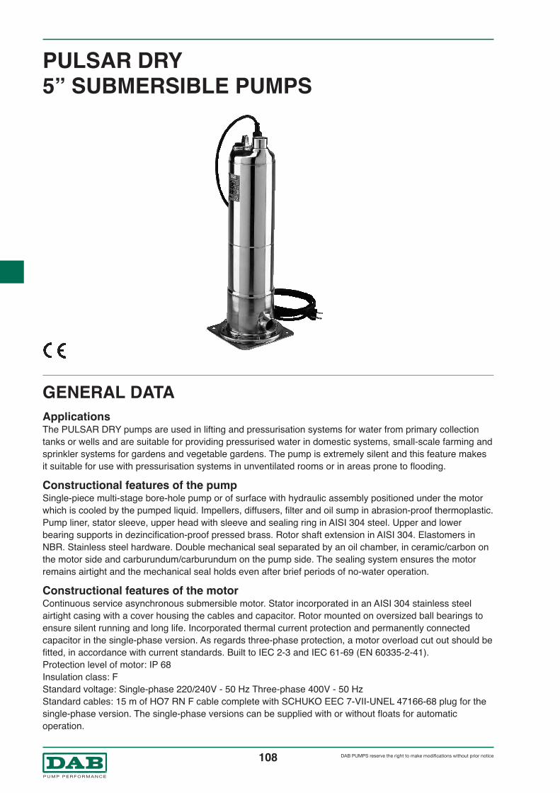
108®
DAB PUMPS reserve the right to make modifications without prior notice
PULSAR DRY5” SUBMERSIBLE PUMPS
GENERAL DATAApplicationsThe PULSAR DRY pumps are used in lifting and pressurisation systems for water from primary collectiontanks or wells and are suitable for providing pressurised water in domestic systems, small-scale farming andsprinkler systems for gardens and vegetable gardens. The pump is extremely silent and this feature makesit suitable for use with pressurisation systems in unventilated rooms or in areas prone to flooding.
Constructional features of the pumpSingle-piece multi-stage bore-hole pump or of surface with hydraulic assembly positioned under the motorwhich is cooled by the pumped liquid. Impellers, diffusers, filter and oil sump in abrasion-proof thermoplastic.Pump liner, stator sleeve, upper head with sleeve and sealing ring in AISI 304 steel. Upper and lowerbearing supports in dezincification-proof pressed brass. Rotor shaft extension in AISI 304. Elastomers inNBR. Stainless steel hardware. Double mechanical seal separated by an oil chamber, in ceramic/carbon onthe motor side and carburundum/carburundum on the pump side. The sealing system ensures the motorremains airtight and the mechanical seal holds even after brief periods of no-water operation.
Constructional features of the motorContinuous service asynchronous submersible motor. Stator incorporated in an AISI 304 stainless steelairtight casing with a cover housing the cables and capacitor. Rotor mounted on oversized ball bearings toensure silent running and long life. Incorporated thermal current protection and permanently connectedcapacitor in the single-phase version. As regards three-phase protection, a motor overload cut out should befitted, in accordance with current standards. Built to IEC 2-3 and IEC 61-69 (EN 60335-2-41).Protection level of motor: IP 68Insulation class: FStandard voltage: Single-phase 220/240V - 50 Hz Three-phase 400V - 50 HzStandard cables: 15 m of HO7 RN F cable complete with SCHUKO EEC 7-VII-UNEL 47166-68 plug for thesingle-phase version. The single-phase versions can be supplied with or without floats for automaticoperation.

109®
DAB PUMPS reserve the right to make modifications without prior notice
- Operating range: from 0.9 to 7.2 m3/h with a head of up to 86 m.
- Pumped liquid: clean, without solid or abrasive substances, not aggressive.
- Max. quantity of sand in water: 50 gr/m3
- Liquid temperature range: from 0°C to +40°C
- Maximum depth of immersion: 20 metres
- Protection level of motor: IP 68
- Protection class of motor: F
- Maximum operating pressure: 10 bar
- Installation: fixed or portable, horizontal or vertical.
- Operation: manual or automatic (continuous operation with pump totally
submerged)
- Diameter of delivery connection: 1" 1/4 GAS
- Maximum diameter of pump: 138 mm
TECHNICAL DATA
170
82
16
81
7
77
115
105
304
6
4
98
166
10
N.
IMPELLER
DIFFUSER
SHAFT WITH ROTOR
MOTOR CASING WITH STATOR
COMPLETE UPPER MECHANICAL SEAL
COMPLETE LOWER MECHANICAL SEAL
PUMP LINER
UPPER BEARING SUPPORT
LOWER BEARING SUPPORT
DIFFUSER BOX
OIL SUMP
SEAL LUBRICANT
CABLE SLOT COVER
REAR DISK
4*
6*
7*
10*
16*
16b
77*
81*
82*
98*
105*
115
170*
304*
TECHNOPOLYMER
TECHNOPOLYMER
AISI 304 ( In contact with the liquid)
AISI 304
NBR/CERAMIC/CARBON
NBR/SILICON/SILICON
AISI 304
BRASS
BRASS
TECHNOPOLYMER
TECHNOPOLYMER
ESSO MARCOL 172 OIL
TECHNOPOLYMER
TECHNOPOLYMER
PARTS MATERIALS
*In contact with the pumped liquid
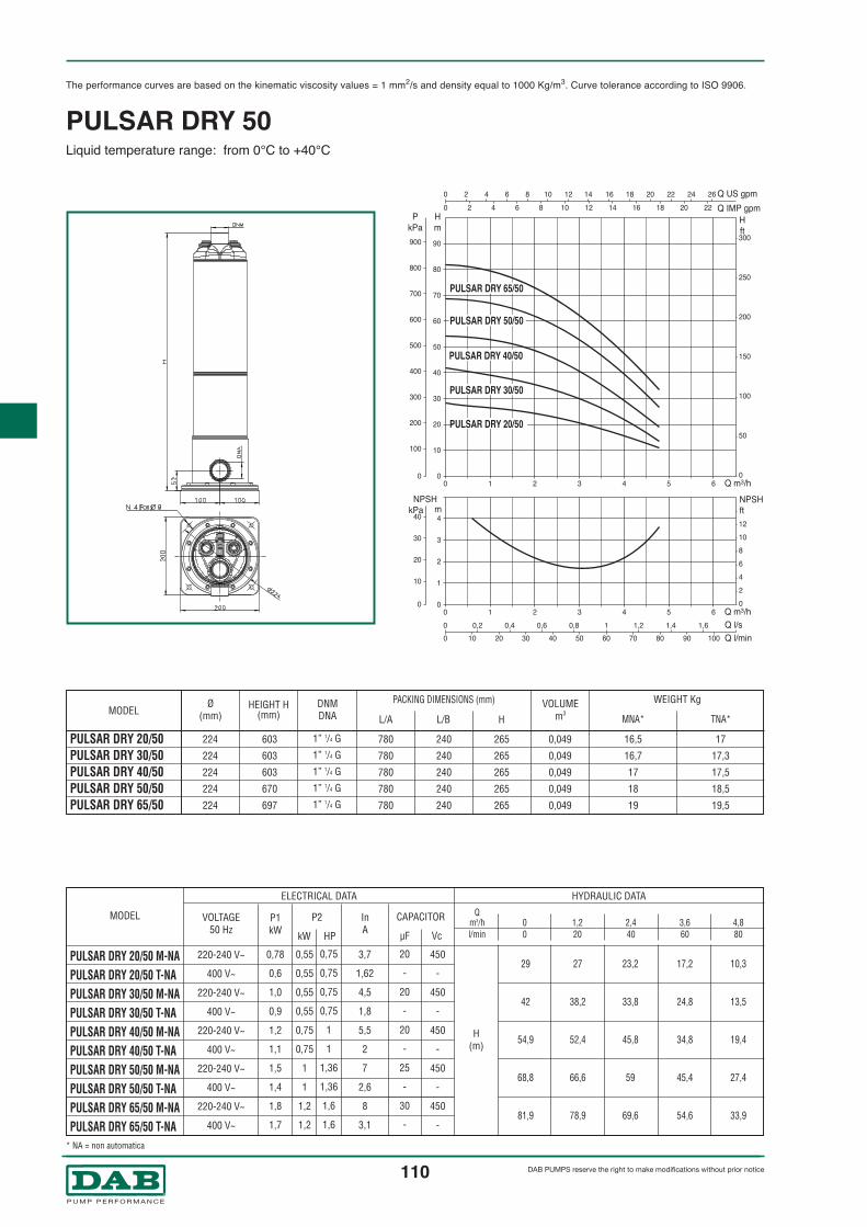
110®
DAB PUMPS reserve the right to make modifications without prior notice
The performance curves are based on the kinematic viscosity values = 1 mm2/s and density equal to 1000 Kg/m3. Curve tolerance according to ISO 9906.
PULSAR DRY 50Liquid temperature range: from 0°C to +40°C
* NA = non automatica
Ø(mm)
HEIGHT H(mm) MNA* TNA*
DNMDNAMODEL
PACKING DIMENSIONS (mm)
HL/BL/A
WEIGHT KgVOLUMEm3
0 0
H m
P kPa
10 100
20 200
30 300
40 400
50 500
60 600
70 700
80 800
90 900
0
10
20
30
40
0
0
2
4
6
8
10
12
50
100
150
200
250
300
H ft
m NPSH kPa
NPSH ft
0
0
Q IMP gpm
Q US gpm 2 4 6 8 10 12 14 16 18 20 22 24 26
2 4 6 8 10 12 14 16 18 20 22
0 1 2 3 4 5 6
0
0
Q m3/h
0
1
2
3
4
0 1 2 3 4 5 6 Q m3/h Q l/s
Q l/min 0,2 0,4 0,6 0,8 1 1,2 1,4 1,6
10 20 30 40 50 60 70 80 90 100
PULSAR DRY 30/50
PULSAR DRY 20/50
PULSAR DRY 40/50
PULSAR DRY 50/50
PULSAR DRY 65/50
PULSAR DRY 20/50PULSAR DRY 30/50PULSAR DRY 40/50PULSAR DRY 50/50PULSAR DRY 65/50
MODEL InA
H(m)
ELECTRICAL DATA HYDRAULIC DATA
P1kW
CAPACITOR
µF Vc
P2
kW HP
Qm3/h 0 1,2 2,4 3,6 4,8l/min 0 20 40 60 80
220-240 V~
400 V~
220-240 V~
400 V~
220-240 V~
400 V~
220-240 V~
400 V~
220-240 V~
400 V~
VOLTAGE50 Hz
1” 1/4 G
1” 1/4 G
1” 1/4 G
1” 1/4 G
1” 1/4 G
265
265
265
265
265
0,049
0,049
0,049
0,049
0,049
0,78
0,6
1,0
0,9
1,2
1,1
1,5
1,4
1,8
1,7
0,55
0,55
0,55
0,55
0,75
0,75
1
1
1,2
1,2
0,75
0,75
0,75
0,75
1
1
1,36
1,36
1,6
1,6
3,7
1,62
4,5
1,8
5,5
2
7
2,6
8
3,1
20
-
20
-
20
-
25
-
30
-
450
-
450
-
450
-
450
-
450
-
224
224
224
224
224
603
603
603
670
697
780
780
780
780
780
240
240
240
240
240
16,5
16,7
17
18
19
17
17,3
17,5
18,5
19,5
PULSAR DRY 20/50 M-NAPULSAR DRY 20/50 T-NAPULSAR DRY 30/50 M-NAPULSAR DRY 30/50 T-NAPULSAR DRY 40/50 M-NAPULSAR DRY 40/50 T-NAPULSAR DRY 50/50 M-NAPULSAR DRY 50/50 T-NAPULSAR DRY 65/50 M-NAPULSAR DRY 65/50 T-NA
29 27 23,2 17,2 10,3
42 38,2 33,8 24,8 13,5
54,9 52,4 45,8 34,8 19,4
68,8 66,6 59 45,4 27,4
81,9 78,9 69,6 54,6 33,9

111®
DAB PUMPS reserve the right to make modifications without prior notice
The performance curves are based on the kinematic viscosity values = 1 mm2/s and density equal to 1000 Kg/m3. Curve tolerance according to ISO 9906.
PULSAR DRY 80Liquid temperature range: from 0°C to +40°C
* NA = non automatica
0 0
H m
P kPa
10 100
20 200
30 300
40 400
50 500
60 600
70 700
80 800
0
50
100
150
200
250
H ft
0
0
Q IMP gpm
Q US gpm 4 8 12 16 20 24 28
4 8 12 16 20 24
0 1 2 3 4 5 6 7
0
0
Q m3/h
0 1 2 3 4 5 6 7 Q m3/h Q l/s
Q l/min 0,5 1 1,5 2
20 40 60 80 100 120
PULSAR DRY 30/80
PULSAR DRY 40/80
PULSAR DRY 50/80
0
10
20
30
40
0
2
4
6
8
10
12
m NPSH kPa
NPSH ft
0
1
2
3
4
MODEL VOLTAGE50 Hz
InA
450
-
450
-
450
-
H(m)
ELECTRICAL DATA HYDRAULIC DATA
P1kW
CAPACITOR
µF Vc
P2
kW HP
Qm3/h 0 1,2 2,4 3,6 4,8 6 7,2l/min 0 20 40 60 80 100 120
46,8 46 42 35,3 30 20 11
59,2 58,5 54 46,9 40 29 17
70,7 68,2 63,3 54,9 45,8 34,5 20,3
PULSAR DRY 30/80 M-NAPULSAR DRY 30/80 T-NAPULSAR DRY 40/80 M-NAPULSAR DRY 40/80 T-NAPULSAR DRY 50/80 M-NAPULSAR DRY 50/80 T-NA
220-240 V~
400 V~
220-240 V~
400 V~
220-240 V~
400 V~
0,75
0,75
1
1
1,2
1,2
1
1
1,36
1,36
1,6
1,6
1,2
1,2
1,5
1,4
1,8
1,6
5,4
2
7
2,5
8,2
3
20
-
25
-
30
-
Ø(mm)
HEIGHT H(mm) MNA* TNA*
DNMDNAMODEL
PACKING DIMENSIONS (mm)
HL/BL/A
WEIGHT KgVOLUMEm3
PULSAR DRY 30/80PULSAR DRY 40/80PULSAR DRY 50/80
224
224
224
603
670
697
780
780
780
1” 1/4 G
1” 1/4 G
1” 1/4 G
240
240
240
265
265
265
0,049
0,049
0,049
17
18
19
17,5
18,5
19,5

112®
DAB PUMPS reserve the right to make modifications without prior notice
BORE-HOLE PUMPS FOR 6” WELLS
GENERAL DATAApplicationsMultistage centrifugal bore-hole electric pumps for wells with a diameter of 6” or greater, capable ofdeveloping a wide range of flows and heads.
These pumps can be used in a wide range of lifting, distributing and pressurising applications in civil andindustrial supplies, autoclaves and tanks, fire-fighting and washing installations, and irrigation systems.
Construction features of pumpMotor support and delivery in stainless spheroidal cast iron (niresist D2B). Lower support dimensioned toNEMA 6” standard. Check valve incorporated in delivery support. Bush bearings: bronze rubber. Totally protected splined shaft (AISI 420). Wear rings, stage box, cablesheath, extraction grid in stainless steel (AISI 304). Noryl impellers and diffusers.
Construction features of motorAsynchronous 2-pole submerged motor totally built from AISI 304 stainless steel. Squirrel-cage rotor mounted on a self-centring thrust block bearing suitable for withstanding axial loads.Stator encased in self-sealing synthetic resin and inserted in a stainless steel airtight casing. The bearingsare lubricated by the pumped liquid. Protection devices must be provided by the user according to EN 60947-4-1 (Cut-in delay <10 sec. a 5 x In).Flanging sized to NEMA 4”. NEMA-6” flanging Protection level: IP 58 Insulation class: F Input voltage: three-phase 400 V / 50Hz (+6% -10% Un)

113®
DAB PUMPS reserve the right to make modifications without prior notice
- Operating range: from 66 m3/h with a head of up to 468 mt.
- Pumped liquid: clean, without solid or abrasive substances, not aggressive.
- Starts/hour: max 20
- Cooling flow: 16 cm/sec.
- Max. quantity of sand in water 40 gr/m3
- Temperature range: 30°C
- Minimun recomennded levelon suction side: mt.1
- Accessories: see page 113
- Power cable section: see table on page 114
- Installation: only vertical (horizontal on request).
TECHNICAL DATA
N. PARTS*
SUPPORT
IMPELLER
DIFFUSER
DISC
COUPLING
SHOULDER WASHER
SPACER BUSHING
SUCTION SIDE SUPPORT
INTERMEDIATE SUPPORT
SHAFT SLEEVE
COUNTERTHRUST RING
PUMP LINER
DIFFUSER BODY
VALVE BODY
SPHEROIDAL CAST IRON
TECHNOPOLYMER
TECHNOPOLYMER
TECHNOPOLYMER
STAINLESS STEEL
STAINLESS STEEL
STAINLESS STEEL AISI 304
STAINLESS STEEL AISI 304
STAINLESS STEEL AISI 304
BRONZE
STAINLESS STEEL AISI 304
STAINLESS STEEL 304
STAINLESS STEEL AISI 304
SPHEROIDAL CAST IRON
3
4
6
34
40
44
55
57
57A
58
66
69
98
117
MATERIALS
* In contact with the liquid

114®
DAB PUMPS reserve the right to make modifications without prior notice
The performance curves are based on the kinematic viscosity values = 1 mm2/s and density equal to 1000 Kg/m3. Curve tolerance according to ISO 9906.
S6BMax. ambient temperature: 30°C
POTENZA MOTORERICHIESTA
kW HPMODEL
H1(mm)
H2(mm)
Pumpweight
Totalweight
Ø
H(mm)
WEIGHTKg.
Axial loadN 1/m Voltage
50 HzPower InstalledkW HP
IN IA MAη (%) cos ϕMODEL
HYDRAULIC DATA (n ∼ 2850 1/min)
MOTORS
0 2 4 6 8 10 12 14 16 Q m3/h0
50
100
150
200
250
300
350
400
450
H�m
0
500
1000
1500
2000
2500
3000
3500
4000
4500
P�kPa
0 50 100 150 200 250 Q l/min
0 1 2 3 4 Q l/s
0
200
400
600
800
1000
1200
1400
H� ft
0 10 20 30 40 50 60 7 Q US gpm
0 10 20 30 40 50 � Q IMP gpm
S6 B9
S6 B12
S6 B15
S6 B18
S6 B21
S6 B24
S6 B28
0 Q m3/h2 4 6 8 10 12 14 161
2
3
4
m
40
50
60
70
NPSH η%
NPSH
η %
S6B-9S6B-12S6B-15S6B-18S6B-21S6B-24S6B-28
4
5,5
7,5
9,2
9,2
11
13
5,5
7,5
10
12,5
12,5
15
17,5
625
738
852
966
1079
1193
1397
1206
1352
1498
1645
1758
1904
2173
11
13,5
15
17
19,5
21
23,5
46,6
52,7
58,3
62,6
65,1
70
78,5
3”
3”
3”
3”
3”
3”
3”
147 125 114 96 85 46
196 172 152 128 113 64
224 216 190 160 141 80
293 250 228 193 169 96
342 291 266 225 197 112
391 340 304 257 226 128
446 400 354 300 263 149
0 6 8,4 10,8 12 15
0 100 140 180 200 250
H
(m)
Qm3/hl/min
S6B-9S6B-12S6B-15S6B-18S6B-21S6B-24S6B-28
581
614
646
679
679
711
776
35,6
39,2
43,3
45,6
45,6
49
55
6500
6500
15500
15500
15500
15500
15500
2860
2870
2860
2870
2870
2860
2860
3X400 V ~
3X400 V ~
3X400 V ~
3X400 V ~
3X400 V ~
3X400 V ~
3X400 V ~
4
5,5
7,5
9,2
9,2
11
15
5,5
7,5
10
12,5
12,5
15
20
9,3
12,5
16
20,7
20,7
23,3
31,3
43
64
83
112
112
129
169
78
79
79
81
81
81
81
0,82
0,82
0,86
0,80
0,80
0,85
0,85
1,5
1,9
1,9
2,2
2,2
2,1
2,1

115®
DAB PUMPS reserve the right to make modifications without prior notice
The performance curves are based on the kinematic viscosity values = 1 mm2/s and density equal to 1000 Kg/m3. Curve tolerance according to ISO 9906.
S6DMax. ambient temperature: 30°C
P2NOMINAL
kW HPMODEL
H(mm)
WEIGHTKg.
Axial loadN 1/m Voltage
50 HzPower InstalledkW HP
IN IA MAη (%) cos ϕMODEL
HYDRAULIC DATA (n ∼ 2850 1/min)
MOTORS
S6D-6S6D-7S6D-8S6D-9S6D-12S6D-15S6D-18S6D-21S6D-24S6D-30
3,7
5,5
5,5
5,5
7,5
9,2
11
13
15
18,5
5
7,5
7,5
7,5
10
12,5
15
17,5
20
25
H
(m)
Qm3/hl/min
S6D-6S6D-7S6D-8S6D-9S6D-12S6D-15S6D-18S6D-21S6D-24S6D-30
581
614
614
614
646
679
711
776
776
842
35,6
39,2
39,2
39,2
43,3
45,6
49
55
55
61,4
6500
6500
6500
6500
15500
15500
15500
15500
15500
15500
2860
2870
2870
2870
2860
2870
2860
2860
2860
2850
3X400 V ~
3X400 V ~
3X400 V ~
3X400 V ~
3X400 V ~
3X400 V ~
3X400 V ~
3X400 V ~
3X400 V ~
3X400 V ~
4
5,5
5,5
5,5
7,5
9,2
11
15
15
18,5
5,5
7,5
7,5
7,5
10
12,5
15
20
20
25
9,3
12,5
12,5
12,5
16
20,7
23,3
31,3
31,3
38,5
43
64
64
64
83
112
129
169
169
231
78
79
79
79
79
81
81
81
81
82
0,82
0,82
0,82
0,82
0,86
0,80
0,85
0,85
0,85
0,85
1,5
1,9
1,9
1,9
1,9
2,2
2,1
2,1
2,1
2,5
94 87 80 76 63 44
109 101 93 89 74 51
125 115 106 102 84 58
140 130 120 114 95 66
187 173 160 153 127 88
234 216 201 191 158 110
281 260 241 229 190 132
328 304 281 267 222 154
374 347 321 305 254 176
468 464 401 381 317 220
0 8,4 10,8 12 15 18
0 140 180 200 250 300
0 2 4 6 8 10 12 14 16 Q m3/h0
50
100
150
200
250
300
350
400
450
H�m
0
500
1000
1500
2000
2500
3000
3500
4000
4500
P�kPa
0 50 100 150 200 250 Q l/min
0 1 2 3 4 Q l/s
0
200
400
600
800
1000
1200
1400
H� ft
0 10 20 30 40 50 60 7 Q US gpm
0 10 20 30 40 50 � Q IMP gpm
S6 D6
S6 D7
S6 D8S6 D9
S6 D12
S6 D15
S6 D18
S6 D21
S6 D24
S6 D30
0 Q m3/h2 4 6 8 10 12 14 161
2
3
4
m
40
50
60
70
NPSH η%
NPSH
η %
H1(mm)
H2(mm)
Pumpweight
Totalweight
Ø
511
549
587
625
738
852
966
1079
1193
1474
1092
1163
1201
1239
1384
1531
1677
1855
1969
2316
9
9,5
11
11
13,5
15
17
19
21
25
44,6
48,7
49,2
50,2
56,8
60,6
66
74
76
86,4
3”
3”
3”
3”
3”
3”
3”
3”
3”
3”

116®
DAB PUMPS reserve the right to make modifications without prior notice
The performance curves are based on the kinematic viscosity values = 1 mm2/s and density equal to 1000 Kg/m3. Curve tolerance according to ISO 9906.
S6FMax. ambient temperature: 30°C
P2NOMINAL
kW HPMODEL
H(mm)
WEIGHTKg.
Axial loadN 1/m Voltage
50 HzPower InstalledkW HP
IN IA MAη (%) cos ϕMODEL
HYDRAULIC DATA (n ∼ 2850 1/min)
MOTORS
S6F-4S6F-6S6F-8S6F-10S6F-12S6F-14S6F-16S6F-20S6F-24
4
5,5
7,5
9,2
11
13
15
18,5
22
5
7,5
10
12,5
15
17,5
20
25
30
H
(m)
Qm3/hl/min
S6F-4S6F-6S6F-8S6F-10S6F-12S6F-14S6F-16S6F-20S6F-24
581
614
646
679
711
776
776
842
907
35,6
39,2
43,3
45,6
49
54,8
54,8
61,4
67,4
6500
6500
15500
15500
15500
15500
15500
15500
15500
2860
2870
2860
2870
2860
2860
2860
2850
2860
3X400 V ~
3X400 V ~
3X400 V ~
3X400 V ~
3X400 V ~
3X400 V ~
3X400 V ~
3X400 V ~
3X400 V ~
4
5,5
7,5
9,2
11
15
15
18,5
22
5
7,5
10
12,5
15
20
20
25
30
9,3
12,5
16
20,7
23,3
31,3
31,3
38,5
45,3
43
64
83
112
129
169
169
231
268
78
79
79
81
81
81
81
82
83
0,82
0,82
0,86
0,80
0,85
0,85
0,85
0,85
0,86
1,5
1,9
1,9
2,2
2,1
2,1
2,1
2,5
2,4
61 53 51 48 40 15
91 80 76 71 59 22
122 106 101 95 79 30
152 133 126 119 99 37
182 159 154 143 119 47
213 186 178 167 139 56
243 212 204 190 158 64
304 265 255 238 198 80
365 318 305 286 238 96
0 12 15 18 24 36
0 200 250 300 400 600
0 4 8 12 16 20 24 28 32 Q m3/h0
50
100
150
200
250
300
350
H�m
0
500
1000
1500
2000
2500
3000
3500
P�kPa
0 100 200 300 400 500 Q l/min
0 2 4 6 8 Q l/s
0
200
400
600
800
1000
1200
H� ft
0 20 40 60 80 100 120 140 Q US gpm
0 20 40 60 80 100 � Q IMP gpm
S6 F4
S6 F6
S6 F8
S6 F10
S6 F12
S6 F14
S6 F16
S6 F20
S6 F24
0 Q m3/h4 8 12 16 20 24 28 321
2
3
4
m
30
40
50
60
70
NPSH η%
NPSH
η %
H1(mm)
H2(mm)
Pumpweight
Totalweight
Ø
511
625
738
852
966
1079
1193
1474
1700
1092
1239
1384
1531
1677
1855
1969
2316
2607
10
11
13
14,5
16
17,5
20
24
27,5
44,6
49,7
56,3
60,1
65
72,3
73,8
85,4
94,9
3”
3”
3”
3”
3”
3”
3”
3”
3”

117®
DAB PUMPS reserve the right to make modifications without prior notice
The performance curves are based on the kinematic viscosity values = 1 mm2/s and density equal to 1000 Kg/m3. Curve tolerance according to ISO 9906.
S6HMax. ambient temperature: 30°C
P2NOMINAL
kW HPMODEL
H(mm)
WEIGHTKg.
Axial loadN 1/m Voltage
50 HzPower InstalledkW HP
IN IA MAη (%) cos ϕMODEL
HYDRAULIC DATA (n ∼ 2850 1/min)
MOTORS
S6H-3S6H-4S6H-5S6H-6S6H-8S6H-9S6H-10S6H-12S6H-15S6H-18S6H-20
4
5,5
7,5
9,2
11
13
15
18,5
22
26
30
5,5
7,5
10
12,5
15
17,5
20
25
30
35
40
48 42 39 30 12
63 57 53 40 16
78 71 66 50 20
94 85 80 60 23
126 114 106 80 31
141 128 120 90 35
157 142 133 100 39
188 170 160 1200 47
235 213 199 150 59
283 256 239 180 71
314 284 266 200 78
0 18 24 36 48
0 300 400 600 800
H
(m)
Qm3/hl/min
S6H-3S6H-4S6H-5S6H-6S6H-8S6H-9S6H-10S6H-12S6H-15S6H-18S6H-20
581
614
646
679
711
776
776
842
907
1037
1037
35,6
39,2
43,3
45,6
49
54,8
54,8
61,4
67,4
81,7
81,7
6500
6500
15500
15500
15500
15500
15500
15500
15500
27500
27500
2860
2870
2860
2870
2860
2860
2860
2850
2860
2860
2860
3X400 V ~3X400 V ~3X400 V ~3X400 V ~3X400 V ~
3X400 V ~
3X400 V ~
3X400 V ~
3X400 V ~
3X400 V ~
3X400 V ~
4
5,5
7,5
9,2
11
15
15
18,5
22
30
30
5,5
7,5
10
12,5
15
20
20
25
30
40
40
9,3
12,5
16
20,7
23,3
31,3
31,3
38,5
45,3
63,5
63,5
43
64
83
112
129
169
169
231
268
393
393
78
79
79
81
81
81
81
82
83
83
83
0,82
0,82
0,86
0,80
0,85
0,85
0,85
0,85
0,86
0,84
0,84
1,5
1,9
1,9
2,2
2,1
2,1
2,1
2,5
2,4
2,6
2,6
0 8 16 24 32 40 Q m3/h
0 100 200 300 400 500 600 700 Q l/min
0 2 4 6 8 10 12 Q l/s
0 20 40 60 80 100 120 140 160 180 Q US gpm
0 20 40 60 80 100 120 140 � Q IMP gpm
0 Q m3/h8 16 24 32 402
3
4
5
30
40
50
60
0
40
80
120
160
200
240
280
320
H�m
0
400
800
1200
1600
2000
2400
2800
P�kPa
0
200
400
600
800
1000
H� ft
S6 H3
S6 H4
S6 H5
S6 H6
S6 H8
S6 H9
S6 H10
S6 H12
S6 H15
S6 H18
S6 H20
NPSH η%
NPSH
η %
H1(mm)
H2(mm)
Pumpweight
Totalweight
Ø
463
522
582
642
762
822
882
1002
1182
1414
1534
1044
1136
1228
1321
1473
1598
1658
1844
2089
2451
2571
7,5
8,5
9,5
10,5
12
14
14
16
19
22
25
43,1
47,7
52,8
56,1
61
67,8
68,8
77,4
86,4
103,7
106,7
3”
3”
3”
3”
3”
3”
3”
3”
3”
3”
3”

118®
DAB PUMPS reserve the right to make modifications without prior notice
The performance curves are based on the kinematic viscosity values = 1 mm2/s and density equal to 1000 Kg/m3. Curve tolerance according to ISO 9906.
S6LMax. ambient temperature: 30°C
P2NOMINAL
kW HPMODEL
H(mm)
WEIGHTKg.
Axial loadN 1/m Voltage
50 HzPower InstalledkW HP
IN IA MAη (%) cos ϕMODEL
HYDRAULIC DATA (n ∼ 2850 1/min)
MOTORS
S6L-3S6L-4S6L-5S6L-6S6L-8S6L-9S6L-10S6L-12S6L-15S6L-18
5,5
7,5
9,2
11
13
15
18,5
22
26
30
7,5
10
12,5
15
17,5
20
25
30
35
40
H
(m)
Qm3/hl/min
S6L-3S6L-4S6L-5S6L-6S6L-8S6L-9S6L-10S6L-12S6L-15S6L-18
614
646
679
711
776
776
842
907
1037
1037
39,2
43,3
45,6
49
54,8
54,8
61,4
67,4
81,7
81,7
6500
15500
15500
15500
15500
15500
15500
15500
27500
27500
2870
2860
2870
2860
2860
2860
2850
2860
2860
2860
3X400 V ~
3X400 V ~
3X400 V ~
3X400 V ~
3X400 V ~
3X400 V ~
3X400 V ~
3X400 V ~
3X400 V ~
3X400 V ~
5,5
7,5
9,2
11
15
15
18,5
22
30
30
7,5
10
12,5
15
20
20
25
30
40
40
12,5
16
20,7
23,3
31,3
31,3
38,5
45,3
63,5
63,5
64
83
112
129
169
169
231
268
393
393
79
79
81
81
81
81
82
83
83
83
0,82
0,86
0,80
0,85
0,85
0,85
0,85
0,86
0,84
0,84
1,9
1,9
2,2
2,1
2,1
2,1
2,5
2,4
2,6
2,6
40 28 22 18 7
52 38 29 23 9
65 48 36 29 11
78 57 44 36 13
104 77 58 47 18
118 86 66 53 20
131 96 73 59 23
158 114 88 71 27
197 144 110 89 34
236 173 130 106 41
0 36 48 54 66
0 600 800 900 1100
0 10 20 30 40 50 60 Q m3/h0
40
80
120
160
200
H�m
0
400
800
1200
1600
2000
P�kPa
0 100 200 300 400 500 600 700 800 900 1000 Q l/min
0 4 8 12 16 Q l/s
0
100
200
300
400
500
600
700
H� ft
0 40 80 120 160 200 240 Q US gpm
0 40 80 120 160 200 � Q IMP gpm
S6 L3
S6 L4
S6 L5
S6 L6
S6 L8
S6 L9
S6 L10
S6 L12
S6 L15
S6 L18
0 Q m3/h10 20 30 40 50 601
2
3
4
5
30
40
50
60
70
NPSH η%
NPSH
η %
H1(mm)
H2(mm)
Pumpweight
Totalweight
Ø
463
522
582
642
762
822
882
1002
1182
1414
1077
1168
1261
1353
1538
1598
1724
1909
2219
2451
7,5
8,5
9,5
10,5
12
13
14
16
19
22
46,7
51,8
55,1
59,5
66,8
67,8
75,4
83,4
100,7
103,7
3”
3”
3”
3”
3”
3”
3”
3”
3”
3”

119®
DAB PUMPS reserve the right to make modifications without prior notice
COMMAND AND CONTROL EQUIPMENT FOR SUBMERGED PUMPS 6”
ES 7,5 T
Electrode probeUsed in the protection and CONTROL SYSTEM ES. Ideal forconductible liquids with maximum temperatures of +40°C.To be connected with a 1,5 mm2 cable - 550V insulation.
Electric control unit for protecting three-phase electric bore-hole pumps fromrunning without water (see table). The panel is self-protected and protects theelectric pump from overloads and short circuits with a manually resettable device.Complete with: - Terminals for min/max. level control (with floats, pressure switches, etc.)- Terminals for connecting a remote control unit- Button for manual/automatic pump operation - Timer for adjusting pause time against running without water.- Protection against an excessive number of start-ups (can be disabled).- Terminals (without potential) for powering a remote acoustic alarm.Can work with 1, 2 or 3 probes depending on use.Protection level IP 55.Operating temperature range: from –10°C to +40°C.Supplied standard with an electric probe and brackets for wall-mounting.Cabinet for wall mounting in flame-proof, thermoplastic material.
MODEL
ES 7,5 T
VOLTAGE50-60 Hz
4-5,5 7,5 14 270 300 190 5,6
POWER kW
P2 MOT.
POWERNOM. MAXD’IMP. (kW)
WEIGHTkg
CURRENTMAX
A
DIMENSIONS
A B H
ES 10 TES 12,5 TES 15 TES 20 TES 25 TES 30 TES 40 T
Electrical panels for protection and automatic control using float/s for bore-holethree-phase electric pumps, installed singly. Available for direct and star-delta starting.Cabinet for wall mounting in flame-proof, thermoplastic material.The panel is self-protected and protects the electric pump from overloading andshort circuits, power failure with a manually resettable device.Supplied complete with:- isolator for the power input line with padlockable door handle;- self-protected transformer for 24V powering of external commands;- terminals for connecting electric pump/s and min. and max. control float/s;- Probes module for the running without water control;- terminals for connecting a remote acoustic or luminous alarm;(without potential)
- switch on the front of the panel for man - 0 - out operation of the electric pump- LED on the front of the panel:
- red LED indicating that the thermal-current protection device has cut in- Green LED on the front of the panel indicating the pump is working- yellow LED indicating that the auxiliary circuits are working correctly- Operating temperature range: -10°C +40°C- Storage temperature range: -25°C +55°C- Relative humidity (without condensation): 50% a t40°C MAX (90% at 20°C)- Max. altitude: 3000 m (a.s.l.)- Level of protection: IP55- The panels are built to EN 60204-1 and EN 60439-1 standards- Supplied standard with an electric probe
MODEL
ES 10 TES 12,5 TES 15 TES 20 TES 25 TES 30 TES 40 T
VOLTAGE50-60 Hz
400V400V400V400V400V400V400V
POWER kW
P2 MOT.WEIGHT
kgCURRENT
MAXA
DIMENSIONS
A B H
7,59,21115
18,52230
18252532406380
270270270270270270270
270270360360360360360
165165165165165165165
5,65,98
8,18,38,58,7

120®
DAB PUMPS reserve the right to make modifications without prior notice
6” DAB MOTORS
6” submerged electric motor, two-pole asynchronous type, with jacket made entirely of stainless steel.Rotor mounted on thrust bearings designed to carry high axial loads.16.000 N for motors up to 30 HP (22Kw)27.000 N for motors up to 50 HP (37Kw)The motor and internal components are cooled by a mixture of water and polypropylene glycol to safeguardagainst pollution of the water table. The stator is encased in a hermetically sealed container (canned type)with steel outer jacket. Motor protection to be provided by the user.
NEMA flange Power supply voltages: 50 Hz: 230V, 230V/400V (Y/D), 400V, 400V/690V (Y/D)
60 Hz: 230V, 380V, 460V, 575V Protection class IP68 Insulation class F
Constructional features of the motor
STATOR. The stator is encased in a hermetically sealed container with steel outer jacket.Insulation class F, the motor can handle 25 starts/stops per hour
POWER CABLE. All the motors are supplied as standard with a four-pole removable cablethat enables easy removal in case of assembly/disassembly of the motor or part of the pump,to prevent damage to the power cable itself.
SUPPORTS. The lower and upper supports are made of G20 cast iron painted withcataphoresis paint and are equipped with carbon graphite bushings.
THRUST BEARING SYSTEM. Kingsbury-type thrust bearings with extra high resistanceshoes made of hardened steel. The special design and treatment guarantee high durability andlong life.
ROTOR SHAFT. Made of stainless steel, with AISI 316 shaft end (up to 25 HP) and AISI 329for the remaining sizes.
MECHANICAL SEAL. All the 6” motors are equipped with traditional type ceramic aluminamechanical seal. Silicon carbide mechanical seal available on request.
All the motors are equipped with connector with 4 m cable.

121®
DAB PUMPS reserve the right to make modifications without prior notice
L(mm)
5,5 4 39,5
43,2
45,5
49
53
59
66,5
72,5
85
3 16000 600
7,5 5,5 3 16000 631
10 7,5 3 16000 660
12,5 9,2 3 16000 685
15 11 3 16000 730
20 15 3 16000 785
25 18,5 3 16000 860
30 22 3 16000 920
40 30 3 16000 1050
AXIALTHRUST
Weight(Kg)
HP kW PHASE
5,5 4 230 17,3 5290 2840 0,77 0,76 74 ∆
5,5 4 400 10 5290 2840 0,77 0,76 43 Y
5,5 4 415 10,5 5500 2850 0,73 0,73 47 Y
5,5 4 400/690 10 5290 2840 0,77 0,76 14 Y/∆
7,5 5,5 230 23,7 7270 2840 0,77 0,76 112 ∆
7,5 5,5 400 13,7 7270 2840 0,77 0,76 65 Y
7,5 5,5 415 14 7330 2850 0,73 0,73 70 Y
7,5 5,5 400/690 13,7 7270 2840 0,77 0,76 22 Y/∆
10 7,5 230 28,7 9550 2840 0,83 0,78 128 ∆
10 7,5 400 16,6 9550 2840 0,83 0,78 74 Y
10 7,5 415 17 9700 2860 0,79 0,77 80 Y
10 7,5 400/690 16,6 9550 2840 0,83 0,78 25 Y/∆
12,5 9,2 230 36,8 11460 2840 0,78 0,8 147 ∆
12,5 9,2 400 21,3 11460 2840 0,78 0,8 85 Y
12,5 9,2 415 21,6 11600 2850 0,73 0,79 95 Y
12,5 9,2 400/690 21,3 11460 2840 0,78 0,8 28 Y/∆
15 11 230 42,3 13860 2840 0,81 0,79 195 ∆
15 11 400 24,5 13860 2840 0,81 0,79 113 Y
15 11 415 25,1 14100 2850 0,79 0,78 125 Y
15 11 400/690 24,5 13860 2840 0,81 0,79 37 Y/∆
20 15 230 56 17960 2840 0,8 0,83 277 ∆
20 15 400 32,5 17960 2840 0,8 0,83 160 Y
20 15 415 33,3 18200 2850 0,77 0,82 170 Y
20 15 400/690 32,5 17960 2840 0,8 0,83 53 Y/∆
25 18,5 230 73,8 22300 2850 0,8 0,83 370 ∆
25 18,5 400 42,7 22300 2850 0,8 0,83 215 Y
25 18,5 415 43,3 22450 2860 0,79 0,82 230 Y
25 18,5 400/690 42,7 22300 2850 0,8 0,83 72 Y/∆
30 22 230 86,5 26500 2850 0,8 0,83 415 ∆
30 22 400 50 26500 2850 0,8 0,83 240 Y
30 22 415 50,8 26850 2860 0,79 0,82 257 Y
30 22 400/690 50 26500 2850 0,8 0,83 80 Y/∆
40 30 400 63 35130 2850 0,81 0,85 280 Y
40 30 415 64 35600 2860 0,8 0,84 296 Y
40 30 400/690 63 35130 2850 0,81 0,85 93 Y/∆
VOLTAGE P2 P2 50 Hz. In P1 MAX R.P.M. cosϕ EFF. Ia CONN.(hp) (kW) (V) (A) (W) η (A)

122®
DAB PUMPS reserve the right to make modifications without prior notice
6” FRANKLIN MOTORS
GENERAL DATAApplicationsThe 6” Franklin Electric motors built according to ISO standard 9001 guarantee reliable operation in wellswith a diameter of 6 inches or larger. The axial and radial bearings, lubricated by the water, enable mainte-nance-free operation. The motors are prefilled with antifreeze, enabling the motor to be stored at temperatu-res down to -15°C. Pressure compensation inside the motor is ensured by a special diaphragm.
Advantages:• Hermetically sealed stator, special resin-filled stator • Removable power supply cable “ Water Block” •Cable material in compliance with drinking water regulations (with related control)• Sand protection and mechanical seal designed to enable optimum operation in the presence of sand• High efficiency at low operating costs • All the motors are pre-filled with liquid and 100% tested• Water-filled design to safeguard against pollution
Technical SpecificationsStandard motor:• 4.0 ... 45 kW• NEMA 6" flange• Protection class: IP68• Number of starts per hour: max. 20• Vertical and horizontal operation• Rated voltage: 380-415V/50Hz, voltage tolerance: +6% / -10% (standard: 415+6% = 440V, 380-10% =342V)• Motor protection: selection of thermal overload relays according to EN 60947-4-1 standard, trip class 10 or10A, trip time < 10 s at 5 x IN• Insulation class F• Ambient temperature: 30°C• Minimum cooling flow 0.16 m/sOptional features• Special voltages available upon request• Motors made entirely of 316 SS stainless steel• PT100 sensor (order separately)• „Sandfighter®“ motors with SiC mechanical seal• Cables available in different lengths, up to 50 m• YΔ start (cable position 90°)• Cooling fluid change• Incorporated PTC temperature sensor• Incorporated transmitter for protection

123®
DAB PUMPS reserve the right to make modifications without prior notice
kWL
mmMOTOR SIZE
WEIGHTKg
4 581,2 135 x 135 x 910 37,5
5,5 614,4 135 x 135 x 910 41,1
7,5 646,2 135 x 135 x 910 45,2
9,3 678,7 135 x 135 x 910 47,5
11 711,2 135 x 135 x 910 50,9
15 776,2 135 x 135 x 1070 56,7
18,5 841,5 135 x 135 x 1070 63,3
22 906,5 135 x 135 x 1070 69,3
30 1036,6 135 x 135 x 1070 83,9
P2(kW)
AXIALTHRUST
VOLTAGE50 Hz
(V)
R.P.M.1/min.
In(A)
Ia(A)
EFF.μ COSϕ Tn
(Nm)Ta
(Nm)
4 15500 220 2840 16,4 73 77 0,85 12,5 17,94 15500 380 2840 9,5 42 77 0,85 12,5 17,94 15500 400 2860 9,3 43 78 0,82 12,3 20,2
5,5 15500 220 2850 22,1 104 78 0,85 18,7 30,35,5 15500 380 2850 12,8 60 78 0,85 18,7 30,35,5 15500 400 2870 12,5 64 79 0,82 18,6 357,5 15500 220 2850 28,2 143 79 0,87 25 437,5 15500 380 2850 16,3 83 79 0,87 25 437,5 15500 400 2860 16 83 79 0,86 25 47,79,3 15500 220 2870 36,4 183 81 0,86 31,1 61,69,3 15500 380 2870 21 106 81 0,86 31,1 61,69,3 15500 400 2870 20,7 112 81 0,8 31,1 68,211 15500 220 2860 41,5 218 81 0,87 37,4 72,811 15500 380 2860 24 126 81 0,87 37,4 72,811 15500 400 2860 23,3 129 81 0,85 37,3 78,315 15500 220 2850 55 283 82 0,86 50 10415 15500 380 2850 32 164 82 0,86 50 10415 15500 400 2860 31,3 169 81 0,85 49,9 107,3
18,5 15500 220 2850 69,2 380 82 0,87 62,4 139,718,5 15500 380 2850 40 220 82 0,87 62,4 139,718,5 15500 400 2850 38,5 231 82 0,85 62,4 154,622 15500 220 2840 81,2 441 82 0,88 75,3 16022 15500 380 2840 47 255 82 0,88 75,3 16022 15500 400 2860 45,3 268 83 0,86 74,7 177,630 15500 220 2860 111 645 82,5 0,85 99,6 237,430 15500 380 2860 64,1 373 82,5 0,85 99,6 237,430 15500 400 2860 63,5 393 83 0,84 99,4 263,1

124®
DAB PUMPS reserve the right to make modifications without prior notice
CHOOSING THE POWER CABLE
The table has been calculated considering a 4% voltage drop along the cable. The loads of the cables have been established for an ambient temperature of 30°C, with H07RNF cables or equivalent.
MODELPower
kW
In
A
QUADRIPOLAR CABLE- SECTION (mm2)
3 x 400V - DIRECT STARTING 3 x 400V - STAR/DELTA STARTING
SECTION (mm2) 1,5 2,5 4 6 10 16 25 1,5 2,5 4 6 10 16 25
S6B-9 4 9,3
MA
XIM
UM
LE
NG
TH IN
ME
TRE
S
61 102 163 244 406
S6B-12 5,5 12,5 47 78 125 187 312 81 134 215 323
S6B-15 7,5 16 59 95 142 237 379 61 102 163 245 408
S6B-18 9,2 20,7 48 76 114 190 304 49 82 131 197 328
S6B-21 9,2 20,7 48 76 114 190 304 49 82 131 197 328
S6B-24 11 23,3 67 100 167 267 418 43 72 115 173 288 461
S6B-28 15 31,3 73 122 195 305 53 84 126 210 336
S6D-6 4 9,3 61 102 163 244 406
S6D-7 5,5 12,5 47 78 125 187 312 81 134 215 323
S6D-8 5,5 12,5 47 78 125 187 312 81 134 215 323
S6D-9 5,5 12,5 47 78 125 187 312 81 134 215 323
S6D-12 7,5 16 59 95 142 237 379 61 102 163 245 408
S6D-15 9,2 20,7 48 76 114 190 304 49 82 131 197 328
S6D-18 11 23,3 67 100 167 267 418 43 72 115 173 288 461
S6D-21 15 31,3 73 122 195 305 53 84 126 210 336
S6D-24 15 31,3 73 122 195 305 53 84 126 210 336
S6D-30 18,5 38,5 98 156 244 42 67 101 168 269 421
S6F-4 4 9,3 61 102 163 244 406
S6F-6 5,5 12,5 47 78 125 187 312 81 134 215 323
S6F-8 7,5 16 59 95 142 237 379 61 102 163 245 408
S6F-10 9,2 20,7 48 76 114 190 304 49 82 131 197 328
S6F-12 11 23,3 67 100 167 267 418 43 72 115 173 288 461
S6F-14 15 31,3 73 122 195 305 53 84 126 210 336
S6F-16 15 31,3 73 122 195 305 53 84 126 210 336
S6F-20 18,5 38,5 98 156 244 42 67 101 168 269 421
S6F-24 22 45,3 86 138 216 60 89 149 238 372
S6H-3 4 9,3 61 102 163 244 406
S6H-4 5,5 12,5 47 78 125 187 312 81 134 215 323
S6H-5 7,5 16 59 95 142 237 379 61 102 163 245 408
S6H-6 9,2 20,7 48 76 114 190 304 49 82 131 197 328
S6H-8 11 23,3 67 100 167 267 418 43 72 115 173 288 461
S6H-9 15 31,3 73 122 195 305 53 84 126 210 336
S6H-10 15 31,3 73 122 195 305 53 84 126 210 336
S6H-12 18,5 38,5 98 156 244 42 67 101 168 269 421
S6H-15 22 45,3 86 138 216 60 89 149 238 372
S6H-18 30 63,5 103 161 67 111 178 278
S6H-20 30 63,5 103 161 67 111 178 278
S6L-3 5,5 12,5 47 78 125 187 312
S6L-4 7,5 16 59 95 142 237 379 61 102 163 245 408
S6L-5 9,2 20,7 48 76 114 190 304 49 82 131 197 328
S6L-6 11 23,3 67 100 167 267 418 43 72 115 173 288 461
S6L-8 15 31,3 73 122 195 305 53 84 126 210 336
S6L-9 15 31,3 73 122 195 305 53 84 126 210 336
S6L-10 18,5 38,5 98 156 244 42 67 101 168 269 421
S6L-12 22 45,3 86 138 216 60 89 149 238 372
S6L-15 30 63,5 103 161 67 111 178 278
S6L-18 30 63,5 103 161 67 111 178 278

DAB PUMPS si riserva il diritto di apportare modifiche senza obbligo di preavviso
NOTES
125®

®
DAB PUMPS si riserva il diritto di apportare modifiche senza obbligo di preavviso
NOTES

DAB PUMPS reserve the right to make modifications without prior notice
NOTES
127®

®
DAB PUMPS reserve the right to make modifications without prior notice
NOTES

TECHNICAL CATALOGUE SECTIONS:
1 WET ROTOR CIRCULATORS AND IN-LINE PUMPS
SELF-PRIMING AND MULTISTAGE CENTRIFUGAL PUMPS
CENTRIFUGAL PUMPS
SUBMERSIBLE AND SUBMERGED PUMPS
BOOSTER SETS
2
3
4
5

2007
®
4
44DAB PUMPS LTD.Unit 4, Stortford Hall IndustrialPark Dunmow Road, Bishops Stortford, HertsCM23 5GZ - UKTel. +44 1279 652 776Fax +44 1279 657 727
DAB PUMPEN DEUTSCHLAND GmbHTackweg 11D - 47918 Tönisvorst - GermanyTel. +49 2151 82136-0 Fax +49 2151 82136-36
DAB PUMPS B.V.Albert Einsteinweg, 45151 DL Drunen - NederlandTel. +31 416 387280Fax +31 416 [email protected]
DAB PUMPS RUSSIA127247 Dmitovskoe sh., 100 bld. 3Moscow, Russiaòåë.: +7 095 485-1679
DAB PUMPS B.V.Brusselstraat 150B-1702 Groot-Bijgaarden - BelgiumTel. +32 2 4668353Fax +32 2 4669218
DAB PUMPS IBERICA S.L.Parque Empresarial San FernandoEdificio Italia Planta 1ª28830 - San Fernando De Henares - Madrid - SpainPh. +34 91 6569545Fax +34 91 6569676
PUMPS AMERICA, INC. DAB PUMPS DIVISION 3226 Benchmark DriveLadson, SC 29456 USAPh. 1-843-824-6332 Toll Free 1-866-896-4DAB (4322)Fax 1-843-797-3366
DAB PUMPS S.p.A.Via M. Polo, 14 - 35035 Mestrino (PD) - ItalyTel. +39 049 9048811 - Fax +39 049 9048847http://www.dabpumps.com
Vendite Italia: Tel. 049 9048873-75-76 049 9048950 Fax 049 9048888
Export Sales Dept: Ph. (+39) 049 9048895-96-97 049 9048964-996 Fax (+39) 049 9048900
Assistenza Tecnica Clienti:Customer Technical Assistance: Ph. (+39) 049 9048911 Fax (+39) 049 9048920
05/2
007
- 00
18 0
21 4
1
SU
BM
ER
SIB
LE A
ND
SU
BM
ER
GE
D P
UM
PS
SUBMERSIBLE ANDSUBMERGED PUMPS


