Embed Size (px)
Citation preview
Support for knowledge acquisition in the Knowledge Engineer’s Assistant (KEATS)
Abstract: The ‘Knowledge EnRincer‘s Assistant’ (KEATSJ is a software environment siritablefor constructing knowledge-based systems. In this paper, we discuss its role in siipportincg the knowled,pe engineer in the tasks of knowledge elicitation and donuin ioirlPr.~tundirifi. KEATS is huxd upon oiir own investigations ofthe behaviour and needs of’ knowlcd~ge en\gineers and provides two rnhancenients to other modem ‘shells’ , ‘toolkits’, ancl ‘ernironmetits’ ,for knowledge engineering: ( iJ transcript analysis facilities. and (i iJ u sketchpad on which the KE niay draw u,fi.eekund representation of tho clornaiir. jronr which (,ode is autoniatit.ally fienerii fed. KEATS uses a hybrid rrl~rescntation fiwnialism /hat includes a frame-based lanpiage arid a rule interpreter. We clesuibr the novel coniponents of KEATS in detail. and present an e.xaniple of how KEATS MWS iised to brrild an electronic fault diagnosis system.
ENRICO MOTTA
MARC EISENSTADT Hirniuri Copi t ion Re \c.orrh Lahorator.y, The Open University Englut7d
KENT PITMAN Ast$ciul Intclligtm~c Lahoratot~y, MIT USA
MALCOLM WEST Ad\*an ced Systems, British TcIer~in? Et 1gIim d
1. Introduction
When building an expert system, a knowledge en- gineer (KE) has to carry out a number of disparate but necessarily interconnected tasks, including knowledge elicitation, domain understanding, domain representation and validation [I]. While a number of researchers have suggested method- ologies for building expert systems 12, 31, most of the existing toolkits do not adequately support the KE, as they only provide tools at the domain rep- resentation level (via representional formalisms), and at the validation level (via debugging and tracing facilities). Very little assistance is provided for knowledge elicitation or domain under- standing, not to mention other difficult tasks such as domain feasibility and problem assessment. In contrast to knowledge representation formalisms, which are arguably an implementation of a theory of knowledge representation, it is probably fair to say that most toolkits are literally sets of tools rather than the implementation of a coherent theory of knowledge engineering. Therefore, there is a need for software tools providing semi- automated assist-ance at each stage of the knowledge engineering enterprise. In particular, it
is crucial to support the KE during the early stages Df the process, when he or she analyses the often messy data gathered during knowledge elicitation sessions.
Preliminary data analysis aims to impose a struc- ture on the data, by working at what has been Zharacterised as the linguistic level (21. At this level the KE is engaged in apparently mundane activities such as reorganising text, drawing graphs, writing notes and structuring textual and graphical entities according to various syntactic and semantic rationales. For instance, the KE may group together all the parts of an interview protocol referring to a particular textual string, or those parts that belong to the same conceptual activity. Also, tentative models of the problem are generated, often at a fairly informal level, in terms of diagrams, flow charts or abstract procedures.
The development of KEATS (The Knowledge Engineer’s Assistant) was motivated by the idea ot’ building a knowledge engineering toolkit that could provide a comprehensive range of tools to help the KE fill the gap between the raw data and the final system. Therefore, KEATS incorporates not only a variety of typical representational aids. but also non-standard facilities such as a packagc for transcript analysis and an ‘intelligent’ graphic interface, to (partially) support the analysis and structuring of the domain.
The KEATS system, which runs on the Sym- bolics 36xxTM family of A1 workstations, is made up of four tightly integrated sub-systems. They are:
0
b
CREF: a Cross-Referencing Editing Facility that helps the KE to structure the protocols obtained from interviews with domain ex- perts. Structuring is accomplished by creat- ing collections of logical textual entities called segments. A limited set of epis- temological links allows for the expression of relations between segments. Furthermore, facilities for multiple views of the text are provided. KDL: a Knowledge Description Language which provides the user with a frame-like representation. Descriptions can be used to specify the properties of individuals and classes. Inheritance is the basic mechanism for sharing and deducing properties of ob- jects. The structure of slots allows the KE to define the semantic and syntactic type of ob- jects. This is linked to a type checking mechanism, which eases the incremental assembly of knowledge bases by signalling inconsistencies. Other features include con-
6 ~ ~~ -
Expert Systems, February 1988. Vol. 5 , No. I.
texts, to allow different perspectives, and at- tachments to slots and to descriptions, which provide for the full utilisation of the under- lying Lisp environment. GIs: an intelligent Graphical Interface Sys- tem providing a graphical front-end to the KDL knowledge base. This front-end takes the form of a 'sketchpad' where the user can draw a free-hand (albeit constrained) repre- sentation of the domain. This is done by manipulating graphical objects that repre- sent entities and relations in the domain. In order to make the treatment of large collec- tions of data easier, GIS provides the user with a facility for creating multiple diagrams and for 'zooming' over sections of the knowledge base. COPS: a Context Oriented Production Sys- tem rule interpreter which interacts with the KDL knowledge base and provides forward and backward chaining control rCgimes. Rules can be factored into contexts in order to make the integration of different rulebases easier and to speed up rule selection.
2. KEATS Philosophy
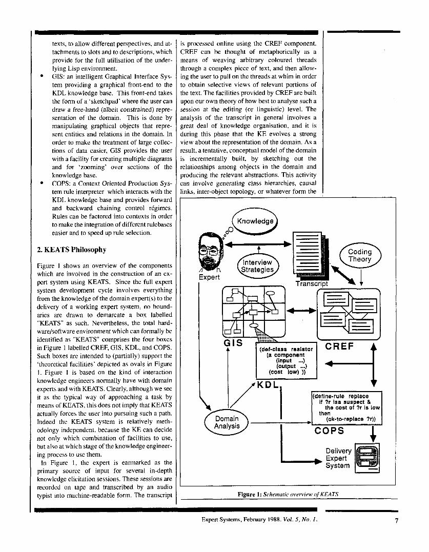
Figure 1 shows an overview of the components which are involved in the construction of an ex- pert system using KEATS. Since the full expert system development cycle involves everything from the knowledge of the domain expert(s) to the delivery of a working expert system, no bound- aries are drawn to demarcate a box labelled "KEATS" as such. Nevertheless, the total hard- ware/software environment which can formally be identified as "KEATS" comprises the four boxes in Figure 1 labelled CREF, GIS, KDL, and COPS. Such boxes are intended to (partially) support the 'theoretical facilities' depicted as ovals in Figure 1. Figure I is based on the kind of interaction knowledge engineers normally have with domain experts and with KEATS. Clearly, although we see it as the typical way of approaching a task by means of KEATS, this does not imply that KEATS actually forces the user into pursuing such a path. Indeed the KEATS system is relatively meth- odology independent, because the KE can decide not only which combination of facilities to use, but also at which stage of the knowledge engineer- ing process to use them.
In Figure 1, the expert is earmarked as the primary source of input for several in-depth knowledge elicitation sessions. These sessions are recorded on tape and transcribed by an audio typist into machine-readable form. The transcript
is processed online using the CREF component. CREF can be thought of metaphorically as a means of weaving arbitrary coloured threads through a complex piece of text, and then allow- ing the user to pull on the threads at whim in order to obtain selective views of relevant portions of the text. The facilities provided by CREF are built upon our own theory of how best to analyse such a session at the editing (or linguistic) level. The analysis of the transcript in general involves a great deal of knowledge organisation, and it is during this phase that the KE evolves a strong view about the representation of the domain. As a result, a tentative, conceptual model of the domain is incrementally built, by sketching out the relationships among objects in the domain and producing the relevant abstractions. This activity can involve generating class hierarchies, causal links, inter-object topology, or whatever form the
Coding
(def-class resistor CREF (a component
(input (output ...)
(cost low) ))
I Y'KDL. I
Domain
(def ine-ru le replace if ?r isa susoect & I
I - L
Figure 1: Schematic overview of KEATS
Expert Systems, February 1988. Vol. 5, No. 1. 7
KE finds convenient for expressing the structure of the domain. Another activity undertaken by the KE is that of developing a tentative architecture of the task’s organisation.
The KE’s preliminary analytic activities are primarily supported by the GIS component. The use of GIS offers several advantages, as it provides an intuitive semantic-network-like inter- face to KDL and it helps the KE to visualise the domain, freeing him or her from many encoding details. Using GTS does not require much exper- tise in knowledge representation, and produces a very clear (even if simplistic) view of the domain. Therefore it also facilitates the communication be- tween KEs and human experts. a s the repre- sentational medium of GIS can be discussed more easily than that of other A1 formalisms. Since GIS diagrams are automatically translated into KDL code, one can always elect to code aspects of the domain directly in KDL.
The automatic generation of KDL code from the diagrams offers another advantage: as KDL code is analysed, dependencies are deduced and incon- sistencies are signalled to the user. Hence, the model of the problem can be incrementally refined and updated both in response to new information being elicited and to the feedback provided by the GIS/KDL system. Once a representation has been developed by means of the GIS/KDL components, specific problem solving behaviour can be modelled by means of rulesets defined in COPS (indeed, the KE can use any combination of KDL, Lisp, and COPS).
The KE faces several tradeoffs when choosing among the various coding and representational styles made available within KEATS. In fact, as formalisms are not neutral media between concep- tual models and implementations, i t is important to provide an intermediate, language-independent layer, that allows the user to build an abstract con- ceptual model of the domain without being forced to make encoding decisions at such an early stage. This is consistent with the methodologies outlined in [2, 31, that stress the importance of separating the concrete implementation of the system from the development of abstract models of the task and of the domain. The direct manipulation of graphi- cal objects serves this purpose, as it frees the KE from many details related to the formalism being used.
We believe that is important for the KE not to be ‘steamrolled’ into the use of a particular style of representation. For instance, rules are better suited for modelling human experts’ empirical associ- ations and problem-solving activity than for modelling structural or algorithmic knowledge.
Moreover, there is a feature of naturalness in rep- -esentational formalisms that is quite subjective md user dependent. We follow [4] in distinguish- ng between definitional and assertional knowl- :dge, and support this distinction by having both a iescription-based language and a rule-based one.
CREF, GIs, and KDL/COPS are described eespectively in sections 3, 4, and 5. Section 6 presents an example of how KEATS was used in Zonjunc ti on with an in- house circui t-draw ing package to build an electronic fault diagnosis sys- tem. Conclusions and comparisons with other work are presented in section 7.
3. REF: A Cross-Referencing Editing Facility
3. I CREF Philosophy
CREF provides an editing facility that helps the KE to impose a structure upon arbitrary text. Therefore, it supports the KE during those ac- tivities that require dealing with written material, e.g. analysing protocols derived from interviews with the domain experts. Typically, when carrying out protocol analysis, the KE performs a set of text-related operations in order to structure the text according to various criteria, including semantic and syntactic features. Such an activity usually produces a large quantity of notes, pictures and pieces of text with different granularity.
Typical editors support text processing within a unidimensional presentation mode that can be re- lated to conventional documents or to a particular programming language. In fact, editors support synthesising activities, such as writing programs or creating documents. In knowledge engineering, however, the activity is mainly analytical, as the KE processes text while aiming to understand an unstructured collection of data. Therefore, it has been recognised [3 ,5] that knowledge engineering tools require dedicated, non-conventional text editors, in order to support data analysis. To this end, KEATS contains a Cross Referencing Editing Facility, CREF, that allows the KE to structure text by imposing a non-linear organisation upon it.
3.2.The CREF display
Several different ‘display configurations’ can be selected by the KEATS user. Typically, the user works in the configuration shown in Figure 2, where the bottom of the screen displays the CREF Edit Area and the top of the screen shows the GIS interface.
In the Edit Area collections of text called seg-
8 Expert Systems, February 1988. Vol. 5, N o . I.

Figure 2. KEATS display cotifi'guratioti. CIS diagram is at the top, and CREF transt ript editor is at the bottom. ~~ ~~
ments are displayed for editing, while the GIS pane shows the graphical representation of a por- tion of the current knowledge base. Operations on segments are performed either by clicking on a segment with the mouse, or by using the keyboard. The upcoming subsections describe the essential concepts and structure of CREE
3.3 Segments
A segment is a block of text which is treated as a unit by CREE Local editing operations are pos- sible within a segment, but a segment is atomic in the sense that most CREF operations work at the level of segments or more complex structures.
The choice of segment size is arbitrary: a seg- ment may contain a word, a sentence, a paragraph, or even many paragraphs. The decision about how to break up the text being edited into segments is left to the user and may vary widely depending upon the application. In our experience, however, a segment typically refers to a paragraph or two of
text, a program definition, or some sort of table. Operations are provided in CREF for splitting
one segment into several ones and for joining several segments into one. This means that any decision about granularity found to be inappro- priate for some application can easily be changed at any time.
A useful metaphor which has been used in the CREF system for visualising segments is that of viewing them as index cards (cf. [6]). Many CREF operations are most easily visualised by appealing to this metaphor.
3.4 Collections
A collection is a possibly ordered set of segments. In practice, collections are used in a manner similar to the way buffers or files are used in con- ventional text editors (e.g. EMACS [7]) , as they partition the space of available data so that it doesn't have to be worked with all at once. On the other hand collections have a number of properties
Expert Systems, February 1988. Vol. 5, No. 1 . 9
that are different from conventional buffers. First, collections are structured entities, as they are made up of smaller units, that are segments. Second, collections can be created by using forms of abstractions. For instance, Figure 2 shows an example of a collection made up by all the seg- ments that contain the string "data receiver". CREF always has a selected collection, the con- tents of which can be edited using essentially con- ventional editing techniques.
Some readers may recognise that the CREF notion of collection was derived from the idea of "surveys" in the BABYL mail reader and "collec- tions" in the ZMAIL mail reader 181. In contrast to BABYL and ZMAIL, CREF presents all the seg- ments belonging to a collection for editing at the same time rather than offering a menu and allow- ing the user to select segments one at a time.
3.5 Keywords
CREF allows the user to attribute one or more fea- tures to a segment by associating it with key- words. The keyword facility provides information similar to that provided by an index in a hardcopy document. It gives the ability to select collections based on conjunctions or disjunctions of key- words. Keywords have been used for a long time to annotate messages in mail reading systems (e.g. MM, BABYL, and ZMAIL), but have no analog in conventional text editors.
Keywords are all defined by the KE and may refer to objects in the domain (e.g. 'transistor l2'), interview events (e.g. 'question'), or problem- solving strategies (e.g. 'test procedure'). Although it is also possible in CREF to select a collection of segments which match a given search string, such matching is often less fruitful than keyword matching. This is because users tend to associate semantic content with their keywords while search strings are necessarily purely lexical 01
syntactic.
3.6 Relational liriks h e m ~ e i i segmerits
Segments in CREF may be annotated by links tc other segments in order to express various kind: of relations. Most traditional text editors have n c analogue to this because they offer little or no wa) to treat regions of text as first class objects whick could be pointed to by such links. Currently CREF uses the following link types:
REFERENCES links are used to point to seg, ments which may provide related information thal is possibly not of general interest or which i: somewhat off the subject. The way in whick
eference links are used can vary widely depend- ng on the application. For example, in a docu- nent they might point to footnotes or references, Jut in code they might point to comments, jus- :ifications, or proofs. SUMMARIZES links are used to impose a
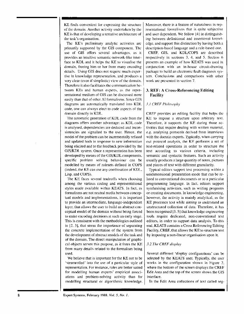
nierarchy upon a given set of segments. A sum- mary is just a piece of text (i.e. a segment) which has a summary link to one or more other Segments. A segment may have more than one summary, and summaries may themselves have summaries. To create a summary, the KE can type a key-
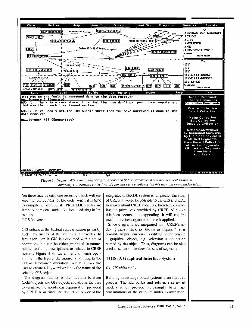
board command (or select the 'summary' option from a pop-up menu) and he or she is placed in a collection containing one new segment and all of the segments which have just been marked. The new segment, which has a generated name such as "Summary 1" is empty and the KE must initialise it with some text that summarises the contents of the other segments. In the example shown in Figure 3, the user has summarised the segment "Segment 474' by means of the segment "Sum- mary I "
Having created a summary, the user can return to the previous collection wherein the marked seg- ments will have been replaced by the summary just created.
At any time, the KE may place the editing cursor within the summary segment and expand the sum- mary (replacing it with the nodes it summarises) or contract it as appropriate by choosing options from a pop-up menu.
SUPERSEDES links are used to implement ver- sioning. When a user 'freezes' a copy of an in- dividual segment, a 'mutable' copy of it is made, and editing continues to take place on the mutable copy. The original copy is kept (and is pointed to by this link) in case the KE wishes to return to i t later. All keyword information and most of the link information are copied from the original seg- ment, and segments which pointed to the original segment are updated to point to the new version. The Supersedes links are important to allow the KE to make changes to the protocol without ac- tually modifying it.
Indeed, the data are not a mutable part of the theory and they shouldn't be modifiable.
PRECEDES links record information about ordering. In general, this information is not used to control presentation order. Rather, i t is used in situations where the presentation order violates some other more important order. For example, when editing code with CREF, there may be several collections, each editing the same set of functions, each with its own presentation order.
10 Expert Systems, February 1988. Vol. 5 , No. 1
I
- 1 - - - - AND-DESCRIPTION
-DATA-BURST -DATA-BURSTS
686 E2 I f you don’t set the 18v bursts there then you have narroued i t doun t o t h e data receiver
w r q m e n t 474 €Summari7~d> I ,
Figure 3. Segnient 474, containin<? paragraphs 68.5 and 868, is sunznzur-ised in a new seSment known as
Yet there may be only one ordering which will en- sure the correctness of the code when it is time to compile or execute it. PRECEDES links are intended to record such additional ordering infor- mation. 3.7 Diagrams
GIS enhances the textual representation given by CREF by means of the graphics it provides. In fact, each icon in GIS is associated with a set of operations that can be either graphical in nature, related to frame descriptions, or related to CREF actions. Figure 4 shows a menu of such oper- ations. In the figure, the mouse is pointing to the “Make Keyword“ operation, which allows the user to create a keyword which is the name of the selected GIS object.
The diagram facility is the medium between CREF objects and GIS objects and allows the user to visualise the non-linear organisation provided by CREF. Also, since the deductive power of the
integrated GIS/KDL system is far greater than that of CREF, it would be possible to use GIS and KDL to reason about CREF concepts, therefore extend- ing the primitives provided by CREF. Although this idea seems quite appealing, it will require much more investigation to have it applied.
Since diagrams are integrated with CREF’s in- dexing capabilities, as shown in Figure 4, it is possible to perform various editing operations on a graphical object, e.g. selecting a collection named by the object. Thus, diagrams can be also used as selection devices for sets of segments.
4 GIS: A Graphical Interface System
4.1 GIs philosophy
Building knowledge-based systems is an iterative process. The KE builds and refines a series of models which provide increasingly better ap- proximations of the problem under examination.
Expert Systems, February 1988. Vol. 5. No. 1. 11
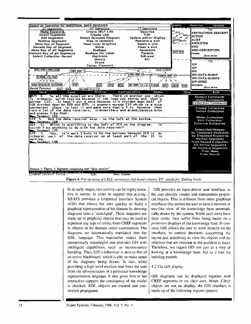
Select an Oneration for INDIVIDUAL DATA-RECEIVEFI ET Owrattons GT O.wrat/ons FT Owrattons
TION-DESCRIPT lhrlake Keywor Create SELF Llnk Describe
Add Segments Select Relevant Diagram Update editor display Select Segmen% Create Llnk Edit
Remove Segments View In Isolation Retrieve a Slot Make Key o f Segment Show Local Graphlcs Insert a slot
Unmake Key of Segment Move Clear a slot Make Key of al l Segments Reshape Ancestors DESCRIPTION
Select Collection Named Dupllcate Kdl-eval Morr &low Unmake Key o f all Segments Reshape for Label Parents
Unbury Kill
In its early stapes, this activity can be highly tenta- tive in nature. In order to support this activity, KEATS provides a Graphical Interface System (GIS) that allows the user quickly to build a graphical representation of the domain by drawing diagrams onto a ‘sketchpad’. These diagrams are made up of graphical objects that may be used to represent any type of entity, from CREF segments to objects in the domain under examination. The diagrams are automatically translated into the KDL language. This translation makes them operationally meaningful and provides GIS with intelligent capabilities, such as inconsistency handling. Thus, GIs’s behaviour is akin to that of an active blackboard, which is able to make sense of the diagrams being drawn. In fact, while providing a high level medium that frees the user from the idiosyncracies of a particular knowledge representation language, it also gives him or her interactive support: the consistency of the model is checked, KDL objects are created and con- straints propagated.
runs a l o t o f the data r e c e i v e r s , t ransmi t te rs and miscellaneous b i t s and pieces l i k e t h a t .
GIS provides an input-driven user interface, as the user directly creates and manipulates graphi- cal objects. This is different from other graphical interfaces that permit the user to have a network or tree-like view of the knowledge base automati- cally drawn by the system. While such tools have their utility, they suffer from being based on a posteriori displays of the knowledge base. In con- trast, GIS allows the user to work directly on the interface, to control decisions concerning the layout and selectively to view the objects and the relations that are relevant to the problem at hand. Therefore, we regard GIS not just as a way of looking at a knowledge base, but as a tool for building models.
4.2 The CIS display
CIS diagrams can be displayed together with CREF segments or on their own. When CKEF objects are not on display, the GIS interface is made up of the following regions (panes):
12 ~
Expert Systems, February 1988. Vol. 5 , No. I
TOP ABSTRACTION-DESCRIPI ACTION ALIST AMPLIFIER AND AND-DESCRIPTION ATOM a.sm
-
- More below
Layout Pane - the window that holds all the graphics within a graphics sheet, i.e. the 'sketchpad'. Menu Pane - a window providing com- mands that range over diagrams, such as switching from page to sheet, and over theories, such as selecting a different theory or saving the current one. Zmacs Pane - a pure Zmacs window that allows the user to edit KDL objects from a source code definition rather than by the other methods available (i.e. graphical or by menu). This provides the user with the freedom of using traditional interface tools. Scroll Panes - these panes provide opera- tions on each of the following types of en- tities: (a) classes (displays the objects in the world that are KDL classes); (b) instances (displays the objects in the world that are KDL individuals); (c) buffers (displays the
18V-DATA-BURST 18V-DATA-BURSTS
More below
More abow COLLECTION 4
buffer names of all the current buffers in Zmacs including CREF collections).
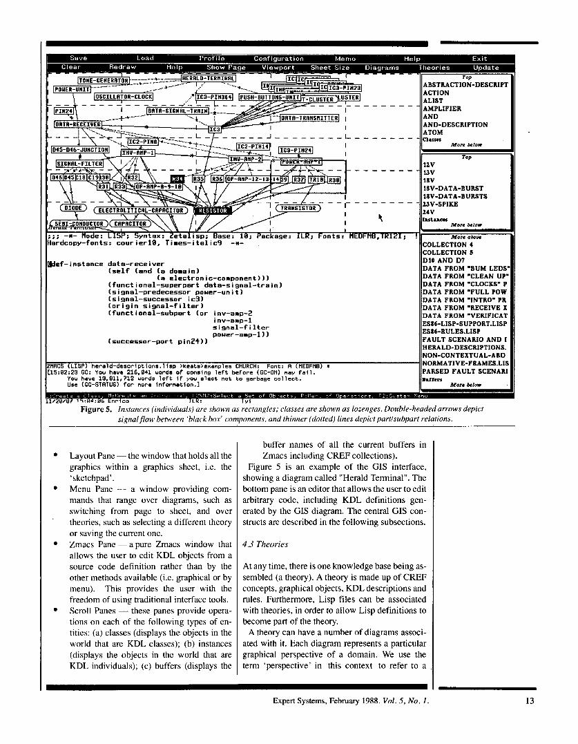
Figure 5 is an example of the GIS interface, showing a diagram called "Herald Terminal". The bottom pane is an editor that allows the user to edit arbitrary code, including KDL definitions gen- erated by the CIS diagram. The central GIS con- structs are described in the following subsections.
4.3 Theories
At any time, there is one knowledge base being as- sembled (a theory). A theory is made up of CREF concepts, graphical objects, KDL descriptions and rules. Furthermore, Lisp files can be associated with theories, in order to allow Lisp definitions to become part of the theory.
A theory can have a number of diagrams associ- ated with it. Each diagram represents a particular graphical perspective of a domain. We use the term 'perspective' in this context to refer to a
I I ~ C O L L E C T I O N 5 Wef-instance data-receiver
(self (end (a doaainl
(functional-superpart data-signal-train) (signal-predecessor pouer-unit) (signal-successor ic3) (origin signal-filter) (functional-subpart (or inv-amp-2
inv-amp-1 sisnal-filter pouer-amp-1 1 1
(a electronic-component)))
(successor-port pin2+))
DlO A N D D 7 DATA FROM "BUM LEDS DATA FROM "CLEAN UP' DATA FROM "CLOCKS" P DATA FROM "FULL POW DATA FROM 'INTRO" PR DATA FROM "RECEIVE X DATA FROM 'VERIFICAT ES86-LISP-SUPPORT.LISP ES86-RULES.LISP FAULT SCENARIO A N D I HERALD-DESCRIPTIONS. NON-CONTEXTUAL-ABD
ZHACS (LISP) herald-descriptions.lisp >keats>exanples CHURCH: Font: A (PIEDFNB) * NORMATIVE-FRAMES.LII C15:82:23 GC: You have 216,841 uords of consing left before (GC-ON) nay fail. PARSED FAULT SCENARI
You have 13,811,712 uords left if you elect not to garbage collect. lhiisn Use (GC-STATUS) for nore infornation.1 More below
I1 K: I v i Figure 5. Instances (individuals) are shown as rectangles; classes are shown as lozenges. Double-headed arrows depict
signal flow between 'black box' components, and thinner (dotted) lines depict partlsubpart relations.
Expert Systems, February 1988. Vol. 5, No. I. 13
multiple graphical organisation, rather than to a possible world. Multiple perspectives allow the user to draw diagrams visualising different aspects of a domain. For instance, we can have one diagram expressing the taxonomy of the domain, another one to represent its topology, etc.. The use of multiple diagrams means that the KE is not forced to draw many types of links into the same sketchpad (although different link types within a given diagram can be viewed selectively as re- quired by the KE).
4.4 Classes and instances
Each diagram consists of a number of graphical objects that denote entities over a domain, con- nected by arrows that denote relationships be- tween them. The objects are partitioned into classes and instances, corresponding to KDL types of descriptions. Both types of objects are repre- sented as closed boxes around their names, the class box being a lozenge and the individual box being a rectangle. For instance, in Figure 5 the in- dividual R34 is represented by the rectangular box labelled "R34" and the class Resistor by the lozenge labelled "Resistor".
4.5 Arrows
Relationships between objects are described by arrows. KDL provides a frame-based formalism for describing structured objects and allows the definition of binary relations by means of the slot mechanism. CIS allows such binary relations to be expressed in a pictorial form. For instance, if we want to yay that Bill is the father of Bob, we can do it by first binding a type of arrow (e.g. dashed line with double arrowhead) to the relation FATHER, and then drawing a particular arrow be- tween the rectangles representing Bill and Bob. When binding an arrow, the user can specify both a relation and its reciprocal. For instance, we can bind an arrow to the pair of relations FATHER/ SON. Since many relations are symmetrical, GIS handles them in a special way, by automatically deriving the link in both directions.
Since GIS and KDL are tightly interconnected. drawing an arrow affects the KDL environment. by filling the corresponding slots of the ap- propriate descriptions. The communication be- tween KDL and GIS is actually bi-directional, a$ the changes made directly in KDL do in facl modify the corresponding GIS representation. Therefore, if we later replace the value 'Bill' in slot FATHER of Bob with the value 'George'. then the system will automatically draw the arrow
)etween Bob and George, and will erase the exist- ng one between Bob and Bill. This bi-directionality is very important in order
o have a sound interface. On the one hand, we want to have the capability of acting from dif- 'erent environments (GIS, COPS, KDL, Lisp) ipon a common knowledge base, but on the other land we require the display of the current theory o be 100% consistent with the current definitions. rherefore, the system takes care of updating the 31s interface each time a new assertion is made, -egardless of the environment being used to make such an assertion. Analogously, if we first assert a relation of type FATHER in KDL and only after- wards bind it to a graphical arrow, the system will automatically draw all the FATHER relations be- tween icons for which FATHER is defined. Another situation is where we have (a) an object Tom in relation FATHER with an object Carl, (b) an arrow bound to FATHER in the diagram, (c) a graphical representation for Tom but (d) no graphical representation for Carl. Clearly, in this case the arrow cannot be drawn as there is no rep- resentation for Carl. Nevertheless, if we later in- sert into the diagram a graphical object repre- senting Carl, then the system will still draw the arrow representing the FATHER relation between the icon representing Tom and the one repre- senting Carl.
Each diagram can have up to eight different ar- rows representing different relations. Our experi- ence is that a diagram with five or more relations starts to become unwieldy. Therefore the KE needs to exploit the multiple diagram facility to cope with large numbers of relations. Selective views of a given diagram are also available to hide objects and arrows quite arbitrarily, in order to concentrate at times upon specific links or objects. It is important to bear in mind that the graphically represented relations are usually just a subset of the large number of links occurring in a typical knowledge base.
4.6 Viewports
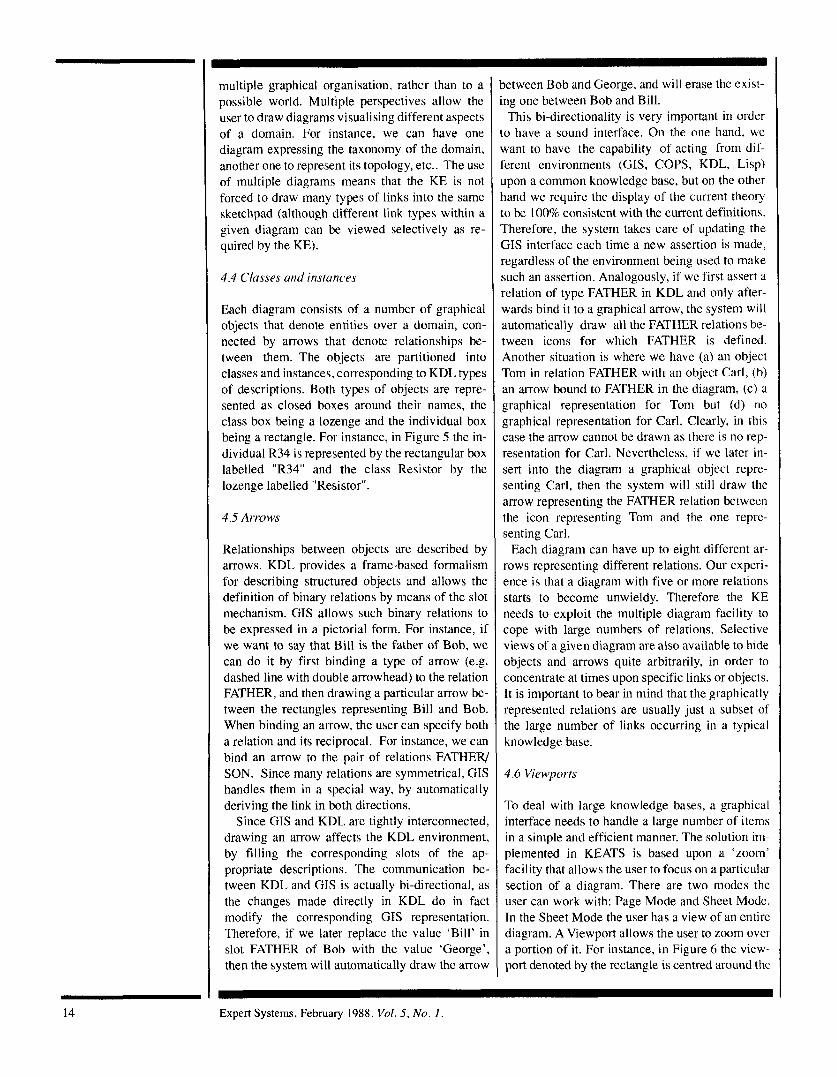
To deal with large knowledge bases, a graphical interface needs to handle a large number of items in a simple and efficient manner. The solution i n - plemented in KEATS is based upon a 'zoom' facility that allows the user to focus on a particular section of a diagram. There are two modes the user can work with: Page Mode and Sheet Mode. In the Sheet Mode the user has a view of an entire diagram. A Viewport allows the user to zoom over a portion of it. For instance, in Figure 6 the view- port denoted by the rectangle is centred around the
14 Expert Systems, February 1988. Vol. 5, No. 1 .
I
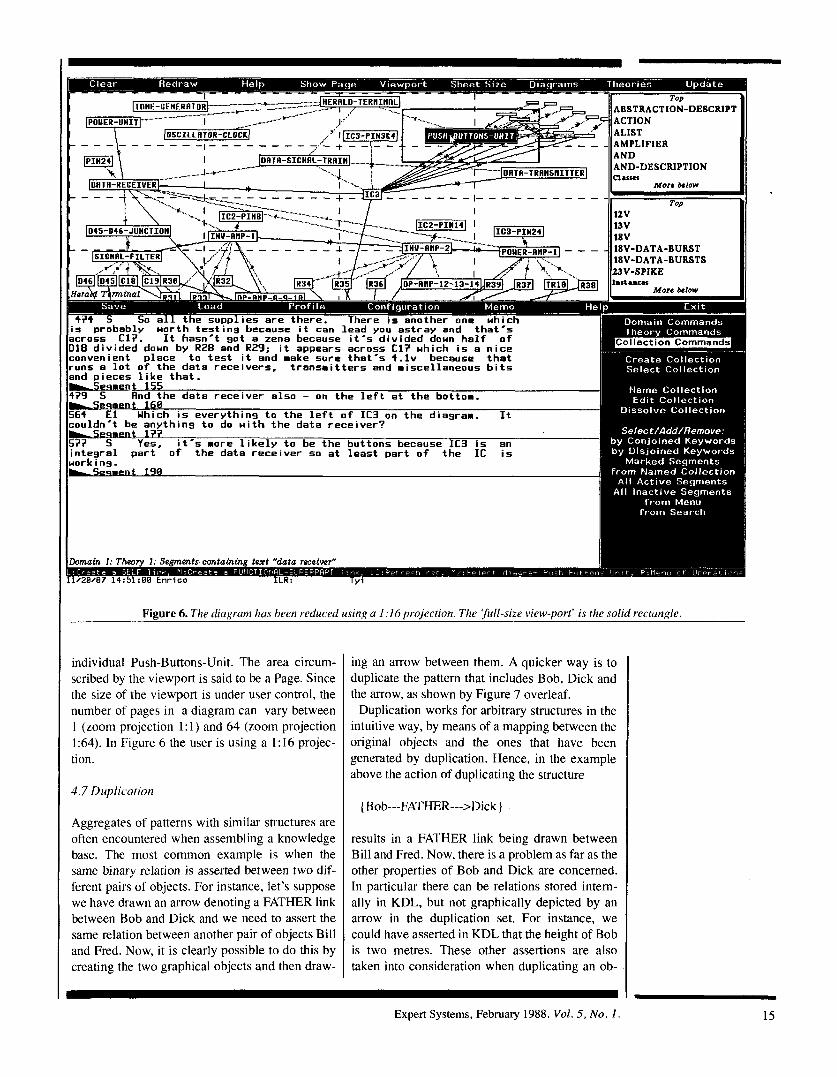
Figure 6. The diagram has been reduced using u 1 :I6 projection. The ‘full-size view-port’ is the solid rectungle.
~ individual Push-Buttons-Unit. The area circum- scribed by the viewport is said to be a Page. Since the size of the viewport is under user control, the number of pages in a diagram can vary between 1 (zoom projection 1:l) and 64 (zoom projection 1:64). In Figure 6 the user is using a I : 16 projec- tion.
4.7 Duplicution
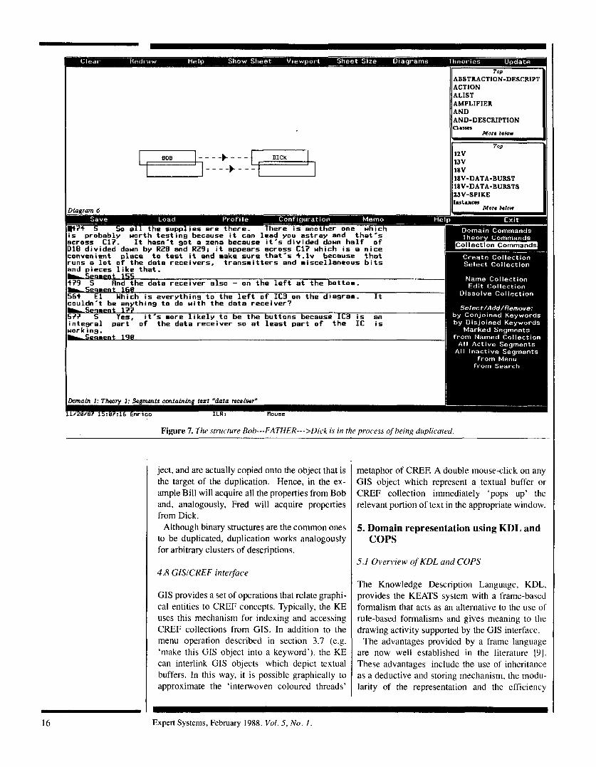
Aggregates of patterns with similar structures are often encountered when assembling a knowledge base. The most common example is when the same binary relation is asserted between two dif- ferent pairs of objects. For instance, let’s suppose we have drawn an arrow denoting a FATHER link between Bob and Dick and we need to assert the same relation between another pair of objects Bill and Fred. Now, it is clearly possible to do this by creating the two graphical objects and then draw-
ing an arrow between them. A quicker way is to duplicate the pattern that includes Bob, Dick and the arrow, as shown by Figure 7 overleaf.
Duplication works for arbitrary structures in the intuitive way, by means of a mapping between the original objects and the ones that have been generated by duplication. Hence, in the example above the action of duplicating the structure
{ Bob---FATHER--->Dic k }
results in a FATHER link being drawn between Bill and Fred. Now, there is a problem as far as the other properties of Bob and Dick are concerned. In particular there can be relations stored intern- ally in KDL, but not graphically depicted by an arrow in the duplication set. For instance, we could have asserted in KDL that the height of Bob is two metres. These other assertions are also taken into consideration when duplicating an ob-
Expert Systems, February 1988. Vol. 5, No. 1 . 15
I
More &Iow
18V-DATA-BURST 18V-DATA-BURSTS 23V-SPIKE Instances
rsimnt 168
nt li’?
El Uhich is everything to the left o f IC3 on the diagram. It
Yes, it’s more likely to be the buttons because IC3 i s an
couldn’t be anything to do with the data receiver?
Figure I. The structure Bob---FATHER--->Dick is in the process of beinn duplicated.
ject, and are actually copied onto the object that is the target of the duplication. Hence, in the ex- ample Bill will acquire all the properties from Bob and, analogously, Fred will acquire properties from Dick.
Although binary structures are the common ones to be duplicated, duplication works analogously for arbitrary clusters of descriptions.
4.8 GISICREF interface
CIS provides a set of operations that relate graphi- cal entities to CREF concepts. Typically, the KE uses this mechanism for indexing and accessing CREF collections from CIS. In addition to the menu operation described in section 3.7 (e.g. ‘make this GIS object into a keyword’), the KE can interlink GIS objects which depict textual buffers. In this way, it is possible graphically to approximate the ‘interwoven coloured threads’
metaphor of CREE A double mouse-click on any GIS object which represent a textual buffer or CREF collection immediately ‘pops up’ the relevant portion of text in the appropriate window.
5. Domain representation using KDL and COPS
5.1 Overview qf KDL und COPS
The Knowledge Description Language, KDL, provides the KEATS system with a frame-based formalism that acts as an alternative to the use of rule-based formalisms and gives meaning to the drawing activity supported by the CIS interface.
The advantages provided by a frame language are now well established in the literature [91. These advantages include the use of inheritance as a deductive and storing mechanism, the modu- larity of the representation and the efficiency
16 Expert Systems, February 1988. Vol. 5 , No. 1.
provided by the structured organisation. The language is based on descriptions, which are
collections of atomic concepts. A small set of operations on descriptions are defined and em- bedded in the language definition. Descriptions are connected together by means of links. A limited number of system links provide hooks to the basic KDL mechanisms, inheritance and evaluation of descriptions. User-definable links are provided with a number of extra-logical flags in order to allow the user to modify the basic in- heritance mechanism. Such modifications express the features of a particular slot, such as the use of defaults or its modality.
COPS (Context Oriented Production System) allows the KEATS user to add inference rules to the knowledge base. As a result of the need to provide a strong link between the other parts of KEATS and the rule interpreter, COPS provides a number of features over and above those found in normal interpreters, the most important of these being the simple link between rules and KDL. Not only can rules test and modify working memory, but they can also test and alter the state of the KDL knowledge base. Other constructs include: (i) contexts which enable the knowledge engineer to structure rules into functional groups, (ii) a full set of logical operators NOT, AND, and OR, (iii) forward and backward chaining control structures, (iv) calls to arbitrary Lisp functions when forward or backward chaining, (v) com- pletely user-definable conflict resolution - the user can even override normally hard-wired con- flict resolution strategies such as refractoriness, and (vi) other special constructs, including the iter-ative pattern matching construct for-each and an assignment operator :=.
In the rest of section 5 we will describe the syn- tax and the concepts underlying KDL. COPS is most easily described by means of the examples presented in section 6.
5.2 KDL descriptions
The KDL knowledge base is made of relations be- tween descriptions. Intuitively, a description can be viewed as a set. For example the description Resistor can be seen as representing the collection of all the particular resistors. This extensional approach is analogous to that followed by the Omega language [lo].
The basic form of description is the individual description. Examples of individual descriptions are Bob, Circuit- 1, Event-1. An individual description represents an atomic entity of the world.
Aclass description names a generic collection of individuals. For example, the description:
(an arithmetical-device (function-performed addition))
can be used to represent the collection of the anth- metical devices that perform addition. Note that this type of description is similar to the ”Generic Concept” used in KL-ONE [ 1 I].
There are several other types of KDL descrip- tion, including Lisp forms and abstraction descrip- tions, which are discussed in detail in [12].
5.3 Links
A link represents a relation between two descrip- tions. System links are special, as their semantics are embedded in the system, whereas domain links are defined by the user. The basic system links in KDL are related to the inheritance mechanism and to the evaluation of descriptions.
Inheritance is an epistemological device that al- lows properties to be shared among different ob- jects, depending on the structure of the knowledge base. Typically (and KDL follows this rule), in- heritance is organised around is-a hierarchies, which are constructed by means of the Self link. For example, the following definition asserts that Bill is a doctor:
(def-instance bill (self (a doctor)))
To state that each doctor has a degree in medicine we write:
(def-class doctor (degree medicine)).
Each particular doctor will then inherit the proper- ty of having a degree in medicine, unless this in- formation is overridden.
Inheritance is implemented by means of a modified version of the shortest-path algorithm, using on-path pre-emption [ 131 to avoid problems caused by redundant self links.
The second type of KDL system link gives a way of providing descriptions with values that are then used by the KDL evaluator. This mechanism is useful as it provides a description with ‘dynamic behaviour’. The system link that implements this mechanism is called Attachment. The name is due to the fact that this link is often used in a similar way to the use of procedural attachments in other formalisms.
~~ ~~~
Exuert Svstems. Februarv 1988. Val. 5, NO. 1. 17
5.4 Filling KDL slots
Facts in KDL are asserted by filling slots of class and individual descriptions. In the previous sec- tion, we showed how simple relations can be as- serted in KDL. In this section we discuss specifi- cation of slots in greater detail. Slots divide naturally into two categories: individual descrip- tion slots and class description slots. 5.4 .I Individual description slots. Individual slot fillers are usually parameterised by means of con- texts, which provide a particular perspective of an individual. In fact, each class description can be viewed as imposing a context upon its instances. To illustrate this, suppose that Bernie is both a manager and a Phd-student, and receives a wage in each of these two activities. We want to anchor the two wages to their respective contexts. We can formalise the situation by means of the following KDL description:
(def-instance Bernie (self (and
(a manager) (a phd-student))
(wage high manager) (wage low phd-student))
Given this definition, if we try to retrieve Bernie's wage, the result will depend on the current view. If we look at Bernie as a phd-student, then the answer will be low, while in context manager it will be high.
Note that since contexts are organised in hierar- chies and these hierarchies follow the network structure, a value specified in context C can be viewed in any context that inherits from C, unless more specific assertions override this assertion. 5.4.2 Class description slots. There are two basic functions that a class slot can perform: (a) specify a value that can be inherited by each member of the class; (b) specify a constraint that each mem- ber of the class must satisfy with respect to the slot.
For instance, suppose we want to define the Lisp function mapcar in KDL. The following is a possible solution.
(def-class mapcar (self (a lisp-construct)) (list (a list) !c) (function (a lisp-function) !c) (attachment
#L(mapcar #>function #>list)))
The symbol #L demarcates the ensuing expression i s a Lisp form. The symbol #> followed by the lame of a slot specifies retrieval of that slot's Ner. The role of the flag !c is to state that the illers of slots list and function play the role of a :onstraint. Thus, the filler (a list) is used for stat- [ng that mapcar cannot be applied to descriptions ither than lists
There are four types of flags in KDL:
!oh. A flag to state the obligatoriness
!c. A flag to specify constraints. !m. A flag to specify meta-constraints. !d. A flag to specify default values.
of a slot.
rhese flags provide extra information about the use of a slot filler. Similar flags are used in the Unit package 1141, while other formalisms provide the user with a language to define the structure of a slot [ 11, 151.
The !ob flag allows the user to assert that some slots are required when describing members of a :lass.
The !c flag is used to specify type control on slot fillers. Any description can act as a constraint. Constraints work by specifying a set of possible values for a slot, and the is-a relation is used to test the consistency between a filler and its con- straints. Domain level constraints are asserted by means of the !c flag, while meta-level constraints (such as cardinality) can be specified by using the !m flag. The difference is that the latter is not a constraint on the meaning of the eventual filler, but rather on its form. In systems such as Kl-one or Unit it is possible to specify, say, the cardinality of a slot by means of a dedicated mechanism. Be- cause cardinality is just a special case of the general class of meta-level constraints we have opted for a general mechanism to express such meta-level constraints.
The role of the default flag is to specify a default value, i.e. a value that is assumed to be true unless contrary information exists. Defaults do not necessarily work as constraints, as demonstrated by one possible KDL representation of the sen- tence "Birds can fly":
(def-class bird (self (an animal)) (can-fly? yes !d (or yes no) !c>)
The default filler is 'yes', but in any event the filler is constrained to be either yes or no. This allows the existence of counterexamples which can still be checked for the appropriateness of
Expert Systems, February 1988. Vol. 5 , No. 1
their-slot fillers. Note that it is also possible to express non-
default statements, by a concurrent use of the default and the constraint flags. In fact, if we want to state that all birds necessarily fly, we can give the value yes both as a default and as a constraint.
6 .An example
6.1 Background
This section presents an example of how KEATS was used in conjunction with an in-house circuit- drawing package to build an electronic trouble- shooting system. The device being diagnosed in this example is known as a ‘Herald Terminal’, which is basically a desktop telephone handset and control unit forming part of a microprocessor- controlled exchange system for small business.
Two knowledge elicitation sessions were con- ducted with an expert repair technician, recorded on a tape and then transcribed. The interviews in- cluded both informal discussions, aimed at assess- ing domain features, and model-driven sessions aimed at gathering the information needed to build an heuristic classification model of the problem V61.
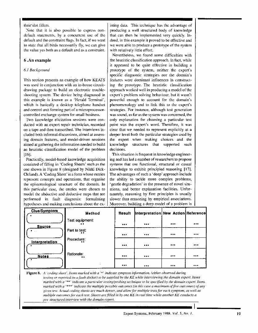
Practically, model-based knowledge acquisition consisted of filling in ‘Coding Sheets’ such as the one shown in Figure 8 (designed by Nikki Dick- Cleland). A ‘Coding Sheet’ is a form whose entries represent concepts and operations, that organise the epistemological structure of the domain. In this particular case, the entries were chosen to model the abductive and deductive steps that are performed in fault diagnosis: formulating hvpotheses and making conclusions about the ex- .. I
Method
Test equipment:
Part to t?$:
Procedug:
..
Rationale: 4 4
isting data. This technique has the advantage of producing a well structured body of knowledge that can then be implemented very quickly. In- deed, in this example it proved to be effective and we were able to produce a prototype of the system with relatively little effort.
Nevertheless, we found some difficulties with the heuristic classification approach. In fact, while it appeared to be quite effective in building a prototype of the system, neither the expert’s specific diagnostic strategies nor the domain’s features were dominant influences in construct- ing the prototype. The heuristic classification approach worked well in producing a model of the expert’s problem solving behaviour, but it wasn’t powerful enough to account for the domain’s phenomenology and to link this to the expert’s strategies. For instance, although test generation was sound, as far as the system was concerned, the only explanation for choosing a particular test point was the expert’s word. Therefore, it was clear that we needed to represent explicitly at a deeper level both the particular strategies used by the expert when making choices and the knowledge structures that supported such decisions.
This situation is frequent in knowledge engineer- ing and has led a number of researchers to propose systems that use functional, structural or casual knowledge to exhibit principled reasoning [ 171. The advantages of such a ‘deep’ approach include the ability to tackle more complex problems, ‘gentle degradation’ in the presence of novel situ- ations, and better explanation facilities. Unfor- tunately, reasoning by first principles is usually slower than reasoning by empirical associations. Moreover, building a deep model of a problem is
I I I I 1
Figure 8. A ‘coding sheet’. Items marked with a ‘*’ indicate symptom information, (either observed during testing or reported on a,fault docket) to be supplied by the KE while interviewing the domain expert. Items marked with a ‘**’ indicate a particular testinglprobing technique to be specified by the domain expert. Items marked with a ‘***’ indicate the multiple possible outcomes (in this rase a maximum of five outcomes) of any gillen test. Actual coding sheets are much denser, and allow,for multiple tests,for each symptom, as well as multiple outcomtxfor each test. Sheets are,filled in by one KE in real time while another KE conducts a pre-structured interview with the domain expert.
I Expert Systems, February 1988. Vol. 5, N o . 1 . 19
20
not easy and sometimes is not even possible, as domains may lack a coherent theory and many tasks are hard to formalise. Finally, representation problems can arise. For instance, consider the dif- ficulty of handling the behaviour of circuits with feedback.
Other researchers have tried to get the best of both worlds by combining heuristic and deep models. An example is given in [lS], which describes a system that embeds two components, one called "experiential" (reasoning by empirical associations) and the other called "physical" (reasoning with the aid of a structural model of the domain). In this approach, the reasoning is primarily performed by the "experiential" com- ponent. Once the experiential component is not able to proceed, the physical one takes over. As they share a common knowledge base, no redun- dant inferences are made.
We have used a similar approach in building the diagnostic system for the Herald Terminal. Very quick deductions are carried out by using the heuristic knowledge elicited with the aid of the coding sheets. Deeper reasoning is based on a functional model of the domain. This model was built by analysing the diagram of the circuit, and by retrospectively analysing (using CREF) the heuristic classification model already developed, the expert's explanations captured in the coding sheets, and the raw transcripts of the knowledge elicitation sessions.
6.2 Afinctional model of the problem.
A high-level 'sketch' of the functional/structural organisation of this device is depicted in the diagram labelled Herald Terminal in Figure 2 (presented earlier). As shown in the figure, a Herald is made of five functional subparts, which are: Power Unit, Oscillator/Clock, Data Signal Train, Tone Generator and Buttons. In tum, each of these components has functional subparts. For example, the Data Signal Train is composed of the Data Receiver, IC3 (Integrated Circuit 3), and the Data Transmitter. In the diagram, the part/subpart hierarchy is represented by the single-headed arrow. This arrow is internally bound to the pair of links FUNCTIONAL-SUBPART/FUNCTION- AL-SUPERPART representing the device hier- archy inside KDL.
The part/subpart hierarchy depicted in the diagram is clearly a functional abstraction of the real circuit layout. In fact, the entities involved are abstract functional concepts (e.g. Data Receiver) and the relationships between them are a function- al simplification of the structural architecture of
he circuit. Thus, the Data Signal Train has no bhysical realisation in the Herald unit. In fact, i t s an abstraction invented by the knowledge en- :ineer (and confirmed later by the domain expert) o account for a particular signal flow throug,h )arts of the device, The reason for using this rep- ,esentation is that, as far as the diagnostic process s concerned, it is more effective than the repre- ;entation of the hardware. The importance of ising the right level of representation has been es- ablished in A1 for a long time [19]. More specifi- :ally in fault diagnosis, the need for developing 'unctional, causal and structural models of the lomain has been widely stressed [ 17, 20, 21, 22 , !3]. Our representation captures the functional
ibstraction that the domain expert imposes upon .he circuit and that he or she uses when perform- ng the diagnosis. Hence, such representation has strategic relevance. Clearly, it cannot account for :he entire diagnostic process, as experts are able to ise different models depending on the type of fault and the data available. Nevertheless, it provides the right level of description of the cir- :uit in the early stages of the diagnosis. Below, we will show how this representation was coupled with another program reasoning about the actual hardware of the circuit in order to extend the com- petence of the diagnostic expert system.
In Figure 2, the signal flow is represented by the double-headed arrow that, for instance, links the Data Receiver to IC3 and IC3 to the Data Trans- mitter. The bindings associated to this arrow are given by the SIGNAL-PREDECESSOR/SIG- NAL-SUCCESSOR pair. Again, note that this representation of the flow of the signal is a strong but effective simplification of the real signal f low in the circuit, as it provides just the amount of in- formation needed in order to perform causal reasoning about interrelations among the func- tional abstractions ('black boxes') of the circuit.
Our implementation diagnoses which com- ponent is faulty by reasoning about the signal flow connections and the parthubpart hierarchy. This is a special case of the 'Structural Isolation' strategy 1241 and works in a way similar to a binary search. First, the current 'signal chain' is tested in the middle. If the expected signal coincides with the actual one, then all the components (and their sub- parts) that precede this point in the 'signal chain', are declared not faulty, and a similar 'binary chop' is made in the second half of the signal chain. If the expected signal is not obtained, of course, then the fault is presumed to lie earlier in the chain, so a binary chop is made in the first half of the signal chain. Thus. the number of tests is minimised arid
Expert Systems, February 1988. Vol. 5, N o . 1 .
each test rules out the maximum number of com- ponents. Once a component (at the 'black box' level) is found to be faulty, the algorithm goes down one level and examines its subparts, apply- ing structural isolation recursively if the signal flow pattern among the subparts permits it.
6.3 A sumple run
In Pigures 9 and 10 we display snapshots of ex-
\ BREAK-RESTART Rerun Run 0 Full Demo Halt EXlTh
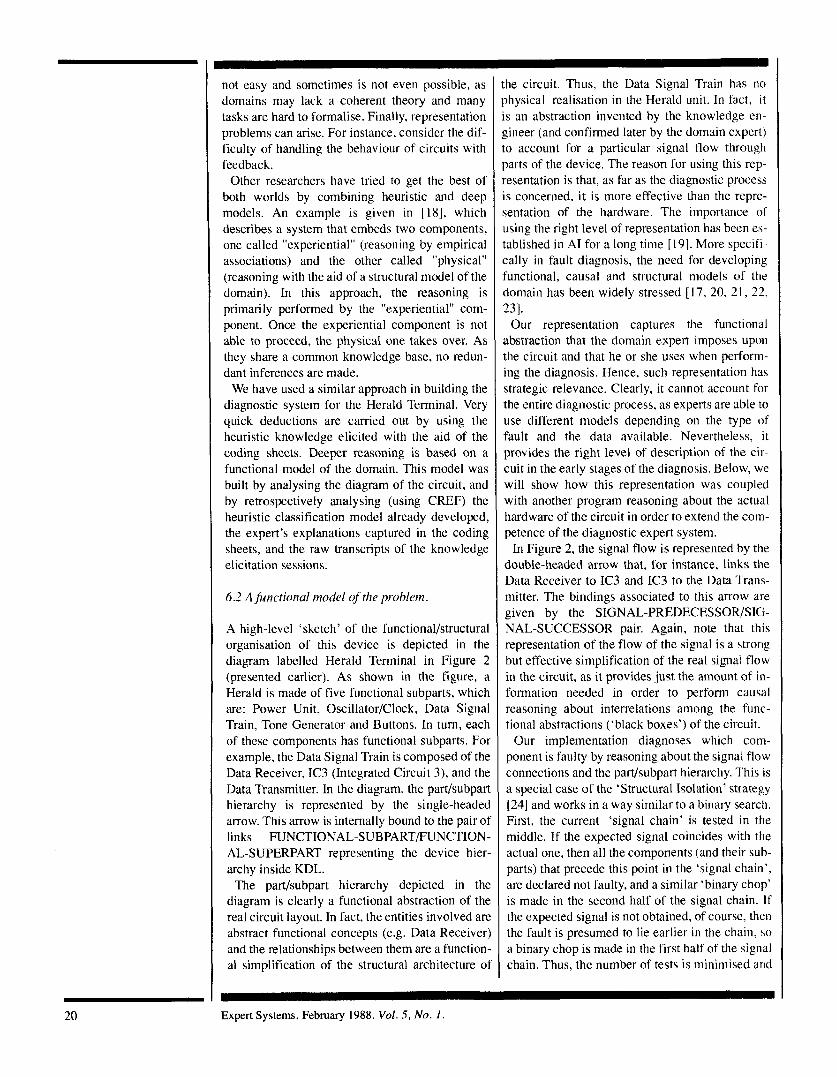
COPS rules and working memory running the diagnosis. The highlighted component is IC2A, that is actually being probed at Pin 8. Both the value (- 8.2 volts) and the type of the signal (Data Bursts) are generated by a constraint-based reasoner which forms part of the circuit-drawing package.
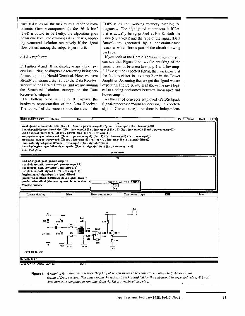
If you look at the Herald Terminal diagram, you can see that Figure 9 shows the breaking of the signal chain in between Inv-amp-1 and Inv-amp-
1 ' "
~
' I
,
1 UP
break-just-in-the-middle-2: ((ln . 2) (lsucc . power-amp-1) (fpree . inv-amp-1) ( t x . inv-amp-2)) rind-the-middle-of-the-chain: ((?a . inv-amp-2) (?a . inv-amp-1) (tn . 2) ( t x . inv-amp-2) (?end . power-amp-1)) snd-of-signal-path ((?n . 2) ( l y . power-amp-1) ( t x . inv-amp-2)) proprgate-suspectr-forward' ((tsucc . power-amp-1) (tn . 1) (?y . inv-amp-2) ( t x . inv-amp-1)) propagate-suspects-forward: ((?succ . inv-amp-2) (?n , 0) ( ty . inv-amp-1) ( t x . signal-filter)) Ptart-note-signal-path' ((lsucc . inv-amp-1) ( t x . signal-filter)) rind-the-beginning-of-the-signal-path ((?part . signal-filter) ( t x . data-receiver)) Rules that fired
More h l 0 W
TOP [end-of-signal-path power-amp-1) [suspicious-path inv-amp4 power-amp-1 2) [suspicious-path inv-amp-1 inv-amp-2 1) (suspicious-path signal-filter inv-amp-1 0) [beginning-of-signal-path signal-filter) [preferred-method (heuristic data-signal-train))
worrturg memory [preferred-method (shape-diagnose data-receiver SI -BURSIS at IC2--
--- No
- 3pdate display Wire New component Component type Rill Lines
I V
4 1L -1*v 4lV L -4.1v s3rc;J 4. '18V
Jata Receiver
Figure 9. A running,fault diagnosis session. Top halfqfscreen shows COPS rule trace, bottom halfshows circuit layout of Data receiver. The place to put the test probe is highlighted for the end-user. The expected value, -8.2 volt data bursts, is computed at run time ,from the KE's own circuit drawing.
~ ~~ ~~~ ~~~~~~ ~
5xpert Systems, February 1988. Vol. 5, No. I . 21
suspicious-path inv-amp-2 power-amp-1 0 ) retract-suspects-before inv-amp-1) beglnnias-of-signal-path inv-amp-2) end-of-signal-path power-amp-1) preferred-method (heuristic data-signal-train)) preferred-method (shape-diagnose data-receiver straight-llne-data-flow)) preferred-method (heuristic data-receiver)) 2 DATA- TS at IC2-pIn147. Vorking memory Y P J
Data
No
m,
I
-1sv
Receiver
I
this algorithm can be used to tackle problems in different domains, provided that they exhibit an analogous causal and structural organisation.
6.4 Inter-nu1 r-cpr-esentution of the model
Here is the KDL description of one of the objects presented originally in Figure 2:
(def-instance data-receiver (self (and (a domain)
(functional-superpart data-signal-train) (signal-predecessor power-unit) (signal-successor ic3) (origin signal-filter) (functional-subpart (or inv-amp-2
inv- amp- 1 signal- filter power- amp- 1 ))
(a electronic-component)))
(successor-port pin24))
The slot sucessor-port is used as shorthand to enable test probes to be planted by the engineer and thereby to monitor the signal flow. This simple representation is sufficient to capture all the information that is needed in order for struc- tureal isolation to work its way along a signal path and down through ‘functional-subparts’ of any black box device.
The ‘binary chop’ within our structural isolation strategy is performed by a rule, called bredk- chain-in-the-middle, which states between which two components the signal has to be tested. In out current implementation, we always test between the two components that are in the middle of the chain. In general, given a set of suspected com. ponents all lying at at the same level of abstrdc- tion, heuristic or likelihood-based consideration. may lead to alternative choices. Here is the ex. pression of the relevant rule in COPS syntax:
22 Expert Systems, February 1988. Vol. 5, No. I
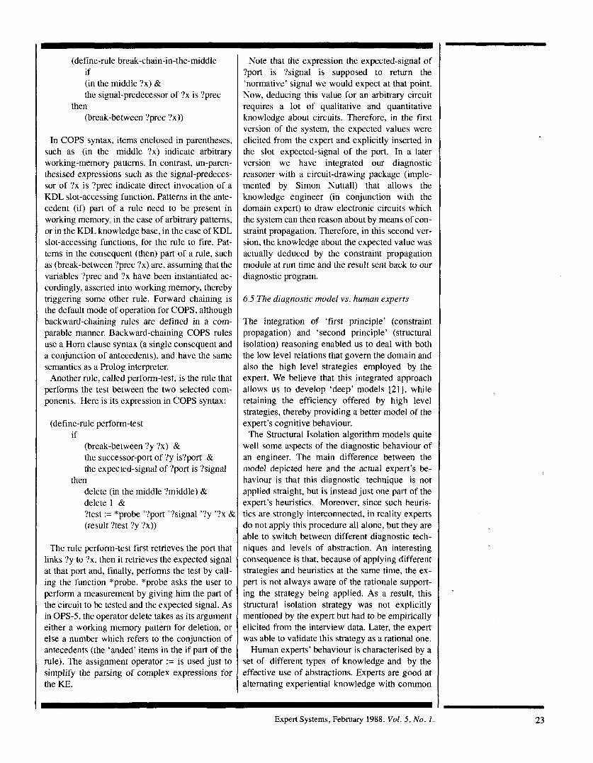
(define-rule break-chain-in-the-middle if (in the middle ?x) & the signal-predecessor of ?x is ?prec
(break-between ?prec ?x)) then
In COPS syntax, items enclosed in parentheses, such as (in the middle ?x) indicate arbitrary working-memory patterns. In contrast, un-paren- thesised expressions such as the signal-predeces- sor of ?x is ?prec indicate direct invocation of a KDL slot-accessing function. Patterns in the ante- cedent (if) part of a rule need to be present in working memory, in the case of arbitrary patterns, or in the KDL knowledge base, in the case of KDL slot-accessing functions, for the rule to fire. Pat- terns in the consequent (then) part of a rule, such as (break-between ?prec ?x) are, assuming that the variables ?prec and ?x have been instantiated ac- cordingly, asserted into working memory, thereby triggering some other rule. Forward chaining is the default mode of operation for COPS, although backward-chaining rules are defined in a com- parable manner. Backward-chaining COPS rules use a Horn clause syntax (a single consequent and a conjunction of antecedents), and have the same semantics as a Prolog interpreter.
Another rule, called perform-test, is the rule that performs the test between the two selected com- ponents. Here is its expression in COPS syntax:
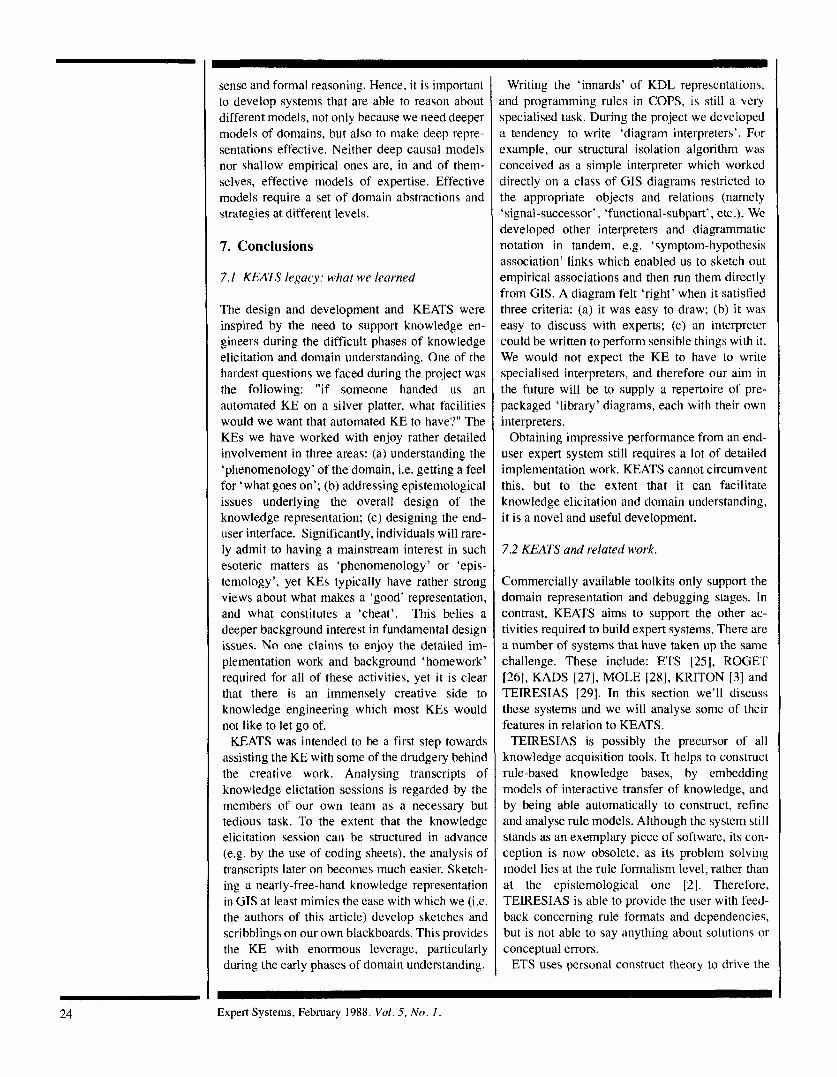
(define-rule perform-test if
(break-between ?y ?x) & the successor-port of ?y is?port & the expected-signal of ?port is ?signal
delete (in the middle ?middle) & delete 1 & ?test := “probe ’?port ’?signal ‘?y ’?x &i
(result ?test ?y ?x))
then
The rule perform-test first retrieves the port that links ‘?y to ?x, then it retrieves the expected signal at that port and, finally, performs the test by call- ing the function *probe. *probe asks the user to perform a measurement by giving him the part of the circuit to be tested and the expected signal. As in OPS-5, the operator delete takes as its argument either a working memory pattern for deletion, or else a number which refers to the conjunction of antecedents (the ‘anded’ items in the if part of the rule). The assignment operator := is used just to simplify the parsing of complex expressions for the KE.
Note that the expression the expected-signal of ?port is ?signal is supposed to return the ‘normative’ signal we would expect at that point. Now, deducing this value for an arbitrary circuit requires a lot of qualitative and quantitative knowledge about circuits. Therefore, in the first version of the system, the expected values were elicited from the expert and explicitly inserted in the slot expected-signal of the port. In a later version we have integrated our diagnostic reasoner with a circuit-drawing package (imple- mented by Simon Nuttall) that allows the knowledge engineer (in conjunction with the domain expert) to draw electronic circuits which the system can then reason about by means of con- straint propagation. Therefore, in this second ver- sion, the knowledge about the expected value was actually deduced by the constraint propagation module at run time and the result sent back to our diagnostic program.
6.5 The diagnostic model vs. human experts
The integration of ‘first principle’ (constraint propagation) and ‘second principle’ (structural isolation) reasoning enabled us to deal with both the low level relations that govern the domain and also the high level strategies employed by the expert. We believe that this integrated approach allows us to develop ‘deep’ models [21], while retaining the efficiency offered by high level strategies, thereby providing a better model of the expert’s cognitive behaviour.
The Structural Isolation algorithm models quite well some aspects of the diagnostic behaviour of an engineer. The main difference between the model depicted here and the actual expert’s be- haviour is that this diagnostic technique is not applied straight, but is instead just one part of the expert’s heuristics. Moreover, since such heuris- tics are strongly interconnected, in reality experts do not apply this procedure all alone, but they are able to switch between different diagnostic tech- niques and levels of abstraction. An interesting consequence is that, because of applying different strategies and heuristics at the same time, the ex- pert is not always aware of the rationale support- ing the strategy being applied. As a result, this structural isolation strategy was not explicitly mentioned by the expert but had to be empirically elicited from the interview data. Later, the expert was able to validate this strategy as a rational one.
Human experts’ behaviour is characterised by a set of different types of knowledge and by the effective use of abstractions. Experts are good at alternating experiential knowledge with common
Expert Systems, February 1988. Vol. 5 , No. 1 . 23
sense and formal reasoning. Hence, it is important to develop systems that are able to reason about different models, not only because we need deeper models of domains, but also to make deep repre- sentations effective. Neither deep causal models nor shallow empirical ones are, in and of them- selves, effective models of expertise. Effective models require a set of domain abstractions and strategies at different levels.
7. Conclusions
7.1 KEATS legacy: what we learned
The design and development and KEATS were inspired by the need to support knowledge en- gineers during the difficult phases of knowledge elicitation and domain understanding. One of the hardest questions we faced during the project was the following: “if someone handed us an automated KE on a silver platter, what facilities would we want that automated KE to have?“ The KEs we have worked with enjoy rather detailed involvement in three areas: (a) understanding the ‘phenomenology’ of the domain, i.e. getting a feel for ‘what goes on’; (b) addressing epistemological issues underlying the overall design of the knowledge representation; (c) designing the end- user interface. Significantly, individuals will rare- ly admit to having a mainstream interest in such esoteric matters as ‘phenomenology’ or ‘epis- temology’, yet KEs typically have rather strong views about what makes a ‘good’ representation, and what constitutes a ’cheat’. This belies a deeper background interest in fundamental design issues. No one claims to enjoy the detailed im- plementation work and background ‘homework’ required for all of these activities, yet it is clear that there is an immensely creative side to knowledge engineering which most KEs would not like to let go of.
KEATS was intended to be a first step towards assisting the KE with some of the drudgery behind the creative work. Analysing transcripts of knowledge elictation sessions is regarded by the members of our own team as a necessary but tedious task. To the extent that the knowledge elicitation session can be structured in advance (e.g. by the use of coding sheets), the analysis of transcripts later on becomes much easier. Sketch- ing a nearly-free-hand knowledge representation in GIS at least mimics the ease with which we (i.e. the authors of this article) develop sketches and scribblings on our own blackboards. This provides the KE with enormous leverage, particularly during the early phases of domain understanding.
Writing the ‘innards’ of KDL representations, md programming rules in COPS, is still a very ,pecialised task. During the project we developed L tendency to write ‘diagram interpreters’. For :xample, our structural isolation algorithm was :onceived as a simple interpreter which worked lirectly on a class of GIS diagrams restricted to he appropriate objects and relations (namely signal-successor’, ‘functional-subpart’, etc.). We leveloped other interpreters and diagrammatic iotation in tandem, e.g. ‘symptom-hypothesis issociation’ links which enabled us to sketch out :mpirical associations and then run them directly i-om GIs. A diagram felt ‘right’ when it satisfied hree criteria: (a) it was easy to draw; (b) i t was :asy to discuss with experts; (c) an interpreter :odd be written to perform sensible things with it. We would not expect the KE to have to write jpecialised interpreters, and therefore our aini in he future will be to supply a repertoire of pre- 2ackaged ‘library’ diagrams, each with their own interpreters.
Obtaining impressive performance from an end- user expert system still requires a lot of detailed implementation work. KEATS cannot circumvent [his, but to the extent that it can facilitate knowledge elicitation and domain understanding, it is a novel and useful development.
7.2 KEATS and related work.
Commercially available toolkits only support the domain representation and debugging stages. In contrast, KEATS aims to support the other ac- tivities required to build expert systems. There are a number of systems that have taken up the same challenge. These include: ETS [25], ROGET [26] , KADS [27 ] , MOLE 1281, KRITON [3] and TEIRESIAS [29]. In this section we’ll discuss these systems and we will analyse some of their features in relation to KEATS.
TEJRESIAS is possibly the precursor of all knowledge acquisition tools. I t helps to construct rule-based knowledge bases, by embedding models of interactive transfer of knowledge, and by being able automatically to construct, refine and analyse rule models. Although the system still stands as an exemplary piece of software, its con- ception is now obsolete, as its problem solving model lies at the rule formalism level, rather than at the epistemological one [ 2 ] . Therefore, TEIRESIAS is able to provide the user with feed- back concerning rule formats and dependencies, but is not able to say anything about solutions or conceptual errors.
ETS uses personal construct theory to drive Lhe
24 ~ _ _ _ _ _ ~ ~
Expert Systems, February 1988. Vol. 5, No. I
acquisition and representation of knowledge. This technique mainly aims to elicit factual and taxonomic knowledge about the domain by means of a dialogue with the domain expert. Although the system is truly general purpose and domain- independent, the repertory grid method of knowl- edge elicitation doesn’t seem powerful enough to build a complete expert system. In particular, eliciting procedural or control knowledge by this technique is quite problematic. Moreover, the set of tools provided is completely top-down and little support is given to bottom-up approaches.
ROGET uses models of classes of problems to assess similarities between the new domain and others previously attempted, to advise about the feasibility of the task and to guide the knowledge elicitation process. The system is really a MYCIN derivative, as it embeds models derived from the MYCIN experience, and MYCIN’s rule-based in- ference mechanism. ROGET also employs an in- triguing common-sense set of heuristics to assess the feasibility of a task, given the nature of the domain and the experience of the KE. Unfor- tunately, its advice appears to be quite weak, as there isn’t really a proper methodology in support. Instead it is based upon empirical experience gathered in building previous systems. As it turns out, a number of factors, including cultural change due to the rapid spreading of knowledge-based systems, make these common-sense heuristics rapidly obsolete (consider for instance the heuris- tics about the time-scale needed to build an expert system). ROGET’s most interesting feature is the way in which it allows the user to build a complete expert system from scratch through a dialogue, which is driven by the pre-stored models. Al- though this interaction is completely top-down, ROGET is able to use the models quite effectively and in some cases it can produce quite impressive results.
MOLE is a ROGET derivative, embedding only one model of problem solving, namely heuristic classification [ 161. Although the scope of the sys- tem is very narrow, MOLE exploits the heuristic classification model in a powerful way and it is able to point out conceptual, model-based flaws in the knowledge base and to help the user debug the prototype expert system.
The KADS group has devised a general methodology for building expert systems and part of it has been implemented in the KADS system. KADS uses interpretation models similar to those of ROGET to drive the knowledge acquisition process. However, existing descriptions of KADS do not make clear all the details of the interaction with the user (more precisely, it is not clear
whether interpretation models fulfil the role of driving the knowledge acquisition process as in ROGET, whether they are generic templates that the user can fill, or whether their role is mainly for documentation purposes). More recently [ 5 ] , KADS has become conceptually more like a KEATS type of toolkit, as it has been extended to embed bottom-up editing and graphical tools. These tools support transcript analysis and domain conceptualisation in a similar way to CREF and GIs, although in one case the linguistic primitives and in the other the style of the user/system inter- action are different. Nevertheless, KADS seems to be one of the very few existing proposals trying to reconcile a sound and comprehensive theoretical methodology with the implementation of both top-down and bottom-up tools, to support the practical building of knowledge based systems.
Finally, KRITON is a comprehensive system whose scope is similar to KEATS, as it provides tools for protocol and text analysis, domain con- ceptualiastion, automatic knowledge base gener- ation and consistency checking. Domain concep- tualisation is supported by means of an inter- mediate representation formalism that helps the user build a prototypical model of the problem. KRITON employs rules, frames and constraint generators to produce the final code from this rep- resentation analogously to the way KDL descrip- tions are generated and constraints propagated from GIS diagrams. KRITON’s methodology appears to be quite close to the typical user/ KEATS interaction described above, as the proponents stress the importance of linguistic tools to support bottom-up approaches. Although KRITON appears to provide a large number of KEATS-like features, the descriptions in the literature don’t really make clear the extent to which the system has been implemented and tested.
7.3 Future development
Most of the KEATS system is currently being redesigned as part of an effort to focus on the following issues:
CREF is being enhanced to provide a greater number of capabilities and a more coherent inter- face to GIS and to the user. In particular, we need to provide better facilities for attaching CREF seg- ments or collections to graphical objects and to descriptions. This would facilitate the generation of explanatory text for documentation purposes both during the development of the system and after its release. Also, we intend to modify the in- teraction with the user to make it more graphical
Expert Systems, February 1988. Vol. 5, No. I 25
in nature rather than editor-based. Because KEATS doesn’t provide much model-
based support, we are working on the develop- ment of a problem-solving library. Although we hope that at some point it should be possible to use the library for automated knowledge acquisition, at the moment we regard it only as a set of generic problem-solving modules [30] that would make the implementation of expert systems more struc- tured and provide automatic generation of model- derived explanations.
As far as model-based knowledge acquisition is concerned, we are experimenting further with ‘coding sheets’, i.e. questionnaires based on inter- pretation models. Because the encoding and appli- cation of coding sheets is still mediated by the KE, it is possible for us to sidestep some difficult human-computer interaction issues and to concen- trate directly upon model-based knowledge acqui- sition. The results so far have been encouraging, as this technique has allowed prototypes to be built very quickly. At the same time, the model- derived approach makes these prototypes more effective and easier to analyse and debug than those derived by other interview techniques.
No support is currently provided by KEATS as far as domain feasibility and assessment are con- cerned. While we intend to build a library of task models similar to KADS interpretation models, it is not clear what type of feedback a system should provide to help the user understand the domain re- quirements and the feasibilty of the project. Other important issues concern the integration of very large knowledge bases, and the integration of rep- resentations developed by disparate teams of KEs working with multiple experts.
Work is being carried out on KDL and COPS to provide a more flexible and integrated knowledge representation system along the lines developed in the JOSHUA system [31]. New features for checking the consistency/completeness of the knowledge base, for providing truth maintenance, and for advanced graphical tracing facilities as in [32] are now being designed and implemented. We eagerly await developments in what we hope to be indicative of the ‘next phases’ of knowledge engineering.
8 . References
[ 1 ] F. Hayes-Roth, D.A. Waterman, D.B. Lenat. Building expert systems, Reading, Mas- sachussetts: Addison-Wesley, 1983.
1 2 1 B.J. Wielinga and J.A. Breuker. ‘Models of expertise’. Proceedings ECAI 86, Brighton, England, 1986.
[ 3 ] J. Diederich, I. Ruhmann, M. May. ‘KRITON: a knowledge-acquisition tool for expert systems’. International Journal Man-Machine Studies, 26, 1987.
[ 4 ] R.J. Brachman, R.E. Fikes, H.J. Levesque. ‘Krypton: A Functional Approach to Knowledge Representation’. In R. Brach- man and H. Levesque (Eds.), Readings in Knowledge Representation. Los Angeles: Morgan Kaufman, 1985a. A. Anjewierden. ‘Knowledge Acquisition Tools,’ A1 Communications 0 (1) North. Holland, August 1987. F. Halasz, T. Moran and R.H. Trigg. ‘Note- Cards in a nutshell‘. Proceedings of CHI- 87, Toronto, Canada, 1987. R. Stallman. ‘EMACS: The Extensible, Customizable, Self-Documenting Display Editor.’ AI Memo 519a, MIT, Cambridge, Massachussetts, March 198 1. J. Handel and T.S. Whitaker. ‘Zmail Con- cepts and Techniques,’ Docunient #990096. Symbolics Inc., Cambridge MA, 1983. T. Winograd. ‘Frame Representation and the DeclarativeProcedural Controversy’. In D. Bobrow and A. Collins (Eds.), Represen- tation and Understanding: Studies in Cog- nitive Science. New York: Academic Press, 1975. G. Attardi, M. Simi. ‘Semantics of In- heritance and Attributions in the Descrip- tion System Omega’. Al Memo 642, MIT Artificial Intelligence Laboratory, August 1981. R.J. Brachman, and J.C. Schmolze. ‘An Overview of the KL-ONE Knowledge Representation System’. Cognitive Science, 9, (2), 198Sb.
[ 12 ] E. Motta, M. Eisenstadt, K. Pitman, M. West, R. Evertsz. ‘KEATS: The Knowledge Engineer’s Assistant.’ Technical Report N o . 20, Human Cognition Research Laboratory, The Open University, Milton Keynes, England, 1986.
[ 13 ] D.S.Touretzky, J.F. Horty, R.H. Thomason. ‘A Clash of Intuitions: The Current State ot Nonmonotonic Multiple Inheritance Sy\- tems.’ Proceedings IJCAI 87, Milan, 1987.
[ 14 ] M. Stefik. ‘An Examination of a Frame- structured Representation Syqtem,’ Proceedings IJCAI 79, Tokyo, 1979.
[ 15 ] L. Steels. ‘Introduction to the Knowledge Representation System KRS,’ Free Univer- sity of Bruselles, A1 Lab, Technical Report, 1985.
26 Expert Systems, February 1988. Vol. 5, No. 1 .
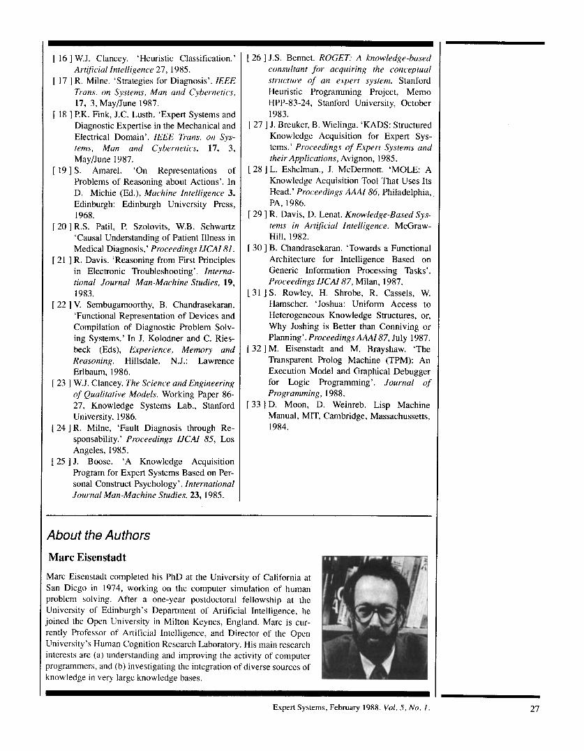
[ 16 1 W.J. Clancey. ‘Heuristic Classification.’ Artificial Intelligence 27, 1985.
[ 17 ] R. Milne. ‘Strategies for Diagnosis’. IEEE Trans. on Systems, Man and Cybernetics, 17, 3, MayjJune 1987.
[ 18 ] P.K. Fink, J.C. Lusth. ‘Expert Systems and Diagnostic Expertise in the Mechanical and Electrical Domain’. IEEE Trans. on Sys- tems, Man and Cybernetics, 17, 3, MayjJune 1987.
[ 19 ] S. Amarel. ‘On Representations of Problems of Reasoning about Actions’. In D. Michie (Ed.), Machine Intelligence 3. Edinburgh: Edinburgh University Press, 1968.
[ 20 ] R.S. Patil, P. Szolovits, W.B. Schwartz ‘Causal Understanding of Patient Illness in Medical Diagnosis,’ Proceedings IJCAI 81.
[ 21 ] R. Davis. ‘Reasoning from First Principles in Electronic Troubleshooting’. Interna- tional Journal Man-Machine Studies, 19, 1983.
[ 22 ] V. Sembugamoorthy, B. Chandrasekaran. ‘Functional Representation of Devices and Compilation of Diagnostic Problem Solv- ing Systems.’ In J. Kolodner and C. Ries- beck (Eds), Experience, Memory and Reasoning. Hillsdale, N.J.: Lawrence Erlbaum, 1986.
[ 23 ] W.J. Clancey. The Science and Engineering of Qualitative Models. Working Paper 86- 27, Knowledge Systems Lab., Stanford University, 1986.
[ 24 ] R. Milne, ‘Fault Diagnosis through Re- sponsability.’ Proceedings IJCAI 85, Los Angeles, 1985.
[ 25 ] J. Boose. ‘A Knowledge Acquisition Program for Expert Systems Based on Per- sonal Construct Psychology’. International Journal Man-Machine Studies, 23, 1985.
[ 26 ] J.S. Bennet. ROGET: A knowledge-based consultant for acquiring the conceptual structure of an expert system. Stanford Heuristic Programming Project, Memo HPP-83-24, Stanford University, October 1983.
I 27 1 J. Breuker, B. Wielinga. ‘KADS: Structured Knowledge Acquisition for Expert Sys- tems.’ Proceedings of Expert Systems and their Applications, Avignon, 1985.
[ 28 ] L. Eshelman., J. McDermott. ‘MOLE: A Knowledge Acquisition Tool That Uses Its Head.’ Proceedings AAAI 86, Philadelphia, PA, 1986.
[ 29 ] R. Davis, D. Lenat. Knowledge-Eased Sys- tems in Artificial Intelligence. McGraw- Hill, 1982.
[ 30 ] B. Chandrasekaran. ‘Towards a Functional Architecture for Intelligence Based on Generic Information Processing Tasks’. Proceedings IJCAI 87, Milan, 1987. S. Rowley, H. Shrobe, R. Cassels, W. Hamscher. ‘Joshua: Uniform Access to Heterogeneous Knowledge Structures, or, Why Joshing is Better than Conniving or Planning’. Proceedings A M 87, July 1987. M. Eisenstadt and M. Brayshaw. ‘The Transparent Prolog Machine (TPM): An Execution Model and Graphical Debugger for Logic Programming’. Journal of Programming, 1988.
[ 33 ] D. Moon, D. Weinreb. Lisp Machine Manual, MIT, Cambridge, Massachussetts, 1984.
About the Authors
Marc Eisenstadt
Marc Eisenstadt completed his PhD at the University of California at San Diego in 1974, working on the computer simulation of human problem solving. After a one-year postdoctoral fellowship at the University of Edinburgh’s Department of Artificial Intelligence, he joined the Open University in Milton Keynes, England. Marc is cur- rently Professor of Artificial Intelligence, and Director of the Open University’s Human Cognition Research Laboratory. His main research interests are (a) understanding and improving the activity of computer programmers, and (b) investigating the integration of diverse sources of knowledge in very large knowledge bases.
I Expert Systems, February 1988. Vol. 5, No. I. 27
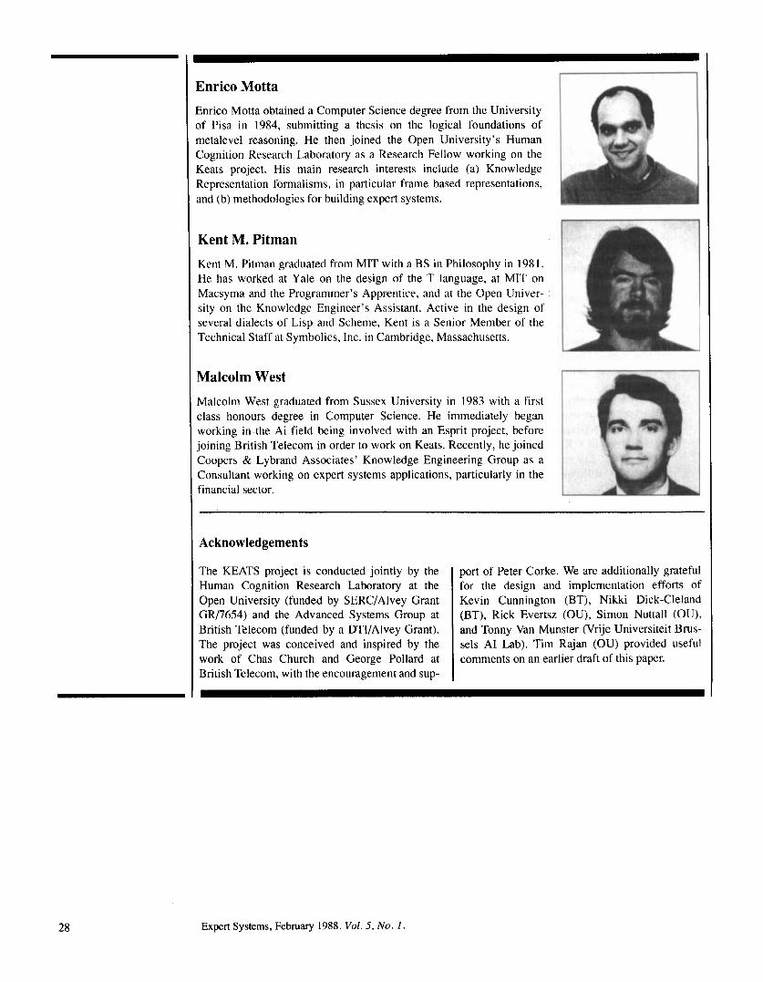
Enrico Motta Enrico Motta obtained a Computer Science degree from the University 3f Pisa in 1984, submitting a thesis on the logical foundations of metalevel reasoning. He then joined the Open University’s Human Cognition Research Laboratory as a Research Fellow working on the Keats project. His main research interests include (a) Knowledge Representation formalisms, in particular frame based representations, and (b) methodologies for building expert systems.
Kent M. Pitman Kent M. Pitman graduated from MIT with a BS in Philosophy in 1981. He has worked at Yale on the design of the T language, at MlT on Macsyma and the Programmer’s Apprentice, and at the Open Univer- sity on the Knowledge Engineer’s Assistant. Active in the design of several dialects of Lisp and Scheme, Kent is a Senior Member of the Technical Staff at Symbolics, Inc. in Cambridge, Massachusetts.
Malcolm West Malcolm West graduated from Sussex University in 1983 with a first class honours degree in Computer Science. He immediately began working in the Ai field being involved with an Esprit project, before joining British Telecom in order to work on Keats. Recently, he joined Coopers & Lybrdnd Associates’ Knowledge Engineering Group as a Consultant working on expert systems applications, particularly in the financial sector.
Acknowledgements
The KEATS project is conducted jointly by the Human Cognition Research Laboratory at the Open University (funded by SERC/Alvey Grant GR/7654) and the Advanced Systems Group at British Telecom (funded by a DTl/Alvey Grant). The project was conceived and inspired by the work of Chas Church and George Pollard at British Telecom, with the encouragement and sup-
port of Peter Corke. We are additionally grateful for the design and implementation efforts of Kevin Cunnington (BT), Nikki Dick-Cleland (BT), Rick Evertsz (OU), Simon Nuttall (OU), and Tonny Van Munster (Vrije Universiteit Brus- sels A1 Lab). Tim Rajan (OU) provided useful comments on an earlier draft of this paper.
28 Expert Systems, February 1988. Vol. 5 , No. I.