Embed Size (px)
Citation preview
Surface Tension Measurements
B Y
MALCOLM DOLE
Department of Chemistry, Northwestern University, Evanston, Illinois
CONTENTS Page
1. Introduction S06 1.1. Definitions 306 1.2. Review of Methods 306 1.3. Review of Applications 306
2. Capillary Rise Method 308 2.1. Absolute Measurements 308
2.1.1. Introduction 308 2.1.2. General Theory 308 2.1.3. Experimental Precautions 310 2.1.4. Experimental Accuracy and Reproducibility 311
2.2. Relative Measurements 312 2.2.1. Double Capillary Tube Methods 312 2.2.2. Relative Methods of Jones and Ray 313
2.3. Combined Capillary Tube-Pressure Methods 314 2.3.1. Single Capillary Tubes 314 2.3.2. Double Capillary Tubes 316
3. Maximum Bubble Pressure Methods 317 3.1. Single Tube Methods 317
3.1.1. Introduction 317 3.1.2. Theory 317 3.1.3. Applications 318
3.2. Double Tube Methods 319 3.2.1. Apparatus of Sugden 319 3.2.2. The Relative Method of Warren 320 3.2.3. Method of Long and Nutting. 321
4. Drop-Weight and Pendant Drop Methods 321 4.1. Drop-Weight Method 321
4.1.1. Introduction 321 4.1.2. Theory 321 4.1.3. Methods 322
4.2. Pendant Drop Method 324 5. Ring Methods 325
5.1. Single Ring Method 325 5.1.1. Introduction 325 5.1.2. Theory of the Ring Method 325 5.1.3. Methods 327
305
3 0 6 MALCOLM D O L E
5.2. Double Ring Method.. 5.3. Straight Wire Method.
References
Page 328
. 330
. 331
1. I N T R O D U C T I O N
1.1. Definitions
Surface tension is defined as the force in the interface between a liquid and gas phase or between a solid and gas phase t h a t opposes an extension of the surface, t h a t is measured along a line, and t h a t is expressed with the symbol y having the units of dynes per centimeter. The force lying in the interface between two liquid phases, or between solid and liquid phase, t h a t opposes an extension of the interface is defined as t he interfacial tension and also has the. symbol y with the uni ts dynes per centimeter. T h u s surface tension is a force per uni t of length.
Surface energy of an area A cm. 2 is defined as y · A ergs.
There are many methods of surface and interfacial tension measurement among which m a y be mentioned the capillary rise, the ring, the maximum bubble pressure, the drop weight, the Wilhelmy, the pendant drop, the centrifugal, the sessile drop, the ripple, the vibrat ing jet methods, and modifications of these. Double capillary tubes, twin-rings, s traight wires, plates, discs, parallel plates, horizontal capillary tubes, etc. have been used. In fact the s tudy of surface tension techniques might be described as a s tudy of scientific inventiveness and ingenuity.
We do not have space here to describe and review all methods and modifications t h a t have been used in the pas t ; instead the four most impor tan t and convenient methods will be discussed. Of these, the maximum bubble pressure method and the drop weight method have most often been used in s tudying the surface tension of liquid metals and alloys, and the maximum bubble pressure method in the analysis of solutions. M a n y of the principles of one method are a t once t ransferable to another method, so t h a t if, for example, the theory underlying the capillary rise method is well understood, it is not difficult t o comprehend the techniques of m a n y of the other methods.
As most metals are formed in the liquid s ta te it is clear t h a t surface tension forces m a y influence some of their properties, in part icular the spreading of one liquid metal over another, possibly solid, metal is
1.2. Methods
1.3. Applications
SURFACE TENSION MEASUREMENTS 307
affected by the surface forces. Thus , Chalmers (10) has investigated the relationship between surface tension and the t inplat ing of steel by the hot dipping process. Coffman and Pa r r (11) found t h a t H C 1 gas not only lowers the surface tension of a Zn-Pb solder, bu t also markedly improves the spreading. The connection is obvious since, as the surface tension of the liquid phase is larger, t he tendency for it to spread is less (the work of adhesion of the liquid to the solid and the contact angles mus t also be considered). As the surface tension of molten metals is remarkably high (10 t imes or more greater t h a n t h a t of water in m a n y cases) with sometimes an unusual positive t empera tu re coefficient, it is not surprising t h a t surface tension forces play a significant role in all processes where the spreading of a liquid metal is concerned.
The accurate determinat ion of the surface tension of molten metals is difficult because of two factors, first the ease with which metals combine with gases of different types t o form surface compounds such as oxides or hydrides t h a t upset the measurements , and second the large contact angle usually exhibited between metals and glass or quar tz . I n the drop weight method, for example, th is means t h a t the inner radius determines the size of the drop whereas when water is used with a quar tz capillary, it is the outer radius which mus t be used in the surface tension calculation.
Grain size in alloys is undoubted ly affected by surface tension: see, for example, the remarks of Bast ien on grain size in Al-Mg alloys (5).
M a n y solutions containing surface active solutes can be analyzed by adding base, let us say, which converts the surface active acid to a surface inactive compound and causes a sharp rise in the surface tension unti l t he end point in the t i t ra t ion is reached, a t which t ime the surface tension becomes constant (see Taubmann , 63, and Preston, 48). The maximum bubble pressure method is used, the pressure rising rapidly to t h e end point . Reference can also be made to the filter-paper s tr ip method of capillary analysis carried out by Liesegang (38).
The flotation of solids, as in the separation of minerals by flotation, is entirely dependent on surface forces; in part icular the proper ty of t he solid, or of the solid plus " col lector / ' t h a t largely determines the flotation is the contact angle between the liquid and solid phase. The stabil i ty of the floated ore will increase with increase in the value of 7 ( 1 — cos 0) where 7 is the surface tension of the liquid phase and 0 is the contact angle.
The ra te of penetra t ion of liquids into solid powders and capillary tubes is a function of the " penet ra t ing p re s su re / ' which is given by the te rm
2γ cos 0 t
r '
again showing the importance of surface tension and contact angle.
308 MALCOLM D O L E
As this chapter will include only a description of methods of surface tension measurement , the reader who is interested in contact angles, frothing agents, surface film pressures, and other surface phenomena is referred to the excellent treatise of Adam (2).
2. C A P I L L A R Y R I S E M E T H O D
2.1. Absolute Measurements
2.1.1. Introduction. Since the capillary rise method has been in the pas t the s tandard surface tension method to which all other methods
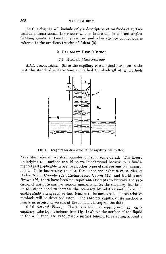
FIG. 1. Diagram for discussion of the capillary rise method.
have been referred, we shall consider it first in some detail . The theory underlying this method should be well understood because it is fundamenta l and applicable in par t to all other types of surface tension measurement . I t is interesting to note t h a t since the exhaustive studies of Richards and Coombs (52), Richards and Carver (51), and Harkins and Brown (26) there have been no impor tan t a t t emp t s to improve, the precision of absolute surface tension measurements ; the tendency has been on the other hand to increase the accuracy by relative methods which enable slight changes in surface tension to be measured. These relative methods will be described later. The absolute capillary rise method is nearly as precise as we can a t the moment interpret the da ta .
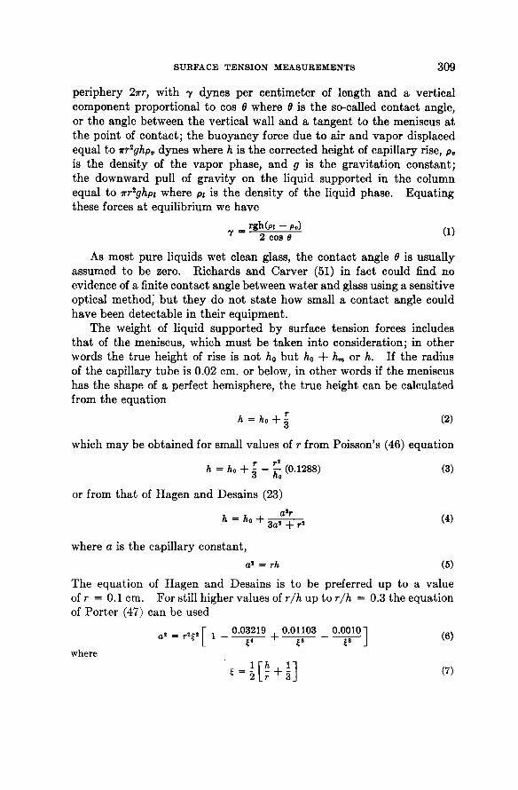
2.1.2. General Theory. The forces tha t , a t equilibrium, act on a capillary tube liquid column (see Fig. 1) above the surface of the liquid in the wide tube , are as follows: a surface tension force acting around a
SURFACE TENSION MEASUREMENTS 309
periphery 2rr, wi th y dynes per cent imeter of length and a vertical component proport ional t o cos θ where θ is t he so-called contact angle, or t he angle between the vertical wall and a t angent t o the meniscus a t t he point of contac t ; t he buoyancy force due t o air and vapor displaced equal t o nr2ghpv dynes where h is t he corrected height of capillary rise, p v
is t he densi ty of t he vapor phase, and g is t he gravi ta t ion cons tan t ; t he downward pull of gravi ty on the liquid supported in t he column equal t o irr2ghpi where pi is t h e densi ty of t he liquid phase. Equa t ing these forces a t equilibrium we have
β rghfo - p,) 7 2 cos θ KL)
As most pure liquids wet clean glass, t he contact angle Θ is usually assumed to be zero. Richards and Carver (51) in fact could find no evidence of a finite contact angle between water and glass using a sensitive optical method," b u t t hey do not s t a te how small a contact angle could have been detectable in their equipment .
T h e weight of liquid suppor ted b y surface tension forces includes t h a t of t he meniscus, which mus t be t aken into consideration; in other words the t rue height of rise is not h0 bu t h0 + hm or h. If t he radius of the capillary tube is 0.02 cm. or below, in other words if t he meniscus has the shape of a perfect hemisphere, t he t rue height can be calculated from the equat ion
h = ho + I (2)
which m a y be obtained for small values of r from Poisson's (46) equation
h - ho + I - £ o (0.1288) (3)
or from t h a t of Hagen and Desains (23)
Α = Λ ° + 3 ^ Τ 7 ' ( 4 )
where a is the capillary constant ,
a* = rh (5)
The equat ion of Hagen and Desains is to be preferred up to a value of r = 0.1 cm. For still higher values of r/h up to r/h = 0.3 the equat ion of Por te r (47) can be used
where
310 MALCOLM DOLE
Equat ion (6) is also based on the assumption t h a t the tube holding the bulk of the liquid is wide enough so t h a t the surface of the liquid is essentially flat.
A correction to the observed height, A0, mus t also be made because of the fact t h a t the lower level of liquid t h a t serves as a reference point in measuring the height, A0, is somewhat higher because of capillary rise on the walls of the wide t ube t h a n a free flat surface would be. The following equat ion of Lord Rayleigh (50) makes possible the calculation of this correction for wide tubes :
As tested by Richards and Carver (51) this equat ion is valid for values of r/a greater t h a n 2.75. The correction factor in the case of smaller tubes can be obtained from the experimental curve given by these authors .
For the most refined work a final correction needs to be made if the capillary tube is not perfectly circular in cross section. If t he tube is elliptical instead of circular, wi th a rat io of major t o minor axis given by Qy then the capillary rise will be greater in hundred ths of one per cent by the factor (from Richards and Carver) ,
This expression is valid only for Q values up to 1.10 ( 1 0 % ellipticity). Apparent ly unaware of the work of Richards and Carver, Smith and Foote (58) have also discussed and given mathemat ica l equations for the surface tension in elliptical tubes .
2.1.8. Experimental Precautions. Since the surface tension as measured by the capillary rise method is directly proportional to the height, the density, and the radius of cross section, it is essential t h a t all of these quant i t ies be known with as great a precision as desired in the final surface tension value. The densi ty of the pure liquid is readily determined with great accuracy, t he height also is fairly readily measured, bu t the radius of cross section offers the greatest difficulty in its determination. The usual procedure is t o force a small slug of mercury through the capillary measuring its length a t various points along the tube with an accurate comparator . Hark ins and Brown (26) point out t h a t gravi tat ional forces m a y distort t he meniscus when the tube is in a horizontal position and Harkins (25) recommends the adopt ion of Young 's scheme, which eliminates the meniscus correction by using a long and short section of mercury. Richards and Carver (51) could not observe any gravi tat ional distort ion in the case of small bore tubes, bu t applied a correction for the mercury meniscus by measuring its length
(8)
1900(Q - 1.00) - 4 (9)
SURFACE TENSION MEASUREMENTS 311
(a distance corresponding to hm) and comput ing the volume of mercury in the meniscus, assuming it to be a hemisphere. One wonders why capillary tubes have not been studied in a vertical position with the mercury column supported on a column of water or some other liquid. F rom theoretical considerations which we shall discuss later, i t would appear t h a t the diameter of t he tube wet with a film of water is of greater significance for surface tension measurements t h a n t h a t of a d ry tube . The greatest care in selecting capillary tubes of uniform t rue right cylindrical shape should be exercised.
Capillary height measurements are made with accurate ca thetometers with a sharp edged black screen immersed in the the rmos ta t t ank jus t under and back of the meniscus, as recommended b y Richards and Coombs (52). The appara tus should be tes ted for optical distort ion by measuring the distance between two ruled lines on a glass p la te inserted in the b a t h a t t he location of t he capillarimeter and comparing this distance wi th a similar measurement made in the air. Richards and co-workers measured the height of rise wi th the capillary t ube in four positions, front, back, inverted front, and inver ted back, and took the average to el iminate t he distort ion of t he image. T h e capillarimeter, as well as the plates through which the observation is made, should be, of course, exactly vertical.
The final experimental precaut ion has t o do with cleanliness of equipment and pur i ty of liquids studied. A slight amount of grease on glass surfaces will change t h e contact angle between liquid and glass, t h u s vi t ia t ing t he measurement . The best technique for the removal of grease is t o wash the glass appa ra tus wi th a hot mixture of nitric and sulfuric acids (cleaning solution should no t be used since chromic oxide seems to pene t r a t e slightly into t he glass s t ructure—as we have often noticed in making accurate densi ty measurements in t h e Nor thwes tern Labora tory) , to rinse with redistilled water , and finally t o s team out the appara tus for about an hour using s team generated from redistilled water . The chief criticism of the work of Richards and his school lies in their use of chromic acid cleaning solution. Nevertheless, their results agreed very closely wi th those of Hark ins and Brown who applied the s teaming out technique to t he cleansing of their glass capillarimeters.
Young et al. (69) describe a useful overflow method of renewing the surface b y flowing the liquid in the capillary t ube out into a t r a p . (The surface could also be renewed in the appara tus of Richards and Coombs (52) and, indeed, was, in their habi t of invert ing their appara tus . )
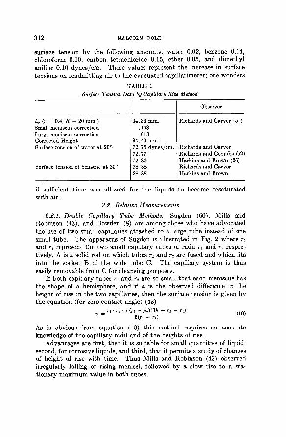
2.1.4. Experimental Accuracy and Reproducibility. Table I gives some da ta from which the degree of accuracy obtainable can be judged.
Richards and Carver (51) found t h a t removal of air increased the
312 MALCOLM DOLE
surface tension by the following amoun t s : water 0.02, benzene 0.14, chloroform 0.10, carbon tetrachloride 0.15, ether 0.05, and dimethyl aniline 0.10 dynes /cm. These values represent the increase in surface tensions on readmit t ing air to the evacuated capillarimeter; one wonders
TABLE I Surface Tension Data by Capillary Rise Method
Observer
Κ (r = 0.4, R = 20 mm.) 34.33 mm. Richards and Carver (51) Small meniscus correction .143 Large meniscus correction .013 Corrected Height 34.49 mm. Surface tension of water at 20° 72.75 dynes/cm. Richards and Carver
72.77 Richards and Coombs (52) 72.80 Harkins and Brown (26)
Surface tension of benzene at 20° 28.88 Richards and Carver 28.88 Harkins and Brown
if sufficient t ime was allowed for the liquids to become resaturated with air.
2.2. Relative Measurements
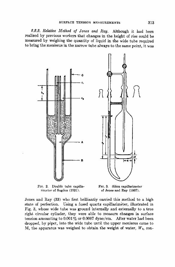
2.2.1. Double Capillary Tube Methods. Sugden (60), Mills and Robinson (43), and Bowden (8) are among those who have advocated the use of two small capillaries a t tached to a large tube instead of one small tube . The appara tus of Sugden is i l lustrated in Fig. 2 where rx
and r 2 represent the two small capillary tubes of radii ri and r 2 respectively, A is a solid rod on which tubes η and r 2 are fused and which fits into the socket Β of the wide tube C. The capillary system is thus easily removable from C for cleansing purposes.
If both capillary tubes η and r2 are so small t h a t each meniscus has the shape of a hemisphere, and if h is the observed difference in the height of rise in the two capillaries, then the surface tension is given by the equat ion (for zero contact angle) (43)
ri · r 2 · g (PI - pv){3h + r 2 - rQ n n . 7 = 6(n - r 2 ) ( 1 0 )
As is obvious from equat ion (10) this method requires an accura te knowledge of the capillary radii and of the heights of rise.
Advantages are first, t h a t it is suitable for small quant i t ies of liquid, second, for corrosive liquids, and third, t ha t it permits a s tudy of changes of height of rise with t ime. Thus Mills and Robinson (43) observed irregularly falling or rising menisci, followed by a slow rise to a s tat ionary maximum value in bo th tubes .
SURFACE TENSION MEASUREMENTS 313
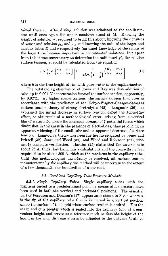
2.2.2. Relative Method of Jones and Ray. Although it had been realized b y previous workers t h a t changes in the height of rise could be measured by weighing the quan t i t y of liquid in the wide tube required to bring the meniscus in the narrow tube always to the same point, it was
FIG. 2 . Double tube capilla- FIG. 3 . Silica capillarimeter rimeter of Sugden ( 1 9 2 1 ) . of Jones and Ray ( 1 9 3 7 ) .
Jones and R a y (33) who first brill iantly carried this method to a high s ta te of perfection. Using a fused quar tz capillarimeter, i l lustrated in Fig. 3, whose wide tube was ground internally and externally t o a t rue right circular cylinder, they were able to measure changes in surface tension amount ing t o 0.001 % or 0.0007 dyne / cm. After water had been dropped, by pipet, into the wide tube unt i l t he upper meniscus came to M, the appara tus was weighed to obtain the weight of water, Wo, con-
314 MALCOLM DOLE
ta ined therein. After drying, solution was admi t ted to the capillarim-eter unti l once again the upper meniscus stood a t M. Knowing the weight of solution Wc required to bring this about , knowing the densities of water and solution p i t 0 and pi,e and knowing the radii of the larger and smaller tubes R and r respectively (an exact knowledge of the radius of the large tube became impor tan t in concentrated solutions, bu t apa r t from this it was unnecessary to determine the radii exactly), the relative surface tension, γ , could be calculated from the equation
= 7 c = Vpi.c — P t . c l
To LPi.o — Pv.o J
where h is the t rue height of rise with pure water in the capillarimeter. The outs tanding observation of Jones and R a y was tha t addit ion of
salts u p to 0.001 Ν concentration lowered the surface tension, apparent ly , by 0 .02%. At higher concentrations, the surface tension then rose in accordance with the prediction of the Debye-Wagner-Onsager-Samaras surface tension theory of strong electrolytes (45). Langmuir (36) has explained the initial decrease in surface tension, called the Jones-Ray effect, as the result of a methodological error, arising from a vertical film of water held above the meniscus because of f-potential forces which diminishes in thickness in the presence of electrolytes, t hus producing an apparent widening of the small tube and an apparent decrease of surface tension. Langmuir ' s theory has been further investigated by Jones and Frizzell (32), Jones and Wood (34), and Wood and Robinson (67), with nearly complete verification. Harkins (25) s ta tes t h a t the water film is about 25 A. thick, bu t Langmuir ' s calculations and the Jones-Ray effect require it t o be about 500 A. thick a t the meniscus in the capillary tube . Until this methodological uncer ta in ty is resolved, all surface tension measurements by the capillary rise method will be uncertain to the extent of a few thousandths or hundredths of a per cent.
2.8. Combined Capillary Tube-Pressure Methods
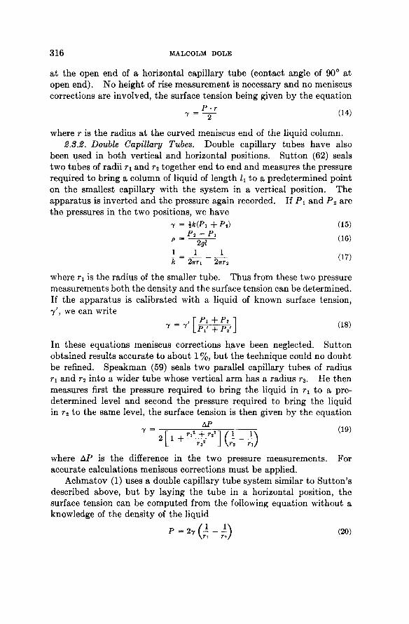
2.8.1. Single Capillary Tubes. Single capillary tubes with the meniscus forced to a predetermined point by means of air pressure have been used in bo th the vertical and horizontal positions. The essential pa r t of Ferguson and Dowson's (17) appa ra tus is shown in Fig. 4 where A is the t ip of the capillary tube t h a t is immersed in a vertical position under the surface of the liquid whose surface tension is desired. Ε is the sharp end of a pointer which is sealed into the capillary tube a t a convenient height and serves as a reference mark so t h a t the height of the liquid in the wide dish can always be adjusted to the distance h2 above
1 + nR*h _l (Wo
( L _ 0 U , Pi (Π)

SURFACE TENSION MEASUREMENTS 315
the flat bo t tom end of the capillary tube . This adjus tment can be made with great accuracy. Pressure is now applied a t Β unti l t he lowest point of t he meniscus of liquid in the capillary tube falls t o a position flush with the flat end. If the capillary tube is small enough so t h a t the meniscus is hemispherical, t he surface tension is given b y the equat ion
- ν (*-.-£) «> If t he liquid in the manomete r used to measure the pressure is the same
ι I
FIG. 4 . Apparatus of Ferguson and Dowson ( 1 9 2 1 ) .
as the liquid under tes t and if hi is t he difference between the heights in the manometer , equat ion (12) m a y be wri t ten
( * . - * , - { ) . (13)
This method can be carried out with great accuracy and has the advantages t h a t (1) the same point on the capillary tube , namely its t ip end, is always used, (2) the radius is easily measured a t various orientat ions with a dividing engine, (3) it is unnecessary to measure the height of rise in the capillary, only the relative measurements of hi in t he manometer have to be carried out wi th a ca thetometer , (4) t he capillary t u b e can be made qui te short and is t h u s more easily cleaned, and (5) t he experiment can be quickly performed. Ferguson and Hakes (18) point out t h a t by varying A2 and making simultaneous measurements of hi and A2, t he densi ty of the unknown liquid can be determined from the slope of a plot of pih\ versus A2 (in th is case t he manometer liquid mus t have a known and different densi ty) .
Ferguson and Kennedy (19) eliminate density considerations entirely by measuring the pressure necessary to produce a flat meniscus of liquid
316 MALCOLM DOLE
a t the open end of a horizontal capillary tube (contact angle of 90° a t open end) . N o height of rise measurement is necessary and no meniscus corrections are involved, the surface tension being given by the equat ion
where r is t he radius a t the curved meniscus end of the liquid column. 2.8.2. Double Capillary Tubes. Double capillary tubes have also
been used in bo th vertical and horizontal positions. Su t ton (62) seals two tubes of radii ΤΊ and r 2 together end to end and measures the pressure required to bring a column of liquid of length h to a predetermined point on the smallest capillary with the system in a vertical position. The appara tus is inverted and the pressure again recorded. If P i and P 2 are the pressures in the two positions, we have
7 = mPi + Pi) (i5)
" = ~ w ( 6 )
! - J L ( 1 7 )
k 27ΓΓΙ 2πΓ2
where r± is the radius of the smaller tube . Thus from these two pressure measurements both the densi ty and the surface tension can be determined. If the appara tus is calibrated with a liquid of known surface tension, y', we can write
In these equat ions meniscus corrections have been neglected. Su t ton obtained results accurate t o about 1 %, bu t the technique could no doubt be refined. Speakman (59) seals two parallel capillary tubes of radius ri and r 2 in to a wider tube whose vertical a rm has a radius r 3. He then measures first t he pressure required to bring the liquid in rx to a predetermined level and second the pressure required to bring the liquid in r 2 to the same level, t he surface tension is then given by the equation
y = ^ (19)
where AP is t he difference in the two pressure measurements . For accurate calculations meniscus corrections mus t be applied.
Achmatov (1) uses a double capillary tube system similar to Sut ton ' s described above, bu t by laying the tube in a horizontal position, the surface tension can be computed from the following equation without a knowledge of the density of the liquid
(20)
S U R F A C E T E N S I O N M E A S U R E M E N T S 3 1 7
where Ρ is t he pressure difference a t t he ends of the two capillaries just sufficient t o prevent t he liquid from moving in either horizontal direction. N o capillary correction is necessary for this method bu t the possibility of gravi ty distortion of the meniscus would have to be investigated for precise results.
3 . M A X I M U M B U B B L E P R E S S U R E M E T H O D
3.1. Single Tube Methods
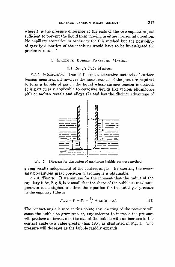
3.1.1. Introduction. One of the most a t t rac t ive methods of surface tension measurement involves the measurement of the pressure required to form a bubble of gas in t he liquid whose surface tension is desired. I t is part icular ly applicable t o corrosive liquids like molten phosphorus ( 3 0 ) or molten metals and alloys ( 7 ) and has the distinct advantage of
FIG. 5. Diagram for discussion of maximum bubble pressure method.
giving results independent of the contact angle. By exerting the necessary precaut ions great precision of technique is obtainable.
3.1.2. Theory. If we assume for the moment t h a t the radius of the capillary tube , Fig. 5 , is so small t h a t t he shape of the bubble a t maximum pressure is hemispherical, then the equat ion for the tota l gas pressure in the capillary tube is
Ptotal = Ρ + Pi = — + Qhl(pi - Pv). (21) r
The contact angle is zero a t this point ; any lowering of the pressure will cause t he bubble t o grow smaller, any a t t e m p t t o increase the pressure will produce an increase in the size of the bubble with an increase in the contact angle t o a value greater t h a n 1 8 0 ° , as i l lustrated in Fig. 5 . The pressure will decrease as the bubble rapidly expands.
3 1 8 MALCOLM DOLE
The pressure across the interface, P , is given for small values of r/L by the equation of Schroedinger (54)
* - ? [ - ! £ - * © " ] where h is given by the equat ion
Ρ = gh(j>i - P9) ( 2 3 )
(In the case of a perfect hemisphere, h of equat ion (23) would be identical with Ζ of Fig. 5.) For more accurate calculations the tables of Bashford and Adams (4) can be used. Sugden (61) has worked out a method for the use of these tables in connection with the maximum bubble pressure method and gives addit ional tables which make it unnecessary to refer to the work of Bashford a n d Adams. The height A, mus t be measured with reference to a flat surface; i.e., if t he outer vessel holding the liquid under investigation is not wide enough to give a flat surface, a correction for capillary rise mus t be included.
8.1.3. Applications. Harkins (25) quotes Young as recommending t h a t the maximum pressure be measured in the formation of a single bubble, ra ther t han measuring the pressure necessary to give a s t ream of bubbles. Long and Nul t ing (40) could detect no difference between a ra te of 9 and 100 seconds per bubble in their accurate relative surface tension studies. The capillary t ip should be thin-walled.
Inasmuch as the pressure drops as each bubble breaks away from the t ip, it is possible to measure the maximum pressure even though the bubble cannot be watched. Thus , Hutchinson (30) has recently measured the surface tension of white phosphorus against C 0 2 by observing the maximum pressure required to form bubbles of this gas in the molten phosphorus. His appa ra tus was calibrated wi th known liquids before use, and a Bourdon gauge was used to measure the pressure (as the system had to be completely evacuated before use). Using a quar tz capillary tube placed under the surface of fused metals , Sauerwald (53) and D r a t h and Sauerwald (13) were able to measure the surface tension of a number of fused metals and alloys. I n this case hydrogen was the gas forced through the capillary t ip .
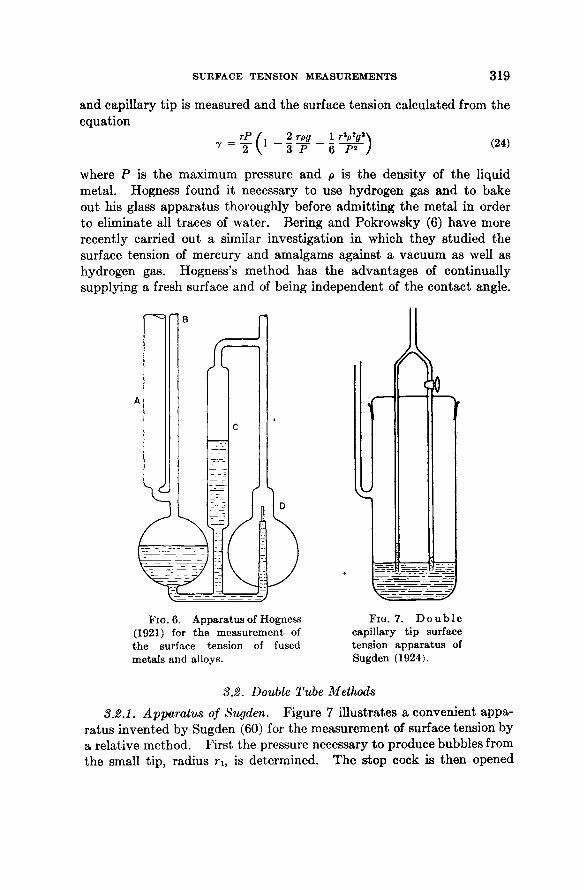
Hogness (29) has developed a maximum pressure method for the measurement of the surface tension of mercury and fused metals in which the pressure necessary to force a drop of the liquid metal upwards through a vertical capillary is measured. His appa ra tus is i l lustrated in Fig. 6 where A is a t ube into which a cylinder of the metal is inserted and later melted by raising t he tempera ture . Pressure is applied a t Β unti l liquid metal drops begin to flow out of the quar tz capillary tube D. At this point the difference in height between the column of metal in C
SURFACE TENSION MEASUREMENTS 319
and capillary t ip is measured and the surface tension calculated from the equat ion
7 2 V 3 Ρ 6 Ρ 2 / K }
where Ρ is t he maximum pressure and ρ is the densi ty of the liquid metal . Hogness found it necessary to use hydrogen gas and to bake out his glass appara tus thoroughly before admi t t ing the meta l in order to eliminate all t races of water . Bering and Pokrowsky ( 6 ) have more recently carried out a similar investigation in which they studied the surface tension of mercury and amalgams against a vacuum as well as hydrogen gas. Hogness's method has t h e advantages of continually supplying a fresh surface and of being independent of the contact angle.
FIG. 6. Apparatus of Hogness FIG. 7. D o u b l e (1921) for the measurement of capillary tip surface the surface tension of fused tension apparatus of metals and alloys. Sugden (1924).
3.2. Double Tube Methods
3.2.1. Apparatus of Sugden. Figure 7 i l lustrates a convenient appara tus invented by Sugden (60) for the measurement of surface tension by a relative method. First the pressure necessary to produce bubbles from the small t ip , radius riy is determined. T h e s top cock is then opened
320 MALCOLM DOLE
and the maximum pressure measured for bubbles formed a t the t ip of the larger capillary tube, radius r 2 . If Ρ is the difference in pressures measured, the surface tension can be calculated from the equation,
where χ = and must be calculated from the tables given by Sugden
(61). This is part icularly t rue for the large capillary tube ; for the small tube
with sufficient accuracy. The recommended values of η and r 2 in cent imeters are
Sugden points out t h a t for approximate calculations, good to 1 par t in 1000, the following equation is satisfactory
where A is a constant , r 2 is expressed in centimeters and Ρ in dynes / cm 2 . Both capillary t ips mus t be a t the same level in the liquid.
Bircumshaw (7) carried out an extensive s tudy of the surface tension of liquid metals and alloys using the double t ip maximum bubble pressure method. Good agreement with the da ta of Hogness was obtained.
Using a similar double capillary t ip appara tus Hutchinson (30) determined the interfacial tension of a number of liquid pairs by measuring the pressure required to form a liquid bubble of one liquid in another . This is a part icular ly good method for interfacial tension measurements as here again the contact angle does not enter into the phenomenon.
3.2.2. The Relative Method of Warren. I n the double tube appara tus of Warren (66) two identical t ips (made by carefully breaking a capillary tube a t one point) are immersed in separate vessels, bo th containing the same fluid a t first. B y suitable mechanical means it is possible t o adjust and measure accurately the dep th of immersion of the jets . One of the jets is moved u p or down unt i l the ra te of escape of bubbles from its t ip is exactly equal to the ra te of bubble formation a t the other t ip . The liquid in the second vessel is then removed and replaced by the liquid under investigation. The difference in surface tension between the two liquids is then given by the equation
(26)
0.005 < r i < 0.01 0.1 < r 2 < 0.2 c m .
(27)
r 1 - 72 = g 7y (P2^ 2 — Pihi) + £ gr2(pi — p2) (28)
S U R F A C E T E N S I O N M E A S U R E M E N T S 321
where hi and h2 are the depths of immersion of the t ip in the experiments on the two liquids plus the radius r in each ease. Warren ' s mean error in the determinat ion of the surface tension of sodium chloride solutions was 0.022 dynes /cm.
3.2.3. Method of Long and Nutting. Long and Nu t t i ng (40) describe a relative method similar t o Warren ' s in which the change in t he depth of immersion was calculated from the weight of liquid added and from the dep th of immersion of a rod of known volume. (By careful regulation of the depth of the rod the height of the liquid level in one of t he vessels is varied unt i l t he bubbling ra te is equal from the two jets.) Wi th pure water initially in bo th vessels, t he depth of immersion, ho, mus t necessarily be equal for the two jets . After a small amount of salt solution is added to one of the halves of the appara tus , and pure water to balance the bubbling ra te added to the other half, t he relative surface tension can be calculated from the equat ion
7 = - = l + f [ΛΟ(ΡΟ - P I ) + Ahopo - AhlPl] (29)
The reproducibili ty of Long and Nut t ing ' s da ta is somewhat be t ter t han 0 . 0 1 % .
Apparent ly the Langmuir film or possibly a finite contact angle which resulted in the Jones-Ray effect does not exist in the maximum bubble pressure method—which suggests t h a t this method m a y be fundamental ly sounder for surface tension measurements t h a n others.
4. D R O P - W E I G H T A N D P E N D A N T D R O P M E T H O D S
4.1. Drop-Weight Method
4.1.1. Introduction. Another useful method of surface and interfacial tension measurement is the drop-weight method in which the surface tension can be calculated from the maximum weight of a drop. I t is, perhaps, most impor tan t from the s tandpoint of interfacial tension measurements difficult to make by other methods . The closely analogous pendan t drop method is in practice less accurate b u t has i ts own advantage in being part icular ly suitable for s tudying the variat ion of surface tension as a function of t ime.
4.1.2. Theory. The theory of the shape of drops has been investigated by Bashford and Adams (4), Lohnstein (39), F reud and Hark ins (21) and a number of early workers. Hark ins (25) has stressed the principle of similitude, namely t h a t all drops have t he same shape if their values of r/Vl are equal where r is t he radius of the t ip from which the drop falls and V is t he volume of the drop. Harkins and Brown (26)
322 MALCOLM DOLE
give a table of their so-called F-faetors from which values of F can be obtained applicable to the part icular liquid under s tudy and which when multiplied by mg/r gives the surface tension in dynes per centimeter. In the case of interfacial tension measurements t he equat ion for the tension is
7 - V(pi - P I ) Q - -F (30)
where V is the volume of a single drop of liquid of density pi formed in a second liquid of density p 2 .
The F-factors have been determined experimentally by first finding the surface tension of the liquids by the capillary-rise method, and then determining the drop-weights in a drop-weight appara tus . The F-factors are finally calculated from the equat ion
F = £ < 31> mg
They are apparent ly valid for liquids having such diverse surface tensions as exhibited by benzene on the one hand and mercury on the other, as Dunken (14) has recently shown. Iredale (31) and Michelli (42) have suggested an a l ternate method of surface tension calculation for the drop weight method based on an equat ion of Worth ington (68). If r is the capillary t ip radius and a the radius of the drop assuming it to be spherical, then Iredale points out t h a t the rat io r/a is roughly a linear function of r. Suppose a is determined for a liquid of unknown surface tension, the value of r/a is then calculated and from the nearly linear curve of ro/cto as a function of ro for water, the value of r 0 for water is found which would give a value of ro/a0 equal to r/a for the unknown liquid. The surface tension can then be calculated from the equat ion
2 2 = 4 (32) P7o r 0
2
where the subscript zero identifies the values for water . As a m a t t e r of fact th is method is essentially t h a t of Harkins and Brown inasmuch tha t , if
7 7o
then ψϊ -
and the F-factors are equal. 4.1.8. Methods. The method of Harkins and Brown (26) is capable
of a precision of 0.02 t o 0 . 0 3 % with certain liquids. The following precautions should be observed:
SURFACE TENSION MEASUREMENTS 323
(a) A flat ground t ip , circular with sharp edges and not polished on the bo t tom should be used.
(b) I t s vertical sides should be polished to prevent liquid wet t ing the side walls.
(c) The size of the t ips should be between 5-7 mm. in diameter for most liquids in the case of surface tension measurements and between 9-11 mm. in diameter for interfacial tension measurements . High densi ty liquids call for smaller t ips t h a n low densi ty liquids.
(d) T h e appa ra tus should be held in a vertical position, bu t a 3° inclination from the vertical can be tolerated as Gans and Hark ins (22) have pointed out (the weight becomes less the greater the angle of inclination).
(e) As the weight of the drops increases with increasing velocity of flow, it is impor tan t to form each drop over a 5-minute interval . Actually the liquid is allowed to flow unt i l the drop approaches its maximum size, then it is allowed to s tand for a few minutes to reach equilibrium (some dilute liquids of long linear organic molecules m a y t ake half an hour to a t t a in surface equil ibrium). Finally, the volume of the drop is allowed to increase slowly and preferably automatical ly unti l it drops. The drops are collected in a suitable weighing bot t le and weighed.
(f) I t is not correct to calibrate the ins t rument with a liquid of known surface tension unless the proper i '-factor correction is applied both to the known and unknown surface tension calculation.
(g) In interfacial tension measurements Ward and Tordai (65) collect drops of t he heavier liquid by displacement of t he lighter liquid from a special pycnometer . The increase in weight of the pycnometer gives just the required information needed for the interfacial tension calculation. The authors point out t h a t a weight measurement of four drops is more accurate t han a volume measurement of 40 drops.
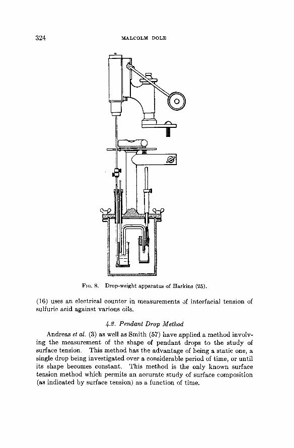
Figure 8 i l lustrates the appa ra tus of Hark ins and Brown (26), suitable for the s tudy of volatile liquids. The capillary t ip is shown a t the r ight ; the rod a t the left which is a t t ached to a rack and pinion device serves t o raise gradual ly the reservoir of liquid, t hus causing the drop to grow very slowly; the in termediate vessel containing a small amount of liquid prevents excessive evaporat ion from the surface of the drop.
Kur t z (35) points out t h a t a film of plastic or other solid material forming on the surface of the drop can vi t ia te the surface tension measurements by prevent ing the drop from taking on its normal shape. Edwards
324 MALCOLM DOLE
FIG. 8 . Drop-weight apparatus of Harkins ( 2 5 ) .
(16) uses an electrical counter in measurements of interfacial tension of sulfuric acid against various oils.
4.2. Pendant Drop Method
Andreas et at. (3) as well as Smi th (57) have applied a me thod involving the measurement of the shape of pendan t drops to the s tudy of surface tension. This method has the advan tage of being a stat ic one, a single drop being investigated over a considerable period of t ime, or unti l i ts shape becomes constant . This method is the only known surface tension method which permits an accurate s tudy of surface composition (as indicated by surface tension) as a function of t ime.
S U R F A C E T E N S I O N M E A S U R E M E N T S 3 2 5
The experimental problem is chiefly an optical one, once a proper dropping t ip has been obtained. B y proper choice of magnifying system and camera results having a probable error of ± 0 . 5 % are obtained. As with the drop weight method, correction factors given in tables must be used to convert measurements of the diameter of the drop a t its equator and a t a selected plane to surface tension. Good agreement for bo th surface and interfacial tension measurements on s tandard substances has been obtained. Andreas et al. believe t h a t this method will prove to be part icular ly valuable for the s tudy of ( 1 ) viscous liquids, ( 2 ) surface-active solutions ( 3 ) small samples of rare chemicals and ( 4 ) systems in which the contact angle is not zero.
5 . R I N G M E T H O D S
5.1. Single Ring
5.1.1. Introduction. Because of the ease and rapidi ty with which the force necessary to pull a ring out of the surface of a liquid can be measured, the ring method of surface tension measurement has had great popular i ty . Like the drop weight and the maximum bubble pressure methods this method is a dynamic one and requires a knowledge of the force necessary to rup ture the liquid-air interface. The da ta obtained by the ring method are quite sensitive to the size of wire and dimension of ring employed, so t h a t absolute values of surface tension cannot be obtained wi thout applying corrections. I n fact it is ra ther surprising to consider the large number of ring surface tension determinat ions in which the shape of the surface was not t aken into account. I t was not unti l 1 9 2 4 - 2 6 when Lenard ( 3 7 ) who used a s traight wire instead of a ring and Harkins et al. ( 2 8 ) first correctly calculated surface tension values from the surface rup tu re forces t h a t the theory of the ring method was pu t on a sound basis. We are including the work of Lenard in this discussion as the problems involved in pulling a s traight wire out of the surface are similar in m a n y ways to those applicable to work with circular rings.
5.1.2. Theory of the Ring Method. If a ring pulled a t rue hollow cylinder of liquid with a vertical plane of contact with the ring from the surface, then a t the moment the liquid surface ruptured , the weight of liquid suppor ted to the point of rup tu re above a flat level surface would be given by the equat ion
W · g = 4 T T# T (33)
where R is t he radius of the ring measured to the center of the wire of which the ring is composed. However, the liquid surface will t ake on the shape i l lustrated in Fig. 9 as the ring is raised (or the liquid lowered).
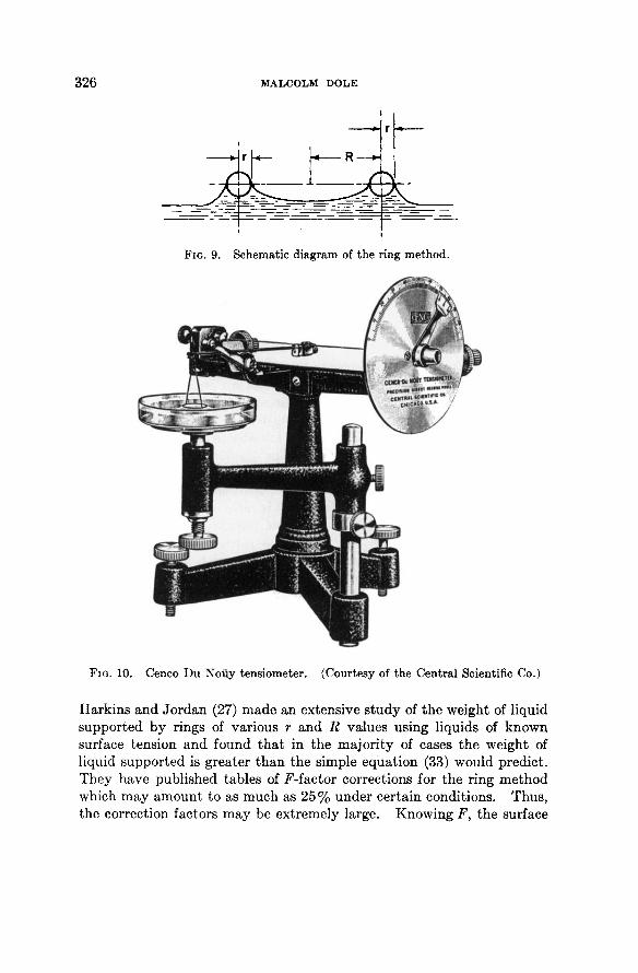
FIG. 10. Cenco Du Noliy tensiometer. (Courtesy of the Central Scientific Co.)
Harkins and Jo rdan (27) made an extensive s tudy of the weight of liquid supported by rings of various r and R values using liquids of known surface tension and found t h a t in the major i ty of cases the weight of liquid supported is greater t h a n the simple equat ion (33) would predict . They have published tables of F-factor corrections for the ring method which may amount to as much as 2 5 % under certain conditions. Thus , the correction factors m a y be extremely large. Knowing F, the surface
326 MALCOLM DOLE
FIG. 9. Schematic diagram of the ring method.
SURFACE TENSION MEASUREMENTS 327
tension is to be calculated from the equat ion
W · g 4 Τ Γ#
• F (34)
To determine F from the tables bo th R and r mus t be known as well as V, the volume of liquid supported a t the moment of break (V = m/p).
Freud and Freud (20) have carried out numerical integrat ions of Laplace's equat ion relating surface curva ture to surface tension and thus succeeded in calculating t he F-factors theoretically. For this reason we can now regard the ring method as being an absolute method.
5.1.3. Methods. For the most precise determinat ions using rings the technique of Hark ins and Jo rdan (27) should be followed al though Schwen-ker ' s s t raight wire method (55) seems to be somewha t more sensitive. The relat ive t w i n - r i n g method of Dole and Swart out (12) described below has the greatest precision of all methods involving a rup tu re of the surface. Various commercial ten-siometers are on the marke t , t he best known being the D u Noliy (15) tensiometer sold by the Centra l Scientific Co., Fig. 10. I n the last ins t rument the liquid is lowered from the ring and the force a t rup tu re measured by a torsion wire balance. The torsion force is calibrated by known weights in advance of the surface tension measurement . The Harkins /^-factor corrections should be applied, of course.
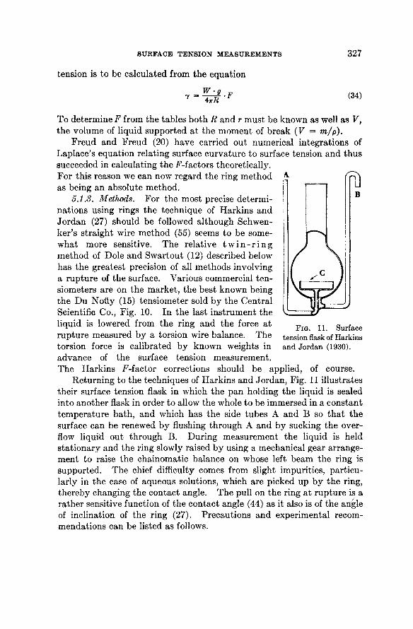
Return ing to the techniques of Hark ins and Jordan, Fig. 11 il lustrates their surface tension flask in which the pan holding the liquid is sealed into another flask in order to allow the whole to be immersed in a cons tant t empera tu re ba th , and which has the side tubes A and Β so t h a t t he surface can be renewed by flushing through A and by sucking the overflow liquid out through B. Dur ing measurement the liquid is held s ta t ionary and the ring slowly raised by using a mechanical gear arrangement to raise the chainomatic balance on whose left beam the ring is supported. The chief difficulty comes from slight impurities, par t icularly in the case of aqueous solutions, which are picked up by the ring, thereby changing the contact angle. The pull on the ring a t rup tu re is a ra ther sensitive function of the contact angle (44) as it also is of the angle of inclination of the ring (27). Precaut ions and experimental recommendat ions can be listed as follows.
FIG. 11. Surface tension flask of Harkins and Jordan (1930).
328 MALCOLM DOLE
(a) Harkins (25) recommends raising the ring ra ther t han lowering the solution as the la t ter might produce disturbing ripples in t he surface. Dole and Swar tout (12), however, show t h a t a precision of 0 .002% is a t ta inable on lowering the liquid (the precision of Harkins and Jo rdan was about 0 .2%) .
(b) The diameter of the pan should be such t h a t it is 4 -5 cm. greater t han the diameter of the ring.
(c) The angle of inclination of the plane of the ring with the free surface should be less t han 0.47° for the error of measurement to be less t han 0.1 %. A positive angle can be detected by carefully observing the ring as it approaches the surface of the liquid. If it makes contact with the liquid simultaneously all about i ts circumference, then no angle of inclination exists (assuming, of course, t h a t the ring is plane) .
(d) Harkins and Jordan adjusted the volume of liquid in the pan so t h a t the surface would be plane a t the moment of rupture .
(e) The ring should be circular and all in a plane. (f) The appara tus should be cleaned wi th a hot mixture of nitr ic
and sulfuric acids, rinsed with redistilled water, s teamed (the s team generated from water t h a t had previously been refluxed with K M n 0 4 ) , and rinsed again. The p H of the rinse water should be checked to insure the complete removal of the acid. These rigorous cleaning directions are of significance chiefly in the measurement of the surface tension of aqueous solutions.
(g) The ring is preferably made of p l a t inum-10% iridium and should be ignited in a flame shortly before use.
(h) The dry weight of the ring must be known. The W of equat ion (34) is the weight a t the moment of rup ture less the dry weight. The fact t ha t drops of liquid adhere to the ring after the rup ture is of no significance except t h a t it indicates a desirable wett ing of the ring by the liquid.
5.2. Double Ring Method
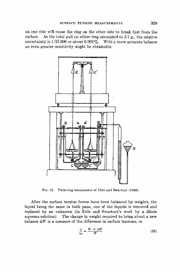
Dole and Swartout (12) have recently invented a twin-ring ten-siometer, i l lustrated in Fig. 12, which makes possible the a t t a inment of a relative precision to 0.002%. In this method it is unnecessary to observe the maximum weight of pull or the weight a t t he moment of rup tu re ; instead notice is t aken merely of the ring which breaks from the surface first as the two liquid surfaces are lowered. The weaker tension on this side is then balanced by the addit ion of weights to this side of the balance and the process repeated. I t is possible to obtain a balance between the forces of tension and the weights such t ha t 0.1 mg. increase in weight
SURFACE TENSION MEASUREMENTS 329
on one side will cause the ring on the other side to break first from the surface. As the tota l pull on either ring amounted to 5.7 g., the relative uncer ta in ty is 1/57,000 or about 0 .002%. Wi th a more accurate balance an even greater sensitivity might be obtainable.
FIG. 12 . Twin-ring tensiometer of Dole and Swartout ( 1 9 4 0 ) .
After the surface tension forces have been balanced by weights, the liquid being the same in bo th pans , one of the liquids is removed and replaced by an unknown (in Dole and Swar tout ' s work by a dilute aqueous solution). The change in weight required to bring about a new balance AW is a measure of the difference in surface tensions, or
330 MALCOLM DOLE
where W is the tota l pull on the r ing in contact with liquid of surface tension 7 0 . In the range of dilute solutions studied by Dole and Swar tout it was unnecessary to apply a Hark in ' s F-factor correction.
The Jones-Ray effect was observed using t h e twin-ring appa ra tu s which indicates t h a t either the contact angle is changed slightly b y the addit ion of electrolytes or t h a t something like the Langmuir film enters in. This indicates t h a t the ring method, similar to the capillary rise method, does not give the t rue surface tension of salt solutions, par t icu
larly in the dilute range. A theoretical explanation of the Jones-Ray effect as exhibited by the ring method is badly needed, because there will be some doubt as to the precise significance of all ring surface tension measurements unti l we unders tand the reason for its existence.
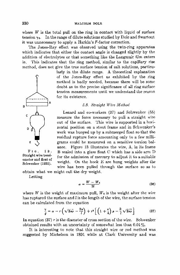
5.3. Straight Wire Method
Lenard and co-workers (37) and Schwenker (55) measure the force necessary to pull a s traight wire out of the surface. This wire is supported in a horizontal position on a s tout frame and in Schwenker 's work was buoyed up by a submerged float so t h a t t he residual rup tu re force amount ing only to a few milligrams could be measured on a sensitive torsion balance. Figure 13 illustrates the wire, A, in its frame Β sealed into a glass float C which has a side arm D for the admission of mercury to adjust it to a suitable weight. On the hook Ε are hung weights after the wire has been pulled through the surface so as to
might call the dry weight.
F I G . 1 3 . Straight wire tensi-ometer and float of Schwenker ( 1 9 3 1 ) .
obta in what we Let t ing
W - Wo 21
( 3 6 )
where W is the weight of max imum pull, Wo is t he weight after the wire has rup tured the surface and I is the length of the wire, the surface tension can be calculated from the equation
( 3 7 )
I n equat ion (37) r is the diameter of cross section of the wire. Schwenker obtained results with an uncer ta in ty of somewhat less t h a n 0 . 0 1 % .
I t is interesting to note t h a t this s t raight wire or rod method was suggested by Michelson in 1891 while a t Clark Universi ty a n d was
SURFACE TENSION MEASUREMENTS 331
first carried out experimentally by Hall (24). Hall discovered the maximum in the weight as a function of rod distance above the surface (see also Harkins and Jo rdan (27)) and eliminated end effects by the use of two rods of different length.
There are a number of other methods of measuring surface tension among which can be ment ioned centrifugal methods (41, 56), method of impact ing jets (9, 49) ripple method (64), etc. all of which require ra ther complicated appara tus or have not yet been developed to great accuracy; hence they will not be discussed here.
REFERENCES
1. Achmatov, Α., Kolloid. Z. 66, 266 (1934). 2. Adam, Ν. K., The Physics and Chemistry of Surfaces. 3rd ed. Oxford University
Press, London, 1941. 3. Andreas, J. M., Hauser, Ε. Α., and Tucker, W. B., J. Phys. Chem. 42,1001 (1938). 4. Bashford and Adams, An Attempt to Test the Theory of Capillary Action.
Cambridge, 1883. 5. Bastien, P., Chimie & Industrie 46, No. 3 bis, 27 (1941). 6. Bering, B. P., and Pokrowsky, N. L., Acta Physicochim. U.R.S.S. 4, 861 (1936). 7. Bircumshaw, L. L., Phil. Mag. [7] 3, 1286 (1927); 12, 596 (1931); 17, 181 (1934);
and others. 8. Bowden, S. T., J. Phys. Chem. 34, 1866 (1930). 9. Buchwald, E., and Konig, H., Ann. Physik. 26, 659 (1936).
10. Chalmers, B., Trans. Faraday Soc. 33, 1167 (1937). 11. Coffman, A. W., and Parr, S. W., Ind. Eng. Chem. 19, 1308 (1927). 12. Dole, M., and Swartout, J. Α., J. Am. Chem. Soc. 62, 3039 (1940). 13. Drath, G., and Sauerwald, F., Z. anorg. allgem. Chem. 162, 301 (1927). 14. Dunken, H., Ann. Physik 41, 567 (1942). 15. Du Nouy, P. Lecomte, Surface Equilibria of Biological and Organic Colloids.
Chemical Catalog Co., New York, 1926. 16. Edwards, J. C , / . Set. Instruments 6, 90 (1929). 17. Ferguson, Α., and Dowson, P. E., Trans. Faraday Soc. 17, 384 (1921). 18. Ferguson, Α., and Hakes, J. Α., Proc. Phys. Soc. London 41, 214 (1929). 19. Ferguson, Α., and Kennedy, S. J., Proc. Phys. Soc. London 44, 511 (1932). 20. Freud, Β. B., and Freud, Η. Z., Science 71, 345 (1930); J. Am. Chem. Soc. 62,
1772 (1930). 21. Freud, Β. B., and Harkins, W. D., Phys. Chem. 33, 1217 (1929). 22. Gans, D. M., and Harkins, W. D., J. Am. Chem. Soc. 52, 2287 (1930). 23. Hagen and Desains, Ann. chim. phys. [3] 61, 417 (1857). 24. Hall, T. P., Phil. Mag. 36, 390 (1893). 25. Harkins, W. D., in Physical Methods of Organic Chemistry. Edited by Arnold
Weissberger, Interscience, New York, 1945, Chapter VI. 26. Harkins, W. D., and Brown, F. E., / . Am. Chem. Soc. 38, 246 (1916); 41, 499
(1919). 27. Harkins, W. D., and Jordan, H. F., J. Am. Chem. Soc. 62, 1751 (1930). 28. Harkins, W. D., Young, T. F., and Cheng, L. H., Science 64, 333 (1926). 29. Hogness, T. R., J. Am. Chem. Soc. 43, 1621 (1921). 30. Hutchinson, E., Trans. Faraday Soc. 39, 229 (1943).
332 MALCOLM DOLE
31. Iredale, T., Phil. Mag. [6] 46, 1088 (1923). 32. Jones, Grinnell, and Frizzell, L. D., / . Chem. Phys. 8, 986 (1940). 33. Jones, Grinnell, and Ray, W. Α., Am. Chem. Soc. 69, 187 (1937). 34. Jones, Grinnell, and Wood, L. Α., J. Chem. Phys. 13, 106 (1945). 35. Kurtz, S. S., Jr., J. Am. Chem. Soc. 49, 1991 (1927). 36. Langmuir, I., Science 88, 430 (1938); J. Chem. Phys. 6, 894 (1938). 37. Lenard, P., v. Dallwitz-Wegener, R., and Zachmann, E., Ann. Physik. 74, 381
(1924). 38. Liesegang, Ε., Z. anal. Chem. 126, 172 (1943); 126, 334 (1944). 39. Lohnstein, T., Ann. Physik. 20, 237 (1906). 40. Long, F. Α., and Nutting, G. C , J. Am. Chem. Soc. 64, 2476 (1942). 41. Meyerstein, W., and Morgan, J. D., Phil Mag. 35, 335 (1944). 42. Michelli, L. I. Α., Phil. Mag. [7] 3, 581 (1927). 43. Mills, H., and Robinson, P. L., / . Chem. Soc. 1927, 1823. 44. Nietz, A. H., and Lambert, R. H., / . Phys. Chem. 33, 1460 (1929). 45. Onsager, L., and Samaras, Ν. Ν. T., / . Chem. Phys. 2, 528 (1934); also Wagner, C.,
Physik. Z. 26, 474 (1924). 46. Poisson, Nouv. Theor. d. Tact, capill. Paris, 1831. 47. Porter, A. W., Trans. Faraday Soc. 27, 205 (1931); 29, 1307 (1933). 48. Preston, J. M., / . Soc. Dyers Colourists. 61, 161 (1945). 49. Puis, H. O., Phil Mag. 22, 970 (1936). 50. Rayleigh, Lord, Proc. Roy. Soc. A92, 184 (1915). 51. Richards, T. W., and Carver, Ε. K., J. Am. Chem. Soc. 43, 827 (1921). 52. Richards, T. W., and Coombs, L. B., J. Am. Chem. Soc. 37, 1656 (1915). 53. Sauerwald, F., Z. Metallkunde 18, 137, 193 (1926). 54. Schroedinger, E., Ann. Physik. 46, 410 (1915). 55. Schwenker, G., Ann. Physik. 11, 525 (1931). 56. Searle, G. F. C , Proc. Phys. Soc. London 63, 681 (1941). 57. Smith, G. W., </. Phys. Chem. 48, 168 (1944). 58. Smith, W. O., and Foote, P. D., Ind. Eng. Chem. 21, 567 (1929). 59. Speakman, J., J. Chem. Soc. 1933, 1449. 60. Sugden, S., Chem. Soc. 119, 1483 (1921). 61. Sugden, S., Chem. Soc. 121, 858 (1922); 125, 27 (1924). 62. Sutton, T. C , Proc. Phys. Soc. London 46, 88 (1933). 63. Taubmann, Α., Ζ. physik. Chem. A161, 129 (1932). 64. Tyler, E., Phil. Mag. 31, 209 (1941). 65. Ward, A. F., and Tordai, L., Sci. Instruments 21, 143 (1944). 66. Warren, E. L., Phil. Mag. [7] 4, 358 (1927). 67. Wood, L. Α., and Robinson, L. B., J. Chem. Phys. 14, 258 (1946). 68. Worthington, Proc. Roy. Soc. London 32, 362 (1881). 69. Young, T. F., Gross, P. L. K., and Harkins, W. D. See Harkins (25).


