Embed Size (px)
Citation preview
SURFACE J1939 VEHICLE RECOMMENDED PRACTICE
Recommended Practice for a Serial Control and Communications Vehicle Network
SAE Technical Standards Board Rules provide that: “This report is published by SAE to advance the state of technical and engineering sciences. The use of this report is entirely voluntary, and its applicability and suitability for any particular use, including any patent infringement arising therefrom, is the sole responsibility of the user.” SAE reviews each technical report at least every five years at which time it may be reaffirmed, revised, or cancelled. SAE invites your written comments and suggestions. Copyright 2003 SAE International All rights reserved. No part of this publication may be reproduced, stored in a retrieval system or transmitted, in any form or by any means, electronic, mechanical, photocopying, recording, or otherwise, without the prior written permission of SAE. TO PLACE A DOCUMENT ORDER: Tel: 877-606-7323 (inside USA and Canada) Tel: 724-776-4970 (outside USA) Fax: 724-776-0790 Email: [email protected]
SAE WEB ADDRESS: http://www.sae.org
Issued 2000-04 Revised 2003-08
Forward
This series of SAE Recommended Practices has been developed by the Truck & Bus Control and Communications Network Subcommittee of the Truck & Bus Electrical & Electronics Committee. The objectives of the subcommittee are to develop information reports, recommended practices and standards concerned with the requirements, design, and usage of ECUs which transmit electrical signals and control information among vehicle components. The usage of these Recommended Practices is not limited to truck and bus applications; other applications may be accommodated with immediate support being provided for construction and agricultural equipment, and stationary power systems.
These SAE Recommended Practices are intended as a guide toward standard practice and are subject to change so as to keep pace with experience and technical advances.
The Controller Area Network (CAN) protocol described in these Recommended Practices is the intellectual property of Robert Bosch GmbH (Bosch). Bosch will grant a license to any company which intends to manufacture or design CAN ECUs. ONLY the manufacturer of the integrated circuit containing the CAN protocol or implementers of the CAN protocol in software must deal with the copyright license process. The user of the CAN protocol does not require a license. Licensing information and applications can be obtained at the following address:
Robert Bosch GmbH Attn: Licensing Department PO Box 106050 D-70049 Stuttgart Federal Republic of Germany
These Recommended Practices are being generated to continue the work accomplished by the J1708, J1587, and J1922 Recommended Practices. The J1939 series of Recommended Practices will offer a higher performance alternative to these earlier documents.
This document reflects changes and additions approved and balloted through December 2001.
Copyright SAE International Provided by IHS under license with SAE
Not for ResaleNo reproduction or networking permitted without license from IHS
--`-`-`,,`,,`,`,,`---
SAE J1939 Revised AUG2003
1. Scope........................................................................................................................... 3 1.1 Degree of Openness .....................................................................................................3 1.2 Proof of Compliance.....................................................................................................3
2. References.....................................................................................................................3 2.1 Publications...................................................................................................................3 2.2 Definitions and Abbreviations .....................................................................................4 2.2.1 Definitions .....................................................................................................................4 2.2.2 Abbreviations................................................................................................................7 2.3 References to the OSI Model: ......................................................................................7 2.4 Documentation Structure and Guide ..........................................................................9
3. Technical Requirements 10 3.1 J1939 Tutorial 10 3.1.1 Introduction 10 3.1.2 Message Format and Usage (J1939/21 for 29 Bit Identifier) ...................................10 3.1.3 Addresses and NAME (J1939/81 and Appendix B)..................................................12 3.1.4 Communication Methods ..........................................................................................13 3.1.5 Transmitting Messages (Using J1939/21 and J1939/7X) ........................................14 3.1.6 Receiving Messages (Using J1939/21 and J1939/7X)..............................................14 3.1.7 ECU Design (Using J1939/11, J1939/21, and J1939/7X) 14 3.1.8 Network Topology ------ J1939/01 Using Physical Layer J1939/11
and Network Layer J1939/31 .....................................................................................15 3.2 Preassigned Values ....................................................................................................15 3.2.1 Parameter Group Numbers .......................................................................................15 3.2.2 Data Field Grouping ...................................................................................................16 3.2.3 NAME Systems and Functions ..................................................................................16 3.2.4 Industry Group............................................................................................................17 3.2.5 Manufacturer Code.....................................................................................................17 3.2.6 Preferred Address 18 3.2.7 Suspect Parameter Number (SPN)............................................................................18 3.3 Application Examples.................................................................................................18
Appendix A Parameter Group Assignments B Address and Identity Assignments C Fault Reporting Parameters D Assignment Request Forms
Copyright SAE International Provided by IHS under license with SAE
Not for ResaleNo reproduction or networking permitted without license from IHS
--`-`-`,,`,,`,`,,`---
3
1. Scope
These Recommended Practices are intended for light, medium, and heavy duty vehicles used on or off road as well as appropriate stationary applications which use vehicle derived components (e.g. generator sets). Vehicles of interest include, but are not limited to: on and off highway trucks and their trailers; construction equipment; and agricultural equipment and implements.
The purpose of these Recommended Practices is to provide an open interconnect system for electronic systems. It is the intention of these Recommended Practices to allow Electronic Control Units to communicate with each other by providing a standard architecture.
1.1 Degree of Openness
A J1939 network is open to the degree that any two ECUs which conform to the same J1939/0X document can be connected via the network and communicate with each other without functional interference. The J1939/0X dcouments describe a specific type of application, typically representing a specific industry to which it pertains such as agricultural or heavy duty trucks. ECUs which conform to a different J1939/0X document may not be capable of communicating directly with one another and in some cases may cause degradation or complete disruption of the entire network.
1.2 Proof of Compliance
There is no procedure presently in place to test, validate, or provide formal approval for ECUs utilizing the J1939 network. Each developer is expected to design their products to the spirit of, as well as the specific content of, this recommended practice. Provisions are made in J1939/11 and J1939/12 for self certification to these documents. In the future, it is hoped that procedures will be defined and implemented to test new products to ensure full compliance with all appropriate J1939 documents. Until that time, compliance will be honorarily determined. Should questions arise regarding the use or interpretation of any part of these recommended practices they should be directed to the SAE Control and Communications Subcommittee for resolution.
2. References
2.1 Publications
ISO 7498 Information Processing Systems - Open Systems Interconnection (OSI) - Basic Reference Model.
ISO 11898 Road Vehicles — Interchange of Digital Information — Controller Area Network (CAN) for High Speed Communication, December 1992
ISO 11992 Road Vehicles - Electrical Connections Between Towing and Towed Vehicles - Interchange of Digital Information (Parts 1, 2, 3)
SAE J1213 Glossary of Automotive Electronic Terms SAE J1708 Recommended Practice for Serial Data Communication Between
Microcomputer Systems in Heavy Duty Vehicle Applications. SAE J1587 Recommended Practice for Electronic Data Interchange Between
Microcomputer Systems in Heavy Duty Vehicle Applications SAE J1922 Powertrain Control Interface for Electronic Controls Used in Medium and Heavy
Duty Diesel On-Highway Vehicle Applications
SAE publications are available from SAE, 400 Commonwealth Drive, Warrendale, PA 15096-0001. ISO publications are available from ANSI, 11 West 42nd Street, New York, NY 10036.
SAE J1939 Revised AUG2003
Copyright SAE International Provided by IHS under license with SAE
Not for ResaleNo reproduction or networking permitted without license from IHS
--`-`-`,,`,,`,`,,`---
4
2.2 Definitions and Abbreviations
Definitions provided herein will supersede those contained in SAE J1213. SAE J1213 will otherwise apply throughout.
2.2.1 Definitions
Acknowledgment (ACK) — Confirms that the requested action has been understood and performed.
Address — The 8 bit field (or fields) used to define the source (and destination when applicable) of a message (e.g. engine, transmission, etc.).
Arbitration — The process by which one or more ECUs resolve conflicts in obtaining access to a shared network bus.
Bit Stuffing — A procedure used to assure the transmitted and received messages maintain a minimum number of dominant to recessive edges, and vise versa, to maintain the proper resynchronization within the string of bits in a CAN Data Frame. See CAN specification for a more detailed discussion.
Bridge — A device which stores and forwards messages between two J1939 network segments. This permits changes in the media, the electrical interface, and data rate between segments. The protocol and address space remain the same on both sides of the bridge. Note that a bridge may selectively filter messages going across it so that the bus load is minimized on each segment.
Bus — See Segment.
CAN Data Frame — The ordered bit fields necessary to create a CAN frame used to convey data, beginning with an SOF and ending with an EOF.
Cyclic Redundancy Check (CRC) — An error control mechanism. A 15 bit cyclic redundancy check is performed for detecting transmission errors. Given a k-bit frame or message, the transmitter generates an n-bit sequence, known as a frame check sequence so that the resulting frame, consisting of k + n bits is exactly divisible by some predefined number. The receiver then divides the incoming frame by the same number and, if there is no remainder, assumes that there was no error.
Data Field — A 0 to 64-bit field normally placed in a CAN data frame which contains the data as defined in the Application Layer (document J1939/7X).
Data Page — One bit in the Identifier portion of the CAN Arbitration Field is used to select one of two pages of Parameter Group Numbers. This provides for the future growth of Parameter Group definitions. It also is one of the fields used to determine the Parameter Group Number which labels the data field of the CAN Data Frame.
Destination Address (DA) — This is a Protocol Data Unit (PDU) specific field in the 29 bit CAN identifier used to indicate the address of the ECU intended to receive the J1939 message.
Device — A physical component with one or more ECUs and network connections.
Electronic Control Unit (ECU) — A computer based electronic assembly from which J1939 messages may be sent or received.
End of Frame (EOF) — A 7 bit field marking the ending of a CAN data frame.
Extended Frame — A CAN data frame using a 29 bit identifier as defined in the CAN 2.0 specification.
Frame — A series of data bits making up a complete message. The frame is subdivided into a number of fields, each field containing a predefined type of data. See CAN Data Frame
Function — A capability of a vehicle system having one or more ECUs that are connected to a J1939 bus segment of a Vehicle System. The function value is used in the 8 bit Function field in the 64 bit NAME entity (See J1939/81, Section 4.1)
SAE J1939 Revised AUG2003
Copyright SAE International Provided by IHS under license with SAE
Not for ResaleNo reproduction or networking permitted without license from IHS
--`-`-`,,`,,`,`,,`---
5
Gateway — This device permits data to be transferred between two networks with different protocols or message sets. The gateway provides a means to repackage parameters into new message groups when transferring messages from one segment to another.
Group Extension (GE) — This is a PDU specific field of a J1939 CAN Data Frame that is used as part of the information necessary to determine the Parameter Group Number.
Identifier — The identifier portion of the CAN arbitration field.
Idle — A state on the CAN bus where no node is transmitting or attempting to transmit data.
Implement — A machine consisting of one or more ECUs which may be attached to or detached from the vehicle as a unit.
Media — The physical entity which conveys the electrical transmission (or equivalent means of communication) between ECUs on the network. For J1939/11, the media consists of shielded twisted pair copper wires.
Message — A “message” is equivalent to one or more “CAN Data Frames” that have the same Parameter Group Number. For instance the information related to a single Parameter Group Number to be transferred on the bus may take several CAN data frames.
Multipacket Messages — A type of J1939 message which is used when more than one CAN data frame is required to transmit all data specific to a given Parameter Group Number. Each CAN data frame will have the same identifier but will contain different data in each packet.
NAME - An 8 byte value which uniquely identifies the primary function of an ECU and its instance on the network. A device's NAME must be unique, no two devices may share the same NAME value on a given vehicle network.
Node — A specific hardware connection of an ECU to the physical media. A specific node may have more than one address claimed on the network.
Non-Volatile — Retention of changeable memory values even though power is turned off for any reason. This term is used with respect to data values, such as ECU addresses or NAMEs, that are changed during use. Read Only Memory (ROM) is technically non-volatile, but is not changeable during use and thus not what is referred to in these documents.
Negative-Acknowledgment (NACK) — A response which indicates that a message has not been understood or a requested action could not be performed.
Packet — A single CAN data frame. This can also be a message if the Parameter Group to be transferred can be expressed in one CAN data frame.
Parameter Group (PG) — A collection of parameters that are conveyed in a J1939 message. Parameter Groups include commands, data, requests, acknowledgments, and negative-acknowledgments. The PG identifies the data in a message, regardless of whether it is a single packet or multipacket message. Parameter Groups are not dependent on the source address field thus allowing any source to send any Parameter Group.
Parameter Group Number (PGN) — A three byte, 24 bit, representation of the Reserved Bit, Data Page, PDU Format, and GE fields. The Parameter Group Number uniquely identifies a particular Parameter Group.
PDU Format (PF) — An 8 bit field in the 29 bit identifier that identifies the PDU format and is used in whole or in part to provide a label for a Parameter Group. It also is one of the fields used to determine the Parameter Group Number which labels the data field of the CAN Data Frame.
PDU Specific (PS) — An 8-bit field in the 29 bit identifier whose definition depends upon the value of the PDU Format field. It can be either a destination address (DA) or Group Extension (GE). It also is one of the fields used to determine the Parameter Group Number which labels the data field of the CAN Data Frame.
PDU1 Format — A PDU format used for messages that are to be sent to a destination address (DA). The PS field contains the destination address (specific or global).
PDU2 Format — A PDU format used to send information that has been labeled using the Group Extension technique. This PDU does not contain a destination address. The PS field contains the Group Extension in the case of PDU2 formats.
SAE J1939 Revised AUG2003
Copyright SAE International Provided by IHS under license with SAE
Not for ResaleNo reproduction or networking permitted without license from IHS
--`-`-`,,`,,`,`,,`---
6
Preferred Address — The address that an ECU will attempt to use first when claiming an address. Preferred Addresses are assigned by the committee.
Priority — A 3-bit field in an identifier that establishes the arbitration priority of the information communicated. The highest priority is zero and the lowest priority is seven.
Protocol Data Unit (PDU) — A PDU is a J1939 specific CAN Data Frame format.
Remote Transmission Request (RTR) — A feature of the CAN protocol allowing an ECU to request that another ECU or ECUs send a message. This feature of CAN is not used in J1939. An alternate request mechanism is specified for J1939.
Repeater — An ECU which regenerates the bus signal onto another segment of media. This permits the network to connect more electrical loads (ECUs) onto the bus, or to connect to another type of media (Physical Layer Expansion). The speed (data rate), protocol (data link layer), and address space are the same on both sides of the repeater. For J1939, any delays in regenerating the data signal must be kept to a very small fraction of one bit interval.
Reserved Bit —A bit in a J1939 29 bit identifier reserved for future definition by SAE. It also is one of the fields used to determine the Parameter Group Number which labels the data field of the CAN Data Frame.
Router— An ECU which allows segments with independent address spaces, data rates, and media to exchange messages. A router may permit each segment to operate with minimum bus loading yet still obtain critical messages from remote segments. The protocol remains the same across all segments. Note that the router must have look up tables to permit the translation and routing of a message with ID X on segment 1 to ID Y on segment 2.
Segment — The physical media and attached nodes of a network not interconnected by network interconnection ECUs. A single segment of a network is characterized by all of the ECUs “seeing” the signal at the same time (i.e., there is no intermediate ECU between electrical sections of the network). Multiple segments can be connected together by network interconnection ECUs including repeaters, bridges, and routers.
Source Address (SA) — An 8-bit field in the 29 bit identifier which allows for the unique identification of the source of a message. The SA field contains the address of the ECU that is sending the message.
Standard Frame — A CAN data frame using an 11 bit identifier as defined in the CAN 2.0b specification.
Start of Frame (SOF) — The initial bit in a CAN frame serving only to indicate the beginning of the frame.
Subnetwork — This refers to the network activity (message traffic) on a specific J1939 segment when multiple segments are used. Subnetworks may include: Tractor; Trailer, Implement, and Braking System. Note that they may be separated by a bridge or router to minimize total bus loading. Collectively the subnetworks are the J1939 Vehicle Network.
Vehicle — A machine which, in most applications, includes a capability to propel itself and includes one or more J1939 segments. A vehicle may be assembled of one or more Vehicle systems which are connected together to form the whole vehicle.
Vehicle System — A subcomponent of a vehicle, or a component that is analogous to a subcomponent of a vehicle, that includes one or more J1939 segments and may be connected or disconnected from the vehicle. A Vehicle System may be made up of one or more Functions, which have ECU's that are connected to a J1939 segment of the Vehicle System.
SAE J1939 Revised AUG2003
Copyright SAE International Provided by IHS under license with SAE
Not for ResaleNo reproduction or networking permitted without license from IHS
--`-`-`,,`,,`,`,,`---
7
2.2.2 Abbreviations
ABS Antilock Braking System ACK Acknowledgment AP Accelerator Pedal ASR Acceleration Slip Regulation (Traction Control) ASCII American Standard Code for Information Interchange CAN Controller Area Network Con-Ag Construction-Agriculture Industry CRC Cyclic Redundancy Check DA Destination Address DLC Data Length Code DP Data Page ECU Electronic Control Unit EOF End of Frame GE Group Extension ID Identifier IDE Identifier Extension Bit LLC Logical Link Control LSB Least Significant Byte or Least Significant Bit MAC Medium Access Control MID Message Identifier MSB Most Significant Byte or Most Significant Bit NA Not Allowed NA Not Available NACK Negative-Acknowledgment OSI Open System Interconnect P Priority PDU Protocol Data Unit PF PDU Format PG Parameter Group PGN Parameter Group Number PID Parameter Identifier PS PDU Specific PS_GE PDU Specific - Group Extension PS_DA PDU Specific - Destination Address PTO Power Take-Off R Reserved RTR Remote Transmission Request SA Source Address SID Subsystem Identifier SLOT Scaling, Limits, Offset, and Transfer Function SOF Start of Frame SPN Suspect Parameter Number SRR Substitute Remote Request un Undefined
2.3 References to the OSI Model:
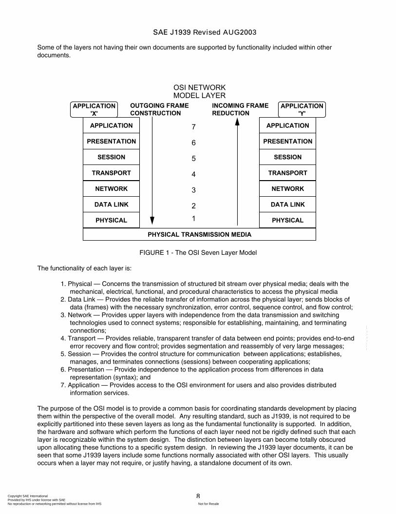
The Open System Interconnect (OSI) model was developed by the International Organization for Standardization (ISO) in 1984 as a model of a computer communications architecture. There are seven layers to the OSI model as shown in Figure 1. The intent is that protocols be developed to perform the functions of each layer as needed. J1939 is structured into several parts based on this ISO Model. While there is a J1939 document allocated to each layer, not all of them are explicitly identified by having their own J1939 document.
SAE J1939 Revised AUG2003
Copyright SAE International Provided by IHS under license with SAE
Not for ResaleNo reproduction or networking permitted without license from IHS
--`-`-`,,`,,`,`,,`---
8
Some of the layers not having their own documents are supported by functionality included within other documents.
PHYSICAL
DATA LINK
NETWORK
TRANSPORT
SESSION
PRESENTATION
APPLICATION
PHYSICAL
DATA LINK
NETWORK
TRANSPORT
SESSION
PRESENTATION
APPLICATION
OUTGOING FRAMECONSTRUCTION
INCOMING FRAMEREDUCTION
PHYSICAL TRANSMISSION MEDIA
APPLICATION'X'
APPLICATION'Y'
OSI NETWORKMODEL LAYER
7
6
5
4
3
2
1
FIGURE 1 - The OSI Seven Layer Model
The functionality of each layer is:
1. Physical — Concerns the transmission of structured bit stream over physical media; deals with the mechanical, electrical, functional, and procedural characteristics to access the physical media
2. Data Link — Provides the reliable transfer of information across the physical layer; sends blocks of data (frames) with the necessary synchronization, error control, sequence control, and flow control;
3. Network — Provides upper layers with independence from the data transmission and switching technologies used to connect systems; responsible for establishing, maintaining, and terminating connections;
4. Transport — Provides reliable, transparent transfer of data between end points; provides end-to-end error recovery and flow control; provides segmentation and reassembly of very large messages;
5. Session — Provides the control structure for communication between applications; establishes, manages, and terminates connections (sessions) between cooperating applications;
6. Presentation — Provide independence to the application process from differences in data representation (syntax); and
7. Application — Provides access to the OSI environment for users and also provides distributed information services.
The purpose of the OSI model is to provide a common basis for coordinating standards development by placing them within the perspective of the overall model. Any resulting standard, such as J1939, is not required to be explicitly partitioned into these seven layers as long as the fundamental functionality is supported. In addition, the hardware and software which perform the functions of each layer need not be rigidly defined such that each layer is recognizable within the system design. The distinction between layers can become totally obscured upon allocating these functions to a specific system design. In reviewing the J1939 layer documents, it can be seen that some J1939 layers include some functions normally associated with other OSI layers. This usually occurs when a layer may not require, or justify having, a standalone document of its own.
SAE J1939 Revised AUG2003
Copyright SAE International Provided by IHS under license with SAE
Not for ResaleNo reproduction or networking permitted without license from IHS
--`-`-`,,`,,`,`,,`---
9
Because the J1939 network is a specific communications system, supporting specific sets of applications and a specific industry, rather than being generalized, not all of the OSI layers are required. Only those layers which are required for the anticipated J1939 uses will be defined, with a separate document being used for each of these layers.
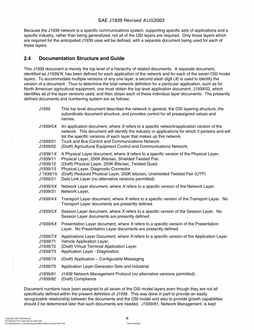
2.4 Documentation Structure and Guide
This J1939 document is merely the top level of a hierarchy of related documents. A separate document, identified as J1939/N, has been defined for each application of the network and for each of the seven OSI model layers. To accommodate multiple versions of any one layer, a second slash digit (X) is used to identify the version of a document. Thus to determine the total network definition for a particular application, such as for North American agricultural equipment, one must obtain the top level application document, J1939/02, which identifies all of the layer versions used, and then obtain each of these individual layer documents. The presently defined documents and numbering system are as follows:
J1939 This top level document describes the network in general, the OSI layering structure, the subordinate document structure, and provides control for all preassigned values and names.
J1939/0X An application document, where X refers to a specific network/application version of the network. This document will identify the industry or applications for which it pertains and will list the specific versions of each layer that makes up this network.
J1939/01 Truck and Bus Control and Communications Network. J1939/02 (Draft) Agricultural Equipment Control and Communications Network.
J1939/1X A Physical Layer document, where X refers to a specific version of the Physical Layer. J1939/11 Physical Layer, 250K Bits/sec, Shielded Twisted Pair. J1939/12 (Draft) Physical Layer, 250K Bits/sec, Twisted Quad. J1939/13 Physical Layer, Diagnostic Connector J 1939/15 (Draft) Reduced Physical Layer, 250K bits/sec, Unshielded Twisted Pair (UTP) J1939/21 Data Link Layer (no alternative versions permitted)
J1939/3X Network Layer document, where X refers to a specific version of the Network Layer. J1939/31 Network Layer,
J1939/4X Transport Layer document, where X refers to a specific version of the Transport Layer. No Transport Layer documents are presently defined.
J1939/5X Session Layer document, where X refers to a specific version of the Session Layer. No Session Layer documents are presently defined.
J1939/6X Presentation Layer document, where X refers to a specific version of the Presentation Layer. No Presentation Layer documents are presently defined.
J1939/7X Applications Layer Document, where X refers to a specific version of the Application Layer. J1939/71 Vehicle Application Layer. J1939/72 (Draft) Virtual Terminal Application Layer. J1939/73 Application Layer - Diagnostics.
J1939/74 (Draft) Application – Configurable Messaging
J1939/75 Application Layer-Generator Sets and Industrial
J1939/81 J1939 Network Management Protocol (no alternative versions permitted). J1939/82 (Draft) Compliance
Document numbers have been assigned to all seven of the OSI model layers even though they are not all specifically defined within the present definition of J1939. This was done in part to provide an easily recognizable relationship between the documents and the OSI model and also to provide growth capabilities should it be determined later that such documents are needed. J1939/81, Network Management, is kept
SAE J1939 Revised AUG2003
Copyright SAE International Provided by IHS under license with SAE
Not for ResaleNo reproduction or networking permitted without license from IHS
--`-`-`,,`,,`,`,,`---
10
separate as it represents a vertical slice through all of the layers and is thus best explained and understood as an individual subject rather than include a subset of network management within each of the affected layers.
Multiple application layer documents may be utilized simultaneously on the same network and thus must maintain compatibility. An example of such a system is a piece of agricultural equipment that utilizes both J1939/71 for the majority of communications and J1939/72 for the display terminal communications, both sets of messages being carried over the exact same network. A single vehicle/application may also utilize different physical layers within the same system but they need not be compatible if on different segments. An example is on-highway trucks where the physical layer used to connect the tractor to the trailer may be different than that used on the tractor itself.
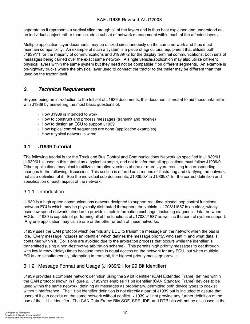
3. Technical Requirements
Beyond being an introduction to the full set of J1939 documents, this document is meant to aid those unfamiliar with J1939 by answering the most basic questions of:
· How J1939 is intended to work · How to construct and process messages (transmit and receive) · How to design an ECU to support J1939 · How typical control sequences are done (application examples) · How a typical network is wired
3.1 J1939 Tutorial
The following tutorial is for the Truck and Bus Control and Communications Network as specified in J1939/01. J1939/01 is used in this tutorial as a typical example, and not to infer that all applications must follow J1939/01. Other applications may elect to utilize alternative versions of one or more layers resulting in corresponding changes to the following discussion. This section is offered as a means of illustrating and clarifying the network, not as a definition of it. See the individual sub documents, J1939/0X to J1939/81 for the correct definition and specification of each aspect of the network.
3.1.1 Introduction
J1939 is a high speed communications network designed to support real-time closed loop control functions between ECUs which may be physically distributed throughout the vehicle. J1708/J1587 is an older, widely used low speed network intended to provide simple information exchange, including diagnostic data, between ECUs. J1939 is capable of performing all of the functions of J1708/J1587 as well as the control system support. Any one application may utilize one or the other or both of these networks.
J1939 uses the CAN protocol which permits any ECU to transmit a message on the network when the bus is idle. Every message includes an identifier which defines the message priority, who sent it, and what data is contained within it. Collisions are avoided due to the arbitration process that occurs while the identifier is transmitted (using a non-destructive arbitration scheme). This permits high priority messages to get through with low latency (delay) times because there is equal access on the network for any ECU, but when multiple ECUs are simultaneously attempting to transmit, the highest priority message prevails.
3.1.2 Message Format and Usage (J1939/21 for 29 Bit Identifier)
J1939 provides a complete network definition using the 29 bit identifier (CAN Extended Frame) defined within the CAN protocol shown in Figure 2. J1939/21 enables 11 bit identifier (CAN Standard Frame) devices to be used within the same network, defining all messages as proprietary, permitting both device types to coexist without interference. The 11 bit identifier definition is not directly a part of J1939 but is included to assure that users of it can coexist on the same network without conflict. J1939 will not provide any further definition of the use of the 11 bit identifier. The CAN Data Frame Bits SOF, SRR, IDE, and RTR bits will not be discussed in the
SAE J1939 Revised AUG2003
Copyright SAE International Provided by IHS under license with SAE
Not for ResaleNo reproduction or networking permitted without license from IHS
--`-`-`,,`,,`,`,,`---
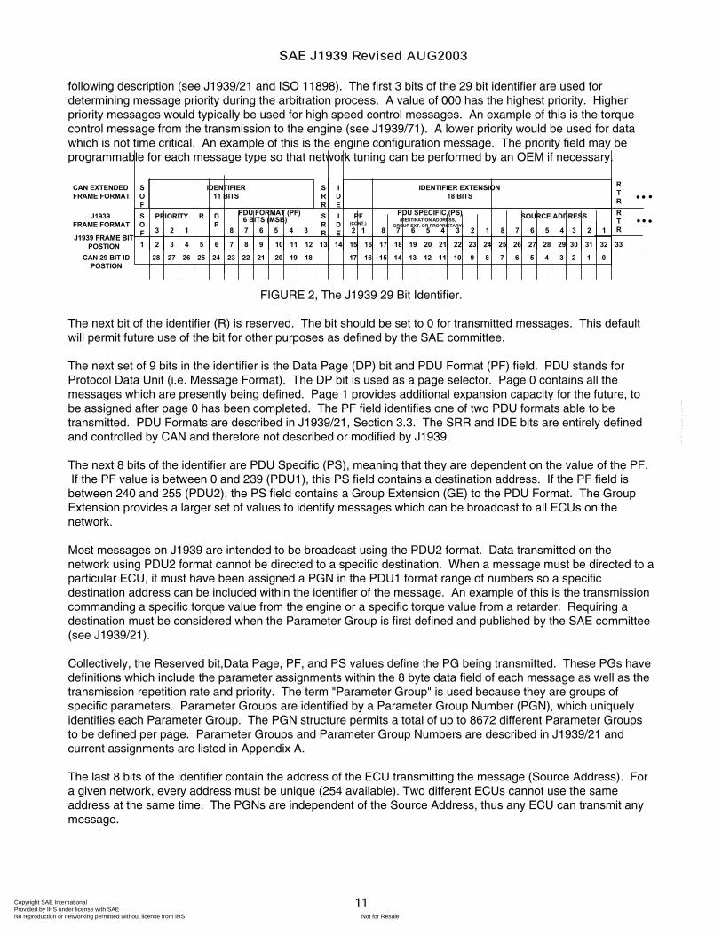
11
following description (see J1939/21 and ISO 11898). The first 3 bits of the 29 bit identifier are used for determining message priority during the arbitration process. A value of 000 has the highest priority. Higher priority messages would typically be used for high speed control messages. An example of this is the torque control message from the transmission to the engine (see J1939/71). A lower priority would be used for data which is not time critical. An example of this is the engine configuration message. The priority field may be programmable for each message type so that network tuning can be performed by an OEM if necessary.
1 2 3 4 5 6 7 8 9 10 11 12 13 14 15 16 17 18 19 20 21 22 23 24 25 26 27 28 29 30
SOF
IDENTIFIER11 BITS
SRR
IDE
IDENTIFIER EXTENSION18 BITS
123
DP 6 BITS (MSB)
PDU SPECIFIC (PS)(DESTINATION ADDRESS,
GROUP EXT. OR PROPRIETARY)
SRR
IDE
PF(CONT.)2 8 7 6 5 4 3 2 1 8 7 6 5 4 3
PRIORITY PDU FORMAT (PF)
345678
SOF
R
1 2 1
RTR
SOURCE ADDRESS
CAN EXTENDED FRAME FORMAT
J1939 FRAME FORMAT
J1939 FRAME BITPOSTION 31 32 33
RTR • • •
• • •
28 27 26 25 24 23 22 21 20 19 18 17 16 15 14 13 12 11 10 9 8 7 6 5 4 3 2CAN 29 BIT IDPOSTION
1 0
FIGURE 2, The J1939 29 Bit Identifier.
The next bit of the identifier (R) is reserved. The bit should be set to 0 for transmitted messages. This default will permit future use of the bit for other purposes as defined by the SAE committee.
The next set of 9 bits in the identifier is the Data Page (DP) bit and PDU Format (PF) field. PDU stands for Protocol Data Unit (i.e. Message Format). The DP bit is used as a page selector. Page 0 contains all the messages which are presently being defined. Page 1 provides additional expansion capacity for the future, to be assigned after page 0 has been completed. The PF field identifies one of two PDU formats able to be transmitted. PDU Formats are described in J1939/21, Section 3.3. The SRR and IDE bits are entirely defined and controlled by CAN and therefore not described or modified by J1939.
The next 8 bits of the identifier are PDU Specific (PS), meaning that they are dependent on the value of the PF. If the PF value is between 0 and 239 (PDU1), this PS field contains a destination address. If the PF field is between 240 and 255 (PDU2), the PS field contains a Group Extension (GE) to the PDU Format. The Group Extension provides a larger set of values to identify messages which can be broadcast to all ECUs on the network.
Most messages on J1939 are intended to be broadcast using the PDU2 format. Data transmitted on the network using PDU2 format cannot be directed to a specific destination. When a message must be directed to a particular ECU, it must have been assigned a PGN in the PDU1 format range of numbers so a specific destination address can be included within the identifier of the message. An example of this is the transmission commanding a specific torque value from the engine or a specific torque value from a retarder. Requiring a destination must be considered when the Parameter Group is first defined and published by the SAE committee (see J1939/21).
Collectively, the Reserved bit,Data Page, PF, and PS values define the PG being transmitted. These PGs have definitions which include the parameter assignments within the 8 byte data field of each message as well as the transmission repetition rate and priority. The term "Parameter Group" is used because they are groups of specific parameters. Parameter Groups are identified by a Parameter Group Number (PGN), which uniquely identifies each Parameter Group. The PGN structure permits a total of up to 8672 different Parameter Groups to be defined per page. Parameter Groups and Parameter Group Numbers are described in J1939/21 and current assignments are listed in Appendix A.
The last 8 bits of the identifier contain the address of the ECU transmitting the message (Source Address). For a given network, every address must be unique (254 available). Two different ECUs cannot use the same address at the same time. The PGNs are independent of the Source Address, thus any ECU can transmit any message.
SAE J1939 Revised AUG2003
Copyright SAE International Provided by IHS under license with SAE
Not for ResaleNo reproduction or networking permitted without license from IHS
--`-`-`,,`,,`,`,,`---
12
3.1.3 Addresses and NAME (J1939/81 and Appendix B)
Each ECU on the network will have at least one name and one address associated with it. There are examples, such as an engine and engine retarder residing in a common ECU, wherein multiple names and multiple addresses may coexist within a single electronics unit. The address of an ECU defines a specific communications source or destination for messages, the name includes identification of the primary function performed at that address and adds an indication of the instance of that functionality in the event that multiple ECUs with the same primary function coexist on the same network. As many as 254 different ECUs of the same function can coexist on the network, each identified by their own address and name.
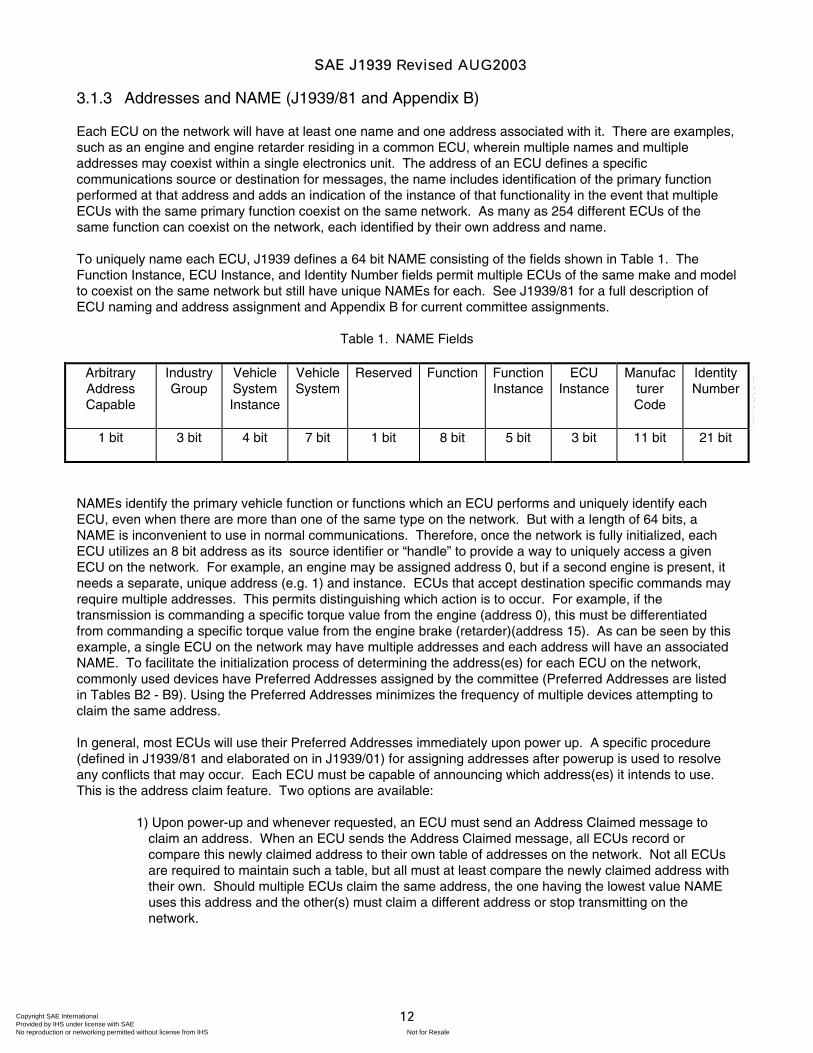
To uniquely name each ECU, J1939 defines a 64 bit NAME consisting of the fields shown in Table 1. The Function Instance, ECU Instance, and Identity Number fields permit multiple ECUs of the same make and model to coexist on the same network but still have unique NAMEs for each. See J1939/81 for a full description of ECU naming and address assignment and Appendix B for current committee assignments.
Table 1. NAME Fields
Arbitrary Address Capable
Industry Group
Vehicle System Instance
Vehicle System
Reserved Function Function Instance
ECU Instance
Manufacturer Code
Identity Number
1 bit 3 bit 4 bit 7 bit 1 bit 8 bit 5 bit 3 bit 11 bit 21 bit
NAMEs identify the primary vehicle function or functions which an ECU performs and uniquely identify each ECU, even when there are more than one of the same type on the network. But with a length of 64 bits, a NAME is inconvenient to use in normal communications. Therefore, once the network is fully initialized, each ECU utilizes an 8 bit address as its source identifier or “handle” to provide a way to uniquely access a given ECU on the network. For example, an engine may be assigned address 0, but if a second engine is present, it needs a separate, unique address (e.g. 1) and instance. ECUs that accept destination specific commands may require multiple addresses. This permits distinguishing which action is to occur. For example, if the transmission is commanding a specific torque value from the engine (address 0), this must be differentiated from commanding a specific torque value from the engine brake (retarder)(address 15). As can be seen by this example, a single ECU on the network may have multiple addresses and each address will have an associated NAME. To facilitate the initialization process of determining the address(es) for each ECU on the network, commonly used devices have Preferred Addresses assigned by the committee (Preferred Addresses are listed in Tables B2 - B9). Using the Preferred Addresses minimizes the frequency of multiple devices attempting to claim the same address.
In general, most ECUs will use their Preferred Addresses immediately upon power up. A specific procedure (defined in J1939/81 and elaborated on in J1939/01) for assigning addresses after powerup is used to resolve any conflicts that may occur. Each ECU must be capable of announcing which address(es) it intends to use. This is the address claim feature. Two options are available:
1) Upon power-up and whenever requested, an ECU must send an Address Claimed message to claim an address. When an ECU sends the Address Claimed message, all ECUs record or compare this newly claimed address to their own table of addresses on the network. Not all ECUs are required to maintain such a table, but all must at least compare the newly claimed address with their own. Should multiple ECUs claim the same address, the one having the lowest value NAME uses this address and the other(s) must claim a different address or stop transmitting on the network.
SAE J1939 Revised AUG2003
Copyright SAE International Provided by IHS under license with SAE
Not for ResaleNo reproduction or networking permitted without license from IHS
--`-`-`,,`,,`,`,,`---
13
2) An ECU may send a request for Address Claimed message to determine addresses claimed by other ECUs. When an ECU sends a request for Address Claimed, all requested ECUs then send their Address Claimed messages. This permits transitional ECUs (tools, trailers, etc.) or ECUs powering up late to obtain the current address table so that an available address can be found and claimed or to determine which ECUs are currently on the network. This approach permits the option of self-configurable addresses for those ECUs which may need it, but does not make this a requirement for all ECUs. Self-configurable addressing is optional; those ECUs which might be expected to encounter address conflicts are recommended to support this capability.
When an address conflict has been detected, the following four options are available, depending upon the capabilities of the ECU involved:
Self-Configurable ECUs — a self-configurable ECU is capable of dynamically computing and claiming an unused address. Most service tools and bridges will have this capability.
Command Configurable ECUs — A network interconnection ECU, such as a bridge, or a service tool may command another ECU to use a given address. The ECU having the unclaimable address would then issue an Address Claimed message to acknowledge acceptance of this new commanded address. The ECU may be commanded to accept a new address even though it has already claimed a valid address.
Service Configurable ECUs — ECUs which are modifiable by service personnel, usually by the means of DIP switches or a service tool. When "commanded address" messages are used, his option differs from the Command Configurable in that a service tool is required and will often use proprietary techniques.
Non-Configurable ECUs — Those ECUs that are neither self-configurable nor reprogrammable would have to cease transmitting if they fail to claim a valid address.
3.1.4 Communication Methods
Three primary communication methods exist within J1939 and appropriate use of each type allows effective use of the available Parameter Group Numbers. The three communications methods are:
Destination specific communications, using PDU1 (PF values 0 - 239) (includes the use of the global destination address - 255)
Broadcast Communications using PDU2 (PF values 240 - 255) Proprietary Communications using either PDU1 or PDU2 format
Each of the communications methods has an appropriate use. Destination specific Parameter Group Numbers are needed where the message must be directed to one or another specific destination and not to both. J1939 currently defines a torque control message which may be sent to an engine or retarder. In the case of more than one engine, this message must be sent only to the desired engine and a destination specific Parameter Group Number is needed and has been assigned.
Broadcast Communications apply in several situations, including:
Messages sent from a single or multiple sources to a single destination Messages sent from a single or multiple sources to multiple destinations
Broadcast Communications cannot be used where a message must be sent to one or another destination and not to both.
SAE J1939 Revised AUG2003
Copyright SAE International Provided by IHS under license with SAE
Not for ResaleNo reproduction or networking permitted without license from IHS
--`-`-`,,`,,`,`,,`---
14
The third communications method in J1939, proprietary communications, is provided by the use of two proprietary Parameter Group Numbers. A Parameter Group Number has been assigned for broadcast proprietary communications and a Parameter Group Number has been assigned for destination specific proprietary communications. This allows for two functions. One, a specific source can send its proprietary message in a PDU2 type format (broadcast). Two, it allows for situations where a service tool must direct its communication to a specific destination out of a possible group of ECUs. For instance this case arises when an engine uses more than one controller but the service tool must be able to perform calibration/reprogramming while all ECUs are connected to the same network. In this case the proprietary protocol needs to be destination specific. Note that the destination ECU must be capable of properly interpreting the proprietary data.
Proprietary communications are useful in two situations:
Where it is unnecessary to have standardized communications Where it is important to communicate proprietary information
3.1.5 Transmitting Messages (Using J1939/21 and J1939/7X)
In addition to the 29 bit identifier shown in Figure 2, a CAN Data Frame includes a 6 bit control field, a data field which is typically 8 bytes, and terminates with CRC, ACK, and EOF fields. To send a particular data item, a message must be constructed by properly filling each of these fields. This is done by first referencing the applicable J1939 documents. This process will define the Parameter Group Number (PGN) to use, the message update (transmission) rate, and default priority. Since multiple data items are typically packed together within a message, it will also define the data field format. Note that when the ECU does not have data available for a given parameter it sets those bits to “not available” so that a receiver knows that the data is not provided.
Parameter Groups which have more than eight bytes of data must be sent as multipacket messages using the Transport Protocol functions defined in J1939/21 Section 3.10.
3.1.6 Receiving Messages (Using J1939/21 and J1939/7X)
There are various techniques (and electronic ICs) available for capturing selected messages off the network. Several general observations can be made however regarding received messages.
1. If it is a destination specific request or command, the ECU must determine if there is an address match between itself and the incoming messages' destination address. If there is, it must process the message and provide some type of acknowledgment.
2. If a message is a global request, every ECU, even the originator, must process it and respond if the data is available.
3. If a message is broadcast, each ECU must determine if it is relevant or not.
3.1.7 ECU Design (Using J1939/11, J1939/21, and J1939/7X)
Although every manufacturer will have different performance requirements for the ECU contained within their product, several observations should be made regarding the resources needed to support J1939. The current data rate of J1939/11 is 250 kbps (400µS/bit). A typical message containing 8 data bytes is 128 bits long (excluding bits used for bit stuffing) which is approximately 0.5 ms. The shortest message is 64 bits long. This means that a new message could be present every 250 microseconds. Even though not every message is relevant, nor is the bus loading likely to be above 50%, the receiving processor must still be able to handle (or buffer) multiple back to back messages. This will require some RAM space as well as processor time for the memory transfers. The requirement is that no messages should be lost due to ECU hardware or software design limitations.
SAE J1939 Revised AUG2003
Copyright SAE International Provided by IHS under license with SAE
Not for ResaleNo reproduction or networking permitted without license from IHS
--`-`-`,,`,,`,`,,`---
15
3.1.8 Network Topology — J1939/01 Using Physical Layer J1939/11 and Network Layer J1939/31
The J1939/01 network defines a system containing one or more segments connected by network interconnecting ECUs. Each J1939 segment consists of a single, linear, shielded twisted pair of wires running around a section of the vehicle to each ECU. A short stub is permitted to connect this “bus” to each ECU. This simplifies the routing of the main bus wiring by not requiring it to come in direct proximity with each ECU. The linear bus is necessary at a data rate of 250 Kbps in order to minimize reflections of the electrical signals. The termination resistor at each end of the bus also reduces reflections. To support a tractor pulling one or more trailers, and the frequent removal and addition of new trailers, a separate J1939 segment (subnetwork) is used within the tractor and in each trailer or dolly.
The J1939 network may thus be composed of multiple segments, with a network interconnection ECU (bridge) between them. These segments need not be directly compatible with each other, as they may operate at different data rates or use different physical media. For example, a bridge provides electrical isolation between segments, provides initialization support for the subnetwork connected to it, and can provide message filtering to prevent unnecessary message traffic on the subnetworks. In the event of a bus failure on the wires exposed between the tractor and trailer, the main J1939 subnetwork on the tractor will continue to function.
3.2 Preassigned Values
Application specific parameters and Parameter Groups are defined in the J1939/7X documents. Parameter Groups that are used for control and management of the network are defined in J1939/21, J1939/31, and J1939/81. Assignments for Preferred Addresses, NAME elements, and Parameter Group Numbers are maintained in the appendices to this document. Each of these items are described in this section. The actual values that have been assigned are listed in the Appendices. If new values are required that are not already assigned, developers may request new values to be assigned by the SAE Control and Communications Network Subcommittee. See Appendix D for information on making a request. Users of the documents should assure that this base document is newer or has the same revision date as the particular application document they are using to avoid making requests that are obsolete at the time of submittal.
3.2.1 Parameter Group Numbers
Parameter Group Numbers are assigned specifically to use either PDU1 format or PDU2 format (PDU types are described in Section 3.1.2 and in J1939/21, Section 3.3). Once assigned to a format the other PDU type is not available for that Parameter Group. The assignment of a Parameter Group Number should be done keeping in mind the following characteristics: priority, update rate, importance of the data in the packet to other ECUs, and length of the data associated with the Parameter Group. Appendix A includes a template for assigning Parameter Group Numbers and the current assignments.
Parameter Group Numbers are assigned linearly to the various sections of the Parameter Group list in Appendix A based on the criteria provided on the Parameter Group Request form (Appendix D).
Much of the communications between ECUs constructed by a single manufacturer do not require standardization. The information that is communicated is not generally useful to other ECUs on the network. In this situation the proprietary Parameter Groups can be used. The use of standardized communications is preferred and should be used whenever practical, however the proprietary option is offered as a means of solving unique problems and situations.
If proprietary information is being communicated, or the information to be communicated is not of general interest, the proprietary method should be used. If the information is of general interest and does not require direction of the message to a particular ECU, a Parameter Group Number utilizing the PDU2 broadcast format should be sought. Finally, if the information is of general interest but requires direction to one or another ECUs then destination specific addressing is needed and a PDU1 format Parameter Group Number should be sought. Proprietary and PDU1 communications methods should be considered carefully and used sparingly.
SAE J1939 Revised AUG2003
Copyright SAE International Provided by IHS under license with SAE
Not for ResaleNo reproduction or networking permitted without license from IHS
--`-`-`,,`,,`,`,,`---
16
3.2.2 Data Field Grouping
Minimizing message overhead with CAN based systems requires full use of the data fields of messages. Except in the case of very time critical messages, parameters should be grouped to fill the 8 byte data field. Following this principle conserves PGNs for future assignment and allows for minimum network loading when all data bytes are known by and sent from the same address. Strong justification is needed to allow definition of Parameter Group Numbers that result in sparsely used data fields.
Parameters should be grouped as follows:
1. By common subsystem (the ECU likely to measure and send the data) 2. With similar update rates (to minimize unnecessary overhead) 3. By function (Oil, Coolant, Fuel, etc.)
It should be recognized that, while these are guidelines, in most cases when parameters are grouped together they will end up violating one or more of the above rules. Since all parameters defined in J1939 have a technique for identifying when they are not available it is not critical that all of the parameters in one Parameter Group come from the same ECU. If a new parameter is defined and there are spare bytes or bits in an existing Parameter Group, then it can be easily added there. When the update rate is fast, it is desirable to make sure that a Parameter Group is as fully utilized as possible (i.e. uses all 8 data bytes) before defining another PG and preferable that all parameters are normally coming from one specific ECU.
For the slower update rate data it is not as critical that all of the parameters in a Parameter Group come from the same ECU. Even though it is desirable to have parameters come from one ECU, the intention of J1939 is to provide a means for communicating the data and not dictating which ECU is to send what data.
3.2.3 NAME Systems and Functions
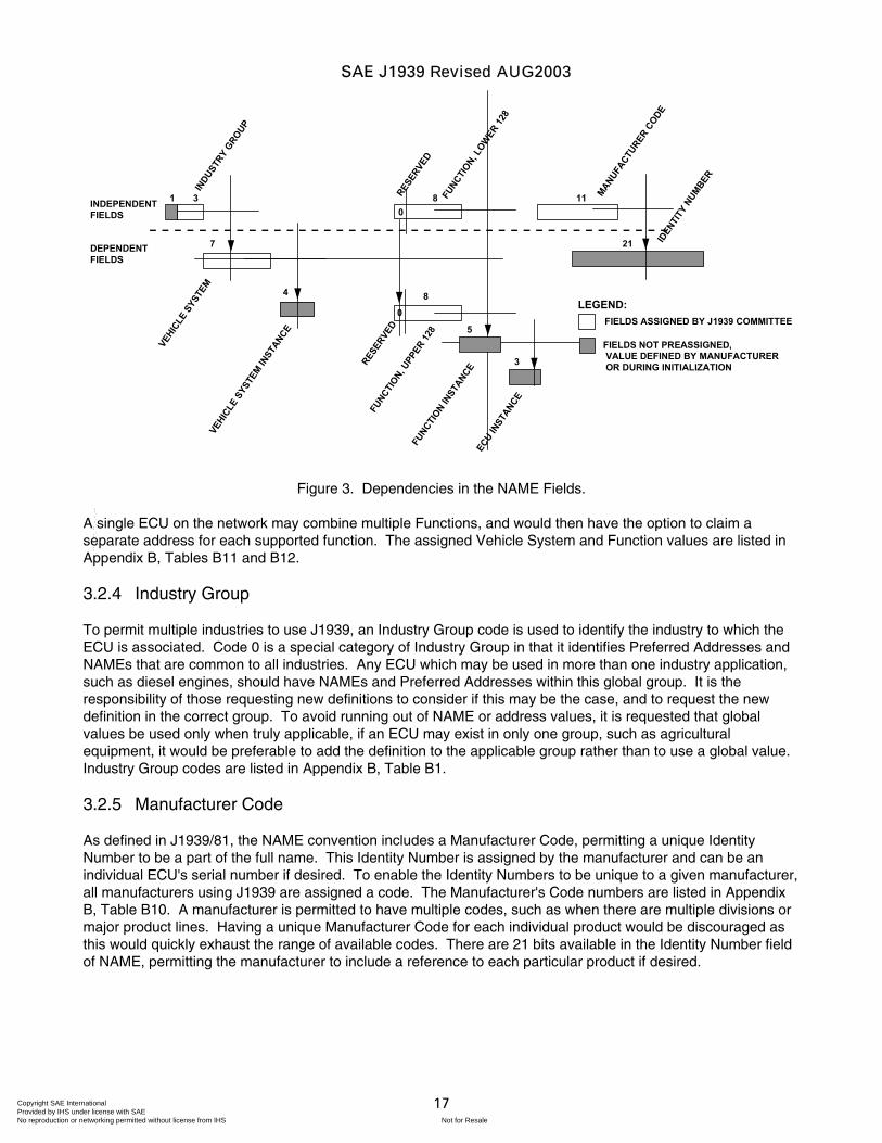
A Function is a capability of a component or group of components served by one or more ECUs. The Function of each ECU is identified within an 8 bit field of that ECU's NAME. As there may be multiple ECUs which identify themselves with the same Function, the Function Instance field of NAME is used to distinguish between them. The same Function value (upper 128 only) may mean different things for different Industry Groups or Vehicle Systems, therefore the Function (upper 128 only) identification is dependent upon the Industry Group, and the Vehicle System as shown in Figure 3 (see J1939/81 Section 4.1.12).
A Vehicle System is a subcomponent of a vehicle or an analogous component that includes one or more J1939 network segments and may be connected or disconnected from the total vehicle. A Vehicle System may be made up of one or more Functions, which have ECUs that are connected to a J1939 network segment of that Vehicle System. A typical on-highway Vehicle System is a tractor or trailer. Because the definition of Vehicle Systems will vary from one industry to another, the System definition is dependent upon the Industry Group as shown in Figure 3 (see J1939/81 Section 4.1.12).
SAE J1939 Revised AUG2003
Copyright SAE International Provided by IHS under license with SAE
Not for ResaleNo reproduction or networking permitted without license from IHS
--`-`-`,,`,,`,`,,`---
17
1 3
7
4
80
11
21
INDU
STRY
GROUP
FUNCTI
ON, L
OWER
128
MANUFACT
URER C
ODE
VEHIC
LE S
YSTE
MVE
HICLE
SYS
TEM IN
STAN
CE
FUNCTI
ON, UPP
ER 12
8FU
NCTION IN
STANCE
ECU IN
STAN
CE
IDEN
TITY
NUMBE
R
RESER
VED
5
8
3
INDEPENDENTFIELDS
DEPENDENTFIELDS
LEGEND:
FIELDS NOT PREASSIGNED, VALUE DEFINED BY MANUFACTURER OR DURING INITIALIZATION
FIELDS ASSIGNED BY J1939 COMMITTEE0
RESER
VED
Figure 3. Dependencies in the NAME Fields.
A single ECU on the network may combine multiple Functions, and would then have the option to claim a separate address for each supported function. The assigned Vehicle System and Function values are listed in Appendix B, Tables B11 and B12.
3.2.4 Industry Group
To permit multiple industries to use J1939, an Industry Group code is used to identify the industry to which the ECU is associated. Code 0 is a special category of Industry Group in that it identifies Preferred Addresses and NAMEs that are common to all industries. Any ECU which may be used in more than one industry application, such as diesel engines, should have NAMEs and Preferred Addresses within this global group. It is the responsibility of those requesting new definitions to consider if this may be the case, and to request the new definition in the correct group. To avoid running out of NAME or address values, it is requested that global values be used only when truly applicable, if an ECU may exist in only one group, such as agricultural equipment, it would be preferable to add the definition to the applicable group rather than to use a global value. Industry Group codes are listed in Appendix B, Table B1.
3.2.5 Manufacturer Code
As defined in J1939/81, the NAME convention includes a Manufacturer Code, permitting a unique Identity Number to be a part of the full name. This Identity Number is assigned by the manufacturer and can be an individual ECU's serial number if desired. To enable the Identity Numbers to be unique to a given manufacturer, all manufacturers using J1939 are assigned a code. The Manufacturer's Code numbers are listed in Appendix B, Table B10. A manufacturer is permitted to have multiple codes, such as when there are multiple divisions or major product lines. Having a unique Manufacturer Code for each individual product would be discouraged as this would quickly exhaust the range of available codes. There are 21 bits available in the Identity Number field of NAME, permitting the manufacturer to include a reference to each particular product if desired.
SAE J1939 Revised AUG2003
Copyright SAE International Provided by IHS under license with SAE
Not for ResaleNo reproduction or networking permitted without license from IHS
--`-`-`,,`,,`,`,,`---
18
3.2.6 Preferred Address
The number of addresses within a given system cannot exceed 254 (null and global cannot be claimed by devices). Most ECUs that operate on a J1939 network will have an assigned Preferred Address that the ECU may use. If the ECU's Preferred Address has been claimed or is in use by another ECU on the network, the conflict will be resolved using the procedures outlined in Section 3.1.3 and detailed in J1939/81 Sections 4.2 and 5. There may be additional contraints or procedures defined in the applicable J1939/0X document. For instance, on-highway trailer bridges and devices have address claiming constraints that differ from Con-Ag systems. A supplier of a Self Configurable ECU may provide any strategy for selecting an address to attempt to claim. However, if an alternative approach is not defined, it should attempt to claim an address in the range 128 - 247, starting at 128. Individual reserved Preferred Address assignments begin at zero and are assigned in a linear fashion as follows:
0 to 127 Reserved for most conventional ECUs in Industry Group 0 - Global 128 to 247 Reserved for Industry Specific assignments 248 to 253 Reserved for special ECUs 254 Null Address 255 Global Address
The current Preferred Address assignments are provided in Appendix B and information for requesting new assignments can be found in Appendix D. For further information, see J1939/81.
3.2.7 Suspect Parameter Number (SPN)
A Suspect Parameter Number (SPN) is a 19 bit number used to identify a particular element, component, or parameter associated with an ECU. This capability is especially useful for diagnostics, permitting an ECU which has detected a fault associated with a particular component, such as a sensor, to transmit a fault message identifying the faulty component. SPNs are assigned by the Committee and are listed in Appendix C. The first 511 SPNs are reserved and will be assigned, when possible, to the exact same number as the Parameter Identifier (PID) of J1587. For example, J1587 PID 91 is "Percent Accelerator Pedal Position" and an accelerator pedal position parameter fault could be reported in J1939 by using SPN 91. All following SPNs will be assigned in order as they are received.
Due to the very large number of SPNs which may ultimately be assigned, and their assignment in order of request, it will be very difficult for one interested in finding the SPN value of a particular component of interest simply by looking through the table. To facilitate the verification that new SPN requests are not duplications of existing assignments, the committee retains this table as an MS Excel™ spreadsheet, with additional data beyond that shown in Table C1. This permits sorting based upon SPN number, name, description, attribute (actuator, pressure, temperature, solenoid, etc.), J1587 attributes (MID, PID, SID), J1939 document paragraph, source name, and source address. It would be desirable for those developing J1939 applications or wishing to request the assignment of a new SPN to have access to an up-to-date version of this spreadsheet so that they can perform various sorts and searches of the data. At the time of publication, the SAE has not yet determined how this data can best be made available to the users of J1939 who are not committee participants.
3.3 Application Examples
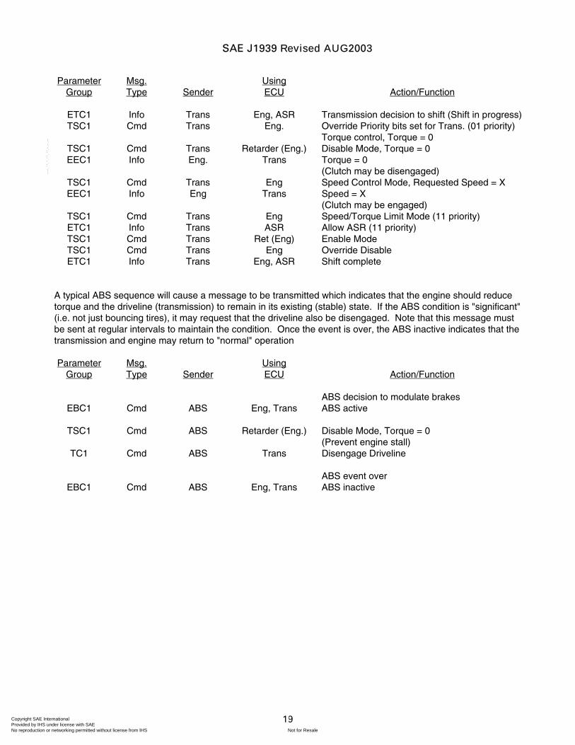
A typical shift sequence consists of a series of commands from the transmission to the engine for controlling engine RPM and torque. Messages from the engine provide status and information which is used to determine when a particular condition has occurred. Other messages may also be sent regularly to disable the engine retarder at the proper time interval, or to inhibit ASR functions which might effect engine demand during portions of the shift sequence.
SAE J1939 Revised AUG2003
Copyright SAE International Provided by IHS under license with SAE
Not for ResaleNo reproduction or networking permitted without license from IHS
--`-`-`,,`,,`,`,,`---
19
Parameter
Group Msg. Type
Sender
Using ECU
Action/Function
ETC1 Info Trans Eng, ASR Transmission decision to shift (Shift in progress) TSC1 Cmd Trans Eng. Override Priority bits set for Trans. (01 priority)
Torque control, Torque = 0 TSC1 Cmd Trans Retarder (Eng.) Disable Mode, Torque = 0 EEC1 Info Eng. Trans Torque = 0
(Clutch may be disengaged) TSC1 Cmd Trans Eng Speed Control Mode, Requested Speed = X EEC1 Info Eng Trans Speed = X
(Clutch may be engaged) TSC1 Cmd Trans Eng Speed/Torque Limit Mode (11 priority) ETC1 Info Trans ASR Allow ASR (11 priority) TSC1 Cmd Trans Ret (Eng) Enable Mode TSC1 Cmd Trans Eng Override Disable ETC1 Info Trans Eng, ASR Shift complete
A typical ABS sequence will cause a message to be transmitted which indicates that the engine should reduce torque and the driveline (transmission) to remain in its existing (stable) state. If the ABS condition is "significant" (i.e. not just bouncing tires), it may request that the driveline also be disengaged. Note that this message must be sent at regular intervals to maintain the condition. Once the event is over, the ABS inactive indicates that the transmission and engine may return to "normal" operation
Parameter Group
Msg. Type
Sender
Using ECU
Action/Function
ABS decision to modulate brakes EBC1 Cmd ABS Eng, Trans ABS active
TSC1 Cmd ABS Retarder (Eng.) Disable Mode, Torque = 0
(Prevent engine stall) TC1 Cmd ABS Trans Disengage Driveline
ABS event over
EBC1 Cmd ABS Eng, Trans ABS inactive
SAE J1939 Revised AUG2003
Copyright SAE International Provided by IHS under license with SAE
Not for ResaleNo reproduction or networking permitted without license from IHS
--`-`-`,,`,,`,`,,`---
20
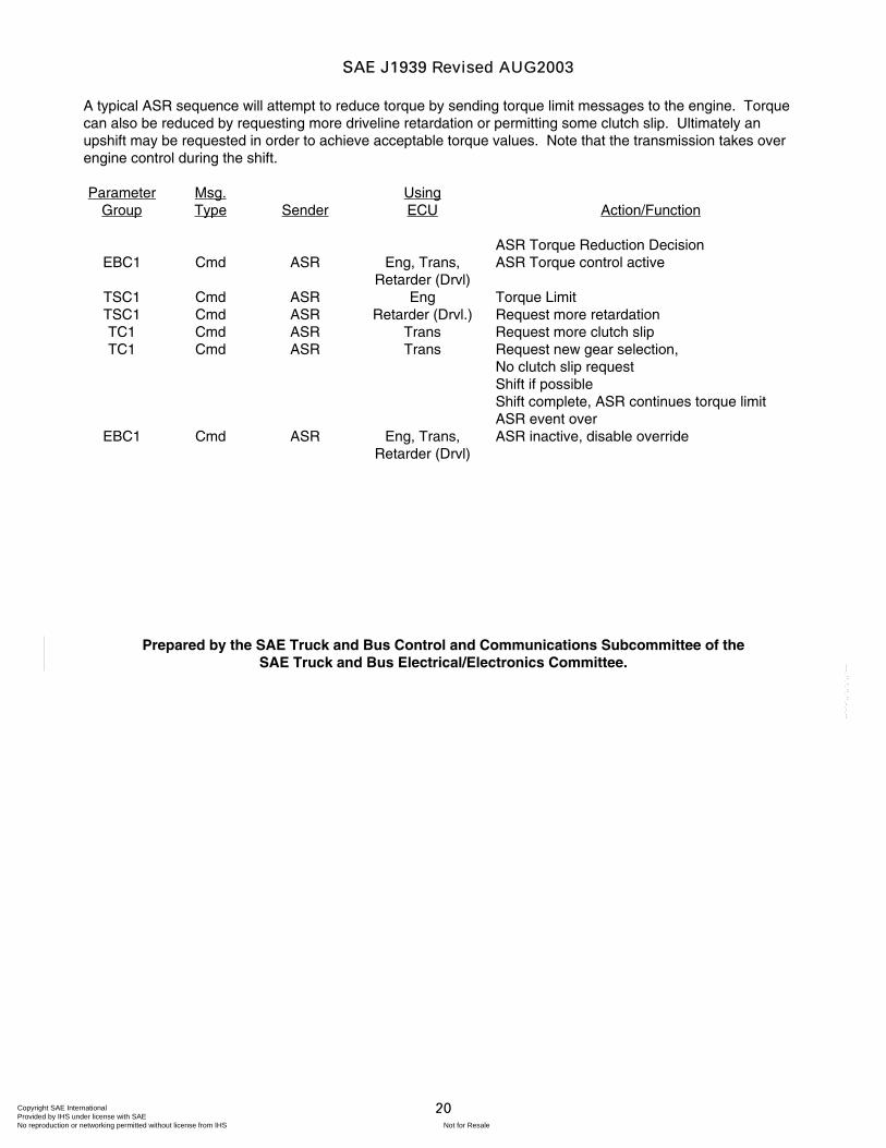
A typical ASR sequence will attempt to reduce torque by sending torque limit messages to the engine. Torque can also be reduced by requesting more driveline retardation or permitting some clutch slip. Ultimately an upshift may be requested in order to achieve acceptable torque values. Note that the transmission takes over engine control during the shift.
Parameter Group
Msg. Type
Sender
Using ECU
Action/Function
ASR Torque Reduction Decision EBC1 Cmd ASR Eng, Trans,
Retarder (Drvl) ASR Torque control active
TSC1 Cmd ASR Eng Torque Limit TSC1 Cmd ASR Retarder (Drvl.) Request more retardation TC1 Cmd ASR Trans Request more clutch slip TC1 Cmd ASR Trans Request new gear selection,
No clutch slip request Shift if possible Shift complete, ASR continues torque limit ASR event over
EBC1 Cmd ASR Eng, Trans, Retarder (Drvl)
ASR inactive, disable override
Prepared by the SAE Truck and Bus Control and Communications Subcommittee of the SAE Truck and Bus Electrical/Electronics Committee.
SAE J1939 Revised AUG2003
Copyright SAE International Provided by IHS under license with SAE
Not for ResaleNo reproduction or networking permitted without license from IHS
--`-`-`,,`,,`,`,,`---
APPENDIX A
PARAMETER GROUP ASSIGNMENTS
Copyright SAE International Provided by IHS under license with SAE
Not for ResaleNo reproduction or networking permitted without license from IHS
--`-`-`,,`,,`,`,,`---
- A1 -
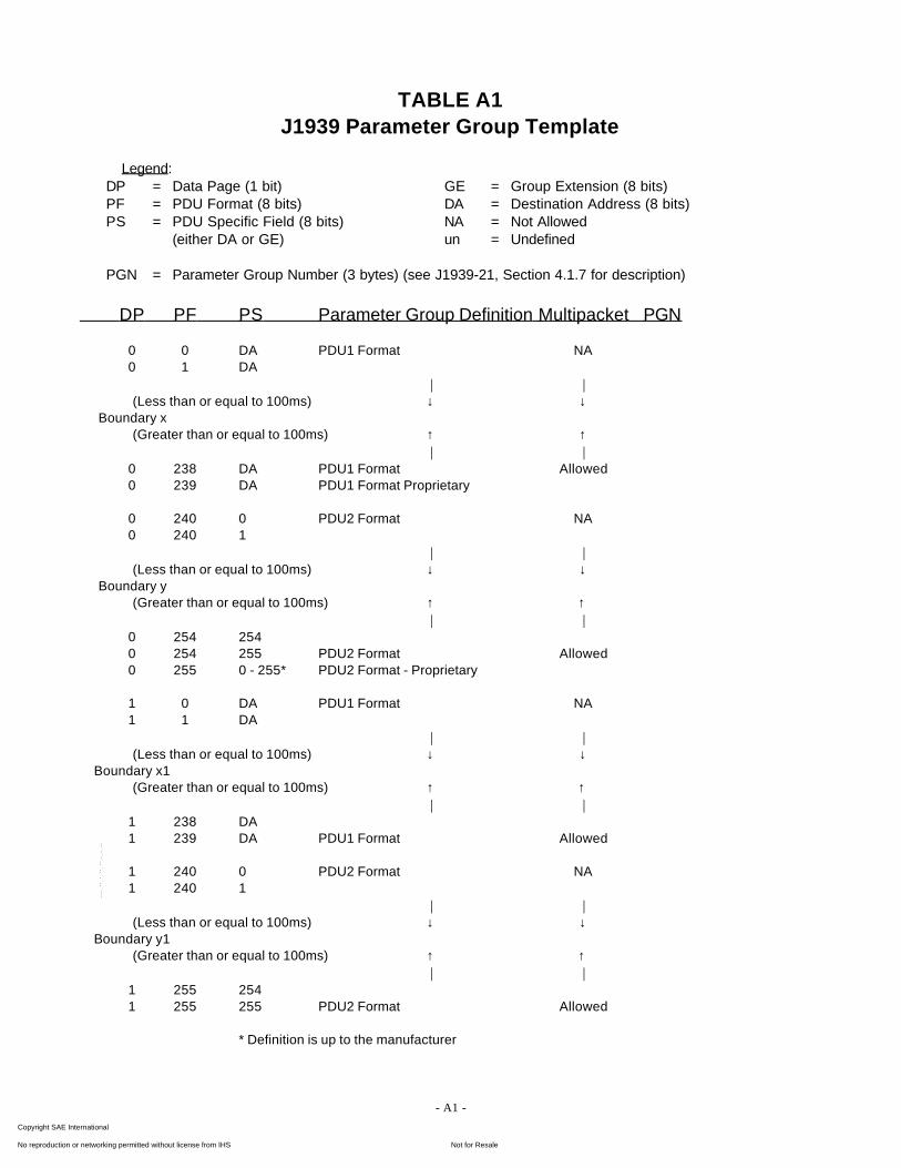
TABLE A1J1939 Parameter Group Template
Legend:DP = Data Page (1 bit) GE = Group Extension (8 bits)PF = PDU Format (8 bits) DA = Destination Address (8 bits)PS = PDU Specific Field (8 bits) NA = Not Allowed
(either DA or GE) un = Undefined
PGN = Parameter Group Number (3 bytes) (see J1939-21, Section 4.1.7 for description)
DP PF PS Parameter Group Definition Multipacket PGN
0 0 DA PDU1 Format NA0 1 DA
| |(Less than or equal to 100ms) ↓ ↓
Boundary x (Greater than or equal to 100ms) ↑ ↑
| |0 238 DA PDU1 Format Allowed0 239 DA PDU1 Format Proprietary
0 240 0 PDU2 Format NA0 240 1
| |(Less than or equal to 100ms) ↓ ↓
Boundary y (Greater than or equal to 100ms) ↑ ↑
| |0 254 2540 254 255 PDU2 Format Allowed0 255 0 - 255* PDU2 Format - Proprietary
1 0 DA PDU1 Format NA1 1 DA
| |(Less than or equal to 100ms) ↓ ↓
Boundary x1 (Greater than or equal to 100ms) ↑ ↑
| |1 238 DA1 239 DA PDU1 Format Allowed
1 240 0 PDU2 Format NA1 240 1
| |(Less than or equal to 100ms) ↓ ↓
Boundary y1 (Greater than or equal to 100ms) ↑ ↑
| |1 255 2541 255 255 PDU2 Format Allowed
* Definition is up to the manufacturer
Copyright SAE International Provided by IHS under license with SAE
Not for ResaleNo reproduction or networking permitted without license from IHS
--`-`-`,,`,,`,`,,`---
- A2 -
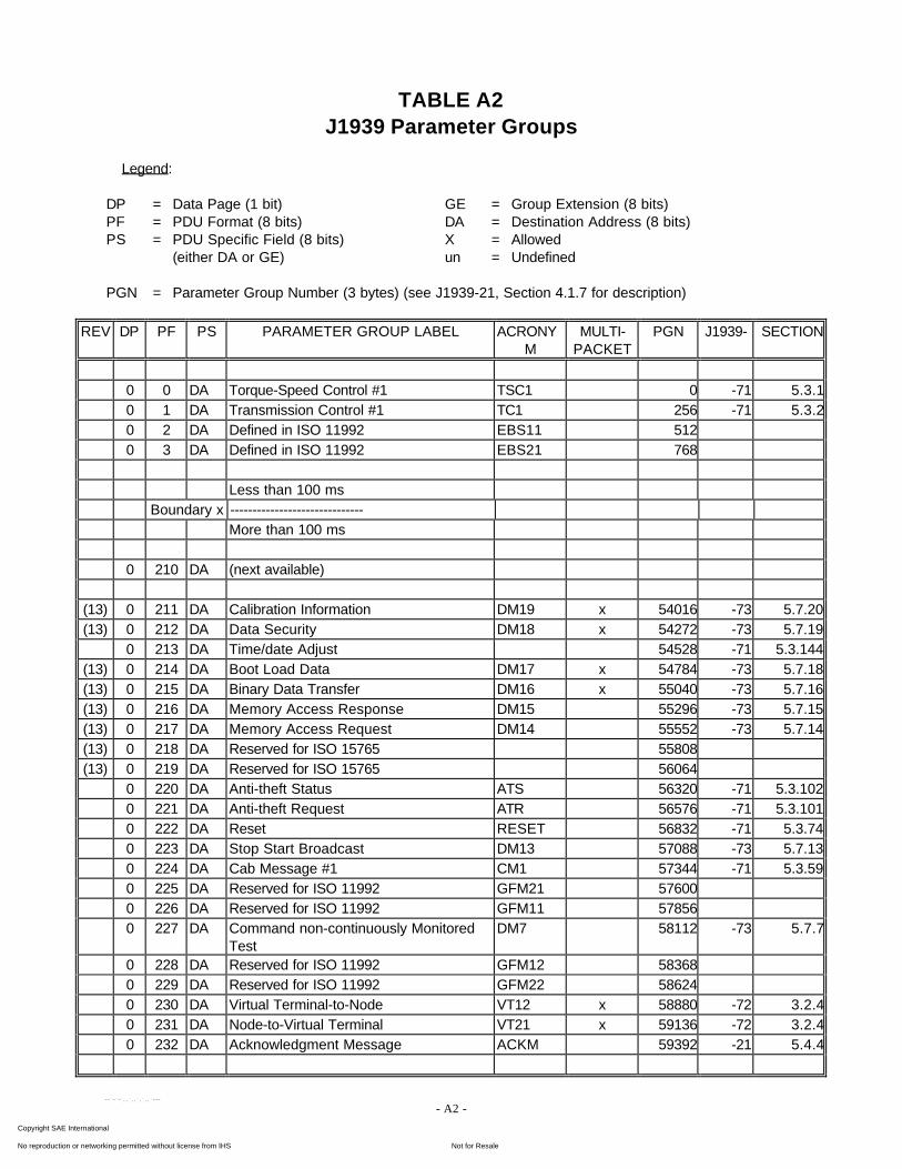
TABLE A2J1939 Parameter Groups
Legend:
DP = Data Page (1 bit) GE = Group Extension (8 bits)PF = PDU Format (8 bits) DA = Destination Address (8 bits)PS = PDU Specific Field (8 bits) X = Allowed
(either DA or GE) un = Undefined
PGN = Parameter Group Number (3 bytes) (see J1939-21, Section 4.1.7 for description)
REV DP PF PS PARAMETER GROUP LABEL ACRONYM
MULTI-PACKET
PGN J1939- SECTION
0 0 DA Torque-Speed Control #1 TSC1 0 -71 5.3.10 1 DA Transmission Control #1 TC1 256 -71 5.3.20 2 DA Defined in ISO 11992 EBS11 5120 3 DA Defined in ISO 11992 EBS21 768
Less than 100 msBoundary x ------------------------------
More than 100 ms
0 210 DA (next available)
(13) 0 211 DA Calibration Information DM19 x 54016 -73 5.7.20(13) 0 212 DA Data Security DM18 x 54272 -73 5.7.19
0 213 DA Time/date Adjust 54528 -71 5.3.144(13) 0 214 DA Boot Load Data DM17 x 54784 -73 5.7.18(13) 0 215 DA Binary Data Transfer DM16 x 55040 -73 5.7.16(13) 0 216 DA Memory Access Response DM15 55296 -73 5.7.15(13) 0 217 DA Memory Access Request DM14 55552 -73 5.7.14(13) 0 218 DA Reserved for ISO 15765 55808(13) 0 219 DA Reserved for ISO 15765 56064
0 220 DA Anti-theft Status ATS 56320 -71 5.3.1020 221 DA Anti-theft Request ATR 56576 -71 5.3.1010 222 DA Reset RESET 56832 -71 5.3.740 223 DA Stop Start Broadcast DM13 57088 -73 5.7.130 224 DA Cab Message #1 CM1 57344 -71 5.3.590 225 DA Reserved for ISO 11992 GFM21 576000 226 DA Reserved for ISO 11992 GFM11 578560 227 DA Command non-continuously Monitored
TestDM7 58112 -73 5.7.7
0 228 DA Reserved for ISO 11992 GFM12 583680 229 DA Reserved for ISO 11992 GFM22 586240 230 DA Virtual Terminal-to-Node VT12 x 58880 -72 3.2.40 231 DA Node-to-Virtual Terminal VT21 x 59136 -72 3.2.40 232 DA Acknowledgment Message ACKM 59392 -21 5.4.4
Copyright SAE International Provided by IHS under license with SAE
Not for ResaleNo reproduction or networking permitted without license from IHS
--`-`-`,,`,,`,`,,`---
- A3 -
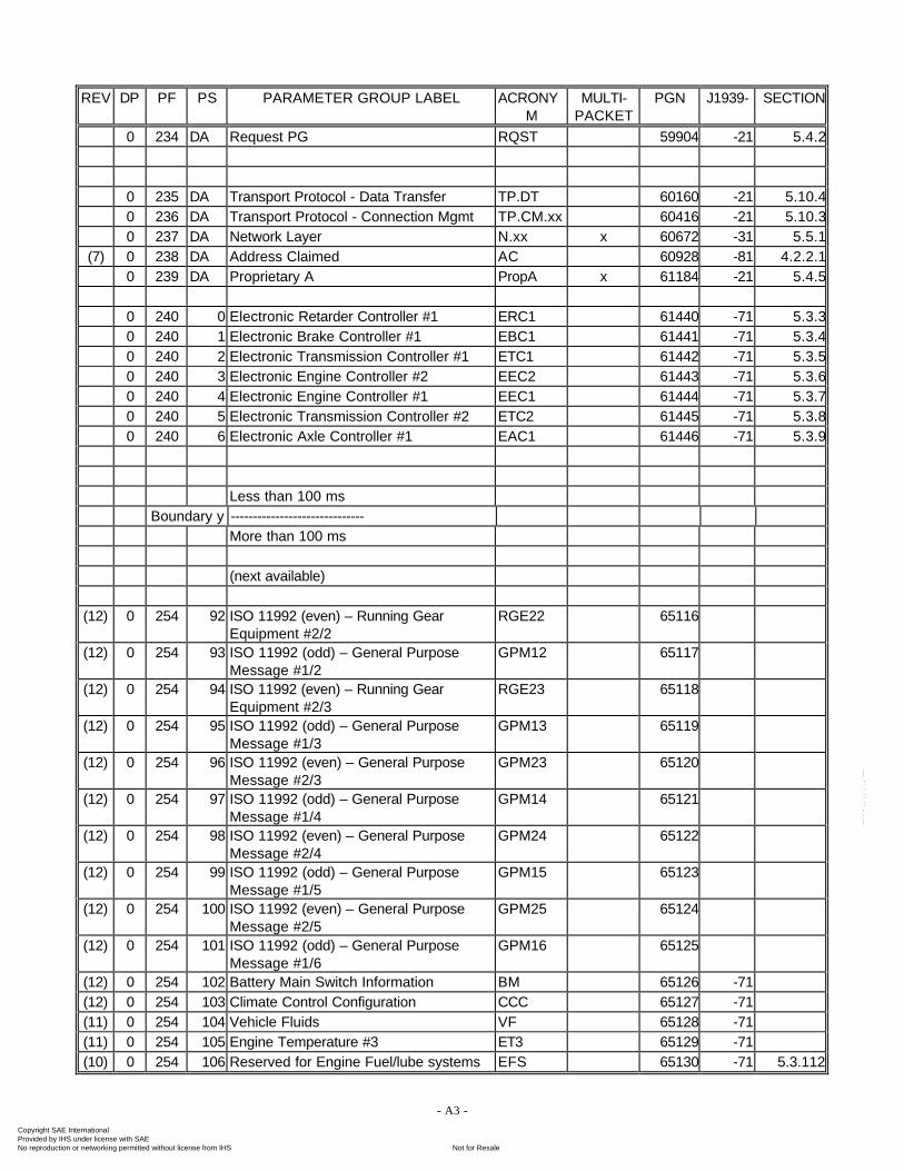
REV DP PF PS PARAMETER GROUP LABEL ACRONYM
MULTI-PACKET
PGN J1939- SECTION
0 234 DA Request PG RQST 59904 -21 5.4.2
0 235 DA Transport Protocol - Data Transfer TP.DT 60160 -21 5.10.40 236 DA Transport Protocol - Connection Mgmt TP.CM.xx 60416 -21 5.10.30 237 DA Network Layer N.xx x 60672 -31 5.5.1
(7) 0 238 DA Address Claimed AC 60928 -81 4.2.2.10 239 DA Proprietary A PropA x 61184 -21 5.4.5
0 240 0 Electronic Retarder Controller #1 ERC1 61440 -71 5.3.30 240 1 Electronic Brake Controller #1 EBC1 61441 -71 5.3.40 240 2 Electronic Transmission Controller #1 ETC1 61442 -71 5.3.50 240 3 Electronic Engine Controller #2 EEC2 61443 -71 5.3.60 240 4 Electronic Engine Controller #1 EEC1 61444 -71 5.3.70 240 5 Electronic Transmission Controller #2 ETC2 61445 -71 5.3.80 240 6 Electronic Axle Controller #1 EAC1 61446 -71 5.3.9
Less than 100 msBoundary y ------------------------------
More than 100 ms
(next available)
(12) 0 254 92 ISO 11992 (even) – Running GearEquipment #2/2
RGE22 65116
(12) 0 254 93 ISO 11992 (odd) – General PurposeMessage #1/2
GPM12 65117
(12) 0 254 94 ISO 11992 (even) – Running GearEquipment #2/3
RGE23 65118
(12) 0 254 95 ISO 11992 (odd) – General PurposeMessage #1/3
GPM13 65119
(12) 0 254 96 ISO 11992 (even) – General PurposeMessage #2/3
GPM23 65120
(12) 0 254 97 ISO 11992 (odd) – General PurposeMessage #1/4
GPM14 65121
(12) 0 254 98 ISO 11992 (even) – General PurposeMessage #2/4
GPM24 65122
(12) 0 254 99 ISO 11992 (odd) – General PurposeMessage #1/5
GPM15 65123
(12) 0 254 100 ISO 11992 (even) – General PurposeMessage #2/5
GPM25 65124
(12) 0 254 101 ISO 11992 (odd) – General PurposeMessage #1/6
GPM16 65125
(12) 0 254 102 Battery Main Switch Information BM 65126 -71(12) 0 254 103 Climate Control Configuration CCC 65127 -71(11) 0 254 104 Vehicle Fluids VF 65128 -71(11) 0 254 105 Engine Temperature #3 ET3 65129 -71(10) 0 254 106 Reserved for Engine Fuel/lube systems EFS 65130 -71 5.3.112
Copyright SAE International Provided by IHS under license with SAE
Not for ResaleNo reproduction or networking permitted without license from IHS
--`-`-`,,`,,`,`,,`---
- A4 -
REV DP PF PS PARAMETER GROUP LABEL ACRONYM
MULTI-PACKET
PGN J1939- SECTION
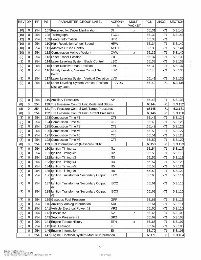
(10) 0 254 107 Reserved for Driver Identification DI x 65131 -71 5.3.145(10) 0 254 108 Tachograph TCO1 65132 -71 5.3.143(12) 0 254 109 Heater Information HTR 65133 -71(10) 0 254 110 High Resolution Wheel Speed HRW 65134 -71 5.3.142(10) 0 254 111 Adaptive Cruise Control ACC1 65135 -71 5.3.141(10) 0 254 112 Combination Vehicle Weight CVW x 65136 -71 5.3.140(9) 0 254 113 Laser Tracer Position LTP 65137 -71 5.3.139(9) 0 254 114 Laser Leveling System Blade Control LBC 65138 -71 5.3.138(9) 0 254 115 Laser Receiver Mast Position LMP 65139 -71 5.3.137(9) 0 254 116 Modify Leveling System Control Set
PointLSP 65140 -71 5.3.136
(9) 0 254 117 Laser Leveling System Vertical Deviation LVD 65141 -71 5.3.135(9) 0 254 118 Laser Leveling System Vertical Position
Display DataLVDD 65142 -71 5.3.134
(9) 0 254 119 Auxiliary Pressures AP 65143 -71 5.3.133(8) 0 254 120 Tire Pressure Control Unit Mode and Status 65144 -71 5.3.132(8) 0 254 121 Tire Pressure Control Unit Target Pressures 65145 -71 5.3.131(8) 0 254 122 Tire Pressure Control Unit Current Pressures 65146 -71 5.3.130(8) 0 254 123 Combustion Time #1 CT1 65147 -71 5.3.124(8) 0 254 124 Combustion Time #2 CT2 65148 -71 5.3.125(8) 0 254 125 Combustion Time #3 CT3 65149 -71 5.3.126(8) 0 254 126 Combustion Time #4 CT4 65150 -71 5.3.127(8) 0 254 127 Combustion Time #5 CT5 65151 -71 5.3.128(8) 0 254 128 Combustion Time #6 CT6 65152 -71 5.3.129(8) 0 254 129 Fuel Information #2 (Gaseous) GFI2 65153 -71 5.3.123(7) 0 254 130 Ignition Timing #1 IT1 65154 -71 5.3.117(7) 0 254 131 Ignition Timing #2 IT2 65155 -71 5.3.118(7) 0 254 132 Ignition Timing #3 IT3 65156 -71 5.3.119(7) 0 254 133 Ignition Timing #4 IT4 65157 -71 5.3.120(7) 0 254 134 Ignition Timing #5 IT5 65158 -71 5.3.121(7) 0 254 135 Ignition Timing #6 IT6 65159 -71 5.3.122(7) 0 254 136 Ignition Transformer Secondary Output
#1ISO1 65160 -71 5.3.114
(7) 0 254 137 Ignition Transformer Secondary Output#2
ISO2 65161 -71 5.3.115
(7) 0 254 138 Ignition Transformer Secondary Output#3
ISO3 65162 -71 5.3.116
(7) 0 254 139 Gaseous Fuel Pressure GFP 65163 -71 5.3.113(7) 0 254 140 Auxiliary Analog Information AAI 65164 -71 5.3.111(7) 0 254 141 Vehicle Electrical Power #2 VP2 65165 -71 5.3.110(6) 0 254 142 Service #2 S2 X 65166 -71 5.3.109(6) 0 254 143 Supply Pressure #2 SP2 65167 -71 5.3.108(6) 0 254 144 Engine Torque History ETH x 65168 -71 5.3.107(6) 0 254 145 Fuel Leakage FL 65169 -71 5.3.106
0 254 146 Engine Information EI 65170 -71 5.3.1050 254 147 Engine Electrical System/Module Information 65171 -71 5.3.104
Copyright SAE International Provided by IHS under license with SAE
Not for ResaleNo reproduction or networking permitted without license from IHS
--`-`-`,,`,,`,`,,`---
- A5 -
REV DP PF PS PARAMETER GROUP LABEL ACRONYM
MULTI-PACKET
PGN J1939- SECTION
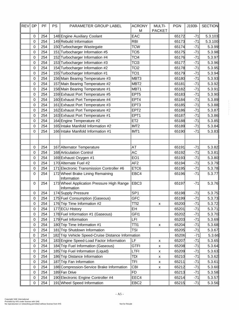
0 254 148 Engine Auxiliary Coolant EAC 65172 -71 5.3.1030 254 149 Rebuild Information RBI 65173 -71 5.3.1000 254 150 Turbocharger Wastegate TCW 65174 -71 5.3.990 254 151 Turbocharger Information #5 TCI5 65175 -71 5.3.980 254 152 Turbocharger Information #4 TCI4 65176 -71 5.3.970 254 153 Turbocharger Information #3 TCI3 65177 -71 5.3.960 254 154 Turbocharger Information #2 TCI2 65178 -71 5.3.950 254 155 Turbocharger Information #1 TCI1 65179 -71 5.3.940 254 156 Main Bearing Temperature #3 MBT3 65180 -71 5.3.930 254 157 Main Bearing Temperature #2 MBT2 65181 -71 5.3.920 254 158 Main Bearing Temperature #1 MBT1 65182 -71 5.3.910 254 159 Exhaust Port Temperature #5 EPT5 65183 -71 5.3.900 254 160 Exhaust Port Temperature #4 EPT4 65184 -71 5.3.890 254 161 Exhaust Port Temperature #3 EPT3 65185 -71 5.3.880 254 162 Exhaust Port Temperature #2 EPT2 65186 -71 5.3.870 254 163 Exhaust Port Temperature #1 EPT1 65187 -71 5.3.860 254 164 Engine Temperature #2 ET2 65188 -71 5.3.850 254 165 Intake Manifold Information #2 IMT2 65189 -71 5.3.840 254 166 Intake Manifold Information #1 IMT1 65190 -71 5.3.83
0 254 167 Alternator Temperature AT 65191 -71 5.3.820 254 168 Articulation Control AC 65192 -71 5.3.810 254 169 Exhaust Oxygen #1 EO1 65193 -71 5.3.800 254 170 Alternate Fuel #2 AF2 65194 -71 5.3.790 254 171 Electronic Transmission Controller #6 ETC6 65195 -71 5.3.780 254 172 Wheel Brake Lining Remaining
InformationEBC4 65196 -71 5.3.77
0 254 173 Wheel Application Pressure High RangeInformation
EBC3 65197 -71 5.3.76
0 254 174 Supply Pressure SP1 65198 -71 5.3.750 254 175 Fuel Consumption (Gaseous) GFC 65199 -71 5.3.730 254 176 Trip Time Information #2 TTI2 x 65200 -71 5.3.720 254 177 ECU History EH 65201 -71 5.3.710 254 178 Fuel Information #1 (Gaseous) GFI1 65202 -71 5.3.700 254 179 Fuel Information LFI 65203 -71 5.3.690 254 180 Trip Time Information #1 TTI1 x 65204 -71 5.3.680 254 181 Trip Shutdown Information TSI 65205 -71 5.3.670 254 182 Trip Vehicle Speed-Cruise Distance Information 65206 -71 5.3.660 254 183 Engine Speed-Load Factor Information LF x 65207 -71 5.3.650 254 184 Trip Fuel Information (Gaseous) GTFI x 65208 -71 5.3.640 254 185 Trip Fuel Information (Liquid) LTFI x 65209 -71 5.3.630 254 186 Trip Distance Information TDI x 65210 -71 5.3.620 254 187 Trip Fan Information TFI x 65211 -71 5.3.610 254 188 Compression-Service Brake Information CBI x 65212 -71 5.3.600 254 189 Fan Drive FD 65213 -71 5.3.580 254 190 Electronic Engine Controller #4 EEC4 65214 -71 5.3.570 254 191 Wheel Speed Information EBC2 65215 -71 5.3.56
Copyright SAE International Provided by IHS under license with SAE
Not for ResaleNo reproduction or networking permitted without license from IHS
--`-`-`,,`,,`,`,,`---
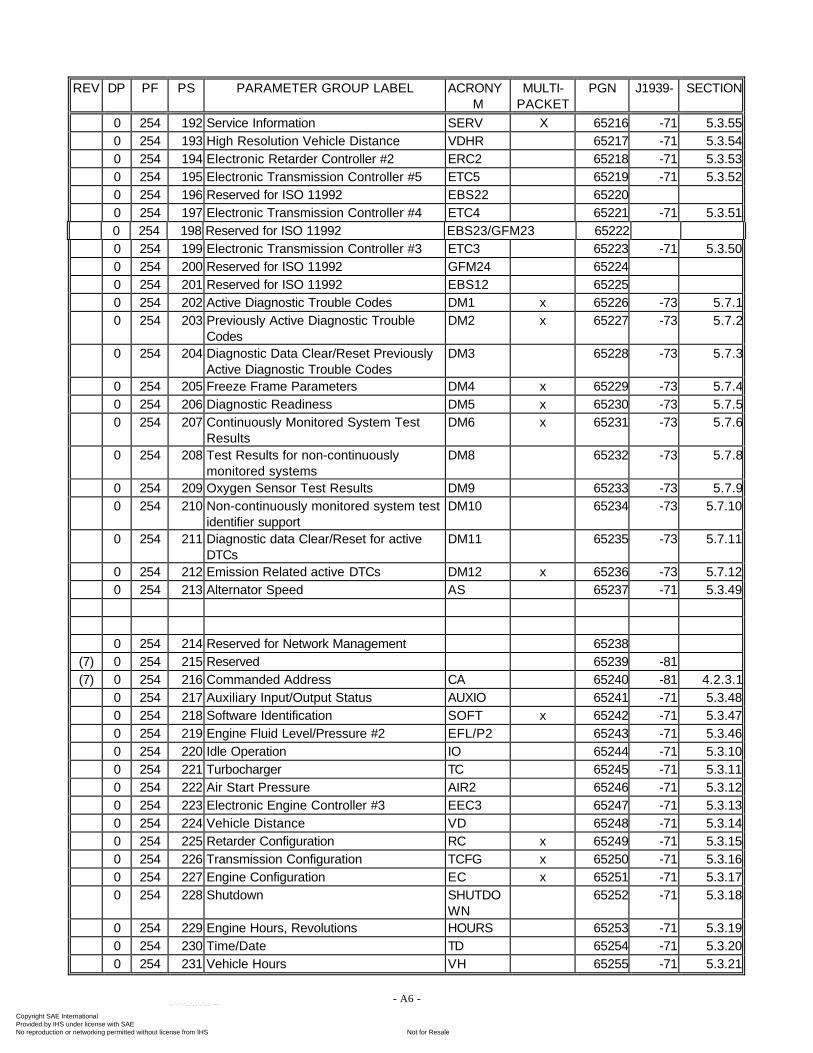
- A6 -
REV DP PF PS PARAMETER GROUP LABEL ACRONYM
MULTI-PACKET
PGN J1939- SECTION
0 254 192 Service Information SERV X 65216 -71 5.3.550 254 193 High Resolution Vehicle Distance VDHR 65217 -71 5.3.540 254 194 Electronic Retarder Controller #2 ERC2 65218 -71 5.3.530 254 195 Electronic Transmission Controller #5 ETC5 65219 -71 5.3.520 254 196 Reserved for ISO 11992 EBS22 652200 254 197 Electronic Transmission Controller #4 ETC4 65221 -71 5.3.510 254 198 Reserved for ISO 11992 EBS23/GFM23 652220 254 199 Electronic Transmission Controller #3 ETC3 65223 -71 5.3.500 254 200 Reserved for ISO 11992 GFM24 652240 254 201 Reserved for ISO 11992 EBS12 652250 254 202 Active Diagnostic Trouble Codes DM1 x 65226 -73 5.7.10 254 203 Previously Active Diagnostic Trouble
CodesDM2 x 65227 -73 5.7.2
0 254 204 Diagnostic Data Clear/Reset PreviouslyActive Diagnostic Trouble Codes
DM3 65228 -73 5.7.3
0 254 205 Freeze Frame Parameters DM4 x 65229 -73 5.7.40 254 206 Diagnostic Readiness DM5 x 65230 -73 5.7.50 254 207 Continuously Monitored System Test
ResultsDM6 x 65231 -73 5.7.6
0 254 208 Test Results for non-continuouslymonitored systems
DM8 65232 -73 5.7.8
0 254 209 Oxygen Sensor Test Results DM9 65233 -73 5.7.90 254 210 Non-continuously monitored system test
identifier supportDM10 65234 -73 5.7.10
0 254 211 Diagnostic data Clear/Reset for activeDTCs
DM11 65235 -73 5.7.11
0 254 212 Emission Related active DTCs DM12 x 65236 -73 5.7.120 254 213 Alternator Speed AS 65237 -71 5.3.49
0 254 214 Reserved for Network Management 65238(7) 0 254 215 Reserved 65239 -81(7) 0 254 216 Commanded Address CA 65240 -81 4.2.3.1
0 254 217 Auxiliary Input/Output Status AUXIO 65241 -71 5.3.480 254 218 Software Identification SOFT x 65242 -71 5.3.470 254 219 Engine Fluid Level/Pressure #2 EFL/P2 65243 -71 5.3.460 254 220 Idle Operation IO 65244 -71 5.3.100 254 221 Turbocharger TC 65245 -71 5.3.110 254 222 Air Start Pressure AIR2 65246 -71 5.3.120 254 223 Electronic Engine Controller #3 EEC3 65247 -71 5.3.130 254 224 Vehicle Distance VD 65248 -71 5.3.140 254 225 Retarder Configuration RC x 65249 -71 5.3.150 254 226 Transmission Configuration TCFG x 65250 -71 5.3.160 254 227 Engine Configuration EC x 65251 -71 5.3.170 254 228 Shutdown SHUTDO
WN65252 -71 5.3.18
0 254 229 Engine Hours, Revolutions HOURS 65253 -71 5.3.190 254 230 Time/Date TD 65254 -71 5.3.200 254 231 Vehicle Hours VH 65255 -71 5.3.21
Copyright SAE International Provided by IHS under license with SAE
Not for ResaleNo reproduction or networking permitted without license from IHS
--`-`-`,,`,,`,`,,`---
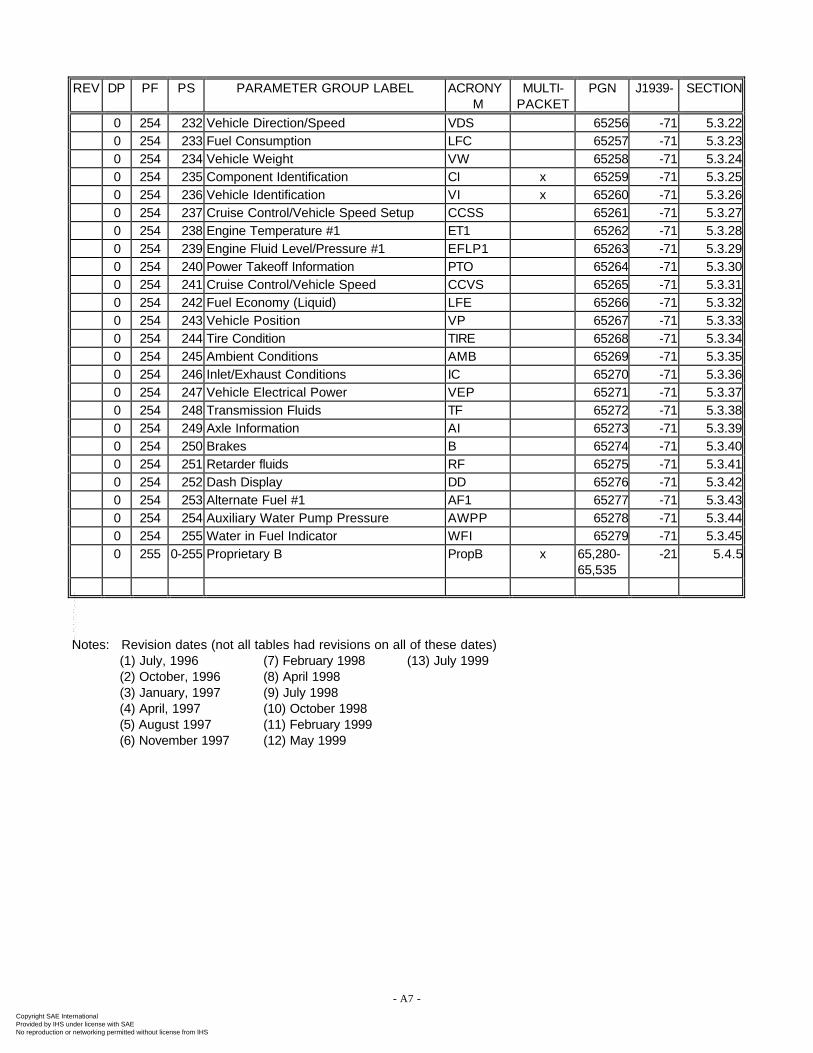
- A7 -
REV DP PF PS PARAMETER GROUP LABEL ACRONYM
MULTI-PACKET
PGN J1939- SECTION
0 254 232 Vehicle Direction/Speed VDS 65256 -71 5.3.220 254 233 Fuel Consumption LFC 65257 -71 5.3.230 254 234 Vehicle Weight VW 65258 -71 5.3.240 254 235 Component Identification CI x 65259 -71 5.3.250 254 236 Vehicle Identification VI x 65260 -71 5.3.260 254 237 Cruise Control/Vehicle Speed Setup CCSS 65261 -71 5.3.270 254 238 Engine Temperature #1 ET1 65262 -71 5.3.280 254 239 Engine Fluid Level/Pressure #1 EFLP1 65263 -71 5.3.290 254 240 Power Takeoff Information PTO 65264 -71 5.3.300 254 241 Cruise Control/Vehicle Speed CCVS 65265 -71 5.3.310 254 242 Fuel Economy (Liquid) LFE 65266 -71 5.3.320 254 243 Vehicle Position VP 65267 -71 5.3.330 254 244 Tire Condition TIRE 65268 -71 5.3.340 254 245 Ambient Conditions AMB 65269 -71 5.3.350 254 246 Inlet/Exhaust Conditions IC 65270 -71 5.3.360 254 247 Vehicle Electrical Power VEP 65271 -71 5.3.370 254 248 Transmission Fluids TF 65272 -71 5.3.380 254 249 Axle Information AI 65273 -71 5.3.390 254 250 Brakes B 65274 -71 5.3.400 254 251 Retarder fluids RF 65275 -71 5.3.410 254 252 Dash Display DD 65276 -71 5.3.420 254 253 Alternate Fuel #1 AF1 65277 -71 5.3.430 254 254 Auxiliary Water Pump Pressure AWPP 65278 -71 5.3.440 254 255 Water in Fuel Indicator WFI 65279 -71 5.3.450 255 0-255 Proprietary B PropB x 65,280-
65,535-21 5.4.5
Notes: Revision dates (not all tables had revisions on all of these dates)(1) July, 1996 (7) February 1998 (13) July 1999(2) October, 1996 (8) April 1998(3) January, 1997 (9) July 1998(4) April, 1997 (10) October 1998(5) August 1997 (11) February 1999(6) November 1997 (12) May 1999
Copyright SAE International Provided by IHS under license with SAE
Not for ResaleNo reproduction or networking permitted without license from IHS
--`-`-`,,`,,`,`,,`---
APPENDIX B
ADDRESS AND IDENTITY ASSIGNMENTS
Copyright SAE International Provided by IHS under license with SAE
Not for ResaleNo reproduction or networking permitted without license from IHS
--`-`-`,,`,,`,`,,`---
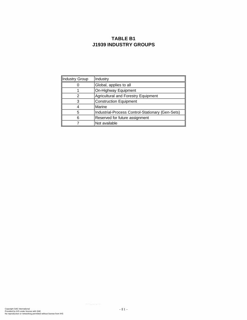
- B1 -
TABLE B1J1939 INDUSTRY GROUPS
Industry Group Industry
0 Global, applies to all1 On-Highway Equipment2 Agricultural and Forestry Equipment3 Construction Equipment4 Marine5 Industrial-Process Control-Stationary (Gen-Sets)6 Reserved for future assignment7 Not available
Copyright SAE International Provided by IHS under license with SAE
Not for ResaleNo reproduction or networking permitted without license from IHS
--`-`-`,,`,,`,`,,`---
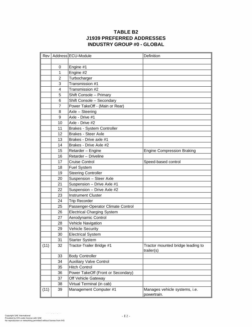
- B2 -
TABLE B2J1939 PREFERRED ADDRESSESINDUSTRY GROUP #0 - GLOBAL
Rev Address ECU-Module Definition
0 Engine #11 Engine #22 Turbocharger3 Transmission #14 Transmission #25 Shift Console – Primary6 Shift Console – Secondary7 Power TakeOff - (Main or Rear)8 Axle – Steering9 Axle - Drive #110 Axle - Drive #211 Brakes - System Controller12 Brakes - Steer Axle13 Brakes - Drive axle #114 Brakes - Drive Axle #215 Retarder – Engine Engine Compression Braking16 Retarder – Driveline17 Cruise Control Speed-based control18 Fuel System19 Steering Controller20 Suspension – Steer Axle21 Suspension – Drive Axle #122 Suspension – Drive Axle #223 Instrument Cluster24 Trip Recorder25 Passenger-Operator Climate Control26 Electrical Charging System27 Aerodynamic Control28 Vehicle Navigation29 Vehicle Security30 Electrical System31 Starter System
(11) 32 Tractor-Trailer Bridge #1 Tractor mounted bridge leading totrailer(s)
33 Body Controller34 Auxiliary Valve Control35 Hitch Control36 Power TakeOff (Front or Secondary)37 Off Vehicle Gateway38 Virtual Terminal (in cab)
(11) 39 Management Computer #1 Manages vehicle systems, i.e.powertrain.
Copyright SAE International Provided by IHS under license with SAE
Not for ResaleNo reproduction or networking permitted without license from IHS
--`-`-`,,`,,`,`,,`---
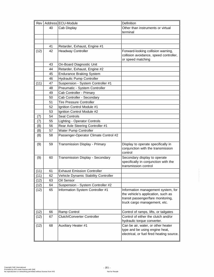
- B3 -
Rev Address ECU-Module Definition40 Cab Display Other than instruments or virtual
terminal
41 Retarder, Exhaust, Engine #1(12) 42 Headway Controller Forward-looking collision warning,
collision avoidance, speed controller,or speed matching
43 On-Board Diagnostic Unit44 Retarder, Exhaust, Engine #245 Endurance Braking System46 Hydraulic Pump Controller
(11) 47 Suspension - System Controller #148 Pneumatic - System Controller49 Cab Controller - Primary50 Cab Controller - Secondary51 Tire Pressure Controller52 Ignition Control Module #153 Ignition Control Module #2
(7) 54 Seat Controls(7) 55 Lighting - Operator Controls(8) 56 Rear Axle Steering Controller #1(8) 57 Water Pump Controller(8) 58 Passenger-Operator Climate Control #2
(9) 59 Transmission Display - Primary Display to operate specifically inconjunction with the transmissioncontrol
(9) 60 Transmission Display - Secondary Secondary display to operatespecifically in conjunction with thetransmission control
(11) 61 Exhaust Emission Controller(11) 62 Vehicle Dynamic Stability Controller(12) 63 Oil Sensor(12) 64 Suspension - System Controller #2(12) 65 Information System Controller #1 Information management system, for
the vehicle’s application, such astransit passenger/fare monitoring,truck cargo management, etc.
(12) 66 Ramp Control Control of ramps, lifts, or tailgates(12) 67 Clutch/Converter Controller Control of either the clutch and/or
hydraulic torque converter.(12) 68 Auxiliary Heater #1 Can be air, water, or other heater
type and be using engine heat,electrical, or fuel fired heating source.
Copyright SAE International Provided by IHS under license with SAE
Not for ResaleNo reproduction or networking permitted without license from IHS
--`-`-`,,`,,`,`,,`---
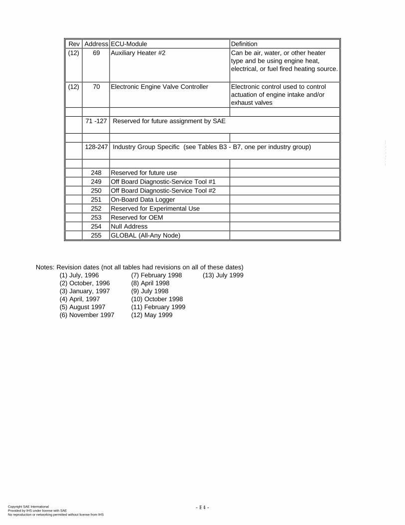
- B4 -
Rev Address ECU-Module Definition(12) 69 Auxiliary Heater #2 Can be air, water, or other heater
type and be using engine heat,electrical, or fuel fired heating source.
(12) 70 Electronic Engine Valve Controller Electronic control used to controlactuation of engine intake and/orexhaust valves
71 -127 Reserved for future assignment by SAE
128-247 Industry Group Specific (see Tables B3 - B7, one per industry group)
248 Reserved for future use249 Off Board Diagnostic-Service Tool #1250 Off Board Diagnostic-Service Tool #2251 On-Board Data Logger252 Reserved for Experimental Use253 Reserved for OEM254 Null Address255 GLOBAL (All-Any Node)
Notes: Revision dates (not all tables had revisions on all of these dates)(1) July, 1996 (7) February 1998 (13) July 1999(2) October, 1996 (8) April 1998(3) January, 1997 (9) July 1998(4) April, 1997 (10) October 1998(5) August 1997 (11) February 1999(6) November 1997 (12) May 1999
Copyright SAE International Provided by IHS under license with SAE
Not for ResaleNo reproduction or networking permitted without license from IHS
--`-`-`,,`,,`,`,,`---
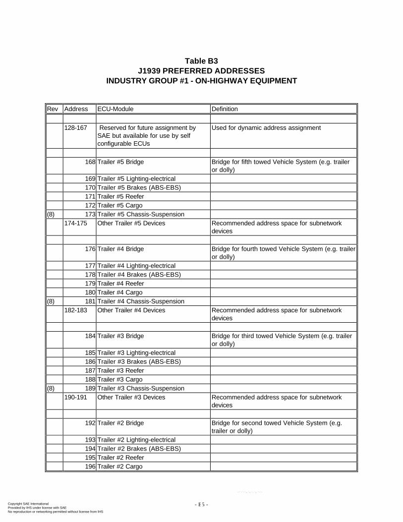
- B5 -
Table B3J1939 PREFERRED ADDRESSES
INDUSTRY GROUP #1 - ON-HIGHWAY EQUIPMENT
Rev Address ECU-Module Definition
128-167 Reserved for future assignment bySAE but available for use by selfconfigurable ECUs
Used for dynamic address assignment
168 Trailer #5 Bridge Bridge for fifth towed Vehicle System (e.g. traileror dolly)
169 Trailer #5 Lighting-electrical170 Trailer #5 Brakes (ABS-EBS)171 Trailer #5 Reefer172 Trailer #5 Cargo
(8) 173 Trailer #5 Chassis-Suspension174-175 Other Trailer #5 Devices Recommended address space for subnetwork
devices
176 Trailer #4 Bridge Bridge for fourth towed Vehicle System (e.g. traileror dolly)
177 Trailer #4 Lighting-electrical178 Trailer #4 Brakes (ABS-EBS)179 Trailer #4 Reefer180 Trailer #4 Cargo
(8) 181 Trailer #4 Chassis-Suspension182-183 Other Trailer #4 Devices Recommended address space for subnetwork
devices
184 Trailer #3 Bridge Bridge for third towed Vehicle System (e.g. traileror dolly)
185 Trailer #3 Lighting-electrical186 Trailer #3 Brakes (ABS-EBS)187 Trailer #3 Reefer188 Trailer #3 Cargo
(8) 189 Trailer #3 Chassis-Suspension190-191 Other Trailer #3 Devices Recommended address space for subnetwork
devices
192 Trailer #2 Bridge Bridge for second towed Vehicle System (e.g.trailer or dolly)
193 Trailer #2 Lighting-electrical194 Trailer #2 Brakes (ABS-EBS)195 Trailer #2 Reefer196 Trailer #2 Cargo
Copyright SAE International Provided by IHS under license with SAE
Not for ResaleNo reproduction or networking permitted without license from IHS
--`-`-`,,`,,`,`,,`---
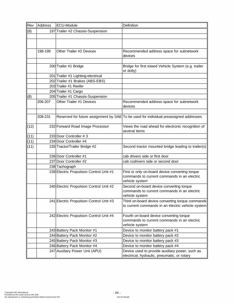
- B6 -
Rev Address ECU-Module Definition
(8) 197 Trailer #2 Chassis-Suspension
198-199 Other Trailer #2 Devices Recommended address space for subnetworkdevices
200 Trailer #1 Bridge Bridge for first towed Vehicle System (e.g. traileror dolly)
201 Trailer #1 Lighting-electrical202 Trailer #1 Brakes (ABS-EBS)203 Trailer #1 Reefer204 Trailer #1 Cargo
(8) 205 Trailer #1 Chassis-Suspension206-207 Other Trailer #1 Devices Recommended address space for subnetwork
devices
208-231 Reserved for future assignment by SAE To be used for individual preassigned addresses
(12) 232 Forward Road Image Processor Views the road ahead for electronic recognition ofseveral items
(11) 233 Door Controller # 3(11) 234 Door Controller #4(11) 235 Tractor/Trailer Bridge #2 Second tractor mounted bridge leading to trailer(s)
236 Door Controller #1 cab drivers side or first door237 Door Controller #2 cab codrivers side or second door238 Tachograph239 Electric Propulsion Control Unit #1 First or only on-board device converting torque
commands to current commands in an electricvehicle system
240 Electric Propulsion Control Unit #2 Second on-board device converting torquecommands to current commands in an electricvehicle system
241 Electric Propulsion Control Unit #3 Third on-board device converting torque commandsto current commands in an electric vehicle system
242 Electric Propulsion Control Unit #4 Fourth on-board device converting torquecommands to current commands in an electricvehicle system
243 Battery Pack Monitor #1 Device to monitor battery pack #1244 Battery Pack Monitor #2 Device to monitor battery pack #2245 Battery Pack Monitor #3 Device to monitor battery pack #3246 Battery Pack Monitor #4 Device to monitor battery pack #4247 Auxiliary Power Unit (APU) Device used to provide auxiliary power, such as
electrical, hydraulic, pneumatic, or rotary
Copyright SAE International Provided by IHS under license with SAE
Not for ResaleNo reproduction or networking permitted without license from IHS
--`-`-`,,`,,`,`,,`---
- B7 -
Notes: Revision dates (not all tables had revisions on all of these dates)(1) July, 1996 (7) February 1998 (13) July 1999(2) October, 1996 (8) April 1998(3) January, 1997 (9) July 1998(4) April, 1997 (10) October 1998(5) August 1997 (11) February 1999(6) November 1997 (12) May 1999
Copyright SAE International Provided by IHS under license with SAE
Not for ResaleNo reproduction or networking permitted without license from IHS
--`-`-`,,`,,`,`,,`---
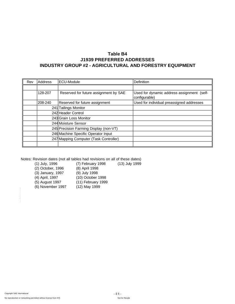
- B8 -
Table B4J1939 PREFERRED ADDRESSES
INDUSTRY GROUP #2 - AGRICULTURAL AND FORESTRY EQUIPMENT
Rev Address ECU-Module Definition
128-207 Reserved for future assignment by SAE Used for dynamic address assignment (self-configurable)
208-240 Reserved for future assignment Used for individual preassigned addresses241 Tailings Monitor242 Header Control243 Grain Loss Monitor244 Moisture Sensor245 Precision Farming Display (non-VT)246 Machine Specific Operator Input247 Mapping Computer (Task Controller)
Notes: Revision dates (not all tables had revisions on all of these dates)(1) July, 1996 (7) February 1998 (13) July 1999(2) October, 1996 (8) April 1998(3) January, 1997 (9) July 1998(4) April, 1997 (10) October 1998(5) August 1997 (11) February 1999(6) November 1997 (12) May 1999
Copyright SAE International Provided by IHS under license with SAE
Not for ResaleNo reproduction or networking permitted without license from IHS
--`-`-`,,`,,`,`,,`---
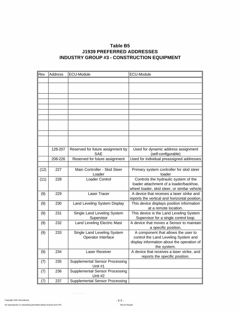
- B9 -
Table B5J1939 PREFERRED ADDRESSES
INDUSTRY GROUP #3 - CONSTRUCTION EQUIPMENT
Rev Address ECU-Module ECU-Module
128-207 Reserved for future assignment bySAE
Used for dynamic address assignment(self-configurable)
208-226 Reserved for future assignment Used for individual preassigned addresses
(12) 227 Main Controller - Skid SteerLoader
Primary system controller for skid steerloader
(11) 228 Loader Control Controls the hydraulic system of theloader attachment of a loader/backhoe,
wheel loader, skid steer, or similar vehicle(9) 229 Laser Tracer A device that receives a laser strike and
reports the vertical and horizontal position.(9) 230 Land Leveling System Display This device displays position information
at a remote location.(9) 231 Single Land Leveling System
SupervisorThis device is the Land Leveling System
Supervisor for a single control loop.(9) 232 Land Leveling Electric Mast A device that moves a Sensor to maintain
a specific position.(9) 233 Single Land Leveling System
Operator InterfaceA component that allows the user to
control the Land Leveling System anddisplay information about the operation of
the system.(9) 234 Laser Receiver A device that receives a laser strike, and
reports the specific position.(7) 235 Supplemental Sensor Processing
Unit #1(7) 236 Supplemental Sensor Processing
Unit #2(7) 237 Supplemental Sensor Processing
Copyright SAE International Provided by IHS under license with SAE
Not for ResaleNo reproduction or networking permitted without license from IHS
--`-`-`,,`,,`,`,,`---
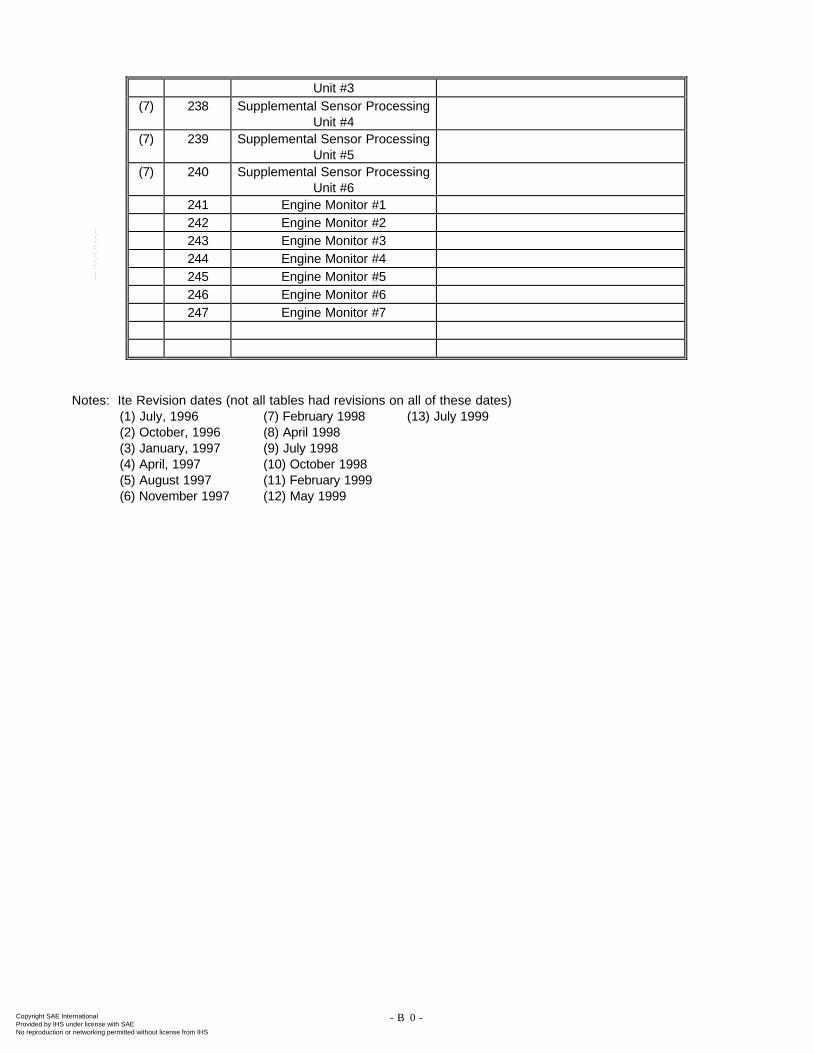
- B10 -
Unit #3(7) 238 Supplemental Sensor Processing
Unit #4(7) 239 Supplemental Sensor Processing
Unit #5(7) 240 Supplemental Sensor Processing
Unit #6241 Engine Monitor #1242 Engine Monitor #2243 Engine Monitor #3244 Engine Monitor #4245 Engine Monitor #5246 Engine Monitor #6247 Engine Monitor #7
Notes: Ite Revision dates (not all tables had revisions on all of these dates)(1) July, 1996 (7) February 1998 (13) July 1999(2) October, 1996 (8) April 1998(3) January, 1997 (9) July 1998(4) April, 1997 (10) October 1998(5) August 1997 (11) February 1999(6) November 1997 (12) May 1999
Copyright SAE International Provided by IHS under license with SAE
Not for ResaleNo reproduction or networking permitted without license from IHS
--`-`-`,,`,,`,`,,`---
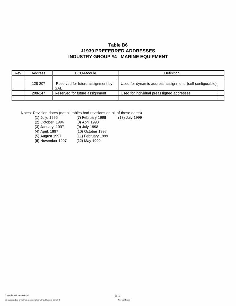
- B11 -
Table B6J1939 PREFERRED ADDRESSES
INDUSTRY GROUP #4 - MARINE EQUIPMENT
Rev Address ECU-Module Definition
128-207 Reserved for future assignment bySAE
Used for dynamic address assignment (self-configurable)
208-247 Reserved for future assignment Used for individual preassigned addresses
Notes: Revision dates (not all tables had revisions on all of these dates)(1) July, 1996 (7) February 1998 (13) July 1999(2) October, 1996 (8) April 1998(3) January, 1997 (9) July 1998(4) April, 1997 (10) October 1998(5) August 1997 (11) February 1999(6) November 1997 (12) May 1999
Copyright SAE International Provided by IHS under license with SAE
Not for ResaleNo reproduction or networking permitted without license from IHS
--`-`-`,,`,,`,`,,`---
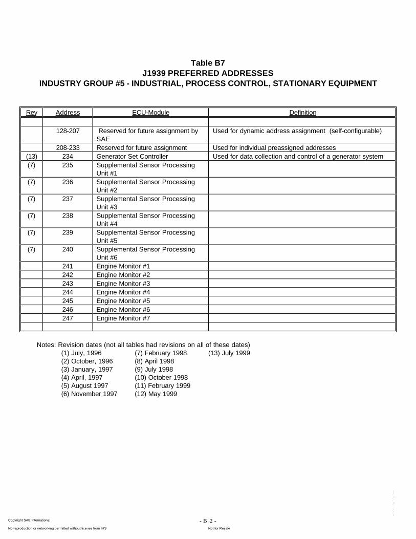
- B12 -
Table B7J1939 PREFERRED ADDRESSES
INDUSTRY GROUP #5 - INDUSTRIAL, PROCESS CONTROL, STATIONARY EQUIPMENT
Rev Address ECU-Module Definition
128-207 Reserved for future assignment bySAE
Used for dynamic address assignment (self-configurable)
208-233 Reserved for future assignment Used for individual preassigned addresses(13) 234 Generator Set Controller Used for data collection and control of a generator system(7) 235 Supplemental Sensor Processing
Unit #1(7) 236 Supplemental Sensor Processing
Unit #2(7) 237 Supplemental Sensor Processing
Unit #3(7) 238 Supplemental Sensor Processing
Unit #4(7) 239 Supplemental Sensor Processing
Unit #5(7) 240 Supplemental Sensor Processing
Unit #6241 Engine Monitor #1242 Engine Monitor #2243 Engine Monitor #3244 Engine Monitor #4245 Engine Monitor #5246 Engine Monitor #6247 Engine Monitor #7
Notes: Revision dates (not all tables had revisions on all of these dates)(1) July, 1996 (7) February 1998 (13) July 1999(2) October, 1996 (8) April 1998(3) January, 1997 (9) July 1998(4) April, 1997 (10) October 1998(5) August 1997 (11) February 1999(6) November 1997 (12) May 1999
Copyright SAE International Provided by IHS under license with SAE
Not for ResaleNo reproduction or networking permitted without license from IHS
--`-`-`,,`,,`,`,,`---
- B13 -
Tables B8 through B9J1939 PREFERRED ADDRESSES
(Industry Groups 6 to 7)Reserved for future assignment
Copyright SAE International Provided by IHS under license with SAE
Not for ResaleNo reproduction or networking permitted without license from IHS
--`-`-`,,`,,`,`,,`---
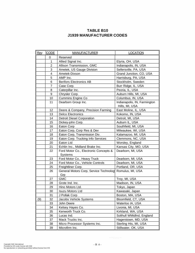
- B14 -
TABLE B10J1939 MANUFACTURER CODES
Rev CODE MANUFACTURER LOCATION0 Reserved1 Allied Signal Inc. Elyria, OH, USA2 Allison Transmission, GMC Indianapolis, IN, USA3 Ametek, US Gauge Division Sellersville, PA, USA4 Ametek-Dixson Grand Junction, CO, USA5 AMP Inc. Harrisburg, PA, USA6 Berifors Electronics AB Stockholm, Sweden7 Case Corp. Burr Ridge, IL, USA8 Caterpillar Inc. Peoria, IL, USA9 Chrysler Corp. Auburn Hills, MI, USA
10 Cummins Engine Co Columbus, IN, USA11 Dearborn Group Inc. Indianapolis, IN, Farmington
Hills, MI, USA12 Deere & Company, Precision Farming East Moline, IL, USA13 Delco Electronics Kokomo, IN, USA14 Detroit Diesel Corporation Detroit, MI, USA15 Dickey-john Corp. Auburn IL, USA16 Eaton Corp Southfield, MI, USA17 Eaton Corp, Corp Res & Dev Milwaukee, WI, USA18 Eaton Corp, Transmission Div. Kalamazoo, MI, USA19 Eaton Corp. Trucking Info Services Clemmons, NC, USA20 Eaton Ltd Worsley, England21 Echlin Inc., Midland Brake Inc. Kansas City, MO, USA22 Ford Motor Co., Electronic Concepts &
SystemsDearborn, MI, USA
23 Ford Motor Co., Heavy Truck Dearborn, MI, USA24 Ford Motor Co., Vehicle Controls Dearborn, MI, USA25 Freightliner Corp. Portland, OR, USA26 General Motors Corp, Service Technology
GrpRomulus, MI, USA
27 GMC Troy, MI, USA28 Grote Ind. Inc. Madison, IN, USA29 Hino Motors Ltd. Tokyo, Japan30 Isuzu Motors Ltd Kawasaki, Japan31 J Pollak Corp Boston, MA, USA
(9) 32 Jacobs Vehicle Systems Bloomfield, CT, USA33 John Deere Waterloo IA, USA34 Kelsey Hayes Co. Livonia, MI, USA35 Kenworth Truck Co. Kirkland, WA, USA36 Lucas Ind. Solihull WMidlnd, England37 Mack Trucks Inc. Hagerstown, MD, USA38 Micro Processor Systems Inc. Sterling Hts, MI, USA39 Microfirm Inc. Stillwater, OK, USA
Copyright SAE International Provided by IHS under license with SAE
Not for ResaleNo reproduction or networking permitted without license from IHS
--`-`-`,,`,,`,`,,`---
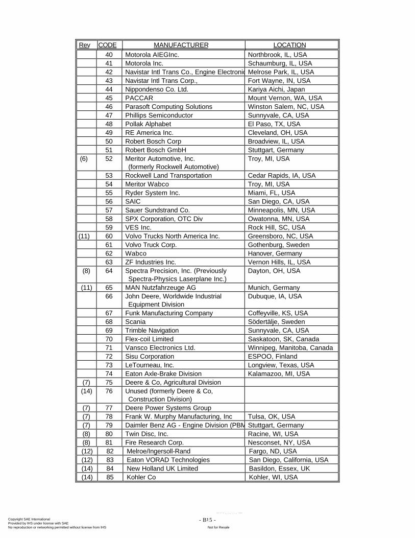
- B15 -
Rev CODE MANUFACTURER LOCATION40 Motorola AIEGInc. Northbrook, IL, USA41 Motorola Inc. Schaumburg, IL, USA42 Navistar Intl Trans Co., Engine ElectronicsMelrose Park, IL, USA43 Navistar Intl Trans Corp., Fort Wayne, IN, USA44 Nippondenso Co. Ltd. Kariya Aichi, Japan45 PACCAR Mount Vernon, WA, USA46 Parasoft Computing Solutions Winston Salem, NC, USA47 Phillips Semiconductor Sunnyvale, CA, USA48 Pollak Alphabet El Paso, TX, USA49 RE America Inc. Cleveland, OH, USA50 Robert Bosch Corp Broadview, IL, USA51 Robert Bosch GmbH Stuttgart, Germany
(6) 52 Meritor Automotive, Inc.(formerly Rockwell Automotive)
Troy, MI, USA
53 Rockwell Land Transportation Cedar Rapids, IA, USA54 Meritor Wabco Troy, MI, USA55 Ryder System Inc. Miami, FL, USA56 SAIC San Diego, CA, USA57 Sauer Sundstrand Co. Minneapolis, MN, USA58 SPX Corporation, OTC Div Owatonna, MN, USA59 VES Inc. Rock Hill, SC, USA
(11) 60 Volvo Trucks North America Inc. Greensboro, NC, USA61 Volvo Truck Corp. Gothenburg, Sweden62 Wabco Hanover, Germany63 ZF Industries Inc. Vernon Hills, IL, USA
(8) 64 Spectra Precision, Inc. (PreviouslySpectra-Physics Laserplane Inc.)
Dayton, OH, USA
(11) 65 MAN Nutzfahrzeuge AG Munich, Germany66 John Deere, Worldwide Industrial
Equipment DivisionDubuque, IA, USA
67 Funk Manufacturing Company Coffeyville, KS, USA68 Scania Södertälje, Sweden69 Trimble Navigation Sunnyvale, CA, USA70 Flex-coil Limited Saskatoon, SK, Canada71 Vansco Electronics Ltd. Winnipeg, Manitoba, Canada72 Sisu Corporation ESPOO, Finland73 LeTourneau, Inc. Longview, Texas, USA74 Eaton Axle-Brake Division Kalamazoo, MI, USA
(7) 75 Deere & Co, Agricultural Division(14) 76 Unused (formerly Deere & Co,
Construction Division)(7) 77 Deere Power Systems Group(7) 78 Frank W. Murphy Manufacturing, Inc Tulsa, OK, USA(7) 79 Daimler Benz AG - Engine Division (PBM)Stuttgart, Germany(8) 80 Twin Disc, Inc. Racine, WI, USA(8) 81 Fire Research Corp. Nesconset, NY, USA(12) 82 Melroe/Ingersoll-Rand Fargo, ND, USA(12) 83 Eaton VORAD Technologies San Diego, California, USA(14) 84 New Holland UK Limited Basildon, Essex, UK(14) 85 Kohler Co Kohler, WI, USA
Copyright SAE International Provided by IHS under license with SAE
Not for ResaleNo reproduction or networking permitted without license from IHS
--`-`-`,,`,,`,`,,`---
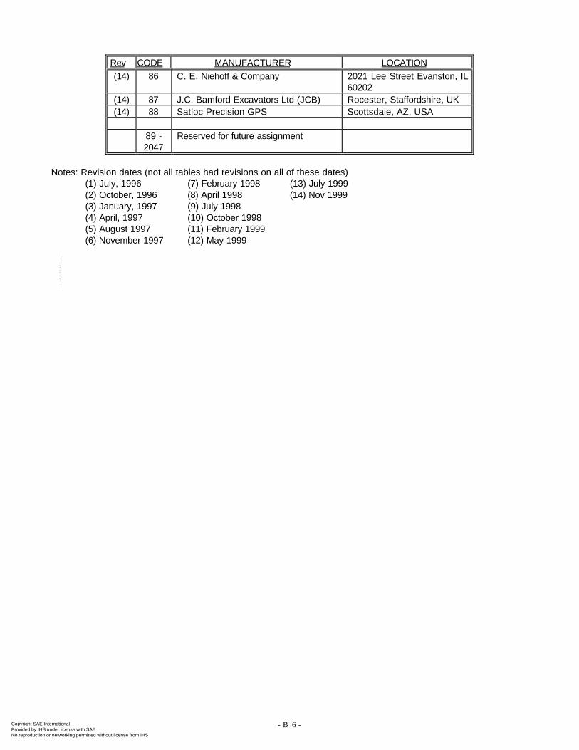
- B16 -
Rev CODE MANUFACTURER LOCATION(14) 86 C. E. Niehoff & Company 2021 Lee Street Evanston, IL
60202(14) 87 J.C. Bamford Excavators Ltd (JCB) Rocester, Staffordshire, UK(14) 88 Satloc Precision GPS Scottsdale, AZ, USA
89 -2047
Reserved for future assignment
Notes: Revision dates (not all tables had revisions on all of these dates)(1) July, 1996 (7) February 1998 (13) July 1999(2) October, 1996 (8) April 1998 (14) Nov 1999(3) January, 1997 (9) July 1998(4) April, 1997 (10) October 1998(5) August 1997 (11) February 1999(6) November 1997 (12) May 1999
Copyright SAE International Provided by IHS under license with SAE
Not for ResaleNo reproduction or networking permitted without license from IHS
--`-`-`,,`,,`,`,,`---
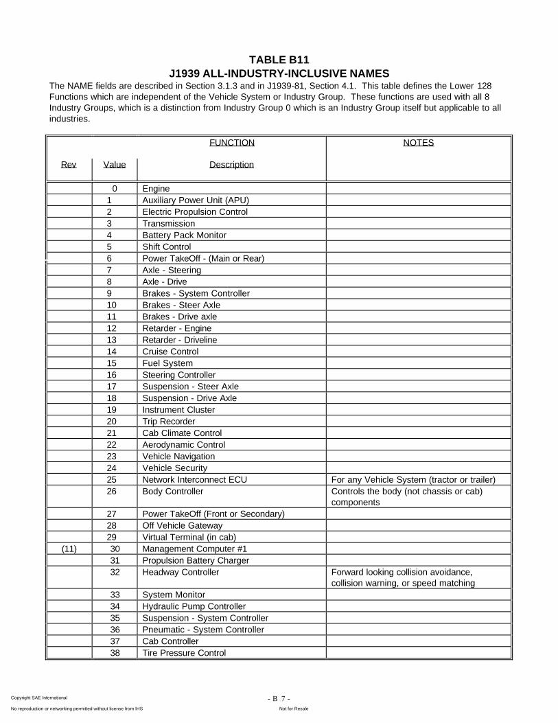
- B17 -
TABLE B11J1939 ALL-INDUSTRY-INCLUSIVE NAMES
The NAME fields are described in Section 3.1.3 and in J1939-81, Section 4.1. This table defines the Lower 128Functions which are independent of the Vehicle System or Industry Group. These functions are used with all 8Industry Groups, which is a distinction from Industry Group 0 which is an Industry Group itself but applicable to allindustries.
FUNCTION NOTES
Rev Value Description
0 Engine1 Auxiliary Power Unit (APU)2 Electric Propulsion Control3 Transmission4 Battery Pack Monitor5 Shift Control6 Power TakeOff - (Main or Rear)7 Axle - Steering8 Axle - Drive9 Brakes - System Controller10 Brakes - Steer Axle11 Brakes - Drive axle12 Retarder - Engine13 Retarder - Driveline14 Cruise Control15 Fuel System16 Steering Controller17 Suspension - Steer Axle18 Suspension - Drive Axle19 Instrument Cluster20 Trip Recorder21 Cab Climate Control22 Aerodynamic Control23 Vehicle Navigation24 Vehicle Security25 Network Interconnect ECU For any Vehicle System (tractor or trailer)26 Body Controller Controls the body (not chassis or cab)
components27 Power TakeOff (Front or Secondary)28 Off Vehicle Gateway29 Virtual Terminal (in cab)
(11) 30 Management Computer #131 Propulsion Battery Charger32 Headway Controller Forward looking collision avoidance,
collision warning, or speed matching33 System Monitor34 Hydraulic Pump Controller35 Suspension - System Controller36 Pneumatic - System Controller37 Cab Controller38 Tire Pressure Control
Copyright SAE International Provided by IHS under license with SAE
Not for ResaleNo reproduction or networking permitted without license from IHS
--`-`-`,,`,,`,`,,`---
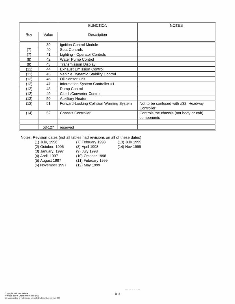
- B18 -
FUNCTION NOTES
Rev Value Description
39 Ignition Control Module(7) 40 Seat Controls(7) 41 Lighting - Operator Controls(8) 42 Water Pump Control(9) 43 Transmission Display(11) 44 Exhaust Emission Control(11) 45 Vehicle Dynamic Stability Control(12) 46 Oil Sensor Unit(12) 47 Information System Controller #1(12) 48 Ramp Control(12) 49 Clutch/Converter Control(12) 50 Auxiliary Heater(12) 51 Forward-Looking Collision Warning System Not to be confused with #32, Headway
Controller(14) 52 Chassis Controller Controls the chassis (not body or cab)
components
53-127 reserved
Notes: Revision dates (not all tables had revisions on all of these dates)(1) July, 1996 (7) February 1998 (13) July 1999(2) October, 1996 (8) April 1998 (14) Nov 1999(3) January, 1997 (9) July 1998(4) April, 1997 (10) October 1998(5) August 1997 (11) February 1999(6) November 1997 (12) May 1999
Copyright SAE International Provided by IHS under license with SAE
Not for ResaleNo reproduction or networking permitted without license from IHS
--`-`-`,,`,,`,`,,`---
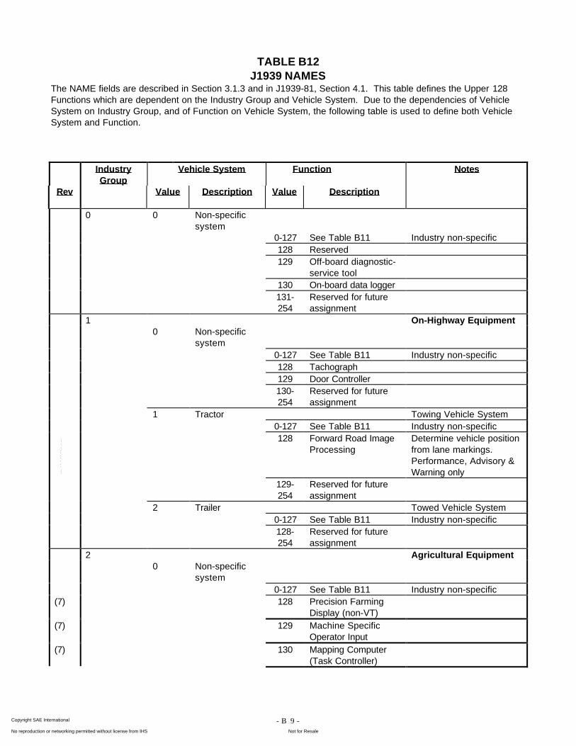
- B19 -
TABLE B12J1939 NAMES
The NAME fields are described in Section 3.1.3 and in J1939-81, Section 4.1. This table defines the Upper 128Functions which are dependent on the Industry Group and Vehicle System. Due to the dependencies of VehicleSystem on Industry Group, and of Function on Vehicle System, the following table is used to define both VehicleSystem and Function.
IndustryGroup
Vehicle System Function Notes
Rev Value Description Value Description
0 0 Non-specificsystem
0-127 See Table B11 Industry non-specific128 Reserved129 Off-board diagnostic-
service tool130 On-board data logger131-254
Reserved for futureassignment
1 On-Highway Equipment0 Non-specific
system0-127 See Table B11 Industry non-specific128 Tachograph129 Door Controller130-254
Reserved for futureassignment
1 Tractor Towing Vehicle System0-127 See Table B11 Industry non-specific128 Forward Road Image
ProcessingDetermine vehicle positionfrom lane markings.Performance, Advisory &Warning only
129-254
Reserved for futureassignment
2 Trailer Towed Vehicle System0-127 See Table B11 Industry non-specific128-254
Reserved for futureassignment
2 Agricultural Equipment0 Non-specific
system0-127 See Table B11 Industry non-specific
(7) 128 Precision FarmingDisplay (non-VT)
(7) 129 Machine SpecificOperator Input
(7) 130 Mapping Computer(Task Controller)
Copyright SAE International Provided by IHS under license with SAE
Not for ResaleNo reproduction or networking permitted without license from IHS
--`-`-`,,`,,`,`,,`---
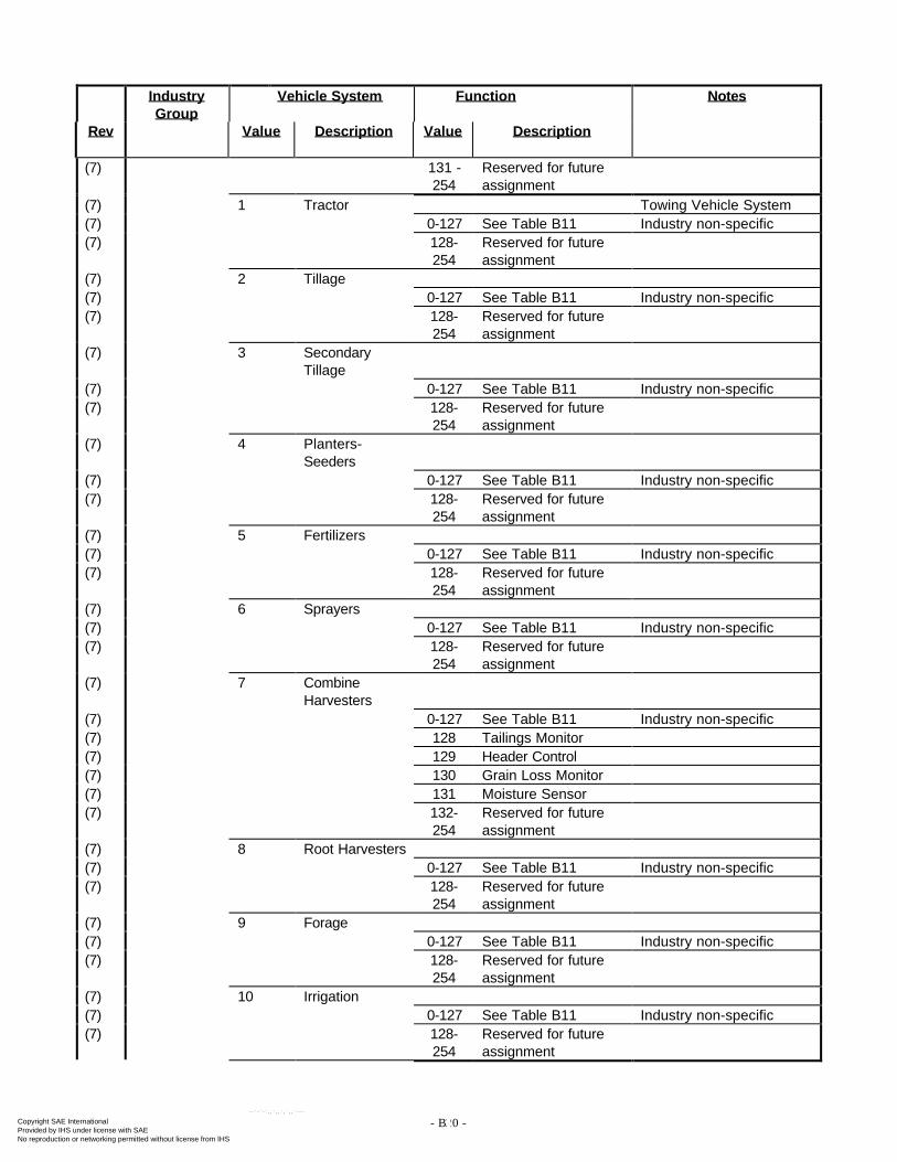
- B20 -
IndustryGroup
Vehicle System Function Notes
Rev Value Description Value Description
(7) 131 -254
Reserved for futureassignment
(7) 1 Tractor Towing Vehicle System(7) 0-127 See Table B11 Industry non-specific(7) 128-
254Reserved for futureassignment
(7) 2 Tillage(7) 0-127 See Table B11 Industry non-specific(7) 128-
254Reserved for futureassignment
(7) 3 SecondaryTillage
(7) 0-127 See Table B11 Industry non-specific(7) 128-
254Reserved for futureassignment
(7) 4 Planters-Seeders
(7) 0-127 See Table B11 Industry non-specific(7) 128-
254Reserved for futureassignment
(7) 5 Fertilizers(7) 0-127 See Table B11 Industry non-specific(7) 128-
254Reserved for futureassignment
(7) 6 Sprayers(7) 0-127 See Table B11 Industry non-specific(7) 128-
254Reserved for futureassignment
(7) 7 CombineHarvesters
(7) 0-127 See Table B11 Industry non-specific(7) 128 Tailings Monitor(7) 129 Header Control(7) 130 Grain Loss Monitor(7) 131 Moisture Sensor(7) 132-
254Reserved for futureassignment
(7) 8 Root Harvesters(7) 0-127 See Table B11 Industry non-specific(7) 128-
254Reserved for futureassignment
(7) 9 Forage(7) 0-127 See Table B11 Industry non-specific(7) 128-
254Reserved for futureassignment
(7) 10 Irrigation(7) 0-127 See Table B11 Industry non-specific(7) 128-
254Reserved for futureassignment
Copyright SAE International Provided by IHS under license with SAE
Not for ResaleNo reproduction or networking permitted without license from IHS
--`-`-`,,`,,`,`,,`---
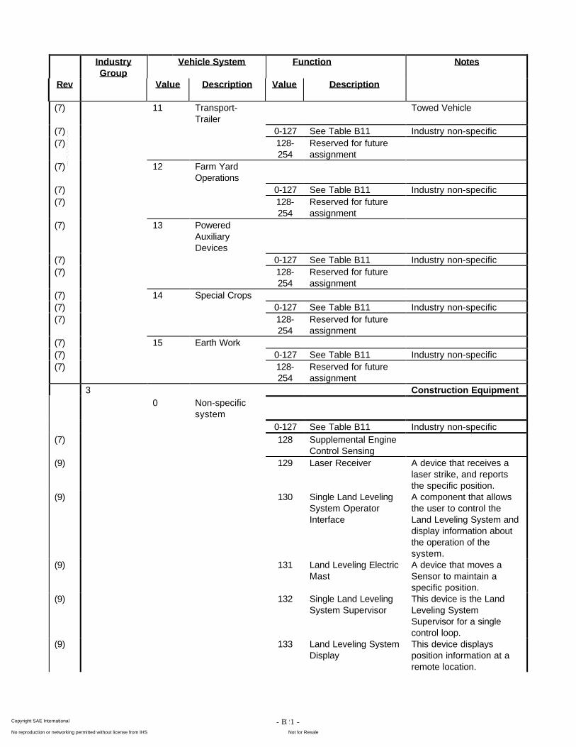
- B21 -
IndustryGroup
Vehicle System Function Notes
Rev Value Description Value Description
(7) 11 Transport-Trailer
Towed Vehicle
(7) 0-127 See Table B11 Industry non-specific(7) 128-
254Reserved for futureassignment
(7) 12 Farm YardOperations
(7) 0-127 See Table B11 Industry non-specific(7) 128-
254Reserved for futureassignment
(7) 13 PoweredAuxiliaryDevices
(7) 0-127 See Table B11 Industry non-specific(7) 128-
254Reserved for futureassignment
(7) 14 Special Crops(7) 0-127 See Table B11 Industry non-specific(7) 128-
254Reserved for futureassignment
(7) 15 Earth Work(7) 0-127 See Table B11 Industry non-specific(7) 128-
254Reserved for futureassignment
3 Construction Equipment0 Non-specific
system0-127 See Table B11 Industry non-specific
(7) 128 Supplemental EngineControl Sensing
(9) 129 Laser Receiver A device that receives alaser strike, and reportsthe specific position.
(9) 130 Single Land LevelingSystem OperatorInterface
A component that allowsthe user to control theLand Leveling System anddisplay information aboutthe operation of thesystem.
(9) 131 Land Leveling ElectricMast
A device that moves aSensor to maintain aspecific position.
(9) 132 Single Land LevelingSystem Supervisor
This device is the LandLeveling SystemSupervisor for a singlecontrol loop.
(9) 133 Land Leveling SystemDisplay
This device displaysposition information at aremote location.
Copyright SAE International Provided by IHS under license with SAE
Not for ResaleNo reproduction or networking permitted without license from IHS
--`-`-`,,`,,`,`,,`---
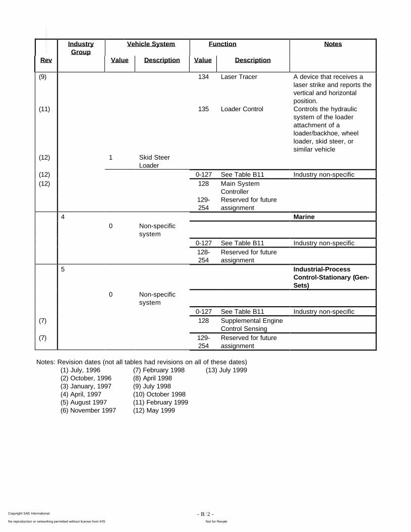
- B22 -
IndustryGroup
Vehicle System Function Notes
Rev Value Description Value Description
(9) 134 Laser Tracer A device that receives alaser strike and reports thevertical and horizontalposition.
(11) 135 Loader Control Controls the hydraulicsystem of the loaderattachment of aloader/backhoe, wheelloader, skid steer, orsimilar vehicle
(12) 1 Skid SteerLoader
(12) 0-127 See Table B11 Industry non-specific(12) 128 Main System
Controller129-254
Reserved for futureassignment
4 Marine0 Non-specific
system0-127 See Table B11 Industry non-specific128-254
Reserved for futureassignment
5 Industrial-ProcessControl-Stationary (Gen-Sets)
0 Non-specificsystem
0-127 See Table B11 Industry non-specific(7) 128 Supplemental Engine
Control Sensing(7) 129-
254Reserved for futureassignment
Notes: Revision dates (not all tables had revisions on all of these dates)(1) July, 1996 (7) February 1998 (13) July 1999(2) October, 1996 (8) April 1998(3) January, 1997 (9) July 1998(4) April, 1997 (10) October 1998(5) August 1997 (11) February 1999(6) November 1997 (12) May 1999
Copyright SAE International Provided by IHS under license with SAE
Not for ResaleNo reproduction or networking permitted without license from IHS
--`-`-`,,`,,`,`,,`---
- C1 -
APPENDIX C
FAULT REPORTING PARAMETERS
Copyright SAE International Provided by IHS under license with SAE
Not for ResaleNo reproduction or networking permitted without license from IHS
--`-`-`,,`,,`,`,,`---
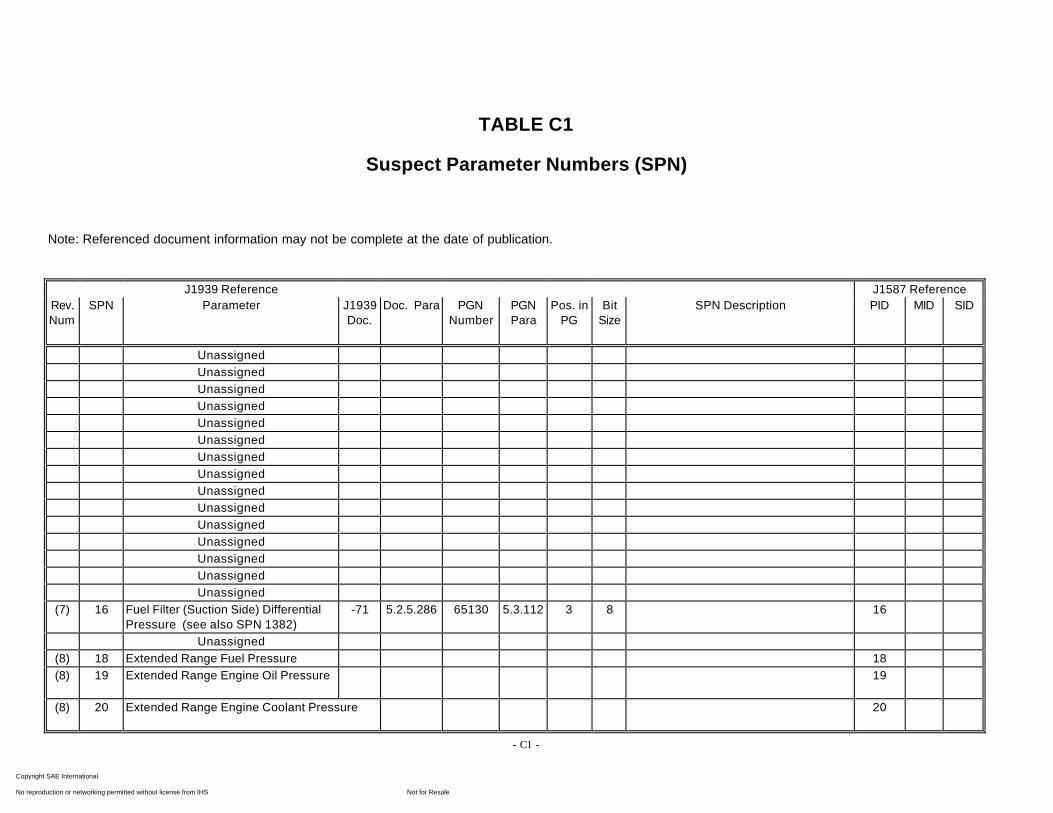
- C1 -
TABLE C1
Suspect Parameter Numbers (SPN)
Note: Referenced document information may not be complete at the date of publication.
J1939 Reference J1587 ReferenceRev.Num
SPN Parameter J1939Doc.
Doc. Para PGNNumber
PGNPara
Pos. inPG
BitSize
SPN Description PID MID SID
UnassignedUnassignedUnassignedUnassignedUnassignedUnassignedUnassignedUnassignedUnassignedUnassignedUnassignedUnassignedUnassignedUnassignedUnassigned
(7) 16 Fuel Filter (Suction Side) DifferentialPressure (see also SPN 1382)
-71 5.2.5.286 65130 5.3.112 3 8 16
Unassigned(8) 18 Extended Range Fuel Pressure 18(8) 19 Extended Range Engine Oil Pressure 19
(8) 20 Extended Range Engine Coolant Pressure 20
Copyright SAE International Provided by IHS under license with SAE
Not for ResaleNo reproduction or networking permitted without license from IHS
--`-`-`,,`,,`,`,,`---
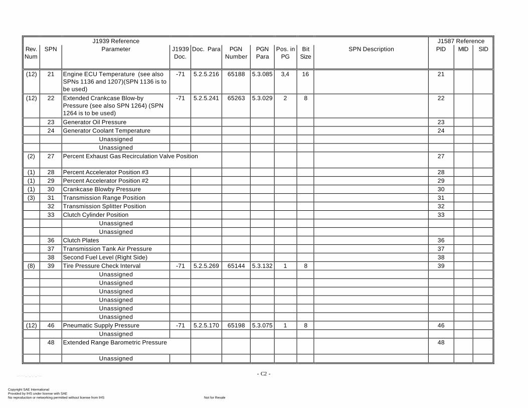
- C2 -
J1939 Reference J1587 ReferenceRev.Num
SPN Parameter J1939Doc.
Doc. Para PGNNumber
PGNPara
Pos. inPG
BitSize
SPN Description PID MID SID
(12) 21 Engine ECU Temperature (see alsoSPNs 1136 and 1207)(SPN 1136 is tobe used)
-71 5.2.5.216 65188 5.3.085 3,4 16 21
(12) 22 Extended Crankcase Blow-byPressure (see also SPN 1264) (SPN1264 is to be used)
-71 5.2.5.241 65263 5.3.029 2 8 22
23 Generator Oil Pressure 2324 Generator Coolant Temperature 24
UnassignedUnassigned
(2) 27 Percent Exhaust Gas Recirculation Valve Position 27
(1) 28 Percent Accelerator Position #3 28(1) 29 Percent Accelerator Position #2 29(1) 30 Crankcase Blowby Pressure 30(3) 31 Transmission Range Position 31
32 Transmission Splitter Position 3233 Clutch Cylinder Position 33
UnassignedUnassigned
36 Clutch Plates 3637 Transmission Tank Air Pressure 3738 Second Fuel Level (Right Side) 38
(8) 39 Tire Pressure Check Interval -71 5.2.5.269 65144 5.3.132 1 8 39UnassignedUnassignedUnassignedUnassignedUnassignedUnassigned
(12) 46 Pneumatic Supply Pressure -71 5.2.5.170 65198 5.3.075 1 8 46Unassigned
48 Extended Range Barometric Pressure 48
Unassigned
Copyright SAE International Provided by IHS under license with SAE
Not for ResaleNo reproduction or networking permitted without license from IHS
--`-`-`,,`,,`,`,,`---
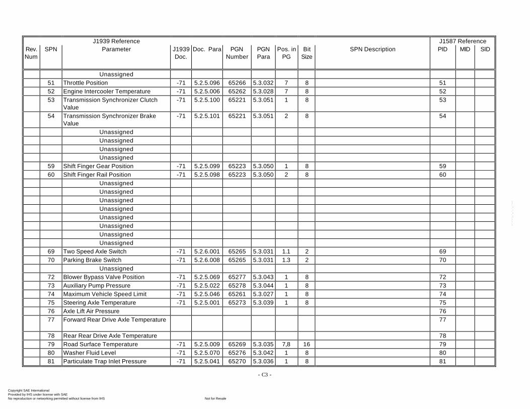
- C3 -
J1939 Reference J1587 ReferenceRev.Num
SPN Parameter J1939Doc.
Doc. Para PGNNumber
PGNPara
Pos. inPG
BitSize
SPN Description PID MID SID
Unassigned51 Throttle Position -71 5.2.5.096 65266 5.3.032 7 8 5152 Engine Intercooler Temperature -71 5.2.5.006 65262 5.3.028 7 8 5253 Transmission Synchronizer Clutch
Value-71 5.2.5.100 65221 5.3.051 1 8 53
54 Transmission Synchronizer BrakeValue
-71 5.2.5.101 65221 5.3.051 2 8 54
UnassignedUnassignedUnassignedUnassigned
59 Shift Finger Gear Position -71 5.2.5.099 65223 5.3.050 1 8 5960 Shift Finger Rail Position -71 5.2.5.098 65223 5.3.050 2 8 60
UnassignedUnassignedUnassignedUnassignedUnassignedUnassignedUnassignedUnassigned
69 Two Speed Axle Switch -71 5.2.6.001 65265 5.3.031 1.1 2 6970 Parking Brake Switch -71 5.2.6.008 65265 5.3.031 1.3 2 70
Unassigned72 Blower Bypass Valve Position -71 5.2.5.069 65277 5.3.043 1 8 7273 Auxiliary Pump Pressure -71 5.2.5.022 65278 5.3.044 1 8 7374 Maximum Vehicle Speed Limit -71 5.2.5.046 65261 5.3.027 1 8 7475 Steering Axle Temperature -71 5.2.5.001 65273 5.3.039 1 8 7576 Axle Lift Air Pressure 7677 Forward Rear Drive Axle Temperature 77
78 Rear Rear Drive Axle Temperature 7879 Road Surface Temperature -71 5.2.5.009 65269 5.3.035 7,8 16 7980 Washer Fluid Level -71 5.2.5.070 65276 5.3.042 1 8 8081 Particulate Trap Inlet Pressure -71 5.2.5.041 65270 5.3.036 1 8 81
Copyright SAE International Provided by IHS under license with SAE
Not for ResaleNo reproduction or networking permitted without license from IHS
--`-`-`,,`,,`,`,,`---
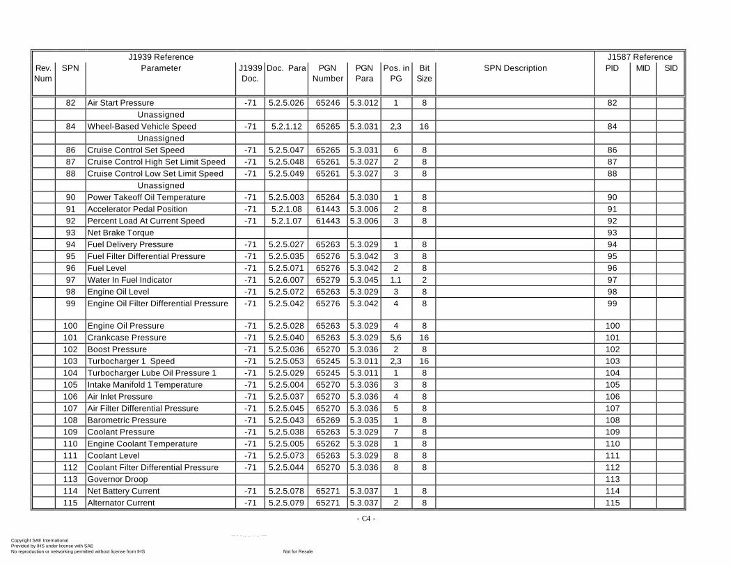
- C4 -
J1939 Reference J1587 ReferenceRev.Num
SPN Parameter J1939Doc.
Doc. Para PGNNumber
PGNPara
Pos. inPG
BitSize
SPN Description PID MID SID
82 Air Start Pressure -71 5.2.5.026 65246 5.3.012 1 8 82Unassigned
84 Wheel-Based Vehicle Speed -71 5.2.1.12 65265 5.3.031 2,3 16 84Unassigned
86 Cruise Control Set Speed -71 5.2.5.047 65265 5.3.031 6 8 8687 Cruise Control High Set Limit Speed -71 5.2.5.048 65261 5.3.027 2 8 8788 Cruise Control Low Set Limit Speed -71 5.2.5.049 65261 5.3.027 3 8 88
Unassigned90 Power Takeoff Oil Temperature -71 5.2.5.003 65264 5.3.030 1 8 9091 Accelerator Pedal Position -71 5.2.1.08 61443 5.3.006 2 8 9192 Percent Load At Current Speed -71 5.2.1.07 61443 5.3.006 3 8 9293 Net Brake Torque 9394 Fuel Delivery Pressure -71 5.2.5.027 65263 5.3.029 1 8 9495 Fuel Filter Differential Pressure -71 5.2.5.035 65276 5.3.042 3 8 9596 Fuel Level -71 5.2.5.071 65276 5.3.042 2 8 9697 Water In Fuel Indicator -71 5.2.6.007 65279 5.3.045 1.1 2 9798 Engine Oil Level -71 5.2.5.072 65263 5.3.029 3 8 9899 Engine Oil Filter Differential Pressure -71 5.2.5.042 65276 5.3.042 4 8 99
100 Engine Oil Pressure -71 5.2.5.028 65263 5.3.029 4 8 100101 Crankcase Pressure -71 5.2.5.040 65263 5.3.029 5,6 16 101102 Boost Pressure -71 5.2.5.036 65270 5.3.036 2 8 102103 Turbocharger 1 Speed -71 5.2.5.053 65245 5.3.011 2,3 16 103104 Turbocharger Lube Oil Pressure 1 -71 5.2.5.029 65245 5.3.011 1 8 104105 Intake Manifold 1 Temperature -71 5.2.5.004 65270 5.3.036 3 8 105106 Air Inlet Pressure -71 5.2.5.037 65270 5.3.036 4 8 106107 Air Filter Differential Pressure -71 5.2.5.045 65270 5.3.036 5 8 107108 Barometric Pressure -71 5.2.5.043 65269 5.3.035 1 8 108109 Coolant Pressure -71 5.2.5.038 65263 5.3.029 7 8 109110 Engine Coolant Temperature -71 5.2.5.005 65262 5.3.028 1 8 110111 Coolant Level -71 5.2.5.073 65263 5.3.029 8 8 111112 Coolant Filter Differential Pressure -71 5.2.5.044 65270 5.3.036 8 8 112113 Governor Droop 113114 Net Battery Current -71 5.2.5.078 65271 5.3.037 1 8 114115 Alternator Current -71 5.2.5.079 65271 5.3.037 2 8 115
Copyright SAE International Provided by IHS under license with SAE
Not for ResaleNo reproduction or networking permitted without license from IHS
--`-`-`,,`,,`,`,,`---
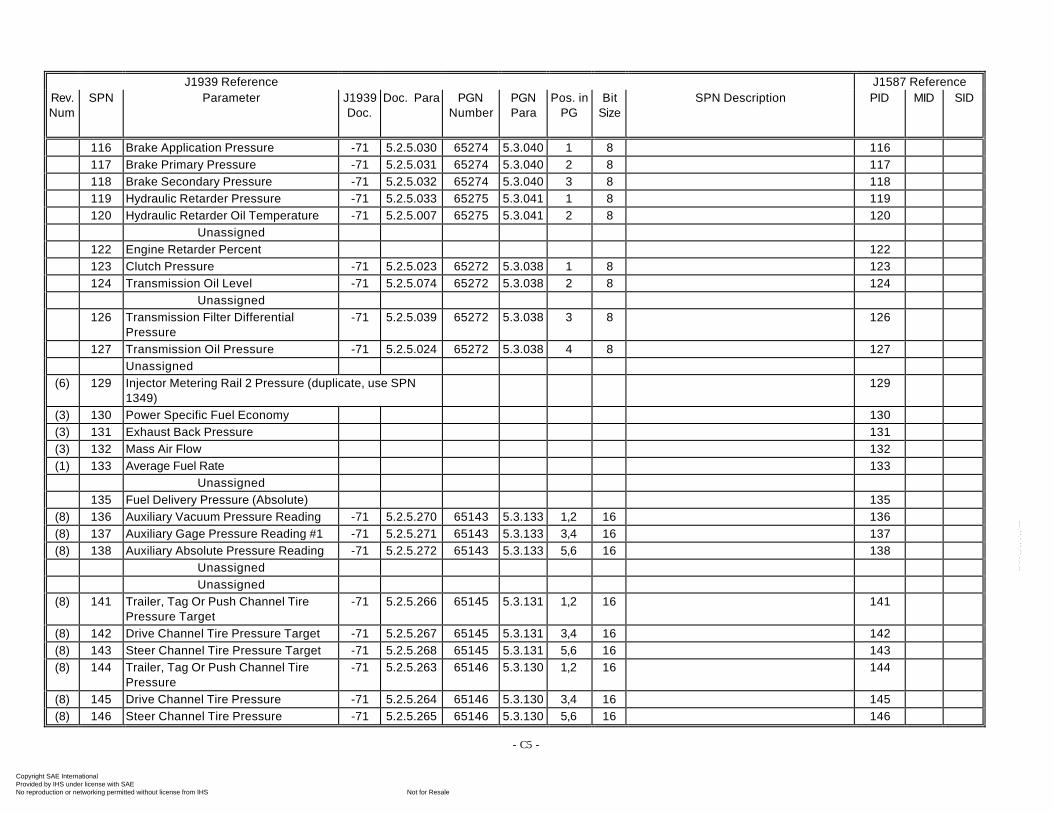
- C5 -
J1939 Reference J1587 ReferenceRev.Num
SPN Parameter J1939Doc.
Doc. Para PGNNumber
PGNPara
Pos. inPG
BitSize
SPN Description PID MID SID
116 Brake Application Pressure -71 5.2.5.030 65274 5.3.040 1 8 116117 Brake Primary Pressure -71 5.2.5.031 65274 5.3.040 2 8 117118 Brake Secondary Pressure -71 5.2.5.032 65274 5.3.040 3 8 118119 Hydraulic Retarder Pressure -71 5.2.5.033 65275 5.3.041 1 8 119120 Hydraulic Retarder Oil Temperature -71 5.2.5.007 65275 5.3.041 2 8 120
Unassigned122 Engine Retarder Percent 122123 Clutch Pressure -71 5.2.5.023 65272 5.3.038 1 8 123124 Transmission Oil Level -71 5.2.5.074 65272 5.3.038 2 8 124
Unassigned126 Transmission Filter Differential
Pressure-71 5.2.5.039 65272 5.3.038 3 8 126
127 Transmission Oil Pressure -71 5.2.5.024 65272 5.3.038 4 8 127Unassigned
(6) 129 Injector Metering Rail 2 Pressure (duplicate, use SPN1349)
129
(3) 130 Power Specific Fuel Economy 130(3) 131 Exhaust Back Pressure 131(3) 132 Mass Air Flow 132(1) 133 Average Fuel Rate 133
Unassigned135 Fuel Delivery Pressure (Absolute) 135
(8) 136 Auxiliary Vacuum Pressure Reading -71 5.2.5.270 65143 5.3.133 1,2 16 136(8) 137 Auxiliary Gage Pressure Reading #1 -71 5.2.5.271 65143 5.3.133 3,4 16 137(8) 138 Auxiliary Absolute Pressure Reading -71 5.2.5.272 65143 5.3.133 5,6 16 138
UnassignedUnassigned
(8) 141 Trailer, Tag Or Push Channel TirePressure Target
-71 5.2.5.266 65145 5.3.131 1,2 16 141
(8) 142 Drive Channel Tire Pressure Target -71 5.2.5.267 65145 5.3.131 3,4 16 142(8) 143 Steer Channel Tire Pressure Target -71 5.2.5.268 65145 5.3.131 5,6 16 143(8) 144 Trailer, Tag Or Push Channel Tire
Pressure-71 5.2.5.263 65146 5.3.130 1,2 16 144
(8) 145 Drive Channel Tire Pressure -71 5.2.5.264 65146 5.3.130 3,4 16 145(8) 146 Steer Channel Tire Pressure -71 5.2.5.265 65146 5.3.130 5,6 16 146
Copyright SAE International Provided by IHS under license with SAE
Not for ResaleNo reproduction or networking permitted without license from IHS
--`-`-`,,`,,`,`,,`---
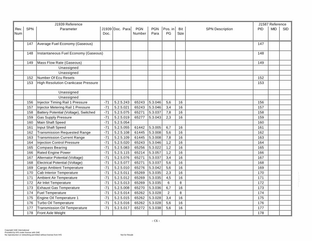
- C6 -
J1939 Reference J1587 ReferenceRev.Num
SPN Parameter J1939Doc.
Doc. Para PGNNumber
PGNPara
Pos. inPG
BitSize
SPN Description PID MID SID
147 Average Fuel Economy (Gaseous) 147
148 Instantaneous Fuel Economy (Gaseous) 148
149 Mass Flow Rate (Gaseous) 149UnassignedUnassigned
152 Number Of Ecu Resets 152153 High Resolution Crankcase Pressure 153
UnassignedUnassigned
156 Injector Timing Rail 1 Pressure -71 5.2.5.243 65243 5.3.046 5,6 16 156157 Injector Metering Rail 1 Pressure -71 5.2.5.021 65243 5.3.046 3,4 16 157158 Battery Potential (Voltage), Switched -71 5.2.5.075 65271 5.3.037 7,8 16 158159 Gas Supply Pressure -71 5.2.5.019 65277 5.3.043 2,3 16 159160 Main Shaft Speed -71 5.2.5.054 160161 Input Shaft Speed -71 5.2.5.055 61442 5.3.005 6,7 16 161162 Transmission Requested Range -71 5.2.5.108 61445 5.3.008 5,6 16 162163 Transmission Current Range -71 5.2.5.109 61445 5.3.008 7,8 16 163164 Injection Control Pressure -71 5.2.5.020 65243 5.3.046 1,2 16 164165 Compass Bearing -71 5.2.5.083 65256 5.3.022 1,2 16 165166 Rated Engine Power -71 5.2.5.115 65214 5.3.057 1,2 16 166167 Alternator Potential (Voltage) -71 5.2.5.076 65271 5.3.037 3,4 16 167168 Electrical Potential (Voltage) -71 5.2.5.077 65271 5.3.037 5,6 16 168169 Cargo Ambient Temperature -71 5.2.5.010 65276 5.3.042 5,6 16 169170 Cab Interior Temperature -71 5.2.5.011 65269 5.3.035 2,3 16 170171 Ambient Air Temperature -71 5.2.5.012 65269 5.3.035 4,5 16 171172 Air Inlet Temperature -71 5.2.5.013 65269 5.3.035 6 8 172173 Exhaust Gas Temperature -71 5.2.5.008 65270 5.3.036 6,7 16 173174 Fuel Temperature -71 5.2.5.014 65262 5.3.028 2 8 174175 Engine Oil Temperature 1 -71 5.2.5.015 65262 5.3.028 3,4 16 175176 Turbo Oil Temperature -71 5.2.5.016 65262 5.3.028 5,6 16 176177 Transmission Oil Temperature -71 5.2.5.017 65272 5.3.038 5,6 16 177178 Front Axle Weight 178
Copyright SAE International Provided by IHS under license with SAE
Not for ResaleNo reproduction or networking permitted without license from IHS
--`-`-`,,`,,`,`,,`---
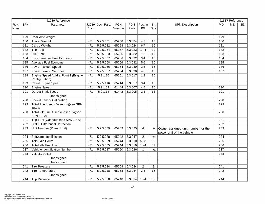
- C7 -
J1939 Reference J1587 ReferenceRev.Num
SPN Parameter J1939Doc.
Doc. Para PGNNumber
PGNPara
Pos. inPG
BitSize
SPN Description PID MID SID
179 Rear Axle Weight 179180 Trailer Weight -71 5.2.5.081 65258 5.3.024 4,5 16 180181 Cargo Weight -71 5.2.5.082 65258 5.3.024 6,7 16 181182 Trip Fuel -71 5.2.5.064 65257 5.3.023 1 - 4 32 182183 Fuel Rate -71 5.2.5.063 65266 5.3.032 1,2 16 183184 Instantaneous Fuel Economy -71 5.2.5.067 65266 5.3.032 3,4 16 184185 Average Fuel Economy -71 5.2.5.068 65266 5.3.032 5,6 16 185186 Power Takeoff Speed -71 5.2.5.056 65264 5.3.030 2,3 16 186187 Power Takeoff Set Speed -71 5.2.5.057 65264 5.3.030 4,5 16 187188 Engine Speed At Idle, Point 1 (Engine
Configuration)-71 5.2.1.26 65251 5.3.017 1,2 16
189 Rated Engine Speed -71 5.2.5.116 65214 5.3.057 3,4 16190 Engine Speed -71 5.2.1.09 61444 5.3.007 4,5 16 190191 Output Shaft Speed -71 5.2.1.14 61442 5.3.005 2,3 16 191
Unassigned228 Speed Sensor Calibration 228229 Total Fuel Used (Gaseous)(see SPN
1040)229
230 Total Idle Fuel Used (Gaseous)(seeSPN 1010)
230
231 Trip Fuel (Gaseous (see SPN 1039) 231232 DGPS Differential Correction 232233 Unit Number (Power Unit) -71 5.2.5.089 65259 5.3.025 4 n/a Owner assigned unit number for the
power unit of the vehicle233
234 Software Identification -71 5.2.5.088 65242 5.3.047 2 n/a 234235 Total Idle Hours -71 5.2.5.059 65244 5.3.010 5 - 8 32 235236 Total Idle Fuel Used -71 5.2.5.065 65244 5.3.010 1 - 4 32 236237 Vehicle Identification Number -71 5.2.5.087 65260 5.3.026 1 n/a 237238 Velocity Vector 238
UnassignedUnassigned
241 Tire Pressure -71 5.2.5.034 65268 5.3.034 2 8 241242 Tire Temperature -71 5.2.5.018 65268 5.3.034 3,4 16 242
Unassigned244 Trip Distance -71 5.2.5.050 65248 5.3.014 1 - 4 32 244
Copyright SAE International Provided by IHS under license with SAE
Not for ResaleNo reproduction or networking permitted without license from IHS
--`-`-`,,`,,`,`,,`---
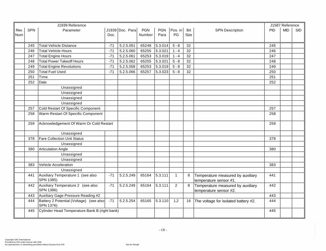
- C8 -
J1939 Reference J1587 ReferenceRev.Num
SPN Parameter J1939Doc.
Doc. Para PGNNumber
PGNPara
Pos. inPG
BitSize
SPN Description PID MID SID
245 Total Vehicle Distance -71 5.2.5.051 65248 5.3.014 5 - 8 32 245246 Total Vehicle Hours -71 5.2.5.060 65255 5.3.021 1 - 4 32 246247 Total Engine Hours -71 5.2.5.061 65253 5.3.019 1 - 4 32 247248 Total Power Takeoff Hours -71 5.2.5.062 65255 5.3.021 5 - 8 32 248249 Total Engine Revolutions -71 5.2.5.058 65253 5.3.019 5 - 8 32 249250 Total Fuel Used -71 5.2.5.066 65257 5.3.023 5 - 8 32 250251 Time 251252 Date 252
UnassignedUnassignedUnassignedUnassigned
257 Cold Restart Of Specific Component 257258 Warm Restart Of Specific Component 258
259 Acknowledgement Of Warm Or Cold Restart 259
Unassigned378 Fare Collection Unit Status 378
Unassigned380 Articulation Angle 380
UnassignedUnassigned
383 Vehicle Acceleration 383Unassigned
441 Auxiliary Temperature 1 (see alsoSPN 1385)
-71 5.2.5.249 65164 5.3.111 1 8 Temperature measured by auxiliarytemperature sensor #1.
441
442 Auxiliary Temperature 2 (see alsoSPN 1386)
-71 5.2.5.249 65164 5.3.111 2 8 Temperature measured by auxiliarytemperature sensor #2.
442
443 Auxiliary Gage Pressure Reading #2 443444 Battery 2 Potential (Voltage) (see also
SPN 1376)-71 5.2.5.254 65165 5.3.110 1,2 16 The voltage for isolated battery #2. 444
445 Cylinder Head Temperature Bank B (right bank) 445
Copyright SAE International Provided by IHS under license with SAE
Not for ResaleNo reproduction or networking permitted without license from IHS
--`-`-`,,`,,`,`,,`---
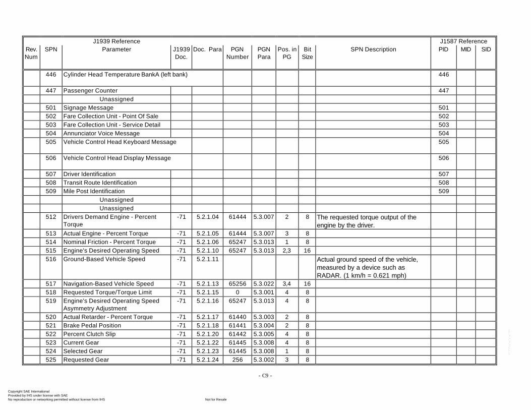
- C9 -
J1939 Reference J1587 ReferenceRev.Num
SPN Parameter J1939Doc.
Doc. Para PGNNumber
PGNPara
Pos. inPG
BitSize
SPN Description PID MID SID
446 Cylinder Head Temperature BankA (left bank) 446
447 Passenger Counter 447Unassigned
501 Signage Message 501502 Fare Collection Unit - Point Of Sale 502503 Fare Collection Unit - Service Detail 503504 Annunciator Voice Message 504505 Vehicle Control Head Keyboard Message 505
506 Vehicle Control Head Display Message 506
507 Driver Identification 507508 Transit Route Identification 508509 Mile Post Identification 509
UnassignedUnassigned
512 Drivers Demand Engine - PercentTorque
-71 5.2.1.04 61444 5.3.007 2 8 The requested torque output of theengine by the driver.
513 Actual Engine - Percent Torque -71 5.2.1.05 61444 5.3.007 3 8514 Nominal Friction - Percent Torque -71 5.2.1.06 65247 5.3.013 1 8515 Engine's Desired Operating Speed -71 5.2.1.10 65247 5.3.013 2,3 16516 Ground-Based Vehicle Speed -71 5.2.1.11 Actual ground speed of the vehicle,
measured by a device such asRADAR. (1 km/h = 0.621 mph)
517 Navigation-Based Vehicle Speed -71 5.2.1.13 65256 5.3.022 3,4 16518 Requested Torque/Torque Limit -71 5.2.1.15 0 5.3.001 4 8519 Engine's Desired Operating Speed
Asymmetry Adjustment-71 5.2.1.16 65247 5.3.013 4 8
520 Actual Retarder - Percent Torque -71 5.2.1.17 61440 5.3.003 2 8521 Brake Pedal Position -71 5.2.1.18 61441 5.3.004 2 8522 Percent Clutch Slip -71 5.2.1.20 61442 5.3.005 4 8523 Current Gear -71 5.2.1.22 61445 5.3.008 4 8524 Selected Gear -71 5.2.1.23 61445 5.3.008 1 8525 Requested Gear -71 5.2.1.24 256 5.3.002 3 8
Copyright SAE International Provided by IHS under license with SAE
Not for ResaleNo reproduction or networking permitted without license from IHS
--`-`-`,,`,,`,`,,`---
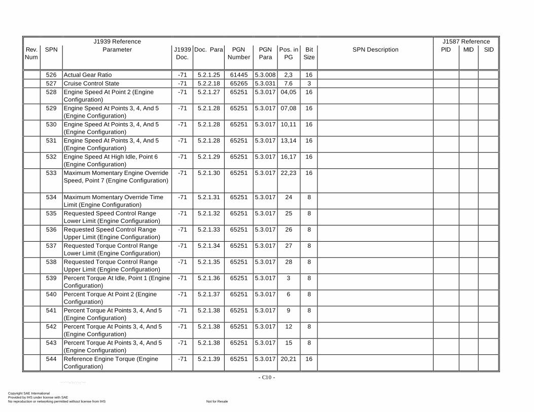
- C10 -
J1939 Reference J1587 ReferenceRev.Num
SPN Parameter J1939Doc.
Doc. Para PGNNumber
PGNPara
Pos. inPG
BitSize
SPN Description PID MID SID
526 Actual Gear Ratio -71 5.2.1.25 61445 5.3.008 2,3 16527 Cruise Control State -71 5.2.2.18 65265 5.3.031 7.6 3528 Engine Speed At Point 2 (Engine
Configuration)-71 5.2.1.27 65251 5.3.017 04,05 16
529 Engine Speed At Points 3, 4, And 5(Engine Configuration)
-71 5.2.1.28 65251 5.3.017 07,08 16
530 Engine Speed At Points 3, 4, And 5(Engine Configuration)
-71 5.2.1.28 65251 5.3.017 10,11 16
531 Engine Speed At Points 3, 4, And 5(Engine Configuration)
-71 5.2.1.28 65251 5.3.017 13,14 16
532 Engine Speed At High Idle, Point 6(Engine Configuration)
-71 5.2.1.29 65251 5.3.017 16,17 16
533 Maximum Momentary Engine OverrideSpeed, Point 7 (Engine Configuration)
-71 5.2.1.30 65251 5.3.017 22,23 16
534 Maximum Momentary Override TimeLimit (Engine Configuration)
-71 5.2.1.31 65251 5.3.017 24 8
535 Requested Speed Control RangeLower Limit (Engine Configuration)
-71 5.2.1.32 65251 5.3.017 25 8
536 Requested Speed Control RangeUpper Limit (Engine Configuration)
-71 5.2.1.33 65251 5.3.017 26 8
537 Requested Torque Control RangeLower Limit (Engine Configuration)
-71 5.2.1.34 65251 5.3.017 27 8
538 Requested Torque Control RangeUpper Limit (Engine Configuration)
-71 5.2.1.35 65251 5.3.017 28 8
539 Percent Torque At Idle, Point 1 (EngineConfiguration)
-71 5.2.1.36 65251 5.3.017 3 8
540 Percent Torque At Point 2 (EngineConfiguration)
-71 5.2.1.37 65251 5.3.017 6 8
541 Percent Torque At Points 3, 4, And 5(Engine Configuration)
-71 5.2.1.38 65251 5.3.017 9 8
542 Percent Torque At Points 3, 4, And 5(Engine Configuration)
-71 5.2.1.38 65251 5.3.017 12 8
543 Percent Torque At Points 3, 4, And 5(Engine Configuration)
-71 5.2.1.38 65251 5.3.017 15 8
544 Reference Engine Torque (EngineConfiguration)
-71 5.2.1.39 65251 5.3.017 20,21 16
Copyright SAE International Provided by IHS under license with SAE
Not for ResaleNo reproduction or networking permitted without license from IHS
--`-`-`,,`,,`,`,,`---
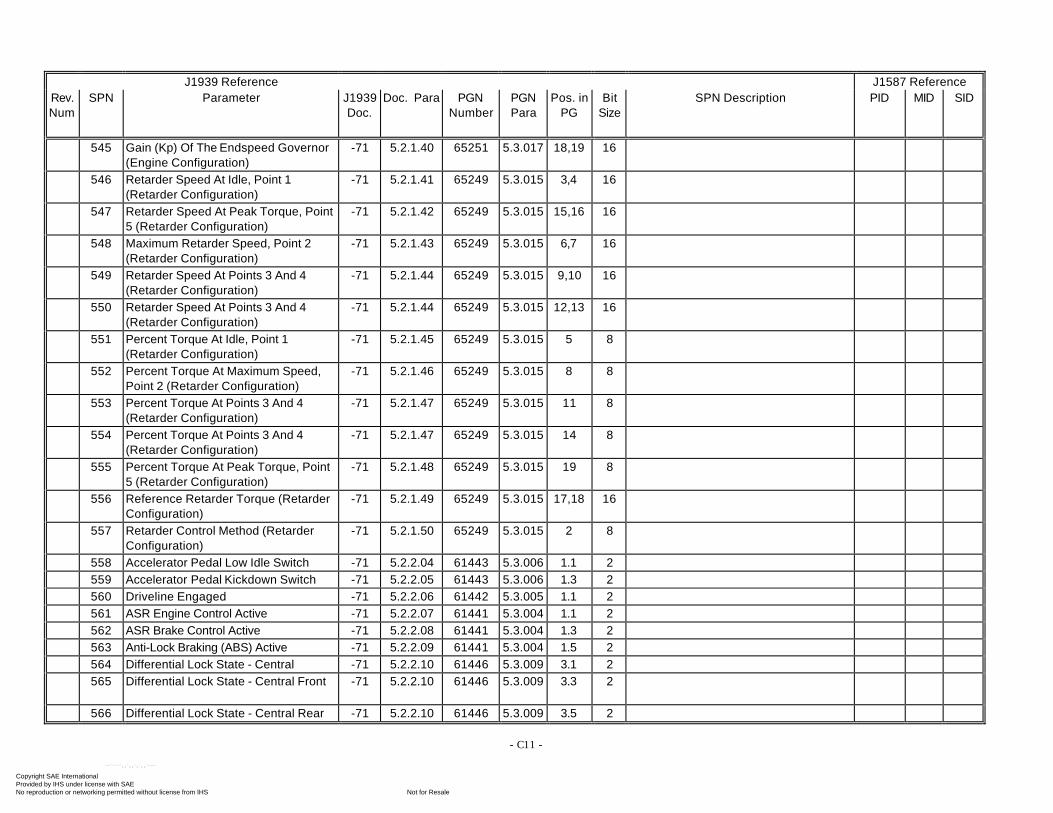
- C11 -
J1939 Reference J1587 ReferenceRev.Num
SPN Parameter J1939Doc.
Doc. Para PGNNumber
PGNPara
Pos. inPG
BitSize
SPN Description PID MID SID
545 Gain (Kp) Of The Endspeed Governor(Engine Configuration)
-71 5.2.1.40 65251 5.3.017 18,19 16
546 Retarder Speed At Idle, Point 1(Retarder Configuration)
-71 5.2.1.41 65249 5.3.015 3,4 16
547 Retarder Speed At Peak Torque, Point5 (Retarder Configuration)
-71 5.2.1.42 65249 5.3.015 15,16 16
548 Maximum Retarder Speed, Point 2(Retarder Configuration)
-71 5.2.1.43 65249 5.3.015 6,7 16
549 Retarder Speed At Points 3 And 4(Retarder Configuration)
-71 5.2.1.44 65249 5.3.015 9,10 16
550 Retarder Speed At Points 3 And 4(Retarder Configuration)
-71 5.2.1.44 65249 5.3.015 12,13 16
551 Percent Torque At Idle, Point 1(Retarder Configuration)
-71 5.2.1.45 65249 5.3.015 5 8
552 Percent Torque At Maximum Speed,Point 2 (Retarder Configuration)
-71 5.2.1.46 65249 5.3.015 8 8
553 Percent Torque At Points 3 And 4(Retarder Configuration)
-71 5.2.1.47 65249 5.3.015 11 8
554 Percent Torque At Points 3 And 4(Retarder Configuration)
-71 5.2.1.47 65249 5.3.015 14 8
555 Percent Torque At Peak Torque, Point5 (Retarder Configuration)
-71 5.2.1.48 65249 5.3.015 19 8
556 Reference Retarder Torque (RetarderConfiguration)
-71 5.2.1.49 65249 5.3.015 17,18 16
557 Retarder Control Method (RetarderConfiguration)
-71 5.2.1.50 65249 5.3.015 2 8
558 Accelerator Pedal Low Idle Switch -71 5.2.2.04 61443 5.3.006 1.1 2559 Accelerator Pedal Kickdown Switch -71 5.2.2.05 61443 5.3.006 1.3 2560 Driveline Engaged -71 5.2.2.06 61442 5.3.005 1.1 2561 ASR Engine Control Active -71 5.2.2.07 61441 5.3.004 1.1 2562 ASR Brake Control Active -71 5.2.2.08 61441 5.3.004 1.3 2563 Anti-Lock Braking (ABS) Active -71 5.2.2.09 61441 5.3.004 1.5 2564 Differential Lock State - Central -71 5.2.2.10 61446 5.3.009 3.1 2565 Differential Lock State - Central Front -71 5.2.2.10 61446 5.3.009 3.3 2
566 Differential Lock State - Central Rear -71 5.2.2.10 61446 5.3.009 3.5 2
Copyright SAE International Provided by IHS under license with SAE
Not for ResaleNo reproduction or networking permitted without license from IHS
--`-`-`,,`,,`,`,,`---
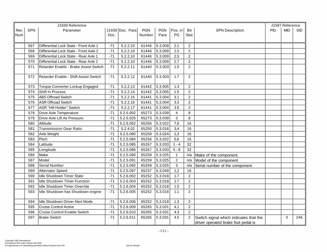
- C12 -
J1939 Reference J1587 ReferenceRev.Num
SPN Parameter J1939Doc.
Doc. Para PGNNumber
PGNPara
Pos. inPG
BitSize
SPN Description PID MID SID
567 Differential Lock State - Front Axle 1 -71 5.2.2.10 61446 5.3.009 2.1 2568 Differential Lock State - Front Axle 2 -71 5.2.2.10 61446 5.3.009 2.3 2569 Differential Lock State - Rear Axle 1 -71 5.2.2.10 61446 5.3.009 2.5 2570 Differential Lock State - Rear Axle 2 -71 5.2.2.10 61446 5.3.009 2.7 2571 Retarder Enable - Brake Assist Switch -71 5.2.2.11 61440 5.3.003 1.5 2
572 Retarder Enable - Shift Assist Switch -71 5.2.2.12 61440 5.3.003 1.7 2
573 Torque Converter Lockup Engaged -71 5.2.2.13 61442 5.3.005 1.3 2574 Shift In Process -71 5.2.2.14 61442 5.3.005 1.5 2575 ABS Offroad Switch -71 5.2.2.15 61441 5.3.004 3.1 2576 ASR Offroad Switch -71 5.2.2.16 61441 5.3.004 3.3 2577 ASR "Hill Holder" Switch -71 5.2.2.17 61441 5.3.004 3.5 2578 Drive Axle Temperature -71 5.2.5.002 65273 5.3.039 4 8579 Drive Axle Lift Air Pressure -71 5.2.5.025 65273 5.3.039 3 8580 Altitude -71 5.2.5.052 65256 5.3.022 7,8 16581 Transmission Gear Ratio -71 5.2.4.02 65250 5.3.016 3,4 16582 Axle Weight -71 5.2.5.080 65258 5.3.024 2,3 16583 Pitch -71 5.2.5.084 65256 5.3.022 5,6 16584 Latitude -71 5.2.5.085 65267 5.3.033 1 - 4 32585 Longitude -71 5.2.5.086 65267 5.3.033 5 - 8 32586 Make -71 5.2.5.090 65259 5.3.025 1 n/a Make of the component.587 Model -71 5.2.5.091 65259 5.3.025 2 n/a Model of the component588 Serial Number -71 5.2.5.092 65259 5.3.025 3 n/a Serial number of the component589 Alternator Speed -71 5.2.5.097 65237 5.3.049 1,2 16590 Idle Shutdown Timer State -71 5.2.6.002 65252 5.3.018 1.7 2591 Idle Shutdown Timer Function -71 5.2.6.003 65252 5.3.018 2.7 2592 Idle Shutdown Timer Override -71 5.2.6.004 65252 5.3.018 1.5 2593 Idle Shutdown has Shutdown engine -71 5.2.6.005 65252 5.3.018 1.1 2
594 Idle Shutdown Driver Alert Mode -71 5.2.6.006 65252 5.3.018 1.3 2595 Cruise Control Active -71 5.2.6.009 65265 5.3.031 4.1 2596 Cruise Control Enable Switch -71 5.2.6.010 65265 5.3.031 4.3 2597 Brake Switch -71 5.2.6.011 65265 5.3.031 4.5 2 Switch signal which indicates that the
driver operated brake foot pedal is0 246
Copyright SAE International Provided by IHS under license with SAE
Not for ResaleNo reproduction or networking permitted without license from IHS
--`-`-`,,`,,`,`,,`---
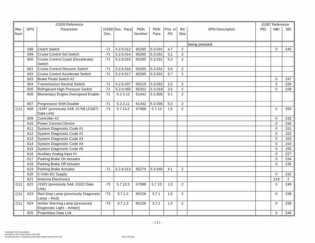
- C13 -
J1939 Reference J1587 ReferenceRev.Num
SPN Parameter J1939Doc.
Doc. Para PGNNumber
PGNPara
Pos. inPG
BitSize
SPN Description PID MID SID
being pressed.598 Clutch Switch -71 5.2.6.012 65265 5.3.031 4.7 2 0 245599 Cruise Control Set Switch -71 5.2.6.014 65265 5.3.031 5.1 2600 Cruise Control Coast (Decelerate)
Switch-71 5.2.6.015 65265 5.3.031 5.3 2
601 Cruise Control Resume Switch -71 5.2.6.016 65265 5.3.031 5.5 2602 Cruise Control Accelerate Switch -71 5.2.6.017 65265 5.3.031 5.7 2603 Brake Pedal Switch #2 0 247604 Transmission Neutral Switch -71 5.2.6.037 65219 5.3.052 2.3 2 0 226605 Refrigerant High Pressure Switch -71 5.2.6.050 65252 5.3.018 3.5 2 0 228606 Momentary Engine Overspeed Enable -71 5.2.3.12 61442 5.3.005 5.1 2
607 Progressive Shift Disable -71 5.2.3.11 61442 5.3.005 5.3 2(11) 608 J1587 (previously SAE J1708 (J1587)
Data Link)-73 5.7.13.2 57088 5.7.13 1.5 2 0 250
609 Controller #2 0 233610 Power Connect Device 0 236611 System Diagnostic Code #1 0 151612 System Diagnostic Code #2 0 152613 System Diagnostic Code #3 0 153614 System Diagnostic Code #4 0 154615 System Diagnostic Code #5 0 155616 Auxiliary Analog Input #1 0 227617 Parking Brake On Actuator 0 234618 Parking Brake Off Actuator 0 235619 Parking Brake Actuator -71 5.2.6.013 65274 5.3.040 4.1 2620 5 Volts DC Supply 0 232621 Antenna Electronics 219 2
(11) 622 J1922 (previously SAE J1922 DataLink)
-73 5.7.13.3 57088 5.7.13 1.3 2 0 249
(11) 623 Red Stop Lamp (previously DiagnosticLamp – Red)
-73 5.7.1.2 65226 5.7.1 1.5 2 0 238
(11) 624 Amber Warning Lamp (previouslyDiagnostic Light – Amber)
-73 5.7.1.3 65226 5.7.1 1.3 2 0 239
625 Proprietary Data Link 0 248
Copyright SAE International Provided by IHS under license with SAE
Not for ResaleNo reproduction or networking permitted without license from IHS
--`-`-`,,`,,`,`,,`---
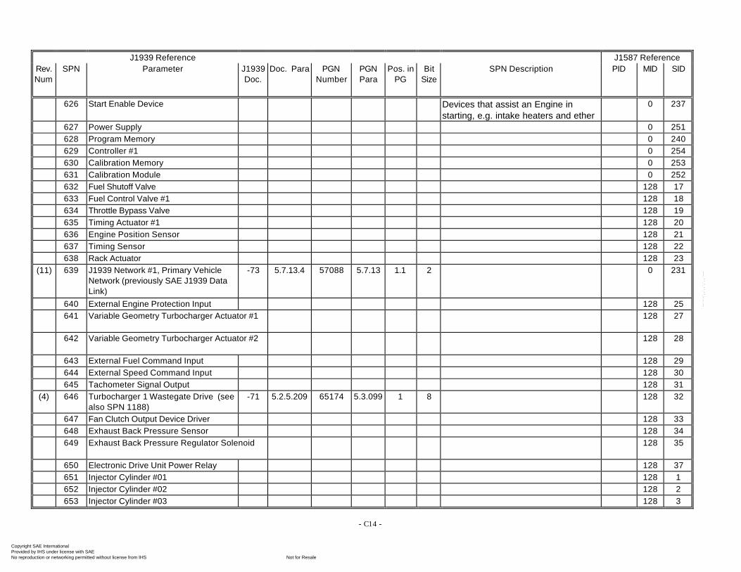
- C14 -
J1939 Reference J1587 ReferenceRev.Num
SPN Parameter J1939Doc.
Doc. Para PGNNumber
PGNPara
Pos. inPG
BitSize
SPN Description PID MID SID
626 Start Enable Device Devices that assist an Engine instarting, e.g. intake heaters and ether
0 237
627 Power Supply 0 251628 Program Memory 0 240629 Controller #1 0 254630 Calibration Memory 0 253631 Calibration Module 0 252632 Fuel Shutoff Valve 128 17633 Fuel Control Valve #1 128 18634 Throttle Bypass Valve 128 19635 Timing Actuator #1 128 20636 Engine Position Sensor 128 21637 Timing Sensor 128 22638 Rack Actuator 128 23
(11) 639 J1939 Network #1, Primary VehicleNetwork (previously SAE J1939 DataLink)
-73 5.7.13.4 57088 5.7.13 1.1 2 0 231
640 External Engine Protection Input 128 25641 Variable Geometry Turbocharger Actuator #1 128 27
642 Variable Geometry Turbocharger Actuator #2 128 28
643 External Fuel Command Input 128 29644 External Speed Command Input 128 30645 Tachometer Signal Output 128 31
(4) 646 Turbocharger 1 Wastegate Drive (seealso SPN 1188)
-71 5.2.5.209 65174 5.3.099 1 8 128 32
647 Fan Clutch Output Device Driver 128 33648 Exhaust Back Pressure Sensor 128 34649 Exhaust Back Pressure Regulator Solenoid 128 35
650 Electronic Drive Unit Power Relay 128 37651 Injector Cylinder #01 128 1652 Injector Cylinder #02 128 2653 Injector Cylinder #03 128 3
Copyright SAE International Provided by IHS under license with SAE
Not for ResaleNo reproduction or networking permitted without license from IHS
--`-`-`,,`,,`,`,,`---
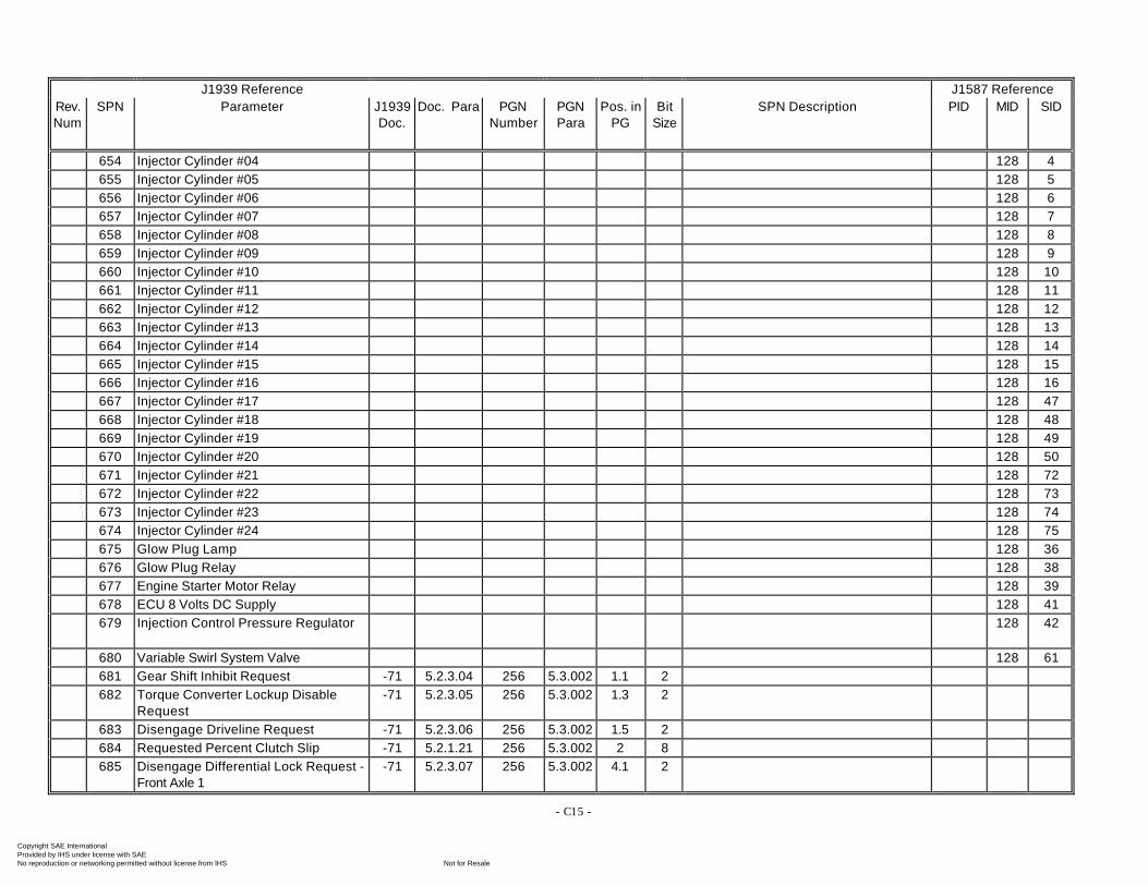
- C15 -
J1939 Reference J1587 ReferenceRev.Num
SPN Parameter J1939Doc.
Doc. Para PGNNumber
PGNPara
Pos. inPG
BitSize
SPN Description PID MID SID
654 Injector Cylinder #04 128 4655 Injector Cylinder #05 128 5656 Injector Cylinder #06 128 6657 Injector Cylinder #07 128 7658 Injector Cylinder #08 128 8659 Injector Cylinder #09 128 9660 Injector Cylinder #10 128 10661 Injector Cylinder #11 128 11662 Injector Cylinder #12 128 12663 Injector Cylinder #13 128 13664 Injector Cylinder #14 128 14665 Injector Cylinder #15 128 15666 Injector Cylinder #16 128 16667 Injector Cylinder #17 128 47668 Injector Cylinder #18 128 48669 Injector Cylinder #19 128 49670 Injector Cylinder #20 128 50671 Injector Cylinder #21 128 72672 Injector Cylinder #22 128 73673 Injector Cylinder #23 128 74674 Injector Cylinder #24 128 75675 Glow Plug Lamp 128 36676 Glow Plug Relay 128 38677 Engine Starter Motor Relay 128 39678 ECU 8 Volts DC Supply 128 41679 Injection Control Pressure Regulator 128 42
680 Variable Swirl System Valve 128 61681 Gear Shift Inhibit Request -71 5.2.3.04 256 5.3.002 1.1 2682 Torque Converter Lockup Disable
Request-71 5.2.3.05 256 5.3.002 1.3 2
683 Disengage Driveline Request -71 5.2.3.06 256 5.3.002 1.5 2684 Requested Percent Clutch Slip -71 5.2.1.21 256 5.3.002 2 8685 Disengage Differential Lock Request -
Front Axle 1-71 5.2.3.07 256 5.3.002 4.1 2
Copyright SAE International Provided by IHS under license with SAE
Not for ResaleNo reproduction or networking permitted without license from IHS
--`-`-`,,`,,`,`,,`---
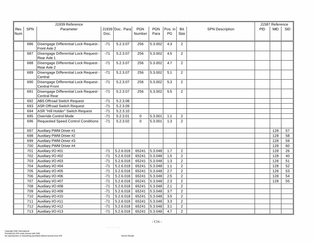
- C16 -
J1939 Reference J1587 ReferenceRev.Num
SPN Parameter J1939Doc.
Doc. Para PGNNumber
PGNPara
Pos. inPG
BitSize
SPN Description PID MID SID
686 Disengage Differential Lock Request -Front Axle 2
-71 5.2.3.07 256 5.3.002 4.3 2
687 Disengage Differential Lock Request -Rear Axle 1
-71 5.2.3.07 256 5.3.002 4.5 2
688 Disengage Differential Lock Request -Rear Axle 2
-71 5.2.3.07 256 5.3.002 4.7 2
689 Disengage Differential Lock Request -Central
-71 5.2.3.07 256 5.3.002 5.1 2
690 Disengage Differential Lock Request -Central Front
-71 5.2.3.07 256 5.3.002 5.3 2
691 Disengage Differential Lock Request -Central Rear
-71 5.2.3.07 256 5.3.002 5.5 2
692 ABS Offroad Switch Request -71 5.2.3.08693 ASR Offroad Switch Request -71 5.2.3.09694 ASR "Hill Holder" Switch Request -71 5.2.3.10695 Override Control Mode -71 5.2.3.01 0 5.3.001 1.1 2696 Requested Speed Control Conditions -71 5.2.3.02 0 5.3.001 1.3 2
697 Auxiliary PWM Driver #1 128 57698 Auxiliary PWM Driver #2 128 58699 Auxiliary PWM Driver #3 128 59700 Auxiliary PWM Driver #4 128 60701 Auxiliary I/O #01 -71 5.2.6.018 65241 5.3.048 1.7 2 128 26702 Auxiliary I/O #02 -71 5.2.6.018 65241 5.3.048 1.5 2 128 40703 Auxiliary I/O #03 -71 5.2.6.018 65241 5.3.048 1.3 2 128 51704 Auxiliary I/O #04 -71 5.2.6.018 65241 5.3.048 1.1 2 128 52705 Auxiliary I/O #05 -71 5.2.6.018 65241 5.3.048 2.7 2 128 53706 Auxiliary I/O #06 -71 5.2.6.018 65241 5.3.048 2.5 2 128 54707 Auxiliary I/O #07 -71 5.2.6.018 65241 5.3.048 2.3 2 128 55708 Auxiliary I/O #08 -71 5.2.6.018 65241 5.3.048 2.1 2709 Auxiliary I/O #09 -71 5.2.6.018 65241 5.3.048 3.7 2710 Auxiliary I/O #10 -71 5.2.6.018 65241 5.3.048 3.5 2711 Auxiliary I/O #11 -71 5.2.6.018 65241 5.3.048 3.3 2712 Auxiliary I/O #12 -71 5.2.6.018 65241 5.3.048 3.1 2713 Auxiliary I/O #13 -71 5.2.6.018 65241 5.3.048 4.7 2
Copyright SAE International Provided by IHS under license with SAE
Not for ResaleNo reproduction or networking permitted without license from IHS
--`-`-`,,`,,`,`,,`---
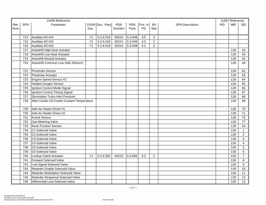
- C17 -
J1939 Reference J1587 ReferenceRev.Num
SPN Parameter J1939Doc.
Doc. Para PGNNumber
PGNPara
Pos. inPG
BitSize
SPN Description PID MID SID
714 Auxiliary I/O #14 -71 5.2.6.018 65241 5.3.048 4.5 2715 Auxiliary I/O #15 -71 5.2.6.018 65241 5.3.048 4.3 2716 Auxiliary I/O #16 -71 5.2.6.018 65241 5.3.048 4.1 2717 Autoshift High Gear Actuator 128 43718 Autoshift Low Gear Actuator 128 44719 Autoshift Neutral Actuator 128 45720 Autoshift Common Low Side (Return) 128 46
721 Prestroke Sensor 128 62722 Prestroke Actuator 128 63723 Engine Speed Sensor #2 128 64724 Heated Oxygen Sensor 128 65725 Ignition Control Mode Signal 128 66726 Ignition Control Timing Signal 128 67727 Secondary Turbo Inlet Pressure 128 68728 After Cooler-Oil Cooler Coolant Temperature 128 69
729 Inlet Air Heater Driver #1 128 70730 Inlet Air Heater Driver #2 128 71731 Knock Sensor 128 76732 Gas Metering Valve 128 77733 Rack Position Sensor 128 24734 C1 Solenoid Valve 130 1735 C2 Solenoid Valve 130 2736 C3 Solenoid Valve 130 3737 C4 Solenoid Valve 130 4738 C5 Solenoid Valve 130 5739 C6 Solenoid Valve 130 6740 Lockup Clutch Actuator -71 5.2.6.032 65223 5.3.050 6.3 2 130 7741 Forward Solenoid Valve 130 8742 Low Signal Solenoid Valve 130 9743 Retarder Enable Solenoid Valve 130 10744 Retarder Modulation Solenoid Valve 130 11745 Retarder Response Solenoid Valve 130 12746 Differential Lock Solenoid Valve 130 13
Copyright SAE International Provided by IHS under license with SAE
Not for ResaleNo reproduction or networking permitted without license from IHS
--`-`-`,,`,,`,`,,`---
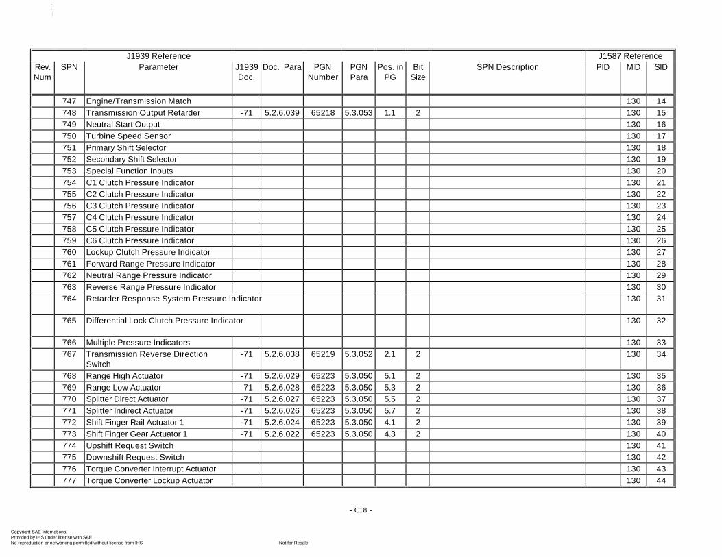
- C18 -
J1939 Reference J1587 ReferenceRev.Num
SPN Parameter J1939Doc.
Doc. Para PGNNumber
PGNPara
Pos. inPG
BitSize
SPN Description PID MID SID
747 Engine/Transmission Match 130 14748 Transmission Output Retarder -71 5.2.6.039 65218 5.3.053 1.1 2 130 15749 Neutral Start Output 130 16750 Turbine Speed Sensor 130 17751 Primary Shift Selector 130 18752 Secondary Shift Selector 130 19753 Special Function Inputs 130 20754 C1 Clutch Pressure Indicator 130 21755 C2 Clutch Pressure Indicator 130 22756 C3 Clutch Pressure Indicator 130 23757 C4 Clutch Pressure Indicator 130 24758 C5 Clutch Pressure Indicator 130 25759 C6 Clutch Pressure Indicator 130 26760 Lockup Clutch Pressure Indicator 130 27761 Forward Range Pressure Indicator 130 28762 Neutral Range Pressure Indicator 130 29763 Reverse Range Pressure Indicator 130 30764 Retarder Response System Pressure Indicator 130 31
765 Differential Lock Clutch Pressure Indicator 130 32
766 Multiple Pressure Indicators 130 33767 Transmission Reverse Direction
Switch-71 5.2.6.038 65219 5.3.052 2.1 2 130 34
768 Range High Actuator -71 5.2.6.029 65223 5.3.050 5.1 2 130 35769 Range Low Actuator -71 5.2.6.028 65223 5.3.050 5.3 2 130 36770 Splitter Direct Actuator -71 5.2.6.027 65223 5.3.050 5.5 2 130 37771 Splitter Indirect Actuator -71 5.2.6.026 65223 5.3.050 5.7 2 130 38772 Shift Finger Rail Actuator 1 -71 5.2.6.024 65223 5.3.050 4.1 2 130 39773 Shift Finger Gear Actuator 1 -71 5.2.6.022 65223 5.3.050 4.3 2 130 40774 Upshift Request Switch 130 41775 Downshift Request Switch 130 42776 Torque Converter Interrupt Actuator 130 43777 Torque Converter Lockup Actuator 130 44
Copyright SAE International Provided by IHS under license with SAE
Not for ResaleNo reproduction or networking permitted without license from IHS
--`-`-`,,`,,`,`,,`---
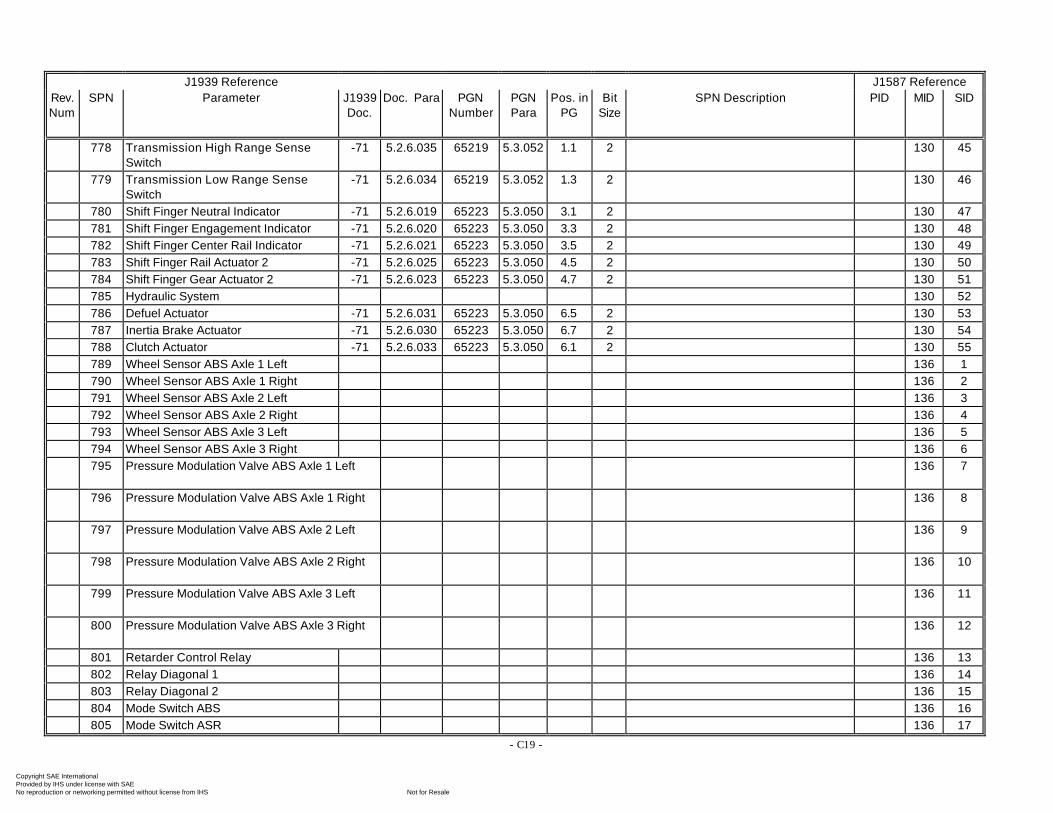
- C19 -
J1939 Reference J1587 ReferenceRev.Num
SPN Parameter J1939Doc.
Doc. Para PGNNumber
PGNPara
Pos. inPG
BitSize
SPN Description PID MID SID
778 Transmission High Range SenseSwitch
-71 5.2.6.035 65219 5.3.052 1.1 2 130 45
779 Transmission Low Range SenseSwitch
-71 5.2.6.034 65219 5.3.052 1.3 2 130 46
780 Shift Finger Neutral Indicator -71 5.2.6.019 65223 5.3.050 3.1 2 130 47781 Shift Finger Engagement Indicator -71 5.2.6.020 65223 5.3.050 3.3 2 130 48782 Shift Finger Center Rail Indicator -71 5.2.6.021 65223 5.3.050 3.5 2 130 49783 Shift Finger Rail Actuator 2 -71 5.2.6.025 65223 5.3.050 4.5 2 130 50784 Shift Finger Gear Actuator 2 -71 5.2.6.023 65223 5.3.050 4.7 2 130 51785 Hydraulic System 130 52786 Defuel Actuator -71 5.2.6.031 65223 5.3.050 6.5 2 130 53787 Inertia Brake Actuator -71 5.2.6.030 65223 5.3.050 6.7 2 130 54788 Clutch Actuator -71 5.2.6.033 65223 5.3.050 6.1 2 130 55789 Wheel Sensor ABS Axle 1 Left 136 1790 Wheel Sensor ABS Axle 1 Right 136 2791 Wheel Sensor ABS Axle 2 Left 136 3792 Wheel Sensor ABS Axle 2 Right 136 4793 Wheel Sensor ABS Axle 3 Left 136 5794 Wheel Sensor ABS Axle 3 Right 136 6795 Pressure Modulation Valve ABS Axle 1 Left 136 7
796 Pressure Modulation Valve ABS Axle 1 Right 136 8
797 Pressure Modulation Valve ABS Axle 2 Left 136 9
798 Pressure Modulation Valve ABS Axle 2 Right 136 10
799 Pressure Modulation Valve ABS Axle 3 Left 136 11
800 Pressure Modulation Valve ABS Axle 3 Right 136 12
801 Retarder Control Relay 136 13802 Relay Diagonal 1 136 14803 Relay Diagonal 2 136 15804 Mode Switch ABS 136 16805 Mode Switch ASR 136 17
Copyright SAE International Provided by IHS under license with SAE
Not for ResaleNo reproduction or networking permitted without license from IHS
--`-`-`,,`,,`,`,,`---
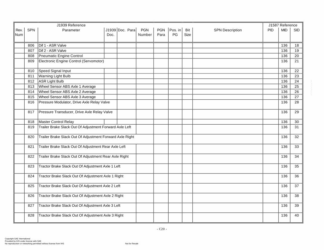
- C20 -
J1939 Reference J1587 ReferenceRev.Num
SPN Parameter J1939Doc.
Doc. Para PGNNumber
PGNPara
Pos. inPG
BitSize
SPN Description PID MID SID
806 Dif 1 - ASR Valve 136 18807 Dif 2 - ASR Valve 136 19808 Pneumatic Engine Control 136 20809 Electronic Engine Control (Servomotor) 136 21
810 Speed Signal Input 136 22811 Warning Light Bulb 136 23812 ASR Light Bulb 136 24813 Wheel Sensor ABS Axle 1 Average 136 25814 Wheel Sensor ABS Axle 2 Average 136 26815 Wheel Sensor ABS Axle 3 Average 136 27816 Pressure Modulator, Drive Axle Relay Valve 136 28
817 Pressure Transducer, Drive Axle Relay Valve 136 29
818 Master Control Relay 136 30819 Trailer Brake Slack Out Of Adjustment Forward Axle Left 136 31
820 Trailer Brake Slack Out Of Adjustment Forward Axle Right 136 32
821 Trailer Brake Slack Out Of Adjustment Rear Axle Left 136 33
822 Trailer Brake Slack Out Of Adjustment Rear Axle Right 136 34
823 Tractor Brake Slack Out Of Adjustment Axle 1 Left 136 35
824 Tractor Brake Slack Out Of Adjustment Axle 1 Right 136 36
825 Tractor Brake Slack Out Of Adjustment Axle 2 Left 136 37
826 Tractor Brake Slack Out Of Adjustment Axle 2 Right 136 38
827 Tractor Brake Slack Out Of Adjustment Axle 3 Left 136 39
828 Tractor Brake Slack Out Of Adjustment Axle 3 Right 136 40
Copyright SAE International Provided by IHS under license with SAE
Not for ResaleNo reproduction or networking permitted without license from IHS
--`-`-`,,`,,`,`,,`---
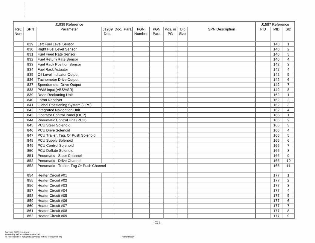
- C21 -
J1939 Reference J1587 ReferenceRev.Num
SPN Parameter J1939Doc.
Doc. Para PGNNumber
PGNPara
Pos. inPG
BitSize
SPN Description PID MID SID
829 Left Fuel Level Sensor 140 1830 Right Fuel Level Sensor 140 2831 Fuel Feed Rate Sensor 140 3832 Fuel Return Rate Sensor 140 4833 Fuel Rack Position Sensor 142 3834 Fuel Rack Actuator 142 4835 Oil Level Indicator Output 142 5836 Tachometer Drive Output 142 6837 Speedometer Drive Output 142 7838 PWM Input (ABS/ASR) 142 8839 Dead Reckoning Unit 162 1840 Loran Receiver 162 2841 Global Positioning System (GPS) 162 3842 Integrated Navigation Unit 162 4843 Operator Control Panel (OCP) 166 1844 Pneumatic Control Unit (PCU) 166 2845 PCU Steer Solenoid 166 3846 PCU Drive Solenoid 166 4847 PCU Trailer, Tag, Or Push Solenoid 166 5848 PCU Supply Solenoid 166 6849 PCU Control Solenoid 166 7850 PCU Deflate Solenoid 166 8851 Pneumatic - Steer Channel 166 9852 Pneumatic - Drive Channel 166 10853 Pneumatic - Trailer, Tag Or Push Channel 166 11
854 Heater Circuit #01 177 1855 Heater Circuit #02 177 2856 Heater Circuit #03 177 3857 Heater Circuit #04 177 4858 Heater Circuit #05 177 5859 Heater Circuit #06 177 6860 Heater Circuit #07 177 7861 Heater Circuit #08 177 8862 Heater Circuit #09 177 9
Copyright SAE International Provided by IHS under license with SAE
Not for ResaleNo reproduction or networking permitted without license from IHS
--`-`-`,,`,,`,`,,`---
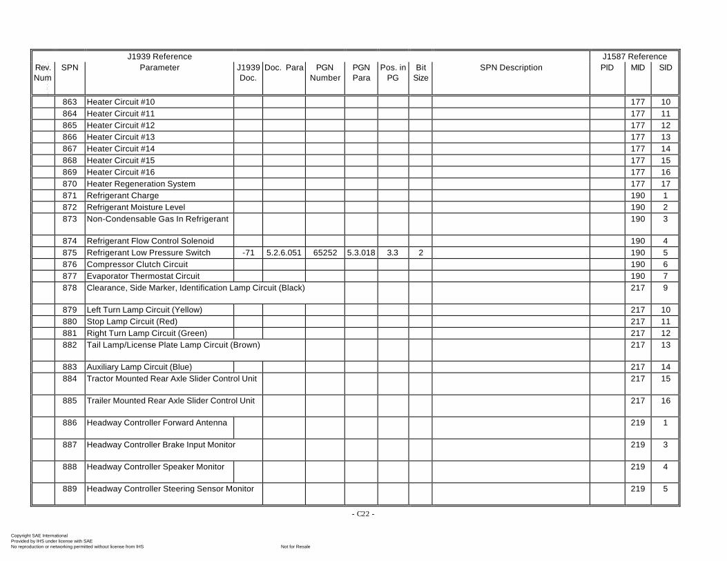
- C22 -
J1939 Reference J1587 ReferenceRev.Num
SPN Parameter J1939Doc.
Doc. Para PGNNumber
PGNPara
Pos. inPG
BitSize
SPN Description PID MID SID
863 Heater Circuit #10 177 10864 Heater Circuit #11 177 11865 Heater Circuit #12 177 12866 Heater Circuit #13 177 13867 Heater Circuit #14 177 14868 Heater Circuit #15 177 15869 Heater Circuit #16 177 16870 Heater Regeneration System 177 17871 Refrigerant Charge 190 1872 Refrigerant Moisture Level 190 2873 Non-Condensable Gas In Refrigerant 190 3
874 Refrigerant Flow Control Solenoid 190 4875 Refrigerant Low Pressure Switch -71 5.2.6.051 65252 5.3.018 3.3 2 190 5876 Compressor Clutch Circuit 190 6877 Evaporator Thermostat Circuit 190 7878 Clearance, Side Marker, Identification Lamp Circuit (Black) 217 9
879 Left Turn Lamp Circuit (Yellow) 217 10880 Stop Lamp Circuit (Red) 217 11881 Right Turn Lamp Circuit (Green) 217 12882 Tail Lamp/License Plate Lamp Circuit (Brown) 217 13
883 Auxiliary Lamp Circuit (Blue) 217 14884 Tractor Mounted Rear Axle Slider Control Unit 217 15
885 Trailer Mounted Rear Axle Slider Control Unit 217 16
886 Headway Controller Forward Antenna 219 1
887 Headway Controller Brake Input Monitor 219 3
888 Headway Controller Speaker Monitor 219 4
889 Headway Controller Steering Sensor Monitor 219 5
Copyright SAE International Provided by IHS under license with SAE
Not for ResaleNo reproduction or networking permitted without license from IHS
--`-`-`,,`,,`,`,,`---
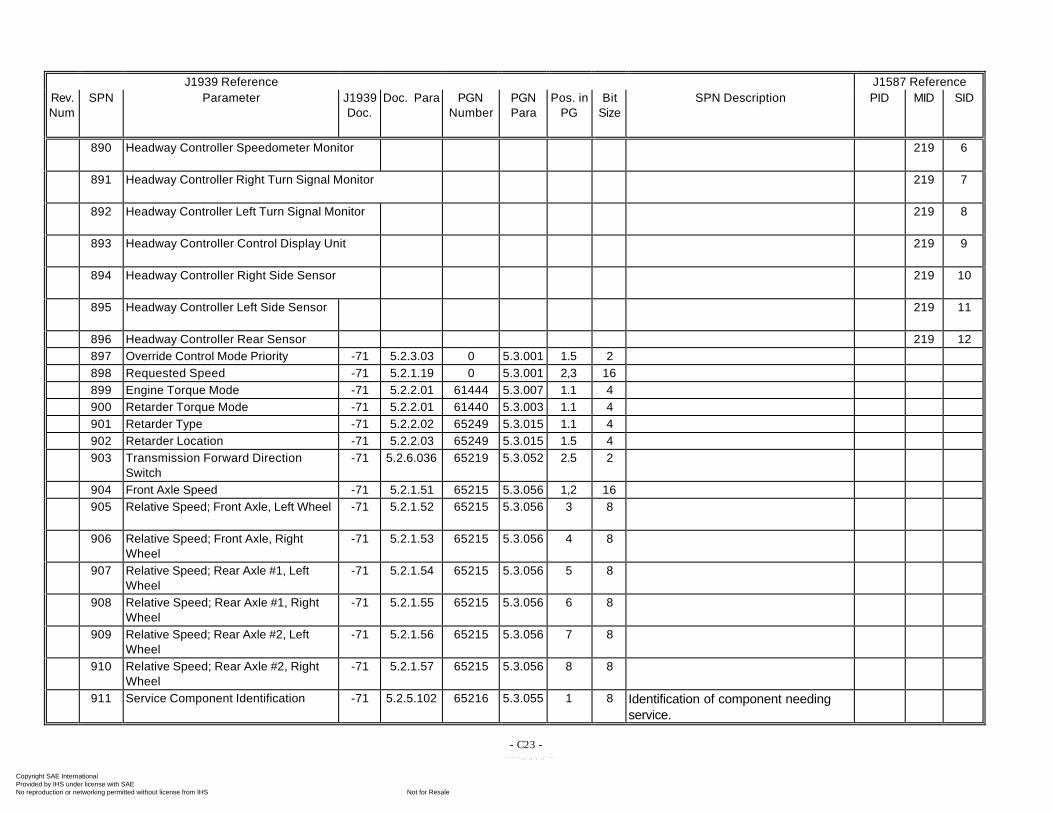
- C23 -
J1939 Reference J1587 ReferenceRev.Num
SPN Parameter J1939Doc.
Doc. Para PGNNumber
PGNPara
Pos. inPG
BitSize
SPN Description PID MID SID
890 Headway Controller Speedometer Monitor 219 6
891 Headway Controller Right Turn Signal Monitor 219 7
892 Headway Controller Left Turn Signal Monitor 219 8
893 Headway Controller Control Display Unit 219 9
894 Headway Controller Right Side Sensor 219 10
895 Headway Controller Left Side Sensor 219 11
896 Headway Controller Rear Sensor 219 12897 Override Control Mode Priority -71 5.2.3.03 0 5.3.001 1.5 2898 Requested Speed -71 5.2.1.19 0 5.3.001 2,3 16899 Engine Torque Mode -71 5.2.2.01 61444 5.3.007 1.1 4900 Retarder Torque Mode -71 5.2.2.01 61440 5.3.003 1.1 4901 Retarder Type -71 5.2.2.02 65249 5.3.015 1.1 4902 Retarder Location -71 5.2.2.03 65249 5.3.015 1.5 4903 Transmission Forward Direction
Switch-71 5.2.6.036 65219 5.3.052 2.5 2
904 Front Axle Speed -71 5.2.1.51 65215 5.3.056 1,2 16905 Relative Speed; Front Axle, Left Wheel -71 5.2.1.52 65215 5.3.056 3 8
906 Relative Speed; Front Axle, RightWheel
-71 5.2.1.53 65215 5.3.056 4 8
907 Relative Speed; Rear Axle #1, LeftWheel
-71 5.2.1.54 65215 5.3.056 5 8
908 Relative Speed; Rear Axle #1, RightWheel
-71 5.2.1.55 65215 5.3.056 6 8
909 Relative Speed; Rear Axle #2, LeftWheel
-71 5.2.1.56 65215 5.3.056 7 8
910 Relative Speed; Rear Axle #2, RightWheel
-71 5.2.1.57 65215 5.3.056 8 8
911 Service Component Identification -71 5.2.5.102 65216 5.3.055 1 8 Identification of component needingservice.
Copyright SAE International Provided by IHS under license with SAE
Not for ResaleNo reproduction or networking permitted without license from IHS
--`-`-`,,`,,`,`,,`---
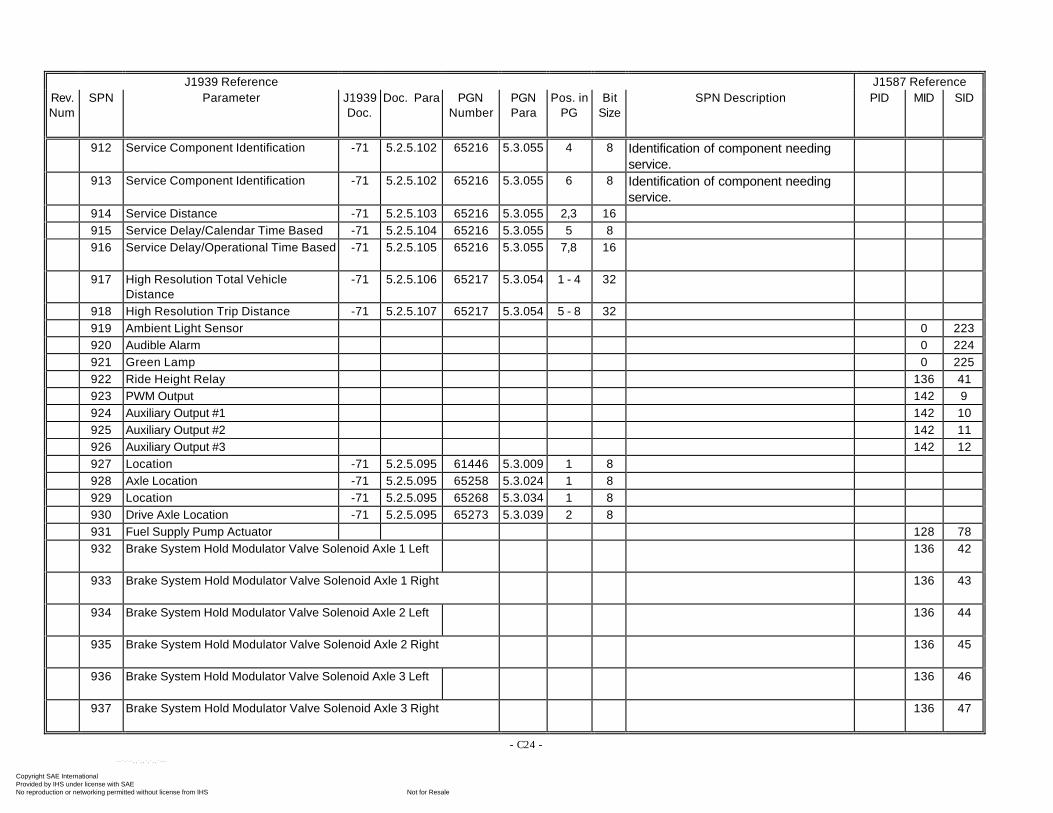
- C24 -
J1939 Reference J1587 ReferenceRev.Num
SPN Parameter J1939Doc.
Doc. Para PGNNumber
PGNPara
Pos. inPG
BitSize
SPN Description PID MID SID
912 Service Component Identification -71 5.2.5.102 65216 5.3.055 4 8 Identification of component needingservice.
913 Service Component Identification -71 5.2.5.102 65216 5.3.055 6 8 Identification of component needingservice.
914 Service Distance -71 5.2.5.103 65216 5.3.055 2,3 16915 Service Delay/Calendar Time Based -71 5.2.5.104 65216 5.3.055 5 8916 Service Delay/Operational Time Based -71 5.2.5.105 65216 5.3.055 7,8 16
917 High Resolution Total VehicleDistance
-71 5.2.5.106 65217 5.3.054 1 - 4 32
918 High Resolution Trip Distance -71 5.2.5.107 65217 5.3.054 5 - 8 32919 Ambient Light Sensor 0 223920 Audible Alarm 0 224921 Green Lamp 0 225922 Ride Height Relay 136 41923 PWM Output 142 9924 Auxiliary Output #1 142 10925 Auxiliary Output #2 142 11926 Auxiliary Output #3 142 12927 Location -71 5.2.5.095 61446 5.3.009 1 8928 Axle Location -71 5.2.5.095 65258 5.3.024 1 8929 Location -71 5.2.5.095 65268 5.3.034 1 8930 Drive Axle Location -71 5.2.5.095 65273 5.3.039 2 8931 Fuel Supply Pump Actuator 128 78932 Brake System Hold Modulator Valve Solenoid Axle 1 Left 136 42
933 Brake System Hold Modulator Valve Solenoid Axle 1 Right 136 43
934 Brake System Hold Modulator Valve Solenoid Axle 2 Left 136 44
935 Brake System Hold Modulator Valve Solenoid Axle 2 Right 136 45
936 Brake System Hold Modulator Valve Solenoid Axle 3 Left 136 46
937 Brake System Hold Modulator Valve Solenoid Axle 3 Right 136 47
Copyright SAE International Provided by IHS under license with SAE
Not for ResaleNo reproduction or networking permitted without license from IHS
--`-`-`,,`,,`,`,,`---
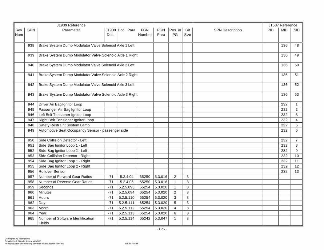
- C25 -
J1939 Reference J1587 ReferenceRev.Num
SPN Parameter J1939Doc.
Doc. Para PGNNumber
PGNPara
Pos. inPG
BitSize
SPN Description PID MID SID
938 Brake System Dump Modulator Valve Solenoid Axle 1 Left 136 48
939 Brake System Dump Modulator Valve Solenoid Axle 1 Right 136 49
940 Brake System Dump Modulator Valve Solenoid Axle 2 Left 136 50
941 Brake System Dump Modulator Valve Solenoid Axle 2 Right 136 51
942 Brake System Dump Modulator Valve Solenoid Axle 3 Left 136 52
943 Brake System Dump Modulator Valve Solenoid Axle 3 Right 136 53
944 Driver Air Bag Ignitor Loop 232 1945 Passenger Air Bag Ignitor Loop 232 2946 Left Belt Tensioner Ignitor Loop 232 3947 Right Belt Tensioner Ignitor Loop 232 4948 Safety Restraint System Lamp 232 5949 Automotive Seat Occupancy Sensor - passenger side 232 6
950 Side Collision Detector - Left 232 7951 Side Bag Ignitor Loop 1 - Left 232 8952 Side Bag Ignitor Loop 2 - Left 232 9953 Side Collision Detector - Right 232 10954 Side Bag Ignitor Loop 1 - Right 232 11955 Side Bag Ignitor Loop 2 - Right 232 12956 Rollover Sensor 232 13957 Number of Forward Gear Ratios -71 5.2.4.04 65250 5.3.016 2 8958 Number of Reverse Gear Ratios -71 5.2.4.05 65250 5.3.016 1 8959 Seconds -71 5.2.5.093 65254 5.3.020 1 8960 Minutes -71 5.2.5.094 65254 5.3.020 2 8961 Hours -71 5.2.5.110 65254 5.3.020 3 8962 Day -71 5.2.5.111 65254 5.3.020 5 8963 Month -71 5.2.5.112 65254 5.3.020 4 8964 Year -71 5.2.5.113 65254 5.3.020 6 8965 Number of Software Identification
Fields-71 5.2.5.114 65242 5.3.047 1 8
Copyright SAE International Provided by IHS under license with SAE
Not for ResaleNo reproduction or networking permitted without license from IHS
--`-`-`,,`,,`,`,,`---
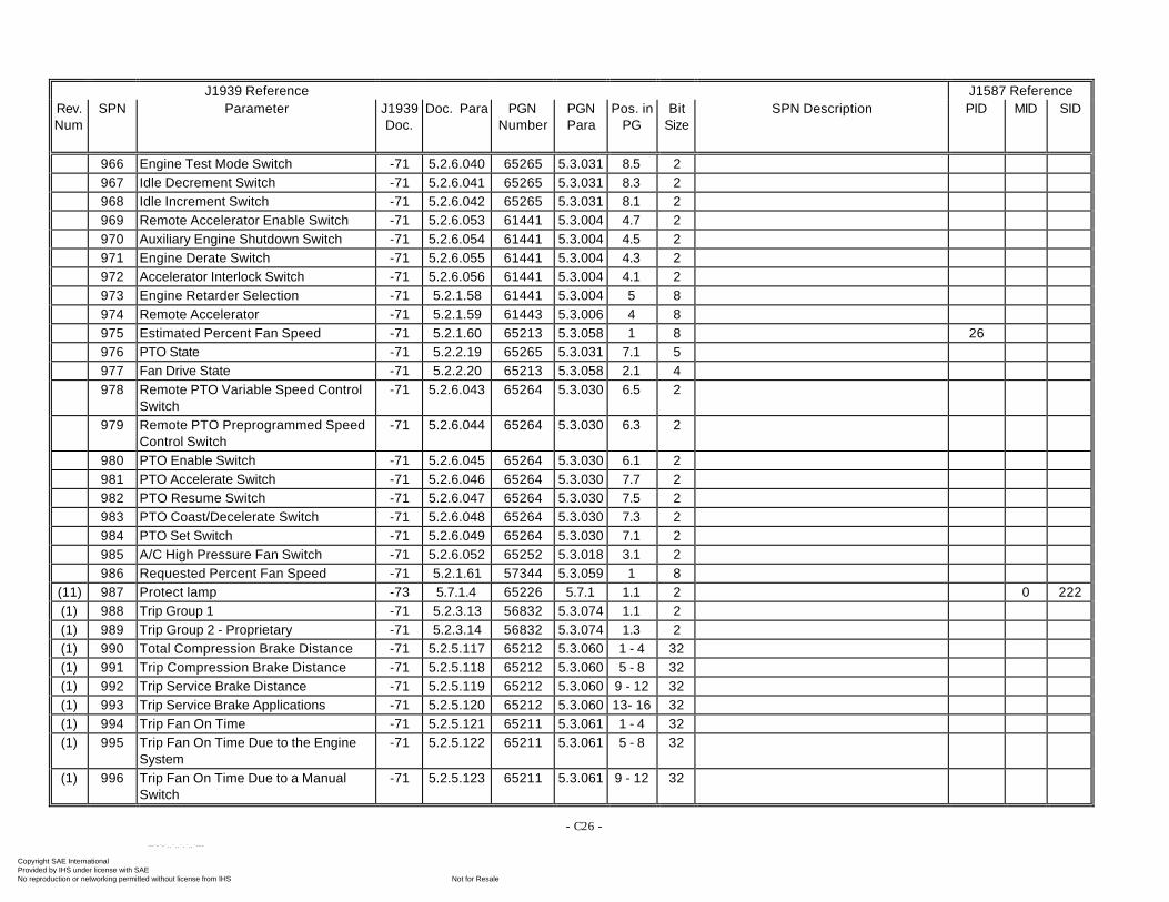
- C26 -
J1939 Reference J1587 ReferenceRev.Num
SPN Parameter J1939Doc.
Doc. Para PGNNumber
PGNPara
Pos. inPG
BitSize
SPN Description PID MID SID
966 Engine Test Mode Switch -71 5.2.6.040 65265 5.3.031 8.5 2967 Idle Decrement Switch -71 5.2.6.041 65265 5.3.031 8.3 2968 Idle Increment Switch -71 5.2.6.042 65265 5.3.031 8.1 2969 Remote Accelerator Enable Switch -71 5.2.6.053 61441 5.3.004 4.7 2970 Auxiliary Engine Shutdown Switch -71 5.2.6.054 61441 5.3.004 4.5 2971 Engine Derate Switch -71 5.2.6.055 61441 5.3.004 4.3 2972 Accelerator Interlock Switch -71 5.2.6.056 61441 5.3.004 4.1 2973 Engine Retarder Selection -71 5.2.1.58 61441 5.3.004 5 8974 Remote Accelerator -71 5.2.1.59 61443 5.3.006 4 8975 Estimated Percent Fan Speed -71 5.2.1.60 65213 5.3.058 1 8 26976 PTO State -71 5.2.2.19 65265 5.3.031 7.1 5977 Fan Drive State -71 5.2.2.20 65213 5.3.058 2.1 4978 Remote PTO Variable Speed Control
Switch-71 5.2.6.043 65264 5.3.030 6.5 2
979 Remote PTO Preprogrammed SpeedControl Switch
-71 5.2.6.044 65264 5.3.030 6.3 2
980 PTO Enable Switch -71 5.2.6.045 65264 5.3.030 6.1 2981 PTO Accelerate Switch -71 5.2.6.046 65264 5.3.030 7.7 2982 PTO Resume Switch -71 5.2.6.047 65264 5.3.030 7.5 2983 PTO Coast/Decelerate Switch -71 5.2.6.048 65264 5.3.030 7.3 2984 PTO Set Switch -71 5.2.6.049 65264 5.3.030 7.1 2985 A/C High Pressure Fan Switch -71 5.2.6.052 65252 5.3.018 3.1 2986 Requested Percent Fan Speed -71 5.2.1.61 57344 5.3.059 1 8
(11) 987 Protect lamp -73 5.7.1.4 65226 5.7.1 1.1 2 0 222(1) 988 Trip Group 1 -71 5.2.3.13 56832 5.3.074 1.1 2(1) 989 Trip Group 2 - Proprietary -71 5.2.3.14 56832 5.3.074 1.3 2(1) 990 Total Compression Brake Distance -71 5.2.5.117 65212 5.3.060 1 - 4 32(1) 991 Trip Compression Brake Distance -71 5.2.5.118 65212 5.3.060 5 - 8 32(1) 992 Trip Service Brake Distance -71 5.2.5.119 65212 5.3.060 9 - 12 32(1) 993 Trip Service Brake Applications -71 5.2.5.120 65212 5.3.060 13- 16 32(1) 994 Trip Fan On Time -71 5.2.5.121 65211 5.3.061 1 - 4 32(1) 995 Trip Fan On Time Due to the Engine
System-71 5.2.5.122 65211 5.3.061 5 - 8 32
(1) 996 Trip Fan On Time Due to a ManualSwitch
-71 5.2.5.123 65211 5.3.061 9 - 12 32
Copyright SAE International Provided by IHS under license with SAE
Not for ResaleNo reproduction or networking permitted without license from IHS
--`-`-`,,`,,`,`,,`---
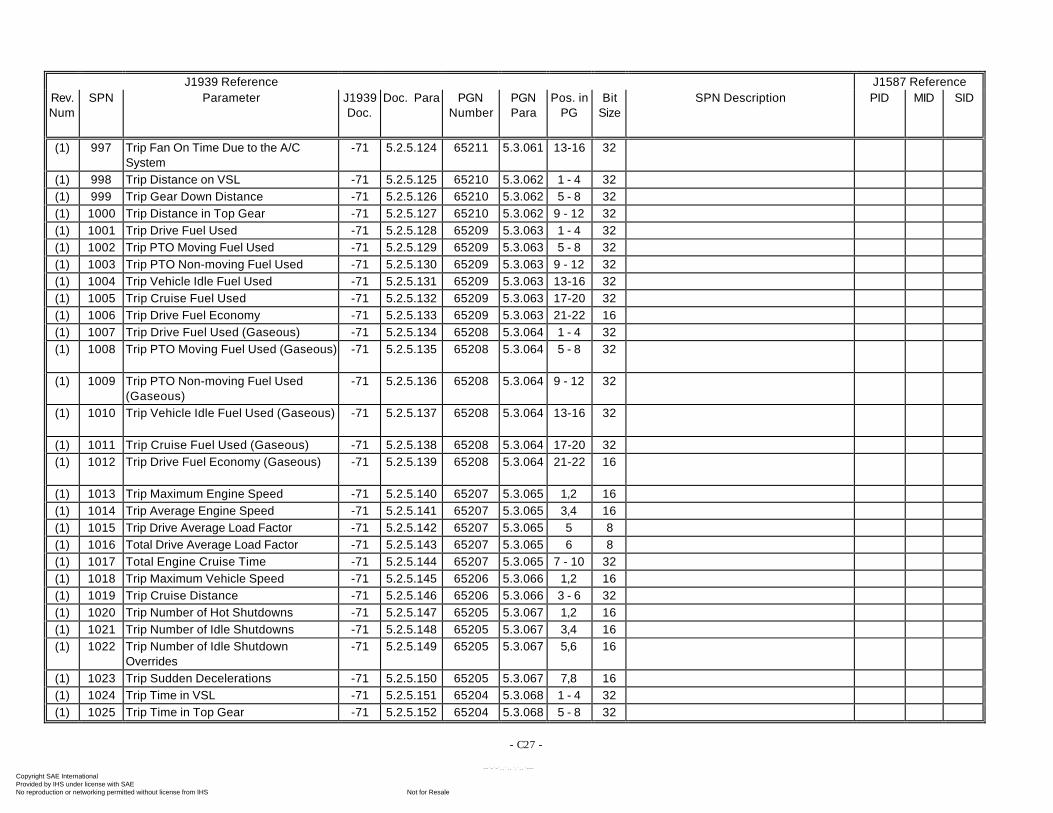
- C27 -
J1939 Reference J1587 ReferenceRev.Num
SPN Parameter J1939Doc.
Doc. Para PGNNumber
PGNPara
Pos. inPG
BitSize
SPN Description PID MID SID
(1) 997 Trip Fan On Time Due to the A/CSystem
-71 5.2.5.124 65211 5.3.061 13-16 32
(1) 998 Trip Distance on VSL -71 5.2.5.125 65210 5.3.062 1 - 4 32(1) 999 Trip Gear Down Distance -71 5.2.5.126 65210 5.3.062 5 - 8 32(1) 1000 Trip Distance in Top Gear -71 5.2.5.127 65210 5.3.062 9 - 12 32(1) 1001 Trip Drive Fuel Used -71 5.2.5.128 65209 5.3.063 1 - 4 32(1) 1002 Trip PTO Moving Fuel Used -71 5.2.5.129 65209 5.3.063 5 - 8 32(1) 1003 Trip PTO Non-moving Fuel Used -71 5.2.5.130 65209 5.3.063 9 - 12 32(1) 1004 Trip Vehicle Idle Fuel Used -71 5.2.5.131 65209 5.3.063 13-16 32(1) 1005 Trip Cruise Fuel Used -71 5.2.5.132 65209 5.3.063 17-20 32(1) 1006 Trip Drive Fuel Economy -71 5.2.5.133 65209 5.3.063 21-22 16(1) 1007 Trip Drive Fuel Used (Gaseous) -71 5.2.5.134 65208 5.3.064 1 - 4 32(1) 1008 Trip PTO Moving Fuel Used (Gaseous) -71 5.2.5.135 65208 5.3.064 5 - 8 32
(1) 1009 Trip PTO Non-moving Fuel Used(Gaseous)
-71 5.2.5.136 65208 5.3.064 9 - 12 32
(1) 1010 Trip Vehicle Idle Fuel Used (Gaseous) -71 5.2.5.137 65208 5.3.064 13-16 32
(1) 1011 Trip Cruise Fuel Used (Gaseous) -71 5.2.5.138 65208 5.3.064 17-20 32(1) 1012 Trip Drive Fuel Economy (Gaseous) -71 5.2.5.139 65208 5.3.064 21-22 16
(1) 1013 Trip Maximum Engine Speed -71 5.2.5.140 65207 5.3.065 1,2 16(1) 1014 Trip Average Engine Speed -71 5.2.5.141 65207 5.3.065 3,4 16(1) 1015 Trip Drive Average Load Factor -71 5.2.5.142 65207 5.3.065 5 8(1) 1016 Total Drive Average Load Factor -71 5.2.5.143 65207 5.3.065 6 8(1) 1017 Total Engine Cruise Time -71 5.2.5.144 65207 5.3.065 7 - 10 32(1) 1018 Trip Maximum Vehicle Speed -71 5.2.5.145 65206 5.3.066 1,2 16(1) 1019 Trip Cruise Distance -71 5.2.5.146 65206 5.3.066 3 - 6 32(1) 1020 Trip Number of Hot Shutdowns -71 5.2.5.147 65205 5.3.067 1,2 16(1) 1021 Trip Number of Idle Shutdowns -71 5.2.5.148 65205 5.3.067 3,4 16(1) 1022 Trip Number of Idle Shutdown
Overrides-71 5.2.5.149 65205 5.3.067 5,6 16
(1) 1023 Trip Sudden Decelerations -71 5.2.5.150 65205 5.3.067 7,8 16(1) 1024 Trip Time in VSL -71 5.2.5.151 65204 5.3.068 1 - 4 32(1) 1025 Trip Time in Top Gear -71 5.2.5.152 65204 5.3.068 5 - 8 32
Copyright SAE International Provided by IHS under license with SAE
Not for ResaleNo reproduction or networking permitted without license from IHS
--`-`-`,,`,,`,`,,`---
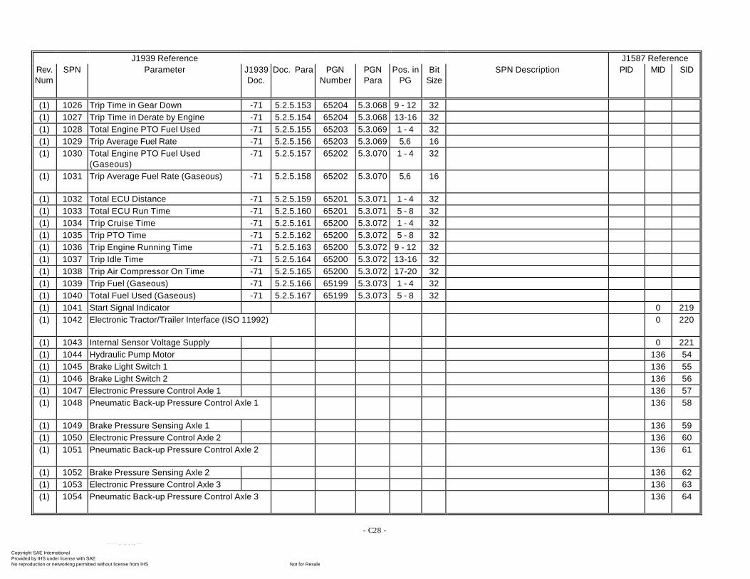
- C28 -
J1939 Reference J1587 ReferenceRev.Num
SPN Parameter J1939Doc.
Doc. Para PGNNumber
PGNPara
Pos. inPG
BitSize
SPN Description PID MID SID
(1) 1026 Trip Time in Gear Down -71 5.2.5.153 65204 5.3.068 9 - 12 32(1) 1027 Trip Time in Derate by Engine -71 5.2.5.154 65204 5.3.068 13-16 32(1) 1028 Total Engine PTO Fuel Used -71 5.2.5.155 65203 5.3.069 1 - 4 32(1) 1029 Trip Average Fuel Rate -71 5.2.5.156 65203 5.3.069 5,6 16(1) 1030 Total Engine PTO Fuel Used
(Gaseous)-71 5.2.5.157 65202 5.3.070 1 - 4 32
(1) 1031 Trip Average Fuel Rate (Gaseous) -71 5.2.5.158 65202 5.3.070 5,6 16
(1) 1032 Total ECU Distance -71 5.2.5.159 65201 5.3.071 1 - 4 32(1) 1033 Total ECU Run Time -71 5.2.5.160 65201 5.3.071 5 - 8 32(1) 1034 Trip Cruise Time -71 5.2.5.161 65200 5.3.072 1 - 4 32(1) 1035 Trip PTO Time -71 5.2.5.162 65200 5.3.072 5 - 8 32(1) 1036 Trip Engine Running Time -71 5.2.5.163 65200 5.3.072 9 - 12 32(1) 1037 Trip Idle Time -71 5.2.5.164 65200 5.3.072 13-16 32(1) 1038 Trip Air Compressor On Time -71 5.2.5.165 65200 5.3.072 17-20 32(1) 1039 Trip Fuel (Gaseous) -71 5.2.5.166 65199 5.3.073 1 - 4 32(1) 1040 Total Fuel Used (Gaseous) -71 5.2.5.167 65199 5.3.073 5 - 8 32(1) 1041 Start Signal Indicator 0 219(1) 1042 Electronic Tractor/Trailer Interface (ISO 11992) 0 220
(1) 1043 Internal Sensor Voltage Supply 0 221(1) 1044 Hydraulic Pump Motor 136 54(1) 1045 Brake Light Switch 1 136 55(1) 1046 Brake Light Switch 2 136 56(1) 1047 Electronic Pressure Control Axle 1 136 57(1) 1048 Pneumatic Back-up Pressure Control Axle 1 136 58
(1) 1049 Brake Pressure Sensing Axle 1 136 59(1) 1050 Electronic Pressure Control Axle 2 136 60(1) 1051 Pneumatic Back-up Pressure Control Axle 2 136 61
(1) 1052 Brake Pressure Sensing Axle 2 136 62(1) 1053 Electronic Pressure Control Axle 3 136 63(1) 1054 Pneumatic Back-up Pressure Control Axle 3 136 64
Copyright SAE International Provided by IHS under license with SAE
Not for ResaleNo reproduction or networking permitted without license from IHS
--`-`-`,,`,,`,`,,`---
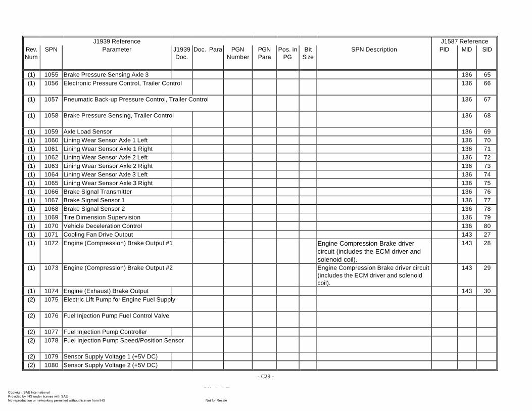
- C29 -
J1939 Reference J1587 ReferenceRev.Num
SPN Parameter J1939Doc.
Doc. Para PGNNumber
PGNPara
Pos. inPG
BitSize
SPN Description PID MID SID
(1) 1055 Brake Pressure Sensing Axle 3 136 65(1) 1056 Electronic Pressure Control, Trailer Control 136 66
(1) 1057 Pneumatic Back-up Pressure Control, Trailer Control 136 67
(1) 1058 Brake Pressure Sensing, Trailer Control 136 68
(1) 1059 Axle Load Sensor 136 69(1) 1060 Lining Wear Sensor Axle 1 Left 136 70(1) 1061 Lining Wear Sensor Axle 1 Right 136 71(1) 1062 Lining Wear Sensor Axle 2 Left 136 72(1) 1063 Lining Wear Sensor Axle 2 Right 136 73(1) 1064 Lining Wear Sensor Axle 3 Left 136 74(1) 1065 Lining Wear Sensor Axle 3 Right 136 75(1) 1066 Brake Signal Transmitter 136 76(1) 1067 Brake Signal Sensor 1 136 77(1) 1068 Brake Signal Sensor 2 136 78(1) 1069 Tire Dimension Supervision 136 79(1) 1070 Vehicle Deceleration Control 136 80(1) 1071 Cooling Fan Drive Output 143 27(1) 1072 Engine (Compression) Brake Output #1 Engine Compression Brake driver
circuit (includes the ECM driver andsolenoid coil).
143 28
(1) 1073 Engine (Compression) Brake Output #2 Engine Compression Brake driver circuit(includes the ECM driver and solenoidcoil).
143 29
(1) 1074 Engine (Exhaust) Brake Output 143 30(2) 1075 Electric Lift Pump for Engine Fuel Supply
(2) 1076 Fuel Injection Pump Fuel Control Valve
(2) 1077 Fuel Injection Pump Controller(2) 1078 Fuel Injection Pump Speed/Position Sensor
(2) 1079 Sensor Supply Voltage 1 (+5V DC)(2) 1080 Sensor Supply Voltage 2 (+5V DC)
Copyright SAE International Provided by IHS under license with SAE
Not for ResaleNo reproduction or networking permitted without license from IHS
--`-`-`,,`,,`,`,,`---
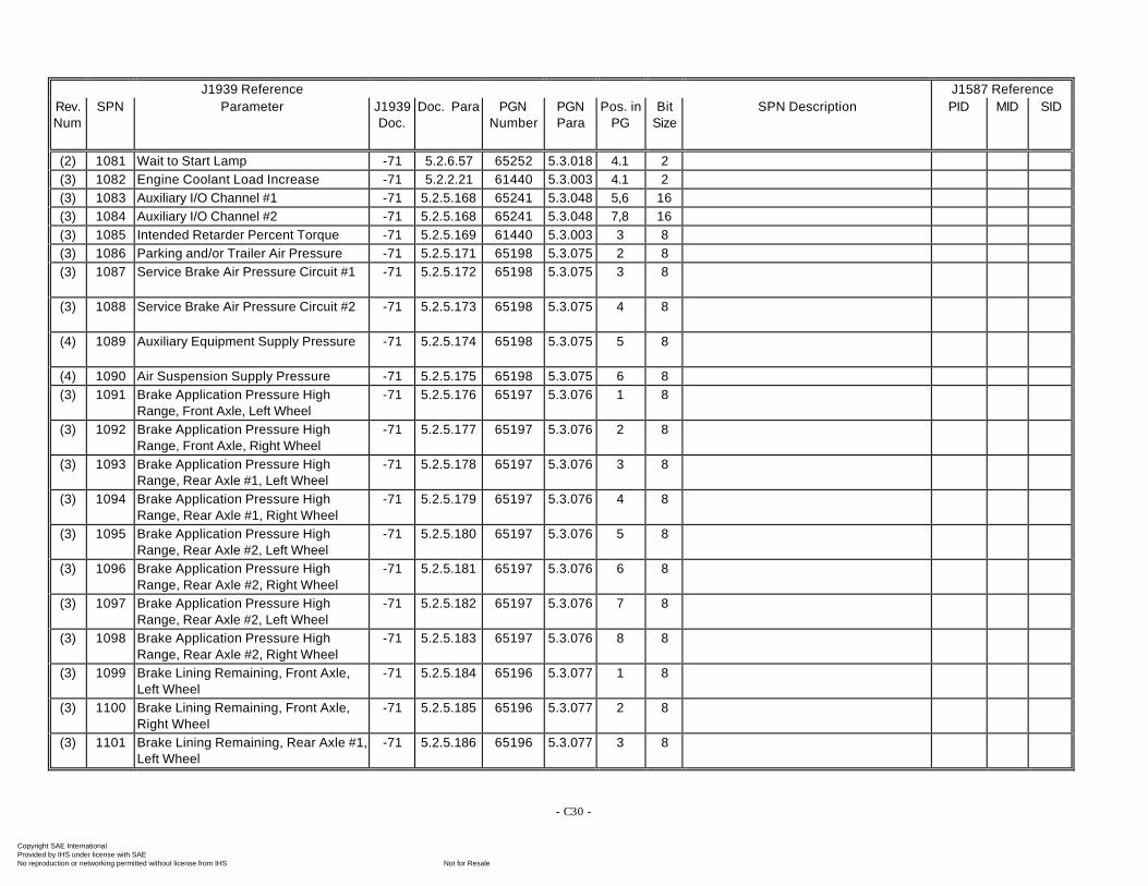
- C30 -
J1939 Reference J1587 ReferenceRev.Num
SPN Parameter J1939Doc.
Doc. Para PGNNumber
PGNPara
Pos. inPG
BitSize
SPN Description PID MID SID
(2) 1081 Wait to Start Lamp -71 5.2.6.57 65252 5.3.018 4.1 2(3) 1082 Engine Coolant Load Increase -71 5.2.2.21 61440 5.3.003 4.1 2(3) 1083 Auxiliary I/O Channel #1 -71 5.2.5.168 65241 5.3.048 5,6 16(3) 1084 Auxiliary I/O Channel #2 -71 5.2.5.168 65241 5.3.048 7,8 16(3) 1085 Intended Retarder Percent Torque -71 5.2.5.169 61440 5.3.003 3 8(3) 1086 Parking and/or Trailer Air Pressure -71 5.2.5.171 65198 5.3.075 2 8(3) 1087 Service Brake Air Pressure Circuit #1 -71 5.2.5.172 65198 5.3.075 3 8
(3) 1088 Service Brake Air Pressure Circuit #2 -71 5.2.5.173 65198 5.3.075 4 8
(4) 1089 Auxiliary Equipment Supply Pressure -71 5.2.5.174 65198 5.3.075 5 8
(4) 1090 Air Suspension Supply Pressure -71 5.2.5.175 65198 5.3.075 6 8(3) 1091 Brake Application Pressure High
Range, Front Axle, Left Wheel-71 5.2.5.176 65197 5.3.076 1 8
(3) 1092 Brake Application Pressure HighRange, Front Axle, Right Wheel
-71 5.2.5.177 65197 5.3.076 2 8
(3) 1093 Brake Application Pressure HighRange, Rear Axle #1, Left Wheel
-71 5.2.5.178 65197 5.3.076 3 8
(3) 1094 Brake Application Pressure HighRange, Rear Axle #1, Right Wheel
-71 5.2.5.179 65197 5.3.076 4 8
(3) 1095 Brake Application Pressure HighRange, Rear Axle #2, Left Wheel
-71 5.2.5.180 65197 5.3.076 5 8
(3) 1096 Brake Application Pressure HighRange, Rear Axle #2, Right Wheel
-71 5.2.5.181 65197 5.3.076 6 8
(3) 1097 Brake Application Pressure HighRange, Rear Axle #2, Left Wheel
-71 5.2.5.182 65197 5.3.076 7 8
(3) 1098 Brake Application Pressure HighRange, Rear Axle #2, Right Wheel
-71 5.2.5.183 65197 5.3.076 8 8
(3) 1099 Brake Lining Remaining, Front Axle,Left Wheel
-71 5.2.5.184 65196 5.3.077 1 8
(3) 1100 Brake Lining Remaining, Front Axle,Right Wheel
-71 5.2.5.185 65196 5.3.077 2 8
(3) 1101 Brake Lining Remaining, Rear Axle #1,Left Wheel
-71 5.2.5.186 65196 5.3.077 3 8
Copyright SAE International Provided by IHS under license with SAE
Not for ResaleNo reproduction or networking permitted without license from IHS
--`-`-`,,`,,`,`,,`---
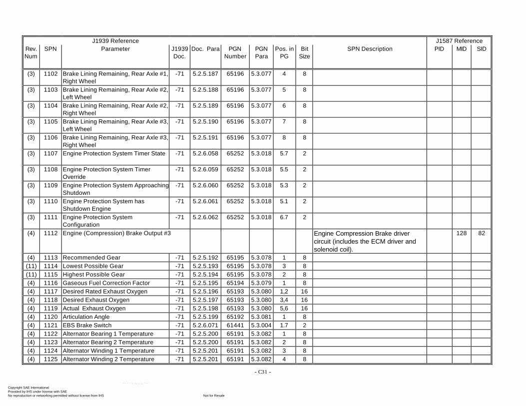
- C31 -
J1939 Reference J1587 ReferenceRev.Num
SPN Parameter J1939Doc.
Doc. Para PGNNumber
PGNPara
Pos. inPG
BitSize
SPN Description PID MID SID
(3) 1102 Brake Lining Remaining, Rear Axle #1,Right Wheel
-71 5.2.5.187 65196 5.3.077 4 8
(3) 1103 Brake Lining Remaining, Rear Axle #2,Left Wheel
-71 5.2.5.188 65196 5.3.077 5 8
(3) 1104 Brake Lining Remaining, Rear Axle #2,Right Wheel
-71 5.2.5.189 65196 5.3.077 6 8
(3) 1105 Brake Lining Remaining, Rear Axle #3,Left Wheel
-71 5.2.5.190 65196 5.3.077 7 8
(3) 1106 Brake Lining Remaining, Rear Axle #3,Right Wheel
-71 5.2.5.191 65196 5.3.077 8 8
(3) 1107 Engine Protection System Timer State -71 5.2.6.058 65252 5.3.018 5.7 2
(3) 1108 Engine Protection System TimerOverride
-71 5.2.6.059 65252 5.3.018 5.5 2
(3) 1109 Engine Protection System ApproachingShutdown
-71 5.2.6.060 65252 5.3.018 5.3 2
(3) 1110 Engine Protection System hasShutdown Engine
-71 5.2.6.061 65252 5.3.018 5.1 2
(3) 1111 Engine Protection SystemConfiguration
-71 5.2.6.062 65252 5.3.018 6.7 2
(4) 1112 Engine (Compression) Brake Output #3 Engine Compression Brake drivercircuit (includes the ECM driver andsolenoid coil).
128 82
(4) 1113 Recommended Gear -71 5.2.5.192 65195 5.3.078 1 8(11) 1114 Lowest Possible Gear -71 5.2.5.193 65195 5.3.078 3 8(11) 1115 Highest Possible Gear -71 5.2.5.194 65195 5.3.078 2 8(4) 1116 Gaseous Fuel Correction Factor -71 5.2.5.195 65194 5.3.079 1 8(4) 1117 Desired Rated Exhaust Oxygen -71 5.2.5.196 65193 5.3.080 1,2 16(4) 1118 Desired Exhaust Oxygen -71 5.2.5.197 65193 5.3.080 3,4 16(4) 1119 Actual Exhaust Oxygen -71 5.2.5.198 65193 5.3.080 5,6 16(4) 1120 Articulation Angle -71 5.2.5.199 65192 5.3.081 1 8(4) 1121 EBS Brake Switch -71 5.2.6.071 61441 5.3.004 1.7 2(4) 1122 Alternator Bearing 1 Temperature -71 5.2.5.200 65191 5.3.082 1 8(4) 1123 Alternator Bearing 2 Temperature -71 5.2.5.200 65191 5.3.082 2 8(4) 1124 Alternator Winding 1 Temperature -71 5.2.5.201 65191 5.3.082 3 8(4) 1125 Alternator Winding 2 Temperature -71 5.2.5.201 65191 5.3.082 4 8
Copyright SAE International Provided by IHS under license with SAE
Not for ResaleNo reproduction or networking permitted without license from IHS
--`-`-`,,`,,`,`,,`---
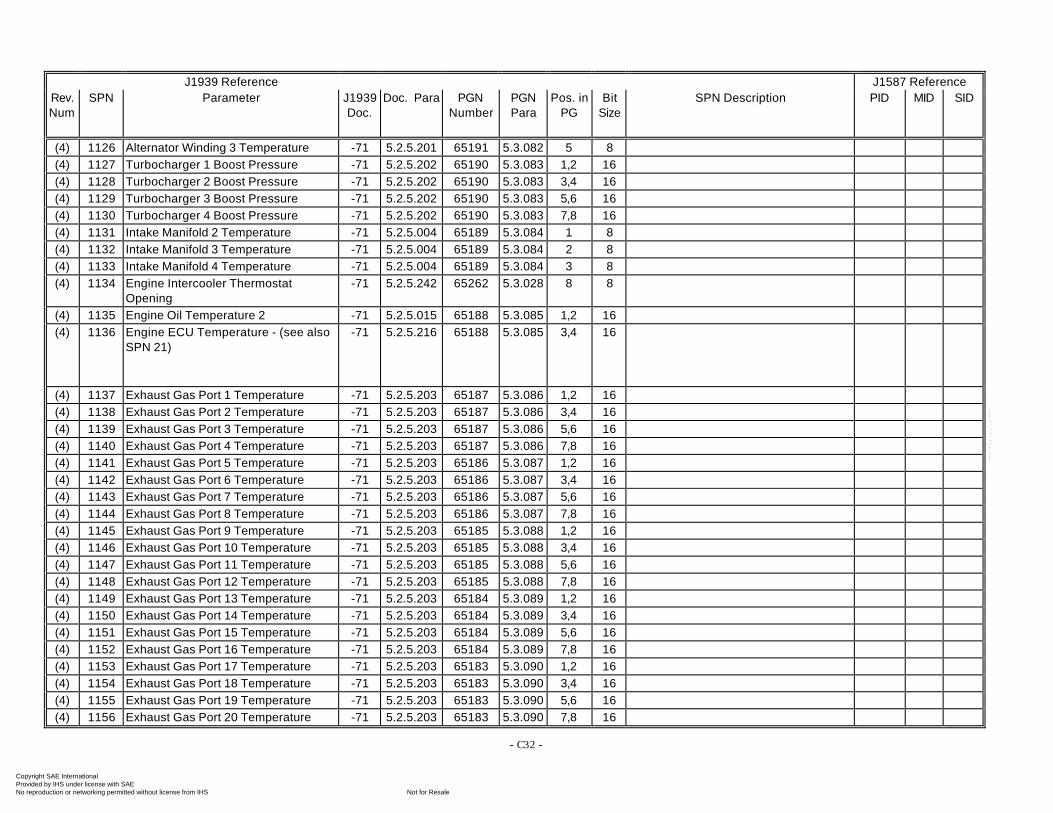
- C32 -
J1939 Reference J1587 ReferenceRev.Num
SPN Parameter J1939Doc.
Doc. Para PGNNumber
PGNPara
Pos. inPG
BitSize
SPN Description PID MID SID
(4) 1126 Alternator Winding 3 Temperature -71 5.2.5.201 65191 5.3.082 5 8(4) 1127 Turbocharger 1 Boost Pressure -71 5.2.5.202 65190 5.3.083 1,2 16(4) 1128 Turbocharger 2 Boost Pressure -71 5.2.5.202 65190 5.3.083 3,4 16(4) 1129 Turbocharger 3 Boost Pressure -71 5.2.5.202 65190 5.3.083 5,6 16(4) 1130 Turbocharger 4 Boost Pressure -71 5.2.5.202 65190 5.3.083 7,8 16(4) 1131 Intake Manifold 2 Temperature -71 5.2.5.004 65189 5.3.084 1 8(4) 1132 Intake Manifold 3 Temperature -71 5.2.5.004 65189 5.3.084 2 8(4) 1133 Intake Manifold 4 Temperature -71 5.2.5.004 65189 5.3.084 3 8(4) 1134 Engine Intercooler Thermostat
Opening-71 5.2.5.242 65262 5.3.028 8 8
(4) 1135 Engine Oil Temperature 2 -71 5.2.5.015 65188 5.3.085 1,2 16(4) 1136 Engine ECU Temperature - (see also
SPN 21)-71 5.2.5.216 65188 5.3.085 3,4 16
(4) 1137 Exhaust Gas Port 1 Temperature -71 5.2.5.203 65187 5.3.086 1,2 16(4) 1138 Exhaust Gas Port 2 Temperature -71 5.2.5.203 65187 5.3.086 3,4 16(4) 1139 Exhaust Gas Port 3 Temperature -71 5.2.5.203 65187 5.3.086 5,6 16(4) 1140 Exhaust Gas Port 4 Temperature -71 5.2.5.203 65187 5.3.086 7,8 16(4) 1141 Exhaust Gas Port 5 Temperature -71 5.2.5.203 65186 5.3.087 1,2 16(4) 1142 Exhaust Gas Port 6 Temperature -71 5.2.5.203 65186 5.3.087 3,4 16(4) 1143 Exhaust Gas Port 7 Temperature -71 5.2.5.203 65186 5.3.087 5,6 16(4) 1144 Exhaust Gas Port 8 Temperature -71 5.2.5.203 65186 5.3.087 7,8 16(4) 1145 Exhaust Gas Port 9 Temperature -71 5.2.5.203 65185 5.3.088 1,2 16(4) 1146 Exhaust Gas Port 10 Temperature -71 5.2.5.203 65185 5.3.088 3,4 16(4) 1147 Exhaust Gas Port 11 Temperature -71 5.2.5.203 65185 5.3.088 5,6 16(4) 1148 Exhaust Gas Port 12 Temperature -71 5.2.5.203 65185 5.3.088 7,8 16(4) 1149 Exhaust Gas Port 13 Temperature -71 5.2.5.203 65184 5.3.089 1,2 16(4) 1150 Exhaust Gas Port 14 Temperature -71 5.2.5.203 65184 5.3.089 3,4 16(4) 1151 Exhaust Gas Port 15 Temperature -71 5.2.5.203 65184 5.3.089 5,6 16(4) 1152 Exhaust Gas Port 16 Temperature -71 5.2.5.203 65184 5.3.089 7,8 16(4) 1153 Exhaust Gas Port 17 Temperature -71 5.2.5.203 65183 5.3.090 1,2 16(4) 1154 Exhaust Gas Port 18 Temperature -71 5.2.5.203 65183 5.3.090 3,4 16(4) 1155 Exhaust Gas Port 19 Temperature -71 5.2.5.203 65183 5.3.090 5,6 16(4) 1156 Exhaust Gas Port 20 Temperature -71 5.2.5.203 65183 5.3.090 7,8 16
Copyright SAE International Provided by IHS under license with SAE
Not for ResaleNo reproduction or networking permitted without license from IHS
--`-`-`,,`,,`,`,,`---
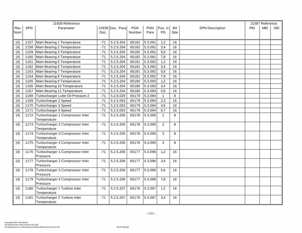
- C33 -
J1939 Reference J1587 ReferenceRev.Num
SPN Parameter J1939Doc.
Doc. Para PGNNumber
PGNPara
Pos. inPG
BitSize
SPN Description PID MID SID
(4) 1157 Main Bearing 1 Temperature -71 5.2.5.204 65182 5.3.091 1,2 16(4) 1158 Main Bearing 2 Temperature -71 5.2.5.204 65182 5.3.091 3,4 16(4) 1159 Main Bearing 3 Temperature -71 5.2.5.204 65182 5.3.091 5,6 16(4) 1160 Main Bearing 4 Temperature -71 5.2.5.204 65182 5.3.091 7,8 16(4) 1161 Main Bearing 5 Temperature -71 5.2.5.204 65181 5.3.092 1,2 16(4) 1162 Main Bearing 6 Temperature -71 5.2.5.204 65181 5.3.092 3,4 16(4) 1163 Main Bearing 7 Temperature -71 5.2.5.204 65181 5.3.092 5,6 16(4) 1164 Main Bearing 8 Temperature -71 5.2.5.204 65181 5.3.092 7,8 16(4) 1165 Main Bearing 9 Temperature -71 5.2.5.204 65180 5.3.093 1,2 16(4) 1166 Main Bearing 10 Temperature -71 5.2.5.204 65180 5.3.093 3,4 16(4) 1167 Main Bearing 11 Temperature -71 5.2.5.204 65180 5.3.093 5,6 16(4) 1168 Turbocharger Lube Oil Pressure 2 -71 5.2.5.029 65179 5.3.094 1 8(4) 1169 Turbocharger 2 Speed -71 5.2.5.053 65179 5.3.094 2,3 16(4) 1170 Turbocharger 3 Speed -71 5.2.5.053 65179 5.3.094 4,5 16(4) 1171 Turbocharger 4 Speed -71 5.2.5.053 65179 5.3.094 6,7 16(4) 1172 Turbocharger 1 Compressor Inlet
Temperature-71 5.2.5.205 65178 5.3.095 1 8
(4) 1173 Turbocharger 2 Compressor InletTemperature
-71 5.2.5.205 65178 5.3.095 2 8
(4) 1174 Turbocharger 3 Compressor InletTemperature
-71 5.2.5.205 65178 5.3.095 3 8
(4) 1175 Turbocharger 4 Compressor InletTemperature
-71 5.2.5.205 65178 5.3.095 4 8
(4) 1176 Turbocharger 1 Compressor InletPressure
-71 5.2.5.206 65177 5.3.096 1,2 16
(4) 1177 Turbocharger 2 Compressor InletPressure
-71 5.2.5.206 65177 5.3.096 3,4 16
(4) 1178 Turbocharger 3 Compressor InletPressure
-71 5.2.5.206 65177 5.3.096 5,6 16
(4) 1179 Turbocharger 4 Compressor InletPressure
-71 5.2.5.206 65177 5.3.096 7,8 16
(4) 1180 Turbocharger 1 Turbine InletTemperature
-71 5.2.5.207 65176 5.3.097 1,2 16
(4) 1181 Turbocharger 2 Turbine InletTemperature
-71 5.2.5.207 65176 5.3.097 3,4 16
Copyright SAE International Provided by IHS under license with SAE
Not for ResaleNo reproduction or networking permitted without license from IHS
--`-`-`,,`,,`,`,,`---
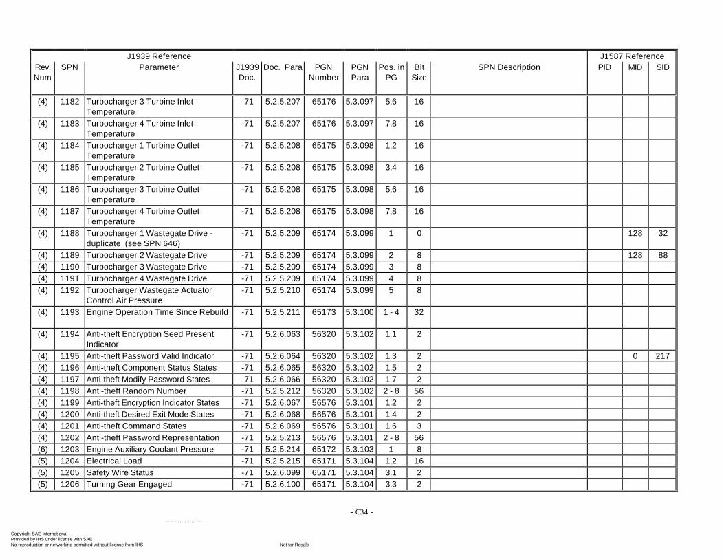
- C34 -
J1939 Reference J1587 ReferenceRev.Num
SPN Parameter J1939Doc.
Doc. Para PGNNumber
PGNPara
Pos. inPG
BitSize
SPN Description PID MID SID
(4) 1182 Turbocharger 3 Turbine InletTemperature
-71 5.2.5.207 65176 5.3.097 5,6 16
(4) 1183 Turbocharger 4 Turbine InletTemperature
-71 5.2.5.207 65176 5.3.097 7,8 16
(4) 1184 Turbocharger 1 Turbine OutletTemperature
-71 5.2.5.208 65175 5.3.098 1,2 16
(4) 1185 Turbocharger 2 Turbine OutletTemperature
-71 5.2.5.208 65175 5.3.098 3,4 16
(4) 1186 Turbocharger 3 Turbine OutletTemperature
-71 5.2.5.208 65175 5.3.098 5,6 16
(4) 1187 Turbocharger 4 Turbine OutletTemperature
-71 5.2.5.208 65175 5.3.098 7,8 16
(4) 1188 Turbocharger 1 Wastegate Drive -duplicate (see SPN 646)
-71 5.2.5.209 65174 5.3.099 1 0 128 32
(4) 1189 Turbocharger 2 Wastegate Drive -71 5.2.5.209 65174 5.3.099 2 8 128 88(4) 1190 Turbocharger 3 Wastegate Drive -71 5.2.5.209 65174 5.3.099 3 8(4) 1191 Turbocharger 4 Wastegate Drive -71 5.2.5.209 65174 5.3.099 4 8(4) 1192 Turbocharger Wastegate Actuator
Control Air Pressure-71 5.2.5.210 65174 5.3.099 5 8
(4) 1193 Engine Operation Time Since Rebuild -71 5.2.5.211 65173 5.3.100 1 - 4 32
(4) 1194 Anti-theft Encryption Seed PresentIndicator
-71 5.2.6.063 56320 5.3.102 1.1 2
(4) 1195 Anti-theft Password Valid Indicator -71 5.2.6.064 56320 5.3.102 1.3 2 0 217(4) 1196 Anti-theft Component Status States -71 5.2.6.065 56320 5.3.102 1.5 2(4) 1197 Anti-theft Modify Password States -71 5.2.6.066 56320 5.3.102 1.7 2(4) 1198 Anti-theft Random Number -71 5.2.5.212 56320 5.3.102 2 - 8 56(4) 1199 Anti-theft Encryption Indicator States -71 5.2.6.067 56576 5.3.101 1.2 2(4) 1200 Anti-theft Desired Exit Mode States -71 5.2.6.068 56576 5.3.101 1.4 2(4) 1201 Anti-theft Command States -71 5.2.6.069 56576 5.3.101 1.6 3(4) 1202 Anti-theft Password Representation -71 5.2.5.213 56576 5.3.101 2 - 8 56(6) 1203 Engine Auxiliary Coolant Pressure -71 5.2.5.214 65172 5.3.103 1 8(5) 1204 Electrical Load -71 5.2.5.215 65171 5.3.104 1,2 16(5) 1205 Safety Wire Status -71 5.2.6.099 65171 5.3.104 3.1 2(5) 1206 Turning Gear Engaged -71 5.2.6.100 65171 5.3.104 3.3 2
Copyright SAE International Provided by IHS under license with SAE
Not for ResaleNo reproduction or networking permitted without license from IHS
--`-`-`,,`,,`,`,,`---
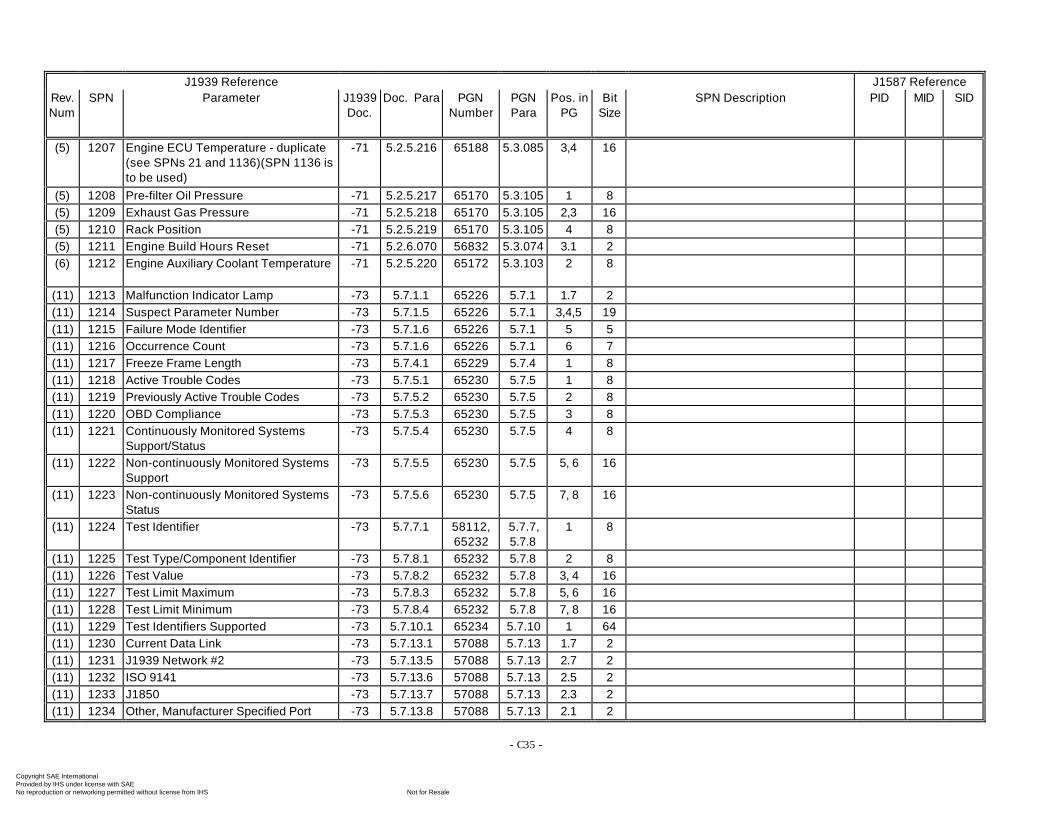
- C35 -
J1939 Reference J1587 ReferenceRev.Num
SPN Parameter J1939Doc.
Doc. Para PGNNumber
PGNPara
Pos. inPG
BitSize
SPN Description PID MID SID
(5) 1207 Engine ECU Temperature - duplicate(see SPNs 21 and 1136)(SPN 1136 isto be used)
-71 5.2.5.216 65188 5.3.085 3,4 16
(5) 1208 Pre-filter Oil Pressure -71 5.2.5.217 65170 5.3.105 1 8(5) 1209 Exhaust Gas Pressure -71 5.2.5.218 65170 5.3.105 2,3 16(5) 1210 Rack Position -71 5.2.5.219 65170 5.3.105 4 8(5) 1211 Engine Build Hours Reset -71 5.2.6.070 56832 5.3.074 3.1 2(6) 1212 Engine Auxiliary Coolant Temperature -71 5.2.5.220 65172 5.3.103 2 8
(11) 1213 Malfunction Indicator Lamp -73 5.7.1.1 65226 5.7.1 1.7 2(11) 1214 Suspect Parameter Number -73 5.7.1.5 65226 5.7.1 3,4,5 19(11) 1215 Failure Mode Identifier -73 5.7.1.6 65226 5.7.1 5 5(11) 1216 Occurrence Count -73 5.7.1.6 65226 5.7.1 6 7(11) 1217 Freeze Frame Length -73 5.7.4.1 65229 5.7.4 1 8(11) 1218 Active Trouble Codes -73 5.7.5.1 65230 5.7.5 1 8(11) 1219 Previously Active Trouble Codes -73 5.7.5.2 65230 5.7.5 2 8(11) 1220 OBD Compliance -73 5.7.5.3 65230 5.7.5 3 8(11) 1221 Continuously Monitored Systems
Support/Status-73 5.7.5.4 65230 5.7.5 4 8
(11) 1222 Non-continuously Monitored SystemsSupport
-73 5.7.5.5 65230 5.7.5 5, 6 16
(11) 1223 Non-continuously Monitored SystemsStatus
-73 5.7.5.6 65230 5.7.5 7, 8 16
(11) 1224 Test Identifier -73 5.7.7.1 58112,65232
5.7.7,5.7.8
1 8
(11) 1225 Test Type/Component Identifier -73 5.7.8.1 65232 5.7.8 2 8(11) 1226 Test Value -73 5.7.8.2 65232 5.7.8 3, 4 16(11) 1227 Test Limit Maximum -73 5.7.8.3 65232 5.7.8 5, 6 16(11) 1228 Test Limit Minimum -73 5.7.8.4 65232 5.7.8 7, 8 16(11) 1229 Test Identifiers Supported -73 5.7.10.1 65234 5.7.10 1 64(11) 1230 Current Data Link -73 5.7.13.1 57088 5.7.13 1.7 2(11) 1231 J1939 Network #2 -73 5.7.13.5 57088 5.7.13 2.7 2(11) 1232 ISO 9141 -73 5.7.13.6 57088 5.7.13 2.5 2(11) 1233 J1850 -73 5.7.13.7 57088 5.7.13 2.3 2(11) 1234 Other, Manufacturer Specified Port -73 5.7.13.8 57088 5.7.13 2.1 2
Copyright SAE International Provided by IHS under license with SAE
Not for ResaleNo reproduction or networking permitted without license from IHS
--`-`-`,,`,,`,`,,`---
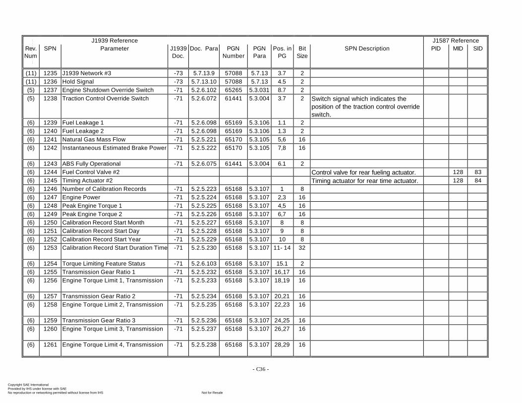
- C36 -
J1939 Reference J1587 ReferenceRev.Num
SPN Parameter J1939Doc.
Doc. Para PGNNumber
PGNPara
Pos. inPG
BitSize
SPN Description PID MID SID
(11) 1235 J1939 Network #3 -73 5.7.13.9 57088 5.7.13 3.7 2(11) 1236 Hold Signal -73 5.7.13.10 57088 5.7.13 4.5 2(5) 1237 Engine Shutdown Override Switch -71 5.2.6.102 65265 5.3.031 8.7 2(5) 1238 Traction Control Override Switch -71 5.2.6.072 61441 5.3.004 3.7 2 Switch signal which indicates the
position of the traction control overrideswitch.
(6) 1239 Fuel Leakage 1 -71 5.2.6.098 65169 5.3.106 1.1 2(6) 1240 Fuel Leakage 2 -71 5.2.6.098 65169 5.3.106 1.3 2(6) 1241 Natural Gas Mass Flow -71 5.2.5.221 65170 5.3.105 5,6 16(6) 1242 Instantaneous Estimated Brake Power -71 5.2.5.222 65170 5.3.105 7,8 16
(6) 1243 ABS Fully Operational -71 5.2.6.075 61441 5.3.004 6.1 2(6) 1244 Fuel Control Valve #2 Control valve for rear fueling actuator. 128 83(6) 1245 Timing Actuator #2 Timing actuator for rear time actuator. 128 84(6) 1246 Number of Calibration Records -71 5.2.5.223 65168 5.3.107 1 8(6) 1247 Engine Power -71 5.2.5.224 65168 5.3.107 2,3 16(6) 1248 Peak Engine Torque 1 -71 5.2.5.225 65168 5.3.107 4,5 16(6) 1249 Peak Engine Torque 2 -71 5.2.5.226 65168 5.3.107 6,7 16(6) 1250 Calibration Record Start Month -71 5.2.5.227 65168 5.3.107 8 8(6) 1251 Calibration Record Start Day -71 5.2.5.228 65168 5.3.107 9 8(6) 1252 Calibration Record Start Year -71 5.2.5.229 65168 5.3.107 10 8(6) 1253 Calibration Record Start Duration Time -71 5.2.5.230 65168 5.3.107 11- 14 32
(6) 1254 Torque Limiting Feature Status -71 5.2.6.103 65168 5.3.107 15.1 2(6) 1255 Transmission Gear Ratio 1 -71 5.2.5.232 65168 5.3.107 16,17 16(6) 1256 Engine Torque Limit 1, Transmission -71 5.2.5.233 65168 5.3.107 18,19 16
(6) 1257 Transmission Gear Ratio 2 -71 5.2.5.234 65168 5.3.107 20,21 16(6) 1258 Engine Torque Limit 2, Transmission -71 5.2.5.235 65168 5.3.107 22,23 16
(6) 1259 Transmission Gear Ratio 3 -71 5.2.5.236 65168 5.3.107 24,25 16(6) 1260 Engine Torque Limit 3, Transmission -71 5.2.5.237 65168 5.3.107 26,27 16
(6) 1261 Engine Torque Limit 4, Transmission -71 5.2.5.238 65168 5.3.107 28,29 16
Copyright SAE International Provided by IHS under license with SAE
Not for ResaleNo reproduction or networking permitted without license from IHS
--`-`-`,,`,,`,`,,`---
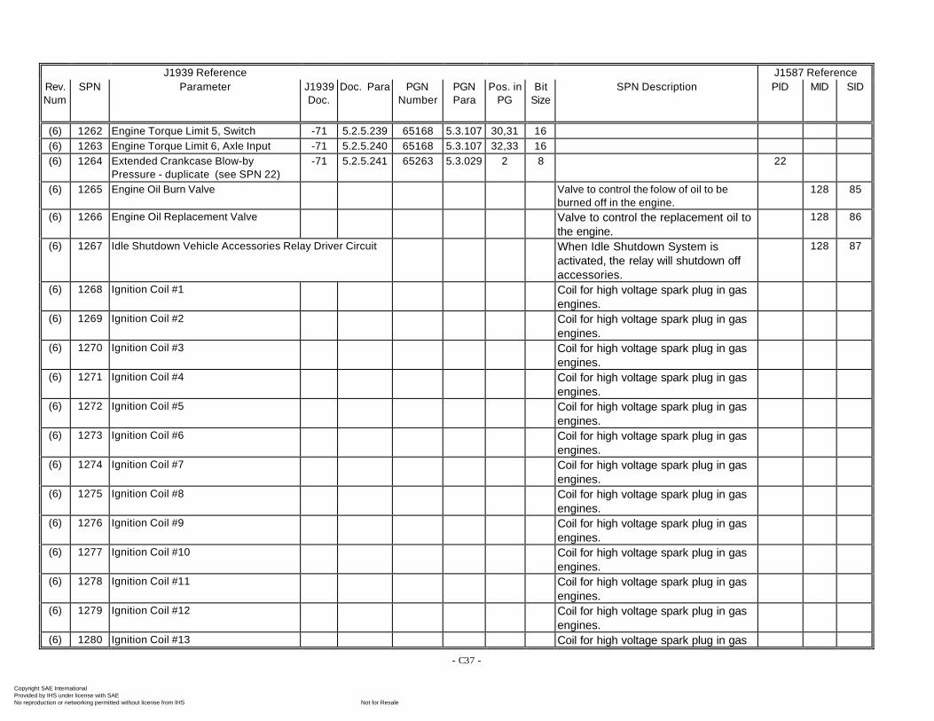
- C37 -
J1939 Reference J1587 ReferenceRev.Num
SPN Parameter J1939Doc.
Doc. Para PGNNumber
PGNPara
Pos. inPG
BitSize
SPN Description PID MID SID
(6) 1262 Engine Torque Limit 5, Switch -71 5.2.5.239 65168 5.3.107 30,31 16(6) 1263 Engine Torque Limit 6, Axle Input -71 5.2.5.240 65168 5.3.107 32,33 16(6) 1264 Extended Crankcase Blow-by
Pressure - duplicate (see SPN 22)-71 5.2.5.241 65263 5.3.029 2 8 22
(6) 1265 Engine Oil Burn Valve Valve to control the folow of oil to beburned off in the engine.
128 85
(6) 1266 Engine Oil Replacement Valve Valve to control the replacement oil tothe engine.
128 86
(6) 1267 Idle Shutdown Vehicle Accessories Relay Driver Circuit When Idle Shutdown System isactivated, the relay will shutdown offaccessories.
128 87
(6) 1268 Ignition Coil #1 Coil for high voltage spark plug in gasengines.
(6) 1269 Ignition Coil #2 Coil for high voltage spark plug in gasengines.
(6) 1270 Ignition Coil #3 Coil for high voltage spark plug in gasengines.
(6) 1271 Ignition Coil #4 Coil for high voltage spark plug in gasengines.
(6) 1272 Ignition Coil #5 Coil for high voltage spark plug in gasengines.
(6) 1273 Ignition Coil #6 Coil for high voltage spark plug in gasengines.
(6) 1274 Ignition Coil #7 Coil for high voltage spark plug in gasengines.
(6) 1275 Ignition Coil #8 Coil for high voltage spark plug in gasengines.
(6) 1276 Ignition Coil #9 Coil for high voltage spark plug in gasengines.
(6) 1277 Ignition Coil #10 Coil for high voltage spark plug in gasengines.
(6) 1278 Ignition Coil #11 Coil for high voltage spark plug in gasengines.
(6) 1279 Ignition Coil #12 Coil for high voltage spark plug in gasengines.
(6) 1280 Ignition Coil #13 Coil for high voltage spark plug in gas
Copyright SAE International Provided by IHS under license with SAE
Not for ResaleNo reproduction or networking permitted without license from IHS
--`-`-`,,`,,`,`,,`---
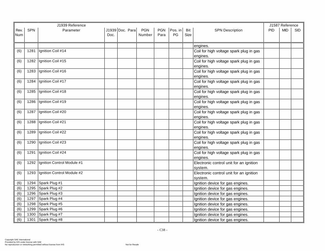
- C38 -
J1939 Reference J1587 ReferenceRev.Num
SPN Parameter J1939Doc.
Doc. Para PGNNumber
PGNPara
Pos. inPG
BitSize
SPN Description PID MID SID
engines.(6) 1281 Ignition Coil #14 Coil for high voltage spark plug in gas
engines.(6) 1282 Ignition Coil #15 Coil for high voltage spark plug in gas
engines.(6) 1283 Ignition Coil #16 Coil for high voltage spark plug in gas
engines.(6) 1284 Ignition Coil #17 Coil for high voltage spark plug in gas
engines.(6) 1285 Ignition Coil #18 Coil for high voltage spark plug in gas
engines.(6) 1286 Ignition Coil #19 Coil for high voltage spark plug in gas
engines.(6) 1287 Ignition Coil #20 Coil for high voltage spark plug in gas
engines.(6) 1288 Ignition Coil #21 Coil for high voltage spark plug in gas
engines.(6) 1289 Ignition Coil #22 Coil for high voltage spark plug in gas
engines.(6) 1290 Ignition Coil #23 Coil for high voltage spark plug in gas
engines.(6) 1291 Ignition Coil #24 Coil for high voltage spark plug in gas
engines.(6) 1292 Ignition Control Module #1 Electronic control unit for an ignition
system.(6) 1293 Ignition Control Module #2 Electronic control unit for an ignition
system.(6) 1294 Spark Plug #1 Ignition device for gas engines.(6) 1295 Spark Plug #2 Ignition device for gas engines.(6) 1296 Spark Plug #3 Ignition device for gas engines.(6) 1297 Spark Plug #4 Ignition device for gas engines.(6) 1298 Spark Plug #5 Ignition device for gas engines.(6) 1299 Spark Plug #6 Ignition device for gas engines.(6) 1300 Spark Plug #7 Ignition device for gas engines.(6) 1301 Spark Plug #8 Ignition device for gas engines.
Copyright SAE International Provided by IHS under license with SAE
Not for ResaleNo reproduction or networking permitted without license from IHS
--`-`-`,,`,,`,`,,`---
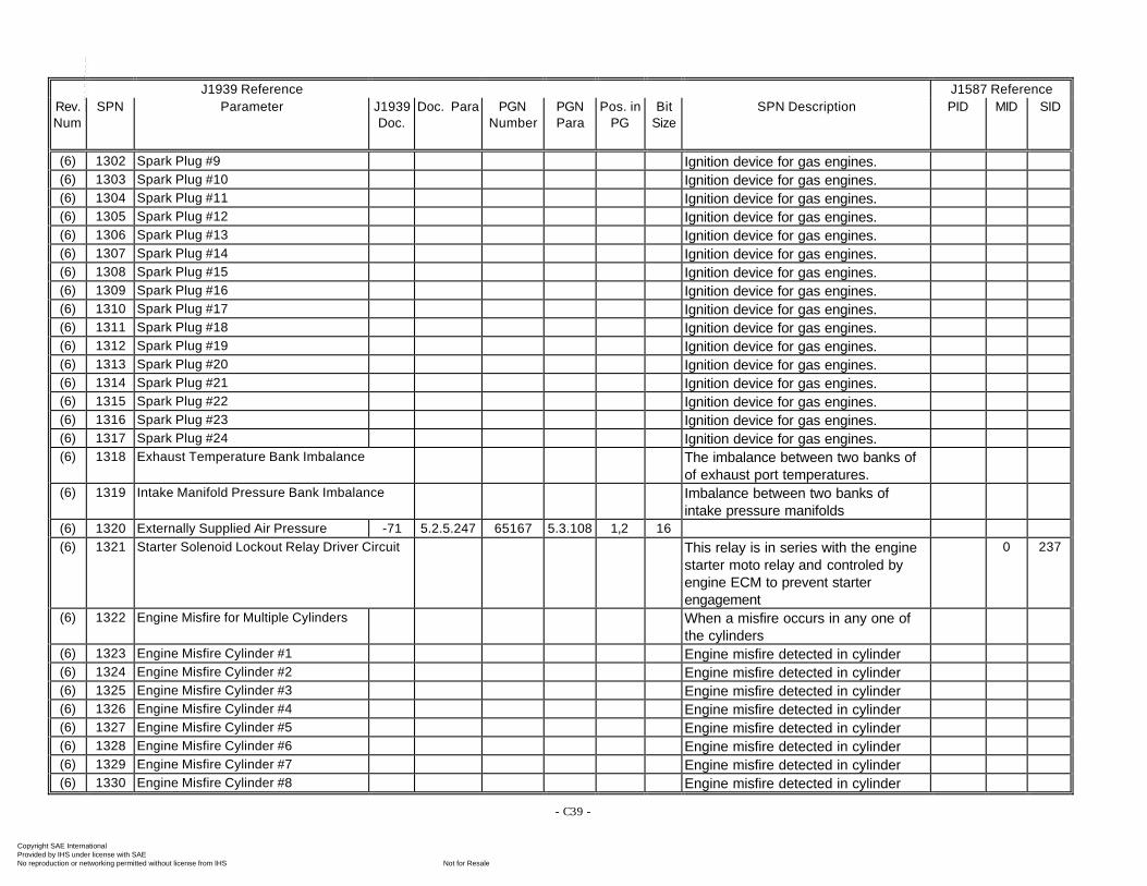
- C39 -
J1939 Reference J1587 ReferenceRev.Num
SPN Parameter J1939Doc.
Doc. Para PGNNumber
PGNPara
Pos. inPG
BitSize
SPN Description PID MID SID
(6) 1302 Spark Plug #9 Ignition device for gas engines.(6) 1303 Spark Plug #10 Ignition device for gas engines.(6) 1304 Spark Plug #11 Ignition device for gas engines.(6) 1305 Spark Plug #12 Ignition device for gas engines.(6) 1306 Spark Plug #13 Ignition device for gas engines.(6) 1307 Spark Plug #14 Ignition device for gas engines.(6) 1308 Spark Plug #15 Ignition device for gas engines.(6) 1309 Spark Plug #16 Ignition device for gas engines.(6) 1310 Spark Plug #17 Ignition device for gas engines.(6) 1311 Spark Plug #18 Ignition device for gas engines.(6) 1312 Spark Plug #19 Ignition device for gas engines.(6) 1313 Spark Plug #20 Ignition device for gas engines.(6) 1314 Spark Plug #21 Ignition device for gas engines.(6) 1315 Spark Plug #22 Ignition device for gas engines.(6) 1316 Spark Plug #23 Ignition device for gas engines.(6) 1317 Spark Plug #24 Ignition device for gas engines.(6) 1318 Exhaust Temperature Bank Imbalance The imbalance between two banks of
of exhaust port temperatures.(6) 1319 Intake Manifold Pressure Bank Imbalance Imbalance between two banks of
intake pressure manifolds(6) 1320 Externally Supplied Air Pressure -71 5.2.5.247 65167 5.3.108 1,2 16(6) 1321 Starter Solenoid Lockout Relay Driver Circuit This relay is in series with the engine
starter moto relay and controled byengine ECM to prevent starterengagement
0 237
(6) 1322 Engine Misfire for Multiple Cylinders When a misfire occurs in any one ofthe cylinders
(6) 1323 Engine Misfire Cylinder #1 Engine misfire detected in cylinder(6) 1324 Engine Misfire Cylinder #2 Engine misfire detected in cylinder(6) 1325 Engine Misfire Cylinder #3 Engine misfire detected in cylinder(6) 1326 Engine Misfire Cylinder #4 Engine misfire detected in cylinder(6) 1327 Engine Misfire Cylinder #5 Engine misfire detected in cylinder(6) 1328 Engine Misfire Cylinder #6 Engine misfire detected in cylinder(6) 1329 Engine Misfire Cylinder #7 Engine misfire detected in cylinder(6) 1330 Engine Misfire Cylinder #8 Engine misfire detected in cylinder
Copyright SAE International Provided by IHS under license with SAE
Not for ResaleNo reproduction or networking permitted without license from IHS
--`-`-`,,`,,`,`,,`---
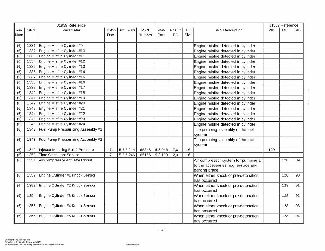
- C40 -
J1939 Reference J1587 ReferenceRev.Num
SPN Parameter J1939Doc.
Doc. Para PGNNumber
PGNPara
Pos. inPG
BitSize
SPN Description PID MID SID
(6) 1331 Engine Misfire Cylinder #9 Engine misfire detected in cylinder(6) 1332 Engine Misfire Cylinder #10 Engine misfire detected in cylinder(6) 1333 Engine Misfire Cylinder #11 Engine misfire detected in cylinder(6) 1334 Engine Misfire Cylinder #12 Engine misfire detected in cylinder(6) 1335 Engine Misfire Cylinder #13 Engine misfire detected in cylinder(6) 1336 Engine Misfire Cylinder #14 Engine misfire detected in cylinder(6) 1337 Engine Misfire Cylinder #15 Engine misfire detected in cylinder(6) 1338 Engine Misfire Cylinder #16 Engine misfire detected in cylinder(6) 1339 Engine Misfire Cylinder #17 Engine misfire detected in cylinder(6) 1340 Engine Misfire Cylinder #18 Engine misfire detected in cylinder(6) 1341 Engine Misfire Cylinder #19 Engine misfire detected in cylinder(6) 1342 Engine Misfire Cylinder #20 Engine misfire detected in cylinder(6) 1343 Engine Misfire Cylinder #21 Engine misfire detected in cylinder(6) 1344 Engine Misfire Cylinder #22 Engine misfire detected in cylinder(6) 1345 Engine Misfire Cylinder #23 Engine misfire detected in cylinder(6) 1346 Engine Misfire Cylinder #24 Engine misfire detected in cylinder(6) 1347 Fuel Pump Pressurizing Assembly #1 The pumping assembly of the fuel
system(6) 1348 Fuel Pump Pressurizing Assembly #2 The pumping assembly of the fuel
system(6) 1349 Injector Metering Rail 2 Pressure -71 5.2.5.244 65243 5.3.046 7,8 16 129(6) 1350 Time Since Last Service -71 5.2.5.246 65166 5.3.109 2,3 16(6) 1351 Air Compressor Actuator Circuit Air compressor system for pumping air
to the accessories, e.g. service andparking brake
128 89
(6) 1352 Engine Cylinder #1 Knock Sensor When either knock or pre-detonationhas occurred
128 90
(6) 1353 Engine Cylinder #2 Knock Sensor When either knock or pre-detonationhas occurred
128 91
(6) 1354 Engine Cylinder #3 Knock Sensor When either knock or pre-detonationhas occurred
128 92
(6) 1355 Engine Cylinder #4 Knock Sensor When either knock or pre-detonationhas occurred
128 93
(6) 1356 Engine Cylinder #5 Knock Sensor When either knock or pre-detonationhas occurred
128 94
Copyright SAE International Provided by IHS under license with SAE
Not for ResaleNo reproduction or networking permitted without license from IHS
--`-`-`,,`,,`,`,,`---
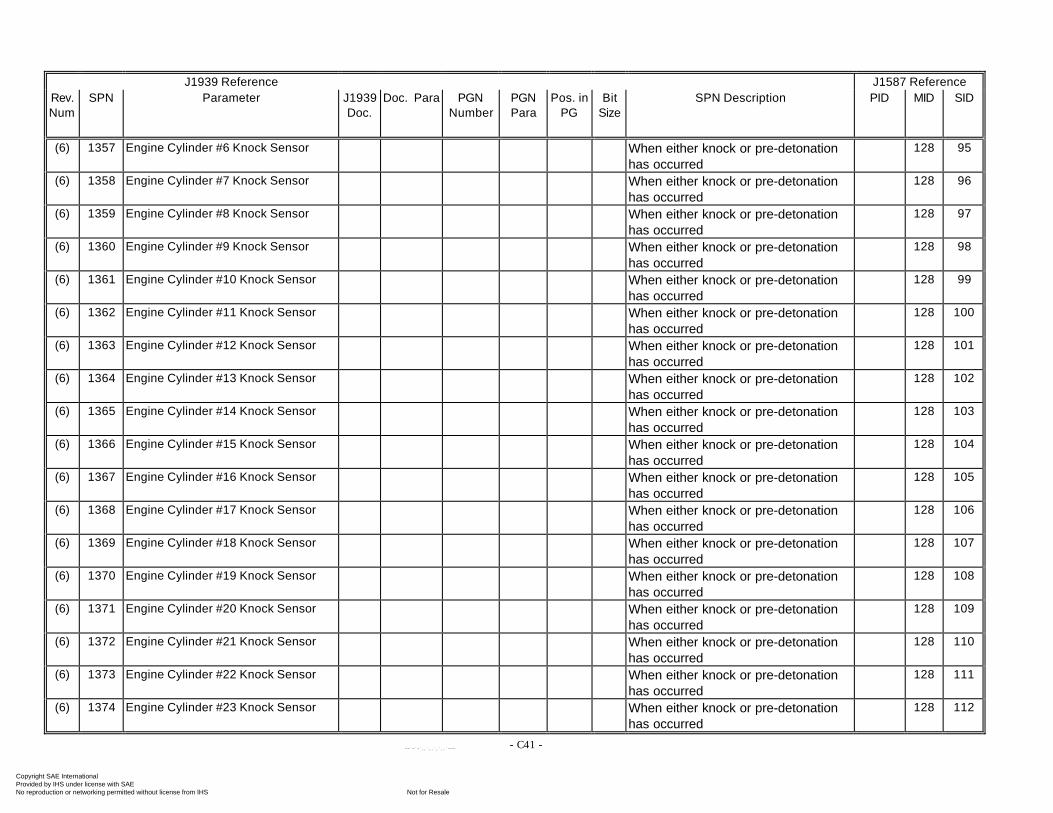
- C41 -
J1939 Reference J1587 ReferenceRev.Num
SPN Parameter J1939Doc.
Doc. Para PGNNumber
PGNPara
Pos. inPG
BitSize
SPN Description PID MID SID
(6) 1357 Engine Cylinder #6 Knock Sensor When either knock or pre-detonationhas occurred
128 95
(6) 1358 Engine Cylinder #7 Knock Sensor When either knock or pre-detonationhas occurred
128 96
(6) 1359 Engine Cylinder #8 Knock Sensor When either knock or pre-detonationhas occurred
128 97
(6) 1360 Engine Cylinder #9 Knock Sensor When either knock or pre-detonationhas occurred
128 98
(6) 1361 Engine Cylinder #10 Knock Sensor When either knock or pre-detonationhas occurred
128 99
(6) 1362 Engine Cylinder #11 Knock Sensor When either knock or pre-detonationhas occurred
128 100
(6) 1363 Engine Cylinder #12 Knock Sensor When either knock or pre-detonationhas occurred
128 101
(6) 1364 Engine Cylinder #13 Knock Sensor When either knock or pre-detonationhas occurred
128 102
(6) 1365 Engine Cylinder #14 Knock Sensor When either knock or pre-detonationhas occurred
128 103
(6) 1366 Engine Cylinder #15 Knock Sensor When either knock or pre-detonationhas occurred
128 104
(6) 1367 Engine Cylinder #16 Knock Sensor When either knock or pre-detonationhas occurred
128 105
(6) 1368 Engine Cylinder #17 Knock Sensor When either knock or pre-detonationhas occurred
128 106
(6) 1369 Engine Cylinder #18 Knock Sensor When either knock or pre-detonationhas occurred
128 107
(6) 1370 Engine Cylinder #19 Knock Sensor When either knock or pre-detonationhas occurred
128 108
(6) 1371 Engine Cylinder #20 Knock Sensor When either knock or pre-detonationhas occurred
128 109
(6) 1372 Engine Cylinder #21 Knock Sensor When either knock or pre-detonationhas occurred
128 110
(6) 1373 Engine Cylinder #22 Knock Sensor When either knock or pre-detonationhas occurred
128 111
(6) 1374 Engine Cylinder #23 Knock Sensor When either knock or pre-detonationhas occurred
128 112
Copyright SAE International Provided by IHS under license with SAE
Not for ResaleNo reproduction or networking permitted without license from IHS
--`-`-`,,`,,`,`,,`---
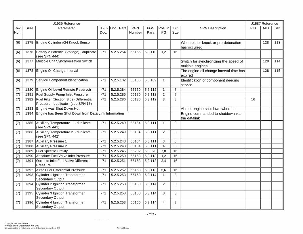
- C42 -
J1939 Reference J1587 ReferenceRev.Num
SPN Parameter J1939Doc.
Doc. Para PGNNumber
PGNPara
Pos. inPG
BitSize
SPN Description PID MID SID
(6) 1375 Engine Cylinder #24 Knock Sensor When either knock or pre-detonationhas occurred
128 113
(6) 1376 Battery 2 Potential (Voltage) - duplicate(see SPN 444)
-71 5.2.5.254 65165 5.3.110 1,2 16
(6) 1377 Multiple Unit Synchronization Switch Switch for synchronizing the speed ofmultiple engines
128 114
(6) 1378 Engine Oil Change Interval The engine oil change interval time hasexpired
128 115
(6) 1379 Service Component Identification -71 5.2.5.102 65166 5.3.109 1 Identification of component needingservice.
(7) 1380 Engine Oil Level Remote Reservoir -71 5.2.5.284 65130 5.3.112 1 8(7) 1381 Fuel Supply Pump Inlet Pressure -71 5.2.5.285 65130 5.3.112 2 8(7) 1382 Fuel Filter (Suction Side) Differential
Pressure - duplicate (see SPN 16)-71 5.2.5.286 65130 5.3.112 3 8 16
(7) 1383 Engine was Shut Down Hot Abrupt engine shutdown when hot(7) 1384 Engine has Been Shut Down from Data Link Information Engine commanded to shutdown via
the datalink(7) 1385 Auxiliary Temperature 1 - duplicate
(see SPN 441)-71 5.2.5.249 65164 5.3.111 1 0
(7) 1386 Auxiliary Temperature 2 - duplicate(see SPN 442)
-71 5.2.5.249 65164 5.3.111 2 0
(7) 1387 Auxiliary Pressure 1 -71 5.2.5.248 65164 5.3.111 3 8(7) 1388 Auxiliary Pressure 2 -71 5.2.5.248 65164 5.3.111 4 8(7) 1389 Fuel Specific Gravity -71 5.2.5.245 65202 5.3.070 7,8 16(7) 1390 Absolute Fuel Valve Inlet Pressure -71 5.2.5.250 65163 5.3.113 1,2 16(7) 1391 Outlet to Inlet Fuel Valve Differential
Pressure-71 5.2.5.251 65163 5.3.113 3,4 16
(7) 1392 Air to Fuel Differential Pressure -71 5.2.5.252 65163 5.3.113 5,6 16(7) 1393 Cylinder 1 Ignition Transformer
Secondary Output-71 5.2.5.253 65160 5.3.114 1 8
(7) 1394 Cylinder 2 Ignition TransformerSecondary Output
-71 5.2.5.253 65160 5.3.114 2 8
(7) 1395 Cylinder 3 Ignition TransformerSecondary Output
-71 5.2.5.253 65160 5.3.114 3 8
(7) 1396 Cylinder 4 Ignition TransformerSecondary Output
-71 5.2.5.253 65160 5.3.114 4 8
Copyright SAE International Provided by IHS under license with SAE
Not for ResaleNo reproduction or networking permitted without license from IHS
--`-`-`,,`,,`,`,,`---
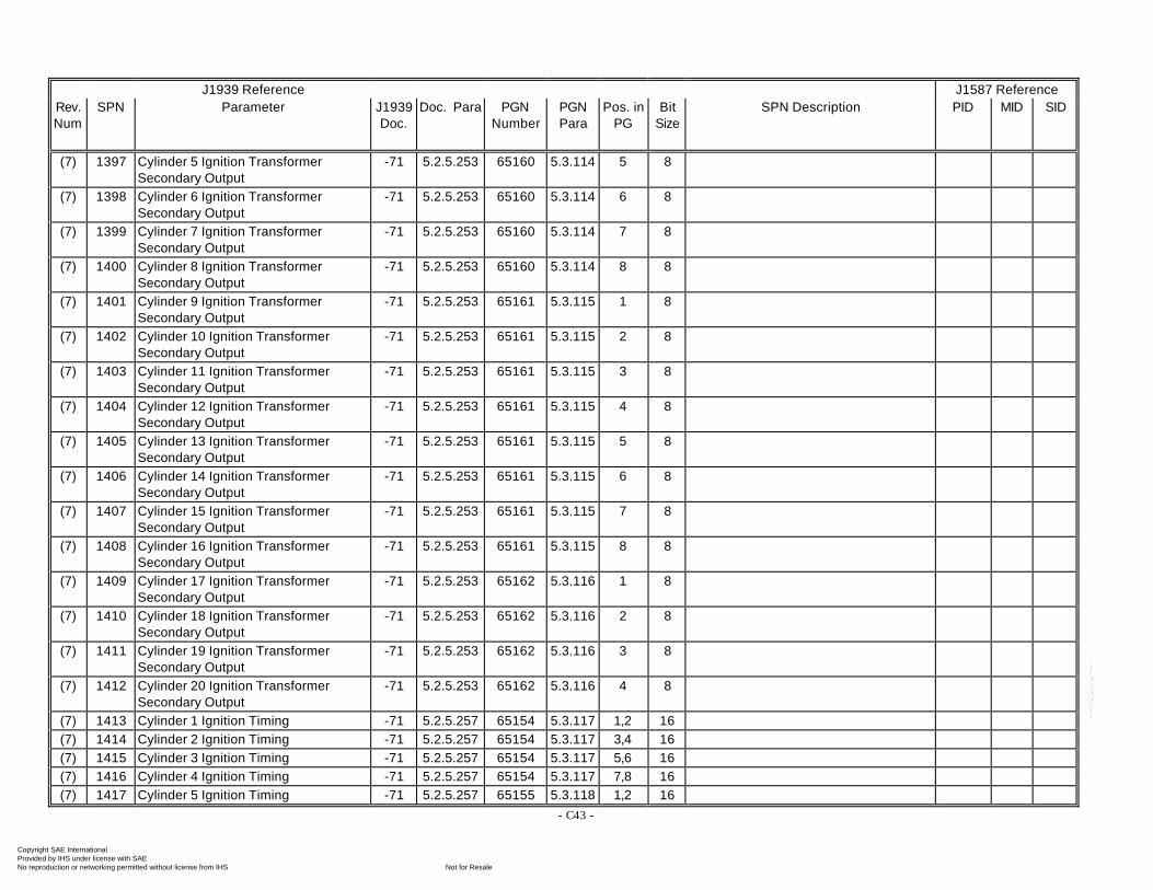
- C43 -
J1939 Reference J1587 ReferenceRev.Num
SPN Parameter J1939Doc.
Doc. Para PGNNumber
PGNPara
Pos. inPG
BitSize
SPN Description PID MID SID
(7) 1397 Cylinder 5 Ignition TransformerSecondary Output
-71 5.2.5.253 65160 5.3.114 5 8
(7) 1398 Cylinder 6 Ignition TransformerSecondary Output
-71 5.2.5.253 65160 5.3.114 6 8
(7) 1399 Cylinder 7 Ignition TransformerSecondary Output
-71 5.2.5.253 65160 5.3.114 7 8
(7) 1400 Cylinder 8 Ignition TransformerSecondary Output
-71 5.2.5.253 65160 5.3.114 8 8
(7) 1401 Cylinder 9 Ignition TransformerSecondary Output
-71 5.2.5.253 65161 5.3.115 1 8
(7) 1402 Cylinder 10 Ignition TransformerSecondary Output
-71 5.2.5.253 65161 5.3.115 2 8
(7) 1403 Cylinder 11 Ignition TransformerSecondary Output
-71 5.2.5.253 65161 5.3.115 3 8
(7) 1404 Cylinder 12 Ignition TransformerSecondary Output
-71 5.2.5.253 65161 5.3.115 4 8
(7) 1405 Cylinder 13 Ignition TransformerSecondary Output
-71 5.2.5.253 65161 5.3.115 5 8
(7) 1406 Cylinder 14 Ignition TransformerSecondary Output
-71 5.2.5.253 65161 5.3.115 6 8
(7) 1407 Cylinder 15 Ignition TransformerSecondary Output
-71 5.2.5.253 65161 5.3.115 7 8
(7) 1408 Cylinder 16 Ignition TransformerSecondary Output
-71 5.2.5.253 65161 5.3.115 8 8
(7) 1409 Cylinder 17 Ignition TransformerSecondary Output
-71 5.2.5.253 65162 5.3.116 1 8
(7) 1410 Cylinder 18 Ignition TransformerSecondary Output
-71 5.2.5.253 65162 5.3.116 2 8
(7) 1411 Cylinder 19 Ignition TransformerSecondary Output
-71 5.2.5.253 65162 5.3.116 3 8
(7) 1412 Cylinder 20 Ignition TransformerSecondary Output
-71 5.2.5.253 65162 5.3.116 4 8
(7) 1413 Cylinder 1 Ignition Timing -71 5.2.5.257 65154 5.3.117 1,2 16(7) 1414 Cylinder 2 Ignition Timing -71 5.2.5.257 65154 5.3.117 3,4 16(7) 1415 Cylinder 3 Ignition Timing -71 5.2.5.257 65154 5.3.117 5,6 16(7) 1416 Cylinder 4 Ignition Timing -71 5.2.5.257 65154 5.3.117 7,8 16(7) 1417 Cylinder 5 Ignition Timing -71 5.2.5.257 65155 5.3.118 1,2 16
Copyright SAE International Provided by IHS under license with SAE
Not for ResaleNo reproduction or networking permitted without license from IHS
--`-`-`,,`,,`,`,,`---
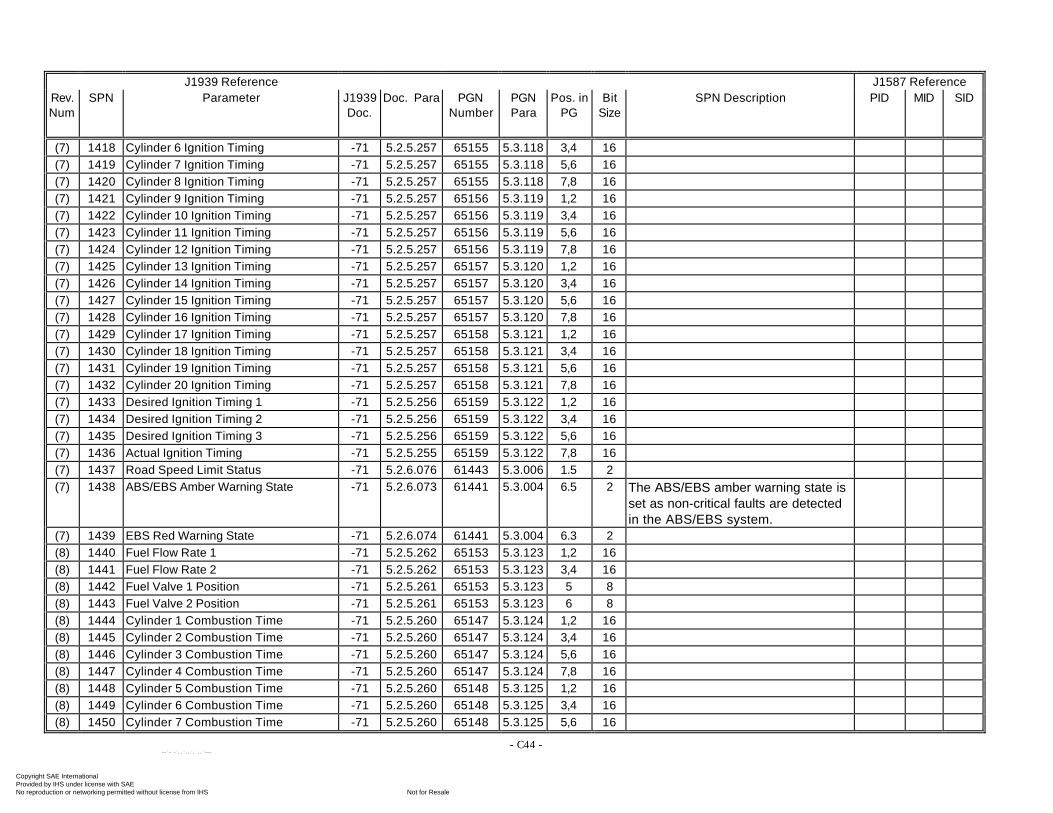
- C44 -
J1939 Reference J1587 ReferenceRev.Num
SPN Parameter J1939Doc.
Doc. Para PGNNumber
PGNPara
Pos. inPG
BitSize
SPN Description PID MID SID
(7) 1418 Cylinder 6 Ignition Timing -71 5.2.5.257 65155 5.3.118 3,4 16(7) 1419 Cylinder 7 Ignition Timing -71 5.2.5.257 65155 5.3.118 5,6 16(7) 1420 Cylinder 8 Ignition Timing -71 5.2.5.257 65155 5.3.118 7,8 16(7) 1421 Cylinder 9 Ignition Timing -71 5.2.5.257 65156 5.3.119 1,2 16(7) 1422 Cylinder 10 Ignition Timing -71 5.2.5.257 65156 5.3.119 3,4 16(7) 1423 Cylinder 11 Ignition Timing -71 5.2.5.257 65156 5.3.119 5,6 16(7) 1424 Cylinder 12 Ignition Timing -71 5.2.5.257 65156 5.3.119 7,8 16(7) 1425 Cylinder 13 Ignition Timing -71 5.2.5.257 65157 5.3.120 1,2 16(7) 1426 Cylinder 14 Ignition Timing -71 5.2.5.257 65157 5.3.120 3,4 16(7) 1427 Cylinder 15 Ignition Timing -71 5.2.5.257 65157 5.3.120 5,6 16(7) 1428 Cylinder 16 Ignition Timing -71 5.2.5.257 65157 5.3.120 7,8 16(7) 1429 Cylinder 17 Ignition Timing -71 5.2.5.257 65158 5.3.121 1,2 16(7) 1430 Cylinder 18 Ignition Timing -71 5.2.5.257 65158 5.3.121 3,4 16(7) 1431 Cylinder 19 Ignition Timing -71 5.2.5.257 65158 5.3.121 5,6 16(7) 1432 Cylinder 20 Ignition Timing -71 5.2.5.257 65158 5.3.121 7,8 16(7) 1433 Desired Ignition Timing 1 -71 5.2.5.256 65159 5.3.122 1,2 16(7) 1434 Desired Ignition Timing 2 -71 5.2.5.256 65159 5.3.122 3,4 16(7) 1435 Desired Ignition Timing 3 -71 5.2.5.256 65159 5.3.122 5,6 16(7) 1436 Actual Ignition Timing -71 5.2.5.255 65159 5.3.122 7,8 16(7) 1437 Road Speed Limit Status -71 5.2.6.076 61443 5.3.006 1.5 2(7) 1438 ABS/EBS Amber Warning State -71 5.2.6.073 61441 5.3.004 6.5 2 The ABS/EBS amber warning state is
set as non-critical faults are detectedin the ABS/EBS system.
(7) 1439 EBS Red Warning State -71 5.2.6.074 61441 5.3.004 6.3 2(8) 1440 Fuel Flow Rate 1 -71 5.2.5.262 65153 5.3.123 1,2 16(8) 1441 Fuel Flow Rate 2 -71 5.2.5.262 65153 5.3.123 3,4 16(8) 1442 Fuel Valve 1 Position -71 5.2.5.261 65153 5.3.123 5 8(8) 1443 Fuel Valve 2 Position -71 5.2.5.261 65153 5.3.123 6 8(8) 1444 Cylinder 1 Combustion Time -71 5.2.5.260 65147 5.3.124 1,2 16(8) 1445 Cylinder 2 Combustion Time -71 5.2.5.260 65147 5.3.124 3,4 16(8) 1446 Cylinder 3 Combustion Time -71 5.2.5.260 65147 5.3.124 5,6 16(8) 1447 Cylinder 4 Combustion Time -71 5.2.5.260 65147 5.3.124 7,8 16(8) 1448 Cylinder 5 Combustion Time -71 5.2.5.260 65148 5.3.125 1,2 16(8) 1449 Cylinder 6 Combustion Time -71 5.2.5.260 65148 5.3.125 3,4 16(8) 1450 Cylinder 7 Combustion Time -71 5.2.5.260 65148 5.3.125 5,6 16
Copyright SAE International Provided by IHS under license with SAE
Not for ResaleNo reproduction or networking permitted without license from IHS
--`-`-`,,`,,`,`,,`---
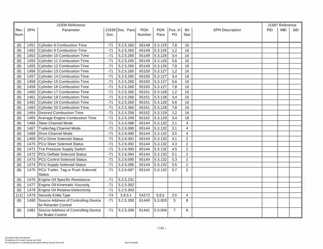
- C45 -
J1939 Reference J1587 ReferenceRev.Num
SPN Parameter J1939Doc.
Doc. Para PGNNumber
PGNPara
Pos. inPG
BitSize
SPN Description PID MID SID
(8) 1451 Cylinder 8 Combustion Time -71 5.2.5.260 65148 5.3.125 7,8 16(8) 1452 Cylinder 9 Combustion Time -71 5.2.5.260 65149 5.3.126 1,2 16(8) 1453 Cylinder 10 Combustion Time -71 5.2.5.260 65149 5.3.126 3,4 16(8) 1454 Cylinder 11 Combustion Time -71 5.2.5.260 65149 5.3.126 5,6 16(8) 1455 Cylinder 12 Combustion Time -71 5.2.5.260 65149 5.3.126 7,8 16(8) 1456 Cylinder 13 Combustion Time -71 5.2.5.260 65150 5.3.127 1,2 16(8) 1457 Cylinder 14 Combustion Time -71 5.2.5.260 65150 5.3.127 3,4 16(8) 1458 Cylinder 15 Combustion Time -71 5.2.5.260 65150 5.3.127 5,6 16(8) 1459 Cylinder 16 Combustion Time -71 5.2.5.260 65150 5.3.127 7,8 16(8) 1460 Cylinder 17 Combustion Time -71 5.2.5.260 65151 5.3.128 1,2 16(8) 1461 Cylinder 18 Combustion Time -71 5.2.5.260 65151 5.3.128 3,4 16(8) 1462 Cylinder 19 Combustion Time -71 5.2.5.260 65151 5.3.128 5,6 16(8) 1463 Cylinder 20 Combustion Time -71 5.2.5.260 65151 5.3.128 7,8 16(8) 1464 Desired Combustion Time -71 5.2.5.258 65152 5.3.129 1,2 16(8) 1465 Average Engine Combustion Time -71 5.2.5.259 65152 5.3.129 3,4 16(8) 1466 Steer Channel Mode -71 5.2.6.088 65144 5.3.132 2.1 4(8) 1467 Trailer/tag Channel Mode -71 5.2.6.089 65144 5.3.132 3.1 4(8) 1468 Drive Channel Mode -71 5.2.6.090 65144 5.3.132 3.5 4(8) 1469 PCU Drive Solenoid Status -71 5.2.6.091 65144 5.3.132 4.1 2(8) 1470 PCU Steer Solenoid Status -71 5.2.6.092 65144 5.3.132 4.3 2(8) 1471 Tire Pressure Supply Switch -71 5.2.6.093 65144 5.3.132 4.5 2(8) 1472 PCU Deflate Solenoid Status -71 5.2.6.094 65144 5.3.132 5.1 2(8) 1473 PCU Control Solenoid Status -71 5.2.6.095 65144 5.3.132 5.3 2(8) 1474 PCU Supply Solenoid Status -71 5.2.6.096 65144 5.3.132 5.5 2(8) 1475 PCU Trailer, Tag or Push Solenoid
Status-71 5.2.6.097 65144 5.3.132 5.7 2
(8) 1476 Engine Oil Specific Resistance -71 5.2.5.231(8) 1477 Engine Oil Kinematic Viscosity -71 5.2.5.302(8) 1478 Engine Oil Relative Dielectricity -71 5.2.5.303(11) 1479 Security Entity Type -73 5.8.5.1 54272 5.8.5 2.5 4(8) 1480 Source Address of Controlling Device
for Retarder Control-71 5.2.5.300 61440 5.3.003 5 8
(8) 1481 Source Address of Controlling Devicefor Brake Control
-71 5.2.5.299 61441 5.3.004 7 8
Copyright SAE International Provided by IHS under license with SAE
Not for ResaleNo reproduction or networking permitted without license from IHS
--`-`-`,,`,,`,`,,`---
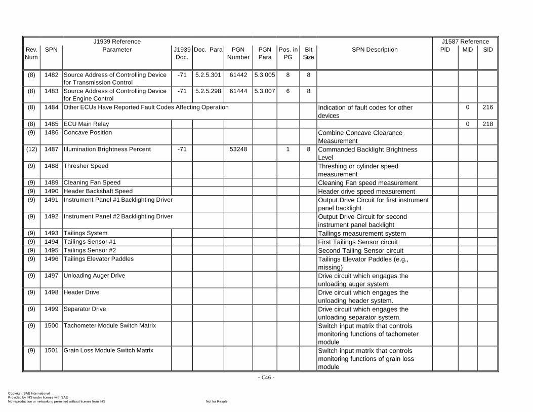
- C46 -
J1939 Reference J1587 ReferenceRev.Num
SPN Parameter J1939Doc.
Doc. Para PGNNumber
PGNPara
Pos. inPG
BitSize
SPN Description PID MID SID
(8) 1482 Source Address of Controlling Devicefor Transmission Control
-71 5.2.5.301 61442 5.3.005 8 8
(8) 1483 Source Address of Controlling Devicefor Engine Control
-71 5.2.5.298 61444 5.3.007 6 8
(8) 1484 Other ECUs Have Reported Fault Codes Affecting Operation Indication of fault codes for otherdevices
0 216
(8) 1485 ECU Main Relay 0 218(9) 1486 Concave Position Combine Concave Clearance
Measurement(12) 1487 Illumination Brightness Percent -71 53248 1 8 Commanded Backlight Brightness
Level(9) 1488 Thresher Speed Threshing or cylinder speed
measurement(9) 1489 Cleaning Fan Speed Cleaning Fan speed measurement(9) 1490 Header Backshaft Speed Header drive speed measurement(9) 1491 Instrument Panel #1 Backlighting Driver Output Drive Circuit for first instrument
panel backlight(9) 1492 Instrument Panel #2 Backlighting Driver Output Drive Circuit for second
instrument panel backlight(9) 1493 Tailings System Tailings measurement system(9) 1494 Tailings Sensor #1 First Tailings Sensor circuit(9) 1495 Tailings Sensor #2 Second Tailing Sensor circuit(9) 1496 Tailings Elevator Paddles Tailings Elevator Paddles (e.g.,
missing)(9) 1497 Unloading Auger Drive Drive circuit which engages the
unloading auger system.(9) 1498 Header Drive Drive circuit which engages the
unloading header system.(9) 1499 Separator Drive Drive circuit which engages the
unloading separator system.(9) 1500 Tachometer Module Switch Matrix Switch input matrix that controls
monitoring functions of tachometermodule
(9) 1501 Grain Loss Module Switch Matrix Switch input matrix that controlsmonitoring functions of grain lossmodule
Copyright SAE International Provided by IHS under license with SAE
Not for ResaleNo reproduction or networking permitted without license from IHS
--`-`-`,,`,,`,`,,`---
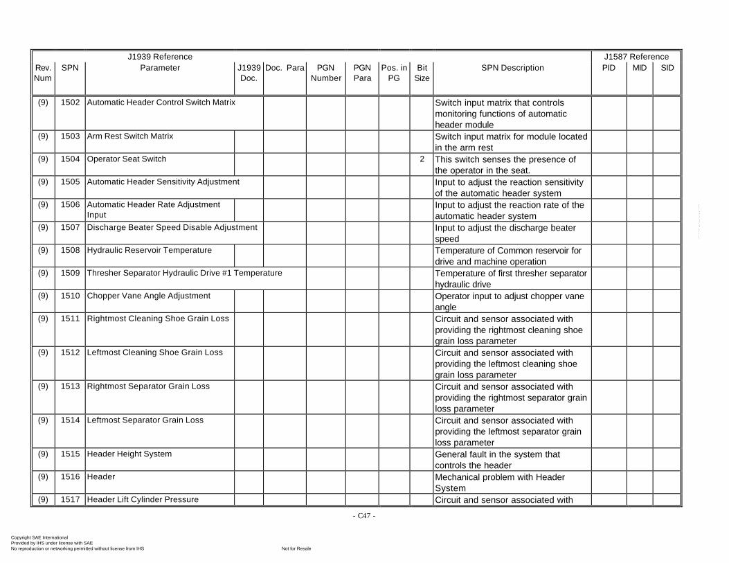
- C47 -
J1939 Reference J1587 ReferenceRev.Num
SPN Parameter J1939Doc.
Doc. Para PGNNumber
PGNPara
Pos. inPG
BitSize
SPN Description PID MID SID
(9) 1502 Automatic Header Control Switch Matrix Switch input matrix that controlsmonitoring functions of automaticheader module
(9) 1503 Arm Rest Switch Matrix Switch input matrix for module locatedin the arm rest
(9) 1504 Operator Seat Switch 2 This switch senses the presence ofthe operator in the seat.
(9) 1505 Automatic Header Sensitivity Adjustment Input to adjust the reaction sensitivityof the automatic header system
(9) 1506 Automatic Header Rate AdjustmentInput
Input to adjust the reaction rate of theautomatic header system
(9) 1507 Discharge Beater Speed Disable Adjustment Input to adjust the discharge beaterspeed
(9) 1508 Hydraulic Reservoir Temperature Temperature of Common reservoir fordrive and machine operation
(9) 1509 Thresher Separator Hydraulic Drive #1 Temperature Temperature of first thresher separatorhydraulic drive
(9) 1510 Chopper Vane Angle Adjustment Operator input to adjust chopper vaneangle
(9) 1511 Rightmost Cleaning Shoe Grain Loss Circuit and sensor associated withproviding the rightmost cleaning shoegrain loss parameter
(9) 1512 Leftmost Cleaning Shoe Grain Loss Circuit and sensor associated withproviding the leftmost cleaning shoegrain loss parameter
(9) 1513 Rightmost Separator Grain Loss Circuit and sensor associated withproviding the rightmost separator grainloss parameter
(9) 1514 Leftmost Separator Grain Loss Circuit and sensor associated withproviding the leftmost separator grainloss parameter
(9) 1515 Header Height System General fault in the system thatcontrols the header
(9) 1516 Header Mechanical problem with HeaderSystem
(9) 1517 Header Lift Cylinder Pressure Circuit and sensor associated with
Copyright SAE International Provided by IHS under license with SAE
Not for ResaleNo reproduction or networking permitted without license from IHS
--`-`-`,,`,,`,`,,`---
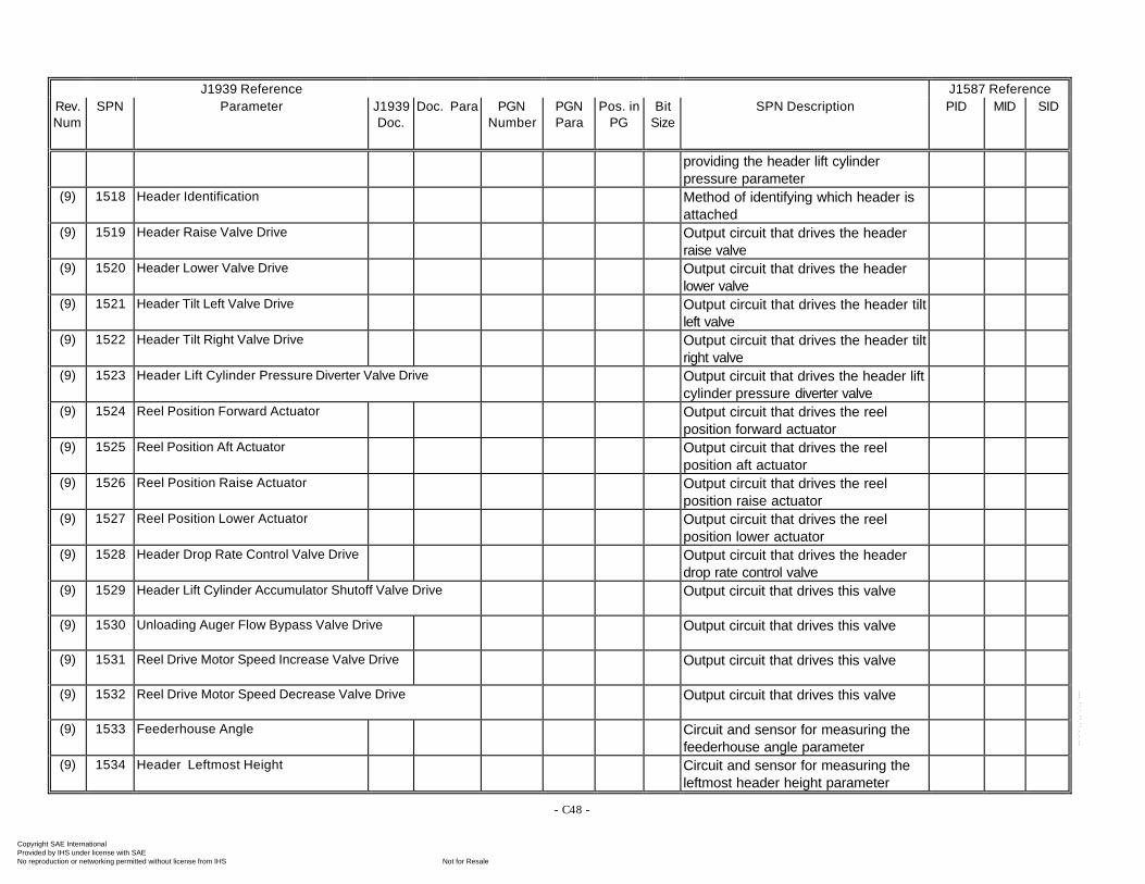
- C48 -
J1939 Reference J1587 ReferenceRev.Num
SPN Parameter J1939Doc.
Doc. Para PGNNumber
PGNPara
Pos. inPG
BitSize
SPN Description PID MID SID
providing the header lift cylinderpressure parameter
(9) 1518 Header Identification Method of identifying which header isattached
(9) 1519 Header Raise Valve Drive Output circuit that drives the headerraise valve
(9) 1520 Header Lower Valve Drive Output circuit that drives the headerlower valve
(9) 1521 Header Tilt Left Valve Drive Output circuit that drives the header tiltleft valve
(9) 1522 Header Tilt Right Valve Drive Output circuit that drives the header tiltright valve
(9) 1523 Header Lift Cylinder Pressure Diverter Valve Drive Output circuit that drives the header liftcylinder pressure diverter valve
(9) 1524 Reel Position Forward Actuator Output circuit that drives the reelposition forward actuator
(9) 1525 Reel Position Aft Actuator Output circuit that drives the reelposition aft actuator
(9) 1526 Reel Position Raise Actuator Output circuit that drives the reelposition raise actuator
(9) 1527 Reel Position Lower Actuator Output circuit that drives the reelposition lower actuator
(9) 1528 Header Drop Rate Control Valve Drive Output circuit that drives the headerdrop rate control valve
(9) 1529 Header Lift Cylinder Accumulator Shutoff Valve Drive Output circuit that drives this valve
(9) 1530 Unloading Auger Flow Bypass Valve Drive Output circuit that drives this valve
(9) 1531 Reel Drive Motor Speed Increase Valve Drive Output circuit that drives this valve
(9) 1532 Reel Drive Motor Speed Decrease Valve Drive Output circuit that drives this valve
(9) 1533 Feederhouse Angle Circuit and sensor for measuring thefeederhouse angle parameter
(9) 1534 Header Leftmost Height Circuit and sensor for measuring theleftmost header height parameter
Copyright SAE International Provided by IHS under license with SAE
Not for ResaleNo reproduction or networking permitted without license from IHS
--`-`-`,,`,,`,`,,`---
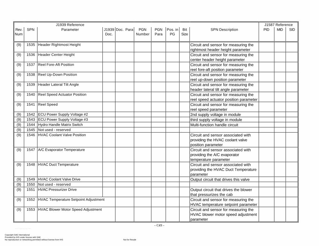
- C49 -
J1939 Reference J1587 ReferenceRev.Num
SPN Parameter J1939Doc.
Doc. Para PGNNumber
PGNPara
Pos. inPG
BitSize
SPN Description PID MID SID
(9) 1535 Header Rightmost Height Circuit and sensor for measuring therightmost header height parameter
(9) 1536 Header Center Height Circuit and sensor for measuring thecenter header height parameter
(9) 1537 Reel Fore-Aft Position Circuit and sensor for measuring thereel fore-aft position parameter
(9) 1538 Reel Up-Down Position Circuit and sensor for measuring thereel up-down position parameter
(9) 1539 Header Lateral Tilt Angle Circuit and sensor for measuring theheader lateral tilt angle parameter
(9) 1540 Reel Speed Actuator Position Circuit and sensor for measuring thereel speed actuator position parameter
(9) 1541 Reel Speed Circuit and sensor for measuring thereel speed parameter
(9) 1542 ECU Power Supply Voltage #2 2nd supply voltage in module(9) 1543 ECU Power Supply Voltage #3 third supply voltage in module(9) 1544 Hydro Handle Matrix Switch Multi-function handle circuit(9) 1545 Not used - reserved(9) 1546 HVAC Coolant Valve Position Circuit and sensor associated with
providing the HVAC coolant valveposition parameter
(9) 1547 A/C Evaporator Temperature Circuit and sensor associated withproviding the A/C evaporatortemperature parameter
(9) 1548 HVAC Duct Temperature Circuit and sensor associated withproviding the HVAC Duct Temperatureparameter
(9) 1549 HVAC Coolant Valve Drive Output circuit that drives this valve(9) 1550 Not used - reserved(9) 1551 HVAC Pressurizer Drive Output circuit that drives the blower
that pressurizes the cab(9) 1552 HVAC Temperature Setpoint Adjustment Circuit and sensor for measuring the
HVAC temperature setpoint parameter(9) 1553 HVAC Blower Motor Speed Adjustment Circuit and sensor for measuring the
HVAC blower motor speed adjustmentparameter
Copyright SAE International Provided by IHS under license with SAE
Not for ResaleNo reproduction or networking permitted without license from IHS
--`-`-`,,`,,`,`,,`---
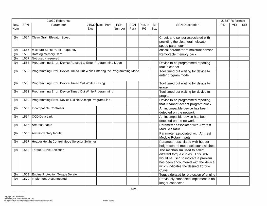
- C50 -
J1939 Reference J1587 ReferenceRev.Num
SPN Parameter J1939Doc.
Doc. Para PGNNumber
PGNPara
Pos. inPG
BitSize
SPN Description PID MID SID
(9) 1554 Clean Grain Elevator Speed Circuit and sensor associated withproviding the clean grain elevatorspeed parameter
(9) 1555 Moisture Sensor Cell Frequency critical parameter of moisture sensor(9) 1556 Datalog memory Card Removable memory pack(9) 1557 Not used - reserved(9) 1558 Programming Error, Device Refused to Enter Programming Mode Device to be programmed reporting
that is cannot(9) 1559 Programming Error, Device Timed Out While Entering the Programming Mode Tool timed out waiting for device to
enter program mode
(9) 1560 Programming Error, Device Timed Out While Erasing Tool timed out waiting for device toerase
(9) 1561 Programming Error, Device Timed Out While Programming Tool timed out waiting for device toprogram
(9) 1562 Programming Error, Device Did Not Accept Program Line Device to be programmed reportingthat it cannot accept program block
(9) 1563 Incompatible Controller An incompatible device has beendetected on the network.
(9) 1564 CCD Data Link An incompatible device has beendetected on the network.
(9) 1565 Armrest Status Parameter associated with ArmrestModule Status
(9) 1566 Armrest Rotary Inputs Parameter associated with ArmrestModule Rotary Inputs
(9) 1567 Header Height Control Mode Selector Switches Parameter associated with headerheight control mode selector switches
(9) 1568 Torque Curve Selection The mechanism used to selectdifferent torque curves. This SPNwould be used to indicate a problemhas been encountered with the devicewhich indicates the desired TorqueCurve.
(9) 1569 Engine Protection Torque Derate Torque derated for protection of engine(9) 1570 Implement Disconnected Previously connected implement is no
longer connected
Copyright SAE International Provided by IHS under license with SAE
Not for ResaleNo reproduction or networking permitted without license from IHS
--`-`-`,,`,,`,`,,`---
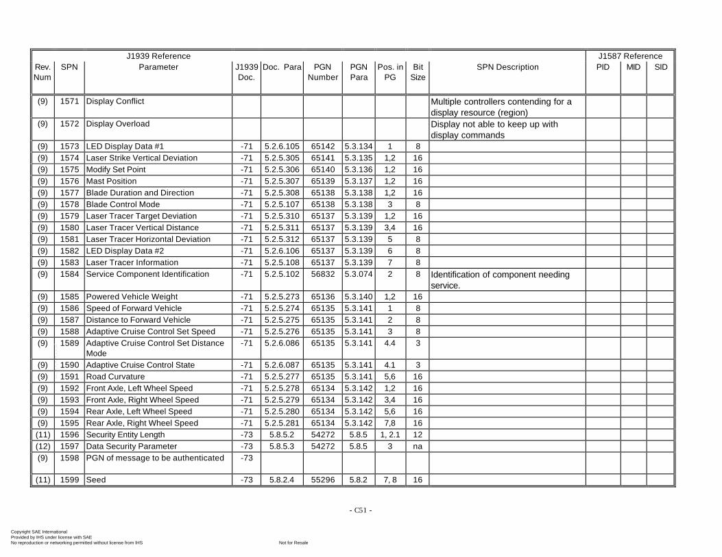
- C51 -
J1939 Reference J1587 ReferenceRev.Num
SPN Parameter J1939Doc.
Doc. Para PGNNumber
PGNPara
Pos. inPG
BitSize
SPN Description PID MID SID
(9) 1571 Display Conflict Multiple controllers contending for adisplay resource (region)
(9) 1572 Display Overload Display not able to keep up withdisplay commands
(9) 1573 LED Display Data #1 -71 5.2.6.105 65142 5.3.134 1 8(9) 1574 Laser Strike Vertical Deviation -71 5.2.5.305 65141 5.3.135 1,2 16(9) 1575 Modify Set Point -71 5.2.5.306 65140 5.3.136 1,2 16(9) 1576 Mast Position -71 5.2.5.307 65139 5.3.137 1,2 16(9) 1577 Blade Duration and Direction -71 5.2.5.308 65138 5.3.138 1,2 16(9) 1578 Blade Control Mode -71 5.2.5.107 65138 5.3.138 3 8(9) 1579 Laser Tracer Target Deviation -71 5.2.5.310 65137 5.3.139 1,2 16(9) 1580 Laser Tracer Vertical Distance -71 5.2.5.311 65137 5.3.139 3,4 16(9) 1581 Laser Tracer Horizontal Deviation -71 5.2.5.312 65137 5.3.139 5 8(9) 1582 LED Display Data #2 -71 5.2.6.106 65137 5.3.139 6 8(9) 1583 Laser Tracer Information -71 5.2.5.108 65137 5.3.139 7 8(9) 1584 Service Component Identification -71 5.2.5.102 56832 5.3.074 2 8 Identification of component needing
service.(9) 1585 Powered Vehicle Weight -71 5.2.5.273 65136 5.3.140 1,2 16(9) 1586 Speed of Forward Vehicle -71 5.2.5.274 65135 5.3.141 1 8(9) 1587 Distance to Forward Vehicle -71 5.2.5.275 65135 5.3.141 2 8(9) 1588 Adaptive Cruise Control Set Speed -71 5.2.5.276 65135 5.3.141 3 8(9) 1589 Adaptive Cruise Control Set Distance
Mode-71 5.2.6.086 65135 5.3.141 4.4 3
(9) 1590 Adaptive Cruise Control State -71 5.2.6.087 65135 5.3.141 4.1 3(9) 1591 Road Curvature -71 5.2.5.277 65135 5.3.141 5,6 16(9) 1592 Front Axle, Left Wheel Speed -71 5.2.5.278 65134 5.3.142 1,2 16(9) 1593 Front Axle, Right Wheel Speed -71 5.2.5.279 65134 5.3.142 3,4 16(9) 1594 Rear Axle, Left Wheel Speed -71 5.2.5.280 65134 5.3.142 5,6 16(9) 1595 Rear Axle, Right Wheel Speed -71 5.2.5.281 65134 5.3.142 7,8 16(11) 1596 Security Entity Length -73 5.8.5.2 54272 5.8.5 1, 2.1 12(12) 1597 Data Security Parameter -73 5.8.5.3 54272 5.8.5 3 na(9) 1598 PGN of message to be authenticated -73
(11) 1599 Seed -73 5.8.2.4 55296 5.8.2 7, 8 16
Copyright SAE International Provided by IHS under license with SAE
Not for ResaleNo reproduction or networking permitted without license from IHS
--`-`-`,,`,,`,`,,`---
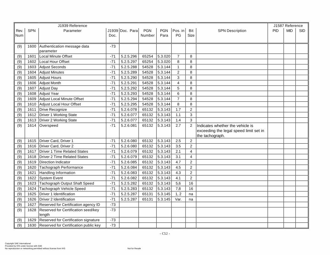
- C52 -
J1939 Reference J1587 ReferenceRev.Num
SPN Parameter J1939Doc.
Doc. Para PGNNumber
PGNPara
Pos. inPG
BitSize
SPN Description PID MID SID
(9) 1600 Authentication message dataparameter
-73
(9) 1601 Local Minute Offset -71 5.2.5.296 65254 5.3.020 7 8(9) 1602 Local Hour Offset -71 5.2.5.297 65254 5.3.020 8 8(9) 1603 Adjust Seconds -71 5.2.5.288 54528 5.3.144 1 8(9) 1604 Adjust Minutes -71 5.2.5.289 54528 5.3.144 2 8(9) 1605 Adjust Hours -71 5.2.5.290 54528 5.3.144 3 8(9) 1606 Adjust Month -71 5.2.5.291 54528 5.3.144 4 8(9) 1607 Adjust Day -71 5.2.5.292 54528 5.3.144 5 8(9) 1608 Adjust Year -71 5.2.5.293 54528 5.3.144 6 8(9) 1609 Adjust Local Minute Offset -71 5.2.5.294 54528 5.3.144 7 8(9) 1610 Adjust Local Hour Offset -71 5.2.5.295 54528 5.3.144 8 8(9) 1611 Drive Recognize -71 5.2.6.078 65132 5.3.143 1.7 2(9) 1612 Driver 1 Working State -71 5.2.6.077 65132 5.3.143 1.1 3(9) 1613 Driver 2 Working State -71 5.2.6.077 65132 5.3.143 1.4 3(9) 1614 Overspeed -71 5.2.6.081 65132 5.3.143 2.7 2 Indicates whether the vehicle is
exceeding the legal speed limit set inthe tachograph.
(9) 1615 Driver Card, Driver 1 -71 5.2.6.080 65132 5.3.143 2.5 2(9) 1616 Driver Card, Driver 2 -71 5.2.6.080 65132 5.3.143 3.5 2(9) 1617 Driver 1 Time Related States -71 5.2.6.079 65132 5.3.143 2.1 4(9) 1618 Driver 2 Time Related States -71 5.2.6.079 65132 5.3.143 3.1 4(9) 1619 Direction Indicator -71 5.2.6.085 65132 5.3.143 4.7 2(9) 1620 Tachograph Performance -71 5.2.6.084 65132 5.3.143 4.5 2(9) 1621 Handling Information -71 5.2.6.083 65132 5.3.143 4.3 2(9) 1622 System Event -71 5.2.6.082 65132 5.3.143 4.1 2(9) 1623 Tachograph Output Shaft Speed -71 5.2.5.282 65132 5.3.143 5,6 16(9) 1624 Tachograph Vehicle Speed -71 5.2.5.283 65132 5.3.143 7,8 16(9) 1625 Driver 1 Identification -71 5.2.5.287 65131 5.3.145 1, 2 na(9) 1626 Driver 2 Identification -71 5.2.5.287 65131 5.3.145 Var. na(9) 1627 Reserved for Certification agency ID -73(9) 1628 Reserved for Certification seed/key
length-73
(9) 1629 Reserved for Certification signature -73(9) 1630 Reserved for Certification public key -73
Copyright SAE International Provided by IHS under license with SAE
Not for ResaleNo reproduction or networking permitted without license from IHS
--`-`-`,,`,,`,`,,`---
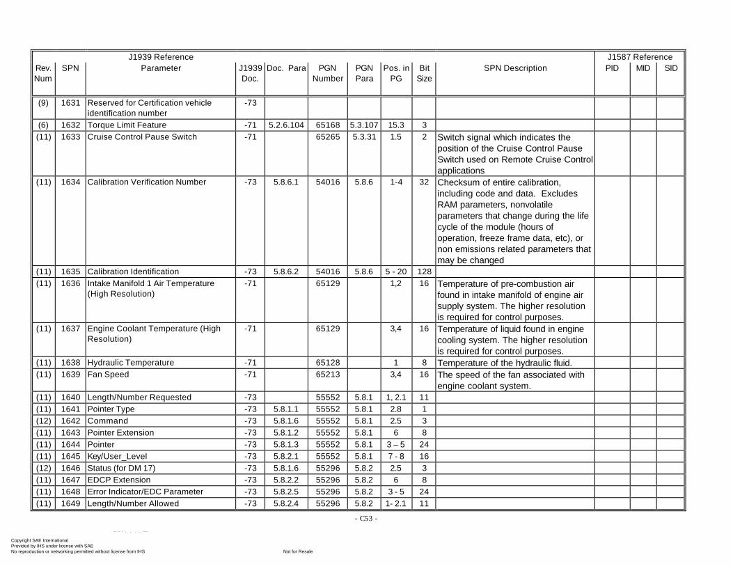
- C53 -
J1939 Reference J1587 ReferenceRev.Num
SPN Parameter J1939Doc.
Doc. Para PGNNumber
PGNPara
Pos. inPG
BitSize
SPN Description PID MID SID
(9) 1631 Reserved for Certification vehicleidentification number
-73
(6) 1632 Torque Limit Feature -71 5.2.6.104 65168 5.3.107 15.3 3(11) 1633 Cruise Control Pause Switch -71 65265 5.3.31 1.5 2 Switch signal which indicates the
position of the Cruise Control PauseSwitch used on Remote Cruise Controlapplications
(11) 1634 Calibration Verification Number -73 5.8.6.1 54016 5.8.6 1-4 32 Checksum of entire calibration,including code and data. ExcludesRAM parameters, nonvolatileparameters that change during the lifecycle of the module (hours ofoperation, freeze frame data, etc), ornon emissions related parameters thatmay be changed
(11) 1635 Calibration Identification -73 5.8.6.2 54016 5.8.6 5 - 20 128(11) 1636 Intake Manifold 1 Air Temperature
(High Resolution)-71 65129 1,2 16 Temperature of pre-combustion air
found in intake manifold of engine airsupply system. The higher resolutionis required for control purposes.
(11) 1637 Engine Coolant Temperature (HighResolution)
-71 65129 3,4 16 Temperature of liquid found in enginecooling system. The higher resolutionis required for control purposes.
(11) 1638 Hydraulic Temperature -71 65128 1 8 Temperature of the hydraulic fluid.(11) 1639 Fan Speed -71 65213 3,4 16 The speed of the fan associated with
engine coolant system.(11) 1640 Length/Number Requested -73 55552 5.8.1 1, 2.1 11(11) 1641 Pointer Type -73 5.8.1.1 55552 5.8.1 2.8 1(12) 1642 Command -73 5.8.1.6 55552 5.8.1 2.5 3(11) 1643 Pointer Extension -73 5.8.1.2 55552 5.8.1 6 8(11) 1644 Pointer -73 5.8.1.3 55552 5.8.1 3 – 5 24(11) 1645 Key/User_Level -73 5.8.2.1 55552 5.8.1 7 - 8 16(12) 1646 Status (for DM 17) -73 5.8.1.6 55296 5.8.2 2.5 3(11) 1647 EDCP Extension -73 5.8.2.2 55296 5.8.2 6 8(11) 1648 Error Indicator/EDC Parameter -73 5.8.2.5 55296 5.8.2 3 - 5 24(11) 1649 Length/Number Allowed -73 5.8.2.4 55296 5.8.2 1- 2.1 11
Copyright SAE International Provided by IHS under license with SAE
Not for ResaleNo reproduction or networking permitted without license from IHS
--`-`-`,,`,,`,`,,`---
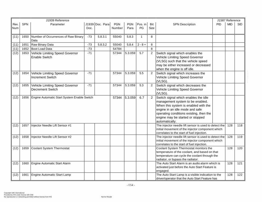
- C54 -
J1939 Reference J1587 ReferenceRev.Num
SPN Parameter J1939Doc.
Doc. Para PGNNumber
PGNPara
Pos. inPG
BitSize
SPN Description PID MID SID
(11) 1650 Number of Occurrences of Raw BinaryData
-73 5.8.3.1 55040 5.8.3 1 8
(11) 1651 Raw Binary Data -73 5.8.3.2 55040 5.8.4 2 - 8 + 8(11) 1652 Boot Load Data -73 54784 8(12) 1653 Vehicle Limiting Speed Governor
Enable Switch-71 57344 5.3.059 5.7 2 Switch signal which enables the
Vehicle Limiting Speed Governor(VLSG) such that the vehicle speedmay be either increased or decreasedwhen the engine is off idle.
(12) 1654 Vehicle Limiting Speed GovernorIncrement Switch
-71 57344 5.3.059 5.5 2 Switch signal which increases theVehicle Limiting Speed Governor(VLSG).
(12) 1655 Vehicle Limiting Speed GovernorDecrement Switch
-71 57344 5.3.059 5.3 2 Switch signal which decreases theVehicle Limiting Speed Governor(VLSG).
(12) 1656 Engine Automatic Start System Enable Switch 57344 5.3.059 6.7 2 Switch signal which enables the idlemanagement system to be enabled.When this system is enabled with theengine in an idle mode and safeoperating conditions existing, then theengine may be started or stoppedautomatically.
(12) 1657 Injector Needle Lift Sensor #1 The injector needle lift sensor is used to detect theinitial movement of the injector component whichcorrelates to the start of fuel injection.
128 118
(12) 1658 Injector Needle Lift Sensor #2 The injector needle lift sensor is used to detect theinitial movement of the injector component whichcorrelates to the start of fuel injection.
128 119
(12) 1659 Coolant System Thermostat Coolant System Thermostat monitors thetemperature of the coolant, and based on thattemperature can cycle the coolant through theradiator, or bypass the radiator.
128 120
(12) 1660 Engine Automatic Start Alarm The Auto Start Alarm is an audio alarm which isactivated just before the Auto Start Feature isengaged.
128 121
(12) 1661 Engine Automatic Start Lamp The Auto Start Lamp is a visible indication to thedriver/operator that the Auto Start Feature has
128 122
Copyright SAE International Provided by IHS under license with SAE
Not for ResaleNo reproduction or networking permitted without license from IHS
--`-`-`,,`,,`,`,,`---
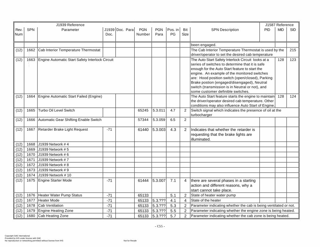
- C55 -
J1939 Reference J1587 ReferenceRev.Num
SPN Parameter J1939Doc.
Doc. Para PGNNumber
PGNPara
Pos. inPG
BitSize
SPN Description PID MID SID
been engaged.(12) 1662 Cab Interior Temperature Thermostat The Cab Interior Temperature Thermostat is used by the
driver/operator to set the desired cab temperature215
(12) 1663 Engine Automatic Start Safety Interlock Circuit The Auto Start Safety Interlock Circuit looks at aseries of switches to determine that it is safeenough for the Auto Start feature to start theengine. An example of the monitored switchesare: Hood position switch (open/closed), ParkingBrake postion (engaged/disengaged), Neutralswitch (transmission is in Neutral or not), andsome customer definible switches.
128 123
(12) 1664 Engine Automatic Start Failed (Engine) The Auto Start feature starts the engine to maintainthe driver/operator desired cab temperature. Otherconditions may also influence Auto Start of Engine.
128 124
(12) 1665 Turbo Oil Level Switch 65245 5.3.011 4.7 2 Switch signal which indicates the presence of oil at theturbocharger
(12) 1666 Automatic Gear Shifting Enable Switch 57344 5.3.059 6.5 2
(12) 1667 Retarder Brake Light Request -71 61440 5.3.003 4.3 2 Indicates that whether the retarder isrequesting that the brake lights areilluminated.
(12) 1668 J1939 Network # 4(12) 1669 J1939 Network # 5(12) 1670 J1939 Network # 6(12) 1671 J1939 Network # 7(12) 1672 J1939 Network # 8(12) 1673 J1939 Network # 9(12) 1674 J1939 Network # 10(12) 1675 Engine Starter Mode -71 61444 5.3.007 7.1 4 there are several phases in a starting
action and different reasons, why astart cannot take place.
(12) 1676 Heater Water Pump Status -71 65133 5.1 2 State of heater water pump(12) 1677 Heater Mode -71 65133 5.3.??? 4.1 4 State of the heater(12) 1678 Cab Ventilation -71 65133 5.3.??? 5.3 2 Parameter indicating whether the cab is being ventilated or not.(12) 1679 Engine Heating Zone -71 65133 5.3.??? 5.5 2 Parameter indicating whether the engine zone is being heated.(12) 1680 Cab Heating Zone -71 65133 5.3.??? 5.7 2 Parameter indicating whether the cab zone is being heated.
Copyright SAE International Provided by IHS under license with SAE
Not for ResaleNo reproduction or networking permitted without license from IHS
--`-`-`,,`,,`,`,,`---
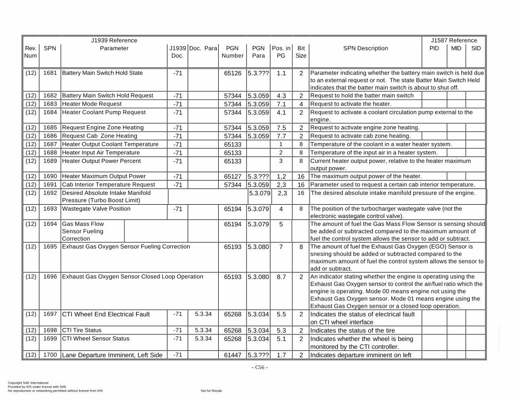
- C56 -
J1939 Reference J1587 ReferenceRev.Num
SPN Parameter J1939Doc.
Doc. Para PGNNumber
PGNPara
Pos. inPG
BitSize
SPN Description PID MID SID
(12) 1681 Battery Main Switch Hold State -71 65126 5.3.??? 1.1 2 Parameter indicating whether the battery main switch is held dueto an external request or not. The state Batter Main Switch Heldindicates that the batter main switch is about to shut off.
(12) 1682 Battery Main Switch Hold Request -71 57344 5.3.059 4.3 2 Request to hold the batter main switch(12) 1683 Heater Mode Request -71 57344 5.3.059 7.1 4 Request to activate the heater.(12) 1684 Heater Coolant Pump Request -71 57344 5.3.059 4.1 2 Request to activate a coolant circulation pump external to the
engine.(12) 1685 Request Engine Zone Heating -71 57344 5.3.059 7.5 2 Request to activate engine zone heating.(12) 1686 Request Cab Zone Heating -71 57344 5.3.059 7.7 2 Request to activate cab zone heating.(12) 1687 Heater Output Coolant Temperature -71 65133 1 8 Temperature of the coolant in a water heater system.(12) 1688 Heater Input Air Temperature -71 65133 2 8 Temperature of the input air in a heater system.(12) 1689 Heater Output Power Percent -71 65133 3 8 Current heater output power, relative to the heater maximum
output power.(12) 1690 Heater Maximum Output Power -71 65127 5.3.??? 1,2 16 The maximum output power of the heater.(12) 1691 Cab Interior Temperature Request -71 57344 5.3.059 2,3 16 Parameter used to request a certain cab interior temperature.(12) 1692 Desired Absolute Intake Manifold
Pressure (Turbo Boost Limit)5.3.079 2,3 16 The desired absolute intake manifold pressure of the engine.
(12) 1693 Wastegate Valve Position -71 65194 5.3.079 4 8 The position of the turbocharger wastegate valve (not theelectronic wastegate control valve).
(12) 1694 Gas Mass FlowSensor FuelingCorrection
65194 5.3.079 5 The amount of fuel the Gas Mass Flow Sensor is sensing shouldbe added or subtracted compared to the maximum amount offuel the control system allows the sensor to add or subtract.
(12) 1695 Exhaust Gas Oxygen Sensor Fueling Correction 65193 5.3.080 7 8 The amount of fuel the Exhaust Gas Oxygen (EGO) Sensor issnesing should be added or subtracted compared to themaximum amount of fuel the control system allows the sensor toadd or subtract.
(12) 1696 Exhaust Gas Oxygen Sensor Closed Loop Operation 65193 5.3.080 8.7 2 An indicator stating whether the engine is operating using theExhaust Gas Oxygen sensor to control the air/fuel ratio which theengine is operating. Mode 00 means engine not using theExhaust Gas Oxygen sensor. Mode 01 means engine using theExhaust Gas Oxygen sensor or a closed loop operation.
(12) 1697 CTI Wheel End Electrical Fault -71 5.3.34 65268 5.3.034 5.5 2 Indicates the status of electrical faulton CTI wheel interface
(12) 1698 CTI Tire Status -71 5.3.34 65268 5.3.034 5.3 2 Indicates the status of the tire(12) 1699 CTI Wheel Sensor Status -71 5.3.34 65268 5.3.034 5.1 2 Indicates whether the wheel is being
monitored by the CTI controller.(12) 1700 Lane Departure Imminent, Left Side -71 61447 5.3.??? 1.7 2 Indicates departure imminent on left
Copyright SAE International Provided by IHS under license with SAE
Not for ResaleNo reproduction or networking permitted without license from IHS
--`-`-`,,`,,`,`,,`---
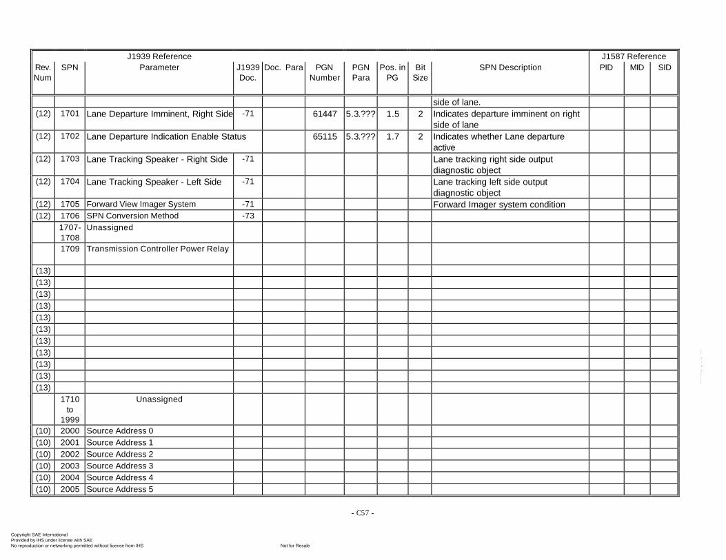
- C57 -
J1939 Reference J1587 ReferenceRev.Num
SPN Parameter J1939Doc.
Doc. Para PGNNumber
PGNPara
Pos. inPG
BitSize
SPN Description PID MID SID
side of lane.(12) 1701 Lane Departure Imminent, Right Side -71 61447 5.3.??? 1.5 2 Indicates departure imminent on right
side of lane(12) 1702 Lane Departure Indication Enable Status 65115 5.3.??? 1.7 2 Indicates whether Lane departure
active(12) 1703 Lane Tracking Speaker - Right Side -71 Lane tracking right side output
diagnostic object(12) 1704 Lane Tracking Speaker - Left Side -71 Lane tracking left side output
diagnostic object(12) 1705 Forward View Imager System -71 Forward Imager system condition(12) 1706 SPN Conversion Method -73
1707-1708
Unassigned
1709 Transmission Controller Power Relay
(13)(13)(13)(13)(13)(13)(13)(13)(13)(13)(13)
1710to
1999
Unassigned
(10) 2000 Source Address 0(10) 2001 Source Address 1(10) 2002 Source Address 2(10) 2003 Source Address 3(10) 2004 Source Address 4(10) 2005 Source Address 5
Copyright SAE International Provided by IHS under license with SAE
Not for ResaleNo reproduction or networking permitted without license from IHS
--`-`-`,,`,,`,`,,`---

- C58 -
J1939 Reference J1587 ReferenceRev.Num
SPN Parameter J1939Doc.
Doc. Para PGNNumber
PGNPara
Pos. inPG
BitSize
SPN Description PID MID SID
(10) 2006 Source Address 6(10) 2007 Source Address 7(10) 2008 Source Address 8(10) 2009 Source Address 9(10) 2010 Source Address 10(10) 2011 Source Address 11(10) 2012 Source Address 12(10) 2013 Source Address 13(10) 2014 Source Address 14(10) 2015 Source Address 15(10) 2016 Source Address 16(10) 2017 Source Address 17(10) 2018 Source Address 18(10) 2019 Source Address 19(10) 2020 Source Address 20(10) 2021 Source Address 21(10) 2022 Source Address 22(10) 2023 Source Address 23(10) 2024 Source Address 24(10) 2025 Source Address 25(10) 2026 Source Address 26(10) 2027 Source Address 27(10) 2028 Source Address 28(10) 2029 Source Address 29(10) 2030 Source Address 30(10) 2031 Source Address 31(10) 2032 Source Address 32(10) 2033 Source Address 33(10) 2034 Source Address 34(10) 2035 Source Address 35(10) 2036 Source Address 36(10) 2037 Source Address 37(10) 2038 Source Address 38(10) 2039 Source Address 39(10) 2040 Source Address 40
Copyright SAE International Provided by IHS under license with SAE
Not for ResaleNo reproduction or networking permitted without license from IHS
--`-`-`,,`,,`,`,,`---

- C59 -
J1939 Reference J1587 ReferenceRev.Num
SPN Parameter J1939Doc.
Doc. Para PGNNumber
PGNPara
Pos. inPG
BitSize
SPN Description PID MID SID
(10) 2041 Source Address 41(10) 2042 Source Address 42(10) 2043 Source Address 43(10) 2044 Source Address 44(10) 2045 Source Address 45(10) 2046 Source Address 46(10) 2047 Source Address 47(10) 2048 Source Address 48(10) 2049 Source Address 49(10) 2050 Source Address 50(10) 2051 Source Address 51(10) 2052 Source Address 52(10) 2053 Source Address 53(10) 2054 Source Address 54(10) 2055 Source Address 55(10) 2056 Source Address 56(10) 2057 Source Address 57(10) 2058 Source Address 58(10) 2059 Source Address 59(10) 2060 Source Address 60(10) 2061 Source Address 61(10) 2062 Source Address 62(10) 2063 Source Address 63(10) 2064 Source Address 64(10) 2065 Source Address 65(10) 2066 Source Address 66(10) 2067 Source Address 67(10) 2068 Source Address 68(10) 2069 Source Address 69(10) 2070 Source Address 70(10) 2071 Source Address 71(10) 2072 Source Address 72(10) 2073 Source Address 73(10) 2074 Source Address 74(10) 2075 Source Address 75
Copyright SAE International Provided by IHS under license with SAE
Not for ResaleNo reproduction or networking permitted without license from IHS
--`-`-`,,`,,`,`,,`---
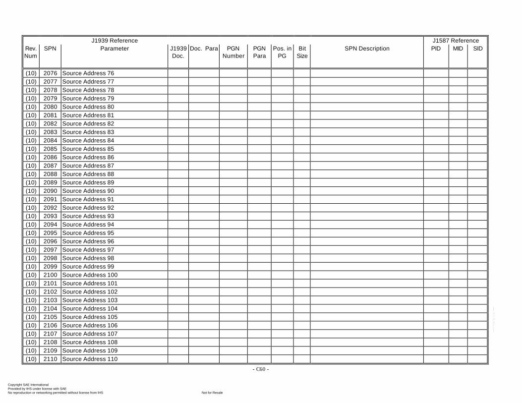
- C60 -
J1939 Reference J1587 ReferenceRev.Num
SPN Parameter J1939Doc.
Doc. Para PGNNumber
PGNPara
Pos. inPG
BitSize
SPN Description PID MID SID
(10) 2076 Source Address 76(10) 2077 Source Address 77(10) 2078 Source Address 78(10) 2079 Source Address 79(10) 2080 Source Address 80(10) 2081 Source Address 81(10) 2082 Source Address 82(10) 2083 Source Address 83(10) 2084 Source Address 84(10) 2085 Source Address 85(10) 2086 Source Address 86(10) 2087 Source Address 87(10) 2088 Source Address 88(10) 2089 Source Address 89(10) 2090 Source Address 90(10) 2091 Source Address 91(10) 2092 Source Address 92(10) 2093 Source Address 93(10) 2094 Source Address 94(10) 2095 Source Address 95(10) 2096 Source Address 96(10) 2097 Source Address 97(10) 2098 Source Address 98(10) 2099 Source Address 99(10) 2100 Source Address 100(10) 2101 Source Address 101(10) 2102 Source Address 102(10) 2103 Source Address 103(10) 2104 Source Address 104(10) 2105 Source Address 105(10) 2106 Source Address 106(10) 2107 Source Address 107(10) 2108 Source Address 108(10) 2109 Source Address 109(10) 2110 Source Address 110
Copyright SAE International Provided by IHS under license with SAE
Not for ResaleNo reproduction or networking permitted without license from IHS
--`-`-`,,`,,`,`,,`---
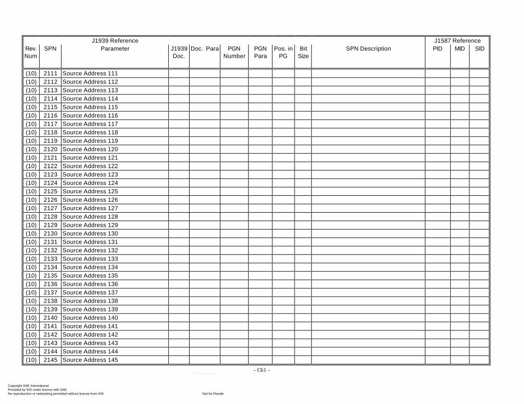
- C61 -
J1939 Reference J1587 ReferenceRev.Num
SPN Parameter J1939Doc.
Doc. Para PGNNumber
PGNPara
Pos. inPG
BitSize
SPN Description PID MID SID
(10) 2111 Source Address 111(10) 2112 Source Address 112(10) 2113 Source Address 113(10) 2114 Source Address 114(10) 2115 Source Address 115(10) 2116 Source Address 116(10) 2117 Source Address 117(10) 2118 Source Address 118(10) 2119 Source Address 119(10) 2120 Source Address 120(10) 2121 Source Address 121(10) 2122 Source Address 122(10) 2123 Source Address 123(10) 2124 Source Address 124(10) 2125 Source Address 125(10) 2126 Source Address 126(10) 2127 Source Address 127(10) 2128 Source Address 128(10) 2129 Source Address 129(10) 2130 Source Address 130(10) 2131 Source Address 131(10) 2132 Source Address 132(10) 2133 Source Address 133(10) 2134 Source Address 134(10) 2135 Source Address 135(10) 2136 Source Address 136(10) 2137 Source Address 137(10) 2138 Source Address 138(10) 2139 Source Address 139(10) 2140 Source Address 140(10) 2141 Source Address 141(10) 2142 Source Address 142(10) 2143 Source Address 143(10) 2144 Source Address 144(10) 2145 Source Address 145
Copyright SAE International Provided by IHS under license with SAE
Not for ResaleNo reproduction or networking permitted without license from IHS
--`-`-`,,`,,`,`,,`---

- C62 -
J1939 Reference J1587 ReferenceRev.Num
SPN Parameter J1939Doc.
Doc. Para PGNNumber
PGNPara
Pos. inPG
BitSize
SPN Description PID MID SID
(10) 2146 Source Address 146(10) 2147 Source Address 147(10) 2148 Source Address 148(10) 2149 Source Address 149(10) 2150 Source Address 150(10) 2151 Source Address 151(10) 2152 Source Address 152(10) 2153 Source Address 153(10) 2154 Source Address 154(10) 2155 Source Address 155(10) 2156 Source Address 156(10) 2157 Source Address 157(10) 2158 Source Address 158(10) 2159 Source Address 159(10) 2160 Source Address 160(10) 2161 Source Address 161(10) 2162 Source Address 162(10) 2163 Source Address 163(10) 2164 Source Address 164(10) 2165 Source Address 165(10) 2166 Source Address 166(10) 2167 Source Address 167(10) 2168 Source Address 168(10) 2169 Source Address 169(10) 2170 Source Address 170(10) 2171 Source Address 171(10) 2172 Source Address 172(10) 2173 Source Address 173(10) 2174 Source Address 174(10) 2175 Source Address 175(10) 2176 Source Address 176(10) 2177 Source Address 177(10) 2178 Source Address 178(10) 2179 Source Address 179(10) 2180 Source Address 180
Copyright SAE International Provided by IHS under license with SAE
Not for ResaleNo reproduction or networking permitted without license from IHS
--`-`-`,,`,,`,`,,`---

- C63 -
J1939 Reference J1587 ReferenceRev.Num
SPN Parameter J1939Doc.
Doc. Para PGNNumber
PGNPara
Pos. inPG
BitSize
SPN Description PID MID SID
(10) 2181 Source Address 181(10) 2182 Source Address 182(10) 2183 Source Address 183(10) 2184 Source Address 184(10) 2185 Source Address 185(10) 2186 Source Address 186(10) 2187 Source Address 187(10) 2188 Source Address 188(10) 2189 Source Address 189(10) 2190 Source Address 190(10) 2191 Source Address 191(10) 2192 Source Address 192(10) 2193 Source Address 193(10) 2194 Source Address 194(10) 2195 Source Address 195(10) 2196 Source Address 196(10) 2197 Source Address 197(10) 2198 Source Address 198(10) 2199 Source Address 199(10) 2200 Source Address 200(10) 2201 Source Address 201(10) 2202 Source Address 202(10) 2203 Source Address 203(10) 2204 Source Address 204(10) 2205 Source Address 205(10) 2206 Source Address 206(10) 2207 Source Address 207(10) 2208 Source Address 208(10) 2209 Source Address 209(10) 2210 Source Address 210(10) 2211 Source Address 211(10) 2212 Source Address 212(10) 2213 Source Address 213(10) 2214 Source Address 214(10) 2215 Source Address 215
Copyright SAE International Provided by IHS under license with SAE
Not for ResaleNo reproduction or networking permitted without license from IHS
--`-`-`,,`,,`,`,,`---

- C64 -
J1939 Reference J1587 ReferenceRev.Num
SPN Parameter J1939Doc.
Doc. Para PGNNumber
PGNPara
Pos. inPG
BitSize
SPN Description PID MID SID
(10) 2216 Source Address 216(10) 2217 Source Address 217(10) 2218 Source Address 218(10) 2219 Source Address 219(10) 2220 Source Address 220(10) 2221 Source Address 221(10) 2222 Source Address 222(10) 2223 Source Address 223(10) 2224 Source Address 224(10) 2225 Source Address 225(10) 2226 Source Address 226(10) 2227 Source Address 227(10) 2228 Source Address 228(10) 2229 Source Address 229(10) 2230 Source Address 230(10) 2231 Source Address 231(10) 2232 Source Address 232(10) 2233 Source Address 233(10) 2234 Source Address 234(10) 2235 Source Address 235(10) 2236 Source Address 236(10) 2237 Source Address 237(10) 2238 Source Address 238(10) 2239 Source Address 239(10) 2240 Source Address 240(10) 2241 Source Address 241(10) 2242 Source Address 242(10) 2243 Source Address 243(10) 2244 Source Address 244(10) 2245 Source Address 245(10) 2246 Source Address 246(10) 2247 Source Address 247(10) 2248 Source Address 248(10) 2249 Source Address 249(10) 2250 Source Address 250
Copyright SAE International Provided by IHS under license with SAE
Not for ResaleNo reproduction or networking permitted without license from IHS
--`-`-`,,`,,`,`,,`---
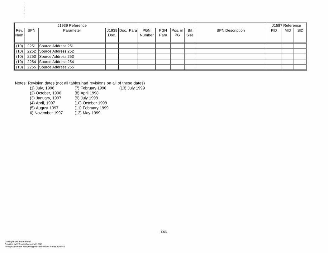
- C65 -
J1939 Reference J1587 ReferenceRev.Num
SPN Parameter J1939Doc.
Doc. Para PGNNumber
PGNPara
Pos. inPG
BitSize
SPN Description PID MID SID
(10) 2251 Source Address 251(10) 2252 Source Address 252(10) 2253 Source Address 253(10) 2254 Source Address 254(10) 2255 Source Address 255
Notes: Revision dates (not all tables had revisions on all of these dates)(1) July, 1996 (7) February 1998 (13) July 1999(2) October, 1996 (8) April 1998(3) January, 1997 (9) July 1998(4) April, 1997 (10) October 1998(5) August 1997 (11) February 19996) November 1997 (12) May 1999
Copyright SAE International Provided by IHS under license with SAE
Not for ResaleNo reproduction or networking permitted without license from IHS
--`-`-`,,`,,`,`,,`---

APPENDIX D
ASSIGNMENT REQUEST FORMS The request process and forms are maintained on the SAE web site under the public FORUM area: http://forums.sae.org/access/dispatch.cgi/TETEpf/docProfile/100077/d20030507173653/No/SAE%20J1939%20Request%20Form%20R1.3.doc
Copyright SAE International Provided by IHS under license with SAE
Not for ResaleNo reproduction or networking permitted without license from IHS
--`-`-`,,`,,`,`,,`---
SAE J1939 Revised AUG2003
Rationale
Section 2.4 was updated to include the latest information on which documents within the J1939 family of documents have been published.
Appendix A, B and C were revised to include changes and additions approved and balloted through December 2001.
Appendix D has been completely revised. Paper request forms will no longer be used. All requests will be made electronically.
Relationship of SAE Standard to ISO Standard
Not applicable.
Application
These Recommended Practices are intended for light, medium, and heavy duty vehicles used on or off road as well as appropriate stationary applications which use vehicle derived components (e.g. generator sets). Vehicles of interest include, but are not limited to: on and off highway trucks and their trailers; construction equipment; and agricultural equipment and implements.
The purpose of these Recommended Practices is to provide an open interconnect system for electronic systems. It is the intention of these Recommended Practices to allow Electronic Control Units to communicate with each other by providing a standard architecture.
Reference Section
ISO 7498 Information Processing Systems - Open Systems Interconnection (OSI) - Basic Reference Model.
ISO 11898 Road Vehicles — Interchange of Digital Information — Controller Area Network (CAN) for High Speed Communication, December 1992
ISO 11992 Road Vehicles - Electrical Connections Between Towing and Towed Vehicles - Interchange of Digital Information (Parts 1, 2, 3)
SAE J1213 Glossary of Automotive Electronic Terms
SAE J1708 Recommended Practice for Serial Data Communication Between Microcomputer Systems in Heavy Duty Vehicle Applications.
SAE J1587 Recommended Practice for Electronic Data Interchange Between Microcomputer Systems in Heavy Duty Vehicle Applications
SAE J1922 Powertrain Control Interface for Electronic Controls Used in Medium and Heavy Duty Diesel On-Highway Vehicle ApplicationsSAE J551—The RefItems style tag is used to list the documents.
Developed By the SAE Truck and Bus Control and Communications Network Subcommittee
Sponsored By the SAE Truck and Bus Electrical/Electronics Committee
Copyright SAE International Provided by IHS under license with SAE
Not for ResaleNo reproduction or networking permitted without license from IHS
--`-`-`,,`,,`,`,,`---