Embed Size (px)
Citation preview

ITTC – Recommended Procedures and Guidelines
7.5-02 -03-02.4
Page 1 of 11
Nominal Wake Measurement by a 5-Hole Pitot Tube
Effective Date 2011
Revision 01
Updated by Approved
26th ITTC Propulsion Committee
26th ITTC
Date 02/2011 Date 09/2011
Table of Contents
1. PURPOSE OF PROCEDURE ............... 2
2. NOMENCLATURE ............................... 2
3. SHIP MODEL AND INSTRUMENT... 3
3.1 Ship Model ............................................ 3 3.2 5-hole pitot-tube................................ .. 3
3.2.1 Choice of probe type ..................... 3 3.2.2 Choice of probe size ...................... 3
3.3 Traverse System................................ .. 3 3.4 Pressure Transducer .......................... 4
4. DESCRIPTION OF PROCEDURE ..... 4
4.1 Operation mode of 5-hole pitot tube . 4
4.2 Pitot Tube Calibration ........................ 4 4.3 Data Reduction Equations.................. 5
4.3.1 Horizontal-Vertical Method (Kh-Kv type) ............................................... 5
4.3.2 Omni-directional type method ....... 6 4.3.3 Modified omni-directional type
method............................................ 6
4.4 Analysis ................................................ 7 4.5 Measurements...................................... 9 4.6 Reporting ............................................. 9
5. UNCERTAINTY ANALYSIS.............. 10
6. REFERENCES...................................... 10

ITTC – Recommended Procedures and Guidelines
7.5-02 -03-02.4
Page 2 of 11
Nominal Wake Measurement by a 5-Hole Pitot Tube
Effective Date 2011
Revision 01
Nominal Wake Measurement Procedure by a 5-Hole Pitot Tube
1. PURPOSE OF PROCEDURE
The purpose of the procedure is to provide guidelines to ensure the consistency of the methodology and the acquisition of the correct nominal wake-field at the propeller disk of a ship model utilizing a 5 hole pitot-tube.
2. NOMENCLATURE
Vx: Axial velocity component (m/s)
Vt : Tangential velocity component (m/s)
Vr: Radial velocity component (m/s)
ρ : Mass density (kg/m3)
q: Magnitude of the velocity (m/s)
= �Vx2 + Vt2 + Vr2
θ: Yaw angle(°) for Pitot tube or
Circumferential angle in propeller plane
φ: Pitch angle(°)
PC, PT, PB, PP, PS, PST: Pressure at the center, top, bottom, port, starboard hole and static, respectively.
PPS: Pressure difference between the port and starboard side pressure hole
PBT: Pressure difference between the bottom and top side pressure hole
PNS: Pressure difference between the nose (center) and static side pressure hole
Hdyn: Dynamic pressure (0.5ρq2)
The coordinate system for the velocity components is shown in Figure 1, and the pressure components at each pressure hole for the 5 hole pitot-tube are given in Figure 2.
Figure 1 Definition of the velocity components
Figure 2 Position of the pressure holes
Vr
Vt
Vx
Vr
PS
PT
PB
PP Pc PST

ITTC – Recommended Procedures and Guidelines
7.5-02 -03-02.4
Page 3 of 11
Nominal Wake Measurement by a 5-Hole Pitot Tube
Effective Date 2011
Revision 01
3. SHIP MODEL AND INSTRUMENT
3.1 Ship Model
A full ship model is required for the measurement of the nominal wake at the propeller plane. The specifications for the ship model should comply with the dedicated procedure in the ITTC 4.9 02-02-01 Quality Manual.
The test for wake measurements is performed on the same model as used in the resistance and self-propulsion tests, without any additional appendages and surface treatment. The ship model should be assembled with all the required appendages, fin stabilizer, and turbulence stimulators that can influence the propeller inflow. Only the rudder can be removed to allow easier access to the propeller disk.
3.2 5-hole Pitot-tube
The head of each Pitot tube contains 5 holes joined by small diameter internal tubes: one on the center, one pair aligned with the radial plane and the other pair in the tangential plane.
3.2.1 Choice of probe type
There are several varieties of multi-hole Pitot probes. Among them, the 5-hole Pitot tube has the capability to measure the three components of velocity and has also been widely used for towing tank tests. Currently, there are several types of 5-hole Pitot tubes: the spherical probe, the Conrad [1] type, the conical type, and the pyramidal type among others. Each of these probes has their own advantages and disadvantages. For instance, a spherical 5-hole Pitot probe is not easily made small. However, the analysis method is based on the theory of potential flow around the
sphere. On the other hand, the Conrad type is easy to make small, but has decreased measurement accuracy for oblique flow. For this reason, specific choice of probes should be made with the specific measurements in mind.
3.2.2 Choice of probe size
For the determination of the probe size, the relation 1000/ >νVD should be used [2], where D is the Probe diameter (m), V is the inflow velocity (m/s) . Since the order of Re is around 106 in a model test, this leads the probe diameter D to be the order of Lpp/1000. For example in the case of a 6 m-long model, the diameter of the probe should be around 6 mm.
For the diameter of the pressure holes, the relation 100/ >νVd should be used [1], where d is the diameter of the pressure hole. From the relation 1000/ >νVD and 100/ >νVd , d/D would be on the order of 0.1. This value should be used as a reference to determine the size of the pressure hole.
3.3 Traverse System
The measurement is executed by using a rake assembly of multiple Pitot tubes or a single probe traversing system [10], both of which are widely used for ship model wake measurements.
The rake systems with multiple 5-hole Pitot-tubes enable efficient and accurate measurements by rotating the rake at the centre of the propeller axis. The angle of the Pitot tube rake is controlled by a stepping motor. Examples of a typical rake traverse system are shown in Figure 3a and 3b.

ITTC – Recommended Procedures and Guidelines
7.5-02 -03-02.4
Page 4 of 11
Nominal Wake Measurement by a 5-Hole Pitot Tube
Effective Date 2011
Revision 01
Figure 3a Rake of the pitot tube
Figure 3b Single probe traverse system
Both the model and the carriage mounted traverse system can be used with either single or multiple 5-hole Pitot-tubes. The traverse system should be designed to cover an area of at least the draft by half of the beam of a model ship.
3.4 Pressure Transducer
The capacity of the pressure transducers is dependent on the maximum flow speed. It is recommended that the calibration of each pressure transducer be performed quarterly, or before each use, in order to insure the quality of measurements.
4. DESCRIPTION OF PROCEDURE
A wake measurement test is conducted to determine the axial, radial and tangential velocity components in the propeller plane.
4.1 Operation mode of 5-hole pitot tube
Though Pitot tubes can be operated in nulling and non-nulling modes, generally only the non-nulling mode is used, and this procedure is for use of the Pitot tube in non-nulling mode.
In non-nulling mode, the probe undergoes an extensive calibration to determine the magnitude and the direction of flow with respect to the coordinate system of a probe. It requires the reverse technique to calculate the magnitude and the direction of flow from the pressure measurement. It has the advantage of measuring the pressure from the flow field at a given probe installation. Treaster and Yocum [3] as well as Morrison et. al. [4] suggested the non-nulling mode measurement by means of a calibration chart.
4.2 Pitot Tube Calibration
The calibration process compensates for the manufacturing inaccuracy and the inability of an analytical solution for the typical type of probe geometry. Specifically in the non-nulling mode, the magnitude and direction of the flow should be correlated to the pressure at the pressure hole through the calibration. A calibration apparatus, which can control pitch and yaw angle independently, is shown in Figure 4. The probe is set in the calibration device, and it is placed on the towing carriage. The carriage is moved at a pre-determined speed that signifies the known inflow velocity to the Pitot-tube. The speed of calibration is determined according to this model ship speed.

ITTC – Recommended Procedures and Guidelines
7.5-02 -03-02.4
Page 5 of 11
Nominal Wake Measurement by a 5-Hole Pitot Tube
Effective Date 2011
Revision 01
Reynolds effects must be considered in the calibration, but the effect of Reynolds number can be negligible in the range of the model ship speed (Kim et al., 1997). To reduce the effect of the water surface, the wake rake should be submerged more than the length of the Pitot tube rake. This method reduces the wall effect that is caused when the calibration is carried out in the water channel.
Figure 4 Schematic view of the calibration
device
The calibration/data reduction methods can be placed in two categories. In this procedure, the horizontal-vertical and omni-directional type methods will be discussed.
4.3 Data Reduction Equations
Three different data reduction methods are introduced through the different types of calibration and analysis methods, typically used during towing tank experiments.
The horizontal-vertical or omni-directional type method is recommended to be used in the wake measurement of high speed ships. However, when high pitch or yaw angles (larger than 30°) are expected, the modified
omni-directional type method is strongly recommended to increase the measurement quality.
4.3.1 Horizontal-Vertical Method (Kh-Kv type)
In the horizontal-vertical method, the horizontal and vertical components of velocity can be determined independently. Pien’s method [6] is typical for the horizontal-vertical method. Using this method, HK , HPg and HSg can be obtained by a stepwise change of θ, every 5 degrees from –30 degrees to 30 degrees, under ϕ=0. Similarly, VK and VTg , VBg are defined by a stepwise change of ϕ under keeping θ=0. From there, calibration curves can be obtained.
Pitch angle coefficient:
BTC
BTV PPP
PPK−−
−=
2
Vertical velocity coefficient:
22/1 q
PPg TCVT ρ
−=
22/1 q
PPg BCVB ρ
−=
Yaw angle coefficient:
PSC
PSH PPP
PPK
−−−
=2
Pitch
Yaw
Pitot Tube Rake
Pitot Tube
( + )
( - )
( - )
( + )
ITTC – Recommended Procedures and Guidelines
7.5-02 -03-02.4
Page 6 of 11
Nominal Wake Measurement by a 5-Hole Pitot Tube
Effective Date 2011
Revision 01
Horizontal velocity coefficient:
22/1 q
PPg PCHP ρ
−=
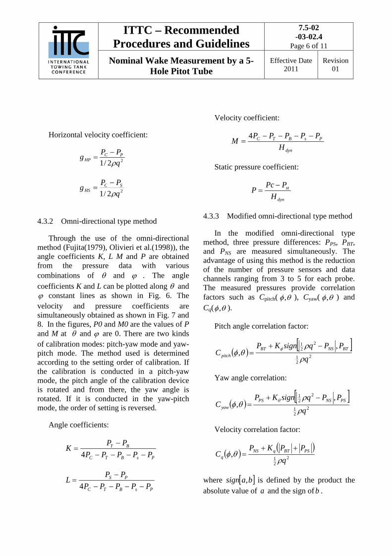
4.3.2 Omni-directional type method
Through the use of the omni-directional method (Fujita(1979), Olivieri et al.(1998)), the angle coefficients K, L M and P are obtained from the pressure data with various combinations of θ and ϕ . The angle coefficients K and L can be plotted along θ and ϕ constant lines as shown in Fig. 6. The velocity and pressure coefficients are simultaneously obtained as shown in Fig. 7 and 8. In the figures, P0 and M0 are the values of P and M at θ and ϕ are 0. There are two kinds of calibration modes: pitch-yaw mode and yaw-pitch mode. The method used is determined according to the setting order of calibration. If the calibration is conducted in a pitch-yaw mode, the pitch angle of the calibration device is rotated and from there, the yaw angle is rotated. If it is conducted in the yaw-pitch mode, the order of setting is reversed.
Angle coefficients:
PsBTC
BT
PPPPPPPK
−−−−−
=4
PsBTC
PS
PPPPPPP
L−−−−
−=
4
Velocity coefficient:
dyn
PsBTC
HPPPPP
M−−−−
=4
Static pressure coefficient:
dyn
st
HPPc
P−
=
4.3.3 Modified omni-directional type method
In the modified omni-directional type method, three pressure differences: PPS, PBT, and PNS are measured simultaneously. The advantage of using this method is the reduction of the number of pressure sensors and data channels ranging from 3 to 5 for each probe. The measured pressures provide correlation factors such as Cpitch( θφ, ), Cyaw( θφ, ) and Cq( θφ, ).
Pitch angle correlation factor:
( )[ ]
221
221 ,
,q
PPqsignKPC BTNSBT
pitch ρ
ρθφ φ −+
=
Yaw angle correlation:
( )[ ]
221
221 ,
,q
PPqsignKPC PSNSPS
yaw ρ
ρθφ θ −+
=
Velocity correlation factor:
( ) ( )2
21
,q
PPKPC PSBTqNS
q ρθφ
++=
where [ ]basign , is defined by the product the absolute value of a and the sign of b .
2 2 / 1 q P P g S C
HS ρ −
=

ITTC – Recommended Procedures and Guidelines
7.5-02 -03-02.4
Page 7 of 11
Nominal Wake Measurement by a 5-Hole Pitot Tube
Effective Date 2011
Revision 01
4.4 Analysis
In the horizontal-vertical method, as shown in Figure 5, the measured pressure at the hole of each 5-hole Pitot probe, HK is estimated. From the characteristic of the θ−HK curve, θ is determined. In the case that the flow comes from the port and goes to the starboard side,
HPg is determined from the characteristic curve of θ−HPg and estimated θ . Then q is evaluated by
( )HP
PC
gPPq
ρ−
=2
.
In the case that the flow comes from the port side, θ−HSg should be used. From the estimated q , the axial and horizontal velocity components can be estimated by VX=qcosθ and VY=qsinθ. The vertical component of velocity can be estimated in a similar manner. The analysis procedure is very simple but one-to-one correspondence can fail when the flow angle exceeds the limit as shown in Figure 5.
Figure 5 Example of horizontal-vertical calibration curves
In the omni-directional method, K and L are estimated from the measured pressure at each hole of the 5-hole pitot-probe. From the calibration charts (K, L) and (θ, ϕ), θ andϕ are interpolated two-dimensionally. From θ and ϕ, M and P can be evaluated using the characteristic charts of M(θ, ϕ)/M0 and P(θ, ϕ)/P0. Therefore, the velocity q and the static pressure statp can be evaluated from M and P.
Figure 6 Example of the angle coefficients K and L for the omni-directional analysis
method
Figure 7 Example of the velocity coefficient for the omni-directional analysis method

ITTC – Recommended Procedures and Guidelines
7.5-02 -03-02.4
Page 8 of 11
Nominal Wake Measurement by a 5-Hole Pitot Tube
Effective Date 2011
Revision 01
Figure 8 Example of the static pressure coefficient for the omni-directional analysis
method
The modified omni-directional method has an advantage of reducing the number of data channels, but it has an intrinsic one-to-one mapping problem when both pitch and yaw angles are as large as those shown in Fig. 9a. This problem is solved however by introducing the additional parameters φK , θK , qK . The best value of φK , θK , qK should be determined for each type of probe. In this method, the iterative approach is needed to determine the velocity vectors. pitchC ( θφ, ), yawC ( θφ, ), qC( θφ, ) values are calculated from the measured pressure and the magnitude of a velocity, q. Since q is not a known value but has to be found, q is assumed in the first iteration (usually the speed of the model ship). The prime is the intermediate value in the iteration step. Then ( '' ,θφ ) are calculated from pitchC
( θφ, ) and yawC ( θφ, ) using two-dimensional
interpolation. 'qC ( θφ, ) can be calculated from
qC ( θφ, ) using ( '' ,θφ ). Next, q can be
calculated from the definition of qC . Finally,
the assumed value q′ and the calculated q are compared. If the difference of these values does not satisfy a tolerance interval, repeat the next step. If it does satisfy the tolerance interval, then the velocity components of the flow field are calculated.
(a) without φK , θK , qK
(b) with φK =0.9, θK =0.4, qK =0.2
Figure 9 Calibration chart of a spherical type probe
CPS(Pitch)
CTB
(Yaw
)
-3 -2 -1 0 1 2 3
-2
0
2
Yaw=-400
Yaw=-400
Pitc
h=40
0
Pitc
h=-4
00
CPS(Pitch)
CTB
(Yaw
)
-3 -2 -1 0 1 2 3
-2
0
2
Yaw=-400
Yaw=-400
Pitc
h=40
0
Pitc
h=-4
00

ITTC – Recommended Procedures and Guidelines
7.5-02 -03-02.4
Page 9 of 11
Nominal Wake Measurement by a 5-Hole Pitot Tube
Effective Date 2011
Revision 01
The final velocity components are determined from the obtained ( q , θ ,ϕ ).
For pitch-yaw mode,
)sin()sin()cos()cos()cos(
φθφθφ
θ qVqVqV
r
x
===
For yaw-pitch mode,
)sin()cos()sin(
)cos()cos(
φθθ
φθ
qVqVqV
t
r
x
===
4.5 Measurements
A typical model installation is shown in Figure 10. The wake rake is installed in the propeller shaft and the rake used in the calibration is also used for the wake measurement. Several rakes are prepared according to the model propeller diameter, which can minimize the positioning errors. The position of the tip of the Pitot probe is located at the propeller generating line and the wake is measured every 10° or less for the whole propeller plane. Figure 11 shows the measurement grid for wake measurement.
The data collection time and sampling frequency of the measurement depends on the unsteadiness of the flow. In a towing tank test, it may be difficult to have sufficient collection time and typically a five to ten seconds run time is used. For reliability of measurements, a thirty second sampling time is recommended for a couple of specially chosen points.
Figure 10 Pitot tube rake arrangement for wake
measurement
Fig. 11 Measurement grid for wake measurement
4.6 Reporting
From the analysis results, iso-axial velocity contours are plotted to show the wake distribution at the propeller plane. The transverse flow direction at the propeller plane is easily seen by plotting these velocity vectors. At the same time, the speed distributions for xV ,
rV and tV normalized by towing speed can be given in the tabulated form along the probe angles for all investigated radii.
051020
30
40
50
60
70
80
90
100
110
120
130
140
150
160170 175 180 185 190
200
210
220
230
240
250
260
270
280
290
300
310
320
330
340350355
Propeller disk
ITTC – Recommended Procedures and Guidelines
7.5-02 -03-02.4
Page 10 of 11
Nominal Wake Measurement by a 5-Hole Pitot Tube
Effective Date 2011
Revision 01
The velocity components at the propeller plane are considered to be a periodic function of period π2 for each radius and represented by the Fourier series.
( ) ( )( )
( )( )∑
∑
=
=
−+=
++=
n
kkko
n
kkkoi
kca
kbkaaV
1
1
cos
sincos
φθ
θθ
Circumferential mean velocity is the mean value of the measured velocity at the radius r and is computed as follows:
( )∫=π
θθπ
2
021 dVV iMi
Total mean velocity is obtained from the value of the circumferential mean velocity from the propeller hub to the propeller tip at the propeller plane and is computed as follows:
( )22
2
hp
r
r Mi
TMi rr
drrVV
p
h
−
⋅⋅=
∫π
π
Wake fraction represents the nominal wake fraction without a propeller at the stern and is computed as follows:
TMXA
N VVVw −=−= 11
5. UNCERTAINTY ANALYSIS
Uncertainty analysis was performed following the ITTC standard method (ITTC, 1999, Coleman and Steele, 1999) and both bias and precision errors were considered. As sources of bias error, the resolution and nonlinearity of amplifiers, transducers, A/D
converters, location of probes, carriage speed, water temperature, density and a tolerance interval of analysis program were considered. The sampled raw data were processed to determine the precision error for each measurement quantity. The uncertainty interval is determined by taking the root sum square of the bias error and the precision error multiplied by t-value in t distribution (Coleman and Steele, 1999). The two-dimensional chart calibration method for a 5-hole Pitot probe produces larger bias errors in the strong velocity defect region, since local flow angles out of the Pitot tube center become greater due to the small axial velocity components. The precision error was slightly greater than the bias error. The fluctuating local velocity components produce larger precision errors, even though the flexible tubing connecting the Pitot tube and the pressure transducers tend to damp the fluctuating pressure signals.
6. REFERENCES [1] Laminar Boundary Layers, Ed. L.
Rosenhead, Oxford Univ. press (1963)
[2] Arts, T.,Carbonaro, M., Charbonnier, J-M., Degrez, G., Olivari,D., Riethmuller,R.A., Van den Braembussche R.A., Measurement techniques in fluid dynamics, course notes presented by members of the faculty of the von Karman Institute for Fluid Dynamics, Chaussee de Waterloo, 72, B-1640, Rhode Saint Genese-Belgium, 81-115, (1994)
[3] Treaster A.L., Yocum A.M., “The Calibration and Application of Five-Hole Probes”, ISA Transaction, Vol. 18, pp. 23-34. 1979

ITTC – Recommended Procedures and Guidelines
7.5-02 -03-02.4
Page 11 of 11
Nominal Wake Measurement by a 5-Hole Pitot Tube
Effective Date 2011
Revision 01
[4] Morrison G.L., Schobeiri M.T., Pappu K.R., “Five-hole pressure probe analysis technique”, Vel 9, PP153-158, 1998
[5] Kim W. J., Kim D.H., Yoon H.S., Moon D.Y., Van S.H. (1997) Study on the calibration of a five-hole Pitot-tube for the wake measurement (in Korean), Journal of the Society of Naval Architecture of Korea 34: 11-19.
[6] Pien, P.C.,: Five-Hole Spherical Pitot Tube, David Taylor Model Basin Report No. 1229, May 1958
[7] Fujita, T.,:On the Flow Measurement in
High Wake Region at the Propeller Plane, JSNAJ, vol 145, pp.1-7, (1979)
[8] Olivieri, A., Pistani, F., Penna, R.,:Experimental Investigation of the flow around a fast displacement ship hull model, Journal of Ship research, vol.47, No.3., Sept 2003, pp.247-261
[9] Van, S. H., Kim, W. J., Yoon, H. S., Lee,
Y. Y., Park, I. R.,: Flow measurement around a model ship with propeller and rudder, Experiments in Fluids, vol.40, 2006, pp.533-545
[10] Wake Survey Device P300q –Manual. Ship Design and Research Centre S.A., Gdansk, Poland, 2006.
[11] Coleman, H. W. and Steele, W. G., Experimentation and Uncertainty Analysis for Engineers
, Wiley & Sons, Inc. 1999 pp. 275.