Embed Size (px)
Citation preview

Surveying
Prof. Rajesh Bhagat Asst. Professor, CED, YCCE, Nagpur
B. E. (Civil Engg.) M. Tech. (Enviro. Engg.)
GCOE, Amravati VNIT, Nagpur
Experience & Achievement:
Selected Scientist, NEERI-CSIR, Govt. of India.
GATE Qualified Three Times.
UGC-NET Qualified in First Attempt.
Selected Junior Engineer, ZP Washim.
Three Times Selected as UGC Approved Assistant Professor.
Assistant Professor, PCE, Nagpur.
Assistant Professor, Cummins College of Engg. For Women, Nagpur
Topper of Pre-PhD Course Work at UGC-HRDC, RTMNU Nagpur
Mobile No.:- 8483002277 / 8483003474 Email ID :- [email protected]
Website:- www.rajeysh7bhagat.wordpress.com
UNIT-IV
1) Theodolite Surveying: Theodolite, type of theodolite, temporary
adjustment, principle axes, relationship, measurement of horizontal
and vertical angles.
2) Traverse Computation: Consecutive and independent co-
ordinates, adjustment of closed traverse, area calculation by co-
ordinate.
2
List of Experiment : - (Min. 10 Experiment)
1) Measurement of bearing of sides of traverse with prismatic compass and computation of correct included
angles.
2) Locating given building by chain and compass traversing (1 full size drawing sheet)
3) Determination of elevation of various points with dumpy level by collimation plane method and rise and
fall method.
4) Fixing the bench mark with respect to temporary bench mark with dumpy level by fly leveling and check
leveling.
5) Measurement of horizontal angle with theodolite by method of repetition.
6) Measurement of vertical angle with theodolite.
7) Determination of horizontal distance between two inaccessible point with theodolite.
8) Locating given building by theodolite traversing. (One full size drawing sheet)
9) Determination of elevation of point by trigonometric leveling.
10)Determination of constants of Tacheometer.
11)Determination of elevation of points by Tacheometric surveying.
12)Determination of elevation of points and horizontal distance between them by Tacheometrical survey.
13)Determination of gradient of given length of road by Tacheometric survey.
3
References:-
SN Title Authors Publisher
1 Surveying and
Leveling (Vol-I & II)
Kanitkar T. P.,
Kulkarni S. V.
Pune Vidyarthi Griha
Prakashan, Pune.
2 Surveying and
Leveling (Vol–I & II)
Punmia B. C.,
Jain A. K.,
Jain A. K.
Laxmi Publication(P) Ltd. New
Delhi.
3 Surveying & Leveling Basak N. N. Tata McGraw Hill Pub. Co. Ltd.
New Delhi
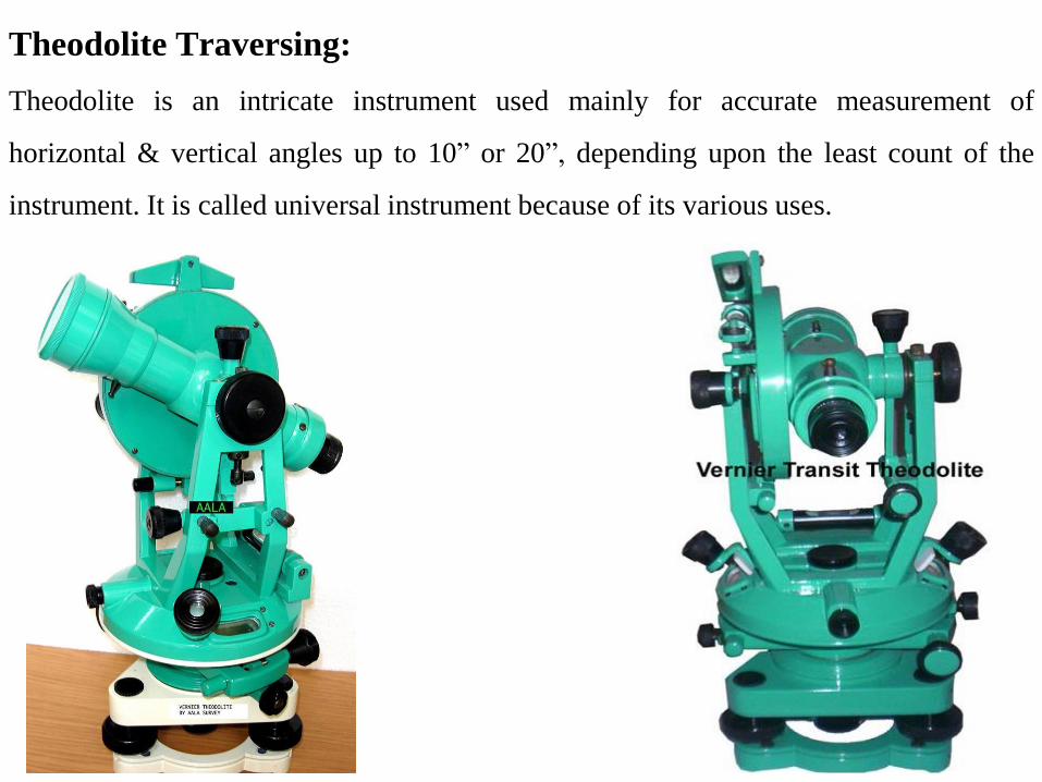
Theodolite Traversing:
Theodolite is an intricate instrument used mainly for accurate measurement of
horizontal & vertical angles up to 10” or 20”, depending upon the least count of the
instrument. It is called universal instrument because of its various uses.
Purpose of Theodolite :
1) Measurement of Horizontal angle.
2) Measurement of Vertical angle.
3) Measurement of Deflection angle.
4) Measurement of Magnetic Bearings.
5) Measurement of Horizontal distance between two points.
6) Finding of Vertical height of an object.
7) Finding the Difference of elevation between various points.
8) Ranging a line.
Theodolite may be of following types:
1) Transit Theodolite: The telescope can be revolved through a complete revolution
about its horizontal axis in a vertical plane.
2) Non-transit Theodolite: The telescope can not be revolved through a complete
revolution in the vertical plane. But it can be revolved to a certain extent in the
vertical plane, in order to measure the angles of elevation or depression.
3) Vernier Theodolite: When fitted with vernier scale.
4) Micrometer Theodolite: When fitted with micrometer.
1) Centring: The setting of a theodolite exactly over a station mark by means of a
plumb-bob is known as centring. The plumb-bob is suspended from a hook fixed
below the vertical axis.
2) Transiting: The method of turning the telescope about its horizontal axis in a
vertical plane through 1800 is termed as transiting. Change in face
3) Face Left: Vertical circle of the theodolite is on the left of the observer at the time
of taking readings. Face left observation.
4) Face Right: When the vertical circle of the instrument is on the right of the
observer while taking reading. Face right observation.
5) Telescope Normal: The face left position is known as telescope normal or
telescope direct. It is also referred to as bubble up.
6) Telescope Inverted: The face right position is called telescope inverted or
telescope reversed. It is also termed bubble down.
7) Changing Face: Bringing the vertical circle from one side of the observer to the
other is known as changing face.
8) Swinging the Telescope: Turning of the telescope in a horizontal plane. When the
telescope is turned clockwise then it is called right swing. When the telescope is
turned anticlockwise then it is left swing.
9) Line of Collimation: Imaginary line passing through the intersection of cross hairs
at the diaphragm & the optical center of the object glass & its continuation.
10) Axis of the Telescope: Imaginary line passing through the optical center of the
object glass & the optical center of the eyepiece.
11) Vertical Axis: It is the axis of rotation of the telescope in the horizontal plane.
12) Horizontal Axis: Axis of rotation of the telescope in vertical plane. Turnnion Axis.
13) Temporary Adjustment: Setting of theodolite over a station at the time of taking
any observation.
14) Permanent Adjustment: When the desired relationship between the fundamental
lines of a theodolite is disturbed then some procedure are adopted to established
this relationship.
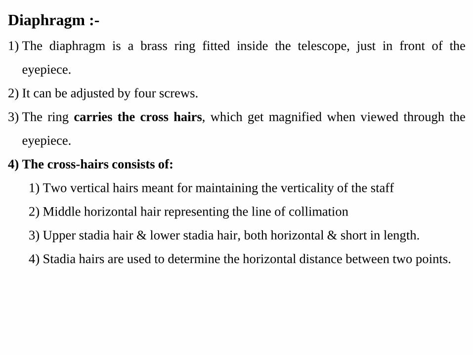
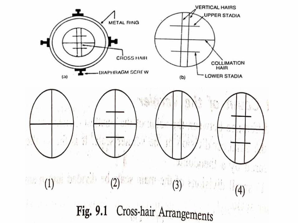
Diaphragm :-
1) The diaphragm is a brass ring fitted inside the telescope, just in front of the
eyepiece.
2) It can be adjusted by four screws.
3) The ring carries the cross hairs, which get magnified when viewed through the
eyepiece.
4) The cross-hairs consists of:
1) Two vertical hairs meant for maintaining the verticality of the staff
2) Middle horizontal hair representing the line of collimation
3) Upper stadia hair & lower stadia hair, both horizontal & short in length.
4) Stadia hairs are used to determine the horizontal distance between two points.
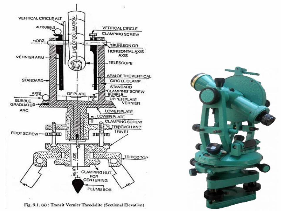
Transit Theodolite:
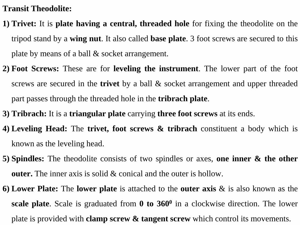
1) Trivet: It is plate having a central, threaded hole for fixing the theodolite on the
tripod stand by a wing nut. It also called base plate. 3 foot screws are secured to this
plate by means of a ball & socket arrangement.
2) Foot Screws: These are for leveling the instrument. The lower part of the foot
screws are secured in the trivet by a ball & socket arrangement and upper threaded
part passes through the threaded hole in the tribrach plate.
3) Tribrach: It is a triangular plate carrying three foot screws at its ends.
4) Leveling Head: The trivet, foot screws & tribrach constituent a body which is
known as the leveling head.
5) Spindles: The theodolite consists of two spindles or axes, one inner & the other
outer. The inner axis is solid & conical and the outer is hollow.
6) Lower Plate: The lower plate is attached to the outer axis & is also known as the
scale plate. Scale is graduated from 0 to 3600 in a clockwise direction. The lower
plate is provided with clamp screw & tangent screw which control its movements.
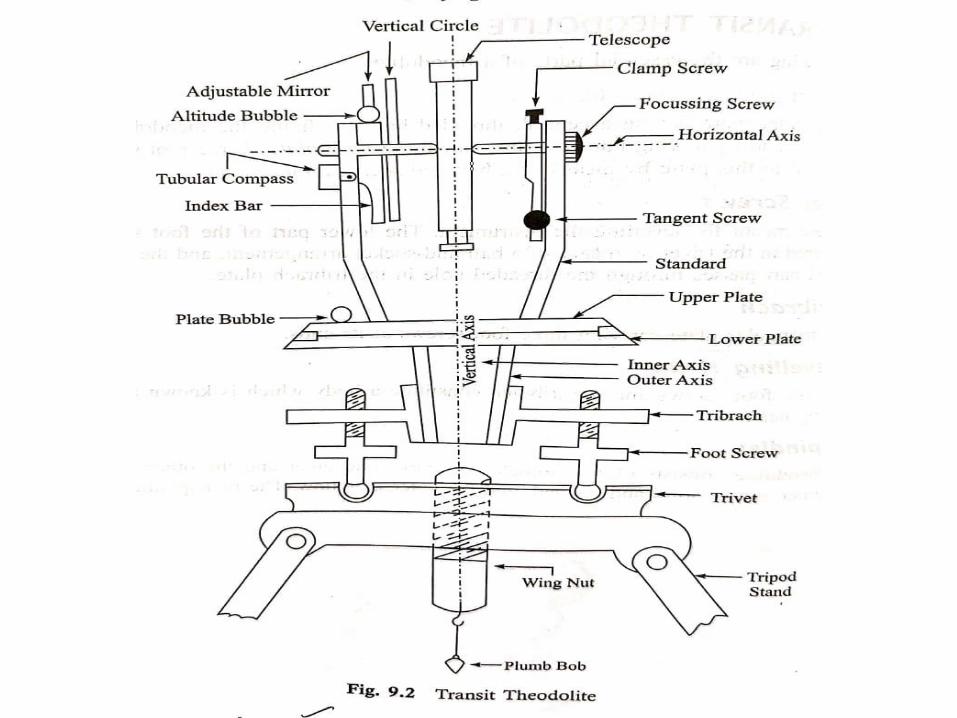
Transit Theodolite:
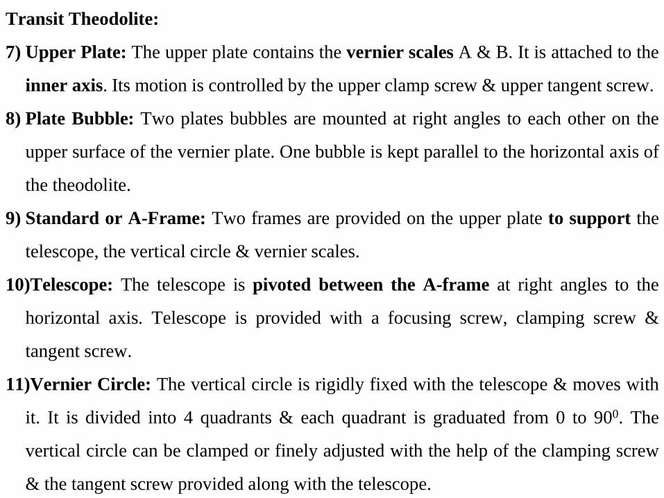
7) Upper Plate: The upper plate contains the vernier scales A & B. It is attached to the
inner axis. Its motion is controlled by the upper clamp screw & upper tangent screw.
8) Plate Bubble: Two plates bubbles are mounted at right angles to each other on the
upper surface of the vernier plate. One bubble is kept parallel to the horizontal axis of
the theodolite.
9) Standard or A-Frame: Two frames are provided on the upper plate to support the
telescope, the vertical circle & vernier scales.
10)Telescope: The telescope is pivoted between the A-frame at right angles to the
horizontal axis. Telescope is provided with a focusing screw, clamping screw &
tangent screw.
11)Vernier Circle: The vertical circle is rigidly fixed with the telescope & moves with
it. It is divided into 4 quadrants & each quadrant is graduated from 0 to 900. The
vertical circle can be clamped or finely adjusted with the help of the clamping screw
& the tangent screw provided along with the telescope.
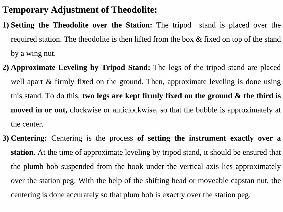
Temporary Adjustment of Theodolite:
1) Setting the Theodolite over the Station: The tripod stand is placed over the
required station. The theodolite is then lifted from the box & fixed on top of the stand
by a wing nut.
2) Approximate Leveling by Tripod Stand: The legs of the tripod stand are placed
well apart & firmly fixed on the ground. Then, approximate leveling is done using
this stand. To do this, two legs are kept firmly fixed on the ground & the third is
moved in or out, clockwise or anticlockwise, so that the bubble is approximately at
the center.
3) Centering: Centering is the process of setting the instrument exactly over a
station. At the time of approximate leveling by tripod stand, it should be ensured that
the plumb bob suspended from the hook under the vertical axis lies approximately
over the station peg. With the help of the shifting head or moveable capstan nut, the
centering is done accurately so that plum bob is exactly over the station peg.
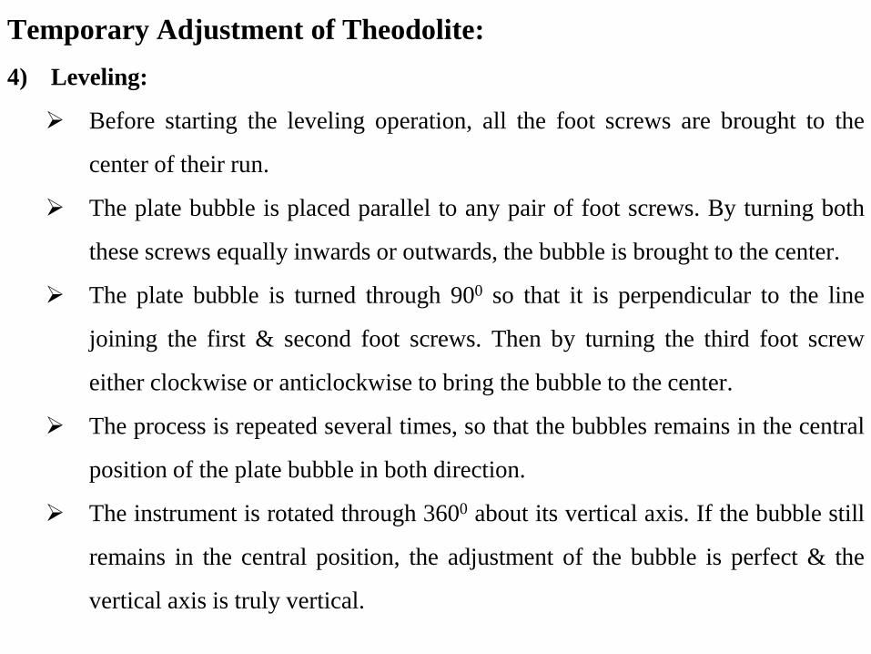
Temporary Adjustment of Theodolite:
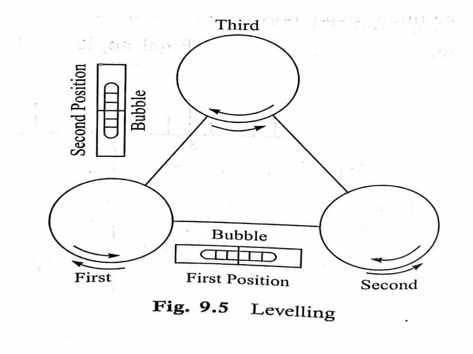
4) Leveling:
Before starting the leveling operation, all the foot screws are brought to the
center of their run.
The plate bubble is placed parallel to any pair of foot screws. By turning both
these screws equally inwards or outwards, the bubble is brought to the center.
The plate bubble is turned through 900 so that it is perpendicular to the line
joining the first & second foot screws. Then by turning the third foot screw
either clockwise or anticlockwise to bring the bubble to the center.
The process is repeated several times, so that the bubbles remains in the central
position of the plate bubble in both direction.
The instrument is rotated through 3600 about its vertical axis. If the bubble still
remains in the central position, the adjustment of the bubble is perfect & the
vertical axis is truly vertical.
Temporary Adjustment of Theodolite:
5) Focusing the Eye Piece: The eyepiece is focused so that the cross hairs can be seen
clearly. To do this, the telescope is directed towards the sky or a piece of white
paper is held in front of the object glass, & the eyepiece is moved in or out by
turning it clockwise or anticlockwise until the cross hairs appear distinct & sharp.
6) Focusing the Object Glass: To bring a sharp image of the object or target in the
plane of cross hairs & to eliminate parallax. The telescope is directed towards the
object or target & the focusing screw is turned clockwise or anticlockwise until
the image appears clear & sharp. There is no relative movements between the
image & cross hairs. The absence of relative movement can be verified by moving
the eye up & down.
Temporary Adjustment of Theodolite:
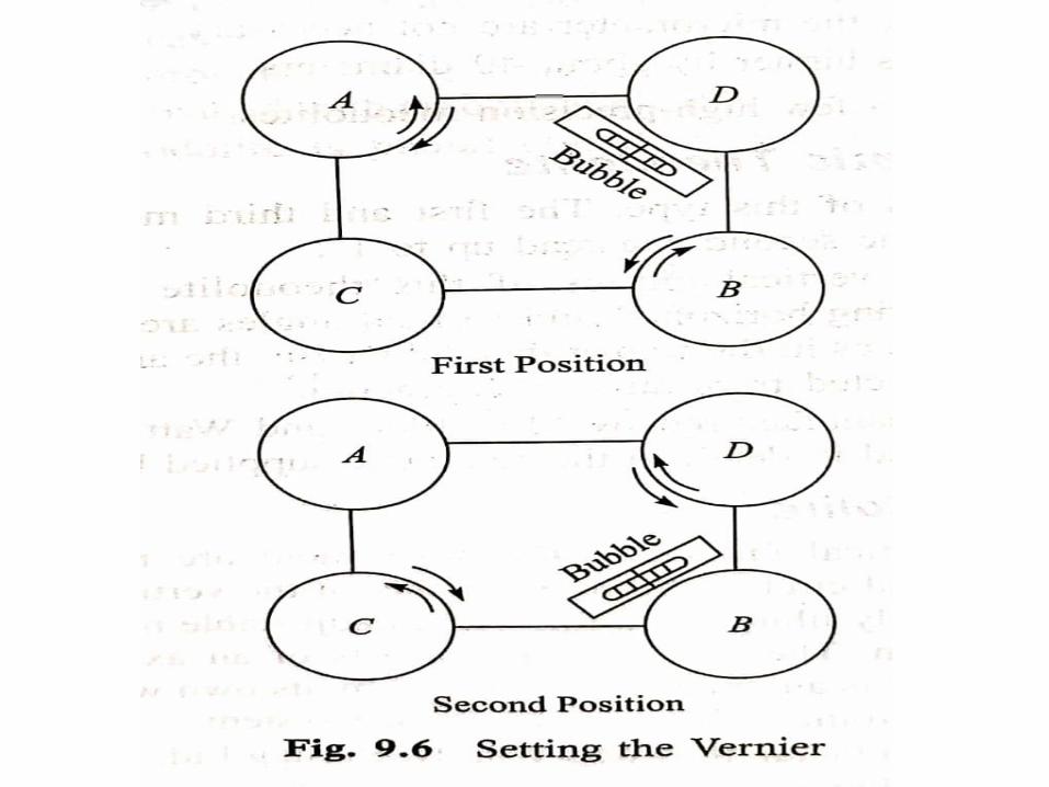
7) Setting the Vernier:
The vernier A is set to 00 & vernier B to 1800.
The lower clamp is fixed.
The upper clamp is loosened & upper plate turned until the arrow of vernier A
approximately coincides with zero & that of vernier B approximately coincides
with the 1800 mark.
Then the upper clamp is tightened & by turning the upper tangent screw, the
arrows are brought to a position of exact coincidence.
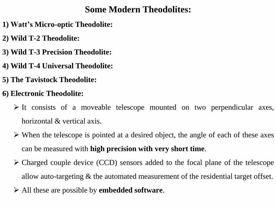
Some Modern Theodolites:
1) Watt’s Micro-optic Theodolite:
2) Wild T-2 Theodolite:
3) Wild T-3 Precision Theodolite:
4) Wild T-4 Universal Theodolite:
5) The Tavistock Theodolite:
6) Electronic Theodolite:
It consists of a moveable telescope mounted on two perpendicular axes,
horizontal & vertical axis.
When the telescope is pointed at a desired object, the angle of each of these axes
can be measured with high precision with very short time.
Charged couple device (CCD) sensors added to the focal plane of the telescope
allow auto-targeting & the automated measurement of the residential target offset.
All these are possible by embedded software.
Characteristics of Modern Theodolite or Electronic Theodolite:
1) More compact & light.
2) Observer can take readings accurate to 1 seconds. Least count = 1”
3) Instrument is waterproof & dustproof.
4) Electrically illuminated to facilitate work at night or in tunnels.
5) Magnification is higher.
6) Adjustment for micrometer are not required.
7) Digital read outs eliminate the personal error because of reading & interpolation of
scale & micrometer settings.
8) They can be upgraded to be a total station or have an EDM attached for distance
measurement.
9) Large dot matrix dual line LCD screen to display.
10)Unique linear focusing mechanism to simplifying focusing.
11)Alkaline Manganese Batteries for continuous operation 48 hours.
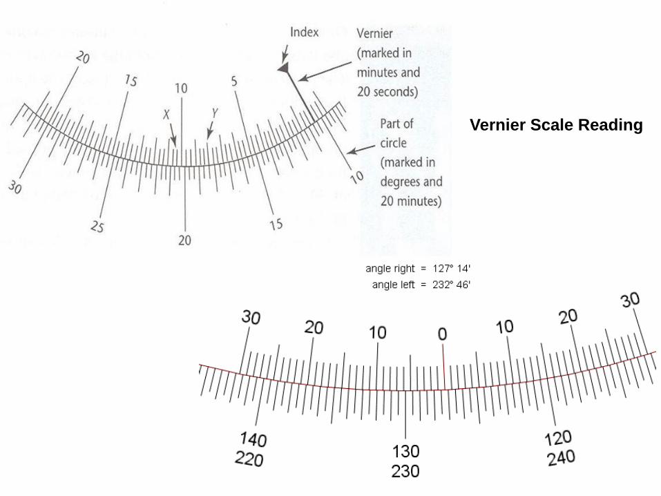
Vernier Scale Reading
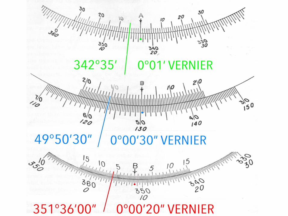
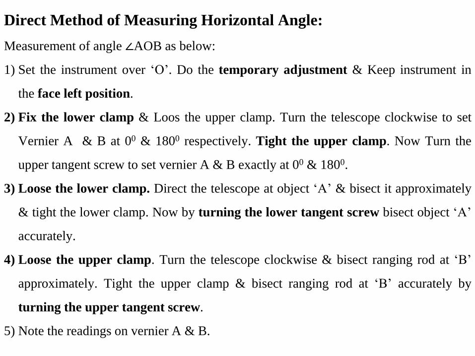
Direct Method of Measuring Horizontal Angle:
Measurement of angle ∠AOB as below:
1) Set the instrument over ‘O’. Do the temporary adjustment & Keep instrument in
the face left position.
2) Fix the lower clamp & Loos the upper clamp. Turn the telescope clockwise to set
Vernier A & B at 00 & 1800 respectively. Tight the upper clamp. Now Turn the
upper tangent screw to set vernier A & B exactly at 00 & 1800.
3) Loose the lower clamp. Direct the telescope at object ‘A’ & bisect it approximately
& tight the lower clamp. Now by turning the lower tangent screw bisect object ‘A’
accurately.
4) Loose the upper clamp. Turn the telescope clockwise & bisect ranging rod at ‘B’
approximately. Tight the upper clamp & bisect ranging rod at ‘B’ accurately by
turning the upper tangent screw.
5) Note the readings on vernier A & B.
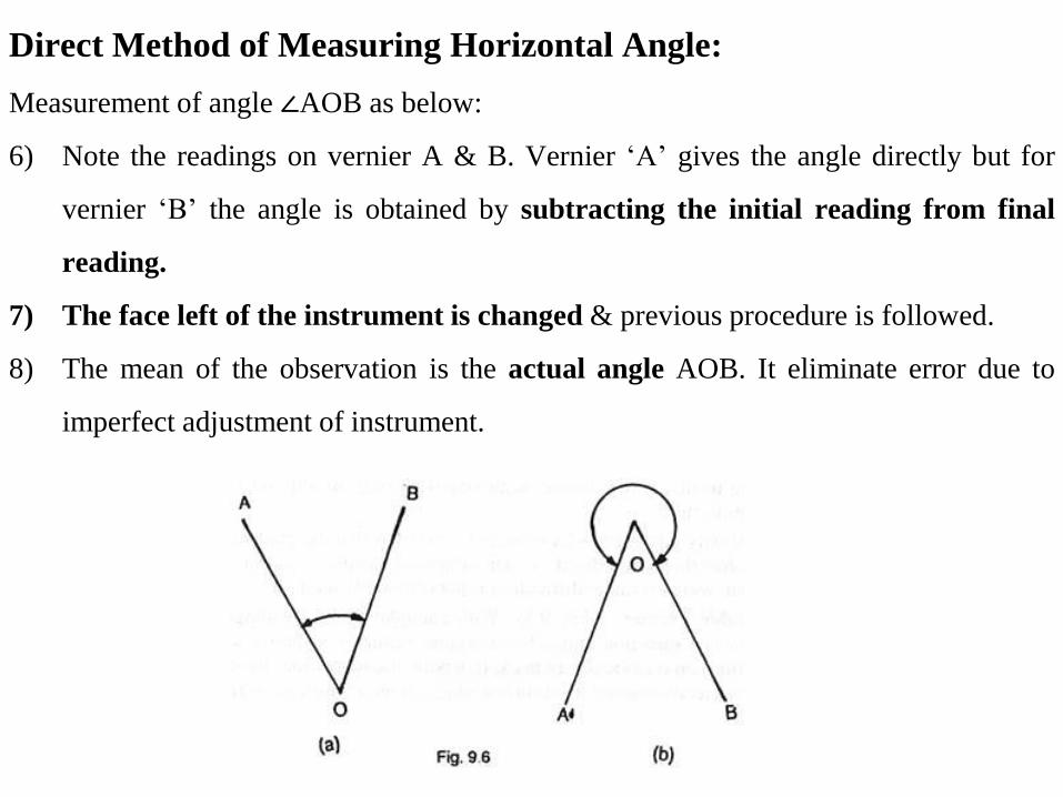
Direct Method of Measuring Horizontal Angle:
Measurement of angle ∠AOB as below:
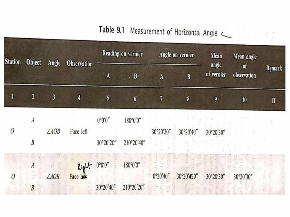
6) Note the readings on vernier A & B. Vernier ‘A’ gives the angle directly but for
vernier ‘B’ the angle is obtained by subtracting the initial reading from final
reading.
7) The face left of the instrument is changed & previous procedure is followed.
8) The mean of the observation is the actual angle AOB. It eliminate error due to
imperfect adjustment of instrument.
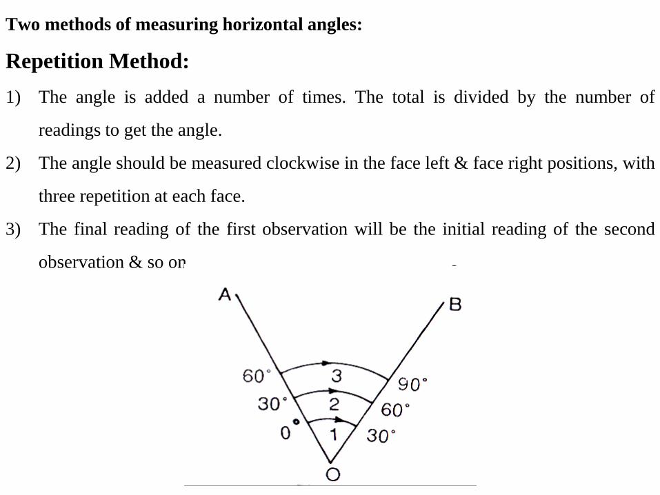
Two methods of measuring horizontal angles:
Repetition Method:
1) The angle is added a number of times. The total is divided by the number of
readings to get the angle.
2) The angle should be measured clockwise in the face left & face right positions, with
three repetition at each face.
3) The final reading of the first observation will be the initial reading of the second
observation & so on.
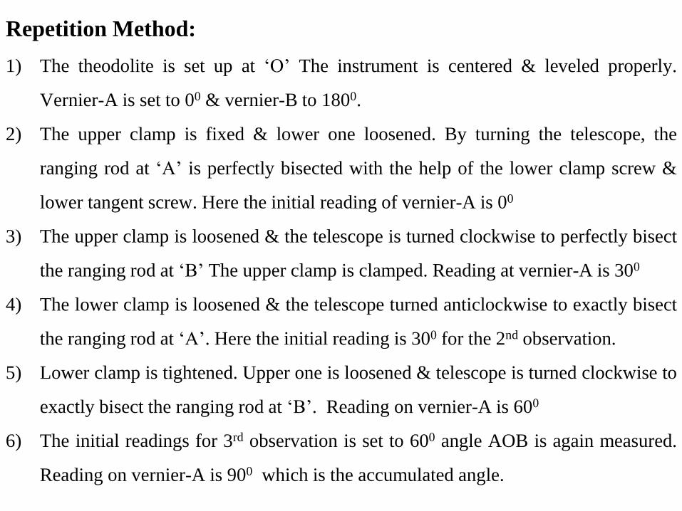
Repetition Method:
1) The theodolite is set up at ‘O’ The instrument is centered & leveled properly.
Vernier-A is set to 00 & vernier-B to 1800.
2) The upper clamp is fixed & lower one loosened. By turning the telescope, the
ranging rod at ‘A’ is perfectly bisected with the help of the lower clamp screw &
lower tangent screw. Here the initial reading of vernier-A is 00
3) The upper clamp is loosened & the telescope is turned clockwise to perfectly bisect
the ranging rod at ‘B’ The upper clamp is clamped. Reading at vernier-A is 300
4) The lower clamp is loosened & the telescope turned anticlockwise to exactly bisect
the ranging rod at ‘A’. Here the initial reading is 300 for the 2nd observation.
5) Lower clamp is tightened. Upper one is loosened & telescope is turned clockwise to
exactly bisect the ranging rod at ‘B’. Reading on vernier-A is 600
6) The initial readings for 3rd observation is set to 600 angle AOB is again measured.
Reading on vernier-A is 900 which is the accumulated angle.
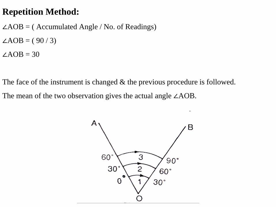
Repetition Method:
∠AOB = ( Accumulated Angle / No. of Readings)
∠AOB = ( 90 / 3)
∠AOB = 30
The face of the instrument is changed & the previous procedure is followed.
The mean of the two observation gives the actual angle ∠AOB.
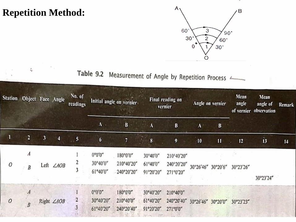
Repetition Method:
Reiteration Method:
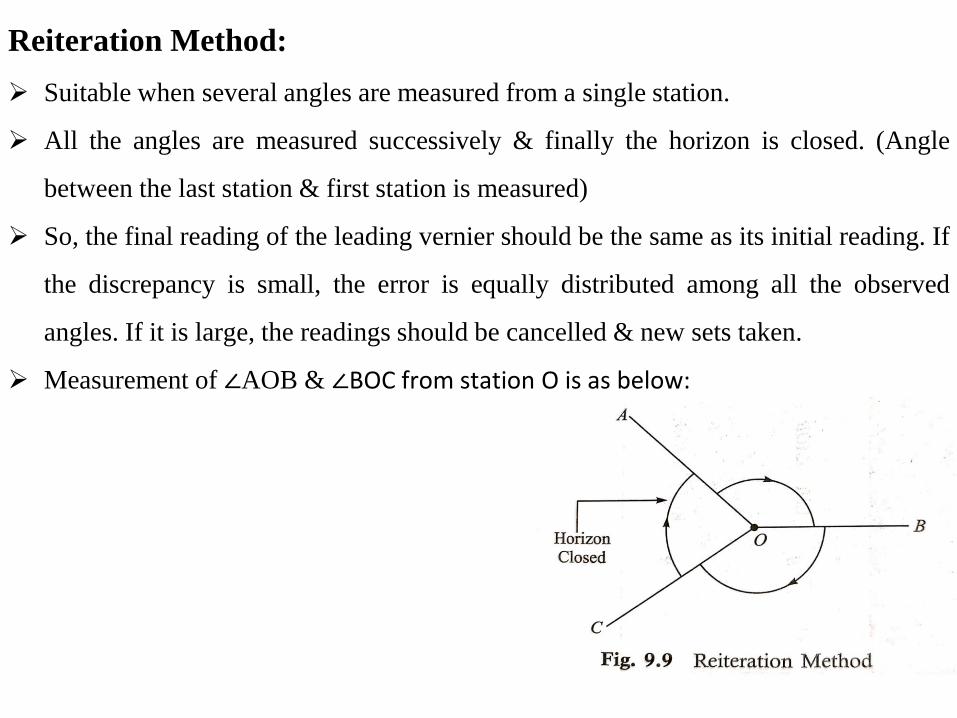
Suitable when several angles are measured from a single station.
All the angles are measured successively & finally the horizon is closed. (Angle
between the last station & first station is measured)
So, the final reading of the leading vernier should be the same as its initial reading. If
the discrepancy is small, the error is equally distributed among all the observed
angles. If it is large, the readings should be cancelled & new sets taken.
Measurement of ∠AOB & ∠BOC from station O is as below:
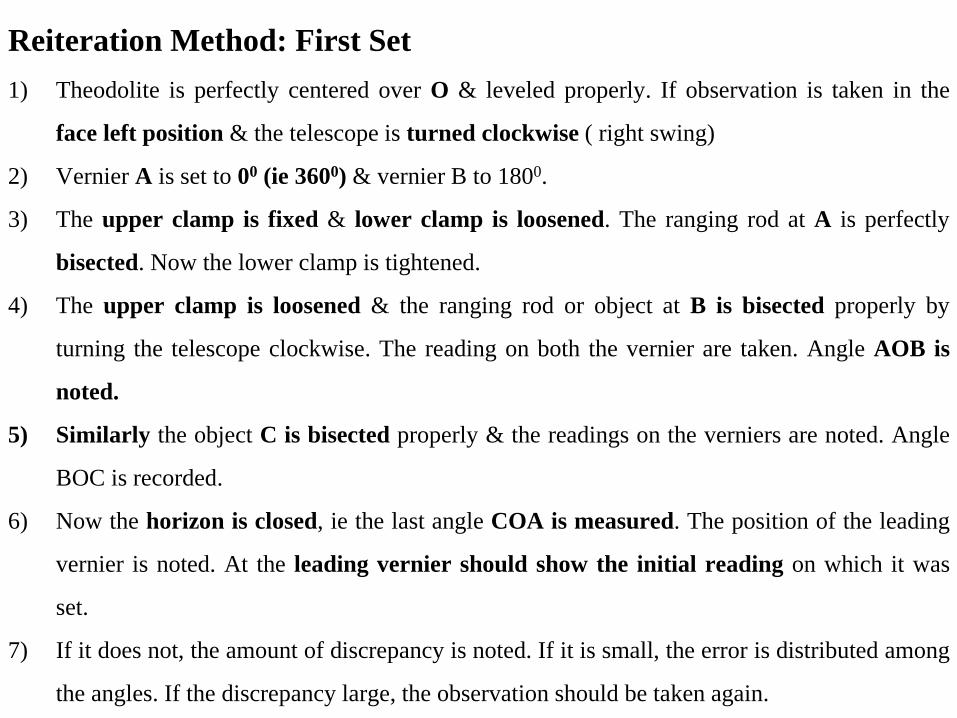
Reiteration Method: First Set
1) Theodolite is perfectly centered over O & leveled properly. If observation is taken in the
face left position & the telescope is turned clockwise ( right swing)
2) Vernier A is set to 00 (ie 3600) & vernier B to 1800.
3) The upper clamp is fixed & lower clamp is loosened. The ranging rod at A is perfectly
bisected. Now the lower clamp is tightened.
4) The upper clamp is loosened & the ranging rod or object at B is bisected properly by
turning the telescope clockwise. The reading on both the vernier are taken. Angle AOB is
noted.
5) Similarly the object C is bisected properly & the readings on the verniers are noted. Angle
BOC is recorded.
6) Now the horizon is closed, ie the last angle COA is measured. The position of the leading
vernier is noted. At the leading vernier should show the initial reading on which it was
set.
7) If it does not, the amount of discrepancy is noted. If it is small, the error is distributed among
the angles. If the discrepancy large, the observation should be taken again.
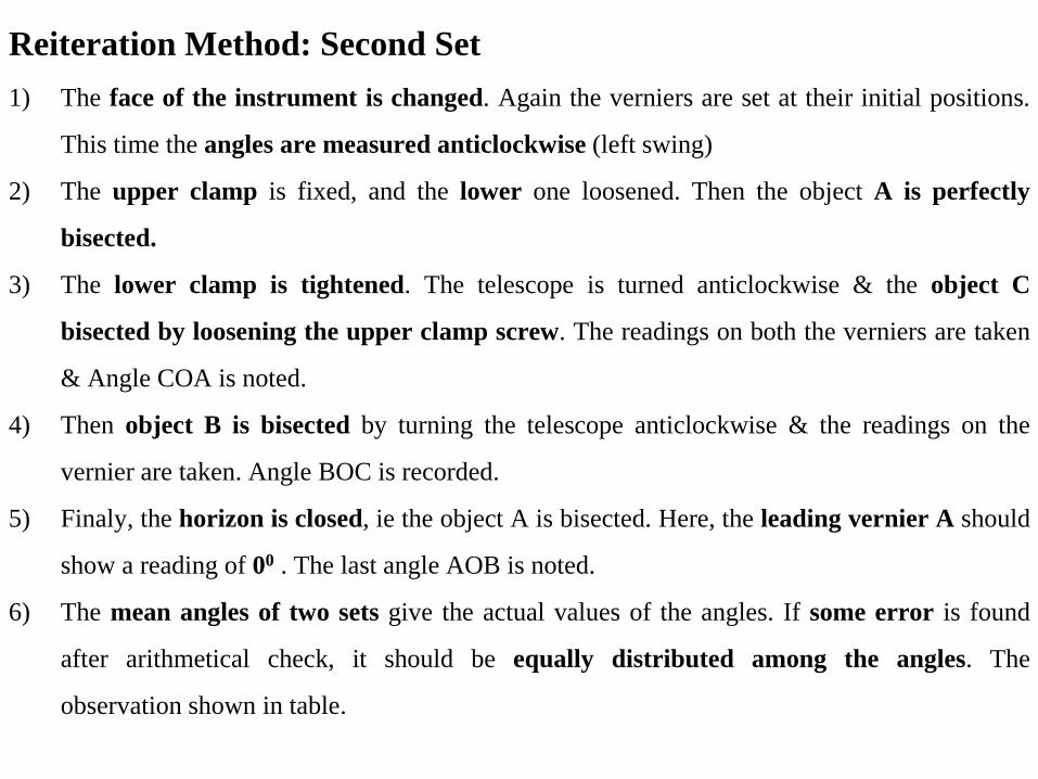
Reiteration Method: Second Set
1) The face of the instrument is changed. Again the verniers are set at their initial positions.
This time the angles are measured anticlockwise (left swing)
2) The upper clamp is fixed, and the lower one loosened. Then the object A is perfectly
bisected.
3) The lower clamp is tightened. The telescope is turned anticlockwise & the object C
bisected by loosening the upper clamp screw. The readings on both the verniers are taken
& Angle COA is noted.
4) Then object B is bisected by turning the telescope anticlockwise & the readings on the
vernier are taken. Angle BOC is recorded.
5) Finaly, the horizon is closed, ie the object A is bisected. Here, the leading vernier A should
show a reading of 00 . The last angle AOB is noted.
6) The mean angles of two sets give the actual values of the angles. If some error is found
after arithmetical check, it should be equally distributed among the angles. The
observation shown in table.
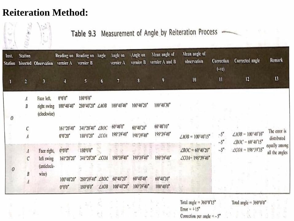
Reiteration Method:
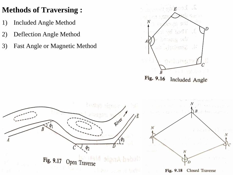
Methods of Traversing :
1) Included Angle Method
2) Deflection Angle Method
3) Fast Angle or Magnetic Method
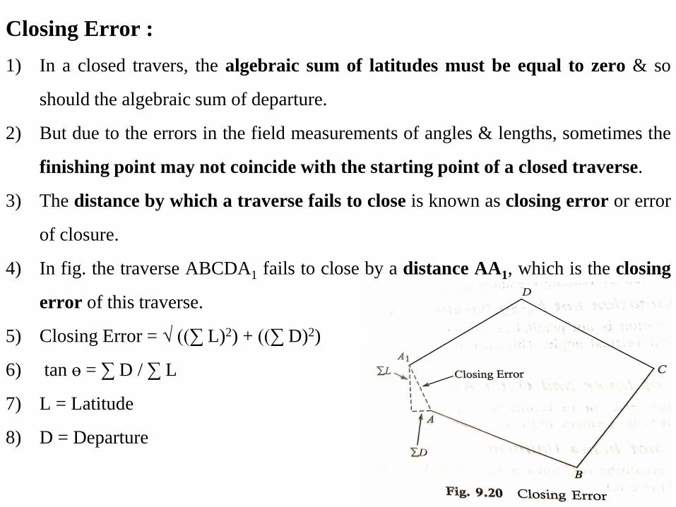
Closing Error :
1) In a closed travers, the algebraic sum of latitudes must be equal to zero & so
should the algebraic sum of departure.
2) But due to the errors in the field measurements of angles & lengths, sometimes the
finishing point may not coincide with the starting point of a closed traverse.
3) The distance by which a traverse fails to close is known as closing error or error
of closure.
4) In fig. the traverse ABCDA1 fails to close by a distance AA1, which is the closing
error of this traverse.
5) Closing Error = √ ((∑ L)2) + ((∑ D)2)
6) tan ɵ = ∑ D / ∑ L
7) L = Latitude
8) D = Departure
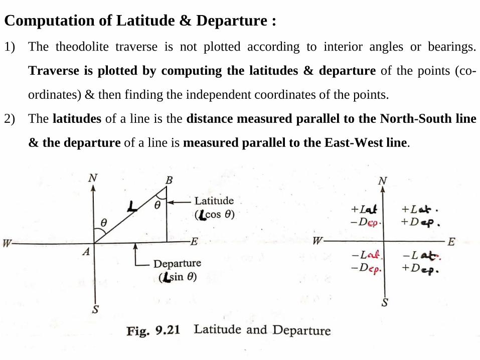
Computation of Latitude & Departure :
1) The theodolite traverse is not plotted according to interior angles or bearings.
Traverse is plotted by computing the latitudes & departure of the points (co-
ordinates) & then finding the independent coordinates of the points.
2) The latitudes of a line is the distance measured parallel to the North-South line
& the departure of a line is measured parallel to the East-West line.
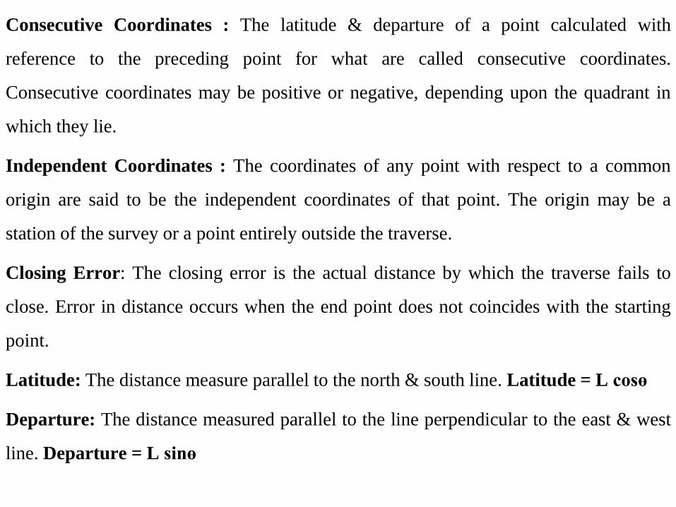
Consecutive Coordinates : The latitude & departure of a point calculated with
reference to the preceding point for what are called consecutive coordinates.
Consecutive coordinates may be positive or negative, depending upon the quadrant in
which they lie.
Independent Coordinates : The coordinates of any point with respect to a common
origin are said to be the independent coordinates of that point. The origin may be a
station of the survey or a point entirely outside the traverse.
Closing Error: The closing error is the actual distance by which the traverse fails to
close. Error in distance occurs when the end point does not coincides with the starting
point.
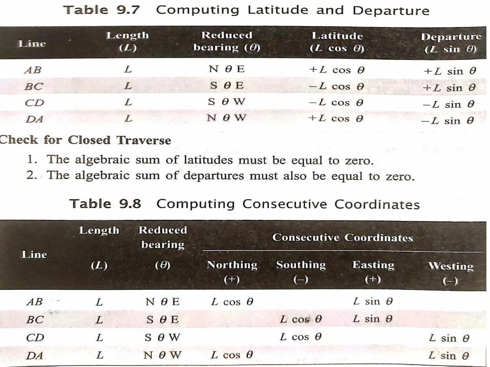
Latitude: The distance measure parallel to the north & south line. Latitude = L cosɵ
Departure: The distance measured parallel to the line perpendicular to the east & west
line. Departure = L sinɵ
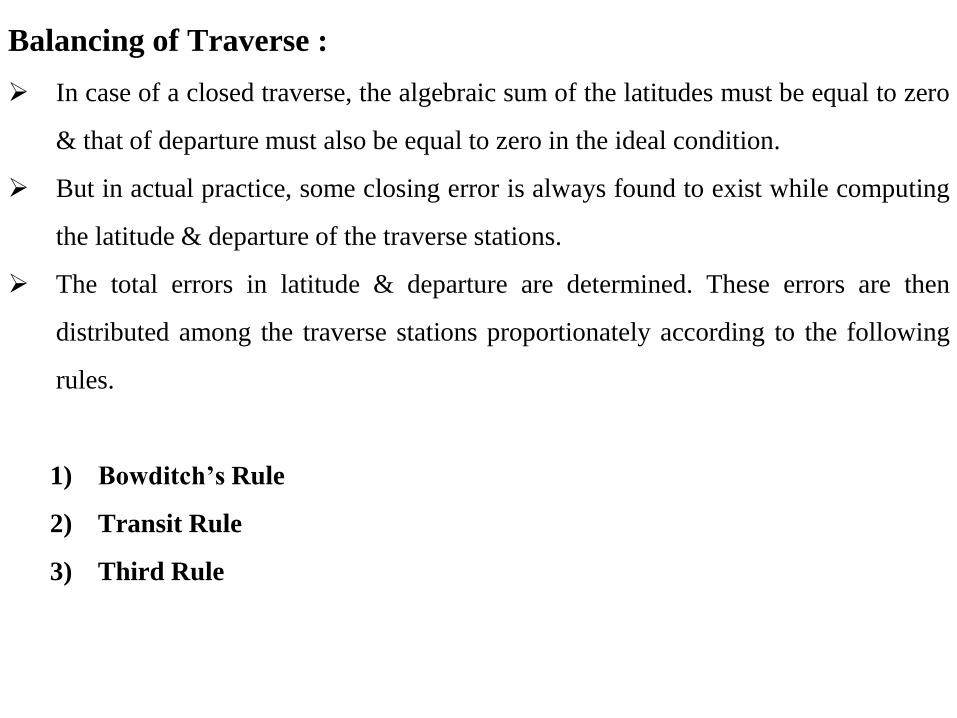
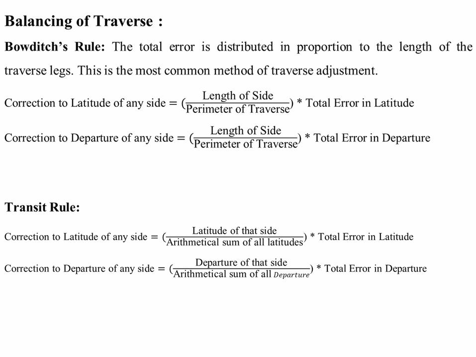
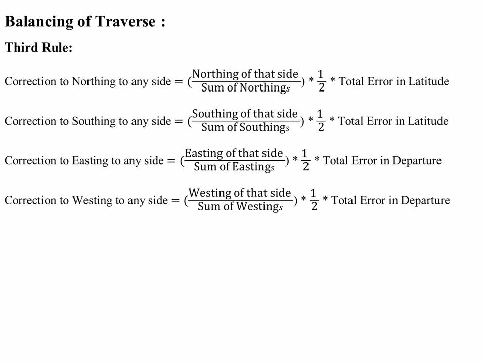
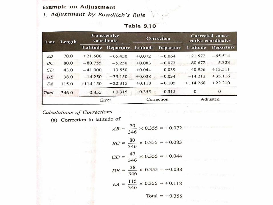
Balancing of Traverse :
In case of a closed traverse, the algebraic sum of the latitudes must be equal to zero
& that of departure must also be equal to zero in the ideal condition.
But in actual practice, some closing error is always found to exist while computing
the latitude & departure of the traverse stations.
The total errors in latitude & departure are determined. These errors are then
distributed among the traverse stations proportionately according to the following
rules.
1) Bowditch’s Rule
2) Transit Rule
3) Third Rule
Calculation of Traverse Area :
Area of a closed traverse may be calculated from:
1) The Coordinates ( x & y )
2) The Latitudes & Double Meridian Distance
3) The Departure & Total Latitudes
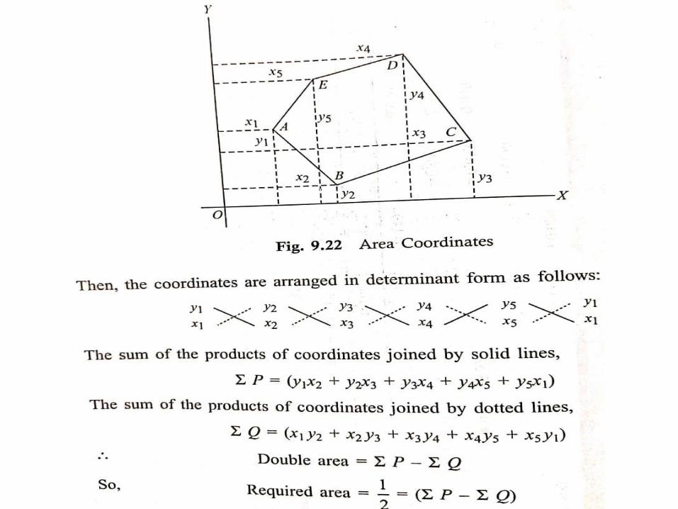
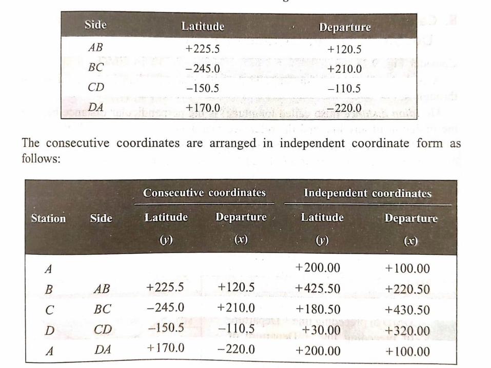
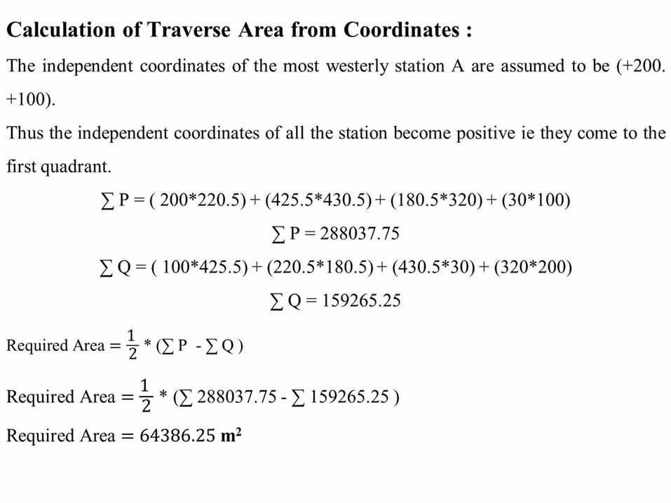
Calculation of Area From Coordinates:
The given consecutive coordinates of a traverse are converted into independent
coordinates with reference to the coordinates of the most westerly station.
Thus the whole traverse is transferred to the first quadrant. ‘A’ is most westerly
station.
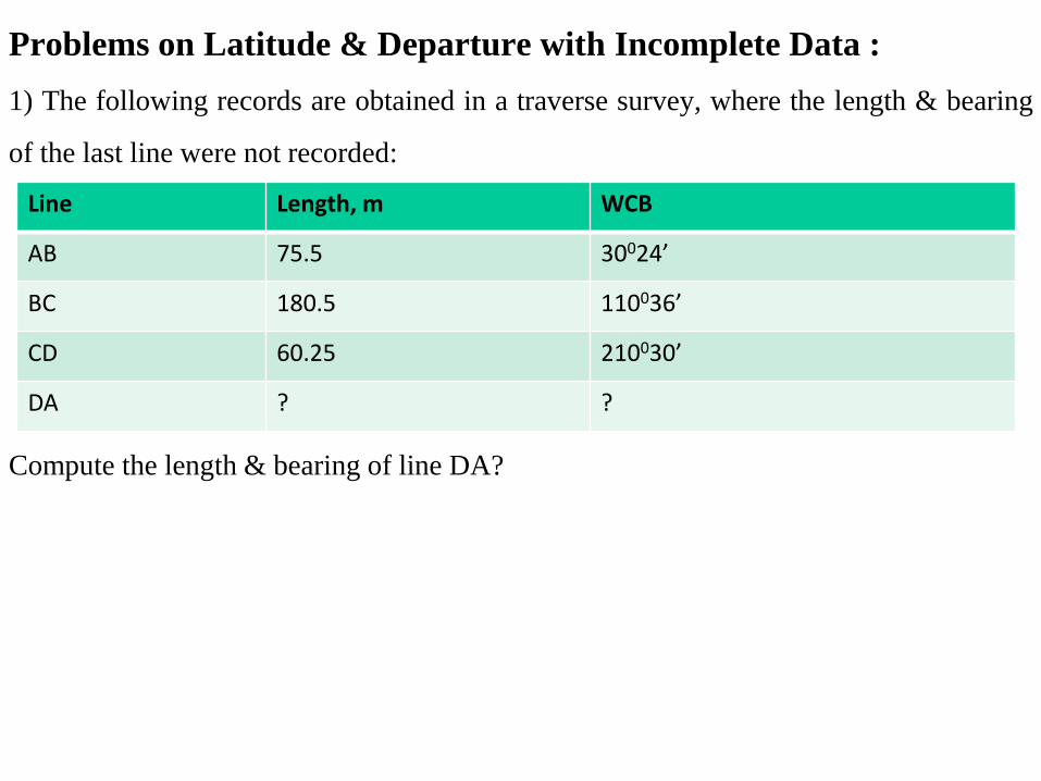
Problems on Latitude & Departure with Incomplete Data :
1) The following records are obtained in a traverse survey, where the length & bearing
of the last line were not recorded:
Compute the length & bearing of line DA?
Line Length, m WCB
AB 75.5 30024’
BC 180.5 110036’
CD 60.25 210030’
DA ? ?
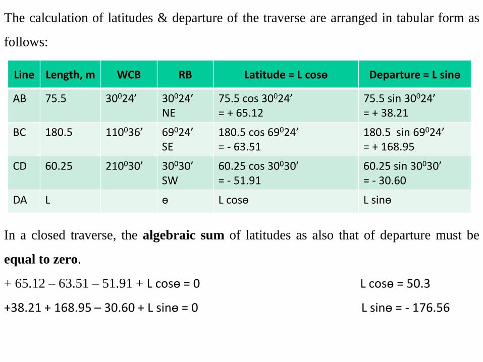
The calculation of latitudes & departure of the traverse are arranged in tabular form as
follows:
In a closed traverse, the algebraic sum of latitudes as also that of departure must be
equal to zero.
+ 65.12 – 63.51 – 51.91 + L cosɵ = 0 L cosɵ = 50.3
+38.21 + 168.95 – 30.60 + L sinɵ = 0 L sinɵ = - 176.56
Line Length, m WCB RB Latitude = L cosɵ Departure = L sinɵ
AB 75.5 30024’ 30024’ NE
75.5 cos 30024’ = + 65.12
75.5 sin 30024’ = + 38.21
BC 180.5 110036’ 69024’ SE
180.5 cos 69024’ = - 63.51
180.5 sin 69024’ = + 168.95
CD 60.25 210030’ 30030’ SW
60.25 cos 30030’ = - 51.91
60.25 sin 30030’ = - 30.60
DA L ɵ L cosɵ L sinɵ
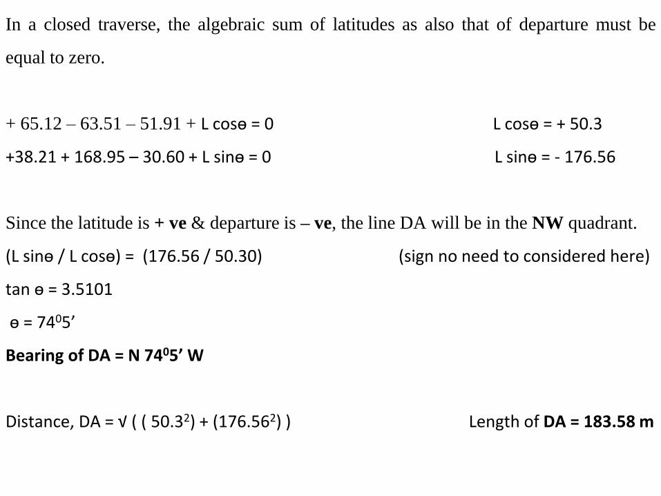
In a closed traverse, the algebraic sum of latitudes as also that of departure must be
equal to zero.
+ 65.12 – 63.51 – 51.91 + L cosɵ = 0 L cosɵ = + 50.3
+38.21 + 168.95 – 30.60 + L sinɵ = 0 L sinɵ = - 176.56
Since the latitude is + ve & departure is – ve, the line DA will be in the NW quadrant.
(L sinɵ / L cosɵ) = (176.56 / 50.30) (sign no need to considered here)
tan ɵ = 3.5101
ɵ = 7405’
Bearing of DA = N 7405’ W
Distance, DA = √ ( ( 50.32) + (176.562) ) Length of DA = 183.58 m
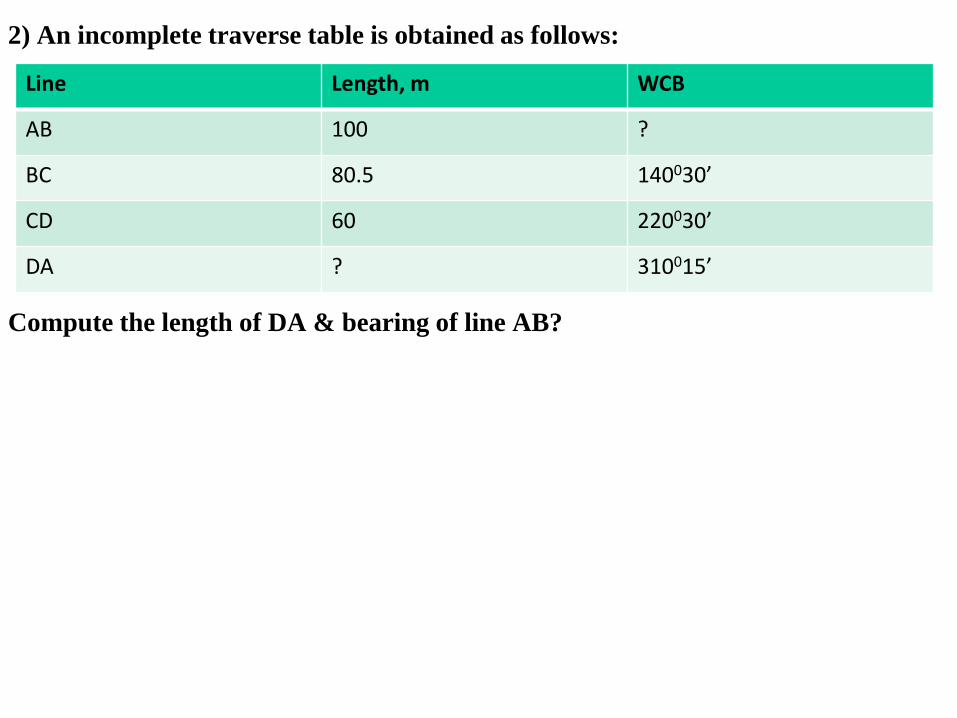
2) An incomplete traverse table is obtained as follows:
Compute the length of DA & bearing of line AB?
Line Length, m WCB
AB 100 ?
BC 80.5 140030’
CD 60 220030’
DA ? 310015’
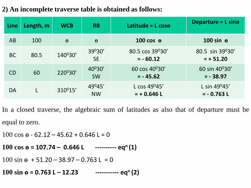
2) An incomplete traverse table is obtained as follows:
In a closed traverse, the algebraic sum of latitudes as also that of departure must be
equal to zero.
100 cos ɵ - 62.12 – 45.62 + 0.646 L = 0
100 cos ɵ = 107.74 – 0.646 L ---------- eqn (1)
100 sin ɵ + 51.20 – 38.97 – 0.763 L = 0
100 sin ɵ = 0.763 L – 12.23 ----------- eqn (2)
Line Length, m WCB RB Latitude = L cosɵ Departure = L sinɵ
AB 100 ɵ ɵ 100 cos ɵ 100 sin ɵ
BC 80.5 140030’ 39030’
SE 80.5 cos 39030’
= - 60.12 80.5 sin 39030’
= + 51.20
CD 60 220030’ 40030’
SW 60 cos 40030’
= - 45.62 60 sin 40030’
= - 38.97
DA L 310015’ 49045’
NW L cos 49045’ = + 0.646 L
L sin 49045’ = - 0.763 L
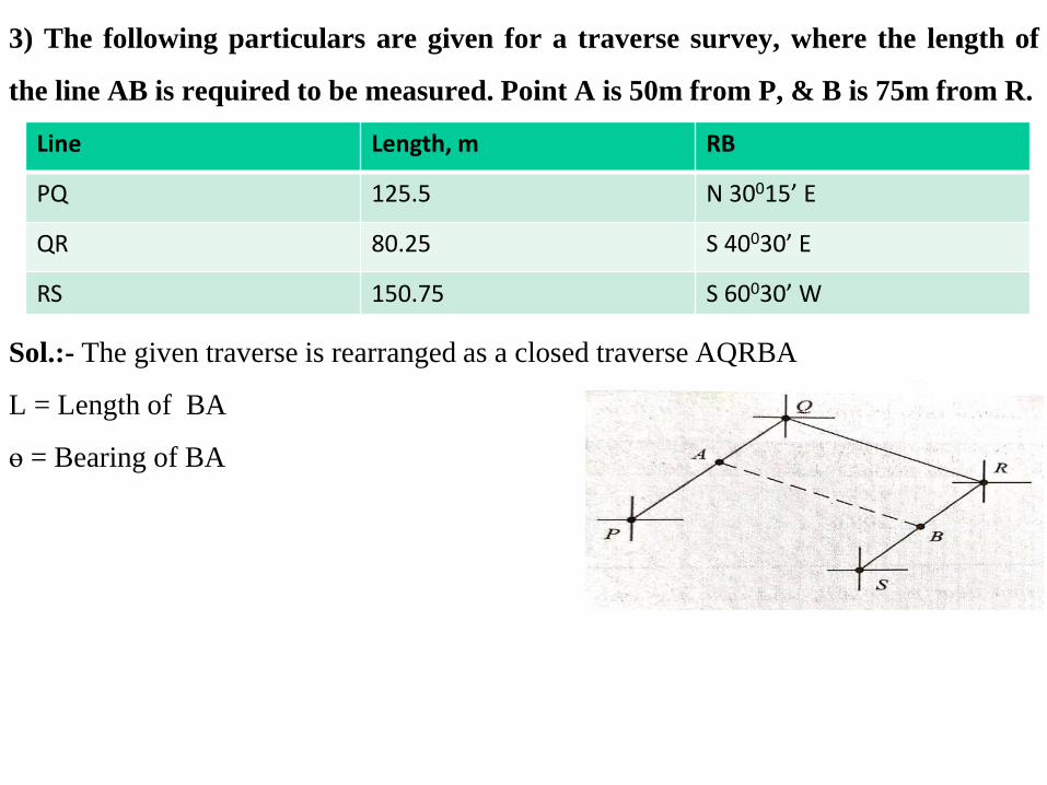
3) The following particulars are given for a traverse survey, where the length of
the line AB is required to be measured. Point A is 50m from P, & B is 75m from R.
Sol.:- The given traverse is rearranged as a closed traverse AQRBA
L = Length of BA
ɵ = Bearing of BA
Line Length, m RB
PQ 125.5 N 30015’ E
QR 80.25 S 40030’ E
RS 150.75 S 60030’ W
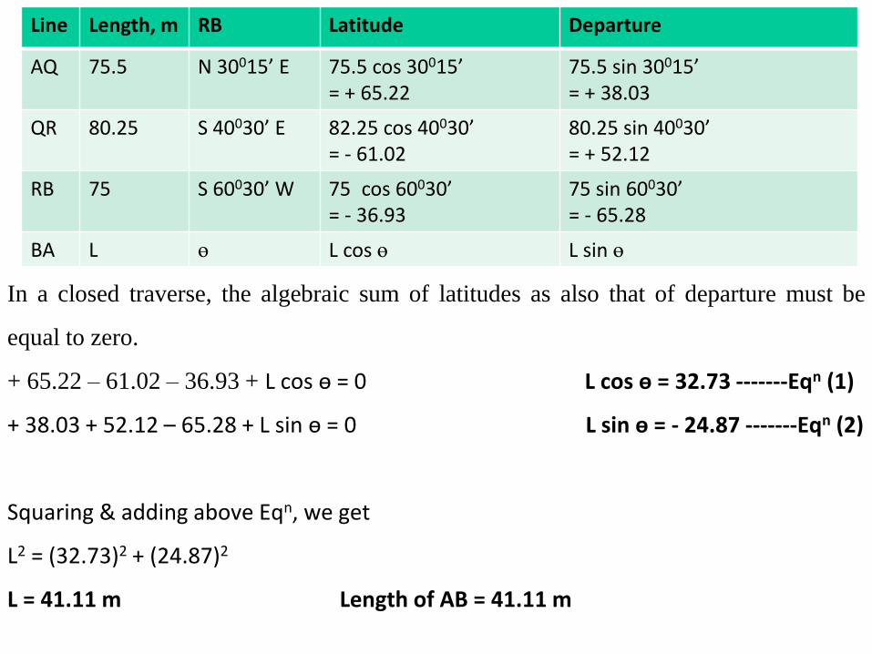
In a closed traverse, the algebraic sum of latitudes as also that of departure must be
equal to zero.
+ 65.22 – 61.02 – 36.93 + L cos ɵ = 0 L cos ɵ = 32.73 -------Eqn (1)
+ 38.03 + 52.12 – 65.28 + L sin ɵ = 0 L sin ɵ = - 24.87 -------Eqn (2)
Squaring & adding above Eqn, we get
L2 = (32.73)2 + (24.87)2
L = 41.11 m Length of AB = 41.11 m
Line Length, m RB Latitude Departure
AQ 75.5 N 30015’ E 75.5 cos 30015’ = + 65.22
75.5 sin 30015’ = + 38.03
QR 80.25 S 40030’ E 82.25 cos 40030’ = - 61.02
80.25 sin 40030’ = + 52.12
RB 75 S 60030’ W 75 cos 60030’ = - 36.93
75 sin 60030’ = - 65.28
BA L ɵ L cos ɵ L sin ɵ
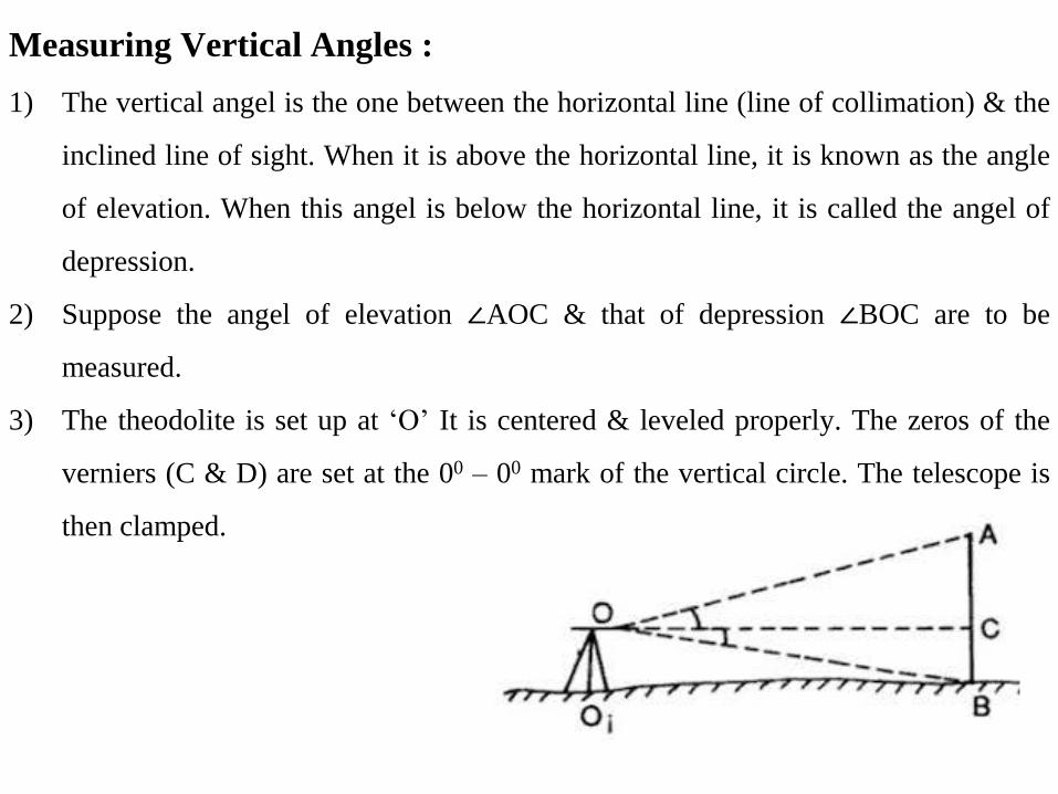
Measuring Vertical Angles :
1) The vertical angel is the one between the horizontal line (line of collimation) & the
inclined line of sight. When it is above the horizontal line, it is known as the angle
of elevation. When this angel is below the horizontal line, it is called the angel of
depression.
2) Suppose the angel of elevation ∠AOC & that of depression ∠BOC are to be
measured.
3) The theodolite is set up at ‘O’ It is centered & leveled properly. The zeros of the
verniers (C & D) are set at the 00 – 00 mark of the vertical circle. The telescope is
then clamped.
Measuring Vertical Angles :
4) The plate bubble is brought to the center with the help of foot screws. Then the
altitude bubble is brought to the center by means of clip screw. At this position the
line of collimation is exactly horizontal.
5) To measure the angles of elevation, the telescope is raised slowly to bisect the point
‘A’ accurately. The readings on both verniers are noted, & angle of elevation
recorded.
6) The face of instrument is changed & the point A is again bisected. The readings on
the vernier are noted. The mean of the angles of the observed is assumed to be the
correct angle of elevation.
7) To measure the angle of depression, the telescope is lowered slowly & the point ‘B’
is bisected. The readings on the verniers are noted for the two observation (face left
& right). The mean angles of the observation is taken to be the correct angles of
depression. Then result is tabulated.
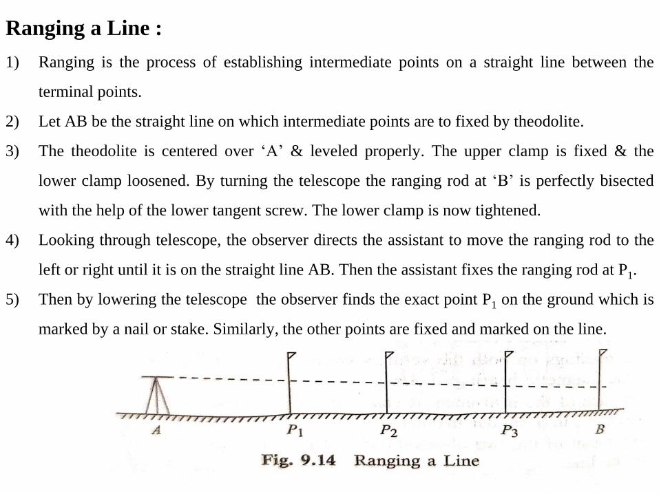
Ranging a Line :
1) Ranging is the process of establishing intermediate points on a straight line between the
terminal points.
2) Let AB be the straight line on which intermediate points are to fixed by theodolite.
3) The theodolite is centered over ‘A’ & leveled properly. The upper clamp is fixed & the
lower clamp loosened. By turning the telescope the ranging rod at ‘B’ is perfectly bisected
with the help of the lower tangent screw. The lower clamp is now tightened.
4) Looking through telescope, the observer directs the assistant to move the ranging rod to the
left or right until it is on the straight line AB. Then the assistant fixes the ranging rod at P1.
5) Then by lowering the telescope the observer finds the exact point P1 on the ground which is
marked by a nail or stake. Similarly, the other points are fixed and marked on the line.


