Embed Size (px)
Citation preview

282 IEEE TRANSACTIONS ON POWER ELECTRONICS, VOL. 22, NO. 1, JANUARY 2007
SVM PMSM Drive With Low ResolutionHall-Effect Sensors
Alessandro Lidozzi, Student Member, IEEE, Luca Solero, Member, IEEE, Fabio Crescimbini, Member, IEEE,and Augusto Di Napoli
Abstract—In this paper, a back-electromotive force-basedmethod is used in conjunction with three very low-cost integratedcircuits based on the Hall-effect to estimate the rotor position ofthe direct-drive permanent-magnet synchronous motors (PMSMs)to be used for traction purpose of an electric wheelchair. A speedestimator based on a rotor frame machine model has been im-plemented for the PMSM drives, and then the rotor positionestimation is achieved by means of a discrete integration of the es-timated speed. The three Hall effect sensors are used to detect therotor initial position as well to reset the error on the rotor positionestimation every 60 electrical degrees. In the specific application,support vector machine technique has been implemented togetherwith the field oriented control. Simulations and experimentalresults are shown in the paper.
Index Terms—Encoderless, low rotational speed, perma-nent-magnet (PM) motor drive.
I. INTRODUCTION
THE permanent-magnet synchronous motor (PMSM) is at-tracting attention in recent years and it is widely recog-
nized to be a very suitable candidate for hybrid and electricvehicles’ applications. Maintenance free operation, robustnessagainst environment, high efficiency, high power density, andhigh controllability are some of the PMSM characteristics re-sponsible for its wide utilization in traction applications suchas electric vehicles (EVs) and hybrid EVs (HEVs). In PMSMdrives, position sensors are required to time the sinusoidal cur-rent waveforms with the rotor position; suitable waveforms ofphase currents and low motor torque ripple ask for high resolu-tion sensors such as either optical encoders or electromagneticresolvers. However, these sensors are expensive and their cou-pling very often requires special constructions for the machine,such as a second shaft end; besides, position sensor misalign-ment can often occur during operation causing unexpected cur-rent overloads. In direct drive PMSMs which are widely usedfor traction applications it is required a periodic monitoring ofthe sensor alignment and, if necessary, the software correctionof the reference position angle.
The requirement of removal of unreliable and expensive po-sition sensors has led academic and industrial researchers to in-vestigate and to propose several methods for the sensorless con-trol of electrical machines. Within the last decade, significant
Manuscript received June 27, 2005; revised December 20, 2005. Recom-mended by Associate Editor J. Ojo.
The authors are with the Department of Mechanical and IndustrialEngineering, University ROMA TRE, Rome 79-00146, Italy (e-mail:[email protected]).
Color versions of one or more of the figures in this paper are available onlineat http://ieeexplore.ieee.org.
Digital Object Identifier 10.1109/TPEL.2006.886603
improvements have been made in the field of sensorless controlof PMSMs; major methods for sensorless position estimationcan be classified in two main groups, the first group collectsmethods which use back-electromotive-force (EMF) estimationwith fundamental excitation, whereas the second group is re-lated to spatial saliency image tracking methods which use ex-citation in addition to the fundamental [1]. The saliency trackingmethods are appropriate for zero and near zero-speed operation,however machines with suitable saliency are required for cor-rectly estimate the rotor position; back-EMF-based methods areeasy to be implemented for symmetric PMSMs, however thefailure of these methods at low rotational speed preclude theiracceptance in direct drive PMSMs for traction applications.
In this paper a back-EMF-based method is used in conjunc-tion with very low resolution sensors [2]–[5] to estimate therotor position of direct-drive PMSMs to be used for traction pur-pose of an electric wheelchair. A speed estimator based on rotorframe machine model (SERF) has been implemented for thePMSM drives, and then the rotor position estimation is achievedby means of a discrete integration of the estimated speed. Duringthe manufacturing process three very low-cost integrated cir-cuits based on the Hall-effect are suitable positioned in the ma-chine stator in order to provide 60 electrical degrees resolutionin rotor position sensing, thus the error on the rotor position esti-mation is reset every time the rotor’s magnetic axes enters a new60 sector univocally identified by means of the three Hall-ef-fect sensors’ binary code. The Hall-effect sensors do not requireany tuning process and are also used to detect the initial posi-tion of the machine rotor, in this case the rotor’s magnetic axesis positioned at the half of the 60 electrical sector identified bymeans of the sensors’ binary code. As a consequence the driveis able to start in sinusoidal operation at a torque which is inthe range of 86.6%–100% of the maximum torque, in fact themaximum error in the initial position detection is 30 electricaldegrees and it is reset to zero at the very first transition of anyof the Hall-effect sensors.
II. WHEELCHAIR PMSM DIRECT DRIVES
To date, the drive train of electric wheelchairs is still arrangedby means of old-fashion chopper-fed dc motor drives which in-clude a gearbox for matching the low speed at which the wheelmust rotate with the relatively higher rating speed of the dcmotor. The use of a gearbox negatively influences mass, costand reliability of the drive train, as well as constrains the overallarrangement of the wheelchair chassis. In addition to that, due tothe use of a gearbox the overall efficiency of the today’s wheel-chair motor drives hardly exceeds 60%, and this leads to waste asignificant amount of the battery-stored energy being availableon board for the propulsion. To the purpose of improving the
0885-8993/$20.00 © 2006 IEEE

LIDOZZI et al.: SVM PMSM DRIVE 283
Fig. 1. Prototype of the electric wheelchair.
wheelchair performance, the use of a direct drive motor is de-sirable in order to eliminate the gearbox, enhance the wheelchairrange of autonomy and make the wheelchair drive train cheaper,quieter and more reliable. Conventional electric motors basedon the radial-field concept generally have poor torque-to-massratio for wheel direct drive applications and thereby would re-sult in a relatively bulky arrangement of the drive.
The advent of high-field permanent magnet materials hasopened up opportunities for electrical machine topologieswith substantially improved performance, typically in terms ofhigher torque-to-mass ratio and improved efficiency. Materialssuch as Nd–Fe–B, for example, enable adequate flux densitiesto be produced, even with quite large air gaps, thus improvingthe prospects for designs of direct drive wheel motors. In thelast decade, slotless axial-flux permanent magnet (AFPM)machines proved to be particularly suitable for low-speedhigh-torque applications, as in comparison with other machinetopologies they allow direct drive motor design which resultsin higher lightness and compactness of the machine [6].
Previous project activities were finalized to design and con-struction of two twin AFPM wheel-motor drives for the replace-ment of the standard dc motor drives a commercially avail-able wheelchair chassis was early equipped with. The prototypeof electric wheelchair having direct-drive motors being housedwithin the wheel rims and designed to achieve performance asrequired for such a particular 24-V battery-operated vehicle ap-plication is shown in Fig. 1 [7].
Due to their modes of operation, electric wheelchairs havemotion requirements which somewhat differ from those ones ofothers road vehicles, namely low rating speed (e.g. maximumspeed of 10 15 km/h on a flat road), smooth driving sensationand maneuverability at very low speed for indoor movement,as well extremely higher peak torque in the form of a pulse ofshort duration (e.g., a single-shot peak torque of 5 6 timesthe rated torque along few decades of seconds). The high relia-bility required for such electric drives as well the location of theAFPM machines (i.e., in each wheel rim) discourages the use ofeither optical encoders or electromagnetic resolvers, thus in this
TABLE IDESIGN CHARACTERISTICS OF DIRECT-DRIVE MOTORS
paper a back-EMF-based method is used, in conjunction withthree Hall-effect sensors to be mounted in the machine stator, toestimate the rotor position of the AFPM motors as well to ac-complish a near-zero speed control for the sinusoidal drives. Inorder to perform the required indoor high maneuverability theminimum continuous rotational speed of the direct-drive motorsmust be at least 3 rev/min. Table I summarizes the characteris-tics of the constructed wheelchair direct-drive motor prototypes.
III. SPEED ESTIMATOR BASED ON ROTOR
FRAME MACHINE MODEL (SERF)
The speed estimator based on rotor frame machine model(SERF) is achieved by using the mathematical expressions in(1) which represent the – axis model of the PMSM
(1)
where , , and are themachine phase inductances on respectively and axes, isthe machine phase resistance on – axes, is the total rotorflux and is the electrical speed.
The rotational speed is estimated on the basis of the knowl-edge of currents and voltages on – axis, both currents andvoltages can be directly measured in the three-phase referenceand then transformed on – axis by means of Park and Stanleymatrixes. However, while current sensors are already present inthe electric drive and required for the torque control loop, in-verter output line-to-line voltages should be appropriately mea-sured by means of sensors in order to calculate – voltagesused in (1).
284 IEEE TRANSACTIONS ON POWER ELECTRONICS, VOL. 22, NO. 1, JANUARY 2007
Fig. 2. Block diagram of PMSM drive with proposed SERF algorithm.
Voltage sensors can be saved when the SERF algorithm re-quired values for – voltages can be directly achieved from
– reference voltages calculated in the torque loop controller,in this case a suitable term taking in account the inverter voltagedrop should be considered in the model of the speed estimator.As a consequence rotor electrical speed and rotor electricalposition are calculated by means of, respectively, (2) and (3)where the term takes fairly in account the voltagedrop in the power inverter, is the sampling time used forSERF algorithm, and . The control algorithmas well the speed and position estimator for each wheelchair’smotor drive has been implemented on 21992 DSP from AnalogDevices, where the sampling time has been set to 400 s. ThreeHall-effect sensors are properly positioned in the machine statorin order to provide 60 electrical degree resolution in rotor posi-tion sensing, then the SERF error of the rotor position estima-tion is reset every time the rotor’s magnetic axes enters a new60 sector univocally identified by means of the three Hall-ef-fect sensors’ binary code
(2)
(3)
Block diagram for each one of the wheelchair AFPM drivesis shown in Fig. 2; support vector machine (SVM) logic blockand speed estimator block receive the same – axis voltagesas inputs, SERF algorithm provides both electrical speed andposition to the drive control section, in particular the positioninformation is directly used by SVM block in order to calculatethe inverter switching pattern.
IV. SVM AND HALL EFFECT POSITION SENSORS
The investigated traction drive has the peculiarity oflow-voltage power supply and it is characterized by high
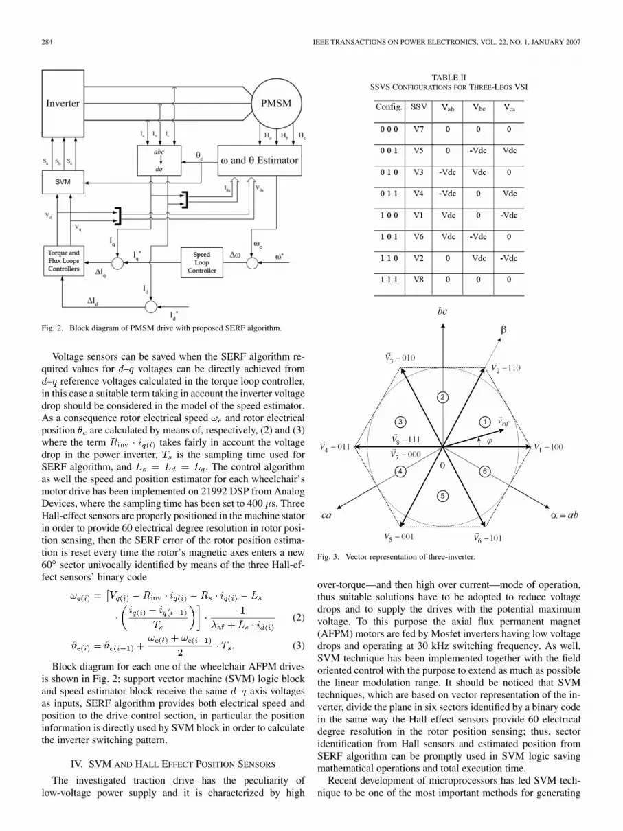
TABLE IISSVS CONFIGURATIONS FOR THREE-LEGS VSI
Fig. 3. Vector representation of three-inverter.
over-torque—and then high over current—mode of operation,thus suitable solutions have to be adopted to reduce voltagedrops and to supply the drives with the potential maximumvoltage. To this purpose the axial flux permanent magnet(AFPM) motors are fed by Mosfet inverters having low voltagedrops and operating at 30 kHz switching frequency. As well,SVM technique has been implemented together with the fieldoriented control with the purpose to extend as much as possiblethe linear modulation range. It should be noticed that SVMtechniques, which are based on vector representation of the in-verter, divide the plane in six sectors identified by a binary codein the same way the Hall effect sensors provide 60 electricaldegree resolution in the rotor position sensing; thus, sectoridentification from Hall sensors and estimated position fromSERF algorithm can be promptly used in SVM logic savingmathematical operations and total execution time.
Recent development of microprocessors has led SVM tech-nique to be one of the most important methods for generating

LIDOZZI et al.: SVM PMSM DRIVE 285
Fig. 4. Duty-cycle calculation for sector 1.
switching patterns for three-phase converters [8]. Differentlyfrom Sinusoidal PWM, the SVM considers the inverter as aunit. The vector technique accomplishes a better utilization ofthe entire conversion system and it’s good for vector controlof three-phase electrical machines. Digital control allows flex-ibility in controlling algorithms, and modulation schemes canbe very easily implemented; furthermore, by selecting differentcriteria in generating the switching pattern, the power systemperformance and efficiency can be significantly affected [9].
SVM techniques are based on the vector representation of theinverter; the state of each leg is represented by the value of thevariable ( 1 if top switch is on and the bottom one is off,
0 vice-versa), thus three-legs inverters can assume eightdifferent configurations as shown in Table II. Through mathe-matical transformations, symmetric three-phase systems can bechanged in equivalent two-phase systems: in the plane a ro-tating vector is obtained. For each configuration of the inverter,we can achieve 8 different vectors (six non-zero vectors and twozero vectors) called switching state vectors (SSVs) that dividethe plane in six sectors. As an example considering topology100, from Table II, the corresponding SSV is and the linevoltages , , are, respectively, equal to , 0, .Fig. 3 shows the plane vector representation of three-legsinverter.
Modeling of SVM technique and corresponding SSVs hasbeen achieved in Matlab-Simulink and then implemented on16 b-fixed point DSP platform. Inputs for SVM block are theangular information and the desired output voltage in –rotating two-phase frame ( , ), the switching pattern is theoutput. In SVM block model information on angle and the 60sector, in which the rotor’s magnetic axes is positioned, allowequations written for sector I to be used for further five sectorsin the same form; mentioned equations, used to find out dutycycle values, are shown in Fig. 4 in relation to sector I. EachSSV is applied for a period resulting from duty-cycle calcula-tions, where dead time effects are included and maximum andminimum conduction period values are limited on the basis ofactual switches characteristics.
Compensation of dead time effects is achieved as suggestedin [10] in order to reduce zero current clamping. As the phasecurrent lies inside the zero current clamping region the com-pensation voltages are
and 0 when the current of the phasea is negative, and
Fig. 5. Rotor’s magnetic axes position at very first startup.
and 0 when the current of the phase is positive; similarexpressions are used for the currents of phase and .
At the very first start, absolute position is obtained from thethree Hall-effect sensors being faced to one motor pole pair. Asshown in Fig. 5, the rotor’s magnetic axes position, with respectto the hexagon locus referred to the six possible combinationsof the three Hall effect sensors, is assumed at the half of the 60electrical sector identified by means of the sensors’ binary code.As a consequence the drive is able to start in sinusoidal opera-tion at a torque which is in the range of 86.6%–100% of themaximum torque, in fact the maximum error in the initial po-sition detection is 30 electrical degrees and it is reset to zero atthe very first transition of any of the Hall-effect sensors. Beingthe sampling time in the control algorithm set at 400 s, thenew values of and are achieved every 400 s; as aresult, the speed resolution of SERF algorithm for the proposedapplication (16 poles PM machine) at the minimum continuousrotational speed (i.e., 3 rev/min) is about 12 higher with re-spect to the maximum resolution achievable from an encoderwith 1024 pulses per revolution.
V. MODELING AND EXPERIMENTAL RESULTS
Simulink model for the SVM PMSM drive has been ar-ranged. In the realized models sampling and A/D conversion ofinput signals as well all the other functions are accomplishedsimulating same operational and calculus characteristics of

286 IEEE TRANSACTIONS ON POWER ELECTRONICS, VOL. 22, NO. 1, JANUARY 2007
(a) (b)
(c)
Fig. 6. (a) Simulation results: speed estimation at speed reference and load torque variations. (b) Simulation results: zoom at startup. (c) Simulation results: zoomat load variation.
16 b-fixed point DSP. Suitable routines have been adopted inorder to achieve 32 b-floating point calculus performances. Inthe model are present both the SERF algorithm and a 1024pulses encoder, used in order to compare speed estimation withthe measured machine rotor speed; furthermore, switchingmodel of inverter fed AFPM drive has been accomplished byusing real components.
In order to investigate the reliability of the proposed SERFalgorithm for the speed estimation in PMSM drives, a sensi-bility analysis has been accomplished by simulations both byvarying the PMSM parameters (i.e. phase resistance and induc-tance) and by adding to the current measures some noise at var-ious frequencies. The motor phase inductance has been reducedby 50% whereas the stator resistance has been changed from therated value (90 m at 25 C) to 133.35 m , correspondent tothe winding operating temperature of 150 C. The frequency ofthe noise signals introduced in the acquisition process has beenchanged in the range 1.25–2.5 kHz (i.e., respectively, the half
and the same value of the sampling frequency in the control al-gorithm), whereas the amplitude of the noise added to the mea-sure signals is respectively 1% (0.24 V) of dc link voltage and1% (1 A) of the current full scale measure. It has been demon-strated that the SERF algorithm is mainly sensitive to PMSMphase resistance variation, whereas the phase inductance valuehardly affects the speed and position estimation and the noisecan be effectively filtered by means of Butterworth II order dig-ital filters. As a result, either the measurement or a roughly es-timation of stator resistance value must be provided to achieveproper results from (2) and (3). The error of 48% on the statorphase resistance value causes the error in the estimated speedand position of almost 30% in the most critical operating con-dition, which occurs when the machine rotates at the minimumcontinuous speed (i.e., 3 rev/min), whereas the error of 5% is re-sponsible for 3.5% error in the estimation algorithm which dropsto 1.1% when the rotational speed is 1 rad/s. It is evident therotational speed per cent error significantly decreases at higher

LIDOZZI et al.: SVM PMSM DRIVE 287
(a)
(b)
Fig. 7. (a) Simulation results: PMSM phase currents at startup. (b) Simulationresults: motor speed at first reset.
speed values, which are common to outdoor modes of opera-tion. By sensing the operating temperature of the stator windingit is possible to achieve the desired accuracy for the estimationof the value of the phase resistance; however, even in absenceof a temperature sensor, the knowledge of the phase current canbe used to estimate the winding resistance with approximationwhich could be acceptable [11].
Fig. 6 shows a simulation achieved by means of the realizedSimulink model of the whole wheelchair; both speed referenceand load torque is changed and in any case the speed estimationfrom SERF algorithm is almost coincident with motor measuredspeed from a 1024 pulses encoder. The simulation test startswith the maximum error in the rotor position (i.e., 30 electricaldegrees), the step variation 0–5 rad/s for the motor speed ref-erence and the step variation 0–2 Nm for the load torque arecommanded; then, after the motor has reached the new steadystate condition, a ramp variation (5–7 rad/s in 3 s) for the speedreference is applied, at 2/3 of the speed reference ramp the load
(a)
(b)
Fig. 8. (a) Simulation results: position estimation. (b) Simulation results: zoomat startup.
torque is changed from 2 to 6 Nm. At the second 10 of thesimulation the commanded speed is decreased to 4 rad/s and1 s later the applied torque changes from 6 to 4 Nm, then thespeed reference is brought to 0 rad/s in the next 3 s. Along theentire simulation the estimated speed and the actual measuredspeed are tight together thus confirming the accuracy of the es-timation algorithm. The considered application does not requirehigh control bandwidth; as a consequence, the low control band-width saves the filtering of speed and position and improves thesystem stability. The same estimation and control algorithmscould be applied to drives requiring better performances, how-ever in this case speed and position filtering should be accepted.Fig. 6(b) shows a zoomed window at very first startup of thewheelchair, where the estimated speed has some small oscilla-tions, mainly due to the effect of the applied torque step when
288 IEEE TRANSACTIONS ON POWER ELECTRONICS, VOL. 22, NO. 1, JANUARY 2007
(a)
(b)
Fig. 9. Experimental results at 5 rad/s: actual speed (4 rad �s =div), estimatedspeed (4 rad�s =div), phase current (10 A/div), estimated position (�rad/div),Hall effect sensor; positive rotational speed.
the rotational speed of the machine is still zero, that howeverdo not affect the start-up of the machine. The speed oscilla-tions are experienced only at starting from zero and they canbe mainly related to the sudden increase of and due to theproportional part of torque and flux loops controllers; further in-vestigation showed that speed oscillations at starting are signifi-cantly reduced when SERF algorithm – voltages are achievedby means of measured AFPM motor line-to-line voltages andtransformed by means of the estimated position. Incidentally,all the experimental testing activity has been accomplished byusing and values at the output of torque and flux loops.Zoomed window in Fig. 6(c) emphasizes good results for speedestimation even at load variation.
The phase currents of the PMSM are shown in Fig. 7(a) for thefirst 0.8 s of the simulation; at start-up one of the phase current isequal to zero because rotor’s magnetic axes position is assumedat the half of the 60 electrical sector identified by means ofthe Hall sensors’ binary code, at 0.13 s the rotor’s magneticaxes enters the first new 60 sector and the initial error on therotor position estimation is reset. From this point on the error inspeed estimation is significantly reduced as shown inFig. 7(b)
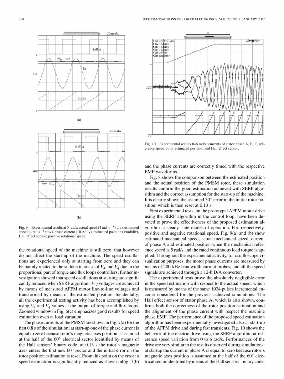
Fig. 10. Experimental results 0–6 rad/s: currents of stator phase A, B, C, ref-erence speed, rotor estimated position, and Hall effect sensor.
and the phase currents are correctly timed with the respectiveEMF waveforms.
Fig. 8 shows the comparison between the estimated positionand the actual position of the PMSM rotor, these simulationresults confirm the good estimation achieved with SERF algo-rithm and the correct assumption for the start-up of the machine.It is clearly shown the assumed 30 error in the initial rotor po-sition, which is then reset at 0.13 s.
First experimental tests, on the prototypal AFPM motor driveusing the SERF algorithm in the control loop, have been de-voted to prove the effectiveness of the proposed estimation al-gorithm at steady state modes of operation. For, respectively,positive and negative rotational speed, Fig. 9(a) and (b) showestimated mechanical speed, actual mechanical speed, currentof phase A and estimated position when the mechanical refer-ence speed is 5 rad/s and the rated continuous load torque is ap-plied. Throughout the experimental activity, for oscilloscope vi-sualization purposes, the motor phase currents are measured bymeans of 200-kHz bandwidth current probes, and all the speedsignals are achieved through a 12-b D/A converter.
The experimental tests prove the absolutely negligible errorin the speed estimation with respect to the actual speed, whichis measured by means of the same 1024 pulses incremental en-coder considered for the previous achieved simulations. TheHall effect sensor of stator phase A, which is also shown, con-firms both the correctness of the rotor position estimation andthe alignment of the phase current with respect the machinephase EMF. The performance of the proposed speed estimationalgorithm has been experimentally investigated also at start-upof the AFPM drive and during fast transients, Fig. 10 shows thebehavior of the electric drive using the SERF algorithm at ref-erence speed variation from 0 to 6 rad/s. Performances of thedrive are very similar to the results observed during simulations:at startup the current in phase A is equal to zero because rotor’smagnetic axes position is assumed at the half of the 60 elec-trical sector identified by means of the Hall sensors’ binary code,

LIDOZZI et al.: SVM PMSM DRIVE 289
when the rotor’s magnetic axes enters the first new 60 sectorthe initial error on the rotor position estimation is reset and eachphase current is correctly timed with the respective EMF wave-form.
VI. CONCLUSION
In the last few decades, the requirement of removal ofunreliable and expensive position sensors has led academicand industrial researchers to investigate and to propose severalmethods for the sensorless control of PMSM drives. However,low reliability and implementation difficulties of these methodsat very low rotational speed modes of operation, preclude theiracceptance in direct drive PMSMs devoted to traction applica-tions. In order to overcome the mentioned disadvantages, in thispaper the application of a back-EMF-based method in conjunc-tion with very low resolution sensors is proposed to estimatethe rotor position of a direct-drive axial-flux permanent-magnetmotor to be used for traction purpose of an electric wheelchair.The investigated Speed Estimator is based on the Rotor Framemachine model (SERF) and it has been implemented on a 16-bfixed point DSP. It is proved that SVM techniques, which arebased on vector representation of the inverter, divide the planein six sectors identified by a binary code in the same way theHall effect sensors provide 60 electrical degree resolution inthe rotor position sensing; thus, sector identification from Hallsensors and estimated position from SERF algorithm can bepromptly used in SVM logic. Mathematical operations aresaved and total execution time of the algorithm is reduced when
– voltages calculated in the torque and flux loops are directlyused in the speed and position estimator, instead of measuringinverter output line-to-line voltages and then transforming themon – axis by means of Park and Stanley matrixes. Accurateinvestigations have been dedicated to startup and near-zerospeed operations for the drive, which have been analyzed bymeans of simulations and experimental tests. Final resultsshow absolutely negligible error in the speed estimation withrespect to the actual speed, which is measured by means ofan incremental encoder, both in steady-state and in transientoperating conditions.
REFERENCES
[1] H. Kim, M. C. Harke, and R. D. Lorenz, “Sensorless control of interiorpermanent-magnet machine drives with zero-phaselag position estima-tion,” IEEE Trans. Ind. Appl., vol. 39, no. 6, pp. 1726–1733, Nov./Dec.2003.
[2] S. Morimoto, M. Sanada, and Y. Takeda, “Sinusoidal current drivesystem of permanent magnet synchronous motor with low resolutionposition sensor,” in Proc. IEEE IAS Annual Meeting, Oct. 9–13, 1996,vol. 1, pp. 9–14.
[3] J. Bu, L. Xu, T. Sebastian, and B. Liu, “Near-zero speed performanceenhancement of PM synchronous machines assisted by low cost Halleffect sensors,” in Proc. IEEE APEC’98, Feb. 68–74, 1998, pp. 68–74.
[4] S. Morimoto, M. Sanada, and Y. Takeda, “High performance current-sensorless drive for PMSM and SynRM with only low resolution po-sition sensor,” IEEE Trans. Ind. Appl., vol. 39, no. 3, pp. 792–801,May/Jun. 2003.
[5] F. G. Capponi, G. De Donato, and L. Del Ferraro, “Brushless AC driveusing an axial flux synchronous motor with low resolution positionsensors,” in Proc. IEEE 35th Annu. Power Electron. Spec. Conf.(PESC’04), Aachen, Germany, 2004, pp. 2287–2292.
[6] L. Solero, O. Honorati, F. Caricchi, and F. Crescimbini, “Non-con-ventional three-wheel electric vehicle for urban mobility,” IEEE Trans.Veh. Technol., vol. 50, no. 4, pp. 1085–1091, Jul. 2001.
[7] M. Raganella, A. Di Napoli, F. Crescimbini, A. Lidozzi, and L. Solero,“Design and modeling of controllers in PM drives for wheelchairs,” inProc. ICEM’04, 2004, [CD ROM].
[8] H. W. van der Broeck, H. C. Skudelny, and G. V. Stanke, “Analysis andrealization of a pulse width modulator based on voltage space vectors,”IEEE Trans. Ind. Appl., vol. IA-24, no. 1, pp. 142–150, Jan./Feb. 1988.
[9] G. Vitale, A. Di Napoli, F. Crescimbini, A. Lidozzi, and L. Solero,“Combination of SVM techniques for electric drive,” in Proc.SPEEDAM’04, 2004, [CD ROM].
[10] J.-W. Choi and S.-K. Sul, “A new compensation strategy reducingvoltage/current distortion in PWM VSI systems operating with lowoutput voltages,” IEEE Trans. Ind. Appl., vol. 31, no. 5, pp. 1001–1008,Sep./Oct. 1995.
[11] L. Sang-Bin, T. G. Habetler, R. G. Harley, and D. J. Gritter, “An eval-uation of model-based stator resistance estimation for induction motorstator winding temperature monitoring,” IEEE Trans. Energy Conv.,vol. 17, no. 1, pp. 7–15, Mar. 2002.
Alessandro Lidozzi (S’04) received the M.S. degreein electronic engineering from the University ofRome “ROMA TRE,” Rome, Italy, in 2003 where heis currently pursuing the Ph.D. degfee.
From 2005 to 2006, he was Visiting Scholar atthe Center for Power Electronics Systems (CPES),Virginia Polytechnic Institute and State University,Blacksburg (VA). His research interests are mainlyfocused in multi-converter based applications,dc–dc power converters modeling and control, andnonlinear control of permanent magnet motor drives.
Mr. Lidozzi In received a Student Award and a Travel Grant at the Interna-tional Symposium on Industrial Electronics (ISIE) in 2004. He is member of theIEEE Industrial Electronics Society.
Luca Solero (M’98) received the Ph.D. degree inelectrical engineering from the University of Rome“La Sapienza,” Rome, Italy, in 1994.
Since 1996, he has been with the Department ofMechanical and Industrial Engineering, Universityof Rome “ROMA TRE,” where he is currently anAssistant Professor. During 2002, he was a VisitingScholar at the Center for Power Electronics Systems(CPES), Virginia Polytechnic Institute and Uni-versity, Blacksburg. His research interests includepower converter topologies, permanent magnet
motor drive and control systems design for unconventional applications suchas electric and hybrid vehicle and renewable energy systems.
Dr. Solero is a member of the IEEE Industry Applications, IEEE Power Elec-tronics, and IEEE Industrial Electronics Societies.
Fabio Crescimbini (M’90) received the M.S. andPh.D. degrees in electrical engineering from theUniversity of Rome “La Sapienza”, Rome, Italy, in1982 and 1987, respectively.
From 1989 to 1998, he was with the Departmentof Electrical Engineering, University of Rome “LaSapienza,” as Director of the Electrical Machines andDrives Laboratory. In 1998, he joined the Departmentof Mechanical and Industrial Engineering, Univer-sity of Rome “ROMA TRE,” where he is currently aFull Professor of electrical machines and drives. His
research interests include newly-conceived permanent magnet machines andpower converter topologies for unconventional applications such as electric ve-hicle motor drives and renewable energy generating systems.
Dr. Crescimbini is a member of the IEEE Industry Applications Society (IAS)and the IEEE Vehicular Technology Society (VTS). Since 2001, he has servedas a member of the IEEE IAS Executive Board.

290 IEEE TRANSACTIONS ON POWER ELECTRONICS, VOL. 22, NO. 1, JANUARY 2007
Augusto Di Napoli received the M.Sc degree in elec-trical engineering from the University of Rome “LaSapienza,” Rome, Italy, in 1969.
From 1970 to 1992, he was with the Departmentof Electrical Engineering, University of Rome “LaSapienza,” as Assistant Professor (1970), AssociateProfessor (1980), and then Full Professor of Elec-trical Drives (1986). In 1992, he joined the Depart-ment of Mechanical and Industrial Engineering, Uni-versity of Rome “ROMA TRE” as a Full Professor atwhere, since 2002, he has been the Head of the De-
partment. He is author of more than 90 papers published in international journalsand in conferences proceedings. His scientific interests include FEM analysisfor electrical machines, control design, and EMC analysis in electrical drives.