Embed Size (px)
Citation preview
polymers
Article
Synthesis, Property Characterization andPhotocatalytic Activity of the Polyaniline/BiYTi2O7Polymer Composite
Jingfei Luan *, Yue Shen, Shu Wang and Ningbin Guo
State Key Laboratory of Pollution Control and Resource Reuse, School of the Environment, Nanjing University,Nanjing 210093, China; [email protected] (Y.S.); [email protected] (S.W.);[email protected] (N.G.)* Correspondence: [email protected]; Tel.: +86-25-8968-0397; Fax: +86-25-8370-7304
Academic Editor: John T. SheridanReceived: 13 December 2016; Accepted: 9 February 2017; Published: 23 February 2017
Abstract: A new polyaniline/BiYTi2O7 polymer composite was synthesized by chemicaloxidation in-situ polymerization method for the first time. The effect of polyaniline doping onstructural and catalytic properties of BiYTi2O7 was reported. The structural properties of novelpolyaniline/BiYTi2O7 have been characterized by X-ray diffraction, scanning electron microscopy,X-ray photoelectron spectroscopy and UV-Vis DRS. The results showed that BiYTi2O7 crystallizedwell with the pyrochlore-type structure, stable cubic crystal system by space group Fd3m. The latticeparameter or band gap energy of BiYTi2O7 was found to be a = 10.2132 Å or 2.349 eV, respectively.The novel polyaniline/BiYTi2O7 polymer composite possessed higher catalytic activity comparedwith BiYTi2O7 or nitrogen doped TiO2 for photocatalytic degradation of Azocarmine G undervisible light irradiation. Additionally, the Azocarmine G removal efficiency was boosted from3.0% for undoped BiYTi2O7 to 78.0% for the 10% polyaniline-modified BiYTi2O7, after only60 min of reaction. After visible light irradiation for 330 min with polyaniline/BiYTi2O7 polymercomposite as photocatalyst, complete removal and mineralization of Azocarmine G was observed.The photocatalytic degradation of Azocarmine G followed first-order reaction kinetics. Ultimately,the promoter action of H2O2 for photocatalytic degradation of AG with BiYTi2O7 as catalyst in thewastewater was discovered.
Keywords: polyaniline/BiYTi2O7; photocatalytic activity; Azocarmine G; visible light irradiation; H2O2
1. Introduction
The pollution of water resources by large quantities of azo-dyes effluents, generated from diverseindustries such as chemical, textile or printing, due to their toxicity, high chemical oxygen demandcontent, and biological degradation, has a dramatically negative environmental impact, affecting thequality of drinking water. In the last decade, photocatalytic degradation processes had been widelyapplied as techniques for the destruction of organic pollutants in wastewater and effluents [1–20].The photocatalytic degradation process has several advantages over other competing processes suchas complete mineralization, no waste disposal problem, low cost, and only needing mild temperatureand pressure [8].
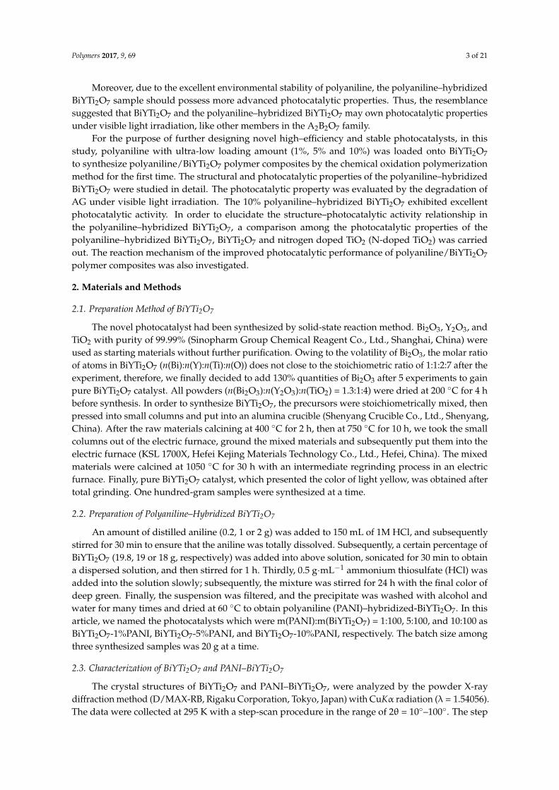
Azocarmine G (AG) (Figure 1) as a common biological stain is often used to determine protein [21],DNA [22] and light neurons [23]. AG, a common kind of azo dye, is more difficult to handle.In exceptional circumstances, azo dyes can decompose to produce over 20 kinds of carcinogenicaromatic amines, which can cause lesions and induce cancer after activation to change the DNAstructure of the human body. Since the Sudan Red incident occurred, the use of biological stain
Polymers 2017, 9, 69; doi:10.3390/polym9030069 www.mdpi.com/journal/polymers
Polymers 2017, 9, 69 2 of 21
and the wastewater treatment has been more cautious to the researchers. AG, however, is harderto be biodegraded and photodegraded directly. Many methods on the photodegradation of AG arereported. Unfortunately, most of these experiments were carried out under ultraviolet light irradiation.Nowadays, there are only a few reports for AG dye degradation under visible light irradiation, findingthat the removal ratio of AG is very low.
Polymers 2017, 9, 69 2 of 20
biodegraded and photodegraded directly. Many methods on the photodegradation of AG are reported. Unfortunately, most of these experiments were carried out under ultraviolet light irradiation. Nowadays, there are only a few reports for AG dye degradation under visible light irradiation, finding that the removal ratio of AG is very low.
N+
N
NH
SO3-Na+
SO3-
Figure 1. The molecular structure of Azocarmine G.
It is known that ultraviolet light only occupies 4% of the solar energy spectrum. For this reason, there is great interest in developing new visible light-responsive photocatalysts which are capable of utilizing the more ample visible light spectrum, which occupies about 43% of the solar energy range. Therefore, it is an urgent need to develop novel visible light-responsive photocatalysts. According to the past articles [24–29], many semiconductors can be used as photocatalysts under ultraviolet light irradiation, such as TiO2 and ZnO.
In view of the efficient utilization of solar energy, numerous attempts have been made in recent years to develop different visible light-active photocatalysts [30–47]. Traditionally, for improving the photocatalytic efficiency of photocatalysts, the bandgap of photocatalysts or loaded cocatalysts plays an important role in photocatalyst system. Therefore, efficient catalysts that can generate electron–hole pairs under visible light irradiation should be developed [48–64]. Among them, A2B2O7 compounds with narrow band gaps have been proven to be good candidates for photocatalytic degradation of organic pollutants under visible light irradiation. In our previous work [65], we found that In2YbSbO7 and Gd2YbSbO7 which owned the pyrochlore-type structure as a photocatalyst under visible light irradiation seemed to be potential for improvement of photocatalytic activity by modifying its structure.
A change and improvement of the electron transport and photophysical properties could be found in the novel BiYTi2O7 compound which might display advanced photocatalytic properties. BiYTi2O7 had never been produced and the data about its structural such as space group and lattice constants had not been previously reported. In addition, the photocatalytic properties of BiYTi2O7 had not been investigated by other investigators. The molecular composition of BiYTi2O7 was very similar to that of other A2B2O7 compounds. BiYTi2O7 also seemed to have potential for improvement of photocatalytic activity by modifying its structure, because it had been proven that a slight modification of a semiconductor structure would cause a remarkable change in photocatalytic properties.
Polyaniline (PANI) has a high application rate in view of its electrical and optical properties, ease of derivatization, solubility in several solvents, processability inside fibers and films, and stability [66–68]. In addition, PANI with delocalized π-conjugated structures is beneficial to rapid charge separation, thus the separation efficiency of photogenerated electron (e−)–hole (h+) pairs can be significantly improved [69]. Shang et al. [70] reported that on the basis of the small grain size, the intrinsic property of PANI, and the synergic effect between PANI and BiVO4, a rapid electron–hole separation and slow recombination was realized. Hidalgo et al. [71] prepared PANI–TiO2 nanocomposites by a novel and green sol-gel spin coating method. The results showed that the photocurrent in PANI/TiO2 electrodes dramatically increased under simulated sunlight irradiation, reaching maximum photocurrent densities around 2 and 1.6 fold higher than the pristine TiO2 NPs.
Figure 1. The molecular structure of Azocarmine G.
It is known that ultraviolet light only occupies 4% of the solar energy spectrum. For this reason,there is great interest in developing new visible light-responsive photocatalysts which are capable ofutilizing the more ample visible light spectrum, which occupies about 43% of the solar energy range.Therefore, it is an urgent need to develop novel visible light-responsive photocatalysts. According tothe past articles [24–29], many semiconductors can be used as photocatalysts under ultraviolet lightirradiation, such as TiO2 and ZnO.
In view of the efficient utilization of solar energy, numerous attempts have been made in recentyears to develop different visible light-active photocatalysts [30–47]. Traditionally, for improving thephotocatalytic efficiency of photocatalysts, the bandgap of photocatalysts or loaded cocatalysts playsan important role in photocatalyst system. Therefore, efficient catalysts that can generate electron–holepairs under visible light irradiation should be developed [48–64]. Among them, A2B2O7 compoundswith narrow band gaps have been proven to be good candidates for photocatalytic degradation oforganic pollutants under visible light irradiation. In our previous work [65], we found that In2YbSbO7
and Gd2YbSbO7 which owned the pyrochlore-type structure as a photocatalyst under visible lightirradiation seemed to be potential for improvement of photocatalytic activity by modifying its structure.
A change and improvement of the electron transport and photophysical properties could be foundin the novel BiYTi2O7 compound which might display advanced photocatalytic properties. BiYTi2O7
had never been produced and the data about its structural such as space group and lattice constantshad not been previously reported. In addition, the photocatalytic properties of BiYTi2O7 had notbeen investigated by other investigators. The molecular composition of BiYTi2O7 was very similarto that of other A2B2O7 compounds. BiYTi2O7 also seemed to have potential for improvement ofphotocatalytic activity by modifying its structure, because it had been proven that a slight modificationof a semiconductor structure would cause a remarkable change in photocatalytic properties.
Polyaniline (PANI) has a high application rate in view of its electrical and optical properties, ease ofderivatization, solubility in several solvents, processability inside fibers and films, and stability [66–68].In addition, PANI with delocalized π-conjugated structures is beneficial to rapid charge separation,thus the separation efficiency of photogenerated electron (e−)–hole (h+) pairs can be significantlyimproved [69]. Shang et al. [70] reported that on the basis of the small grain size, the intrinsicproperty of PANI, and the synergic effect between PANI and BiVO4, a rapid electron–hole separationand slow recombination was realized. Hidalgo et al. [71] prepared PANI–TiO2 nanocompositesby a novel and green sol-gel spin coating method. The results showed that the photocurrent inPANI/TiO2 electrodes dramatically increased under simulated sunlight irradiation, reaching maximumphotocurrent densities around 2 and 1.6 fold higher than the pristine TiO2 NPs.
Polymers 2017, 9, 69 3 of 21
Moreover, due to the excellent environmental stability of polyaniline, the polyaniline–hybridizedBiYTi2O7 sample should possess more advanced photocatalytic properties. Thus, the resemblancesuggested that BiYTi2O7 and the polyaniline–hybridized BiYTi2O7 may own photocatalytic propertiesunder visible light irradiation, like other members in the A2B2O7 family.
For the purpose of further designing novel high–efficiency and stable photocatalysts, in thisstudy, polyaniline with ultra-low loading amount (1%, 5% and 10%) was loaded onto BiYTi2O7
to synthesize polyaniline/BiYTi2O7 polymer composites by the chemical oxidation polymerizationmethod for the first time. The structural and photocatalytic properties of the polyaniline–hybridizedBiYTi2O7 were studied in detail. The photocatalytic property was evaluated by the degradation ofAG under visible light irradiation. The 10% polyaniline–hybridized BiYTi2O7 exhibited excellentphotocatalytic activity. In order to elucidate the structure–photocatalytic activity relationship inthe polyaniline–hybridized BiYTi2O7, a comparison among the photocatalytic properties of thepolyaniline–hybridized BiYTi2O7, BiYTi2O7 and nitrogen doped TiO2 (N-doped TiO2) was carriedout. The reaction mechanism of the improved photocatalytic performance of polyaniline/BiYTi2O7
polymer composites was also investigated.
2. Materials and Methods
2.1. Preparation Method of BiYTi2O7
The novel photocatalyst had been synthesized by solid-state reaction method. Bi2O3, Y2O3, andTiO2 with purity of 99.99% (Sinopharm Group Chemical Reagent Co., Ltd., Shanghai, China) wereused as starting materials without further purification. Owing to the volatility of Bi2O3, the molar ratioof atoms in BiYTi2O7 (n(Bi):n(Y):n(Ti):n(O)) does not close to the stoichiometric ratio of 1:1:2:7 after theexperiment, therefore, we finally decided to add 130% quantities of Bi2O3 after 5 experiments to gainpure BiYTi2O7 catalyst. All powders (n(Bi2O3):n(Y2O3):n(TiO2) = 1.3:1:4) were dried at 200 ◦C for 4 hbefore synthesis. In order to synthesize BiYTi2O7, the precursors were stoichiometrically mixed, thenpressed into small columns and put into an alumina crucible (Shenyang Crucible Co., Ltd., Shenyang,China). After the raw materials calcining at 400 ◦C for 2 h, then at 750 ◦C for 10 h, we took the smallcolumns out of the electric furnace, ground the mixed materials and subsequently put them into theelectric furnace (KSL 1700X, Hefei Kejing Materials Technology Co., Ltd., Hefei, China). The mixedmaterials were calcined at 1050 ◦C for 30 h with an intermediate regrinding process in an electricfurnace. Finally, pure BiYTi2O7 catalyst, which presented the color of light yellow, was obtained aftertotal grinding. One hundred-gram samples were synthesized at a time.
2.2. Preparation of Polyaniline–Hybridized BiYTi2O7
An amount of distilled aniline (0.2, 1 or 2 g) was added to 150 mL of 1M HCl, and subsequentlystirred for 30 min to ensure that the aniline was totally dissolved. Subsequently, a certain percentage ofBiYTi2O7 (19.8, 19 or 18 g, respectively) was added into above solution, sonicated for 30 min to obtaina dispersed solution, and then stirred for 1 h. Thirdly, 0.5 g·mL−1 ammonium thiosulfate (HCl) wasadded into the solution slowly; subsequently, the mixture was stirred for 24 h with the final color ofdeep green. Finally, the suspension was filtered, and the precipitate was washed with alcohol andwater for many times and dried at 60 ◦C to obtain polyaniline (PANI)–hybridized-BiYTi2O7. In thisarticle, we named the photocatalysts which were m(PANI):m(BiYTi2O7) = 1:100, 5:100, and 10:100 asBiYTi2O7-1%PANI, BiYTi2O7-5%PANI, and BiYTi2O7-10%PANI, respectively. The batch size amongthree synthesized samples was 20 g at a time.
2.3. Characterization of BiYTi2O7 and PANI–BiYTi2O7
The crystal structures of BiYTi2O7 and PANI–BiYTi2O7, were analyzed by the powder X-raydiffraction method (D/MAX-RB, Rigaku Corporation, Tokyo, Japan) with CuKα radiation (λ = 1.54056).The data were collected at 295 K with a step-scan procedure in the range of 2θ = 10◦–100◦. The step
Polymers 2017, 9, 69 4 of 21
interval was 0.02◦ and the time per step was 1.2 s. The chemical composition of the compoundwas determined by Scanning Electron Microscope-X-ray Energy Dispersion Spectrum (SEM-EDS,LEO 1530VP, LEO Corporation, Dresden, Germany). The Bi3+ content, Y3+ content, Ti4+ content, andO2− content of BiYTi2O7 were determined by X-ray photoelectron spectroscopy (XPS, ESCALABMK-2,VG Scientific Ltd., London, UK). The chemical composition within the depth profile of BiYTi2O7
was examined by the argon ion denudation method when X-ray photoelectron spectroscopy wasused. The optical absorption of BiYTi2O7 and PANI–BiYTi2O7 was analyzed with an UV-Visiblespectrophotometer (UV-2450, Shimadzu Corporation, Kyoto, Japan). The particle sizes of thephotocatalysts were determined by Malvern’s Mastersize-2000 particle size analyzer (MalvernInstruments Ltd., Malvern, UK).
2.4. Photocatalytic Characterizations of BiYTi2O7 and PANI–BiYTi2O7
The photocatalytic degradation experiments of AG were carried out with photocatalyst powderswhich were suspended in 50 mL 20 mg·L−1 solution in 12 identical Pyrex glass cells (Nanjing XujiangIndustry, Nanjing, China). Before light irradiation, the suspensions were magnetically stirred inthe darkness for 30 min to ensure establishment of an adsorption-desorption equilibrium amongphotocatalyst, the dye and atmospheric oxygen. The photocatalytic reaction system consisted of a500 W Xe arc lamp (Nanjing Xujiang Industry, Nanjing, China), a magnetic stirrer and a cut-off filter(λ > 420 nm, Nanjing Xujiang Industry, Nanjing, China). The Xe arc lamp was surrounded by a quartzjacket and was positioned in a photoreactor quartz vessel. Room temperature (25 ◦C) was maintainedby an outer recycling water glass jacket. The solution was continuously stirred magnetically. Afterevery 30 min, one of the Pyrex glass cells was sampled. Without pH adjustment, the initial pH valuewas 6.0 for AG. Additionally, the concentration of AG was determined according to the absorptionwavelength at 524 nm as measured by a UV-Vis spectrophotometer (UV-2550, Shimadzu Corporation,Kyoto, Japan), since the highest absorption wavelength of AG was 524 nm. The total organic carbon(TOC) concentration was determined with a TOC analyzer (TOC-5000, Shimadzu Corporation).
3. Results and Discussion
3.1. Characterization
3.1.1. XRD Analysis
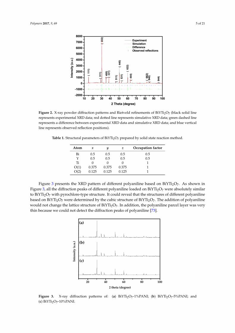
The structure with full-profile refinements of the as-prepared product BiYTi2O7 was examined byX-ray diffraction technique and the results were shown in Figure 2. The collected data was obtained bythe Materials Studio program, which was based on Rietveld analysis. The powder X-ray diffractionanalysis revealed that the product could be melted when sintering temperature was over 1150 ◦C.In the light of Figure 2, it could be concluded that BiYTi2O7 was single phase and that the latticeparameter for this new photocatalyst BiYTi2O7 was 10.21323 Å. Simultaneously, the final refinementfor BiYTi2O7 showed a good agreement between the observed and calculated intensities for thepyrochlore-type structure, a cubic crystal system and a space group Fd3m (O atoms are included in themodel). In addition, all of the diffraction peaks for this photocatalyst could be indexed successfully,according to the lattice constant and above space group. Moreover, the atomic coordinates andstructural parameters of BiYTi2O7 are recorded in Table 1.
As can be seen from the X-ray diffraction, it could be concluded that BiYTi2O7 crystallized intopyrochlore-type structure. The cubic system structure with space group Fd3m for Bi2Ti2O7 keepedunchanged after Bi3+ being substituted by Y3+. The results of full-profile structure refinements forBiYTi2O7 generated the unweighted R factors, RP = 13.80% with space group Fd3m. Contrary to thework of Zou et al. [72], Bi2InNbO7 which was slightly modified had a larger R factor.
Polymers 2017, 9, 69 5 of 21Polymers 2017, 9, 69 5 of 20
10 20 30 40 50 60 70 80 90 100-2000
-1000
0
1000
2000
3000
4000
5000
6000
7000
8000
(84
4)
(84
0)(
662)
(44
4)(
622)
(53
1)(
440)
(51
1)(33
1)(
400)
(31
1)(
222)
(11
1)
Experiment Simulation Difference Observed reflections
Inte
nsi
ty (
a.u
.)
2 Theta (degree)
Figure 2. X-ray powder diffraction patterns and Rietveld refinements of BiYTi2O7 (black solid line represents experimental XRD data; red dotted line represents simulative XRD data; green dashed line represents a difference between experimental XRD data and simulative XRD data; and blue vertical line represents observed reflection positions).
Table 1. Structural parameters of BiYTi2O7 prepared by solid state reaction method.
Atom x y z Occupation factorBi 0.5 0.5 0.5 0.5 Y 0.5 0.5 0.5 0.5 Ti 0 0 0 1
O(1) 0.375 0.375 0.375 1 O(2) 0.125 0.125 0.125 1
Figure 3 presents the XRD pattern of different polyaniline based on BiYTi2O7. As shown in Figure 3, all the diffraction peaks of different polyaniline loaded on BiYTi2O7 were absolutely similar to BiYTi2O7 with pyrochlore-type structure. It could reveal that the structures of different polyaniline based on BiYTi2O7 were determined by the cubic structure of BiYTi2O7. The addition of polyaniline would not change the lattice structure of BiYTi2O7. In addition, the polyaniline parcel layer was very thin because we could not detect the diffraction peaks of polyaniline [73].
20 40 60 80 100
(c)
(b)
(a)
Inte
nsity
(a.u
.)
2 theta (degree)
Figure 3. X-ray diffraction patterns of: (a) BiYTi2O7-1%PANI; (b) BiYTi2O7-5%PANI; and (c) BiYTi2O7-10%PANI.
Figure 2. X-ray powder diffraction patterns and Rietveld refinements of BiYTi2O7 (black solid linerepresents experimental XRD data; red dotted line represents simulative XRD data; green dashed linerepresents a difference between experimental XRD data and simulative XRD data; and blue verticalline represents observed reflection positions).
Table 1. Structural parameters of BiYTi2O7 prepared by solid state reaction method.
Atom x y z Occupation factor
Bi 0.5 0.5 0.5 0.5Y 0.5 0.5 0.5 0.5Ti 0 0 0 1
O(1) 0.375 0.375 0.375 1O(2) 0.125 0.125 0.125 1
Figure 3 presents the XRD pattern of different polyaniline based on BiYTi2O7. As shown inFigure 3, all the diffraction peaks of different polyaniline loaded on BiYTi2O7 were absolutely similarto BiYTi2O7 with pyrochlore-type structure. It could reveal that the structures of different polyanilinebased on BiYTi2O7 were determined by the cubic structure of BiYTi2O7. The addition of polyanilinewould not change the lattice structure of BiYTi2O7. In addition, the polyaniline parcel layer was verythin because we could not detect the diffraction peaks of polyaniline [73].
Polymers 2017, 9, 69 5 of 20
10 20 30 40 50 60 70 80 90 100-2000
-1000
0
1000
2000
3000
4000
5000
6000
7000
8000
(84
4)
(84
0)(
662)
(44
4)(
622)
(53
1)(
440)
(51
1)(33
1)(
400)
(31
1)(
222)
(11
1)
Experiment Simulation Difference Observed reflections
Inte
nsi
ty (
a.u
.)
2 Theta (degree)
Figure 2. X-ray powder diffraction patterns and Rietveld refinements of BiYTi2O7 (black solid line represents experimental XRD data; red dotted line represents simulative XRD data; green dashed line represents a difference between experimental XRD data and simulative XRD data; and blue vertical line represents observed reflection positions).
Table 1. Structural parameters of BiYTi2O7 prepared by solid state reaction method.
Atom x y z Occupation factorBi 0.5 0.5 0.5 0.5 Y 0.5 0.5 0.5 0.5 Ti 0 0 0 1
O(1) 0.375 0.375 0.375 1 O(2) 0.125 0.125 0.125 1
Figure 3 presents the XRD pattern of different polyaniline based on BiYTi2O7. As shown in Figure 3, all the diffraction peaks of different polyaniline loaded on BiYTi2O7 were absolutely similar to BiYTi2O7 with pyrochlore-type structure. It could reveal that the structures of different polyaniline based on BiYTi2O7 were determined by the cubic structure of BiYTi2O7. The addition of polyaniline would not change the lattice structure of BiYTi2O7. In addition, the polyaniline parcel layer was very thin because we could not detect the diffraction peaks of polyaniline [73].
20 40 60 80 100
(c)
(b)
(a)
Inte
nsity
(a.u
.)
2 theta (degree)
Figure 3. X-ray diffraction patterns of: (a) BiYTi2O7-1%PANI; (b) BiYTi2O7-5%PANI; and (c) BiYTi2O7-10%PANI.
Figure 3. X-ray diffraction patterns of: (a) BiYTi2O7-1%PANI; (b) BiYTi2O7-5%PANI; and(c) BiYTi2O7-10%PANI.
Polymers 2017, 9, 69 6 of 21
3.1.2. SEM Analysis
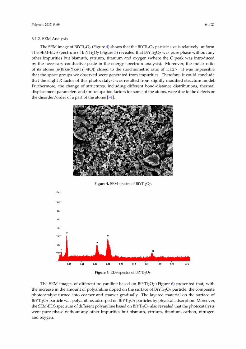
The SEM image of BiYTi2O7 (Figure 4) shows that the BiYTi2O7 particle size is relatively uniform.The SEM-EDS spectrum of BiYTi2O7 (Figure 5) revealed that BiYTi2O7 was pure phase without anyother impurities but bismuth, yttrium, titanium and oxygen (where the C peak was introducedby the necessary conductive paste in the energy spectrum analysis). Moreover, the molar ratioof its atoms (n(Bi):n(Y):n(Ti):n(O)) closed to the stoichiometric ratio of 1:1:2:7. It was impossiblethat the space groups we observed were generated from impurities. Therefore, it could concludethat the slight R factor of this photocatalyst was resulted from slightly modified structure model.Furthermore, the change of structures, including different bond-distance distributions, thermaldisplacement parameters and/or occupation factors for some of the atoms, were due to the defects orthe disorder/order of a part of the atoms [74].
Polymers 2017, 9, 69 6 of 20
3.1.2. SEM Analysis
The SEM image of BiYTi2O7 (Figure 4) shows that the BiYTi2O7 particle size is relatively uniform. The SEM-EDS spectrum of BiYTi2O7 (Figure 5) revealed that BiYTi2O7 was pure phase without any other impurities but bismuth, yttrium, titanium and oxygen (where the C peak was introduced by the necessary conductive paste in the energy spectrum analysis). Moreover, the molar ratio of its atoms (n(Bi):n(Y):n(Ti):n(O)) closed to the stoichiometric ratio of 1:1:2:7. It was impossible that the space groups we observed were generated from impurities. Therefore, it could conclude that the slight R factor of this photocatalyst was resulted from slightly modified structure model. Furthermore, the change of structures, including different bond-distance distributions, thermal displacement parameters and/or occupation factors for some of the atoms, were due to the defects or the disorder/order of a part of the atoms [74].
Figure 4. SEM spectra of BiYTi2O7.
Figure 5. EDS spectra of BiYTi2O7.
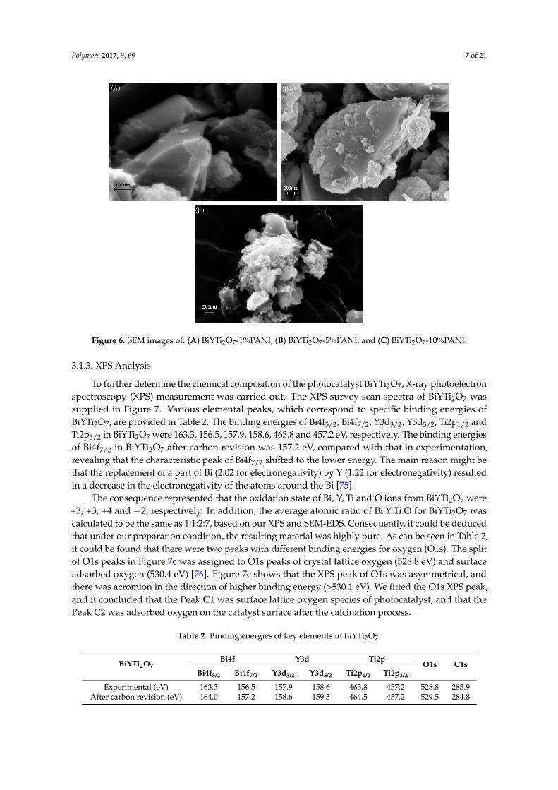
The SEM images of different polyaniline based on BiYTi2O7 (Figure 6) presented that, with the increase in the amount of polyaniline doped on the surface of BiYTi2O7 particle, the composite photocatalyst turned into coarser and coarser gradually. The layered material on the surface of BiYTi2O7 particle was polyaniline, adsorped on BiYTi2O7 particles by physical adsorption. Moreover, the SEM-EDS spectrum of different polyaniline based on BiYTi2O7 also revealed that the photocatalysts were pure phase without any other impurities but bismuth, yttrium, titanium, carbon, nitrogen and oxygen.
Figure 4. SEM spectra of BiYTi2O7.
Polymers 2017, 9, 69 6 of 20
3.1.2. SEM Analysis
The SEM image of BiYTi2O7 (Figure 4) shows that the BiYTi2O7 particle size is relatively uniform. The SEM-EDS spectrum of BiYTi2O7 (Figure 5) revealed that BiYTi2O7 was pure phase without any other impurities but bismuth, yttrium, titanium and oxygen (where the C peak was introduced by the necessary conductive paste in the energy spectrum analysis). Moreover, the molar ratio of its atoms (n(Bi):n(Y):n(Ti):n(O)) closed to the stoichiometric ratio of 1:1:2:7. It was impossible that the space groups we observed were generated from impurities. Therefore, it could conclude that the slight R factor of this photocatalyst was resulted from slightly modified structure model. Furthermore, the change of structures, including different bond-distance distributions, thermal displacement parameters and/or occupation factors for some of the atoms, were due to the defects or the disorder/order of a part of the atoms [74].
Figure 4. SEM spectra of BiYTi2O7.
Figure 5. EDS spectra of BiYTi2O7.
The SEM images of different polyaniline based on BiYTi2O7 (Figure 6) presented that, with the increase in the amount of polyaniline doped on the surface of BiYTi2O7 particle, the composite photocatalyst turned into coarser and coarser gradually. The layered material on the surface of BiYTi2O7 particle was polyaniline, adsorped on BiYTi2O7 particles by physical adsorption. Moreover, the SEM-EDS spectrum of different polyaniline based on BiYTi2O7 also revealed that the photocatalysts were pure phase without any other impurities but bismuth, yttrium, titanium, carbon, nitrogen and oxygen.
Figure 5. EDS spectra of BiYTi2O7.
The SEM images of different polyaniline based on BiYTi2O7 (Figure 6) presented that, withthe increase in the amount of polyaniline doped on the surface of BiYTi2O7 particle, the compositephotocatalyst turned into coarser and coarser gradually. The layered material on the surface ofBiYTi2O7 particle was polyaniline, adsorped on BiYTi2O7 particles by physical adsorption. Moreover,the SEM-EDS spectrum of different polyaniline based on BiYTi2O7 also revealed that the photocatalystswere pure phase without any other impurities but bismuth, yttrium, titanium, carbon, nitrogenand oxygen.
Polymers 2017, 9, 69 7 of 21Polymers 2017, 9, 69 7 of 20
Figure 6. SEM images of: (A) BiYTi2O7-1%PANI; (B) BiYTi2O7-5%PANI; and (C) BiYTi2O7-10%PANI.
3.1.3. XPS Analysis
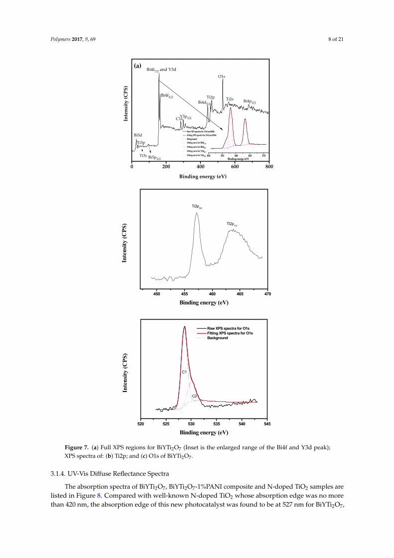
To further determine the chemical composition of the photocatalyst BiYTi2O7, X-ray photoelectron spectroscopy (XPS) measurement was carried out. The XPS survey scan spectra of BiYTi2O7 was supplied in Figure 7. Various elemental peaks, which correspond to specific binding energies of BiYTi2O7, are provided in Table 2. The binding energies of Bi4f5/2, Bi4f7/2, Y3d3/2, Y3d5/2, Ti2p1/2 and Ti2p3/2 in BiYTi2O7 were 163.3, 156.5, 157.9, 158.6, 463.8 and 457.2 eV, respectively. The binding energies of Bi4f7/2 in BiYTi2O7 after carbon revision was 157.2 eV, compared with that in experimentation, revealing that the characteristic peak of Bi4f7/2 shifted to the lower energy. The main reason might be that the replacement of a part of Bi (2.02 for electronegativity) by Y (1.22 for electronegativity) resulted in a decrease in the electronegativity of the atoms around the Bi [75].
The consequence represented that the oxidation state of Bi, Y, Ti and O ions from BiYTi2O7 were +3, +3, +4 and −2, respectively. In addition, the average atomic ratio of Bi:Y:Ti:O for BiYTi2O7 was calculated to be the same as 1:1:2:7, based on our XPS and SEM-EDS. Consequently, it could be deduced that under our preparation condition, the resulting material was highly pure. As can be seen in Table 2, it could be found that there were two peaks with different binding energies for oxygen (O1s). The split of O1s peaks in Figure 7c was assigned to O1s peaks of crystal lattice oxygen (528.8 eV) and surface adsorbed oxygen (530.4 eV) [76]. Figure 7c shows that the XPS peak of O1s was asymmetrical, and there was acromion in the direction of higher binding energy (>530.1 eV). We fitted the O1s XPS peak, and it concluded that the Peak C1 was surface lattice oxygen species of photocatalyst, and that the Peak C2 was adsorbed oxygen on the catalyst surface after the calcination process.
Table 2. Binding energies of key elements in BiYTi2O7.
BiYTi2O7 Bi4f Y3d Ti2p
O1s C1s Bi4f5/2 Bi4f7/2 Y3d3/2 Y3d5/2 Ti2p1/2 Ti2p3/2
Experimental (eV) 163.3 156.5 157.9 158.6 463.8 457.2 528.8 283.9 After carbon revision (eV) 164.0 157.2 158.6 159.3 464.5 457.2 529.5 284.8
Figure 6. SEM images of: (A) BiYTi2O7-1%PANI; (B) BiYTi2O7-5%PANI; and (C) BiYTi2O7-10%PANI.
3.1.3. XPS Analysis
To further determine the chemical composition of the photocatalyst BiYTi2O7, X-ray photoelectronspectroscopy (XPS) measurement was carried out. The XPS survey scan spectra of BiYTi2O7 wassupplied in Figure 7. Various elemental peaks, which correspond to specific binding energies ofBiYTi2O7, are provided in Table 2. The binding energies of Bi4f5/2, Bi4f7/2, Y3d3/2, Y3d5/2, Ti2p1/2 andTi2p3/2 in BiYTi2O7 were 163.3, 156.5, 157.9, 158.6, 463.8 and 457.2 eV, respectively. The binding energiesof Bi4f7/2 in BiYTi2O7 after carbon revision was 157.2 eV, compared with that in experimentation,revealing that the characteristic peak of Bi4f7/2 shifted to the lower energy. The main reason might bethat the replacement of a part of Bi (2.02 for electronegativity) by Y (1.22 for electronegativity) resultedin a decrease in the electronegativity of the atoms around the Bi [75].
The consequence represented that the oxidation state of Bi, Y, Ti and O ions from BiYTi2O7 were+3, +3, +4 and −2, respectively. In addition, the average atomic ratio of Bi:Y:Ti:O for BiYTi2O7 wascalculated to be the same as 1:1:2:7, based on our XPS and SEM-EDS. Consequently, it could be deducedthat under our preparation condition, the resulting material was highly pure. As can be seen in Table 2,it could be found that there were two peaks with different binding energies for oxygen (O1s). The splitof O1s peaks in Figure 7c was assigned to O1s peaks of crystal lattice oxygen (528.8 eV) and surfaceadsorbed oxygen (530.4 eV) [76]. Figure 7c shows that the XPS peak of O1s was asymmetrical, andthere was acromion in the direction of higher binding energy (>530.1 eV). We fitted the O1s XPS peak,and it concluded that the Peak C1 was surface lattice oxygen species of photocatalyst, and that thePeak C2 was adsorbed oxygen on the catalyst surface after the calcination process.
Table 2. Binding energies of key elements in BiYTi2O7.
BiYTi2O7Bi4f Y3d Ti2p
O1s C1sBi4f5/2 Bi4f7/2 Y3d3/2 Y3d5/2 Ti2p1/2 Ti2p3/2
Experimental (eV) 163.3 156.5 157.9 158.6 463.8 457.2 528.8 283.9After carbon revision (eV) 164.0 157.2 158.6 159.3 464.5 457.2 529.5 284.8
Polymers 2017, 9, 69 8 of 21Polymers 2017, 9, 69 8 of 20
0 200 400 600 800
150 155 160 165 170Binding energy (eV)
Raw XPS spectra for Y3d and Bi4f Fitting XPS spectra for Y3d and Bi4f Background Fitting curve for Bi4f7/2
Fitting curve for Bi4f5/2
Fitting curve for Y3d5/2
Fitting curve for Y3d3/2
Inte
nsity
(CPS
)
Bi4p3/2
Bi5p3/2Ti3s
Y3p3/2
Bi4d5/2
Bi5d
Ti3p
Ti2sTi2p
O1s
C1s
Bi4f5/2
Bi4f7/2 and Y3d
Binding energy (eV)
(a)
450 455 460 465 470
Binding energy (eV)
Inte
nsit
y (C
PS)
Ti2p1/2
Ti2p3/2
520 525 530 535 540 545
Binding energy (eV)
Inte
nsit
y (C
PS)
C2
C1
Raw XPS spectra for O1s Fitting XPS spectra for O1s Background
Figure 7. (a) Full XPS regions for BiYTi2O7 (Inset is the enlarged range of the Bi4f and Y3d peak); XPS spectra of: (b) Ti2p; and (c) O1s of BiYTi2O7.
3.1.4. UV-Vis Diffuse Reflectance Spectra
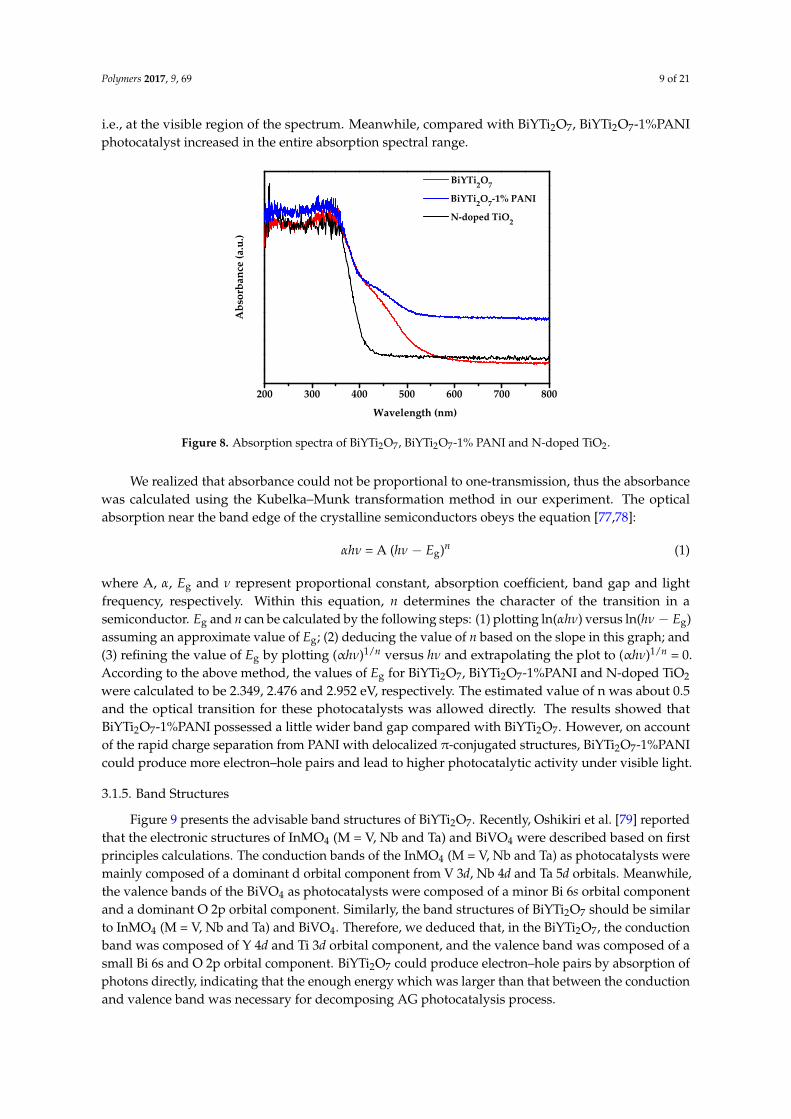
The absorption spectra of BiYTi2O7, BiYTi2O7-1%PANI composite and N-doped TiO2 samples are listed in Figure 8. Compared with well-known N-doped TiO2 whose absorption edge was no more than 420 nm, the absorption edge of this new photocatalyst was found to be at 527 nm for BiYTi2O7,
Figure 7. (a) Full XPS regions for BiYTi2O7 (Inset is the enlarged range of the Bi4f and Y3d peak);XPS spectra of: (b) Ti2p; and (c) O1s of BiYTi2O7.
3.1.4. UV-Vis Diffuse Reflectance Spectra
The absorption spectra of BiYTi2O7, BiYTi2O7-1%PANI composite and N-doped TiO2 samples arelisted in Figure 8. Compared with well-known N-doped TiO2 whose absorption edge was no morethan 420 nm, the absorption edge of this new photocatalyst was found to be at 527 nm for BiYTi2O7,
Polymers 2017, 9, 69 9 of 21
i.e., at the visible region of the spectrum. Meanwhile, compared with BiYTi2O7, BiYTi2O7-1%PANIphotocatalyst increased in the entire absorption spectral range.
Polymers 2017, 9, 69 9 of 20
i.e., at the visible region of the spectrum. Meanwhile, compared with BiYTi2O7, BiYTi2O7-1%PANI photocatalyst increased in the entire absorption spectral range.
200 300 400 500 600 700 800
Abs
orba
nce
(a.u
.)
Wavelength (nm)
BiYTi2O7
BiYTi2O7-1% PANI
N-doped TiO2
Figure 8. Absorption spectra of BiYTi2O7, BiYTi2O7-1% PANI and N-doped TiO2.
We realized that absorbance could not be proportional to one-transmission, thus the absorbance was calculated using the Kubelka–Munk transformation method in our experiment. The optical absorption near the band edge of the crystalline semiconductors obeys the equation [77,78]:
αhν = A (hν − Eg)n (1)
where A, α, Eg and ν represent proportional constant, absorption coefficient, band gap and light frequency, respectively. Within this equation, n determines the character of the transition in a semiconductor. Eg and n can be calculated by the following steps: (1) plotting ln(αhν) versus ln(hν − Eg) assuming an approximate value of Eg; (2) deducing the value of n based on the slope in this graph; and (3) refining the value of Eg by plotting (αhν)1/n versus hν and extrapolating the plot to (αhν)1/n = 0. According to the above method, the values of Eg for BiYTi2O7, BiYTi2O7-1%PANI and N-doped TiO2 were calculated to be 2.349, 2.476 and 2.952 eV, respectively. The estimated value of n was about 0.5 and the optical transition for these photocatalysts was allowed directly. The results showed that BiYTi2O7-1%PANI possessed a little wider band gap compared with BiYTi2O7. However, on account of the rapid charge separation from PANI with delocalized π-conjugated structures, BiYTi2O7-1%PANI could produce more electron–hole pairs and lead to higher photocatalytic activity under visible light.
3.1.5. Band Structures
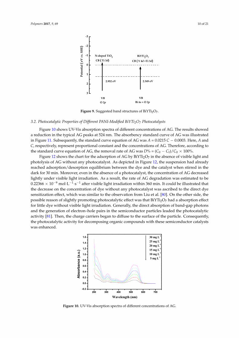
Figure 9 presents the advisable band structures of BiYTi2O7. Recently, Oshikiri et al. [79] reported that the electronic structures of InMO4 (M = V, Nb and Ta) and BiVO4 were described based on first principles calculations. The conduction bands of the InMO4 (M = V, Nb and Ta) as photocatalysts were mainly composed of a dominant d orbital component from V 3d, Nb 4d and Ta 5d orbitals. Meanwhile, the valence bands of the BiVO4 as photocatalysts were composed of a minor Bi 6s orbital component and a dominant O 2p orbital component. Similarly, the band structures of BiYTi2O7 should be similar to InMO4 (M = V, Nb and Ta) and BiVO4. Therefore, we deduced that, in the BiYTi2O7, the conduction band was composed of Y 4d and Ti 3d orbital component, and the valence band was composed of a small Bi 6s and O 2p orbital component. BiYTi2O7 could produce electron–hole pairs by absorption of photons directly, indicating that the enough energy which was larger than that between the conduction and valence band was necessary for decomposing AG photocatalysis process.
Figure 8. Absorption spectra of BiYTi2O7, BiYTi2O7-1% PANI and N-doped TiO2.
We realized that absorbance could not be proportional to one-transmission, thus the absorbancewas calculated using the Kubelka–Munk transformation method in our experiment. The opticalabsorption near the band edge of the crystalline semiconductors obeys the equation [77,78]:
αhν = A (hν − Eg)n (1)
where A, α, Eg and ν represent proportional constant, absorption coefficient, band gap and lightfrequency, respectively. Within this equation, n determines the character of the transition in asemiconductor. Eg and n can be calculated by the following steps: (1) plotting ln(αhν) versus ln(hν − Eg)assuming an approximate value of Eg; (2) deducing the value of n based on the slope in this graph; and(3) refining the value of Eg by plotting (αhν)1/n versus hν and extrapolating the plot to (αhν)1/n = 0.According to the above method, the values of Eg for BiYTi2O7, BiYTi2O7-1%PANI and N-doped TiO2
were calculated to be 2.349, 2.476 and 2.952 eV, respectively. The estimated value of n was about 0.5and the optical transition for these photocatalysts was allowed directly. The results showed thatBiYTi2O7-1%PANI possessed a little wider band gap compared with BiYTi2O7. However, on accountof the rapid charge separation from PANI with delocalized π-conjugated structures, BiYTi2O7-1%PANIcould produce more electron–hole pairs and lead to higher photocatalytic activity under visible light.
3.1.5. Band Structures
Figure 9 presents the advisable band structures of BiYTi2O7. Recently, Oshikiri et al. [79] reportedthat the electronic structures of InMO4 (M = V, Nb and Ta) and BiVO4 were described based on firstprinciples calculations. The conduction bands of the InMO4 (M = V, Nb and Ta) as photocatalysts weremainly composed of a dominant d orbital component from V 3d, Nb 4d and Ta 5d orbitals. Meanwhile,the valence bands of the BiVO4 as photocatalysts were composed of a minor Bi 6s orbital componentand a dominant O 2p orbital component. Similarly, the band structures of BiYTi2O7 should be similarto InMO4 (M = V, Nb and Ta) and BiVO4. Therefore, we deduced that, in the BiYTi2O7, the conductionband was composed of Y 4d and Ti 3d orbital component, and the valence band was composed of asmall Bi 6s and O 2p orbital component. BiYTi2O7 could produce electron–hole pairs by absorption ofphotons directly, indicating that the enough energy which was larger than that between the conductionand valence band was necessary for decomposing AG photocatalysis process.
Polymers 2017, 9, 69 10 of 21
3
2
1
0
-1
-2
-3
CB ( Ti 3d)N-doped TiO2
2.952 eV
O 2p VB
CB ( Y 4d +Ti 3d)
2.349 eV
Bi 6s + O 2p
BiYTi2O7
VB
Pote
ntia
l (eV
vs.
SH
E)
Figure 9. Suggested band structures of BiYTi2O7.Figure 9. Suggested band structures of BiYTi2O7.
3.2. Photocatalytic Properties of Different PANI-Modified BiYTi2O7 Photocatalysts
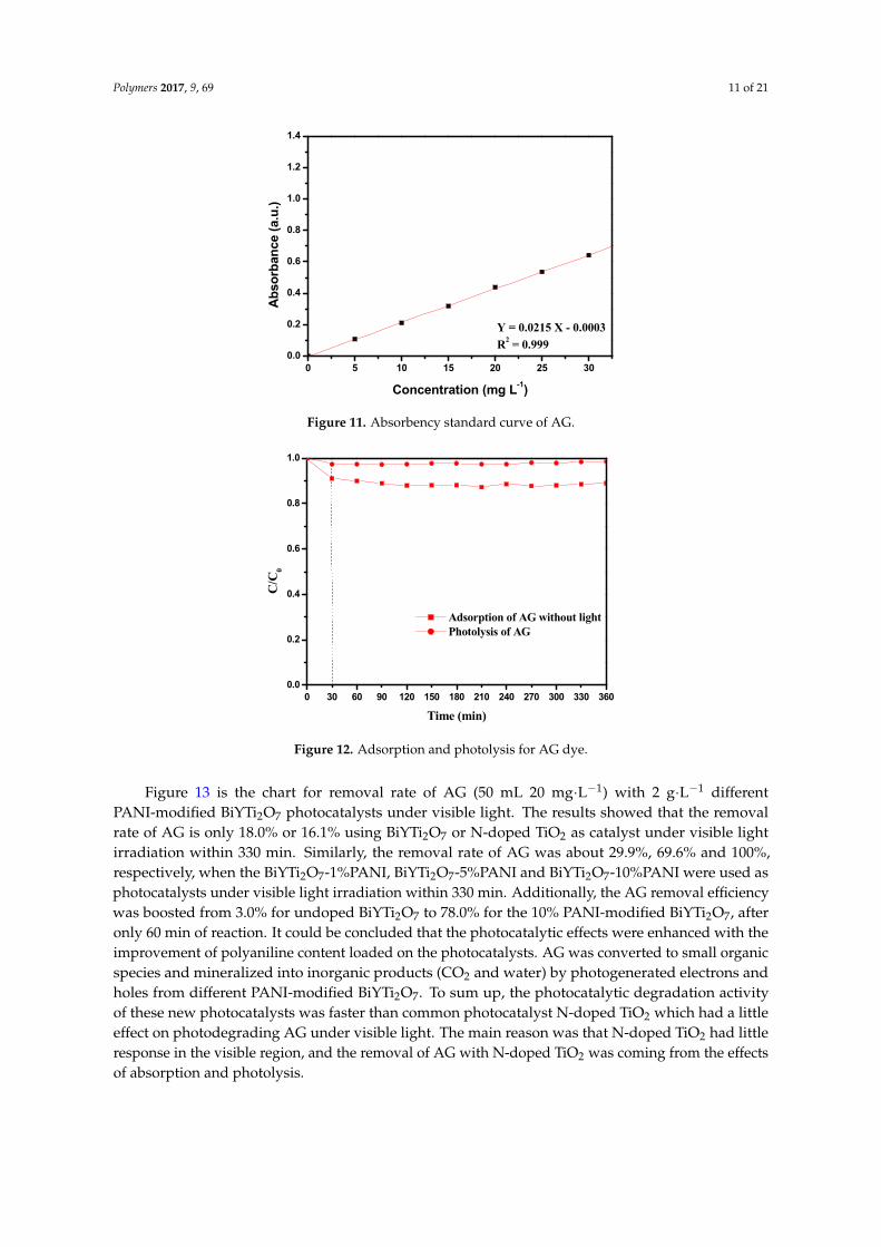
Figure 10 shows UV-Vis absorption spectra of different concentrations of AG. The results showeda reduction in the typical AG peaks at 524 nm. The absorbency standard curve of AG was illustratedin Figure 11. Subsequently, the standard curve equation of AG was A = 0.0215 C − 0.0003. Here, A andC, respectively, represent proportional constant and the concentrations of AG. Therefore, according tothe standard curve equation of AG, the removal rate of AG was D% = (C0 − Ct)/C0 × 100%.
Figure 12 shows the chart for the adsorption of AG by BiYTi2O7 in the absence of visible light andphotolysis of AG without any photocatalyst. As depicted in Figure 12, the suspension had alreadyreached adsorption/desorption equilibrium between the dye and the catalyst when stirred in thedark for 30 min. Moreover, even in the absence of a photocatalyst, the concentration of AG decreasedlightly under visible light irradiation. As a result, the rate of AG degradation was estimated to be0.22366 × 10−9 mol·L−1·s−1 after visible light irradiation within 360 min. It could be illustrated thatthe decrease on the concentration of dye without any photocatalyst was ascribed to the direct dyesensitization effect, which was similar to the observation from Liu et al. [80]. On the other side, thepossible reason of slightly promoting photocatalytic effect was that BiYTi2O7 had a absorption effectfor little dye without visible light irradiation. Generally, the direct absorption of band-gap photonsand the generation of electron–hole pairs in the semiconductor particles leaded the photocatalyticactivity [81]. Then, the charge carriers began to diffuse to the surface of the particle. Consequently,the photocatalytic activity for decomposing organic compounds with these semiconductor catalystswas enhanced.
Polymers 2017, 9, 69 10 of 20
3
2
1
0
-1
-2
-3
CB (Ti 3d)
TiO2
3.2 eV
O 2p
VB
CB (Y 4d +Ti 3d)
2.349 eV
Bi 6s + O 2p
BiYTi2O
7
VB
Po
ten
tial
(eV
vs.
SH
E)
Figure 9. Suggested band structures of BiYTi2O7.
3.2. Photocatalytic Properties of Different PANI-Modified BiYTi2O7 Photocatalysts
Figure 10 shows UV-Vis absorption spectra of different concentrations of AG. The results showed a reduction in the typical AG peaks at 524 nm. The absorbency standard curve of AG was illustrated in Figure 11. Subsequently, the standard curve equation of AG was A = 0.0215 C − 0.0003. Here, A and C, respectively, represent proportional constant and the concentrations of AG. Therefore, according to the standard curve equation of AG, the removal rate of AG was D% = (C0 − Ct)/C0 × 100%.
Figure 12 shows the chart for the adsorption of AG by BiYTi2O7 in the absence of visible light and photolysis of AG without any photocatalyst. As depicted in Figure 12, the suspension had already reached adsorption/desorption equilibrium between the dye and the catalyst when stirred in the dark for 30 min. Moreover, even in the absence of a photocatalyst, the concentration of AG decreased lightly under visible light irradiation. As a result, the rate of AG degradation was estimated to be 0.22366 × 10⁻⁹ mol·L−1·s−1 after visible light irradiation within 360 min. It could be illustrated that the decrease on the concentration of dye without any photocatalyst was ascribed to the direct dye sensitization effect, which was similar to the observation from Liu et al. [80]. On the other side, the possible reason of slightly promoting photocatalytic effect was that BiYTi2O7 had a absorption effect for little dye without visible light irradiation. Generally, the direct absorption of band-gap photons and the generation of electron–hole pairs in the semiconductor particles leaded the photocatalytic activity [81]. Then, the charge carriers began to diffuse to the surface of the particle. Consequently, the photocatalytic activity for decomposing organic compounds with these semiconductor catalysts was enhanced.
200 300 400 500 600 700-0.2
0.0
0.2
0.4
0.6
0.8
1.0
1.2
1.4
1.6 30 mg L-1
25 mg L-1
20 mg L-1
15 mg L-1
10 mg L-1
5 mg L-1
Ab
sorb
ance
(a.
u.)
Wavelength (nm) Figure 10. UV-Vis absorption spectra of different concentrations of AG. Figure 10. UV-Vis absorption spectra of different concentrations of AG.
Polymers 2017, 9, 69 11 of 21Polymers 2017, 9, 69 11 of 20
0 5 10 15 20 25 300.0
0.2
0.4
0.6
0.8
1.0
1.2
1.4
Y = 0.0215 X - 0.0003
R2 = 0.999
Ab
sorb
ance
(a.
u.)
Concentration (mg L-1)
Figure 11. Absorbency standard curve of AG.
0 30 60 90 120 150 180 210 240 270 300 330 3600.0
0.2
0.4
0.6
0.8
1.0
C/C
0
Time (min)
Adsorption of AG without light Photolysis of AG
Figure 12. Adsorption and photolysis for AG dye.
Figure 13 is the chart for removal rate of AG (50 mL 20 mg·L−1) with 2 g·L−1 different PANI-modified BiYTi2O7 photocatalysts under visible light. The results showed that the removal rate of AG is only 18.0% or 16.1% using BiYTi2O7 or N-doped TiO2 as catalyst under visible light irradiation within 330 min. Similarly, the removal rate of AG was about 29.9%, 69.6% and 100%, respectively, when the BiYTi2O7-1%PANI, BiYTi2O7-5%PANI and BiYTi2O7-10%PANI were used as photocatalysts under visible light irradiation within 330 min. Additionally, the AG removal efficiency was boosted from 3.0% for undoped BiYTi2O7 to 78.0% for the 10% PANI-modified BiYTi2O7, after only 60 min of reaction. It could be concluded that the photocatalytic effects were enhanced with the improvement of polyaniline content loaded on the photocatalysts. AG was converted to small organic species and mineralized into inorganic products (CO2 and water) by photogenerated electrons and holes from different PANI-modified BiYTi2O7. To sum up, the photocatalytic degradation activity of these new photocatalysts was faster than common photocatalyst N-doped TiO2 which had a little effect on photodegrading AG under visible light. The main reason was that N-doped TiO2 had little response in the visible region, and the removal of AG with N-doped TiO2 was coming from the effects of absorption and photolysis.
Figure 11. Absorbency standard curve of AG.
Polymers 2017, 9, 69 11 of 20
0 5 10 15 20 25 300.0
0.2
0.4
0.6
0.8
1.0
1.2
1.4
Y = 0.0215 X - 0.0003
R2 = 0.999
Ab
sorb
ance
(a.
u.)
Concentration (mg L-1)
Figure 11. Absorbency standard curve of AG.
0 30 60 90 120 150 180 210 240 270 300 330 3600.0
0.2
0.4
0.6
0.8
1.0
C/C
0
Time (min)
Adsorption of AG without light Photolysis of AG
Figure 12. Adsorption and photolysis for AG dye.
Figure 13 is the chart for removal rate of AG (50 mL 20 mg·L−1) with 2 g·L−1 different PANI-modified BiYTi2O7 photocatalysts under visible light. The results showed that the removal rate of AG is only 18.0% or 16.1% using BiYTi2O7 or N-doped TiO2 as catalyst under visible light irradiation within 330 min. Similarly, the removal rate of AG was about 29.9%, 69.6% and 100%, respectively, when the BiYTi2O7-1%PANI, BiYTi2O7-5%PANI and BiYTi2O7-10%PANI were used as photocatalysts under visible light irradiation within 330 min. Additionally, the AG removal efficiency was boosted from 3.0% for undoped BiYTi2O7 to 78.0% for the 10% PANI-modified BiYTi2O7, after only 60 min of reaction. It could be concluded that the photocatalytic effects were enhanced with the improvement of polyaniline content loaded on the photocatalysts. AG was converted to small organic species and mineralized into inorganic products (CO2 and water) by photogenerated electrons and holes from different PANI-modified BiYTi2O7. To sum up, the photocatalytic degradation activity of these new photocatalysts was faster than common photocatalyst N-doped TiO2 which had a little effect on photodegrading AG under visible light. The main reason was that N-doped TiO2 had little response in the visible region, and the removal of AG with N-doped TiO2 was coming from the effects of absorption and photolysis.
Figure 12. Adsorption and photolysis for AG dye.
Figure 13 is the chart for removal rate of AG (50 mL 20 mg·L−1) with 2 g·L−1 differentPANI-modified BiYTi2O7 photocatalysts under visible light. The results showed that the removalrate of AG is only 18.0% or 16.1% using BiYTi2O7 or N-doped TiO2 as catalyst under visible lightirradiation within 330 min. Similarly, the removal rate of AG was about 29.9%, 69.6% and 100%,respectively, when the BiYTi2O7-1%PANI, BiYTi2O7-5%PANI and BiYTi2O7-10%PANI were used asphotocatalysts under visible light irradiation within 330 min. Additionally, the AG removal efficiencywas boosted from 3.0% for undoped BiYTi2O7 to 78.0% for the 10% PANI-modified BiYTi2O7, afteronly 60 min of reaction. It could be concluded that the photocatalytic effects were enhanced with theimprovement of polyaniline content loaded on the photocatalysts. AG was converted to small organicspecies and mineralized into inorganic products (CO2 and water) by photogenerated electrons andholes from different PANI-modified BiYTi2O7. To sum up, the photocatalytic degradation activityof these new photocatalysts was faster than common photocatalyst N-doped TiO2 which had a littleeffect on photodegrading AG under visible light. The main reason was that N-doped TiO2 had littleresponse in the visible region, and the removal of AG with N-doped TiO2 was coming from the effectsof absorption and photolysis.
Polymers 2017, 9, 69 12 of 21Polymers 2017, 9, 69 12 of 20
-30 0 30 60 90 120 150 180 210 240 270 300 3300.000
0.005
0.010
0.015
0.020
0.025
0.030
0.035
AG
con
cent
ratio
n (m
mol
·L-1)
Time (min)
N-doped TiO2
BiYTi2O7
BiYTi2O7-1% PANI
BiYTi2O7-5% PANI
BiYTi2O7-10% PANI
Figure 13. Photocatalytic degradation of AG under visible light irradiation in the presence of different PANI-modified BiYTi2O7 photocatalysts and N-doped TiO2.
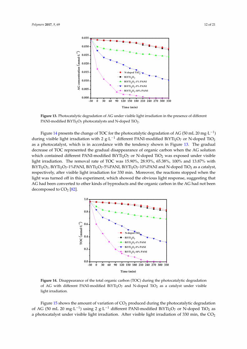
Figure 14 presents the change of TOC for the photocatalytic degradation of AG (50 mL 20 mg·L−1) during visible light irradiation with 2 g·L−1 different PANI-modified BiYTi2O7 or N-doped TiO2 as a photocatalyst, which is in accordance with the tendency shown in Figure 13. The gradual decrease of TOC represented the gradual disappearance of organic carbon when the AG solution which contained different PANI-modified BiYTi2O7 or N-doped TiO2 was exposed under visible light irradiation. The removal rate of TOC was 15.90%, 28.93%, 65.38%, 100% and 13.87% with BiYTi2O7, BiYTi2O7-1%PANI, BiYTi2O7-5%PANI, BiYTi2O7-10%PANI and N-doped TiO2 as a catalyst, respectively, after visible light irradiation for 330 min. Moreover, the reactions stopped when the light was turned off in this experiment, which showed the obvious light response, suggesting that AG had been converted to other kinds of byproducts and the organic carbon in the AG had not been decomposed to CO2 [82].
-30 0 30 60 90 120 150 180 210 240 270 300 3300.0
0.2
0.4
0.6
0.8
1.0
TOC
(m
mol
·L-1)
Time (min)
N-doped TiO2
BiYTi2O7
BiYTi2O7-1% PANI
BiYTi2O7-5% PANI
BiYTi2O7-10% PANI
Figure 14. Disappearance of the total organic carbon (TOC) during the photocatalytic degradation of AG with different PANI-modified BiYTi2O7 and N-doped TiO2 as a catalyst under visible light irradiation.
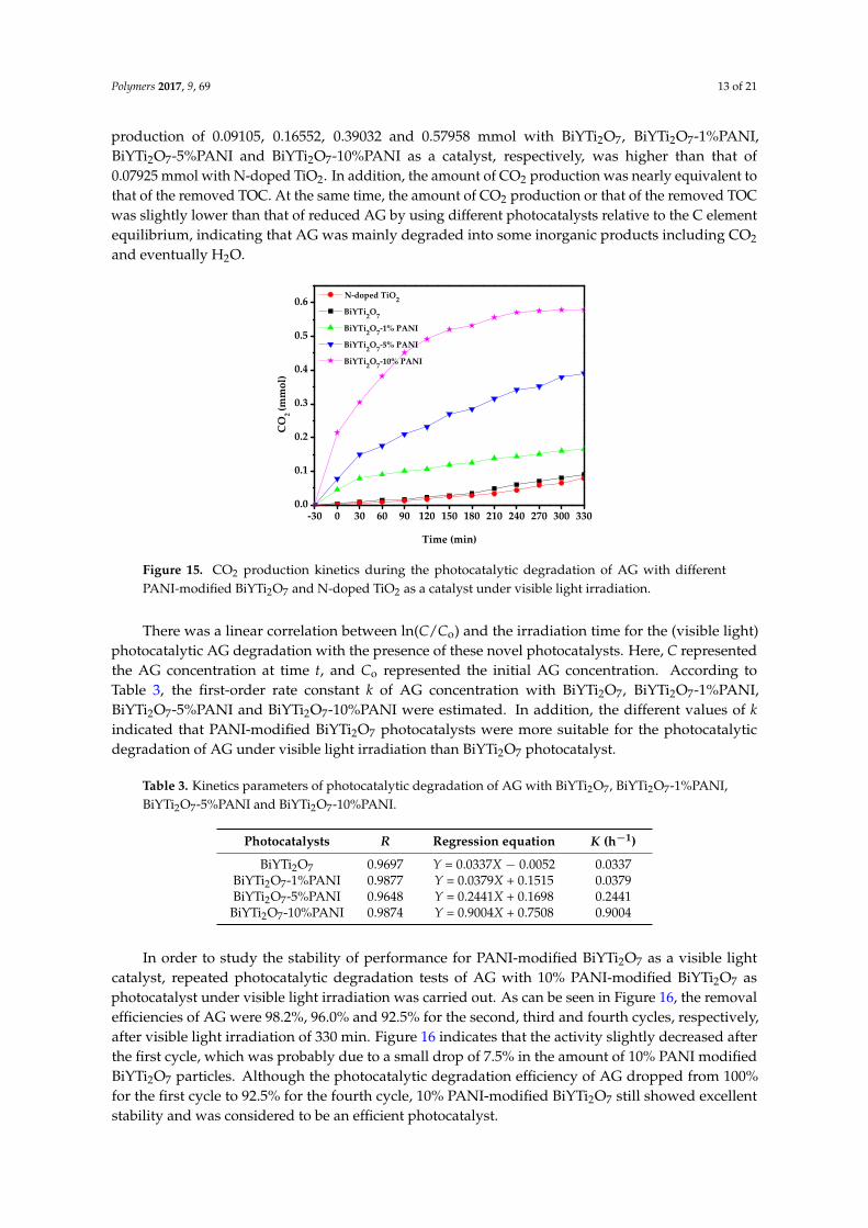
Figure 15 shows the amount of variation of CO2 produced during the photocatalytic degradation of AG (50 mL 20 mg·L−1) using 2 g·L−1 different PANI-modified BiYTi2O7 or N-doped TiO2 as a photocatalyst under visible light irradiation. After visible light irradiation of 330 min, the CO2 production of 0.09105, 0.16552, 0.39032 and 0.57958 mmol with BiYTi2O7, BiYTi2O7-1%PANI,
Figure 13. Photocatalytic degradation of AG under visible light irradiation in the presence of differentPANI-modified BiYTi2O7 photocatalysts and N-doped TiO2.
Figure 14 presents the change of TOC for the photocatalytic degradation of AG (50 mL 20 mg·L−1)during visible light irradiation with 2 g·L−1 different PANI-modified BiYTi2O7 or N-doped TiO2
as a photocatalyst, which is in accordance with the tendency shown in Figure 13. The gradualdecrease of TOC represented the gradual disappearance of organic carbon when the AG solutionwhich contained different PANI-modified BiYTi2O7 or N-doped TiO2 was exposed under visiblelight irradiation. The removal rate of TOC was 15.90%, 28.93%, 65.38%, 100% and 13.87% withBiYTi2O7, BiYTi2O7-1%PANI, BiYTi2O7-5%PANI, BiYTi2O7-10%PANI and N-doped TiO2 as a catalyst,respectively, after visible light irradiation for 330 min. Moreover, the reactions stopped when thelight was turned off in this experiment, which showed the obvious light response, suggesting thatAG had been converted to other kinds of byproducts and the organic carbon in the AG had not beendecomposed to CO2 [82].
Polymers 2017, 9, 69 12 of 20
-30 0 30 60 90 120 150 180 210 240 270 300 3300.000
0.005
0.010
0.015
0.020
0.025
0.030
0.035
AG
con
cent
ratio
n (m
mol
·L-1)
Time (min)
N-doped TiO2
BiYTi2O7
BiYTi2O7-1% PANI
BiYTi2O7-5% PANI
BiYTi2O7-10% PANI
Figure 13. Photocatalytic degradation of AG under visible light irradiation in the presence of different PANI-modified BiYTi2O7 photocatalysts and N-doped TiO2.
Figure 14 presents the change of TOC for the photocatalytic degradation of AG (50 mL 20 mg·L−1) during visible light irradiation with 2 g·L−1 different PANI-modified BiYTi2O7 or N-doped TiO2 as a photocatalyst, which is in accordance with the tendency shown in Figure 13. The gradual decrease of TOC represented the gradual disappearance of organic carbon when the AG solution which contained different PANI-modified BiYTi2O7 or N-doped TiO2 was exposed under visible light irradiation. The removal rate of TOC was 15.90%, 28.93%, 65.38%, 100% and 13.87% with BiYTi2O7, BiYTi2O7-1%PANI, BiYTi2O7-5%PANI, BiYTi2O7-10%PANI and N-doped TiO2 as a catalyst, respectively, after visible light irradiation for 330 min. Moreover, the reactions stopped when the light was turned off in this experiment, which showed the obvious light response, suggesting that AG had been converted to other kinds of byproducts and the organic carbon in the AG had not been decomposed to CO2 [82].
-30 0 30 60 90 120 150 180 210 240 270 300 3300.0
0.2
0.4
0.6
0.8
1.0
TOC
(m
mol
·L-1)
Time (min)
N-doped TiO2
BiYTi2O7
BiYTi2O7-1% PANI
BiYTi2O7-5% PANI
BiYTi2O7-10% PANI
Figure 14. Disappearance of the total organic carbon (TOC) during the photocatalytic degradation of AG with different PANI-modified BiYTi2O7 and N-doped TiO2 as a catalyst under visible light irradiation.
Figure 15 shows the amount of variation of CO2 produced during the photocatalytic degradation of AG (50 mL 20 mg·L−1) using 2 g·L−1 different PANI-modified BiYTi2O7 or N-doped TiO2 as a photocatalyst under visible light irradiation. After visible light irradiation of 330 min, the CO2 production of 0.09105, 0.16552, 0.39032 and 0.57958 mmol with BiYTi2O7, BiYTi2O7-1%PANI,
Figure 14. Disappearance of the total organic carbon (TOC) during the photocatalytic degradationof AG with different PANI-modified BiYTi2O7 and N-doped TiO2 as a catalyst under visiblelight irradiation.
Figure 15 shows the amount of variation of CO2 produced during the photocatalytic degradationof AG (50 mL 20 mg·L−1) using 2 g·L−1 different PANI-modified BiYTi2O7 or N-doped TiO2 asa photocatalyst under visible light irradiation. After visible light irradiation of 330 min, the CO2
Polymers 2017, 9, 69 13 of 21
production of 0.09105, 0.16552, 0.39032 and 0.57958 mmol with BiYTi2O7, BiYTi2O7-1%PANI,BiYTi2O7-5%PANI and BiYTi2O7-10%PANI as a catalyst, respectively, was higher than that of0.07925 mmol with N-doped TiO2. In addition, the amount of CO2 production was nearly equivalent tothat of the removed TOC. At the same time, the amount of CO2 production or that of the removed TOCwas slightly lower than that of reduced AG by using different photocatalysts relative to the C elementequilibrium, indicating that AG was mainly degraded into some inorganic products including CO2
and eventually H2O.
Polymers 2017, 9, 69 13 of 20
BiYTi2O7-5%PANI and BiYTi2O7-10%PANI as a catalyst, respectively, was higher than that of 0.07925 mmol with N-doped TiO2. In addition, the amount of CO2 production was nearly equivalent to that of the removed TOC. At the same time, the amount of CO2 production or that of the removed TOC was slightly lower than that of reduced AG by using different photocatalysts relative to the C element equilibrium, indicating that AG was mainly degraded into some inorganic products including CO2 and eventually H2O.
-30 0 30 60 90 120 150 180 210 240 270 300 3300.0
0.1
0.2
0.3
0.4
0.5
0.6
CO
2 (mm
ol)
Time (min)
N-doped TiO2
BiYTi2O7
BiYTi2O7-1% PANI
BiYTi2O7-5% PANI
BiYTi2O7-10% PANI
Figure 15. CO2 production kinetics during the photocatalytic degradation of AG with different PANI-modified BiYTi2O7 and N-doped TiO2 as a catalyst under visible light irradiation.
There was a linear correlation between ln(C/Co) and the irradiation time for the (visible light) photocatalytic AG degradation with the presence of these novel photocatalysts. Here, C represented the AG concentration at time t, and Co represented the initial AG concentration. According to Table 3, the first-order rate constant k of AG concentration with BiYTi2O7, BiYTi2O7-1%PANI, BiYTi2O7-5%PANI and BiYTi2O7-10%PANI were estimated. In addition, the different values of k indicated that PANI-modified BiYTi2O7 photocatalysts were more suitable for the photocatalytic degradation of AG under visible light irradiation than BiYTi2O7 photocatalyst.
Table 3. Kinetics parameters of photocatalytic degradation of AG with BiYTi2O7, BiYTi2O7-1%PANI, BiYTi2O7-5%PANI and BiYTi2O7-10%PANI.
Photocatalysts R Regression equation K (h−1) BiYTi2O7 0.9697 Y = 0.0337X − 0.0052 0.0337
BiYTi2O7-1%PANI 0.9877 Y = 0.0379X + 0.1515 0.0379 BiYTi2O7-5%PANI 0.9648 Y = 0.2441X + 0.1698 0.2441
BiYTi2O7-10%PANI 0.9874 Y = 0.9004X + 0.7508 0.9004
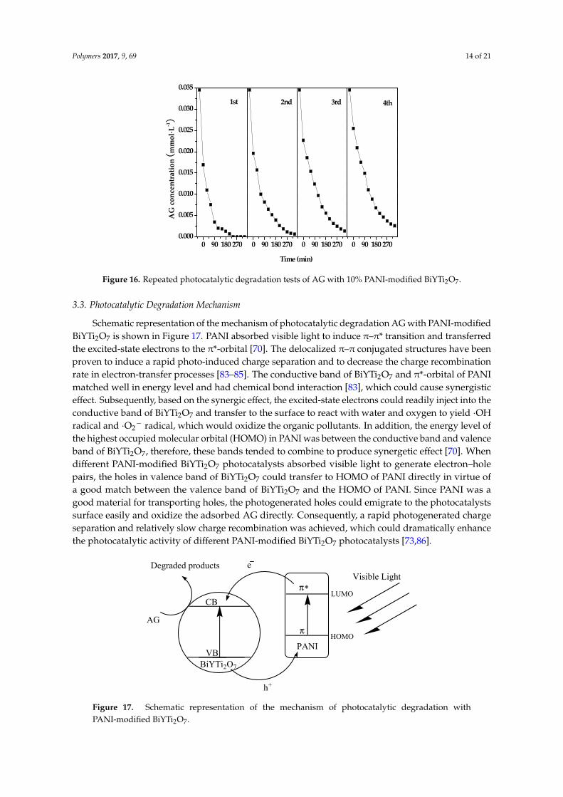
In order to study the stability of performance for PANI-modified BiYTi2O7 as a visible light catalyst, repeated photocatalytic degradation tests of AG with 10% PANI-modified BiYTi2O7 as photocatalyst under visible light irradiation was carried out. As can be seen in Figure 16, the removal efficiencies of AG were 98.2%, 96.0% and 92.5% for the second, third and fourth cycles, respectively, after visible light irradiation of 330 min. Figure 16 indicates that the activity slightly decreased after the first cycle, which was probably due to a small drop of 7.5% in the amount of 10% PANI modified BiYTi2O7 particles. Although the photocatalytic degradation efficiency of AG dropped from 100% for the first cycle to 92.5% for the fourth cycle, 10% PANI-modified BiYTi2O7 still showed excellent stability and was considered to be an efficient photocatalyst.
Figure 15. CO2 production kinetics during the photocatalytic degradation of AG with differentPANI-modified BiYTi2O7 and N-doped TiO2 as a catalyst under visible light irradiation.
There was a linear correlation between ln(C/Co) and the irradiation time for the (visible light)photocatalytic AG degradation with the presence of these novel photocatalysts. Here, C representedthe AG concentration at time t, and Co represented the initial AG concentration. According toTable 3, the first-order rate constant k of AG concentration with BiYTi2O7, BiYTi2O7-1%PANI,BiYTi2O7-5%PANI and BiYTi2O7-10%PANI were estimated. In addition, the different values of kindicated that PANI-modified BiYTi2O7 photocatalysts were more suitable for the photocatalyticdegradation of AG under visible light irradiation than BiYTi2O7 photocatalyst.
Table 3. Kinetics parameters of photocatalytic degradation of AG with BiYTi2O7, BiYTi2O7-1%PANI,BiYTi2O7-5%PANI and BiYTi2O7-10%PANI.
Photocatalysts R Regression equation K (h−1)
BiYTi2O7 0.9697 Y = 0.0337X − 0.0052 0.0337BiYTi2O7-1%PANI 0.9877 Y = 0.0379X + 0.1515 0.0379BiYTi2O7-5%PANI 0.9648 Y = 0.2441X + 0.1698 0.2441
BiYTi2O7-10%PANI 0.9874 Y = 0.9004X + 0.7508 0.9004
In order to study the stability of performance for PANI-modified BiYTi2O7 as a visible lightcatalyst, repeated photocatalytic degradation tests of AG with 10% PANI-modified BiYTi2O7 asphotocatalyst under visible light irradiation was carried out. As can be seen in Figure 16, the removalefficiencies of AG were 98.2%, 96.0% and 92.5% for the second, third and fourth cycles, respectively,after visible light irradiation of 330 min. Figure 16 indicates that the activity slightly decreased afterthe first cycle, which was probably due to a small drop of 7.5% in the amount of 10% PANI modifiedBiYTi2O7 particles. Although the photocatalytic degradation efficiency of AG dropped from 100%for the first cycle to 92.5% for the fourth cycle, 10% PANI-modified BiYTi2O7 still showed excellentstability and was considered to be an efficient photocatalyst.
Polymers 2017, 9, 69 14 of 21Polymers 2017, 9, 69 14 of 20
0 90 180 2700.000
0.005
0.010
0.015
0.020
0.025
0.030
0.035
0 90 180 270 0 90 180 270 0 90 180 270
AG
con
cent
ratio
n (m
mol
·L-1)
Time (min)
1st
2nd
3rd
4th
Figure 16. Repeated photocatalytic degradation tests of AG with 10% PANI-modified BiYTi2O7.
3.3. Photocatalytic Degradation Mechanism
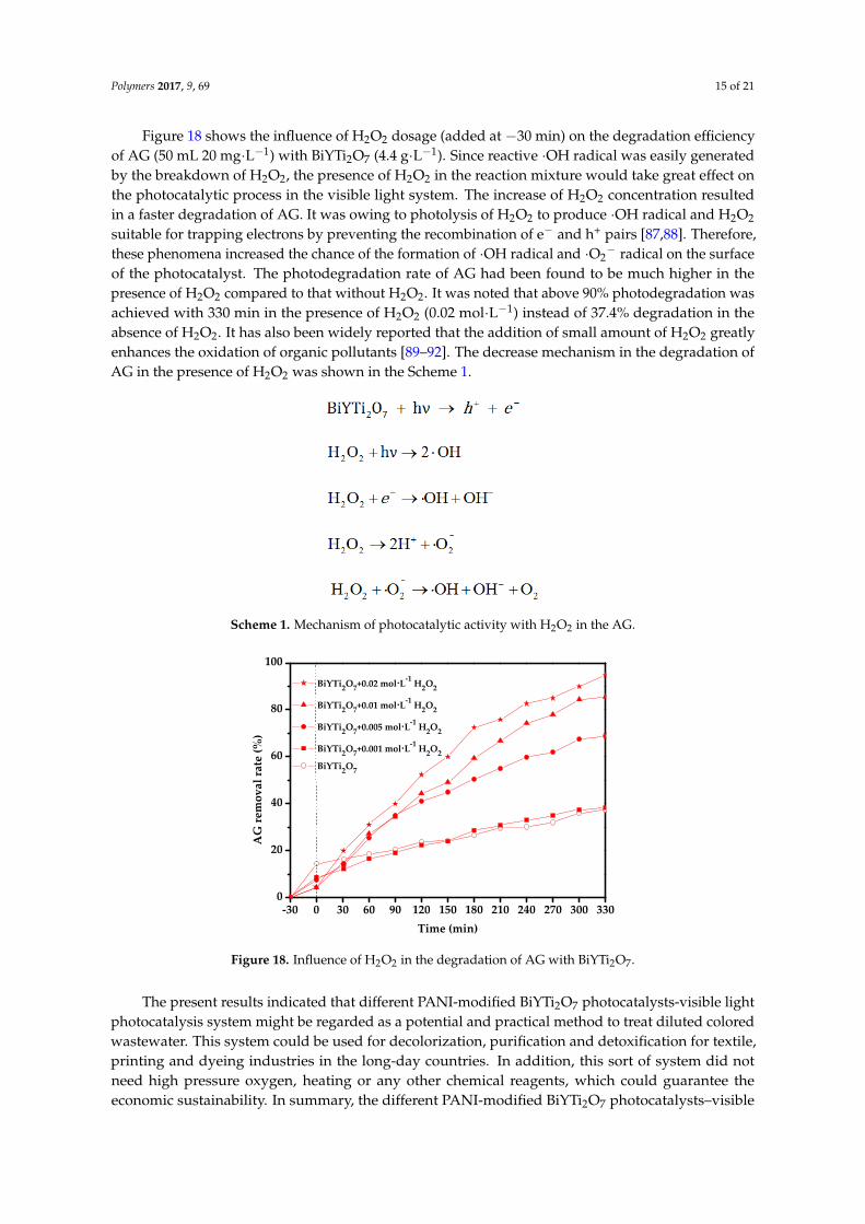
Schematic representation of the mechanism of photocatalytic degradation AG with PANI-modified BiYTi2O7 is shown in Figure 17. PANI absorbed visible light to induce π–π* transition and transferred the excited-state electrons to the π*-orbital [70]. The delocalized π–π conjugated structures have been proven to induce a rapid photo-induced charge separation and to decrease the charge recombination rate in electron-transfer processes [83–85]. The conductive band of BiYTi2O7 and π*-orbital of PANI matched well in energy level and had chemical bond interaction [83], which could cause synergistic effect. Subsequently, based on the synergic effect, the excited-state electrons could readily inject into the conductive band of BiYTi2O7 and transfer to the surface to react with water and oxygen to yield •OH radical and •O2− radical, which would oxidize the organic pollutants. In addition, the energy level of the highest occupied molecular orbital (HOMO) in PANI was between the conductive band and valence band of BiYTi2O7, therefore, these bands tended to combine to produce synergetic effect [70]. When different PANI-modified BiYTi2O7 photocatalysts absorbed visible light to generate electron–hole pairs, the holes in valence band of BiYTi2O7 could transfer to HOMO of PANI directly in virtue of a good match between the valence band of BiYTi2O7 and the HOMO of PANI. Since PANI was a good material for transporting holes, the photogenerated holes could emigrate to the photocatalysts surface easily and oxidize the adsorbed AG directly. Consequently, a rapid photogenerated charge separation and relatively slow charge recombination was achieved, which could dramatically enhance the photocatalytic activity of different PANI-modified BiYTi2O7 photocatalysts [73,86].
PANI
*
e
BiYTi2O7
h+
AG
Degraded products
VB
CB
Visible Light
LUMO
HOMO
π
π
Figure 17. Schematic representation of the mechanism of photocatalytic degradation with PANI-modified BiYTi2O7.
Figure 16. Repeated photocatalytic degradation tests of AG with 10% PANI-modified BiYTi2O7.
3.3. Photocatalytic Degradation Mechanism
Schematic representation of the mechanism of photocatalytic degradation AG with PANI-modifiedBiYTi2O7 is shown in Figure 17. PANI absorbed visible light to induce π–π* transition and transferredthe excited-state electrons to the π*-orbital [70]. The delocalized π–π conjugated structures have beenproven to induce a rapid photo-induced charge separation and to decrease the charge recombinationrate in electron-transfer processes [83–85]. The conductive band of BiYTi2O7 and π*-orbital of PANImatched well in energy level and had chemical bond interaction [83], which could cause synergisticeffect. Subsequently, based on the synergic effect, the excited-state electrons could readily inject into theconductive band of BiYTi2O7 and transfer to the surface to react with water and oxygen to yield ·OHradical and ·O2
− radical, which would oxidize the organic pollutants. In addition, the energy level ofthe highest occupied molecular orbital (HOMO) in PANI was between the conductive band and valenceband of BiYTi2O7, therefore, these bands tended to combine to produce synergetic effect [70]. Whendifferent PANI-modified BiYTi2O7 photocatalysts absorbed visible light to generate electron–holepairs, the holes in valence band of BiYTi2O7 could transfer to HOMO of PANI directly in virtue ofa good match between the valence band of BiYTi2O7 and the HOMO of PANI. Since PANI was agood material for transporting holes, the photogenerated holes could emigrate to the photocatalystssurface easily and oxidize the adsorbed AG directly. Consequently, a rapid photogenerated chargeseparation and relatively slow charge recombination was achieved, which could dramatically enhancethe photocatalytic activity of different PANI-modified BiYTi2O7 photocatalysts [73,86].
Polymers 2017, 9, 69 14 of 20
0 90 180 2700.000
0.005
0.010
0.015
0.020
0.025
0.030
0.035
0 90 180 270 0 90 180 270 0 90 180 270
AG
con
cent
ratio
n (m
mol
·L-1)
Time (min)
1st
2nd
3rd
4th
Figure 16. Repeated photocatalytic degradation tests of AG with 10% PANI-modified BiYTi2O7.
3.3. Photocatalytic Degradation Mechanism
Schematic representation of the mechanism of photocatalytic degradation AG with PANI-modified BiYTi2O7 is shown in Figure 17. PANI absorbed visible light to induce π–π* transition and transferred the excited-state electrons to the π*-orbital [70]. The delocalized π–π conjugated structures have been proven to induce a rapid photo-induced charge separation and to decrease the charge recombination rate in electron-transfer processes [83–85]. The conductive band of BiYTi2O7 and π*-orbital of PANI matched well in energy level and had chemical bond interaction [83], which could cause synergistic effect. Subsequently, based on the synergic effect, the excited-state electrons could readily inject into the conductive band of BiYTi2O7 and transfer to the surface to react with water and oxygen to yield •OH radical and •O2− radical, which would oxidize the organic pollutants. In addition, the energy level of the highest occupied molecular orbital (HOMO) in PANI was between the conductive band and valence band of BiYTi2O7, therefore, these bands tended to combine to produce synergetic effect [70]. When different PANI-modified BiYTi2O7 photocatalysts absorbed visible light to generate electron–hole pairs, the holes in valence band of BiYTi2O7 could transfer to HOMO of PANI directly in virtue of a good match between the valence band of BiYTi2O7 and the HOMO of PANI. Since PANI was a good material for transporting holes, the photogenerated holes could emigrate to the photocatalysts surface easily and oxidize the adsorbed AG directly. Consequently, a rapid photogenerated charge separation and relatively slow charge recombination was achieved, which could dramatically enhance the photocatalytic activity of different PANI-modified BiYTi2O7 photocatalysts [73,86].
PANI
*
e
BiYTi2O7
h+
AG
Degraded products
VB
CB
Visible Light
LUMO
HOMO
π
π
Figure 17. Schematic representation of the mechanism of photocatalytic degradation with PANI-modified BiYTi2O7. Figure 17. Schematic representation of the mechanism of photocatalytic degradation withPANI-modified BiYTi2O7.
Polymers 2017, 9, 69 15 of 21
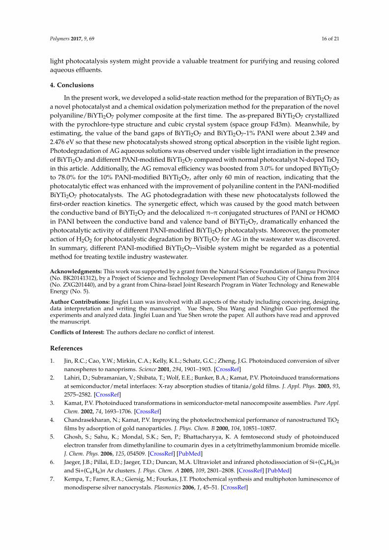
Figure 18 shows the influence of H2O2 dosage (added at −30 min) on the degradation efficiencyof AG (50 mL 20 mg·L−1) with BiYTi2O7 (4.4 g·L−1). Since reactive ·OH radical was easily generatedby the breakdown of H2O2, the presence of H2O2 in the reaction mixture would take great effect onthe photocatalytic process in the visible light system. The increase of H2O2 concentration resultedin a faster degradation of AG. It was owing to photolysis of H2O2 to produce ·OH radical and H2O2
suitable for trapping electrons by preventing the recombination of e− and h+ pairs [87,88]. Therefore,these phenomena increased the chance of the formation of ·OH radical and ·O2
− radical on the surfaceof the photocatalyst. The photodegradation rate of AG had been found to be much higher in thepresence of H2O2 compared to that without H2O2. It was noted that above 90% photodegradation wasachieved with 330 min in the presence of H2O2 (0.02 mol·L−1) instead of 37.4% degradation in theabsence of H2O2. It has also been widely reported that the addition of small amount of H2O2 greatlyenhances the oxidation of organic pollutants [89–92]. The decrease mechanism in the degradation ofAG in the presence of H2O2 was shown in the Scheme 1.
Polymers 2017, 9, 69 15 of 20
Figure 18 shows the influence of H2O2 dosage (added at −30 min) on the degradation efficiency of AG (50 mL 20 mg·L−1) with BiYTi2O7 (4.4 g·L−1). Since reactive •OH radical was easily generated by the breakdown of H2O2, the presence of H2O2 in the reaction mixture would take great effect on the photocatalytic process in the visible light system. The increase of H2O2 concentration resulted in a faster degradation of AG. It was owing to photolysis of H2O2 to produce •OH radical and H2O2 suitable for trapping electrons by preventing the recombination of e− and h+ pairs [87,88]. Therefore, these phenomena increased the chance of the formation of •OH radical and •O2− radical on the surface of the photocatalyst. The photodegradation rate of AG had been found to be much higher in the presence of H2O2 compared to that without H2O2. It was noted that above 90% photodegradation was achieved with 330 min in the presence of H2O2 (0.02 mol·L−1) instead of 37.4% degradation in the absence of H2O2. It has also been widely reported that the addition of small amount of H2O2 greatly enhances the oxidation of organic pollutants [89–92]. The decrease mechanism in the degradation of AG in the presence of H2O2 was shown in the Scheme 1.
Scheme 1. Mechanism of photocatalytic activity with H2O2 in the AG.
-30 0 30 60 90 120 150 180 210 240 270 300 3300
20
40
60
80
100
BiYTi2O7+0.02 mol·L-1 H2O2
BiYTi2O7+0.01 mol·L-1 H2O2
BiYTi2O7+0.005 mol·L-1 H2O2
BiYTi2O7+0.001 mol·L-1 H2O2
BiYTi2O7
AG
rem
oval
rate
(%)
Time (min)
Figure 18. Influence of H2O2 in the degradation of AG with BiYTi2O7.
The present results indicated that different PANI-modified BiYTi2O7 photocatalysts-visible light photocatalysis system might be regarded as a potential and practical method to treat diluted colored wastewater. This system could be used for decolorization, purification and detoxification for textile, printing and dyeing industries in the long-day countries. In addition, this sort of system did not need high pressure oxygen, heating or any other chemical reagents, which could guarantee the
Scheme 1. Mechanism of photocatalytic activity with H2O2 in the AG.
Polymers 2017, 9, 69 15 of 20
Figure 18 shows the influence of H2O2 dosage (added at −30 min) on the degradation efficiency of AG (50 mL 20 mg·L−1) with BiYTi2O7 (4.4 g·L−1). Since reactive •OH radical was easily generated by the breakdown of H2O2, the presence of H2O2 in the reaction mixture would take great effect on the photocatalytic process in the visible light system. The increase of H2O2 concentration resulted in a faster degradation of AG. It was owing to photolysis of H2O2 to produce •OH radical and H2O2 suitable for trapping electrons by preventing the recombination of e− and h+ pairs [87,88]. Therefore, these phenomena increased the chance of the formation of •OH radical and •O2− radical on the surface of the photocatalyst. The photodegradation rate of AG had been found to be much higher in the presence of H2O2 compared to that without H2O2. It was noted that above 90% photodegradation was achieved with 330 min in the presence of H2O2 (0.02 mol·L−1) instead of 37.4% degradation in the absence of H2O2. It has also been widely reported that the addition of small amount of H2O2 greatly enhances the oxidation of organic pollutants [89–92]. The decrease mechanism in the degradation of AG in the presence of H2O2 was shown in the Scheme 1.
Scheme 1. Mechanism of photocatalytic activity with H2O2 in the AG.
-30 0 30 60 90 120 150 180 210 240 270 300 3300
20
40
60
80
100
BiYTi2O7+0.02 mol·L-1 H2O2
BiYTi2O7+0.01 mol·L-1 H2O2
BiYTi2O7+0.005 mol·L-1 H2O2
BiYTi2O7+0.001 mol·L-1 H2O2
BiYTi2O7
AG
rem
oval
rate
(%)
Time (min)
Figure 18. Influence of H2O2 in the degradation of AG with BiYTi2O7.
The present results indicated that different PANI-modified BiYTi2O7 photocatalysts-visible light photocatalysis system might be regarded as a potential and practical method to treat diluted colored wastewater. This system could be used for decolorization, purification and detoxification for textile, printing and dyeing industries in the long-day countries. In addition, this sort of system did not need high pressure oxygen, heating or any other chemical reagents, which could guarantee the
Figure 18. Influence of H2O2 in the degradation of AG with BiYTi2O7.
The present results indicated that different PANI-modified BiYTi2O7 photocatalysts-visible lightphotocatalysis system might be regarded as a potential and practical method to treat diluted coloredwastewater. This system could be used for decolorization, purification and detoxification for textile,printing and dyeing industries in the long-day countries. In addition, this sort of system did notneed high pressure oxygen, heating or any other chemical reagents, which could guarantee theeconomic sustainability. In summary, the different PANI-modified BiYTi2O7 photocatalysts–visible
Polymers 2017, 9, 69 16 of 21
light photocatalysis system might provide a valuable treatment for purifying and reusing coloredaqueous effluents.
4. Conclusions
In the present work, we developed a solid-state reaction method for the preparation of BiYTi2O7 asa novel photocatalyst and a chemical oxidation polymerization method for the preparation of the novelpolyaniline/BiYTi2O7 polymer composite at the first time. The as-prepared BiYTi2O7 crystallizedwith the pyrochlore-type structure and cubic crystal system (space group Fd3m). Meanwhile, byestimating, the value of the band gaps of BiYTi2O7 and BiYTi2O7-1% PANI were about 2.349 and2.476 eV so that these new photocatalysts showed strong optical absorption in the visible light region.Photodegradation of AG aqueous solutions was observed under visible light irradiation in the presenceof BiYTi2O7 and different PANI-modified BiYTi2O7 compared with normal photocatalyst N-doped TiO2
in this article. Additionally, the AG removal efficiency was boosted from 3.0% for undoped BiYTi2O7
to 78.0% for the 10% PANI-modified BiYTi2O7, after only 60 min of reaction, indicating that thephotocatalytic effect was enhanced with the improvement of polyaniline content in the PANI-modifiedBiYTi2O7 photocatalysts. The AG photodegradation with these new photocatalysts followed thefirst-order reaction kinetics. The synergetic effect, which was caused by the good match betweenthe conductive band of BiYTi2O7 and the delocalized π–π conjugated structures of PANI or HOMOin PANI between the conductive band and valence band of BiYTi2O7, dramatically enhanced thephotocatalytic activity of different PANI-modified BiYTi2O7 photocatalysts. Moreover, the promoteraction of H2O2 for photocatalystic degradation by BiYTi2O7 for AG in the wastewater was discovered.In summary, different PANI-modified BiYTi2O7–Visible system might be regarded as a potentialmethod for treating textile industry wastewater.
Acknowledgments: This work was supported by a grant from the Natural Science Foundation of Jiangsu Province(No. BK20141312), by a Project of Science and Technology Development Plan of Suzhou City of China from 2014(No. ZXG201440), and by a grant from China-Israel Joint Research Program in Water Technology and RenewableEnergy (No. 5).
Author Contributions: Jingfei Luan was involved with all aspects of the study including conceiving, designing,data interpretation and writing the manuscript. Yue Shen, Shu Wang and Ningbin Guo performed theexperiments and analyzed data. Jingfei Luan and Yue Shen wrote the paper. All authors have read and approvedthe manuscript.
Conflicts of Interest: The authors declare no conflict of interest.
References
1. Jin, R.C.; Cao, Y.W.; Mirkin, C.A.; Kelly, K.L.; Schatz, G.C.; Zheng, J.G. Photoinduced conversion of silvernanospheres to nanoprisms. Science 2001, 294, 1901–1903. [CrossRef]
2. Lahiri, D.; Subramanian, V.; Shibata, T.; Wolf, E.E.; Bunker, B.A.; Kamat, P.V. Photoinduced transformationsat semiconductor/metal interfaces: X-ray absorption studies of titania/gold films. J. Appl. Phys. 2003, 93,2575–2582. [CrossRef]
3. Kamat, P.V. Photoinduced transformations in semiconductor-metal nanocomposite assemblies. Pure Appl.Chem. 2002, 74, 1693–1706. [CrossRef]
4. Chandrasekharan, N.; Kamat, P.V. Improving the photoelectrochemical performance of nanostructured TiO2
films by adsorption of gold nanoparticles. J. Phys. Chem. B 2000, 104, 10851–10857.5. Ghosh, S.; Sahu, K.; Mondal, S.K.; Sen, P.; Bhattacharyya, K. A femtosecond study of photoinduced
electron transfer from dimethylaniline to coumarin dyes in a cetyltrimethylammonium bromide micelle.J. Chem. Phys. 2006, 125, 054509. [CrossRef] [PubMed]
6. Jaeger, J.B.; Pillai, E.D.; Jaeger, T.D.; Duncan, M.A. Ultraviolet and infrared photodissociation of Si+(C6H6)nand Si+(C6H6)n Ar clusters. J. Phys. Chem. A 2005, 109, 2801–2808. [CrossRef] [PubMed]
7. Kempa, T.; Farrer, R.A.; Giersig, M.; Fourkas, J.T. Photochemical synthesis and multiphoton luminescence ofmonodisperse silver nanocrystals. Plasmonics 2006, 1, 45–51. [CrossRef]
Polymers 2017, 9, 69 17 of 21
8. Bhatkhande, D.S.; Pangarkar, V.G.; Beenackers, A.A.C.M. Photocatalytic degradation for environmentalapplications—A review. J. Chem. Technol. Biotechnol. 2002, 77, 102–116. [CrossRef]
9. Breault, T.M.; Bartlett, B.M. Lowering the band gap of anatase-structured TiO2 by coalloying with Nb andN: Electronic structure and photocatalytic degradation of methylene blue dye. J. Phys. Chem. C 2012, 116,5986–5994. [CrossRef]
10. Kuwahara, Y.; Aoyama, J.; Miyakubo, K.; Eguchi, T.; Kamegawa, T.; Mori, K.; Yamashita, H. TiO2
photocatalyst for degradation of organic compounds in water and air supported on highly hydrophobicFAU zeolite: Structural, sorptive, and photocatalytic studies. J. Catal. 2012, 285, 223–234. [CrossRef]
11. Da Dalt, S.; Alves, A.K.; Bergmann, C.P. Photocatalytic degradation of methyl orange dye in water solutionsin the presence of MWCNT/TiO2 composites. Mater. Res. Bull. 2013, 48, 1845–1850. [CrossRef]
12. Sinha, A.K.; Pradhan, M.; Sarkar, S.; Pal, T. Large-scale solid-state synthesis of Sn-SnO2 nanoparticlesfrom layered SnO by sunlight: A material for dye degradation in water by photocatalytic reaction.Environ. Sci. Technol. 2013, 47, 2339–2345. [CrossRef] [PubMed]
13. Breault, T.M.; Bartlett, B.M. Composition dependence of TiO2:(Nb,N)-x compounds on the rate ofphotocatalytic methylene blue dye degradation. J. Phys. Chem. C 2013, 117, 8611–8618. [CrossRef]
14. Iyyapushpam, S.; Nishanthi, S.T.; Pathinettam Padiyan, D. Photocatalytic degradation of methyl orangeusing alpha-Bi2O3 prepared without surfactant. J. Alloy. Compd. 2013, 563, 104–107. [CrossRef]
15. Jin, S.Q.; Wang, X.; Wang, X.L.; Ju, M.G.; Shen, S.; Liang, W.Z.; Zhao, Y.; Feng, Z.C.; Playford, H.Y.; Walton, R.I.Effect of phase junction structure on the photocatalytic performance in overall water splitting: Ga2O3
photocatalyst as an example. J. Phys. Chem. C 2015, 119, 18221–18228. [CrossRef]16. Srinivasu, K.; Modak, B.; Ghosh, S.K. Porous graphitic carbon nitride: A possible metal-free photocatalyst
for water splitting. J. Phys. Chem. C 2014, 118, 26479–26484. [CrossRef]17. Lee, K.M.; Lai, C.W.; Ngai, K.S.; Juan, J.C. Recent developments of zinc oxide based photocatalyst in water
treatment technology: A review. Water Res. 2016, 88, 428–448. [CrossRef] [PubMed]18. Liyanage, A.D.; Perera, S.D.; Tan, K.; Chabal, Y.; Balkus, K.J. Synthesis, characterization, and photocatalytic
activity of Y-doped CeO2 nanorods. ACS Catal. 2014, 4, 577–584. [CrossRef]19. Yu, X.L.; Shavel, A.; An, X.Q.; Luo, Z.S.; Ibanez, M.; Cabot, A. Cu2ZnSnS4-Pt and Cu2ZnSnS4-Au
heterostructured nanoparticles for photocatalytic water splitting and pollutant degradation. J. Am. Chem. Soc.2014, 136, 9236–9239. [CrossRef] [PubMed]
20. Zhou, X.M.; Xu, Q.L.; Lei, W.Y.; Zhang, T.T.; Qi, X.Y.; Liu, G.; Deng, K.; Yu, J.G. Origin of tunablephotocatalytic selectivity of well-defined alpha-Fe2O3 nanocrystals. Small 2014, 10, 674–679. [CrossRef][PubMed]
21. Wang, L.L.; Wang, J.F.; Zhang, Y.; Ding, Z.T.; Cao, Q.E. Investigation on the determination of proteins byspectrophotometry with azocarmine G. J. Yunnan Univ. Nat. Sci. 2008, 30, 83–86.
22. Chen, Z.G.; Ren, F.L.; Si, S.H.; Liao, X.H.; Ding, W.F.; Liu, J.B. Sensitive determination of DNA based onresonance light scattering enhancement of Azocarmine G and CTAB. J. Cent. South Univ. Technol. 2005, 12,688–692. [CrossRef]
23. Murakami, T.; Mahmut, N.; Hitomi, S.; Ohtsuka, A. Dark and light neurons in the human brain, with specialreference to their reactions to Golgi’s silver nitrate, luxol fast blue MBS and azocarmine G. Arch. Histol. Cytol.1997, 60, 265–274. [CrossRef] [PubMed]
24. Low, G.K.C.; Mcevoy, S.R.; Matthews, R.W. Formation of nitrate and ammonium-ions in titanium-dioxideImediated photocatalytic degradation of organic-compounds containing nitrogen-atoms. Environ. Sci. Technol.1991, 25, 460–467. [CrossRef]
25. Matos, J.; Laine, J.; Herrmann, J.M. Effect of the type of activated carbons on the photocatalytic degradationof aqueous organic pollutants by UV-irradiated titania. J. Catal. 2001, 200, 10–20. [CrossRef]
26. Khodja, A.A.; Lavedrine, B.; Richard, C.; Sehili, T. Photocatalytic degradation of metoxuron in aqueoussuspensions of TiO2 analytical and kinetic studies. Int. J. Photoenergy 2002, 4, 147–151. [CrossRef]
27. Zhao, W.; Ma, W.H.; Chen, C.C.; Zhao, J.C.; Shuai, Z.G. Efficient degradation of toxic organic pollutants withNi2O3/TiO2-xBx under visible irradiation. J. Am. Chem. Soc. 2004, 126, 4782–4783. [CrossRef] [PubMed]
28. Murashkina, A.A.; Murzin, P.D.; Rudakova, A.V.; Ryabchuk, V.K.; Emeline, A.V.; Bahnemann, D.W. Influenceof the dopant concentration on the photocatalytic activity: Al-doped TiO2. J. Phys. Chem. C 2015, 119,24695–24703. [CrossRef]
Polymers 2017, 9, 69 18 of 21
29. Lu, F.; Cai, W.P.; Zhang, Y.G. ZnO Hierarchical micro/nanoarchitectures: Solvothermal synthesis andstructurally enhanced photocatalytic performance. Adv. Funct. Mater. 2008, 18, 1047–1056. [CrossRef]
30. Kitano, M.; Takeuchi, M.; Matsuoka, M.; Thomas, J.M.; Anpo, M. Preparation of visible light-responsiveTiO2 thin film photocatalysts by an RF magnetron sputtering deposition method and their photocatalyticreactivity. Chem. Lett. 2005, 34, 616–617. [CrossRef]
31. Chatterjee, D.; Dasgupta, S. Visible light induced photocatalytic degradation of organic pollutants.J. Photochem. Photobiol. C. 2005, 6, 186–205. [CrossRef]
32. Zhao, J.C.; Chen, C.C.; Ma, W.H. Photocatalytic degradation of organic pollutants under visible lightirradiation. Top. Catal. 2005, 35, 269–278. [CrossRef]
33. Zou, Z.G.; Ye, J.H.; Sayama, K.; Arakawa, H. Direct splitting of water under visible light irradiation with anoxide semiconductor photocatalyst. Nature 2001, 414, 625–627. [CrossRef] [PubMed]
34. Sivalingam, G.; Madras, G. Photocatalytic degradation of poly(bisphenol-A-carbonate) in solution overcombustion-synthesized TiO2: Mechanism and kinetics. Appl. Catal. A. 2004, 269, 81–90. [CrossRef]
35. Maeda, K.; Terashima, H.; Kase, K.; Higashi, M.; Tabata, M.; Domen, K. Surface modification of TaON withmonoclinic ZrO2 to produce a composite photocatalyst with enhanced hydrogen evolution activity undervisible light. Bull. Chem. Soc. Jpn. 2008, 81, 927–937. [CrossRef]
36. Shi, H.X.; Chen, J.Y.; Li, G.Y.; Nie, X.; Zhao, H.J.; Wong, P.K.; An, T.C. Synthesis and characterization ofnovel plasmonic Ag/AgX-CNTs (X = Cl, Br, I) nanocomposite photocatalysts and synergetic degradation oforganic pollutant under visible light. ACS Appl. Mater. Interfaces 2013, 5, 6959–6967. [CrossRef] [PubMed]
37. Ge, L.; Han, C.C.; Liu, J. In situ synthesis and enhanced visible Light photocatalytic activities of novelPANI-g-C3N4 composite photocatalysts. J. Mater. Chem. 2012, 22, 11843–11850. [CrossRef]
38. He, G.H.; Liang, C.J.; Ou, Y.D.; Liu, D.N.; Fang, Y.P.; Xu, Y.H. Preparation of novel Sb2O3/WO3 photocatalystsand their activities under visible light irradiation. Mater. Res. Bull. 2013, 48, 2244–2249. [CrossRef]
39. Wang, J.X.; Ruan, H.; Li, W.J.; Li, D.Z.; Hu, Y.; Chen, J.; Shao, Y.; Zheng, Y. Highly efficient oxidation ofgaseous benzene on novel Ag3VO4/TiO2 nanocomposite photocatalysts under visible and simulated solarlight irradiation. J. Phys. Chem. C 2012, 116, 13935–13943. [CrossRef]
40. Kameyama, T.; Takahashi, T.; Machida, T.; Kamiya, Y.; Yamamoto, T.; Kuwabata, S.; Torimoto, T. Controllingthe electronic energy structure of ZnS-AgInS2 solid solution nanocrystals for photoluminescence andphotocatalytic hydrogen evolution. J. Phys. Chem. C 2015, 119, 24740–24749. [CrossRef]
41. Teng, F.; Liu, Z.L.; Zhang, A.; Li, M. Photocatalytic performances of Ag3PO4 polypods for degradation of dyepollutant under natural indoor weak light irradiation. Environ. Sci. Technol. 2015, 49, 9489–9494. [CrossRef][PubMed]
42. Han, S.C.; Hu, L.F.; Liang, Z.Q.; Wageh, S.; Al-Ghamdi, A.A.; Chen, Y.S.; Fang, X.S. One-step hydrothermalsynthesis of 2D hexagonal nanoplates of alpha-Fe2O3/graphene composites with enhanced photocatalyticactivity. Adv. Funct. Mater. 2014, 24, 5719–5727. [CrossRef]
43. Luan, J.F.; Li, Y.Y. Photocatalytic water splitting for hydrogen production with Gd2MSbO7 (M = Fe, In, Y)photocatalysts under visible light irradiation. Materials 2015, 8, 16–30. [CrossRef]
44. Liu, W.; Ji, M.S.; Chen, S.F. Preparation, characterization and activity evaluation of Ag2Mo4O13 photocatalyst.J. Hazard. Mater. 2011, 186, 2001–2008. [CrossRef] [PubMed]
45. Zhao, J.; Dong, W.W.; Wu, Y.P.; Wang, Y.N.; Wang, C.; Li, D.S.; Zhang, Q.C. Two (3,6)-connectedporous metal-organic frameworks based on linear trinuclear [Co-3(COO)(6)] and paddlewheel dinuclear[Cu-2(COO)(4)] SBUs: Gas adsorption, photocatalytic behaviour, and magnetic properties. J. Mater. Chem. A2015, 3, 6962–6969. [CrossRef]
46. Gao, J.K.; Miao, J.W.; Li, P.Z.; Teng, W.Y.; Yang, L.; Zhao, Y.L.; Liu, B.; Zhang, Q.C. A p-type Ti( IV)-basedmetal-organic framework with visible-light photo-response. Chem. Commun. 2014, 50, 3786–3788. [CrossRef][PubMed]
47. Gao, J.K.; Cao, S.W.; Tay, Q.L.; Liu, Y.; Yu, L.M.; Ye, K.Q.; Mun, P.C.S.; Li, Y.X.; Rakesh, G.; Loo, S.C.J.; et al.Molecule-based water-oxidation catalysts (WOCs): Cluster-size-dependent dye-sensitized polyoxometalatesfor visible-light-driven O2 evolution. Sci. Rep. 2013, 3, 1853. [CrossRef] [PubMed]
48. Luan, J.F.; Ma, K.; Pan, B.C.; Li, Y.M.; Wu, X.S.; Zou, Z.G. Synthesis and catalytic activity of new Gd2BiSbO7
and Gd2YSbO7 nanocatalysts. J. Mol. Catal. A Chem. 2010, 321, 1–9. [CrossRef]49. Luan, J.F.; Ma, K.; Li, Y.M.; Zou, Z.G. Photophysical and photocatalytic properties of novel Y2GaSbO7 and
Y2YbSbO7 photocatalysts under visible light irradiation. J. Mater. Sci. 2011, 46, 813–823. [CrossRef]
Polymers 2017, 9, 69 19 of 21
50. Luan, J.F.; Li, M.; Ma, K.; Li, Y.M.; Zou, Z.G. Photocatalytic activity of novel Y2InSbO7 and Y2GdSbO7
nanocatalysts for degradation of environmental pollutant rhodamine B under visible light irradiation.Chem. Eng. J. 2011, 167, 162–171. [CrossRef]
51. Luan, J.F.; Cai, H.L.; Zheng, S.R.; Hao, X.P.; Luan, G.Y.; Wu, X.S.; Zou, Z.G. Structural and photocatalyticproperties of novel Bi2GaVO7. Mater. Chem. Phys. 2007, 104, 119–124. [CrossRef]
52. Luan, J.F.; Cai, H.L.; Hao, X.P.; Zhang, J.B.; Luan, G.Y.; Wu, X.S.; Zou, Z.G. Structural characterization andphotocatalytic properties of novel Bi2FeVO7. Res. Chem. Intermed. 2007, 33, 487–500. [CrossRef]
53. Barka, N.; Assabbane, A.; Nounah, A.; Ichou, Y.A. Photocatalytic degradation of indigo carmine in aqueoussolution by TiO2-coated non-woven fibres. J. Hazard. Mater. 2008, 152, 1054–1059. [CrossRef] [PubMed]
54. Chen, X.; Mao, S.S. Titanium dioxide nanomaterials: Synthesis, properties, modifications, and applications.Chem. Rev. 2007, 107, 2891–2959. [CrossRef] [PubMed]
55. Cheng, H.; Huang, B.; Dai, Y.; Qin, X.; Zhang, X.; Wang, Z.; Jiang, M. Visible-light photocatalytic activity ofthe metastable Bi20TiO32 synthesized by a high-temperature quenching method. J. Solid State Chem. 2009,182, 2274–2278. [CrossRef]
56. Guillard, C.; Disdier, J.; Monnet, C.; Dussaud, J.; Malato, S.; Blanco, J.; Maldonado, M.I.; Herrmann, J.M. Solarefficiency of a new deposited titania photocatalyst: Chlorophenol, pesticide and dye removal applications.Appl. Catal. B 2003, 46, 319–332. [CrossRef]
57. Dong, F.; Li, Q.Y.; Sun, Y.J.; Ho, W.K. Noble metal-like behavior of plasmonic Bi particles as a cocatalystdeposited on (BiO)2CO3 microspheres for efficient visible light photocatalysis. ACS Catal. 2014, 4, 4341–4350.[CrossRef]
58. Yang, D.R.; Feng, J.; Jiang, L.L.; Wu, X.L.; Sheng, L.Z.; Jiang, Y.T.; Wei, T.; Fan, Z.J. Photocatalystinterface engineering: Spatially confined growth of ZnFe2O4 within graphene networks as excellentvisible-light-driven photocatalysts. Adv. Funct. Mater. 2015, 25, 7080–7087. [CrossRef]
59. Li, G.Y.; Nie, X.; Chen, J.Y.; Jiang, Q.; An, T.C.; Wong, P.K.; Zhang, H.M.; Zhao, H.J.; Yamashita, H. Enhancedvisible-light-driven photocatalytic inactivation of Escherichia coli using g-C3N4/TiO2 hybrid photocatalystsynthesized using a hydrothermal-calcination approach. Water Res. 2015, 86, 17–24. [CrossRef] [PubMed]
60. Zhang, G.; Hu, Z.Y.; Sun, M.; Liu, Y.; Liu, L.M.; Liu, H.J.; Huang, C.P.; Qu, J.H.; Li, J.H. Formation ofBi2WO6 bipyramids with vacancy pairs for enhanced solar-driven photoactivity. Adv. Funct. Mater. 2015, 25,3726–3734. [CrossRef]
61. Li, N.; Li, Y.M.; Li, W.J.; Ji, S.D.; Jin, P. One-step hydrothermal synthesis of TiO2@MoO3 core-shellnanomaterial: Microstructure, growth mechanism, and improved photochromic property. J. Phys. Chem. C2016, 120, 3341–3349. [CrossRef]
62. Gnayem, H.; Sasson, Y. Nanostructured 3D sunflower-like bismuth doped BiOClxBr1−x solid solutions withenhanced visible light photocatalytic activity as a remarkably efficient technology for water Purification.J. Phys. Chem. C 2015, 119, 19201–19209. [CrossRef]
63. Li, H.L.; Yu, K.; Lei, X.; Guo, B.J.; Fu, H.; Zhu, Z.Q. Hydrothermal synthesis of novel MoS2/BiVO4
hetero-nanoflowers with enhanced photocatalytic activity and a mechanism investigation. J. Phys. Chem. C2015, 119, 22681–22689. [CrossRef]
64. Grigioni, I.; Stamplecoskie, K.G.; Selli, E.; Kamat, P.V. Dynamics of photogenerated charge carriers inWO3/BiVO4 heterojunction photoanodes. J.Phys. Chem. C 2015, 119, 20792–20800. [CrossRef]
65. Luan, J.F.; Wang, S.; Ma, K.; Li, Y.M.; Pan, B.C. Structural property and catalytic activity of new In2YbSbO7
and Gd2YbSbO7 nanocatalysts under visible light irradiation. J. Phys. Chem. C 2010, 114, 9398–9407.[CrossRef]
66. El Jaouhari, A.; Laabd, M.; Aouzal, Z.; Bouabdallaoui, M.; Bazzaoui, E.A.; Albourine, A.; Martins, J.I.;Wang, R.; Bazzaoui, M. Effect of electrolytic conditions on PANi electrosynthesis on stainless steel: A newapplication to polycarboxy-benzoic acids removal from industrial effluents. Prog. Org. Coat. 2016, 101,233–239. [CrossRef]
67. Negi, Y.S.; Adhyapak, P.V. Development in polyaniline conducting polymers. J. Macromol. Sci. Polym. Rev.2002, 42, 35–53. [CrossRef]
68. Xie, J.; Zhao, C.E.; Lin, Z.Q.; Gu, P.Y.; Zhang, Q.C. Nanostructured conjugated polymers for energy-relatedapplications beyond solar cells. Chem. Asian J. 2016, 11, 1489–1511. [CrossRef] [PubMed]
Polymers 2017, 9, 69 20 of 21
69. Pandiselvi, K.; Fang, H.F.; Huang, X.B.; Wang, J.Y.; Xu, X.C.; Li, T. Constructing a novel carbonnitride/polyaniline/ZnO ternary heterostructure with enhanced photocatalytic performance using exfoliatedcarbon nitride nanosheets as supports. J. Hazard. Mater. 2016, 314, 67–77. [CrossRef] [PubMed]
70. Shang, M.; Wang, W.Z.; Sun, S.M.; Ren, J.; Zhou, L.; Zhang, L. Efficient visible light-induced photocatalyticdegradation of contaminant by spindle-like PANI/BiVO4. J. Phys. Chem. C 2009, 113, 20228–20233. [CrossRef]
71. Hidalgo, D.; Bocchini, S.; Fontana, M.; Saracco, G.; Hernandez, S. Green and low-cost synthesis of PANI-TiO2
nanocomposite mesoporous films for photoelectrochemical water splitting. RSC Adv. 2015, 5, 49429–49438.[CrossRef]
72. Zou, Z.G.; Ye, J.H.; Arakawa, H. Compositional dependence of crystallization in the glass-ceramics systemBi2O3-In2O3-MnO2-B2O3. J. Mater. Sci. Lett. 2000, 19, 1909–1911. [CrossRef]
73. Zhang, H.; Zong, R.L.; Zhao, J.C.; Zhu, Y.F. Dramatic visible photocatalytic degradation performances due tosynergetic effect of TiO2 with PANI. Environ. Sci. Technol. 2008, 42, 3803–3807. [CrossRef] [PubMed]
74. Chen, L.X.; Rajh, T.; Wang, Z.Y.; Thurnauer, M.C. XAFS studies of surface structures of TiO2 nanoparticlesand photocatalytic reduction of metal ions. J. Phys. Chem. B 1997, 101, 10688–10697. [CrossRef]
75. Chen, W.F.; Koshy, P.; Huang, Y.; Adabifiroozjaei, E.; Yao, Y.; Sorrell, C.C. Effects of precipitation, liquidformation, and intervalence charge transfer on the properties andphotocatalytic performance of cobalt- orvanadium-doped TiO2 thin films. J. Hydrogen Energy 2016, 41, 19025–19056. [CrossRef]
76. Liao, Y.H.B.; Wang, J.X.; Lin, J.S.; Chung, W.H.; Lin, W.Y.; Chen, C.C. Synthesis, photocatalytic activities anddegradation mechanism of Bi2WO6 toward crystal violet dye. Catal. Today 2011, 174, 148–159. [CrossRef]
77. Tauc, J.; Grigorov, R.; Vancu, A. Optical properties and electronic structure of amorphous germanium.Phys. Status Solidi 1966, 15, 627–637. [CrossRef]
78. Butler, M.A. Photoelectrolysis with YFeO3 electrodes. J. Appl. Phys. 1977, 48, 1914–1920. [CrossRef]79. Oshikiri, M.; Boero, M.; Ye, J.H.; Zou, Z.G.; Kido, G. Electronic structures of promising photocatalysts InMO4
(M=V, Nb, Ta) and BiVO4 for water decomposition in the visible wavelength region. J. Chem. Phys. 2002, 117,7313–7318. [CrossRef]
80. Liu, G.M.; Wu, T.X.; Zhao, J.C.; Hidaka, H.; Serpone, N. Photoassisted degradation of dye pollutants. 8.Irreversible degradation of alizarin red under visible light radiation in air-equilibrated aqueous TiO2
dispersions. Environ. Sci. Technol. 1999, 33, 2081–2087. [CrossRef]81. Reddy, V.R.; Hwang, D.W.; Lee, J.S. Effect of Zr substitution for Ti in KLaTiO4 for photocatalytic water
splitting. Catal. Lett. 2003, 90, 39–43. [CrossRef]82. Sun, H.; Qiu, G.H.; Wang, Y.; Feng, X.H.; Yin, H.; Liu, F. Effects of Co and Ni co-doping on the physicochemical
properties of cryptomelane and its enhanced performance on photocatalytic degradation of phenol.Mater. Chem. Phys. 2014, 148, 783–789. [CrossRef]
83. Liu, L.; Ding, L.; Liu, Y.G.; An, W.J.; Lin, S.L.; Liang, Y.H.; Cui, W.Q. A stable Ag3PO4@PANI core@shellhybrid: Enrichment photocatalytic degradation with pi-pi conjugation. Appl. Catal. B 2017, 210, 92–104.[CrossRef]
84. Williams, G.; Seger, B.; Kamat, P.V. TiO2-graphene nanocomposites. UV-assisted photocatalytic reduction ofgraphene oxide. ACS Nano 2008, 2, 1487–1491. [CrossRef] [PubMed]
85. Zhu, S.B.; Xu, T.G.; Fu, H.B.; Zhao, J.C.; Zhu, Y.F. Synergetic effect of Bi2WO6 photocatalyst with C-60 andenhanced photoactivity under visible irradiation. Environ. Sci. Technol. 2007, 41, 6234–6239. [CrossRef][PubMed]
86. Ameen, S.; Akhtar, M.S.; Kim, Y.S.; Yang, O.B.; Shin, H.S. An effective nanocomposite of polyaniline andZnO: Preparation, characterizations, and its photocatalytic activity. Colloid Polym. Sci. 2011, 289, 415–421.[CrossRef]
87. Hou, J.G.; Cao, R.; Jiao, S.Q.; Zhu, H.M.; Kumar, R.V. PANI/Bi12TiO20 complex architectures: Controllablesynthesis and enhanced visible-light photocatalytic activities. Appl. Catal. B 2011, 104, 399–406. [CrossRef]
88. Chen, H.H.; Xiong, X.Q.; Hao, L.L.; Zhang, X.; Xu, Y.M. Improved visible light photocatalytic activity ofWO3 through CuWO4 for phenol degradation. Appl. Surf. Sci. 2016, 389, 491–495. [CrossRef]
89. Neppolian, B.; Kanel, S.R.; Choi, H.C.; Shankar, M.V.; Arabindoo, B.; Murugesan, V. Photocatalyticdegradation of reactive yellow 17 dye in aqueous solution in the presence of TiO2 with cement binder.Int. J. Photoenergy 2003, 5, 45–49. [CrossRef]
90. Muruganandham, M.; Swaminathan, M. Solar photocatalytic degradation of a reactive azo dye inTiO2-suspension. Sol. Energy Mater. Sol. Cells 2004, 81, 439–457. [CrossRef]

Polymers 2017, 9, 69 21 of 21
91. Wang, G.L.; Xu, X.F.; Wu, X.M.; Cao, G.X.; Dong, Y.M.; Li, Z.J. Visible-light-stimulated enzymelike activityof graphene oxide and its application for facile glucose sensing. J. Phys. Chem. C 2014, 118, 28109–28117.[CrossRef]
92. Ng, T.W.; Zhang, L.S.; Liu, J.S.; Huang, G.C.; Wang, W.; Wong, P.K. Visible-light-driven photocatalyticinactivation of escherichia coli by magnetic Fe2O3-AgBr. Water Res. 2016, 90, 111–118. [CrossRef] [PubMed]
© 2017 by the authors; licensee MDPI, Basel, Switzerland. This article is an open accessarticle distributed under the terms and conditions of the Creative Commons Attribution(CC BY) license (http://creativecommons.org/licenses/by/4.0/).


![Microwave assisted synthesis of ZnO nanoparticles in ionic liquid [Bmim]cl and their photocatalytic investigation](https://img.pdfslide.net/doc/110x75/635025ea483af7f78c02067f/microwave-assisted-synthesis-of-zno-nanoparticles-in-ionic-liquid-bmimcl-and-their.jpg)


