Embed Size (px)
Citation preview

User’sManual TDLS8100
Probe TypeTunable Diode Laser Spectrometer
IM 11Y01D02-01EN
IM 11Y01D02-01EN7th Edition
i
IM 11Y01D02-01EN 7th Edition: Dec. 10, 2021-00
u IntroductionThank you for purchasing the TDLSTM8100 Probe Type Tunable Diode Laser Spectrometer.Please read the following respective documents before installing and using the TDLS8100.
The description of the following products are also included in this manual. YH8000 HMI Interface Unit The related documents are as follows.General Specifications GS 11Y01D02-01EN User’s Manual IM 11Y01D02-01EN (this manual)
* the “EN” in the document number is the language code.
An exclusive User’s Manual might be attached to the products whose suffix codes or option codes contain the code “Z” (made to customers’ specifications). Please read it along with this manual.
n Notes on Handling User’s Manuals• Please hand over the user’s manuals to your end users so that they can keep the user’s
manuals on hand for convenient reference.• Please read the information thoroughly before using the product.• The purpose of these user’s manuals is not to warrant that the product is well suited to any
particular purpose but rather to describe the functional details of the product.• No part of the user’s manuals may be transferred or reproduced without prior written
consent from YOKOGAWA.• YOKOGAWA reserves the right to make improvements in the user’s manuals and product at
any time, without notice or obligation.• If you have any questions, or you find mistakes or omissions in the user’s manuals, please
contact our sales representative or your local distributor.
n Drawing ConventionsSome drawings may be partially emphasized, simplified, or omitted, for the convenience of description.Some screen images depicted in the user’s manual may have different display positions or character types (e.g., the upper / lower case). Also note that some of the images contained in this user’s manual display examples.
n Notes on Hardware
l Appearance and AccessoriesCheck the following when you receive the product:
• Appearance• Standard accessories
l ModelandSuffixCodesThe name plate on the product contains the model and suffix codes. Compare them with those in the general specification to make sure the product is the correct one. If you have any questions, contact our sales representative or your local distributor.
Media No. IM 11Y01D02-01EN 7th Edition: Dec. 2021 (YK)All Rights Reserved Copyright © 2019, Yokogawa Electric Corporation
ii
IM 11Y01D02-01EN 7th Edition: Dec. 10, 2021-00
u Safety Precautionsn Safety,Protection,andModificationoftheProduct
• To protect the system controlled by the product and the product itself and ensure safe operation, observe the safety precautions described in this user’s manual. We assume no liability for safety if users fail to observe these instructions when operating the product.
• If TDLS8100 and YH8000 are used in a manner not specified in this user’s manual, the protection provided by these instruments may be impaired.
• If any protection or safety circuit is required for the system controlled by the product or for the product itself, prepare it separately.
• Be sure to use the spare parts approved by Yokogawa Electric Corporation (hereafter simply referred to as YOKOGAWA) when replacing parts or consumables.
• Modification of the product is strictly prohibited.• The following safety symbols are used on the product as well as in this manual.
WARNINGThis symbol indicates that an operator must follow the instructions laid out in this manual in order to avoid the risks, for the human body, of injury, electric shock, or fatalities. The manual describes what special care the operator must take to avoid such risks.
CAUTIONThis symbol indicates that the operator must refer to the instructions in this manual in order to prevent the instrument (hardware) or software from being damaged, or a system failure from occurring.
CAUTIONThis symbol gives information essential for understanding the operations and functions.
NOTEThis symbol indicates information that complements the present topic.
This symbol indicates Protective Ground Terminal.
This symbol indicates Function Ground Terminal. Do not use this terminal as the protective ground terminal.
n Warning and DisclaimerThe product is provided on an “as is” basis. YOKOGAWA shall have neither liability nor responsibility to any person or entity with respect to any direct or indirect loss or damage arising from using the product or any defect of the product that YOKOGAWA cannot predict in advance.
n SafetyPrecautionsforExplosionProtectedTypeInstrumentSpecified types of TDLS8100 and YH8000 are designed to protect against explosion.When these type instruments are used in a hazardous area, please be sure to read Appendix 5.
iii
IM 11Y01D02-01EN 7th Edition: Dec. 10, 2021-00
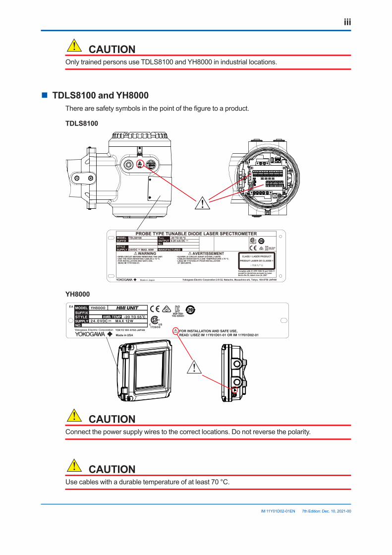
CAUTIONOnly trained persons use TDLS8100 and YH8000 in industrial locations.
n TDLS8100 and YH8000There are safety symbols in the point of the figure to a product.
TDLS8100
YD12
PROBE TYPE TUNABLE DIODE LASER SPECTROMETERMODEL TDLS8100
WARNING AVERTISSEMENT
-20 TO 55 ºC
Complies with 21 CFR 1040.10 and 1040.11except for deviations pursuant to LaserNotice No.50, dated June 24, 2007
4-20 mA DC
24VDC MAX. 60W
TambOUTPUTNo.
MANUFACTUREDSTYLESUPPLY
Yokogawa Electric Corporation 2-9-32, Nakacho, Musashino-shi, Tokyo, 180-8750 JAPAN
SUFFIX
・OPEN CIRCUIT BEFORE REMOVING THE UNIT.・USE THE HEAT-RESISTING CABLES ≥ 70 ºC.・FOR INSTALLATION AND SAFE USE, READ IM 11Y01D02-01.
CLASS 1 LASER PRODUCT
PRODUIT LASER DE CLASSE 1
・OUVRIR LE CIRCUIT AVANT D'ÔTER L'UNITÉ.・CÂBLES RESISTANTS A UNE TEMPÉRATURE ≥ 70 °C. ・LISEZ IM 11Y01D02-01 POUR INSTALLATION ET SÉCURITÉ.
Made in Japan
R-R-YHQ-EEN462
YH8000
abcdegfhija;lsdjfowei
CAUTIONConnect the power supply wires to the correct locations. Do not reverse the polarity.
CAUTIONUse cables with a durable temperature of at least 70 °C.
iv
IM 11Y01D02-01EN 7th Edition: Dec. 10, 2021-00
• Don’t install “general purpose type” instruments in the hazardous area.• The Instrument is packed carefully with shock absorbing materials, nevertheless, the
instrument may be damaged or broken if subjected to strong shock, such as if the instrument is dropped. Handle with care.
• Components that can be damaged by static electricity are used in the TDLS8100 probe type tunable diode laser spectrometer and YH8000 HMI interface unit. Take protective measures against static electricity when performing maintenance and inspection and use conductive packing material for shipping replacement components.
• Do not use an abrasive or organic solvent for cleaning the TDLS8100 probe type tunable diode laser spectrometer and YH8000 HMI interface unit.
• The HART communication may be influenced by strong electromagnetic field. In this case another trial of the HART communication and/or operation with TDLS8100 touch
screen can be carried out.
CAUTIONTDLS8100 and YH80000 are EN61326-1 Class A products, and it is designed for use in the industrial environment. Please use these instruments in the industrial environment only.
WARNINGDepending on the specifications, toxic CO and NH3 gas may be used for the offline calibration of this product. Take special care and ensure correct use when using such gas.
WARNINGSufficiently ventilate the room to ensure the purge gas does not accumulate and there is no shortage of oxygen.
CAUTIONDo not subject the equipment to an impact. It may cause irreparable damage to the laser.
CAUTIONSufficiently understand this user’s manual and carry out the work carefully so as not to make a mistake with a pipe or wire.
v
IM 11Y01D02-01EN 7th Edition: Dec. 10, 2021-00
CAUTIONElectrostaticdischargeThe TDLS8100 and YH8000 contains devices that can be damaged by electrostatic discharge.When servicing this equipment, please observe proper procedures to prevent such damage.Replacement components should be shipped in conductive packaging. Repair work should be done at grounded workstations using grounded soldering irons and wrist straps to avoid electrostatic discharge.
CAUTIONDo not use an abrasive or organic solvent in cleaning the instrument.
CAUTIONPlease turn off the power to the TDLS8100 before remove the analyzer from process flange.
n MaintenancebyqualifiedengineerWork carried out by other than a qualified engineer may cause injury to the worker and/or severe damage to the equipment. Furthermore, if the warnings in this manual are not observed, the worker may be seriously injured and/or the equipment may be severely damaged.Maintenance of the equipment must be performed by a qualified engineer. Qualified engineer refers to the following:
• Engineer who is familiar with how to safely handle process analyzers (or general automation technology) and has read this manual and understood its content.
• Engineer who has received training on how to start and configure equipment and has read this manual and understood its content.
n Replacement of batteryThe battery (CR2050 type) on the CPU board in TDLS8100 cannot be installed on site because it must be mounted at the factory. If it needs replacing, contact a Yokogawa service center.
n TransportationofproductscontaininglithiumbatteriesTDLS8100 contains lithium batteries. Primary lithium batteries are regulated in transportation by the U.S. Department of Transportation, and are also covered by the International Air Transport Association (IATA), the International Civil Aviation Organization (ICAO), and the European Ground Transportation of Dangerous Goods (ARD). It is the responsibility of the shipper to ensure compliance with these or any other local requirements. Please consult the current regulations and requirements regarding the transportation of lithium batteries before shipping.
n Product DisposalThe instrument should be disposed of in accordance with local and national legislation/regulations.
vi
IM 11Y01D02-01EN 7th Edition: Dec. 10, 2021-00
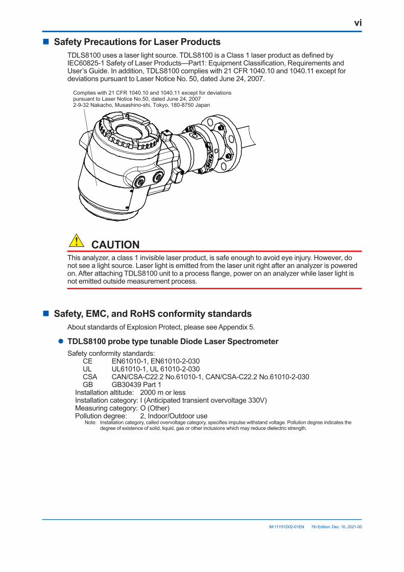
n Safety Precautions for Laser ProductsTDLS8100 uses a laser light source. TDLS8100 is a Class 1 laser product as defined by IEC60825-1 Safety of Laser Products—Part1: Equipment Classification, Requirements and User’s Guide. In addition, TDLS8100 complies with 21 CFR 1040.10 and 1040.11 except for deviations pursuant to Laser Notice No. 50, dated June 24, 2007.
Complies with 21 CFR 1040.10 and 1040.11 except for deviationspursuant to Laser Notice No.50, dated June 24, 20072-9-32 Nakacho, Musashino-shi, Tokyo, 180-8750 Japan
CAUTIONThis analyzer, a class 1 invisible laser product, is safe enough to avoid eye injury. However, do not see a light source. Laser light is emitted from the laser unit right after an analyzer is powered on. After attaching TDLS8100 unit to a process flange, power on an analyzer while laser light is not emitted outside measurement process.
n Safety, EMC, and RoHS conformity standardsAbout standards of Explosion Protect, please see Appendix 5.
l TDLS8100 probe type tunable Diode Laser SpectrometerSafety conformity standards:
CE EN61010-1, EN61010-2-030UL UL61010-1, UL 61010-2-030CSA CAN/CSA-C22.2 No.61010-1, CAN/CSA-C22.2 No.61010-2-030GB GB30439 Part 1
Installation altitude: 2000 m or lessInstallation category: I (Anticipated transient overvoltage 330V)Measuring category: O (Other)Pollution degree: 2, Indoor/Outdoor use
Note: Installation category, called overvoltage category, specifies impulse withstand voltage. Pollution degree indicates the degree of existence of solid, liquid, gas or other inclusions which may reduce dielectric strength.
vii
IM 11Y01D02-01EN 7th Edition: Dec. 10, 2021-00
EMC conformity standards:CE EN55011 Class A Group 1
EN61326-1 Class A Table 2 (For use in industrial location), EN61326-2-3
RCM EN55011 Class A Group 1KC KN11 Class A Group 1, KN61000-6-2 (Korea Electromagnetic Conformity) 한국 전자파적합성 기준
A급 기기 (업무용 방송통신기자재) 이 기기는 업무용(A급) 전자파적합기기로서 판매자 또는 사용자는 이 점을 주의하시기 바라며, 가정외의 지역에서 사용하는 것을 목적으로 합니다.
RoHS conformity standards: EN IEC 63000:2018* *: For only TDLS8100-G1, -G2, -S1
l YH8000 HMI UnitSafety conformity standards:
CE EN61010-1UL UL61010-1CSA CAN/CSA-C22.2 No.61010-1GB GB30439 Part 1
Installation Altitude: 2000 m or lessInstallation category: I (Anticipated transient overvoltage 330 V)Pollution degree: 2, Indoor/Outdoor use
EMC conformity standards:CE EN55011 Class A Group 1 EN61326-1 Class A Table 2 (For use in industrial location)RCM EN55011 Class A Group 1KC KN11 Class A Group 1, KN61000-6-2 (Korea Electromagnetic Conformity) 한국 전자파적합성 기준
A급 기기 (업무용 방송통신기자재) 이 기기는 업무용(A급) 전자파적합기기로서 판매자 또는 사용자는 이 점을 주의하시기 바라며, 가정외의 지역에서 사용하는 것을 목적으로 합니다.
RoHS conformity standards: EN IEC 63000:2018* *: For only YH8000-G1-G2 (manufactured in Japan) and -S2
Cable conditions: • Power cable Use a shielded cable. • Local HMI connection cable Use a separately sold dedicated cable (shield cable). • Ethernet cable Use an STP cable (shielded) of category 5e or higher.
Product conformity assessments of YH8000 for the relevant standards are performed in its own right.
n Unused function on TDLS8100TDLS8100 and TDLS8000 use common software. Although the following function are only for TDLS8000 but not assumed to be available to TDLS8100, the software enables operators to use these functions.
• Non-process Parameter settings (This function is not described in this manual.)• Process gas flow path switch• Automatic offline validation
viii
IM 11Y01D02-01EN 7th Edition: Dec. 10, 2021-00
• Automatic calibration• LU LED (TDLS8100 does not have this function.)
n TerminologyTDLS8100 and TDLS8000 use common software. In this manual, some words relevant to TDLS8100’s operations or alarms are defined according to the user’s manual of TDLS80000.
Word DefinitiononTDLS8100Sensor control unit (SCU) analyzer partLaser unit (LU) analyzer partflow cell calibration cell
n Trademark Notices• TDLS, FieldMate are trademarks of Yokogawa Electric Corporation.• Ethernet is a registered trademark of XEROX Corporation.• Modbus are registered trademarks of Schneider Electric SA.• All other company and product names mentioned in this user’s manual are trademarks or
registered trademarks of their respective companies.• We do not use TM or ® mark to indicate those trademarks or registered trademarks in this
user’s manual.
ix
IM 11Y01D02-01EN 7th Edition: Dec. 10, 2021-00
u CE marking products n AuthorizedRepresentativeinEEA
The Authorized Representative for this product in EEA is Yokogawa Europe B.V. (Euroweg 2, 3825 HD Amersfoort, The Netherlands).
n IdentificationTagThis manual and the identification tag attached on a packing box are essential parts of the product. Keep them together in a safe place for future reference.
n UsersThis product is designed to be used by a person with specialized knowledge.
n HowtodisposethebatteriesThis is an explanation about the new EU Battery Directive. This directive is only valid in the EU.Batteries are included in this product. Batteries incorporated into this product cannot be removed by yourself. Dispose them together with this product.When you dispose this product in the EU, contact your local Yokogawa Europe B.V.office.Do not dispose them as domestic household waste. Battery type: Manganese dioxide lithium battery
Notice:The symbol (see above) means they shall be sorted out and collected as ordained in ANNEX II in DIRECTIVE 2006/66/EC.
n InformationoftheWEEEDirectiveThis product is purposely designed to be used in a large scale fixed installations only and, therefore, is out of scope of the WEEE Directive. The WEEE Directive does not apply. This product should be disposed in accordance with local and national legislation/regulations.The WEEE Directive is only valid in the EU.

Blank Page
Toc-1
IM 11Y01D02-01EN 7th Edition: Dec. 10, 2021-00
TDLS8100Probe TypeTunable Diode Laser Spectrometer
CONTENTS
IM11Y01D02-01EN7thEdition
u Introduction ....................................................................................................iu Safety Precautions .......................................................................................iiu CE marking products .................................................................................ix1. Overview .................................................................................................... 1-1
1.1 Systemconfiguration .......................................................................................1-11.2 NameandFunctionofEachPart ....................................................................1-3
1.2.1 TDLS8100 analyzer part ....................................................................1-31.2.2 TDLS8100 Probe ...............................................................................1-71.2.3 YH8000 HMI Unit ...............................................................................1-7
2. Specifications ........................................................................................... 2-12.1 TDLS8100TunableDiodeLaserSpectrometerSpecifications.................... 2-12.2 Specificationofotherunit ...............................................................................2-6
2.2.1 YH8000 HMI Unit ...............................................................................2-62.2.2 Calibration Cell ...................................................................................2-8
2.3 Model and Codes ..............................................................................................2-82.4 ExternalDimensions ......................................................................................2-10
3. Installation,Wiring,OpticalAxisAdjustment,andPiping ................... 3-13.1 Installation .........................................................................................................3-1
3.1.1 Measurement Point Selection ............................................................3-23.1.2 Constructing Process Flanges ...........................................................3-33.1.3 Probe direction ...................................................................................3-33.1.4 Installation of TDLS8100 to the process flange ................................. 3-43.1.5 Installation of Analyzer part and probe on to the process flange ....... 3-4
3.2 Wiring .................................................................................................................3-83.2.1 Connecting the Power Cable and Grounding ..................................3-123.2.2 Connecting to Temperature and Pressure Transmitters ..................3-133.2.3 Wiring Analog Outputs (AO) ............................................................3-153.2.4 Wiring Digital Outputs ......................................................................3-163.2.5 Wiring Digital Inputs .........................................................................3-173.2.6 Wiring Solenoid Valve Control Outputs ...........................................3-183.2.7 Connecting an Ethernet Cable ........................................................3-193.2.8 Attaching ferrite clamp .....................................................................3-21
3.3 OpticalAxisAdjustment .................................................................................3-21
Toc-2
IM 11Y01D02-01EN 7th Edition: Dec. 10, 2021-00
3.4 Piping ...............................................................................................................3-233.4.1 Purge Gas Piping .....................................................................................3-243.4.2 Optical area Purge of Zone 1/Div. 1/Flameproof “d” ................................3-26
4. YH8000 Installation .................................................................................. 4-14.1 Local HMI Installation .......................................................................................4-24.2 Wiring for Local HMI Installation .....................................................................4-44.3 Remote HMI Installation ...................................................................................4-74.4 Wiring for Remote HMI Installation ...............................................................4-10
5. Startup ....................................................................................................... 5-15.1 ConnectingtheHARTConfigurationTool .....................................................5-1
5.1.1 Installing a DD File .............................................................................5-15.1.2 Connection Procedure .......................................................................5-25.1.3 Basic Menu Configuration..................................................................5-2
5.2 ConnectingtotheYH8000 ...............................................................................5-35.2.1 Initialization and Connection Procedure ............................................ 5-35.2.2 Setting the IP Address........................................................................5-45.2.3 Connecting to the TDLS8100 ............................................................5-75.2.4 Handling Connection Failures .........................................................5-105.2.5 Basic Screen Configuration .............................................................5-10
5.3 Setting Basic Parameters ..............................................................................5-135.3.1 Setting the Date and Time ...............................................................5-145.3.2 Setting the Process Optical Path Length .........................................5-175.3.3 Setting the Process Pressure ..........................................................5-185.3.4 Setting the Process Temperature ....................................................5-185.3.5 Setting the Output Range ................................................................5-195.3.6 Setting Process Alarms ....................................................................5-19
5.4 LoopCheck(Simulationoutput) ...................................................................5-225.4.1 Executing a Loop Check ..................................................................5-225.4.2 Auto Release Function ....................................................................5-23
6. Configuration ............................................................................................ 6-16.1 Process Parameter Settings ............................................................................6-1
6.1.1 Process Optical Path Length .............................................................6-16.1.2 Process Pressure...............................................................................6-16.1.3 Process Temperature .........................................................................6-4
6.2 Unit Settings ......................................................................................................6-56.3 Analog Input Settings .......................................................................................6-56.4 Analog Output Settings ....................................................................................6-5
6.4.1 Normal Range Output ........................................................................6-56.4.2 Output Hold ........................................................................................6-6
6.5 Digital Output Settings .....................................................................................6-86.5.1 DO Contact (DO-1) ............................................................................6-86.5.2 Fault Contact (DO-2) ..........................................................................6-9
Toc-3
IM 11Y01D02-01EN 7th Edition: Dec. 10, 2021-00
6.6 Process Alarm Settings ....................................................................................6-96.7 Digital Input Settings ......................................................................................6-106.8 Valve Stream Settings ....................................................................................6-10
6.8.1 Definitions of Stream Numbers ........................................................6-106.8.2 Valve Usage Setting ......................................................................... 6-116.8.3 Stream Settings ...............................................................................6-126.8.4 Initial Stream (Stream at Startup) ....................................................6-14
6.9 OtherSettings .................................................................................................6-156.9.1 Tag....................................................................................................6-156.9.2 Date and Time ..................................................................................6-156.9.3 User Password Setting ....................................................................6-156.9.4 Display .............................................................................................6-156.9.5 Communication Address Setting .....................................................6-176.9.6 Moving Average Count for Analysis Values .....................................6-176.9.7 Concentration Offset ........................................................................6-176.9.8 Safety Mode .....................................................................................6-18
6.10 InitializingtheSettings(FactoryDefaultSettings)......................................6-196.10.1 Initialization Procedure.....................................................................6-196.10.2 Parameter Initial Value List ..............................................................6-19
7. HART Communication ............................................................................. 7-17.1 Connection ........................................................................................................7-17.2 Menu Tree ..........................................................................................................7-1
7.2.1 DD Menu ............................................................................................7-17.2.2 DTM Menu (FieldMate) ......................................................................7-5
7.3 Write Protection ................................................................................................7-57.3.1 Hardware Write Protection .................................................................7-57.3.2 Software Write Protection ..................................................................7-67.3.3 Device Configuration Locked .............................................................7-8
7.4 AlarmDefinition(Statusgroup) ......................................................................7-87.5 FunctionsSpecifictoHARTCommunication ..............................................7-10
7.5.1 Multidrop Mode ................................................................................7-107.5.2 Squawk ............................................................................................7-107.5.3 Aborting Calibration and Validation ..................................................7-10
8. YH8000 HMI Unit ....................................................................................... 8-18.1 Connection ........................................................................................................8-18.2 Home Screen .....................................................................................................8-1
8.2.1 Home Screen Display Items ..............................................................8-28.2.2 Selecting the Style .............................................................................8-48.2.3 Setting the Meter Range ....................................................................8-48.2.4 Alarm Indicator ...................................................................................8-5
8.3 Trend Screen .....................................................................................................8-78.3.1 Trend Screen Display Items ...............................................................8-7
Toc-4
IM 11Y01D02-01EN 7th Edition: Dec. 10, 2021-00
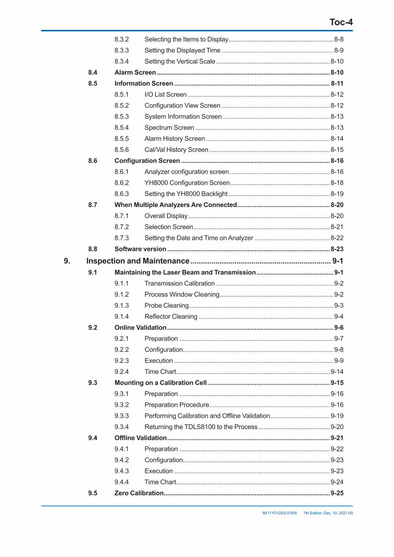
8.3.2 Selecting the Items to Display ............................................................8-88.3.3 Setting the Displayed Time ................................................................8-98.3.4 Setting the Vertical Scale .................................................................8-10
8.4 Alarm Screen ...................................................................................................8-108.5 Information Screen ......................................................................................... 8-11
8.5.1 I/O List Screen .................................................................................8-128.5.2 Configuration View Screen ..............................................................8-128.5.3 System Information Screen .............................................................8-138.5.4 Spectrum Screen .............................................................................8-138.5.5 Alarm History Screen .......................................................................8-148.5.6 Cal/Val History Screen .....................................................................8-15
8.6 ConfigurationScreen .....................................................................................8-168.6.1 Analyzer configuration screen .........................................................8-168.6.2 YH8000 Configuration Screen .........................................................8-188.6.3 Setting the YH8000 Backlight ..........................................................8-19
8.7 WhenMultipleAnalyzersAreConnected .....................................................8-208.7.1 Overall Display .................................................................................8-208.7.2 Selection Screen ..............................................................................8-218.7.3 Setting the Date and Time on Analyzer ...........................................8-22
8.8 Software version .............................................................................................8-23
9. Inspection and Maintenance ................................................................... 9-19.1 MaintainingtheLaserBeamandTransmission ............................................ 9-1
9.1.1 Transmission Calibration ...................................................................9-29.1.2 Process Window Cleaning .................................................................9-29.1.3 Probe Cleaning ..................................................................................9-39.1.4 Reflector Cleaning .............................................................................9-4
9.2 Online Validation ...............................................................................................9-69.2.1 Preparation ........................................................................................9-79.2.2 Configuration ......................................................................................9-89.2.3 Execution ...........................................................................................9-99.2.4 Time Chart........................................................................................9-14
9.3 Mounting on a Calibration Cell ......................................................................9-159.3.1 Preparation ......................................................................................9-169.3.2 Preparation Procedure .....................................................................9-169.3.3 Performing Calibration and Offline Validation ..................................9-199.3.4 Returning the TDLS8100 to the Process .........................................9-20
9.4 OfflineValidation .............................................................................................9-219.4.1 Preparation ......................................................................................9-229.4.2 Configuration ....................................................................................9-239.4.3 Execution .........................................................................................9-239.4.4 Time Chart........................................................................................9-24
9.5 Zero Calibration ...............................................................................................9-25
Toc-5
IM 11Y01D02-01EN 7th Edition: Dec. 10, 2021-00
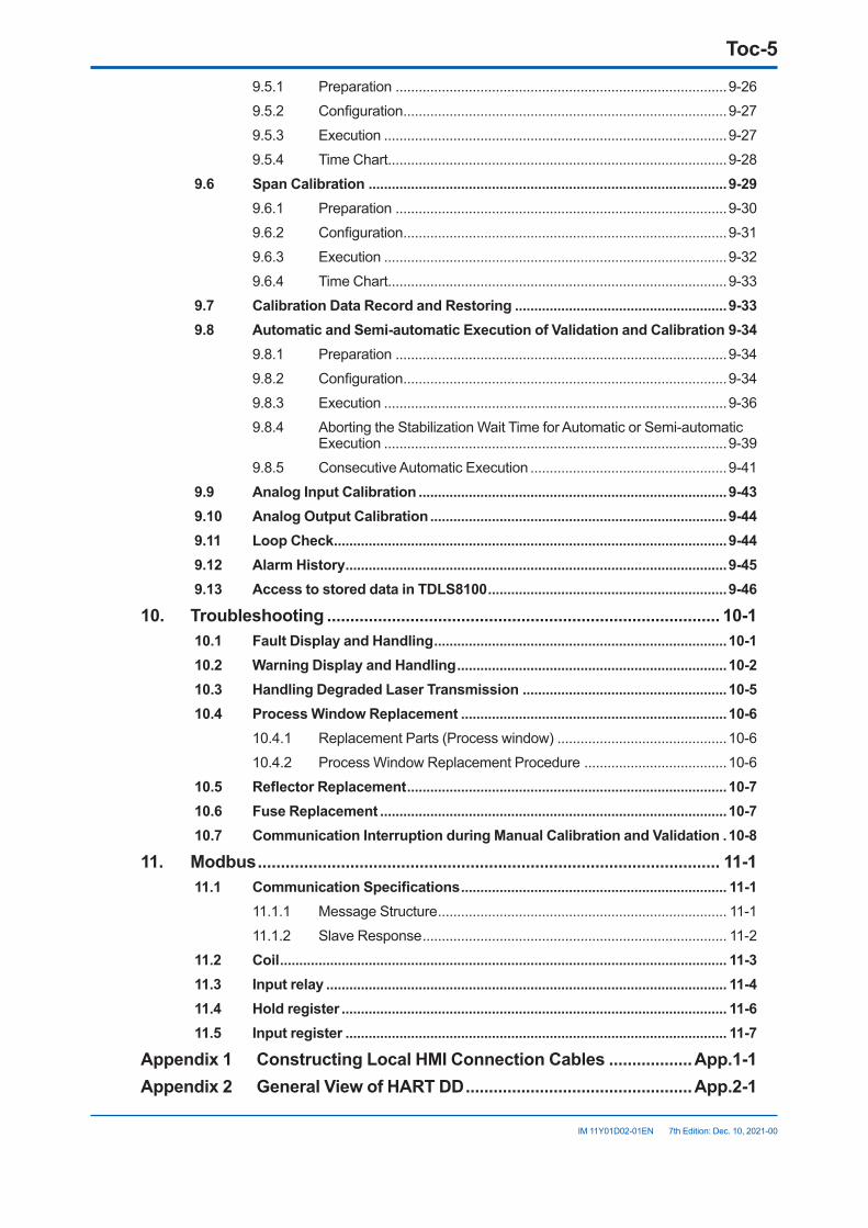
9.5.1 Preparation ......................................................................................9-269.5.2 Configuration ....................................................................................9-279.5.3 Execution .........................................................................................9-279.5.4 Time Chart........................................................................................9-28
9.6 Span Calibration .............................................................................................9-299.6.1 Preparation ......................................................................................9-309.6.2 Configuration ....................................................................................9-319.6.3 Execution .........................................................................................9-329.6.4 Time Chart........................................................................................9-33
9.7 Calibration Data Record and Restoring .......................................................9-339.8 AutomaticandSemi-automaticExecutionofValidationandCalibration 9-34
9.8.1 Preparation ......................................................................................9-349.8.2 Configuration ....................................................................................9-349.8.3 Execution .........................................................................................9-369.8.4 Aborting the Stabilization Wait Time for Automatic or Semi-automatic
Execution .........................................................................................9-399.8.5 Consecutive Automatic Execution ...................................................9-41
9.9 Analog Input Calibration ................................................................................9-439.10 Analog Output Calibration .............................................................................9-449.11 LoopCheck ......................................................................................................9-449.12 Alarm History ...................................................................................................9-459.13 Access to stored data in TDLS8100 ..............................................................9-46
10. Troubleshooting ..................................................................................... 10-110.1 Fault Display and Handling ............................................................................10-110.2 Warning Display and Handling ......................................................................10-210.3 Handling Degraded Laser Transmission .....................................................10-510.4 Process Window Replacement .....................................................................10-6
10.4.1 Replacement Parts (Process window) ............................................10-610.4.2 Process Window Replacement Procedure .....................................10-6
10.5 ReflectorReplacement ...................................................................................10-710.6 Fuse Replacement ..........................................................................................10-710.7 Communication Interruption during Manual Calibration and Validation .10-8
11. Modbus .................................................................................................... 11-111.1 CommunicationSpecifications ..................................................................... 11-1
11.1.1 Message Structure ........................................................................... 11-111.1.2 Slave Response ............................................................................... 11-2
11.2 Coil .................................................................................................................... 11-311.3 Input relay ........................................................................................................ 11-411.4 Hold register .................................................................................................... 11-611.5 Input register ................................................................................................... 11-7
Appendix1 ConstructingLocalHMIConnectionCables ..................App.1-1Appendix2 GeneralViewofHARTDD .................................................App.2-1

Toc-6
IM 11Y01D02-01EN 7th Edition: Dec. 10, 2021-00
Appendix3 YH8000MenuTree .............................................................App.3-1Appendix4 WhatIsanAnalysisPeriod? .............................................App.4-1Appendix5 SafetyInstrumentedSystemInstallation ........................App.5-1Appendix6 ExplosionProtectedTypeInstrument .............................App.6-1Customer Maintenance Parts List ................................... CMPL 11Y01D02-01ENCustomer Maintenance Parts List ................................... CMPL 11Y01D02-21ENCustomer Maintenance Parts List ................................... CMPL 11Y01D02-22ENCustomer Maintenance Parts List ................................... CMPL 11Y01D10-01ENRevision Information ...............................................................................................i
<1. Overview> 1-1
IM 11Y01D02-01EN 7th Edition: Dec. 10, 2021-00
1. OverviewYokogawa’s TDLSTM8100 is a laser gas analyzer that measures the concentration of various gases (O2, CO, CH4, NH3, HCl and many more NIR absorbing gases) in various processes such as petrochemical, power geneartion.Since it can be inserted directly into the duct, the sampling equipment is unnecessary and installation cost and maintenance cost can be reduced. Moreover, it is possible to measure with high accuracy compared to other process analyzers because it is rarely affected by interference of other components in high-speed measurement.
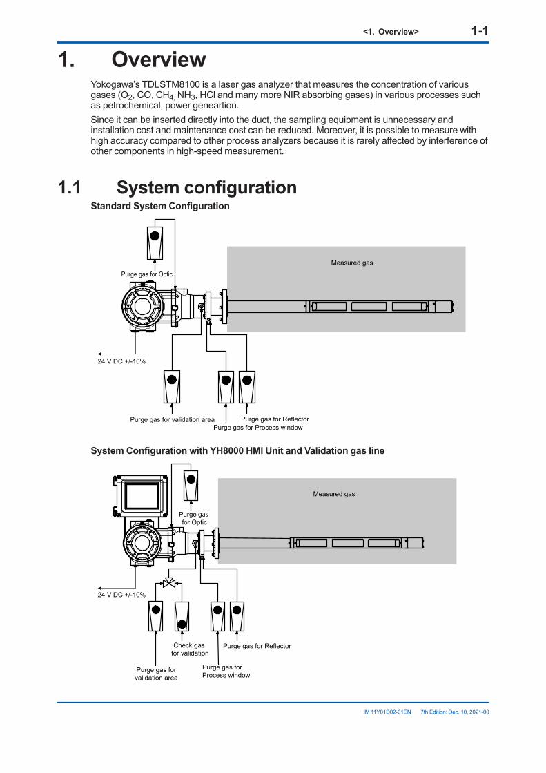
1.1 SystemconfigurationStandardSystemConfiguration
Purge gas for Optic
24 V DC +/-10%
Measured gas
Purge gas for ReflectorPurge gas for validation areaPurge gas for Process window
SystemConfigurationwithYH8000HMIUnitandValidationgasline
24 V DC +/-10%
Purge gas for ReflectorCheck gas for validation
Purge gas forvalidation area
Purge gas forProcess window
Purge gas for Optic
Measured gas
<1. Overview> 1-2
IM 11Y01D02-01EN 7th Edition: Dec. 10, 2021-00
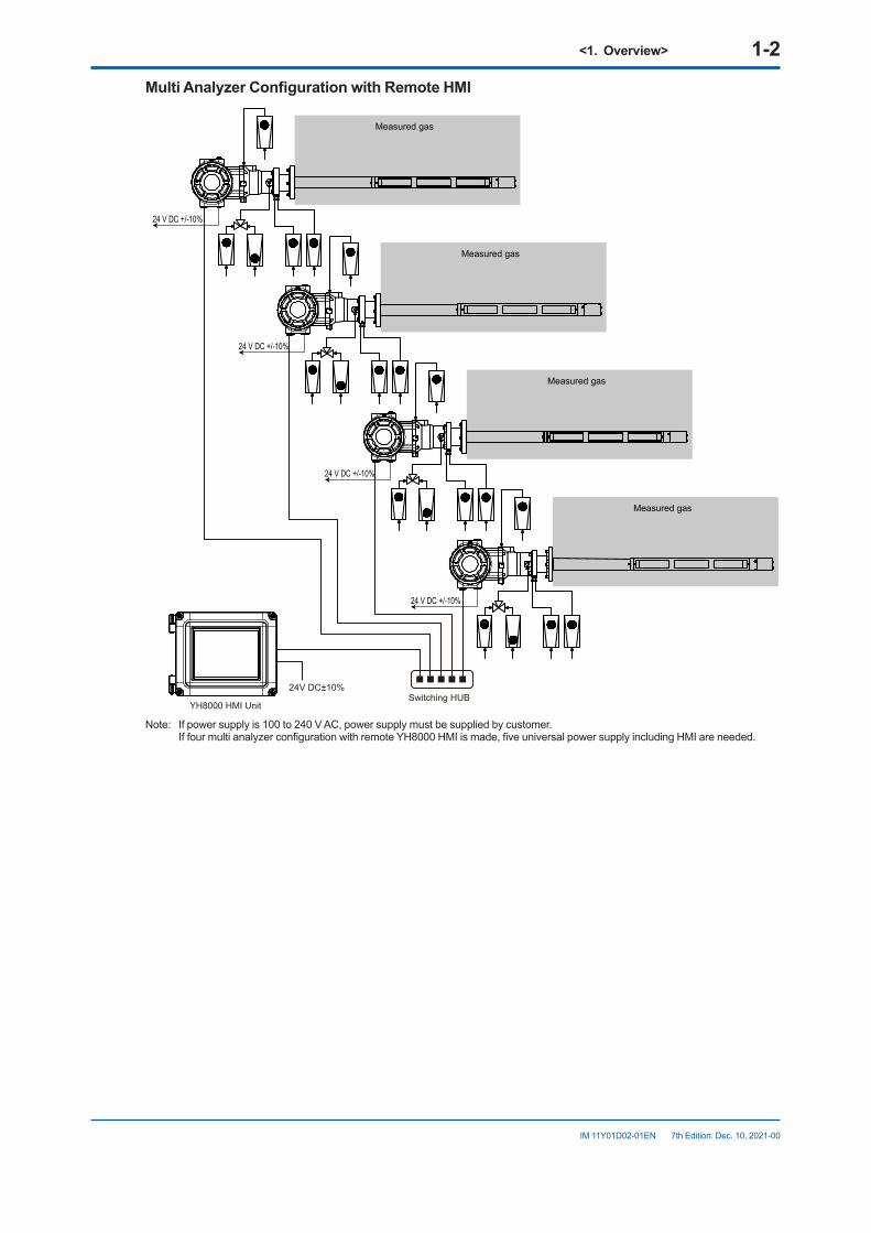
MultiAnalyzerConfigurationwithRemoteHMI
YH8000 HMI UnitSwitching HUB
24V DC±10%
24 V DC +/-10%
Measured gas
24 V DC +/-10%
Measured gas
24 V DC +/-10%
Measured gas
24 V DC +/-10%
Measured gas
Note: If power supply is 100 to 240 V AC, power supply must be supplied by customer. If four multi analyzer configuration with remote YH8000 HMI is made, five universal power supply including HMI are needed.
<1. Overview> 1-3
IM 11Y01D02-01EN 7th Edition: Dec. 10, 2021-00
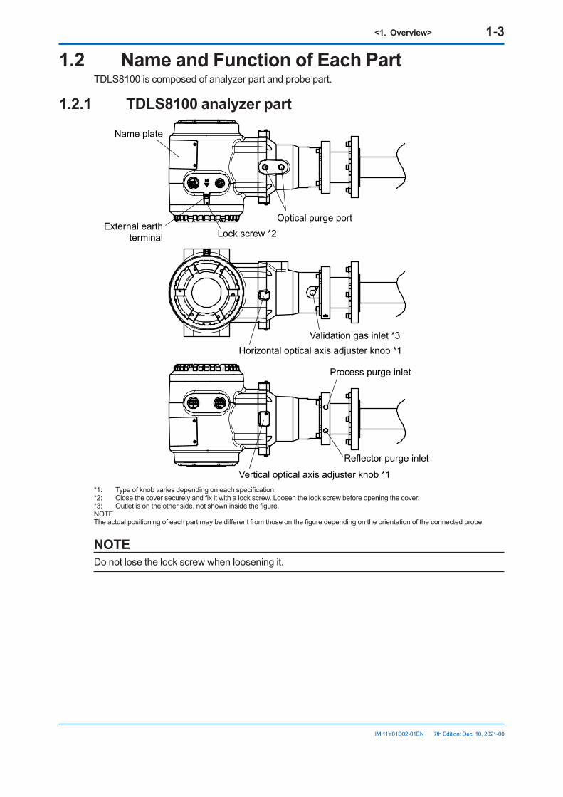
1.2 NameandFunctionofEachPartTDLS8100 is composed of analyzer part and probe part.
1.2.1 TDLS8100analyzerpart
Optical purge portLock screw *2
Name plate
External earth terminal
Validation gas inlet *3Horizontal optical axis adjuster knob *1
Reflector purge inlet
Process purge inlet
Vertical optical axis adjuster knob *1*1: Type of knob varies depending on each specification.*2: Close the cover securely and fix it with a lock screw. Loosen the lock screw before opening the cover.*3: Outlet is on the other side, not shown inside the figure.NOTE The actual positioning of each part may be different from those on the figure depending on the orientation of the connected probe.
NOTEDo not lose the lock screw when loosening it.
<1. Overview> 1-4
IM 11Y01D02-01EN 7th Edition: Dec. 10, 2021-00
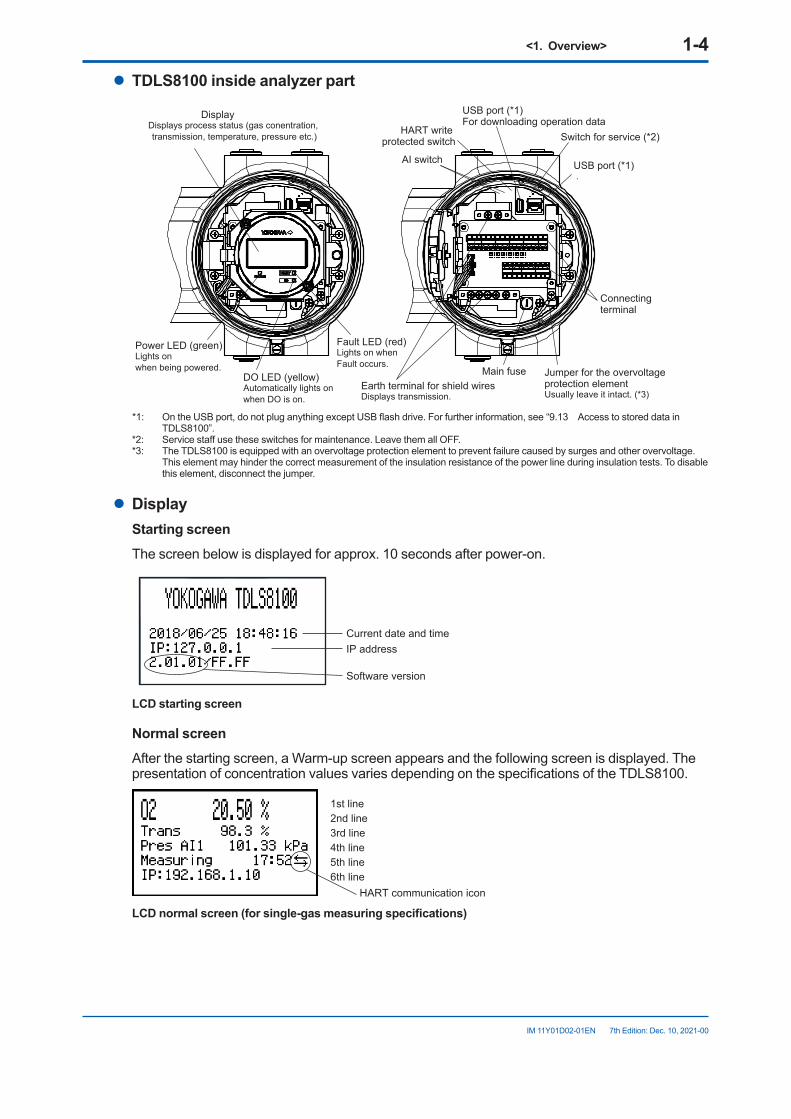
l TDLS8100insideanalyzerpart
Main fuse
Switch for service (*2)
AI switch
DisplayDisplays process status (gas conentration, transmission, temperature, pressure etc.)
USB port (*1)For downloading operation data
USB port (*1) .
Power LED (green)Lights on when being powered.
DO LED (yellow)Automatically lights onwhen DO is on.
Fault LED (red)Lights on whenFault occurs.
Earth terminal for shield wiresDisplays transmission.
HART write protected switch
Connecting terminal
Jumper for the overvoltage protection elementUsually leave it intact. (*3)
*1: On the USB port, do not plug anything except USB flash drive. For further information, see “9.13 Access to stored data in TDLS8100”.
*2: Service staff use these switches for maintenance. Leave them all OFF.*3: The TDLS8100 is equipped with an overvoltage protection element to prevent failure caused by surges and other overvoltage.
This element may hinder the correct measurement of the insulation resistance of the power line during insulation tests. To disable this element, disconnect the jumper.
l DisplayStarting screenThe screen below is displayed for approx. 10 seconds after power-on.
Software version
IP addressCurrent date and time
LCD starting screen
Normal screenAfter the starting screen, a Warm-up screen appears and the following screen is displayed. The presentation of concentration values varies depending on the specifications of the TDLS8100.
1st line2nd line3rd line4th line5th line6th line
HART communication icon
LCDnormalscreen(forsingle-gasmeasuringspecifications)
<1. Overview> 1-5
IM 11Y01D02-01EN 7th Edition: Dec. 10, 2021-00
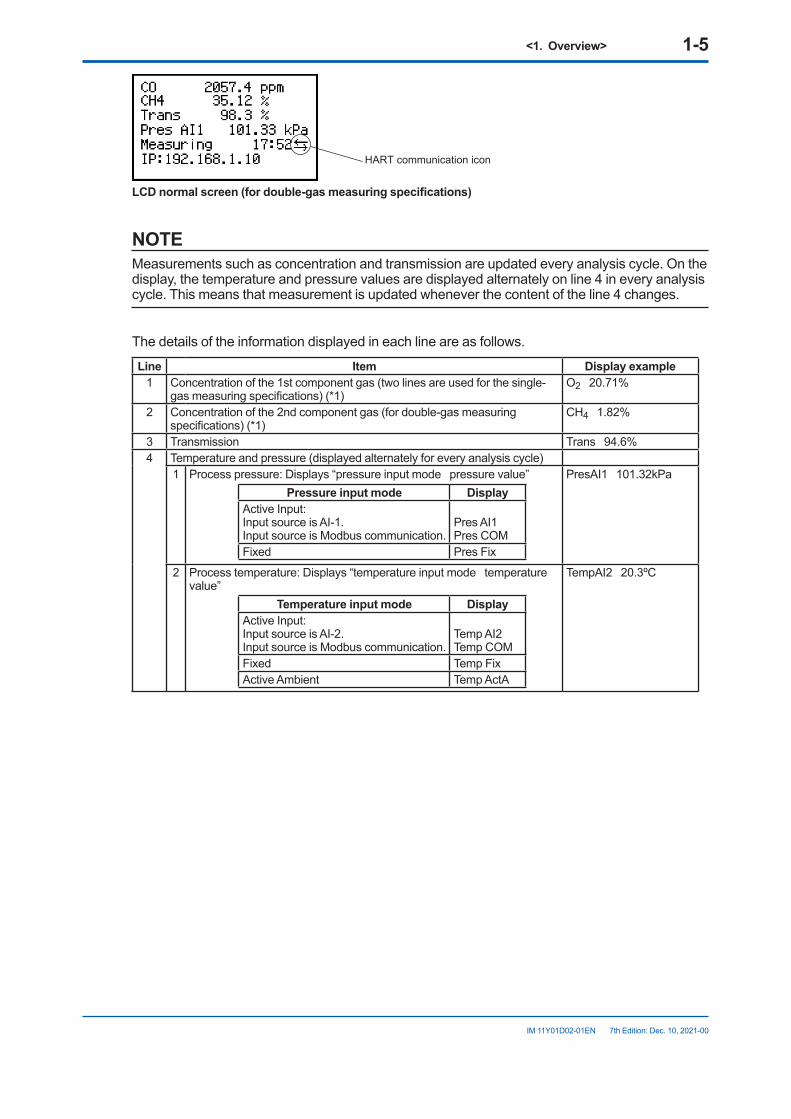
HART communication icon
LCDnormalscreen(fordouble-gasmeasuringspecifications)
NOTEMeasurements such as concentration and transmission are updated every analysis cycle. On the display, the temperature and pressure values are displayed alternately on line 4 in every analysis cycle. This means that measurement is updated whenever the content of the line 4 changes.
The details of the information displayed in each line are as follows.
Line Item Displayexample1 Concentration of the 1st component gas (two lines are used for the single-
gas measuring specifications) (*1)O2 20.71%
2 Concentration of the 2nd component gas (for double-gas measuring specifications) (*1)
CH4 1.82%
3 Transmission Trans 94.6%4 Temperature and pressure (displayed alternately for every analysis cycle)
1 Process pressure: Displays “pressure input mode pressure value”Pressure input mode Display
Active Input:Input source is AI-1.Input source is Modbus communication.
Pres AI1Pres COM
Fixed Pres Fix
PresAI1 101.32kPa
2 Process temperature: Displays “temperature input mode temperature value”
Temperature input mode DisplayActive Input:Input source is AI-2.Input source is Modbus communication.
Temp AI2Temp COM
Fixed Temp FixActive Ambient Temp ActA
TempAI2 20.3ºC
<1. Overview> 1-6
IM 11Y01D02-01EN 7th Edition: Dec. 10, 2021-00
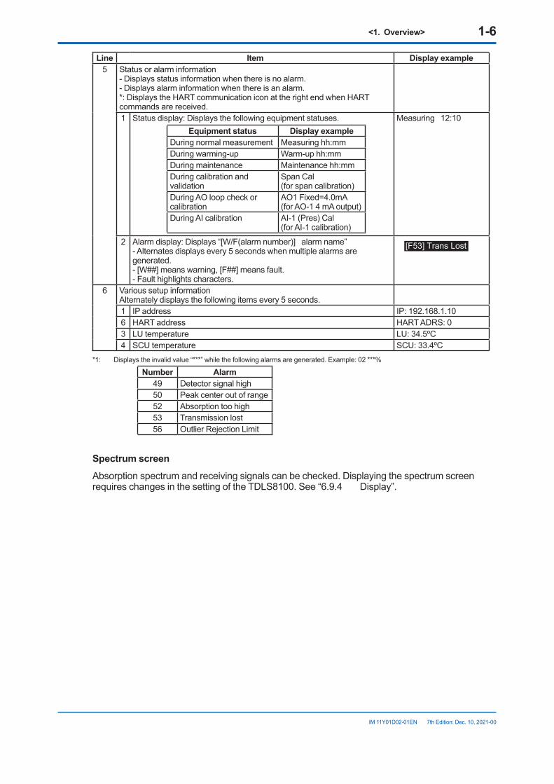
Line Item Displayexample5 Status or alarm information
- Displays status information when there is no alarm.- Displays alarm information when there is an alarm.*: Displays the HART communication icon at the right end when HART commands are received.1 Status display: Displays the following equipment statuses.
Equipment status DisplayexampleDuring normal measurement Measuring hh:mmDuring warming-up Warm-up hh:mmDuring maintenance Maintenance hh:mmDuring calibration and validation
Span Cal(for span calibration)
During AO loop check or calibration
AO1 Fixed=4.0mA(for AO-1 4 mA output)
During AI calibration AI-1 (Pres) Cal(for AI-1 calibration)
Measuring 12:10
2 Alarm display: Displays “[W/F(alarm number)] alarm name”- Alternates displays every 5 seconds when multiple alarms are generated.- [W##] means warning, [F##] means fault.- Fault highlights characters.
[F53] Trans Lost
6 Various setup informationAlternately displays the following items every 5 seconds.1 IP address IP: 192.168.1.106 HART address HART ADRS: 03 LU temperature LU: 34.5ºC4 SCU temperature SCU: 33.4ºC
*1: Displays the invalid value “***” while the following alarms are generated. Example: 02 ***%
Number Alarm49 Detector signal high50 Peak center out of range52 Absorption too high53 Transmission lost56 Outlier Rejection Limit
Spectrum screenAbsorption spectrum and receiving signals can be checked. Displaying the spectrum screen requires changes in the setting of the TDLS8100. See “6.9.4 Display”.
<1. Overview> 1-7
IM 11Y01D02-01EN 7th Edition: Dec. 10, 2021-00
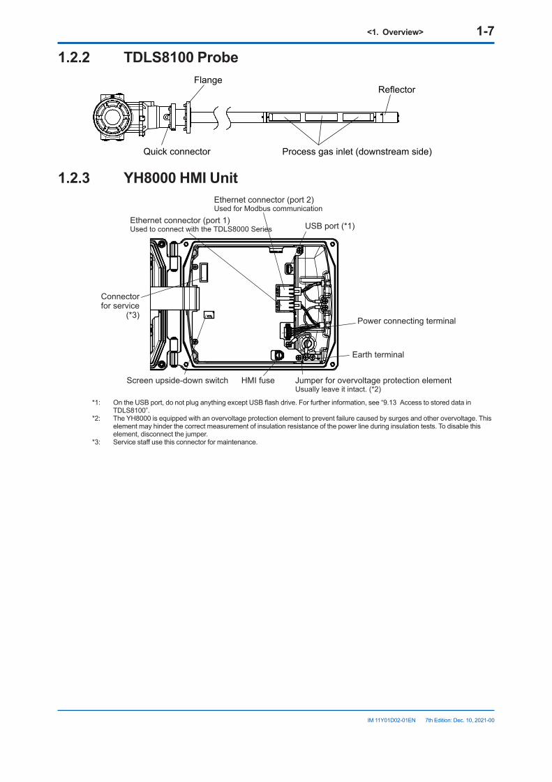
1.2.2 TDLS8100 ProbeFlange
Reflector
Quick connector Process gas inlet (downstream side)
1.2.3 YH8000 HMI Unit
Ethernet connector (port 1)Used to connect with the TDLS8000 Series
Ethernet connector (port 2)Used for Modbus communication
Earth terminal
HMI fuseScreen upside-down switch
Power connecting terminal
USB port (*1)
Jumper for overvoltage protection elementUsually leave it intact. (*2)
Connectorfor service
(*3)
*1: On the USB port, do not plug anything except USB flash drive. For further information, see “9.13 Access to stored data in TDLS8100”.
*2: The YH8000 is equipped with an overvoltage protection element to prevent failure caused by surges and other overvoltage. This element may hinder the correct measurement of insulation resistance of the power line during insulation tests. To disable this element, disconnect the jumper.
*3: Service staff use this connector for maintenance.

Blank Page
<2.Specifications> 2-1
IM 11Y01D02-01EN 7th Edition: Dec. 10, 2021-00
2. Specifications2.1 TDLS8100 Tunable Diode Laser
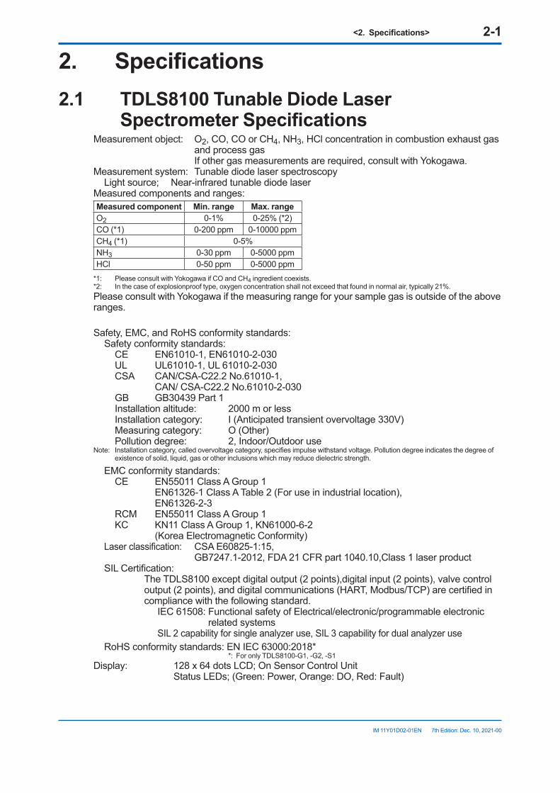
SpectrometerSpecificationsMeasurement object: O2, CO, CO or CH4, NH3, HCl concentration in combustion exhaust gas
and process gas If other gas measurements are required, consult with Yokogawa.Measurement system: Tunable diode laser spectroscopy
Light source; Near-infrared tunable diode laserMeasured components and ranges:Measured component Min. range Max.rangeO2 0-1% 0-25% (*2)CO (*1) 0-200 ppm 0-10000 ppmCH4 (*1) 0-5%NH3 0-30 ppm 0-5000 ppmHCl 0-50 ppm 0-5000 ppm
*1: Please consult with Yokogawa if CO and CH4 ingredient coexists.*2: In the case of explosionproof type, oxygen concentration shall not exceed that found in normal air, typically 21%.Please consult with Yokogawa if the measuring range for your sample gas is outside of the above ranges.
Safety, EMC, and RoHS conformity standards:Safety conformity standards:
CE EN61010-1, EN61010-2-030UL UL61010-1, UL 61010-2-030CSA CAN/CSA-C22.2 No.61010-1,
CAN/ CSA-C22.2 No.61010-2-030GB GB30439 Part 1Installation altitude: 2000 m or lessInstallation category: I (Anticipated transient overvoltage 330V)Measuring category: O (Other)Pollution degree: 2, Indoor/Outdoor use
Note: Installation category, called overvoltage category, specifies impulse withstand voltage. Pollution degree indicates the degree of existence of solid, liquid, gas or other inclusions which may reduce dielectric strength.
EMC conformity standards:CE EN55011 Class A Group 1
EN61326-1 Class A Table 2 (For use in industrial location), EN61326-2-3
RCM EN55011 Class A Group 1KC KN11 Class A Group 1, KN61000-6-2
(Korea Electromagnetic Conformity)Laser classification: CSA E60825-1:15,
GB7247.1-2012, FDA 21 CFR part 1040.10,Class 1 laser productSIL Certification: The TDLS8100 except digital output (2 points),digital input (2 points), valve control
output (2 points), and digital communications (HART, Modbus/TCP) are certified in compliance with the following standard.
IEC 61508: Functional safety of Electrical/electronic/programmable electronic related systems
SIL 2 capability for single analyzer use, SIL 3 capability for dual analyzer useRoHS conformity standards: EN IEC 63000:2018*
*: For only TDLS8100-G1, -G2, -S1 Display: 128 x 64 dots LCD; On Sensor Control Unit
Status LEDs; (Green: Power, Orange: DO, Red: Fault)
<2.Specifications> 2-2
IM 11Y01D02-01EN 7th Edition: Dec. 10, 2021-00
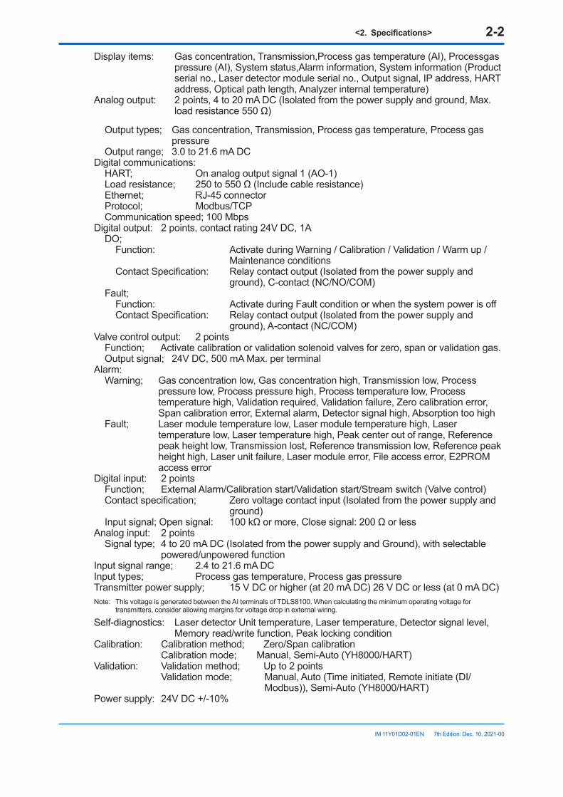
Display items: Gas concentration, Transmission,Process gas temperature (AI), Processgas pressure (AI), System status,Alarm information, System information (Product serial no., Laser detector module serial no., Output signal, IP address, HART address, Optical path length, Analyzer internal temperature)
Analog output: 2 points, 4 to 20 mA DC (Isolated from the power supply and ground, Max. load resistance 550 Ω)
Output types; Gas concentration, Transmission, Process gas temperature, Process gas pressure
Output range; 3.0 to 21.6 mA DCDigital communications:
HART; On analog output signal 1 (AO-1)Load resistance; 250 to 550 Ω (Include cable resistance)Ethernet; RJ-45 connectorProtocol; Modbus/TCPCommunication speed; 100 Mbps
Digital output: 2 points, contact rating 24V DC, 1ADO;
Function: Activate during Warning / Calibration / Validation / Warm up / Maintenance conditions
Contact Specification: Relay contact output (Isolated from the power supply and ground), C-contact (NC/NO/COM)
Fault;Function: Activate during Fault condition or when the system power is offContact Specification: Relay contact output (Isolated from the power supply and
ground), A-contact (NC/COM)Valve control output: 2 points
Function; Activate calibration or validation solenoid valves for zero, span or validation gas.Output signal; 24V DC, 500 mA Max. per terminal
Alarm:Warning; Gas concentration low, Gas concentration high, Transmission low, Process
pressure low, Process pressure high, Process temperature low, Process temperature high, Validation required, Validation failure, Zero calibration error, Span calibration error, External alarm, Detector signal high, Absorption too high
Fault; Laser module temperature low, Laser module temperature high, Laser temperature low, Laser temperature high, Peak center out of range, Reference peak height low, Transmission lost, Reference transmission low, Reference peak height high, Laser unit failure, Laser module error, File access error, E2PROM access error
Digital input: 2 pointsFunction; External Alarm/Calibration start/Validation start/Stream switch (Valve control)Contact specification; Zero voltage contact input (Isolated from the power supply and
ground)Input signal; Open signal: 100 kΩ or more, Close signal: 200 Ω or less
Analog input: 2 pointsSignal type; 4 to 20 mA DC (Isolated from the power supply and Ground), with selectable
powered/unpowered functionInput signal range; 2.4 to 21.6 mA DCInput types; Process gas temperature, Process gas pressureTransmitter power supply; 15 V DC or higher (at 20 mA DC) 26 V DC or less (at 0 mA DC)Note: This voltage is generated between the AI terminals of TDLS8100. When calculating the minimum operating voltage for
transmitters, consider allowing margins for voltage drop in external wiring.
Self-diagnostics: Laser detector Unit temperature, Laser temperature, Detector signal level, Memory read/write function, Peak locking condition
Calibration: Calibration method; Zero/Span calibration Calibration mode; Manual, Semi-Auto (YH8000/HART)
Validation: Validation method; Up to 2 points Validation mode; Manual, Auto (Time initiated, Remote initiate (DI/
Modbus)), Semi-Auto (YH8000/HART)Power supply: 24V DC +/-10%
<2.Specifications> 2-3
IM 11Y01D02-01EN 7th Edition: Dec. 10, 2021-00
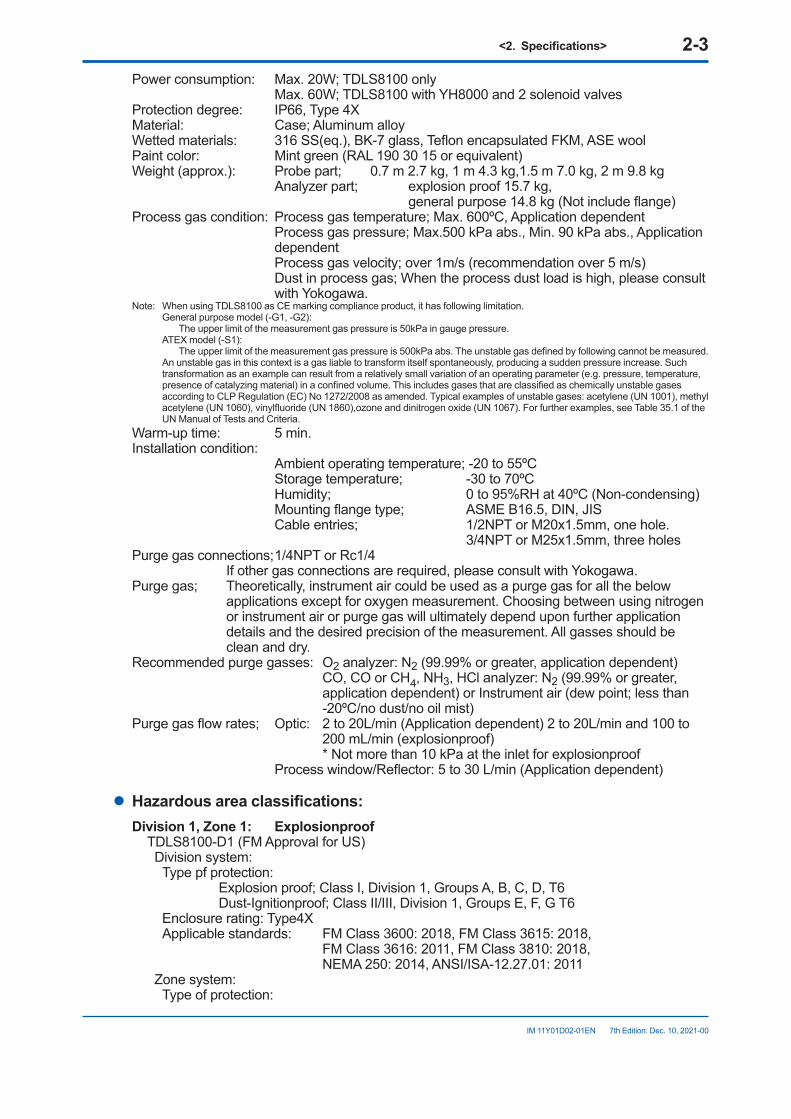
Power consumption: Max. 20W; TDLS8100 only Max. 60W; TDLS8100 with YH8000 and 2 solenoid valves
Protection degree: IP66, Type 4XMaterial: Case; Aluminum alloyWetted materials: 316 SS(eq.), BK-7 glass, Teflon encapsulated FKM, ASE woolPaint color: Mint green (RAL 190 30 15 or equivalent)Weight (approx.): Probe part; 0.7 m 2.7 kg, 1 m 4.3 kg,1.5 m 7.0 kg, 2 m 9.8 kg
Analyzer part; explosion proof 15.7 kg, general purpose 14.8 kg (Not include flange)
Process gas condition: Process gas temperature; Max. 600ºC, Application dependent Process gas pressure; Max.500 kPa abs., Min. 90 kPa abs., Application
dependent Process gas velocity; over 1m/s (recommendation over 5 m/s) Dust in process gas; When the process dust load is high, please consult
with Yokogawa.Note: When using TDLS8100 as CE marking compliance product, it has following limitation.
General purpose model (-G1, -G2): The upper limit of the measurement gas pressure is 50kPa in gauge pressure. ATEX model (-S1): The upper limit of the measurement gas pressure is 500kPa abs. The unstable gas defined by following cannot be measured. An unstable gas in this context is a gas liable to transform itself spontaneously, producing a sudden pressure increase. Such transformation as an example can result from a relatively small variation of an operating parameter (e.g. pressure, temperature, presence of catalyzing material) in a confined volume. This includes gases that are classified as chemically unstable gases according to CLP Regulation (EC) No 1272/2008 as amended. Typical examples of unstable gases: acetylene (UN 1001), methyl acetylene (UN 1060), vinylfluoride (UN 1860),ozone and dinitrogen oxide (UN 1067). For further examples, see Table 35.1 of the UN Manual of Tests and Criteria.
Warm-up time: 5 min.Installation condition: Ambient operating temperature; -20 to 55ºC Storage temperature; -30 to 70ºC Humidity; 0 to 95%RH at 40ºC (Non-condensing) Mounting flange type; ASME B16.5, DIN, JIS Cable entries; 1/2NPT or M20x1.5mm, one hole.
3/4NPT or M25x1.5mm, three holesPurge gas connections; 1/4NPT or Rc1/4 If other gas connections are required, please consult with Yokogawa.Purge gas; Theoretically, instrument air could be used as a purge gas for all the below
applications except for oxygen measurement. Choosing between using nitrogen or instrument air or purge gas will ultimately depend upon further application details and the desired precision of the measurement. All gasses should be clean and dry.
Recommended purge gasses: O2 analyzer: N2 (99.99% or greater, application dependent) CO, CO or CH4, NH3, HCl analyzer: N2 (99.99% or greater,
application dependent) or Instrument air (dew point; less than -20ºC/no dust/no oil mist)
Purge gas flow rates; Optic: 2 to 20L/min (Application dependent) 2 to 20L/min and 100 to 200 mL/min (explosionproof)
* Not more than 10 kPa at the inlet for explosionproof Process window/Reflector: 5 to 30 L/min (Application dependent)
l Hazardousareaclassifications:Division1,Zone1: Explosionproof
TDLS8100-D1 (FM Approval for US) Division system:
Type pf protection: Explosion proof; Class I, Division 1, Groups A, B, C, D, T6 Dust-Ignitionproof; Class II/III, Division 1, Groups E, F, G T6Enclosure rating: Type4XApplicable standards: FM Class 3600: 2018, FM Class 3615: 2018,
FM Class 3616: 2011, FM Class 3810: 2018, NEMA 250: 2014, ANSI/ISA-12.27.01: 2011
Zone system:Type of protection:
<2.Specifications> 2-4
IM 11Y01D02-01EN 7th Edition: Dec. 10, 2021-00
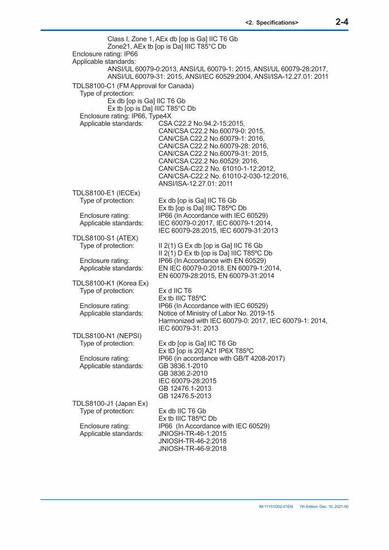
Class I, Zone 1, AEx db [op is Ga] IIC T6 Gb Zone21, AEx tb [op is Da] IIIC T85°C Db
Enclosure rating: IP66Applicable standards:
ANSI/UL 60079-0:2013, ANSI/UL 60079-1: 2015, ANSI/UL 60079-28:2017, ANSI/UL 60079-31: 2015, ANSI/IEC 60529:2004, ANSI/ISA-12.27.01: 2011
TDLS8100-C1 (FM Approval for Canada)Type of protection: Ex db [op is Ga] IIC T6 Gb Ex tb [op is Da] IIIC T85°C DbEnclosure rating: IP66, Type4XApplicable standards: CSA C22.2 No.94.2-15:2015,
CAN/CSA C22.2 No.60079-0: 2015, CAN/CSA C22.2 No.60079-1: 2016, CAN/CSA C22.2 No.60079-28: 2016, CAN/CSA C22.2 No.60079-31: 2015, CAN/CSA C22.2 No.60529: 2016, CAN/CSA-C22.2 No. 61010-1-12:2012, CAN/CSA-C22.2 No. 61010-2-030-12:2016, ANSI/ISA-12.27.01: 2011
TDLS8100-E1 (IECEx)Type of protection: Ex db [op is Ga] IIC T6 Gb
Ex tb [op is Da] IIIC T85ºC DbEnclosure rating: IP66 (In Accordance with IEC 60529)Applicable standards: IEC 60079-0:2017, IEC 60079-1:2014,
IEC 60079-28:2015, IEC 60079-31:2013TDLS8100-S1 (ATEX)
Type of protection: II 2(1) G Ex db [op is Ga] IIC T6 Gb II 2(1) D Ex tb [op is Da] IIIC T85ºC Db
Enclosure rating: IP66 (In Accordance with EN 60529)Applicable standards: EN IEC 60079-0:2018, EN 60079-1:2014,
EN 60079-28:2015, EN 60079-31:2014TDLS8100-K1 (Korea Ex)
Type of protection: Ex d IIC T6 Ex tb IIIC T85ºC
Enclosure rating: IP66 (In Accordance with IEC 60529)Applicable standards: Notice of Ministry of Labor No. 2019-15
Harmonized with IEC 60079-0: 2017, IEC 60079-1: 2014, IEC 60079-31: 2013
TDLS8100-N1 (NEPSI)Type of protection: Ex db [op is Ga] IIC T6 Gb
Ex tD [op is 20] A21 IP6X T85ºCEnclosure rating: IP66 (in accordance with GB/T 4208-2017)Applicable standards: GB 3836.1-2010
GB 3836.2-2010 IEC 60079-28:2015 GB 12476.1-2013 GB 12476.5-2013
TDLS8100-J1 (Japan Ex)Type of protection: Ex db IIC T6 Gb
Ex tb IIIC T85ºC DbEnclosure rating: IP66 (In Accordance with IEC 60529)Applicable standards: JNIOSH-TR-46-1:2015
JNIOSH-TR-46-2:2018 JNIOSH-TR-46-9:2018
<2.Specifications> 2-5
IM 11Y01D02-01EN 7th Edition: Dec. 10, 2021-00
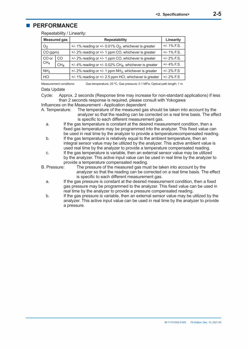
n PERFORMANCERepeatability / Linearity:
Measured gas Repeatability LinearityO2 +/- 1% reading or +/- 0.01% O2, whichever is greater +/- 1% F.S.
CO (ppm) +/- 2% reading or +/- 1 ppm CO, whichever is greater +/- 1% F.S.CO orCH4
CO +/- 2% reading or +/- 1 ppm CO, whichever is greater +/- 2% F.S.
CH4 +/- 4% reading or +/- 0.02% CH4, whichever is greater +/- 4% F.S.
NH3 +/- 2% reading or +/- 1 ppm NH3, whichever is greater +/- 2% F.SHCl +/- 1% reading or +/- 2.5 ppm HCl, whichever is greater +/- 2% F.S
Measurement conditions: Gas temperature; 25 ºC, Gas pressure; 0.1 MPa, Optical path length; 1 m
Data UpdateCycle: Approx. 2 seconds (Response time may increase for non-standard applications) If less
than 2 seconds response is required, please consult with YokogawaInfluences on the Measurement - Application dependentA. Temperature: The temperature of the measured gas should be taken into account by the
analyzer so that the reading can be corrected on a real time basis. The effect is specific to each different measurement gas.
a. If the gas temperature is constant at the desired measurement condition, then a fixed gas temperature may be programmed into the analyzer. This fixed value can be used in real time by the analyzer to provide a temperaturecompensated reading.
b. If the gas temperature is relatively equal to the ambient temperature, then an integral sensor value may be utilized by the analyzer. This active ambient value is used real time by the analyzer to provide a temperature compensated reading.
c. If the gas temperature is variable, then an external sensor value may be utilized by the analyzer. This active input value can be used in real time by the analyzer to provide a temperature compensated reading.
B. Pressure: The pressure of the measured gas must be taken into account by the analyzer so that the reading can be corrected on a real time basis. The effect is specific to each different measurement gas.
a. If the gas pressure is constant at the desired measurement condition, then a fixed gas pressure may be programmed to the analyzer. This fixed value can be used in real time by the analyzer to provide a pressure compensated reading.
b. If the gas pressure is variable, then an external sensor value may be utilized by the analyzer. This active input value can be used in real time by the analyzer to provide a pressure.
<2.Specifications> 2-6
IM 11Y01D02-01EN 7th Edition: Dec. 10, 2021-00
2.2 Specificationofotherunit2.2.1 YH8000 HMI Unit
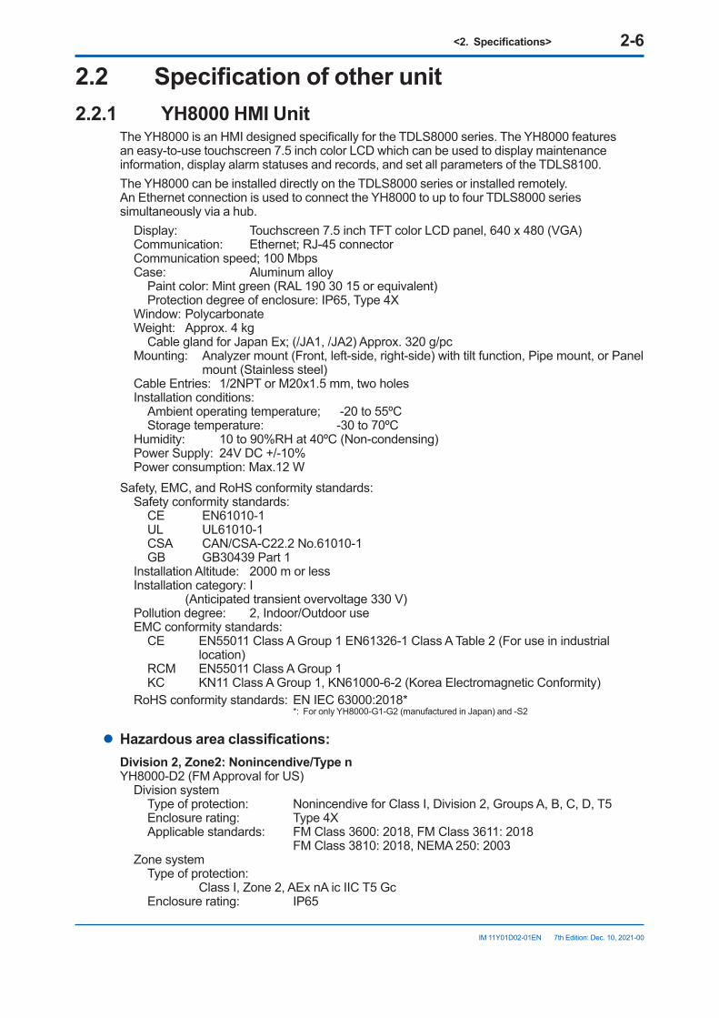
The YH8000 is an HMI designed specifically for the TDLS8000 series. The YH8000 features an easy-to-use touchscreen 7.5 inch color LCD which can be used to display maintenance information, display alarm statuses and records, and set all parameters of the TDLS8100.The YH8000 can be installed directly on the TDLS8000 series or installed remotely. An Ethernet connection is used to connect the YH8000 to up to four TDLS8000 series simultaneously via a hub.
Display: Touchscreen 7.5 inch TFT color LCD panel, 640 x 480 (VGA)Communication: Ethernet; RJ-45 connectorCommunication speed; 100 MbpsCase: Aluminum alloy
Paint color: Mint green (RAL 190 30 15 or equivalent)Protection degree of enclosure: IP65, Type 4X
Window: PolycarbonateWeight: Approx. 4 kg
Cable gland for Japan Ex; (/JA1, /JA2) Approx. 320 g/pcMounting: Analyzer mount (Front, left-side, right-side) with tilt function, Pipe mount, or Panel
mount (Stainless steel)Cable Entries: 1/2NPT or M20x1.5 mm, two holesInstallation conditions:
Ambient operating temperature; -20 to 55ºCStorage temperature: -30 to 70ºC
Humidity: 10 to 90%RH at 40ºC (Non-condensing)Power Supply: 24V DC +/-10%Power consumption: Max.12 W
Safety, EMC, and RoHS conformity standards:Safety conformity standards:
CE EN61010-1UL UL61010-1CSA CAN/CSA-C22.2 No.61010-1GB GB30439 Part 1
Installation Altitude: 2000 m or lessInstallation category: I (Anticipated transient overvoltage 330 V)Pollution degree: 2, Indoor/Outdoor useEMC conformity standards:
CE EN55011 Class A Group 1 EN61326-1 Class A Table 2 (For use in industrial location)
RCM EN55011 Class A Group 1KC KN11 Class A Group 1, KN61000-6-2 (Korea Electromagnetic Conformity)
RoHS conformity standards: EN IEC 63000:2018* *: For only YH8000-G1-G2 (manufactured in Japan) and -S2
l Hazardousareaclassifications:Division2,Zone2:Nonincendive/TypenYH8000-D2 (FM Approval for US)
Division systemType of protection: Nonincendive for Class I, Division 2, Groups A, B, C, D, T5Enclosure rating: Type 4XApplicable standards: FM Class 3600: 2018, FM Class 3611: 2018
FM Class 3810: 2018, NEMA 250: 2003Zone system
Type of protection: Class I, Zone 2, AEx nA ic IIC T5 GcEnclosure rating: IP65
<2.Specifications> 2-7
IM 11Y01D02-01EN 7th Edition: Dec. 10, 2021-00
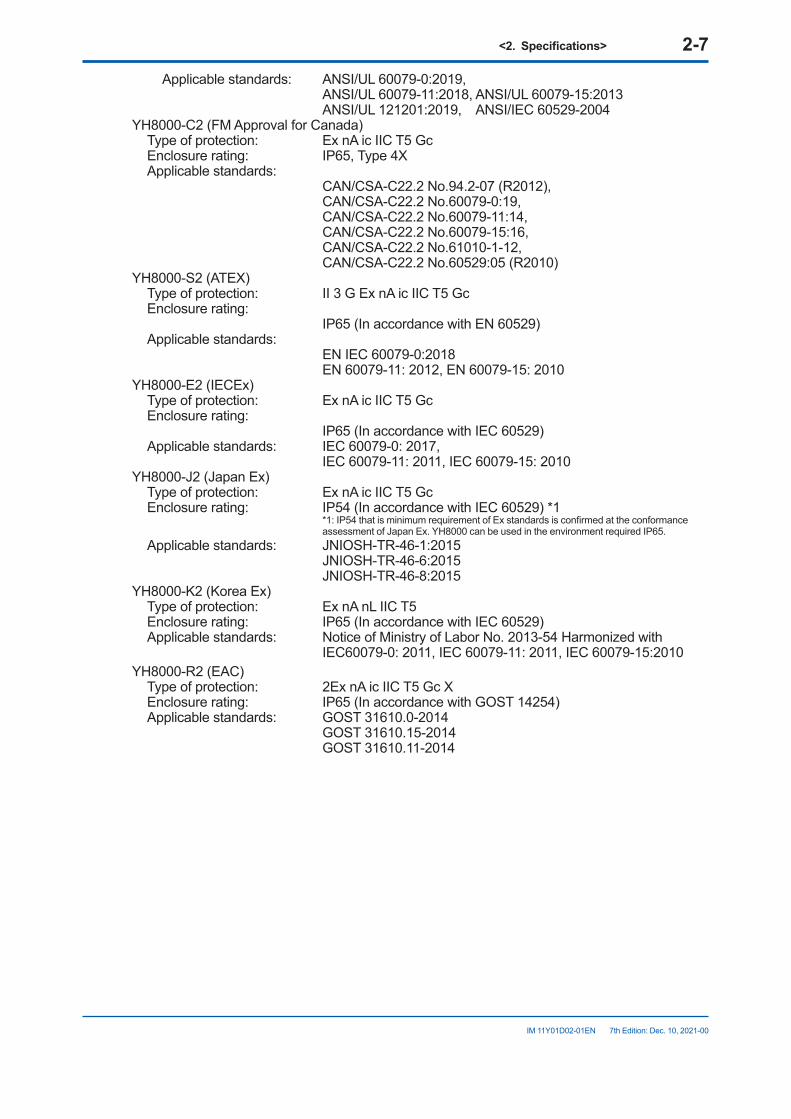
Applicable standards: ANSI/UL 60079-0:2019, ANSI/UL 60079-11:2018, ANSI/UL 60079-15:2013
ANSI/UL 121201:2019, ANSI/IEC 60529-2004YH8000-C2 (FM Approval for Canada)
Type of protection: Ex nA ic IIC T5 GcEnclosure rating: IP65, Type 4XApplicable standards:
CAN/CSA-C22.2 No.94.2-07 (R2012), CAN/CSA-C22.2 No.60079-0:19, CAN/CSA-C22.2 No.60079-11:14, CAN/CSA-C22.2 No.60079-15:16, CAN/CSA-C22.2 No.61010-1-12, CAN/CSA-C22.2 No.60529:05 (R2010)
YH8000-S2 (ATEX)Type of protection: II 3 G Ex nA ic IIC T5 GcEnclosure rating:
IP65 (In accordance with EN 60529)Applicable standards:
EN IEC 60079-0:2018 EN 60079-11: 2012, EN 60079-15: 2010
YH8000-E2 (IECEx)Type of protection: Ex nA ic IIC T5 GcEnclosure rating:
IP65 (In accordance with IEC 60529)Applicable standards: IEC 60079-0: 2017,
IEC 60079-11: 2011, IEC 60079-15: 2010YH8000-J2 (Japan Ex)
Type of protection: Ex nA ic IIC T5 GcEnclosure rating: IP54 (In accordance with IEC 60529) *1
*1: IP54 that is minimum requirement of Ex standards is confirmed at the conformance assessment of Japan Ex. YH8000 can be used in the environment required IP65.
Applicable standards: JNIOSH-TR-46-1:2015 JNIOSH-TR-46-6:2015 JNIOSH-TR-46-8:2015
YH8000-K2 (Korea Ex)Type of protection: Ex nA nL IIC T5Enclosure rating: IP65 (In accordance with IEC 60529)Applicable standards: Notice of Ministry of Labor No. 2013-54 Harmonized with
IEC60079-0: 2011, IEC 60079-11: 2011, IEC 60079-15:2010YH8000-R2 (EAC)
Type of protection: 2Ex nA ic IIC T5 Gc XEnclosure rating: IP65 (In accordance with GOST 14254)Applicable standards: GOST 31610.0-2014
GOST 31610.15-2014 GOST 31610.11-2014
<2.Specifications> 2-8
IM 11Y01D02-01EN 7th Edition: Dec. 10, 2021-00
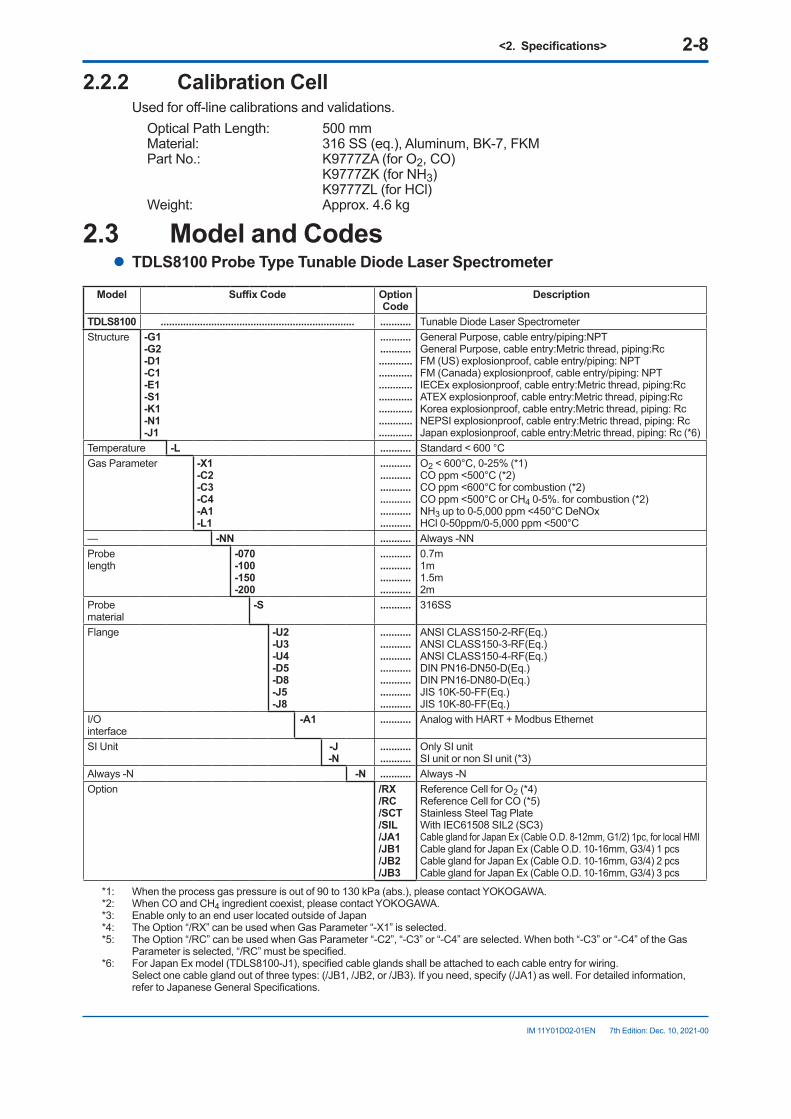
2.2.2 Calibration CellUsed for off-line calibrations and validations.
Optical Path Length: 500 mmMaterial: 316 SS (eq.), Aluminum, BK-7, FKM Part No.: K9777ZA (for O2, CO)
K9777ZK (for NH3) K9777ZL (for HCl)
Weight: Approx. 4.6 kg
2.3 Model and Codesl TDLS8100 Probe Type Tunable Diode Laser Spectrometer
Model SuffixCode Option Code
Description
TDLS8100 ..................................................................... ........... Tunable Diode Laser SpectrometerStructure -G1
-G2-D1-C1-E1-S1-K1-N1-J1
...........
...............................................................................................
General Purpose, cable entry/piping:NPTGeneral Purpose, cable entry:Metric thread, piping:RcFM (US) explosionproof, cable entry/piping: NPTFM (Canada) explosionproof, cable entry/piping: NPTIECEx explosionproof, cable entry:Metric thread, piping:RcATEX explosionproof, cable entry:Metric thread, piping:RcKorea explosionproof, cable entry:Metric thread, piping: RcNEPSI explosionproof, cable entry:Metric thread, piping: RcJapan explosionproof, cable entry:Metric thread, piping: Rc (*6)
Temperature -L ........... Standard < 600 °CGas Parameter -X1
-C2-C3-C4-A1-L1
...........
...........
...........
...........
...........
...........
O2 < 600°C, 0-25% (*1)CO ppm <500°C (*2)CO ppm <600°C for combustion (*2)CO ppm <500°C or CH4 0-5%. for combustion (*2)NH3 up to 0-5,000 ppm <450°C DeNOxHCl 0-50ppm/0-5,000 ppm <500°C
— -NN ........... Always -NNProbe length
-070-100-150-200
...........
...........
...........
...........
0.7m1m1.5m2m
Probe material
-S ........... 316SS
Flange -U2-U3-U4-D5-D8-J5-J8
...........
...........
...........
...........
...........
...........
...........
ANSI CLASS150-2-RF(Eq.)ANSI CLASS150-3-RF(Eq.)ANSI CLASS150-4-RF(Eq.)DIN PN16-DN50-D(Eq.)DIN PN16-DN80-D(Eq.)JIS 10K-50-FF(Eq.)JIS 10K-80-FF(Eq.)
I/O interface
-A1 ........... Analog with HART + Modbus Ethernet
SI Unit -J-N
...........
...........Only SI unitSI unit or non SI unit (*3)
Always -N -N ........... Always -NOption /RX
/RC/SCT/SIL/JA1/JB1/JB2/JB3
Reference Cell for O2 (*4)Reference Cell for CO (*5)Stainless Steel Tag PlateWith IEC61508 SIL2 (SC3)Cable gland for Japan Ex (Cable O.D. 8-12mm, G1/2) 1pc, for local HMICable gland for Japan Ex (Cable O.D. 10-16mm, G3/4) 1 pcsCable gland for Japan Ex (Cable O.D. 10-16mm, G3/4) 2 pcsCable gland for Japan Ex (Cable O.D. 10-16mm, G3/4) 3 pcs
*1: When the process gas pressure is out of 90 to 130 kPa (abs.), please contact YOKOGAWA.*2: When CO and CH4 ingredient coexist, please contact YOKOGAWA.*3: Enable only to an end user located outside of Japan*4: The Option “/RX” can be used when Gas Parameter “-X1” is selected.*5: The Option “/RC” can be used when Gas Parameter “-C2”, “-C3” or “-C4” are selected. When both “-C3” or “-C4” of the Gas
Parameter is selected, “/RC” must be specified.*6: For Japan Ex model (TDLS8100-J1), specified cable glands shall be attached to each cable entry for wiring.
Select one cable gland out of three types: (/JB1, /JB2, or /JB3). If you need, specify (/JA1) as well. For detailed information, refer to Japanese General Specifications.
<2.Specifications> 2-9
IM 11Y01D02-01EN 7th Edition: Dec. 10, 2021-00
n YH8000 HMI Unit
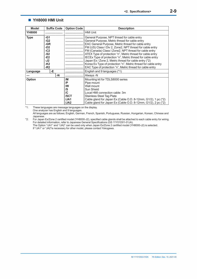
Model SuffixCode Option Code Description YH8000 ...................... ....................... HMI UnitType -G1
-G2-GR-D2-C2-S2-E2-J2-K2-R2
.......................
.......................
.......................
.......................
.......................
.......................
.......................
.......................
.......................
.......................
General Purpose, NPT thread for cable entryGeneral Purpose, Metric thread for cable entryEAC General Purpose, Metric thread for cable entryFM (US) Class I Div 2, Zone2, NPT thread for cable entryFM (Canada) Class I Zone2, NPT thread for cable entryATEX Type of protection “n”, Metric thread for cable entryIECEx Type of protection “n”, Metric thread for cable entryJapan Ex / Zone 2, Metric thread for cable entry (*2)Korea Ex Type of protection “n”, Metric thread for cable entryEAC Type of protection “n”, Metric thread for cable entry
Language -E ....................... English and 9 languages (*1)— -N ....................... Always -NOption /M
/P/W/S/C/SCT/JA1/JA2
Mounting kit for TDLS8000 seriesPipe mountWall mountSun ShieldLocal HMI connection cable: 3mStainless Steel Tag PlateCable gland for Japan Ex (Cable O.D. 8-12mm, G1/2), 1 pc (*2)Cable gland for Japan Ex (Cable O.D. 8-12mm, G1/2), 2 pc (*2)
*1: These languages are message languages on the display. One analyzer has English and 9 languages. All languages are as follows; English, German, French, Spanish, Portuguese, Russian, Hungarian, Korean, Chinese and Japanese.
*2: For Japan Ex/Zone 2 certified model (YH8000-J2), specified cable glands shall be attached to each cable entry for wiring. For detailed information, refer to Japanese General Specifications (GS 11Y01D01-01JA). The Option “/JA1” and “/JA2” can be used only when Japan Ex/Zone 2 certified model (YH8000-J2) is selected.
If “/JA1” or “JA2”is necessary for other model, please contact Yokogawa.
<2.Specifications> 2-10
IM 11Y01D02-01EN 7th Edition: Dec. 10, 2021-00
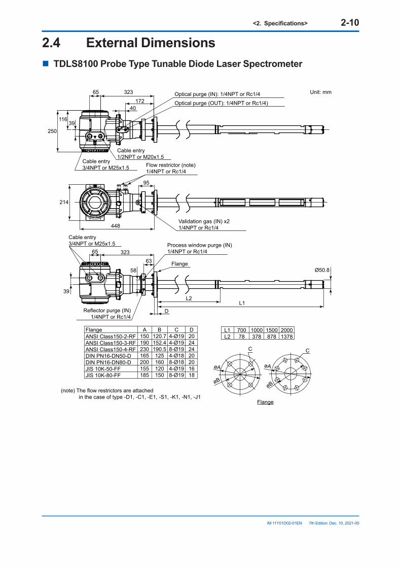
2.4 ExternalDimensionsn TDLS8100 Probe Type Tunable Diode Laser Spectrometer
65
250
214
39
58
11639
323
95
L2
Ø50.8
L1
448
32365
63
17240
D
øB
øA
C
øB
øA
C
L1L2
70078
1000378
1500878
20001378
A150190230165200155185
B120.7152.4190.5125160120150
C4-Ø194-Ø198-Ø194-Ø188-Ø184-Ø198-Ø19
D20242420201618
ANSI Class150-2-RFANSI Class150-3-RFANSI Class150-4-RFDIN PN16-DN50-DDIN PN16-DN80-DJIS 10K-50-FFJIS 10K-80-FF
Process window purge (IN)1/4NPT or Rc1/4
Reflector purge (IN)1/4NPT or Rc1/4
Flow restrictor (note)1/4NPT or Rc1/4
Flange
Optical purge (IN): 1/4NPT or Rc1/4 Unit: mm
Optical purge (OUT): 1/4NPT or Rc1/4)
(note) The flow restrictors are attached in the case of type -D1, -C1, -E1, -S1, -K1, -N1, -J1
Cable entry3/4NPT or M25x1.5
Cable entry3/4NPT or M25x1.5
Validation gas (IN) x21/4NPT or Rc1/4
Cable entry1/2NPT or M20x1.5
Flange
Flange
<2.Specifications> 2-11
IM 11Y01D02-01EN 7th Edition: Dec. 10, 2021-00
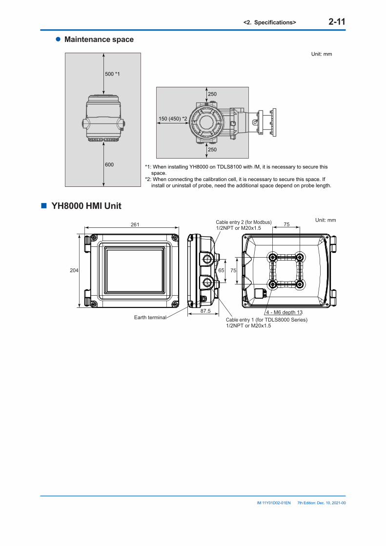
l Maintenance space
250
250
150 (450) *2
500 *1
600
Unit: mm
*1: When installing YH8000 on TDLS8100 with /M, it is necessary to secure this space.
*2: When connecting the calibration cell, it is necessary to secure this space. If install or uninstall of probe, need the additional space depend on probe length.
n YH8000 HMI Unit
261
65 75
75
87.5 4 - M6 depth 13
204
Earth terminal
Cable entry 2 (for Modbus)1/2NPT or M20x1.5
Cable entry 1 (for TDLS8000 Series)1/2NPT or M20x1.5
Unit: mm
<2.Specifications> 2-12
IM 11Y01D02-01EN 7th Edition: Dec. 10, 2021-00
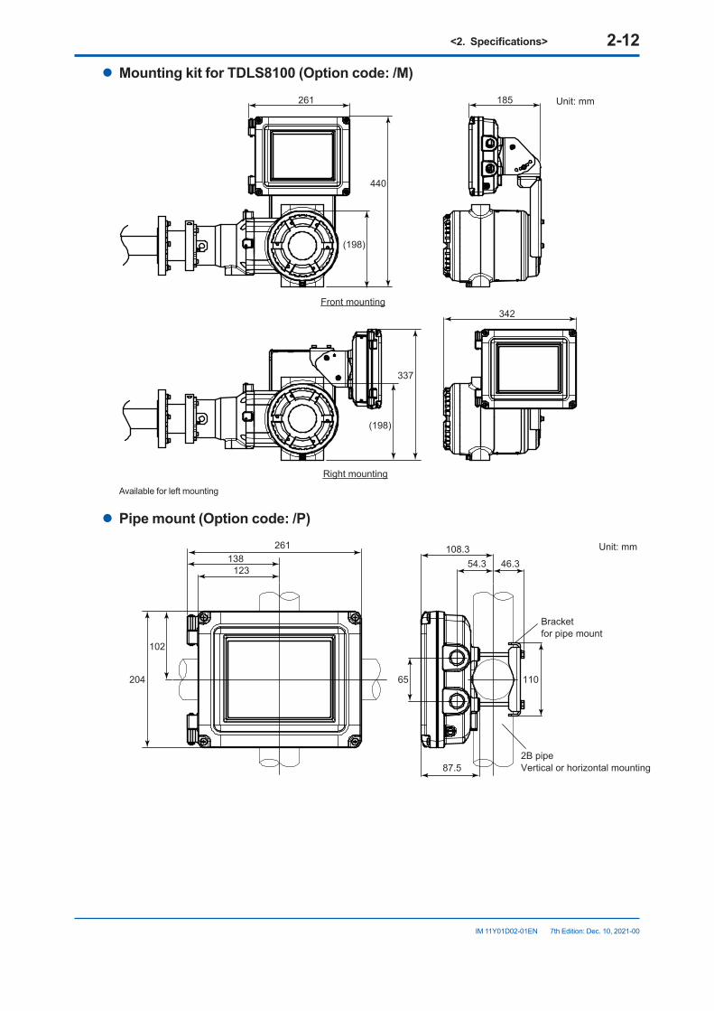
l MountingkitforTDLS8100(Optioncode:/M)
440
(198)
(198)
337
342
261 185
Front mounting
Unit: mm
Right mounting
Available for left mounting
l Pipemount(Optioncode:/P)
102
204 65 110
261138
123
108.354.3
87.5
46.3
Unit: mm
2B pipeVertical or horizontal mounting
Bracketfor pipe mount
<2.Specifications> 2-13
IM 11Y01D02-01EN 7th Edition: Dec. 10, 2021-00
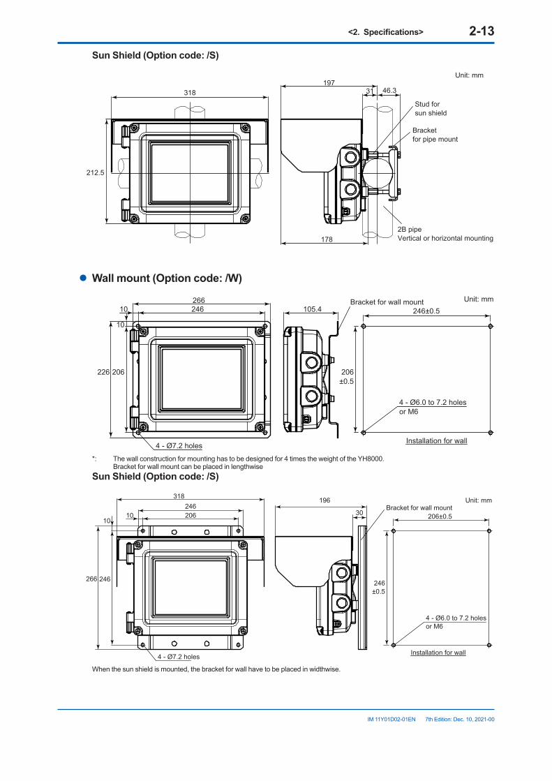
SunShield(Optioncode:/S)
212.5
318197
31
178
46.3
Unit: mm
2B pipeVertical or horizontal mounting
Bracketfor pipe mount
Stud forsun shield
l Wallmount(Optioncode:/W)
105.4246 246±0.510266
4 - Ø7.2 holes
4 - Ø6.0 to 7.2 holesor M6
226 206 206±0.5
10
Unit: mmBracket for wall mount
Installation for wall
*: The wall construction for mounting has to be designed for 4 times the weight of the YH8000. Bracket for wall mount can be placed in lengthwiseSunShield(Optioncode:/S)
196
3020610
318246
4 - Ø7.2 holes
266 246
10
Unit: mmBracket for wall mount
206±0.5
4 - Ø6.0 to 7.2 holesor M6
246±0.5
Installation for wall
When the sun shield is mounted, the bracket for wall have to be placed in widthwise.
<2.Specifications> 2-14
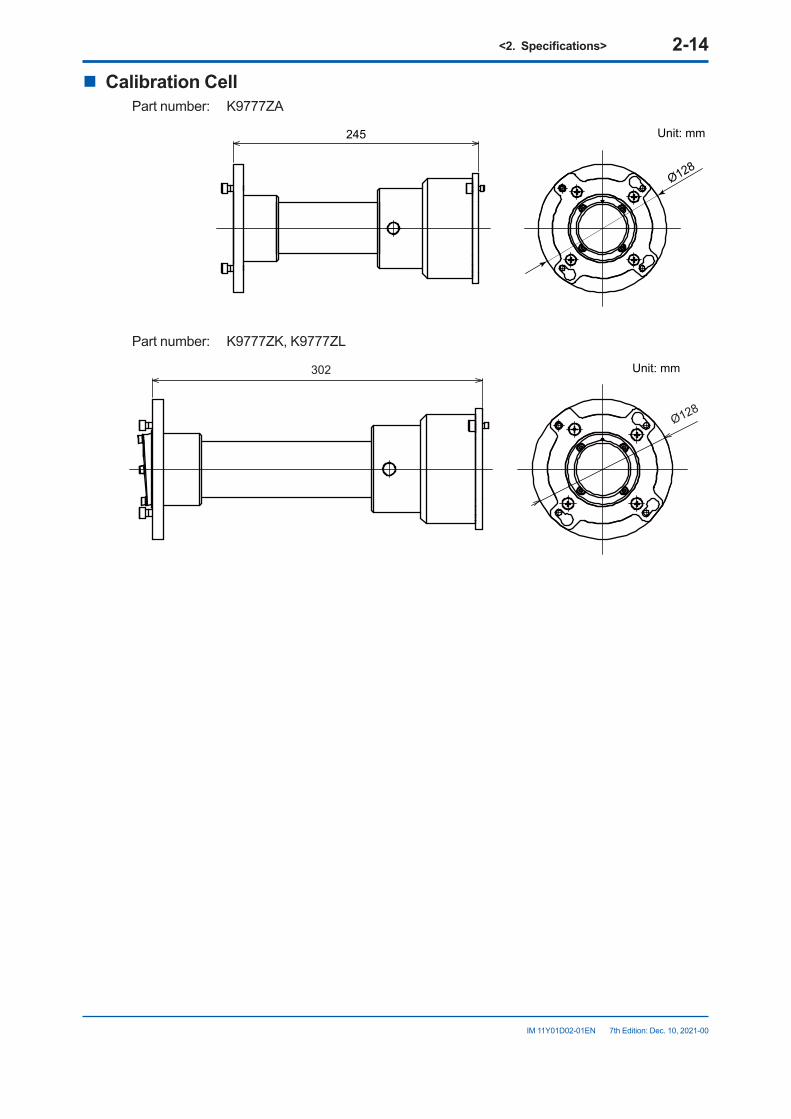
IM 11Y01D02-01EN 7th Edition: Dec. 10, 2021-00
n Calibration CellPart number: K9777ZA
245
Ø128
Unit: mm
Part number: K9777ZK, K9777ZL
302
Ø128
Unit: mm
<3. Installation, Wiring, Optical Axis Adjustment, and Piping> 3-1
IM 11Y01D02-01EN 7th Edition: Dec. 10, 2021-00
3. Installation,Wiring,OpticalAxisAdjustment,andPiping
This chapter describes installation, wiring, optical axis adjustment, and purge gas piping in the order they need be performed.If you use the YH8000, install it after you complete the procedures in this chapter.
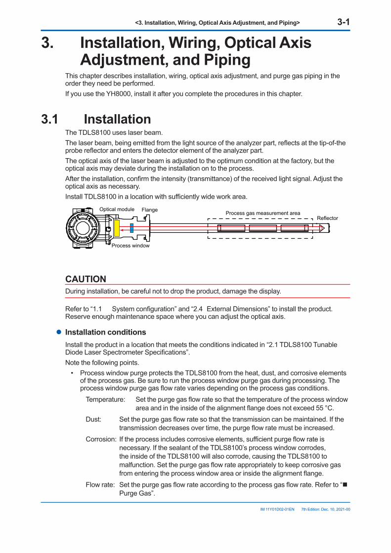
3.1 InstallationThe TDLS8100 uses laser beam.The laser beam, being emitted from the light source of the analyzer part, reflects at the tip-of-the probe reflector and enters the detector element of the analyzer part.The optical axis of the laser beam is adjusted to the optimum condition at the factory, but the optical axis may deviate during the installation on to the process.After the installation, confirm the intensity (transmittance) of the received light signal. Adjust the optical axis as necessary.Install TDLS8100 in a location with sufficiently wide work area.
Optical module
Process window
Flange Process gas measurement areaReflector
CAUTIONDuring installation, be careful not to drop the product, damage the display.
Refer to “1.1 System configuration” and “2.4 External Dimensions” to install the product. Reserve enough maintenance space where you can adjust the optical axis.
l Installation conditionsInstall the product in a location that meets the conditions indicated in “2.1 TDLS8100 Tunable Diode Laser Spectrometer Specifications”.Note the following points.
• Process window purge protects the TDLS8100 from the heat, dust, and corrosive elements of the process gas. Be sure to run the process window purge gas during processing. The process window purge gas flow rate varies depending on the process gas conditions.
Temperature: Set the purge gas flow rate so that the temperature of the process window area and in the inside of the alignment flange does not exceed 55 °C.
Dust: Set the purge gas flow rate so that the transmission can be maintained. If the transmission decreases over time, the purge flow rate must be increased.
Corrosion: If the process includes corrosive elements, sufficient purge flow rate is necessary. If the sealant of the TDLS8100’s process window corrodes, the inside of the TDLS8100 will also corrode, causing the TDLS8100 to malfunction. Set the purge gas flow rate appropriately to keep corrosive gas from entering the process window area or inside the alignment flange.
Flow rate: Set the purge gas flow rate according to the process gas flow rate. Refer to “n Purge Gas”.
<3. Installation, Wiring, Optical Axis Adjustment, and Piping> 3-2
IM 11Y01D02-01EN 7th Edition: Dec. 10, 2021-00
3.1.1 Measurement Point SelectionTake the following process conditions into consideration when selecting the measurement point.
l ProcessgasflowrateconditionsSet the measurement point to a location where the concentration distribution of the streamline flow is uniform.In the case of a duct or flue with a circular cross section, a typical measurement point is where the distance from the end of a curved process area is at least three times the diameter (D) of the duct or flue and where there is nothing that would interfere with measurements.In the case of a duct or flue with a rectangular cross section, the equivalent diameter (D) can be determined from the following equation. Diameter (D) = 4 × duct cross sectional area/duct circumference
If such point is not available or if setting a measurement point at such point is not possible, the measurement point is a location two-thirds of the length away from the duct inlet end or one-third from the outlet end.Once the measurement point is determined, double-check that it is at the appropriate location.
l Process gas temperatureInstall the TDLS8100 in a location with minimal process gas temperature fluctuations.If the gas temperature fluctuation where the TDLS8100 is installed exceeds ±10 °C, connect an external thermometer to the TDLS8100 temperature input terminal and enter the actual measured gas temperature to obtain correct measurements (for details, see “6.1.3 Process Temperature”).Check that a thermometer suitable for the maximum process gas temperature is being used.In general, the lower the gas temperature, the better the measurement.
l Process gas pressureInstall the TDLS8100 in a location with minimal pressure fluctuations.If the gas pressure fluctuation where the TDLS8100 is installed exceeds ±5 kPa, enter the pressure signal from a separately applied process pressure meter to obtain correct measurements (for details, see “6.1.2 Process Pressure”).Check that a pressure meter suitable for the maximum process gas pressure is being used.Check that the process window interfacing the process gas is suitable for the maximum preset gas pressure.In general, the lower the gas pressure, the better the measurement.
l Processdust/particulateconcentrationInstall the TDLS8100 in a location with minimal dust concentration.If the installation needs to be implemented in highly dusty condition, utilize blaster equipment and others alike to protect the analyzer from build-up dust. For further information, consult our service.
l ProcessflowrateInstall TDLS8100 at a location with a flow rate of 1 m/s or above. Flow rate of 5 m/sec. or above secures more stable measurement.Install TDLS8100 at a location with minimum fluctuation of flow rate, otherwise it may result in the deviation of the measurement result.
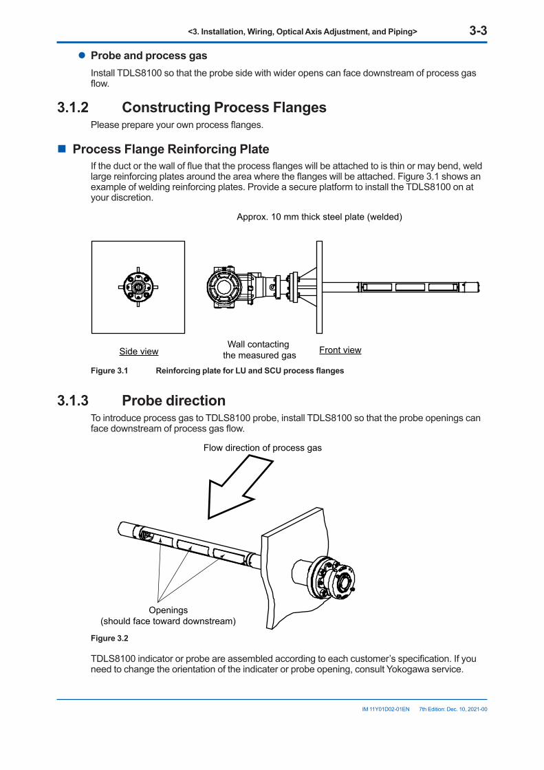
<3. Installation, Wiring, Optical Axis Adjustment, and Piping> 3-3
IM 11Y01D02-01EN 7th Edition: Dec. 10, 2021-00
l Probe and process gasInstall TDLS8100 so that the probe side with wider opens can face downstream of process gas flow.
3.1.2 Constructing Process FlangesPlease prepare your own process flanges.
n Process Flange Reinforcing PlateIf the duct or the wall of flue that the process flanges will be attached to is thin or may bend, weld large reinforcing plates around the area where the flanges will be attached. Figure 3.1 shows an example of welding reinforcing plates. Provide a secure platform to install the TDLS8100 on at your discretion.
Front viewSide viewWall contacting
the measured gas
Approx. 10 mm thick steel plate (welded)
Figure3.1 ReinforcingplateforLUandSCUprocessflanges
3.1.3 Probe directionTo introduce process gas to TDLS8100 probe, install TDLS8100 so that the probe openings can face downstream of process gas flow.
Openings (should face toward downstream)
Flow direction of process gas
Figure 3.2
TDLS8100 indicator or probe are assembled according to each customer’s specification. If you need to change the orientation of the indicater or probe opening, consult Yokogawa service.
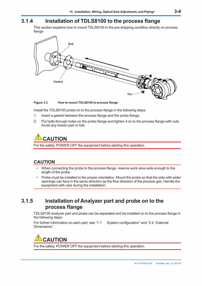
<3. Installation, Wiring, Optical Axis Adjustment, and Piping> 3-4
IM 11Y01D02-01EN 7th Edition: Dec. 10, 2021-00
3.1.4 InstallationofTDLS8100totheprocessflangeThis section explains how to mount TDLS8100 in the pre-shipping condition directly on process flange
Bolt
Gasket
Nut
Figure3.3 HowtomountTDLS8100toprocessflange
Install the TDLS8100 probe on to the process flange in the following steps.1: Insert a gasket between the process flange and the probe flange.2: Put bolts through holes on the probe flange and tighten it on to the process flange with nuts.
Avoid any loosen part or lost.
CAUTIONFor the safety, POWER OFF the equipment before starting this operation.
CAUTION• When connecting the probe to the process flange, reserve work area wide enough to the
length of the probe.• Probe must be installed in the proper orientation. Mount the probe so that the side with wider
openings can face in the same direction as the flow direction of the process gas. Handle the equipment with care during the installation.
3.1.5 InstallationofAnalyzerpartandprobeontotheprocessflange
TDLS8100 analyzer part and probe can be separated and be installed on to the process flange in the following steps.For further information on each part, see “1.1 System configuration” and “2.4 External Dimensions”.
CAUTIONFor the safety, POWER OFF the equipment before starting this operation.
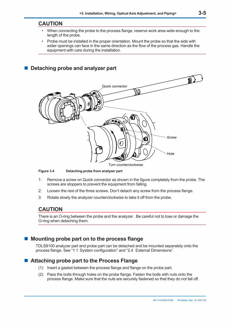
<3. Installation, Wiring, Optical Axis Adjustment, and Piping> 3-5
IM 11Y01D02-01EN 7th Edition: Dec. 10, 2021-00
CAUTION• When connecting the probe to the process flange, reserve work area wide enough to the
length of the probe.• Probe must be installed in the proper orientation. Mount the probe so that the side with
wider openings can face in the same direction as the flow of the process gas. Handle the equipment with care during the installation.
n Detachingprobeandanalyzerpart
Quick connector
Hole
Turn counterclockwise
Screw
Figure3.4 Detachingprobefromanalyzerpart
1: Remove a screw on Quick connector as shown in the figure completely from the probe. The screws are stoppers to prevent the equipment from falling.
2: Loosen the rest of the three screws. Don’t detach any screw from the process flange.3: Rotate slowly the analyzer counterclockwise to take it off from the probe.
CAUTIONThere is an O-ring between the probe and the analyzer . Be careful not to lose or damage the O-ring when detaching them.
n MountingprobepartontotheprocessflangeTDLS8100 analyzer part and probe part can be detached and be mounted separately onto the process flange. See “1.1 System configuration” and “2.4 External Dimensions”.
n AttachingprobeparttotheProcessFlange(1) Insert a gasket between the process flange and flange on the probe part.(2) Pass the bolts through holes on the probe flange. Fasten the bolts with nuts onto the
process flange. Make sure that the nuts are securely fastened so that they do not fall off.
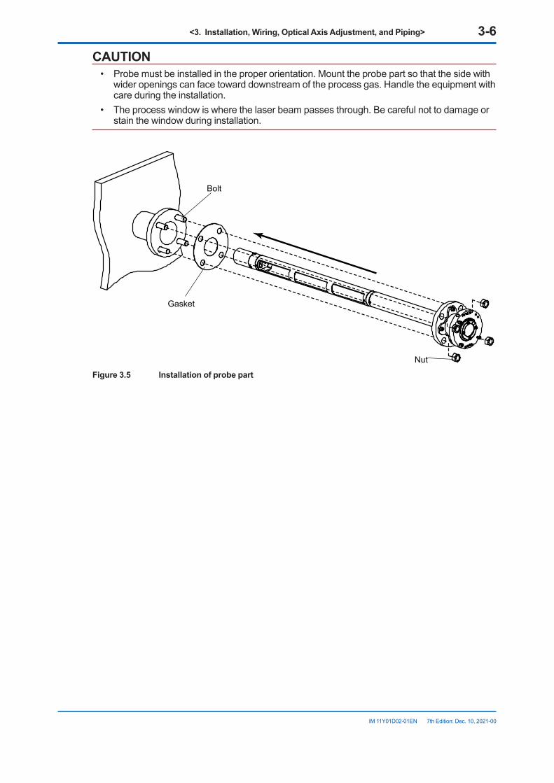
<3. Installation, Wiring, Optical Axis Adjustment, and Piping> 3-6
IM 11Y01D02-01EN 7th Edition: Dec. 10, 2021-00
CAUTION• Probe must be installed in the proper orientation. Mount the probe part so that the side with
wider openings can face toward downstream of the process gas. Handle the equipment with care during the installation.
• The process window is where the laser beam passes through. Be careful not to damage or stain the window during installation.
Bolt
Gasket
Nut
Figure 3.5 Installation of probe part
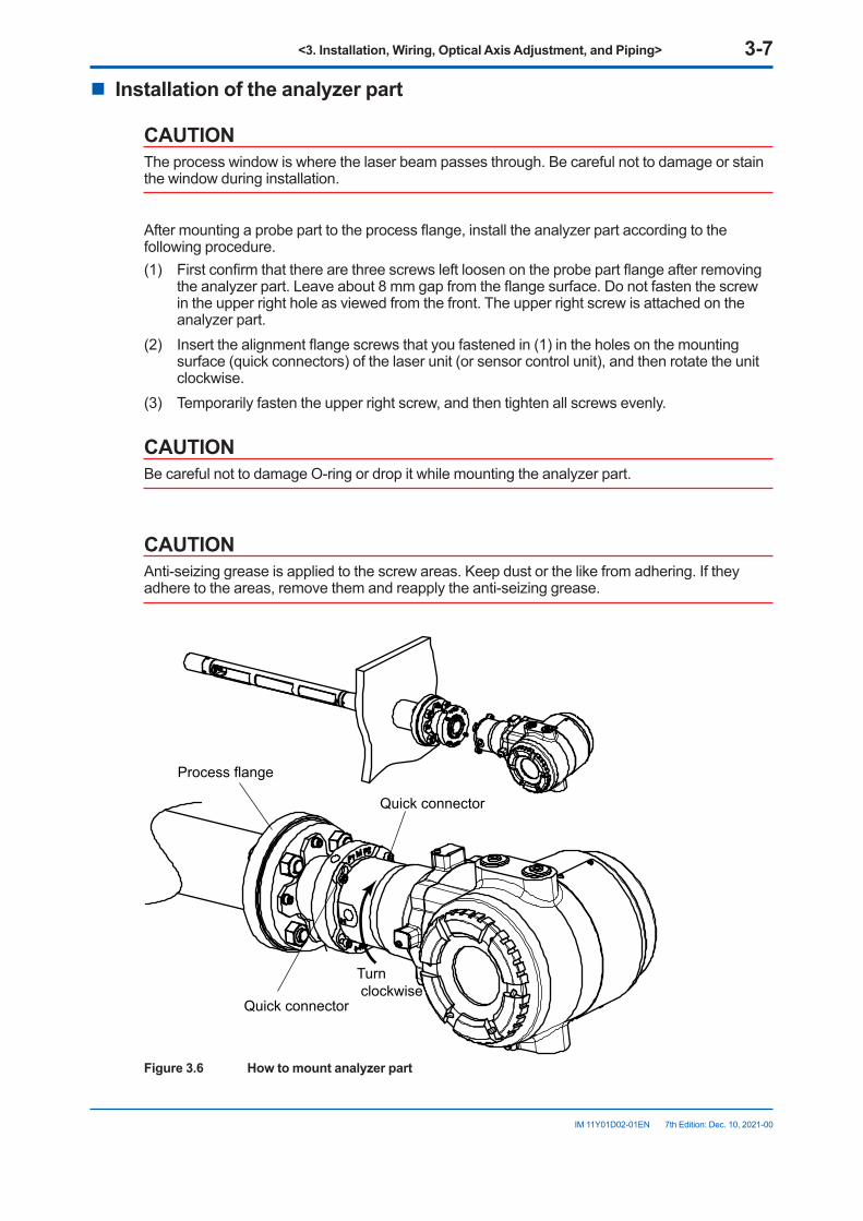
<3. Installation, Wiring, Optical Axis Adjustment, and Piping> 3-7
IM 11Y01D02-01EN 7th Edition: Dec. 10, 2021-00
n Installationoftheanalyzerpart
CAUTIONThe process window is where the laser beam passes through. Be careful not to damage or stain the window during installation.
After mounting a probe part to the process flange, install the analyzer part according to the following procedure.(1) First confirm that there are three screws left loosen on the probe part flange after removing
the analyzer part. Leave about 8 mm gap from the flange surface. Do not fasten the screw in the upper right hole as viewed from the front. The upper right screw is attached on the analyzer part.
(2) Insert the alignment flange screws that you fastened in (1) in the holes on the mounting surface (quick connectors) of the laser unit (or sensor control unit), and then rotate the unit clockwise.
(3) Temporarily fasten the upper right screw, and then tighten all screws evenly.
CAUTIONBe careful not to damage O-ring or drop it while mounting the analyzer part.
CAUTIONAnti-seizing grease is applied to the screw areas. Keep dust or the like from adhering. If they adhere to the areas, remove them and reapply the anti-seizing grease.
Quick connector
Quick connector
Turn clockwise
Process flange
Figure3.6 Howtomountanalyzerpart
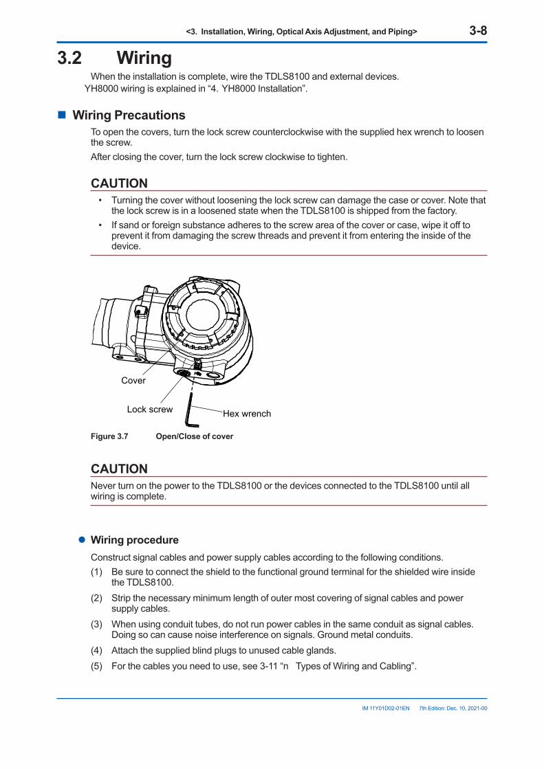
<3. Installation, Wiring, Optical Axis Adjustment, and Piping> 3-8
IM 11Y01D02-01EN 7th Edition: Dec. 10, 2021-00
3.2 WiringWhen the installation is complete, wire the TDLS8100 and external devices.
YH8000 wiring is explained in “4. YH8000 Installation”.
n Wiring PrecautionsTo open the covers, turn the lock screw counterclockwise with the supplied hex wrench to loosen the screw.After closing the cover, turn the lock screw clockwise to tighten.
CAUTION• Turning the cover without loosening the lock screw can damage the case or cover. Note that
the lock screw is in a loosened state when the TDLS8100 is shipped from the factory.• If sand or foreign substance adheres to the screw area of the cover or case, wipe it off to
prevent it from damaging the screw threads and prevent it from entering the inside of the device.
Hex wrench
Cover
Lock screw
Figure3.7 Open/Closeofcover
CAUTIONNever turn on the power to the TDLS8100 or the devices connected to the TDLS8100 until all wiring is complete.
l Wiring procedureConstruct signal cables and power supply cables according to the following conditions.(1) Be sure to connect the shield to the functional ground terminal for the shielded wire inside
the TDLS8100.(2) Strip the necessary minimum length of outer most covering of signal cables and power
supply cables.(3) When using conduit tubes, do not run power cables in the same conduit as signal cables.
Doing so can cause noise interference on signals. Ground metal conduits.(4) Attach the supplied blind plugs to unused cable glands.(5) For the cables you need to use, see 3-11 “n Types of Wiring and Cabling”.
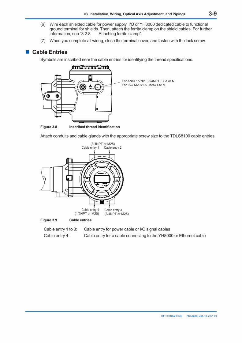
<3. Installation, Wiring, Optical Axis Adjustment, and Piping> 3-9
IM 11Y01D02-01EN 7th Edition: Dec. 10, 2021-00
(6) Wire each shielded cable for power supply, I/O or YH8000 dedicated cable to functional ground terminal for shields. Then, attach the ferrite clamp on the shield cables. For further information, see “3.2.8 Attaching ferrite clamp”.
(7) When you complete all wiring, close the terminal cover, and fasten with the lock screw.
n Cable EntriesSymbols are inscribed near the cable entries for identifying the thread specifications.
For ANSI 1/2NPT, 3/4NPT(F): A or NFor ISO M20x1.5, M25x1.5: M
Figure3.8 Inscribedthreadidentification
Attach conduits and cable glands with the appropriate screw size to the TDLS8100 cable entries.
Cable entry 2Cable entry 1
Cable entry 3(3/4NPT or M25)
Cable entry 4(1/2NPT or M20)
(3/4NPT or M25)
Figure 3.9 Cable entries
Cable entry 1 to 3: Cable entry for power cable or I/O signal cablesCable entry 4: Cable entry for a cable connecting to the YH8000 or Ethernet cable
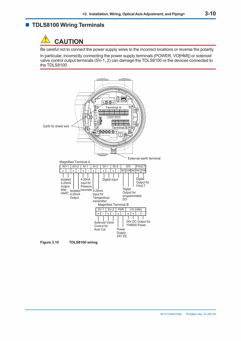
<3. Installation, Wiring, Optical Axis Adjustment, and Piping> 3-10
IM 11Y01D02-01EN 7th Edition: Dec. 10, 2021-00
n TDLS8100 Wiring Terminals
CAUTIONBe careful not to connect the power supply wires to the incorrect locations or reverse the polarity.In particular, incorrectly connecting the power supply terminals (POWER, VO[HMI]) or solenoid valve control output terminals (SV-1, 2) can damage the TDLS8100 or the devices connected to the TDLS8100.
AO-1 AO-2 AI-1 AI-2 DI-1 DI-2 DO FAULT+ - + - + - + - + - + - NC COM NO NC COM
SV-1 SV-2 PWR VO (HMI)+ - + - + - + + - -
Isolated4-20mAOutputWithHART
4-20mAInput forPressure transmitter 4-20mA
Input forTemperature transmitter
Solenoid ValveControl forAuto Cal
DigitalOutput for programmableDO
DigitalOutput forFAULT
PowerSupply24V DC
24V DC Output for YH8000 Power
Isolated4-20mAOutput
Magnified Terminal A
Terminal A
Magnified Terminal B
Terminal B
Digital Input
Earth for shield wire
External earth terminal
Figure 3.10 TDLS8100 wiring
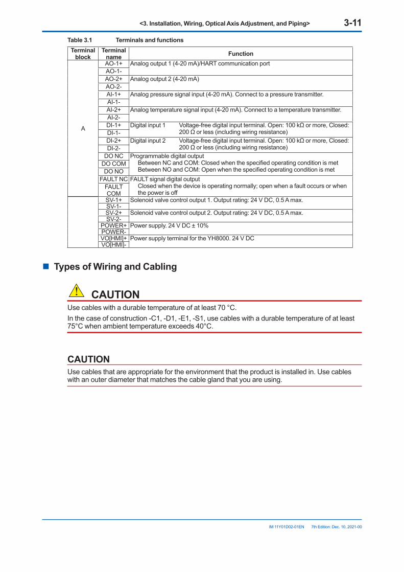
<3. Installation, Wiring, Optical Axis Adjustment, and Piping> 3-11
IM 11Y01D02-01EN 7th Edition: Dec. 10, 2021-00
Table 3.1 Terminals and functionsTerminal
blockTerminal
name Function
A
AO-1+ Analog output 1 (4-20 mA)/HART communication portAO-1-AO-2+ Analog output 2 (4-20 mA)AO-2-AI-1+ Analog pressure signal input (4-20 mA). Connect to a pressure transmitter.AI-1-AI-2+ Analog temperature signal input (4-20 mA). Connect to a temperature transmitter.AI-2-DI-1+ Digital input 1 Voltage-free digital input terminal. Open: 100 kΩ or more, Closed:
200 Ω or less (including wiring resistance)DI-1-DI-2+ Digital input 2 Voltage-free digital input terminal. Open: 100 kΩ or more, Closed:
200 Ω or less (including wiring resistance)DI-2-DO NC Programmable digital output
Between NC and COM: Closed when the specified operating condition is met Between NO and COM: Open when the specified operating condition is met
DO COMDO NO
FAULT NC FAULT signal digital output Closed when the device is operating normally; open when a fault occurs or when
the power is offFAULT COMSV-1+ Solenoid valve control output 1. Output rating: 24 V DC, 0.5 A max.SV-1-SV-2+ Solenoid valve control output 2. Output rating: 24 V DC, 0.5 A max.SV-2-
POWER+ Power supply. 24 V DC ± 10%POWER-VO[HMI]+ Power supply terminal for the YH8000. 24 V DCVO[HMI]-
n Types of Wiring and Cabling
CAUTIONUse cables with a durable temperature of at least 70 °C.In the case of construction -C1, -D1, -E1, -S1, use cables with a durable temperature of at least 75°C when ambient temperature exceeds 40°C.
CAUTIONUse cables that are appropriate for the environment that the product is installed in. Use cables with an outer diameter that matches the cable gland that you are using.
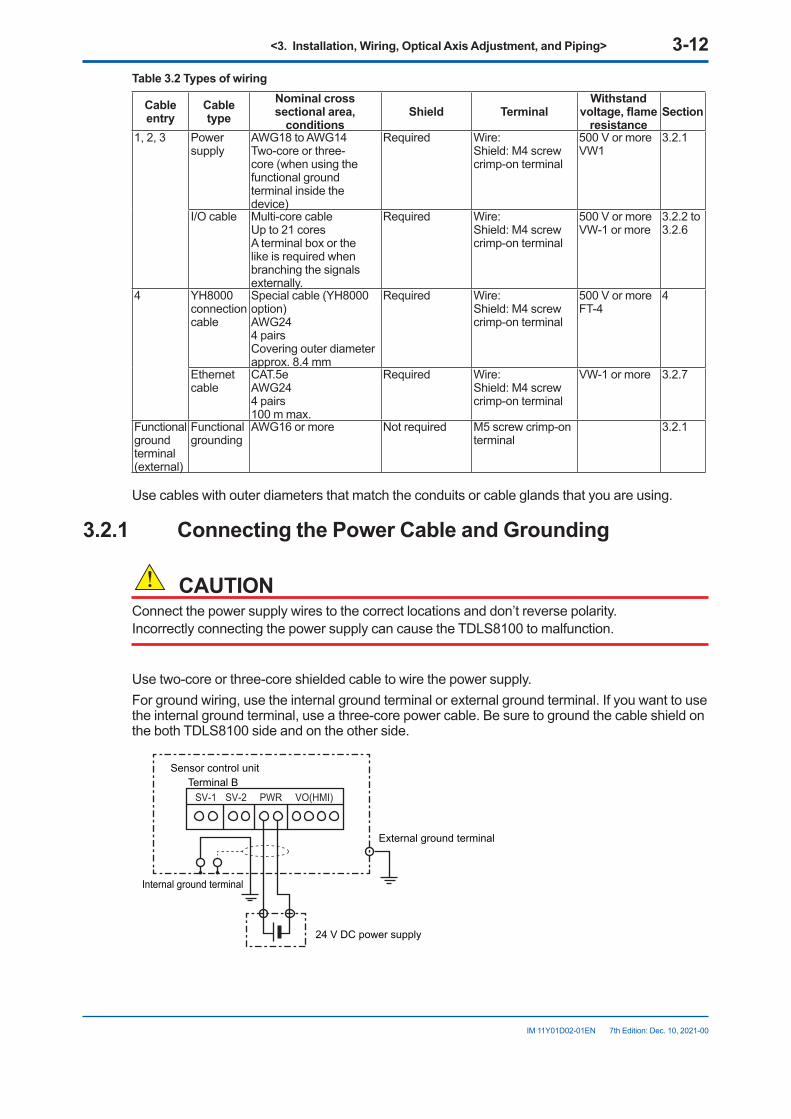
<3. Installation, Wiring, Optical Axis Adjustment, and Piping> 3-12
IM 11Y01D02-01EN 7th Edition: Dec. 10, 2021-00
Table 3.2 Types of wiring
Cable entry
Cable type
Nominal cross sectional area,
conditionsShield Terminal
Withstandvoltage,flame
resistanceSection
1, 2, 3 Power supply
AWG18 to AWG14Two-core or three-core (when using the functional ground terminal inside the device)
Required Wire:Shield: M4 screw crimp-on terminal
500 V or moreVW1
3.2.1
I/O cable Multi-core cableUp to 21 coresA terminal box or the like is required when branching the signals externally.
Required Wire:Shield: M4 screw crimp-on terminal
500 V or moreVW-1 or more
3.2.2 to 3.2.6
4 YH8000 connection cable
Special cable (YH8000 option)AWG244 pairsCovering outer diameter approx. 8.4 mm
Required Wire:Shield: M4 screw crimp-on terminal
500 V or moreFT-4
4
Ethernet cable
CAT.5eAWG244 pairs100 m max.
Required Wire:Shield: M4 screw crimp-on terminal
VW-1 or more 3.2.7
Functional ground terminal (external)
Functional grounding
AWG16 or more Not required M5 screw crimp-on terminal
3.2.1
Use cables with outer diameters that match the conduits or cable glands that you are using.
3.2.1 ConnectingthePowerCableandGrounding
CAUTIONConnect the power supply wires to the correct locations and don’t reverse polarity.Incorrectly connecting the power supply can cause the TDLS8100 to malfunction.
Use two-core or three-core shielded cable to wire the power supply.For ground wiring, use the internal ground terminal or external ground terminal. If you want to use the internal ground terminal, use a three-core power cable. Be sure to ground the cable shield on the both TDLS8100 side and on the other side.
SV-1 VO(HMI)SV-2 PWR
Internal ground terminal
External ground terminal
24 V DC power supply
Sensor control unitTerminal B
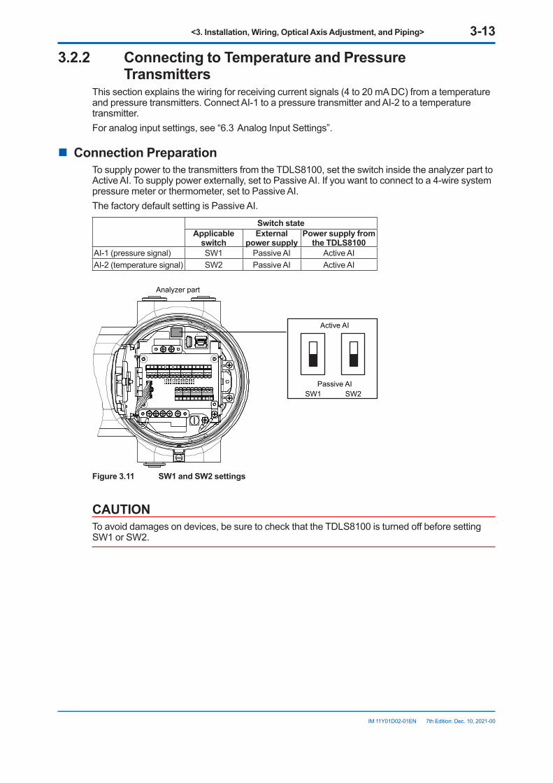
<3. Installation, Wiring, Optical Axis Adjustment, and Piping> 3-13
IM 11Y01D02-01EN 7th Edition: Dec. 10, 2021-00
3.2.2 Connecting to Temperature and Pressure Transmitters
This section explains the wiring for receiving current signals (4 to 20 mA DC) from a temperature and pressure transmitters. Connect AI-1 to a pressure transmitter and AI-2 to a temperature transmitter.For analog input settings, see “6.3 Analog Input Settings”.
n Connection PreparationTo supply power to the transmitters from the TDLS8100, set the switch inside the analyzer part to Active AI. To supply power externally, set to Passive AI. If you want to connect to a 4-wire system pressure meter or thermometer, set to Passive AI.The factory default setting is Passive AI.
SwitchstateApplicable switch
Externalpower supply
Power supply from theTDLS8100
AI-1 (pressure signal) SW1 Passive AI Active AIAI-2 (temperature signal) SW2 Passive AI Active AI
Active AI
Passive AISW1 SW2
Analyzer part
Figure 3.11 SW1 and SW2 settings
CAUTIONTo avoid damages on devices, be sure to check that the TDLS8100 is turned off before setting SW1 or SW2.
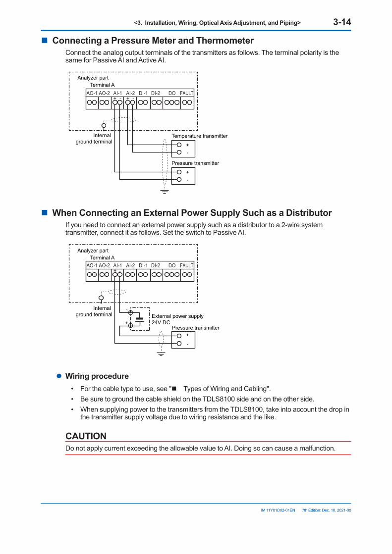
<3. Installation, Wiring, Optical Axis Adjustment, and Piping> 3-14
IM 11Y01D02-01EN 7th Edition: Dec. 10, 2021-00
n ConnectingaPressureMeterandThermometerConnect the analog output terminals of the transmitters as follows. The terminal polarity is the same for Passive AI and Active AI.
AO-1 AI-2AO-2 AI-1 DI-1
+
+ -+ -
-
FAULTDI-2 DO
+-
Internal ground terminal
Temperature transmitter
Analyzer partTerminal A
Pressure transmitter
n WhenConnectinganExternalPowerSupplySuchasaDistributorIf you need to connect an external power supply such as a distributor to a 2-wire system transmitter, connect it as follows. Set the switch to Passive AI.
AO-1 AI-2AO-2 AI-1 DI-1 FAULTDI-2 DO
+
+
+
-
-
-
Internal ground terminal
Analyzer partTerminal A
External power supply24V DC
Pressure transmitter
l Wiring procedure• For the cable type to use, see "n Types of Wiring and Cabling".• Be sure to ground the cable shield on the TDLS8100 side and on the other side.• When supplying power to the transmitters from the TDLS8100, take into account the drop in
the transmitter supply voltage due to wiring resistance and the like.
CAUTIONDo not apply current exceeding the allowable value to AI. Doing so can cause a malfunction.
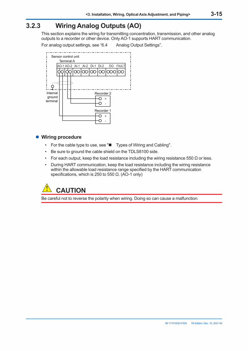
<3. Installation, Wiring, Optical Axis Adjustment, and Piping> 3-15
IM 11Y01D02-01EN 7th Edition: Dec. 10, 2021-00
3.2.3 WiringAnalogOutputs(AO)This section explains the wiring for transmitting concentration, transmission, and other analog outputs to a recorder or other device. Only AO-1 supports HART communication.For analog output settings, see “6.4 Analog Output Settings”.
AO-1 AI-2AO-2 AI-1 DI-1
+
+ -+ -
-
FAULTDI-2 DO
+-
Internal ground
terminal
Recorder 2
Sensor control unitTerminal A
Recorder 1
l Wiring procedure• For the cable type to use, see "n Types of Wiring and Cabling".• Be sure to ground the cable shield on the TDLS8100 side.• For each output, keep the load resistance including the wiring resistance 550 Ω or less.• During HART communication, keep the load resistance including the wiring resistance
within the allowable load resistance range specified by the HART communication specifications, which is 250 to 550 Ω. (AO-1 only)
CAUTIONBe careful not to reverse the polarity when wiring. Doing so can cause a malfunction.
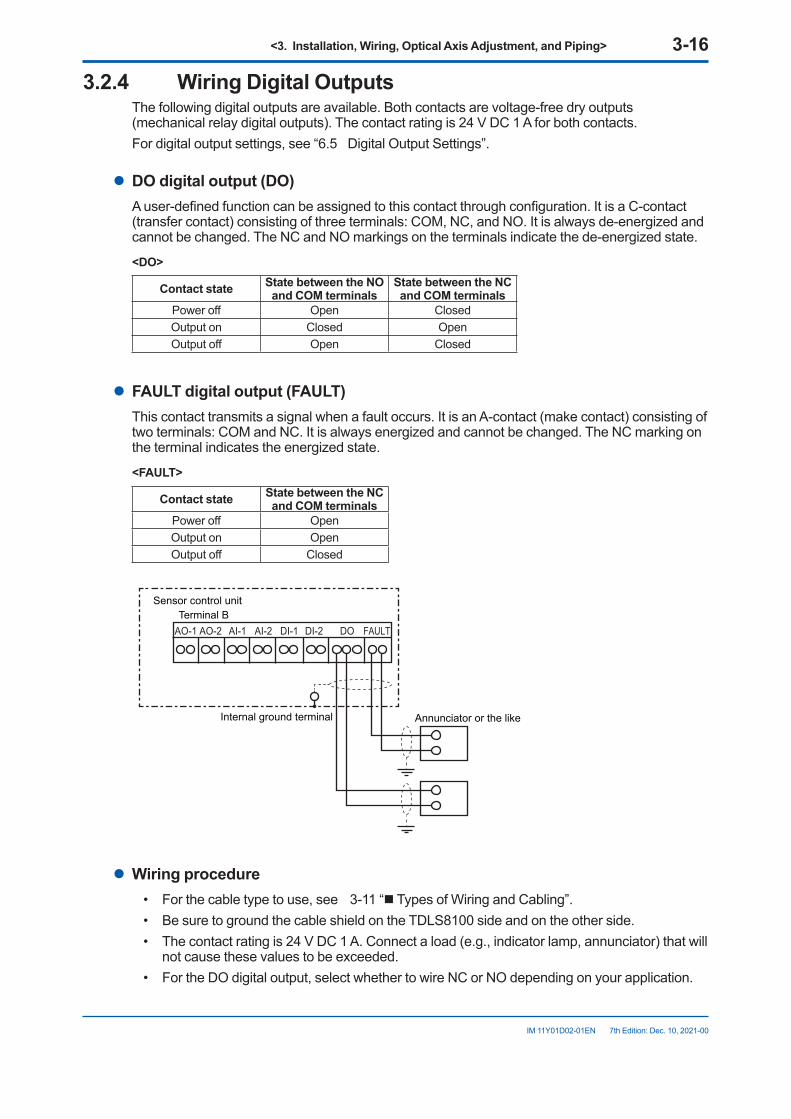
<3. Installation, Wiring, Optical Axis Adjustment, and Piping> 3-16
IM 11Y01D02-01EN 7th Edition: Dec. 10, 2021-00
3.2.4 Wiring Digital OutputsThe following digital outputs are available. Both contacts are voltage-free dry outputs (mechanical relay digital outputs). The contact rating is 24 V DC 1 A for both contacts.For digital output settings, see “6.5 Digital Output Settings”.
l DOdigitaloutput(DO)A user-defined function can be assigned to this contact through configuration. It is a C-contact (transfer contact) consisting of three terminals: COM, NC, and NO. It is always de-energized and cannot be changed. The NC and NO markings on the terminals indicate the de-energized state.
<DO>
Contact state StatebetweentheNOand COM terminals
StatebetweentheNCand COM terminals
Power off Open ClosedOutput on Closed OpenOutput off Open Closed
l FAULTdigitaloutput(FAULT)This contact transmits a signal when a fault occurs. It is an A-contact (make contact) consisting of two terminals: COM and NC. It is always energized and cannot be changed. The NC marking on the terminal indicates the energized state.
<FAULT>
Contact state StatebetweentheNCand COM terminals
Power off OpenOutput on OpenOutput off Closed
AO-1 AI-2AO-2 AI-1 DI-1 FAULTDI-2 DO
Internal ground terminal Annunciator or the like
Sensor control unitTerminal B
l Wiring procedure• For the cable type to use, see 3-11 “n Types of Wiring and Cabling”.• Be sure to ground the cable shield on the TDLS8100 side and on the other side.• The contact rating is 24 V DC 1 A. Connect a load (e.g., indicator lamp, annunciator) that will
not cause these values to be exceeded.• For the DO digital output, select whether to wire NC or NO depending on your application.
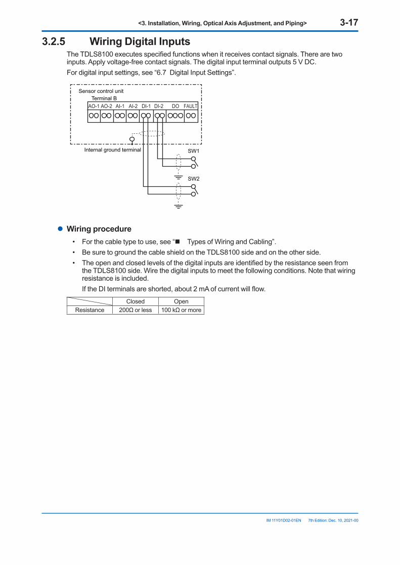
<3. Installation, Wiring, Optical Axis Adjustment, and Piping> 3-17
IM 11Y01D02-01EN 7th Edition: Dec. 10, 2021-00
3.2.5 Wiring Digital InputsThe TDLS8100 executes specified functions when it receives contact signals. There are two inputs. Apply voltage-free contact signals. The digital input terminal outputs 5 V DC.For digital input settings, see “6.7 Digital Input Settings”.
AO-1 AI-2AO-2 AI-1 DI-1 FAULTDI-2 DO
SW1
SW2
Internal ground terminal
Sensor control unitTerminal B
l Wiring procedure• For the cable type to use, see “n Types of Wiring and Cabling”.• Be sure to ground the cable shield on the TDLS8100 side and on the other side.• The open and closed levels of the digital inputs are identified by the resistance seen from
the TDLS8100 side. Wire the digital inputs to meet the following conditions. Note that wiring resistance is included.
If the DI terminals are shorted, about 2 mA of current will flow.
Closed OpenResistance 200Ω or less 100 kΩ or more
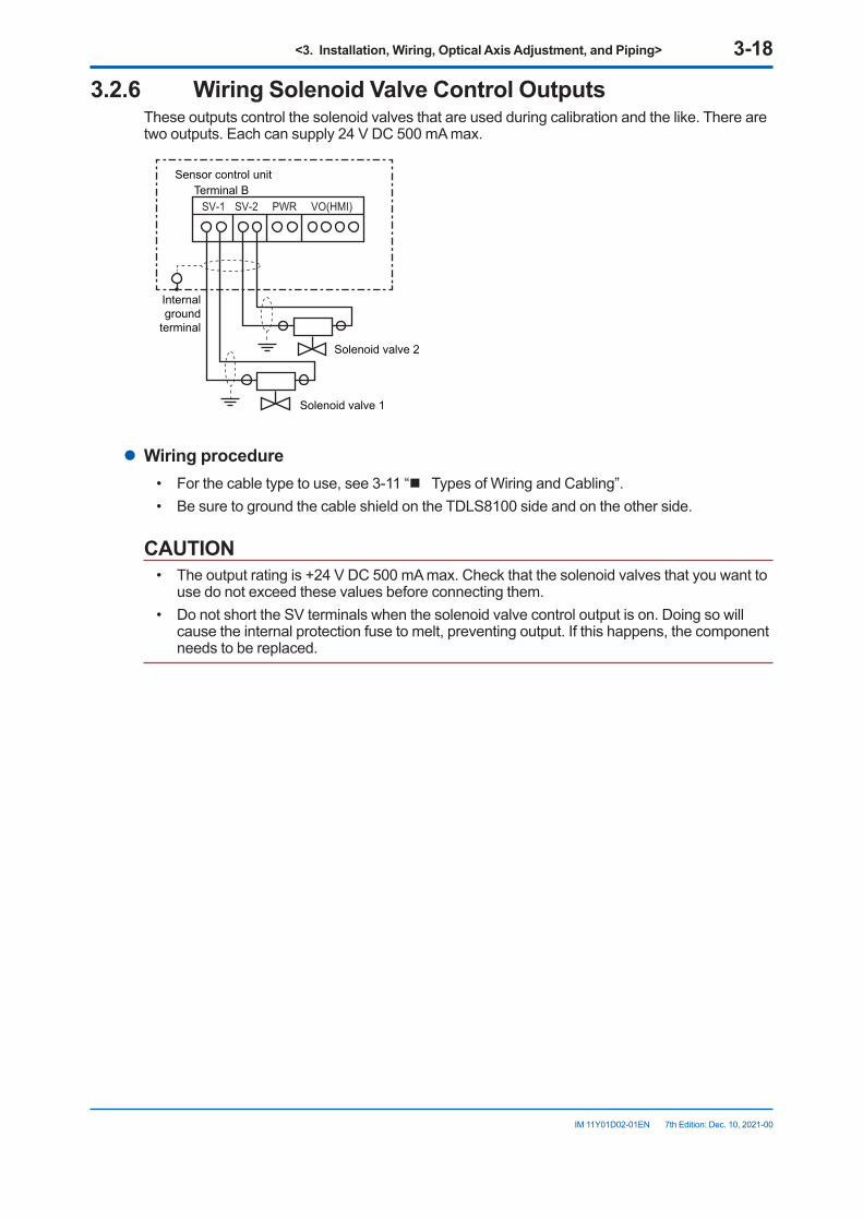
<3. Installation, Wiring, Optical Axis Adjustment, and Piping> 3-18
IM 11Y01D02-01EN 7th Edition: Dec. 10, 2021-00
3.2.6 Wiring Solenoid Valve Control OutputsThese outputs control the solenoid valves that are used during calibration and the like. There are two outputs. Each can supply 24 V DC 500 mA max.
SV-1 VO(HMI)SV-2 PWR
Sensor control unitTerminal B
Internal ground
terminal
Solenoid valve 1
Solenoid valve 2
l Wiring procedure• For the cable type to use, see 3-11 “n Types of Wiring and Cabling”.• Be sure to ground the cable shield on the TDLS8100 side and on the other side.
CAUTION• The output rating is +24 V DC 500 mA max. Check that the solenoid valves that you want to
use do not exceed these values before connecting them.• Do not short the SV terminals when the solenoid valve control output is on. Doing so will
cause the internal protection fuse to melt, preventing output. If this happens, the component needs to be replaced.
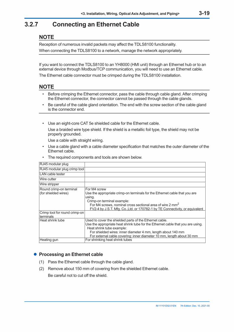
<3. Installation, Wiring, Optical Axis Adjustment, and Piping> 3-19
IM 11Y01D02-01EN 7th Edition: Dec. 10, 2021-00
3.2.7 ConnectinganEthernetCable
NOTEReception of numerous invalid packets may affect the TDLS8100 functionality.When connecting the TDLS8100 to a network, manage the network appropriately.
If you want to connect the TDLS8100 to an YH8000 (HMI unit) through an Ethernet hub or to an external device through Modbus/TCP communication, you will need to use an Ethernet cable.The Ethernet cable connector must be crimped during the TDLS8100 installation.
NOTE• Before crimping the Ethernet connector, pass the cable through cable gland. After crimping
the Ethernet connector, the connector cannot be passed through the cable glands.• Be careful of the cable gland orientation. The end with the screw section of the cable gland
is the connector end.
• Use an eight-core CAT 5e shielded cable for the Ethernet cable. Use a braided wire type shield. If the shield is a metallic foil type, the shield may not be
properly grounded. Use a cable with straight wiring.• Use a cable gland with a cable diameter specification that matches the outer diameter of the
Ethernet cable.• The required components and tools are shown below.
RJ45 modular plugRJ45 modular plug crimp toolLAN cable testerWire cutterWire stripperRound crimp-on terminal(for shielded wires)
For M4 screwUse the appropriate crimp-on terminals for the Ethernet cable that you are using.Crimp-on terminal example: For M4 screws, nominal cross sectional area of wire 2 mm2
FV2-4 by J.S.T. Mfg. Co.,Ltd. or 170782-1 by TE Connectivity, or equivalentCrimp tool for round crimp-on terminalsHeat shrink tube Used to cover the shielded parts of the Ethernet cable.
Use the appropriate heat shrink tube for the Ethernet cable that you are using.Heat shrink tube example: For shielded wires: inner diameter 4 mm, length about 140 mm For external cable covering: inner diameter 10 mm, length about 30 mm
Heating gun For shrinking heat shrink tubes
l ProcessinganEthernetcable(1) Pass the Ethernet cable through the cable gland.(2) Remove about 150 mm of covering from the shielded Ethernet cable. Be careful not to cut off the shield.
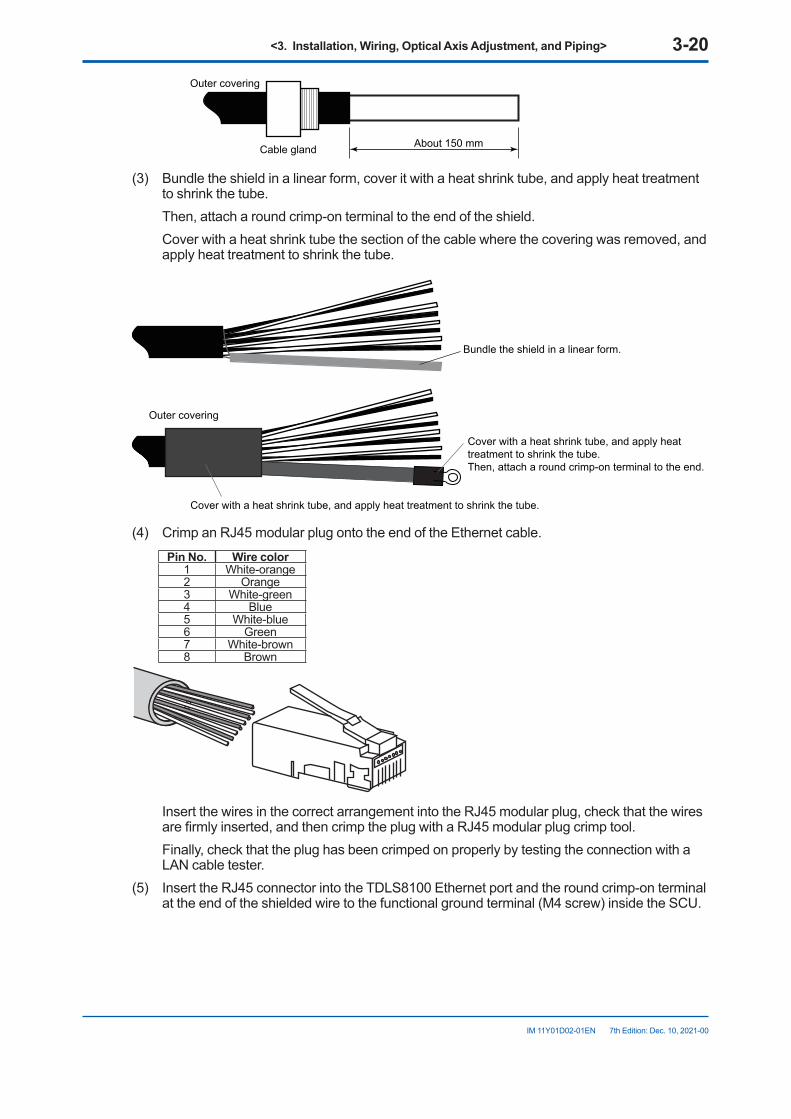
<3. Installation, Wiring, Optical Axis Adjustment, and Piping> 3-20
IM 11Y01D02-01EN 7th Edition: Dec. 10, 2021-00
Outer covering
Cable gland About 150 mm
(3) Bundle the shield in a linear form, cover it with a heat shrink tube, and apply heat treatment to shrink the tube.
Then, attach a round crimp-on terminal to the end of the shield. Cover with a heat shrink tube the section of the cable where the covering was removed, and
apply heat treatment to shrink the tube.
Outer covering
Cover with a heat shrink tube, and apply heat treatment to shrink the tube.Then, attach a round crimp-on terminal to the end.
Bundle the shield in a linear form.
Cover with a heat shrink tube, and apply heat treatment to shrink the tube.
(4) Crimp an RJ45 modular plug onto the end of the Ethernet cable.Pin No. Wire color
1 White-orange2 Orange3 White-green4 Blue5 White-blue6 Green7 White-brown8 Brown
Insert the wires in the correct arrangement into the RJ45 modular plug, check that the wires are firmly inserted, and then crimp the plug with a RJ45 modular plug crimp tool.
Finally, check that the plug has been crimped on properly by testing the connection with a LAN cable tester.
(5) Insert the RJ45 connector into the TDLS8100 Ethernet port and the round crimp-on terminal at the end of the shielded wire to the functional ground terminal (M4 screw) inside the SCU.
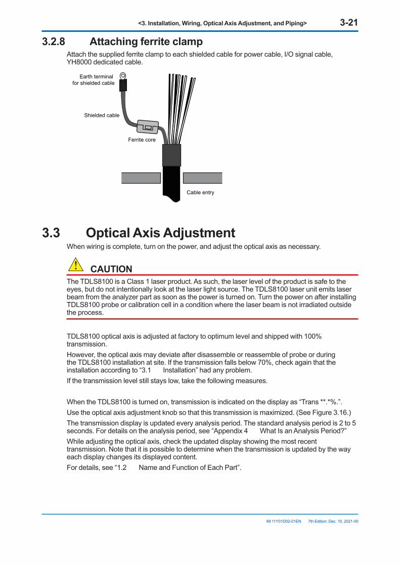
<3. Installation, Wiring, Optical Axis Adjustment, and Piping> 3-21
IM 11Y01D02-01EN 7th Edition: Dec. 10, 2021-00
3.2.8 AttachingferriteclampAttach the supplied ferrite clamp to each shielded cable for power cable, I/O signal cable, YH8000 dedicated cable.
Shielded cable
Earth terminal for shielded cable
Ferrite core
Cable entry
3.3 OpticalAxisAdjustmentWhen wiring is complete, turn on the power, and adjust the optical axis as necessary.
CAUTIONThe TDLS8100 is a Class 1 laser product. As such, the laser level of the product is safe to the eyes, but do not intentionally look at the laser light source. The TDLS8100 laser unit emits laser beam from the analyzer part as soon as the power is turned on. Turn the power on after installing TDLS8100 probe or calibration cell in a condition where the laser beam is not irradiated outside the process.
TDLS8100 optical axis is adjusted at factory to optimum level and shipped with 100% transmission.However, the optical axis may deviate after disassemble or reassemble of probe or during the TDLS8100 installation at site. If the transmission falls below 70%, check again that the installation according to “3.1 Installation” had any problem.If the transmission level still stays low, take the following measures.
When the TDLS8100 is turned on, transmission is indicated on the display as “Trans **.*%.”.Use the optical axis adjustment knob so that this transmission is maximized. (See Figure 3.16.)The transmission display is updated every analysis period. The standard analysis period is 2 to 5 seconds. For details on the analysis period, see “Appendix 4 What Is an Analysis Period?”While adjusting the optical axis, check the updated display showing the most recent transmission. Note that it is possible to determine when the transmission is updated by the way each display changes its displayed content.For details, see “1.2 Name and Function of Each Part”.
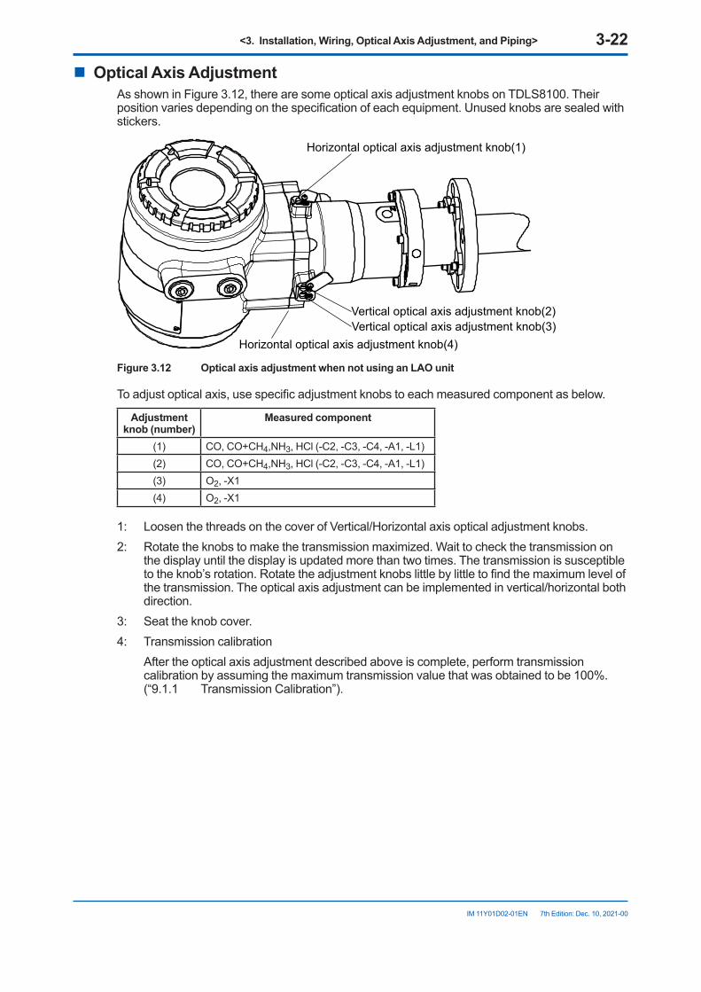
<3. Installation, Wiring, Optical Axis Adjustment, and Piping> 3-22
IM 11Y01D02-01EN 7th Edition: Dec. 10, 2021-00
n OpticalAxisAdjustmentAs shown in Figure 3.12, there are some optical axis adjustment knobs on TDLS8100. Their position varies depending on the specification of each equipment. Unused knobs are sealed with stickers.
Vertical optical axis adjustment knob(3)Horizontal optical axis adjustment knob(4)
Horizontal optical axis adjustment knob(1)
Vertical optical axis adjustment knob(2)
Figure3.12 OpticalaxisadjustmentwhennotusinganLAOunit
To adjust optical axis, use specific adjustment knobs to each measured component as below.
Adjustmentknob(number)
Measured component
(1) CO, CO+CH4,NH3, HCl (-C2, -C3, -C4, -A1, -L1)(2) CO, CO+CH4,NH3, HCl (-C2, -C3, -C4, -A1, -L1)(3) O2, -X1(4) O2, -X1
1: Loosen the threads on the cover of Vertical/Horizontal axis optical adjustment knobs.2: Rotate the knobs to make the transmission maximized. Wait to check the transmission on
the display until the display is updated more than two times. The transmission is susceptible to the knob’s rotation. Rotate the adjustment knobs little by little to find the maximum level of the transmission. The optical axis adjustment can be implemented in vertical/horizontal both direction.
3: Seat the knob cover.4: Transmission calibration After the optical axis adjustment described above is complete, perform transmission
calibration by assuming the maximum transmission value that was obtained to be 100%. (“9.1.1 Transmission Calibration”).
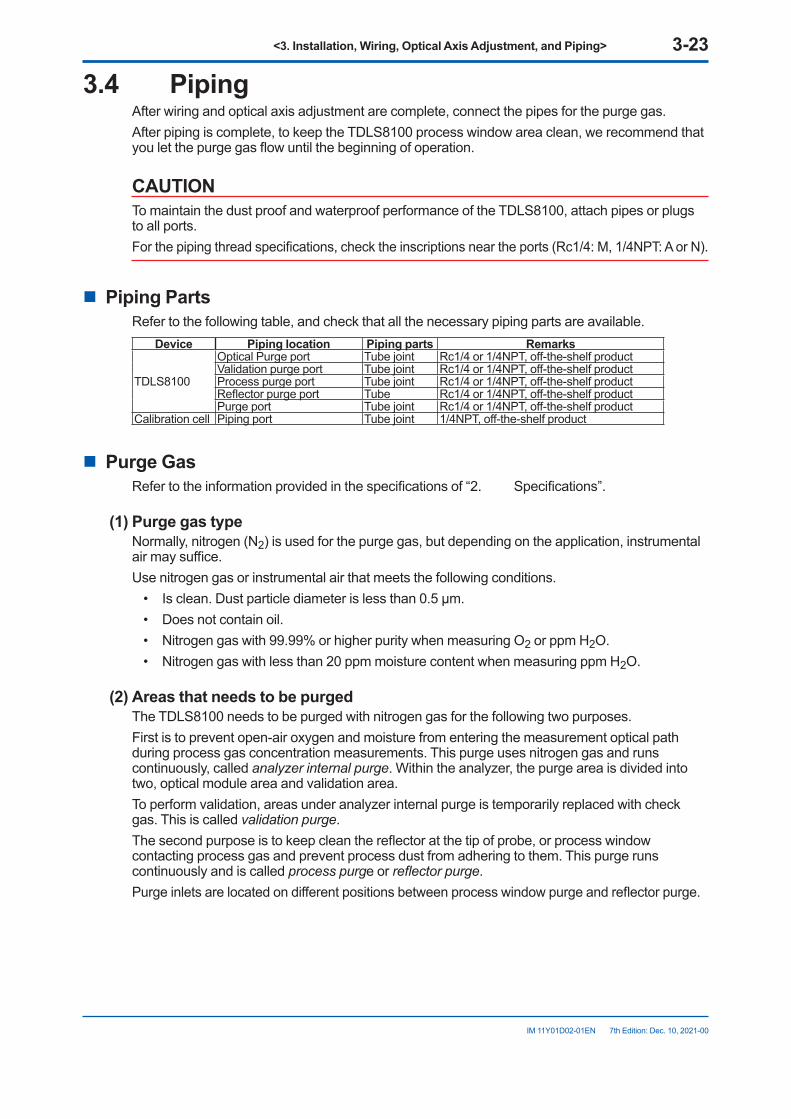
<3. Installation, Wiring, Optical Axis Adjustment, and Piping> 3-23
IM 11Y01D02-01EN 7th Edition: Dec. 10, 2021-00
3.4 PipingAfter wiring and optical axis adjustment are complete, connect the pipes for the purge gas.After piping is complete, to keep the TDLS8100 process window area clean, we recommend that you let the purge gas flow until the beginning of operation.
CAUTIONTo maintain the dust proof and waterproof performance of the TDLS8100, attach pipes or plugs to all ports.For the piping thread specifications, check the inscriptions near the ports (Rc1/4: M, 1/4NPT: A or N).
n Piping PartsRefer to the following table, and check that all the necessary piping parts are available.
Device Piping location Piping parts Remarks
TDLS8100
Optical Purge port Tube joint Rc1/4 or 1/4NPT, off-the-shelf productValidation purge port Tube joint Rc1/4 or 1/4NPT, off-the-shelf productProcess purge port Tube joint Rc1/4 or 1/4NPT, off-the-shelf productReflector purge port Tube Rc1/4 or 1/4NPT, off-the-shelf productPurge port Tube joint Rc1/4 or 1/4NPT, off-the-shelf product
Calibration cell Piping port Tube joint 1/4NPT, off-the-shelf product
n Purge GasRefer to the information provided in the specifications of “2. Specifications”.
(1)PurgegastypeNormally, nitrogen (N2) is used for the purge gas, but depending on the application, instrumental air may suffice.Use nitrogen gas or instrumental air that meets the following conditions.
• Is clean. Dust particle diameter is less than 0.5 µm.• Does not contain oil.• Nitrogen gas with 99.99% or higher purity when measuring O2 or ppm H2O.• Nitrogen gas with less than 20 ppm moisture content when measuring ppm H2O.
(2)AreasthatneedstobepurgedThe TDLS8100 needs to be purged with nitrogen gas for the following two purposes.First is to prevent open-air oxygen and moisture from entering the measurement optical path during process gas concentration measurements. This purge uses nitrogen gas and runs continuously, called analyzer internal purge. Within the analyzer, the purge area is divided into two, optical module area and validation area.To perform validation, areas under analyzer internal purge is temporarily replaced with check gas. This is called validation purge.The second purpose is to keep clean the reflector at the tip of probe, or process window contacting process gas and prevent process dust from adhering to them. This purge runs continuously and is called process purge or reflector purge.Purge inlets are located on different positions between process window purge and reflector purge.
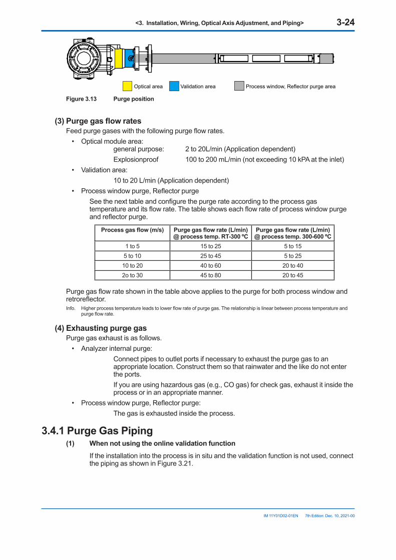
<3. Installation, Wiring, Optical Axis Adjustment, and Piping> 3-24
IM 11Y01D02-01EN 7th Edition: Dec. 10, 2021-00
Optical area Validation area Process window, Reflector purge area
Figure 3.13 Purge position
(3)PurgegasflowratesFeed purge gases with the following purge flow rates.
• Optical module area: general purpose: 2 to 20L/min (Application dependent)
Explosionproof 100 to 200 mL/min (not exceeding 10 kPA at the inlet)• Validation area: 10 to 20 L/min (Application dependent)• Process window purge, Reflector purge See the next table and configure the purge rate according to the process gas
temperature and its flow rate. The table shows each flow rate of process window purge and reflector purge.
Processgasflow(m/s) Purgegasflowrate(L/min)@ process temp. RT-300 ºC
Purgegasflowrate(L/min)@ process temp. 300-600 ºC
1 to 5 15 to 25 5 to 155 to 10 25 to 45 5 to 2510 to 20 40 to 60 20 to 402o to 30 45 to 80 20 to 45
Purge gas flow rate shown in the table above applies to the purge for both process window and retroreflector.Info. Higher process temperature leads to lower flow rate of purge gas. The relationship is linear between process temperature and
purge flow rate.
(4)ExhaustingpurgegasPurge gas exhaust is as follows.
• Analyzer internal purge: Connect pipes to outlet ports if necessary to exhaust the purge gas to an
appropriate location. Construct them so that rainwater and the like do not enter the ports.
If you are using hazardous gas (e.g., CO gas) for check gas, exhaust it inside the process or in an appropriate manner.
• Process window purge, Reflector purge: The gas is exhausted inside the process.
3.4.1 Purge Gas Piping(1) Whennotusingtheonlinevalidationfunction If the installation into the process is in situ and the validation function is not used, connect
the piping as shown in Figure 3.21.
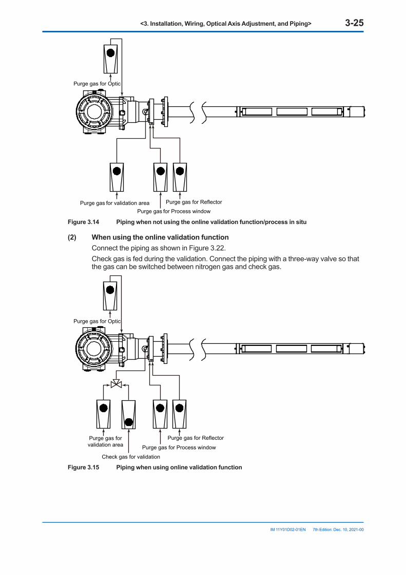
<3. Installation, Wiring, Optical Axis Adjustment, and Piping> 3-25
IM 11Y01D02-01EN 7th Edition: Dec. 10, 2021-00
Purge gas for Optic
Purge gas for ReflectorPurge gas for Process window
Purge gas for validation area
Figure3.14 Pipingwhennotusingtheonlinevalidationfunction/processinsitu
(2) Whenusingtheonlinevalidationfunction Connect the piping as shown in Figure 3.22. Check gas is fed during the validation. Connect the piping with a three-way valve so that
the gas can be switched between nitrogen gas and check gas.
Purge gas for Reflector
Purge gas for Process windowPurge gas for validation area
Purge gas for Optic
Check gas for validation
Figure3.15 Pipingwhenusingonlinevalidationfunction
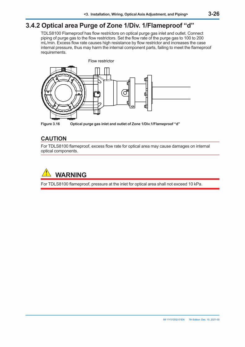
<3. Installation, Wiring, Optical Axis Adjustment, and Piping> 3-26
IM 11Y01D02-01EN 7th Edition: Dec. 10, 2021-00
3.4.2OpticalareaPurgeofZone1/Div.1/Flameproof“d”TDLS8100 Flameproof has flow restrictors on optical purge gas inlet and outlet. Connect piping of purge gas to the flow restrictors. Set the flow rate of the purge gas to 100 to 200 mL/min. Excess flow rate causes high resistance by flow restrictor and increases the case internal pressure, thus may harm the internal component parts, failing to meet the flameproof requirements.
Flow restrictor
Figure3.16 OpticalpurgegasinletandoutletofZone1/Div.1/Flameproof“d”
CAUTIONFor TDLS8100 flameproof, excess flow rate for optical area may cause damages on internal optical components.
WARNINGFor TDLS8100 flameproof, pressure at the inlet for optical area shall not exceed 10 kPa.
<4. YH8000 Installation> 4-1
IM 11Y01D02-01EN 7th Edition: Dec. 10, 2021-00
4. YH8000 InstallationThere are two methods of YH8000 HMI unit installation: local HMI installation in which the unit is mounted directly on the TDLS8100 and remote HMI installation in which the unit is mounted by itself on a wall or the like.See “2.4 External Dimensions”.
CAUTIONDuring installation, be careful not to drop the product or damage the display.
l Installation locationThe YH8000 is designed to work even in harsh environmental conditions, but note the following points in order to use it stably for a long time.
Select an installation location where the ambient temperature and humidity are within the specifications.Be sure to block direct sunlight such as by attaching a sun shield or installing it in a cubicle.If the YH8000 it subject to heat radiation such as from plant facilities, take heat insulation measures.Also, select a location that meets the following conditions.
• Where there is hardly any mechanical vibration or shock• Where it is not subject to direct sunlight or harsh weather conditions• Where there is no corrosive atmosphere
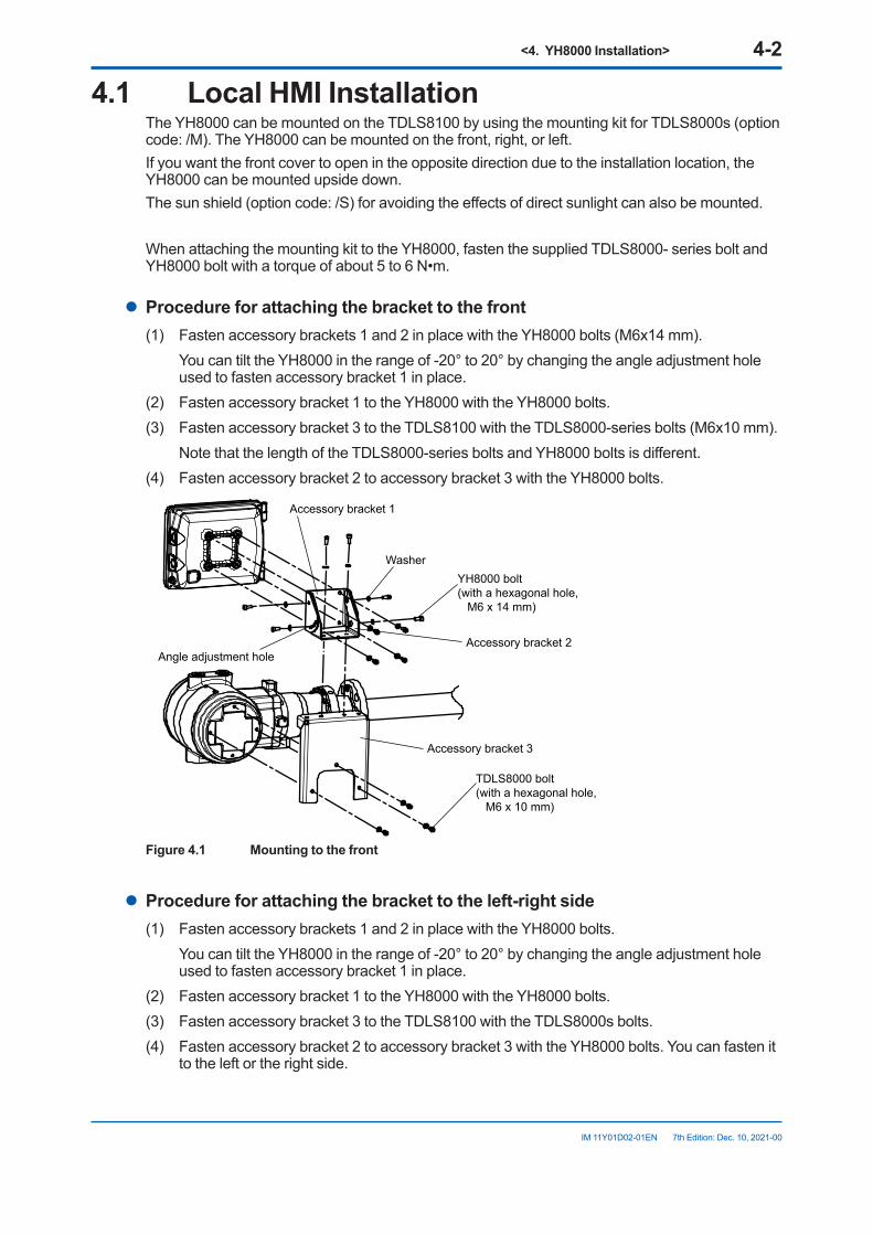
<4. YH8000 Installation> 4-2
IM 11Y01D02-01EN 7th Edition: Dec. 10, 2021-00
4.1 Local HMI InstallationThe YH8000 can be mounted on the TDLS8100 by using the mounting kit for TDLS8000s (option code: /M). The YH8000 can be mounted on the front, right, or left.If you want the front cover to open in the opposite direction due to the installation location, the YH8000 can be mounted upside down.The sun shield (option code: /S) for avoiding the effects of direct sunlight can also be mounted.
When attaching the mounting kit to the YH8000, fasten the supplied TDLS8000- series bolt and YH8000 bolt with a torque of about 5 to 6 N•m.
l Procedureforattachingthebrackettothefront(1) Fasten accessory brackets 1 and 2 in place with the YH8000 bolts (M6x14 mm). You can tilt the YH8000 in the range of -20° to 20° by changing the angle adjustment hole
used to fasten accessory bracket 1 in place.(2) Fasten accessory bracket 1 to the YH8000 with the YH8000 bolts.(3) Fasten accessory bracket 3 to the TDLS8100 with the TDLS8000-series bolts (M6x10 mm). Note that the length of the TDLS8000-series bolts and YH8000 bolts is different.(4) Fasten accessory bracket 2 to accessory bracket 3 with the YH8000 bolts.
YH8000 bolt(with a hexagonal hole, M6 x 14 mm)
TDLS8000 bolt(with a hexagonal hole, M6 x 10 mm)
Washer
Accessory bracket 1
Angle adjustment holeAccessory bracket 2
Accessory bracket 3
Figure4.1 Mountingtothefront
l Procedureforattachingthebrackettotheleft-rightside(1) Fasten accessory brackets 1 and 2 in place with the YH8000 bolts. You can tilt the YH8000 in the range of -20° to 20° by changing the angle adjustment hole
used to fasten accessory bracket 1 in place.(2) Fasten accessory bracket 1 to the YH8000 with the YH8000 bolts.(3) Fasten accessory bracket 3 to the TDLS8100 with the TDLS8000s bolts.(4) Fasten accessory bracket 2 to accessory bracket 3 with the YH8000 bolts. You can fasten it
to the left or the right side.
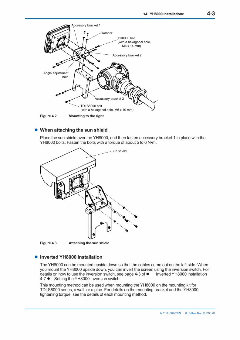
<4. YH8000 Installation> 4-3
IM 11Y01D02-01EN 7th Edition: Dec. 10, 2021-00
YH8000 bolt(with a hexagonal hole, M6 x 14 mm)
TDLS8000 bolt(with a hexagonal hole, M6 x 10 mm)
Washer
Accessory bracket 1
Angle adjustmenthole
Accessory bracket 2
Accessory bracket 3
Figure4.2 Mountingtotheright
l WhenattachingthesunshieldPlace the sun shield over the YH8000, and then fasten accessory bracket 1 in place with the YH8000 bolts. Fasten the bolts with a torque of about 5 to 6 N•m.
Sun shield
Figure4.3 Attachingthesunshield
l Inverted YH8000 installationThe YH8000 can be mounted upside down so that the cables come out on the left side. When you mount the YH8000 upside down, you can invert the screen using the inversion switch. For details on how to use the inversion switch, see page 4-3 of l Inverted YH8000 installation 4-7 l Setting the YH8000 inversion switch.This mounting method can be used when mounting the YH8000 on the mounting kit for TDLS8000 series, a wall, or a pipe. For details on the mounting bracket and the YH8000 tightening torque, see the details of each mounting method.
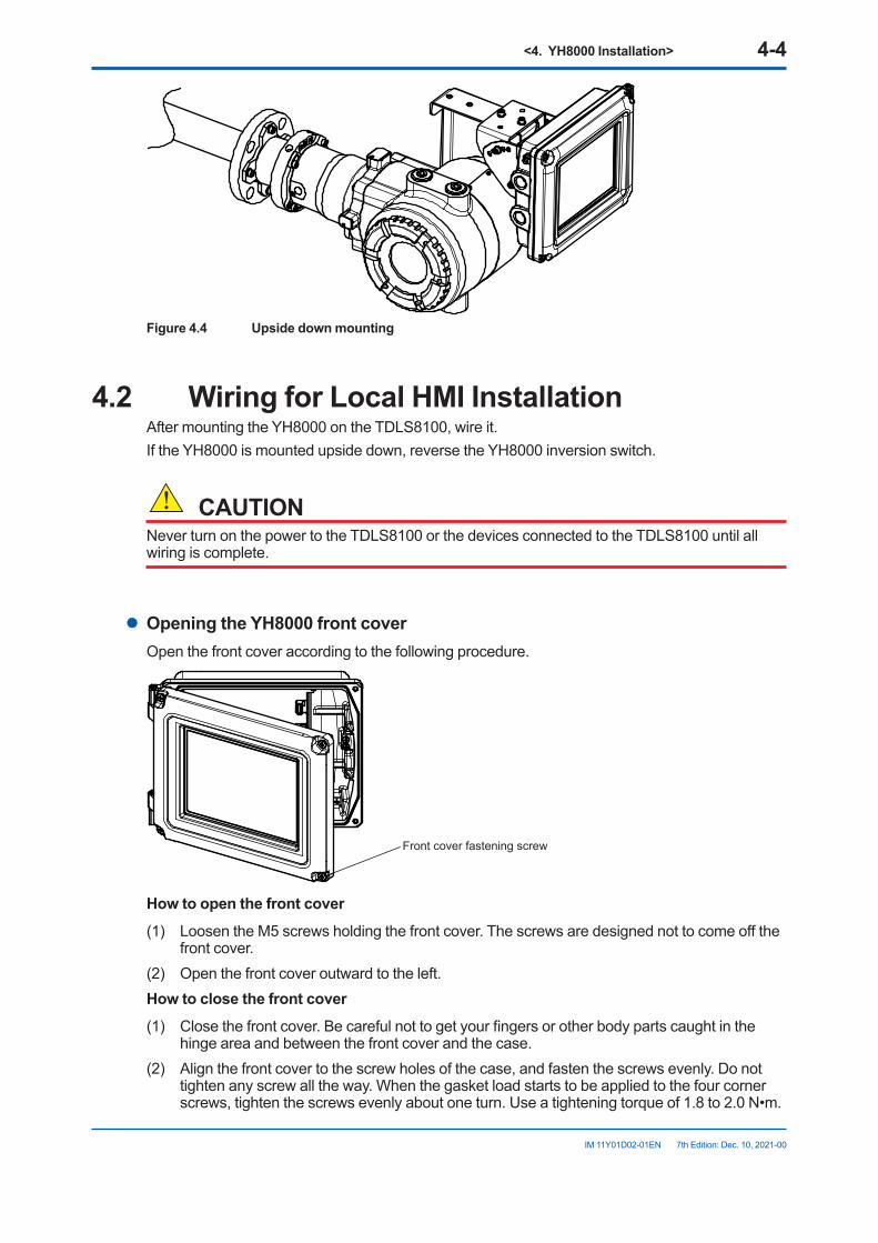
<4. YH8000 Installation> 4-4
IM 11Y01D02-01EN 7th Edition: Dec. 10, 2021-00
Figure 4.4 Upside down mounting
4.2 Wiring for Local HMI InstallationAfter mounting the YH8000 on the TDLS8100, wire it.If the YH8000 is mounted upside down, reverse the YH8000 inversion switch.
CAUTIONNever turn on the power to the TDLS8100 or the devices connected to the TDLS8100 until all wiring is complete.
l OpeningtheYH8000frontcoverOpen the front cover according to the following procedure.
Front cover fastening screw
Howtoopenthefrontcover(1) Loosen the M5 screws holding the front cover. The screws are designed not to come off the
front cover.(2) Open the front cover outward to the left.Howtoclosethefrontcover(1) Close the front cover. Be careful not to get your fingers or other body parts caught in the
hinge area and between the front cover and the case.(2) Align the front cover to the screw holes of the case, and fasten the screws evenly. Do not
tighten any screw all the way. When the gasket load starts to be applied to the four corner screws, tighten the screws evenly about one turn. Use a tightening torque of 1.8 to 2.0 N•m.
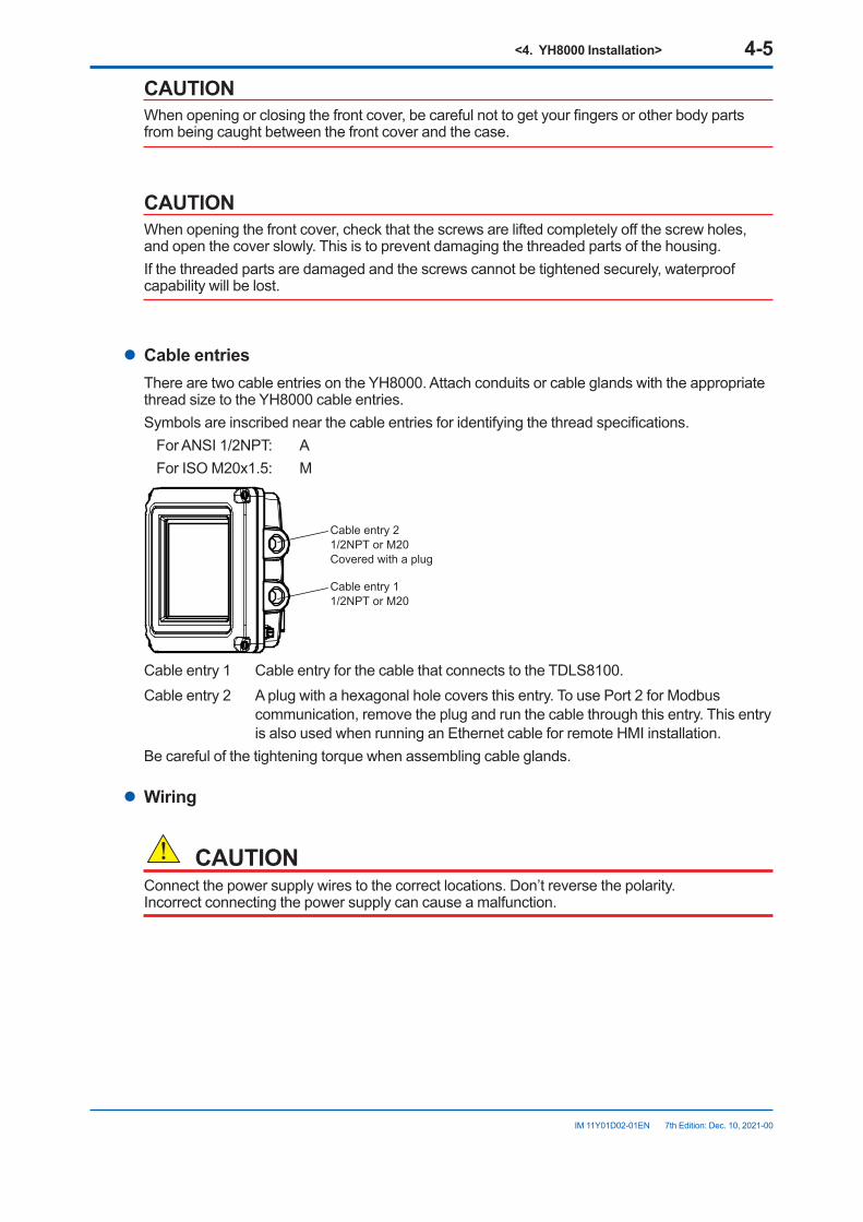
<4. YH8000 Installation> 4-5
IM 11Y01D02-01EN 7th Edition: Dec. 10, 2021-00
CAUTIONWhen opening or closing the front cover, be careful not to get your fingers or other body parts from being caught between the front cover and the case.
CAUTIONWhen opening the front cover, check that the screws are lifted completely off the screw holes, and open the cover slowly. This is to prevent damaging the threaded parts of the housing.If the threaded parts are damaged and the screws cannot be tightened securely, waterproof capability will be lost.
l Cable entriesThere are two cable entries on the YH8000. Attach conduits or cable glands with the appropriate thread size to the YH8000 cable entries.Symbols are inscribed near the cable entries for identifying the thread specifications.
For ANSI 1/2NPT: AFor ISO M20x1.5: M
Cable entry 21/2NPT or M20Covered with a plug
Cable entry 11/2NPT or M20
Cable entry 1 Cable entry for the cable that connects to the TDLS8100.Cable entry 2 A plug with a hexagonal hole covers this entry. To use Port 2 for Modbus
communication, remove the plug and run the cable through this entry. This entry is also used when running an Ethernet cable for remote HMI installation.
Be careful of the tightening torque when assembling cable glands.
l Wiring
CAUTIONConnect the power supply wires to the correct locations. Don’t reverse the polarity. Incorrect connecting the power supply can cause a malfunction.
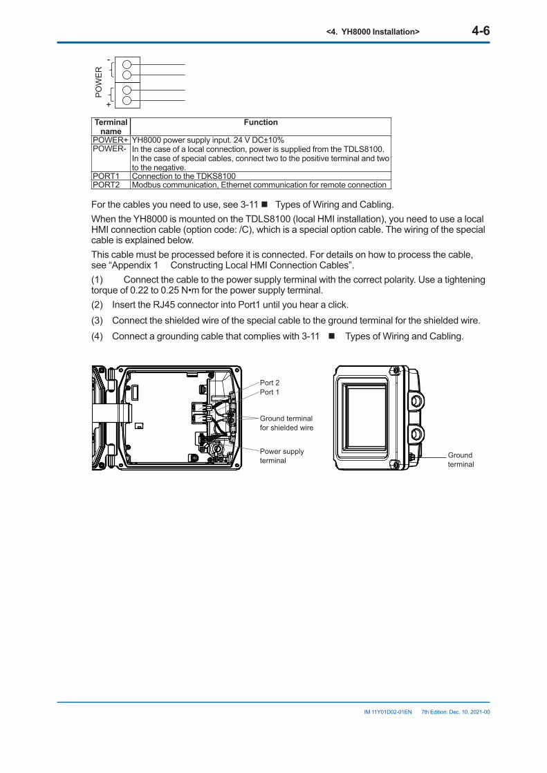
<4. YH8000 Installation> 4-6
IM 11Y01D02-01EN 7th Edition: Dec. 10, 2021-00
POW
ER
-
+
Terminal name
Function
POWER+ YH8000 power supply input. 24 V DC±10%In the case of a local connection, power is supplied from the TDLS8100.In the case of special cables, connect two to the positive terminal and two to the negative.
POWER-
PORT1 Connection to the TDKS8100PORT2 Modbus communication, Ethernet communication for remote connection
For the cables you need to use, see 3-11 n Types of Wiring and Cabling.When the YH8000 is mounted on the TDLS8100 (local HMI installation), you need to use a local HMI connection cable (option code: /C), which is a special option cable. The wiring of the special cable is explained below.This cable must be processed before it is connected. For details on how to process the cable, see “Appendix 1 Constructing Local HMI Connection Cables”.(1) Connect the cable to the power supply terminal with the correct polarity. Use a tightening torque of 0.22 to 0.25 N•m for the power supply terminal.(2) Insert the RJ45 connector into Port1 until you hear a click.(3) Connect the shielded wire of the special cable to the ground terminal for the shielded wire.(4) Connect a grounding cable that complies with 3-11 n Types of Wiring and Cabling.
Ground terminal for shielded wire
Power supply terminal
Port 1Port 2
Ground terminal
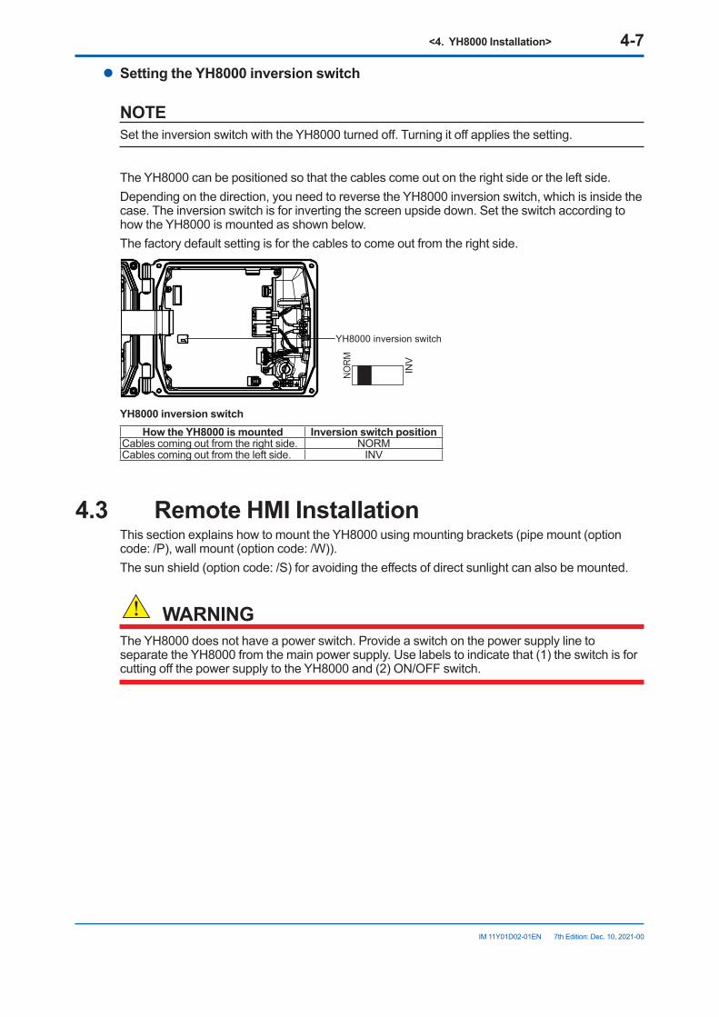
<4. YH8000 Installation> 4-7
IM 11Y01D02-01EN 7th Edition: Dec. 10, 2021-00
l SettingtheYH8000inversionswitch
NOTESet the inversion switch with the YH8000 turned off. Turning it off applies the setting.
The YH8000 can be positioned so that the cables come out on the right side or the left side.Depending on the direction, you need to reverse the YH8000 inversion switch, which is inside the case. The inversion switch is for inverting the screen upside down. Set the switch according to how the YH8000 is mounted as shown below.The factory default setting is for the cables to come out from the right side.
INV
NORM
YH8000 inversion switch
YH8000inversionswitchHowtheYH8000ismounted Inversionswitchposition
Cables coming out from the right side. NORMCables coming out from the left side. INV
4.3 Remote HMI InstallationThis section explains how to mount the YH8000 using mounting brackets (pipe mount (option code: /P), wall mount (option code: /W)).The sun shield (option code: /S) for avoiding the effects of direct sunlight can also be mounted.
WARNINGThe YH8000 does not have a power switch. Provide a switch on the power supply line to separate the YH8000 from the main power supply. Use labels to indicate that (1) the switch is for cutting off the power supply to the YH8000 and (2) ON/OFF switch.
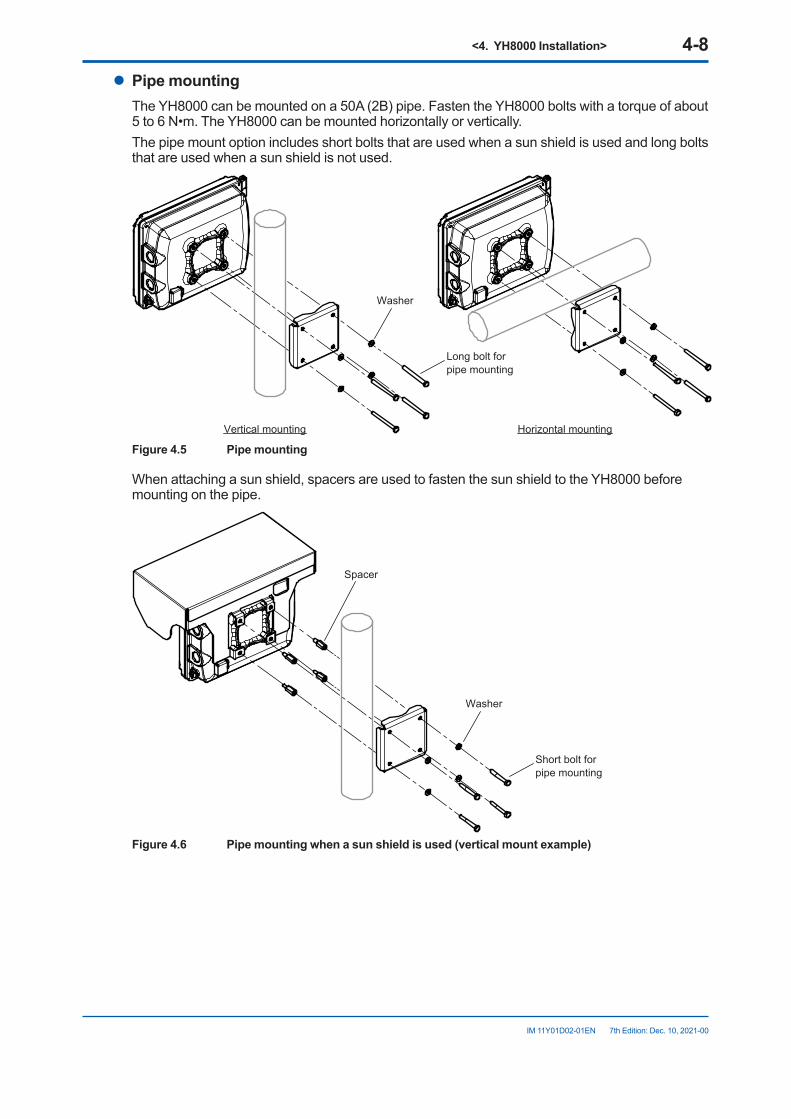
<4. YH8000 Installation> 4-8
IM 11Y01D02-01EN 7th Edition: Dec. 10, 2021-00
l Pipe mountingThe YH8000 can be mounted on a 50A (2B) pipe. Fasten the YH8000 bolts with a torque of about 5 to 6 N•m. The YH8000 can be mounted horizontally or vertically.The pipe mount option includes short bolts that are used when a sun shield is used and long bolts that are used when a sun shield is not used.
Washer
Vertical mounting Horizontal mounting
Long bolt for pipe mounting
Figure 4.5 Pipe mounting
When attaching a sun shield, spacers are used to fasten the sun shield to the YH8000 before mounting on the pipe.
Washer
Spacer
Short bolt for pipe mounting
Figure4.6 Pipemountingwhenasunshieldisused(verticalmountexample)
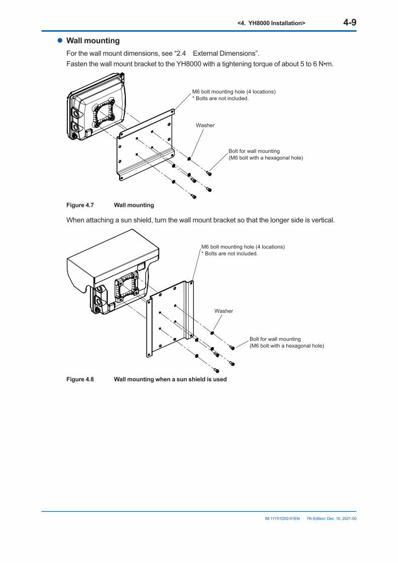
<4. YH8000 Installation> 4-9
IM 11Y01D02-01EN 7th Edition: Dec. 10, 2021-00
l Wall mountingFor the wall mount dimensions, see “2.4 External Dimensions”.Fasten the wall mount bracket to the YH8000 with a tightening torque of about 5 to 6 N•m.
Washer
Bolt for wall mounting(M6 bolt with a hexagonal hole)
M6 bolt mounting hole (4 locations)* Bolts are not included.
Figure 4.7 Wall mounting
When attaching a sun shield, turn the wall mount bracket so that the longer side is vertical.
Washer
Bolt for wall mounting(M6 bolt with a hexagonal hole)
M6 bolt mounting hole (4 locations)* Bolts are not included.
Figure4.8 Wallmountingwhenasunshieldisused
<4. YH8000 Installation> 4-10
IM 11Y01D02-01EN 7th Edition: Dec. 10, 2021-00
4.4 Wiring for Remote HMI InstallationWire the cables after completing the remote HMI installation.
CAUTIONNever turn on the power to the YH8000 or the devices connected to the YH8000 until all wiring is complete.
l OpeningtheYH8000frontcoverSee “4.2 Wiring for Local HMI Installation”.
l Cable entriesRun the power cable through cable entry 1 shown in "4.2 Wiring for Local HMI Installation". Run the Ethernet cable through cable entry 2 after removing the plug with a hexagonal hole.
l WiringSee “4.2 Wiring for Local HMI Installation”.
CAUTIONBe careful not to connect the power supply wires to the incorrect locations or reverse the polarity.
Incorrectly connecting the power supply can cause a malfunction.
For the cables you need to use, see page 3-11 n Types of Wiring and Cabling.Use two-core or three-core shielded cable to wire the power supply.If you want to connect the functional ground terminal inside the instrument, use a three-core power cable.
l ConnectinganEthernetCableIf you want to connect the YH8000 to TDLS8100 through an Ethernet hub, you will need to use an Ethernet cable. The Ethernet cable connector must be crimped during the YH8000 installation.The processing of the Ethernet cable is the same as for the TDLS8100. See”3.2.7 Connecting an Ethernet Cable”Power supply wiring, ground wiring, and Ethernet cable connection when using the YH8000 remotely are explained below. For the terminal positions, see the wiring diagram in “4.2 Wiring for Local HMI Installation”(1) Connect the cable to the power supply terminal with the correct polarity. Use a tightening
torque of 0.22 to 0.25 N•m for the power supply terminal.(2) Insert the RJ45 connector into Ethernet Port2 until you hear a click.(3) Connect the shielded wire of the special cable to the ground terminal for the shielded wire.(4) Connect a grounding cable that complies with page 3-11 n Types of Wiring and Cabling.
<5. Startup> 5-1
IM 11Y01D02-01EN 7th Edition: Dec. 10, 2021-00
5. StartupRefer to “3.2 Wiring” and “”, and verify that the system has been constructed correctly. Perform the startup procedure with the optical axis adjustment completed.
Run optical area purge gas, process window purge gas and reflector purge gas at the appropriate flow rates.Supply power to the TDLS8100.The LCD display shows a screen indicated in “1.2 Name and Function of Each Part”.
NOTEEven in an application that requires the system to be regularly run and suspended repeatedly, we recommend that you continuously supply power, process window purge gas, and reflector purge gas to the TDLS8100. This is to prevent unnecessary temperature changes in and placing unnecessary load on the laser device and sensor.
5.1 ConnectingtheHARTConfigurationToolThis section explains how to connect the HART configuration tool and provides a brief overview of the menu tree shown on the tool. For details on the menu tree and HART communication function, see “7. HART Communication” and “Appendix 2 General View of HART DD”.
NOTEWrite protection based on password authentication is available for TDLS8100 HART communication. By factory default, the write protection is disabled. Therefore, you can change the settings simply by connecting the configuration tool. For details on how to enable write protection, see “7.3 Write Protection”.
5.1.1 Installing a DD FileBefore using the HART configuration tool, the TDLS8100 DD (Device Description) must be installed in the configuration tool. DD is common between TDLS8100 and TDLS8000, therefore install TDLS8000 DD in TDLS8100. In this case, each device tool shows TDLS8000 as model.If you use FieldMate for the configuration tool, obtain the latest Device Files, and install a DTM. For details, see the FieldMate instruction manual.The following table shows the relation between DD and Device Files.
Software Revision
HART Device
RevisionDD
Revision Device Files Revision
1.** ** 01 01 3.06.1102 3.06.24
2.01.01 or above 02 01 3.08.13
If you want to connect your own configuration tool, download the DD file from the YOKOGAWA website and install it. https://partner.yokogawa.com/global/interoperability/dd-file-hart_an.htm
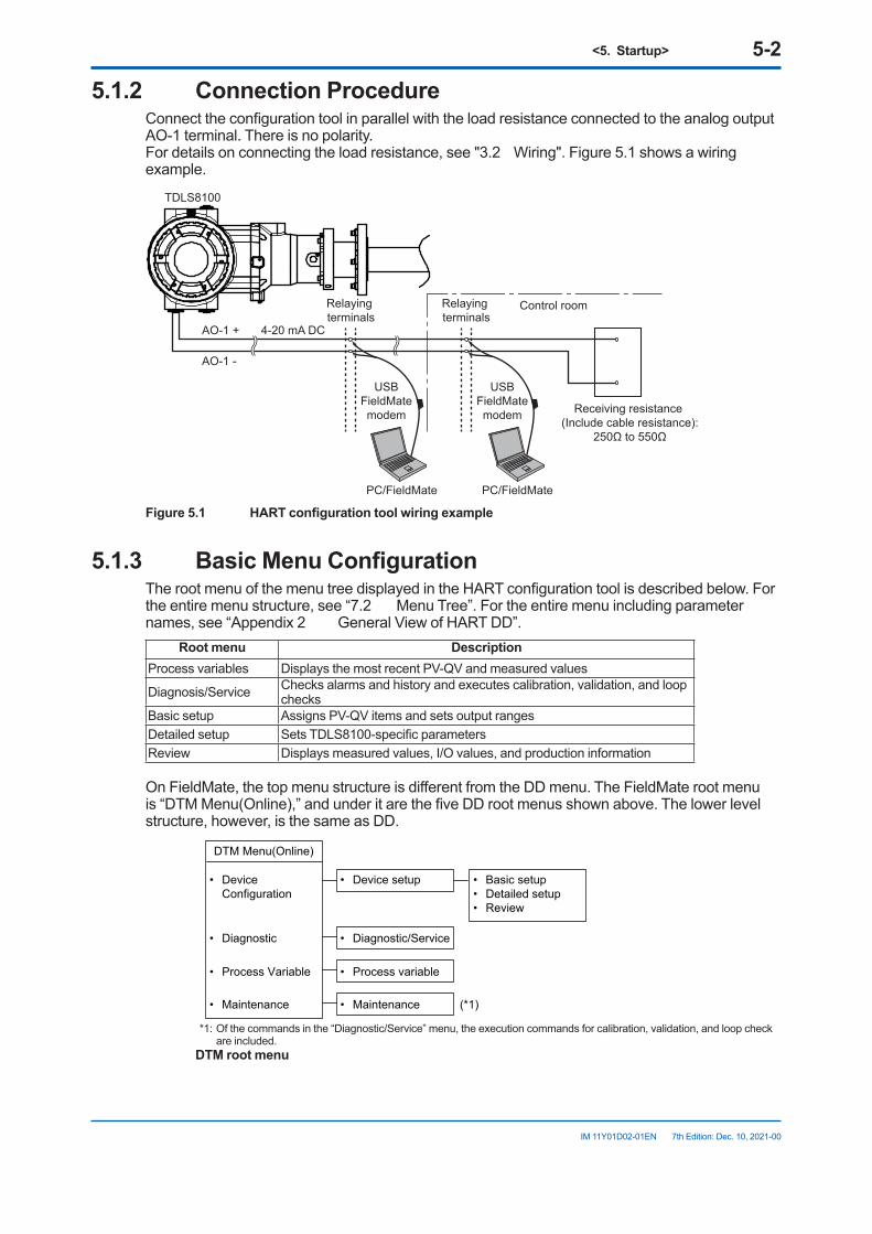
<5. Startup> 5-2
IM 11Y01D02-01EN 7th Edition: Dec. 10, 2021-00
5.1.2 Connection ProcedureConnect the configuration tool in parallel with the load resistance connected to the analog output AO-1 terminal. There is no polarity. For details on connecting the load resistance, see "3.2 Wiring". Figure 5.1 shows a wiring example.
AO-1 +
TDLS8100
AO-1 -
Receiving resistance (Include cable resistance):
250Ω to 550Ω
4-20 mA DC
Relaying terminals
Relaying terminals
USBFieldMatemodem
USBFieldMatemodem
Control room
PC/FieldMate PC/FieldMate
Figure5.1 HARTconfigurationtoolwiringexample
5.1.3 BasicMenuConfigurationThe root menu of the menu tree displayed in the HART configuration tool is described below. For the entire menu structure, see “7.2 Menu Tree”. For the entire menu including parameter names, see “Appendix 2 General View of HART DD”.
Root menu DescriptionProcess variables Displays the most recent PV-QV and measured values
Diagnosis/Service Checks alarms and history and executes calibration, validation, and loop checks
Basic setup Assigns PV-QV items and sets output rangesDetailed setup Sets TDLS8100-specific parametersReview Displays measured values, I/O values, and production information
On FieldMate, the top menu structure is different from the DD menu. The FieldMate root menu is “DTM Menu(Online),” and under it are the five DD root menus shown above. The lower level structure, however, is the same as DD.
• Device Configuration
DTM Menu(Online)
• Diagnostic
• Process Variable
• Device setup • Basic setup• Detailed setup• Review
• Diagnostic/Service
• Process variable
• Maintenance • Maintenance (*1)
*1: Of the commands in the “Diagnostic/Service” menu, the execution commands for calibration, validation, and loop check are included.
DTM root menu
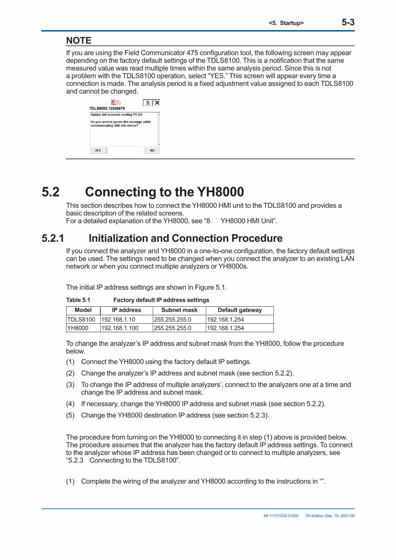
<5. Startup> 5-3
IM 11Y01D02-01EN 7th Edition: Dec. 10, 2021-00
NOTEIf you are using the Field Communicator 475 configuration tool, the following screen may appear depending on the factory default settings of the TDLS8100. This is a notification that the same measured value was read multiple times within the same analysis period. Since this is not a problem with the TDLS8100 operation, select “YES.” This screen will appear every time a connection is made. The analysis period is a fixed adjustment value assigned to each TDLS8100 and cannot be changed.
5.2 ConnectingtotheYH8000This section describes how to connect the YH8000 HMI unit to the TDLS8100 and provides a basic description of the related screens. For a detailed explanation of the YH8000, see “8. YH8000 HMI Unit”.
5.2.1 InitializationandConnectionProcedureIf you connect the analyzer and YH8000 in a one-to-one configuration, the factory default settings can be used. The settings need to be changed when you connect the analyzer to an existing LAN network or when you connect multiple analyzers or YH8000s.
The initial IP address settings are shown in Figure 5.1.
Table 5.1 Factory default IP address settingsModel IP address Subnet mask Default gateway
TDLS8100 192.168.1.10 255.255.255.0 192.168.1.254YH8000 192.168.1.100 255.255.255.0 192.168.1.254
To change the analyzer’s IP address and subnet mask from the YH8000, follow the procedure below.(1) Connect the YH8000 using the factory default IP settings.(2) Change the analyzer’s IP address and subnet mask (see section 5.2.2).(3) To change the IP address of multiple analyzers’, connect to the analyzers one at a time and
change the IP address and subnet mask.(4) If necessary, change the YH8000 IP address and subnet mask (see section 5.2.2).(5) Change the YH8000 destination IP address (see section 5.2.3).
The procedure from turning on the YH8000 to connecting it in step (1) above is provided below. The procedure assumes that the analyzer has the factory default IP address settings. To connect to the analyzer whose IP address has been changed or to connect to multiple analyzers, see “5.2.3 Connecting to the TDLS8100”.
(1) Complete the wiring of the analyzer and YH8000 according to the instructions in “”.
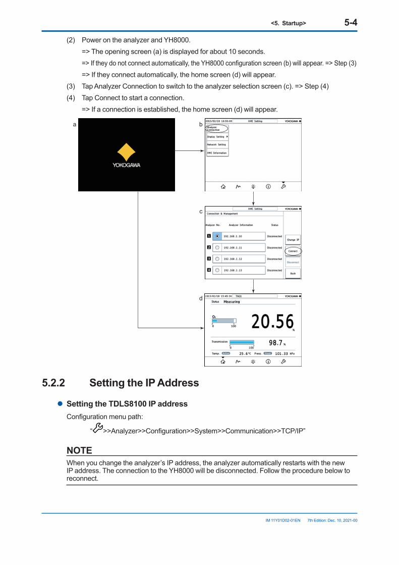
<5. Startup> 5-4
IM 11Y01D02-01EN 7th Edition: Dec. 10, 2021-00
(2) Power on the analyzer and YH8000. => The opening screen (a) is displayed for about 10 seconds. => If they do not connect automatically, the YH8000 configuration screen (b) will appear. => Step (3) => If they connect automatically, the home screen (d) will appear.(3) Tap Analyzer Connection to switch to the analyzer selection screen (c). => Step (4)(4) Tap Connect to start a connection. => If a connection is established, the home screen (d) will appear.
a b
c
d
5.2.2 SettingtheIPAddress
l SettingtheTDLS8100IPaddressConfiguration menu path:
“ >>Analyzer>>Configuration>>System>>Communication>>TCP/IP”
NOTEWhen you change the analyzer’s IP address, the analyzer automatically restarts with the new IP address. The connection to the YH8000 will be disconnected. Follow the procedure below to reconnect.
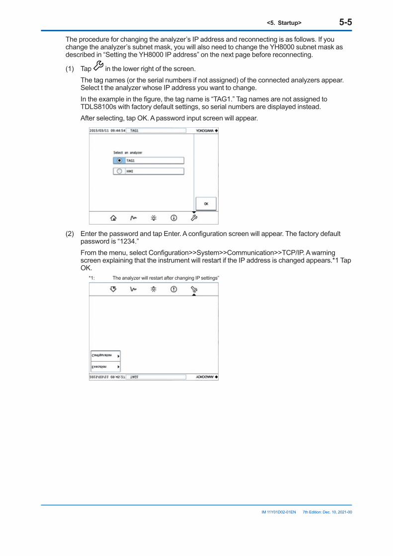
<5. Startup> 5-5
IM 11Y01D02-01EN 7th Edition: Dec. 10, 2021-00
The procedure for changing the analyzer’s IP address and reconnecting is as follows. If you change the analyzer’s subnet mask, you will also need to change the YH8000 subnet mask as described in “Setting the YH8000 IP address” on the next page before reconnecting.
(1) Tap in the lower right of the screen. The tag names (or the serial numbers if not assigned) of the connected analyzers appear.
Select t the analyzer whose IP address you want to change. In the example in the figure, the tag name is “TAG1.” Tag names are not assigned to
TDLS8100s with factory default settings, so serial numbers are displayed instead. After selecting, tap OK. A password input screen will appear.
(2) Enter the password and tap Enter. A configuration screen will appear. The factory default
password is “1234.” From the menu, select Configuration>>System>>Communication>>TCP/IP. A warning
screen explaining that the instrument will restart if the IP address is changed appears.*1 Tap OK.
*1: The analyzer will restart after changing IP settings”
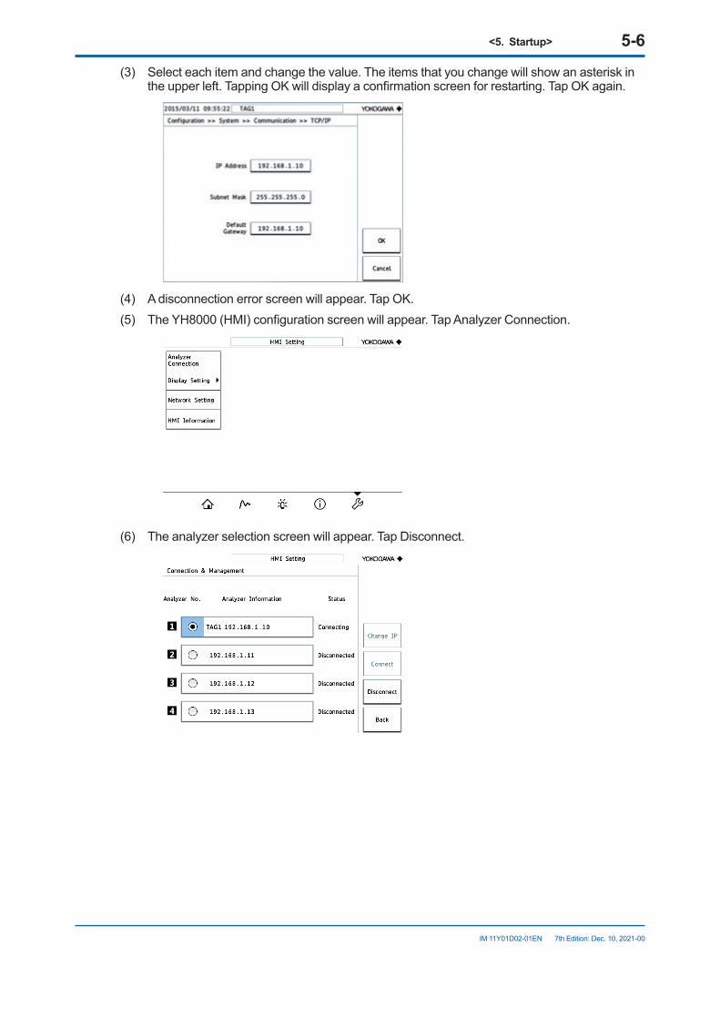
<5. Startup> 5-6
IM 11Y01D02-01EN 7th Edition: Dec. 10, 2021-00
(3) Select each item and change the value. The items that you change will show an asterisk in the upper left. Tapping OK will display a confirmation screen for restarting. Tap OK again.
(4) A disconnection error screen will appear. Tap OK.(5) The YH8000 (HMI) configuration screen will appear. Tap Analyzer Connection.
(6) The analyzer selection screen will appear. Tap Disconnect.
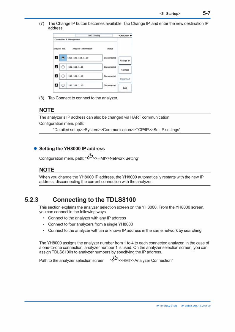
<5. Startup> 5-7
IM 11Y01D02-01EN 7th Edition: Dec. 10, 2021-00
(7) The Change IP button becomes available. Tap Change IP, and enter the new destination IP address.
(8) Tap Connect to connect to the analyzer.
NOTEThe analyzer’s IP address can also be changed via HART communication.Configuration menu path: “Detailed setup>>System>>Communication>>TCP/IP>>Set IP settings”
l SettingtheYH8000IPaddress
Configuration menu path: “ >>HMI>>Network Setting”
NOTEWhen you change the YH8000 IP address, the YH8000 automatically restarts with the new IP address, disconnecting the current connection with the analyzer.
5.2.3 ConnectingtotheTDLS8100This section explains the analyzer selection screen on the YH8000. From the YH8000 screen, you can connect in the following ways.
• Connect to the analyzer with any IP address• Connect to four analyzers from a single YH8000• Connect to the analyzer with an unknown IP address in the same network by searching
The YH8000 assigns the analyzer number from 1 to 4 to each connected analyzer. In the case of a one-to-one connection, analyzer number 1 is used. On the analyzer selection screen, you can assign TDLS8100s to analyzer numbers by specifying the IP address.
Path to the analyzer selection screen “ >>HMI>>Analyzer Connection”
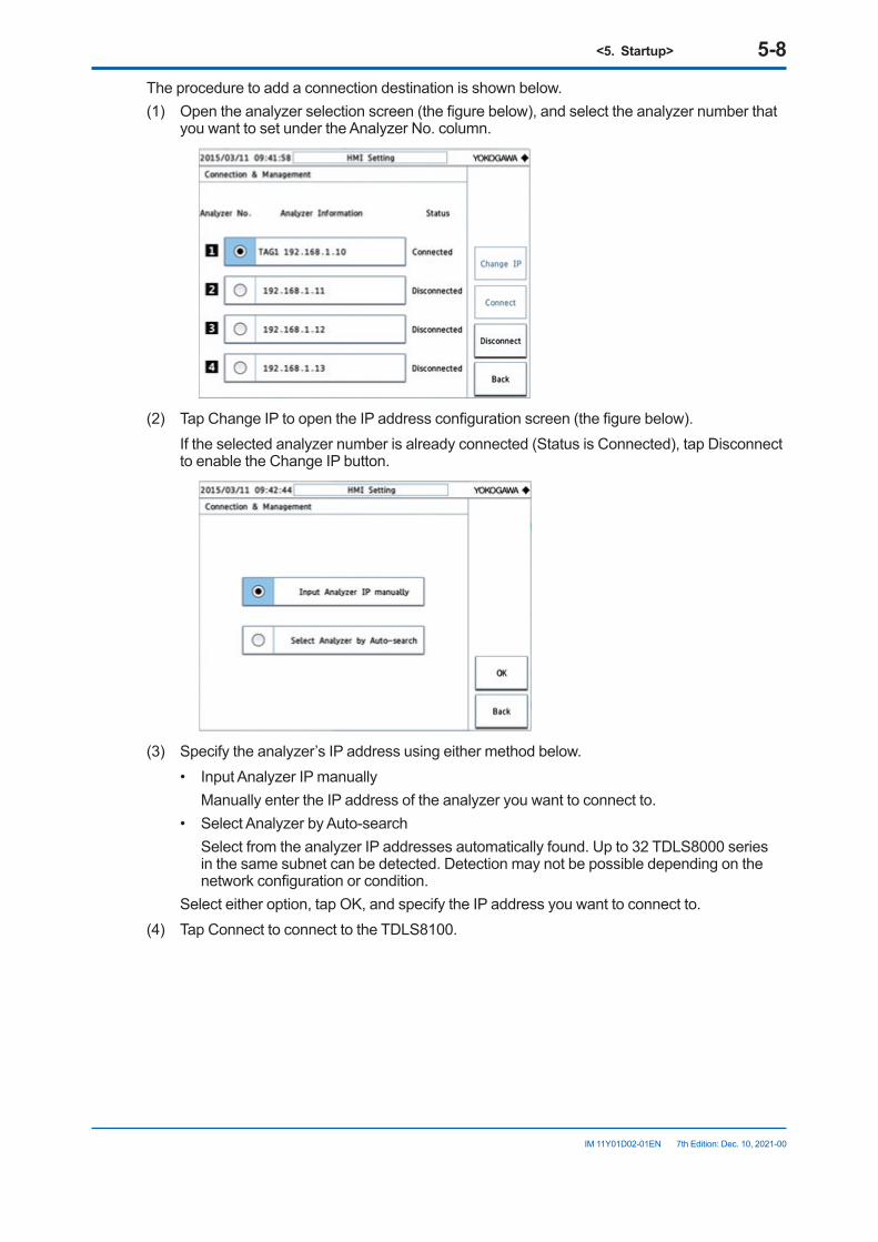
<5. Startup> 5-8
IM 11Y01D02-01EN 7th Edition: Dec. 10, 2021-00
The procedure to add a connection destination is shown below.(1) Open the analyzer selection screen (the figure below), and select the analyzer number that
you want to set under the Analyzer No. column.
(2) Tap Change IP to open the IP address configuration screen (the figure below). If the selected analyzer number is already connected (Status is Connected), tap Disconnect
to enable the Change IP button.
(3) Specify the analyzer’s IP address using either method below.
• Input Analyzer IP manually Manually enter the IP address of the analyzer you want to connect to.• Select Analyzer by Auto-search Select from the analyzer IP addresses automatically found. Up to 32 TDLS8000 series
in the same subnet can be detected. Detection may not be possible depending on the network configuration or condition.
Select either option, tap OK, and specify the IP address you want to connect to.(4) Tap Connect to connect to the TDLS8100.
<5. Startup> 5-9
IM 11Y01D02-01EN 7th Edition: Dec. 10, 2021-00
l DescriptionoftheanalyzerselectionscreenAnalyzerNo.column Shows analyzer numbers 1 to 4. You can select a number and assign an IP address to
connect to the corresponding analyzer
NOTEIf YH8000 connects to only a single analyzer, connect it to analyzer number 1. If you connect it other number, you need to reset the display items when displaying the trend waveform.
AnalyzerInformationcolumn Shows the analyzer IP addresses and tag names. For analyzers that have not been
connected before, tag names do not appear. If the analyzer is connected but its tag name is not assigned, a serial number will be displayed.
Status column Shows analyzer’s connection status. Connected Connecting DisconnectedChangeIPbutton Switches to the IP address configuration screen. This button is not available if the analyzer
is connected.Connect button Starts a connection with the analyzer. This button is available when the analyzer is
disconnected.Disconnect button Disconnects from the analyzer that is connected or is in the process of establishing a
connection.
NOTEOnce a connection is established between the YH8000 and the analyzer, the connection information is saved. Therefore, the next time the power is turned on or after restarting, the connection will be established automatically.
NOTEUp to two YH8000 can connect to a single analyzer.
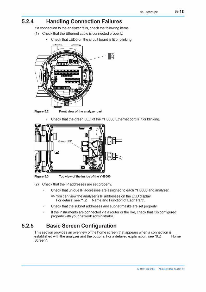
<5. Startup> 5-10
IM 11Y01D02-01EN 7th Edition: Dec. 10, 2021-00
5.2.4 Handling Connection FailuresIf a connection to the analyzer fails, check the following items.(1) Check that the Ethernet cable is connected properly.
• Check that LED5 on the circuit board is lit or blinking.
LED5
Figure5.2 Frontviewoftheanalyzerpart
• Check that the green LED of the YH8000 Ethernet port is lit or blinking.
Green LED
Figure5.3 TopviewoftheinsideoftheYH8000
(2) Check that the IP addresses are set properly.• Check that unique IP addresses are assigned to each YH8000 and analyzer. => You can view the analyzer’s IP addresses on the LCD display.
For details, see “1.2 Name and Function of Each Part”.• Check that the subnet addresses and subnet masks are set properly.• If the instruments are connected via a router or the like, check that it is configured
properly with your network administrator.
5.2.5 BasicScreenConfigurationThis section provides an overview of the home screen that appears when a connection is established with the analyzer and the buttons. For a detailed explanation, see “8.2 Home Screen”.
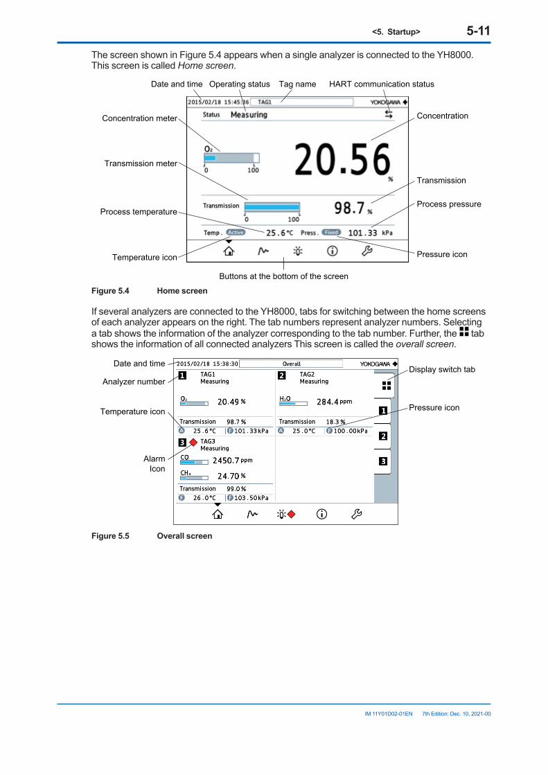
<5. Startup> 5-11
IM 11Y01D02-01EN 7th Edition: Dec. 10, 2021-00
The screen shown in Figure 5.4 appears when a single analyzer is connected to the YH8000. This screen is called Home screen.
Date and time Tag nameOperating status
Concentration
Transmission
Concentration meter
Transmission meter
Process temperatureProcess pressure
Temperature icon Pressure icon
Buttons at the bottom of the screen
HART communication status
Figure 5.4 Home screen
If several analyzers are connected to the YH8000, tabs for switching between the home screens of each analyzer appears on the right. The tab numbers represent analyzer numbers. Selecting a tab shows the information of the analyzer corresponding to the tab number. Further, the tab shows the information of all connected analyzers This screen is called the overall screen.
Display switch tabAnalyzer number
Date and time
Pressure iconTemperature icon
AlarmIcon
Figure 5.5 Overall screen
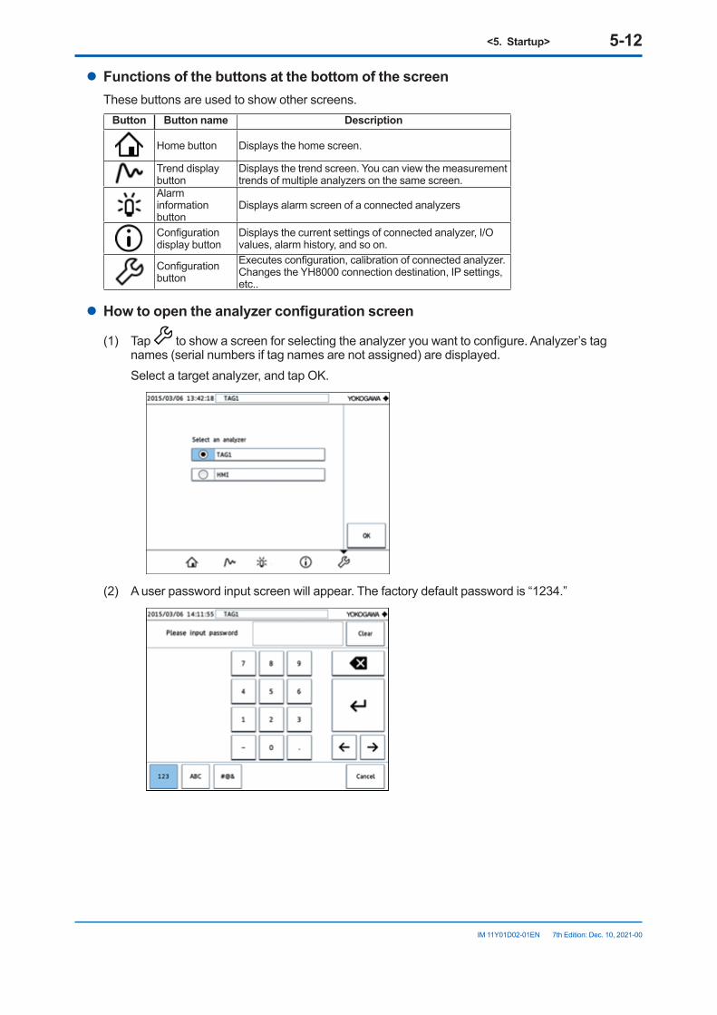
<5. Startup> 5-12
IM 11Y01D02-01EN 7th Edition: Dec. 10, 2021-00
l FunctionsofthebuttonsatthebottomofthescreenThese buttons are used to show other screens.
Button Button name Description
Home button Displays the home screen.
Trend display button
Displays the trend screen. You can view the measurement trends of multiple analyzers on the same screen.
Alarm information button
Displays alarm screen of a connected analyzers
Configuration display button
Displays the current settings of connected analyzer, I/O values, alarm history, and so on.
Configuration button
Executes configuration, calibration of connected analyzer.Changes the YH8000 connection destination, IP settings, etc..
l Howtoopentheanalyzerconfigurationscreen
(1) Tap to show a screen for selecting the analyzer you want to configure. Analyzer’s tag names (serial numbers if tag names are not assigned) are displayed.
Select a target analyzer, and tap OK.
(2) A user password input screen will appear. The factory default password is “1234.”
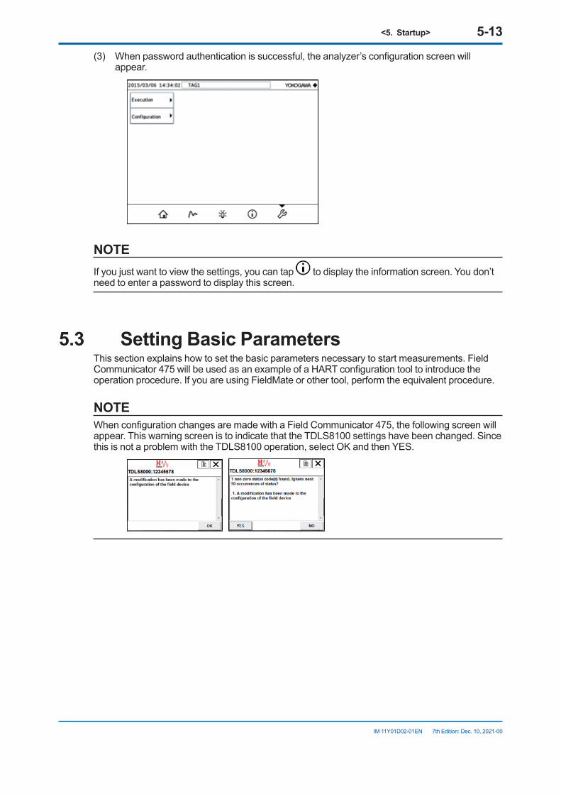
<5. Startup> 5-13
IM 11Y01D02-01EN 7th Edition: Dec. 10, 2021-00
(3) When password authentication is successful, the analyzer’s configuration screen will appear.
NOTEIf you just want to view the settings, you can tap to display the information screen. You don’t need to enter a password to display this screen.
5.3 Setting Basic ParametersThis section explains how to set the basic parameters necessary to start measurements. Field Communicator 475 will be used as an example of a HART configuration tool to introduce the operation procedure. If you are using FieldMate or other tool, perform the equivalent procedure.
NOTEWhen configuration changes are made with a Field Communicator 475, the following screen will appear. This warning screen is to indicate that the TDLS8100 settings have been changed. Since this is not a problem with the TDLS8100 operation, select OK and then YES.
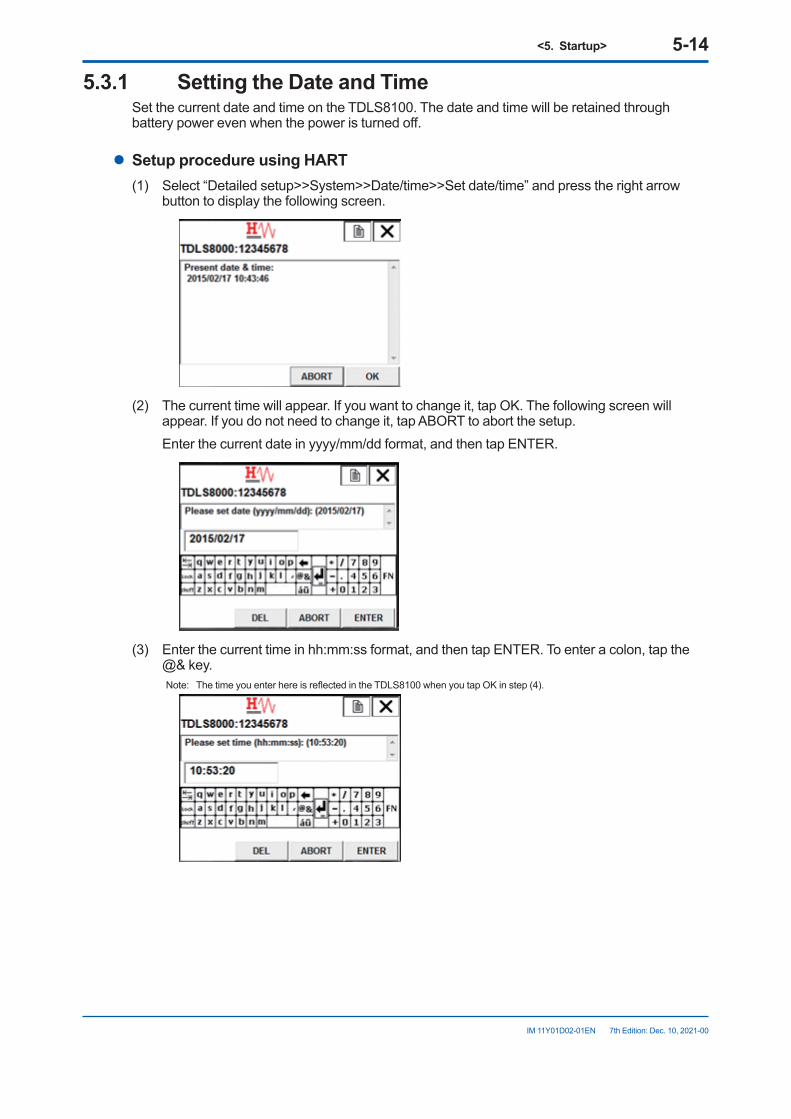
<5. Startup> 5-14
IM 11Y01D02-01EN 7th Edition: Dec. 10, 2021-00
5.3.1 SettingtheDateandTimeSet the current date and time on the TDLS8100. The date and time will be retained through battery power even when the power is turned off.
l Setup procedure using HART(1) Select “Detailed setup>>System>>Date/time>>Set date/time” and press the right arrow
button to display the following screen.
(2) The current time will appear. If you want to change it, tap OK. The following screen will
appear. If you do not need to change it, tap ABORT to abort the setup. Enter the current date in yyyy/mm/dd format, and then tap ENTER.
(3) Enter the current time in hh:mm:ss format, and then tap ENTER. To enter a colon, tap the
@& key.Note: The time you enter here is reflected in the TDLS8100 when you tap OK in step (4).
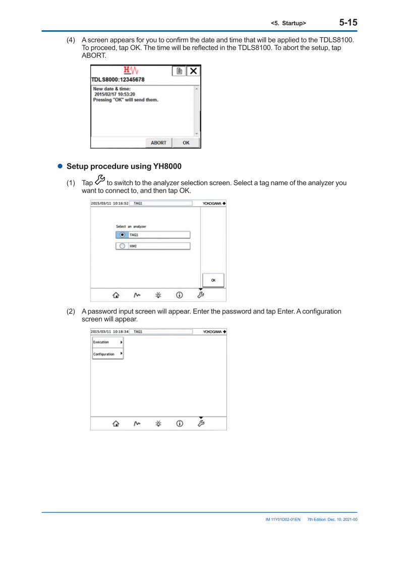
<5. Startup> 5-15
IM 11Y01D02-01EN 7th Edition: Dec. 10, 2021-00
(4) A screen appears for you to confirm the date and time that will be applied to the TDLS8100. To proceed, tap OK. The time will be reflected in the TDLS8100. To abort the setup, tap ABORT.
l Setup procedure using YH8000
(1) Tap to switch to the analyzer selection screen. Select a tag name of the analyzer you want to connect to, and then tap OK.
(2) A password input screen will appear. Enter the password and tap Enter. A configuration
screen will appear.
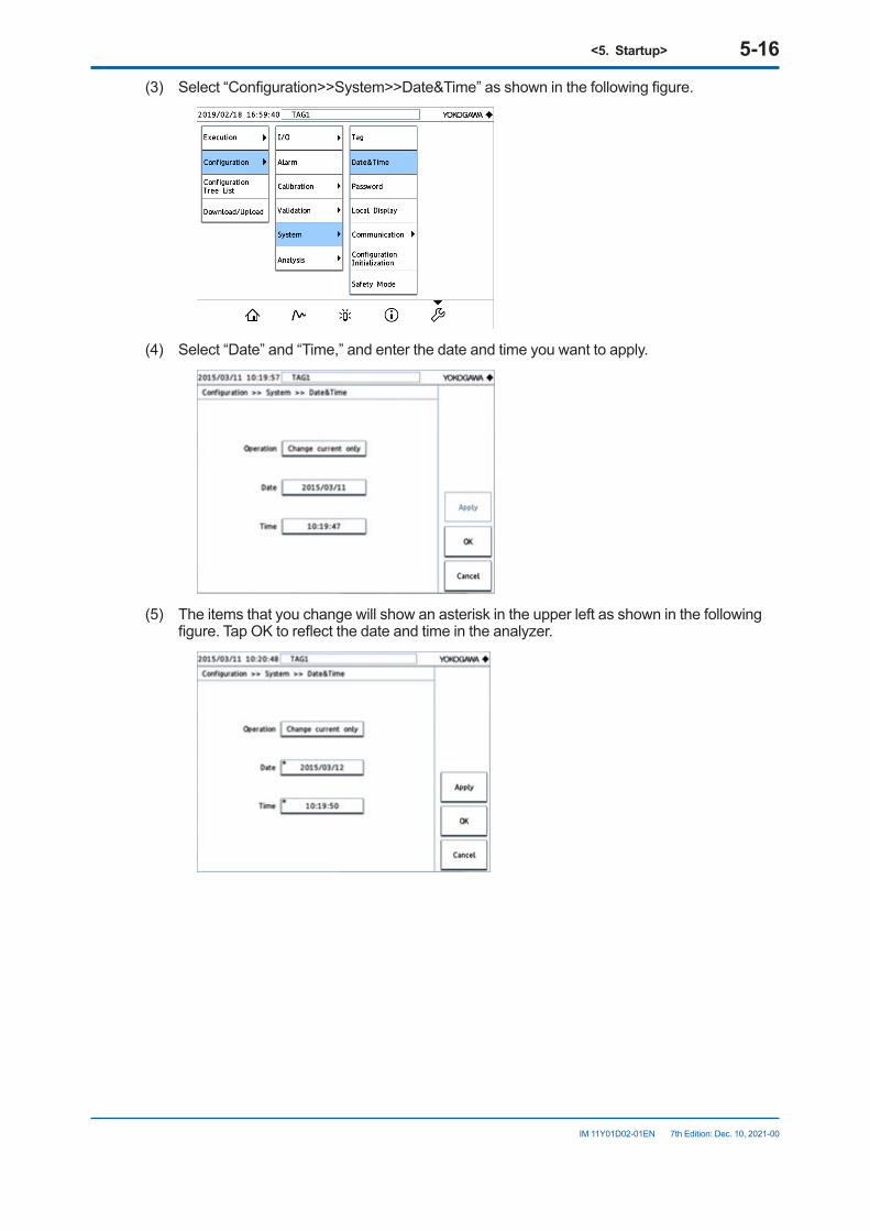
<5. Startup> 5-16
IM 11Y01D02-01EN 7th Edition: Dec. 10, 2021-00
(3) Select “Configuration>>System>>Date&Time” as shown in the following figure.
(4) Select “Date” and “Time,” and enter the date and time you want to apply.
(5) The items that you change will show an asterisk in the upper left as shown in the following
figure. Tap OK to reflect the date and time in the analyzer.
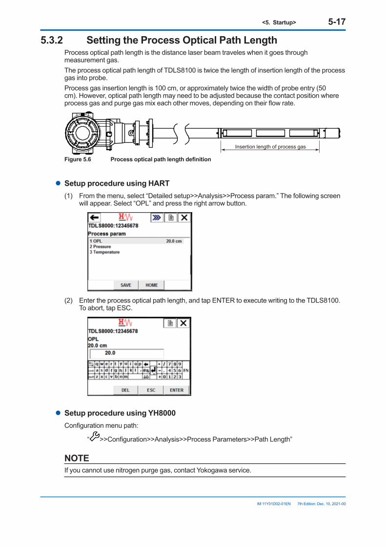
<5. Startup> 5-17
IM 11Y01D02-01EN 7th Edition: Dec. 10, 2021-00
5.3.2 SettingtheProcessOpticalPathLengthProcess optical path length is the distance laser beam traveles when it goes through measurement gas.The process optical path length of TDLS8100 is twice the length of insertion length of the process gas into probe.Process gas insertion length is 100 cm, or approximately twice the width of probe entry (50 cm). However, optical path length may need to be adjusted because the contact position where process gas and purge gas mix each other moves, depending on their flow rate.
Insertion length of process gas
Figure5.6 Processopticalpathlengthdefinition
l Setup procedure using HART(1) From the menu, select “Detailed setup>>Analysis>>Process param.” The following screen
will appear. Select “OPL” and press the right arrow button.
(2) Enter the process optical path length, and tap ENTER to execute writing to the TDLS8100.
To abort, tap ESC.
l Setup procedure using YH8000Configuration menu path:
“ >>Configuration>>Analysis>>Process Parameters>>Path Length”
NOTEIf you cannot use nitrogen purge gas, contact Yokogawa service.
<5. Startup> 5-18
IM 11Y01D02-01EN 7th Edition: Dec. 10, 2021-00
5.3.3 SettingtheProcessPressureThis section explains the pressure value of the measurement process when the input mode is analog input (AI-1). When using other input modes, see “6.1.2 Process Pressure”.
Configuration menu path: [HART] “Detailed setup>>Analysis>>Process param>>Pressure”
[YH8000] “ >>Configuration>>Analysis>>Process Parameters>>Pressure”
(1) Set Mode (pressure input mode) to Active input.(2) Set Active type (pressure input source) to AI-1.(3) Select Backup mode (pressure value backup when the analog input is outside the range)
from the following options. If you select Disable, the analog input is converted as-is into a pressure value without
backing up. If you select Backup value, the pressure value is fixed to the value specified by Backup set
value. Set Backup set value to a value of your choice. If you select Hold, the pressure value is held at the previous value within the proper range.(4) Set the analog input range. Set the pressure values corresponding to 4 mA and 20 mA. Configuration menu path: [HART] “Detailed setup>>I/O condition>>Analog input>>AI-1(Pressure)”
[YH8000] “ >>Configuration>>I/O>>Analog Input>>AI-1(Pressure)”
5.3.4 SettingtheProcessTemperatureThis section explains the temperature value of the measurement process when the input mode is analog input (AI-2). When using other input modes, see “6.1.3 Process Temperature” .
Configuration menu path: [HART] “Detailed setup>>Analysis>>Process param>>Temperature”
[YH8000] “ >>Configuration>>Analysis>>Process Parameters>>Temperature”
(1) Set Mode (temperature input mode) to Active input.(2) Set Active type (temperature input source) to AI-2.(3) Select Backup mode (temperature value backup when the analog input is outside the
range) from the following options. If you select Disable, the analog input is converted as-is into a temperature value without
backing up. If you select Backup value, the pressure value is fixed to the value specified by Backup set
value. Set Backup set value to a value of your choice. If you select Hold, the pressure value is held at the previous value within the proper range.(4) Set the analog input range. Set the temperature values corresponding to 4 mA and 20 mA. Configuration menu path: [HART] “Detailed setup>>I/O condition>>Analog input>>AI-2(Temperature)”
[YH8000] “ >>Configuration>>I/O>>Analog Input>>AI-2(Temperature)”
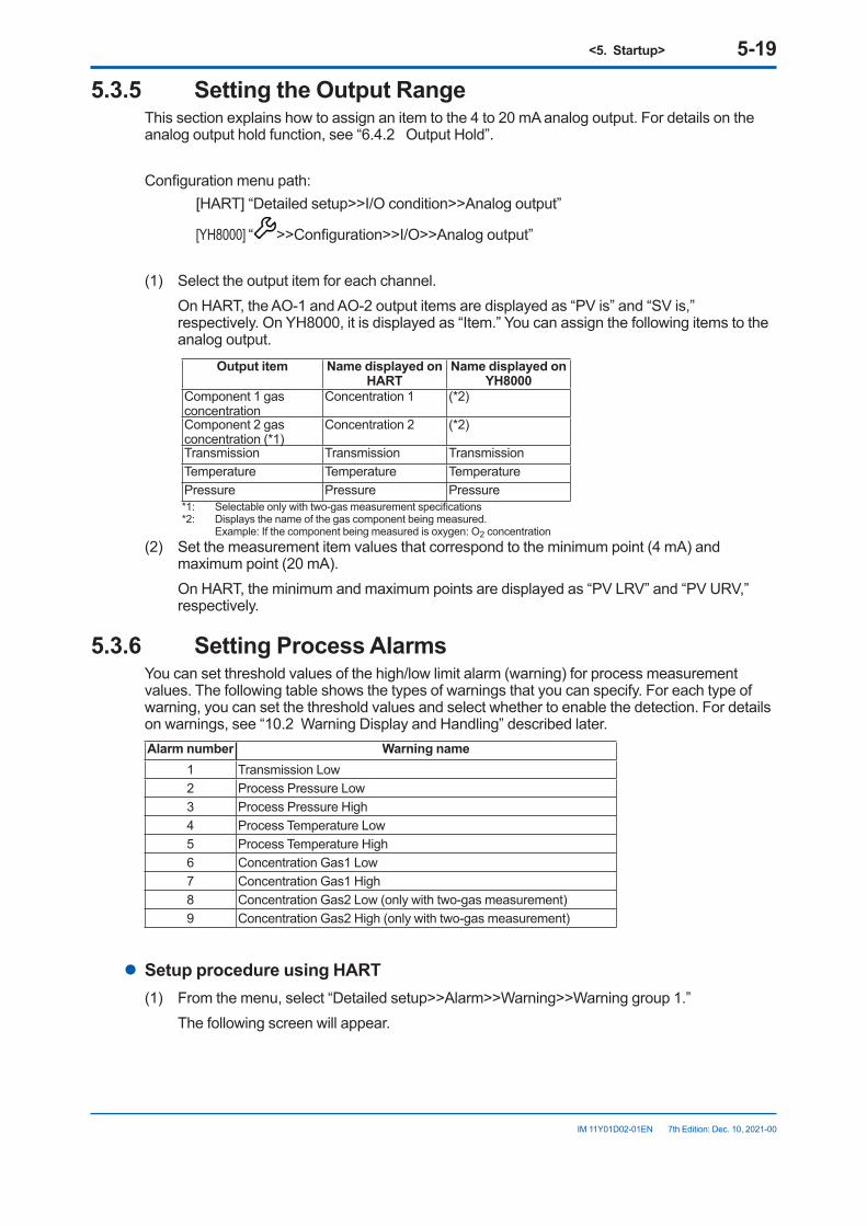
<5. Startup> 5-19
IM 11Y01D02-01EN 7th Edition: Dec. 10, 2021-00
5.3.5 SettingtheOutputRangeThis section explains how to assign an item to the 4 to 20 mA analog output. For details on the analog output hold function, see “6.4.2 Output Hold”.
Configuration menu path: [HART] “Detailed setup>>I/O condition>>Analog output”
[YH8000] “ >>Configuration>>I/O>>Analog output”
(1) Select the output item for each channel. On HART, the AO-1 and AO-2 output items are displayed as “PV is” and “SV is,”
respectively. On YH8000, it is displayed as “Item.” You can assign the following items to the analog output.
Output item Name displayed on HART
Name displayed on YH8000
Component 1 gas concentration
Concentration 1 (*2)
Component 2 gas concentration (*1)
Concentration 2 (*2)
Transmission Transmission TransmissionTemperature Temperature TemperaturePressure Pressure Pressure*1: Selectable only with two-gas measurement specifications*2: Displays the name of the gas component being measured. Example: If the component being measured is oxygen: O2 concentration
(2) Set the measurement item values that correspond to the minimum point (4 mA) and maximum point (20 mA).
On HART, the minimum and maximum points are displayed as “PV LRV” and “PV URV,” respectively.
5.3.6 Setting Process AlarmsYou can set threshold values of the high/low limit alarm (warning) for process measurement values. The following table shows the types of warnings that you can specify. For each type of warning, you can set the threshold values and select whether to enable the detection. For details on warnings, see “10.2 Warning Display and Handling” described later.Alarm number Warning name
1 Transmission Low2 Process Pressure Low3 Process Pressure High4 Process Temperature Low5 Process Temperature High6 Concentration Gas1 Low7 Concentration Gas1 High8 Concentration Gas2 Low (only with two-gas measurement)9 Concentration Gas2 High (only with two-gas measurement)
l Setup procedure using HART(1) From the menu, select “Detailed setup>>Alarm>>Warning>>Warning group 1.” The following screen will appear.
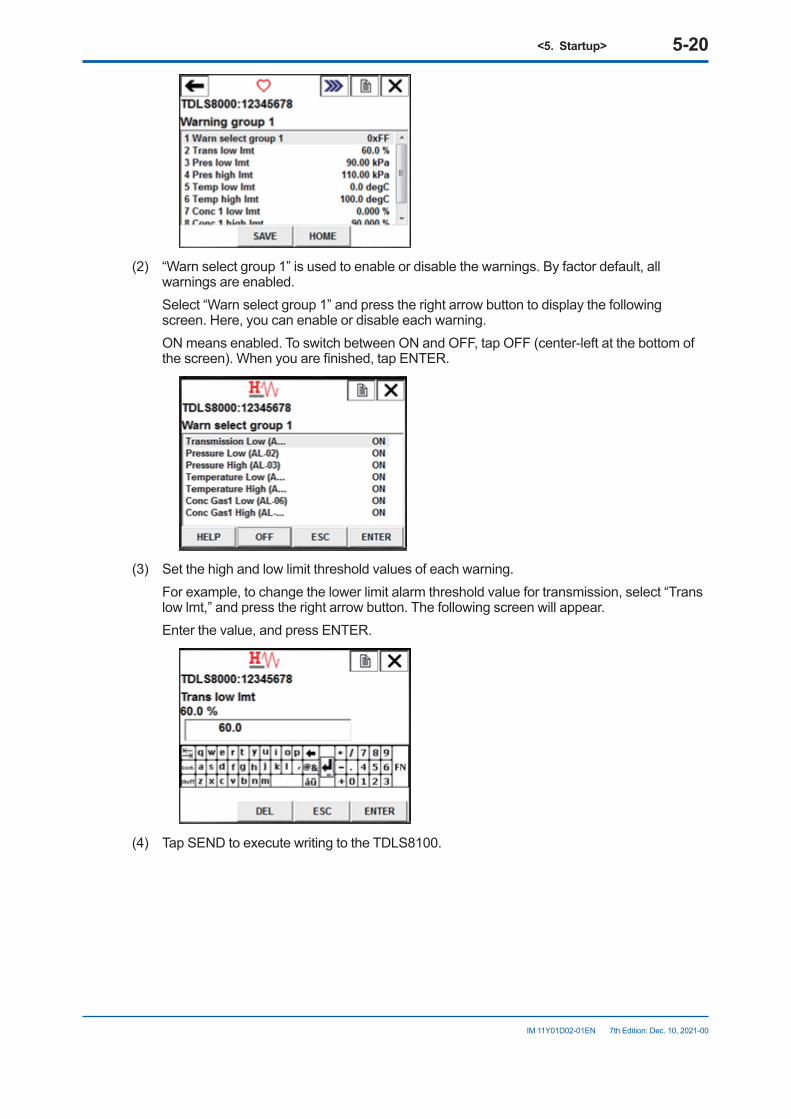
<5. Startup> 5-20
IM 11Y01D02-01EN 7th Edition: Dec. 10, 2021-00
(2) “Warn select group 1” is used to enable or disable the warnings. By factor default, all
warnings are enabled. Select “Warn select group 1” and press the right arrow button to display the following
screen. Here, you can enable or disable each warning. ON means enabled. To switch between ON and OFF, tap OFF (center-left at the bottom of
the screen). When you are finished, tap ENTER.
(3) Set the high and low limit threshold values of each warning. For example, to change the lower limit alarm threshold value for transmission, select “Trans
low lmt,” and press the right arrow button. The following screen will appear. Enter the value, and press ENTER.
(4) Tap SEND to execute writing to the TDLS8100.
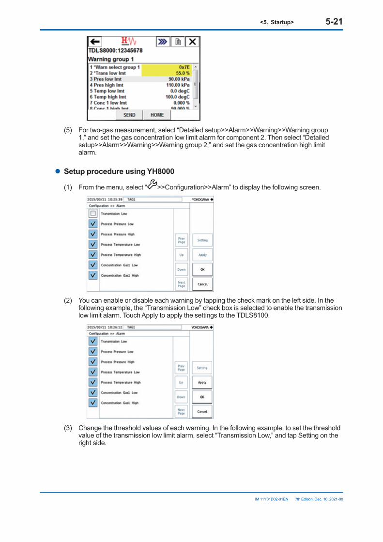
<5. Startup> 5-21
IM 11Y01D02-01EN 7th Edition: Dec. 10, 2021-00
(5) For two-gas measurement, select “Detailed setup>>Alarm>>Warning>>Warning group
1,” and set the gas concentration low limit alarm for component 2. Then select “Detailed setup>>Alarm>>Warning>>Warning group 2,” and set the gas concentration high limit alarm.
l Setup procedure using YH8000
(1) From the menu, select “ >>Configuration>>Alarm” to display the following screen.
(2) You can enable or disable each warning by tapping the check mark on the left side. In the
following example, the “Transmission Low” check box is selected to enable the transmission low limit alarm. Touch Apply to apply the settings to the TDLS8100.
(3) Change the threshold values of each warning. In the following example, to set the threshold
value of the transmission low limit alarm, select “Transmission Low,” and tap Setting on the right side.
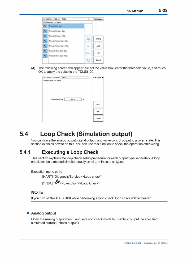
<5. Startup> 5-22
IM 11Y01D02-01EN 7th Edition: Dec. 10, 2021-00
(4) The following screen will appear. Select the value box, enter the threshold value, and touch
OK to apply the value to the TDLS8100.
5.4 LoopCheck(Simulationoutput)You can force the analog output, digital output, and valve control output to a given state. This section explains how to do this. You can use this function to check the operation after wiring.
5.4.1 ExecutingaLoopCheckThis section explains the loop check setup procedure for each output type separately. A loop check can be executed simultaneously on all terminals of all types.
Execution menu path: [HART] “Diagnosis/Service>>Loop check”
[YH8000] “ >>Execution>>Loop Check”
NOTEIf you turn off the TDLS8100 while performing a loop check, loop check will be cleared.
l Analog outputOpen the Analog output menu, and set Loop check mode to Enable to output the specified simulated current (“check output”).
<5. Startup> 5-23
IM 11Y01D02-01EN 7th Edition: Dec. 10, 2021-00
NOTEIf multi-drop mode is set on HART, loop checking of AO-1 via HART is not possible.
l Digital outputOpen the Digital output menu, and set Loop check mode to Enable to output the specified simulated state (“check output”).
l Valvecontroloutput(SV)Open the Valve output menu, and set Loop check mode to Enable to output the specified simulated state (“check output”).
5.4.2 Auto Release FunctionThe auto release function automatically clears loop checking on all terminals and restores normal output after the specified time elapses. The auto release counter starts when any of the loop check is enabled. The counter restarts whenever a loop check setting is changed. When the counter expires, all loop checking is disabled.
To set the auto release time, set Auto release time in the Loop check menu. If you select Disable, the auto release function is disabled, and the simulated output is maintained until you manually clear the loop check mode. The specified values are retained even after the power is turned off.

Blank Page
<6.Configuration> 6-1
IM 11Y01D02-01EN 7th Edition: Dec. 10, 2021-00
6. ConfigurationThis chapter provides details of all the setting items and shows the locations of the setting menus of the TDLS8100. However, the setting items related to calibration and validation are described in "9. Inspection and Maintenance".The setting menus of the YH8000 can be opened by performing the operation of “ >> Select analyzer >>Configuration” but the location is shown as just being under “Configuration” in this chapter for simplicity.
6.1 Process Parameter SettingsProcess parameters indicate the measurement conditions related to measurement process gas. Set the process optical path length, process pressure, and process temperature of the process gas correctly because they directly affect the measurement values.
NOTEIf nitrogen purge gas cannot be used, contact Yokogawa.
6.1.1 ProcessOpticalPathLengthSet the process optical path length of the process to be measured. For a definition of the process optical path length, see5.3.2 Setting the Process Optical Path Length Setup menu path: [HART] “Detailed setup>>Analysis>>Process param>>OPL” [YH8000] “Configuration>>Analysis>>Process Parameters>>Path Length”
6.1.2 Process PressureSet the process pressure of the process to be measured. When you select the input source, set the action for error input as described in the procedure below.Setup menu path: [HART] “Detailed setup>>Analysis>>Process param>>Pressure” [YH8000] “Configuration>>Analysis>>Process Parameters>>Pressure”(1) Select “Mode” (pressure input mode). When “Fixed” is selected, set the pressure value as an arbitrary fixed value. When “Active input” is selected, input the pressure value via a 4-20 mA analog input (AI-1)
or Modbus. The TDLS8100 acquires a pressure value sent from the input source at every measurement value analysis cycle and uses it for the concentration calculation.
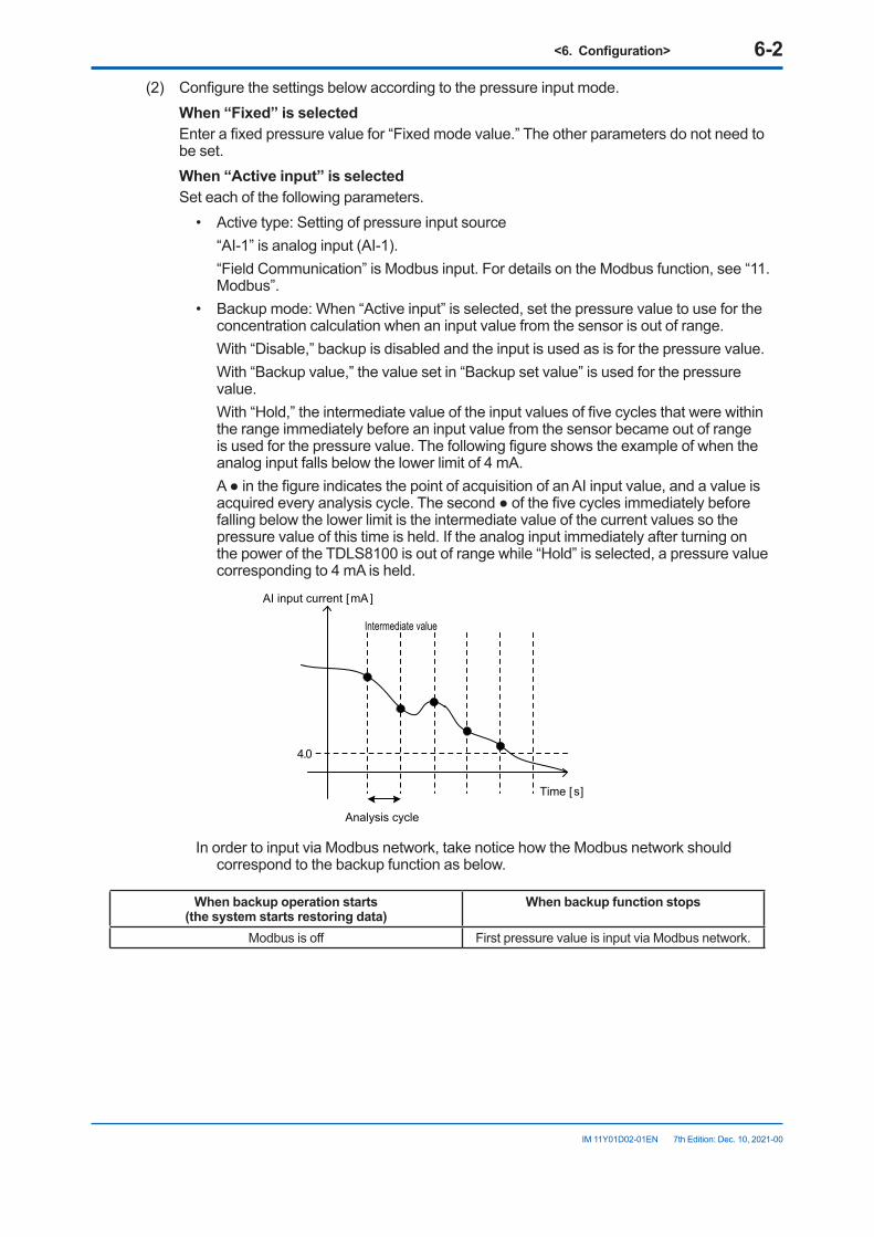
<6.Configuration> 6-2
IM 11Y01D02-01EN 7th Edition: Dec. 10, 2021-00
(2) Configure the settings below according to the pressure input mode. When“Fixed”isselected Enter a fixed pressure value for “Fixed mode value.” The other parameters do not need to
be set. When“Activeinput”isselected Set each of the following parameters.
• Active type: Setting of pressure input source “AI-1” is analog input (AI-1). “Field Communication” is Modbus input. For details on the Modbus function, see “11.
Modbus”.• Backup mode: When “Active input” is selected, set the pressure value to use for the
concentration calculation when an input value from the sensor is out of range. With “Disable,” backup is disabled and the input is used as is for the pressure value. With “Backup value,” the value set in “Backup set value” is used for the pressure
value. With “Hold,” the intermediate value of the input values of five cycles that were within
the range immediately before an input value from the sensor became out of range is used for the pressure value. The following figure shows the example of when the analog input falls below the lower limit of 4 mA.
A ● in the figure indicates the point of acquisition of an AI input value, and a value is acquired every analysis cycle. The second ● of the five cycles immediately before falling below the lower limit is the intermediate value of the current values so the pressure value of this time is held. If the analog input immediately after turning on the power of the TDLS8100 is out of range while “Hold” is selected, a pressure value corresponding to 4 mA is held.
[mA ]
[s]
4.0
AI input current
Time
Analysis cycle
Intermediate value
In order to input via Modbus network, take notice how the Modbus network should correspond to the backup function as below.
Whenbackupoperationstarts (thesystemstartsrestoringdata)
Whenbackupfunctionstops
Modbus is off First pressure value is input via Modbus network.
<6.Configuration> 6-3
IM 11Y01D02-01EN 7th Edition: Dec. 10, 2021-00
NOTEMaintain Modbus network connected when the backup function is activated. If you want to shut down the Modbus network regularly, set the backup mode “Disable”.
• If you select “Disable” in the backup mode, the last pressure value you enter remains valid i.e. in the same status as “Hold”.
• After the power of TDLS8100 turns on, the backup function keeps active until the first pressure value is received. During this period, when you select “Hold”, or “Disable” in the backup mode, the pressure values will be on hold at the equivalent of the one obtained within the Analog input range mentioned below (3) with 4mA.
• Backup set value: Backup pressure value when “Backup mode” is “Backup value” (3) Configure the analog input range setting only when “AI-1” is selected in “Active type.” Enter the pressure value corresponding to each of 4 mA and 20 mA. Setup menu path: [HART] “Detailed setup>>I/O condition>>Analog input>>AI-1(Pressure)” [YH8000] “Configuration>>I/O>>Analog Input>>AI-1 (Pressure)”
<6.Configuration> 6-4
IM 11Y01D02-01EN 7th Edition: Dec. 10, 2021-00
6.1.3 Process TemperatureSet the process temperature of the process to be measured. When you select the input source, set the action for error input as described in the procedure below.Setup menu path: [HART] “Detailed setup>>Analysis>>Process param>>Temperature” [YH8000] “Configuration>>Analysis>>Process Parameters>>Temperature”
(1) Select “Mode” (temperature input mode). When “Fixed” is selected, set the temperature value as an arbitrary fixed value. When “Active input” is selected, input the temperature value via a 4-20 mA analog input (AI-
2) or Modbus. The TDLS8100 acquires a temperature value sent from the input source at every measurement value analysis cycle and uses it for the concentration calculation.
When “Active ambient” is selected, the value of the temperature sensor mounted near the laser device in the TDLS8100 is used as the process temperature.
(2) Configure each of the settings below according to the temperature input mode. When“Fixed”isselected Enter a fixed temperature value for “Fixed mode value.” The other parameters do not need
to be set. When“Activeinput”isselected The setting items are the same as those in section 6.1.2. Read “pressure” as “temperature”
and “AI-1” as “AI-2” when configuring the settings. When “Active ambient” is selected Set the temperature offset value in “Temp act amb ofst” (“Offset value” on the YH8000). The temperature sensor value is the temperature in the vicinity of the laser device, and is
not exactly equal to the process temperature so set a difference as an offset. (3) Configure the analog input range setting only when “AI-2” is selected in “Active type.” Enter the temperature value corresponding to each of 4 mA and 20 mA. Setup menu path: [HART] “Detailed setup>>I/O condition>>Analog input>>AI-2(Temperature)” [YH8000] “Configuration>>I/O>>Analog Input>>AI-2 (Temperature)”
<6.Configuration> 6-5
IM 11Y01D02-01EN 7th Edition: Dec. 10, 2021-00
6.2 Unit SettingsSet the units for physical quantities related to concentration measurement. The physical quantities for which units can be set are “optical path length,” “pressure,” and “temperature,” and you can select from the following units for each of them.When Only SI unit (-J) is assigned to TDLS8100, non SI Unit will not be displayed.
Item SIOptical path length m, cm inch, feetPressure kPa, atm, bar psi, torr
Temperature deg C, K deg F
Setup menu path: [HART] “Detailed setup>>Analysis>>Unit” [YH8000] “Configuration>>Analysis>>Units”
6.3 Analog Input SettingsAnalog input is used for the purpose of calculating a pressure value and temperature value from analog input within the 4-20 mA range. Set the pressure value and temperature value ranges here which will correspond to 4 mA and 20 mA.Setup menu path to A1-1 (pressure input): [HART] “Detailed setup>>I/O condition>>Analog input>>AI-1(Pressure)” [YH8000] “Configuration>>I/O>>Analog Input>>AI-1(Pressure)”Setup menu path to A1-2 (temperature input): [HART] “Detailed setup>>I/O condition>>Analog input>>AI-2(Temperature)” [YH8000] “Configuration>>I/O>>Analog Input>>AI-2(Temperature)”
NOTEFor how to set the pressure values and temperature values for analog input, see and 6.1.2 Process Pressure and "6.1.3 Process Temperature".
6.4 Analog Output SettingsThis section describes how to set the process measurement values for analog output and the function to hold output in accordance with the status of the TDLS8100.
6.4.1 Normal Range OutputThis section describes how to set 4-20 mA analog output and the detailed operation.Setup menu path: [HART] “Detailed setup>>I/O condition>>Analog output>>AO-1 or AO-2” [YH8000] “Configuration>>I/O>>Analog Output>>AO-1 or AO-2>>Output”
<6.Configuration> 6-6
IM 11Y01D02-01EN 7th Edition: Dec. 10, 2021-00
l Output items and range settings (1) Select the measurement item to assign to analog output.
Output Item HART Display Name YH8000 Display Name1st component gas concentration Concentration 1 (*2)2nd component gas concentration (*1) Concentration 2 (*2)Transmission Transmission TransmissionTemperature Temperature TemperaturePressure Pressure Pressure*1: Only selectable for two-gas measurement specification*2: Displays the gas name of the measurement component (Example) When the measurement component is oxygen: O2 Concentration
(2) Enter the values for the measurement items corresponding to the lower range value (4 mA) and upper range value (20 mA). In the case of HART, each of the lower range value (LVR) and upper range value (URV) is displayed.
l Output value at startupThe analog output value is fixed to 4.0 mA during the period from after turning on the power of the TDLS8100 until the first measurement result is updated. However, if output hold is set for the warming-up state, the value is in accordance with that setting.
l Analog output rangeMeasurement values within the range from 3.8 mA to 20.5 mA are output (NAMUR NE43 compliant).
6.4.2 Output HoldOutput hold is a function to fix (hold) analog output to a set value when the TDLS8100 is in the following specific states.Setup menu path: [HART] “Detailed setup>>I/O condition>>Analog output>>AO-1 or AO-2>>Hold menu for
each specific state” [YH8000] “Configuration>>I/O>>Analog Output>>AO-1 or AO-2>>Hold Mode”
l DefinitionsofspecificstatesSet output hold individually for each of the following states.
During fault occurrence StatewhenanyfaultisoccurringDuring warning occurrence
State when any warning is occurring
During calibration and validation
State when either the calibration or validation function is being executed
During maintenance State in which the password for maintenance has been entered from the YH8000 and changing of the settings is enabled
During warm-up State up until the temperature of the laser device stabilizes and measurement becomes possible after turning on the power of the TDLS8100.
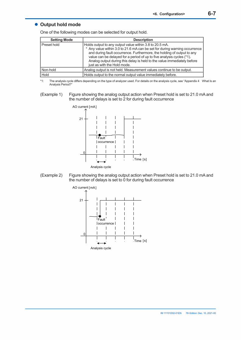
<6.Configuration> 6-7
IM 11Y01D02-01EN 7th Edition: Dec. 10, 2021-00
l OutputholdmodeOne of the following modes can be selected for output hold.
Setting Mode DescriptionPreset hold Holds output to any output value within 3.8 to 20.5 mA.
* Any value within 3.0 to 21.6 mA can be set for during warning occurrence and during fault occurrence. Furthermore, the holding of output to any value can be delayed for a period of up to five analysis cycles (*1). Analog output during this delay is held to the value immediately before just as with the Hold mode.
Non-hold Analog output is not held. Measurement values continue to be output.Hold Holds output to the normal output value immediately before.
*1: The analysis cycle differs depending on the type of analyzer used. For details on the analysis cycle, see “Appendix 4 What Is an Analysis Period?”
(Example 1) Figure showing the analog output action when Preset hold is set to 21.0 mA and the number of delays is set to 2 for during fault occurrence
[mA ]
[s]
0
21
AO current
Time
Analysis cycle
Fault occurrence
(Example 2) Figure showing the analog output action when Preset hold is set to 21.0 mA and the number of delays is set to 0 for during fault occurrence
[ s]
0
21
[mA]AO current
Time
Analysis cycle
Fault occurrence
<6.Configuration> 6-8
IM 11Y01D02-01EN 7th Edition: Dec. 10, 2021-00
l OutputholdpriorityWhen multiple specific states occur at the same time and multiple holds are enabled (when multiple Preset holds or Hold modes are enabled), the output hold is determined according to the following priority order.
During fault occurrenceDuring warning occurrenceDuring calibration and validationDuring maintenanceDuring warm-up
Priority High
(Example) When during warning occurrence = Non-hold, during maintenance = Preset hold, and during calibration and validation execution = Hold, and all three of the aforementioned states occurred at the same time, output hold becomes the Hold mode.
6.5 Digital Output SettingsThis function is for turning on digital output when the TDLS8100 enters the following specific states.
6.5.1 DOContact(DO-1)Setup menu path: [HART] “Detailed setup>>I/O condition>>Digital output>>DO-1(DO)” [YH8000] “Configuration>>I/O>>Digital Output>>DO-1(DO)”
l DefinitionsofspecificstatesWhen any of the following specific states occurs, the contact turns on. Enabling or disabling of digital output can be set separately for each specific state. For an explanation of each state, see 6.4.2 Output Hold.
• During warning occurrence• Calibration and validation• During maintenance• During warm-up
l Output delayA delay of up to 100 analysis cycles can be set for the period from when a specific state occurs until when the contact actually turns on. When the number of delays is set to zero, the contact turns on immediately after a state occurs.The analysis cycle differs depending on the application and is set to the optimum value at the time of shipment. For details, see “Appendix 4 What Is an Analysis Period?”
<6.Configuration> 6-9
IM 11Y01D02-01EN 7th Edition: Dec. 10, 2021-00
6.5.2 FaultContact(DO-2)Setup menu path: [HART] “Detailed setup>>I/O condition>>Digital output>>DO-2(Fault)” [YH8000] “Configuration>>I/O>>Digital Output>>DO-2(Fault)”
l DefinitionsofspecificstatesWhen a fault occurs, the contact turns on. This contact is specifically for fault notification and cannot be disabled.
l Output delayA delay of up to 100 analysis cycles can be set for the period from when a fault occurs until when the contact actually turns on. When the number of delays is set to zero, the contact turns on immediately after a fault occurs.The analysis cycle differs depending on the application and is set to the optimum value at the time of shipment. For details, see App.4-1 Appendix 4 What Is an Analysis Period?
6.6 Process Alarm SettingsOf the alarms of the TDLS8100, the threshold value and enable and disable can be set arbitrarily only for the following warnings related to the measurement process status. For details on each alarm, see "10.2 Warning Display and Handling".
Alarm No. Alarm Name1 Transmission low2 Pressure low3 Pressure high4 Temperature low5 Temperature high6 Concentration gas1 low7 Concentration gas1 high8 Concentration gas2 low (analyzer 2 only)9 Concentration gas2 high (analyzer 2 only)
Setup menu path: [HART] “Detailed setup>>Alarm” [YH8000] “Configuration>>Alarm”For details on the setting procedure, see "5.3.6 Setting Process Alarms".
<6.Configuration> 6-10
IM 11Y01D02-01EN 7th Edition: Dec. 10, 2021-00
6.7 Digital Input SettingsA specific function can be executed depending on the digital input (DI-1, DI-2). Also, the function to execute can be set for each channel. There are two types of digital input methods, edge input and status input, and the input method differs depending on the function.
• Edge input Execute a function when the digital input changes from “open” to “closed.”• Status input Execute and continue executing a function while the digital input is closed.
Setup menu path: [HART] “Detailed setup>>I/O condition>>Digital input>>DI-1 or DI-2” [YH8000] “Configuration>>I/O>>Digital Input>>DI-1 or DI-2”
l FunctionsthatcanbeexecutedThe following shows the functions that can be executed.
Function Name Action InputMethodExternal Alarm Generates the “External Alarm” warning. StatusZero Calibration Executes automatic zero calibration. EdgeSpan Calibration Executes automatic span calibration. EdgeZero + Span Calibration
Continuously executes automatic zero calibration and automatic span calibration.
Edge
Offline Validation 1 Executes automatic offline validation 1. EdgeOffline Validation 2 Executes automatic offline validation 2. EdgeOffline Validation 1 + 2 Continuously executes automatic offline validation 1 and 2. EdgeOnline Validation 1 Executes automatic online validation 1. EdgeOnline Validation 2 Executes automatic online validation 2. EdgeStream 1 Switches the valve to stream 1. StatusStream 2 Switches the valve to stream 2. StatusStream 3 Switches the valve to stream 3. Status
Note: The items of the above selection options that have been disabled by the “Valve usage setting” are not displayed. For details, see “6.8.2 Valve Usage Setting”
l Filter timeA cutoff time can be set to prevent wrong operation due to chattering. A digital input change within the specified time will be ignored.
6.8 Valve Stream SettingsThis section describes the procedure to automatically control multiple process gas streams according to the TDLS8100 valve control output (SV terminal). Up to three streams can be switched.
6.8.1 DefinitionsofStreamNumbersImplement the valve operation of the TDLS8100 using stream numbers defined for the statuses of the two valves connected to the valve control outputs (SV-1 and SV-2). Do not perform valve operation independently but specify stream numbers (independent operation is possible only when performing a loop check).The following shows the stream numbers to define for the TDLS8100 and the corresponding status of each valve.
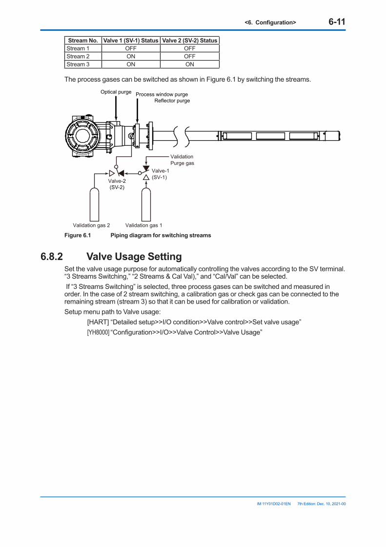
<6.Configuration> 6-11
IM 11Y01D02-01EN 7th Edition: Dec. 10, 2021-00
Stream No. Valve1(SV-1)Status Valve2(SV-2)StatusStream 1 OFF OFFStream 2 ON OFFStream 3 ON ON
The process gases can be switched as shown in Figure 6.1 by switching the streams.
Optical purge Process window purge Reflector purge
ValidationPurge gas
Valve-1(SV-1)
Valve-2(SV-2)
Validation gas 2 Validation gas 1
Figure6.1 Pipingdiagramforswitchingstreams
6.8.2 Valve Usage SettingSet the valve usage purpose for automatically controlling the valves according to the SV terminal. “3 Streams Switching,” “2 Streams & Cal Val),” and “Cal/Val” can be selected. If “3 Streams Switching” is selected, three process gases can be switched and measured in order. In the case of 2 stream switching, a calibration gas or check gas can be connected to the remaining stream (stream 3) so that it can be used for calibration or validation.Setup menu path to Valve usage: [HART] “Detailed setup>>I/O condition>>Valve control>>Set valve usage” [YH8000] “Configuration>>I/O>>Valve Control>>Valve Usage”
<6.Configuration> 6-12
IM 11Y01D02-01EN 7th Edition: Dec. 10, 2021-00
NOTEThe stream switching and automatic calibration and validation items that can be executed according to the TDLS8100 valve control output (SV terminal) are limited depending on the “Valve usage” setting.
• Cal/Val Usage Stream switching cannot be used because all streams are used for automatic calibration
and validation. When calibration and validation are not executed, the stream is fixed to stream 1.
To switch the process gas, do it manually.• 2 Streams & Cal/Val Usage Sets only stream 3 to be used for automatic calibration and validation. The following
automatic calibration and validation cannot be executed because they would use stream 2. Calibration and validation can only be executed manually.
• Zero calibration• Offline validation 1• Online validation 1
• 3 Streams Switching Usage All streams are set to be used for stream switching. None of the automatic calibration or
validation can be executed. Calibration and validation can only be executed manually.
NOTEIf valve usage is changed, the following setting values are initialized.
• The time execution setting (Time initiate) of all automatic calibration and validation is set to “Disable.”
• If remote execution of automatic calibration and validation is set for digital input, it is set to “Disable.”
• If stream switching is set for digital input, it is set to “Disable.”• The “Current stream” setting is set to “Stream 1.”• The “Initial stream” setting is set to “Stream 1.”
6.8.3 Stream SettingsThere are the following three stream switching methods.
Manual Specify a stream and then switch to it from an YH8000 or HART screen.Time elapse Switches to the next stream automatically when the specified time elapses after a stream has
been switched. When switching is performed manually or when switching to the initial stream is performed after the power of the TDLS8100 is turned on, counting of the specified time begins. This function does not work for switching by digital input.
Digital input Switches to the specified stream while the digital input is closed. The specified stream is switched to giving priority over the stream switched to with the manual or time elapse method. When the digital input returns to the open state, the stream returns to that switched to with the manual or time elapse method. The following figure shows the priority order.
The following figure shows the priority order. The manual and time elapse methods have the same priority level, and operation of the digital input is given higher priority.
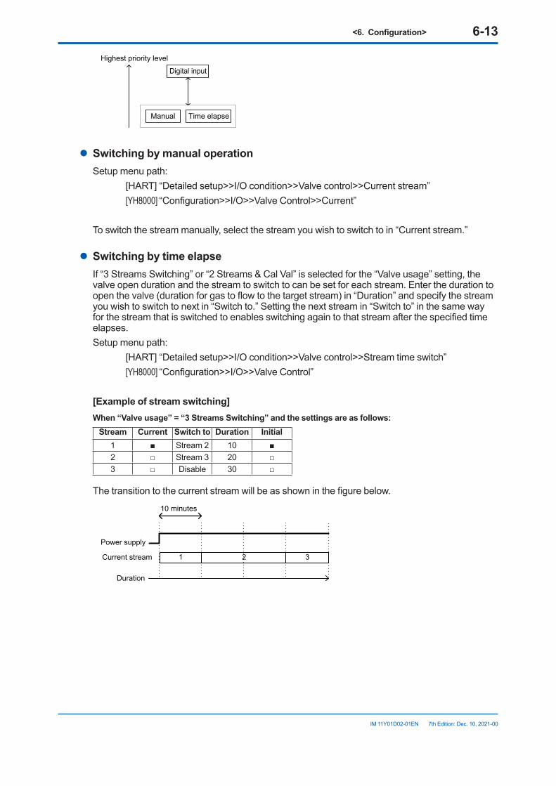
<6.Configuration> 6-13
IM 11Y01D02-01EN 7th Edition: Dec. 10, 2021-00
Manual Time elapse
Digital input
Highest priority level
l SwitchingbymanualoperationSetup menu path: [HART] “Detailed setup>>I/O condition>>Valve control>>Current stream” [YH8000] “Configuration>>I/O>>Valve Control>>Current”
To switch the stream manually, select the stream you wish to switch to in “Current stream.”
l SwitchingbytimeelapseIf “3 Streams Switching” or “2 Streams & Cal Val” is selected for the “Valve usage” setting, the valve open duration and the stream to switch to can be set for each stream. Enter the duration to open the valve (duration for gas to flow to the target stream) in “Duration” and specify the stream you wish to switch to next in “Switch to.” Setting the next stream in “Switch to” in the same way for the stream that is switched to enables switching again to that stream after the specified time elapses. Setup menu path: [HART] “Detailed setup>>I/O condition>>Valve control>>Stream time switch” [YH8000] “Configuration>>I/O>>Valve Control”
[Exampleofstreamswitching]When“Valveusage”=“3StreamsSwitching”andthesettingsareasfollows:
Stream Current Switchto Duration Initial1 ■ Stream 2 10 ■2 □ Stream 3 20 □3 □ Disable 30 □
The transition to the current stream will be as shown in the figure below.
1 2 3
10 minutes
Duration
Power supply
Current stream
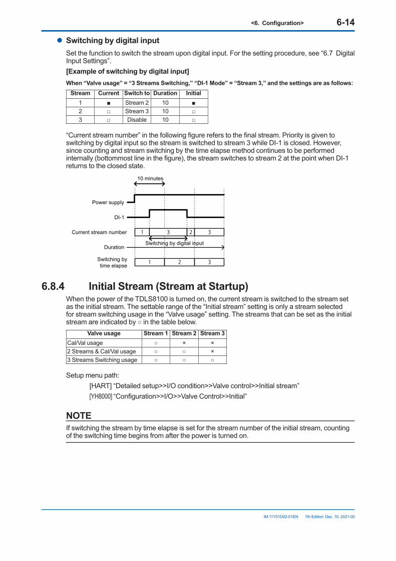
<6.Configuration> 6-14
IM 11Y01D02-01EN 7th Edition: Dec. 10, 2021-00
l SwitchingbydigitalinputSet the function to switch the stream upon digital input. For the setting procedure, see “6.7 Digital Input Settings”.[Exampleofswitchingbydigitalinput]When“Valveusage”=“3StreamsSwitching,”“DI-1Mode”=“Stream3,”andthesettingsareasfollows:
Stream Current Switchto Duration Initial 1 ■ Stream 2 10 ■2 □ Stream 3 10 □3 □ Disable 10 □
“Current stream number” in the following figure refers to the final stream. Priority is given to switching by digital input so the stream is switched to stream 3 while DI-1 is closed. However, since counting and stream switching by the time elapse method continues to be performed internally (bottommost line in the figure), the stream switches to stream 2 at the point when DI-1 returns to the closed state.
1 3 2 3
1 2 3
10 minutes
Duration
Power supply
DI-1
Current stream number
Switching by time elapse
Switching by digital input
6.8.4 InitialStream(StreamatStartup)When the power of the TDLS8100 is turned on, the current stream is switched to the stream set as the initial stream. The settable range of the “Initial stream” setting is only a stream selected for stream switching usage in the “Valve usage” setting. The streams that can be set as the initial stream are indicated by ○ in the table below.
Valve usage Stream 1 Stream 2 Stream 3Cal/Val usage ○ × ×2 Streams & Cal/Val usage ○ ○ ×3 Streams Switching usage ○ ○ ○
Setup menu path: [HART] “Detailed setup>>I/O condition>>Valve control>>Initial stream” [YH8000] “Configuration>>I/O>>Valve Control>>Initial”
NOTEIf switching the stream by time elapse is set for the stream number of the initial stream, counting of the switching time begins from after the power is turned on.
<6.Configuration> 6-15
IM 11Y01D02-01EN 7th Edition: Dec. 10, 2021-00
6.9 OtherSettingsThis section describes various settings other than measurement process settings and the I/O and alarm settings.
6.9.1 TagThis is a tag of up to 32 ASCII characters for identifying individual TDLS8100. It is displayed when you connect to the TDLS8100 from the YH8000. Furthermore, the long tag defined as standard in HART communication is the same as this tag. From YH8000, Latin-1 character cannot be inputted on tag.Setup menu path: [HART] “Detailed setup>>System>>Long tag” [YH8000] “Configuration>>System>>Tag”
6.9.2 Date and TimeSet the current date and time. For a detailed description of the setting screen, read “5.3.1 Setting the Date and Time”. Furthermore, it is possible to set the time simultaneously for multiple connected TDLS8000 series only when setting them from the YH8000. For details, see “8.7.3 Setting the Date and Time on Analyzer”.Setup menu path: [HART] “Detailed setup>>System>>Date/time>>Set date/time” [YH8000] “Configuration>>System>>Date&Time”
6.9.3 User Password SettingChange the user password for when entering the setting screen from the YH8000. Enter the current password and then enter a new password twice for confirmation. Setup menu path: [YH8000] “Configuration>>System>>Password”
6.9.4 DisplayConfigure settings related to the LU display and SCU display.
l BrightnessadjustmentofLUdisplaySet the brightness to any of 11 levels.Setup menu path: [HART] “Detailed setup>>System>>Local display>>LU LED display” [YH8000] “Configuration>>System>>Local Display>>LU”
l BrightnessadjustmentofSCUdisplayAdjust backlight brightness and contrast to any of 11 levels.Setup menu path: [HART] “Detailed setup>>System>>Local display>>SCU LCD display” [YH8000] “Configuration>>System>>Local Display>>SCU”
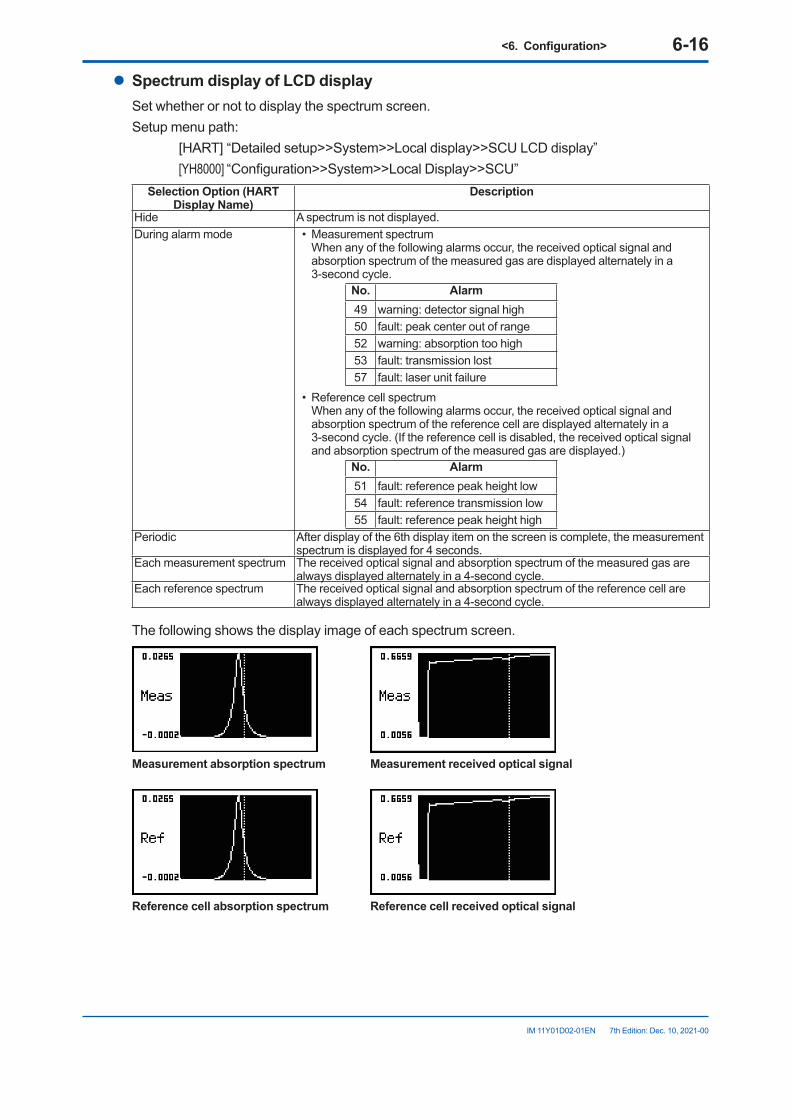
<6.Configuration> 6-16
IM 11Y01D02-01EN 7th Edition: Dec. 10, 2021-00
l Spectrum display of LCD displaySet whether or not to display the spectrum screen.Setup menu path: [HART] “Detailed setup>>System>>Local display>>SCU LCD display” [YH8000] “Configuration>>System>>Local Display>>SCU”
SelectionOption(HARTDisplayName)
Description
Hide A spectrum is not displayed.During alarm mode • Measurement spectrum
When any of the following alarms occur, the received optical signal and absorption spectrum of the measured gas are displayed alternately in a 3-second cycle.
No. Alarm49 warning: detector signal high50 fault: peak center out of range52 warning: absorption too high53 fault: transmission lost57 fault: laser unit failure
• Reference cell spectrum When any of the following alarms occur, the received optical signal and
absorption spectrum of the reference cell are displayed alternately in a 3-second cycle. (If the reference cell is disabled, the received optical signal and absorption spectrum of the measured gas are displayed.)
No. Alarm51 fault: reference peak height low54 fault: reference transmission low55 fault: reference peak height high
Periodic After display of the 6th display item on the screen is complete, the measurement spectrum is displayed for 4 seconds.
Each measurement spectrum The received optical signal and absorption spectrum of the measured gas are always displayed alternately in a 4-second cycle.
Each reference spectrum The received optical signal and absorption spectrum of the reference cell are always displayed alternately in a 4-second cycle.
The following shows the display image of each spectrum screen.
Measurement absorption spectrum Measurement received optical signal
Reference cell absorption spectrum Reference cell received optical signal
<6.Configuration> 6-17
IM 11Y01D02-01EN 7th Edition: Dec. 10, 2021-00
6.9.5 Communication Address SettingConfigure the address settings for TDLS8100 and HART communication.
l IP address setting of TDLS8100Setup menu path: [HART] “Detailed setup>>System>>Communication>>TCP/IP>>Set IP settings” [YH8000] “Configuration>>System>>Communication>>TCP/IP”
NOTEWhen the IP address is changed, the TDLS8100 restarts automatically.
NOTEWhen the IP address of the TDLS8100 is changed via the YH8000, the YH8000 connection settings need to be configured again. For details, see “5.2.3 Connecting to the TDLS8100”.
l HART address settingSetup menu path: [HART] “Detailed setup>>System>>Communication>>HART output” [YH8000] “Configuration>>System>>Communication>>HART”
“Loop current mode” is a setting related to multi-drop mode. For details on multi-drop mode, see “7.5.1 Multidrop Mode”.
6.9.6 Moving Average Count for Analysis ValuesConfigure the setting for how many analysis cycles of spectrum data to take the moving average. Increasing this value enables a more stable analysis result to be obtained but the response time will increase. For explanations on the analysis cycle and average count, see “Appendix 4 What Is an Analysis Period?”Setup menu path: [HART] “Detailed setup>>Analysis>>Averaging” [YH8000] “Configuration>>Analysis>>Average”
6.9.7 ConcentrationOffsetIt is possible to display the value resulting from adding a fixed offset value to the calculated concentration value as the final reading. For the two-gas measurement specification, you can set an offset for each of the first component gas concentration and second component gas concentration.Setup menu path: [HART] “Detailed setup>>Analysis>>Zero offset” [YH8000] “Configuration>>Analysis>>Zero Offset”
<6.Configuration> 6-18
IM 11Y01D02-01EN 7th Edition: Dec. 10, 2021-00
6.9.8 Safety ModeSafety Mode secures TDLS8100 operation in the safety instrumented system. The following table shows how configuration of Safety Mode affects the operation.See “Appendix 5 Safety Instrumented System Installation”.Setup menu path: [HART] “Detailed setup>> System >>Safety mode” [YH8000] “Configuration>>System >>Safety Mode”
Safety modeEffecton
Enable Disable(default)
Condition of fault clearance Fault stays until the system reboots. Once the problem is solved, the fault is cleared.
Threshold of Fault: Transmission Lost Detector sensitivity becomes high Detector sensitivity becomes standardAnalog output on the following conditions:●Al-1 <= 3.6 mA, or Al-1 >= 21.0 mA●Process pressure input mode is
“Active Input” and “Input source is “A1-1”. Follow the Output Hold setting for Fault
Follow the Output Hold setting for Warning. (Warning appears when analog input is less than or equal to 4 mA or greater than or equal to 20 mA.)
Analog output on the following conditions:●Al-2 <= 3.6 mA , or Al-2 >= 21.0 mA●Process temperature input mode is
“Active Input” and “Input source is “A1-2”.
Analog output after Fault reset =0 mA normal operation
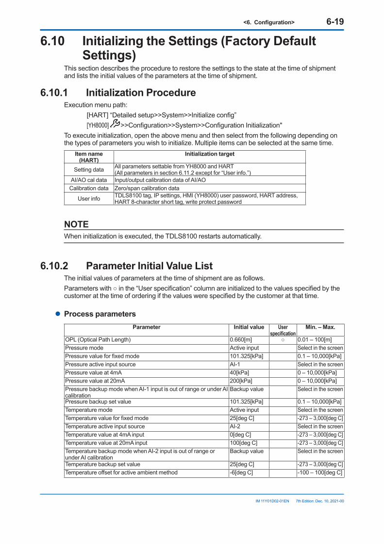
<6.Configuration> 6-19
IM 11Y01D02-01EN 7th Edition: Dec. 10, 2021-00
6.10 InitializingtheSettings(FactoryDefaultSettings)
This section describes the procedure to restore the settings to the state at the time of shipment and lists the initial values of the parameters at the time of shipment.
6.10.1 InitializationProcedureExecution menu path: [HART] “Detailed setup>>System>>Initialize config” [YH8000] >>Configuration>>System>>Configuration Initialization"To execute initialization, open the above menu and then select from the following depending on the types of parameters you wish to initialize. Multiple items can be selected at the same time.
Item name (HART)
Initializationtarget
Setting data All parameters settable from YH8000 and HART(All parameters in section 6.11.2 except for “User info.”)
AI/AO cal data Input/output calibration data of AI/AOCalibration data Zero/span calibration data
User info TDLS8100 tag, IP settings, HMI (YH8000) user password, HART address, HART 8-character short tag, write protect password
NOTEWhen initialization is executed, the TDLS8100 restarts automatically.
6.10.2 Parameter Initial Value ListThe initial values of parameters at the time of shipment are as follows.Parameters with ○ in the “User specification” column are initialized to the values specified by the customer at the time of ordering if the values were specified by the customer at that time.
l Process parametersParameter Initial value User
specificationMin.–Max.
OPL (Optical Path Length) 0.660[m] ○ 0.01 – 100[m]Pressure mode Active input Select in the screen Pressure value for fixed mode 101.325[kPa] 0.1 – 10,000[kPa]Pressure active input source AI-1 Select in the screen Pressure value at 4mA 40[kPa] 0 – 10,000[kPa]Pressure value at 20mA 200[kPa] 0 – 10,000[kPa]Pressure backup mode when AI-1 input is out of range or under AI calibration
Backup value Select in the screen
Pressure backup set value 101.325[kPa] 0.1 – 10,000[kPa]Temperature mode Active input Select in the screen Temperature value for fixed mode 25[deg C] -273 – 3,000[deg C]Temperature active input source AI-2 Select in the screen Temperature value at 4mA input 0[deg C] -273 – 3,000[deg C]Temperature value at 20mA input 100[deg C] -273 – 3,000[deg C]Temperature backup mode when AI-2 input is out of range or under AI calibration
Backup value Select in the screen
Temperature backup set value 25[deg C] -273 – 3,000[deg C]Temperature offset for active ambient method -6[deg C] -100 – 100[deg C]
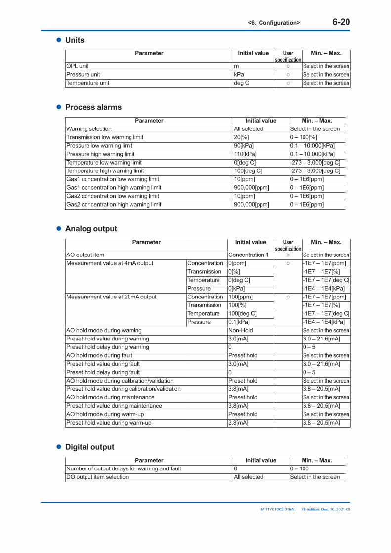
<6.Configuration> 6-20
IM 11Y01D02-01EN 7th Edition: Dec. 10, 2021-00
l UnitsParameter Initial value User
specificationMin.–Max.
OPL unit m ○ Select in the screen Pressure unit kPa ○ Select in the screen Temperature unit deg C ○ Select in the screen
l Process alarmsParameter Initial value Min.–Max.
Warning selection All selected Select in the screen Transmission low warning limit 20[%] 0 – 100[%]Pressure low warning limit 90[kPa] 0.1 – 10,000[kPa]Pressure high warning limit 110[kPa] 0.1 – 10,000[kPa]Temperature low warning limit 0[deg C] -273 – 3,000[deg C]Temperature high warning limit 100[deg C] -273 – 3,000[deg C]Gas1 concentration low warning limit 10[ppm] 0 – 1E6[ppm]Gas1 concentration high warning limit 900,000[ppm] 0 – 1E6[ppm]Gas2 concentration low warning limit 10[ppm] 0 – 1E6[ppm]Gas2 concentration high warning limit 900,000[ppm] 0 – 1E6[ppm]
l Analog outputParameter Initial value User
specificationMin.–Max.
AO output item Concentration 1 ○ Select in the screen Measurement value at 4mA output Concentration 0[ppm] ○ -1E7 – 1E7[ppm]
Transmission 0[%] -1E7 – 1E7[%]Temperature 0[deg C] -1E7 – 1E7[deg C]Pressure 0[kPa] -1E4 – 1E4[kPa]
Measurement value at 20mA output Concentration 100[ppm] ○ -1E7 – 1E7[ppm] Transmission 100[%] -1E7 – 1E7[%]Temperature 100[deg C] -1E7 – 1E7[deg C]Pressure 0.1[kPa] -1E4 – 1E4[kPa]
AO hold mode during warning Non-Hold Select in the screen Preset hold value during warning 3.0[mA] 3.0 – 21.6[mA]Preset hold delay during warning 0 0 – 5AO hold mode during fault Preset hold Select in the screen Preset hold value during fault 3.0[mA] 3.0 – 21.6[mA]Preset hold delay during fault 0 0 – 5AO hold mode during calibration/validation Preset hold Select in the screen Preset hold value during calibration/validation 3.8[mA] 3.8 – 20.5[mA]AO hold mode during maintenance Preset hold Select in the screen Preset hold value during maintenance 3.8[mA] 3.8 – 20.5[mA]AO hold mode during warm-up Preset hold Select in the screen Preset hold value during warm-up 3.8[mA] 3.8 – 20.5[mA]
l Digital outputParameter Initial value Min.–Max.
Number of output delays for warning and fault 0 0 – 100DO output item selection All selected Select in the screen
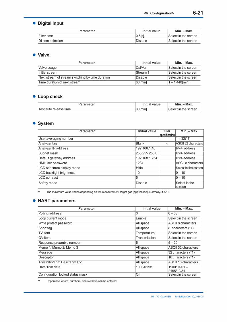
<6.Configuration> 6-21
IM 11Y01D02-01EN 7th Edition: Dec. 10, 2021-00
l Digital inputParameter Initial value Min.–Max.
Filter time 0.5[s] Select in the screen DI item selection Disable Select in the screen
l ValveParameter Initial value Min.–Max.
Valve usage Cal/Val Select in the screen Initial stream Stream 1 Select in the screen Next stream of stream switching by time duration Disable Select in the screen Time duration of next stream 60[min] 1 – 1,440[min]
l LoopcheckParameter Initial value Min.–Max.
Test auto release time 30[min] Select in the screen
l SystemParameter Initial value User
specificationMin.–Max.
User averaging number 1 1 – 32(*1)Analyzer tag Blank ○ ASCII 32 charactersAnalyzer IP address 192.168.1.10 IPv4 addressSubnet mask 255.255.255.0 IPv4 addressDefault gateway address 192.168.1.254 IPv4 addressHMI user password 1234 ASCII 8 charactersLCD spectrum display mode Hide Select in the screen LCD backlight brightness 10 0 – 10LCD contrast 5 0 – 10Safety mode Disable Select in the
screen*1: The maximum value varies depending on the measurement target gas (application). Normally, it is 16.
l HART parametersParameter Initial value Min.–Max.
Polling address 0 0 – 63Loop current mode Enable Select in the screen Write protect password All space ASCII 8 charactersShort tag All space 8 characters (*1)TV item Temperature Select in the screen QV item Transmission Select in the screen Response preamble number 5 5 – 20Memo 1/ Memo 2/ Memo 3 All space ASCII 32 charactersMessage All space 32 characters (*1)Descriptor All space 16 characters (*1)Trim Who/Trim Desc/Trim Loc All space ASCII 16 charactersDate/Trim date 1900/01/01 1900/01/01 –
2155/12/31Configuration locked status mask Off Select in the screen
*1: Uppercase letters, numbers, and symbols can be entered.
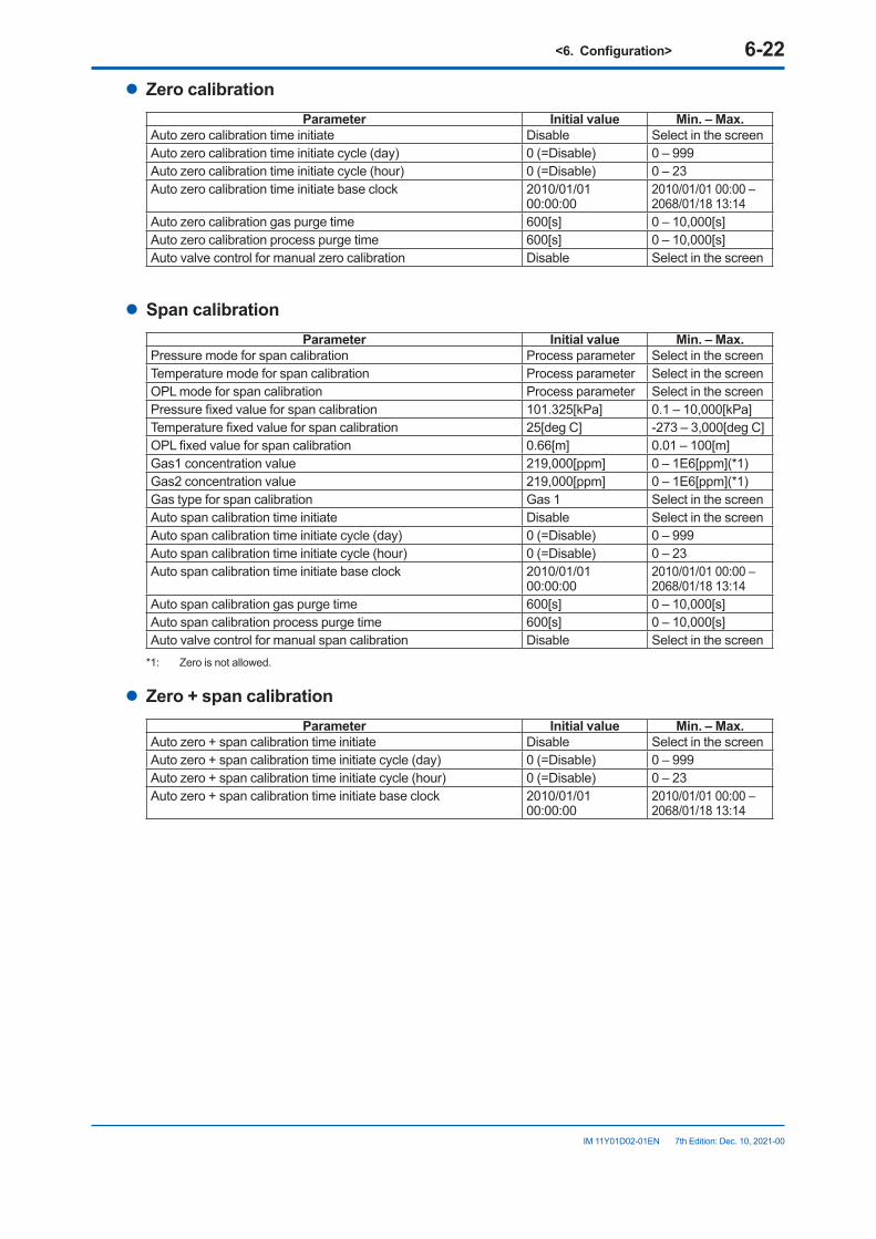
<6.Configuration> 6-22
IM 11Y01D02-01EN 7th Edition: Dec. 10, 2021-00
l Zero calibrationParameter Initial value Min.–Max.
Auto zero calibration time initiate Disable Select in the screen Auto zero calibration time initiate cycle (day) 0 (=Disable) 0 – 999Auto zero calibration time initiate cycle (hour) 0 (=Disable) 0 – 23Auto zero calibration time initiate base clock 2010/01/01
00:00:002010/01/01 00:00 –2068/01/18 13:14
Auto zero calibration gas purge time 600[s] 0 – 10,000[s]Auto zero calibration process purge time 600[s] 0 – 10,000[s]Auto valve control for manual zero calibration Disable Select in the screen
l Span calibrationParameter Initial value Min.–Max.
Pressure mode for span calibration Process parameter Select in the screen Temperature mode for span calibration Process parameter Select in the screen OPL mode for span calibration Process parameter Select in the screen Pressure fixed value for span calibration 101.325[kPa] 0.1 – 10,000[kPa]Temperature fixed value for span calibration 25[deg C] -273 – 3,000[deg C]OPL fixed value for span calibration 0.66[m] 0.01 – 100[m]Gas1 concentration value 219,000[ppm] 0 – 1E6[ppm](*1)Gas2 concentration value 219,000[ppm] 0 – 1E6[ppm](*1)Gas type for span calibration Gas 1 Select in the screen Auto span calibration time initiate Disable Select in the screen Auto span calibration time initiate cycle (day) 0 (=Disable) 0 – 999Auto span calibration time initiate cycle (hour) 0 (=Disable) 0 – 23Auto span calibration time initiate base clock 2010/01/01
00:00:002010/01/01 00:00 –2068/01/18 13:14
Auto span calibration gas purge time 600[s] 0 – 10,000[s]Auto span calibration process purge time 600[s] 0 – 10,000[s]Auto valve control for manual span calibration Disable Select in the screen
*1: Zero is not allowed.
l Zero + span calibrationParameter Initial value Min.–Max.
Auto zero + span calibration time initiate Disable Select in the screen Auto zero + span calibration time initiate cycle (day) 0 (=Disable) 0 – 999Auto zero + span calibration time initiate cycle (hour) 0 (=Disable) 0 – 23Auto zero + span calibration time initiate base clock 2010/01/01
00:00:002010/01/01 00:00 –2068/01/18 13:14
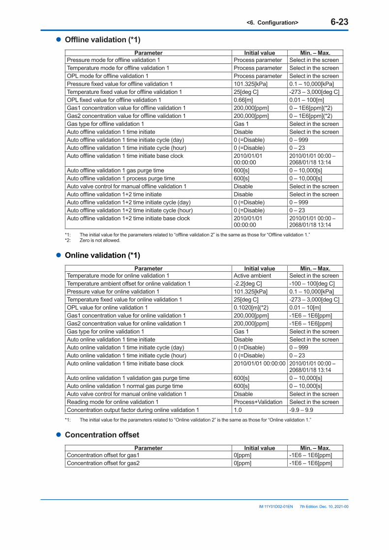
<6.Configuration> 6-23
IM 11Y01D02-01EN 7th Edition: Dec. 10, 2021-00
l Offlinevalidation(*1)Parameter Initial value Min.–Max.
Pressure mode for offline validation 1 Process parameter Select in the screen Temperature mode for offline validation 1 Process parameter Select in the screen OPL mode for offline validation 1 Process parameter Select in the screen Pressure fixed value for offline validation 1 101.325[kPa] 0.1 – 10,000[kPa]Temperature fixed value for offline validation 1 25[deg C] -273 – 3,000[deg C]OPL fixed value for offline validation 1 0.66[m] 0.01 – 100[m]Gas1 concentration value for offline validation 1 200,000[ppm] 0 – 1E6[ppm](*2)Gas2 concentration value for offline validation 1 200,000[ppm] 0 – 1E6[ppm](*2)Gas type for offline validation 1 Gas 1 Select in the screen Auto offline validation 1 time initiate Disable Select in the screen Auto offline validation 1 time initiate cycle (day) 0 (=Disable) 0 – 999Auto offline validation 1 time initiate cycle (hour) 0 (=Disable) 0 – 23Auto offline validation 1 time initiate base clock 2010/01/01
00:00:002010/01/01 00:00 –2068/01/18 13:14
Auto offline validation 1 gas purge time 600[s] 0 – 10,000[s]Auto offline validation 1 process purge time 600[s] 0 – 10,000[s]Auto valve control for manual offline validation 1 Disable Select in the screen Auto offline validation 1+2 time initiate Disable Select in the screen Auto offline validation 1+2 time initiate cycle (day) 0 (=Disable) 0 – 999Auto offline validation 1+2 time initiate cycle (hour) 0 (=Disable) 0 – 23Auto offline validation 1+2 time initiate base clock 2010/01/01
00:00:002010/01/01 00:00 –2068/01/18 13:14
*1: The initial value for the parameters related to “offline validation 2” is the same as those for “Offline validation 1.”*2: Zero is not allowed.
l Onlinevalidation(*1)Parameter Initial value Min.–Max.
Temperature mode for online validation 1 Active ambient Select in the screen Temperature ambient offset for online validation 1 -2.2[deg C] -100 – 100[deg C]Pressure value for online validation 1 101.325[kPa] 0.1 – 10,000[kPa]Temperature fixed value for online validation 1 25[deg C] -273 – 3,000[deg C]OPL value for online validation 1 0.1020[m](*2) 0.01 – 10[m]Gas1 concentration value for online validation 1 200,000[ppm] -1E6 – 1E6[ppm]Gas2 concentration value for online validation 1 200,000[ppm] -1E6 – 1E6[ppm]Gas type for online validation 1 Gas 1 Select in the screen Auto online validation 1 time initiate Disable Select in the screen Auto online validation 1 time initiate cycle (day) 0 (=Disable) 0 – 999Auto online validation 1 time initiate cycle (hour) 0 (=Disable) 0 – 23Auto online validation 1 time initiate base clock 2010/01/01 00:00:00 2010/01/01 00:00 –
2068/01/18 13:14Auto online validation 1 validation gas purge time 600[s] 0 – 10,000[s]Auto online validation 1 normal gas purge time 600[s] 0 – 10,000[s]Auto valve control for manual online validation 1 Disable Select in the screen Reading mode for online validation 1 Process+Validation Select in the screen Concentration output factor during online validation 1 1.0 -9.9 – 9.9
*1: The initial value for the parameters related to “Online validation 2” is the same as those for “Online validation 1.”
l ConcentrationoffsetParameter Initial value Min.–Max.
Concentration offset for gas1 0[ppm] -1E6 – 1E6[ppm] Concentration offset for gas2 0[ppm] -1E6 – 1E6[ppm]

Blank Page
<7. HART Communication> 7-1
IM 11Y01D02-01EN 7th Edition: Dec. 10, 2021-00
7. HART CommunicationThe following functions can be performed via HART communication.
• Checking concentration, transmission, process pressure, and process temperature• Checking alarm statuses• Setting parameters• Performing calibration and validation• Performing loop check• Checking alarms and calibration history
This chapter explains matters specific to HART communication.
7.1 ConnectionFor the method of connecting a HART setting tool to the TDLS8100, see "5.1 Connecting the HART Configuration Tool".
7.2 Menu TreeThis section shows the hierarchal configuration of the DD menu. For the whole configuration containing all parameters, see “Appendix 2 General View of HART DD”.
7.2.1 DD MenuThe root menu (top menu) is as follows.
Root menu DescriptionProcess variables Displays the latest values of PV-QV and measurements.Diagnosis/Service Checks alarms and history; performs calibration, validation, and loop checkBasic setup Assigns PV-QV items; sets output rangesDetailed setup Sets parameters specific to the TDLS8100Review Displays measurements, I/O values, and manufacturing information
The menus in the second and lower layers are as follows.
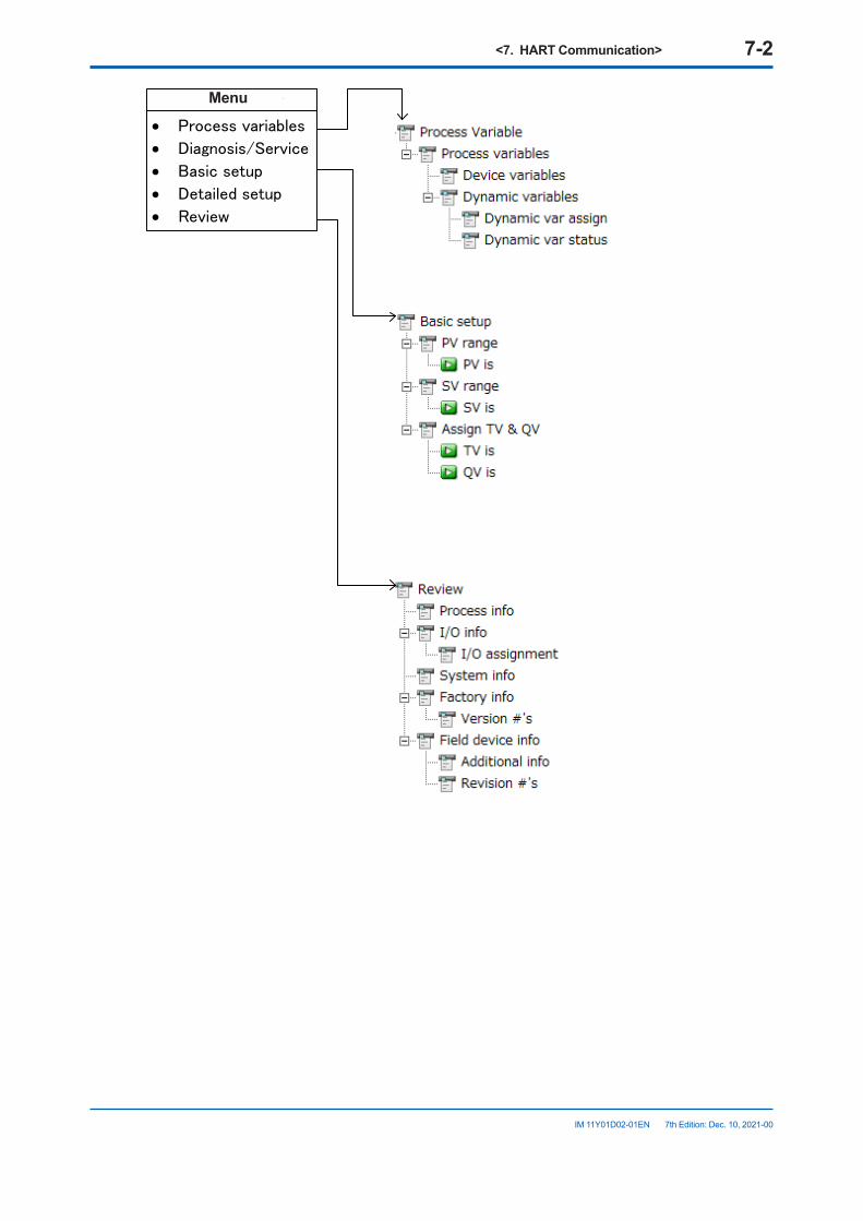
<7. HART Communication> 7-2
IM 11Y01D02-01EN 7th Edition: Dec. 10, 2021-00
• Process variables
• Diagnosis/Service
• Basic setup
• Detailed setup
• Review
ルートメニューMenu
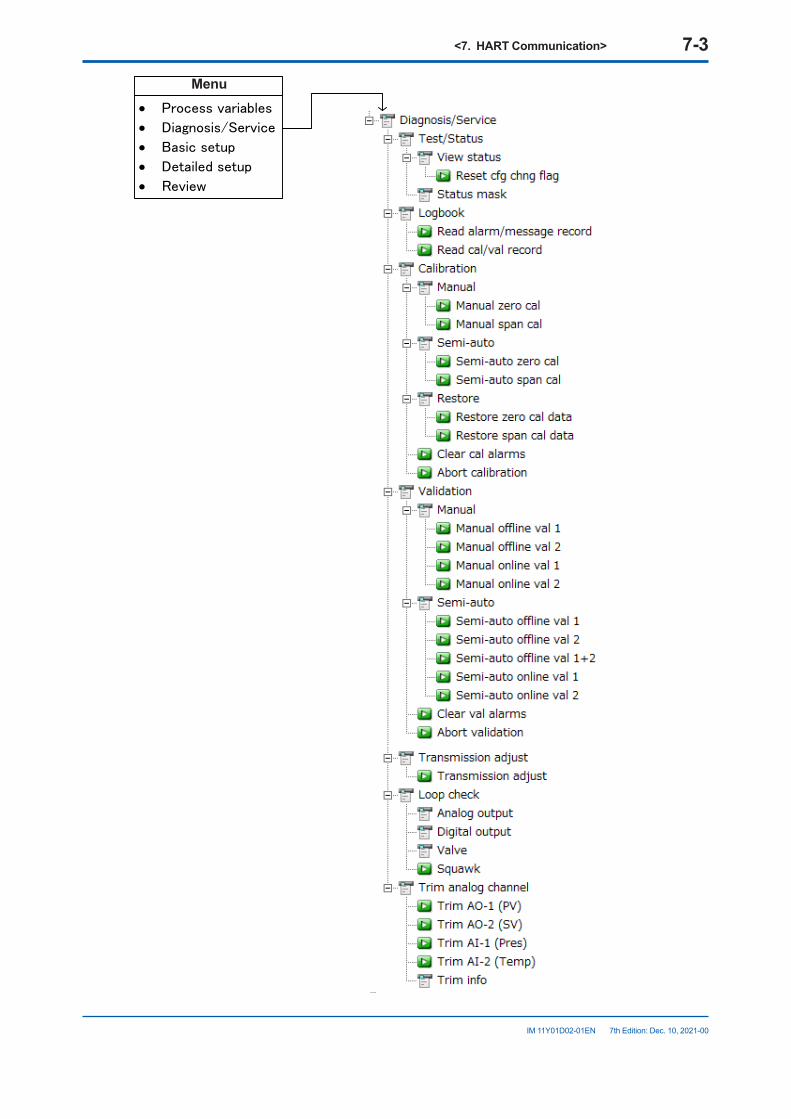
<7. HART Communication> 7-3
IM 11Y01D02-01EN 7th Edition: Dec. 10, 2021-00
• Process variables
• Diagnosis/Service
• Basic setup
• Detailed setup
• Review
ルートメニューMenu
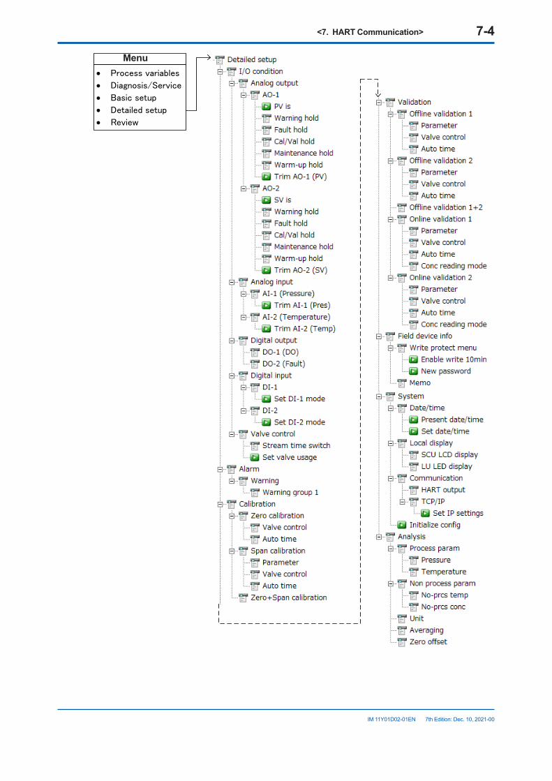
<7. HART Communication> 7-4
IM 11Y01D02-01EN 7th Edition: Dec. 10, 2021-00
• Process variables
• Diagnosis/Service
• Basic setup
• Detailed setup
• Review
ルートメニューMenu
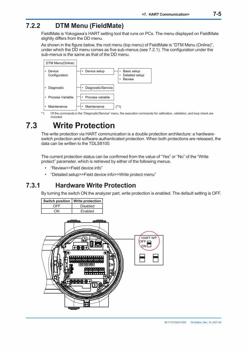
<7. HART Communication> 7-5
IM 11Y01D02-01EN 7th Edition: Dec. 10, 2021-00
7.2.2 DTMMenu(FieldMate)FieldMate is Yokogawa’s HART setting tool that runs on PCs. The menu displayed on FieldMate slightly differs from the DD menu. As shown in the figure below, the root menu (top menu) of FieldMate is “DTM Menu (Online)”, under which the DD menu comes as five sub-menus (see 7.2.1). The configuration under the sub-menus is the same as that of the DD menu.
• Device Configuration
DTM Menu(Online)
• Diagnostic
• Process Variable
• Device setup • Basic setup• Detailed setup• Review
• Diagnostic/Service
• Process variable
• Maintenance • Maintenance (*1)
*1: Of the commands in the “Diagnostic/Service” menu, the execution commands for calibration, validation, and loop check are included.
7.3 Write ProtectionThe write protection via HART communication is a double protection architecture: a hardware-switch protection and software-authenticated protection. When both protections are released, the data can be written to the TDLS8100.
The current protection status can be confirmed from the value of “Yes” or “No” of the “Write protect” parameter, which is retrieved by either of the following menus.
• “Review>>Field device info”• “Detailed setup>>Field device info>>Write protect menu”
7.3.1 Hardware Write ProtectionBy turning the switch ON the analyzer part, write protection is enabled. The default setting is OFF.
Switchposition Write protectionOFF DisabledON Enabled
HART WPOFF
ON
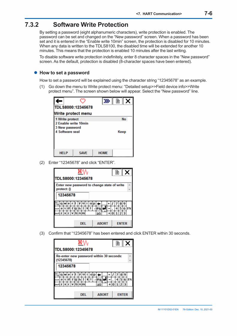
<7. HART Communication> 7-6
IM 11Y01D02-01EN 7th Edition: Dec. 10, 2021-00
7.3.2 Software Write ProtectionBy setting a password (eight alphanumeric characters), write protection is enabled. The password can be set and changed on the “New password” screen. When a password has been set and it is entered in the “Enable write 10min” screen, the protection is disabled for 10 minutes. When any data is written to the TDLS8100, the disabled time will be extended for another 10 minutes. This means that the protection is enabled 10 minutes after the last writing. To disable software write protection indefinitely, enter 8 character spaces in the “New password” screen. As the default, protection is disabled (8-character spaces have been entered).
l How to set a passwordHow to set a password will be explained using the character string “12345678” as an example.(1) Go down the menu to Write protect menu: “Detailed setup>>Field device info>>Write
protect menu”. The screen shown below will appear. Select the “New password” line.
(2) Enter “12345678” and click “ENTER”.
(3) Confirm that “12345678” has been entered and click ENTER within 30 seconds.
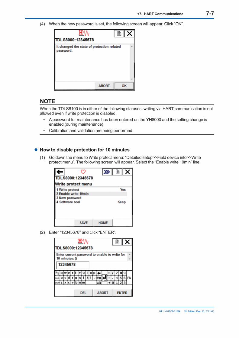
<7. HART Communication> 7-7
IM 11Y01D02-01EN 7th Edition: Dec. 10, 2021-00
(4) When the new password is set, the following screen will appear. Click “OK”.
NOTEWhen the TDLS8100 is in either of the following statuses, writing via HART communication is not allowed even if write protection is disabled.
• A password for maintenance has been entered on the YH8000 and the setting change is enabled (during maintenance)
• Calibration and validation are being performed.
l How to disable protection for 10 minutes(1) Go down the menu to Write protect menu: “Detailed setup>>Field device info>>Write
protect menu”. The following screen will appear. Select the “Enable write 10min” line.
(2) Enter “12345678” and click “ENTER”.
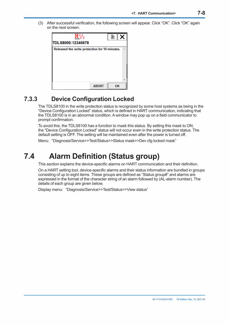
<7. HART Communication> 7-8
IM 11Y01D02-01EN 7th Edition: Dec. 10, 2021-00
(3) After successful verification, the following screen will appear. Click “OK”. Click “OK” again on the next screen.
7.3.3 DeviceConfigurationLockedThe TDLS8100 in the write protection status is recognized by some host systems as being in the “Device Configuration Locked” status, which is defined in HART communication, indicating that the TDLS8100 is in an abnormal condition. A window may pop up on a field communicator to prompt confirmation. To avoid this, the TDLS8100 has a function to mask this status. By setting this mask to ON, the “Device Configuration Locked” status will not occur even in the write protection status. The default setting is OFF. The setting will be maintained even after the power is turned off.Menu: “Diagnosis/Service>>Test/Status>>Status mask>>Dev cfg locked mask”
7.4 AlarmDefinition(Statusgroup)This section explains the device-specific alarms on HART communication and their definition. On a HART setting tool, device-specific alarms and their status information are bundled in groups consisting of up to eight items. These groups are defined as “Status group#” and alarms are expressed in the format of the character string of an alarm followed by (AL-alarm number). The details of each group are given below.Display menu: “Diagnosis/Service>>Test/Status>>View status”
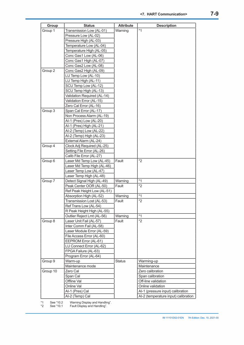
<7. HART Communication> 7-9
IM 11Y01D02-01EN 7th Edition: Dec. 10, 2021-00
Group Status Attribute DescriptionGroup 1 Transmission Low (AL-01) Warning *1
Pressure Low (AL-02)Pressure High (AL-03)Temperature Low (AL-04)Temperature High (AL-05)Conc Gas1 Low (AL-06)Conc Gas1 High (AL-07)Conc Gas2 Low (AL-08)
Group 2 Conc Gas2 High (AL-09)LU Temp Low (AL-10)LU Temp High (AL-11)SCU Temp Low (AL-12)SCU Temp High (AL-13)Validation Required (AL-14)Validation Error (AL-15)Zero Cal Error (AL-16)
Group 3 Span Cal Error (AL-17)Non Process Alarm (AL-19)AI-1 (Pres) Low (AL-20)AI-1 (Pres) High (AL-21)AI-2 (Temp) Low (AL-22)AI-2 (Temp) High (AL-23)External Alarm (AL-24)
Group 4 Clock Adj Required (AL-25)Setting File Error (AL-26)Calib File Error (AL-27)
Group 6 Laser Md Temp Low (AL-45) Fault *2Laser Md Temp High (AL-46)Laser Temp Low (AL-47)Laser Temp High (AL-48)
Group 7 Detect Signal High (AL-49) Warning *1Peak Center OOR (AL-50) Fault *2Ref Peak Height Low (AL-51)Absorption High (AL-52) Warning *1Transmission Lost (AL-53) Fault *2Ref Trans Low (AL-54)R Peak Height High (AL-55)Outlier Reject Lmt (AL-56) Warning *1
Group 8 Laser Unit Fail (AL-57) Fault *2Inter Comm Fail (AL-58)Laser Module Error (AL-59)File Access Error (AL-60)EEPROM Error (AL-61)LU Connect Error (AL-62)FPGA Failure (AL-63)Program Error (AL-64)
Group 9 Warm-up Status Warming-upMaintenance mode Maintenance
Group 10 Zero Cal Zero calibrationSpan Cal Span calibrationOffline Val Off-line validationOnline Val Online validationAI-1 (Pres) Cal AI-1 (pressure input) calibrationAI-2 (Temp) Cal AI-2 (temperature input) calibration
*1 See “10.2 Warning Display and Handling”.*2 See “10.1 Fault Display and Handling”.
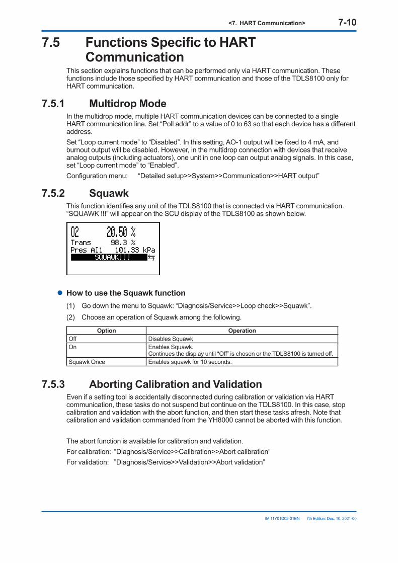
<7. HART Communication> 7-10
IM 11Y01D02-01EN 7th Edition: Dec. 10, 2021-00
7.5 FunctionsSpecifictoHARTCommunication
This section explains functions that can be performed only via HART communication. These functions include those specified by HART communication and those of the TDLS8100 only for HART communication.
7.5.1 Multidrop ModeIn the multidrop mode, multiple HART communication devices can be connected to a single HART communication line. Set “Poll addr” to a value of 0 to 63 so that each device has a different address.Set “Loop current mode” to “Disabled”. In this setting, AO-1 output will be fixed to 4 mA, and burnout output will be disabled. However, in the multidrop connection with devices that receive analog outputs (including actuators), one unit in one loop can output analog signals. In this case, set “Loop current mode” to “Enabled”.Configuration menu: “Detailed setup>>System>>Communication>>HART output”
7.5.2 SquawkThis function identifies any unit of the TDLS8100 that is connected via HART communication. “SQUAWK !!!” will appear on the SCU display of the TDLS8100 as shown below.
l HowtousetheSquawkfunction(1) Go down the menu to Squawk: “Diagnosis/Service>>Loop check>>Squawk”.(2) Choose an operation of Squawk among the following.
Option OperationOff Disables SquawkOn Enables Squawk.
Continues the display until “Off” is chosen or the TDLS8100 is turned off.Squawk Once Enables squawk for 10 seconds.
7.5.3 Aborting Calibration and ValidationEven if a setting tool is accidentally disconnected during calibration or validation via HART communication, these tasks do not suspend but continue on the TDLS8100. In this case, stop calibration and validation with the abort function, and then start these tasks afresh. Note that calibration and validation commanded from the YH8000 cannot be aborted with this function.
The abort function is available for calibration and validation.For calibration: “Diagnosis/Service>>Calibration>>Abort calibration”For validation: ”Diagnosis/Service>>Validation>>Abort validation”
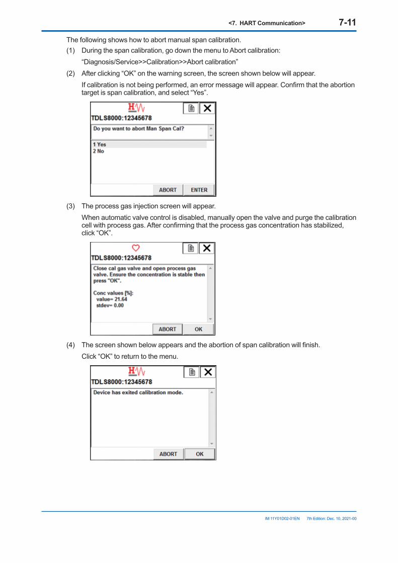
<7. HART Communication> 7-11
IM 11Y01D02-01EN 7th Edition: Dec. 10, 2021-00
The following shows how to abort manual span calibration.(1) During the span calibration, go down the menu to Abort calibration: “Diagnosis/Service>>Calibration>>Abort calibration”(2) After clicking “OK” on the warning screen, the screen shown below will appear. If calibration is not being performed, an error message will appear. Confirm that the abortion
target is span calibration, and select “Yes”.
(3) The process gas injection screen will appear. When automatic valve control is disabled, manually open the valve and purge the calibration
cell with process gas. After confirming that the process gas concentration has stabilized, click “OK”.
(4) The screen shown below appears and the abortion of span calibration will finish. Click “OK” to return to the menu.

Blank Page
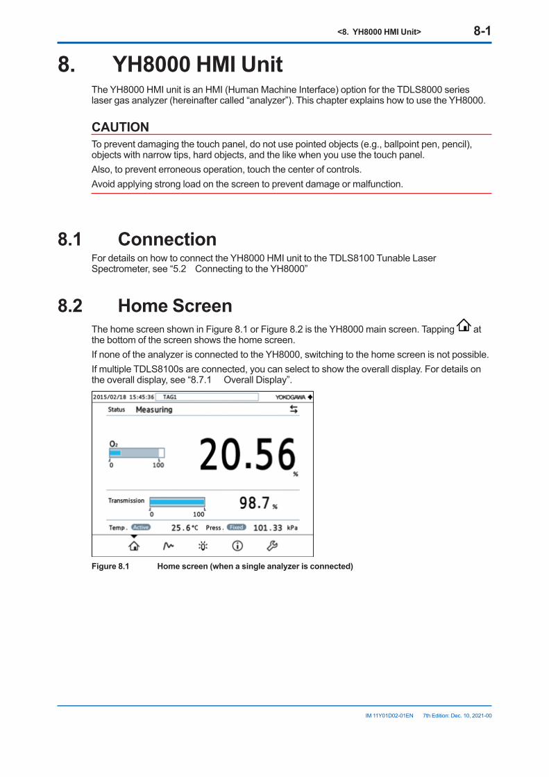
<8. YH8000 HMI Unit> 8-1
IM 11Y01D02-01EN 7th Edition: Dec. 10, 2021-00
8. YH8000 HMI UnitThe YH8000 HMI unit is an HMI (Human Machine Interface) option for the TDLS8000 series laser gas analyzer (hereinafter called “analyzer”). This chapter explains how to use the YH8000.
CAUTIONTo prevent damaging the touch panel, do not use pointed objects (e.g., ballpoint pen, pencil), objects with narrow tips, hard objects, and the like when you use the touch panel.Also, to prevent erroneous operation, touch the center of controls.Avoid applying strong load on the screen to prevent damage or malfunction.
8.1 ConnectionFor details on how to connect the YH8000 HMI unit to the TDLS8100 Tunable Laser Spectrometer, see “5.2 Connecting to the YH8000”
8.2 Home ScreenThe home screen shown in Figure 8.1 or Figure 8.2 is the YH8000 main screen. Tapping at the bottom of the screen shows the home screen.If none of the analyzer is connected to the YH8000, switching to the home screen is not possible.If multiple TDLS8100s are connected, you can select to show the overall display. For details on the overall display, see “8.7.1 Overall Display”.
Figure8.1 Homescreen(whenasingleanalyzerisconnected)
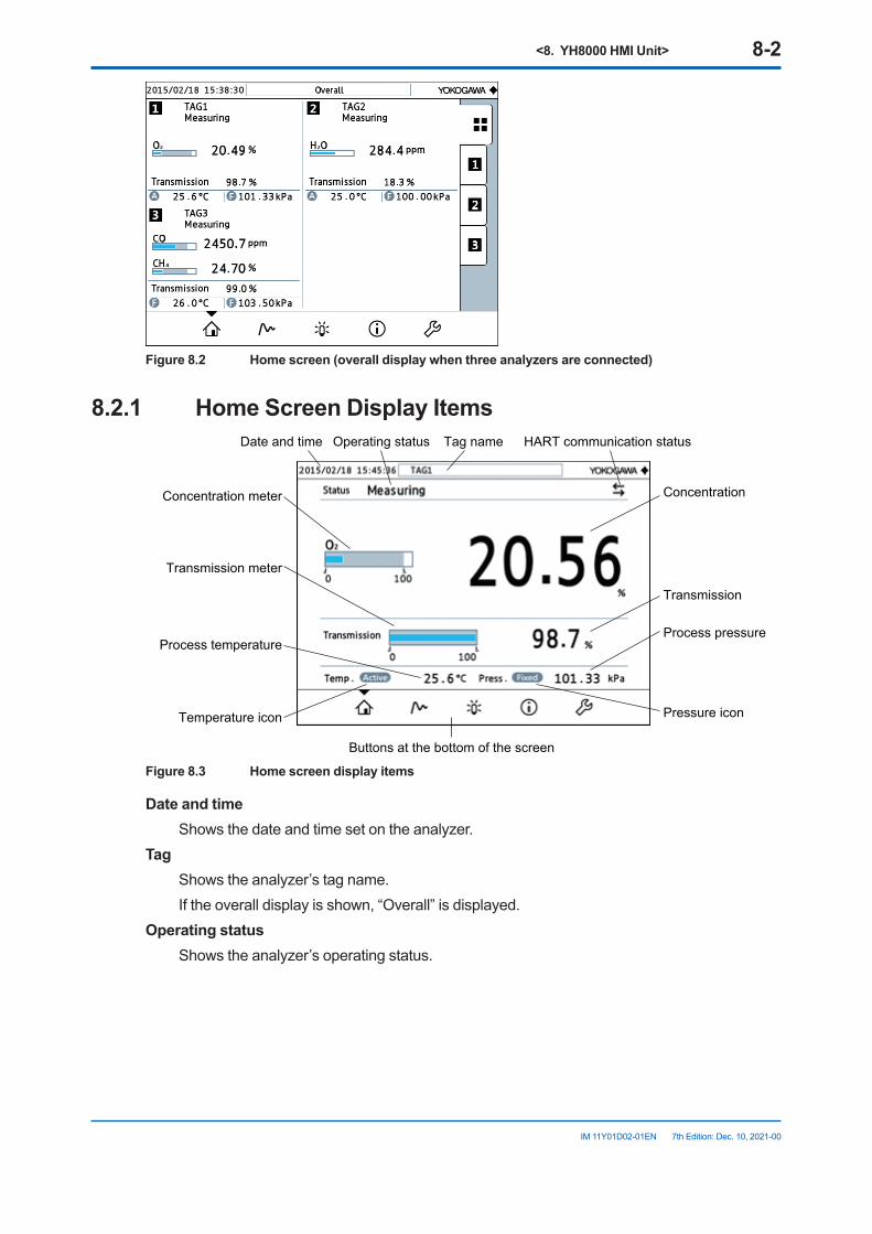
<8. YH8000 HMI Unit> 8-2
IM 11Y01D02-01EN 7th Edition: Dec. 10, 2021-00
Figure8.2 Homescreen(overalldisplaywhenthreeanalyzersareconnected)
8.2.1 Home Screen Display ItemsDate and time Tag nameOperating status
Concentration
Transmission
Concentration meter
Transmission meter
Process temperatureProcess pressure
Temperature icon Pressure icon
Buttons at the bottom of the screen
HART communication status
Figure 8.3 Home screen display items
Date and time Shows the date and time set on the analyzer.Tag Shows the analyzer’s tag name. If the overall display is shown, “Overall” is displayed.Operating status Shows the analyzer’s operating status.
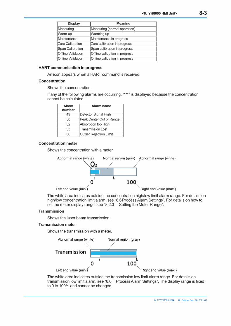
<8. YH8000 HMI Unit> 8-3
IM 11Y01D02-01EN 7th Edition: Dec. 10, 2021-00
Display MeaningMeasuring Measuring (normal operation)Warm-up Warming upMaintenance Maintenance in progressZero Calibration Zero calibration in progressSpan Calibration Span calibration in progressOffline Validation Offline validation in progressOnline Validation Online validation in progress
HART communication in progress An icon appears when a HART command is received.Concentration Shows the concentration. If any of the following alarms are occurring, “***” is displayed because the concentration
cannot be calculated.Alarm
numberAlarm name
49 Detector Signal High50 Peak Center Out of Range52 Absorption too High53 Transmission Lost56 Outlier Rejection Limit
Concentration meter Shows the concentration with a meter.
Abnormal range (white)Normal region (gray)
Right end value (max.)
Abnormal range (white)
Left end value (min.)
The white area indicates outside the concentration high/low limit alarm range. For details on high/low concentration limit alarm, see “6.6 Process Alarm Settings”. For details on how to set the meter display range, see “8.2.3 Setting the Meter Range”.
Transmission Shows the laser beam transmission.Transmission meter Shows the transmission with a meter.
Normal region (gray)
Right end value (max.)
Abnormal range (white)
Left end value (min.)
The white area indicates outside the transmission low limit alarm range. For details on transmission low limit alarm, see “6.6 Process Alarm Settings”. The display range is fixed to 0 to 100% and cannot be changed.
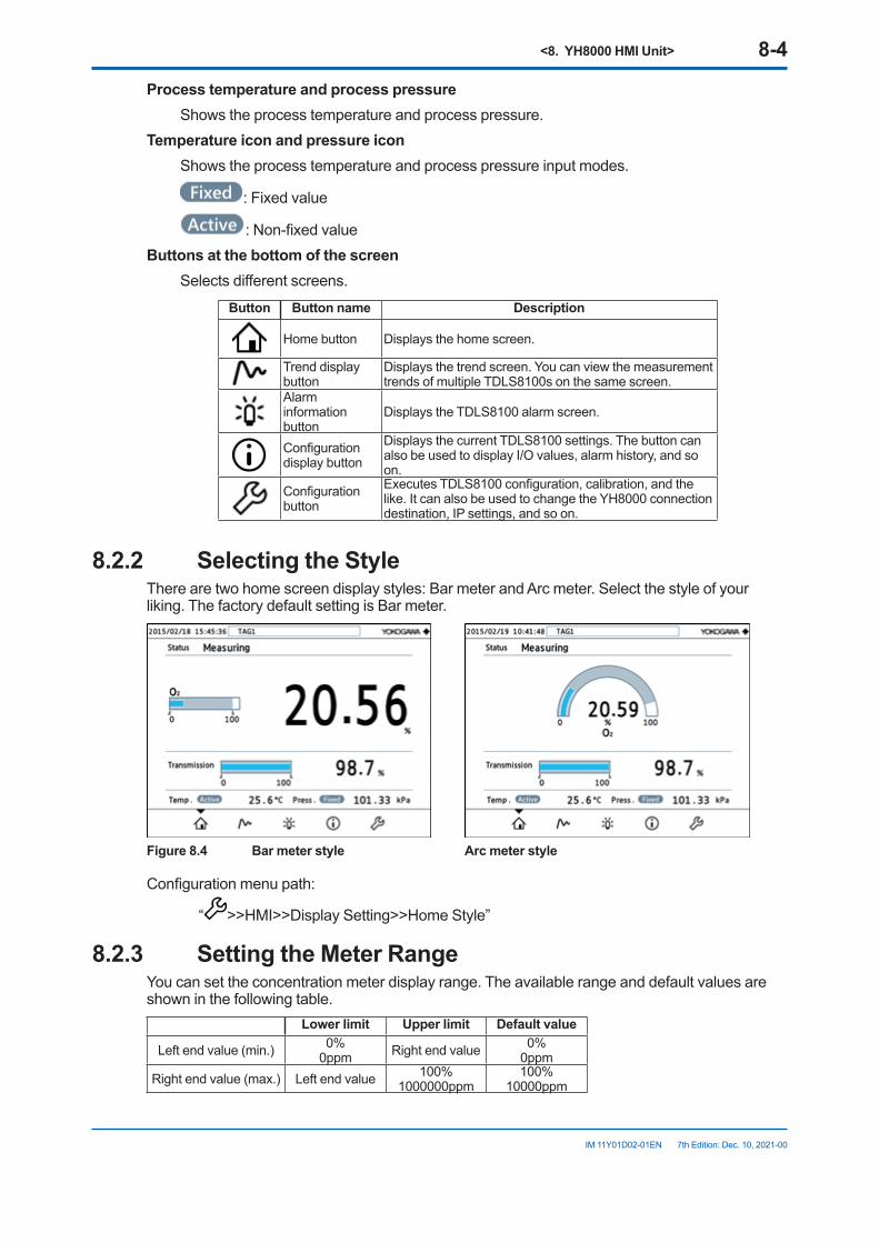
<8. YH8000 HMI Unit> 8-4
IM 11Y01D02-01EN 7th Edition: Dec. 10, 2021-00
Process temperature and process pressure Shows the process temperature and process pressure.Temperature icon and pressure icon Shows the process temperature and process pressure input modes.
: Fixed value
: Non-fixed valueButtonsatthebottomofthescreen Selects different screens.
Button Button name Description
Home button Displays the home screen.
Trend display button
Displays the trend screen. You can view the measurement trends of multiple TDLS8100s on the same screen.
Alarm information button
Displays the TDLS8100 alarm screen.
Configuration display button
Displays the current TDLS8100 settings. The button can also be used to display I/O values, alarm history, and so on.
Configuration button
Executes TDLS8100 configuration, calibration, and the like. It can also be used to change the YH8000 connection destination, IP settings, and so on.
8.2.2 SelectingtheStyleThere are two home screen display styles: Bar meter and Arc meter. Select the style of your liking. The factory default setting is Bar meter.
Figure 8.4 Bar meter style Arc meter style
Configuration menu path:
“ >>HMI>>Display Setting>>Home Style”
8.2.3 SettingtheMeterRangeYou can set the concentration meter display range. The available range and default values are shown in the following table.
Lower limit Upper limit Default value
Left end value (min.) 0%0ppm Right end value 0%
0ppmRight end value (max.) Left end value 100%
1000000ppm100%
10000ppm
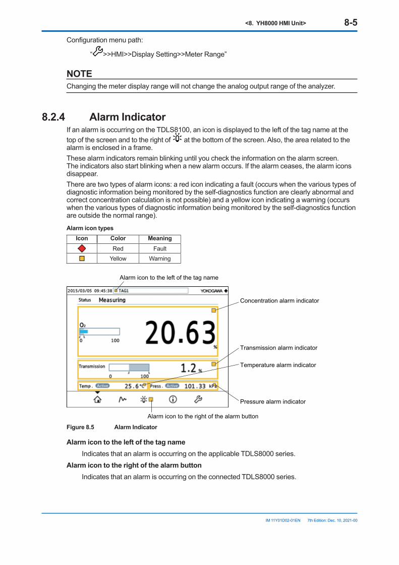
<8. YH8000 HMI Unit> 8-5
IM 11Y01D02-01EN 7th Edition: Dec. 10, 2021-00
Configuration menu path:
“ >>HMI>>Display Setting>>Meter Range”
NOTEChanging the meter display range will not change the analog output range of the analyzer.
8.2.4 Alarm IndicatorIf an alarm is occurring on the TDLS8100, an icon is displayed to the left of the tag name at the top of the screen and to the right of at the bottom of the screen. Also, the area related to the alarm is enclosed in a frame.These alarm indicators remain blinking until you check the information on the alarm screen. The indicators also start blinking when a new alarm occurs. If the alarm ceases, the alarm icons disappear.There are two types of alarm icons: a red icon indicating a fault (occurs when the various types of diagnostic information being monitored by the self-diagnostics function are clearly abnormal and correct concentration calculation is not possible) and a yellow icon indicating a warning (occurs when the various types of diagnostic information being monitored by the self-diagnostics function are outside the normal range).
Alarm icon typesIcon Color Meaning
Red FaultYellow Warning
Alarm icon to the left of the tag name
Concentration alarm indicator
Transmission alarm indicator
Temperature alarm indicator
Pressure alarm indicator
Alarm icon to the right of the alarm button
Figure 8.5 Alarm Indicator
Alarmicontotheleftofthetagname Indicates that an alarm is occurring on the applicable TDLS8000 series.Alarmicontotherightofthealarmbutton Indicates that an alarm is occurring on the connected TDLS8000 series.
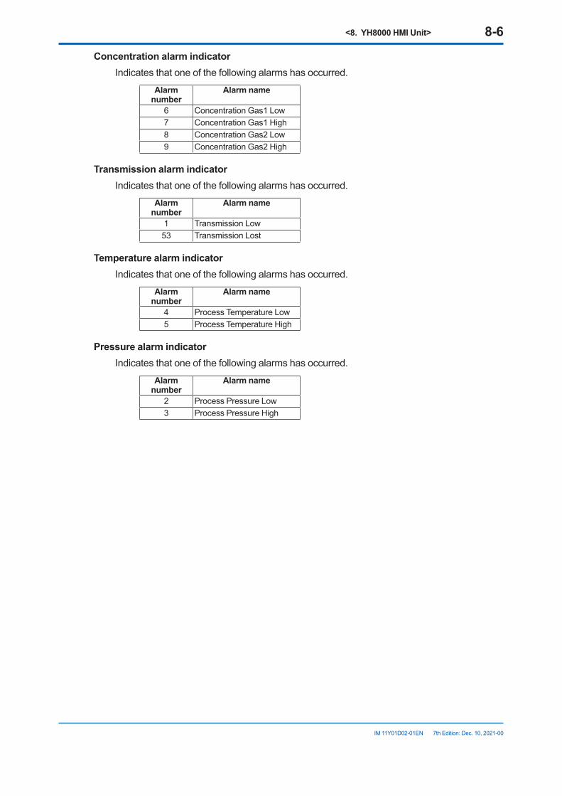
<8. YH8000 HMI Unit> 8-6
IM 11Y01D02-01EN 7th Edition: Dec. 10, 2021-00
Concentration alarm indicator Indicates that one of the following alarms has occurred.
Alarm number
Alarm name
6 Concentration Gas1 Low7 Concentration Gas1 High8 Concentration Gas2 Low9 Concentration Gas2 High
Transmission alarm indicator Indicates that one of the following alarms has occurred.
Alarm number
Alarm name
1 Transmission Low53 Transmission Lost
Temperature alarm indicator Indicates that one of the following alarms has occurred.
Alarm number
Alarm name
4 Process Temperature Low5 Process Temperature High
Pressure alarm indicator Indicates that one of the following alarms has occurred.
Alarm number
Alarm name
2 Process Pressure Low3 Process Pressure High
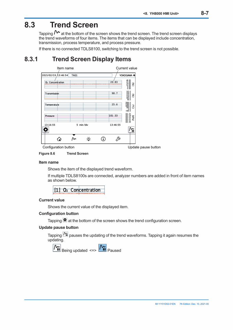
<8. YH8000 HMI Unit> 8-7
IM 11Y01D02-01EN 7th Edition: Dec. 10, 2021-00
8.3 Trend ScreenTapping at the bottom of the screen shows the trend screen. The trend screen displays the trend waveforms of four items. The items that can be displayed include concentration, transmission, process temperature, and process pressure.If there is no connected TDLS8100, switching to the trend screen is not possible.
8.3.1 Trend Screen Display ItemsItem name
Configuration button
Current value
Update pause button
Figure 8.6 Trend Screen
Item name Shows the item of the displayed trend waveform. If multiple TDLS8100s are connected, analyzer numbers are added in front of item names
as shown below.
Current value Shows the current value of the displayed item.Configurationbutton Tapping at the bottom of the screen shows the trend configuration screen.Update pause button
Tapping pauses the updating of the trend waveforms. Tapping it again resumes the updating.
Being updated <=> Paused
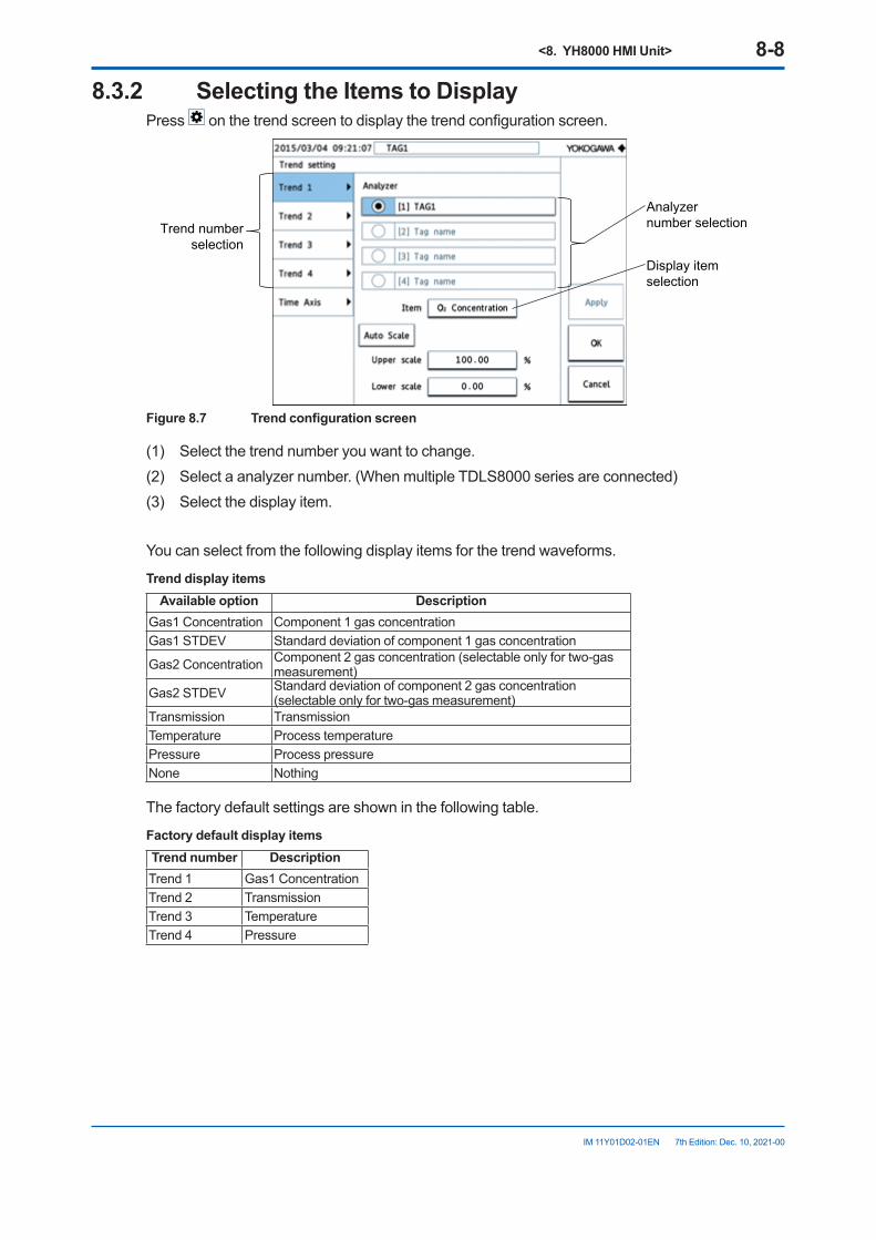
<8. YH8000 HMI Unit> 8-8
IM 11Y01D02-01EN 7th Edition: Dec. 10, 2021-00
8.3.2 SelectingtheItemstoDisplayPress on the trend screen to display the trend configuration screen.
Analyzer number selection
Display item selection
Trend number selection
Figure8.7 Trendconfigurationscreen
(1) Select the trend number you want to change.(2) Select a analyzer number. (When multiple TDLS8000 series are connected)(3) Select the display item.
You can select from the following display items for the trend waveforms.
Trend display itemsAvailable option Description
Gas1 Concentration Component 1 gas concentrationGas1 STDEV Standard deviation of component 1 gas concentration
Gas2 Concentration Component 2 gas concentration (selectable only for two-gas measurement)
Gas2 STDEV Standard deviation of component 2 gas concentration (selectable only for two-gas measurement)
Transmission TransmissionTemperature Process temperaturePressure Process pressureNone Nothing
The factory default settings are shown in the following table.
Factory default display itemsTrend number DescriptionTrend 1 Gas1 ConcentrationTrend 2 TransmissionTrend 3 TemperatureTrend 4 Pressure
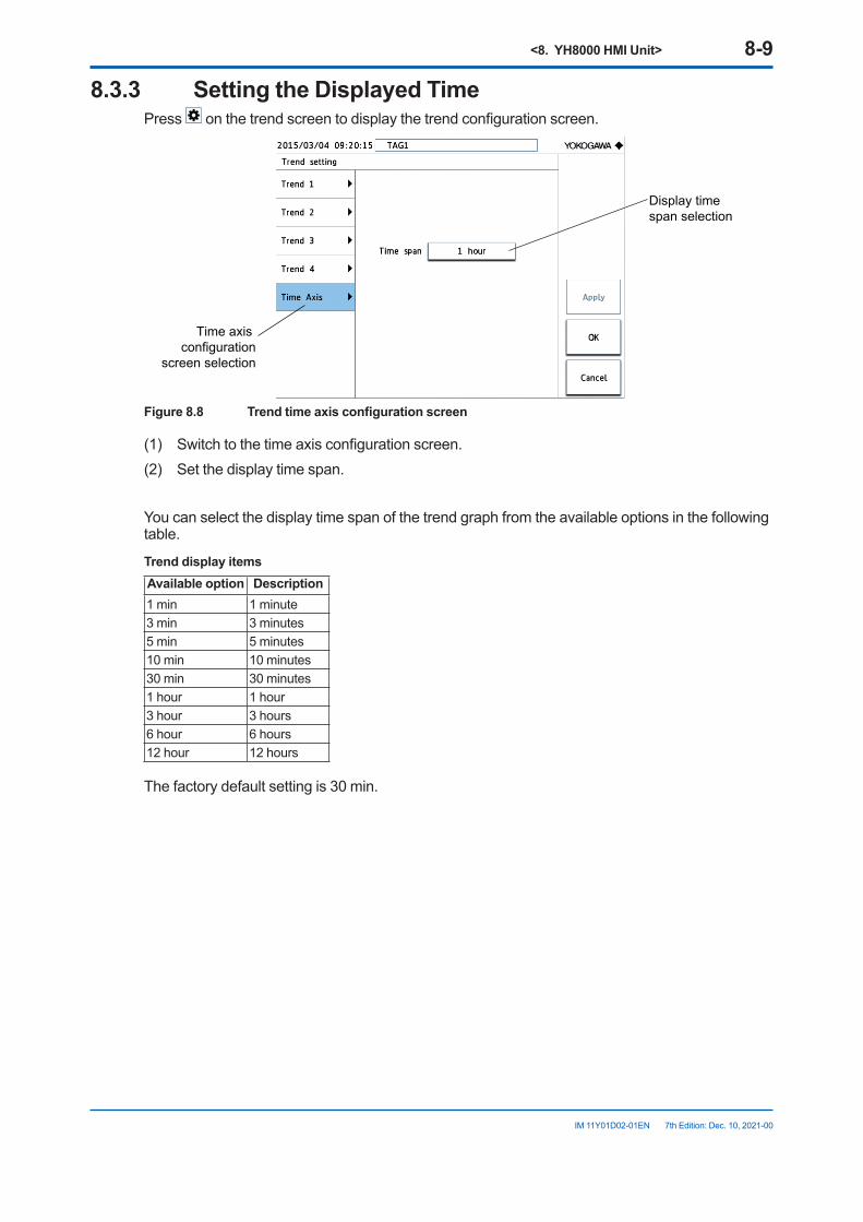
<8. YH8000 HMI Unit> 8-9
IM 11Y01D02-01EN 7th Edition: Dec. 10, 2021-00
8.3.3 SettingtheDisplayedTimePress on the trend screen to display the trend configuration screen.
Display time span selection
Time axis configuration
screen selection
Figure8.8 Trendtimeaxisconfigurationscreen
(1) Switch to the time axis configuration screen.(2) Set the display time span.
You can select the display time span of the trend graph from the available options in the following table.
Trend display itemsAvailable option Description1 min 1 minute3 min 3 minutes5 min 5 minutes10 min 10 minutes30 min 30 minutes1 hour 1 hour3 hour 3 hours6 hour 6 hours12 hour 12 hours
The factory default setting is 30 min.
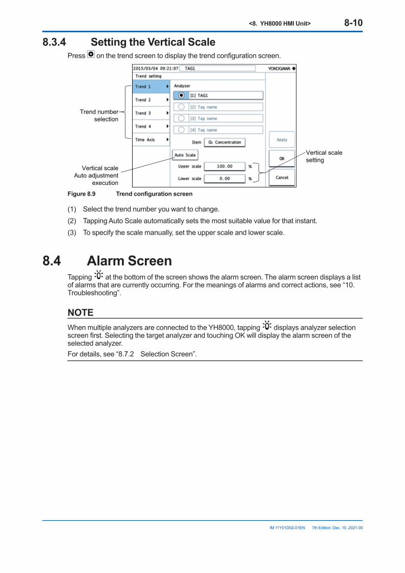
<8. YH8000 HMI Unit> 8-10
IM 11Y01D02-01EN 7th Edition: Dec. 10, 2021-00
8.3.4 SettingtheVerticalScalePress on the trend screen to display the trend configuration screen.
Vertical scale setting
Vertical scaleAuto adjustment
execution
Trend number selection
Figure8.9 Trendconfigurationscreen
(1) Select the trend number you want to change.(2) Tapping Auto Scale automatically sets the most suitable value for that instant.(3) To specify the scale manually, set the upper scale and lower scale.
8.4 Alarm ScreenTapping at the bottom of the screen shows the alarm screen. The alarm screen displays a list of alarms that are currently occurring. For the meanings of alarms and correct actions, see “10. Troubleshooting”.
NOTEWhen multiple analyzers are connected to the YH8000, tapping displays analyzer selection screen first. Selecting the target analyzer and touching OK will display the alarm screen of the selected analyzer.For details, see “8.7.2 Selection Screen”.
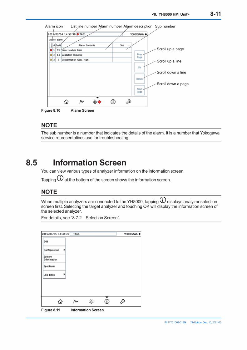
<8. YH8000 HMI Unit> 8-11
IM 11Y01D02-01EN 7th Edition: Dec. 10, 2021-00
Alarm icon List line number Alarm number Alarm description Sub number
Scroll up a page
Scroll up a line
Scroll down a line
Scroll down a page
Figure 8.10 Alarm Screen
NOTEThe sub number is a number that indicates the details of the alarm. It is a number that Yokogawa service representatives use for troubleshooting.
8.5 Information ScreenYou can view various types of analyzer information on the information screen.
Tapping at the bottom of the screen shows the information screen.
NOTEWhen multiple analyzers are connected to the YH8000, tapping displays analyzer selection screen first. Selecting the target analyzer and touching OK will display the information screen of the selected analyzer.For details, see “8.7.2 Selection Screen”.
Figure 8.11 Information Screen
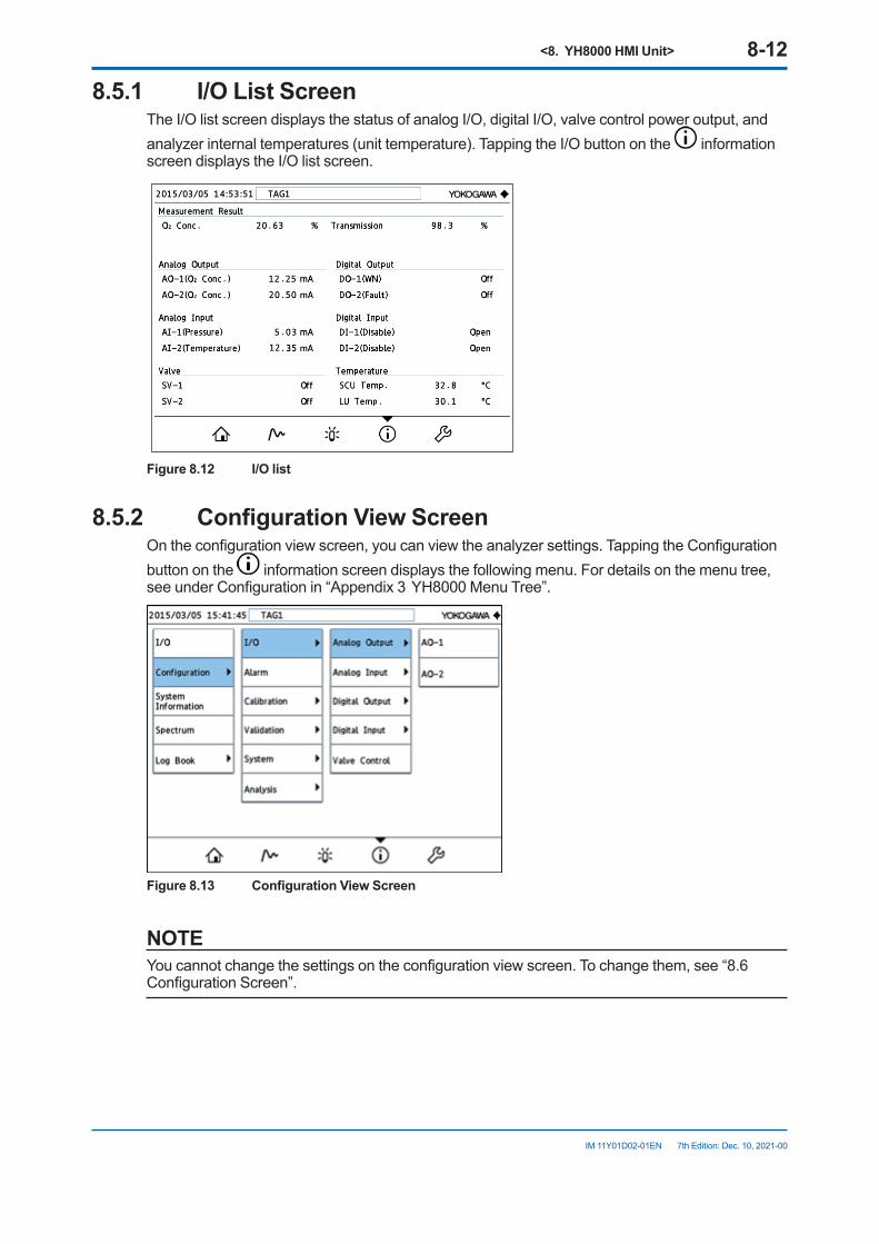
<8. YH8000 HMI Unit> 8-12
IM 11Y01D02-01EN 7th Edition: Dec. 10, 2021-00
8.5.1 I/OListScreenThe I/O list screen displays the status of analog I/O, digital I/O, valve control power output, and analyzer internal temperatures (unit temperature). Tapping the I/O button on the information screen displays the I/O list screen.
Figure8.12 I/Olist
8.5.2 ConfigurationViewScreenOn the configuration view screen, you can view the analyzer settings. Tapping the Configuration button on the information screen displays the following menu. For details on the menu tree, see under Configuration in “Appendix 3 YH8000 Menu Tree”.
Figure8.13 ConfigurationViewScreen
NOTEYou cannot change the settings on the configuration view screen. To change them, see “8.6 Configuration Screen”.
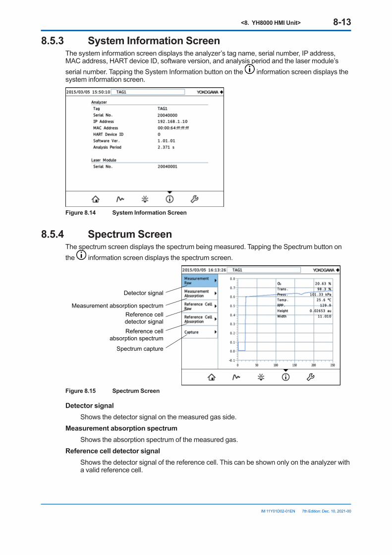
<8. YH8000 HMI Unit> 8-13
IM 11Y01D02-01EN 7th Edition: Dec. 10, 2021-00
8.5.3 System Information ScreenThe system information screen displays the analyzer’s tag name, serial number, IP address, MAC address, HART device ID, software version, and analysis period and the laser module’s serial number. Tapping the System Information button on the information screen displays the system information screen.
Figure 8.14 System Information Screen
8.5.4 Spectrum ScreenThe spectrum screen displays the spectrum being measured. Tapping the Spectrum button on the information screen displays the spectrum screen.
Measurement absorption spectrum
Detector signal
Reference celldetector signalReference cell
absorption spectrum
Spectrum capture
Figure 8.15 Spectrum Screen
Detector signal Shows the detector signal on the measured gas side.Measurement absorption spectrum Shows the absorption spectrum of the measured gas.Reference cell detector signal Shows the detector signal of the reference cell. This can be shown only on the analyzer with
a valid reference cell.
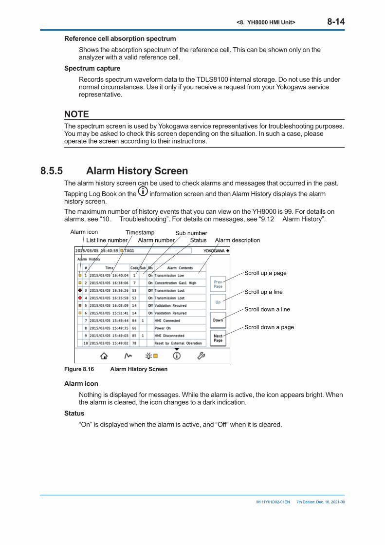
<8. YH8000 HMI Unit> 8-14
IM 11Y01D02-01EN 7th Edition: Dec. 10, 2021-00
Reference cell absorption spectrum Shows the absorption spectrum of the reference cell. This can be shown only on the
analyzer with a valid reference cell.Spectrum capture Records spectrum waveform data to the TDLS8100 internal storage. Do not use this under
normal circumstances. Use it only if you receive a request from your Yokogawa service representative.
NOTEThe spectrum screen is used by Yokogawa service representatives for troubleshooting purposes. You may be asked to check this screen depending on the situation. In such a case, please operate the screen according to their instructions.
8.5.5 Alarm History ScreenThe alarm history screen can be used to check alarms and messages that occurred in the past. Tapping Log Book on the information screen and then Alarm History displays the alarm history screen.The maximum number of history events that you can view on the YH8000 is 99. For details on alarms, see “10. Troubleshooting”. For details on messages, see “9.12 Alarm History”.
Alarm iconList line number Alarm number
TimestampAlarm descriptionStatus
Sub number
Scroll up a page
Scroll up a line
Scroll down a line
Scroll down a page
Figure 8.16 Alarm History Screen
Alarm icon Nothing is displayed for messages. While the alarm is active, the icon appears bright. When
the alarm is cleared, the icon changes to a dark indication.Status “On” is displayed when the alarm is active, and “Off” when it is cleared.
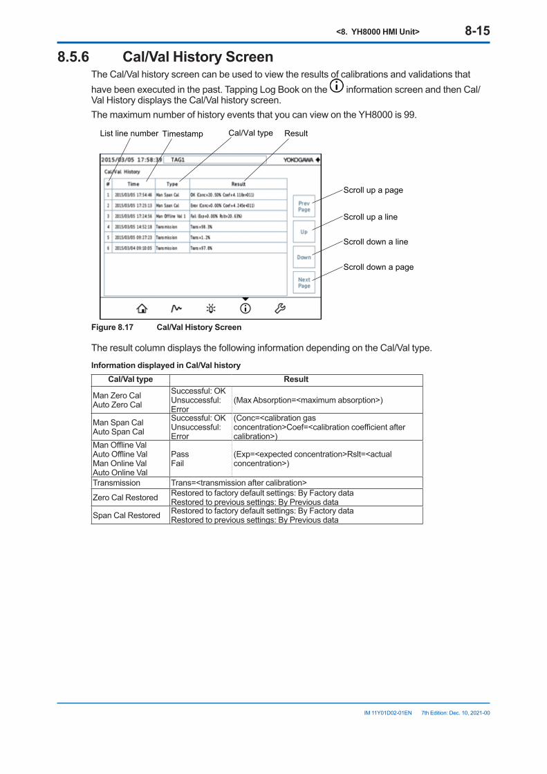
<8. YH8000 HMI Unit> 8-15
IM 11Y01D02-01EN 7th Edition: Dec. 10, 2021-00
8.5.6 Cal/ValHistoryScreenThe Cal/Val history screen can be used to view the results of calibrations and validations that have been executed in the past. Tapping Log Book on the information screen and then Cal/Val History displays the Cal/Val history screen.The maximum number of history events that you can view on the YH8000 is 99.
List line number Timestamp ResultCal/Val type
Scroll up a page
Scroll up a line
Scroll down a line
Scroll down a page
Figure8.17 Cal/ValHistoryScreen
The result column displays the following information depending on the Cal/Val type.
InformationdisplayedinCal/ValhistoryCal/Valtype Result
Man Zero CalAuto Zero Cal
Successful: OKUnsuccessful: Error
(Max Absorption=<maximum absorption>)
Man Span CalAuto Span Cal
Successful: OKUnsuccessful: Error
(Conc=<calibration gas concentration>Coef=<calibration coefficient after calibration>)
Man Offline ValAuto Offline ValMan Online ValAuto Online Val
PassFail
(Exp=<expected concentration>Rslt=<actual concentration>)
Transmission Trans=<transmission after calibration>
Zero Cal Restored Restored to factory default settings: By Factory dataRestored to previous settings: By Previous data
Span Cal Restored Restored to factory default settings: By Factory dataRestored to previous settings: By Previous data
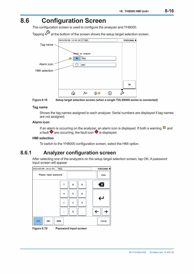
<8. YH8000 HMI Unit> 8-16
IM 11Y01D02-01EN 7th Edition: Dec. 10, 2021-00
8.6 ConfigurationScreenThe configuration screen is used to configure the analyzer and YH8000.
Tapping at the bottom of the screen shows the setup target selection screen.
HMI selection
Alarm icon
Tag name
Figure8.18 Setuptargetselectionscreen(whenasingleTDLS8000seriesisconnected)
Tag name Shows the tag names assigned to each analyzer. Serial numbers are displayed if tag names
are not assigned.Alarm icon If an alarm is occurring on the analyzer, an alarm icon is displayed. If both a warning and
a fault are occurring, the fault icon is displayed.HMI selection To switch to the YH8000 configuration screen, select the HMI option.
8.6.1 AnalyzerconfigurationscreenAfter selecting one of the analyzers on the setup target selection screen, tap OK. A password input screen will appear.
Figure 8.19 Password input screen
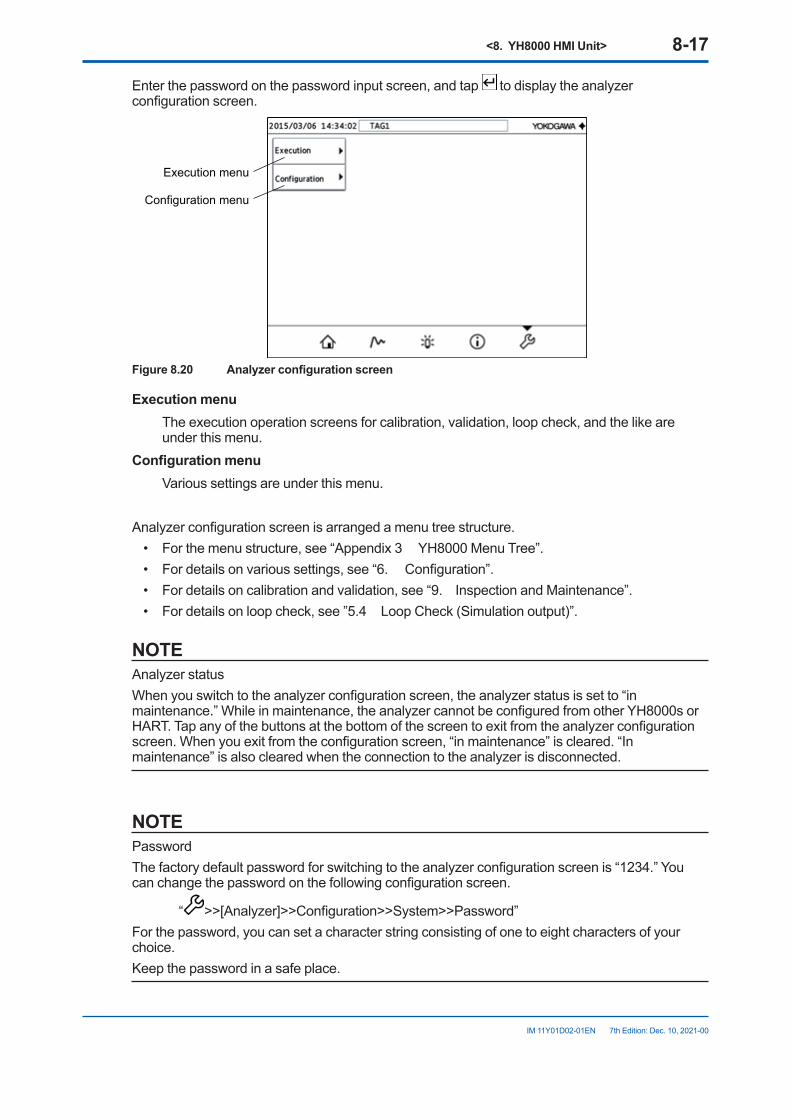
<8. YH8000 HMI Unit> 8-17
IM 11Y01D02-01EN 7th Edition: Dec. 10, 2021-00
Enter the password on the password input screen, and tap to display the analyzer configuration screen.
Configuration menu
Execution menu
Figure8.20 Analyzerconfigurationscreen
Executionmenu The execution operation screens for calibration, validation, loop check, and the like are
under this menu.Configurationmenu Various settings are under this menu.
Analyzer configuration screen is arranged a menu tree structure.• For the menu structure, see “Appendix 3 YH8000 Menu Tree”.• For details on various settings, see “6. Configuration”.• For details on calibration and validation, see “9. Inspection and Maintenance”.• For details on loop check, see ”5.4 Loop Check (Simulation output)”.
NOTEAnalyzer statusWhen you switch to the analyzer configuration screen, the analyzer status is set to “in maintenance.” While in maintenance, the analyzer cannot be configured from other YH8000s or HART. Tap any of the buttons at the bottom of the screen to exit from the analyzer configuration screen. When you exit from the configuration screen, “in maintenance” is cleared. “In maintenance” is also cleared when the connection to the analyzer is disconnected.
NOTEPasswordThe factory default password for switching to the analyzer configuration screen is “1234.” You can change the password on the following configuration screen.
“ >>[Analyzer]>>Configuration>>System>>Password”For the password, you can set a character string consisting of one to eight characters of your choice.Keep the password in a safe place.
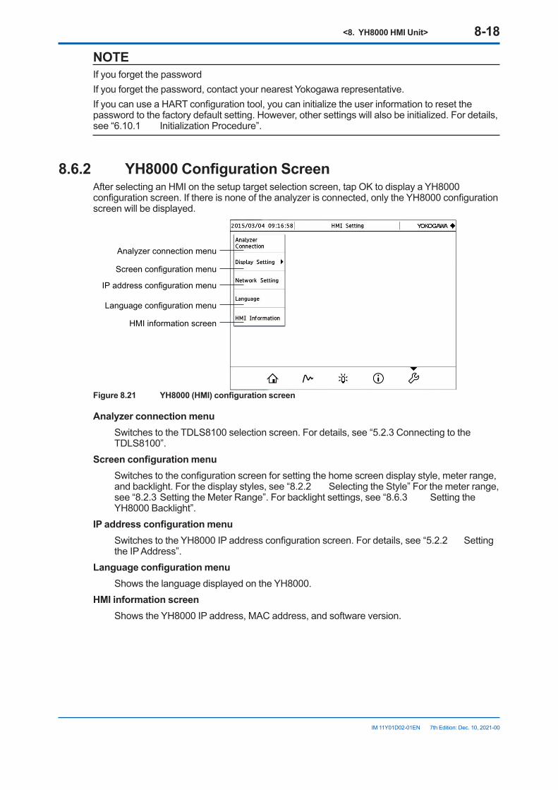
<8. YH8000 HMI Unit> 8-18
IM 11Y01D02-01EN 7th Edition: Dec. 10, 2021-00
NOTEIf you forget the passwordIf you forget the password, contact your nearest Yokogawa representative.If you can use a HART configuration tool, you can initialize the user information to reset the password to the factory default setting. However, other settings will also be initialized. For details, see “6.10.1 Initialization Procedure”.
8.6.2 YH8000ConfigurationScreenAfter selecting an HMI on the setup target selection screen, tap OK to display a YH8000 configuration screen. If there is none of the analyzer is connected, only the YH8000 configuration screen will be displayed.
Screen configuration menu
Analyzer connection menu
IP address configuration menu
Language configuration menu
HMI information screen
Figure8.21 YH8000(HMI)configurationscreen
Analyzerconnectionmenu Switches to the TDLS8100 selection screen. For details, see “5.2.3 Connecting to the
TDLS8100”.Screenconfigurationmenu Switches to the configuration screen for setting the home screen display style, meter range,
and backlight. For the display styles, see “8.2.2 Selecting the Style” For the meter range, see “8.2.3 Setting the Meter Range”. For backlight settings, see “8.6.3 Setting the YH8000 Backlight”.
IPaddressconfigurationmenu Switches to the YH8000 IP address configuration screen. For details, see “5.2.2 Setting
the IP Address”.Languageconfigurationmenu Shows the language displayed on the YH8000.HMI information screen Shows the YH8000 IP address, MAC address, and software version.
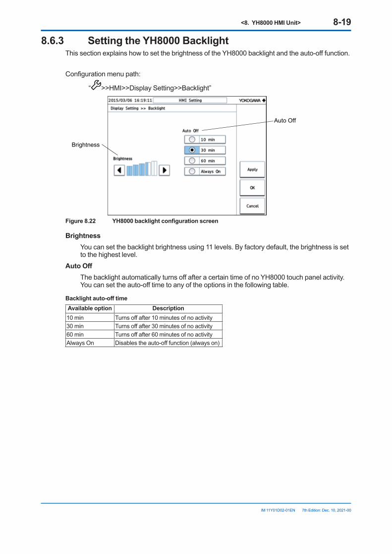
<8. YH8000 HMI Unit> 8-19
IM 11Y01D02-01EN 7th Edition: Dec. 10, 2021-00
8.6.3 SettingtheYH8000BacklightThis section explains how to set the brightness of the YH8000 backlight and the auto-off function.
Configuration menu path:
“ >>HMI>>Display Setting>>Backlight”
Auto Off
Brightness
Figure8.22 YH8000backlightconfigurationscreen
Brightness You can set the backlight brightness using 11 levels. By factory default, the brightness is set
to the highest level.AutoOff The backlight automatically turns off after a certain time of no YH8000 touch panel activity.
You can set the auto-off time to any of the options in the following table.
Backlightauto-offtimeAvailable option Description10 min Turns off after 10 minutes of no activity30 min Turns off after 30 minutes of no activity60 min Turns off after 60 minutes of no activityAlways On Disables the auto-off function (always on)
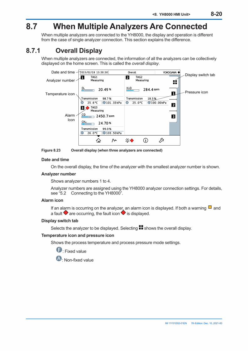
<8. YH8000 HMI Unit> 8-20
IM 11Y01D02-01EN 7th Edition: Dec. 10, 2021-00
8.7 WhenMultipleAnalyzersAreConnectedWhen multiple analyzers are connected to the YH8000, the display and operation is different from the case of single analyzer connection. This section explains the difference.
8.7.1 Overall DisplayWhen multiple analyzers are connected, the information of all the analyzers can be collectively displayed on the home screen. This is called the overall display.
Display switch tabAnalyzer number
Date and time
Pressure iconTemperature icon
AlarmIcon
Figure8.23 Overalldisplay(whenthreeanalyzersareconnected)
Date and time On the overall display, the time of the analyzer with the smallest analyzer number is shown.Analyzernumber Shows analyzer numbers 1 to 4. Analyzer numbers are assigned using the YH8000 analyzer connection settings. For details,
see “5.2 Connecting to the YH8000”.Alarm icon If an alarm is occurring on the analyzer, an alarm icon is displayed. If both a warning and
a fault are occurring, the fault icon is displayed.Displayswitchtab Selects the analyzer to be displayed. Selecting shows the overall display.Temperature icon and pressure icon Shows the process temperature and process pressure mode settings.
: Fixed value
: Non-fixed value
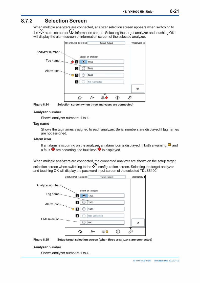
<8. YH8000 HMI Unit> 8-21
IM 11Y01D02-01EN 7th Edition: Dec. 10, 2021-00
8.7.2 Selection ScreenWhen multiple analyzers are connected, analyzer selection screen appears when switching to the alarm screen or information screen. Selecting the target analyzer and touching OK will display the alarm screen or information screen of the selected analyzer.
Analyzer number
Tag name
Alarm icon
Figure8.24 Selectionscreen(whenthreeanalyzersareconnected)
Analyzernumber Shows analyzer numbers 1 to 4.Tag name Shows the tag names assigned to each analyzer. Serial numbers are displayed if tag names
are not assigned.Alarm icon If an alarm is occurring on the analyzer, an alarm icon is displayed. If both a warning and
a fault are occurring, the fault icon is displayed.
When multiple analyzers are connected, the connected analyzer are shown on the setup target selection screen when switching to the configuration screen. Selecting the target analyzer and touching OK will display the password input screen of the selected TDLS8100.
Analyzer number
Tag name
Alarm icon
HMI selection
Figure8.25 Setuptargetselectionscreen(whenthreeanalyzersareconnected)
Analyzernumber Shows analyzer numbers 1 to 4.
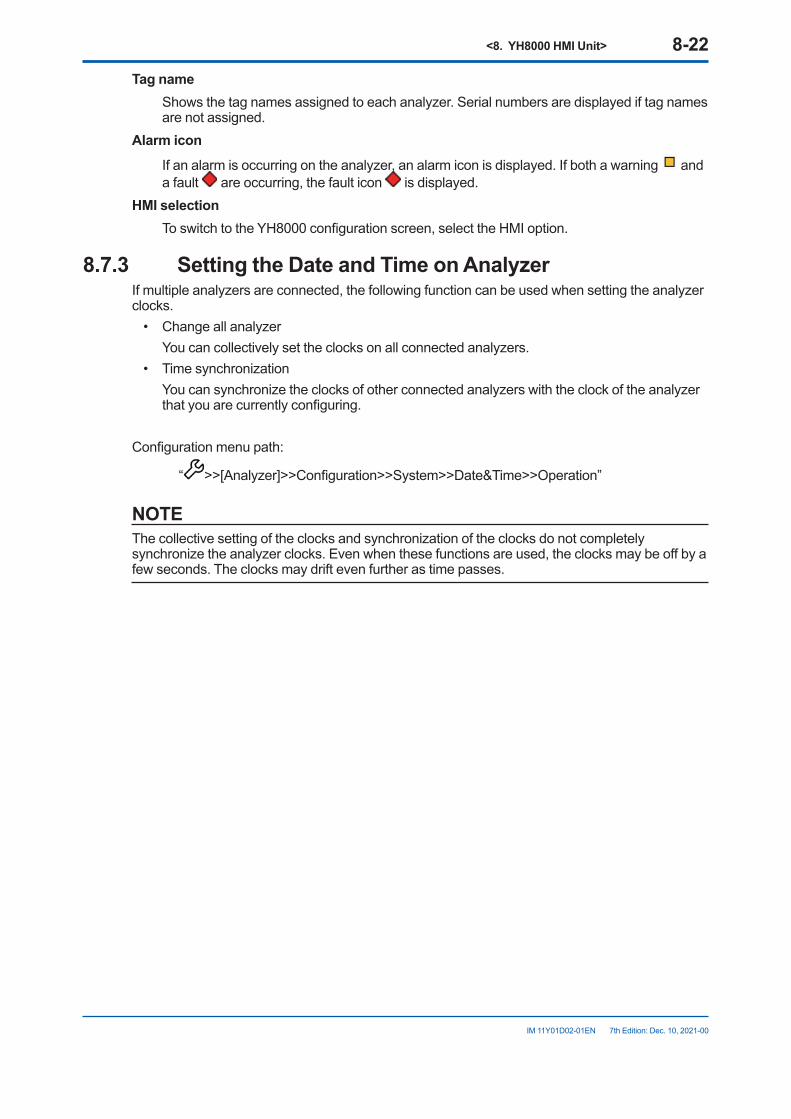
<8. YH8000 HMI Unit> 8-22
IM 11Y01D02-01EN 7th Edition: Dec. 10, 2021-00
Tag name Shows the tag names assigned to each analyzer. Serial numbers are displayed if tag names
are not assigned.Alarm icon If an alarm is occurring on the analyzer, an alarm icon is displayed. If both a warning and
a fault are occurring, the fault icon is displayed.HMI selection To switch to the YH8000 configuration screen, select the HMI option.
8.7.3 SettingtheDateandTimeonAnalyzerIf multiple analyzers are connected, the following function can be used when setting the analyzer clocks.
• Change all analyzer You can collectively set the clocks on all connected analyzers.• Time synchronization You can synchronize the clocks of other connected analyzers with the clock of the analyzer
that you are currently configuring.
Configuration menu path:
“ >>[Analyzer]>>Configuration>>System>>Date&Time>>Operation”
NOTEThe collective setting of the clocks and synchronization of the clocks do not completely synchronize the analyzer clocks. Even when these functions are used, the clocks may be off by a few seconds. The clocks may drift even further as time passes.
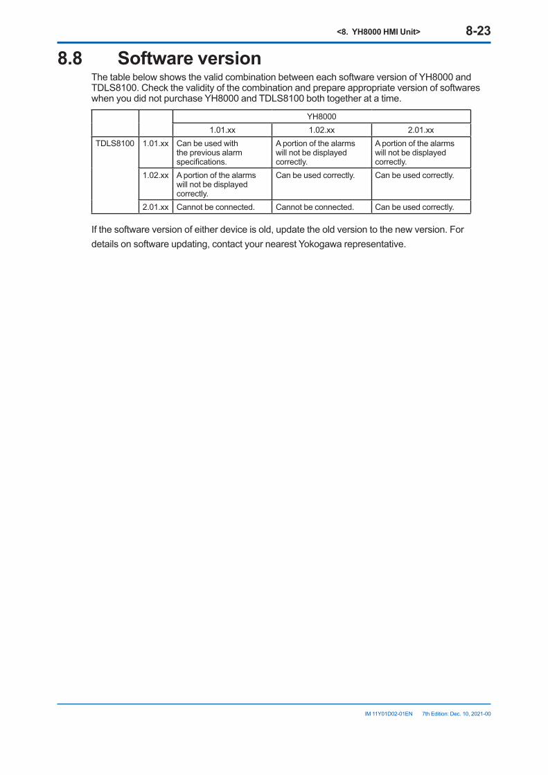
<8. YH8000 HMI Unit> 8-23
IM 11Y01D02-01EN 7th Edition: Dec. 10, 2021-00
8.8 Software versionThe table below shows the valid combination between each software version of YH8000 and TDLS8100. Check the validity of the combination and prepare appropriate version of softwares when you did not purchase YH8000 and TDLS8100 both together at a time.
YH80001.01.xx 1.02.xx 2.01.xx
TDLS8100 1.01.xx Can be used with the previous alarm specifications.
A portion of the alarms will not be displayed correctly.
A portion of the alarms will not be displayed correctly.
1.02.xx A portion of the alarms will not be displayed correctly.
Can be used correctly. Can be used correctly.
2.01.xx Cannot be connected. Cannot be connected. Can be used correctly.
If the software version of either device is old, update the old version to the new version. Fordetails on software updating, contact your nearest Yokogawa representative.

Blank Page
<9. Inspection and Maintenance> 9-1
IM 11Y01D02-01EN 7th Edition: Dec. 10, 2021-00
9. Inspection and Maintenance
CAUTIONIf you need to remove the TDLS8100 from the process flange for inspection or maintenance, be sure to turn off the power beforehand.
Work performed by an unqualified engineer can cause injury or severe damage to instruments. Not following the warnings in this manual can also cause injury or severe damage to instruments.Make sure that maintenance is carried out by a qualified engineer. A qualified engineer is an engineer who:
• Is knowledgeable about the safe handling of process analysis instruments (or general automation technology) and has read and understood the content of this manual.
• Has received instructions on how to start and configure instruments and has read and understood the content of this manual.
This chapter explains inspection and maintenance to retain the measurement performance of the TDLS8100.There are no operations that need to be performed regularly on the TDLS8100.When the laser beam transmission decreases, clean the probe area (probe, process window, reflector.)
9.1 MaintainingtheLaserBeamandTransmission
Transmission is a value determined by the magnitude of laser power that reaches the photo detector in the analyzer part after the laser beam, being emitted from the laser element of the analyzer part, reflects at the tip of probe and passes through the gas to be measured. Transmission is used to verify aging after the optical axis is adjusted. As startup, adjust the optical axis correctly, perform transmission calibration, and set the transmission value to 100%.By checking the variation in the transmission after startup, you can determine the state of the region that the laser beam travels through, the degree of optical axis misalignment, and the states of the laser beam emitting/receiving components. This information is important for maintenance and troubleshooting.
Generally, the transmission degrades due to the conditions shown below.To maintain normal TDLS8100 operation, perform the required inspection and maintenance to prevent the transmission from degrading. To maximize the TDLS8100 performance, it is particularly important to optimally adjust the optical axis and keep the process window clean.
l Stained process windowStained process window keeps laser beam from reaching the photo detector. Perform process window purge continuously to prevent stains from adhering to the process window. See “9.1.3 Probe Cleaning”.
<9. Inspection and Maintenance> 9-2
IM 11Y01D02-01EN 7th Edition: Dec. 10, 2021-00
l DustintheprocessDust (particles) in the process gas keeps the laser beam from reaching the photo detector. If dust adheres to and accumulates around the opening of probe, the dust completely blocks the laser beam. When the equipment is installed with high level of particles in the process, clean the probe regularly.
l OpticalaxisadjustmentWhen you remove analyzer part from probe or reassemble it to perform inspection and maintenance, optical axis may deviate. If the transmission falls down obviously, check the equipment is installed appropriately or adjust the optical axis as necessary.
9.1.1 Transmission CalibrationAfter reinstalling the TDLS8100 in the measurement location and performing optical axis adjustment according to “3.3 Optical Axis Adjustment”, perform transmission calibration.
NOTEOptimum transmission may not be attainable if the optical axis is not adjusted correctly. Refer to “3.3 Optical Axis Adjustment”, and perform optical axis adjustment correctly.
Execution menu path: [HART] “Diagnosis/Service>>Transmission adjust>>Transmission adjust”
[YH8000] “ >>Execution>>Transmission Adjustment>>Measurement>>Transmission Adjustment”
9.1.2 Process Window CleaningUnder normal operation, if process window purge is performed correctly, the surface of the process window rarely become stained. However, the surface of the process window may become stained or clouded under the following conditions.
• If the gas to be measured including dust or stain makes contact with the process window due to insufficient process window purge flow rate or purge gas pressure.
• If the surface of the process window condenses when the process window is hot• If gas that would cause quality deterioration in the process window (e.g., hydrogen fluoride
on BK-7) makes contact with the window• If particles, oil, and the like from the purge gas facility adheres to the surface of the process
window
If the surface of the process window is stained, remove and clean the process window according to the following procedure.
CAUTION• Before removing the process window, check that the process is completely stopped or that
the process is isolated from open air and no process gas will be discharged.• Be careful in handling the process window as it is made of optical glass that is easily
damaged.
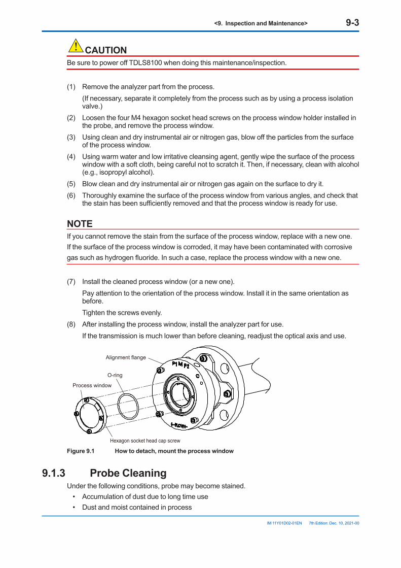
<9. Inspection and Maintenance> 9-3
IM 11Y01D02-01EN 7th Edition: Dec. 10, 2021-00
CAUTIONBe sure to power off TDLS8100 when doing this maintenance/inspection.
(1) Remove the analyzer part from the process. (If necessary, separate it completely from the process such as by using a process isolation
valve.)(2) Loosen the four M4 hexagon socket head screws on the process window holder installed in
the probe, and remove the process window.(3) Using clean and dry instrumental air or nitrogen gas, blow off the particles from the surface
of the process window.(4) Using warm water and low irritative cleansing agent, gently wipe the surface of the process
window with a soft cloth, being careful not to scratch it. Then, if necessary, clean with alcohol (e.g., isopropyl alcohol).
(5) Blow clean and dry instrumental air or nitrogen gas again on the surface to dry it.(6) Thoroughly examine the surface of the process window from various angles, and check that
the stain has been sufficiently removed and that the process window is ready for use.
NOTEIf you cannot remove the stain from the surface of the process window, replace with a new one.If the surface of the process window is corroded, it may have been contaminated with corrosivegas such as hydrogen fluoride. In such a case, replace the process window with a new one.
(7) Install the cleaned process window (or a new one). Pay attention to the orientation of the process window. Install it in the same orientation as
before. Tighten the screws evenly.(8) After installing the process window, install the analyzer part for use. If the transmission is much lower than before cleaning, readjust the optical axis and use.
Alignment flange
Process window
Hexagon socket head cap screw
O-ring
Figure9.1 Howtodetach,mounttheprocesswindow
9.1.3 Probe CleaningUnder the following conditions, probe may become stained.
• Accumulation of dust due to long time use• Dust and moist contained in process
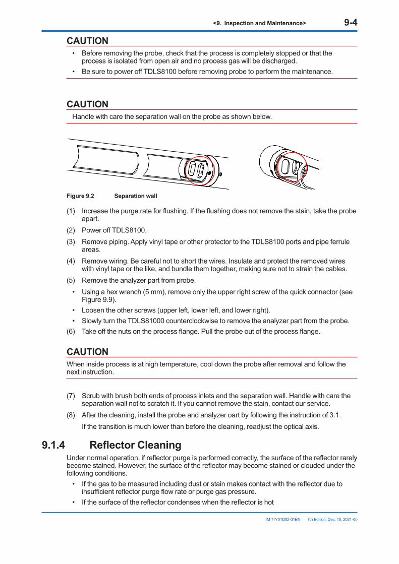
<9. Inspection and Maintenance> 9-4
IM 11Y01D02-01EN 7th Edition: Dec. 10, 2021-00
CAUTION• Before removing the probe, check that the process is completely stopped or that the
process is isolated from open air and no process gas will be discharged.• Be sure to power off TDLS8100 before removing probe to perform the maintenance.
CAUTIONHandle with care the separation wall on the probe as shown below.
Figure 9.2 Separation wall
(1) Increase the purge rate for flushing. If the flushing does not remove the stain, take the probe apart.
(2) Power off TDLS8100.(3) Remove piping. Apply vinyl tape or other protector to the TDLS8100 ports and pipe ferrule
areas.(4) Remove wiring. Be careful not to short the wires. Insulate and protect the removed wires
with vinyl tape or the like, and bundle them together, making sure not to strain the cables. (5) Remove the analyzer part from probe.
• Using a hex wrench (5 mm), remove only the upper right screw of the quick connector (see Figure 9.9).
• Loosen the other screws (upper left, lower left, and lower right).• Slowly turn the TDLS81000 counterclockwise to remove the analyzer part from the probe.
(6) Take off the nuts on the process flange. Pull the probe out of the process flange.
CAUTIONWhen inside process is at high temperature, cool down the probe after removal and follow the next instruction.
(7) Scrub with brush both ends of process inlets and the separation wall. Handle with care the separation wall not to scratch it. If you cannot remove the stain, contact our service.
(8) After the cleaning, install the probe and analyzer oart by following the instruction of 3.1. If the transition is much lower than before the cleaning, readjust the optical axis.
9.1.4 ReflectorCleaningUnder normal operation, if reflector purge is performed correctly, the surface of the reflector rarely become stained. However, the surface of the reflector may become stained or clouded under the following conditions.
• If the gas to be measured including dust or stain makes contact with the reflector due to insufficient reflector purge flow rate or purge gas pressure.
• If the surface of the reflector condenses when the reflector is hot
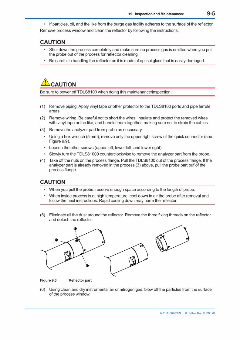
<9. Inspection and Maintenance> 9-5
IM 11Y01D02-01EN 7th Edition: Dec. 10, 2021-00
• If particles, oil, and the like from the purge gas facility adheres to the surface of the reflectorRemove process window and clean the reflector by following the instructions.
CAUTION• Shut down the process completely and make sure no process gas is emitted when you pull
the probe out of the process for reflector cleaning.• Be careful in handling the reflector as it is made of optical glass that is easily damaged.
CAUTIONBe sure to power off TDLS8100 when doing this maintenance/inspection.
(1) Remove piping. Apply vinyl tape or other protector to the TDLS8100 ports and pipe ferrule areas.
(2) Remove wiring. Be careful not to short the wires. Insulate and protect the removed wires with vinyl tape or the like, and bundle them together, making sure not to strain the cables.
(3) Remove the analyzer part from probe as necessary.• Using a hex wrench (5 mm), remove only the upper right screw of the quick connector (see
Figure 9.9).• Loosen the other screws (upper left, lower left, and lower right).• Slowly turn the TDLS81000 counterclockwise to remove the analyzer part from the probe.
(4) Take off the nuts on the process flange. Pull the TDLS8100 out of the process flange. If the analyzer part is already removed in the process (3) above, pull the probe part ouf of the process flange.
CAUTION• When you pull the probe, reserve enough space according to the length of probe.• When inside process is at high temperature, cool down in air the probe after removal and
follow the next instructions. Rapid cooling down may harm the reflector.
(5) Eliminate all the dust around the reflector. Remove the three fixing threads on the reflector and detach the reflector.
Figure9.3 Reflectorpart
(6) Using clean and dry instrumental air or nitrogen gas, blow off the particles from the surface of the process window.
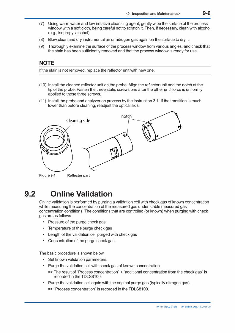
<9. Inspection and Maintenance> 9-6
IM 11Y01D02-01EN 7th Edition: Dec. 10, 2021-00
(7) Using warm water and low irritative cleansing agent, gently wipe the surface of the process window with a soft cloth, being careful not to scratch it. Then, if necessary, clean with alcohol (e.g., isopropyl alcohol).
(8) Blow clean and dry instrumental air or nitrogen gas again on the surface to dry it.(9) Thoroughly examine the surface of the process window from various angles, and check that
the stain has been sufficiently removed and that the process window is ready for use.
NOTEIf the stain is not removed, replace the reflector unit with new one.
(10) Install the cleaned reflector unit on the probe. Align the reflector unit and the notch at the tip of the probe. Fasten the three static screws one after the other until force is uniformly applied to those three screws.
(11) Install the probe and analyzer on process by the instruction 3.1. If the transition is much lower than before cleaning, readjust the optical axis.
notchCleaning side
Figure9.4 Reflectorpart
9.2 Online ValidationOnline validation is performed by purging a validation cell with check gas of known concentration while measuring the concentration of the measured gas under stable measured gas concentration conditions. The conditions that are controlled (or known) when purging with check gas are as follows.
• Pressure of the purge check gas• Temperature of the purge check gas• Length of the validation cell purged with check gas• Concentration of the purge check gas
The basic procedure is shown below.• Set known validation parameters.• Purge the validation cell with check gas of known concentration. => The result of “Process concentration” + “additional concentration from the check gas” is
recorded in the TDLS8100.• Purge the validation cell again with the original purge gas (typically nitrogen gas). => “Process concentration” is recorded in the TDLS8100.
<9. Inspection and Maintenance> 9-7
IM 11Y01D02-01EN 7th Edition: Dec. 10, 2021-00
=> The expected value for the “additional concentration from the check gas” is calculated from the known parameters.
=> The expected value and the actual value are compared and validated (pass or fail).
NOTEPerform the online validation when the process is sufficiently stable.
NOTEValidation is a procedure to check whether the TDLS8100 is operating properly. If there is a reading error because of validation, check that there is no gas leak from the process. If no gas leak is confirmed, perform calibration.
9.2.1 PreparationIn online validation, a validation cell is purged with check gas. The following shows check gas piping methods.
Up to two check gases are connected for online validation 1 and online validation 2 (Figure 9.5).
NOTEIf you want to switch the check gas stream through automatic valve control using the TDLS8100 SV terminal, you need to set the TDLS8100 valve usage to CAL/VAL. For details on valve usage, see “6.8.2 Valve Usage Setting”.
Online validation piping diagram is shown below.When using the type of Zone1/Div1/Flameproof “d”, see “3.4.2 Optical area Purge of Zone 1/Div. 1/Flameproof “d””.
Connect up to two types of online validation check gas. Execute online validation 1 or 2 to validate using the respective check gas. If you want to control valves automatically through the SV terminal, you need to set the valve usage to Cal/Val.
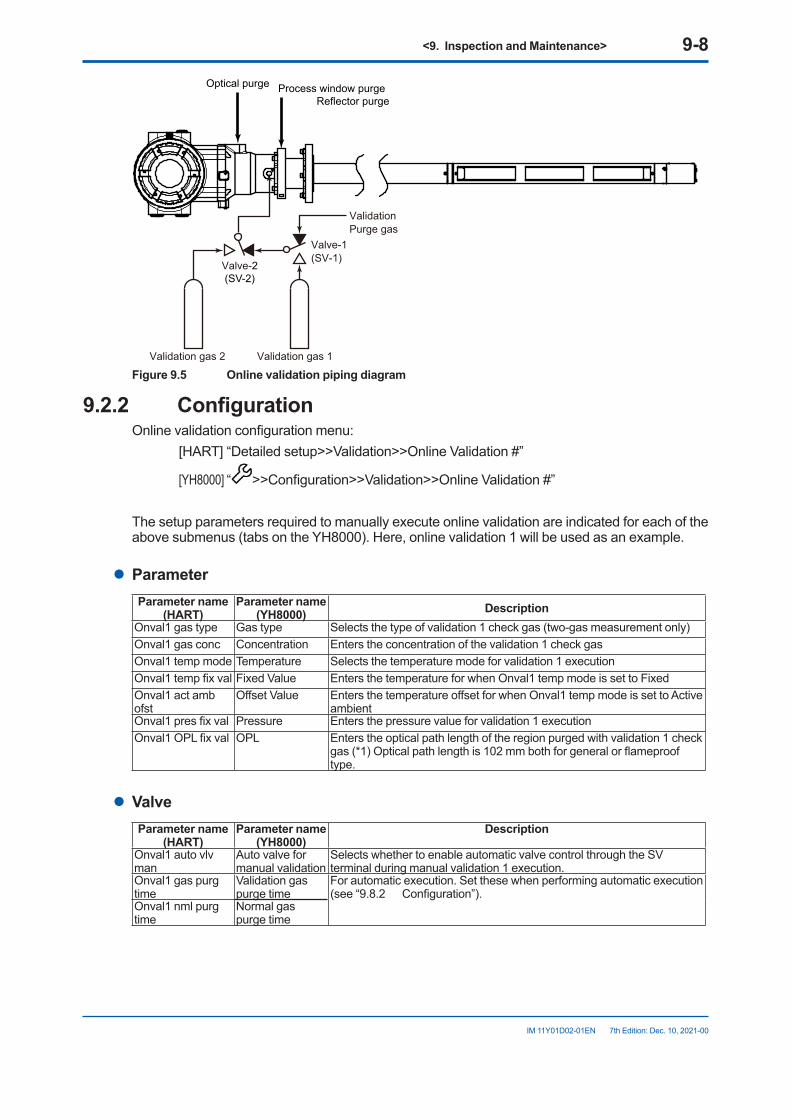
<9. Inspection and Maintenance> 9-8
IM 11Y01D02-01EN 7th Edition: Dec. 10, 2021-00
Optical purge Process window purge Reflector purge
ValidationPurge gas
Valve-1(SV-1)
Valve-2(SV-2)
Validation gas 2 Validation gas 1 Figure 9.5 Online validation piping diagram
9.2.2 ConfigurationOnline validation configuration menu: [HART] “Detailed setup>>Validation>>Online Validation #”
[YH8000] “ >>Configuration>>Validation>>Online Validation #”
The setup parameters required to manually execute online validation are indicated for each of the above submenus (tabs on the YH8000). Here, online validation 1 will be used as an example.
l ParameterParameter name
(HART)Parameter name
(YH8000) DescriptionOnval1 gas type Gas type Selects the type of validation 1 check gas (two-gas measurement only)Onval1 gas conc Concentration Enters the concentration of the validation 1 check gasOnval1 temp mode Temperature Selects the temperature mode for validation 1 executionOnval1 temp fix val Fixed Value Enters the temperature for when Onval1 temp mode is set to FixedOnval1 act amb ofst
Offset Value Enters the temperature offset for when Onval1 temp mode is set to Active ambient
Onval1 pres fix val Pressure Enters the pressure value for validation 1 executionOnval1 OPL fix val OPL Enters the optical path length of the region purged with validation 1 check
gas (*1) Optical path length is 102 mm both for general or flameproof type.
l ValveParameter name
(HART)Parameter name
(YH8000)Description
Onval1 auto vlv man
Auto valve for manual validation
Selects whether to enable automatic valve control through the SV terminal during manual validation 1 execution.
Onval1 gas purg time
Validation gas purge time
For automatic execution. Set these when performing automatic execution (see “9.8.2 Configuration”).
Onval1 nml purg time
Normal gas purge time
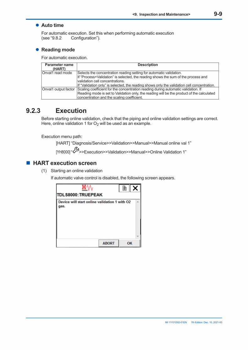
<9. Inspection and Maintenance> 9-9
IM 11Y01D02-01EN 7th Edition: Dec. 10, 2021-00
l Auto timeFor automatic execution. Set this when performing automatic execution (see “9.8.2 Configuration”).
l Reading modeFor automatic execution.
Parameter name (HART)
Description
Onval1 read mode Selects the concentration reading setting for automatic validation.If “Process+Validation” is selected, the reading shows the sum of the process and validation cell concentrations.If “Validation only” is selected, the reading shows only the validation cell concentration.
Onval1 output factor Scaling coefficient for the concentration reading during automatic validation. If Reading mode is set to Validation only, the reading will be the product of the calculated concentration and the scaling coefficient.
9.2.3 ExecutionBefore starting online validation, check that the piping and online validation settings are correct. Here, online validation 1 for O2 will be used as an example.
Execution menu path: [HART] “Diagnosis/Service>>Validation>>Manual>>Manual online val 1”
[YH8000] “ >>Execution>>Validation>>Manual>>Online Validation 1”
n HARTexecutionscreen(1) Starting an online validation If automatic valve control is disabled, the following screen appears.
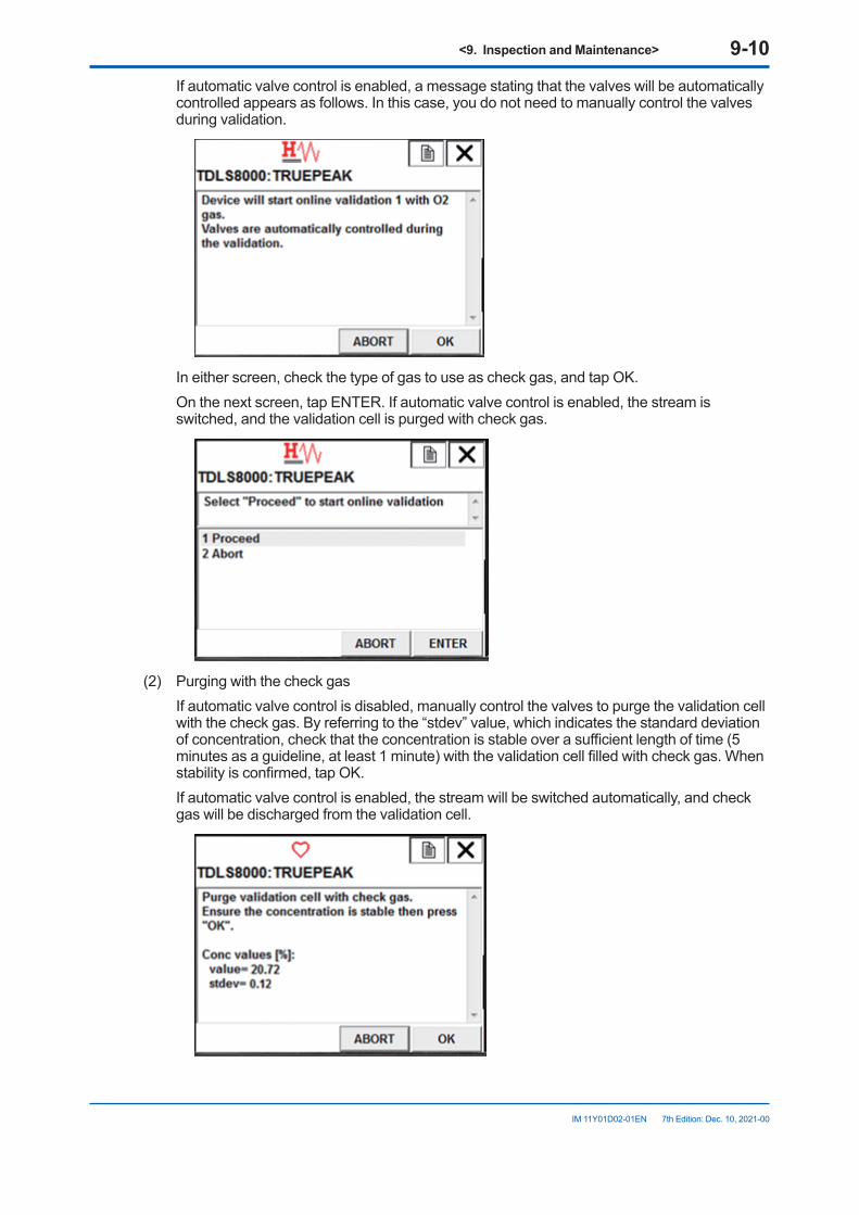
<9. Inspection and Maintenance> 9-10
IM 11Y01D02-01EN 7th Edition: Dec. 10, 2021-00
If automatic valve control is enabled, a message stating that the valves will be automatically controlled appears as follows. In this case, you do not need to manually control the valves during validation.
In either screen, check the type of gas to use as check gas, and tap OK. On the next screen, tap ENTER. If automatic valve control is enabled, the stream is
switched, and the validation cell is purged with check gas.
(2) Purging with the check gas If automatic valve control is disabled, manually control the valves to purge the validation cell
with the check gas. By referring to the “stdev” value, which indicates the standard deviation of concentration, check that the concentration is stable over a sufficient length of time (5 minutes as a guideline, at least 1 minute) with the validation cell filled with check gas. When stability is confirmed, tap OK.
If automatic valve control is enabled, the stream will be switched automatically, and check gas will be discharged from the validation cell.
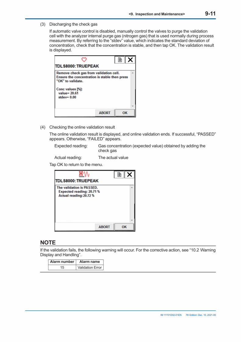
<9. Inspection and Maintenance> 9-11
IM 11Y01D02-01EN 7th Edition: Dec. 10, 2021-00
(3) Discharging the check gas If automatic valve control is disabled, manually control the valves to purge the validation
cell with the analyzer internal purge gas (nitrogen gas) that is used normally during process measurement. By referring to the “stdev” value, which indicates the standard deviation of concentration, check that the concentration is stable, and then tap OK. The validation result is displayed.
(4) Checking the online validation result The online validation result is displayed, and online validation ends. If successful, “PASSED”
appears. Otherwise, “FAILED” appears. Expected reading: Gas concentration (expected value) obtained by adding the
check gas Actual reading: The actual value Tap OK to return to the menu.
NOTEIf the validation fails, the following warning will occur. For the corrective action, see “10.2 Warning Display and Handling”.
Alarm number Alarm name15 Validation Error
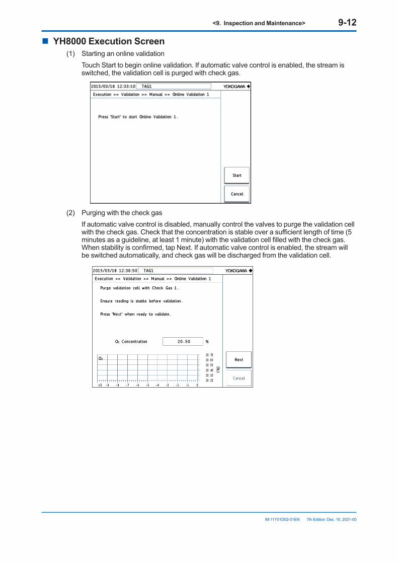
<9. Inspection and Maintenance> 9-12
IM 11Y01D02-01EN 7th Edition: Dec. 10, 2021-00
n YH8000ExecutionScreen(1) Starting an online validation Touch Start to begin online validation. If automatic valve control is enabled, the stream is
switched, the validation cell is purged with check gas.
(2) Purging with the check gas If automatic valve control is disabled, manually control the valves to purge the validation cell
with the check gas. Check that the concentration is stable over a sufficient length of time (5 minutes as a guideline, at least 1 minute) with the validation cell filled with the check gas. When stability is confirmed, tap Next. If automatic valve control is enabled, the stream will be switched automatically, and check gas will be discharged from the validation cell.
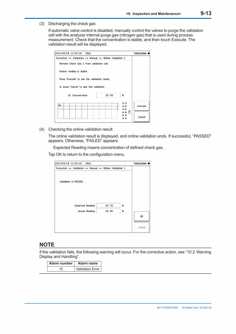
<9. Inspection and Maintenance> 9-13
IM 11Y01D02-01EN 7th Edition: Dec. 10, 2021-00
(3) Discharging the check gas If automatic valve control is disabled, manually control the valves to purge the validation
cell with the analyzer internal purge gas (nitrogen gas) that is used during process measurement. Check that the concentration is stable, and then touch Execute. The validation result will be displayed.
(4) Checking the online validation result The online validation result is displayed, and online validation ends. If successful, “PASSED”
appears. Otherwise, “FAILED” appears. Expected Reading means concentration of defined check gas. Tap OK to return to the configuration menu.
NOTEIf the validation fails, the following warning will occur. For the corrective action, see “10.2 Warning Display and Handling”.
Alarm number Alarm name15 Validation Error
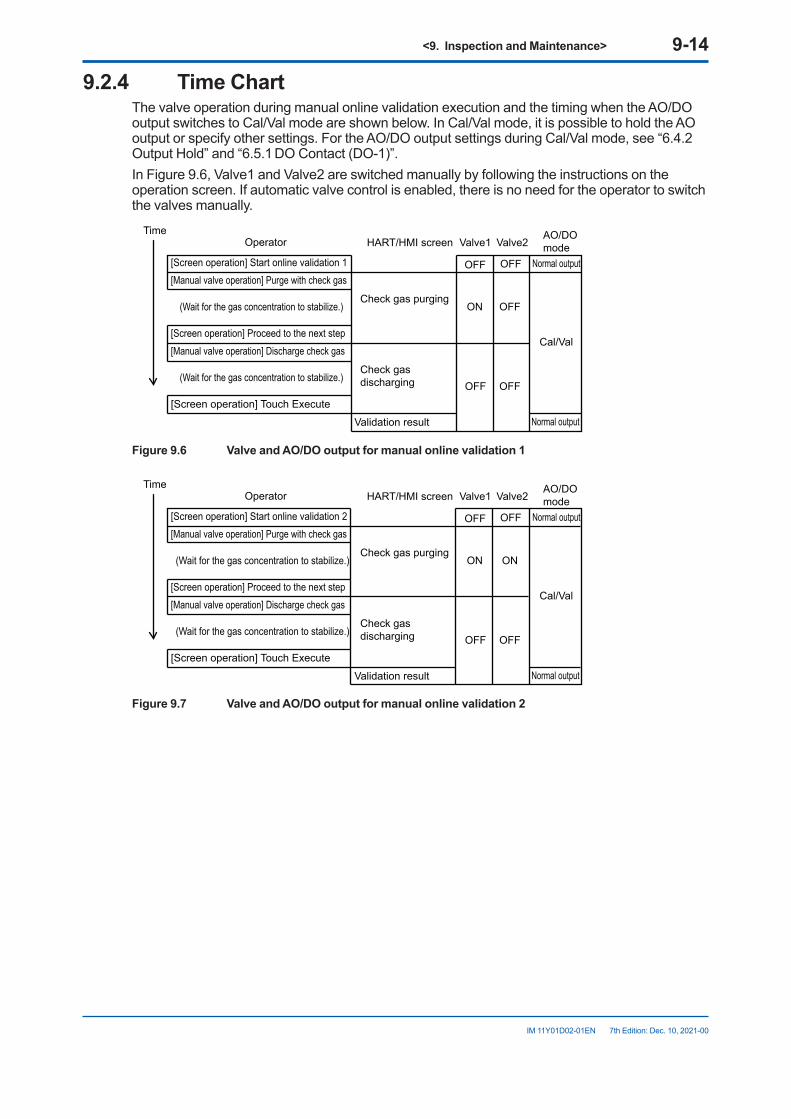
<9. Inspection and Maintenance> 9-14
IM 11Y01D02-01EN 7th Edition: Dec. 10, 2021-00
9.2.4 TimeChartThe valve operation during manual online validation execution and the timing when the AO/DO output switches to Cal/Val mode are shown below. In Cal/Val mode, it is possible to hold the AO output or specify other settings. For the AO/DO output settings during Cal/Val mode, see “6.4.2 Output Hold” and “6.5.1 DO Contact (DO-1)”.In Figure 9.6, Valve1 and Valve2 are switched manually by following the instructions on the operation screen. If automatic valve control is enabled, there is no need for the operator to switch the valves manually.
Operator HART/HMI screen Valve1 Valve2AO/DOmode
[Screen operation] Start online validation 1 OFF OFF Normal output[Manual valve operation] Purge with check gas
Check gas purgingON OFF
Cal/Val
(Wait for the gas concentration to stabilize.)
[Screen operation] Proceed to the next step
[Manual valve operation] Discharge check gas
Check gas discharging OFF OFF
(Wait for the gas concentration to stabilize.)
[Screen operation] Touch Execute
Validation result Normal output
Time
Figure9.6 ValveandAO/DOoutputformanualonlinevalidation1
Operator HART/HMI screen Valve1 Valve2AO/DOmode
[Screen operation] Start online validation 2 OFF OFF Normal output[Manual valve operation] Purge with check gas
Check gas purgingON ON
Cal/Val
(Wait for the gas concentration to stabilize.)
[Screen operation] Proceed to the next step
[Manual valve operation] Discharge check gas
Check gas discharging OFF OFF
(Wait for the gas concentration to stabilize.)
[Screen operation] Touch Execute
Validation result Normal output
Time
Figure9.7 ValveandAO/DOoutputformanualonlinevalidation2
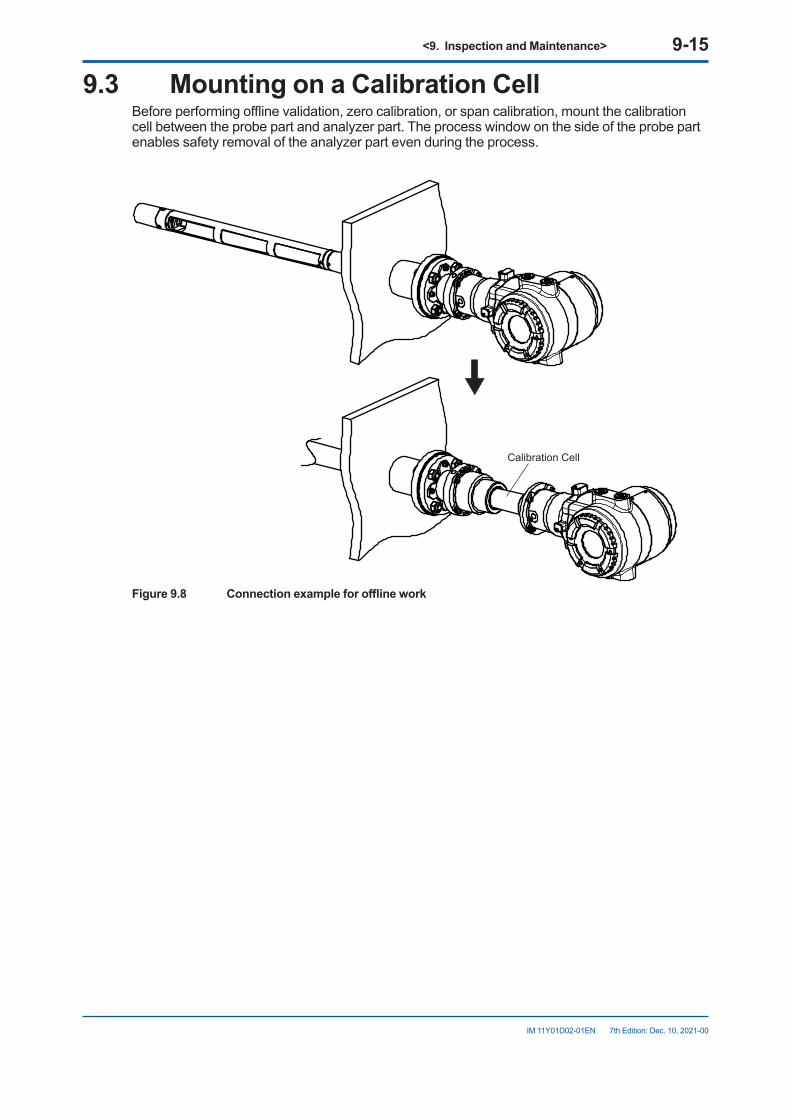
<9. Inspection and Maintenance> 9-15
IM 11Y01D02-01EN 7th Edition: Dec. 10, 2021-00
9.3 Mounting on a Calibration CellBefore performing offline validation, zero calibration, or span calibration, mount the calibration cell between the probe part and analyzer part. The process window on the side of the probe part enables safety removal of the analyzer part even during the process.
Calibration Cell
Figure9.8 Connectionexampleforofflinework
<9. Inspection and Maintenance> 9-16
IM 11Y01D02-01EN 7th Edition: Dec. 10, 2021-00
9.3.1 PreparationIf you want to perform calibration or offline validation, prepare the following tools, instruments, nitrogen gas, and gas for offline work (check gas, zero calibration gas (nitrogen gas), span calibration gas).
Tool or instrument Quantity RemarksCalibration cell 1YH8000 or HART configuration tool
1 For executing offline calibration and validation
24 V DC power cable 1Valve drive cable As required (1 or 2) For controlling valves automatically through the
SV terminalYH8000 connection cable 1 When using the YH800024 V DC power supply 11/4 inch piping Several meters1/4 inch ferrule set As requiredPressure regulator 11/4 inch pipe plug 2Three-way valve As requiredThermometer 1Pressure meter 1Coupling As requiredNitrogen gas As required For TDLS8100 purging
For zero calibrationSpan calibration gas As required For span calibrationCheck gas As required For offline validationFlowmeter 3 For TDLS8100 purging
For zero calibrationFor span calibration and offline validation
Needle valve 3 For flow rate adjustment
9.3.2 Preparation ProcedurePerform the following procedure. Purge pipe connection is different for Offline validation, zero calibration, and span calibration. For details, see sections 9.4, 9.5, and 9.6.
CAUTION• Do not apply physical shock to the TDLS8100 when relocating the TDLS8100 to a
calibration cell and when returning it to the process. Doing so can cause a malfunction.• During calibration work, do not remove the analyzer part while the power is on.• If the process gas is positive pressure, shut off the TDLS8100 from the process, stop the
process window purge, and prevent excessive pressure from being applied to the process window.
(1)RecordingthesettingsCheck the following settings and the process conditions before removing the analyzer part.These will be used when returning the TDLS8100 to the process.
• Process optical path length• Process pressure (record only when the input mode is set to Fixed)• Process temperature (record only when the input mode is set to Fixed)• Transmission• Process window/Reflector purge flow rate (record only when purge is stopped)
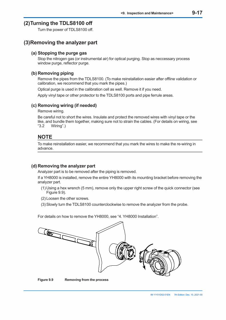
<9. Inspection and Maintenance> 9-17
IM 11Y01D02-01EN 7th Edition: Dec. 10, 2021-00
(2)TurningtheTDLS8100offTurn the power of TDLS8100 off.
(3)Removingtheanalyzerpart
(a)StoppingthepurgegasStop the nitrogen gas (or instrumental air) for optical purging. Stop as neccessary process window purge, reflector purge.
(b)RemovingpipingRemove the pipes from the TDLS8100. (To make reinstallation easier after offline validation or calibration, we recommend that you mark the pipes.)Optical purge is used in the calibration cell as well. Remove it if you need.Apply vinyl tape or other protector to the TDLS8100 ports and pipe ferrule areas.
(c)Removingwiring(ifneeded)Remove wiring.Be careful not to short the wires. Insulate and protect the removed wires with vinyl tape or the like, and bundle them together, making sure not to strain the cables. (For details on wiring, see “3.2 Wiring”.)
NOTETo make reinstallation easier, we recommend that you mark the wires to make the re-wiring in advance.
(d)RemovingtheanalyzerpartAnalyzer part is to be removed after the piping is removed.If a YH8000 is installed, remove the entire YH8000 with its mounting bracket before removing the analyzer part.
(1) Using a hex wrench (5 mm), remove only the upper right screw of the quick connector (see Figure 9.9).
(2) Loosen the other screws.(3) Slowly turn the TDLS8100 counterclockwise to remove the analyzer from the probe.
For details on how to remove the YH8000, see “4. YH8000 Installation”.
Figure9.9 Removingfromtheprocess
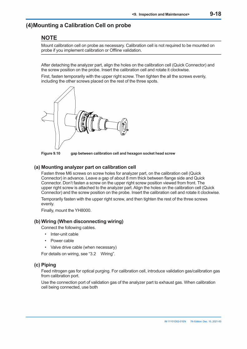
<9. Inspection and Maintenance> 9-18
IM 11Y01D02-01EN 7th Edition: Dec. 10, 2021-00
(4)MountingaCalibrationCellonprobe
NOTEMount calibration cell on probe as necessary. Calibration cell is not required to be mounted on probe if you implement calibration or Offline validation.
After detaching the analyzer part, align the holes on the calibration cell (Quick Connector) and the screw position on the probe. Insert the calibration cell and rotate it clockwise.First, fasten temporarily with the upper right screw. Then tighten the all the screws evenly, including the other screws placed on the rest of the three spots.
Figure9.10 gapbetweencalibrationcellandhexagonsocketheadscrew
(a)MountinganalyzerpartoncalibrationcellFasten three M6 screws on screw holes for analyzer part, on the calibration cell (Quick Connector) in advance. Leave a gap of about 8 mm thick between flange side and Quick Connector. Don’t fasten a screw on the upper right screw position viewed from front. The upper right screw is attached to the analyzer part. Align the holes on the calibration cell (Quick Connector) and the screw position on the probe. Insert the calibration cell and rotate it clockwise.Temporarily fasten with the upper right screw, and then tighten the rest of the three screws evenly.Finally, mount the YH8000.
(b)Wiring(Whendisconnectingwiring)Connect the following cables.
• Inter-unit cable• Power cable• Valve drive cable (when necessary)
For details on wiring, see “3.2 Wiring”.
(c)PipingFeed nitrogen gas for optical purging. For calibration cell, introduce validation gas/calibration gas from calibration port.Use the connection port of validation gas of the analyzer part to exhaust gas. When calibration cell being connected, use both
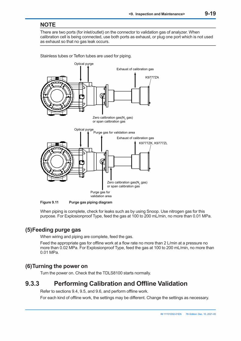
<9. Inspection and Maintenance> 9-19
IM 11Y01D02-01EN 7th Edition: Dec. 10, 2021-00
NOTEThere are two ports (for inlet/outlet) on the connector to validation gas of analyzer. When calibration cell is being connected, use both ports as exhaust, or plug one port which is not used as exhaust so that no gas leak occurs.
Stainless tubes or Teflon tubes are used for piping.
Optical purge Exhaust of calibration gas
K9777ZA
Zero calibration gas(N2 gas)or span calibration gas
Optical purge
Exhaust of calibration gasPurge gas for validation area
K9777ZK, K9777ZL
Zero calibration gas(N2 gas)or span calibration gas
Purge gas forvalidation area
Figure 9.11 Purge gas piping diagram
When piping is complete, check for leaks such as by using Snoop. Use nitrogen gas for this purpose. For Explosionproof Type, feed the gas at 100 to 200 mL/min, no more than 0.01 MPa.
(5)FeedingpurgegasWhen wiring and piping are complete, feed the gas.Feed the appropriate gas for offline work at a flow rate no more than 2 L/min at a pressure no more than 0.02 MPa. For Explosionproof Type, feed the gas at 100 to 200 mL/min, no more than 0.01 MPa.
(6)TurningthepoweronTurn the power on. Check that the TDLS8100 starts normally.
9.3.3 PerformingCalibrationandOfflineValidationRefer to sections 9.4, 9.5, and 9.6, and perform offline work.For each kind of offline work, the settings may be different. Change the settings as necessary.
<9. Inspection and Maintenance> 9-20
IM 11Y01D02-01EN 7th Edition: Dec. 10, 2021-00
9.3.4 ReturningtheTDLS8100totheProcessWhen offline work is complete, return the TDLS8100 to the process. Follow the procedure below.
NOTERemove piping after gas inside the calibration cell is completly replaced with safety gas.
(1) Switching the span calibration gas or check gas If hazardous gas is flowing (e.g., CO gas), switch it to nitrogen gas. Wait for the gas inside
the calibration cell to be completely replaced before proceeding.(2) Stopping the gas On the TDLS8100 display, check that the calibration gas concentration has dropped to zero,
and then stop all purge gases.(3) Removing piping Check that there is no residual internal pressure, and then remove the piping.(4) Turning the TDLS8100 off Check the above items, and then turn the TDLS8100 off.(5) Removing wiring (as neceessarry) Remove wiring according to the procedure of section 9.3.2 (3) (d).(6) Removing the analyzer part from the calibration cell Remove the analyzer part according to the procedure of section 9.3.2 (3) (e).(7) Removing the calibration cell (as necessary) Remove the calibration cell when it is attached to the probe.(8) Installing the analyzer part in the process Install the analyzer part by reversing the procedure for removing it.
(a) Wiring Connect the following cables. • Cable between the LU and SCU • Power cable • Valve drive cable (when necessary) • AI/AO/DO/DI cable (when necessary) For details on wiring, see “3.2 Wiring”.(b) Piping Refer to “3.4 Piping”, and connect the pipes to restore the analyzer part to its original
condition before it was removed.(9) Feeding purge gas When wiring and piping are complete, feed the purge gas. Since the internal pressure from the process window purge gas may become high when
process isolation valve (ball valve) is used, open the valve immediately after starting to feed the process window purge gas.
(10) Turning the power on Turn the power on. Check that the TDLS8100 starts normally.
<9. Inspection and Maintenance> 9-21
IM 11Y01D02-01EN 7th Edition: Dec. 10, 2021-00
(11) Optical Axis Adjustment Refer to “3.3 Optical Axis Adjustment”, and adjust the optical axis.(12) Checking the settings Refer to the settings that you recorded before removing the TDLS8100, and reset them if
necessary. a) Process optical path length b) Process pressure c) Process temperature d) Transmission
9.4 OfflineValidationOffline validation is a function used to verify the validity of gas concentration measurements. For the validation process, the TDLS8100 is separated from the measurement process, and a known check gas if fed through a calibration cell or flow cell.Before performing a validation, you need to enter the following information in the TDLS8100.
• Pressure of the purge check gas• Temperature of the purge check gas• Length of the calibration cell• Concentration of the purge check gas
The basic procedure is shown below.• Set known validation parameters.• Purge the calibration cell or flow cell with check gas of known concentration. => The check gas concentration reading will be recorded. => The expected value for the “check gas” is calculated from the known parameters. => The expected value and the actual value are compared and validated (pass or fail).
NOTEValidation is a procedure to check whether the TDLS8100 is operating properly. If there is an error in reading, implement calibration.
Normally, after detaching the analyzer part from process and installing on the calibration cell, Offline validation is to be performed.
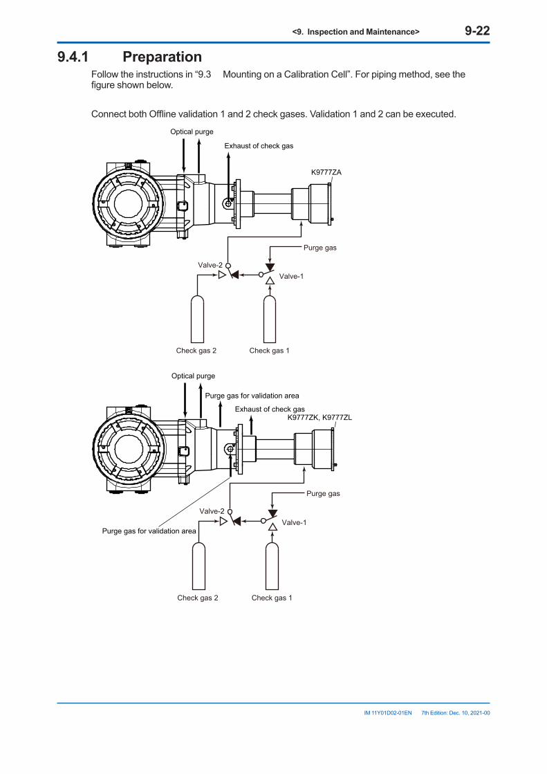
<9. Inspection and Maintenance> 9-22
IM 11Y01D02-01EN 7th Edition: Dec. 10, 2021-00
9.4.1 PreparationFollow the instructions in “9.3 Mounting on a Calibration Cell”. For piping method, see the figure shown below.
Connect both Offline validation 1 and 2 check gases. Validation 1 and 2 can be executed.
Optical purge
K9777ZA
Exhaust of check gas
Purge gas
Valve-1Valve-2
Check gas 2 Check gas 1
Optical purge
K9777ZK, K9777ZLExhaust of check gas
Purge gas for validation area
Purge gas for validation area
Purge gas
Valve-1Valve-2
Check gas 2 Check gas 1
<9. Inspection and Maintenance> 9-23
IM 11Y01D02-01EN 7th Edition: Dec. 10, 2021-00
9.4.2 ConfigurationOffline validation configuration menu: [HART] “Detailed setup>>Validation>>Offline validation #”
[YH8000] “ >>Configuration>Validation>>Offline Validation #”The setup parameters required to manually execute Offline validation are indicated for each of the above submenus (tabs on the YH8000). Here, Offline validation 1 will be used as an example.
l ParameterParameter name
(HART)Parameter name
(YH8000)Description
Offval1 gas type Gas type Selects the type of validation 1 check gas (two-gas measurement only)Offval1 gas conc Concentration Enters the concentration of the validation 1 check gasOffval1 pres mode Pressure Selects the pressure mode for validation 1 execution (*1)Offval1 pres fix val Fixed Value Enters the pressure for when Offval1 pres mode is set to FixedOffval1 temp mode Temperature Selects the temperature mode for validation 1 execution (*1)Offval1 temp fix val Fixed Value Enters the temperature for when Offval1 temp mode is set to FixedOffval1 OPL mode OPL Selects the optical path length mode for validation 1 execution (*1)Offval1 OPL fix val Fixed Value Enters the process optical path length for when Offval1 OPL mode is
set to Fixed*1: Process parameter: Uses the process parameter value Fixed value: Set to a fixed value
l ValveParameter name
(HART)Parameter name
(YH8000)Description
Offval1 auto vlv man Auto valve for manual validation
Selects whether to enable automatic valve control through the SV terminal during manual validation 1 execution.
Offval1 gas purg time Validation gas purge time
For automatic execution. Set these when performing automatic execution (see “9.8.2 Configuration”).
Offval1 prc purg time Process gas purge time
9.4.3 ExecutionBefore starting offline validation, check that the piping and offline validation settings are correct. Here, offline validation 1 will be used as an example.
Execution menu path: [HART] “Diagnosis/Service>>Validation>>Manual>>Manual offline val 1”
[YH8000] “ >>Execution>>Validation>>Manual>>Offline Validation 1”(1) Starting an offline validation On HART or YH8000, open the above menu, and start offline validation. If automatic
valve control is enabled, a message stating that the valves will be automatically controlled will appear.*1 In this case, you do not need to manually control the valves during offline validation.
(2) Purging with check gas An instruction to purge the calibration cell with check gas will appear.*2 If automatic valve
control is disabled, manually control the valves to purge the calibration cell with the check gas. For safety verification, the standard deviation (stdev) of concentration is displayed on HART and the concentration trend on the YH8000. Check that the concentration is stable over a sufficient length of time (5 minutes as a guideline, at least 1 minute) with the validation cell filled with check gas. Then, execute validation.
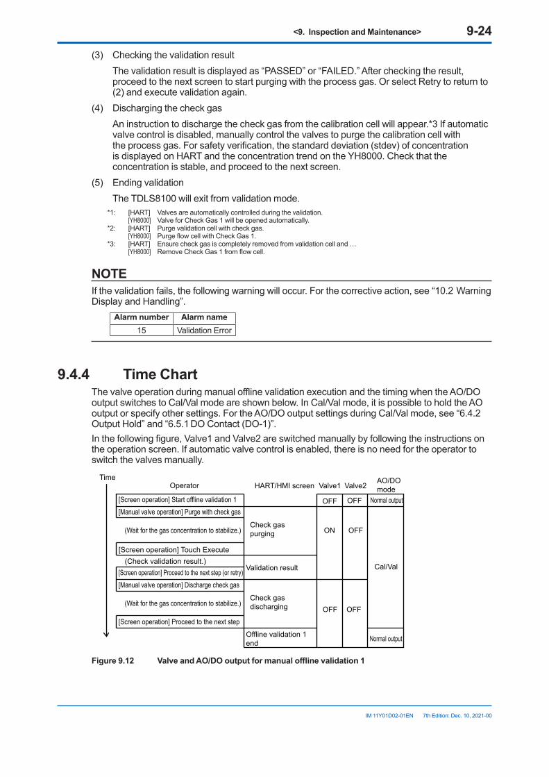
<9. Inspection and Maintenance> 9-24
IM 11Y01D02-01EN 7th Edition: Dec. 10, 2021-00
(3) Checking the validation result The validation result is displayed as “PASSED” or “FAILED.” After checking the result,
proceed to the next screen to start purging with the process gas. Or select Retry to return to (2) and execute validation again.
(4) Discharging the check gas An instruction to discharge the check gas from the calibration cell will appear.*3 If automatic
valve control is disabled, manually control the valves to purge the calibration cell with the process gas. For safety verification, the standard deviation (stdev) of concentration is displayed on HART and the concentration trend on the YH8000. Check that the concentration is stable, and proceed to the next screen.
(5) Ending validation The TDLS8100 will exit from validation mode.
*1: [HART] Valves are automatically controlled during the validation. [YH8000] Valve for Check Gas 1 will be opened automatically.*2: [HART] Purge validation cell with check gas. [YH8000] Purge flow cell with Check Gas 1.*3: [HART] Ensure check gas is completely removed from validation cell and … [YH8000] Remove Check Gas 1 from flow cell.
NOTEIf the validation fails, the following warning will occur. For the corrective action, see “10.2 Warning Display and Handling”.
Alarm number Alarm name15 Validation Error
9.4.4 TimeChartThe valve operation during manual offline validation execution and the timing when the AO/DO output switches to Cal/Val mode are shown below. In Cal/Val mode, it is possible to hold the AO output or specify other settings. For the AO/DO output settings during Cal/Val mode, see “6.4.2 Output Hold” and “6.5.1 DO Contact (DO-1)”.In the following figure, Valve1 and Valve2 are switched manually by following the instructions on the operation screen. If automatic valve control is enabled, there is no need for the operator to switch the valves manually.
Operator HART/HMI screen Valve1 Valve2AO/DOmode
[Screen operation] Start offline validation 1 OFF OFF Normal output[Manual valve operation] Purge with check gas
Check gas purging ON OFF
Cal/Val
(Wait for the gas concentration to stabilize.)
(Check validation result.)[Screen operation] Proceed to the next step (or retry)
[Manual valve operation] Discharge check gas
Check gas discharging OFF OFF
(Wait for the gas concentration to stabilize.)
[Screen operation] Proceed to the next step
[Screen operation] Touch Execute
Offline validation 1end
Validation result
Normal output
Time
Figure9.12 ValveandAO/DOoutputformanualofflinevalidation1
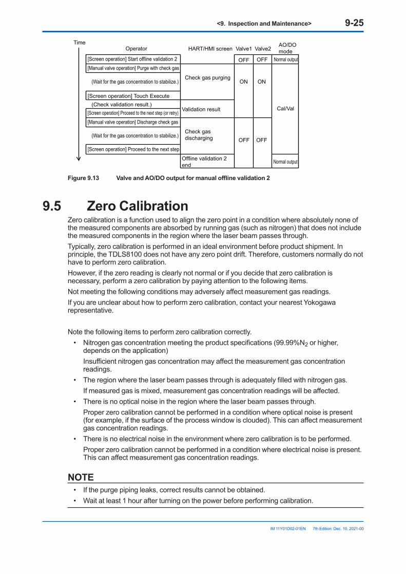
<9. Inspection and Maintenance> 9-25
IM 11Y01D02-01EN 7th Edition: Dec. 10, 2021-00
Operator HART/HMI screen Valve1 Valve2AO/DOmode
[Screen operation] Start offline validation 2 OFF OFF Normal output[Manual valve operation] Purge with check gas
Check gas purgingON ON
Cal/Val
(Wait for the gas concentration to stabilize.)
(Check validation result.)[Screen operation] Proceed to the next step (or retry)
[Manual valve operation] Discharge check gas
Check gas discharging OFF OFF
(Wait for the gas concentration to stabilize.)
[Screen operation] Proceed to the next step
[Screen operation] Touch Execute
Offline validation 2end
Validation result
Normal output
Time
Figure9.13 ValveandAO/DOoutputformanualofflinevalidation2
9.5 Zero CalibrationZero calibration is a function used to align the zero point in a condition where absolutely none of the measured components are absorbed by running gas (such as nitrogen) that does not include the measured components in the region where the laser beam passes through.Typically, zero calibration is performed in an ideal environment before product shipment. In principle, the TDLS8100 does not have any zero point drift. Therefore, customers normally do not have to perform zero calibration.However, if the zero reading is clearly not normal or if you decide that zero calibration is necessary, perform a zero calibration by paying attention to the following items.Not meeting the following conditions may adversely affect measurement gas readings.If you are unclear about how to perform zero calibration, contact your nearest Yokogawa representative.
Note the following items to perform zero calibration correctly.• Nitrogen gas concentration meeting the product specifications (99.99%N2 or higher,
depends on the application) Insufficient nitrogen gas concentration may affect the measurement gas concentration
readings.• The region where the laser beam passes through is adequately filled with nitrogen gas. If measured gas is mixed, measurement gas concentration readings will be affected.• There is no optical noise in the region where the laser beam passes through. Proper zero calibration cannot be performed in a condition where optical noise is present
(for example, if the surface of the process window is clouded). This can affect measurement gas concentration readings.
• There is no electrical noise in the environment where zero calibration is to be performed. Proper zero calibration cannot be performed in a condition where electrical noise is present.
This can affect measurement gas concentration readings.
NOTE• If the purge piping leaks, correct results cannot be obtained.• Wait at least 1 hour after turning on the power before performing calibration.
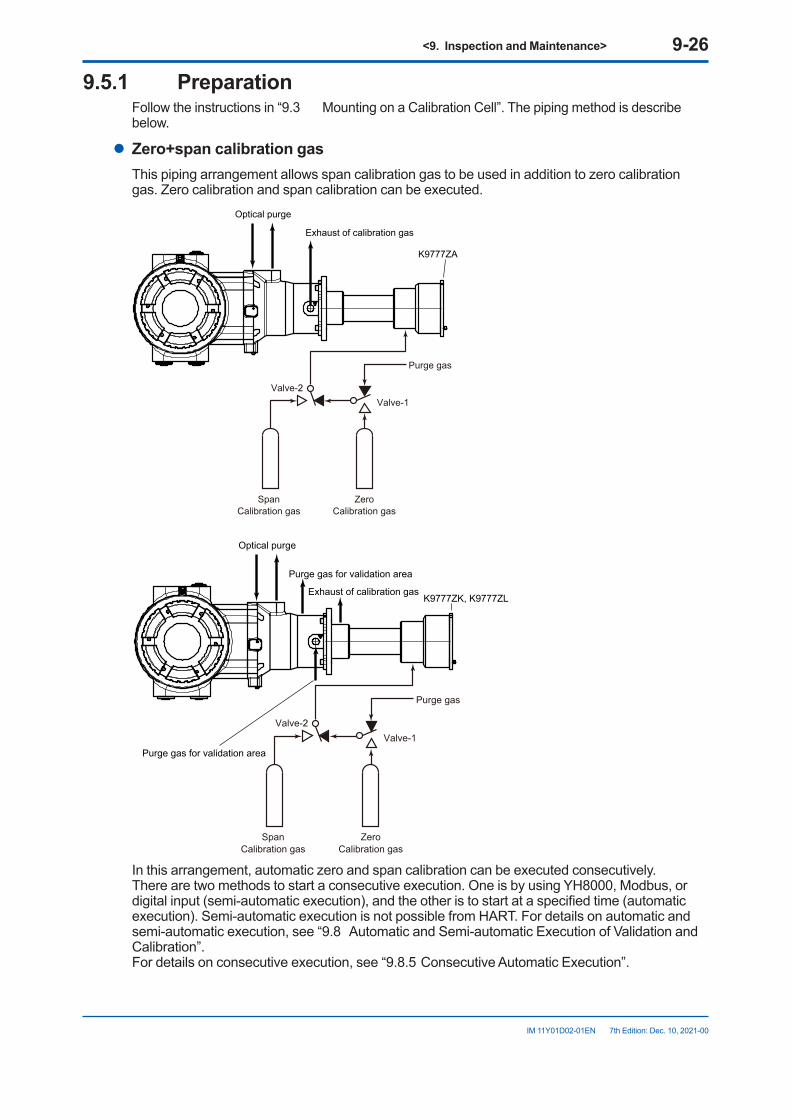
<9. Inspection and Maintenance> 9-26
IM 11Y01D02-01EN 7th Edition: Dec. 10, 2021-00
9.5.1 PreparationFollow the instructions in “9.3 Mounting on a Calibration Cell”. The piping method is describe below.
l Zero+span calibration gasThis piping arrangement allows span calibration gas to be used in addition to zero calibration gas. Zero calibration and span calibration can be executed.
Optical purge
Exhaust of calibration gas
K9777ZA
Purge gas
Valve-1Valve-2
SpanCalibration gas
ZeroCalibration gas
Purge gas for validation area
Optical purge
Exhaust of calibration gasK9777ZK, K9777ZL
Purge gas
Valve-1Valve-2
SpanCalibration gas
ZeroCalibration gas
Purge gas for validation area
In this arrangement, automatic zero and span calibration can be executed consecutively. There are two methods to start a consecutive execution. One is by using YH8000, Modbus, or digital input (semi-automatic execution), and the other is to start at a specified time (automatic execution). Semi-automatic execution is not possible from HART. For details on automatic and semi-automatic execution, see “9.8 Automatic and Semi-automatic Execution of Validation and Calibration”. For details on consecutive execution, see “9.8.5 Consecutive Automatic Execution”.
<9. Inspection and Maintenance> 9-27
IM 11Y01D02-01EN 7th Edition: Dec. 10, 2021-00
If you want to switch the zero calibration gas stream through automatic valve control using the TDLS8100 SV terminal, you need to set the TDLS8100 valve usage to Cal/Val. For details on valve usage, see “6.8.2 Valve Usage Setting”.
9.5.2 ConfigurationZero calibration configuration menu: [HART] “Detailed setup>>Calibration>>Zero calibration”
[YH8000] “ >>Configuration>Calibration>>Zero Calibration”The setup parameters required to manually execute zero calibration are indicated for each of the above submenus (tabs on the YH8000).
l ValveParameter name
(HART)Description
Z-cal auto vlv man Selects whether to enable automatic valve control through the SV terminal during manual zero calibration execution.
9.5.3 ExecutionBefore starting zero calibration, check that the piping and zero calibration settings are correct.Execution menu path: [HART] “Diagnosis/Service>>Calibration>>Manual>>Manual zero cal”
[YH8000] “ >>Execution>>Calibration>>Manual>>Zero Calibration”(1) Starting zero calibration On HART or YH8000, open the above menu, and start zero calibration. First, a message
appears to ask you for careful execution of zero calibration.*1 Next, if automatic valve control is enabled, a message stating that the valves will be automatically controlled will appear.*2 In this case, you do not need to manually control the valves during zero calibration.
(2) Purging with zero calibration gas An instruction to purge the calibration cell with zero calibration gas will appear.*3 If
automatic valve control is disabled, manually control the valves to purge the calibration cell with the zero calibration gas. For safety verification, the standard deviation (stdev) of concentration is displayed on HART and the concentration trend on the YH8000. Check that the concentration is stable over a sufficient length of time (10 minutes as a guideline, at least 1 minute) with the validation cell filled with the zero calibration gas. Then, execute calibration.
(3) Checking the zero calibration result The result of calibration is displayed as “successful” or “failed.” After checking the result,
proceed to the next screen to start purging with the span calibration gas or process gas. Or select Retry to return to (2) and execute calibration again.
(4) Purging with process gas An instruction to discharge the zero calibration gas from the calibration cell will appear.*4 If
automatic valve control is disabled, manually control the valves to purge the calibration cell with the process gas. For safety verification, the standard deviation (stdev) of concentration is displayed on HART and the concentration trend on the YH8000. Check that the concentration is stable, and proceed to the next screen.
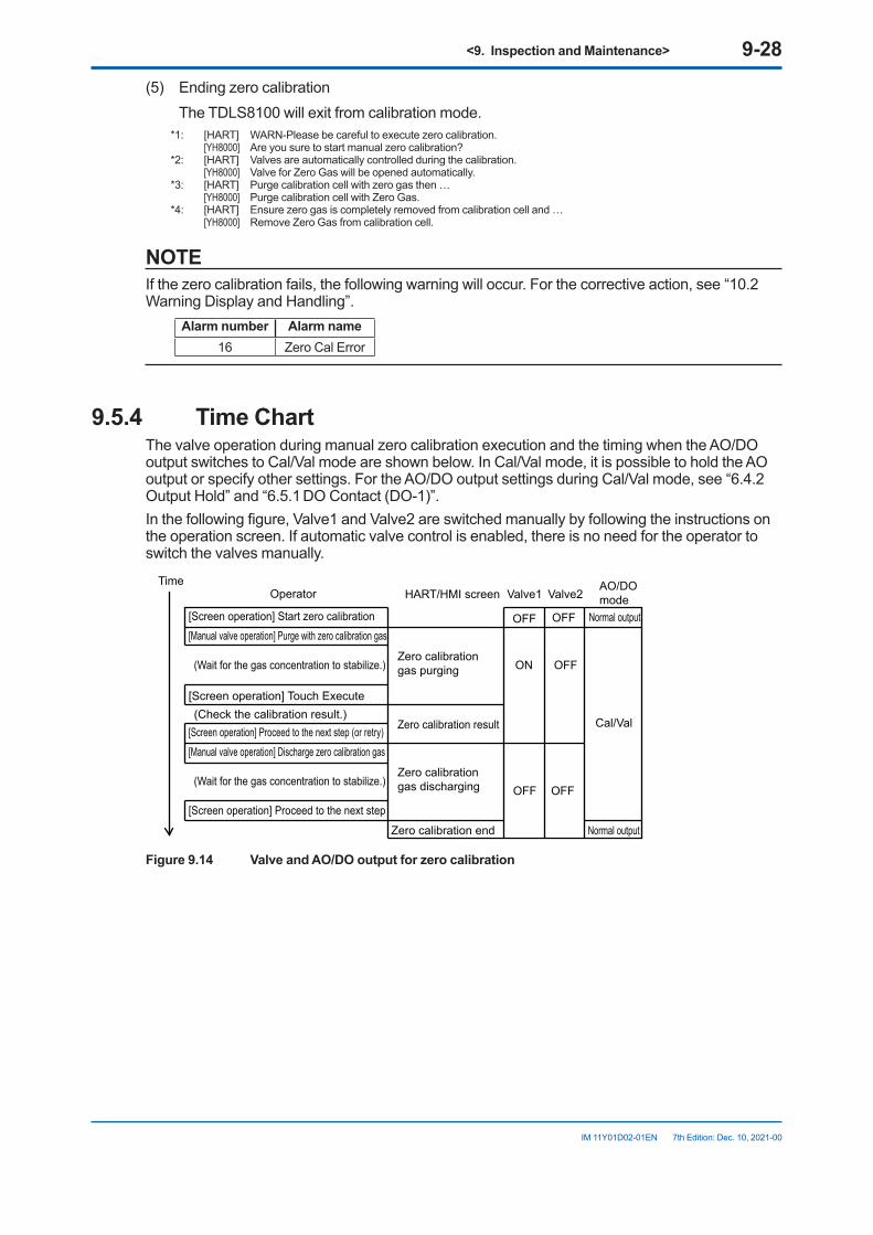
<9. Inspection and Maintenance> 9-28
IM 11Y01D02-01EN 7th Edition: Dec. 10, 2021-00
(5) Ending zero calibration The TDLS8100 will exit from calibration mode.
*1: [HART] WARN-Please be careful to execute zero calibration. [YH8000] Are you sure to start manual zero calibration?*2: [HART] Valves are automatically controlled during the calibration. [YH8000] Valve for Zero Gas will be opened automatically.*3: [HART] Purge calibration cell with zero gas then … [YH8000] Purge calibration cell with Zero Gas.*4: [HART] Ensure zero gas is completely removed from calibration cell and … [YH8000] Remove Zero Gas from calibration cell.
NOTEIf the zero calibration fails, the following warning will occur. For the corrective action, see “10.2 Warning Display and Handling”.
Alarm number Alarm name16 Zero Cal Error
9.5.4 TimeChartThe valve operation during manual zero calibration execution and the timing when the AO/DO output switches to Cal/Val mode are shown below. In Cal/Val mode, it is possible to hold the AO output or specify other settings. For the AO/DO output settings during Cal/Val mode, see “6.4.2 Output Hold” and “6.5.1 DO Contact (DO-1)”.In the following figure, Valve1 and Valve2 are switched manually by following the instructions on the operation screen. If automatic valve control is enabled, there is no need for the operator to switch the valves manually.
Operator HART/HMI screen Valve1 Valve2AO/DOmode
[Screen operation] Start zero calibration OFF OFF Normal output[Manual valve operation] Purge with zero calibration gas
Zero calibration gas purging ON OFF
Cal/Val
(Wait for the gas concentration to stabilize.)
(Check the calibration result.)[Screen operation] Proceed to the next step (or retry)
[Manual valve operation] Discharge zero calibration gas
Zero calibration gas discharging OFF OFF
(Wait for the gas concentration to stabilize.)
[Screen operation] Proceed to the next step
[Screen operation] Touch Execute
Zero calibration end
Zero calibration result
Normal output
Time
Figure9.14 ValveandAO/DOoutputforzerocalibration
<9. Inspection and Maintenance> 9-29
IM 11Y01D02-01EN 7th Edition: Dec. 10, 2021-00
9.6 Span CalibrationSpan calibration is a function used to align the concentration calculation result of the TDLS8100 to the concentration of the calibration gas by purging a calibration cell with span calibration gas of known concentration.Note the following items to perform span calibration correctly.
• Use gas with accurate concentration for the span calibration gas.• Perform span calibration with the target region adequately filled with span calibration gas
(purge with calibration gas and check that the reading is adequately stable).• There is no optical noise in the region where the laser beam passes through. Proper span calibration cannot be performed in a condition where optical noise is present
(particularly if the surface condition of the process window changes). This can affect measurement gas concentration readings.
• There is no electrical noise in the environment where span calibration is to be performed. Proper span calibration cannot be performed in a condition where electrical noise is present.
This can affect measurement gas concentration readings.
NOTE• If the purge piping leaks, correct results cannot be obtained.• Wait at least 1 hour after turning on the power before performing calibration.• Correct measurements may not be obtained if span calibration is performed when the
reading is not stable.
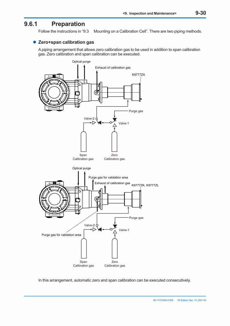
<9. Inspection and Maintenance> 9-30
IM 11Y01D02-01EN 7th Edition: Dec. 10, 2021-00
9.6.1 PreparationFollow the instructions in “9.3 Mounting on a Calibration Cell”. There are two piping methods.
l Zero+span calibration gasA piping arrangement that allows zero calibration gas to be used in addition to span calibration gas. Zero calibration and span calibration can be executed.
Optical purge
Exhaust of calibration gas
K9777ZA
Purge gas
Valve-1Valve-2
SpanCalibration gas
ZeroCalibration gas
Purge gas for validation area
Optical purge
Exhaust of calibration gasK9777ZK, K9777ZL
Purge gas
Valve-1Valve-2
SpanCalibration gas
ZeroCalibration gas
Purge gas for validation area
In this arrangement, automatic zero and span calibration can be executed consecutively.
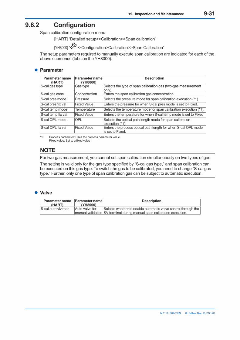
<9. Inspection and Maintenance> 9-31
IM 11Y01D02-01EN 7th Edition: Dec. 10, 2021-00
9.6.2 ConfigurationSpan calibration configuration menu: [HART] “Detailed setup>>Calibration>>Span calibration”
[YH8000] “ >>Configuration>Calibration>>Span Calibration”The setup parameters required to manually execute span calibration are indicated for each of the above submenus (tabs on the YH8000).
l ParameterParameter name
(HART)Parameter name
(YH8000)Description
S-cal gas type Gas type Selects the type of span calibration gas (two-gas measurement only).
S-cal gas conc Concentration Enters the span calibration gas concentration.S-cal pres mode Pressure Selects the pressure mode for span calibration execution (*1).S-cal pres fix val Fixed Value Enters the pressure for when S-cal pres mode is set to Fixed.S-cal temp mode Temperature Selects the temperature mode for span calibration execution (*1).S-cal temp fix val Fixed Value Enters the temperature for when S-cal temp mode is set to FixedS-cal OPL mode OPL Selects the optical path length mode for span calibration
execution (*1).S-cal OPL fix val Fixed Value Enters the process optical path length for when S-cal OPL mode
is set to Fixed.*1: Process parameter: Uses the process parameter value Fixed value: Set to a fixed value
NOTEFor two-gas measurement, you cannot set span calibration simultaneously on two types of gas.The setting is valid only for the gas type specified by “S-cal gas type,” and span calibration can be executed on this gas type. To switch the gas to be calibrated, you need to change “S-cal gas type.” Further, only one type of span calibration gas can be subject to automatic execution.
l ValveParameter name
(HART)Parameter name
(YH8000)Description
S-cal auto vlv man Auto valve for manual validation
Selects whether to enable automatic valve control through the SV terminal during manual span calibration execution.
<9. Inspection and Maintenance> 9-32
IM 11Y01D02-01EN 7th Edition: Dec. 10, 2021-00
9.6.3 ExecutionBefore starting span calibration, check that the piping and span calibration settings are correct.
Execution menu path: [HART] “Diagnosis/Service>>Calibration>>Manual>>Manual span cal”
[YH8000] “ >>Execution>>Calibration>>Manual>>Span Calibration”
(1) Starting span calibration On HART or YH8000, open the above menu, and start span calibration. If automatic
valve control is enabled, a message stating that the valves will be automatically controlled will appear.*1 In this case, you do not need to manually control the valves during span calibration.
(2) Purging with span calibration gas An instruction to purge the calibration cell with span calibration gas will appear.*2 If
automatic valve control is disabled, manually control the valves to purge the calibration cell with the span calibration gas gas. For safety verification, the standard deviation (stdev) of concentration is displayed on HART and the concentration trend on the YH8000. Check that the concentration is stable over a sufficient length of time (10 minutes as a guideline, at least 1 minute) with the validation cell filled with the span calibration gas. Then, execute calibration.
(3) Checking the span calibration result The result of calibration is displayed as “successful” or “failed.” After checking the result,
proceed to the next screen to purge with the process gas. Or select Retry to return to (2) and execute calibration again.
(4) Purging with process gas An instruction to discharge the span calibration gas from the calibration cell will appear.*3 If
automatic valve control is disabled, manually control the valves to purge the calibration cell with the process gas. For safety verification, the standard deviation (stdev) of concentration is displayed on HART and the concentration trend on the YH8000. Check that the concentration is stable, and proceed to the next screen.
(5) Ending span calibration The TDLS8100 will exit from calibration mode.
*1: [HART] Valves are automatically controlled during the validation. [YH8000] Valve for Check Gas 1 will be opened automatically.*2: [HART] Purge calibration cell with span gas then … [YH8000] Purge calibration cell with Span Gas.*3: [HART] Ensure span gas is completely removed from calibration cell and … [YH8000] Remove Span Gas from calibration cell.
NOTEIf the span calibration fails, the following warning will occur. For the corrective action, see “10.2 Warning Display and Handling”.
Alarm number Alarm name17 Span Cal Error
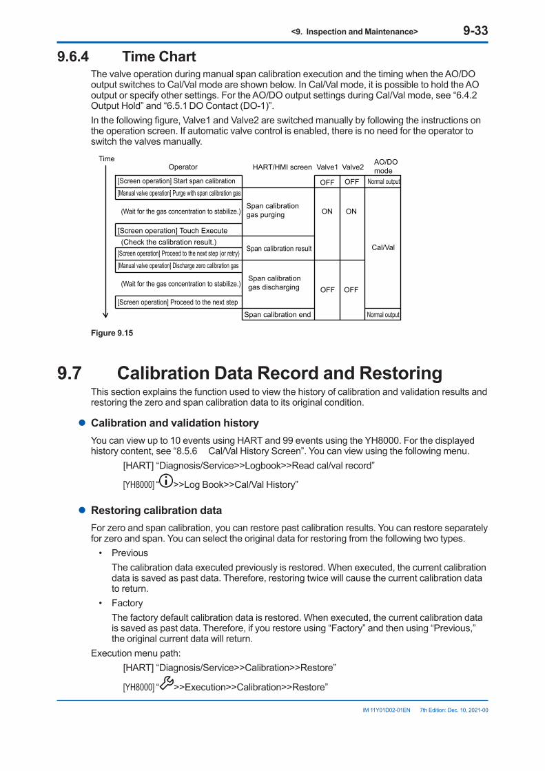
<9. Inspection and Maintenance> 9-33
IM 11Y01D02-01EN 7th Edition: Dec. 10, 2021-00
9.6.4 TimeChartThe valve operation during manual span calibration execution and the timing when the AO/DO output switches to Cal/Val mode are shown below. In Cal/Val mode, it is possible to hold the AO output or specify other settings. For the AO/DO output settings during Cal/Val mode, see “6.4.2 Output Hold” and “6.5.1 DO Contact (DO-1)”.In the following figure, Valve1 and Valve2 are switched manually by following the instructions on the operation screen. If automatic valve control is enabled, there is no need for the operator to switch the valves manually.
Operator HART/HMI screen Valve1 Valve2AO/DOmode
[Screen operation] Start span calibration OFF OFF Normal output[Manual valve operation] Purge with span calibration gas
Span calibration gas purging ON ON
Cal/Val
(Wait for the gas concentration to stabilize.)
(Check the calibration result.)[Screen operation] Proceed to the next step (or retry)
[Manual valve operation] Discharge zero calibration gas
Span calibration gas discharging OFF OFF
(Wait for the gas concentration to stabilize.)
[Screen operation] Proceed to the next step
[Screen operation] Touch Execute
Span calibration end
Span calibration result
Normal output
Time
Figure 9.15
9.7 Calibration Data Record and RestoringThis section explains the function used to view the history of calibration and validation results and restoring the zero and span calibration data to its original condition.
l CalibrationandvalidationhistoryYou can view up to 10 events using HART and 99 events using the YH8000. For the displayed history content, see “8.5.6 Cal/Val History Screen”. You can view using the following menu. [HART] “Diagnosis/Service>>Logbook>>Read cal/val record”
[YH8000] “ >>Log Book>>Cal/Val History”
l Restoring calibration dataFor zero and span calibration, you can restore past calibration results. You can restore separately for zero and span. You can select the original data for restoring from the following two types.
• Previous The calibration data executed previously is restored. When executed, the current calibration
data is saved as past data. Therefore, restoring twice will cause the current calibration data to return.
• Factory The factory default calibration data is restored. When executed, the current calibration data
is saved as past data. Therefore, if you restore using “Factory” and then using “Previous,” the original current data will return.
Execution menu path: [HART] “Diagnosis/Service>>Calibration>>Restore”
[YH8000] “ >>Execution>>Calibration>>Restore”
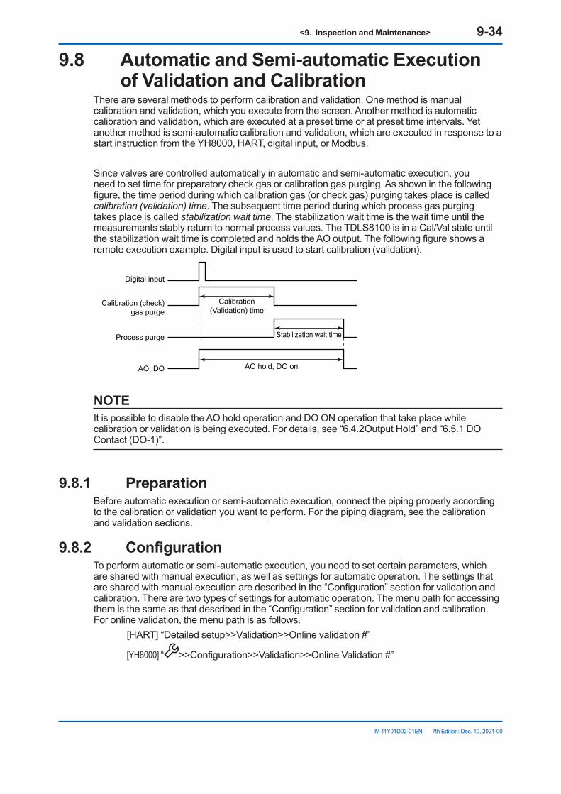
<9. Inspection and Maintenance> 9-34
IM 11Y01D02-01EN 7th Edition: Dec. 10, 2021-00
9.8 AutomaticandSemi-automaticExecutionof Validation and Calibration
There are several methods to perform calibration and validation. One method is manual calibration and validation, which you execute from the screen. Another method is automatic calibration and validation, which are executed at a preset time or at preset time intervals. Yet another method is semi-automatic calibration and validation, which are executed in response to a start instruction from the YH8000, HART, digital input, or Modbus.
Since valves are controlled automatically in automatic and semi-automatic execution, you need to set time for preparatory check gas or calibration gas purging. As shown in the following figure, the time period during which calibration gas (or check gas) purging takes place is called calibration (validation) time. The subsequent time period during which process gas purging takes place is called stabilization wait time. The stabilization wait time is the wait time until the measurements stably return to normal process values. The TDLS8100 is in a Cal/Val state until the stabilization wait time is completed and holds the AO output. The following figure shows a remote execution example. Digital input is used to start calibration (validation).
Digital input
Calibration (check)gas purge
Process purge
AO, DO
Calibration(Validation) time
Stabilization wait time
AO hold, DO on
NOTEIt is possible to disable the AO hold operation and DO ON operation that take place while calibration or validation is being executed. For details, see “6.4.2 Output Hold” and “6.5.1 DO Contact (DO-1)”.
9.8.1 PreparationBefore automatic execution or semi-automatic execution, connect the piping properly according to the calibration or validation you want to perform. For the piping diagram, see the calibration and validation sections.
9.8.2 ConfigurationTo perform automatic or semi-automatic execution, you need to set certain parameters, which are shared with manual execution, as well as settings for automatic operation. The settings that are shared with manual execution are described in the “Configuration” section for validation and calibration. There are two types of settings for automatic operation. The menu path for accessing them is the same as that described in the “Configuration” section for validation and calibration. For online validation, the menu path is as follows. [HART] “Detailed setup>>Validation>>Online validation #”
[YH8000] “ >>Configuration>>Validation>>Online Validation #”
<9. Inspection and Maintenance> 9-35
IM 11Y01D02-01EN 7th Edition: Dec. 10, 2021-00
l CalibrationgasorcheckgasandprocessgaspurgetimeThe purge time must be set regardless of automatic execution or semi-automatic execution. As an example, the parameters for online validation 1 are shown below.Parameter name
(HART)Parameter name
(YH8000) DescriptionOnval1 gas purg time
Validation gas Purge time
Enters the purge time of online validation 1 check gas. This corresponds to the validation time.
Onval1 nml purg time
Normal gas Purge time
Enters the normal purge gas purge time for process measurement. This corresponds to the stabilization wait time.
l AutomaticexecutionsettingsTo perform automatic execution, you need to set the execution method you want to use. This is not necessary for semi-automatic execution.
• Parameters for time initiate As an example, the parameters for online validation 1 are shown below.
Parameter name (HART)
Parameter name (YH8000)
Description
Onval1 time initiate TIme Initiate Enables time initiate of online validation 1Onval1 init date Initial time Enters the initial execution dateOnval1 init time Enters the initial execution timeOnval1 day cycle Cycle (day) Enters the cycle in days for time initiateOnval1 hour cycle Cycle (hour) Enters the cycle in hours for time initiate
For example, if the initial execution time is 12:00:00 on January 1, 2015, the day cycle is 10, and the hour cycle is 0, the execution will take place at 12:00:00 on January 11, 2015, 12:00:00 on January 21, 2015, and so on.
NOTEIf both the day and hour cycles for time initiate are set to zero, automatic execution takes place once at the initial execution time.
• If you want to use digital input, see “6.7 Digital Input Settings”.• If you are using Modbus instructions, you do not need to set the parameters. For the
instruction address, see “11.2 Coil”.
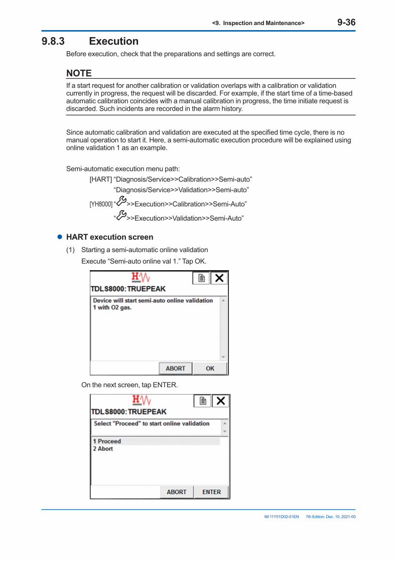
<9. Inspection and Maintenance> 9-36
IM 11Y01D02-01EN 7th Edition: Dec. 10, 2021-00
9.8.3 ExecutionBefore execution, check that the preparations and settings are correct.
NOTEIf a start request for another calibration or validation overlaps with a calibration or validation currently in progress, the request will be discarded. For example, if the start time of a time-based automatic calibration coincides with a manual calibration in progress, the time initiate request is discarded. Such incidents are recorded in the alarm history.
Since automatic calibration and validation are executed at the specified time cycle, there is no manual operation to start it. Here, a semi-automatic execution procedure will be explained using online validation 1 as an example.
Semi-automatic execution menu path: [HART] “Diagnosis/Service>>Calibration>>Semi-auto” “Diagnosis/Service>>Validation>>Semi-auto”
[YH8000] “ >>Execution>>Calibration>>Semi-Auto”
“ >>Execution>>Validation>>Semi-Auto”
l HARTexecutionscreen(1) Starting a semi-automatic online validation Execute “Semi-auto online val 1.” Tap OK.
On the next screen, tap ENTER.
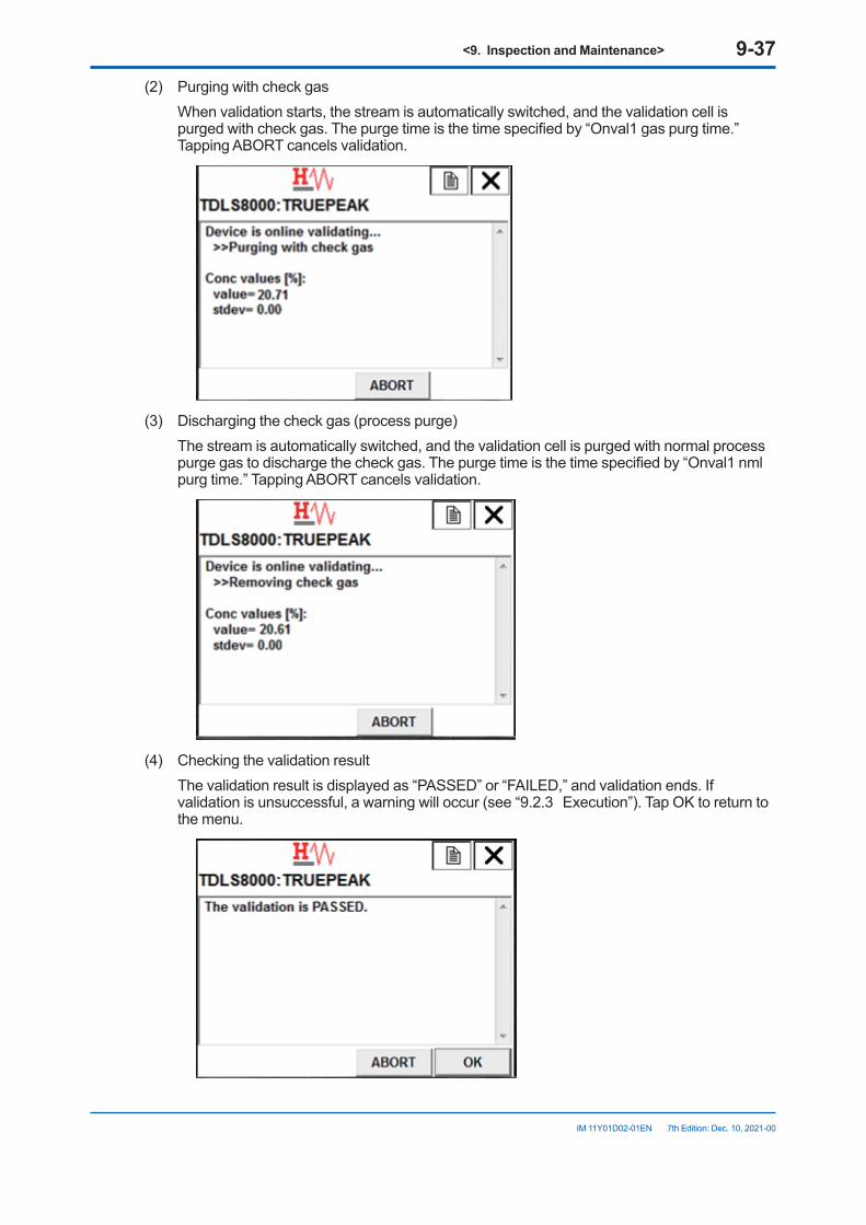
<9. Inspection and Maintenance> 9-37
IM 11Y01D02-01EN 7th Edition: Dec. 10, 2021-00
(2) Purging with check gas When validation starts, the stream is automatically switched, and the validation cell is
purged with check gas. The purge time is the time specified by “Onval1 gas purg time.” Tapping ABORT cancels validation.
(3) Discharging the check gas (process purge) The stream is automatically switched, and the validation cell is purged with normal process
purge gas to discharge the check gas. The purge time is the time specified by “Onval1 nml purg time.” Tapping ABORT cancels validation.
(4) Checking the validation result The validation result is displayed as “PASSED” or “FAILED,” and validation ends. If
validation is unsuccessful, a warning will occur (see “9.2.3 Execution”). Tap OK to return to the menu.
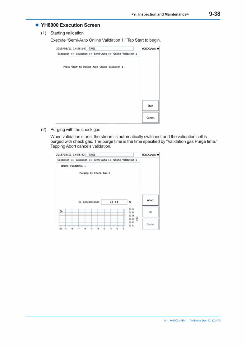
<9. Inspection and Maintenance> 9-38
IM 11Y01D02-01EN 7th Edition: Dec. 10, 2021-00
l YH8000ExecutionScreen(1) Starting validation Execute “Semi-Auto Online Validation 1.” Tap Start to begin.
(2) Purging with the check gas When validation starts, the stream is automatically switched, and the validation cell is
purged with check gas. The purge time is the time specified by “Validation gas Purge time.” Tapping Abort cancels validation.
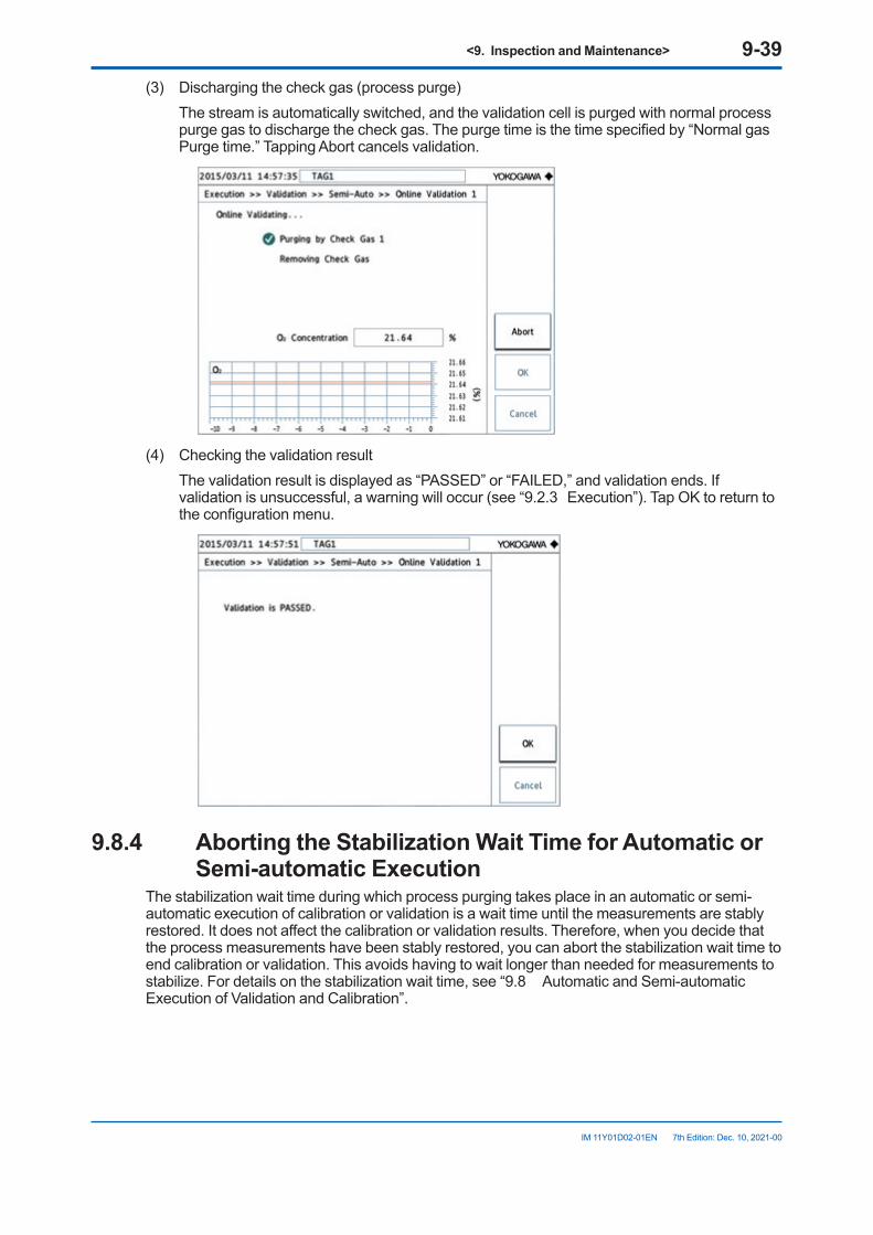
<9. Inspection and Maintenance> 9-39
IM 11Y01D02-01EN 7th Edition: Dec. 10, 2021-00
(3) Discharging the check gas (process purge) The stream is automatically switched, and the validation cell is purged with normal process
purge gas to discharge the check gas. The purge time is the time specified by “Normal gas Purge time.” Tapping Abort cancels validation.
(4) Checking the validation result The validation result is displayed as “PASSED” or “FAILED,” and validation ends. If
validation is unsuccessful, a warning will occur (see “9.2.3 Execution”). Tap OK to return to the configuration menu.
9.8.4 AbortingtheStabilizationWaitTimeforAutomaticorSemi-automaticExecution
The stabilization wait time during which process purging takes place in an automatic or semi-automatic execution of calibration or validation is a wait time until the measurements are stably restored. It does not affect the calibration or validation results. Therefore, when you decide that the process measurements have been stably restored, you can abort the stabilization wait time to end calibration or validation. This avoids having to wait longer than needed for measurements to stabilize. For details on the stabilization wait time, see “9.8 Automatic and Semi-automatic Execution of Validation and Calibration”.
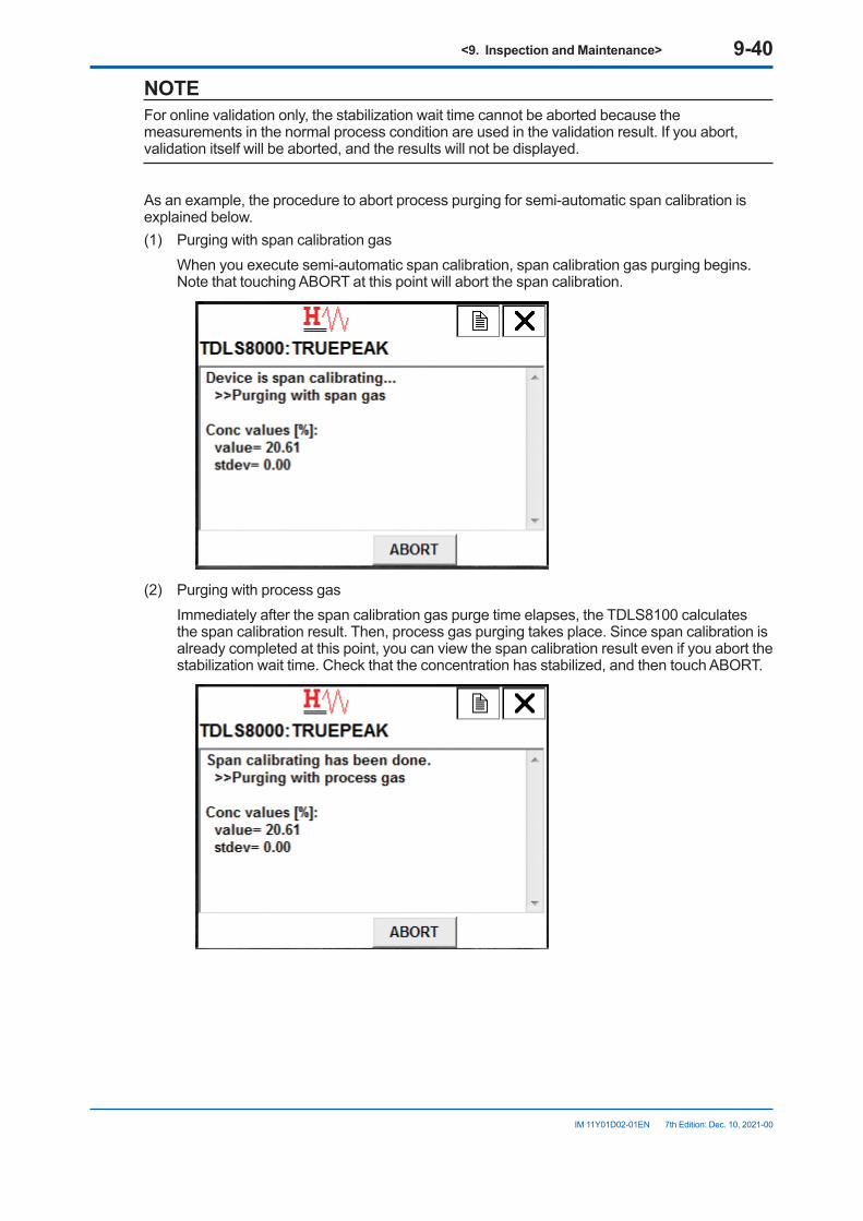
<9. Inspection and Maintenance> 9-40
IM 11Y01D02-01EN 7th Edition: Dec. 10, 2021-00
NOTEFor online validation only, the stabilization wait time cannot be aborted because the measurements in the normal process condition are used in the validation result. If you abort, validation itself will be aborted, and the results will not be displayed.
As an example, the procedure to abort process purging for semi-automatic span calibration is explained below.(1) Purging with span calibration gas When you execute semi-automatic span calibration, span calibration gas purging begins.
Note that touching ABORT at this point will abort the span calibration.
(2) Purging with process gas Immediately after the span calibration gas purge time elapses, the TDLS8100 calculates
the span calibration result. Then, process gas purging takes place. Since span calibration is already completed at this point, you can view the span calibration result even if you abort the stabilization wait time. Check that the concentration has stabilized, and then touch ABORT.
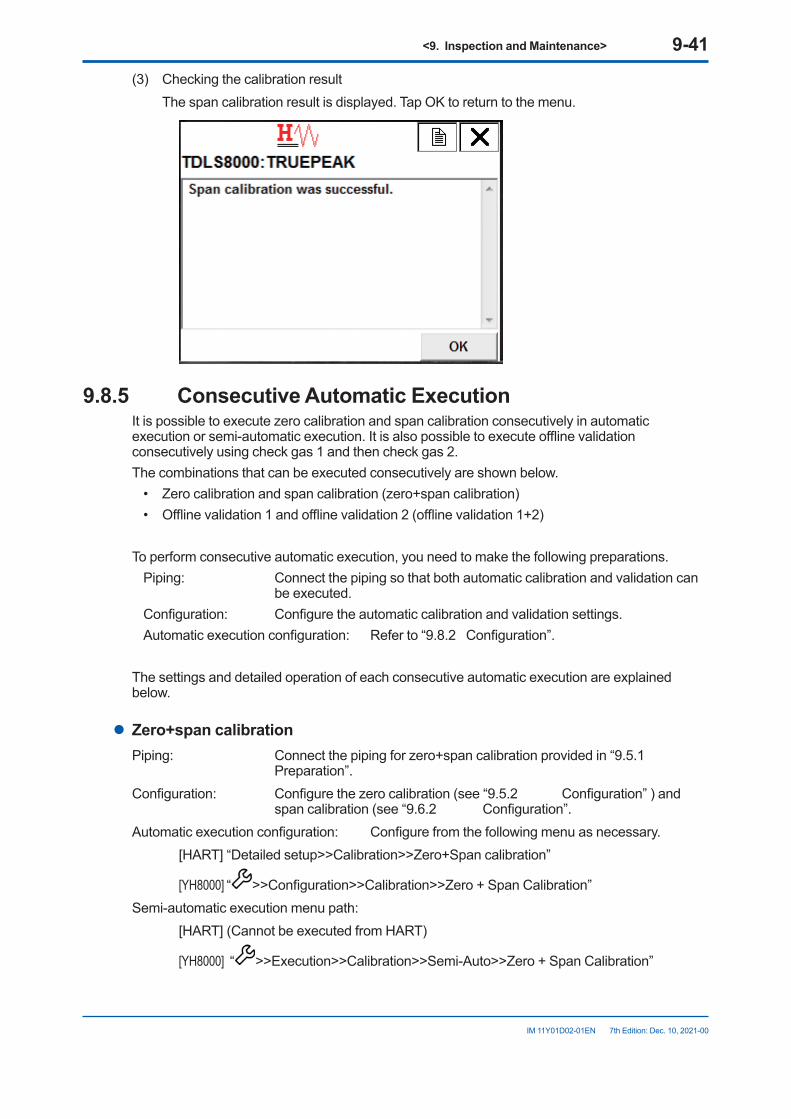
<9. Inspection and Maintenance> 9-41
IM 11Y01D02-01EN 7th Edition: Dec. 10, 2021-00
(3) Checking the calibration result The span calibration result is displayed. Tap OK to return to the menu.
9.8.5 ConsecutiveAutomaticExecutionIt is possible to execute zero calibration and span calibration consecutively in automatic execution or semi-automatic execution. It is also possible to execute offline validation consecutively using check gas 1 and then check gas 2.The combinations that can be executed consecutively are shown below.
• Zero calibration and span calibration (zero+span calibration)• Offline validation 1 and offline validation 2 (offline validation 1+2)
To perform consecutive automatic execution, you need to make the following preparations.Piping: Connect the piping so that both automatic calibration and validation can
be executed.Configuration: Configure the automatic calibration and validation settings.Automatic execution configuration: Refer to “9.8.2 Configuration”.
The settings and detailed operation of each consecutive automatic execution are explained below.
l Zero+span calibrationPiping: Connect the piping for zero+span calibration provided in “9.5.1
Preparation”.Configuration: Configure the zero calibration (see “9.5.2 Configuration” ) and
span calibration (see “9.6.2 Configuration”.Automatic execution configuration: Configure from the following menu as necessary. [HART] “Detailed setup>>Calibration>>Zero+Span calibration”
[YH8000] “ >>Configuration>>Calibration>>Zero + Span Calibration”Semi-automatic execution menu path: [HART] (Cannot be executed from HART)
[YH8000] “ >>Execution>>Calibration>>Semi-Auto>>Zero + Span Calibration”
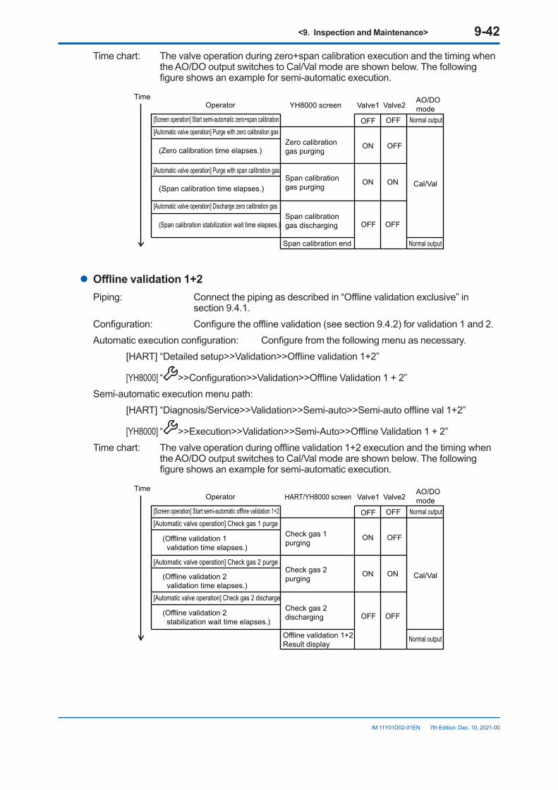
<9. Inspection and Maintenance> 9-42
IM 11Y01D02-01EN 7th Edition: Dec. 10, 2021-00
Time chart: The valve operation during zero+span calibration execution and the timing when the AO/DO output switches to Cal/Val mode are shown below. The following figure shows an example for semi-automatic execution.
Operator YH8000 screen Valve1 Valve2AO/DOmode
[Screen operation] Start semi-automatic zero+span calibration OFF OFF Normal output[Automatic valve operation] Purge with zero calibration gas
Zero calibration gas purging
Span calibration gas purging
ON OFF
ON ON Cal/Val
(Zero calibration time elapses.)
(Span calibration time elapses.)
[Automatic valve operation] Discharge zero calibration gasSpan calibration gas discharging OFF OFF(Span calibration stabilization wait time elapses.)
[Automatic valve operation] Purge with span calibration gas
Span calibration end Normal output
Time
l Offlinevalidation1+2Piping: Connect the piping as described in “Offline validation exclusive” in
section 9.4.1.Configuration: Configure the offline validation (see section 9.4.2) for validation 1 and 2.Automatic execution configuration: Configure from the following menu as necessary. [HART] “Detailed setup>>Validation>>Offline validation 1+2”
[YH8000] “ >>Configuration>>Validation>>Offline Validation 1 + 2”Semi-automatic execution menu path: [HART] “Diagnosis/Service>>Validation>>Semi-auto>>Semi-auto offline val 1+2”
[YH8000] “ >>Execution>>Validation>>Semi-Auto>>Offline Validation 1 + 2”Time chart: The valve operation during offline validation 1+2 execution and the timing when
the AO/DO output switches to Cal/Val mode are shown below. The following figure shows an example for semi-automatic execution.
Operator HART/YH8000 screen Valve1 Valve2AO/DOmode
[Screen operation] Start semi-automatic offline validation 1+2 OFF OFF Normal output[Automatic valve operation] Check gas 1 purge
Check gas 1 purging
Check gas 2purging
ON OFF
ON ON Cal/Val
(Offline validation 1 validation time elapses.)
(Offline validation 2 validation time elapses.)
[Automatic valve operation] Check gas 2 dischargeCheck gas 2 discharging OFF OFF(Offline validation 2
stabilization wait time elapses.)
[Automatic valve operation] Check gas 2 purge
Offline validation 1+2Result display
Normal output
Time
<9. Inspection and Maintenance> 9-43
IM 11Y01D02-01EN 7th Edition: Dec. 10, 2021-00
9.9 Analog Input CalibrationThis section explains analog-digital conversion calibration of the analog input terminal (AI). Since the TDLS8100 is calibrated before shipment, you normally do not need to calibrate.
CAUTIONAnalog input must be calibrated with Passive Al Check the setting on 3.2.3. If Active A is on, power down first and switch to “Passive A”
Execution menu path: [HART] “Diagnosis/Service>>Trim analog channel>>Trim AI-1 (Pres)” “Diagnosis/Service>>Trim analog channel>>Trim AI-2 (Temp)”
[YH8000] “ >>Configuration>>I/O>>Analog Input>>AI-1(Pressure)>>Calibration”
“ >>Configuration>>I/O>>Analog Input>>AI-2(Temperature)>>Calibration”
The calibration procedure is as follows.(1) From HART or YH8000, start AI calibration.(2) Connect a current source to the AI terminal, and apply 4 mA as instructed on the screen.(3) Check that the analog input is stable, and proceed to the next screen.(4) Apply 20 mA as instructed on the screen.(5) Check that the analog input is stable, and proceed to the next screen. Calibration is
complete.
NOTEIf analog input calibration is executed when the analog input is set to process pressure or temperature, the pressure or temperature during calibration is calculated based on the backup function. For example, if the pressure’s Backup mode is set to Back value and Backup set value is set to 101.0 kPa, the pressure at AI-1 during calibration is fixed to 101.0 kPa. For details on the backup function, see “5.3.3 Setting the Process Pressure”.
CAUTIONTo return to process, confirm Active A or Passive A are selected then turn the power on.
<9. Inspection and Maintenance> 9-44
IM 11Y01D02-01EN 7th Edition: Dec. 10, 2021-00
9.10 Analog Output CalibrationThis section explains digital analog conversion calibration of the analog output terminal (AO). Since the TDLS8100 is calibrated before shipment, you normally do not need to calibrate.
Execution menu path: [HART] “Diagnosis/Service>>Trim analog channel>>Trim AO-1 (PV)” “Diagnosis/Service>>Trim analog channel>>Trim AO-2 (SV)”
[YH8000] “ >>Configuration>>I/O>>Analog Output>>AO-1>>Calibration”
“ >>Configuration>>I/O>>Analog Output>>AO-2>>Calibration”The calibration procedure is as follows.(1) Connect ammeter to the AO terminal.(2) From HART or YH8000, start AO calibration.(3) A current corresponding to 4 mA will flow. When the measuring instrument reading becomes
stable, enter the measured value.(4) A current corresponding to 20 mA will flow. When the measuring instrument reading
becomes stable, enter the measured value.(5) Calibration is complete.
NOTEWhen analog output calibration is complete, the 20 mA fixed output is released, and normal analog output returns. At this point, the AO loop check simulation output is also released. For example, if analog output calibration is executed while AO-1 loop check is in progress, when the calibration is complete, AO-1 returns to normal output.
9.11 LoopCheckSee “5.4 Loop Check (Simulation output)”.
<9. Inspection and Maintenance> 9-45
IM 11Y01D02-01EN 7th Edition: Dec. 10, 2021-00
9.12 Alarm HistoryYou can view the history of alarms (faults and warnings) that occurred in the past. In addition, if an non-alarm event shown in Table 9.1 occurs, it is recorded as a message.
Menu path: [HART] “Diagnosis/Service>>Logbook>>Read alarm/message record”
[YH8000] “ >>Log Book>>Alarm History”
The information displayed in the alarm history is as follows.• Times when faults and warnings occur and clear• Times when messages occur• Sub numbers of alarm messages (only for certain alarms and messages) These numbers are used by Yokogawa service representatives for troubleshooting
purposes. The numbers are displayed in HART and the YH8000.
You can view up to 30 events using HART and 99 events using the YH8000. For an explanation of the YH8000 alarm history screen, see “8.5.5 Alarm History Screen”.
For details on faults and warnings, see “10. Troubleshooting”.Items recorded as messages are shown in the following table.
Table 9.1No. Message Description66 Power On The power was turned on.67 Restarted by WDT Restarted due to a watchdog timeout.68 Restarted by Power Failure Restarted by a power supply monitoring IC.69 Laser Module Replaced Laser module was replaced.70 Bootloader Updated Boot loader was updated.71 Firmware Updated Firmware was updated.72 FPGA Updated CIO-FPGA was updated.73 Config File Updated The configuration file was updated.74 Backup Config Loaded Backup configuration was loaded.75 Default Config Loaded Default configuration was loaded.76 Default Firmware Loaded Default firmware was loaded.77 Default HART config loaded Default ROM values for HART parameters were loaded.78 Reset by External Operation Restarted by an external instruction.79 RTC was Adjusted The real-time clock was synchronized.80 Auto Zero Cal was Skipped Automatic zero calibration start instruction was skipped.81 Auto Span Cal was Skipped Automatic span calibration start instruction was skipped.83 Auto Validation was Skipped Automatic validation start instruction was skipped.84 HMI Connected YH8000 was connected.85 HMI Disconnected YH8000 was disconnected.86 HMI Disconnected(recv) YH8000 was disconnected while receiving.87 HMI Disconnected(send) YH8000 was disconnected while sending.88 History File was Corrupted The history file was corrupted.
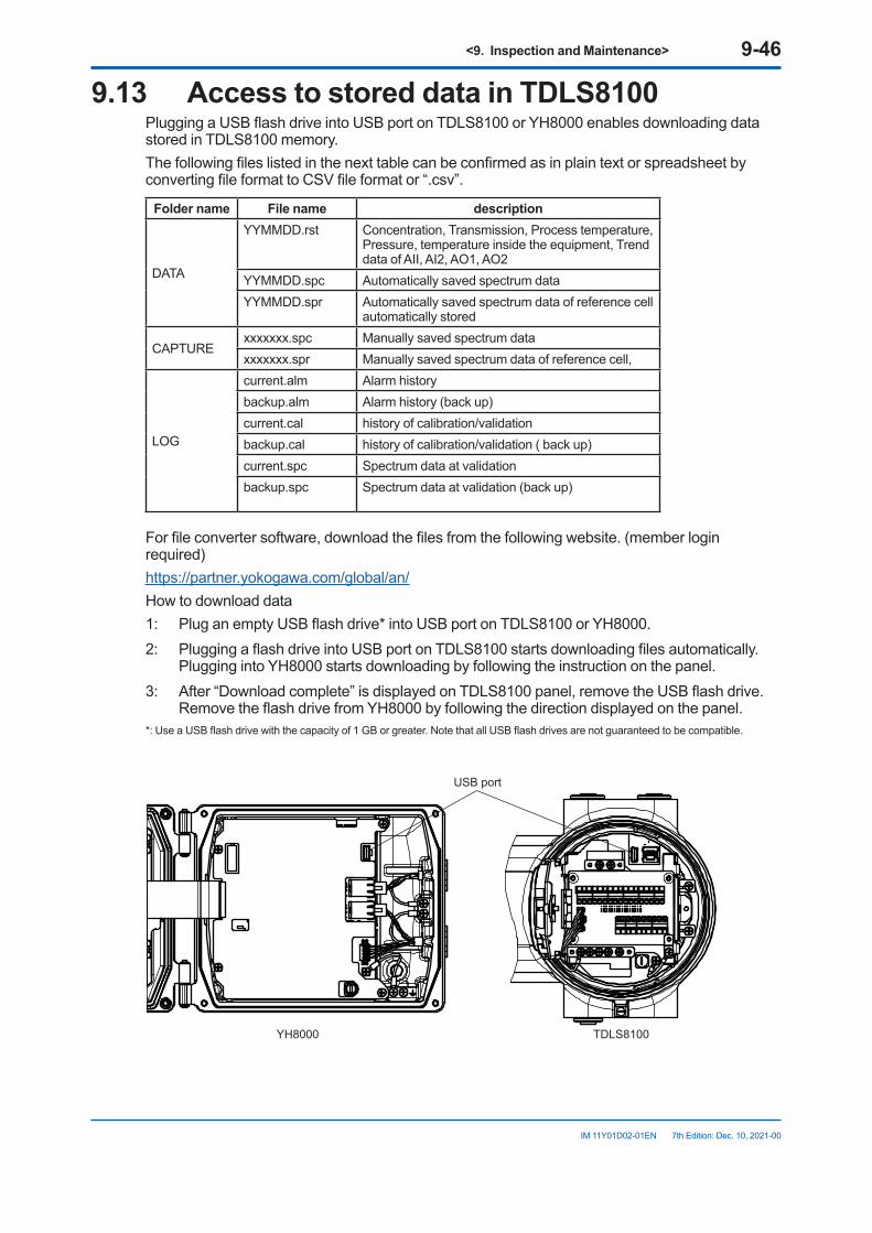
<9. Inspection and Maintenance> 9-46
IM 11Y01D02-01EN 7th Edition: Dec. 10, 2021-00
9.13 Access to stored data in TDLS8100Plugging a USB flash drive into USB port on TDLS8100 or YH8000 enables downloading data stored in TDLS8100 memory.The following files listed in the next table can be confirmed as in plain text or spreadsheet by converting file format to CSV file format or “.csv”.
Folder name File name description
DATA
YYMMDD.rst Concentration, Transmission, Process temperature, Pressure, temperature inside the equipment, Trend data of AII, AI2, AO1, AO2
YYMMDD.spc Automatically saved spectrum data YYMMDD.spr Automatically saved spectrum data of reference cell
automatically stored
CAPTURExxxxxxx.spc Manually saved spectrum data xxxxxxx.spr Manually saved spectrum data of reference cell,
LOG
current.alm Alarm historybackup.alm Alarm history (back up)current.cal history of calibration/validationbackup.cal history of calibration/validation ( back up)current.spc Spectrum data at validationbackup.spc Spectrum data at validation (back up)
For file converter software, download the files from the following website. (member login required)https://partner.yokogawa.com/global/an/How to download data1: Plug an empty USB flash drive* into USB port on TDLS8100 or YH8000.2: Plugging a flash drive into USB port on TDLS8100 starts downloading files automatically.
Plugging into YH8000 starts downloading by following the instruction on the panel.3: After “Download complete” is displayed on TDLS8100 panel, remove the USB flash drive.
Remove the flash drive from YH8000 by following the direction displayed on the panel.*: Use a USB flash drive with the capacity of 1 GB or greater. Note that all USB flash drives are not guaranteed to be compatible.
USB port
YH8000 TDLS8100
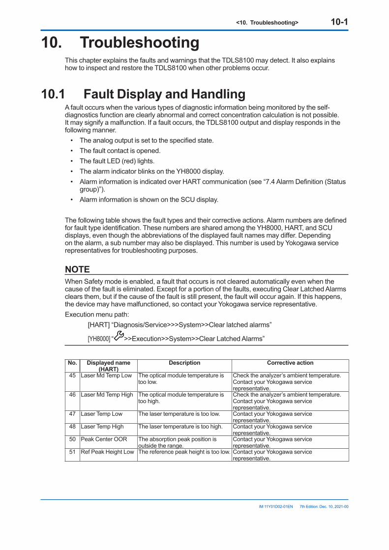
<10. Troubleshooting> 10-1
IM 11Y01D02-01EN 7th Edition: Dec. 10, 2021-00
10. TroubleshootingThis chapter explains the faults and warnings that the TDLS8100 may detect. It also explains how to inspect and restore the TDLS8100 when other problems occur.
10.1 Fault Display and HandlingA fault occurs when the various types of diagnostic information being monitored by the self-diagnostics function are clearly abnormal and correct concentration calculation is not possible. It may signify a malfunction. If a fault occurs, the TDLS8100 output and display responds in the following manner.
• The analog output is set to the specified state.• The fault contact is opened.• The fault LED (red) lights.• The alarm indicator blinks on the YH8000 display.• Alarm information is indicated over HART communication (see “7.4 Alarm Definition (Status
group)”).• Alarm information is shown on the SCU display.
The following table shows the fault types and their corrective actions. Alarm numbers are defined for fault type identification. These numbers are shared among the YH8000, HART, and SCU displays, even though the abbreviations of the displayed fault names may differ. Depending on the alarm, a sub number may also be displayed. This number is used by Yokogawa service representatives for troubleshooting purposes.
NOTEWhen Safety mode is enabled, a fault that occurs is not cleared automatically even when the cause of the fault is eliminated. Except for a portion of the faults, executing Clear Latched Alarms clears them, but if the cause of the fault is still present, the fault will occur again. If this happens, the device may have malfunctioned, so contact your Yokogawa service representative.Execution menu path: [HART] “Diagnosis/Service>>>System>>Clear latched alarms”
[YH8000] “ >>Execution>>System>>Clear Latched Alarms”
No. Displayed name (HART)
Description Corrective action
45 Laser Md Temp Low The optical module temperature is too low.
Check the analyzer’s ambient temperature.Contact your Yokogawa service representative.
46 Laser Md Temp High The optical module temperature is too high.
Check the analyzer’s ambient temperature.Contact your Yokogawa service representative.
47 Laser Temp Low The laser temperature is too low. Contact your Yokogawa service representative.
48 Laser Temp High The laser temperature is too high. Contact your Yokogawa service representative.
50 Peak Center OOR The absorption peak position is outside the range.
Contact your Yokogawa service representative.
51 Ref Peak Height Low The reference peak height is too low. Contact your Yokogawa service representative.
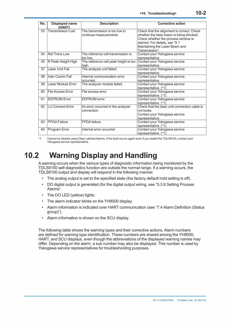
<10. Troubleshooting> 10-2
IM 11Y01D02-01EN 7th Edition: Dec. 10, 2021-00
No. Displayed name (HART)
Description Corrective action
53 Transmission Lost The transmission is too low to continue measurements.
Check that the alignment is correct. Check whether the laser beam is being blocked. Check whether the process window is stained. For details, see “9.1 Maintaining the Laser Beam and Transmission”.
54 Ref Trans Low The reference cell transmission is too low.
Contact your Yokogawa service representative.
55 R Peak Height High The reference cell peak height is too high.
Contact your Yokogawa service representative.
57 Laser Unit Fail The analyzer unit failed. Contact your Yokogawa service representative.
58 Inter Comm Fail Internal communication error occurred.
Contact your Yokogawa service representative.
59 Laser Module Error The analyzer module failed. Contact your Yokogawa service representative. (*1)
60 File Access Error File access error. Contact your Yokogawa service representative. (*1)
61 EEPROM Error EEPROM error. Contact your Yokogawa service representative. (*1)
62 LU Connect Error An error occurred in the analyzer connection.
Check that the laser unit connection cable is not loose.Contact your Yokogawa service representative.
63 FPGA Failure FPGA failure. Contact your Yokogawa service representative. (*1)
64 Program Error Internal error occurred. Contact your Yokogawa service representative. (*1)
*1: Cannot be cleared using Clear Latched Alarms. If the fault occurs again even if you restart the TDLS8100, contact your Yokogawa service representative.
10.2 Warning Display and HandlingA warning occurs when the various types of diagnostic information being monitored by the TDLS8100 self-diagnostics function are outside the normal range. If a warning occurs, the TDLS8100 output and display will respond in the following manner.
• The analog output is set to the specified state (the factory default hold setting is off).• DO digital output is generated (for the digital output wiring, see “5.3.6 Setting Process
Alarms”.• The DO LED (yellow) lights.• The alarm indicator blinks on the YH8000 display.• Alarm information is indicated over HART communication (see “7.4 Alarm Definition (Status
group)”).• Alarm information is shown on the SCU display.
The following table shows the warning types and their corrective actions. Alarm numbers are defined for warning type identification. These numbers are shared among the YH8000, HART, and SCU displays, even though the abbreviations of the displayed warning names may differ. Depending on the alarm, a sub number may also be displayed. This number is used by Yokogawa service representatives for troubleshooting purposes.
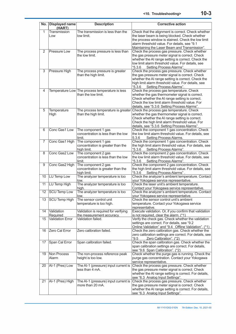
<10. Troubleshooting> 10-3
IM 11Y01D02-01EN 7th Edition: Dec. 10, 2021-00
No. Displayed name (HART)
Description Corrective action
1 Transmission Low
The transmission is less than the low limit.
Check that the alignment is correct. Check whether the laser beam is being blocked. Check whether the process window is stained. Check the low limit alarm threshold value. For details, see “9.1 Maintaining the Laser Beam and Transmission”.
2 Pressure Low The process pressure is less than the low limit.
Check the process gas pressure. Check whether the gas pressure meter signal is correct. Check whether the AI range setting is correct. Check the low limit alarm threshold value. For details, see “5.3.6 Setting Process Alarms”.
3 Pressure High The process pressure is greater than the high limit.
Check the process gas pressure. Check whether the gas pressure meter signal is correct. Check whether the AI range setting is correct. Check the high limit alarm threshold value. For details, see “5.3.6 Setting Process Alarms”.
4 Temperature Low The process temperature is less than the low limit.
Check the process gas temperature. Check whether the gas thermometer signal is correct. Check whether the AI range setting is correct. Check the low limit alarm threshold value. For details, see “5.3.6 Setting Process Alarms”.
5 Temperature High
The process temperature is greater than the high limit.
Check the process gas temperature. Check whether the gas thermometer signal is correct. Check whether the AI range setting is correct. Check the high limit alarm threshold value. For details, see “5.3.6 Setting Process Alarms”.
6 Conc Gas1 Low The component 1 gas concentration is less than the low limit.
Check the component 1 gas concentration. Check the low limit alarm threshold value. For details, see 5.3.6 Setting Process Alarms.
7 Conc Gas1 High The component 1 gas concentration is greater than the high limit.
Check the component 1 gas concentration. Check the high limit alarm threshold value. For details, see “5.3.6 Setting Process Alarms”.
8 Conc Gas2 Low The component 2 gas concentration is less than the low limit.
Check the component 2 gas concentration. Check the low limit alarm threshold value. For details, see “5.3.6 Setting Process Alarms”.
9 Conc Gas2 High The component 2 gas concentration is greater than the high limit.
Check the component 2 gas concentration. Check the high limit alarm threshold value. For details, see“5.3.6 Setting Process Alarms” .
10 LU Temp Low The analyzer temperature is too low.
Check the analyzer’s ambient temperature. Contact your Yokogawa service representative.
11 LU Temp High The analyzer temperature is too high.
Check the laser unit’s ambient temperature. Contact your Yokogawa service representative.
12 SCU Temp Low The analyzer temperature is too low.
Check the analyzer’s ambient temperature. Contact your Yokogawa service representative.
13 SCU Temp High The sensor control unit temperature is too high.
Check the sensor control unit’s ambient temperature. Contact your Yokogawa service representative.
14 Validation Required
Validation is required for verifying the measurement accuracy.
Execute validation. Or, if you confirm that validation is not required, clear the alarm. (*1)
15 Validation Error Validation failed. Verify the check gas. Check whether the validation settings are correct. For details, see “9.2 Online Validation” and “9.4 Offline Validation”. (*1)
16 Zero Cal Error Zero calibration failed. Check the zero calibration gas. Check whether the zero calibration settings are correct. For details, see “9.5 Zero Calibration”. (*2)
17 Span Cal Error Span calibration failed. Check the span calibration gas. Check whether the span calibration settings are correct. For details, see “9.6 Span Calibration”. (*2)
19 Non Process Alarm
The non-process reference peak height is too low.
Check whether the purge gas is running. Check the purge gas concentration. Contact your Yokogawa service representative.
20 AI-1 (Pres) Low The AI-1 (pressure) input current is less than 4 mA.
Check the process gas pressure. Check whether the gas pressure meter signal is correct. Check whether the AI range setting is correct. For details, see “6.3 Analog Input Settings”.
21 AI-1 (Pres) High The AI-1 (pressure) input current is more than 20 mA.
Check the process gas pressure. Check whether the gas pressure meter signal is correct. Check whether the AI range setting is correct. For details, see “6.3 Analog Input Settings”.
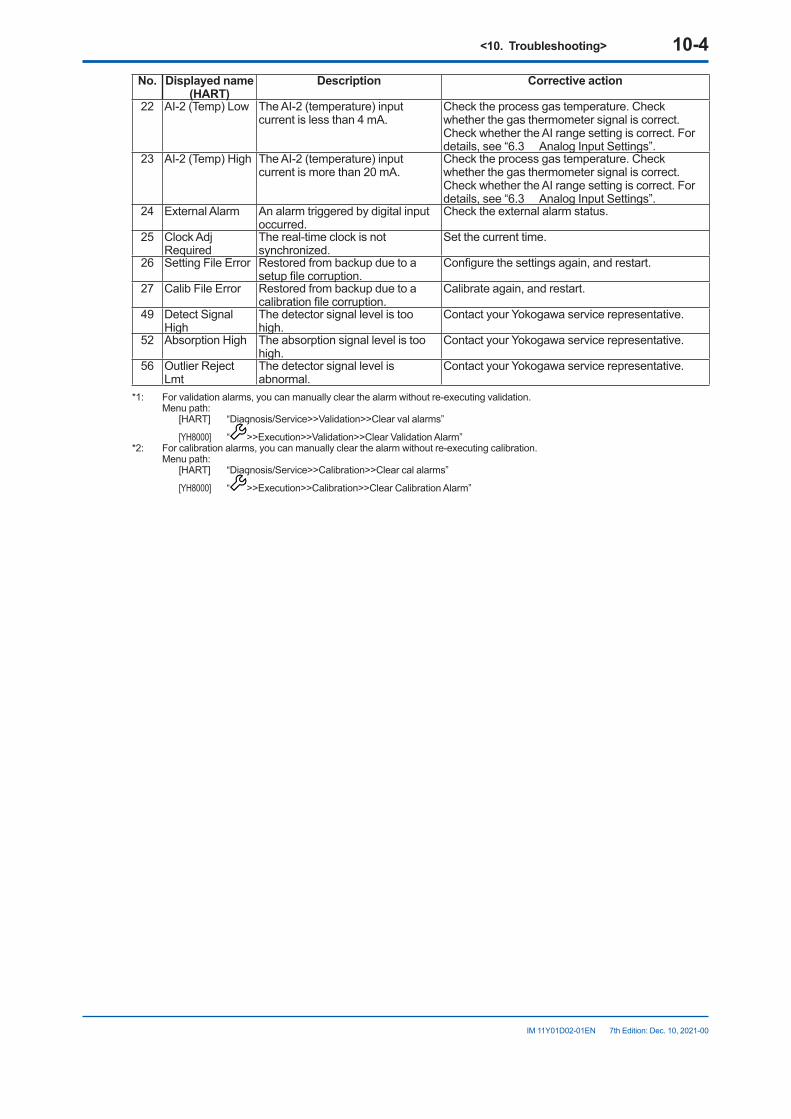
<10. Troubleshooting> 10-4
IM 11Y01D02-01EN 7th Edition: Dec. 10, 2021-00
No. Displayed name (HART)
Description Corrective action
22 AI-2 (Temp) Low The AI-2 (temperature) input current is less than 4 mA.
Check the process gas temperature. Check whether the gas thermometer signal is correct. Check whether the AI range setting is correct. For details, see “6.3 Analog Input Settings”.
23 AI-2 (Temp) High The AI-2 (temperature) input current is more than 20 mA.
Check the process gas temperature. Check whether the gas thermometer signal is correct. Check whether the AI range setting is correct. For details, see “6.3 Analog Input Settings”.
24 External Alarm An alarm triggered by digital input occurred.
Check the external alarm status.
25 Clock Adj Required
The real-time clock is not synchronized.
Set the current time.
26 Setting File Error Restored from backup due to a setup file corruption.
Configure the settings again, and restart.
27 Calib File Error Restored from backup due to a calibration file corruption.
Calibrate again, and restart.
49 Detect Signal High
The detector signal level is too high.
Contact your Yokogawa service representative.
52 Absorption High The absorption signal level is too high.
Contact your Yokogawa service representative.
56 Outlier Reject Lmt
The detector signal level is abnormal.
Contact your Yokogawa service representative.
*1: For validation alarms, you can manually clear the alarm without re-executing validation. Menu path: [HART] “Diagnosis/Service>>Validation>>Clear val alarms”
[YH8000] “ >>Execution>>Validation>>Clear Validation Alarm”*2: For calibration alarms, you can manually clear the alarm without re-executing calibration. Menu path: [HART] “Diagnosis/Service>>Calibration>>Clear cal alarms”
[YH8000] “ >>Execution>>Calibration>>Clear Calibration Alarm”
<10. Troubleshooting> 10-5
IM 11Y01D02-01EN 7th Edition: Dec. 10, 2021-00
10.3 Handling Degraded Laser TransmissionFor the TDLS8100 to operate normally, the optimal level of laser beam needs to reach the photo detector unit.The following phenomena can cause the laser beam level to degrade. These factors may occur separately or together.● Optical axis error: Degradation of received light level due to optical axis misalignment● Clogging: The opening where the laser beam travels through is blocked or is unclean.
• Dust has accumulated inside probe, blocking the laser beam.• Stain or foreign substances adhering to the process window are attenuating the laser beam
level.● Particles: Dust in the process gas is attenuating the laser beam level.
• Smoke concentration, opacity, or particle concentration is extremely high, and not enough laser beam is reaching the photo detector unit.
● Laser degradation: The output power of the laser element itself has degraded.• The laser light source has degraded or malfunctioned, and not enough laser beam is being
emitted.
n Improving transmissionThis section provides corrective actions for when the transmission is lost or reduced after installing the TDLS8100.
(1)AdjustingtheopticalaxisIf the laser beam is not shut off but the transmission is low, double check that the optical axis is adjusted correctly. As described in “9.1 Maintaining the Laser Beam and Transmission”, normally optical axis adjustment and transmission calibration are performed after the TDLS8100 is installed. But if the process gas temperature is high, the optical axis may diverge from the initial adjustment due to a deformation in the duct or the like causing the process flange or nozzle to be misaligned.If optical axis readjustment is necessary, do so by referring to “3.3 Optical Axis Adjustment”.If the transmission does not improve even when the optical axis adjustment described in section 3.3 is executed, other factors may be causing the problem.
(2)SolvingDegraded/LostLaserTransmissionIf no improvement is seen even when the measures described in (1) above are taken, the laser itself might be malfunctioning.To verify the laser output power, first detach the analyzer from probe and mount the analyzer on a calibration cell, then read the transmission. Follow the instruction of “9.3 Mounting on a Calibration Cell” on how to mount calibration cell.
<10. Troubleshooting> 10-6
IM 11Y01D02-01EN 7th Edition: Dec. 10, 2021-00
10.4 Process Window ReplacementIf the stain on the surface of a process window does not come off even if you clean it according to section “9.1.2 Process Window Cleaning” or if the surface has corroded due to corrosive gas such as hydrogen fluoride, you need to replace the process window. Replace it according to the procedures in “10.4.2 Process Window Replacement Procedure”. When you replace a process window, be sure to also replace the O-ring.
10.4.1 ReplacementParts(Processwindow)If you need to replace a process window, prepare the relevant parts in Table 10.1.
Table 10.1 Replacement partsNo. Parts no. Parts name Purpose* Quantity1 K9776GA Process window unit For purge block (for -X1)
12 K9777GB Process window unit For purge block (for -C2, -C3, -c4)3 K9772TH Process window unit For process window attached to purge block
*: Codes in parenthesis represent Gas Parameter on Model and Suffix Codes of TDLS8100.
10.4.2 Process Window Replacement Procedure The procedure for replacing the process window is provided below.
NOTEBefore removing the probe from process to clean, check that the process is completely stopped and no process gas will be discharged.
CAUTIONBe careful in handling the process window as it is made of optical glass.
(1) Turn the power off.(2) Stop the purge gas.(3) Remove the purge piping.(4) Remove the analyzer from the process. (If necessary, separate it completely from the process such as by using a process isolation
valve.)(5) Check the stained area of the process window, and remove the relevant process window.(6) Loosen the four M4 hexagon socket head cap screws on the process window holder
installed in the alignment flange, and remove the process window.(7) Install a new process window. Replace the O-ring also. The position of the O-ring is indicated in Figure 10.4. Firmly mount the O-ring in the O-ring
groove.
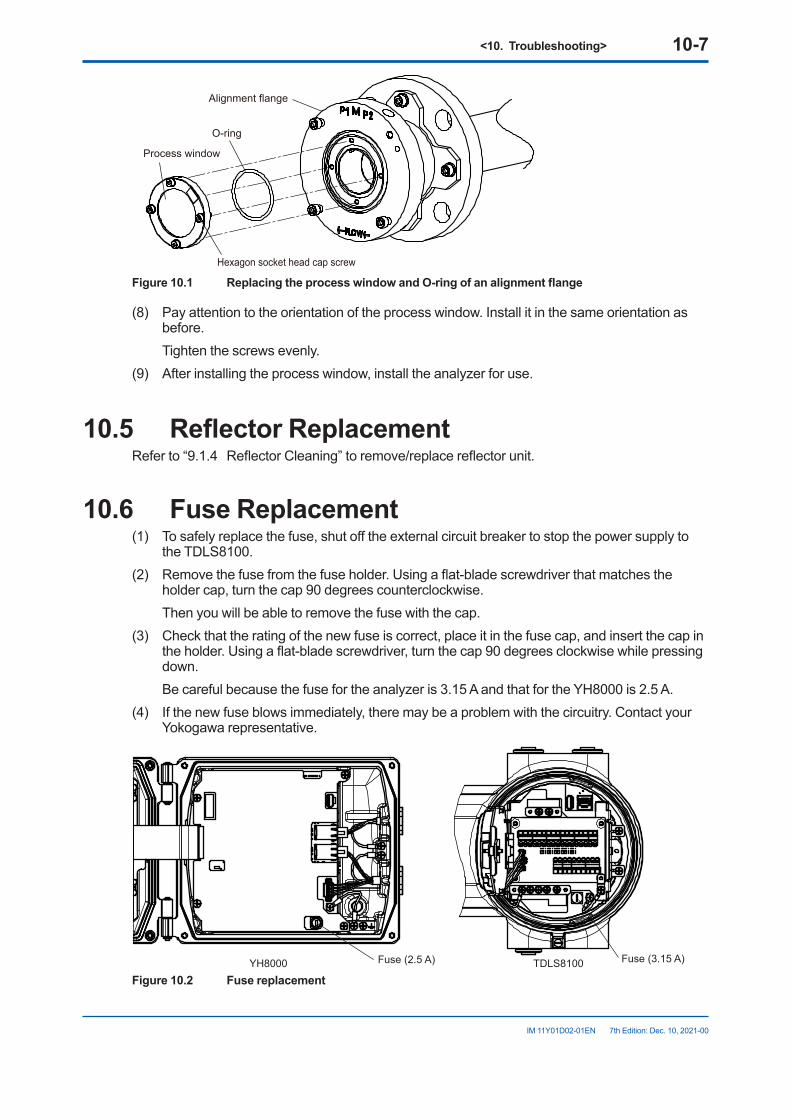
<10. Troubleshooting> 10-7
IM 11Y01D02-01EN 7th Edition: Dec. 10, 2021-00
Alignment flange
Process window
Hexagon socket head cap screw
O-ring
Figure10.1 ReplacingtheprocesswindowandO-ringofanalignmentflange
(8) Pay attention to the orientation of the process window. Install it in the same orientation as before.
Tighten the screws evenly.(9) After installing the process window, install the analyzer for use.
10.5 ReflectorReplacementRefer to “9.1.4 Reflector Cleaning” to remove/replace reflector unit.
10.6 Fuse Replacement(1) To safely replace the fuse, shut off the external circuit breaker to stop the power supply to
the TDLS8100.(2) Remove the fuse from the fuse holder. Using a flat-blade screwdriver that matches the
holder cap, turn the cap 90 degrees counterclockwise. Then you will be able to remove the fuse with the cap.(3) Check that the rating of the new fuse is correct, place it in the fuse cap, and insert the cap in
the holder. Using a flat-blade screwdriver, turn the cap 90 degrees clockwise while pressing down.
Be careful because the fuse for the analyzer is 3.15 A and that for the YH8000 is 2.5 A.(4) If the new fuse blows immediately, there may be a problem with the circuitry. Contact your
Yokogawa representative.
YH8000 TDLS8100 Fuse (3.15 A)Fuse (2.5 A)
Figure 10.2 Fuse replacement
<10. Troubleshooting> 10-8
IM 11Y01D02-01EN 7th Edition: Dec. 10, 2021-00
10.7 Communication Interruption during Manual Calibration and Validation
If the communication between HART or YH8000 and the TDLS8100 is disconnected while performing manual calibration or validation from HART or YH8000, take the following corrective action.
l HARTSee “7.5.3 Aborting Calibration and Validation”.
l YH8000(1) Reconnect.
(2) Tap to enter the TDLS8100 configuration screen. The screen for the calibration or validation in progress automatically recovers. You can continue the calibration or validation.
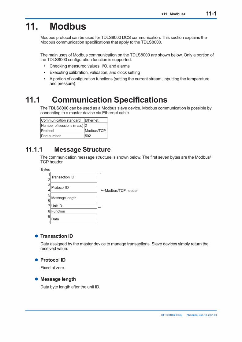
<11. Modbus> 11-1
IM 11Y01D02-01EN 7th Edition: Dec. 10, 2021-00
11. ModbusModbus protocol can be used for TDLS8000 DCS communication. This section explains the Modbus communication specifications that apply to the TDLS8000.
The main uses of Modbus communication on the TDLS8000 are shown below. Only a portion of the TDLS8000 configuration function is supported.
• Checking measured values, I/O, and alarms• Executing calibration, validation, and clock setting• A portion of configuration functions (setting the current stream, inputting the temperature
and pressure)
11.1 CommunicationSpecificationsThe TDLS8000 can be used as a Modbus slave device. Modbus communication is possible by connecting to a master device via Ethernet cable.
Communication standard EthernetNumber of sessions (max.) 2Protocol Modbus/TCPPort number 502
11.1.1 Message StructureThe communication message structure is shown below. The first seven bytes are the Modbus/TCP header.Bytes
1Transaction ID
Modbus/TCP header
23
Protocol ID45
Message length67 Unit ID8 Function9
Data:
l Transaction IDData assigned by the master device to manage transactions. Slave devices simply return the received value.
l Protocol IDFixed at zero.
l MessagelengthData byte length after the unit ID.
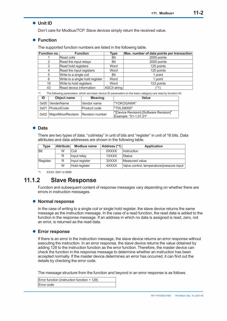
<11. Modbus> 11-2
IM 11Y01D02-01EN 7th Edition: Dec. 10, 2021-00
l Unit IDDon’t care for Modbus/TCP. Slave devices simply return the received value.
l FunctionThe supported function numbers are listed in the following table.Function no. Function Type Max.numberofdatapointspertransaction
1 Read coils Bit 2000 points2 Read the input relays Bit 2000 points3 Read hold registers Word 125 points4 Read the input registers Word 125 points5 Write to a single coil Bit 1 point6 Write to a single hold register Word 1 point16 Write to hold registers Word 123 points43 Read device information ASCII string (*1)
*1: The following parameters, which are basic device ID parameters (in the basic category) are read by function 43.ID Objectname Meaning Value
0x00 VenderName Vendor name "YOKOGAWA"0x01 ProductCode Product code "TDLS8000"
0x02 MajorMinorRevision Revision number "[Device Revision]-[Software Revision]" Example: "01-1.01.01"
l DataThere are two types of data: “coil/relay” in unit of bits and “register” in unit of 16 bits. Data attributes and data addresses are shown in the following table.
Type Attribute Modbus name Address(*1) ApplicationBit W Coil 0XXXX Instruction
R Input relay 1XXXX StatusRegister R Input register 3XXXX Measured value
W Hold register 4XXXX Valve control, temperature/pressure input
*1: XXXX: 0001 to 9999
11.1.2 Slave ResponseFunction and subsequent content of response messages vary depending on whether there are errors in instruction messages.
l Normal responseIn the case of writing to a single coil or single hold register, the slave device returns the same message as the instruction message. In the case of a read function, the read data is added to the function in the response message. If an address in which no data is assigned is read, zero, not an error, is returned as the read data.
l Error responseIf there is an error in the instruction message, the slave device returns an error response without executing the instruction. In an error response, the slave device returns the value obtained by adding 128 to the instruction function as the error function. Therefore, the master device can check the function in the response message to determine whether an instruction has been accepted normally. If the master device determines an error has occurred, it can find out the details by checking the error code.
The message structure from the function and beyond in an error response is as follows.
Error function (instruction function + 128)Error code
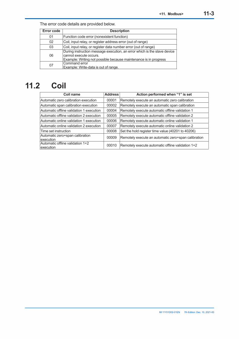
<11. Modbus> 11-3
IM 11Y01D02-01EN 7th Edition: Dec. 10, 2021-00
The error code details are provided below.Error code Description
01 Function code error (nonexistent function)02 Coil, input relay, or register address error (out of range)03 Coil, input relay, or register data number error (out of range)
06During instruction message execution, an error which is the slave device cannot execute occurs.Example: Writing not possible because maintenance is in progress
07 Command errorExample: Write-data is out of range.
11.2 CoilCoil name Address Actionperformedwhen“1”isset
Automatic zero calibration execution 00001 Remotely execute an automatic zero calibrationAutomatic span calibration execution 00002 Remotely execute an automatic span calibrationAutomatic offline validation 1 execution 00004 Remotely execute automatic offline validation 1Automatic offline validation 2 execution 00005 Remotely execute automatic offline validation 2Automatic online validation 1 execution 00006 Remotely execute automatic online validation 1Automatic online validation 2 execution 00007 Remotely execute automatic online validation 2Time set instruction 00008 Set the hold register time value (40201 to 40206)Automatic zero+span calibration execution 00009 Remotely execute an automatic zero+span calibrationAutomatic offline validation 1+2 execution 00010 Remotely execute automatic offline validation 1+2
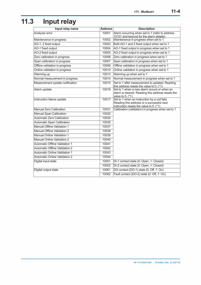
<11. Modbus> 11-4
IM 11Y01D02-01EN 7th Edition: Dec. 10, 2021-00
11.3 Input relayInput relay name Address Description
Analyzer error 10001 Alarm occurring when set to 1 (refer to address 10101 and beyond for the alarm details)
Maintenance in progress 10002 Maintenance in progress when set to 1AO-1, 2 fixed output 10003 Both AO-1 and 2 fixed output when set to 1AO-1 fixed output 10004 AO-1 fixed output in progress when set to 1AO-2 fixed output 10005 AO-2 fixed output in progress when set to 1Zero calibration in progress 10006 Zero calibration in progress when set to 1Span calibration in progress 10007 Span calibration in progress when set to 1Offline validation in progress 10009 Offline validation in progress when set to 1Online validation in progress 10010 Online validation in progress when set to 1Warming up 10013 Warming up when set to 1Normal measurement in progress 10014 Normal measurement in progress when set to 1Measurement update notification 10015 Set to 1 after measurement is updated. Reading
this address resets the value to 0. (*1)Alarm update 10016 Set to 1 when a new alarm occurs or when an
alarm is cleared. Reading this address resets the value to 0. (*1)
Instruction failure update 10017 Set to 1 when an instruction by a coil fails.Reading this address or a successful next instruction resets the value to 0. (*1)
Manual Zero Calibration 10031 Calibration (validation) in progress when set to 1Manual Span Calibration 10032Automatic Zero Calibration 10034Automatic Span Calibration 10035Manual Offline Validation 1 10037Manual Offline Validation 2 10038Manual Online Validation 1 10039Manual Online Validation 2 10040Automatic Offline Validation 1 10041Automatic Offline Validation 2 10042Automatic Online Validation 1 10043Automatic Online Validation 2 10044Digital input state 10051 DI-1 contact state (0: Open, 1: Closed)
10052 DI-2 contact state (0: Open, 1: Closed)Digital output state 10061 DO contact (DO-1) state (0: Off, 1: On)
10062 Fault contact (DO-2) state (0: Off, 1: On)
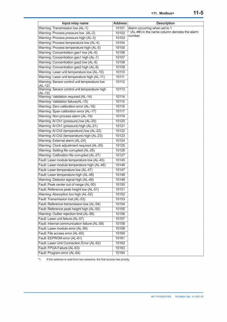
<11. Modbus> 11-5
IM 11Y01D02-01EN 7th Edition: Dec. 10, 2021-00
Input relay name Address Description Warning: Transmission low (AL-1) 10101 Alarm occurring when set to 1
* (AL-##) in the name column denotes the alarm number.
Warning: Process pressure low (AL-2) 10102Warning: Process pressure high (AL-3) 10103Warning: Process temperature low (AL-4) 10104Warning: Process temperature high (AL-5) 10105Warning: Concentration gas1 low (AL-6) 10106Warning: Concentration gas1 high (AL-7) 10107Warning: Concentration gas2 low (AL-8) 10108Warning: Concentration gas2 high (AL-9) 10109Warning: Laser unit temperature low (AL-10) 10110Warning: Laser unit temperature high (AL-11) 10111Warning: Sensor control unit temperature low (AL-12)
10112
Warning: Sensor control unit temperature high (AL-13)
10113
Warning: Validation required (AL-14) 10114Warning: Validation failure(AL-15) 10115Warning: Zero calibration error (AL-16) 10116Warning: Span calibration error (AL-17) 10117Warning: Non process alarm (AL-19) 10119Warning: AI Ch1 (pressure) low (AL-20) 10120Warning: AI Ch1 (pressure) high (AL-21) 10121Warning: AI Ch2 (temperature) low (AL-22) 10122Warning: AI Ch2 (temperature) high (AL-23) 10123Warning: External alarm (AL-24) 10124Warning: Clock adjustment required (AL-25) 10125Warning: Setting file corrupted (AL-26) 10126Warning: Calibration file corrupted (AL-27) 10127Fault: Laser module temperature low (AL-45) 10145Fault: Laser module temperature high (AL-46) 10146Fault: Laser temperature low (AL-47) 10147Fault: Laser temperature high (AL-48) 10148Warning: Detector signal high (AL-49) 10149Fault: Peak center out of range (AL-50) 10150Fault: Reference peak height low (AL-51) 10151Warning: Absorption too high (AL-52) 10152Fault: Transmission lost (AL-53) 10153Fault: Reference transmission low (AL-54) 10154Fault: Reference peak height high (AL-55) 10155Warning: Outlier rejection limit (AL-56) 10156Fault: Laser unit failure (AL-57) 10157Fault: Internal communication failure (AL-58) 10158Fault: Laser module error (AL-59) 10159Fault: File access error (AL-60) 10160Fault: EEPROM error (AL-61) 10161Fault: Laser Unit Connection Error (AL-62) 10162Fault: FPGA Failure (AL-63) 10163Fault: Program error (AL-64) 10164
*1: If this address is read from two sessions, the first access has priority.
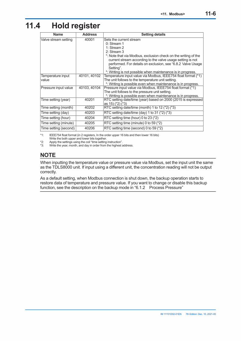
<11. Modbus> 11-6
IM 11Y01D02-01EN 7th Edition: Dec. 10, 2021-00
11.4 Hold registerName Address Setting details
Valve stream setting 40001 Sets the current stream0: Stream 11: Stream 22: Stream 3*: Note that via Modbus, exclusion check on the writing of the
current stream according to the valve usage setting is not performed. For details on exclusion, see “6.8.2 Valve Usage Setting”.
*: Writing is not possible when maintenance is in progress.Temperature input value
40101, 40102 Temperature input value via Modbus, IEEE754 float format (*1)The unit follows to the temperature unit setting.*: Writing is possible even when maintenance is in progress.
Pressure input value 40103, 40104 Pressure input value via Modbus, IEEE754 float format (*1)The unit follows to the pressure unit setting.*: Writing is possible even when maintenance is in progress.
Time setting (year) 40201 RTC setting date/time (year) based on 2000 (2015 is expressed as 15) (*2) (*3)
Time setting (month) 40202 RTC setting date/time (month) 1 to 12 (*2) (*3)Time setting (day) 40203 RTC setting date/time (day) 1 to 31 (*2) (*3)Time setting (hour) 40204 RTC setting time (hour) 0 to 23 (*2)Time setting (minute) 40205 RTC setting time (minute) 0 to 59 (*2)Time setting (second) 40206 RTC setting time (second) 0 to 59 (*2)
*1: IEEE754 float format (in 2 registers, In the order upper 16 bits and then lower 16 bits) Write the both upper and lower bits together.*2: Apply the settings using the coil “time setting instruction”.*3: Write the year, month, and day in order from the highest address.
NOTEWhen inputting the temperature value or pressure value via Modbus, set the input unit the same as the TDLS8000 unit. If input using a different unit, the concentration reading will not be output correctly.As a default setting, when Modbus connection is shut down, the backup operation starts to restore data of temperature and pressure value. If you want to change or disable this backup function, see the description on the backup mode in “6.1.2 Process Pressure”
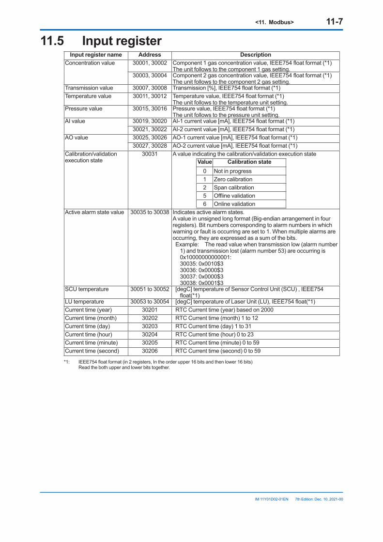
<11. Modbus> 11-7
IM 11Y01D02-01EN 7th Edition: Dec. 10, 2021-00
11.5 Input registerInput register name Address Description
Concentration value 30001, 30002 Component 1 gas concentration value, IEEE754 float format (*1)The unit follows to the component 1 gas setting.
30003, 30004 Component 2 gas concentration value, IEEE754 float format (*1)The unit follows to the component 2 gas setting.
Transmission value 30007, 30008 Transmission [%], IEEE754 float format (*1)Temperature value 30011, 30012 Temperature value, IEEE754 float format (*1)
The unit follows to the temperature unit setting.Pressure value 30015, 30016 Pressure value, IEEE754 float format (*1)
The unit follows to the pressure unit setting.AI value 30019, 30020 AI-1 current value [mA], IEEE754 float format (*1)
30021, 30022 AI-2 current value [mA], IEEE754 float format (*1)AO value 30025, 30026 AO-1 current value [mA], IEEE754 float format (*1)
30027, 30028 AO-2 current value [mA], IEEE754 float format (*1)Calibration/validation execution state
30031 A value indicating the calibration/validation execution stateValue Calibration state
0 Not in progress1 Zero calibration2 Span calibration5 Offline validation6 Online validation
Active alarm state value 30035 to 30038 Indicates active alarm states.A value in unsigned long format (Big-endian arrangement in four registers). Bit numbers corresponding to alarm numbers in which warning or fault is occurring are set to 1. When multiple alarms are occurring, they are expressed as a sum of the bits.Example: The read value when transmission low (alarm number
1) and transmission lost (alarm number 53) are occurring is 0x10000000000001:
30035: 0x0010$3 30036: 0x0000$3 30037: 0x0000$3 30038: 0x0001$3
SCU temperature 30051 to 30052 [degC] temperature of Sensor Control Unit (SCU) , IEEE754 float(*1)
LU temperature 30053 to 30054 [degC] temperature of Laser Unit (LU), IEEE754 float(*1)Current time (year) 30201 RTC Current time (year) based on 2000Current time (month) 30202 RTC Current time (month) 1 to 12Current time (day) 30203 RTC Current time (day) 1 to 31Current time (hour) 30204 RTC Current time (hour) 0 to 23Current time (minute) 30205 RTC Current time (minute) 0 to 59Current time (second) 30206 RTC Current time (second) 0 to 59
*1: IEEE754 float format (in 2 registers, In the order upper 16 bits and then lower 16 bits) Read the both upper and lower bits together.

Blank Page
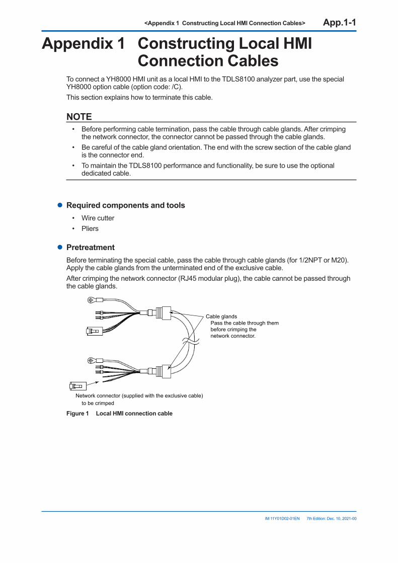
<Appendix 1 Constructing Local HMI Connection Cables> App.1-1
IM 11Y01D02-01EN 7th Edition: Dec. 10, 2021-00
Appendix1 ConstructingLocalHMIConnection Cables
To connect a YH8000 HMI unit as a local HMI to the TDLS8100 analyzer part, use the special YH8000 option cable (option code: /C).This section explains how to terminate this cable.
NOTE• Before performing cable termination, pass the cable through cable glands. After crimping
the network connector, the connector cannot be passed through the cable glands.• Be careful of the cable gland orientation. The end with the screw section of the cable gland
is the connector end.• To maintain the TDLS8100 performance and functionality, be sure to use the optional
dedicated cable.
l Required components and tools• Wire cutter• Pliers
l PretreatmentBefore terminating the special cable, pass the cable through cable glands (for 1/2NPT or M20). Apply the cable glands from the unterminated end of the exclusive cable.After crimping the network connector (RJ45 modular plug), the cable cannot be passed through the cable glands.
Cable glands
Network connector (supplied with the exclusive cable)to be crimped
Pass the cable through them before crimping the network connector.
Figure 1 Local HMI connection cable
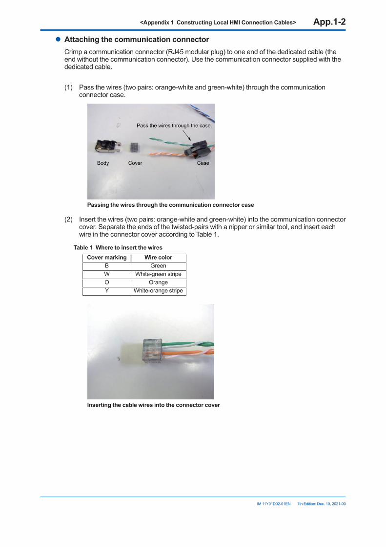
<Appendix 1 Constructing Local HMI Connection Cables> App.1-2
IM 11Y01D02-01EN 7th Edition: Dec. 10, 2021-00
l AttachingthecommunicationconnectorCrimp a communication connector (RJ45 modular plug) to one end of the dedicated cable (the end without the communication connector). Use the communication connector supplied with the dedicated cable.
(1) Pass the wires (two pairs: orange-white and green-white) through the communication connector case.
Pass the wires through the case.
CaseCoverBody
Passingthewiresthroughthecommunicationconnectorcase
(2) Insert the wires (two pairs: orange-white and green-white) into the communication connector cover. Separate the ends of the twisted-pairs with a nipper or similar tool, and insert each wire in the connector cover according to Table 1.
Table1 WheretoinsertthewiresCover marking Wire color
B GreenW White-green stripeO OrangeY White-orange stripe
Insertingthecablewiresintotheconnectorcover
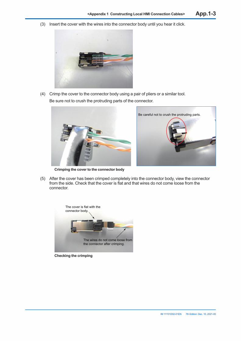
<Appendix 1 Constructing Local HMI Connection Cables> App.1-3
IM 11Y01D02-01EN 7th Edition: Dec. 10, 2021-00
(3) Insert the cover with the wires into the connector body until you hear it click.
(4) Crimp the cover to the connector body using a pair of pliers or a similar tool. Be sure not to crush the protruding parts of the connector.
Be careful not to crush the protruding parts.
Crimpingthecovertotheconnectorbody
(5) After the cover has been crimped completely into the connector body, view the connector from the side. Check that the cover is flat and that wires do not come loose from the connector.
The cover is flat with the connector body.
The wires do not come loose from the connector after crimping.
Checkingthecrimping
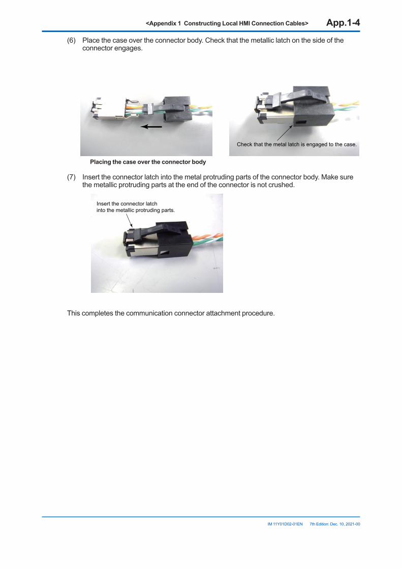
<Appendix 1 Constructing Local HMI Connection Cables> App.1-4
IM 11Y01D02-01EN 7th Edition: Dec. 10, 2021-00
(6) Place the case over the connector body. Check that the metallic latch on the side of the connector engages.
Check that the metal latch is engaged to the case.
Placingthecaseovertheconnectorbody
(7) Insert the connector latch into the metal protruding parts of the connector body. Make sure the metallic protruding parts at the end of the connector is not crushed.
Insert the connector latch into the metallic protruding parts.
This completes the communication connector attachment procedure.
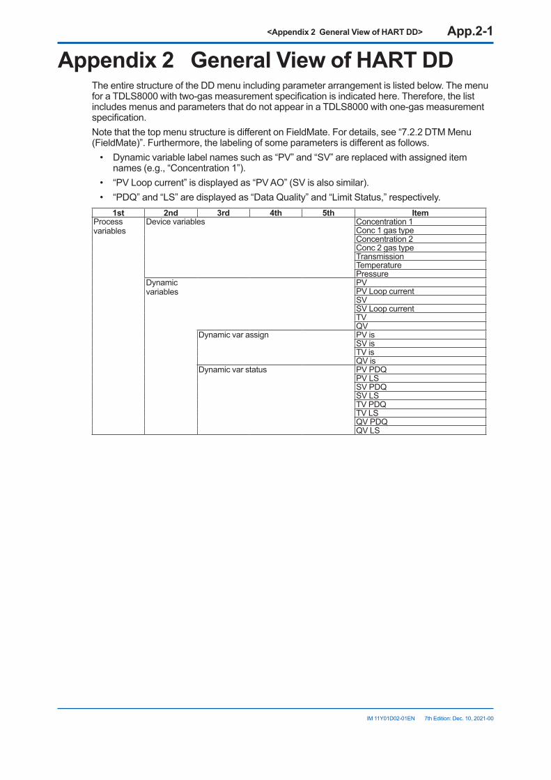
<Appendix 2 General View of HART DD> App.2-1
IM 11Y01D02-01EN 7th Edition: Dec. 10, 2021-00
Appendix2 GeneralViewofHARTDDThe entire structure of the DD menu including parameter arrangement is listed below. The menu for a TDLS8000 with two-gas measurement specification is indicated here. Therefore, the list includes menus and parameters that do not appear in a TDLS8000 with one-gas measurement specification.Note that the top menu structure is different on FieldMate. For details, see “7.2.2 DTM Menu (FieldMate)”. Furthermore, the labeling of some parameters is different as follows.
• Dynamic variable label names such as “PV” and “SV” are replaced with assigned item names (e.g., “Concentration 1”).
• “PV Loop current” is displayed as “PV AO” (SV is also similar).• “PDQ” and “LS” are displayed as “Data Quality” and “Limit Status,” respectively.
1st 2nd 3rd 4th 5th ItemProcess variables
Device variables Concentration 1Conc 1 gas typeConcentration 2Conc 2 gas typeTransmissionTemperaturePressure
Dynamic variables
PVPV Loop currentSVSV Loop currentTVQV
Dynamic var assign PV isSV isTV isQV is
Dynamic var status PV PDQPV LSSV PDQSV LSTV PDQTV LSQV PDQQV LS
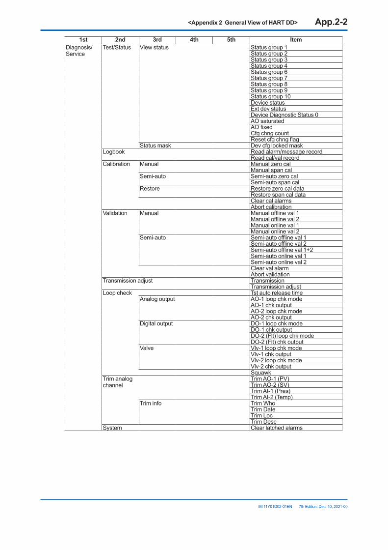
<Appendix 2 General View of HART DD> App.2-2
IM 11Y01D02-01EN 7th Edition: Dec. 10, 2021-00
1st 2nd 3rd 4th 5th ItemDiagnosis/Service
Test/Status View status Status group 1Status group 2Status group 3Status group 4Status group 6Status group 7Status group 8Status group 9Status group 10Device statusExt dev statusDevice Diagnostic Status 0AO saturatedAO fixedCfg chng countReset cfg chng flag
Status mask Dev cfg locked maskLogbook Read alarm/message record
Read cal/val recordCalibration Manual Manual zero cal
Manual span calSemi-auto Semi-auto zero cal
Semi-auto span calRestore Restore zero cal data
Restore span cal dataClear cal alarmsAbort calibration
Validation Manual Manual offline val 1Manual offline val 2Manual online val 1Manual online val 2
Semi-auto Semi-auto offline val 1Semi-auto offline val 2Semi-auto offline val 1+2Semi-auto online val 1Semi-auto online val 2Clear val alarmAbort validation
Transmission adjust TransmissionTransmission adjust
Loop check Tst auto release timeAnalog output AO-1 loop chk mode
AO-1 chk outputAO-2 loop chk modeAO-2 chk output
Digital output DO-1 loop chk modeDO-1 chk outputDO-2 (Flt) loop chk modeDO-2 (Flt) chk output
Valve Vlv-1 loop chk modeVlv-1 chk outputVlv-2 loop chk modeVlv-2 chk outputSquawk
Trim analog channel
Trim AO-1 (PV)Trim AO-2 (SV)Trim AI-1 (Pres)Trim AI-2 (Temp)
Trim info Trim WhoTrim DateTrim LocTrim Desc
System Clear latched alarms

<Appendix 2 General View of HART DD> App.2-3
IM 11Y01D02-01EN 7th Edition: Dec. 10, 2021-00
1st 2nd 3rd 4th 5th ItemBasic setup Tag
Long tagPV range PV is
PV LRVPV URVPV unit
SV range SV isSV LRVSV URVSV unit
Assign TV & QV TV isQV is
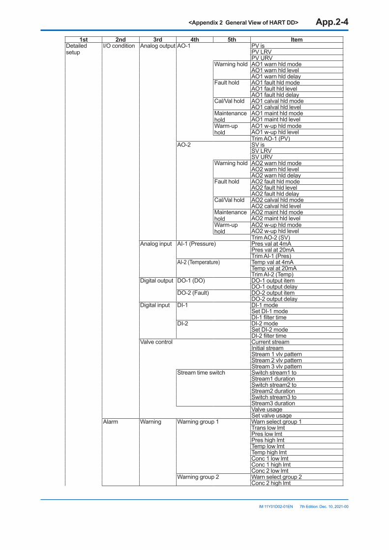
<Appendix 2 General View of HART DD> App.2-4
IM 11Y01D02-01EN 7th Edition: Dec. 10, 2021-00
1st 2nd 3rd 4th 5th ItemDetailed setup
I/O condition Analog output AO-1 PV isPV LRVPV URV
Warning hold AO1 warn hld modeAO1 warn hld levelAO1 warn hld delay
Fault hold AO1 fault hld modeAO1 fault hld levelAO1 fault hld delay
Cal/Val hold AO1 calval hld modeAO1 calval hld level
Maintenance hold
AO1 maint hld modeAO1 maint hld level
Warm-up hold
AO1 w-up hld modeAO1 w-up hld levelTrim AO-1 (PV)
AO-2 SV isSV LRVSV URV
Warning hold AO2 warn hld modeAO2 warn hld levelAO2 warn hld delay
Fault hold AO2 fault hld modeAO2 fault hld levelAO2 fault hld delay
Cal/Val hold AO2 calval hld modeAO2 calval hld level
Maintenance hold
AO2 maint hld modeAO2 maint hld level
Warm-up hold
AO2 w-up hld modeAO2 w-up hld levelTrim AO-2 (SV)
Analog input AI-1 (Pressure) Pres val at 4mAPres val at 20mATrim AI-1 (Pres)
AI-2 (Temperature) Temp val at 4mATemp val at 20mATrim AI-2 (Temp)
Digital output DO-1 (DO) DO-1 output itemDO-1 output delay
DO-2 (Fault) DO-2 output itemDO-2 output delay
Digital input DI-1 DI-1 modeSet DI-1 modeDI-1 filter time
DI-2 DI-2 modeSet DI-2 modeDI-2 filter time
Valve control Current streamInitial streamStream 1 vlv patternStream 2 vlv patternStream 3 vlv pattern
Stream time switch Switch stream1 toStream1 durationSwitch stream2 toStream2 durationSwitch stream3 toStream3 durationValve usageSet valve usage
Alarm Warning Warning group 1 Warn select group 1Trans low lmtPres low lmtPres high lmtTemp low lmtTemp high lmtConc 1 low lmtConc 1 high lmtConc 2 low lmt
Warning group 2 Warn select group 2Conc 2 high lmt
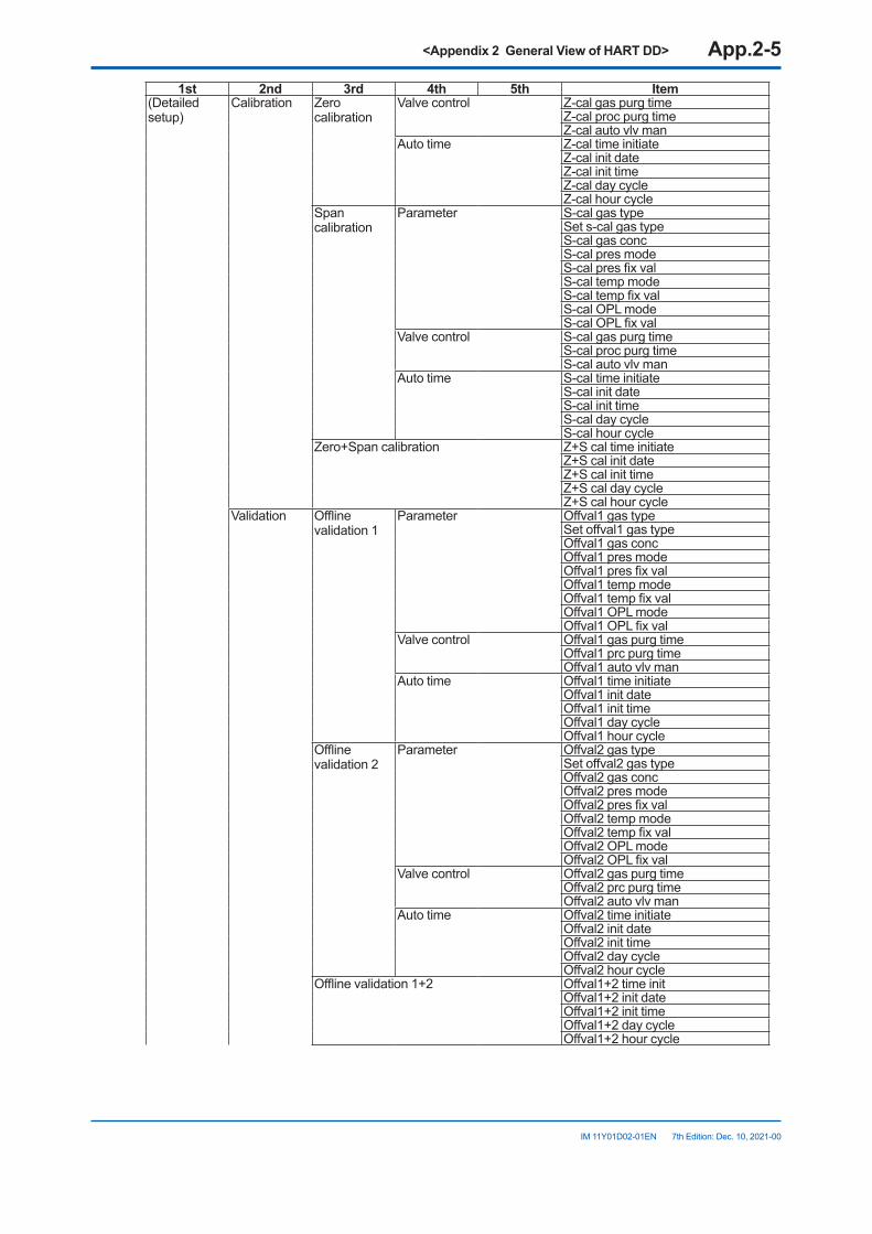
<Appendix 2 General View of HART DD> App.2-5
IM 11Y01D02-01EN 7th Edition: Dec. 10, 2021-00
1st 2nd 3rd 4th 5th Item(Detailed setup)
Calibration Zero calibration
Valve control Z-cal gas purg timeZ-cal proc purg timeZ-cal auto vlv man
Auto time Z-cal time initiateZ-cal init dateZ-cal init timeZ-cal day cycleZ-cal hour cycle
Span calibration
Parameter S-cal gas typeSet s-cal gas typeS-cal gas concS-cal pres modeS-cal pres fix valS-cal temp modeS-cal temp fix valS-cal OPL modeS-cal OPL fix val
Valve control S-cal gas purg timeS-cal proc purg timeS-cal auto vlv man
Auto time S-cal time initiateS-cal init dateS-cal init timeS-cal day cycleS-cal hour cycle
Zero+Span calibration Z+S cal time initiateZ+S cal init dateZ+S cal init timeZ+S cal day cycleZ+S cal hour cycle
Validation Offline validation 1
Parameter Offval1 gas typeSet offval1 gas typeOffval1 gas concOffval1 pres modeOffval1 pres fix valOffval1 temp modeOffval1 temp fix valOffval1 OPL modeOffval1 OPL fix val
Valve control Offval1 gas purg timeOffval1 prc purg timeOffval1 auto vlv man
Auto time Offval1 time initiateOffval1 init dateOffval1 init timeOffval1 day cycleOffval1 hour cycle
Offline validation 2
Parameter Offval2 gas typeSet offval2 gas typeOffval2 gas concOffval2 pres modeOffval2 pres fix valOffval2 temp modeOffval2 temp fix valOffval2 OPL modeOffval2 OPL fix val
Valve control Offval2 gas purg timeOffval2 prc purg timeOffval2 auto vlv man
Auto time Offval2 time initiateOffval2 init dateOffval2 init timeOffval2 day cycleOffval2 hour cycle
Offline validation 1+2 Offval1+2 time initOffval1+2 init dateOffval1+2 init timeOffval1+2 day cycleOffval1+2 hour cycle
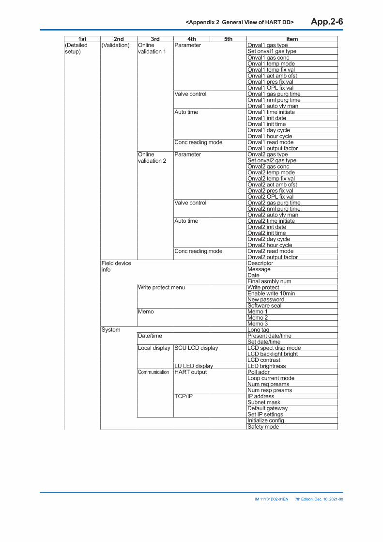
<Appendix 2 General View of HART DD> App.2-6
IM 11Y01D02-01EN 7th Edition: Dec. 10, 2021-00
1st 2nd 3rd 4th 5th Item(Detailed setup)
(Validation) Online validation 1
Parameter Onval1 gas typeSet onval1 gas typeOnval1 gas concOnval1 temp modeOnval1 temp fix valOnval1 act amb ofstOnval1 pres fix valOnval1 OPL fix val
Valve control Onval1 gas purg timeOnval1 nml purg timeOnval1 auto vlv man
Auto time Onval1 time initiateOnval1 init dateOnval1 init timeOnval1 day cycleOnval1 hour cycle
Conc reading mode Onval1 read modeOnval1 output factor
Online validation 2
Parameter Onval2 gas typeSet onval2 gas typeOnval2 gas concOnval2 temp modeOnval2 temp fix valOnval2 act amb ofstOnval2 pres fix valOnval2 OPL fix val
Valve control Onval2 gas purg timeOnval2 nml purg timeOnval2 auto vlv man
Auto time Onval2 time initiateOnval2 init dateOnval2 init timeOnval2 day cycleOnval2 hour cycle
Conc reading mode Onval2 read modeOnval2 output factor
Field device info
DescriptorMessageDateFinal asmbly num
Write protect menu Write protectEnable write 10minNew passwordSoftware seal
Memo Memo 1Memo 2Memo 3
System Long tagDate/time Present date/time
Set date/timeLocal display SCU LCD display LCD spect disp mode
LCD backlight brightLCD contrast
LU LED display LED brightnessCommunication HART output Poll addr
Loop current modeNum req preamsNum resp preams
TCP/IP IP addressSubnet maskDefault gatewaySet IP settingsInitialize configSafety mode
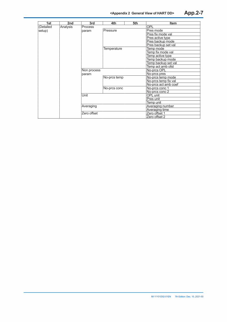
<Appendix 2 General View of HART DD> App.2-7
IM 11Y01D02-01EN 7th Edition: Dec. 10, 2021-00
1st 2nd 3rd 4th 5th Item(Detailed setup)
Analysis Process param
OPLPressure Pres mode
Pres fix mode valPres active typePres backup modePres backup set val
Temperature Temp modeTemp fix mode valTemp active typeTemp backup modeTemp backup set valTemp act amb ofst
Non process param
No-prcs OPLNo-prcs pres
No-prcs temp No-prcs temp modeNo-prcs temp fix valNo-prcs act amb coef
No-prcs conc No-prcs conc 1No-prcs conc 2
Unit OPL unitPres unitTemp unit
Averaging Averaging numberAveraging time
Zero offset Zero offset 1Zero offset 2
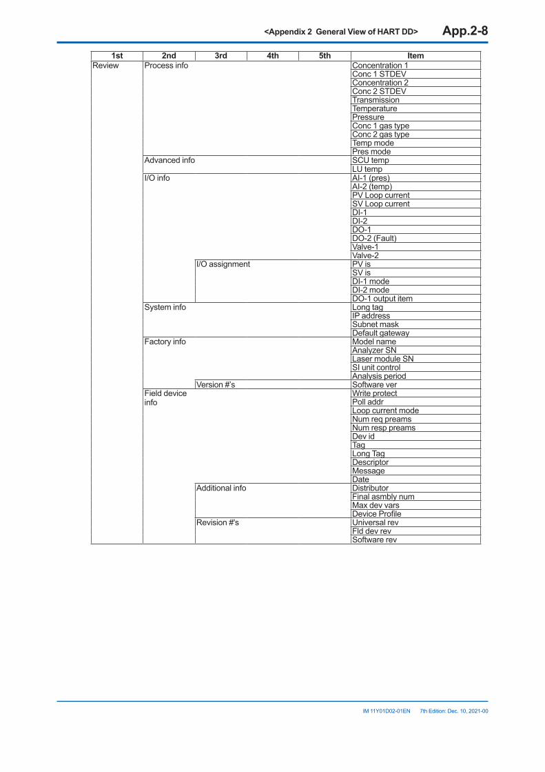
<Appendix 2 General View of HART DD> App.2-8
IM 11Y01D02-01EN 7th Edition: Dec. 10, 2021-00
1st 2nd 3rd 4th 5th ItemReview Process info Concentration 1
Conc 1 STDEVConcentration 2Conc 2 STDEVTransmissionTemperaturePressureConc 1 gas typeConc 2 gas typeTemp modePres mode
Advanced info SCU tempLU temp
I/O info AI-1 (pres)AI-2 (temp)PV Loop currentSV Loop currentDI-1DI-2DO-1DO-2 (Fault)Valve-1Valve-2
I/O assignment PV isSV isDI-1 modeDI-2 modeDO-1 output item
System info Long tagIP addressSubnet maskDefault gateway
Factory info Model nameAnalyzer SNLaser module SNSI unit controlAnalysis period
Version #’s Software verField device info
Write protectPoll addrLoop current modeNum req preamsNum resp preamsDev idTagLong TagDescriptorMessageDate
Additional info DistributorFinal asmbly numMax dev varsDevice Profile
Revision #'s Universal revFld dev revSoftware rev
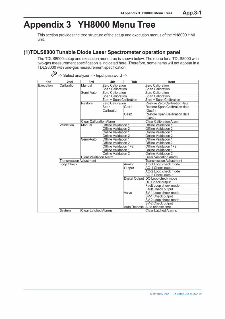
<Appendix 3 YH8000 Menu Tree> App.3-1
IM 11Y01D02-01EN 7th Edition: Dec. 10, 2021-00
Appendix3 YH8000MenuTreeThis section provides the tree structure of the setup and execution menus of the YH8000 HMI unit.
(1)TDLS8000TunableDiodeLaserSpectrometeroperationpanelThe TDLS8000 setup and execution menu tree is shown below. The menu for a TDLS8000 with two-gas measurement specification is indicated here. Therefore, some items will not appear in a TDLS8000 with one-gas measurement specification.
=> Select analyzer => Input password =>1st 2nd 3rd 4th Tab Item
Execution Calibration Manual Zero Calibration Zero CalibrationSpan Calibration Span Calibration
Semi-Auto Zero Calibration Zero CalibrationSpan Calibration Span CalibrationZero + Span Calibration Zero + Span Calibration
Restore Zero Calibration Restore Zero Calibration dataSpan Calibration
Gas1 Restore Span Calibration data (Gas1)
Gas2 Restore Span Calibration data (Gas2)
Clear Calibration Alarm Clear Calibration AlarmValidation Manual Offline Validation 1 Offline Validation 1
Offline Validation 2 Offline Validation 2Online Validation 1 Online Validation 1Online Validation 2 Online Validation 2
Semi-Auto Offline Validation 1 Offline Validation 1Offline Validation 2 Offline Validation 2Offline Validation 1+2 Offline Validation 1+2Online Validation 1 Online Validation 1Online Validation 2 Online Validation 2
Clear Validation Alarm Clear Validation AlarmTransmission Adjustment Transmission AdjustmentLoop Check Analog
OutputAO-1 Loop check modeAO-1 Check outputAO-2 Loop check modeAO-2 Check output
Digital Output DO Loop check modeDO Check outputFault Loop check modeFault Check output
Valve SV-1 Loop check modeSV-1 Check outputSV-2 Loop check modeSV-2 Check output
Auto Release Auto release timeSystem Clear Latched Alarms Clear Latched Alarms
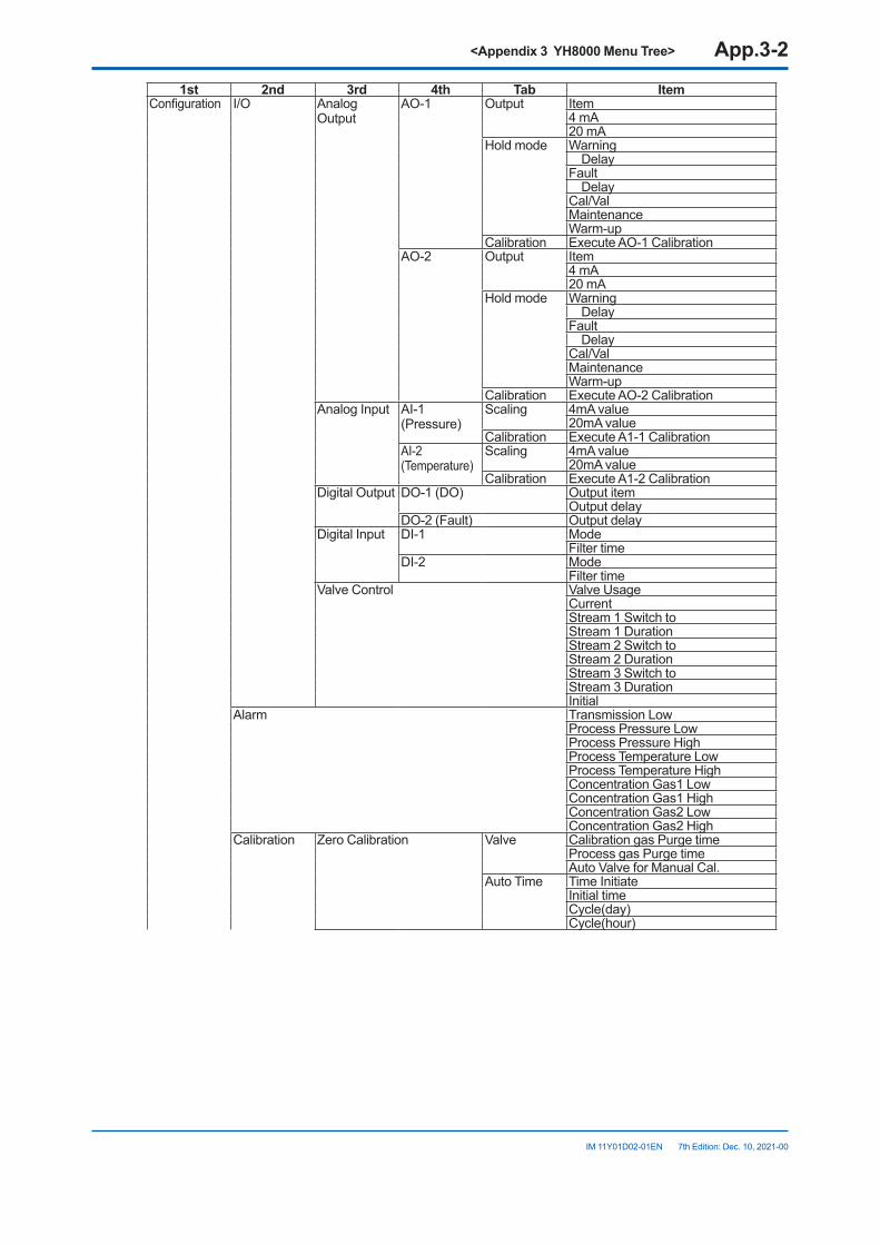
<Appendix 3 YH8000 Menu Tree> App.3-2
IM 11Y01D02-01EN 7th Edition: Dec. 10, 2021-00
1st 2nd 3rd 4th Tab ItemConfiguration I/O Analog
OutputAO-1 Output Item
4 mA 20 mA
Hold mode Warning DelayFault DelayCal/ValMaintenanceWarm-up
Calibration Execute AO-1 CalibrationAO-2 Output Item
4 mA 20 mA
Hold mode Warning DelayFault DelayCal/ValMaintenanceWarm-up
Calibration Execute AO-2 CalibrationAnalog Input AI-1
(Pressure)Scaling 4mA value
20mA valueCalibration Execute A1-1 Calibration
AI-2 (Temperature)
Scaling 4mA value20mA value
Calibration Execute A1-2 CalibrationDigital Output DO-1 (DO) Output item
Output delayDO-2 (Fault) Output delay
Digital Input DI-1 ModeFilter time
DI-2 ModeFilter time
Valve Control Valve UsageCurrentStream 1 Switch toStream 1 DurationStream 2 Switch toStream 2 DurationStream 3 Switch toStream 3 DurationInitial
Alarm Transmission LowProcess Pressure LowProcess Pressure HighProcess Temperature LowProcess Temperature HighConcentration Gas1 LowConcentration Gas1 HighConcentration Gas2 LowConcentration Gas2 High
Calibration Zero Calibration Valve Calibration gas Purge timeProcess gas Purge timeAuto Valve for Manual Cal.
Auto Time Time InitiateInitial timeCycle(day)Cycle(hour)
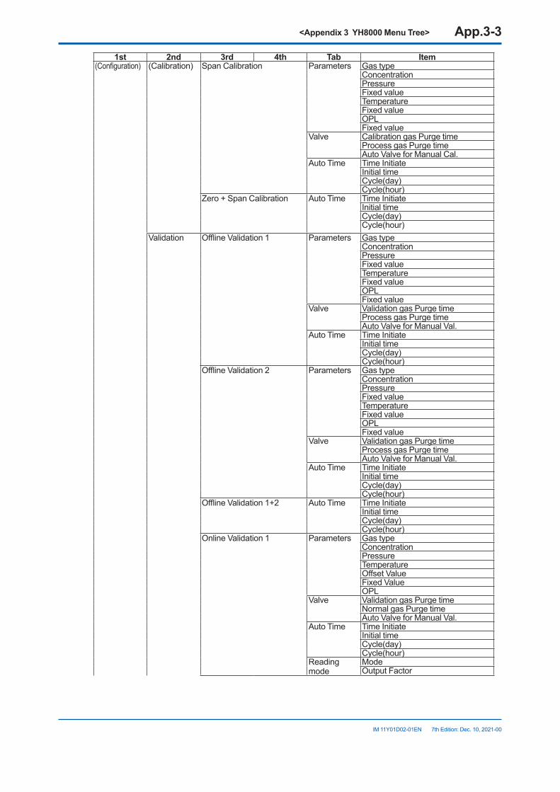
<Appendix 3 YH8000 Menu Tree> App.3-3
IM 11Y01D02-01EN 7th Edition: Dec. 10, 2021-00
1st 2nd 3rd 4th Tab Item(Configuration) (Calibration) Span Calibration Parameters Gas type
ConcentrationPressureFixed valueTemperatureFixed valueOPLFixed value
Valve Calibration gas Purge timeProcess gas Purge timeAuto Valve for Manual Cal.
Auto Time Time InitiateInitial timeCycle(day)Cycle(hour)
Zero + Span Calibration Auto Time Time InitiateInitial timeCycle(day)Cycle(hour)
Validation Offline Validation 1 Parameters Gas typeConcentrationPressureFixed valueTemperatureFixed valueOPLFixed value
Valve Validation gas Purge timeProcess gas Purge timeAuto Valve for Manual Val.
Auto Time Time InitiateInitial timeCycle(day)Cycle(hour)
Offline Validation 2 Parameters Gas typeConcentrationPressureFixed valueTemperatureFixed valueOPLFixed value
Valve Validation gas Purge timeProcess gas Purge timeAuto Valve for Manual Val.
Auto Time Time InitiateInitial timeCycle(day)Cycle(hour)
Offline Validation 1+2 Auto Time Time InitiateInitial timeCycle(day)Cycle(hour)
Online Validation 1 Parameters Gas typeConcentrationPressureTemperatureOffset ValueFixed ValueOPL
Valve Validation gas Purge timeNormal gas Purge timeAuto Valve for Manual Val.
Auto Time Time InitiateInitial timeCycle(day)Cycle(hour)
Reading mode
ModeOutput Factor
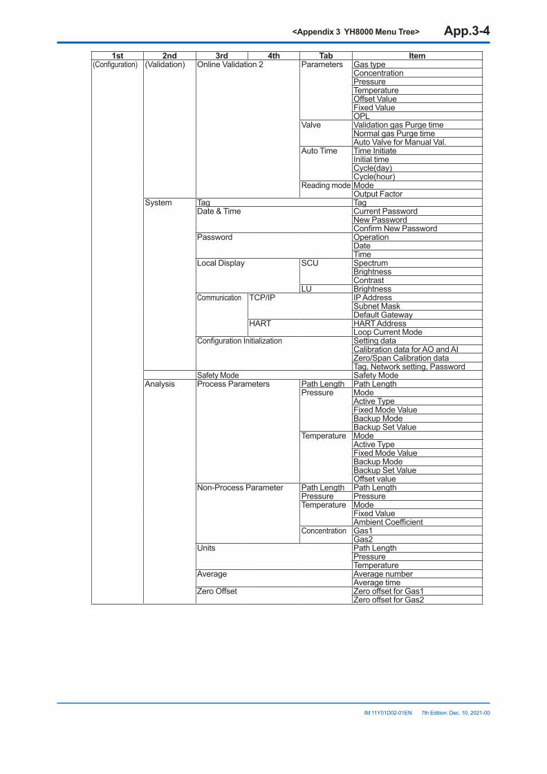
<Appendix 3 YH8000 Menu Tree> App.3-4
IM 11Y01D02-01EN 7th Edition: Dec. 10, 2021-00
1st 2nd 3rd 4th Tab Item(Configuration) (Validation) Online Validation 2 Parameters Gas type
ConcentrationPressureTemperatureOffset ValueFixed ValueOPL
Valve Validation gas Purge timeNormal gas Purge timeAuto Valve for Manual Val.
Auto Time Time InitiateInitial timeCycle(day)Cycle(hour)
Reading mode ModeOutput Factor
System Tag TagDate & Time Current Password
New PasswordConfirm New Password
Password OperationDate Time
Local Display SCU Spectrum BrightnessContrast
LU BrightnessCommunication TCP/IP IP Address
Subnet MaskDefault Gateway
HART HART AddressLoop Current Mode
Configuration Initialization Setting dataCalibration data for AO and AIZero/Span Calibration dataTag, Network setting, Password
Safety Mode Safety ModeAnalysis Process Parameters Path Length Path Length
Pressure ModeActive TypeFixed Mode ValueBackup ModeBackup Set Value
Temperature ModeActive TypeFixed Mode ValueBackup ModeBackup Set ValueOffset value
Non-Process Parameter Path Length Path Length Pressure PressureTemperature Mode
Fixed ValueAmbient Coefficient
Concentration Gas1Gas2
Units Path LengthPressureTemperature
Average Average numberAverage time
Zero Offset Zero offset for Gas1Zero offset for Gas2
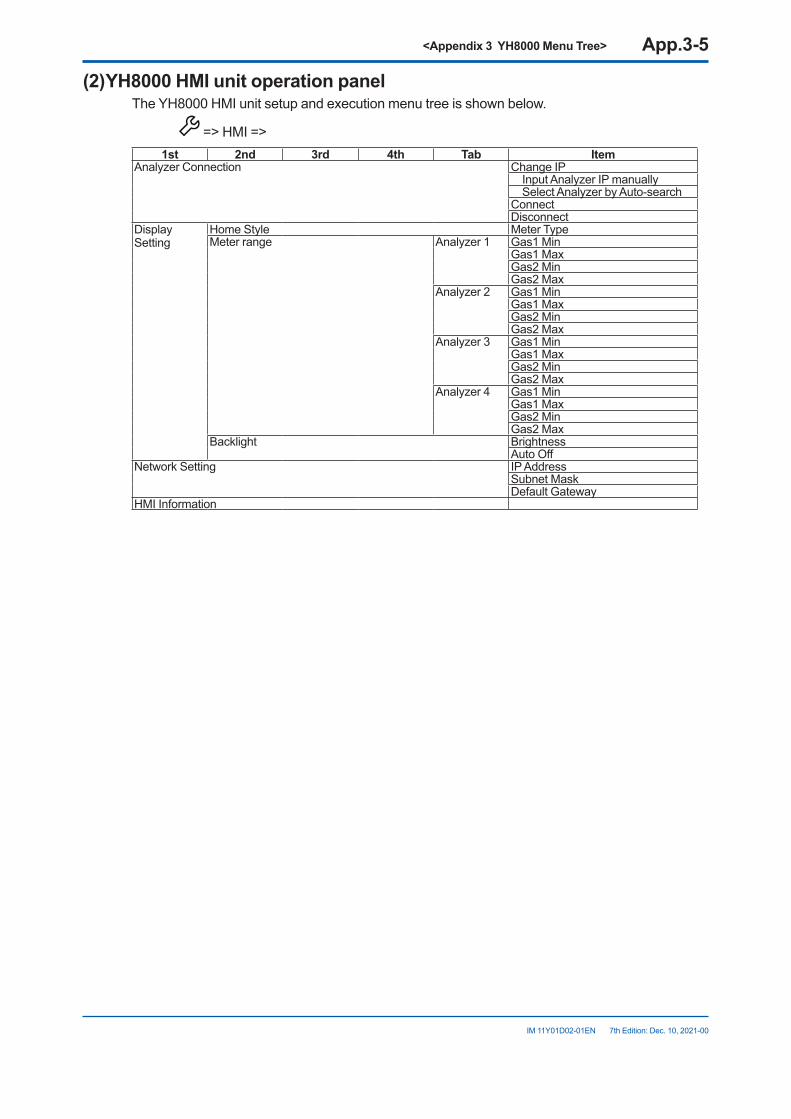
<Appendix 3 YH8000 Menu Tree> App.3-5
IM 11Y01D02-01EN 7th Edition: Dec. 10, 2021-00
(2)YH8000HMIunitoperationpanelThe YH8000 HMI unit setup and execution menu tree is shown below.
=> HMI =>1st 2nd 3rd 4th Tab Item
Analyzer Connection Change IP Input Analyzer IP manually Select Analyzer by Auto-searchConnectDisconnect
Display Setting
Home Style Meter TypeMeter range Analyzer 1 Gas1 Min
Gas1 MaxGas2 MinGas2 Max
Analyzer 2 Gas1 MinGas1 MaxGas2 MinGas2 Max
Analyzer 3 Gas1 MinGas1 MaxGas2 MinGas2 Max
Analyzer 4 Gas1 MinGas1 MaxGas2 MinGas2 Max
Backlight BrightnessAuto Off
Network Setting IP AddressSubnet MaskDefault Gateway
HMI Information

Blank Page
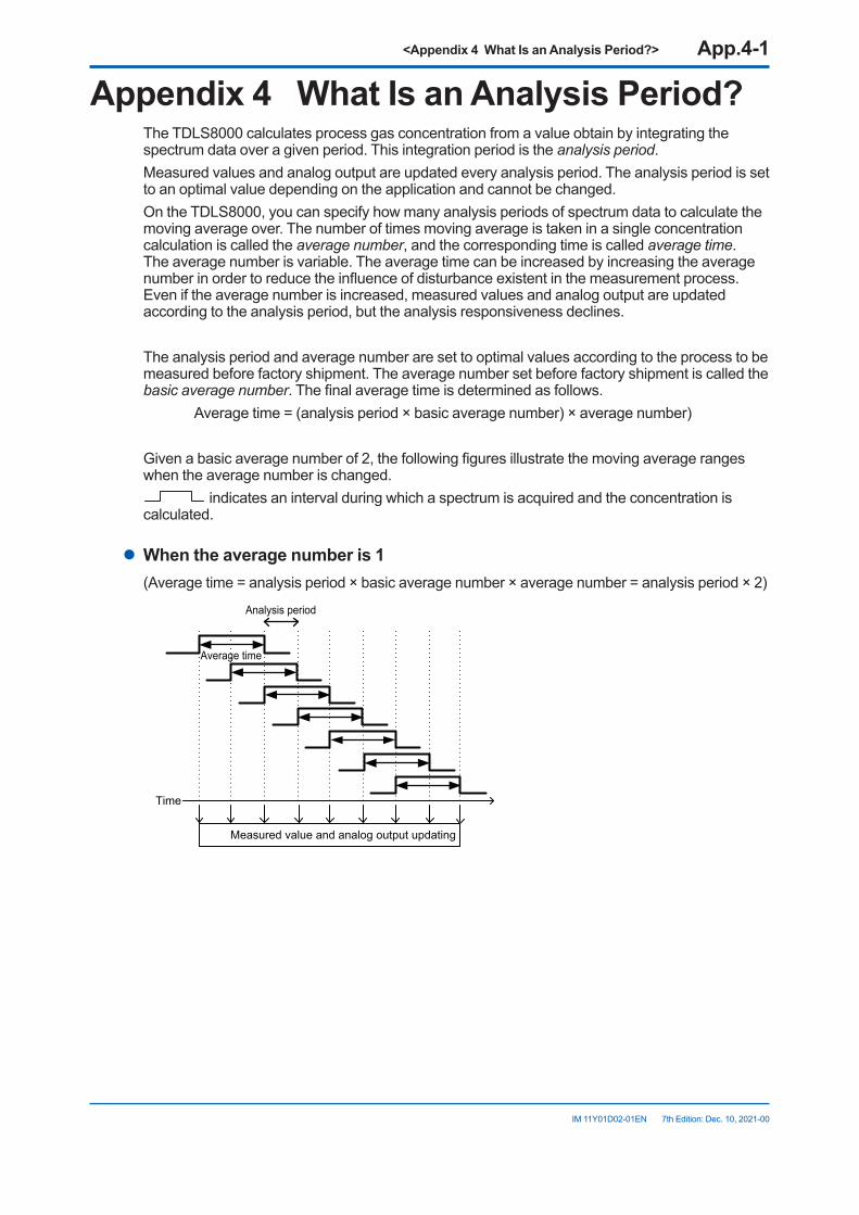
<Appendix 4 What Is an Analysis Period?> App.4-1
IM 11Y01D02-01EN 7th Edition: Dec. 10, 2021-00
Appendix4 WhatIsanAnalysisPeriod?The TDLS8000 calculates process gas concentration from a value obtain by integrating the spectrum data over a given period. This integration period is the analysis period.Measured values and analog output are updated every analysis period. The analysis period is set to an optimal value depending on the application and cannot be changed.On the TDLS8000, you can specify how many analysis periods of spectrum data to calculate the moving average over. The number of times moving average is taken in a single concentration calculation is called the average number, and the corresponding time is called average time. The average number is variable. The average time can be increased by increasing the average number in order to reduce the influence of disturbance existent in the measurement process. Even if the average number is increased, measured values and analog output are updated according to the analysis period, but the analysis responsiveness declines.
The analysis period and average number are set to optimal values according to the process to be measured before factory shipment. The average number set before factory shipment is called the basic average number. The final average time is determined as follows. Average time = (analysis period × basic average number) × average number)
Given a basic average number of 2, the following figures illustrate the moving average ranges when the average number is changed.
indicates an interval during which a spectrum is acquired and the concentration is calculated.
l Whentheaveragenumberis1(Average time = analysis period × basic average number × average number = analysis period × 2)
Analysis period
Average time
Measured value and analog output updating
Time
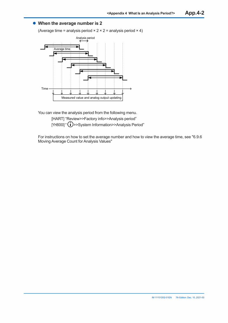
<Appendix 4 What Is an Analysis Period?> App.4-2
IM 11Y01D02-01EN 7th Edition: Dec. 10, 2021-00
l Whentheaveragenumberis2(Average time = analysis period × 2 × 2 = analysis period × 4)
Analysis period
Average time
Measured value and analog output updating
Time
You can view the analysis period from the following menu. [HART] “Review>>Factory info>>Analysis period” [YH8000] “ >>System Information>>Analysis Period”
For instructions on how to set the average number and how to view the average time, see "6.9.6 Moving Average Count for Analysis Values"
<Appendix 5 Safety Instrumented System Installation> App.5-1
IM 11Y01D02-01EN 7th Edition: Dec. 10, 2021-00
Appendix5 SafetyInstrumentedSystemInstallation
WARNINGWhen using TDLS8100 as a Safety Instrumented Systems (SIS), in order to maintain the necessary level of safety, strictly observe the instructions and procedures provided in this Appendix.
n Scope and PurposeThis section describes the handling precautions to be taken when installing and operating the TDLS8100 in order to maintain the level of safety designed for using the TDLS8100 in a Safety Instrumented System application. It also provides an overview of the operation. The topics discussed in this section are the TDLS8100’s proof test, repairs, and replacement; safety data; service life; environmental and application limitations; and parameter settings.
n UsingtheTDLS8100inaSafetyInstrumentedSystemApplication
l Safety accuracyThe following table shows the TDLS8100 safety accuracy. When an error caused by an internal component failure exceeds the safety accuracy, the TDLS8100 is considered to have malfunctioned.
Measured gas Safety accuracyO2 +/-0.2 % O2 or 15 % of reading, whichever is greater.CO(ppm) +/-50 ppm CO or 15% of reading, whichever is greater. CO+CH4 CO +/-50 ppm CO or 15% of reading, whichever is greater.
CH4 +/- 1% CH4 or 15% of reading, whichever is greater.NH3 +/-10 ppm NH3 or 15% of reading, whichever is greater.HCl (ppm) +/-3 ppm HCl or 15% of reading, whichever is greater.
l Diagnostic response timeThe TDLS8100 can indicate an internal malfunction within 30 seconds.
l I/ORestrictionOnly analog output AO-1, AO-2 and analog input AI-1, AI-2 comply with Safety Instrumented System. Do not use other input or outputs as part of a Safety Instrumented System.
l OpeningandClosingtheTDLS8100When online, do not open or close the cover. If you need to open and close the TDLS8100 cover for maintenance, obtain permission from your safety administrator.
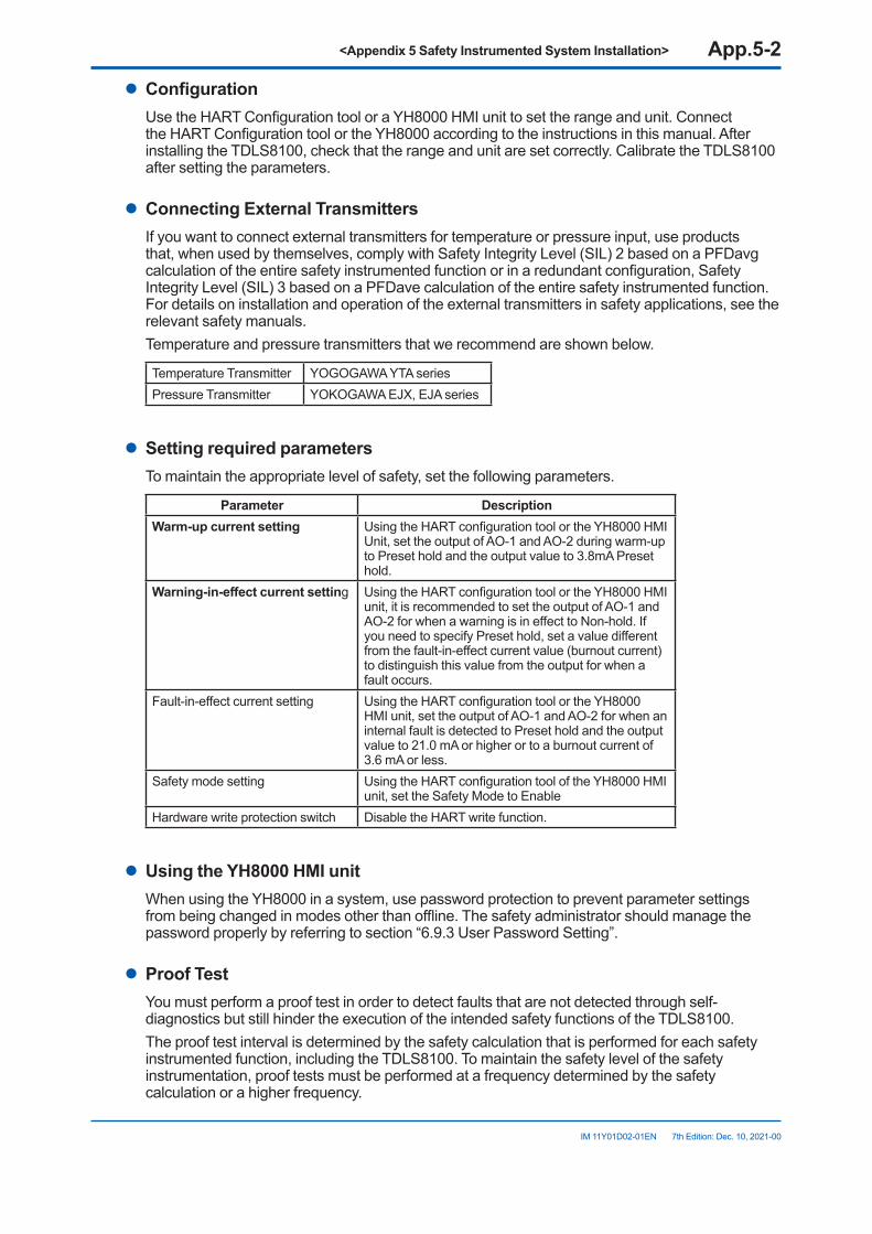
<Appendix 5 Safety Instrumented System Installation> App.5-2
IM 11Y01D02-01EN 7th Edition: Dec. 10, 2021-00
l ConfigurationUse the HART Configuration tool or a YH8000 HMI unit to set the range and unit. Connect the HART Configuration tool or the YH8000 according to the instructions in this manual. After installing the TDLS8100, check that the range and unit are set correctly. Calibrate the TDLS8100 after setting the parameters.
l ConnectingExternalTransmittersIf you want to connect external transmitters for temperature or pressure input, use products that, when used by themselves, comply with Safety Integrity Level (SIL) 2 based on a PFDavg calculation of the entire safety instrumented function or in a redundant configuration, Safety Integrity Level (SIL) 3 based on a PFDave calculation of the entire safety instrumented function. For details on installation and operation of the external transmitters in safety applications, see the relevant safety manuals.Temperature and pressure transmitters that we recommend are shown below.
Temperature Transmitter YOGOGAWA YTA seriesPressure Transmitter YOKOGAWA EJX, EJA series
l Setting required parametersTo maintain the appropriate level of safety, set the following parameters.
Parameter DescriptionWarm-up current setting Using the HART configuration tool or the YH8000 HMI
Unit, set the output of AO-1 and AO-2 during warm-up to Preset hold and the output value to 3.8mA Preset hold.
Warning-in-effectcurrentsetting Using the HART configuration tool or the YH8000 HMI unit, it is recommended to set the output of AO-1 and AO-2 for when a warning is in effect to Non-hold. If you need to specify Preset hold, set a value different from the fault-in-effect current value (burnout current) to distinguish this value from the output for when a fault occurs.
Fault-in-effect current setting Using the HART configuration tool or the YH8000 HMI unit, set the output of AO-1 and AO-2 for when an internal fault is detected to Preset hold and the output value to 21.0 mA or higher or to a burnout current of 3.6 mA or less.
Safety mode setting Using the HART configuration tool of the YH8000 HMI unit, set the Safety Mode to Enable
Hardware write protection switch Disable the HART write function.
l UsingtheYH8000HMIunitWhen using the YH8000 in a system, use password protection to prevent parameter settings from being changed in modes other than offline. The safety administrator should manage the password properly by referring to section “6.9.3 User Password Setting”.
l Proof TestYou must perform a proof test in order to detect faults that are not detected through self-diagnostics but still hinder the execution of the intended safety functions of the TDLS8100.The proof test interval is determined by the safety calculation that is performed for each safety instrumented function, including the TDLS8100. To maintain the safety level of the safety instrumentation, proof tests must be performed at a frequency determined by the safety calculation or a higher frequency.
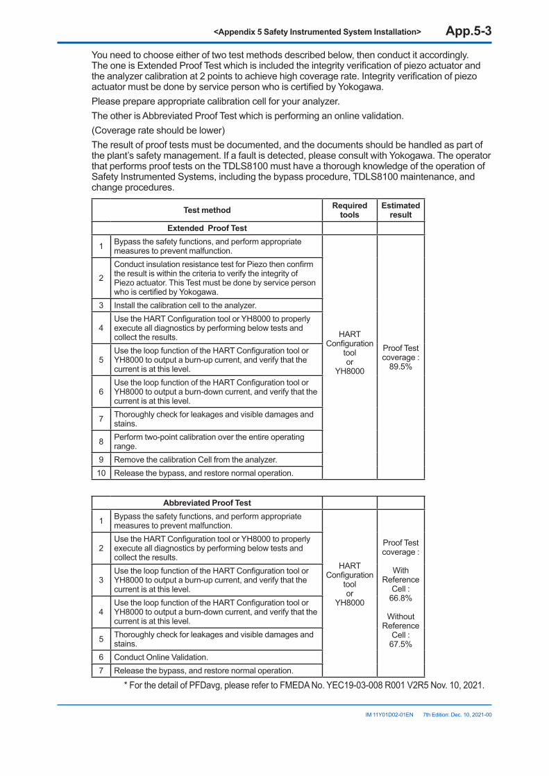
<Appendix 5 Safety Instrumented System Installation> App.5-3
IM 11Y01D02-01EN 7th Edition: Dec. 10, 2021-00
You need to choose either of two test methods described below, then conduct it accordingly. The one is Extended Proof Test which is included the integrity verification of piezo actuator and the analyzer calibration at 2 points to achieve high coverage rate. Integrity verification of piezo actuator must be done by service person who is certified by Yokogawa.Please prepare appropriate calibration cell for your analyzer.The other is Abbreviated Proof Test which is performing an online validation.(Coverage rate should be lower)The result of proof tests must be documented, and the documents should be handled as part of the plant’s safety management. If a fault is detected, please consult with Yokogawa. The operator that performs proof tests on the TDLS8100 must have a thorough knowledge of the operation of Safety Instrumented Systems, including the bypass procedure, TDLS8100 maintenance, and change procedures.
Testmethod Required tools
Estimated result
ExtendedProofTest
1 Bypass the safety functions, and perform appropriate measures to prevent malfunction.
HARTConfiguration
toolor
YH8000
Proof Test coverage :
89.5%
2 Conduct insulation resistance test for Piezo then confirm the result is within the criteria to verify the integrity of Piezo actuator. This Test must be done by service person who is certified by Yokogawa.
3 Install the calibration cell to the analyzer.
4Use the HART Configuration tool or YH8000 to properly execute all diagnostics by performing below tests and collect the results.
5Use the loop function of the HART Configuration tool or YH8000 to output a burn-up current, and verify that the current is at this level.
6Use the loop function of the HART Configuration tool or YH8000 to output a burn-down current, and verify that the current is at this level.
7 Thoroughly check for leakages and visible damages and stains.
8 Perform two-point calibration over the entire operating range.
9 Remove the calibration Cell from the analyzer.10 Release the bypass, and restore normal operation.
Abbreviated Proof Test
1 Bypass the safety functions, and perform appropriate measures to prevent malfunction.
HARTConfiguration
toolor
YH8000
Proof Test coverage :
With
Reference Cell :
66.8%
Without Reference
Cell : 67.5%
2 Use the HART Configuration tool or YH8000 to properly execute all diagnostics by performing below tests and collect the results.
3Use the loop function of the HART Configuration tool or YH8000 to output a burn-up current, and verify that the current is at this level.
4Use the loop function of the HART Configuration tool or YH8000 to output a burn-down current, and verify that the current is at this level.
5 Thoroughly check for leakages and visible damages and stains.
6 Conduct Online Validation.7 Release the bypass, and restore normal operation.
* For the detail of PFDavg, please refer to FMEDA No. YEC19-03-008 R001 V2R5 Nov. 10, 2021.
<Appendix 5 Safety Instrumented System Installation> App.5-4
IM 11Y01D02-01EN 7th Edition: Dec. 10, 2021-00
l Repair and replacementTo repair the TDLS8100 while the process is online, bypass the TDLS8100. You must perform the bypass procedure correctly. If a fault is detected, please consult with Yokogawa. TDLS8100 replacement must be performed by a trained engineer.
l Startup timeTheTDLS8100 sends valid signal within 5 minutes after power on.
l Firmware updatingFor firmware updating, please consult with Yokogawa.
l Reliability DataThe FMEDA (Failure Mode, Effects and Diagnostic Analysis) report that Yokogawa provides contains failure rates and failure modes.When used by itself, the TDLS8100 is certified for compliance with up to Safety Integrity Level (SIL) 2 based on a PFDavg calculation of the entire safety instrumented function. The development process of the TDLS8100 is certified for compliance with up to SIL3. When used in a redundant configuration, it can be used at Safety Integrity Level (SIL) 3 based on a PFDavg calculation of the entire safety instrumented function. When used in a redundant configuration, we recommend that the common cause factors (β-factor) for the PFD calculation of the entire safety instrumented function be set at 5%. If the plant operator provides “common cause failure” training and a clear, detailed maintenance procedure for preventing common cause failures, the common cause factors (β-factor) can be set to 2 %. * For the detail of PFDavg, please refer to FMEDA No. YEC19-03-008 R001 V2R5 Nov. 10, 2021.
l Lifetime limitationThe expected lifetime of the TDLS8100 is 10 years. The reliability data in the FMEDA report is valid to 10 years. It is assumed that the failure rates of the TDLS8100 would increase when it is used over 10 years. Therefore, the safety integrity level based on the reliability data given in the FMEDA report may not be attainable.
l Environmental limitationThe environmental limitation of the TDLS8100 is defined in this manual.
l Application limitationIf the TDLS8100 is used in an application outside the limits defined in this manual, the reliability data is void.
n Terminology and Acronyms
l TermsSafety Freedom from unacceptable risk of harmFunctional Safety The ability of a system to carry out the actions necessary to achieve or to maintain a
defined safe state for the equipment, machinery, plant, and apparatus under control of the system.
<Appendix 5 Safety Instrumented System Installation> App.5-5
IM 11Y01D02-01EN 7th Edition: Dec. 10, 2021-00
Basic Safety The equipment must be designed and manufactured such that it protects against risk of
damage to persons by electrical shock and other hazards and against resulting fire and explosion. The protection must be effective under all conditions of the nominal operation and under single fault condition.
Verification● Compliance and confirmation
The demonstration for each phase of the life-cycle that the (output) deliverables of the phase meet the objectives and requirements specified by the inputs to the phase. The verification is usually executed by analysis, testing, or both.
● Validation The demonstration that the safety-related system(s) or the combination of safety-
related system(s) and external risk reduction facilities meet, in all respects, the Safety Requirements Specification. The validation is usually executed by testing.
● Safety Assessment The investigation to arrive at a judgment—based on evidence—of the safety achieved by
safety-related systems.Further definitions of terms used for safety techniques and measures and the description of safety related systems are given in IEC 61508-4.
l AcronymsFMEDA: Failure Mode, Effects and Diagnostic AnalysisSIF: Safety Instrumented FunctionSIL: Safety Integrity LevelSIS: Safety Instrumented SystemSLC: Safety Lifecycle

Blank Page
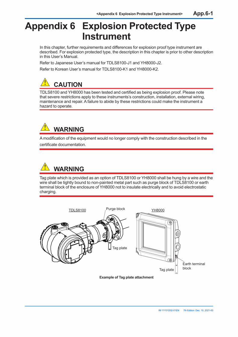
<Appendix 6 Explosion Protected Type Instrument> App.6-1
IM 11Y01D02-01EN 7th Edition: Dec. 10, 2021-00
Appendix6 ExplosionProtectedTypeInstrument
In this chapter, further requirements and differences for explosion proof type instrument are described. For explosion protected type, the description in this chapter is prior to other description in this User’s Manual.Refer to Japanese User’s manual for TDLS8100-J1 and YH8000-J2.Refer to Korean User’s manual for TDLS8100-K1 and YH8000-K2.
CAUTIONTDLS8100 and YH8000 has been tested and certified as being explosion proof. Please note that severe restrictions apply to these instruments’s construction, installation, external wiring, maintenance and repair. A failure to abide by these restrictions could make the instrument a hazard to operate.
WARNINGA modification of the equipment would no longer comply with the construction described in thecertificate documentation.
WARNINGTag plate which is provided as an option of TDLS8100 or YH8000 shall be hung by a wire and the wire shall be tightly bound to non-painted metal part such as purge block of TDLS8100 or earth terminal block of the enclosure of YH8000 not to insulate electrically and to avoid electrostatic charging.
TDLS8100 YH8000
Tag plate
Purge block
Tag plateEarth terminal block
ExampleofTagplateattachment
<Appendix 6 Explosion Protected Type Instrument> App.6-2
IM 11Y01D02-01EN 7th Edition: Dec. 10, 2021-00
n TDLS8100
l TDLS8100-D1(FMApprovalforUS)(1) Technicaldata
• Applicable standards FM Class 3600: 2018 FM Class 3615: 2018 FM Class 3616: 2011 FM Class 3810: 2018 ANSI/UL 50E: 2015 NEMA 250: 2014 ANSI/UL 60079-0:2013 ANSI/UL 60079-1: 2015, ANSI/UL 60079-28:2017, ANSI/UL 60079-31: 2015, ANSI/IEC 60529:2004 ANSI/ISA-12.27.01: 2011• Certificate No. FM18US0164X
Note: The symbol “X” placed after the certificate number indicates that the equipment is subjected to specific conditions of use. Refer to specific condition of use.
• Specifications Refer to chapter 2 for other specifications than that described below. • Equipment ratings (Ex marking) Explosionproof for Class I, Division 1, Groups A, B, C and D; T6 Dust-Ignitionproof for Class II/III; Division 1;, Groups E, F, G; T6 Class I, Zone 1, □ AEx db [op is Ga] IIC T6 Gb Zone21, □ AEx tb [op is Da] IIIC T85°C Db
Note: “□” is the checkbox for selecting type of protection. Select the type of protection and check one of “□” on the nameplate. Once the type of protection is selected, it shall not be changed.
• Enclosure TYPE4X, IP66 • Ambient temperature -20 to +55°C
l Specificconditionofuse• Electrostatic charges on the non-metallic parts (excluding glass parts) or coated parts of the
equipment shall be avoided.• If the TDLS8100 is mounted in an area where the use of EPL Db equipment is required, it
shall be installed in such a way that the risk from electrostatic discharges and propagating burst discharges caused by rapid flow of dust is avoided.
• Flameproof joints are not intended to be repaired. Contact Yokogawa representative or Yokogawa office.
• The property class of the special fastener 1 used to fasten the shaft onto the enclosure below is at least A*-50, C*-50, or F1-60.
• The property class of the special fastener 2 used to fasten the optics case to the case below is at least A*-80 or C*-80.
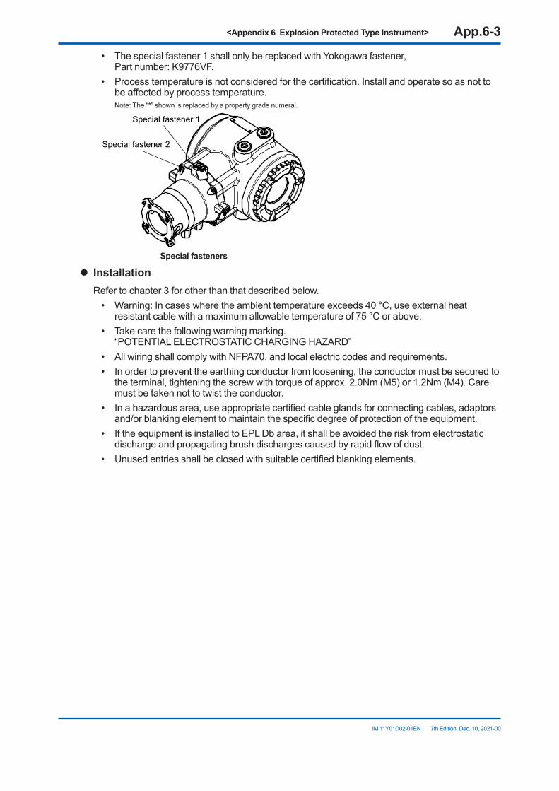
<Appendix 6 Explosion Protected Type Instrument> App.6-3
IM 11Y01D02-01EN 7th Edition: Dec. 10, 2021-00
• The special fastener 1 shall only be replaced with Yokogawa fastener, Part number: K9776VF.
• Process temperature is not considered for the certification. Install and operate so as not to be affected by process temperature.
Note: The “*” shown is replaced by a property grade numeral.
Special fastener 1
Special fastener 2
Special fasteners
l InstallationRefer to chapter 3 for other than that described below.
• Warning: In cases where the ambient temperature exceeds 40 °C, use external heat resistant cable with a maximum allowable temperature of 75 °C or above.
• Take care the following warning marking. “POTENTIAL ELECTROSTATIC CHARGING HAZARD”
• All wiring shall comply with NFPA70, and local electric codes and requirements.• In order to prevent the earthing conductor from loosening, the conductor must be secured to
the terminal, tightening the screw with torque of approx. 2.0Nm (M5) or 1.2Nm (M4). Care must be taken not to twist the conductor.
• In a hazardous area, use appropriate certified cable glands for connecting cables, adaptors and/or blanking element to maintain the specific degree of protection of the equipment.
• If the equipment is installed to EPL Db area, it shall be avoided the risk from electrostatic discharge and propagating brush discharges caused by rapid flow of dust.
• Unused entries shall be closed with suitable certified blanking elements.
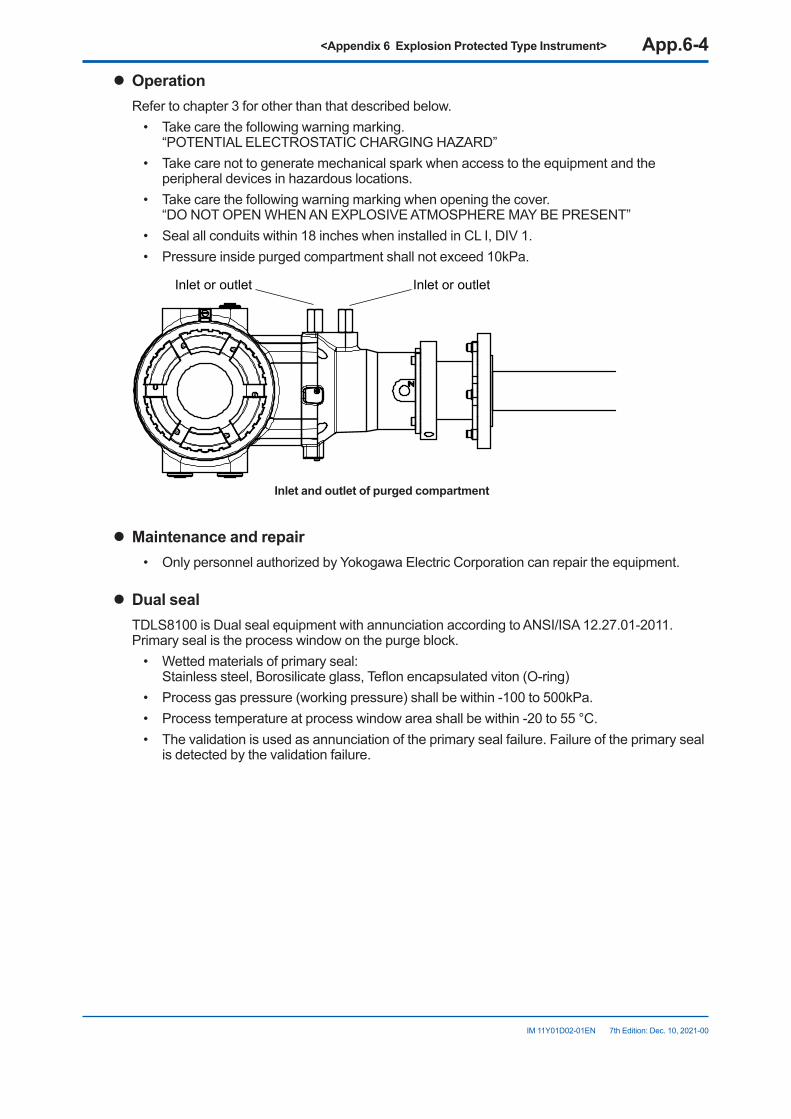
<Appendix 6 Explosion Protected Type Instrument> App.6-4
IM 11Y01D02-01EN 7th Edition: Dec. 10, 2021-00
l OperationRefer to chapter 3 for other than that described below.
• Take care the following warning marking. “POTENTIAL ELECTROSTATIC CHARGING HAZARD”
• Take care not to generate mechanical spark when access to the equipment and the peripheral devices in hazardous locations.
• Take care the following warning marking when opening the cover. “DO NOT OPEN WHEN AN EXPLOSIVE ATMOSPHERE MAY BE PRESENT”
• Seal all conduits within 18 inches when installed in CL I, DIV 1.• Pressure inside purged compartment shall not exceed 10kPa.
Inlet or outletInlet or outlet
Inlet and outlet of purged compartment
l Maintenance and repair• Only personnel authorized by Yokogawa Electric Corporation can repair the equipment.
l Dual sealTDLS8100 is Dual seal equipment with annunciation according to ANSI/ISA 12.27.01-2011.Primary seal is the process window on the purge block.
• Wetted materials of primary seal: Stainless steel, Borosilicate glass, Teflon encapsulated viton (O-ring)
• Process gas pressure (working pressure) shall be within -100 to 500kPa.• Process temperature at process window area shall be within -20 to 55 °C.• The validation is used as annunciation of the primary seal failure. Failure of the primary seal
is detected by the validation failure.
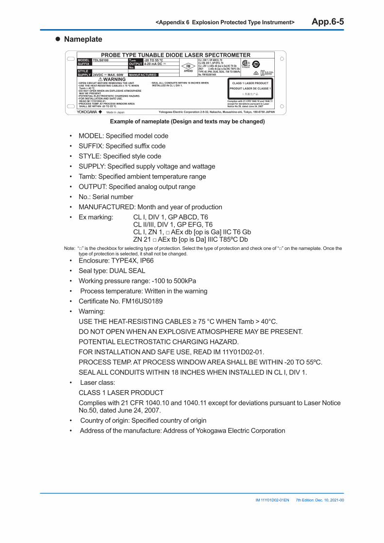
<Appendix 6 Explosion Protected Type Instrument> App.6-5
IM 11Y01D02-01EN 7th Edition: Dec. 10, 2021-00
l Nameplate
YD12
PROBE TYPE TUNABLE DIODE LASER SPECTROMETERMODEL TDLS8100
WARNING
-20 TO 55 ºC
Complies with 21 CFR 1040.10 and 1040.11except for deviations pursuant to LaserNotice No.50, dated June 24, 2007
4-20 mA DC
24VDC MAX. 60W
TambOUTPUTNo.
MANUFACTUREDSTYLESUPPLY
SUFFIX
CLASS 1 LASER PRODUCT
PRODUIT LASER DE CLASSE 1
Made in Japan
CL I, DIV 1, GP ABCD, T6CL II/III, DIV 1, GP EFG, T6CL I, ZN 1, AEx db [op is Ga] IIC T6 GbZN21 AEx tb [op is Da] IIIC T85ºC DbTYPE 4X, IP66, DUAL SEAL -100 TO 500kPa No. FM18US0164X
・OPEN CIRCUIT BEFORE REMOVING THE UNIT.・USE THE HEAT-RESISTING CABLES ≥ 75 ºC WHEN Tamb > 40 ºC.・DO NOT OPEN WHEN AN EXPLOSIVE ATMOSPHERE MAY BE PRESENT.・POTENTIAL ELECTROSTATIC CHARGING HAZARD.・FOR INSTALLATION AND SAFE USE, READ IM 11Y01D02-01.・PROCESS TEMP. AT PROCESS WINDOW AREA SHALL BE WITHIN -20 TO 55 ºC.
・SEAL ALL CONDUITS WITHIN 18 INCHES WHEN INSTALLED IN CL I, DIV 1.
R-R-YHQ-EEN462
Yokogawa Electric Corporation 2-9-32, Nakacho, Musashino-shi, Tokyo, 180-8750 JAPAN
Exampleofnameplate(Designandtextsmaybechanged)
• MODEL: Specified model code• SUFFIX: Specified suffix code• STYLE: Specified style code• SUPPLY: Specified supply voltage and wattage• Tamb: Specified ambient temperature range• OUTPUT: Specified analog output range• No.: Serial number• MANUFACTURED: Month and year of production• Ex marking: CL I, DIV 1, GP ABCD, T6
CL II/III, DIV 1, GP EFG, T6 CL I, ZN 1, □ AEx db [op is Ga] IIC T6 Gb ZN 21 □ AEx tb [op is Da] IIIC T85ºC Db
Note: “□” is the checkbox for selecting type of protection. Select the type of protection and check one of “□” on the nameplate. Once the type of protection is selected, it shall not be changed.
• Enclosure: TYPE4X, IP66• Seal type: DUAL SEAL• Working pressure range: -100 to 500kPa• Process temperature: Written in the warning• Certificate No. FM16US0189• Warning: USE THE HEAT-RESISTING CABLES ≥ 75 °C WHEN Tamb > 40°C. DO NOT OPEN WHEN AN EXPLOSIVE ATMOSPHERE MAY BE PRESENT. POTENTIAL ELECTROSTATIC CHARGING HAZARD. FOR INSTALLATION AND SAFE USE, READ IM 11Y01D02-01. PROCESS TEMP. AT PROCESS WINDOW AREA SHALL BE WITHIN -20 TO 55ºC. SEAL ALL CONDUITS WITHIN 18 INCHES WHEN INSTALLED IN CL I, DIV 1.• Laser class: CLASS 1 LASER PRODUCT Complies with 21 CFR 1040.10 and 1040.11 except for deviations pursuant to Laser Notice
No.50, dated June 24, 2007.• Country of origin: Specified country of origin• Address of the manufacture: Address of Yokogawa Electric Corporation
<Appendix 6 Explosion Protected Type Instrument> App.6-6
IM 11Y01D02-01EN 7th Edition: Dec. 10, 2021-00
l TDLS8100-C1(FMApprovalforCanada)
l Applicable standardsCSA-C22.2 No. 94.2-15:2015CAN/CSA-C22.2 No. 60079-0:2015CAN/CSA-C22.2 No. 60079-1:2016CAN/CSA C22.2 No. 60079-28:2016CAN/CSA C22.2 No. 60079-31:2015CSA-C22.2 No. 60529:2016CAN/CSA-C22.2 No. 61010-1-12:2012CAN/CSA-No. 61010-2-030-12:2016ANSI/ISA-12.27.01:2011
l CertificateNo.FM18CA0075X
Note: The symbol “X” placed after the certificate number indicates that the equipment is subjected to specific conditions of use. Refer to specific condition of use.
l SpecificationsRefer to chapter 2 for other specifications than that described below.
• Equipment ratings (Ex marking) □ Ex db [op is Ga] IIC T6 Gb □ Ex tb [op is Da] IIIC T85°C Gb
Note: “□” is the checkbox for selecting type of protection. Select the type of protection and check one of “□” on the nameplate. Once the type of protection is selected, it shall not be changed.
• Enclosure TYPE4X, IP66• Ambient temperature -20 to +55°C
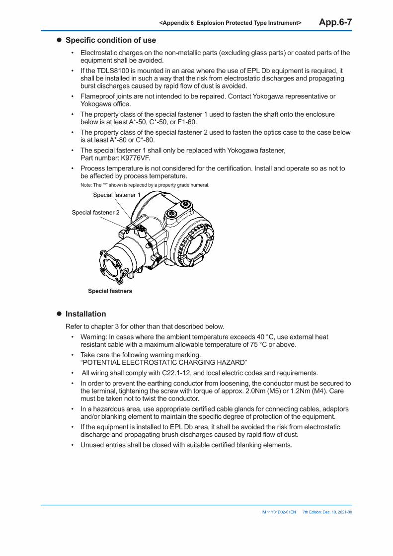
<Appendix 6 Explosion Protected Type Instrument> App.6-7
IM 11Y01D02-01EN 7th Edition: Dec. 10, 2021-00
l Specificconditionofuse• Electrostatic charges on the non-metallic parts (excluding glass parts) or coated parts of the
equipment shall be avoided.• If the TDLS8100 is mounted in an area where the use of EPL Db equipment is required, it
shall be installed in such a way that the risk from electrostatic discharges and propagating burst discharges caused by rapid flow of dust is avoided.
• Flameproof joints are not intended to be repaired. Contact Yokogawa representative or Yokogawa office.
• The property class of the special fastener 1 used to fasten the shaft onto the enclosure below is at least A*-50, C*-50, or F1-60.
• The property class of the special fastener 2 used to fasten the optics case to the case below is at least A*-80 or C*-80.
• The special fastener 1 shall only be replaced with Yokogawa fastener, Part number: K9776VF.
• Process temperature is not considered for the certification. Install and operate so as not to be affected by process temperature.
Note: The “*” shown is replaced by a property grade numeral.
Special fastener 1
Special fastener 2
Special fastners
l InstallationRefer to chapter 3 for other than that described below.
• Warning: In cases where the ambient temperature exceeds 40 °C, use external heat resistant cable with a maximum allowable temperature of 75 °C or above.
• Take care the following warning marking. “POTENTIAL ELECTROSTATIC CHARGING HAZARD”
• All wiring shall comply with C22.1-12, and local electric codes and requirements.• In order to prevent the earthing conductor from loosening, the conductor must be secured to
the terminal, tightening the screw with torque of approx. 2.0Nm (M5) or 1.2Nm (M4). Care must be taken not to twist the conductor.
• In a hazardous area, use appropriate certified cable glands for connecting cables, adaptors and/or blanking element to maintain the specific degree of protection of the equipment.
• If the equipment is installed to EPL Db area, it shall be avoided the risk from electrostatic discharge and propagating brush discharges caused by rapid flow of dust.
• Unused entries shall be closed with suitable certified blanking elements.
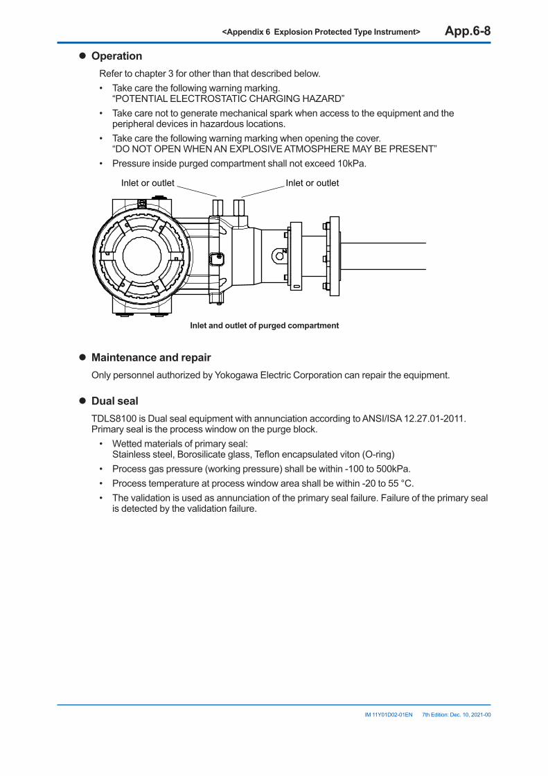
<Appendix 6 Explosion Protected Type Instrument> App.6-8
IM 11Y01D02-01EN 7th Edition: Dec. 10, 2021-00
l OperationRefer to chapter 3 for other than that described below.• Take care the following warning marking.
“POTENTIAL ELECTROSTATIC CHARGING HAZARD”• Take care not to generate mechanical spark when access to the equipment and the
peripheral devices in hazardous locations.• Take care the following warning marking when opening the cover.
“DO NOT OPEN WHEN AN EXPLOSIVE ATMOSPHERE MAY BE PRESENT”• Pressure inside purged compartment shall not exceed 10kPa.
Inlet or outletInlet or outlet
Inlet and outlet of purged compartment
l Maintenance and repairOnly personnel authorized by Yokogawa Electric Corporation can repair the equipment.
l Dual sealTDLS8100 is Dual seal equipment with annunciation according to ANSI/ISA 12.27.01-2011. Primary seal is the process window on the purge block.
• Wetted materials of primary seal: Stainless steel, Borosilicate glass, Teflon encapsulated viton (O-ring)
• Process gas pressure (working pressure) shall be within -100 to 500kPa.• Process temperature at process window area shall be within -20 to 55 °C.• The validation is used as annunciation of the primary seal failure. Failure of the primary seal
is detected by the validation failure.
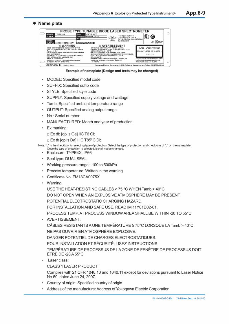
<Appendix 6 Explosion Protected Type Instrument> App.6-9
IM 11Y01D02-01EN 7th Edition: Dec. 10, 2021-00
l Name plate
YD12
PROBE TYPE TUNABLE DIODE LASER SPECTROMETERMODEL TDLS8100
WARNING AVERTISSEMENT
-20 TO 55 ºC
Complies with 21 CFR 1040.10 and 1040.11except for deviations pursuant to LaserNotice No.50, dated June 24, 2007
4-20 mA DC
24VDC MAX. 60W
TambOUTPUTNo.
MANUFACTUREDSTYLESUPPLY
SUFFIX Ex db [op is Ga] IIC T6 Gb Ex tb [op is Da] IIIC T85ºC DbTYPE 4X, IP66, DUAL SEAL -100 TO 500kPa No. FM18CA0075X
CLASS 1 LASER PRODUCT
PRODUIT LASER DE CLASSE 1
Made in Japan
・OPEN CIRCUIT BEFORE REMOVING THE UNIT.・USE THE HEAT-RESISTING CABLES ≥ 75 ºC WHEN Tamb > 40 ºC.・DO NOT OPEN WHEN AN EXPLOSIVE ATMOSPHERE MAY BE PRESENT.・POTENTIAL ELECTROSTATIC CHARGING HAZARD.・FOR INSTALLATION AND SAFE USE, READ IM 11Y01D02-01.・PROCESS TEMP. AT PROCESS WINDOW AREA SHALL BE WITHIN -20 TO 55 ºC.
・OUVRIR LE CIRCUIT AVANT D'ÔTER L'UNITÉ.・CÂBLES RESISTANTS A UNE TEMPÉRATURE ≥ 75 °C LORSQUE LA Tamb > 40 °C. ・NE PAS OUVRIR EN ATMOSPHÈRE EXPLOSIVE.・DANGER POTENTIEL DE CHARGES ÉLECTROSTATIQUES.・LISEZ IM 11Y01D02-01 POUR INSTALLATION ET SÉCURITÉ.・TEMPÉRATURE DE PROCESSUS DE LA ZONE DE FENÉTRE DE PROCESSUS DOIT ÉTRE DE -20 A 55 ºC.
R-R-YHQ-EEN462
Yokogawa Electric Corporation 2-9-32, Nakacho, Musashino-shi, Tokyo, 180-8750 JAPAN
Exampleofnameplate(Designandtextsmaybechanged)
• MODEL: Specified model code• SUFFIX: Specified suffix code• STYLE: Specified style code• SUPPLY: Specified supply voltage and wattage• Tamb: Specified ambient temperature range• OUTPUT: Specified analog output range• No.: Serial number• MANUFACTURED: Month and year of production• Ex marking: □ Ex db [op is Ga] IIC T6 Gb □ Ex tb [op is Da] IIIC T85°C Db
Note: “□” is the checkbox for selecting type of protection. Select the type of protection and check one of “□” on the nameplate. Once the type of protection is selected, it shall not be changed.
• Enclosure: TYPE4X, IP66• Seal type: DUAL SEAL• Working pressure range: -100 to 500kPa• Process temperature: Written in the warning• Certificate No. FM18CA0075X• Warning: USE THE HEAT-RESISTING CABLES ≥ 75 °C WHEN Tamb > 40°C. DO NOT OPEN WHEN AN EXPLOSIVE ATMOSPHERE MAY BE PRESENT. POTENTIAL ELECTROSTATIC CHARGING HAZARD. FOR INSTALLATION AND SAFE USE, READ IM 11Y01D02-01. PROCESS TEMP. AT PROCESS WINDOW AREA SHALL BE WITHIN -20 TO 55°C.• AVERTISSEMENT: CÂBLES RESISTANTS A UNE TEMPÉRATURE ≥ 75°C LORSQUE LA Tamb > 40°C. NE PAS OUVRIR EN ATMOSPHÈRE EXPLOSIVE. DANGER POTENTIEL DE CHARGES ÉLECTROSTATIQUES. POUR INSTALLATION ET SÉCURITÉ, LISEZ INSTRUCTIONS. TEMPÉRATURE DE PROCESSUS DE LA ZONE DE FENÊTRE DE PROCESSUS DOIT
ÊTRE DE -20 A 55°C.• Laser class: CLASS 1 LASER PRODUCT Complies with 21 CFR 1040.10 and 1040.11 except for deviations pursuant to Laser Notice
No.50, dated June 24, 2007.• Country of origin: Specified country of origin• Address of the manufacture: Address of Yokogawa Electric Corporation
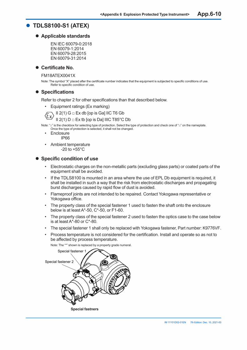
<Appendix 6 Explosion Protected Type Instrument> App.6-10
IM 11Y01D02-01EN 7th Edition: Dec. 10, 2021-00
l TDLS8100-S1(ATEX)l Applicable standards
EN IEC 60079-0:2018 EN 60079-1:2014 EN 60079-28:2015 EN 60079-31:2014
l CertificateNo.FM18ATEX0041XNote: The symbol “X” placed after the certificate number indicates that the equipment is subjected to specific conditions of use.
Refer to specific condition of use.
l SpecificationsRefer to chapter 2 for other specifications than that described below.
• Equipment ratings (Ex marking) II 2(1) G □ Ex db [op is Ga] IIC T6 Gb
II 2(1) D □ Ex tb [op is Da] IIIC T85°C DbNote: “□” is the checkbox for selecting type of protection. Select the type of protection and check one of “□” on the nameplate.
Once the type of protection is selected, it shall not be changed.• Enclosure
IP66• Ambient temperature
-20 to +55°C
l Specificconditionofuse• Electrostatic charges on the non-metallic parts (excluding glass parts) or coated parts of the
equipment shall be avoided.• If the TDLS8100 is mounted in an area where the use of EPL Db equipment is required, it
shall be installed in such a way that the risk from electrostatic discharges and propagating burst discharges caused by rapid flow of dust is avoided.
• Flameproof joints are not intended to be repaired. Contact Yokogawa representative or Yokogawa office.
• The property class of the special fastener 1 used to fasten the shaft onto the enclosure below is at least A*-50, C*-50, or F1-60.
• The property class of the special fastener 2 used to fasten the optics case to the case below is at least A*-80 or C*-80.
• The special fastener 1 shall only be replaced with Yokogawa fastener, Part number: K9776VF.• Process temperature is not considered for the certification. Install and operate so as not to
be affected by process temperature. Note: The “*” shown is replaced by a property grade numeral.
Special fastener 1
Special fastener 2
Special fastners

<Appendix 6 Explosion Protected Type Instrument> App.6-11
IM 11Y01D02-01EN 7th Edition: Dec. 10, 2021-00
l InstallationRefer to chapter 3 for other than that described below.
• Warning: In cases where the ambient temperature exceeds 40 °C, use external heat resistant cable with a maximum allowable temperature of 75 °C or above.
• Take care the following warning marking. “POTENTIAL ELECTROSTATIC CHARGING HAZARD”
• All wiring shall comply with EN60079-14, and local electric codes and requirements.• Cable glands, adapters and/or blanking elements with a suitable IP rating shall be of Ex db
IIC/Ex tb IIIC certified by ATEX and shall be installed so as to maintain the specific degree of protection (IP Code) of the equipment.
• In order to prevent the earthing conductor from loosening, the conductor must be secured to the terminal, tightening the screw with torque of approx. 2.0Nm (M5) or 1.2Nm (M4). Care must be taken not to twist the conductor.
• If the equipment is installed to EPL Db area, it shall be avoided the risk from electrostatic discharge and propagating brush discharges caused by rapid flow of dust.
• Unused entries shall be closed with suitable certified blanking elements.
l OperationRefer to chapter 3 for other than that described below.
• Take care the following warning marking. “POTENTIAL ELECTROSTATIC CHARGING HAZARD”
• Take care not to generate mechanical spark when access to the equipment and the peripheral devices in hazardous locations.
• Take care the following warning marking when opening the cover. “DO NOT OPEN WHEN AN EXPLOSIVE ATMOSPHERE MAY BE PRESENT”
• Pressure inside purged compartment shall not exceed 10kPa.
Inlet or outletInlet or outlet
Inlet and outlet of purged compartment
l Maintenance and repairOnly personnel authorized by Yokogawa Electric Corporation can repair the equipment.
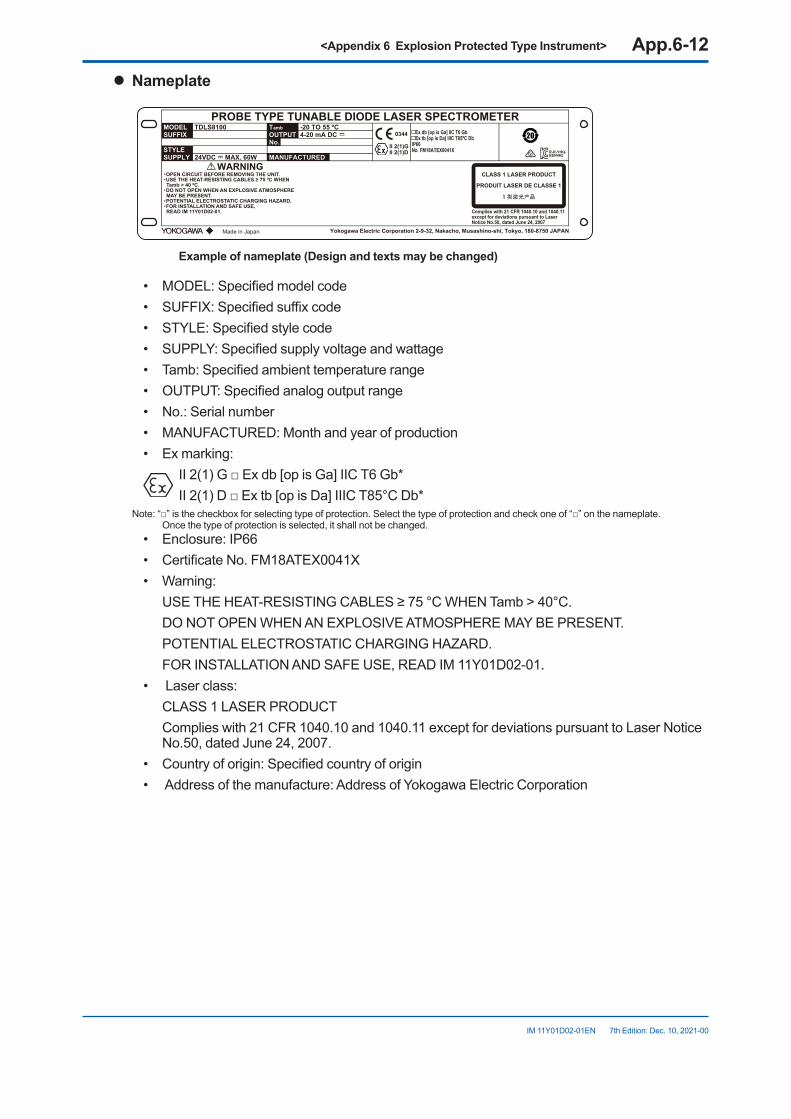
<Appendix 6 Explosion Protected Type Instrument> App.6-12
IM 11Y01D02-01EN 7th Edition: Dec. 10, 2021-00
l Nameplate
YD12
PROBE TYPE TUNABLE DIODE LASER SPECTROMETERMODEL TDLS8100
WARNING
-20 TO 55 ºC
Complies with 21 CFR 1040.10 and 1040.11except for deviations pursuant to LaserNotice No.50, dated June 24, 2007
4-20 mA DC
24VDC MAX. 60W
TambOUTPUTNo.
MANUFACTUREDSTYLESUPPLY
SUFFIXII 2(1)GII 2(1)D
0344 Ex db [op is Ga] IIC T6 Gb Ex tb [op is Da] IIIC T85ºC DbIP66No. FM18ATEX0041X
CLASS 1 LASER PRODUCT
PRODUIT LASER DE CLASSE 1
1 类激光产品
Made in Japan
・OPEN CIRCUIT BEFORE REMOVING THE UNIT.・USE THE HEAT-RESISTING CABLES ≥ 75 ºC WHEN Tamb > 40 ºC.・DO NOT OPEN WHEN AN EXPLOSIVE ATMOSPHERE MAY BE PRESENT.・POTENTIAL ELECTROSTATIC CHARGING HAZARD.・FOR INSTALLATION AND SAFE USE, READ IM 11Y01D02-01.
R-R-YHQ-EEN462
Yokogawa Electric Corporation 2-9-32, Nakacho, Musashino-shi, Tokyo, 180-8750 JAPAN
Exampleofnameplate(Designandtextsmaybechanged)
• MODEL: Specified model code• SUFFIX: Specified suffix code• STYLE: Specified style code• SUPPLY: Specified supply voltage and wattage• Tamb: Specified ambient temperature range• OUTPUT: Specified analog output range• No.: Serial number• MANUFACTURED: Month and year of production• Ex marking:
II 2(1) G □ Ex db [op is Ga] IIC T6 Gb* II 2(1) D □ Ex tb [op is Da] IIIC T85°C Db*
Note: “□” is the checkbox for selecting type of protection. Select the type of protection and check one of “□” on the nameplate. Once the type of protection is selected, it shall not be changed.
• Enclosure: IP66• Certificate No. FM18ATEX0041X• Warning: USE THE HEAT-RESISTING CABLES ≥ 75 °C WHEN Tamb > 40°C. DO NOT OPEN WHEN AN EXPLOSIVE ATMOSPHERE MAY BE PRESENT. POTENTIAL ELECTROSTATIC CHARGING HAZARD. FOR INSTALLATION AND SAFE USE, READ IM 11Y01D02-01.• Laser class: CLASS 1 LASER PRODUCT Complies with 21 CFR 1040.10 and 1040.11 except for deviations pursuant to Laser Notice
No.50, dated June 24, 2007.• Country of origin: Specified country of origin• Address of the manufacture: Address of Yokogawa Electric Corporation
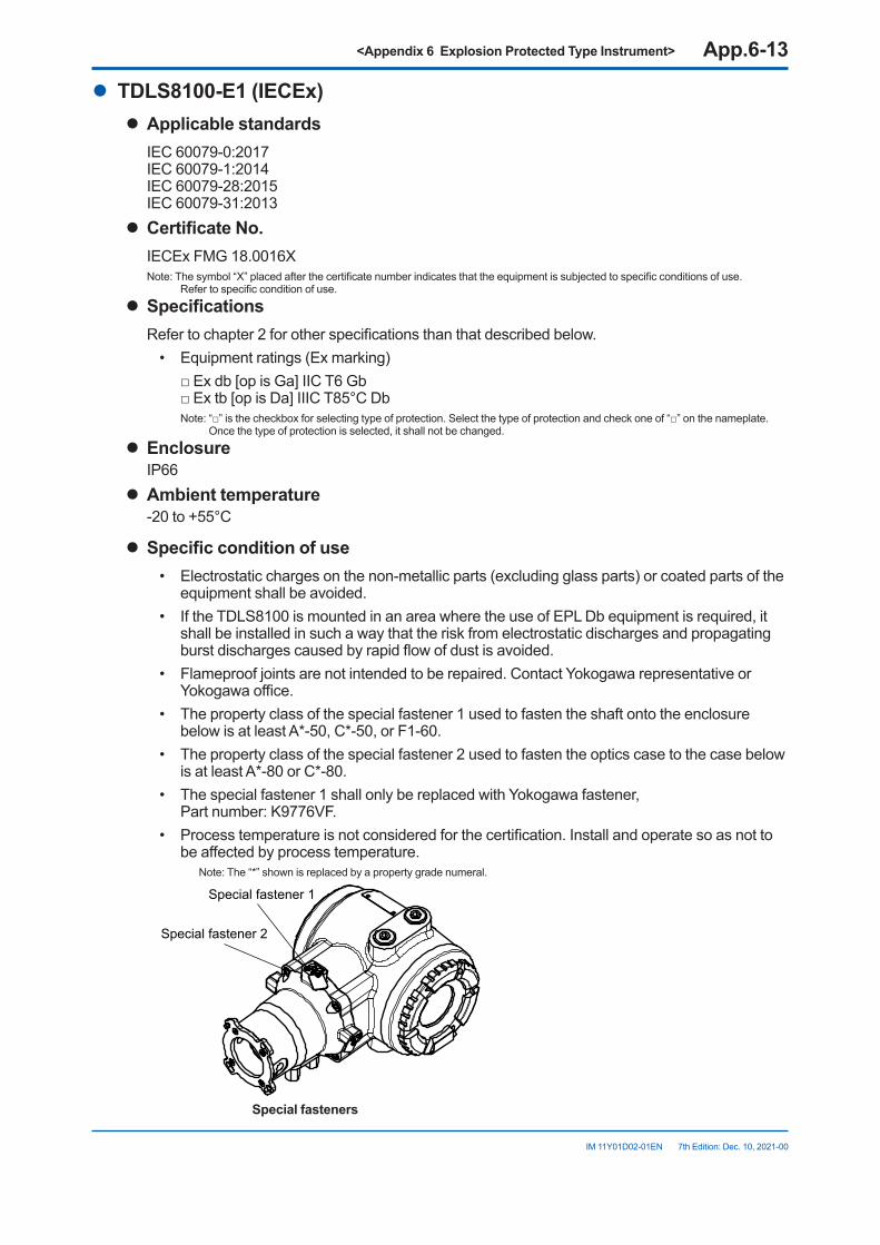
<Appendix 6 Explosion Protected Type Instrument> App.6-13
IM 11Y01D02-01EN 7th Edition: Dec. 10, 2021-00
l TDLS8100-E1(IECEx)l Applicable standards
IEC 60079-0:2017 IEC 60079-1:2014 IEC 60079-28:2015 IEC 60079-31:2013
l CertificateNo.IECEx FMG 18.0016XNote: The symbol “X” placed after the certificate number indicates that the equipment is subjected to specific conditions of use.
Refer to specific condition of use.
l SpecificationsRefer to chapter 2 for other specifications than that described below.
• Equipment ratings (Ex marking) □ Ex db [op is Ga] IIC T6 Gb
□ Ex tb [op is Da] IIIC T85°C Db Note: “□” is the checkbox for selecting type of protection. Select the type of protection and check one of “□” on the nameplate.
Once the type of protection is selected, it shall not be changed.
l EnclosureIP66
l Ambient temperature-20 to +55°C
l Specificconditionofuse• Electrostatic charges on the non-metallic parts (excluding glass parts) or coated parts of the
equipment shall be avoided.• If the TDLS8100 is mounted in an area where the use of EPL Db equipment is required, it
shall be installed in such a way that the risk from electrostatic discharges and propagating burst discharges caused by rapid flow of dust is avoided.
• Flameproof joints are not intended to be repaired. Contact Yokogawa representative or Yokogawa office.
• The property class of the special fastener 1 used to fasten the shaft onto the enclosure below is at least A*-50, C*-50, or F1-60.
• The property class of the special fastener 2 used to fasten the optics case to the case below is at least A*-80 or C*-80.
• The special fastener 1 shall only be replaced with Yokogawa fastener, Part number: K9776VF.
• Process temperature is not considered for the certification. Install and operate so as not to be affected by process temperature.
Note: The “*” shown is replaced by a property grade numeral.
Special fastener 1
Special fastener 2
Special fasteners
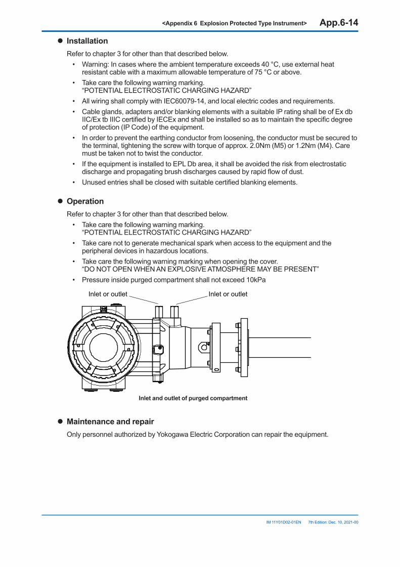
<Appendix 6 Explosion Protected Type Instrument> App.6-14
IM 11Y01D02-01EN 7th Edition: Dec. 10, 2021-00
l InstallationRefer to chapter 3 for other than that described below.
• Warning: In cases where the ambient temperature exceeds 40 °C, use external heat resistant cable with a maximum allowable temperature of 75 °C or above.
• Take care the following warning marking. “POTENTIAL ELECTROSTATIC CHARGING HAZARD”
• All wiring shall comply with IEC60079-14, and local electric codes and requirements.• Cable glands, adapters and/or blanking elements with a suitable IP rating shall be of Ex db
IIC/Ex tb IIIC certified by IECEx and shall be installed so as to maintain the specific degree of protection (IP Code) of the equipment.
• In order to prevent the earthing conductor from loosening, the conductor must be secured to the terminal, tightening the screw with torque of approx. 2.0Nm (M5) or 1.2Nm (M4). Care must be taken not to twist the conductor.
• If the equipment is installed to EPL Db area, it shall be avoided the risk from electrostatic discharge and propagating brush discharges caused by rapid flow of dust.
• Unused entries shall be closed with suitable certified blanking elements.
l OperationRefer to chapter 3 for other than that described below.
• Take care the following warning marking. “POTENTIAL ELECTROSTATIC CHARGING HAZARD”
• Take care not to generate mechanical spark when access to the equipment and the peripheral devices in hazardous locations.
• Take care the following warning marking when opening the cover. “DO NOT OPEN WHEN AN EXPLOSIVE ATMOSPHERE MAY BE PRESENT”
• Pressure inside purged compartment shall not exceed 10kPa
Inlet or outletInlet or outlet
Inlet and outlet of purged compartment
l Maintenance and repairOnly personnel authorized by Yokogawa Electric Corporation can repair the equipment.

<Appendix 6 Explosion Protected Type Instrument> App.6-15
IM 11Y01D02-01EN 7th Edition: Dec. 10, 2021-00
l Nameplate
YD12
PROBE TYPE TUNABLE DIODE LASER SPECTROMETERMODEL TDLS8100
WARNING
-20 TO 55 ºC
Complies with 21 CFR 1040.10 and 1040.11except for deviations pursuant to LaserNotice No.50, dated June 24, 2007
4-20 mA DC
24VDC MAX. 60W
TambOUTPUTNo.
MANUFACTUREDSTYLESUPPLY
SUFFIX Ex db [op is Ga] IIC T6 Gb Ex tb [op is Da] IIIC T85ºC DbIP66No. IECEx FMG 18.0016X
CLASS 1 LASER PRODUCT
PRODUIT LASER DE CLASSE 1
1 类激光产品
Made in Japan
・OPEN CIRCUIT BEFORE REMOVING THE UNIT.・USE THE HEAT-RESISTING CABLES ≥ 75 ºC WHEN Tamb > 40 ºC.・DO NOT OPEN WHEN AN EXPLOSIVE ATMOSPHERE MAY BE PRESENT.・POTENTIAL ELECTROSTATIC CHARGING HAZARD.・FOR INSTALLATION AND SAFE USE, READ IM 11Y01D02-01.
R-R-YHQ-EEN462
Yokogawa Electric Corporation 2-9-32, Nakacho, Musashino-shi, Tokyo, 180-8750 JAPAN
Exampleofnameplate(Designandtextsmaybechanged)
• MODEL: Specified model code• SUFFIX: Specified suffix code• STYLE: Specified style code• SUPPLY: Specified supply voltage and wattage• Tamb: Specified ambient temperature range• OUTPUT: Specified analog output range• No.: Serial number• MANUFACTURED: Month and year of production• Ex marking: □ Ex db [op is Ga] IIC T6 Gb □ Ex tb [op is Da] IIIC T85°C Db
Note: “□” is the checkbox for selecting type of protection. Select the type of protection and check one of “□” on the nameplate. Once the type of protection is selected, it shall not be changed.
• Enclosure: IP66• Certificate No. IECEx FMG 18.0016X• Warning: USE THE HEAT-RESISTING CABLES ≥ 75 °C WHEN Tamb > 40°C. DO NOT OPEN WHEN AN EXPLOSIVE ATMOSPHERE MAY BE PRESENT. POTENTIAL ELECTROSTATIC CHARGING HAZARD. FOR INSTALLATION AND SAFE USE, READ IM 11Y01D02-01.• Laser class: CLASS 1 LASER PRODUCT Complies with 21 CFR 1040.10 and 1040.11 except for deviations pursuant to Laser Notice
No.50, dated June 24, 2007.• Country of origin: Specified country of origin• Address of the manufacture: Address of Yokogawa Electric Corporation
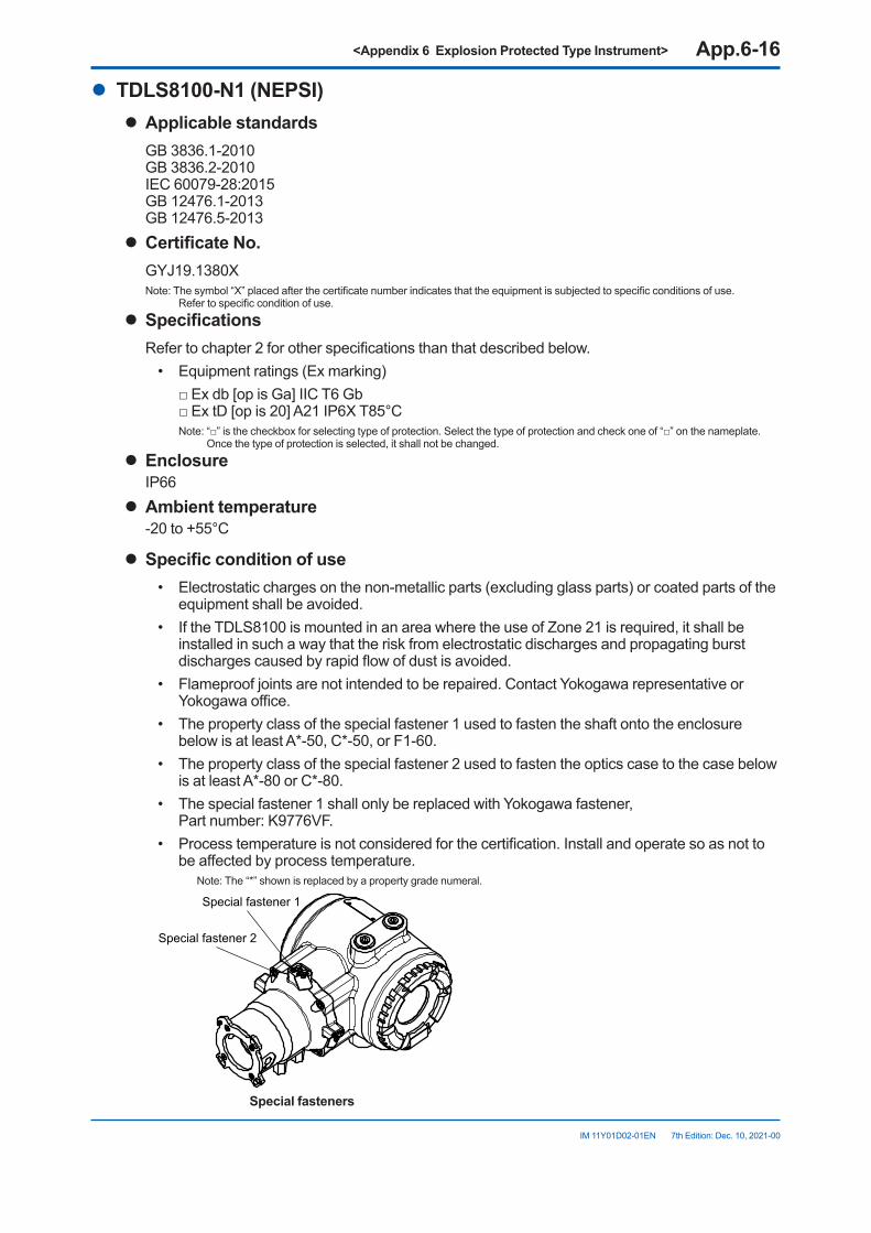
<Appendix 6 Explosion Protected Type Instrument> App.6-16
IM 11Y01D02-01EN 7th Edition: Dec. 10, 2021-00
l TDLS8100-N1(NEPSI)l Applicable standards
GB 3836.1-2010 GB 3836.2-2010 IEC 60079-28:2015 GB 12476.1-2013 GB 12476.5-2013
l CertificateNo.GYJ19.1380XNote: The symbol “X” placed after the certificate number indicates that the equipment is subjected to specific conditions of use.
Refer to specific condition of use.
l SpecificationsRefer to chapter 2 for other specifications than that described below.
• Equipment ratings (Ex marking) □ Ex db [op is Ga] IIC T6 Gb
□ Ex tD [op is 20] A21 IP6X T85°C Note: “□” is the checkbox for selecting type of protection. Select the type of protection and check one of “□” on the nameplate.
Once the type of protection is selected, it shall not be changed.
l EnclosureIP66
l Ambient temperature-20 to +55°C
l Specificconditionofuse• Electrostatic charges on the non-metallic parts (excluding glass parts) or coated parts of the
equipment shall be avoided.• If the TDLS8100 is mounted in an area where the use of Zone 21 is required, it shall be
installed in such a way that the risk from electrostatic discharges and propagating burst discharges caused by rapid flow of dust is avoided.
• Flameproof joints are not intended to be repaired. Contact Yokogawa representative or Yokogawa office.
• The property class of the special fastener 1 used to fasten the shaft onto the enclosure below is at least A*-50, C*-50, or F1-60.
• The property class of the special fastener 2 used to fasten the optics case to the case below is at least A*-80 or C*-80.
• The special fastener 1 shall only be replaced with Yokogawa fastener, Part number: K9776VF.
• Process temperature is not considered for the certification. Install and operate so as not to be affected by process temperature.
Note: The “*” shown is replaced by a property grade numeral.
Special fastener 1
Special fastener 2
Special fasteners
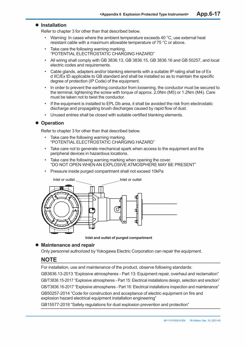
<Appendix 6 Explosion Protected Type Instrument> App.6-17
IM 11Y01D02-01EN 7th Edition: Dec. 10, 2021-00
l InstallationRefer to chapter 3 for other than that described below.
• Warning: In cases where the ambient temperature exceeds 40 °C, use external heat resistant cable with a maximum allowable temperature of 75 °C or above.
• Take care the following warning marking. “POTENTIAL ELECTROSTATIC CHARGING HAZARD”
• All wiring shall comply with GB 3836.13, GB 3836.15, GB 3836.16 and GB 50257, and local electric codes and requirements.
• Cable glands, adapters and/or blanking elements with a suitable IP rating shall be of Ex d IIC/Ex tD applicable to GB standard and shall be installed so as to maintain the specific degree of protection (IP Code) of the equipment.
• In order to prevent the earthing conductor from loosening, the conductor must be secured to the terminal, tightening the screw with torque of approx. 2.0Nm (M5) or 1.2Nm (M4). Care must be taken not to twist the conductor.
• If the equipment is installed to EPL Db area, it shall be avoided the risk from electrostatic discharge and propagating brush discharges caused by rapid flow of dust.
• Unused entries shall be closed with suitable certified blanking elements.
l OperationRefer to chapter 3 for other than that described below.
• Take care the following warning marking. “POTENTIAL ELECTROSTATIC CHARGING HAZARD”
• Take care not to generate mechanical spark when access to the equipment and the peripheral devices in hazardous locations.
• Take care the following warning marking when opening the cover. “DO NOT OPEN WHEN AN EXPLOSIVE ATMOSPHERE MAY BE PRESENT”
• Pressure inside purged compartment shall not exceed 10kPa
Inlet or outletInlet or outlet
Inlet and outlet of purged compartment
l Maintenance and repairOnly personnel authorized by Yokogawa Electric Corporation can repair the equipment.
NOTEFor installation, use and maintenance of the product, observe following standards:GB3836.13-2013 “Explosive atmospheres - Part 13: Equipment repair, overhaul and reclamation”GB/T3836.15-2017 “Explosive atmospheres - Part 15: Electrical installations design, selection and erection”GB/T3836.16-2017 “Explosive atmospheres - Part 16: Electrical installations inspection and maintenance”GB50257-2014 ”Code for construction and acceptance of electric equipment on fire and explosion hazard electrical equipment installation engineering”GB15577-2018 “Safety regulations for dust explosion prevention and protection”
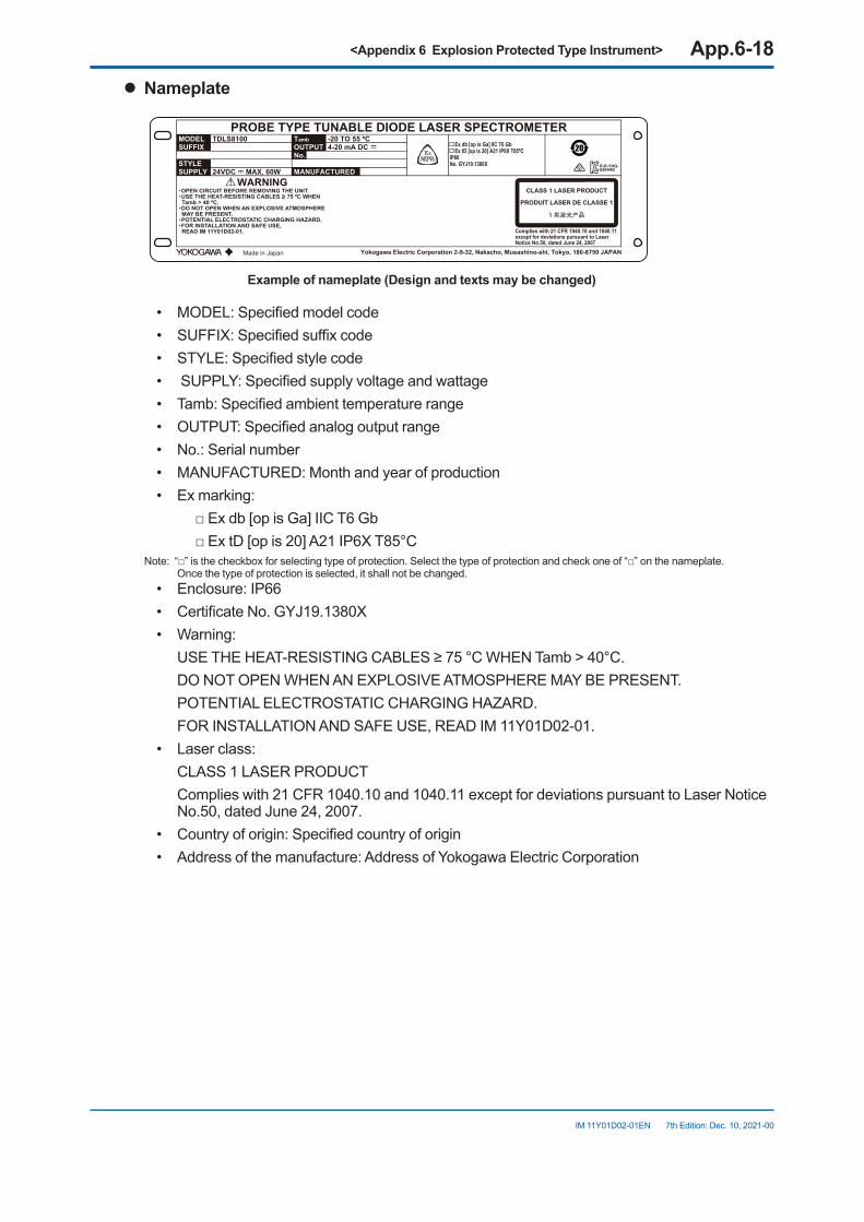
<Appendix 6 Explosion Protected Type Instrument> App.6-18
IM 11Y01D02-01EN 7th Edition: Dec. 10, 2021-00
l Nameplate
YD12
PROBE TYPE TUNABLE DIODE LASER SPECTROMETERMODEL TDLS8100
WARNING
-20 TO 55 ºC
Complies with 21 CFR 1040.10 and 1040.11except for deviations pursuant to LaserNotice No.50, dated June 24, 2007
4-20 mA DC
24VDC MAX. 60W
TambOUTPUTNo.
MANUFACTUREDSTYLESUPPLY
SUFFIX Ex db [op is Ga] IIC T6 Gb Ex tD [op is 20] A21 IP6X T85ºCIP66No. GYJ19.1380X
CLASS 1 LASER PRODUCT
PRODUIT LASER DE CLASSE 1
1 类激光产品
Made in Japan
・OPEN CIRCUIT BEFORE REMOVING THE UNIT.・USE THE HEAT-RESISTING CABLES ≥ 75 ºC WHEN Tamb > 40 ºC.・DO NOT OPEN WHEN AN EXPLOSIVE ATMOSPHERE MAY BE PRESENT.・POTENTIAL ELECTROSTATIC CHARGING HAZARD.・FOR INSTALLATION AND SAFE USE, READ IM 11Y01D02-01.
R-R-YHQ-EEN462
Yokogawa Electric Corporation 2-9-32, Nakacho, Musashino-shi, Tokyo, 180-8750 JAPAN
Exampleofnameplate(Designandtextsmaybechanged)
• MODEL: Specified model code• SUFFIX: Specified suffix code• STYLE: Specified style code• SUPPLY: Specified supply voltage and wattage• Tamb: Specified ambient temperature range• OUTPUT: Specified analog output range• No.: Serial number• MANUFACTURED: Month and year of production• Ex marking: □ Ex db [op is Ga] IIC T6 Gb □ Ex tD [op is 20] A21 IP6X T85°C
Note: “□” is the checkbox for selecting type of protection. Select the type of protection and check one of “□” on the nameplate. Once the type of protection is selected, it shall not be changed.
• Enclosure: IP66• Certificate No. GYJ19.1380X• Warning: USE THE HEAT-RESISTING CABLES ≥ 75 °C WHEN Tamb > 40°C. DO NOT OPEN WHEN AN EXPLOSIVE ATMOSPHERE MAY BE PRESENT. POTENTIAL ELECTROSTATIC CHARGING HAZARD. FOR INSTALLATION AND SAFE USE, READ IM 11Y01D02-01.• Laser class: CLASS 1 LASER PRODUCT Complies with 21 CFR 1040.10 and 1040.11 except for deviations pursuant to Laser Notice
No.50, dated June 24, 2007.• Country of origin: Specified country of origin• Address of the manufacture: Address of Yokogawa Electric Corporation
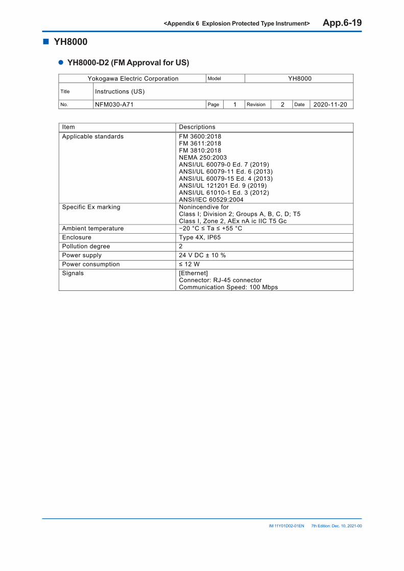
<Appendix 6 Explosion Protected Type Instrument> App.6-19
IM 11Y01D02-01EN 7th Edition: Dec. 10, 2021-00
n YH8000
l YH8000-D2(FMApprovalforUS)
Yokogawa Electric Corporation Model YH8000
Title Instructions (US)
No. NFM030-A71 Page 1 Revision 2 Date 2020-11-20
Item Descriptions Applicable standards FM 3600 :2018
FM 3611:2018 FM 3810:2018 NEMA 250:2003 ANSI/UL 60079-0 Ed. 7 (2019) ANSI/UL 60079-11 Ed. 6 (2013) ANSI/UL 60079-15 Ed. 4 (2013) ANSI/UL 121201 Ed. 9 (2019) ANSI/UL 61010-1 Ed. 3 (2012) ANSI/IEC 60529:2004
Specific Ex marking Nonincendive for Class I; Division 2; Groups A, B, C, D; T5 Class I, Zone 2, AEx nA ic IIC T5 Gc
Ambient temperature −20 °C ≤ Ta ≤ +55 °C Enclosure Type 4X, IP65 Pollution degree 2 Power supply 24 V DC ± 10 % Power consumption ≤ 12 W Signals [Ethernet]
Connector: RJ-45 connector Communication Speed: 100 Mbps
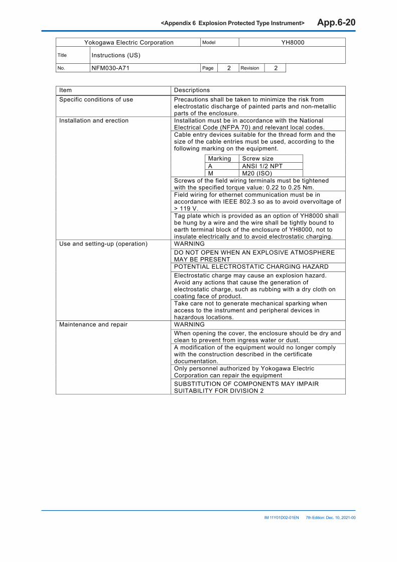
<Appendix 6 Explosion Protected Type Instrument> App.6-20
IM 11Y01D02-01EN 7th Edition: Dec. 10, 2021-00
Yokogawa Electric Corporation Model YH8000
Title Instructions (US)
No. NFM030-A71 Page 2 Revision 2
Item Descriptions Specific conditions of use Precautions shall be taken to minimize the risk from
electrostatic discharge of painted parts and non-metallic parts of the enclosure.
Installation and erection Installation must be in accordance with the National Electrical Code (NFPA 70) and relevant local codes.Cable entry devices suitable for the thread form and the size of the cable entries must be used, according to the following marking on the equipment. Marking Screw size
A ANSI 1/2 NPT M M20 (ISO)
Screws of the field wiring terminals must be tightened with the specified torque value: 0.22 to 0.25 Nm.Field wiring for ethernet communication must be in accordance with IEEE 802.3 so as to avoid overvoltage of > 119 V.Tag plate which is provided as an option of YH8000 shall be hung by a wire and the wire shall be tightly bound to earth terminal block of the enclosure of YH8000, not to insulate electrically and to avoid electrostatic charging.
Use and setting-up (operation) WARNING DO NOT OPEN WHEN AN EXPLOSIVE ATMOSPHERE MAY BE PRESENTPOTENTIAL ELECTROSTATIC CHARGING HAZARD Electrostatic charge may cause an explosion hazard. Avoid any actions that cause the generation of electrostatic charge, such as rubbing with a dry cloth on coating face of product.Take care not to generate mechanical sparking when access to the instrument and peripheral devices in hazardous locations.
Maintenance and repair WARNING When opening the cover, the enclosure should be dry and clean to prevent from ingress water or dust. A modification of the equipment would no longer comply with the construction described in the certificate documentation.Only personnel authorized by Yokogawa Electric Corporation can repair the equipment SUBSTITUTION OF COMPONENTS MAY IMPAIR SUITABILITY FOR DIVISION 2
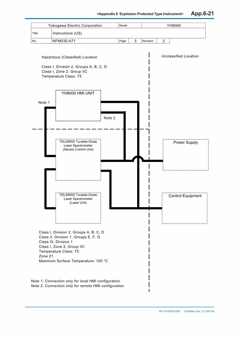
<Appendix 6 Explosion Protected Type Instrument> App.6-21
IM 11Y01D02-01EN 7th Edition: Dec. 10, 2021-00
Yokogawa Electric Corporation Model YH8000
Title Instructions (US)
No. NFM030-A71 Page 3 Revision 2 Note 1: Connection only for local HMI configuration Note 2: Connection only for remote HMI configuration
YH8000 HMI UNIT
TDLS8000 Tunable Diode Laser Spectrometer
(Sensor Control Unit)
Power Supply
TDLS8000 Tunable Diode Laser Spectrometer
(Laser Unit)
Control Equipment
Hazardous (Classified) Location Class I, Division 2, Groups A, B, C, D Class I, Zone 2, Group IIC Temperature Class: T5
Class I, Division 2, Groups A, B, C, D Class II, Division 1, Groups E, F, G Class III, Division 1 Class I, Zone 2, Group IIC Temperature Class: T5 Zone 21 Maximum Surface Temperature: 100 °C
Unclassified Location
Note 1
Note 2
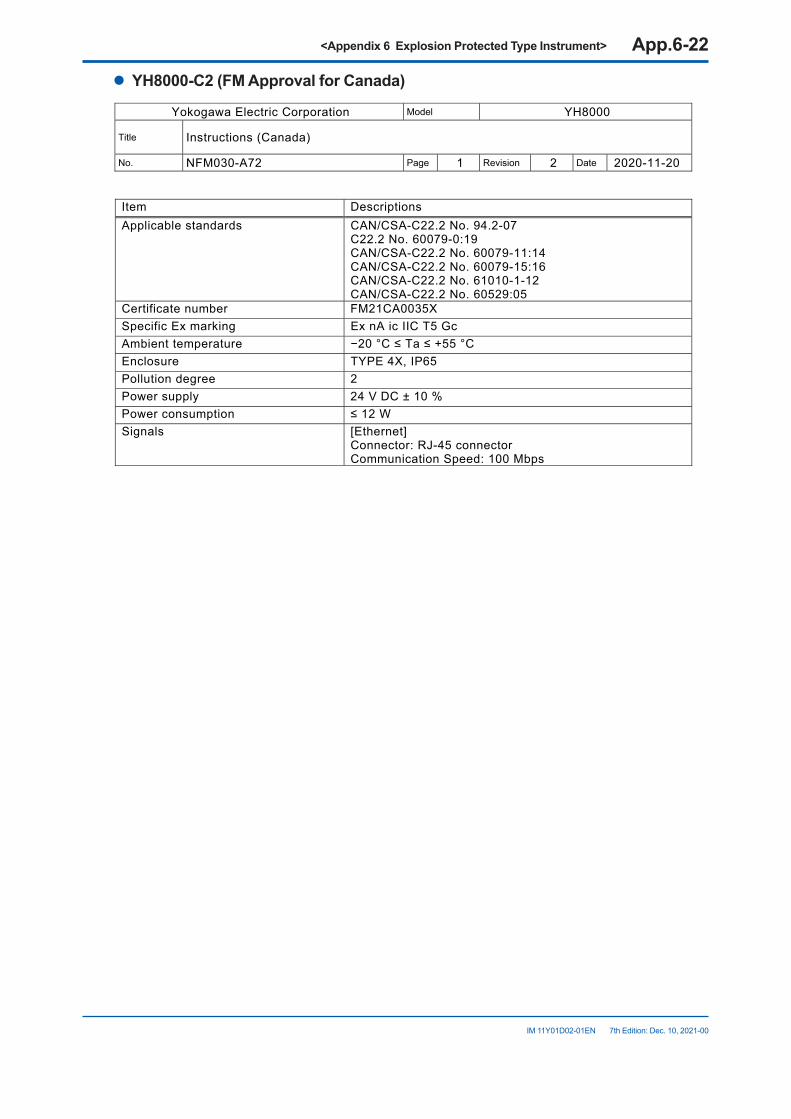
<Appendix 6 Explosion Protected Type Instrument> App.6-22
IM 11Y01D02-01EN 7th Edition: Dec. 10, 2021-00
l YH8000-C2(FMApprovalforCanada)
Yokogawa Electric Corporation Model YH8000
Title Instructions (Canada)
No. NFM030-A72 Page 1 Revision 2 Date 2020-11-20
Item Descriptions Applicable standards CAN/CSA-C22.2 No. 94.2-07
C22.2 No. 60079-0:19 CAN/CSA-C22.2 No. 60079-11:14 CAN/CSA-C22.2 No. 60079-15:16 CAN/CSA-C22.2 No. 61010-1-12 CAN/CSA-C22.2 No. 60529:05
Certificate number FM21CA0035X Specific Ex marking Ex nA ic IIC T5 Gc Ambient temperature −20 °C ≤ Ta ≤ +55 °C Enclosure TYPE 4X, IP65 Pollution degree 2 Power supply 24 V DC ± 10 % Power consumption ≤ 12 W Signals [Ethernet]
Connector: RJ-45 connector Communication Speed: 100 Mbps
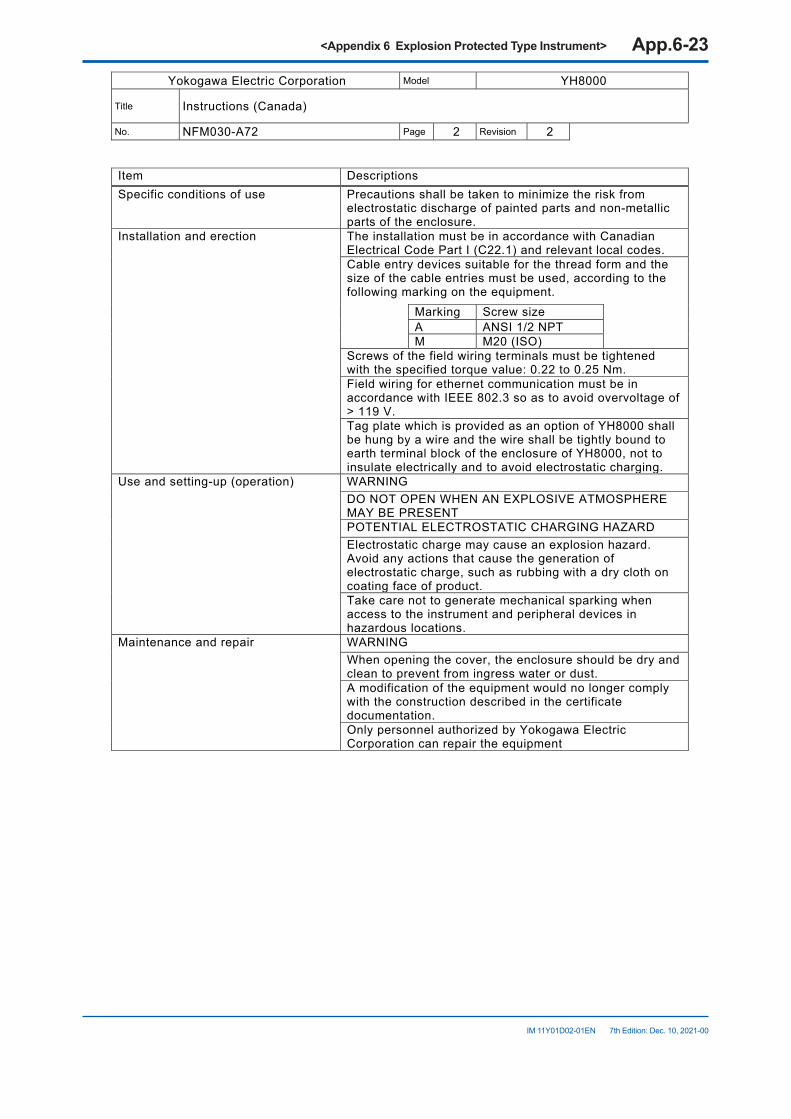
<Appendix 6 Explosion Protected Type Instrument> App.6-23
IM 11Y01D02-01EN 7th Edition: Dec. 10, 2021-00
Yokogawa Electric Corporation Model YH8000
Title Instructions (Canada)
No. NFM030-A72 Page 2 Revision 2
Item Descriptions Specific conditions of use Precautions shall be taken to minimize the risk from
electrostatic discharge of painted parts and non-metallic parts of the enclosure.
Installation and erection The installation must be in accordance with Canadian Electrical Code Part I (C22.1) and relevant local codes.Cable entry devices suitable for the thread form and the size of the cable entries must be used, according to the following marking on the equipment. Marking Screw size
A ANSI 1/2 NPT M M20 (ISO)
Screws of the field wiring terminals must be tightened with the specified torque value: 0.22 to 0.25 Nm.Field wiring for ethernet communication must be in accordance with IEEE 802.3 so as to avoid overvoltage of > 119 V.Tag plate which is provided as an option of YH8000 shall be hung by a wire and the wire shall be tightly bound to earth terminal block of the enclosure of YH8000, not to insulate electrically and to avoid electrostatic charging.
Use and setting-up (operation) WARNING DO NOT OPEN WHEN AN EXPLOSIVE ATMOSPHERE MAY BE PRESENTPOTENTIAL ELECTROSTATIC CHARGING HAZARD Electrostatic charge may cause an explosion hazard. Avoid any actions that cause the generation of electrostatic charge, such as rubbing with a dry cloth on coating face of product.Take care not to generate mechanical sparking when access to the instrument and peripheral devices in hazardous locations.
Maintenance and repair WARNING When opening the cover, the enclosure should be dry and clean to prevent from ingress water or dust. A modification of the equipment would no longer comply with the construction described in the certificate documentation.Only personnel authorized by Yokogawa Electric Corporation can repair the equipment
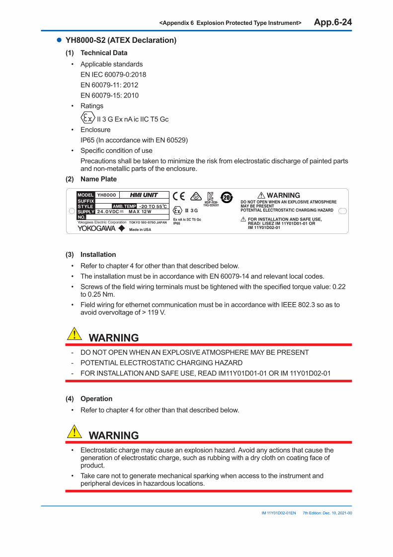
<Appendix 6 Explosion Protected Type Instrument> App.6-24
IM 11Y01D02-01EN 7th Edition: Dec. 10, 2021-00
l YH8000-S2(ATEXDeclaration)(1) TechnicalData
• Applicable standards EN IEC 60079-0:2018 EN 60079-11: 2012 EN 60079-15: 2010• Ratings
II 3 G Ex nA ic IIC T5 Gc• Enclosure IP65 (In accordance with EN 60529)• Specific condition of use Precautions shall be taken to minimize the risk from electrostatic discharge of painted parts
and non-metallic parts of the enclosure.(2) NamePlate
abcdegfhija;lsdjfowei
(3) Installation• Refer to chapter 4 for other than that described below.• The installation must be in accordance with EN 60079-14 and relevant local codes.• Screws of the field wiring terminals must be tightened with the specified torque value: 0.22
to 0.25 Nm.• Field wiring for ethernet communication must be in accordance with IEEE 802.3 so as to
avoid overvoltage of > 119 V.
WARNING- DO NOT OPEN WHEN AN EXPLOSIVE ATMOSPHERE MAY BE PRESENT- POTENTIAL ELECTROSTATIC CHARGING HAZARD- FOR INSTALLATION AND SAFE USE, READ IM11Y01D01-01 OR IM 11Y01D02-01
(4) Operation• Refer to chapter 4 for other than that described below.
WARNING• Electrostatic charge may cause an explosion hazard. Avoid any actions that cause the
generation of electrostatic charge, such as rubbing with a dry cloth on coating face of product.
• Take care not to generate mechanical sparking when access to the instrument and peripheral devices in hazardous locations.

<Appendix 6 Explosion Protected Type Instrument> App.6-25
IM 11Y01D02-01EN 7th Edition: Dec. 10, 2021-00
(5) MaintenanceandRepairOnly personnel authorized by Yokogawa Electric Corporation can repair the equipment.When opening the cover, the enclosure should be dry and clean to prevent from ingress water or dust.
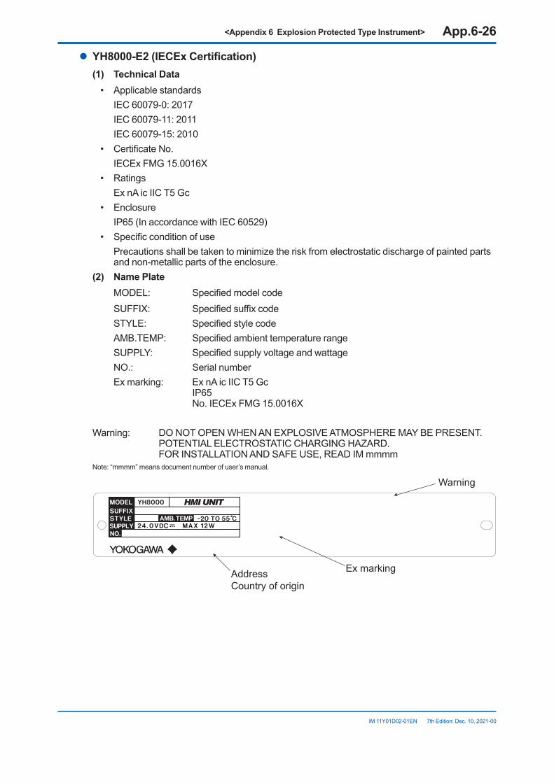
<Appendix 6 Explosion Protected Type Instrument> App.6-26
IM 11Y01D02-01EN 7th Edition: Dec. 10, 2021-00
l YH8000-E2(IECExCertification)(1) TechnicalData
• Applicable standards IEC 60079-0: 2017 IEC 60079-11: 2011 IEC 60079-15: 2010• Certificate No. IECEx FMG 15.0016X• Ratings Ex nA ic IIC T5 Gc• Enclosure IP65 (In accordance with IEC 60529)• Specific condition of use Precautions shall be taken to minimize the risk from electrostatic discharge of painted parts
and non-metallic parts of the enclosure.(2) NamePlate MODEL: Specified model code
SUFFIX: Specified suffix code STYLE: Specified style code AMB.TEMP: Specified ambient temperature range SUPPLY: Specified supply voltage and wattage NO.: Serial number Ex marking: Ex nA ic IIC T5 Gc
IP65 No. IECEx FMG 15.0016X
Warning: DO NOT OPEN WHEN AN EXPLOSIVE ATMOSPHERE MAY BE PRESENT.POTENTIAL ELECTROSTATIC CHARGING HAZARD. FOR INSTALLATION AND SAFE USE, READ IM mmmm
Note: “mmmm” means document number of user’s manual.
AddressCountry of origin
Ex marking
Warning
<Appendix 6 Explosion Protected Type Instrument> App.6-27
IM 11Y01D02-01EN 7th Edition: Dec. 10, 2021-00
(3) Installation• Refer to chapter 4 for other than that described below.• The installation must be in accordance with IEC 60079-14 and relevant local codes.• Screws of the field wiring terminals must be tightened with the specified torque value: 0.22
to 0.25 Nm.• Field wiring for ethernet communication must be in accordance with IEEE 802.3 so as to
avoid overvoltage of > 119 V.
WARNING- DO NOT OPEN WHEN AN EXPLOSIVE ATMOSPHERE MAY BE PRESENT- POTENTIAL ELECTROSTATIC CHARGING HAZARD- FOR INSTALLATION AND SAFE USE, READ IM11Y01D01-01 OR IM 11Y01D02-01.
(4) Operation• Refer to chapter 4 for other than that described below.
WARNING• Electrostatic charge may cause an explosion hazard. Avoid any actions that cause the
generation of electrostatic charge, such as rubbing with a dry cloth on coating face of product.
• Take care not to generate mechanical sparking when access to the instrument and peripheral devices in hazardous locations.
(5) MaintenanceandRepairOnly personnel authorized by Yokogawa Electric Corporation can repair the equipment.When opening the cover, the enclosure should be dry and clean to prevent from ingress water or dust.

Blank Page
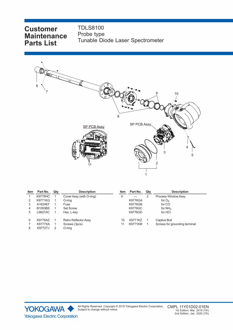
CustomerMaintenanceParts List
TDLS8100Probe typeTunable Diode Laser Spectrometer
CMPL 11Y01D02-01EN1st Edition: Mar. 2019 (YK)
2nd Edition: Jan. 2020 (YK)
1
2
4
11
5
67
8
SP PCB AssySP PCB Assy
9 10
3
Item Part No. Qty Description Item Part No. Qty Description1 K9776HC 1 Cover Assy (with O-ring) 9 — 2 Process Window Assy2 K9771KG 1 O-ring K9776GA for O23 A1624EF 1 Fuse K9776GB for CO4 B1093BS 1 Set Screw K9776GC for NH35 L9827AC 1 Hex. L-key K9776GD for HCl
6 K9776AZ 1 Retro Reflector Assy 10 K9771KZ 1 Captive Bolt7 K9777XA 1 Screws (3pcs) 11 K9771KM 1 Screws for grounding terminal8 K9772TJ 2 O-ring
All Rights Reserved. Copyright © 2019 Yokogawa Electric Corporation.Subject to change without notice.

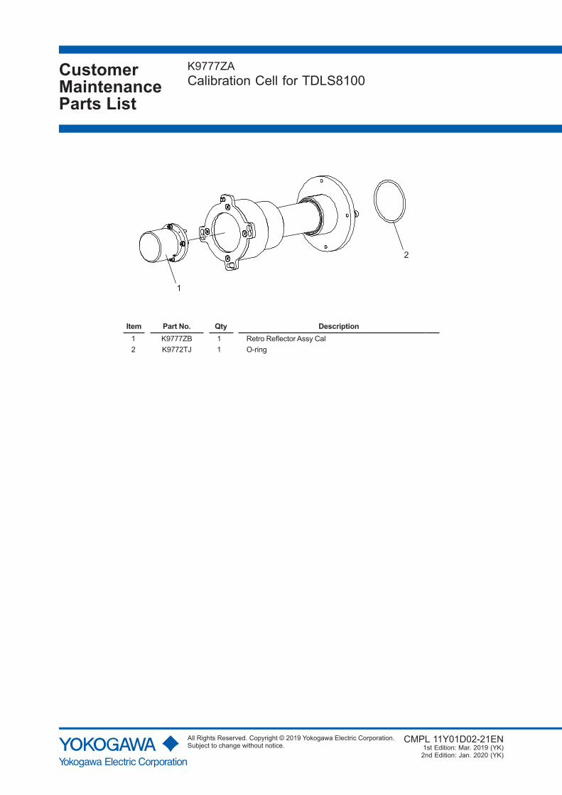
CustomerMaintenanceParts List
K9777ZACalibration Cell for TDLS8100
CMPL 11Y01D02-21EN1st Edition: Mar. 2019 (YK)
2nd Edition: Jan. 2020 (YK)
1
2
Item Part No. Qty Description1 K9777ZB 1 Retro Reflector Assy Cal2 K9772TJ 1 O-ring
All Rights Reserved. Copyright © 2019 Yokogawa Electric Corporation.Subject to change without notice.

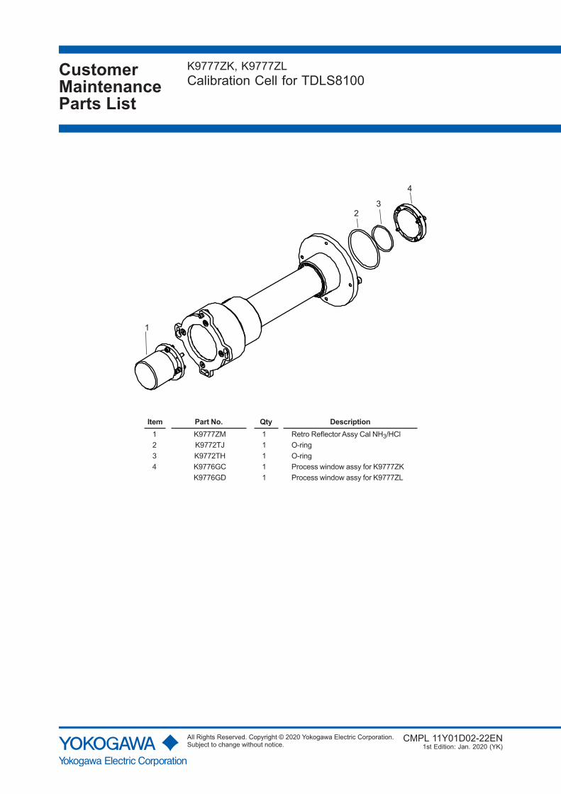
CustomerMaintenanceParts List
K9777ZK, K9777ZLCalibration Cell for TDLS8100
CMPL 11Y01D02-22EN 1st Edition: Jan. 2020 (YK)
1
23
4
Item Part No. Qty Description1 K9777ZM 1 Retro Reflector Assy Cal NH3/HCl2 K9772TJ 1 O-ring3 K9772TH 1 O-ring4 K9776GC 1 Process window assy for K9777ZK
K9776GD 1 Process window assy for K9777ZL
All Rights Reserved. Copyright © 2020 Yokogawa Electric Corporation.Subject to change without notice.

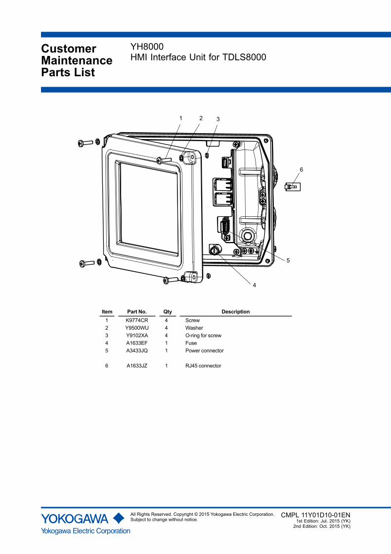
CustomerMaintenanceParts List
YH8000HMI Interface Unit for TDLS8000
CMPL 11Y01D10-01EN1st Edition: Jul. 2015 (YK)
2nd Edition: Oct. 2015 (YK)
4
5
1 2 3
6
Item Part No. Qty Description1 K9774CR 4 Screw2 Y9500WU 4 Washer3 Y9102XA 4 O-ring for screw4 A1633EF 1 Fuse5 A3433JQ 1 Power connector
6 A1633JZ 1 RJ45 connector
All Rights Reserved. Copyright © 2015 Yokogawa Electric Corporation.Subject to change without notice.

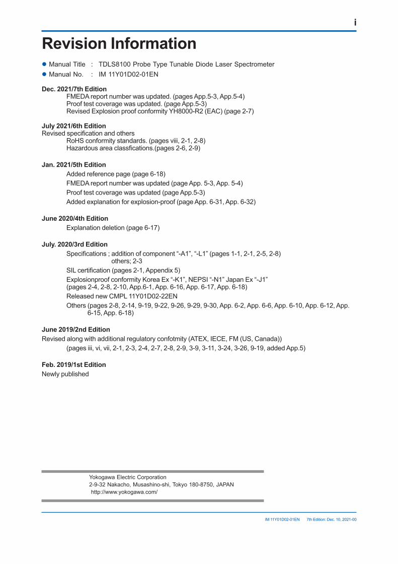
i
IM 11Y01D02-01EN 7th Edition: Dec. 10, 2021-00
Revision Informationl Manual Title : TDLS8100 Probe Type Tunable Diode Laser Spectrometerl Manual No. : IM 11Y01D02-01EN
Dec.2021/7thEdition FMEDA report number was updated. (pages App.5-3, App.5-4) Proof test coverage was updated. (page App.5-3) Revised Explosion proof conformity YH8000-R2 (EAC) (page 2-7)
July2021/6thEditionRevised specification and others RoHS conformity standards. (pages viii, 2-1, 2-8) Hazardous area classfications.(pages 2-6, 2-9)
Jan.2021/5thEdition Added reference page (page 6-18) FMEDA report number was updated (page App. 5-3, App. 5-4) Proof test coverage was updated (page App.5-3) Added explanation for explosion-proof (page App. 6-31, App. 6-32)
June2020/4thEdition Explanation deletion (page 6-17)
July.2020/3rdEdition Specifications ; addition of component “-A1”, “-L1” (pages 1-1, 2-1, 2-5, 2-8)
others; 2-3 SIL certification (pages 2-1, Appendix 5) Explosionproof conformity Korea Ex “-K1”, NEPSI “-N1” Japan Ex “-J1”
(pages 2-4, 2-8, 2-10, App.6-1, App. 6-16, App. 6-17, App. 6-18) Released new CMPL 11Y01D02-22EN Others (pages 2-8, 2-14, 9-19, 9-22, 9-26, 9-29, 9-30, App. 6-2, App. 6-6, App. 6-10, App. 6-12, App.
6-15, App. 6-18)
June2019/2ndEditionRevised along with additional regulatory confotmity (ATEX, IECE, FM (US, Canada)) (pages iii, vi, vii, 2-1, 2-3, 2-4, 2-7, 2-8, 2-9, 3-9, 3-11, 3-24, 3-26, 9-19, added App.5)
Feb.2019/1stEditionNewly published
Yokogawa Electric Corporation 2-9-32 Nakacho, Musashino-shi, Tokyo 180-8750, JAPAN http://www.yokogawa.com/

Blank Page


