Embed Size (px)
Citation preview
DO
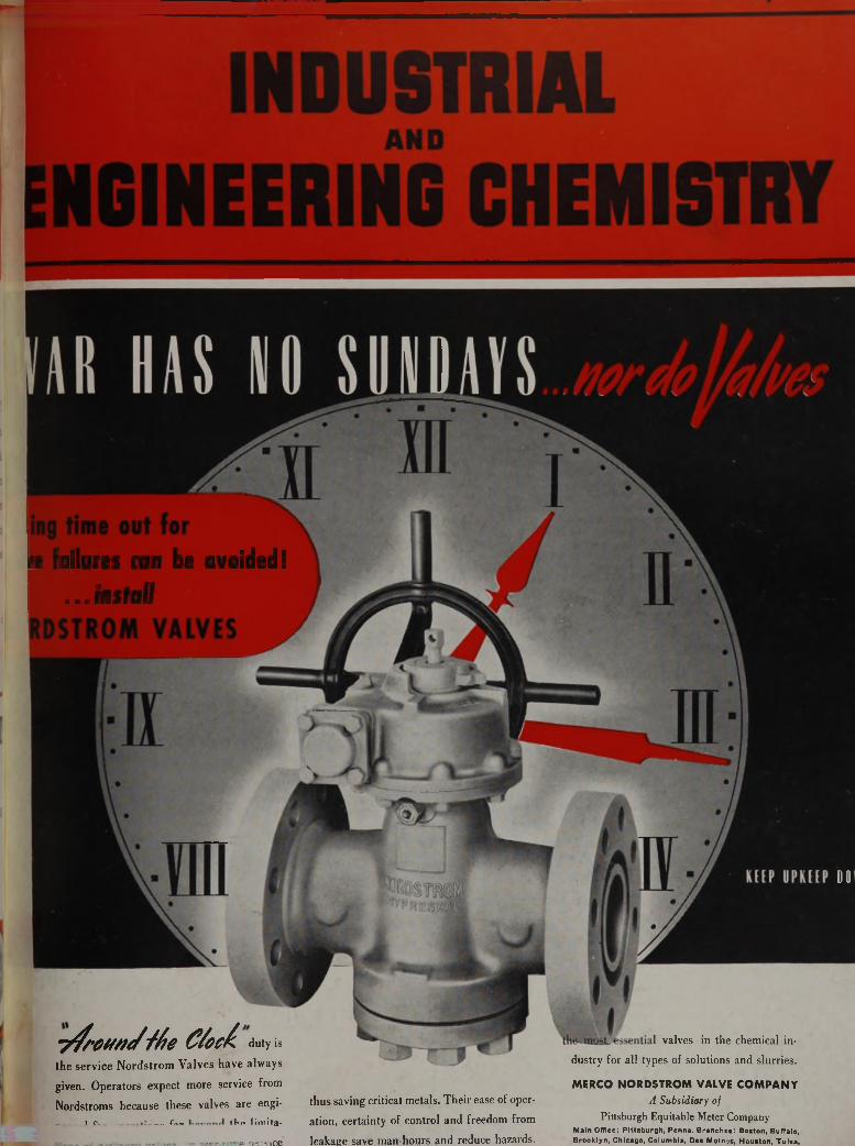
te failures can be avoided!I V I t f l l l W I V « * v v W W l t f l V W •
... install
■ y fr in /n //S ite C /o c & duty is
the service Nordstrom Valves have always
given. Operators expect more service from
Nordstroms because these valves are engi-_ _ - i tv „ ___ f — tVia lim ita -
SfftrwtiCe
thus saving critical metals. Their ease of oper
ation, certainty of control and freedom from
leakage save man-hours and reduce hazards.
valves in the chemical in
dustry for all types of solutions and slurries.
M E R C O N O R D S T R O M V A LV E C O M P A N Y
A Subsidiary of Pittsburgh Equitable Meter Company
Main Office: P ittsburgh , Penna. B ran ch es: Boston, Buffalo, Brooklyn, Chicago, Colum bia, Des Moinc-s, Houston, T u lsa ,
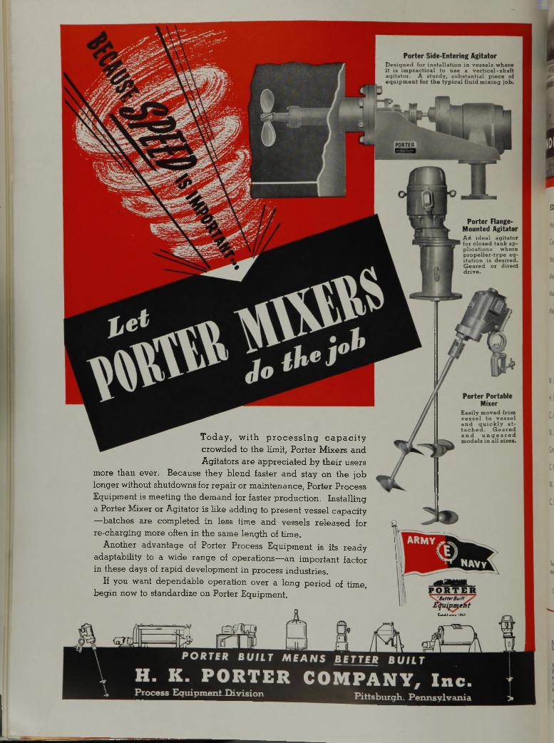
Today, with processing capacity crowded to the limit, Porter Mixers and Agitators are appreciated by their users
more than ever. Because they blend faster and stay on the job longer without shutdowns for repair or maintenance, Porter Process Equipment is meeting the demand for faster production. Installing a Porter Mixer or Agitator is like adding to present vessel capacity —batches are completed in less time and vessels released for re-charging more often in the same length of time.
Another advantage of Porter Process Equipment is its ready adaptability to a wide range of operations—an important factor in these days of rapid development in process industries.
If you want dependable operation over a long period of time, begin now to standardize on Porter Equipment.
EaUbliahM 1866
■
:iUr :. & .
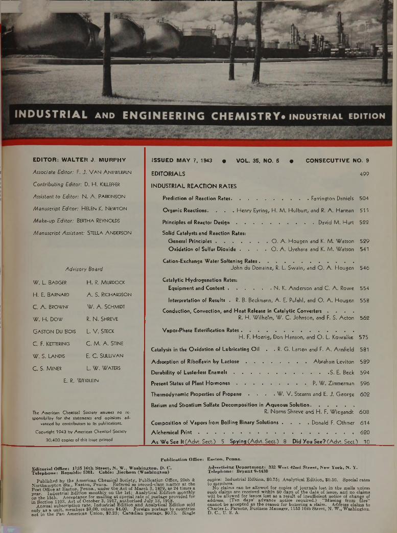
E D IT O R : W A L T E R J. M U R PH Y
Associate Editor: F. J. VAN ANTWERPEN
Contributing Editor: D. H. KlLLEFFER
Assistant to Editor: N. A. PARKINSON
Manuscript Editor: HELEN K. NEWTON
Make-up Editor: BERTHA REYNOLDS
Manuscript Assistant: STELLA ANDERSON
Advisory Board
W. L. Badger H. R. Murdock
H. E. Barnard A. S. Richardson
C. A. Browne W. A. Schmidt
W. H. Dow R. N. SHREVE
G aston Du Bois L. V. Steck
C. F. Kettering C. M. A. Stine
W. S. Landis E. C. Sullivan
C. S. M iner L. W. WATERS
E. R. WEIDLEIN
The American Chemical Society assumes no responsibility for the statements and opinions ad
vanced by contributors to its publications.Copyrisht 1943 by American Chemical Society
30,400 copies of this issue printed
ISSU ED M AY 7, 1943 • V O L. 35, NO. 5 • C O N S E C U T IV E NO. 9
EDITORIALS 499
INDUSTRIAL REACTION RATES
Prediction of Reaction Rates Farrington Daniels 504
Organic Reactions. . . . Henry Eyring, H. M. Hulburt, and R. A. Harman 511
Principles of Reactor D e s ig n ............................................................ David M. Hurt 522
Solid Catalysts and Reaction Rates:General P rincip les............................... O . A. Hougen and K. M. Watson 529Oxidation of Sulfur Dioxide . . . . O . A. Uyehara and K. M. Watson 541
Cation-Exchange Water Softening Rates.....................................................................John du Domaine, R. L. Swain, and O . A. Hougen 546
Catalytic Hydrogenation Rates:Equipment and C o n ten t...................................N. K. Anderson and C. A. Rowe 554
Interpretation of Results . R. B. Beckmann, A. E. Pufahl, and O . A. Hougen 558
Conduction, Convection, and Heat Release in Catalytic Converters . . . .R. H. Wilhelm, W. C. Johnson, and F. S. Acton 562
Vapor-Phase Estérification RatesH. F. Hoerig, Don Hanson, and O . L. Kowalke 575
Catalysis in the Oxidation of Lubricating Oil . . R. G. Larsen and F. A. Armfield 581
Adsorption of Riboflavin by L a c to s e ................................................. Abraham Leviton 589
Durability of Lusterless E n a m e ls .......................................................................S. E. Beck 594
Present Status of Plant H o rm o n e s .........................................................P. W. Zimmerman 596
Thermodynamic Properties of Propane . . . . W. V. Stearns and E. J. George 602
Barium and Strontium Sulfate Decomposition in Aqueous Solution................................R. Norris Shreve and H. F. Wiegandt 608
Composition of Vapors from Boiling Binary Solutions . . . . Donald F. Othmer 614
Alchemical P r i n t ....................................................................................................................... 620
As We See It (Advt. Sect.) 5 Spying (A dvt. Sect.) 8 Did You See? (Advt. Sect.) 10
P u b l ic a t i o n O ffice : E a s to n , P e n n a .
E d i to r ia l O ff ic e : 1155 1 6 th S t r e e t , N . W ., W a s h in g to n , D . C . T e le p h o n e : R e p u b l ic 5301. C a b le : J i e c h e m (W a s h in g to n )
P u b lis h e d b y th e A m erican C hem ica l S o c ie ty , P u b lic a tio n Office, 2 0 th & N o r th a m p to n S ts ., E a s to n , P e n n a . E n te re d as second -c lass m a tte r a t th e P o s t O ffice a t E a s to n , P e n n a ., u n d e r th e A c t of M a rc h 3 , 1879, as 24 tim e s a y e a r. I n d u s tr ia l E d i tio n m o n th ly on th e 1 s t; A n a ly tic a l E d itio n m o n th ly on th e 15 th . A ccep tan ce fo r m a iling a t specia l r a te of p o s tag e p ro v id e d for in S ec tio n 1103, A c t of O c to b e r 3, 1917, a u th o riz e d J u ly 13, 1918.
A n n u a l s u b sc r ip tio n ra te . In d u s tr ia l E d itio n a n d A n a ly tic a l E d itio n sold o n ly a s a u n it , m e m b ers $3 .00 , o th e rs $4 .00 . F o re ig n p o s tag e to co u n tries n o t in th e P a n A m erican U n io n , $2 .25 ; C a n a d ia n p o s tag e , $0 .75 . S ingle
A d v e r ti s in g D e p a r tm e n t : 332 W e st 4 2 n d S t r e e t , N ew Y o rk , N . Y. T e le p h o n e : B r y a n t 9-4430
copies; In d u s tr ia l E d itio n , $0 .75; A n a ly tic a l E d itio n , $0.50. S pecia l r a te s to m em bers.
N o claim s can be_ a llow ed fo r copies of jo u rn a ls lo s t in th e m ails un less such claim s a re rece ived w ith in 60 d a y s of th e d a te of issue, a n d no claim s w ill be a llow ed fo r issues lo s t as a re s u lt of in su ffic ien t n o tice of ch an g e of ad d ress . (T e n d a y s ’ a d v a n c e n o tice req u ired .) " M iss in g fro m files” c a n n o t be accep te d as th e rea so n fo r h o n o rin g a c laim . A d d ress c la im s to C h arles L . P a rso n s, B usiness M an ag er, 1155 16 th S tre e t, N . W ., W a sh in g to n . D . C ., U. S. A.
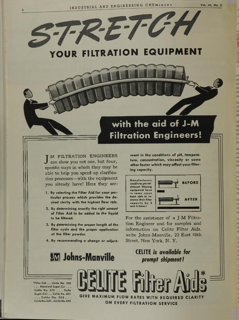
YOUR FILTRATION EQUIPMENT
with the aid of J-M Filtration Engineers!
J -M FILTRATION ENGINEERS can show you not one, but f o u r ,
specific ways in which they may be able to help you speed up clarification processes—with the equipment you already have! Here they are:
1. By selecting the Filter Aid for your particular process which provides the desired clarity with the highest flow rate.
2. By determining exactly the right amount of Filter Aid to be added to the liquid to be filtered.
3. By determining the proper length of the filter cycle and the proper application of the filter powder.
4. By recommending a change or adjust
ment in the conditions of pH, temperature, concentration, viscosity or some other factor which m ay affect your filtering capacity.
Manufacturers unable to get additional filtering equipment have in some cases been able to increase their filter capacity by 3 and 4 times I
BEFORE
AFTER
For the assistance of a J-M Filtration Engineer and for samples and information on Celite Filter Aids, write Johns-Manville, 22 East 40th Street, New York, N . Y.
Johns-Manville CELITE is a v a ila b le fo r
p ro m p t s h ip m e n t!
H I S B b f Ä
*Filter-Cel. . . Celite No. 505 • • . Standard Super-Cel . . .Celite No. 512 . . . Hyflo Super-Cel. . . Celite No. 501 w. . . Celite No. 503 . . . G IV E M A X I M U M F L OW RATE S W I T H R E Q U I R E D C L A R I T YCelite No.535...Celite No.545
O N E V E R Y F I L T R A T I O N S E R V I C E
May, 1943 I N D US T R I A L AND E NGI NE E R ING CHEMISTRY
► R e a c t i o n R a t e s , upon which ou tpu t from chemical processes primarily depends, a tta in special significance in a war of production when prodigious demand cannot be m et simply by enlarging plants. Hence, a discussion of this subject now possesses urgent interest for production men as well as scientists. Ten papers in this issue are devoted to it.
► P r e d i c t i o n of reaction rates is examined in considerable detail by Daniels (page 504) who points out the im portance of including all hidden factors in the calculation. Examples are given of the application of several rules employed and these are compared.
► R a t e s o f O r g a n i c R e a c t i o n s can be calculated from the fundamental physical properties of the molecules, and the calculations provide a useful framework for correlating empirical observations, according to Eyring, H ulburt, and Harman (page 511). Applications of the theory to a number of different types of reactions are given.
► P e r f o r m a n c e o f small-scale units for carrying out gas-solid reactions is correlated by H u rt (page 522) with th a t of p lant production units. The method, especially useful when the intermediate steps of development m ust be shortened or omitted, is illustrated by the platinum -catalyzed oxidation of sulfur dioxide.
► C a t a l y s t s function properly only in the optim um tem perature range for the reaction involved. Because changes in heat always occur during reaction, the heat transfer characteristics of the catalyst bed necessarily control the design of converters. Wilhelm, Johnson, and Acton (page 562) discuss this phase of design of equipment for catalytic processes.
► E s t e r i f i c a t i o n of acetic acid by alcohol in the vapor phase over silica gel catalyst has been investigated by Hoerig, Hanson, and Kowalke (page 575), who find mass transfer through a condensed phase on the catalyst to be the controlling factor in rate.
► R a t e s o f R e a c t i o n s involving solid catalysts conform to general equations based on the theory of activated adsorption by Hougen and W atson (page 529). They propose quantitative expressions for the effects of the several factors involved.
► O x i d a t i o n of sulfur dioxide over platinized asbestos is used by Uyehara and W atson (page 541) to exemplify the application of the generalized theory presented in the preceding paper. Experimental da ta conform to an equation based on the assumption that rate is controlled by the surface reaction between adsorbed sulfur dioxide and atomic oxygen.
► C a t a l y t i c H y d r o g e n a t i o n possesses special interest through its wide industrial applications. Anderson and Rowe (page 554) describe unique equipment, devised to study reactions of this type as well as other high-pressure processes, and having important advantages over other apparatus.
► H y d r o g e n a t i o n of isooctene over nickel catalyst has been studied by Beckmann, Pufahl, and Hougen (page 558) using the equipment of Anderson and Rowe. R ate equations have been developed to correlate experimental results.
► Softening of Water by cation exchangers was investigated by du Domaine, Swain, and Hougen (page 546), and the results of the experiments were reduced to a differential ra te equation. From this, both performance and design of commercial softeners are charted.
► Lubricating Oils in service undergo oxidation catalyzed by the metals in contact with them . Larsen and Armfield (page 581) have investigated this catalytic reaction as i t occurs in internal combustion engines. While massive metals are active, the fine particles worn from engine parts are much more so. Three representative oils were used in the experiments.
► E xtenders added to pigments in lusterless olive drab enamels appear not to affect durability so long as pigment makes up less than 60 per cent of the total volume of solids, according to Beck (page 594). Life of the enamel is shortened if the pigm ent bulks larger than that.
► P lant H ormones, defined as physiologically active compounds, have fired many imaginations, and Zimmerman (page 596) reviews recent progress in the use of such materials on the basis of work done a t the Boyce Thompson Institu te for P lan t Research.
► P ropane’s widening uses as a refrigerant lend special in terest to its thermodynamic properties provided in detail by Stearns and George (page 602). Both tables and graphs are given.
► Barium and Strontium Chlorides can be recovered from fusions of their respective sulfates with calcium chloride and extraction with aqueous methanol, according to Shreve and Wie- gandt (page 608). Conversion of a soluble modification of anhydrite, produced in the aqueous reaction, to an insoluble form is apparently accomplished by the fusion, since w ater can also be used as the solvent for recovering the chloride.
► Lactose adsorbs riboflavin during crystallization from whey, and the product thus formed is believed by Leviton (page 589) to have a useful function in supplying riboflavin for hum an consumption. The concentration of riboflavin in the crystals is a linear function of its concentration in the original solution.
► Vapor-Liquid equilibrium data on tw enty-three binary liquid systems are presented by Othmer (page 614). Included are: acetaldehyde w ith toluene, benzene, and furfural; acetone with benzene and monochlorobenzene; w ater with propionic and butyric acids; acetic acid w ith seventeen other liquids; butanol with butyl bu tyrate; and m ethyl ethyl ketone with propionic acid. A pparatus used is described in detail.
i n d u s t r i a l a n d e n g i n e e r i n g _ ç h e m i s t h y _ Vol. 35, No. 5
B herm ex high freq u en cy
HEATING FOR BONDING or HEAT
PROCESSING NON-CONDUCTING
MATERIALS MAY BE THE ANSWER
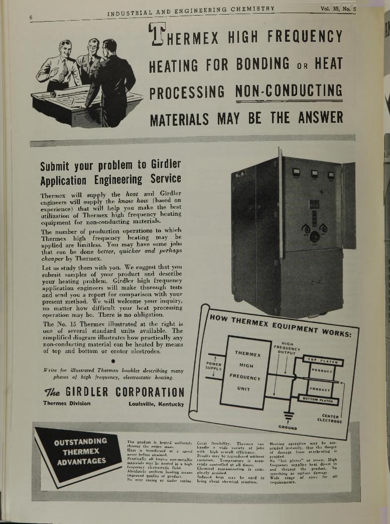
S u b m i t y o u r p r o b l e m t o G i r d l e r A p p l i c a t i o n E n g i n e e r i n g S e r v i c eThermex will supply the heat and Girdler engineers will supply the know how (based on experience) that will help you make the best utilization of Thermex high frequency heating equipment for non-conducting materials.The number of production operations to which Thermex high frequency heating may be applied are limitless. You may have some jobs that can be done better, qu icker and perhaps cheaper by Thermex.Let us study them with you. We suggest that you submit samples of your product and describe your heating problem. Girdler high frequency application engineers will make thorough tests and send you a report for comparison with your present method. We will welcome your inquiry, no matter how difficult your heat processing operation may be. There is no obligation.The No. 15 Thermex illustrated at the right is one of several standard units available. The simplified diagram illustrates how practically any non-conducting material can be heated by means of top and bottom or center electrodes.
W rite fo r illustra ted T h erm ex b o o k le t describ ing m any phases o f h igh frequency , electrostatic heating.
G I R D L E R C O R P O R A T I O NThermex Division Louisville, Kentucky
T h e p ro d u c t is h e a te d u n ifo rm ly thruout th e e n t i re m ass .H e a t is tra n s f e r r e d a t a speed n e v e r b e fo re a t ta in e d .P ra c tic a lly a l l kn o w n n o n -m e ta ll ic m a te r ia ls m ay be h e a te d in a h ig h fre q u e n c y e le c tro s ta t ic f ie ld . A b so lu te ly uniform h e a tin g m ea n s im proved q u a li ty of p ro d u c t.N o o v er c u r in g o r u n d e r cu r in g .
G re a t f l e x ib i l i ty . T h e r m e x ca n h a n d le a w id e v a r ie ty o f jo b s w-ith h ig h o v e ra ll e f f ic ie n c y . R esu lts m a y b e re p ro d u c e d u i th o u t variation. T e m p e r a tu r e is a c c u ra te ly c o n tro lle d a t a l l t im e s . C h e m ic a l c o n ta m in a tio n is c o m p le te ly a v o id e d .In d u c e d h e a t m a y b e u s e d to b rin g a b o u t c h e m ic a l r e a c t io n .
H e a t in g o p e r a t io n m a y b e su sp e n d e d in s ta n t ly , th u s th e d a n g e r o f d a m a g e fro m o v e r h e a t in g is a v o id e d .N o “ h o t p l a t e s ” o r s te a m . H ig h f r e q u e n c y s u p p l ie s h e a t d i re c t to a n d t h r u o u t th e p ro d u c t. N o s c o rc h in g o r s u r fa c e d a m a g e . W id e ra n g e o f s izes fo r allr e q u ir e m e n ts .
May, 1943 I N DU S T R I AL AND E NG I NE E R IN G CHEMI STRY 7
AN ELEVATOR, A CONVEYOR AND FEEDERIN A SINGLE UNIT
CONSERVES IN MANY WAYS
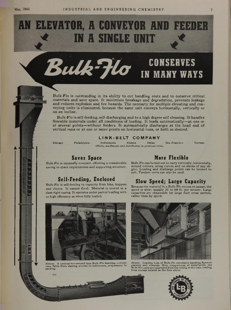
A b o v e: A v e r t ic a l ru n -a ro u n d ty p e B u lk -F lo h an d lin g oversize A bove: L o a d in g ru n s o f B u lk -F lo co n v e y o rs h a n d lin g S p a n ishso ap flakes f ro m sh a k in g sc reens to p u lv e rize rs , p re p a ra to ry to p e a n u ts a n d a lm o n d s . N o te co m p ac tn e ss o f in s ta lla tio n ; th ep ac k in g . B u lk -F lo u n its a re s u sp e n d ed fro m th e ce iling in th is case , lo ad ing
' fro m s to rag e lo c a te d on th e floor above .
Bulk-Flo is outstanding in its ability to cut handling costs and to conserve critical materials and save space. It minimizes breakage and degradation, prevents leakage and reduces explosion and fire hazards. The necessity for multiple elevating and conveying units is eliminated, because the same unit conveys horizontally, vertically or on an incline.
Bulk-Flo is self-feeding, self-discharging and to a high degree self-cleaning. It handles flowable materials under all conditions of loading. It loads automatically—at one or at several points—without feeders. It automatically discharges at the head end of vertical runs or at one or more points on horizontal runs, or both as desired.
S a v e s S p a c eBulk-Flo is unusually compact, effecting a considerable saving in space requirements and supporting structure.
M o r e F l e x i b l eBulk-Flo can be laid out to carry vertically, horizontally, around corners, along curves and on slants of any degree. Loading and discharge points can be located to suit. Tandem units can also be used.
S e l f - F e e d i n g , E n c l o s e dBulk-Flo is self-feeding to capacity from bins, hoppers and chutes. It cannot flood. Material is moved in a dust-tight casing. It operates under partial loading with as high efficiency as when fully loaded.
S l o w S p e e d ; L a r g e C a p a c i t yBecause the material in a Bulk-Flo moves en masse, the speed is slow; usually 30 to 60 ft. per minute. Large capacities are obtainable by large duct cross section, rather than by speed.
L I N K - B E L T C O M P A N YC h ic ag o P h ila d e lp h ia In d ia n ap o lis A tla n ta D a llas S an F ran c isc o T o ro n to
Offices, w arehouses a n d d is tr ib u to rs in p r in c ip a l c itie s .
W ith w ar o rders red u cin g th e speed o f d e liv ery —
w ith a ll em phasis o n g e tt in g eq u ip m en t th a t w ill s tand u p in th e
em ergency—w ith a ll efforts d irec ted to w ard conserv ing m etals an d a lloys—e n g i
neers w ill m ake fre q u e n t use o f th is ready reference covering all th e facts a b o u t w h a t
to look fo r w hen spec ify ing stain less steel processing equ ipm en t:
/ . What grade will you 3 . How will you design order? for economy and for
conservation of steel ?2. What finish w ill 4 . How can you be sure
serve you best? of sound welds?
T hese and o th e r questions, im p o rta n t to your p ro d u c tio n , a re answ ered in th e
new in fo rm ativ e b ro ch u re issued byS. B lickm an, Inc.
S . B L I C K M A N , i n c .1 2 0 2 GREGORY AVE., W EEHAW KEN, N J.
TANKS . KETTLES • CONDENSERS • AGITATORS • EVAPORATORS • PANS . VATS • CYLINDERS
r a c k i n g petroleum, despite the age of the basic process, con- w tinues so fruitful in industry as to encourage search for further modifications to yield even greater values for the future. The introduction of catalysts into the cracking reaction has immensely increased the range of its usefulness and a t the same time the area to be explored for a proper understanding of the mechanism involved. On th a t we shall learn details of what happens to cyclohexane.
Brine from oil wells presents a special disposal problem in the field. In its stay above ground, conditions are reached which favor precipitation of calcium carbonate to clog porous structures when it is pumped into the earth again. We shall learn how the remarkable stabilizer, sodium hexametaphosphate, improves th a t condition.
Selective solvents have performed near miracles in separating constituents of petroleum. Now, we learn, a somewhat similar technique may yield equally valuable results in separating constituents of w hat we have traditionally called the “fixed oils” . Amazing and most useful is the parting of such oils as soybean into fractions possessing different degrees of unsaturation by the simple expedient of solvent extraction.
Another solvent problem now vexing has to do with the highly useful zein, a protein from corn. A group of helpful binary solvents for this m aterial enlarge its applications; it is already important as a coating through its resistance to greases.
Design problems are always im portant. This time we shall learn of a new still to determine vapor-liqmd equilibrium data essential in the design of fractional distillations.
H eat capacity of gases, also essential in many design problems, are calculated by a new and better method to be described for us.
Similarly, viscosities of fluids are needed in designing vital parts of equipment for every type of process. Often experimental values are missing in required ranges and hence calculation is used to extrapolate them. An improved method for this purpose will prove valuable.
Behaviors of starch and glue in swelling in water will be discussed for the light they throw on these im portant materials and their applications.
Alkylation and dealkylation are suggested as methods of separating individuals from the usual complex mixtures of cresols and xylenols. Despite its apparent complexity, the method, we are assured, works.
Then we shall learn more about the behavior of Buna S with petroleum products, information we shall find most useful as the synthetic rubber program gets into production.
From the D etroit meeting of the Society come two well received articles, one dealing with the newer art and contributions of the petroleum industry, the other a passing show of the rubber field (the censor willing).
And there will, as always, be much more.Y o u r H u m b l e S p y
8
May, 1943 I N D US T R I A L AND E N GI NE E R IN G C HEMI STRY
IC H E M I C A L
ty ie l& l
M E T A L9 * td u ¿ ¿ sU e ¿ .
■■
G I R D L E R P r o c e s s
H Y D R O G E N
W E L D I N GId é e l
C O S t s 3 0 c to 5 0
less per 1 / 0 0 0 cu. ft .
G I R D L E R O F F E R S
p r o c e s s e s f o r .
P r o d u c t i o n , P u r i f i c a t i o nSeparation, Reforming oi
Dehydration of HYDROGEN s u lf id e carbon monoxide
BLUE WATER GAS o rg an ic s u l f u rCARBON DIOXIDE
H y d r o c a r b o n s
H ydrogen N itrogen
OXYGEN
and various mixtures.
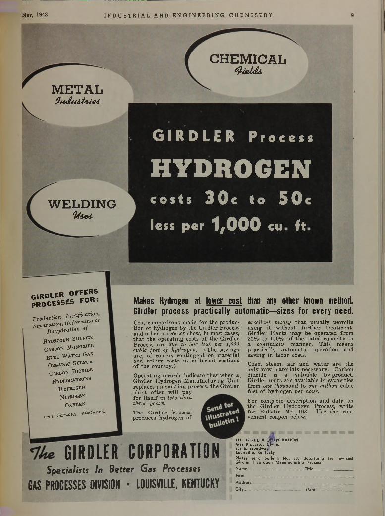
Makes Hydrogen at lower cost than any other known method. Girdler process practically automatic—sizes for every need.C ost com parisons m ade fo r the production o f hydrogen by the G ird ler Process and o th e r processes show, in m ost cases, th a t th e o p e ra tin g costs o f th e G ird ler P rocess a re 30c to 50c less per 1,000 cubic feet of hydrogen. (T he savings a re , of course, con tingen t on m ate ria l and u ti li ty costs in d if fe re n t sections o f the coun try .)
O p era tin g records ind icate th a t w hen a v G ird ler H ydrogen M an u fac tu rin g U n it rep laces an ex is tin g process, th e G ird ler p la n t o ften w ill pay fo r its e lf in less than three years.The G ird ler Process produces hydrogen of
excellent purity th a t u sua lly perm its using i t w ithou t fu r th e r tre a tm en t. G ird ler P lan ts m ay be opera ted from 20% to 100% of the ra te d cap ac ity in a continuous m anner. T h is m eans p rac tica lly au tom atic opera tion and sav ing in labor costs.
Coke, steam , a i r and w a te r a re the only ra w m a te ria ls necessary . C arbon dioxide is a valuab le by-product. G ird ler u n its a re availab le in capacities from one thousand to one million cubic fee t o f hydrogen per hour.F o r com plete descrip tion and d a ta on the G ird le r H ydrogen P rocess, w rite fo r B u lle tin No. 103. U se th e conven ien t coupon below.
G I R D L E R C O R P O R A T I O NS p e c i a l i s t s I n B e t t e r G a s P r o c e s s e s
GAS PROCESSES DIVISION • LOUISVILLE, KENTUCKY
TH E G IR D L E R C O R P O R A T IO N Gas Processes Division 202 E. Broadway Louisville, KentuckyPlease send bulletin No. 103 describing the low-cost Girdler Hydrogen Manufacturing Process.Name ..___ ____________ Title ....................Firm.......................................................................Address...................................... .....................................Cify_...........................................State............................
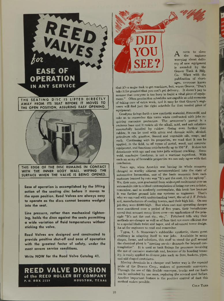
Ease of operation is accomplished by the lifting action of the seating disc before it moves to the open position. Reed Valves are always easy to operate as the discs cannot become wedged into the seat.
Line pressure, rather than mechanical tightening, holds the discs against the seats permitting a wide variation of fluid temperatures without sticking the valve.
Reed Valves are designed and constructed to provide positive shut-ofF and ease of operation with the greatest factor of safety, under the most severe service conditions.
THE S E A T I N G DI SC IS L I FTED DIRE AWAY FROM ITS SEAT BEFORE IT MOVES TO THE OPEN POSITION, ASSURING EASY OPENING^
THIS EDGE OF THE DISC REMAINS IN CONTACT WITH THE INNER BODY WALL, WIPING THE SURFACE WHEN THE VALVE IS BEING OPENED.
W rite N O W for the Reed Valve Catalog 41.
SEE?,A n o te to cheer
the engineer worrying about delivery of new equipment is sounded by the Graver Tank & Mfg. Co. W hat with the publization of shortages, everyone knows
th a t it’s a major task to get machines, but, warns Graver, “Don’t take it for granted th a t you can’t get delivery. I t doesn’t pay to assume th a t everyone is too busy to build a vital piece of equipment.” Often production schedules are capable a t odd moments of taking care of extra work, and it may be th a t Graver’s engineers will find ju s t the right schedule for th a t needed piece of equipment.
Goodyear brings forth a new synthetic material, Resoweld, and asks us to remember this name when confronted with jobs requiring corrosion protection. The newcomer’s parent is a resinous base and it resists all the alkali, acid, and salt solutions successfully handled by rubber. Going even further than rubber, it can be used with nitric and chromic acids, alcohol, petroleum oils, gasoline, linseed and vegetable oils, soaps, and such. Continuing with its properties, we read th a t it can be applied, in the field, to all types of metal, wood, and concrete equipment, and functions satisfactorily up to 150 ° F . I t does not deteriorate with age and can take jolts w ithout cracking. Resoweld, concludes Goodyear, is not a wartime expedient. With such an array of favorable properties we can only agree with th a t conclusion.
Years ago, when America was having its whole economy changed as worthy citizens metamorphized into the state of automotive locomotion, one of the basic economic laws each customer learned by rote was “ I t ’s not the cost, i t ’s the upkeep” . We, their sons, now graduated from wide-eyed excitement over an automobile ride to a blase contemplation of being our own aviator, remember, and as somberly contemplate, this basic law because it was further ground into our systems as engineers. T hat’s why we can read with understanding heart, the ad of J. F. Pritchard, manufacturers of cooling towers, and their high bid. On one job they were $8000 high. B ut when cost and operating charges were considered over a period of five years, their installations saved th a t amount many times over—an application of the principle “ I t ’s not the cost etc., etc.,” . Pritchard tells why their methods are cheaper as well as of fans th a t are more efficient due to a special blade tw ist and taper, and of advanced tower design. An ad for engineers to read and remember.
Tygon, U. S. Stoneware’s rubberlike synthetic, shows great resiliency in adapting itself to war jobs. Available in many shapes, forms, and solutions, this stuff to stand the guff around the chemical plant is “ meeting service demands far beyond contemplation” . I t is used as tank linings for processes involving the use of corrosive materials and, because of its bonding tenacity, is easily applied to diverse jobs such as fans, baskets, pipes, and odd shaped containers.
M oving chemicals in a cheaper and better way is the especial pride of the Dracco Corp., makers of pneumatic conveyors. Through the use of this flexible conveyor, trucks and car loads can be unloaded by one man, replacing the several used before. Another important feature is the positive control o f dust this method makes possible.
Cole T arr
REED VALVE DIVISIONo f t h e R E E D R O L L E R B I T C O M P A N Y
P .O . B O X 2 1 1 9 H O U S T O N , T E X A S
10
May, 1943 I N DU S T R I AL AND E NG I NE E R IN G CHEMI STRY 11
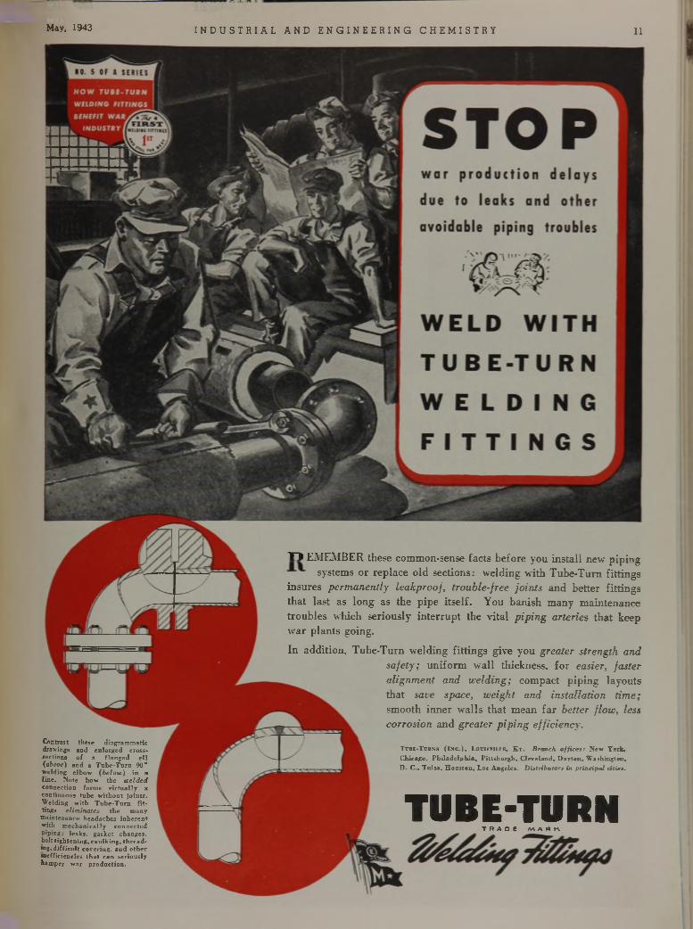
"D EMEMBER these common-sense facts before you install new piping systems or replace old sections: welding with Tube-Tum fittings
insures perm anently leakprooj, trouble-free join ts and better fittings that last as long as the pipe itself. You banish many maintenance troubles which seriously interrupt the vital pip in g arteries that keep war plants going.In addition, Tube-Turn welding fittings give you greater strength and
safety; uniform wall thickness, for easier, faster alignment and w elding; compact piping layouts that sate space, weight and installation tim e; smooth inner walls that mean far better flow , less corrosion and greater p ip in g efficiency.
C o n tra s t th e s e d ia g ra m m a tic draw ings a n d e n la rg e d c ro s s - se c tio n s o f a f la n g e d e l l (above) a n d a T u b e - T u r n 90® w e ld in g e lb o w (b e lo ic ) in a l in e . N o te h o w th e ice ld ed c o n n e c tio n fo rm s v i r t u a l l y a c o n tin u o u s tu b e w i th o u t j o in ts . W e ld in g w ith T u b e - T u r n f i t tings e lim in a tes t h e m a n y
m a in te n a n c e h e a d a c h e s in h e r e n t w ith m e c h a n ic a l ly c o n n e c te d p ip in g : l e a k s , g a s k e t c h a n g e s , bo lt t ig h te n in g , c a u lk in g , t h r e a d ing , d i f f ic u lt c o v e r in g , a n d o th e r in e ff ic ie n c ie s t h a t c a n s e r io u s ly h a m p e r w a r p ro d u c tio n .
T u b e -T u rn s ( I n c . ) , L o u is v i l le , K y . Branch o ffic e s : N e w Y o rk , C h ic a g o , P h i l a d e lp h ia , P i t t s b u r g h , C le v e la n d . D a y to n . W a s h in g to n . D . C ., T u ls a . H o u s to n , L os A n g e le s . D istributors in p r inc ipa l c ities.
TUBE-TURNT R A D E M A R n
i n d u s t r i a l a n d e n g i n e e r i n g c h e m i s t r y Vol. 35, No. s
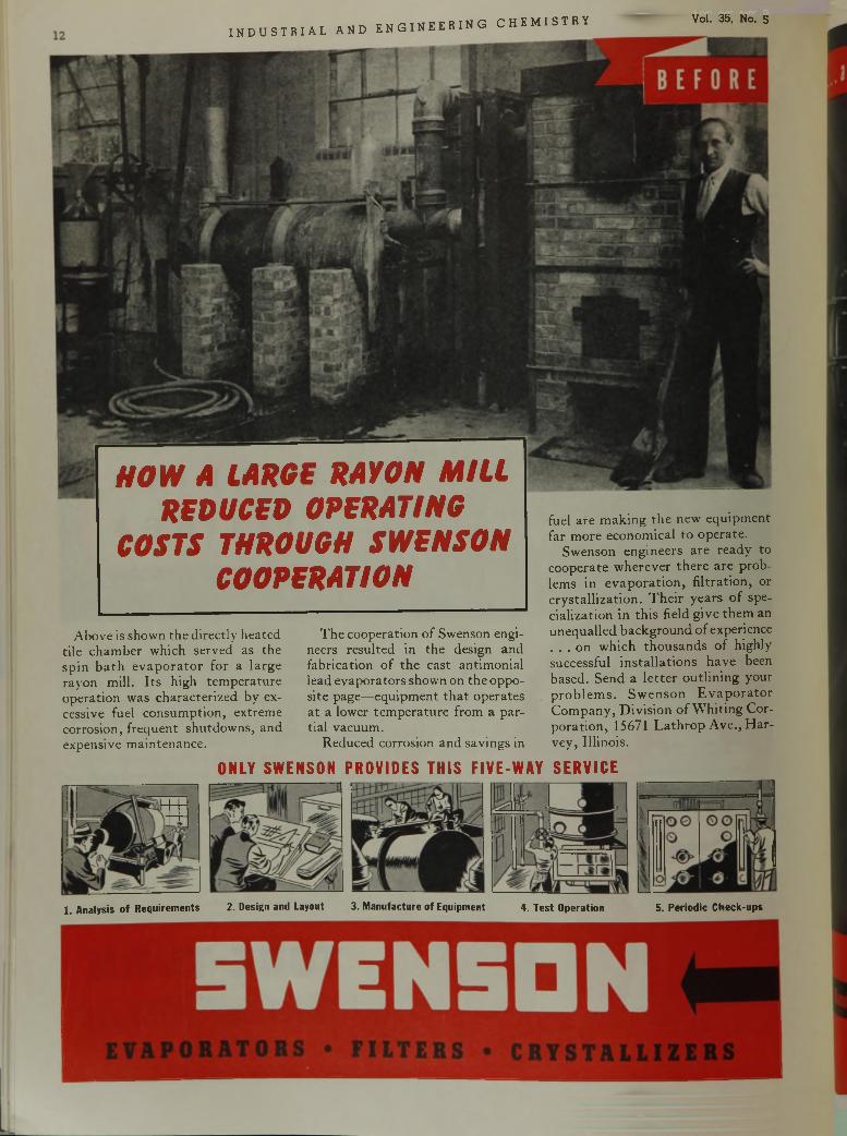
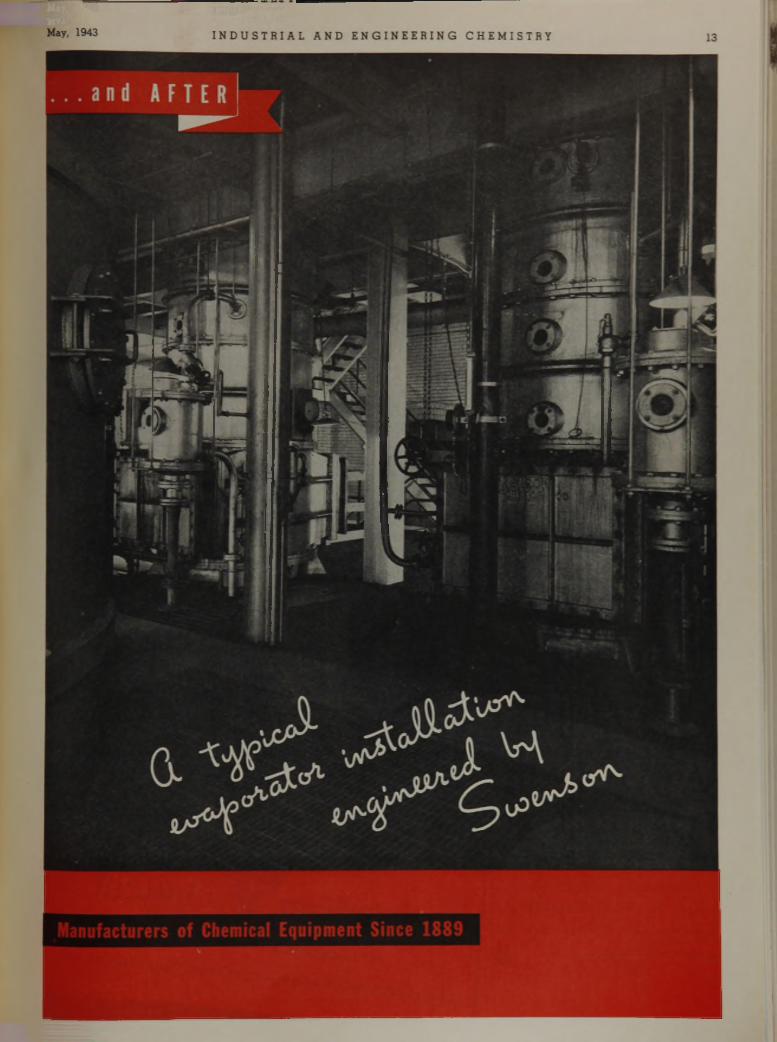
Above is shown the directly heated tile chamber which served as the spin bath evaporator for a large rayon mill. Its high temperature operation was characterized by excessive fuel consumption, extreme corrosion, frequent shutdowns, and expensive maintenance.
The cooperation of Swenson engineers resulted in the design and fabrication of the cast antimonial lead evaporators shown on the opposite page—equipment that operates at a lower temperature from a partial vacuum.
Reduced corrosion and savings in
fuel are making the new equipment far more economical to operate.
Swenson engineers are ready to cooperate wherever there are problems in evaporation, filtration, or crystallization. Their years of specialization in this field give them an unequalled background of experience . . . on which thousands of highly successful installations have been based. Send a letter outlining your problems. Swenson Evaporator Company, Division of Whiting Corporation, 15671 Lathrop Ave., Harvey, Illinois.
HOW A LARGE RAYON MILL REDUCED OPERATING
COSTS THROUGH SWENSON COOPERATION
ONLY SWENSON PROVIDES THIS FIVE-WAY SERVICE
1. Analysis o f Requirements 2. Design and Layout 3. Manufacture of Equipment 4. Test Operation 5. Periodic Check-ups
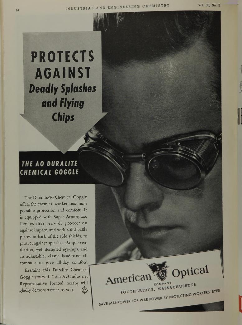
PROTECTSAGAINST
D e a d l y S p l a s h e s
a n d F l y i n g
C h i p s
The Duralite-50 Chemical Goggle offers the chemical worker maximum possible protection and comfort. It is equipped with Super Armorplate Lenses that provide protection against impact, and with solid baffle plates, in back of the side shields, to protect against splashes. Ample ventilation, well-designed eye-cups, and an adjustable, elastic head-band all combine to give all-day comfort.
Examine this Duralite Chemical Goggle yourself. Your AO Industrial Representative located nearby will gladly demonstrate it to you. jjj
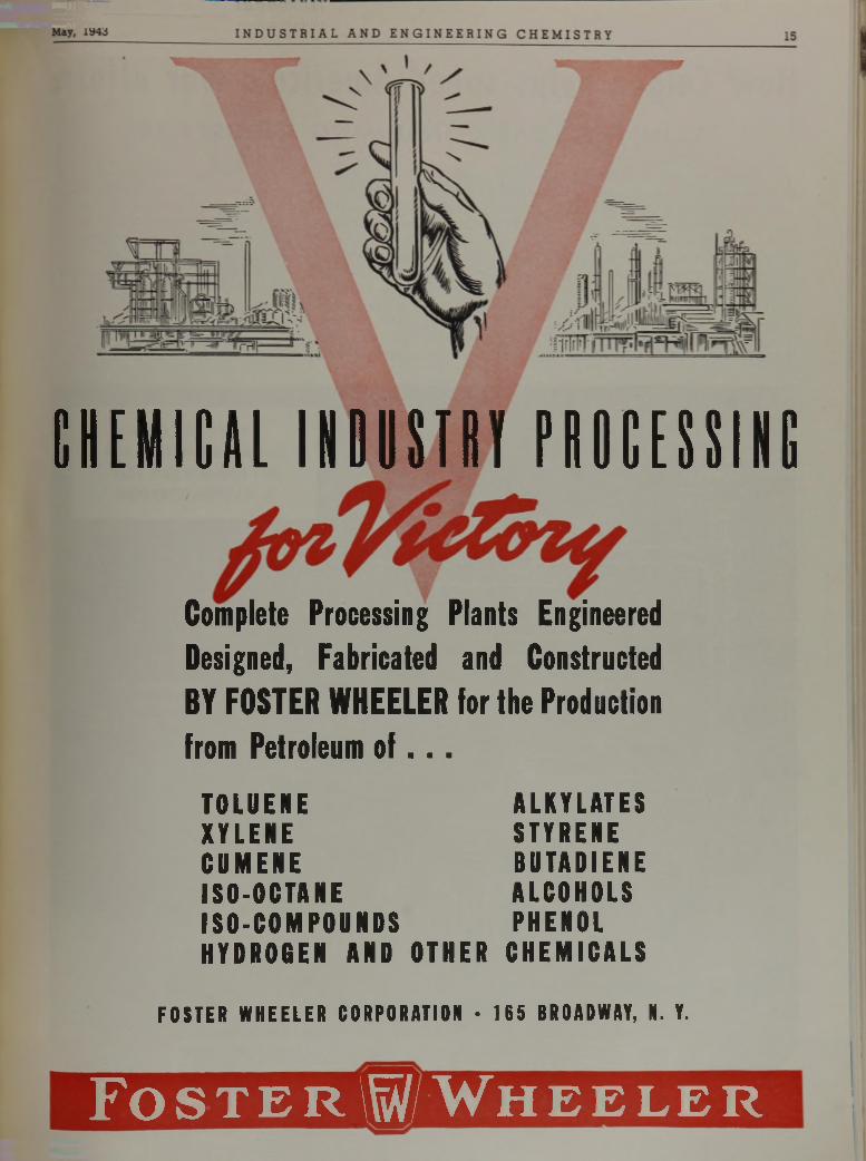
CHEMICAL INDUSTRY PROCESSING
Complete Processing Plants Engineered Designed, Fabricated and Constructed BY FOSTER WHEELER for the Production from Petroleum of . . .
TOLUENE ALKYLATESXYLENE STYRENECUMENE BUTADIENEISO-OCTANE ALCOHOLSISO-COMPOUNDS PHENOLHYDROGEN AND OTHER CHEMICALS
FOSTER WHEELER CORPORATION • 165 BROADWAY, N. Y.
F o s t e r 1 / W h e e l e r
INDUSTR i a l a n d e n g i n e e r i n g c h e m i n vol. OO, «o. 5
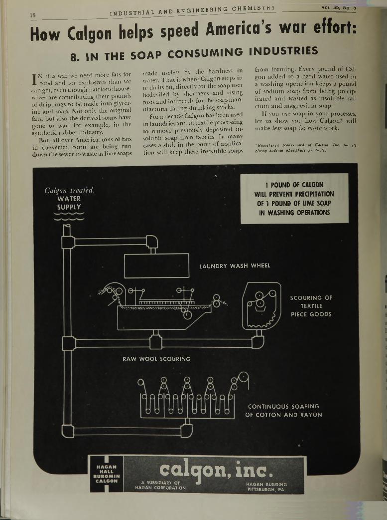
How Calgon helps speed America s war effort:8. IN THE S O A P C O N S U M I N G I N D U S T R I E S
IN this war we need more fats for food and for explosives than we
can get, even though patriotic housewives are contributing their pounds of drippings to be made into glycerine and soap. Not only the original fats, but also the derived soaps have gone to war, for example, in the synthetic-rubber industry.
But, all over America, tons of fats in converted form are being run down the sewer to waste as lime soaps
made useless by the hardness in water. That is where Calgon steps in to do its bit, directly for the s o a p user bedeviled by shortages and rising costs and indirectly for the soap manufacturer facing shrinking stocks.
For a decade Calgon has been used in laundries and in textile processing to remove previously deposited insoluble soap from fabrics. In many cases a shift in the point of application will keep these insoluble soaps
o
Calgon treatedW A T E RS U P P L Y
from forming. Every pound of Cal- eon added to a hard water used in a washing operation keeps a pound of sodium soap from being precipitated and wasted as insoluble calcium and magnesium soap.
If you use soap in your processes, let us show you how Calgon* will make less soap do m ore work.
*R eg iste red , tra d e -m a r k o f C algon, In c . fo r its g la ssy s o d iu m p h o sp h a te p ro d u c ts .
1 POUND OF CALGON
WILL PREVENT PRECIPITATION
OF 1 POUND OF LIME SOAP
IN WASHING OPERATIONS
LA U N D R Y W A S H W H EE L
S C O U R IN G O F
T EXTILE
P IE C E G O O D S
R A W W O O L S C O U R IN G
C O N T IN U O U S S O A P IN G
O F C O T T O N A N D R A Y O N
calqon, in c .DIARY OF J m a c ;a m nmA SUBSIDIARY OF
HAGAN CORPORATION HAGAN BUILDING PITTSBURGH, PA.
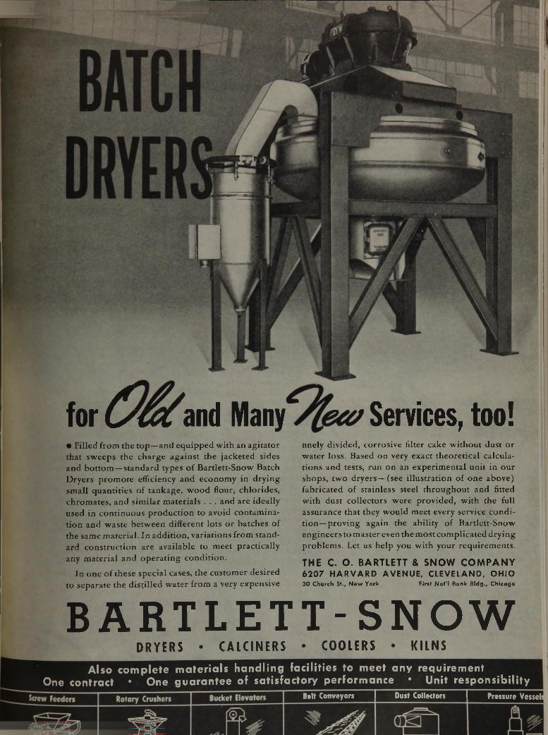
• Filled from the top—and equipped with an agitator that sweeps the charge against the jacketed sides and bottom—standard types of Bartlett-Snow Batch Dryers promote efficiency and economy in drying small quantities of tankage, wood flour, chlorides, chromates, and similar materials . . . and are ideally used in continuous production to avoid contamination and waste between different lots or batches of the same material. In addition, variations from standard construction are available to meet practically any material and operating condition.
In one of these special cases, the customer desired to separate the distilled water from a very expensive
finely divided, corrosive filter cake without dust or water loss. Based on very exact theoretical calculations and tests, run on an experimental unit in our shops, two dryers— (see illustration of one above) fabricated of stainless steel throughout and fitted with dust collectors were provided, with the full assurance that they would meet every service condition-proving again the ability of Bartlett-Snow engineers to master even the most complicated drying problems. Let us help you with your requirements.
T H E C . O . B A R T L E T T & S N O W C O M P A N Y 6 2 0 7 H A R V A R D A VEN U E, CLEVELAND, O H IO30 Church St., New York First Nat’l Bank Bldg., Chicago
BARTLETT-SNOWD R Y E R S C A L C I N E R S C O O L E R S K I L N S
Also complete materials handling facilities to meet any requirement One contract * One guarantee of satisfactory performance '• Unit responsibility
Belt Conveyors I Dust Collectors I Pressure Vessel
fo r^ m 'a n d Many Services, too!
i n d u s t r i a l a n d e n g i n e e r i n g c h e m i s t r y Vol. 35, No. 5
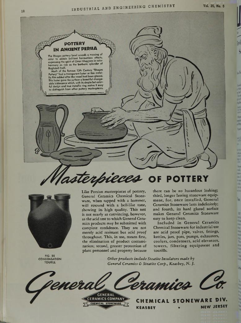
P O T T E R Y
I N A N C I E N T P E R S I A
The Rhages pottery bowl reveals a massing of color to obtain brilliant harmonious effects, expressing the spirit of Omar Khayyam in color harmony as rich as the barbaric splendor of Baghdad itself.
Much of the famous 13th Century Rhages Potter/' had a transparent luster or thin metallic film added after the vessel had been glazed. This luster gave the surface a beautiful changeable iridescence which, with its simple but colorful design and true metallic ring makes it easy to distinguish from other pottery masterpieces.
Like Persian masterpieces of pottery, General Ceramics Chemical Stoneware, when tapped with a hammer, will resound with a bell-like tone, showing its high quality. This test is not nearly as convincing, however, as the acid test to which General Ceramics products may be submitted with complete confidence. They are not merely acid resistant but acid proof throughout. This, in use, means first, the elimination of product contamination; second, greater protection of plant personnel and property because
OF POTTERYthere can be no hazardous leaking; third, longer lasting stoneware equipment, for, once installed, General Ceramics Stoneware lasts indefinitely; and fourth, its hard glazed surface makes General Ceramics Stoneware easy to keep clean.
Included in General Ceramics Chemical Stoneware for industrial use are acid proof pipe, valves, fittings, kettles, jars, pots, pumps, exhausters, coolers, condensers, acid elevators, towers, filtering equipment and tourills.
FIG. 55 CONDENSATION
TOURILlO ther products include S teatite Insulators m ade by General Ceramics & Steatite Corp., K easbey, N. J.
C H E M I C A L S T O N E W A R E D I V .K EAS BEY • N E W JERSEY
ADVERTISEMENT—this entire page is a paid advertisement. Prepared Monthly by U. S. Industrial Chemicals, Inc.
U . S . I . C H E M I C A L N E W SMay A Monthly Series for Chemists and Executives of the Solvents and Chemical Consuming Industries 1943
R e v i s e d D a t a o n
S o l o x P r o p e r t i e s
I s s u e d b y U . S . I .
New Folder Lists ApplicationsOf General-Purpose Solvent
Revised information on the specifications for Solox, the popular general-purpose solvent, has been prepared by U.S.l.
The authorized composition of Solox now calls for the addition of the following to every 100 gallons of S.D. Alcohol No. 1:
Denaturing Grade Methanol............. 2.0 gals.tthyl Aceiate .................................. 1.0 gal.Aviation Gasoline............................ 1.0 gal.190-proof S.D. Alcohol No. 1 is used in the
preparation of the Regular grade of Solox, and 200-proof for the Anhydrous grade.
Properties are as follows:Regu- Anhy- lar drous
Specific Gravity(at 60°/¿0° F.)............................ 0.8158 0.7962
Color Water WaterWhite White
Flash Point (approx) .................... 71° F. 71° F.Coefficient of Ex
pansion (per 1° F.).................... 0.0006 0.0006Weight, Lbs. per
Gallon (at 60° F.)...................... 6.790 6.630Because of its unusual solvent powers and
its mild, non-residual odor, Solox has found extensive use in a variety of industrial applications. A revised folder, now in preparation, lists many of the most important applications in fields ranging from lacquer formulation to fuel oil conditioning. Copies of this folder may be obtained by writing to U.S.l.
N e w M e t h o d D e t e r m i n e s S a l t s i n C r u d e O i l s
NEW YORK, N. Y. — Extensive tests con- lucted in five laboratories of a large company vith headquarters here to determine the most iccurate and reproducible method of deter- nining the salt contents of crude oils concomitant with reasonable speed and ease of nanipulation have led to a new method, employing hydrochloric acid reflux apparatus.
When the separation of layers after heat ipplication is slow, or an emulsion forms at he interface, the addition of about 5 ml. of putanol and the judicious application of heat s claimed to effect sharp separation. Butanol las broken all emulsions encountered to date.
Carbon D ioxide U seful Against Electrical Fires
The snow and gas discharged from carbon dioxide extinguishers of the first aid type are non-conductive even in the presence of voltages up to 100,000 volts alternating current so long as the extinguisher horns retain their original high dielectric qualities. These facts are the result of an investigation made by engineers of Underwriters’ Laboratories, Inc. to determine the electrical conductivity of L __ _______ :„1 , . r U n £ rrVi 11 r t rr f i r P C j f l OF
mient.
C a l c i u m S e p a r a t e d F r o m
S t r o n t i u m b y U s e o f A c e t o n e
Calcium can be separated from strontium with fairly good results through the use of acetone as a solvent, according to a recent claim. After the two materials have been evaporated to dryness in a nitric acid solution and further dried at 170°, the calcium nitrate is extracted with acetone, in which it is very soluble, then evaporated to dryness and weighed. Strontium nitrate, only slightly soluble in acetone, remains as a residue and can be weighed separately.
R e s e a r c h W o r k e r s U n c o v e r N e w F i e ld s f o r S t a r c h E s t e r s
PRINCETON, N. J. — A study conducted here reveals that starch esters have potentialities for use in the coating, sizing, and adhesive industries; in the preparation of aqueous emulsions or suspensions of high polymers; and in soft rubberlike plastics.
When using such esters to form either plastics or coatings, dibutyl phthalate is recommended as a plasticizer. For example, it is claimed that a soft plastic with relatively high tack can be made with starch butyrate containing 25% dibutyl phthalate. In coatings, dibutyl phthalate minimizes checking.
Iodine Compounds o f Steroids Produced by New Method
BLOOMFIELD, N. J. — A new method has been patented and assigned to a company here for the production of iodine compounds of steroids. The iodo compounds obtained are expected to find application for pharmaceutical use as therapeutic agents and also as intermediate products.
According to the invention, the hydroxy steroids are first converted into esters of true organic sulfonic acids. These are then treated with iodides, preferably in organic solvents such as acetone, at an elevated temperature whereby the corresponding steroid iodides and alkyl or aryl sulfonic acid salts are produced.
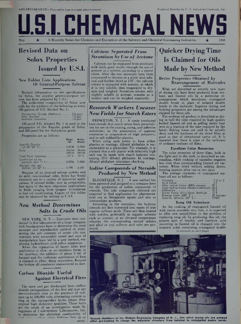
Q u i c k e r D r y i n g T i m e
I s C l a i m e d f o r O i l s
M a d e b y N e w M e t h o d
Better Properties Obtained byRearrangement of Molecules
What are described as entirely new types of drying oils have been produced from soybean and linseed oils by a molecular rearrangement which introduces conjugated double bonds in place of isolated double bonds in the molecule. Superior drying and bodying properties are among the advantages claimed for these oils.
The soybean oil product is described as drying in half the time required by high quality bodied linseed oil and as gelling under heat tests in a fraction of the time required by the latter. Baking times are said to be equally short and the hardness of the dried films as good as that of dehydrated castor oil. It is reported that there is none of the tackiness of ordinary soybean oil films.
Excellent Color R etentionThe color retention of these films, both in
the light and in the dark, is described as outstanding, while cooking of varnishes requires less time than corresponding linseed oil varnishes. When dried without adding driers, frosting appears after one or two days.
The average constants of conjugated soybean oil are as follows:
Viscosity ......................................... Z-3 or ZAcid Value..................................... 5.9Wiis Iodine Value (400% excess) ... 97.1 Total Iodine Value (Woburn Method) 128.3Difference....................................... 31.2Diene Value (Ellis-Jones Method).. 17.4Browne Heat (600° C.)................... 20 minutesSpecific Gravity (25° C.)............... 0.9427
T ung Oil Substitu teAs the cooking of conjugated linseed oil
with resins proceeds very fast, it is expected to offer new possibilities in the problem of replacing tung oil. In producing this oil, the greater part of linoleic and linolenic acid occurring in linseed oil is changed into the isomeric acids containing conjugated double
(.Continued on next page)
Vacuum chambers at the Woburn Degreasing Company of N. J., into which drying oils are pumped after pre-heating to change the molecular structure from isolated to conjugated double bonds.
AtVVËRTtSËMËNT—This entire page is a paid advertisement.
May U.S1 CHEMICAL NEWS 1943
Simple Method Devised to Extract Resin from ShellacA new method for preparing pure resin from
shellac was described recently, which was said to yield about 98% of the total hard resin present in the sample of shellac used.
Two litres of ethyl acetate are added to one pound of finely powdered lac and two litres of benzene added after about five minutes. The whole mass is occasionally stirred for an hour, then the admixed liquid is filtered out by pressing through a cloth or canvas bag. The swelled residue is again treated with a mixture of one litre of ethyl acetate and one litre of benzene to free the mechanically held solvent and the soft resin along with it. The whole is again filtered and pressed in a canvas bag after ten to fifteen minutes and the residue dried in a vacuum oven at 60 to 65°. Finally, the dried mass is melted under water and drawn into fibers.
S o a p D e t e r i o r a t i o n R e d u c e d T h r o u g h t h e U se o f A c e t o n e
PACKANACK LAKE, N. J.—The addition to a soap composition of a small quantity of a product obtainable by the reaction of an aliphatic ketone compound, such as acetone, with ammonium thiocyanate prevents or greatly reduces deterioration and oxidation of the soap, it is claimed in a patent granted to an inventor here.
In tests the reaction product was mixed in the proportion of .1% with a pure white toilet soap stock containing .07% free sodium hydroxide and 12% moisture. It is said that the antioxidant is neutral in reaction and does not interfere with the estimation of the proper end point of the reaction in the manufacture of the soap. __________
New Procedure for Making Smoke Without Combustion
LOS ANGELES, Calif. —- A new method for making smoke without combustion for use in screening, overcoming riotous crowds, and photography is described in a patent recently awarded to an inventor of this city. The smoke is said to be harmless and can be regulated in density.
In forming the smoke, cyclohexylamine and a volatile, normally liquid organic acid, such as acetic acid, are brought into contact with each other in the presence of atmosphere with
O b t a i n s H i g h e r R e s i s t a n c e I n H e c t o g r a p h B l a n k e t s
CHICAGO, 111. — By incorporating a minor proportion of a glycol solvent in the composition, an inventor here claims that a hectograph blanket can be produced without “burning” that has exceptional heat and humidity resistance and high copy strength.
The following composition is one of several suggested: Per cent
Gelatin, bloom strength 220...................... 7Water.....................................................Phthalic glycerin resin ............................ IGlycerin ................................................Ethylene glycol ....................................... v/*Formaldehyde (40%) .......................................... A
New Drying Oils(Continued from preceding page)
bonds. It is available in viscosities ranging from Z up. Tests show striking differences in gelation and drying times between the natural, bodied oil and its conjugated isomer which suggest its advantages for air-drying or baking finishes.
The greater activity of the conjugated double bonds permits cooking this oil with slow resins and gums which are usually not used with linseed oil alone. Frosting is produced when the oil is dried without metals. On baking this oil without driers, it sets and dries faster than either linseed oil or dehydrated castor oil but somewhat slower than oiticica or tung oil. The hardness of the baked film is somewhat greater than linseed oil.
C onjugated Fatty Acids Another important development from the
same laboratories is conjugated fatty acids, isomerized products distinguished from their natural counterparts by the presence of a substantial proportion of conjugated double bonds which are formed by a “shifting” process from the isolated double bonds of linoleic and linoleneic acids. Viscosity can be controlled according to the amount of polymerization taking place during isomerization.
Foremost among the property changes wrought by this molecular rearrangement is said to be a greatly increased speed of polymerization. Others include light color and good color retention at elevated temperatures.
either one, or both, in vaporous form. In order to dilute and facilitate evaporation of the amine, ethyl alcohol is added. The weight of the smoke may be varied by adding a volatile liquid of low boiling point such as acetone.
Further information on these items may be obtained by writing to U.S.I.
An alkali cleaner and de-oxidizer for aluminum, copper, nickel and galvanized metal is described as a free-flowing powder form which is readily soluble in water. (No. 690)
U S IA vitreouc enamel frit is offered whioh is described as being luminous, phosphorescent and fluorescent. Suggested uses include war purposes, lamp shades, and license plates. (No. 691)
U S IA siphon for transferring carboy acids or otherdangerous liquids is announced, which is said to eliminate the possibility of carboys bursting, since the pumping action is contained withirvthe siphon, thus creating no pressure in the carboy. (No. 692)
U S IA rotary clarification filter has been put on themarket which is claimed to incorporate an unusually sturdier leaf design. This leaf is described as producing a uniform tautness of screen, giving longer screen life, and eliminating the customary clamping rings and bolts. (No. 693)
U S IA special kettle has been designed for mixing or processing viscous materials, creams or pastes which must be heated and which have a tendency to settle to the sides of a processing vessel. A full steam or hot water jacket surrounds the kettle for heating the contents, it is said. (No. 694)
U S ISpecial cholesterol and sterol products have been developed which are said to be effective stabilizers, emulsifiers, and dispersing agents for such products as drugs, cosmetics, textiles, dyes, and inks. They are described as pale, oaorless, semi-solid, non-volatile oils which will not thicken or dry out. Complete solubility in animal, vegetable and mineral oils and ready dispersement in soapy water is claimed. (No. 695)
U S IA finish coat in color for masonry has been produced which is claimed not to require priming or an undercoat. The maker says that one coat penetrates, waterproofs, preserves and beautifies masonry whether inside or out. (No. 696)
U S IA floor cleaning compound is offered which is said to be so fire-resistant that it will not burn when the flame of a blow torch is played upon it nor as the result of spontaneous combustion. It is further described as highly absorbent of oils and greases. (No. 697)
U S IA plastic containing silicon has been developed which is said to combine the advantages of organic and inorganic compounds and which can be used as a solid or a liquid. The solid form has a melting point close to 500° F., it is claimed, while the liquid remains stable in consistency under temperature extremes. Properties can be altered by changing the organic molecules.
(No. 698)U S I
An adhesive is announced for sealing protective paper to plastic plane parts which is said to offer the following advantages over crude rubber adhesive: better resistance to sunlight with no "cracking-off" from the plastic, slower aging and greater uniformity of quality. (No. 699)
N D U S T R I A L C H E M I C A L S , I N C .
------------------------------------CHEMICALS > ( SOLVENTS ----------------------------------------------------------------60 EAST 42NO STREET, NEW YO R K B R ANCHES I N ALL PRINCIPAL CITIES
\ 1 V SERVICE TO ILMiiLyV industrk/
ALCOHOLS -AN SOLS OTHER ESTERS ETHERSAmyl Alcohol Ansol M ’•:Diatol Ethyl EtherButanol (Normal Butyl Alcohol) Ansol PR Ethyl Carbonate Ethyl Ether Absolute—A.C.S.Fusel Oil—Refined ACETIC ESTERS Ethyl Chloroformate OTHER PRODUCTS
Ethanol (Ethyl Alcohol) Amyl Acetate Ethyl Formate o AcetoneSpecially Denatured— All regular
and anhydrous formulas Butyl Acetate Ethyl Acetate » INTERMEDIATES Collodions
-Curbay B-G *»Completely Denatured—all regular Ace toacetan Hide -Curbay Binders
and anhydrous formulas OXALIC ESTERS Acetoacet-ortho-anisidide -Curbay X (Powder)Pure— 190 proof, C.P. 96%, Butyl Oxalate Acetoacet-ortho-chloranilide Ethylene
Absolute Ethyl Oxalate Aceioocet-ortho-toluidide Ethylene GlycolU.S.I. Denatured Alcohol Acetoacet-para-chloranilide - Indalone
Anti-freeze PHTHALIC ESTERS Ethyl Acetoacetate Nitrocellulose Solutions-Super Pyro Anti-freeze Amyl Phthalate Ethyl Benzoylacetate Potash, Agricultural:;:Solox Proprietary Solvent Butyl Phthalate Ethyl Sodium Oxalacetate Urethan•"Solox D-l De-icing Fluid Ethyl Phthalate -Registered Trade Mark : VacatoneUrethan
■Mnrmsffi ~ ......
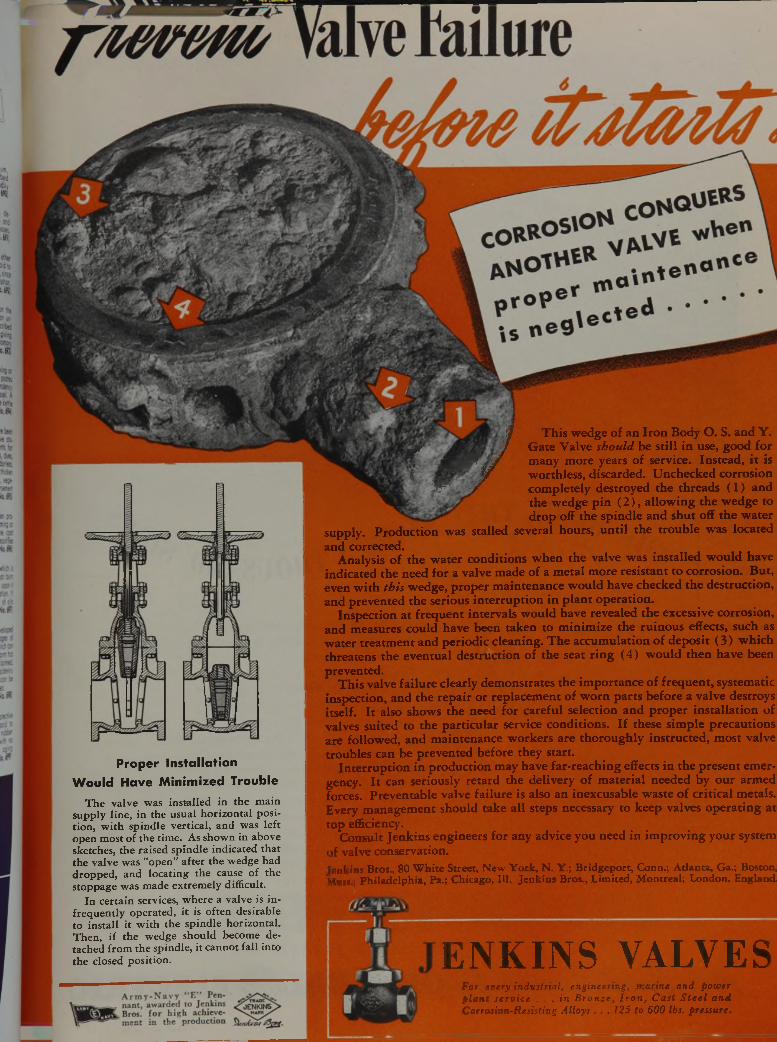
wJ-ff'h j This wedge of an Iron Body O. S. and Y.¿Jk* m?' J Gate Valve should be still in use, good for
v* M & Sr^ / many more years of service. Instead, it is\ / worthless, discarded. Unchecked corrosion
J r s ' / completely destroyed the threads ( 1 ) andNQfe the wedge pin ( 2 ) , allowing the wedge to
drop off the spindle and shut off the water supply. Production was stalled several hours, until the trouble was located and corrected.
Analysis of the water conditions when the valve was installed would have indicated the need for a valve made of a metal more resistant to corrosion. But, even with th is wedge, proper maintenance would have checked the destruction, and prevented the serious interruption in plant operation.
Inspection at frequent intervals would have revealed the excessive corrosion, and measures could have been taken to minimize the ruinous effects, such as water treatment and periodic cleaning. The accumulation of deposit (3) which threatens the eventual destruction of the seat ring (4) would then have been prevented.
This valve failure clearly demonstrates the importance of frequent, systematic inspection, and the repair or replacement of worn parts before a valve destroys itself. It also shows the need for careful selection and proper installation of valves suited to the particular service conditions. If these simple precautions are followed, and maintenance workers are thoroughly instructed, most valve troubles can be prevented before they start.
Interruption in production may have far-reaching effects in the present emergency. It can seriously retard the delivery of material needed by our armed forces. Preventable valve failure is also an inexcusable waste of critical metals. Every management should take all steps necessary to keep valves operating at top efficiency.
Consult Jenkins engineers for any advice you need in improving your system of valve conservation.Jenkins Bros., 80 W hite Street, New Y ork, N . Y.; B ridgeport, Conn.; A tlanta, Ga.; Boston, Mass.; Philadelphia, Pa.; Chicago, 111. Jenkins Bros., Limited, M ontreal; London, England.
P ro p e r In sta lla t io n
W o u ld H ave M in im ized Trouble
T h e v a lv e w a s in s t a l le d in t h e m a in s u p p ly l in e , i n th e u s u a l h o r i z o n t a l p o s it io n , w i t h s p in d le v e r t ic a l , a n d w a s l e f t o p e n m o s t o f t h e t im e . A s s h o w n in a b o v e s k e tc h e s , t h e ra is e d s p in d le in d ic a te d t h a t t h e v a lv e w a s " o p e n ” a f t e r th e w e d g e h a d d r o p p e d , a n d lo c a t in g t h e c au se o f t h e s to p p a g e w a s m a d e e x t r e m e ly d i f f ic u l t .
I n c e r t a in s e rv ic e s , w h e r e a v a lv e is i n f r e q u e n t l y o p e r a te d , i t is o f te n d e s ir a b le t o i n s t a l l i t w i t h t h e s p in d le h o r iz o n t a l . T h e n , i f t h e w e d g e s h o u ld b e c o m e d e ta c h e d f r o m t h e s p in d le , i t c a n n o t f a l l in to
t h e c lo s e d p o s it io n . ENKINS VALVESFor every industrial, engineering, marine and power plant service . . . in Bronze, Iron, Cast Steel and Corrosion-Resisting Alloys . . . 125 to 600 lbs. pressure.
/ iO i f c f , G E N E R A L ® E L E C T R IC
*
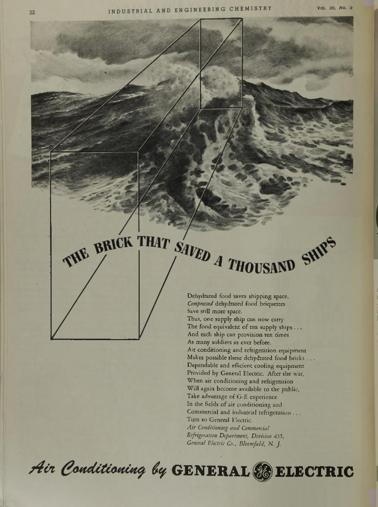
Dehydrated food saves shipping space.Compressed dehydrated food briquettes Save still more space.Thus, one supply ship can now carry The food equivalent of ten supply ships . ..And each ship can provision ten times As many soldiers as ever before.Air conditioning and refrigeration equipment Makes possible these dehydrated food bricks . . . Dependable and efficient cooling equipment Provided by General Electric. After the war, When air conditioning and refrigeration Will again become available to the public,Take advantage of G-E experience In the fields of air conditioning and Commercial and industrial refrigeration . ..Turn to General Electric.A ir Conditioning and Commercial Refrigeration Department, Division 435,General Electric Co., Bloomfield, N .J .
May, 1943 INDUS THi AL a n d e n g i n e e r i n g c h e m i s t r y 23
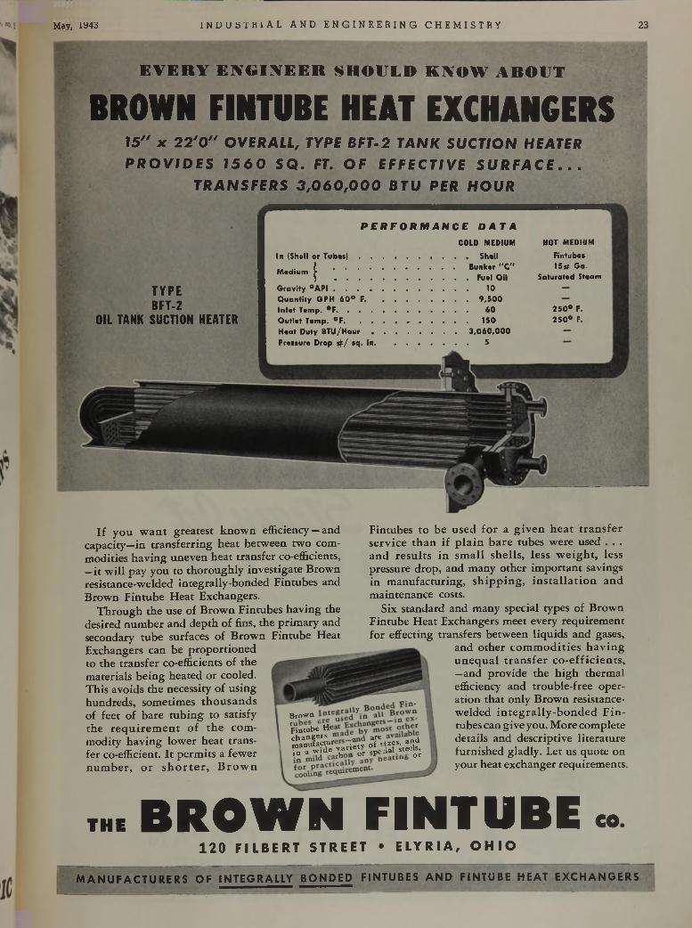
E V E R Y E N G I N E E R S H O U L D K N O W A B O U T
BROWN FINTUBE HEAT EXCHANGERS1 5 " X 2 2 ' 0 " O V E R A L L , T Y P E B E T - 2 T A N K S U C T I O N H E A T E R
P R O V I D E S 1 5 6 0 S Q . FT. OF E F F E C T I V E S U R F A C E . . . T R A N S F E R S 3 ,0 6 0 ,0 0 0 B T U P E R H O U R
P E R F O R M A N C E D A T A
T Y P EB F T - 2
O I L T A N K S U CTION H E A T E R
In (Shell or T u b e s ) ..............................................................Shell. | Bunker “ C"M edium f _
) .................................................................... Fuel OilGravity ° A P I ..................................................................... 10Quantity GPH 6 0 ° F.......................................................... 9 ,5 0 0In le t Temp. ° F ....................................................................... 60Outlet Temp. ° F ................................ 150Heat Duty B T U /H o u r .............................................. 3 ,0 6 0 ,0 0 0Pressure Drop # / sq. in ........................................................5
COLD MEDIUM HOT MEDIUMFintubes 1 5 s Ga.
Saturated Steam
2 5 0 ° F. 2 5 0 ° F.
If you want greatest known efficiency — and capacity—in transferring heat between two commodities having uneven heat transfer co-efficients, —it will pay you to thoroughly investigate Brown resistance-welded integrally-bonded Fintubes and Brown Fintube Heat Exchangers.
Through the use of Brown Fintubes having the desired number and depth of fins, the primary and secondary tube surfaces of Brown Fintube Heat Exchangers can be proportioned to the transfer co-efficients of the materials being heated or cooled.This avoids the necessity of using hundreds, sometimes thousands of feet of bare tubing to satisfy the requirement of the commodity having lower heat transfer co-efficient. It permits a fewer number, or shorter, Brown
Fintubes to be used for a given heat transfer service than if plain bare tubes were used . . . and results in small shells, less weight, less pressure drop, and many other important savings in manufacturing, shipping, installation and maintenance costs.
Six standard and many special types of Brown Fintube Heat Exchangers meet every requirement for effecting transfers between liquids and gases,
and other commodities having unequal transfer co-efficients, —and provide the high thermal efficiency and trouble-free operation that only Brown resistance- welded integrally-bonded Fintubes can give you. More complete details and descriptive literature furnished gladly. Let us quote on your heat exchanger requirements.
B r o « »
'FK s h *Kfev-FsSavS
the B R O W N F I N T U B E «120 FILBERT STREET • ELYRIA, OHI O
M A N U F A C T U R E R S OF IN TE G R A LLY B O N D E D F I NTUBES A N D F I NTUBE HEAT E X C H A N G E R S
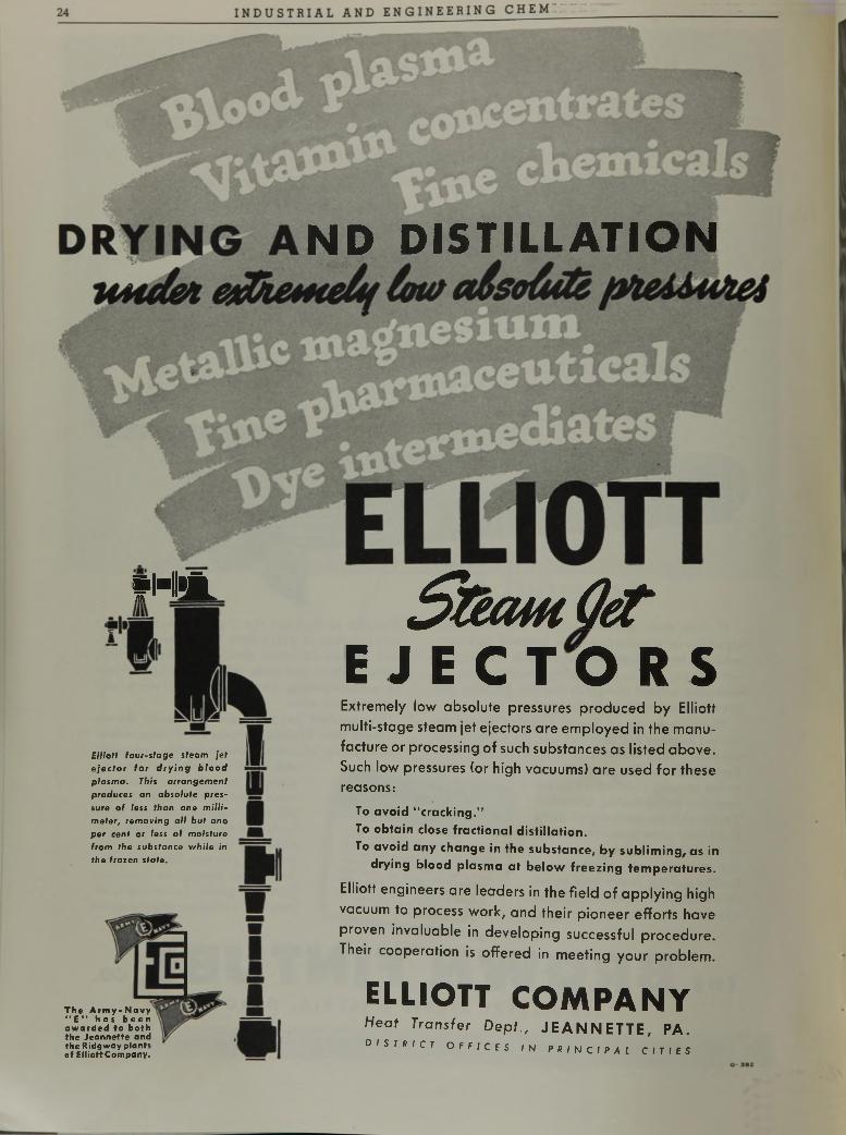
ND DISTILLATION
fHii.
Elliott four-stage steam jet e je c to r fo r d r y in g b lo o d p lasm a . This a rrangem ent produces an abso lu te pressure o f less than one m illim eter, rem oving all bu t o n e per cent or less o f m oisture from the substance w h ile in the frozen sta te .
The Army-Novy “ E” has been awarded to both the Jeannette and the Ridgway plants of ElliottCompany.
S t e a m C e t
E J E C T O R SE x t r e m e l y l o w a b s o l u t e p r e s s u r e s p r o d u c e d b y E l l i o t t
m u l t i - s t a g e s t e a m j e t e j e c t o r s a r e e m p l o y e d i n t h e m a n u
f a c t u r e o r p r o c e s s i n g o f s u c h s u b s t a n c e s a s l i s t e d a b o v e .
S u c h l o w p r e s s u r e s ( o r h i g h v a c u u m s ) a r e u s e d f o r t h e s e
r e a s o n s :
To avoid “ cracking."To obtain close fractional distillation.To avoid any change in the substance, by subliming, as in
drying blood plasma at below freezing temperatures.
E l l i o t t e n g i n e e r s a r e l e a d e r s i n t h e f i e l d o f a p p l y i n g h i g h
v a c u u m t o p r o c e s s w o r k , a n d t h e i r p i o n e e r e f f o r t s h a v e
p r o v e n i n v a l u a b l e i n d e v e l o p i n g s u c c e s s f u l p r o c e d u r e .
T h e i r c o o p e r a t i o n i s o f f e r e d i n m e e t i n g y o u r p r o b l e m .
ELLIOTT COMPANYHeat Transfer Dept., J E A N N E T T E , P A .d i s t r i c t o f f i c e s i n p r i n c i p a l c i t i e s
May, iy43 m u u ü i n l A L AND E NG I NE E R IN G CHEMI STRY
R E M E M B E R f v T H I S N A M E -
R E S O W E L D
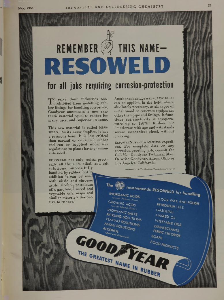
for all jobs requiring corrosion-protectionTO serve those industries now
prohibited from installing rubber linings for handling corrosives, Goodyear announces a new synthetic material equal to rubber for manv uses, and superior in some.
This new material is called RESOWELD. As its name implies, it has a resinous base. It is less critical than natural or reclaimed rubber and can be supplied under "war regulations to plants having reasonable need.
RESOWELD not only resists practically all the acid, alkali and salt solutions successfully handled by rubber, but i addition it can be use with nitric and chromic acids, alcohol, petroleum oils, gasoline, linseed and vegetable oils, soaps and similar materials destructive to rubber.
Another advantage is that RESOWELD can be applied, in the field, where absolutely necessary, to all types of metal, wood or concrete equipment other than pipe and fittings. It functions satisfactorily at temperatures up to 150°F. It does not deteriorate with age and withstands severe mechanical shock without cracking.RESOWELD is not a wartime expedient. For complete data on any corrosion-proofing job, consult the G.T.M.—Goodyear Technical Man. Or write Goodyear, Akron, Ohio or Los Angeles, California.
Eesoweia—T .M . The Goodyear T ire & Rubber Company
W re c o ,n m e n d s
' * w (J
° * g a n i c a c id s
, n o * g ^
PlO ,« G ° .Ur'°NS
* « O W E l D f o r h a n
flO O B WAX AND A
OILSg a s o l i n e -
l i^ e e d 0 il
^ E G F T a b . -

'
Bausch & Lomb Contour Measuring Projector
Today Precision Must Be CommonplaceAmerican fighting men on our fighting fronts depend upon production line accuracy . . . for ten-
thousandths of an inch variation on the production line can mean the difference between a hit or a miss on the battleline.
The Bausch & Lomb Contour Measuring Projector makes such accuracy possible on the fastest moving production lines, because it takes many vital
inspection jobs “off the surface plate” and eliminates the tedious, time-consuming computations of the “sine bar.” Inspections for accuracy become routine jobs.
Throwing an accurate, sharply defined shadow image of the object under examination on a translucent screen, the B&L Contour Projector permits exact measurements or comparison with an enlarged template drawing at magnifications great enough for easy and accurate dimensioning.
Here again is a Bausch & Lomb peacetime development that serves America at War. The B&L Contour Measuring Projector is helping speed production of fighting tools for our fighting men.
For Bausch & Lomb Instruments essential to V ictory—priorities govern delivery schedules.
B A U S C H & L O M BO P T I C A L C O . . R O C H E S T E R , N .Y .
E S T A B L I S H E D 1 8 5 3
A N A M E R IC A N S C IE N T IF IC IN ST IT U T IO N P R O D U C IN G O P T IC A L G L A S S AND IN ST R U M E N T S FO R M ILIT Ä R Y I TOT -------------------------- ----------------------------------------------------------------- -m iL U A K Y U SE. ED U CA TIO N , R E S E A R C H , IN D U S T R Y AND E Y E S IG H T C O R R EC T IO N
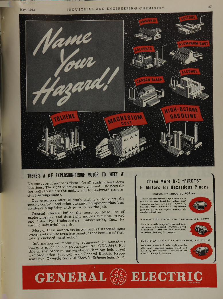
THERE’S A G-E EXPLOSION-PROOF MOTOR TO MEET ITNo one type of motor is “best” for all kinds of hazardous locations. The righ t selection may eliminate the need for fire-walls to isolate the motor, and for awkward remote- drive arrangements.
Our engineers offer to work with you to select the motor, control, and other auxiliary equipment that best combines simplicity with security on the job.
General Electric builds the most complete line of explosion-proof and dust-tight motors available, tested and listed by Underwriters’ Laboratories, Inc., tor specific industrial hazards.
Most of these motors are as compact as standard open types, and require even less maintenance because of their totally enclosed construction.
Information on motorizing equipment in hazardous places is given in our publication No. GEA-3647. For this or any other motor assistance that can help speed war production, just call your General Electric Repre- sentative. Or write G enexal E lec tric , S ch en ec ta d y , N . Y.
f
Three More G-E “FIRSTS” in Motors for Hazardous Places
e x p l o s i o n - p r o o f t o 600 h p
T o ta lly en c lo se d s q u ir re l- c a g e m o to rs u p to 600 h p a re n o w l is te d b y U n d e rw r i te r s ’L a b o ra to r ie s , In c . , fo r C lass I , G ro u p D , lo c a tio n s , w h e re a tm o s p h e re s m ay c o n ta in g a so lin e , p e tro le u m v a p o rs , a c e to n e , a l c o h o ls , n a tu r a l gas.
T E S T E D A N D L I S T E D F O R C O M B U S T I B L E D U S T S
F O R M E T A L D U S T S L I K E M A G N E S I U M , A L U M I N U M
G E N E R A L ( M ) E L E C T R I C
B u il t in a w id e ra n g e o f ty p e s a n d s izes , th is m o to r is U .L .- lis te d fo r C lass I I , G ro u p F , lo c a tio n s — w h e re co a l d u s t , c o k e d u s t , o r c a rb o n b la c k m ay b e p re s e n t.
O rd n a n c e p la n ts find w id e a p p lic a tio n fo r th is to ta l ly e n c lo se d m o to r , te s te d a n d lis te d b y U n d e rw r i te r s ’ L a b o ra to r ie s fo r C la ss I I , G ro u p E , lo c a tio n s .
28 I NDUS TR I AL AND ENGI NEER I NG CHEMI ST HY vui. oj, nu. ü
(
T h i s R e f r a c t o r y H a s
H i g h F u s i o n P o i n t — P L U S !
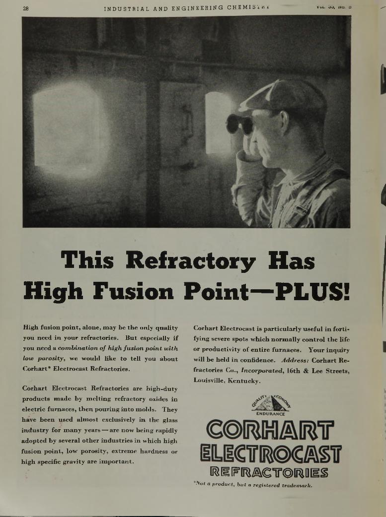
High fusion p oint, alone, m ay be the only quality you need in your refractories. B ut especially if
you need a c o m b i n a t i o n o f h ig h f u s i o n p o i n t w i t h
lo w p o r o s i t y , we would like to tell you about Corhart* Electrocast Refractories.
Corhart Electrocast Refractories are h igh-duty products m ade by m elting refractory oxides in
electric furnaces, then pouring in to m olds. They
have been used alm ost exclusively in the glass
industry for m any years — are now being rapidly
adopted by several other industries in which high
fusion p o in t, low porosity, extrem e hardness or
high specific gravity are im portant.
Corhart Electrocast is particularly u sefu l in fortifying severe spots w hich norm ally control the life
or productivity o f entire furnaces. Your inquiry
will be held in confidence. A d d r e s s : Corhart Re
fractories Co., I n c o r p o r a te d , 16th & Lee Streets, Louisville, K entucky.
B$ I I IF lR j^ g T O IE lD d §N o t a p r o d u c t , b u t a r e g i s te r e d t r a d e m a r k .
May, 1943 I ND U S T R I A L AND E N GI NE E R I NG CHE MI ST RY 31
I s t h i s t h e b e g i n n i n g o i a m i r a c l e ?
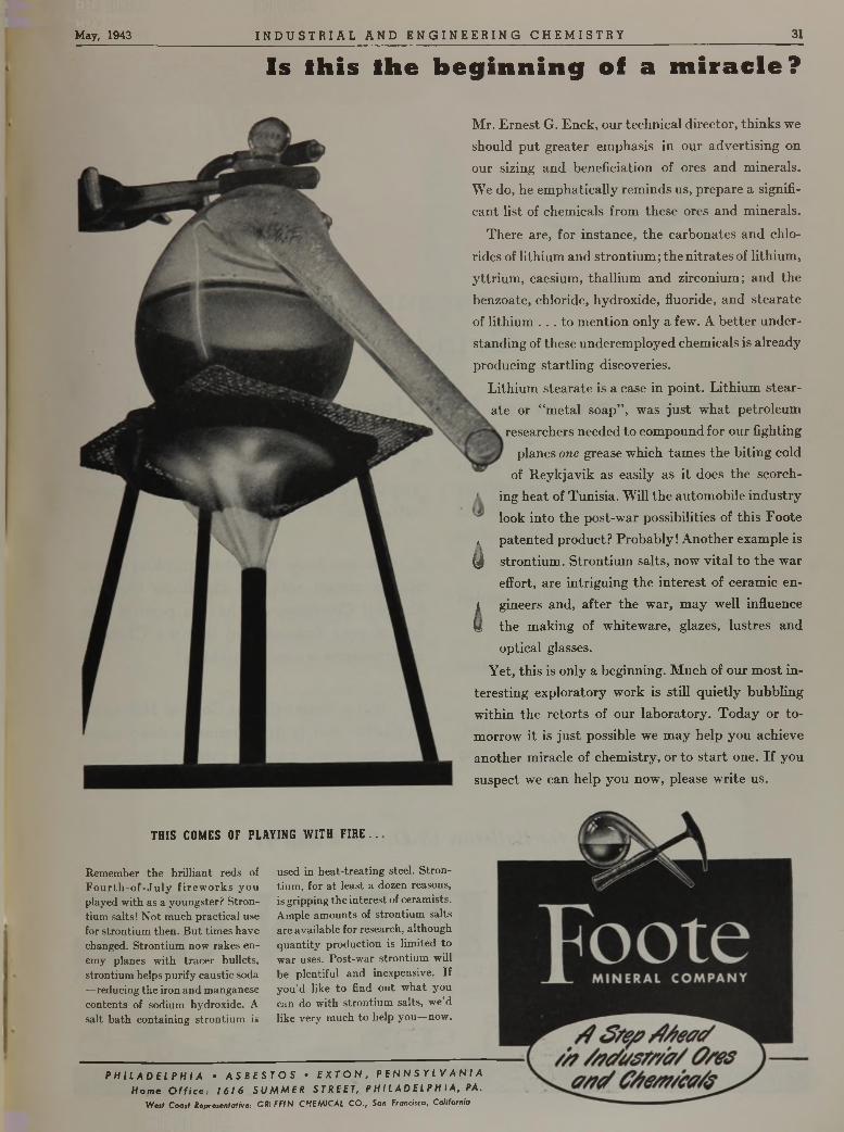
Mr. Ernest G. Enck, our technical director, thinks we should put greater emphasis in our advertising on our sizing and beneficiation of ores and minerals. We do, he emphatically reminds us, prepare a significant list of chemicals from these ores and minerals.
There are, for instance, the carbonates and chlorides of lithium and strontium; the nitrates of lithium, yttrium, caesium, thallium and zirconium; and the benzoate, chloride, hydroxide, fluoride, and stearate of lithium . . . to mention only a few. A better understanding of these underemployed chemicals is already producing startling discoveries.
Lithium stearate is a case in point. Lithium stearate or “metal soap”, was just what petroleum
researchers needed to compound for our fighting planes one grease which tames the biting cold
of Reykjavik as easily as it does the scorch- ! ing heat of Tunisia. Will the automobile industry
look into the post-war possibilities of this Foote * patented product? Probably! Another example is
(I strontium. Strontium salts, now vital to the wareffort, are intriguing the interest of ceramic en-
| gineers and, after the war, may well influencei the making of whiteware, glazes, lustres and
optical glasses.Yet, this is only a beginning. Much of our most in
teresting exploratory work is still quietly bubbling within the retorts of our laboratory. Today or tomorrow it is just possible we may help you achieve another miracle of chemistry, or to start one. If you suspect we can help you now, please write us.
THIS COMES OF PLAYING WITH FIRE..
Remember the brilliant reds of F o u rth -o f-Ju ly firew orks you played with as a youngster? Strontium salts! Not much practical use for strontium then. But times have changed. Strontium now rakes enemy planes with tracer bullets, strontium helps purify caustic soda —reducing the iron and manganese contents of sodium hydroxide. A salt bath containing strontium is
used in heat-treating steel. Strontium, for a t least a dozen reasons, is gripping the interest of ceramists. Ample amounts of strontium salts are available for research, although quantity production is limited to war uses. Post-war strontium will be plentiful and inexpensive. If you’d like to find out what you can do with strontium salts, we’d like very much to help you—now.
P H I L A D E L P H I A • A S B E S T O S • E X T O N , P E N N S Y L V A N I A H o m e O f f i c e . 1 6 1 6 S U M M E R S T R E E T , P H IL A D E L P H I A , PA.
West Coast Representative: GUI FFIN CHEMICAL CO., San Francisco, California
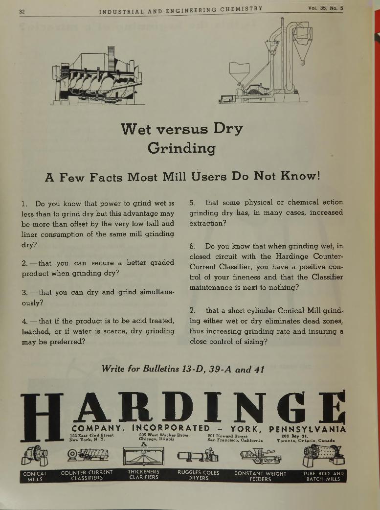
W et v e r s u s D r y G rin d in g
A F e w F a c t s M o s t M i l l U s e r s D o N o t K n o w !
1. Do you know that power to grind wet is less than to grind dry but this advantage may be more than offset by the very low ball and liner consumption of the same mill grinding dry?
2 .— that you can secure a better graded product w hen grinding dry?
3. — that you can dry and grind simultaneously?
4. — that if the product is to be acid treated, leached, or if water is scarce, dry grinding may be preferred?
5 .— that some physical or chem ical action grinding dry has, in many cases, increased extraction?
6. — Do you know that w hen grinding wet, in closed circuit with the Hardinge Counter- Current Classifier, you have a positive control of your fineness and that the Classifier maintenance is next to nothing?
7. — that a short cylinder C onical Mill grinding either wet or dry elim inates dead zones, thus increasing grinding rate and insuring a close control of sizing?
W r i t e f o r B u l l e t i n s 1 3 - D , 3 9 - A a n d 4 1
A R D I N G EC O M P A N Y , IN C O R P O R A T ED - Y O R K , P E N N S Y LV A N IA
CONICALMILLS
122 E a s t 4 2nd S t r e e t N ew Y o rk , N . Y .
m m
COUNTER CURRENT CLASSIFIERS
205 W e st W a c k e r D rive C h ic a g o , I l l in o isA
501 H o w a rd S tr e e t S a n F r a n c is c o , C a l i f o rn ia
200 Bay St.T o r o n to , O n ta r io , C a n a d a
THICKENERSCLARIFIERS
RUGGLES-COLESDRYERS
CONSTANT WEIGHT FEEDERS
TUBE ROD AND BATCH MILLS
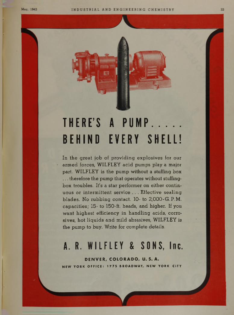
T H E R E ’ S A P U M P . . . . . . . .B E H I N D E V E R Y S H E L L !In the great job of providing exp losives for our armed forces, WILFLEY acid pumps play a major part. WILFLEY is the pump without a stuffing box . . . therefore the pump that operates without stuffing- box troubles. It's a star performer on either continuous or intermittent service . . . Effective sea lin g blades. No rubbing contact. 10- to 2 ,0 0 0 -G.P.M. capacities; 15- to 150-ft. heads, and higher. If you want highest efficiency in handling acids, corrosives, hot liquids and mild abrasives, WILFLEY is the pump to buy. Write for complete details.
A. R. WILFLEY & SONS, Inc.D E N V E R , C O L O R A D O , U. S. A.
N EW YORK O F F I C E : 1 7 7 5 B RO A D WA Y , N E W YORK CITY
I NDUS TR I AL AND ENGI NEER I NG CHEMISTRY
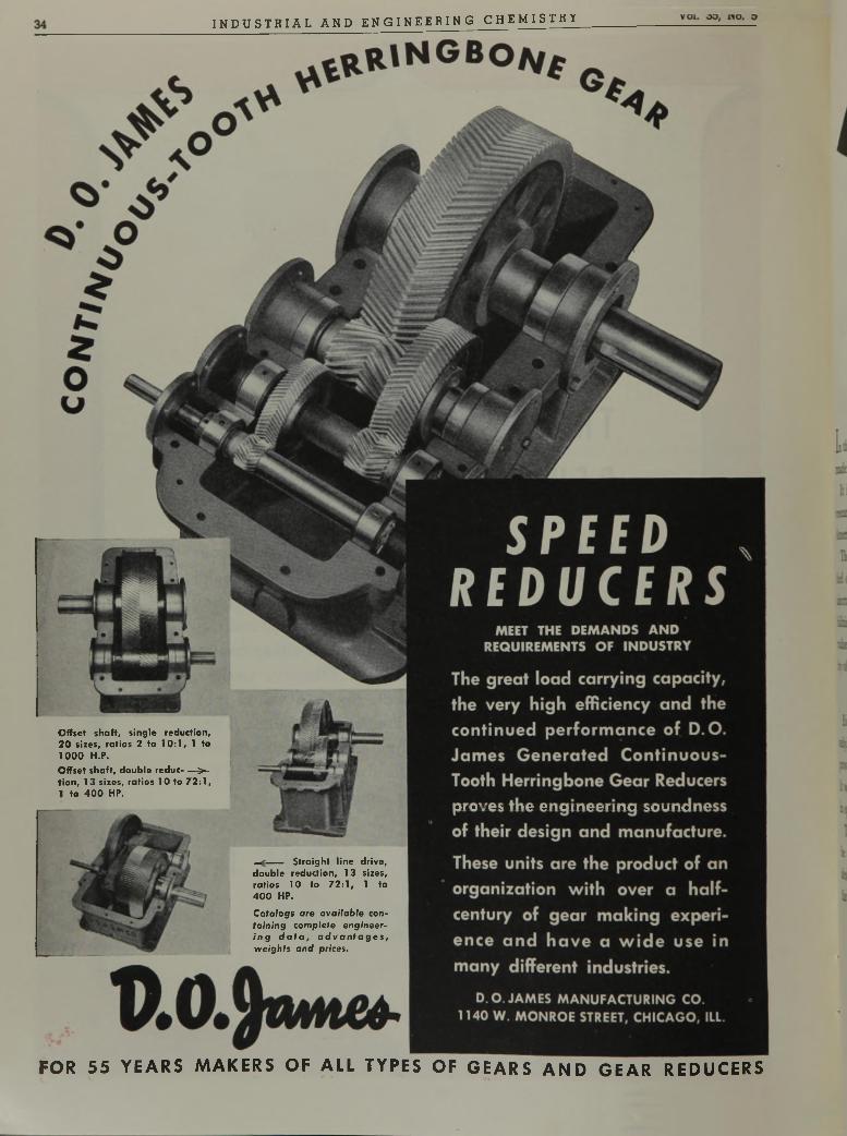
FOR 55 YEARS MAKERS OF ALL TYPES OF GEARS AND GEAR REDUCERS
C atalogs are ava ilab le conta in ing com plete eng ineeri n g d a t a , a d v a n t a g e s , w eigh ts a nd prices.
Offset shaft, single reduction, 20 sizes, ratios 2 to 10:1, 1 to 1000 H.P.Offset shaft, double reduc- —>- tion, 13 sizes, ratios 10 to 72:1, 1 to 400 HP.
Straight line drive, double reduction, 13 sizes, ratios 10 to 72:1, 1 to 400 HP.
¿▼¿ay, iin>j I N D U S T R I A L AND E N G I N EE R IN G CHEMI STRY 35
A
N E W H O U D R Y P R O C E S S C A N :
P t / ie q v a f a y o f p r e s e n t
a t !O J 1 g a s o / in e s !
S p e e ( / u p
s u p e r e r , « -
s / 7 g ^ e s ^ p r o v
p e r d u e ls n o w /
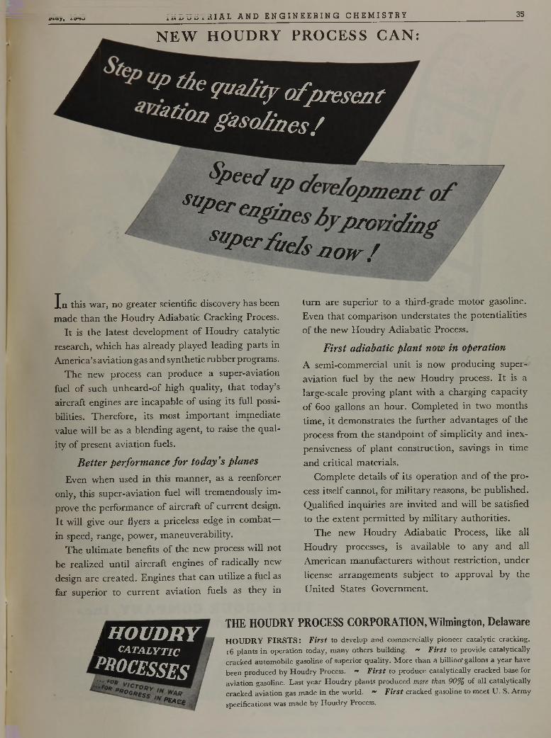
In this war, no greater scientific discovery has been made than the Houdry Adiabatic Cracking Process.
It is the latest development of Houdry catalytic research, which has already played leading parts in America’s aviation gas and synthetic rubber programs.
The new process can produce a super-aviation fuel of such unheard-of high quality, that today’s aircraft engines are incapable of using its full possibilities. Therefore, its most important immediate value will be as a blending agent, to raise the quality of present aviation fuels.
B e t t e r p e r f o r m a n c e f o r t o d a y ’s p l a n e s
Even when used in this manner, as a reenforcer only, this super-aviation fuel will tremendously improve the performance of aircraft of current design. It will give our flyers a priceless edge in combat— in speed, range, power, maneuverability.
The ultimate benefits of the new process will not be realized until aircraft engines of radically new design are created. Engines that can utilize a fuel as far superior to current aviation fuels as they in
turn are superior to a third-grade motor gasoline. Even that comparison understates the potentialities of the new Houdry Adiabatic Process.
F i r s t a d i a b a t i c p l a n t n o w i n o p e r a t i o n
A semi-commercial unit is now producing superaviation fuel by the new Houdry process. It is a large-scale proving plant with a charging capacity of 600 gallons an hour. Completed in two months time, it demonstrates the further advantages of the process from the standpoint of simplicity and inexpensiveness of plant construction, savings in time and critical materials.
Complete details of its operation and of the process itself cannot, for military reasons, be published. Qualified inquiries are invited and will be satisfied to the extent permitted by military authorities.
The new Houdry Adiabatic Process, like all Houdry processes, is available to any and all American manufacturers without restriction, under license arrangements subject to approval by the United States Government.
i H O U D R YC A T A L Y T I C
p { ° ? £ s s e s
' p £ A e e
THE HOUDRY PROCESS CORPORATION, Wilmington, DelawareH O U D R Y F I R S T S : F i r s t to d e v e lo p a n d c o m m e r c ia l ly p io n e e r c a ta ly t ic c ra c k in g .
16 p la n ts i n o p e ra t io n t o d a y , m a n y o th e rs b u i ld in g . ~ F i r s t to p r o v id e c a ta ly t ic a l ly
c ra c k e d a u to m o b i le g a s o lin e o f s u p e r io r q u a l i t y . M o r e t h a n a b i l l io n ' g a llo n s a y e a r h a v e
b e e n p ro d u c e d b y H o u d r y Process. ~ F i r s t to p ro d u c e c a ta ly t ic a l ly c ra c k e d b as e fo r
a v ia t io n g a s o lin e . L a s t y e a r H o u d r y p la n ts p ro d u c e d more th an 9 0 % o f a l l c a ta ly t ic a l ly
c ra c k e d a v ia t io n gas m a d e in th e w o r ld . " F i r s t c ra c k e d g a s o lin e to m e e t U . S . A r m y
s p e c if ic a tio n s w a s m a d e b y H o u d r y Process.

34 I NDUS TR I AL AND ENGINEER ING CHEMISTRY VOl. OO. IV o. o
.
D.O. nweFOR 55 YEARS MAKERS OF ALL TYPES OF GEARS AND GEAR REDUCERS
xnajr, 171^ ¡ " “ XJSTRIAL AND E NG I NE E R IN G CHEMI STRY 35
A
N E W H O U D R Y P R O C E S S C A N :
rP the q a a /itjr o f p re s e n t
s i r o T ^ ^ d e v e lo p m e n t 0 /
^ p T / T ,h y p m v ic / jh gJ J e r f u e ls 1 2 o w /
w
In this war, no greater scientific discovery has been made than the Houdry Adiabatic Cracking Process.
It is the latest development of Houdry catalytic research, which has already played leading parts in America’s aviation gas and synthetic rubber programs.
The new process can produce a super-aviation fuel of such unheard-of high quality, that today’s aircraft engines are incapable of using its full possibilities. Therefore, its most important immediate value will be as a blending agent, to raise the quality of present aviation fuels.
B e t t e r p e r f o r m a n c e f o r t o d a y ’s p l a n e s
Even when used in this manner, as a reenforcer only, this super-aviation fuel will tremendously improve the performance of aircraft of current design. It will give our flyers a priceless edge in combat in speed, range, power, maneuverability.
The ultimate benefits of the new process will not be realized until aircraft engines of radically new design are created. Engines that can utilize a fuel as far superior to current aviation fuels as they in
turn are superior to a third-grade motor gasoline. Even that comparison understates the potentialities of the new Houdry Adiabatic Process.
F i r s t a d i a b a t i c p l a n t n o w i n o p e r a t i o n
A semi-commercial unit is now producing superaviation fuel by the new Houdry process. It is a large-scale proving plant with a charging capacity of 600 gallons an hour. Completed in two months time, it demonstrates the further advantages of the process from the standpoint of simplicity and inexpensiveness of plant construction, savings in time and critical materials.
Complete details of its operation and of the process itself cannot, for military reasons, be published. Qualified inquiries are invited and will be satisfied to the extent permitted by military authorities.
The new Houdry Adiabatic Process, like all Houdry processes, is available to any and all American manufacturers without restriction, under license arrangements subject to approval by the United States Government.
iH O U D R Y
C A T A L Y T I C
J e s s e s
'«ess ¡¡¡Z * *p £a c e
THE HOUDRY PROCESS CORPORATION, Wilmington, DelawareH O U D R Y F I R S T S : F i r s t to d e v e lo p a n d c o m m e r c ia l ly p io n e e r c a t a ly t ic c ra c k in g .
16 p la n ts i n o p e ra t io n to d a y , m a n y o th e rs b u i ld in g . ~ F i r s t to p r o v id e c a t a ly t ic a l ly
c ra c k e d a u to m o b i le g a s o lin e o f s u p e r io r q u a l i t y . M o r e t h a n a b i l l io n - g a llo n s a y e a r h a v e
b e e n p ro d u c e d b y H o u d r y Process. ~ F i r s t to p ro d u c e c a t a ly t ic a l ly c ra c k e d b a s e fo r
a v ia t io n g a s o lin e . L a s t y e a r H o u d r y p la n ts p r o d u c e d more than 9 0 % o f a l l c a t a ly t ic a l ly
c ra c k e d a v ia t io n gas m a d e i n t h e w o r ld . ~ F i r s t c ra c k e d g a s o lin e to m e e t U . S . A r m y
s p e c if ic a tio n s w a s m a d e b y H o u d r y Process.

l a b o u r p u m p s
L aB our T ype Q , a n e w d e s ig n c e n tr i fu g a l fo r la s t in g e f f i c i e n c y w h e r e p r im in g a b i li ty is n o t re q u ire d .
I NDUS TR I AL AND ENGI NEER I NG C H E M I S Q Q
L a B o u r T y p e D PL , th e c e n tr ifu g a l pu m p th a t p rim es itse lf.
Making explosives, like making high-octane gasoline and so many other items demanded for war, is a chemical process involving large quantities of corrosive liquids. Acids must be manufactured, loaded and unloaded, transferred from tank to vat. Those corrosive liquids must be moved quickly, safely, dependably . . . if there are to be bombs for Berlin and TNT for Tokyo.
The fact that LaBour Pumps are doing the major portion of that moving job in American chemical plants; is important to the future buyer of chemical pumps only because today's performance is a positive test of inbuilt quality. LaBours are making good under the toughest conditions it is possible to impose. That is why LaBour facilities are devoted completely to the war effort; that is why manufacturers of civilian chemicals cannot get LaBour Pumps now.
Out of this severe period of test will come even better LaBour Pumps for tomorrow, for we never stop learning. In the competitive business world that will come with peace, efficient pumping of chemicals will be at cc premium just as today—and LaBours will do the job with the same economy and dependability that mark their performance in war.
THE La b o u r COMPANY, Inc.E l k h a r t , I n d i a n a , U . S . A .
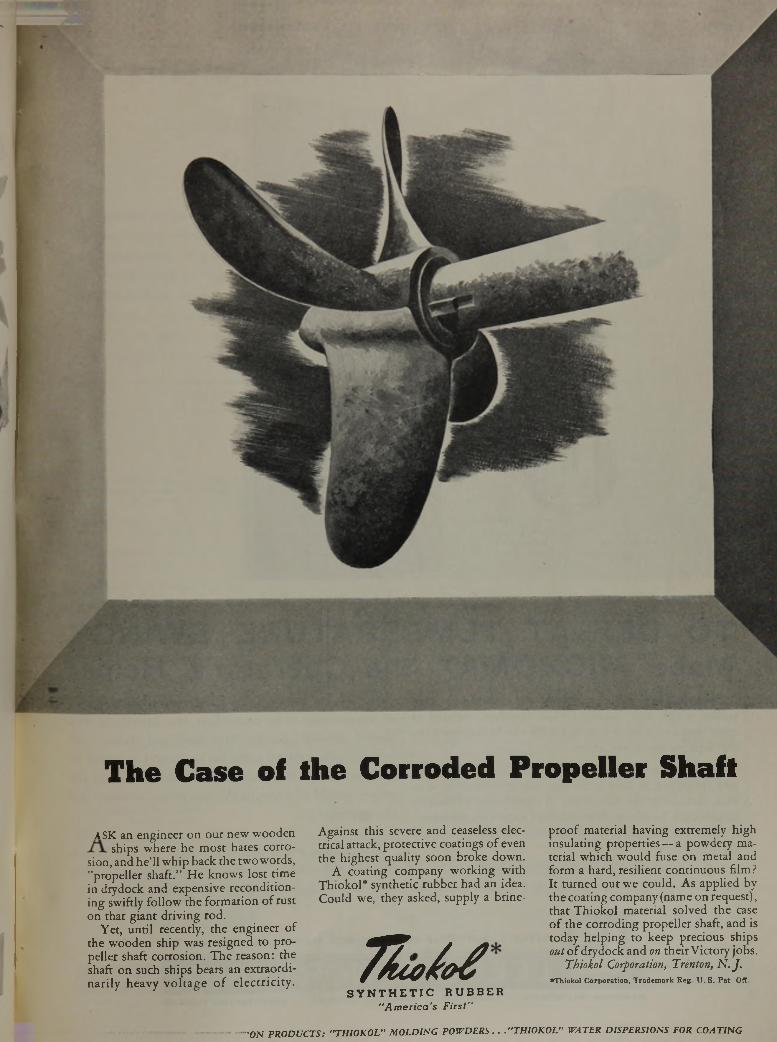
T h e C a s e o f th e C o r r o d e d P r o p e l le r S h a ft
A SK an engineer on our new wooden ships where he most hates corro
sion, and he’ll whip back the two words, "propeller shaft.” He knows lost time in drydock and expensive reconditioning swiftly follow the formation of rust on that giant driving rod.
Yet, until recently, the engineer of the wooden ship was resigned to propeller shaft corrosion. The reason: the shaft on such ships bears an extraordinarily heavy voltage of electricity.
Against this severe and ceaseless electrical attack, protective coatings of even the highest quality' soon broke down.
A coating company working with Thiokol* synthetic rubber had an idea. Could we, they asked, supply a brine-
T Z c o ^ o t fS Y N T H E T I C R U B B E R
" Am erica's First"
proof material having extremely high insulating properties — a powdery material which would fuse on metal and form a hard, resilient continuous film ? It turned out we could. As applied by the coating company (name on request), that Thiokol material solved the case of the corroding propeller shaft, and is today helping to keep precious ships out of drydock and on their Victory jobs.
Thiokol Corporation, Trenton, N .J .♦Thiokol Corporation, Tradem ark Reg U . S . Pat. Off
"ON PRODUCTS: "THIOKOL" MOLDING POWDERS . . ."THIOKOL" WATER DISPERSIONS FOR COATING
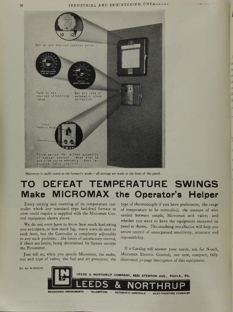
38 I NDUS TR I AL AND ENGI NEER I NG C H E m ï s i é i ï
Micromax is easily tuned to the furnace’s needs — all settings are made at the front of the panel.
Turn to anyd e s I red th r o t t l ingrange
Set any r a t e of aut omat i c droop c o r r e c t i on
M anual C o n t r o l Knob
Throw swi tch for e i t her automatic or manual control . Move knob to pos i t i on valve manual ly. Knob ind i ca t e s valve pos i t i on.
TO DEFEAT TEMPERATURE SWINGS Make MICROMAX the Operator’s Helper
Every setting and resetting of its temperature controller which any standard type fuel-fired furnace or oven could require is supplied with the Micromax Control equipment shown above.
We do not even have to know how much load-swing you anticipate, or how much lag; many users do send us such facts, but the Controller is completely adjustable to any such problem. . .the limits of satisfactory control, if there are limits, being determined by factors outside the Pyrometer.
Just tell us, when you specify Micromax, the make, size and type of valve; the fuel and air pressures; the
type of thermocouple if you have preference; the range of temperature to be controlled; the amount of wire needed between couple, Micromax and valve; and whether you want to have the equipment mounted on panel as shown. Thej'esulting installation will help you secure control of unsurpassed sensitivity, accuracy and dependability.
If a Catalog will answer your needs, ask for N-ooA, Micromax Electric Control; our new, compact, fully illustrated 30-page description of this equipment.
J r l . A d N -33A (19)
M E A S U R I N G IN S T R U M E N T S
L E E D S A N O R T H R U P C O M P A N Y , 4 9 2 0 S T E N T O N A V E ., P H I L A .. P A .
LEEDS & NORTHRUPT E L E M E T E R S • A U T O M A T IC C O N T R O L S • H E A T - T R E A T I N G F U R N A C E S
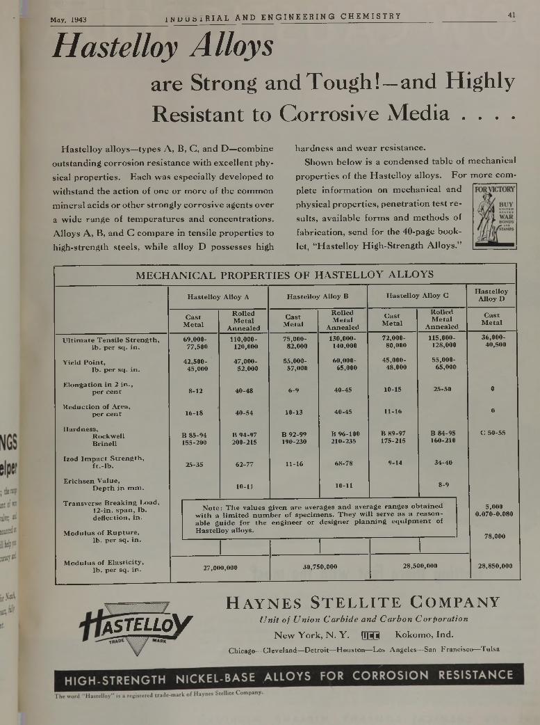
May, 1943 I H U U S I R I A L AND E N G I N E E R I N G C HEMI STRY 41
H a s t e l l o y A l l o y s
a re S tr o n g a n d T o u g h ! —a n d H ig h ly
R e s is ta n t to C o r r o s iv e M e d ia • • • •
Hastelloy alloys—types A, B, C, and D—combine outstanding corrosion resistance with excellent physical properties. Each was especially developed to withstand the action of one or more of the common mineral acids or other strongly corrosive agents over a wide range of temperatures and concentrations. Alloys A, B, and G compare in tensile properties to high-strength steels, while alloy D possesses high
hardness and wear resistance.Shown below is a condensed table of mechanical
properties of the Hastelloy alloys. For more complete information on mechanical and physical properties, penetration test results, available forms and methods of fabrication, send for the 40-page booklet, “Hastelloy High-Strength Alloys.”
M E C H A N IC A L PRO PERTIES O F H A ST ELL O Y A LLO YS
H a s t e l l o y A l lo y A H a s t e l l o y A l lo y B H a s t e l l o y A l lo y CH a s t e l l o y
A l lo y D
C a s tM e t a l
R o l l e dM e t a l
A n n e a l e d
C a s tM e t a l
R o l l e dM e t a l
A n n e a l e d
C a s tM e t a l
R o l l e dM e t a l
A n n e a l e d
C a s tM e t a l
U l t i m a t e T e n s i l e S t r e n g t h , l b . p e r s q . i n .
6 9 ,GOO- 7 7 ,5 0 0
110,000-120,000
7 5 ,0 0 0 -8 2 ,0 0 0
1 3 0 ,0 0 0 -1 4 0 ,0 0 0
7 2 ,0 0 0 -8 0 ,0 0 0
1 1 5 ,0 0 0 -1 2 8 ,0 0 0
3 6 ,0 0 0 -4 0 ,5 0 0
Y i e l d P o i n t ,l b . p e r s q . i n .
4 2 ,5 0 0 -4 5 ,0 0 0
4 7 ,0 0 0 -5 2 ,0 0 0
5 5 ,0 0 0 -5 7 ,0 0 0
6 0 ,0 0 0 -6 5 ,0 0 0
4 5 ,0 0 0 -4 8 ,0 0 0
5 5 ,0 0 0 -6 5 ,0 0 0
E l o n g a t i o n i n 2 i n . , p e r c e n t 8-12 4 0 -4 8 6 -9 4 0 -4 5 1 0 -1 5 2 5 -5 0 0
R e d u c t i o n o f A r e a , p e r c e n t 1 6 -1 8 4 0 -5 4 1 0 -1 3 4 0 -4 5 1 1 -1 6 0
H a r d n e s s ,R o c k w e l lB r i n e l l
B 8 5 -9 4 1 5 5 -2 0 0
B 9 4 -9 7 2 0 0 -2 1 5
B 9 2 -9 9 1 9 0 -2 3 0
B 9 6 -1 0 0 2 1 0 -2 3 5
B 8 9 -9 7 1 7 5 -2 1 5
B 8 4 -9 5 1 6 0 -2 1 0
C 5 0 - 5 5
I z o d I m p a c t S t r e n g t h , f t . - l b . 2 5 -3 5 6 2 -7 7 1 1 -1 6 6 8 -7 8 9 -1 4 3 4 -4 0
E r i c h s e n V a l u e ,D e p t h i n m m . 10-11 10-11 8 -9
T r a n s v e r s e B r e a k i n g L o a d , 12- i n . s p a n , l b . d e f l e c t i o n , i n .
M o d u l u s o f R u p t u r e ,
N o t e : T h e v a l u e s g i v e n a r e a v e r a g e s a n d a v e r a g e r a n g e s o b t a i n e d w i t h a l i m i t e d n u m b e r o f s p e c i m e n s . T h e y w i l l s e r v e a s a r e a s o n a b l e g u i d e f o r t h e e n g i n e e r o r d e s i g n e r p l a n n i n g e q u i p m e n t o f H a s t e l l o y a l l o y s .
5 .0 0 0 0 .0 7 0 - 0 .0 8 0
7 8 .0 0 0l b . p e r s q . i n .
M o d u l u s o f E l a s t i c i t y , l b . p e r s q . i n . 2 7 ,0 0 0 ,0 0 0 3 0 ,7 5 0 ,0 0 0 2 8 ,5 0 0 ,0 0 0 2 8 ,8 5 0 ,0 0 0
ASTELLoVH a y n e s S t e l l i t e C o m p a n y
U n it o f U n io n C a r b id e a n d C a rb o n C o r p o ra tio n
New York, N. Y. |I|M Kokomo, Ind.Chicago—Cleveland—Detroit—Houston—Los Angeles—San Francisco—Tulsa
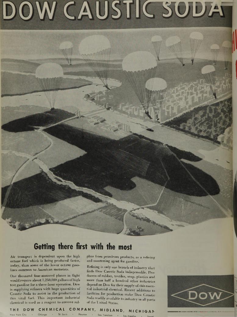
Getting there first with the mostAir traasp o rt is dependent upon the high octane fuel w hich is being produced faster, today , th a n some o f th e lower octane gasolines comm on to A m erican m otorists.
One thousand four-motored planes in flight would require about 1,2S0.000 gallons of high test gasoline for a three-hour operation. Dow is supplying refiners with huge quantities of Caustic Soda to assist in the production of this vital fuel. This important industrial chemical is used as a reagent to remove sul-
T H E D O WNew York City
phur from petroleum products, as a refining and sweetening agent for gasoline.Refining is only one branch of industry that finds Dow Caustic Soda indispensable. Producers of rubber, textiles, soap, plastics and more than half a hundred other industries depend on Dow for their supply of this essential industrial chemical. Recent additions to facilities for production make Dow Caustic Soda readily available to industry in all parts of the United States.
C H E M I C A L C O M P A N Y , M I D L A N D , M I C H I G A NChicago • St. Louis • Houston . San Francisco . Las Angeles . S.......
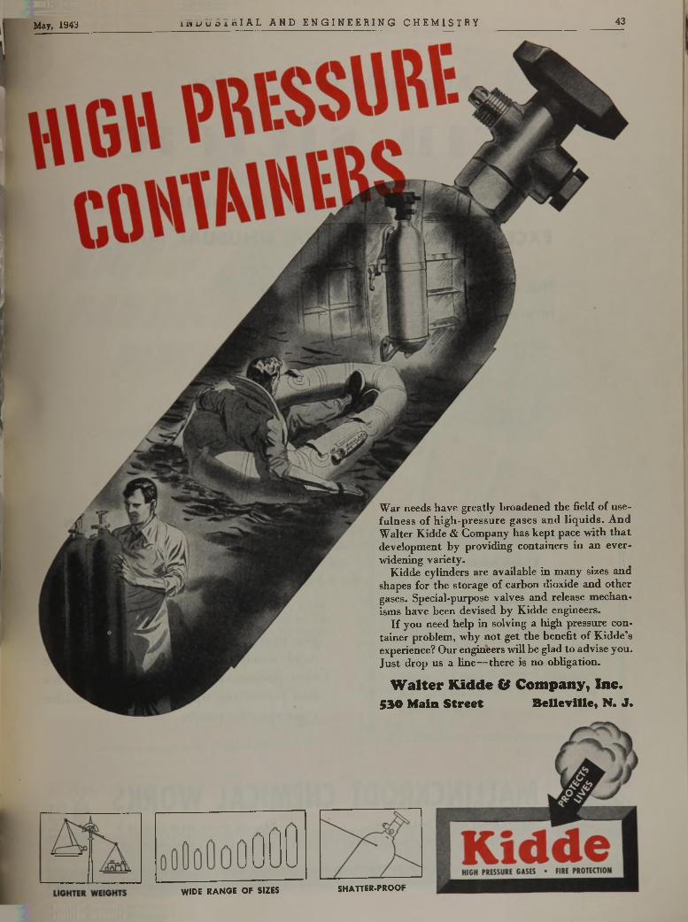
May, 1943 I N D U S T R I A L A N D E N G I N E E R I N G C H E M I S T R Y 43
War needs have greatly broadened the field of usefulness of high-pressure gases and liquids. And Walter Kidde & Company has kept pace with that development by providing containers in an ever- widening variety.
Kidde cylinders are available in many sizes and shapes for the storage of carbon dioxide and other gases. Special-purpose valves and release mechanisms have been devised by Kidde engineers.
If you need help in solving a high pressure container problem, why not get the benefit of Kidde’s experience? Our engineers will be glad to advise you. Just drop us a line— there is no obligation.
W a l t e r K i d d e & C o m p a n y , I n c .
5 3 0 M a i n S t r e e t B e l l e v i l l e , N . J .
WIDE RANGE OF SIZES SHATTER-PROOF
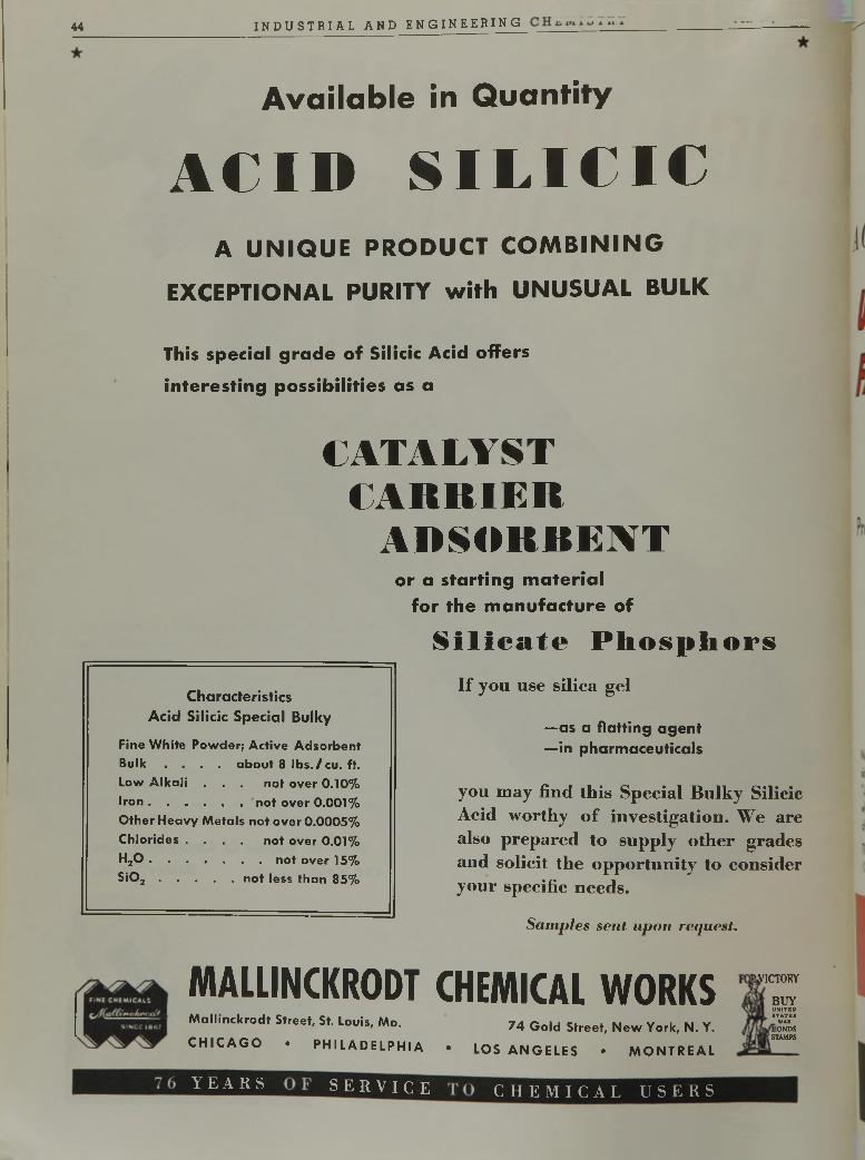
44 I N D U S T R I A L A N D E N G I N E E R I N G
A v a i l a b l e i n Q u a n t i t y
A C I D S I L I C I CA U N IQ U E PR O DUCT C O M B IN IN G
EXCEPTIONAL PURITY w ith UNUSUAL BULK
T h i s s p e c i a l g r a d e o f S i l i c i c A c i d o f f e r s
i n t e r e s t i n g p o s s i b i l i t i e s a s a
Characteristics
A c id Silicic Special Bulky
Fine White Powder; Active Adsorbent Bulk . . . . about 8 lb s ./ cu. ft. Low A lka li . . . not over 0.10%Iro n ........................................not over 0.001%Other Heavy Metals not over 0.0005% Chlorides . . . . not over 0.01%H20 ...............................................not over 15%S i0 2 ............................not less than 85%
C A T A L Y S T
C A R R I E R
A D S O R R E N T
o r a s t a r t i n g m a t e r i a l
f o r t h e m a n u f a c t u r e o f
S i l i c a t e P h o s p h o r sI f y o u u s e s i l i c a g e l
— a s a fla ttin g a g e n t
— in p h arm aceu tica ls
y o u m a y f i n d t h i s S p e c i a l B u l k y S i l i c i c
A c i d w o r t h y o f i n v e s t i g a t i o n . W e a r e
a l s o p r e p a r e d t o s u p p l y o t h e r g r a d e s
a n d s o l i c i t t h e o p p o r t u n i t y t o c o n s i d e r
y o u r s p e c i f i c n e e d s .
Sam ples sen t upon request.
MALLINCKRODT CHEMICAL WORKSM allinckrodt Street, St. Louis, Mo. 7 4 G o |d Streeti New Yo rk, N. Y .
C H I C A G O • P H I L A D E L P H I A • LOS A N G E L E S • M O N T R E A L
.VICTORY
BUYUNITEDSTATESWARlONDS
STAMPS
Y E A R S S E R V I C E C H E M I C A L U S E R S
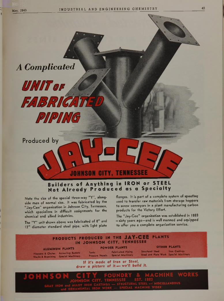
May, 1943 I N D U S T R I A L A N D E N G I N E E R I N G C H E M I S T R Y 45
Builders of Anything in IRON or STEEL Not Already Produced as a Specialty
A Complicated
U N IT t r
P I P IN G
Produced by
Note the size of the special three-way "Y", alongside man of normal size. It was fab rica ted by the "Jay -C ee" organization in Johnson City, Tennessee, which specializes in difficult assignments for the chemical and allied industries.
The "Y" unit shown above was fab rica ted of 8" and 12" d iam eter standard steel pipe, with light plate
flanges. It is part o f a com plete system of spouting used to transfer raw materials from storage hoppers to screw conveyors in a plant manufacturing carbon products for the Victory Effort.
The "Jay -C ee" organization was established in 1883 — sixty years a g o —and is well manned and equipped to offer you a com plete organization service.
P R O D U C T S P R O D U C E D IN T H E JA Y -C E E P L A N T S IN J O H N S O N C IT Y . T E N N E S S E E
ALUMINUM PLANTSHopper* ft C hu t« Annealing Ba*ket* Stack* ft Breeching Special Machinery
Tank*Pressure Vessels
POWDER PLANTSFabricated Piptng Special Machinery
OTHER PLANTSStructural Steel Iron CastingsSteel and Plate Work Special Machinery
If it's made of Iron or Steel, draw a picture of it — we'll build it.
J O H N S O N C I T Y foundry & m a c h in e worksJ n J O H N S O N c m . TENNESSEE EST. I8 > 3
. . . . IBOH . „ H A u o r IRON CASTINGS - STRUCTURAI STEEL - MISCELLANEOUS L ORNAMENTAL IRON WORK - SPECIAL MACHINE WORE
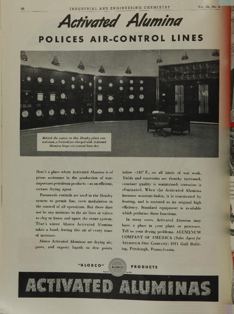
A c t i v a t e e f A / u m / n a
P O L I C E S A I R - C O N T R O L L I N E S
I N D U S T R I A L A N D E N G I N E E R I N G C H E M I S T R Y ___________________Vol
H ere’s a place where A ctivated A lum ina is of
prim e assistance in the production of w ar-
im p o rtan t petro leum p roducts— as an efficient, certain drying agent.
P neum atic controls are used in th e H oudry
system to perm it fine, even m odulation in
th e contro l of all operations. B u t th e re dare
no t be any m oisture in th e air lines or valves
to clog or freeze and upse t th e en tire system .
T h a t ’s w here A lorco A c tiv a te d A lum ina
takes a hand , freeing th is air o f every trace of m oisture.
Alorco A ctivated A lum inas are drying air,
gases, and organic liquids to dew points
below —110° F ., on all k inds of w ar w ork.
Y ields an d recoveries are th e re b y increased ;
co n s tan t q u a lity is m a in ta in ed ; corrosion is
e l im in a te d . W h en th e A c t iv a te d A lu m in a
becom es m o istu re-laden , i t is re a c tiv a te d by
heating , and is resto red to its o rig inal h igh
efficiency. S ta n d a rd eq u ip m en t is av a ilab le which perform s these functions.
In m any cases, A ctiv a ted A lum ina m ay
have a place in y ou r p la n t o r processes.
Tell us your d ry ing p roblem s. A L U M IN U M
C O M P A N Y O F A M E R IC A (Sales Agent fo r
A l u m in u m O r e C o m p a n y ) 1911 G u lf B uild-
ing, P ittsb u rg h , P en n sy lv an ia .
Behind the scenes in this Houdry-plant control room, a Lectrodryer charged with Activated
Alumina keeps air-control lines dry.
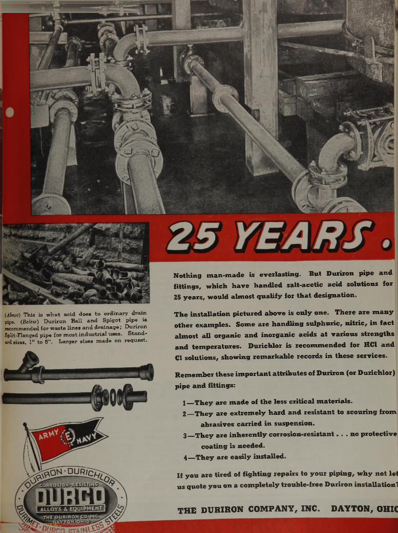
(Above) This is what acid does to ordinary drain pipe. (Below) Duriron Bell and Spigot pipe is recommended for waste lines and drainage; Duriron Split-Flanged pipe £or m ost industrial uses. Standard sizes, 1" to 8". Larger sizes made on request.
N o t h i n g m a n - m a d e is e v e r l a s t i n g . B u t D u r i r o n p i p e a n d
f i t t i n g s , w h i c h h a v e h a n d l e d s a l t - a c e t i c a c i d s o l u t i o n s f o r
25 y e a r s , w o u ld a l m o s t q u a l i f y f o r t h a t d e s i g n a t i o n .
T h e i n s t a l l a t i o n p i c t u r e d a b o v e i s o n l y o n e . T h e r e a r e m a n y
o t h e r e x a m p l e s . S o m e a r e h a n d l i n g s u l p h u r i c , n i t r i c , i n f a c t
a l m o s t a l l o r g a n i c a n d i n o r g a n i c a c i d s a t v a r i o u s s t r e n g t h s
a n d t e m p e r a t u r e s . D u r i c h l o r i s r e c o m m e n d e d f o r H C 1 a n d
C l s o l u t i o n s , s h o w i n g r e m a r k a b l e r e c o r d s i n t h e s e s e r v i c e s .
R e m e m b e r t h e s e i m p o r t a n t a t t r i b u t e s o f D u r i r o n ( o r D u r i c h l o r )
p i p e a n d f i t t i n g s :
1 T h e y a r e m a d e o f t h e l e s s c r i t i c a l m a t e r i a l s .
2 T h e y a r e e x t r e m e l y h a r d a n d r e s i s t a n t t o s c o u r i n g f r o m
a b r a s i v e s c a r r i e d i n s u s p e n s i o n .
3 T h e y a r e i n h e r e n t l y c o r r o s i o n - r e s i s t a n t . . . n o p r o t e c t i v e
c o a t i n g i s n e e d e d .
4 — T h e y a r e e a s i l y i n s t a l l e d .
I f y o u a r e t i r e d o f f i g h t i n g r e p a i r s t o y o u r p i p i n g , w h y n o t l e t
u s q u o t e y o u o n a c o m p l e t e l y t r o u b l e - f r e e D u r i r o n i n s t a l l a t i o n ?
T H E D U R I R O N C O M P A N Y , I N C . D A Y T O N , O H I C
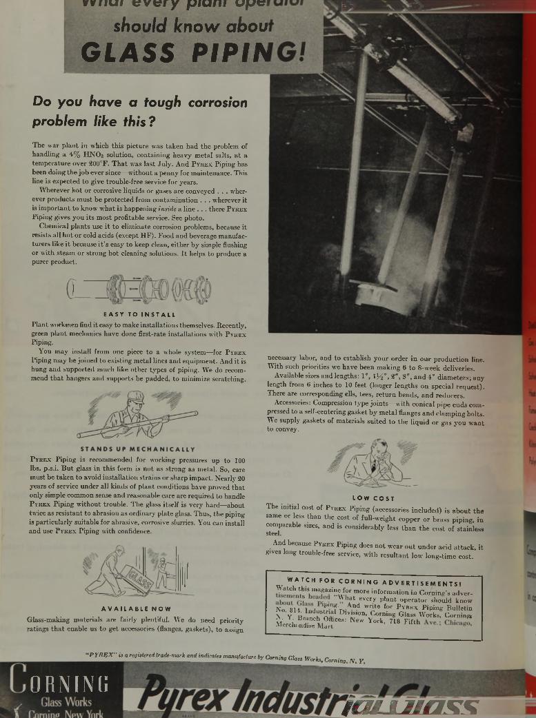
v v n a r every p i a n r a p t ? ¡
s h o u l d k n o w a b o u
G L A S S P I P I A
D o y o u h a v e a t o u g h c o r r o s i o n
p r o b l e m l i k e t h i s ?
E A S Y T O I N S T A L L
Plant workmen find it easy to make installations themselves. Recently, green plant mechanics have done first-rate installations with P y r e x
Piping.You may install from one piece to a whole system—for P y r e x
Piping may be joined to existing metal lines and equipment. And it is hung and supported much like other types of piping. We do recommend that hangers and supports be padded, to minimize scratching.
The war plant in which this picture was taken had the problem of handling a 4% HNO3 solution, containing heavy metal salts, a t a temperature over 200°F. That was last July. And P y r e x Piping has been doing the job ever since—without a penny for maintenance. This fine is expected to give trouble-free service for years.
Wherever hot or corrosive liquids or gases are conveyed . . . wherever products must be protected from contamination . . . wherever it is important to know what is happening inside a line . . . there P y r e x
Piping gives you its most profitable service. See photo.Chemical plants use it to eliminate corrosion problems, because it
resists all hot or cold acids (except HF). Food and beverage manufacturers like it because i t ’s easy to keep clean, either by simple flushing or with steam or strong hot cleaning solutions. I t helps to produce a purer product.
P y r e x Piping is recommended for working pressures up to 100 lbs. p.s.i. But glass in this form is not as strong as metal. So, care must be taken to avoid installation strains or sharp impact. Nearly 20 years of service under all kinds of plant conditions have proved that only simple common sense and reasonable care are required to handle P y r e x Piping without trouble. The glass itself is very hard—about twice as resistant to abrasion as ordinary plate glass. Thus, the piping is particularly suitable for abrasive, corrosive slurries. You can install and use P y r e x Piping with confidence.
necessary labor, and to establish your order in our production line. With such priorities we have been making 6 to 8-week deliveries.
Available sizes and lengths: 1 ", lj^ " , 2", 3", and 4" diameters; any length from 6 inches to 10 feet (longer lengths on special request). There are corresponding ells, tees, return bends, and reducers.
Accessories: Compression type joints—with conical pipe ends compressed to a self-centering gasket by metal flanges and clamping bolts. We supply gaskets of materials suited to the liquid or gas you want to convey.
L O W C O S T
The initial cost of P y r e x Piping (accessories included) is about thesame or less than the cost of full-weight copper or brass piping, incomparable sizes, and is considerably less than the cost of stainless steel.
And because P y r e x Piping does not wear out under acid attack, it gives long trouble-free service, with resultant low long-time cost.
A V A I L A B L E N O W
Glass-making materials are fairly plentiful. We do need priority ratings that enable us to get accessories (flanges, gaskets), to assign
w W1A T C H F O R C O R N I N G A D V E R T I S E M E N T S !atch th is m agazine for m ore in fo rm ation in C o m in g ’s adver-
: “ W hat every p lan t o p era to r should knowN o U H !>mf n A nd W ri,e for PvREX P ip ing B u lle tin N o. 81A In d u s tria 1 D iv is ion . C orning Glass W orks , C orning,
L & i Ä & r " • * York' 7,8 F m t
•P Y R E X " is a registered trade-mark and indicate, manufacture by Corning Glass Worfo, Corning N , Y
O R N I N G
i m jL u a s s
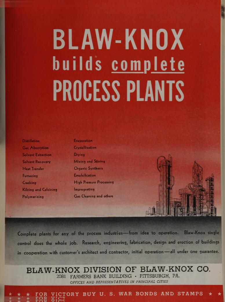
Distillation
G as A bso rp tion
Solvent Extraction
Solvent Recovery
H ea t Transfer
Fumacing
Cracking
Kilning and Calcining
Polym erizing
Evaporation
Crystallization
Drying
M ixing and Stirring
O rganic Synthesis
Emulsification
High Pressure Processing
Impregnating
G as Cleaning and others
Complete plants for any of the process industries— from idea to operation. Blaw-Knox single
control does the whole job. Research, engineering, fabrication, design and erection of buildings
in cooperation with customer's architect and contractor, initial operation— all under one guarantee.
B L A W - K N O X D I V I S I O N O F B L A W - K N O X CO.2081 FARM ERS B A N K B U IL D IN G • P IT T SB U R G H , PA-
OFFICES A N D REPRESENTATIVES IN PRINCIPAL CITIES
* ★ F O R V I C T O R Y B U Y U . S . W A R B O N D S A N D S T A M P S ★ ★* + e + F O R V T C Tà- ± ± r n n
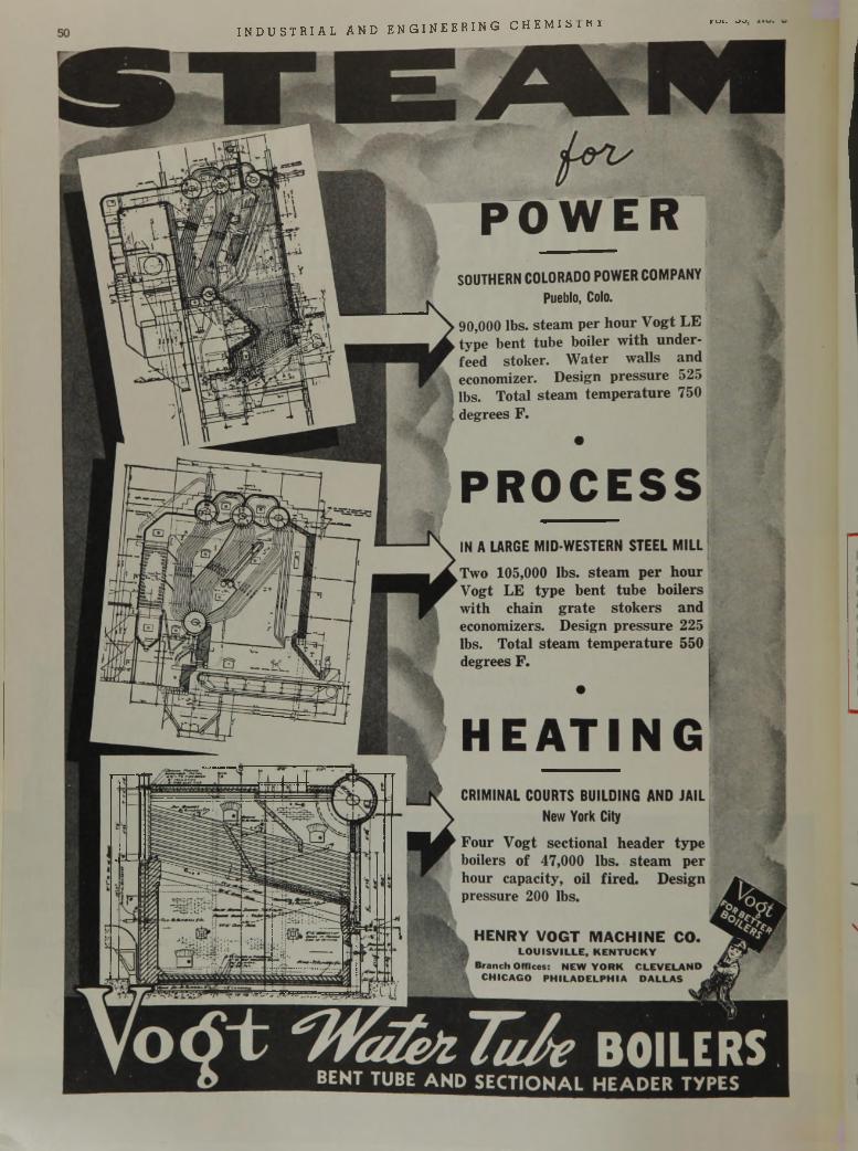
I N D U S T R I A L A N D E N G I N E E R I N G C H E M l S l K iV Ul. v»a.

A THOUSAND TIMES MORE NSITIVE THAN HUMAN TOUCH
Illustra ted here is P h o to sw itch L e v e l C o n t r o l Series P15NX. Designed for hazardous location m ounting, directly on the tank, th is m odern electronic control operates signals o r programs pumps to m aintain constant levels in the handling of explosive liquids, and to detect w ater in tanks of oil or gasoline.
T h e electronic fingers o f P H O T O S W IT C H — the FLO A TLESS LEVEL C O N T R O L — actually “ fee l" liq u id s o r p o w d e rs an d m a in ta in levels electronicaJJg.
PHOTOSWITCH operates ort the simplest and m ost efficient principle ised for control ling h e level of any material— liquid or powder—1 tire or combustible. Only th e m e ta l p ro b e— th e " e le c tro n ic f in g e r" —
itacts the materia ljmnder c o n tro l . T h e re a re no m o v in g p a r ts to ear o u t— n o t h i n g ^ o fa il in o p e ra t io n . P H O T O S W IT C H h a s an
u nlim ited life— is lo w in c o s t— sim p le to in s ta l l— p ro v id e s d e p e n d a b le maintenance-free o p e ra t io n — ends w a r t im e re p la c e m e n t p ro b le m s.
Today throughout industry modern PH O TO SW ITCH installations:• Control pim ps to maintain constant liquid level• Provide Kigh and low level safeguards• Maintain interface between two liquids• Control liquids in mixture for desired concentration or specific ^ ^ K v ity .
• G o v e r n p u m p p r o g r a m m i n g o p e r a t i o n s• Detect water accumulation in tanks of gasoline or oil and in trans
formers.• P ro v id e c o m p le te b o i le r f e e d w a te r c o n t r o l .There is a Photoswitch Level Control to meet every need. W rite fo r complete catalogue information.
— For inform ation on electronic tim ing, photoelectric smoke density indication, counting, autom atic inspection, conveyor control, m ach.nery safeguards, and similar applications, consult Photosw .tch Incorporated, specialists in photoelectric and electronic controls for industry.
P H O T O S W I T C H I N C O R P O R A T E D
PHOTOELECTRIC & ELECTRONIC CONTROLS FOR EVERY INDUSTRIAL PURPOSE
C A M B R I D G E , M A S S . • District Offices I N A L L P R I N C I P A L C I T I E S
H ave you a tu rb id ity c o n tro l problem ? W rite for d e ta ils on th e new P h o to sw itc h p h o to e lec tric tu rb id ity c o n tr o l - c o n t in u o u s lyind ica tes m in u te den sity changes in v is ib le to th e h u m an eye.
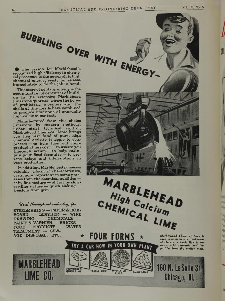
52 I N D U S T R I A L A N D E N G I N E E R I N G C H E M I S T R Y Vol. 35, No. 5
^ T he reason for M arblehead’s recognized h igh efficiency in ch em ical processes, is th e power of its h igh ch em ica l energy, ready for release im m ed ia te ly to do th e job in hand .
T his store of p en t-u p energy is th e a ccu m u la tio n of cen tu ries of b u ild up in th e extensive M arblehead lim esto n e quarries, w here th e bones of preh istoric m on sters and th e sh ells of tin y fossils have com bined to produce lim esto n e of u n u su a lly h igh ca lc iu m co n ten t.
M anufactured from th is choice lim esto n e by m odern m eth ods, under str ic t tech n ica l control, M arblehead C hem ical L im e brings you th is vast fund of pure, h igh ch em ica l activ ity to apply to your process — to help tu rn ou t m ore product a t less cost — to assure you th orou gh action — to help m a in ta in your fixed form ulae — to preven t delays and in terru p tion s in your production .
In addition , M arblehead possesses valuable p h y s i c a l characteristics, even m ore im p ortan t in som e processes th a n th e ch em ica l q u a lities — so ft, fine textu re — of fast or slow - se ttlin g n ature — quick slak ing — freedom from grit.
'U ie tl iJ w o u tfJ to u t ¿ ncU ubuf, jp s i
STEELMAKING — PAPER & BOX- BOARD — LEATHER — WIRE DRAW ING — CHEMICALS — PAINT & VARNISH — BRICKS — FOOD PRODUCTS — WATER TREATMENT — SEWAGE DISPOSAL, ETC. *
M A R B L E H E A D
L I M E C O .
4 i
FOUR FORMS
LIMt
M arblehead Chemical Lime i used in open hearth steel man ufacture as a basic flux to re move acid elements and im purities from the molten mass
160 N. LaSalle St. Chicago, III.
¿KDin¡W-Sieadc»ta
ti,
S
%
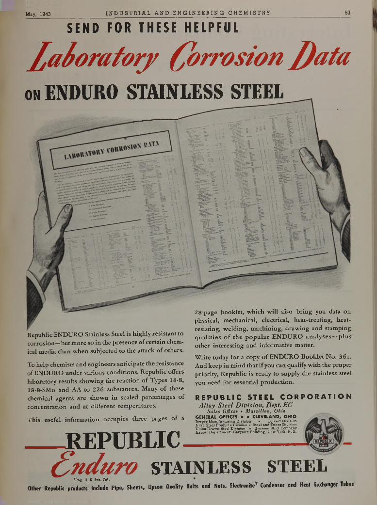
May, 1943 I N D U S T R I A L A N D E N G I N E E R I N G C H E M I S T R Y 53
S E N D F O R T H E S E H E L P F U L
¿ a í o r a t o r j ( C o r r o s io n J ) a t a
O N ENDURO STAIN LESS STEEL
Republic ENDURO Stainless Steel is highly resistant to corrosion—but more so in the presence of certain chemical media than when subjected to the attack o f others.
To help chemists and engineers anticipate the resistance of ENDURO under various conditions, Republic offers laboratory results showing the reaction o f Types 18-8, 18-8-SMo and AA to 226 substances. Many of these chemical agents are shown in scaled percentages of concentration and at different temperatures.
This useful information occupies three pages of a
REPUBLIC
28-page booklet, which will also bring you data on physical, mechanical, electrical, heat-treating, heat- resisting, welding, machining, drawing and stamping qualities o f the popular ENDURO analyses —plus other interesting and informative matter.
Write today for a copy o f ENDURO Booklet No. 361. And keep in mind that if you can qualify with the proper priority, Republic is ready to supply the stainless steel you need for essential production.
R E P U B L I C S T E E L C O R P O R A T I O NA l l o y S t e e l D i v i s i o n , D e p t . E C
Sales Offices • Massillon, Ohio GENERAL OFFICES • • CLEVELAND, O H IOBerger Manufacturing Division • Culvert Division Niles Steel Products Division • Steel and Tubes Division Union Drawn Steel Division • Truscon Steel Company Export Departm ent: Chrysler Building, New York, N. Y.
( i n d u r o s t a i n l e s s s t e e l*Reg. U. S. Pat. Offrce®. *>• rui. vii. .
Other Republic products include Pipe, Sheets, Upson Quality Bolts and Nuts. Electrunite* Condenser and Heat Exchanger Tubes
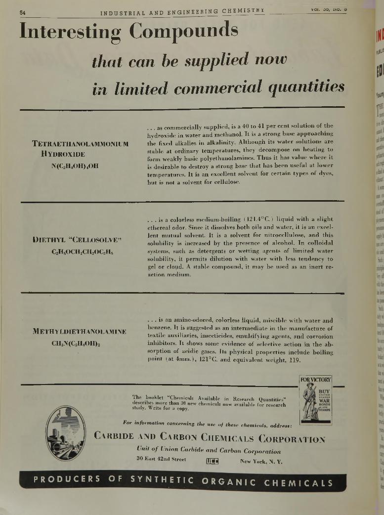
In te re s t in g C o m p o u n d s
t h a t c a n b e s u p p l i e d n o w
i n l i m i t e d c o m m e r c i a l q u a n t i t i e s
. . . as com m ercially supp lied , is a 40 to 41 p e r cen t so lu tio n of th e hyd ro x id e in w ater and m ethano l. I t is a strong base a p p ro a c h in g th e fixed alkalies in a lk a lin ity . A lth o u g h its w a te r so lu tio n s are stab le a t o rd in ary te m p era tu re s , th ey decom pose on h e a tin g to form w eakly basic po lye thano lam ines. 1 h u s it has v a lu e w h ere it is d esirab le to destroy a strong base th a t has b ee n usefu l at low er tem p era tu res . I t is an excellen t solvent for c e r ta in ty p es of dyes, b u t is not a solvent for cellulose.
54______________________________ I N D U S T R I A L A N D E N G I N E E R I N G C H E M I S l H i ___________________ voi. oo, n o . .
. . . is a colorless m ed ium -bo iling (121 .4°C .) l iq u id w ith a slig h t e th e rea l odor. Since it dissolves b o th oils and w ate r, i t is an excelle n t m u tu a l solvent. I t is a so lvent for n itro c e llu lo se , an d th is so lub ility is increased by th e p resence of a lcoho l. In co llo id a l systems, such as detergents o r w etting agents of l im ite d w ate r so lub ility , it perm its d ilu tio n w ith w a te r w ith less ten d en c y to gel o r cloud. A stab le com pound, it m ay be used as an in e rt re action m edium .
. . . is an am ine-odored, colorless liq u id , m isc ib le w ith w a te r and benzene. I t is suggested as an in te rm e d ia te in th e m a n u fa c tu re of te x tile auxiliaries, insecticides, em u lsify ing agents, an d co rro sion in h ib ito rs . I t shows some evidence of se lective ac tio n in th e a b so rp tion of acidic gases. Its physical p ro p e r tie s in c lu d e b o ilin g po in t (a t 4 m m .), 121°C. and e q u iv a le n t w eigh t, 119.
M ETH YLDIETH ANOLAMINE
CH3N(C2HtOH)2
D i e t h y l “ C e l l o s o l v e ”
c 2h 5o c h 2c h 2o c 2h s
T e t r a e t h a n o l a m m o n i u m
H y d r o x i d e
N(C2H tOH)4OH
FOR VICTORY
The booklet “Chemicals Available in Research Quantities” describes more than 30 new chemicals now available for research study. Write for a copy.
For inform ation concerning the use o f these chem icals, address:
C a r b i d e a n d C a r b o n C h e m i c a l s C o r p o r a t i o n
Unit o f Union Carbide and Carbon C orpora tion
30 East 42nd Street [T ffl New York, N. Y.
P R O D U C E R S O F S Y N T H E T I C O R G A N I C C H E M I C A L S
I N D U S T R I A L and E N G I N E E R I N G C H E M I S T R YP U B L I S H E D B Y T H E A M E R I C A N C H E M I C A L S O C I E T Y • W A L T E R J . M U R P H Y , E D I T O R
E D I T O R I A L S ---------
Y o u n g T e c h n o l o g i s t s a n d t h e D r a f t
T HE introduction of Manning Tables and Replacement Schedules seems to have convinced the execu
tives directing many of our war industries that they cannot hope to retain the services of young chemists and chemical engineers. In too many instances these executives file 42A forms on these young men in a very perfunctory manner and, if the local board classifies such registrants in 1A, the executives accept such action as final and allow the ten-day period for appeal to lapse without further action.
A somewhat similar situation occurs infrequently in some companies which find themselves temporarily overstaffed with chemists and chemical engineers. Instead of frankly advising the young men to seek employment with concerns which are short of technical personnel, the management solves its problem of oversupply by doing nothing, with the result that the young men are inducted. The management feels very patriotic and the war effort suffers.
Such practices by management are contrary to the principle upheld by Selective Service headquarters. Very often a young technologist becomes acquainted with the method followed by his employer only after he has been placed in 1A and the ten-day appeal period has passed.
Such an individual should establish contact immediately with the occupational adviser in Selective Service headquarters of his state or the nearest U. S. Employment Office. He may expect to receive assurance from the occupational adviser that he wifi be given an opportunity to connect with a war industry needing liis particular kind of services and may even receive suggestions as to what concerns may need him. Meamvhile, induction will be stayed. As soon as appropriate employment is found, the new employer should file Form 42A, thus reopening the case with the local board.
When industry includes chemists and chemical engineers in the Manning Tables, it should be made perfectly clear that such men are, like doctors and dentists, practically irreplaceable, for it takes from four to seven years to train a chemist and a chemical engineer.
In his straight-from-the-shoulder talk on the manpower problem before the A m e r ic a n C h e m i c a l Soc i e t y in Detroit last month, Fowler V. Harper, Deputy Chairman of the War Manpower Commission, made it quite plain that those who are administering this law have an intelligent and realistic viewpoint and understanding of the needs of industry. W e must ha1, e
active and intelligent cooperation by industry to prevent chaotic conditions arising in the next twelve months.
A s k t h e B a r u c h C o m m i t t e e
T HE spectacle of Undersecretary of War Patterson, Secretary of the Interior Ickes, and OWI Director
Elmer Davis, on the one hand, and Rubber Director Jeffers, on the other, conducting “The Rattle of Washington” is very disconcerting and must provide much comfort if not downright aid to our enemies.
The American public has every right to know the truth. It should be given the facts concerning the output of high-octane gasoline. It should be told whether or not it is true, as Patterson and Ickes charge, that Jeffers is weakening American air strength by shrinking combat supplies of high-octane gasoline in order to coddle civilian motorists. The public wants the facts, not from Dorothy Thompson and other columnists, but from somebody technically qualified to pass judgment on the merits of these charges. It does not want either the Gillette Committee or the Truman Committee to mix into this mess. The one group it does have confidence in is the Raruch Committee.
R e v i s e t h e S p e c i f i c a t i o n s
A MONTH ago the country was startled to learn that steel plate had been shipped from a plant of
a United States Steel subsidiary which failed to comply with the physical and chemical specifications as prescribed by the Government. The “affair” of the substandard plates was eagerly seized upon by a number of individuals and groups seeking publicity and a new “angle” to discredit industry’s war effort.
It now becomes increasingly evident that while the specifications were not met the steel was perfectly sound for the purpose for which it was used. Chemists, physicists, and other technologists should not be placed in the intolerable position of necessarily omitting detailed analyses and tests in order to maintain production. Many specifications have been drawn without proper consideration being given to the end use of the material and the practical conditions under which it must be manufactured in huge quantities in the stress of war conditions. Very definitely the purpose of such specifications should be to determine the minimum satisfactory quality, certainly not to force upon industry a wholly unnecessary burden. Where such conditions
exist technical men have every reason to request revisions. For their own personal protection they should be very insistent that changes be made without delay. No chemist wants to slow up the war eflort, nor does he wish to run the risk of being held up to ridicule and his profession given the proverbial ‘‘black eye”.
G a g e s o f R e s e a r c h
CH EM ICAL A B STR A C TS has often served as an indicator of trends in chemical research. Two
recent analyses of its content are suggestive.Editor Crane points out, in Little C A ., that the num
ber of contributions of different nations to the content of Chemical Abstracts indicates the changing emphasis each has placed on research. The 1913 volume showed Germany as the source of 34.4 per cent of all papers abstracted. Following in order were: the United States (20.7 per cent), British Empire (14.4 per cent), France (13.0 per cent), Italy (4.7 per cent), Russia (2.5 per cent), and Japan (0.37 per cent). By 1939, the relative order was: United States (27.7 per cent), Germany (18.7 per cent), British Empire (14.1 per cent), Russia (11.1 per cent), France (9.1 per cent), Japan (4.4 per cent), and Italy (3.0 per cent). The changes these figures suggest may not be pictured with the utmost accuracy but certainly they are approximately true.
Another interesting compilation appears in a recent issue of Science over the signature of Edward Thomas. Mr. Thomas deals with the numbers of abstracts published in each volume of Chemical Abstracts from 1907 through 1942. The figures reveal an amazing uniformity in the rate of increase in each year of peace. From 1907 through 1913, the average increase in number of papers abstracted was 1858 per year. From 1918 through 1938 the average increase was 1832 per year. When the differences between the two periods are considered, the close agreement is striking. Indeed, the agreement of the figures suggests that some cause other than the productivity of research may be the controlling factor.
During World War I (1913-1918) the number of abstracts published diminished an average of 1948 per year. The average decrease has been 3859 per year to date during World War II (1938-1942).
One is tempted to conclude from these figures that research is suffering from war. That is, of course, true in some fields, particularly in pure or fundamental research as contrasted with applied research. But other evidence clearly indicates that never have research workers been so busy as now. The pace of research is quickened and its objectives changed by war. Teams, not individuals, conduct today’s investigations. Publication takes the form of military offensives and not scientific papers. Experience, much of it grim, is being accumulated in individuals, rather than in printed papers, to be loosed at war’s end in tangible develop
5 0 0
ments that will help build a better world, not simply a more bulky literature.
“ O u r C h a n g e o f A d d r e s s ” ? ? ?
A T LONG last Elmer Davis and his Office of War Information have stopped feuding with Rubber-
Czar Jeffers sufficiently to grant us the necessary permission to disclose the sad news that the A m e r ic a n Chemical Society has been forced by the exigency of modern warfare to move its quarters. We are established with a fair degree of comfort in the same block with the Mills Building which was the home of this Society several years ago.
Some time ago our beautiful building at 1155 Sixteenth Street, N. W., Washington, was seriously bombed and a portion of our records was destroyed. Our good friends in the United States Bureau of Mines very graciously offered us asylum for a few months at College Park, Md.-, until the necessary repairs could be made. Unfortunately, within a very brief space of time, we were again visited by high-explosive bombs dropped by enemy raiders flying up the Potomac and it became necessary to find temporary quarters once more—this time in the comparatively safe atmosphere of Williamsburg, Va. Regretfully we must report that hardly were repairs made and our building made partially tenantable when we were advised that the overflow of lawyers and economists in Prentiss Brown’s Office of Price Administration was moving in for the duration and we must seek offices elsewhere.
Bewildered reader, this is not an attempt to out-do Orson Welles! As we pen these words we momentarily lift our eyes to gaze upon the beautiful vista of Sixteenth Street, and, while enjoying once again the sight of the rebirth of Nature coaxed by a strong spring sun, we contemplate an editorial in the March issue of our British contemporary, Chemistry 4 Industry, entitled “Our Change of Address”. We are attempting in a very amateurish manner to visualize what the experiences of all-out total war are really like. Suddenly the purchase of a war bond each month-end and a two-hour trick once a week as a plane spotter seem like pitifully inadequate personal contributions to the war effort.
So far we have been spared the horrors of bombing. Our homes and our institutions are intact. If we are attacked at some future time may your Editor have the intestinal fortitude to write as did Stephen Miall in Chemistry 4 Industry two months ago:
The war has caused us undoubtedly some little inconvenience, but nothing by comparison with the disasters tha t have befallen many societies, so we have every reason to be thankful.
In the not too distant future a maniacal ex-Austrian paperhanger will discover, as did Emperor Wilhelm and Napoleon, that a nation so universally gifted in the role of the art of understatement as sharp invective is not to be trifled with.
Vol. 35, No. 3I N D U S T R I A L A N D E N G I N E E R I N G C H E M I S T R Y
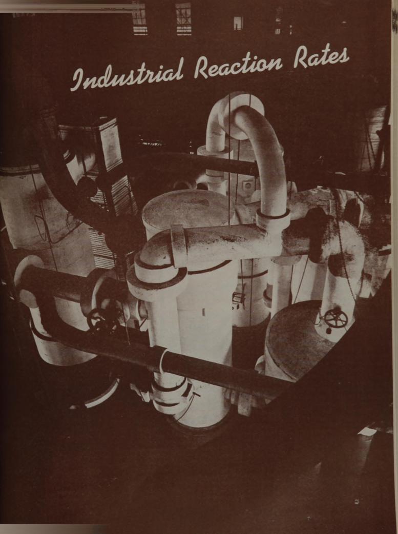
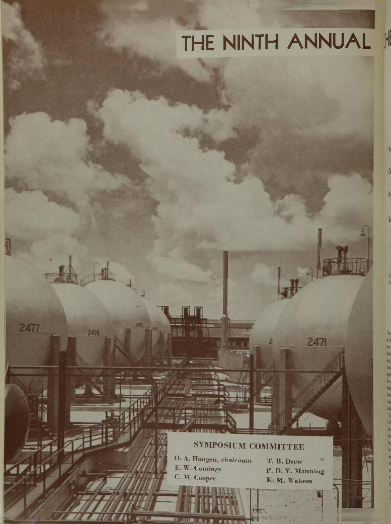
THE NINTH AN N U AL
'
2476
jüflB jâ
M r i r
WÊÊÆS V
» t i l m m 1 Æ
- 2 m
i
w *ÎV a
S Y M P O S I U M C O M M I T T E E
O. A. Hougen, ch a irm a n T. B. Drew ^E. W. Comings p . D . y . M anningC. M. Cooper K. M. W atson
■ » J y i M A j M i t 1 1 r r
CHEM ICAL ENGINEERING SYMPOSIUM
D i v i s i o n o f I n d u s t r i a l a n d E n g i n e e r i n g C h e m i s t r y
A m e r i c a n C h e m ic a l S o c i e t y
Prediction of Reaction RatesFarrington Daniels 504
O rganic ReactionsHenry Eyring, H. M. Hulburt, R. A. Harman 511
Principles of Reactor Design. G as-SolidInterface Reactions David M. Hurt 522
Solid Catalysts and Reaction Rates:
G eneral PrinciplesO. A. Hougen and K. M. Watson 5 29
O xidation of Sulfur D ioxideO. A. Uyehara and K. M. Watson 541
Cation-Exchange W ater Softening RatesJohn du Domaine, R. L. Swain, O. A. Hougen 5 4 6
Catalytic H ydrogenation Rates:
Equipment and ControlN. K. Anderson and C. A. Rowe 554
Interpretation of ResultsR. B. Beckmann, A. E. Pufahl, O. A. Hougen 558
C onduction, Convection, and H eat Release in Catalytic Converters
R. H. Wilhelm, W. C. Johnson, F. S. Acton 5 62
V apor-Phase Estérification RatesH. F. Hoerig, Don Hanson, O. L. Kowalke 575
The papers not received in time to be included in this issue wil l be printed later. The pictures on pases 501 and 5 0 2 are reproduced through courtesy of E. I. du Pont de Nemours & Company, Inc., and Chicago Bridge and Iron Company, respectively.
The Symposium Com m ittee o f the Division of Industrial and Engineering Chemistry undertook its 1912 assignment with special interest, since the topic of Industrial Reaction Rates seemed sufficiently' im portant to justify study during the war period. Despite the interest of chemical engineers in the release of industrial data on the applications of reaction rate principles to reactor design, the com m ittee soon found that contributions were not readily forthcoming. The extra burden of war assignments was one reason. In most instances the rate data resulting from pilot plant studies were not organized for publication.
The last twenty years have seen extensive developments in the theory of chem ical reaction kinetics, but m ost of them have involved such advanced scientific concepts as to discourage attem pts at industrial application. However, the tim e now seem s opportune to translate these scientific developments into engineering terms and to develop a special literature in the applications of rate data. The techniques required in acquiring rate data and in interpreting the results to design and operation should result in reducing the tim e and cost o f process development. Many of the customary repeated and extensive pilot plant investigations m ight be elim inated by more com plete understanding of the principles involved.
The subject Industrial Reaction Rates had been frequently suggested in past years by members of the division, and the present com m ittee inherited the correspondence of D. B. Keyes on this m atter. The com m ittee brought together two groups of investigators, those engaged in the more theoretical developments of chemical kinetics and those experienced in the interpretation of pilot plant rate data to process design. In the field of theoretical chemical kinetics the com m ittee was fortunate in securing such authorities as Henry Eyring, Farring- ton Daniels, and P. H. Em m ett. The com m ittee tried to avoid a local selection of papers but was driven to a preponderance of University of Wisconsin contributions to fill vacancies in the program left by last-m inute withdrawals.
The Symposium Comm ittee w ishes to acknowledge the services of Harry McCormack in making local arrangem ents and the active support and encouragement of the Division Com m ittee, particularly its officers, L. W. Bass, R. N. Shreve, T. H. Chilton, and Whitney Weinrich.
In an early postw ar y ear another sym posium on the same subject should be tim ely and bring forth remarkable developments resulting from wartime activities.
O. A. HOUGEN
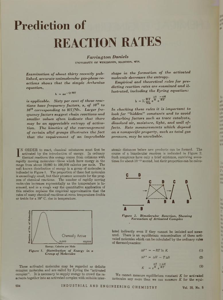
P r e d i c t i o n o f
R E A C T I O N R A T E S
Farrington DanielsU N I V E R S I T Y O F W I S C O N S I N , M A D IS O N , W I S .
E x a m in a t io n o f a b o u t t h i r t y re c e n t ly p u b lis h e d , a c c u ra te u n im o le c u la r gas-phase re a c tio n s shoves th a t th e s im p le A r rh e n iu s e q u a t io n ,
k = a e -Q/RT
is a p p lic a b le . S ix ty p e r c e n t o f these reactio n s have f r e q u e n c y fa c to rs , a , o f 10 to 1014 c o rre s p o n d in g to R T /N h . L a rg e r f r e q u e n c y fa c to rs suggest c h a in re a c tio n s a n d s m a lle r va lues o f te n in d ic a te th a t th e re m a y be a n a p p re c ia b le e n tro p y o f a c t iv a t io n . T h e k in e t ic s o f th e re a r ra n g e m e n t o f c e r ta in a l ly l g ro u p s i l lu s t ra te s th e f a c t th a t th e re q u ire m e n t o f a n im p ro b a b le
shape in th e fo r m a t io n o f th e a c t iv a te d m o le c u le decreases th e e n tro p y .
E m p ir ic a l a n d th e o re t ic a l ru le s f o r p r e d ic t in g re a c t io n ra te s a re e x a m in e d a n d i l lu s tra te d , in c lu d in g th e E y r in g e q u a t io n :
AS - A H
k = K — e R e RT k Nh
I n c h e c k in g these ru le s i t is im p o r t a n t to lo o k f o r “ h id d e n ” c o n s ta n ts a n d to a v o id d is tu rb in g fa c to rs s u c h as tra c e c a ta ly s ts , d isso lved a ir , m o is tu re , l ig h t , a n d w a ll e f fe c ts . R a te m e a s u re m e n ts w h ic h d e p e n d o n a n o n s p e c if ic p ro p e r ty , s u c h as t o ta l gas pressu re , m a y be u n re lia b le .
IN ORDER to react, chemical substances must first be
activated by the introduction of energy. In ordinary thermal reactions this energy comes from collisions with
rapidly moving molecules—those which have energy in the range from about 10,000 to 100,000 calories per mole. The well known distribution of energy in a group of molecules is indicated in Figure 1. The proportion of these fast molecules is exceedingly small, but their presence accounts for the progress of chemical reactions. The number of rapidly moving molecules increases exponentially as the temperature is increased, and in a rough way the quantitative application of this relation explains the empirical approximation tha t the rates of many chemical reactions a t room temperature double or treble for a 10° C. rise in temperature.
F igure 1. D is tr ib u tio n o f Energy in G roup o f M olecules
These activated molecules may be regarded as definite complex molecules and are called by Eyring the “activated complex” . I t is necessary to supply energy to crowd the reactants together into an activated complex with suitable inter
atomic distances before new products can be formed. The course of a bimolecular reaction is indicated in Figure 2. Such complexes have only a brief existence, surviving sometimes for about 10-13 second, but their properties can be calcu-
C D C D
■ M - / \A B A B
B
Figure 2. B im o lecu la r R ea c tio n , Shouting F o rm a tio n o f A c tiv a te d C om plex
lated indirectly even if they cannot be isolated and meas ured. There is an equilibrium concentration of these acti vated molecules which can be calculated by the ordinary rulei of thermodynamics:
AF° = - R T ln K
AF° = AH - TAS
AS -A lt K = e Ä e R T
(1)
(2)
(3)
We cannot measure equilibrium constant K for activated molecules any more than we can measure K for the equi
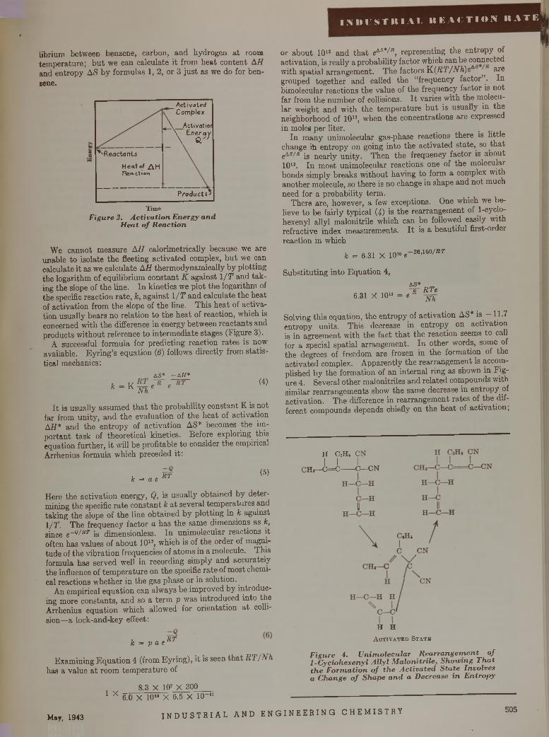
I N D U S T R I A L R E A C T I O N R A T E
librium between benzene, carbon, and hydrogen a t room temperature; b u t we can calculate it from heat content AH and entropy AS by formulas 1, 2, or 3 just as we do for benzene.
_Activated\ Complex
\ _Activatior\ Energy\ & '
^ReactantsHeat of AH rteac.1 ion
Products*
T im eF igure 3. A c tiv a tio n E nergy a n d
H ea t o f R ea c tio n
We cannot measure A H calorimetrically because we are unable to isolate the fleeting activated complex, bu t we can calculate it as we calculate AH thermodynamically by plotting the logarithm of equilibrium constant K against 1 /T and tak ing the slope of the line. In kinetics we plot the logarithm of the specific reaction rate, k, against 1 /T and calculate the heat of activation from the slope of the line. This heat of activation usually bears no relation to the heat of reaction, which is concerned with the difference in energy between reactants and products w ithout reference to intermediate stages (Figure 3).
A successful formula for predicting reaction rates is now available. Eyring’s equation (6) follows directly from statistical mechanics:
AS* - A H *
k “ K N h e(4)
I t is usually assumed th a t the probability constant K is not far from unity, and the evaluation of the heat of activation AH * and the entropy of activation AS* becomes the important task of theoretical kinetics. Before exploring this equation further, it will be profitable to consider the empirical Arrhenius formula which preceded it:
k = a e R T (5)
Here the activation energy, Q, is usually obtained by determining the specific rate constant k a t several temperatures and taking the slope of the line obtained by plotting In k against 1/T. The frequency factor a has the same dimensions as k, since e~Q/RT is dimensionless. In unimolecular reactions it often has values of about 101S, which is of the order of magnitude of the vibration frequencies of atoms in a molecule. This formula has served well in recording simply and accurately the influence of tem perature on the specific rate of most chemical reactions whether in the gas phase or in solution.
An empirical equation can always be improved by introducing more constants, and so a term p was introduced into the Arrhenius equation which allowed for orientation a t collision—a lock-and-key effect:
8.3 X 107 X 300 1 X 6.0 X 10" X 6.5 X 1 0 -"
or about 10l* and th a t eAS*/fl, representing the entropy of activation, is really a probability factor which can be connected with spatial arrangement. The factors K(/iT'/Arfi)eA are grouped together and called the “frequency factor . In bimolecular reactions the value of the frequency factor is not far from the number of collisions. I t varies with the molecular weight and with the tem perature bu t is usually in the neighborhood of 1011, when the concentrations are expressed in moles per liter. _ .
In many unimolecular gas-phase reactions there is little change ih entropy on going into the activated state,^ so tha t eAs/ r jg neariy unity. Then the frequency factor is about 1013. In most unimolecular reactions one of the molecular bonds simply breaks without having to form a complex with another molecule, so there is no change in shape and not much need for a probability term.
There are, however, a few exceptions. One which we believe to be fairly typical (4) is the rearrangement of 1-cyclo- hexenyl allyl malonitrile which can be followed easily with refractive index measurements. I t is a beautiful first-order reaction in which
7
k = 6.31 X 101“ e-26,i60/ier
Substituting into Equation 4,
6.31 X 1010 = eA S *p RTe
Nh
Solving this equation, the entropy of activation AS* is 11.7 entropy units. This decrease in entropy on activation is in agreement with the fact th a t the reaction seems to call for a special spatial arrangement. In other words, some of the degrees of freedom are frozen in the formation of the activated complex. Apparently the rearrangement is accomplished by the formation of an internal ring as shown in Figure 4. Several other malonitriles and related compounds with similar rearrangements show the same decrease in entropy of activation. The difference in rearrangement rates of the different compounds depends chiefly on the heat of activation,
CHi
H C2H6 CNI I I
-C = C ---- C—CN
I f ffc = p a e K1
Examining Equation 4 (from Eyring), it is seen th a t R T /N h has a value a t room tem perature of
H H A c t i v a t e d S t a t e
F igure 4. U n im o lecu la r R e a rra n g e m e n t o f 1 -C yc lohexeny l A lly l M a lo n itr ile , S h o w in g T h a t th e F o rm a tio n o f th e A c tiv a te d S ta te Invo lves a C hange o f Sh a p e a n d a Decrease in E n tro p y
May, 1943 I N D U S T R I A L A N D E N G I N E E R I N G C H E M I S T R Y 505
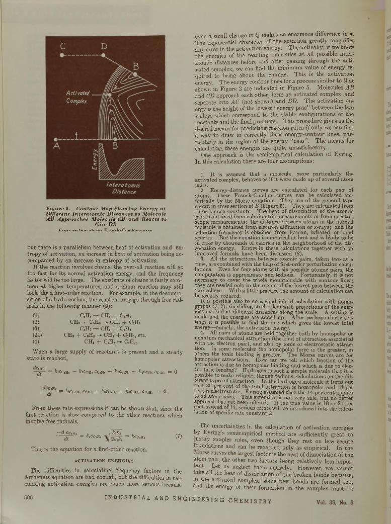
F igure 5. C on tour M ap Show ing E nergy a t D ifferen t In te ra to m ic D istances as M olecule A it A pproaches M olecule CD an d R eacts to
Give DBC ro ss sectio n show s F r a n c k -C o n d o n cu rve.
but there is a parallelism between heat of activation and entropy of activation, an increase in heat of activation being accompanied by an increase in entropy of activation.
If the reaction involves chains, the over-all reaction will go too fast for its normal activation energy, and the frequency factor will be too large. The existence of chains is fairly common a t higher temperatures, and a chain reaction may still look like a first-order reaction. For example, in the decomposition of a hydrocarbon, the reaction may go through free radicals in the following manner (9):
(1) C,H8 — CH, + C2HS(2) CH, + CaHa — CH, + CSH7(3) CaH7 — CHS + C2H,(2a) CH, + CsH8 — CH, + C3H7, etc.(4) CH, + Call, - C,HJ0
When a large supply of reactants is present and a steady state is reached,
( H' = fclCC,H« — h C c H i C C tB , + fcaCCiH, — &,CCHj CC1H7 = 0
— J p - 7 = A - jC ch » C c h j — h C C iB i — k t CcB3 Cc3H7 = 0
From these rate expressions it can be shown that, since the first reaction is slow compared to the other reactions which involve free radicals,
—d ccjH s i I ktk3dt = klCc’H° \ = kCCim (?)
This is the equation for a first-order reaction.
ACTIVATION ENERGIES
The difficulties in calculating frequency factors in the Arrhenius equation are bad enough, but the difficulties in calculating activation energies are much more serious because
even a small change in Q makes an enormous difference in k. The exponential character of the equation greatly magnifies any error in the activation energy. Theoretically, if we know the energies of the reacting molecules a t all possible interatomic distances before and after passing through the activated complex, we can find the minimum value of energy required to bring about the change. This is the activation energy. The energy contour lines for a process similar to th a t shown in Figure 2 are indicated in Figure 5. Molecules A B and CD approach each other, form an activated complex, and separate into AC (not shown) and BD. The activation energy is the height of the lowest “energy pass” between the two valleys which correspond to the stable configurations of the reactants and the final products. This procedure gives us the desired means for predicting reaction rates i f only we can find a way to draw in correctly these energy-contour lines, particularly in the region of the energy “pass” . The means for calculating these energies are quite unsatisfactory.
One approach is the semiempirical calculation of Eyring. In this calculation there are four assumptions:
1. I t is assumed th a t a molecule, more particularly the activated complex, behaves as if it were made up of several atom pairs.
2. Energy-distance curves are calculated for each pair of atoms. These Franck-Condon curves can be calculated empirically by the Morse equation. They are of the general type shown in cross section a t B (Figure 5). They are calculated from three known constants. The heat of dissociation of the atomic pair is obtained from calorimetric measurements or from spectroscopic measurements; the distance between atom s in the normal molecule is obtained from electron diffraction or x-rays; and the vibration frequency is obtained from Raman, infrared, or band spectra. But the equation is empirical a t best and is likely to be in error by thousands of calories in the neighborhood of the dissociation energy. Errors in these calculations together with an improved formula have been discussed (<S).
3. All the attractions between atomic pairs, taken two a t a time, are combined with the help of first-order perturbation calculations. Even for four atoms with six possible atomic pairs, the computation is approximate and tedious. Fortunately, it is not necessary to cover the whole mountainside with contour lines; they are needed only in the region of the lowest pass between the two valleys. With a little practice the am ount of calculation can be greatly reduced.
I t is possible also to do a good job of calculation with nomographs (1, 7), six sliding steel rulers with projections of the energies marked a t different distances along the scale. A setting is made and the energies are added up. After perhaps th irty settings it is possible to find the one which gives the lowest total energy—namely, the activation energy.
4. All pairs of atoms are held together both by homopolar or quantum mechanical attraction (the kind of a ttraction associated with the electron pair), and also by ionic or electrostatic a ttraction. In some molecules the homopolar force is the greater, in others the ionic binding is greater. The Morse curves are for homopolar attractions. How can we tell which fraction of the attraction is due to homopolar binding and which is due to electrostatic binding? Hydrogen is such a simple molecule th a t it is possible to make reliable, though tedious, calculations on the different types of attraction. In the hydrogen molecule it turns out that 86 per cent of the total a ttraction is homopolar and 14 per cent is electrostatic; Eyring assumed th a t the 14 per cent applies to ail atom pairs. This extension is not very safe, but no better approach has yet been offered. If the true value is 10 or 20 per cent instead of 14, serious errors will be introduced into the calculation of specific rate constant k.
The uncertainties in the calculation of activation energies by Eyring s semiempirical method are sufficiently great to justify simpler rules, even though they rest on less secure foundations and can be regarded only as empirical. In the " se curves ^ e largest factor is the heat of dissociation of the atom pair, the other two factors being relatively less impor- ant. Let us neglect them entirely. However, we cannot a e all the heat of dissociation of the broken bonds because,
in the activated complex, some new bonds are formed too, and the energy of their formation in the complex must be
5 0 6 I N D U S T R I A L A N D E N G I N E E R I N G C H E
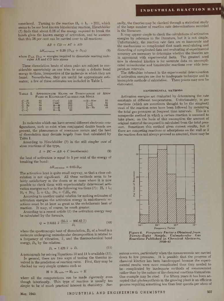
I I V 1> U S T IK 1 A L R E A C T I O N R A T I »
considered. Turning to the reaction H 2 + I 2 —> 2HI, which seems to be our best known bimolecular reaction, Hirschfelder (7) finds th a t about 0.28 of the energy required to break the bonds gives the known energy of activation, and he assumes tha t this 28 per cent can be carried over to all reactions:
A B + CD -* AC + BD
Aflactivation = 0.28 (DAB + DcD) (8)
where D a b , D cd = energies required to dissociate reacting molecules A B and CD into atoms
These dissociation heats of atom pairs are subject to considerable uncertainty as one tries to assign a definite bond energy to them, irrespective of the molecule in which they are found. Nevertheless, they are useful for approximate estimates; a few of these estimates are included in Table I.
T a b l e I. A p p r o x i m a t e H e a t s o f D i s s o c i a t i o n o f A t o m
P a i r s i n K i l o g r a m - C a l o r i e s p e r M o l e
C — H 92 C = C 122 = N — N = 33C — Cl 79 C = C 200 C— O 82C— B r 58 H — H 102 c = o 188C — I 44 O— H 113 B r— B r 45c —c 77 N — H 96
In molecules which can have several different electronic configurations, such as exist when conjugated double bonds are present, the phenomenon of resonance occurs and the heat of dissociation m ay deviate largely from th a t calculated by Table I.
According to Hirschfelder (7) in the still simpler case of atom reactions of the type,
A + BC —► A B + C (exothermic) (9)
the heat of activation is equal to 5 per cent of the energy of breaking the bond :
A/ïactivation = 0.05 D]JC
The activation heat is quite small anyway, so th a t a close calculation is not significant. All these methods seem to be fairly satisfactory in the dozen or so cases where it is now possible to check them with experimentally determined activation energies such as in the following reactions (7) : H 2 + I 2; H2 + Br2; I 2 Cl2; B r2 + C2H 4, etc.
According to another useful relation for making estimates of activation energies the activation energy in endothermie reactions m ust be a t least as great as the endothermie heat of reaction. I t may, of course, be much greater.
According to a recent article (5) the activation energy may be calculated by the formula,
= 2.8581 v(35.5 - 900.45 7)
D'(10)
ondly, the theories may be checked through a statistical study of the large number of reaction rate determinations recorded in the literature.
I t may appear simple to check the calculations of activation energies by reference to the literature, bu t it is not simple. Unfortunately, the reaction rate data are so inaccurate and the mechanisms so complicated th a t much recalculating and discarding of complicated data and evaluating of experimental accuracy are necessary to determine whether the theories are in agreement with experimental facts. The greatest need now in chemical kinetics is for accurate data on uncomplicated unimoleeular and bimolecular reactions over wide temperature intervals.
The difficulties inherent in the experimental determination of activation energies are due to inadequate technique and to incomplete methods of calculation. These points may now be elaborated.
E X P E R IM E N T A L M E T H O D S
Activation energies are evaluated by determining the rate constants a t different temperatures. Unfortunately, in gas reactions (which are sometimes thought to be the simplest) most of the reaction rates have been followed by measuring the total gas pressures a t frequent time intervals. This is a nonspecific method in which a certain reaction is assumed to take place; on the basis of this assumption the am ount of original material decomposed is calculated from the total pressure. Sometimes this method gives correct results, bu t if there are competing reactions or adsorptions on the wall or if the reaction does not always proceed as assumed, there m ay be
10“ 10“
where the spectroscopic heat of dissociation, D e, of a bond in a molecule undergoing unimoleeular decomposition is related to a frequency of vibration, v, and the thermochemical bond energy, D 0, by the relation:
De = 1.429 T + Do (U)
A nomograph for solving Equations 10 and 11 is available (11).In general, there are two ways of testing the theories in
volved in the prediction of reaction rates. First, they may be checked for very simple systems such as
H -}- H2 ortho H2 para "b H
where all the com putations can be made rigorously even though laboriously. This type of reaction is usually too simple to be of much practical interest in chemistry. Sec
10“ 10 »F requency F ac to r
F igure 6. F requency F actor a O b ta in ed fr o m T w e n ty -E ig h t S im p le , U n im oleeu lar Gas R ea ctio n s P u b lish ed in C h em ica l A b strac ts ,
1936-41
serious errors, particularly when the measurements are carried down to low pressures. I t is possible th a t the progress of chemical kinetics has been handicapped because the experimental results were more complicated than they needed to be—complicated by inadequate methods of measurement rather than by the nature of the chemical reactions themselves. One example may be cited. For fifteen years it has been accepted th a t photosynthesis in the growing plant is an efficient process requiring something less than four quanta per atom of
May, 1943 I N D U S T R I A L A N D E N G I N E E R I N G C H E M I S T R Y 507
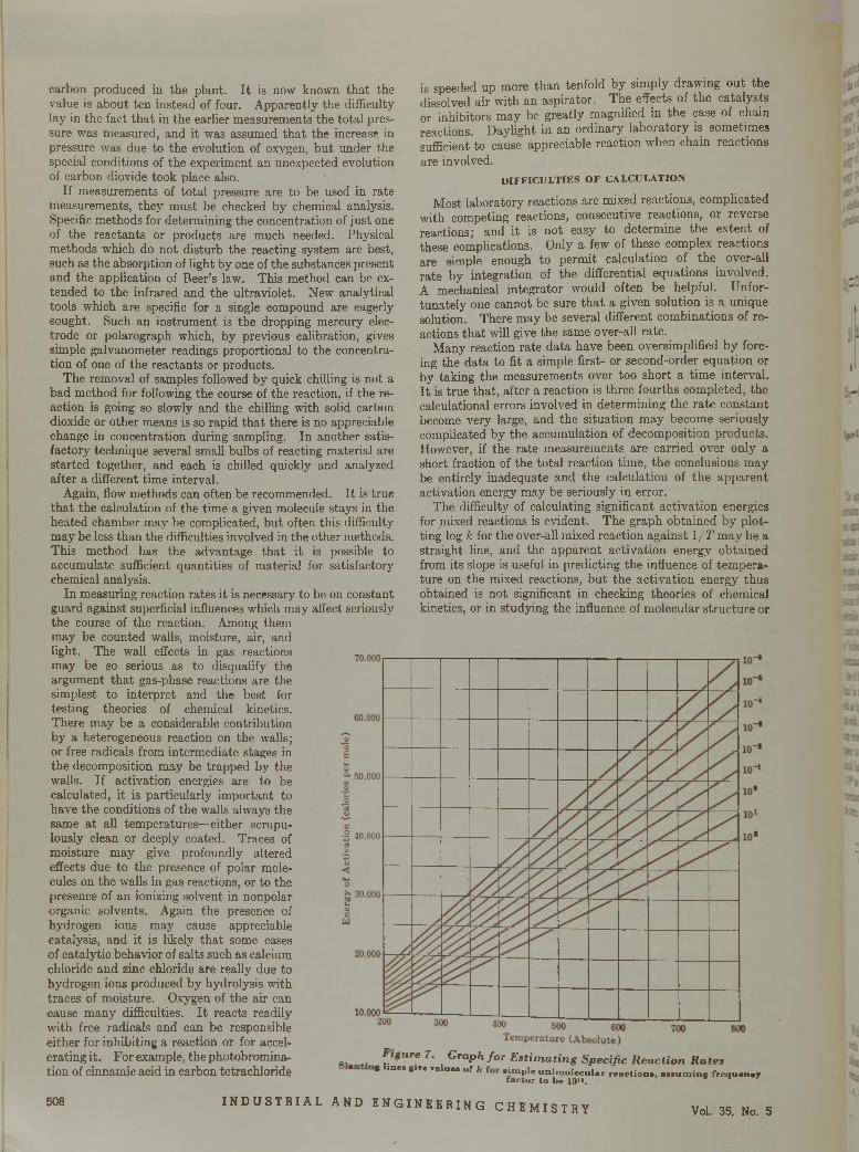
carbon produced in the plant. I t is now known tha t the value is about ten instead of four. Apparently the difficulty lay in the fact tha t in the earlier measurements the total pressure was measured, and it was assumed tha t the increase in pressure was due to the evolution of oxygen, but under the special conditions of the experiment an unexpected evolution of carbon dioxide took place also.
If measurements of to tal pressure are to be used in rate measurements, they must be checked by chemical analysis. Specific methods for determining the concentration of just one of the reactants or products are much needed. Physical methods which do not disturb the reacting system are best, such as the absorption of light by one of the substances present and the application of Beer’s law. This method can be extended to the infrared and the ultraviolet. New analytical tools which are specific for a single compound are eagerly sought. Such an instrument is the dropping mercury electrode or polarograph which, by previous calibration, gives simple galvanometer readings proportional to the concentration of one of the reactants or products.
The removal of samples followed by quick chilling is not a bad method for following the course of the reaction, if the reaction is going so slowly and the chilling with solid carbon dioxide or other means is so rapid tha t there is no appreciable change in concentration during sampling. In another satisfactory technique several small bulbs of reacting material are started together, and each is chilled quickly and analyzed after a different time interval.
Again, flow methods can often be recommended. I t is true tha t the calculation of the time a given molecule stays in the heated chamber may be complicated, bu t often this difficulty may be less than the difficulties involved in the other methods. This method has the advantage tha t it is possible to accumulate sufficient quantities of material for satisfactory chemical analysis.
In measuring reaction rates it is necessary to be on constant guard against superficial influences which may affect seriously the course of the reaction. Among them may be counted walls, moisture, air, and light. The wall effects in gas reactions may be so serious as to disqualify the argument tha t gas-phase reactions are the simplest to interpret and the best for testing theories of chemical kinetics.There may be a considerable contribution by a heterogeneous reaction on the walls; or free radicals from intermediate stages in the decomposition may be trapped by the walls. If activation energies are to be calculated, it is particularly important to have the conditions of the walls always the same at all temperatures—either scrupulously clean or deeply coated. Traces of moisture m ay give profoundly altered effects due to the presence of polar molecules on the walls in gas reactions, or to the presence of an ionizing solvent in nonpolar organic solvents. Again the presence of hydrogen ions m ay cause appreciable catalysis, and it is likely tha t some cases of catalytic behavior of salts such as calcium chloride and zinc chloride are really due to hydrogen ions produced by hydrolysis with traces of moisture. Oxygen of the air can cause many difficulties. I t reacts readily with free radicals and can be responsible either for inhibiting a reaction or for accelerating i t . For example, the photobromina- tion of cinnamic acid in carbon tetrachloride
is speeded up more than tenfold by simply drawing out the dissolved air with an aspirator. The effects of the catalysts or inhibitors may be greatly magnified in the case of chain reactions. Daylight in an ordinary laboratory is sometimes sufficient to cause appreciable reaction when chain reactions are involved.
D IF F IC U L T IE S O F C A L C U L A T IO N
Most laboratory reactions are mixed reactions, complicated with competing reactions, consecutive reactions, or reverse reactions; and it is not easy to determine the extent of these complications. Only a few of these complex reactions are simple enough to permit calculation of the over-all rate by integration of the differential equations involved. A mechanical integrator would often be helpful. Unfortunately one cannot be sure th a t a given solution is a unique solution. There may be several different combinations of reactions tha t will give the same over-all rate.
M any reaction rate data have been oversimplified by forcing the data to fit a simple first- or second-order equation or by taking the measurements over too short a tim e interval. I t is true that, after a reaction is three fourths completed, the calculational errors involved in determining the rate constant become very large, and the situation m ay become seriously complicated by the accumulation of decomposition products. However, if the rate measurements are carried over only a short fraction of the total reaction time, the conclusions may be entirely inadequate and the calculation of the apparent activation energy may be seriously in error.
The difficulty of calculating significant activation energies for mixed reactions is evident. The graph obtained by plotting log k for the over-all mixed reaction against 1 /T m ay be a straight line, and the apparent activation energy obtained from its slope is useful in predicting the influence of temperature on the mixed reactions, bu t the activation energy thus obtained is not significant in checking theories of chemical kinetics, or in studying the influence of molecular structure or
a, .. ^*£u re 7• G raph fo r E s tim a tin g Specific R e a c tio n R a te s* lm M 8IT* TaIu" o f k « ¡ » P i e u n im o le c u la r r e a c t io n ., . . . u n n n g f r c q u . n . y
f a c to r to b e 1 0 » .
508 I N D U S T R I A L A N D E N G I N E E R I N G C H E M I S T R Y Vol. 35, No. 5
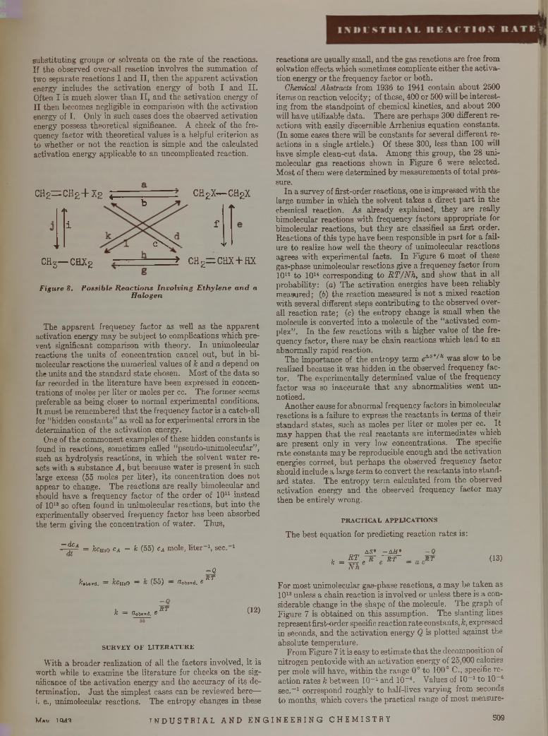
substituting groups or solvents on the rate of the reactions. If the observed over-all reaction involves the summation of two separate reactions I and II, then the apparent activation energy includes the activation energy of both I and II. Often I is much slower than II, and the activation energy of II then becomes negligible in comparison with the activation energy of I. Only in such cases does the observed activation energy possess theoretical significance. A check of the frequency factor with theoretical values is a helpful criterion as to whether or not the reaction is simple and the calculated activation energy applicable to an uncomplicated reaction.
c h 2= c h 2 + x 2 i : c h 2 x— c h 2 x
1k b 4k
▼
i
c \ X
f
>f
c h 5— c h x 2 ■± c h 2= c h x + h x
Figure 8. Possible Reactions Invo lv ing E thylene and a Halogen
The apparent frequency factor as well as the apparent activation energy m ay be subject to complications which prevent significant comparison with theory. In unimolecular reactions the units of concentration cancel out, bu t in bi- molecular reactions the numerical values of k and a depend on the units and the standard state chosen. M ost of the data so far recorded in the literature have been expressed in concentrations of moles per liter or moles per cc. The former seems preferable as being closer to normal experimental conditions. I t must be remembered th a t the frequency factor is a catch-all for “hidden constants” as well as for experimental errors in the determination of the activation energy.
One of the commonest examples of these hidden constants is found in reactions, sometimes called “pseudo-ummoleeular” , such as hydrolysis reactions, in which the solvent water reacts with a substance A, bu t because water is present in such large excess (55 moles per liter), its concentration does not appear to change. The reactions are really bimolecular and should have a frequency factor of the order of 10u instead of 1013 so often found in unimolecular reactions, b u t into the experimentally observed frequency factor has been absorbed the term giving the concentration of water. Thus,
—dcAdt
= kemo cA = k (55) cA mole, liter 1, sec. 1
-Qr R T
fc«bsrd. = kcji,0 ~ k (5o) — UobaTd. C
k — Oobsrd, SR T (12)
S U R V E Y O F L IT E R A T U R E
With a broader realization of all the factors involved, it is worth while to examine the literature for checks on the significance of the activation energy and the accuracy of its determination. Just the simplest cases can be reviewed here—i. e., unimolecular reactions. The entropy changes in these
reactions are usually small, and the gas reactions are free from solvation effects which sometimes complicate either the activation energy or the frequency factor or both.
Chemical Abstracts from 1936 to 1941 contain about 2500 items on reaction velocity; of these, 400 or 500 will be interesting from the standpoint of chemical kinetics, and about 200 will have utilizable data. There are perhaps 300 different reactions with easily discernible Arrhenius equation constants. (In some cases there will be constants for several different reactions in a single article.) Of these 300, less than 100 will have simple clean-cut data. Among this group, the 28 unimolecular gas reactions shown in Figure 6 were selected. M ost of them were determined by measurements of to ta l pressure.
In a survey of first-order reactions, one is impressed w ith the large number in which the solvent takes a direct p art in the chemical reaction. As already explained, they are really bimolecular reactions with frequency factors appropriate for bimolecular reactions, bu t they are classified as first order. Reactions of this type have been responsible in part for a failure to realize how well the theory of unimolecular reactions agrees with experimental facts. In Figure 6 most of these gas-phase unimolecular reactions give a frequency factor from 101J to 1014 corresponding to R T/N h , and show th a t in all probability: (a) The activation energies have been reliably measured; (6) the reaction measured is not a mixed reaction with several different steps contributing to the observed overall reaction rate; (c) the entropy change is small when the molecule is converted into a molecule of the “activated complex” . In the few reactions with a higher value of the frequency factor, there may be chain reactions which lead to an abnormally rapid reaction.
The importance of the entropy term eAS*///i was slow to be realized because it was hidden in the observed frequency factor. The experimentally determined value of the frequency factor was so inaccurate th a t any abnormalities went unnoticed.
Another cause for abnormal frequency factors in bimolecular reactions is a failure to express the reactants in term s of their standard states, such as moles per liter or moles per cc. I t may happen th a t the real reactants are intermediates which are present only in very low concentrations. The specific rate constants m ay be reproducible enough and the activation energies correct, bu t perhaps the observed frequency factor should include a large term to convert the reactants into standard states. The entropy term calculated from the observed activation energy and the observed frequency factor may then be entirely wrong.
P R A C T IC A L A P P L IC A T IO N S
The best equation for predicting reaction rates is:
a s * - a h * - Q1, _ R T . R . R T „RTK ~ N h e
(13)
For most unimolecular gas-phase reactions, a may be taken as 1013 unless a chain reaction is involved or unless there is a considerable change in the shape of the molecule. The graph of Figure 7 is obtained on this assumption. The slanting lines represent first-order specific reaction rate constants, k, expressed in seconds, and the activation energy Q is plotted against the absolute tem perature.
From Figure 7 it is easy to estimate tha t the decomposition of nitrogen pentoxide with an activation energy of 25,000 calories per mole will have, within the range 0° to 100° C., specific reaction rates k between 10-1 and 10“ 6. Values of 10-1 to 10 6 sec.-1 correspond roughly to half-lives varying from seconds to months, which covers the practical range of most measure
M»i7 1 QA'i I N D U S T R I A L A N D E N G I N E E R I N G C H E M I S T R Y 5 0 9
ments in chemical kinetics. E thyl bromide, which is known to decompose with easily measurable rates (perhaps 10 ~3) a t 400° C. into ethylene and hydrobromic acid, must have an activation energy of about 55,000 calories. These estimates are in good agreement with experimental facts.
Two more illustrations of Figure 7 may be offered. Referring to Table I and realizing tha t the activation energy in an endothermic reaction must be a t least as great as the heat of reaction, it is expected tha t the decomposition of ethyl chloride will require a temperature between 500 ° and 600° C. Again, any process involving a direct rupture of the carbon hydrogen bond a t a cost of 92,000 calories per mole must have a slow, limiting step which will require a still higher temperature. Such reactions can be completely neglected a t ordinary temperatures. Even though these estimates of reaction rates are rough, they are particularly helpful in eliminating the corresponding reactions from consideration when a number of competing reactions are present.
The calculations of Figure 7 are still less satisfactory for unimolecular reactions in solution. A distribution curve of a large number of first-order reactions recorded in the literature similar to th a t of Figure 6 still shows a maximum in the neighborhood of 10u to 10’5 but it is much flatter and broader. Combination with the solvent may easily change the constants of the equation by large amounts.
For bimolecular reactions, eAS*/R is not negligible as it often is in unimolecular reactions, and a no longer has the value of about 1013 which is equivalent to R T/Nh. The two terms together come out to be of the order of the collision frequency between molecules. When concentrations are expressed in moles per liter, the term a in many bimolecular reactions often has a value in the neighborhood of 1010 or 10'h However, this short cut for estimating constant a as 10u in a bimolecular reaction is not very satisfactory. The activation energy for the bimolecular reactions can be estimated roughly from heats of dissociation as given in Equations 8, 9, and 10 or from the semiempirical calculation of Eyring.
In general, it is safer to predict relative values than absolute values, and the estimation of differences in reaction rates is more reliable than the estimation of the actual rate. Some of the errors due to inadequate data or mathematical approximations are the same in each of the reactions being compared, and they tend to cancel out.
The separation of isotopes may be taken as an example in which nearly all the factors except those depending on mass cancel out, a t least to a certain extent. Using the semiempirical method of Eyring it can be calculated (5) tha t the activation energy for rupturing the carbon-carbon bond, C12—C 12, is 29 gram-calories less than that required to rupture the C12—C13 bond. This leads to a ratio of the two velocity constants &c12- c 12/A;cI2- c 13 of 1.05. Preliminary experiments on the fractional fermentation of sugar seem to be in accord with this calculation. If these measurements are later confirmed, they will constitute a strong support for the semiempirical calculation.
The addition of the different halogens to a given unsaturated compound provides another opportunity for making predictions of reaction rates under conditions where some of the uncertainties tend to cancel out. A halogen may add to ethylene in a number of different ways, as shown in Figure 8. The halogen may add directly or it may react by a free radical chain of the ty p e :
X , — 2X
X + CH2= C H 2 — CH2—c h 2x
x 2 + c h 2—CHjX — CH2X - C H 2X + X I
W ith the semiempirical calculations it is possible to calculate the activation energy in each of the several reactions for both direct addition and for the atom chain (10). W hen the activation energy is considerably less for one reaction than for the other possible reactions, it may be concluded th a t this reaction will predominate. For example, reaction a (Figure 8) with an activation energy of 25,000 calories will take place in preference to reaction c with an activation energy of about 50,000 calories per mole. Furthermore, there seems to be little difference in these two cases between the activation energy for direct addition and for the atom chain. In reaction b, however, the calculated activation energy with chlorine is 80,000 calories by the bimolecular reaction and 57,000 calories by the atom chain. Although the chain mechanism predominates in the decomposition of the chloride, both mechanisms seem equally possible for the decomposition of the iodide.
Many ionic reactions are so fast th a t their rates cannot be measured. The ion itself may be regarded as being in an activated state. Some ionic reactions are slow and here the theories of Br0nsted (2) and Bjerrum are useful, not for calculating absolute rates, but in predicting the effect of electrolytes and other factors on the reaction rate.
In photochemical reactions a knowledge of the quantum yield (molecules acting per quantum absorbed) enables one to calculate the reaction rate when the intensity of the photo- chemically active light is known. In some reactions, where reversal of the reaction occurs or competing reactions are present, the quantum yield may be considerably less than unity; in chain reactions it is greater than unity. Some of these quantum yields may be estimated by analogy when they have not been recorded in the literature. As in the case of thermal reactions, catalytic impurities m ay seriously affect the rates of the reaction.
The fact tha t most reactions are complex and contain intermediate reaction products suggests th a t rapid chilling of a reacting system should provide a chemical means for obtaining certain desired products. Applications of this technique have not yet been fully explored.
Although most chemical reactions are complicated with competing, consecutive, and reverse reactions, and thus lead to fractional orders in the rate equation and to time lags and changes in the rate expression during the course of the reaction, the realization th a t all chemical reactions take place in simple unimolecular and bimolecular (and occasionally ter- molecular) steps leads to simplification in predicting reaction rates. The formulas for estimating the rates of the separate unimolecular and bimolecular reaction steps are not yet satisfactory and the mathematical calculations are often extremely complicated, but the problem is clearly defined.
L I T E R A T U R E C I T E D
(1) Altar, W. B., and Eyring, H. E., J. Chem. Phys., 4, 661 (1936).(2) Br^nsted, J. N., Chem. Rev., 5, 231 (1928); LaMer, V. K.,
Ibid., 10, 179 (1932).(3) Daniels, F., “Chemical Kinetics” , p. 249, Ithaca, Cornell Univ.
Press, 1938.(4) Foster, E. G., Cope, F. J., and Daniels, F., forthcoming publica
tion.(5) Fugassi, P., and Warrick, E., J. Phys. Chem., 46, 630 (1942).(6) Glasstone, A. C., Laidler, F. J., and Eyring, H. E., “Theory of
Rate Processes” , New York, McGraw-Hill Book Co., 1941.(7) Hirschfelder, J. O., J. Chem. Phys., 9, 645 (1941).(8) Hulburt, H. M„ and Hirschfelder, J. O., Ibid., 9, 61 (1941).(9) Rice, F. O., and Herzfeld, K. F., J. Am. Chem. Soc., 56, 286
(1934).(10) Sherman, A., Sutherland, R. 0., and Quimby, O. T., J. Chem.
Phys., 4, 732 (1936).(11) Warrick, E„ J. Chem. Education, 20, 134 (1943).
510 I N D U S T R I A L A N D E N G I N E E R I N G C H E M I S T R Y Vol. 35, No. 5
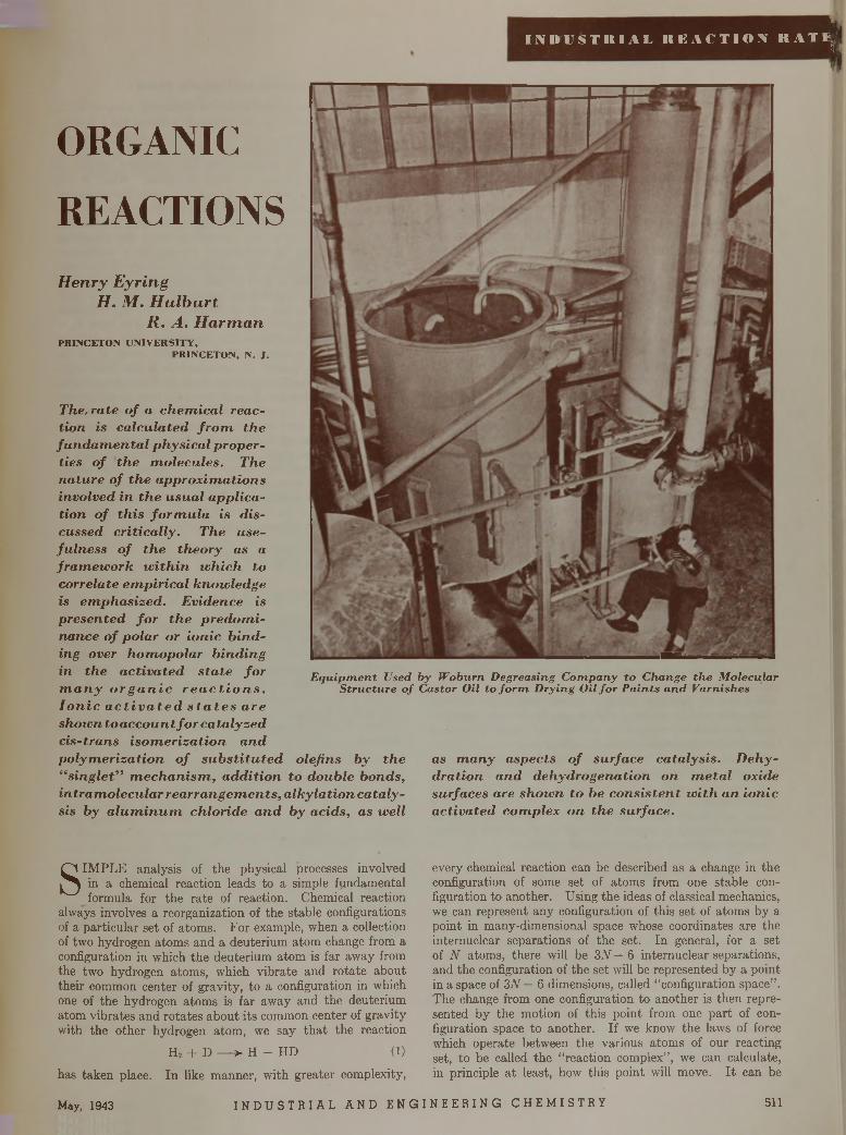
Tl|I N D U S T I M A L R E A C T I O N R A T E
if i
ORGANIC
REACTIONS
Henry Eyring H. M. H ulburt
R. A. H arm anP R IN C E T O N U N IV E R S IT Y ,
P R IN C E T O N , N . J .
The, ra te o f a c h e m ic a l reactio n is c a lc u la te d f r o m th e fu n d a m e n ta l p h y s ic a l p ro p e r ties o f th e m o lecu le s . The n a tu re o f th e a p p ro x im a tio n s in vo lved in th e u su a l a p p lic a tio n o f th is fo r m u la is d is cu ssed c r it ic a lly . The u sefu ln e s s o f th e th e o ry as a fra m e w o rk w ith in w h ich to co rre la te e m p ir ic a l k n o w led g e is e m p h a s ize d . E v id en ce is p re se n te d f o r th e p r e d o m inance o f p o la r or io n ic b in d ing over h o m o p o la r b in d in g in th e a c tiv a te d s ta te f o r m a n y o r g a n i c r e a c t i o n s .I o n i c a c t i v a i e d s i a t e s a r e shoivn to a c c o u n t f o r ca ta ly s e d c is - tra n s is o m e r iz a tio n a n dp o ly m e r iz a tio n o f s u b s t i tu te d o lefin s b y th e “ s in g le t” m e c h a n ism , a d d it io n to d o u b le b o n d s, in tra m o lecu la r r e a rra n g e m e n ts , a lk y la tio n c a ta ly sis b y a lu m in u m ch lo r id e a n d b y a c id s , as w ell
E q u ip m e n t Used by W oburn D egreasing C o m p a n y to C hange th e M olecu lar S tr u c tu re o f C astor Oil to fo r m D rying O il fo r P a in ts a n d V arnishes
as m a n y a sp e c ts o f su rfa ce c a ta ly s is . D e h y d ra tio n a n d d e h y d ro g e n a tio n on m e ta l ox ide su rfa ces are sh o w n to be c o n s is te n t w i th a n io n ic a c tiv a te d co m p lex o n th e su rfa ce .
SIM PLE analysis of the physical processes involved in a chemical reaction leads to a simple fundamental formula for the rate of reaction. Chemical reaction
always involves a reorganization of the stable configurations of a particular set of atoms. For example, when a collection of two hydrogen atom s and a deuterium atom change from a configuration in which the deuterium atom is far away from the two hydrogen atoms, which vibrate and ro tate about their common center of gravity, to a configuration in which one of the hydrogen atoms is far away and the deuterium atom vibrates and rotates about its common center of gravity with the other hydrogen atom, we say th a t the reaction
H , + D — > H + HD (1)
has taken place. In like manner, with greater complexity,
every chemical reaction can be described as a change in the configuration of some set of atoms from one stable configuration to another. Using the ideas of classical mechanics, we can represent any configuration of this set of atoms by a point in many-dimensional space whose coordinates are the internuclear separations of the set. In general, for a set of N atoms, there will be 3.V— 6 internuclear separations, and the configuration of the set will be represented by a point in a space of 3N — 6 dimensions, called “configuration space” . The change from one configuration to another is then represented by the motion of this point from one part of configuration space to another. If we know the laws of force which operate between the various atoms of our reacting set, to be called the “reaction complex” , we can calculate, in principle a t least, how tliis point will move. I t can be
May, 1943 I N D U S T R I A L A N D E N G I N E E R I N G C H E M I S T R Y 511
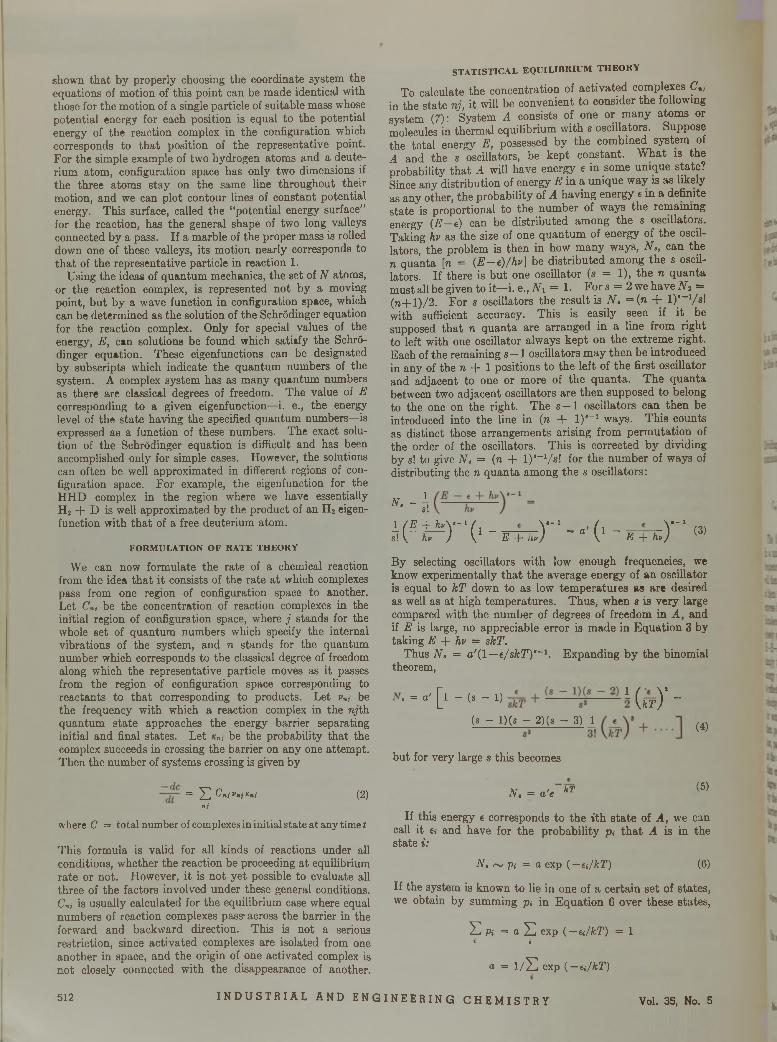
shown tha t by properly choosing the coordinate system the equations of motion of this point can be made identical with those for the motion of a single particle of suitable mass whose potential energy for each position is equal to the potential energy of the reaction complex in the configuration which corresponds to tha t position of the representative point. For the simple example of two hydrogen atoms and a deuterium atom, configuration space has only two dimensions if the three atoms stay on the same line throughout their motion, and we can plot contour lines of constant potential energy. This surface, called the “potential energy surface” for the reaction, has the general shape of two long valleys connected by a pass. If a marble of the proper mass is rolled down one of these valleys, its motion nearly corresponds to tha t of the representative particle in reaction 1.
Using the ideas of quantum mechanics, the set of N atoms, or the reaction complex, is represented not by a moving point, bu t by a wave function in configuration space, which can be determined as the solution of the Schrödinger equation for the reaction complex. Only for special values of the energy, E, can solutions be found which satiafy the Schrödinger equation. These eigenfunctions can be designated by subscripts which indicate the quantum numbers of the system. A complex system has as many quantum numbers as there are classical degrees of freedom. The value of E corresponding to a given eigenfunction—i. e., the energy level of the state having the specified quantum numbers—is expressed as a function of these numbers. The exact solution of the Schrödinger equation is difficult and has been accomplished only for simple cases. However, the solutions can often be well approximated in different regions of configuration space. For example, the eigenfunction for the HHD complex in the region where we have essentially H 2 + D is well approximated by the product of an H 2 eigenfunction with tha t of a free deuterium atom.
F O R M U L A T IO N O F R A T E T H E O R Y
We can now formulate the rate of a chemical reaction from the idea tha t it consists of the rate a t which complexes pass from one region of configuration space to another. Let Cnj be the concentration of reaction complexes in the initial region of configuration space, where j stands for the whole set of quantum numbers which specify the internal vibrations of the system, and n stands for the quantum number which corresponds to the classical degree of freedom along which the representative particle moves as it passes from the region of configuration space corresponding to reactants to tha t corresponding to products. Let vn, be the frequency with which a reaction complex in the ryth quantum state approaches the energy barrier separating initial and final states. Let x„, be the probability tha t the complex succeeds in crossing the barrier on any one attem pt. Then the number of systems crossing is given by
= S C*iv* iK»i (2)n j
where C = total number of complexes in initial state at any time t
This formula is valid for all kinds of reactions under all conditions, whether the reaction be proceeding a t equilibrium rate or not. However, it is not yet possible to evaluate all three of the factors involved under these general conditions. Cnj is usually calculated for the equilibrium case where equal numbers of reaction complexes pass- across the barrier in the forward and backward direction. This is not a serious restriction, since activated complexes are isolated from one another in space, and the origin of one activated complex is not closely connected with the disappearance of another.
S T A T IS T IC A L E Q U IL IB R IU M T H E O R Y
To calculate the concentration of activated complexes C „ in the state nj, it will be convenient to consider the following system (7): System A consists of one or m any atoms or molecules in thermal equilibrium with s oscillators. Suppose the total energy E, possessed by the combined system of A and the s oscillators, be kept constant. W hat is the probability tha t A will have energy e in some unique state? Since any distribution of energy E in a unique way is as likely as any other, the probability of A having energy e m a definite state is proportional to the number of ways the remaining energy ( E - t ) can be distributed among the s oscillators. Taking hv as the size of one quantum of energy of the oscillators, the problem is then in how many ways, N., can the n quanta [n = (E -e ) /h v ] be distributed among the s oscillators. If there is but one oscillator (s = 1), the n quanta must all be given to it—i. e., N i = 1. For s = 2 we have N a = (n + l) /2 . For s oscillators the result is N . = (n + l)*-1/s! with sufficient accuracy. This is easily seen if it be supposed tha t n quanta are arranged in a line from right to left with one oscillator always kept on the extreme right. Each of the remaining s — 1 oscillators m ay then be introduced in any of the n + 1 positions to the left of the first oscillator and adjacent to one or more of the quanta. The quanta between two adjacent oscillators are then supposed to belong to the one on the right. The s - 1 oscillators can then be introduced into the line in (n + I ) ' -1 ways. This counts as distinct those arrangements arising from perm utation of the order of the oscillators. This is corrected by dividing by s! to give N, = (n + l ) s_1/s! for the number of ways of distributing the n quanta among the s oscillators:
" ■ - à
¿ ( ^ r o - r n c r - ' O - E -f- hv
y ,(3)
By selecting oscillators with low enough frequencies, we know experimentally th a t the average energy of an oscillator is equal to kT down to as low tem peratures as are desired as well as a t high temperatures. Thus, when s is very large compared with the number of degrees of freedom in A , and if E is large, no appreciable error is made in Equation 3 by taking E + hv = skT.
Thus N, = a ' ( l —e/sfcT )-1. Expanding by the binomial theorem,
N. = o ' [ l - (s - 1) ~ I ( u 5)* ~
(g - l)(s — 2)(s — 3) 1
but for very large s this becomes
N , = a'e k T
(4)
(5)
If this energy e corresponds to the ith s ta te of A, we can call it €» and have for the probability p. th a t A is in the state i :
N. ~ p,- = a exp ( —t i/k T ) (6)
If the system is known to lie in one of a certain set of states, we obtain by summing pi in Equation 6 over these states,
S Pi = a S exp ( —ei/kT) = 1 » »
a = 1 / S exp ( —ei/kT)
512 I N D U S T R I A L A N D E N G I N E E R I N G C H E M I S T R Y Vol. 35, No. 5
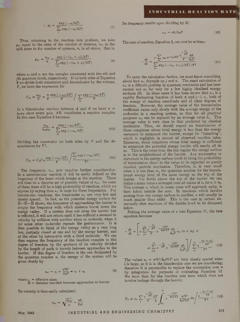
Piexp ( - t j/k T )
E exp ( -e i/k T ) (7)
Thus, returning to the reaction rate problem, we take p„i equal to the ratio of the number of systems, n„, in the ry'th sta te to the number of systems, n, in all states; th a t is,
P.; =exp [ — (e„ + f j ) /k T ]
E e x p [-(«„ + *j)/kT] (8)
Its frequency results upon dividing by 21:
yni = n h /ifd 1 (10)
The rate of reaction, Equation 2, can now be w ritten:
, c E 4. «—//*r %de ni V
kT nh4 A 2
dt E exp [ —(e» +« ¡ ) /k T ]/V 2(11)
where e. and e, are the energies associated with the n th and jth quantum levels, respectively. If on both sides of Equation 8 we divide both num erator and denom inator by the volume, V, we have the expression for
rinj n exp ( —enj/kT) 1'*» — y y y / ?
exp ( —tnj/kT) V
In a bimolecular reaction between A and B we have n = uaUb since every pair, AB, constitutes a reaction complex. In this case Equation 8 becomes:
rinj _ exp ( —t„j/kT )
n*nB E exp ( —tnj/kT) (8A)
Dividing the num erator on both sides by V and the denominators by V2,
/ E exp ( -cn j/kT )¡n _ p ri exp ( enj/kT) j nj_____________ (813)- C iC j y j y 2
The frequency, vni, now requires further consideration. In a unimolecular reaction it will be easily defined as the frequency of the bond which breaks in the reaction. There will then be a discrete set of possible values of vnj,: for some of them there will be a high probability of reaction, which we express by saying th a t xn, is large for these frequencies. For bimolecular reactions, the frequencies vni are very low and closely spaced. In fact, as the potential energy surface for H—H —H shows, the frequency of approaching the barrier is simply the frequency with which systems travel down the energy valley. If a system does not cross the barrier bu t is reflected, it will not return until it has suffered a reversal in velocity by collision with another atom or molecule, when it (or some other molecule) repeats the performance. I t is then possible to think of the energy valley as a very long box, partially closed a t one end by the energy barrier, and a t the other by interaction with a th ird molecule. We can then express the frequency of the reaction complex in this degree of freedom by the quotient of its velocity divided by the length of path it travels between approaches to the barrier. If this degree of freedom is the one designated by the quantum number n, the energy of the system will be given closely by
, n2h2 ,**' = + 1 Â 2 ~ Ci + *“
where — effective mass21 = distance traveled between approaches to barrier
(9)
To carry the calculation farther, we m ust know something about how depends on j and n. The exact calculation of Knj is a difficult problem in quantum mechanics and has been carried out so far only for a few highly idealized energy surfaces (3). In these cases it has been shown th a t is a rapidly fluctuating function of both n and j —i. e., both of the energy of reaction coordinate and of other degrees of freedom. However, the average value of the transmission coefficient varies only slowly with the average energy of the molecules in a reacting system, so th a t for all practical purposes can be replaced by an average value k„. This average value is very close to th a t predicted by classical mechanics. Thus, we should expect no transmission of those complexes whose to tal energy is less than the energy necessary to surmount the barrier, except for “tunneling” , which is negligible in almost all observed reaction rates. Moreover, those complexes whose to ta l energy is sufficient to surmount the potential energy barrier will nearly all do so. This is the more true, the less regular the energy surface is in the neighborhood of the barrier. Any asymmetry or curvature in the energy surface tends to bring the probability of transmission closer to the value to be expected on purely classical particle mechanics. Therefore, x„ is very small when n is less than na, the quantum number for the translational energy level of the same energy as the top of the barrier. For levels above the top of the barrier we can define a mean value k averaged over all values of x„ for n > Wo. This average k, which in m any case3 will approach unity, is then taken outside the sum. In reactions which involve passing from one energy surface to another, k will usually be much smaller than unity. This is the case in certain abnormally slow reactions of the double bond to be discussed below.
Putting the average value of k into Equation 11, the rate equation becomes
dcdt c
I— in
«JK'TE % ^ 8ldtkTI ^ Kin (n < n ») +
kT „ 8ul'kT nh 4id*.
_ (t; ~h in)kT (12)
V2
The values e„ = n2h2/8 ^ l2kT are very closely spaced when I is large, as it is in the bimolecular case we are considering; therefore it is permissible to replace the summation over n by integration for purposes of evaluating Equation 12. We have then for the reaction rate term which does not involve leakage through the barrier,
Its velocity is then easily calculated:
yt — ck E ' kT kT
00
/Jilo
n*h*"8 nl'kT n2h2
4A2kT !
(en + t j )
kT_ (13)V 2
May, 1943 I N D U S T R I A L A N D E N G I N E E R I N G C H E M I S T R Y 513
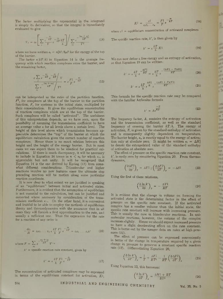
The factor multiplying the exponential in the integrand is simply its derivative, so tha t the integral is immediately evaluated to give
V2 Z' k T - Xk T kT Z'
( i n + i ; )
k T
V2(14)
where we have written e0 = nlh-/8^l- for the energy of the top of the barrier.
The factor n(kT/h) in Equation 14 is the average frequency with which reaction complexes cross the barrier, and the remaining factor,
Z e 47\ k T I
(«; + tn)kT
(15)
V 2
can be interpreted as the ratio of the partition function, F t, for complexes a t the top of the barrier to the partition function, F, for systems in the initial state, multiplied by their concentration. I t gives the equilibrium concentration of reaction complexes which are a t the top of the barrier. Such complexes will be called “activated” . The usefulness of this interpretation depends, as we have seen, upon the possibility of assuming the transmission coefficient to have an average value k for all levels above a certain level. The height of this level above which transmission becomes appreciable determines the “top” of the barrier a t which the equilibrium calculation gives the correct number of reaction complexes. Hence there is no exact relation between this height and the height of the energy barrier. But in most cases we can expect them to be identical for practical calculations. If there is much discrepancy, it will be necessary to include in Equation 14 terms in n < n0 for which k,„ is appreciable but not unity. I t will be recognized that Equation 14 is the one derived by Eyring (11) from somewhat different considerations. Trimolecular and higher reactions involve no new features since the ultimate step preceding reaction will be motion along some particular reaction coordinate.
I t is now clear to what extent we are justified in speaking of an “equilibrium” between initial and activated states. Furthermore, it is evident tha t the assumption of equilibrium is not essential to the calculation, but can be justified and corrected where necessary by consideration of the transmission coefficient k On the other hand, it is convenient and fruitful to be able to employ the methods of equilibrium theory and thermodynamics with the assurance tha t in all cases they will furnish a first approximation to the rate, and usually a sufficient one. Thus the expression for the rate for a reaction of anv order is
d,C\ kT F t^ C1 C2 . . . Cn K ^ j~y € C1 C2 . . . C n k '
4~ ej
where F = Z e kT V ~nni
k ' = specific reaction rate constant, given by
*— T T - ' W
(16)
(17)
The concentration of activated complexes may be expressed in terms of the equilibrium constant for activation K t
K tct F t kT (18)
C1C2. . . Cn F
where ct = equilibrium concentration of activated complexes
The specific reaction rate, k', is then given by
k ' = K ^ K t (19)
We can now define a free energy and an entropy of activation, so that Equation 19 can be written:
kTAF i
' R T kT(AHt - TASt)
R T
ASX, , kT n rk = k - 7- e < h
(A EX + PAVX) R T
(20)
(21)
This formula for the specific reaction rate m ay be compared with the familiar Arrhenius formula
k ' = Ae- E R T (22)
The frequency factor, A, contains the entropy of activation and the transmission coefficient, as well as the standard frequency of crossing the barrier kT /h . The energy of activation, E, is given by the standard enthalpy of activation and is consequently slightly dependent on temperature. The barrier height, e0, is exactly equal to the energy of activation only at absolute zero. I t might be w ritten e0 = A//* to denote the extrapolated value of the standard enthalpy of activation at absolute zero.
The effect of pressure on the specific reaction rate constant, k', is easily seen by considering Equation 20. From thermo- dvnamics,
Using the first of these relations,
/ ö In k ' \ A V tV àp ) T ~ R T
(23)
(24)
It is evident tha t the change in volume on forming the activated state is the determining factor in the effect of pressure on the specific rate constant. If the activated complex has a smaller volume than the initial state, the specific rate constant will increase with increasing pressure. This is usually the case in bimolecular reactions. In uni- molecular reactions, however, the volume of the complex increases slightly. Hence we should expect increased pressure to have a slight decelerating effect on the rate constant. This is borne out by the meager data on rates a t high pressures (3 4 .).
The effect of pressure can be expressed conveniently in terms of the change in tem perature required by a given change in pressure to preserve a constant specific reaction rate (12). Differentiating Equation 20,
( à In k ' \ 1\ àT ) p ~ f
AFX+ R T 2 R T V àT ) p
1 ( à A F t \
Using Equation 23, this becomes:
/c) In k ' \ \ ^ T ~ ) p
A H t + R T R T 2
(25)
(26)
514 I N D U S T R I A L A N D E N G I N E E R I N G C H E M I S T R Y Vol. 35, No. 5
\
I M M S T l ( I A I . R E A C T I O N R A T E * .
With Equation 24 this gives
m ,
a relation reminiscent of the Clausius-Clapeyron equation.Although it is not often possible a t present to evaluate the
necessary quantities in the foregoing rate expressions from fundamental physical data, such as spectroscopic frequencies, the concepts to which they lead are fruitful. The activated complex has most of the properties of an ordinary molecule except for an unstable vibrational degree of freedom which will lead to consummation of the reaction. Thus it is possible to speak of a free energy of activation and to apply all the usual therm odynamic treatm ent to the activated state. This leads us to classify rate processes according to the type of activated complex involved in the rate controlling step. There are three such types.
T Y P E S O F A C T I V A T E D C O M P L E X
In certain processes only the weaker secondary bonds between molecules, b u t no valence bonds, are broken. Viscous and plastic flow and diffusion are examples of this type of process. They were discussed in a previous paper (30).
There are two types of activated complexes which involve rupture of valence bonds in molecules. In the first the bonds in the activated sta te are predominantly the homopolar or shared-electron type. Thus when a hydrogen molecule approaches an iodine molecule, an activated complex of two hydrogen and two iodine atoms is formed in which all the bonds are essentially the same as those in H 2 or L. Similarly, three hydrogen atoms form an activated complex in ortho-para hydrogen conversion in which the bonds are covalent or homopolar bonds. This type of activated complex was the first to be treated theoretically and is the one to which the semiempirical scheme of calculating activation energies applies (13). In this type of activated state, the valence electrons cannot be said to be associated with one atom any more than w ith another. Another example of this type of activated complex is found in those unimolecular reactions which proceed through dissociation into neutral radicals, such as the therm al cracking of hydrocarbons (29). Thus ethane dissociates to form an ethyl radical and a hydrogen atom. In the activated complex, the C—H bond will be lengthened, but each atom will have nearly a normal electron density around it. Thus the proton can be pictured as about to depart with its electron. The activated complex represents incipient radical formation.
The second type of activated complex represents incipient dissociation into ions. The bonds between the atoms are predominantly polar, or ionic, in character. This means that the electrons are more closely associated with one of the bonded atoms than the other. The extreme case of this sort is represented by alkali halide crystals, in which the sodium and chlorine exist as separate ions. However, all degrees of polarity exist, from the almost completely homo- polar bond such as H 2 to the extremely polar bonds of the alkali halides. For convenience, those bonds in which polar configurations play a m ajor role will be called “ ionic” , although this is not to be construed as implying “dissociated into ions” . Thus even so ionic a compound as sodium chloride dissociates into atoms in the gas phase, although it reacts with water to yield ions in solution. The activated complexes into which this and similar substances enter will be termed “ionic” , since the binding is better represented by ionic structures than by homopolar ones.
/ b In k ' \ / / d In k ' \V dT ) J V dp ) r
a / / : + r tT W t (27)
IO N IC R E A C T I O N M E C H A N I S M S
Ionizations in solution afford a major class of reactions which m ust proceed through an ionic activated state, and m any of the features of the energy surfaces for ionic reactions may be most readily studied in this class. Acid strengths and relative rates of reactions involving ionic activated complexes (e. g., nitration of benzene) afford im portant information on the influence of substituents on the strength of the unstable bond in the activated complex. One method is to correlate acid strengths (31) and rates of n itration of substituted benzenes with activated complexes in which the substituent group is assigned a fractional charge to account for the inductive effect of the substituent through the carbon chain. The induced charge on each carbon atom is reduced by a fixed am ount on each atom in the chain through which the induction is transm itted. The resulting charge distribution accounts for the dipole moment of the substituted molecule as well as for the change in strength of the critical bond as the substituent is varied. The activated complex is thought of as intermediate between a completely homopolar and a completely polar structure. The differences in activation energy are assigned to differences in the initial states of the molecules. Another m ethod (38) is to calculate the energy required to furnish an electron a t the spot of attack in the molecule. T hat is, for attack by an ion, the energy of a completely polar activated complex is calculated, supposing the substituent affects the energy of the activated state. This method is equally successful in predicting relative rates and acid strengths, and neither is sufficiently advanced to do more. The ease of ionization has been empirically correlated with the “negativity” of the substituent (16), and several empirical electronegativity scales of the elements have been devised (28).
The chief structural features tha t enter into the ease of excitation of an ionic state are the following:
1. Dissociation into symmetrical ions is highly improbable since there is normally no tendency for the electrons to be localized in any one part of a symmetrical bond.
2. Large resonating substituents, such as conjugated systems or aromatic groups, favor ion formation, since the larger the number of resonance structures possible for the ion, the greater will be its stabilization. Thus triphenyl m ethyl chloride forms conducting solutions in cresol and in liquid sulfur dioxide. B ent and co-workers (4) studied reactions of the type Xa + R —► X a” + R ” for radicals, R, of the triaryl methane type. The free energies of these reactions in ether solution are all about —20 kg.-cal. per mole. The free energies of the reactions R» —► 2R are all about + 10 kg.-cal. for the same radicals; the stabilizing power of the resonating group for the ionic reaction is evident.
3. Great differences in the electronegativities of the two groups favor dissociation into ions, since the electrons are then located nearer to one of the groups than to the other, even in the initial state.
. Actual dissociation into ions does not usually occur in the absence of solvent, even though the molecule m ay exist in a polar electronic state. The power of the solvent to dissociate a molecule depends largely upon its ability to form coordination compounds with the ions formed—i. e., to solvate them. Substances which can accommodate unshared electrons from the negative ion or which have unshared electrons to fill the available orbitals of the positive ion are good ionizing solvents. W ater is such a substance. I t owes its solvating power to the unshared electron pairs of its oxygen, which are free to bond the H 20 to any ion having an unoccupied orbital—i. e., a positive ion. In addition, the proton can often form hydrogen bonds with negative ions and thus give water the power to solvate both positive and negative ions.
May, 1943 I N D U S T R I A L A N D E N G I N E E R I N G C H E M I S T R Y 515
The ionizing power of a solvent can often be enhanced by addition of a substance (such as anhydrous aluminum chloride) which can coordinate one or both of the ions formed. The aluminum has an available empty orbital, lacking two electrons to complete an octet. Hence, it can bond negative ions readily and would be expected to promote ionization. Alcohol solutions of triphenyl methyl chloride which are nonconducting become conductors when aluminum chloride is added {16). Even alkyl halides in which aluminum chloride is dissolved exhibit conductivity which increases with the length of the carbon chain (57); this is evidence of both a solvent and a substituent effect. Addition of benzene increases the conductivities. Thus it is apparent that ionization accompanies reactions in which aluminum chloride is involved. Concentrated sulfuric acid dissociates according to the equation,
2H2SO, H3SO«+ + HSO,
in which the solvated proton H sS 04+ has an orbital available for bonding with negative ions. Strong acids catalyze many of the same reactions as aluminum chloride—e. g., alkylation and isomerization. The effect of boron trifluoride may be attributed to the same sort of action. Anhydrous hydrogen fluoride is an ionic molecule and would likewise be expected to furnish protons readily which can catalyze condensations.
INTRAMOLECULAR REARRANGEMENT
Ten years ago Whitmore {39) proposed tha t all alkyl chain rearrangements proceed through the formation of carbonium ions. Considerable qualitative and quantitative evidence has been presented in support of this view. These reactions are almost invariable concomitants of alkylations which are catalyzed either by strong acids such as hydrofluoric and sulfuric or by Friedel-Crafts catalysts such as boron fluoride and aluminum chloride. There is good reason, therefore, to attribute the same activated state to each type of reaction. However, in the absence of kinetic data it is impossible to state what is the slowest step of the mechanism.
T hat intramolecular rearrangements should occur easily via positive ions is evident from consideration of the simple cases of H s and H 3+, which have been studied theoretically {18). I t has been shown tha t the H 3 molecule is most stable in the linear configuration, whereas H 3+ is most stable in a triangular configuration. Thus the proton in other positive ions when bound to both the nuclei is probably stable.
H HFor example, the ion CHSC—CCH3 can exist in the form
H +H H H H
CHSC—CCH>+ or in the form HC—CCHS+ without much
' V ^CH»activation energy. If the methyl finally shifts to the middle carbon, the system will have rearranged. This mechanism is reminiscent of tha t proposed by Egloff {10) and others, who supposed two hydrogen atoms to be removed from the hydrocarbon with a resulting triangular free radical. However, there is reason to think the triangular configuration is much less stable than the linear one for neutral radicals {18). For rearrangement to occur, it is not necessary tha t the charged fragments of the molecule separate completely, although conductivity measurements seem to indicate that in some cases they do. All th a t is required is tha t the positive group be sufficiently free to rotate as a nearly independent unit. Since electrostatic forces are much longer range than covalent bond forces, this freedom to rotate may be attained prior to complete dissociation into ions.
a l k y l a t io n a n d f r i e d e l -c r a f t s c a t a l y s t s
Alkylation of benzene with normal alkyl halides in the presence of aluminum chloride leads to a large degree of b anched-chain products under conditions such th a t alcohols g[ve unrearranged products {35). Moreover, alkylation of benzene with olefins in the presence of aluminum chloride leads to much less isomerization than in the presence of concentrated sulfuric acid {22). The reaction with alcohols requires the presence of hydrochloric acid in addition to aluminum chloride, whereas th a t with alkyl halides does not. All these facts are consistent with the following mechanism. Aluminum chloride has great power to form complexes with substances which can furnish a pair of electrons to occupy the available low-energy orbital on the aluminum. Halogen in alkyl and acyl halides, oxygen in carbonyl, and, to a lesser extent labile hydrogen (as hydride ion) and double bonds are good electron donors. The resulting complexes are highly ionic in nature. For example, ethyl bromide and aluminum bromide yield the complex [C2H 6+ (AlBr4) ] in which the two ions {8) are nearly independent. This is evident experimentally from the rapid exchange of radioactive bromine between aluminum bromide and ethyl bromide {U ). The positive ethyl is then free to attack the unsaturation electrons in benzene with the displacement of hydrogen. Acid chlorides have two electron donors, the chloride and the carbonyl oxygen. This accounts for the fact that the addition of aluminum chloride in excess of the acyl halide yields much greater catalysis than the first equivalent of catalyst added. I t is also borne out by the fact that a mixture of alkyl chloride, benzene, and acetic anhydride in the presence of aluminum chloride yields the alkylated acetophenone directly if more than one mole of aluminum chloride is used, whereas acylation alone takes place if less than one mole is used {36). Similarly, hydrohalogen acids form ionic complexes with aluminum chloride— e. g., H+ (AlCh)- . I t has been found th a t the conductivity of solutions of aluminum bromide in toluene is increased over a thousand times upon addition of hydrogen bromide {26). This indicates considerable dissociation of the complex. Thus we should expect the presence of protons in solutions of aluminum chloride, hydrochloric acid, and alcohols. The proton has a greater polarizing effect on the C—0 bond in ROH than has aluminum chloride, bu t it is improbable tha t dissociation into ions takes place. R ather
theH -|+
R—C—OH-C—OH complex has an electrostatic bond be-H H J
tween oxygen and carbon which is too strong to permit sufficient freedom for the alkyl group to rearrange. The difference in rearranging power between sulfuric acid, which also furnishes protons according to the scheme, 2H 2SO4 —> H3S04+ + H S04- , and aluminum chloride can be similarly understood. In this case since sulfuric acid is much more soluble in the reaction mixture than aluminum chloride, it furnishes a more highly ionizing solvent; consequently there i® greater loosening and perhaps even dissociation of the complex which allows rearrangment of the alkyl radical. The fact tha t rearrangement does occur in alkylation with secondary and tertiary alcohols {21) is in accord with the usual view of the weakening of the C—0 bond by the electron- repellent influence of adjacent alkyl groups. This explanation will account for the difference in rearranging powers when benzene is alkylated with olefins {22). The complex (e. g., H2C—CH2+ in the case of ethylene) is then similar to
Vthat proposed by Roberts and Kimball {32) for bromination. The mechanism presented here is essentially th a t of Fair-
516 I N D U S T R I A L A N D E N G I N E E R I N G C H E M I S T R Y Vol. 35, No. 5
¡Heb«K¡¡ Wfe
Men 30® laitiat ;¡kl#S
siía El’S as. h
flcMB *■ a it
¿ a
BCRiJ lS !
netikiéEiffi:9raB I S
:ó¿4
'isa*:(!.-SjfcRub
*Wtfc«sadMUMl««*ü>¡*nlüttNsluÜt'4 k
HÍJftL
brother (15) who gives as additional evidence of complex formation the large increase in molar polarization when ethyl bromide is added to a solution of aluminum bromide in cyclo- hexane. In contrast, addition of bromobenzene in place of ethyl bromide gives a polarization of the solution which is the sum of those of the separate components; this indicates little or no complex formation and m ay be evidence as to why aryl halides react very slowly in Friedel-Crafts reactions. Complex formation might be supposed to inhibit reaction by stabilizing the initial state. However, if as in the case of alkyl halides the activated state of the complex is stabilized even more than the initial state, the activation free energy will be lowered. Since polar or internally ionized substances make better bonds with electron-seeking reagents such as aluminum chloride th an do homopolar substances, the observed facts indicate th a t the activated state in these reactions is extremely polar.
DOUBLE BOND REACTIONS
There are also specific catalysts for radical formation. Introduction of free radicals or atoms into the system will favor this type of reaction. The two cases can be compared in the reactions of olefinic double bonds. I t has been pointed out (2 4 ) th a t the cis-trans isomerizations and the polymerizations of substituted ethylenes fall into two distinct kinetic classes. In one group are those reactions in which the frequency factor is about 1012 and the activation energy is about 45,000 calories per mole. The other group contains those reactions in which the frequency factor is very low (105) and the activation energy is only 23,000 calories per mole. The first group is catalyzed by such compounds as aluminum chloride, ferric chloride, and sulfuric acid; the second group is catalyzed by O2, benzoyl peroxide, atoms (Br, Na, etc.) Some reactions exhibit both types of kinetics, depending upon the tem perature. This general behavior can be well correlated with the electronic structure of the double bond. Mulliken (25) discussed the electronic states of ethylene by considering the energy states of a single electron moving in the average potential field of C2H 4++ in which the bonds are considered to be disposed as follows:
H H
. C : C .H • ’ H
Hence, the electron density in ethylene can be inferred to a first approximation by considering the juxtaposition of two CH j+ ions. In the free methylene the electrons are not distributed about the carbon with spherical symmetry, but are localized in three m utually perpendicular pear-shaped orbitals, which lie along the coordinate axes. These orbitals, or wave functions, whose absolute value is a measure of the electron density in the molecule, are usually denoted as [x], [y ], and [z], respectively. The axes are so chosen tha t the [z] orbitals overlap when two methylenes join to form an ethylene; the [y] orbitals lie in the plane of the CH2 and serve to overlap the spherically symmetric hydrogen orbitals to form the C—H bonds. The [z] orbitals project perpendicular to the plane of the methylenes. Thus the [z] orbitals combine to form one of the two bonds of the double bond, whereas the [x] orbitals form the other and the weaker of the two. Each orbital can be occupied by two electrons a t most, according to the Pauli exclusion principle. Hence in C2H 4++ there are orbitals available for two electrons, which make up the second of the two bonds in the double bond. I t is these electrons which are most significant in determining the chemical behavior of the double bond.
In the ground state of ethylene, the methylenes lie in the same plane. The [2 ] orbitals are superposed to approximate the orbitals for ethylene. Two different combinations are possible—viz., [xa + xb] and [xa — xb]. In the first (bonding) orbital, the wave functions of the separate methylenes are added; hence a bonding orbital corresponds to a greater electron density between the carbons than tha t calculated simply by adding the electron densities of two methylenes. The orbital [x„ — xb\ is called “antibonding” since it corresponds to a smaller electron density in the region between the two carbons than the sum of the two methylene densities. In the ground state both electrons are in the bonding orbital, and the antibonding orbital is unoccupied. This means th a t the electrons occupy [x] methylene orbitals which overlap—i. e., have like sign on the same side of the molecule plane. The lowest excited state is one in which one electron occupies the bonding orbital and the other the antibonding orbital. Since the electrons occupy different orbitals, their spins need not be paired, and there will be two states, a singlet and a triplet, with somewhere near the same energy. However, when the excited singlet state is written out, it corresponds to both electrons occupying the same methylene orbital—i. e., to the structures CH2+— CH2~ and CH2_—CH2+ of internally ionized ethylene. The excited triplet state corresponds to a homopolar state in which the electrons are on different carbon atoms.
Now as one methylene is rotated about the C—-C bond in the ground state, the bonding [2 ] orbitals overlap less and less as the rotation proceeds and the bond becomes correspondingly weaker. As it approaches the position in which the planes of the methylenes are perpendicular to each other, the [2 ] orbitals are forced closer and closer to the [y] orbitals on the opposite methylene, w ith which they cannot combine. Hence there is an increasing repulsion as the methylene rotates, so th a t the perpendicular configuration of ethylene has a higher energy than the planar configuration. The exchange energy in the second C—-C bond becomes less and less as the methylene rotates, and somewhere near 45° becomes actually a repulsion. In the perpendicular configuration the lowest energy state is one in which the electrons are on different carbons with unpaired spins, a triplet state.
When the methylene has rotated by 180°, the sign of the[2 ] orbital on th a t methylene is reversed, and both electrons are in antibonding orbitals of very high energy. Thus if [ z j indicates the [2 ] orbital on methylene A , a wave function which is a bonding molecular orbital is given by [xa + z j , whereas the antibonding orbital is [2 . — xb]. As methylene B is rotated by 180°, [xb] changes sign, and bonding orbitals become antibonding upon rotation by 180°. Thus the activated state for the singlet mechanism will be represented by a linear combination of the wave functions [2« +**], I*. + *»]. and I1« “ x?l> Adding and multi‘plying give the wave function
[z«]i[x„]2 -1- [zb] 1 [zi,] 2 (28)
Subtracting gives
[x.] ,[*»], + [x&ljx,,], (29)
The first excited singlet state has the wave function
[x„ + Xfc] ,[Xo — x&], + [x0 + xb],[xa — Xb]l
in which only one electron is in the antibonding orbital. M ultiplying gives
[x«],[x0]s - [xdjxi], (30)
The activated singlet state is some linear combination ofstates 28, 29, and 30. States 28 and 30 are polar (i. e., both
May. 1943 I N D U S T R I A L A N D E N G I N E E R I N G C H E M I S T R Y 517
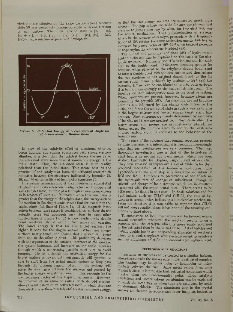
electrons are situated on the same carbon atom) whereas state 29 is a completely homopolar state, with one electron on each carbon. The initial ground state is [x» + x&],[ l a + Xb], = [X a ] , [X a ]2 + [X l , ] , [X t , ]2 + [X a ] , [ x * ] , + [Xb],[x«]2—i. e., a mixture of polar and homopolar.
Figure 1. P o ten tia l E nergy as a F u n c tio n o f A ngle fo r R o ta tio n a b o u t a D ouble Bond
In view of the catalytic effect of aluminum chloride, boron fluoride, and similar substances with strong electron affinities, it is clear tha t the catalyst lowers the energy of the activated state more than it lowers the energy of the initial state. Thus, the activated state is more readily polarized than the initial state. This means that, in the presence of the catalyst at least, the activated state which resonates between the structures indicated by formulas 28, 29, and 30 contains little of homopolar structure 29.
In cis-trans isomerization, if a symmetrically substituted ethylene retains its electronic configuration with antiparallel spins (singlet state), it must pass through an energy maximum as it rotates (Figure 1). Moreover, since this maximum is greater than the energy of the triplet state, the energy surface for reaction in the singlet state crosses tha t for reaction in the triplet state (full lines of Figure 1). If the magnetic interaction between these states is considered, the surfaces do not actually cross bu t approach very close to each other (dotted lines of Figure 1). I t is now evident why double bond reactions should exhibit two activation energies. The lower energy is tha t for the triplet surface; the higher is tha t for the singlet surface. When two energy surfaces nearly touch, the chance tha t a system will jump from one to the other is great. This probability decreases with the separation of the surfaces, increases as the speed of the system increases, and increases as the angle increases through which a noncrossing particle must turn to avoid jumping. Hence, although the activation energy for the triplet surface is lower, only infrequently will systems be able to shift from the initial singlet surface as they pass through the crossing region. Most of the systems will jump the small gap between the surfaces and proceed by the higher energy singlet mechanism. This accounts for the low frequency factor of the triplet mechanism. However, the presence of an atom or radical with its odd electron allows the formation of an activated state in which there are three electrons in three orbitals and greater resonance energy,
so tha t the two energy surfaces are separated much more widely. The gap is then too wide for any except very fast systems to jump; most go by what, for two electrons, was the triplet mechanism. Thus polymerization of styrene, which in the absence of catalyst proceeds with a frequency factor of 105 retains the same activation energy bu t has an increased frequency factor of 1010-1012 when benzoyl peroxide or triphenylmethylazobenzene is added (83).
The normal and abnormal additions (28) of hydrobromie acid to olefin can also be explained on the basis of the electronic structure. Normally, the H Br is ionized and H + adds first to the double bond. Ortho-para directing groups for benzene, when adjacent to the ethylenic double bond, tend to form a double bond with the new carbon and thus release the two electrons of the original double bond to the far carbon atom. Thus, although by analogy to Br+ (32) the incoming 11 ion can be considered to add to both carbons, it is bound more strongly to the least substituted one. The bromide ion then subsequently adds to the positive carbon. When peroxides are present, however, bromine atoms are formed by the peroxide (23). An incoming neutral bromine atom is not influenced by the charge distribution in the olefin, and forms the activated state in such a way as to give it the largest entropy and lowest energy (least steric hindrance). Since entropies are mainly determined by moments of inertia, and these are greatest for molecules in which the heavy atoms and groups are symmetrically placed, we should expect the bromine atom to add to the least substituted carbon atom, in contrast to the behavior of th e bromide ion.
While most of the evidence th a t organic reactions proceed by ionic mechanisms is inferential, it is becoming increasingly clear tha t such mechanisms are very common. The most thoroughly investigated case is th a t of the hydrolysis of alkyl halides in neutral and basic media, which has been studied kinetically by Hughes, Ingold, and others (20). They have amassed an impressive array of evidence for their proposed mechanism of the first-order hydrolysis. The hypothesis tha t the slow step is a reversible ionization of RC1 into R + + Cl- leads to predictions of the effects on the hydrolysis rate of change of substituent, change of solvent, and change of ionic strength which are in excellent agreement with the experimental data. There seems to be little room for doubt in this case. In basic solutions and for light halides, such as CH3C1 and C2H 5CI, the rate of hydrolysis is second order, indicating a bimolecular mechanism. From the structure it is reasonable to suppose th a t CH3CI will not ionize readily, since it has none of the favoring conditions outlined above.
To summarize, an ionic mechanism will be favored over a radical mechanism whenever the reactant readily forms a complex with the catalyst which is more easily polarized in the activated than in the initial state. Alkyl halides and olefinic double bonds are outstanding examples of reactants which form such complexes with electron-accepting catalysts such as aluminum chloride and concentrated sulfuric acid.
H E T E R O G E N E O U S R E A C T IO N S
Reactions on surfaces can be treated in a similar fashion, where the atoms in the surface enter into the activated complex. This binding may be either polar or homopolar or intermediate between the two. Since m etal oxides form ionic crystal lattices, it is probable th a t activated complexes which involve them are predominantly polar. Thus catalytic alkylations and isomerizations on alumina can be explained in much the same way as when they are catalyzed by acids or aluminum chloride. The aluminum ions in the crystal surface are electron acceptors and favor incipient ionization
5 1 8 I N D U S T R I A L A N D E N G I N E E R I N G C H
I X I U J S T K I A I - R E A T T I O X K A T E i
in the activated complex. In many cases the charged fragm ents m ay actually separate sufficiently to allow one of them to ro tate freely in the field of the other and thus to undergo rearrangement. In such cases it is convenient to think of the surface as a polar solvent, and the reactants as forming a reasonably mobile two-dimensional ionic solution. The adsorbed negative ions move on a checkerboard of positive ions in the surface, and the adsorbed positive ions move over the negative ions in the surface. There is thus the possibility that, for some reactions, diffusion on the surface may be rate controlling. This does not appear to have been observed, however, except possibly in the case of sulfur dioxide oxidation (6). The measurement of the surface conductivity of catalyst surfaces would give information as to the mobility of the adsorbed ions on the surface. The importance of ionic mechanisms in catalysis was emphasized by Nyrop from a different point of view (27)
Of special interest is the large class of reactions on surfaces which are capable of simultaneously dehydrating and de- hydrogenating an alcohol acid or ester. T hat both reactions proceed simultaneously a t measurable rates indicates tha t their free energies of activation can differ by no more than 1 or 2 kg.-cal. Since this is true for a wide variety of surfaces (4 0 ) and for m any different molecules, it is evidence th a t the strengths of the critical bonds in the activated complexes for these reactions do not depend strongly on the nature of the surface. This would be the case in an ionic activated complex where the change in bond strengths when the surface is changed depends mainly on the change in the radii of the ions in the surface. Thus, suppose ROH is adsorbed as R + O H - on the surface of ions Zn++ and 0 in the reaction leading to dehydration. The bonding energy with the surface will then be:
of the rate determining step. To do this it m ust have so speeded up, or circumvented, some previously rate-determining process as to make the rate-determining step an earlier or later one in which the catalyst is not involved.
If two competing reactions are both speeded up in this way by each of a group of catalysts, the relative rates of the processes will be independent of the catalyst. Whenever relative yields of competing reactants are independent of or only slightly dependent on the catalyst, one suspects tha t the new rate-determining activated complexes make no bonds or only weak ones with the catalyst. The meager kinetic data available indicate th a t desorption of products is probably the slowest step in the above reactions. The variations in relative lates of dehydration and dehydrogenation on different surfaces and for different molecules represent relatively minor variations in the free energy of activation. These minor changes are of primary importance in selecting a catalyst, b u t a t present they are not sufficiently well understood experimentally to permit more than speculation concerning them.
The numerous experiments of Adkins and co-workers (5) on simultaneous dehydration and dehydrogenation of alcohols, acids, and esters over alumina, thoria, and titania catalysts indicate the main features of the reaction mechanism. E thyl acetate reacts on an alumina surface to yield ethylene, carbon dioxide, acetic acid, and acetone, with smaller quantities of ethanol, hydrogen, and ethane. The following mechanism explains the facts. Ester cleavage can occur a t either C—0 bond (3). On the surface both of these cleavages occur, yielding positive and negative adsorbed ions. The oxide ion in the surface adsorbs the positive ion and the metal ion in the surface adsorbs the negativeion:
E\onio —Ze2 Z'e2
(rti* + To ) (ro h* + rZn + + (31)
wheree = electronic charge Z = effective charge on surface anion Z ' — effective charge on metal ion
Alternatively, for dehydrogenation, suppose ROH is adsorbed as RO~ and H +. The bonding energy with the surface is then:
w*•“ ionicZe2
+Z'e2
( rH+ + To—) (/RO" + rz n + +)(32)
The activation energies for dehydration and dehydrogenation will differ by the amount,
E ' - E = ZeHr-B.* — t-b.*)(n t + + To )(rH+ + r0" )
Z 'e2(rRQ- — rpH~)_____(rRo" + rzn + +)(roH~ + rznt+)
+
+SE (independent
of surface)(33)
where the radii are 0 for the activated state. Since most of the charge in R O - is located on the oxygen, trq- and toh" will be nearly equal and the second term will be small. Neglecting ra + in comparison with the other radii, the firstterm becomes Z e /(ro b 7o““/ r R*)- The value of ro— is1.4 A. so th a t for rR+ > 2 A., this term too will be small. When the metal is changed, it is evident th a t E ' — E will not change greatly. If the activated sta te consists of an ion pair about to desorb as a neutral molecule, the surface will have little influence on the activation energy.
A catalyst m ay greatly accelerate an over-all process w ithout itself being a constituent of the activated complex
CH3COOC2H5—(A120,) C H jC = 0 + + OC2H6- (34)
CHaC—O- + CjHs+ (35)IIO
There are then two reactions competing for the acetate ion:
OII
CH,CO+ + CH3C—O-
c h 3c —o - + C2H6+ -
«5
(CH3)2CO + C 02 (36)
CH3COOH + C2H, (37)
The ethyl ion adsorbed on the oxide ion in the surface undergoes further reaction. A molecule of ethylene m ay be desorbed, leaving a proton on the surface:
C2Hs+ C2H4 + H-* (38)
Similarly, the ethylate ion adsorbed on the m etal ion in the surface m ay desorb acetaldehyde, leaving a hydride ion on the surface which combines w ith the proton from reaction 38 to give H 2 or with an ethyl ion to give ethane:
c 2h 5o - CH3CHO + H-
H+ + H - — >- H2
H - + C2H6+ — >- C2H,
(39)
(40)
(41)
M aw lQ < n I N D U S T R I A L A N D E N G I N E E R I N G C H E M I S T R Y 519
Alternatively, the ethylate may desorb ethylene, leaving a hydroxyl ion on the surface which combines with its proton to give water:
C2H50 - — C2H, + OH-
H+ + OH- — > H20
(42)
(43)
Or the ethylate may combine with the proton from reaction 38 to give ethanol:
CiHsO- + H 4 • C2H 5OH (44)
All of these substances occur in the decomposition products of ethyl acetate in proportions which vary with the catalyst and with its mode of preparation. One series of fourteen alumina catalysts is reported (2) in which ethane and hydrogen production is very small (2-3 per cent of the gaseous product). In this case, reactions 39, 40, 41, and 44 can be neglected.
The remaining equations formulate a mechanism leading to specific stoichiometric consequences which can be checked on Adkins’ data. Since all the ethyl ions are changed to ethylene, the amount of ethylene produced is independent of the amounts of carbon dioxide, acetone, and acetic acid formed. This result is reported by Adkins (2). Furthermore, since all the acetate ion results in either carbon dioxide or acetic acid, and all the acetyl results in acetone, the ratio of the number of moles of ester decomposing by reaction 34 to the number decomposing by reaction 35 is given by the ratio of acetone to carbon dioxide plus acetic acid:
[molecules decomposing by Equation 35][molecules decomposing by Equation 34]
[C02] + [CHjCOOH] [OOJ
(45)
But every molecule of acetone comes from an acetyl (Equa-. tion 36); hence the number of moles of acetone must equal the number of moles of carbon dioxide if there are no side reactions. Consequently, the total number of moles of ethyl acetate decomposed must equal twice the number of moles of carbon dioxide plus the number of moles of acetic acid:
2[COt] + [CH.COOH] = [CH,COOC2Hs] = [C2H4] (46)
where the brackets refer to the number of moles of the respective substances. For experiments on fourteen different catalysts the average value, taken without regard to sign, of the expression:
[C,Hd - 2[C 02] - [CHjCOOH] = D,
is 0.0411 [C2H<], and the average value of
[CHjCOOCjH j] - 2[C 02] - [CH,COOH] = D2
(47)
(48)
is 0.0331 [CHsCOOC2H 5]. The smallness of the deviations Di and D 2 thus supports Equation 46 and therefore the postulated mechanisms. In seventeen other cases where deviation of more than 10 per cent occurs, appreciable amounts of ethane and hydrogen are also noted in the products. This results from Equations 39, 40, and 41. Since the other products were not analyzed quantitatively, stoichiometric checks cannot be made in these cases.
The ratio [CH3C 0 0 H ]/[C 0 2] varies from 0.365 to 4.43 (over twelvefold) in this series of experiments; whereas the
values of D 2 vary from 0.5 to 9.3 per cent of the ester decomposed. Experiments on eleven other alumina catalysts (1 ) prepared in various ways, mainly by hydrolysis of aluminum alkoxides, yielded unmeasured quantities; o ethanol (Equation 44) and consequently check Equation 46 less well.
Ethanol undergoes similar reactions a t an oxide surface. This can be explained by a preliminary adsorption of ethanol in two analogous ways:
'■CA OH-C2H5OH<
-C2H sO - + H 4
(49)
(50)
The negative ion is always adsorbed on the m etal ion in the surface. Reactions 38 to 41, inclusive, complete the steps of the mechanism. Hoover and Rideal (Iff) studied the reactions of ethanol a t 297° to 326° C. on precipitated thoria. Since very little ethane was produced under these conditions, reaction 41 can be neglected in comparison with 38. The activation energy for hydrogen production is given as 24 kg.-cal. per mole whereas th a t for ethylene production is given as 30. Since almost equal volumes of hydrogen and ethylene are produced in unit time, this difference in heat of activation, if real, must be made up by a corresponding difference in the entropy of activation. This would indicate tha t the slowest step of dehydration involves an activated state with more rotational and translational freedom than does the activated state for dehydrogenation. This condition is satisfied if the activated state for dehydration consists in the detachment of a water molecule, formed by Equation 43, from the surface, whereas th a t for dehydrogenation consists in the detachment of acetaldehyde to leave a hydride ion adsorbed on the surface (Equation 39). The dehydration-activated complex then has the additional entropy of a practically free water molecule.
The effect of added gases can also be explained by this mechanism. Hoover and Rideal report th a t small amounts of added water vapor inhibit the production of ethylene more than the production of hydrogen, whereas added chloroform works in the opposite direction. W ater ionizes on the surface to give H + and OH- , and chloroform ionizes to give H + and CCI3- . If the adsorbed ions are somewhat free to move on the surface, a surface phase equilibrium would be expected in reactions 49 and 50 since they are not the slowest steps of the reactions. If, then, additional H + and O H - ions are furnished in equal amounts, straightforward calculation shows that, of reactions 49 and 50, the one with the larger equilibrium constant will be reversed most. Hence the concentration of ethyl ion will be reduced more than th a t of ethoxide ion, if Equation 49 has a larger equilibrium constant than 50; the result would be a decrease in the rate of production of ethylene relative to hydrogen. On the other hand, when chloroform is added, the only common ion is the proton which shifts the equilibrium so th a t the concentration of ethoxide ion is reduced relative to th a t of ethyl, and the production of ethylene is enhanced relative to hydrogen. The absolute rates of both reactions are reduced by either water or chloroform since they reduce the number of sites available for adsorption of alcohols.
A similar effect explains the action of water in raising the ratio of carbon dioxide to ethylene in ethyl acetate decomposition (6). The additional hydroxyl ions from the water use up the ethyl ions in Equation 37 to form ethanol and thus decrease the am ount of ethylene obtainable from ethyl acetate. D ata are not available to check the stoichiometry in this case, but the above assumption is a t least a plausible one and is analogous to the ethanol case. Acetone also raises the ratio of carbon dioxide to ethylene (5). This can be understood by an increase in the concentration of
520 I N D U S T R I A L A N D E N G I N E E R I N G C H E M I S T R Y Vol. 35, No. 5
acetyl ions which are available to displace carbon dioxide from acetate by Equation 36, since acetone would ionize on the surface to give CH 3CO+ and CH :~ ions. The slight effect of added phenol in lowering the ratio of carbon dioxide to ethylene can be explained in the same way as the effect of chloroform on ethanol, since phenol would give CsH 50 ~ and H + ions on the surface. The additional protons compete with the acetyl ions for acetate in Equations 36 and 37, and thus increase the acetic acid and ethylene production at the expense of carbon dioxide and acetone. T hat the effect is only slight is evidence of the weakness of phenol as an acid.
A third reaction of this same type is the decomposition of formic acid on zinc oxide (17). The competing reactionsare:
HCOOH'<
H20 + CO
h 2 + co2(51)
(52)
In this case the molecule is so simple th a t the mechanism is quite straightforward, consisting only of analogies to reactions 34 and 35:
HCOOHcHCO+ + OH-
H C O O -+ H+
HCO+ — >- CO + H+
HCOO- — CO, + H-
H+ + H- — > H,
H+ + O H - — >- H20
(53)
(54)
(55)
(56)
(57)
(58)
The activation energy for the production of hydrogen is given as 28 kg.-cal. per mole and th a t for the production of water as 16.8 kg.-cal. per mole. Again the rates of production of H 20 and H , are nearly equal, so th a t this difference in heat of activation, if real, is balanced by a difference in entropy of activation of about 20-25 entropy units in favor of the production of hydrogen. This is in contrast to the case of ethanol, where the entropy of activation for the production of water was greater. In formic acid decomposition, the activated state for hydrogen production would then have the greater entropy. This would be the case if it consisted of hydrogen being desorbed from the surface, whereas th a t for water production consisted of the desorption of CO from HCO+ leaving a proton on the surface. The difference in heats then would represent the difference in the heats of desorption of hydrogen and water.
The general features of surface reactions may be summarized as follows: M etal oxide surfaces adsorb reactants as ions, the metal ion adsorbing a negative reactant ion. The resulting reactan t ions are in m any cases sufficiently mobile on the surface so th a t equilibrium can be established between the ionized and un-ionized forms. The surface then acts essentially as a polar solvent. In all cases the slow step is either the adsorption in which ions are formed, or the desorption in which the ions recombine with the old or with new partners. In either case the reactants in the activated complex make weak bonds with the surface; they are either ju st beginning to make a bond or just on the point of breaking a bond. The result is tha t, if two processes such as hydrogenation and dehydration go a t about the same rate on one catalyst, the relative free energies of activation are only slightly shifted by a new catalyst. The
theory of the activated complex is helpful in interpreting the observed kinetic data and the effects of poisons so as to build a unified picture of the mechanism of an im portant class of catalyzed organic reactions.
L IT E R A T U R E C IT E D
(1) Adkins, H„ J. Am. Chem. Soc., 44, 2175 (1922).(2) Adkins, H., and Krause, A. C., Ibid., 44, 385 (1922).(3) Balfe, M. P., Hills, H W. J., Kenyon, J„ Phillips, H., and
Platt, B. C., J. Chem. Soc., 1942, 556 and references cited.(4) Bent, H. E., and Keevil, N. B., J. Am. Chem. Soc., 60, 193 and
references cited (1938); Dorfman, M., Ibid., 57, 1455 (1935).(5) Bischoff, F., and Adkins, H„ Ibid., 47, 807 and references cited
(1925).(6) Bodenstein, M., Z. physik. Chem., B2, 345 (1939).(7) Condon, E. U., Phys. Rev., 54, 937 (1938); Walter, J., and
Eyring, H., J. Chem. Education, 18, 73 (1941).(8) Dougherty, G., J. Am. Chem. Soc., 51, 576 (1929).(9) Eckart, C„ Phys. Rev., 35, 1303 (1930); Hirschfelder, J. O., and
Wigner, E„ J. Chem. Phys., 7, 616 (1939); Hulburt, H. M„ and Hirschfelder, J. O., Ibid., in press.
(10) Egloff, Hulla, and Komarewski, “Isomerization of Pure Hydrocarbons” , p. 25, New York, Reinhold Pub. Corp., 1941.
(11) Eyring, H., J. Chem. Phys., 3, 107 (1935).(12) Eyring, H., and Magee, J. L., J. Cellular Comp. Physiol., 20,
169 (1942).(13) Eyring, H., and Polanyi, M„ Z. physik. Chem., B12, 279 (1931);
Hirschfelder, J. O., Eyring, H., and Topley, B., J. Chem. Phys., 4, 170 (1936); Eyring, H., Gershinowitz, H., and Sun, C. E„ Ibid., 3, 786 (1935); Wheeler, A., Topley, B., and Eyring, H., Ibid., 4, 178 (1936).
(14) Fairbrother, F., J . Chem. Soc., 1937, 503.(15) Fairbrother, F., Trans. Faraday Soc., 37, 763 (1941).(16) Hammett, L. P., “Physical Organic Chemistry” , Chap. IV,
New York, McGraw-Hill Book Co., 1940.(17) Hinshelwood, C. N„ Hartley, H., and Topley, B., Proc. Roy.
Soc. (London), A100, 575 (1922).(18) Hirschfelder, J. O., J. Chem. Phys., 6, 795 (1938).(19) Hoover and Rideal, J . Am. Chem. Soc., 49, 104 (1927).(20) Hughes, E. D„ Ingold, C. K., et al„ J. Chem. Soc., 1940, 899-
1017.(21) Huston, R. C., and Hsieh, T. Y„ / . Am. Chem. Soc., 58, 439
(1936); Huston, R. C., et al., J. Org. Chem., 3, 251 (1938).(22) Ipatieff, V. N., Pines, H., and Schmerling, L., Ibid., 5, 253
(1940).(23) Kharaseh, M. S., and Mayo, F. R., J. Am. Chem. Soc., 55, 2468
(1933).(24) Magee, J. L., Shand, W., and Eyring, H., Ibid., 63, 677 (1941);
Harman, R. A., and Eyring, H., J. Chem. Phys., 10, 557 (1942).
(25) Mulliken, R. S., Phys. Rev., 41, 751 (1932), 43, 279 (1933);J. Chem. Phys., 1, 492 (1933), 3, 517 (1935).
(26) Norris, J. F., and Wood, J. E., J. Am. Chem. Soc., 62, 1428(1940).
(27) Nyrop, J. E., “Catalytic Action of Surfaces” , 1937: Emmett,P. H., and Teller, E., 12th Rept. of Comm, on Catalysis, Natl. Research Council, 1940, 68.
(28) Pauling, L., “Nature of the Chemical Bond”, p. 58, Ithaca, Cornell Univ. Press, 1940.
(29) Pease, R. N„ and Morton, J. M„ J . Am. Chem. Soc., 55, 3190(1933).
(30) Powell, R. E., Roseveare, W. E., and Eyring, H., I n d . E n g .C h e m ., 33, 430 (1941).
(31) Ri, T„ Eyring, H., J. Chem. Phys., 8, 433 (1940); Magee, J. L.,Ri, T., and Eyring, H., Ibid., 9, 419 (1941).
(32) Roberts, J. R., and Kimball, G. E„ J . Am. Chem. Soc., 59, 947(1937).
(33) Schulz, G. V., Dinglinger, A., and Husemann, E., Z. physik.Chem., B43, 385 (1939).
(34) Stearn, A. E., and Eyring, H., Chem. Rev., 29, 509 (1941).(35) Thomas, C. A., “Anhydrous Aluminum Chloride in Organic
Chemistry” , Chap. 5 and 12, New York, Reinhold Pub. Corp., 1941.
(36) Ibid., p . 94.(37) Wertyporoch, E., and Firla, T., Z. physik. Chem., A162, 398
(1932).(38) Wheland, G. W„ J. Am. Chem. Soc., 64, 900 (1942).(39) Whitmore, F. C„ Ibid., 54, 3274 (1932).(40) Williamson, A. T., and Taylor, H. S., Ibid., 53, 3270 (1931).
R . A. H a rm an is on le av e of ab sen ce fro m A llied C hem ica l a n d D y e C o rp o ra t io n , N ew Y o rk ; H . M . H u lb u r t is th e N a tio n a l R esea rc h F ellow a t P r in c e to n fo r 1942-43.
May, 1943 I N D U S T R I A L A N D E N G I N E E R I N G C H E M I S T R Y 521
P r i n c i p l e s o f R e a c t o r D e s i g n
G A S - S O L I D I N T E R F A C E
R E A C T I O N S
D avid M . H u r tE . I . D U P O N T D E N E M O U R S & C O M P A N Y , IN C ., W IL M IN G T O N , D E L .
A m e th o d o f corre la tin g th e perform an ce o f sm a ll-sca le w ith large-scale reactors has been developed . This m e th o d , l im ite d 1o g a s-so lid in terface reaction s, has p ro ved u sefu l fo r th e ra tio n a l design o f p la n t-sca le reac tors f r o m sm a ll-sca le te s t da ta .
O ver-all reaction ra tes have been sh ow n to be a fu n c tio n o f su rface reaction ra tes an d diffu sion a l, or m ass tran sfer, ra tes an d th e se c o m p o n e n t fa c to r s have been in d iv id u a lly corre la ted w ith th e ir respective ly im p o r ta n t variables. The new co n cep ts o f
H. R . U. (h e ig h t o f over-a ll rea c tio n u n i t ) a n d H. C. U. (h e ig h t o f c a ta ly t ic u n i t or surface reaction u n it) have been in tro d u c e d as m easures o f over-a ll rea c tio n ra te a n d surface reaction ra te , a n d u sed in c o n ju n c tio n w ith a co n ven tio n a l g a s-film H. T. U. as a m easu re o f m ass tra n sfe r ra te .
N ew d a ta on g a s-film H. T. U. va lu es, covering p a r tic le sizes a n d sh a p es n o rm a lly u sed as c a ta ly s ts , are p re se n te d . D a ta fo r th e o x ida tion o f su lfu r d iox ide o n p la t in u m c a ta ly s ts are g iven to i l lu s tr a te th e m e th o d .
T H E central problem in the development of any chemical process is the rational design of the reactor or the equipm ent in which the chemical changes involved in the
process take place. In contrast to un it operations such as heat transfer, absorption, distillation, etc., there has been little progress in developing general principles of design for reactors. Plant-scale reaction equipm ent has reached a high degree of perfection for m any specific reactions, b u t in many cases th is has been accomplished largely by trial-and-error m ethods on relatively large-scale equipm ent. On the other hand, there are m any plant-scale reactors in use today which are, in effect, nothing more than hundreds or even thousands of small-scale reactors arranged for parallel flow.
The problem of correlating the performance of small-scale and large-scale reactors is obviously more complex than for un it operation equipm ent involving physical changes only. A review of previous work on this problem will serve to illustra te the inherent difficulties as well as the general background from which the specific solution given here was developed.
W O R K O F O T H E R IN V E S T IG A T O R S
Literature references on this general subject are not numerous. Damkôhler (4, 6, 6) made a generalized mathematical analysis of this problem by the theory of dimensional similitude; although interesting, his work does not particularly advance the art, except perhaps in a negative sense by demonstrating and proving the inherent limitations. For the general case of fluid reactants in a continuous reactor, he started with the interrelations between the different variables as governed by the following fundamental laws: Newton’s law of motion, Fourier’s law of heat conduction, Fick’s law of diffusion, conservation of mass, and conservation of energy; he then derived five dimensionless parameters, given in nonmathematical terms below, which must be respectively equal in both large and small reactors for complete similarity:
Inertia force Viscous force
(Reynolds number)
II.
III.
IV.
V.
Moles generated per second due to chemical reaction Moles accumulating per second due to flow
Moles generated per second due to chemical reaction Moles accumulating per second due to diffusion
Heat generated per second chemically Net heat brought in per second by flow
Heat generated per second chemically Net heat brought in per second by conduction
Thus for a chemical reaction taking place in a model and its prototype, equality of I (Reynolds number) is necessary for dynamic similarity, equality of II and I I I for reaction-kinetic similarity, and equality of IV and V for thermodynam ic similarity. However, attem pts to apply this analysis to practical design problems showed th a t complete similarity for two reactors of dissimilar size was impossible of attainm ent. By neglecting certain of the above groups, the conditions for partial similarity could be derived, but since the relative im portance of the dimensionless groups disregarded cannot be accurately predetermined, this leaves the results open to considerable doubt.
Laupichler (10), for the catalyzed water-gas reaction, introduced the concept of total reaction resistance as the sum of conversion resistance and diffusion resistance. He showed th a t the influence of diffusion resistance on over-all reaction rate was negligible for the catalyzed water-gas reaction w ith the specific catalyst, temperature range, and flow rate which he investigated. However, Laupichler’s work gives no method of predicting the relative importance of diffusion resistance and conversion resistance for other flow rates, other tem peratures, other catalysts, or on other reactions.
Edgeworth-Johnstone (7) reviewed the previous work on the general subject of the transference of chemical processes from small- to large-scale operation, and summarized the general factors of importance for similarity of results when either chemical resistance is controlling, or when dynamic resistance is controlling. fo r conditions where both resistances are im portant, he states that there is no satisfactory m ethod of predicting larges s e performance from small-scale tests.
I he above references, although of no particular value for actual problems of reactor design, serve to illustrate the inherent
522 I N D U S T R I A L A N D E N G I N E E R I N G C H E M I S T R Y Vol. 35, No. 5

I M M S T I t l A L R E A C T I O N R A T Bil
H. R. U. to its component parts may be readily derived. The derivation is made for “point conditions” , or for a point in the catalyst bed where the mole fraction of reacting gas is y, and for equimolar counterdiffusion (no volume change).
Eliminating (d Z / d y ) from Equations 1 and 2,
Hr = H r ~ v} (4)(yi - y)
Cy* - y) _ y* — y* + yi — (Vi - y) (y* - y)
(y * - (:yi - y)
= ! + (6)
Substituting Equation 6 in 4,
Eliminating (dZ/dy) from Equations 2 and 3,
Hc = H t (8)(y.- - y)
dZ dyH r (:y * - y )dZ dyH t (y< - y)
dZ dyH c (y* - Vi)
For the simplified conditions of steady state, unpoisoned catalyst surface, and first- order reaction, the relation of
E q u ip m e n t fo r C o n ta c t C onversion o f C arbon M onoxide in W ater Gas w ith S te a m to P roduce C arbon D ioxide a n d H ydrogen a t O ne o f th e P la n ts o f
E. I. d u P o n t de N em o u rs a n d C o m p a n y , In c .
difficulties encountered in previous attem pts to correlate the performance of reactors. For example, Damkohler’s work proved th a t similarity of over-all performance for two reactors of dissimilar size is obtainable only through various combinations of dissimilar values for the essential dimensionless groupings of the fundam ental variables. (Obviously, increase in capacity w ithout change in unit reactor size is always possible by increasing the number of units in direct ratio to the desired capacity increase, but this simple method is either impractical or uneconomic in most cases.) I t follows th a t progress can be made in this field only by breaking down over-all reaction rates into two or more component factors and correlating these factors individually with their respective variables.
C O R R E L A T I N G P L A N T - S C A L E W I T H S M A L L - S C A L E P E R F O R M A N C E
The general problem of principles of reactor design has been limited here to gas-solid interface reactions in continuous- type reactors. The solution developed for this field consists of evaluating over-all reaction rates as a function of mass transfer rate and surface reaction rate, and then determining the relation between these component factors and their respective variables th a t will give satisfactory correlation for reactors or converters of widely different capacity.
Since most solid catalysts are employed as packed beds of irregular particles and their actual surface is difficult to determine, we have utilized the familiar H. T . U. concept to represent a measure of the difficulty of the desired performance, w ith respect to both over-all performance and its component factors. We have retained the gas-ffim H. T. U.(height of packed bed which gives a change in partial pressure equal to the mean driving force across the gas film) as a measure of mass transfer rate ; and we have introduced the new concepts of H. R. U. (height of a reaction unit or depth of catalyst bed which gives a change in partial pressure of reactant equal to the mean over-all driving force), and H . C . U .(height of a catalytic unit, or surface reaction unit, of similar meaning bu t referred to surface reaction driving force) as measures of over-all reaction rate and surface reaction rate, respectively.Thus the driving forces are (:y - y*) for H. R. U., (y - yt) for H. T. U., and (y< — y*) for H. C. U. The equations of definition, in differential form, follow for these term s:
TN D U S T R I A L a n d e n g i n e e r i n g c h e m i s t r y 523
P r i n c i p l e s o f R e a c t o r D e s i g n
G A S - S O L I D I N T E R F A C E
R E A C T I O N S
D avid M . H u r tE . I . D U P O N T D E N E M O U R S & C O M P A N Y , IN C ., W IL M IN G T O N , D E L .
A m e th o d o f corre la tin g th e perform an ce o f sm a ll-sca le w ith large-scale reactors has been developed . This m e th o d , lim ite d to g a s-so lid in terfa ce reaction s, has proved u sefu l fo r th e ra tio n a l design o f p la n t-sca le reac tors f r o m sm all-sca le te s t da ta .
O ver-all reaction ra tes have been sh ow n to be a fu n c tio n o f surface reaction ra tes an d diffusional, or m ass tran sfer, ra tes an d th ese co m p o n en t fa c to r s have been in d iv id u a lly corre la ted w ith th e ir respective ly im p o r ta n t variab les. The new con cep ts o f
H. R . U. (h e ig h t o f over-a ll rea c tio n u n i t ) a n d H. C. U. (h e ig h t o f c a ta ly tic u n i t or surface reaction u n it) have been in tro d u c e d as m easures o f over-a ll rea c tio n ra te a n d surface reaction ra te , a n d u sed in c o n ju n c tio n w ith a con ven tio n a l g a s-film H. T. U. as a m easure o f m ass tra n sfe r ra te .
N ew d a ta on gas-film H. T. U. va lu es, covering p a r tic le sizes a n d sh a p es n o rm a lly u sed as c a ta ly s ts , are p re se n te d . D a ta fo r th e ox ida tion o f su lfu r d iox ide on p la t in u m c a ta ly s ts are g iven 1o il lu s tr a te th e m e th o d .
THE central problem in the development of any chemical process is the rational design of the reactor or the equipment in which the chemical changes involved in the
process take place. In contrast to unit operations such as heat transfer, absorption, distillation, etc., there has been little progress in developing general principles of design for reactors. Plant-scale reaction equipment has reached a high degree of perfection for many specific reactions, but in many cases this has been accomplished largely by trial-and-error methods on relatively large-scale equipment. On the other hand, there are many plant-scale reactors in use today which are, in effect, nothing more than hundreds or even thousands of small-scale reactors arranged for parallel flow.
The problem of correlating the performance of small-scale and large-scale reactors is obviously more complex than for unit operation equipment involving physical changes only. A review of previous work on this problem will serve to illustrate the inherent difficulties as well as the general background from which the specific solution given here was developed.
W O R K O F O T H E R IN V E S T IG A T O R S
Literature references on this general subject are not numerous. Damkôhler (4, 5, 6) made a generalized mathematical analysis of this problem by the theory of dimensional similitude ; although interesting, his work does not particularly advance the art, except perhaps in a negative sense by demonstrating and proving the inherent limitations. For the general case of fluid reactants in a continuous reactor, he started with the interrelations between the different variables as governed by the following fundamental laws: Newton’s law of motion, Fourier’s law of heat conduction, Fick’s law of diffusion, conservation of mass, and conservation of energy; he then derived five dimensionless parameters, given in nonmathematical terms below, which must be respectively equal in both large and small reactors for complete similarity:
Inertia force Viscous force
(Reynolds number)
II.
III.
IV.
V.
Moles generated per second due to chemical reaction Moles accumulating per second due to flow
Moles generated per second due to chemical reaction Moles accumulating per second due to diffusion
Heat generated per second chemically Net heat brought in per second by flow
Heat generated per second chemically Net heat brought in per second by conduction
Thus for a chemical reaction taking place in a model and its prototype, equality of I (Reynolds number) is necessary for dynamic similarity, equality of II and III for reaction-kinetic similarity, and equality of IV and V for thermodynamic similarity. However, attempts to apply this analysis to practical design problems showed that complete similarity for two reactors of dissimilar size was impossible of attainment. By neglecting certain of the above groups, the conditions for partial similarity could be derived, but since the relative importance of the dimensionless groups disregarded cannot be accurately predetermined, this leaves the results open to considerable doubt.
Laupichler (10), for the catalyzed water-gas reaction, introduced the concept of total reaction resistance as the sum of conversion resistance and diffusion resistance. He showed that the influence of diffusion resistance on over-all reaction rate was negligible for the catalyzed water-gas reaction with the specific catalyst, temperature range, and flow rate which he investigated. However, Laupichler’s work gives no method of predicting the relative importance of diffusion resistance and conversion resistance for other flow rates, other temperatures, other catalysts, or on other reactions.
Edgeworth-Johnstone (7) reviewed the previous work on the general subject of the transference of chemical processes from small- to large-scale operation, and summarized the general factors of importance for similarity of results when either chemical resistance is controlling, or when dynamic resistance is controlling. For conditions where both resistances are important, ne states that there is no satisfactory method of predicting large- scale performance from small-scale tests.
the above references, although of no particular value for actual problems of reactor design, serve to illustrate the inherent
522 I N D U S T R I A L A N D E N G I N E E R I N G C H E M I S T R Y Vol. 35, No. 5
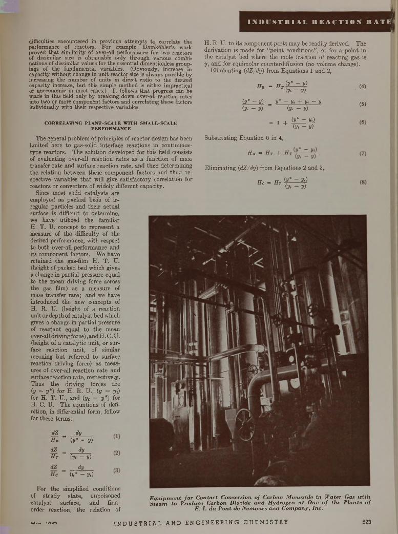
I M M S T I t l A I . R E A C T I O N R A T E 'li
difficulties encountered in previous attempts to correlate the performance of reactors. For example, Damkohler’s work proved that similarity of over-all performance for two reactors of dissimilar size is obtainable only through various combinations of dissimilar values for the essential dimensionless groupings of the fundamental variables. (Obviously, increase in capacity without change in unit reactor size is always possible by increasing the number of units in direct ratio to the desired capacity increase, but this simple method is either impractical or uneconomic in most cases.) I t follows that progress can be made in this field only by breaking down over-all reaction rates into two or more component factors and correlating these factors individually with their respective variables.
H. R. U. to its component parts may be readily derived. The derivation is made for “point conditions” , or for a point in the catalyst bed where the mole fraction of reacting gas is y, and for equimolar counterdiffusion (no volume change).
Eliminating (dZ/dy) from Equations 1 and 2,
H r = H t (y* - y) (y< - y)
(y* - y) _ y* - y» + y» - y (y.- - y) (y.- - y)
(4)
(5)
dZ _ dy H r ~ (y* - y) dZ _ dy H t ~ (y. - y)
(y* - Vi)
For the simplified conditions of steady state, unpoisoned catalyst surface, and first- order reaction, the relation of
E q u ip m e n t fo r C o n ta c t C onversion o f C arbon M onoxide in W ater Gas w ith S te a m to P roduce C arbon D ioxide a n d H ydrogen a t O ne o f th e P la n ts o f
E. I. d u P o n t de N em o u rs a n d C o m p a n y , Inc .
1 _i_ (y* - yd + (y» - y)
Substituting Equation 6 in 4,
X - -
Eliminating (dZ/dy) from Equations 2 and 3,
Hc = Ht ~ Vi}(:y. - y)
C O R R E L A T I N G P L A N T - S C A L E W IT H S M A L L - S C A L E P E R F O R M A N C E
The general problem of principles of reactor design has been limited here to gas-solid interface reactions in continuous- type reactors. The solution developed for this field consists of evaluating over-all reaction rates as a function of mass transfer rate and surface reaction rate, and then determining the relation between these component factors and their respective variables th a t will give satisfactory correlation for reactors or converters of widely different capacity.
Since most solid catalysts are employed as packed beds of irregular particles and their actual surface is difficult to determine, we have utilized the familiar H. T. U. concept to represent a measure of the difficulty of the desired performance, with respect to both over-all performance and its component factors. We have retained the gas-film H. T. U.(height of packed bed which gives a change in partial pressure equal to the mean driving force across the gas film) as a measure of mass transfer rate; and we have introduced the new concepts of H. R. U. (height of a reaction unit or depth of catalyst bed which gives a change in partial pressure of reactant equal to the mean over-all driving force), and H. C. U.(height of a catalytic unit, or surface reaction unit, of similar meaning but referred to surface reaction driving force) as measures of over-all reaction rate and surface reaction rate, respectively.Thus the driving forces are (y ~ y*) for H. R. U., (y - y<) for H. T. U., and (y< - y*) for H. C. U. The equations of definition, in differential form, follow for these terms:
\J tCiA'i I N D U S T R I A L A N D E N G I N E E R I N G C H E M I S T R Y 523
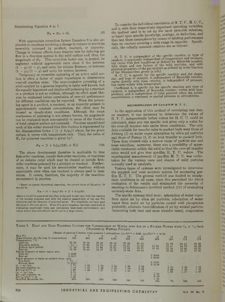
Substituting Equation 8 in 7,
H r = H t + H e (9)
W ith appropriate correction factors Equation 9 is also applicable to reactions involving a change in volume or reactions reversibly poisoned by product, reactant, or impurity. Change in volume affects mass transfer rate by inducing gas flow in a direction normal to the solid surface and, thus, the magnitude of H T. This correction factor can, in general, be neglected without appreciable error since it lies between (1 _ y)/ ( i _ y)f and unity for volume decrease, or between (1 — y )//( l ~ V) and unity for volume increase.
Temporary or reversible poisoning of an active solid surface is often a factor of major importance in determining over-all reaction rates. The noncumulative poisoning of a solid catalyst by a gaseous impurity is fairly well known, but the equally important and similar self-poisoning by a reactant or a product is not so evident, although its effect must likewise be evaluated before correlation of over-all performance for different conditions can be expected. When the poisoning agent is a product, a reactant, or an impurity present in approximately constant concentration, the effect may be treated as steady-state conditions. Although the exact mechanism of poisoning is not always known, its magnitude can be evaluated most conveniently in terms of the fraction of total catalyst surface not poisoned. Previous unpublished work of the writer showed that this fraction is represented by the dimensionless factor 1/[1 + k\{pp) J where, for the given surface, k\ varies with temperature only. Thus, the value of H r for poisoned reactions is given by1:
H r = [1 + h(pP)](H T + He) (10)
The above development therefore is applicable to true first-order reactions, pseudo first-order reactions, or reactions of no definite order which may be classed as pseudo first- order reactions poisoned by a product or reactant. Furthermore, it may be used for second-order reactions without appreciable error when one reactant is always used in large excess. I t covers, therefore, the majority of the reactions encountered in practice.
1 B ased on purely th eo re tica l reasoning , th e co rrec t form of E q u a tio n 10 should be
H r = ( 1 + k i p P) T Ht + ( 1 + hpP)Hcw here z w ould be som ew hat less th a n u n ity an d w ould v ary w ith th e frac tio n of th e surface poisoned and w ith th e re la tiv e m agnitudes of th e gas film th ickness and th e d iam eter of poisoned areas. F o r sim plicity , we h ave used th e form in th e te x t above. Since th is sam e eq u a tio n has been used b o th in e v a lu a tin g sm all-scale te s ts and ca lcu la ting large-scale perfo rm ance, any m inor errors th u s in troduced cancel o u t to a large ex ten t.
To consider the individual correlation of H. T. U., H . C .U ., and jfe, with their respectively im portant operating variables, the method used is to set up the most probable relations as based upon specific knowledge, analogy or deduction, and then test these assumptions by means of existing performance data on reactors covering a wide range in capacity. Specifically, the initially assumed relations are as follows:
H T U is independent of the specific reaction or type of cataiyst is practically independent of tem perature and pressure, but varies w i t h f l o w conditions as defined by Reynolds number trith shape and size factors of the solid particles, and with physical properties of the gas mixture as defined by some function of the dimensionless group (jt/pD„).
H C. U. is specific for the specific reaction and the shape, size, and type of catalyst, is independent of Reynolds number, varies directly with mass velocity, is independent of pressure, but varies widely with tem perature.
Coefficient k¡ is specific for the specific reaction and type of catalyst, is independent of Reynolds number, vanes with tem perature, and is independent of total pressure when fbe poison concentration is expressed as partial pressure in atmospheres.
D E T E R M IN A T IO N O F G A S -F IL M H . T . U .
In the application of this method of correlating test data on reactors, it was necessary to determine the values of H. T. U. independently before values for H. C. U. could be calculated, since any one specific test gives only a value for the over-all reaction rate under those conditions. The only data available for transfer rates to packed beds were those of Ahlberg (/) on water vapor absorption by silica gel particles and those of Furnas (8, 9) on heat transfer to packed beds. These data covered only a narrow range of particle size and mass velocities; moreover, there was a possibility of appreciable resistances within the solid so th a t the over-all transfer rates would not give true gas-film H. T. U. values. The experimental measurement of gas-film H. T. U. was undertaken for the various sizes and shapes of solid particles normally used as catalysts.
Various types of systems were investigated to determine the simplest and most accurate system for measuring gas- film H. T. U. The general method was limited to steady- state conditions in all cases, since this perm itted the direct evaluation of the results and eliminated the necessity of resorting to Schumann’s involved method (11) of evaluating unsteady-state data.
The specific systems tried were: adsorption of water vapor from moist air by silica gel particles, adsorption of water vapor from moist air by particles coated with phosphorus pentoxide, adiabatic humidification of air by w etted particles (measuring both heat and mass transfer rates), evaporation
7 8 9 10895 895 1180 335
26 .9 0 2 6 .9 0 2 6 .9 0 2 7 .0 013.88 14 .70 14 .05 13 .2713.68 13.80 13 .65 13 .2216.45 16.47 16.42 15 .44
0.83, 0 i/pD „)»/» = 0.72)
T a b l e I . H e a t a n d M a s s T r a n s f e r F a c t o r s f o r V a p o r iz a t i o n o f W a t e r i n t o A i r i n a P a c k e d T o w e r w i t h 3/$ X V s I n c hC y l i n d r i c a l W e t t e d P e l l e t s
(H eigh t of pack ing 2 inches, to ta l p ressu re 1 a tm osphere , ( c / i / i ) 17»R u n N o. 6M ass velocity , lb . / (h r .) ( s q . f t . cross section) 526 T e m p e ra tu re , 0 C .
In le t a ir 23 .23T o p layer p e lle ts I A v. 1B o tto m la y er pe lle ts \ 11 .13 ;E x it a ir 13 .25
P a r tia l p ressu re of w a te r v ap o r, a tm .In le t a ir 0 .0047E x it a ir 0 .0117
V apor p ressu re of w a te r a t su rface te m p ., a tm .T o p layer / Av. 1B o tto m la y e r (0 .0131J
(ii - 0 1 / Aim 1 .75H T h e a t tra n sfe r , in . 1 .14H T / ( . c p / k ) , / t , in . 1 .36(pi — p»)/A pm 1 .75H t m ass tra n sfe r , in . 1 .14ffr /(M /p D r)» '» , in . 1 .5 9M odified R eyno ld s N o . 374
1.62 1 .54 1 .541 .23 1 .30 1 .301 .48 1.57 1.57
¿30 '630 840
1 .831 .091.31
240
11 12 13 14 15205 205 102 715 715
2 7 .0 5 2 4 .7 8 2 6 .6 1 2 6 .8 514 .25 13 .99 12 .31 1 4 .7 0 1 4 .3 013 .35 1 3 .4 0 12 .1 8 1 3 .8 0 1 3 .3 015 .44 13 .5 2 16 .37 16 .07
0 .0 0 4 80 .0 1 3 6
0 .0 1 5 50 .0 1 5 0
i . 08 2" 25 i ! 54 Í ' 520 .9 6 0 .8 9 1 .3 0 1.321 .15 1 .0 7 1 .5 7 1 .6 0
2 .0 40 .9 8
Í 451 .3 5
145 ’ 72 505 505
524 I N D U S T R I A L A N D E N G I N E E R I N G C H E M I S T R Y v„i « «?
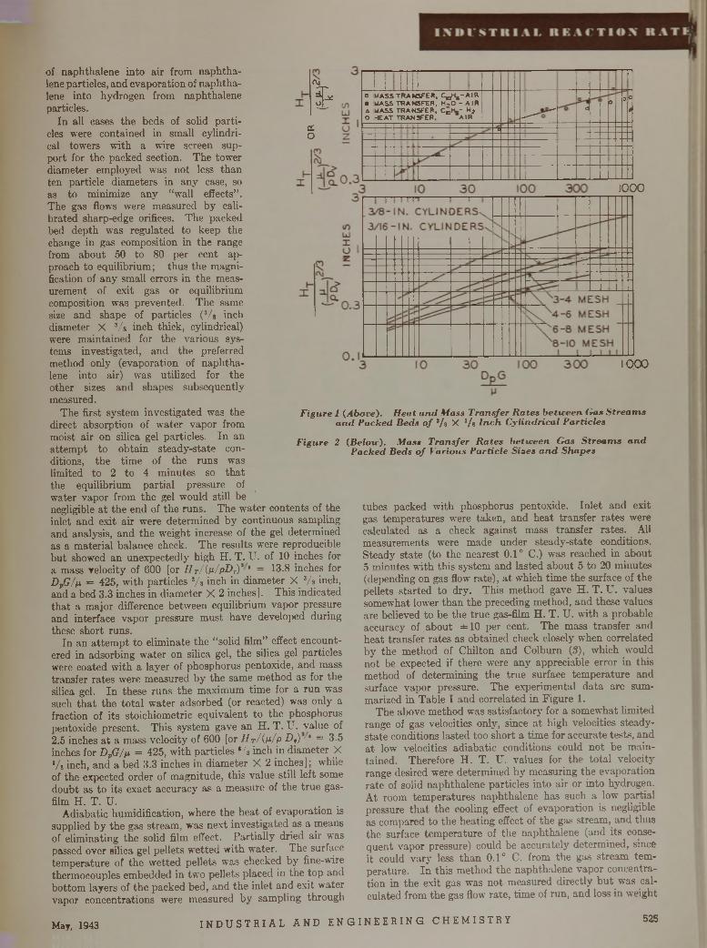
CVj
£
a.o
1 IIIf
0•A0
MASS MASS MASS *E AT
TRANSFER, CjqH ^-A IR TRANSFER, H ,0 - AIRt r a n s f e r , c 0 h . - h 2TRANSFER, AIR
—•4"*—
oo 0&
/*
— u
i1
’ 11000
1 0 0 0
F igure 1 (Above). H eat a n d M ass Transfer R a tes be ticeen Gas S trea m s a n d P acked Beds o f 3/ 8 X 3/s In c h C ylindrica l P articles
F igure 2 (Beloic). M ass T ransfer R a tes be ticeen Gas S tre a m s a n d P acked Beds o f Various P article S izes a n d Shapes
of naphthalene into air from naphthalene particles, and evaporation of naphthalene into hydrogen from naphthalene particles.
In all cases the beds of solid particles were contained in small cylindrical towers with a wire screen support for the packed section. The tower diameter employed was not less than ten particle diameters in any case, so as to minimize any “ wall effects” .The gas flows were measured by calibrated sharp-edge orifices. The packed bed depth was regulated to keep the change in gas composition in the range from about 50 to 80 per cent approach to equilibrium ; thus the magnification of any small errors in the measurement of exit gas or equilibrium composition was prevented. The same size and shape of particles (3/s inch diameter X Vs inch thick, cylindrical) were m aintained for the various systems investigated, and the preferred method only (evaporation of naphthalene into air) was utilized for the other sizes and shapes subsequently measured.
The first system investigated was the direct absorption of water vapor from moist air on silica gel particles. In an attem pt to obtain steady-state conditions, the tim e of the runs was limited to 2 to 4 minutes so th a t the equilibrium partial pressure of water vapor from the gel would still be negligible a t the end of the runs. The water contents of the inlet and exit air were determined by continuous sampling and analysis, and the weight increase of the gel determined as a material balance check. The results were reproducible but showed an unexpectedly high H. T. U. of 10 inches for a mass velocity of 600 [or H T/( ji /p D rY ' = 13.8 inches for D vG/p = 425, with particles s/s inch in diameter X 3/s inch, and a bed 3.3 inches in diameter X 2 inches]. This indicated tha t a major difference between equilibrium vapor pressure and interface vapor pressure m ust have developed during these short runs.
In an attem pt to eliminate the “solid film” effect encountered in adsorbing water on silica gel, the silica gel particles were coated with a layer of phosphorus pentoxide, and mass transfer rates were measured by the same method as for the silica gel. In these runs the maximum tim e for a run was such th a t the to ta l water adsorbed (or reacted) was only a fraction of its stoichiometric equivalent to the phosphorus pentoxide present. This system gave an H. T . U. value of2.5 inches a t a mass velocity of 600 [or H t/(p / p D ,) -1 = 3.5 inches for D pG/p = 425, w ith particles */a inch in diameter X */s inch, and a bed 3.3 inches in diameter X 2 inches]; while of the expected order of magnitude, this value still left some doubt as to its exact accuracy as a measure of the true gas- film H. T. U.
Adiabatic humidification, where the heat of evaporation is supplied by the gas stream, was next investigated as a means of eliminating the solid film effect. Partially dried air was passed over silica gel pellets wetted with water. The surface tem perature of the w etted pellets was checked by fine-wire thermocouples embedded in two pellets placed in the top and bottom layers of the packed bed, and the inlet and exit water vapor concentrations were measured by sampling through
tubes packed with phosphorus pentoxide. In let and exit gas temperatures were taken, and heat transfer rates were calculated as a check against mass transfer rates. All measurements were made under steady-state conditions. Steady state (to the nearest 0.1° C.) was reached in about 5 minutes with this system and lasted about 5 to 20 minutes (depending on gas flow rate), a t which time the surface of the pellets started to dry. This method gave H. T . U. values somewhat lower than the preceding method, and these values are believed to be the true gas-film H. T. U. with a probable accuracy of , about ± 10 per cent. The mass transfer and heat transfer rates as obtained check closely when correlated by the method of Chilton and Colburn (S), which would not be expected if there were any appreciable error in this method of determining the true surface tem perature and surface vapor pressure. The experimental data are summarized in Table I and correlated in Figure 1.
The above method was satisfactory for a somewhat limited range of gas velocities only, since a t high velocities steady- state conditions lasted too short a time for accurate tests, and a t low velocities adiabatic conditions could not be maintained. Therefore H. T. U. values for the total velocity range desired were determined by measuring the evaporation rate of solid naphthalene particles into air or into hydrogen. At room tem peratures naphthalene has such a low partial pressure th a t the cooling effect of evaporation is negligible as compared to the heating effect of the gas stream, and thus the surface tem perature of the naphthalene (and its consequent vapor pressure) could be accurately determined, since it could vary less than 0.1° C. from the gas stream temperature. In this method the naphthalene vapor concentration in the exit gas was not measured directly bu t was calculated from the gas flow rate, tim e of run, and loss in weight
May, 1943 I N D U S T R I A L A N D E N G I N E E R I N G C H E M I S T R Y 525
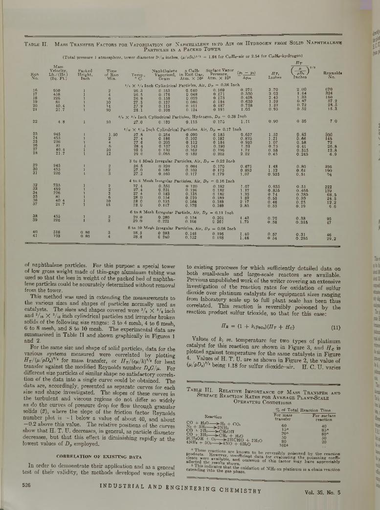
T able II . M a s s T r a n s f e r F a c t o r s f o r V a p o r i z a t i o n o f N a p h t h a l e n e i n t o A i r o r H y d r o g e n f r o m S o l i d N a p h t h a l e n e
P a r t i c l e s i n a P a c k e d T o w e r
1.84 for C ioH s-air or 2.54 fo r C io H j-hyd rogen )(T o ta l pressu re 1 a tm osphere , tow er d iam ete r 35/i« inches, ( n / p D v ) 2
H tM ass
V elocity, P ackedRun L b ./(H r .) H eigh t,No. (Sq. F t.) Inch
16 950 117 458 118 226 119 81 120 4 0 .4 121 21 .7 1
22 4 .8 1
23 945 124 455 125 226 126 81 127 40 .4 128 2 1 .7 1
29 945 130 455 131 226 1
32 735 133 459 134 226 135 81 136 4 0 .4 137 21 .7 1
38 455 139 226 1
40 318 0 .8 041 193 0 .8 0
T im e of R un
M in.
N ap h th a len e p CioHg T em p ., V aporized , in E x it G as,
° C. G ram A tm . X 10*
S urface V apor P ressure ,
A tm . X 10s
101420
10
1 .50246
1012
2236
1015
(pi — p i) A p m
a/s X 3/« Inch C ylindrica l P artic le s, A ir, D p = 0.38 In ch2 6 .3 0 .1 5 3 0 .0 4 0 0 .1 6 9 0 .2 7 02 6 .5 0 .1 7 6 0 .0 4 8 0 .171 0 .3 5 02 6 .9 0 .1 5 9 0 .0 5 9 0 .1 7 5 0 .4 0 82 7 .5 0 .1 3 7 0 .0 8 6 0 .1 8 4 0 .6 3 02 7 .9 0 .1 1 5 0 .101 0 .1 8 7 0 .7 5 82 8 .1 0 .1 0 8 0 .1 2 4 0 .191 1 .0 5
8 X */a In ch C ylindrica l P artic le s, H ydrogen , D p = 0.38 In ch2 7 .0 0 .1 5 9 0 .1 1 5 0 .1 7 5 1.11
*/i8 X */i« In ch C ylindrica l P artic le s, A ir, D p = 0.17 Inch 2 7 .8 0 .2 5 4 0 .0 9 0 0 .1 8 52 7 .4 0 .1 8 6 0 .1 0 2 0 .1822 7 .6 0 .2 0 5 0 .1 1 2 0 .1842 8 .4 0 .1 3 7 0 .1 4 3 0 .1932 8 .6 0 .1 3 0 0 .1 6 2 0 .1 9 62 9 .0 0 .0 9 5 0 .1 8 2 0 .203
3 to 4 M esh Irreg u la r P artic le s, A ir, D p = 0 .2 2 Inch2 6 .5 0 .3 2 0 0 .0 8 4 0 .1 7 02 7 .0 0 .1 8 9 0 .1 0 3 0 .1 7 52 7 .2 0 .1 6 0 0 .1 1 7 0 .1 7 9
4 to 6 M esh Irreg u la r P artic le s, A ir, D p = 0.16 Inch2 7 .42 7 .42 7 .4 2 8 .0 2 8 .0 2 8 .0
0 .3510.2310 .1830 .1540 .1 3 50 .117
0.1200 .1260 .1350 .1590 .1 6 80 .1 7 8
0 .1 8 20 .1820 .1820 .1 8 90 .1890 .1 8 9
= 0.11 Inch 0.201 0.201
6 to 8 M esh Irreg u la r P artic le , A ir, D p2 9 .0 0 .2 8 0 0 .1542 9 .0 0 .221 0 .166
8 to 10 M esh Irreg u la r P artic le s, A ir, D p = 0.08 Inch 2 8 .5 0 .2 8 3 0 .1 4 9 0 .1 9 62 8 .8 0 .2 4 0 0 .1 5 2 0 .1 9 8
H t , V p D v ) R eyno ldsInches In ch es N o.
3 .7 0 2 .0 0 6703 .0 3 1 .6 4 3242 .4 5 1 .3 3 1601 .5 9 0 .8 7 5 7 .21 .3 2 0 .7 2 2 8 .50 .9 5 0 .5 2 1 5 .3
0 .9 0 0 .3 6 7 .0
0 .6 5 7 1 .5 2 p . 83 3ÖÖ0 .8 2 5 1 .21 0 .8 6 1450 .9 3 5 1 .0 7 0 .5 8 721 .33 0 .7 5 0 .4 1 2 6 .81 .72 0 .5 8 0 .3 1 5 1 2 .82 .2 2 0 .4 5 0 .2 4 5 6 .9
0 .6 7 5 1 .4 8 0 .8 0 3950 .8 9 3 1 .1 2 0 .6 1 1901.07 0 .9 3 5 0 .5 1 94
1 .07 0 .9 3 5 0 .5 1 2221.17 0 .8 5 5 0 .4 6 5 1391.35 0 .7 4 0 .3 8 5 6 8 .51 .82 0 .5 5 0 .3 0 2 4 .52 .1 7 0 .4 6 0 .2 5 12 .22 .8 5 0 .3 5 0 .1 9 6 .6
1 .43 0 .7 0 0 .3 8 951 .73 0 .5 8 0 .3 1 5 47
1 .4 0 0 .5 7 0 .3 1 461 .4 8 0 .5 4 0 .2 9 5 2 9 .2
of naphthalene particles. For this purpose a special tower of low gross weight made of thin-gage aluminum tubing was used so tha t the loss in weight of the packed bed of naphthalene particles could be accurately determined without removal from the tower.
This method was used in extending the measurements to the various sizes and shapes of particles normally used as catalysts. The sizes and shapes covered were 3/ 8 X 3/ 8 inch and 3/16 X 3/16 inch cylindrical particles and irregular broken solids of the following size ranges: 3 to 4 mesh, 4 to 6 mesh, 6 to 8 mesh, and 8 to 10 mesh. The experimental data are summarized in Table II and shown graphically in Figures 1 and 2.
For the same size and shape of solid particles, data for the various systems measured were correlated by plotting H T/(p /pD ,y/l for mass transfer, or H T/(cp /k) '^ for heat transfer against the modified Reynolds number DpG/p. For different size particles of similar shape no satisfactory correlation of the data into a single curve could be obtained. The data are, accordingly, presented as separate curves for each size and shape investigated. The slopes of these curves in the turbulent and viscous regions do not differ so widely as do the curves of pressure drop for flow through granular solids (2), where the slope of the friction factor-Reynolds number plot is - 1 below a value of about 40, and about - 0 .2 above this value. The relative positions of the curves show tha t H. T. U. decreases, in general, as particle diameter decreases, bu t tha t this effect is diminishing rapidly a t the lowest values of Dp employed.
C O R R E L A T IO N O F E X IS T IN G DATA
In order to demonstrate their application and as a general test of their validity, the methods developed were applied
to existing processes for which sufficiently detailed data on both small-scale and large-scale reactors are available. Previous unpublished work of the writer covering an extensive investigation of the reaction rates for oxidation of sulfur dioxide over platinum catalysts for equipment sizes ranging from laboratory scale up to full plant scale has been thus correlated. This reaction is reversibly poisoned by the reaction product sulfur trioxide, so th a t for this case:
H r = (1 + fc,psoa) ( I IT + He) (11)
Values of hi vs. temperature for two types of platinum catalyst for this reaction are shown in Figure 3, and H c is plotted against temperature for the same catalysts in Figure ( / n ! iJ/6S, of T - U. are as shown in Figure 2, the value of W pD . ) b e i n g 1.18 for sulfur dioxide-air. H. C. U. varies
T A B «F; , ïI .I Î ' S e l a t i v e I m p o r t a n c e o f M a s s T r a n s f e r a n d o u r f a c e R e a c t i o n R a t e s f o r A v e r a g e P l a n t - S c a l e
O p e r a t i n g C o n d i t i o n s
ReactionCO + H2O -f- CO?
CO + 2H; >-CHjOH.% + > h£ = î c h : T h,o S í ? ™ °HÍ. 2H'°
% of T o ta l R ea c tio n T im e F o r m ass F o r su rfacetra n s fe r reac tio n
6015«20«5080
160b
4085«80«5020
products. However insufficient teversib ly poisoned by the reactioncients were available «nH ° • f°r evaluating the poisoning coeffi-aSected the results shown omi8slon of th ls factor m ay have appreciably
extend ing in tc f th V g a s p lfa se N a tio n of N H , on p la tin u m is a ch a in reac tio n
526I N D U S T R I A L A N D E N G I N E E R I N G C H E M I S T R Y
Vol. 35. No. 5
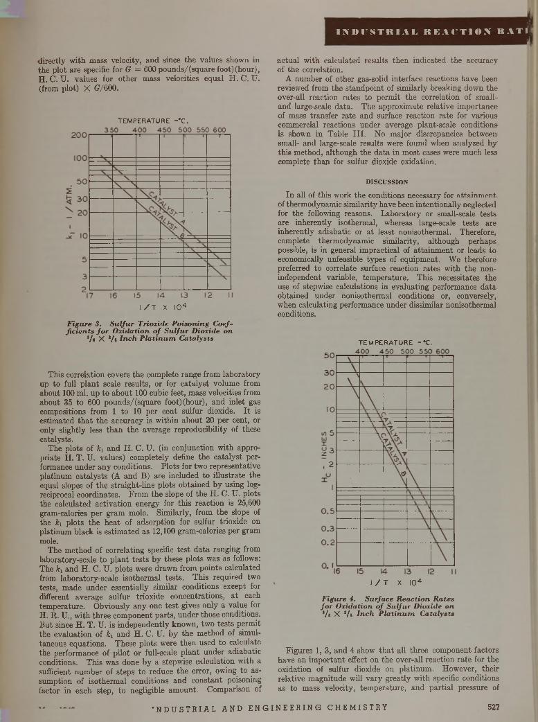
I N D U S T R I A L R E A C T I O N R A T ÏJ
directly w ith mass velocity, and since the values shown in the plot are specific for G = 600 pounds/(square foot)(hour), H . C. U. values for other mass velocities equal H . C. U. (from plot) X (?/600.
actual with calculated results then indicated the accuracy of the correlation.
A number of other gas-solid interface reactions have been reviewed from the standpoint of similarly breaking down the over-all reaction rates to perm it the correlation of small- and large-scale data. The approximate relative importance of mass transfer rate and surface reaction rate for various commercial reactions under average plant-scale conditions is shown in Table I II . No major discrepancies between small- and large-scale results were found when analyzed b y this method, although the data in most cases were much less complete than for sulfur dioxide oxidation.
D IS C U S S IO N
In all of this work the conditions necessary for attainment, of thermodynamic similarity have been intentionally neglected for the following reasons. Laboratory or small-scale tests are inherently isothermal, whereas large-scale tests are inherently adiabatic or a t least nonisothermal. Therefore, complete thermodynamic similarity, although perhaps possible, is in general impractical of attainm ent or leads to economically unfeasible types of equipment. We therefore preferred to correlate surface reaction rates with the non- independent variable, temperature. This necessitates the use of stepwise calculations in evaluating performance data obtained under nonisothermal conditions or, conversely, when calculating performance under dissimilar nonisothermal conditions.
T E M P E R A T U R E - * C .
T E M P E R A T U R E - *C .
I / T X I04
F igure 4. S u rfa ce R ea c tio n R a tes fo r O x ida tion o f S u lfu r D ioxide on Vs X */a In c h P la tinum . C a ta lysts
I / T X I 0 4
F igure 3. S u l fu r T rioxide P o ison ing C oeffic ie n ts f o r O xid a tio n o f S u lfu r D ioxide on
Vs X 3/s In c h P la t in u m C ata lysts
This correlation covers the complete range from laboratory up to full p lant scale results, or for catalyst volume from about 100 ml. up to about 100 cubic feet, mass velocities from about 35 to 600 pounds/(square foot)(hour), and inlet gas compositions from 1 to 10 per cent sulfur dioxide. I t is estimated th a t the accuracy is within about 20 per cent, or only slightly less than the average reproducibility of these catalysts.
The plots of ki and H. C. U. (in conjunction with appropriate H . T. U. values) completely define the catalyst performance under any conditions. Plots for two representative platinum catalysts (A and B) are included to illustrate the equal slopes of the straight-line plots obtained by using log- reciprocal coordinates. From the slope of the H. C. U. plots the calculated activation energy for this reaction is 25,600 gram-calories per gram mole. Similarly, from the slope of the ki plots the heat of adsorption for sulfur trioxide on platinum black is estim ated as 12,100 gram-calories per gram mole.
The method of correlating specific test data ranging from laboratory-scale to p lant tests by these plots was as follows: The ki and H . C. U. plots were drawn from points calculated from laboratory-scale isothermal tests. This required two tests, made under essentially similar conditions except for different average sulfur trioxide concentrations, a t each temperature. Obviously any one test gives only a value for H. R. U., with three component parts, under those conditions. But since H . T. U. is independently known, two tests permit the evaluation of ki and H. C. U. by the method of simultaneous equations. These plots were then used to calculate the performance of pilot or full-scale p lant under adiabatic conditions. This was done by a stepwise calculation with a sufficient number of steps to reduce the error, owing to assumption of isothermal conditions and constant poisoning factor in each step, to negligible am ount. Comparison of
Figures 1, 3, and 4 show th a t all three component factors have an im portant effect on the over-all reaction rate for the oxidation of sulfur dioxide on platinum . However, their relative magnitude will vary greatly with specific conditions as to mass velocity, temperature, and partial pressure of
’ N D U S T R I A L A N D E N G I N E E R I N G C H E M I S T R Y 527
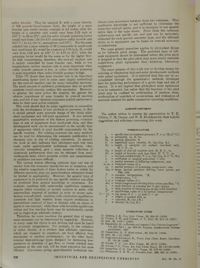
sulfur trioxide. Thus for catalyst B, with a mass velocity of 600 pounds/(hour)(square foot), the height of a mass transfer unit would remain constant a t 2.0 inches while the height of a catalytic unit would vary from 0.22 inch at 575° C. to 33 a t 375°, and the sulfur trioxide poisoning factor would vary from 1.04 (for 0.01 atmosphere sulfur trioxide and 575° C.) to 5.3 (for 0.1 atmosphere and 375°). For the same catalyst but a mass velocity of 50 (comparable to small-scale test conditions) H T would be constant at 0.95 inch, H c would vary from 0.02 inch a t 575° C. to 2.75 a t 375°, wffiile the poisoning factor would be the same as for the higher flow. At high temperatures, therefore, the over-all reaction rate is largely controlled by mass transfer rate, while at low temperatures surface reaction rate is most important when sulfur trioxide pressure is low, or sulfur trioxide poisoning is most important when sulfur trioxide pressure is high.
Table I I I shows tha t mass transfer rate is an important contributing factor (and in some cases largely controlling) for the over-all reaction rate for many industrial reactions. The small amount of published performance data on specific catalysts would scarcely confirm this conclusion. However, in general, the more active the catalyst, the greater the relative importance of mass transfer to over-all reaction rate, and few if any chemical companies publish performance data for their most active catalysts.
This work should find its major application in connection with the development of new products or processes, in that it should permit more accurate design of the initial pilot- plant equipment and full-scale equipment. I t also permits quantitative evaluation of the factors governing economic type or size of equipment from small-scale data, and thus development work can be concentrated on the specific type of equipment which is most feasible economically for the specific reaction. For existing processes the same methods can be used for determining the economic justification for changing type or size of existing converters. In general, the work to date indicates tha t laboratory-scale test data made under approximately isothermal conditions, when correctly interpreted, give a more accurate indication of plant-scale performance than can be obtained from semi- works-scale tests, where accurate control and measurement of conditions are more difficult.
The various factors affecting optimum type and size of reactor from the economic standpoint are so numerous, and the relative magnitude of these factors varies so widely for different reactions, tha t any generalizations attem pted would be limited in applicability. However, the general type of equipment to be preferred for any specific reaction can often be predicted from general knowledge or experience. For example, reactions with unfavorable equilibrium constants require either recycling or several reactors in series with intermediate removal of product in order to secure satisfactory over-all yield; reactions with satisfactory equilibrium constants but high reaction heats require continuous or interm ittent removal of heat or dilution with an excess of inerts or one reactant; while those with favorable equilibrium values and low reaction heats may be satisfactorily carried out in single-stage adiabatic systems.
Therefore, for some reactions the general type of equipment necessary can be determined by inspection. However, in many cases the choice is not obvious and must be based on economic comparisons. For example, in the oxidation of sulfur dioxide, it is evident tha t adiabatic converters, which are cheapest to construct, are least efficient from standpoint of catalyst performance; on the other hand, internal heat-exchange types designed for decreasing temperatures in direction of gas flow, or lowest catalyst temperatures a t the exit end, will be most expensive but most efficient. Converters giving approximately isothermal con
ditions come somewhere between these two extremes. Thus qualitative knowledge is not sufficient to determine the respective over-all merits, and it is necessary to use quantitative data of the type shown. From them the optimum performance and specific size and cost can be accurately estimated for each general converter type, and the ultim ate choice as to equipment can be based on over-all economic considerations.
The same general procedure applies to pilot-plant design as for full-scale plant design. The preferred type of full- scale equipment should be determined before the pilot plant is designed so tha t the pilot plant may more nearly resemble scaled-down plant equipment than scaled-up laboratory equipment.
The major purpose of this work was to develop means for reducing or eliminating trial-and-error development methods with actual equipment. I t is believed th a t this can be accomplished through the quantitative methods developed here for predicting performance of a given type and size of reactor. I t is not implied th a t pilot-plant scale equipment is to be outmoded, but rather th a t the function of the pilot plant may be confined to confirmation of reaction rates, confirmation of materials of construction, and evaluation of economic catalyst life under commercial operating conditions.
A C K N O W L E D G M E N T
The author wishes to express his appreciation to T. H. Chilton, C. M. Cooper, and W. H. McAdams for their helpful suggestions and criticisms concerning this work.
N O M E N C L A T U R E
c = specific heat at constant pressure, P. c. u./(lb.)(° C.) D, = diffusivity, sq. ft./hr.Dp = particle diameter, ft.G = superficial mass velocity, lb./(hr.)(sq. ft.)He = height of catalytic (or surface reaction) unit,
H. C. U., in.H r = height of over-all reaction unit, H. R. U., in.H t = height of transfer unit (gas film), H. T. U., in. k = thermal conductivity, P. c. u./(hr.)(sq. ft.)(° C./ft.) ki = coefficient of catalyst poisoning, l/a tm . p = partial pressure of diffusing component, atm.
P i, Vi = terminal values of p pp = partial pressure of poisoning component, atm.Apm = mean partial pressure driving force across gas
film, atm.T = absolute temperature, ° K. t = temperature, ° C.<i, U = terminal values of tAtm = mean temperature driving force across gas film, ° C. y = mole fraction of reacting gas in gas stream Vi = mole fraction of reacting gas a t gas-solid interface V* = equilibrium value of y a t surface temperature
(1 — V)/ = log mean of (1 - y) and (1 — y.)Z = height of packed bed, in.M = viscosity, lb./(hr.)(ft.)P = density, lb./(cu. ft.)
L I T E R A T U R E C I T E D
(1) Ahlberg, J . E., I n d . E n g . C h e m ., 31, 988-92 (1939).(2) Chilton, T. H., and Colburn, A. P., Ibid., 23, 913-19 (1931).(3) Ibid., 26, 1183-7 (1934).(4) Damköhler, G., in Eucken and Jakob’s “Der Chemie-Ingenieur’
to i. III, Part 1, pp. 453-68, Leipzig, Akademische Verlags gesellschaft, 1937.
(5) Damköhler, G., Z. Elektrochem., 42, 846-62 (1936).(6) Ibid., 43, 1-13 (1937).(7) Edgew orth-Johnstone, R ., Trans. Inst. Chem. Engrs. (London
17, 129-36 (1939).® Pumas, C. C., I n d . E n o . C h e m ., 22, 26-31 (1930).(9) Furnas, C. C., Trans. Am. Inst. Chem. Engrs., 24, 142-86 (1930
t ,a1upichler' P- G-. I n d . E n g . C h e m ., 30, 578-86 (1938).(11) bchumann, T. E. W., J. Franklin Inst., 208, 305-16 (1929).
528 I N D U S T R I A L A N D E N G I N E E R I N G C H E M I S T R Y Vnl AS Nn 5
I M M N T H I A I R K . H T I O X H A T E . ’,
SOLID CATALYSTSand
REACTION RATES G e n e r a l P r i n c i p l e s
B ased on th e th e o ry o f a c tiv a te d a d so rp tio n , gen era l ra te e q u a tio n s are d e ve lo p ed f o r c h e m ic a l rea c tio n s c a ta ly ze d b y so lid s . C o n sid era tio n is g iven to th e d ifferen ces in e q u a tio n fo r m s re su ltin g f r o m c o n tro l o f th e ra te by d iffe re n t ty p e s o f a c tiv a te d s te p s . Q u a n tita tiv e expression s are p ro p o se d fo r th e effec ts o f a d so rp tio n , c a ta ly s t a c tiv i ty , p a r tic le s ize , p o r o s ity , f lo w c o n d itio n s , p o iso n s , a n d d ilu e n ts as w e ll as te m p e ra tu re , p re ssu re , a n d c o n c e n tra tio n . E x p e r im e n ta l p ro c e d u re s f o r th e e v a lu a tio n o f th e c o n s ta n ts o f th e e q u a tio n s are d iscu ssed . A gen era l m e th o d is o u tlin e d f o r in te g ra tio n o f ra te e q u a tio n s in th e d es ig n o f c o m m e rc ia l rea c to rs.
O. A. H ougen an d K . M. W atsonU N IV E R S IT Y O F W IS C O N S IN , M A D IS O N , W IS .
I S A BASIS for the development of rate equations, it is \ postulated th a t when catalyzed by a solid, a liquid-
or gas-phase chemical reaction actually occurs on the surface of the catalyst and involves the reaction of molecules or atoms which are adsorbed by activation on the active centers of the surface. From this viewpoint the catalyst increases the rate of reaction through its ability to adsorb the reactants in such a form th a t the activation energy necessary for reaction is reduced far below its value in the uncatalyzed reaction. These principles are extensively discussed in the periodical literature and in theoretical treatises on catalytic rate phenomena (4, 7). The purpose of this paper is to develop from these principles equations which may be applied to the interpretation and extension of rate data and to point out experimental procedures best adapted to the complete evaluation of such equations from a minimum of data. Methods are also developed for the use of such equations in the design of industrial reactors. _
In order th a t a reactant in the main fluid phase may be converted catalytically to a product in the main fluid phase, it is necessary th a t the reactant be transferred from its position in the fluid to the catalytic interface, be activatedly adsorbed on the surface, and undergo reaction to form the adsorbed product. The product m ust then be desorbed and transferred from the interface to a position in the fluid phase. The rate a t which each of these steps occurs influences the distribution of concentrations in the system and plays a part in determining the over-all rate. Because of the differences in the mechanisms involved, it is convenient to classify these steps as follows when dealing with catalysts in the form of porous particles:
1. The mass transfer of reactants and products to and from the gross exterior surface of the catalyst particle and the main body of the fluid. , , , ,
2. The diffusional and flow transfer of reactants and products in and out of the pore structure of the catalyst particle when reaction takes place at interior interfaces.
lQ A 'I
3. The activated adsorption of reactants and activated desorption of products at the catalytic interface.
4. The surface reaction of adsorbed reactants to form acti- vation-adsorbed products.
I t is evident th a t the rates of these four types of operations are dependent on widely different factors in addition to the concentrations or concentration gradients involved. Type 1 is determined by the flow characteristics of the system, such as the mass velocity of the fluid stream, the size of the particles, and the diffusional characteristics of the fluid. Type 2 is determined by degree of porosity of the catalyst, the dimensions of the pores, the extent to which they are interconnected, the size of the particles, the diffusional characteristics of the system, and the rate a t which the reaction occurs a t the interface. Type 3 is determined by the character and extent of the catalytic surface, and by the specific activation energies required for the adsorption and desorption of each of the components of the fluid. Type 4 is determined by the nature and extent of the catalytic surface and by the activation energies required for the reaction on the surface.
The relative importance of these four operations in determining the over-all rate varies widely. Type 1 is im portant only when dealing with rapid reactions or where flow conditions are unfavorable. Since the rate of this operation is little affected by tem perature, its relative importance tends to vary for a particular system; it is frequently negligible a t low and highly im portant a t high temperatures. Type 2 is frequently negligible for catalysts of low activity in small particles with large interconnected pores, and ceases to be a factor for nonporous catalysts having no internal surface. However, in the general case of an active catalyst in moderately large particles having large internal surfaces with restricted capillarity it m ay be of major importance.
Operations of types 3 and 4 are chemical phenomena generally involving relatively large activation energies and are therefore highly sensitive to tem perature. The actual chemical transformations frequently proceed by several suc-
529I N D U S T R I A L A N D E N G I N E E R I N G C H E M I S T R Y
cessive stages, each with its own characteristic rate. This is particularly true where several molecules are involved. Since chemical rates vary over wide ranges, it is improbable tha t the rates of any two steps of types 3 and 4 will be of equal order in any given system. For this reason in many cases it is permissible to consider only the slowest single step of types 3 and 4 and assume tha t equilibrium is maintained in all other steps of these types. Under such conditions the slowest activated step may be termed the “rate-controlling step” , and the over-all rate is determined by consideration of it in combination with the physical steps of types 1 and 2.
A C T I V A T E D A D S O R P T IO N
Activated adsorption, as differentiated from ordinary van der Waals adsorption and capillary condensation, is a highly specific reaction between the adsórbate and the surface, and possesses the characteristics of a reversible chemical reaction. Since this concept was introduced by Taylor in 1930, much attention has been devoted to it in the literature, recently summarized by Taylor (7), Emmett (7), and Glasstone, Laid- ler, and Eyring (4).
I t may be assumed tha t a unit area of catalytic surface contains L ' active centers on which activated adsorption can take place and tha t all of these centers behave similarly. Frequently the active centers are not uniform, and as adsorption proceeds, the remaining centers are progressively less active; the results are an increase in energy of activation and a decrease in heat of adsorption. In the present discussion the energy of activated adsorption will be assumed the same for all spots, or an average value will be assumed to represent the entire surface.
The rate of adsorption of a component, A, from a fluid in contact with the surface is then proportional to its activity aAi in the fluid at the interface and to the concentration c\ of vacant active centers per unit area of surface. A surface concentration of c i adsorbed A molecules per unit area will result.
In the development of rate equations for application to industrial processes, it is convenient to express rates r in moles per unit time per unit mass of catalyst a t uniform conditions. The total volume occupied by the catalyst particles, including interstices between particles, is related to the mass of the catalyst by the bulk density, p6, as contrasted to the density of the individual pellets, pp, and the true density of the catalytic solid pc. Similarly, it is convenient to express surface concentrations in moles per unit mass of catalyst. Thus, if A is the catalytic area per unit mass,
L = AL'/No = maximum molal adsorption capacity pergram of catalyst with one molecule per active center
ca — Ac a /N 0 = moles of adsorbed A per unit mass of catalystci = Aci/No = molal adsorption sites unoccupied per unit
mass of catalyst
Expressing the rate of adsorption, r, in moles per unit time per unit mass of catalyst:
r = kA<iAiCi (1)
Since activated adsorption is a reversible phenomenon, component A is also desorbed from the surface a t a rate proportional to the concentration of adsorbed molecules on the surface. Thus the rate of desorption is expressed by:
T = k 'A CA (2)
When adsorption equilibrium is reached, the rates of adsorption and desorption become equal. Equating (1) and (2),
kA@AiCl = k AC A
o r ^ L - % - - K a (3)a A \C i » a
If component A is in admixture with other components B, R S and I which are also adsorbed on active centers of the samé type, rate and equilibrium equations similar to 1, 2, and 3 may be written for each component. Then,
ci = L - ( c a + cB + c r + °s + c¡.. .) (4)
At equilibrium conditions each of the adsórbate concentration terms in Equation 4 may be replaced by an expression similar to tha t obtained by solving Equation 3 for cA:
c i = L - c i { a A i K A + c i b íK b + (i r í K r + a s i K s + a n K n . . . ) (5 )
L /mCl = (1 + a a,A a + (Ib í K b + o.ríKr + asiKs + a n K i . ..)
An expression for the equilibrium surface concentration of A in terms of interfacial fluid activities is obtained by combining Equations 3 and 6:
Q AiN aL (7\°Á ~ (1 + ciaíKa + cibíKb + ciríKr + a s i K s + a¡%Ki...)
Similar equations may be written for the equilibrium surface concentrations of the other components of the mixture.
S U R F A C E R E A C T I O N S
Surface reactions may be assumed to take place either between an absorbed reactant molecule and a molecule in the fluid phase or between adsorbed molecules on adjacently situated active centers. W ith the latter mechanism a reaction proceeds a t rates proportional to the concentrations of adjacently adsorbed reactants. Thus, if adsorbed molecule A reacts with adsorbed molecule B, the rate of the reaction is proportional to the number of pairs of adjacently adsorbed A and B molecules per unit area of surface. Similarly, if in a monomolecular reaction, adsorbed molecule A is reacting with a vacant active center to form a complex which subsequently breaks down to form two adsorbed product molecules, the rate of the reaction is proportional to the number per unit area of A molecules adsorbed adjacent to vacant active centers.
I t is assumed tha t the active centers of the surface are distributed in a regular geometrical pattern determined by the lattice structure such th a t each individual center is surrounded by s other centers equidistant from it. Thus, if th e pattern is rectangular with the active centers forming the corners of squares, s = 4. If the pattern is such th a t the centers form the corners of equilateral triangles, s = 6.
An average adsorbed molecule of A has adjacent to it sdt vacant centers, where 0j is the fraction of the to ta l centers which is vacant. Similarly, sdB molecules of B are adjacent to each adsorbed A molecule, where dB is the fraction of the total centers which is occupied by adsorbed B molecules. Then the surface concentration of A molecules and vacan t active centers adjacent to each other becomes 1/^c 'A0i, and the concentration of A molecules and B molecules adsorbed in adjacent positions becomes l / 2sc'AdB. The factor »/* results from the fact that, in the summation represented bythe product of the concentration and fractional adsorptionterms, each pair of adjacent molecules and centers is counted twice.
Since 0, equals c'JL' and dB equals c 'JL ',
°'Al = 217 Ca°1' ^
, s°ab = 22 / cacb (9)
530 I N D U S T R I A L A N D E N G I N E E R I N G C H E M I S T R Y Vol. 35, No. 5
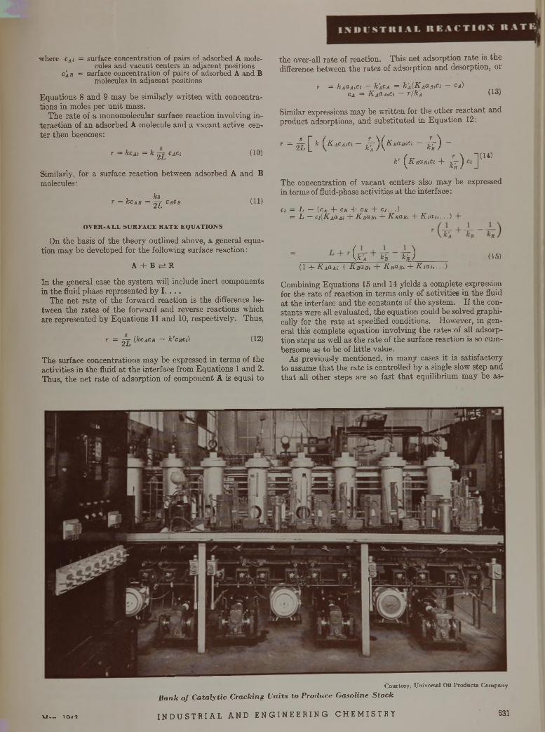
where cAi = surface concentration of pairs of adsorbed A molecules and vacant centers in adjacent positions
c 'a b = surface concentration of pairs of adsorbed A and B molecules in adjacent positions
Equations 8 and 9 m ay be similarly w ritten with concentrations in moles per unit mass.
The rate of a monomolecular surface reaction involving interaction of an adsorbed A molecule and a vacant active center then becomes:
r - kcAi = k 2 L °A°l (10)
Similarly, for a surface reaction between adsorbed A and B molecules:
ksr = kcAB = 2 2 CaCb
O V E R -A L L S U R F A C E R A T E E Q U A T IO N S
(11)
On the basis of the theory outlined above, a general equation m ay be developed for the following surface reaction:
A + B <=± R
In the general case the system will include inert components in the fluid phase represented by I . . . .
The net rate of the forward reaction is the difference between the rates of the forward and reverse reactions which are represented by Equations 11 and 10, respectively. Thus,
r = 2 2 (kcACB — k'ciici) (12)
The surface concentrations may be expressed in term s of the activities in the fluid a t the interface from Equations 1 and 2. Thus, the net rate of adsorption of component A is equal to
the over-all rate of reaction. This net adsorption rate is the difference between the rates of adsorption and desorption, or
r = kAaAiCi — k'ACA = k'A(K aO. a iC i — Ca)ca - K AcLAiCi — r /k A (lo;
Similar expressions may be written for the other reactant and product adsorptions, and substituted in Equation 12:
= k [ * ( K aCA'ci ~ i ) ( KBaBiCl ~ i k ) ~
k' ^KRdRiCi + 2 ^ J(14)
The concentration of vacant centers also may be expressed in terms of fluid-phase activities a t the interface:
ci = L — (ca + cb -b ck + c i . . .)= L — c , { K A a.Ai + K Bo,Bt + K rclrx + K i a n . . . )
( f c a kB k'R ) (15)(1 + K aclai + K bObx + K rUri + K ia n . . .)
Combining Equations 15 and 14 yields a complete expression for the rate of reaction in terms only of activities in the fluid at the interface and the constants of the system. If the constants were all evaluated, the equation could be solved graphically for the rate a t specified conditions. However, in general this complete equation involving the rates of all adsorption steps as well as the rate of the surface reaction is so cumbersome as to be of little value.
As previously mentioned, in many cases it is satisfactory to assume th a t the rate is controlled by a single slow step and th a t all other steps are so fast th a t equilibrium m ay be as-
C ourtesy , U niversa l Oil P ro d u c ts C om pany
B a n k o f C a ta ly tic C racking U nits to P roduce G asoline S to c k
I N D U S T R I A L A N D E N G I N E E R I N G C H E M I S T R YV /-— X C\AO t u n i I u T h I a I u n i ) p. n v t i i t I . r . u i n vu v ü ui i u , ^ i i , , 531
sumed. The slow step may be either the surface reaction or the adsorption of any one reactant or the desorption of any product. Simplified useful equations may be developed on this basis.
S I M P L IF IE D E Q U A T IO N S F O R M O N O M O L E C U L A R S U R F A C E R E A C T IO N S
Two mechanisms may be postulated for reversible surface reactions which are monomolecular in both directions, such as isomerization reactions. The reaction might proceed through an adsorbed molecule, acquiring sufficient energy to cause it to react and form a product molecule (all the time confined to a single active center). In the other mechanism an adsorbed molecule becomes sufficiently energized to form a complex with an adjacent active center, which then decomposes to form an adsorbed product molecule.
If the first mechanism is followed, the rate of reaction is proportional to the concentration of adsorbed reactant molecules:
r = kcA (16)
If the second mechanism is correct, the rate of reaction is proportional to the concentration of pairs of adsorbed molecules and adjacent vacant active centers. This rate is expressed by Equation 10.
Assuming tha t only a single activated step is rate controlling, simplified over-all equations may be derived according to either mechanism for the reaction:
Surface Reaction Controlling. If the surface reaction is rate controlling, it is assumed th a t all adsorption steps are in equilibrium, and the surface concentration term s in Equations 10 and 16 may be replaced by Equations 6 and 7:Mechanism 1
kL ( „ a«,AjAhK i . . . \ aAiKA K ' )1 + a-AiK/t. + hrxKr + an-
where A ' — surface equilibrium constant = k /k '
At equilibrium the net rate becomes zero and
a « K a
a a\ K r
Substituting Equation 18 in 17,
kLKA1 4~ oaxK a + a mR r + anK i
Mechanism 2ksLK A
2(1 + caxK a + am K R + anK
- ( — ¥ )
7777)* ( ° Ai ~ i t )
(17)
(18)
(19)
(20)
The essential difference between Equations 19 and 20 is the squared term in the denominator. According to these equations the initial rate, when aRi = 0, of a reaction following mechanism 1 is progressively increased by increased activity of the reactant in the fluid phase. If mechanism 2 is followed, the initial rate may increase with increased activity of A at low activities, reach a maximum corresponding to an optimum activity, and then diminish as the activity of A is further increased. Effects of this type have been experimentally observed in varying the pressure on monomolecular catalytic reactions.
Adsorption of R eactant Controlling. If the adsorption of the reac tan t is the rate-controlling step, it is assumed th a t the surface reaction and the other adsorption steps are in equilibrium. The ra te is expressed by Equation 1:
r = k A a A iC i — k 'A CA (21)
In the application of Equation 21 all surface concentrations may be expressed in terms of the equilibrium of Equation 3 with the exception of cA. This surface concentration must be arrived a t from the condition of equilibrium in the surfacereaction:
(22)C a
crK a _ aRiCiKA io Cr ~ K
Cl • ( c a + c b + c i . . . )■ c ; ( a s . A a / A + a RiK R +
a n K ,. . . )
Cl ' + ürîK a/ K + aRiKR + a n K i(23)
Combining Equations 22 and 23 with 21,
JcaL ( ~ (24)T = 1 + clrxK a/ K + aRiK R + a n K i . . . \ K )
Equation 24 is independent of the mechanism of the surface reaction.
Comparing the form of Equation 24 with 19 and 20, i t will be noted that, when adsorption of the reactant is controlling, the initial rate (where aRi = 0) is directly proportional to the activity of the reactant; if the surface reaction is controlling, the initial rate will increase less than in proportion to increased activity of the reactant.
Another characteristic of reactions controlled by adsorption is evident by consideration of the net rate of the reverse reaction of Equation 24. If the over-all equilibrium constant K is small, the net rate of the reverse reaction becomes independent of the activity of A. This behavior is characteristic of reactions in which the rate is controlled by the rate of desorption of the product.
B IM O L E C U L A R -M O N O M O L E C U L A R R E A C T IO N
The class of reaction which is bimolecular in one direction and monomolecular in the other may be represented by the equation :
A + B <=; R
If it is assumed tha t the reaction takes place between adjacently adsorbed molecules, it is necessary th a t the monomolecular reverse reaction follow the mechanism expressed by Equation 10. By the same procedures followed in the preceding section, the following rate equations are developed:
S u r f a c e R e a c t i o n C o n t r o l l i n g
ksL K AK B2(1 + üaîK a + ffls;As 4~ aRiKR -(- a n K i. . .)*
( ÛAiOBi jç I
A d s o r p t io n o f A C o n t r o l l i n g
_ ______ k AL
(25)
1 4- aBiKß + + aRiKR + a n K i + ■ • ■X
a si A
A d s o r p t io n o f R C o n t r o l l i n g
______ k RLK
dAi_ dRi \
aBiK ) (26)
1 4" a Ai A a asiKß UAiasiAsA 4- anKi 4- ... X
ojk\k )
(27)
In Equation 25 the initial rate of the reaction is increased by increased activity of component B ; in Equation 26 increasing the activity of B reduces the initial rate where the activity of R is zero. Thus, it is characteristic of a bimolecular reaction in which the rate is controlled by the adsorption of a re-
532 I N D U S T R I A L A N D E N G I N E E R I N G C H E M I S T R Y Vol. 35, No. 5
I N D U S T I t l A L R E A C T I O N 11 A T I
actant th a t the initial rate is reduced by increased activity of the other reactant.
In Equation 25 the over-all equilibrium constant of the reaction appears in both the num erator and denominator of the multiplying fraction. Under conditions favorable for the forward reaction where K is large, the rate becomes independent of the activity of the product and m ay approach kRL / K R, independent of the activities of both reactants and product.
If the reaction on the surface occurs between an adsorbed A molecule and an unabsorbed B molecule in the fluid phase, the rate is proportional to the product of the surface concentration of A and the interfacial fluid activity of B. Equations similar to 25, 26, and 27 resu 't, except th a t the adsorption equilibrium constant of B does not appear. If the surface reaction is controlling, the term s/2 does not appear, and the denominator group enters as the first power instead of the square.
R E A C T IO N S B IM O L E C U L A R IN B O T H D IR E C T IO N S
Reactions of this type are represented by the following equation:
A + B i i R + S
By extension of the methods dem onstrated above, the following rate equations m ay be derived, assuming the surface reaction to take place between adjacently adsorbed molecules:
S u r f a c e R e a c t i o n C o n t r o l l i n g
______________________ksL K aK b______________________2 (1 + (1a\K a + ctBiKs + ciRiKR + asiKs + anK i + .. ,)2
^a Aids,- - aR£ s,SJ (28)
A d s o r p t i o n o f A C o n t r o l l i n g
kAL
1 + as'as' A -)_ clbíK b + oríK r + asiKs + a¡K¡ + ...X
ag<K
A d s o r p t i o n o f R C o n t r o l l i n g
IzrL K
( d R id S * \ ,n r\\° Ai ~ÔbÏK ) (29)
1 + oaíKa + aBiKß + aA'aB' ^ R . -j- asiKs + a ^K i + . ..asi
x ( t 5 T - x ) <30)'
Comparisons between Equations 28, 29, and 30 are similar to those between 25, 26, and 27. A reaction whose rate is controlled by the adsorption of a reagent is characterized by an adverse effect on initial rate resulting from an increase in activity of the other reactant. A reaction whose rate is controlled by adsorption of a product is characterized by the initial rate being independent of reactant activities under conditions of large over-all equilibrium constants and negligible reverse reaction.
R E A C T IO N S IN V O L V IN G M O R E T H A N T W O M O L E C U L E S
The adsorption theory of catalysis does not preclude reactions involving the simultaneous interaction of several molecules, and no highly improbable mechanism such as the simultaneous collision of all molecules is involved. The rates of such reactions should be proportional to the concentration of groups of the required number of molecules adsorbed on adjacent active centers. R ate equations might be built up by extension of the procedures used in developing Equations 10 and 11 and the following relations.
I t would be expected th a t the rates of such reactions would be low because of the low concentrations of properly adsorbed groups except in the case of one reactant molecule or
atom A reacting with several other molecules or atoms B, all of the same species. In such a case high rates are obtained with a catalyst which strongly absorbs reactant B so th a t the m ajority of the surface is covered with adsorbed B molecules or atoms, and most of the A molecules or atoms which are adsorbed are surrounded by the requisite number of B units on adjacent centers.
A D S O R P T IO N W IT H D IS S O C IA T IO N
Although other mechanisms are possible, Glasstone, Laid- ler, and Eyring (/) suggest that, where a molecule is dissociated during adsorption, it is commonly first adsorbed on a dual adsorption site consisting of two adjacent active centers. This adsorbed molecule then decomposes, and the atoms jump to two vacant active centers. Thus, if A2 is a molecule which dissociates into two A atoms and U is a dual adsorption site,
A2 + U A2Z2 + 21
' A2I2- 2AI + h
I t is believed tha t the first step is rate controlling and th a t equilibrium is maintained in the second. Then if r is expressed in moles of A2,
r kA,aAtCii kA,CA,i2
Since the second step maintains equilibrium,
CAlChca,i, = K ’aC?
(31)
(32)
The concentration of dual adsorption sites is expressed by an equation similar to 8 and 9:
(33)
Combining 31, 32, and 33,
r = £jr (kA,aÁicí - k ’A, (34)
At equilibrium,/»2 . b . V
(35)¿A.I ^AiK a 7-7-ÖAiW
c a — Ca i = c i y / a A , K A , (36)
If A2 is adsorbed with dissociation from a mixture also containing components B, R, and I, an expression similar to Equation 7 may be developed for adsorption equilibrium conditions:
C a =V a A i K a , L
1 + y /a A,K A, + ubK b + ürK r + a¡K¡ + . . .(37)
Effect of Dissociation on Reaction Rate Equations.From E quation 37 it is evident th a t, where a molecule dissociates as i t is adsorbed, the square root of the product of its ac tiv ity tim es its adsorption equilibrium constan t appears in all adsorption equilibrium expressions in place of the first power of this product. Thus, Equations 19, 20, 25, and 28, in which all adsorption steps are a t equilibrium, m ay be modified to apply where a component is dissociated and one half molecule participates in the reaction merely by raising to the one half power the activity and adsorption equilibrium constant of the component which is dissociated wherever either appears in the equation.
The effects of dissociation where adsorption rate is controlling m ay be dem onstrated by consideration of the effect on Equation 29 of the dissociation of B first and then A. If
Mav. 1943 I N D U S T R I A L A N D E N G I N E E R I N G C H E M I S T R Y 533
A is not dissociated the rate is expressed by Equations 1 and 2:
(38)= k (d Ac, - g )
If B is dissociated and only V_B molecule enters into the reaction, an expression for cA is derived from the equilibrium of the surface reaction:
Ca =crcs c¡aR¡K RasiK, _ cidmdsjK /
Ci/ 2 bK VdBiKs K ' L
Cl = dRidsiKA -f \ dBiKß 4" dmKRdsiKsidiK i 4-
(39)
(40)
nct, I t is assumed
e q S » “ ' » the activities of the reactants The rate of reaction is, then, the rate of decomposition of the activated complex molecules into products which in tu rn is proportional to^he concentration of activated complex molecules accord- ng to a relation which was derived (4) from the principles of
statistical mechanics. Thus, for the surface phenomena under discussion in which rates are expressed m moles perunit mass,
V d B iK
Substituting Equations 39 and 40 in 38,
kAL
1 +dRjd siKA V d B iK
dßiKß T dmKR 4- dsiKsi + duK ¡ 4- ■ - •/ dmdsi \( a- - V ^ K ) W
Comparing Equations 41 and 29, if the component whose adsorption rate is controlling is not dissociated, the rate equations are modified for application where a component is dissociated and only one half molecule enters the reaction, by raising the activity and adsorption equilibrium constant of the dissociated component to one half power wherever they appear in the equation.
If component A of Equation 29 is dissociated and only one half molecule enters the reaction, it is necessary to express the rate of reaction by Equation 34. From the equilibrium of the surface reaction,
Cl/ 2 A —CRCS
Cb K '
cidmdsiV K adßiK
(42)
Cl =! + dRiaSi \ / K A + aB.K it + aR.KR + as.Ks + a i.K l + ...
OiBiK(43)
Substituting Equations 42 and 43 in 34,sLkA
2 [ 1 4- dRidsíV K adßiK
4- dBiKß + dRiK R 4- dsiKs 4- d¡iK¡ 4 - ...r _ / dmdsiL A \ dßiK
(44)
This equation is quite different in form from Equation 29, and it is also dependent on the mechanism assumed for the adsorption and dissociation of A. By assuming a different mechanism (4), an equation can be obtained in which the initial rate is proportional to the one half power of the activity •of A instead of the first power of Equation 44.
Effect of Tem perature. Each of the equilibrium constan ts appearing in the ra te equations is expressed as a function of tem perature by the following equation applicable to both chemical and adsorption equilibria:
- a g°
K = e
- A u ° A S 0 ÜT + Ä
(45)
Although in general AG° varies greatly with temperature, it is frequently satisfactory to assume AH ° and AS0 to be independent of temperature a t average values.
According to the Eyring theory of absolute reaction rates (4), any reaction may be considered as proceeding in two steps, first the formation of an activated complex and then the decomposition of this activated complex into the final prod-
k T t _ k Tk = ~h h 6
-A n t Ast(46)
where k = reaction velocity constant, moles per unit time per unit mass of catalyst
Am ASt = molal standard enthalpy and entropy changes ac- ’ companying formation of activated complex
Equation 46 applies both to activated adsorptions and surface reactions.
Since in all the rate equations the reaction velocity constant is multiplied by either L or sL/2, it is convenient to group the constants together:
- A f l j A s t
k L „ f - C'Te " * <47)
where constant C' is a function of the nature and extent of the catalytic surface.
To extend the catalytic rate equations to all temperatures, the expressions of Equations 45 and 47 are substituted for all equilibrium and velocity constants, respectively. The resultant equations become cumbersome and it is preferable to consider the temperature variation of the individual constants separately with the aid of simplifying assumptions which will be discussed later.
P O IS O N S
The term “poison” has been loosely used to denote any material which retards the rate of a catalytic reaction. Thus, the products of the reaction are sometimes referred to as poisons because increasing their concentration reduces the rate. However, it is believed more logical to eliminate all reactants and products from classification as poisons and reserve the term for other components which retard the reaction by reducing the number of active centers available for the reactants. Such poisons may be classified as either temporary or permanent.
From inspection of the rate equations it is evident th a t any inert component, I, which is adsorbed on the active centers promoting the reaction, serves as a poison; the extent of the retardation depends on the concentration of the inert and its adsorption equilibrium constant. If the adsorption of the inert is reversible with a moderate equilibrium constant, the poisoning effect quickly reaches a constant value which is temporary and is eliminated by removal of the component from the reactant fluid. Thus, the nitrogen in air might serve as a temporary poison in a catalytic oxidation. The effects of such inerts are included in the rate equations.
Another type of poisoning frequently encountered results from the permanent, substantially irreversible adsorption of components present in small quantities in the reactant fluid. The effect of this type of poisoning is progressively to reduce L', the number of active centers per unit area, as the catalyst continues in service. The frequently observed loss of activity of a catalyst in service may result from poisoning of this type, from structural changes affecting the area and L, or from physically coating the active surface with a solid or semisolid material either present in the reactants or formed by secondary reactions. In high-temperature organic reactions, catalysts
534 I N D U S T R I A L A N D E N G I N E E R I N G C H E M I S T R Y Vol. 35, No. 5
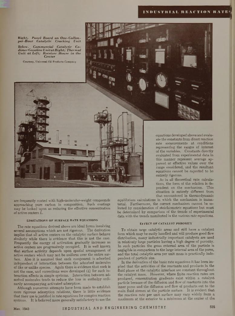
■ II M M S T K I A I , R E A C T I O N K A T E V
May. 1943 I N D U S T R I A L A N D E N G I N E E R I N G C H E M I S T R Y 535
R ig h t. P anel B oard o n O ne-G allon- p er-H o u r C a ta ly tic C racking U n it
Below. C o m m erc ia l C a ta ly tic Co- d im er G asoline U n ita tR ig h t; T h erm a l U nit a t L e ft; R eceiver H ouse in th e
C en terC ourtesy , U n iversa l Oil P ro d u c ts C om pany
are frequently coated with high-molecular-weight compounds approaching pure carbon in composition. Such coatings may be looked upon as reducing the effective concentration of active centers L.
L IM IT A T IO N S O F S U R F A C E R A T E E Q U A T IO N S
The rate equations derived above are ideal forms involving several assumptions which are not rigorous. The derivation implies th a t all active centers on the catalytic surface behave similarly while there is evidence th a t this is not the case. Frequently the energy of activation gradually increases as active centers are progressively occupied. I t is well known tha t surface activ ity depends upon spatial arrangement of active centers which m ay not be uniform over the entire surface. Also it is assumed th a t each component is adsorbed independent of interaction between the adsorbed molecules of like or unlike species. Again there is evidence th a t such is not the case, and corrections were developed (4) for such interaction effects in simple systems. Interaction between adsorbed molecules tends to reduce the loss in enthalpy ordinarily accompanying activated adsorption.
Although numerous attem pts have been made to establish more rigorous adsorption relations, there is little evidence tha t their use is justified in rate equations for complex reaction systems. I t is believed more generally satisfactory to use the
equations developed above and evaluate the constants from direct reaction rate measurements a t conditions representing the ranges of interest of the variables. Constants directly evaluated from experimental data in this manner represent average apparent or effective values over the range considered, and the resultant equations cannot be expected to be entirely rigorous.
As in all theoretical ra te calculations, the form of the relation is dependent on the mechanism. This situation is entirely different from th a t encountered in thermodynamic
equilibrium calculations in which the mechanism is unmaterial. Furthermore, the correct mechanism cannot be selected by consideration of stoichiometric equations bu t m ust be determined by comparison of the trends of experimental data with the trends manifested in the various ra te equations.
E F F E C T O F C A T A L Y S T P O R O S IT Y
To obtain iarge catalytic areas and still have a catalyst form which may be easily handled and will produce good flow distribution, m any industrially im portant catalysts are used in relatively large particles having a high degree of porosity. In such particles the gross external area of the particle is negligible in comparison to the large internal area of the pores, and the to ta l catalytic area per unit mass is practically independent of particle size.
In the derivation of the basic rate equations it has been implied th a t the activities of the reactants and products in the fluid phase a t the catalytic interface are constant throughout the catalyst mass. However, where finite reaction rates are produced, concentration gradients exist within a catalyst particle because of the diffusion and flow of reactants into the inner pores and the diffusion and flow of products out to the main fluid stream a t the particle surface. I t is evident th a t the reaction rate per un it surface m ay vary widely from a maximum at the exterior to a minimum at the center of the
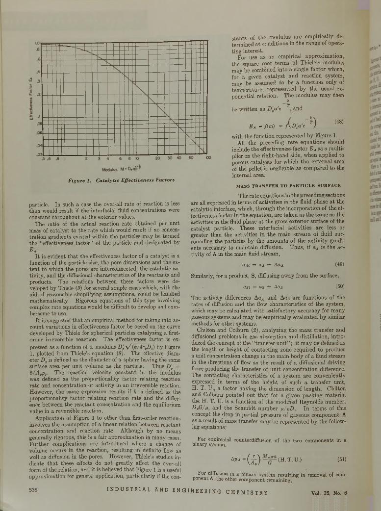
Figure 1. C atalytic E ffectiveness Factors
particle. In such a case the over-all rate of reaction is less than would result if the interfacial fluid concentrations were constant throughout a t the exterior values.
The ratio of the actual reaction rate obtained per unit mass of catalyst to the rate which would result if no concentration gradients existed within the particles may be termed the “effectiveness factor” of the particle and designated bye a.
I t is evident tha t the effectiveness factor of a catalyst is a function of the particle size, the pore dimensions and the exten t to which the pores are interconnected, the catalytic activity, and the diffusional characteristics of the reactants and products. The relations between these factors were developed by Thiele (9) for several simple cases which, with the aid of reasonable simplifying assumptions, could be handled mathematically. Rigorous equations of this type involving complex rate equations would be difficult to develop and cumbersome to use.
I t is suggested tha t an empirical method for taking into account variations in effectiveness factor be based on the curve developed by Thiele for spherical particles catalyzing a first- order irreversible reaction. The effectiveness factor is expressed as a function of a modulus D'vy / (k/4rpDt) by Figure 1, plotted from Thiele’s equation (9). The effective diameter D 'p is defined as the diameter of a sphere having the same surface area per unit volume as the particle. Thus D'p = 6/-4j,pj,. The reaction velocity constant in the modulus was defined as the proportionality factor relating reaction ra te and concentration or activity in an irreversible reaction. However, the same expression results if k is defined as the proportionality factor relating reaction rate and the difference between the reactant concentration and the equilibrium value in a reversible reaction.
Application of Figure 1 to other than first-order reactions involves the assumption of a linear relation between reactant concentration and reaction rate. Although by no means generally rigorous, this is a fair approximation in many cases. Further complications are introduced where a change of volume occurs in the reaction, resulting in definite flow as well as diffusion in the pores. However, Thiele’s studies indicate th a t these effects do not greatly affect the over-all form of the relation, and it is believed tha t Figure 1 is a useful approximation for general application, particularly if the con
stants of the modulus are empirically determined at conditions in the range of operating interest.
For use as an empirical approximation, the square root terms of Thiele’s modulus may be combined into a single factor which, for a given catalyst and reaction system, may be assumed to be a function only of temperature, represented by the usual exponential relation. The modulus may then
bT
be written as D'va'e , and
( ~T 1 (48)E a = f(m) = f \D 'Pa'e )
with the function represented by Figure 1.All the preceding rate equations should
include the effectiveness factor E A as a multiplier on the right-hand side, when applied to porous catalysts for which the external area of the pellet is negligible as compared to the internal area.
M A S S T R A N S F E R T O P A R T I C L E S U R F A C E
The rate equations in the preceding sections are all expressed in terms of activities in the fluid phase a t the catalytic interface, which, through the incorporation of the effectiveness factor in the equation, are taken as the same as the activities in the fluid phase a t the gross exterior surface of the catalyst particle. These interfacial activities are less or greater than the activities in the main stream of fluid surrounding the particles by the amounts of the activity gradients necessary to maintain diffusion. Thus, if aA is the activity of A in the main fluid stream,
aAi = oa — Aua (49)
Similarly, for a product, S, diffusing away from the surface,
asi = o s + Ads (50)
The activity differences AaA and Aas are functions of the rates of diffusion and the flow characteristics of the system, which may be calculated with satisfactory accuracy for many gaseous systems and may be empirically evaluated by similar methods for other systems.
Chilton and Colburn (2), analyzing the mass transfer and diffusional problems in gas absorption and distillation, introduced the concept of the “ transfer un it” ; it m ay be defined as the length or height of contacting zone required to produce a unit concentration change in the main body of a fluid stream in the directions of flow as the result of a diffusional driving force producing the transfer of unit concentration difference. The contacting characteristics of a system are conveniently expressed in terms of the height of such a transfer unit, H. T. U., a factor having the dimension of length. Chilton and Colburn pointed out th a t for a given packing material the H. T. U. is a function of the modified Reynolds number, DpG/g., and the Schmidt number p /p D t. In term s of this concept the drop in partial pressure of gaseous component A as a result of mass transfer may be represented by the following equations:
For equimolal counterdiffusion of the two components in a binary system,
Apa = ( ¿ ) (H ' T - u '} (51)
For diffusion in a binary system resulting in removal of component A, the other component remaining,
5 3 6 I N D U S T R I A L A N D E N G I N E E R I N G C H E M I S T R Y Vol. 35, No. 5
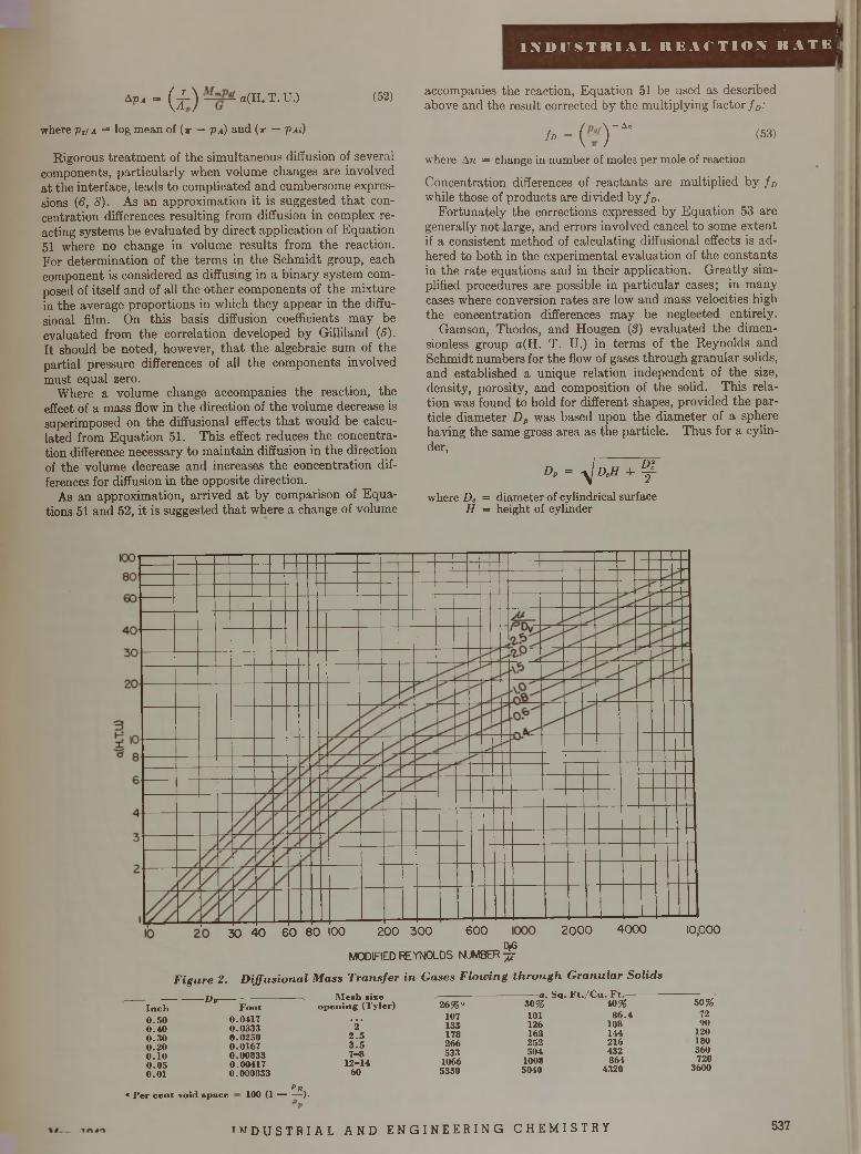
I
I N D U S T R I A L R E A C T I O N R A T E I
APa = Q l ) a(H . T . U.) (52)
where p„/A = log mean of ( x — Pa) and ( x — px<)
Rigorous treatm ent of the simultaneous diffusion of several components, particularly when volume changes are involved at the interface, leads to complicated and cumbersome expressions (6, 8). As an approximation it is suggested th a t concentration differences resulting from diffusion in complex reacting systems be evaluated by direct application of Equation 51 where no change in volume results from the reaction.For determination of the term s in the Schmidt group, eachcomponent is considered as diffusing in a binary system composed of itself and of all the other components of the mixture in the average proportions in which they appear in the diffu- sional film. On this basis diffusion coefficients m ay be evaluated from the correlation developed by Gilliland (5). I t should be noted, however, th a t the algebraic sum of the partial pressure differences of all the components involved must equal zero.
Where a volume change accompanies the reaction, the effect of a mass flow in the direction of the volume decrease is superimposed on the diffusional effects th a t would be calculated from Equation 51. This effect reduces the concentration difference necessary to m aintain diffusion in the direction of the volume decrease and increases the concentration differences for diffusion in the opposite direction.
As an approximation, arrived a t by comparison of Equations 51 and 52, it is suggested th a t where a change of volume
accompanies the reaction, Equation 51 be used as described above and the result corrected by the multiplying factor f D:
f D = ( - y * " (53)
where An = change in number of moles per mole of reaction
Concentration differences of reactants are multiplied by f D while those of products are divided by f D.
Fortunately the corrections expressed by Equation 53 are generally not large, and errors involved cancel to some extent if a consistent method of calculating diffusional effects is adhered to both in the experimental evaluation of the constants in the rate equations and in their application. Greatly simplified procedures are possible in particular cases; in many cases where conversion rates are low and mass velocities high the concentration differences m ay be neglected entirely.
Gamson, Thodos, and Hougen (3) evaluated the dimen- sionless group a(H. T. U.) in term s of the Reynolds and Schmidt numbers for the flow of gases through granular solids, and established a unique relation independent of the size, density, porosity, and composition of the solid. This relation was found to hold for different shapes, provided the particle diameter D p was based upon the diameter of a sphere having the same gross area as the particle. Thus for a cylinder,
Dp = y D cH + ^
where Dc = diameter of cylindrical surface H = height of cylinder
200 300 600 2000 400030 40 60 80 100cyG
MOOFIED REYNOLDS NUMBER t t
F igure 2. D iffu sio n a l M ass T ra n s fe r in Gases F low ing th r o u g h G ranu la r Solids
- D r
10,000
I n c h 0.50 0 .4 0 0 .3 0 0.20 0.10 0 .0 5 0.01
« P e r c e n t void s p a c e
F o o t— . M e s h size
o p e n in g (T y le r ) 2 6 % “
0 .0 4 1 7 ... 10 70 .0 3 3 3 2 1 3 30 .0 2 5 0 2 . 5 17 80 .0 1 6 7 3 . 5 2660 .0 0 8 3 3 7 - 8 5 3 30 .0 0 4 17 1 2 - 1 4 10 660 .0 0 0 8 33 60 5 3 3 0
------ a , S q . F t . / C u . F t .-------------3 0 % 4 0 % 5 0 %
1 0 1 8 6 .4 7212 6 10 8 oo16 8 14 4 12 02 5 2 2 1 6 180504 4 32 360
1008 864 7205040 4 320 3600
P R100 (1 -).
™ D U S T R I A L A N D E N G I N E E R I N G C H E M I S T R Y 537
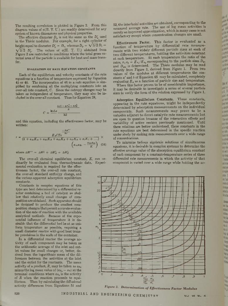
The resulting correlation is plotted in Figure 2. From this diagram values of a(H. T. U.) are readily determined for any system of known dimensions and physical properties.
The effective diameter D p is not the same as the D'p used in the Thiele modulus. For example, for a right cylinder of height equal to diameter D'p = Dc, whereas Dp = y / 3/2 Dc = y / 3/2 D'p. The values of a(H. T. U.) obtained from Figure 2 are restricted to conditions where the total gross external area of the particle is available for heat and mass transfer.
E V A L U A T IO N O F R A T E E Q U A T IO N C O N S T A N T S
Each of the equilibrium and velocity constants of the rate equations is a function of temperature expressed by Equation 45 or 46. The incorporation of 46 in a rate equation is simplified by combining all the multiplying constants into an over-all rate constant, C. Since the entropy changes may be taken as independent of temperature, they may also be included in the over-all constant. Thus for Equation 28,
A s t + AS Â + ASr
„ k sLe RL h 2
and this equation, including the effectiveness factor, may be written :
— A H ° '
_ _________________ EACTe RT___________________(1 + aMK A + a-BiKB + hrîH r + asiKs + a iK i + . . . )
/ dRiO>Si\ / f j \( dAidBi ) (54)
where A H ° ' = A H t + A H \ + A H%
The over-all chemical equilibrium constant, K , can ordinarily be evaluated from thermodynamic data. Experimental evaluation is required for the effectiveness factor, the over-all rate constant, the over-all standard enthalpy change, and the various apparent adsorption equilibrium constants.
Constants in complex equations of this type are best determined by a differential reactor containing a bed of catalyst so shallow tha t relatively small changes of composition are obtained. Such apparatus should be designed to produce the smallest composition changes tha t permit accurate evaluation of the rate of reaction with the available analytical methods. Because of the exponential influence of temperature it is desirable tha t the differential bed be a t as uniform temperature as possible, requiring a small diameter reactor with good heat transfer provisions in the walls of the container.
In a differential reactor the average activity of each component may be taken as the arithmetic average of the mlet and outlet values for small changes or, better, derived from the logarithmic mean of the differences between the activities a t the inlet and the outlet for the reactants. The mean activity of a product, R, may be taken as a,Re minus the log mean value of (or, — as) a t the terminal conditions where or, is the activity of R when the reaction proceeds to equilibrium. Then by calculating the diffusional activity differences from Equations 51 and
53 the interfacial activities are obtained, corresponding to the measured average rate. The use of log mean activities is merely an improved approximation, which in many cases is not satisfactory except where concentration changes are small.
Effectiveness F acto r. This factor is evaluated as a function of tem perature by differential ra te m easurem ents with two widely different particle sizes a t each of two different tem peratures, holding the activities constan t a t each temperature. At each tem perature the ratio of the rates, r l f r t = E aJ E a2 corresponding to the particle sizes D pl and Dm is determined. The Thiele modulus may be read directly from Figure 3, derived from Figure 1. From two values of the modulus a t different tem peratures the constants a' and b of Equation 48 may be calculated, completely evaluating EA as a function of particle size and temperature.
Where this factor proves to be of considerable importance, it may be desirable to investigate a series of several particle sizes to verify the form of the relation expressed by Figure 1.
A dsorption E qu ilib rium C o n stan ts . These constants, appearing in the ra te equations, m ight be independently determined by adsorption m easurem ents on the individual components. Such m easurem ents m ay prove to be a valuable adjunct to direct cataly tic ra te m easurem ents bu t are open to question because of the interaction effects and variability of active centers previously mentioned. Until these relations are better understood, these constants in the rate equations are best determined in the specific reaction under study by making rate measurements over a wide range of concentrations.
To minimize tedious algebraic solutions of simultaneous equations, it is desirable in complex systems to determine the effective average value of the absorption equilibrium constant of each component by a constant-tem perature series of three differential rate measurements in which the activity of th a t component is varied over a wide range while holding the ac
538 I N D U S T R I A L A N D E N G I N E E R I N G C H E M I S T R Y \Trvl QR TJ/-k R
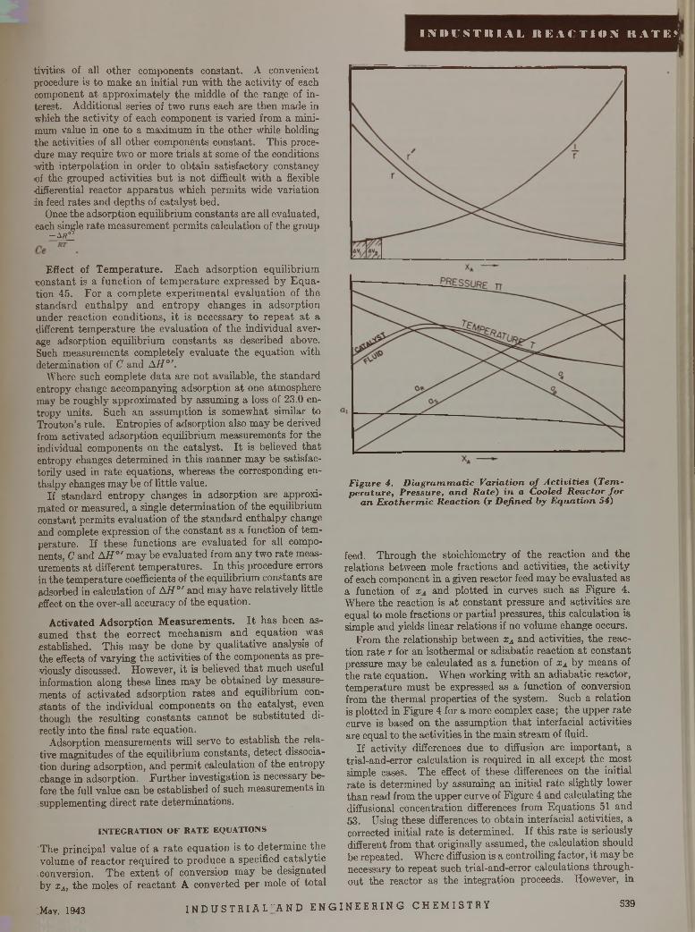
I N D U S T R I A L R E A C T I O N R A T E . * ;
tivities of all other components constant. A convenient procedure is to make an initial run with the activity of each component a t approxim ately the middle of the range of interest. Additional series of two runs each are then made in which the activity of each component is varied from a minimum value in one to a maximum in the other while holding the activities of all other components constant. This procedure m ay require two or more trials a t some of the conditions with interpolation in order to obtain satisfactory constancy of the grouped activities bu t is no t difficult with a flexible differential reactor apparatus which permits wide variation in feed rates and depths of catalyst bed.
Once the adsorption equilibrium constants are all evaluated, each single rate measurement permits calculation of the group
-A B°'
Effect of T em peratu re. E ach adsorption equilibrium constant is a function of tem peratu re expressed by E q u ation 45. For a com plete experim ental evaluation of the standard en thalpy and en tropy changes in adsorption under reaction conditions, i t is necessary to repeat a t a different tem perature the evaluation of the individual average adsorption equilibrium constants as described above. Such measurements completely evaluate the equation with determination of C and AH ° '.
Where such complete data are not available, the standard entropy change accompanying adsorption a t one atmosphere may be roughly approximated by assuming a loss of 23.0 entropy units. Such an assumption is somewhat similar to Trouton’s rule. Entropies of adsorption also m ay be derived from activated adsorption equilibrium measurements for the individual components on the catalyst. I t is believed th a t entropy changes determined in this manner m ay be satisfactorily used in rate equations, whereas the corresponding enthalpy changes m ay be of little value.
If standard entropy changes in adsorption are approximated or measured, a single determination of the equilibrium constant permits evaluation of the standard enthalpy change and complete expression of the constant as a function of tem perature. If these functions are evaluated for all components, C and AH ° ' m ay be evaluated from any two rate measurements a t different tem peratures. In this procedure errors in the tem perature coefficients of the equilibrium constants are adsorbed in calculation of AH ° ' and may have relatively little effect on the over-all accuracy of the equation.
Activated Adsorption M easurem ents. I t has been assumed th a t the correct m echanism and equation was established. This m ay be done by qualitative analysis of the effects of varying the activities of the components as previously discussed. However, it is believed th a t much useful information along these lines m ay be obtained by measurements of activated adsorption rates and equilibrium constants of the individual components on the catalyst, even though the resulting constants cannot be substituted directly into the final rate equation.
Adsorption measurements will serve to establish the relative magnitudes of the equilibrium constants, detect dissociation during adsorption, and perm it calculation of the entropy change in adsorption. Further investigation is necessary before the full value can be established of such measurements in supplementing direct ra te determinations.
IN T E G R A T IO N O F R A T E E Q U A T IO N S
The principal value of a ra te equation is to determ ine the volume of reactor required to produce a specified cata ly tic conversion. The extent of conversion m ay be designated by xA, the moles of reactant A converted per mole of total
F igure 4. D ia g ra m m a tic V aria tion o f A c tiv it ie s ( T e m p e ra tu re , P ressure, a n d R a te ) in a C ooled R ea c to r fo r
a n E x o th e rm ic R ea c tio n (r D efined by E q u a tio n 54)
feed. Through the stoichiometry of the reaction and the relations between mole fractions and activities, the activity of each component in a given reactor feed m ay be evaluated as a function of xA and plotted in curves such as Figure 4. Where the reaction is a t constant pressure and activities are equal to mole fractions or partial pressures, this calculation is simple and yields linear relations if no volume change occurs.
From the relationship between xA and activities, the reaction rate r for an isothermal or adiabatic reaction a t constant pressure m ay be calculated as a function of xA by means of the rate equation. When working w ith an adiabatic reactor, tem perature m ust be expressed as a function of conversion from the therm al properties of the system. Such a relation is plotted in Figure 4 for a more complex case; the upper ra te curve is based on the assumption th a t interfacial activities are equal to the activities in the main stream of fluid.
If activity differences due to diffusion are im portant, a trial-and-error calculation is required in all except the most simple cases. The effect of these differences on the initial rate is determined by assuming an initial rate slightly lower than read from the upper curve of Figure 4 and calculating the diffusional concentration differences from Equations 51 and 53. Using these differences to obtain interfacial activities, a corrected initial rate is determined. If this rate is seriously different from th a t originally assumed, the calculation should be repeated. Where diffusion is a controlling factor, it m ay be necessary to repeat such trial-and-error calculations throughout the reactor as the integration proceeds. However, in
! May, 1943 I N D U S T R I A L " A N D E N G I N E E R I N G C H E M I S T R Y 539
many cases the complete rate curve based on true interfacial activities is satisfactorily established by the following approximation:
r'dr'/dxAr = r ' - (r,' - r0) (55)r'%dr'% /dxA
where r, ro = corrected rate, based on true interfacial activities corresponding to conversion xa and initial conditions, respectively
r \ r,' = corresponding rates, neglecting diffusional effects
In this manner the lower rate curve of Figure 4 may be approximated from a single trial-and-error calculation at the initial conditions.
In an elementary cross section of catalyst bed, having a volume dV, a conversion dxA is produced. From the definition of r,
FdxA = rpBdV (56)
Since r is a function of xA expressed by the curve of Figure 4, this equation may be written:
F diAdV = rBm
y = F_ r*A dXAPB Jo f ix a)
(57)
I t is common practice to express correlations of catalytic conversion data in terms of the space velocity, S „ which is defined as the volumes of feed, measured a t standard conditions, per unit time per volume of catalyst. Equation 57 may be rewritten to express the relation between space velocity and conversion:
S, = FMjVpf
J t f
pi f :dXA
f(x A)
(58)
The integral is readily evaluated by plotting the reciprocal of the corrected rate curve of Figure 4 and measuring the area under it.
Although the above procedure is not particularly tedious, considerable simplification is possible under ideal conditions involving simple forms of rate equations or where/(zU satisfactorily approximates a straight line.
In the general case, frequently encountered in process design problems, the integration of the rate equation may be complicated by significant pressure drop in the reactor and temperature conditions which are neither isothermal nor adiabatic, but correspond to some specified rate of heat transfer to or from the reactor. Under these conditions the curves of Figure 4 may be developed by a progressive series of trial- and-error calculations starting from the reactor inlet. A further complication is introduced by the transverse temperature gradients resulting from the heating or cooling of the reactor walls and temperature differences between the fluid and the adjacent catalyst surfaces. The temperature curves of Figure 4 represent the effective average temperatures across any transverse section of the catalyst bed. Reactors are generally designed to keep these transverse temperature differences small. The temperature difference between the fluid and the catalyst is given by the following equation (8) if no volume change accompanies the reaction:
AT = Ay a AH a 1.076jrC'p„ (59)
Where a volume change occurs, A T of Equation 59 is divided by //) of Equation 53.
A small increment of conversion, xAl is selected in which the average values of all variables may be assumed to be the
arithmetic mean of the terminal values. An average rate r ' for this increment is assumed generally somewhat lower than the initial rate t'o calculated from the initial activities. Based on this assumed value of r ', the diffusion corrections are calculated and the corresponding value of the corrected average rate, rav., evaluated. The volume of catalyst corresponding to the selected increment of conversion is then F A x J p Br»v. Using this volume, the pressure drop (1, 3)and temperature change in the increment are calculated from the flow and thermal characteristics of the system after approximation values of t\ and pi have been established from which the activities corresponding to xAl are calculated. Using the average activities and average tem perature of the incremental section, a second value of the average rate is calculated. If this value differs greatly from th a t initially assumed, the calculation is repeated. After satisfactory values for the average and terminal conditions of the first increment are established, the procedure is repeated for a second increment, Axaj, and these stepwise calculations are continued until the desired conversion xAt is reached. The total reactor volume is then the sum of the incremental volumes, and the temperature and pressure variations throughout the reactor will have been evaluated. This procedure is not unduly tedious because with experience the various curves can be extrapolated from increment to increment with sufficient accuracy to make second approximations rarely necessary.
C O N C L U S IO N S
The foregoing equations and methods have been developed in the belief tha t a fundamentally sound approach will greatly minimize the amount of pilot plant experimentation ordinarily employed in evaluating the effects of the operating variables of catalytic systems and arriving a t optimum reactor designs. In ideal cases a few differential rate measurements will obviate the need of a pilot plant and permit immediate design of large-scale reactors for optimum results. However, it must be recognized th a t the theoretical treatm ent is idealized and in its simple form does not take into account secondary and side reactions which may accompany the main reaction. Furthermore, in the extension of equations to conditions far different from those a t which the constants are evaluated, serious errors may result from the assumptions of constancy for such variable factors as enthalpy changes in activated adsorption. Careful consideration of such limitations with considerable discretion m ust be used in the application of these methods until the basic principles have been more thoroughly explored and tested.
A C K N O W L E D G M E N T
The work reported here was made possible by the financial support of the Wisconsin Alumni Research Foundation and the sponsorship of the University Research Committee. The helpful suggestions and criticisms of J. 0 . Hirschfelder are gratefully acknowledged.
N O M E N C L A T U R E
a = gross external area of catalyst particles/unit of total/ catalyst volume including interstices
o' = empirical constantoa, as, etc. = activities of components A, B, etc., in main fluid
phaseoai, a Bi, etc. = activities of components A, B, etc., at catalytic
interface A = component AA = total interfacial area/unit mass of catalyst
f = gross external area of catalyst particles/unit mass ofcatalyst
b = empirical constantB = component Bc a , C b = surface concentrations of adsorbed A and B, moles/unit
mass of catalyst
540 I N D U S T R I A L A N D E N G I N E E R I N G C H E M I S T R Y Vol. 35, No. 5
I N D U S T R I A L R E A C T I O N R A T E J|
c eg = surface concentration of adsorbed A and B molecules/ unit cataly tic area _ .
d = concentration of vacant adsorption sites, equivalentm oles/unit mass of catalyst
c[ = concentration of vacant adsorption sites/unit areaC, C' = over-all rate constantsCPm = mean molal heat capacity of fluid streamW = effective average diam eter of cata lyst particles for
Thiele modulus = 6/ A vpv Dp = effective average diam eter of catalyst particles for
Reynolds numberD, = coefficient of diffusionE a = effectiveness factorJD = diffusional correction factor (Equation 53)F = reactor feed rate, m oles/unit time G = mass velocity/unit to ta l cross section AG° = standard free-energy change h = Planck constant A Ha = heat of reaction per mole of A AH ° = standard enthalpy change A R0' = over-all standard enthalpy change A # t = standard enthalpy of activation I = inert componentk, k ' = forward and reverse reaction velocity constantsk = Boltzmann constantkA, k A, etc. = adsorption and desorption velocity constants of
component A jfc* = therm al conductivity of fluidX = over-all fluid-phase reaction equilibrium constantK ’ = surface reaction equilibrium constantK a, K b, etc. = adsorption equilibrium constants of components
A and BL = to ta l molal adsorption sites/un it mass of catalystL ’ = to ta l active centers per unit area of surfacem = Thiele modulusMf = average molecular weight of reactor feed
= Avogadro number Pa — partial pressure of component A in main fluid streampAi = partial pressure of component A at particle interfacePu/ — log mean of ( t — Pa) and (it — Pai)
r = reaction rate, m oles/unit mass of ca ta lyst/um t timer ' = reaction rate, neglecting external diffusion gradientsTp = average hydraulic radius of catalyst poresR = gas law constantR = component Rs = number of equidistant sites adjacent to each active
center S = component SA5° = standard entropy changeANt = entropy of activationS , = space velocityx a = moles of A converted/m ole of reactor feed9a, 9b = fraction of to ta l sites occupied by adsorbed A and B
molecules0i = fraction of to ta l adsorption sites unoccupiedn = viscosityp = density of fluidpB = bulk density of catalystpc = true density of catalytic solidPf = density of feed a t standard conditionsPp = density of catalyst particlex = to ta l pressure
L I T E R A T U R E C I T E D
(1) Chilton, T . C., and Colburn, A. P., I n d . E n g . Chem ., 23, 913(1931).
(2) Ibid., 27, 255 (1935).(3) Gamson, B . W ., Thodos, G„ and Hougen, O. A., Trams. Am.
Inst. Chem. Engrs., 39, 1—35 (1943).(4) Glasstone, S., Laidler, K . J., and Eyring. H „ “Theory of R ate
Processes” , N ew York, M cGraw-Hill Book Co., 1941.(5) Gilliland, E . R .. I n d . E n g . Chem ., 26, 6S1 (1934).(6) Lewis, W. K „ and Chang, K . C„ Trans. Am. Inst. Chem. Engrs..
21, 127 (1928). . T u(7) N atl. Research Council, 12th Rept. of Com. on Catalysis, John
W iley & Sons, 1940.(8) Sherwood, T . K .. “Absorption and Extraction , N ew York,
McGraw-Hill Book Co., 1937.(9) Thiele, E . W ., I n d . E n g . Chem ., 31, 916 (1939).
(SOLID C A TA LY STS an d REACTIO N RATES)
j-v , i . • r o i p O. A. Uyehara an d K . M. TT a t sonO x i d a t i o n o f S u l f u r D l O X ( I U n i v e r s i t y o f W i s c o n s i n , m a d i s o n , w i s .
T h e dmta o f L e w is a n d R ie s o n th e o x id a tio n o f s u l fu r d io x id e in a f lo w s y s te m o ver a p la t in iz e d a sb e s to s c a ta ly s t h a v e b e en a n a ly z e d in a c co rd a n ce w i th th e p r in c ip le s o u t l i n e d in th e p re c e d in g p a p e r (p a g e 519). T h e d a ta are w e ll r e p re se n te d b y a n e q u a t io n b a se d o n th e a s s u m p t io n t h a t th e ra te c o n tr o l l in g s te p is a s u r fa c e r e a c tio n b e tw e e n a c tiv a tio n -a d s o r b e d s u l fu r d io x id e a n d a to m ic o x y g e n . T h e e x p e r im e n ta l d a ta s h o w s o m e w h a t less d e v ia t io n f r o m th is g e n e ra l e q u a t io n th a n f r o m th e e m p ir ic a l e x p re ss io n p ro p o s e d b y Le tcis a n d R ie s .
E R IFIC A T IO N of the applicability of the rate equations developed in the preceding paper (page 529) is difficult because of the almost complete lack of suitable
published data. M any catalytic rate measurements have been carried out in static systems in which large diffusional concentration differences were inevitable and controlled by conditions of natural convection which are not subject to generalized analysis. Of the data obtained in flow systems, many are unsuitable because of the large concentration changes accompanying high degrees of conversion intended to simulate the over-all results of commercial reactors.
w - i n n I N D U S T R I A L A N D EN
Ideally, data should be obtained under flow conditions in a differential reactor containing a bed of catalyst so shallow th a t relatively small changes of composition occur. Since tem perature has an im portant influence on reaction rate, it is desirable th a t the differential section be kept at a tem perature as uniform as possible. This requires a small-diameter reactor with good heat transfer a t the walls.
One of the most thoroughly investigated catalytic reactions is the oxidation of sulfur dioxide over a platinum catalyst. The extensive experimental data obtained by Bodenstein and Fink (5), Knietsch (-5), and Taylor and Lenher (7) cannot be used for the development of general rate equations because in each case a static system was employed in which diffusional concentration and tem perature differences are difficult to predict. Each of these investigators and Benton (1) proposed empirical expressions representing their own data, but in all cases diffusional effects were neglected and the resultant equations are applicable only over limited ranges of conditions.
Lewis and Ries (6) carried out a series of flow experiments in reactors reasonably approximating differential operation. A platinized asbestos catalyst was used in glass U-tube reactors immersed in a molten m etal bath. Although data necessary for the evaluation of diffusional concentration differences are not presented, it seems reasonable to neglect these effects be-
I N E E R I N G C H E M I S T R Y 541
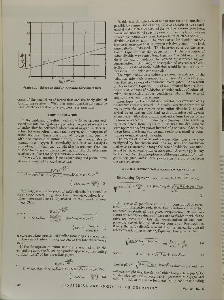
Figure 1. E ffect o f S u lfu r Trioxide C oncen tra tion
cause of the conditions of forced flow and the finely divided form of the catalyst. With this assumption the data may be used for the evaluation of a complete rate equation.
F O R M O F E Q U A T IO N
In the oxidation of sulfur dioxide the following four activated rate influencing steps are possible : activated adsorption of sulfur dioxide, activated adsorption of oxygen, surface reaction between sulfur dioxide and oxygen, and desorption of sulfur trioxide. Since one atom of oxygen must combine with one molecule of sulfur dioxide, it seems reasonable to assume tha t oxygen is atomically adsorbed on catalysts promoting this reaction. I t will also be assumed tha t one of these four steps is rate controlling, and tha t the others are relatively so fast tha t they maintain equilibrium.
If the surface reaction is rate controlling and partial pressures are assumed to equal activities,
EACTe- A H °
R T
(1 + Pso, Kso2 + \Z p0lK 0l +Psos-Ksos + PsiKtf,)* X
(psoiVpo* ~ (1)
Similarly, if the adsorption of sulfur dioxide is assumed to be the rate determining step, the following equation is obtained, corresponding to Equation 26 of the preceding paper (page 532):
-AHJ EACTe RT
(1 + \ / p 0 l K 0 , + + P b o , K b o , + P n ,A n ,)X
( Pso, - _ Ä _ \ V V po , k )
(2)
A corresponding equation of similar form may also be written for the case of adsorption of oxygen as the rate determining step.
If the desorption of sulfur trioxide is assumed to be the controlling step, the following equation applies, corresponding to Equation 27 of the preceding paper:
- A H °
EACTe RT(1 - f Pso, Ä soj + V Po,K0, + Pso, V P o , K Bo, K + Pn, ¿fNl)
x ( p so iV P o , — (3)
In this case the selection of the proper form of equation is possible by comparison of the qualitative trends of the experimental data with those called for by the various equations. Lewis and Ries found th a t the rate of initial oxidation was in- creased by increasing the partial pressure of either the sulfur dioxide or the oxygen. The effect of sulfur dioxide concentration is large and tha t of oxygen relatively small, bu t both were definitely indicated. This behavior rules out the selection of Equation 2 as the proper form. If the adsorption of sulfur dioxide were controlling, Equation 2 would require tha t the initial rate of oxidation be reduced by increased oxygen concentration. Similarly, if adsorption of oxygen were controlling, the rate of initial oxidation would be reduced by increased sulfur dioxide concentration.
The experimental data indicate a strong retardation of the oxidation rate with increased sulfur trioxide concentration over the entire range of conditions investigated. As a result of this behavior, Equation 3 is also eliminated because it requires tha t the rate of oxidation be independent of sulfur trioxide concentration under conditions where the over-all equilibrium constant K is large.
Thus, Equation 1 represents the most logical expression of the qualitative effects observed. A possible alternate form would result from the assumption th a t sulfur dioxide is not adsorbed by activation and th a t activation-adsorbed oxygen atoms react with sulfur dioxide molecules from the gas phase to form adsorbed sulfur trioxide molecules. The resulting equation differs from Equation 1, in th a t the denominator term appears as a first power instead of a square. Choice between these two forms can be made only as a result of quantitative examination of the data.
The effects of nitrogen and various other inerts were investigated by Bodenstein and Fink (3) with the conclusion tha t over a considerable range the rate of oxidation was unaffected by the concentration of nitrogen. Accordingly it may be assumed tha t the adsorption equilibrium constant of nitrogen is negligible, and all terms involving it are dropped from the rate equations.
G E N E R A L M E T H O D F O R E V A L U A T IN G C O N S T A N T S
- A H 0’Rearranging Equation 1 and letting E ACTe RT = Ct.
i -! VPO* -
PBOi
K 1 + Pso, Asp, + V po, K 0i + Pso, Kao,V c ,
(4)
If the over-all gas-phase equilibrium constant K is calculated from thermodynamic data, this equation contains four unknown constants a t any given tem perature. These constants are readily evaluated if data are available in which the rates are measured while the concentration of one component is varied, holding all others constant. For example, if only the sulfur dioxide concentration is varied, holding all other concentrations constant, Equation 4 may be w ritten :
V
where
Pso, V poi - psoi/jy
^ = 1 V pot Kot + psoi Ksoa
= Pso, ^ + ~ (5)V c , V c ,
(6)
Thus a plot of yj P s m V p ^ -_ p s o J K against ^ shou,d re_
suit in a straight line, the slope of which is equal to K s<^/V C u lmi ar p ots against varying partial pressures of oxygen and
su ur noxide a t the same tem perature, in each case holding542 I N D U S T R I A L A N D E N G I N E E R I N G C H E M I S T R Y Vol. 35, No. 5
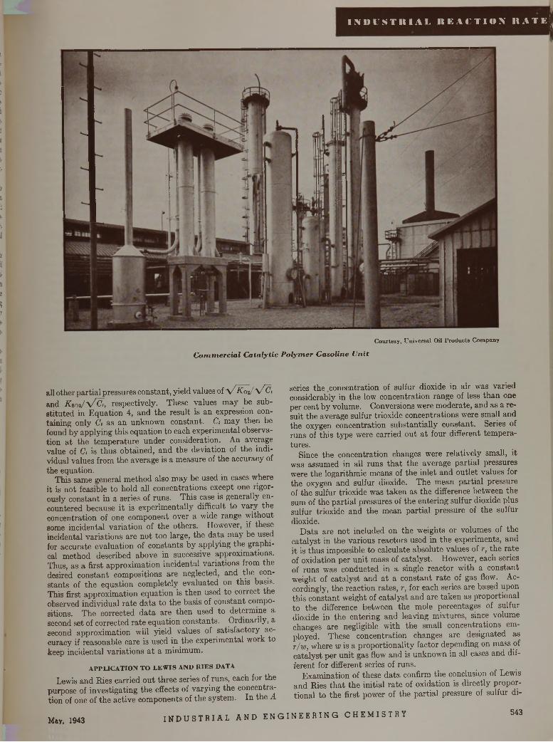
I N D U S T K I A L R E A C T I O N I I A T E ^
5!•
t¡,I
ii
I
*«I(■¡j. I
ÏÏit5
i?t
C ourtesy , U niversa l Oil P ro d u c ts C om pany
C o m m erc ia l C a ta ly tic P o lym er G asoline U n it
all other partial pressures constant, yield values of y / K 02 / V e t and K ao t/y /C t, respectively. These values may be substituted in Equation 4, and the result is an expression containing only Ci as an unknown constant. Ct may then be found by applying this equation to each experimental observation a t the tem perature under consideration. An average value of Ct is thus obtained, and the deviation of the individual values from the average is a measure of the accuracy of the equation.
This same general method also m ay be used in cases where it is not feasible to hold all concentrations except one rigorously constant in a series of runs. This case is generally encountered because it is experimentally difficult to vary the concentration of one component over a wide range without some incidental variation of the others. However, if these incidental variations are not too large, the data may be used for accurate evaluation of constants by applying the graphical method described above in successive approximations. Thus, as a first approximation incidental variations from the desired constant compositions are neglected, and the constants of the equation completely evaluated on this basis. This first approximation equation is then used to correct the observed individual rate data to the basis of constant compositions. The corrected data are then used to determine a second set of corrected rate equation constants. Ordinarily, a second approximation will yield values of satisfactory accuracy if reasonable care is used in the experimental work to keep incidental variations a t a minimum.
A P P L IC A T IO N T O L E W IS A N D H IE S D A T A
Lewis and Ries carried out three series of runs, each for the purpose of investigating the effects of varying the concentration of one of the active components of the system. In the A
series the concentration of sulfur dioxide in air was varied considerably in the low concentration range of less than one per cent by volume. Conversions were moderate, and as a result the average sulfur trioxide concentrations were small and the oxygen concentration substantially constant. Series of runs of this type were carried out a t four different tem peratures.
Since the concentration changes were relatively small, it was assumed in all runs th a t the average partial pressures were the logarithmic means of the inlet and outlet values for the oxygen and sulfur dioxide. The mean partial pressure of the sulfur trioxide was taken as the difference between the sum of the partial pressures of the entering sulfur dioxide plus sulfur trioxide and the mean partial pressure of the sulfur dioxide.
D ata are not included on the weights or volumes of the catalyst in the various reactors used in the experiments, and it is thus impossible to calculate absolute values of r, the rate of oxidation per unit mass of catalyst. However, each series of runs was conducted in a single reactor with a constant weight of catalyst and a t a constant rate of gas flow. Accordingly, the reaction rates, r, for each series are based upon this constant weight of catalyst and are taken as proportional to the difference between the mole percentages of sulfur dioxide in the entering and leaving mixtures, since volume changes are negligible with the small concentrations employed. These concentration changes are designated as r/w , where w is a proportionality factor depending on mass of catalyst per unit gas flow and is unknown in all cases and different for different series of runs.
Examination of these data confirm the conclusion of Lewis and Ries th a t the initial rate of oxidation is directly proportional to the first power of the partial pressure of sulfur di
May, 1943I N D U S T R I A L A N D E N G I N E E R I N G C H E M I S T R Y 543
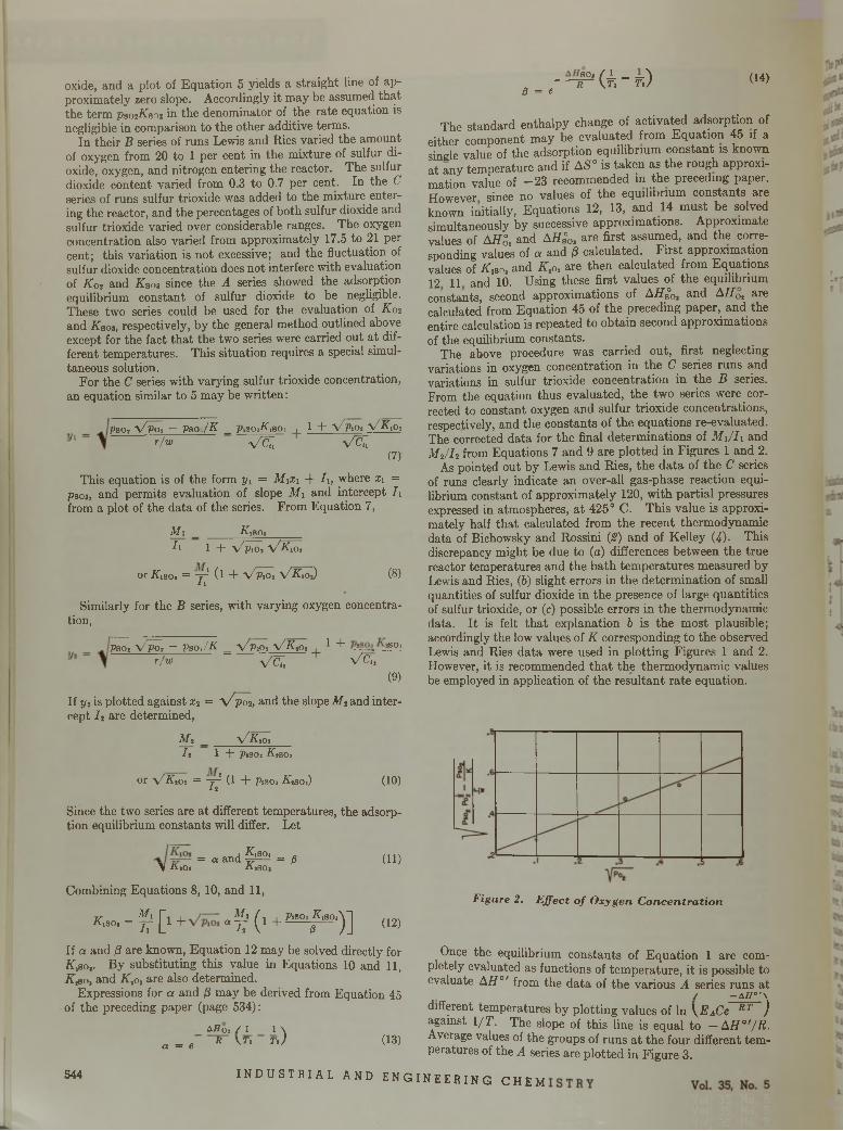
oxide, and a plot of Equation 5 yields a straight line of approximately zero slope. Accordingly it may be assumed that the term psotKBot in the denominator of the rate equation is negligible in comparison to the other additive terms.
In their B series of runs Lewis and Ries varied the amount of oxygen from 20 to 1 per cent in the mixture of sulfur dioxide, oxygen, and nitrogen entering the reactor. The sulfur dioxide content varied from 0.3 to 0.7 per cent. In the C series of runs sulfur trioxide was added to the mixture entering the reactor, and the percentages of both sulfur dioxide and sulfur trioxide varied over considerable ranges. The oxygen concentration also varied from approximately 17.5 to 21 per cent; this variation is not excessive; and the fluctuation of sulfur dioxide concentration does not interfere with evaluation of K02 and Kbo3 since the A series showed the adsorption equilibrium constant of sulfur dioxide to be negligible. These two series could be used for the evaluation of K02 and Kaoi, respectively, by the general method outlined above except for the fact tha t the two series were carried out at different temperatures. This situation requires a special simultaneous solution.
For the C series with varying sulfur trioxide concentration, an equation similar to 5 may be w ritten:
Pso, y/poi ~ Vso./K _ P1SO3A 18O1 , 1 + x/piO; y/Kio,r / w vc;> V c li
(7)
This equation is of the form yi = M \x 1 + l \ , where X\ = P303, and permits evaluation of slope M i and intercept /1 from a plot of the data of the series. From Equation 7,
M i _ __________A iS O a _____7i l -(- y/ptOt y/KiOi
or A,soi = -v-1 (l + V P1O1 V K,oJ (8)11
Similarly for the B series, with varying oxygen concentration,
Psoi Vpo» — Pso,/K = y/y& i V K ,o, 1..+ so,r/w V&7, V7 C„
(9)
If yt is plotted against x2 = \ / p o 2, and the slope M z and intercept I t are determined,
M2 _ \ /K , O;I t 1 + Pisoi Ktso,
or \ / K,o, = - j l (1 + Pjsoi A,SOi) (10)12
Since the two series are a t different temperatures, the adsorption equilibrium constants will differ. Let
= «and §5 0 ' = p (1 1 )\ A tO i A j SO i
Combining Equations 8, 10, and 11,
Kisoi = f [ l + « f ’ ( l + ^ 0i^ 801) ] (12)
If a and /S are known, Equation 12 may be solved directly for K,so,. By substituting this value in Equations 10 and 1 1 , K # o, and K,o, are also determined.
Expressions for a and /3 may be derived from Equation 45 of the preceding paper (page 534):
aflo2 / l 1 \ a = e R \T i r j (13)
5 4 4
- t P U - k ) <■«0 = e
The standard enthalpy change of activated adsorption of either component may be evaluated from Equation 45 if a single value of the adsorption equilibrium constant is known at any temperature and if AS° is taken as the rough approximation value of - 2 3 recommended in the precedmg paper. However since no values of the equilibrium constants are known initially, Equations 12, 13, and 14 m ust be solved simultaneously by successive approximations. Approximate values of A HZ, and AHS0, are first assumed, and the corresponding values of a and /3 calculated. F irst approximation values of K * o. and K to, are then calculated from Equations 12 11 and 10. Using these first values of the equilibrium constants, second approximations of A/7S°0> and AH 0l are calculated from Equation 45 of the preceding paper, and the entire calculation is repeated to obtain second approximations of the equilibrium constants.
The above procedure was carried out, first neglecting variations in oxygen concentration in the C series runs and variations in sulfur trioxide concentration in the B series. From the equation thus evaluated, the two series were corrected to constant oxygen and sulfur trioxide concentrations, respectively, and the constants of the equations re-evaluated. The corrected data for the final determinations of M i/h and M 2/ I 2 from Equations 7 and 9 are plotted in Figures 1 and 2.
As pointed out by Lewis and Ries, the da ta of the C series of runs clearly indicate an over-all gas-phase reaction equilibrium constant of approximately 120, w ith partial pressures expressed in atmospheres, a t 425° C. This value is approximately half tha t calculated from the recent thermodynamic data of Bichowsky and Rossini (2) and of Kelley (4). This discrepancy might be due to (a) differences between the true reactor temperatures and the bath tem peratures measured by Lewis and Ries, (6) slight errors in the determ ination of small quantities of sulfur dioxide in the presence of large quantities of sulfur trioxide, or (c) possible errors in the thermodynamic data. I t is felt tha t explanation b is the most plausible; accordingly the low values of K corresponding to the observed Lewis and Ries data were used in plotting Figures 1 and 2. However, it is recommended th a t the thermodynamic values be employed in application of the resultant rate equation.
F ig u re 2. E ffe c t o f O x yg e n C o n c e n tr a t io n
Once the equilibrium constants of Equation 1 are completely evaluated as functions of tem perature, it is possible to evaluate AH ° r from the data of the various A series runs at
/ — a h 0 f \
different temperatures by plotting values of In \ E ACe RT ) against l / T . The slope of this line is equal to — AH ° '/R . Average values of the groups of runs a t the four different tem peratures of the A series are plotted in Figure 3.
I N D U S T R I A L A N D E N G I N E E R I N G C H E M
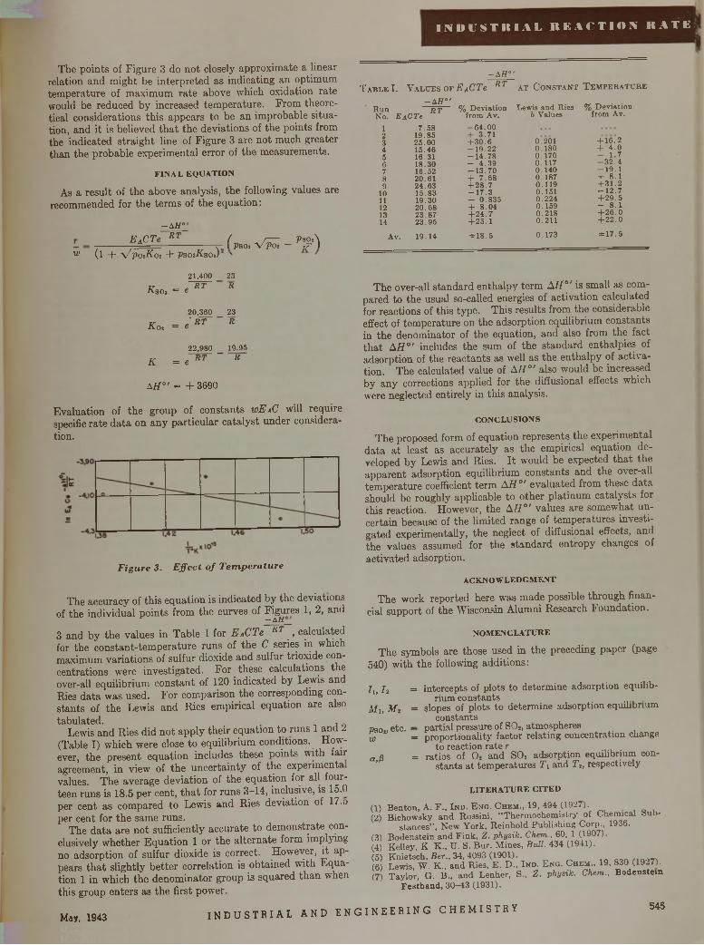
I N D U S T R I A L R E A C T I O N R A T E
The points of Figure 3 do not closely approximate a linear relation and might be interpreted as indicating an optimum tem perature of maximum rate above which oxidation rate would be reduced by increased tem perature. From theoretical considerations this appears to be an improbable situation, and it is believed th a t the deviations of the points from the indicated straight line of Figure 3 are not much greater than the probable experimental error of the measurements.
F I N A L E Q U A T I O N
As a result of the above analysis, the following values are recommended for the term s of the equation:
- A H °R T
W (1 +E ACTe RT ( „ _ r z r PsoA
. r - 1 PSO, V P O í 7 7 Iy / potKoi + psosKsoi) '
- A H 0
T a b l e I. V a l u e s o f EACTe R T a t C o n s t a n t T e m p e r a t u r e
- A H 0 ' H u n R TN o. E A C T e
12345678 9
1011121314
7 .5 8 1 9 .8 5 2 5 .0 0 1 5 .4 6 1 6 .311 8 .3 0 16 .5 2 2 0 .6 1 2 4 .6 3 1 5 .8 31 9 .3 0 20.68 2 3 .8 7 2 3 .9 5
A v. 19 .1 4
% D ev ia tio n from A v.- 6 4 . 0 0 + 3 .7 1 + 3 0 .6 - 1 9 . 2 2 - 1 4 .7 8 - 4 .3 9 - 1 3 . 7 0 + 7 .6 8 + 2 8 .7 - 1 7 . 3 + 0 .8 3 5 + 8 .0 4 + 2 4 .7 + 2 5 .1
± 1 8 . 5
Lewis a n d R ies b V alues
0.201 0 .1 8 0 0 .1 7 0 0 .1 1 7 0 .1 4 0 0 .1 8 7 0 .1 1 9 0 .1 5 1 0 .2 2 4 0 .1 5 9 0 .2 1 8 0.2110 .1 7 3
% D ev ia tio n from Av.
+ 1 6 .2 + 4 .0- 1 .7 - 3 2 . 4 - 1 9 . 1 + 8.1 + 3 1 .2 - 1 2 . 7 + 2 9 .5- 8.1 + 2 6 .0 + 22.0±17.5
RsOi = «21,400
R T
20,360
Koi = « R T
23R
23R
K = e22,980
R T
19.95R
A H°' = + 3 6 9 0
Evaluation of the group of constants w EAC will require specific rate d ata on any particular catalyst under consideration.
The accuracy of this equation is indicated by the deviations of the individual points from the curves of Figures 1, 2, and
— A H
3 and by the values in Table I for E ACTe RT , calculated for the constant-tem perature runs of the C series in which maximum variations of sulfur dioxide and sulfur trioxide concentrations were investigated. For these calculations the over-all equilibrium constant of 120 indicated by Lewis and Ries data was used. For comparison the corresponding constants of the Lewis and Ries empirical equation are alsotabulated. ,
Lewis and Ries did not apply their equation to runs 1 and 2 (Table I) which were close to equilibrium conditions. However, the present equation includes these points with fair agreement, in view of the uncertainty of the experiments values. The average deviation of the equation for all fourteen runs is 18.5 per cent, th a t for runs 3-14, inclusive, is 15.0 per cent as compared to Lewis and Ries deviation of 17.o per cent for the same runs.
The data are not sufficiently accurate to dem onstrate conclusively whether Equation 1 or the alternate form implying no adsorption of sulfur dioxide is correct. However, it appears th a t slightly better correlation is obtained with Equation 1 in which the denom inator group is squared than when this group enters as the first power.
The over-all standard enthalpy term AH ° ' is small as compared to the usual so-called energies of activation calculated for reactions of this type. This results from the considerable effect of tem perature on the adsorption equilibrium constants in the denominator of the equation, and also from the fact th a t AH ° ' includes the sum of the standard enthalpies of adsorption of the reactants as well as the enthalpy of activation. The calculated value of AH0' also would be increased by any corrections applied for the diffusional effects which were neglected entirely in this analysis.
C O N C L U S I O N S
The proposed form of equation represents the experimental data a t least as accurately as the empirical equation developed by Lewis and Ries. I t would be expected th a t the apparent adsorption equilibrium constants and the over-all tem perature coefficient term A H 0' evaluated from these data should be roughly applicable to other platinum catalysts for this reaction. However, the A H °' values are somewhat uncertain because of the limited range of tem peratures investigated experimentally, the neglect of diffusional effects, and the values assumed for the standard entropy changes of activated adsorption.
a c k n o w l e d g m e n t
The work reported here was made possible through financial support of the Wisconsin Alumni Research Foundation.
N O M E N C L A T U R E
The symbols are those used in the preceding paper (page 540) with the following additions:
= intercepts of plots to determine adsorption equilibrium constants
= slopes of plots to determine adsorption equilibrium constants
partial pressure of S02, atmospheres proportionality factor relating concentration change
to reaction rate r ratios of 0 2 and SOs adsorption equilibrium con
stants at temperatures T2 and T2, respectively
L I T E R A T U R E C I T E D
Benton, A. F „ In d . E ng . Chem ., 19, 494 (1927).Bichowsky and Rossini, “ Thermochemistry of Chemical bub-
stances” , N ew York, Reinhold Publishing Corp., 1936.(3) Bodenstein and Fink, Z. physik. Chem , 60, 1 (1907).(4) K elley, K K ., U . S. Bur. M ines, Bull. 434 (1941).(5) Knietsch, Ber., 34, 4093 (1901).(6) Lewis, W. K., and Ries, E. D ., Ind. Eng. Chem., 19, 830 (1927).(7) Taylor, G. B ., and Lenher, S., Z. physik. Chem.. Bodenstein
F estband, 30—43 (1931).
Iu I i
M i, M 2
Paov etc. — w =
a, ß =
G)(2)
May, 1943I N D U S T R I A L A N D E N G I N E E R I N G C H E M I S T R Y 545
F igure 3. E ffe c t o f T em p era tu re
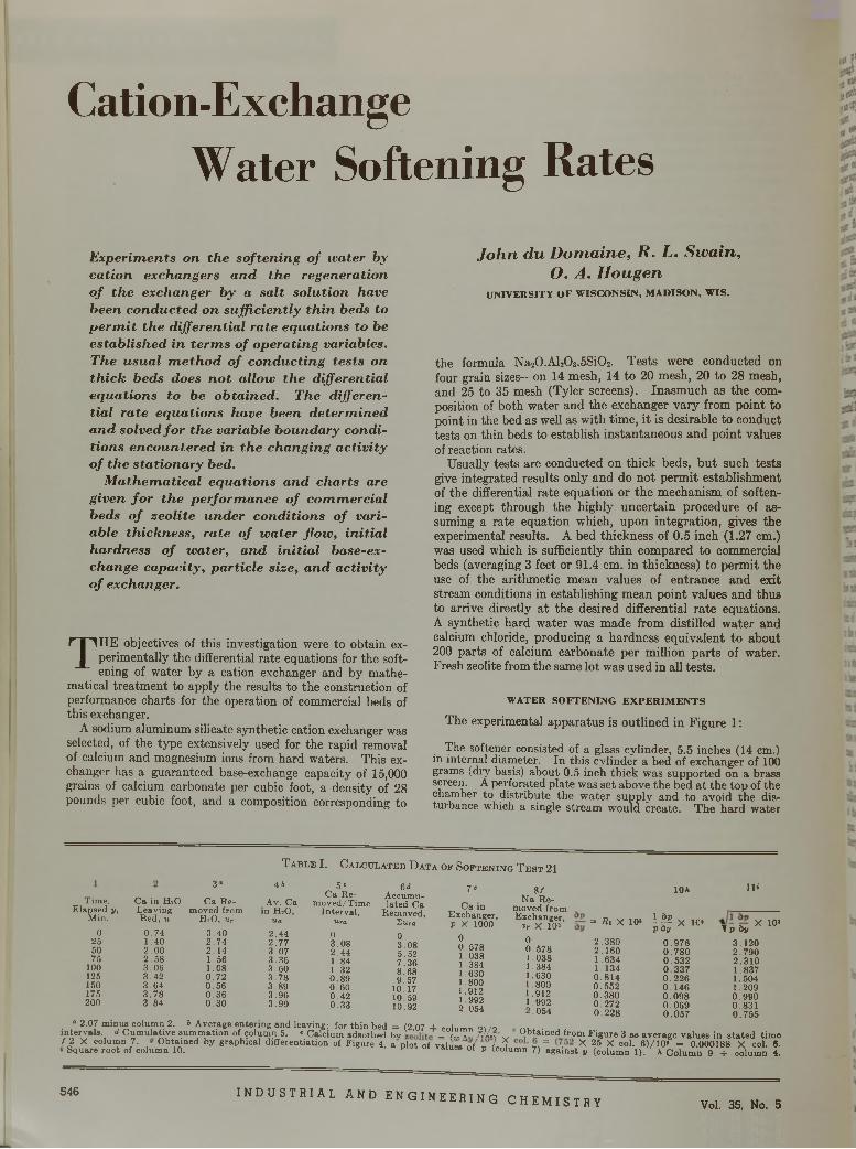
C a t i o n - E x c h a n g e
W a t e r S o f t e n i n g R a t e s
E x p erim en ts on th e so ften in g o f w a ter by ca tio n exchangers a n d th e regen era tion o f th e exchanger b y a sa lt so lu tio n have been c o n d u c te d on su ffic ien tly th in beds to p e r m it th e d ifferen tia l ra te eq u a tio n s to be e s ta b lish e d in te rm s o f o p era tin g variables. The u su a l m e th o d o f co n d u c tin g te s ts on th ic k beds does n o t a llow th e d ifferen tia l e q u a tio n s to be o b ta in ed . The d ifferentia l ra te eq u a tio n s have been d e te rm in e d a n d so lved fo r th e variable b ou n dary co n d itio n s en co u n te red in th e ch an gin g a c tiv ity o f th e s ta tio n a ry bed.
M a th e m a tic a l eq u a tio n s a n d ch a rts are g iven f o r th e p erfo rm a n ce o f co m m erc ia l beds o f ze o lite u n d er co n d itio n s o f varia b le th ick n ess , ra te o f w a ter flo w , in itia l h ardn ess o f w a ter , a n d in itia l base-exchange ca p a c ity , p a r tic le s ize , a n d a c tiv ity o f exchanger.
TH E objectives of this investigation were to obtain experimentally the differential rate equations for the softening of water by a cation exchanger and by mathe
matical treatm ent to apply the results to the construction of performance charts for the operation of commercial beds of this exchanger.
A sodium aluminum silicate synthetic cation exchanger was selected, of the type extensively used for the rapid removal of calcium and magnesium ions from hard waters. This exchanger has a guaranteed base-exchange capacity of 15,000 grains of calcium carbonate per cubic foot, a density of 28 pounds per cubic foot, and a composition corresponding to
Jo h n du D om aine, R . L. Sw ain, O. A. H ougen
U N IV E R S IT Y O F W IS C O N S IN , M A D IS O N , W IS .
the formula Na20.Al203.5Si02. Tests were conducted on four grain sizes—on 14 mesh, 14 to 20 mesh, 20 to 28 mesh, and 25 to 35 mesh (Tyler screens). Inasmuch as the composition of both water and the exchanger vary from point to point in the bed as well as with time, it is desirable to conduct tests on thin beds to establish instantaneous and point values of reaction rates.
Usually tests are conducted on thick beds, b u t such tests give integrated results only and do not perm it establishment of the differential rate equation or the mechanism of softening except through the highly uncertain procedure of assuming a rate equation which, upon integration, gives the experimental results. A bed thickness of 0.5 inch (1.27 cm.) was used which is sufficiently th in compared to commercial beds (averaging 3 feet or 91.4 cm. in thickness) to perm it the use of the arithmetic mean values of entrance and exit stream conditions in establishing mean point values and thus to arrive directly a t the desired differential rate equations. A synthetic hard water was made from distilled water and calcium chloride, producing a hardness equivalent to about 200 parts of calcium carbonate per million parts of water. Fresh zeolite from the same lot was used in all tests.
W A T E R S O F T E N IN G E X P E R IM E N T S
The experimental apparatus is outlined in Figure 1:
The softener consisted of a glass cylinder, 5.5 inches (14 cm.) in internal diameter. In this cylinder a bed of exchanger of 100 grams (dry basis) about 0.5 inch thick was supported on a brass screen. A perforated plate was set above the bed at the top of the chamber to distribute the water supply and to avoid the disturbance which a single stream would create. The hard water
T a b l e I . C a l c u l a t e d D a t a o p S o f t e n i n g T e s t 21
T im e, E lapsed y ,
M in.
0255075
100125150175200
C a in H 20 Leav ing B ed , u
0 .7 41 .4 02.002 .5 83 .0 63 .4 23 .6 43 .7 83 .8 4
3 °
C a R em oved from
H 2O f u r
3 .4 02 .7 42 .1 41.561 .0 80 .7 20 .5 60 .3 60 .3 0
4 b
Av. C a in H 20 ,
Ua
2 .4 42 .7 7 3 .0 7 3 .3 6 3 .6 03 .7 8 3 .8 9 3 .9 6 3 .9 9
5 c C a R e
m o v e d /T im e In te rv a l,
Ur a
03 .0 82 .4 41 .841.320 .8 90 .6 00 .4 20 .3 3
6d A ccum ula ted C a
Rem oved, Sura03 .0 85 .5 27 .3 68.689 .5 7
10.1710.5910.92
7«
C a in E xchanger, P X 1000
00 .5 7 81.0381.3841.6301.8001.9121.9922 .0 5 4
° 2.07 m inus colum n 2.in te rv a ls , i / 2 X co lum n 7.' S q u a re ro o t of co lum n 10.
is co lum n 2. b A verage e n te r in g an d leav ing ; for th in b ed = (2.07 + colum n 21 /■> C u m u la tiv e su m m a tio n of co lum n 5. • C alcium adsorbed hv _ 7 . . . . . f . ’L . .
8/N a R e
m oved from E xchanger,
v r X 10“00 .5 7 8 1 .038 1.384 1 .630 1 .800 1 .912 1.992 2 .0 5 4
: O b ta in ed from
10« 11«'
= Ri X 10'1 ÖD- 5 ^ X 1 0 * X 10 'P à u t p 01/
2 .3 8 0 0 .9 7 6 3 .1 2 02 .1 6 0 0 .7 8 0 2 .7 9 01 .6 3 4 0 .5 3 2 2 .3 1 01 .1 3 4 0 337 1 .8370 .8 1 4 0 .2 2 6 1 .5 0 40 .5 5 2 0 146 1 .2090 .3 8 0 0 .0 9 8 0 .9 9 00 .2 7 2 0 .0 6 9 0 .8 3 10 .2 2 8 0 .0 5 7 0 .7 5 5
itive su m m a tio n of co lum n 5. * C alcium adsorbed hv f . A . . -----------O b ta in ed by g raph ica l d iffe ren tia tion of F igure 4, a p lo t of values o t p (colum n 7) “aga inst**
F ig u re 3 a s a v e ra g e v a lu es in s ta te d tim e 25 X col. 6 )/10» = 0.000188 X col. 6. (co lum n 1). 5 C o lu m n 9 4- co lum n 4.
5 4 6 I N D U S T R I A L A N D E N G I N E E R I N G C H E M I S T R Y Vol. 35, No. 5
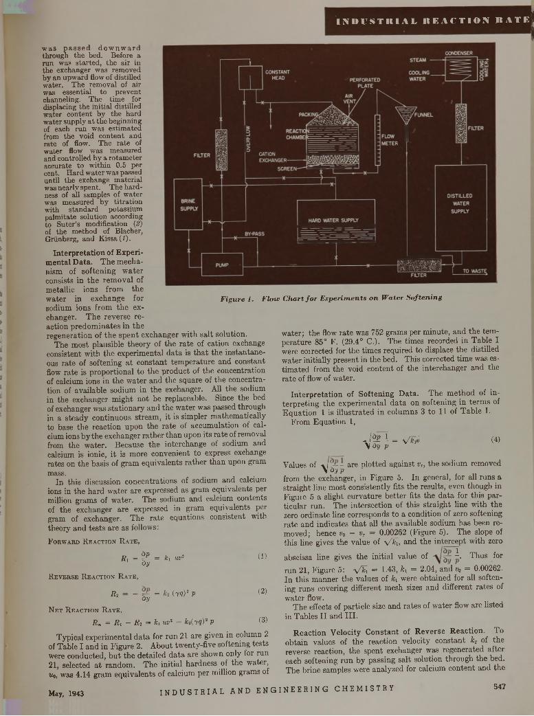
• 9
I N D U S T I l l A L R E A C T I O N R A T E (
F ig u r e 1. F lo w C h a r t f o r E x p e r i m e n t s o n W a te r S o f t e n i n g
w as p a s s e d d o w n w a rd through the bed. Before a run was started, the air in the exchanger was removed by an upward flow of distilled water. The removal of air was essential to prevent channeling. The tim e for displacing the initial distilled water content by the hard water supply a t the beginning of each run was estim ated from the void content and rate of flow. The rate of water flow was measured and controlled by a rotam eter accurate to within 0.5 per cent. H ard w ater was passed until the exchange m aterial was nearly spent. The hardness of all samples of water was measured by titra tion with standard potassium palm itate solution according to Suter’s modification (2) of the method of Blacher,Griinberg, and Kissa (1).
Interpretation of Experimental Data. The mechanism of softening water consists in the removal of metallic ions from the water in exchange for sodium ions from the exchanger. The reverse reaction predominates in the regeneration of the spent exchanger with salt solution.
The most plausible theory of the rate of cation exchange consistent with the experimental data is that the instantaneous rate of softening at constant temperature and constant flow rate is proportional to the product of the concentration of calcium ions in the water and the square of the concentration of available sodium in the exchanger. All the sodium in the exchanger might not be replaceable. Since the bed of exchanger was stationary and the water was passed through in a steady continuous stream, it is simpler mathematically to base the reaction upon the rate of accumulation of calcium ions by the exchanger rather than upon its rate of removal from the water. Because the interchange of sodium and calcium is ionic, it is more convenient to express exchange rates on the basis of gram equivalents rather than upon gram mass.
In this discussion concentrations of sodium and calcium ions in the hard water are expressed as gram equivalents per million grams of water. The sodium and calcium contents of the exchanger are expressed in gram equivalents per gram of exchanger. The rate equations consistent with theory and tests are as follows:F o r w a r d R e a c t i o n R a t e ,
R, = ^ = k, iw2 ( ! )by
R e v e r s e R e a c t i o n R a t e ,
«2 = - V = (T?)2 P ^byN e t R e a c t i o n R a t e ,
R n = Ri - R 2 = h uv2 - k i(yq)2 p (3)
Typical experimental data for run 21 are given in column 2 of Table I and in Figure 2. About twenty-five softening tests were conducted, but the detailed data are shown only for run 21, selected at random. The initial hardness of the water, Uo, was 4.14 gram equivalents of calcium per million grams of
water; the flow rate was 752 grams per minute, and the temperature 85° F. (29.4° C.). The times recorded in Table I were coirected for the times required to displace the distilled water initially present in the bed. This corrected time was estimated from the void content of the interchanger and the rate of flow of water.
In te rp re ta tio n of S often ing D a ta . The method of interpreting the experimental data on softening in terms of Equation 1 is illustrated in columns 3 to 11 of Table I.
From Equation 1,
J p l = x/k7v (4)\ by p
Values of -\ r — - are plotted against vT, the sodium removed \b y pfrom the exchanger, in Figure 5. In general, for all runs a straight line most consistently fits the results, even though in Figuie 5 a slight curvature better fits the data for this particular run. The intersection of this straight line with the zero ordinate line corresponds to a condition of zero softening rate and indicates that all the available sodium has been removed; hence v0 = vr = 0.00262 (Figure 5). The slope of this line gives the value of V K and the intercept with zero
abscissa line gives the initial value of K Thus forrun 21, Figure 5: y /k i = 1-43, k\ = 2.04, and Vo = 0.00262. In this manner the values of h were obtained for all softening runs covering different mesh sizes and different rates of water flow.
The effects of particle size and rates of water flow are listed in Tables II and III.
R eac tio n V elocity C o n stan t of R ev e rse R eac tio n . Toobtain values of the reaction velocity constant k? of the reverse reaction, the spent exchanger was regenerated after each softening run by passing salt solution through the bed. The brine samples were analyzed for calcium content and the
May, 1943 I N D U S T R I A L AND E N GI NE E R I NG CHEMI STRY 547
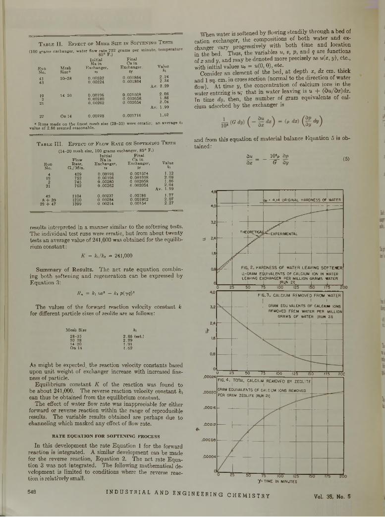
T a b l e I I . E f f e c t o f M e s h S i z e i n S o f t e n i n g T e s t s
(100 g ram s exchanger, w ate r flow ™ te^7 2 gram s per i
In itia l F in a lN a in C a in
R un M esh E xchanger, E xchanger,N o. S ize0 ®o Vf41 20-28 0.00232 0 .00186443 0 .00224 0 .001864
19 14-20 0.00196 0 .0015082 0 .00280 0.002058
21 0.00262 0.002054
27 O n 14 0 .00228 0 .001716
V alueki
2 .2 4 2 .3 4
A v. 2 .2 9
2 .0 8 1.86 2 .0 4
Av. 1 .99
1 .62
a R u n s m ade on th e finest m esh size (28—35) w ere e rra tic ; an average k i va lue of 2.86 seem ed reasonable.
T a b l e I I I . E f f e c t o f F l o w R a t e o n S o f t e n i n g T e s t s
(14-20 m esh size, 100 g ram s exchanger, 85° F .)In itia l F inal
Flow N a in C a inR un R a te , E xchanger, E xchanger,No. G ./M in . v$ Vf
4 409 0.00196 0.00157419 752 0.00196 0.0015082 745 0.00280 0.00205821 752 0.00262 0.002054
45 1104 0.00237 0.001868 + 39 1210 0.00264 0.00190229 + 47 1399 0.00214 0.00154
V alueki
Av.
1.122 .0 81.862 .041.991 .772 .072 .27
results interpreted in a manner similar to the softening tests. The individual test runs were erratic, but from about twenty tests an average value of 241,000 was obtained for the equilibrium constant:
K = k j k t = 241,000
Summary of Results. The net rate equation combining both softening and regeneration can be expressed by Equation 3:
Rn = kx uvl — kt piyq)*
The values of the forward reaction velocity constant k for different particle sizes of zeolite are as follows:
M esh Size28-35 20-28 14-20 On 14
2.86 (eat.)2 .2 91.911 .62
As might be expected, the reaction velocity constants based upon unit weight of exchanger increase with increased fineness of particle.
Equilibrium constant K of the reaction was found to be about 241,000. The reverse reaction velocity constant k2 can thus be obtained from the equilibrium constant.
The effect of water flow rate was inappreciable for either forward or reverse reaction within the range of reproducible results. The variable results obtained are perhaps due to channeling which masked any effect of flow rate.
R A T E E Q U A T IO N F O R S O F T E N IN G P R O C E S S
In this development the rate Equation 1 for the forward reaction is integrated. A similar development can be made for the reverse reaction, Equation 2. The net rate Equation 3 was not integrated. The following mathematical development is limited to conditions where the reverse reaction is relatively small.
When water is softened by flowing steadily through a bed of cation exchanger, the compositions of both water and exchanger vary progressively with both time and location in the bed. Thus, the variables u , v, p , and q are functions of x and y, and may be denoted more precisely as u (x , y ) , etc.,with initial values Uo = u (0 , 0), etc.
Consider an element of the bed, at depth x , d x cm. thick and 1 sq. cm. in cross section (normal to the direction of water flow). At time y, the concentration of calcium ions in the water entering is u; that in water leaving is u + (d u / d x ) d x . In time dy, then, the number of gram equivalents of calcium adsorbed by the exchanger is
and from this equation of material balance Equation 5 is obtained:
ÖUàx
ioy àpG ày
(5)
i l l
THEORETICAl •EXPERIMENTAL
.00012
Uo =■ 4.14 ORIGINAL HARDNESS OF WATER
HARDNESS OF WATER LEAVING SOFTENERU.-GRAM EQUIVALENTS OF CALCIUM ION IN WATER LEAVING EXCHANGER PER MILLION GRAMS WATER
_______ (RUN 21) [ ,
.00024
.00020
.00016
.00008
.00004
FIC>.3. CALCIUM REMOVED FROM WATER ! 1 1 1
GRAM EQUIVALENTS OF CAIC.IM mwQREMOVED FRC
GRAMS C!
M WATER PER MILLION F WATER (RUN 21)
...
O 25 50 75 100 125 150 175 20C
FIG. 4 . TOTAL CALCIUM REMOVED BY ZEOLITE 1 1 1 1 1 GRAM EQUIVALENTS OF CALCIUM IONS REMOVEDPER GRAM ZEOLITE (RUN 21)
y • TIME IN MINUTES
548 INDUSTRIAL AND ENGINEERING CHEMI STRY Vol. 35, No. 5
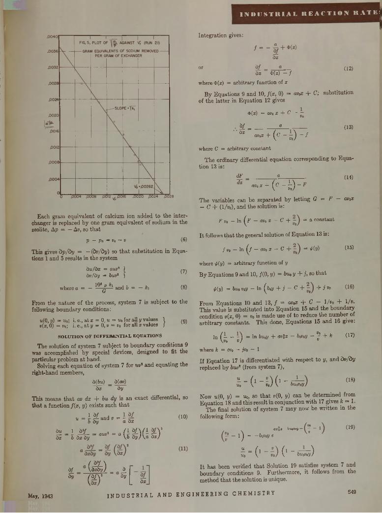
I N D U S T R I A L R E A C T I O N R A T E !
Each gram equivalent of calcium ion added to the inter- changer is replaced by one gram equivalent of sodium in the zeolite, A p = — Av, so that
p — p 0 = Vo — v (6)
This gives b p / b y = — (b v /b y ) so that substitution in Equations 1 and 5 results in the system
b u /b x = au v2 / b v /b y = buv1 )
, 1 0 6 p k i , , ,where a = — — g — and o = — fci
(7 )
(8)
From the nature of the process, system 7 is subject to the following boundary conditions:
w(0, y) = uo; i. e., at x = 0, u = u0 for all y values j (9 )t>(x,’o) = Vo) i. e.’ at y = o' v = va for all x values
S O L U T IO N O F D IF F E R E N T IA L E Q U A T IO N S
The solution of system 7 subject to boundary conditions 9 was accomplished by special devices, designed to fit the particular problem at hand.
Solving each equation of system 7 for uv* and equating the right-hand members,
b(bu) _ b(av) bx ~ by
This means that av d x + bu dy is an exact differential, so that a function f ( x , y) exists such that
u = J % and * = i (10)b by a bx
Integration gives:
bx
à f (12)dx $(x) — /
where $(x) = arbitrary function of x
By Equations 9 and 10, /(x, 0) = avox + C ; substitution of the latter in Equation 12 gives
4>(x) = avo x + C — 7Vqb f = ________ a________
” a i ' +(c-s)-/ (1 3 )
avox
where C = arbitrary constant
The ordinary differential equation corresponding to Equation 13 is:
dFdx av o x + (c"i)-
(1 4 )
(1 5 )
The variables can be separated by letting G — F avox — C + (1/wo), and the solution is:
F Vo - In (^F - av„ x - C + = a constant
It follows that the general solution of Equation 13 is:
/ Vo — In ( f — avo x — C + = 'l'(y)
where ¡piy) = arbitrary function of y
By Equations 9 and 10, /(0, y) = buo y + j> so that
<p{y) = buo v0y - In ( b 0y + j - C + + j
From Equations 10 and 13, / = avox + C — 1/fo + l / y- This value is substituted into Equation 15 and the boundary condition v{x , 0) = Vo is made use of to reduce the number of arbitrary constants. This done, Equations 15 and 16 give.
Vo (1 6 )
- V + k v
(1 7 )In ( ----- J = ln buoy + av%x -\vo v )
where k = cvo — jvo — 1
If Equation 17 is differentiated with respect to y, and b v /b y replaced by buo* (from system 7),
« = ( i - ( i ____uo \ Vo) \ buoVoy)
(1 8 )
Now u(0, y ) = uo, so that t/(0, y) can be determined from Equation 18 a n d this result in conjunction with 17 gives k = 1.
The final solution of system 7 may now be written in the following form:
~ 1) = ~ boV°y e
« = ( i ( l _____ — ^Uo \ V o ) \ buoVoy)
à u 1 Ö2/ _ 2 _ / l V \ ( l à f Vb i = b b ï b h - aUV ~ a \ b b y ) \ a b x )
bj_ a ( d i 4 ) = ±by Ç b f Y ày
lay, 1943 I N D U S T R I A L AND E N G I N E E R I N G CHEMI STRY
q v q X — buovoy (1 9 )
bx
It has been verified that Solution 19 satisfies system 7 and boundary conditions 9. Furthermore, it follows from the method that the solution is unique.
549
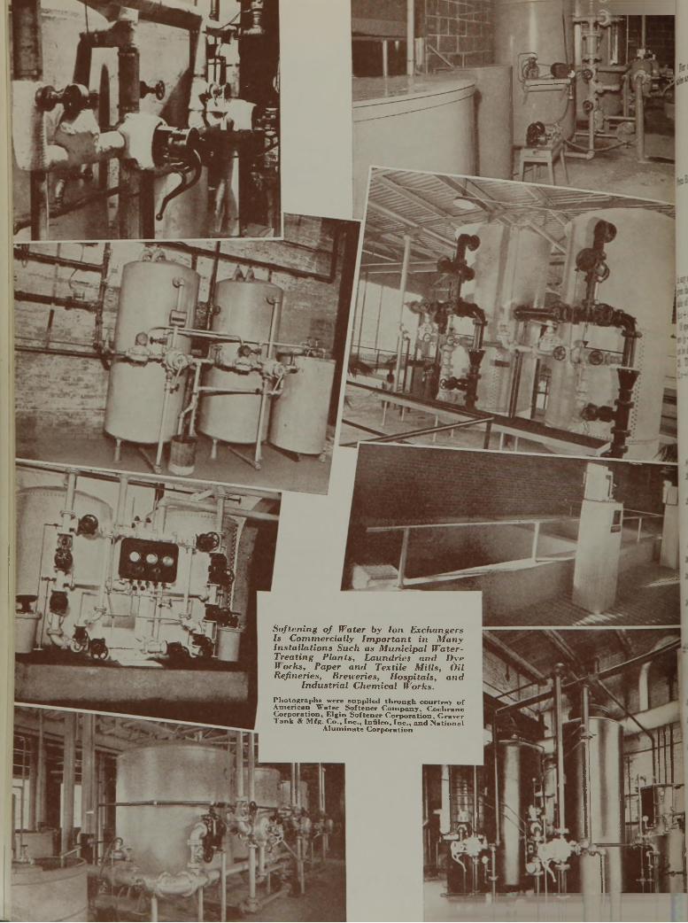
S o f t e n in g o f W a te r b y I o n E x c h a n g e r s I s C o m m e r c ia l ly I m p o r t a n t in M a n y I n s ta l la t i o n s S u c h a s M u n ic ip a l W a te r - T r e a t in g P la n ts , L a u n d r ie s a n d D y e W o rk s , P a p e r a n d T e x t i le M i l l s , O il R e fin e r ie s , B re w e r ie s , H o s p ita ls , a n d
I n d u s t r ia l C h e m ic a l W o r k s .
P h o to g ra p h s w ere s u p p lie d th r o u g h c o u r te s y o f A m e r ic a n W a te r S o f te n e r C o m p a n y , C o c h ra n e C o r p o r a t io n , E lg in S o f te n e r C o rp o ra t io n , G ra v e r T a n k & M fg . C o ., I n c . , In f ilc o , I n c . , a n d N a tio n a l
A lu m in a te C o rp o ra t io n
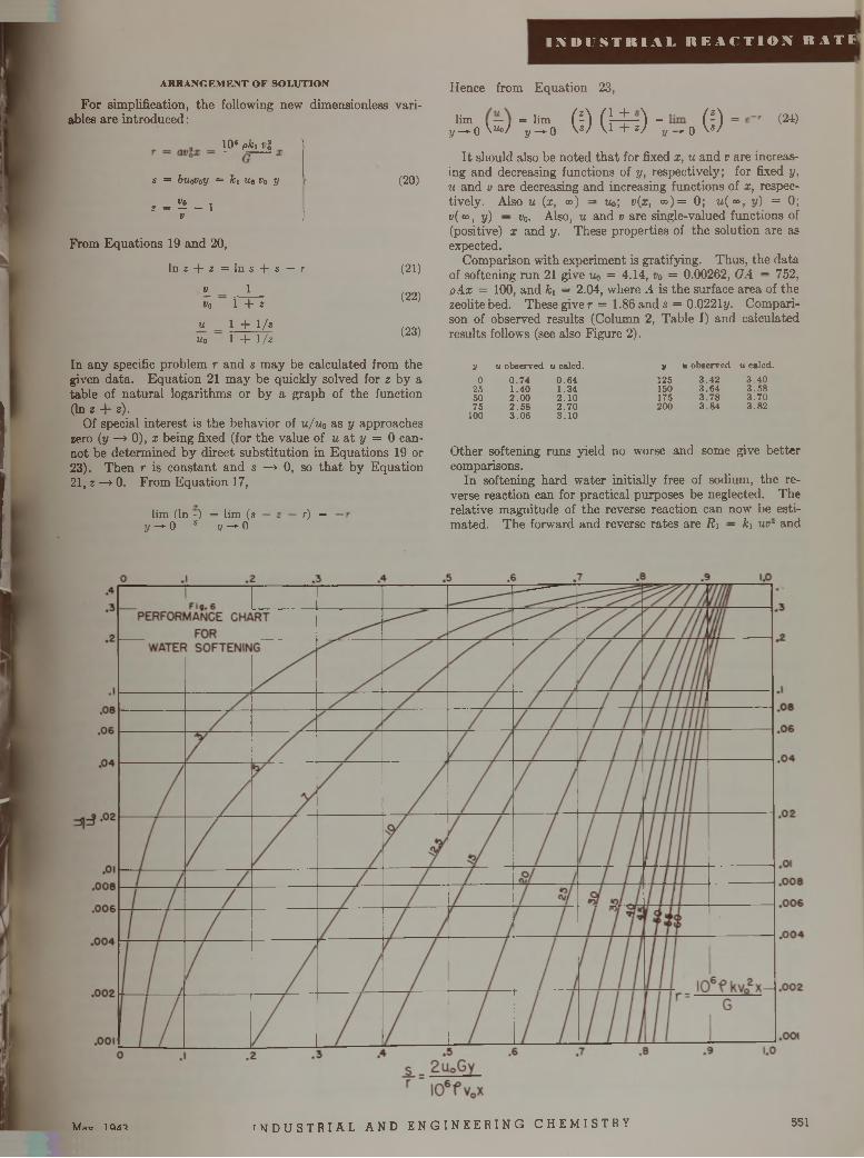
I N D U S T R I A L R E A C T I O N R A T S
A R R A N G E M E N T O F S O L U T IO N
For simplification, the following new dimensionless variables are introduced:
10‘ pfc, t;?
s = biiaVoy = ki Ut Vo yvo ,2 = 1V
(20)
J
From Equations 19 and 20,
ln z + z = l n s + s — rv_V o
uuo
11 + 2
1 + 1 / s
1 + 1/2
(21)
(22)
(23)
In any specific problem r and s may be calculated from the given data. Equation 21 may be quickly solved for 2 by a table of natural logarithms or by a graph of the function (In 2 + z).
Of special interest is the behavior of u / uq as y approaches zero (y —> 0), x being fixed (for the value of u at y = 0 cannot be determined by direct substitution in Equations 19 or 23). Then r is constant and s —» 0, so that by Equation 21, 2 —> 0. From Equation 17,
l im ( In - ) = l im (s y — 0 s y — 0
r) =
Hence from Equation 23,
G)G+lim =y - o W j
l im y - * 0 + 2) - „ - 0 ( 0
(24)
It should also be noted that for fixed x , u and v are increasing and decreasing functions of y, respectively; for fixed y, u and v are decreasing and increasing functions of x , respectively. Also u {x , o») - tío; v(x, co)= 0; u(c°, y ) = 0; "(“ > y) — Vo- Also, u and v are single-valued functions of (positive) x and y . These properties of the solution are as expected.
Comparison with experiment is gratifying. Thus, the data of softening run 21 give Uo = 4.14, v0 = 0.00262, G A = 752, p A x = 100, and ki = 2.04, where .4 is the surface area of the zeolite bed. These giver = 1.86 and s = 0.0221y. Comparison of observed results (Column 2, Table I) and calculated results follows (see also Figure 2).
V u observed u caled. V « observed u calcd.
0 0 .7 4 0 .6 4 125 3 .4 2 3 .4 025 1 .4 0 1 .3 4 150 3 .6 4 3 .5 850 2.00 2.10 175 3 .7 8 3 .7 075 2 .5 8 2 .7 0 200 3 .8 4 3 .8 2100 3 .0 6 3 .1 0
Other softening runs yield no worse and some give better comparisons.
In softening hard water initially free of sodium, the reverse reaction can for practical purposes be neglected. The relative magnitude of the reverse reaction can now be estimated. The forward and reverse rates are R i — ki uv- and
Mav 1QA'? I N DU S T R I A L AND E NG I N EE R IN G C HEMI STRY 551
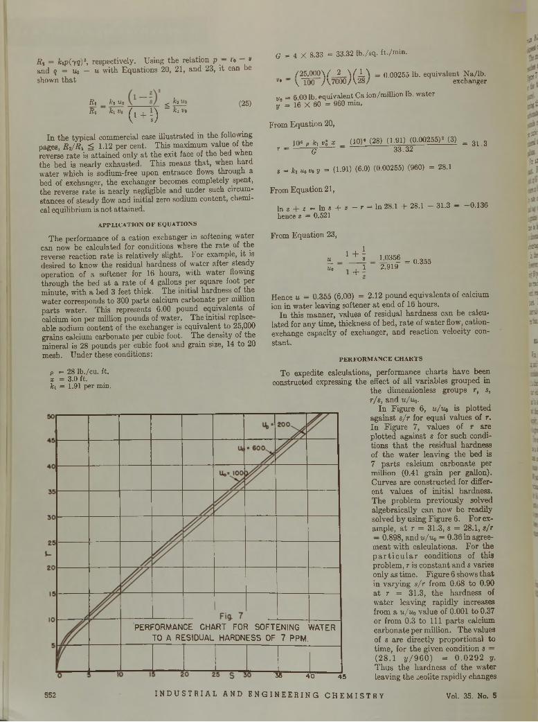
;3>1
R t = k ip (y q )1, respectively. Using the relation p — *■'<> »and q = Uc — u with Equations 20, 21, and 23, it can be shown that
RtRi
ki up k i Vo
( - ; )
< ki up = ki Vo
(25)
In the typical commercial case illustrated in the following pages, R i / R i ^ 1.12 per cent. This maximum value of the reverse rate is attained only at the exit face of the bed when the bed is nearly exhausted. This means that, when hard water which is sodium-free upon entrance flows through a bed of exchanger, the exchanger becomes completely spent, the reverse rate is nearly negligible and under such circumstances of steady flow and initial zero sodium content, chemical equilibrium is not attained.
A P P L IC A T IO N O F E Q U A T IO N S
The performance of a cation exchanger in softening water can now be calculated for conditions where the rate of the reverse reaction rate is relatively slight. For example, it is desired to know the residual hardness of water after stea,dy operation of a softener for 16 hours, with water flowing through the bed at a rate of 4 gallons per square foot per minute, with a bed 3 feet thick. The initial hardness of the water corresponds to 300 parts calcium carbonate per million parts water. This represents 6.00 pound equivalents of calcium ion per million pounds of water. The initial replaceable sodium content of the exchanger is equivalent to 25,000 grains calcium carbonate per cubic foot. The density of the mineral is 28 pounds per cubic foot and grain size, 14 to 20 mesh. Under these conditions:
G = 4 X 8.33 = 33.32 lb . /s q . f t . /m in .
/'25 ,000\ / ' 2 \ ( _ L \ = 0 .00255 lb . eq u iv a len t N a /lb . v* ~ \ 100 A T O O O A 2 8 / exchanger
tu = 6.00 lb. equivalent Ca ion /m illion lb. w ater y = 16 X 60 = 960 m in.
From Equation 20,
10* „ h v l x _ (10)« (28) (1.91) (0 .0 0 2 5 5 )2 (3) = 31 3 r ■ q 3 3 .3 2
s = k 1 u0 va y = (1-91) (6.0) (0.00255) (960) = 28.1
From Equation 21,
1 n z z = In s + s — r = In 28.1 + 28.1 — 31.3 - 0.136hence z = 0.521
From Equation 23,
u_
Up
1 + is 1.0356
1 + 1 2.919= 0.355
Hence u = 0.355 (6.00) = 2.12 pound equivalents of calcium ion in water leaving softener at end of 16 hours.
In this manner, values of residual hardness can be calculated for any time, thickness of bed, rate of water flow, cation- exchange capacity of exchanger, and reaction velocity constant.
P E R FO R xM A N C E C H A R T S
dc
•mt'
-wt!
6<(*
fi t
-32 ß
2»'
mk*
i l li *S’. 9 3 1 2« IX
IÜ
hitc;
nazsillIBbj:
ish i
2l
It35
p = 28 lb ./cu . ft.x = 3.0 ft.ki = 1.91 per min.
PERFORMANCE CHART FOR SOFTENING WATER TO A RESIDUAL HARDNESS OF 7 PPM.
To expedite calculations, performance charts have been constructed expressing the effect of all variables grouped in
the dimensionless groups r, s, r/s, and u /u q .
In Figure 6, u /u 0 is plotted against s / r for equal values of r . In Figure 7, values of r are plotted against s for such conditions that the residual hardness of the water leaving the bed is 7 parts calcium carbonate per million (0.41 grain per gallon). Curves are constructed for different values of initial hardness. The problem previously solved algebraically can now be readily solved by using Figure 6. For example, at r = 31.3, s = 28.1, s/r — 0.898, and u /u p = 0.36 in agreement with calculations. For the p articu lar conditions of this problem, r is constant and s varies only as time. Figure 6 shows that in varying s / r from 0.68 to 0.90 at r = 31.3, the hardness of water leaving rapidly increases from au/uo value of 0.001 to 0.37 or from 0.3 to 111 parts calcium carbonate per million. The values of s are directly proportional to time, for the given condition s = (28.1 y /9 6 0 ) = 0 .0 2 9 2 y.
___________________ Thus the hardness of the water35 40 45 leaving the zeolite rapidly changes
552 INDUSTR I AL AND ENGINEERING CHEMI STRY Vol. 35. No. 5
I N D U S T R I A L R E A C T I O N R A T E
from 0.3 to 111 p. p. m. calcium carbonate as the time elapsed changes from 12.2 to 16.1 hours.
The mineral should be regenerated when the water leaving reaches a hardness of 7 p. p. m. calcium carbonate. From Figure 7 an r value of 31.3 corresponds to an s value of 24.6, or the time elapsed is 24.6/0.0292 = 844 minutes (14.1 hours). The water softened by 3 cubic feet of mineral during this period is 844 X 4 = 3376 gallons; the calcium carbonate removed is (3376 X 8.34 X 300-7)/109 = 8.24 pounds calcium carbonate (57,680 grains), or 19,227 grains per cubic foot. The total water softened by one cubic foot of mineral under the above conditions is (4 X 844)/3 = 1130 gallons.
For any particular zeolite values of k u p and Vo are constant. For any particular zeolite it is more convenient to plot x / G against v0y , instead of r against s as in Figure, 7, where x / G can be expressed in thickness of bed in feet divided by rate of water flow in gallons per square foot per minute, and imy can be expressed as initial hardness of water supply in grains calcium carbonate per gallon multiplied by softening time in hours. Such a plot is neither general nor expressed in dimensionless units, but for a particular zeolite it has the advantage of reading directly in commercial terms.
In these calculations the reverse reaction was neglected. However, even in the case where the bed was used until only 60 per cent of the hardness was removed, the reverse reaction reached a maximum ratio of only 1.1 per cent of the forward reaction at the exit side of the bed at the end of 16 hours. For all shorter distances in the bed and for all shorter intervals of time, the reverse rate would be correspondingly less than 1.1 per cent of the forward rate.
REACTION VELOCITY fci FROM PERFORMANCE DATA
With the kinetic equations established for water softening and its mathematical development, it becomes possible to calculate reaction velocity constant k\ from the performance of a thick bed as in commercial operation. It is necessary to start either with a fully regenerated or fresh cation exchanger and to know its density, maximum cation-exchange capacity, and thickness of bed. The initial hardness, Uo, of the water supply, rate of water flow, G , and exit hardness, u , at the end of a given time, y , must be measured.
For example, a bed of exchanger is used which is 3 feet thick, has a density of 28 pounds per cubic foot, and has a maximum cation-exchange capacity of 25,000 grains calcium carbonate per cubic foot. Water having an initial hardness of300 parts calcium carbonate per million is passed through theexchanger at a rate of 4 gallons per square foot per minute for 14.1 hours when the water leaving has a hardness of 7 parts calcium carbonate per million. These data are similar to previous illustration, but k\ is now to be calculated. Under these conditions, Uq = 6.0, Vo = 0.00255, G = 33.32 pounds per square foot per minute, u /u a = 0.0233; y = 846 minutes:
s 2(33.32 X 3.0 X 846) = o 79r (10® X 28 X 0.00255 X 3)
From Figure 6 the intersection of s / r = 0.79 with u / uq =0.0233 gives an r value of 32. Thus,
r<7 _ (32) (33.32) = -1 ~ 10V »1* ~ (10) 6 (28) (0.00255)* (3)
LIMITATIONS OF EQUATIONS AND PROCEDURE
The actual experimental values reported in this paper are of value only for a particular cation exchanger and a particular type of water. The mathematical treatment is of
general value and has been developed for both the forward and reverse reactions but not for the net reaction rate. Where the initial water supply has a high sodium content, the reverse reaction becomes appreciable and the given equations do not strictly apply. It is believed, however, that this general procedure, the mathematical treatment, and the general performance charts presented here can be used to obtain the complete performance characteristics of a bed of cation exchanger with the minimum of experimental data; in general the method should be applicable to any waters for the removal of magnesium as well as calcium. The effects of pH, temperature, and mineral composition of the water, and the effects of grain size, chemical composition, and structure of the mineral can be evaluated by this procedure and the results extrapolated with the minimum of experimental data. The mathematical treatment can also be applied to similar heterogeneous reactions in a batch process where one atom or ion in the fluid phase reacts with two atoms or active spots in the solid phase.
A C K N O W L E D G M E N T
Credit is gratefully acknowledged to E. C. Carlson and D. K. Starr for technical services in experimental work; to N. A. Ednie for construction of performance charts; to R. E. Langer for the method of deriving Equation 11 from system 7; to Milton Shoemaker for information on industrial performance; and to the Wisconsin Alumni Research Foundation for financial support.
NOMENCLATUREa = —(W‘ pki)/G b = —ki C - c o n s ta n tG = mass velocity of water flow, lb./sq. ft./m in. ki = reaction velocity constant of softening as defined by
Equation 1k2 = reaction velocity constant of regeneration as defined by
Equation 2 K = equilibrium constant = fa/k*p = c a lc iu m c o n te n t o f e x c h a n g e r , g r a m e q u iv a le n t s /g r a m
z e o lite , a n d lb . e q u iv a le n t A b . z e o lite q = s o d iu m c o n te n t o f b r in e , g r a m e q u iv a le n t s /m i l l io n
g ra m s w a te r , a n d lb . e q u iv a le n t / m i l l i o n lb . w a te r r = — a v lx (d im e n s io n le s s g ro u p )E i = r a t e o f s o fte n in g , g r a m e q u iv a le n ts c a lc iu m re m o v e d
b y z e o l i t e /m in . / g r a m e x c h a n g e r R 2 = r a t e o f r e g e n e ra t io n , g r a m e q u iv a le n ts c a lc iu m re m o v e d
f ro m z e o l i t e / m in . / g r a m e x c h a n g e r
R n = n e t r a t e = Ri — Ri s = -b u o v 0y (d im e n s io n le s s g ro u p )u = c a lc iu m io n s in w a te r , g r a m e q u iv a le n t s /m i l l io n g ra m s
w a te r , a n d lb . e q u iv a le n t s /m i l l io n lb . w a te r v = s o d iu m c o n te n t o f e x c h a n g e r , g r a m e q u iv a le n t s /
g r a m e x c h a n g e r , a n d lb . e q u iv a le n t A b . e x c h a n g e r w = f lo w r a t e o f w a te r , g r a m s /m in . x = d is ta n c e in b e d , c m . o r f t . y = t im e e la p s e d , m in . z = (vo/v) — 1 (d im e n s io n le s s g ro u p )y = a c t i v i t y c o e ff ic ie n t f o r s o d iu m io n in s o lu t io n ; a t lo w
c o n c e n tra t io n s 7 = 1 d = d i f f e r e n t ia l o p e ra to rp - d e n s ity2 = s u m m a t io n
Subscriptsa — a v e ra g e t - r e m o v e d r a = a v e ra g e re m o v e d 0 = i n i t i a l s ta te
LITERATURE CITED(1) Blacher, Griinberg, and Kissa, Chem.-Ztg.. 37, 56 (1913).(2) Suter, Max, J- A m . Waterworks Assoc., 29, 1001 (1937).
May, 1943 I N D U S T R I A L AND E NG I N EE R IN G C H E M I S T R f 553
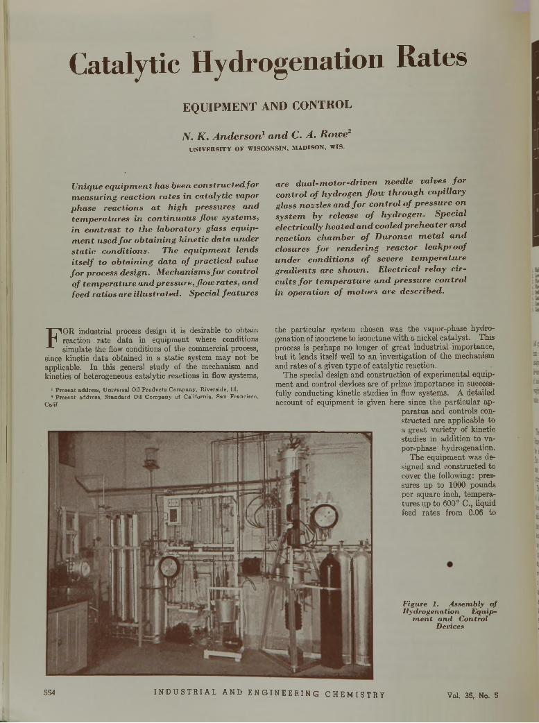
Catalytic Hydrogenation RatesE Q U I P M E N T A N D C O N T R O L
N . K . A n d e r s o n 1 a n d C . A . R o w e 2
UNIVERSITY OF WISCONSIN, MADISON, WIS.
U n iq u e e q u i p m e n t h a s b e e n c o n s t r u c t e d f o r m e a s u r in g r e a c t io n r a t e s in c a t a l y t i c v a p o r p h a s e r e a c t io n s a t h ig h p r e s s u r e s a n d t e m p e r a t u r e s in c o n t in u o u s f l o w s y s t e m s , in c o n t r a s t to th e la b o r a to r y g la s s e q u ip m e n t u s e d f o r o b ta in in g k in e t i c d a ta u n d e r s t a t i c c o n d i t io n s . T h e e q u ip m e n t le n d s i t s e l f to o b ta in in g d a ta o f p r a c t i c a l v a lu e f o r p r o c e s s d e s ig n . M e c h a n is m s f o r c o n tr o l o f t e m p e r a t u r e a n d p r e s s u r e , f l o w r a te s , a n d f e e d r a t io s a r e i l lu s t r a t e d . S p e c ia l f e a t u r e s
a r e d u a l - m o t o r - d r i v e n n e e d le v a lv e s f o r c o n tr o l o f h y d r o g e n f l o w t h r o u g h c a p i l la r y g la s s n o z z le s a n d f o r c o n t r o l o f p r e s s u r e o n s y s t e m b y r e le a s e o f h y d r o g e n . S p e c ia l e le c t r i c a l l y h e a t e d a n d c o o le d p r e h e a t e r a n d r e a c t io n c h a m b e r o f D u r o n z e m e t a l a n d c lo s u r e s f o r r e n d e r in g r e a c to r le a k p r o o f u n d e r c o n d i t i o n s o f s e v e r e t e m p e r a t u r e g r a d i e n t s a r e s h o w n . E le c t r i c a l r e la y c i r c u i t s f o r t e m p e r a t u r e a n d p r e s s u r e c o n t r o l in o p e r a t io n o f m o t o r s a r e d e s c r ib e d .
ips!&-rainx
aI !
u8>j
?!n
the particular system chosen was the vapor-phase hydrogenation of isooctene to isooctane with a nickel catalyst. This process is perhaps no longer of great industrial importance, but it lends itself well to an investigation of the mechanism and rates of a given type of catalytic reaction.
The special design and construction of experimental equipment and control devices are of prime importance in successfully conducting kinetic studies in flow systems. A detailed account of equipment is given here since the particular ap
paratus and controls constructed are applicable to a great variety of kinetic studies in addition to vapor-phase hydrogenation.
The equipment was designed and constructed to cover the following: pressures up to 1000 pounds per square inch, temperatures up to 600° C., liquid feed rates from 0.06 to
F ig u r e 1. A s s e m b l y o f H y d r o g e n a t io n E q u ip
m e n t a n d C o n tr o l D e v ic e s
F OR industrial process design it is desirable to obtain reaction rate data in equipment where conditions simulate the flow conditions of the commercial process,
since kinetic data obtained in a static system may not be applicable. In this general study of the mechanism and kinetics of heterogeneous catalytic reactions in flow systems,
1 P resen t address, U niversal Oil P ro d u c ts C om pany , R iverside, 111.1 P resen t address, S tan d a rd Oil C om pany of C aliforn ia , San F rancisco ,
Calif.
554 INDUSTRIAL AND ENGINEER ING CHEMI STRY Vol. 35, No. 5
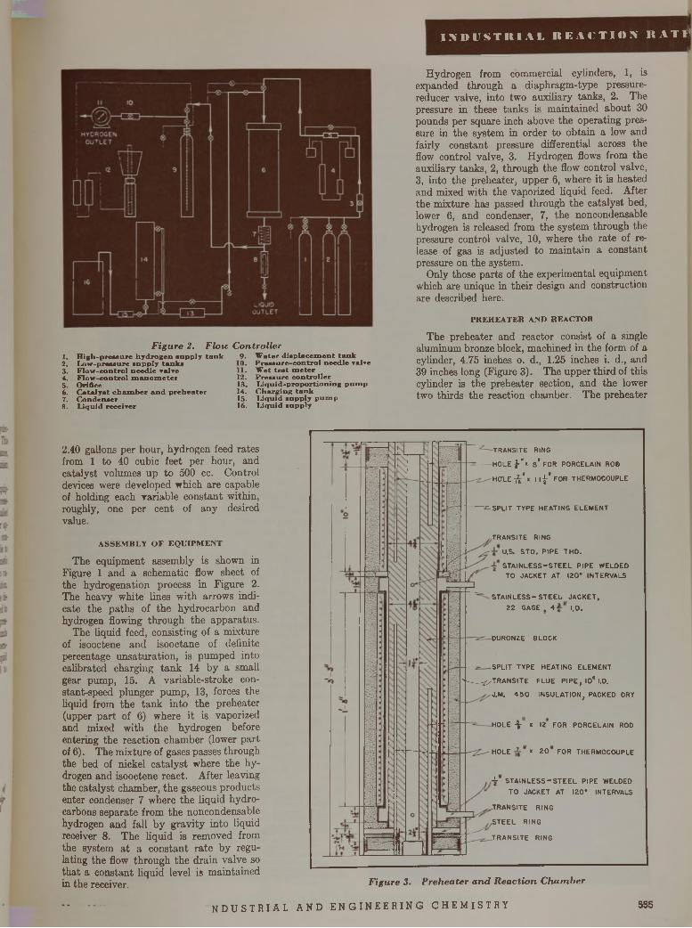
I N D U S T R I A L R E A C T I O N R A T Î -
F ig u r e 2 , F lo w C o n tr o l le r1. H ig h -p re » s u re h y d r o g e n s u p p ly t a n k 9 . W a te r d i s p la c e m e n t t a n k2. L o w -p re s s u re s n p p ly ta n k s3. F lo w -c o n tro l n e e d le r a l r e4. F lo w -c o n tro l m a n o m e t e r5. O rifice6. C a ta ly s t c h a m b e r a n d p r e h e a te r7. C o n d e n s e r8. L iq u id re c e iv e r
10. P r e s s u r e - c o n t r o l n e e d le valve11. W e t t e s t m e te r12. P r e s s u r e c o n t r o l l e r13. L i q u id - p r o p o r t i o n in g p u m p14. C h a r g in g t a n k15. L iq u id s u p p ly p u m p16. L iq u id s u p p ly
Hydrogen from commercial cylinders, 1, is expanded through a diaphragm-type pressure- reducer valve, into two auxiliary tanks, 2. The pressure in these tanks is maintained about 30 pounds per square inch above the operating pressure in the system in order to obtain a low and fairly constant pressure differential across the flow control valve, 3. Hydrogen flows from the auxiliary tanks, 2, through the flow control valve, 3, into the preheater, upper 6, where it is heated and mixed with the vaporized liquid feed. After the mixture has passed through the catalyst bed, lower 6, and condenser, 7, the noncondensable hydrogen is released from the system through the pressure control valve, 10, where the rate of release of gas is adjusted to maintain a constant pressure on the system.
Only those parts of the experimental equipment which are unique in their design and construction are described here.
P R E H E A T E R A N D R E A C T O R
The preheater and reactor consist of a single aluminum bronze block, machined in the form of a cylinder, 4.75 inches o. d., 1.25 inches i. d., and 39 inches long (Figure 3). The upper third of this cylinder is the preheater section, and the lower two thirds the reaction chamber. The preheater
2.40 gallons per hour, hydrogen feed rates from 1 to 40 cubic feet per hour, and catalyst volumes up to 500 cc. Control devices were developed which are capable of holding each variable constant within, roughly, one per cent of any desired value.
A S S E M B L Y O F E Q U IP M E N T
The equipment assembly is shown in Figure 1 and a schematic flow sheet of the hydrogenation process in Figure 2. The heavy white lines with arrows indicate the paths of the hydrocarbon and hydrogen flowing through the apparatus.
The liquid feed, consisting of a mixture of isooctene and isooctane of definite percentage unsaturation, is pumped into calibrated charging tank 14 by a small gear pump, 15. A variable-stroke con- stant-speed plunger pump, 13, forces the liquid from the tank into the preheater (upper part of 6) where it is vaporized and mixed with the hydrogen before entering the reaction chamber (lower part of 6). The mixture of gases passes through the bed of nickel catalyst where the hydrogen and isooctene react. After leaving the catalyst chamber, the gaseous products enter condenser 7 where the liquid hydrocarbons separate from the noncondensable hydrogen and fall by gravity into liquid receiver 8. The liquid is removed from the system at a constant rate by regulating the flow through the drain valve so that a constant liquid level is maintained in the receiver.
TRANSITE RINGHOLE I-"* a" FOR PORCELAIN ROB HCTLE- 'x 11-£-' FOR THERMOCOUPLE
SPLIT TYPE HEATING ELEMENT
TRANSITE RINGU.S. STD. PIPE THD.STAINLESS-STEEL PIPE WELDED TO JACKET AT 120° INTERVALS
STAINLESS-STEEL JACKET,22 GAGE , 4-j
DURONZE BLOCK
I.D.
SPLIT TYPE HEATING ELEMENT4 jj/TRANSITE FLUE PIPE, IO" I.D.
J.M. 450 INSULATION, PACKED DRY
HOLE ^ x 12 FOR PORCELAIN ROD
HOLE x 20 FOR THERMOCOUPLE
-A- STAINLESS-STEEL PIPE WELDED TO JACKET AT 120* INTERVALS
.TRANSITE RINGSTEEL RINGTRANSITE RING
F ig u r e 3 . P r e h e a te r a n d R e a c t i o n C h a m b e r
n d u s t r i a l a n d e n g i n e e r i n g c h e m i s t r y 555
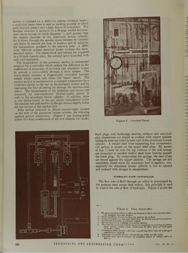
section is enclosed by a 2000-volt radiant electrical heater, a small-link brass chain is used as packing material to afford good thermal contact and a high degree of turbulence. The reaction chamber is enclosed by a 20-gage welded stainless- steel sleeve having an inside diameter Vs inch greater than the outside diameter of the aluminum bronze cylinder. Air is blown through the annular space between the cylinder and sleeve to remove the heat of reaction and to minimize the temperature gradient in the reaction zone. A 4000- watt, 220-volt radiant electrical heater encloses the stainless-steel sleeve. The entire block and heaters are mounted in a 10-inch transite pipe; the annular space is packed with rock wool insulation.
The temperature of the preheater section is maintained constant by a controller which utilizes the difference in the coefficients of expansion of porcelain and aluminum bronze to operate a micro-switch through a lever system. The micro-switch actuates a magnetically controlled mercury switch which opens and closes the heater circuit. The reactor section is maintained at a constant temperature by a controller similar to the one on the preheater section and by regulating the flow of cooling air through the stainless-steel sleeve. The temperatures of the preheater and reactor are measured by iron-constantan thermocouples placed in wells in the aluminum bronze cylinder. In addition, there is one thermocouple in the gas stream immediately below the catalyst bed and another in the gas stream slightly below the top surface of the catalyst bed.
After several attempts to obtain pressure-tight closures on the ends of the aluminum bronze cylinder, the following method proved satisfactory. (Figure 1 was photographed before this final modification of the end closures was made.)
F ig u r e 5. C o n tr o l P a n e l
Steel plugs with knife-edge bearing surfaces and standard pipe connections are placed in contact with copper gaskets resting on seats machined in each end of the aluminum bronze cylinder. A welded steel truss supporting four compression coil springs is placed on the upper steel plug. By means of four Vs-inch tie rods the top surfaces of the coil springs are connected to another welded steel truss bearing against the lower plug. By compressing the springs, the steel plugs are forced against the copper gaskets. The springs are not completely closed when the maximum load is applied; consequently the aluminum bronze cylinder is free to expand and contract with changes in temperature.
HYDROGEN FLOW CONTROLLER
The flow rate of fluid through an orifice is determined by the pressure drop across that orifice; this principle is used to control the rate of flow of hydrogen. Figure 4 shows the
F ig u r e 4. F lo w C o n tr o l le r
B y -p ass a r o u n d o r if ice to a l lo w h y d ro g e n to flow in to s y s te m w ith o u t p a s s in g th r o u g h o r if ic e
C la s s c a p i l la ry d r a w n to f in e t ip (se rv es a s orifice)T ra p s to c a tc h a n y m e r c u r y t h a t m a y be b lo w n o u t o f m a n o m e te r L le c tr ic a l c o n ta c t s to a c t u a t e r e la y s R e lay s o p e r a t in g ta n d e m r e v e rs ib le m o to rM e rc u ry m a n o m e te r w h ic h m o v e s in resp o n se to v a r y in g p re ssu re
d ro p ac ro ss o rif ic e f r o m v a r ia tio n s in flow r a te o f h y d ro g e n th r o u g h o rifice
I ly d r o g e n - in le t n e e d le va lv e fo r r e g u la t in g flow r a te o f h y d ro g e n a d m i t t e d to s y s te m
T a n d e m re v e rs ib le m o to r w h ic h d rive s in le t n e e d le valve V a r ia b le -g e a r sp e e d r e d u c e r to r e g u la te speed a t w h ic h va lv e is
d r iv e n
556 I NDUSTR I AL AND ENGINEERING CHE MTO,rDV W~1 OR W« R
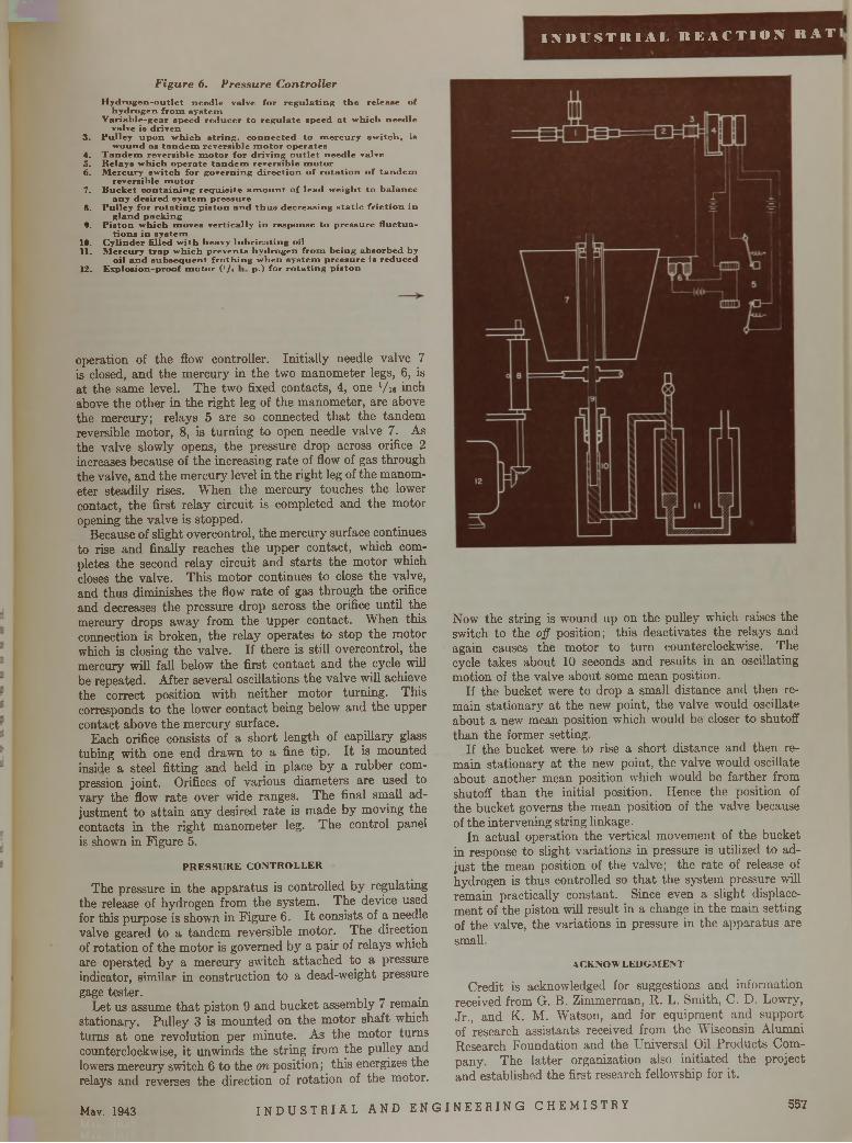
II N U V S T I I I A L R E A C T I O N ! R A T
F ig u r e 6 . P r e s s u r e C o n tr o l l e r
H y d r o g e n - o u t l e t n e e d le va lv e fo r r e g u l a t i n g t h e re le a a e o f h y d r o g e n f r o m s y s te m
V a r ia b le - g e a r s p e e d r e d u c e r to r e g u la te s p e e d a t w h ic h n e e d le v a lve is d r iv e n
3 . P u l le y u p o n w h ic h s t r i n g , c o n n e c te d to m e r c u r y s w i tc h , isw o u n d a s t a n d e m r e v e rs ib le m o t o r o p e ra te s
4. T a n d e m re v e rs ib le m o t o r f o r d r iv in g o u t l e t n e e d le valve5. R e la y s w h ic h o p e r a t e t a n d e m r e v e rs ib le m o to r6. M e rc u r y s w i tc h fo r g o v e r n in g d i r e c t i o n o f r o t a t i o n o f t a n d e m
re v e r s ib le m o t o r7. B u c k e t c o n t a in i n g r e q u i s i t e a m o u n t o f le a d w e ig h t to b a la n c e
a n y d e s i r e d s y s te m p r e s s u r e8. P u lle y f o r r o t a t i n g p i s to n a n d t h u s d e c re a s in g s t a t i c f r i c t i o n in
g la n d p a c k in gf . P i s to n w h ic h m o v e s v e r t ic a l ly in r e s p o n s e to p r e s s u r e f lu c tu a
t i o n s in s y s te m 19. C y lin d e r f il le d w i th h e a v y l u b r i c a t i n g o il11. M e r c u ry t r a p w h ic h p r e v e n t s h y d r o g e n f r o m b e in g a b s o rb e d by
o il a n d s u b s e q u e n t f r o th i n g w h e n s y s t e m p r e s s u r e is r e d u c e d12. E x p lo s io n -p ro o f m o t o r ( l /< P*) fo r r o t a t i n g p i s to n
operation of the flow controller. Initially needle valve 7 is closed, and the mercury in the two manometer legs, 6, is at the same level. The two fixed contacts, 4, one Vn inch above the other in the right leg of the manometer, are above the mercury; relays 5 are so connected that the tandem reversible motor, 8, is turning to open needle valve 7. As the valve slowly opens, the pressure drop across orifice 2 increases because of the increasing rate of flow of gas through the valve, and the mercury level in the right leg of the manometer steadily rises. When the mercury touches the lower contact, the first relay circuit is completed and the motor opening the valve is stopped.
Because of slight overcontrol, the mercury surface continues to rise and finally reaches the upper contact, which completes the second relay circuit and starts the motor which closes the valve. This motor continues to close the valve, and thus diminishes the flow rate of gas through the orifice and decreases the pressure drop across the orifice until the mercury drops away from the upper contact. When this connection is broken, the relay operates to stop the motor which is closing the valve. If there is still overcontrol, the mercury will fall below the first contact and the cycle will be repeated. After several oscillations the valve will achieve the correct position with neither motor turning. This corresponds to the lower contact being below and the upper contact above the mercury surface.
Each orifice consists of a short length of capillary glass tubing with one end drawn to a fine tip. It is mounted inside a steel fitting and held in place by a rubber compression joint. Orifices of various diameters are used to vary the flow rate over wide ranges. The final small adjustment to attain any desired rate is made by moving the contacts in the right manometer leg. The control panel is shown in Figure 5.
P R E S S U R E C O N T R O L L E R
The pressure in the apparatus is controlled by regulating the release of hydrogen from the system. The device used for this purpose is shown in Figure 6. It consists of a needle valve geared to a tandem reversible motor. The direction of rotation of the motor is governed by a pair of relays which are operated by a mercury switch attached to a pressure indicator, s im ila r in construction to a dead-weight pressure gage tester.
Let us assume that piston 9 and bucket assembly 7 remain stationary. Pulley 3 is mounted on the motor shaft which turns at one revolution per minute. As the motor turns counterclockwise, it unwinds the string from the pulley and lowers mercury switch 6 to the on position; this energizes the relays and reverses the direction of rotation of the motor.
Now the string is wound up on the pulley which raises the switch to the off position; this deactivates the relays and again causes the motor to turn counterclockwise. The cycle takes about 10 seconds and results in an oscillating motion of the valve about some mean position.
If the bucket were to drop a small distance and then remain stationary at the new point, the valve would oscillate about a new mean position which would be closer to shutoff than the former setting.
If the bucket were to rise a short distance and then remain stationary at the new point, the valve would oscillate about another mean position which would be farther from shutoff than the initial position. Hence the position of the bucket governs the mean position of the valve because of the intervening string linkage.
In actual operation the vertical movement of the bucket in response to slight variations in pressure is utilized to adjust the mean position of the valve; the rate of release of hydrogen is thus controlled so that the system pressure will remain practically constant. Since even a slight displacement of the piston will result in a change in the main setting of the valve, the variations in pressure in the apparatus are small.
ACKNOW LEDGMENT
Credit is acknowledged for suggestions and information received from G. B. Zimmerman, R. L. Smith, C. D. Lowry, Jr., and K. M. Watson, and for equipment and support of research assistants received from the Wisconsin Alumni Research Foundation and the Universal Oil Products Company. The latter organization also initiated the project and established the first research fellowship for it.
Mav. 1943 I N D U S T R I A L AND E N GI NE E R I NG CHEMI STRY 557
( C A T A L Y T I C H Y D R O G E N A T I O N R A T E S )
I N T E R P R E T A T I O N O F R E S U L T S
P r o c e d u r e s f o r s t u d y i n g r a t e s o f c a t a l y t i c h y d r o g e n a t io n a r e o u t l in e d , t o g e t h e r w i t h p r e c a u t io n s in p u r i f i c a t io n o f r e a c t a n ts , a c t i v a t i o n o f c a t a l y s t , a n d a n a ly s i s o f p r o d u c t . E x p e r im e n ta l d a t a s e e m to in d i c a te t h a t ih e c o n tr o l l in g s t e p in th i s p r o c e s s is th e r a t e o f s u r fa c e r e a c t io n , t h a t t h e m a s s t r a n s f e r s t e p i s n e g l ig ib le , a n d t h a t a d s o r p t io n e q u i l i b r iu m is m a i n ta i n e d b e tw e e n t h e g a s p h a s e a n d a d s o r b e d c o m p o n e n ts . R e a c t io n r a t e e q u a t io n s a r e d e v e l o p e d , in c lu d in g t h e e f f e c ts o f a c t i v a t e d a d s o r p t io n a n d s u r fa c e r e a c t io n e x p r e s s e d in t e r m s o f c o n c e n tr a t i o n s f o r tw o c a ta l y s t s . F u r th e r w o r k is u n d e r w a y a t v a r io u s t o t a l p r e s s u r e s , t e m p e r a t u r e s , a n d c a t a l y s t s i z e s t o e v a lu a te th e s e a d d i t i o n a l e f f e c ts a n d to im p r o v e th e p r e s e n t in t e r p r e t a t i o n .
i S STATED by Anderson and Rowe (page 554) the f \ system chosen for studying the rates of catalytic hy-
drogenation was the reaction of hydrogen with iso- octene to form isooctane in the vapor phase in a continuous flow process. Adequate nickel catalyst was obtained to ensure uniformity of supply for a large number of tests. The catalyst pellets were cylinders ‘/ i X Vs inch and, as received, contained nickel in an oxidized state supported on kiesel- guhr. This catalyst is commonly used for hydrogenation of unsaturated hydrocarbons. Its exact composition and chemical analysis were not disclosed by the producer. Before use the catalyst was activated by reduction and heating for 4 hours in a stream of hydrogen at 300° C. and 5 atmospheres pressure. The hydrogen was flowed at a rate of 2.64 cubic feet per hour (at standard conditions) through a catalyst bed l 1/« inches in diameter.
To ensure uniformity of isooctene for all tests, an initial supply of 550 gallons was made available, and to dilute the feed, 100 gallons of isooctane were also placed in storage. Both stocks were commercial grade. Because of the sensitivity of the nickel catalyst to poisoning, it was necessary to remove even small traces of sulfur, polymers, and peroxides. Polymers and peroxides formed upon storage so that the stock required purification just prior to use.
The vaporized feed stock was passed through an activated bed of catalyst in the absence of hydrogen, and this catalyst was not used for rate studies. This treatment was adequate to remove the permanent poisons such as sulfur. To eliminate polymers and peroxides, the stock was steam-distilled and dried before each use; the feed so treated was satisfactory for 4 or 5 days before repurification became necessary.
R A T E S T U D IE S
The experimental procedure was outlined in detail by Anderson and Rowe. Successive tests were made on the same batch of catalyst until its activity decreased. To detect this decline, a
R . B . B e c k m a n n , A . E . P u f a h l ,
O . A . H o u g e n
U N IV E R S IT Y O F W IS C O N S IN , M A D IS O N , W IS .
standard run was repeated during each series ofexperim ents. No general conclusions can be made regarding the life of the catalyst because the process variables differ in each series of tests and because each process variable affects the catalyst life m a singular manner. , ,
When the first runs were made, the liquid feed was undiluted isooctene, and no special means were provided for removing the heat of reaction. Operation under these conditions resulted m temperature gradients in the catalyst bed as high as 150 to 200° C. At first a 10-inch bed was used, b u t to ensure better temperature control and to a tta in lower changes in concentration, the thickness was reduced to 1.5 inches using 30 cc. of catalyst. To decrease the tem perature gradients and make the operation more nearly isothermal, a cooling jacket was added to the reactor block. However, even with a blast of cold air passing through the jacket, operation was still far from isothermal. The amount of heat liberated in the initial portion of the bed, where the greatest part of the reaction occurs, was too great to be dissipated without setting up tem perature gradients of 20° to 30° C. To decrease further the tem perature gradients, the isooctene feed was diluted with isooctane. This reduced the concentration of reactants entering the catalyst bed and supplied a material of high heat capacity to absorb some of the heat liberated. I t was found th a t the tem perature could be kept within reasonable limits by use of a feed containing not more than 50 per cent olefin. The liquid feed stock was mixed in 50-gallon lots.
A n a l y t i c a l P r o c e d u r e . The analyses of the feed stock and the product require a method for determining the olefin content in a mixture of paraffins and olefins. Bromination, hydrogenation, and refractive index were used. In the bromination method, the concentration of unsaturated hydrocarbons is determined by the amount of bromine necessary to combine with the double bonds, as described by Thomas, Bloch, and Hoek- stra (8). Hydrogenation is carried out statically in a high-pressure bomb according to the method of Adkins (1). The degree of unsaturation of a hydrocarbon mixture is measured by determining the amount of hydrogen necessary to satu rate the sample completely. In the third method the concentration of unsaturated hydrocarbons is determined by the refractive index of the mixture.
The bromination method gives accurate, reproducible results if the unsaturation is less than 30 per cent, bu t the procedure is lengthy and does not permit rapid and immediate analysis of the product as the run progresses. The refractometer, calibrated with mixtures of isooctene and isooctane of known degrees of unsaturation as determined by a static bomb hydrogenation as a primary standard, permits the rapid analysis of the products and gives accurate results over the entire range of composition. The refractive index method is dependable as long as the feed stock is free of polymers and peroxides. The effect of composition upon the index of refraction of isooctene-isooctane solutions a t 24° C. is shown in Figure 1.
P r e l i m i n a r y T e s t s . In tests conducted over several months it was found difficult to secure reproducible results. The catalyst rapidly lost its activity and required frequent replacement. When tests were conducted over a wide tem perature range, the anomalous situation was encountered in having the rate of reaction reach a maximum a t 220° C. and then decline. A t first it was thought this effect might be due to a reverse or secondary reaction. Tests were conducted for detecting reversal of reaction by passing pure isooctane through the catalyst a t atmospheric pressure and 300° C., with and w ithout hydrogen. These tests were repeated with a mixed feed. In no case was a dehydrogena- tion effect noted. Later thermodynamic calculations support the observation and show th a t no reverse reaction is possible a t these low temperatures. Indeed, the reverse reaction is scarcely evident a t 400° C. The tem perature reversal effect noted was fi-
■ i l j due to localized reaction and poisoning in athick bed which resulted in faulty tem perature observations.
558 INDUSTR I AL AND ENGINEERING CHEMI STRY Vol. 35, No. 5
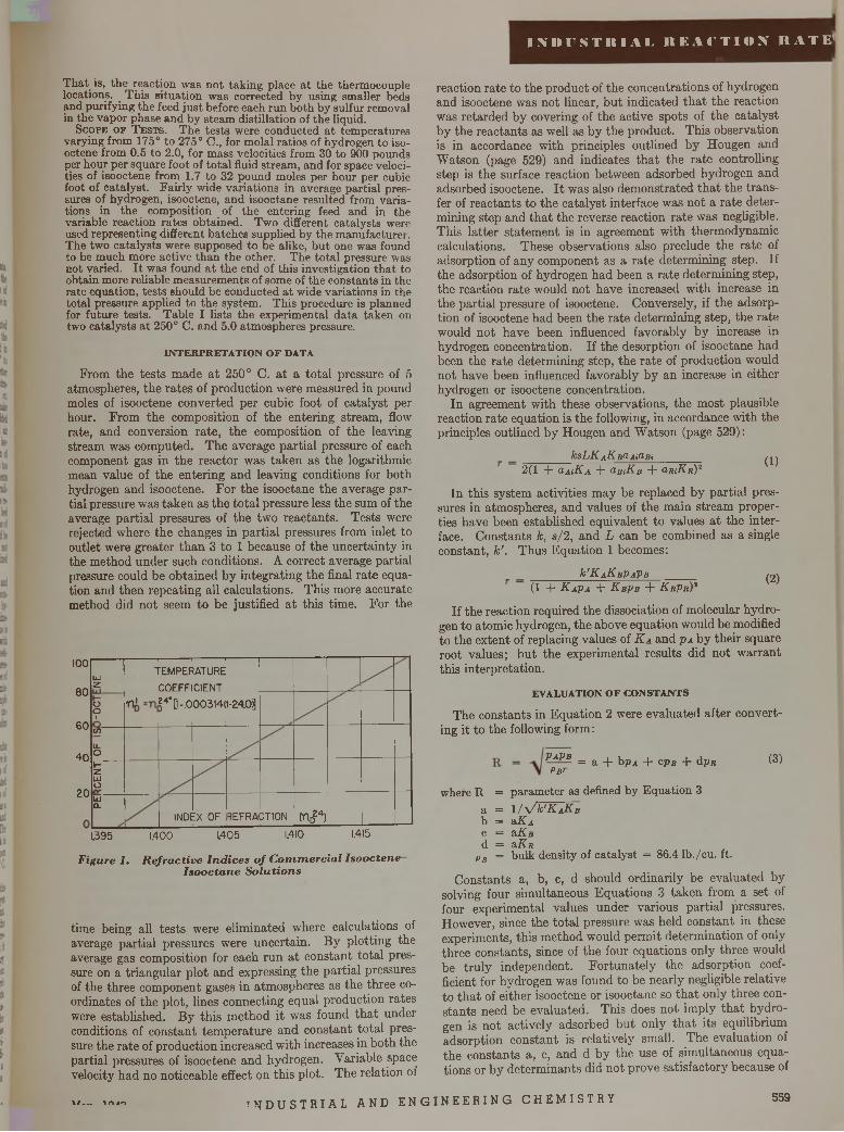
I N IM ' $ T It 1 A 1. R E A f T l O X K A T E ’
T hat is, the reaction was not taking place a t the thermocouple locations. _ This situation was corrected by using smaller beds and purifying the feed just before each run both by sulfur removal in the vapor phase and by steam distillation of the liquid.
S c o p e o f T e s t s . The tests were conducted a t tem peratures varying from 175° to 275° C., for molal ratios of hydrogen to iso- octene from 0.5 to 2.0, for mass velocities from 30 to 900 pounds per hour per square foot of to ta l fluid stream, and for space velocities of isooctene from 1.7 to 32 pound moles per hour per cubic foot of catalyst. Fairly wide variations in average partial pressures of hydrogen, isooctene, and isooctane resulted from variations in the composition of the entering feed and in the variable reaction rates obtained. Two different catalysts were used representing different batches supplied by the manufacturer. The two catalysts were supposed to be alike, bu t one was found to be much more active than the other. The to tal pressure was not varied. I t was found a t the end of this investigation th a t to obtain more reliable measurements of some of the constants in the rate equation, tests should be conducted a t wide variations in the total pressure applied to the system. This procedure is planned for future tests. Table I lists the experimental da ta taken on two catalysts a t 250° C. and 5.0 atmospheres pressure.
IN T E R P R E T A T IO N O F D A TA
From the tests made at 250° C. at a total pressure of 5 atmospheres, the rates of production were measured in pound moles of isooctene converted per cubic foot of catalyst per hour. From the composition of the entering stream, flow rate, and conversion rate, the composition of the leaving stream was computed. The average partial pressure of each component gas in the reactor was taken as the logarithmic mean value of the entering and leaving conditions for both hydrogen and isooctene. For the isooctane the average partial pressure was taken as the total pressure less the sum of the average partial pressures of the two reactants. Tests were rejected where the changes in partial pressures from inlet to outlet were greater than 3 to 1 because of the uncertainty in the method under such conditions. A correct average partial pressure could be obtained by integrating the final rate equation and then repeating all calculations. This more accurate method did not seem to be justified at this time. For the
100
80
60
40
20
LÜz
-------------1--------- 1----------1--- —----TEMPERATURECOEFFICIENT
o01
tt* r o - o 003141t-24.0j]
If)ILoHZUJoUJ0 .
1NDE:x o f REFRA : tio n tnD24)
1.395 1.400 1405 1.410 1.415
F ig u r e I . R e f r a c t i v e I n d i c e s o f C o m m e r c i a l I s o o c t e n e I s o o c t a n e S o l u t i o n s
time being all tests were eliminated where calculations of average partial pressures were uncertain. By plotting the average gas composition for each run at constant total pressure on a triangular plot and expressing the partial pressures of the three component gases in atmospheres as the three coordinates of the plot, lines connecting equal production rates were established. By this method it was found that under conditions of constant temperature and constant total pressure the rate of production increased with increases in both the partial pressures of isooctene and hydrogen. Variable space velocity had no noticeable effect on this plot. The relation of
reaction rate to the product of the concentrations of hydrogen and isooctene was not linear, but indicated that the reaction was retarded by covering of the active spots of the catalyst by the reactants as well as by the product. This observation is in accordance with principles outlined by Hougen and Watson (page 529) and indicates that the rate controlling step is the surface reaction between adsorbed hydrogen and adsorbed isooctene. It was also demonstrated that the transfer of reactants to the catalyst interface was not a rate determining step and that the reverse reaction rate was negligible. This latter statement is in agreement with thermodynamic calculations. These observations also preclude the rate of adsorption of any component as a rate determining step. If the adsorption of hydrogen had been a rate determining step, the reaction rate would not have increased with increase in the partial pressure of isooctene. Conversely, if the adsorption of isooctene had been the rate determining step, the rate would not have been influenced favorably by increase in hydrogen concentration. If the desorption of isooctane had been the rate determining step, the rate of production would not have been influenced favorably by an increase in either hydrogen or isooctene concentration.
In agreement with these observations, the most plausible reaction rate equation is the following, in accordance with the principles outlined by Hougen and Watson (page 529):
_______ k sL K aK b i AidBi_______2(1 + OmKa + CLBiK-B + O.RiKlt)'1 (1)
In this system activities may be replaced by partial pressures in atmospheres, and values of the main stream properties have been established equivalent to values at the interface. Constants k, s/2, and L can be combined as a single constant, k ’ . Thus Equation 1 becomes:
^ K aK bP aP b
(1 + K a P a + K b Pb + K r P r )*(2)
If the reaction required the dissociation of molecular hydrogen to atomic hydrogen, the above equation would be modified to the extent of replacing values of K a and p a by their square root values; but the experimental results did not warrant this interpretation.
E V A L U A T IO N O F C O N S T A N T S
The constants in Equation 2 were evaluated after converting it to the following form:
P a P b Pb r
= a + bp^ + c pa + d pr (3)
where R = parameter as defined by Equation 3a = 1 / V V K a K b b = a K a c = a K b d = slK r
Pb = bulk density of catalyst = 86.4 lb./cu. ft.
Constants a, b, c, d should ordinarily be evaluated by solving four simultaneous Equations 3 taken from a set of four experimental values under various partial pressures. However, since the total pressure was held constant in these experiments, this method would permit determination of only three constants, since of the four equations only three would be truly independent. Fortunately the adsorption coefficient for hydrogen was found to be nearly negligible relative to that of either isooctene or isooctane so that only three constants need be evaluated. This does not imply that hydrogen is not actively adsorbed but only that its equilibrium adsorption constant is relatively small. The evaluation of the constants a, c, and d by the use of simultaneous equations or by determinants did not prove satisfactory because of
\ / __ m m I N D U S T R I A L AND E NG I NE E R IN G CHEMI STRY 559
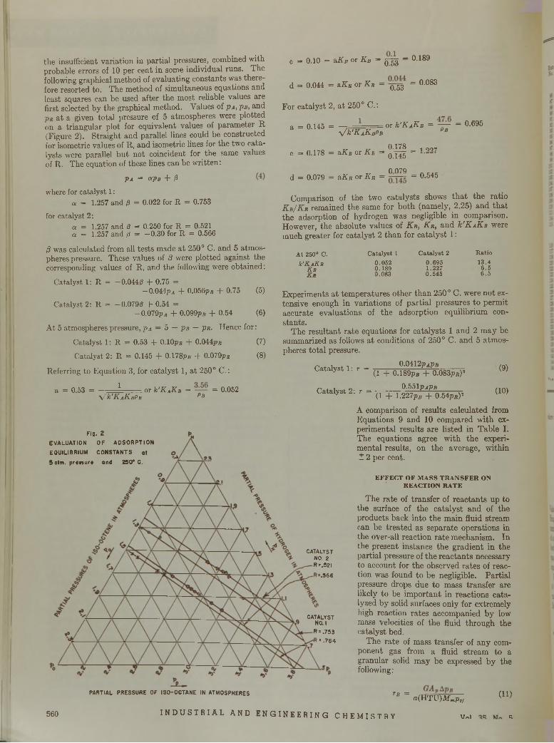
the insufficient variation in partia l pressures, combined with probable errors of 10 per cent in some individual runs. The following graphical m ethod of evaluating constants was therefore resorted to. The m ethod of simultaneous equations and least squares can be used after the m ost reliable values are first selected by the graphical m ethod. Values of p A , P b , and Pr a t a given to ta l pressure of 5 atm ospheres were plo tted on a triangular p lo t for equivalent values of param eter R (Figure 2). S traight and parallel lines could be constructed for isometric values of R, and isometric lines for the two catalysts were parallel b u t no t coincident for the same values of R. The equation of these lines can be w ritten:
P a = &PB + 0where for catalyst 1:
a = 1.257 and /3 = 0.022 for R = 0.753
for catalyst 2 :a = 1.257 and 0 = 0.250 for R = 0.521a = 1.257 and /? = -0 .3 0 for R = 0.566
/3 was calculated from all tests made a t 250° C. and 5 atm ospheres pressure. These values of /3 were plo tted against the corresponding values of R, and the following were obtained:
Catalyst 1: R = —0.044/3 + 0.75 =-0 .044pa + 0.056pB + 0.75 (5)
Catalyst 2: R = —0.079/3 + 0.54 =-0 .079pA + 0.099ps + 0.54 (6)
A t 5 atmospheres pressure, pa — 5 — pB — pu. Hence for:
Catalyst 1: R = 0.53 + 0.10ps + 0.044pB (7)
Catalyst 2: R = 0.145 + 0.178pB + 0.079pB (8)
Referring to E quation 3, for cata lyst 1, a t 250° C.:
a = 0.53 = - 1 .... or k'KAKB = — = 0.052V k'K AKBPB Pb
c = 0.10 = aKb or K B = g-j-g - 0.189
d = 0.044 = a K r or K r = = 0.083
F or ca ta lyst 2, a t 250° C .:
a = 0.145 = y/k'KAKBPB
0.53
or k'KAKB = —— — 0.695 Pb
T, 0.178 1 qq7c = 0.178 = a K b or K B = q!4 5 ~~
0 070d = 0.079 = a K r or K r = = 0.545
Com parison of th e tw o ca ta lysts shows th a t th e ratio K b / K r rem ained the sam e for b o th (nam ely, 2.25) and th a t the adsorption of hydrogen was negligible in com parison. However, the absolute values of K b , K r , and k ' K AK B were m uch greater for ca ta ly st 2 th a n for c a ta ly s t 1 :
A t 250° c .k 'K AK B
K bK r
C a ta ly s t 10 .0 5 20 .1 8 90 .0 8 3
C a ta ly s t 20 .6 9 51 .2270 .5 4 5
R a tio1 3 .4
6 .56 .5
E xperim ents a t tem pera tu res o ther th a n 250° C . were n o t extensive enough in varia tions of p a rtia l p ressures to perm it accurate evaluations of th e adso rp tion equilibrium constan ts.
T he resu ltan t ra te equations for ca ta lysts 1 and 2 m ay be sum m arized as follows a t conditions of 250° C. and 5 atm ospheres to ta l pressure.
C atalyst 1 : r = 0.0412 paPb(1 + 0.189pfl + 0.083pB)2
C atalyst 2: r = 0.551pApB(1 + 1.227pB + 0.54pB)2
(9)
(10)
A comparison of results calculated from Equations 9 and 10 compared with experimental results are listed in Table I. The equations agree with the experimental results, on the average, within ± 2 per cent.
E F F E C T O F M A S S T R A N S F E R O N R E A C T IO N R A T E
The rate of transfer of reactants up to the surface of the catalyst and of the products back into the main fluid stream can be treated as separate operations in the over-all reaction rate mechanism. In the present instance the gradient in the partial pressure of the reactants necessary to account for the observed rates of reaction was found to be negligible. Partial pressure drops due to mass transfer are likely to be important in reactions catalyzed by solid surfaces only for extremely high reaction rates accompanied by low mass velocities of the fluid through the catalyst bed.
The rate of mass transfer of any component gas from a fluid stream to a granular solid may be expressed by the following:
560
PARTIAL PRESSURE OF ISO-OCTANE IN ATMOSPHERES
INDUSTRIAL AND ENGINEERING CHEMISTRY
TB = ( i na ( H T U ) M mPs/
Mr,i n
Fig. 2EVALUATION OF ADSORPTION EQUILIBRIUM CONSTANTS at 5 atm. prenur» and 250“ 0.
CATALYST NO. 2 R =.521
=.566
CATALYST NO. IR = .753
= .764
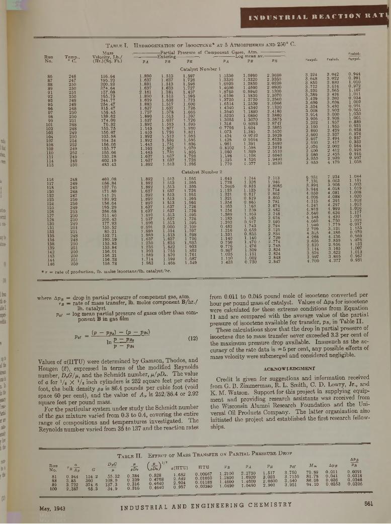
I N D U S T I I I A L R E A C T I O N R A T
T a b l e I . H y d r o g e n a t i o n o f I s o o c t e n e * a t 5 A t m o s p h e r e s a n d 250° C.
R u nN o.
868788 899192939596979899 101
102103104107108109110 111114115
116117118 120 122123124125126127128130131 133135136138139142143144 146
T em ícP"
248247 250250251 250249249248250250251 248248249250 254252 249 252 249249250
248249 245248247250 250249 253250250249251 251248 248250251 250250251 250
M ass V eloc ity . L b . / (H r.) (S q . F t .)
15 6 .6 4 1 9 5 .2 93 0 0 .2 33 7 4 .6 415 7 .0 8 19 5 .7 32 4 4 .7 72 5 4 .4 73 1 5 .4 7 1 5 6 .4 5 13 0 .6 2174 .0 9
7 6 .3 21 5 5 .7 5156 .0 71 0 5 .5 8104 .2 41 5 6 .0 61 5 5 .7 715 6 .0 6 1 3 0 .2 8 6 0 2 .1 9 4 8 3 .4 3
4 6 9 .0 86 5 6 .8 41 3 7 .7 61 71 .8 01 41 .211 3 9 .9 2 1 5 6 .6 4 195 .29 2 6 6 .6 8 3 1 1 .4 0 2 0 6 .4 3177 .9 3 155 .5 2
8 5 .3 1152 .7119 0 .1 915 5 .8 315 5 .8 4 156 .01156 .21 1 5 6 .3 8 1 56 .7 8
- P a r t i a l P re s su re of C o m p o n e n t G ases, A tm .-
PA
1 .8 9 01 .6 3 71 .8911 .6 3 7 2 .1 6 11 .8 9 0 1 .6 3 9 1 .8 8 31 .6 3 7 1 .7 5 71 .8 9 01 .6 3 71 .8 9 2 1 .1 4 3 1 .4 5 31 .8 9 21 .8 9 21 .4 4 3 1 .1 6 31 .4 4 31 .6 3 71 .6 3 71 .892
1 .8 9 21 .8 9 21 .8 9 21 .6 3 71 .8 9 21 .8 9 21 .8 9 21 .6 3 71 .6371 .8 9 21 .6 3 71 .8 9 2 0 .8 9 11 .8 8 91 .8 8 91 .6 3 7 1 .2 3 0 1 .2 3 5 1 .3 9 3 1 .5 6 9 1 .7 1 4 1 .9 8 3
—E n te r in g - VB PR PA
-L o g m e an a v .- PB PR
1 .5 1 31 .6 3 71 .5 1 3 1 .633 1 .381 1 .5 1 51 .6 3 8 1 .5171 .637 1 .5 7 81 .5 1 31 .6 3 71 .5 1 3 1 .877 1 .7 2 61 .5 1 3 1 .5 3 61.731 1 .8671 .7311 .6 3 71 .6 3 71 .5 1 3
1 .5 1 31 .5131 .5 1 31 .6371 .5 1 31 .5 1 31 .5 1 31 .6371 .6371 .5131 .6 3 71 .513 2.0001 .5 1 4 1 .5 1 31 .637 1 .8 3 5 1 .8 3 2 1 .7 5 5 1 .6 7 0 1 .5 9 9 1 .4 6 8
C a ta ly s t N u m b e r 11 .5 9 7 1 .53301 .7 2 6 1 .33201 .5 9 6 1 .69201 .7 2 7 1 .46001 .4 5 7 1 .87601 .5 9 5 1 .61001 .7 2 3 1 .3 7 2 01 .6 0 0 1 .6 5 1 41 .7 2 6 1 .43401 .6 6 5 1 .39401 .5 9 7 1 .52501 .7 2 6 1 .30551 .5 9 5 1 .3161 .9 8 0 0 .7 7 9 51 .8 2 1 1 .0731 .5 9 5 1 .4341 .5 9 5 1 .4 2 81 .8 2 6 1 .0611 .9 7 0 0 .8 1 0 21 .8 2 6 1 .0601 .7 2 6 1 .1 9 81 .7 2 6 1 .5 2 51 .5 9 5 1 .770
C a ta ly s t N u m b er 2
1 .5 9 51 .5 9 51 .5 9 51 .7 2 61 .5 9 51 .5 9 51 .5 9 51 .7 2 61 .7 2 61 .5 9 51 .7261 .5 9 5 2 .1 0 91 .5971 .5 9 81 .726 1 .9 3 5 1 .933 1 .8 5 2 1 .761 1 .687 1 .549
1 .6431 .7 2 81 .26651 .1231.3211 .321 1 .3 5 4 1 .163 1 .254 1 .5 8 9 1 .183 1 .3 9 3 0 .4 6 3 1 .2 1 6 1 .331 1 .140 0 .7 5 0 0 .7 7 6 0 .8 6 7 1 .0 2 5 1 .150 1 .423
1 .0990 1 .3320 1 .2850 1 .4600 0 .9 9 4 0 1 .1830 1 .3720 1 .2520 1 .4340 1 .1880 1 .0890 1 .3070 0 .8 0 9 3 1 .6 3 4 1 .385 0 .9 7 3 2 0 .9 5 9 4 1 .391 1 .5 9 8 1 .389 1 .198 1 .526 1 .377
1 .2441 .3260 .8 3 51 .1230 .8 1 70 .8 1 90 .8 6 51 .163 1 .2 5 91 .163 1 .183 0 .9 1 7 1 .743 0 .6 5 9 0 .8 3 5 1 .140 1 .4 7 0 / 1 .476 1 .3 0 9 1 .151 1.002 0 .7 3 0
2 .3 6 8 0 2 .3 3 6 0 2 .0 2 3 0 2 .0 8 0 0 2 .1 3 0 0 2 .2 0 7 0 2 .2 5 6 0 2 .0 9 6 6 2 .1 3 2 0 2 .4 1 8 0 2 .3 8 6 0 2 .3 8 7 5 2 .8 7 4 7 2 .5 8 6 5 2 .5 4 2 0 2 .5 9 2 8 2 .6 1 2 6 2 .5 4 8 0 2 .5 9 1 8 2 .5 5 1 0 2 .6 0 4 0 1 .9490 1 .8530
2 .1 1 31 .9462 .8 9 8 52 .7 5 42 .8 6 22 .8 6 02 .7812 .6 7 42 .4 8 22 .2 4 82 .6 3 42 .6 9 02 .7 9 43 .1 2 52 .8 3 42 .7 2 02 .7 7 42 .7 4 82 .8 2 42 .8 2 4 2 .8 4 8 2 .8 4 7
rexptl.
3 .2 2 43 .0 4 83 .8 5 03 .7 2 23 .2 2 03 .3 8 93 .4 2 93 .6 9 03 .5 2 43 .0 0 82 .9 1 42 .9 0 62.2022.1002 .6 0 02 .6 0 02 .6 0 72 .5 9 02 .0 7 62 .6 0 02 .6 8 03 .9 5 03 .9 5 0
6 .9 3 17 .1 3 13 .8 9 43 .9 4 44 .0 5 04 .0 0 64 .3 1 5 4 .2 4 1 4 .9 1 8 5 .6 4 0 4 .3 4 8 4 .6 6 0 1 .9 4 0 2 .7 0 94 .3 1 5 4 .2 6 8 2 .6 5 6 2 .6 1 0 3 .1 4 4 3 .5 7 6 3 .9 9 7 4 .7 0 0
roalcd.real cd. rexptl.
3 .0 4 2 0 .9 4 43 .0 2 2 0 .9 9 13 .8 8 9 1.0103 .6 1 6 0 .9 7 23 .5 6 5 1 .1 0 73 .4 2 6 1.0113 .2 0 2 0 .9 3 43 .6 9 8 1.0023 .4 9 2 0 .9 9 12 .9 0 2 0 .9 6 53 .0 0 0 1 .0 3 02 .9 0 8 1.0011 .957 0 .8 8 91 .9 5 5 0 .9 3 12 .4 3 9 0 .9 3 82 .5 3 7 0 .9 7 62 .4 9 4 0 .9 5 72 .4 1 7 0 .9 3 32.002 0 .9 6 42 .4 1 2 0 .9 2 82 .4 5 5 0 .9 1 63 .9 3 9 0 .9 9 74 .1 7 9 1 .058
7 .2 3 4 1 .0 4 48 .0 6 3 1.1313 .9 0 6 1 .0034 .0 1 8 1 .0 1 94 .0 8 1 1 .0 0 84 .0 8 8 1.0204 .3 9 1 1 .0 1 84 .2 9 7 1 .0 1 34 .9 9 9 1 .0 1 66 .6 3 6 1 .1774 .4 3 9 1.0214 .7 5 0 1 .0191 .7 7 9 0 .9 1 73 .1 2 1 1 .1534 .1 8 6 0 .9 7 04 .1 3 6 0 .9 6 92 .8 5 9 1 .0 7 62 .9 5 6 1 .1333 .1 6 5 1 .0073 .6 2 3 1 .0133 .8 6 5 0 .9 6 74 .3 7 7 0 .9 3 1
= r a t e of p ro d u c tio n , lb . m oles is o o c ta n e / lb . c a ta ly s t /h r .
where Ap B — drop in partial pressure of component gas, atm.tb — rate of mass transfer, lb. moles component B/hr./
lb. catalystpof = log mean partial pressure of gases other than com
ponent B in gas film
( V ~ P bo) ~ (P ~ V B i)Vat —
In P ~ VBq V ~ VBi
(12)
Values of a(HTU) were determined by Gamson, Thodos, and Hougen (2 ) , expressed in terms of the modified Reynolds number, D PG / p , and the Schmidt number, p ./p D *. The value of a for Vs X Vs inch cylinders is 252 square feet per cubic foot, the bulk density pB is 86.4 pounds per cubic foot (void space 60 per cent), and the value of A v is 252/86.4 or 2.92 square feet per pound mass.
For the particular system under study the Schmidt number of the gas mixture varied from 0.3 to 0.4, covering the entire range of compositions and temperatures investigated. The Reynolds number varied from 35 to 137 and the reaction rates
from 0.011 to 0.045 pound mole of isooctene converted per hour per pound mass of catalyst. Values of Aps for isooctene were calculated for these extreme conditions from Equation 11 and are compared with the average value of the partial pressure of isooctene available for transfer, pa, in Table II.
These calculations show that the drop in partial pressure of isooctene due to mass transfer never exceeded 3.3 per cent of the maximum pressure drop available. Inasmuch as the accuracy of the rate data is ± 5 per cent, any possible effects of mass velocity were submerged and considered negligible.
A C K N O W L E D G M E N T
Credit is given for suggestions and information received from G. B. Zimmerman, R. L. Smith, C. D. Lowry, Jr., and K. M. Watson. Support for this project in supplying equipment and providing research assistants was received from the Wisconsin Alumni Research Foundation and the Universal Oil Products Company. The latter organization also initiated the project and established the first research fellowships.
T a b l e IIR u nN o.
aG
DpGp
PpDv
81 0 .9 4 4 1 5 4 .2 5 5 .2 2 0 .3 8 488 3 .8 5 300 1 0 8 .9 0 .3 2 989 3 .7 2 2 3 7 4 .6 1 3 7 .3 0 .3 1 6100 2 .3 8 7 9 5 .3 3 4 .9 0 .3 1 6
E f f e c t o f M a s s T r a n s f e r o n P a r t i a l P r e s s u r e D r o p
(*T0 .5 2 80 .4 7 6 80 .4 6 4 00 .4 6 4 0
a (H T U )
1 .6822 .6 4 92 .9 9 40 .9 5 7
A Pb
H T U PB PA PR Put Mm A ps PB
0 .0 0 6 6 70 .0 1 0 5 00 .0 1 1 8 80 .0 0 3 8 0
1.21001 .28501 .4 6 0 01 .0490
2 .2 7 3 01 .6 9 2 01 .4 6 0 01 .0 4 9 0
1 .5172 .0 2 32 .0 8 0 02 .9 0 2
3 .7 5 03 .7 1 5 03 .5 4 03 .9 5 1
7 0 .8 98 1 .7 88 6 .0 89 4 .1 0
0.0110 .0 4 10 .0 3 60 .0 3 5 3
0 .0 0 9 10 .0 3 1 80 .0 2 4 60 .0 3 2 6
May, 1943 I N D U S T R I A L AND E NG I N EE R IN G CHEMI STRY 561
N O M E N C L A T U R E
a a, a Ai, e tc . = a c t i v i t y o f c o m p o n e n t gas in m a in f lu id p h a se a , b , c , d = c o n s ta n ts in E q u a t io n 3 o ( H T U ) = d im e n s io n le s s u n i t fo r m a s s t ra n s fe r a = gross o u ts id e a re a o f c a t a ly s t p e l le ts , sq . f t . / c u . f t .A = c o m p o n e n t AA , = gross o u ts id e a re a o f c a ta ly s t p e lle ts , sq. f t . / l b .B = c o m p o n e n t BD p = a v . d ia m e te r o f c a t a ly s t p a r t ic leD , = d i f f us i v i t y . . .G = m a s s v e lo c i ty o f f lu id f lo w in g , lb . / ( s q . f t . ) ( h r . ) k = fo r w a r d re a c t io n v e lo c i ty c o n s ta n t k ' = fo r w a r d re a c t io n v e lo c i ty c o n s ta n t K = a d s o rp tio n e q u il ib r iu m c o n s ta n t L = t o t a l m o la l a d s o rp tio n s ite s p e r u n i t m ass o f c a ta ly s t M m = m e a n m o le c u la r w e ig h t o f gases in m a in f lu id s tre a m P a , P b , e tc . = p a r t ia l p re s s u re o f c o m p o n e n t gas in m a in f lu id
s tre a mR = gas la w c o n s ta n t R = p a ra m e te r as d e fin e d b y E q u a t io n 3 R = c o m p o n e n t Rr = re a c t io n ra te , lb . m o le s is o o c te n e c o n v e r te d / lb .
c a ta ly s t /h r .
s = n u m b e r o f e q u id is ta n t s ite s a d ja c e n t to e a c h a c t iv e c e n te ra = c o n s ta n t in E q u a t io n 40 = v a r ia b le in E q u a t io n 4p = d e n s ity o f f lu idpB = b u lk d e n s ity o f c a t a ly s t , l b . / c u . f t .p = v is c o s ity
S u b s c r ip tsA = c o m p o n e n t A (h y d ro g e n )B = c o m p o n e n t B ( is o o c te n e )R = c o m p o n e n t R ( is o o c ta n e )i = in te r fa c eg - gas
L IT E R A T U R E C IT E D
(1) Adkins, H., “Reactions of Hydrogen over Copper-ChromiumOxides and Nickel Catalysts”, Madison, Univ. of Wis. Press, 1937.
(2) Gamson, B. W., Thodos, George, and Hougen, O. A., Trans. A m .In st. Chem . Engrs., 3 9 , 1 - 3 5 ( 1 9 4 3 ) .
(3 ) Thomas, C. L., Bloch, H. S., and Hoekstra, J., I n d . Eng. Chem.,A n a l . E d ., 10 , 1 5 3 ( 1 9 3 8 ) .
Conduction, Convection and Heat Release in
CATALYTIC CONVERTERSR . H . W i l h e l m , W . C . J o h n s o n ,
F . S . A c t o n
P R IN C E T O N U N IV E R S IT Y , P R IN C E T O N , N . J .
H EAT transfer considerations form an important part of a catalytic converter design. The productivity of a continuous converter depends greatly upon provisions
for removing the exothermic heat of reaction or, in the case of an endothermic reaction, for supplying it. An increased efficiency in heat transfer generally permits a larger output of product per unit volume of catalyst. Heat transfer also is essential in maintaining a temperature uniformity within the catalyst bed. The rates of heat generation in the catalyst granules must be balanced by corresponding rates of heat removal such that the point-to-point temperatures in the bed as a whole will lie within specified limits. In extreme cases these limits may be as narrow as 10-20° C. When the thermal balance is not properly arranged by design or is disturbed by faulty operation, an excessive and local rise or fall in temperature will result. In the former case an excessive “hot spot” may lead to the destruction of the catalyst or to by-product formation; in the latter, cooling the bed may lead to a stoppage of the reaction. Thus, from the viewpoint of efficiency and control, some measure of heat exchange is essential in a catalytic reactor.
This paper deals with the solutions of differential thermal equations for cylindrical and slab-shaped catalyst beds. The specific solutions deal with conditions in the catalyst cross section, and relate point and average catalyst temperature with (a) the temperature of the gas, (6) the average temperature of the catalyst at the periphery of the bed, (c) the rate of heat release by the chemical reaction, and the rates of heat transfer both (d) by transverse conduction through the solid
catalyst and (e) by convection through the gas film between the catalyst and the flowing gas stream. Since the rate of reaction (and of heat release) is a function not only of temperature, but also of concentration of reactants and time of contact, this rate will vary down the length of the catalyst bed. The temperature of the gas stream, which is assumed uniform at any cross section, will also vary along the catalyst bed. Thus, a complete reactor design involves a step-by- step analysis in the direction of gas flow from one cross section to the next with the aid of heat and material balances. By this means the following items may be computed for beds of different dimensions:
1. C a ta ly s t a n d g as te m p e r a tu r e s a t a n y p o in t i n t h e b e d .2. T r a n s v e r s e h e a t f lo w r a te s a t a n y cross s e c tio n .3 . P r o d u c t f o r m a t io n in a v o lu m e o f c a t a ly s t p e r u n i t o f t im e .
The following fundamental information is required for thecomputations:
1. V a r ia t io n o f r a t e o f r e a c t io n w i t h t e m p e r a t u r e , r e a c t a n t c o n c e n tra tio n s , a n d t im e o f c o n ta c t , u s u a lly o b t a in e d f r o m p i lo t p la n t d a ta .
2 . M o la r h e a t o f r e a c t io n .3 . T h e r m a l c o n d u c t iv i t y o f t h e c a ta ly s t -g a s s y s te m .4 . G a s - f i lm h e a t t r a n s f e r c o e ff ic ie n t in b r o k e n s o lid s o f c a ta
ly s t s ize as a fu n c t io n o f f lo w c o n d it io n s a n d g as p r o p e r t ie s .5 . T h e r m a l p ro p e r t ie s o f t h e gas s t r e a m .
The following design variables must be set:
1 . Catalyst wall temperature from point to point. ( T h is w i l lin v o lv e t n a l - a n d -e r r o r m e th o d s s u c h t h a t t h e r a t e o f t ra n s v e rs e
L R E A C T I O N R A T I 1____________________I
heat transfer from the catalyst bed at a given cross section equals the rate of its removal by the heat transfer medium.)
2. Catalyst bed diameter or thickness.3. Length of catalyst bed.4. Inlet gas composition, flow rate, and temperature.
It is also suggested that the thermal equations presented afford opportunities for obtaining better insight to the complexity of converter variables through analysis of the effect of variations of the major variables, taken singly. Moreover, the equations are not limited to heat release by chemical reaction, but may be applied to electrical heating problems or any other cases for which the assumptions listed below are valid. Furthermore, they may be applied to a combination involving any two of the three basic rates—conduction, convection, and heat release. Thus, conduction and convection alone, for example, would apply to cross-sectional conditions
- ERiTfc0e“‘" « e + ml = k '
Equation 1 may therefore be rewritten :
TV- = Co -t- Clt
(2)
(3)
(4)Vcat
dq = (Co -f- C it)d V rat.
where Co = <p[t, Q, 0, C]
Ci = <p[m, Q, 9, C]
Co and Ci vary with longitudinal position in a catalyst bed, but within a thin cross-sectional slice they may be assumed constant. Equation 3 therefore expresses the linear variation of heat release with temperature in a catalyst cross section.
S o l u t i o n s a r e p r e s e n t e d f o r t h e r m a l e q u a t i o n s i n v o lv in g t h e r a t e o f h e a t g e n e r a t io n i n c y l in d r ic a l a n d s l a b - s h a p e d c a t a l y s t b e d s , t h e r a te o f h e a t r e m o v a l b y c o n v e c t i o n b e t w e e n s o l id a n d g a s , a n d i t s r e m o v a l b y c o n d u c t i o n t h r o u g h t h e c a t a l y s t a n d g a s i n a d i r e c t io n p e r p e n d i c u l a r t o t h e g a s s t r e a m . P o in t t e m p e r a t u r e s i n a n y c a t a l y s t c r o s s s e c t io n , t h e i n t e g r a l m e a n t e m p e r a t u r e o f t h e s e c t io n , a n d t h e r a t e o f h e a t t r a n s f e r t h r o u g h t h e p e r i p h e r y o f t h e b e d h a v e b e e n r e l a te d t o t h e d i a m e t e r o r t h i c k n e s s o f b e d , o u t e r b e d t e m p e r a t u r e , g a s t e m p e r a tu r e , c a t a l y s t a c t i v i t y , t e m p e r a t u r e c o e f f i c i e n t o f h e a t g e n e r a t io n , t h e r m a l c o n d u c t i v i t y o f c a t a l y s t , a n d c o n v e c t i o n c o e f f i c ie n t .
T h e f u n c t i o n s a r e p l o t t e d i n d i m e n s i o n le s s f o r m
in t e r m s o f a t e m p e r a t u r e v a r ia b le ,t — t R
lR +
■nV-Cp + h tg
C i — h
-, a n d a p o s i t i o n v a r ia b le ,a r a te v a r ia b leT k
r/R . M a jo r a s s u m p t i o n s i n c l u d e u n i f o r m g a s t e m p e r a t u r e a t e v e r y c r o s s s e c t io n a n d s m a l l l o n g i t u d i n a l s o l id s t e m p e r a t u r e g r a d ie n t c o m p a r e d w i t h t h e t r a n s v e r s e g r a d ie n t .
A c a t a l y t i c r e a c to r d e s ig n p r o c e d u r e in v o lv in g a n a ly s is b y s u c c e s s iv e s m a l l i n c r e m e n t s i n t h e d i r e c t io n o f g a s f l o w i s s u g g e s te d . S a m p l e c o m p u t a t i o n s a re p r e s e n t e d o f t h e r m a l g r a d ie n t s i n a c a t a l y s t b e d . A p p l i c a t io n s t o p a c k e d h e a t e x c h a n g e r s a n d f i n e x c h a n g e r p r o b l e m s a r e i n d i c a t e d .
in a packed heat exchanger, and also to certain disk and strip- fin heat exchanger problems (4).
The present analysis and computations based upon it are on an a priori basis and are subject to experimental check.
The problem of heat transmission in a catalyst bed has been extensively discussed with qualitative conclusions by Dam- koehler (1 ). Paterson (5) presented a mathematical treatment for the conduction of heat in an infinite or semi-infinite medium generating heat. Problems relating to the measurement of gas and solid in a catalyst bed were pointed out by Jakob (3), and temperature differences between catalyst and gas were measured under various conditions for the hydrogenation of ethylene. Convection heat transfer coefficients in beds of subdivided solids in the catalyst range have recently been measured over a wide range of conditions and correlated by Hougen, Gamson, and Thodos (3).
ASSUMPTIONS
1. The rate of heat release at any point in a catalyst bed is a function of catalyst activity ko, catalyst temperature e 1 ,heat of reaction Q, time of contact 0, and reactant concentration C . Thus the rate of heat release per unit volume of catalyst is:
1Vcat. = * \_koeRlT, Q, e, c ]
(1)
Over the limited range of temperatures of interest in a catalyst bed the specific reaction rate may be expressed as a linear function of temperature as in Equation 2.
2. Temperatures at all points in the catalyst are constant with respect to time. Heat released or absorbed by the reaction at any point is removed or introduced by heat conduction and convection. Radiation is neglected.
3. Heat transfer by conduction through solid catalyst and gas is entirely in a direction perpendicular to gas flow. (This transfer is essentially independent of longitudinal gas velocity.) Temperature gradients and heat flow rates in a longitudinal direction are considered negligibly small and are not included.
4. Because of mixing, the temperature of the gas within any thin cross-sectional slice of catalyst bed is uniform and constant.
CYLINDRICAL CATALYST BED SECTIONTemperature Distribution. Consider an elementary ring in a
catalyst section having an outer radius R and thickness M (Figure 1). The ring with radius r, width dr, and thickness AI will have a volume:
dV cai = 2ir Alrdr (5)
Combine with Equation 4 to obtain rate of heat release:
dq = (Co + Cit) (2x Alr)dr (6)
The rate of heat release by an exothermic reaction in a disk having a radius r and thickness AI is:
(Co + Cit)(2irr M )dr
I N D U S T R I A L AND E NG I N EE R IN G C HEMI STRY
(7)
563
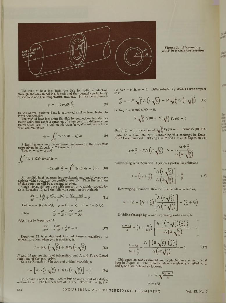
Figure 1. Elementary- Ring in a Catalyst Section
The rate of heat loss from the disk by radial conduction through the area 2irr AI is a function of the thermal conductivity of the solid and the temperature gradient. I t may be expressed:
92 = — 2-rrAlk ^ (8)
In the above, positive heat is expressed as flow from higher to lower temperature.
The rate of heat loss from the disk by convection transfer between solid and gas is a function of a temperature difference between these two, of a volumetric transfer coefficient, and of the disk volume, thus:
2-rrr Alh{t — t„) dr (9)
A heat balance may be expressed in terms of the heat flow rates given in Equations 7 through 9.
Thus ?i = q2 + ?s and
/ :(Co + C\t)(2irr ¿d)dr —
—2irr Aik !+/’2irrAlh(t — t„)dr (10)
All possible heat balances for exothermic and endothermie reactions yield equations convertible into 10. Thus the solution of this equation will be a general solution.
Cancel 2r A I, differentiate with respect to r, divide through by rk in Equation 10, and the following equation is obtained:
dH , 1 dt , (Co + AO , {C ,-h)t „dr* r dr ' k + k " 0 (11)
Define n = (Co + htt), p = (Ci — h), i ' = i -f (n/p)
Then dTdr
dl . dH/ dr ’ dr2
dHdr1
Substitute in Equation 11:
+ft ' = odr2 r dr k (12)
Equation 12 is a standard form of Bessel’s equation; its general solution, when p/k is positive, is:
V - N J . ( r ^ l ) + M Y . { , -y / f ) (13)
N and M are constants of integration and Jo and F0 are Bessel functions of the zero order.
Express Equation 13 in terms of original variable, t:
- ["• (-• Vf) + M Y " (r Vf)l - 1 <>4>B o u n d a r y C o n d i t i o n s . Let radius to outer limit of catalyst
section be R. The tem perature a t R is Ir. Then a t r = Rt t =
tR; a t r = 0, dt/dr = 0. Differentiate Equation 14 with respect to r:
i--"VHrVf)-MVr,(rVf) (i5>Setting r = 0 and dt/dr = 0,
N J i (0) + M y , (0) = 0
But J , (0) = 0 ; therefore M i <P) “ Since F ‘ ( ° ) is in'finite, M — 0 and the term containing this constant in Equation 14 is eliminated. Setting r = R and t = tR in Equation 14:
Ir + z
tR + - = IVJ< P
( r J ? ) ; N = — ------
Substituting N in Equation 14 yields a particular solution:
H i ) '
Rearranging Equation 16 into dimensionless variables,
Jo
(16)
- !«) - (<« + ! ) '•(’Vi)- (-p + '»)/• (* Vf).
Dividing through by tR and expressing radius as r/K
J,t — tR
tR -(1+ä) •KfiVi)(s)} ' •(sVf)
j‘ i (* Vi) (s) 1 (B’V!) - 1 (17)
This function was evaluated and is plotted as a series of solid lines in Figure 2. The dimensionless variables are called x, y, and z, and are defined as follows:
- H -- h
564V = r/R
INDUS TR I AL AND ENGINEER ING CHEMI STRY Vol. 35, No. 5
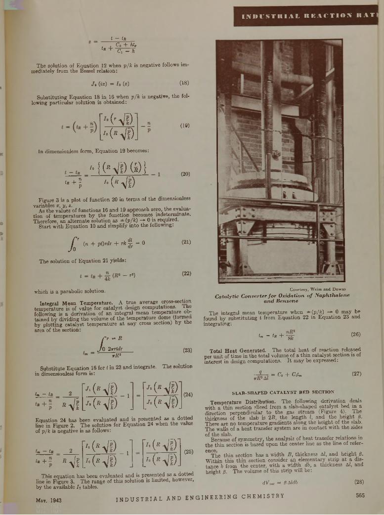
I N D U S T R I A L R E A C T I O N R A T
t - Ir
Ir +Co + hta Cx - h
The solution of Equation 12 when p / k is negative follows immediately from the Bessel relation:
J» (ix) - Io (x) (18)
Substituting Equation 18 in 16 when p / k is negative, the following particular solution is obtained:
HD/•(HD
In dimensionless form, Equation 19 becomes:
(19)
l* + lV
'• j(> VD (i) i'• (s VD
(20)
Figure 3 is a plot of function 20 in term s of the dimensionless variables x, y, z. , ,
As the values of functions 16 and 19 approach zero, the evaluation of tem peratures by the function becomes indeterminate. Therefore, an alternate solution as ± (p/k) -*■ 0 is required.
S tart with E quation 10 and simplify into the following:
X(n + p t)rdr + rk ^ = 0
The solution of Equation 21 yields:
r1)
(21)
(22)
which is a parabolic solution.
Integral M ean Tem perature. A true average cross-section tem perature is of value for catalyst design computations, in e following is a derivation of an integral mean tem perature obtained by dividing the volume of the tem perature dome (formed by plotting catalyst tem perature a t any cross section) by tne area of the section:
X= R
2 tn id rt R 2
(23)
Substitute Equation 16 for t in 23 and integrate. The solution in dimensionless form is:
lm — îr
t R + Z R Vi■(HD ,
/• ( R VD•(HD
/ • (r V d .
(24)
Equation 24 has been evaluated and is presented as a dotted line in Figure 2. The solution for Equation 24 when the value of p / k is negative is as follows:
Lr
Ir + R Vi'■ (* Vi) _, /• ( r Vi)
■(Hi) /•(HD.
(25)
This equation has been evaluated and is presented as a, dotted line in Figure 3. The range of th is solution is limited, however, by the available / j tables.
May. 1943 I N D U S T R I A L AND ENG
C ourtesy , W eiss an d D ow ns
C a ta ly t i c C o n v e r te r f o r O x id a t io n o f N a p h t h a l e n e a n d B e n z e n e
The integral mean tem perature when ±(p/k) ->- 0 may be found by substituting t from Equation 22 in Equation 23 and integrating:
tm = tR + -g-jZ (26)
Total H eat Generated. The to ta l heat of reaction released per unit of tim e in the to tal volume of a th in catalyst section is of interest in design computations. I t may be expressed:
= C° + C lU (2?)
S L A B -S H A P E D C A T A L Y S T B E D S E C T IO N
Temperature Distribution. The following derivation deals with a th in section sliced from a slab-shaped catalyst bed in a direction perpendicular to the gas stream (Figure 4). Thethickness of the slab is 2B, the length I, and the height ¡3-There are no tem perature gradients along the height of the slab. The walls of a heat transfer system are in contact with the sides
°* Because of symmetry, the analysis of heat transfer relations in the thin section is based upon the center line as the line of refer-
ellThe th in section has a w idth B, thickness A I, and height 0. W ithin this th in section consider an elementary strip a t a distance b from the center, w ith a width db, a thickness A I, and height (3. The volume of this strip will be:
dVot = flMdb (28)
INEER I NG C HEMI STRY 565
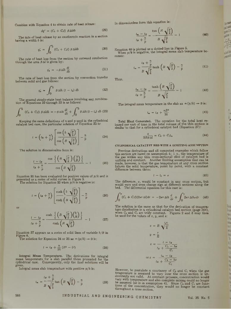
Combine with Equation 4 to obtain rate of heat release:
dq' = (Co + Cit) pAldb (29)
The rate of heat release by an exothermic reaction in a section having a width b is:
' P?i = /JO
(Co + c ,0 ßAldb (30)
The rate of heat loss from the section by outward conduction through the area 0 Ai is given by:
„ dt q , = - ß A l k Tb (31)
The rate of heat loss from the section by convection transfer between solid and gas follows:
- P9, = /JoßAlh (t - t„) db (32)
The general steady-state heat balance involving any combination of Equations 30 through 32 is as follows:
/ :(Co + Cl«) ß Aldb = — ß Alk ^ + ßAlh(t- t ,) db (33)
Keeping the same definitions of n and p used in the cylindrical catalyst bed case, the particular solution of Equation 33 is:
= ( l° + I )
cos
The solution in dimensionless form is:
t - lB
lB + lV
Nf)(* Vs).form is:
K*Vf)(I)ic o s ( ß ^ l )
(34)
- 1 (35)
Equation 35 has been evaluated for positive values of p/k and is presented as a series of solid curves in Figure 5.
The solution for Equation 33 when p/k is negative is :
0*+p) cosh (* Vf)cosh (s Vi).
t — tß
tB + lv
cosh | |Nf)(!)icos!*(*Vp)
k)
- l
(36)
(37)
Equation 37 appears as a series of solid lines of variable b/B in Figure 6.
The solution for Equation 34 or 35 as =*= (p/k) —► 0 is:
1 = tB + à {B I ~ bl) (38)
Integral M ean Temperature. The derivations for integral mean tem perature for a slab parallel those presented for the cylindrical case. Consequently, only the final solutions will be given.
Integral mean slab tem perature with positive p/k is :
Lb + z
tm =B Vf (39)
In dimensionless form this equation is:
-(■Vf) .tß 4* B Vf
(40)
Equation 40 is plotted as a dotted line in Figure 5.When p/k is negative, the integral mean slab tem perature be-
comes:
tß +tm =
B Vp- tanhPk
Thus,
tm — tB
t B + lV
ta n h
B
(Wf)-i
HI) ,Vf
(41)
(42)
The integral mean tem perature in the slab as ±(p/fc) — 0 is:
n B 2tm = ta + 3 k
(43)
Total H eat Generated. The equation for the to ta l heat released per unit of time in the to ta l volume of the th in section is similar to tha t for a cylindrical catalyst bed (Equation 27):
= Co + C\tm (44)2 B 0 A I
C Y L IN D R IC A L C A T A L Y S T B E D W IT H A L IM IT I N G A S S U M P T IO N
Previous derivations and all computed examples which follow this section are based on assumption 4; i.e ., the tem perature of the gas within any thin cross-sectional slice of catalyst bed is uniform and constant. Another limiting assumption th a t can be made, however, is th a t the gas tem perature a t any cross section follows the solid temperature, point by point, with a constant difference between them:
to = (45)
The difference, a, would be constant in any cross section, but would vary and even change sign a t different sections along the bed. The differential equation for this case is:
(Co + C \t)(2 irr Al)dr = — 2irr Aik +dr 2 ttt Alhodr (46)
The solution is the same as th a t for the derivation of tem perature distribution in a cylindrical catalyst bed section (page 564), when Co and Ci are truly constant. Figures 2 and 3 m ay then be used for the values of x, y, and z:
-vsrR
t — tu
tR + Co — hi7Ci
tm tR
tR + Co — hac,
However, to postulate a constancy of Co and C\ when the gas temperature is assumed to vary over the cross section is undoubtedly not valid. At constant pressure, concentration would vary with temperature and also complete mixing could no longer be assumed (as is in assumption 4). Since Co and Ci are func- tions of the concentration, they would no longer be constant throughout a cross section.
566 INDUSTRIAL AND ENGI NEER I NG CHEMI STRY Vol. 35. No. 5
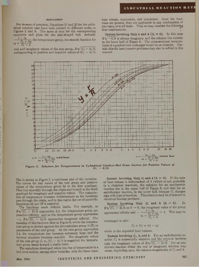
n n r s T i t i A L r e a c t i o n r a t
D IS C U S S IO N
For reasons of precision, Equations 17 and 20 for the cylindrical catalyst case have been plotted to different scales in Figures 2 and 3. The same is true for the corresponding equations and plots for the slab-shaped bed. Actually temperature group, is a smooth function for
real and imaginary values of the rate group, R 'V (Ci — h ) /k , corresponding to positive and negative values of (Ci — h ) /k .
heat release, conduction, and convection. Since the functions are general, they are applicable to any combination of two rates, or to all three. Thus we may consider the following four combinations. _
System Involving Only h and k (Ci = 0). In this case R \ / —h /k is always imaginary and the solution lies entirely in the lower half of Figure 8. The cross-sectional temperatures of a packed heat exchanger would be an example. Certain thin-fin heat transfer problems may also be solved in this manner.
i -gtf I
tfi . . . . , a = ----- — T~~Z— (d o tte d lin e)( so lid l in e s ) Co + fits* = , . , Co + ht„ t R + - p r -
« + c, ^ ~h C' ~ h
F ig u r e 2 . S o l u t i o n f o r T e m p e r a t u r e s i n C y l in d r ic a l C a ta l y s t - B e d C r o ss S e c t i o n f o r P o s i t iv e V a lu e s o f(C \ — h ) / k
This is shown in Figure 7, a rectilinear plot of the variables. The curves for real values of the rate group and positive values of the temperature group lie in the first quadrant. They run smoothly through the origin and branch in the third quadrant for imaginary and negative values. The computation of temperature becomes indeterminate as the functions pass through the origin, and in this region the use of parabolic Equations 22 and 38 is essential.
The functions reach definite limits. For example, as R y / ( C i - h ) /k approaches 2.4, the temperature group approaches infinity ; and as the temperature group approaches — 1, R \ / (Ci — h ) /k approaches imaginary infinity. The meaning of this becomes clear in Figure 8, where the temperature group is plotted against the dimensionless group ix /R ) at parameters of the rate group. As the rate group approaches 2.4, the temperature rise becomes extremely large and the thermal situation becomes unstable. For imaginary values of the rate group (i. e., (C \ — h ) /k is negative) the temperature group tends toward a stable limit.
The equations developed relate the rise of temperature in a bed cross section, among other variables, with the three rates.
System Involving Only C\ and k ( h = 0). If the rate of heat release is independent of h (which is not probable in a chemical reaction), the solution for an exothermic reaction lies in the upper half of Figure 8, and that for an endothermic reaction, in the lower half, because C i changes sign with type of reaction. This solution may be of interest in electrical heating problems.
System Involving Only Ci and h (fc = 0). In R \ / ( C i — h ) /k as k —» 0, the imaginary value of the group approaches infinity a n d ^ ^ = 1. This may be
tR + ~ k ^ hrearranged to give
Co “b Clt — hit tg)
which is the expected heat balance.System Involving Ci, h , and k . For an endothermic re
action Ci is numerically negative and the solution involves only the imaginary values of R ' V (Ci — h ) /k . For an exothermic reaction either the real or imaginary solution may occur, depending upon the relative magnitudes of C \ and h.
May, 1943 I N D U S T R I A L AND E N G I N EE R IN G CHEMI STRY 567
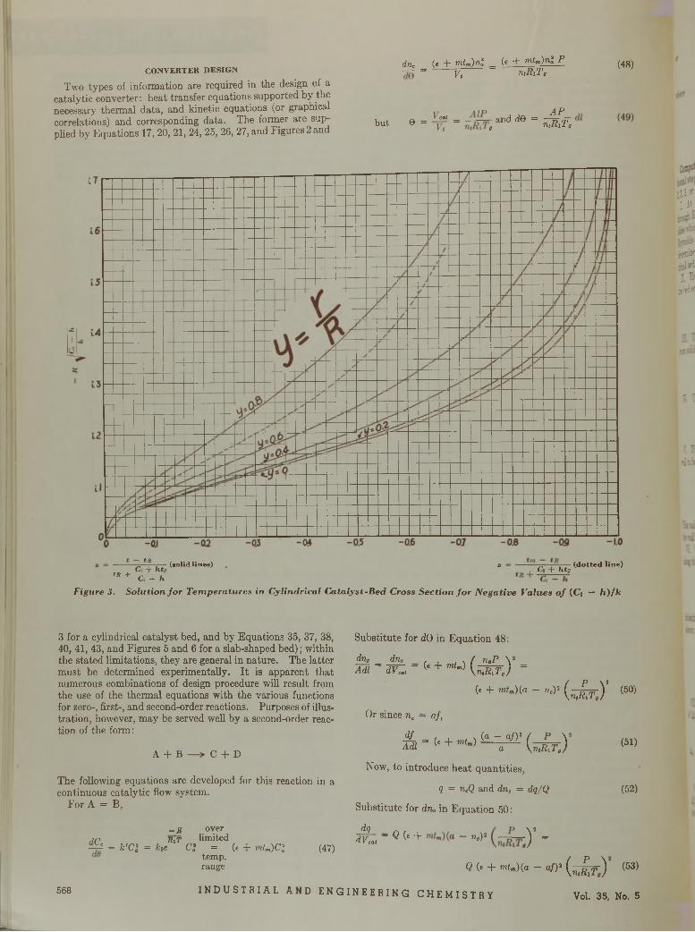
dnr (t + rntm)n l _ U + mtm)n î P (4g^C O N V E R T E R D E S IG N — = i ------- ^ ------------------------n tR lT ç V >
Two types of information are required in the design of a catalytic converter: heat transfer equations supported by thenecessary thermal data, and kinetic equations (or graphical A pcorrelations) and corresponding data. The former are sup- but e = »« = and d e = n ,R iT acorrelations; ana corresponuing uaua. m e r but yp l i e d b y E q u a t i o n s 17, 20, 21, 24, 25, 26, 27, and Figures 2 and »
3,3, «• Lit'
0 0jiölbci!L 13
ÿbed
I ï
u z i
tR (so lid lin e s )Co + htg
+ C, - h
S o lu t io n f o r T e m p e r a tu r e s in C y lin d r ic a l C a ta ly s t - B e d C ro ss
tR
F ig u r e 3.
s — — ■—— — ( d o t t e d lin e )Co + htg
S e c t io n f o r N e g a t iv e V a lu e s o f (C, — h ) / k
3 for a cylindrical catalyst bed, and by Equations 35, 37, 38, 40, 41, 43, and Figures 5 and 6 for a slab-shaped bed) ; within the stated limitations, they are general in nature. The latter must be determined experimentally. It is apparent that numerous combinations of design procedure will result from the use of the thermal equations with the various functions for zero-, first-, and second-order reactions. Purposes of illustration, however, may be served well by a second-order reaction of the form:
A + B C + D
The following equations are developed for this reaction in a continuous catalytic flow system.
For A = B,
_ e overdC Kir limitedFkf = k'C: = he Cl = (* + rntm)C l
temp, range
(47)
Substitute for dQ in Equation 48:
dnc dn,Adi = w z t = (e + mlm)
( riqP\ n ,R
B y =
i T j
( . + m tn)(a - nc,)• ( ¿ ¿ r ) ’ (50)
O r since nc = a f ,
d f— = (e + fflf ) (® " a/)2 ( P \ A dl (« + m tm) a y ru R fT g )
Now, to introduce heat quantities,
q = n cQ and dnc = dq/Q
Substitute for dnc in Equation 50:
dq
(51)
(52)
d v i , - « < « + ^ y =
Q (* + m t„)(a - a f)1 ( ^ ¿ r ) (53)
568 INDUSTRIAL AND ENGINEERING CHEMISTRY Vol. 35 , No. 5
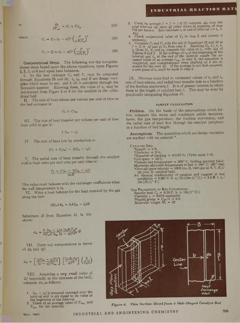
or
where
dqdVZ Co + Cd
Co - Q e(a - af)1 ( n(Rljy )
Ci = Q m (a - af)1
(54)
(55)
(56)
Computational Steps. The following are the computational steps based upon the above equations, upon Figures 2, 3, 5, or 6 and upon heat balances.
I. At the bed entrance C0 and C\ may be computed through Equations 55 and 56; ta, tR, and R are design variables which must be set; and h (2) is calculable through the Reynolds number. Knowing these, the value of tm may be determined from Figure 2 or 3 for the catalyst in the cylindrical bed. .
II. The rate of heat release per volume per unit of time atthe bed entrance is:
Co -t- C\tm
III. The rate of heat transfer per volume per unit of time from solid to gas is:
h {tm to)
IV. The rate of heat loss by conduction is:
(Co + C lU - IHtm - to) 1
V. The radial rate of heat transfer through the catalyst wall in heat units per unit area per unit time is:
Co + Cdm - \h(tm - to) ]27 r
This value must balance with the exchanger coefficients when the wall tempei
VI. Write a along the bed:
the wall temperature is fa. • i,VI. Write a heat balance for the heat received by the gas
I N D U S T R I A L R E A C T I O N R A T
3. Using an average / = / + (A //2) compute Atg over the to tal interval Af, since all other terms in equation of step V II are known. Also calculate ta a t end of interval ( = t„ + A t0).
4. Check conjectured value of Ta in step 2 and correct if necessary.
5. Compute Co and C, with the aid of Equations 5o and 56 at / = fo + Af and a t T0 from step 4. Knowing Co, Ci, K k, to (from 3), R, and tn, compute the value of tm w ith aid of Figures 2 and 3. If the average of tm a t the beginning of the interval and t'm a t the end of the interval equals the assumed value of an average tmv . in step 2, the operation is completed, and computational steps starting a t I are repeated for the next Af. If the average is not th a t assumed, a new guess of tm must be made in step 2 .
IX. Previous steps lead to estimated values of tm and t„ ,
rate of heat release, and radial heat transfer rate as a function of the fraction conversion/. It is of greater interest to relate these to the length of catalyst bed, I. This may be done by graphically integrating Equation 51.
SAMPLE CALCULATION
Problem. On the basis of the assumptions which follow, compute the mean and maximum solids temperatures, the gas temperature, the fraction conversion, and the radial rate of heat flow through the catalyst periphery as a function of bed length.
Assumptions. T h e q u a n titie s w hich are design v ariab les are m ark ed w ith an a ste risk *.
C a t a l y s t Be d :‘Length = 3 ft.‘Diameter = 3 in. .‘Diameter of packing = 0.0167 ft. (Tyler mesh 7-8)Void space = 40%‘Outside bed tem perature = 360° C. (boiling mercury bath) Maximum allowable tem perature in bed = 440° C. (80 rise) ‘Over-all space velocity = 5000 (cu. ft. inlet gas a t S. 1 . 1 .) /
(hr.) (cu. ft. catalyst bed) .Av. thermal conductivity of catalyst and support a t bed
conditions = 0.001 C. h. u ./(ft.)(sec.)(° C.) = 3.6 B. t. u ./ (hr.)(ft.)(° F.)
I
GCpAdt, = hA{tm - t,)dl
G a s P r o p e r t i e s a t B e d C o n d i t i o n s : Specific heat CP = 0.33 C. h. u ./( lb .)(‘ Viscosity m = 0.018 centipoise Prandtl group = Cpg/k = 0.8 Molecular weight Mo = 30
C.)
Substitute dl from Equation 51 in the above:
h {tm - lo)a (ntRiT,)1 dt' ~ GCpA k,m {a - ajyP1
VII. Carry out computations in terms of A to and A/:
TAf { U - t o ) T n r(n«R,)2a-] f j k _ \= L (a - a/p/a d [ T A P ^ l U c j
VIII. Assuming a very sm a ll value of A/ (especially at the entrance of the bed), -compute Af„ as follows:
1. (tm — t0) is assumed constant over the interval and is set equal to its value at the beginning of the interval.
2. Guess at an average value of T mav. and T Qav for the interval.
F ig u r e 4. T h i n S e c t i o n S l i c e d f r o m a S la b - S h a p e d C a ta l y s t B e d
1Q41 I N D U S T R I A L AND E NG I NE E R IN G CHEMI STRY 569
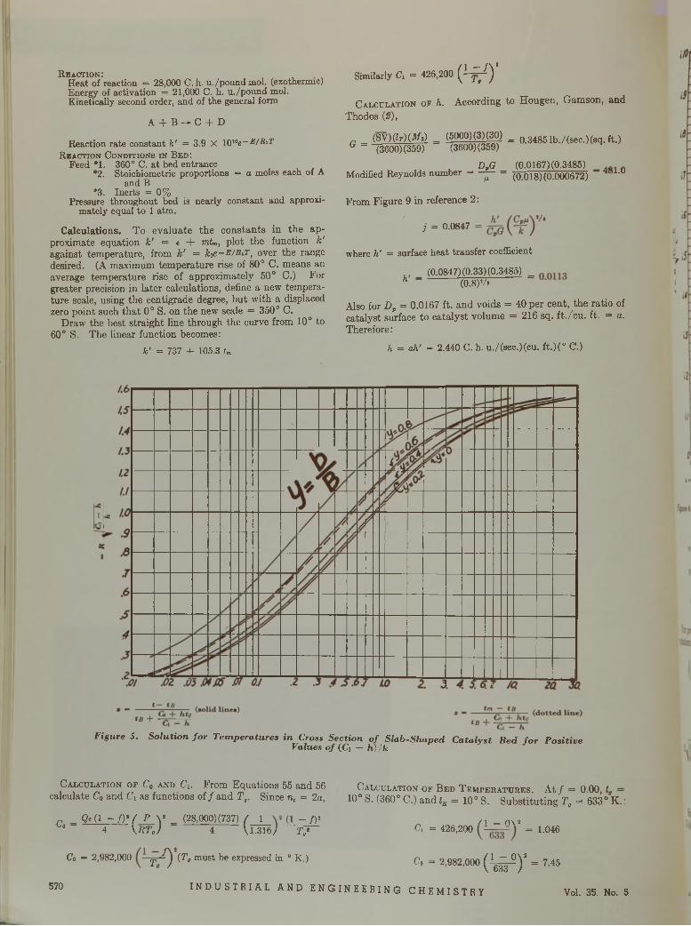
R e a c t io n :Heat of reaction = 28,000 C. h. u./pound mol. (exothermic) Energy of activation = 21,000 C. h. u./pound mol. Kinetically second order, and of the general form
A + B —*■ C I - D
Reaction rate constant k' = 3.9 X I0l0e-R/R'TR e a c t i o n C o n d i t i o n s i n B e d :
Feed *1. 360° C. a t bed entrance*2. Stoichiometric proportions = a moles each of A
and B *3. Inerts = 0 %
Pressure throughout bed is nearly constant and approximately equal to 1 atm.
Calculations. T o ev a lua te th e co n stan ts in th e ap proximate equation k' = t + mtm, p lo t the function k' against tem perature, from k' = kgfi-E/RiTt over the range desired. (A maximum tem perature rise of 80° C. m eans an average tem perature rise of approxim ately 50° C.) For greater precision in la te r calculations, define a new tem perature scale, using the centigrade degree, b u t w ith a displaced zero point such th a t 0° S. on the new scale = 350° C.
D raw the best stra igh t line through the curve from 10° to 60° S. The linear function becomes:
k ’ = 7 3 7 + 1 0 5 .3 tm
'M0( V ) ’Sim ilarly Ci = 426
C a lc u la t io n o f h. According to H ougen, G am son, and Thodos (2),
G = (SV)(Zr)(3fe) = (5000)(3)(30) = q.3485 lb./(sec.)(sq. ft.)(3600) (359) (3600) (359)
DpGu. ~ (0.018) (0.000672)
From Figure 9 in reference 2:
DvG (0.0167) (0.3485)Modified Reynolds number = --- = -------------------------' - 481-u
, - 0.0847 - M W
where h' = surface heat transfer coefficient
_ (0.0847)(0.33)(0.3485) = h (0.8)’/»
Also for Dp = 0.0167 ft. and voids = 40 per cent, th e ra tio of catalyst surface to ca ta lyst volum e = 216 sq. f t ./c u . ft. = a. Therefore:
h = ah' = 2.440 C. h. u./(sec.)(cu. ft.)(° C.)
F ig u r e 5 . S o lu t i o n f o r T e m p e r a tu r e s in C ro ss S e c t io n o f S la b - S h a p e d C a ta l y s t B e d f o r P o s i t iv eV a lu e s o f (Ci - h ) / k
C a l c u l a t i o n o f C 0 a n d C x. F r o m Equations 55 and 56 C a l c u l a t i o n o f B e d T e m p e r a t u r e s . At / = 0.00, t . = calculate C0 and C \ as functions of / and T ,. Since n, = 2a, 10° S. (360° C.) and tR = 10° S. Substituting T 0 = 633° K .:
„ _ Q e ( l - f ) * ( P V _ (28,000)(737) / 1 (l — /)• „ _ nN 2Lo 4 \ S T g ) 4 1,1.316/ T t ‘ C> = 426,200 = 1.046
Co = 2,982,000 T ^ (Po must be expressed in 0 K.) C0 = 2 982 000 ( 1 ~ ° V = 7 4 5\ 633 /
570 I NDUSTR I AL AND ENGINEER ING CHEMI STRY Vol. 35. No. 5
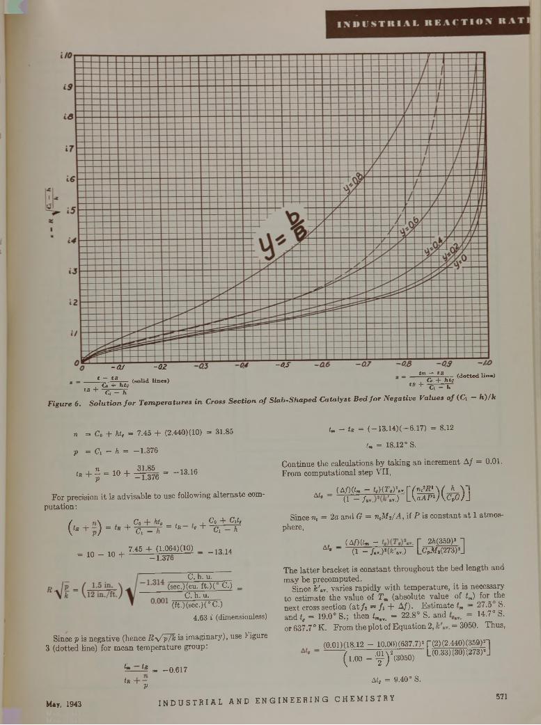
- Q Jt — tB
tB +Co + h ty
Ci - h
- 0 2
(so lid lin e s)
-c /.jtm — tB
tB +Co + ht{jCi - h
(d o tted lin e)
F ig u r e 6 . S o l u t i o n f o r T e m p e r a t u r e s i n C r o ss S e c t i o n o f S la b - S h a p e d C a ta l y s t B e d f o r N e g a t iv e V a lu e s o f (C, - h ) / k
n = Co + hi, = 7.45 + (2.440) (10) = 31.85
p = Ci - h = -1.376
+f=10+ S6="13-16For precision it is advisable to use following alternate com
putation:
/ . . n \ . , Co + hi, _ , Co + C}t,( t* + p ) ==tR+ Cl - X ~ tR t + Cl - h
= 10 - 10 +7.45 + (1-064) (10) _ 13 14
-1.376
C. h. u.(sec.)(cu. ft.)(° C.) _
C. h. u.(ft.)(sec.)(° C.)
4.63 i (dimensionless)
Since p is negative (hence R \ / p /k is imaginary), use Figure 3 (dotted line) for mean temperature group:
tR V
i . - is = ( —13.14)( —6.17) = 8.12
tm = 18.12° S.
Continue the calculations by taking an increment A f = 0.01. From computational step VII,
A t,( A f ) ( t m - t , ) ( T , ) \ r . V ( n f R ' \ ( h
(1 - /aT,)*„C(n?R'\( h \ - |^ f L W p 2A<v ?/J
Since n, = 2a and G = ntM ,/ A , if P is constant at 1 atmosphere,
(Af ) { U - T 2A(359)* 1At‘ ~ ' (1 - /a..)2(fc V ) LCPM1(273)2J
The latter bracket is constant throughout the bed length and may be precomputed.
Since fc'.v. varies rapidly with temperature, it is necessary to estimate the value of T m (absolute value of tm) for the next cross section (at /2 = /1 + A f ) . Estimate tm - 27.5 S. and t, = 19.0° S.; then fm„. = 22.8° S. and = 14.7° S. or637.7°K. From the plot of Equation 2, = 3050. Thus,
(0.01)(18.12 - 10.00)(637.7)2 |~(2)(2.440)(359)2~
May, 1943
*=----^ = -0.617
I N DU S T R I A L AND ENG
■ r (2) (2.440) (359) H (1.00 - f )*<3050> L{0.33)(30)(273)!J
A t, = 9.40° S.
I N E E R I N G C H E M I S T R Y 571
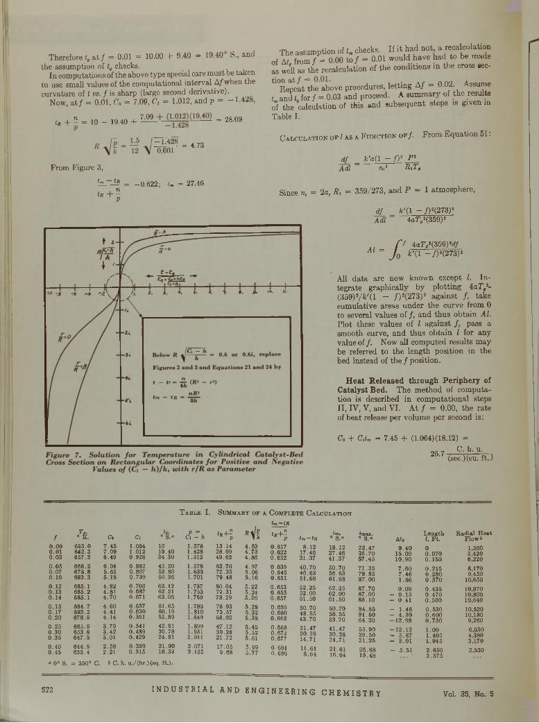
Therefore f, a t / = 0.01 = 10.00 + 9.40 — 19.40 S., and the assumption of t, checks.
In computations of the above type special care must be taken to use small values of the computational interval A/when the curvature of t vs. f is sharp (large second derivative).
Now, at / = 0.01, Co = 7.09, C\ = 1.012, and p = -1.428,
tR + 5 = 10 - 19.40 + 7 - M + = 28.09
-1.428 .001 = 4.73
From Figure 3,tm tR
tR + "V
= -0.622; tm = 27.46
The assumption of L checks. If it had not a recalculation of At from / = 0.00 to / = 0.01 would have had to be made as we'll as the recalculation of the conditions in the cross sec-
ti0Repeat=the above procedures, letting A/ = 0.02 Assume I anci t for / = 0.03 and proceed. A summary of the results o"f the calculation of this and subsequent steps is given in Table I.
C a l c u l a t i o n o f I a s a F u n c t io n o f / . From Equation 51 :
d f _ fc 'a (l - f ) 2 P 2 A d i n,* R i T ,
Since n, = 2a, Rx = 359/273, and P = 1 atmosphere,
Æ .A di
k '( 1 - / ) 2(273)2 4a7V(359)2
A l- a
4a7’i!(359)2d/ /c'(l - / ) 2(273)2
All data are now known except I. Integrate graphically by plotting 4aT,2- (359)2/&'(l - / ) 2(273)2 against / , take cumulative areas under the curve from 0 to several values of / , and thus obtain A l. Plot these values of I against / , pass a smooth curve, and thus obtain I for any value of / . Now all computed results may be referred to the length position in the bed instead of the/position.
Heat Released through Periphery of Catalyst Bed. The method of computation is described in computational steps II, IV, V, and VI. At / = 0.00, the rate of heat release per volume per second is:
Co + Cxtm = 7.45 + (1.064) (18.12) =C. h. u.26.7 (sec.Rcu. ft.)
T a b l e I. S u m m a b y o f a C o m p l e t e C a l c u l a t i o n
/ fy . C, Ci 2*
1 It tR + l "Vi t m - tR
tR + lV0.00 6 3 3 .0 7 .4 5 1.064 10 1.376 13 .14 4 .6 3 0 .6 1 70.01 64 2 .3 7 .0 9 1.012 19 .40 1.428 28 .09 4 .7 3 0 .6 2 20 .0 3 6 5 7 .3 6 .4 9 0 .9 2 8 3 4 .3 0 1.512 4 9 .6 2 4 .8 6 0 .6 3 20 .0 5 668.2 6 .0 4 0 .8 6 2 45 .2 0 1 .578 63 .7 0 4 .9 7 0 .6390 .0 7 6 7 5 .8 5 .6 5 0 .807 52 .80 1.633 72 .3 5 5 .0 6 0 .6 4 50.10 6 8 3 .3 5 .1 8 0 .7 3 9 60 .26 1.701 79 .4 8 5 .1 6 0 .6510.12 685 .1 4 .9 2 0 .7 0 3 62 .12 1 .737 8 0 .0 4 5 .2 2 0 .6 5 30 .1 3 6 8 5 .2 4 .8 1 0 .6 8 7 62 .21 1.753 79 .31 5 .2 4 0 .6 5 50 .1 4 685 .1 4 .7 0 0 .671 62 .06 1 .769 7 8 .2 9 5 .2 6 0 .6570 .1 5 6 8 4 .7 4 .6 0 0 .6 5 7 61 .65 1.783 76 .9 3 5 .2 8 0 .6590 .1 7 6 8 3 .2 4 .41 0 .6 3 0 60 .1 9 1 .810 73 .57 5 .3 2 0 .6 6 00.20 6 7 8 .9 4 .1 4 0 .591 55 .89 1.849 66.02 5 .3 8 0 .6620 .2 5 6 6 5 .9 3 .7 9 0 .541 42 .91 1.899 47 .1 2 5 .4 5 0.6680 .3 0 6 5 3 .8 3 .4 2 0 .4 8 9 30 .7 8 1.951 30 .26 5 .5 2 0 .6 7 20 .3 5 6 4 7 .9 3 .0 1 0 .4 2 9 24 .91 2.011 21 .72 5 .61 0 .6770 .4 0 6 4 4 .9 2 .5 8 0 .3 6 9 2 1 .9 0 2.071 17.05 5 .6 9 0 .6810 .4 5 6 3 3 .4 2.21 0 .3 1 5 16 .39 2 .125 9 .6 8 5 .7 7 0.686« 0° S. = 350° C . & C. h. u ./( h r .) ( s q . f t.) .
tm—'tRtm,
° S .“(m u ,° S .“ A tg
L e n g th 1, F t .
R ad ia l H e a t F lo w t
8.1217 .4631 .3 7
18 .122 7 .4 64 1 .3 7
2 2 .4 73 6 .7 05 7 .4 5
9 .4 01 5 .0 01 0 .9 0
00 .0 7 00 .1 5 0
1,5603,4206,220
40 .7 046 .6 35 1 .6 8
5 0 .7 056 .6 36 1 .6 8
7 1 .3 57 9 .8 58 7 .0 0
7 .6 07 .4 61.86
0 .2 1 50 .2 8 00 .3 7 0
8,1709,450
10,65052 .2552 .0 051 .5 0
6 2 .2 56 2 .0 06 1 .5 0
8 7 .7 08 7 .0 086.10
0 .0 9- 0 .1 5- 0 .4 1
0 .4 3 50 .4 7 00 .5 0 0
10,87010,80010,640
5 0 .7 0 4 8 .5 54 3 .7 0
6 0 .7 0 5 8 .5 55 3 .7 0
8 4 .8 58 1 .6 06 4 .3 0
- 1 .4 6- 4 .3 0 - 1 2 . 9 8
0 .5 3 00 .6 0 00 .7 3 0
10,52010,1809,260
3 1 .4 72 0 .2 814.71
4 1 .4 73 0 .2 824 .71
5 5 .9 03 9 .5 03 1 .2 5
- 1 2 . 1 3- 5 .8 7- 3 .0 1
1.001 .4 0 51 .9 4 5
6,6304,3803,170
11.616 .6 4
2 1 .6116 .64
2 6 .6 81 9 .4 8
- 5 .5 1 2 .6 5 03 .5 7 5
2,530
572 I NDUSTRIAL AND ENGINEERING CHEMI STRY Vol. 35, No. 5
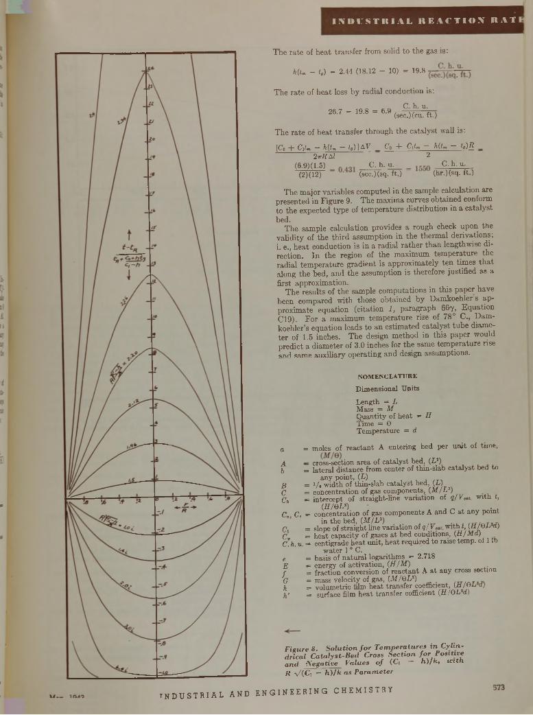
Ü N 'D L 'S T It l A L R E A C T I O N R A T
The rate of heat transfer from solid to the gas is:
H lm - t . ) = 2 .4 4 (1 8 .1 2 - 10) = 19-8
The rate of heat loss by radial conduction is:
26.7 - 19.8 = 6.9 (seg )(hcu\ )
The rate of heat transfer through the catalyst wall is:
[Co + C iU — h(tm — fc)] A V _ Co + Citm — h(tm — t„)R _ 2 ttR M ^
(6.9)(1.5) _ „ C. h. u. C.h. u.(2)(12) (sec.)(sq. ft.) (hr.)(sq. ft.)
The major variables computed in the sample calculation are presented in Figure 9. The maxima curves obtained conform to the expected type of temperature distribution in a catalyst bed.
The sample calculation provides a rough check upon the validity of the third assumption in the thermal derivations:i. e., heat conduction is in a radial rather than lengthwise direction. In the region of the maximum temperature the radial temperature gradient is approximately ten times that along the bed, and the assumption is therefore justified as a first approximation.
The results of the sample computations in this paper have been compared with those obtained by Damkoehler s approximate equation (citation 1 , paragraph 6 6 7 , Equation C19). For a maximum temperature rise of 78° C., Dam- koehler’s equation leads to an estimated catalyst tube diameter of 1.5 inches. The design method in this paper would predict a diameter of 3 .0 inches for the same temperature rise and same auxiliary operating and design assumptions.
NOMENCLATUREDimensional Units
Length = L Mass = MQuantity of heat = H Time = 0 Temperature = d
a = moles of reactant A entering bed per unit of time,
A — cross-section area of catalyst bed, (L2)b = lateral distance from center of thin-slab catalyst bed to
any point, (L)B = i / t width of thin-slab catalyst bed, (L)C = concentration of gas components, (Af/Ls)Co = intercept of straight-line variation of q/Vcot. w ith t,
(H/OL*)c„ Cc = concentration of gas components A and C a t any point
in the bed, (M /L 3)C, = slope of straight line variation of q/y with t, (HJVL a)Cv = heat capacity of gases a t bed conditions, (U/Ma)C. h. u. = centigrade heat unit, heat required to raise temp, of 1 lb
water 10 C. e = basis of natural logarithms = 2.718E = energy of activation, (H/M)f = fraction conversion of reactant A a t any cross sectionG = mass velocity of gas, (M/0L2)h = volumetric film heat transfer coefficient, (a/eL d)h' = surface f i lm heat transfer cofficient (H/QLH)
F ig u r e 8 . S o l u t i o n f o r T e m p e r a t u r e s i n C y l i n d r ic a l C a t a l y s t - B e d C ro ss S e c t i o n f o r P o s i t iv e a n d N e g a t iv e V a lu e s o f (Ci — h ) / k 1 w i t h R V l C i — h ) / k a s P a r a m e te r
I N D U S T R I A L AND E N GI NE E R I NG CHEMI STRY
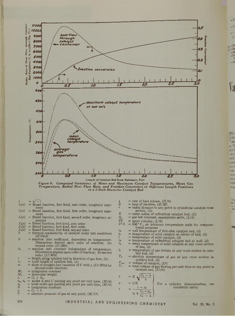
I I I 0 0 0
] ¿ 1 0 0 0 0ö
~ÏÏO 2 ,0L e n g th o f C a ta ly s t B ed f ro m E n tra n c e « F e e t
F ig u r e 9 . C o m p u te d V a r ia t io n s o f M e a n a n d M a x i m u m C a ta ly s t T e m p e r a t u r e s , M e a n G a s T e m p e r a tu r e , R a d ia l H e a t F lo w R a te , a n d F r a c t io n C o n v e r s io n a t D i f f e r e n t L e n g t h P o s i t i o n s
in a 3 - I n c h D ia m e te r C a ta ly s t B e d
/.(*)
/.(*)
/»(*)
/.(*)Ji(x)/.(* )kk'
fco
M iM inna, tic TUNPP
574
= V ~ 1= Bessel function, first kind, zero order, imaginary argu
ment= Bessel function, first kind, first order, imaginary argu
ment= Bessel function, first kind, second order, imaginary ar
gument= Bessel function, first kind, zero order = Bessel function, first kind, first order = Bessel function, first kind, second order = thermal conductivity of catalyst under bed conditions
(H/eLd)= reaction rate coefficient, dependent on temperature.
Dimensions depend upon order of reaction; for second order (L3/MO)
= reaction rate constant independent of temperature. Dimensions depend upon order of reaction; for second order (L3/MQ)
= length along catalyst bed in direction of gas flow, (L)= total length of catalyst bed, (L)= slope of straight-fine variation of k' with t, (L3/MOd for
second-order reaction)= integration constant = molecular weight — Cq “f- htg= moles A and C passing any point per unit time, (M/e) = total moles gas passing any point per unit time, (M/e) = integration constant = Ci - h= absolute pressure of gas a t any point, (M/L%)
qQr
RRi_S70°S.
Veal-V,
= rate of heat release, (H/e)= heat of reaction, (H/M )= radial distance to any point in cylindrical catalyst cross
section, (L)= outer radius of cylindrical catalyst bed, (L)= gas law constant, appropriate units, (L/d)= space velocity, (1/9)= 350° C., an arbitrary tem perature scale for computa
tional purposes = wall temperature of thin-slab catalyst bed, (d)= temperature of solid catalyst a t center of bed, (d)= temperature of solid catalyst, (d)= temperature of cylindrical catalyst bed a t wall, (d)= mean tem perature of solid catalyst a t any cross section
of bed, (d)= temperature of gas stream a t any cross section in cata
lyst bed, (d)= absolute tem perature of gas a t any cross section in
catalyst bed, (d)= volume of catalyst, (Ls)= total volume of gas flowing per unit time a t any point in
catalyst bed, (L3/ 9 )
= r /RI — tR
For
Ir +Ci -f" htg Ci - h
INDUSTR I AL AND ENGINEERING CHEMISTRY
cylinder (dimensionless, consistent units)
Vol. 35, No. 5
Htszï:kam35/¿CSSS RH itKI kér m s:
îshs
SS 3
11
«a
r - h
= b /Bt - tB
F o r a s la b (d im e n s io n le s s , use c o n s is te n t u n i ts )
+ Co -{- htfC i - h
F0(z) = B e s s e l f u n c t io n , s e c o n d k in d , z e ro o rd e r Y i ( x ) = B e s s e l f u n c t io n , s e c o n d k in d , f ir s t o rd e r 0 = h e ig h t o f t h in s la b c a t a ly s t b e d , ( L )f = in te r c e p t o f s t r a ig h t - l in e v a r ia t io n o f k' w it h f, (Ll/MQ)
f o r s e c o n d -o rd e r r e a c t io n )9 = t im e , ( 0 )
I N D U S T R I A L R E A C T I O N R A T
t = 3 .1 4 1 6Ij = t — tt,ß = v is c o s i ty , ( M / L G )
literature cited
(1 ) D a m k o e h le r , “ D e r C h e m ie In g e n ie u r” , V o t . I l l , P a r t 1,p . 3 5 9 , L e ip z ig , A k a d e m is c h e V e rla g s g e s e lls c h a ft, 193 7 .
(2 ) H o u g e n , G a m s o n , a n d T h o d o s , T r a m . A m . In s t . C hem . E n g rs .,3 9 , 1 (1 9 4 2 ) .
(3 ) J a k o b , Ib id ., 3 5 , 56 3 (1 9 3 9 ) . . . „ Q.(4 ) J a k o b - H a w k in s , “ E l e m e n ts o f H e a t T r a n s m is s io n , p . 86,
N e w Y o r k , Jo h n W ile y & Sons, 194 2 .(5 ) P a te rs o n , P h il . M a g ., [7 ] 3 2 , 38 4 (1 9 4 1 ) .
Vapor-Phase Estérification RatesH . F . H o e r i g 1, D o n H a n s o n ,
O . L . K o w a l k e
UNIVERSITY OF WISCONSIN, MADISON, WIS.
T HE esterification reaction between organic acids and alcohols has been studied quantitatively in the liquid phase from the standpoint of equilibria and of reaction
rates. The reaction in the vapor phase has not been investigated so thoroughly, however. The equilibrium constants for the vapor-phase reaction have been accurately determined (2), and various catalysts have been employed; silica gel apparently has been the most successful (1 , S , 5 , £>)•_ data are available to correlate the effect of mass velocity of the gases and the effect of temperature on the reaction rate. In this investigation the esterification reaction between ethyl alcohol and acetic acid in the vapor phase was studied in a flow system, operated at atmospheric pressure, and employing a silica gel catalyst.
ESTERIFICATION UNITT h e a p p a r a tu s c o n s is te d , in g e n e ra l, o f a c a l ib r a te d d e l iv e r y
s y s te m fo r t h e r e a c ta n ts , a p r o p o r t io n in g p u m p , v a p o r iz e rs ,
1 P re sen t ad d ress , E . I . d u P o n t de N em o u rs * C o m p a n y , In c .. B uffalo,
N . Y.
r e a c t io n c h a m b e r , D o w t h e r m h e a t in g s y s te m , c o n d e n s e r, a n d c o n tro l p a n e l ( F ig u r e 1 ) . T h e c a l ib r a te d d e h v e r y s y s te m fo r a c e t ic a c id a n d f o r e t h y l a lc o h o l w a s c o n s tru c te d o f g lass. A l l t h e o th e r u n i t s in t h e r e a c t io n s y s te m w e re c o n s tru c te d otK A 2 S M o s ta in le s s s te e l. „ , . . . , ,
T h e r e a c ta n ts w e re p u m p e d s e p a r a te ly f r o m t h e c a l ib ra te d g lass b u r e ts b y t h e p r o p o r t io n in g p u m p i n o r d e r t o a d ju s t t f ie p u m p to t h e d e s ire d f lo w r a t e . A f t e r t h e r a t e w a s s e t, t h e re a c t a n t s w e re p u m p e d f r o m s to ra g e c a rb o y s t o a v o id r e p e a te d r e f i l l in g o f t h e fla s k s w h ic h s u p p lie d t h e b u re ts . C a lc iu m c h lo r id e t u b e s w e re c o n n e c te d t o a l l a i r in le ts o f t h e fe e d s y s te m so t h a t o n ly d r y a i r c a m e in c o n ta c t w i t h t h e h y g ro s c o p ic r e a c ta n ts
A s e p a ra te v a p o r iz e r w a s b u i l t fo r e a c h r e a c t a n t f r o m a /« - in c h s ta in le s s s te e l n ip p le , 1 8 in c h e s lo n g T h e s e n ip p le s w e re c a p p e d o n t h e e n d s , a n d w e re c a s t i n p a r a l le l in t o t w o a lu m in u m b lo c k s w h ic h w e re h e a te d s e p a r a te ly b y c h ro m e l re s is ta n c e s T h e p u rp o s e o f th e s e h e a te d a lu m in u m b lo c k s w a s t o v a p o r iz e t h e l iq u id s a t a n i n i t i a l , c o n tro l le d , c o n s ta n t te m p e r a t u r e . I n a d d it io n , a se c o n d s im i la r ly c o n tro l le d r e g i o n w a s p r o v id e d a t th e d is c h a rg e e n d o f e a c h v a p o r iz e r t o c o n tro l th e d e g re e o f s u p e rh e a t T h e a lu m in u m b lo c k s a c te d as c o n s ta n t - te m p e r a tu r e re s e rv o irs o f h e a t , p r e v e n t in g s lo w v a p o r iz a t io n o f t h e r e a c ta n ts a n d c o n s e q u e n t c o l le c tio n o f l iq u id m p o o ls i n t h e v a p o r iz e rs . T h e s u p e rh e a t in g s e c tio n w a s n e c e s s a ry t o o b t a in c lose c o n tr o l o l t h e te m p e r a t u r e o f t h e re a c ta n ts e n te r in g t h e r e a c t io n c h a m b e r .
T h e e s t e r i f i c a t io n r a t e o f a c e t i c a c id w i t h e t h y l a lc o h o l i n t h e v a p o r p h a s e w a s i n v e s t i g a t e d i n a f l o w s y s t e m u s i n g a s i l i c a g e l c a t a l y s t . T h e m a s s v e l o c i t y o f t h e v a p o r d i d n o t a f f e c t t h e c o n s t a n t s i n t h e r a t e e q u a t i o n s r e p r e s e n t i n g c o n d i t i o n s a t s p e c if ic lo c a t io n s i n t h e b e d . I t a p p e a r s t h e n t h a t m a s s t r a n s f e r in t h e v a p o r p h a s e w a s
n o t s ig n i f i c a n t .F u r th e r m o r e , w i t h t e m p e r a t u r e in c r e a s e ,
th e s e c o n s t a n t s w e r e a u g m e n t e d l in e a r l y , w h ic h i n d i c a t e d t h a t t h e s u r f a c e r e a c t io n
r a t e iv a s n o t a c o n t r o l l in g f a c t o r . T h e ex p e r i m e n t a l e v id e n c e s h o w s t h a t t h e r a t e o f v a p o r - p h a s e e s t e r i f i c a t io n is c o n t r o l l e d b y t h e r a t e o f m a s s t r a n s f e r o r d i f fu s io n t h r o u g h a c o n d e n s e d p h a s e p r e s e n t in th e c a p i l la r ie s o f t h e s i l i c a g e l . T h e t e m p e r a tu r e e f f e c t i s i n a g r e e m e n t w i t h t h i s o b s e r v a t io n , a s i s t h e m a g n i t u d e o f th e a c t i v a t i o n e n e r g y . T h e s e c o n d - o r d e r r e a c t i o n r a t e o r d i n a r i l y e n c o u n te r e d in l i q u id - p h a s e e s t e r i f i c a t io n tv a s n e g l ig ib l e i n th e
c a t a l y z e d r e a c t io n .
Mav 1943 I N D U S T R I A L AND E N G I N E E R I N G C HEMI STRY 575
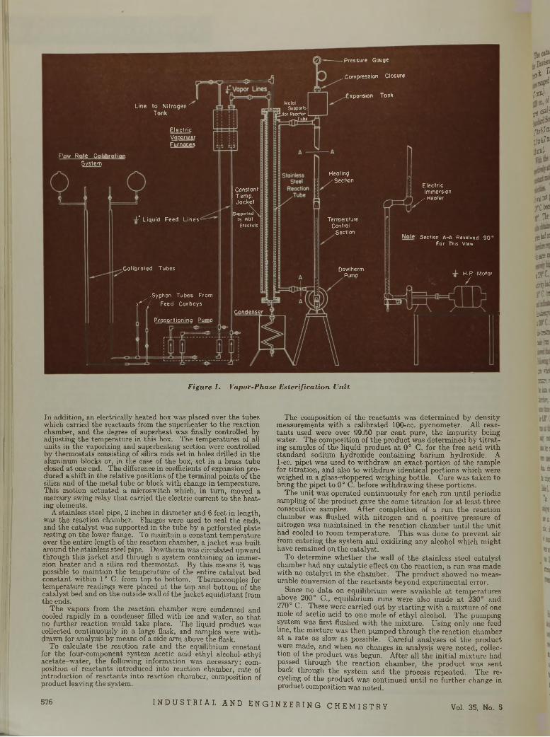
-Pressure Gouge
Line to Nitrogen' Tank
MetalSupports
for Reaction L Tube
ElectricVooorizerFurnaces
Flow Rote Colibrotion System
I Constant I T emp. Jacket
-L" Liquid Feed Lines*
Calibrated Tubes
,Syphon Tubes From , - 7 Feed Carboys
Proportioning Pumo
. Compression Closure
.-Expansion Tonk
Heating / Section
Electric Immersion
/ Heater
Supported \ by Wall
BracketsTemperatureControl.Section
Dowtherm.Pump
Note: Section A-A Revolved 90' For This View
H.R Motor /
Condenserr
F ig u r e 1. V a p o r -P h a s e E s t é r i f i c a t io n U n i t
In addition, an electrically heated box was placed over the tubes which carried the reactants from the superheater to the reaction chamber, and the degree of superheat was finally controlled by adjusting the temperature in this box. The temperatures of all units in the vaporizing and superheating section were controlled by thermostats consisting of silica rods set in holes drilled in the aluminum blocks or, in the case of the box, set in a brass tubeclosed at one end. The difference in coefficients of expansion produced a shift in the relative positions of the terminal points ofthe
The composition of the reactants was determined by density measurements with a calibrated 100-cc. pycnometer. All reactants used were over 99.50 per cent pure, the im purity being water. The composition of the product was determined by ti tra ting samples of the liquid product a t 0° C. for the free acid with standard sodium hydroxide containing barium hydroxide. A 1-cc. pipet was used to withdraw an exact portion of the sample for titration, and also to withdraw identical portions which were
silica and of the metal tube or block with change in temperature. This motion actuated a microswitch which, in turn, moved a mercury swing relay tha t carried the electric current to the heating elements.
A stainless steel pipe, 2 inches in diameter and 6 feet in length, was the reaction chamber. Flanges were used to seal the ends, and the catalyst was supported in the tube by a perforated plate resting on the lower flange. To maintain a constant temperature over the entire length of the reaction chamber, a jacket was built around the stainless steel pipe. Dowtherm was circulated upward through this jacket and through a system containing an immersion heater and a silica rod thermostat. By this means it was possible to maintain the temperature of the entire catalyst bed constant within 1° C. from top to bottom. Thermocouples for temperature readings were placed at the top and bottom of the catalyst bed and on the outside wall of the jacket equidistant from the ends.
The vapors from the reaction chamber were condensed and cooled rapidly in a condenser filled with ice and water, so that no further reaction would take place. The liquid product was collected continuously in a large flask, and samples were withdrawn for analysis by means of a side arm above the flask.
To calculate the reaction rate and the equilibrium constant for the four-component system acetic acid-ethyl alcohol-ethyl acetate-w ater, the following information was necessary: composition of reactants introduced into reaction chamber, rate of introduction of reactants into reaction chamber, composition of product leaving the system.
weighed in a glass-stoppered weighing bottle. Care was taken to bring the pipet to 0° C. before withdrawing these portions.
The unit was operated continuously for each run until periodic sampling of the product gave the same titra tion for a t least three consecutive samples. After completion of a run the reaction chamber was flushed with nitrogen and a positive pressure of nitrogen was maintained in the reaction chamber until the unit had cooled to room tem perature. This was done to prevent air from entering the system and oxidizing any alcohol which might have remained on the catalyst.
To determine whether the wall of the stainless steel catalyst chamber had any catalytic effect on the reaction, a run was made with no catalyst in the chamber. The product showed no measurable conversion of the reactants beyond experimental error.
Since no data on equilibrium were available a t tem peratures above 200° C., equilibrium runs were also made a t 230° and 270° C. These were carried out by starting with a mixture of one mole of acetic acid to one mole of ethyl alcohol. The pumping system was first flushed with the mixture. Using only one feed line, the mixture was then pumped through the reaction chamber a t a rate as slow as possible. Careful analyses of the product were made, and when no changes in analysis were noted, collection of the product was begun. After all the initial mixture had passed through the reaction chamber, the product was sent back through the system and the process repeated. The recycling of the product was continued until no further change in product composition was noted.
nijji!'
lim®-)-.
prfr
,;to6 .Í® jjtoiî® ¡luit)'
¡is not! jftbea 1 1'*1
iglsdw
iJBtS
i3!C.aritradjfC-in
Ï1SE3
iłfC-i533a *
21»SR a ■ ÉB9jhrí
■arc
V KBill
sairsi l i i arc » ¡¡ »ii !* sa
fct
576 I N D U S T R I A L A N D E N G I N E E R I N G C H E M I S T R Y Vol. 35, No. 5
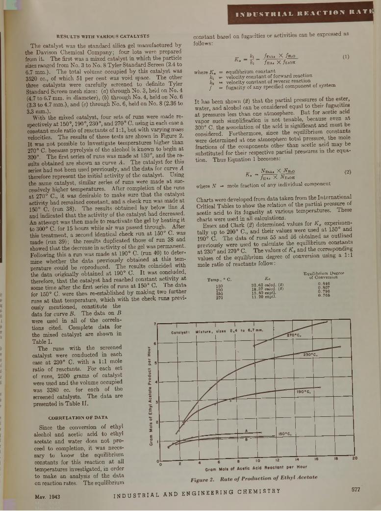
I N D U S T R I A L R E A C T I O N R A T H
RESULTS WITH VARIOUS CATALYSTSThe catalyst was the standard silica gel manufactured by
the Davison Chemical Company; four lots were prepared from it. The first was a mixed catalyst in which the particle sizes ranged from No. 3 to No. 8 Tyler Standard Screen (2.4 to6.7 mm.). The total volume occupied by this catalyst was 3520 cc., of which 51 per cent was void space. The other three catalysts were carefully screened to definite Tyler Standard Screen mesh sizes: (a) through No. 3, held on No. 4 (4.7 to 6.7 mm. in diameter), (6) through No. 4, held on No. 6 (3.3 to 4.7 mm.), and (c) through No. 6, held on No. 8 (2.36 to3.3 mm.).
With the mixed catalyst, four sets of runs were made respectively at 150°, 190°, 230°, and 270° C. using in each case a constant mole ratio of reactants of 1:1, but with varying mass velocities. The results of these tests are shown in Figure 2. It was not possible to investigate temperatures higher than 270° C. because pyrolysis of the alcohol is known to begin at 300°. The first series of runs was made at 150°, and the results obtained are shown as curve A . The catalyst for this series had not been used previously, and the data for curve A therefore represent the initial activity of the catalyst. Using the same catalyst, similar series of runs were made at successively higher temperatures. After completion of the runs at 270° C., it was desirable to make sure that the catalyst activity had remained constant, and a check run was made at 150° C. (run 38). The results obtained lay below line A and indicated that the activity of the catalyst had decreased. An attempt was then made to reactivate the gel by heating it to 300° C. for 15 hours while air was passed through. After this treatment, a second identical check run at 150° C. was made (run 39); the results duplicated those of run 38 and showed that the decrease in activity of the gel was permanent. Following this a run was made at 190° C. (run 40) to determine whether the data previously obtained at this temperature could be reproduced. The results coincided with the data originally obtained at 190° C. It was concluded, therefore, that the catalyst had reached constant activity at some time after the first series of runs at 150° C. The data for 150° C. were then re-established by making two further runs at that temperature, which with the check runs previously mentioned, constitute the data for curve B . The data on B were used in all of the correlations cited. Complete data forthe mixed catalyst are shown inTable I.
The runs with the screened catalyst were conducted in each case at 230° C. with a 1:1 mole ratio of reactants. For each set of r u n s , 2500 grams of catalyst were used and the volume occupied was 3380 cc. for each of the screened catalysts. The data are presented in Table II.
constant based on fugacities or activities can be expressed as follows:
„ _ h _ /eia. X /m o ( i )° fcj / ha* X /EtOH
where K„ = equilibrium constantki = ve lo c ity constant of forward reactionL = v e lo c ity constant of reverse reaction/ = fugacity of any specified com ponent of sy stem
It has been shown (2) that the partial pressures of the ester, water, and alcohol can be considered equal to their fugacities at pressures less than one atmosphere. But for acetic acid vapor such simplification is not tenable, because even at 300° C. the association of the acid is significant and must be considered. Furthermore, since the equilibrium constants were determined at one atmosphere total pressure, the mole fractions of the components other than acetic acid may be substituted for their respective partial pressures in the equation. Thus Equation 1 becomes:
K a =Ae.a. X jVh-0 (2)/ ha. X AeiOH
where N = m ole fraction of any ind ividual com ponent
Charts were developed from data taken from the International Critical Tables to show the relation of the partial pressure of acetic acid to its fugacity at various temperatures. These charts were used in all calculations.
Essex and Clark (2 ) determined values for K a experimentally up to 200° C., and their values were used at 150 and 190° C The data of runs 55 and 56 obtained as outlined previously were used to calculate the equilibrium constants at 230° and 270° C. The values of K a and the corresponding values of the equilibrium degree of conversion using a 1:1 mole ratio of reactants follow:
T e m p ., 0 C .150190230270
Ka3 3 .6 2 ca led . (2) 1 8 .3 7 ca led . (2) 1 5 .6 0 exp tl. 11.20 exp tl.
E q u ilib r iu m D egree of C onv ers io n
0 .8 4 60 .8 0 70 .7 9 60 .7 6 8
CORRELATION OF DATA
Since the conversion of ethyl alcohol and acetic acid to ethyl acetate and water does not proceed to completion, it was necessary to know the equilibrium constants for this reaction at all temperatures investigated, in order to make an analysis of the data on reaction rates. The equilibrium
Mav. 1943 i n d u s t r i a l AND E NG I NE E R IN G CHE MI ST RY 577
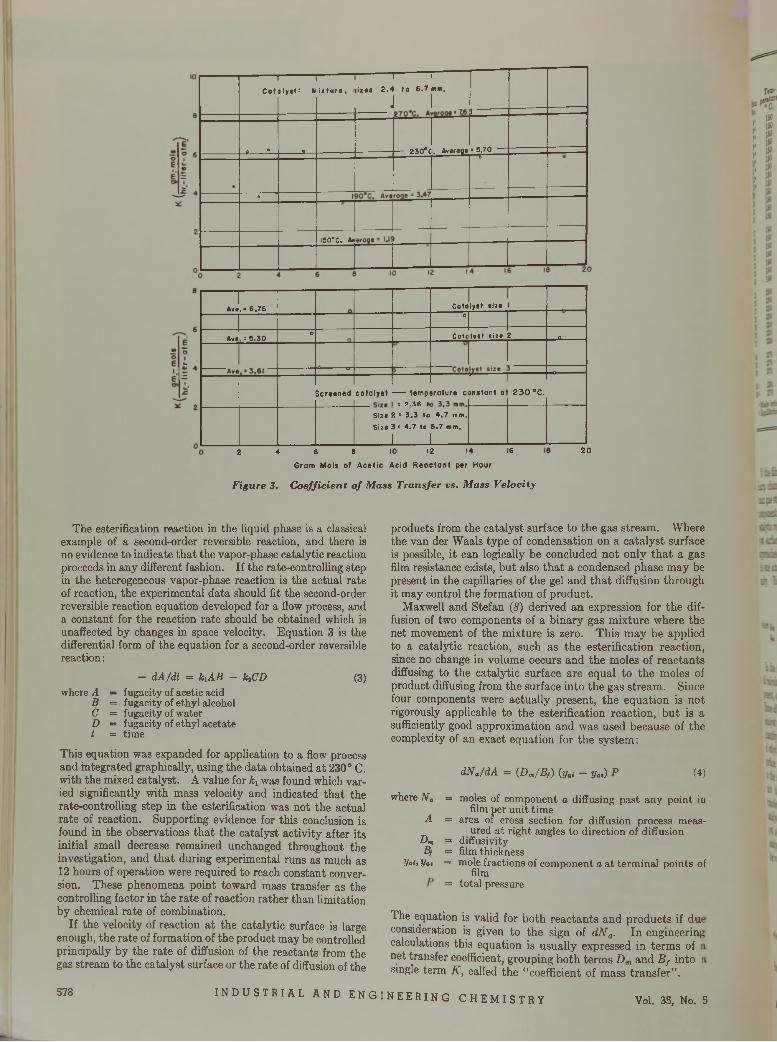
Col— 1 nalyst: m
---------is tur•,
--------I 1iiz«s 2.4 to 6.7 mm.
J 1 \
» . • s.. — 230* C. Average= 5.700
o 1
I50°C. A*
1Aw«.= 6.76 Cotolyst sir«
o
Av«. = 5.30 o Cotalyst size 2 _Q-----
------o-
Scrtened catalyst — temp= 2.36 t
rirature c
r ~onstant a 230 °C.
Sir« 2 = 3.3 to 4.7 mm. Sir« 3 B 4.7 to 6.7 mm.
1 12 4 6 8 10 12 14 16
Gram Mois of Acetic Acid Reoctont per Hour
F ig u r e 3. C o e f f i c ie n t o f M a ss T r a n s fe r v s . M a ss V e lo c i ty
20
The estérification reaction in the liquid phase is a classical example of a second-order reversible reaction, and there is no evidence to indicate that the vapor-phase catalytic reaction proceeds in any different fashion. If the rate-controlling step in the heterogeneous vapor-phase reaction is the actual rate of reaction, the experimental data should fit the second-order reversible reaction equation developed for a flow process, and a constant for the reaction rate should be obtained which is unaffected by changes in space velocity. Equation 3 is the differential form of the equation for a second-order reversible reaction :
— dA /dt = k iA B — k iC D (3)where A = fugacity of acetic acid
B = fugacity of ethyl alcohol C = fugacity of water D = fugacity of ethyl acetate t = time
This equation was expanded for application to a flow process and integrated graphically, using the data obtained at 230° C. with the mixed catalyst. A value for ki was found which varied significantly with mass velocity and indicated that the rate-controlling step in the estérification was not the actual rate of reaction. Supporting evidence for this conclusion is found in the observations that the catalyst activity after its initial small decrease remained unchanged throughout the investigation, and that during experimental runs as much as 12 hours of operation were required to reach constant conversion. These phenomena point toward mass transfer as the controlling factor in the rate of reaction rather than limitation by chemical rate of combination.
If the velocity of reaction at the catalytic surface is large enough, the rate of formation of the product may be controlled principally by the rate of diffusion of the reactants from the gas stream to the catalyst surface or the rate of diffusion of the
products from the catalyst surface to the gas stream. Where the van der Waals type of condensation on a catalyst surface is possible, it can logically be concluded not only that a gas film resistance exists, but also that a condensed phase may be present in the capillaries of the gel and that diffusion through it may control the formation of product.
Maxwell and Stefan (8 ) derived an expression for the diffusion of two components of a binary gas mixture where the net movement of the mixture is zero. This may be applied to a catalytic reaction, such as the estérification reaction, since no change in volume occurs and the moles of reactants diffusing to the catalytic surface are equal to the moles of product diffusing from the surface into the gas stream. Since four components were actually present, the equation is not rigorously applicable to the estérification reaction, but is a sufficiently good approximation and was used because of the complexity of an exact equation for the system:
dN a/dA = (D m/B f) {yai - y „ ) P (4)
where N a
A
D mB,
Vaiy y at
= moles of component a diffusing past any point in film per unit time
= area of cross section for diffusion process measured at right angles to direction of diffusion
= diffusivity = film thickness= mole fractions of component a at terminal points of
film= total pressure
The equation is valid for both reactants and products if du consideration is given to the sign of d N a . In engineerini calculations this equation is usually expressed in terms of net transfer coefficient, grouping both terms D m and B f into single term K , called the “coefficient of mass transfer”.
578 I N D U S T R I A L A N D E N G I N E E R I N G C H E M I S T R Y Vol. 35, No. 5
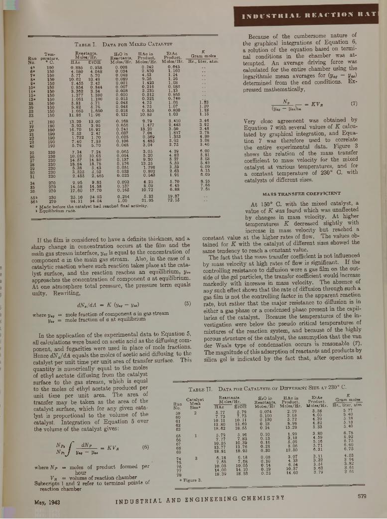
I N D U S T R I A L R E A C T I O N R A T
T a b l e I. D a t a f o r M i x e d C a t a l y s t
R unNo.
4°6*7 “8*9»
10»11»12*13«38395253
171920 21 22 2340
25262728293031343536
556 56 6
T e m p e ra tu re ,
° C . 150 150 150 150 150 150 150 150 150 150 150 150 150
190190190190190190190
230230230230230230230
270270270
230 270
R e a e ta u te ,M o le a /H r .
H A c0 .8 8 54 .0 8 0 5 .7 7
1 0 .6 22 .4 5 5 0 .8 5 4 3 .3 6 2 1 .3 7 7 1 .0 6 15 .8 15 .8 2 1 .6 6 5
11.861 3 .2 0
3 .9 216 .7 0
2 .5 21 .7 2 27 .4 05 .7 97 .3 4
10.021 4 .5 7 1 8 .8 4
5 .3 83 .5 2 52 .4 5 5
9 .9 51 4 .5 8 1 7 .6 0
E tO H0 .9 3 84 .0 4 85 .7 0
1 0 .4 92 .4 2 0 .8 4 4 3 .3 4 1 .3 9 0 1.1005 .7 1 5 .7 6 1 .6 5 0
1 1 .9 8
13 .0 03 .9 5
16 .9 22 .4 71 .7 0 7 .3 35 .7 07 .2 4
1 0 .0 514 .8 018 .7 8
5 .4 3 3 .5 2 2 .4 6 5
9 .8 51 4 .5 81 7 .7 0
HaO in H A c in R e a c ta n ta , P ro d u c t, M o le a /H r. M o le s /H r.
0 .0 0 80 .0 3 40 .0 4 80 .0 8 90.0210 .0 0 70 .0 2 80.0200 .0 1 50 .0 4 80 .0 4 80 .0 1 80 .1 3 2
0 .1 6 80 .0 5 60 .2 4 10 .0 3 70 .0 2 50 .1 0 60 .0 4 8
0 .0 6 50 .0 9 40 .1 3 70 .1 7 60 .0 5 10 .0 3 30 .0 2 3
0 .0 9 30 .1 3 70 .1 6 5
0 .2 4 22 .8 2 04 .5 39 .3 61.4230 .2 1 62 .2 3 50 .6 1 20 .3 2 14 .7 54 .7 5 0 .8 5 5
10 .83
9 .7 91 .477
13 .2 07 .0 4 0 .3 6 9 4 .4 8 53 .0 4
3 .0 5 5 .2 0 9 .3 0
13 .251 .7 9 80 .8 9 20 .5 4 3
4 .2 58 .0 9
10 .72
2 5 .1 0 2 4 .9 3 0 .2 6 4 5 .2 39 4 .1 1 9 4 .0 4 1 .0 0 2 1 .9 5
• M a d e b e fo re th e c a ta ly s t h a d reac h ed final a c tiv i ty .6 E q u ilib r iu m runs .
E tA cP ro d u c t,
M o le s /H r.0 .6 4 31 .1 6 01 .2 41 .2 61 .0 3 0 .6 8 3 1 .1 3 0 .8 6 5 0 .7 4 0 1 .0 6 1 .0 7 0 .8 0 01 .0 3
3 .4 1 02 .4 4 33 .5 01.8171 .3532 .9 22 .7 5
4 .2 94 .8 25 .2 75 .5 93 .5 9 2 .6 3 1 .91
5 .7 06 .4 96.88
19 .877 2 .1 5
KG ram m oles
H r ., li te r , a tm .
Because of the cumbersome nature of the graphical integrations of Equation 6, a solution of the equation based on terminal conditions in the chamber was attempted. An average driving force was calculated for the entire chamber using the logarithmic mean averages for {yaQ — Vat) determined from the end conditions. Expressed mathematically,
1 .231.201 .1 81.13
3 .4 6 3 923 .4 8 3 .7 8 4 .3 0 3 .3 83 .4 6
6.005 .815 .6 35 .4 96 .0 9 6 .1 56 .0 9
8 .2 57 .6 57 .61
Ar K V r (7)
If the film is considered to have a definite thickness, and a sharp change in concentration occurs at the film and the main gas stream interface, ya\ is equal to the concentration of component a in the main gas stream. Also, in the case of a catalytic reaction where such reaction takes place at the catalyst surface, and the reaction reaches an equilibrium, y„. approaches the concentration of component a at equilibrium. At one atmosphere total pressure, the pressure term equals unity. Rewriting,
d N a/d A — K (yag Vat)
where ya„ = m o l e fraction of component a in gas streamy a, = mole fraction of a at equilibrium
In the application of the experimental data to Equation 5, all calculations were based on acetic acid as the diffusing component, and fugacities were used in place of mole fractions. Hence d N J d A equals the moles of acetic acid diffusing to the catalyst per unit time per unit area of transfer surface. This quantity is numerically equal to the moles of ethyl acetate diffusing from the catalyst surface to the gas stream, which is equal = =to the moles of ethyl acetate produced per unit time per unit area. The area of transfer may be taken as the area of the catalyst surface, which for any given catalyst is proportional to the volume of the catalyst. Integration of Equation 5 over the volume of the catalyst gives:
Very close agreement was obtained by Equation 7 with several values of K calculated by graphical integration, and Equation 7 was therefore used to correlate the entire experimental data. Figure 3 shows the relation of the mass transfer coefficient to mass velocity for the mixed catalyst at various temperatures, and for a constant temperature of 230° C. with catalysts of different sizes.
M A S S T R A N S F E R C O E F F IC IE N T
At 150° C. with the mixed catalyst, a value of K was found which was unaffected
— by changes in mass velocity. At highertemperatures K decreased slightly with increase in mass velocity but reached a
constant value at the higher rates of flow. The values obtained for K with the catalyst of different sizes showed the same tendency to reach a constant value.
The fact that the mass transfer coefficient is not influenced by mass velocity at high rates of flow is significant. If the controlling resistance to diffusion were a gas film on the outside of the gel particles, the transfer coefficient would increase markedly with increase in mass velocity. The absence of any such effect shows that the rate of diffusion through such a gas film is not the controlling factor in the apparent reaction
(5) rate, but rather that the major resistance to diffusion is in either a gas phase or a condensed phase present in the capillaries of the catalyst. Because the temperatures of the investigation were below the pseudo critical temperatures of mixtures of the reaction system, and because of the highly porous structure of the catalyst, the assumption that the van der Waals type of condensation occurs is reasonable (7). The magnitude of this adsorption of reactants and products by silica gel is indicated by the fact that, after operation at
T a b l e I I . D a t a f o r C a t a l y s t s o f D i f f e r e n t S i z e a t 2 3 0 ° C .
C a ta ly s tM eshS ize0
2
AaAft
> f dN*\ J Vit ~ Va
= k v b (6)
where N p = moles of product formed per hour
V r = v o l u m e of reaction chamber Subscripts 1 and 2 refer to terminal points of
reaction chamber
R unNo.
5960 61 62 63
65666768
74 375767778
° F ig u re 3.
R e a c ta n ts ,M o le s /H r.
E tO H 79
H A c5 .7 77 .7 3
10.1113 .8018 .62
5 .7 97 .7 7
10 .2 513 .7718 .81
6 .1 87 .6 5
10 .0514 .0 018 .39
5. 7 .7 3
10.1113 .6 918 .5 5
5 .9 67 .8 3
10 .3 913 .7 618 .9 5
6 .1 87 .6 8
10 .0 514 .1 018 .53
H jO in R e a c ta n ts , M o le s /H r
0 .0 7 4 0.100 0 .1 3 0 0 .1 8 0 .2 4
0.100 .1 30 .1 60.210 .3 0
0 .0 80.100 .1 40 .1 90 .2 5
H A c in P ro d u c t,
M o le s /H r . 2 .1 9 3 .6 8 5 .7 2 8 .9 8
13 .2 9
1 .9 93 .3 85 .0 98 .0 6
12 .5 0
3 .0 74 .3 36 .5 4
10 .3714 .60
E tA eP ro d u c t,
M o le s /H r .
KG ram moles
H r., lite r , a tm3 .5 8 5 .7 74 .0 5 5 .4 04 .3 9 5 .1 84 .8 2 5 .1 85 .3 3 5 .4 0
3 .8 0 6 .7 84 .5 9 6 .9 25 .1 6 6 .7 55 .7 1 6 .6 06 .3 1 6 .7 5
3 .1 1 4 .0 33 .3 2 3 .9 43 .5 1 3 .8 23 .6 3 3 .6 13 .7 9 3 .6 1
May, 1943 I N D U S T R I A L AND E NG I NE E R IN G CHEMI STRY 579
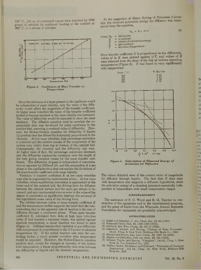
150° C., 161 cc. of condensed vapors were desorbed by 2500 grams of catalyst by continued heating of the catalyst at 300° C. in a stream of nitrogen.
F ig u r e 4. C o e f f ic ie n t o f M a ss T r a n s fe r vs . T e m p e r a tu r e
Since the thickness of a layer present in the capillaries would be independent of mass velocity, only the value of the diffu- sivity would affect the magnitude of the transfer coefficient. At higher mass velocities the value of the transfer coefficient tended to become constant as the mass velocity was increased. The value of diffusivity would be expected to show the same tendency. The diffusion equation used to correlate the experimental data was developed for point conditions in the catalyst bed, assuming a constant value of diffusivity. However, the Stokes-Einstein equation for diffusivity of liquids(4) predicts that the diffusivity is inversely proportional to the viscosity. At low mass velocities, high percentage conversion is achieved and the relative masses of the components of the system vary widely from top to bottom of the catalyst bed. Consequently, the viscosity and the diffusivity also vary. At higher rates of flow, the percentage conversion decreases and the diffusivity approaches constancy over the length of the bed, giving constant values for the mass transfer coefficient. The diffusivity of gases is independent of concentration as reported by Gilliland (S), and the assumption of a gas phase in the capillaries thus does not explain the deviations of the mass transfer coefficient with mass velocity.
Variation of transfer coefficient K at low mass velocities may also be augmented by experimental errors. At low mass velocities, where equilibrium conversion is approached at the lower end of the catalyst bed, the driving force for diffusion between the catalyst surface and the main gas stream is decreased, and any experimental error or error in the value of the degree of conversion at equilibrium destroys the accuracy of the logarithmic mean value of the driving force.
The relation between values of mass transfer coefficient K and the temperature further supports the belief that the rate- controlling step in the apparent rate of reaction is the rate of diffusion through a condensed phase. When mass transfer coefficient K , calculated from data at high mass velocities (after K had reached a constant value), was plotted against absolute temperature, a linear function was found to exist (Figure 4). Gilliland reports that variation of gas diffusivity with temperature is proportional to the 3/2 power of absolute temperature (3). If the actual reaction rate were the controlling factor, a much greater variation with temperature would be expected. However, the Stokes-Einstein equation predicts that, except for changes in viscosity of the system with temperature, a linear proportionality does exist between the diffusivity of liquids and the absolute temperature.
At the suggestion of Henry Eyring of Princeton University, the observed activation energy for diffusion was determined from the equation,
(8)Dm = A e - B / R T
where Dm A E R T
= diffusivity ■ a constant
= observed activation energy = gas constant = absolute temperature
Since transfer coefficient K is proportional to the diffusivity values of In £ were plotted against l / T , and values of E were obtained from the slope of the line at various operating temperatures (Figure 5). E was found to vary significantly with temperature:
T em p., ° C. E ■ K g .-C al.3 .4 2 1 .8 2 1 .2 8 0 .5 5
150190230270
F ig u r e 5. C a lc u la t io n o f O b s e r v e d E n e r g y o f A c t iv a t io n f o r D i f f u s i o n
The values obtained were of the correct order of magnitude for diffusion through liquids. The fact that E does vary with temperature also supports a diffusion hypothesis, since the activation energy of a chemical process is essentially independent of temperature over small temperature ranges.
ACKNOWLEDGMENTThe assistance of F. C. Wood and R. G. Taecker in con
struction of the apparatus and in the experimental program, and the grant of funds from the Wisconsin Alumni Research Foundation for equipment are gratefully acknowledged.
LITERATURE CITED(1) Edgar and Schuyler, J . A m . Chem. Soc., 46, 64 (1924).(2) Essex and Clark, Ibid., 54, 1290-1306 (1932).(3) Gilliland, I n d . E n g . C h e m ., 26, 681-5 (1934).(4) Glasstone, Laidler, and Eyring, “Theory of Rate Processes”,
1st ed., Chap. 9, New York, McGraw-Hill Book Co., 1941.(5) K e a r b y and Swann, I n d . E n g . C h e m ., 3 2 , 1 6 0 7 -1 4 (1 9 4 0 ) .(6) Mailhe and DeGodon, B ull. soc. chim ., 2 9 , 101 (1 9 3 9 ) .(7) Schwab, Taylor, and Spence, “Catalysis”, 1st ed., Chap. 1, New
York, D. Van Nostrand Co., 1937.(8) Walker, Lewis, McAdams, and Gilliland, “Principles of Chemical
Engineering”, 3rd ed., Chap. 14, New York, McGraw-Hill Book Co., 1937.
Heint
broi
Cili It t
hti
tie
miDO:
si!
SEE. : ini: 2 3 131aaabfaÇÎESS
ESBit
«Blltop
insat«Bha*5istototototolto*
*
Temperature (°K)
CATALYST: MIXTURE, SIZES Z.4 TO 6.7 mm.
580 I NDUSTR I AL AND ENGINEERING CHEMI STRY Vol. 35, No. 5
Catalysis in the Oxidationof
LUBRICATING OILR. G. LARSEN A N D F. A. ARM FIELD
S h e l l D e v e l o p m e n t C o m p a n y , E m e r y v i l l e , C a l i f .
T he cata lytic effect o f iron, copper, and lead in th e bulk and dissolved form on three oils broadly representative o f those obtainable from Pennsylvania, M id -con tin en t, and California crudes has been studied in detail. It is concluded th a t th e variations in cataly tic susceptib ilities o f th e oils, as w ell as th e variations o f cata lytic activities o f the m etals w ith concentration , are so great th a t no specified catalyst can be used in labora
tory oxidation tests unless correspondence w ith engines is first well established.
In addition, the catalytic effect o f engines on oils was investigated. It was found that th e oil insolubles (called “ crankcase cataly sts” ) w hich accum ulate in engine lubricants are extrem ely active catalysts. This catalytic activity resides in th e m etallic com ponents, particularly th e halides ofiron.
T HE “stability” of a lubricating oil may be classified, with other nebulous characteristics such as “oiliness”, as a generally desired property the true meaning or
requirements of which are but vaguely defined. It must be conceded, however, that a “stable” oil is one which does not break down in an engine to form sludge, corrode bearings, stick rings, or permit excessive wear. To define stability we must°understand the underlying principles of all thesephenomena. . ..
The theory has been presented that, since almost all engine deposits contain relatively large amounts of oxygen and since bearings are corroded by acids produced by oxidation, stability of an oil toward oxygen is an essential requirement of a good engine lubricant. The authors believe this to be true; in an earlier report (14 ) they showed that oxidation stability of a lubricant is not achieved by removal of “unstable aromatics”, but rather that it is a result of the presence of natural antioxidants which stabilize the relatively reactive hydrocarbons constituting the bulk of the oil. These findings are confirmed by many experimenters among the most recent being Fenske and co-workers (11 ) and von Fuchs and Diamond (1 2 ) . Before they are applied to refinery practice, it is well to appreciate the importance of factors external to the oil itself which may alter or modify the quantitative aspects of oil stability. Thus, w le ere can be no question that natural or synthetic antioxidants are needed to produce satisfactory lubricants, the actual amoun or type required may be modified by the environment in which the oil is to be used. The effect of an engine on le oil must therefore be studied.
The most important environmental factors affecting e oxidation stability of an oil in an engine are temperature and catalysis. The extreme range of temperatures encoun ere has led many investigators (2 ) to the conclusion t ia no laboratory test can satisfactorily measure the performance of an oil in an engine. This view is unduly pessimistic since,
fortunately, the variation of chemical reactivity with temperature is subject to precise mathematical definition; many recent experimenters, such as Dornte and co-workers (6 , 7, 8 ), have shown that mineral oils behave normally in this respect. Thus, fundamentally the effect of temperature on oxidation stability is understood. The effect of temperature on cracking, polymerization, condensation, and volatilization of lubricants or their oxidation products is, however, not well understood and requires further study.
When it first became desirable to have a laboratory test for oxidation stability, the only accelerating factor employed was temperature. Such widely accepted tests as the Indiana, Sligh, and British Air Ministry tests oxidize oils at high temperatures but are devoid of other accelerating factors. Within the past decade there has been a growing tendency to recognize that various metallic catalysts must also be used. Thus, practically all of the tests recently described employ catalysts in some form. The Indiana test has been modified by the addition of a coil of iron wire and then referred to as the Continental oxidation test (1 7 ) , or by the use of copper, iron, and lead in a test described by Burk and co-workers (S ) . ’ A further modification described as the stirring Indiana test uses iron and copper ( I S ) . In the work of Davis and coworkers (5) a modified Sligh apparatus is used in conjunction with various catalysts, particularly soluble iron salts. The McCoull test measures stability as well as corrosivity in the presence of iron and copper and copper-lead (1 5 ) bearings. The Underwood test employs soluble lead or iron catalysts. The possibility of using copper or iron alone is discussed by Evans (1 0 ) . Many of these experimenters leave the test conditions sufficiently flexible so that several engine metals may be added if desired.
It is evident that a great many tests may be used to evaluate oxidation stability, each varying in the amount or type of catalyst used, the oxidation temperature employed, or in the method of contacting the oil with air or oxygen.
581
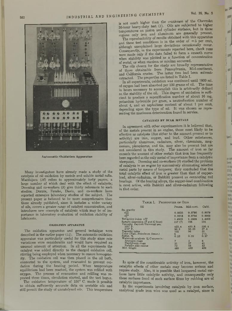
582 I NDUSTRIAL AND ENGINEERING CHEMISTRY Vol. 35, No. 5
I
£' i
*
\’ 1
A u t o m a t i c O x i d a t i o n A p p a r a t u s
Many investigators have already made a study of the catalysis of oil oxidation by metals and soluble metal salts. Matthijsen (16) refers to approximately forty papers, a large number of which deal with the effect of catalysts; Downing and co-workers (3) give thirty references to such studies. Dornte, Fenske, Davis, and co-workers have reported extensive laboratory studies of the subject. The present paper is believed to be more comprehensive than those already published, since it includes a wider variety of oils, covers a greater range of catalyst concentration, and introduces new concepts of catalysis which may be of importance in laboratory evaluation of oxidation stability of lubricants.
OXIDATION APPARATUS
The oxidation apparatus and general technique were described in the earlier paper {1 4 ). The automatic oxidation apparatus was particularly useful for this study since rate variations were considerable and would have required an unusual amount of attention. In all the experiments the catalyst was added directly to the charged oxidation cell, stirring being employed when necessary to ensure homogeneity. The oxidation cell was then placed in the oil bath, connected to the system, and evacuated to prevent oxidation during the heating period. When temperature equilibrium had been reached, the system was refilled with oxygen. The process of evacuation and refilling was repeated three times, circulation started, and the test begun.
The oxidation temperature of 150° C. made it possible to obtain sufficiently accurate data on unstable oils and still permit the study of uncatalyzed oils. This temperature
is not much higher than the crankcase of the Chevrolet 36-hour heavy-duty test (I). Oils are subjected to higher temperatures on piston and cylinder surfaces, but in these regions only iron and aluminum are generally present.
The reproducibility of results obtained with this apparatus and these test conditions is in the order of ± 5 per cent, although unexplained large deviations occasionafiy occur. Consequently, in the experiments reported here, check runs were made only if the data failed to form a smooth curve when stability was plotted as a function of concentration of metal, or when maxima or minima occurred.
The oils chosen for the study are broadly representative of those obtainable from Pennsylvania, Mid-continent, and California crudes. The latter two had been solvent- extracted. The properties are listed in Table I.
In all experiments, oxidation was continued until 1800 ml. of oxygen had been absorbed per 100 grams of oil. The time in hours necessary to accomplish this is arbitrarily defined as the stability of the oil. This degree of oxidation is sufficient to produce a saponification number of about 16 mg. potassium hydroxide per gram, a neutralization number of about 4, and an asphaltene content of about 1 per cent, depending upon the type of oil. It was chosen as representing the maximum deterioration found in service.
CATALYSIS BY BULK METALS
In agreement with other experimenters it is believed that, of the metals present in an engine, those most likely to be effective as catalysts (due either to the amount present or to activity) are iron, copper, and lead. Other substances, particularly aluminum, cadmium, silver, chromium, magnesium, phosphorus, and tin, may also be present but are not considered in this study. The amount of iron so far exceeds the amount of other metals that iron has frequently been regarded as the only metal of importance from a catalytic viewpoint. Downing and co-workers (3) studied the problem of catalysis in an engine by successively eliminating selected metal parts by means of lacquers; they concluded that the total catalytic effect of iron is greater than that of copper- lead, silver-cadmium, or Babbitt present as connecting rod bearings. Of the bearing alloys, the copper-lead combination is most active, with Babbitt and silver-cadmium following in that order.
T a b l e I . P r o p e r t i e s o f O i l s
O ilSp. g rav ityJ20 2 0
d 1°R efrac tive index n 2Specific dispersion (F an d C lines)V iscosity Ś ay b o lt U n iversa l sec.
100° F .210° F.
V iscosity indexC olor (N a tl . P e tro leu m Assoc.)Sulfur, %W aterm an analysis % C a to m s in :
A rom atic rings N ap h th en ic rings Paraffin side chains
M ol. w eight
In spite of the considerable activity of iron, however, the catalytic effects of other metals may become serious and require study. Also, it is possible that lacquered metal surfaces have little catalytic activity, and consequently only those surfaces freed of such surface films by rubbing are of catalytic importance.
In the experiments involving catalysis by iron surface, analytical grade iron wire was used as a catalyst, since it
P e n n a . M id -co n t. C alif.
0 .8 8 3 5 0 .8 7 8 0 0 .8 9 7 90 .8 8 1 8 0 .8 7 6 4 0 .8 9 6 31 .4903 1 .4 8 3 8 1 .4903117 (7) 108 104
4 2 3 .4 4 5 0 .8 5 3 0 .46 0 .2 6 0 .6 6 5 7 .4102 96 516 1' / .0 .2 3 Ó! 09 0 .2 7
7 5 621 27 4172 68 53485 492 439
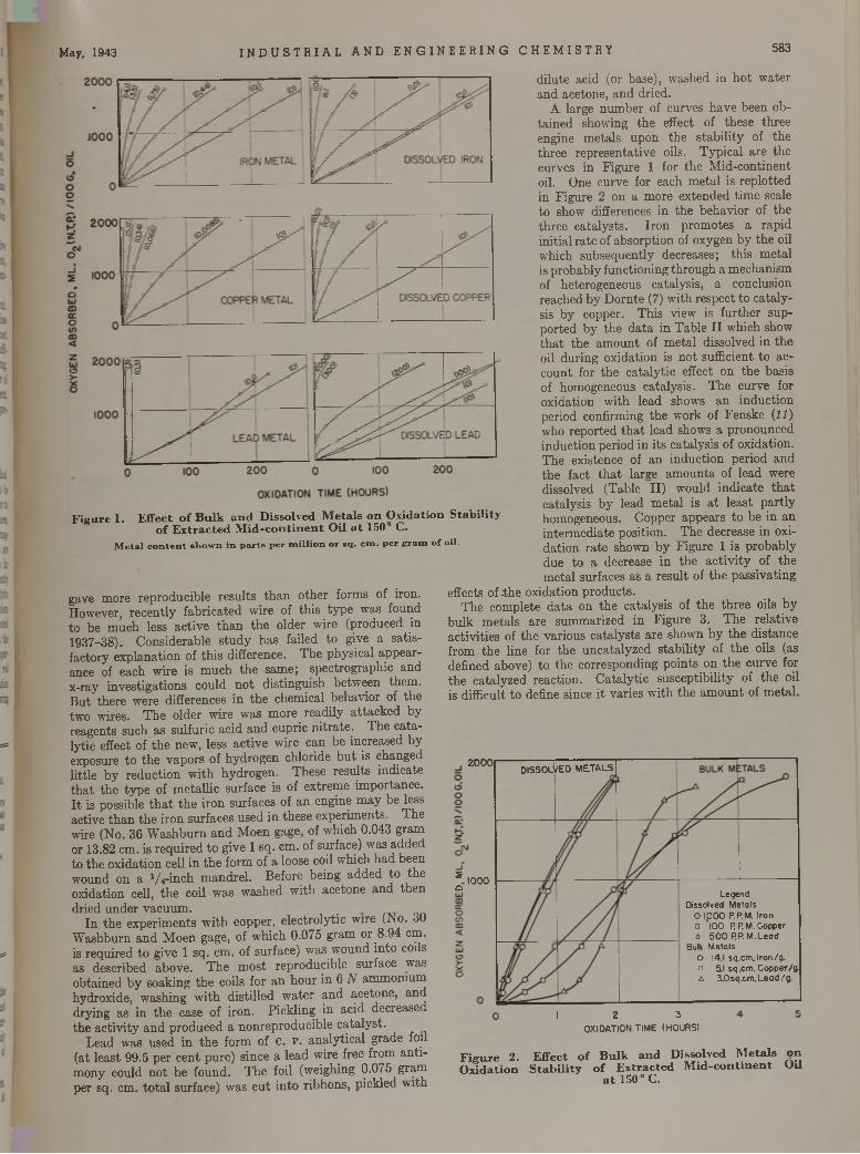
May, 1943 I N D U S T R I A L AND E NG I NE E R ING CHEMI STRY 583
F i g u r e 1 . E f f e c t o f B u l k a n d D i s s o l v e d M e t a l s o n O x i d a t i o n S t a b i l i t y o f E x t r a c t e d M i d - c o n t i n e n t O i l a t 1 5 0 ° C .
M e ta l c o n t e n t s h o w n i n p a r t s p e r m i l l i o n o r s q . c m . p e r g r a m o f o il .
gave more reproducible results than other forms of iron. However, recently fabricated wire of this type was found to be much less active than the older wire (produced in 1937-38). Considerable study has failed to give a satisfactory explanation of this difference. The physical appearance of each wire is much the same; spectrographic and x-ray investigations could not distinguish between them. But there were differences in the chemical behavior of the two wires. The older wire was more readily attacked by reagents such as sulfuric acid and cupric nitrate. The catalytic effect of the new, less active wire can be increased by exposure to the vapors of hydrogen chloride but is changed little by reduction with hydrogen. These results indicate that the type of metallic surface is of extreme importance. It is possible that the iron surfaces of an engine may be less active than the iron surfaces used in these experiments. The wire (No. 36 Washburn and Moen gage, of which 0.043 gram or 13.82 cm. is required to give 1 sq. cm. of surface) was added to the oxidation cell in the form of a loose coil which had been wound on a Vi-inch mandrel. Before being added to the oxidation cell, the coil was washed with acetone and thendried under vacuum.
In the experiments with copper, electrolytic wire (No. 30 Washburn and Moen gage, of which 0.075 gram or 8.94 cm. is required to give 1 sq. cm. of surface) was wound into coils as described above. The most reproducible surface was obtained by soaking the coils for an hour in 6 N ammonium hydroxide, washing with distilled water and acetone, and drying as in the case of iron. Pickling in acid decreased the activity and produced a nonreproducible catalyst.
Lead was used in the form of c. p. analytical grade foil (at least 99.5 per cent pure) since a lead wire free from antimony could not be found. The foil (weighing 0.075 gram per sq. cm. total surface) was cut into ribbons, pickled with
dilute acid (or base), washed in hot water and acetone, and dried.
A large number of curves have been obtained showing the effect of these three engine metals upon the stability of the three representative oils. Typical are the curves in Figure 1 for the Mid-continent oil. One curve for each metal is replotted in Figure 2 on a more extended time scale to show differences in the behavior of the three catalysts. Iron promotes a rapid initial rate of absorption of oxygen by the oil which subsequently decreases; this metal is probably functioning through a mechanism of heterogeneous catalysis, a conclusion reached by Domte (7) with respect to catalysis by copper. This view is further supported by the data in Table II which show that the amount of metal dissolved in the oil during oxidation is not sufficient to account for the catalytic effect on the basis of homogeneous catalysis. The curve for oxidation with lead shows an induction period confirming the work of Fenske {1 1 ) who reported that lead shows a pronounced induction period in its catalysis of oxidation. The existence of an induction period and the fact that large amounts of lead were dissolved (Table II) would indicate that catalysis by lead metal is at least partly homogeneous. Copper appears to be in an intermediate position. The decrease in oxidation rate shown by Figure 1 is probably due to a decrease in the activity of the metal surfaces as a result of the passivating
effects of .the oxidation products.The complete data on the catalysis of the three oils by
bulk metals are summarized in Figure 3. The relative activities of the various catalysts are shown by the distance from the line for the uncatalyzed stability of the oils (as defined above) to the corresponding points on the curve for the catalyzed reaction. Catalytic susceptibility of the oil is difficult to define since it varies with the amount of metal.
F i g u r e 2 . E f f e c t o f B u l k a n d D i s s o l v e d M e t a l s o n O x i d a t i o n S t a b i l i t y o f E x t r a c t e d M i d - c o n t i n e n t O U
a t 1 5 0 ° C .
I 2 3OXIDATION TIME (HOURS)
2000
2 . IOOOQ Legend Dissolved Metals
O 1,000 P.P.M. Iron o ’lOO RP.M.Copper a 500 P.P.M.Lead
Bulk MetalsO |4.I sq.cm. Iron/g a 5.1 sq.cm. Copper/g o 3.0sq.cm.Lead/g
DISSOLl/ED METALS
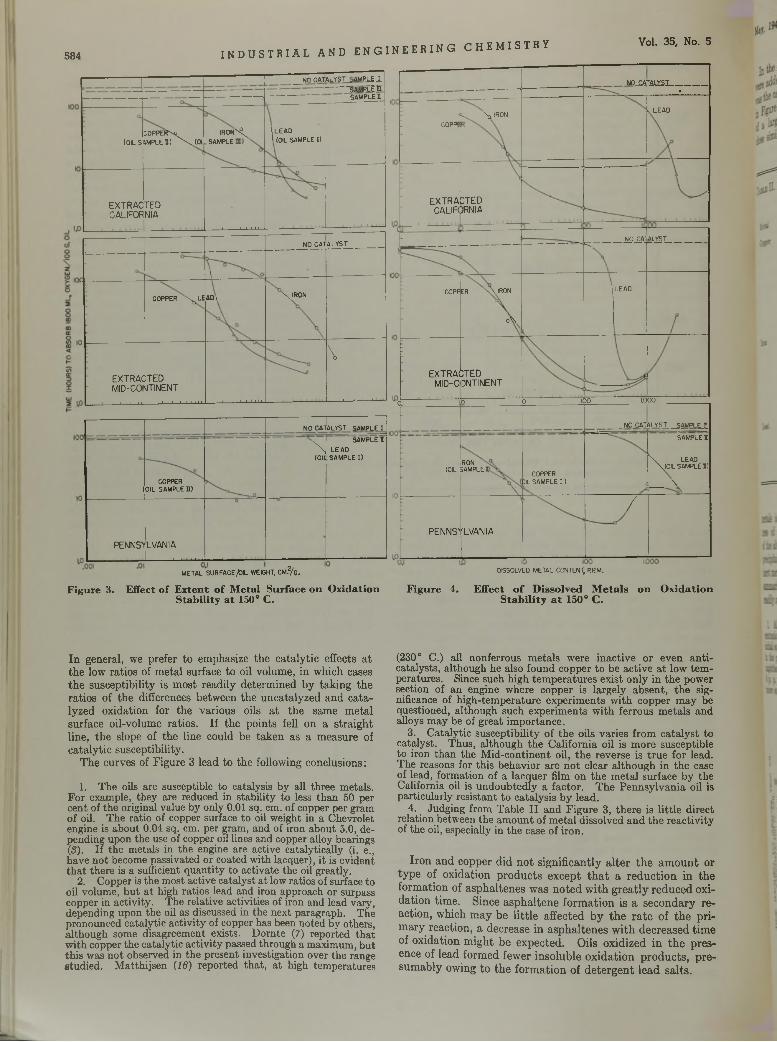
584 INDUSTRIAL AND ENGINEERING CHEMI STRY Vol. 35, No. 5
___NO CATALYS AMPL£ -L-------- SÂMPLË |T
SAMPLE!--------------—
(OILSCOPPEfT-sj ¡IMPLE H) ^xJOII
IRON"^SAMPLE
(LEAD\ (OIL SAMPLE I)
EXTRACCALIFOR
TEDNIA
____ 1__J--L 1 1 1 li-
\
NO CATALYST
COPPER \^LE A0\ \IR0N
EXTRACMID-CO■ 1 1 1 1 1 L
; t e dSITINENT1 .................... 1 1 1 1 1 1 1
\
1 i i 1 i
1NO CATALYST SAMPLE I
(COPPER
OIL SAMPLED
' \ (OIL
SAMPLE II, LEAD SAMPLE I)
PENNST LVANIA.......................
__________ N0_£AT01ISI_________•
I C0PPE3. Nq IRON V LEAD
EXTRACALIF
CTED)RNIA
- NO CA' ALYST
GOPPER NAIRON
oV
LEAD
EXTRACMID-C
!;t e dDNTINENT
OJ n 10 IOO LOGO
__ NO_CATALYST. _SĄMPLĘ_r_
(OILronSAMPLE COPPER
)IL SAMPLE I )
SAMPLE I
\ LEAD \(0IL SAMPLE I)
i___ \
PENNS'
__l--1 1 I
'LVANIA
/
METAL SURFACE /DIL WEIGHT, CM?/g. DISSOLVED METAL CONTENT; P.RM.
F i g u r e 3 . E f f e c t o f E x t e n t o f M e t a l S u r f a c e o n O x i d a t i o n F i g u r e 4 . E f f e c t o f D i s s o l v e d M e t a l s o n O x i d a t i o n S t a b i l i t y a t 1 5 0 ° C . S t a b i l i t y a t 1 5 0 ° C .
In general, we prefer to emphasize the catalytic effects at the low ratios of metal surface to oil volume, in which cases the susceptibility is most readily determined by taking the ratios of the differences between the uncatalyzed and catalyzed oxidation for the various oils at the same metal surface oil-volume ratios. If the points fell on a straight line, the slope of the line could be taken as a measure of catalytic susceptibility.
The curves of Figure 3 lead to the following conclusions:
1. The oils are susceptible to catalysis by all three metals. For example, they are reduced in stability to less than 50 per cent of the original value by only 0.01 sq. cm. of copper per gram of oil. The ratio of copper surface to oil weight in a Chevrolet engine is about 0.04 sq. cm. per gram, and of iron about 5.0, depending upon the use of copper oil lines and copper alloy bearings(S). If the metals in the engine are active catalytically (i. e., have not become passivated or coated with lacquer), it is evident th a t there is a sufficient quantity to activate the oil greatly.
2. Copper is the most active catalyst a t low ratios of surface to oil volume, but a t high ratios lead and iron approach or surpass copper in activity. The relative activities of iron and lead vary, depending upon the oil as discussed in the next paragraph. The pronounced catalytic activity of copper has been noted by others, although some disagreement exists. D om te (7) reported tha t with copper the catalytic activity passed through a maximum, but this was not observed in the present investigation over the range studied. M atthijsen (16) reported that, a t high temperatures
(230° C.) all nonferrous metals were inactive or even an ticatalysts, although he also found copper to be active a t low tem peratures. Since such high tem peratures exist only in the power section of an engine where copper is largely absent, the significance of high-temperature experiments w ith copper may be questioned, although such experiments w ith ferrous metals and alloys may be of great importance.
3. Catalytic susceptibility of the oils varies from catalyst to catalyst. Thus, although the California oil is more susceptible to iron than the Mid-continent oil, the reverse is true for lead. The reasons for this behavior are no t clear although in the case of lead, formation of a lacquer film on the m etal surface by the California oil is undoubtedly a factor. The Pennsylvania oil is particularly resistant to catalysis by lead.
4. Judging from Table I I and Figure 3, there is little direct relation between the am ount of m etal dissolved and the reactivity of the oil, especially in the case of iron.
Iron and copper did not significantly alter the amount or type of oxidation products except that a reduction in the formation of asphaltenes was noted with greatly reduced oxidation time. Since asphaltene formation is a secondary reaction, which may be little affected by the rate of the primary reaction, a decrease in asphaltenes with decreased time of oxidation might be expected. Oils oxidized in the presence of lead formed fewer insoluble oxidation products, presumably owing to the formation of detergent lead salts.
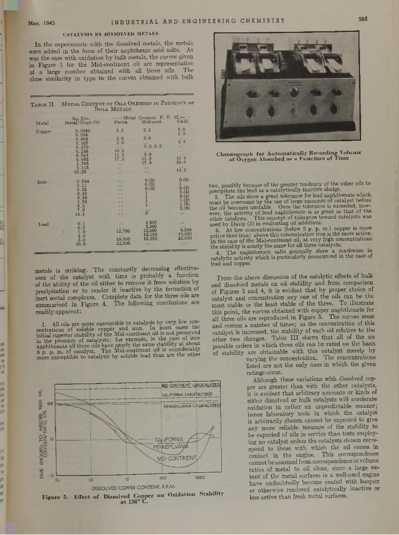
May, 1943 I ND U S TR I AL AND E NG I NE E R ING CHEMI STRY 585
CATALYSIS BY DISSOLVED METALS
In th e experim ents w ith th e dissolved m etals, the m etals were added in th e form of th e ir naph then ic acid salts. As was th e case w ith ox idation b y bu lk m etals, th e curves given in F igure 1 for th e M id-con tinen t oil are represen tative of a large num ber ob ta ined w ith all th ree oils. T he close sim ilarity in ty p e to th e curves ob ta ined w ith bulk
MIO^ONT'ÎÊ'iL <UN CATALYZED
CALIFORNIA (UNCATALYZED)
PENNSYLVANIA lUfJCATALYZEO)
CALIFORNIAPENNSYLVAI
MID-CONTINENT.
T a b l e II.
M e ta l
C opper
M e t a l C o n t e n t o f O i l s O x i d i z e d i n P r e s e n c e o f B u l k M e t a l s
L ead
S q . C m . M e ta l /G r a m Oil
0 .0 0 8 50 .0 3 40 .0 6 80.1020 .1 7 00 .2 3 80 .3 4 10 .6 8 21 .7 0 55 .1 1 5
1 0 .2 3
0 .0 4 40.110.220 .4 30.881 .7 63 .57 .0
1 4 .1
0.10 .31.03 .05 .0 10.0
-M e ta l C o n te n t P . P . M . ■ —>P e n n a . M id -co n t. C a lif .
12,700
19.50022.500
4,6003,500
12,00012,50016,180
10.23 0 .9
12! 5
0.(6)0.(2)0.(4)0.(4)1.(2) 1.(8) 0.(8)
9,35019,90022,250
m etals is strik ing . T he constan tly decreasing effectiveness of th e ca ta ly s t w ith tim e is probably a function of the ab ility of th e oil e ither to rem ove i t from solution by precip ita tion o r to render i t inactive by th e form ation of inert m etal complexes. C om plete d a ta for th e th ree oils are sum m arized in F igure 4. T he following conclusions are readily ap p aren t:
1. All oils are quite susceptible to catalysis by very low concentrations of soluble copper and iron. In most cases the initial superior stability of the M id-continent oil is not preserved in the presence of catalysts; for example, in the case of iron naphthenate all three oils have nearly the same stability a t about 6 p. p. m. of catalyst. The M id-continent oil is considerably more susceptible to catalysis by soluble lead than are the other
DISSOLVED COPPER CONTENT, P.P.M.F ig u re 5. E ffect o f D issolved C opper o n O x idation S tab ility
a t 150° C.
C h r o n o g r a p h f o r A u t o m a t i c a l l y R e c o r d i n g V o l u m e o f O x y g e n A b s o r b e d a s a F u n c t i o n o f T i m e
two, possibly because of the greater tendency of the other oils to precipitate the lead as a catalytieally inactive sludge.
2 The oils show a great tolerance for lead naphthenate which must be overcome by the use of large amounts of catalyst before the oil becomes unstable. Once the tolerance is exceeded, however the activity of lead naphthenate is as great as th a t of the other catalysts. This concept of tolerance toward catalysts was used by Davis (<J) in evaluating oil additives.
3. At low concentrations (below 5 p. p. m.) copper is more active than iron; above this concentration iron is the more active.In the case of the M id-continent oil, a t very high concentrations the stability is nearly the same for all three catalysts.
4 The naphthenate salts generally show a maximum in catalytic activity which is particularly pronounced in the case of lead and copper.
F rom the above discussion of th e cata ly tic effects of bulk and dissolved m etals on oil stab ility and from com parison of Figures 3 and 4, i t is ev iden t th a t by proper choice of ca ta ly st and concentration any one of th e oils can be the m ost stable or th e least stable of the th ree . To illu stra te th is poin t, th e curves ob tained w ith copper n ap h thena te for all th ree oils are reproduced in Figure 5. T he curves cross and recross a num ber of tim es; as th e concentration of th is ca ta lyst is increased, th e stab ility of each oil re la tive to the o ther tw o changes. T able I I I shows th a t all of th e six possible orders in w hich th ree oils can be ra ted on the basis of stab ility are ob tainable w ith th is ca ta ly st m erely by
vary ing th e concentration . T he concentrations listed are n o t th e only ones in w hich th e given ratings occur.
A lthough these varia tions w ith dissolved copper are greater th a n w ith th e o ther catalysts, i t is ev iden t th a t a rb itra ry am ounts or k inds of either dissolved or bu lk ca ta lysts will accelerate oxidation in ra th e r an unpredictable m anner; hence labora to ry te s ts in which the ca ta lyst is a rb itra rily chosen cannot be expected to give any m ore reliable m easure of th e stab ility to be expected of oils in service th a n tes ts employing no ca ta ly st unless the ca ta lysts chosen correspond to those w ith w hich the oil comes in con tac t in th e engine. T his correspondence cannot be assum ed from correspondence in volum e ratios of m eta l to oil alone, since a large exte n t of th e m eta l surfaces in a well-used engine have undoub ted ly become coated w ith lacquer or otherw ise rendered cata ly tieally inactive or less active th a n fresh m eta l surfaces.
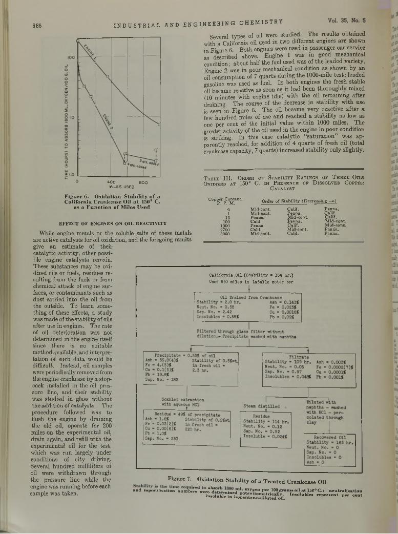
586 INDUS TR I AL AND ENGINEERING CHEMIST
4 0 0 8 0 0MILES USED
Several types of oil were studied. The results obtained with a California oil used in two different engines are shown in Figure 6. Both engines were used in passenger car service as described above. Engine 1 was in good mechanical condition; about half the fuel used was of the leaded variety. Engine 2 was in poor mechanical condition as shown by an oil consumption of 7 quarts during the 1000-mile test; leaded gasoline was used as fuel. In both engines the fresh stable oil became reactive as soon as it had been thoroughly mixed (10 minutes with engine idle) with the oil remaining after draining. The course of the decrease in stability with use is seen in Figure 6. The oil became very reactive after a few hundred miles of use and reached a stability as low as one per cent of the initial value within 1000 miles. The greater activity of the oil used in the engine in poor condition is striking. In this case catalytic “saturation” was apparently reached, for addition of 4 quarts of fresh oil (total crankcase capacity, 7 quarts) increased stability only slightly.
T a b l e I I I . O r d e r o f S t a b i l i t y R a t i n g s o f T h r e e O i l s O x i d i z e d a t 150° C. i n P r e s e n c e o f D i s s o l v e d C o p p e r
C a t a l y s t
F i g u r e 6 . O x i d a t i o n S t a b i l i t y o f a C a l i f o r n i a C r a n k c a s e O i l a t 1 5 0 ° C .
a s a F u n c t i o n o f M i l e s U s e d
EFFECT OF ENGINES ON OIL REACTIVITYWhile engine metals or the soluble salts of these metals
are active catalysts for oil oxidation, and the foregoing results give an estimate of their catalytic activity, other possible engine catalysts remain.These substances may be oxidized oils or fuels, residues resulting from the fuels or from chemical attack of engine surfaces, or contaminants such as dust carried into the oil from the outside. To learn something of these effects, a study was made of the stability of oils after use in engines. The rate of oil deterioration was not determined in the engine itself since there is no suitable method available, and interpretation of such data would be difficult. Instead, oil samples were periodically removed from the engine crankcase by a stopcock installed in the oil pressure line, and their stability was studied in glass without the addition of catalysts. The procedure followed was to flush the engine by draining the old oil, operate for 200 miles on the experimental oil, drain again, and refill with the experimental oil for the test, which was run largely under conditions of city driving.Several hundred milliliters of oil were withdrawn through the pressure fine while the engine was running before each sample was taken.
C opper C on ten t, P P. M . O rder of S ta b i li ty (D ec rea sin g —>)
0 M id-con t. C alif. P e n n a .1 M id-con t. P en n a . C alif.10 P en n a . M id -co n t. C alif.100 Calif. P e n n a . M id -co n t.1000 P en n a . C alif. M id -co n t.2700 Calif. M id -co n t. P e n n a .3000 M id-con t. C alif. P e n n a .
C a l i f o r n ia O il ( S t a b i l i t y - 184 h r . ) Used 950 m ile s in L a S a lle m o to r c a r
F i g u r e 7 . O x i d a t i o n S t a b i l i t y o f a T r e a t e d C r a n k c a s e O i l
a n d s a p o n if ic a t io n n u r n b e ^ w e i ^ ^ e t e r ' ' " xyE' n P e r lOO g r a m s o il a t 130° C . ; n e u t r a l i z a t i o nw ere d e te r m in e d p o te n t io m e t r i c a l l y . in s o lu b le in i s o p e n ta n e - d i lu te d o il .
In s o lu b le s r e p r e s e n t p e r c e n t
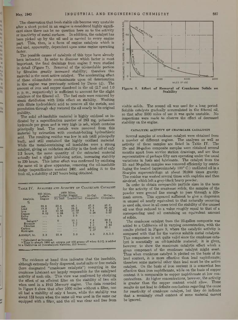
May, 1943 I N DU S T R I A L AND E NG I NE E R IN G CHEMI STRY 587
The observation that fresh stable oils become very unstable after a short period in an engine is considered highly significant since there can be no question here as to the activity or inactivity of metal surfaces. In addition, the catalyst has been picked up by the oil and is carried to every engine part. This, then, is a form of engine catalysis which is real and, apparently, dependent upon some engine operating factor.
The possible causes of catalysis of this type have already been indicated. In order to discover which factor is most important, the final drainings from engine 2 were studied in detail (Figure 7). Removal of the oil-insoluble portion by filtration greatly increased stability; therefore this material is the most active catalyst. The accelerating effect of these oil-insoluble contaminants upon oil deterioration in the engine was previously noticed by Davis (4). The amount of iron and copper dissolved in the oil (2.7 and 1.0 p. p. m., respectively) is sufficient to account for the slight catalysis of the filtered oil. The fuel ends were removed by steam distillation with little effect on stability. Washing with dilute hydrochloric acid to remove all the metals, and percolation through clay restored the oil nearly to its original stability.
The solid oil-insoluble material is highly oxidized as indicated by a saponification number of 283 mg. potassium hydroxide per gram and is very high in ash, which contains principally lead. The metals were removed from this material by extraction with constant-boiling hydrochloric acid. The resulting residue was low in ash (still principally lead), and still contained the highly oxidized material. While the metal-containing oil insolubles were a strong catalyst, giving an oxidation stability in the fresh oil of only2.3 hours, the same quantity of the extracted material actually had a slight inhibiting action, increasing stability to 220 hours. This latter effect was confirmed by oxidizing the same oil in glass apparatus, removing the oil-insoluble sludge (saponification number 240). and adding it to the fresh oil, a stability of 247 hours being obtained.
T a b l e IV. A n a l y s e s a n d A c t i v i t y or C r a n k c a s e C a t a l y s t
1000 M iles,D o d g e E n g in e
A nalysis,
950 M iles, L aS a lle E n g in e
%Ash 3 5 .8L ead 1 9 .8Iron 4 .5C opper 0.12S ulfurT o ta l
h a lo g en1aB rom ineC hlorine
C arbonH ydrogen
A c tiv ity &, h r. 2 .3
2 2 .42 .9
10.660 .0 84 .5
2 5 .0
4 8 .12 4 .2 1 0 .6 90 .1 73 .5
3 .0
25-G al. 30-G al.C o m p o s ite C o m p o site
4 7 .2 4 6 .02 7 .4 3 6 .4 5
5 .4 5 .8 20 .3 4 0 .0 7
7 .4 10 .94 .5 6 .7 41 .3 1 .8 5
30 .6 1 22.12 .5 7
4 .5 2. 8, 3 . 0
° C a lcu la ted as b ro m in e . , . , , ,& T im e to ab so rb 1800 m l. oxygen p e r 100 g ram s oil w hen 0 .5 % is a d d e d
to a C alifo rn ia oil (u n c a ta ly z e d s ta b i li ty , 213 h o u rs).
The evidence at hand thus indicates that the insoluble, although extremely finely dispersed, metal salts or free metals (here designated “crankcase catalysts”) occurring in the crankcase lubricant are largely responsible for the catalyzed activity of such oils. This view was confirmed by studying the effect of an efficient filter on the stability of two oils when used in a 1941 Mercury engine. The data recorded in Figure 8 show that after 1000 miles without a filter, one oil had a ' stability of only 4 hours, while the stability was about 153 hours when the same oil was used in the same car equipped with a filter, and the oil was clear and free from
F i g u r e 8 . E f f e c t o f R e m o v a l o f C r a n k c a s e S o l i d s o n S t a b i l i t y
visible solids. The second oil was used for a long period. Soluble catalysts gradually accumulated in the filtered oil, so that after 5000 miles of use it was quite unstable. No inspections were made to observe the effect of decreased stability on the engine.
CATALYTIC ACTIVITY OF CRANKCASE CATALYSTS
Several samples of crankcase catalyst were obtained from a number of different engines. The analyses as well as activity of these samples are listed in Table IV. The 25- and 30-gallon composite samples were obtained several months apart from service station drainings, and are thus representative of perhaps fifty cars operating under the usual variations in fuels and lubricants. The catalyst from the 25- and 30-gallon samples was removed efficiently by centrifuging the heated (approximately 100° C.) undiluted oil in a Sharpies supercentrifuge at about 20,000 times gravity. The residue was washed several times with naphtha and then air-dried, which left a gray-black heavy powder.
In order to obtain comparable particle sizes in the tests for the activity of the crankcase solids, the samples of the powder were ground fine enough to pass through a 325- mesh screen. This appeared sufficient to give a dispersion in unused oil nearly equivalent to that naturally occurring in used oils, since in all cases tried the stability of the unused oil was thus reduced to a value roughly equal to that of a corresponding used oil containing an equivalent amount of solids.
The crankcase catalyst from the 25-gallon composite was added to a California oil in varying concentration, with the results plotted in Figure 9, where the catalytic activity is compared with that for the various soluble metal catalysts. This comparison is not quite valid since the crankcase catalyst is essentially an oil-insoluble material; it is given, however, to show the maximum catalytic effect which a given component of the crankcase catalyst might exert. Thus when crankcase catalyst is plotted on the basis of its lead content, it is more effective than lead naphthenate; therefore some material other than lead must be the active catalyst. On the basis of iron content it is somewhat less effective than iron naphthenate, while on the basis of copper content it is comparable to copper naphthenate at low concentrations. At higher concentrations, however, the activity is greater than the copper content would allow. These results do not lead to definite conclusions regarding the cause for reactivity of crankcase catalyst, but they do indicate that a seemingly small content of some material cannot be ignored.
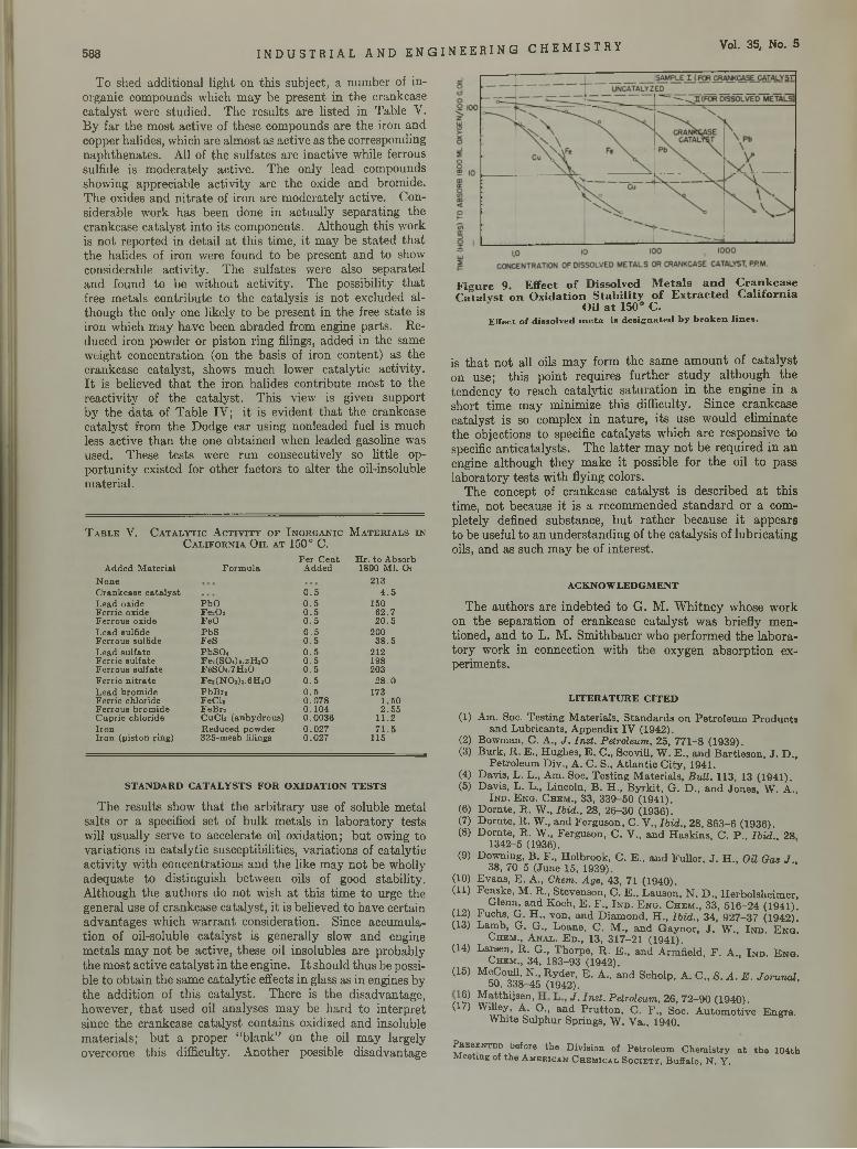
588 INDUSTRIAL AND ENGINEER ING CHEMISTRY Vol. 35, No. 5
To shed additional light on this subject, a number of inorganic compounds which may be present in the crankcase catalyst were studied. The results are listed in Table V. By far the most active of these compounds are the iron and copper halides, which are almost as active as the corresponding naphthenates. All of the sulfates are inactive while ferrous sulfide is moderately active. The only lead compounds showing appreciable activity are the oxide and bromide. The oxides and nitrate of iron are moderately active. Considerable work has been done in actually separating the crankcase catalyst into its components. Although this work is not reported in detail at this time, it may be stated that the halides of iron were found to be present and to show considerable activity. The sulfates were also separated and found to be without activity. The possibility that free metals contribute to the catalysis is not excluded although the only one likely to be present in the free state is iron which may have been abraded from engine parts. Reduced iron powder or piston ring filings, added in the same weight concentration (on the basis of iron content) as the crankcase catalyst, shows much lower catalytic activity. It is believed that the iron halides contribute most to the reactivity of the catalyst. This view is given support by the data of Table IV; it is evident that the crankcase catalyst from the Dodge car using nonleaded fuel is much less active than the one obtained when leaded gasoline was used. These tests were run consecutively so little opportunity existed for other factors to alter the oil-insoluble material.
T a b l e V. C a t a l y t i c A c t i v i t y o f I n o r g a n i c M a t e r i a l s i n C a l i f o r n i a O i l a t 1 5 0 ° C .
P e r C en t H r. to A bsorbA dded M ate ria l F o rm u la A dded 1800 M l. 0 2
N one 213C ran k case c a ta ly s t 0 .5 4 .5L ead oxide PbO 0 .5 150F erric oxide F e203 0 .5 6 2 .7F erro u s oxide FeO 0 .5 2 0 .5L ead sulfide P bS 0 .5 200F erro u s sulfide FeS 0 .5 3 8 .5L ead su lfa te P bS04 0 .5 212F erric su lfa te FeaCSCMs.xELO 0 .5 198F erro u s su lfa te FeS 04 .7H 20 0 .5 203F errio n it ra te Fe»(NOa)a.6HaO 0 .5 2 8 .0L ead b rom ide P b B r2 0 .5 173F erric chloride FeCl» 0 .0 7 8 1 .50F erro u s brom ide F eB r2 0 .104 2 .5 5C upric ch loride C uC l2 (anhydrous) 0 .0 0 3 6 11.2Iro n R educed pow der 0 .0 2 7 7 1 .5I ro n (p is ton ring) 325-m esh filings 0 .0 2 7 115
STANDARD CATALYSTS FOR OXIDATION TESTSThe results show that the arbitrary use of soluble metal
salts or a specified set of bulk metals in laboratory tests will usually serve to accelerate oil oxidation; but owing to variations in catalytic susceptibilities, variations of catalytic activity with concentrations and the like may not be wholly adequate to distinguish between oils of good stability. Although the authors do not wish at this time to urge the general use of crankcase catalyst, it is believed to have certain advantages which warrant consideration. Since accumulation of oil-soluble catalyst is generally slow and engine metals may not be active, these oil insolubles are probably the most active catalyst in the engine. It should thus be possible to obtain the same catalytic effects in glass as in engines by the addition of this catalyst. There is the disadvantage, however, that used oil analyses may be hard to interpret since the crankcase catalyst contains oxidized and insoluble materials; but a proper “blank” on the oil may largely overcome this difficulty. Another possible disadvantage
F i g u r e 9 . E f f e c t o f D i s s o l v e d M e t a l s a n d C r a n k c a s e C a t a l v s t o n O x i d a t i o n S t a b i l i t y o f E x t r a c t e d C a l i f o r n i a
O i l a t 1 5 0 ° C .E ffec t o f d is so lv ed m e ta is d e s ig n a te d b y b r o k e n l i n e s .
is that not all oils may form the same amount of catalyst on use; this point requires further study although the tendency to reach catalytic saturation in the engine in a short time may minimize this difficulty. Since crankcase catalyst is so complex in nature, its use would eliminate the objections to specific catalysts which are responsive to specific anticatalysts. The latter may not be required in an engine although they make it possible for the oil to pass laboratory tests with flying colors.
The concept of crankcase catalyst is described at this time, not because it is a recommended standard or a completely defined substance, but rather because it appears to be useful to an understanding of the catalysis of lubricating oils, and as such may be of interest.
A C K N O W L E D G M E N T
The authors are indebted to G. M. Whitney whose work on the separation of crankcase catalyst was briefly mentioned, and to L. M. Smithbauer who performed the laboratory work in connection with the oxygen absorption experiments.
L IT E R A T U R E C IT E D
(1) Am. Soc. Testing Materials, Standards on Petroleum Productsand Lubricants, Appendix IV (1942).
(2) Bowman, C. A., J . In st. Petroleum, 25, 771-8 (1939).(3) Burk, R. E., Hughes, E. C., Scovill, W. E., and Bartleson, J. D.,
Petroleum Div., A. C. S., Atlantic City, 1941.(4) Davis, L. L., Am. Soc. Testing Materials, B ull. 1 1 3 , 13 ( 1 9 4 1 ) .(5) Davis, L. L., Lincoln, B. H., Byrkit, G. D., and Jones, W. A.,
I n d . E n g . C h e m ., 3 3 , 3 3 9 -5 0 (1 9 4 1 ) .(6) Dornte, R. W., Ibid., 28, 26-30 (1936).(7) Dornte, R. W., and Ferguson, C. V., Ib id ., 28, 863-6 (1 9 3 6 ) .(8) Dornte, R. W„ Ferguson, C. V., and Haskins, C. P., Ib id .. 28
1342-5 (1936).(9) Downing, B. F., Holbrook, C. E., and Fuller, J. H., Oil Gas J ..
38, 70-5 (June 15, 1939).(10) Evans, E. A., Chem. Age, 43, 71 (1940).(11) Fenske, M. R., Stevenson, C. E., Lauson, N. D., Herbolsheimer,
G le n n , a n d K o c h , E . F . , I n d . E n g . C h e m ., 3 3 , 5 1 6 - 2 4 (1 9 4 1 ) .(12) Fuchs, G. H., von, and Diamond, H., Ib id ., 34, 927-37 (1942).(13) Lamb, G. G., Loane, C. M., and Gaynor, J. W., I n d . E n g !
C h e m ., A n a l . E d ., 13 , 3 1 7 -2 1 (1 9 4 1 ) .(14) Larsen, R. G., Thorpe, R. E., and Armfield, F. A., I n d . E n g .
Chem., 34, 183-93 (1942).(15) McCoull, N., Ryder, E. A., and Scholp, A. C., S . A . E . JoruruU,
50, 338-45 (1942). n S Matthijsen. J - In s t- Petroleum, 26, 72-90 (1940).(17) WiUey, A. O., and Prutton, C. F., Soc. Automotive Engrs.
White Sulphur Springs, W. Va., 1940.
P r e s e n t e d before th e D iv is io n of P e tro le u m C h e m is try a t th e 104 thM eeting of th e A m e bica n C h e m ic a l S o c ie t y , B uffa lo , N . Y .
Adsorption of Riboflavin by Lactose
I n f l u e n c e o f C o n c e n t r a t i o n
In crystallizing from whey concentrates, lactose adsorbs riboflavin selectively.The relation betw een degree o f adsorption and in itia l riboflavin concentration under conditions o f com plete crystallization is linear. A m in im u m concentration o f riboflavin exists below w hich no adsorption occurs. Under conditions o f incom plete crystallization the value o f th e riboflavin concentration below w hich no adsorption occurs is displaced toward lower and lower values as th e degree of supersaturation w ith respect to lactose is lowered, and reaches a final m in im u m value o f 2.5 m icrograms per m l. It has been found practical to pre
pare lactose contain ing as high as 300 m icrogram s riboflavin per gram. M uch higher concentrations m ay
be realized, b ut the rate o f crystallization under the conditions required for the preparation o f the m ore concentrated adsorbates becom es exceedingly slow. C oncom itantly, th e lactose crystals change from a characteristic tom ahawk to a th in platy form. Riboflavin exerts a definite retarding action on th e rate of crystallization o f lactose, an effect which becom es more and m ore pronounced as th e riboflavin concentration is in creased, and as th e degree o f supersaturation w ith respect to lactose is decreased.
ABRAHAM LEVITONBureau of D airy Industry, U. S. D epartm ent
of Agriculture, Washington, D. C.
I N THE crystallization of lactose from concentrated whey, a portion of the coloring matter of whey is adsorbed. This property of lactose is undesirable in certain respects
since it necessitates additional processing in the manufacture of lactose; but when properly understood and utilized, it becomes of practical significance.
The importance of the adsorption of riboflavin by lactose as a basis for the preparation of riboflavin adsorbates has passed unnoticed, notwithstanding the fact that the general subject of adsorption on crystals during their growth has been amply investigated. The phenomenon relating to the adsorption by lactose was extensively investigated, and as a result the preparation of potent and pure adsorbates has been placed upon a practical basis.
A large number of factors influence the degree and rate of adsorption. Of these, variations in riboflavin concentration and in the degree of supersaturation with respect to lactose are most significant. These variables will be considered here to the exclusion of others, such as temperature, nature of solvent, nature of adsorbent, hydrogen-ion concentration, and stirring, which require further study.
PREPARATION OF STOCK SOLUTIONS AND ADSORBATESExperiments were conducted largely on whey concentrates
of known riboflavin and lactose concentration. These concentrates were obtained from spray-processed Cheddar cheese whey powder (2). Briefly, 1 part of powder was treated with 17.5 parts of 70 per cent ethyl alcohol by weight After several minutes the undissolved proteins were removed by filtration, ana a hours lactose which had crystallized was recovered from t e acidified filtrate. Following neutralization of the mother liquor the alcohol was recovered and the residual liquor concentra e o contain approximately 40 per cent solids. Decolorizing car was added, and the mixture was agitated one week a t 2 to o . and then filtered. This riboflavin-free filtrate, the stock solu
in these experiments, had a pH of 4.5 and a solids concentration of 30.5 per cent, and contained lactose in slight excess of the quantity (17.4 grams per 100 ml. water) required to effect saturation a t 5° C.
Adsorbates containing natural riboflavin were prepared along approximately the same lines as indicated above. Following the recovery of alcohol, however, and the concentration of the m other liquor, the addition of carbon was omitted. The concentrate, after storage a t 2-5° C. for one day, was filtered and stirred a t 7° for a week. The adsórbate which crystallized to the extent of 12 grams per 100 grams of concentrate was washed with 70 per cent alcohol. Analysis showed 170 micrograms riboflavin per gram, representing approximately 85 per cent recovery of riboflavin. In one experiment in which 5 parts of the concentrate were diluted with 1 part by weight of water, the adsórbate which was recovered contained 230 micrograms riboflavin per gram, representing a yield of 75 per cent.
The method outlined was applied on a small pilot plant scale to the preparation of adsorbates. The concentrated liquor from which the adsórbate crystallizes is obtained as a by-product in an extraction process developed in this laboratory for the preparation of soluble proteins and lactose. Directions for the recovery of this concentrated liquor have been published (2).
M e t h o d s . Experiments were conducted on measured portions of the stock solution fortified with measured quantities of synthetic riboflavin and lactose. These fortified solutions were seeded with 0.05 per cent milk sugar. Sealed 22 X 175 mm. test tubes containing the solutions of varying riboflavin and sugar content were rotated in a therm ostat m aintained a t 5.0 ± 0.1° C. Tubes were removed periodically, their contents filtered rapidly (within 15 seconds), and the lactose residues washed well, but w ithout elution, w ith 70 per cent alcohol saturated with lactose.
Riboflavin determinations were conducted fluorimetrically and colorimetrically. Prelim inary experiments had established the good agreement between results obtained with colorimetric, microbiological, and fluorimetric methods. I t was found sufficiently accurate in all colorimetric and fluorimetric methods to consider riboflavin as the only pigment associated w ith lactose. Absorption curves were obtained by means of a sensitive photoelectric spectrophotometer employing a Hilger monochromator with 0.0025-inch slits.
589
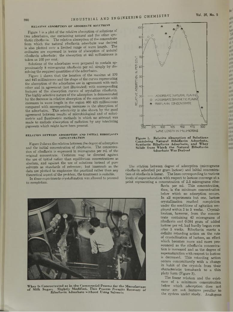
590 I N D U S T R I A La n d e n g i n e e r i n g CHEMISTRY Vol. 35, No. 5
RELATIVE ABSORPTION OF ADSORBATE SOLUTIONSFigure 1 is a plot of the relative absorption of solutions of
two adsorbates, one containing natural and the other synthetic riboflavin. The relative absorption of the concentrate from which the natural riboflavin adsórbate was derived is also plotted over a limited range of wave length. The ordinates are expressed in terms of absorption of natural riboflavin adsórbate; the absorption at 445 millimicrons is taken as 100 per cent.
Solutions of the adsorbates were prepared to contain approximately 8 micrograms riboflavin per ml. simply by dissolving the required quantities of the adsorbates.
Figure 1 shows that the location of the maxima at 370 and 445 millimicrons and the shape of the curves representing the absorption of the adsorbates are in agreement with each other and in agreement (not illustrated) with corresponding features of the absorption curves of crystalline riboflavin. The highly selective nature of the adsorption is demonstrated by the decrease in relative absorption of the concentrate with increases in wave length in the region 400-425 millimicrons compared with corresponding increases in the absorption of the adsorbates. This selectivity is also shown by the good agreement between results of microbiological and of colorimetric and fluorimetric methods in which no attempt was made to exclude absorption of radiation by any interfering pigments which might have been present.
RELATION BETWEEN ADSORPTION AND INITIAL RIBOFLAVIN CONCENTRATION
Figure 2 shows the relation between the degree of adsorption and the initial concentration of riboflavin. The concentration of riboflavin is expressed in micrograms per ml. of the original concentrate. Criticism may be directed against the use of initial rather than equilibrium concentrations as abscissa, and against the use of solutions instead of pure solvents as standards of reference; but inasmuch as the data are plotted to emphasize the practical rather than any theoretical aspect of the problem, the treatment is suitable.
In these experiments crystallization was allowed to proceed to completion.
W h e y I s C o n c e n t r a t e d a s i n t h e C o m m e r c i a l P r o c e s s f o r t h e o f M i l k S u g a r ; S l i g h t l y M o d i f i e d , T h i s P r o c e s s P e r m i t s
R i b o f l a v i n A d s o r b a t e w i t h o u t U s i n g S o l v e n t s
F i g u r e 1 . R e l a t i v e A b s o r p t i o n o f S o l u t i o n s C o n t a i n i n g N a t u r a l R i b o f l a v i n A d s o r b a t e , S y n t h e t i c R i b o f l a v i n A d s o r b a t e , a n d W h e y S o l i d s f r o m W h i c h t h e N a t u r a l R i b o f l a v i n
A d s o r b a t e W a s D e r i v e d
The relation between degree of adsorption (micrograms riboflavin adsorbed per gram lactose) and initial concentration of riboflavin is linear. The lines corresponding to various levels of supersaturation with respect to lactose converge at a point representing a concentration of 2.5 micrograms ribo
flavin per ml. This concentration, then, is the minimum concentration below which no adsorption occurs. In all experiments but one, lactose crystallization reached completion under the conditions of agitation employed within 3 to 5 weeks. Crystallization, however, from the concentrate containing 42 micrograms of riboflavin and 0.084 gram of added lactose per ml. had hardly begun even after 5 weeks. Riboflavin exerts a definite retarding action on the rate of crystallization of lactose, an effect which becomes more and more pronounced as the riboflavin concentration is increased and as the degree of supersaturation with respect to lactose is decreased. This retarding action occurs concomitantly with a change in habit of the crystals from their characteristic tomahawk to a thin platy form (Figure 3).
The linear relation and the existence of a minimum concentration below which adsorption does not occur are not features peculiar to the system under study. Analogous
M an u fac tu re Recovery of
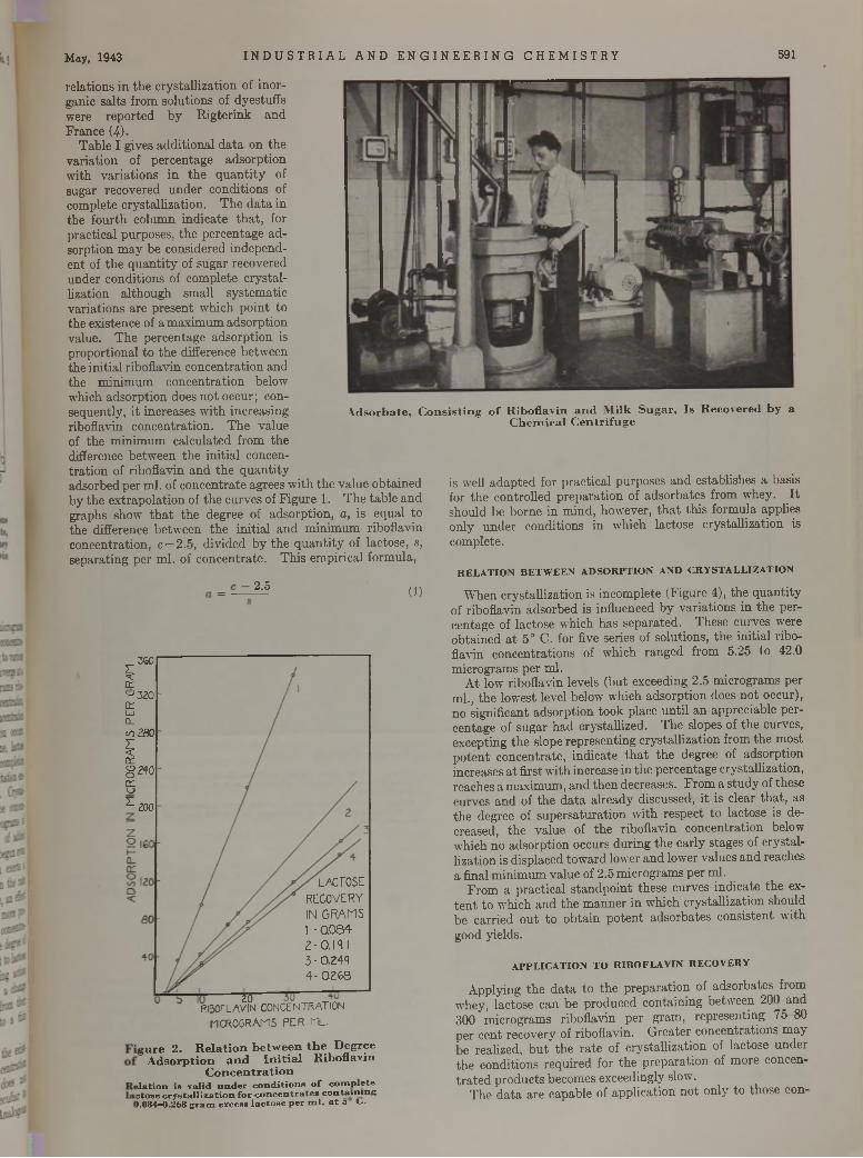
May, 1943 I ND U S T R I AL AND E NG I NE E R IN G CHEMI STRY 591
relations in the crystallization of inorganic salts from solutions of dyestuffs were reported by Rigterink and France (4).
Table I gives additional data on the variation of percentage adsorption with variations in the quantity of sugar recovered under conditions of complete crystallization. The data in the fourth column indicate that, for practical purposes, the percentage adsorption may be considered independent of the quantity of sugar recovered under conditions of complete crystallization although small systematic variations are present which point to the existence of a maximum adsorption value. The percentage adsorption is proportional to the difference between the initial riboflavin concentration and the minimum concentration below which adsorption does not occur; consequently, it increases with increasing riboflavin concentration. The value of the minimum calculated from the difference between the initial concentration of riboflavin and the quantityadsorbed per ml. of concentrate agrees with the value obtained by the extrapolation of the curves of Figure 1. The table and graphs show that the degree of adsorption, a , is equal to the difference between the initial and minimum riboflavin concentration, c —2.5, divided by the quantity of lactose, s, separating per ml. of concentrate. This empirical formula,
A d s o r b a t e , C o n s i s t i n g o f R i b o f l a v i n a n d M i l k S u g a r , I s R e c o v e r e d b y aC h e m i c a l C e n t r i f u g e
is well adapted for practical purposes and estabhshes a basis for the controlled preparation of adsorbates from whey. It should be borne in mind, however, that this formula applies only under conditions in which lactose crystallization is complete.
2.5RELATION BETWEEN ADSORPTION AND CRYSTALLIZATION
(1) When crystallization is incomplete (Figure 4), the quantityof riboflavin adsorbed is influenced by variations in the percentage of lactose which has separated. These curves were obtained at 5° C. for five series of solutions, the initial riboflavin concentrations of which ranged from 5.25 to 42.0 micrograms per ml.
At low riboflavin levels (but exceeding 2.5 micrograms per ml., the lowest level below which adsorption does not occur), no significant adsorption took place until an appreciable percentage of sugar had crystallized. The slopes of the curves, excepting the slope representing crystallization from the most potent concentrate, indicate that the degree of adsorption increases at first with increase in the percentage crystallization, reaches a maximum, and then decreases. From a study of these curves and of the data already discussed, it is clear that, as the degree of supersaturation with respect to lactose is decreased, the value of the riboflavin concentration below which no adsorption occurs during the early stages of crystallization is displaced toward lower and lower values and reaches a final minimum value of 2.5 micrograms per ml.
From a practical standpoint these curves indicate the extent to which and the manner in which crystallization should be carried out to obtain potent adsorbates consistent with good yields.
APPLICATION TO RIBOFLAVIN RECOVERY
Applying the data to the preparation of adsorbates from whey, lactose can be produced containing between 200 and 300 micrograms riboflavin per gram, representing 75-80 per cent recovery of riboflavin. Greater concentrations may be realized, but the rate of crystallization of lactose under the conditions required for the preparation of more concentrated products becomes exceedingly slow.
The data are capable of application not only to those con-
360z *c£E'-’320 DrLaJ CL</} 2805ccg 240m oZ 200
20RIBOFLAVIN CONCENTRATION
MICROGRAMS PER ML.
g u r e 2 . R e l a t i o n b e t w e e n t h e D e g r e e A d s o r p t i o n a n d I n i t i a l R i b o f l a v i n
C o n c e n t r a t i o n s ta t io n i s v a l id u n d e r c o n d i t io n s o f c o m p le t e c to se c r y s t a l l i z a t i o n f o r c o n c e n t r a t e s c o n t a in i n g).084—0.268 g r a m ex c ess la c to s e p e r m l . a t 5 C .
l a c t o s e
RECOVERY IN G R A M S 1 - 0.084- 2-0.13 I 3 - 0.244 4- 0.268
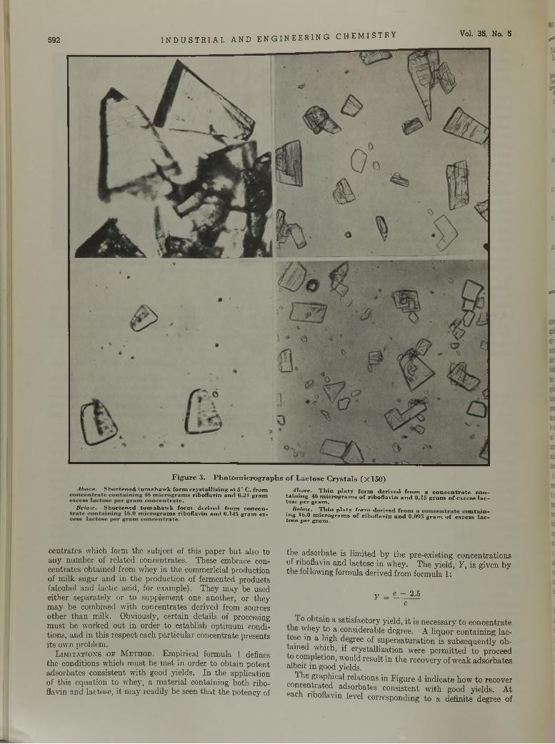
S92 INDUSTRIAL AND ENGINEERING CHEMISTRY Vol. 35, No. 5
F i g u r e 3 . P h o t o m i c r o g r a p h s o f L a c t o s e C r y s t a l s ( X 1 5 0 )
Above. S h o r te n e d to m a h a w k f o rm c r y s ta l l iz in g a t 5° C . f ro mrÍb0flaV Ín a n d 0 21 g r a m ‘ a iD in g 46 a e r o g r a m , o f r ib o f la v in a n d 0 .15 g r a m o f e x c e a . l a d
Above. T h in p la ty f o rm d e r iv e d f r o m a c o n c e n t r a t e c o n -
to se p e r g ra m .Below . S h o r te n e d to m a h a w k fo rm d e riv e d f ro m c o n c e n - Below. T h in n la tv fo rm (l Pr;V4>ii * * •
^ ¿ i b o f l a v i n a n d 0 .H 5 g ra m ex - in g 16.0 m ic ro g ra m s o f r ib o f la v in a n d 0.095 g r a m o f exces“ ' ^ :to s e p e r g ra m .
centrâtes which form the subject of this paper but also to any number of related concentrates. These embrace concentrates obtained from whey in the commericial production of milk sugar and in the production of fermented products (alcohol and lactic acid, for example). They may be used either separately or to supplement one another, or they may be combined with concentrates derived from sources other than milk. Obviously, certain details of processing must be worked out in order to establish optimum conditions, and in this respect each particular concentrate presents its own problem.
L i m i t a t i o n s o f M e t h o d . Empirical formula 1 defines the conditions which must be met in order to obtain potent adsorbates consistent with good yields. In the application of this equation to whey, a material containing both riboflavin and lactose, it may readily be seen that the potency of
the adsórbate is limited by the pre-existing concentrations of riboflavin and lactose in whey. The yield, Y , is given by the following formula derived from formula 1:
Y = c - 2.5
o obtain a satisfactory yield, it is necessary to concentrate e whey to a considerable degree. A liquor containing lac-
ose in a high degree of supersaturation is subsequently ob- aine which, if crystallization were permitted to proceed o comp etion, would result in the recovery of weak adsorbates
albeit in good yields.1 he graphical relations in Figure 4 indicate how to recover
concentrated adsorbates consistent with good yields. At eac l rno a\in level corresponding to a definite degree of
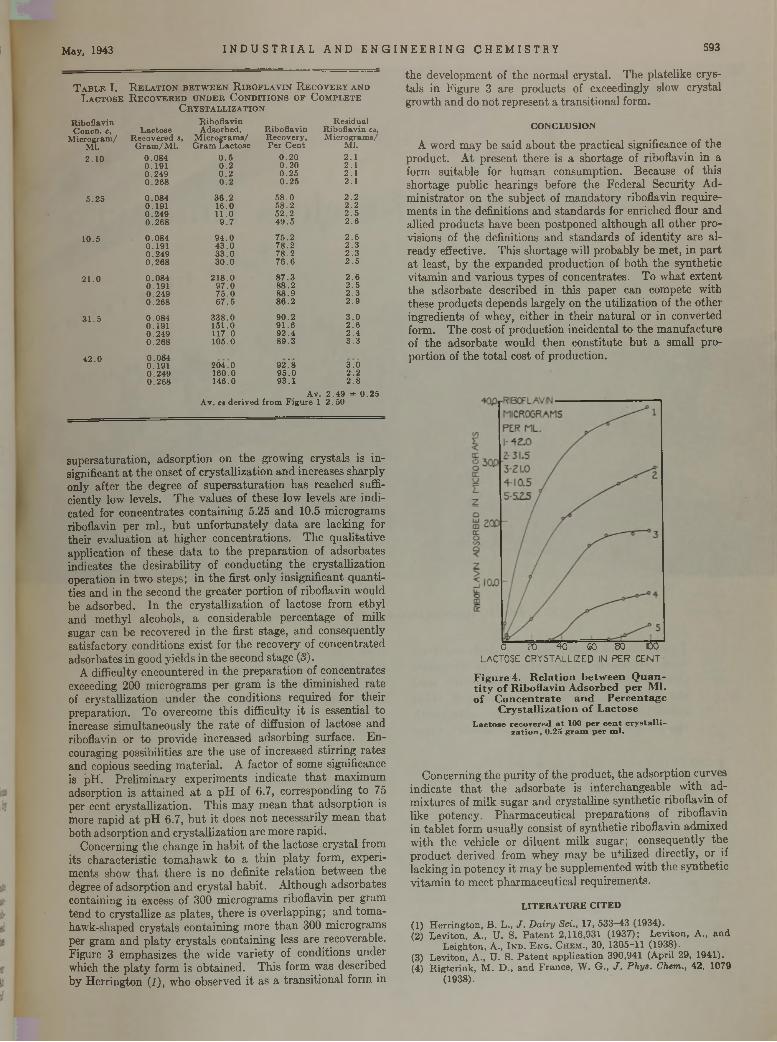
May, 1943 I ND U S T R I A L AND E NGI NEER I NG CHEMISTRY 593
T a b l e I . R e l a t i o n b e t w e e n R i b o f l a v i n R e c o v e r y a n d L a c t o s e R e c o v e r e d u n d e r C o n d i t i o n s o f C o m p l e t e
C r y s t a l l i z a t i o n
R ib o flav in R ib o flav in R es id u a lC oncn . c, L a c to se A dso rbed , R ib o flav in R ib o flav in co,
M ic ro g ra m s /M ic ro g ra m / R ec o v e red s, M ic ro g ra m s / R ecovery ,M l. G ra m /M l. G ra m L a c to se P e r C e n t M l.
2.10 0 .0 8 4 0 .5 0.20 2.10 .1 9 1 0.2 0.20 2.10 .2 4 9 0.2 0 .2 5 2.10 .2 6 8 0.2 0 .2 5 2.1
5 .2 5 0 .0 8 4 3 6 .2 5 8 .0 2.20 .1 9 1 1 6 .0 5 8 .2 2.20 .2 4 9 11.0 5 2 .2 2 .50 .2 6 8 9 .7 4 9 .5 2.6
1 0 .5 0 .0 8 4 9 4 .0 7 5 .2 2.60 .1 9 1 4 3 .0 7 8 .2 2 .30 .2 4 9 3 3 .0 7 8 .2 2 .30 .2 6 8 3 0 .0 7 6 .6 2 .5
21.0 0 .0 8 4 2 1 8 .0 8 7 .3 2.60 .1 9 1 9 7 .0 88.2 2 .50 .2 4 9 7 5 .0 8 8 .9 2 .30 .2 6 8 6 7 .5 86.2 2 .9
3 1 .5 0 .0 8 4 3 3 8 .0 9 0 .2 3 .00 .1 9 1 1 5 1 .0 9 1 .6 2.60 .2 4 9 11 7 .0 9 2 .4 2 .40 .2 6 8 10 5 .0 8 9 .3 3 .3
4 2 .0 0 .0 8 40 .1 9 1 2 0 4 .0 92.' 8 3.Ó0 .2 4 9 16 0 .0 9 5 .0 2.20 .2 6 8 14 6 .0 9 3 .1
A v.2.8
2 .4 9 ± 0 .2 5A v. co d e r iv ed from F ig u re 1 2 .5 0
supersaturation, adsorption on the growing crystals is insignificant at the onset of crystallization and increases sharply only after the degree of supersaturation has reached sufficiently low levels. The values of these low levels are indicated for concentrates containing 5.25 and 10.5 micrograms riboflavin per ml., but unfortunately data are lacking for their evaluation at higher concentrations. The qualitative application of these data to the preparation of adsorbates indicates the desirability of conducting the crystallization operation in two steps; in the first only insignificant quantities and in the second the greater portion of riboflavin would be adsorbed. In the crystallization of lactose from ethyl and methyl alcohols, a considerable percentage of milk sugar can be recovered in the first stage, and consequently satisfactory conditions exist for the recovery of concentrated adsorbates in good yields in the second stage (S).
A difficulty encountered in the preparation of concentrates exceeding 200 micrograms per gram is the diminished rate of crystallization under the conditions required for their preparation. To overcome this difficulty it is essential to increase simultaneously the rate of diffusion of lactose and riboflavin or to provide increased adsorbing surface. Encouraging possibilities are the use of increased stirring rates and copious seeding material. A factor of some significance is pH. Preliminary experiments indicate that maximum adsorption is attained at a pH of 6.7, corresponding to 75 per cent crystallization. This may mean that adsorption is more rapid at pH 6.7, but it does not necessarily mean that both adsorption and crystallization are more rapid.
Concerning the change in habit of the lactose crystal from its characteristic tomahawk to a thin platy form, experiments show that there is no definite relation between the degree of adsorption and crystal habit. Although adsorbates containing in excess of 300 micrograms riboflavin per gram tend to crystallize as plates, there is overlapping; and tomahawk-shaped crystals containing more than 300 micrograms per gram and platy crystals containing less are recoverable. Figure 3 emphasizes the wide variety of conditions under which the platy form is obtained. This form was described by Herrington (1), who observed it as a transitional form in
the development of the normal crystal. The platelike crystals in Figure 3 are products of exceedingly slow crystal growth and do not represent a transitional form.
C O N C L U S IO N
A word may be said about the practical significance of the product. At present there is a shortage of riboflavin in a form suitable for human consumption. Because of this shortage public hearings before the Federal Security Administrator on the subject of mandatory riboflavin requirements in the definitions and standards for enriched flour and allied products have been postponed although all other provisions of the definitions and standards of identity are already effective. This shortage will probably be met, in part at least, by the expanded production of both the synthetic vitamin and various types of concentrates. To what extent the adsórbate described in this paper can compete with these products depends largely on the utilization of the other ingredients of whey, either in their natural or in converted form. The cost of production incidental to the manufacture of the adsórbate would then constitute but a small proportion of the total cost of production.
O 20 40 £0 80 100lactose: crystallized in per cent
F i g u r e 4 . R e l a t i o n b e t w e e n Q u a n t i t y o f R i b o f l a v i n A d s o r b e d p e r M l . o f C o n c e n t r a t e a n d P e r c e n t a g e
C r y s t a l l i z a t i o n o f L a c t o s e
L a c to s e re c o v e re d a t 100 p e r c e n t c r y s t a l l i - z a t io n , 0 .25 g r a m p e r m l .
Concerning the purity of the product, the adsorption curves indicate that the adsórbate is interchangeable with admixtures of milk sugar and crystalline synthetic riboflavin of like potency. Pharmaceutical preparations of riboflavin in tablet form usually consist of synthetic riboflavin admixed with the vehicle or diluent milk sugar; consequently the product derived from whey may be utilized directly, or if lacking in potency it may be supplemented with the synthetic vitamin to meet pharmaceutical requirements.
L IT E R A T U R E C IT E D
(1) Herrington, B. L., J . D a iry Sci., 17, 533—43 (1934).(2) Levitón, A., U. S. Patent 2,116,931 (1937); Levitón, A., and
Leighton, A., Ind. E n g . Chem., 30, 1305-11 (1938).(3) Levitón, A., U. S. Patent application 390,941 (April 29, 1941).(4) Rigterink, M. D., and France, W. G., J . P hys. Chem., 42, 1079
(1938).
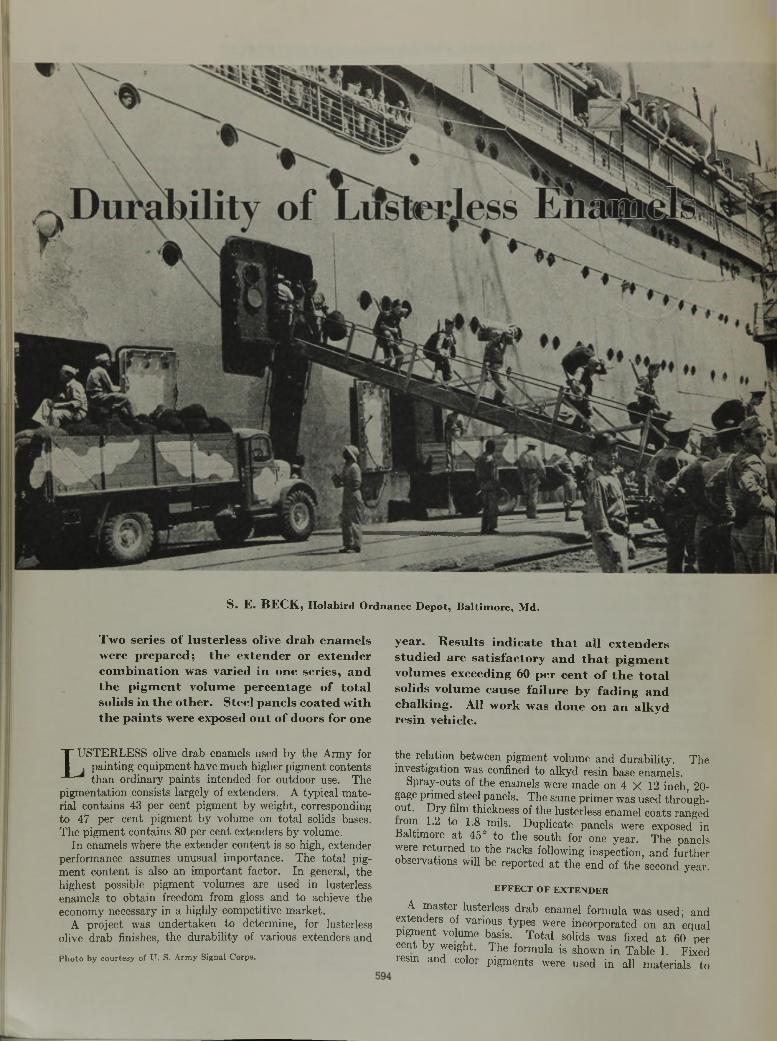
S. E. BECK, H o l a b i r d O r d n a n c e D e p o t , B a l t i m o r e , M d .
Two series of lusterless olive drab enam els were prepared; the extender or extender com bination was varied in one series, and the p igm ent volum e percentage of total solids in the other. Steel panels coated with the paints were exposed out of doors for one
year. Results indicate th at all extenders studied are satisfactory and th at p igm ent volumes exceeding 60 per cent o f th e tota l solids volume cause failure by fading and chalking. All work was done on an alkyd resin vehicle.
t USTERLESS olive drab enamels used by the Army for . painting equipment have much higher pigment contents
than ordinary paints intended for outdoor use. The pigmentation consists largely of extenders. A typical material contains 43 per cent pigment by weight, corresponding to 47 per cent pigment by volume on total solids bases. The pigment contains 80 per cent extenders by volume.
In enamels where the extender content is so high, extender performance assumes unusual importance. The total pigment content is also an important factor. In general, the highest possible pigment volumes are used in lusterless enamels to obtain freedom from gloss and to achieve the economy necessary in a highly competitive market.
A project was undertaken to determine, for lusterless olive drab finishes, the durability of various extenders andP h o to b y co u rte sy of U . S. A rm y Signal C orps.
the relation between pigment volume and durability. The investigation was confined to alkyd resin base enamels.
Spray-outs of the enamels were made on 4 X 12 inch, 20- gage primed steel panels. The same primer was used throughout. Dry film thickness of the lusterless enamel coats ranged rom 1.2 to 1.8 mils. Duplicate panels were exposed in
Baltimore at 45° to the south for one year. The panels were returned to the racks following inspection, and further observations will be reported at the end of the second year.
EFFECT OF EXTENDER
A master lusterless drab enamel formula was used; and extenders of various types were incorporated on an equal pigment volume basis. Total solids was fixed at 60 per cent by weight. The formula is shown in Table I. Fixed resm and color pigments were used in all materials to
May, 1943 I ND U S T R I A L AND E NGI NEER I NG CHEMI STRY 595
T a b l e I.-P ig m e n ta tio n -
F o r m u l a f o r E x t e n d e r S t u d y
-F o rm u la tio n -
H y d ra te d yellow oxide L am p b lack C h ro m e yellow m e
d iu m , c . p .
E x ten d e r
% by % byw t. of vol. ofto ta l to ta l
p ig m en t p a in t so lids
1 3 .6 Solids 6053'. 33 .3
3 .5A lk y d resin (35% p h th a lic an h y d rid e)
7 9 .6
100.0
T o ta l p ig m en t
V o la tile (m inera l sp irits) 40
4 6 .7
100.0
100
no change on exposure; 35 to 48 per cent showed slight fading, and 50 to 70 per cent gave moderate to extensive fading, increasing directly with pigment volume. However, only panels from 60 to 70 per cent, inclusive, showed bad enough fading or chalking to be considered failures.
Adhesion was satisfactory up to 60 per cent pigment volume; other factors, such as abrasion resistance, might affect the suitability of such a high pigment volume. Above 60 per cent, films were powdery, dry, and easily removed with the thumbnail. However, even the 70 per cent pigment volume material adhered to the primer and showed no noticeable erosion or wearing through.
T a b l e I I . E f f e c t o f E x t e n d e r o n C o l o r R e t e n t i o n a n d C h a l k i n g R e s i s t a n c e
E x t e n d e r
A s b e s t in eA s b e s t in e 5 0 % , C a C O i 5 0 % A s b e s t in e 5 0 % , b a r y t e s 5 0 % A s b e s t in e 5 0 % , d ia to m a -
c e o u s s i l ic a 5 0 %A s b e s t in e 5 0 % , s i l ic a 5 0 % A s b e s t in e 5 0 % , s la t e f lo u r
5 0 %A s b e s t in e 5 0 % , w a te r -
g ro u n d m ic a 5 0 % A s b e s t in e 5 0 % , c h in a c la y
5 0 %C aC O aB a r y t e s
D ia to m a c e o u s s i l ic a D ia to m a c e o u s s i l ic a 50%,
CaCOa 50%D ia to m a c e o u s s i l ic a 5 0 % ,
b a r y t e s 5 0 %
D ia to m a c e o u s s i l ic a 5 0 % , s i l ic a 5 0 %
D ia to m a c e o u s s i l ic a 5 0 % , s la t e f lo u r 5 0 %
P a n e l
N o .
1,2 1, 2 1,2 1,2
1,2121,2
E x p o s u r e O b s e r v a t io n
Slight chalking No changeVery slight darkening Very slight chalking
Moderate chalking Slight chalking Moderate chalking Very slight chalking
1, 2 Slight chalking
1.2 No change1, 2 Slight darkening and chalk
ing1, 2 Slight chalking1.2 No change
1 Slight chalking2 Slight darkening, very slight
chalking1 Moderate fading and chalk
ing2 Slight darkening and chalk
ing1 Moderate chalking2 Slight chalking, darkening
E x t e n d e r
Diatomaceous silica 50%, water-ground mica 50%
Diatomaceous silica 50%, china clay 50%
Silica
Slate flour
Water-ground mica
China clayAsbestine 33’/3%, diatoma
ceous silica 33*/3%, CaCOs 33Vs%
Asbestine 33V3%, diatomaceous silica 33V3%, China clay 33*/3%
Asbestine 40%, diatomaceous silica 40%, barytes 20%
Slate flour 50%, china clay50% . _
Slate flour 50%, CaCOa 50% Asbestine 60%, diatoma
ceous silica 30%, CaCOj 10%
Diatomaceous silica 60%, asbestine 30%, CaCCh 10%
P a n e l
No. E x p o s u r e O b s e r v a t io n
1,2 Slight chalking
1, 2 Moderate chalking
1 Marked chalking and fading2 Moderate chalking1 Slight chalking2 No change1 Very slight chalking2 Slight chalking1 Moderate chalking1 Very slight chalking2 No change
1 Moderate chalking and fad
2ing
Very slight chalking1 Very slight chalking2 No change
1 Moderate chalking2 Slight chalking1,2 No change1 Moderate fading2 Very slight chalking
1 Slight chalking2 Slight darkening, chalking
T a b l e I I I . F o r m u l a f o r P i g m e n t V o l u m e
obtain uniformity. Enamels were ground on a ball miU Drier content (in per cent of resin solids) follows: 0.03 cobalt, 0.01 manganese, and 0.20 lead.
Evaluations of duplicate panels are reported m table 11 for each extender. Appraisals were made by the same operator and were based on visual appearance only. . . . .
The results indicate that none of the extenders studied is so poor that it is necessary to omit it from formulations for lusterless olive drab enamel. Calcium carbonate appears to be the most desirable from the point of view of color re- tention and chalking resistance.
EFFECT OF VOLUME OF PIGMENT
Materials used, conditions of grind, driers, etc., were the same as in the extender study. Pigment volumes are expressed on a total solids basis. A range from 20 to 70 per cent pigment volume was used, i n c r e a s i n g m steps of 5 per cent between 20 and 40 and between 60 and 70, and of 2 per cent between 42 and 60. The general formula is shown inTable III. , j
Inspections were based both on visual appearance a mechanical film properties. No panel-by-panel description is necessary because of the uniform manner in which fading and chalking increased directly with pigment volume. Wit a pigment volume of 20 to 30 per cent there was practically
-P ig m e n ta t io n - •F o rm u la tio n -
H y d ra te d yellow oxide L am p b lack C hrom e yellow
m edium , c . P.
A sbestineD ia tom aceous silica
B a ry te s
% by % byw t. of vol. ofto ta l to ta l
p ig m en t p a in t solids
18 Solids 602 T o ta l p ig m en t X7 A l k y l r e s i n
(35% p h th a lic100 — *
an h y d rid e) 1003326 V olatile (m in era l
sp irits)40
14 100100
ACKNOW LEDGMENT
The author wishes to express his indebtedness to the Cook Paint and Varnish Company, the Ditzler Color Company, E. I. du Pont de Nemours & Company, Inc., the Enterprise Paint Manufacturing Company, the Pittsburgh Plate Glass Company, and C. K. Williams & Company for their cooperation in preparing the paints.
T h is re p o r t is based on la b o ra to ry findings a n d is p re sen ted o n ly fo r its te ch n ica l in te re s t. I t is n o t to b e considered in th e lig h t of a n official G o v e rn m e n t p ro n o u n cem en t, no r is a d o p tio n of a n y of th e se reco m m e n d a tio n s or fo rm u las req u ired of m a n u fa c tu re rs d ea ling w ith th e G o v e rn m e n t, d ire c tly or in d irec tly .
Present Status of PLANT HORMONES
P. W. ZIMMERMANBoyce Thompson Institute for P lant Research, Inc.,
Yonkers, N. Y.
P h e n o x y a n d b e n z o i c a c i d s s u b s t i t u t e d i n t h e n u c l e u s w i t h h a l o g e n , m e t h y l , a n d n i t r o g r o u p s h a v e o p e n e d a n e w l i n e o f a t t a c k o n p l a n t h o r m o n e p r o b l e m s . P h e n o x y a c e t i c a c i d i s s l i g h t l y a c t i v e f o r c e l l e l o n g a t i o n b u t d o e s n o t i n d u c e f o r m a t i v e e f f e c t s o f g r o w i n g p l a n t s . W h e n s u b s t i t u t e d i n t h e
o r t h o a n d p a r a p o s i t i o n s , t h e r e s u l t i n g d i c h l o r o - p h e n o x y a c e t i c a c i d i s e f f e c t i v e , c a u s i n g c e l l e l o n g a t i o n , a d v e n t i t i o u s r o o t s , p a r t h e n o c a r p y , a n d f o r
m a t i v e e f f e c t s . p - C h l o r o p h e n o x y a c e t i c i s l e s s a c t i v e t h a n t h e d i c h l o r o , a n d t h e o r t h o c o m p o u n d i s l e s s a c t i v e t h a n t h e p a r a . B r o m o - s u b s t i t u t e d c o m p o u n d s a r e s l i g h t l y l e s s a c t i v e t h a n t h e c h l o r o . 2 , 4 , 6 - T r i b r o m o p h e n o x y a c e t i c a c i d i s i n a c t i v e , b u t 2 , 3 , 5 - t r i i o d o b e n z o i c a c i d i s v e r y a c t i v e . T h e h i g h e r h o m o l o g s , s u c h a s c h l o r o p h e n o x y - a - p r o p i o n i c a n d c h l o r o p h e n o x y - a - b u t y r i c a c i d s , a r e a c t i v e f o r c e l l e l o n g a t i o n a n d a d v e n t i t i o u s r o o t s b u t n o t v e r y
a c t i v e f o r f o r m a t i v e e f f e c t s . B e n z o i c a c i d i s p h y s i o l o g i c a l l y i n a c t i v e u n t i l s u b s t i t u t e d w i t h h a l o g e n o r n i t r o g r o u p s . 2 - C h l o r o - 5 - n i t r o b e n z o i c a c i d i s i n
a c t i v e f o r c e l l e l o n g a t i o n b u t i s a c t i v e f o r m o d i f y i n g t h e p a t t e r n o f l e a v e s . 2 - B r o m o - 3 - n i t r o b e n z o i c
a c i d i s a c t i v e f o r b o t h f a c t o r s .C o n s i d e r i n g t h e i n c r e a s e d a c t i v i t y o f s u b s t i t u t e d
p h e n o x y a n d b e n z o i c a c i d s o v e r p h e n o x y a n d b e n
z o i c a c i d s , t h e a c t i v i t y o f m a n y o t h e r s u b s t a n c e s i n t h e h o r m o n e f i e l d m i g h t b e i n c r e a s e d b y t h i s
m e t h o d . T h e p r i n c i p a l u s e s f o r g r o w t h s u b s t a n c e s a r e t o p r o p a g a t e p l a n t s f r o m c u t t i n g s , p r e v e n t p r e -
h a r v e s t d r o p o f a p p l e s , i n d u c e s e e d l e s s f r u i t ( e s p e c i a l l y t o m a t o e s ) , a n d i n h i b i t b u d s ( e s p e c i a l l y
b u d s o f p o t a t o t u b e r s ) . F l o w e r i n g o f p l a n t s c a n b e
r e g u l a t e d t o s o m e e x t e n t w i t h t h e m o s t a c t i v e c o m p o u n d s . T r e a t m e n t o f s e e d s w i t h g r o w t h s u b
s t a n c e s t o i n c r e a s e t h e c r o p h a s n o t b e e n e f f e c t i v e .
T HE purpose of this paper is to list the most important physiologically active substances discovered to date and to discuss some of their practical applications which
have been reported from or verified at the Boyce Thompson Institute laboratories. No references will be made to other workers in this field.
Owing to the fact that hormonelike substances induce many varied responses when applied to plants, unwarranted claims have been made, especially for the purpose of exploitation. Vitamin Bi has fallen by the way as a cure-all for plants, although recently attempts were made to revive it for horticultural practice. The vitamin stories printed in the trade journals and advertisements were fantastic but popular, and it took scientists a long time to convince gardeners that they were wasting their time and money when they added Ba to fertilizers or sprayed it on their lawns.
Although growth substances of the auxin groups have some practical value, they are not cure-alls and must not be considered as fertilizers. They are commonly referred to as plant hormones although the ones in practical use (with the possible exception of the indoles) have never been isolated and chemically identified from green tissue. This, however, should not be taken to mean that these substances do not exist in nature. A variety of physiologically active substances has been extracted from fungi, pollen, seeds, bark, and growing parts of plants. These crude extracts, when applied to growing plants, bring about responses similar to those induced with synthetic compounds. In some cases these substances may be by-products of metabolism, acting like hormones only when applied in relatively high concentrations.
For practical purposes the synthetic substances are applied as acids, esters, amides, or salts. Wherever a given acid is
active, its derivatives (salts, esters, and amides) have approximately equal activity. Owing, however, to their differences in volatility, solubility, availability, or ease of application, one may be preferred over the other for a particular use. When applied as a vapor, the methyl or ethyl esters are preferred because they are more volatile than the acids; when used as a lanolin preparation, the acid may be preferred; and when used as a water solution, the salts or acids are preferred. The amides and esters are nearly insoluble in water but can be used for certain purposes in water solutions because only small amounts of the growth substances are required to induce responses in plants.
EFFECT OF VARIOUS GROUPS
The various groups of compounds have different practical uses although there is considerable overlapping. For convenience and brevity the groups are considered separately.
Naphthalene Compounds. When properly applied, a-naphthaleneacetic acid and its derivatives inhibit buds, induce roots on cuttings, and prevent abscission layers from forming. It is frequently important to prevent buds of tubers, bulbs, corms, cuttings, and trees from growing. For this purpose naphthalene compounds are very effective. After treatment with a-naphthaleneacetic acid, potatoes can be stored indefinitely without much shrinkage, and fruit trees can be prevented from flowering (although methods have not been fully perfected) until the danger of frost has passed. The same treatment may be important to delay flowering of trees and thus to spread the fruit crops over a longer period or harvest. This would apply particularly to tropical species
such as mango and avocado. Also, the flowering period for
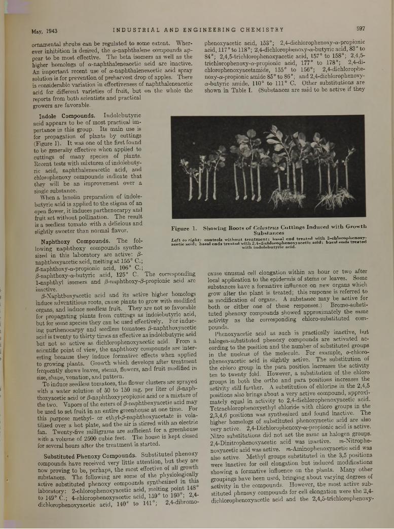
May, 1943 I N D US T R I A L AND E NGI NEER I NG CHEMISTRY 597
ornamental shrubs can be regulated to some extent. Wherever inhibition is desired, the a-naphthalene compounds appear to be most effective. The beta isomers as well as the higher homologs of a-naphthaleneacetic acid are inactive. An important recent use of a-naphthaleneacetic acid spray solution is for prevention of preharvest drop of apples. There is considerable variation in effectiveness of naphthaleneacetic acid for different varieties of fruit, but on the whole the reports from both scientists and practical growers are favorable.
Indole Compounds. Indolebutyric acid appears to be of most practical importance in this group. Its main use is for propagation of plants by cuttings (Figure 1). It was one of the first found to be generally effective when applied to cuttings of many species of plants.Recent tests with mixtures of indolebutyric acid, naphthaleneacetic acid, and chlorophenoxy compounds indicate that they will be an improvement over a single substance.
When a lanolin preparation of indole- butyric acid is applied to the stigma of an open flower, it induces parthenocarpy and fruit set without pollination. The result is a seedless tomato with a delicious and slightly sweeter than normal flavor.
Naphthoxy Compounds. The following naphthoxy compounds synthesized in this laboratory are active: 0- naphthoxyacetic acid, melting at 155° C.; /3-naphthoxy-a-propionic acid, 106° C.; d-naphthoxy-a-butyric acid, 125° C. The corresponding 1-naphthyl isomers and /3-naphthoxy-/3-propionic acid are inactive.
d-Naphthoxyacetic acid and its active higher homologs induce adventitious roots, cause plants to grow with modified organs, and induce seedless fruit. They are not so favorable for propagating plants from cuttings as indolebutyric acid, but for some species they can be used effectively. For inducing parthenocarpy and seedless tomatoes /3-naphthoxyacetic acid is twenty to thirty times as effective as indolebutyric acid but not so active as dichlorophenoxyacetic acid. From a scientific point of view, the naphthoxy compounds are interesting because they induce formative effects when applied to growing plants. Growth which develops after treatment frequently shows leaves, stems, flowers, and fruit modified in size, shape, venation, and pattern.
To induce seedless tomatoes, the flower clusters are sprayed with a water solution of 50 to 150 mg. per liter of d"naP " thoxyacetic acid or d-naphthoxypropionic acid or a mixture o the two. Vapors of the esters of d-naphthoxyacetic acid may be used to set fruit in an entire greenhouse at one time. For this purpose methyl- or ethyl-/3-naphthoxyacetate is vo a tilized over a hot plate, and the air is stirred with an e ec ric fan. Twenty-five milligrams are sufficient for a greenhouse with a volume of 2500 cubic feet. The house is kept closed for several hours after the treatment is started.
Substituted Phenoxy Compounds. Substituted phenoxy compounds have received very little attention, but they are now proving to be, perhaps, the most effective of all gro substancep. The following are some of the physio ogica y active substituted phenoxy compounds synthesized in is laboratory: 2 -chlorophenoxyacetic acid, melting pomto 149° C.; 4-chlorophenoxyacetic acid, 159° to 160 ; 2,4- dichlorophenoxyacetic acid, 140° to 141 ; 2,4-di romo
phenoxyacetic acid, 153°; 2,4-dichlorophenoxy-a-propionic acid, 117°to 118°; 2,4-dichlorophenoxy-a-butyric acid, 83° to 84°; 2,4,5-trichlorophenoxyacetic acid, 157° to 158°; 2,4,5- trichlorophenoxy-a-propionic acid, 177° to 178°; 2,4-di-chlorophenoxyacetamide, 155° to 156°; 2,4-dichlorophe- noxy-a-propionic amide 85° to 86°; and 2,4-dichlorophenoxy- a-butyric amide, 110° to 111° C. Other substitutions are shown in Table I. (Substances are said to be active if they
cause unusual cell elongation within an hour or two after local application to the epidermis of stems or leaves. Some substances have a formative influence on new organs which grow after the plant is treated; this response is referred to as modification of organs. A substance may be active for both or either one of these responses.) Bromo-substi- tuted phenoxy compounds showed approximately the same activity as the corresponding chloro-substituted compounds.
Phenoxyacetic acid as such is practically inactive, but halogen-substituted phenoxy compounds are activated according to the position and the number of substituted groups in the nucleus of the molecule. For example, o-chloro- phenoxyacetic acid is slightly active. The substitution of the chloro group in the para position increases the activity ten to twenty fold. However, a substitution of the chloro groups in both the ortho and para positions increases the activity still further. A substitution of chlorine in the 2,4,5 positions also brings about a very active compound, approximately equal in activity to 2,4-dichlorophenoxyacetic acid. Tetrachlorophenoxyethyl chloride with chloro groups in the 2,3,4,6 positions was synthesized and found inactive. The higher homologs of substituted phenoxyacetic acid are also very active. 2,4-Dichlorophenoxy-a-propionic acid is active. Nitro substitutions did not act the same as halogen groups. 2,4-Dinitrophenoxyacetic acid was inactive. m-Nitrophe- n’oxyacetic acid was active. wvAminophenoxyacetic acid was also active. Methyl groups substituted in the 3,5 positions were inactive for cell elongation but induced modifications showing a formative influence on the plants. Many other groupings have been used, bringing about varying degrees of activity in the compounds. However, the most active substituted phenoxy compounds for cell elongation were the 2,4- dichlorophenoxyacetic acid and the 2,4,5-trichlorophenoxy-
F i g u r e 1 . S h o w i n g R o o t s o f C e l a s t r u s C u t t i n g s I n d u c e d w i t h G r o w t hS u b s t a n c e s
L e f t to r ig h t : co n tro ls w ith o u t tr e a t m e n t ; b a sa l e n d tr e a te d w it h 2 -c h lo r o p h e n o x y - a c e tic a c id ; b a sa l e n d s tr e a te d w ith 2 ,4 -d ic h lo r o p h e n o x y a c e tic a c id ; b a s a l e n d s t r e a t e d
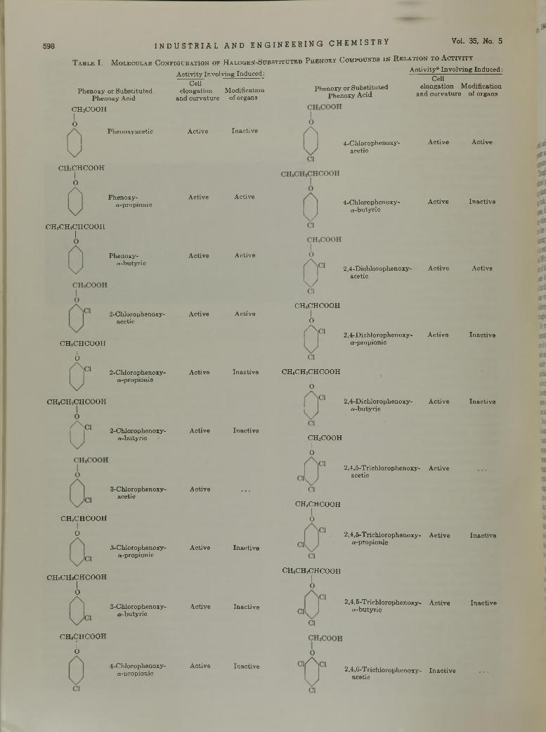
598 I NDUS TR I AL AND ENGI NEER I NG CHEMISTRY Vol. 35, No. 5
T a b l e I . M o l e c u l a r C o n f i g u r a t i o n o f H a l o g e n - S u b s t i t u t e d P h e n o x y C o m p o u n d s i n R e l a t i o n t o A c t i v i t yA c tiv ity “ In v o lv in g Induced:
Phenoxy or Substituted Phenoxy Acid
CH2COOHIO
Phenoxyacetic
CHaCHCOOHIo
Phenoxy-«-propionic
CH8CH2CHCOOHio
Phenoxy-« -bu tyric
2-Chlorophenoxy-acetic
CHaCHCOOHIO
CHjCHíCHCOOH
CHaCHCOOHIO
CHaCHsCHCOOHIo
CHaCHCOOHIo
A c tiv ity In vo lv ing Induced : CeU
elongation M odification and curvature of organs
2-Chlorophenoxy-a-propionie
2-Chlorophenoxy-a -butyric
3-Chlorophenoxy-acetic
3-Chlorophenoxy-a-propionic
3-Chlorophenoxy-a-b u ty ric
4-ChJorophenoxy-a-propionic
A ctive
A ctive
A ctive
Active
Active
Active
Active
Active
A ctive
A ctive
In active
A ctive
A ctive
A ctive
Inactive
Inactive
Inactive
Inactive
In a c t iv e
Phenoxy or S ubstituted Phenoxy A c id
4-Chlorophenoxy-acetic
CeUelongation Modification
and curvature of organs
A ctive
4-Chlorophenoxy-a -b u ty ric
A ctive
2,4-D ichlorophenoxy- A c tive acetic
CHaCHCOOHIO
2,4-D ichlorophenoxy- A ctive «-propionic
CHaCHiCHCOOHIO
2,4-D ichlorophenoxy- A ctive « -b u ty ric
CH2COOHI0
2,4,5-Trich lorophenoxy- A ctive acetic
CHaCHCOOHIO
2,4,5-Trichlorophenoxy- Active a-propionic
CHaCHjCHCOOHIO
2,4,5-Trichlorophenoxy- Active a-butyric
2,4,6-Trichlorophenoxy- Inactive acetic
A ctive
In ac tiv e
A ctive
Inactive
Inactive
In ac tive
Inactive
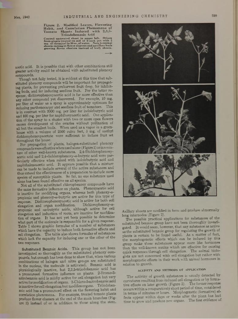
May, 1943 I N D U S T R I A L AND E N G I N E E R I N G C H E M I S T R Y 599
F i g u r e 2 . M o d i f i e d L e a v e s , F l o w e r i n g H a b i t , a n d C o r r e l a t i o n P h e n o m e n a o f T o m a t o S h o o t s I n d u c e d w i t h 2 , 3 , 5 -
T r i i o d o b e n z o i c A c i dC o n t r o l u n t r e a t e d s h o o t i n u p p e r l e f t . O th e r s f r o m p l a n t s t r e a t e d o n s o il o f 4 - in c h p o t w i th o m g . o f c h e m ic a l i n 50 c c . o f w a te r . N o te t e r m i n a l s h o o ts e n d in g i n f lo w er c l u s t e r s a n d a u x i l ia r y b u d s g ro w in g f lo w er c l u s t e r s i n s t e a d o f le a fy s h o o ts .
acetic acid. It is possible that with other combinations still greater activity could be obtained with substituted phenoxy compounds.
Though not fully tested, it is evident at this time that substituted phenoxy compounds will be important for propagating plants, for preventing preharvest fruit drop, for inhibiting buds, and for inducing seedless fruit. For the latter response, dichlorophenoxyacetic acid is far more effective than any other compound yet discovered. For example, 10 mg. per liter of water as a spray is approximately optimum for inducing parthenocarpy and seedless fruit of tomatoes. This is in contrast with 3000 mg. per liter for indolebutyric acid and 100 mg. per liter for naphthoxyacetic acid. One application of the spray to a cluster with two or more open flowers causes development of the ovaries without pollination of all but the smallest buds. When used as a vapor in a greenhouse with a volume of 2500 cubic feet, 5 mg. of methyl dichlorophenoxyacetate were sufficient to induce fruit set throughout the house.
For propagation of plants, halogen-substituted phenoxy compounds were effective when used alone (Figure 1) or in a mixture of other well-known substances. 2,4-Diehlorophenoxy- acetic acid and 2,4-dichlorophenoxy-a-butyric acid were particularly effective when mixed with indolebutyric acid and naphthaleneacetic acid. It appears possible that a mixture can be made to include several of the active substances and thus extend the effectiveness of a preparation to include more species of susceptible plants. So far, no one substance used alone has been found effective on all species.
Not all of the substituted chlorophenoxy compounds have the same formative influence on plants. Phenoxyacetic acid is inactive for modifying organs, whereas both phenoxy-a- propionic and phenoxy-a-butyric are active for this type of response. Dichlorophenoxyacetic acid is active for both cell elongation and organ modification. Dichlorophenoxy-a- propionic and -a-butyric acids, although active for cell elongation and induction of roots, are inactive for modification of organs. It has not yet been possible to determine what part of the molecule is responsible for a given response. Table I shows graphic formulas of a number of substances which have the capacity to induce both formative effects and cell elongation. The table also shows formulas of substances which lack the capacity for inducing one or the other of the two responses.
Substituted Benzoic Acids. This group has not been investigated so thoroughly as the substituted phenoxy compounds, but enough has been done to show that, when \ anous combinations of halogen and nitro groups are substituted in the nucleus, the molecule is activated. Benzoic acid is physiologically inactive, but 2,3,5-triiodobenzoic acid has a pronounced formative influence on plants. 2-Broruo-3- nitrobenzoic acid is mildly active for cell elongation but very active for modification of organs. 2-Chloro-5-nitrobenzoic acid is inactive for cell elongation but modifies organs. Triiodoben- zoic acid has a pronounced effect on the flowering habit and correlation phenomena. For example, treated tomato plants produce flower clusters at the end of the main branches (Figure 2) instead of or in addition to those along the stem.
Axillary shoots are modified in form and produce abnormally long intemodes (Figure 2).
The possible practical applications for substances of the substituted benzoic group have not been thoroughly investigated. It would seem, however, that any substance as active as the substituted benzoic group for regulating the growth of plants is certain to be found useful. As a matter of fact, the morphogenetic effects which can be induced by this group make these substances appear more like hormones than the well-known auxins which are effective for causing quick responses through cell elongation. The animal biologists are not concerned with cell elongation but rather with morphogenetic effects in their work with animal hormones in relation to growth.
ACTIVITY AND METHODS OF APPLICATION
The activity of growth substances is usually detected by curvatures resulting from induced cell elongation or by formative effects on later growth (Figure 3). The former response occurs within a comparatively short period of time, considered in terms of minutes or hours. Morphogenetic (formath e effects appear within days or weeks after the plant has had time to grow and produce new organs. The first evidence of
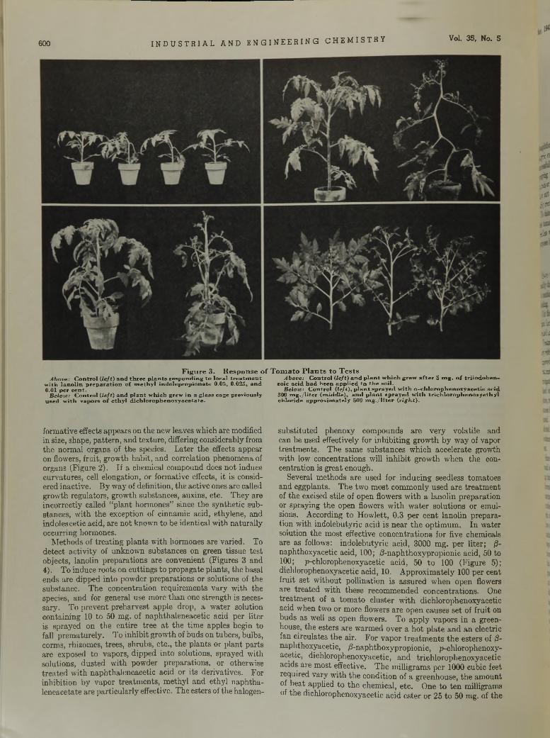
600 I N D U S T R I A L A N D E N G I N E E R I N G C H E M I S T R Y Vol. 35, No. 5
-J«*5
Above: C o n tr o l (le ft) a n d th r e e p la n t s r e s p o n d in g to lo c a l t r e a tm e n t w ith la n o l in p r e p a r a t io n o f m e th y l in d o le p r o p io n a te 0 .05, 0 .025, a n d 0.01 p e r c e n t .
Beloic: C o n tro l (le ft) a n d p l a n t w h ic h g rew in a g la ss cag e p rev io u s ly u s e d w ith v a p o rs o f e th y l d ic h lo ro p h e n o x y a c e ta te .
F i g u r e 3 . R e s p o n s e o f T o m a t o P l a n t s t o T e s t sAbove: C o n tro l (le ft) a n d p l a n t w h ic h g re w a f t e r 5 m g . o f t r i io d o b e n -
ro ic a c id h a d b e e n a p p l ie d to t h e so il.Below: C o n tro l ( le / t ) , p l a n t s p r a y e d w i th o - c h lo ro p h e n o x y a c e t ic a c id
300 m g . / l i t e r (m id d le ) , a n d p l a n t s p r a y e d w i th t r i c h lo r o p h e n o x y e th y l c h lo r id e a p p ro x im a te ly 500 m g . / l i t e r (r ig h t) .
formative effects appears on the new leaves which are modified in size, shape, pattern, and texture, differing considerably from the normal organs of the species. Later the effects appear on flowers, fruit, growth habit, and correlation phenomena of organs (Figure 2). If a chemical compound does not induce curvatures, cell elongation, or formative effects, it is considered inactive. By way of definition, the active ones are called growth regulators, growth substances, auxins, etc. They are incorrectly called “plant hormones” since the synthetic substances, with the exception of cinnamic acid, ethylene, and indoleacetic acid, are not known to be identical with naturally occurring hormones.
Methods of treating plants with hormones are varied. To detect activity of unknown substances on green tissue test objects, lanolin preparations are convenient (Figures 3 and4). To induce roots on cuttings to propagate plants, the basal ends are dipped into powder preparations or solutions of the substance. The concentration requirements vary with the species, and for general use more than one strength is necessary. To prevent preharvest apple drop, a water solution containing 10 to 50 mg. of naphthaleneacetic acid per liter is sprayed on the entire tree at the time apples begin to fall prematurely. To inhibit growth of buds on tubers, bulbs, corms, rhizomes, trees, shrubs, etc., the plants or plant parts are exposed to vapors, dipped into solutions, sprayed with solutions, dusted with powder preparations, or otherwise treated with naphthaleneacetic acid or its derivatives. For inhibition by vapor treatments, methyl and ethyl naphtha- leneacetate are particularly effective. The esters of the halogen-
substituted phenoxy compounds are very volatile and can be used effectively for inhibiting growth by way of vapor treatments. The same substances which accelerate growth with low concentrations will inhibit growth when the concentration is great enough.
Several methods are used for inducing seedless tomatoes and eggplants. The two most commonly used are treatment of the excised stile of open flowers with a lanolin preparation or spraying the open flowers with water solutions or emulsions. According to Howlett, 0.3 per cent lanolin preparation with indolebutyric acid is near the optimum. In water solution the most effective concentrations for five chemicals are as follows: indolebutyric acid, 3000 mg. per liter; (3- naphthoxyacetic acid, 100; /3-naphthoxypropionic acid, 50 to 100; p-chlorophenoxyacetic acid, 50 to 100 (Figure 5); dichlorophenoxyacetic acid, 10. Approximately 100 per cent fruit set without pollination is assured when open flowers are treated with these recommended concentrations. One treatment of a tomato cluster with dichlorophenoxyacetic acid when two or more flowers are open causes set of fruit on buds as well as open flowers. To apply vapors in a greenhouse, the esters are warmed over a hot plate and an electric fan circulates the air. For vapor treatments the esters of ¡3- naphthoxyacetic, |8-naphthoxypropionic, p-chlorophenoxyacetic, dichlorophenoxyacetic, and trichlorophenoxyacetic acids are most effective. The milligrams per 1000 cubic feet required vary with the condition of a greenhouse, the amount of heat applied to the chemical, etc. One to ten milligrams of the dichlorophenoxyacetic acid ester or 25 to 50 mg. of the
,02 1 ju t¡ftot # 0
u s*
•ß■'
**SJS53f i t3*varffi
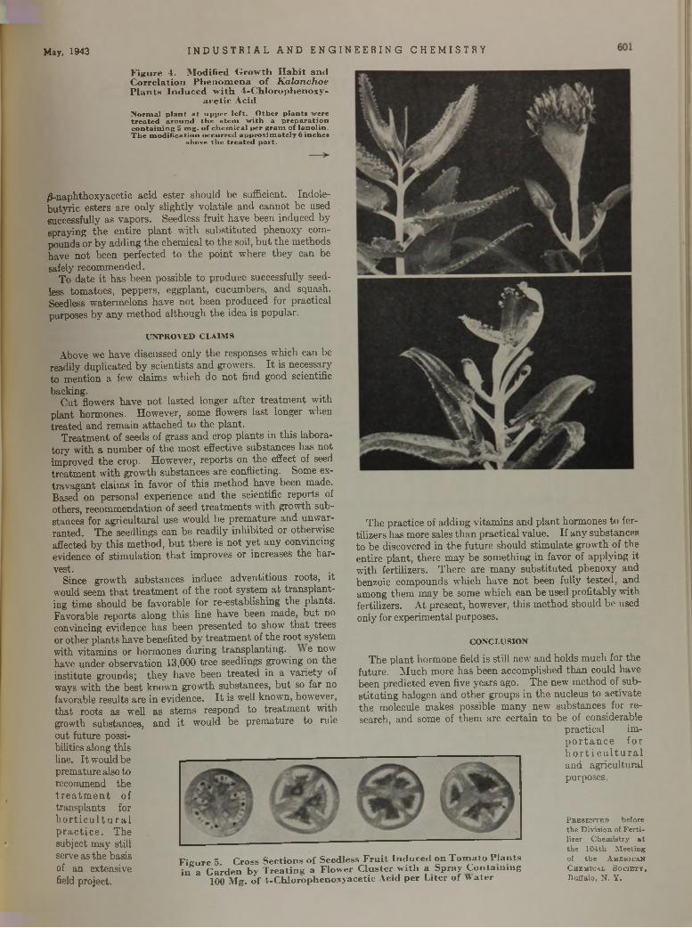
/S-naphthoxyacetic acid ester should be sufficient. Indole- butyric esters are only slightly volatile and cannot be used successfully as vapors. Seedless fruit have been induced by spraying the entire plant with substituted phenoxy compounds or by adding the chemical to the soil, but the methods have not been perfected to the point where they can be safely recommended.
To date it has been possible to produce successfully seedless tomatoes, peppers, eggplant, cucumbers, and squash. Seedless watermelons have not been produced for practical purposes by any method although the idea is popular.
U N P R O V E D C L A IM S
Above we have discussed only the responses which can be readily duplicated by scientists and growers. It is necessary to mention a few claims which do not find good scientific backing.
Cut flowers have not lasted longer after treatment with plant hormones. However, some flowers last longer when treated and remain attached to the plant.
Treatment of seeds of grass and crop plants in this laboratory with a number of the most effective substances has not improved the crop. However, reports on the effect of seed treatment with growth substances are conflicting. Some extravagant claims in favor of this method have been made. Based on personal experience and the scientific reports of others, recommendation of seed treatments with growth substances for agricultural use would be premature and unwarranted. The seedlings can be readily inhibited or otherwise affected by this method, but there is not yet any convincing evidence of stimulation that improves or increases the harvest.
Since growth substances induce adventitious roots, it would seem that treatment of the root system at transplanting time should be favorable for re-establishing the plants. Favorable reports along this line have been made, but no convincing evidence has been presented to show that trees or other plants have benefited by treatment of the root system with vitamins or hormones during transplanting. e now have under observation 13,000 tree seedlings growing on the institute grounds; they have been treated in a variety of ways with the best known growth substances, but so far no favorable results are in evidence. It is well known, however, that roots as well as stems respond to treatment with growth substances, and it would be premature to rule out future possibilities along this line. It would be premature also to recommend the treatm ent of transplants for h orticu lt ural practice. The subject may still serve as the basis of an extensive field project.
The practice of adding vitamins and plant hormones to fertilizers has more sales than practical value. If any substances to be discovered in the future should stimulate growth of the entire plant, there may be something in favor of applying it with fertilizers. There are many substituted phenoxy and benzoic compounds which have not been fully tested, and among them may be some which can be used profitably with fertilizers. At present, however, this method should be used only for experimental purposes.
C O N C L U S IO N
The plant hormone field is still new and holds much for the future. Much more has been accomplished than could have been predicted even five years ago. The new method of substituting halogen and other groups in the nucleus to activate the molecule makes possible many new substances for research, and some of them are certain to be of considerable
practical importance for h o r t ic u ltu r a l and agricultural purposes.
F i g u r e 5 . C r o s s S e c t i o n s o f S e e d l e s s F r u i t I n d u c e d o n T o m a t o P l a n t s i n " a G a r d e n b y T r e a t i n g a F l o w e r C l u s t e r w i t h a S p r a y C o n t a i n i n g
1 0 0 M g . o f 4- C h l o r o p h e n o x y a c e t i c A c i d p e r L i t e r o f W a t e r
P r e s e n t e d b e fo re th e D iv is io n of F e r t i lizer C h e m is try a t th e 1 0 4 th M ee tin g of th e A m e r ic a n C h e m ic a l So c ie t y , B u ffa lo . N . Y .
M ay, 1943
F i g u r e 4 . M o d i f i e d G r o w t h H a b i t a n d C o r r e l a t i o n P h e n o m e n a o f K a l a n c h o e P l a n t s I n d u c e d w i t h 4 - C h l o r o p h e n o x y -
a c e t i c A c i d
N o r m a l p l a n t a t u p p e r l e f t . O th e r p l a n t s w e re t r e a t e d a r o u n d t h e s t e m w i th a p r e p a r a t i o n c o n t a in i n g 5 m g . o f c h e m ic a l p e r g r a m o f l a n o l in .T h e m o d i f ic a t io n o c c u r r e d a p p r o x im a te ly 6 in c h e s
ab o v e t h e t r e a t e d p a r t .
I ND U S T R I A L AND ENGI NEER I NG CHEMISTRY
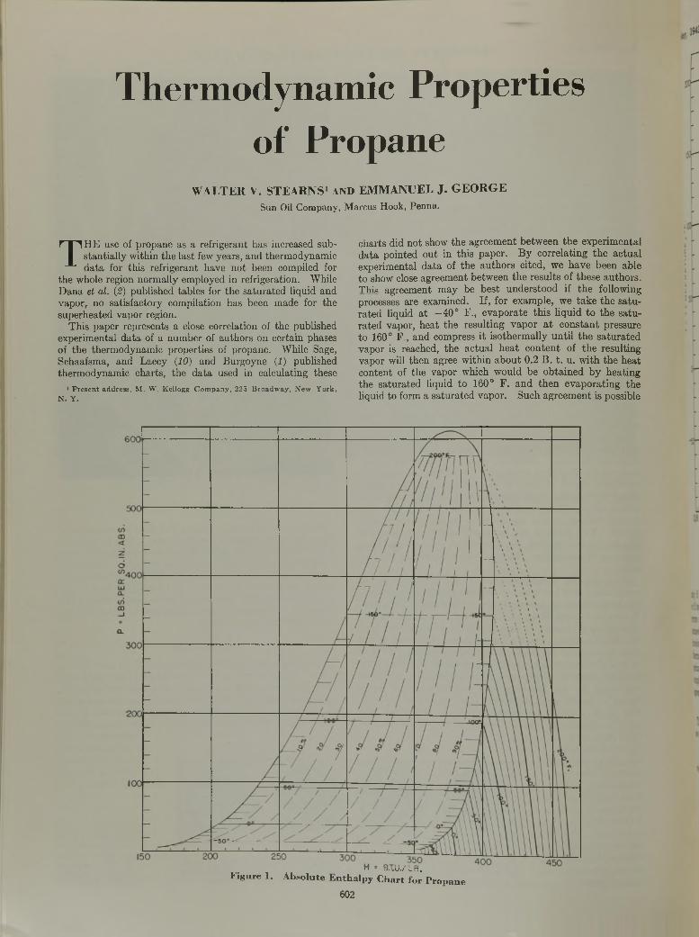
Thermodynamic Properties of Propane
WALTER V . STEARNS1 AND EMMANUEL J. GEORGESun Oil Company, Marcus Hook, Penna.
T HE use of propane as a refrigerant has increased substantially within the last few years, and thermodynamic data for this refrigerant have not been compiled for
the whole region normally employed in refrigeration. While Dana et a l. (2) published tables for the saturated liquid and vapor, no satisfactory compilation has been made for the superheated vapor region.
This paper represents a close correlation of the published experimental data of a number of authors on certain phases of the thermodynamic properties of propane. While Sage, Schaafsma, and Lacey (10) and Burgoyne (1) published thermodynamic charts, the data used in calculating these
1 P re se n t address, M . W . K ellogg C om pany , 22.5 B roadw ay , N ew Y ork , N . Y .
charts did not show the agreement between the experimental data pointed out in this paper. By correlating the actual experimental data of the authors cited, we have been able to show close agreement between the results of these authors. T his agreement may be best understood if the following processes are examined. If, for example, we take the saturated liquid at —40° F., evaporate this liquid to the saturated vapor, heat the resulting vapor at constant pressure to 160° F , and compress it isothermally until the saturated vapor is reached, the actual heat content of the resulting vapor will then agree within about 0.2 B. t. u. with the heat content of the vapor which would be obtained by heating the saturated liquid to 160° F. and then evaporating the liquid to form a saturated vapor. Such agreement is possible
■ 1 U .I.U ./ L D .
F i g u r e 1 . A b s o l u t e E n t h a l p y C h a r t f o r P r o p a n e
602
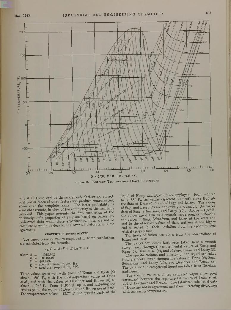
May, 1943 I N D U S T R I A L AND E NG I N EE R IN G CHEMI STRY 603
S * B.T.U. P E R L B . P E R ° F .
F i g u r e 2 . E n t r o p y - T e m p e r a t u r e C h a r t f o r P r o p a n e
only if all these various thermodynamic factors are correct or if two or more of these factors will produce compensating errors over the complete range. The latter probability is somewhat remote, in view of the complexity of the functions involved. This paper presents the first correlation of the thermodynamic properties of propane based on pure y ex perimental data while these experimental data are not so complete as would be desired, the over-all picture is in close agreement.
PROPERTIES INVESTIGATEDThe vapor pressure values employed in these correlations
are calculated from the formula:log P = A / T + B log T + C
where A = —1018.502 B = -0 .1 6 6 4 6 C = +6.67979P = absolute pressure, cm. Hg T = absolute temperature, ° K.
These values agree well with those of Kemp and Egan (6) above -8 0 ° F., with the low-temperature values of Dana et ah , and with the values of Deschner and Brown ( J o about +195° F. From +195° F. up to and including the critical point, the values of Deschner and Brown are uti lze . For temperatures below —43.7° F. the specific heats o e
liquid of Kemp and Egan (6 ) are employed. From -43.7° to +155° F., the values represent a smooth curve through the data of Dana et a l. and of Sage and Lacey. The values of Sage and Lacey (0) are apparently a revision of the earlier data of Sage, Schaafsma, and Lacey {1 0 ) . Above +155 F. the values are drawn as a smooth curve roughly following the values of Sage, Schaafsma, and Lacey at the lower end and to the observed values of these authors at the higher end corrected for their deviation from the apparent truecritical temperature.
The heats of fusion are taken from the observations otKemp and Egan.
The values for latent heat were taken from a smooth curve drawn through the experimental values of Kemp and Egan (6 ), Dana et a l . {2 ) , and of Sage, Evans, and Lacey (<?).
The specific volume and density of the liquid are taken from a smooth curve through the values of Dana {2 ) , Sage, Schaafsma, and Lacey {1 0 ) , and Deschner and Brown {8 ) . The data for the compressed liquid are taken from Deschnerand Brown. ,
The specific volumes of the saturated vapor show good agreement between the experimental values of Dana et a l . and of Deschner and Brown. The tabulated calculated data of Dana are not in agreement and show increasing divergence with increasing temperature.
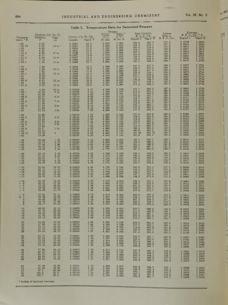
604 I N D U S T R I A L A N D E N G I N E E R I N G C H E M I S T R Y Vol. 35, No. 5
T a b l e I . T e m p e r a t u r e D a t a f o r S a t u r a t e d P r o p a n e
D en s ity E n tro p y ,B . T . U . /L b . / ° F .
T e m p era tu re f, ° F .
- 8 0- 7 8 .7 5- 7 8- 7 6- 7 5 . 9- 7 4- 7 3 . 2- 7 2- 7 0 . 7
P ressu re , L b ./S q . In .V olum e, C u. F t . /L b .
L iqu id(1/ r ) ,
V apor(1/ 10.
n e a t B . T.. U ./L b .
L a te n t H e a t L ,
A bso lu te ,P5 .6 55 .8 76.006 .3 26 .3 5 6 .7 1 6.86 7 .1 87 .3 5
U age,OP
18 in ."
17 in.
16 in.
15 in.
L iq u id h162 .6163.2163.6164 .6164 .6165 .6 166 .0166.6167 .2
V apor H3 5 4 .03 5 4 .4 3 5 4 .63 5 5 .23 5 5 .2 3 5 5 .83 5 6 .03 5 6 .43 5 6 .5
B. T . U ./L b .19 1 .4191 .2191 .01 9 0 .61 90 .6190 .2190 .0 189 .8189 .5
L iq u id s0 .8 7 9 4 0 .8 8 1 2 0 .8 8 2 1 0 .8 8 4 7 0 .8 8 5 0 0 .8 8 7 4 0 .8 8 8 4 0 .8 9 0 0 0 .8 9 1 8
V apor S
1 .3832 1 .3826 1 .3822 1 .3812 1 .3811 1 .3801 1 .3797 1.3791 1 .3785
L iqu id v0 .0 2 6 50 .0 2 6 50 .02660 .02660 .0 2 6 60 .02670 .02670 .0 2 6 80 .0 2 6 8
V apor V16 .215 .6 15 .314 .614 .6 1 3 .8 13 .5 13 .012 .7
lb ./g a l.5 .0525 .0435.0415 .0 3 05 .030 5 .0 2 0 5 .019 5 .009 5 .002
lb ./c u . ft.0 .0 6 20 .0640 .0 6 50 .0 6 80 .0 6 80 .0 7 20 .0 7 40 .0 7 60 .0 7 9
- 7 0- 6 8 . 4-68- 66.1-66- 6 4- 6 3 . 9- 6 2- 6 1 . 9
7 .4 87 .8 47 .9 18 .3 28 .3 3 8 .8 0 8 .81 9 .2 8 9 .3 0
14 in.
13 in .
12 in .
11 in.
0 .0 2 6 80 .0 2 6 80 .0 2 6 80 .0 2 6 80 .02690 .02690 .0 2 6 90 .0 2 7 00 .0 2 7 0
12 .512.011 .91 1 .311 .3 10.8 10.81 0 .31 0 .3
4 .9 9 84 .9 9 04 .9 8 84 .9 7 84 .9 7 84 .9 6 84 .9 6 84 .9 5 74 .9 5 7
0 .0 8 00 .0830 .0 8 40 .0 8 80 .0 8 80 .0 9 30 .0930 .0 9 70 .0 9 7
167 .6 168.4168.6 169.8169.7170.7170 .8171 .7171 .8
3 5 7 .035 7 .53 5 7 .6358 .13 5 8 .23 5 8 .835 8 .93 5 9 .43 5 9 .5
189 .4 189.118 9 .0188 .5188 .5188 .1 188 .1187 .7187 .7
0 .8 9 2 7 0 .8 9 4 9 0 .8 9 5 4 0 .8 9 7 8 0 .8 9 8 0 0 .9 0 0 7 0 .9 0 0 8 0 .9 0 3 3 0 .9 0 3 4
1.37811 .37751 .37731 .37661 .37651 .37561 .37561 .37481 .3748
- 6 0- 5 8 . 1- 5 8- 5 6 . 2- 5 6- 5 4 . 4- 5 4- 5 2 . 6- 5 2- 5 1
9 .7 810 .2810 .2910 .7710 .8011 .2611 .3611 .7511 .9512 .24
10 in. 9 in .
8 in .
7 in .
6 in .
5 in .
0 .027030 .027090 .027090 .027140 .027150 .027200.027210 .027250 .027270 .02730
9 .7 79 .3 59 .3 38 .9 68 .9 2 8 .5 9 8 .51 8 .2 4 8.127 .9 3
4 .9 4 64 .9 3 64 .9 3 6 4 .9 2 6 4 .9 2 5 4 .9 1 7 4 .9 1 5 4 .9 0 7 4 .9 0 4 4 .8 9 8
0.1020.1070.1070.1120.1120 .1 1 60 .1 1 70.1200.1220.125
172.7173 .6173.7174.6174.7 175 .6175 .8 176.5176.8 177.3
3 6 0 .03 6 0 .53 6 0 .6361 .136 1 .1 36 1 .436 1 .73 62 .1 3 6 2 .3 36 2 .6
187 .31 86 .9186 .918 6 .51 86 .41 8 5 .81 85 .91 8 5 .61 8 5 .5 1 85 .3
0 .9 0 6 0 0 .9 0 8 5 0 .9 0 8 6 0 .9 1 0 8 0 .9 1 1 1 0 .9 1 3 2 0 .9 1 3 7 0 .9 1 5 4 0 .9 1 6 2 0 .9 1 7 5
1 .37401 .37321 .3732 1 .3726 1 .3725 1 .3719 1 .3717 1 .3712 1 .3710 1 .3706
- 5 0- 4 9 . 6- 4 8- 4 7 . 9- 4 6 . 5- 4 6- 4 4 . 9- 4 4- 4 3 .7 1- 4 2
12 .6012 .7313 .2013 .2213.7113 .8514 .214 .5214 .7015 .28
4 in .
3 in . 2 in .
1 in .
0
0 .027330 .027340 .027390 .027390 .027430 .027450 .027480.027510 .027520 .02757
7 .7 3 7 .7 2 7 .5 0 7 .4 4 7 .1 7 7 .0 6 6 .9 06 .7 4 6.66 6 .4 2
4 .8 9 34 .8914 .8 8 24 .8 8 3 4 .8 7 5 4 .8 7 2 4 .8 6 6 4 .861 4 .8 6 0 4 .8 5 0
0 .1 2 90 .1 3 00 .1 3 30 .1 3 40 .1 3 90 .1 4 20 .1 4 50 .1 4 80.1500 .1 5 6
177 .8 178.0178 .8178.9 179.7179.9 180 .4180.9 181.36181.9
3 6 2 .83 6 2 .93 6 3 .436 3 .5 36 3 .8 36 4 .0 36 4 .336 4 .6 364 .7 6 36 5 .2
18 5 .0184 .9184 .6184 .6184 .1184.1183 .9 18 3 .8 183 .5 183 .3
0 .9 1 8 80 .9 1 9 30 .9 2 1 30 .9 2 1 40 .9 2 3 20 .9 2 3 80 .9 2 5 20 .9 2 6 40 .9 2 6 60 .9 2 8 9
1 .37021.37011 .36961 .3696 1.3691 1 .3689 1 .3686 1 .3683 1 .3682 1 .3676
- 4 0- 3 8- 3 6- 3 4- 3 2
16 .0016 .7917 .5618 .4019 .30
1 .3 02 .0 92.863 .7 04 .6 0
0 .027630 .027690 .027750 .027820 .02788
6 .1 65 .9 25 .6 65 .4 45 .2 2
4 .8 3 94 .8 2 84 .8 1 84.8074 .7 9 7
0.1620.1690.1770.1840.192
183.0184.0185.1186.2 187.3
365 .736 6 .336 6 .936 7 .536 8 .0
182 .7182 .3181 .8181 .3 180 .7
0 .9 3 1 50 .9 3 4 00 .9 3 6 50 .9 3 9 10 .9 4 1 6
1 .36701 .36641 .36581.36521 .3646
- 3 0- 2 8- 2 6- 2 4-22
20 .1 82 1 .0 522.012 2 .9 823 .9 8
5 .4 86 .3 57.318 .2 89 .2 8
0 .027940 .028000.028070.028130 .02820
5 .0 24 .8 24 .6 34 .4 44 .2 5
4 .7 8 64 .7 7 54 .7 6 44 .7 5 24.741
0 .1 9 90.2070 .2 1 60 .2 2 50 .2 3 5
188.4189.4190 .5191 .6192.7
3 6 8 .636 9 .23 6 9 .837 0 .33 7 0 .9
180 .2179 .7 179 .3178 .7 17 8 .2
0 .94410 .9 4 6 70 .9 4 9 20 .9 5 1 70 .9 5 4 3
1 .3640 1 .3634 1 .3628 1 .3622 1 .3616
-20- 1 8- 1 6- 1 4-12
2 5 .0 526 .1 527 .3 02 8 .5 029 .7 0
10 .35 11 .4512 .6013 .8015 .00
0 .028260.028330 .028390.028460 .02852
4 .0 63 .9 03 .7 63 .613 .4 7
4 .7 3 04 .7 1 94 .7 0 84 .6 9 74 .6 8 6
0 .2 4 60 .2560 .2 6 60 .2770 .2 8 8
193 .8194.9196 .0197.1198.2
37 1 .5372 .137 2 .737 3 .23 7 3 .8
177 .717 7 .217 6 .6 176 .1175 .6
0 .9 5 6 80 .9 5 9 20 .9 6 1 70 .96410 .9 6 6 6
1 .3610 1 .3604 1 .3599 1 .3593 1 .3588
-10 - 8 - 6- 4- 2
30 .9 532 .2 333 .5 535 .0 036 .4 0
16 .2517.5318 .852 0 .3 02 1 .7 0
0 .028590 .028660.028730 .028790 .02886
3 .3 33 .2 03 .0 82 .9 82.86
4 .6 7 54 .6 6 44 .6 5 24 .6414 .6 2 9
0 .3000 .3130 .3 2 50 .3360 .3 5 0
199 .4200 .5201.620 2 .720 3 .8
3 7 4 .43 7 5 .037 5 .5376 .1 3 7 6 .7
17 5 .017 4 .5173 .917 3 .417 2 .8
0 .9 6 9 00 .9 7 1 40 .9 7 3 90 .9 7 6 30 .9 7 8 8
1 .35821 .35771.35711 .35661 .3560
- 0+ 2
4 6 8
37 .813 9 .3 04 0 .8 54 2 .5 04 4 .1 3
23.112 4 .6 02 6 .1 52 7 .8 02 9 .4 3
0 .028930 .029000 .029080 .029150 .02923
2 .7 42.662 .5 62 .4 72 .3 8
4 .6 1 84 .6 0 74 .5 9 64 .5 8 44 .573
0 .3 6 50 .3760 .3910 .4050 .4 2 0
2 0 5 .0206.1 2 07 .2 2 0 8 .4 2 0 9 .6
3 7 7 .23 7 7 .83 7 8 .33 7 8 .9 3 7 9 .5
172 .217 1 .6171 .117 0 .516 9 .9
0 .9 8 1 20 .9 8 3 60 .9 8 6 00 .9 8 8 40 .9 9 0 8
1 .35551 .35501 .35451.35411 .3536
1012141618
4 5 .8 54 7 .5 54 9 .3 55 1 .2 05 3 .1 0
3 1 .1 53 2 .8 53 4 .6 53 6 .5 03 8 .4 0
0 .029300 .029380 .029460 .029540 .02962
2 .3 02.222 .1 42 .0 82.00
4 .5624 .5 5 04 .5 3 84 .5 2 64 .5 1 4
0 .4 3 50 .4 5 00 .4670 .4810 .5 0 0
210 .7211 .9213 .12 1 4 .2 215 .4
3 8 0 .03 8 0 .6381 .13 8 1 .63 82 .1
16 9 .3168 .7 1 6 8 .0167 .4166 .7
0 .9 9 3 20 .9 9 5 60 .9 9 7 91 .0 0 0 31 .0026
1.35311 .35271 .35231 .35181 .3514
202224262 8
55 .0 05 7 .0 55 9 .1 06 1 .2 56 3 .4 5
4 0 .3 04 2 .3 54 4 .4 04 6 .5 54 8 .7 5
0 .029700 .029780 .029860 .029950.03003
1.931.861.791 .731 .67
4 .5 0 24 .5 9 04 .4774 .4 6 54 .452
0 .5 1 80 .5 3 80 .5590 .5 7 80 .5 9 8
21 6 .621 7 .721 8 .8 220.0 221.2
3 8 2 .6383 .13 8 3 .6384 .13 8 4 .6
16 6 .016 5 .4 16 4 .8 164 .216 3 .5
1 .0050 1 .0073 1 .0097 1.0120 1 .0 1 4 4
1 .3510 1 .3506 1 .3502 1 .3499 1 .3495
303234363 8
6 5 .7 06 7 .9 57 0 .3 37 2 .7 57 5 .2 0
5 1 .0 05 3 .2 555 .635 8 .0 56 0 .5 0
0 .030110 .030200 .030290 .030370 .03046
1 .6 0 '1 .541 .481 .431 .39
4 .4 4 04 .4274 .4 1 44 .4014 .3 8 8
0 .6 2 50 .6 4 90 .6 7 60 .6 9 90 .7 1 9
222 .32 2 3 .42 2 4 .52 2 5 .6 2 2 6 .8
3 85 .13 8 5 .638 6 .13 8 6 .638 7 .1
1 6 2 .8162 .21 6 1 .51 6 0 .81 6 0 .2
1 .01671 .01901 .02131 .02371 .0 2 6 0
1.3491 1 .3487 1 .3484 1 .3480 1 .3477
404244
4648
7 7 .8 08 0 .4 08 3 .0 58 5 .8 38 8 .6 5
6 3 .1 06 5 .7 06 8 .3 57 1 .1 37 3 .9 5
0 .030550 .030640 .030730 .030830 .03092
1 .331 .281 .251.211 .17
4 .3 7 54 .3 6 24 .3 4 84 .3 3 54 .321
0 .7 5 20.7810 .8 0 00 .8 2 60 .8 5 5
2 2 7 .92 29 .1230 .2 2 3 1 .4 23 2 .6
3 8 7 .53 8 8 .03 8 8 .53 8 9 .03 8 9 .5
1 5 9 .61 5 8 .91 5 8 .21 5 7 .51 5 6 .8
1 .0 2 8 3 1 .0306 1 .0329 1 .0 3 5 2 1 .0 3 7 5
1 .3473 1 .3470 1 .3466 1 .3463 1 .3459
5052545658
9 1 .5 09 4 .5 0 9 7 .5100.6
1 03 .7
7 6 .8 07 9 .8 08 2 .8 0 8 5 .9 8 9 .0
0 .031010 .031110 .031210 .031300 .03140
1 .141.101 .071 .041.01
4 .3 0 84 .2 9 44 .2814 .2 6 74 .2 5 4
0 .8770 .9 0 90 .9 3 50 .9 6 20 .9 9 0
2 3 3 .82 3 4 .9 2 36 .1 2 3 7 .3 2 3 8 .5
3 8 9 .93 9 0 .43 9 0 .83 9 1 .33 9 1 .7
1 56 .115 5 .41 5 4 .71 5 4 .01 5 3 .3
1 .0 3 9 81 .04211 .0 4 4 31 .0 4 6 61 .0 4 8 8
1 .34561 .34531 .34501 .34471 .3444
«t«»
“ In ch es of m e rcu ry v ac u u m .
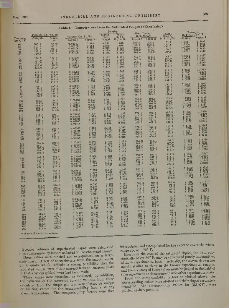
May, 1943 I N D US T R I A L AND E NG I NE E R ING CHEMISTRY 605
T e m p e ra tu re t, ° F .
60626466687072747678
80828486889092949698
100102104106108
110112114116118
120122124126128
130132134136138
140142144146148
150152154156158
160162164166168
170172174176178
180182184186188190200
P re s su re , L b ./S q . In . A b so lu te , G age,
P QV9 2 .2 ° 9 5 .5 9 8 .9
1 0 2 .4 1 0 5 .9
T a b l e I . T e m p e r a t u r e D a t a f o r S a t u r a t e d P r o p a n e ( C o n c l u d e d )
D e n s ityL iq u id
1 0 6 .9 110.21 1 3 .61 1 7 .1120.61 2 4 .31 2 7 .9 1 3 1 .71 3 5 .61 3 9 .6
1 4 3 .61 4 7 .71 5 1 .81 5 6 .2 1 6 0 .6
1 6 5 .01 6 9 .61 7 4 .217 8 .91 8 3 .7
1 8 8 .71 9 3 .81 9 8 .92 0 4 .12 0 9 .3
2 1 4 .82 2 0 .4 2 2 6 .02 3 1 .62 3 7 .3
2 4 3 .42 4 9 .72 5 5 .72 6 1 .72 6 7 .9
2 7 4 .52 8 1 .12 8 7 .92 9 4 .73 0 1 .4
3 0 8 .43 1 5 .53 2 2 .83 3 0 .23 3 7 .6
3 4 5 .43 5 2 .93 6 0 .83 6 8 .63 7 6 .6
3 8 5 .03 9 2 .94 0 1 .04 0 9 .34 1 7 .8
4 2 6 .04 3 6 .44 4 5 .9 4 5 5 .24 6 4 .1
4 7 3 .24 8 3 .04 9 2 .95 0 3 .1 5 1 2 .85 2 3 .4 5 7 5 .0
1 0 9 .611 3 .21 1 7 .01 2 0 .91 2 4 .9
1 2 8 .91 3 3 .0137 .114 1 .51 4 5 .9
15 0 .31 5 4 .915 9 .516 4 .21 6 9 .0
1 7 4 .0179 .118 4 .218 9 .41 9 4 .6
200.12 0 5 .72 1 1 .32 1 6 .9 222.62 2 8 .72 3 5 .02 4 1 .02 4 7 .02 5 3 .2
2 5 9 .82 6 6 .42 7 3 .22 8 0 .02 8 6 .7
2 9 3 .73 0 0 .83 0 8 .13 1 5 .53 2 2 .9
3 3 0 .73 3 8 .23 4 6 .13 5 3 .93 6 1 .9
3 7 0 .33 7 8 .23 8 6 .33 9 4 .64 0 3 .1
4 1 1 .34 2 1 .74 3 1 .2 4 4 0 .54 4 9 .4
4 5 8 .54 6 8 .34 7 8 .24 8 8 .4 4 9 8 .15 0 8 .75 6 0 .3
L iq u id v V apor V lb . /g a l .
0 .0 3 1 5 0 0 .9 8 4 4 .2 4 00 .0 3 1 6 2 0 .9 5 8 4 .2 2 60 .0 3 1 7 4 0 .9 3 2 4 .2 1 30 .0 3 1 8 5 0 .9 0 6 4 .1 9 90 .0 3 1 9 7 0 .8 8 0 4 .1 8 6
0 .0 3 2 0 9 0 .8 5 4 4 .1 7 20 .03 2 2 1 0 .8 3 2 4 .1 5 80 .0 3 2 3 3 0 .8 1 0 4 .1 4 40 .0 3 2 4 5 0 .7 8 8 4 .1 3 10 .0 3 2 5 7 0 .7 6 6 4 .1 1 7
0 .0 3 2 6 9 0 .7 4 5 4 .1 0 30 .03281 0 .7 2 5 4 .0 8 80 .0 3 2 9 3 0 .7 0 4 4 .0 7 40 .0 3 3 0 5 0 .6 8 4 4 .0 5 90 .0 3 3 1 7 0 .6 6 3 4 .0 4 5
0 .0 3 3 2 9 0 .6 4 3 4 .0 3 00 .0 3 3 4 1 0 .6 2 6 4 .0 1 50 .0 3 3 5 3 0 .6 0 9 4 .0 0 10 .0 3 3 6 6 0 .5 9 2 3 .9 8 60 .0 3 3 7 8 0 .5 7 5 3 .9 7 2
0 .0 3 3 9 0 0 .5 5 8 3 .9 5 70 .0 3 4 0 2 0 .5 4 4 3 .9 4 10 .0 3 4 1 5 0 .5 3 0 3 .9 2 50 .03 4 2 7 0 .5 1 6 3 .9 1 00 .0 3 4 3 9 0 .5 0 2 3 .8 9 4
0 .0 3 4 5 2 0 .4 8 7 3 .8 7 80 .0 3 4 6 8 0 .4 7 5 3 .8 6 20 .0 3 4 8 4 0 .4 6 3 3 .8 4 60 .0 3 5 0 0 0 .4 5 1 3 .8 3 00 .0 3 5 1 6 0 .4 3 9 3 .8 1 4
0 .0 3 5 3 2 0 .4 2 6 3 .7 9 80 .0 3 5 4 8 0 .4 1 5 3 .7 8 00 .0 3 5 6 4 0 .4 0 4 3 .7 6 30 .0 3 5 8 0 0 .3 9 3 3 .7 4 50 .0 3 5 9 6 0 .3 8 2 3 .7 2 8
0 .0 3 6 1 2 0 .3 7 0 3 .7 1 00 .0 3 6 3 0 0 .3 6 0 3 .6 9 20 .0 3 6 4 8 0 .3 5 0 3 .6 7 40 .0 3 6 6 6 0 .3 4 0 3 .6 5 70 .0 3 6 8 4 0 .3 3 0 3 .6 3 9
0 .0 3 7 0 2 0 .3 2 0 3 .6 2 10 .0 3 7 2 5 0 .3 1 2 3 .6 0 00 .0 3 7 4 8 0 .3 0 3 3 .5 7 80 .0 3 7 7 1 0 .2 9 5 3 .5 5 70 .0 3 7 9 4 0 .2 8 6 3 .5 3 5
0 .0 3 8 1 7 0 .2 7 8 3 .5 1 40 .0 3 8 4 6 0 .2 7 0 3 .4 8 70 .0 3 8 7 5 0 .2 6 3 3 .4 6 00 .0 3 9 0 4 0 .2 5 5 3 .4 3 40 .0 3 9 3 3 0 .2 4 8 3 .4 0 7
0 .0 3 9 6 2 0 .2 4 0 3 .3 8 00 .0 3 9 9 6 0 .2 3 4 3 .3 5 10 .0 4 0 3 0 0 .2 2 7 3 .3 2 20 .0 4 0 6 4 0.221 3 .2 9 20 .0 4 0 9 8 0 .2 1 4 3 .2 6 3
0 .0 4 1 3 2 0 .2 0 8 3 .2 3 40 .0 4 1 7 9 0.202 3 .2 0 10 .0 4 2 2 6 0 .1 9 7 3 .1 6 80 .0 4 2 7 3 0 .1 9 1 3 .1 3 60 .0 4 3 2 0 0 .1 8 6 3 .1 0 3
0 .0 4 3 6 7 0 .1 8 0 3 .0 70 .0 4 4 3 6 0 .1 7 4 3 .0 30 .0 4 5 0 5 0 .1 6 8 2 .9 90 .0 4 5 7 4 0 .1 6 1 2 .9 50 .0 4 6 4 3 0 .1 5 5 2 .9 10 .0 4 7 1 2 0 .1 4 9 2 .8 70 .0 5 2 1 0 .1 1 3 2 .5 9
V apor (I/P),
lb . / e u . f t .
1 .0 1 61 .0 4 41 .0731 .1041 .1 3 6
1 .1711.2021 .2351 .2691 .3 0 5
1 .3 4 21 .3791 .4 2 01 .4621 .5 0 8
1 .5 5 5 1 .597 1 .642 1 .689 1 .739
1 .7921 .8 3 81 .8 8 71 .9 3 81 .992
2 .0 5 32 .1 0 52 .1 6 02 .2 1 72 .2 7 8
2 .3 4 72 .4 1 02 .4 7 52 .5 4 42 .6 1 8
2 .7 0 3 2 .7 7 8 2 .8 5 7 2 .9 4 1 3 .0 3 0
3 .1 2 53 .2 0 53 .3 0 03 .3 9 03 .4 9 6
3 .5 9 73 .7 0 4 3 .8 0 2 3 .9 2 2 4 .0 3 2
4 .1 6 74 .2 7 34 .4 0 54 .5 2 54 .6 7 3
4 .8 0 84 .9 5 05 .0 7 65 .2 3 65 .3 7 6
5 .5 5 65 .7 4 75 .9 5 26.2116 .4 5 26 .7 1 18 .8 5 0
H e a t C o n te n t,B . T . U ./L b .
L iq u id h V apor H
L a te n t H e a t L,
B . T . U ./L b .
E n tro p y ,B . T . U . /L b . /* F .
L iq u id 8 V ap o r S
2 3 9 .6 3 9 2 .2 1 5 2 .62 4 0 .8 3 9 2 .7 1 5 1 .82 4 2 .0 39 3 .1 151 .12 4 3 .2 3 9 3 .5 1 5 0 .32 4 4 .4 3 9 4 .0 1 4 9 .5
2 4 5 .7 3 9 4 .4 14 8 .72 4 6 .9 3 9 4 .8 14 7 .824 8 .1 3 9 5 .2 14 7 .02 4 9 .4 3 9 5 .6 1 4 6 .22 5 0 .2 3 9 6 .0 1 4 5 .4
2 5 1 .9 3 9 6 .4 1 4 4 .5253 .1 3 9 6 .8 1 43 .72 5 4 .4 3 9 7 .2 1 4 2 .82 5 5 .6 3 9 7 .6 1 4 1 .92 5 6 .9 3 9 8 .0 1 4 1 .0
2 5 8 .2 3 9 8 .3 140 .12 5 9 .5 3 9 8 .7 1 3 9 .22 6 0 .8 39 9 .1 1 38 .32 6 2 .1 3 9 9 .5 1 37 .42 6 3 .3 3 9 9 .9 1 3 6 .5
2 6 4 .6 4 0 0 .2 13 5 .62 6 5 .9 4 0 0 .5 13 4 .62 6 7 .2 4 0 0 .9 1 33 .72 6 8 .5 4 0 1 .2 1 3 2 .72 6 9 .8 4 0 1 .6 131 .8
271 .12 7 2 .52 7 3 .92 7 5 .22 7 6 .6
2 7 8 .02 7 9 .42 8 0 .92 8 2 .3 2 8 3 .8
2 8 5 .22 8 6 .72 8 8 .22 8 9 .72 9 1 .2
2 9 2 .72 9 4 .22 9 5 .72 9 7 .2 2 9 8 .6
4 0 1 .94 0 2 .34 0 2 .74 0 3 .04 0 3 .4
4 0 3 .84 0 4 .14 0 4 .54 0 4 .84 0 5 .2
4 0 5 .44 0 5 .7 4 0 6 .14 0 6 .44 0 6 .7
4 0 7 .04 0 7 .34 0 7 .64 0 7 .84 0 8 .0
3 0 0 .2 4 0 8 .23 0 1 .8 4 0 8 .43 0 3 .4 4 0 8 .630 5 .1 4 0 8 .73 0 6 .8 4 0 8 .8
3 0 8 .4 4 0 8 .83 1 0 .2 4 0 8 .83 1 2 .0 4 0 8 .93 1 3 .9 4 0 8 .93 1 5 .7 4 0 8 .8
3 1 7 .5 4 0 8 .63 1 9 .5 4 0 8 .63 2 1 .5 4 0 8 .63 2 3 .5 4 0 8 .43 2 5 .5 4 0 8 .2
3 2 7 .5 4 0 7 .63 2 9 .8 4 0 7 .43 3 2 .2 4 0 7 .13 3 4 .5 4 0 6 .63 3 6 .9 4 0 5 .93 3 9 .2 4 0 4 .63 5 3 .5 3 9 8 .3
13 0 .812 9 .81 2 8 .81 2 7 .81 2 6 .8
1 2 5 .8 124 .7123 .6 122 .5121 .4
120.211 9 .0117 .9116 .71 1 5 .5
1 14 .3113 .11 11 .9110.6109 .4
1 0 8 .01 0 6 .61 0 5 .2 1 0 3 .6 102.01 0 0 .4
9 8 .69 6 .99 5 .09 3 .1
9 1 .18 9 .18 7 .18 4 .98 2 .7
8 0 .17 7 .67 4 .9 7 2 .1 6 9 .06 5 .74 4 .8
1 .05111 .0 5 3 41 .0 5 5 61 .0 5 7 91 .0601
1 .0 6 2 41 .06471 .0 6 6 91 .06921 .0 7 1 4
1 .07371 .0 7 6 01 .0 7 8 21 .0 8 0 51 .0827
1 .0 8 5 01 .08731 .0 8 9 51 .0 9 1 81 .0940
1 .0963 1 .0986 1.1010 1 .1033 1 .1057
1 .1080 1 .1103 1 .1 1 2 6 1 .1149 1 .1172
1 .1 1 9 5 1 .1218 1 .1241 1 .1 2 6 4 1 .1287
1 .1310 1 .1 3 3 4 1 .1 3 5 8 1 .1382 1 .1406
1 .1 4 3 0 1 .1454 1 .1479 1 .1 5 0 3 1 .1 5 2 8
1 .34411 .3 4 3 81 .3 4 3 51 .3 4 3 31 .3 4 3 0
1 .34271 .3 4 2 41 .34211 .3 4 1 91 .3 4 1 6
1 .34131 .3 4 1 01 .3 4 0 81 .3 4 0 51 .3403
1 .3 4 0 01 .3 3 9 81 .3 3 9 51 .3 3 9 31 .3 3 9 0
1 .3 3 8 81 .33861 .3 3 8 41 .3 3 8 21 .3 3 8 0
1 .3 3 7 81 .3 3 7 61 .3 3 7 41 .3 3 7 21 .3 3 7 0
1 .3 3 6 81 .3 3 6 61 .3 3 6 31 .33611 .3 3 5 8
1 .3 3 5 6 1 .3 3 5 3 1 .3 3 5 0 1 .3 3 4 8 1 .3 3 4 5
1 .3 3 4 71 .3 3 3 91 .3 3 3 61 .3 3 3 21 .3 3 2 9
1 .1 5 5 2 1 .3 3 2 61 .1 5 7 8 1 .3 3 2 11 .1603 1 .33171 .1629 1 .3 3 1 21 .1 6 5 4 1 .3 3 0 8
1 .1 6 8 0 1 .3 3 0 31 .1707 1 .32971 .1 7 3 4 1 .3 2 9 11 .1 7 6 2 1 .3 2 8 41 .1 7 8 9 1 .3 2 7 8
1 .1 8 1 6 1 .3 2 7 21 .1847 1 .3 2 6 21 .1 8 7 8 1 .3 2 5 21 .1 9 0 8 1 .3 2 4 31 .1 9 3 9 1 .3 2 3 3
1 .1 9 7 01 .2 0 0 41 .2 0 3 81 .2 0 7 21 .2 1 0 61 .2 1 4 01 .2 3 6 0
1 .3 2 2 31 .3 2 1 01 .3 1 9 61 .3 1 8 31 .3 1 6 91 .3 1 5 61 .3 0 4 0
“ In ch es of m e rc u ry v a c u u m .
Specific volumes of superheated vapor were calculated from compressibility factors as based on Deschner an rown.
These values were plotted and extrapolated on a large- scale chart. A few of them deviate from the smooth curve by amounts which indicate a strong possibili y a tabulated values were either misread from the ongma c ar or that a typographical error had been made.
These values were smoothed as indicated; in addition, the deviation of the saturated specific volumes rom ose calculated from the simple gas law were plotted as unique or limiting values for the compressibility factors a any given temperature. The compressibility factors were en
interpolated and extrapolated for the vapor to cover the wholerange above -7 0 ° F.
Except in the case of the saturated liquid, the data substantially below 86° F. may be considered purely imaginative, without experimental basis. Actually, the curves drawn are merely similar to those in the known experimental regions and the accuracy of these values must be judged in the light of their agreement or disagreement with other experimental data.
From the compressibility factors as plotted above, the corresponding isobars were plotted and their slopes accurately evaluated; the corresponding values for $ Z / d T ) P were plotted against pressure.
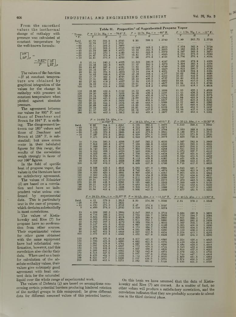
606 I NDUS TR I AL AND ENGINEER ING CHEMI STRY Vol. 35, No. 5
From the sm oothed v a lu es the isotherm al change of enthalpy with pressure was calculated at constant temperature by the well-known formula:
T a b l e II . P r o p e r t i e s * o f S u p e r h e a t e d P r o p a n e V a p o rP = 5 In . H g , t
PJHL d P j r
- N R T 2CSLThe values of the function
—I I at constant temperature are obtained by graphical integration of the values for the change in enthalpy with pressure at constant temperature when plotted against absolute pressure.
The agreement between our values for 190° F. and those of Deschner and Brown for 194° F. is striking. The disagreement between our 160° values and those of Deschner and Brown at 158° F. is substantial; but since errors occur in their tabulated figures for this range, the results of the correlation weigh strongly in favor of our 160° figures.
In the field of specific heat of propane vapor, the values in the literature have no satisfactory agreement.
The values of Edmister (5) are based on a correlation and have no independent value unless confirmed by experimental data. This is particularly true in the case of propane, which deviates substantially in most correlations.
The values of Kistia- kowsky and Rice (7) for propane have no confirmation from other sources.Their experimental values for other gases obtained with the same equipment have had substantial confirmation, however, and this correlation also checks their data. When used as a basis for calculation of the absolute enthalpy values, their = = = = = =values give extremely good agreement with heat content data for the saturated liquid over the whole range of experimental work.
The values of Dobratz (4) are based on assumptions concerning certain potential barriers producing hindered rotation of the methyl groups in this compound; he gives different data for different assumed values of this potential barrier.
T em p . P — 15 In . H g , t == - 7 0 .6 ° F.° F . V H S
S atd . 12 .72 3 5 6 .5 1 .3785- 7 0 12 .78 3 5 7 .0 1.3791- 6 0 13.11 36 0 .3 1 .3869- 5 0 13 .45 36 3 .5 1 .3946- 4 0 13 .79 36 6 .8 1 .4023- 3 0 14 .13 370 .1 1 .4100-20 14 .47 3 7 3 .4 1 .4177-10 14.81 3 7 6 .8 1 .4253
0 15 .14 3 8 0 .2 1 .432910 15 .48 3 8 3 .8 1 .440520 15 .82 38 7 .4 1.448130 16 .16 391 .1 1 .455740 16 .50 3 9 4 .8 1 .463350 16 .83 39 8 .6 1 .470960 17 .17 4 0 2 .4 1 .478570 17.51 4 0 6 .3 1.486180 1 7 .85 4 1 0 .2 1 .493790 18.19 4 14 .3 1 .5013100 18 .52 41 8 .4 1 .5088
110 18 .86 4 2 2 .5 1 .5162120 19 .20 42 6 .6 1 .5235130 19.54 4 3 0 .8 1 .5308140 19 .88 4 3 5 .2 1 .5380150 20.21 4 3 9 .6 1 .5452160 2 0 .5 5 444 .1 1 .5524170 20 .8 9 448 .6 1.5596180 2 1 .2 3 453 .1 1 .5668190 21 .5 7 4 5 7 .9 1.5740200 2 1 .9 0 4 6 2 .5 1 .5812
P = 14.696 Lb. A bs., t =-43 .708° F .
S a td . 6.66 36 4 .6 1.3681- 4 0 6 .7 7 5 36 5 .8 1 .3710- 3 0 6 .9 4 9 3 6 9 .3 1 .3788-20 7 .1 2 3 37 2 .8 1 .3866-10 7 .2 9 7 37 6 .3 1 .39430 7 .471 37 9 .8 1 .4020
10 7 .6 4 4 383 .3 1 .409620 7 .8 1 6 38 6 .8 1 .477230 7 .9 8 8 3 9 0 .6 1 .424840 8 .1 6 0 39 4 .3 1 .432450 8 .332 398 .1 1 .439960 8 .5 0 3 40 1 .9 1 .447470 8 .674 4 0 5 .8 1 .454980 8 .8 4 4 4 0 9 .8 1 .462390 9 .0 1 6 41 3 .9 1 .4698100 9 .187 41 8 .0 1.4772
110 9 .3 5 8 422 .1 1 .4845120 9 .5 2 8 42 6 .2 1 .4918130 9 .6 9 9 4 3 0 .4 1.4991140 9 .869 4 3 4 .8 1 .5064150 10.040 43 9 .2 1.5137160 10.21 443 .7 1 .5210170 10 .38 4 4 8 .3 1.5283180 10.51 4 5 2 .9 1 .5256190 10 .72 4 5 7 .5 1 .5428200 10 .84 46 2 .4 1.5500
P = 24 L b. A bs., i =■ - 2 1 .9 7 ° F .S a td . 4 .2 5 37 0 .9 1 .3615-20 4 .2 7 9 371 .7 1.3632-10 4 .3 9 0 37 5 .3 1.37120 4 .4 9 9 3 7 8 .9 1 .3790
10 4 .6 0 8 38 2 .5 1 .380620 4 .7 1 6 386 .2 1.394230 4 .8 2 4 38 9 .9 1 .401840 4 .9 3 2 39 3 .6 1.409450 5 .0 4 0 39 7 .4 1 .417060 5 .147 40 1 .3 1 .424570 5 .2 5 4 40 5 .2 1 .432080 5 .361 4 0 9 .2 1.439490 5 .4 6 7 41 3 .3 1 .4468100 5 .5 7 3 4 1 7 .4 1 .4542
110 5 .6 7 9 4 2 1 .5 1 .4616120 5 .7 8 5 4 2 5 .6 1 .4690130 5.891 4 2 9 .8 1 .4764140 5 .997 4 3 4 .3 1.4837150 6 .103 4 3 8 .8 1.4910160 6 .2 0 9 44 3 .3 1 .4983170 6 .3 1 5 4 4 7 .9 1 .5056180 6 .4 2 0 4 5 2 .5 1 .5128190 6 .525 457 .1 1.5200200 6 .6 3 0 46 2 .0 1.5272
p = 10 In . H g , t
9 .8 0
10 .042 10 .30 10 .55 10.81 11 .06
11.32111 .5711 .8312 .0 81 2 .3412 .5912.8513 .1013 .3613.6113.87
14 .1214 .3814 .6314 .8915 .1415 .4015 .6515.9116 .1616.42
-6 0 ° F. - 5 1 ° F .H S V H S
3 6 0 .0 1 .3740 7 .9 0 3 6 2 .7 5 1 .3718
363.2 1 Í3 8 Í6 7'.97 8 362! 8 1Í372036 6 .5 1 .3893 8 .1 8 2 3 6 6 .2 1 .37963 6 9 .8 1 .3970 8 .3 8 7 3 6 9 .6 1 .3872373 .1 1 .4045 8 .5 9 1 3 7 3 .0 1 .39483 7 6 .6 1 .4121 8 .7 9 6 3 7 6 .4 1 .4024
38 0 .0 1 .4197 9 .0 0 0 3 7 9 .9 1 .410038 3 .6 1 .4273 9 .2 0 4 3 8 3 .4 1 .41763 8 7 .2 1 .4349 9 .4 0 9 3 8 7 .0 1 .425239 0 .9 1 .4425 9 .6 1 3 3 9 0 .7 1 .432839 4 .6 1.4501 9 .8 1 8 3 9 4 .4 1 .440439 8 .4 1 .4577 10.02 3 9 8 .2 1 .44804 0 2 .2 1 .4652 10 .23 4 0 2 .0 1 .4556406 .1 1 .4727 10 .4 3 4 0 6 .0 1 .46304 1 0 .0 1 .4802 10 .6 4 4 1 0 .0 1 .4706414 .1 1 .4877 10 .8 4 4 1 4 .0 1 .47804 1 8 .2 1 .4952 11 .0 5 0 4 1 8 .1 1 .4854
42 2 .3 1 .5026 11 .2 5 4 2 2 .1 1 .492842 6 .4 1.5101 11 .4 5 4 2 6 .2 1 .50024 3 0 .6 1 .5174 11.66 4 3 0 .6 1 .507543 5 .0 1 .5 2 4 5 11.86 4 3 5 .9 1 .514843 9 .4 1 .5317 12 .0 7 4 3 9 .3 1 .52214 4 3 .9 1 .5389 12 .2 7 4 4 3 .8 1 .52934 4 8 .4 1 .5461 12 .4 7 4 4 8 .4 1 .536545 2 .9 1 .5533 12.68 4 5 2 .9 1 .543745 7 .7 1 .5 6 0 5 12.88 4 5 7 .6 1 .55094 6 2 .4 1 .5677 13 .0 9 4 6 2 .4 1.5581
P = 16 L b . A bs., t = - 4 0 .0 1 ° F . P = 20 L b. A bs., t = -3 0 .3 0 ° F .6 .195 3 6 5 .5 1 .3670 5 .0 5 0 3 6 8 .4 1 .36406.212 36 5 .6 1 .36716.371 36 9 .2 1 .3784 5ÍÓ ¿0 368! 6 1.36426 .5 3 0 3 7 2 .6 1 .3825 5 .1 8 6 3 7 2 .2 1 .37196 .6 5 9 376 .1 1 .3902 5 .3 1 3 3 7 5 .8 1 .37966 .8 4 8 3 7 9 .6 1 .3979 5 .4 3 9 7 3 9 .3 1 .3873
7 .0 0 7 38 3 .2 1 .4056 5 .5 6 7 3 8 2 .9 1 .39497 .1 6 6 3 8 6 .8 1 .4132 5 .6 9 5 3 8 6 .5 1 .40257 .3 2 4 39 0 .4 1 .4208 5 .8 2 3 3 9 0 .2 1.41017 .482 3 9 4 .2 1 .4 2 8 4 5 .951 3 9 3 .9 1 .41777 .6 4 0 3 9 8 .0 1 .4359 6 .0 7 9 3 9 7 .7 1 .42527 .7 9 8 4 0 1 .8 1 .4434 6 .2 0 7 4 0 1 .6 1 .43277 .9 5 5 4 0 5 .8 1 .4508 6 .3 3 4 4 0 5 .5 1 .44028.112 4 0 9 .8 1 .4582 6 .4 6 1 4 0 9 .4 1 .44778 .269 4 1 3 .8 1 .4656 6 .5 8 8 4 1 3 .5 1.45518 .4 2 6 4 1 7 .9 1 .4 7 3 0 6 .7 1 6 4 1 7 .6 1 .4625
8 .5 8 3 4 2 1 .9 1 .4804 6 .8 4 3 4 2 1 .7 1 .46988 .7 4 0 42 6 .1 1 .4878 6 .9 6 9 4 2 5 .9 1.47718 .897 4 3 0 .4 1 .4952 7 .0 9 5 4 3 0 .2 1 .48449 .054 43 4 .8 1 .5026 7 .2 2 1 4 3 4 .6 1 .49179 .211 4 3 9 .2 1 .5099 7 .3 4 7 4 3 9 .0 1 .49909 .3 6 8 4 4 3 .7 1 .5172 7 .4 7 3 4 4 3 .5 1 .50639 .5 2 5 4 4 8 .2 1 .5 2 4 5 7 .5 9 9 4 4 8 .0 1 .51369 .682 4 5 2 .8 1 .5317 7 .7 2 5 4 5 2 .6 1 .52099 .839 4 5 7 .4 1 .5389 7 .8 5 1 4 5 7 .3 1 .52829 .9 9 6 4 6 2 .2 1 .5460 7 .9 7 7 4 6 1 .9 1 .5355
P = 30 L b. A bs., t = - 1 1 .5 2 ° F . P = 40 L b . A bs., t = + 2.90° F .3 .3 0 3 7 4 .0 0 1 .3588 2 .6 1 3 7 8 .2 1 .3548
3 .4 7 374.6 1Í35973 .5 5 9 3 7 8 .3 1 .3678
3 .6 4 7 38 2 .0 1 .3754 2 .6 8 4 3 8 0 .9 1 .36033 .7 3 5 385 .7 1 .3830 2 .7 5 3 3 8 4 .7 1 .36843 .8 2 3 3 8 9 .4 1 .3905 2 .8 2 1 3 8 8 .5 1.37613.911 393 .1 1 .3980 2 .8 8 9 3 9 2 .2 1 .38383 .999 39 6 .9 1 .4055 2 .9 5 7 39 6 .1 1 .39144 .0 8 7 4 0 0 .8 1 .4130 3 .0 2 5 4 0 0 .0 1 .39904 .1 7 4 40 4 .7 1 .4205 3 .0 9 2 4 0 4 .0 1 .40654.261 40 8 .7 1 .4280 3 .1 5 9 4 0 8 .0 1 .41404 .347 4 1 2 .8 1 .4354 3 .2 2 4 4 1 2 .1 1 .42154 .4 3 2 4 1 7 .0 1 .4 4 2 8 3 .2 8 9 4 1 6 .2 1 .4290
4 .5 1 7 4 2 1 .2 1 .4502 3 .3 5 4 4 2 0 .4 1 .43654 .6 0 2 4 2 5 .4 1 .4576 3 .4 1 9 4 2 4 .6 1 .44404 .6 8 7 4 2 9 .6 1 .4650 3 .4 8 4 4 2 9 .0 1 .45144 .7 7 2 4 3 4 .0 1 .4724 3 .5 4 9 4 3 3 .4 1 .45884 .857 4 3 8 .4 1 .4898 3 .6 1 4 4 3 7 .9 1 .46624 .9 4 2 4 4 3 .0 1 .4872 3 .6 7 9 4 4 2 .5 1 .47365 .027 4 4 7 .6 1 .4946 3 .7 4 4 44 7 .1 1 .48105 .112 4 5 2 .2 1 .5020 3 .8 0 9 4 5 1 .8 1 .48845 .197 45 6 .9 1 .5094 3 .8 7 4 4 5 6 .5 1 .49575 .2 8 2 4 6 1 .8 1 .5168 3 .9 3 9 4 6 1 .3 1 .5030
On this basis we have assumed that the data of Kistia- kowsky and Rice (7) are correct. As a matter of fact, no other values will produce a satisfactory correlation, and the correlation indicates that they are probably accurate to about one in the third decimal place.
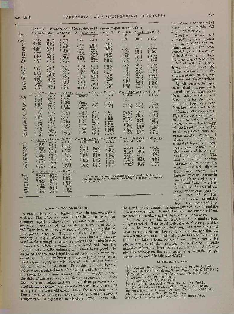
May, 1943 I N DU S T R I A L AND E N GI NE E R I NG CHEMI STRY
T e m p .• F .
S a td .2030405060708090100
110120130140150160170180190200
S a td .60708090100
110120130140150160170180190200
S atd .110120130140150160170180190200
S atd .140150160170180190200
T a b l e I I . P r o p e r t i e s * o f S u p e r h e a t e d P r o p a n e V a p o r ( C o n c lu d e d )P = 60 L b._A bs„ t = 24.80° F . P = 80 L b . A ba., t = 41.69°
V ’“ 3 S1 .7 6 3 8 3 .8 1 .3501
F 3 5 4 7 1 .3630 1 .3710 1 .3789 1 .3808 1 .3948 1 .4 0 2 5 1 .4102
1 .4179 1 .4 2 5 4 1 .4330 1 .4404 1 .4479 1 .4554 1 .4629 1 .4703 1 .4777 1 .4851
P = 50 L b . A bs., t = 14.7° F .V H S
2 .1 1 5 3 8 1 .2 1 .35212 .1 5 9 3 8 3 .5 1 .3 5 6 22 .2 1 7 3 8 7 .4 1 .36472 .2 7 5 3 9 1 .3 1 .3 7 2 62 .3 3 1 3 9 5 .2 1 .3 8 0 42 .3 8 6 3 9 9 .1 1 .38812 .4 4 1 4 0 3 .1 1 .39572 .4 9 5 4 0 7 .1 1 .4 0 3 32 .5 4 9 4 1 1 .2 1 .41092 .6 0 2 4 1 5 .4 1 .4 1 8 5
2 .6 5 6 4 1 9 .6 1 .42612 .7 0 9 4 2 3 .9 1 .43372 .7 6 2 4 2 8 .3 1 .44122 .8 1 5 4 3 2 .8 1 .44872.868 4 3 7 .3 1 .45622 .9 2 1 4 4 1 .9 1 .46372 .9 7 5 4 4 6 .6 1 .47113 .0 2 7 4 5 1 .3 1 .4 7 8 53 .0 7 9 4 5 6 .1 1 .48593 .1 3 1 4 6 0 .9 1 .4 9 3 3
P = 100 L b . A bs., t = 55.62° F .1 .0 6 3 9 1 .2 1 .3 4 4 81 .0 9 4 3 9 3 .5 1 .3 4 8 81 .131 3 9 8 .3 1 .3 5 7 31 .1 6 4 4 0 2 .6 1 .3 6 5 61 .1 9 6 4 0 6 .9 1 .3 7 3 51 .227 4 1 1 .4 1 .3 8 1 6
1 .2 5 8 4 1 5 .7 1 .38931 .2 8 9 4 2 0 .3 1 .3 9 6 21 .3 1 8 4 2 4 .9 1 .4 0 5 01 .3 4 7 4 2 9 .6 1 .4 1 3 01 .3 7 5 4 3 4 .4 1 .4 2 0 91 .4 0 0 4 3 9 .1 1 .4 2 8 61 .4 3 2 4 4 4 .0 1 .43621 .4 6 0 4 4 8 .8 1 .4 4 4 01 .4 8 8 4 5 3 .8 1 .4 5 1 81 .5 1 6 4 5 8 .8 1 .4 5 9 8
P = 190 L b . A bs., t = 100.50° F.0 .5 5 4 0 4 0 0 .4 1 .3 3 8 80 .5 7 7 4 4 0 5 .9 1 .3 4 8 50 .5 9 9 5 4 1 0 .4 1 .3 5 8 00 .6 2 0 8 4 1 5 .9 1 .3 6 7 00 .6 4 1 5 4 2 1 .1 1 .37590 .6 6 0 7 4 2 6 .4 1 .3 8 4 40 .6 7 9 2 4 3 1 .5 1 .3 9 3 00 .6 9 7 1 4 3 7 .0 1 .40130 .7 1 4 4 4 4 2 .2 1 .4 0 9 60 .7 3 1 1 4 4 7 .5 1 .4 1 7 60 .7 4 7 2 4 5 2 .7 1 .4 2 5 5
P = 300 L b . A b s., t = 137.55° F
1 .8 1 4 3 8 6 .11 .8 6 3 3 9 0 .11 .911 3 9 4 .11 .9 5 9 3 9 8 .22 .0 0 6 4 0 2 .22 .0 5 3 4 0 6 .32 .0 9 9 4 1 0 .52 .1 4 5 4 1 4 .8
2 .1 9 0 4 1 9 .02 .2 3 5 4 2 3 .42 .2 8 0 4 2 7 .82 .3 2 5 4 3 2 .22 .3 7 0 4 3 6 .82 .4 1 5 4 4 1 .42 .4 6 0 4 4 6 .12 .5 0 5 4 5 0 .82 .5 4 9 4 5 5 .62 .5 9 3 46(1.5
> = 130 L b . A bs., (0 .8 1 6 5 3 9 5 .0
6 !8456 398 A0 .8 7 6 2 4 0 3 .60 .9 0 4 5 4 0 8 .3
0 .9 3 1 5 4 1 2 .90 .9 5 8 8 4 1 7 .80 .9 8 1 5 4 2 0 .71 .0 0 6 4 2 5 .71 .0 2 9 4 3 0 .71 .0 5 2 4 3 5 .71 .0 7 6 4 4 0 .71 .0 9 8 4 4 5 .31.120 4 5 0 .91 .1 4 3 4 5 6 .1
= 220 L b . A bs., t
. 73.20 1
F.3424
0 .4 7 3 8 4 0 2 .5 1 .
Ö'. 4911 407 '.7 l !0 .5 1 2 1 4 1 3 .7 1 .0 .5 3 1 4 4 1 9 .2 1 .0 .5 4 9 8 4 2 4 .5 1 .0 .5 6 7 3 4 2 9 .7 1 .0 .5 8 4 6 4 3 5 .3 1 .0 .5 9 9 8 4 4 0 .6 1 .0 .6 1 4 9 4 4 5 .9 1 .0 .6 3 0 2 4 5 1 .2 1 .
1 .3 4 8 6 1 .3571 1 .3659
1 .3740 1 .3822 1 .3903 1 .3987 1 .4059 1 .4 1 5 0 1 .4230 1 .4310 1 .4389 1 .4 4 6 8
1*11.85° F . 1 .3375
34603558365037393827
0 .3 3 3 20 .3 3 9 20 .3 5 7 90 .3 7 4 50 .3 8 9 60 .4 0 3 70 .4 1 7 10 .4 3 0 3
4 0 6 .64 0 8 .7 4 1 5 .6 4 2 2 .04 2 7 .84 3 3 .24 3 9 .24 4 4 .9
1 .3 3 7 2 1 .3 4 8 0 1 .3 5 8 0 1 .3 6 7 4 1 .3 7 6 5 1 .3 8 5 5 1 .3 9 4 4
CORRELATION OF RESULTSA b s o l u t e E n t h a l p y . Figure 1 gives the first correlation
of data. The reference value for the heat content of the saturated liquid at atmospheric pressure was obtained by graphical integration of the specific heat values of Kemp and Egan between absolute zero and the boiling point at atmospheric pressure. Therefore, these data give the enthalpy of propane above the solid at absolute zero and are based on the assumption that the entropy at this point is zero.
From this reference value for the liquid and from the specific heats, specific volumes, and latent heats previously discussed, the saturated liquid and saturated vapor curve was calculated. From a reference point at —40° F. on the saturated vapor line, Ho was calculated at —40° F. and infinite dilution from our — AH data. From this point the absolute values were calculated for the heat content at infinite dilution at various temperatures between —70° and +200 F. from the data of Kistiakowsky and Rice as extrapolated. From these reference values and the —AH data previously calculated, the absolute heat contents at various temperatures and pressures were obtained. Then the extension of the lines showing the change in enthalpy with pressure at constant temperature, as expressed in absolute values, agrees with
the values on the saturated vapor curve within 0.2 B. t. u. in most cases.
Over the range from — 40 ° to +200° F., independent of the interpolations and extrapolations on the compressibility chart, the values of Kistiakowsky and Rice are in good agreement, since — AH at —40° F. is relatively small. However, the values obtained from the compressibility chart correlate well with the other data.
Specific heats of the vapor at constant pressure for 0 pound absolute were taken from Kistiakowsky and Rice; and for the higher pressures, they were read from the heat content chart.
E n t r o p y - T e m p e r a t u r e .
Figure 2 gives a second correlation of data. The reference value for the entropy of the liquid at its boiling point was taken from the experimental values of Kemp and Egan. The saturated liquid and saturated vapor curves were then calculated in the conventional manner. The lines of constant quality, expressed as per cent vapor, were calculated directly from these values. The lines of constant pressure in the superheat region were calculated from our values for the specific heat of the vapor at constant pressure.
~ The lines of constantvolume were calculated from the compressibility
chart and plotted against the temperature coordinate and the pressure parameters. The enthalpy parameters were read from the heat content chart and plotted in the same manner.
All data are reported on the B. t. u.-° F.-pound system, , except as noted. The actual molecular weights employed by each author were used in calculating data from the molal basis, and in each case the author’s value for the absolute temperature was used in calculating the Fahrenheit temperature. The data of Deschner and Brown were corrected for ethane content of their sample. H signifies the absolute enthalpy referred to the solid at absolute zero. S refers to absolute entropy on the same basis, V is in cubic feet per pound units, and J is taken as 0.18511.
LITERATURE CITED
607
V H S
1 .3 2 3 8 7 .8 1 .3 4 7 0
i .361 .4 2 41 .4621 .5 0 01 .5371 .5 7 3
3 9 Ü 939 6 .1 4 0 0 .3 4 0 4 .6 4 0 8 .94 1 3 .2
U3540 1 .3624 1 .3707 1 .3785 1 .3863 1 .3940
1 .6091 .6441 .6791.7141 .7 4 91 .7841 .8 1 81 .8521.8861 .9 2 0
4 1 7 .54 2 1 .84 2 6 .34 3 0 .94 3 5 .64 4 0 .3 4 4 5 .0 4 4 9 .84 5 4 .74 5 9 .7
1 .40171 .40941 .41711 .4 2 4 81 .43251 .44021 .44781 .45541 .46291 .4704
P = 160 L b . A bs., t = 87.71° F .0 .6 6 8 5 3 9 7 .9 1 .3404
6 !6695 0 .6 9 6 9
3 9 9 .2 4 0 4 .7
1!3423 1 .3521
0 .7 2 2 2 0 .7 4 6 4 0 .7 6 9 1 0 .7 9 0 8 0 .8 1 1 8 0 .8 3 1 9 0 .8 5 2 0 0 .8 7 1 2 0 .8 9 0 3 0 .9 0 9 3
4 0 9 .64 1 4 .64 1 9 .74 2 4 .84 2 9 .94 3 4 .94 4 0 .04 4 5 .14 5 0 .945 6 .1
1 .3610 1 .3698 1 .3784 1 .3867 1 .3949 1 .4031 1 .4113 1 .4195 1 .4276 1 .4357
P = 250 L b . A bs., f = 122.12° F .0 .4 1 3 0 4 0 4 .2 1 .3355
0*42830 .4 4 7 30 .4 6 4 90 .4 8 1 60 .4 9 7 20 .51210 .5 2 6 60 .5 4 0 8
4 i9 V4 2 5 .94 3 1 .4 4 3 7 .1 4 4 2 .6 4 4 8 .04 5 3 .54 5 8 .9
1 *. 3450 1 .3550 1 .3640 1 .3732 1 .3819 1 .3908 1 .3990 1 .40744161
* P re ssu re s below a tm o sp h e ric a re expressed in inches of H g v a c u u m p re ssu re s ; ab o v e a tm o sp h e ric , in p o u n d s p e r sq u are in ch ab so lu te .
B urgoyne, Proc. R a y . Soc (London) A 176 28 ° -9 4 (1940). D an a , Jenkins, B urd ick , and T im m , R e f rig. E n g ., 1 2 ,3 8 7 (1920). Deschner and B row n, In d . E n g . C hem ., 32, 837 (1940). D o b ra tz , Ib id ., 33, 758 (1941).E dm ister, Ib id ., 30, 354 (1938). /in o o i
(O) K em p and E gan, J . A m . C hem . Soc., 60, 1521 C ^ 3» ).(7) K is tiakow sky and R ice, J . C hem . P h ys ., 8, 616 C1 0) .(8) Sage, Evans, and Lacey, I n d . E n q . C h e m ., 31, 763 (1939 ).(9) Sage and Lacey, Ib id 27, 14 8 7 (1935).
(10) Sage, Schaafsma, and Lacey, Ib id ., 2o, 121» (.iuoa;.
(1)(2)(3)(4)(5)(6)
Barium and Strontium Sulfate Decomposition in Aqueous
SolutionR. NORRIS SHREVE AND H. F. WIEGANDT1
Purdue University, Lafayette, Ind.
The decom position of barium and strontiu m su lfates by the action of strong solutions o f calcium chloride results in the form ation o f th e soluble m odification of anhydrite (CaSO„). D ilution o f the reaction m ass at th is point w ith water results in im m ediate reversion to the in itially reacting m aterials, due to the reactivity of th e soluble m odification o f the anhydrite. The soluble anhydrite is converted to the m uch less reactive insoluble modification
by heating the reaction products at elevated tem peratures. This procedure m akes practical the use o f aqueous m eth anol as an extraction solvent for th e recovery o f th e barium chloride m ade. Under these circum stances even water alone will extract m ost of the barium chloride in itia lly formed before the insoluble anhydrite has had tim e to react. The effect o f aqueous extractions on decom positions carried ou t by fusing the reactants also gives sim ilar results2.
T HE production of inorganic salts is often carried out by ordinary double decompositions. Usually such reactions, involving the formation of insoluble salts,
are considered essentially quantitative in one direction. A few double decomposition reactions involving insoluble salts reverse their equilibrium position as the solution is changed from dilute to concentrated. Among them are barium sulfate and calcium nitrate in equilibrium with barium nitrate and calcium sulfate (6 , 1 1 ), barium sulfate and calcium chloride in equilibrium with barium chloride and calcium sulfate (6 ) , strontium sulfate and calcium nitrate in equilibrium with strontium nitrate and calcium sulfate (1 0 ), and barium sulfate and an alkali carbonate in equilibrium with barium carbonate and an alkali sulfate (12 ).
The change in equilibrium position as the solution medium is changed from dilute to concentrated has been studied in the Purdue Chemical Engineering Laboratories especially in the cases of barium and strontium sulfates decomposed by calcium chloride and calcium nitrate. As the solution is made more concentrated, the reaction proceeds farther in the direction of obtaining the soluble strontium and barium salts. Efforts to produce soluble strontium and barium compounds were reviewed in previous publications U , 6 , 7 ). In this work only enough water was used to make the ionic reaction possible. The consistency of the reaction mass was that of a thick mush.
The experiments of Shreve and Toner (8) and Shreve and Watkins (9 ) indicated a possible mechanism for these equilibrium reactions. They and others observed that the solubility of calcium sulfate decreases with a rise in tempera
1 P re s e n t ad d ress . S ta n d a rd O il C o m p a n y (In d ia n a ) , W hiting , Ind .2 A fte r th is w ork h a d been com pleted , a p a p e r a p p e a red on ‘'T h e rm o
d y n am ic P ro p e r tie s of G y p su m an d I ts D e h y d ra tio n P ro d u c ts ” [K elley, S o u th a rd , an d A nderson , V . S. B u r. M ines, Tech. Paper 625 (1941)].
ture, the solubilities of strontium and barium sulfates increase with a rise in temperature, calcium chloride lowers the solubility of calcium sulfate, and barium and strontium chlorides are virtually insoluble in concentrated calcium chloride solutions. Under the conditions in which these experiments were carried out, highly concentrated solutions of calcium chloride were employed; since this double decomposition was carried out in the presence of only a small amount of water, the problem of separating the reaction products without causing reversion (the opposite of conversion) had to be solved.
A number of methods might be possible for the separation of two inorganic salts which have been produced by evaporation of an aqueous solution media or by fusion. Extractions with water would be the first obvious choice. However, if the properties of the salts are such that the reversion reaction takes place (for example, the reaction products of barium and strontium sulfates with calcium chloride), water alone may not be satisfactory. In this case an organic solvent has been used successfully. Previous work on the decomposition of barium and strontium sulfates with calcium chloride and nitrate (6 -1 0 ) describes the use of organic solvents for extracting the reaction products. As the salts are essentially un-ionized in the organic solvents, no reversion takes place. The chlorides are soluble and are separated from the insoluble sulfates by filtration. If certain modifications could be made so that aqueous methanol or even water could be substituted for the organic solvent under special conditions without obtaining too much reversion, the process would be more economical. A large part of the experimental work described here is a study o these possibilities on the double decomposition products of barium and strontium sulfates with calcium chloride.
608
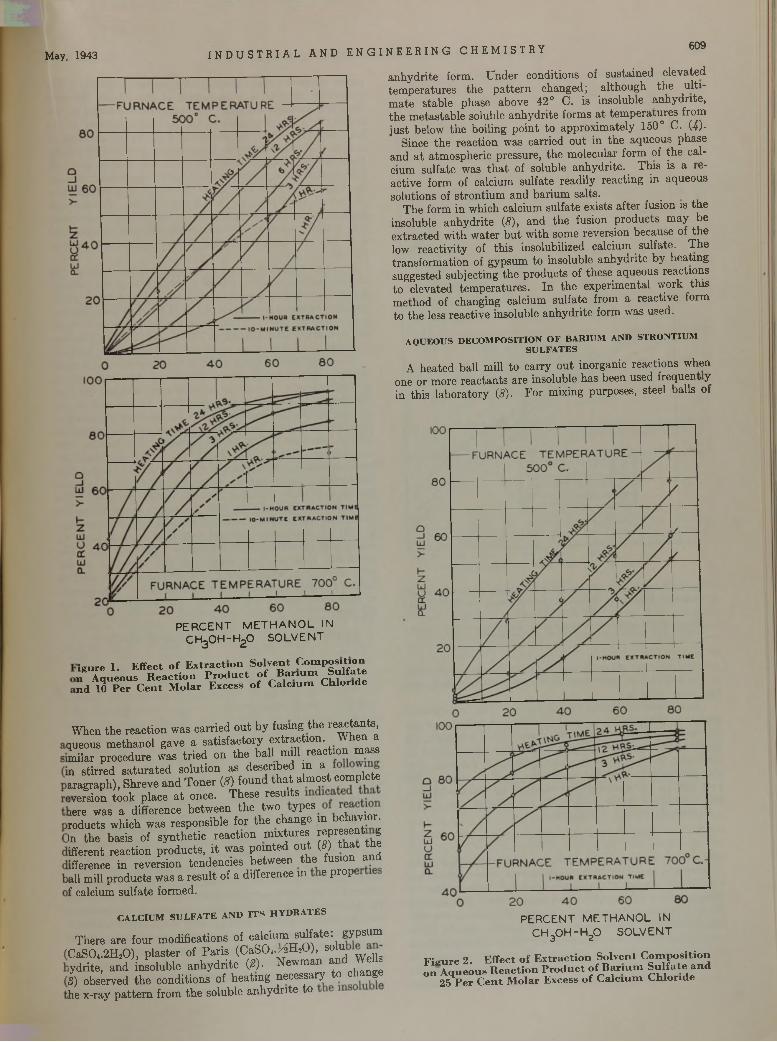
May, 1943 I N D U S T R I A L A N D E N G I N E E R I N G C H E M I S T R Y609
P E R C E N T M E T H A N O L IN c h 3 o h - h 2 o S O L V E N T
a n h y d r ite fo rm . U n d e r co n d itio n s of su s ta in ed e le v a te d te m p e ra tu re s th e p a t te rn c h a n g e d ; a lth o u g h th e u l t i m a te s ta b le p h ase ab o v e 42° C . is in so lub le a n h y d r ite , th e m e ta s ta b le so lub le a n h y d r ite fo rm s a t te m p e ra tu re s from ju s t below th e bo ilin g p o in t to a p p ro x im a te ly 150° C . (4)-
Since th e re ac tio n w as ca rried o u t in th e a q u eo u s p h a se a n d a t a tm o sp h e ric p ressu re , th e m o lecu la r fo rm of th e ca lc ium su lfa te w as t h a t of so lub le a n h y d rite . T h is is a le - a c tiv e fo rm of calc ium su lfa te re ad ily re a c tin g in a q u eo u s so lu tio n s of s tro n tiu m a n d b a r iu m sa lts .
T h e fo rm in w h ich calc ium su lfa te ex is ts a f te r fu sion is th e inso lub le a n h y d r ite (8 ), a n d th e fusion p ro d u c ts m a y b e e x tra c te d w ith w a te r b u t w ith som e rev ersio n b ecau se of th e low re a c tiv i ty of th is inso lub ilized calc ium su lfa te . T h e tra n s fo rm a tio n of g y p su m to in so lub le a n h y d r ite b y h e a tin g sugg ested su b je c tin g th e p ro d u c ts of th ese aq u eo u s re ac tio n s to e lev a ted tem p e ra tu re s . I n th e ex p erim e n ta l w o rk th is m e th o d of ch an g in g calc ium su lfa te from a re a c tiv e fo rm to th e less re ac tiv e inso lub le a n h y d r ite fo rm w as u sed .
AQUEOUS DECOMPOSITION OF BARIUM AND STRONTIUM SULFATES
A h e a te d b a ll m ill to c a rry o u t ino rg an ic re ac tio n s w hen one o r m o re re a c ta n ts a re in so lub le h a s been u sed fre q u e n t y in th is la b o ra to ry (5). F o r m ix ing pu rposes, s tee l b a lls o f
igu re 1. E ffect o f E x tra c tio n S o lven t C om position n A queous R e a c tio n P ro d u c t o f B a r iu m S u lfa te n d 10 P e r C e n t M o lar Excess o f C a lc iu m C hlo ride
W hen th e re a c tio n w as c a rr ie d o u t b y fusing th e re a c ta n ts , m eous m e th a n o l g av e a sa tis fa c to ry e x tra c tio n . W h en a L ila r p ro c ed u re w as t r ie d o n th e ball. n u l l . r e a c t io n m a s s n s tir re d s a tu ra te d so lu tio n as d e sc rib ed m a a rag rap h ), S h rev e a n d T o n e r (8) fo u n d t h a t a lm o s t co m p le te ¡version to o k p lace a t once. T h e se re su lts lere w as a d ifference b e tw ee n th e tw o y p es .ro d u c ts w h ich w as re sp o n sib le fo r th e c h an g e in b d u m o r . in th e b as is of s y n th e tic re a c tio n m ix tu re s re p re se n t g ifferen t re a c tio n p ro d u c ts , i t w as p o in te d o u t (8) t h a t th e ifference in re v ers io n ten d e n c ie s b e tw ee n th e fusion a n d all m ill p ro d u c ts w as a re s u l t of a d iffe ren ce m e p ro p f calcium su lfa te fo rm ed .
CALCIUM SULFATE AND IT S HYDRATES
T h ere a re fo u r m o d ifica tio n s of ca lc iu m su lfa te : g y p su m C a S 0 4.2H 20 ) , p la s te r of P a r is (C a S O ,./3 H sO ), solu y d r i te , a n d in so lu b le a n h y d r ite (*). N e w m an « d W JS) ob se rv ed th e c o n d itio n s o f h e a t in g n ece ssa ry to change he x -ray p a t t e rn fro m th e so lu b le a n h y d r ite to
P E R C E N T M E T H A N O L IN
C H 30 H - H 20 S O L V E N T
F ig u re 2. E ffect o f E x tra c tio n S olvent C o m p o sitio n o n A queous R eac tio n P ro d u c t o f B a riu m S u lfa te a n d
25 P e r C e n t M o lar Excess o f C a lc iu m C h lo ride
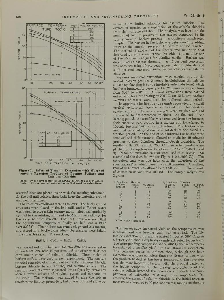
610 I N D U S T R I A L A N D E N G I N E E R I N G C H E M I S T R Y Vol. 35, No. 5
TIME OF EXTRACTION IN MINUTES
F igure 3. Effect o f T im e on E x trac tio n w ith W ater ofA queous R eaction P ro d u c t o f B a riu m S u lfa te an d
C alc ium C hlorideAbove, 10 per cen t m olar excess CaCls; below, 25 per cen t excessCaClî. The volum e o f water refers to th a t used for extractions.
asso rted sizes a re p laced inside w ith th e reac tin g substances. A s th e ba ll m ill ro ta te s , th ese ba lls keep th e m ate ria ls g round a n d well in te rm ixed .
T h e reac tio n cond itions w ere as follows : T h e finely g round re a c ta n ts w ere p laced in th e b a ll m ill, a n d sufficient w a ter w as ad d ed to g ive a th in c ream y m ass. H e a t w as g rad u a lly ap p lied to th e ro ta t in g m ill, a n d 24 -36 h o u rs w ere allow ed for th e w a te r to be d riv en off. T h e h e a t in p u t w as such th a t th e eq u ilib riu m te m p e ra tu re finally reach ed w as a little o v e r 200° C . T h e p ro d u c t w as rem oved , g ro u n d in a m o rta r , a n d s to re d in a b o ttle from w hich th e sam ples w ere tak e n .
B a r i u m S u l f a t e . T h e reac tio n ,
BaSCh -f- CftClj = B aC h -f- CaSCh
w as c a rried o u t in a b a ll m ill fo r tw o d ifferen t m o la r ra tio s o f r e a c ta n ts , on e w ith 10 p e r cen t a n d th e o th e r w ith 25 p er c e n t m o la r excess of calc ium ch loride. T h ree m oles of b a r iu m su lfa te w ere u sed in each ex p erim en t. T h e reac tio n p ro d u c t co n sisted of a m ix tu re of fou r sa lts : calcium chloride, b a r iu m ch loride, b a r iu m su lfa te , a n d calcium su lfa te . T h e re a c tio n p ro d u c ts w ere se p a ra te d fo r an a ly sis b y ex tra c tio n w ith a m ix ed so lv en t of e th y le n e glycol a n d m e th a n o l in 1 :3 ra tio . T h e m e th a n o l w as a d d e d to g ive th e so lven t s a t is fa c to ry f lu id ity p ro p e rtie s , b u t i t w as n o t u sed a lone b e
cause of i ts lim ited so lu b ility for b a r iu m ch loride. T h e e x tra c tio n re su lte d in a se p a ra tio n of th e so lub le ch lorides from th e inso lub le su lfa tes . T h e an a ly s is w as b a se d o n th e am ount, of b a riu m p re sen t in th e e x tra c t co m p ared to th e to ta l a m o u n t of b a r iu m p re se n t in a d u p lic a te u n e x tra c te d sam ple. T h e b a riu m in th e la t te r w as d e te rm in e d b y ad d in g w a te r to th e sam p le ; re v e is io n to b a r iu m su lfa te resu lted . T h e m eth o d of an a ly sis of th e f i ltra te w as s im ila r to th a t described b y S h reve a n d T o n e r (8 ) w h ich is a m o d ificatio n of th e s ta n d a rd an aly sis fo r a lk a lin e e a r th s . B a riu m w as d e te rm in ed as b a riu m c h ro m a te . A 95 p e r c e n t conversion w as o b ta in e d using 10 p e r c en t excess ca lc iu m ch loride, a n d a 97 p e r cen t conversion u s in g 25 p e r c e n t excess calcium chloride.
A queous m eth an o l e x tra c tio n s w ere c a rried o u t on th e h e a ted reac tio n p ro d u c t ( th e re b y in so lub iliz ing th e calcium su lfa te b y changing i t to th e in so lu b le a n h y d r ite fo rm ) w hich h a d been fu rn aced fo r p e rio d s of 1 to 24 h o u rs a t te m p e ra tu re s from 300° to 700° C . A qu eo u s e x tra c tio n s w ere carried o u t on sam ples a fte r h e a tin g a t 700° C . fo r 12 h o u rs ; v a rio u s am o u n ts of w a te r w ere u sed fo r d iffe ren t tim e periods.
T h e a p p a ra tu s for h e a tin g th e sam p les co n sis ted of a sm all v e rtica l cy lind rica l fu rn ac e c a lib ra te d fo r te m p e ra tu re ag a in st c u rren t. T w o -g ram sam p les w ere w eighed o u t and tran sfe rred to fla t-b o tto m ed c ru cib les. A t th e en d of th e h ea tin g periods th e crucib les w ere rem o v ed fro m th e fu rn ace ; th e ir co n ten ts w ere g ro u n d in a m o r ta r a n d tra n s fe rre d to 100-ml. t in c tu re b o ttle s fo r e x tra c tio n . T h e b o ttle s w ere m o u n ted on a ro ta ry sh a k e r a n d r o ta te d fo r th e t im e d extra c tio n period . A t th e en d of th is in te rv a l th e b o ttle s w ere rem oved an d th e ir c o n te n ts a llow ed to s e ttle fo r 10 m in u te s p rev ious to th e ir f i ltra tio n th ro u g h G ooch crucib les. T h e re su lts for th e 500° a n d th e 700° C . fu rn ac e te m p e ra tu re s a re p lo tte d for th e aq u eo u s m e th a n o l e x tra c tio n s in F ig u re s 1 an d 2 ; 100 m l. of e x tra c tio n so lv e n t w ere u sed in e ach case. A n exam ple of th e d a ta follow s fo r F ig u re 1 ( a t 500° C .) . T h e ex trac tio n tim e w as one h o u r w ith th e ex cep tio n of th e ru n s m ark ed “ in w hich case i t w as 10 m in u te s . A se ttlin g tim e of 10 m in u tes w as allow ed befo re f i ltra tio n . T h e vo lu m e of ex trac tio n so lv en t w as 100 m l. T h e sam p le w e ig h t w as2 gram s:
% Methanol in Extn.
HeatingTime, % BaCk
% Methanol in Extn.
HeatingTime, % BaClj
Solvent Hr. Yield Solvent Hr. Yield0 1 0 0 12 0
40 1 12 20 12 2260 1 24 60 12 6880 1 51 80 12 73
0 3 0 0 24 240 3 23 40 24 5660 3 48 60 24 7580 3 72 80 24 89
0 6 0 0 “ 1 060 6 56 60“ 1 4980 6 80 80“ 1 58
a Ten-minute extraction.
T h e curves show increased y ie ld as th e te m p e ra tu re w as increased a n d th e h e a tin g t im e w as ex te n d ed . T h e 10- m in u te e x trac tio n for a sam p le h e a te d 1 h o u r a t 500° C . gave a b e tte r yield th a n a d u p lic a te sam p le e x tra c te d for a n hour. T h e corresponding com parison a t th e 700° C . fu rn ace tem p e ra tu re show ed a sm alle r y ie ld fo r th e 1 0 -m in u te e x trac tio n . T h is b eh av io r seem s to in d ic a te t h a t , a lth o u g h th e h o u r ex trac tio n w as m ore co m p le te th a n th e 1 0 -m in u te one, w ith th e p ro d u c t h e a ted a t th e low er te m p e ra tu re th e reversion was th e m ore im p o r ta n t fa c to r ; w ith th e p ro d u c t h e a te d a t th e h igher tem p e ra tu re , th e g re a te r in so lub iliz ing of th e calcium su lfa te lessened th e rev ers io n a n d m ad e th e com p leteness of e x tra c tio n re la tiv e ly m o re im p o r ta n t. I n creasing th e excess of calc ium ch lo rid e in th e in itia l reac tio n m ass (25 as com pared to 10 p e r c e n t excess) m ad e considerab le
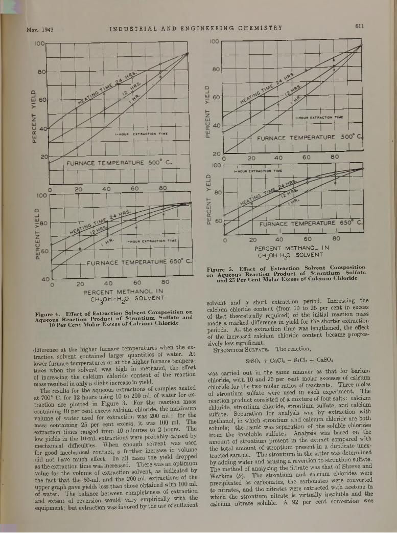
May, 1943 I N D U S T R I A L A N D E N G I
c h 3 o h - h 2 o S O L V E N T
F igu re 4. E ffect o f E x tra c tio n S o lven t C o m p o sitio n on A queous R eac tio n P ro d u c t o f S tro n tiu m S u lfa te an d
10 P e r C e n t M o lar Excess o f C a lc iu m C hlo ride
difference a t th e h ig h e r fu rn ac e te m p e ra tu re s w h en th e extra c tio n so lv e n t c o n ta in e d la rg e r q u a n ti t ie s of w a te r . A t lower fu rn ace te m p e ra tu re s o r a t th e h ig h er fu rn ace te m p e ra tu re s w hen th e so lv e n t w as h ig h in m eth a n o l, th e effect of in creasing th e calc iu m ch lo ride c o n te n t of th e re ac tio n m ass re su lte d in o n ly a s lig h t in crease in y ield .
T h e re su lts fo r th e a q u eo u s e x tra c tio n s of sam p le s h e a te d a t 700° C . fo r 12 h o u rs u s in g 10 to 200 m l. of w a te r fo r extra c tio n a re p lo tte d in F ig u re 3. F o r th e re a c tio n m ass co n ta in in g 10 p e r c en t excess calc iu m ch lo ride , th e m ax im u mvolum e of w a te r u sed fo r e x tra c t io n w as 200 m l., o r em ass c o n ta in in g 25 p e r c e n t excess, i t w as 100 m l. ee x tra c tio n tim e s ra n g ed fro m 10 m in u te s to 2 h o u rs. elow y ields in th e 10-m l. e x tra c tio n s w ere p ro b a b ly cau sed by m echanical d ifficulties. W h en en o u g h so lv e n t w as used for good m ech an ica l c o n ta c t, a fu r th e r increase m v o um e d id n o t h a v e m u ch effect. I n a ll cases th e y ie ld ro p p e as th e e x tra c tio n t im e w as in c re ased . T h e re w as a n o p tim u m v a lu e for th e v o lu m e of e x tra c t io n so lv e n t, as in d ic a te d by th e fa c t t h a t th e 50-m l. a n d th e 2 0 0 -ml. e x tra c tio n s of th e u p p e r g ra p h gave y ie ld s less th a n th o se o b ta in e d w i th m . of w a te r. T h e b a la n ce b e tw ee n co m p le ten ess of e x tra c tio n a n d e x te n t of re v ers io n w o u ld v a ry e m p irica lly w ith e e q u ip m e n t; b u t e x tra c tio n w as fa v o re d b y th e use of sufficien
E E R I N G C H E M I S T R Y
P E R C E N T M E T H A N O L I N
c h 3 o h - h 2o S O L V E N T
F ig u re 5. E ffect o f E x trac tio n S o lven t C o m position on A queous R eac tio n P ro d u c t o f S tro n tiu m S u lfa te
a n d 25 P e r C en t M olar Excess o f C a lc iu m C hlo ride
so lv en t a n d a sh o r t e x tra c tio n pe rio d . In c re a s in g th e calc ium ch lo ride c o n te n t (from 10 to 25 p e r cen t in excess of t h a t th eo re tic a lly re q u ire d ) of th e in itia l re a c tio n m ass m ad e a m ark e d d ifference in y ie ld fo r th e sh o rte r e x tra c tio n p e riods . As th e e x tra c tio n t im e w as len g th en ed , th e effect of th e in creased calc ium ch lo ride c o n te n t b ecam e p ro g ressiv e ly less s ign ifican t.
S t r o n t i u m S u l f a t e . T h e re ac tio n ,
S rS C h + C a C l2 = S rC h + C a S O ,
w as ca rried o u t in th e sam e m a n n e r as t h a t for b a r iu m ch lo ride , w ith 10 a n d 25 p e r c en t m o la r excesses of calcium ch lo ride for th e tw o m o la r ra tio s of re a c ta n ts . T h re e m oles of s tro n tiu m su lfa te w ere u sed in eac h ex p erim en t. T h e re ac tio n p ro d u c t co n sis ted of a m ix tu re of fo u r sa lts : calcium ch loride, s tro n tiu m ch lo rid e , s tro n tiu m su lfa te , a n d calcium su lfa te . S e p a ra tio n fo r an a ly s is w as b y e x tra c tio n w ith m e th a n o l, in w h ich s tro n tiu m a n d calc iu m ch lo ride a re b o th so lub le ; th e re su lt w as se p a ra tio n of th e so lub le chlorides from th e in so lu b le su lfa te s . A n a ly sis w as b ased on th e a m o u n t of s tro n tiu m p re se n t in th e e x tra c t co m p ared w ith th e to ta l a m o u n t of s tro n tiu m p re se n t in a d u p lic a te unex- t r a c te d sam p le . T h e s tro n tiu m in th e la t te r w as d e te rm in ed b y a d d in g w a te r a n d cau sin g a rev ersio n to s tro n tiu m su lfa te . T h e m e th o d of an a ly z in g th e f i ltra te w as t h a t of S h rev e a n d W a tk in s {9). T h e s tro n tiu m a n d calc ium ch lorides w ere p re c ip ita te d as c a rb o n a te s , th e c a rb o n a te s w ere co n v erted to n i tra te s , a n d th e n i tr a te s w ere e x tra c te d w ith a ce to n e m w h ich th e s t ro n t iu m n i t r a te is v ir tu a l ly in so lu b le a n d th e calc iu m n i t r a te so lub le. A 92 p e r c en t con v ersio n w as
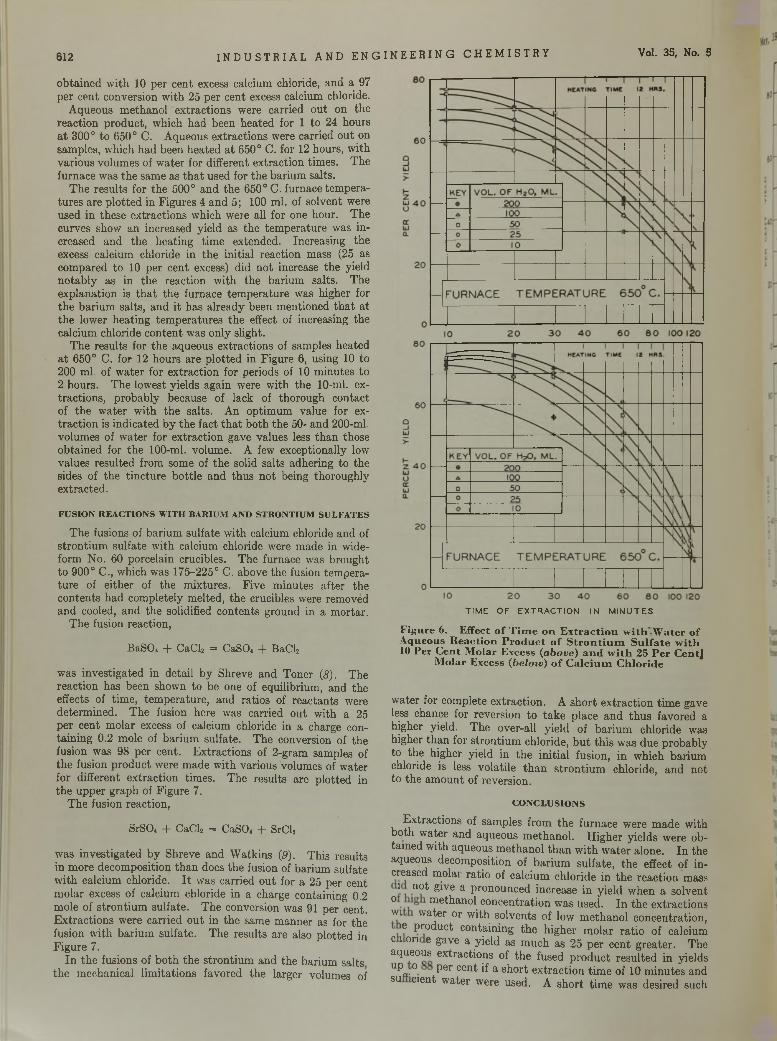
612 I N D U S T R I A L A N D E N G I N E E R I N G C H E M I S T R Y Vol. 35, No. 5
o b ta in e d w ith 10 p e r cen t excess calcium chloride, a n d a 97 p e r cen t conversion w ith 25 p e r cen t excess calcium chloride.
A qu eo u s m e th a n o l e x tra c tio n s w ere carried o u t o n th e re ac tio n p ro d u c t, w hich h a d been h e a te d fo r 1 to 24 h o u rs a t 300° to 650° C. A queous e x tra c tio n s w ere carried o u t on sam ples, w hich h a d b een h e a ted a t 650° C . for 12 h ours, w ith v a rio u s vo lu m es of w a te r for d ifferen t e x tra c tio n tim es. T h e fu rn ace w as th e sam e as t h a t u sed for th e b a riu m sa lts .
T h e re su lts fo r th e 500° a n d th e 650° C . fu rn ace tem p era tu re s a re p lo tte d in F ig u res 4 a n d 5; 100 m l. of so lv en t were u sed in th ese e x tra c tio n s w hich w ere all fo r one h o u r. T h e cu rves show a n in creased y ield as th e te m p e ra tu re w as in creased a n d th e h e a tin g tim e ex tended . In c reasin g th e excess calcium chloride in th e in itia l reac tio n m ass (25 as co m pared to 10 p e r cen t excess) d id n o t increase th e y ield n o ta b ly as in th e reac tio n w ith th e b a riu m sa lts . T h e ex p lan a tio n is th a t th e fu rn ace te m p e ra tu re w as h igher for th e b a r iu m sa lts , a n d i t h a s a lre ad y been m en tio n ed th a t a t th e low er h e a tin g te m p e ra tu re s th e effect of increasing th e calcium ch loride c o n te n t w as on ly sligh t.
T h e re su lts for th e aq ueous ex trac tio n s of sam ples h ea ted a t 650° C . for 12 h o u rs a re p lo tte d in F ig u re 6, using 10 to 200 m l. of w a te r for e x trac tio n fo r periods of 10 m in u te s to 2 hours. T h e low est y ields ag a in w ere w ith th e 10-m l. extrac tio n s , p ro b a b ly because of lack of th o ro u g h c o n tac t of th e w a te r w ith th e sa lts . A n o p tim u m v a lu e for extra c tio n is in d ic a te d b y th e fa c t t h a t b o th th e 50- a n d 200-ml. vo lum es of w a te r for e x tra c tio n gave va lues less th a n those o b ta in e d fo r th e 100-ml. vo lum e. A few excep tionally low v a lu es re su lte d from som e of th e solid sa lts ad h erin g to th e sides of th e tin c tu re b o ttle an d th u s n o t being th o ro u g h ly ex trac ted .
FUSION REACTIONS WITH BARIUM AND STRONTIUM SULFATES
T h e fusions of b a riu m su lfa te w ith calcium chloride an d of s tro n tiu m su lfa te w ith calcium chloride w ere m ad e in wide- fo rm N o . 60 p o rcela in crucib les. T h e fu rn ace w as b ro u g h t to 900° C ., w hich w as 175-225° C . above th e fusion tem p era tu re of e ith e r of th e m ix tu res . F iv e m in u te s a fte r th e c o n te n ts h a d com ple te ly m elted , th e crucibles w ere rem oved a n d cooled, a n d th e solidified co n te n ts g ro u n d in a m o rta r.
T h e fusion reac tio n ,
B a S O i + C a C l2 = C aS O , + B a C l2
w as in v es tig a te d in d e ta il b y S h reve an d T o n er (8 ). T h e re ac tio n h as been show n to be one of equ ilib rium , an d th e effects of tim e , tem p e ra tu re , a n d ra tio s of re a c ta n ts were d e te rm in ed . T h e fusion he re w as carried o u t w ith a 25 p e r cen t m o la r excess of calcium ch loride in a charge conta in in g 0.2 m ole of b a riu m su lfa te . T h e conversion of th e fusion w as 98 p e r cen t. E x tra c tio n s of 2 -gram sam ples of th e fusion p ro d u c t w ere m ad e w ith v a rio u s volum es of w a ter fo r d iffe ren t e x tra c tio n tim es. T h e resu lts a re p lo tte d in th e u p p e r g ra p h of F ig u re 7.
T h e fusion reac tio n ,
SrSO« + C a C l2 = C a S O , + S rC l2
w as in v e s tig a te d b y S h rev e a n d W atk in s (9 ). T h is re su lts in m o re d eco m p o sitio n th a n does th e fusion of b a riu m su lfa te w ith calc ium ch loride. I t w as carried o u t for a 25 p e r cen t m o la r excess of calc ium ch lo ride in a charge co n ta in ing 0.2 m ole of s tro n tiu m su lfa te . T h e conversion w as 91 p e r cent. E x tra c t io n s w ere c a rried o u t in th e sam e m an n e r as for th e fusion w ith b a r iu m su lfa te . T h e re su lts a re also p lo tte d in F ig u re 7.
I n th e fusions of b o th th e s tro n tiu m a n d th e b a riu m sa lts th e m ech an ica l lim ita tio n s fav o red th e larger vo lum es of
TIME OF EXTRACTION IN MINUTES
F igure 6. Effect o f T im e o n E x tra c tio n w ith -W a te r o f A queous R eaction P ro d u c t o f S tr o n tiu m S u lfa te w ith 10 Per C en t M olar Excess (a b o ve) a n d w ith 25 P e r CentJ
M olar Excess (b e lo w ) o f C a lc iu m C h lo ride
w ater for com ple te e x tra c tio n . A sh o r t e x tra c tio n tim e gave less chance for rev ersio n to ta k e p lace a n d th u s fav o red a h igher yield . T h e over-a ll y ie ld of b a r iu m ch lo rid e w as h igher th a n for s tro n tiu m ch lo ride , b u t th is w as d u e p ro b ab ly to th e h igher y ie ld in th e in itia l fusion , in w h ich b a riu m chloride is less v o la tile th a n s tro n tiu m ch lo ride , a n d n o t to th e a m o u n t of reversio n .
CONCLUSIONS
E x tra c tio n s of sam ples from th e fu rn ac e w ere m ad e w ith b o th w a te r a n d aq u eo u s m e th a n o l. H ig h e r y ie ld s w ere ob ta in e d w ith aq u eo u s m e th a n o l th a n w ith w a te r a lo n e . I n th e aq ueous decom position of b a r iu m su lfa te , th e e ffect of in- c leased m °la i ra tio of calc iu m ch lo rid e in th e re ac tio n m ass
i n o t give a p ro n o u n ced increase in y ie ld w hen a so lven t ° u ie th an o l c o n ce n tra tio n w as u sed . I n th e e x tra c tio n s wi w a te r o r w ith so lv en ts of low m e th a n o l co n ce n tra tio n ,
ie p ro d u c t co n ta in in g th e h ig h er m o la r ra tio o f calcium c i o n e gave a y ie ld as m u ch a s 25 p e r c en t g re a te r . T h e aq ueous e x tra c tio n s of th e fused p ro d u c t re su lte d in y ie lds U^ „ .° Pe r cent if a sh o r t e x tra c tio n t im e of 10 m in u te s an d su c ien t w a te r w ere used . A sh o r t tim e w as desired such
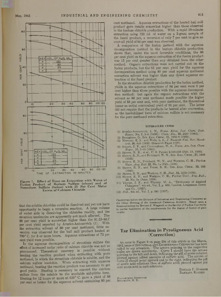
May, 1943 I N D U S T R I A L A N D E N G I N E E R I N G C H E M I S T R Y 613
F igure 7. E ffect o f T im e o n E x tra c tio n w ith W a te r of F usion P ro d u c t o f B a r iu m S u lfa te (a b o ve) a n d o f S tro n tiu m S u lfa te (b e lo w ) w ith 23 P e r C en t * Io la r
Excess o f C a lc iu m C hlo ride
c e n t m e th a n o l. A qu eo u s e x tra c tio n s of th e h e a te d b a ll m ill p ro d u c t gave re su lts so m ew h at h ig h er t h an th o se ob se rv ed in th e b a r iu m chloride p ro d u c tio n . W ith a ra p id 1 0 -m in u te ex tra c tio n u sing 100 m l. of w a te r on a 2 -g ram sam p le of th e fused p ro d u c t, a rev ersio n of on ly 7 p e r c en t to g ive an over-a ll y ie ld of 84 p e r cen t w as observed .
A com parison of th e fusion m e th o d w ith th e aq u eo u s d ecom position m e th o d in th e b a r iu m ch lo ride p ro d u c tio n show s th a t , u n d e r th e m o s t fav o rab le co nd itions, th e 88 p e r cen t y ie ld on th e aq ueous e x tra c tio n of th e fusion p ro d u c t w as 15 p e r cen t g re a te r th a n a n y o b ta in e d fro m th e o th e r m eth o d . O rganic e x tra c tio n s w ere n o t e a rn e d o u t o n th e fusion p ro d u c ts , b u t th e 95 p e r cen t y ie ld fo r th e aq u eo u s decom position m e th o d using 80 p e r cen t aq u eo u s m eth a n o l e x tra c tio n so lv en t w as h ig h er th a n a n y d irec t a q u eo u s extra c tio n of th e fused p ro d u c t.
I n th e s tro n tiu m chloride p ro d u c tio n b y th e fusion m e th o d , y ields in th e aq ueous e x tra c tio n s of 84 p e r cen t w ere 6 p e r cen t h ig h er th a n th o se possib le w ith th e aq u eo u s decom posit io n m e th o d ; b u t ag a in th e o rgan ic ex tra c tio n s w ith th e so lv en t as 80 p e r cen t m e th a n o l m ad e possib le th e h ig h er y ield of 88 p e r cen t an d , w ith p u re m e th an o l, th e th eo re tic a l (sam e as in itia l conversion) y ie ld of 91 p e r cen t. T h e la t te r d id n o t req u ire t h a t th e p ro d u c ts b e h e a te d a f te r conversion , as th e inso lub ilized form of calcium su lfa te is n o t n ecessary for th e p u re m e th a n o l e x trac tio n .
LITERATURE CITED
1) A v e rk o -A n to n o v ic h , I . N . , Trans. K ir art. Inst. Chem. Tech.Kazan, N o . 7, 3—6 (1 93 8 ); Chem. Abs., 35, 2431 (1941).
(2) B ro u g h to n , G ., I.vn . E n g . Ch e m ., 31, 1 002 -6 (1939).(3 ) N e w m a n , E . S., and W e lls , L . S., J . Research Nall. Bur. Stand
ards, 20, 825 (1938) (R esearch P a p e r 1107).(4) Sehoch, E . P ., a nd C u n n in g h a m , W . A . , Trans. Am . Inst. Chem.
Engrs., 37, 1 -1 8 (1941).(5 ) S hreve, R . N . , et at., U . S. P a te n t 2 ,030,659 (F e b . 11, 1936).(6) S hreve. R . N ., and P r itc h a rd , W . N „ In d . E n g . Ch e m ., 27, 1488
( 1935)- ^ ^(7) Shreve, R . N „ P r itc h a rd , W . N ., a nd W a tk in s , C . H . , P u rd u e
U n iv . , Eng. BuU. 22, N o . l a (F e b ., 1938).(8 ) S hreve, R . N . , a nd T o n e r, R . K -, I n d . E n g . C h e m ., 32, 568
(1940).(9) S hreve, R . N . , a nd W a tk in s , C . H . , Ibid., 31, 1173 (1939).
(10) Shreve, R . N „ and W a tk in s , C . H . , P u rd u e U n iv . . Eng. Ball.,23, N o . 3a (June , 1939).
(11) T h o rp e , J . F „ and W h ite ly , M . ' A ., “ D ic t io n a ry o f A p p lie dC h e m is try ” , 4 th e d „ V o l. I , p . 639, L o n d o n , L o n gm an s , G reena nd C o ., (1937).
(12) Ibid., 4 th ed., V o l. I , p . 641 (1937 ).
h a t th e so lub le ch lo rid es co u ld b e d isso lved a n d y e t n o t h a \ e ip p o rtu n ity to b e g in a re v ers io n re ac tio n . A la rg e v o lu m e if w a te r a id s in d isso lv in g th e ch lo rides re ad ily , a n d th e eversion ten d en c ie s a re a p p a re n tly n o t m u ch affec ted . T h e !8 p e r cen t y ie ld is so m e w h a t h ig h e r th a n th e 8 1 .5 2 -8 3 ./ >er cen t y ie ld re p o rte d b y A v e rk o -A n to n o v ich (1 ). ih e e x tra c tio n so lv e n t o f 80 p e r c e n t m e th a n o l l i t t le re version w as ob se rv ed fo r th e b a ll m ill p ro d u c t h e a te d a t f00° C . fo r 3 o r m o re h o u rs . A q u eo u s e x tra c tio n s of /3 p e r:ent y ie ld w ere possib le . . , , , ,
I n th e aq u eo u s d eco m p o sitio n of s tro n tiu m su lia te th e ;ffect of in creased m o la r ra tio of calc iu m ch lo ride w as n o t so pronounced. T h e o re tic a l re co v e ry is possib le w ith o u t lea tin g th e re a c tio n p ro d u c t w h en e x tra c tin g w it p u re m ethanol, in w h ich th e s tro n tiu m ch lo ride is so lub le, an r t e lalcium su lfa te in so lub le . W h e n e x tra c t in g w ith aq ueous m ethanol, h e a tin g th e re a c tio n p ro d u c t w as n ecessa ry to get ?ood yields. H e a tin g is necessary ' to c o n v e rt th e calc ium sulfate from th e so lub le to th e in so lu b le a n h y d r ite form . H eating for 12 h o u rs o r m o re a t 650° C. g av e a y ie ld o per cen t o r b e t te r fo r th e a q u eo u s so lv e n t c o n ta in in g p e r
Presented before the Division of Industrial and Engineering Chemistry at the 102nd Meeting of the American Chemical Society. Based upon a thesis submitted by Heroert F. Wiegandt to the faculty of Purdue University in partial fulfillment of the requirements for the degree of doctor of phil-osophy.
Tar E lim ination in Pyroligneous Acid (Correction)
A n error in F igure 9 on page 294 of th is article in th e M arch, 1943 issue of I n d u s t r i a l a n d E n g i n e e r i n g C h e m is t r y has been called to our a tten tio n . T h e arrow s po in ting to th e respective scales are d raw n incorrectly . C urve I should have the arrow s po in ting to th e left an d down, ind ica ting th e p H of acetic solution p lo tted against ad d ed am oun ts of sulfuric y n d . T h e arrow s of curve I I should p o in t upw ard and to th e rig h t, indicating th e pH of acetic acid so lu tions (free of sulfuric acid) p lo tted against per cent acetic acid in such solutions.
D o n a l d F . O t h m e r R a p h a e l K a t z e n
Polytechnic Institute B rooklyn, N . Y .
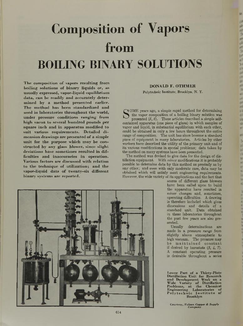
Composition of Vaporsfrom
B O I L I N G B I N A R Y S O L U T I O N S
T h e c o m p o s i t i o n o f v a p o r s r e s u l t i n g f r o m
b o i l i n g s o l u t i o n s o f b i n a r y l i q u i d s o r , a s
u s u a l l y e x p r e s s e d , v a p o r - l i q u i d e q u i l i b r i u m
d a t a , c a n b e r e a d i l y a n d a c c u r a t e l y d e t e r
m i n e d b y a m e t h o d p r e s e n t e d e a r l i e r .
T h e m e t h o d h a s b e e n s t a n d a r d i z e d a n d
u s e d i n l a b o r a t o r i e s t h r o u g h o u t t h e w o r l d ,
u n d e r p r e s s u r e c o n d i t i o n s r a n g i n g f r o m
h i g h v a c u a t o s e v e r a l h u n d r e d p o u n d s p e r
s q u a r e i n c h a n d i n a p p a r a t u s m o d i f i e d t o
s u i t v a r i o u s r e q u i r e m e n t s . D e t a i l e d d i
m e n s i o n d r a w i n g s a r e p r e s e n t e d o f a s i m p l e
u n i t f o r t h e p u r p o s e w h i c h m a y b e c o n
s t r u c t e d b y a n y g l a s s b l o w e r , s i n c e s l i g h t
d e v i a t i o n s h a v e s o m e t i m e s r e s u l t e d i n d i f
f i c u l t i e s a n d i n a c c u r a c i e s i n o p e r a t i o n .
V a r i o u s f a c t o r s a r e d i s c u s s e d w i t h r e l a t i o n
t o t h e t e c h n i q u e o f u t i l i z a t i o n ; a n d t h e
v a p o r - l i q u i d d a t a o f t w e n t y - s i x d i f f e r e n t
b i n a r y s y s t e m s a r e r e p o r t e d .
D O N A L D F . O T H M E R
Polytechnic In s titu te , B rooklyn, N . Y.
S O M E y e ars ago, a sim ple ra p id m e th o d fo r d e te rm in in g th e v a p o r com position of a bo iling b in a ry so lu tio n w as p re sen te d (5 , 8 ). T h ese a rtic le s d e sc rib ed a sim ple self-
co n ta in ed a p p a ra tu s (one p iece of g lass) in w h ich sam p les of v a p o r a n d liqu id , in s u b s ta n tia l eq u ilib riu m w ith e ach o th e r, cou ld be o b ta in e d in o n ly a few h o u rs th ro u g h o u t th e en tire ran g e of co m position . T h e u n i t h a s since becom e a s ta n d a rd p iece of e q u ip m e n t in m a n y lab o ra to rie s . A rtic les b y o th e r w orkers h a v e d esc rib ed th e u t i l i ty of th e p r im a ry u n i t a n d of i ts v a rio u s m o d ificatio n s in spec ia l p ro b lem s; d a ta ta k e n b y th e m e th o d o n m a n y sy s te m s h a v e b een p re sen te d .
T h e m e th o d w as dev ised to g ive d a ta fo r th e d esign of d is til la tio n e q u ip m e n t. W ith m in o r m o d ifica tio n s i t is p ro b a b ly possib le to d e te rm in e d a ta b y th is m e th o d a s p rec ise ly a s b y a n y o th e r ; a n d ev en w ith o n ly m o d e ra te care , d a ta m a y be o b ta in e d w hich w ill sa tis fy m o s t eng in eerin g req u irem en ts . H ow ever, th e w ide v a r ie ty of i ts a p p lic a tio n s a n d th e fa c t th a t
scores o f d iffe re n t g lass blow ers h a v e b een called u p o n to bu ild th e a p p a ra tu s h a v e re su lte d in m in o r ch an g es a n d , som etim es, o p e ra tin g difficulties. A d raw ing is th e re fo re in c lu d ed w hich gives d im en sio n s a n d d e ta ils of a s ta n d a rd u n it. D a ta ob ta in ed in th e se lab o ra to rie s th ro u g h o u t th e p a s t few y e a rs a re a lso p re se n ted .
U su a lly d e te rm in a tio n s a re m ad e in a p re ssu re ran g e from slig h tly a b o v e a tm o sp h e ric to h ig h v a cu u m . T h e p re ssu re m ay b e m a i n t a i n e d c o n s t a n t if d esired b y b a ro s ta ts (8, 4, 7). A c o n s ta n t o p e ra tin g p ressu re is d esirab le th ro u g h o u t a series
Low er P a r t o f a T h ir ty -P la te D is tilla tio n U n it fo r R esearch an d D evelopm en t W ork o n a W ide V arie ty o f D is tilla tio n P ro b lem s, a t th e C hem ical E n g in ee rin g L ab o ra to rie s o f P o l y t e c h n i c I n s t i t u t e o f
B rook lyn
C o u r te s y , V u lc a n C o p p er & S u p p ly C o m p a n y
614
I« a
a *
11 I.
h h
:•: id
•« 5
1'
* *
« «
a i
-1
*•
S'%
! v
VM
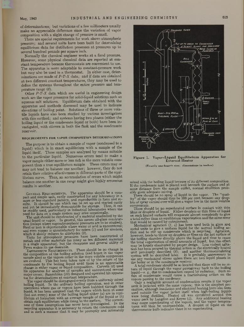
of d e te rm in a tio n s ; b u t v a r ia tio n s of a few m illim e te rs u su a lly m ak e n o a p p rec ia b le d ifference since th e v a r ia tio n of v a p o r com p o sitio n w ith a s lig h t ch an g e o f p re ssu re is sm all.
T h e re a re sp ec ia l re q u ire m e n ts fo r w ork a b o v e a tm o sp h e ric p re ssu re ; a n d sev era l u n its h a v e been b u ilt fo r d e te rm in in g eq u ilib riu m d a ta fo r d is tilla tio n processes a t p re ssu re s u p to severa l h u n d re d p o u n d s pe r sq u a re inch .
N o rm a lly th e chem ica l en g in eer w orks a t a fixed p ressu re . H ow ever, som e p h y sica l chem ica l d a ta a re re p o rte d a t cons ta n t te m p e ra tu re b ecau se th e rm o s ta ts a re c o n v en ien t to use . T h e a p p a ra tu s is m o re a d a p ta b le to co n s tan t-p re ssu re w ork b u t m a y also b e u sed in a th e rm o s ta t . I n e ith e r case, d e te r m in a tio n s a re m ad e of P - T - X d a ta ; a n d if d a ta a re o b ta in e d a t tw o d iffe ren t c o n s ta n t te m p e ra tu re s , th e y m a y b e u sed to define th e sy s te m s th ro u g h o u t th e e n tire p ressu re a n d te m p e ra tu re ra n g e (6).
O th e r P - T - X d a ta w h ich a re usefu l in eng in eerin g design w ork a re th e v a p o r p re ssu re s fo r so lid -liqu id so lu tio n s su ch as aq ueous s a lt so lu tio n s . E q u ilib r iu m d a ta o b ta in e d w ith th e a p p a ra tu s a n d m e th o d s d iscussed m a y be u sed to in d ic a te e lev atio n s of bo iling p o in t. S o lu tio n s of th re e o r m o re v o la tile liq u id s h a v e also been s tu d ied b y v a rio u s in v es tig a to rs w ith th is m e th o d ; a n d sy s tem s h a v in g tw o p h a se s (e ith e r th e boiling liq u id o r th e co n d en sa te liq u id o r b o th ) h a v e b e en in v estig a ted , w ith s tir re rs in b o th th e flask a n d th e co n d en sa te reservo ir.
REQUIREM ENTS FOR VAPOR COMPOSITION DETERM INATIONS
T h e p u rp o se is to o b ta in a sam p le of v a p o r (condensed to a liquid) w h ich is in e x ac t eq u ilib riu m w ith a sam p le of th e liqu id itse lf. T h ese sam p les a re a n a ly ze d b y m ean s su itab le to th e p a r tic u la r liq u id . N u m e ro u s e rro rs te n d to m ak e a v ap o r sam p le e ith e r m ore o r less rich in th e m ore v o la tile com p o n e n t th a n a t ru e e q u ilib riu m sam ple . T h ese e rro rs m a y or m ay n o t te n d to b a la n ce one a n o th e r ; how ever, th e y do n o t re ta in th e ir re la tiv e e ffectiveness in d iffe ren t p a r ts of th e eq u ilib rium cu rv e . T h u s , a n acc u m u la tio n of e rro rs w hich m ig h t ba lance one a n o th e r in one ran g e m ig h t g ive h ig h ly e rroneous resu lts in a n o th e r.
G e n e r a l R e q u ir e m e n t s . T he ap p ara tu s should be a com pact and sim ple u n it, easily constructed for any lab o ra to ry in a more or less s ta n d a rd p a tte rn , an d reproducible in form and results. I t should be one w hich can be se t up and s ta r te d easily and y e t be im m ediately dem ountab le for storage. T hus, it can be readily used, pa rticu la rly in in d u stria l laboratories where th e need for d a ta on a single system m ay arise occasionally.
The u n it should be co nstructed of a m ateria l unaffected by th e usual liquid or vapor. In general, th is m eans all-glass constructio n (except w here superatm ospheric pressures a re to be studied). Steel or iron is objectionable where w ater or acid is encountered; and even copper is u n sa tisfac to ry for esters (1) and for alcohols, which it slowly reduces to a ldehydes (9).
U nits for atm ospheric pressures have been constructed ol m etals and o th er m ateria ls (as m any as ten d ifferent m ateria ls in a single ap p ara tu s), b u t th e cheapness and general u tility ot Pyrex m akes its use desirable.
E q u i l ib r iu m R e q u ir e m e n t s . T here should be no change m the com position of th e boiling so lu tion (and hence in th e vapor sample also) as th e vapors richer in th e m ore volatile com ponent are evolved. T his h as been tak e n care of by th e re tu rn of th e condensate to th e boiling liquid u n til th ere is no apprecia e change in e ither v apor o r liqu id com position. G a rv e th (¿ ) used his ap p ara tu s for analyses of sam ples an d encountered severa m ajor errors; Sam eshim a (10) designed an d o p erated his ap p ara tus for determ inations a t co n stan t tem p era tu re . ,
T he vapor should be d isengaged evenly from a uniform ly m ixed boiling liquid. In th e o rd inary boiling operation , and in o ther operations where gas or vapors have been bubbled th ro u g h e liquid, i t has been assum ed th a t th e vapors which form a t some (but n o t every) zone of th e boiling liquid e ither (a) a re m eclhi- librium a t fo rm ation w ith an average sam ple of th e hquid o r (. ) obtain such equilibrium while rising to th e surface. 1 he correc - ness of these assum ptions has never been investigated , i n t e recycling ap p ara tu s i t is necessary to re tu rn th e condensate co d and in such a m anner th a t i t m ay be p ro m p tly and in tim ate y
May, 1943 I N D U S T R I A L A N D E N G I E E R I N G C H E M I S T R Y 615
F ig u re 1. V ap o r-L iqu id E q u ilib r iu m A p p a ra tu s fo r E x te rn a l H e a te r
(Exactly one fou rth size; d im en sion s in inches)
mixed w ith th e boiling liquid because of its different com position. If th e condensate in let is placed well benea th th e surface and a t some distance from th e sam ple o u tle t, norm al ebullition p robab ly gives adequate mixing.
T here should be no spray of liquid in th e vapor. I he quali ty ” of th e v ap o r should th u s be 100 per cen t because any drople ts of spray carried o ver will give a v apor low in th e m ore volatile com ponents. .
T here should be no superhea ted surface in co n tact w ith th in films or d roplets of liquid. E ith e r d rop lets o r th in films of liquid on such h eated surfaces will evapora te a lm ost com pletely to give a to ta l ra th e r th a n an equilibrium vaporization an d th e sam e error th a t would be caused by en tra inm en t.
M echanical ag ita tio n (1, 4) has been used b o th in glass and m eta l u n its to give a uniform liquid for th e norm al boiling actio n an d to s tir up condensate which is recycling. A gitation, however, ten d s to th row up d rop lets o r films on th e h o t surface of th e boiling cham ber d irectly above th e liquid and th u s to cause th e to ta l vaporization of sm all am oun ts of liquid ; b u t th is effect m ay be largely e lim inated by proper design. Less v io len t ag itatio n has been secured by th erm al action in th e electrically heated u n it previously described (8); and an o th er therm ocirculating system will be described la te r. I t is probab ly unnecessary to use any m echanical s tirrer unless th ere are tw o liquid phases in th e boiler or in th e condensate receiver.
A to ta l condenser should be so located th a t there will be no re tu rn of liquid th ro u g h th e v apor passagew ay back to th e boiling liquid— e. g., due to condensation caused by rad ia tion , feuch reflux of condensate would cause a frac tiona ting action on the vapors passing to th e condenser.
Only a negligible am o u n t of condensation results it th e vapor neck is jacketed w ith th e sam e vapors; th is is th e sim plest p recaution , although insu lation and electrical heating have also been used outside th e v ap o r jacket itself when high-boiling liquids were being d istilled. H eated oil was c irculated a round th is v ap o r neck b y L angdon and K eyes (4). A ny add itional heating m ay cause superheating of th e vapors, and th e v apor tem p era tu res will th en be undependable. A d rop let of liquid on th e th erm o m eter bulb indicates th ere is no superheating .
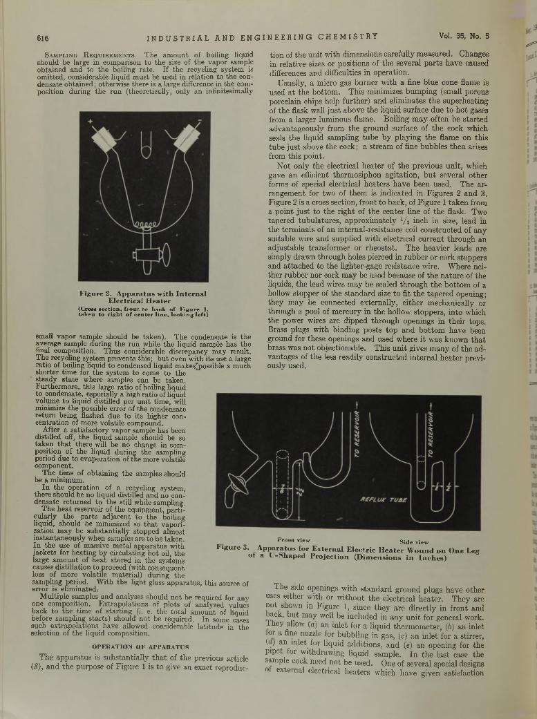
S a m p lin g R e q u ir e m e n t s . T he am ount of boiling liquid should be large in com parison to th e size of the vapor sample obtained and to th e boiling ra te . If the recycling system is om itted , considerable liquid m ust be used in relation to the condensate o b ta ined ; otherw ise there is a large difference in the composition during th e ru n (theoretically, only an infinitesim ally
616
F igure 2. A p p ara tu s w ith In te rn a l E lec trica l H ea te r
(Cross section , front to back o f Figure 1, taken to right o f center lin e, looking le ft)
small vapor sample should be taken). The condensate is the average sample during th e run while the liquid sam ple has the final composition. T hus considerable discrepancy m ay result. T he recycling system prevents th is; b u t even w ith its use a large ra tio of boiling liquid to condensed liquid m akes'possible a m uch shorter tim e for the system to come to the steady s ta te where samples can be taken.Furtherm ore, th is large ratio of boiling liquid to condensate, especially a high ra tio of liquid volume to liquid distilled per un it tim e, will minimize th e possible error of the condensate re tu rn being flashed due to its higher concentration of m ore volatile compound.
A fter a satisfactory vapor sample has been distilled off, the liquid sam ple should be so taken th a t there will be no change in composition of the liquid during the sam pling period due to evaporation of the more volatile com ponent.
T he tim e of obtaining the samples should be a m inim um .
In the operation of a recycling system , there should be no liquid distilled and no condensate re tu rned to the still while sampling.
T he h ea t reservoir of the equipm ent, p a rticularly th e p a rts ad jacen t to the boiling liquid, should be minim ized so th a t vaporization m ay be substan tia lly stopped alm ost instan taneously when samples are to be taken.In th e use of m assive m etal ap para tus w ith jackets for heating by circulating h o t oil, the large am o u n t of h ea t stored in the system s causes distillation to proceed (with consequent loss of m ore volatile m aterial) during the sam pling period. W ith th e light glass apparatus, th is source of erro r is elim inated.
M ultip le sam ples and analyses should n o t be required for any one com position. E x trapo lations of plots of analyzed values back to th e tim e of sta rtin g (i. e. the to ta l am ount of liquid before sam pling s ta rts ) should n o t be required. In some cases such extrapo lations have allowed considerable latitude in the selection of th e liquid composition.
OPERATION OF APPARATUS
T h e a p p a ra tu s is su b s ta n tia lly th a t of th e p rev ious a rtic le(8), a n d th e p u rp o se of F ig u re 1 is to give a n ex ac t rep ro d u c
tio n of th e u n it w ith d im ensions care fu lly m easu red . C h anges in re la tiv e sizes o r p o sitio n s of th e sev era l p a r ts h a v e caused d ifferences a n d difficulties in o p e ra tio n .
U sually , a m icro gas b u rn e r w ith a fine b lu e cone flam e is used a t th e b o tto m . T h is m in im izes b u m p in g (sm all po rous po rcela in chips help fu r th e r) a n d e lim in a tes th e su p e rh ea tin g of th e flask w all ju s t ab o v e th e liq u id su rface d u e to h o t gases from a la rg e r lum inous flam e. B o iling m a y o f te n be s ta r te d a d v an tag e o u sly from th e g ro u n d su rface of th e cock w hich seals th e liq u id sam p lin g tu b e b y p lay in g th e flam e on th is tu b e ju s t ab ove th e cock; a s tre am of fine bu b b les th e n arises from th is p o in t.
N o t o n ly th e e lectrica l h e a te r of th e p rev io u s u n it, w hich gave a n efficient th e rm o sip h o n a g ita tio n , b u t sev era l o th e r form s of specia l e lectrica l h e a te rs h a v e b een u sed . T h e a r ra n g em en t for tw o of th e m is in d ic a te d in F ig u re s 2 a n d 3. F ig u re 2 is a cross sec tion , f ro n t to b ack , of F ig u re 1 ta k e n from a p o in t ju s t to th e r ig h t of th e c en te r line of th e flask. T w o tap e red tu b u la tu re s , a p p ro x im a te ly 1/ i in ch in size, lead in th e te rm in a ls of a n in te rn a l-re s is tan c e coil c o n s tru c ted of a n y su itab le w ire a n d su p p lied w ith e lec trica l c u rre n t th ro u g h a n a d ju s ta b le tran s fo rm e r o r rh e o s ta t . T h e h e av ie r lead s a re s im p ly d raw n th ro u g h holes p ierced in ru b b e r o r co rk s to p p ers a n d a tta c h e d to th e lig h te r-g ag e re s is tan ce w ire. W here neith e r ru b b e r n o r cork m a y be used becau se of th e n a tu re of th e liqu ids, th e lead w ires m a y b e sealed th ro u g h th e b o t to m of a hollow s to p p e r of th e s ta n d a rd size to fit th e ta p e re d opening ; th e y m ay be connected ex te rn a lly , e ith e r m ech an ica lly or th ro u g h a pool of m erc u ry in th e ho llow s to p p e rs , in to w hich th e pow er w ires a re d ip p ed th ro u g h o p en ings in th e ir tops. B rass p lugs w ith b in d in g p o s ts to p a n d b o tto m h av e been g ro u n d fo r th ese openings a n d u sed w here i t w as k n o w n th a t b rass w as n o t ob jec tio n ab le . T h is u n it g ives m a n y of th e a d v an tag es of th e less re ad ily c o n s tru c ted in te rn a l h e a te r p rev iously used .
Vol. 35, No. 5
T h e side openings w ith s ta n d a rd g ro u n d p lugs h av e o th e r uses e ith e r w ith o r w ith o u t th e e lec trica l h e a te r . T h e y are n o t show n in F ig u re 1, since th e y a re d ire c tly in f ro n t and lack, b u t m ay well be inc lu d ed in a n y u n i t for g enera l w ork. 1 hey allow (a) an in le t for a liq u id th e rm o m e te r , (b) a n in le t o r a fine nozzle for b u b b lin g in gas, (c) a n in le t for a s tirre r,
( ) an in le t for liqu id a d d itio n s , a n d (e) a n o p en ing for th e p ip e t for w ith d raw in g liqu id sam ple . I n th e la s t case th e sam ple cock need n o t be used . O ne of sev era l special designs o ex te rn al e lectrica l h e a te rs w hich h a v e g iven sa tis fac tio n
I N D U S T R I A L A N D E N G I N E E R I N G C H E M I S T R Y
r r° n t v,cw Side viewf ig u re 3. A p p ara tu s fo r E x te rna l E lec tric H e a te r W ound on O ne Leg
ot a U -sh ap ed P ro jec tio n (D im ensions in In ch es)
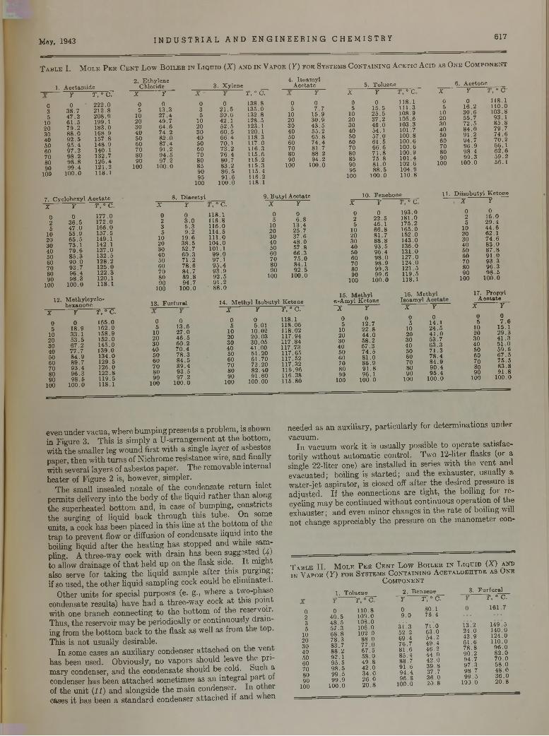
May, 1943 I N D U S T R I A L A N D E N G I N E E R I N G C H E M I S T R Y 617
T a b l e I . M o l e P e r C e n t L o w B o i l e r in L iq u id (X ) a n d in V a p o r ( Y ) f o r S y s t e m s C o n t a i n in g A c e t i c A c id a s O n e C o m p o n e n t
1. Acetamide
035
102030405060708090
100
7. Cyclohexyl AcetateX Y T, ° C.
0 0 177.02 36 .5 172.05 4 7 .0 166.0
10 55 .9 157.520 65 .5 149.130 73 .1 142.140 79 .6 137.050 85 .3 132.560 90 .0 128.270 93.7 125.080 96 .4 122.390 98 .3 120.1
100 100.0 118.1
12. M ethylcyclo- hexanone
X Y T, ° C.
0 0 165.05 18.9 162.0
10 33.1 158.920 53 .5 152.030 67.2 145.040 77 .7 139.050 84 .9 134.060 89.7 129.570 93 .4 126.080 96.3 122.890 98 .5 119.5
100 100.0 118.1
2. Ethylene Chloride
Y T, ° C. X Y
0 222 .0 0 038.7 212 .8 5 13.347 .2 208.9 10 27 .461 .5 199.1 20 49 .779 .2 183.0 30 64 .688 .0 168.9 40 74 .292 .5 157.8 50 82 .095 .4 148.9 60 87.497 .2 140.1 70 91 .298 .2 132.7 80 94 .598 .8 126.4 90 97.299 .4 121.2 100 100.0
100.0 118.1
3. Xylene
0 3 5
10 20 30 40 50 60 70 80 85 90 95
100
8. D iacetyl
021 .530 .642.152 .560 .566 .470.173 .276 .480.783.286 .591.6
100.0
T, ° C.
138.8135.0132.8128.5123.1120.1 118 3117.0 116.3115.6115.2115.3115.4 116.2118.1
4. Isoamyl Acetate
05
102030405060708090
100
9. Butyl AcetateX Y
ÖO
0 0 118.12 3.0 116.83 5 .3 116.05 9 .2 114.5
10 19.6 111.020 38 .5 104.030 52.7 101.140 60 .3 99 .050 71 .2 97.160 78 .6 95 .470 84.7 93 .980 89 .8 92 .590 94.7 91.2
100 100.0 88 .0
X Y0 05 6 .8
10 13.420 25.730 37.640 48 .050 57 .860 66.370 75 .080 84.190 92 .5
100 100.0
13. Furfural 14. M ethyl Isobutyl Ketone
05
102030405060708090
100
013.627 .046 .560.270 .478 .384 .589 .493 .5 97.2
100.0
X Y T, ° C.
0 0 118.15 5.01 118.06
10 10.02 118.0220 20.03 117.9430 30.05 117.8440 41.00 117.7350 51.20 117.6560 61.70 117.5270 72.20 117.3280 82.40 116.9690 91.60 116.38
100 100.00 115.80
5. Toluene 6. AcetoneY X Y O O
0 0 0 118.17 .7 5 15.5 111.3
15.9 10 25 .5 108.930.9 20 37.2 105.643 .5 30 46 .0 103.355.2 40 54.1 101.765 .8 50 57.0 100.874 .4 60 61.5 100.681.7 70 66.6 100.688.2 80 71 .8 100.994.2 85 75 .8 101.4
100.0 90 81 .0 102.695 88.5 104.9
100 100.0 110.8
X Y O O
0 0 118.15 16.2 110.0
10 30 .6 103.820 55.7 93.130 72 .5 85 .840 84 .0 79 .750 91.2 74 .660 94.7 70 .270 96 .9 66.180 98 .4 62 .690 99 .3 59 .2
100 100.0 56.1
10. Fenchone 11. Diisobutyl KetoneX Y O O
0 0 193.02 22.5 181.05 46.1 175.2
10 66.8 165.020 81.7 152.030 88 .8 143.040 93.5 136.050 96.4 131.060 98 .0 127.070 98.9 124.080 99.3 121.590 99 .6 119.5
100 100.0 118.1
15. Methyl n-Amyl Ketone
16. Me Isoamyl
X Y0 02 16.05 29 .4
10 44 .620 62.130 74 .640 83 .050 87 .860 91 .070 93 .380 96 .390 98 .5
100 100.0
17. PropylA oetate
X Y0 05 12.7
10 22.820 44 .030 58.240 67.350 74 .560 81 .070 86.980 91 .890 96.1
100 100.0
X Y0 05 14.1
10 24.520 41 .030 53.740 63.350 71.360 78.470 84.980 90.490 95 .4
100 100.0
X Y0 05 7 .6
10 15.120 29.330 41 .340 51 .050 59.660 67 .570 75 .580 83.890 91.8
100 100.0
even u n d e r va cu a , w here b u m p in g p re sen ts a p ro b lem , is show n in F ig u re 3. T h is is sim p ly a U -a rra n g e m e n t a t th e b o tto m , w ith th e sm alle r leg w o u n d firs t w ith a single lay e r of a sb esto s p aper, th e n w ith tu rn s of N ich ro m e re s is tan ce w ire, a n d finally w ith severa l lay e rs of a sb esto s p a p e r. T h e rem o v ab le in te rn a l h e a te r of F ig u re 2 is, how ever, sim p ler.
T h e sm all in sea led nozzle of th e co n d en sa te r e tu rn in le t p e rm its d e liv e ry in to th e b o d y of th e liq u id ra th e r th a n along th e su p e rh ea ted b o tto m a n d , in case of b u m p in g , c o n str ic ts th e su rg ing of liq u id b a ck th ro u g h th is tu b e . O n som e u n its , a cock h a s b een p lac ed in th is line a t th e b o tto m of t e tra p to p re v e n t flow o r d iffusion of co n d en sa te liq u id in to th e boiling liq u id a f te r th e h e a tin g h a s s to p p e d a n d w hile sam pling. A th ree -w a y cock w ith d ra in h a s b een sugg ested (4) to allow d ra in a g e of t h a t h e ld u p on th e flask side. I t m ig t also serve fo r ta k in g th e liq u id sam p le a f te r th is p u rg in g , if so used, th e o th e r liq u id sam p lin g cock cou ld b e e lim in a ted .
O th er u n its fo r spec ia l p u rp o se s (e. g., w here a tw o -p h ase condensate re su lts ) h a v e h a d a th ree -w a y cock a t th is p o in t w ith one b ra n ch co n n ec tin g to th e b o tto m of th e reservo ir. T hus, th e reserv o ir m a y b e p e rio d ica lly o r c o n tin u o u sly d ra in ing from th e b o tto m b a c k to th e flask a s well as from t e op. T h is is n o t u su a lly desirab le .
I n som e cases a n a u x ilia ry co n d en ser a tta c h e d on t e v en h as been used . O b v iously , n o v a p o rs sh o u ld leav e t e p ri m ary condenser, a n d th e c o n d en sa te sh o u ld be cold. > uc a condenser h as been a tta c h e d so m e tim es as a n in te g ra p a r o of th e u n i t (11) a n d a lo n g sid e th e m a in condenser. n o er cases i t h a s been a s ta n d a rd co n d en ser a tta c h e d if a n w en
needed as a n au x ilia ry , p a r tic u la r ly for d e te rm in a tio n s u n d e r v acu u m .
I n v a cu u m w ork i t is u su a lly possib le to o p e ra te sa tis fac to r ily w ith o u t a u to m a tic co n tro l. T w o 12-liter flasks (or a single 22-lite r one) a re in s ta lled in series w ith th e v e n t a n d e v ac u a te d ; boiling is s ta r te d ; a n d th e e x h au s te r , u su a lly a w a te r- je t a sp ira to r , is c losed off a f te r th e d esired p re ssu re is a d ju s te d . I f th e con n ec tio n s a re t ig h t, th e b o iling fo r re cycling m a y b e c o n tin u e d w ith o u t co n tin u o u s o p e ra tio n of th e e x h au s te r ; a n d ev en m in o r ch an g es in th e r a te of b o ilin g will n o t change a p p rec ia b ly th e p ressu re on th e m a n o m e te r con-
T a b l e I I M o l e P e r C e n t L o w B o i l e r i n L iq u id (X ) a n d i n V a p o r (Y ) f o r S y s t e m s C o n t a i n in g A c e t a l d e h y d e a s U n e
C o m p o n e n t
1. Toluene
0235
102030405060708090
100
040 .548 .557.3 68.878.3 83.7 88.2 92.195 .598 .599 .5 99 .9
100.0
T, ° C.110.8109.0108.0 106.0 102.0
88.077 .0 67 .558.049 .84 2 .034 .026 .020.8
2. Benzene Y T, ° C.
80.176 .4
7 Í .063.054.249 .446.244 .042 .0 39 .837.736 .020.8
3. Furfural
09 .0
3 Í ' 3 52 .269 .476.7 81 .685.488.7 91 .694 .496 .8
100.0
13.224 .0 42 .9 61 .6 78 .890 .294 .797 .398.7 9 9 .5
109.0
T, ° C. 161.7
149.5140.0124.0110.0
96 .082 .07 0 .058 .048 .036 .0 20.8
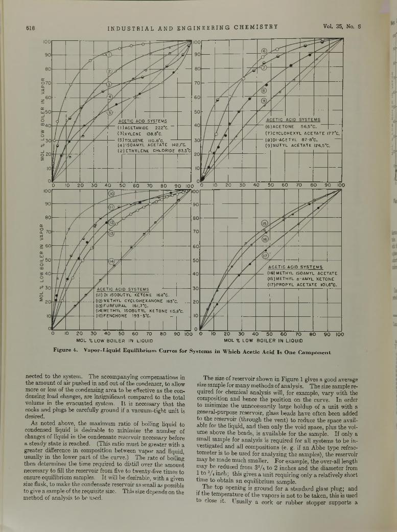
618 I N D U S T R I A L A N D E N G I N E E R I N G C H E M I S T R Y Vol. 35, No. 5
CETIC ACID SYSTEMS 5) METHYL ISOAMYL ACETATE
(15)METHYL n-AMYL KETONE (I7)PR0PYL ACETATE I0I.6*C.
ACID SYSTEMS OACETAMIDE 222°C.
(UXYLENE I38.8°C.(5)T0LUENE 110.8°C. ---- ---------(4) ISOAMYL ACETATE 142.1'C. (2 ) ETHYLENE CHLORIDE 83.5*C
0 10 2 0 3 0 4 0 5 0 6 0 70 8 0 9 0 100 0 10 2 0 3 0 4 0 5 0 6 0 7 0 8 0 9 0 l<30
Figure 4. V apor-L iqu id E q u ilib riu m Curves for S ystem s in W hich A cetic A cid Is O ne C o m p o n e n t
(7)CYCL0HEXYL ACETATE I77°C.(8)D|-ACETYL 87-8°C. —(9)BUTYL ACETATE I26.5°C.
8 0
troQ.<>
2 6 0a:üjd 5 0
0 10 2 0 3 0 4 0 5 0 6 0 70 8 0 9 0 100 0 10MOL X LOW BOILER IN LIQUID
20 30 40 50 60 70 80 90 100MOL % LOW BOILER IN LIQUID
a:
(11) Dl ISOBUTYL KETONE I68*C.(12) METHYL CYCLOHEXANONE I65’C______(13) FURFURAL I6I.7*C.(14) METHYL ISOBUTYL KETONE 115.8'C. (lO)FENCHONE I93-5"C. _________
n ec ted to th e sys tem . T h e acco m pany ing com pensa tions in th e a m o u n t of a ir p u sh ed in a n d o u t of th e condenser, to allow m ore o r less of th e condensing a rea to be effective a s th e condensing load changes, a re insign ifican t com pared to th e to ta l v o lum e in th e ev ac u a te d sy s tem . I t is necessary th a t th e cocks a n d p lugs be carefu lly g ro u n d if a v acu u m -tig h t u n it is desired .
A s n o ted above, th e m ax im u m ra tio of boiling liquid to condensed liq u id is d esirab le to m inim ize th e n u m b er of changes of liq u id in th e co n d en sate reservo ir necessary before a s te a d y s ta te is reach ed . (T h is ra tio m u s t be g re a te r w ith a g re a te r difference in com position b e tw een v a p o r an d liquid, u su a lly in th e low er p a r t of th e curve.) T h e ra te of boiling th e n d e te rm in es th e tim e req u ired to d istill over th e a m o u n t necessa ry to fill th e reserv o ir from five to tw en ty -five tim es to ensu re eq u ilib riu m sam ples. I t will be desirab le, w ith a given size flask, to m ak e th e co n d en sa te reserv o ir a s sm all as possible to g ive a sam p le of th e req u is ite size. T h is size d ep en d s on th e m e th o d of an alysis to be used.
T h e size of re serv o ir show n in F ig u re 1 g ives a good average size sam ple for m an y m e th o d s o f an a ly sis . T h e size sam ple req u ired for chem ical a n a ly sis will, fo r exam ple, v a ry w ith th e com position a n d hence th e p o sitio n on th e cu rve. In order to m inim ize th e un n ecessa rily la rg e h o ld u p of a u n it w ith a general-purpose reservo ir, g lass b e ad s h a v e o ften been added to th e reservo ir ( th ro u g h th e v e n t) to red u ce th e space availab le for th e liquid , an d th e n o n ly th e v o id space, p lus th e volum e above th e beads, is a v a ilab le fo r th e sam p le . I f on ly a sm all sam ple for an a ly sis is re q u ire d fo r a ll sy s tem s to be in v estig a ted a n d all co m positions (e. g. if a n A b b e ty p e refrac- to m e te r is to be used fo r an a ly z in g th e sam ples), th e reservo ir m ay be m ad e m u ch sm alle r. F o r exam ple, th e over-all leng th m ay^be red u ced from 3 3/s to 2 inch es a n d th e d iam e te r from 1 to 3/ 4 in ch ; th is gives a u n i t re q u irin g o n ly a re la tiv e ly sh o rt tim e to o b ta in a n eq u ilib riu m sam ple .
T h e to p open ing is g ro u n d fo r a s ta n d a rd g lass p lu g ; an d if th e te m p e ra tu re of th e v a p o rs is n o t to be ta k e n , th is is used to close it. U su ally a cork o r ru b b e r s to p p e r su p p o rts a
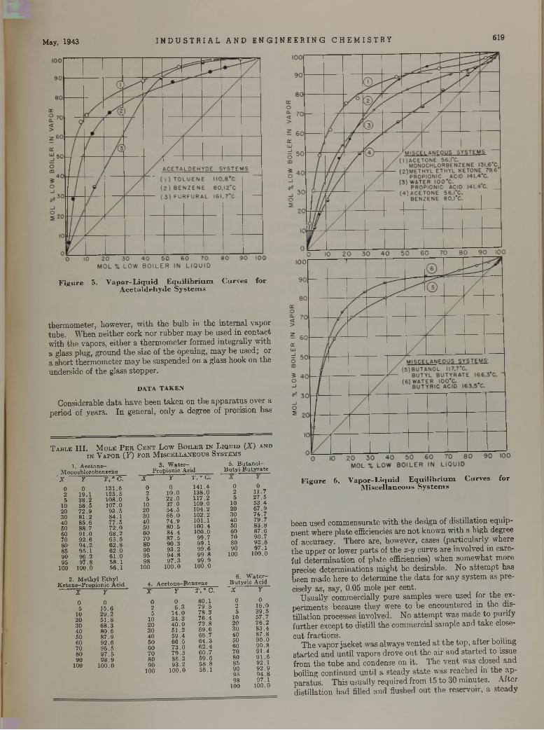
May, 1943 I N D U S T R I A L A N D E N G I N E E R I N G C H E M I S T R Y 619
F ig u re 5. V ap o r-L iq u id E q u ilib r iu m C urves fo r A ce ta ldehyde S ystem s
th e rm o m ete r, how ever, w ith th e b u lb in th e in te rn a l v ap o r tu b e . W h en n e ith e r co rk n o r ru b b e r m a y b e u sed in c o n ta c t w ith th e v ap o rs , e ith e r a th e rm o m e te r fo rm ed in te g ra lly w ith a glass p lu g , g ro u n d th e size of th e open ing , m a y b e u sed ; or a sh o rt th e rm o m e te r m a y be su sp en d ed on a g lass h o o k on th e un d erside of th e g lass s to p p e r.
DATA TAKEN
C o nsiderab le d a ta h a v e b een ta k e n on th e a p p a ra tu s o ver a period of y ea rs . I n g en era l, o n ly a deg ree of p recision h as
T a b l e I I I . M o l e P e r C e n t L o w B o il e r i n L iq u id (X ) a n di n V a p o r ( F ) f o r M is c e l l a n e o u s S y s t e m s
1 Acetone- 3. W ater- 5. Butanol-Monochlorobenzene Propionic Acid Butyl ButyrateX Y T ,° C.
0 0 131.62 19.1 125.55 38 .2 108.0
10 5 6 .5 107.020 72 .9 93 .530 81 .2 84.140 85 .6 77 .550 88 .7 72 .060 91 .0 68 .270 92 .6 65 .580 94 .2 62 .885 95 .1 62 .090 96 .2 61 .095 97 .8 58.1
100 100.0 56.1
2. M ethyl Ethyl Ketone-Propionic Acid
X Y0 05 15.6
10 29.220 51 .830 68.340 80 .650 87.960 92 .670 95 .580 97 .590 98 .9
100 100.0
98 97.1100 100.0
X Y T, " U.
0 0 141.42 10.0 138.05 22 .0 117.2
10 37 .0 109.020 54 .5 104.230 66 .0 102.240 74 .9 101.150 80 .5 100.460 84 .4 100.070 87 .5 99.780 90 .3 99.190 93 .2 99 .695 94 .8 99 .898 97 .3 99 .9
100 100.0 100.0
0 02 11.75 27 .5
10 53.420 67.930 74 .740 79.750 83 .860 87.670 90.780 93 .890 97.1
100 100.0
6. W ater-4. Acetone—Benzene Butyric AcidX Y
doSh" X Y
0 0 80.1 0 02 6 .3 79 .5 2 16.05 14.0 78 .3 5 39.5
10 24 .3 76 .4 10 57.720 40 .0 72 .8 20 76 .230 51 .2 69 .6 30 83.440 59 .4 66 .7 40 87 .850 66 .5 64 .3 50 90 .060 73 .0 6 2 .4 60 90 .870 79 .5 60.7 70 91 .480 86 .3 59 .6 80 91 .690 93 .2 58 .8 85 92.1
100 100.0 56.1 9095
92 .994 .8
F ig u re 6. V ap o r-L iq u id E q u ilib r iu m C urves fo r M iscellaneous S ystem s
b een used c o m m en su ra te w ith th e design of d is tilla tio n eq u ip m e n t w here p la te efficiencies a re n o t k n o w n w ith a h ig h degree of accu racy . T h e re a re , how ever, cases (p a rtic u la r ly w h ere th e u p p e r o r low er p a r ts of th e x -y cu rv e a re in v o lv ed in c a re fu l d e te rm in a tio n of p la te efficiencies) w h en so m ew h a t m ore p recise d e te rm in a tio n s m ig h t b e d esirab le . N o a t te m p t h as been m ad e he re to d e te rm in e th e d a ta fo r a n y sy s tem as p re cisely as, say , 0.05 m ole p e r cen t.
U su a lly co m m erc ia lly p u re sam p les w ere u sed for th e exp e rim en ts becau se th e y w ere to b e en co u n te red in th e d ist il la tio n p rocesses in v o lv ed . N o a t te m p t w as m ad e to p u rify fu r th e r ex cep t to d is till th e co m m erc ia l sam p le a n d ta k e close- c u t frac tio n s .
T h e v a p o r ja c k e t w as a lw ay s v e n te d a t t h e to p , a f te r bo iling s ta r te d a n d u n til v a p o rs d ro v e o u t th e a ir a n d s ta r te d to issue from th e tu b e a n d condense on it. T h e v e n t w as c losed a n d b o iling co n tin u e d u n til a s te a d y s ta te w as reach ed in th e a p p a ra tu s . T h is u su a lly req u ired from 15 to 30 m in u te s . A fte r d is tilla tio n h a d filled a n d flushed o u t th e reserv o ir, a s te a d y
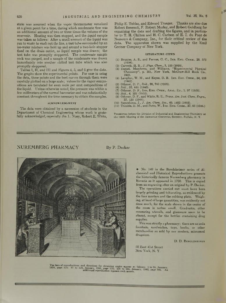
620 I N D U S T R I A L A N D E N G I N E E R I N G C H E M I S T R Y Vol. 35, No. 5
s ta te w as assum ed w hen th e v ap o r th e rm o m ete r rem ained a t a g iven p o in t for a tim e, d u rin g w hich co ndensate flow w as an a d d itio n a l a m o u n t of tw o or th ree tim es th e volum e of th e reservo ir. H e a tin g was th e n sto p p ed , a n d th e liqu id sam ple w as ta k e n as follow s: A fte r a sm all am o u n t of th e liqu id w as ru n to w aste to w ash o u t th e line, a te s t tu b e su rro u n d ed b y an ice-w ater m ix tu re w as held up an d a ro u n d a tw o-hole sto p p er fixed on th e d ra in o u tle t, as liquid sam ple w as d raw n ; th e te s t tu b e w as p ro m p tly stoppered . T h e condensate sam ple cock w as purged , an d a sam ple of th e condensate w as d raw n im m edia te ly in to a n o th e r chilled te s t tu b e w hich w as also p ro m p tly stoppered .
T ab les I , I I , a n d I I I an d F igures 4, 5, an d 6 give th e d a ta . T h e g rap h s show th e experim en tal po in ts . F o r ease in using th e d a ta , th ese p o in ts an d th e b est curves th ro u g h th em w ere carefu lly p lo tted on a large scale; values for th e v ap o r com positions a re ta o u la te d for even m ole p er cen t com positions of th e liquid . Unless otherw ise n o ted , th e p ressure w as w ith in a few m illim eters of th e norm al b a ro m e te r a n d w as su b s ta n tia lly c o n stan t th ro u g h o u t th e tim e necessary to o b ta in th e sam ples.
ACKNOWLEDGMENT
T h e d a ta were ob ta in ed b y a succession of s tu d e n ts in th e D e p a rtm en t of C hem ical E ng ineering w hose w ork is g ra te fu lly acknow ledged, especially J in L. N u ey , R o b e rt E . W hite ,
P h ilip E . T o b ias , a n d E d w a rd T ru eg e r. T h a n k s a re a lso d ue R o b e rt B en en a ti, F . R o b e r t M o rley , a n d R o b e r t G o ld b erg for o rgan iz ing th e d a ta a n d d ra ftin g th e figures, a n d in p a r tic u la r to T . H . C h ilto n a n d H . C . C a rlso n o f E . I . d u P o n t de N e m o u rs & C o m p an y , In c ., fo r th e ir c r itic a l rev iew o f th e d a ta . T h e a p p a ra tu s sh o w n w as su p p lied b y th e E m il G re in e r C o m p an y o f N ew Y o rk .
LITERATURE CITED
(1) B ru n je s , A . S., and F u rn a s , C . C ., I n d . E n o . C h e m ., 28, 573(1936).
(2) C a rv e th , H . R ., J . Phys. Chem., 3 , 193 (1899).(3) D a n ie l, M a tth e w s , and W illia m s , “ E x p e r im e n ta l P h y s ic a l
C h e m is try ” , p . 301, N e w Y o rk , M c G r a w - H i l l B o o k Co., 1929.
(4) L a n g d o n , W . M . , and K e ye s , D . B ., I n d . E n g . C he m ., 34, 938(1942).
(5) O th m e r, D . F ., Ibid., 20, 743 (1928).(6) Ibid., 32, 841 (1940).(7) O th m e r, D . F ., I n d . E n g . C hem ., A n a l . E d ., 1, 97 (1929).(8) Ibid., 4, 232 (1932).(9) O th m e r, D . F ., and W h ite , R . E ., Trans. Am . Inst. Chem. Engrs.,
37, 135 (1941).(10) Sam esh im a, J ., J . Am. Chem. Soc., 40, 1482 (1918).(11) T r im b le , H . M ., and P o tts , W ., I n d . E n g . C he m ., 27, 66 (1935.)
Presented before the Division of Industrial and Engineering Chemistry at the 104th Meeting of the American Chemical Society, Buffalo, N. Y.
N U R E M B E R G P H A R M A C Y B y P . D e c k e r
♦ N o . 149 in th e B e ro lzh e im er series o f A lchem ical a n d H is to r ic a l R e p ro d u c tio n s p re sen ts th e h is to r ic a lly fam o u s N u re m b e rg p h a rm a c y in B a v a ria as i t a p p e a re d in 1700. T h is is cop ied from a n e n g ra v in g a f te r a n o rig in a l b y P . D eck e r.
T h e o p e ra tio n s c a r r ie d o u t m u s t h a v e been la rg e ly g rin d in g a n d t r i tu r a t in g , as ev id en ced b y th e fo u r m o r ta rs a n d th e ru b b in g p la te . W eighing , a t le a s t o f la rg e q u a n ti t ie s , w as e v id e n tly n o t done m u ch , for th e scale sh ow n in th e ce n te r o f th e ro o m is r a th e r sm all. G ra d u a te s , o ther m easu rin g u ten s ils , a n d g lassw are seem to b e ab se n t, ex cep t fo r th e b o tt le s co n ta in in g d rug supplies.
T h is w as s t r ic t ly a p h a rm a c y ; th e re a re no soda fo u n ta in , san d w ich es, to y s , books, o r o th e r m erch an d ise a s so ld b y o u r m o d ern , m isnam ed d ru g sto re .
D . D . B e r o lz h e im e r
50 E a s t 41st S tre e t N ew Y o rk , N . Y .
2 9 3 Ä f ci T ^ r : r . r fol,ow?óAadditiońal reprodumfon appears each m o n llary’ « 4 3 , page 106. An
May, 1943 I N D U S T R I A L A N D E N G I N E E R I N G C H E M I S T R Y 55
Plants and PlantationsP l a n t a t i o n s h a l f a c r o s s t h e w o r l d —
t h a t ’s w h e r e o u r p e a c e t i m e r u b b e r u s e d
t o c o m e f r o m
P l a n t s r i g h t h e r e i n t h e U . S . A . — t h a t ’s
w h e r e t h e r u b b e r i s c o m i n g f r o m t h a t w e
m u s t h a v e t o w i n t h e w a r T h e f i r s t o f
s e v e r a l p l a n t s i s a l r e a d y i n o p e r a t i o n
P l a n t a t i o n r u b b e r i s n a t u r a l — i t ’s m a d e
f r o m t h e s a p o f a t r e e P l a n t r u b b e r i s
s y n t h e t i c — i t ’ s m a d e f r o m b u t a d i e n e
a n d s t y r e n e p r o d u c e d f r o m c r u d e o i l i n
A m e r i c a n r e f i n e r i e s
B u t a d i e n e a n d s t y r e n e a r e d e r i v e d f r o m
p e t r o l e u m b y U n i v e r s a l p r o c e s s e s , w h i c h
c a n m a k e u s f o r e v e r i n d e p e n d e n t o f r u b
b e r p l a n t a t i o n s 1 0 , 0 0 0 m i l e s f r o m h o m e
D o y o u t h i n k p r o d u c t i o n o f s y n t h e t i c
r u b b e r w i l l e n d w i t h t h e w a r ?
T h e o i l i n d u s t r y n e v e r g o e s b a c k w a r d
O IL IS A M M U N IT IO N — USE IT W IS E L YC A R E FOR YO U R C A R FOR YO U R C O U N T R Y
U n i v e r s a l O i l P r o d u c t s C o
Chicago, Illinois
D u b b s C r a c k i n g P r o c e s s
Owner and Licensor
T H E R E F I N E R S I N S T I T U T E O F P E T R O L E U M T E C H N O L O G Y
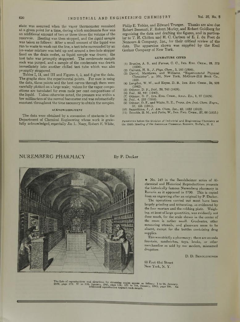
620 I N D U S T R I A L A N D E N G I N E E R I N G C H E M I S T R Y Vol. 35, No. 5
s ta te w as assum ed w hen th e v a p o r th e rm o m ete r rem ained a t a g iven p o in t fo r a tim e , d u rin g w hich condensate flow was an a d d itio n a l am o u n t of tw o o r th ree tim es th e volum e of th e reservo ir. H e a tin g w as th e n s to p p ed , a n d th e liquid sam ple w as ta k e n as follow s: A fte r a sm all a m o u n t of th e liquid w as ru n to w aste to w ash o u t th e line, a te s t tu b e su rro u n d ed b y an ice-w ater m ix tu re w as h e ld u p a n d a ro u n d a tw o-hole s topper fixed on th e d ra in o u tle t, a s liqu id sam ple w as d raw n ; th e te s t tu b e w as p ro m p tly s toppered . T h e condensate sam ple cock w as purged , a n d a sam ple of th e condensate w as d raw n im m ed ia te ly in to a n o th e r chilled te s t tu b e w hich was also p ro m p tly sto p p ered .
T ab les I , I I , a n d I I I a n d F igu res 4, 5, an d 6 give th e d a ta . T h e g rap h s show th e experim en tal po in ts. F o r ease in using th e d a ta , th ese p o in ts an d th e b e s t curves th ro u g h th em were carefu lly p lo tte d on a large scale; values for th e v ap o r com positions a re ta o u la te d for even m ole p er cen t com positions of th e liqu id . U nless o therw ise n o ted , th e p ressure was w ith in a few m illim eters of th e no rm al b a ro m e te r a n d was su b stan tia lly c o n s ta n t th ro u g h o u t th e tim e necessary to o b ta in th e sam ples.
ACKNOWLEDGMENT
T h e d a ta w ere o b ta in ed b y a succession of s tu d en ts in the D e p a r tm e n t of C hem ical E ngineering w hose w ork is g ra te fu lly acknow ledged, especially J in L. N uey , R o b e rt E . W hite,
Ph ilip E . T obias, an d E d w a rd T ru eg e r. T h a n k s a re a lso du e R o b e rt B en en a ti, F . R o b e r t M o rley , a n d R o b e r t G o ld b erg for organizing th e d a ta an d d ra ftin g th e figures, a n d in p a r tic u la r to T . H . C h ilto n a n d H . C . C a rlso n o f E . I . d u P o n t de N em o u rs & C o m p an y , In c ., fo r th e ir c r itic a l rev iew o f th e d a ta . T h e a p p a ra tu s show n w as su p p lie d b y th e E m il G re iner C o m p an y of N ew Y o rk .
LITERATURE CITED
(1) B ru n je s , A . S., and F u rn a s , C . C ., I n d . E n g . C h e m ., 28, 573(1936).
(2) C a rv e th , H . R ., J . Phys. Chem., 3 , 193 (1899).(3) D a n ie l, M a tth e w s , and W illia m s , “ E x p e r im e n ta l P h y s ic a l
C h e m is try ” , p . 301, N e w Y o rk , M c G r a w - H i l l B o o k C o.,1929.
(4) Langdon , W . M ., and K eyes , D . B ., I n d . E n g . C he m ., 34, 938(1942).
(5) O thm e r, D . F ., Ibid., 20, 743 (1928 ).(6) Ibid., 32, 841 (1940).(7) O thm e r, D . F ., I n d . E n g . C hem ., A n a l . E d ., 1, 97 (1929 ).(8) Ibid., 4, 232 (1932).(9) O thm e r, D . F ., and W h ite , R . E ., Trans. Am . Inst. Chem. Engrs.,
37, 135 (1941).(10) Sam eshim a, J ., J . Am. Chem. Soc., 40, 1482 (1918 ).(11) T r im b le , H . M ., and P o tts , W ., I n d . E n g . C he m ., 27, 66 (1935.)
Presented before the Division of Industrial and Engineering Chemistry at the 104th Meeting of the American Chemical Society, Buffalo, N. Y.
N U R E M B E R G P H A R M A C Y B y P . D e c k e r
♦ N o . 149 in th e B e ro lzh e im er se ries o f A lchem ical a n d H is to r ic a l R e p ro d u c tio n s p re sen ts th e h is to r ic a lly fam o u s N u re m b e rg p h a rm a c y in B a v a ria a s i t a p p e a re d in 1700. T h is is cop ied from a n en g rav in g a f te r a n o rig in a l b y P . D eck e r.
T h e o p e ra tio n s c a r r ie d o u t m u s t h a v e been largely g rin d in g a n d t r i tu r a t in g , a s ev id en ced b y th e fou r m o r ta rs a n d th e ru b b in g p la te . W eigh ing, a t lea s t o f la rg e q u a n ti t ie s , w as e v id e n tly n o t done m u ch , fo r th e scale sh o w n in th e c e n te r o f th e room is r a th e r sm all. G ra d u a te s , o th er m easu rin g u ten s ils , a n d g lassw are seem to be ab sen t, ex cep t fo r th e b o tt le s co n ta in in g d rug supplies.
T h is w as s t r ic t ly a p h a rm a c y ; th e re a re no soda fo u n ta in , sand w ich es, to y s , books, o r o th e r m erch an d ise a s so ld b y o u r m o d ern , m isn am ed d ru g sto re .
D . D . B e r o lz h e im e r
50 E a s t 41st S tre e t N ew Y ork , N . Y .
The lists of reproductions and directions for ohi*»;«;™ .1939, page 124: 97 ta 120, January, 1941, page1?4- m Y f l i f i“ ° lloW,3: 1 95, January.
addition aire prod u etfo n a p peare eaoh mon 11 a r y ’ U43. I»*e 106. An
;m m m
May, 1943 I N D U S T R I A L A N D E N G I N E E R I N G C H E M I S T R Y 55
Plants and PlantationsP l a n t a t i o n s h a l f a c r o s s t h e w o r l d —
t h a t ’s w h e r e o u r p e a c e t i m e r u b b e r u s e d
t o c o m e f r o m
P l a n t s r i g h t h e r e i n t h e U . S . A . — t h a t ’s
w h e r e t h e r u b b e r i s c o m i n g f r o m t h a t w e
m u s t h a v e t o w i n t h e w a r T h e f i r s t o f
s e v e r a l p l a n t s i s a l r e a d y i n o p e r a t i o n
P l a n t a t i o n r u b b e r i s n a t u r a l — i t ’s m a d e
f r o m t h e s a p o f a t r e e P l a n t r u b b e r i s
s y n t h e t i c — i t ’ s m a d e f r o m b u t a d i e n e
a n d s t y r e n e p r o d u c e d f r o m c r u d e o i l i n
A m e r i c a n r e f i n e r i e s
B u t a d i e n e a n d s t y r e n e a r e d e r i v e d f r o m
p e t r o l e u m b y U n i v e r s a l p r o c e s s e s , w h i c h
c a n m a k e u s f o r e v e r i n d e p e n d e n t o f r u b
b e r p l a n t a t i o n s 1 0 , 0 0 0 m i l e s f r o m h o m e
D o y o u t h i n k p r o d u c t i o n o f s y n t h e t i c
r u b b e r w i l l e n d w i t h t h e w a r ?
T h e o i l i n d u s t r y n e v e r g o e s b a c k w a r d
O IL IS A M M U N IT IO N — USE IT W IS E L YC A R E FOR YO U R C A R FOR Y O U R C O U N T R Y
U n i v e r s a l O i l P r o d u c t s C o
Chicago, Illinois
D u b b s C r a c k i n g P r o c e s s
Owner and Licensor
T H E R E F I N E R S I N S T I T U T E O F P E T R O L E U M T E C H N O L O G Y
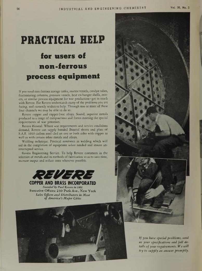
56 I N D U S T R I A L A N D E N G I N E E R I N G C H E M I S T R Y Vol. 35, No. 5
I f y o u h a v e s p e c ia l p r o b le m s , s e n d
u s y o u r s p e c i f ic a t io n s a n d f u l l d e
ta i l s o f y o u r r e q u i r e m e n t s . W e w i l l
t r y t o s u p p l y a n a n s w e r p r o m p t l y .
P R A C T IC A L H E L P
for users of non-ferrous
process equipmentI f you n eed n o n -fe rro u s sto rage tanks, reac to r vessels, catalyst tubes, frac tio n a tin g colum ns, p ressu re vessels, h ea t ex changer shells , m ix ers, o r s im ilar process e q u ip m en t fo r w ar p ro d u c tio n —g e t in to u ch w ith R evere. F o r R evere u n d e rs tan d s m any o f th e p ro b lem s you are facing , an d earnestly w ishes to h e lp . T h ro u g h on e o r m o re o f these fo u r ch annels w e m ay be ab le to do so:
R evere co p p er an d copper-base alloys. Sound , su p e rio r m etals p ro d u ced in a range o f com positions and fo rm s m ee tin g th e special requ irem en ts o f w a r processes.
R evere B im etal. W h e re w ar req u irem en ts an d service co n d itio n s d em and , R evere can supp ly b o n d ed B im etal sheets an d p la te o f S.A .E. 1010 carbon steel c lad on one o r b o th sides w ith c o p p er as w e ll as w ith certa in o th e r m eta ls an d alloys.
W e ld in g techn ique. P rac tica l assistance in w e ld in g w h ich w ill a id in th e com p le tio n o f e q u ip m en t w h e n n e ed ed a n d in su re u n in te rru p ted service.
R evere E n g in eerin g Service. T o h e lp R evere custom ers in th e selection o f m etals and in m eth o d s o f fab rica tio n so as to save tim e, increase o u tp u t an d reduce costs w h e rev e r possible.
COPPER AND BRASS INCORPORATEDFounded by P aul Revere in 1801
E x e c u t i v e O f f i c e s : 2 3 0 P a r k A v e . , N e w Y o r k
S a le s O ff ic e s a n d D i s t r i b u t o r s in M o s t o f A m e r i c a ’s M a j o r C it ie s
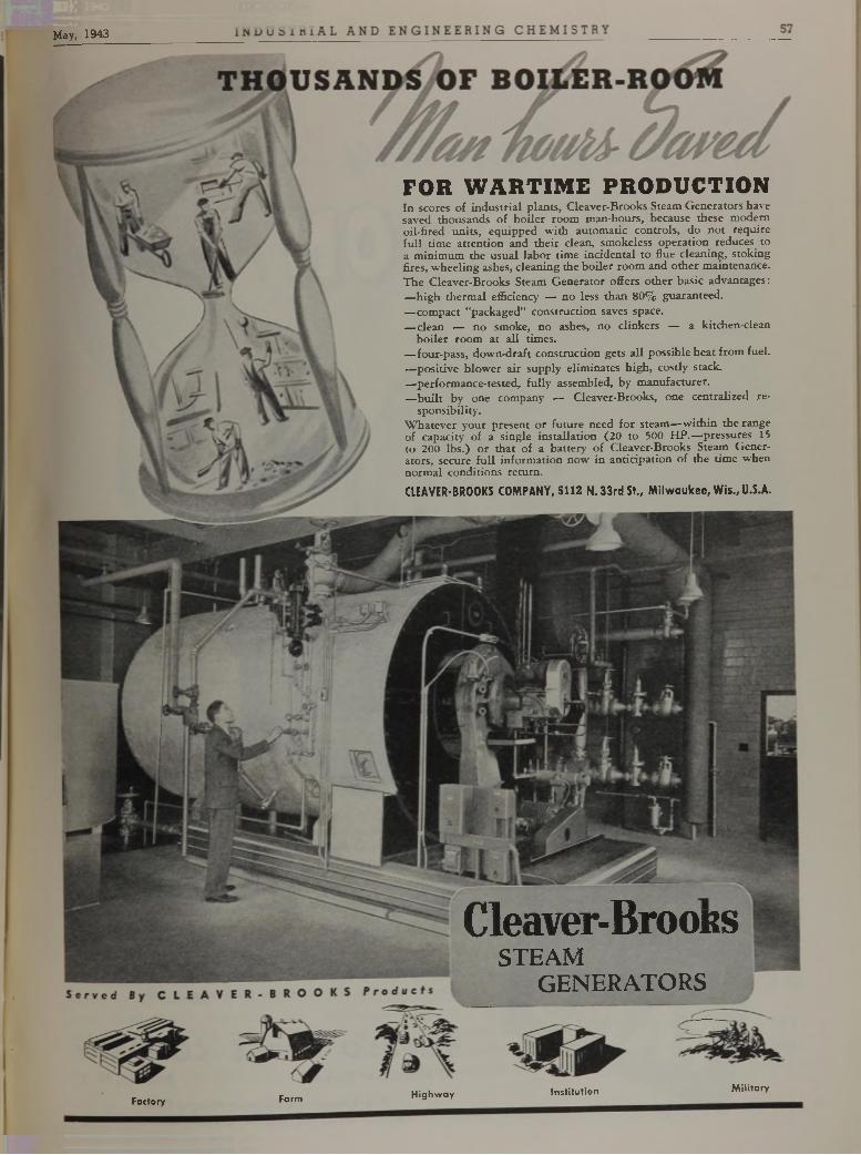
May, 1943
C l e a v e r - B r o o R SSTEAM
GENERATORS
Factory Farm H ighw ay Institution Military
FOR W A R T IM E PRODUCTIONI n scores o f in d u s t r ia l p la n ts , C le a v e r-B ro o k s S team G e n e ra to rs have saved th o u s a n d s o f b o i le r ro o m m a n -h o u rs , because these m o d e rn o i l - f i r e d u n its , e q u ip p e d w i t h a u to m a t ic c o n tro ls , d o n o t re q u ire f u l l t im e a t te n t io n a nd th e ir d e a n , sm oke less o p e ra t io n reduces to a m in im u m th e u s u a l la b o r t im e in c id e n ta l to flu e c le a n in g , s to k in g f ire s , w h e e l in g ashes, c le a n in g th e b o i le r ro o m a n d o th e r m a in te n a n ce .
T h e C le a v e r-B ro o k s S team G e n e ra to r o ffe rs o th e r b a s ic a dva n ta g e s :
— h ig h th e rm a l e ffic ie n c y — n o less th a n 8 0 % g u a ra n te e d .
— c o m p a c t "p a c k a g e d ” c o n s tru c t io n saves space.— d e a n — n o sm o ke , n o ashes, n o d in k e r s — a k itc h e n -c le a n
b o i le r ro o m a t a l l tim e s .— fo u r-p a s s , d o w n -d ra f t c o n s tru c t io n ge ts a l l p o s s ib le h e a t f r o m fu e l.
— p o s it iv e b lo w e r a ir s u p p ly e lim in a te s h ig h , c o s tly s tack .
— •p e rfo rm a n c e -te s te d , f u l l y assem b led, b y m a n u fa c tu re r .— b u i l t b y o ne c o m p a n y — C le a v e r-B ro o k s , one c e n tra liz e d re
s p o n s ib il i ty .W h a te v e r y o u r p re s e n t o r fu tu r e need f o r s te a m — w it h in th e ra n g e o f c a p a c ity o f a s in g le in s ta l la t io n (2 0 to 500 H P .— p ressu res 15 to 200 lb s . ) o r th a t o f a b a t te n ' o f C le a v e r-B ro o k s S team G e n e ra to rs , secure f u l l in fo r m a t io n n o w in a n t id p a t io n o f th e t im e w h e n n o rm a l c o n d it io n s re tu rn .
CLEAVER-BROOKS COMPANY, 5112 N .33 rd St., M ilw aukee, W is., U.S.A.
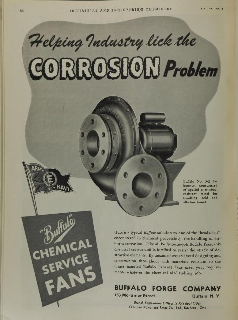
I N D U S T R I A L A N D E N G I N E E R I N, G C H E M I S T R Y voi. 03, « 0 . 3
Buffalo N o. 5-E Exhauster, constructed o f special corrosion- resistan t m etal for hand ling acid and alkaline fumes.
H e r e i s a t y p i c a l B u f fa lo s o l u t i o n t o o n e o f t h e “ h e a d a c h e s ”
e n c o u n t e r e d i n c h e m i c a l p r o c e s s i n g — t h e h a n d l i n g of a i r
b o r n e c o r r o s i o n . L i k e a l l b u i l t - t o - t h e - j o b B u f f a l o F a n s , t h i s
c h e m i c a l s e r v i c e u n i t i s f o r t i f i e d t o r e s i s t t h e a t t a c k o f d e
s t r u c t iv e e l e m e n t s . B y m e a n s o f e x p e r i e n c e d d e s i g n i n g a n d
c o n s t r u c t i o n t h r o u g h o u t w i t h m a t e r i a l s r e s i s t a n t t o t h e
f u m e s h a n d l e d B u f f a l o E x h a u s t F a n s m e e t y o u r r e q u i r e
m e n t s w h a t e v e r t h e c h e m i c a l a i r - h a n d l i n g j o b .
BUFFALO FORGE COMPANY153 Mortimer Street Bu ffa lo , N.
Branch Engineering O ffices in Principal Cities Canadian B low e r and Forse C o ., L td . , K itc h e n e r, O n t .
May, 1943 I N D U S T R I A L A N D E N G I N E E R I N G C H E M I S T R Y 59
Accent on EXPERIENCE
" R estore to m e y o u th , hut let me re ta in
the experience o f m y threescore yea rs o f
m a tu rity — a n d I w il l b u ild a n ew w o r ld .”
T h e s a g e w h o s a i d t h a t l i v e d i n a n
e r a w h e n m u c h o f a m a n ' s k n o w l e d g e
d ie d w i t h h i m . . . w h e n p r o g r e s s
m o v e d s l o w l y u n d e r t h e u n c e r
t a i n t y o f c o n t i n u a l t r i a l - a n d - e r r o r .
T o d a y , t h r o u g h d a t a , r e c o r d s a n d
c o r p o r a t e e n t i t i e s , e x p e r i e n c e i s
c u m u l a t i v e . F a r m o r e c o m p l e t e .
I n f i n i t e l y m o r e r e l i a b l e . H e l p f u l l y
a v a i l a b l e t o p o s t e r i t y . I t h a s f e w e r
l a p s e s o r l o o s e e n d s . I t p r o t e c t s
a g a i n s t p i t f a l l s .
T h i s i s s i g n a l l y t r u e o f B a d g e r .
A c e n t u r y o f u n b r o k e n e x p e r i e n c e
i s a B a d g e r h e r i t a g e o f i n e s t i m a b l e
v a l u e t o a d v a n c i n g e n t e r p r i s e .
S t e e p e d i n t h i s b a c k g r o u n d , y e t
i m b u e d w i t h y o u t h f u l v i s i o n a n d
e n e r g y , i s a l i v i n g g e n e r a t i o n o f
B a d g e r c h e m i s t s a n d e n g i n e e r s .
PROCESS E N G IN E E R S AND C O N S T R U C
B a d g e r i s a n o r g a n i z a t i o n o f
s p e c i a l i s t s w h o k n o w h o w t o t a k e
a “ p i l o t - p r o v e d ” p r o c e s s a n d c l o t h e
i t w i t h t h e p r o p e r e q u i p m e n t f o r
p r a c t i c a l c o m m e r c i a l p r o d u c t i o n .
I t i s a g r o u p o f t r a i n e d m i n d s
w h o c a n m a s t e r t h e p r o b l e m s p o s
s i b l y u n i m p o r t a n t i n p i l o t - p l a n t
t e s t s b u t w h i c h ( l i k e f l o w , h e a t ,
p r e s s u r e , c o r r o s i o n a n d c h e m i c a l
r e a c t i o n s ) a r e v i t a l i n t h e s u c c e s s f u l
o p e r a t i o n o f a f u l l - f l e d g e d p r o d u c
i n g p l a n t .
L o n g a n d b r o a d e x p e r i e n c e i n
s u c h m a t t e r s i s o n e o f t h e r e a s o n s
w h y B a d g e r e n g i n e e r i n g i s b e i n g
e n t r u s t e d w i t h t h e d e s i g n i n g ,
a n d t h e c o m p l e t e c o n s t r u c t i o n t o
t h e p o i n t o f e f f i c i e n t o p e r a t i o n , o f
n e w p l a n t s f o r t h e p r o d u c t i o n o f
TO R S FOR TH E CHEMICAL. PETROLEU
b u t a d i e n e , h i g h - o c t a n e g a s o l i n e ,
h i g h - p o w e r e x p l o s i v e s , a l c o h o l s
a n d o t h e r p r o d u c t s o f t o d a y ’s a n d
t o m o r r o w ’ s c h e m i c a l , p e t r o l e u m
a n d p e t r o - c h e m i c a l i n d u s t r i e s .
I t i s a l s o a r e a s o n wTh y B a d g e r i s
c a l l e d o n m o r e a n d m o r e t o u n d e r
t a k e n e w - p l a n t c o n s t r u c t i o n o r o l d -
p l a n t c o n v e r s i o n i n c o - o p e r a t i o n
w i t h o p e r a t i n g c o m p a n i e s .
B a d g e r e x p e r i e n c e a n d f a c i l i t i e s
a r e w o r t h k e e p i n g i n m i n d w h e n
l o o k i n g t o w a r d y o u r p o s t - w a r p l a n s .
E B B a d g e r & S0NS coB O S T O N . . . . E S T . 1841
N E W Y O R K • P H IL A D E L P H IA
SA N F R A N C IS C O • L O N D O N
M AND PETRO-CHEMICAL IN D U S T R IE S
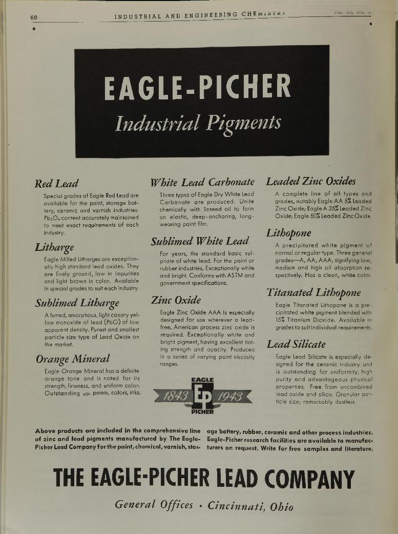
6 0 I N D U S T R I A L A N D E N G I N E E R I N G C H E M i S ï _ » £
E A G L E - P I C H E R
Industrial Pigments
R e d h e a d
S p e c ia l g ra d e s o f E a g le R ed L e a d a re
a v a i la b le f o r th e p a in t , s to r a g e b a t
te r y , c e ra m ic a n d v a rn is h in d u s tr ie s .
P b30 4 c o n te n t a c c u r a te ly m a in ta in e d
to m e e t e x a c t re q u ire m e n ts o f e a c h
in d u s try .
L i t h a r g e
E a g le M i l le d L ith a rg e s a re e x c e p t io n
a l ly h ig h s ta n d a r d le a d o x id e s . T h e y
a re f in e ly g r o u n d , lo w in im p u r it ie s
a n d l ig h t b r o w n in c o lo r . A v a i la b le
in s p e c ia l g ra d e s to s u it e a c h in d u s try .
S u b l i m e d L i t h a r g e
A fu m e d , a m o rp h o u s , l ig h t c a n a r y y e l
lo w m o n o x id e o f le a d ( P b O ) o f lo w
a p p a r e n t d e n s ity . P u re s t a n d s m a lle s t
p a r t ic le s iz e ty p e o f L ea d O x id e o n
th e m a rk e t.
O r a n g e M i n e r a l
E a g le O r a n g e M jn e r a l has a d e f in ite
o r a n g e to n e a n d is n o te d f o r its
s tre n g th , f in e n e s s , a n d u n ifo rm c o lo r .
O u t s t a n d in g (o i p a in ts , c o lo rs , inks .
W h i t e L e a d C a r b o n a t e
T h re e ty p e s o f E a g le D ry W h ite Lead
C a r b o n a t e a r e p r o d u c e d . U n i te
c h e m ic a lly w ith lin s e e d o i l to fo rm
a n e la s t ic , d e e p - a n c h o r in g , lo n g -
w e a r in g p a in t film .
S u b l i m e d W h i t e L e a d
F o r y e a rs , th e s ta n d a r d b a s ic s u l
p h a te o f w h ite le a d . F o r th e p a in t o r
r u b b e r in d u s tr ie s . E x c e p t io n a lly w h ite
a n d b r ig h t. C o n fo rm s w ith A S T M a n d
g o v e rn m e n t s p e c if ic a t io n s .
Z i n c O x i d e
E a g le Z in c O x id e A A A is e s p e c ia lly
d e s ig n e d f o r use w h e r e v e r a le a d -
fre e , A m e r ic a n p ro c e s s z in c o x id e is
r e q u ir e d . E x c e p t io n a l ly w h i te a n d
b r ig h t p ig m e n t, h a v in g e x c e l le n t t in t
in g s tre n g th a n d o p a c ity . P ro d u c e d
in a s e rie s o f v a ry in g p a in t v is c o s ity
ra n g e s .
P IC H E R
L e a d e d Z i n c O x i d e s
A c o m p le te l in e o f a l l t y p e s a n d
g r a d e s , n o t a b ly E a g le A A 5% L e a d e d
Z in c O x id e ; E a g le A 35% L e a d e d Z in c
O x id e ,- E a g le 50% L e a d e d Z in c O x id e .
L i t h o p o n e
A p r e c i p i t a t e d w h i t e p ig m e n t o f
n o rm a l o r r e g u la r ty p e . T h re e g e n e ra l
g r a d e s — A , A A , A A A , s ig n ify in g lo w ,
m e d iu m a n d h ig h o i l a b s o r p t io n re
s p e c t iv e ly . H a s a c le a n , w h i te c o lo r .
T i t a n a t e d L i t h o p o n e
E a g le T i ta n a te d L ith o p o n e is a p re
c ip i ta te d w h i te p ig m e n t b le n d e d w ith
15% T i ta n i urn D io x id e . A v a i la b le in
g r a d e s to s u it in d iv id u a l re q u ire m e n ts .
L e a d S i l i c a t e
E a g le L e a d S i l ic a te is e s p e c ia l ly d e
s ig n e d f o r th e c e ra m ic in d u s tr y a n d
is o u t s t a n d in g f o r u n i fo r m i t y , h ig h
p u r i t y a n d a d v a n t a g e o u s p h y s ic a l
p r o p e r t ie s . F re e f r o m u n c o m b in e d
le a d o x id e a n d s i l ic a . G r a n u la r p a r
t ic le s iz e ; r e m a r k a b ly d u s tle s s .
A bove products are included in the comprehensive line age battery, rubber, ceramic and other process industries, of zinc and lead pigments manufactured by The Eagle- Eagle-Picher research facilities are availab le to manufac- Picher Lead Company fo rthe paint,chemical,varnish, stor- turers on request. Write for free samples and literature.
THE EAGLE-PICHER LEAD COMPANYG e n e r a l O f f i c e s . C i n c i n n a t i , O h i o
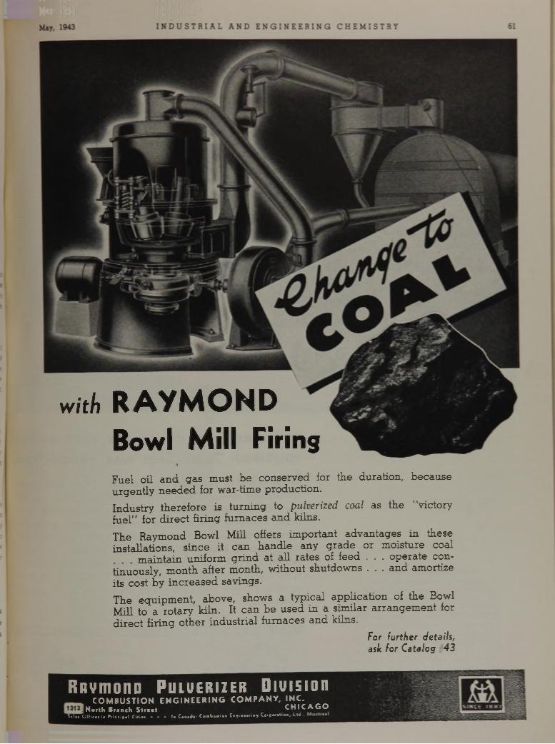
w i t h R A Y M O N D
B o w l M il l F ir in g«
Fuel oil a n d gas m ust b e con serv ed for the duration , b eca u se u rg en tly n e e d e d for w ar-tim e production .
Industry th e re fo re is tu rn in g to pulverized coal as th e "victory fu e l'' for d ire c t firing fu rn aces a n d kilns.The R aym ond Bowl Mill offers im portan t ad v an tag es in th ese installa tions, s in ce it c an h an d le any g ra d e or m oistu re coal
m ain ta in uniform g rin d at all ra tes of feed . . . o p e ra te co n tinuously , m onth afte r m onth, w ithout shutdow ns . . . an d am ortize its cost by in c re a se d savings.T he eq u ip m en t, above, show s a typ ica l a p p h ca tio n of th e Bowl M ill to a ro ta ry kiln. It c a n b e u sed in a sim ilar a rra n g e m e n t for d ire c t firing o th e r in d u s tria l fu rn aces a n d kilns.
For further details, ask for Catalog =43
Rflvm ono P u l v e r iz e r D iv is io nCO M BUSTIO N E N G IN EE R IN G
I North Branch Streetla CaiuJ«: Combmtio« Ei.*ia«*ri«s CorB<w«l‘0 «, -Lw.,
C O M P A N Y , IN C .C H IC A G O
Sales Offices ia Principal Cities
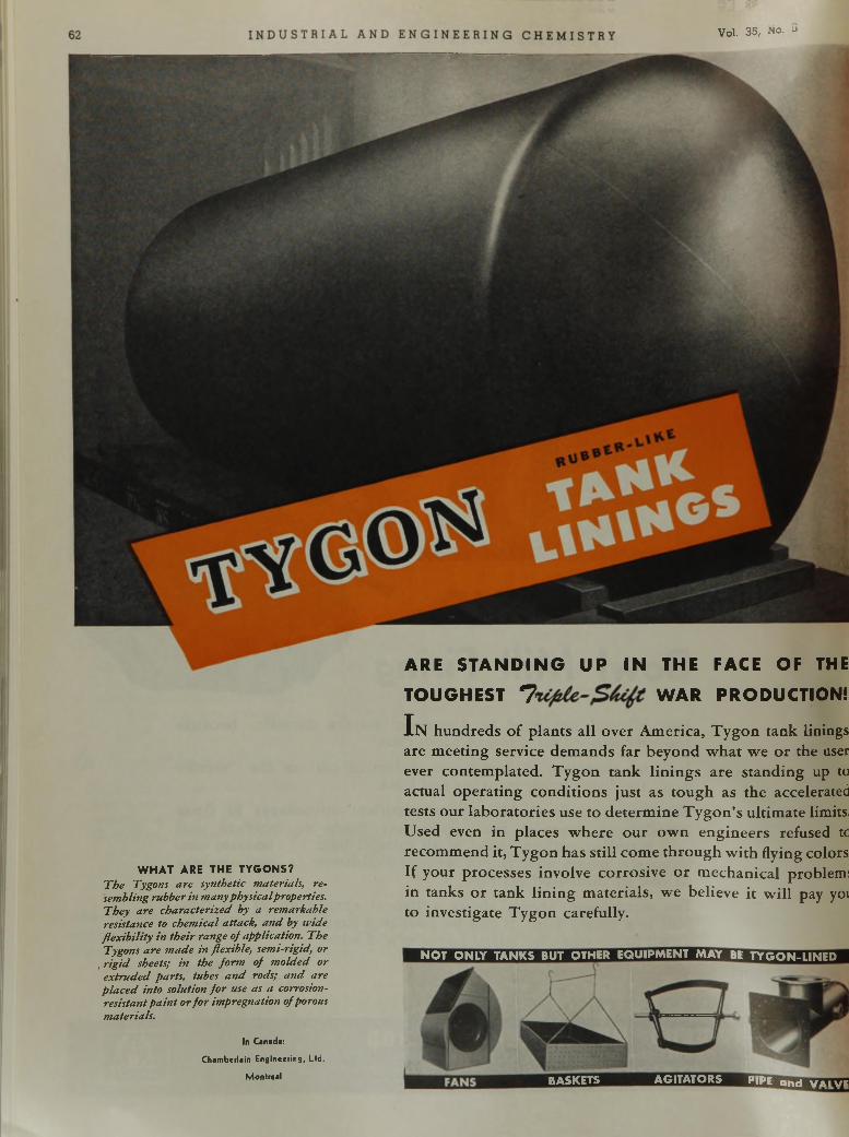
ARE STANDING UP IN THE FACE OF THE
Vol. 35, No. 3
WHAT ARE THE TYGONS?T h e Tygons are synthetic materials, resembling rubber in many physical properties. They are characterized by a remarkable resistance to chem ical attack, a n d by w ide flex ib ility in their range of application. The Tygons are m ade in flexible, semi-rigid, or
, rig id sheets; in the fo rm of m olded or extru d ed parts, tubes a n d rods; a n d are p la ced into solution fo r use as a corrosion- resistant p a in t or fo r impregnation of porous materials.
In Canada:
Chamberlain Engineering, Ltd.
Montreal
TOUGHEST 7 WAR PRODUCTION!
I n hundreds of plants all over America, T ygon tank linings are m eeting service dem ands far beyond w hat we o r the user ever contem plated. Tygon tank lin ings are standing up to actual operating conditions just as tough as the accelerated tests our laboratories use to determ ine T ygon’s ultimate limits. Used even in places w here our ow n engineers refused tc recom m end it, Tygon has still come through w ith flying colors If your processes involve corrosive o r m echanical problem: in tanks o r tank lin ing m aterials, we believe it w ill pay yoi to investigate Tygon carefully.
NOT ONLY TANKS BUT OTHER EQUIPMENT MAY BE TYGON-UNED
BASKETS AGITATORS PIPE and v a i v e
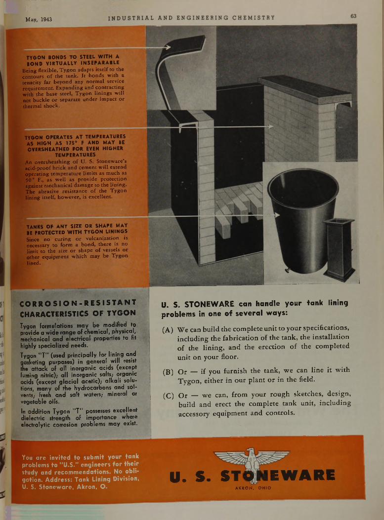
M ay, 1943
C O R R O S I O N - R E S I S T A N T
CHARACTERISTICS OF TYG O N
T y g o n f o r m u la t io n s m a y b e m o d i f i e d t o
p r o v id e a w id e r a n g e o f c h e m ic a l , p h y s ic a l , m e c h a n ic a l a n d e le c t r i c a l p r o p e r t ie s t o f i t
h ig h ly s p e c ia l iz e d n e e d s .
T y g o n “ T ” ( u s e d p r i n c i p a l l y f o r l i n i n g a n d g a s k e t in g p u r p o s e s ) in g e n e r a l w i l l re s is t
th e a t t a c k o f a l l i n o r g a n i c a c id s ( e x c e p t
fu m in g n i t r i c ) ; a l l i n o r g a n i c s a lt s ; o r g a n ic
a c id s ( e x c e p t g l a c i a l a c e t i c ) ; a l k a l i s o lu
t io n s , m a n y o f t h e h y d r o c a r b o n s a n d s o l
v e n ts ; fre s h a n d s a l t w a te rs , - m in e r a l o r
v e g e t a b le o i ls .
In a d d i t i o n T y g o n " T ” p o s s e s s e s e x c e l le n t
d ie le c t r ic s t r e n g th o f im p o r t a n c e w h e r e
e le c t r o l y t i c c o r r o s io n p r o b le m s m a y e x is t .
u. S. STONEWARE can handle your tank lining problems in one of several ways:
(A) We can build the com plete unit to your specifications, including the fabrication of the tank, the installation o f the lining, and the erection of the com pleted unit on your floor.
(B) O r — if you furnish the tank, we can line it w ith Tygon, either in our plant o r in the field.
(C) O r — we can, from your rough sketches, design, build and erect the com plete tank unit, including accessory equipm ent and controls.
TYGON BONDS TO STEEL WITH A BOND VIRTUALLY INSEPARABLE
B e in g flex ib le , T y g o n a d a p ts i t s e l f t o th e c o n to u r s o f th e ta n k . I t b o n d s w ith a te n a c ity fa r b e y o n d any n o r m a l se rv ic e r e q u ire m e n t. E x p a n d in g a n d c o n t r a c t in g w ith th e b a se s te e l , T y g o n l in in g s w il l n o t b u c k le o r s e p a ra te u n d e r im p a c t o r th e rm a l s h o c k .
TYGON OPERATES AT TEMPERATURES AS HIGH AS 175° F AND MAY BE OVERSHEATHED FOR EVEN HIGHER
TEMPERATURESA n o v e r s h e a th in g o f U . S. S to n e w a re 's a c id -p ro o f b r ic k a n d c e m e n t w il l e x te n d o p e ra t in g te m p e r a tu re l im its as m u c h as 5 0 ° F., a s w e ll a s p ro v id e p r o te c t io n a g a in s t m e c h a n ic a l d a m a g e to th e l in in g . T h e a b ra s iv e re s is ta n c e o f th e T y g o n lin in g itse lf , h o w e v e r , is e x c e lle n t .
TANKS OF ANY SIZE OR SHAPE MAY BE PROTECTED WITH TYGON LININGSS ince n o c u r in g o r v u lc a n iz a tio n is n ecessa ry to fo rm a b o n d , th e r e is n o lim it to th e s ize o r s h a p e o f v e sse ls o r o th e r e q u ip m e n t w h ic h m ay b e T y g o n lin ed .
You are invited to submit your tank problems to "U .S ." engineers for their study and recommendations. No obligation. Address: Tank Lining Division, U. S. Stoneware, Akron, O.
U. S. STONEWAREA K R O N , O H IO
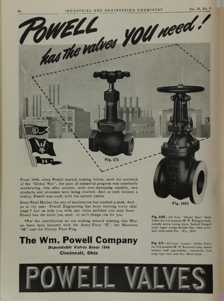
Vol. 35, No. 5
r ^ r
F r o m 1 8 4 6 , w h e n P o w e l l s t a r t e d m a k i n g v a l v e s , u n t i l t h e o u t b r e a k
o f t h e “ G l o b a l W a r ’’ , t h e p a c e o f i n d u s t r i a l p r o g r e s s w a s c o n s t a n t l y a c c e l e r a t i n g . O n e a f t e r a n o t h e r , w i t h e v e r - i n c r e a s i n g r a p i d i t y , n e w
p r o d u c t s a n d p r o c e s s e s w e r e b e i n g e v o l v e d . A n d a s e a c h b e c a m e a
r e a l i t y , P o w e l l w a s r e a d y w i t h t h e c o r r e c t v a l v e s .
S i n c e P e a r l H a r b o r t h e r a t e o f a c c e l e r a t i o n h a s r e a c h e d a p e a k . A n d — •
a s i n t h e p a s t — P o w e l l E n g i n e e r i n g h a s b e e n m e e t i n g e v e r y c h a l
l e n g e . * L e t u s h e l p y o u w i t h a n y v a l v e p r o b l e m y o u m a y h a v e —
P o w e l l h a s t h e v a l v e y o u n e e d — o r w e ’l l d e s i g n o n e f o r y o u .
* F o r t h e c o n t r i b u t i o n w e a r e m a k i n g t o w a r d w i n n i n g t h i s W a r ,
w e h a v e b e e n h o n o r e d w i t h t h e A r m y - N a v y “ E ” , t h e M a r i t i m e
“ M ” a n d t h e V i c t o r y F l e e t F l a g .
Fig. 1453
F ig . 1 4 5 3 — A l l I r o n “ M o d e l S ta r ” G a te V a lv e f o r 125 p o u n d s W . P . F la n g e d ends , o u ts id e s c re w r is in g s te m , b o l te d f la n g e d y o k e , ta p e r w e d g e d o u b le d is c . A ls o a v a i l a b le w i t h s o lid d is c — F ig . 1816.
The Wm. Powell CompanyD e p e n d a b l e V a l v e s S i n c e 1 8 4 6
C i n c i n n a t i , O h io
F ig . 1 71 — A l l I r o n “ I r e n e w ” G lo b e V a lv e fo r 150 p o u n d s W . P . S c re w e d e n d s , u n io n b o n n e t a n d re g r in d a b le , re n e w a b le i r o n p lu g ty p e s e a t a n d d is c . S te e l s te m .
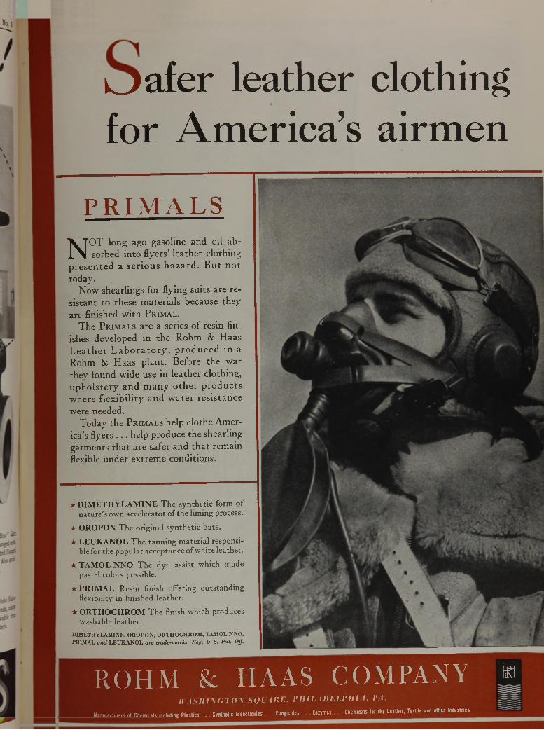
k j a f e r l e a t h e r c l o t h i n g
f o r A m e r i c a ’ s a i r m e n
P R I M A L S
N O T l o n g a g o g a s o l i n e a n d o i l a b
s o r b e d i n t o f l y e r s ’ l e a t h e r c l o t h i n g
p r e s e n t e d a s e r i o u s h a z a r d . B u t n o t
t o d a y .
N o w s h e a r l i n g s f o r f l y i n g s u i t s a r e r e
s i s t a n t t o t h e s e m a t e r i a l s b e c a u s e t h e y
a r e f i n i s h e d w i t h P r i m a l .
T h e P r i m a l s a r e a s e r i e s o f r e s i n f i n
i s h e s d e v e l o p e d i n t h e R o h m & H a a s
L e a t h e r L a b o r a t o r y , p r o d u c e d i n a
R o h m & H a a s p l a n t . B e f o r e t h e w a r
t h e y f o u n d w i d e u s e i n l e a t h e r c l o t h i n g ,
u p h o l s t e r y a n d m a n y o t h e r p r o d u c t s
w h e r e f l e x i b i l i t y a n d w a t e r r e s i s t a n c e
w e r e n e e d e d .
T o d a y t h e P r i m a l s h e l p c l o t h e A m e r
i c a ’s f l y e r s . . . h e l p p r o d u c e t h e s h e a r l i n g
g a r m e n t s t h a t a r e s a f e r a n d t h a t r e m a i n
f l e x i b l e u n d e r e x t r e m e c o n d i t i o n s .
★ D IM E T H Y L A M IN E T h e sy n th e tic fo rm o f n a tu re ’s ow n a cc e le ra to r o f th e lim ing process.
★ O R O P O N T h e o rig in a l sy n th e tic b a te .
★ L E U K A N O L T h e ta n n in g m a te r ia l resp o n sible for th e p o p u la r a cc ep ta n ce o f w h ite lea th e r.
★ T A M O L N N O T h e d y e a ss is t w hich m ad e paste l co lors possib le .
★ P R IM A L R esin finish o ffering o u ts ta n d in g flexibility in fin ished le a th e r .
★ O R T H O C H R O M T h e finish w hich p roduces w ashab le le a th e r .
DIMETHYLAMINE, OROPON, ORTHOCHROM, TAMOL NNO,PRIMAL and LEUKANOL are trade-marks, Reg. U. S. Pat. Off.
R O H M & H A A S C O M P A N Y m
n t \ S I I I \ G T O \ S Q L U t E , P H I L A D E L P H I A . VA.
Manufacturers „I Chemicak including Plastics . . . Synthetic Insecticides . . . Fungicides . . Enzymes . . . Chemicals tor the Leather. Textile and other Industries
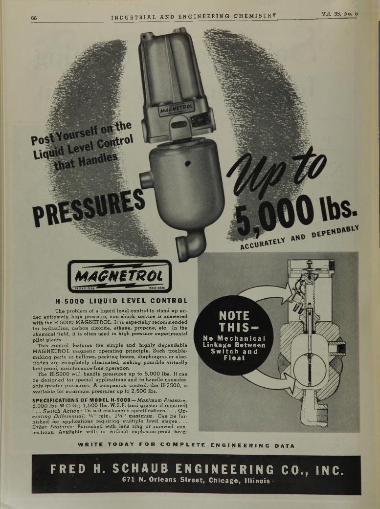
66 I N D U S T R I A L A N D E N G I N E E R I N G C H E M I S T R Y Vol. 35, w o. 3
M A G m m o L
NOTETHIS-
N o M e c h a n i c a l
L i n k a g e B e t w e e n S w i t c h a n d
F l o a t
H - 5 0 0 0 L I Q U I D L E V E L C O N T R O L
T h e p r o b le m o f a l iq u id le v e l c o n t r o l to s ta n d u p u n d e r e x t r e m e ly h ig h p re s s u re , n o n - s h o c k s e rv ic e is a n s w e re d w i t h th e H - 5 0 0 0 M A G N E T R O L . I t is e s p e c ia l ly re c o m m e n d e d fo r h y d r a u l ic s , c a rb o n d io x id e , e th a n e , p ro p a n e , e tc . I n th e c h e m ic a l f ie ld , i t is o f te n u s e d in h ig h p re s s u re e x p e r im e n ta l p i l o t p la n ts .
T h is c o n t r o l fe a tu re s th e s im p le a n d h ig h ly d e p e n d a b le M A G N E T R O L m a g n e t ic o p e r a t in g p r in c ip le . S u c h t r o u b le - m a k in g p a r ts as b e l lo w s , p a c k in g b o x e s , d ia p h r a g m s o r e le c t r o d e s a re c o m p le te ly e l im in a te d , m a k in g p o s s ib le v i r t u a l l y f o o l- p r o o f , m a in te n a n c e - f re e o p e r a t io n .
T h e H - 5 0 0 0 w i l l h a n d le p re s s u re s u p to 5 , 0 0 0 lb s . I t c a n b e d e s ig n e d fo r s p e c ia l a p p l ic a t io n s a n d to h a n d le c o n s id e r a b ly g re a te r p re s s u re s . A c o m p a n io n c o n t r o l , th e H - 2 5 0 0 , is a v a i la b le fo r m a x im u m p re s s u re s u p to 2 ,5 0 0 lb s .
S P E C IF IC A T IO N S O F M O D E L H - 5 0 0 0 — M a xim u m P ressure:5 ,0 0 0 lb s . W .O .G . ; 1 ,5 0 0 lb s . W .S .P . (a n d g re a te r i f r e q u ir e d ). .. . S w itc h A c tio n : T o s u it c u s to m e r 's s p e c i f ic a t io n s . . . O p e ra tin g D if fe r e n t ia l : 34 " m in . , 1 1 4 " m a x im u m . C a n b e f u r n is h e d fo r a p p l ic a t io n s r e q u i r in g m u l t ip le le v e l s ta g e s . . .O th er F ea tu re s: F u r n is h e d w i t h le n s r in g o r s c re w e d c o n n e c t io n s . A v a i la b le w i t h o r w i t h o u t e x p lo s io n - p r o o f h e a d .
W R I T E T O D A Y F O R C O M P L E T E E N G I N E E R I N G D A T A
FRED H. SCHAUB ENGINEERING CO., INC.6 7 1 N . O r l e a n s S t r e e t , C h i c a g o , I l l i n o i s •
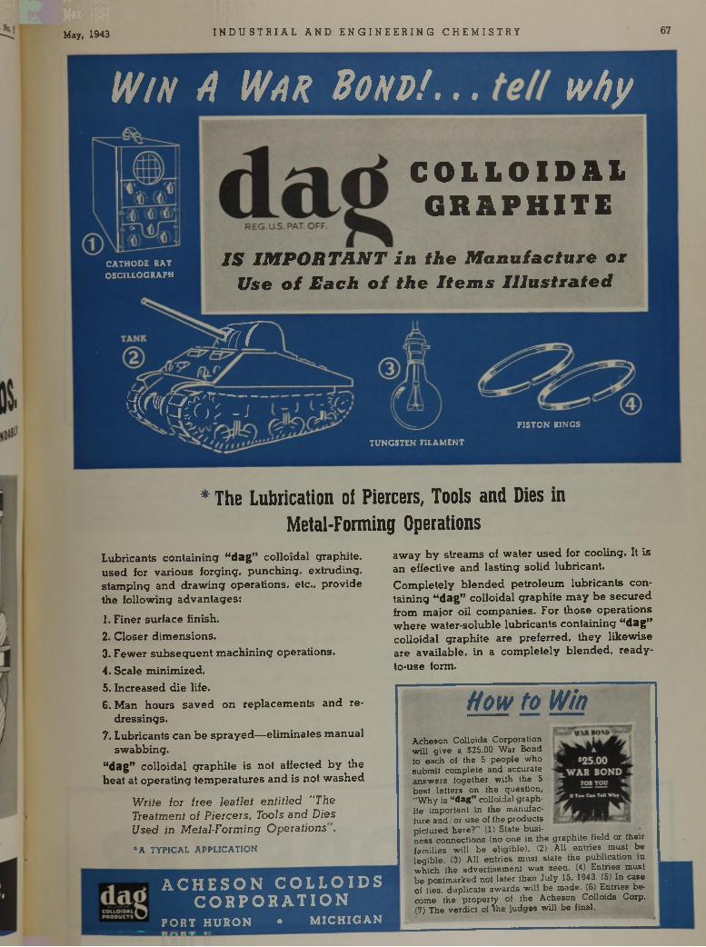
May, 1943 I N D U S T R I A L A N D E N G I N E E R I N G C H E M I S T R Y 67
W i n A W a n B o n d ! . .. w h y
CATHODE BAY OSCILLOGRAPH
C O L L O I D A L G R A P H I T E
I S I M P O R T A N T i n t h e M a n u f a c t u r e o r
U s e o i E a c h o f t h e I t e m s I l l u s t r a t e d
sf i T
T O r . rPISTON RINGS
TUNGSTEN FILAMENT
* T h e L u b r i c a t i o n o i P i e r c e r s , T o o l s a n d D ies i n
M e t a l - F o r m i n g O p e r a t i o n s
Lubricants containing “ dag” colloidal graphite, used for various forging, punching, extruding, stamping and draw ing operations, etc., provide the following advantages:
1. Finer surface finish.
2. C loser dim ensions.
3. Few er subsequent m achining operations.
4. Scale m inim ized.
5. Increased die life.
6. Man hours saved on replacem ents and re- dressings.
7. Lubricants can be sp rayed— elim inates m anual swabbing.
“dag” colloidal graphite is not affected b y the heat at operating temperatures and is not w ashed
W r i t e l o r i r e e l e a f l e t e n t i t l e d " T h e T r e a t m e n t o i P i e r c e r s , T o o l s a n d D i e s U s e d i n M e t a l - F o r m i n g O p e r a t i o n s .
* A T Y P IC A L A PP LIC A T IO N
A C H E S O N C O L L O I D S
C O R P O R A T I O N
PORT HURON • MICHIGAN
aw ay by streams of water used for cooling. It is an effective and lasting solid lubricant.
Com pletely blended petroleum lubricants containing “dag” colloidal graphite m ay be secured from major oil com panies. For those operations w here water-soluble lubricants containing “ dag” colloidal graphite are preferred, they likew ise are available, in a com pletely blended, ready- to-use form.
H o w to W in
A c h e s o n C o llo id s C o rp o ra tio n w i l l g iv e a S25.00 W a r B ond to each o f th e 5 p e o p le w h o s u b m it c o m p le te and accura te a n s w e rs to g e th e r w ith th e 5 b e s t le t te rs o n th e q ue s tio n ," W h y is “ d a g ” c o llo id a l g ra p h ite im p o rta n t in th e m a nu fac tu re a n d /o r use o f th e p ro d u c ts p ic tu re d h e re ? " (1) S la te bus i- ness co n n e c tio n s (no one in th e g ra p h ite f ie ld o r th e ir fa m ilie s w i l l be e lig ib le ) . (2) A l l e n tr ie s m u s t be le g ib le . (3) A l l e n tr ie s m us t s ta le the p u b lic a t io n in w h ic h th e a d v e rt is e m e n t w as seen. (4) E n tr ie s m us t b e p o s tm a rk e d n o t la te r th a n J u ly 15, 1943. (5) In case o f tie s , d u p lic a te a w a rd s w i l l be m ade. (B) E n tr ie s b e com e th e p ro p e r ty o f th e A c h e s o n C o llo id s C o rp .(7) The v e rd ic t o i The ju d g e s w i l l b e f in a l.
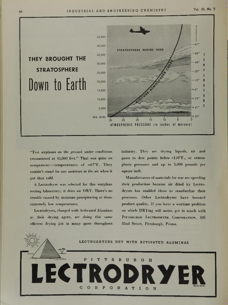
6 8 I N D U S T R I A L A N D E N G I N E E R I N G C H E M I S T R Y Vol. 35, No. 5
T H E Y B R O U G H T T H E
S T R A T O S P H E R E
Down to Earth
“ T e s t a i r p la n e s o n t h e g r o u n d u n d e r c o n d i t i o n s
e n c o u n t e r e d a t 4 5 , 0 0 0 f e e t . ” T h a t w a s q u i t e a n
a s s i g n m e n t — t e m p e r a t u r e s o f —6 7 ° F . T h e y
c o u l d n ’t s t a n d f o r a n y m o i s t u r e i n t h e a ir w h e n i t
g o t t h a t c o l d .
A L e c t r o d r y e r w a s s e l e c t e d f o r t h i s w a r p la n e
t e s t i n g l a b o r a t o r y ; i t d r ie s a ir D R Y . T h e r e ’s n o
t r o u b l e c a u s e d b y m o i s t u r e p r e c i p i t a t i n g a t t h o s e
e x t r e m e l y l o w t e m p e r a t u r e s .
L e c t r o d r y e r s , c h a r g e d w i t h A c t i v a t e d A l u m i n a s
a s t h e i r d r y i n g a g e n t , a r e d o in g t h i s s a m e
e f f i c i e n t d r y i n g j o b in m a n y s p o t s t h r o u g h o u t
i n d u s t r y . T h e y a r e d r y i n g l i q u i d s , a ir a n d
g a s e s t o d e w p o i n t s b e l o w —1 1 0 ° F . , a t a t m o s
p h e r i c p r e s s u r e s a n d u p t o 3 , 0 0 0 p o u n d s p e r
s q u a r e i n c h .
M a n u f a c t u r e r s o f m a t e r i a l s f o r w a r a r e s p e e d i n g
t h e i r p r o d u c t i o n b e c a u s e a ir d r i e d b y L e c t r o
d r y e r s h a s e n a b l e d t h e m t o s t a n d a r d i z e t h e i r
p r o c e s s e s . O t h e r L e c t r o d r y e r s h a v e b o o s t e d
p r o d u c t q u a l i t y . I f y o u h a v e a w a r t i m e p r o b l e m
o n w h i c h D R Y i n g w i l l a s s i s t , g e t i n t o u c h w i t h
P i t t s b u r g h L e c t r o d r y e r C o r p o r a t i o n , 3 0 5
3 2 n d S t r e e t , P i t t s b u r g h , P e u n a .
L E C T R O D R Y E R S D R Y W I T H A C T I V A T E D A L U M I N A S
P I T T S B U R G H
L E C T R O D R Y E R^ _ KM.s.Nion.
C O R P O R A T I O N
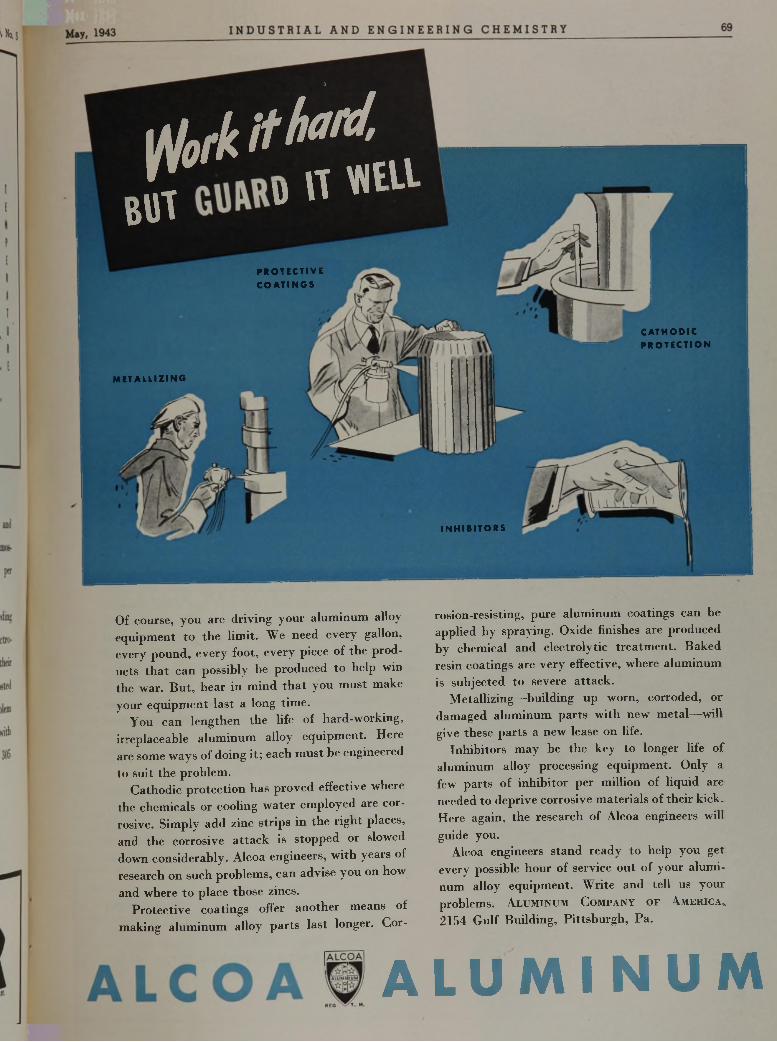
f l o f k i t h o l d , ,B{ i w w n « u -
0
PROTECTIVEC O A T IN G S
CATHODICPR O TEC TIO N
METALLIZING
IN H IB ITO R S
O f c o u r s e , y o u a r e d r i v i n g y o u r a l u m i n u m a l l o y
e q u i p m e n t t o t h e l i m i t . W e n e e d e v e r y g a l l o n ,
e v e r y p o u n d , e v e r y f o o t , e v e r y p i e c e o f t h e p r o d
u c t s t h a t c a n p o s s i b l y h e p r o d u c e d t o h e l p w in
t h e w a r . B u t , b e a r i n m i n d t h a t y o u m u s t m a k e
y o u r e q u i p m e n t l a s t a l o n g t i m e .
Y o u c a n l e n g t h e n t h e l i f e o f h a r d - w o r k i n g ,
i r r e p l a c e a b l e a l u m i n u m a l l o y e q u i p m e n t . H e r e
a r e s o m e w a y s o f d o i n g i t ; e a c h m u s t b e e n g i n e e r e d
t o s u i t t h e p r o b l e m .
C a t h o d i c p r o t e c t i o n h a s p r o v e d e f f e c t i v e w h e r e
t h e c h e m i c a l s o r c o o l i n g w a t e r e m p l o y e d a r e c o r
r o s i v e . S i m p l y a d d z i n c s t r i p s i n t h e r i g h t p l a c e s ,
a n d t h e c o r r o s i v e a t t a c k i s s t o p p e d o r s l o w e d
d o w n c o n s i d e r a b l y . A l c o a e n g i n e e r s , w i t h y e a r s o f
r e s e a r c h o n s u c h p r o b l e m s , c a n a d v i s e y o u o n h o w
a n d w h e r e t o p l a c e t h o s e z i n c s .
P r o t e c t i v e c o a t i n g s o f f e r a n o t h e r m e a n s o f
m a k i n g a l u m i n u m a l l o y p a r t s l a s t l o n g e r . C o r -
A
r o s i o n - r e s i s t i n g , p u r e a l u m i n u m c o a t i n g s c a n b e
a p p l i e d b y s p r a y i n g . O x i d e f i n i s h e s a r e p r o d u c e d
b y c h e m i c a l a n d e l e c t r o l y t i c t r e a t m e n t . B a k e d
r e s in c o a t i n g s a r e v e r y e f f e c t i v e , w h e r e a l u m i n u m
i s s u b j e c t e d t o s e v e r e a t t a c k .
M e t a l l i z i n g — b u i l d i n g u p w o r n , c o r r o d e d , o r
d a m a g e d a l u m i n u m p a r t s w i t h n e w m e t a l — w i l l
g i v e t h e s e p a r t s a n e w l e a s e o n l i f e .
I n h i b i t o r s m a y b e t h e k e y t o l o n g e r l i f e o f
a l u m i n u m a l l o y p r o c e s s i n g e q u i p m e n t . O n l y a
f e w p a r t s o f i n h i b i t o r p e r m i l l i o n o f l i q u i d a r e
n e e d e d t o d e p r i v e c o r r o s i v e m a t e r i a l s o f t h e i r k i c k .
H e r e a g a i n , t h e r e s e a r c h o f A l c o a e n g i n e e r s w i l l
g u i d e y o u .
A l c o a e n g i n e e r s s t a n d r e a d y t o h e l p y o u g e t
e v e r y p o s s i b l e h o u r o f s e r v i c e o u t o f y o u r a l u m i
n u m a l l o y e q u i p m e n t . W r i t e a n d t e l l u s y o u r
p r o b l e m s . A l u m i n u m C o m p a n y o f A m e r i c a ,,
2 1 5 4 G u l f B u i l d i n g , P i t t s b u r g h , P a .
L U M I N U M
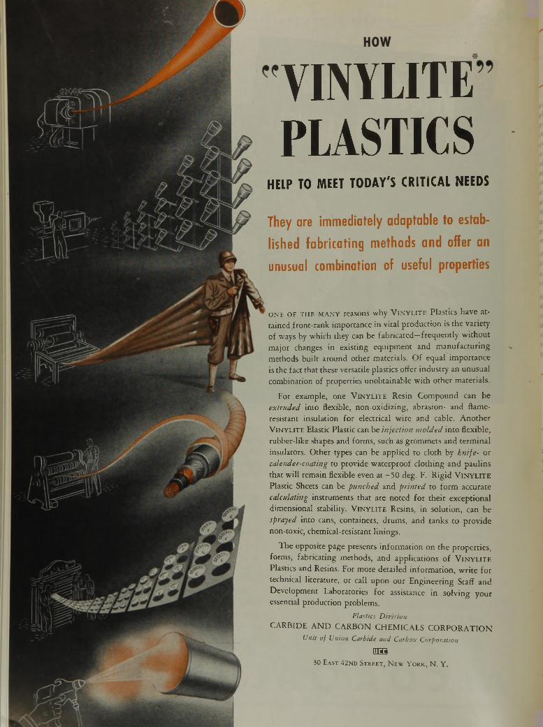
V IN Y L IT E F U S T I C S
HELP TO MEET TODAY'S CRITICAL NEEDS
They are immediately adaptable to established fabricating methods and offer an unusual combination of useful properties
o n e o f t h e m a n y reasons w hy V in y l it e P lastic s h a v e a t
ta in ed fro n t-ra n k im p o rtan ce in v ita l p ro d u c tio n is th e v a rie ty o f ways by w h ich they can be fa b ric a te d —fre q u e n tly w ith o u t m a jo r changes in e x is tin g e q u ip m e n t a n d m a n u fa c tu r in g
m eth o d s b u ilt a ro u n d o th e r m ate ria ls . O f e q u a l im p o rta n c e is th e fact th a t these versa tile p las tic s o ffer in d u s try an u n u su a l co m b in a tio n o f p ro p e rtie s u n o b ta in a b le w ith o th e r m ate ria ls .
F o r exam ple, one V i n y l i t e R esin C o m p o u n d can b e ex tru d e d in to flexible, n o n -o x id iz in g , ab rasio n - a n d flam e- resis tan t in su la tio n fo r e lectrica l w ire a n d cable. A n o th e r
V i n y l i t e E lastic P lastic can be in je c tio n m o ld e d in to flex ib le, ru b b e r-lik e shapes an d fo rm s, such as g ro m m e ts a n d te rm in a l
insu la to rs. O th e r types can be a p p lie d to c lo th by k n ife - o r ca lender-coating to p ro v id e w a te rp ro o f c lo th in g a n d p a u lin s th a t w ill rem ain flexib le even at - 5 0 deg . F. R ig id V i n y l i t e P lastic Sheets can be p u n c h ed a n d p r in te d to fo rm accu ra te
ca lcu la ting in s tru m en ts th a t a re n o te d fo r th e ir ex ce p tio n a l d im en sio n a l stability . V i n y l i t e R esins, in so lu tio n , can be sprayed in to cans, co n ta in ers , d ru m s, a n d tan k s to p ro v id e non-tox ic , chem ica l-resis tan t lin in g s .
T h e o p p o site p ag e p re sen ts in fo rm a tio n o n th e p ro p e rtie s , fo rm s, fab rica tin g m eth o d s , an d a p p lic a tio n s o f V in y l it e P lastics an d R esins. F o r m o re d e ta ile d in fo rm a tio n , w r i te fo r techn ica l lite ra tu re , o r call u p o n o u r E n g in e e r in g S taff a n d
D e v e lo p m en t L abo ra to ries fo r assistance in so lv in g y o u r essen tia l p ro d u c tio n p ro b lem s.
Plastics DivisionC A R B ID E A N D C A R B O N C H E M IC A L S C O R P O R A T IO N
Unit of Union Carbide and Carbon Corporation
Q H 9
30 E a s t 42 nd S t r e e t , N e w Y o r k , N . Y .
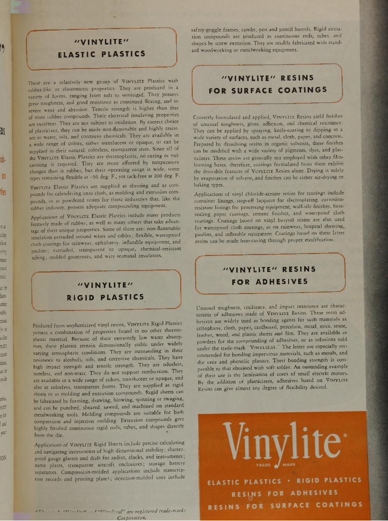
))
¡Di
i
ont i«
re l
ujar
á n
nrm|T
macs
mai!
eriiii.
¡ait
im- wtbe
l i t
minii
ft- ot joiios
Yiin
COffiE
DOful
aa be
wide
ate.
n jit
tef«
iaad
tool
ION
" V I N Y L I T E "
E L A S T I C P L A S T I C S
These are a re la t iv e ly new g ro u p o f V i n y l it e P lastics w ith
rubbe r-like o r e la s to m e ric p ro p e rtie s . T h e y are p rod u ce d in a
varie ty o f fo rm s , ra n g in g fro m s o ft to s e m ir ig id . T h e y possess
great toughness, and g oo d resistance to c o n tin u e d fle x in g , and to
severe w ear and ab ras ion . T e n s ile s tre n g th is h ig h e r than th a t
o f most ru bb e r com pounds. T h e ir e le c tr ica l in s u la tin g p rop e rtie s
are exce llen t. T h e y are n o t su b je c t to o x id a tio n . B y co rrec t choice
o f p las tic ize r, they can be m ade n o n -fla m m a b le and h ig h ly res is t
ant to w a te r, o ils , and co rros ive chem ica ls . T h e y are a v a ila b le in
a w ide range o f co lo rs , e ith e r tra n s lu c e n t o r opaque, o r can be
supplied in th e ir n a tu ra l, co lo rless , tra n sp a re n t state. S ince a ll o f
the V i n y l it e E la s tic P lastics are th e rm o p la s tic , no c u r in g o r v u l
canizing is re q u ire d . T h e y are m ore a ffec ted by te m p e ra tu re
changes than is ru b b e r, b u t th e ir o p e ra tin g range is w id e , some
types re m a in in g fle x ib le a t - 5 0 deg. F „ ye t ta ck -fre e at 200 deg. F.
V in y l it e E las tic P las tics are s u p p lie d as shee ting and as com
pounds fo r ca le n d e rin g o n to c lo th , as m o ld in g and e x tru s io n com
pounds, o r as pow d e red res ins fo r those in d u s tr ie s th a t, l ik e the
rubber in d u s try , possess adequate c o m p o u n d in g e q u ip m e n t.
A p p lica tion s o f V in y l i t e E la s tic P las tics in c lu d e m any p rod u c ts
fo rm e rly m ade o f ru b b e r, as w e l l as m any o the rs th a t take advan
tage o f th e ir u n iq u e p ro p e rtie s . Some o f these a re : n on -fla m m a b le
insu la tion e x tru d e d a ro u n d w ire s and cab les ; f le x ib le , w a te rp ro o f
c loth coatings fo r ra in w e a r, u p h o ls te ry , in f la ta b le e q u ip m e n t, and
p a u lin s ; e x tru d e d , tra n sp a re n t o r opaque, ch em ica l-re s is ta n t
tu b in g ; m o ld e d g rom m e ts , and w ire te rm in a l in s u la to rs .
" V I N Y L I T E 7'
R I G I D P L A S T I C S
Produced fro m u np la s tic iz e d v in y l resins, V i n y l it e R ig id P lastics
possess a co m b in a tio n o f p ro p e rtie s fo u n d in no o th e r th e rm o
plastic m a te ria l. Because o f th e ir e x tre m e ly lo w w a te r absorp
tion, these p las tics re m a in d im e n s io n a lly stab le u n d e r w id e ly
vary ing a tm osphe ric c o n d itio n s . T h e y are o u ts ta n d in g in th e ir
resistance to a lco h o ls , o ils , and co rros ive chem ica ls . T h e y have
high im pac t s tre n g th and te n s ile s tre n g th . T h e y are odorless,
tasteless, and n o n -to x ic . T h e y do n o t s u p p o rt co m b u s tio n . T h e y
are ava ilab le in a w id e range o f co lo rs , tra n s lu ce n t o r opaque, and
also in co lo rless, tra n sp a re n t fo rm s . T h e y are s u p p lie d as r ig id
sheets o r as m o ld in g and e x tru s io n co m po u n ds . R ig id sheets can
be fabricated by fo rm in g , d ra w in g , b lo w in g , s p in n in g o r sw ag in g ,
and can be punched, sheared, sawed, and m ach ined on s tandard
m e ta lw o rk in g to o ls . M o ld in g co m po u n ds are s u ita b le fo r b o th
compression and in je c tio n m o ld in g . E x tru s io n com pounds g ive
h ig h ly fin ished c o n tin u o u s r ig id rods, tubes, and shapes d ire c tly
fro m the d ie .
A p p lica tio n s o f V i n y l it e R ig id Sheets in c lu d e precise c a lc u la tin g
¿nd n a v ig a tin g in s tru m e n ts o f h ig h d im e n s io n a l s ta b il i ty , shatte r
p roo f gauge glasses and d ia ls fo r ra d io s , c locks, and in s tru m e n ts ,
name p la tes, tra n sp a re n t a irc ra ft enclosures ; sto rage b a tte r}
separators. C om p re ss io n -m o ld e d a p p lic a tio n s in c lu d e tra n s c r ip
tio n records and p r in t in g p la te s ; in je c tio n -m o ld e d uses in c lu d e
sa fe ty -g o gg le fram es, com bs, pen and p e n c il ba rre ls . R ig id e x tru
s ion com pounds are p roduced as c o n tin u o u s rods, tubes, and
shapes by screw e x tru s io n . T h e y are re a d ily fa b rica te d w ith stand
ard w o o d w o rk in g o r m e ta lw o rk in g e q u ip m e n t.
" V I N Y L I T E " R E S I N S
F O R S U R F A C E C O A T I N G S
C o rre c tly fo rm u la te d and a p p lie d , V in y l it e Resins y ie ld fin ishes
o f unu su a l toughness, g loss, adhesion , and chem ica l resistance.
T h e y can be a p p lie d by sp ray in g , k n ife -c o a tin g o r d ip p in g to a
w id e v a rie ty o f surfaces, such as m e ta l, c lo th , paper, and concrete.
P repared by d is s o lv in g resins in o rg a n ic so lven ts, these fin ishes
can be m o d ifie d w ith a w id e v a rie ty o f p igm en ts , dyes, and plas-
t ic ize rs . These resins are g en e ra lly n o t em ployed w ith o th e r f i lm -
fo rm in g bases, th e re fo re , coatings fo rm u la te d fro m them e x h ib it the des irab le fea tu res o f V in y l it e Resins a lone. D ry in g is so le ly by e vap o ra tion o f so lven t, and fin ishes can be e ith e r a ir -d ry in g o r
b a k in g types.
A p p lic a tio n s o f v in y l ch lo ride -ace ta te resins fo r coatings in c lu d e
co n ta in e r lin in g s , s to p -o ff lacquers fo r e le c tro p la tin g , c o rros io n -
res is tan t l in in g s fo r processing e qu ip m en t, w a l l- t i le fin ishes, heat-
sea ling paper coatings, cem ent fin ishes, and w a te rp ro o f c lo th coatings. C oa tings based on v in y l b u ty ra l resins are also used
fo r w a te rp ro o f c lo th coatings, as on ra in w e a r, h o s p ita l shee ting ,
p au lins , and in f la ta b le e qu ip m en t. C oa tings based on these la t te r
resins can be m ade h e a t-cu rin g th ro u g h p ro p e r m o d ific a tio n .
" V I N Y L I T E " R E S I N S
F O R A D H E S I V E S
U n u s u a l toughness, res iliency , and im p a c t resistance are charac
te r is tic o f adhesives m ade o f V i n y l it e Resins. These res in ad
hesives are w id e ly used as b o n d in g agents fo r such m a te ria ls as
ce llophane , c lo th , paper, ca rdboard , p o rce la in , m e ta l, m ica , stone,
lea th e r, w o o d , and p la s tic sheets and f i lm . T h e y are a va ila b le as p ow de rs fo r the c o m p o u n d in g o f adhesives, o r as s o lu tio n s so ld u n d e r the tra d e -m a rk V in y l s e a l . T h e la t te r are espec ia lly rec
om m ended fo r b o n d in g im p e rv io u s m a te ria ls , such as m eta ls , and
the urea and p h e n o lic p lastics. T h e ir b o n d in g s tre n g th is com
p arab le to th a t o b ta in e d w ith s o ft so lde r. A n o u s ta n d in g e xam p le
o f th e ir use is the la m in a t io n o f cores o f sm a ll e le c tr ic m o to rs .
B y the a d d it io n o f p la s tic ize rs , adhesives based on V i n y l it e
Resins can g iv e a lm o s t any degree o f f le x ib i l i ty des ired .
- t i - j . i-.-it ... -i are registered trade-marksCorporation.
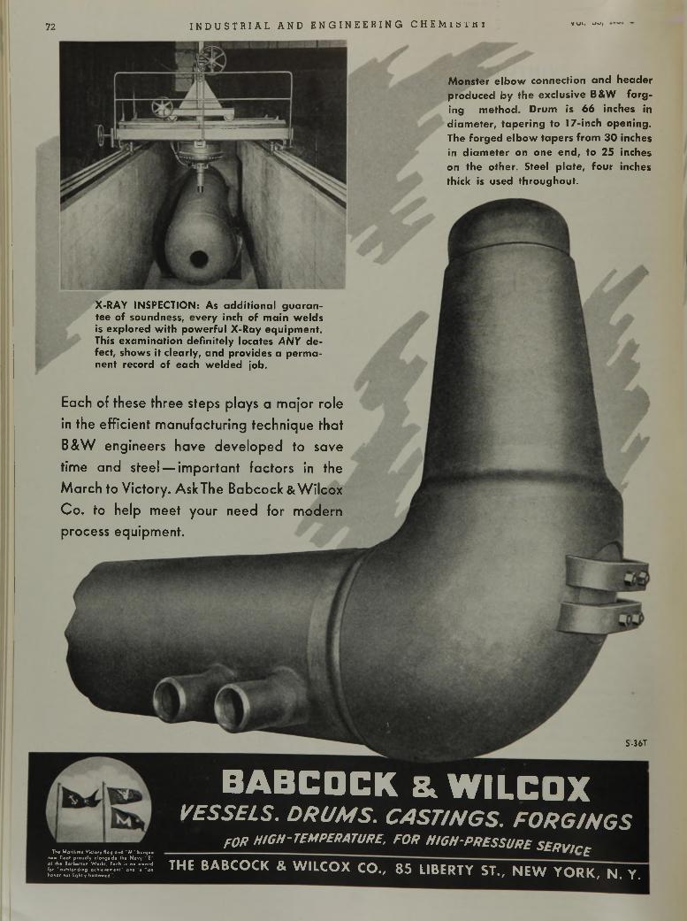
72 I N D U S T R I A L A N D E N G I N E E R I N G C H E M i s i i t i v v i . sJsSf
1
X-RAY INSPECTION: As additional guarantee of soundness, every inch of main welds is explored with powerful X-Ray equipment. This examination definitely locates AN Y defect, shows it clearly, and provides a permanent record of each welded job.
Monster elbow connection and header produced by the exclusive B&W forging method. Drum is 66 inches in diam eter, tapering to 17-inch opening. The forged elbow tapers from 30 inches in d iam eter on one end, to 25 inches on the other. Steel plate, four inches thick is used throughout.
E a c h o f t h e s e t h r e e s t e p s p l a y s a m a j o r r o l e
i n t h e e f f i c i e n t m a n u f a c t u r i n g t e c h n i q u e t h a t
B & W e n g i n e e r s h a v e d e v e l o p e d t o s a v e
t i m e a n d s t e e l — i m p o r t a n t f a c t o r s i n t h e
M a r c h t o V i c t o r y . A s k T h e B a b c o c k & W i l c o x
C o . t o h e l p m e e t y o u r n e e d f o r m o d e r n
p r o c e s s e q u i p m e n t .
S-36T
The Maritime Victory flog and "M" burgee now float proudly olongiide the Navy "E" at the Barberton Works. Each ii an award for "outstanding achievement" and is "an honor not lightly bellowed".
BABCDCK & WILCOXV E S S E L S . D R U M S . C A S T / N G S . F O R G / N G S
FOR HIGH-TEMPERATURE, FOR HIGH-PRESSURE SERVir.F
THE BABCO CK & W ILCOX CO., 8 5 LIBERTY ST., N EW Y O R K , N. Y.
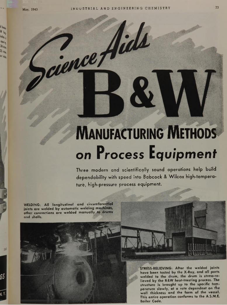
May, 1943 I N D U S T R I A L A N D E N G I N E E R I N G C H E M I S T R Y 73
Wir:
Indies
¡«dis
indisw
Manufacturing Methods
o n P r o c e s s E q u i p m e n t
T h r e e m o d e r n a n d s c i e n t i f i c a l l y s o u n d o p e r a t i o n s h e l p b u i l d
d e p e n d a b i l i t y w i t h s p e e d i n t o B a b c o c k & W i l c o x h i g h - t e m p e r a -
t u r e , h i g h - p r e s s u r e p r o c e s s e q u i p m e n t .
STRESS-RELIEVING: After the welded joints have been tested by the X-Ray, and all parts welded to the drum, the drum is stress-relieved by the B&W heat-treating process. The structure is brought up to the specific tem perature slowly, at a rate dependent on the w all thickness and the form of the vessel. This entire operation conforms to the A.S.M.E. Boiler Code.
WELDING: All longitudinal and circum ferential joints are welded by autom atic w eld ing machines, other connections are w elded m anually to drums and shells.
74 I N D U S T R I A L A N D E N G I N E E R I N G C H E r a i o i n i V U i. W/W/
TWO SUPER REFRACTORIES THAT OPERATE SAFELY AT
3 2 0 0 ^ 4 0 0 0 7T A M Z i r c o n ( Z i r c o n i u m S i l i c a t e ) r e
f r a c t o r i e s o p e r a t e s a f e l y a t t e m p e r
a t u r e s o v e r 3 2 0 0 ° F . w h i l e T A M
Z i r c o n i u m O x i d e r e f r a c t o r i e s a r e
u s e d in a p p l i c a t i o n s o v e r 4 0 0 0 ° F .
T h e s e t w o T A M s u p e r r e f r a c t o r i e s
r e s i s t a c i d s a n d o x i d i z i n g a t m o s
p h e r e s . T h e y a r e b e i n g s u c c e s s f u l l y
u s e d i n t h e m a n u f a c t u r e o f p h o s -
" ---------------A M P * O d , 3 C V ;
oM' V V
p h a t e s , f u s e d s i l i c a , a l u m i n u m m e l t
i n g a n d p l a t i n u m s m e l t i n g . T h e y a r e
a l s o w i d e l y u s e d a s c r u c i b l e b a c k
i n g a n d f o r v a r i o u s h i g h t e m p e r a
t u r e a p p l i c a t i o n s .
A n e x p e r i e n c e d s t a f f o f f i e l d e n g i
n e e r s l o c a t e d i n v a r i o u s p a r t s o f
t h e c o u n t r y a r e a v a i l a b l e f o r c o n
s u l t a t i o n s w i t h o u t o b l i g a t i o n . W r i t e :
TITANIUMALLOY M ANUFACTURING CO M PA NY
G E N E R A L O F F I C E S A N D W O R K S : N I A G A R A F A L L S , N . Y. , U. S. A .
E X E C U T I V E O F F I C E S : 111 B R O A D W A Y , N E W Y O R K C I T Y
R e p re s e n ta t iv e s f o r th e Pacific Coos, S ta te ............................ H. BUTCHER COMPANY, t o s A ngeles , San Francisco, P o r t i a n d , S e a t t l eR e p re s e n ta t iv e s f a r Europe
' i^ÆÊÊÊÊKÊÊ^ÊÊÊÊÊtÊIÊKÊI^aKÊÊ
UNION OXIDE » CHEMICAL CO.. l , d „ .......................................... „ „ £ ^
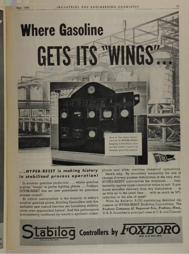
May, 1943 I N U U s T R I A L A N D E N G I N E E R I N G C H E M I S T R Y 75
. . . H Y P E R - R E SE T is m a k i n g h i s t o r y in s t a b i l i z e d p r o c e s s o p e r a t i o n !
I n a v i a t i o n g a s o l i n e p r o d u c t i o n . . . w h e r e g a s o l i n e
i s g i v e n " w i n g s ” t o p o w e r f i g h t i n g p l a n e s . . . F o x b o r o
H Y P E R -R E S E T h a s s e t n e w p r e c e d e n t s f o r p r e c i s i o n
p r o c e s s c o n t r o l !A t c r i t i c a l c o n t r o l - p o i n t s i n t h e m a j o r i t y o f t o d a y s
a v i a t i o n g a s o l i n e p l a n t s , S t a b i l o g C o n t r o l l e r s w i t h t h i s
e x c l u s i v e n e w c o n t r o l f u n c t i o n a r e f u r n i s h i n g s t a b i l i t y
n e v e r e v e n a p p r o a c h e d b e f o r e ! A n d t h i s p e r f o r m a n c e
i s c o n s i s t e n t l y c o n f i r m e d b y r e s u l t s i n s y n t h e t i c r u b b e r
p l a n t s a n d o t h e r w a r t i m e c h e m i c a l o p e r a t i o n s .
H e r e ' s w h y . B y a c c u r a t e l y m e a s u r i n g t h e r a t e o f
c h a n g e o f e v e r y p r o c e s s d i s t u r b a n c e a t t h e v e r y s t a r t ,
H Y P E R - R E S E T a n t i c i p a t e s t h e m a x i m u m . . . t h e n ,
i n s t a n t l y a p p l i e s h y p e r - c o r r e c t i v e a c t i o n t o s u i t . It p r o
d u c e s s m o o t h e r r e c o v e r y f r o m a n y d i s t u r b a n c e . . . i n
a s l i t t l e a s V* t h e u s u a l t i m e . . . w i t h a s m u c h a s 5 0 %
r e d u c t i o n i n t h e s i z e o f u p s e t !
W r i t e f o r B u l l e t i n A - 3 3 0 c o n t a i n i n g d e t a i l e d d i s
c u s s i o n o f H Y P E R -R E S E T S t a b i l o g C o n t r o l l e r s . T h e
F o x b o r o C o m p a n y , 4 0 N e p o n s e t A v e . , F o x b o r o , M a s s . ,
U . S . A . B r a n c h e s i n p r i n c i p a l c i t i e s o f U . S . a n d C a n a d a .
»«■
J
Stabilog Controllers by t O X B O R OREG. U.S. PAT. OFF.
O ne of th e m an y in s ta lla tio n s of HYPER-RESET Stabilog C o n tro llers n ow g iv in g c lo se r con tro l in aviation g a s o lin e p la n ts .
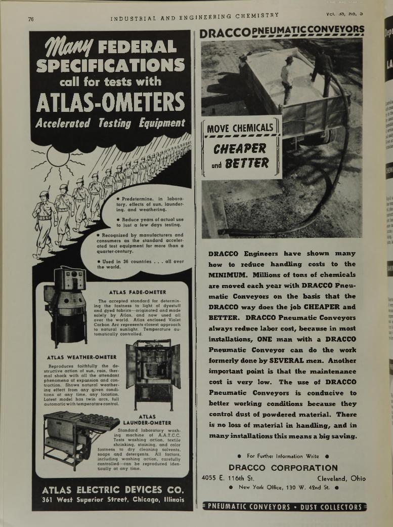
76 I N D U S T R I A L A N D E N G I N E E R I N G C H E M I S T R Yvci. óo, n o . o
t fla M / F E D E R A L
S P E C I F I C A T I O N Scall for te s ts w ith
ATLAS-OMETERSA c c e l e r a t e d T e s t i n g E q u i p m e n t
A T L A S E L E C T R I C D E V I C E S C O .
361 W est Superior Street, Chicago, Illinois
D R A C C O E n g i n e e r s h a v e s h o w n m a n y
h o w t o r e d u c e h a n d l i n g c o s t s t o t h e
M I N I M U M . M i l l i o n s o f t o n s o f c h e m i c a l s
a r e m o v e d e a c h y e a r w i t h D R A C C O P n e u
m a t i c C o n v e y o r s o n t h e b a s i s t h a t t h e
D R A C C O w a y d o e s t h e j o b C H E A P E R a n d
B E T T E R . D R A C C O P n e u m a t i c C o n v e y o r s
a l w a y s r e d u c e l a b o r c o s t , b e c a u s e i n m o s t
i n s t a l l a t i o n s , O N E m a n w i t h a D R A C C O
P n e u m a t i c C o n v e y o r c a n d o t h e w o r k
f o r m e r l y d o n e b y S E V E R A L m e n . A n o t h e r
i m p o r t a n t p o i n t i s t h a t t h e m a i n t e n a n c e
c o s t i s v e r y l o w . T h e u s e o f D R A C C O
P n e u m a t i c C o n v e y o r s i s c o n d u c i v e t o
b e t t e r w o r k i n g c o n d i t i o n s b e c a u s e t h e y
c o n t r o l d u s t o f p o w d e r e d m a t e r i a l . T h e r e
i s n o l o s s o f m a t e r i a l i n h a n d l i n g , a n d i n
m a n y i n s t a l l a t i o n s t h i s m e a n s a b i g s a v i n g .
O For Further In fo rm a tio n W r ite •
D R A C C O C O R P O R A T I O N4 0 5 5 E . 1 1 6 t h S t. C le v e la n d , O h i o
O N e w Y o rk O f f ic e , 1 3 0 W . 4 2 n d St. •
P N E U M A T I C C O N V E Y O R S • D US T C O L L E C T O R S
MOVE CHEMICAL
C H E A P E R
and S E T T E R
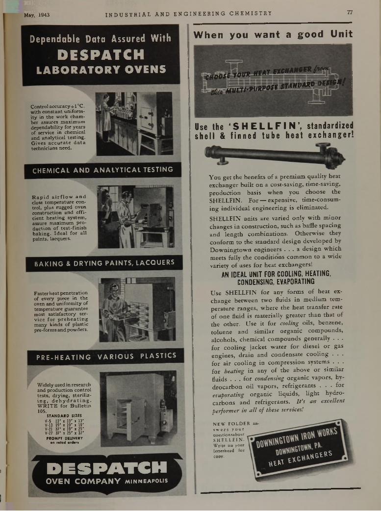
May, 1943 I N D U S T R I A L A N D E N G I N E E R I N G C H E M I S T R Y 77
D e p e n d a b l e D a t a A s s u r e d W i t h
DESPATCHL A B O R A T O R Y O V E N S
W h e n y o u w a n t a g o o d U n i t
C o n tro l a c c u r a c y ± l° C . w it h c o n s ta n t u n i fo r m i t y in th e w o r k c h a m b e r assures m a x im u m d e p e n d a b i li ty fo r y e a rs o f s e rv ice in c h e m ic a l a n d a n a ly t ic a l te s t in g . G iv e s a c c u r a t e d a t a te c h n ic ia n s need .
C H E M I C A L A N D A N A L Y T I C A L T E S T I N G
R a p i d a i r f l o w a n d close te m p e ra tu re c o n t r o l , p lu s ru g g e d o v e n c o n s t ru c t io n a n d e f f i c ie n t h e a t in g s y s te m , assure m a x im u m p r o d u c t io n o f t e s t - f in is h b a k in g . I d e a l f o r a l l p a in ts , la c q u e rs .
B A K I N G & D R Y I N G P A I N T S , L A C Q U E R S
F a s te r h e a t p e n e tra t io n o f e v e ry p ie c e in th e o ven a n d u n i f o r m i t y o f te m p e ra tu re g u a ra n te e m o s t s a t is fa c to ry s e rv ic e f o r p r e h e a t i n g m a n y k in d s o f p la s t ic p re - fo rm s a n d p o w d e rs .
P R E - H E A T I N G V A R I O U S P L A S T I C S
W id e ly used in re s e a rc h a n d p ro d u c t io n c o n t r o l te s ts , d r y in g , s t e r i l i z i n g , d e h y d r a t i n g . W R I T E f o r B u l l e t i n 105.
STANDARD SIZESV-5 13' x 13' x 13' V-13 19' x 19' x 19' V-21 37' x 19’ x 25' V-27 37' x 25' x 37' PROMPT DELIVERY
on rated order«
c e n t r o m * * * t * * * * * * * * * * ” *
I p y fc w M iy îf f lW i
U s e t h e ‘ S H E L L F I N ’, s t a n d a r d i z e d
s h e l l & f i n n e d t u b e h e a t e x c h a n g e r !
Y o u g e t t h e b e n e f i t s o f a p r e m i u m q u a l i t y h e a t
e x c h a n g e r b u i l t o n a c o s t - s a v i n g , t i m e - s a v i n g ,
p r o d u c t i o n b a s i s w h e n y o u c h o o s e t h e
S H E L L F I N . F o r — e x p e n s i v e , t i m e - c o n s u m
i n g i n d i v i d u a l e n g i n e e r i n g i s e l i m i n a t e d .
S H E L L F I N u n i t s a r e v a r i e d o n l y w i t h m i n o r
c h a n g e s i n c o n s t r u c t i o n , s u c h a s b a f f le s p a c i n g
a n d l e n g t h c o m b i n a t i o n s . O t h e r w i s e t h e y
c o n f o r m t o t h e s t a n d a r d d e s i g n d e v e l o p e d b y
D o w n i n g t o w n e n g i n e e r s . . . a d e s i g n w h i c h
m e e t s f u l l y t h e c o n d i t i o n s c o m m o n t o a w i d e
v a r i e t y o f u s e s f o r h e a t e x c h a n g e r s !
A N ID E A L U N IT F O R C O O L IN G , H E A T IN G ,
C O N D E N S IN G , E V A P O R A T IN G
U s e S H E L L F I N f o r a n y f o r m s o f h e a t e x
c h a n g e b e t w e e n t w o f l u i d s i n m e d i u m t e m
p e r a t u r e r a n g e s , w h e r e t h e h e a t t r a n s f e r r a t e
o f o n e f lu id i s m a t e r i a l l y g r e a t e r t h a n t h a t o f
t h e o t h e r . U s e i t f o r c o o l in g o i l s , b e n z e n e ,
t o l u e n e a n d s i m i l a r o r g a n i c c o m p o u n d s ,
a l c o h o l s , c h e m i c a l c o m p o u n d s g e n e r a l l y . . .
f o r c o o l i n g j a c k e t w a t e r f o r d i e s e l o r g a s
e n g i n e s , d r a i n a n d c o n d e n s a t e c o o l i n g . . .
f o r a i r c o o l i n g i n c o m p r e s s i o n s y s t e m s . . .
f o r h e a t i n g i n a n y o f t h e a b o v e o r s i m i l a r
f lu id s . . . f o r c o n d e n s in g o r g a n i c v a p o r s , h y
d r o c a r b o n o i l v a p o r s , r e f r i g e r a n t s . . . f o r
e v a p o r a t in g o r g a n i c l i q u i d s , l i g h t h y d r o
c a r b o n s a n d r e f r i g e r a n t s . I t ’s a n e x c e l l e n t
p e r f o r m e r i n a l l o f th e s e s e n ic e s '
N E W F O L D E R an s w e r s y o u rquestionsaboutS H E L L F I N .Write on your letterhead for copy.
h i m
H R S t « s
D E S P A T C HO V E N C O M P A N Y M i n n e a p o l i s
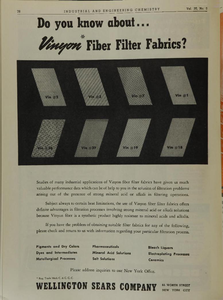
Vol. 35, No. 5
Do you know about... P t h y c v t Fiber Filter Fabrics?
S t u d i e s o f m a n y i n d u s t r i a l a p p l i c a t i o n s o f V i n y o n f ib e r f i l t e r f a b r i c s h a v e g i v e n u s m u c h
v a l u a b l e p e r f o r m a n c e d a t a w h i c h c a n b e o f h e l p t o y o u i n t h e s o l u t i o n o f f i l t r a t i o n p r o b l e m s
a r i s i n g o u t o f t h e p r e s e n c e o f s t r o n g m i n e r a l a c i d o r a l k a l i i n f i l t e r i n g o p e r a t i o n s .
S u b j e c t a l w a y s t o c e r t a i n h e a t l i m i t a t i o n s , t h e u s e o f V i n y o n f i b e r f i l t e r f a b r i c s o f f e r s
d e f i n i t e a d v a n t a g e s i n f i l t r a t i o n p r o c e s s e s i n v o l v i n g s t r o n g m i n e r a l a c i d o r a l k a l i s o l u t i o n s
b e c a u s e V i n y o n f ib e r is a s y n t h e t i c p r o d u c t h i g h l y r e s i s t a n t t o m i n e r a l a c i d s a n d a l k a l i s .
I f y o u h a v e t h e p r o b l e m o f o b t a i n i n g s u i t a b l e f i l t e r f a b r i c s f o r a n y o f t h e f o l l o w i n g ,
p l e a s e c h e c k a n d r e t u r n t o u s w i t h i n f o r m a t i o n r e g a r d i n g y o u r p a r t i c u l a r f i l t r a t i o n p r o c e s s .
Pigments and Dry Colors Pharmaceuticals Bleach Liquors
Dyes and Intermediates Mineral Acid Solutions Electroplating Processes
M etallurgical Processes Salt Solutions Ceramics
P l e a s e a d d r e s s i n q u i r i e s t o o u r N e w Y o r k O f f i c e .
* Reg. Trade Mark C. & C. C. C.
WELLINGTON SEARS COMPANY 65 W O R T H STREET
N E W Y O R K C IT Y
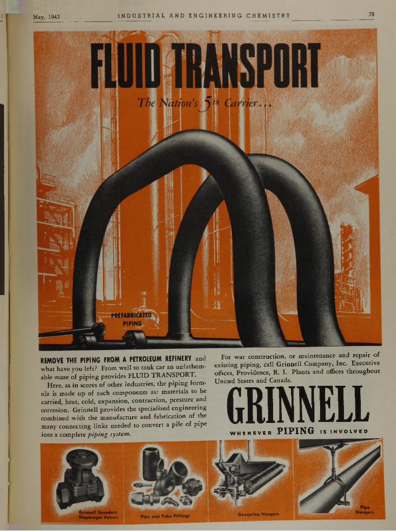
M ay( 1943 I N D U S T R I A L A N D E N G I N E E R I N G C H E M I S T R Y 79
REMOVE THE PIPING FROM A PETROLEUM REFINERY a n d
w h a t h a v e y o u l e f t ? F r o m w e l l t o t a n k c a r a n u n f a t h o m
a b le m a z e o f p i p i n g p r o v i d e s F L U I D T R A N S P O R T .
H e r e , a s i n s c o r e s o f o t h e r i n d u s t r i e s , t h e p i p i n g f o r m
u l a i s m a d e u p o f s u c h c o m p o n e n t s a s : m a t e r i a l s t o b e
c a r r ie d , h e a t , c o l d , e x p a n s i o n , c o n t r a c t i o n , p r e s s u r e a n d
c o r r o s io n . G r i n n e l l p r o v i d e s t h e s p e c i a l i z e d e n g i n e e r i n g
c o m b i n e d w i t h t h e m a n u f a c t u r e a n d f a b r i c a t i o n o f t h e
m a n y c o n n e c t i n g l i n k s n e e d e d t o c o n v e r t a p i l e o f p i p e
i n t o a c o m p l e t e p i p i n g s y s t e m .
F o r w a r c o n s t r u c t i o n , o r m a i n t e n a n c e a n d r e p a i r o f
e x i s t i n g p i p i n g , c a l l G r i n n e l l C o m p a n y , I n c . E x e c u t i v e
o f f i c e s , P r o v i d e n c e , R . I . P l a n t s a n d o f f ic e s t h r o u g h o u t
U n i t e d S t a t e s a n d C a n a d a .
G R IN N ELLW H E N E V E R P I P I N G IS I N V O L V E D
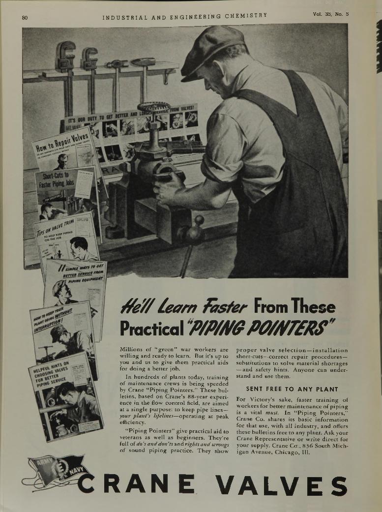
80 I N D U S T R I A L A N D E N G I N E E R I N G C H E M I S T R Y Vol. 35, No. 5
f f e / / ¿ e a r n f a s t e r From T h eseP ractica l P / P m P O W £ R S
M illio n s o f “ g r e e n ” w a r w o r k e r s a re w i l l in g a n d re a d y to le a rn . B u t i t ’s u p to you a n d us to g iv e th e m p ra c t ic a l a id s fo r d o in g a b e t te r jo b .
In h u n d r e d s o f p la n ts to d a y , t r a in in g o f m a in te n a n c e c re w s is b e in g s p e e d e d by C ra n e “ P ip in g P o in te r s .” T h e s e b u lle tin s , b a se d o n C r a n e ’s 8 8 -y e a r e x p e r i e n c e in th e flow c o n tr o l field , a re a im e d a t a s in g le p u rp o s e : to k e e p p ip e l in e s — y o u r p la n t ’s life lin e s— o p e r a t in g a t p e a k effic iency .
“ P ip in g P o in t e r s ” g iv e p ra c t ic a l a id to v e te ra n s as w e ll as b e g in n e r s . T h e y ’re fu ll o f d o ’s a n d d o n ’ts a n d rig h ts a n d wrongs o f s o u n d p ip in g p ra c t ic e . T h e y s h o w
p r o p e r v a lv e s e l e c t i o n — i n s t a l l a t i o n s h o r t - c u ts — c o r r e c t r e p a i r p r o c e d u r e s — s u b s ti tu t io n s to so lv e m a te r ia l s h o r ta g e s — a n d sa fe ty h in ts . A n y o n e c a n u n d e r s ta n d a n d u se th e m .
SENT FREE TO A N Y P L A N T
F o r V ic to r y ’s sa k e , f a s te r t r a i n i n g o f w o r k e r s f o r b e t t e r m a in te n a n c e o f p ip in g is a v ita l m ust. I n “ P i p i n g P o i n t e r s , ” C ra n e C o . s h a r e s its b a s ic in f o r m a t io n fo r th a t u se , w i th a ll in d u s t r y , a n d o ffe rs th e s e b u l le t in s f re e to a n y p la n t . A s k y o u r C ra n e R e p r e s e n ta t iv e o r w r i t e d i r e c t fo r y o u r su p p ly . C ra n e C o ., 8 36 S o u th M ic h i g a n A v e n u e , C h ic a g o , 111.
RAN E V A L V E S
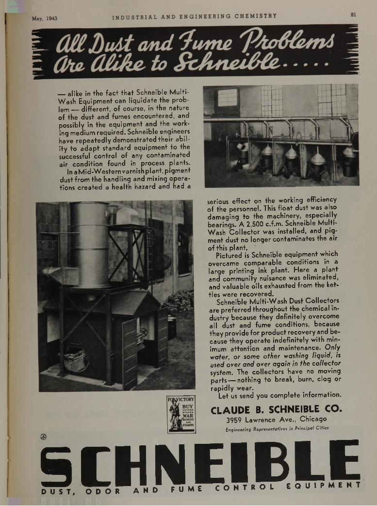
— a l i k e i n t h e f a c t t h a t S c h n e i b l e M u l t i -
W a s h E q u i p m e n t c a n l i q u i d a t e t h e p r o b
l e m — d i f f e r e n t , o f c o u r s e , i n t h e n a t u r e
o f t h e d u s t a n d f u m e s e n c o u n t e r e d , a n d
p o s s i b l y i n t h e e q u i p m e n t a n d t h e w o r k
i n g m e d i u m r e q u i r e d . S c h n e i b l e e n g i n e e r s
h a v e r e p e a t e d l y d e m o n s t r a t e d t h e i r a b i l
i t y t o a d a p t s t a n d a r d e q u i p m e n t t o t h e
s u c c e s s f u l c o n t r o l o f a n y c o n t a m i n a t e d
a i r c o n d i t i o n f o u n d i n p r o c e s s p l a n t s .
I n a M i d - W e s t e r n v a r n i s h p l a n t , p i g m e n t
d u s t f r o m t h e h a n d l i n g a n d m i x i n g o p e r a
t i o n s c r e a t e d a h e a l t h h a z a r d a n d h a d a
CLAUDE B. SCHNEIBLE CO.3 9 5 9 L a w r e n c e A v e . , C h i c a g o
Engineering Representatives in Principal Cities
S C H N E I B L E. c r o N T R O L E Q U I P M E N T D U S T , O D O R A N D F U M E C O N T K U L
s e r i o u s e f f e c t o n t h e w o r k i n g e f f i c i e n c y
o f t h e p e r s o n n e l . T h i s f l o a t d u s t w a s a l s o
d a m a g i n g t o t h e m a c h i n e r y , e s p e c i a l l y
b e a r i n g s . A 2 , 5 0 0 c . f . m . S c h n e i b l e M u l t i -
W a s h C o l l e c t o r w a s i n s t a l l e d , a n d p i g
m e n t d u s t n o l o n g e r c o n t a m i n a t e s t h e a i r
o f t h i s p l a n t .
P i c t u r e d is S c h n e i b l e e q u i p m e n t w h i c h
o v e r c a m e c o m p a r a b l e c o n d i t i o n s i n a
l a r g e p r i n t i n g i n k p l a n t . H e r e a p l a n t
a n d c o m m u n i t y n u i s a n c e w a s e l i m i n a t e d ,
a n d v a l u a b l e o i l s e x h a u s t e d f r o m t h e k e t
t l e s w e r e r e c o v e r e d .
S c h n e i b l e M u l t i - W a s h D u s t C o l l e c t o r s
a r e p r e f e r r e d t h r o u g h o u t t h e c h e m i c a l i n
d u s t r y b e c a u s e t h e y d e f i n i t e l y o v e r c o m e
a l l d u s t a n d f u m e c o n d i t i o n s , b e c a u s e
t h e y p r o v i d e f o r p r o d u c t r e c o v e r y a n d b e
c a u s e t h e y o p e r a t e i n d e f i n i t e l y w i t h m i n
i m u m a t t e n t i o n a n d m a i n t e n a n c e . O n l y w a t e r , o r s o m e o t h e r w a s h i n g l i q u i d , is u s e d o v e r a n d o v e r a g a i n in t h e c o l l e c t o r s y s t e m . T h e c o l l e c t o r s h a v e n o m o v i n g
p a r t s — n o t h i n g t o b r e a k , b u r n , c l o g o r
r a p i d l y w e a r .
L e t u s s e n d y o u c o m p l e t e i n f o r m a t i o n .
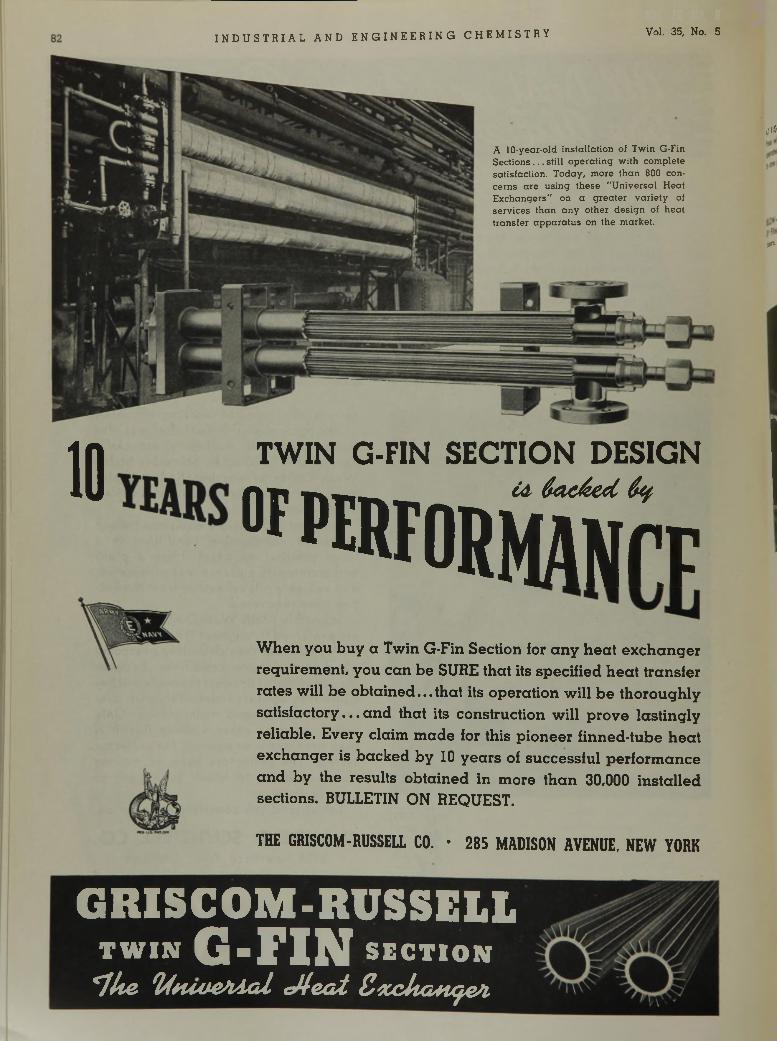
I N D U S T R I A L A N D E N G I N E E R I N G C H E M I S T R Y Vol. 35, No. 5
A 1 0 -ye a r-o ld in s ta l la t io n o f T w in G -F in S e c tio n s . . . s t i l l o p e ra tin g w ith co m p le te s a tis fa c tio n . T o d a y , m o re th a n 800 co n ce rns a re u s in g these " U n iv e rs a l H ea t E x c h a n g e rs " on a g re a te r v a r ie ty o f s e rv ice s th a n a n y o th e r d e s ig n o f h e a t tra n s fe r a p p a ra tu s on th e m a rk e t.
,1»!»
1 0
TWIN G-FIN SECTION DESIGN
» I f ® F 0 R ÄWhen you buy a Twin G-Fin Section for any heat exchanger requirement, you can be SURE that its specified heat transfer rates will be obtained... that its operation will be thoroughly satisfactory. , . and that its construction will prove lastingly reliable. Every claim made for this pioneer finned-tube heat exchanger is backed by 10 years of successful performance and by the results obtained in more than 30,000 installed sections. BULLETIN ON REQUEST.
T H E G R IS C O M - R U S S E L L C O . • 2 8 5 M A D I S O N A V E N U E , N E W Y O R K
GRISCOM-RUSSELLT W I N G - r iN S E C T I O N
*7 l i e f y t u v e s U a i c M e a t Z x c U a + u je A .
*
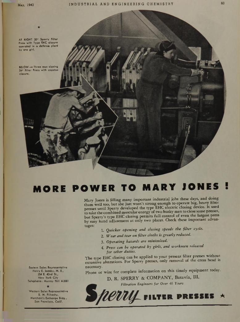
I May( 1943 I N D U S T R I A L A N D E N G I N E E R I N G C H E M I S T R Y 83
AT RIGHT 30" S perry Filter Press w ith Type EHC closure operated in a defense p lan t by one g ir l .
BELOW — Three men closing 24" F ilter Press w ith capstan closure.
MORE P OWE R TO MARY JONES !
Eastern Soles Representative Henry E. Jacoby, M . E.,
204 E. 42nd St.,New York C ity
Telephone: M u rray H ill 4-3581
W estern Sales Representative B. M . Pilhashy,
M erchant's Exchange B ldg., San Francisco, C a lif.
M a r y J o n e s i s f i l l i n g m a n y i m p o r t a n t i n d u s t r i a l j o b s t h e s e d a y s , a n d d o i n g t h e m w e l l t o o , b u t s h e j u s t w a s n ’t s t r o n g e n o u g h t o o p e r a t e b i g , h e a v y f i l t e r p r e s s e s u n t i l S p e r r y d e v e l o p e d t h e t y p e E H C e l e c t r i c c l o s i n g d e v i c e . I t u s e d t o t a k e t h e c o m b i n e d m u s c u l a r e n e r g y o f t w o h u s k y m e n t o c l o s e s o m e p r e s s e s , b u t S p e r r y ’s t y p e E H C c l o s i n g p e r m i t s f u l l c o n t r o l o f e v e n t h e l a r g e s t p r e s s b y e a s y h a n d a d j u s t m e n t a t o n l y t w o p l a c e s . C h e c k t h e s e i m p o r t a n t a d v a n -
t a g e s :1 . Q u i c k e r o p e n i n g a n d c l o s in g s p e e d s t h e f i l t e r c y c le .
2 . W e a r a n d t e a r o n f i l t e r c l o t h s i s g r e a t l y r e d u c e d .
3 . O p e r a t i n g h a z a r d s a r e m i n i m i z e d .
4 . P r e s s c a n b e o p e r a t e d b y g i r l s , a n d w o r k m e n r e le a s e d
f o r o t h e r d u t i e s .
T h e t y p e E H C c l o s i n g c a n b e a p p l i e d t o y o u r p r e s e n t f i l t e r p r e s s e s w i t h o u t e x t e n s i v e a l t e r a t i o n s . F o r S p e r r y p r e s s e s , o n l y r e m o v a l o f t h e c r o s s h e a d is
n e c e s s a r y .
P h o n e o r w i r e f o r c o m p l e t e i n f o r m a t i o n o n t h i s t i m e l y e q u i p m e n t t o d a y .
D . R . S P E R R Y & C O M P A N Y , B a t a v i a , 111 .
F iltr a tio n E n g in e e rs f o r O v e r 4 6 Y e a rs
F I L T E R P R E S S E S A
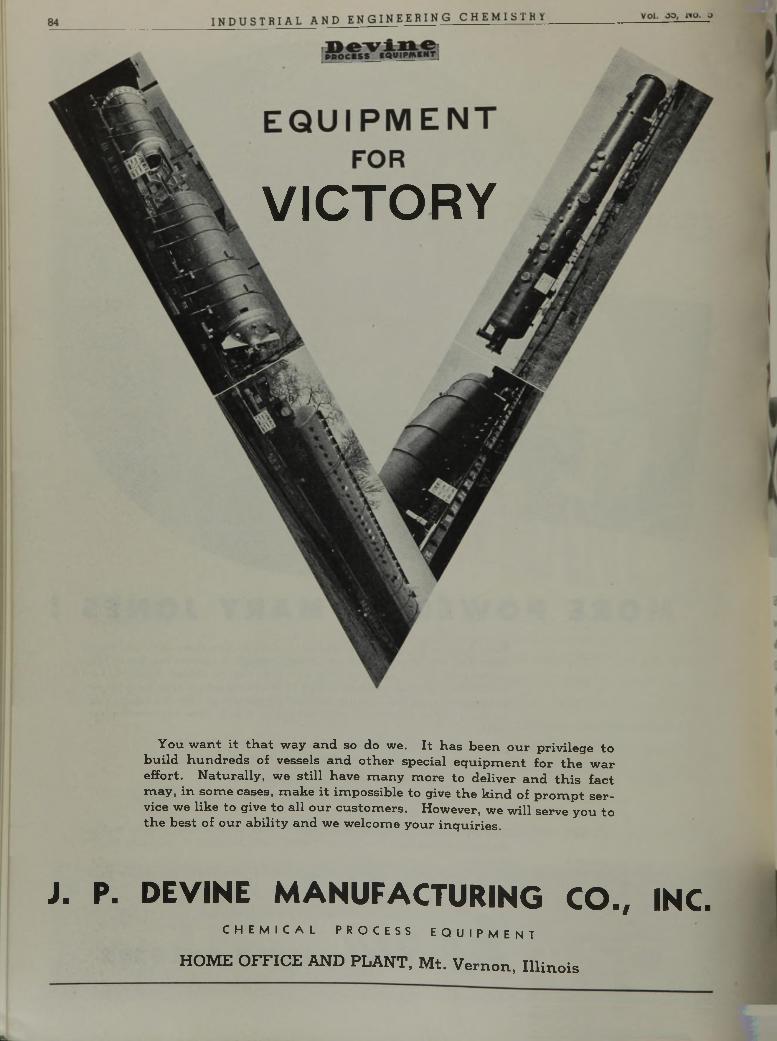
VICTORY
Y o u w a n t i t t h a t w a y a n d s o d o w e . I t h a s b e e n o u r p r i v i l e g e t o
b u i l d h u n d r e d s o f v e s s e l s a n d o t h e r s p e c i a l e q u i p m e n t f o r t h e w a r
e f f o r t . N a t u r a l l y , w e s t i l l h a v e m a n y m o r e t o d e l i v e r a n d t h i s f a c t
m a y , i n s o m e c a s e s , m a k e i t i m p o s s i b l e t o g i v e t h e k i n d o f p r o m p t s e r
v i c e w e l i k e t o g i v e t o a l l o u r c u s t o m e r s . H o w e v e r , w e w i l l s e r v e y o u t o
t h e b e s t o f o u r a b i l i t y a n d w e w e l c o m e y o u r i n q u i r i e s .
J . P . D E V I N E M A N U F A C T U R I N G C O . , I N C .C H E M I C A L P R O C E S S E Q U I P M E N T
HOME OFFICE AND PLANT, M t. Vernon, I llin o is
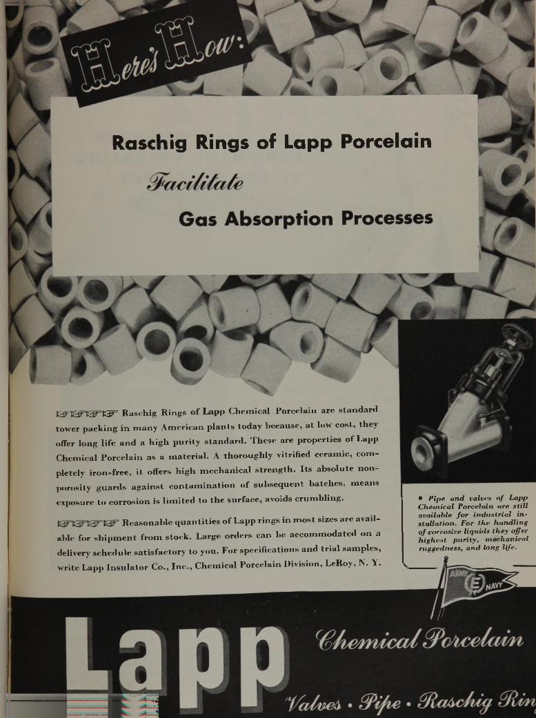
Raschig Rings of Lapp Porcelain
¡ C ^ = K ^ W =E ^ = R a s c h i g R i n g s o f L a p p C h e m i c a l P o r c e l a i n a r e s t a n d a r d
t o w e r p a c k i n g i n m a n y A m e r i c a n p l a n t s t o d a y b e c a u s e , a t l o w c o s t , t h e y
o f f e r l o n g l i f e a n d a h i g h p u r i t y s t a n d a r d . T h e s e a r e p r o p e r t i e s o f L a p p
C h e m i c a l P o r c e l a i n a s a m a t e r i a l . A t h o r o u g h l y v i t r i f i e d c e r a m i c , c o m
p l e t e l y i r o n - f r e e , i t o f f e r s h i g h m e c h a n i c a l s t r e n g t h . I t s a b s o l u t e n o n -
p o r o s i t y g u a r d s a g a i n s t c o n t a m i n a t i o n o f s u b s e q u e n t b a t c h e s , m e a n s
e x p o s u r e t o c o r r o s i o n i s l i m i t e d t o t h e s u r f a c e , a v o i d s c r u m b l i n g .
R e a s o n a b l e q u a n t i t i e s o f L a p p r i n g s i n m o s t s i z e s a r e a v a i l
a b l e f o r s h i p m e n t f r o m s t o c k . L a r g e o r d e r s c a n b e a c c o m m o d a t e d o n a
d e l i v e r y s c h e d u l e s a t i s f a c t o r y t o y o u . F o r s p e c i f i c a t i o n s a n d t r i a l s a m p l e s ,
w r i t e L a p p I n s u l a t o r C o . , I n c . , C h e m i c a l P o r c e l a i n D i v i s i o n , L e R o y , N . Y .
• P ip e a n d v a lv es o f L a p p C h e m ic a l P o rc e la in a re s t i l l a v a ila b le f o r in d u s t r ia l i n s ta l la t io n . F o r th e h a n d l in g o f c o rro s iv e l iq u id s t h e y o ffe r h ig h e s t p u r i t y , m e c h a n ic a l ru g g e d n e ss , a n d lo n g li fe .
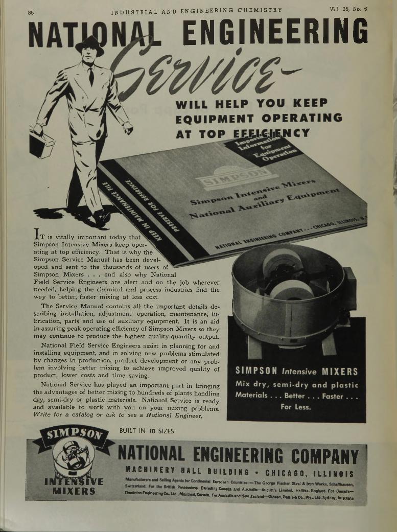
86 I N D U S T R I A L A N D E N G I N E E R I N G C H E M I S T R Y Vol. 35, No. 5
E N G I N E E R I N G
l T i s v i t a l l y i m p o r t a n t t o d a y
S i m p s o n I n t e n s i v e M i x e r s k e e p o p e r
a t i n g a t t o p e f f i c i e n c y . T h a t i s w h y t h e
S i m p s o n S e r v i c e M a n u a l h a s b e e n d e v e l
o p e d a n d s e n t t o t h e t h o u s a n d s o f u s e r s o f
S i m p s o n M i x e r s . . . a n d a l s o w h y N a t i o n a l
F i e l d S e r v i c e E n g i n e e r s a r e a l e r t a n d o n t h e j o b w h e r e v e r
n e e d e d , h e l p i n g t h e c h e m i c a l a n d p r o c e s s i n d u s t r i e s f in d t h e w a y t o b e t t e r , f a s t e r m i x i n g a t l e s s c o s t .
T h e S e r v i c e M a n u a l c o n t a i n s a l l t h e i m p o r t a n t d e t a i l s d e s c r i b i n g i n s t a l l a t i o n , a d j u s t m e n t , o p e r a t i o n , m a i n t e n a n c e , l u
b r i c a t i o n , p a r t s a n d u s e o f a u x i l i a r y e q u i p m e n t . I t i s a n a id
i n a s s u r i n g p e a k o p e r a t i n g e f f i c i e n c y o f S i m p s o n M i x e r s s o t h e y
m a y c o n t i n u e t o p r o d u c e t h e h i g h e s t q u a l i t y - q u a n t i t y o u t p u t .
N a t i o n a l F i e l d S e r v i c e E n g i n e e r s a s s i s t in p l a n n i n g f o r a n d
i n s t a l l i n g e q u i p m e n t , a n d in s o l v i n g n e w p r o b l e m s s t i m u l a t e d
b y c h a n g e s i n p r o d u c t i o n , p r o d u c t d e v e l o p m e n t o r a n y p r o b
l e m i n v o l v i n g b e t t e r m i x i n g t o a c h i e v e i m p r o v e d q u a l i t y o f p r o d u c t , l o w e r c o s t s a n d t i m e s a v i n g .
N a t i o n a l S e r v i c e h a s p l a y e d a n i m p o r t a n t p a r t in b r i n g i n g
t h e a d v a n t a g e s o f b e t t e r m i x i n g t o h u n d r e d s o f p l a n t s h a n d l i n g
d r y , s e m i - d r y o r p l a s t i c m a t e r i a l s . N a t i o n a l S e r v i c e i s r e a d y
a n d a v a i l a b l e t o w o r k w i t h y o u o n y o u r m i x i n g p r o b l e m s .
W r i t e f o r a c a t a l o g o r a s k t o s e e a N a t i o n a l E n g in e e r .
B U IL T IN 10 S IZ E S
INTtlvSIVEMIXERS
ENGINEERING COMPANYM A C H I N E R Y H A L L B U I L D I N G • C H I C A G O , I L L I N O I S
Europ“ n ^ ^ * »«•"n Possessions. Excluding Canada and Australia—August's Limited. Halifax. England. For Canada—Dominion Engineering Co Ltd., Montreal, Canada. For Australia and New Z e a la n d -**™ . Battle* Co.. Pty.. Ltd. Sydney, A uste ll,
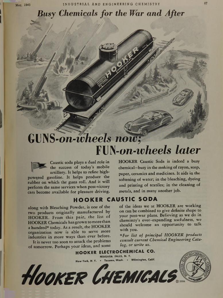
May, 1943 I N D U S T R I A L A N D E N G I N E E R I N G C H E M I S T R Y 87
GUNS-on-w FUN-on-w/iee/s l a t e r
B u s y C h e m i c a l s f o r t h e W a r a n d A f t e r
Caustic soda plays a dual role in the success of today’s mobile artillery. It helps to refine high-
powered gasoline. I t helps produce the rubber on which the guns roll. And it w ill perform the same services when post-victory cars become available for pleasure driving.
HOOKER Caustic Soda is indeed a busy chemical—busy in the making of rayon, soap, paper, ceramics and medicines. It aids in the softening of water; in the bleaching, dyeing and printing of textiles; in the cleaning ofmetals, and in many another job.
H O O K E R C A U S T I C S O D Aalong w ith Bleaching Powder, is one of the two products originally m anufactured by H O O K ER. F rom th is p a ir , the lis t of HOOKER Chemicals has grow n to more than a hundred* today. As a result, the HOOKER organization now is able to serve more industries in more ways than ever before.
It is never too soon to attack the problems of tomorrow. Perhaps your ideas, and some
of the ideas we at HOOKER are w orking on can be combined to give definite shape to your post-war plans. Believing as we do in chemistry’s ever-expanding usefulness, we should welcome an opportunity to ta lk w ith you.* F o r l i s t o f p r i n c i p a l H O O K E R p r o d u c t s
c o n s u l t c u r r e n t C h e m i c a l E n g i n e e r i n g C a t a
l o g , o r w r i t e u s .
H O O K E R E L E C T R O C H E M I C A L C O .
NIAGARA FAILS, N. Y.New York, N. Y. • Tacoma, Wath. • Wilmington, Calif.
¡ 'f í o O K E h ? Û / £ M / C A L $
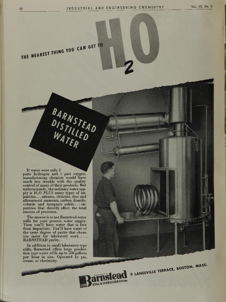
8 8 I N D U S T R I A L A N D E N G I N E E R I N G C H E M I S T R Y Vol. 35, No. 5
n e a r * s t
T H I N G Y O U C A N
I f w a t e r w e r e o n l y 2 p a r t s h y d r o g e n a n d 1 p a r t o x y g e n , m a n u f a c t u r i n g c h e m i s t s w o u l d h a v e m u c h l e s s t r o u b l e w i t h t h e q u a l i t y c o n t r o l o f m a n y o f t h e i r p r o d u c t s . B u t u n f o r t u n a t e l y , t h e o r d i n a r y w a t e r s u p p l y i s H 20 P L U S m a n y t y p e s o f i m p u r i t i e s . . . n i t r a t e s , c h l o r i n e , f r e e a n d a l b u m i n o i d a m m o n i a , c a r b o n d i o x i d e , v o l a t i l e a n d i n o r g a n i c s o l i d s . . . i m p u r i t i e s t h a t d i r e c t l y a f f e c t t h e t o t a l s u c c e s s o f p r o c e s s e s .
T h e a n s w e r i s t o u s e B a r n s t e a d w a t e r s t i l l s f o r y o u r p r o c e s s w a t e r s u p p l y . T h e n y o u ’l l h a v e w a t e r t h a t i s f r e e f r o m i m p u r i t i e s . Y o u ’l l h a v e w a t e r o f t h e s a m e d e g r e e o f p u r i t y t h a t c h e m i s t s i n s i s t f o r l a b o r a t o r y w o r k . . . B A R N S T E A D p u r i t y .
I n a d d i t i o n t o s m a l l l a b o r a t o r y t y p e s t i l l s , B a r n s t e a d o f f e r s l a r g e p r o d u c t i o n t y p e w a t e r s t i l l s u p t o 5 0 0 g a l l o n s p e r h o u r i n s i z e . O p e r a t e d b y g a s , s t e a m , o r e l e c t r i c i t y .
S L s ä S Ö
b o s t o n , * * S S ‘
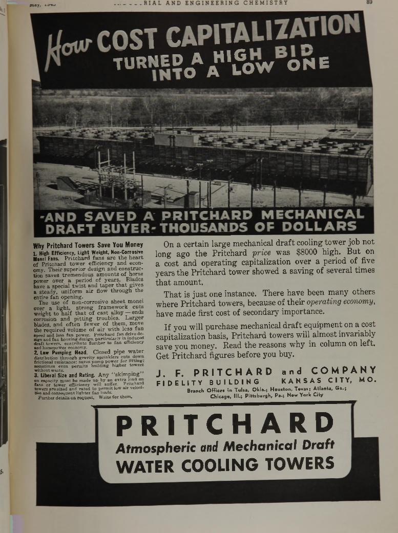
> \ J O I v f t i ■ ■ ■ n
T U R N E D 0 A AH i o W O N E
v >
Why Pritchard Towers Save You Money1. High Efficiency, Light Weight, Non-CorrosiveMonel Fans. P r i tc h a rd f a n s a re th e h e a r t o f P r itc h a rd to w e r efficiency a n d economy. T h e ir su p e r io r d e s ig n an d c o n s tru c tion sav es t re m e n d o u s a m o u n ts o f h o rse pow er o ver a p e rio d o f y e a rs . B lades have a spec ia l tw is t a n d ta p e r t h a t g iv es a steady , u n ifo rm a ir flow th ro u g h th e en tire fa n open ing .
The use o f n o n -co rro s iv e s h e e t m onel over a lig h t, s tro n g f ra m e w o rk c u ts w eigh t to h a lf t h a t o f c a s t a lloy — ends corrosion and p i t t in g tro u b le s . L a rg e r blades, an d o f te n f e w e r o f th e m , m ove the req u ired vo lum e o f a ir w ith less fa nspeed and less fan power. Pritchard fan drive de- sign and fan housing design, particularly in induced draft towers, contribute further to fan efficiency and horsepower economy.2. Low Pumping Head. C losed p ip e w a te rdistribution through gravity sprinklers frictional resistance; saves pump power for lifting, sometimes even permits building higher towers without waste.3. Liberal Size and Rating. A n y 4‘sk im p in gon capacity m ust be made up by an extr? loai? ° j fans or tower effiiciency w ill suffer. Pritchard towers are sized and rated to permit low air velocities and consequent lighter fan loads.
Furthe r details on request. W r ite fo r them.
O n a c e r t a i n l a r g e m e c h a n i c a l d r a f t c o o l i n g t o w e r j o b n o t
l o n g a g o t h e P r i t c h a r d p r i c e w a s $ 8 0 0 0 h i g h . B u t o n
a c o s t a n d o p e r a t i n g c a p i t a l i z a t i o n o v e r a p e r i o d o f f i v e
y e a r s t h e P r i t c h a r d t o w e r s h o w e d a s a v i n g o f s e v e r a l t i m e s
t h a t a m o u n t .
T h a t i s j u s t o n e i n s t a n c e . T h e r e h a v e b e e n m a n y o t h e r s
w h e r e P r i t c h a r d t o w e r s , b e c a u s e o f t h e i r o p e r a t i n g e c o n o m y ,
h a v e m a d e f i r s t c o s t o f s e c o n d a r y i m p o r t a n c e .
I f y o u w i l l p u r c h a s e m e c h a n i c a l d r a f t e q u i p m e n t o n a c o s t
c a p i t a l i z a t i o n b a s i s , P r i t c h a r d t o w e r s w i l l a l m o s t i n v a r i a b l y
s a v e y o u m o n e y . R e a d t h e r e a s o n s w Th y i n c o l u m n o n l e f t .
G e t P r i t c h a r d f i g u r e s b e f o r e y o u b u y .
J . F . P R I T C H A R D a n d C O M P A N Y
F I D E L I T Y B U I L D I N G K A N S A S C I T Y , M O .
Branch Offices in Tulsa, Okla.; Houston, Texas; Atlanta, Ga.;Chicago, III.; Pittsburgh, Pa.; New York City
P R I T C H A R DA t m o s p h e r i c a n d M e c h a n i c a l D r a f t
W A T E R C O O L I N G T O W E R S
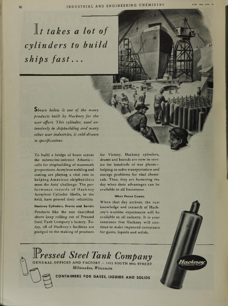
90
T o b u i l d a b r i d g e o f b o a t s a c r o s s
t h e s u b m a r i n e - i n f e s t e d A t l a n t i c —
c a l l s f o r s h i p b u i l d i n g o f m a m m o t h
p r o p o r t i o n s . A c e t y l e n e w e l d i n g a n d
c u t t i n g a r e p l a y i n g a v i t a l r o l e in
h e l p i n g A m e r i c a n s h i p b u i l d e r s
m e e t t h e A x i s ’ c h a l l e n g e . T h e p e r
f o r m a n c e r e c o r d s o f H a c k n e y
A c e t y l e n e C y l i n d e r S h e l l s , i n t h e
h e l d , h a v e p r o v e d t h e i r r e l i a b i l i t y .
Hackney Cylinders, Drums and Barrels
P r o d u c t s l i k e t h e o n e d e s c r i b e d
a b o v e k e e p r o l l i n g o u t o f P r e s s e d
S t e e l T a n k C o m p a n y ’s f a c t o r y . T o
d a y , a l l o f H a c k n e y ’s f a c i l i t i e s a r e
p l e d g e d t o t h e m a k i n g o f p r o d u c t s
f o r V i c t o r y . H a c k n e y c y l i n d e r s ,
d r u m s a n d b a r r e l s a r e n o w i n s e r v
i c e f o r h u n d r e d s o f w a r p l a n t s —
h e l p i n g t o s o l v e t r a n s p o r t a t i o n a n d
s t o r a g e p r o b l e m s f o r v i t a l c h e m i
c a l s . T h u s , t h e y a r e h a s t e n i n g t h e
d a y w h e n t h e i r a d v a n t a g e s c a n b e
a v a i l a b l e t o a l l b u s i n e s s e s .
When Peace Comes
W h e n t h a t d a y a r r i v e s , t h e v a s t
k n o w l e d g e a n d r e s e a r c h o f H a c k
n e y ’s w a r t i m e e x p e r i e n c e s w i l l b e
a v a i l a b l e t o a l l i n d u s t r y . I t i s y o u r
a s s u r a n c e t h a t H a c k n e y w i l l c o n
t i n u e t o m a k e i m p r o v e d c o n t a i n e r s
f o r g a s e s , l i q u i d s a n d s o l i d s .
K r e s s e d S t e e l T a n k C o m p a n yG E N E R A L O F F IC E S A N D FA C TO R Y • 1451 S O U T H 66th S T R E E T
Milwaukee, Wisconsin
C O N T A I N E R S FOR GASES, L IQ U ID S A N D SO L IDS
vui. *j>j, n u .
1 / t a k e s a l o t o f
c y l i n d e r s t o b u i l d
s h i p s f a s t . . .
S h o w n b e l o w i s o n e o f t h e m a n y
p r o d u c t s b u i l t b y H a c k n e y f o r t h e
w a r e f f o r t . T h i s c y l i n d e r , u s e d e x
t e n s i v e l y i n s h i p b u i l d i n g a n d m a n y
o t h e r w a r i n d u s t r i e s , i s c o l d - d r a w n
to s p e c i f i c a t i o n s .
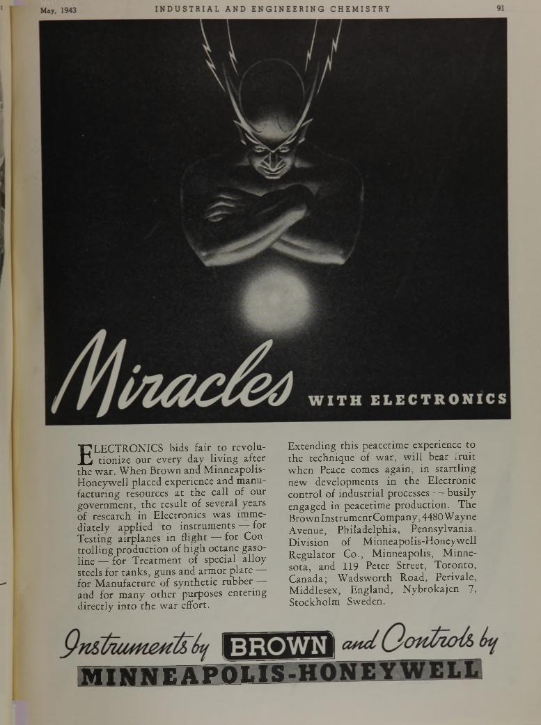
E LECTRONICS bids fair to revolution ize our every day liv ing after
the w ar. W hen B row n and M inneapolis- H oneyw ell placed experience and m anufacturing resources a t the call of our governm ent, th e result of several years of research in Electronics w as im med ia tely applied to instrum ents for Testing airplanes in flight — for Con tro lling p roduction of h ig h octane gasoline — for T reatm ent of special alloy steels for tanks, guns and arm or p la te — for M anufacture of syn thetic rubber and for m any o th e r purposes entering directly in to th e w ar effort.
E xtending th is peacetim e experience to the technique of w ar, w ill bear iru it w hen Peace comes again, in s ta rtlin g new developments in the Electronic contro l of industrial processes — busily engaged in peacetime production . The Brown Instrum ent Com pany, 4480W ayne Avenue, Philadelphia , Pennsylvania. D ivision of M inneapolis-H oneyw ell R egulator Co., M inneapolis, M innesota, and 119 Peter Street, T oron to , Canada; W adsw orth Road, Peri vale, M iddlesex, England, N ybrokajen 7, S tockholm Sweden.
M I N N E A P O L I S
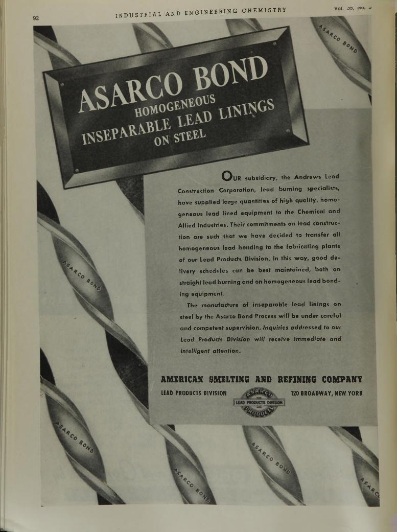
A M E R I C A N S M E L T I N G A N D R E F I N I N G C O M P A N Y
LEAD PRODUCTS DIVISION 120 BROADWAY, NEW YORK
i n d u s t r i a l a n d e n g i n e e r i n g c h e m i s t r y
^ ) l l R subsidiary, the Andrews Lead
Construction Corporation, lead burning specialists,
have supplied large quantities of high quality, homo
geneous lead lined equipment to the Chemical and
Allied Industries. Their commitments on lead construc
tion are such that w e have decided to transfer all
homogeneous lead bonding to the fabricating plants
of our Lead Products Division. In this w ay , good de
livery schedules can be best m aintained, both on
straight lead burning and on homogeneous lead bond
ing equipment.
The manufacture of inseparable lead linings on
steel by the Asarco Bond Process w ill be under careful
and competent supervision. Inquiries addressed to our
Lead Products Division will receive immediate and
intelligent attention.
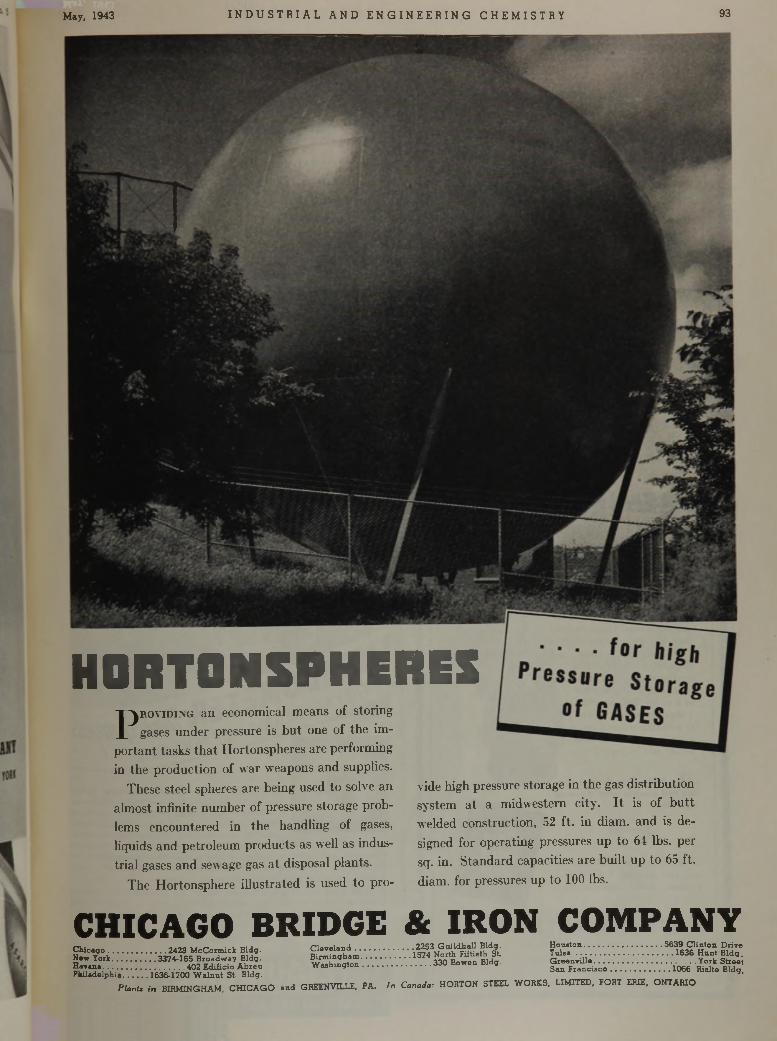
May, 1943 I N D U S T R I A L A N D E N G I N E E R I N G C H E M I S T R Y 93
C H I C A G O B R I D G E & I R O N C O M P A N YC leveland............................ 2253 Guildhall Bldg.Birmingham........................1574 North Fiftieth St.W ashington.................... .. 330 Bowen Bldg.
Chicago 2428 McCormick Bldg.New York.....................3374-165 Broadway Bldg.Havana.......................................402 Edificio AbreuPhiladelphia 1636-1700 Walnut St. Bldg.
Plant, in BIRMINGHAM, CHICAGO and GREENVILLE, PA. In Canada: HORTON STEEL WORKS, LIMITED, FORT ERIE, ONTARIO
Houston..................................... 5639 Clinton DriveT u lsa ........................................ 1636 Hunt Bldg.Greenville................................................ York StreetSan Francisco.............................1066 Rialte Bldg.
H0 RT0 NSPHERES
•j
P r o v i d i n g a n e c o n o m i c a l m e a n s o f s t o r i n g
g a s e s u n d e r p r e s s u r e i s b u t o n e o f t h e i m
p o r t a n t t a s k s t h a t H o r t o n s p h e r e s a r e p e r f o r m i n g
in t h e p r o d u c t i o n o f w a r w e a p o n s a n d s u p p l i e s .
T h e s e s t e e l s p h e r e s a r e b e i n g u s e d t o s o l v e a n
a l m o s t i n f i n i t e n u m b e r o f p r e s s u r e s t o r a g e p r o b
l e m s e n c o u n t e r e d i n t h e h a n d l i n g o f g a s e s ,
h q u i d s a n d p e t r o l e u m p r o d u c t s a s w e l l a s i n d u s
t r i a l g a s e s a n d s e w a g e g a s a t d i s p o s a l p l a n t s .
T h e H o r t o n s p h e r e i l l u s t r a t e d i s u s e d t o p r o
v i d e h i g h p r e s s u r e s t o r a g e i n t h e g a s d i s t r i b u t i o n
s y s t e m a t a m i d w e s t e m c i t y . I t i s o f b u t t
w e l d e d c o n s t r u c t i o n , 5 2 f t . i n d i a m . a n d i s d e
s i g n e d f o r o p e r a t i n g p r e s s u r e s u p t o 6 4 l b s . p e r
s q . i n . S t a n d a r d c a p a c i t i e s a r e b u i l t u p t o 6 5 f t .
d i a m . f o r p r e s s u r e s u p t o 1 0 0 lb s .
94I N D U S T R I A L A N D E N G I N E E R I N G C H E M I S T R Y voi. oa, i"'.
DISPERSION
D1SHVTEGR4 TIDN
LIQUIDS SOLIDS w
P R E M I E R C O L L O I D
M I L L W h e n c o m p le ted is p e rs io n and m o re th o ro u g h b re a k d o w n o f p a r t ic le s o f a m ix are re q u ire d , th e r ig h t m o d e l o f th e P re m ie r C o l lo id M i l l does the jo b m o re econ o m ic a lly . O p e ra te d w i t h u n s k i l l e d h e lp — la r g e o u t p u t w it h lo w p o w e r c o n s u m p tio n —a m a z in g ly easy to c lean . P r e m ie r C o l l o i d M i l l s o pe ra te th ro u g h the re v o lu t io n s o f a s im p le ro to r in a s ta to r. T h is p ro v id e s a sh e a rin g a c tio n as w e l l as a m ix in g a c tio n . C le a ra nce s m a y b e a d ju s te d fro m .0 0 1 " u p w a rd .
¿/ / ie Paste Type Premier Col lo id M ill d irect coupled to geared up motor.
£ jp e n (/ for your FREE copy of our new bookle t C-5, “ Better Products M ore P ro fitab ly Pro
cessed.”
P R E M IE R M ILL C O R P .2 1 8 G e n e s e e S t r e e t . G E N E V A , N E W Y O R K
General Sales O ffice : 110 East 42nd Street, New York
OUR
P E R FO R M A N C E
G U A R A N TEEc o v e r s t h e a b i l i t y o f M ik r o - P u l v e r i z e r to p r o d u c e t h e results y o u e x p e c t .
I N V E S T I G A T E T H E M I K R O• D u s tle s s - n o fa n s , c y c lo n e s , s e p a ra to rs• F o r D r y o r W e t m i l l i n g o r g r a n u la t in g• Saves 7 5 % in p o w e r - saves f lo o r space• W o r k e d w i t h u n s k i l le d la b o r• L o w o p e r a t in g co s t• F in en e ss u p to 99.99% t h r o u g h 325 m e sh
Send for our )2 page catalog now.Submit your materials for a free test grind
P U L V E R IZ IN G M A C H IN E R Y C O M P A N Y40 C h a 'h a m R o a d • S u m m it , N . J .
REG. U. S. PAT. OFF.
S ilq A r fc c a fa z a /
T T ia Ü ÿ / i^ / * / / i ' ^ >
I . . .
100% au tom atic —th ese ta n k g a u g e s insure accu ra te , tro u b le -free r e a d in g s w h en ev e r req u ired . No pum ps, v a lv es , or au x ilia ry un its req u ired to re a d them . M odels a v a ila b le so th a t re a d in g s c a n b e ta k e n rem otely
from or directly a t the tank. Rem ote re a d in g ty p e s utilize b a la n c e d h ydrau lic transm ission system w hich com pletely c o m p en sa te s for tem peratu re varia tions on com m unicating tub in g . A ccu racy u n a ffected by specific g rav ity of tank liquid.A pproved for g au g in g h aza rd o u s liq u id s b y U nderw rite rs ' L ab o ra tories and other sim ilar groups. M odels a v a ila b le to au to m atica lly control pum ps, motors, s ig n a ls or o ther d ev ices for m ain ta in in g minimum or m axim um liquid levels.
Write for complete details.
L I A U I D O M E T E R CORP.33-13 SKILLI
May, 1943 I N D U S T R I A L A N D E N G I N E E R I N G C H E M I S T R Y 95
Q u a l i t y i s a m a t t e r o f r e f i n e m e n t s s t e a d i l y b r e d i n t o a p r o d u c t a n d
d i l i g e n t l y c u l t i v a t e d .
E a t o n - D i k e m a n f i l t e r p a p e r s , f o r t w e n t y y e a r s t h e s t a n d a r d j
a r e i n d i c a t i v e o f t h e m a n u f a c t u r e r ’ s p e r e n n i a l r e s p o n s i b i l i t y t o h i s c l i e n t s ,
t h e C h e m i s t a n d t h e E n g i n e e r . T h i s a p p r e c i a t i o n o f r e s p o n s i b i l i t y
m a k e s t h e E & D s y m b o l s y n o n y m o u s w i t h Q u a l i t y .
€ATOn-DIK€mAn COMANUF A C T URE RS o f f i n e f i l t e r p a p e r s • •
I n s t e e l m i l l s , c o a l y a r d s , s h i p y a r d s , r a i l r o a d s a n d
o t h e r w a r p l a n t s a l l o v e r A m e r i c a , I . B . C r a n e s a r e
w o r k i n g n i g h t a n d d a y m o v i n g h e a v y m a t e r i a l s ,
g e t t i n g t h i n g s d o n e i n a h u r r y . I . B . C r a n e s a r e d o
i n g t h e i r j o b s c o n t i n u o u s l y — s e ld o m i f e v e r r e q u i r
i n g t i m e o u t f o r r e p a i r s . T h e y ' r e p o w e r f u l — h a n d
l i n g t h e t o u g h j o b s w i t h e a s e . T h e y ' r e e f f i c i e n t —
t h e y g e t m o r e w o r k o u t o f a g a l l o n o f p r e c i o u s f u e l
o i l t h a n r i g h t f u l l y c o u l d b e e x p e c t e d . I f y o u ' r e i n
t e r e s t e d i n s p e e d i n g u p y o u r s h a r e i n A m e r i c a ' s
w a r e f f o r t , I . B . C r a n e s c a n h e l p y o u . W r i t e t o I n
d u s t r i a l B r o w n h o i s t C o r p o r a t i o n , B a y C i t y , M i c h i
g a n . D i s t r i c t o f f i c e s : N e w Y o r k , P h i l a d e l p h i a , P i t t s
b u r g , C l e v e l a n d , C h i c a g o .
. tlALBROW NHOIST
* l • ' % « « i-■■■ ’ S r \ . - A. A *
/ } Q -o m p -le t e R e ^ ie d h e A . G o u s r ie
in 9 n x lu A fo i( d G b e * n t i& u f
For the man who is changing over to an essential war job and lor everyone who wants to familiarize himsell with industrial chemistry, here is the best book, covering more than 5 0 key industries in which chemistryplays an important part.
I N D U S T R I A L
C H E M I S T R Y
b y E m i l R a y m o n d R i e g e l
Prof. of Industrial Chemistry, Univ. of Buffalo
The fourth revised edition of INDUSTRIAL CHEMISTRY is an authoritative, readable treatise that surveys all the important processes and practises of the chemical industries, used in producing the materials essential to our war effort. More than a textbook, it is written for the layman. This book is just the kind of orientation in the field of industrial chemistry that is needed byevery STUDENT, TEACHER, CHEMIST, PHYSICIST, ENGINEER, TECH-
NICAL and SCIENTIFIC WORKER.The style is ". . . sufficiently simple, so that a person who remembers his college (or even high school) chemistry would have little difficulty.” - J a m e s Stokley, N. Y. HERALD-TRIBUNE
861 pps. — 293 lllust.110 Tables — $5.50 Postpaid
SEND FOR A COPY ON OUR TEN DAY APPROVAL OFFER
TEN DAY
/l-o p A & U cUREINHOLD PUBL. CORP.Dept. R, 330 W. 42nd St., New York
Please send me a copy of INDUSTRIAL CHEMISTRY by Emil R. Riegel, Ph.D., for which I enclose $5.50. If not satisfied, I agree to return the booh in ten days at which time my money will be refunded.□ / Check here for a copy of "Let's Look It Up,"J/l&g, a list of over 200 books on Chemistry, Science
If and Technology, with complete descriptions.
N A M E .......................................................................
ADDRESS.................................................... ..............
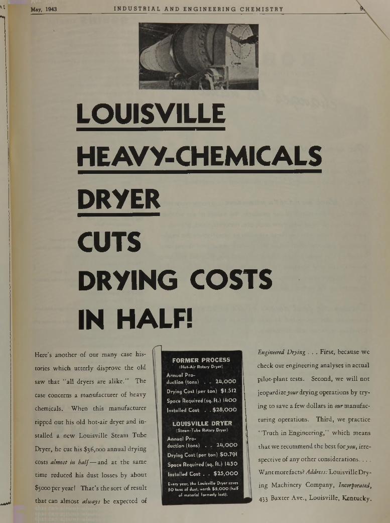
o.5
LOUISVILLEHEAVY-CHEMICALSDRYERCUTSDRYING COSTS IN HALF!
E ng ineered D r y in g . . . F i r s t , b e c a u s e w e
c h e c k o u r e n g i n e e r i n g a n a l y s e s i n a c t u a l
p i l o t - p l a n t t e s t s . S e c o n d , w e w i l l n o t
j e o p a r d iz e y o u r d r y i n g o p e r a t i o n s b y t r y
i n g t o s a v e a f e w d o l l a r s i n our m a n u f a c
t u r i n g o p e r a t i o n s . T h i r d , w e p r a c t i c e
“ T r u t h i n E n g i n e e r i n g , ” w h i c h m e a n s
t h a t w e r e c o m m e n d t h e b e s t i o r y o u , i r r e
s p e c t i v e o f a n y o t h e r c o n s i d e r a t i o n s . . . .
W a n t m o r e f a c t s ? A d d re s s : L o u i s v i l l e D r y
i n g M a c h i n e r y C o m p a n y , In co rp o ra ted ,
4 3 3 B a x t e r A v e . , L o u i s v i l l e , K e n t u c k y .
H e r e ’s a n o t h e r o f o u r m a n y c a s e h i s
t o r ie s w h i c h u t t e r l y d i s p r o v e t h e o l d
s a w t h a t “ a l l d r y e r s a r e a l i k e . ” T h e
c a s e c o n c e r n s a m a n u f a c t u r e r o f h e a v y
c h e m ic a l s . W h e n t h i s m a n u f a c t u r e r
r ip p e d o u t h i s o l d h o t - a i r d r y e r a n d i n
s t a l l e d a n e w L o u i s v i l l e S t e a m T u b e
D r y e r , h e c u t h i s $ 3 6 , 0 0 0 a n n u a l d r y i n g
c o s t s a lm o s t in h a l f — a n d a t t h e s a m e
t im e r e d u c e d h i s d u s t l o s s e s b y a b o u t
$ 5 0 0 0 p e r y e a r ! T h a t ’s t h e s o r t o f r e s u l t
t h a t c a n a l m o s t a lw a y s b e e x p e c t e d o f
F O R M E R P R O C E S S(Hot-Air Rotary Dryer)
Annual Production (tons) . . 24 ,000
Drying Cost (per ton) $1,512
Space Required (sq. ft.) 1400
Installed Cost . . $28,000
L O U I S V I L L E D R Y E R(Steam-Tube Rotary Dryer)
Annual Production (tons) . . 24 ,000
Drying Cost (per ton) $0,791
Space Required (sq. ft.) 1450
Installed Cost . . $25 ,000
Every year, the Louisville Dryer saves 50 tons of dust, worth $ 5,000 (half
of material formerly lost).
Vol. 03, *'l°-
98; N D U S T R I A L A N D E N G I N E E R I N G C H E M I S T R Y
R O B I N S created
ROBI NSC O N V E Y IN G BELT C O M P A N Y
t t e a n l y ¿ a t y * C C a tc C U f , w e ’ v e b o r n e t h i s f i n e o l d
n a m e . . . b o r n e i t p r o u d l y . . . m a d e i t t h e s y n o n y m a n d s y m b o l o f
q u a l i t y n o t o n l y h e r e b u t i n m a n y o t h e r p a r t s o f t h e w o r l d . N o w
w e l a y i t a s i d e t e n d e r l y . . . n o t e n t o m b e d b u t e n s h r i n e d .
^ a c t c f d o c e , c v e a d c ^ t t a a e e v a a a t e m o r e t r u l y
d e f i n i t i v e o f t h e r a n g e o f o u r p r o d u c t s , t h e e x t e n t o f o u r s e r v ic e s
. s e r v i c e s t o t h o s e w h o m in e c o a l , o r e , m i n e r a l s , s a n d , g r a v e l . . .
s e r v i c e s t o t h o s e w h o u s e t h e s e e le m e n t s t o m a n u f a c t u r e t h e i m p l e
m e n t s o f i n d u s t r y w h i c h m a k e t h i s c o u n t r y g r e a t a n d s t r o n g a n d
v i c t o r i o u s . T o t h e s e p e o p l e , t h e s e c o r p o r a t i o n s , R O B I N S h a s l o n g
b e e n k n o w n a n d h o n o r e d f o r i t s p i o n e e r i n g s p i r i t . . . i t s d a r i n g
t o t r y t h e s e e m i n g l y i m p o s s i b l e in o r d e r t o a d v a n c e t h e i n d u s t r i a l
e c o n o m y o f t h e n a t i o n a n d t h e w o r l d .
'D c c x ta y t £ e f a c t d e c a d e e tc e x i s t e n c e , r o b i n s
c o n c e i v e d a n d i n t r o d u c e d 4 1 i n n o v a t i o n s in t h e f i e l d o f m a t e r i a l s
h a n d l i n g m e t h o d s a n d m a c h i n e r y .
* ) tt t& e C fe C V ie d a c e t& e a , o t h e r e q u a l l y r a d i c a l a n d c o n
s t r u c t i v e a d v a n c e m e n t s h a v e b e e n i n i t i a t e d b y R O B I N S . B e c a u s e
t h e y a r e s o w i d e in v a r i e t y , in u t i l i t y a n d in a p p l i c a t i o n , w e
b e l i e v e i t a d v i s a b l e t o a d o p t a n a m e m o r e e n c o m p a s s in g , a
n a m e le s s r e s t r i c t i v e i n i t s c o n n o t a t i o n s t h a n R o b in s
C o n v e y i n g B e l t C o .
j 4 a d O C C V — w i t h o u t a n y c h a n g e i n d i r e c t o r s h i p ,
m a n a g e m e n t o r c o r p o r a t e s t r u c t u r e , w e b e c o m e :
R O B I N S C O N V E Y O R S I N C O R P O R A T E D .
THE FIRST b e ll m ade espec ia lly fo r co nve y in g m ateria ls
THE FIRST troughed b e ll conveyor
THE FIRST b e ll w ith a th ick cover a t the center
THE FIRST splice m ade w ith a po rtab le vu lcam ze r
THE FIRST s ing le -p lane id le r
THE FIRST stepped-p ly belt
THE FIRST protected screw takeup
THE FIRST se lf-reve rs ing tr ippe r
THE FIRST belt conveyo r fo r h a n d lin g stone
THE FIRST belt conveyo r fo r ca rry in g coal
THE FIRST belt conveyo r fo r sand and g rave l
THE FIRST conveyor storage system
THE FIRST p ick ing belt
THE FIRST belt conveyo r in a gas w orks
THE FIRST belt conveyor th a t ever h and led copper
oreTHE FIRST m echan ica l ore bedd ing system
THE FIRST belt system fo r lo a d in g co llie rs
THE FIRST conveyor fo r h a n d lin g excava ted mate ria l
THE FIRST system o f be lt conveyors to hand le m ixed concrete
THE FIRST tandem -driven be lt conveyo r
THE FIRST trippe r w ith a s ide-d ischarge be lt
THE FIRST conveyor belt 96 inches w id e the w idest ever b u ilt
THE FIRST conveyor on a dredge
THE FIRST counter-w e igh ted ho is ting to w e r
THE FIRST “ W ard Leonard System” h o is tin g to w e r
THE FIRST h ydrau lic ho is ting to w er
THE FIRST pow er-sav ing id le r
THE FIRST be lt-un load ing system fo r boats
THE FIRST tra v e llin g bridge us ing a b e lt fo r stocking and a bucket fo r re c la im in g
THE FIRST a irp lane-tripper
THE FIRST belt feeder
THE FIRST ship lo a d in g p la n t w ith tr ip p e r and load- ing boom
THE FIRST conveyor in a tu n n e l under a storage pile
THE FIRST ro ta ry g riz z ly
THE FIRST ro ta ry stone g riz z ly
THE FIRST tra in in g return id le r
THE FIRST pos itive tra in in g tro u g h in g id le r
THE FIRST c irc le -th row screen
THE FIRST s ing le -sha ft c irc le -th row screen
THE FIRST to use cider clo th on conve yo r be lting
THE FIRST se lf-feed ing coke w h a rf
ENGINEERS • M ANUFACTURERS • ERECTORS
ROBI NSC O N V E Y O R SI N C O R P O R A T E D
( R O B I N S C O N V E Y I N G B E L T C O . )
P A S S A I C • N E W J E R S E Y
F O R M A T E R IA L A ID IN M A T E R IA L S H A N D L IN G I t ’ s R O B I N S M A T E R I A L S H A N D L I N G M A C H I N E R Y
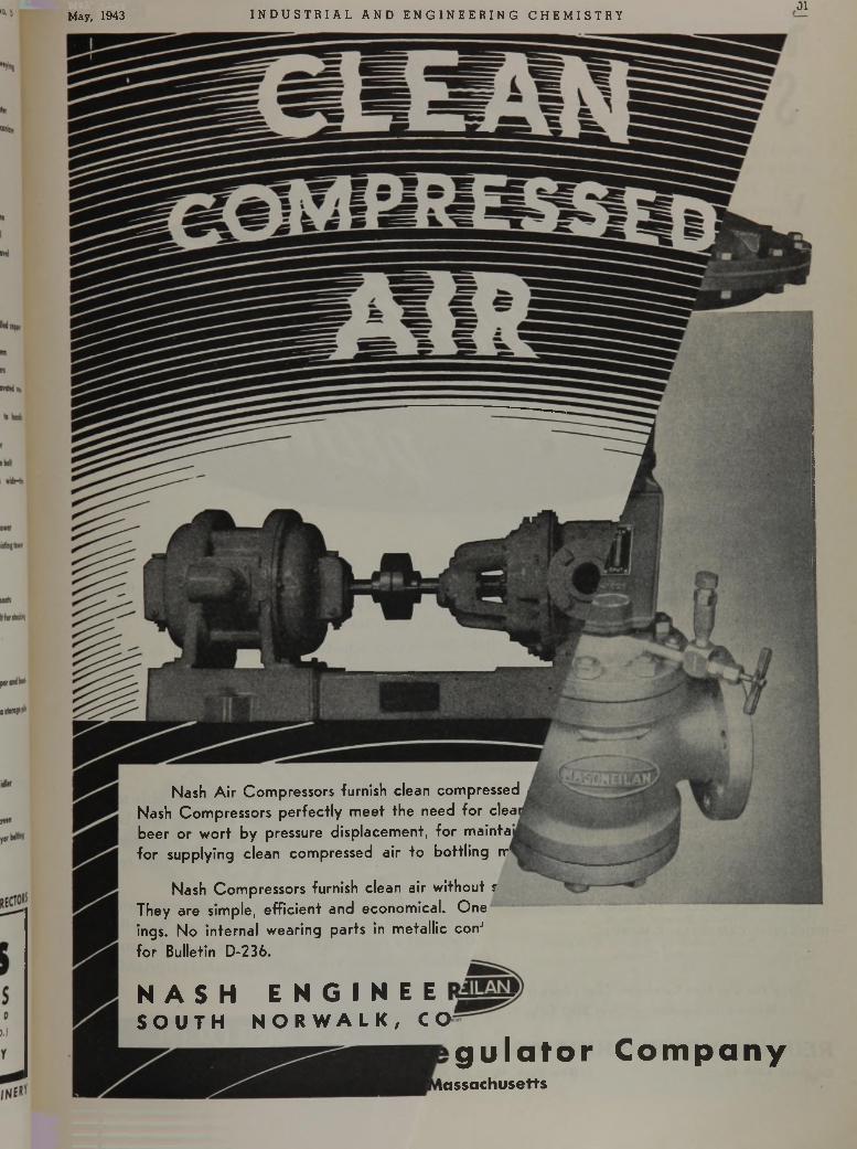
May, 1943 I N D U S T R I A L A N D E N G I N E E R I N G C H E M I S T R Y01
N a s h A i r C o m p r e s s o r s f u r n i s h c l e a n c o m p r e s s e d
N a s h C o m p r e s s o r s p e r f e c t l y m e e t t h e n e e d f o r c l e a
b e e r o r w o r t b y p r e s s u r e d i s p l a c e m e n t , f o r m a i n t a
f o r s u p p l y i n g c l e a n c o m p r e s s e d a i r t o b o t t l i n g n r1
N a s h C o m p r e s s o r s f u r n i s h c l e a n a i r w i t h o u t r
T h e y a r e s i m p l e , e f f i c i e n t a n d e c o n o m i c a l . O n e
i n g s . N o i n t e r n a l w e a r i n g p a r t s i n m e t a l l i c c o n J
f o r B u l l e t i n D - 2 3 6 .
N A S H E N G I N E ES O U T H N O R W A L K , CO'
g u la t o r C o m p an yl a s s a c h u s e t t s
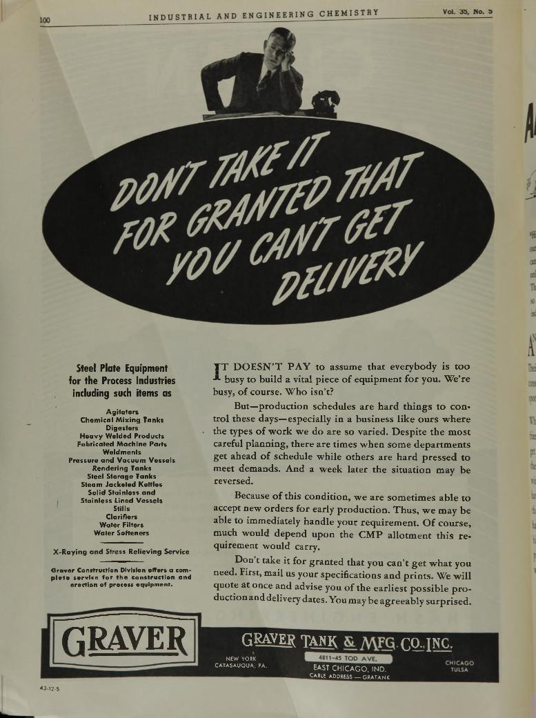
Steel Plate Equipment for the Process Industries including such items as
Agitators Chemical M ixing Tanks
Digesters Heavy Welded Products
Fabricated Machine Parts Weldments
Pressure and Vacuum Vessels Rendering Tanks
Steel Storage Tanks Steam Jacketed Kettles
Solid Stainless and Stainless Lined Vessels
Stills Clarifiers
W ater Filters Water Softeners
X-R aying and Stress Relieving Service
G r a v e r Construction Division offers a comp l e t e s e r v i c e f o r t h e c o n s t r u c t i o n a n d
e rec t io n of p rocess equ ipm en t .
T T D O ESN ’T PA Y to assume that everybody is too -*• busy to build a vital piece o f equipm ent for you. We’re busy, of course. W ho isn’t?
But—production schedules are hard th ings to control these days—especially in a business like ours w here the types o f w ork we do are so varied. D espite the m ost careful planning, there are times when some departm ents get ahead o f schedule while others are hard pressed to meet demands. And a week later the situation may be reversed.
Because o f this condition, we are som etim es able to accept new orders for early production. Thus, w e may be able to immediately handle your requirem ent. O f course, much would depend upon the CM P allotm ent th is re quirement would carry.
Don t take it for granted that you can’t get w hat you need. First, mail us your specifications and prin ts. We w ill quote at once and advise you o f the earliest possib le p ro duction and delivery dates. You may be agreeably surprised.
BRAVER GRAVE® t a n k CQiINÇ.NEW YORK
CATASAUQUA, PA.EAST C H IC A G O , IN D .
CABLE ADDRESS — GRATANK
«3-12-S
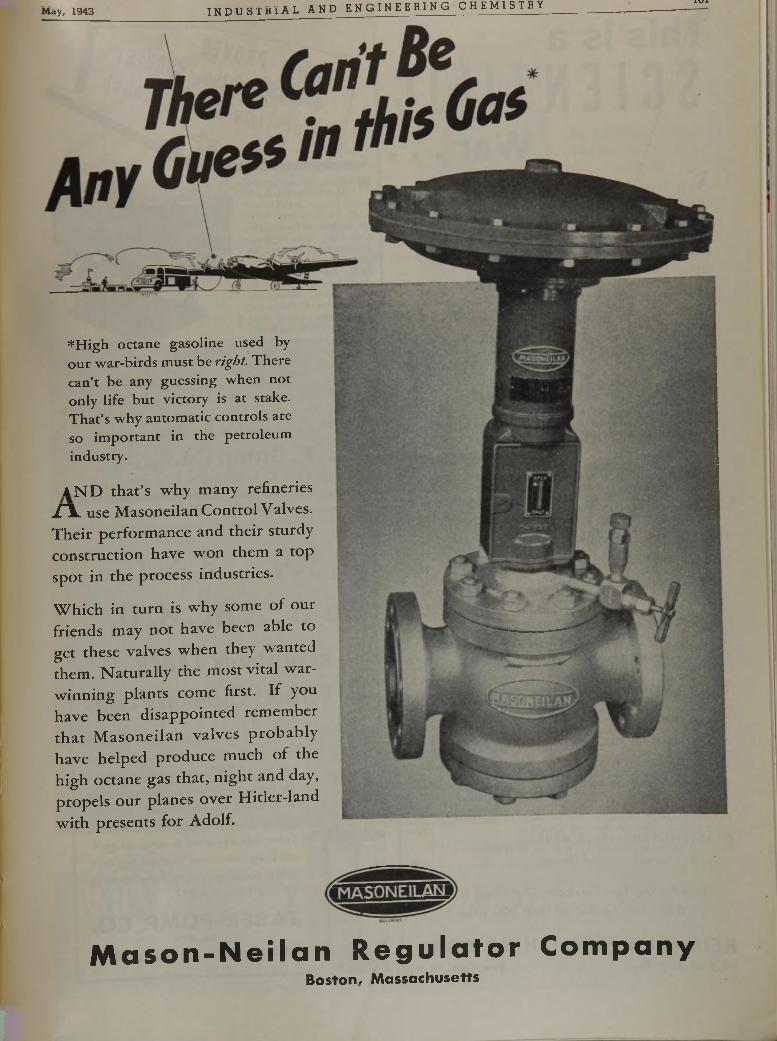
May, 1943 I N D U S T R I A L A N D E N G I N E E R I N G C H E M I S T R Yi Ul
*High octane gasoline used by our w ar-birds m ust be right. There can’t be any guessing when not only life bu t victory is at stake. T h a t’s w hy autom atic controls are so im portan t in the petroleum industry.
A N D that’s why many refineries jHL use Masoneilan Control Valves. Their performance and their sturdy construction have won them a top spot in the process industries.
Which in turn is why some of our friends may not have been able to get these valves when they wanted them. Naturally the most vital war- winning plants come first. If you have been disappointed remember that M asoneilan valves probably have helped produce much of the high octane gas that, night and day, propels our planes over Hitler-land with presents for Adolf.
M a s o n - N e i l a n R e g u la to r C om panyB o s t o n , M a s s a c h u s e t t s
I N D U S T R I A L A N D E N G I N E E R I N G C H E M I S T K ï
T h is i s a
SCIENTIFICW a r . . .
V I C T O R Y i n t o d a y ’ s h i g h l y s c i e n t i f i c w a r w i l l ’ b e
b a s e d o n t e c h n ic a l k n o w le d g e . . . t h e k i n d o f k n o w le d g e
i m p a r t e d b y t h e m a n y s c ie n t i f i c b o o k s p u b l i s h e d b y
R e in h o ld . P r e c is e , i n f o r m a t i v e a n d a u t h o r i t a t i v e . . .
t h e y a r e t o b e f o u n d i n t h e l i b r a r ie s o f e n g in e e r s , s c ie n
t i s t s a n d t e c h n ic ia n s e v e r y w h e r e .
P R O T E IN S , A M IN O A C ID S , A N D P E P T ID E S as Io n sa n d D ip o la r Io n s , Edwin J . Cohn and John T. E dsall. . $13.50
T H E C H E M IS T R Y O F N A T U R A L C O L O R IN G M A T T E R S , Fritz M ayer and A . H. Conk........................................... 10.00
E L E C T R O P H O R E S IS O F P R O T E IN S , a n d th e C h e m is t r y o f C e ll S u rfaces, Harold A . Abramson, Laurence S.Moyer and M anuel H . G onn .......................................................... 6.00
U S E S A N D A P P L IC A T IO N S O F C H E M IC A L S A N DR E L A T E D M A T E R IA L S , Thomas C. Gregory..................... 10.00
IN D U S T R IA L C H E M IS T R Y (4 th E d it io n )E m il Raymond Riegel............................................................................ 5.50
C O N D E N S E D C H E M IC A L D IC T IO N A R Y (3 d E d it io n )Francis M . Turner, Edit. Dir., T. C. Gregory, E ditor 12.00
C O N V E R S IO N O F P E T R O L E U MA . N . Sachanen ......................................................................................... 6 .00
S IL V E R IN IN D U S T R YLawrence. Addicks, E ditor ............................................................... 10.00
M O D E R N P U L P A N D P A P E R M A K IN GG. S. Witham, S r ....................................................................................... 6.75
T H E C H E M IS T R Y O F S Y N T H E T IC R E S IN SCarleton E llis ......................................................................................... 20.00
T H E C H E M IS T R Y A N D T E C H N O L O G Y O F R U B B E RC. C. Davis and J . T. B lake ........................................................ 15.00
T H E S C IE N C E O F R U B B E RK . Memmler, Editor .......................................................................... 15.00
M O D E R N P R A C T IC E IN L E A T H E R M A N U F A C T U R EJohn Arthur W ilson ................................................................................ 9.50
T H E P R O P E R T IE S O F G L A S SGeorge W . M o re y ............................................................................... 12.50
W E N E E D V IT A M IN SWalter H. Eddy and G. G. Hawley .......................................... 1.50
O U T L IN E S O F F O O D T E C H N O L O G YHarry W . von Loesecke.................................................................... 7 .00
M IN E R A L S IN N U T R IT IO NZollon T. Wirtschafter....................................................................... 1.75
T H E E L E C T R O N M IC R O S C O P EE . F. Burton and W . H . K oh l............................................... 3 .85
N O X IO U S G A S E S a n d th e P r in c ip le s o f R e s p ira t io n I n flu e n ce T h e ir A c t io n (S econd E d it io n ) , Yandell Henderson and Howard W . Haggard............................................................ 3 .50
t h e a m a z in g p e t r o l e u m i n d u s t r yVladimir A . Kalichevsky..................................................................... 2.25
A C O U R S E IN P O W D E R M E T A L L U R G YWalter J . Baeza .................................................................................... 3 .50
C H E M IC A L R E F IN IN G O F P E T R O L E U MV. A . Kalichevsky and B. A . Stagner.......................................... 7 .50
T H E C H E M IS T R Y O F P E T R O L E U M D E R IV A T IV E SV o lu m e I 18.00
Carleton E llis ................................................................... V o lu m e I I 20.00F A T IG U E O F W O R K E R S , I t s R e la t io n to In d u s t r ia l
P ro d u c t io n , National Research Council....................................... 2 .50IN D U S T R IA L C A M O U F L A G E M A N U A L ,Prepared at Pratt Institute by Konrad F. W ittmann,
chief of Industrial Camouflage D ivision ........................................... 4 .00
S e n d For O u r F ree C a ta lo g u e , " L e t 's L o o k I t U p "
W h ic h Lists C o n ten ts o f O v e r 2 0 0 T itle s
REINHOLD PUBLISHING CORP.330 W est 42nd S t., New Y ork , N. Y .
102
Q f t
« f t '.Y\W®
W A R p la n ts processing vita l m a te ria ls have
proved th e ab ility o f BAR-NUN R o tary S if ters to deliver th o ro u g h , u n ifo rm separa tions. T h ey ’ll ope ra te day in an d day o u t on 24-h o u r d u ty , w ith m in im u m a tte n tio n an d m a in te n an ce cost. Based on a c tu a l p e r f o rm a n c e , p la n t a f te r p la n t has ordered ad d itio n a l BAR- NUN S to keep pace w ith expanding opera tions. T h e s e p re c is io n -b u il t ROTARY S ifte rs a r e m ade in 9 sizes, 4 to 60 sq. fee t o f c lo th surface.
BAR-NUN
R o t a i tSIFTERS
C O M P LE TE IN F O R M A T IO N O N R E Q U E S T
B. F. Gump Co.E N G IN E E R S and M A N U F A C T U R E R S S IN C E 1 8 7 2
H, S O . . . . H, S2 0 , No, S . . . HC, H, 0 ,
n e e d s t u r d y T A B E R
V e r t i c a l C h e m i c a l P u m p s
O r d in a r y s u m p p u m p c o n s t r u c t io n is
n o t s a t is f a c to r y f o r p u m p in g c h e m ic a l
s o lu t io n s . T h is f a c t h a s b e e n p r o v e d
b y T a b e r o v e r m a n y y e a r s ' e x p e r ie n c e
w it h s o m e o f t h e la r g e s t c h e m ic a l
p la n ts . F ro m th is p r ic e le s s e x p e r ie n c e
T a b e r h a s d e s ig n e d a s e r ie s o f v e r t i
c a l c h e m ic a l p u m p s s u i t a b le f o r m o s t
a n y p r o c e s s in g s y s te m . W r i t e f o r h e lp
f u l n e w B u lle t in V - 8 3 7 .
TABER PUMP CO.f St. 1859
P i 2 9 3 Elm St. Buffalo, N. Y .5408
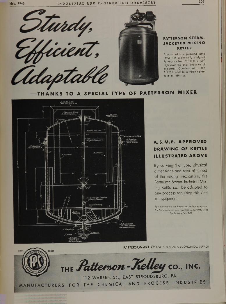
May, 1943 I N DU S T R I A L AND ENGI NE E R I NG CHEMI STRY 103
PATTERSON STEAM- JACKETED MI XI NG
KETTLEA standard type jacketed kettle fitted with a specially designed Patterson mixer. 76” O.D. x 109 high over the shell exclusive of supports. Constructed to the A.S.M.E. code for a working pressure of 150 lbs.
— T H A N K S TO A S PECI AL TYPE OF P A T T E R S O N M I X E R
A . S . M . E . A P P R O V E D
D R A W I N G OF KETTLE
I L L U S T R A T E D A B O V E
By varying the type, physical dimensions and rate of sp eed of the mixing mechanism, this Patterson Steam-Jacketed Mixing Kettle can be adapted to any process requiring this kind of equipment.
For information on Patterson-Kelley equipment for the chemical and process industries, write
for Bulletin No. 202.
PATTERSON-KELLEY FOR DEPENDABLE, ECONOMICAL SERVICE
T H E i h t t C f A G f l C O . / I N C .
112 WARREN ST., EAST STROUDSBURG, PA. RS FOR THE CHEMICAL AND PROCESS INDUSTRIES
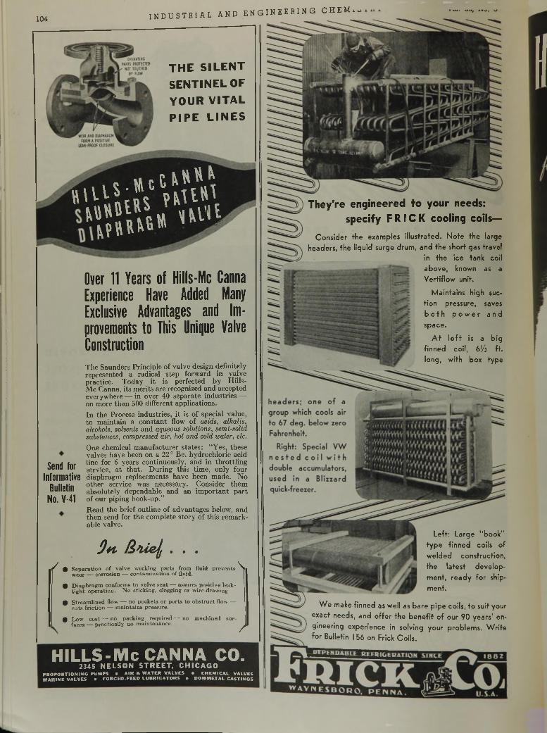
104i n d u s t r i a l a n d e n g i n e e r i n g c h e m .
T H E S I L E N T
S E N T I N E L OF
Y O U R V I T A L
P I P E L I N E S
* i U S ; , 7 n U » lM Ü lU « ill'll
-»te I» *k,
» » I « »
Send for Informative
Bulletin No. V-41
Over 11 Years of Hills-Mc Canna Experience Have Added Many Exclusive Advantages and Improvements to This Unique Valve ConstructionThe Saunders Principle of valve design definitely represented a radical step forward in valve practice. Today it is perfected by Hills- Mc Canna, its merits are recognized and accepted everywhere — in over 40 separate industries —- on more than 500 different applications.In the Process industries, it is of special value, to maintain a constant flow of acids, alkalis, alcohols, solvenls and aqueous solutions, semi-solid substances, compressed air, hot and cold water, etc.One chemical manufacturer states: “Yes, these valves have been on a 220 Be. hydrochloric acid line for 6 years continuously, and in throttling service, at that. During this time, only four diaphragm replacements have been made. No other service was necessary. Consider them absolutely dependable and an im portant part of our piping hook-up.”Read the brief outline of advantages below, and then send for the complete story of this remarkable valve.
9h /i lle f . . .
^ % S e p a ra t io n o f v a lv e w o rk in g p a r ts fro m flu id p re v e n ts 'S i w e a r — c o rro s io n — c o n ta m in a tio n o f flu id .
# D ia p h ra g m c o n fo rm s to v a lv e s e a t — a ssu res p o s itiv e leak - t ig h t o p e ra t io n . N o s tic k in g , c logg ing o r w ire-d raw in g .
# S tre a m lin e d flow — n o p o c k e ts o r p o r ts to o b s tru c t flow — c u ts f r ic tio n — m a in ta in s p ressu re .
0 L o w c o s t — n o p a c k in g r e q u i r e d — n o m ac h in e d su r- faces — p ra c t ic a l ly n o m a in te n a n c e . ^
They're engineered to your needs:specify F R I C K cooling coils—
Consider the examples illustrated. Note the large headers, the liquid surge drum, and the short gas travel
in the ice tank coil above, known as a Vertiflow unit.
Maintains high suction pressure, saves b o t h p o w e r a n d space.
A t le f t is a big finned coil, 6V2 ft. long, with box type
Left: Large "book" type finned coils of welded construction, the latest development, ready fo r shipment.
W e make finned as well as bare pipe coils, to suit your exact needs, and offer the benefit o f our 90 years' engineering experience in solving your problems. W rite fo r Bulletin I 56 on Frick Coils.
HILLS-Mc CANNA CO.2345 N E L S O N S T R E E T , C H IC A G O
P RO PO R TIO N IN G PU M PS • AIR * WATER VALVES • CHEM ICAL VALVES M ARINE VALVES • FORCED -FEED LUBRICATORS • DOWMETAL CASTINGS
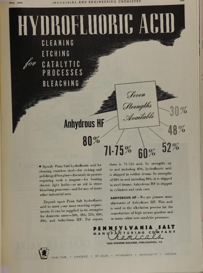
HYDROFLUORIC ACIDC L E A N I N GE T CHI NGC A T A L Y T I CP R O C E S S E SB L E A C H I N G
Anhydrous HF
7 1 -7 5 ^• Specify Penn Salt hydrofluoric acid for cleaning stainless steel—for etching and polishing of fine g lass-forcata ly tic process requiring such a reagen t-for frosting electric light b u lb s -a s an aid in straw bleaching processes—and for any of many
other industrial uses.
Depend upon Penn Salt hydrofluoric acid to m eet your most exacting requirements. I t can be supplied in six strengths for domestic users—30%, 48%, 52%, 60%,
and Anhydrous H F. For export,
there is 71-75% acid. In strengths up to and including 60%, hydrofluoric acid is shipped in rubber drums. In strengths of 60% to and including 80%, it is shipped in steel drums. Anhydrous HF is shipped
in cylinders and tank cars.
ANHYDROUS HF—We are pioneer manufacturers of Anhydrous H F. This acid is used in the alkylation process for the manufacture of high octane gasoline and
in many other new catalytic processes.
P E N H J Y L V A N U /, * A l TM A N U / f 1 / c T U R I N G C o//fA I P A N Y
L A ju t u - c ju l a ^ . . . . n . m n i U E D U I I A H F I P H I A . P A .
W NEW YOEK • CHICAGO • ST. IOUIS • PITTSBU.GH • WYANDOTTE • TACOMA
. . . or ¡ustinto a cold sweat?W hen som ething new busts loose all o f a sudden, look behind you before you leap too far. For a lo t o f valve problems are no th ing bu t paper bags full o f a i r . . . old gags that have been deflated tim e and again. They sound like dynamite at first, and w hen they w ere first new, maybe they were. But Chapman has m et m ost o f them before ... worked them o u t . . . and, if the application for a certain special valve was w ide enough, then Chapman added this special to its standard line. Tb.at’s why so many process plants make this a hard and fast rule; "In case o f new process or new valve problem , w alk . . . do no t run . . . to the Chapman plan t o r nearest office.” And you would be mighty interested to know w hat scores o f them have saved . . . in w orry, w ork, and tim e . . . by checking their "special” valve problem s w ith Chapm an’s Standard Line.
CHAPMAN VALVEM a n u f a c t u r i n g C o m p a n y
IN D IAN O R C H A R D , M A SSA C H U SETTS
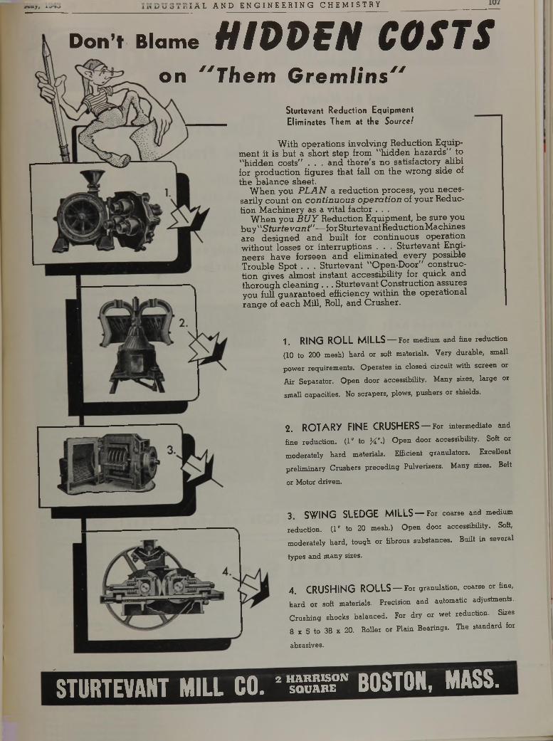
¡ IÄL AND ENGI NEER I NG CHEMI STRY ________
Don’t Blame H I 0 0 S N C 0 S T Son " T h e m G rem lin s"
Sturtevant R eduction E quipm ent E lim inates Them at th e Source!
2 . R O T A R Y FIN E CRU SH ERS — For intermediate and
fine reduction. (1" to X “-) Open door accessibility. Soft or
moderately bard materials. Efficient granulators. Excellent
preliminary Crushers preceding Pulverizers. Many sizes. Belt
or Motor driven.
3 . S W IN G SL E D G E M IL L S — For coarse and medium
reduction. (1" to 20 mesh.) Open door accessibility. Soft,
moderately hard, tough or fibrous substances. Built in several
types and many sizes.
4 . C R U S H IN G R O L L S — For granulation, coarse or fine,
hard or soft materials. Precision and automatic adjustments.
Crushing shocks balanced. For dry or wet reduction. Sizes
8 x 5 to 38 x 20. Roller or Plain Bearings. The standard for
abrasives.
With, operations involving Reduction Equipment it is but a short step from "hidden hazards'' to "hidden costs'' . . . and there 's no satisfactory alibi for production figures that fall on the wrong side of the balance sheet.
W hen you P L A N a reduction process, you necessarily count on co n tin u o u s opera tio n of your Reduction M achinery as a vital factor . . .
W hen you B U Y Reduction Equipment, be sure you buy1 'S turte v a n t" — for Sturtevant Reduction M achines are designed and built for continuous operation without losses or interruptions . . . Sturtevant Engineers have forseen and eliminated every possible Trouble Spot . . . Sturtevant "Open-Door" construction gives almost instant accessibility for quick and thorough cleaning . . . Sturtevant Construction assures you full guaranteed efficiency within the operational range of each Mill, Roll, and Crusher.
1. R IN G R O L L M ILL S — For medium and fine reduction
(10 to 200 mesh) hard or soft materials. Very durable, small
power requirements. Operates in closed circuit with screen or
Air Separator. Open door accessibility. Many sizes, large or
small capacities. No scrapers, plows, pushers or shields.
STURTEVANT MILL CO. 2 S " BOSTON, MASS.
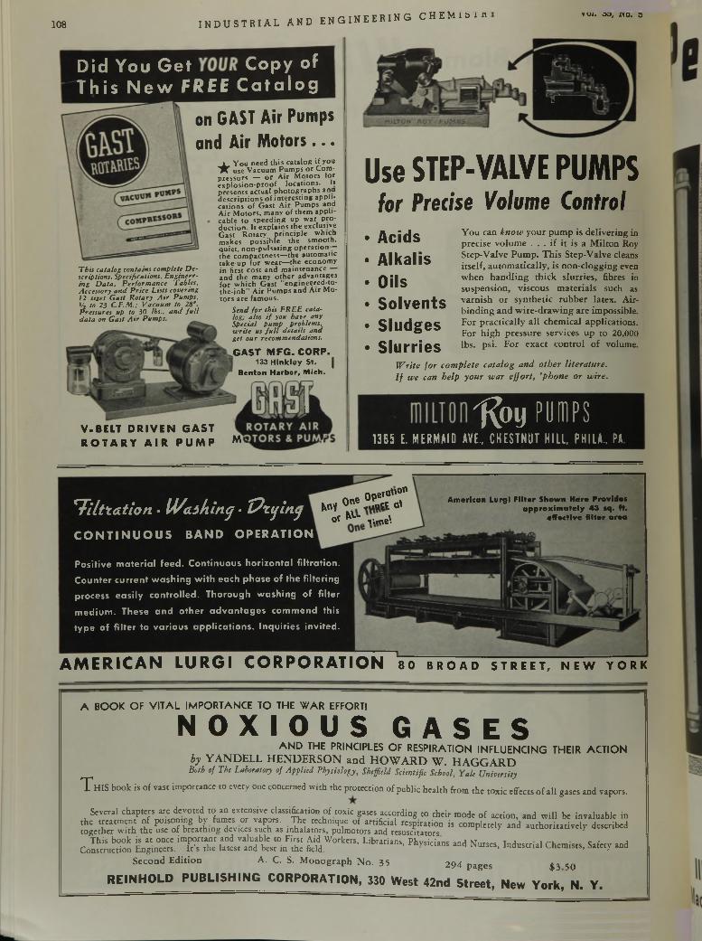
108 INDUSTRIAL AND ENGINEERING C H E M l ö i « voi. oo, no. o
D i d Y o u G e t C o p y o f T h i s N e w F R E E C a t a l o g
This catalog contains complete Descriptions, Specifications, Engineering Data, Performance Tables, Accessory and Price Lists covering 12 sizes Gast Rotary Air Pumps, Vi to 23 C.F.M.; Vacuum to 29". Pressures up to 30 lbs., and full data on Gast Air Pumps.
o n G A S T A ir P u m p s
a n d A ir M o t o r s . . .
★ You need this catalog if you use Vacuum Pumps or Com
pressors — or Air Motors for explosion-proof locations. It presents actual photographs ana descriptions of interesting applications of Gast Air Pumps and Air Motors, many of them applicable to speeding up war production. It explains the exclusive Gast Rotary principle which makes possible the smooth, quiet, non-pulsating operation— the compactness—the automatic take-up for wear—the economy in first cost and maintenance and the many other advantages for which Gast "engineered-to- the-job” Air Pumps and Air Motors are famous.
Send for this FREE catalog; also if you have any Special pump problems, write us full details and get our recommendations.G A S T M F G . C O R P .
133 Hinkley St. j Benton Harbor, Mich.
Hr-------
U se STEP-VALVE PUM PSfor Predse Volume Control
V-BELT DRIVEN GAST R O TA R Y A IR PUMP M
A c i d sA l k a l i s
O i l sS o l v e n t sS l u d g e sS l u r r i e s
You can know your pump is delivering in precise volume . . . if it is a Milton Roy Step-Valve Pump. This Step-Valve cleans itself, automatically, is non-clogging even when handling thick slurries, fibres in suspension, viscous materials such as varnish or synthetic rubber latex. Air- binding and wire-drawing are impossible. For practically all chemical applications. For high pressure services up to 20,000 lbs. psi. For exact control of volume.
Write for complete catalog and other literature. If we can help your war effort, ’phone or wire.
"Roy pumps1365 E. MERMAID AVE., CHESTNUT HILL, PH I LA., PA
*T iltra tio n • IW alk inq • T?tijin<j
C O N T IN U O U S BAND O PERATION
0pefQ" ° n 0 °e .aort alM l
0» *V\ time'.
American Lurgi Filter Shown Here Provides approximately 43 sq. ft.
effective filter area
Positive m ateria l feed. Continuous horizontal filtration.
Counter current w ash ing with each phase of the filtering
process easily controlled. Thorough w ashing of filter
m edium . These and other ad van tag es commend this
type of filter to various app lications. Inquiries invited.
A M E R I C A N L U R G I C O R P O R A T I O N so b r o a d s t r e e t , n e w y o r k
A BOOK OF V ITA L IMPORTANCE TO THE W AR EFFORTI
N OX I OU S G A S E SA N D THE PRINCIPLES OF RESPIRATION INFLUENCING THEIR ACTION
by YAND ELL H EN D E R SO N and H O W A R D W . H A G G A R DBoth of The Laboratory of Applied Physiology, Sb,field Scientific School, Yale University
T H IS book is of vast importance to evety one concerned with the protection of public health from the toxic effects of all gases and vapors.
Several chapters are devoted to an extensive classification of toxic gases according to their mode of action, and will be invaluable in the treatment of poisoning by fumes or vapors. The technique of artificial respiration is completely and authoritatively described together with the use of breathing devices such as inhalators, pulmotors and resuscitators autnoritauvciy aescrmcu
This book is at once important and valuable to First Aid Workers, Librarians Phvsirisnc M.,,™ r j i rs. c r jConstruction Engineers. lYs the latest and best in the field. ’ ^ slclans and Nurses> Industrial Chemists, Safety and
Second Edition A. C. S. M onograph No. 35 294 pages $3 50
R E I N H O L D P U B L I S H I N G C O R P O R A T I O N , 330 W e s t 42n d S t r e e t , N e w Y o r k , N . Y .
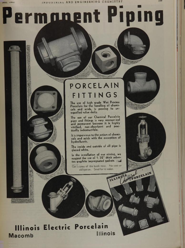
May, xsrio AND E NG I NE E R IN G CHEMI STRY
Perm nt Piping
PORCELAIN F I T T I N G S
The use of high grade W e t Process P orcela in for th e hand ling of chem icals and ac ids, is proving its une q u a lle d value d a ily .
The use of our C hem ical Porcelain p ip e and fittings is very econom ical and perm anen t because it is h igh ly v itrified , n o n -ab so rb en t and practica lly indestructib le .
It is im pervious to th e ac tion of chem icals and acids w ith th e ex cep tio n of hydrofluoric .
The inside and o u ts ide of all p ip e is g lazed w hite.
In the installation of our Dioing, we suggest the use of 1 /3 2 thick asbestos graphite impregnated gaskets.
Get^a copy of this book now. No cost or obligation. Send for it today.
¡ n o i s E l e c t r i c P o r c e l a i nM a c o m b I l l i n o i s
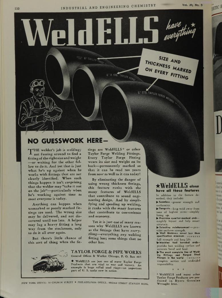
NO GUESSW ORK H ERE-T H E w e ld e r ’s jo b is welding;
n o t fu s s in g a ro u n d to find a f i t t in g o f th e r i g h t size a n d w e ig h t — o r w a i t in g f o r th e o th e r f e l lo w to do i t . A n d y e t t h a t is ju s t w h a t h e ’s u p a g a in s t w h e n he w o rk s w i th f i t t in g s t h a t a re n o t c le a r ly id e n tif ie d . W h en su ch th in g s h a p p e n i t isn ’t su rp r is in g t h a t th e w e ld e r m a y " t a k e i t o u t o n th e jo b ” — p a r t ic u l a r ly w h e n h e ’s w o rk in g a g a in s t tim e as m o s t e v e ry o n e is to d a y .
A n y th in g c a n h a p p e n w h e n u n m a r k e d o r p o o rly m a rk e d f i t t in g s a re u sed . T h e w ro n g size m a y be d e liv e re d , a n d n o t d is c o v e re d u n t i l to o la te . A h e lp e r m a y lu g a h e a v y f i t t in g a lo n g w a y f ro m th e s to c k ro o m , on ly to do i t a ll o v e r a g a in .
B u t th e r e ’s l i t t le c h a n c e o f th is s o r t o f th in g w h e n th e f i t
tin g s a re W e l d E L L S o r o th e r T a y lo r F o rg e W e ld in g F it t in g s . E v e ry T a y lo r F o rg e F i t t in g w e a rs its size a n d w e ig h t on its b a c k — p e rm a n e n tly m a rk e d so t h a t i t c a n be re a d te n y e a rs f ro m n o w as w e ll as i t c a n to d a y !
By e lim in a tin g th e d a n g e r o f u s in g w ro n g th ick n ess f i tt in g s , th is f e a tu r e r a n k s w i th th e m a n y f e a tu re s o f W eldE L L S th a t c o n tr ib u te to so u n d e n g in e e rin g design . A n d b y sim p lify in g a n d sp eed ing u p w e ld in g , i t r a n k s w i th th e m a n y fe a tu re s th a t c o n tr ib u te to co n v en ien ce a n d econom y.
Y et i t is ju s t one o f m a n y re a sons w h y W eldE L L S a re k n o w n as th e f i tt in g s t h a t h a v e everything— e v e ry th in g any w e ld in g f i t t in g h a s ; som e th in g s t h a t no o th e r has.
- T A Y L O R F O R G E & P IP E W O R K S' General Offices & Works: Chicago, P. O. Box 48 5
• WeldELLS are just one of many Taylor Forge Products that are vital to war and victory. An example is huge rolled steel rings— an important part of U. S. tanks now in action.
NEW YORK OFFICE: 50 CHURCH STREET • PHILADELPHIA OFFICE; BROAD STREET STATION BLDG,
★WeldELLS a l o n eh a v e a l l t h e s e f e a t u r e sIn a d d itio n to th e fe a tu re desc rib e d , th e y in c lu d e :^ Seamless— g re a te r s tr e n g th and u n ifo rm ity .^Tangents— keep w eld aw ay fro m zone o f h ig h e s t s tress— sim p lify lin in g up .^ Precision quarter-marked ends—s im p lify la y o u t an d h e lp insure ac cu racy .^Selective reinforcement — p r o vides u n ifo rm s tre n g th .^ Wall thickness never less than specification minimum—assures fu l l s t r e n g th an d lo n g life .► Machine tool beveled ends— p rov ides b est w e ld in g s u rfa c e and a c c u ra te beve l an d la n d .^The most complete line of Welding Fittings and Forged Steel Flanges in the world— i n s u r e s c o m p le te serv ice and u n d iv id ed resp o n s ib ility .
* «• ** WeldELLS and many other Taylor Forge Products are prod uced in B yers G enuine Wrought Iron.
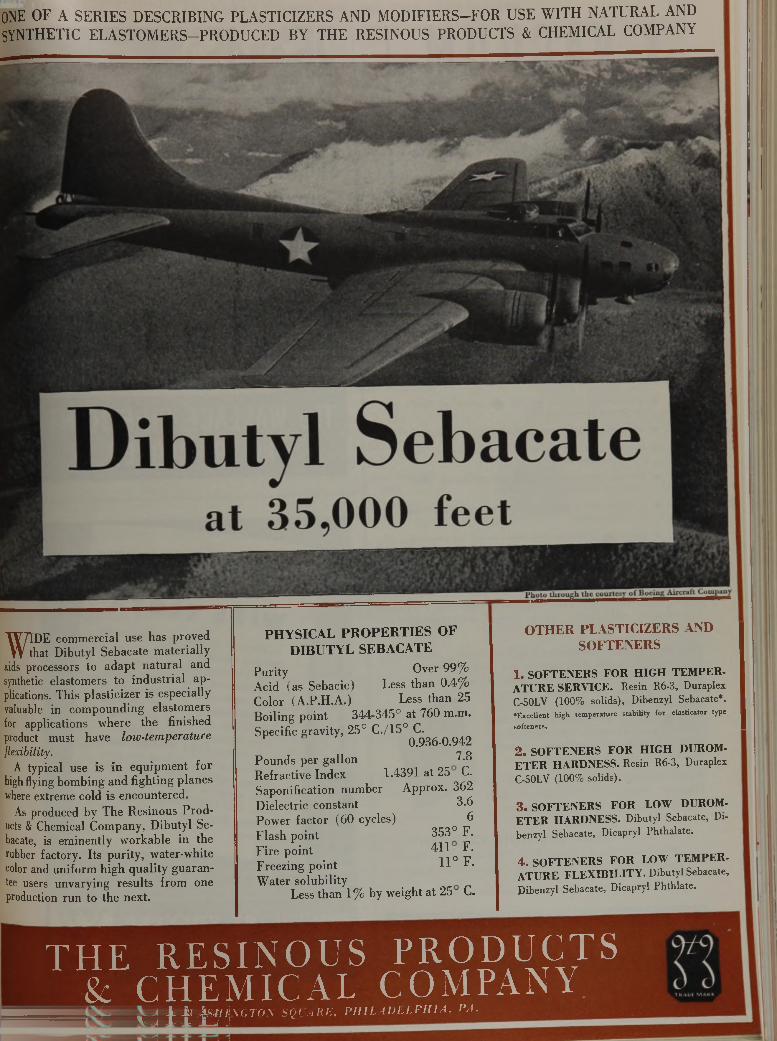
W IDE commercial use has proved that Dibutyl Sebacate materially
aids processors to adapt natural and synthetic elastomers to industrial applications. This plasticizer is especially valuable in compounding elastomers for applications where the finished product must have lo w - te m p e r a t u r e
flexib ility.A typical use is in equipment for
high flying bombing and fighting planes where extreme cold is encountered.
As produced by The Resinous Products & Chemical Company, Dibutyl Sebacate, is eminently workable in the rubber factory. Its purity, water-white color and uniform high quality guarantee users unvarying results from one production run to the next.
PHYSICAL PR O PE R T IE S OF DIBUTYL SEBACATE
Purity Over 99%Acid (as Sebacic) Less than 0.4%Color (A.P.H.A.) Less than 25Boiling point 344-345° at 760 m.m.Specific gravity, 25° C ./150 C.
P 0.936-0.942Pounds per gallon 7.8Refractive Index 1.4391 at 25 C.Saponification number Approx. 362Dielectric constant 3.6Power factor (60 cycles) 6Flash point 353° F.Fire point 411 F.
\ . n 0 PFreezing point J-1 r *Water solubility
Less than 1% by weight at 25 C.
OTH ER PLASTICIZERS AND SOFTENERS
1 . SOFTENERS FO R H IG H T EM PER ATURE SERV ICE. Resin R6-3, Duraplex C-50LV (100% solids), Dibenzyl Sebacate*.•Excellent h igh tem perature stability for elasticator type
softeners.
2 . SOFTENERS FO R H IG H DUROM- E T E R HARDNESS. Resin R6-3, Duraplex C-50LV (100% solids).
3 . SOFTENERS FO R LOW DUROM- E T E R HARDNESS. Dibutyl Sebacate, Di- benzyl Sebacate, Dicapryl Phthalate.
4 . SOFTENERS FOR LOW TEM PER ATU RE FL EX IB ILITY . Dibutyl Sebacate, Dibenzyl Sebacate, Dicapryl Phthlate.
T H E R E S I N O U S P R O D U C T S & C H E M I C A L C O M P A N Y
i - f a 'teM lh'GTO V SQL ARE, PHILADELPHI A. PA. V^4 1 1 Í_J J
ONE OF A SERIES DESCRIBING PLASTICIZERS AND MODIFIERS—FOR USE WITH NATURAL AND SYNTHETIC ELASTOMERS-PRODUCED BY THE RESINOUS PRODUCTS & CHEMICAL COMPANY
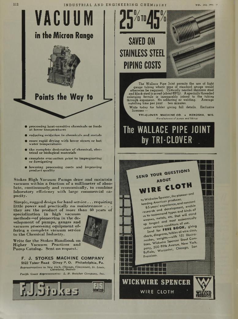
112 I NDUS TR I AL AND ENGI NE E R I NG CHE M i s i k y VOl. OO, no.
VACUUMin the Micron Range
The WALLACE PIPE JOINT by TRI-CLOVER
• p ro c e ss in g h e a t- s e n s i t iv e c h e m ic a ls o r fo o d s a t lo w e r t e m p e ra tu r e s
• re d u c in g o x id a tio n in c h e m ic a ls a n d m e ta ls
• m o re r a p id d ry in g w ith lo w er s te a m o r h o t w a te r t e m p e ra tu r e s
• t h e c o m p le te d e s ic c a t io n o f c h e m ic a l, e lec t r ic a l o r b io lo g ic a l m a te r ia ls
• c o m p le te e v a c u a tio n p r io r to im p re g n a t in g o r fu m ig a t in g
• lo w e rin g p ro c e ss in g c o s ts a n d im p ro v in g p ro d u c t q u a li ty
S tokes H igh V acuum P u m p s draw a n d m a in ta in vacu u m w ith in a frac tio n o f a m illim e te r of absolu te , co n tin u o u sly an d econom ically , to com bine lab o ra to ry efficiency w ith large com m ercia l cap ac ity .S im ple, rugged design for h a rd service . . . req u ir in g l i t t le pow er an d p rac tica lly no m a in te n a n c e . . . th ey are th e p ro d u c t o f m ore th a n 40 years of sp ec ia liza tio n in h ig h vacuum m e th o d s—o f p ioneering in th e deve lo p m en t o f p u m p s , gauges an d v acu u m processing eq u ip m e n t offe ring a com ple te v acu u m service to th e C hem ical In d u s try .
W rite for th e S tokes H andbook on H ig h er V acu u m P rac tices an d P u m p C ata log . S en t on req u est.
F . J . S T O K E S M A C H I N E C O M P A N Y5922 T a b o r Road O ln ey P. O . P h ilad e lp h ia , Pa.
Representatives in New York, Chicago, C incinnati, S t. Louis, Cleveland, D etroit
Pacific Coast R epresentative: L. H. B utcher C om pany. Inc.
s99
■ j
SI91
ABOUT
VflRE■ Soencer>eP''oneer°nto Wiclowire Sp ducer.
leading American p ^ cons,ant 85 years' e*Pe" enab'e
research °"d ^ y p e s and kinds of us to recommend typ ^ ^ standweaves, metab, ^ eCononricaiiy up longest du-l0ns of use-under various eojdrt o K f gWmg
Se0d ^ tables of vrire sizes,charts, diagram ^ ^ lUustra-meshes, v/e.ght ^ Q om.f.nns V /ickvcre Sp ^ York,tions. ” Ayenue,pany, 500 Fifth A SanBuffalo, Worcester,Francisco.
E » s u
W I C K W I R E S P E N C E R
W IR E C L O T H
SAVED ON STAINLESS STEEL
PIPING COSTS
The Wallace Pipe loint permits the use of light gauge tubing where pipe of standard gauge would
otherwise be required. Critically needed stainless steel and black steel is saved (about 65%). A specially threaded
enlarging ferrule is inseparably joined to the tubing through expansion. No soldering or welding. Average installing time per joint — two minutes.Write today for folder giving full details. Exclusive
licensee —TRI-CLOVER MACHINE CO. . KENOSHA, WIS.
Manufacturers of pumps and fittings
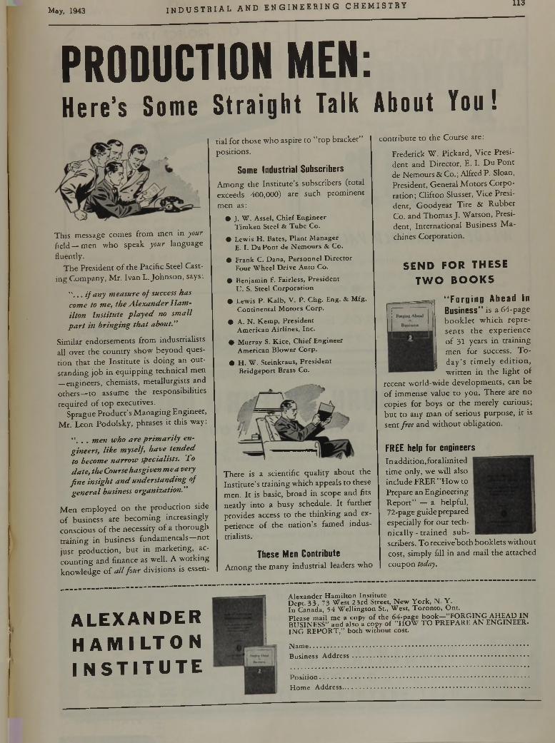
May, 1943 INDUS TR I AL AND E N GI NE E R IN G CHEMI STRY 113
PRO DUCTIO N M EN :H e r e ’s S o m e S t r a i g h t T a l k A b o u t Y o u !
This message comes from m en in your field — m en w ho speak your language fluently.
The President o f the Pacific Steel Casting Com pany, M r. Ivan L. Johnson , says:
" , . . i f any measure of success has come to me, the Alexander Hamilton Institute played no small part in bringing that about.”
Similar endorsem ents from industrialists all over the country show beyond question th a t the Institu te is doing an o u tstanding job in equipp ing technical men —engineers, chemists, m etallurgists and others—to assum e the responsibilities required o f to p executives.
Sprague P roduct’s M anaging Engineer, M r. Leon Podolsky, phrases it this way:
", . . men who are prim arily engineers, like myself, have tended to become narrow specialists. To date, the Course hasgivenme a very fine insight and understanding of general business organization.”
M en em ployed on the production side o f business are becom ing increasingly conscious o f the necessity o f a thorough training in business fundam entals—not just production , b u t in m arketing, accounting and finance as well. A w orking know ledge o f all four divisions is essen
tial for those who aspire to "top bracket” positions.
Some Industrial SubscribersAmong the Institute’s subscribers (total exceeds 400,000) are such prominent men as:
• J. W. Assel, Chief Engineer Timken Steel & Tube Co.
• Lewis H. Bates, Plant Manager E. I. DuPont de Nemours & Co.
• Frank C. Dana, Personnel Director Four Wheel Drive Auto Co.
• Benjamin F. Fairless, President U. S. Steel Corporation
• Lewis P. Kalb, V. P. Chg. Eng. & Mfg. Continental Motors Corp.
• A. N. Kemp, President American Airlines, Inc.
• Murray S. Kice, Chief Engineer American Blower Corp.
• H. W. Steinkraus, President Bridgeport Brass Co.
There is a scientific quality about the In stitu te’s training which appeals to these men. I t is basic, broad in scope and fits neatly in to a busy schedule. I t further provides access to the th ink ing and experience o f the nation’s famed industrialists.
These Men ContributeA m ong the many industrial leaders who
contribute to the Course are:
Frederick W . Pickard, Vice President and D irector, E. I. D u P on t de Nemours & Co. ; Alfred P . Sloan, President, General M otors C orporation; Clifton Slusser, Vice President, G oodyear Tire & R ubber Co. and Thom as J . W atson, President, International Business M achines Corporation.
S E N D F O R THESE T W O B O O K S
“ Forging Ahead InBusiness” is a 64-page b o o k le t w h ich rep re sen ts th e experience o f 31 years in training m en for success. T o d a y ’s tim e ly e d it io n , w ritten in the ligh t of
recent world-wide developm ents, can be o f im m ense value to you. T here are no copies for boys or the merely curious; b u t to any m an o f serious purpose, it is sent free and w ithout obligation.
FREE help for engineersIn addition,foralim ited tim e only, we will also include FREE "H ow to Prepare an Engineering R epo rt” — a helpful,72-page guide prepared especially for our techn ic a l ly - tra in e d s u b scribers. T o receive’bo th booklets w ithout cost, simply fill in and m ail the attached coupon today.
A L E X A N D E R H A M I L T O N I N S T I T U T E
Alexander Hamilton Institute ^Dept. 33, 73 West 2 3rd Street, New York, N. Y.In Canada, 54 Wellington St., West, Toronto, Ont.Please mail me a copy of the 64-page book—"FORGING AHEAD IN BUSINESS” and also a copy of "HOW TO PREPARE AN ENGINEERING REPORT,” both without cost.
Name...................................................................................................................Business Address.............................................................................................
Position.............Home Address..
114 I NDUS TR I AL AND ENGI NE E R I NG C HEMI STRY vol. 30, «o. o-
WELDED MANIFOLD VALVESA no ther one o f the many outstanding products
made by HICKS from the metal best suited fo r
the service. A lso Fabricators o f com plete eq u ip
ment fo r the Process Industries.
S. D. H IC K S E N G IN E E R IN G C O ., Inc.
1671 HYDE PARK AVE., HYDE PARK, MASS.
O P R O J E C T 1 7 6 3 O \
PR O B L E M : U n s ta b le T h e rm o s ta t ic C o n tro l d u e to V ib r a t io n
S O L U T IO N :F e n w a l T h erm o sw itch
R E A S O N S :
The design is such tha t the element has high spring tension at a ll times. Consequently the expanding member (the outer shell) has positive, direct control o f the contacts resulting in a de fin ite vibrationless break on circu it open or closing.Maximum rating I0 A ., 115V & ± .1°F. Sensitivity. H igher capacity and greater sensitivity a v a ilable. W rite .
2 0 3 M A IN ST. A S H L A N D
M ASSACHUSETTS
kkI F Y O U B U R N S U L F U R . .LET V I R G I N I A B U R N I T F O R Y O U / '— H ave you ev er co n sid ered a ll of th e ad v a n ta g e s of p u re ,[ cool 100% SO L, in th e liqu id o r gas p h ase as a m ean s of
s tab iliz in g your p rocess . . .W h a t is th e SOu co n ten t of th e b u rn e r gas su p p ly in g
• your process . . .Do th e in h e re n t im p u ritie s in th e b u rn e r gas p ro d u ce
• u n d es ira b le o r u n p re d ic ta b le side re ac tio n s . . .•f D oes th e h e a t of th e b u rn e r gas or v a ria tio n in th is tern-• p e ra tu re in te rfe re w ith your o p e ra tio n o r p rocess con tro l.
It is the job of “ V IR G IN IA ’S ” Te ch n ic ian s to prove the overa ll econom ic advantages of “ E S O T O O ” *, to demonstrate the value of control in terms of stepped up output, sim plified operation and quality production.T o the M anufacturer who desires an alternate com m odity source or the assurance of a continuous supply of raw m aterials in these cru cia l days we say again “ I f you burns u lfu r . . . let Virginia burn it fo r you .”
* “ E S O T O O ” is V irg in ia ’s Trad e Name for L iq u id S u lfu r D io xid e
V i r g i n i a S m e l t i n gC O M P A N Y
W E S T N O R F O L K , V I R G I N I A
About Sh ipm ents—
* I I
Portable cylinders containing ISO lb., semi-portable drums containing 2000 lb. liquid SO2. L. C. L. or carload.
Carload: 15 drums on multiunit car frame; 30,000 lb. For users without storage facilities.
Tank car lots of 40,000 lb. for users equipped with storage facilities.
Prompt shipment from the strategically located works of the largest producer of liquid sulfur dioxide in the U. S. J
May, 1943 I N DU S T R I A L a n d e n g i n e e r i n g c h e m i s t r y 115
D E T E R M I N A T I O N O F M A G N E S I U M
REAGENT— Titan Yellow
METHOD — Spectrophotometric
REFERENCE — Ludwig and Johnson, Ind. Eng. Chem .,Anal. Ed., 14, 895 (1942)
M
K O D A K .
agnesium hydroxide, w h e n p r e c ip ita te d in th e p r e se n c e o f t i t a n y e llo w , J fo r m s a la k e w h ic h is s u ita b le fo r sp e c tr o p h o to m e tr ic m e a su r e m e n t. D e te r m in a t io n o f m a g n e s iu m b y th is m e a n s is ra p id , r e q u ir in g a b o u t t w e n t y m in u te s , a n d c o m p a r e s fa v o r a b ly in a c c u r a c y w ith th e o ffic ia g r a v im e tr ic p ro ced u re . I t is le s s su b je c t to u n c e r ta in t ie s th a n th e s ta n d a r d v o lu m e tr ic m e th o d s , a n d fo r m o s t p r a c t ic a l p u r p o se s th e in te r fe r e n c e s l ik e ly t o b e e n c o u n te r e d d o n o t a ffe c t th e r e su lts . T h e r e a g e n t
is a v a ila b le a s E a s t m a n P 4 4 5 4 T i t a n Y e l l o w ( P r a d . ) .
Write fo r an abstract of the article in which the determination of magnesium with titan yellow is described. . . . Eastm an K odak Company,
Chemical Sales D ivision, Rochester, A . Y .
There are m ore than 3 4 0 0E A S T M A N O R G A N I C C H E M I C A L S
DE IONIZED W A T E R y ^ D I S T I L L E D W A T E RA T A F R A C T I O N O F T H E C O S T !
Without heat, without fuel, ILLCO-WAY De-ionizing units are daily producing the equivalent of single-distilled water . . . meeting exacting standards in aircraft factories, synthetic rubber plants, chemical industries, etc. . . . This modem method is based on ion exchange, and uses Amberlite resins^
f ' S v *
Read the full story of this remarkable m odern m ethod! S e n d f o r f o l d e r !
.vas
,\\o»s
10,000 gallons for less than a dollar!— on average raw water supply. When water supply is low in dissolved solids, cost may be considerably less!
\ H T H E U f f »
^ STRUT ^I L L I N O I S W A T E R T R E A T M E N T C O . «ÔckÎoro, ILLINOIS
116 I NDUSTR I AL AND ENGI NEER I NG CHEMI STRY Vol. 35, No. 5
A ir d i a p h r a g m m o to r f o r a u to m a t ic o p e r a t io n
— 15 p o u n d s p r e s s u r e .
S t a n d a r d 2 4 - in c h 1 2 5 lb . i r o n va lv e
w i t h b a l l c r a n k a r m f o r c o n n e c t i o n t o e x te n d e d r e a c h r o d . S le ev e b e a r i n g l u b r i c a te d s tu ff in g b o x w i th c a g e . W h e n t h e v a n e i s fu lly o p e n , f l o w c o n d i t i o n s a r e s im i l a r t o t h o s e p r o - d u c e d i n t w o V e n tu r i T u b e s .
L o w P r e s s u r e L o s s W h en O p e n
&
The pressure loss in a wide open R-S Butterfly Valve is less than in most conventional types o f wedge gates. In fact, the streamlined vane is a Venturi maker and is practically self-cleaning. Any member of the R-S Butterfly Valve line will sting the maintenance bill every time.
These valves are accurately machined and are either manually o r automatically co ntrolled. The beveled vane seats at an angle against the valve body. There is a size and type for practically any service condition.
SUBSTITUTE METALS—R-S has developed pressure iron castings for resistance against heat, abrasion and corrosion. They replace vital victory production metals and are considerably lower in price. For instance, R-S "A” Metal, a tough dense metal of high endurance, is used in applications where hard wear and severe stresses are encountered. Has a tensile up to 50,000 p s i and is readily machinable. Write for detailed information and the R-S Butterfly Valve Catalog.
VALVE DIVISIONR - S P R O D U C T S C O R P O R A T I O NG erm antown A v e . & B erk ley St. • P h ilad elph ia , Pa.
The Materials that will overcome the
RUBBER SHORTAGE
are being developed in laboratories where
ALBERENE STONE
is standard equipment for table tops, fume hoods, sinks, tanks,
and shelving. Prompt deliveries
can still be made.
ALBERENE STONE CORPORATION OF V IR G IN IA
419 FOURTH AVENUE, NEW YORK
g ( j 5 f f s e » ° TOUR CATALOG TO
Company..........................
A ddress................................
Attention of......................
May, 1943 I N D U S T R I A L AND E N GI NE E R I NG C HEMI STRY 117
!
t i
Stainless Steel Heat Exchanger Coils
PROCESS VESSEL EQUIPMENT
BRIGHTON STATION
© © iPlPilSiW © I I M
CINCINNATI, OHIO
PROCESSING EQUIPMENTipM^Pk? ■'v; '■
M IXERSSIFTERS
CUTTERSCRUSHERSG R IN D E R S
PULVERIZERSH A M M E R M ILLS
A T T R IT IO N M ILLS •
RUBBERR E C LA IM IN GEQ UIPM ENT
Famous for over forty years, Robinson “ Unique" machines today incorporate the most advanced engineering design and construction. Illustrated manuals and expert counsel are yours for the asking!
ROBINSONM ANUFACTURING CO M PANY30 CHURCH STREET, NEW YORK
Web. MUNCY. PENNA.
T oday—it ' s J HAMMER MILLSMany sizes. Extra heavy construction. Accurately balanced. For coarse, medium and fin e g rin d in g . E lectro
magnetic separator and dust collector optional.
1000 Gal. Stainless Steel Oil Cooking 1500 Gal. Stainless Clad Steel M ixing Kettle Tank
BRIGHTON
Stainless Steel Control Panel 1000 Gal. Stainless Steel M ixing T a n k
We will build special Vessel Equipment to Your.sP«c *fica‘i|o n *m; ' '” *C't tical equipment built for long hard service. And doubly important today — BRIGHTON can give you prompt delivery.
Our engineering department is maintained to help you with your development problems.
ATTRITION MILLSBosom-bodied, burr-type grinding plates produce maximum capacity. Simple adjustment provides uniform extrem ely fine or coarse product. Many sizes availab le . Thousands in service!
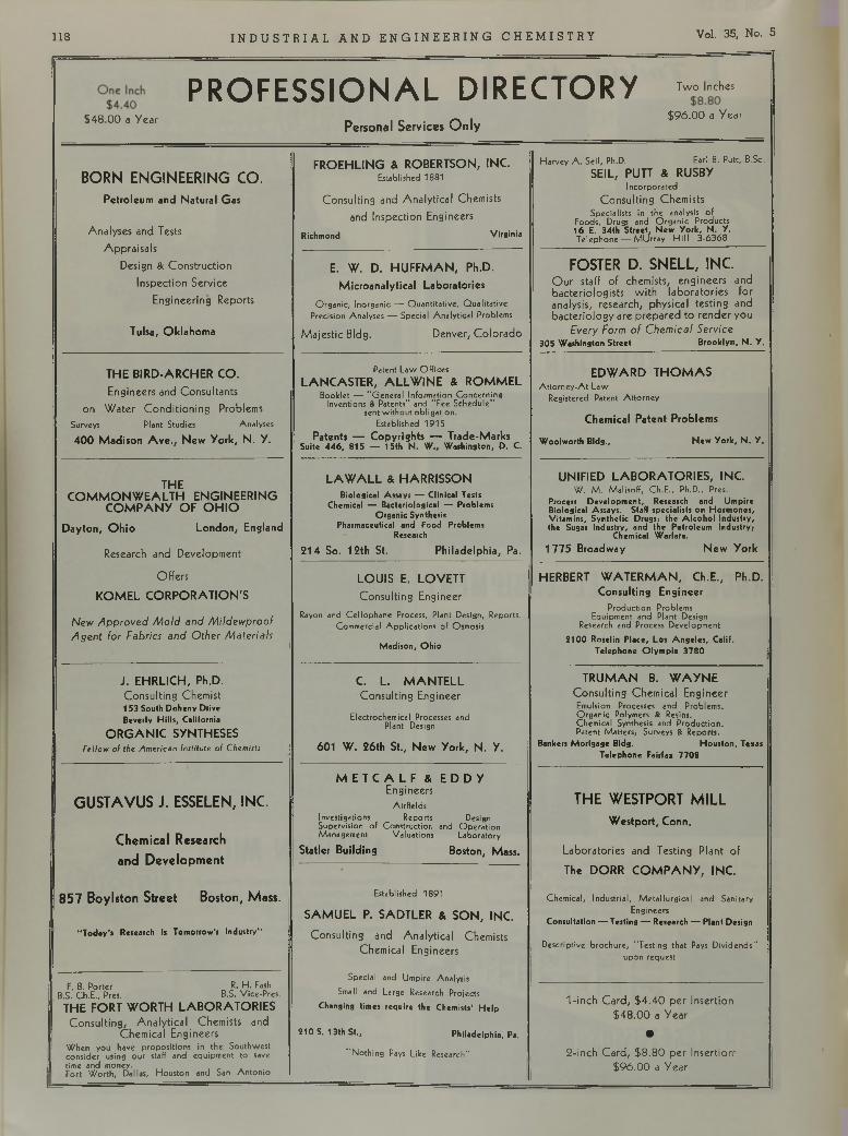
118 INDUS TR I AL AND ENGI NEER I NG CHEMI STRY Vol. 35, No. 5
PROFESSIONAL DIRECTORY “
,4 8 0 0 * y “ ' Personal Services O n ly *96.00 , V „ r
B O R N E N G IN E E R IN G C O .
Petroleum and Natural Gas
Analyses and Tests Appraisals
Design & Construction Inspection Service
Engineering Reports
Tulsa, Oklahoma
FROEHLING & ROBERTSON, INC.Established 1881
Consulting and Analytical Chemists and Inspection Engineers
Richmond Virginia
Harvey A. Seil, Ph.D. Earl B. Putt, B.Sc.SEIL, PUTT & RUSBY
IncorporatedConsulting Chemists
Specialists in the analysis of Foods, Drugs and Organic Products 16 E. 34th Street, New York, N. Y.Telephone — MUrray Hill 3-6368
E. W. D. HUFFMAN, Ph.D.Microanalytical Laboratories
Organic, Inorganic —- Quantitative, Qualitative Precision Analyses — Special Analytical Problems
Majestic Bldg. Denver, Colorado
FOSTER D. S N E L L , IN C.Our staff of chemists, engineers and bacteriologists with laboratories for analysis, research, physical testing and bacteriology are prepared to render you
Every Form o f C hem ical Service 305 Washington Street Brooklyn, N. Y.
THE BIRD-ARCHER CO.Engineers and Consultants
on Water Conditioning ProblemsSurveys Plant Studies Analyses400 Madison A ve., New York, N. Y.
Patent Law OfficesLANCASTER, ALLWINE & ROMMEL
Booklet — "General Information Concerning Inventions & Patents” and "Fee Schedule"
sent without obligation.Established 1915
Patents — Copyrights — Trade-Marks Suite 446, 815 — 15th N. W„ Washington, D. C.
EDWARD THO M A SAttorney-At-Law
Registered Patent Attorney
Chemical Patent Problems
Woolworth Bldg., New York, N. Y.
THECOM MONW EALTH ENGINEERING
COM PANY OF O H IO
Dayton, Ohio London, England
Research and Development
Offers
KOMEL CORPORATION'S
N ew A p p ro v e d M o ld and M ildew proo f A g e n t for Fabrics and O ther M ateria ls
LAWALL & HARRISSONBiological Assays — Clinical Tests
Chemical — Bacteriological — Problems Organic Synthesis
Pharmaceutical and Food Problems Research
214 So. 12th St. Philadelphia, Pa.
UNIFIED LABORATORIES, INC.W. M. Malisoff, Ch.E., Ph.D., Pres.
Process Development, Research and Umpire Biological Assays. Staff specialists on Hormones, Vitamins, Synthetic Drugs; the Alcohol Industry, the Sugar Industry, and the Petroleum Industry;
Chemical Warfare.1775 Broadway New York 1
LOUIS E. LOVETTConsulting Engineer
Rayon and Cellophane Process, Plant Design, Reports. Commercial Applications of Osmosis
Madison, Ohio
HERBERT WATERMAN, Ch.E., Ph.D.Consulting Engineer
Production Problems Equipment and Plant Design
Research and Process Development2100 Roselin Place, Los Angeles, Calif.
Telephone Olympia 3780 t
J. EHRLICH, Ph.D.Consulting Chemist153 South Doheny Drive Beverly Hills, California
ORGANIC SYNTHESESFtllow of the American Institute of Chemists
C. L. MANTELLConsulting Engineer
Electrochemical Processes and Plant Design
601 W. 26th St., New York, N. Y.
TRUMAN B. WAYNEConsulting Chemical EngineerEmulsion Processes and Problems.Organic Polymers & Resins.Chemical Synthesis and Production.Patent Matters; Surveys & Reports.
Bankers Mortgage Bldg. Houston, Texas ! Telephone Fairfax 7708
G U S T A V U S J . ESSELEN, INC.
C hem ical Research
and D eve lopm en t
8 5 7 B oylston S tree t B oston, M ass.
"Today’s Research Is Tomorrow’s Industry"
M E T C A L F & E D D YEngineers
AirfieldsInvestigations Reports Design Supervision of Construction and Operation Management Valuations Laboratory
Statler Building Boston, Mass.
T H E W E STPO R T M IL L
Westport, Conn.
Laboratories and Testing Plant of
The DORR COM PAN Y, INC.
Chemical, Industrial, Metallurgical and Sanitary Engineers
Consultation — Testing — Research — Plant Design
Descriptive brochure, "Testing that Pays Dividends" upon request
Established 1891SAMUEL P. SADTLER & SON, INC.
Consulting and Analytical Chemists Chemical Engineers
Special and Umpire Analysis Small and Large Research Projects
Changing times require the Chemists’ Help
210 S. 1 3th St., Philadelphia, Pa. !
“Nothing Pays Like Research"
F. B. Porter R. H. Fash B.S. Ch.E., Pres. B.S. Vice-Pres.
THE FORT WORTH LABORATORIESConsulting, Analytical Chemists and
Chemical EngineersWhen you have propositions in the Southwest consider using our staff and equipment to save time and money.Fort Worth, Dallas, Houston and San Antonio
1-inch Card, S4.40 per Insertion$48.00 a Year
•2-inch Card, $8.80 per Insertion'
$96.00 a Year
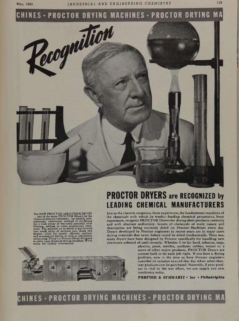
May, 1943 I NDUS TR I AL AND ENGI NE E R I NG CHEMI STRY 119
CHINES-PROCTOR DRYING MACHINES • PROCTOR DRYING MA
PROCTOR DRYERS are RECOGNIZED by LEADING CHEMICAL MANUFACTURERS
T h e N E W P R O C T O R A E R O -F O R M D R Y E R . . o n e o f t h e m a n y P R O C T O R D r y e r s f o r th e c h e m ic a l p r o c e s s in d u s t r ie s . A n e n t i r e ly n e w , a u to m a t ic , c o n t in u o u s m e th o d o f a i r - d r y in g f o r a w id e r a n g e o f w e t - s o l id m a te r i a ls a f te r f i l te r in g , s e t t l i n g o r o t h e r p r e l im in a r y t r e a t m e n t . T h e m a te r i a l t o b e d r i e d is p r e - f o r m e d i n to s m a l l s t i c k s o f u n i f o r m s iz e , s h a p e a n d d e n s i t y . . i d e a l f o r s p e e d y , e ff ic ie n t, u n i fo r m a n d e c o n o m ic a l d r y in g a s w e l l a s s u b s e q u e n t p r o c e s s in g . T h e r e 's a P r o c t o r D r y e r d e s ig n e d t o s o lv e y o u r c h e m ic a l d r y in g p r o b le m . W r i t e to d a y f o r f u r t h e r i n f o r m a t io n .
Just as the chemist recognizes, from experience, the fundam ental reactions of the chemicals with w hich he w orks—leading chem ical p rocessors, from experience, recognize PR O C T O R Dryers for drying the ir p roducts correctly and w ith absolute uniformity. Scores o f chem icals of every nature and description, are being correctly dried on P roc to r M achines every day. Dryers developed by P rocto r engineers in recent years are in many cases drying m aterials that never before could be dried m echanically. T hen too, many dryers have been designed by P roc to r specifically for handling new chemicals unheard o f until recently. W hether it be for food, tobacco, soap,
plastics, paint, textiles, synthetic rubber, veneer o r a score of o ther m ajor products, PR O C T O R D ryers are custom -built to do each job righ t. If you have a drying problem , now is the time to have P rocto r engineers consider its solution tow ard that day w hen other-than- w ar products can be purchased. Naturally, if your p ro d uct is vital to the w ar effort, we can supply you new machinery today.PROCTOR & SCHWARTZ • Inc • Philadelphia
HINES • PROCTOR DRYING MACHINES • PROCTOR DRYING MA
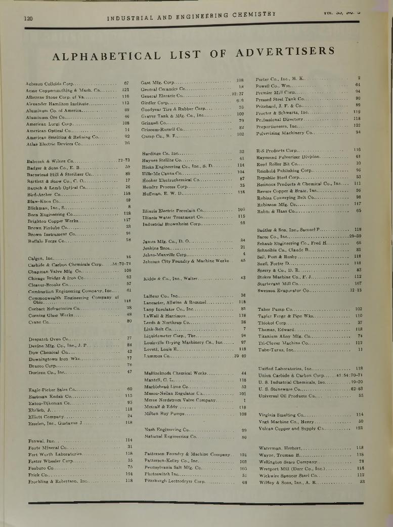
INDUSTR I AL AND ENGINEER ING CHEMISTRY VOI. OQ, AiU. o
A L P H A B E T I C A L L I S T O F A D V E R T I S E R S
A c h e s o n C o llo id s C o r p ............................................... 67
A c m e C o p p e r s m i th in g & M a c h . C o ..................... 121
A lb e re n e S to n e C o rp . o f V a ...................................... 116
A le x a n d e r H a m il to n I n s t i t u t e ................................. 113
A lu m in u m C o . o f A m e r ic a ..................................... 69
A lu m in u m O re C o ........................................................ 46
A m e r ic a n L u r g i C o r p ................................................ 168
A m e r ic a n O p t ic a l C o .................................................. 14
A m e r ic a n S m e lt in g & R e f in in g C o .................... 62
A t la s E le c t r ic D e v ic e s C o ....................................... 76
B a b c o c k & W ilc o x C o .................................................7 2 -7 3
B a d g e r & S o n s C o ., E . B ......................................... 69
B a r n s te a d S t i l l & S te r i liz e r C o ............................ 8 8
B a r t l e t t & S n o w C o ., C . 0 ..................................... 17
B a u s c h & L o m b O p t ic a l C o ................................... 26
B ird -A rc h e r C o ............................................................... H 8
B la w - K n o x C o ................................................................. 49
B l ic k m a n , I n c . , S .......................................................... 8
B o r n E n g in e e r in g C o ................................................. 11®
B r ig h to n C o p p e r W o rk s ........................................... 117
B ro w n F i n tu b e C o ............................................ 23
B ro w n I n s t r u m e n t C o ............................................... 61
B u ffa lo F o rg e C o ........................................................... ^ 8
C a lg o n , I n c ........................................................................ 1®C a r b id e & C a r b o n C h e m ic a ls C o r p 5 4 :7 0 -7 1
C h a p m a n V a lv e M fg . C o ......................................... 166
C h ic a g o B r id g e & I r o n C o ...................................... 63
C le a v e r - B r o o k s C o ....................................................... 67
C o m b u s t io n E n g in e e r in g C o m p a n y , I n c 61
C o m m o n w e a lth E n g in e e r in g C o m p a n y ofO h io .................................................................................. 1 1 8
C o r h a r t R e f r a c to r ie s C o ........................................... 28
C o r n in g G la s s W o r k s ................................................. 48
C r a n e C o ............................................................................. 8 6
D e s p a tc h O v e n C o ....................................................... 77
D e v in e M fg . C o ., I n c . , J . P .................................. 84
D o w C h e m ic a l C o ......................................................... 42
D o w n in g to w n I ro n W k s ........................................... 77
D r a c c o C o r p ..................................................................... 76
D u r i r o n C o ., I n c ............................................................ 47
E a g le - P ic h e r S a le s C o ................................................ 60
E a s tm a n K o d a k C o ..................................................... 116
E a t o n - D ik e m a n C o ...................................................... 65
E h r l ic h , J ............................................................................ 118
E l l i o t t C o m p a n y ............................................................ 24
E s s e le n , In c . , G u s t a v u s J ........................................ 118
F e n w a l , I n c ........................................................................ 114
F o o te M in e r a l C o .......................................................... 31
F o r t W o r th L a b o r a t o r ie s ......................................... 118
F o s t e r W h e e le r C o r p ................................................... 15
F o x b o r o C o ........................................................................ 75
F r i c k C o ............................................................................... 164
F r o e h l in g & R o b e r ts o n , I n c ................................... 118
G a s t M fg . C o r p .............................................................18G e n e r a l C e ra m ic s C o .................................................
G e n e ra l E l e c t r ic C o ...................................................... 2 2 .2 7
G ird le r C o r p ..................................................................... 6 : 9
G o o d y e a r T i r e & R u b b e r C o r p ............................ 25
G r a v e r T a n k & M fg . C o ., I n c .............................. 166
G r in n e l l C o . . ............................................................... *^9
G r isc o m -R u s se l l C o ..................................................... ^G u m p C o ., B . F .............................................................
H a r d in g e C o . I n c ..........................................................
H a y n e s S te l l i t e C o .......................................................
H ic k s E n g in e e r in g C o ., I n c . , S . D ..................... 114
H il ls -M c C a n n a C o ....................................................... 1 0 4
H o o k e r E le c t ro c h e m ic a l C o ................................... 87
H o u d r y P ro c e s s C o r p ................................................ 35
H u f fm a n , E . W . D ....................................................... H 8
I l l in o is E le c t r ic P o r c e la in C o ................................ 169
I l l in o i s W a te r T r e a t m e n t C o ................................ H 5
I n d u s t r ia l B ro w n h o is t C o r p ................................... 65
J a m e s M fg . C o ., D . 0 ............................................... 34
J e n k in s B r o s ..................................................................... 21
J o h n s - M a n v ille C o r p .................................................. 4
J o h n s o n C i ty F o u n d r y & M a c h in e W o rk s . . 45
K id d e & C o ., In c . , W a l t e r ..................................... 43
L a B o u r C o ., I n c ............................................................ 36
L a n c a s te r , A llw in e & R o m m e l ............................. 118
L a p p I n s u l a to r C o ., I n c ........................................... 85
L a W a ll & H a r r i s s o n ................................................... 118
L e e d s & N o r th r u p C o ................................................ 38
L in k -B e lt C o .................................................................... 7
L iq u id o m e te r C o rp . , T h e ........................................ 94
L o u is v il le D r y in g M a c h in e ry C o ., I n c 97
L o v e t t , L o u is E .............................................................. 118
L u m m u s C o .......................................................................3 9 -4 0
M a ll in c k r o d t C h e m ic a l W o r k s ............................ 44
M a n te l l , C . L .................................................................. 118
M a rb le h e a d L im e C o ................................................. 52
M a s o n -N e i la n R e g u la to r C o .................................. 101
M e rc o N o r d s tr o m V a lv e C o m p a n y .................. 1
M e tc a lf & E d d y ............................................................ 118
M il to n R o y P u m p s ..................................................... 108
N a s h E n g in e e r in g C o ................................................. 9 9
N a t io n a l E n g in e e r in g C o ......................................... 8 6
P a t te r s o n F o u n d r y & M a c h in e C o m p a n y . . 124
P a t te r s o n - K e l le y C o ., I n c ....................................... 1 0 3
P e n n s y lv a n ia S a l t M fg . C o .................................... 105
P h o to s w i tc h I n c ............................................................. 5 1
P i t t s b u r g h L e c tr o d r y e r C o r p ................................ 6 8
P o r te r C o ., I n c . , H . K ................................................ 2
P o w e ll C o ., W m .............................................................. 64
P r e m ie r M ill C o r p ......................................................... 64
P re s s e d S te e l T a n k C o ............................................... 60
P r i t c h a r d , J . F . & C o .................................................. 89
P r o c to r & S c h w a r tz , I n c ........................................... 119
P ro fe s s io n a l D i r e c t o r y ................................................ 118
P r o p o r t io n e e r s , I n c • • 122
P u lv e r iz in g M a c h in e r y C o ....................................... 94
R -S P r o d u c ts C o r p ........................................................ H 6
R a y m o n d P u lv e r iz e r D i v i s i o n .............................. 61
R e e d R o lle r B i t C o ....................................................... 16
R e in h o ld P u b l is h in g C o r p ........................................ 96
R e p u b l ic S te e l C o r p ..................................................... 53
R e s in o u s P r o d u c ts & C h e m ic a l C o . , I n c . . . . I l l
R e v e re C o p p e r & B r a s s , I n c .................................. 56
R o b in s C o n v e y in g B e l t C o ...................................... 98
R o b in s o n M fg . C o ......................................................... 117
R o h m & H a a s C o ........................................................... 65
S a d t le r & S o n , In c . , S a m u e l P ............................... 118
S a rc o C o ., I n c .................................................................... 2 9 —36
S c h a u b E n g in e e r in g C o . , F r e d H ........................ 66
S c h n e ib le C o ., C la u d e B ............................................ 81
S e il, P u t t & R u s b y ....................................................... 118
S n e ll, F o s t e r D ................................................................. 118
S p e r ry & C o ., D . R ....................................................... 83
S to k e s M a c h in e C o ., F . J ........................................ 112
S t u r t e v a n t M ill C o ....................................................... 167
S w en so n E v a p o r a t o r C o .............................................1 2 -1 3
T a b e r P u m p C o ............................................................... 162
T a y lo r F o rg e & P ip e W k s ........................................ 110
T h io k o l C o r p ..................................................................... 37
T h o m a s , E d w a r d ............................................................ 118
T i ta n iu m A llo y M fg . C o ........................................... 74
T r i- C lo v e r M a c h in e C o .............................................. 112
T u b e - T u r n s , I n c .............................................................. 11
U n if ie d L a b o r a to r ie s , I n c .......................................... 118
U n io n C a r b id e & C a r b o n C o r p 4 1 :5 4 :7 0 - 7 1
U . S . I n d u s t r ia l C h e m ic a ls , I n c ...........................1 9 -2 0
U . S . S to n e w a re C o ........................................................6 2 -6 3
U n iv e r s a l O il P r o d u c ts C o ....................................... 55
V irg in ia S m e lt in g C o ................................................... 114
V o g t M a c h in e C o ., H e n r y ....................................... 50
V u lc a n C o p p e r a n d S u p p ly C o ............................. 123
W a te r m a n , H e r b e r t ..................... 118
W a y n e , T r u m a n B ........................................................ 118
W e ll in g to n S e a rs C o m p a n y ..................................... 78
W e s t p o r t M ill ( D o r r C o ., I n c . ) ........................... 118
W ic k w ire S p e n c e r S te e l C o ..................................... 112
W ilf le y & S o n s , I n c . , A . R ....................................... 33
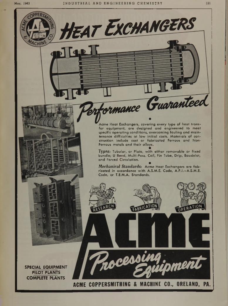
May, 1943 I N D US T R I A L AND E NG I NE E R ING CHEMI STRY 121
H b a t E x c h a n g e r s
’O M fU M X
A cm e H ea t E xchangers , c o v e rin g e v e ry ty p e o f h e a t tra n s fe r e q u ip m e n t, a re de s ig n e d a n d e n g in e e re d to m ee t sp e c ific o p e ra tin g co n d itio n s , o v e rc o m in g fo u lin g a n d m a in ten ance d if f ic u lt ie s a t lo w in it ia l costs. M a te r ia ls o f con s tru c tio n in c lu d e cast o r fa b r ic a te d Ferrous an d N o n - Ferrous m eta ls a n d th e ir a llo ys .
•Types: T u b u la r, o r P la te , w ith e ith e r re m o v a b le o r f ix e d b u n d le ; U B end, M u lti-P ass , C o il, Fin Tube , D r ip , B a u d e lo t, a n d Forced C irc u la tio n .
•Mechanical Standards: A cm e H eat Exchangers a re f a b ric a te d in acco rda nce w ith A .S .M .E . C ode, A .P .I.—A.S.M .E. C ode, o r T .E .M .A . S ta n d a rd s .
SPECIAL EQUIPMENTPILOT PLANTS
COMPLETE PLANTS
A C M E C O P P E R S M I T H I N G & M A C H I N E C O . , O R E L A N D , P A .
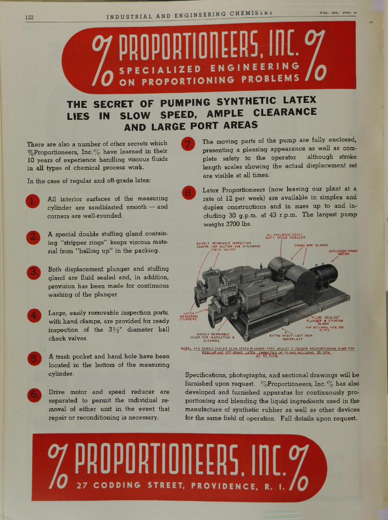
T H E S E C R E T O F P U M P I N G S Y N T H E T I C L A T E X L I E S I N S L O W S P E E D , A M P L E C L E A R A N C E
A N D L A R G E P O R T A R E A S
There are also a num ber of other secrets which % Proportioneers( Inc.% have learned in their 10 years of experience handling viscous fluids in all types of chemical process work.
In the case of regular and off-grade latex:
All interior surfaces of the measuring cylinder are sandblasted smooth — and corners are well-rounded.
A special double stuffing gland containing "stripper rings” keeps viscous material from "balling up” in the packing.
Both displacement plunger and stuffing gland are fluid sealed and, in addition, provision has been made for continuous washing of the plunger.
8
The moving parts of the pum p are fully enclosed, presenting a pleasing appearance as well as complete safety to the operator — although stroke length scales showing the actual displacem ent set are visible at all times.
Latex Proportioneers (now leaving our plant at a rate of 12 per week) are available in simplex and duplex constructions and in sizes up to and including 30 g.p.m. at 43 r.p.m. The largest pump weighs 3700 lbs.
Large, easily removable inspection ports, with hand clamps, are provided for ready inspection of the 3 diameter ball check valves.
A trash pocket and hand hole have been located in the bottom of the measuring cylinder.
Drive motor and speed reducer are separated to permit the individual removal of either unit in the event that repair or reconditioning is necessary.
.MODEL 4XD SERIES PUPLEX SLOW SPEEO PLUNGER TYPE AQJUST -Q-FEEDER PROPORTIONING PUMP FOR BEGULAR AND OFF-GRADE LATEX. CAPACITIES UP TO AND INCLUDING 30 GPM
AT R.EM.
Specifications, photographs, and sectional draw ings will be furnished upon request. % Proportioneers, Inc .% has also developed and furnished apparatus for continuously proportioning and blending the liquid ingredients used in the manufacture of synthetic rubber as well as other devices for the same field of operation. Full details upon request.
QUICKLY REMOVABLE INSPECTION COVERS FOR SUCTION ANB DISCHARGE ARM GUARDS
QUICKLY REMOVABLE COVER FOR INSPECTION 6
CLEANING
0 SEALED PLUNGER t STUFFING
GLAWD
EXTRA HEAVY CAST IRON BASEPLATE

P R O C E S S E S A N D E Q U I P M E N T
T HE d e m a n d s p laced u p o n ch em ica l en g in ee rin g o rg a n iz a tio n s by th e N a tio n a l E m ergency a re
fa r re a c h in g a n d e x ten d in to m a n y in d u s tr ie s . T he V ulcan o rg a n iz a tio n h a s m a d e m a n y im p o r ta n t c o n tr ib u tio n s to th e ex p an sio n of th e p rocess in d u s tr ie s d u r in g th e p a s t 41 years . T h is fa c t h a s m ad e th e w ar t im e conversion of th e se in d u s tr ie s a m u c h
easie r ta s k th a n w ould o th erw ise have been possib le w ith o u t th e p rogressive d ev e lo p m en ts offered by th e V u lcan o rg a n iz a tio n in th e fields of D is tilla tio n , E v ap o ra tio n a n d E x trac tio n . V u lcan is p ro u d of th e im p o r ta n t p a r t w h ich i ts c o n tr ib u t io n s to c h em ica l e n g in ee rin g a re p lay in g in A m erican in d u s try today .
J C O P P E R AND1
v 3 1 v. , Im m ■CINCINNATI O U S 1 1 1 11 1 > * 1 / w'/ v ' ; S U P P L Y C O .
1
P A T T E R S O N M A C H I N E RFOR T H E C H E M I C A L P R O C E S S I N D U S T R I E S
T H E P A T T E R S O N F O U N D R Y & M A C H IN E C O M P A N Y - F


![ATPS - TE..[1]](https://img.pdfslide.net/doc/110x75/6312ab29fc260b71020ec05a/atps-te1.jpg)


![[Biosynthesis of nitric oxide in infection: should it be induced or avoided?]](https://img.pdfslide.net/doc/110x75/6354d11ac0ae8253fa0d1cb1/biosynthesis-of-nitric-oxide-in-infection-should-it-be-induced-or-avoided.jpg)


