Embed Size (px)
Citation preview

Technical Service Information
TSI–13–12–21
Date: NOVEMBER 2013
Subject File: ENGINE
Subject: Exhaust Manifold Ring Seal Installation for Only Standard Torque Vehicles Not Equipped with ISC
Engine Family: MaxxForce® DT, 9, and 10 (EPA 10)
Engine Family: MaxxForce® DT, 9, and 10 (EPA 10) with HD-OBD
DESCRIPTIONSome MaxxForce® DT, 9, and 10 (EPA 10) and MaxxForce® DT, 9, and 10 (EPA 10) with HD-OBD engines mayleak exhaust from the exhaust manifold FEY ring joints. This TSI includes installation procedure for exhaustmanifold ring seal (exhaust cuff) for only the cylinder 2 and 3 exhaust manifold FEY ring joint.
PARTS INFORMATIONTable 1. Parts Information.
Part Number Description Quantity7092423C91 Kit, Exhaust Manifold Seal 1
Obtain Locally 2-in Clear Packaging Tape As Needed
Table 2. 7092423C91 Exhaust Manifold Seal Kit Contents.
Part Number Description Quantity3017160C1 Shield 2
3017161C1 Packing, Seal Assy 1
3017163C1 Ceramic, Mat Wrap Assy 1
1616029C1 Clamp, Constant Tension 2
4328039R1 Instruction Sheet 1
© 2013 Navistar, Inc. All rights reserved. All marks are trademarks of their respective owners.1
SB-10054103-4232

REMOVAL
WARNING: Park vehicle on hard flat surface, turn the engine off, set the parking brake, andinstall wheel chocks to prevent the vehicle from moving in both directions. Failure to do so mayresult in property damage, personal injury, and / or death.
WARNING: If the vehicle must be raised, do not work under the vehicle supported only byjacks. Jacks can slip or fall over, potentially resulting in property damage, personal injury, and / ordeath.
WARNING: Always wear safe eye protection when performing vehicle maintenance. Failureto do so may result in personal injury and / or death.
WARNING: Keep flames or sparks away from vehicle and do not smoke while servicingthe vehicle’s batteries. Batteries expel explosive gases. Failure to do so may result in propertydamage, personal injury, and / or death.
WARNING: Remove the ground cable from the negative terminal of the battery box beforedisconnecting any electrical components. Always connect the ground cable last. Failure to do somay result in property damage, personal injury, and / or death.
1. Bring vehicle into shop and park on flat surface with wheels turned fully to the right.
2. Shift transmission to Park or Neutral, set parking brake, and install wheel chocks.
3. Unlatch and open hood.
4. Open battery box and disconnect negative battery cable.
NOTE: Draining of the cooling system and removal of the oil centrifuge filter is not required to performthis procedure.
5. Remove four bolts, washers, and right-side inner fender.
TSI–13–12–21 2

REMOVAL (CONT.)
Figure 1. Mass Air Flow (MAF) Sensor and Air Compressor Inlet Hose.
1. Air box2. Air compressor inlet hose3. Low Pressure (LP) turbocharger inlet elbow duct4. LP turbocharger inlet elbow duct clamp5. MAF sensor connector6. MAF sensor
6. Disconnect MAF sensor connector (Figure 1, Item 5) from MAF sensor (Figure 1, Item 6).
7. Disconnect air compressor inlet hose (Figure 1, Item 2) from air box (Figure 1, Item 1).
8. Loosen air box to LP turbocharger inlet elbow duct clamp (Figure 1, Item 4) on LP turbocharger inletelbow duct (Figure 1, Item 3).
9. Remove bolt, two nuts, and air box with bracket from vehicle.
10. Loosen LP turbocharger inlet elbow clamp and reposition elbow for access to exhaust manifold heat shield.
3 TSI–13–12–21

REMOVAL (CONT.)
Figure 2. HP Charge Air Cooler (HPCAC) Duct.
1. Clamp (2)2. HPCAC duct3. Bolt4. P-clamp
11. Remove bolt (Figure 2, Item 3) from P-clamp (Figure 2, Item 4) on HPCAC duct (Figure 2, Item 2).
12. Loosen two clamps (Figure 2, Item 1) and remove HPCAC duct (Figure 2, Item 2).
TSI–13–12–21 4

REMOVAL (CONT.)
Figure 3. Crossover Tube.
1. Turbocharger 2 Wastegate Control (TC2WC) sensor2. Engine boost control inlet3. Outlet to actuator
13. Disconnect outlet to actuator (Figure 3, Item 3) from TC2WC valve.
14. Disconnect engine boost control inlet (Figure 3, Item 2) from TC2WC valve.
15. Disconnect Turbocharger 2 Wastegate Control (TC2WC) sensor (Figure 3, Item 1) from TC2WC valve.
5 TSI–13–12–21
REMOVAL (CONT.)
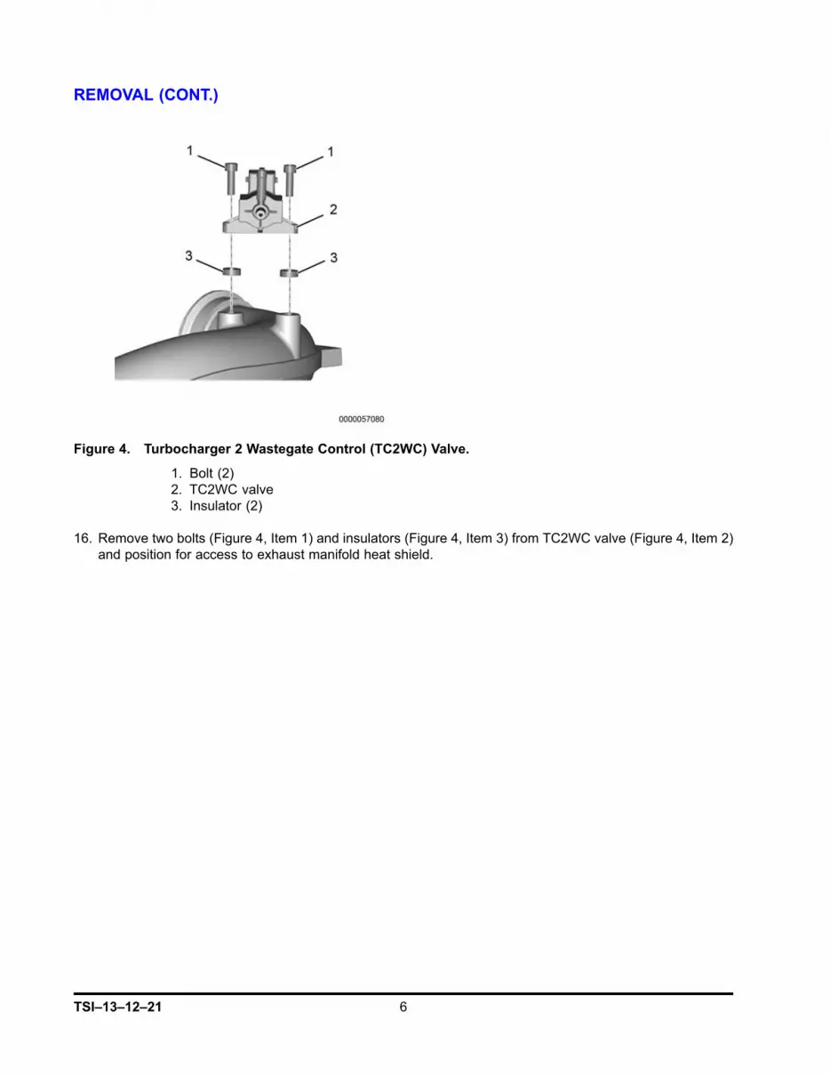
Figure 4. Turbocharger 2 Wastegate Control (TC2WC) Valve.
1. Bolt (2)2. TC2WC valve3. Insulator (2)
16. Remove two bolts (Figure 4, Item 1) and insulators (Figure 4, Item 3) from TC2WC valve (Figure 4, Item 2)and position for access to exhaust manifold heat shield.
TSI–13–12–21 6

REMOVAL (CONT.)
Figure 5. Crossover Tube.
1. V-band clamp2. Crossover tube
17. Remove V-band clamp (Figure 5, Item 1) and crossover tube (Figure 5, Item 2).
7 TSI–13–12–21

REMOVAL (CONT.)
Figure 6. Exhaust Manifold Heat Shield.
1. M8 X 25 bolt2. Lock nut (3)3. Exhaust manifold temperature sensor
18. Remove bolt (Figure 6, Item 1) from crankcase breather tube.
19. Remove exhaust manifold temperature sensor (Figure 6, Item 3).
20. Remove three lock nuts (Figure 6, Item 2) from heat shield.
TSI–13–12–21 8

REMOVAL (CONT.)
Figure 7. Exhaust Manifold.
1. Crankcase breather tube2. Heat shield
21. Pull out on crankcase breather tube (Figure 7, Item 1) until loose.
22. Pull heat shield (Figure 7, Item 2) out and turn back end of heat shield up.
9 TSI–13–12–21

REMOVAL (CONT.)
Figure 8. Exhaust Manifold Heat Shield Removal.
1. Heat shield
23. Push back end of heat shield (Figure 8, Item 1) towards engine and pull front end of heat shield outtowards right tire until heat shield is completely free.
TSI–13–12–21 10

INSTALLATION
Figure 9. Exhaust Manifold Seal Packing.
1. Seal packing
1. Wrap seal packing (Figure 9, Item 1) around manifold joint and align so that packing ends meet at topof manifold.
2. Press seal packing tightly into joint with fingers.
Figure 10. Ceramic Mat Wrap.
1. Folded end of 2-in clear packaging tape2. Ceramic mat wrap3. Thick end
3. Add 12-in piece of 2-in clear packaging tape (Figure 10, Item 1) to back of ceramic mat wrap (Figure10, Item 2) and fold over end of tape.
11 TSI–13–12–21

INSTALLATION (CONT.)
Figure 11. Exhaust Manifold Seal Ceramic Mat Wrap.
1. Ceramic mat wrap2. Seal packing3. Folded end of tape4. Cylinder head5. Exhaust manifold
4. Feed end of ceramic mat wrap (Figure 11, Item 1) with folded end of tape (Figure 11, Item 3) betweenexhaust manifold (Figure 11, Item 5) and cylinder head (Figure 11, Item 4), covering seal packing with thickend (Figure 10, Item 3) of mat wrap.
5. Pull on folded end of tape (Figure 11, Item 3) while pushing other end of mat wrap.
TSI–13–12–21 12

INSTALLATION (CONT.)
Figure 12. Exhaust Manifold Ring Seal.
1. Ring seal clamp2. Shield3. Manifold midpoint
NOTE: Verify shield completely covers ceramic mat wrap, and ceramic mat wrap overlaps seal packing.
6. Install two shield halves (Figure 12, Item 2) with beveled flange facing rear of engine, and align joint withmanifold midpoint (Figure 12, Item 3).
NOTE: This procedure requires installation of only one of the two ring seal clamps contained in theExhaust Manifold Seal Kit 7092423C91.
NOTE: Ring seal clamp alignment must match the clamp alignment in Figure 12 to prevent problemswhen installing the exhaust manifold heat shield.
7. Install ring seal clamp (Figure 12, Item 1). Using torque wrench, tighten clamp to 70 lb-in (8 N•m).
13 TSI–13–12–21

INSTALLATION (CONT.)
Figure 13. Exhaust Manifold Heat Shield Installation.
1. Heat shield2. Crankcase breather tube3. Exhaust manifold stud
8. Install heat shield (Figure 13, Item 1) with front end facing down between crankcase breather tube (Figure13, Item 2) and exhaust manifold stud (Figure 13, Item 3).
9. Rotate back end of heat shield counterclockwise until heat shield is in place.
TSI–13–12–21 14

INSTALLATION (CONT.)
Figure 14. Exhaust Manifold Heat Shield.
1. M8 X 25 bolt2. Exhaust manifold heat shield3. Lock nut (3)4. Crankcase breather tube5. Exhaust manifold temperature sensor
10. Install crankcase breather tube (Figure 14, Item 4) onto exhaust manifold heat shield (Figure 14, Item 2).
11. Install bolt onto crankcase breather tube (Figure 14, Item 1). Using torque wrench, tighten bolt to 23 lb-ft(31 N•m).
12. Install three lock nuts (Figure 14, Item 3) onto heat shield. Using torque wrench, tighten lock nuts to20 lb-ft (27 N•m).
13. Install exhaust manifold temperature sensor (Figure 14, Item 5). Using torque wrench, tighten exhaustmanifold temperature sensor to 32 lb-ft (44 N•m).
15 TSI–13–12–21
INSTALLATION (CONT.)
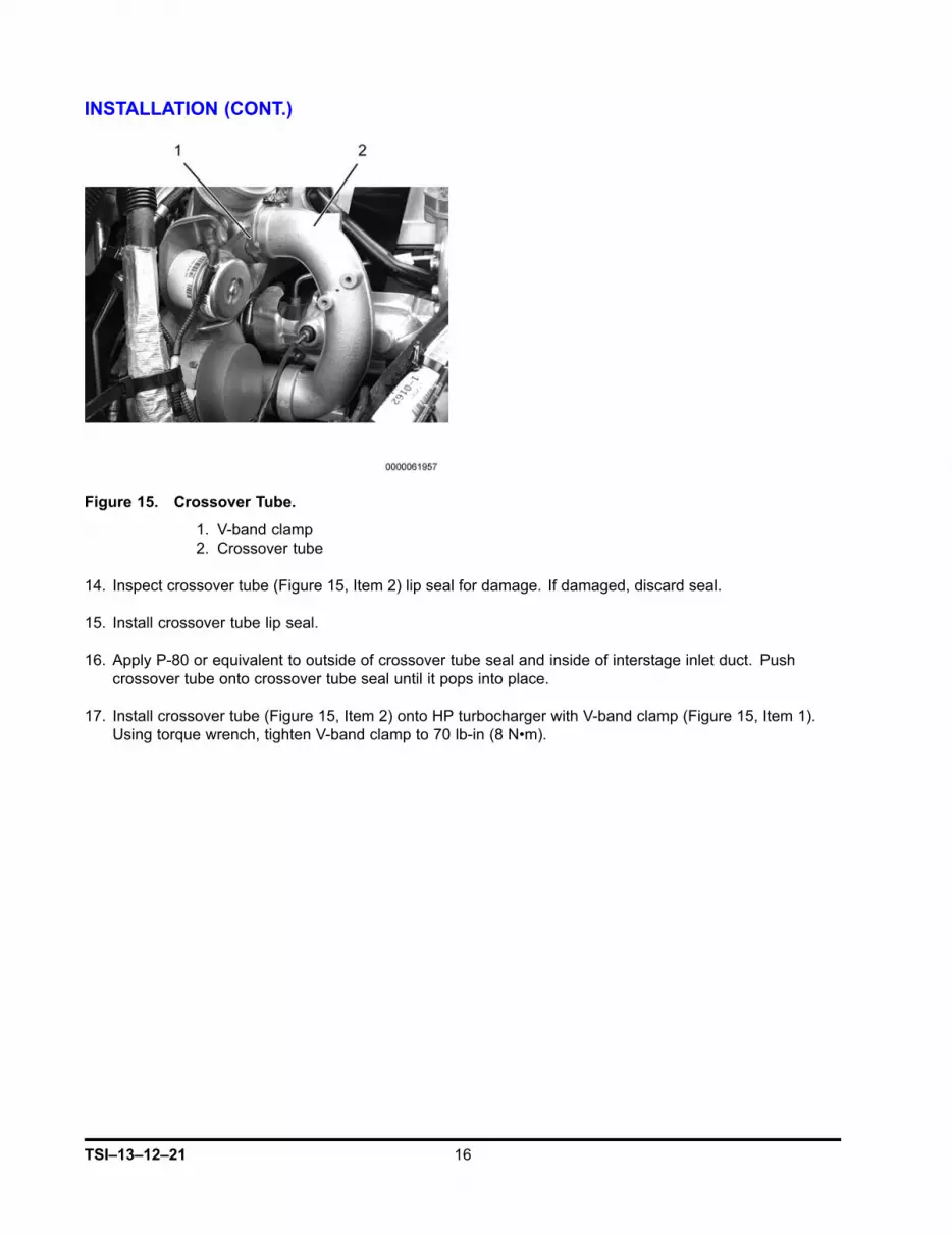
Figure 15. Crossover Tube.
1. V-band clamp2. Crossover tube
14. Inspect crossover tube (Figure 15, Item 2) lip seal for damage. If damaged, discard seal.
15. Install crossover tube lip seal.
16. Apply P-80 or equivalent to outside of crossover tube seal and inside of interstage inlet duct. Pushcrossover tube onto crossover tube seal until it pops into place.
17. Install crossover tube (Figure 15, Item 2) onto HP turbocharger with V-band clamp (Figure 15, Item 1).Using torque wrench, tighten V-band clamp to 70 lb-in (8 N•m).
TSI–13–12–21 16

INSTALLATION (CONT.)
Figure 16. TC2WC Valve.
1. Bolt (2)2. TC2WC valve3. Insulator (2)
18. Install TC2WC valve (Figure 16, Item 2) onto crossover tube with two insulators (Figure 16, Item 3)and bolts (Figure 16, Item 1).
17 TSI–13–12–21
INSTALLATION (CONT.)
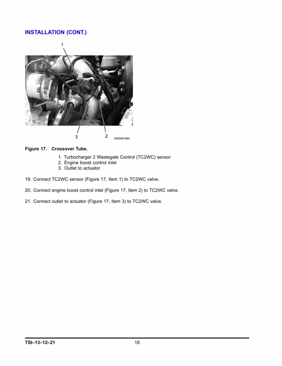
Figure 17. Crossover Tube.
1. Turbocharger 2 Wastegate Control (TC2WC) sensor2. Engine boost control inlet3. Outlet to actuator
19. Connect TC2WC sensor (Figure 17, Item 1) to TC2WC valve.
20. Connect engine boost control inlet (Figure 17, Item 2) to TC2WC valve.
21. Connect outlet to actuator (Figure 17, Item 3) to TC2WC valve.
TSI–13–12–21 18

INSTALLATION (CONT.)
Figure 18. HPCAC Duct.
1. Clamp (2)2. HPCAC duct3. Bolt4. P-clamp
22. Install HPCAC duct (Figure 18, Item 2) with two clamps (Figure 18, Item 1).
23. Install bolt (Figure 18, Item 3) in P-clamp (Figure 18, Item 4) on HPCAC duct (Figure 18, Item 2).
19 TSI–13–12–21

INSTALLATION (CONT.)
Figure 19. MAF Sensor and Air Compressor Inlet Hose.
1. Air box2. Air compressor inlet hose3. LP turbocharger inlet elbow duct4. LP turbocharger inlet elbow duct clamp5. MAF sensor connector6. MAF sensor
24. Install Low Pressure (LP) turbocharger inlet elbow duct (Figure 19, Item 3).
25. Install air box (Figure 19, Item 1) and bracket with bolt and two nuts.
26. Install air box outlet into LP turbocharger inlet elbow duct (Figure 19, Item 3) with clamp (Figure 18, Item4). Using torque wrench, torque clamp to 40 - 49 lb-in (4.5 - 5.5 N•m).
27. Connect air compressor inlet hose (Figure 19, Item 2) to air box (Figure 19, Item 1).
28. Connect MAF sensor connector (Figure 19, Item 5) to MAF sensor (Figure 19, Item 6).
29. Install right side inner fender with four washers and bolts.
30. Connect negative battery cable and close battery box.
31. Run engine to verify proper operation, no leaks, and no fault codes.
32. Perform MAF Calibration Procedure - Using ServiceMaxx Software. Refer to 2010 MaxxForce® DT, 9,and 10 Engine Diagnostic Manual 0000001624.
33. Close and latch hood.
34. Remove wheel chocks.
TSI–13–12–21 20


