Embed Size (px)
Citation preview
Innhold
TEMA
Guest editorial, Birger J Nymo 3
Telemedicine, Birger J Nymo 4
Telemedicine services integrated into a healthcare network – Analysis of communicationneeds in a regional health care system,Sigurd From, Lilly Ann Stenvold, Thore Danielsen 12
Telecommunication for remote consultationand diagnoses,Gjermund Hartviksen, Eivind Rinde 23
Mira – teleradiology and digital radiology,Torbjørn Sund 33
Telediagnosis in the context of digital imageanalysis, Håvard E Danielsen 37
Teaching and learning aspects of remotemedical consultations, Sigmund Akselsen, Svein-Ivar Lillehaug 42
Telemedicine as health-political means,Steinar Pedersen, Unni Holand 48
Quality requirements for telemedical services,Unni Holand, Steinar Pedersen 51
Standards for health care telematics – A newdimension and challenge to standards makers,Sigurd From 54
ISDN: New possibilities for telemedicine,Sigmund Akselsen, Arne K Eidsvik, Trine Folkow 64
The challenge of computer-mediatedcommunication in health care, Thore Danielsen 72
Restraining and facilitating factors in the diffusion oftelemedicine – An interview study,Deede Gammon 78
SPESIAL
Liberalisering av telekommunikasjonsområdet,Kjell Stordahl 85
Etterspørsel etter 2 Mbit/s samband for telefonii Oslo teledistrikt – Utarbeiding av prognoser nårdatagrunnlaget er sparsomt, Carlo Hjelkrem 101
Rapport fra “15. Jahrestagung der FKTG”,Berlin, 1-5 juni 1992, Olav Grov 110
Tale kontra data og video, Inge Vabø 116
B-ISDN – et viktig grunnlag for multimedia,Kjell Hermansen 118
Broadband Integrated Services Digital Network,Erik Skåtun 123
Posisjonsberegning med tidsdifferansehyperbler,Åge Eriksen 131
MMIC – new technology offers new opportunities,Leif Hanssen, Christian F Heide 134
File transfer performance tuning in X.25and TCP/IP, Per Sigmond 146
Software maintainability – on purpose oraccidentally? Magne Jørgensen 150
A coaxial notch filter with several notches,Knut N Stokke 157
NTR’s high speed testbeds and multimediaactivities, Øivind Kure, Ingvild Sorteberg,Terje Ormhaug, Rune Fløisbonn 163
TelektronikkTeleverkets tekniske tidsskrift
89. årgang Nr. 1 - 1993ISSN 0085-7130
Redaktør:Ola EspvikTlf. + 47 63 80 98 83
Redaksjonssekretariat:Gunhild LukeTlf. + 47 63 80 91 52
Adresse:TelektronikkTeleverkets ForskningsinstituttPostboks 83N-2007 Kjeller
Redaksjonsråd:Teknisk direktør Ole Petter HåkonsenForskningsdirektør Karl KlingsheimStrategidirektør Bjørn Løken
Utforming:Gunhild Luke, Britt Kjus, Åse AardalTeleverkets Forskningsinstitutt
RESEARCH
Telektronikk utkommer med firenummer pr år.
Telecommunication services havetraditionally been developed with aview to a mass market consistingof “anonymous” users. The stresshas been put on technical solutionswhich promote optimum servicesin a perspective of equality.
The perspective has changed,partly because of the technicaldevelopment, in the way that theparticular needs of certain usergroups are taken into consideration.Thus, the users of telecommunica-tions no longer emerge as ananonymous mass, but in marketrelations they appear as householdsubscribers, company subscribers,small companies, large companies,etc. The services are adapted to thecommon characteristics of aggre-gated groups.
For the telecommunications of thefuture it is not enough to take intoconsideration the aggregated common characteristics. Individu-als, groups, companies, etc. are inter-linked in social networksfor co-operation, job sharing, community, etc. The compositionand tasks of these networks are just as significant characteristicsof the individual user as they are common characteristics of thegroup he or she belongs to. In order to offer optimum telecom-munication solutions, this type of information about the sub-scriber must be obtained.
I would not be strictly accurate if I was to say that it was thisrecognition which formed the basis for starting a major researchproject on telemedicine under the management of NorwegianTelecom Research in the autumn of 1988. The basis was ratherthe fact that the Norwegian public health service was a majorsubscriber to telecommunications, but not a very advanced one.By realising individual applications the project has brought for-ward examples of a more advanced use of telecommunications.Along the course of the project the knowledge of the publichealth service of the present day and its future challenges haveshown us the importance of flexible communication solutionson the basis of the tasks and structure of the public health sec-tor.
The public health service has a lot to profit from efficient use oftelecommunications. The greatest challenge the health service isfaced with, is the growing gap between the expectations of thepopulation, and the resources that society can set aside forhealth purposes. Increasing the level of efficiency and co-opera-tion is therefore the most probable response to the challenge.Telecommunications may contribute to a more effective utilisa-tion of resources through tying the resources of the health sec-tor’s resources together in a large number of telemedical ser-vices.
In order for the health service to profit from telemedicine vari-ous parties must set to work on a number of challenges.
On the political level,telemedicine must be integratedinto the strategy of health carepolicies. Individual applicationsmay relieve acute situations likethe problems arising because of ageographically unequal distribu-tion of medical specialists. How-ever, the greatest profit will begained when telemedicine formsan integrated part of the composi-tion of the public health service. Asignificant piece in this context isthe work that the Ministry ofHealth and Social Affairs has initi-ated with a view to laying thechannels and regulations for theexchange of information in thehealth sector by establishing stan-dards.
For the health services and theprofessions which have their dailywork within it, it is a challenge tothink in the way of new co-opera-
tive relations which demand different ways of organising workand thereby new work routines and roles. As sub-specialisingwithin the medical professions continues, it will be necessary tothink in the way of extensive co-operation beyond the adminis-trative limitations which regulate the health services today.
The public health service is highly technological when it comesto medical equipment. New equipment offers the possibility ofnew methods of examination and forms of treatment. The chal-lenge for the producers of this equipment is to ensure that theinformation produced by the equipment may be presented notonly locally, but also be transmitted to experts at other locationsin the health service for interpretation. Exchangeable data frommedical information systems are also crucial in order to achieveefficiency through co-operation beyond the limitations of insti-tutions.
The main requirements made to telecommunications bytelemedicine are connected to flexibility and security. Thehealth service constitutes an infrastructure which captures thewhole of the population in a system from primary health serviceon the municipal level, to specialised hospitals with a nationalresponsibility. The challenge is to match this medical profes-sional frame with a flexible telecommunications structure whichin a cost-effective manner enables the medical professionalresources to be utilised wherever the patient is located. Securityin this connection affects the protection of privacy as well asgeneral quality assurance of medical services. On the one handsensitive medical information must not go astray, and on theother hand the flow of information to the right person at theright time must be safeguarded without loss of quality.
3
Guest editorial
B Y B I R G E R J N Y M O
621.39:61
4
Telemedicine
B Y B I R G E R J N Y M O
Introduction
The concept of Telemedicine is notclearly defined. In the literature there areseveral definitions, which largely havebeen modified in step with access toteletechnology. In 1975 Bird stated thisdefinition: “Telemedicine is the practiceof medicine without the usual physician-patient physical confrontation via aninteractive audio-video communicationsystem”. In the early eighties Conrath etal (1983) gave a far more general defini-tion: “Telemedicine is the use oftelecommunication technology to assistin the delivery of health care”. Gradually,as the division between telecommunica-tion and the management of informationbecame more veiled, even this definitionis too narrow, even if it takes intoaccount other relations in the health carethan only the meeting between physician
and patient. What is called medical com-puter science is an important part of thetechnological angle of telemedicine.Basically, medical computer sciencereflects the application of data technol-ogy where storage, systematising, man-agement and filing of information inter-nally in medical institutions are superiorfactors. Such applications are a conditionfor telebased collection and reception ofinformation whether it is for administra-tive or purely medical purposes.
In many contexts the concept oftelemedicine is reserved for applicationswhere the subject is to render health ser-vices based on application of telecommu-nication. Classical in that sense are formsof remote consultations and remote diag-noses within various medical specialities.In some cases transmission of knowledgein the form of distance education and
remote instructions is included in theconcept of telemedicine.
For our purpose we have found the fol-lowing definition useful: “The investiga-tion, monitoring and management ofpatients and the education of patients andstaff using systems which allow readyaccess to expert advice and patient infor-mation no matter where the patient or rel-evant information is located” (AIM1990).
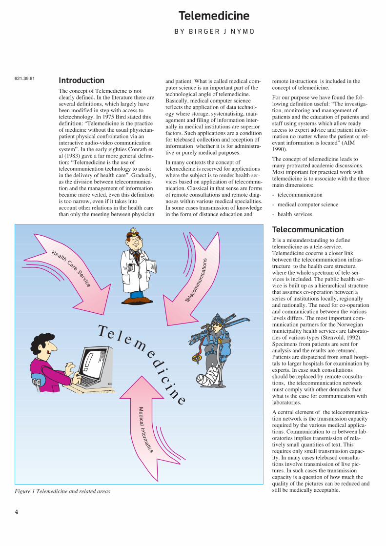
The concept of telemedicine leads tomany protracted academic discussions.Most important for practical work withtelemedicine is to associate with the threemain dimensions:
- telecommunication
- medical computer science
- health services.
Telecommunication
It is a misunderstanding to definetelemedicine as a tele-service.Telemedicine cocerns a closer linkbetween the telecommunication infras-tructure to the health care structure,where the whole spectrum of tele-ser-vices is included. The public health ser-vice is built up as a hierarchical structurethat assumes co-operation between aseries of institutions locally, regionallyand nationally. The need for co-operationand communication between the variouslevels differs. The most important com-munication partners for the Norwegianmunicipality health services are laborato-ries of various types (Stenvold, 1992).Specimens from patients are sent foranalysis and the results are returned.Patients are dispatched from small hospi-tals to larger hospitals for examination byexperts. In case such consultationsshould be replaced by remote consulta-tions, the telecommunication networkmust comply with other demands thanwhat is the case for communication withlaboratories.
A central element of the telecommunica-tion network is the transmission capacityrequired by the various medical applica-tions. Communication to or between lab-oratories implies transmission of rela-tively small quantities of text. Thisrequires only small transmission capac-ity. In many cases telebased consulta-tions involve transmission of live pic-tures. In such cases the transmissioncapacity is a question of how much thequality of the pictures can be reduced andstill be medically acceptable.
Me
dica
l Inform
atics
Te l e m e di c
i n e
Tele
com
mun
icat
ion
s
Health Care Service
Figure 1 Telemedicine and related areas
621.39:61
5
Another aspect is to what degree networkand services allow on-line communica-tion. In most cases the laboratory com-munication does not require “consulta-tion” between GP and laboratory withregard to interpretation of the outcome ofthe analysis. The laboratory sends theresults when they are ready and the GPstudies them when it suits his work rou-tine. Many types of remote consultationsare a direct meeting between patient andphysician and require two-way sound andpicture communication.
As an integrated part of the working toolsof the health services, telemedicine putsstrong demands on telecommunicationsecurity. One aspect is that the contentsof the communication must not comeinto the wrong hands. Another aspect isthat in some cases of remote diagnosis itwould be catastrophic if the connection isnot obtained or if the connection breaksdown.
Reliability and security of the telecom-munication network is a deciding factorfor which telemedical applications can berealised, for both practical and economicreasons.
Medical informatics
Medical computer science and informa-tion processing must be regarded in twoconnections: computer technology inmedical equipment, and the more tradi-tional internal EDP based systems withinthe institutions to take care of routines inthe administration of health services.
Within modern health services the per-formance of diagnosis, treatment andrehabilitation is marked by a widespreaduse of medical technical equipment of ahigh technological level. An importantelement of this equipment is electronicsand computer technology. However, thesituation today is that this equipment to alimited extent is integrated into largeinternal information systems. The greaterpart of the equipment is a well definedentity in itself. A typical example is pic-ture diagnosis where a computer tomo-graph produces pictures which are trans-ferred to a film before they are includedin the patient’s case record or filed.
One problem concerning telemedicine isthe necessity of a standardised interfacein order to communicate information outfrom the equipment and through internaland external networks.
The core of electronic management ofinformation at many health institutions
are various administrative EDP systems.In the first place this concerns systems totake care of accounting, budget, pay-ment, and material. Gradually, systemstaking care of administration of patientsand other activities have been put to use.The main motive for introduction of suchsystems is to increase the efficiency ofpaper work and the production of statis-tics. To a very small extent systems foradministration, planning and medicaltreatment are integrated into one system.
The lack of national co-ordination haslead to a health service marked by asmall degree of harmonisation con-cerning both hardware and functional useof medical information systems. Thereare many different systems which arerepresentative of system dependence anda structure that is functionally adapted tolocal conditions. The lack of compatibil-ity makes the transmission of informationbetween the systems difficult, if notimpossible. Another condition that tendsto amplify these problems is the lack ofstandards. This concerns medical nomen-clature, terminology, and classification.
The medical information systems requirea high degree of security. Today the insti-tutional systems are closed to the outsideworld. There is no gateway into them.This concerns protection of privacy, buteven more important is to prevent “sabo-teurs” to enter and put the system intodisorder.
The problems concerning integration,standardisation, security, and communi-cation interface of medical informationsystems are relevant to telemedicine.
Health services
The organisation of health services is animportant cue for telemedicine. Whetherit concerns special cases or total strate-gies where telemedicine is involved aspart of the working tools for the healthservices to obtain its objectives, qualitycontrol, economy, and legal conditionsmust be considered.
Quality control is to a high degree relatedto the question of whether telebasedapplications, e.g. for diagnosing, willproduce the same results as by tradi-tional methods. Telebased applicationsimply changes in the work routines, e.g.the expert does not himself guide theprobe by an ultrasound examination.Another example is that the pathologistmust examine the microscope pictures onan image display and not directly throughthe eye piece of the microscope. Another
question is whether telebased transmis-sion results in loss of details in the trans-mitted information, details that areimportant for the diagnosing. It is, ofcourse, a basic condition for telemedicinefrom a medical point of view that thehealth services shall not be reduced inquality.
The legal aspects within medicine havebecome more pronounced by the focus-ing on the patients’ rights. In the case ofsome medical applications it is importantto clarify the responsibility towards diag-nosis and treatment. A concrete exampleis when a patient together with a generalpractitioner call on a specialist viatelecommunication. By traditional spe-cialist consultation it is general practicethat the specialist’s instructions are valid.Thereby the specialist has the responsi-bility. The same will be the case by tele-based specialist consultations, but thishas not been tried before a court of jus-tice. Another question is the responsibil-ity of the supplier of the communicationservice in case of e.g. a breakdown ofcommunication.
Economic considerations abouttelemedicine might be regarded from twolevels, one is social economics andanother level is related to the perform-ance of one single health service in a par-ticular situation. In the latter case itmight be a question of replacing an exist-ing arrangement with another one, basedon telemedicine. A typical example is thearrangement with travelling medical spe-cialists in areas where it is difficult toestablish permanent specialist services.Around such arrangements is usuallybuilt up a system of economic transferwhich keeps the balance for all partsinvolved. If this arrangement is replacedby a telebased service, the economicarrangement will not balance. Therebyclear-cut winners and losers will emerge.This might result in demand for acost/benefit analysis and a demand foradjustment of the existing economicarrangements.
In the perspective of social economicsthe problem might be related to effi-ciency and effectiveness of the healthservices. The starting point is a steadilyincreasing gap between the expectationsof the population to the health servicesand what the community can makeaccessible for health purposes. The ques-tion becomes partly how telemedicinecan contribute to optimum production ofhealth services from a given amount of
6
resources, and partly how telemedicinecan contribute to fulfil central health-political objectives. This perspectivereaches far into the way of organisinghealth services, and not least of all howco-operation and sharing of labourshould be arranged.
Why telemedicine?
The superior goal of the health services isto fight sickness and promote health.Considerable resources are used forhealth purposes. Typical for Europeancountries are health expenses to anamount of 7-9 % of gross national prod-uct, and it is steadily increasing. Thehealth trade is characterised by a rapiddevelopment of medical technology. Thisapplies to advanced instruments for diag-nosing and treatment, drugs, technicalremedies for nursing and biotechnology.One of the greatest challenges for thehealth services is to match the expecta-tion of the population to the health ser-vices to the services which can be deliv-ered on a large scale.
Another characteristic feature is a largeproduction of knowledge throughresearch and practical clinical work. Theclassical medical field is steadily dividedinto more specialised fields. At the sametime the contact with other fields isextended. The health services willchange character, partly because, in addi-tion to the curative and preventivemedicine, there will be more emphasis onpredictive medicine based on the devel-opment in biochemistry and molecularbiology.
In organising health services these devel-opment trends point towards a largerdivision of work duties and a centralisa-tion of specialised functions. New pro-fessional environments and new equip-ment for diagnosing and treatmentrequire comprehensive efforts of as welleconomic as organisational character. Inthe first place this will be important on anational level by the fact that some insti-tutions will have nationwide responsibil-ity for certain specialities imposed onthem. In the long run we can se a needfor greater international sharing oflabour.
Another challenge for the public healthservices is that the population during thenext ten years will be changed withregard to composition of age groups.Older people, who are the major users ofhealth services, will considerablyincrease in number. In Norway the num-
ber of persons over the age of 80 hasdoubled since 1970. Towards the year2020 this number will increase further.The part of the population over the age of90 will increase considerably. In general,there will be more heavy users of thehealth services at the same time as therewill be fewer persons in the age groupwhich can produce health services andcontribute to the economic resourcesneeded by the health services. In addi-tion, an increased number of handi-capped and chronically sick persons isexpected (St. meld. (White Paper) No.41, 1987-88).
As an answer to the increasing cost ofrunning the institutions of the health ser-vices (hospitals, nursing homes), we willhave a change towards greater emphasison primary health service. In Norway weare already phasing over to more daycare activity where staying time in hospi-tal is reduced and in the nursing sector atransition to homebased care.
In light of these challenges telemedicinemust be assessed as a tool for more effi-cient exploitation of available resources.Telecommunication will never replacethe physician or other health workersinvolved in a patient relation. Instead, itgives a possibility of increasing the inte-gration between various health servicesand in this way contributes to better caredirected towards the patient.
From technological
curiosity to economical
benefit
The idea of using telecommunication formedical purposes is as old as the spreadof the telecommunication means. Soonafter the invention of the telephoneexperiments were made to transfer heartand lung sounds to a skilled specialistwho could give an opinion of the state ofthe organ. The inventor of the electrocar-diograph, Wilhelm Einthoven, startedexperiments with remote consultationsvia the telephone network (Einthoven,1906). Also in Norway such possibilitieswere utilised. Haukeland Hospital estab-lished in the 1920’s a service where shipsat sea could consult physicians in hospi-tals via Bergen Radio in case of accidentand sickness. It has ben said that thephysicians not only contributed withdiagnoses and proposals for treatment,but also complicated surgical operationswere performed by help of instructionsvia radio (Rafto, 1955).
During the 1950’s and 60’s many indi-vidual experiments with medical serviceswere carried out on the basis of telecom-munication. Often it was enthusiasts withmedical background who saw the possi-bilities as the teletechnology graduallydeveloped. We may safely assert thatthose experiments were mainly directedtowards the technology, even if medicaland organising matters were on theagenda. The equipment used was poorlyadapted to the services to be practised.The cost might be so high that the dataobtained could not be generalised andlead to safe conclusions (Bashur andLovett, 1977).
Gradually the starting point for develop-ment of telemedicine changed towardsthe solution of concrete medical prob-lems. Such a field was supervision ofphysiological functions of crews in spaceships (Pool, Stonesifter and Balasco,1975). Another field was improvement ofprimary health services in areas withscattered population (Fuchs, 1979, Dunnand Higgins, 1984). Telecommunicationwas put to use for remote consultationsand remote diagnoses and for distanceeducation of medical personnel atremote locations.
With the linking up of teletechnologywith data technology the horizon oftelemedicine was appreciably extendedin the 1980’s. Within medical computerscience a series of data programs andsystems were developed of both adminis-trative and medical varieties. Even if theywere intended to take care of internaltasks in institutions, they laid the founda-tion for new and also improved oldertelemedical methods. As an example,digital picture processing has nowobtained a central place in severaltelemedical applications.
However, at the same time it may beasserted that while the health serviceshave been progressive in adaptation ofadvanced medical technology, far lessattention has been focused on the use oftelecommunication and information pro-cessing. Introduction and acceptance ofthis type of technology have been slowerwithin the health services than in severalother fields (AIM, 1992). This concernsthe more administrative sides for person-nel, institutions, and patients, but espe-cially within medical treatment. This is incontrast to the fact that the health ser-vices have been very information inten-sive at all levels. As an example a hospi-tal bed in Europe represents a yearly pro-duction of X-rays amounting to an aver-
7
age of 1 Gigabyte (France and Santucci,1991).
During the 1990’s the strongest drivingforce for development of telemedicine isthe economic dimension. Viewed fromone angle this is due to the challengesfacing the health services, where greaterefficiency in performing the health ser-vices can moderate the conflict betweenaccess to resources and the expectationsand demands of the population. Informa-tion technology is regarded as an impor-tant tool for increased efficiency (WorldHealth Organisation, 1988, Arthur D Lit-tle, 1992). On the other hand the healthservices in this perspective represent aconsiderable market for informationtechnology (France and Santucci, 1991).
In Europe the economic driving force isclearly demonstrated by the two develop-ment programmes under EC directionconcerning health services and telecom-munication, by AIM (Advanced Infor-matics in Medicine) and the RACE(Research and development in AdvancedCommunication in Europe) projectTELEMED. In both programmes theparticipants are a composition of researchinstitutions, medical institutions andindustry concerned with informationtechnology.
In the TELEMED project the perspectiveis to find the problems emerging whenmedical experts communicate through abroadband network. Based on trials andexperiments the experience is trans-formed into technical specificationsregarding equipment for telecommunica-tions and terminals. The objective is toproduce commercial systems adapted toco-operation between medical expertswithin diagnosis and therapeutics(TELEMED 1991).
In the AIM programme objectives areclearly expressed to promote a more effi-cient co-operation within the health ser-vices through development of tools, tech-niques and practice about medical infor-matics and telecommunication with acommon European foundation. A furtherobjective is to prepare the European mar-ket and strengthen the competitive forceof European industry within this field(AIM 1992).
Telemedicine in Norway
The Norwegian public health services aredecentralised and based on the principleof treatment on the lowest efficient levelof care. The primary health service is theresponsibility of the municipalities while
the counties are responsible for the hos-pitals. Each county has a central hospitaland a varying number of local hospitals.The country is divided into five health re-gions. Each region has a regional hospitalwith the responsibility of taking care ofspecial medical competence and treat-ment. On a national level there are alsosome hospitals to take care of particu-larly rare or complicated types of ill-nesses.
The hierarchical structure assumes co-operation between a series of units. Thisimplies transfer of large amounts ofinformation between the various levels.In the same way as for the rest of Europe,electronic processing of information islargely tied to administrative routinesinside the institutions. The public healthservice lacks an integrated electronicinformation system. It is rightly assertedin several connections that managementof information is lagging behind in timein relation to the demands created by thedevelopment of treatment of patients(Health region 3, 1988).
However, in one field the work with bet-ter resource utilisation through integratedinformation exchange has progressed; i.e.medical emergency reporting services.By law a common national emergencyreporting service is to be established,which co-ordinates communication readi-ness for various medical levels and co-operating services such as police and fireservice (Odelstings Prop. No. 26, 1988-89). The core of the communication sys-tem is a communication centre for acutemedical needs on a county level, wherethe various telephone and radio servicescan be exploited for co-operation.
An example of a more classical incite-ment to telemedical thinking is the pro-ject “Telematics in the health service ofFinnmark” When the idea was launchedin 1986, the starting point was the lack-ing coverage of health personnel, longdistances, and in general poorer healthservices in this county than in the rest ofthe country. The main ingredients of theproject (Andersen, 1992) were videoconferences for remote diagnoses, educa-tion and professional meeting activitiesbetween the county hospital and the Uni-versity Hospital of Tromsø. The experi-ence gained was satisfactory to a degreethat the local health authorities havedecided to include telematics in theirstrategic plans and to strengthen the co-operation between health services withinand outside the county.
Telemedicine in North
Norway
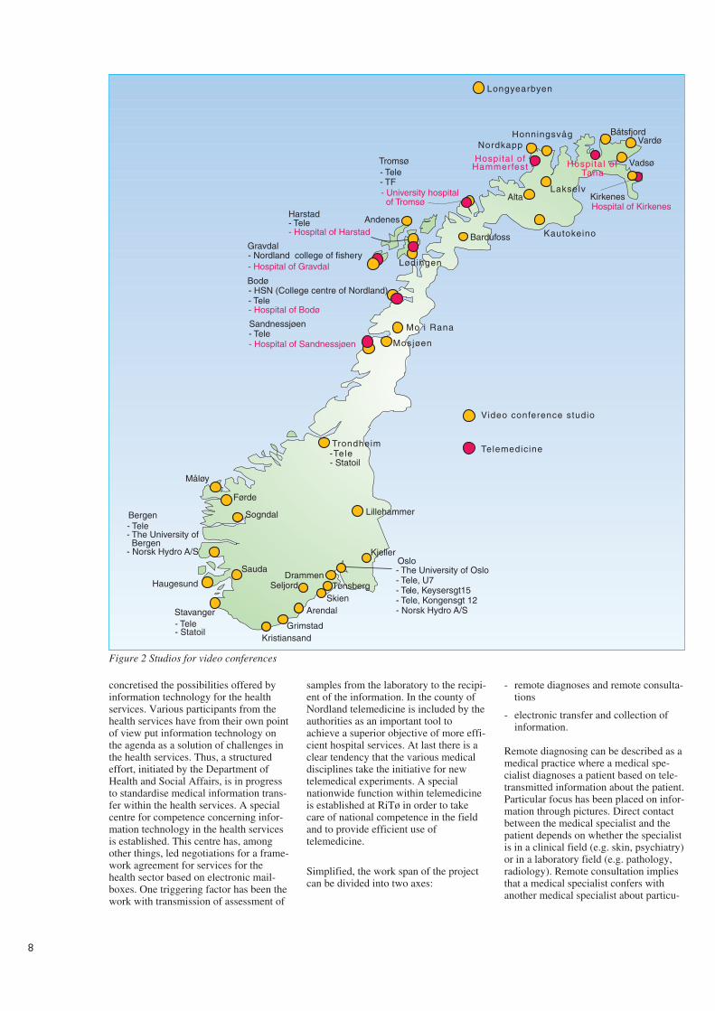
The largest effort within telemedicine inNorway is a project under the directionof Norwegian Telecom. Following thegood result from an experiment withtransmission of ultrasound picturesthrough the telecommunication networkbetween the local health services at Jev-naker and Ullevål Hospital in Oslo(Andersen and Nordby, 1988), the pro-ject “Telemedicine in North Norway”was established. There are two reasonswhy the project was located in the north-ern part of Norway: One is the geographyof that part of the country, scattered pop-ulation and in many places poor heathservices, especially for medical specialistservices. Secondly, this area has a welldeveloped infrastructure of telecommu-nication, especially networks for videoconferences and video transmission(Nymo, 1989).
From the outset the project tried to incorpo-rate the three dimensions of telemedicine,namely medical informatics, health ser-vices, and telecommunication. This hasmade the approach to the project rathercomplex. It ranges from development oftechnical equipment through participationin international standardisation work toassessment of questionnaires concerningthe satisfaction of the patients with thetelemedical services. The superior objec-tive was to arrive at medically secure, tech-nical, and organising solutions for the Nor-wegian health services. A joint approach tothe problems was field trials where anapproach crossing professional borders wastaken care of through co-operationbetween the Norwegian Telecom Research(NTR), other research institutions, individ-uals and institutions in the health services.The most important collaborator for thefield trials has been the University Hospitalof Tromsø (RiTø).
The field trials can be characterised asexplosive. Ideas around techniques andprocedures have been developed in a realsituation, and these have been furtherdeveloped into equipment and routines.Thus systems for telepathology and tel-eradiology have been developed, systemswhich have been commercialised andwhich are currently in operation. Testshave been made within this area whichconfirm the fact that the systems render asatisfactory quality of medical services.
The field trials have also had a consider-able educational effect. The trials have
8
concretised the possibilities offered byinformation technology for the healthservices. Various participants from thehealth services have from their own pointof view put information technology onthe agenda as a solution of challenges inthe health services. Thus, a structuredeffort, initiated by the Department ofHealth and Social Affairs, is in progressto standardise medical information trans-fer within the health services. A specialcentre for competence concerning infor-mation technology in the health servicesis established. This centre has, amongother things, led negotiations for a frame-work agreement for services for thehealth sector based on electronic mail-boxes. One triggering factor has been thework with transmission of assessment of
samples from the laboratory to the recipi-ent of the information. In the county ofNordland telemedicine is included by theauthorities as an important tool toachieve a superior objective of more effi-cient hospital services. At last there is aclear tendency that the various medicaldisciplines take the initiative for newtelemedical experiments. A specialnationwide function within telemedicineis established at RiTø in order to takecare of national competence in the fieldand to provide efficient use oftelemedicine.
Simplified, the work span of the projectcan be divided into two axes:
- remote diagnoses and remote consulta-tions
- electronic transfer and collection ofinformation.
Remote diagnosing can be described as amedical practice where a medical spe-cialist diagnoses a patient based on tele-transmitted information about the patient.Particular focus has been placed on infor-mation through pictures. Direct contactbetween the medical specialist and thepatient depends on whether the specialistis in a clinical field (e.g. skin, psychiatry)or in a laboratory field (e.g. pathology,radiology). Remote consultation impliesthat a medical specialist confers withanother medical specialist about particu-
Hospital of Hammerfest
Bardufoss
Mo i Rana
Trondheim
Video conference studio
Telemedicine
Kjeller
Mosjøen
- Nordland college of fishery- Hospital of Gravdal Lødingen
Alta
Honningsvåg BåtsfjordVardø
Lakselv
Stavanger
Sogndal
Førde
Longyearbyen
Nordkapp
AndenesHarstad- Tele- Hospital of Harstad
- The University of Bergen- Norsk Hydro A/S
Haugesund
- Tele
- Tele
Grimstad
Arendal
Drammen
Kristiansand
Seljord Tønsberg
Gravdal
- Hospital of Bodø
- Hospital of Sandnessjøen
-Tele- Statoil
Lillehammer
- Tele- Statoil
Bergen
Skien
Kautokeino
Vadsø
Hospital of Kirkenes
- University hospital of Tromsø
- Tele- TF
Tromsø
Sauda - The University of Oslo- Tele, U7- Tele, Keysersgt15- Tele, Kongensgt 12- Norsk Hydro A/S
Hospital of Tana
Måløy
- HSN (College centre of Nordland)
Kirkenes
Bodø
Sandnessjøen
- Tele
Oslo
Figure 2 Studios for video conferences
9
lar difficult cases, interpretation of find-ings, etc.
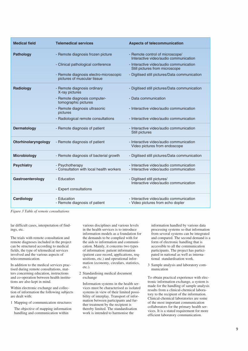
The trials with remote consultation andremote diagnoses included in the projectcan be structured according to medicalfields, the type of telemedical servicesinvolved and the various aspects oftelecommunication.
In addition to the medical services prac-tised during remote consultations, mat-ters concerning education, instructionsand co-operation between health institu-tions are also kept in mind.
Within electronic exchange and collec-tion of information the following subjectsare dealt with:
1 Mapping of communication structures
The objective of mapping informationhandling and communication within
various disciplines and various levelsin the health services is to introduceinformation models as a foundation forthe demands to be complied with forthe aids to information and communi-cation. Mainly, it concerns two typesof information: patient information(patient case record, applications, req-uisitions, etc.) and operational infor-mation (economy, circulars, statistics,etc.).
2 Standardising medical documentexchange
Information systems in the health ser-vices must be characterised as isolatedsystems in view of their limited possi-bility of interplay. Transport of infor-mation between participants and fur-ther treatment by the recipient isthereby limited. The standardisationwork is intended to harmonise the
information handled by various dataprocessing systems so that informationfrom several systems can be integratedand compared. The second demand is aform of electronic handling that isaccessible to all the communicationparticipants. The project has partici-pated in national as well as interna-tional standardisation work.
3 Sample analysis and laboratory com-munication
To obtain practical experience with elec-tronic information exchange, a system ismade for the handling of sample analysisresults from a clinical-chemical labora-tory to the recipient of the information.Clinical-chemical laboratories are someof the most important communicationcollaborators for the primary health ser-vices. It is a stated requirement for moreefficient laboratory communication.
Medical field Telemedical services Aspects of telecommunication
Pathology - Remote diagnosis frozen picture - Remote control of microscope/Interactive video/audio communication
- Clinical pathological conference - Interactive video/audio communicationStill pictures from microscope
- Remote diagnosis electro-microscopic - Digitised still pictures/Data communicationpictures of muscular tissue
Radiology - Remote diagnosis ordinary - Digitised still pictures/Data communicationX-ray pictures
- Remote diagnosis computer- - Data communicationtomographic pictures
- Remote diagnosis ultrasonic - Interactive video/audio communicationpictures
- Radiological remote consultations - Interactive video/audio communication
Dermatology - Remote diagnosis of patient - Interactive video/audio communicationStill pictures
Otorhinolaryngology - Remote diagnosis of patient - Interactive video/audio communicationVideo pictures from endoscope
Microbiology - Remote diagnosis of bacterial growth - Digitised still pictures/Data communication
Psychiatry - Psychotherapy - Interactive video/audio communication- Consultation with local health workers - Interactive video/audio communication
Gastroenterology - Education - Digitised still pictures/Interactive video/audio communication
- Expert consultations
Cardiology - Education - Interactive video/audio communication- Remote diagnosis of patient - Video pictures from echo dopler
Figure 3 Table of remote consultations
Experience from the work with labora-tory communication is closely related toverification of specifications evolvedthrough the standardisation work.
4 Electronic access to medical knowl-edge and experience
Large amounts of knowledge are gen-erated through research and practicalwork within medicine and related pro-fessional fields. The quality of healthservices depends on the professionalqualifications of the health personnel. Itis not a trifling challenge to keep one-self professionally updated. There areseveral electronic sources for medicalinformation in the form of factsdatabases, literature databases and elec-tronic conferences for particular pro-fessional fields. The project has beenworking with a system for medicalinformation services (MEDIS) whereemphasis is put upon making access tothe information sources as simple aspossible for the users. Among otherthings, this is achieved by making auniform interface to the various infor-mation sources.
The challenge
As data technology has taken over fromelectromechanical equipment in telecom-munication, the horizon for exploitationhas been considerably extended. How-ever, a condition is that data technologyhas a widespread use in the community,where it is used to systematise, store, file,and treat information. When this is thecase, we have a technical foundation forcollection, reception and treatment ofinformation by help of telecommunica-tion. Thereby, new fields for exploitationare found. It may be a long road from thefact that technical foundations exist tothe realisation of new fields for exploita-tion. This is related to the need for socialchanges in the form of organising, workroutines and roles. It is a challenge forthe health services, the supplier oftelecommunication and for the producersof medical technical equipment andmedical information systems.
The challenges facing the health servicesmake it necessary to try new methods forpractising the services. The main prob-lem in Europe, and even more so in theUSA, is the rising cost involved withhealth services. Better utilisation ofresources through extensive co-opera-tion between participants is a more real-istic solution than increased share of thesociety’s expenses for health purposes. In
this light more focus should be directedtowards telemedicine in a fully organis-ing and strategic perspective.
This implies that the field oftelemedicine changes from a local orregional starting point with focus onloose concrete problems, giving poorcoverage of specialist services in ruralareas, to the making of a telemedicalinfrastructure that matches the generalinfrastructure of the health services. Thestructure can be based on the existingwork sharing between the levels of thehealth services, but it must have enoughflexibility to realise new patterns of co-operation. For example, there are manyreasons why greater emphasis should beput on homebased rather than institu-tional care for the growing number ofpersons in need of nursing. Thus, theinfrastructure must also include home-based care. As the sub-specialisationcontinues, it might be impossible forsmall nations to establish lasting profes-sional environments on a national basis.Professional environments in the form ofnetworks across national borders is oneway to organise such services.
There are a great number of applicationsof telecommunication within the healthservices. Some are more important thanothers. An American investigation (Lit-tle, 1992) calculated the potential for theyearly reduction of costs for some appli-cation groups. The application groupfound to give the highest reduction ofcosts is electronic handling and transportof patient information. The investigationcalculated that in the USA it is possibleto save USD 30 billions(30,000,000,000) yearly by employingsuch applications. The potential for costreduction by systematic use of video con-ferences for remote consultation andeducation was estimated to a yearlyamount of USD 200 millions.
Systematic exploitation of applicationsassumes flexible possibilities fortelecommunications. In today’s pilot pro-jects and other work within telemedicine,by and large the applications are realisedin general teleservices in different net-works. For some purposes this does notresult in the best cost optimum solutions.At the same time users’ choice of type ofcommunication is limited. For manymedical purposes where pictures are partof the information basis, there is a needto choose transmission rate according toa particular situation. In an acute casethere are other demands for speed of con-
nection and transmission than for routineexaminations.
ISDN seems to give the necessary flexi-bility by using a combination of basicaccess and primary rate access. The pri-mary health services’ need for communi-cation both to local hospitals and in thehomebased care, basic access offering two64 kbit/s channels (B-channels) in thegreat majority of cases give sufficientcapacity for the applications we see today.For telemedical services between hospi-tals the flexibility will be secured by pri-mary rate access (30 B-channels). In acomplete “health network” it is also nec-essary to integrate mobile communica-tion, especially in cases of catastrophes.
References
Advanced Informatics in Medicine(AIM), Commission of the EuropeanCommunities. Supplement Application ofTelecommunications of Health CareTelemedicine. AI 1685, 1990.
AIM’92. Research and technology devel-opment on telematics systems in healthcare. Brussels, Commission of the Euro-pean Communities, 1992.
Andersen, K A. Videokonferanser i hel-sevesenet, erfaringer fra to års bruk iTroms og Finnmark. Kjeller, NorwegianTelecom Research. (NTR paper N3/92.)
Anderson, D, Nordby, K. Video tele-phony revisited: The development andtest of a broadband multifunction termi-nal. Lecture held at the 12th InternationalSymposium on Human Factors inTelecommunication, the Hague, 1988.
Bashur, R L, Lovett, J. Assessment oftelemedicine: Results of the initial expe-rience. Aviation, Space and Environmen-tal Medicine, 177, 65-70.
Bird, K T. Telemedicine; concept andpractice. In: R L Bashur, P A Armstrongand Z I Youssef (eds.), Telemedicine;explorations in the use of telecommuni-cation in health care. Springfield, Illi-nois, Thomas, 1975.
Conrath, D W et al. Evaluating telecom-munications technology in medicine.Dedham, Massachusetts, Artech House,1983.
1 0
Dunn, E V, Higgins, C A. Telemedicinein Canada; an overview. Dimensions, 68,16-18, 1984.
Einthoven, W. Het telecardiogram. Ned-erlens Tijdschrift voor Geeneskunde, 50,1517-1547, 1906..
Fuchs, M. Provider attitudes towardSTARPACH: a telemedicine project onthe Papago Reservation. Medical Care,17, 59-68, 1979.
Helseregion 3: telemedisinutvalget,Bergen, 1988.
Little, A D. Telecommunications: Can ithelp solve America’s health care prob-lems? Cambridge, Massachusetts, ArthurD Little, 1992.
Nymo, B J. Telemedisin i Nord-Norge.Telektronikk, 85, 260-263, 1989.
Ot. prp 26(1988-89): Om telekommu-nikasjoner i helsetjenesten, herundermedisinsk nødmeldetjeneste.
Pool, S L, Stonesifter, J C, Belasco, N.Application of telemedicine systems infuture manned space flight. Lecture heldat the 2nd Telemedicine Workshop, Tus-con, Arizona, 1975.
Rafto, T. Telegrafverkets historie 1855-1955. Bergen, Grieg, 1955.
Roger France, F H, Santucci, G (eds.).Perspectives of information processing inmedical applications. Strategic issues,requirements and options for the Euro-pean Community. Brussels, Springer-Verlag, 1991.
Stenvold, L A. Kommunikasjonsstruk-turer i helsevesenet, en gjennomgang avkartleggingsforsøk i telemedisinprosjek-tet. Kjeller, Norwegian TelecomResearch. (NTR report R7/92.)
St.mld. 41(1987-88). Helsepolitikken motår 2000. Nasjonal helseplan.
TELEMED-Project: Annual projectreport 1991. Berlin, DETECON GmbH,1991.
World Health Organisation. Informaticsand telematics in health. Present andpotential uses. Geneva, WHO, 1988.
1 1
1 2
Telemedicine services integrated into a health care network
– Analysis of communication needs in a regional health care system
B Y S I G U R D F R O M , L I L L Y A N N S T E N V O L D A N D T H O R E D A N I E L S E N
1 Introduction
Since 1988 Norwegian Telecom Re-search has initiated and developed sev-eral telemedicine applications.Telemedicine services supported by theapplications range from exchange of clin-ical chemistry laboratory results to inter-active radiology consultations. All theapplications have a common objective toimprove efficiency and quality of thehealth care.
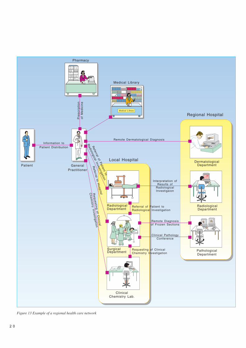
This paper defines a set of objectives forintroducing telemedicine in the Norwe-gian health sector. It also outlines thestructure of the regional health care sys-tem in Norway which will be the scopefor this paper. Communication needswithin a typical health care region isanalysed. Later, telemedicine applica-tions which meet these needs aredescribed by scenarios. Finally, the appli-cations are integrated to form an exampleof a regional health care network.
2 The objectives of
telemedicine
One of the basic ideas of telemedicinecan be expressed by the saying: “Movethe information, not the patient”. When apatient needs to consult a specialist,information about the patient could beobtained locally and exchanged through anetwork to a specialist. In many situa-tions this can replace transporting thepatient or the specialist to a given loca-tion. This exchange of information formedical diagnosing and treatment is abasic concept of telemedicine.
In general, we may use the followingfunctional definition of telemedicine(AIM, 1990):
The investigation, monitoring andmanagement of patients and the educa-tion of patients and staff using systemswhich allow ready access to expertadvice and patient information no mat-ter where the patient or relevant infor-mation is located.
Telemedicine may therefore be seen asall situations where information isexchanged electronically between healthcare parties that collaborate in treatingpatients.
In 1992 the Norwegian Ministry ofHealth defined 5 information technology(IT) objectives for the Norwegian healthcare sector (Hidas, 1992):
IT1 Improve service and quality of thehealth services
IT2 Improve productivity and effi-ciency in the health sector
IT3 When meeting IT1 and IT2 theaspects of security of privacy forthe individual patient should beconsidered
IT4 Use the opportunities of IT to dis-tribute information to the generalpublic and the health care profes-sionals and to increase the level ofknowledge
IT5 Improve working conditions andpersonal planning for health careprofessionals.
These objectives relate to the whole ofthe health sector, not only telemedicine.However, those objectives directlyrelated to patient care may be used toform similar objectives of telemedicine.By combing IT1-5 and the previous defi-nition of telemedicine we have definedthe following 7 objectives oftelemedicine:
TM1 Patients should be treated as closeto their homes as possible (IT1).
TM2 Medical expertise should beequally available independent ofwhere the patient lives (IT1).
TM3 The quality of medical decisionsshould be improved by makingexisting information about patientsmore easily available (IT1).
TM4 Patients should get more informa-tion and better service (IT1).
TM5 The health services shouldimprove efficiency and productiv-ity by reducing unnecessaryadministrative work such as retyp-ing information already existing inelectronic form and by distributingtasks between health care institu-tions and health care personnel(IT2).
TM6 All exchange of information needsto take into account the aspects ofsecurity of privacy for the individ-ual patient (IT3).
TM7 Medical knowledge should bemore easily accessible (IT 4).
3 Communication scenarios
The following section explains themethod used to describe telemedicineapplications in brief. Telemedicine appli-
cations support the process of communi-cating between groups of health careworkers. Such group processes have ear-lier been described in Computer SupportCo-operative Work (CSCW). We havechosen to use the AMIGO ActivityModel (Pankoke-Babatz, 1988) com-bined with some concepts from theOpen-EDI work (SIS-ITS) as a basis forour method.
In our context a telemedical applicationis the total solution implemented to sup-port the need for a telemedicine service.It includes both software and hardware atall party sites, and the communicationbetween them. A telemedical service is amedical service provided by one party toone or more other parties through appli-cations. A telemedicine application maysupport one or more telemedicine ser-vices.
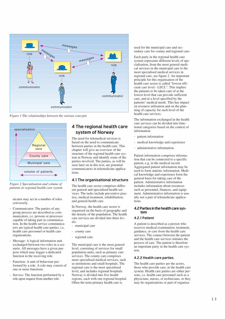
The overall picture of the activity sup-ported by a telemedicine application isdescribed in a communication scenario.As for theatres, a scenario consists of aset of roles played by a number of per-sons or role players. We will focus on theroles participating in the communicationprocess. An actual role player is calledthe communicator. In health care thecommunicator is typically a health careparty, i.e. a health care professional suchas a physician, a nurse or a health careinstitution such as a laboratory. One roleis associated with one or more functionsthat describe the actual work done, thebehaviour of the role. One role may sendmessages to one or more other roleswhich trigger a function in that role to beperformed. In the situation whererequester and provider roles are involvedin the scenario, a service is defined as thefunction performed by the provider roleupon request from the request-role. Fig-ure 1 illustrates the relationship betweenthe various concepts.
The following gives a summary of theconcepts defined:
- Communication scenario: A collectionof matching roles grouped together tosupport an activity with a given pur-pose.
- Role: The definition of a communica-tive role of communicators in a sce-nario describing the specific behaviourof the communicator. Examples ofroles are: laboratory requester and lab-oratory service provider. There mayexist a number of communicatorsattached to any role, and any commu-
621.39:61
1 3
nicator may act in a number of rolesconversely.
- Communicator: The parties of anygroup process are described as com-municators, i.e. persons or processescapable of taking part in communica-tion. In the health service communica-tors are typical health care parties, i.e.health care personnel or health careorganisations.
- Message: A logical information unitexchanged between two roles in a sce-nario. All messages have a given pur-pose which may trigger a dedicatedfunction in the receiving role.
- Function: A unit of behaviour per-formed by a role. A role may consist ofone or more functions.
- Service: The function performed by arole upon request from another role.
4 The regional health care
system of Norway
The need for telemedical services isbased on the need to communicatebetween parties in the health care. Thischapter will give an overview of thestructure of the regional health care sys-tem in Norway and identify some of theparties involved. The parties, as will beseen later on in this text, are potentialcommunicators in telemedicine applica-tions.
4.1 The organisational structure
The health care sector comprises differ-ent general and specialised health ser-vices. The tasks include preventive prac-tice, medical treatment, rehabilitation,and general health care.
In Norway, the health care sector isorganised on the basis of geography andthe density of the population. The healthcare services are divided into three lev-els:- municipal care
- county care
- regional care.
The municipal care is the most generallevel, consisting of services for smallpopulation units, such as primary careservices. The county care comprisesmore specialised medical services, suchas institutions and small hospitals. Theregional care is the most specialisedlevel, and includes regional hospitals.Norway is divided into five healthregions, each with one regional hospital.Often the term primary health care is
used for the municipal care and sec-ondary care for county and regional care.
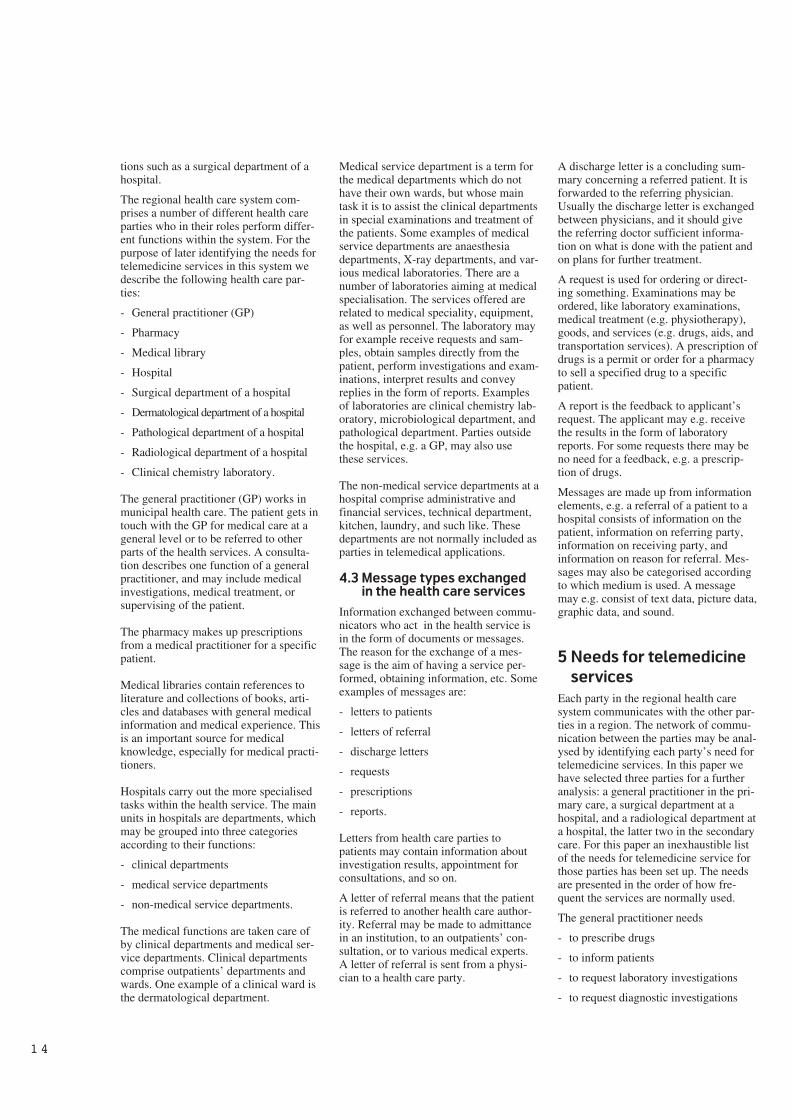
Each party in the regional health caresystem represents different levels of spe-cialisation, from the most general medi-cal services in the municipal care to themost specialised medical services inregional care, see figure 2. An importantprinciple for this organisation of thehealth care sector is called “lowest effi-cient care level - LECL”. This impliesthe patients to be taken care of at thelowest level that can provide sufficientcare, and at a level specified by thepatients’ medical needs. This has impacton resource utilisation and on the plan-ning of capacity for each level of thehealth care services.
The information exchanged in the healthcare services can be divided into func-tional categories based on the context ofinformation:
- patient information
- medical knowledge and experience
- administrative information.
Patient information comprises informa-tion that can be connected to a specificpatient, e.g. in the medical record.Aggregated patient information may beused to form statistic information. Medi-cal knowledge and experience form thegeneral basis for taking care of thepatient. Administrative informationincludes information about resourcessuch as personnel, finances, and equip-ment. Administrative information is usu-ally not a part of telemedicine applica-tions.
4.2 Parties in the health care sys-
tem
4.2.1 Patient
A patient is described as a person whoreceives medical examination, treatment,guidance, or care from the health careservices. The contact between the patientand the health care services initiates theprocess of care. The patient is thereforean important party in the health care sys-tem.
4.2.2 Health care parties
The health care parties are the actors,those who provide care, in the health caresystem. Health care parties are either per-sons, i.e. health care personnel such as aphysicians, nurses, or technicians, or theymay be organisations or part of organisa-
role
role
role
messages
messages
messages
communicator
communicator
communicator
Figure 1 The relationships between the various concepts
Regionalcare
County care
Municipal care
volume of patients
specialisation
Figure 2 Specialisation and volume ofpatients in regional health care system
1 4
tions such as a surgical department of ahospital.
The regional health care system com-prises a number of different health careparties who in their roles perform differ-ent functions within the system. For thepurpose of later identifying the needs fortelemedicine services in this system wedescribe the following health care par-ties:
- General practitioner (GP)
- Pharmacy
- Medical library
- Hospital
- Surgical department of a hospital
- Dermatological department of a hospital
- Pathological department of a hospital
- Radiological department of a hospital
- Clinical chemistry laboratory.
The general practitioner (GP) works inmunicipal health care. The patient gets intouch with the GP for medical care at ageneral level or to be referred to otherparts of the health services. A consulta-tion describes one function of a generalpractitioner, and may include medicalinvestigations, medical treatment, orsupervising of the patient.
The pharmacy makes up prescriptionsfrom a medical practitioner for a specificpatient.
Medical libraries contain references toliterature and collections of books, arti-cles and databases with general medicalinformation and medical experience. Thisis an important source for medicalknowledge, especially for medical practi-tioners.
Hospitals carry out the more specialisedtasks within the health service. The mainunits in hospitals are departments, whichmay be grouped into three categoriesaccording to their functions:
- clinical departments
- medical service departments
- non-medical service departments.
The medical functions are taken care ofby clinical departments and medical ser-vice departments. Clinical departmentscomprise outpatients’ departments andwards. One example of a clinical ward isthe dermatological department.
Medical service department is a term forthe medical departments which do nothave their own wards, but whose maintask it is to assist the clinical departmentsin special examinations and treatment ofthe patients. Some examples of medicalservice departments are anaesthesiadepartments, X-ray departments, and var-ious medical laboratories. There are anumber of laboratories aiming at medicalspecialisation. The services offered arerelated to medical speciality, equipment,as well as personnel. The laboratory mayfor example receive requests and sam-ples, obtain samples directly from thepatient, perform investigations and exam-inations, interpret results and conveyreplies in the form of reports. Examplesof laboratories are clinical chemistry lab-oratory, microbiological department, andpathological department. Parties outsidethe hospital, e.g. a GP, may also usethese services.
The non-medical service departments at ahospital comprise administrative andfinancial services, technical department,kitchen, laundry, and such like. Thesedepartments are not normally included asparties in telemedical applications.
4.3 Message types exchanged
in the health care services
Information exchanged between commu-nicators who act in the health service isin the form of documents or messages.The reason for the exchange of a mes-sage is the aim of having a service per-formed, obtaining information, etc. Someexamples of messages are:
- letters to patients
- letters of referral
- discharge letters
- requests
- prescriptions
- reports.
Letters from health care parties topatients may contain information aboutinvestigation results, appointment forconsultations, and so on.
A letter of referral means that the patientis referred to another health care author-ity. Referral may be made to admittancein an institution, to an outpatients’ con-sultation, or to various medical experts.A letter of referral is sent from a physi-cian to a health care party.
A discharge letter is a concluding sum-mary concerning a referred patient. It isforwarded to the referring physician.Usually the discharge letter is exchangedbetween physicians, and it should givethe referring doctor sufficient informa-tion on what is done with the patient andon plans for further treatment.
A request is used for ordering or direct-ing something. Examinations may beordered, like laboratory examinations,medical treatment (e.g. physiotherapy),goods, and services (e.g. drugs, aids, andtransportation services). A prescription ofdrugs is a permit or order for a pharmacyto sell a specified drug to a specificpatient.
A report is the feedback to applicant’srequest. The applicant may e.g. receivethe results in the form of laboratoryreports. For some requests there may beno need for a feedback, e.g. a prescrip-tion of drugs.
Messages are made up from informationelements, e.g. a referral of a patient to ahospital consists of information on thepatient, information on referring party,information on receiving party, andinformation on reason for referral. Mes-sages may also be categorised accordingto which medium is used. A messagemay e.g. consist of text data, picture data,graphic data, and sound.
5 Needs for telemedicine
services
Each party in the regional health caresystem communicates with the other par-ties in a region. The network of commu-nication between the parties may be anal-ysed by identifying each party’s need fortelemedicine services. In this paper wehave selected three parties for a furtheranalysis: a general practitioner in the pri-mary care, a surgical department at ahospital, and a radiological department ata hospital, the latter two in the secondarycare. For this paper an inexhaustible listof the needs for telemedicine service forthose parties has been set up. The needsare presented in the order of how fre-quent the services are normally used.
The general practitioner needs
- to prescribe drugs
- to inform patients
- to request laboratory investigations
- to request diagnostic investigations
1 5
- to refer patients to hospital
- to look up medical information
- to interactively discuss medical issueswith an expert.
The surgical department of a hospitalneeds
- to request laboratory investigations
- to request other diagnostic investiga-tions
- to have conferences with experts inpathology.
The radiological department of a hospitalneeds
- to get radiological images interpretedby specialists.
6 Telemedicine
applications
The needs presented above must be metby solutions for how telemedicine ser-vices can be provided. This chapter willuse the method introduced in chapter 3and outline a set of communication sce-narios for telemedicine applications.Each scenario will support one or moreof the needs identified in the previouschapter. The scenarios will be presentedaccording to the sequence of the needs inthe previous chapter.
6.1 Prescription of drugs
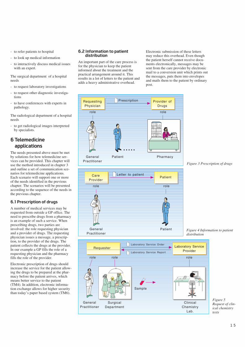
A number of medical services may berequested from outside a GP office. Theneed to prescribe drugs from a pharmacyis an example of such a service. Whenprescribing drugs, two parties areinvolved: the role requesting physicianand a provider of drugs. The requestingphysician issues a message, a prescrip-tion, to the provider of the drugs. Thepatient collects the drugs at the provider.In our example a GP fills the role of arequesting physician and the pharmacyfills the role of the provider.
Electronic prescription of drugs shouldincrease the service for the patient allow-ing the drugs to be prepared at the phar-macy before the patient arrives, whichmeans better service to the patient(TM4). In addition, electronic informa-tion exchange allows for higher securitythan today’s paper based system (TM6).
6.2 Information to patient
distribution
An important part of the care process isfor the physician to keep the patientinformed about the treatment and thepractical arrangement around it. Thisresults in a lot of letters to the patient andadds a heavy administrative overhead.
role
RequestingPhysician
Patient
Provider ofDrugs
GeneralPractitioner
Pharmacy
Prescription
role
• • • • •
GeneralPractitioner
role
CareProvider
Patient
PatientLetter to patient
role
GeneralPractitioner
Requester Laboratory ServiceProvider
Laboratory Service Order
Laboratory Service Report
SurgicalDepartment
ClinicalChemistry
Lab.
Sample
role role role
Figure 3 Prescription of drugs
Figure 4 Information to patientdistribution
Figure 5Request of clin-ical chemistrytests
Electronic submission of these lettersmay reduce this overhead. Even thoughthe patient herself cannot receive docu-ments electronically, messages may besent from the care provider by electronicmail to a conversion unit which prints outthe messages, puts them into envelopesand mails them to the patient by ordinarypost.
1 6
The roles involved in this scenario arethe care provider, which issues the letter,and the patient. In our example the roleof a care provider is filled by a GP andthe patient role is filled by the patientparty.
6.3 Requesting of clinical
chemistry investigation
Diagnostic services play an importantrole in arriving at the patient’s diagnosis.One category of the diagnostic services isthe laboratory services where a sample,e.g. a blood sample, is taken from thepatient and sent to a laboratory. By use ofelectronic communication both the orderand the report may be exchanged elec-tronically between the requester and thelaboratory service provider.
Our example illustrates the situationwhere a GP in the role of a requesterrequests services from a clinical chem-istry laboratory in the role of laboratoryservice provider. A laboratory serviceorder is exchanged from the requester tothe provider and a laboratory servicereport is returned.
The same scenario may also be used inthe secondary care between a surgicaldepartment of a hospital and the hospi-tal’s internal laboratory.
Electronic laboratory communicationimproves the quality of the informationexchange which should result in higherquality on the medical decision (TM3).The effort of retyping the information forthe receiving party is removed, whichshould result in a more efficient service(TM5). The possibility of encryptingelectronic data allows for a higher levelof security (TM6).
6.4 Referral to radiological
investigation
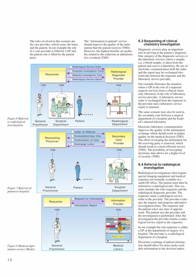
Radiological investigations often requirespecial imaging equipment and medicalexpertise not normally available in asmall GP office. The patient must then bereferred to a radiological unit. This sce-nario includes the roles requester and theradiological diagnostic provider. Therequester sends a radiological serviceorder to the provider. The provider evalu-ates the request, and proposes alternativeinvestigation times. The requester andthe patient select one time of appoint-ment. The patient sees the provider andthe investigation is performed. After theinvestigation the provider returns a radio-logical service report to the requester.
In our example the role requester is eithera GP or the department of surgery of ahospital. The provider is a radiologicaldepartment of a hospital.
Electronic exchange of patient informa-tion should allow for more easily avail-able information to the decision maker.
GeneralPractitioner
RequesterRadiologicalDiagnosticProvider
Radiological Service Order
Proposed Investigation Times
Selected Investigation Time
Radiological Service Report
SurgicalDepartment
RadiologicalDepartment
Patient
role role role
• • • • •
RequestingPhysician
SecondaryCare
Provider
Letter of Referral
Consultation/stay time
Confirmation of time
Discharge Letter
SurgicalDepartment
Patient
role role
• • • • •
GeneralPractitioner
GeneralPractitioner
Requester InformationProvider
Request for Information
Information Report
MedicalLibrary
role role
Medical Library
Figure 6 Referralto radiologicalinvestigation
Figure 7 Referral ofpatient to hospital
Figure 8 Medical infor-mation service (Medis)
The “information to patient” serviceshould improve the quality of the infor-mation that the patient receives (TM4).However, the highest benefits are proba-bly related to the reduction in administra-tive overhead (TM5).
1 7
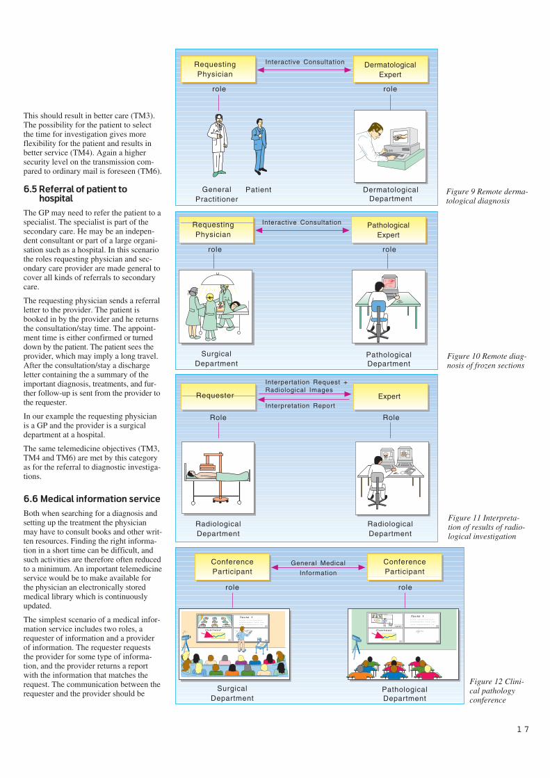
This should result in better care (TM3).The possibility for the patient to selectthe time for investigation gives moreflexibility for the patient and results inbetter service (TM4). Again a highersecurity level on the transmission com-pared to ordinary mail is foreseen (TM6).
6.5 Referral of patient to
hospital
The GP may need to refer the patient to aspecialist. The specialist is part of thesecondary care. He may be an indepen-dent consultant or part of a large organi-sation such as a hospital. In this scenariothe roles requesting physician and sec-ondary care provider are made general tocover all kinds of referrals to secondarycare.
The requesting physician sends a referralletter to the provider. The patient isbooked in by the provider and he returnsthe consultation/stay time. The appoint-ment time is either confirmed or turneddown by the patient. The patient sees theprovider, which may imply a long travel.After the consultation/stay a dischargeletter containing the a summary of theimportant diagnosis, treatments, and fur-ther follow-up is sent from the provider tothe requester.
In our example the requesting physicianis a GP and the provider is a surgicaldepartment at a hospital.
The same telemedicine objectives (TM3,TM4 and TM6) are met by this categoryas for the referral to diagnostic investiga-tions.
6.6 Medical information service
Both when searching for a diagnosis andsetting up the treatment the physicianmay have to consult books and other writ-ten resources. Finding the right informa-tion in a short time can be difficult, andsuch activities are therefore often reducedto a minimum. An important telemedicineservice would be to make available forthe physician an electronically storedmedical library which is continuouslyupdated.
The simplest scenario of a medical infor-mation service includes two roles, arequester of information and a providerof information. The requester requeststhe provider for some type of informa-tion, and the provider returns a reportwith the information that matches therequest. The communication between therequester and the provider should be
GeneralPractitioner
RequestingPhysician
DermatologicalExpert
Interactive Consultation
DermatologicalDepartment
Patient
role role
RequestingPhysician
PathologicalExpert
SurgicalDepartment
Interactive Consultation
PathologicalDepartment
role role
Requester Expert
RadiologicalDepartment
Interpertation Request +Radiological Images
Interpretation Report
RadiologicalDepartment
Role Role
UiO
Tavle 1..... ........................ .... ....... ........... ..
Overhead
Tavle 1..... ........................ .... ....... ........... ..
Overhead
Overhead
UNIKTavle 1..... ........................ .... ....... ........... ..
Overhead
Overhead
UNIK
ConferenceParticipant
SurgicalDepartment
General Medical
Information
PathologicalDepartment
ConferenceParticipant
role role
Figure 9 Remote derma-tological diagnosis
Figure 10 Remote diag-nosis of frozen sections
Figure 12 Clini-cal pathologyconference
Figure 11 Interpreta-tion of results of radio-logical investigation
1 8
TelemedicineServices
Comm. Roles/Communicators
Message types/information types
Characteristics ofCommunications
TMObjectives
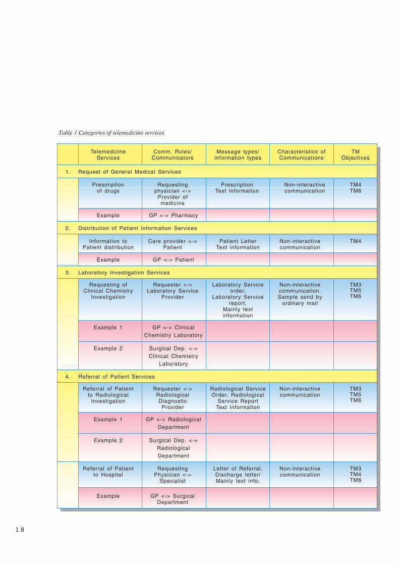
Request of General Medical Services1.
Prescriptionof drugs
Requestingphysician <->
Provider ofmedicine
PrescriptionText information
Non-interactivecommunication
TM4TM6
Example GP <-> Pharmacy
Distribution of Patient Information Services2.
Information toPatient distribution
Care provider <->Patient
Patient LetterText information
Non-interactivecommunication
TM4
Example GP <-> Patient
Laboratory Investigation Services3.
Requesting ofClinical Chemistry
Investigation
Requester <->Laboratory Service
Provider
Laboratory Serviceorder,
Laboratory Servicereport,
Mainly textinformation
Non-interactivecommunication.Sample send by
ordinary mail
TM3TM5TM6
Example 1 GP <-> ClinicalChemistry Laboratory
Example 2 Surgical Dep. <->Clinical Chemistry
Laboratory
Referral of Patient Services4.
Referral of Patientto Radiological
Investigation
Requester <->RadiologicalDiagnosticProvider
Radiological ServiceOrder, Radiological
Service ReportText Information
Non-interactivecommunication
TM3TM5TM6
Example 1 GP <-> RadiologicalDepartment
Example 2 Surgical Dep. <->RadiologicalDepartment
Referral of Patientto Hospital
RequestingPhysician <->
Specialist
Letter of Referral,Discharge letter/Mainly text info.
Non-interactivecommunication
TM3TM4TM6
Example GP <-> SurgicalDepartment
Table 1 Categories of telemedicine services
1 9
Example Surgical Dep. <->PathologicalDepartment
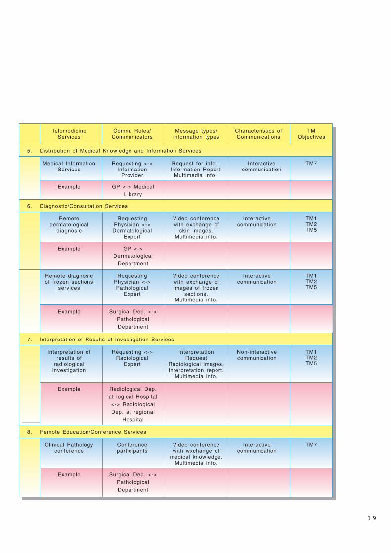
Remote Education/Conference Services8.
Clinical Pathologyconference
Conferenceparticipants
Video conferencewith wxchange of
medical knowledge.Multimedia info.
Interactivecommunication
TM7
Interpretation of Results of Investigation Services7.
Interpretation ofresults of
radiologicalinvestigation
Requesting <->Radiological
Expert
InterpretationRequest
Radiological images,Interpretation report.
Multimedia info.
Non-interactivecommunication
TM1TM2TM5
TelemedicineServices
Comm. Roles/Communicators
Message types/information types
Characteristics ofCommunications
TMObjectives
Distribution of Medical Knowledge and Information Services5.
Medical InformationServices
Requesting <->Information
Provider
Request for info.,Information Report
Multimedia info.
Interactivecommunication
TM7
Example GP <-> MedicalLibrary
Diagnostic/Consultation Services6.
Remotedermatological
diagnosic
RequestingPhysician <->Dermatological
Expert
Video conferencewith exchange of
skin images.Multimedia info.
Interactivecommunication
TM1TM2TM5
Example GP <->Dermatological
Department
Remote diagnosicof frozen sections
services
RequestingPhysician <->Pathological
Expert
Video conferencewith exchange ofimages of frozen
sections.Multimedia info.
Interactivecommunication
TM1TM2TM5
Example Surgical Dep. <->PathologicalDepartment
Example Radiological Dep.at logical Hospital<-> RadiologicalDep. at regional
Hospital
2 0
Figure 13 Example of a regional health care network
GeneralPractitioner
Medical Library
DermatologicalDepartmentPatient
RadiologicalDepartment
PathologicalDepartment
SurgicalDepartment
RadiologicalDepartment
ClinicalChemistry Lab.
Medical Library
Pharmacy
Local Hospital
Regional Hospital
Information toPatient Distribution
Remote Dermatological Diagnosis
Interpretation of Results of
Radiological Investigaion
Pre
scri
pti
on
of
Me
dic
ine
Remote Diagnosisof Frozen Sections
Clinical PathologyConference
Referral of P
atient to
Radiological Investrigation
Re
ferra
l to H
osp
italRe
qu
estin
g o
f Clin
ical
Ch
em
istry Inve
stiga
tion
Referral of Patient toRadiological Investigation
Requesting of ClinicalChemistry Investigation
interactive in order to allow the requesterto do repetitive search for information. Inour example, the requester is a GP, theprovider is a medical library.
This service fulfils the objective of mak-ing medical knowledge more accessible(TM7).
6.7 Remote dermatological
diagnosis
A physician may need to consult anexpert before he makes the patient’sdiagnosis. Today, experts are contactedthrough the use of a telephone, but thisonly allows for solving some of the prob-lems. By using a remote diagnostic/con-sultation service with interactive video itis possible for a remote expert to partici-pate in the patient consultation. This sce-nario includes the roles requesting physi-cian and the expert which are interac-tively exchanging information about thepatient. Depending on the situation, thepatient may or may not be directly partic-ipating in the consultation.
In our example a GP consults an expertat the dermatological department of ahospital. Images of the patient’s skin istransferred from the GP to the dermato-logical expert who diagnoses them andgives his advice for treatment. The GPand the expert are able to discuss theimages together. The patient needs toparticipate in the consultation in order forthe expert to select those images herequires.
This scenario fulfils a number of thetelemedicine objectives. The benefit oftreating a patient as close as possible tohis home is met (TM1). The expertise atthe dermatological department as well asthe pathological department is madeavailable to other parts of the health caresectors (TM2). Experts are shared with-out high travelling costs, thus resulting inbetter use of human resources (TM5).
6.8 Remote diagnosis of frozen
sections
Another scenario for doing remote diag-nosis is the remote diagnosis of frozensections. The scenario consists of arequesting physician and a pathologicalexpert. In our example a physician at asurgical department of a hospital consultsa pathological expert at another hospital.During a cancer operation a sample istaken from the patient. The sample is cutinto slices and prepared for microscopeinvestigation. By use of video conferenc-ing and remote microscope steering, the
pathological expert can control themicroscope and get those images heneeds to have a detailed look at. Thepathological expert makes a diagnosisand advises the surgeon on what to donext.
The telemedicine objective met by thisscenario is the same as for the dermato-logical scenario (TM1, TM2 and TM5).
6.9 Interpretation of
radiological investigation
If the physician is able to perform aninvestigation but not to interpret theresult, he may forward the result to anexpert for interpretation. A scenariowhich describes this situation includesthe two roles, requester and expert.
In our example the requester and theexpert are both physicians at departmentsof radiology, but at different hospitals.The requester takes the images of thepatient and transfers them to the expert atthe other hospital. The radiologicalexpert interprets the images and makesthe diagnosis. The diagnosis is returnedto the requester in an investigation report.The communication between requesterand expert is non-interactive and therequest and report are sent in separatesessions.
This type of service reduces the need forthe patient to travel to a large hospital inorder to perform a radiological investiga-tion (TM1). The images can be taken atthe local hospital and exchanged forinterpretation by an expert at anotherhospital. As for the remotediagnosis/consultation services this ser-vice makes medical expertise more easilyavailable (TM2) and the ability to sharemedical experts higher (TM5).
6.10 Clinical pathology
conference
In addition to provide care for patients,the health care workers have the respon-sibility to update themselves continu-ously. This is today done by medical lit-erature, workshops, and education pro-grams. Participation in such meetingsnormally requires the health care workerto leave the working place and be out ofwork for a period of time.
By use of video conferencing, meetingscan be arranged without travelling. Thecost is presumable lower than traditionaltravelling and in case of an educationprogram, meetings could be held morerapidly. In this scenario we have one or
more parties with the same roles, confer-ence participants. General medical infor-mation is exchanged between the confer-ence participants.
Our example is the clinical pathologyconference where participants from a sur-gical department of a local hospital dis-cuss a number of pathological cases withexperts form the pathological departmentof the regional hospital. The aim of themeeting is not to follow up any particularpatient but to teach the physicians at thelocal hospital to interpret pathologicalimages themselves.
Distant education/conference servicesmakes medical knowledge more accessi-ble (TM7).
7 Categories of tele-
medicine services
Based on the previous analysis of sometelemedicine application, a list of cate-gories for main types of telemedicine ser-vices may be created. Table 1 identifieseight different categories of telemedicineservices.
8 Integration of tele-
medicine services into a
health care network
In the two previous chapters individualtelemedicine services and their applica-tions have been described. We startedthis paper with a short presentation of theregional health care system in Norway.In order to reach the objectives oftelemedicine the presented applicationsmust be integrated in a network that sup-ports the activity in the regional healthcare system.
During the presentation of the varioustelemedicine applications, we have indi-cated the parties who are involved. Wenow take the view of the parties and lookfor which roles and applications they par-ticipate in. Based on the result of thisanalysis we create a network for the com-munication in a health care region.
Figure 13 shows an example of a re-gional health care network. The partiesare organised in such a way that primarycare is found on the left side and sec-ondary care is situated on the right side.
2 1
9 Conclusions
This paper has defined seven objectivesfor the introduction of telemedicine. Ithas outlined the structure of the regionalhealth care system of Norway. It thenselected three parties in the regional sys-tem: a GP, a surgical department of ahospital and a radiological department ofa hospital for an analysis of their needsfor telemedicine services. Based on theirneeds, a total of ten differenttelemedicine applications were analysedand described. These were latercategorised into groups of similar charac-teristics. Finally, the ten applicationswere put together forming a regionalhealth care network.
The number of health care parties anal-ysed in this paper has been limited forpractical reasons. However, even withthis restricted selection, the telemedicineapplications described fulfil the objec-tives introduced at the beginning of thispaper. This means that our example of aregional network as a whole meets theobjectives.
This paper limited its scope to analysingthe regional health care system. The needto communicate in the Norwegian healthcare sector extends beyond communica-tion within one region. A health care net-work should also cover the need forcommunicating between regions andwith national health care institutions.
In a situation where the possibilities formedical treatment improves much fasterthan the availability of resources, a newway of organising the health care isrequired. The concept of a networkbetween the parties in a health careregion is rather new and promising. Byestablishing such networks medicalknowledge and resources will be moreeasily available and can be more effi-ciently used within the regional healthcare system.
In this paper we have mainly focused ondoing a horizontal analysis of theregional health care system. By horizon-tal we mean that a number of needs ofthe parties have been briefly analysed toget an overview of their roles, functionsand possible services. Contrary to a hori-zontal analysis, a vertical analysis wouldhave selected one particular scenario anddetailed this in order to find a concretesolution. A horizontal analysis may befollowed by a vertical one for particularapplications.
A vertical analysis of each application inthe network is necessary prior to determi-nation of the detailed technical infras-tructure. However, the lists of categoriesof telemedicine services give some direc-tions. In order to reduce the cost of theinfrastructure the technical communica-tion platform should be reused as muchas possible. Eight of the twelve applica-tions require only non-interactive com-munication. These applications may use,as an example, a store-and-forward com-munication protocol such as X.400 as acommon communication platform. Thechallenge both for the Norwegian healthcare community and Norwegian Telecomis to establish practical solutions for aninfrastructure for telemedicine servicesbased on international standards.
By looking at the information types foreach application five out of twelve appli-cations require handling of multi mediainformation exchange. Seven applica-tions require only text-based interchangeformats, but all the analysed parties areinvolved in some application thatrequires multi-media informationexchange.
Horizontal and vertical analysis areimportant tools for defining which healthcare and technical standards are requiredto establish interworking computer sys-tems in the health care. Scenario descrip-tions already play an important part ofthe electronic data interchange (EDI)standardisation work both inside and out-side of the health care. The scenariodescription method is likely to be furtherdeveloped in the coming months.
A major challenge is the requirement tointegrate different applications at oneparty site. Two applications may havedifferent health care and technicalrequirements. A party that needs to useboth applications will have to implementthe synergy of the requirements for eachapplication. In our network the GP par-ticipates in seven applications. A stan-dardised, yet flexible way of doing thisintegration is then required.
When defining a strategy for introducingIT and telemedicine applications intohealth care the network conceptdescribed here should be a fundamentalbasis. By using the horizontal analysismethod, the communication needs in thehealth care can be identified. The resultmay be used to decide which applicationtypes should have the highest prioritywhen building a health care network.
References
(AIM, 1990) Advanced Informatics inMedicine (AIM), Commission of theEuropean Communities. SupplementApplication of the Telecommunicationsfor Health Care Telemedicine, Ref AI,1685, 1990.
Hidas, P. 1992. HIT-prosjektet: Hel-sevesen og informasjonsteknologi. ver-sjon 2. Oslo, Stradec, Sosialdeparte-mentet.
Pankoke-Babatz, U. 1988. Computerbased group communication: the AMIGOActivity Model. Ellis Horwood. ISBN 0-7458-0694-5.
Report on the Open-EDI ConceptualModel. SIS-ITS Information Technologystandardisation. ISO/IEC JTC1/SWG-EDI N222-1, 21 May 1991.
Stenvold, L A. 1992. Kommunikasjon-sstrukturer i helsevesenet. En gjennom-gang av kartleggingsforsøk i Teleme-disin-prosjektet. Kjeller, NorwegianTelecom Research. (TF report R7/92.)
2 2
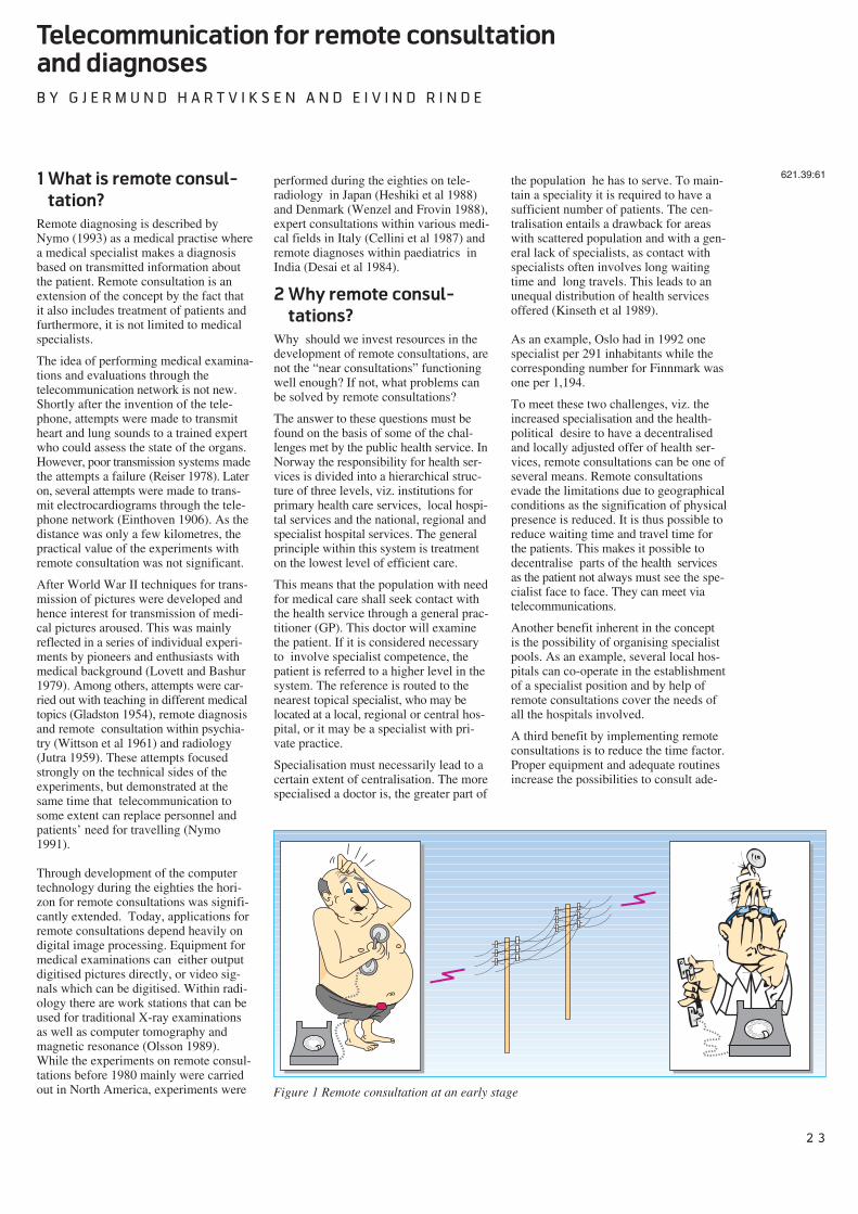
2 3
Telecommunication for remote consultation
and diagnoses
B Y G J E R M U N D H A R T V I K S E N A N D E I V I N D R I N D E
1 What is remote consul-
tation?
Remote diagnosing is described byNymo (1993) as a medical practise wherea medical specialist makes a diagnosisbased on transmitted information aboutthe patient. Remote consultation is anextension of the concept by the fact thatit also includes treatment of patients andfurthermore, it is not limited to medicalspecialists.
The idea of performing medical examina-tions and evaluations through thetelecommunication network is not new.Shortly after the invention of the tele-phone, attempts were made to transmitheart and lung sounds to a trained expertwho could assess the state of the organs.However, poor transmission systems madethe attempts a failure (Reiser 1978). Lateron, several attempts were made to trans-mit electrocardiograms through the tele-phone network (Einthoven 1906). As thedistance was only a few kilometres, thepractical value of the experiments withremote consultation was not significant.
After World War II techniques for trans-mission of pictures were developed andhence interest for transmission of medi-cal pictures aroused. This was mainlyreflected in a series of individual experi-ments by pioneers and enthusiasts withmedical background (Lovett and Bashur1979). Among others, attempts were car-ried out with teaching in different medicaltopics (Gladston 1954), remote diagnosisand remote consultation within psychia-try (Wittson et al 1961) and radiology(Jutra 1959). These attempts focusedstrongly on the technical sides of theexperiments, but demonstrated at thesame time that telecommunication tosome extent can replace personnel andpatients’ need for travelling (Nymo1991).
Through development of the computertechnology during the eighties the hori-zon for remote consultations was signifi-cantly extended. Today, applications forremote consultations depend heavily ondigital image processing. Equipment formedical examinations can either outputdigitised pictures directly, or video sig-nals which can be digitised. Within radi-ology there are work stations that can beused for traditional X-ray examinationsas well as computer tomography andmagnetic resonance (Olsson 1989).While the experiments on remote consul-tations before 1980 mainly were carriedout in North America, experiments were
performed during the eighties on tele-radiology in Japan (Heshiki et al 1988)and Denmark (Wenzel and Frovin 1988),expert consultations within various medi-cal fields in Italy (Cellini et al 1987) andremote diagnoses within paediatrics inIndia (Desai et al 1984).
2 Why remote consul-
tations?
Why should we invest resources in thedevelopment of remote consultations, arenot the “near consultations” functioningwell enough? If not, what problems canbe solved by remote consultations?
The answer to these questions must befound on the basis of some of the chal-lenges met by the public health service. InNorway the responsibility for health ser-vices is divided into a hierarchical struc-ture of three levels, viz. institutions forprimary health care services, local hospi-tal services and the national, regional andspecialist hospital services. The generalprinciple within this system is treatmenton the lowest level of efficient care.
This means that the population with needfor medical care shall seek contact withthe health service through a general prac-titioner (GP). This doctor will examinethe patient. If it is considered necessaryto involve specialist competence, thepatient is referred to a higher level in thesystem. The reference is routed to thenearest topical specialist, who may belocated at a local, regional or central hos-pital, or it may be a specialist with pri-vate practice.
Specialisation must necessarily lead to acertain extent of centralisation. The morespecialised a doctor is, the greater part of
the population he has to serve. To main-tain a speciality it is required to have asufficient number of patients. The cen-tralisation entails a drawback for areaswith scattered population and with a gen-eral lack of specialists, as contact withspecialists often involves long waitingtime and long travels. This leads to anunequal distribution of health servicesoffered (Kinseth et al 1989).
As an example, Oslo had in 1992 onespecialist per 291 inhabitants while thecorresponding number for Finnmark wasone per 1,194.
To meet these two challenges, viz. theincreased specialisation and the health-political desire to have a decentralisedand locally adjusted offer of health ser-vices, remote consultations can be one ofseveral means. Remote consultationsevade the limitations due to geographicalconditions as the signification of physicalpresence is reduced. It is thus possible toreduce waiting time and travel time forthe patients. This makes it possible todecentralise parts of the health servicesas the patient not always must see the spe-cialist face to face. They can meet viatelecommunications.
Another benefit inherent in the conceptis the possibility of organising specialistpools. As an example, several local hos-pitals can co-operate in the establishmentof a specialist position and by help ofremote consultations cover the needs ofall the hospitals involved.
A third benefit by implementing remoteconsultations is to reduce the time factor.Proper equipment and adequate routinesincrease the possibilities to consult ade-
621.39:61
Figure 1 Remote consultation at an early stage
2 4
quate expertise in case of immediatehelp.
The introduction of remote consultationsmay also entail the possibility of gradingthe importance of specialists. This isillustrated by the following example. Apatient with a sore throat first calls on ageneral practitioner with his troubles.The GP examines the patient and makeshis assessment based on his qualifica-tions. A possible assessment could bethat the patient should be examined byan ear-nose-throat specialist. Then theGP sends a reference to a specialist. Thistwofold reference/ not reference entailssome weaknesses. Among other things,the outcome depends strongly on theexperience of the GP in question. Byhelp of alternative forms of remote con-sultations it is possible to introduce agraded specialist influence. The firstlevel covers the cases where the GPfeels certain of the treatment he himselfcan give. The next level is to have a spe-cialist’s assessment whether consultationis required. The base for such assessmentcould be transmitted still pictures.
If the specialist deems it necessary, hegoes further to a remote consultationbased on video conference.
On the last level the patient has to meetto an ordinary specialist consultation.The effect of such a process is that thepatient feels confident about getting anadequate medical treatment. For the GPit means that he is able to offer an ade-quate solution. Further, it allows a trans-fer of competence from the specialist tothe GP.
3 How to perform remote
consultation
Remote consultation can be performedwithin one of the three levels in the Nor-wegian public health service, or it can becarried out between two levels. The sub-ject of remote consultation may be directtreatment of a patient, instruction or teach-ing, where the health personnel are pre-sent at both locations.
Telephone inquiries from patient to adoctor are also a kind of remote consulta-tion. With one exception, this paper willnot elaborate on this kind of remote con-sultation.
The way remote consultations are per-formed varies over a wide range. Oneextreme is within psychiatry whereskilled personnel at a child guidanceclinic treat children or whole families
through two-way sound and picture con-nection. The conversations take placewith or without skilled personnel presenttogether with the patient. For this processto function properly, the psychologist/-social worker must know the patient sheis treating. The conversation itself ismost important. It is also an advantage ifthe remote consultations can be supple-mented by “near-consultations”.
An example of the other extreme may beteleradiology, where the X-ray is takenand transmitted together with the requisi-tion. In turn, this is assessed by the radi-ologist to a certain extent independent ofinformation about the patient or in whichenvironment the picture had been taken.Most remote consultations are performedsomewhere in between these twoextremes, where medical pictures mightbe supplemented by relevant informationabout the patient.
When developing methods for remoteconsultations, one must take as a startingpoint the topical speciality and see howconsultations are performed locally andwhat sort of equipment is employed.
A lot of medical equipment producingimages exists, but not all of it producesimages that are adapted for direct tele-transmission. X-ray instruments e.g. pro-duce images on analogue film. Applica-tions for remote consultations employedare thus rather diversified. In some spe-cialities it is sufficient with still pictures,while in other cases live pictures arerequired. In some cases video sequencesof examinations can be recorded andtransmitted, while other examinationsrequire instruction and guidance by thespecialist. The demand for resolution,colours or shades of grey, as well asdemand for dynamics of the picture willvary. In addition, there are both analogueand digital picture sources. All these var-ious demands put conditions on thechoice of tele-technical solutions.
4 Remote consultations in
Northern Norway
During the time NTR has run thetelemedicine project, experience has beenmade through a series of experiments anddevelopment work within various medi-cal fields. This includes development ofmethods and products with the objectiveof giving smaller health service unitsaccess to specialist services, independentof where such competence is located. Amain collaborator has been the Univer-sity Hospital of Tromsø (UHT). This
paper basically focuses on experiencefrom remote consultations betweenregional and local hospitals, or betweenregional hospitals and the primary healthservice.
Transmission of images via differentkinds of telecommunications, mainlyvideo conferences and data communica-tion, is a central issue in remote consulta-tions. Development has reached varyingstages within individual medical disci-plines. In some disciplines there areproducts for remote consultation alreadyin daily use, whereas others are still in anearly phase of development.
5 Radiology
In radiology we have experimented withexpert consultation by video conference(VC), and with high quality image trans-fer between workstations. The consulta-tions via VC have not been on a regularbasis. The image quality in VC is notgood enough for displaying all detailsand grey levels in i.e. a thorax image. Byzooming into the region of interest andby grey scale manipulation, it has beenuseful, however, for remote educationand some kinds of remote consultationwhere more time than usual may be usedon the consultation.
To obtain diagnostic quality for a routineteleradiological service it is necessary touse high quality digitisers and monitors.We have replaced a weekly ambulatoryservice by radiologists from UHT to asmall regional clinic, Troms MilitaryClinic (TMS). The new procedureinvolves daily scanning of analoguefilms, transmission of the digital imagesto UHT, diagnostic examination on amulti-screen workstation, which isdescribed in a separate article, and digitaltransmission of dictated reports back tothe local clinic (see figure 2). We havedesigned new work procedures, andinstalled the necessary equipment.
5.1 The TMS trial
TMS is situated at Setermoen, which is160 km, or 2.5 - 3 hours car travel oneway from Tromsø. X-rays are takendaily, serving both the military and sur-rounding health centres. The averageload is 25 patients per day. In the tradi-tional procedure, a senior radiologistfrom UHT travels once a week to TMS todescribe and diagnose the previousweek’s 120 examinations. Our projectwas aimed to completely replace thisambulatory service with the transmission
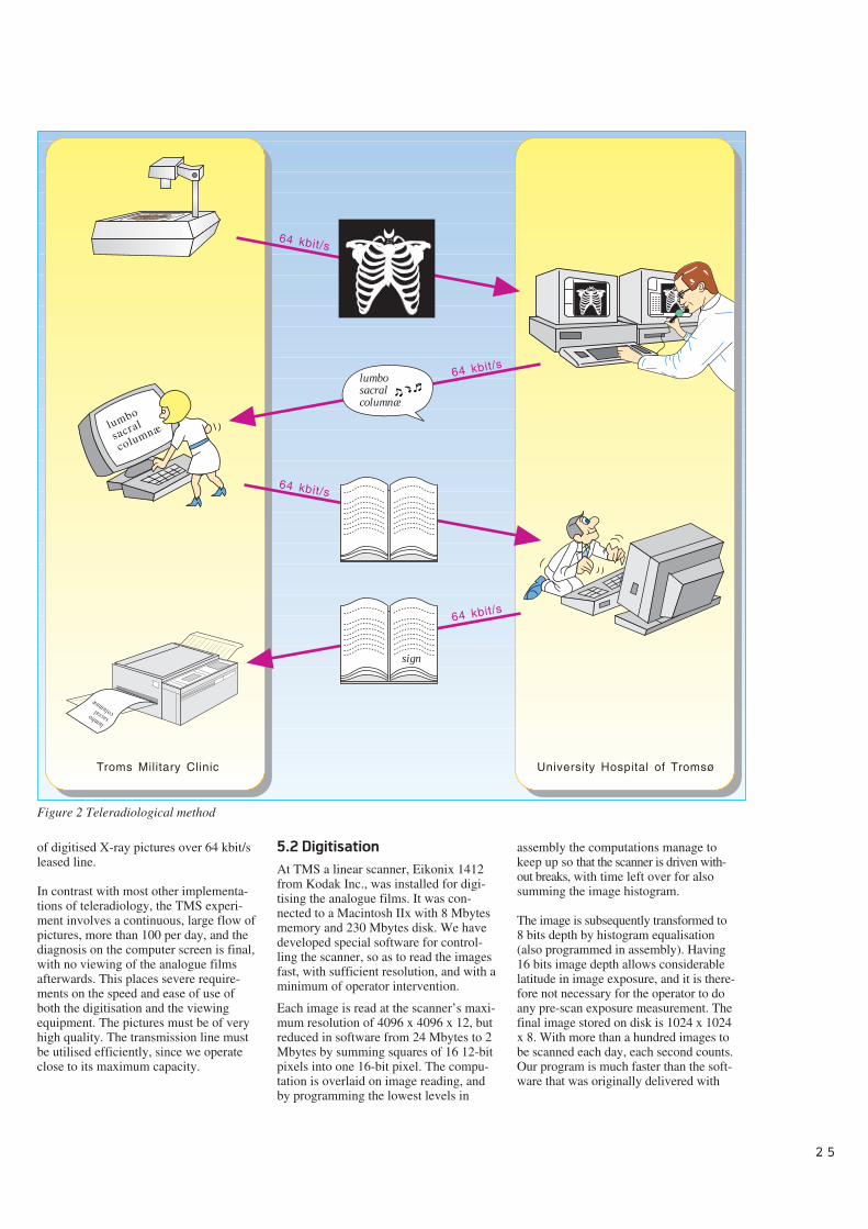
2 5
of digitised X-ray pictures over 64 kbit/sleased line.
In contrast with most other implementa-tions of teleradiology, the TMS experi-ment involves a continuous, large flow ofpictures, more than 100 per day, and thediagnosis on the computer screen is final,with no viewing of the analogue filmsafterwards. This places severe require-ments on the speed and ease of use ofboth the digitisation and the viewingequipment. The pictures must be of veryhigh quality. The transmission line mustbe utilised efficiently, since we operateclose to its maximum capacity.
5.2 Digitisation
At TMS a linear scanner, Eikonix 1412from Kodak Inc., was installed for digi-tising the analogue films. It was con-nected to a Macintosh IIx with 8 Mbytesmemory and 230 Mbytes disk. We havedeveloped special software for control-ling the scanner, so as to read the imagesfast, with sufficient resolution, and with aminimum of operator intervention.
Each image is read at the scanner’s maxi-mum resolution of 4096 x 4096 x 12, butreduced in software from 24 Mbytes to 2Mbytes by summing squares of 16 12-bitpixels into one 16-bit pixel. The compu-tation is overlaid on image reading, andby programming the lowest levels in
assembly the computations manage tokeep up so that the scanner is driven with-out breaks, with time left over for alsosumming the image histogram.
The image is subsequently transformed to8 bits depth by histogram equalisation(also programmed in assembly). Having16 bits image depth allows considerablelatitude in image exposure, and it is there-fore not necessary for the operator to doany pre-scan exposure measurement. Thefinal image stored on disk is 1024 x 1024x 8. With more than a hundred images tobe scanned each day, each second counts.Our program is much faster than the soft-ware that was originally delivered with
sign
Troms Military Clinic University Hospital of Tromsø
64 kbit/s
64 kbit/s
64 kbit/s
64 kbit/s
lumbo
sacral
columnæ
lumbosacralcolumnæ
lumbo sacral columnæ
Figure 2 Teleradiological method
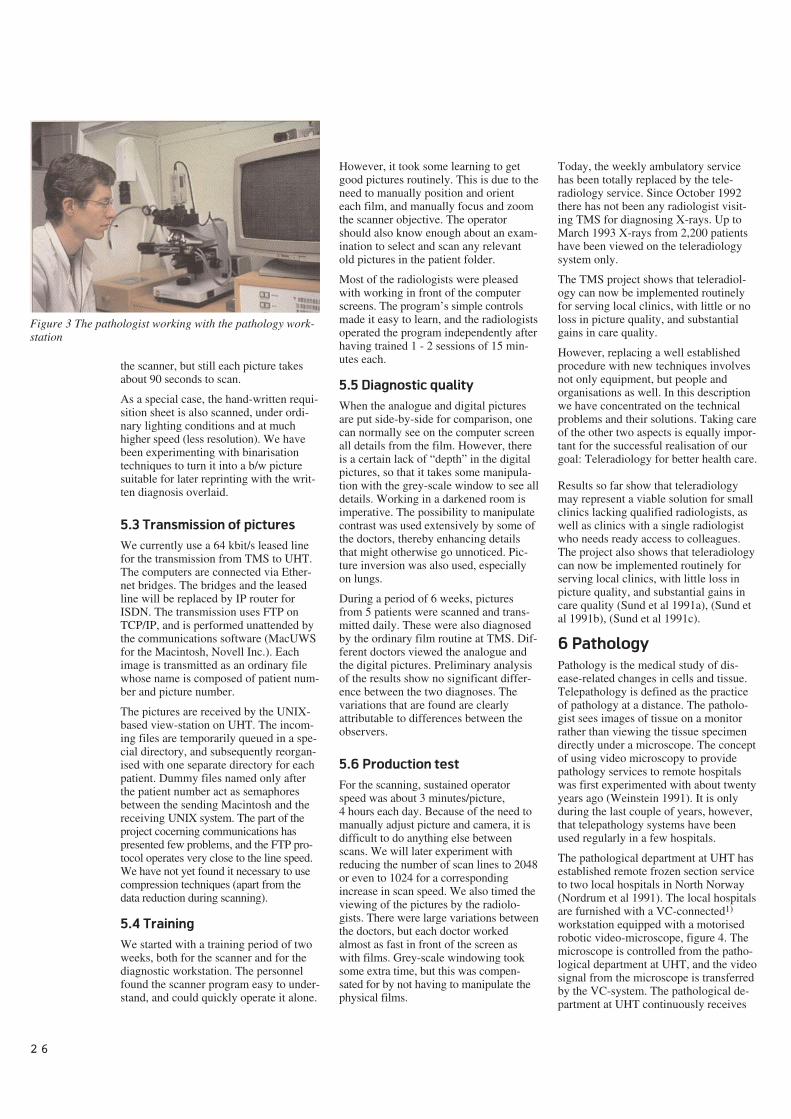
2 6
the scanner, but still each picture takesabout 90 seconds to scan.
As a special case, the hand-written requi-sition sheet is also scanned, under ordi-nary lighting conditions and at muchhigher speed (less resolution). We havebeen experimenting with binarisationtechniques to turn it into a b/w picturesuitable for later reprinting with the writ-ten diagnosis overlaid.
5.3 Transmission of pictures
We currently use a 64 kbit/s leased linefor the transmission from TMS to UHT.The computers are connected via Ether-net bridges. The bridges and the leasedline will be replaced by IP router forISDN. The transmission uses FTP onTCP/IP, and is performed unattended bythe communications software (MacUWSfor the Macintosh, Novell Inc.). Eachimage is transmitted as an ordinary filewhose name is composed of patient num-ber and picture number.
The pictures are received by the UNIX-based view-station on UHT. The incom-ing files are temporarily queued in a spe-cial directory, and subsequently reorgan-ised with one separate directory for eachpatient. Dummy files named only afterthe patient number act as semaphoresbetween the sending Macintosh and thereceiving UNIX system. The part of theproject cocerning communications haspresented few problems, and the FTP pro-tocol operates very close to the line speed.We have not yet found it necessary to usecompression techniques (apart from thedata reduction during scanning).
5.4 Training
We started with a training period of twoweeks, both for the scanner and for thediagnostic workstation. The personnelfound the scanner program easy to under-stand, and could quickly operate it alone.
However, it took some learning to getgood pictures routinely. This is due to theneed to manually position and orienteach film, and manually focus and zoomthe scanner objective. The operatorshould also know enough about an exam-ination to select and scan any relevantold pictures in the patient folder.
Most of the radiologists were pleasedwith working in front of the computerscreens. The program’s simple controlsmade it easy to learn, and the radiologistsoperated the program independently afterhaving trained 1 - 2 sessions of 15 min-utes each.
5.5 Diagnostic quality
When the analogue and digital picturesare put side-by-side for comparison, onecan normally see on the computer screenall details from the film. However, thereis a certain lack of “depth” in the digitalpictures, so that it takes some manipula-tion with the grey-scale window to see alldetails. Working in a darkened room isimperative. The possibility to manipulatecontrast was used extensively by some ofthe doctors, thereby enhancing detailsthat might otherwise go unnoticed. Pic-ture inversion was also used, especiallyon lungs.
During a period of 6 weeks, picturesfrom 5 patients were scanned and trans-mitted daily. These were also diagnosedby the ordinary film routine at TMS. Dif-ferent doctors viewed the analogue andthe digital pictures. Preliminary analysisof the results show no significant differ-ence between the two diagnoses. Thevariations that are found are clearlyattributable to differences between theobservers.
5.6 Production test
For the scanning, sustained operatorspeed was about 3 minutes/picture,4 hours each day. Because of the need tomanually adjust picture and camera, it isdifficult to do anything else betweenscans. We will later experiment withreducing the number of scan lines to 2048or even to 1024 for a correspondingincrease in scan speed. We also timed theviewing of the pictures by the radiolo-gists. There were large variations betweenthe doctors, but each doctor workedalmost as fast in front of the screen aswith films. Grey-scale windowing tooksome extra time, but this was compen-sated for by not having to manipulate thephysical films.
Today, the weekly ambulatory servicehas been totally replaced by the tele-radiology service. Since October 1992there has not been any radiologist visit-ing TMS for diagnosing X-rays. Up toMarch 1993 X-rays from 2,200 patientshave been viewed on the teleradiologysystem only.
The TMS project shows that teleradiol-ogy can now be implemented routinelyfor serving local clinics, with little or noloss in picture quality, and substantialgains in care quality.
However, replacing a well establishedprocedure with new techniques involvesnot only equipment, but people andorganisations as well. In this descriptionwe have concentrated on the technicalproblems and their solutions. Taking careof the other two aspects is equally impor-tant for the successful realisation of ourgoal: Teleradiology for better health care.
Results so far show that teleradiologymay represent a viable solution for smallclinics lacking qualified radiologists, aswell as clinics with a single radiologistwho needs ready access to colleagues.The project also shows that teleradiologycan now be implemented routinely forserving local clinics, with little loss inpicture quality, and substantial gains incare quality (Sund et al 1991a), (Sund etal 1991b), (Sund et al 1991c).
6 Pathology
Pathology is the medical study of dis-ease-related changes in cells and tissue.Telepathology is defined as the practiceof pathology at a distance. The patholo-gist sees images of tissue on a monitorrather than viewing the tissue specimendirectly under a microscope. The conceptof using video microscopy to providepathology services to remote hospitalswas first experimented with about twentyyears ago (Weinstein 1991). It is onlyduring the last couple of years, however,that telepathology systems have beenused regularly in a few hospitals.
The pathological department at UHT hasestablished remote frozen section serviceto two local hospitals in North Norway(Nordrum et al 1991). The local hospitalsare furnished with a VC-connected1)
workstation equipped with a motorisedrobotic video-microscope, figure 4. Themicroscope is controlled from the patho-logical department at UHT, and the videosignal from the microscope is transferredby the VC-system. The pathological de-partment at UHT continuously receives
Figure 3 The pathologist working with the pathology work-station
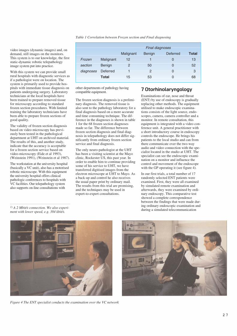
2 7
video images (dynamic images) and, ondemand, still images on the monitors.This system is to our knowledge, the firststatic-dynamic robotic telepathologyimage system put into practice.
With this system we can provide smallrural hospitals with diagnostic services asif a pathologist were on location. Thesystem is primarily used to provide hos-pitals with immediate tissue diagnosis onpatients undergoing surgery. Laboratorytechnicians at the local hospitals havebeen trained to prepare removed tissuefor microscopy according to standardfrozen section procedures. With limitedtraining the laboratory technicians havebeen able to prepare frozen sections ofgood quality.
The validity of frozen section diagnosisbased on video microscopy has previ-ously been tested in the pathologicaldepartment at UHT on archived material.The results of this, and another study,indicate that the accuracy is acceptablefor a frozen section service based onvideo-microscopy (Eide et al 1993),(Weinstein 1991), (Weinstein et al 1987).
The workstation at the university hospital(basically a VC unit), also has a motorisedrobotic microscope. With this equipmentthe university hospital offers clinicalpathologic conferences to hospitals withVC facilities. Our telepathology systemalso supports on-line consultations with
other departments of pathology havingcompatible equipment.
The frozen section diagnosis is a prelimi-nary diagnosis. The removed tissue isalso sent to the pathology laboratory for afinal diagnosis based on a more accurateand time consuming technique. The dif-ference in the diagnoses is shown in table1 for the 68 frozen section diagnosesmade so far. The difference betweenfrozen section diagnosis and final diag-nosis in telepathology does not differ sig-nificantly from ordinary frozen sectionservice and final diagnosis.
The only neuro-pathologist at the UHThas been a visiting scientist at the Mayoclinic, Rockester US, this past year. Inorder to enable him to continue providingsome of his service to UHT, we havetransferred digitised images from theelectron microscope at UHT to Mayo. Asa back-up and control he also receivesthe usual paper print by ordinary mail.The results from this trial are promising,and the techniques may be used inexpert-to-expert consultations.
7 Otorhinolaryngology
Examinations of ear, nose and throat(ENT) by use of endoscopy is graduallyreplacing other methods. The equipmentutilised to make endoscopic examina-tions consists of the light source, endo-scopes, camera, camera controller and amonitor. In remote consultation, thisequipment is integrated with a video con-ference unit. A general practitioner witha short introductory course in endoscopycontrols the endoscope. He brings hispatients to the local studio and can fromthere communicate over the two-wayaudio and video connection with the spe-cialist located in the studio at UHT. Thespecialist can see the endoscopic exami-nation on a monitor and influence thecontrol and movement of the endoscopewith the GP operating it (see figure 4).
In our first trials, a total number of 17randomly selected ENT patients wereexamined. First, they were all examinedby simulated remote examination andafterwards, they were examined by ordi-nary endoscopy. This comparative testshowed a complete correspondencebetween the findings that were made dur-ing ordinary endoscopic examination andduring a simulated telecommunication
Figure 4 The ENT specialist conducts the examination over the VC network
Final diagnoses
Malignant Benign Deferred Total
Frozen Malignant 12 1 0 13
section Benign 2 50 0 52
diagnoses Deferred 1 2 0 3
Total 15 53 0 68
Table 1 Correlation between Frozen section and Final diagnosing
1) A 2 Mbit/s connection. We also experi-ment with lower speed, e.g. 384 kbit/s.
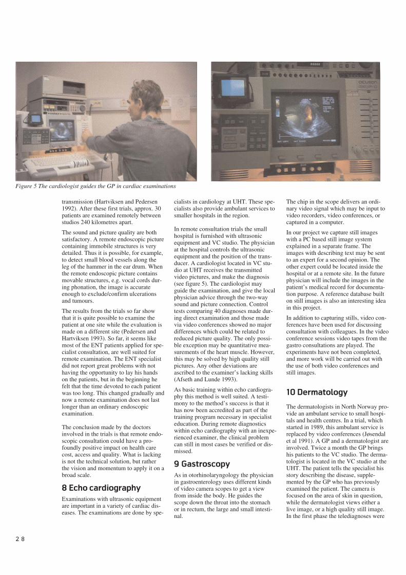
2 8
transmission (Hartviksen and Pedersen1992). After these first trials, approx. 30patients are examined remotely betweenstudios 240 kilometres apart.
The sound and picture quality are bothsatisfactory. A remote endoscopic picturecontaining immobile structures is verydetailed. Thus it is possible, for example,to detect small blood vessels along theleg of the hammer in the ear drum. Whenthe remote endoscopic picture containsmovable structures, e.g. vocal cords dur-ing phonation, the image is accurateenough to exclude/confirm ulcerationsand tumours.
The results from the trials so far showthat it is quite possible to examine thepatient at one site while the evaluation ismade on a different site (Pedersen andHartviksen 1993). So far, it seems likemost of the ENT patients applied for spe-cialist consultation, are well suited forremote examination. The ENT specialistdid not report great problems with nothaving the opportunity to lay his handson the patients, but in the beginning hefelt that the time devoted to each patientwas too long. This changed gradually andnow a remote examination does not lastlonger than an ordinary endoscopicexamination.
The conclusion made by the doctorsinvolved in the trials is that remote endo-scopic consultation could have a pro-foundly positive impact on health carecost, access and quality. What is lackingis not the technical solution, but ratherthe vision and momentum to apply it on abroad scale.
8 Echo cardiography
Examinations with ultrasonic equipmentare important in a variety of cardiac dis-eases. The examinations are done by spe-
cialists in cardiology at UHT. These spe-cialists also provide ambulant services tosmaller hospitals in the region.
In remote consultation trials the smallhospital is furnished with ultrasonicequipment and VC studio. The physicianat the hospital controls the ultrasonicequipment and the position of the trans-ducer. A cardiologist located in VC stu-dio at UHT receives the transmittedvideo pictures, and make the diagnosis(see figure 5). The cardiologist mayguide the examination, and give the localphysician advice through the two-waysound and picture connection. Controltests comparing 40 diagnoses made dur-ing direct examination and those madevia video conferences showed no majordifferences which could be related toreduced picture quality. The only possi-ble exception may be quantitative mea-surements of the heart muscle. However,this may be solved by high quality stillpictures. Any other deviations areascribed to the examiner’s lacking skills(Afseth and Lunde 1993).
As basic training within echo cardiogra-phy this method is well suited. A testi-mony to the method’s success is that ithas now been accredited as part of thetraining program necessary in specialisteducation. During remote diagnosticswithin echo cardiography with an inexpe-rienced examiner, the clinical problemcan still in most cases be verified or dis-missed.
9 Gastroscopy
As in otorhinolaryngology the physicianin gastroenterology uses different kindsof video camera scopes to get a viewfrom inside the body. He guides thescope down the throat into the stomachor in rectum, the large and small intesti-nal.
The chip in the scope delivers an ordi-nary video signal which may be input tovideo recorders, video conferences, orcaptured in a computer.
In our project we capture still imageswith a PC based still image systemexplained in a separate frame. Theimages with describing text may be sentto an expert for a second opinion. Theother expert could be located inside thehospital or at a remote site. In the futurephysician will include the images in thepatient’s medical record for documenta-tion purpose. A reference database builton still images is also an interesting ideain this project.
In addition to capturing stills, video con-ferences have been used for discussingconsultation with colleagues. In the videoconference sessions video tapes from thegastro consultations are played. Theexperiments have not been completed,and more work will be carried out withthe use of both video conferences andstill images.
10 Dermatology
The dermatologists in North Norway pro-vide an ambulant service to small hospi-tals and health centres. In a trial, whichstarted in 1989, this ambulant service isreplaced by video conferences (Jøsendalet al 1991). A GP and a dermatologist areinvolved. Twice a month the GP bringshis patients to the VC studio. The derma-tologist is located in the VC studio at theUHT. The patient tells the specialist hisstory describing the disease, supple-mented by the GP who has previouslyexamined the patient. The camera isfocused on the area of skin in question,while the dermatologist views either alive image, or a high quality still image.In the first phase the telediagnoses were
Figure 5 The cardiologist guides the GP in cardiac examinations
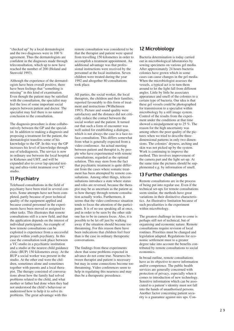
2 9
“checked up” by a local dermatologistand the two diagnoses were in 100 %agreement. Thus the dermatologists areconfident in the diagnoses made throughteleconsultation, which up to now havereached the number of 200 (Holand andStenvold 1993).
Although the experience of the dermatol-ogists have been overall positive, therehave been feelings that “something ismissing” in this kind of examination.Even though the patient may be satisfiedwith the consultation, the specialist mayfeel the loss of some important socialaspects between patient and doctor. Thespecialist may feel there is no naturalconclusion to the consultation.
The diagnosis procedure is done collabo-ratively between the GP and the special-ist. In addition to making a diagnosis andproposing a treatment for the patient, thedermatologist transfers some of hisknowledge to the GP. In this way the GPincreases his level of knowledge throughuse of telediagnosis. The service is nowin ordinary use between the local hospitalin Kirkenes and UHT, and will beexpanded also to cover lap epicutal test-ing and ultra-violet treatment over VCstudio.
11 Psychiatry
Telebased consultations in the field ofpsychiatry have been tried in several con-texts. Some attempts have not been com-pleted, partly because of poor technicalquality of the equipment applied andbecause central personnel in the experi-ments have been moved or assigned toother tasks. This illustrates that remoteconsultations still is a new field, and thatthe application depends on the interest ofindividual participants. An example ofhow remote consultations can beexploited is experience from a successfulproject within youth psychiatry. In thiscase the consultation took place betweena VC-studio in a psychiatric institutionand a studio at the nearest child guidanceclinic (BUP) 150 kilometres away. At theBUP a social worker was present in thestudio. At the other end were the chil-dren, sometimes alone and sometimestogether with parents and a local thera-pist. The therapy consisted of conversa-tions about how the family had solvedproblems related to the child, and whatmother or father had done when they hadnot understood the child’s behaviour orunderstood how to help it to solve itsproblems. The great advantage with this
remote consultation was considered to bethat the therapist and patient were sparedfrom travelling 150 kilometres in order toaccomplish a treatment appointment. Anadditional advantage was that profes-sional instructions were received by thepersonnel at the local institution. Sevenchildren were treated during the year1992 and altogether 80 consultationstook place.
All parties, the social worker, the localtherapists, the children and their families,reported favourably to this form of treat-ment and instructions (Wilhelmsen1993). Picture and sound quality weresatisfactory and the distance did not criti-cally reduce the contact between thesocial worker and the patient. It turnedout that such a form of encounter waswell suited for establishing a dialogue,which is not always the case in a face-to-face consultation. This differs somewhatfrom what is generally expected from avideo conference. An actual meetingbetween patient and therapist is, by peo-ple who have experimented with remoteconsultations, regarded as the optimalsolution. This may stem from the factthat psychiatric treatment is quite differ-ent from the cases where somatic treat-ment has been attempted by remote con-sultations. Among other things, telecon-sultations introduce a state where statusand roles are reversed, because the thera-pist may be as uncertain as the patient asto how therapy through remote consulta-tion actually works. Furthermore, itseems that the video conference situationtends to focus the attention of the partici-pants. It is of no use speaking all at once,and in order to be seen by the other sideone has to be in camera focus. Also, it ispossible to be let off just by walkingaway if the situation should become toothreatening. For this reason there havebeen indications that children feel freerthan is the case in ordinary therapeuticconversations.
The findings from these experimentsshow that some problems expected inadvance do not come true. Nearness be-tween therapist and patient is necessarybut may in some connections become toothreatening. Video conferences seem tohelp in regulating this nearness and maythus be a therapeutic presedence.
12 Microbiology
Bacteria determination is today carriedout in microbiological laboratories bysowing specimens on various gel media.After approximately 24 hours bacteriacolonies have grown which in somecases can cause changes in the gel media.When the microbiologist assesses thevessels, a typical act is to turn themaround to let the light fall from differentangles. Little by little he associatesappearance and smell of the colonies to acertain type of bacteria. Our idea is thatthese gel vessels could be photographedfor transmission to a specialist withinmicrobiology by a still image system.Control of the results from the experi-ment under the conditions at that timeshowed a misjudgement up to 25 %. Thereason for the high uncertainty wasamong others the poor quality of the pic-tures when we tried to describe three-dimensional patterns in only two dimen-sions. The colonies’ dryness, arching andskin was not picked up by the system.Work is continuing to improve themethod. This involves improvement ofthe camera part and the light set-up. Atthe same time the pictures should be sup-plemented e.g. by information of smell.
13 Further challenges
Remote consultations are in the processof being put into regular use. Even if thetechnical set-ups for remote consultationsseem similar, the methods have greatvariations in their distinctive characteris-tics. An illustrative limitation because ofsuch peculiarities is the experimentwithin microbiology.
The greatest challenge in time to come isperhaps still not of technical, but oforganising and economic nature. Remoteconsultations require revision of localroutines. Priorities must be changed andlegislation adapted. Regulations for eco-nomic settlement must to a greaterdegree take into account the benefits con-tributed by remote consultations to socialeconomics.
In broad outline, remote consultationshave as its objective to move informationand/or competence. The public healthservices are generally concerned withprotection of privacy, especially when itcomes to introduction of new technology.Sensitive information which can be asso-ciated to a patient’s identity must not fallinto the hands of unauthorised persons.Another factor concerning patient secu-rity is a guarantee against mix ups. Con-
3 0
cerning transmission of medical informa-tion through remote consultations, pro-tection of privacy is fairly well taken careof. On the other hand, it is a wish by themedical profession that informationshould be stored for later consultations,statistics, research, etc. This introduces anew approach to the problem regardinghow this information should be managed.The problem of data storage within thehealth care is far from solved and theprocess of archiving images electroni-cally has just begun. Use of remoteconsultations will be a driving force inthis process.
14 Concluding remarks
Experiments in Northern Norway over aperiod of four years have shown thatremote consultations are possible. Withinsome medical fields this method of prac-tising is also in daily use. Remote consul-tations are still at an early stage, and theexamples quoted in this paper are basedon just a few experiments. Furthermore,we have reasons to believe that the per-sons who have been willing to try outremote consultations have been wellmotivated. Therefore we must be openfor the emergence of new applicationsand new objections when remote consul-tations are taken into use within othermedical fields.
15 References
Afseth, J E, Lunde, P. 1993. Teleechocar-diography: remote instruction in echocar-diography via video conferences. Oral pre-sentation on First International Conferenceon Medical Aspects of Telemedicine,Tromsø, Norway, 21 May 1993.
Cellini, N et al. 1987. Teleconsultation:four years of experience. Rays, 12, 89-95.
Desai, A B et al. 1984. Telemedicine: afeasibility experiment for national appli-cation. Indian Paediatrics, 21, 773-775.
Eide, T J, Nordrum, I, Stalsberg, H.1993. The validity of frozen section diag-nosis based on video microscopy. Zen-tralblatt für Pathologie, 138, 405-407.
Einthoven, W. 1906. Het telecardiogram.Nederlands Tijdschrift voor Gee-neskunde, 50, 1517-1547.
Gammon, D. 1991. Telemedicine inNorth Norway. Kjeller, Norwegian Tele-com Research. (NTR Report R27/91.)
Gladston, J. 1954. What have radio andtelevision to contribute to continuingmedical education? Journal of MedicalEducation, 29, 28-30.
Hartviksen, G, Pedersen, S. 1992.Remote endoscopy of otorhinolaryngol-ogy. SPIE Proc., 1649.
Heshiki, A et al. 1988. Teleradiology atGunma University Hospital. MedicalInformatics, 13, 295-301.
Holand, U, Stenvold, S E. 1993. Are thepatients satisfied with teledermatologicalconsultations? Oral presentation on FirstInternational Conference on MedicalAspects of Telemedicine, Tromsø, Nor-way, 21 May 1993.
Jutra, A. 1959. Teleroentgen diagnosisby means of videotape recording (Edito-rial). American Journal of Roentgenol-ogy, 82, 1099-1102.
Jøsendal, O et al. 1991. Long distancediagnosis of skin diseases. Journal of theNorwegian Medical Association, 111,20-22.
Kindseth, O et al. 1989. Sammenlign-ingsdata for somatiske sykehus. Trond-heim: Norsk Institutt for Sykehusforskn-ing, NIS-report No. 7.
Lovett, J E, Bashur, R L. 1979.Telemedicine in USA: an overview.Telecommunication Policy, 3, 3-14.
Nordrum, I et al. 1991. Remote frozensection service: a telepathology project inNorthern Norway. Human Pathology, 22,514-518.
VIDA – a still picture system
The project has developed a PC-based system for the collection, storage, and trans-mission of still pictures through the telecommunication network. The system isdeveloped especially with a view to being applied within medicine. A standardframe-grabber card and self-developed software constitutes the system. The soft-ware consists of three modules which reflect the usage. From a video input sourcethe frame-grabber module continuously grabs the still pictures from the consulta-tion and stores the digitised pictures on the hard disk. Only this module depends onthe special hardware. Through the editing module the doctor can inspect the pic-tures, comment on each picture and on the whole series in the form of text. Thesystem is adapted to transmission by both V.32 and V.32-bis modems and throughISDN. In order to reduce transmission and storage costs series of pictures are com-pressed. To this end a program based on the JPEG algorithm is employed. Thedegree of compression varies from 1:30 to 1:50. This implies that a full screen pic-ture is compressed from approximately 1 Mbyte to approximately 20 kbyte. Therecipient receives the consultation and can assess the pictures and text associatedwith the series with the help of the editing module. Among other things, the systemis used for experiments within gastroscopy, endoscopy, and microbiology.
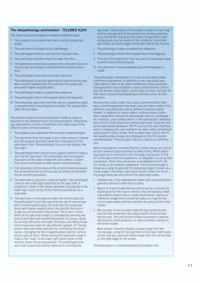
3 1
specimen. The location of the marks is shown on the “map”and he may go back to this position by clicking, pointingand clicking the mouse on the marks. Images from inter-esting areas may be saved on the computer’s hard diskand shown as small images in the right half of the monitor.
7 The pathologist makes a preliminary diagnosis.
8 The pathologist informs the surgeon about the diagnosis.
9 The rest of the specimen from the cancer suspected organis sent to the central hospital.
10 The specimen is here prepared and a final diagnosis ismade.
The pathologist’s workstation is in fact a specialised videoconference equipment. In addition to two-way audio andvideo, which is part of all video conference communication,the equipment must establish a data connection for control-ling the remote video switch, microscope controls, the light forthe macro camera and displaying of remote cursor at bothlocations.
Almost every video codec has a data communication inter-face, and the equipment has been used on video codecs fromdifferent manufacturers and at different communicationspeeds. In addition to video codecs, ordinary video confer-ence equipment consists of video/audio sources, loudspeak-ers, monitors, and a video switch. In the pathologist’s worksta-tion all this is built around an ordinary personal computer andsome specialised hardware. The PC acts as the user interfaceand so changing the user interface for other video conferenceapplications is fairly simple. With a video input card in the PCtwo relating video images are displayed on the PC monitorsimultaneously. These images may be scaled to an arbitrarysize.
When the program is started the first screen brings up a list ofactual communication partners to select from. When select-ing a partner a command is sent through a serial port of thePC to the data terminal equipment, i.e. MegaNet, to set up theconnection. When the connection is established the PC willact nearly as an ordinary viewphone. The incoming image isshown as a large image and the outgoing image is shown as asmall image in the lower right hand corner. Under the incom-ing image there are soft buttons for selecting modes.
1 Videophone. In the videophone mode both communicationpartners see each other face to face.
2 Macro. In macro mode the big control button controls theillumination for the macro camera. The soft buttons makeit possible to select over or under illumination, capture areference image which should be used as a map for themicroscope modes and has a button for going to the othermodes.
3 Microscope. In microscope mode the big control buttoncontrols the movement and adjustments of the remotemicroscope. The soft buttons make it possible to capturestill pictures, mark positions, re-select position, and go tothe other modes.
Both parties’ monitors display a large image from themicroscope, a map of the specimen in the lower right handcorner and any captured small image from the microscopeon the right edge of the screen.
The workstation is commercialised by NovaKom A/S.
The telepathology workstation - TELEMED A200
The frozen section procedure is made of different parts.
1 The surgeon cuts a specimen from a cancer suspectedorgan.
2 The specimen is brought to the pathologist.
3 The pathologist looks at and touches the specimen.
4 The pathologist decides where to make the slice.
5 The laboratory technicians prepare the removed tissue formicroscopy according to standard frozen section proce-dure.
6 The pathologist looks directly at the specimen.
7 The pathologist scans the specimen by use of microscopewith a small magnification. He searches the suspectedareas with higher magnification.
8 The pathologist makes a preliminary diagnosis.
9 The pathologist informs the surgeon about the diagnosis.
10 The remaining specimen from the cancer suspected organis prepared and a final diagnosis is made. This preparationtakes several days.
The remote frozen section procedure is made as close aspossible to the ordinary frozen section procedure. The pathol-ogy workstation consists of elements that takes care of thedifferent parts of the procedure.
1 The surgeon cuts a specimen from a cancer suspected organ.
2 The specimen from the organ is put under a macro cameraand the surgeon describes what the consistency of thespecimen is like. The pathologist turns on and adjusts theover light.
3 The pathologist then instructs the surgeon where to make aslice for the specimen. The pathologist and the surgeonmay point at the video image with each others’ cursors.The cursors are shown at both places simultaneously.
4 The laboratory technicians at the remote hospital preparethe removed tissue for microscopy according to standardfrozen section procedure.
5 The specimen is placed in a special holder. The pathologistturns on the under light and looks at the specimen. Asnapshot is taken of the whole specimen and placed in thelower right hand corner of the monitor and will act as amap later.
6 The specimen is then placed under the microscope andthe pathologist scans the specimen by use of microscopewith a small magnification. He searches the suspectedareas with higher magnification. He controls the micro-scope by use of a kind of big button. The X and Y move-ment of the specimen stage is controlled by pressing thebutton left/right and forward/backward. Focusing is doneby turning the button left/right. All these controlling move-ments have two steps for two different speeds. On the bigbutton there are three switches for controlling the illumi-nation, changing the lens (magnification) and for control-ling an optical zoom. While moving the specimen stage amark in the “map” in the lower right hand corner of themonitor shows the actual position. The pathologist mayalso mark suspected position while he is scanning the
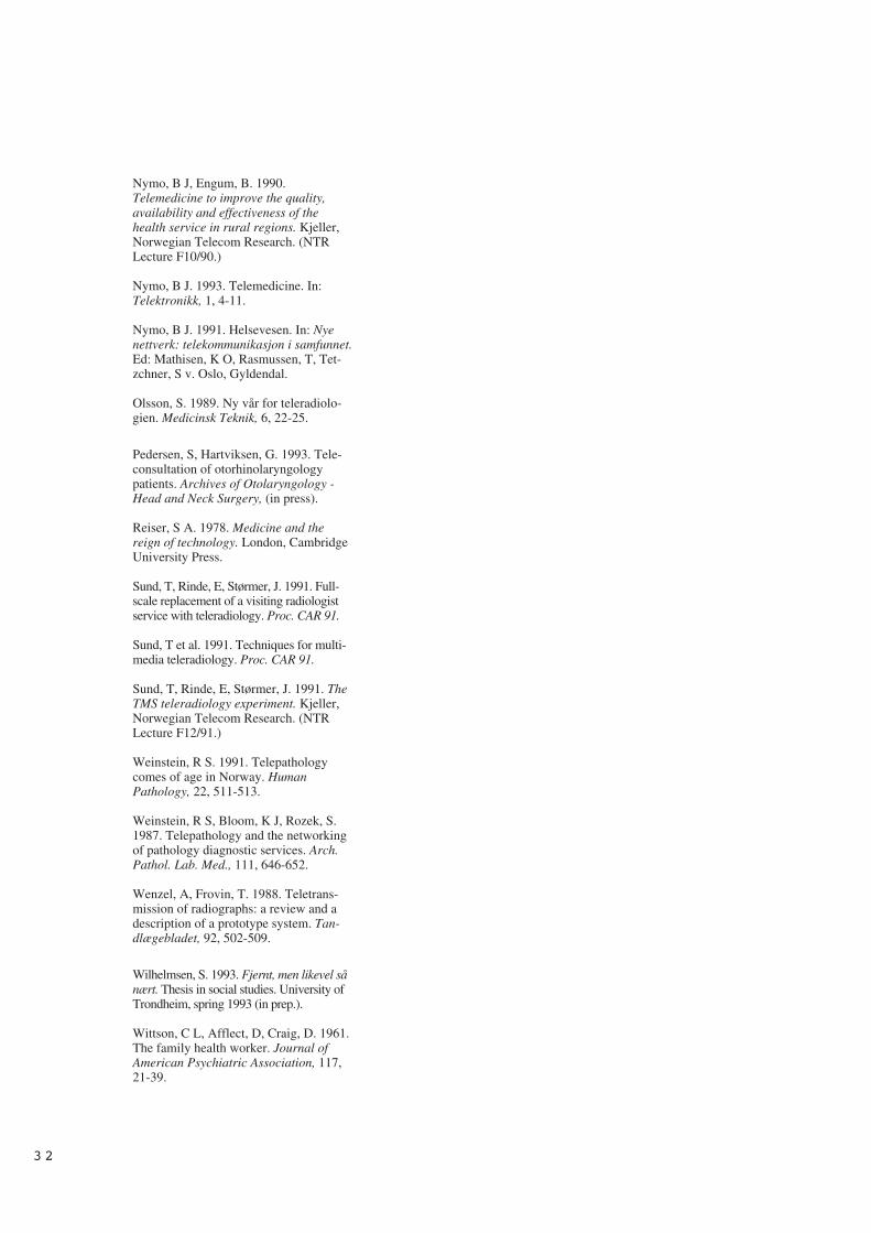
Nymo, B J, Engum, B. 1990.Telemedicine to improve the quality,availability and effectiveness of thehealth service in rural regions. Kjeller,Norwegian Telecom Research. (NTRLecture F10/90.)
Nymo, B J. 1993. Telemedicine. In:Telektronikk, 1, 4-11.
Nymo, B J. 1991. Helsevesen. In: Nyenettverk: telekommunikasjon i samfunnet.Ed: Mathisen, K O, Rasmussen, T, Tet-zchner, S v. Oslo, Gyldendal.
Olsson, S. 1989. Ny vår for teleradiolo-gien. Medicinsk Teknik, 6, 22-25.
Pedersen, S, Hartviksen, G. 1993. Tele-consultation of otorhinolaryngologypatients. Archives of Otolaryngology -Head and Neck Surgery, (in press).
Reiser, S A. 1978. Medicine and thereign of technology. London, CambridgeUniversity Press.
Sund, T, Rinde, E, Størmer, J. 1991. Full-scale replacement of a visiting radiologistservice with teleradiology. Proc. CAR 91.
Sund, T et al. 1991. Techniques for multi-media teleradiology. Proc. CAR 91.
Sund, T, Rinde, E, Størmer, J. 1991. TheTMS teleradiology experiment. Kjeller,Norwegian Telecom Research. (NTRLecture F12/91.)
Weinstein, R S. 1991. Telepathologycomes of age in Norway. HumanPathology, 22, 511-513.
Weinstein, R S, Bloom, K J, Rozek, S.1987. Telepathology and the networkingof pathology diagnostic services. Arch.Pathol. Lab. Med., 111, 646-652.
Wenzel, A, Frovin, T. 1988. Teletrans-mission of radiographs: a review and adescription of a prototype system. Tan-dlægebladet, 92, 502-509.
Wilhelmsen, S. 1993. Fjernt, men likevel sånært. Thesis in social studies. University ofTrondheim, spring 1993 (in prep.).
Wittson, C L, Afflect, D, Craig, D. 1961.The family health worker. Journal ofAmerican Psychiatric Association, 117,21-39.
3 2
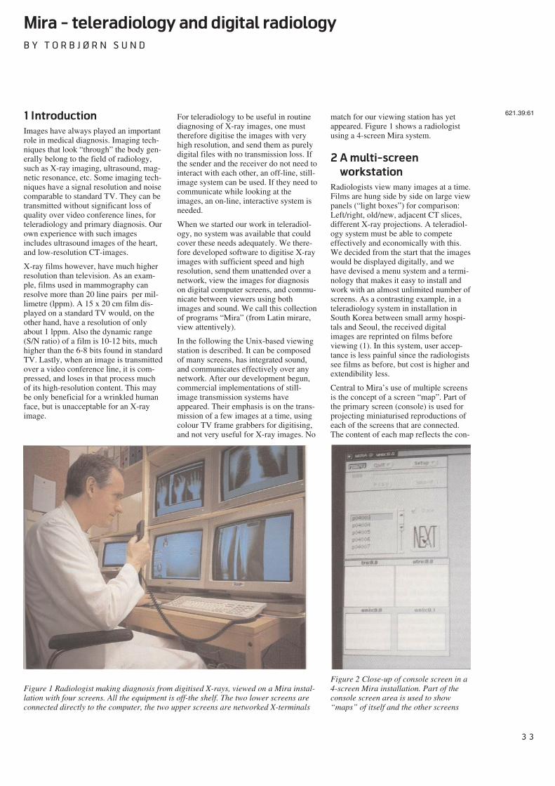
3 3
Mira - teleradiology and digital radiology
B Y T O R B J Ø R N S U N D
1 Introduction
Images have always played an importantrole in medical diagnosis. Imaging tech-niques that look “through” the body gen-erally belong to the field of radiology,such as X-ray imaging, ultrasound, mag-netic resonance, etc. Some imaging tech-niques have a signal resolution and noisecomparable to standard TV. They can betransmitted without significant loss ofquality over video conference lines, forteleradiology and primary diagnosis. Ourown experience with such imagesincludes ultrasound images of the heart,and low-resolution CT-images.
X-ray films however, have much higherresolution than television. As an exam-ple, films used in mammography canresolve more than 20 line pairs per mil-limetre (lppm). A 15 x 20 cm film dis-played on a standard TV would, on theother hand, have a resolution of onlyabout 1 lppm. Also the dynamic range(S/N ratio) of a film is 10-12 bits, muchhigher than the 6-8 bits found in standardTV. Lastly, when an image is transmittedover a video conference line, it is com-pressed, and loses in that process muchof its high-resolution content. This maybe only beneficial for a wrinkled humanface, but is unacceptable for an X-rayimage.
For teleradiology to be useful in routinediagnosing of X-ray images, one musttherefore digitise the images with veryhigh resolution, and send them as purelydigital files with no transmission loss. Ifthe sender and the receiver do not need tointeract with each other, an off-line, still-image system can be used. If they need tocommunicate while looking at theimages, an on-line, interactive system isneeded.
When we started our work in teleradiol-ogy, no system was available that couldcover these needs adequately. We there-fore developed software to digitise X-rayimages with sufficient speed and highresolution, send them unattended over anetwork, view the images for diagnosison digital computer screens, and commu-nicate between viewers using bothimages and sound. We call this collectionof programs “Mira” (from Latin mirare,view attentively).
In the following the Unix-based viewingstation is described. It can be composedof many screens, has integrated sound,and communicates effectively over anynetwork. After our development begun,commercial implementations of still-image transmission systems haveappeared. Their emphasis is on the trans-mission of a few images at a time, usingcolour TV frame grabbers for digitising,and not very useful for X-ray images. No
match for our viewing station has yetappeared. Figure 1 shows a radiologistusing a 4-screen Mira system.
2 A multi-screen
workstation
Radiologists view many images at a time.Films are hung side by side on large viewpanels (“light boxes”) for comparison:Left/right, old/new, adjacent CT slices,different X-ray projections. A teleradiol-ogy system must be able to competeeffectively and economically with this.We decided from the start that the imageswould be displayed digitally, and wehave devised a menu system and a termi-nology that makes it easy to install andwork with an almost unlimited number ofscreens. As a contrasting example, in ateleradiology system in installation inSouth Korea between small army hospi-tals and Seoul, the received digitalimages are reprinted on films beforeviewing (1). In this system, user accep-tance is less painful since the radiologistssee films as before, but cost is higher andextendibility less.
Central to Mira’s use of multiple screensis the concept of a screen “map”. Part ofthe primary screen (console) is used forprojecting miniaturised reproductions ofeach of the screens that are connected.The content of each map reflects the con-
621.39:61
Figure 1 Radiologist making diagnosis from digitised X-rays, viewed on a Mira instal-lation with four screens. All the equipment is off-the shelf. The two lower screens areconnected directly to the computer, the two upper screens are networked X-terminals
Figure 2 Close-up of console screen in a4-screen Mira installation. Part of theconsole screen area is used to show“maps” of itself and the other screens
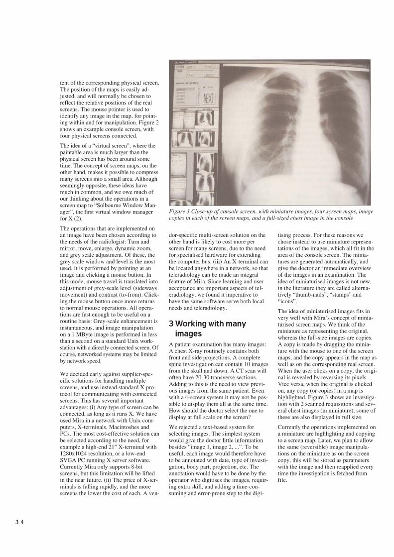
3 4
tent of the corresponding physical screen.The position of the maps is easily ad-justed, and will normally be chosen toreflect the relative positions of the realscreens. The mouse pointer is used toidentify any image in the map, for point-ing within and for manipulation. Figure 2shows an example console screen, withfour physical screens connected.
The idea of a “virtual screen”, where thepaintable area is much larger than thephysical screen has been around sometime. The concept of screen maps, on theother hand, makes it possible to compressmany screens into a small area. Althoughseemingly opposite, these ideas havemuch in common, and we owe much ofour thinking about the operations in ascreen map to “Solbourne Window Man-ager”, the first virtual window managerfor X (2).
The operations that are implemented onan image have been chosen according tothe needs of the radiologist: Turn andmirror, move, enlarge, dynamic zoom,and grey scale adjustment. Of these, thegrey scale window and level is the mostused. It is performed by pointing at animage and clicking a mouse button. Inthis mode, mouse travel is translated intoadjustment of grey-scale level (sidewaysmovement) and contrast (to-from). Click-ing the mouse button once more returnsto normal mouse operations. All opera-tions are fast enough to be useful on aroutine basis: Grey-scale enhancement isinstantaneous, and image manipulationon a 1 MByte image is performed in lessthan a second on a standard Unix work-station with a directly connected screen. Ofcourse, networked systems may be limitedby network speed.
We decided early against supplier-spe-cific solutions for handling multiplescreens, and use instead standard X pro-tocol for communicating with connectedscreens. This has several importantadvantages: (i) Any type of screen can beconnected, as long as it runs X. We haveused Mira in a network with Unix com-puters, X-terminals, Macintoshes andPCs. The most cost-effective solution canbe selected according to the need, forexample a high-end 21" X-terminal with1280x1024 resolution, or a low-endSVGA PC running X server software.Currently Mira only supports 8-bitscreens, but this limitation will be liftedin the near future. (ii) The price of X-ter-minals is falling rapidly, and the morescreens the lower the cost of each. A ven-
dor-specific multi-screen solution on theother hand is likely to cost more perscreen for many screens, due to the needfor specialised hardware for extendingthe computer bus. (iii) An X-terminal canbe located anywhere in a network, so thatteleradiology can be made an integralfeature of Mira. Since learning and useracceptance are important aspects of tel-eradiology, we found it imperative tohave the same software serve both localneeds and teleradiology.
3 Working with many
images
A patient examination has many images:A chest X-ray routinely contains bothfront and side projections. A completespine investigation can contain 10 imagesfrom the skull and down. A CT scan willoften have 20-30 transverse sections.Adding to this is the need to view previ-ous images from the same patient. Evenwith a 4-screen system it may not be pos-sible to display them all at the same time.How should the doctor select the one todisplay at full scale on the screen?
We rejected a text-based system forselecting images. The simplest systemwould give the doctor little informationbesides “image 1, image 2, ...”. To beuseful, each image would therefore haveto be annotated with date, type of investi-gation, body part, projection, etc. Theannotation would have to be done by theoperator who digitises the images, requir-ing extra skill, and adding a time-con-suming and error-prone step to the digi-
tising process. For these reasons wechose instead to use miniature represen-tations of the images, which all fit in thearea of the console screen. The minia-tures are generated automatically, andgive the doctor an immediate overviewof the images in an examination. Theidea of miniaturised images is not new,in the literature they are called alterna-tively “thumb-nails”, “stamps” and“icons”.
The idea of miniaturised images fits invery well with Mira’s concept of minia-turised screen maps. We think of theminiature as representing the original,whereas the full-size images are copies.A copy is made by dragging the minia-ture with the mouse to one of the screenmaps, and the copy appears in the map aswell as on the corresponding real screen.When the user clicks on a copy, the origi-nal is revealed by reversing its pixels.Vice versa, when the original is clickedon, any copy (or copies) in a map ishighlighted. Figure 3 shows an investiga-tion with 2 scanned requisitions and sev-eral chest images (in miniature), some ofthese are also displayed in full size.
Currently the operations implemented ona miniature are highlighting and copyingto a screen map. Later, we plan to allowthe same (reversible) image manipula-tions on the miniature as on the screencopy, this will be stored as parameterswith the image and then reapplied everytime the investigation is fetched fromfile.
Figure 3 Close-up of console screen, with miniature images, four screen maps, imagecopies in each of the screen maps, and a full-sized chest image in the console
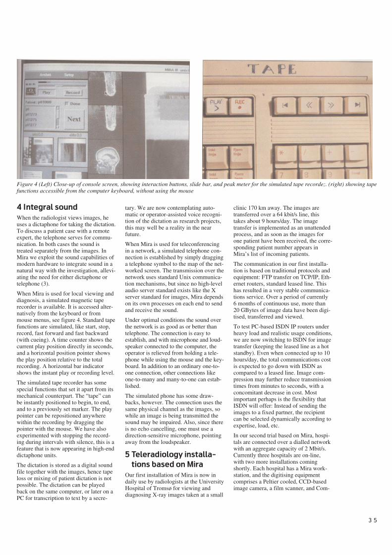
3 5
4 Integral sound
When the radiologist views images, heuses a dictaphone for taking the dictation.To discuss a patient case with a remoteexpert, the telephone serves for commu-nication. In both cases the sound istreated separately from the images. InMira we exploit the sound capabilities ofmodern hardware to integrate sound in anatural way with the investigation, allevi-ating the need for either dictaphone ortelephone (3).
When Mira is used for local viewing anddiagnosis, a simulated magnetic taperecorder is available. It is accessed alter-natively from the keyboard or frommouse menus, see figure 4. Standard tapefunctions are simulated, like start, stop,record, fast forward and fast backward(with cueing). A time counter shows thecurrent play position directly in seconds,and a horizontal position pointer showsthe play position relative to the totalrecording. A horizontal bar indicatorshows the instant play or recording level.
The simulated tape recorder has somespecial functions that set it apart from itsmechanical counterpart. The “tape” canbe instantly positioned to begin, to end,and to a previously set marker. The playpointer can be repositioned anywherewithin the recording by dragging thepointer with the mouse. We have alsoexperimented with stopping the record-ing during intervals with silence, this is afeature that is now appearing in high-enddictaphone units.
The dictation is stored as a digital soundfile together with the images, hence tapeloss or mixing of patient dictation is notpossible. The dictation can be playedback on the same computer, or later on aPC for transcription to text by a secre-
tary. We are now contemplating auto-matic or operator-assisted voice recogni-tion of the dictation as research projects,this may well be a reality in the nearfuture.
When Mira is used for teleconferencingin a network, a simulated telephone con-nection is established by simply dragginga telephone symbol to the map of the net-worked screen. The transmission over thenetwork uses standard Unix communica-tion mechanisms, but since no high-levelaudio server standard exists like the Xserver standard for images, Mira dependson its own processes on each end to sendand receive the sound.
Under optimal conditions the sound overthe network is as good as or better thantelephone. The connection is easy toestablish, and with microphone and loud-speaker connected to the computer, theoperator is relieved from holding a tele-phone while using the mouse and the key-board. In addition to an ordinary one-to-one connection, other connections likeone-to-many and many-to-one can estab-lished.
The simulated phone has some draw-backs, however. The connection uses thesame physical channel as the images, sowhile an image is being transmitted thesound may be impaired. Also, since thereis no echo cancelling, one must use adirection-sensitive microphone, pointingaway from the loudspeaker.
5 Teleradiology installa-
tions based on Mira
Our first installation of Mira is now indaily use by radiologists at the UniversityHospital of Tromsø for viewing anddiagnosing X-ray images taken at a small
clinic 170 km away. The images aretransferred over a 64 kbit/s line, thistakes about 9 hours/day. The imagetransfer is implemented as an unattendedprocess, and as soon as the images forone patient have been received, the corre-sponding patient number appears inMira’s list of incoming patients.
The communication in our first installa-tion is based on traditional protocols andequipment: FTP transfer on TCP/IP, Eth-ernet routers, standard leased line. Thishas resulted in a very stable communica-tions service. Over a period of currently6 months of continuous use, more than20 GBytes of image data have been digi-tised, transferred and viewed.
To test PC-based ISDN IP routers underheavy load and realistic usage conditions,we are now switching to ISDN for imagetransfer (keeping the leased line as a hotstandby). Even when connected up to 10hours/day, the total communications costis expected to go down with ISDN ascompared to a leased line. Image com-pression may further reduce transmissiontimes from minutes to seconds, with aconcomitant decrease in cost. Mostimportant perhaps is the flexibility thatISDN will offer: Instead of sending theimages to a fixed partner, the recipientcan be selected dynamically according toexpertise, load, etc.
In our second trial based on Mira, hospi-tals are connected over a dialled networkwith an aggregate capacity of 2 Mbit/s.Currently three hospitals are on-line,with two more installations comingshortly. Each hospital has a Mira work-station, and the digitising equipmentcomprises a Peltier cooled, CCD-basedimage camera, a film scanner, and Com-
Figure 4 (Left) Close-up of console screen, showing interaction buttons, slide bar, and peak meter for the simulated tape recorde;. (right) showing tapefunctions accessible from the computer keyboard, without using the mouse
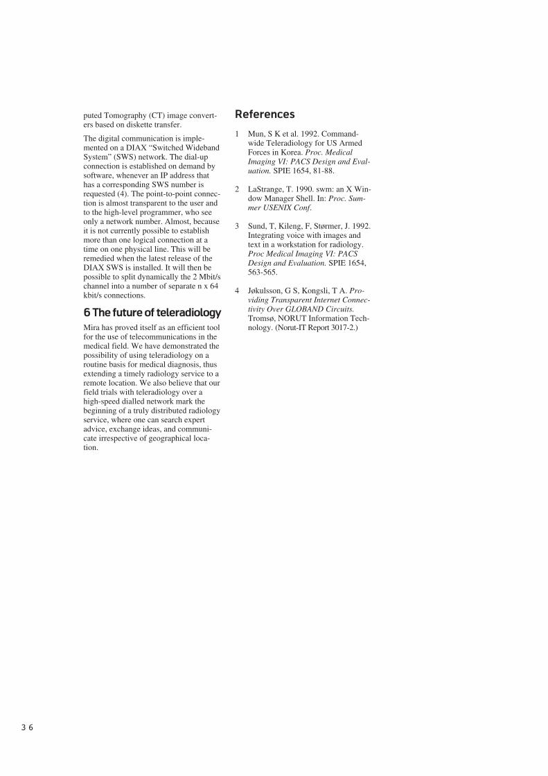
3 6
puted Tomography (CT) image convert-ers based on diskette transfer.
The digital communication is imple-mented on a DIAX “Switched WidebandSystem” (SWS) network. The dial-upconnection is established on demand bysoftware, whenever an IP address thathas a corresponding SWS number isrequested (4). The point-to-point connec-tion is almost transparent to the user andto the high-level programmer, who seeonly a network number. Almost, becauseit is not currently possible to establishmore than one logical connection at atime on one physical line. This will beremedied when the latest release of theDIAX SWS is installed. It will then bepossible to split dynamically the 2 Mbit/schannel into a number of separate n x 64kbit/s connections.
6 The future of teleradiology
Mira has proved itself as an efficient toolfor the use of telecommunications in themedical field. We have demonstrated thepossibility of using teleradiology on aroutine basis for medical diagnosis, thusextending a timely radiology service to aremote location. We also believe that ourfield trials with teleradiology over ahigh-speed dialled network mark thebeginning of a truly distributed radiologyservice, where one can search expertadvice, exchange ideas, and communi-cate irrespective of geographical loca-tion.
References
1 Mun, S K et al. 1992. Command-wide Teleradiology for US ArmedForces in Korea. Proc. MedicalImaging VI: PACS Design and Eval-uation. SPIE 1654, 81-88.
2 LaStrange, T. 1990. swm: an X Win-dow Manager Shell. In: Proc. Sum-mer USENIX Conf.
3 Sund, T, Kileng, F, Størmer, J. 1992.Integrating voice with images andtext in a workstation for radiology.Proc Medical Imaging VI: PACSDesign and Evaluation. SPIE 1654,563-565.
4 Jøkulsson, G S, Kongsli, T A. Pro-viding Transparent Internet Connec-tivity Over GLOBAND Circuits.Tromsø, NORUT Information Tech-nology. (Norut-IT Report 3017-2.)
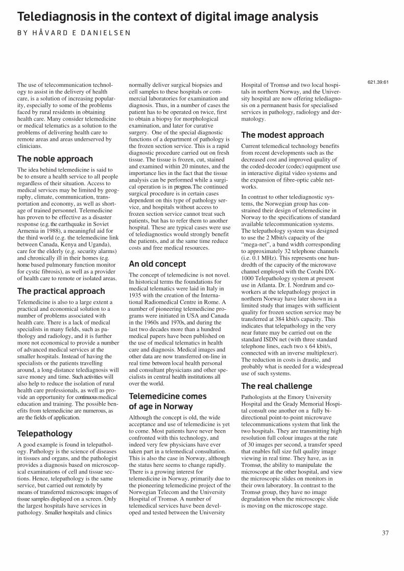
37
Telediagnosis in the context of digital image analysis
B Y H Å V A R D E D A N I E L S E N
The use of telecommunication technol-ogy to assist in the delivery of healthcare, is a solution of increasing popular-ity, especially to some of the problemsfaced by rural residents in obtaininghealth care. Many consider telemedicineor medical telematics as a solution to theproblems of delivering health care toremote areas and areas underserved byclinicians.
The noble approach
The idea behind telemedicine is said tobe to ensure a health service to all peopleregardless of their situation. Access tomedical services may be limited by geog-raphy, climate, communication, trans-portation and economy, as well as short-age of trained personnel. Telemedicinehas proven to be effective as a disasterresponse (e.g. the earthquake in SovietArmenia in 1988), a meaningful aid forthe third world (e.g. the telemedicine linkbetween Canada, Kenya and Uganda),care for the elderly (e.g. security alarms)and chronically ill in their homes (e.g.home based pulmonary function monitorfor cystic fibrosis), as well as a providerof health care to remote or isolated areas.
The practical approach
Telemedicine is also to a large extent apractical and economical solution to anumber of problems associated withhealth care. There is a lack of medicalspecialists in many fields, such as pa-thology and radiology, and it is furthermore not economical to provide a numberof advanced medical services at thesmaller hospitals. Instead of having thespecialists or the patients travellingaround, a long-distance telediagnosis willsave money and time. Such activities willalso help to reduce the isolation of ruralhealth care professionals, as well as pro-vide an opportunity for continuous medicaleducation and training. The possible ben-efits from telemedicine are numerous, asare the fields of application.
Telepathology
A good example is found in telepathol-ogy. Pathology is the science of diseasesin tissues and organs, and the pathologistprovides a diagnosis based on microscop-ical examinations of cell and tissue sec-tions. Hence, telepathology is the sameservice, but carried out remotely bymeans of transferred microscopic images oftissue samples displayed on a screen. Onlythe largest hospitals have services inpathology. Smaller hospitals and clinics
normally deliver surgical biopsies andcell samples to these hospitals or com-mercial laboratories for examination anddiagnosis. Thus, in a number of cases thepatient has to be operated on twice, firstto obtain a biopsy for morphologicalexamination, and later for curativesurgery. One of the special diagnosticfunctions of a department of pathology isthe frozen section service. This is a rapiddiagnostic procedure carried out on freshtissue. The tissue is frozen, cut, stainedand examined within 20 minutes, and theimportance lies in the fact that the tissueanalysis can be performed while a surgi-cal operation is in progress. The continuedsurgical procedure is in certain casesdependent on this type of pathology ser-vice, and hospitals without access tofrozen section service cannot treat suchpatients, but has to refer them to anotherhospital. These are typical cases were useof telediagnostics would strongly benefitthe patients, and at the same time reducecosts and free medical resources.
An old concept
The concept of telemedicine is not novel.In historical terms the foundations formedical telematics were laid in Italy in1935 with the creation of the Interna-tional Radiomedical Centre in Rome. Anumber of pioneering telemedicine pro-grams were initiated in USA and Canadain the 1960s and 1970s, and during thelast two decades more than a hundredmedical papers have been published onthe use of medical telematics in healthcare and diagnosis. Medical images andother data are now transferred on-line inreal time between local health personaland consultant physicians and other spe-cialists in central health institutions allover the world.
Telemedicine comes
of age in Norway
Although the concept is old, the wideacceptance and use of telemedicine is yetto come. Most patients have never beenconfronted with this technology, andindeed very few physicians have evertaken part in a telemedical consultation.This is also the case in Norway, althoughthe status here seems to change rapidly.There is a growing interest fortelemedicine in Norway, primarily due tothe pioneering telemedicine project of theNorwegian Telecom and the UniversityHospital of Tromsø. A number oftelemedical services have been devel-oped and tested between the University
Hospital of Tromsø and two local hospi-tals in northern Norway, and the Univer-sity hospital are now offering telediagno-sis on a permanent basis for specialisedservices in pathology, radiology and der-matology.
The modest approach
Current telemedical technology benefitsfrom recent developments such as thedecreased cost and improved quality ofthe coded-decoder (codec) equipment usein interactive digital video systems andthe expansion of fibre-optic cable net-works.
In contrast to other telediagnostic sys-tems, the Norwegian group has con-strained their design of telemedicine inNorway to the specifications of standardavailable telecommunication systems.The telepathology system was designedto use the 2 Mbit/s capacity of the“mega-net”, a band width correspondingto approximately 32 telephone channels(i.e. 0.1 MHz). This represents one hun-dredth of the capacity of the microwavechannel employed with the Corabi DX-1000 Telepathology system at presentuse in Atlanta. Dr. I. Nordrum and co-workers at the telepathology project innorthern Norway have later shown in alimited study that images with sufficientquality for frozen section service may betransferred at 384 kbit/s capacity. Thisindicates that telepathology in the verynear future may be carried out on thestandard ISDN net (with three standardtelephone lines, each two x 64 kbit/s,connected with an inverse multiplexer).The reduction in costs is drastic, andprobably what is needed for a widespreaduse of such systems.
The real challenge
Pathologists at the Emory UniversityHospital and the Grady Memorial Hospi-tal consult one another on a fully bi-directional point-to-point microwavetelecommunications system that link thetwo hospitals. They are transmitting highresolution full colour images at the rateof 30 images per second, a transfer speedthat enables full size full quality imageviewing in real time. They have, as inTromsø, the ability to manipulate themicroscope at the other hospital, and viewthe microscopic slides on monitors intheir own laboratory. In contrast to theTromsø group, they have no imagedegradation when the microscopic slideis moving on the microscope stage.
621.39:61
38
A high resolution full colour image froma microscope (e.g. with a size of 1024 x1024 pixels and 8 bit resolution per pixelper colour) represent roughly 3.1 Mbyteof data (-25 Mbit). The capacity neededfor transmitting 30 such images per sec-ond in an uncompressed form is thus 750Mbit, and the cost is significant (and toohigh for the benefits obtained, at least inNorway). On a 384 kbit/s line eachimage (in uncompressed form) wouldneed a little more than one minute fortransfer, and hence, living images in highresolution and full colour is out of thequestion.
The technology needed for telediagnosisin pathology (and other disciplines aswell) is already available. The real chal-lenge is to make such systems work asclose to the standard methods as possible,employing telecommunication systemsavailable on a general basis, and withacceptable quality and costs. The Norwe-gian Telecom and the University Hospi-tal of Tromsø seem to have taken on thischallenge with their project“Telemedicine in North Norway”, anddefinitely gone a part of the distance.However, as they say, the best is proba-bly yet to come.
Different strategies
There are two principle strategies to fol-low, either to increase the transfer capac-ity without increasing the costs, or toincrease the transfer speed by reducingthe amount of data to be transferred. Aslong as 750 Mbit lines are not likely to bea part of the telecommunication systemgenerally accessible to the public in thenear future, the latter strategy appears tobe the more valid one. A reduction indata may be accomplished in severalways:
- reduction in image resolution
- reduction in image size
- compression (packing) of data
- processor controlled transfer schemes(e.g. to transfer only those pixelswhich are different from one image tothe other).
Although all these methods will reducetransfer time, a reduction in image qual-ity is also inevitable. The more effectivereduction in time, the more significantimage degradation. For some applica-tions, a significant image degradation isacceptable, for others it is not.
Different applications
– different images
Different applications do not only havedifferent acceptance levels for imagedegradation, but they vary in initial reso-lution, image size, colour versus b/w andstatic versus living images. Several dif-ferent features might be important in anobject, and of special concern to a givenapplication:- mobility
- architecture
- morphology
- colours
- density
- intensity
- texture.
Mobility clearly demands living images,and real time transfer is also important ine.g. endoscopy (examination of bodycavities with a camera). Real time trans-fers are also important in telepathologyduring the selection of the putative diag-nostic fields in tissue specimens, but hav-ing located those fields, transfer of staticimages are sufficient for detailed exami-nation. High resolution and full colourare important for such examinations ofstandard prepared specimens, but resolu-tion and colours may be reduced forfreeze section service as these specimensare low in details and growth pattern isthe prevailing feature analysed. Radio-graphic images have clearly no need ofreal time transfer, but depend heavily onlarge size images of high resolution foranalysis of grey level distributions anddensity. Typically a radiographic imagecomprises 4096 x 3584 pixels with 12bits resolution/pixel. This representsroughly 22 Mbyte of data (1.76 x 10⁸
bits), and the transfer time on a 64 kbit/stelephone line would be nearly 46 min-utes. So, even static images need highcapacity telenet and/or advanced com-pression algorithms.
Since functionality as well as the needfor quality differs from one application toanother, it might be profitable to treatthese different images individually. Forsome applications the morphology andarchitecture are the most important fea-tures (e.g. freeze section service), forother (e.g. X-rays) grey level distributionand density prevails. The need for indi-vidual treatment of images makes strongdemands on the methodology, but thefact that different features are important
in different applications also opens newpossibilities with regards to data reduc-tion.
Alternatively (or actually supplementary) tothe different algorithms for data com-pression one could look for methods toenhance image validity before and aftertransfer. Image validity in this contextmeans those regions in the image that isof special interest. To put is simply, if theobjective was to evaluate the size of thenuclei within the cells, the nuclei couldhave been segmented and the microscopyimage reduced to a binary (two bit)image before transfer. A more realisticexample would be to enhance contrast orreduce noise in order to maintain imagevalidity during e.g. compression. Themethods of noise reduction, imageenhancement and segmentation belong tothe discipline called image analysis.
Digital image analysis
Image analysis is a set of standard tech-niques with wide applications in allbranches of science and technology.Beyond a visual examination of animage, there are several methods of fur-ther analysing the image. The objective isto extract the maximum amount of struc-tural information, and image analysisprovides a quantitative way of assessingimage defects and image resolution.Based on such analyses, structural andnon-structural (noise) information maybe separated to give an enhanced image,which shows more clearly the structureof the objects which are of interest.Clearly, if that is achieved, one canafford more image degradation due todata reduction, and still maintain thenecessary qualities for the final visualexamination (or quantitative analysis).Correspondingly, image processing tech-niques may be applied on the image afterdecoding to compensate the loss of reso-lution due to e.g. compression. Furthermore, quantitative image analysis mayease the burden of long distance diagno-sis by extracting new objective featuresfrom the image.
The concept of image analysis is datareduction, and the principal steps are out-lined in figure 1. This data reduction ishowever directional, in the sense that oneideally keeps the data of interest and dis-charge the rest.
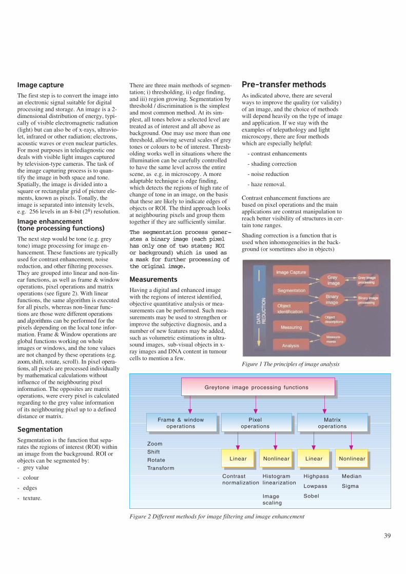
39
Image capture
The first step is to convert the image intoan electronic signal suitable for digitalprocessing and storage. An image is a 2-dimensional distribution of energy, typi-cally of visible electromagnetic radiation(light) but can also be of x-rays, ultravio-let, infrared or other radiation; electrons,acoustic waves or even nuclear particles.For most purposes in telediagnostic onedeals with visible light images capturedby television-type cameras. The task ofthe image capturing process is to quan-tify the image in both space and tone.Spatially, the image is divided into asquare or rectangular grid of picture ele-ments, known as pixels. Tonally, theimage is separated into intensity levels,e.g. 256 levels in an 8-bit (28) resolution.
Image enhancement (tone processing functions)
The next step would be tone (e.g. greytone) image processing for image en-hancement. These functions are typicallyused for contrast enhancement, noisereduction, and other filtering processes.They are grouped into linear and non-lin-ear functions, as well as frame & windowoperations, pixel operations and matrixoperations (see figure 2). With linearfunctions, the same algorithm is executedfor all pixels, whereas non-linear func-tions are those were different operationsand algorithms can be performed for thepixels depending on the local tone infor-mation. Frame & Window operations areglobal functions working on wholeimages or windows, and the tone valuesare not changed by these operations (e.g.zoom, shift, rotate, scroll). In pixel opera-tions, all pixels are processed individuallyby mathematical calculations withoutinfluence of the neighbouring pixelinformation. The opposites are matrixoperations, were every pixel is calculatedregarding to the grey value informationof its neighbouring pixel up to a defineddistance or matrix.
Segmentation
Segmentation is the function that sepa-rates the regions of interest (ROI) withinan image from the background. ROI orobjects can be segmented by:- grey value
- colour
- edges
- texture.
There are three main methods of segmen-tation; i) thresholding, ii) edge finding,and iii) region growing. Segmentation bythreshold / discrimination is the simplestand most common method. At its sim-plest, all tones below a selected level aretreated as of interest and all above asbackground. One may use more than onethreshold, allowing several scales of greytones or colours to be of interest. Thresh-olding works well in situations where theillumination can be carefully controlledto have the same level across the entirescene, as e.g. in microscopy. A moreadaptable technique is edge finding,which detects the regions of high rate ofchange of tone in an image, on the basisthat these are likely to indicate edges ofobjects or ROI. The third approach looksat neighbouring pixels and group themtogether if they are sufficiently similar.
The segmentation process gener-ates a binary image (each pixelhas only one of two states; ROIor background) which is used asa mask for further processing ofthe original image.
Measurements
Having a digital and enhanced imagewith the regions of interest identified,objective quantitative analysis or mea-surements can be performed. Such mea-surements may be used to strengthen orimprove the subjective diagnosis, and anumber of new features may be added,such as volumetric estimations in ultra-sound images, sub-visual objects in x-ray images and DNA content in tumourcells to mention a few.
Pre-transfer methods
As indicated above, there are severalways to improve the quality (or validity)of an image, and the choice of methodswill depend heavily on the type of imageand application. If we stay with theexamples of telepathology and lightmicroscopy, there are four methodswhich are especially helpful:
- contrast enhancements
- shading correction
- noise reduction
- haze removal.
Contrast enhancement functions arebased on pixel operations and the mainapplications are contrast manipulation toreach better visibility of structures in cer-tain tone ranges.
Shading correction is a function that isused when inhomogeneities in the back-ground (or sometimes also in objects)
Figure 1 The principles of image analysis
Greytone image processing functions
Frame & windowoperations
Pixeloperations
Nonlinear
Matrixoperations
Linear NonlinearLinear
Zoom
Shift
Rotate
Transform
Contrastnormalization
Histogramlinearization
Highpass
Lowpass
Sobel
Median
Sigma
Imagescaling
Figure 2 Different methods for image filtering and image enhancement
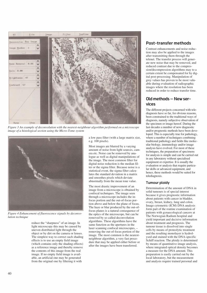
40
reduce the “sharpness” of an image. Inlight microscopy this may be caused byuneven distributed light through theobject or by dirt on the camera or lenses.The simplest way to correct such shadingeffects is to use an empty field image(which contains only the shading effects)as a reference image and thereby removethe contents of this image from the realimage. If no empty field image is avail-able, an artificial one may be generatedfrom the original one by filtering it with
a low pass filter (with a large matrix size,e.g. 100 pixels).
Most images are blurred by a varyingamount of noise from light sources, cam-era etc. Noise can be removed by ana-logue as well as digital manipulations ofthe image. The most common filter fordigital noise reduction is the median fil-ter or the sigma filter. Because noise is astatistical event, the sigma filter calcu-lates the standard deviation in a matrixand smoothes pixels which deviateabnormally from the mean tone value.
The most drastic improvement of animage from a microscope is obtained byconfocal techniques. The image seenthrough a microscope includes the in-focus portion and the out-of-focus por-tion above and below the plane of focus.The haze or blur produced by the out-of-focus planes is a natural consequence ofthe optics of the microscope, but can beremoved by so called deconvolutionalgorithms. These algorithms have thesame function as the apertures in thelaser scanning confocal microscopes, –removing the out-of-focus portion of theimage. The most common is the nearest-neighbour algorithm, a very fast proce-dure that may be applied either before orafter the images have been transferred.
Post-transfer methods
Contrast enhancements and noise reduc-tion may also be applied to the imagesafter transmitting them through thetelenet. The transfer process will gener-ate new noise that may be removed, andreduced contrast due to the compres-sion/decompression algorithms may to acertain extent be compensated for by dig-ital post-processing. Manipulation ofgrey values has proven to be most valu-able during evaluation of radiographicimages where the resolution has beenreduced in order to reduce transfer time.
Old methods – New ser-
vices
The different projects concerned with tele-diagnosis have so far, for obvious reasons,been constrained to the traditional ways ofdiagnosis, namely subjective observation ofthe specimen or image hereof. During thelast decades a number of new diagnosticand/or prognostic methods have been deve-loped. This is especially true for pathology,where a number of techniques combiningtraditional pathology and fields like molec-ular biology, immunology and/or imageanalysis have evolved. For most of thesetechniques, the preparation of specimensfor analysis is simple and can be carried outin any laboratory without specialisedequipment or expertise. It is usually theevaluation or analysis that require particu-lar skills or advanced equipment, andhence, these methods would be suited fortelediagnosis.
Tumour ploidy
Determination of the amount of DNA insolid tumours is of special interestbecause it gives prognostic informationabout patients with cancer in bladder,ovary, breast, kidney, lung and colon.Image cytometric (ICM) DNA analysisform part of the routine examination ofpatients with gynaecological cancers atThe Norwegian Radium hospital andyield important and decisive informationabout treatment and prognosis. Thetumour tissue is dissolved into singlecells by means of proteolytic treatmentand the resulting monolayer is hydrol-ysed and stained with the DNA-specificSchiff reaction. The ploidy is determinedby means of quantitative image analysis,where integrated optical density becomesa measure for the DNA amount. Thispreparation is easily carried out by thelocal laboratory, but the measurementand analysis require trained personal and
Figure 3 An example of deconvolution with the nearest-neighbour algorithm performed on a microscopeimage of a histological section using the Micro-Tome system
Figure 4 Enhancement of fluorescence signals by deconvo-lution technique
41
image analysis equipment. A telediag-nostic approach would require approxi-mately 20 random selected images withstandard resolution in black and white(512 x 512 pixels with 8 bit resolutionper pixel) which can be transferred withstandard ISDN telecommunication withinless than six minutes. The measurementand analysis would be performed off-linein the department of pathology within 30- 90 minutes and the resulting DNA his-togram and diagnosis may be transferredback as one image to the local laboratory.
Hormone receptors
and antigen markers
A similar case exists for quantification ofdifferent hormone receptors as well asidentification of other antigens byimmunostaining applying monoclonal orpolyclonal antibodies. Such immunohis-tochemistry methods have gained appli-cability in several special diagnosticcases, but the use is normally limited tolarger central institutions since specialexperience and/or special equipment isrequired to analyse these preparations.Again, local hospitals could gain accessto this experience through the telenet.
Karyotyping
Chromosome analysis is another exampleof an important diagnostic method wherethe utilisation is limited due to lack ofspecially trained personal. Although thepreparation of suitable metaphases is alittle more demanding compared to themethods mentioned above, it would beadvantageous to do this locally since thepreparation requires living cells. Themain obstacle for a widespread use ofkaryotyping as a diagnostic method is thefact that it takes 4 - 6 years of training tobe able to set up the correct karyotype.Most cytogeneticists employ digitalimages and computers for the arrange-ment and analysis of chromosomalpreparations anyway, and the methodshould therefore be well suited for teledi-agnostics. Again the requirements forimage size and resolution are low, and a768 x 640 b/w image with 8 bit per pixelis more than sufficient. Ten metaphasescould therefore be transferred with astandard telephone-line on the ISDN-netin five minutes. Transmittance in realtime or on-line analysis is not requiredunless a consultative dialogue is desir-able.
Quantitative image
analysis in medicine
The use of morphometric analysis has along history in pathology, were measure-ment of nuclear size for histological grad-ing and counting of mitotic cells as aprognostic indicator are typical examples.Image analysis is more recently also usedfor automatic classification of tissue speci-mens, and there exist several systems forautomatic pre-screening of cytosmears(cell samples).
Besides the examples from pathology,quantitative image analysis is used in anumber of diagnostic methods inmedicine. Image analysis is a prerequisitefor such diagnostic methods as computertomography (CT) and magnetic reso-nance (MR), and is frequently used aspart of diagnostic apparatus in ophthal-mology and cardiology. 3-dimensionalreconstruction and visualisation are othermethods which are fast growing inmedicine, and where image analysis is thefoundation.
The image analysis systems are oftenexpensive add-on equipment to standardapparatuses, which in addition to costlyinvestments requires specially trainedpersonal. The link is either a digital com-munication or an analogue camera, and itwill therefore in many cases be possibleto examine the patient with the standardapparatus at the local hospital while thespecialist is analysing the images at acentral institution (e.g. volumetric heartanalysis with ultrasound, classification ofEEG results, enhancement of radio-graphic images, quantitative analysis ofmicroscopical images etc.).
How to have the cake
and eat it too
One of the main controversial issuesregarding national health care has beenwhether to centralise the hospital treat-ment of certain diseases such as cancer.Arguments in favour of centralisationhave been to save money and obtain fulluse of expensive equipment, as well asimproved quality of treatment due togreater experience. This is comparedagainst the advantage of being treated inthe local hospital.
By telemedicine and image analysis, thepossibility exists that a large number ofpatients may be treated in their local hos-pitals by medical specialists in centralinstitutions, and this might prove to be
the solution of the national health admin-istrators dilemma; how to have the cakeand eat it too.
The scientific approach
Apart from the many practical and eco-nomical advantages gained bytelemedicine, one should not overlookthe scientific value of communicatingdigital images through the telenet. Thedigitalisation of images is easily com-bined with a database in which everycase may be classified and commentedon for future reference. Besides becom-ing an excellent tool for training, suchdatabases may be used for feature extrac-tion by image analysis systems. Theextraction of features is the basis for anobjective description of the cases, and ifthat is obtained, further possibilities areautomatic recognition and classificationsystems.
Communicating digital images in a con-sultative function will by definition pro-mote medical education and training. Thevery existence of telediagnostic equip-ment will stimulate co-operation betweenclinicians and researchers in differentinstitutions, as well as nourish develop-ment of new applications.
Whether telemedicine will be a generalsuccess will to a large extent depend onwhether or not one manages to meet thereal challenge – to make such systemswork as close to the standard methods aspossible, employing telecommunicationsystems available on a general basis, andwith acceptable quality and costs. Cur-rent telemedical technology benefitsfrom recent developments such as thedecreased cost and improved quality ofthe coder-decoder equipment, and suchequipment will be further developed inthe near future. By an additional imple-mentation of image analysis, telediagno-sis will continue to grow, both in distri-bution and application.
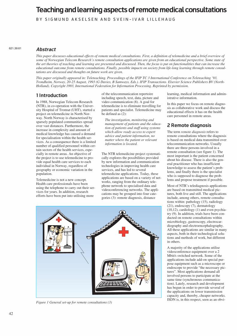
42
Teaching and learning aspects of remote medical consultations
B Y S I G M U N D A K S E L S E N A N D S V E I N - I V A R L I L L E H A U G
1 Introduction
In 1988, Norwegian Telecom Research(NTR), in co-operation with the Univer-sity Hospital of Tromsø (UHT), started aproject on telemedicine in North Nor-way. North Norway is characterised bysparsely populated communities spreadover vast distances. Furthermore, theincrease in complexity and amount ofmedical knowledge has caused a demandfor specialisation within the health ser-vices. As a consequence there is a limitednumber of qualified personnel within cer-tain sectors of the health services, espe-cially in remote areas. An objective ofthe project is to use telemedicine to pro-vide equal health care services to eachindividual in Norway, regardless ofgeography or economic variation in thepopulation.
Telemedicine is not a new concept.Health care professionals have beenusing the telephone to carry out their ser-vices for years. In addition, researchefforts have been put into utilising more
of the telecommunication repertoireincluding speech, text, data, picture andvideo communication (8). A goal fortelemedicine is to eliminate travelling forpatients and specialist. Telemedicine maybe defined as (2):
The investigation, monitoring andmanagement of patients and the educa-tion of patients and staff using systemswhich allow ready access to expertadvice and patient information, nomatter where the patient or relevantinformation is located.
The NTR telemedicine project systemati-cally explores the possibilities providedby new information and communicationtechnologies in improving health careservices, and has led to severaltelemedicine applications. Today, theseapplications are based on a variety of net-works, ranging from the ordinary tele-phone network to specialised data andvideoconferencing networks. The appli-cations may be grouped into four cate-gories (3): remote diagnosis, distance
learning, medical information and admin-istrative information.
In this paper we focus on remote diagno-sis as collaborative work and discuss theeducational effects it has on the healthcare personnel in remote areas.
2 Remote diagnosis
The term remote diagnosis refers toremote consultations where the diagnosisis based on medical data transmitted overtelecommunication networks. Usuallythere are three persons involved in aremote consultation (see figure 1). Themost important is the patient concernedabout his disease. There is also the gen-eral practitioner who has insufficientknowledge to assess the patient’s prob-lems, and finally there is the specialistwho is supposed to diagnose the prob-lems and propose treatment if possible.
Most of NTR’s telediagnosis applicationsare based on transmitted medical pic-tures, both live and still. The applicationsinclude, among others, remote consulta-tions within: pathology (15), radiology(21), endoscopy (7), dermatology(10,12), cardiology (1) and even psychia-try (9). In addition, trials have been con-ducted on remote consultations withinmicrobiology, gastroscopy, electrocar-diography and electroencephalography.All these applications are similar in manyaspects, both in their technological solu-tions and methods of work, but differentin others.
A majority of the applications utilisevideoconference equipment over a 2Mbit/s switched network. Some of theapplications include add-on special pur-pose equipment such as a microscope orendoscope to provide “the necessary pic-tures”. Most applications demand allinvolved persons to participate at thesame time (synchronous communica-tion). Lately, research and developmenthas begun in order to provide several ofthe applications on lower transmissioncapacity and, thereby, cheaper networks.ISDN is, in this respect, seen as an obvi-
Abstract
This paper discusses educational effects of remote medical consultations. First, a definition of telemedicine and a brief overview ofsome of Norwegian Telecom Research’s remote consultation applications are given from an educational perspective. Some state ofthe art theories of teaching and learning are presented and discussed. Then, the focus is put on functionalities that can increase theeducational outcome from remote consultations. Finally, possible impacts on society from life-long learning through remote consul-tations are discussed and thoughts on future work are given.
This paper originally appeared in: Teleteaching. Proceedings of the IFIP TC 3 International Conference on Teleteaching ’93,Trondheim, Norway, 20-25 August, 1993 (G Davies, B Samways, Eds.). IFIP Transactions. Elsevier Science Publishers BV (North-Holland). Copyright 1993, International Federation for Information Processing. Reprinted by permission.
621.39:61
Figure 1 General set-up for remote consultations (3)
43
ous network solution (3). Terminalequipment used in the ISDN solutionsinclude the Tandberg Vision videophone(14), and NTR’s own system for digitis-ing, storing and transmitting medicalstills (pictures) from arbitrary videosources. Further, the applications willalso provide for asynchronous communi-cation, (i.e. the participants will not nec-essarily be present at the same time).
Below, tele-endoscopy, remote diagnosisof skin diseases and remote echocardiol-ogy will be described in more detail withfocus on the educational aspects. Below,the term practitioner will refer to bothgeneral practitioners in primary healthcare and residents in remote hospitals.
2.1 Tele-endoscopy
An endoscope is a device for guiding asource of light inside the human bodyand transposing an image of the exam-ined organ on a monitor. Tele-endoscopyrefers to the transmission of these imagesover the telecommunications network toa specialist at the other end. A practi-tioner is, however, still needed to bringthe endoscope inside the patient andadjust the positioning to get the correctimages (7). Tele-endoscopy is used inNorth Norway for ear, nose and throat(othorhinolaryngology) consultations.Telecommunications are presently basedon a 2 Mbit/s connection. Videoconfer-encing equipment provides a two-wayaudio and video connection between thespecialist and the practitioner in chargeof the patient. As a service, tele-endoscopy is meant to cover two aspects:remote consultations and transfer of com-petence to the practitioner.
An endoscopy session is divided in threeparts: examination, diagnosis, and com-pilation of a treatment plan. From aneducational perspective, tele-endoscopygoes through four phases. First, the prac-titioner has to go through a short tutoringperiod together with a specialist at UHT.During this period he acquires the basicknowledge and skills that are necessaryto operate the endoscope. In the secondphase the practitioner is back at theremote hospital where he operates theendoscope with directions from the spe-cialist. The specialist explains the endo-scope movements he has requested andwhat is being seen. Through this processthe practitioner receives practical instruc-tion in endoscopy examination tech-niques. Based on the findings from theendoscopy and through conversation withthe patient, the specialist makes his diagno-
sis and plan for treatment, all whileexplaining his reasoning to the practi-tioner. In the third phase the practitionerbegins to more actively cooperate withthe specialist in the examination, diagno-sis and compilation of a treatment plan.Finally, in the fourth phase, the practi-tioner is ready to take over the consulta-tion. Remote consultations are only usedfor patients that the practitioner finds dif-ficult to diagnose. At this stage the spe-cialist monitors and evaluates the practi-tioner’s examination, diagnosis and pro-posed treatment plan on a limited scale.
2.2 Remote diagnosis of skin dis-
eases
Remote diagnosis of skin diseases isbased on technical solutions similar totele-endoscopy. The only difference isthat instead of the endoscope the practi-tioner has several cameras which areused to transfer still and motion picturesof the patient to the specialist. As withtele-endoscopy, a session of remote diag-nosis of skin diseases can be divided intoexamination, diagnosis and compilationof treatment plan. From the educationalperspective the service can be describedthrough three phases. First, the practi-tioner functions as the specialist’sextended arm by providing the specialistwith different pictures (by moving andfocusing cameras) of the patient, and giv-ing comments about how the skin feels aswell as other necessary anamnestic infor-mation. This process might also includethe practitioner taking a biopsy or per-forming other tests. Throughout the ses-sion the specialist explains the differentactions as well as the reasoning behindhis diagnosis and the resulting treatmentplan. In the second phase the practitionerand the specialist cooperate as colleaguesduring the consultation. As the practi-tioner gains the necessary knowledge andskills through collaborative practising, heis ready to move over to the third phaseof independent consultation with thepatient. Similar to the tele-endoscopyservice, the specialist is brought in when-ever necessary to help, monitor and eval-uate and the practitioners’ actions.
2.3 Cardiology diagnosis through
remote echocardiology
The project of remote diagnosis throughechocardiology has taken a somewhatdifferent approach than tele-endoscopyand remote diagnosis of skin diseases. Sofar the main topic has been to investigatethe appropriateness of remote echocardi-
ology as a tool for distance education ofphysicians with minor practical experi-ence in echocardiology (1). The technicalsolutions are similar to the other present-ed projects. In addition to videoconfer-ence two dimensional, M-mode anddoppler echocardiology are transferred.
The practitioner involved in the test trialhad no further experience with echocar-diology than a five days theoretical intro-duction course. During the test trial, 38patients were first examined by the prac-titioner with the specialist remotely mon-itoring the practitioner’s performanceand giving supervision. Practical instruc-tion in examination techniques, diagnosisand compilation of treatment plans weregiven by the specialist wheneverrequired. To double-check the practi-tioner’s performance, and to evaluate thequality of remote echocardiology, thepatients were directly examined by thespecialist later. Based on a comparisonbetween the two consultations of eachpatient, Afseth et. al (1) concludes thatremote echocardiology is an efficient andappropriate technique for education inechocardiology.
3 Educational implications
of remote consultations
The projects described above have simi-larities both in technical solutions andphases of execution. A typical sessiongoes through the steps of examination,diagnosis and compilation of a treatmentplan. Within each discipline the practi-tioner evolves from having minor experi-ence in the field to becoming a semi-spe-cialist through three phases: practicaldemonstrations given by specialist, prac-tising in co-operation with specialist and,practising under supervision of the spe-cialist. This approach of learning isknown as the role model within the medi-cal system (13). The role model has itsparallel in educational theory in whatCollins et. al and Brown et. al (4,5,6)have proposed as the cognitive appren-ticeship model for instruction of cogni-tive skills. Since ancient timesapprenticeship has been the most com-mon method to transmit the knowledgefrom a master to an apprentice in a widevariety of fields, also within medicine. Intheir argument for cognitive appren-ticeship, Brown et. al claim:
“... that knowledge is situated, being inpart a product of the activity, contextand culture in which it is developedand used ((4), p 32).”
44
The cognitive apprenticeship model com-prises three methods similar to the threephases of the role model: situated mod-elling, coaching and fading. These aredescribed as follows in (4):
- Situated modelling: The teacher/coachpromotes learning, first by makingexplicit their tacit knowledge or bymodelling their strategies for studentsin authentic activity.
- Coaching: The teacher/coach supportsthe student’s attempts at doing thetask.
- Fading: The teacher/coach empowersthe student to continue independentlywhile the support is gradually with-drawn.
Collins et. al (6) summarise the benefitsof the cognitive apprenticeship model forinstruction as follows:
- Learners will more easily understandthe purpose and use of knowledge.
- Learners learn by actively using, ratherthan passively receiving, knowledge.
- Learners learn different conditionsunder which they can apply theirknowledge.
- Learners can generalise the knowledgeacross meaningful situations (insteadof directly acquiring a generalisationwithout any context).
A good educational outcome of the CAmodel relies on good and efficient com-munication between the apprentice andthe specialist throughout the differentphases of the model. Both the practition-ers and the specialists involved in thethree projects presented above, report abetter educational outcome throughremote consultations as compared to thetraditional specialist education within therespective disciplines. They explain thatthe practitioner in a remote consultationreceives much more attention and super-vision from the specialist than a physi-cian going through his special educationat a central hospital. This observationcorresponds with the following short-comings identified in an evaluation of thetraditional education in ventilator therapyamong nurses and physicians specialisingin intensive care and anaesthesiology atUHT (13):
- There are weaknesses in the supervi-sor’s ability to explain cases/problemsand their solutions.
- Feedback on student performance ismissing or of varying quality.
- Students are rarely required to explaincases/problems encountered or theirown solutions.
- Supervisors are not available whenneeded, and when available, time limi-tations prevent the supervisor fromdemonstrating or giving detailedenough explanations.
A remote consultation provides an envi-ronment that, by its characteristics, forcesthe participants to bypass these possibleweaknesses in traditional education.These characteristics can be identified as:
- The specialist needs to involve thepractitioner in the procedures in orderto carry out the examination/consulta-tion.
- The specialist is dependent on thepractitioner doing a good job.
- The practitioner is more frequentlyrequired to explain his reasoning andperformance.
- The specialist is available during theentire session.
- The specialist saves time as the practi-tioner begins to work more indepen-dently.
- The specialist can use his time on chal-lenging cases, as more patients aretreated by the practitioner.
As a result, both the practitioner and thespecialist are highly motivated to followthe CA methods of situated modelling,coaching and fading thereby leading toan efficient educational outcome of eachsession.
A measure of the success of the NTR’stelemedicine project is the high numberof requests from remote hospitals andhealth institutions that want access to thedifferent services. The hospitals want totake advantage of the benefits thattelemedicine provides. For example, thepatients can receive specialist consulta-tions locally. In a remote consultation,the three participants have the opportu-nity to discuss the problem at the sametime. This has not been the case earlier.The gap in time from the problem’soccurrence, the call of the practitioner’sattention to it, the specialist consultation,and the practitioner being informed ofthe diagnosis and the treatment plan, isreduced. Same time, same subject andsame information available is, according
to Jøsendal et. al (12), the remote consul-tations’ greatest pro. The medical person-nel (in primary health care) get betteropportunities to keep professional con-tact with other institutions and groups ofspecialists. This may improve stability,competence and recruiting of medicalpersonnel, thus increasing the possibili-ties for running a qualitatively good andsafe service. Further, through goodtelecommunications the medical person-nel can take part in an exchange ofknowledge and professional discussionsindependent of geographic location. Thepersonnel can raise their competence andget further education without leavingtheir district and thereby save many andexpensive travels. Time saved on travel-ling can instead be invested as worktime. In summary the remote areas canprovide a better health care system at alower cost.
Up until recently, most of the services inthe telemedicine project have been per-formed on a trial basis to a few remotesites. Opening the services for morewidespread use will increase the load onthe specialists and their departments atthe central hospitals. Therefore, the dif-ferent services need to be investigated forhow to most efficiently meet the newdemands.
4 Increasing the edu-
cational outcome
A main focus of the telemedicine projecthas been to provide remote medical con-sultations by combining advanced medi-cal technology and telecommunications.The above discussion implies that theeducational outcome of remote consulta-tions might be just as important as theservice provision. This has lead to appli-cations, such as remote echocardiology,where the main topic has been to investi-gate the appropriateness of remoteconsultations as a method for distanceeducation of health care workers.
One way to prevent an increased load onthe specialists and their departmentsmight be to make the practitioners moreindependent. This can be done by provid-ing additional tools for educational pur-poses and specialist advice. In otherwords tools that offer the practitioner anefficient learning environment combinedwith supervision functionalities withoutnecessarily having access to the special-ist. Computer applications have thepotential to facilitate both learning andassistance during a consultation. By inte-
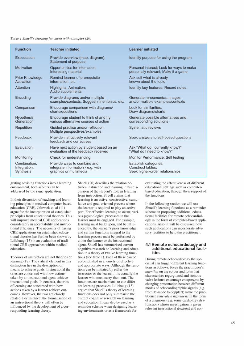
45
grating advising functions into a learningenvironment, both aspects can beaddressed by the same application.
In their discussion of teaching and learn-ing principles in medical computer-basededucation (CBE), Jelovsek et. al (11)argue for the incorporation of establishedprinciples from educational theories. Thiswill improve medical CBE applicationsconsiderably in acceptability and instruc-tional efficiency. The necessity of basingCBE applications on established educa-tional theories has further been shown byLillehaug (13) in an evaluation of tradi-tional CBE approaches within medicaleducation.
Theories of instruction are not theories oflearning (18). The critical element in thisdistinction lies in the description ofmeans to achieve goals. Instructional the-ories are concerned with how actionstaken by an instructional agent achieveinstructional goals. In contrast, theoriesof learning are concerned with howactions taken by a learner achieve out-comes. However, the two are closelyrelated. For instance, the formalisation ofan instructional theory will often beinfluenced by the development of a cor-responding learning theory.
Shuell (20) describes the relation be-tween instruction and learning in his dis-cussion of the student’s role in learningfrom instruction. Shuell claims thatlearning is an active, constructive, cumu-lative and goal-oriented process wherethe learner is required to play an activepart. For effective learning to occur, vari-ous psychological processes in thelearner must be engaged. For example,learning must build upon, and be influ-enced by, the learner’s prior knowledge,and certain functions integral to thelearning process must be performed byeither the learner or the instructionalagent. Shuell has summarised currentcognitive research on learning and educa-tion in a theory of twelve learning func-tions (see table 1). Each of these can beaccomplished in a variety of effectiveand appropriate ways. Although the func-tions can be initiated by either theinstructor or the learner, it is actually thelearner who must carry them out. Thefunctions are mechanisms to cue differ-ent learning processes. Lillehaug (13)argues that Shuell’s theory of learningfunctions does not only summarise thecurrent cognitive research on learningand education. It can also be used as areminder scheme when designing learn-ing environments or as a framework for
evaluating the effectiveness of differenteducational settings such as computer-based education, through their support ofthe functions.
In the following section we will useShuell’s learning functions as a reminderscheme in proposing additional educa-tional facilities for remote echocardiol-ogy in the form of computer-based appli-cations. Also, it will be discussed howsuch applications can incorporate advi-sory facilities to help the practitioner.
4.1 Remote echocardiology and
additional educational facil-
ities
During remote echocardiology the spe-cialist can trigger different learning func-tions as follows: focus the practitioner’sattention on the colour and form thatcharacterises regurgitated and stenoticvalve lesions; encourage comparison bychanging presentation between differentmodes of echocardiographic signals (e.g.from M-mode to doppler); make the prac-titioner generate a hypothesis in the formof a diagnosis (e.g. some cardiology dys-function) whose investigation is givenrelevant instructional feedback and cor-
Function Teacher initiated Learner initiated
Expectation Provide overview (map, diagram); Identify purpose for using the programStatement of purpose
Motivation Opportunities for interaction; Personal interest; Look for ways to makeInteresting material personally relevant; Make it a game
Prior Knowledge Remind learner of prerequisite Ask self what is alreadyActivation information, etc. known about the topic
Attention Highlights; Animation; Identify key features; Record notesAudio supplements
Encoding Provide diagrams and/or multiple Generate mneumonics, imagesexamples/contexts; Suggest mnemonics, etc. and/or multiple examples/contexts
Comparison Encourage comparison with diagrams/ Look for similarities;charts/questions Draw diagrams/charts
Hypothesis Encourage student to think of and try Generate possible alternatives andGeneration various alternative courses of action corresponding solutions
Repetition Guided practice and/or reflection; Systematic reviewsMultiple perspectives/examples
Feedback Provide instructively relevant Seek answers to self-posed questionsfeedback and correctives
Evaluation Have next action by student based on an Ask “What do I currently know?”evaluation of the feedback received “What do I need to know?”
Monitoring Check for understanding Monitor Performance; Self testing
Combination, Provide ways to combine and Establish categories;Integration, integrate information - e.g. with Construct tables;Synthesis graphics or multimedia Seek higher-order relationships
Table 1 Shuell’s learning functions with examples (20)
46
rectives (e.g. turn the probe 30 degrees toget a more informative view). During theentire session the specialist monitors thepractitioner’s performance (e.g. posesquestions that check for understanding).The practitioner also has the opportunityto initiate the different learning functionshimself (e.g. comparison by looking forsimilarities between a particular patientcase and previous examined patients). Acomputer-based application for enhancinglearning efficiency needs to support thelearning functions in a similar way.
The first thing the practitioner has tolearn is how the movements of the probeaffect the presentation of echocardiologysignals and when to make use of the dif-ferent modes (good examination tech-niques). A learning environment cancover these aspects through integration ofmultimedia where the moves of the probeare shown in one picture frame while thecorresponding output of echocardiologyis shown in another frame. The move-ments of the probe can be accompaniedby textual information which explainswhat is done and which effect this has onthe output. By including possibilities toshow outputs of all three modes at thesame time, the relations between thesecan also be explained.
Typical patient cases with textual infor-mation could be stored (also by the spe-cialist and the practitioner) in a databasefor reviews by the practitioner. Throughoptions for freezing and focusing, thepractitioner may freeze a case and focuson details of particular interest. Exclu-sion/inclusion of textual information canbe used by the practitioner to test out hisown hypothesis.
A learning environment with the de-scribed facilities may give support forShuell’s learning functions as follows:
- Expectation and motivation: Supportedthrough overviews of what needs to belearned, and further, by pointers to thepaths for how to learn it.
- Prior knowledge activation: In demon-strating techniques for how to use theprobe, textual information/explanationreminds the practitioner of prerequisitegeneral knowledge or particular infor-mation about the actual patient.
- Attention: Supported through visualand textual pointers to details of partic-ular interest in a reviewed patient case.Further, the practitioner is given time
to process all available informationthrough speed/pause control. Also, ascratchpad editor might be usable tomake notes and save information forfuture reference.
- Encoding: Supported by real-lifepatient cases examined with the sameequipment as by the practitioner.
- Comparison: Supported through possi-bilities for comparing different typicalcases stored in a database, or throughcomparing the practitioner’s hypothe-sis with the corresponding cases in thedatabase. Further, demonstrations ofhow to best make use of the differentexamination modes can be valuable.
- Hypothesis generation: Supportedthrough possibilities for the practi-tioner to make hypothesis on patientcases which can be checked out versuscases in the database.
- Repetition: The practitioner can repeatthe review of any case available in thedatabase, or he can store own patientcases for later systematic reviews.
- Feedback: The practitioner can run astored case, first without textual expla-nation, generate hypothesis, and getfeedback through reviewing the casewith textual explanations.
- Evaluation: Supported through feed-back that can be applied by the practi-tioner in future cases.
- Monitoring: Supported by having theapplication check out the practitioner’ssuggestions for diagnosis and treat-ment plans on stored cases. In additionthe practitioner can continuously mon-itor his own performance through thefeedback he receives.
- Combination, integration, synthesis:Supported through a combination ofdemonstrations with and withoutexplanations, comparisons betweenstored cases and practitioner’s cases,and presentation of relations betweenthe output of the different examinationmodes.
The suggested facilities for a computerapplication may support some of thepractitioner’s educational needs. Further,use of the application may make it possi-ble for the practitioner to train/workwithout having the specialist available.Thus, the above discussions has implic-itly indicated the potential for such anapplication to function as a kind of jobaid (19). However, it is of utmost impor-tance that the specialist still do supervis-
ing from time to time through ordinaryremote consultations.
We have focused on, and discussed addi-tional educational facilities for one par-ticular remote consultation, namelyremote echocardiology. It is a topic forfurther work to specify our initial sugges-tions in more detail, and to implementand investigate them. The possible gener-alisation of facilities for other kinds ofremote consultations should also be puton the future agenda.
5 Conclusions
A number of services have been investi-gated and further developed within theNTR’s telemedicine project (16,17). Theuse of remote medical consultations hasnot only been successful in the sense ofmaking specialist medical services avail-able to a larger part of the population, butalso in enhancing the competence of thehealth care personnel in remote areas.Patients, practitioners and specialists are,in general, positive to the use of remoteconsultations.
The educational success obtainedthrough remote consultations has beendiscussed and the learning effects havefound support in theory of cognitiveapprenticeship.
The current organisation of remote con-sultations has to be revised in order forthe different hospitals to provide suchservices on a larger scale. The load onthe specialists and their departments canbe reduced by facilitating practitionerswith supplementary computer-basedapplications. The specification of appro-priate functionalities will benefit fromconsulting educational theory, e.g. fromhaving Shuell’s learning functions serveas a reminder scheme.
The consequences on society of offeringspecialist services based on remote consul-tations, where the practitioner can learnwhile performing his job, include amongothers that the stability, competence andrecruiting of medical personnel in the dis-tricts may increase.
We have, in fact, discussed a service andan organisational set-up which facilitateson the job training, where learning occursas you work, and may, thus, make the oldvision of life-long learning a reality.
47
Acknowledgements
The authors thank Per Lunde, SteinarPedersen, Svein Erik Stenvold for valu-able discussions on their participation inthe telemedicine projects, and BirgerNymo and Barbara Wasson for usefulcomments on earlier drafts of this paper.
References
1 Afseth, J E, Lunde, P. Distance educa-tion in echocardiology through video-conferences, The Journal of the Nor-wegian Medical Association. (In Nor-wegian, In Press).
2 AIM. Supplement application of tele-communications for health caretelemedicine. (Advanced Informaticsin Medicine. Commission of theEuropean Communities, 1990) AI,1685.
3 Akselsen, S, Eidsvik, A K, Folkow,T. Telemedicine and ISDN, IEEECommunications Magazine, 31(1),46-51, 1993.
4 Brown, J S, Collins, A, Duguid, P.Situated cognition and the culture oflearning, Educational Research, 18,32-41, 1989.
5 Collins, A, Brown, J S. The computeras a tool for learning through reflec-tion. In: H Mandl and A Lesgold(eds), Learning issues for intelligenttutoring systems. New York,Springer Verlag, 1988, 1-18.
6 Collins, A, Brown, J S, Newman, SE. Cognitive apprenticeship: Teach-ing students the crafts of reading,writing and mathematics. In L BResnick (ed), Knowing, learning andinstruction: Essays in honour ofRobert Glaser. Hillsdale, NJ,Lawrence Erlbaum Associates, 1989,455-494.
7 Hartviksen, G, Pedersen, S. Remoteendoscopy of otorhinolaryngologypatients. In: A Katzir (ed), Opticalfibres in medicine VII, (SPIE Pro-ceedings 1649), 1992.
8 Higgins, C, Dunn, E, Conrath, D.Telemedicine: a historical perspective,Telecommunications Policy, 1984.
9 Holand, U, Tetzchner, S von, Stein-dal, K. Two field trials with video-phones in psychiatric and habilitativework. In: S von Tetzchner (ed),Issues in telecommunication and dis-ability. COST 219, 1991.
10 Holand, U, Stenvold, S E. Are thepatients satisfied with teledermatologi-cal consultations? (In Preparation).
11 Jelovsek, F R et al. Application ofTeaching and Learning Principles toComputer-Aided Instruction. M. D.Computing, 6, 267-273, 1989.
12 Jøsendal, O et al. Distance diagnosisof skin diseases, The Journal of theNorwegian Medical Association 111,20-22, 1991. (In Norwegian)
13 Lillehaug, S-I. ILE-VT: Towards anintelligent learning environment inventilator therapy. Cand. Scient.Thesis. Department of computer sci-ence, University of Tromsø, Norway,1992. (Also available as TF-educa-tion U6/92, Norwegian TelecomResearch, Kjeller, 1992.)
14 Møllerbråten, B. Videotelephonedevelopment in Norway. In: T Kris-tiansen (ed), A window to the future.The videotelephone experience inNorway. Kjeller, Norwegian Tele-com Research, 1991, 9-20.
15 Nordrum, I et al. Remote frozen sec-tion service: A telepathology projectin Northern Norway, Human Pathol-ogy 22, 511-518, 1991.
16 Nymo, B (ed). Special issue onTelemedicine. Telektronikk, 1, 1993.
17 Nymo, B, Engum, B. Telemedicine toimprove the quality, availability andeffectiveness of the health service inrural regions. Kjeller, NorwegianTelecom Research, 1990. (TF lectureF10/90.)
18 Pirolli, P, Greeno, J G. The problemspace of instructional design. In: JPsotka, L D Massey, S A Mutter(eds). Intelligent tutoring systems:Lessons learned. Hillsdale, NJ,Lawrence Erlbaum Associates, 1988.
19 Romiszowski, A. Expert systems ineducation and training: Automatedjob aids or sophisticated instructional
media, Educational Technology 27,22-30, 1987.
20 Shuell, T J. Designing instructionalcomputing systems for meaningfullearning. In: M Jones and P Winne(eds), Foundations and frontiers ofadaptive learning environments. NewYork, Springer Verlag, 1992.
21 Sund, T, Rinde, E, Størmer, J. Full-scale replacement of a visiting radiol-ogist service with teleradiology. In:H U Lemke et. al (eds), Computerassisted radiology, Proceedings ofthe International Symposiums CAR-91. Berlin, Springer-Verlag, 1991.
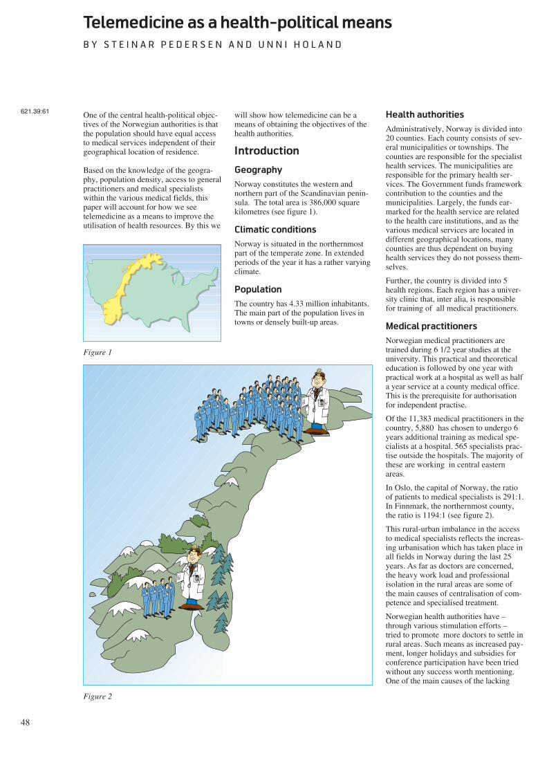
48
Telemedicine as a health-political means
B Y S T E I N A R P E D E R S E N A N D U N N I H O L A N D
One of the central health-political objec-tives of the Norwegian authorities is thatthe population should have equal accessto medical services independent of theirgeographical location of residence.
Based on the knowledge of the geogra-phy, population density, access to generalpractitioners and medical specialistswithin the various medical fields, thispaper will account for how we seetelemedicine as a means to improve theutilisation of health resources. By this we
will show how telemedicine can be ameans of obtaining the objectives of thehealth authorities.
Introduction
Geography
Norway constitutes the western andnorthern part of the Scandinavian penin-sula. The total area is 386,000 squarekilometres (see figure 1).
Climatic conditions
Norway is situated in the northernmostpart of the temperate zone. In extendedperiods of the year it has a rather varyingclimate.
Population
The country has 4.33 million inhabitants.The main part of the population lives intowns or densely built-up areas.
Health authorities
Administratively, Norway is divided into20 counties. Each county consists of sev-eral municipalities or townships. Thecounties are responsible for the specialisthealth services. The municipalities areresponsible for the primary health ser-vices. The Government funds frameworkcontribution to the counties and themunicipalities. Largely, the funds ear-marked for the health service are relatedto the health care institutions, and as thevarious medical services are located indifferent geographical locations, manycounties are thus dependent on buyinghealth services they do not possess them-selves.
Further, the country is divided into 5health regions. Each region has a univer-sity clinic that, inter alia, is responsiblefor training of all medical practitioners.
Medical practitioners
Norwegian medical practitioners aretrained during 6 1/2 year studies at theuniversity. This practical and theoreticaleducation is followed by one year withpractical work at a hospital as well as halfa year service at a county medical office.This is the prerequisite for authorisationfor independent practise.
Of the 11,383 medical practitioners in thecountry, 5,880 has chosen to undergo 6years additional training as medical spe-cialists at a hospital. 565 specialists prac-tise outside the hospitals. The majority ofthese are working in central easternareas.
In Oslo, the capital of Norway, the ratioof patients to medical specialists is 291:1.In Finnmark, the northernmost county,the ratio is 1194:1 (see figure 2).
This rural-urban imbalance in the accessto medical specialists reflects the increas-ing urbanisation which has taken place inall fields in Norway during the last 25years. As far as doctors are concerned,the heavy work load and professionalisolation in the rural areas are some ofthe main causes of centralisation of com-petence and specialised treatment.
Norwegian health authorities have –through various stimulation efforts –tried to promote more doctors to settle inrural areas. Such means as increased pay-ment, longer holidays and subsidies forconference participation have been triedwithout any success worth mentioning.One of the main causes of the lacking
621.39:61
Figure 1
Figure 2
49
success is that the efforts have notimproved the doctors feeling of profes-sional isolation (see figure 3).
Telemedicine
Telemedicine is defined as the investiga-tion, monitoring and management ofpatients which allow ready access toexpert advice and patient information nomatter where the patient or relevant infor-mation is located.
Effect of telemedicine on
the Norwegian public
health service
Help to the patients and the
medical practitioners
By help of telemedicine it is possible togive Norwegian general practitioners(GPs) immediate and direct access tomedical experts in various hospitals. Thisreduces the feeling of professional isola-tion. As described above, this is one ofthe main causes of the poor coverage ofdoctors in rural areas.
In this way, telemedicine will have atwofold function by improving access tomedical expertise, as well as at the sametime stabilising the manpower situationamong health workers in rural areas.
By help of telemedicine the rural generalpractitioners will – at least as long as itdisseminated by video conference net-work – have an advantage in preferenceto their urban colleagues in being counselfor their patients by obtaining quick accessto expert assistance.
Distribution of competence
We would like to summarise the maineffects of new developments intelemedicine in the conception of build-ing up decentralised competence. Besidesgiving the population in rural areasaccess to required medical expertise, itturns out that telemedicine contributes toa considerable professional strengtheningof local GPs by means of the personalinstruction that has been brought about.
Usually, remote consultation takes placein collaboration with the local doctor andthe patient. This implicates that the localdoctor can participate in the specialistexamination. In turn, this leads to agreater insight in the medical problem.In the longer term the local doctors willby this means be able to treat far morepatients who otherwise would have to be
referred to outpatients department at thehospitals. In this way resources at thehospitals are released and travellingexpenses are reduced.
The conditions for personal instructioncan be further developed to distance edu-cation through the system of video con-ference. By reorganisation of the internaltraining at larger hospitals, it can be dis-tributed via the telecommunication net-work to health workers at peripheralinstitutions.
For general practitioners, it is acceptedthat telemedicine counts for the specialityconcerning skin diseases and psychiatry.
Help to better exploitation of
resources
Telemedicine has no geographicalboundaries. In principle, medicalresources are available wherever thetelecommunication network is accessible.The vision is that required medicalexpertise can be utilised at the placewhere it exists. In the future, it will notbe essential that all medical centres pos-sess all leading-edge competence in theirmidst. It can be sought where it can befound. In the near future the nationalhealth network can be extended withdirect connection to professionals abroad.
Up to now, the selection of professionalcollaborators within the health network
has to a great extent been regulated byeconomic frameworks. The future tele-market will be characterised by the factthat demand for medical competence willbe directed towards centres that are dis-tinguished by their medical competence,availability, price and general level ofservice.
Help to health-political planning
Telemedicine will also be an aid to betterstandardisation of treatment and controlprocedures for medical treatment plans.Where the telecommunication network isused to distribute information and advise,it could at the same time be considered acollection and adaptation of medical dataabout the population, standardised on acountry basis. This would give medicalresearchers and health planners animproved foundation for future strategicdecisions.
Critical factors
For the time being, technical solutionsare not a limiting factor for developmentor utilisation of the potential oftelemedicine. Today, good technicalsolutions are available in several fields.These will be further improved in thefuture. Furthermore, new technology willbe developed, making more and morenew services obtainable.
$
Z Z Z Z
Figure 3
50
The cost of technical solutions and con-sequently, the use of them, will steadilydecrease. The limiting factor will be theability of the health authorities to adaptin order to fully use the telemedicalpotential.
In Norway the greatest obstacle will bethe economic and administrative frame-works inherent in the fact that the Nor-wegian public health service is decen-tralised to 3 financing levels with geo-graphical boundaries. As the telecommu-nication network does not take suchboundaries into consideration, the presentorganising and administrative manage-ment structures must be altered and mademore flexible. Otherwise, this will consti-tute a great threat to the present positivedevelopment. In addition, within the vari-ous administrations there will be personswho feel their own positions threatened.Furthermore, such groups of health per-sonnel who have built up their positionsby being the sole holders of medicalcompetence will have their positionsthreatened and may act as saboteurs.
Department of telemedicine
In order to consolidate the telemedicalcompetence in Norway the Ministry ofHealth and Social Affairs has assignedthe nationwide function for telemedicineto the University Hospital of Tromsø. Aspecial department is now being estab-lished through co-operation between
researchers at the Norwegian TelecomResearch in Tromsø and medical person-nel at the University Hospital ofTromsø. In addition to developing newapplications for telemedicine, the Depart-ment of Telemedicine shall guaranteethat tele-medical services match medicalstandards. It shall also further developlegal and organisational conditionswithin telemedicine, propose new pay-ment arrangements for the service andseek to put approved applications intooperation on a nationwide basis.
In its preliminary work this telemedicaldepartment has proposed towards thecentral health authorities that the legalresponsibilities towards the individualpatient in a telemedical consultation situ-ation shall not differ from any otherpatient/doctor situation. This means thatit is always the person with highest medi-cal competence who decides whether thepatient information upon which a deci-sion is made, is of satisfactory quality.This principle must be considered inde-pendent of the way in which the informa-tion is obtained by the specialist.
Responsibility to prevent leakage of datain the telecommunication network isimposed on the company delivering theservice. Responsibility for storage of dataat health institutions must be imposed onthe individual institution in accordancewith further regulations by superior datasupervision and health authorities. Thetelemedical department has further pro-
posed that payment for telemedical ser-vices should be channelled to the depart-ment which has rendered the service. It isour opinion that the economic profitinherent in the reorganisation into a med-ical nationwide health network forms agood basis for such a financing model.The central health authorities would thenbe the financing sources.
When the premises for infrastructurewithin telecommunication are presentand the required reorganisation of thepublic health services is complete,telemedicine will be the potential meansneeded by the health authorities to reachthe objective of giving Norway’s popula-tion equal access to medical servicesindependent of their geographic locationof residence.
Department of Telemedicine
Figure 4
51
Quality requirements for telemedical services
B Y U N N I H O L A N D A N D S T E I N A R P E D E R S E N
Telemedicine implies the use of newmethods, routines and aids within thepublic health services. The telemedicalhistory is short and experience is lim-ited. Today many health workers andpatients meet the telemedical services forthe first time.
Among others, this is one reason why thefollowing question is of central impor-tance: Can patients and health workershave the same confidence in a diagnosiswhen the examination is carried outthrough telecommunication as when it iscarried out in a traditional way? Thisquestion concerns the quality of thetelemedical services. Justification anddiffusion into the health services presup-pose a positive answer to this and relatedquestions.
Quality assurance is steadily gainingimportance within the health services.Diagnostic confidence is a central pointin the telemedical work. In the course oftime the criteria for quality have changedsomewhat. Only a few years ago qualitywould be assessed on the basis of criterialike equal offer of health services andfairness in the access to medical services.Today we see how the patients’ ownassessment and experience of the serviceare taken into account, coupled with thefact that quality tends to be assessedbased on efficiency, productivity andother factors of practical economics.Quality cannot be assessed isolated fromthe ideological and health-political prior-ities applied at a certain time. To strivefor the best possible quality entails a bal-ance of various values.
Examination of service quality assumesan adequate base for comparison. Towhat standards of quality shouldtelemedicine be compared? It is irrele-vant to set up a standard requiring 100 %correct diagnosis in all cases, unquestion-able satisfaction by the patients, orincreased efficiency of all tasks encoun-tered. Such an absolute standard is notapplied by assessment of other functionsof the health services either.
Assessment of quality should in ouropinion be undertaken by a comparisonof relative standard, based upon estab-lished practice by the health service. Asan example, we know that the diagnosticpractice implies a certain probability ofmistakes. Such errors emerge either bydiagnosis of a disease not present in thepatient (false positives) or by a complaintnot detected and diagnosed (false nega-tives).
Within the health services there seem toexist unwritten and fraternal general linesfor acceptable levels of erroneous diag-nosis. Such levels will vary depending onthe field and environment in the healthservice. In spite of these variations, it isthese quality requirements thattelemedicine has to be put up against.
One recurring problem is the fact thatdocumentation of the qualitative level oftoday’s examination methods is oftenlacking. Examinations of quality oftelemedical services have brought to lightthe lack of corresponding data by use oftraditional methods.
Within telemedicine we will argue thatquality should be discussed based upontwo main conditions: first, an objectivemeasure on performance of the medicalpractice and the management of compe-tence and resources; and second, patientsatisfaction concerning the telemedicalservices.
Standard of exercising
medical service
The first main criterion for quality isrelated to medical and professional prob-lems and the practising of medical com-petence. In concrete terms this implies:
- diagnostic security
- whether the help is given in adequateplace and at adequate time
- whether the way of working adds tothe competence and skill by the localhealth services in the long run.
Telemedical services must satisfy thedemand on precise medical assessmentsand diagnosing. This is termed diagnosticconfidence and constitutes an essentialcondition for application and furtherdevelopment of telemedicine.
Diagnosing has a central function withinthe health services. In the first place thediagnosis gives directions for treatmentof the individual patient. In broad out-line, the same diagnosis for severalpatients implies that they shall haveequal treatment.
Another central function of the diagnosisis as “label” on patients with nearly com-mon medical status. Such “labels” makeit possible to exchange information aboutthe phenomenon indicated by the diagno-sis. In this way it is possible to systema-tise experience gained by the healthworkers, draw up strategies for the run-ning of the institution and set up priori-
ties in accordance with the population’scondition of health.
A requirement to telemedical servicesmust be that the probability of erroneousdiagnoses does not exceed the error oftraditional procedures. In particular, thisrequirement must cover the danger offalse negatives.
The task of assuring diagnostic quality isan important part of the testing of thetelemedical services. This is accom-plished by a systematic comparison ofthe diagnostic precision of telemedicaland traditional diagnosing respectively.Results from such investigations areavailable within the fields of dermatol-ogy (Jøsendal and Fosse, 1991), pathol-ogy (Eide, Nordrum and Stalsberg, 1992)and endoscopy (Hartviksen and Peder-sen, 1992). All of these papers verify thattelebased diagnosing maintains a highprofessional standard. In addition tothese investigations, work is carried outon new quality studies in connection withthe use of endoscopy and investigationsare initiated in the field of cardiology.Preliminary results from the ongoingstudies indicates that remote consulta-tions within cardiology also satisfies thestringent requirements for diagnosticconfidence.
Through remote diagnosing or by obtain-ing external competence in the work of alocal practitioner, telemedicine makes itpossible to deliver health services at theright point of time and at the right place.The patient can be examined, diagnosed,and have treatment as soon as it is appro-priate from a professional assessment.
This effect has emerged in spite of theshort period of time the telemedical ser-vices have been operational. The use oftelemedicine leads to a genuine reductionof waiting time between reference andexamination by a specialist. Early identi-fication of the problems and consequenttreatment improves the probability ofeffective recovery. This reduces the needfor further referral for the same patient,which in turn leads to reduced waitingtime for new patients. Telemedical ser-vices also provides access to medicalexpertise on very short notice, e.g. in anacute situation. Reduced travel activityincreases the efficiency of the doctor.
Reduced waiting time and more efficientuse of resources are related to the factthat telemedicine reduces the relevanceof geographic address. In principle, itmakes no difference whether the distancebetween doctor and patient is short or
621.39:61658.56
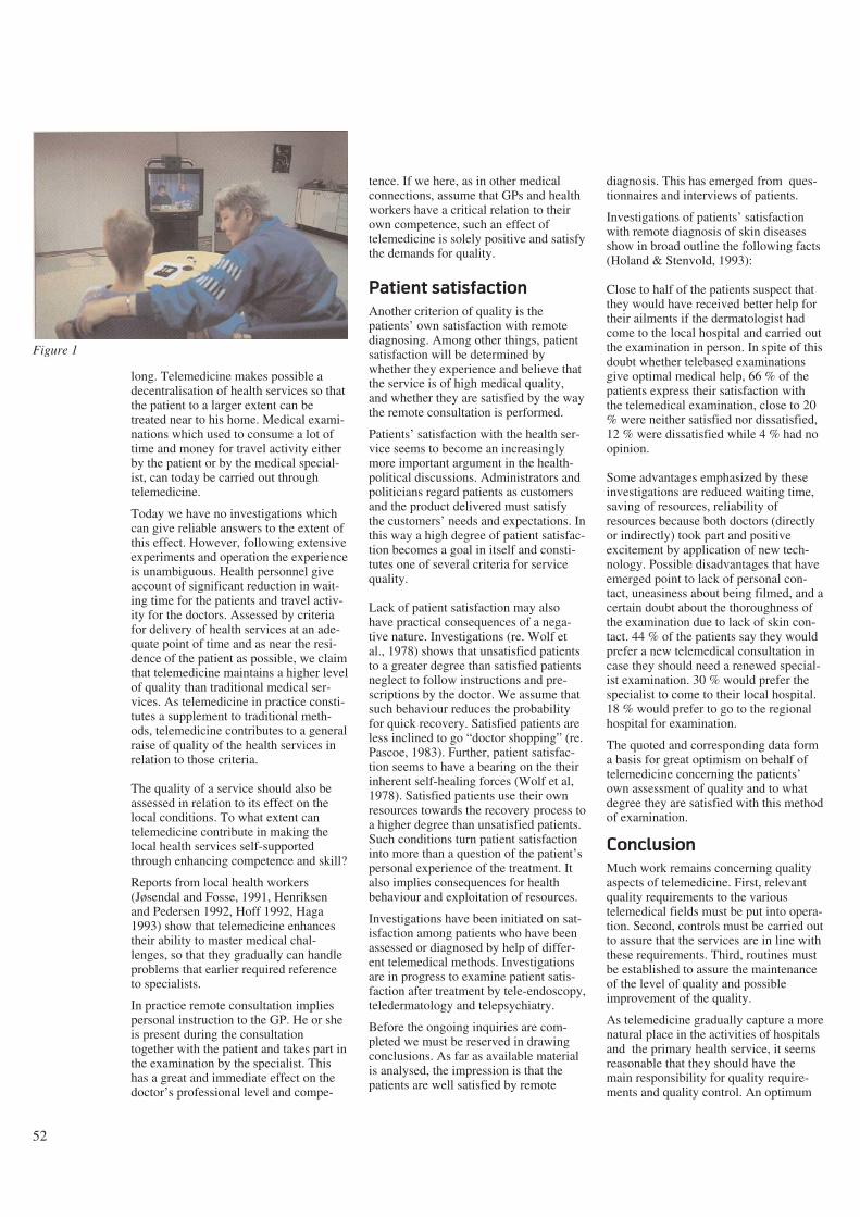
52
long. Telemedicine makes possible adecentralisation of health services so thatthe patient to a larger extent can betreated near to his home. Medical exami-nations which used to consume a lot oftime and money for travel activity eitherby the patient or by the medical special-ist, can today be carried out throughtelemedicine.
Today we have no investigations whichcan give reliable answers to the extent ofthis effect. However, following extensiveexperiments and operation the experienceis unambiguous. Health personnel giveaccount of significant reduction in wait-ing time for the patients and travel activ-ity for the doctors. Assessed by criteriafor delivery of health services at an ade-quate point of time and as near the resi-dence of the patient as possible, we claimthat telemedicine maintains a higher levelof quality than traditional medical ser-vices. As telemedicine in practice consti-tutes a supplement to traditional meth-ods, telemedicine contributes to a generalraise of quality of the health services inrelation to those criteria.
The quality of a service should also beassessed in relation to its effect on thelocal conditions. To what extent cantelemedicine contribute in making thelocal health services self-supportedthrough enhancing competence and skill?
Reports from local health workers(Jøsendal and Fosse, 1991, Henriksenand Pedersen 1992, Hoff 1992, Haga1993) show that telemedicine enhancestheir ability to master medical chal-lenges, so that they gradually can handleproblems that earlier required referenceto specialists.
In practice remote consultation impliespersonal instruction to the GP. He or sheis present during the consultationtogether with the patient and takes part inthe examination by the specialist. Thishas a great and immediate effect on thedoctor’s professional level and compe-
tence. If we here, as in other medicalconnections, assume that GPs and healthworkers have a critical relation to theirown competence, such an effect oftelemedicine is solely positive and satisfythe demands for quality.
Patient satisfaction
Another criterion of quality is thepatients’ own satisfaction with remotediagnosing. Among other things, patientsatisfaction will be determined bywhether they experience and believe thatthe service is of high medical quality,and whether they are satisfied by the waythe remote consultation is performed.
Patients’ satisfaction with the health ser-vice seems to become an increasinglymore important argument in the health-political discussions. Administrators andpoliticians regard patients as customersand the product delivered must satisfythe customers’ needs and expectations. Inthis way a high degree of patient satisfac-tion becomes a goal in itself and consti-tutes one of several criteria for servicequality.
Lack of patient satisfaction may alsohave practical consequences of a nega-tive nature. Investigations (re. Wolf etal., 1978) shows that unsatisfied patientsto a greater degree than satisfied patientsneglect to follow instructions and pre-scriptions by the doctor. We assume thatsuch behaviour reduces the probabilityfor quick recovery. Satisfied patients areless inclined to go “doctor shopping” (re.Pascoe, 1983). Further, patient satisfac-tion seems to have a bearing on the theirinherent self-healing forces (Wolf et al,1978). Satisfied patients use their ownresources towards the recovery process toa higher degree than unsatisfied patients.Such conditions turn patient satisfactioninto more than a question of the patient’spersonal experience of the treatment. Italso implies consequences for healthbehaviour and exploitation of resources.
Investigations have been initiated on sat-isfaction among patients who have beenassessed or diagnosed by help of differ-ent telemedical methods. Investigationsare in progress to examine patient satis-faction after treatment by tele-endoscopy,teledermatology and telepsychiatry.
Before the ongoing inquiries are com-pleted we must be reserved in drawingconclusions. As far as available materialis analysed, the impression is that thepatients are well satisfied by remote
diagnosis. This has emerged from ques-tionnaires and interviews of patients.
Investigations of patients’ satisfactionwith remote diagnosis of skin diseasesshow in broad outline the following facts(Holand & Stenvold, 1993):
Close to half of the patients suspect thatthey would have received better help fortheir ailments if the dermatologist hadcome to the local hospital and carried outthe examination in person. In spite of thisdoubt whether telebased examinationsgive optimal medical help, 66 % of thepatients express their satisfaction withthe telemedical examination, close to 20% were neither satisfied nor dissatisfied,12 % were dissatisfied while 4 % had noopinion.
Some advantages emphasized by theseinvestigations are reduced waiting time,saving of resources, reliability ofresources because both doctors (directlyor indirectly) took part and positiveexcitement by application of new tech-nology. Possible disadvantages that haveemerged point to lack of personal con-tact, uneasiness about being filmed, and acertain doubt about the thoroughness ofthe examination due to lack of skin con-tact. 44 % of the patients say they wouldprefer a new telemedical consultation incase they should need a renewed special-ist examination. 30 % would prefer thespecialist to come to their local hospital.18 % would prefer to go to the regionalhospital for examination.
The quoted and corresponding data forma basis for great optimism on behalf oftelemedicine concerning the patients’own assessment of quality and to whatdegree they are satisfied with this methodof examination.
Conclusion
Much work remains concerning qualityaspects of telemedicine. First, relevantquality requirements to the varioustelemedical fields must be put into opera-tion. Second, controls must be carried outto assure that the services are in line withthese requirements. Third, routines mustbe established to assure the maintenanceof the level of quality and possibleimprovement of the quality.
As telemedicine gradually capture a morenatural place in the activities of hospitalsand the primary health service, it seemsreasonable that they should have themain responsibility for quality require-ments and quality control. An optimum
Figure 1
53
solution would be for quality to be con-tinuously assessed on the basis of medi-cal requirements, technical requirements,and patients’ own requirements.
References
Eide, T J, Nordrum, I, Stalsberg, H.1992. The validity of frozen section diag-nosis based on video-microscopy. Inpress, Zentralblatt für Patologie.
Haga, D. 1993. Opinion presented inSosialkanalen, Norwegian BroadcastingSystem, TV, 13.01.93.
Hartviksen, G, Pedersen, S. 1992.Remote endoscopy of otorhinolaryngol-ogy patients. In: Proceedings of OpticalFibres in Medicine VII, ed. by A Katzir,Proceedings SPIE; vol 1649, 186-91.
Hoff, I. 1992. Video: Telepsychiatry.Another way of meeting. Kåre TannvikA/S, Kirkenes. (In Norwegian)
Holand, U, Stenvold, S E. 1993. Are thepatients satisfied with remote telederma-tological consultations? In prep. for Firstinternational conference on medicalaspects of Telemedicine, Tromsø.
Jøsendal, O et al. 1991. Remote diagno-sis of skin complaints. The Journal of theNorwegian Medical Association, 3(111),343-5. (In Norwegian)
Pascoe, G C. 1991. Patient satisfaction inprimary health care. Evaluation and pro-gram planning, 6, 185-210.
Wolf, M H et al. 1978. The medicalinterview satisfaction scale: Develop-ment of a scale to measure patient per-ception of physician behaviour. Journalof Behavioural Medicine, 1.
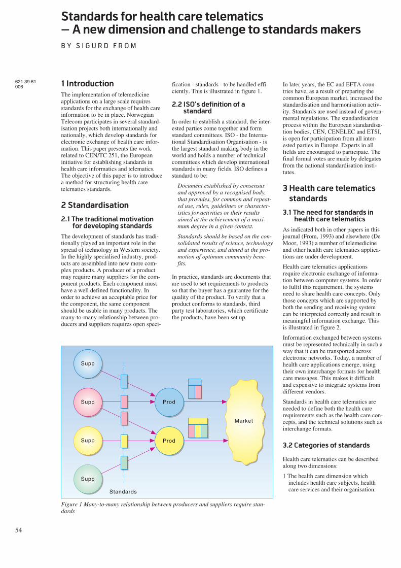
54
Standards for health care telematics
– A new dimension and challenge to standards makers
B Y S I G U R D F R O M
1 Introduction
The implementation of telemedicineapplications on a large scale requiresstandards for the exchange of health careinformation to be in place. NorwegianTelecom participates in several standard-isation projects both internationally andnationally, which develop standards forelectronic exchange of health care infor-mation. This paper presents the workrelated to CEN/TC 251, the Europeaninitiative for establishing standards inhealth care informatics and telematics.The objective of this paper is to introducea method for structuring health caretelematics standards.
2 Standardisation
2.1 The traditional motivation
for developing standards
The development of standards has tradi-tionally played an important role in thespread of technology in Western society.In the highly specialised industry, prod-ucts are assembled into new more com-plex products. A producer of a productmay require many suppliers for the com-ponent products. Each component musthave a well defined functionality. Inorder to achieve an acceptable price forthe component, the same componentshould be usable in many products. Themany-to-many relationship between pro-ducers and suppliers requires open speci-
fication - standards - to be handled effi-ciently. This is illustrated in figure 1.
2.2 ISO’s definition of a
standard
In order to establish a standard, the inter-ested parties come together and formstandard committees. ISO - the Interna-tional Standardisation Organisation - isthe largest standard making body in theworld and holds a number of technicalcommittees which develop internationalstandards in many fields. ISO defines astandard to be:
Document established by consensusand approved by a recognised body,that provides, for common and repeat-ed use, rules, guidelines or character-istics for activities or their resultsaimed at the achievement of a maxi-mum degree in a given context.
Standards should be based on the con-solidated results of science, technologyand experience, and aimed at the pro-motion of optimum community bene-fits.
In practice, standards are documents thatare used to set requirements to productsso that the buyer has a guarantee for thequality of the product. To verify that aproduct conforms to standards, thirdparty test laboratories, which certificatethe products, have been set up.
In later years, the EC and EFTA coun-tries have, as a result of preparing thecommon European market, increased thestandardisation and harmonisation activ-ity. Standards are used instead of govern-mental regulations. The standardisationprocess within the European standardisa-tion bodies, CEN, CENELEC and ETSI,is open for participation from all inter-ested parties in Europe. Experts in allfields are encouraged to participate. Thefinal formal votes are made by delegatesfrom the national standardisation insti-tutes.
3 Health care telematics
standards
3.1 The need for standards in
health care telematics
As indicated both in other papers in thisjournal (From, 1993) and elsewhere (DeMoor, 1993) a number of telemedicineand other health care telematics applica-tions are under development.
Health care telematics applicationsrequire electronic exchange of informa-tion between computer systems. In orderto fulfil this requirement, the systemsneed to share health care concepts. Onlythose concepts which are supported byboth the sending and receiving systemcan be interpreted correctly and result inmeaningful information exchange. Thisis illustrated in figure 2.
Information exchanged between systemsmust be represented technically in such away that it can be transported acrosselectronic networks. Today, a number ofhealth care applications emerge, usingtheir own interchange formats for healthcare messages. This makes it difficultand expensive to integrate systems fromdifferent vendors.
Standards in health care telematics areneeded to define both the health carerequirements such as the health care con-cepts, and the technical solutions such asinterchange formats.
3.2 Categories of standards
Health care telematics can be describedalong two dimensions:
1 The health care dimension whichincludes health care subjects, healthcare services and their organisation.
621.39:61006
Supp
Supp
Supp
Supp
Prod
Prod
Market
Standards
Figure 1 Many-to-many relationship between producers and suppliers require stan-dards
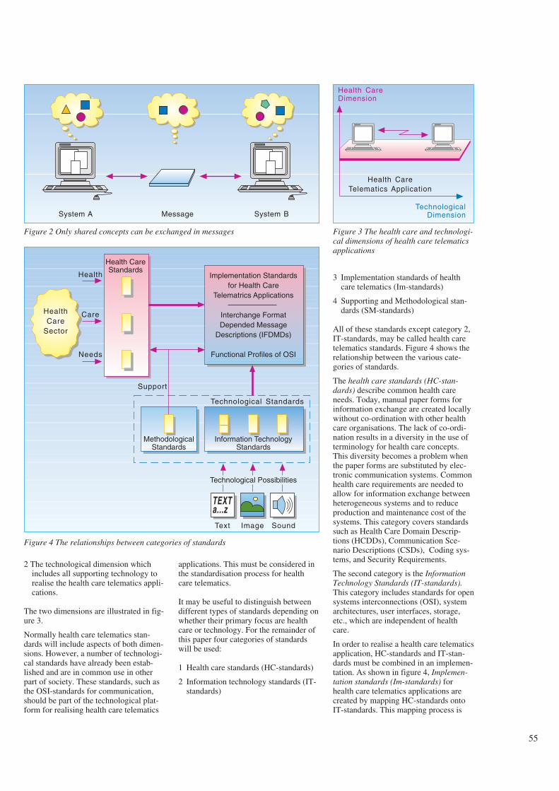
55
2 The technological dimension whichincludes all supporting technology torealise the health care telematics appli-cations.
The two dimensions are illustrated in fig-ure 3.
Normally health care telematics stan-dards will include aspects of both dimen-sions. However, a number of technologi-cal standards have already been estab-lished and are in common use in otherpart of society. These standards, such asthe OSI-standards for communication,should be part of the technological plat-form for realising health care telematics
applications. This must be considered inthe standardisation process for healthcare telematics.
It may be useful to distinguish betweendifferent types of standards depending onwhether their primary focus are healthcare or technology. For the remainder ofthis paper four categories of standardswill be used:
1 Health care standards (HC-standards)
2 Information technology standards (IT-standards)
3 Implementation standards of healthcare telematics (Im-standards)
4 Supporting and Methodological stan-dards (SM-standards)
All of these standards except category 2,IT-standards, may be called health caretelematics standards. Figure 4 shows therelationship between the various cate-gories of standards.
The health care standards (HC-stan-dards) describe common health careneeds. Today, manual paper forms forinformation exchange are created locallywithout co-ordination with other healthcare organisations. The lack of co-ordi-nation results in a diversity in the use ofterminology for health care concepts.This diversity becomes a problem whenthe paper forms are substituted by elec-tronic communication systems. Commonhealth care requirements are needed toallow for information exchange betweenheterogeneous systems and to reduceproduction and maintenance cost of thesystems. This category covers standardssuch as Health Care Domain Descrip-tions (HCDDs), Communication Sce-nario Descriptions (CSDs), Coding sys-tems, and Security Requirements.
The second category is the InformationTechnology Standards (IT-standards).This category includes standards for opensystems interconnections (OSI), systemarchitectures, user interfaces, storage,etc., which are independent of healthcare.
In order to realise a health care telematicsapplication, HC-standards and IT-stan-dards must be combined in an implemen-tation. As shown in figure 4, Implemen-tation standards (Im-standards) forhealth care telematics applications arecreated by mapping HC-standards ontoIT-standards. This mapping process is
System A Message System B
Figure 2 Only shared concepts can be exchanged in messages
Health CareTelematics Application
Health CareDimension
TechnologicalDimension
Figure 3 The health care and technologi-cal dimensions of health care telematicsapplications
HealthCare
Sector
Health CareStandards
Implementation Standardsfor Health Care
Telematrics Applications
Interchange FormatDepended Message
Descriptions (IFDMDs)
Functional Profiles of OSI
Health
Care
Needs
MethodologicalStandards
Information TechnologyStandards
Technological Possibilities
TEXTa...z
Support
Technological Standards
Text Image Sound
Figure 4 The relationships between categories of standards
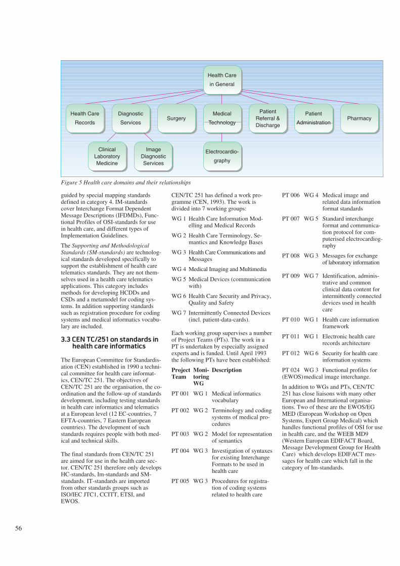
56
guided by special mapping standardsdefined in category 4. IM-standardscover Interchange Format DependentMessage Descriptions (IFDMDs), Func-tional Profiles of OSI-standards for usein health care, and different types ofImplementation Guidelines.
The Supporting and MethodologicalStandards (SM-standards) are technolog-ical standards developed specifically tosupport the establishment of health caretelematics standards. They are not them-selves used in a health care telematicsapplications. This category includesmethods for developing HCDDs andCSDs and a metamodel for coding sys-tems. In addition supporting standardssuch as registration procedure for codingsystems and medical informatics vocabu-lary are included.
3.3 CEN TC/251 on standards in
health care informatics
The European Committee for Standardis-ation (CEN) established in 1990 a techni-cal committee for health care informat-ics, CEN/TC 251. The objectives ofCEN/TC 251 are the organisation, the co-ordination and the follow-up of standardsdevelopment, including testing standardsin health care informatics and telematicsat a European level (12 EC-countries, 7EFTA-countries, 7 Eastern Europeancountries). The development of suchstandards requires people with both med-ical and technical skills.
The final standards from CEN/TC 251are aimed for use in the health care sec-tor. CEN/TC 251 therefore only developsHC-standards, Im-standards and SM-standards. IT-standards are importedfrom other standards groups such asISO/IEC JTC1, CCITT, ETSI, andEWOS.
CEN/TC 251 has defined a work pro-gramme (CEN, 1993). The work isdivided into 7 working groups:
WG 1 Health Care Information Mod-elling and Medical Records
WG 2 Health Care Terminology, Se-mantics and Knowledge Bases
WG 3 Health Care Communications andMessages
WG 4 Medical Imaging and Multimedia
WG 5 Medical Devices (communicationwith)
WG 6 Health Care Security and Privacy,Quality and Safety
WG 7 Intermittently Connected Devices(incl. patient-data-cards).
Each working group supervises a numberof Project Teams (PTs). The work in aPT is undertaken by especially assignedexperts and is funded. Until April 1993the following PTs have been established:
Project Moni- DescriptionTeam toring
WG
PT 001 WG 1 Medical informaticsvocabulary
PT 002 WG 2 Terminology and codingsystems of medical pro-cedures
PT 003 WG 2 Model for representationof semantics
PT 004 WG 3 Investigation of syntaxesfor existing InterchangeFormats to be used inhealth care
PT 005 WG 3 Procedures for registra-tion of coding systemsrelated to health care
PT 006 WG 4 Medical image andrelated data informationformat standards
PT 007 WG 5 Standard interchangeformat and communica-tion protocol for com-puterised electrocardiog-raphy
PT 008 WG 3 Messages for exchangeof laboratory information
PT 009 WG 7 Identification, adminis-trative and commonclinical data content forintermittently connecteddevices used in healthcare
PT 010 WG 1 Health care informationframework
PT 011 WG 1 Electronic health carerecords architecture
PT 012 WG 6 Security for health careinformation systems
PT 024 WG 3 Functional profiles for(EWOS)medical image interchange.
In addition to WGs and PTs, CEN/TC251 has close liaisons with many otherEuropean and International organisa-tions. Two of these are the EWOS/EGMED (European Workshop on OpenSystems, Expert Group Medical) whichhandles functional profiles of OSI for usein health care, and the WEEB MD9(Western European EDIFACT Board,Message Development Group for HealthCare) which develops EDIFACT mes-sages for health care which fall in thecategory of Im-standards.
Health Care
Records
Diagnostic
ServicesSurgery
Medical
Technology
PatientReferral &Discharge
Patient
AdministrationPharmacy
Health Care
in General
Electrocardio-
graphy
ClinicalLaboratoryMedicine
ImageDiagnosticServices
Figure 5 Health care domains and their relationships
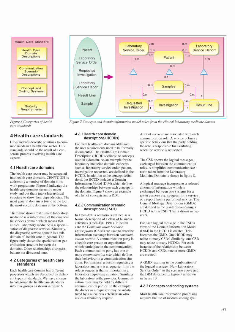
57
4 Health care standards
HC-standards describe solutions to com-mon needs in a health care sector. HC-standards should be the result of a con-sensus process involving health careexperts.
4.1 Health care domains
The health care sector may be separatedinto health care domains. CEN/TC 251 isaddressing a number of domain in itswork programme. Figure 5 indicates thehealth care domains currently understudy and put them into a hierarchicalstructure to show their dependencies. Themost general domain is found at the top;the most specific domains at the bottom.
The figure shows that clinical laboratorymedicine is a sub-domain of the diagnos-tic services domain which means thatclinical laboratory medicine is a speciali-sation of diagnostic services. Similarly,the diagnostic service domain is a sub-domain of health care in general. Thefigure only shows the specialisation-gen-eralisation structure between thedomains. Other relationships also existbut are not discussed here.
4.2 Categories of health care
standards
Each health care domain has differentproperties which are described by differ-ent types of standards. We have chosento categorise the health care standardsinto four groups as shown in figure 6.
4.2.1 Health care domain
descriptions (HCDDs)
For each health care domain addressed,the user requirements need to be formallydocumented. The Health Care DomainDescription (HCDD) defines the conceptsused in a domain. As an example for thelaboratory medicine domain, conceptssuch as laboratory service order, patient,investigation requested, are defined in theHCDD. In addition to the concept defini-tions, the HCDD includes a DomainInformation Model (DIM) which definesthe relationships between each concept inthe domain. Figure 7 shows an exampleof a list of concepts and a DIM.
4.2.2 Communication scenario
descriptions (CSDs)
In Open-Edi, a scenario is defined as aformal description of a class of businessactivities (Open-Edi, 1991). In healthcare the Communication ScenarioDescriptions (CSDs) are used to describeinformation exchange between communi-cation parties. A communication party isa health care person or organisationwhich participate in the communication.Each communication party has one ormore communication role which definestheir behaviour in a communication situ-ation. For instance, a doctor requesting alaboratory analysis is a requester. It is therole as requester that is important in alaboratory requesting situation. Similarlythe laboratory is the provider. Communi-cation roles may be held by differentcommunication parties. In the example,the doctor as a requester may be substi-tuted by a nurse or a veterinarian whoissues a laboratory request.
A set of services are associated with eachcommunication role. A service defines aspecific behaviour that the party holdingthe role is responsible for exhibitingwhen the service is requested.
The CSD shows the logical messagesexchanged between the communicationroles. A simplified communication sce-nario taken from the LaboratoryMedicine Domain is shown in figure 8.
A logical message incorporates a selectedamount of information which isexchanged between two systems for agiven purpose e.g. a request for a serviceor a report from a performed service. TheGeneral Message Descriptions (GMDs)are defined as the result of combining aHCDD with a CSD. This is shown in fig-ure 9.
For each logical message in the CSD aview of the Domain Information Model(DIM) in the HCDD is created. Thisbecomes the GMD. One HCDD mayrelate to many CSDs. Similarly, one CSDmay relate to many HCDDs. For eachinstance of the relationship betweenHCDDs and CSDs, one or more GMDsare created.
A GMD resulting in the combination ofthe logical message “New LaboratoryService Order” in the scenario above andthe DIM described in figure 7 is shownin figure 10.
4.2.3 Concepts and coding systems
Most health care information processingrequires the use of medical coding sys-
Health CareDomain
Descriptions
Health Care Standard
CommunicationScenario
Descriptions
Concept andCoding Systems
SecurityRequirements
Figure 6 Categories of healthcare standards
LaboratoryService Order
Patient
LaboratoryService Report
Samples
InvestigationRequestedInvestigation
Result line
1.m
1
1 1
1
1.m
1.m
1.m 1.m
0.m
0.m
0.m
0.m
0.m0.m
0.m
0.m 0.m
0.1
0.m
Patient
LaboratoryService Order
RequestedInvestigation
LaboratoryService Report
Result Line
Sample
Figure 7 Concepts and domain information model taken from the clinical laboratory medicine domain
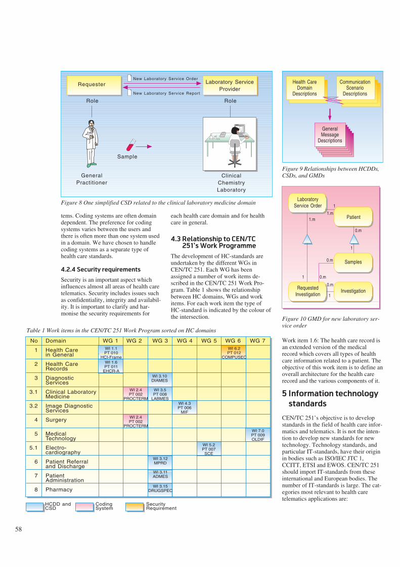
58
tems. Coding systems are often domaindependent. The preference for codingsystems varies between the users andthere is often more than one system usedin a domain. We have chosen to handlecoding systems as a separate type ofhealth care standards.
4.2.4 Security requirements
Security is an important aspect whichinfluences almost all areas of health caretelematics. Security includes issues suchas confidentiality, integrity and availabil-ity. It is important to clarify and har-monise the security requirements for
each health care domain and for healthcare in general.
4.3 Relationship to CEN/TC
251’s Work Programme
The development of HC-standards areundertaken by the different WGs inCEN/TC 251. Each WG has beenassigned a number of work items de-scribed in the CEN/TC 251 Work Pro-gram. Table 1 shows the relationshipbetween HC domains, WGs and workitems. For each work item the type ofHC-standard is indicated by the colour ofthe intersection.
Work item 1.6: The health care record isan extended version of the medicalrecord which covers all types of healthcare information related to a patient. Theobjective of this work item is to define anoverall architecture for the health carerecord and the various components of it.
5 Information technology
standards
CEN/TC 251’s objective is to developstandards in the field of health care infor-matics and telematics. It is not the inten-tion to develop new standards for newtechnology. Technology standards, andparticular IT-standards, have their originin bodies such as ISO/IEC JTC 1,CCITT, ETSI and EWOS. CEN/TC 251should import IT-standards from theseinternational and European bodies. Thenumber of IT-standards is large. The cat-egories most relevant to health caretelematics applications are:
GeneralPractitioner
ClinicalChemistryLaboratory
Requester Laboratory ServiceProvider
New Laboratory Service Order
New Laboratory Service Report
Sample
Role Role
Figure 8 One simplified CSD related to the clinical laboratory medicine domain
Health CareDomain
Descriptions
CommunicationScenario
Descriptions
GeneralMessage
Descriptions
Figure 9 Relationships between HCDDs,CSDs, and GMDs
1.m
1
1
1
1.m
0.m
0.m
0.m
1
0.m
LaboratoryService Order
Patient
Samples
InvestigationRequestedInvestigation
Figure 10 GMD for new laboratory ser-vice order
Domain
Health Carein General
Health CareRecords
DiagnosticServices
Clinical LaboratoryMedicine
Image DiagnosticServices
Surgery
MedicalTechnology
Electro-cardiography
Patient Referraland Discharge
PatientAdministration
Pharmacy
WG 1 WG 2 WG 3 WG 4 WG 5 WG 6 WG 7
HCDD andCSD
CodingSystem
SecurityRequirement
WI 1.1PT 010
HCI-FrameWI 1.6PT 011
EHCR-AWI 3.10DIAMES
WI 3.5PT 008
LABMES
WI 2.4PT 002
PROCTERM
WI 2.4PT 002
PROCTERM
WI 4.3PT 006
MIF
WI 6.2PT 012
COMPUSEC
WI 7.0PT 009OLDIF
WI 5.2PT 007
SCEWI 3.12MPRD
WI 3.11ADMES
WI 3.15DRUGSPEC
No
1
2
3
3.1
3.2
4
5
5.1
6
7
8
Table 1 Work items in the CEN/TC 251 Work Program sorted on HC domains
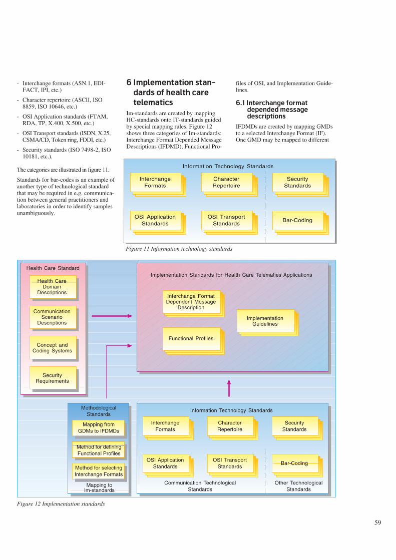
59
- Interchange formats (ASN.1, EDI-FACT, IPI, etc.)
- Character repertoire (ASCII, ISO8859, ISO 10646, etc.)
- OSI Application standards (FTAM,RDA, TP, X.400, X.500, etc.)
- OSI Transport standards (ISDN, X.25,CSMA/CD, Token ring, FDDI, etc.)
- Security standards (ISO 7498-2, ISO10181, etc.).
The categories are illustrated in figure 11.
Standards for bar-codes is an example ofanother type of technological standardthat may be required in e.g. communica-tion between general practitioners andlaboratories in order to identify samplesunambiguously.
6 Implementation stan-
dards of health care
telematics
Im-standards are created by mappingHC-standards onto IT-standards guidedby special mapping rules. Figure 12shows three categories of Im-standards:Interchange Format Depended MessageDescriptions (IFDMD), Functional Pro-
files of OSI, and Implementation Guide-lines.
6.1 Interchange format
depended message
descriptions
IFDMDs are created by mapping GMDsto a selected Interchange Format (IF).One GMD may be mapped to different
InterchangeFormats
CharacterRepertoire
SecurityStandards
OSI ApplicationStandards
Bar-CodingOSI Transport
Standards
Information Technology Standards
Figure 11 Information technology standards
InterchangeFormats
CharacterRepertoire
SecurityStandards
OSI ApplicationStandards
Bar-CodingOSI Transport
Standards
Information Technology Standards
Communication TechnologicalStandards
Other TechnologicalStandards
Mapping fromGDMs to IFDMDs
Method for definingFunctional Profiles
Method for selectingInterchange Formats
MethodologicalStandards
Mapping toIm-standards
Health CareDomain
Descriptions
Health Care Standard
CommunicationScenario
Descriptions
Concept andCoding Systems
SecurityRequirements
Implementation Standards for Health Care Telematies Applications
Interchange FormatDependent Message
Description
Functional Profiles
ImplementationGuidelines
Figure 12 Implementation standards
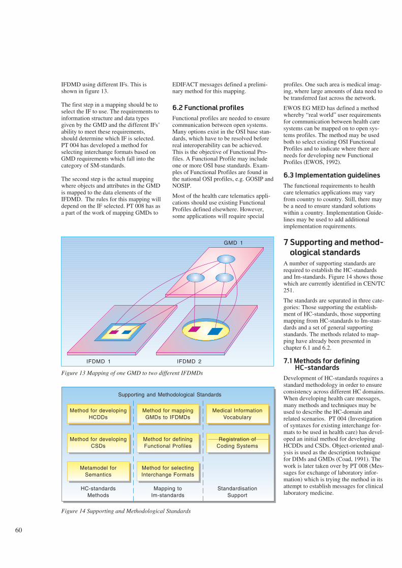
60
IFDMD using different IFs. This isshown in figure 13.
The first step in a mapping should be toselect the IF to use. The requirements toinformation structure and data typesgiven by the GMD and the different IFs’ability to meet these requirements,should determine which IF is selected.PT 004 has developed a method forselecting interchange formats based onGMD requirements which fall into thecategory of SM-standards.
The second step is the actual mappingwhere objects and attributes in the GMDis mapped to the data elements of theIFDMD. The rules for this mapping willdepend on the IF selected. PT 008 has asa part of the work of mapping GMDs to
EDIFACT messages defined a prelimi-nary method for this mapping.
6.2 Functional profiles
Functional profiles are needed to ensurecommunication between open systems.Many options exist in the OSI base stan-dards, which have to be resolved beforereal interoperability can be achieved.This is the objective of Functional Pro-files. A Functional Profile may includeone or more OSI base standards. Exam-ples of Functional Profiles are found inthe national OSI profiles, e.g. GOSIP andNOSIP.
Most of the health care telematics appli-cations should use existing FunctionalProfiles defined elsewhere. However,some applications will require special
profiles. One such area is medical imag-ing, where large amounts of data need tobe transferred fast across the network.
EWOS EG MED has defined a methodwhereby “real world” user requirementsfor communication between health caresystems can be mapped on to open sys-tems profiles. The method may be usedboth to select existing OSI FunctionalProfiles and to indicate where there areneeds for developing new FunctionalProfiles (EWOS, 1992).
6.3 Implementation guidelines
The functional requirements to healthcare telematics applications may varyfrom country to country. Still, there maybe a need to ensure standard solutionswithin a country. Implementation Guide-lines may be used to add additionalimplementation requirements.
7 Supporting and method-
ological standards
A number of supporting standards arerequired to establish the HC-standardsand Im-standards. Figure 14 shows thosewhich are currently identified in CEN/TC251.
The standards are separated in three cate-gories: Those supporting the establish-ment of HC-standards, those supportingmapping from HC-standards to Im-stan-dards and a set of general supportingstandards. The methods related to map-ping have already been presented inchapter 6.1 and 6.2.
7.1 Methods for defining
HC-standards
Development of HC-standards requires astandard methodology in order to ensureconsistency across different HC domains.When developing health care messages,many methods and techniques may beused to describe the HC-domain andrelated scenarios. PT 004 (Investigationof syntaxes for existing interchange for-mats to be used in health care) has devel-oped an initial method for developingHCDDs and CSDs. Object-oriented anal-ysis is used as the description techniquefor DIMs and GMDs (Coad, 1991). Thework is later taken over by PT 008 (Mes-sages for exchange of laboratory infor-mation) which is trying the method in itsattempt to establish messages for clinicallaboratory medicine.
GMD 1
IFDMD 1 IFDMD 2
Method for developingHCDDs
Supporting and Methodological Standards
Method for developingCSDs
Metamodel forSemantics
Method for mappingGMDs to IFDMDs
Method for definingFunctional Profiles
Method for selectingInterchange Formats
Medical InformationVocabulary
Registration ofCoding Systems
HC-standardsMethods
Mapping toIm-standards
StandardisationSupport
Figure 14 Supporting and Methodological Standards
Figure 13 Mapping of one GMD to two different IFDMDs
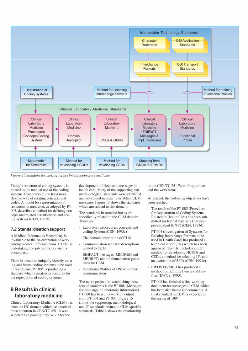
61
Today’s structure of coding systems isrelated to the manual use of the codingsystems. Computers allow for a moreflexible way of relating concepts andcodes. A model for representation ofsemantics in medicine, developed by PT003, describes a method for defining con-cepts and related classification and cod-ing systems (CEN, 1993b).
7.2 Standardisation support
A Medical Informatics Vocabulary isinvaluable to the co-ordination of workamong medical informaticians. PT 001 isundertaking the job to produce such avocabulary.
There is a need to uniquely identify exist-ing and future coding systems to be usedin health care. PT 005 is producing astandard which specifies procedures forthe registration of coding systems.
8 Results in clinical
laboratory medicine
Clinical Laboratory Medicine (CLM) hasbeen the HC domain which has receivedmost attention in CEN/TC 251. It wasselected as a paradigm by WG 3 for the
development of electronic messages inhealth care. Many of the supporting andmethodological standards were identifiedand developed in order to establish CLMmessages. Figure 15 shows the standardswhich are related to this domain.
The standards in rounded boxes arespecifically related to the CLM domain.These are:
- Laboratory procedures, concepts andcoding System (CEN, 1993c)
- The domain description of CLM
- Communication scenario descriptionsrelated to CLM
- EDIFACT messages (MEDREQ andMEDRPT) and implementation guide-lines for CLM
- Functional Profiles of OSI to supportcommunication
The nerve project for establishing thesesets of standards is the PT 008 (Messagesfor exchange of laboratory information).PT 008 has based its work on outputfrom PT 004 and PT 005. Figure 15shows the supporting, methodologicaland IT-standards related to CLM specificstandards. Table 2 shows the relationship
to the CEN/TC 251 Work Programmeand the work items.
At present, the following objectives havebeen reached:
- The result of the PT 005 (Procedurefor Registration of Coding SystemsRelated to Health Care) has been sub-mitted for formal vote as a Europeanpre-standard (ENV) (CEN, 1993d).
- PT 004 (Investigation of Syntaxes forExisting Interchange Formats to beused in Health Care) has produced atechnical report (TR) which has beenapproved. The TR includes a draftmethod for developing HCDDs andCSDs, a method for selecting IFs andan evaluation of 5 IFs (CEN, 1993c).
- EWOS EG MED has produced amethod for defining Functional Pro-files (EWOS, 1993).
- PT 008 has finished a first workingdocument for messages in CLM whichhas been distributed for comments. Afinal standard in CLM is expected inthe spring of 1994.
OSI ApplicationStandards
Registration ofCoding Systems
Metamodelfor Semantics
Method fordeveloping HCDDs
Mapping fromGMDs to IFDMDs
Method for selectingInterchange Formats
Method fordeveloping CSDs
CharacterRepertoire
OSI TransportStandards
InterchangeFormats
Information Technology Standards
Clinical Laboratory Medicine Standards
ClinicalLaboratoryMedicine
ProceduresConcepts/Coding
System
ClinicalLaboratoryMedicine
DomainDescription
ClinicalLaboratoryMedicine
CSDs & GMDs
ClinicalLaboratoryMedicineEDIFACT
Messages &Impl. Guidelines
ClinicalLaboratoryMedicine
FunctionalProfile
Method for definingFunctional Profiles
Figure 15 Standard for messaging in clinical laboratory medicine
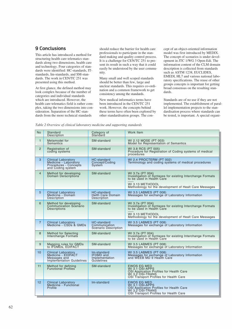
62
9 Conclusions
This article has introduced a method forstructuring health care telematics stan-dards along two dimensions, health careand technology. Four categories of stan-dards were identified: HC-standards, IT-standards, Im-standards, and SM-stan-dards. The work in CEN/TC 251 waspresented using this method.
At first glance, the defined method maylook complex because of the number ofcategories and individual standardswhich are introduced. However, thehealth care telematics field is rather com-plex, taking the two dimensions into con-sideration. Separation of the HC-stan-dards from the more technical standards
should reduce the barrier for health careprofessionals to participate in the stan-dard making and quality control process.It is a challenge for CEN/TC 251 to pre-sent its result in such a way that it couldeasily be understood by the user commu-nity.
Many small and well scoped standardsshould be better than few, large andunclear standards. This requires co-ordi-nation and a common framework to getconsistency among the standards.
New medical informatics terms havebeen introduced in the CEN/TC 251work. However, the concepts behindthese terms have often been explored byother standardisation groups. The con-
cept of an object-oriented informationmodel was first introduced by MEDIX.The concept of scenarios is under devel-opment in JTC 1/WG 3 Open-Edi. Theinformation content of the CLM domaindescription is collected from standardssuch as ASTM 1238, EUCLIDES,EMEDI, HL7 and various national labo-ratory specifications. The reuse of othergroups concepts is important for gettingbroad consensus on the resulting stan-dards.
Standards are of no use if they are notimplemented. The establishment of paral-lel implementation projects to the stan-dardisation process where standards canbe tested, is important. A special organi-
StandardDescription
Metamodel forSemantics
Registration ofcoding systems
Clinical LaboratoryMedicine - LaboratoryProcedures - Conceptsand Coding system
Method for developingDomain Derscriptions
Clinical LaboratoryMedicine - DomainDescription
Method for developingCommunication ScenarioDescriptions
Clinical LaboratoryMedicine - CSDs & GMDs
Method for SelectingInterchange Formats
Mapping rules for GMDsto IFDMDs, EDIFACT
Clinical LaboratoryMedicine - EDIFACTMessages andImplementation Guidelines
Method for definingFunctional Profiles
Clinical LaboratoryMedicine - FunctionalProfile
No
1
2
3
4
5
6
7
8
9
10
11
12
Category ofStandard
SM-standard
SM-standard
HC-standardConcept/CodingSystem
SM-standard
HC-standardHelth Care DomainDescription
SM-standard
HC-standardCommunicationScenario Description
SM-standard
SM-standard
Im-standardIFDMD andImplementationGuidelines
SM-standard
Im-standard
Work Item
WI 2.12 MOSE (PT 003)Model for Representation of Semantics
WI 3.8 RCS (PT 005)Procedure for Registration of Coding systems of medical procedures
WI 2.4 PROCTERM (PT 002)Terminology and coding systems of medical procedures
WI 3.7a (PT 004)Investigation of Syntaxes for existing Interchange Formats to be used in Health Care-----WI 3.13 METHODOLMethodology for the development of Healt Care Messages
WI 3.5 LABMES (PT 008)Messages for exchange of Laboratory Information
WI 3.7a (PT 004)Investigation of Syntaxes for existing Interchange Formats to be used in Health Care-----WI 3.13 METHODOLMethodology for the development of Healt Care Messages
WI 3.5 LABMES (PT 008)Messages for exchange of Laboratory Information
WI 3.7a (PT 004)Investigation of Syntaxes for existing Interchange Formats to be used in Health Care
WI 3.5 LABMES (PT 008)Messages for exchange of Laboratory Information
WI 3.5 LABMES (PT 008)Messages for exchange of Laboratory Informationand WEEB MD 9 Health Care
EWOS EG MEDWI 3.1 OSI-APPSOSI Application Profiles for Health CareWI 3.2 OSI-TRANSOSI Transport Profiles for Health Care
EWOS EG MEDWI 3.1 OSI-APPSOSI Application Profiles for Health CareWI 3.2 OSI-TRANSOSI Transport Profiles for Health Care
Table 2 Overview of clinical laboratory medicine and supporting standards
63
sation, ACOSTA, has been set up on theEuropean level to co-ordinate R & D,standardisation and industrial promotionin the field of health care telematics.Similar co-ordination is required onnational levels involving the nationalhealth authorities and user-groups inimplementation projects.
CEN/TC 251 has made rapid progresssince its establishment in 1990. Today,about 700 individual experts are active inCEN/TC 251 including national mirrorgroups. Two standards are in the processof formal voting. At the beginning of1994 a complete set of standards in theCLM domain are expected. Standards inthe other domains vary from 1994 to1996 depending on whether paid projectteams are used to carry out the work.
CEN/TC 251 represents a new construc-tion in the formal standardisation world.It serves a specific user-community(health care). Standardised user require-ments are given to the technical standard-isation bodies to influence the develop-ment of IT-standards. In the future it islikely that other industry sectors will cre-ate similar standardisation mechanismsas CEN/TC 251. Even though the result-ing standards of CEN/TC 251 are nottransferrable to domains outside thehealth care sector, the methods devel-oped are fairly general and could easilybe exported. CEN/TC 251 may then be aparadigm for a new category of user-ori-ented IT standardisation.
References
CEN. 1993a. Directory of the Europeanstandardisation requirements for healthcare informatics and programme for thedevelopment of standards. Gent,CEN/TC 251. (Draft version 1.7.)
CEN. 1993b. Model for representation ofsemantics in medicine. Gent, CEN/ TC251. (Document 1993/N 5.)
CEN. 1993c. Investigation of Syntaxesfor Existing Interchange Formats to beused in Health care. Gent, CEN/TC 251.(Document N93-87.)
CEN. 1993d. Health care informaticsinterchange, Registration of codingschemes. Gent, CEN/TC 251. (DocumentN93-44.)
CEN, 1993e. Structure for classificationand coding of Laboratory Procedures,CEN/TC 251. (Document N93-3.)
Coad, P and Yourdon, E. 1991 Object-Oriented Analysis. 2nd edition. Engle-wood Cliffs, New Jersey, Prentice Hall.ISBN-0-13-629981-4.
De Moor, G. 1993. Standardisation inHealth Care Informatics and Telematicsin Europe: CEN TC 251 Activities. In :De Moor et al. Progress in Standardisa-tion in Health Care Informatics. Amster-dam, ISO Press, 52-59. ISBN 90-5199-114-2.
EWOS. 1993. A Method for definingfunctional profiles for health care. Brus-sels, EWOS EG MED. (DocumentEWOS/EG MED/92/26.)
From, S, Stenvold, L. A, Danielsen, T.1993. Telemedicine services integratedinto a health care network. Telektronikk1, 12-22.
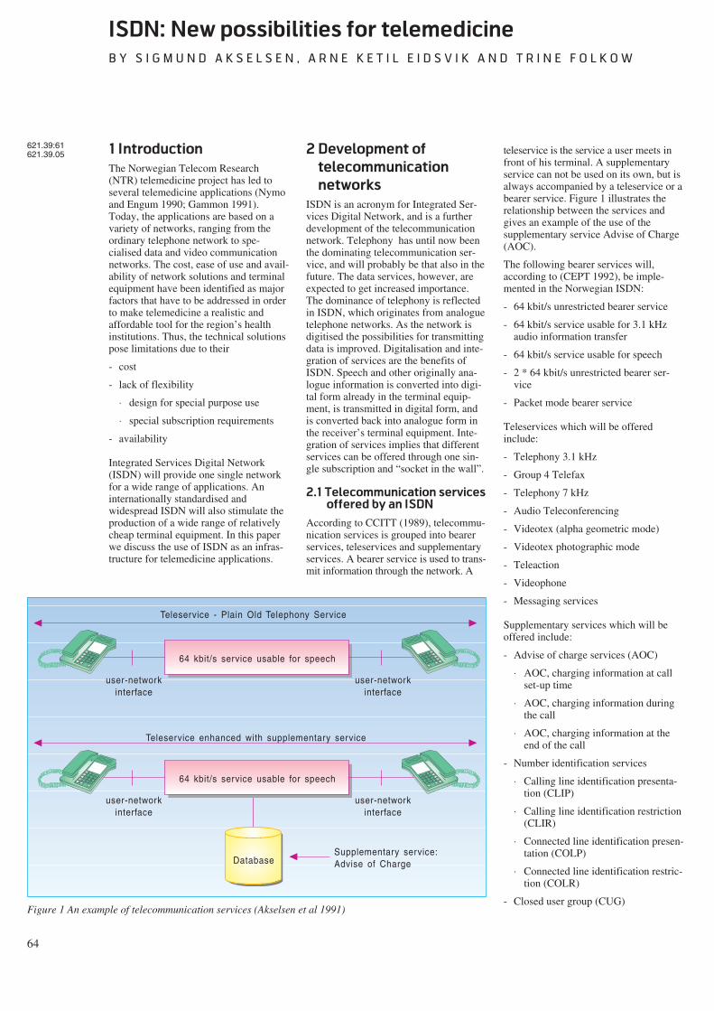
64
ISDN: New possibilities for telemedicine
B Y S I G M U N D A K S E L S E N , A R N E K E T I L E I D S V I K A N D T R I N E F O L K O W
1 Introduction
The Norwegian Telecom Research(NTR) telemedicine project has led toseveral telemedicine applications (Nymoand Engum 1990; Gammon 1991).Today, the applications are based on avariety of networks, ranging from theordinary telephone network to spe-cialised data and video communicationnetworks. The cost, ease of use and avail-ability of network solutions and terminalequipment have been identified as majorfactors that have to be addressed in orderto make telemedicine a realistic andaffordable tool for the region’s healthinstitutions. Thus, the technical solutionspose limitations due to their
- cost
- lack of flexibility
⋅ design for special purpose use
⋅ special subscription requirements
- availability
Integrated Services Digital Network(ISDN) will provide one single networkfor a wide range of applications. Aninternationally standardised andwidespread ISDN will also stimulate theproduction of a wide range of relativelycheap terminal equipment. In this paperwe discuss the use of ISDN as an infras-tructure for telemedicine applications.
2 Development of
telecommunication
networks
ISDN is an acronym for Integrated Ser-vices Digital Network, and is a furtherdevelopment of the telecommunicationnetwork. Telephony has until now beenthe dominating telecommunication ser-vice, and will probably be that also in thefuture. The data services, however, areexpected to get increased importance.The dominance of telephony is reflectedin ISDN, which originates from analoguetelephone networks. As the network isdigitised the possibilities for transmittingdata is improved. Digitalisation and inte-gration of services are the benefits ofISDN. Speech and other originally ana-logue information is converted into digi-tal form already in the terminal equip-ment, is transmitted in digital form, andis converted back into analogue form inthe receiver’s terminal equipment. Inte-gration of services implies that differentservices can be offered through one sin-gle subscription and “socket in the wall”.
2.1 Telecommunication services
offered by an ISDN
According to CCITT (1989), telecommu-nication services is grouped into bearerservices, teleservices and supplementaryservices. A bearer service is used to trans-mit information through the network. A
teleservice is the service a user meets infront of his terminal. A supplementaryservice can not be used on its own, but isalways accompanied by a teleservice or abearer service. Figure 1 illustrates therelationship between the services andgives an example of the use of thesupplementary service Advise of Charge(AOC).
The following bearer services will,according to (CEPT 1992), be imple-mented in the Norwegian ISDN:
- 64 kbit/s unrestricted bearer service
- 64 kbit/s service usable for 3.1 kHzaudio information transfer
- 64 kbit/s service usable for speech
- 2 * 64 kbit/s unrestricted bearer ser-vice
- Packet mode bearer service
Teleservices which will be offeredinclude:
- Telephony 3.1 kHz
- Group 4 Telefax
- Telephony 7 kHz
- Audio Teleconferencing
- Videotex (alpha geometric mode)
- Videotex photographic mode
- Teleaction
- Videophone
- Messaging services
Supplementary services which will beoffered include:
- Advise of charge services (AOC)
⋅ AOC, charging information at callset-up time
⋅ AOC, charging information duringthe call
⋅ AOC, charging information at theend of the call
- Number identification services
⋅ Calling line identification presenta-tion (CLIP)
⋅ Calling line identification restriction(CLIR)
⋅ Connected line identification presen-tation (COLP)
⋅ Connected line identification restric-tion (COLR)
- Closed user group (CUG)
621.39:61621.39.05
64 kbit/s service usable for speech
user-networkinterface
user-networkinterface
Teleservice - Plain Old Telephony Service
64 kbit/s service usable for speech
user-networkinterface
user-networkinterface
Teleservice enhanced with supplementary service
DatabaseSupplementary service:Advise of Charge
Figure 1 An example of telecommunication services (Akselsen et al 1991)
65
- Call waiting (CW)
- Completion of call to busy subscribers(CCBS)
- Conference services
⋅ Conference call, add-on (CONF)
⋅ Meet me conference (MMC)
- Direct dialling in (DDI)
- Diversion services
⋅ Call forwarding unconditional (CFU)
⋅ Call forwarding busy (CFB)
⋅ Call forwarding no reply (CFNR)
⋅ Call deflection
- Freephone (FPH)
- Malicious call identification (MCI)
- Multiple subscriber number (MSN)
- Subaddressing (SUB)
- Terminal portability (TP)
- Three party service (3PTY)
- User-user signalling (UUS)
ISDN provides various telecommunica-tion services through one common inter-face to the subscriber line. Previously,access to these services were possible viaspecial add-on equipment and over sepa-rate networks.
Due to the multiplicity of services it isunreasonable to restrict the customers touse only one channel at a time. For thisreason a basic rate ISDN access, offeringtwo 64 kbit/s channels, is standardised,thus allowing the use of more than oneterminal at a time. These channels arecalled B channels. A 16 kbit/s signallingchannel is also offered. This channel iscalled a D channel and may be used foruser-to-user information as well as sig-nalling. Packet mode communication isfacilitated on both B and D channels,whereas circuit mode communication isfacilitated on the B channels. It is possi-ble to connect 8 different terminals inparallel across the incoming subscriberline. A primary rate ISDN access offers30 B channels (23 in the US) and 1 D (64kbit/s) channel. In addition there existsterminal equipment that can combineseveral B channels to increase capacity(n * 64 kbit/s).
The telecommunication services offeredby ISDN must be accessed by digital ter-minal equipment. This equipmentincludes:
- Telephones
⋅ alphanumeric keyboard and displayfor simple text messages
⋅ 3.1 kHz telephony with enhancedperformance (quality of digitaltransmission, quicker call set-up,new supplementary services)
⋅ 7 kHz telephony offers better voicequality and is appropriate for broad-cast-quality calls and audio telecon-ferencing
- Videophones
⋅ simultaneous transmission of speechand moving pictures
- Group 4 Telefax
⋅ transmission of fax messages withenhanced quality (400 * 400 dotsper inch) and speed (one A4 page inless than 10 s)
⋅ colour transmission under develop-ment
- PCs with cards for voice, data, andvideo communication
⋅ file transfer
⋅ messaging
⋅ desktop conferencing
⋅ videophony
In addition it is possible to connect exist-ing (pre-ISDN) terminals to ISDNthrough terminal adapters.
2.2 ISDN Features
Digital transmission and use of a com-mon network for different kinds of ser-vices offer the users new possibilities:
- Standardisation of services, user proce-dures, terminals and access line con-nections/interfaces
- Integration of services including voice,data and picture communication
- Availability of a large number of ser-vices through one “socket in the wall”
- Flexibility when it comes to use ofchannels, choice of bearer services,choice of telecommunication service,and connection of terminal equipment
- Reasonable costs. Taxation is based onvolume of transmitted informationwhen using packet mode transmissionor on connection time when using cir-cuit mode
- High transmission rates (e.g. faster andbetter facsimile and other text services)
- Less error-rate on transmission
- Secure transmission of information(e.g. functions such as closed usergroup, prevention against tap of infor-mation and guarantee for transmissionof identity by the network).
ISDN has been standardised interna-tionally by CCITT (Kano et al 1991).Today, ISDNs are implemented andaccessible on a limited scale. Within 5years, however, ISDN is expected tobecome widely available in most coun-tries in Europe, North America and East-ern Asia.1)
For the health services the ISDN infras-tructure offers the opportunity to solvemost telecommunication needs (Akselsenet al 1991). Reasonable costs and onestandardised network may make applica-tions available for institutions on a largescale.
2.3 Further development
The development of a digital telecommu-nication network leads to an infrastruc-ture that makes it possible to introduceintelligent networks (IN). IN consists ofmethods and tools for defining, develop-ing, testing, and implementing cus-tomised services. Centralised databasesand service control are essential parts ofIN. Typically, information from thedatabases will be used for controllingresources in the network. When anincoming call is detected in theexchange, further actions are suspendeduntil relevant instructions are retrievedfrom a database. This facilitates an inde-pendent control of services activatedfrom several different networks. IN isdiscussed in more detail in (Løken 1992).
Some examples of the services that willbe available through IN are:
- universal personal telecommunicationservice
- queue service
1) Notice for instance the launch ofEuro/ISDN in December 1993, whichwill provide a common ISDN betweena number of European countries,including among others Belgium, Den-mark, Germany, France, Ireland, Italy,Netherlands, Norway, Portugal, Spain,Sweden, and the United Kingdom.
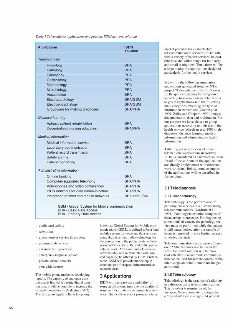
66
- credit card calling
- televoting
- green number service (freephone)
- premium rate service
- alternate billing service
- emergency response service
- private virtual network
- area wide centrex.
The mobile phone market is developingrapidly. The capacity of analogue trans-mission is limited. By using digital trans-mission, it will be possible to increase thecapacity considerably (Valentino 1992).The European digital cellular telephony,
known as Global System for Mobile com-munications (GSM), is defined to be a landmobile system for voice and data servicesusing digital cellular radio technology forthe connection to the public switched tele-phone network, to ISDN, and to the publicdata network. All bearer and teleservicesoffered today will in principle (with lim-ited capacity) be offered by GSM. Further-more, GSM will provide mobile equip-ment and pan-European infrastructure atreduced costs.
3 Applications
ISDN will increase the availability ofsome applications, improve the quality ofsome and facilitate some completely newones. The health services promise a large
market potential for cost-effectivetelecommunication services. ISDN will,with a variety of bearer services, be cost-effective and within range for both largeand small institutions. Thus, there will bea large market for applications designedparticularly for the health services.
We will in the following summariseapplications generated from the NTRproject “Telemedicine in North Norway”.ISDN applications may be categorisedaccording to several criteria. One way isto group applications into the followingmain categories reflecting the type ofinformation transmitted (Guenin et al1991; Zulke and Chopard 1990): image,documentation, data and multimedia. Forour purpose we have chosen to groupapplications according to their use in thehealth service (Akselsen et al 1993): tele-diagnosis, distance learning, medicalinformation and administrative healthinformation.
Table 1 gives an overview of sometelemedicine applications in Norway.ISDN is considered as a network solutionfor all of these. Some of the applicationsare already implemented with other net-work solutions. Below, some examplesof the applications will be described infurther detail.
3.1 Telediagnosis
3.1.1 Telepathology
Telepathology is the performance ofpathological services at a distance usingtelecommunications (Nordrum et al1991). Pathologists examine samples oftissue using microscope. For diagnosingsome kinds of cancer, the pathology ser-vice must be performed while the patientis still anaesthetised after the sample oftissue is removed, in case further surgeryis needed instantly.
Telecommunications are at present basedon a 2 Mbit/s connection between thesites. An ISDN solution will be morecost-effective. Packet mode communica-tion can be used for remote control of themicroscope and circuit mode for imagesand sound.
3.1.2 Teleradiology
Teleradiology is the practice of radiologyat a distance using telecommunications.This involves transmission of, forinstance, X-ray, computer tomography(CT) and ultrasonic images. At present
Table 1 Telemedicine applications and possible ISDN network solutions
Application ISDNsolution
Telediagnosis
Radiology BRAPathology PRAEndoscopy PRAGastroscopy PRADermatology PRAMicrobiology PRAAuscultation BRAElectrocardiology BRA/GSMElectroencephalogy BRA/GSMGroupware for making diagnoses BRA/PRA
Distance learning
Aphasic patient rehabilitation BRADecentralised nursing education BRA/PRA
Medical information
Medical information service BRALaboratory communication BRAPatient record transmission BRASafety alarms BRAPatient monitoring BRA
Administrative information
On-line booking BRAComputer-supported telephony BRA/PRAVideophones and video conferences BRA/PRAISDN networks for data communication BRA/PRAIntegration of fixed and mobile networks BRA and GSM
GSM - Global System for Mobile communicationBRA - Basic Rate AccessPRA - Primary Rate Access
67
the data communication is implementedwith a 64 kbit/s permanent connectionand Vitalink bridges connecting LANs atthe two hospitals. Equipment and projectare further described in (Sund et al1991a; Sund et al 1991b).
The first step towards an ISDN imple-mentation of teleradiology will be toreplace the Ethernet bridges with IP(Internet Protocol) routers for ISDN, andthe 64 kbit/s permanent connection witha basic rate ISDN subscription. X-rayimages comprise large amounts of infor-mation and all images for one day areusually transmitted in one batch. Largevolumes of data have to be transmitted,and a circuit switched connection will bemost suitable. Hence, users will pay onlyfor connection time. Loss of informationis an important concern in compressionof medical images, hence the relativelylarge capacity of ISDN is needed. ISDNcommunication over IP routers will inaddition provide a transparent LAN toLAN connection between the two hospi-tals, transparent in the sense that users atone of the LANs can accessservices/resources at the other one as ifthey were on the same (local) network.
3.1.3 Tele-endoscopy
An endoscope is a device for guiding asource of light inside the human bodyand transposing an image of the exam-ined organ on a monitor. Tele-endoscopyrefers to the transmission of these imagesover the telecommunications network toa specialist at the other end. A practi-tioner is, however, still needed to bringthe endoscope inside the patient andadjust the positioning to get the correctimages (Hartviksen and Pedersen 1992).
Tele-endoscopy is used in North Norwayfor ear, nose and throat (otorhinolaryn-gology) consultations. Telecommunica-tions are today implemented with a 2Mbit/s switched connection. Video con-ferencing equipment is used for present-ing images and transmitting speechbetween the specialist and the practi-tioner in charge of the patient. An ISDNimplementation may replace the 2 Mbit/sconnection. In fact, the initial trials usingthe Norwegian Tandberg Vision video-phone (Møllerbråten 1991) over 2 ISDNB-channels, i.e. 128 kbit/s, has alreadybeen done. An ISDN solution where sev-eral B-channels are combined, e.g. 6channels which total 384 kbit/s may benecessary if the quality of 128 kbit/s istoo poor. An alternative/complementarysystem for making remote diagnoses is
under development. This system candigitise, store and transfer medical stills(pictures) from arbitrary video sources.Among other medical areas, gastroscopyis considered as a suitable area for mak-ing remote diagnoses using similar tools.
3.1.4 Groupware for making
diagnoses
Multipurpose groupware can be used bymedical practitioners for co-operationand consultation when making diagnoses.ICL’s Desktop Conferencing application,designed particularly for ISDN, is anexample. Eight users may, in addition tovoice communication, share screenimages and applications. An extension ofthe system to include videophony willmake it possible to utilise the groupwarefacilities further. The specialists will beable to look at pictures, hear examples ofsounds and read medical records to getan overview of the patient in question.Participants of the co-operating groupmay point at, and modify, the screenimages as the discussion goes on. Oneparticipant is assigned to be the chair-man. He is supported with computerbased means for directing the meeting,e.g. dedicate the cursor control to eachparticipant in turn.
3.2 Distance learning
Distance learning and education hasevolved from the use of paper, pencil andordinary mail to data communication andvideoconferencing. ISDN has the facili-ties to combine synchronous (videocon-ferencing, groupware, etc.) and asyn-chronous (electronic mail, electronic con-ferencing) communication. Both institu-tions and private households will benefitfrom distance learning over ISDN due tolow costs. Distance learning may thus beused for educating patients and clients aswell as health care personnel. Thefollowing project from the NTRtelemedicine portfolio illustrates howISDN may be used for patient rehabilita-tion and learning.
3.2.1 Aphasic patient rehabilitation
Aphasia is loss or reduction of the abilityto use and understand language, oftencaused by stroke (apoplexy) or injuriesfrom an accident. People suffering fromaphasia have to learn their own languageall over again. In our project the speechtherapists and the clients were suppliedwith personal computers configured forsynchronous communication. Graphics
and text containing exercises were trans-mitted from the speech therapists’ com-puters to the clients’ computers overordinary telephone lines. The clientsworked with the exercises in their ownspare time or assisted by on-line guid-ance from the speech therapist. When on-line, therapist and client had access to thesame screen image on the computers,facilitating pointing and editing. In addi-tion voice communication was offeredover the same connection (Eidsvik 1990;Holand 1991).
This application is well suited for ISDN,as the combination of data and voicecommunication is essential. At presentthe system uses ordinary telephone lineswith modems facilitating both data andvoice communication on the same line,resulting in poor quality and low transferrates. ISDN will give much better audioquality and much faster data transfer.Supplementary ISDN services such asCalling Line Identification Presentation(CLIP) may simplify the user interfacefor the patients, with for instance auto-matic start of the software upon a callfrom the speech therapist.
3.3 Medical Information
3.3.1 Medical information service
(MEDIS)
Medical research and development gen-erates enormous amounts of information.The information may be retrieved fromboth traditional literature and variouselectronic sources. User interfaces aredifferent for most sources of information.Medical practitioners will experience anincreasing problem of keeping up withnew results and methods. The projectMEDIS is aimed to give users a uniformuser interface to several sources of infor-mation including electronic mail, elec-tronic conference systems and on-linedatabases (Danielsen et al 1990; Wassonand Akselsen 1992).
Higher rates of data transfer throughISDN will facilitate a better user inter-face compared to the possibilities of ordi-nary telephone lines. The integration ofvoice and data communication in ISDN,and two or more parallel communicationlines for each subscriber, makes it possi-ble to combine database searching withadd-on information from human experts.
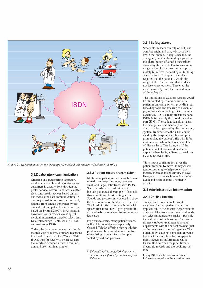
68
3.3.2 Laboratory communication
Ordering and transmitting laboratoryresults between clinical laboratories andcustomers is usually done through thepostal service. Several laboratories offerelectronic result services based on vari-ous models for data communication. Inour project solutions have been offered,ranging from telefax generated by theclinical test computer, to electronic mailbased on TelemaX.4002). Investigationshave been conducted on exchange ofmedical information based on ElectronicData Interchange (EDI), see e.g. (Broxand Antonsen 1990).
Today, the data communication is imple-mented with modems, ordinary telephonelines and packet switched WANs. WithISDN, transfer rates will be higher andthe interface between network termina-tion and user terminal simpler.
3.3.3 Patient record transmission
Multimedia patient records may be trans-mitted over large distances, betweensmall and large institutions, with ISDN.Such records may in addition to textinclude pictures and examples of sounds(from breathing, heart beating, etc.).Sounds and pictures may be used to showthe development of the disease over time.This kind of information combined withspeech transmission will give practition-ers a valuable tool when discussing med-ical cases.
For years to come, many patient recordswill still be available on paper only.Group 4 Telefax offering high resolutionprintouts will be a suitable medium fortransmitting patient information pre-sented by text and pictures.
3.3.4 Safety alarms
Safety alarm users can rely on help andcomfort, night and day, wherever theyare in their home. If help is needed, theemergency unit is alarmed by a push onthe alarm button of a radio transmittercarried by the patient. The transmissionrange of a typical transmitter is approxi-mately 60 metres, depending on buildingconstructions. The system thereforerequires that the patient is within therange of the receiver, and that he doesnot lose consciousness. These require-ments evidently limit the use and valueof the safety alarm.
The limitations of existing systems couldbe eliminated by combined use of apatient monitoring system providing realtime diagnosis and tracking of dynamicphysiological events (e.g. ECG, haemo-dynamics, EEG), a radio transmitter andISDN (alternatively the mobile counter-part GSM). The patient can either alarmthe emergency unit manually, or thealarm can be triggered by the monitoringsystem. In either case the CLIP can beused by the hospital’s application pro-gram to find the patient’s file with infor-mation about where he lives, what kindof disease he suffers from, etc. If thepatient is not at home and unable toexplain where he is, a distress signal canbe used to locate him.
This system configuration gives thepatient freedom to move. It may enablethe hospital to give help sooner, andthereby increase the possibility to savelives, e.g. in cases such as sudden infantdeath and heart, asthma or epilepsyattacks.
3.4 Administrative information
3.4.1 On-line booking
Today, practitioners book hospitaltreatment for their patients by writingapplications to the hospital department inquestion. Electronic equipment and mod-ern telecommunications make it possibleto facilitate on-line booking. The practi-tioners can book treatment at hospitaldepartments with the patient present (justas the customer at a travel agency). Thepatient may leave his physician knowingthe exact date and time for his appoint-ment. Necessary information can betransmitted between the practitionerselectronic records and the booking sys-tem.
Using ISDN as the communicationsinfrastructure, where the taxation rates
2) TelemaX.400 is an X.400 electronicmail service offered by the NorwegianTelecom.
ISDN
Figure 2 Telecommunication for exchange for medical information (Akselsen et al 1993)
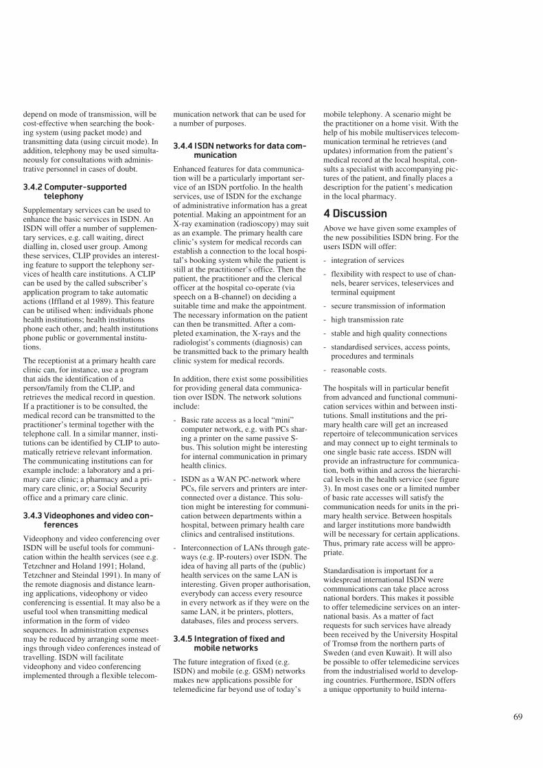
69
depend on mode of transmission, will becost-effective when searching the book-ing system (using packet mode) andtransmitting data (using circuit mode). Inaddition, telephony may be used simulta-neously for consultations with adminis-trative personnel in cases of doubt.
3.4.2 Computer-supported
telephony
Supplementary services can be used toenhance the basic services in ISDN. AnISDN will offer a number of supplemen-tary services, e.g. call waiting, directdialling in, closed user group. Amongthese services, CLIP provides an interest-ing feature to support the telephony ser-vices of health care institutions. A CLIPcan be used by the called subscriber’sapplication program to take automaticactions (Iffland et al 1989). This featurecan be utilised when: individuals phonehealth institutions; health institutionsphone each other, and; health institutionsphone public or governmental institu-tions.
The receptionist at a primary health careclinic can, for instance, use a programthat aids the identification of aperson/family from the CLIP, andretrieves the medical record in question.If a practitioner is to be consulted, themedical record can be transmitted to thepractitioner’s terminal together with thetelephone call. In a similar manner, insti-tutions can be identified by CLIP to auto-matically retrieve relevant information.The communicating institutions can forexample include: a laboratory and a pri-mary care clinic; a pharmacy and a pri-mary care clinic, or; a Social Securityoffice and a primary care clinic.
3.4.3 Videophones and video con-
ferences
Videophony and video conferencing overISDN will be useful tools for communi-cation within the health services (see e.g.Tetzchner and Holand 1991; Holand,Tetzchner and Steindal 1991). In many ofthe remote diagnosis and distance learn-ing applications, videophony or videoconferencing is essential. It may also be auseful tool when transmitting medicalinformation in the form of videosequences. In administration expensesmay be reduced by arranging some meet-ings through video conferences instead oftravelling. ISDN will facilitatevideophony and video conferencingimplemented through a flexible telecom-
munication network that can be used fora number of purposes.
3.4.4 ISDN networks for data com-
munication
Enhanced features for data communica-tion will be a particularly important ser-vice of an ISDN portfolio. In the healthservices, use of ISDN for the exchangeof administrative information has a greatpotential. Making an appointment for anX-ray examination (radioscopy) may suitas an example. The primary health careclinic’s system for medical records canestablish a connection to the local hospi-tal’s booking system while the patient isstill at the practitioner’s office. Then thepatient, the practitioner and the clericalofficer at the hospital co-operate (viaspeech on a B-channel) on deciding asuitable time and make the appointment.The necessary information on the patientcan then be transmitted. After a com-pleted examination, the X-rays and theradiologist’s comments (diagnosis) canbe transmitted back to the primary healthclinic system for medical records.
In addition, there exist some possibilitiesfor providing general data communica-tion over ISDN. The network solutionsinclude:
- Basic rate access as a local “mini”computer network, e.g. with PCs shar-ing a printer on the same passive S-bus. This solution might be interestingfor internal communication in primaryhealth clinics.
- ISDN as a WAN PC-network wherePCs, file servers and printers are inter-connected over a distance. This solu-tion might be interesting for communi-cation between departments within ahospital, between primary health careclinics and centralised institutions.
- Interconnection of LANs through gate-ways (e.g. IP-routers) over ISDN. Theidea of having all parts of the (public)health services on the same LAN isinteresting. Given proper authorisation,everybody can access every resourcein every network as if they were on thesame LAN, it be printers, plotters,databases, files and process servers.
3.4.5 Integration of fixed and
mobile networks
The future integration of fixed (e.g.ISDN) and mobile (e.g. GSM) networksmakes new applications possible fortelemedicine far beyond use of today’s
mobile telephony. A scenario might bethe practitioner on a home visit. With thehelp of his mobile multiservices telecom-munication terminal he retrieves (andupdates) information from the patient’smedical record at the local hospital, con-sults a specialist with accompanying pic-tures of the patient, and finally places adescription for the patient’s medicationin the local pharmacy.
4 Discussion
Above we have given some examples ofthe new possibilities ISDN bring. For theusers ISDN will offer:
- integration of services
- flexibility with respect to use of chan-nels, bearer services, teleservices andterminal equipment
- secure transmission of information
- high transmission rate
- stable and high quality connections
- standardised services, access points,procedures and terminals
- reasonable costs.
The hospitals will in particular benefitfrom advanced and functional communi-cation services within and between insti-tutions. Small institutions and the pri-mary health care will get an increasedrepertoire of telecommunication servicesand may connect up to eight terminals toone single basic rate access. ISDN willprovide an infrastructure for communica-tion, both within and across the hierarchi-cal levels in the health service (see figure3). In most cases one or a limited numberof basic rate accesses will satisfy thecommunication needs for units in the pri-mary health service. Between hospitalsand larger institutions more bandwidthwill be necessary for certain applications.Thus, primary rate access will be appro-priate.
Standardisation is important for awidespread international ISDN werecommunications can take place acrossnational borders. This makes it possibleto offer telemedicine services on an inter-national basis. As a matter of factrequests for such services have alreadybeen received by the University Hospitalof Tromsø from the northern parts ofSweden (and even Kuwait). It will alsobe possible to offer telemedicine servicesfrom the industrialised world to develop-ing countries. Furthermore, ISDN offersa unique opportunity to build interna-
70
tional networks for professional discus-sions and transfer of competence.
However, there are some factors that mayprohibit the promises that ISDN brings totelemedicine. The current costs of termi-nal equipment and lack of compatibilitylimit the number of ISDN users. As withany new technology, ISDN also is depen-dent on a critical mass of users. If thismass is not reached within a reasonablynear future, ISDN may become just aparenthesis in the history of telecommu-nications.
In the health service compression ofmedical data is controversial. Thus, forsome telemedicine applications thecapacity of ISDN communication maynot be sufficient.
5 Summary and
conclusions
In a five year period ISDN technologyand services will be available in mostindustrialised countries. ISDN will offernew services and higher transmissionrates at lower prices. ISDN also will pro-vide greater flexibility with regard toexisting communication solutions. Untilnow, the utilisation of ISDN has beentied mainly to already existing servicesand applications. However, develop-ments are still at an early stage when itcomes to utilising calling-line identifica-tion and other supplementary services.Furthermore, IN services are beingdeveloped and will become an importantpart of the future telecommunication ser-vices repertoire. These services will findnumerous applications within the health
service. One illustrative use of IN ser-vices is utilisation of the universal accessnumber service to call a pool of special-ists and get direct access to one available.
One of the arguments for thedevelopment of telemedicine ser-vices in Norway has been theprinciple of equal access tohealth services, independent ofeconomic, social, religious, raceand last but not least, geo-graphical issues. A widespreadISDN will constitute an importantpart of the infrastructurenecessary for fulfilment of thisprinciple.
We consider the principle of equal accessa most important argument in justifyingdevelopments in telemedicine. The futureof telemedicine depends on applicationsthat are technically and organisationallypossible, economically feasible and polit-ically acceptable. ISDN can fulfil thetechnical and economical conditions nec-essary for such applications.
We have reviewed some telemedicineapplications and proposed a number ofideas for further development of suchapplications based on ISDN technology.We have argued that ISDN may increasethe possibility for successful use oftelemedicine. However, neither ISDNnor any other technology alone will auto-matically fulfil the goals of equality anddecentralisation. A unified political strat-egy is a necessary precondition.
The availability and the relatively (cost-effective) low pricing of future ISDN
services and terminals are the keys thatmake telemedicine realistic for the pub-lic, i.e. available to a majority of healthcare personnel and not just a curiosity forthe “chosen few”.
6 References
Akselsen, S, Eidsvik, A K, Folkow, T.1991. Health services and ISDN. Kjeller,Norwegian Telecom Research. (TF-report R68/91.) (In Norwegian.)
Akselsen, S, Eidsvik, A K, Folkow, T.1993. Telemedicine and ISDN. IEEE Com-munications Magazine, 31(1), 46-51.
Brox, E, Antonsen, T. 1990. Exchange ofmedical information based on EDI.Foundation for Applied Research at theUniversity of Tromsø. ISSN 082-2011.
CCITT. 1989. Integrated Services Digi-tal Network (ISDN). General Structureand Service Capabilities. Geneva.(CCITT Blue Book vol III - fascicleIII.7.)
CEPT. 1992. User Handbook ISDN.Bern, CEPT (The European Conferenceof Postal and TelecommunicationsAdministrations).
Danielsen, T et al. 1990. RATATOSK -an adaptive user interface to computer-mediated communication. Presented at“Message Handling Systems and Appli-cation Layer Communication Protocols”,Zürich, 3-5 October. Also available asTF-lecture F16/90, Kjeller, NorwegianTelecom Research.
Eidsvik, A K. 1990. Distance learningfor people suffering from aphasia. Pre-sented at “IFIP Fifth World Conferenceon Computers in Education”, Sydney, 9-13 July. Also available as TF-lectureF18/90, Kjeller, Norwegian TelecomResearch.
Gammon, D. 1991. Telemedicine inNorth Norway. Kjeller, Norwegian Tele-com Research. (TF-report R27/91.)
Guenin, J P et al. 1991. ISDN in France -1987 to 1990: from the first commercialoffering to national coverage ofNUMERIS. IEEE Communications Mag-azine, 29(1), 30-35.
Region
County
Municipality
Figure 3 Communication structures in the Norwegian health service hierarchy
71
Hartviksen, G, Pedersen, S. 1992.Remote endoscopy of otorhinolaryngol-ogy patients. In: A Katzir (ed): Opticalfibres in medicine VII, SPIE Proceed-ings, 1649.
Holand, U. 1991. Use of graphic commu-nication in distance training of patientswith aphasia. In: S v Tetzchner (ed):Issues in telecommunication and disabil-ity. COST 219.
Holand, U, Tetzchner, S v, Steindal, K.1991. Two field trials with videophonesin psychiatric and habilitative work. In: Sv Tetzchner (ed): Issues in telecommuni-cation and disability. COST 219.
Iffland, C, Norton, G, Waxman, M. 1989.ISDN applications: their identificationand development. IEEE Network Maga-zine, 3(9), 6-11.
Kano, S, Kitami, K, Kawarasaki, M.1991. ISDN standardisation. Proceedingsof the IEEE, (Special issue on ISDN), 79,118-124.
Løken, B (ed). 1992. Intelligent Net-works. Telektronikk, 2.
Møllerbråten, B. 1991. Videotelephonedevelopment in Norway. In: T Kris-tiansen (ed): A window to the future. Thevideotelephone experience in Norway.Kjeller, Norwegian Telecom Research,9-20.
Nordrum, I et al. 1991. Remote FrozenSection Service; A Telepathology Projectin Northern Norway. Human Pathology,22, 511-518.
Nymo, B, Engum, B. 1990. Telemedicineto improve the quality, availability andeffectiveness of the health service inrural regions. Kjeller, Norwegian Tele-com Research. (TF-lecture F10/90.)
Sund, T, Rinde, E, Størmer, J. 1991a.Full-scale replacement of a visiting radi-ologist service with teleradiology. In:H.U. Lemke et al (ed): Computerassisted radiology, Proceedings of theinternational Symposiums CAR-91.Berlin, Springer-Verlag.
Sund, T et al. 1991b. Techniques formultimedia Teleradiology. In: H.U.Lemke et al (ed): Computer assistedradiology, Proceedings of the interna-tional Symposiums CAR-91. Berlin.Springer-Verlag.
Tetzchner, S v, Holand, U. 1991. Super-vision of habilitation and psychiatricwork. In: T Kristiansen (ed): A windowto the future. The videotelephone experi-ence in Norway. Kjeller, NorwegianTelecom Research, 32-48.
Valentino, G. 1992. A survey on CellularMobile Communications Systems. In:Proceedings of the twelfth internationalsymposium on biotelemetry. August 31 -September 5, Ancona, Italy.
Wasson, B, Akselsen, S. 1992. Anoverview of on-line assistance: from on-line documentation to intelligent help andtraining. The knowledge engineeringreview, 7(4), 289-322.
Zulke, M, Chopard, S. 1990. ISDNApplications in France. Telecommunica-tions, 24, 45-48.
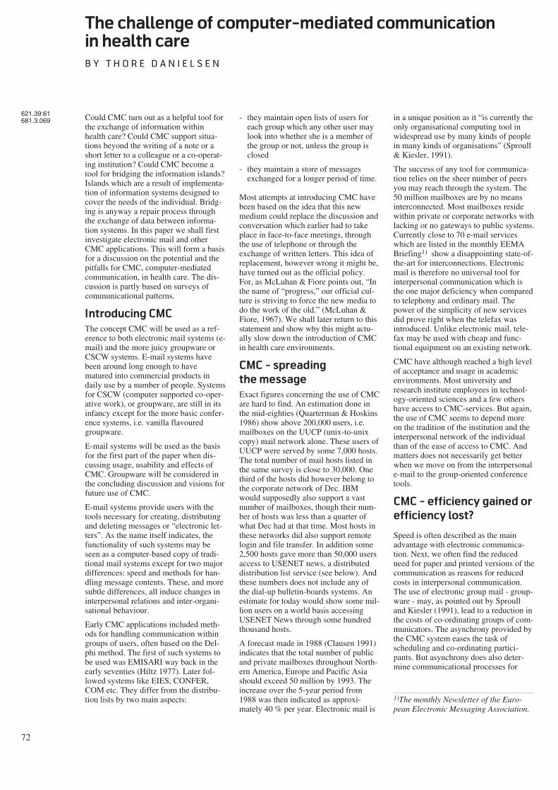
72
The challenge of computer-mediated communication
in health care
B Y T H O R E D A N I E L S E N
Could CMC turn out as a helpful tool forthe exchange of information withinhealth care? Could CMC support situa-tions beyond the writing of a note or ashort letter to a colleague or a co-operat-ing institution? Could CMC become atool for bridging the information islands?Islands which are a result of implementa-tion of information systems designed tocover the needs of the individual. Bridg-ing is anyway a repair process throughthe exchange of data between informa-tion systems. In this paper we shall firstinvestigate electronic mail and otherCMC applications. This will form a basisfor a discussion on the potential and thepitfalls for CMC, computer-mediatedcommunication, in health care. The dis-cussion is partly based on surveys ofcommunicational patterns.
Introducing CMC
The concept CMC will be used as a ref-erence to both electronic mail systems (e-mail) and the more juicy groupware orCSCW systems. E-mail systems havebeen around long enough to havematured into commercial products indaily use by a number of people. Systemsfor CSCW (computer supported co-oper-ative work), or groupware, are still in itsinfancy except for the more basic confer-ence systems, i.e. vanilla flavouredgroupware.
E-mail systems will be used as the basisfor the first part of the paper when dis-cussing usage, usability and effects ofCMC. Groupware will be considered inthe concluding discussion and visions forfuture use of CMC.
E-mail systems provide users with thetools necessary for creating, distributingand deleting messages or “electronic let-ters”. As the name itself indicates, thefunctionality of such systems may beseen as a computer-based copy of tradi-tional mail systems except for two majordifferences: speed and methods for han-dling message contents. These, and moresubtle differences, all induce changes ininterpersonal relations and inter-organi-sational behaviour.
Early CMC applications included meth-ods for handling communication withingroups of users, often based on the Del-phi method. The first of such systems tobe used was EMISARI way back in theearly seventies (Hiltz 1977). Later fol-lowed systems like EIES, CONFER,COM etc. They differ from the distribu-tion lists by two main aspects:
- they maintain open lists of users foreach group which any other user maylook into whether she is a member ofthe group or not, unless the group isclosed
- they maintain a store of messagesexchanged for a longer period of time.
Most attempts at introducing CMC havebeen based on the idea that this newmedium could replace the discussion andconversation which earlier had to takeplace in face-to-face meetings, throughthe use of telephone or through theexchange of written letters. This idea ofreplacement, however wrong it might be,have turned out as the official policy.For, as McLuhan & Fiore points out, “Inthe name of “progress,” our official cul-ture is striving to force the new media todo the work of the old.” (McLuhan &Fiore, 1967). We shall later return to thisstatement and show why this might actu-ally slow down the introduction of CMCin health care environments.
CMC - spreading
the message
Exact figures concerning the use of CMCare hard to find. An estimation done inthe mid-eighties (Quarterman & Hoskins1986) show above 200,000 users, i.e.mailboxes on the UUCP (unix-to-unixcopy) mail network alone. These users ofUUCP were served by some 7,000 hosts.The total number of mail hosts listed inthe same survey is close to 30,000. Onethird of the hosts did however belong tothe corporate network of Dec. IBMwould supposedly also support a vastnumber of mailboxes, though their num-ber of hosts was less than a quarter ofwhat Dec had at that time. Most hosts inthese networks did also support remotelogin and file transfer. In addition some2,500 hosts gave more than 50,000 usersaccess to USENET news, a distributeddistribution list service (see below). Andthese numbers does not include any ofthe dial-up bulletin-boards systems. Anestimate for today would show some mil-lion users on a world basis accessingUSENET News through some hundredthousand hosts.
A forecast made in 1988 (Clausen 1991)indicates that the total number of publicand private mailboxes throughout North-ern America, Europe and Pacific Asiashould exceed 50 million by 1993. Theincrease over the 5-year period from1988 was then indicated as approxi-mately 40 % per year. Electronic mail is
in a unique position as it “is currently theonly organisational computing tool inwidespread use by many kinds of peoplein many kinds of organisations” (Sproull& Kiesler, 1991).
The success of any tool for communica-tion relies on the sheer number of peersyou may reach through the system. The50 million mailboxes are by no meansinterconnected. Most mailboxes residewithin private or corporate networks withlacking or no gateways to public systems.Currently close to 70 e-mail serviceswhich are listed in the monthly EEMABriefing1) show a disappointing state-of-the-art for interconnections. Electronicmail is therefore no universal tool forinterpersonal communication which isthe one major deficiency when comparedto telephony and ordinary mail. Thepower of the simplicity of new servicesdid prove right when the telefax wasintroduced. Unlike electronic mail, tele-fax may be used with cheap and func-tional equipment on an existing network.
CMC have although reached a high levelof acceptance and usage in academicenvironments. Most university andresearch institute employees in technol-ogy-oriented sciences and a few othershave access to CMC-services. But again,the use of CMC seems to depend moreon the tradition of the institution and theinterpersonal network of the individualthan of the ease of access to CMC. Andmatters does not necessarily get betterwhen we move on from the interpersonale-mail to the group-oriented conferencetools.
CMC - efficiency gained or
efficiency lost?
Speed is often described as the mainadvantage with electronic communica-tion. Next, we often find the reducedneed for paper and printed versions of thecommunication as reasons for reducedcosts in interpersonal communication.The use of electronic group mail - group-ware - may, as pointed out by Sproulland Kiesler (1991), lead to a reduction inthe costs of co-ordinating groups of com-municators. The asynchrony provided bythe CMC system eases the task ofscheduling and co-ordinating partici-pants. But asynchrony does also deter-mine communicational processes for
621.39:61681.3.069
1)The monthly Newsletter of the Euro-pean Electronic Messaging Association.
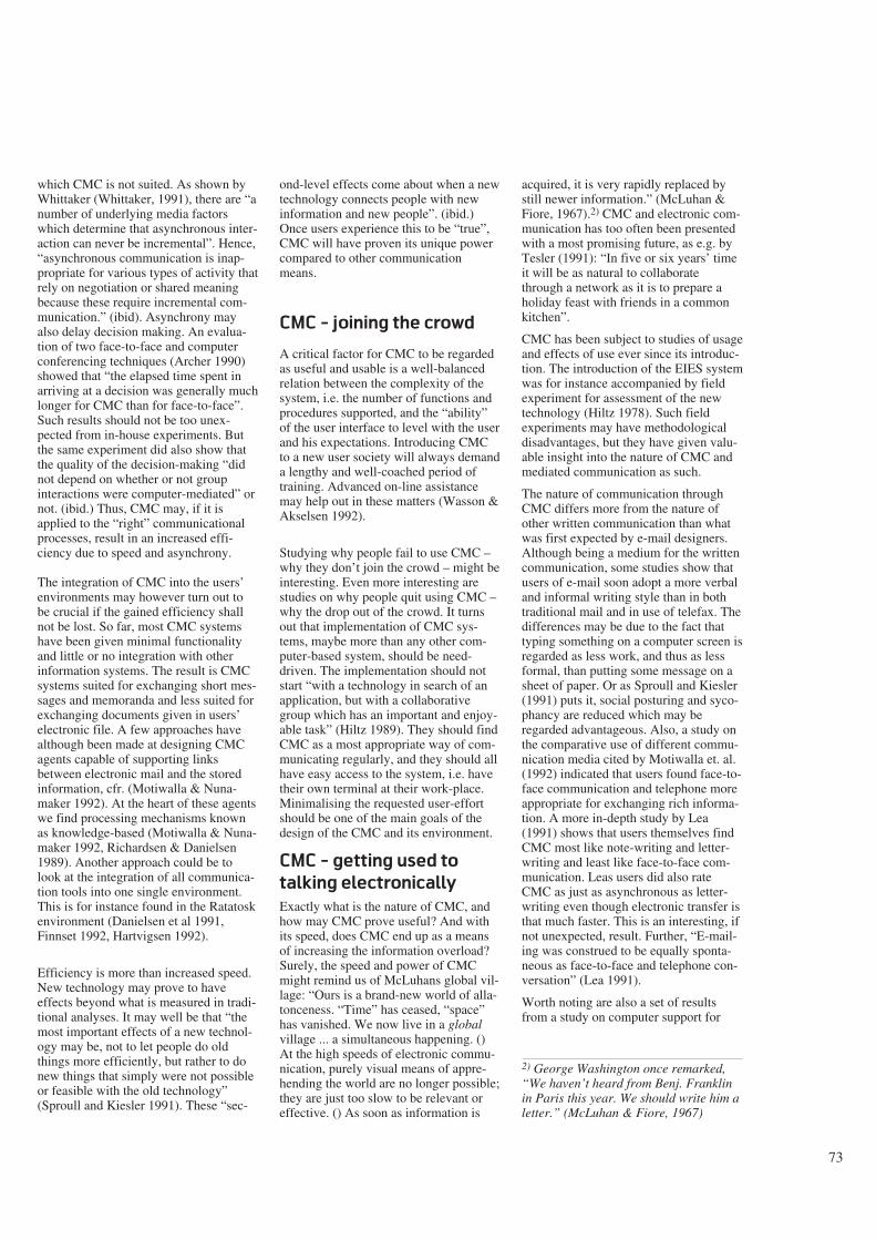
73
which CMC is not suited. As shown byWhittaker (Whittaker, 1991), there are “anumber of underlying media factorswhich determine that asynchronous inter-action can never be incremental”. Hence,“asynchronous communication is inap-propriate for various types of activity thatrely on negotiation or shared meaningbecause these require incremental com-munication.” (ibid). Asynchrony mayalso delay decision making. An evalua-tion of two face-to-face and computerconferencing techniques (Archer 1990)showed that “the elapsed time spent inarriving at a decision was generally muchlonger for CMC than for face-to-face”.Such results should not be too unex-pected from in-house experiments. Butthe same experiment did also show thatthe quality of the decision-making “didnot depend on whether or not groupinteractions were computer-mediated” ornot. (ibid.) Thus, CMC may, if it isapplied to the “right” communicationalprocesses, result in an increased effi-ciency due to speed and asynchrony.
The integration of CMC into the users’environments may however turn out tobe crucial if the gained efficiency shallnot be lost. So far, most CMC systemshave been given minimal functionalityand little or no integration with otherinformation systems. The result is CMCsystems suited for exchanging short mes-sages and memoranda and less suited forexchanging documents given in users’electronic file. A few approaches havealthough been made at designing CMCagents capable of supporting linksbetween electronic mail and the storedinformation, cfr. (Motiwalla & Nuna-maker 1992). At the heart of these agentswe find processing mechanisms knownas knowledge-based (Motiwalla & Nuna-maker 1992, Richardsen & Danielsen1989). Another approach could be tolook at the integration of all communica-tion tools into one single environment.This is for instance found in the Ratatoskenvironment (Danielsen et al 1991,Finnset 1992, Hartvigsen 1992).
Efficiency is more than increased speed.New technology may prove to haveeffects beyond what is measured in tradi-tional analyses. It may well be that “themost important effects of a new technol-ogy may be, not to let people do oldthings more efficiently, but rather to donew things that simply were not possibleor feasible with the old technology”(Sproull and Kiesler 1991). These “sec-
ond-level effects come about when a newtechnology connects people with newinformation and new people”. (ibid.)Once users experience this to be “true”,CMC will have proven its unique powercompared to other communicationmeans.
CMC - joining the crowd
A critical factor for CMC to be regardedas useful and usable is a well-balancedrelation between the complexity of thesystem, i.e. the number of functions andprocedures supported, and the “ability”of the user interface to level with the userand his expectations. Introducing CMCto a new user society will always demanda lengthy and well-coached period oftraining. Advanced on-line assistancemay help out in these matters (Wasson &Akselsen 1992).
Studying why people fail to use CMC –why they don’t join the crowd – might beinteresting. Even more interesting arestudies on why people quit using CMC –why the drop out of the crowd. It turnsout that implementation of CMC sys-tems, maybe more than any other com-puter-based system, should be need-driven. The implementation should notstart “with a technology in search of anapplication, but with a collaborativegroup which has an important and enjoy-able task” (Hiltz 1989). They should findCMC as a most appropriate way of com-municating regularly, and they should allhave easy access to the system, i.e. havetheir own terminal at their work-place.Minimalising the requested user-effortshould be one of the main goals of thedesign of the CMC and its environment.
CMC - getting used to
talking electronically
Exactly what is the nature of CMC, andhow may CMC prove useful? And withits speed, does CMC end up as a meansof increasing the information overload?Surely, the speed and power of CMCmight remind us of McLuhans global vil-lage: “Ours is a brand-new world of alla-tonceness. “Time” has ceased, “space”has vanished. We now live in a globalvillage ... a simultaneous happening. ()At the high speeds of electronic commu-nication, purely visual means of appre-hending the world are no longer possible;they are just too slow to be relevant oreffective. () As soon as information is
acquired, it is very rapidly replaced bystill newer information.” (McLuhan &Fiore, 1967).2) CMC and electronic com-munication has too often been presentedwith a most promising future, as e.g. byTesler (1991): “In five or six years’ timeit will be as natural to collaboratethrough a network as it is to prepare aholiday feast with friends in a commonkitchen”.
CMC has been subject to studies of usageand effects of use ever since its introduc-tion. The introduction of the EIES systemwas for instance accompanied by fieldexperiment for assessment of the newtechnology (Hiltz 1978). Such fieldexperiments may have methodologicaldisadvantages, but they have given valu-able insight into the nature of CMC andmediated communication as such.
The nature of communication throughCMC differs more from the nature ofother written communication than whatwas first expected by e-mail designers.Although being a medium for the writtencommunication, some studies show thatusers of e-mail soon adopt a more verbaland informal writing style than in bothtraditional mail and in use of telefax. Thedifferences may be due to the fact thattyping something on a computer screen isregarded as less work, and thus as lessformal, than putting some message on asheet of paper. Or as Sproull and Kiesler(1991) puts it, social posturing and syco-phancy are reduced which may beregarded advantageous. Also, a study onthe comparative use of different commu-nication media cited by Motiwalla et. al.(1992) indicated that users found face-to-face communication and telephone moreappropriate for exchanging rich informa-tion. A more in-depth study by Lea(1991) shows that users themselves findCMC most like note-writing and letter-writing and least like face-to-face com-munication. Leas users did also rateCMC as just as asynchronous as letter-writing even though electronic transfer isthat much faster. This is an interesting, ifnot unexpected, result. Further, “E-mail-ing was construed to be equally sponta-neous as face-to-face and telephone con-versation” (Lea 1991).
Worth noting are also a set of resultsfrom a study on computer support for
2) George Washington once remarked,“We haven’t heard from Benj. Franklinin Paris this year. We should write him aletter.” (McLuhan & Fiore, 1967)
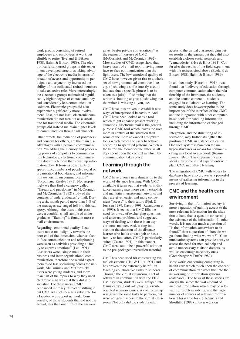
74
work groups consisting of retiredemployees and employees at work buteligible to retire (Eveland & Bikson1988, Hahm & Bikson 1989). The elec-tronically supported groups in this exper-iment developed structures taking advan-tage of the electronic media in terms ofbreadth of access and opportunity to par-ticipate and asynchrony increased theability of non-collocated retired membersto take an active role. More interestingly,the electronic groups maintained signifi-cantly higher degree of contact and theyhad considerably less communicationisolation. Electronic groups did alsoexperience significantly more involve-ment. Last, but not least, electronic com-munication did not turn out as a substi-tute for traditional media. The electronicgroups did instead maintain higher levelsof communication through all channels.
Other effects, the reduction of politenessand concern for others, are the main dis-advantages with electronic communica-tion. “In adding the memory and process-ing power of computers to communica-tion technology, electronic communica-tion does much more than speed up infor-mation flow. It loosens constraints ofspace, time, numbers of people, social ororganisational boundaries, and informa-tion ownership on communication”(Sproull and Kiesler 1991). Not surpris-ingly we thus find a category called“Threats and put-downs” in McCormickand McCormicks (1992) study of thecontents of undergraduates’ e-mail. Dur-ing a six month period more than 3 % ofthe messages exchanged fell into this cat-egory. Although the users in this casewere a youthful, small sample of under-graduates, “flaming” is found in most e-mail environments.
Regarding “emotional quality” Leasusers rate e-mail slightly towards thepoor end of the dimension, whereas face-to-face communication and telephoningwere seen as activities providing a “facil-ity to express emotions” (Lea 1991).Leas users were using e-mail in theirbusiness and inter-organisational com-munication, therefore one would expectthem to do less socialising across the net-work. McCormick and McCormicksusers were young students, and morethan half of the replies to why they usedelectronic mail was that they did it tosocialise. For these users, CMC“enhanced intimacy instead of stifling it”but CMC was not seen as a substitute fora face-to-face support network. Con-versely, of those students that did not usee-mail, less than one fifth of the answers
gave “Prefer private conversations” asthe reason of non-use of CMC(McCormick and McCormick 1992).Most studies of CMC-usage show thatheavy users of e-mail report having moreface-to-face communication than thelight users. The low emotional quality ofCMC have however given rise to a wholeset of new grammatical constructs likee.g. :-) showing a smile (mostly used toindicate that a specific phrase is to betaken as a joke), :-0 showing that thewriter is shouting at you; ;-) showing thatthe writer is winking at you, etc.
CMC have thus proven to establish newways of interpersonal behaviour. AndCMC have been looked at as a toolwhich might enhance present workingsituations. Electronic mail is the general-purpose CMC tool which leaves the usermore in control of the situation thansome of the more advanced groupwaretools which forces the users to behaveaccording to specified patterns. Which isthe better, the former or the latter, is alldependent upon the context in which thecommunication takes place.
Learning through the
network
CMC have given a new dimension to theworld of distance learning. With CMCavailable it turns out that students in dis-tance learning may more easily establishand maintain interpersonal networks andthey are given easier and more conve-nient “access” to their tutors (Fjuk &Jenssen 1989, Castro 1991, Rasmussen etal 1993). It seems that CMC fills theneed for a way of exchanging questionsand answers, problems and suggestedways of dealing with those in an asyn-chronous manner. And, taking intoaccount the situation of the distancelearner who holds down a job or has afamily to look after, CMC is particularlysuited (Castro 1991). In this manner,CMC turns out to be a powerful additionto the pre-packaged instruction material.
CMC has been used for constructing vir-tual classrooms (Hsu & Hiltz 1991) andhas proven to be extremely helpful inteaching collaborative skills to students.Through the virtual classroom, a set ofsoftware in combination with the EIESCMC system, students were grouped intoteams carrying out role playing, event-oriented scenario games. A control groupwas given the same tasks to perform, butwere not given access to the virtual class-room. Not only did the students with
access to the virtual classroom gain bet-ter results in the games, but they did alsoestablish a closer social network and“camaraderie” (Hsu & Hiltz 1991). Con-fer also the results of the field experimentwith the retirees cited above (Eveland &Bikson 1988, Hahm & Bikson 1989).
In another study (Harasim 1991) it wasfound that “delivery of education throughcomputer communication alters the rela-tionship of the instructor, the students,and the course content” – studentsengaged in collaborative learning. Thesame study does however point to theimportance of the interface of the CMCand the integration with other computer-based tools for handling information,including the information exchangedthrough CMC.
Integration, and the structuring of in-formation, may further strengthen theposition of CMC in distance education.One such system is based on the usehyper-structures as means for communi-cating in a local area network (Romis-zowski 1990). This experiment cameabout after some initial experiments withplain CMC in distance learning.
The integration of CMC with access todatabases have also proven as a powerfulmeans of gathering information in theprocess of learning.
CMC and the health care
environment
Surviving in the information society ismore a question of gaining access to themost relevant information for the situa-tion at hand than a question concerningthe existence of the information. In otherwords, it is not that much a question of“is the information somewhere to befound?” than a question of “how do wego about finding what we want?” “Com-munication systems can provide a way toassess the need for medical help andavoid unnecessary visits to doctors, aswell as encourage necessary ones.”(Greenberger & Puffer 1989).
Most works concerning computing inhealth care which touch upon the conceptof communication translates this into thenetworking of information systems(databases). The basis of these stories arealways the same: the vast amount ofmedical information which may be rele-vant for problem solving, and the largenumber of sources of relevant informa-tion. This is true for e.g. Rennels andShortliffe (1987) in their work on
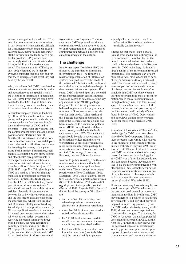
75
advanced computing for medicine: “Theneed for communication systems arisesin part because it is increasingly difficultfor a physician (or a biomedical investi-gator) to read, memorise and rememberall the information needed to solve a par-ticular problem. () Physicians haveaccordingly started to use literature databases, or bibliographic retrieval sys-tems.” The same is true for O’Desky et.al. (1990) when they try to identifyevolving computer technologies and fur-ther try to anticipate what effect they willhave by the year 2000.
Also, we seldom find CMC considered asrelevant in works on medical informaticsand education (e.g. the special issue ofthe Methods of information in medicine,vol. 28, 1989). From this we could haveconcluded that CMC has no future nei-ther in the daily work in health care, norin the education of health care workers.
A counterexample is found in the bookby Ellis (1987) where he looks at com-puting and applications in medical envi-ronments where a few passages brieflytouches the concept of CMC and itspotential: “A particular growth area is inthe computer technology analogue of thepostal service: electronic mail. ()Whether this is between individual doc-tors or health centres and hospital depart-ments, electronic mail offers much scopefor breaking the tyranny of the paper-based health service. Furthermore, suchfacilities as bulletin boards allow doctorsand other health care professionals toexchange views and information in amore immediate and informal fashionthan the traditional letter in a journal.”(Ellis 1987, page 28). This gives hope forCMC as a method of establishing andmaintaining professional interpersonalnetworks. Further, Ellis finds applica-tions for CMC in relation to the generalpractitioners information systems: “...what the doctor could do with is: a) moreefficient channels of communicationbetween his or her clinical environmentand the outside; b) assistance in sortingthe informational wheat from the chaff;and c) practical strategies for handlingknowledge in a more positive manner. ()Obvious applications of electronic mailin general practice include sending refer-ral letters to out-patient departments,receiving discharge summaries directfrom hospitals, the rapid reporting ofpathology results, and so on.” (Ellis1987, page 139). So Ellis points directlyto, for instance, the application of CMCin the distribution of information to and
from patient record systems. The nextstep into a CMC-supported health careenvironment would then have to be basedon an investigation into “the channels ofcommunication between a doctors clini-cal environment and the outside.
The challenge
In a former paper (Danielsen 1990) wediscussed the information islands andinformation bridges. The former is aresult of implementation of informationsystems designed to cover the needs ofthe individual. The latter is the traditionalmethod of repair through the exchange ofdata between information systems. Forsome, CMC is looked upon as a potentialbridge between health care institutions.CMC and access to databases are the keyapplications in the MEDIS package(Engum 1991). This integration wasbelieved to give users, i.e. physicians, aminimum of information services rele-vant for their needs. A first version ofthis package has been implemented aspart of the telemedicine project and hasbeen introduced to a number of potentialusers. MEDIS is built to fit with hard-ware currently available in the healthcare sector - that is PCs. That means thatusers should be able to access medicalinformation services from their ownworkstations. A prototype version of amore advanced integrated package forinformation services has also been imple-mented. This package, known asRatatosk, runs on Unix workstations.
In order to gather knowledge on the com-municational structures within healthcare, a number of surveys have beenundertaken. These surveys cover generalpractitioners offices (Danielsen 1991a,Danielsen 1991b), use of external labora-tory tests for general practitioners offices(Stenvold & Karlsen 1991) and a radiol-ogy department at a specific hospital(Braa et al 1991, Engevik 1991). Some ofthe results of the survey at GP officesare:
- one out of two letters received arerelated to previous communication(letters sent or phone conversations)
- more than 90 % of letters received arestored - often electronically
- for 5 to 10 % of letters received itwould have been seen as an improve-ment if they were received earlier
- less than half the letters sent are to afew select receivers (hospitals, labsetc.) the rest are mainly to patients
- nearly all letters sent are based oninformation likely to be stored elec-tronically (patient records).
It turns out that speed is not a crucialissue if other media than ordinary mail isto be considered. Less than half of theunits to be mailed had receivers whichcould be believed to have, or be likely toinvest in, CMC technology. Although alarge quantity of the information receivedthrough mail was related to earlier com-municative acts, most where not as partsof longer discussions through externalmail. This means that most mail receivedwere not parts of incremental commu-nicative processes. We could thereforeconclude that CMC could have been auseful tool for handling most of the infor-mation which today is communicatedthrough ordinary mail. The transmissionspeed of the medium used was of littleinterest, but the pre- and post-storing ofthe information could be a significantfactor in favour of CMC. Observationsand interviews did not uncover urgentneeds for more group-oriented CMCtools.
A number of forecasts and “dreams” of agolden age for CMC have been givensince the birth of computers. Whetherthese forecasts were wrong with respectto the number of people using or the fre-quency with which they use CMC are ofless interest. What is of interest to note isthat CMC has not turned out to be a keyreason for investing in technology forany CMC type of user, i.e. people do notbuy computers because they need to orlike to use them for communicating withother people. Yet, technology for person-to-person communication is seen as oneof the information technologies whichwill have a significant organisationalimpact (Straub & Wetherbe 1989).
However promising forecasts may be, weshould not expect CMC to take over asthe one most used general purpose com-munication medium in health care. CMCmay strengthen its position in health careenvironments if, and only if, it proves tohelp out in improving productivity. Asfor CMC and productivity, a study (Hiltz1988) shows that pre-use expectationscorrelates the strongest. That means, forCMC to “conquer” the market, potentialusers should state belief in CMC as theright tool. Further, the study shows thatthe perceived value of information pro-vided by peers, time spent on-line, per-ception of problems with this mode ofcommunication and how many users get
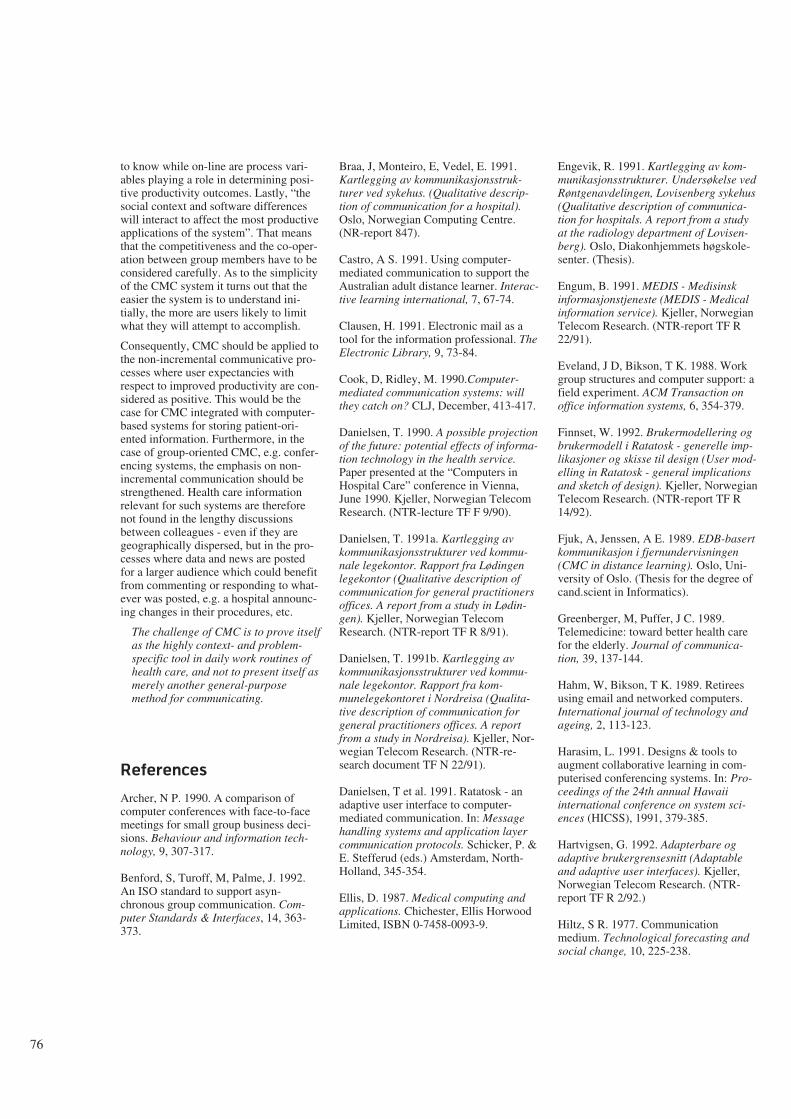
76
to know while on-line are process vari-ables playing a role in determining posi-tive productivity outcomes. Lastly, “thesocial context and software differenceswill interact to affect the most productiveapplications of the system”. That meansthat the competitiveness and the co-oper-ation between group members have to beconsidered carefully. As to the simplicityof the CMC system it turns out that theeasier the system is to understand ini-tially, the more are users likely to limitwhat they will attempt to accomplish.
Consequently, CMC should be applied tothe non-incremental communicative pro-cesses where user expectancies withrespect to improved productivity are con-sidered as positive. This would be thecase for CMC integrated with computer-based systems for storing patient-ori-ented information. Furthermore, in thecase of group-oriented CMC, e.g. confer-encing systems, the emphasis on non-incremental communication should bestrengthened. Health care informationrelevant for such systems are thereforenot found in the lengthy discussionsbetween colleagues - even if they aregeographically dispersed, but in the pro-cesses where data and news are postedfor a larger audience which could benefitfrom commenting or responding to what-ever was posted, e.g. a hospital announc-ing changes in their procedures, etc.
The challenge of CMC is to prove itselfas the highly context- and problem-specific tool in daily work routines ofhealth care, and not to present itself asmerely another general-purposemethod for communicating.
References
Archer, N P. 1990. A comparison ofcomputer conferences with face-to-facemeetings for small group business deci-sions. Behaviour and information tech-nology, 9, 307-317.
Benford, S, Turoff, M, Palme, J. 1992.An ISO standard to support asyn-chronous group communication. Com-puter Standards & Interfaces, 14, 363-373.
Braa, J, Monteiro, E, Vedel, E. 1991.Kartlegging av kommunikasjonsstruk-turer ved sykehus. (Qualitative descrip-tion of communication for a hospital).Oslo, Norwegian Computing Centre.(NR-report 847).
Castro, A S. 1991. Using computer-mediated communication to support theAustralian adult distance learner. Interac-tive learning international, 7, 67-74.
Clausen, H. 1991. Electronic mail as atool for the information professional. TheElectronic Library, 9, 73-84.
Cook, D, Ridley, M. 1990.Computer-mediated communication systems: willthey catch on? CLJ, December, 413-417.
Danielsen, T. 1990. A possible projectionof the future: potential effects of informa-tion technology in the health service.Paper presented at the “Computers inHospital Care” conference in Vienna,June 1990. Kjeller, Norwegian TelecomResearch. (NTR-lecture TF F 9/90).
Danielsen, T. 1991a. Kartlegging avkommunikasjonsstrukturer ved kommu-nale legekontor. Rapport fra Lødingenlegekontor (Qualitative description ofcommunication for general practitionersoffices. A report from a study in Lødin-gen). Kjeller, Norwegian TelecomResearch. (NTR-report TF R 8/91).
Danielsen, T. 1991b. Kartlegging avkommunikasjonsstrukturer ved kommu-nale legekontor. Rapport fra kom-munelegekontoret i Nordreisa (Qualita-tive description of communication forgeneral practitioners offices. A reportfrom a study in Nordreisa). Kjeller, Nor-wegian Telecom Research. (NTR-re-search document TF N 22/91).
Danielsen, T et al. 1991. Ratatosk - anadaptive user interface to computer-mediated communication. In: Messagehandling systems and application layercommunication protocols. Schicker, P. &E. Stefferud (eds.) Amsterdam, North-Holland, 345-354.
Ellis, D. 1987. Medical computing andapplications. Chichester, Ellis HorwoodLimited, ISBN 0-7458-0093-9.
Engevik, R. 1991. Kartlegging av kom-munikasjonsstrukturer. Undersøkelse vedRøntgenavdelingen, Lovisenberg sykehus(Qualitative description of communica-tion for hospitals. A report from a studyat the radiology department of Lovisen-berg). Oslo, Diakonhjemmets høgskole-senter. (Thesis).
Engum, B. 1991. MEDIS - Medisinskinformasjonstjeneste (MEDIS - Medicalinformation service). Kjeller, NorwegianTelecom Research. (NTR-report TF R22/91).
Eveland, J D, Bikson, T K. 1988. Workgroup structures and computer support: afield experiment. ACM Transaction onoffice information systems, 6, 354-379.
Finnset, W. 1992. Brukermodellering ogbrukermodell i Ratatosk - generelle imp-likasjoner og skisse til design (User mod-elling in Ratatosk - general implicationsand sketch of design). Kjeller, NorwegianTelecom Research. (NTR-report TF R14/92).
Fjuk, A, Jenssen, A E. 1989. EDB-basertkommunikasjon i fjernundervisningen(CMC in distance learning). Oslo, Uni-versity of Oslo. (Thesis for the degree ofcand.scient in Informatics).
Greenberger, M, Puffer, J C. 1989.Telemedicine: toward better health carefor the elderly. Journal of communica-tion, 39, 137-144.
Hahm, W, Bikson, T K. 1989. Retireesusing email and networked computers.International journal of technology andageing, 2, 113-123.
Harasim, L. 1991. Designs & tools toaugment collaborative learning in com-puterised conferencing systems. In: Pro-ceedings of the 24th annual Hawaiiinternational conference on system sci-ences (HICSS), 1991, 379-385.
Hartvigsen, G. 1992. Adapterbare ogadaptive brukergrensesnitt (Adaptableand adaptive user interfaces). Kjeller,Norwegian Telecom Research. (NTR-report TF R 2/92.)
Hiltz, S R. 1977. Communicationmedium. Technological forecasting andsocial change, 10, 225-238.
77
Hiltz, S R. 1978. Impact of a comput-erised conferencing system upon scien-tific research specialities. Journal ofresearch communication studies, 1, 111-124.
Hiltz, S R. 1988. Productivity enhance-ment from computer-mediated communi-cation: a systems contingency approach.Communications of the ACM, 31, 1438-1454.
Hiltz, S R. 1989. Computer-mediatedcommunication systems: dropouts versususers. In: Proceedings of the IFIP 11thWorld Computer Congress. Amsterdam,North-Holland, 1989, 1089-1094. ISBN:0-444-88015-1.
Hsu, E Y P, Hiltz, S R. 1991. Manage-ment gaming on a computer mediatedconferencing system: a case of collabora-tive learning through computer confer-encing. In: Proceedings of the 24thannual Hawaii international conferenceon system sciences (HICSS), 1991, 367-371.
Lea, M. 1991. Rationalist assumptions incross-media comparisons of computer-mediated communication. Behaviour &information technology, 10, 153-172.
McCormick, N B, McCormick, J W.1992. Computer friends and foes: contentof undergraduates’ electronic mail. Com-puters in human behaviour, 8, 379-405.
McLuhan, M, Fiore, Q. 1967. Themedium is the massage. London, PenguinBooks.
Motiwalla, L F, Nunamaker, J F. 1992.MAIL-MAN: A knowledge-based mailassistant for managers. Journal of organ-isational computing, 2, 131-154.
O’Desky, R I, Ball, M J, Ball, E E. 1990.Computers in health care for the 21stcentury. Methods of information inmedicine, 29, 158-161.
Pankoke-Babatz, U. (ed.) 1989. Com-puter based group communication. TheAMIGO activity model. London, EllisHorwood. ISBN 0-7458-0694-5.
Quarterman, J S, Hoskins, J C. 1986.Notable computer networks. Communi-cations of the ACM, 29, 932-969.
Rasmussen, T et al. 1993. PROFF: Com-puter-mediated communication in Nordicresearch education: a social feasibilitystudy. Kjeller, Norwegian TelecomResearch. (NTR-report TF R 7/93.)
Rennels, G D, Shortliffe, H. 1987.Advanced computing for Medicine. Sci-entific American, 257, 146-153.
Richardsen, P W, Danielsen, T. 1989.Intelligent messages or when messagescome alive. In: Network information pro-cessing systems. Boyanov, K. & R.Angelinov (eds.) Amsterdam, North-Hol-land, 257-264.
Romiszowski, A J. 1990. Computermediated communication and hypertext:building structure into distance seminars.In: Proceedings of Pacific telecommuni-cations: weaving the technology andsocial fabric. Wedemeyer, D J. & M D.Lofstrom (eds.) Honolulu, Jan. 1990,540-547.
Smith, H, Onions, J, Benford, S. (eds.)1989. Distributed group communication:the AMIGO information model. London,Ellis Horwood. ISBN 0-7458-0741-0.
Sproull, L, Kiesler, S. 1991. Two-LevelPerspective on Electronic Mail in Organ-isations. Journal of Organisational Com-puting, 1, 125-134.
Stenvold, L A, Karlsen, E. 1991. Kart-legging av analyserekvisisjoner fra kom-munalt helsesenter. Rapport fra en studieved Båtsfjord helsesenter (Qualitativedescription of the use of external labora-tory tests for general practitionersoffices. A report from a study at Båts-fjord helsesenter). Kjeller, NorwegianTelecom Research. (NTR-research docu-ment TF N 16/91.)
Straub, D W, Wetherbe, J C. 1989. Infor-mation technologies for the 1990s: anorganisational impact perspective. Com-munications of the ACM, 32, 1328-1339.
Tesler, L G. 1987. Networked computingin the 1990s. Scientific American,September 1991, 54-61.
Wasson, B, Akselsen, S. 1992. Anoverview of on-line assistance: from on-line documentation to intelligent help andtraining. The knowledge engineeringreview, 7, 289-322.
Whittaker, S. 1991. Towards a theory ofmediated communication. Bristol. (HPLaboratories, report No. HPL-91-78.)
78
Restraining and facilitating factors in the diffusion of
telemedicine – An interview study
B Y D E E D E G A M M O N
1 Background
There appears to be every indication thattelemedicine will spread rapidly withinthe Norwegian health care sector. A widerange of telemedicine applications hasalready been established as permanentservices in several health care institu-tions, and more hospitals are anxious toestablish their own services. The Norwe-gian Ministry of Health and SocialAffairs has accredited telemedicine as aspecialist field, and has appointed theUniversity Hospital of Tromsø as anational competence centre devoted tofurthering developments in telemedicine.If today’s wide and positive (both popu-lar and professional) press coverage con-tinues, telemedicine will soon become aterm both understood and anticipated bythe general public.
In spite of these positive developments,however, there is every reason to ask:How will telemedicine fare within theNorwegian health care sector? What fac-tors will influence the diffusion process –that is the rate and pattern of dispersion.While both technical and user groupexperiences are well documented, social,economic and organisational issues nowcome to the foreground as essential inassessing the potential diffusion of thistechnology. These issues now come tothe foreground in our efforts to anticipateand influence the future of telemedicinewithin the Norwegian health care sector.
The interview material reported in thispaper was our first effort in gaining abetter idea of the factors which can influ-ence the process of diffusion within theNorwegian health care sector. Subjectswho have participated in, or beenaffected by Norwegian Telecom’stelemedicine R&D activities were inter-viewed based on the following generalquestion: What factors can be expectedto have restraining and facilitatingeffects on the diffusion of telemedicinewithin the health care sector? They wereasked to formulate “educated guesses”about the future of this technology asthey saw it from each of their varyingexperiences and positions: local and cen-tral hospitals, municipality administra-tions, the Ministry of Health and SocialAffairs, Norwegian Telecom, and theNorwegian Telecom’s primary collabora-tors.
The goal of the study was to
- gain a preliminary overview of therange of factors which are considered
relevant to the diffusion oftelemedicine
- gain a basis for designing measureswhich can contribute to mutual adap-tion between telemedicine technologyand health care organisations.
2 What can be gained by
the diffusion of
telemedicine?
Ideally, the primary factor facilitating thediffusion of telemedicine is its ability toachieve important health care goals, inaddition to the goals of telemedicine-related industry. Indeed, the majority ofinterview subjects emphasised all thattelemedicine can help us to achieve asthe major factor which would facilitatethe diffusion of telemedicine. We willnot discuss the validity of this assump-tion (that “do-good” technologies diffusequickly, while others do not). Here wewill merely provide a summary of thereasons why Norwegian Telecom as wellas the health care sector are concernedwith the issue of diffusion.
The Norwegian Telecom has fairlystraight forward motives for its efforts indeveloping and spreading telemedicine;increase the use of telecommunicationsand thus increase the profits. Further-more, the health care sector provideschallenges which are important to tacklein order to maintain dominance in otherareas of the public and private sector.
The health care sector on its part is obli-gated to provide satisfactory health careto all members of society within the eco-nomic framework provided by the gov-ernment. Here, the legitimacy oftelemedicine will be assessed accordingto its ability to contribute in achievingimportant goals within the health caresector. The following list shows the typesof goals or potential benefits which bothhealth care personnel in the telemedicinepilot projects and interview subjects haveformulated:
- More efficient and equal access tomedical specialists, less waiting time
- Reduced patient travel⋅ Lower transport costs
⋅ Fewer and shorter leaves of absence(due to rapid diagnosis)
- Reduced number of ambulatory ser-vices
⋅ Lower specialist travel expenses
⋅ Increased specialist productivity
- Improved knowledge transfer to ruralphysicians
⋅ Accreditation of distant consultationas part of specialist education
⋅ Better access to patient cases neces-sary for maintaining hospital
⋅ Fulfilment of criterion for specialistaccreditation
- Fewer number of referrals to special-ists
- Reduced turnover of medical person-nel among rural health care institutionsdue to isolation and lack of access towider professional network
- Avoidance of unnecessary surgery(telepathology)
- Improved quality of health care ser-vices due to better co-ordination andcontinuity of treatment, and betterinformation to the patient.
To date, the projects have concentratedprimarily upon assessing the technicaland medical feasibility of the applica-tions. The above types of goals or poten-tial benefits have functioned as informalguidelines for assessing the relevanceand/or feasibility of the various pilot pro-jects. Few of the goals listed above havebeen operationalised and assessed sys-tematically. This will be among the pri-mary concerns in future studies.
3 Interview study
Twenty-nine interview subjects wereselected according to two criteria: a)acquaintance with the developments oftelemedicine, either directly through par-ticipation in pilot projects, or indirectlythrough contact and co-operation withthe Telemedicine project, and b) repre-sentation of areas of interest and influ-ence as shown in table 1.
It is worth noting that several of theinterview subjects are pioneers who haveinvested a fair amount of energy andprestige in developing and implementingtelemedicine applications. Furthermore,the study was conducted by a NorwegianTelecom research scientist also involvedin this field. The questions and opinionsof potential users and institutions whohave not been involved in these develop-ments will be important in gaining a
621.39:61
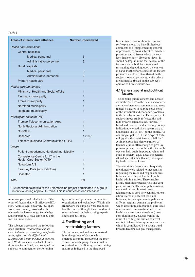
more complete and reliable idea of thetypes of factors that will influence diffu-sion. At this stage, however, few apartfrom those directly involved withtelemedicine have enough knowledgeand experience to have developed opin-ions on these issues.
The subjects were asked the followingopen question: What factors can beexpected to have restraining and facili-tating effects on the diffusion oftelemedicine within the health care sec-tor? While no specific subset of ques-tions was formulated, we prompted thesubjects to comment on the following
types of issues; personnel, economics,organisation and technology. Within thisframework the subjects were free to fol-low the lines of thought they found mostrelevant based on their varying experi-ences and positions.
4 Facilitating and
restraining factors
The interview material is summarisedinto nine groups of factors whichemerged as central throughout the inter-views. For each group, the material isorganised into facilitating and restrainingfactors as indicated in the shadowed
boxes. Since most of these factors areself-explanatory, we have limited ourcomments to a) supplementing generalimpressions, b) areas subject to misinter-pretation, and c) issues where the sub-jects had seriously divergent views. Itshould be kept in mind that several of thefactors may be both facilitating andrestraining, depending upon the contextat hand. Furthermore, some of the factorspresented are descriptive (based on thesubject’s own experience), while othersare normative (based on the subject’sopinion of how it should be).
4.1 General social and political
factors
The ongoing public concern and debateabout the “crisis” in the health sector cre-ates a readiness to assess newer and moreradical measures in helping solve someof the structural and economic problemsin the health care sector. The majority ofsubjects in our study reflected this atti-tude towards telemedicine. Further, ifbroad and positive media coverage is anyindication, telemedicine appears easy tounderstand and to “sell” to the public. Asone subject put it, “This is a type of tech-nology that the politicians will fall for.”A simple, practical demonstration oftelemedicine is often enough to give laypersons perspectives of how this technol-ogy can help attain important values andgoals in society; equal access to general-ist and specialist health care, more qual-ity health care per krone.
The restraining factors most frequentlymentioned were related to mechanismsregulating the roles and responsibilitiesbetween the different levels of publichealth administration. These mecha-nisms, often described as rigid and com-plex, are constantly under public assess-ment and debate. In most cases,telemedicine is used between institutionsadministered at different levels orbetween, for example, municipalities indifferent regions. Among the problemswhich arise in this interaction is the issueof economic compensation tied to thehealth care services themselves (travel,consultation fees, etc.) as well as theissue of dividing the burden of invest-ments in telemedicine systems – an issuewhich is complicated by a strong trendtowards decentralised goal management.
Areas of interest and influence Number interviewed
Health care institutions
Central hospitals
Medical personnel 5
Administrative personnel 3
Rural hospitals
Medical personnel 3
Administrative personnel 2
Primary health care 1
Health care authorities
Ministry of Health and Social Affairs 1
Finnmark municipality 1
Troms municipality 1
Nordland municipality 1
Rogaland municipality 1
Norwegian Telecom (NT)
Tromsø Telecommunication Area 1
North Regional Administration 1
ComStrat 1
Research 1 (10)*
Telecom Business Communication (TBK) 1
Others
Patient ombudsman, Nordland municipality 1
Competence Centre for IT in theHealth Care Sector (KITH) 1
NovaKom A/S 1
Fearnley Data (now EdiCom) 1
Spacetec 1
Total 29
* 10 research scientists at the Telemedicine project participated in a groupinterview lasting approx. 45 mins. This is counted as one interview.
Table 1
79
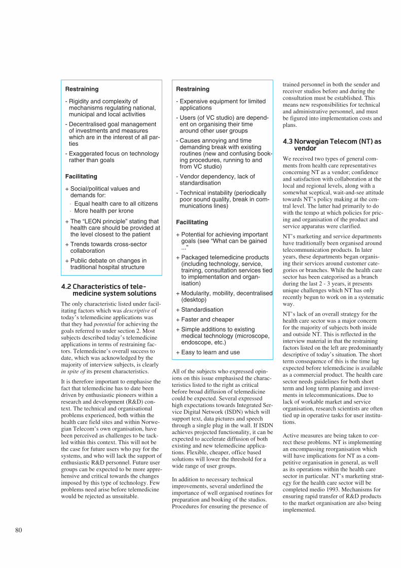
80
4.2 Characteristics of tele-
medicine system solutions
The only characteristic listed under facil-itating factors which was descriptive oftoday’s telemedicine applications wasthat they had potential for achieving thegoals referred to under section 2. Mostsubjects described today’s telemedicineapplications in terms of restraining fac-tors. Telemedicine’s overall success todate, which was acknowledged by themajority of interview subjects, is clearlyin spite of its present characteristics.
It is therefore important to emphasise thefact that telemedicine has to date beendriven by enthusiastic pioneers within aresearch and development (R&D) con-text. The technical and organisationalproblems experienced, both within thehealth care field sites and within Norwe-gian Telecom’s own organisation, havebeen perceived as challenges to be tack-led within this context. This will not bethe case for future users who pay for thesystems, and who will lack the support ofenthusiastic R&D personnel. Future usergroups can be expected to be more appre-hensive and critical towards the changesimposed by this type of technology. Fewproblems need arise before telemedicinewould be rejected as unsuitable.
All of the subjects who expressed opin-ions on this issue emphasised the charac-teristics listed to the right as criticalbefore broad diffusion of telemedicinecould be expected. Several expressedhigh expectations towards Integrated Ser-vice Digital Network (ISDN) which willsupport text, data pictures and speechthrough a single plug in the wall. If ISDNachieves projected functionality, it can beexpected to accelerate diffusion of bothexisting and new telemedicine applica-tions. Flexible, cheaper, office basedsolutions will lower the threshold for awide range of user groups.
In addition to necessary technicalimprovements, several underlined theimportance of well organised routines forpreparation and booking of the studios.Procedures for ensuring the presence of
trained personnel in both the sender andreceiver studios before and during theconsultation must be established. Thismeans new responsibilities for technicaland administrative personnel, and mustbe figured into implementation costs andplans.
4.3 Norwegian Telecom (NT) as
vendor
We received two types of general com-ments from health care representativesconcerning NT as a vendor; confidenceand satisfaction with collaboration at thelocal and regional levels, along with asomewhat sceptical, wait-and-see attitudetowards NT’s policy making at the cen-tral level. The latter had primarily to dowith the tempo at which policies for pric-ing and organisation of the product andservice apparatus were clarified.
NT’s marketing and service departmentshave traditionally been organised aroundtelecommunication products. In lateryears, these departments began organis-ing their services around customer cate-gories or branches. While the health caresector has been categorised as a branchduring the last 2 - 3 years, it presentsunique challenges which NT has onlyrecently begun to work on in a systematicway.
NT’s lack of an overall strategy for thehealth care sector was a major concernfor the majority of subjects both insideand outside NT. This is reflected in theinterview material in that the restrainingfactors listed on the left are predominantlydescriptive of today’s situation. The shortterm consequence of this is the time lagexpected before telemedicine is availableas a commercial product. The health caresector needs guidelines for both shortterm and long term planning and invest-ments in telecommunications. Due tolack of workable market and serviceorganisation, research scientists are oftentied up in operative tasks for user institu-tions.
Active measures are being taken to cor-rect these problems. NT is implementingan encompassing reorganisation whichwill have implications for NT as a com-petitive organisation in general, as wellas its operations within the health caresector in particular. NT’s marketing strat-egy for the health care sector will becompleted medio 1993. Mechanisms forensuring rapid transfer of R&D productsto the market organisation are also beingimplemented.
Restraining
- Rigidity and complexity ofmechanisms regulating national,municipal and local activities
- Decentralised goal managementof investments and measureswhich are in the interest of all par-ties
- Exaggerated focus on technologyrather than goals
Facilitating
+ Social/political values anddemands for:⋅ Equal health care to all citizens⋅ More health per krone
+ The “LEON principle” stating thathealth care should be provided atthe level closest to the patient
+ Trends towards cross-sectorcollaboration
+ Public debate on changes intraditional hospital structure
Restraining
- Expensive equipment for limitedapplications
- Users (of VC studio) are depend-ent on organising their timearound other user groups
- Causes annoying and timedemanding break with existingroutines (new and confusing book-ing procedures, running to andfrom VC studio)
- Vendor dependency, lack ofstandardisation
- Technical instability (periodicallypoor sound quality, break in com-munications lines)
Facilitating
+ Potential for achieving importantgoals (see “What can be gained...”
+ Packaged telemedicine products(including technology, service,training, consultation services tiedto implementation and organ-isation)
+ Modularity, mobility, decentralised(desktop)
+ Standardisation
+ Faster and cheaper
+ Simple additions to existingmedical technology (microscope,endoscope, etc.)
+ Easy to learn and use
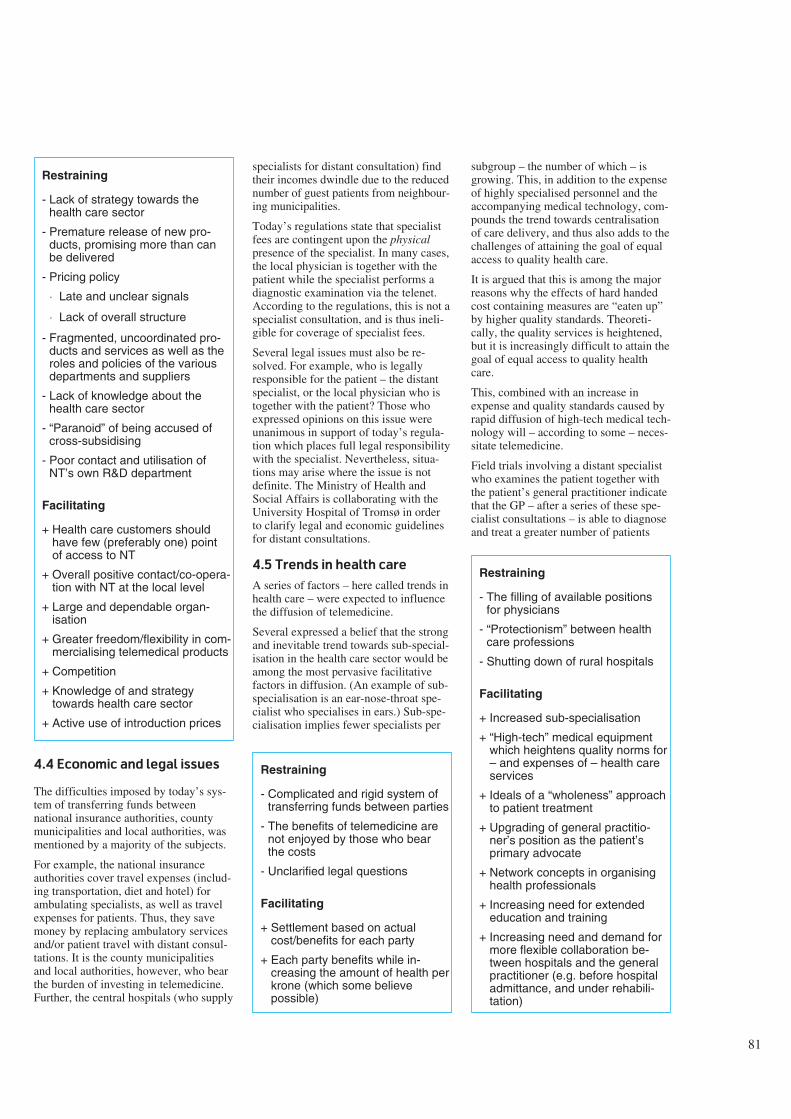
4.4 Economic and legal issues
The difficulties imposed by today’s sys-tem of transferring funds betweennational insurance authorities, countymunicipalities and local authorities, wasmentioned by a majority of the subjects.
For example, the national insuranceauthorities cover travel expenses (includ-ing transportation, diet and hotel) forambulating specialists, as well as travelexpenses for patients. Thus, they savemoney by replacing ambulatory servicesand/or patient travel with distant consul-tations. It is the county municipalitiesand local authorities, however, who bearthe burden of investing in telemedicine.Further, the central hospitals (who supply
specialists for distant consultation) findtheir incomes dwindle due to the reducednumber of guest patients from neighbour-ing municipalities.
Today’s regulations state that specialistfees are contingent upon the physicalpresence of the specialist. In many cases,the local physician is together with thepatient while the specialist performs adiagnostic examination via the telenet.According to the regulations, this is not aspecialist consultation, and is thus ineli-gible for coverage of specialist fees.
Several legal issues must also be re-solved. For example, who is legallyresponsible for the patient – the distantspecialist, or the local physician who istogether with the patient? Those whoexpressed opinions on this issue wereunanimous in support of today’s regula-tion which places full legal responsibilitywith the specialist. Nevertheless, situa-tions may arise where the issue is notdefinite. The Ministry of Health andSocial Affairs is collaborating with theUniversity Hospital of Tromsø in orderto clarify legal and economic guidelinesfor distant consultations.
4.5 Trends in health care
A series of factors – here called trends inhealth care – were expected to influencethe diffusion of telemedicine.
Several expressed a belief that the strongand inevitable trend towards sub-special-isation in the health care sector would beamong the most pervasive facilitativefactors in diffusion. (An example of sub-specialisation is an ear-nose-throat spe-cialist who specialises in ears.) Sub-spe-cialisation implies fewer specialists per
subgroup – the number of which – isgrowing. This, in addition to the expenseof highly specialised personnel and theaccompanying medical technology, com-pounds the trend towards centralisationof care delivery, and thus also adds to thechallenges of attaining the goal of equalaccess to quality health care.
It is argued that this is among the majorreasons why the effects of hard handedcost containing measures are “eaten up”by higher quality standards. Theoreti-cally, the quality services is heightened,but it is increasingly difficult to attain thegoal of equal access to quality healthcare.
This, combined with an increase inexpense and quality standards caused byrapid diffusion of high-tech medical tech-nology will – according to some – neces-sitate telemedicine.
Field trials involving a distant specialistwho examines the patient together withthe patient’s general practitioner indicatethat the GP – after a series of these spe-cialist consultations – is able to diagnoseand treat a greater number of patients
Restraining
- Lack of strategy towards thehealth care sector
- Premature release of new pro-ducts, promising more than canbe delivered
- Pricing policy
⋅ Late and unclear signals
⋅ Lack of overall structure
- Fragmented, uncoordinated pro-ducts and services as well as theroles and policies of the variousdepartments and suppliers
- Lack of knowledge about thehealth care sector
- “Paranoid” of being accused ofcross-subsidising
- Poor contact and utilisation ofNT’s own R&D department
Facilitating
+ Health care customers shouldhave few (preferably one) pointof access to NT
+ Overall positive contact/co-opera-tion with NT at the local level
+ Large and dependable organ-isation
+ Greater freedom/flexibility in com-mercialising telemedical products
+ Competition
+ Knowledge of and strategytowards health care sector
+ Active use of introduction prices
Restraining
- Complicated and rigid system oftransferring funds between parties
- The benefits of telemedicine arenot enjoyed by those who bearthe costs
- Unclarified legal questions
Facilitating
+ Settlement based on actualcost/benefits for each party
+ Each party benefits while in-creasing the amount of health perkrone (which some believepossible)
Restraining
- The filling of available positionsfor physicians
- “Protectionism” between healthcare professions
- Shutting down of rural hospitals
Facilitating
+ Increased sub-specialisation
+ “High-tech” medical equipmentwhich heightens quality norms for– and expenses of – health careservices
+ Ideals of a “wholeness” approachto patient treatment
+ Upgrading of general practitio-ner’s position as the patient’sprimary advocate
+ Network concepts in organisinghealth professionals
+ Increasing need for extendededucation and training
+ Increasing need and demand formore flexible collaboration be-tween hospitals and the generalpractitioner (e.g. before hospitaladmittance, and under rehabili-tation)
81
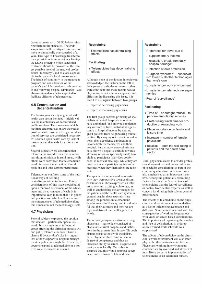
82
(some estimate up to 50 %) before refer-ring them to the specialist. The endo-scopic trials will investigate this questionmore systematically over a period of ayear. This type of knowledge transfer torural physicians is important in achievingthe LEON-principle which states thattreatment should be provided at the low-est possible level of the medical profes-sional “hierarchy”, and as close as possi-ble to the patient’s local environment.The ideals of continuity in the treatmentprogram and consideration of thepatient’s total life situation – both previousto and following hospital admittance – wasalso mentioned as a factor expected tofacilitate diffusion of telemedicine.
4.6 Centralisation and
decentralisation
The Norwegian society in general – thehealth care sector included – highly val-ues the maintenance of decentralisedpublic services. Thus, measures whichfacilitate decentralisation are viewed aspositive while those involving centralisa-tion of services are considered necessaryevils forced upon health care by lack ofresources and demands for rationalisa-tion.
Several subjects were concerned thattelemedicine would reduce pressure forrecruiting physicians in rural areas, whileothers were convinced that telemedicinewould increase the attraction of ruralpositions and thus support recruitment.
Telemedicine confuses some of the tradi-tional ways of definingcentralisation/decentralisation. Futureconsiderations of this issue should buildupon a renewed assessment of the advan-tages and disadvantages of each. It isimportant to keep in mind that it is policyand practical use which will determinethe consequences of telemedicine alongthis dimension, not the technology itself.
4.7 Physicians
Several subjects expressed the opinionthat doctors – particularly specialists –would be the single most influentialgroup effecting the diffusion process. Asone put it, telemedicine won’t have achance if doctors don’t like it – regard-less of how supportive hospital manage-ment or politicians might be. Likewise, ifdoctors respond to telemedicine in a pos-itive way, its success is assured.
Although none of the doctors interviewedacknowledged the factors on the left astheir personal attitudes or interests, theywere confident that these factors wouldplay an important role in acceptance anddiffusion. In discussing this issue, it isuseful to distinguish between two groups:
- Expertise delivering physicians
- Expertise receiving physicians
The first group consists primarily of spe-cialists at central hospitals who eitherhave ambulated (and enjoyed supplemen-tary income) or have contributed signifi-cantly to hospital income by treatingguest patients from neighbouring munici-palities. By carrying out distant consulta-tions, they experience a reduction inincome both for themselves and theirhospital. Furthermore, some physicianshave shown a negative attitude towardsallowing receiving (primarily rural) hos-pitals to participate (via video confer-ence) in medical meetings, while they arepositive towards participating in similarmeetings when they themselves are recip-ients.
The specialists interviewed were askedwhy they were positive towards distantconsultations. These expressed an inter-est in new and exciting technology, aswell as emphasising the advantages forthe patient and the health care system ingeneral. Again, these specialists areamong the pioneers in telemedicinedevelopments in Norway, and it is doubt-ful that their attitudes and motives arerepresentative of their colleagues as awhole.
The second group – expertise receivingphysicians – has to date consisted ofphysicians at rural hospitals and institu-tions in the primary health care. Throughdistant consultations with specialists,these physicians have built up a newdegree of competence and thus anincreased ability to screen, diagnose andtreat patients locally. Our subjectsassumed that this would promote accep-tance and diffusion of telemedicine.
Rural physician access to a wider profes-sional network, as well as accreditationof specialist consultations as part of thecontinuing education curriculum, wasalso emphasised as an important incen-tive. Among the potentially restrainingfactors for this group’s acceptance oftelemedicine was the fear of surveillanceor control from central experts, as well asconcern for diluting their role as generalpractitioners.
The effects of telemedicine on the physi-cian’s work environment was underlinedas a factor influencing acceptance anddiffusion. Some were concerned with theconsequences of working long periodswith video or screen based consultations.The importance of organising the numberand type of consultations in order toallow a varied work schedule wasemphasised.
The effects of telemedicine on the physi-cian’s work environment will also inter-play with other environmental factors.Physicians working in environmentscharacterised by overload and stress willmost likely perceive implementation oftelemedicine as an additional burden.
Restraining
- Telemedicine has centralisingeffects
Facilitating
+ Telemedicine has decentralisingeffects
Restraining
- Preference for travel due to
. supplementary income
. relaxation, break from dailyhospital “drudge”
- Protection of own profession
- “Surgeon syndrome” – conservat-ism towards all other technologiesthan one’s own
- Unsatisfactory work environment
- Unsatisfactory telemedicine ergo-nomics
- Fear of “surveillance”
Facilitating
+ Tired of – or outright refusal – toperform ambulatory services
+ Prefer using travel time for pro-ductive or rewarding work
+ Place importance on family andleisure time
+ Increase in number of femalephysicians
+ Idealists – seek the well being ofpatients and the health caresector
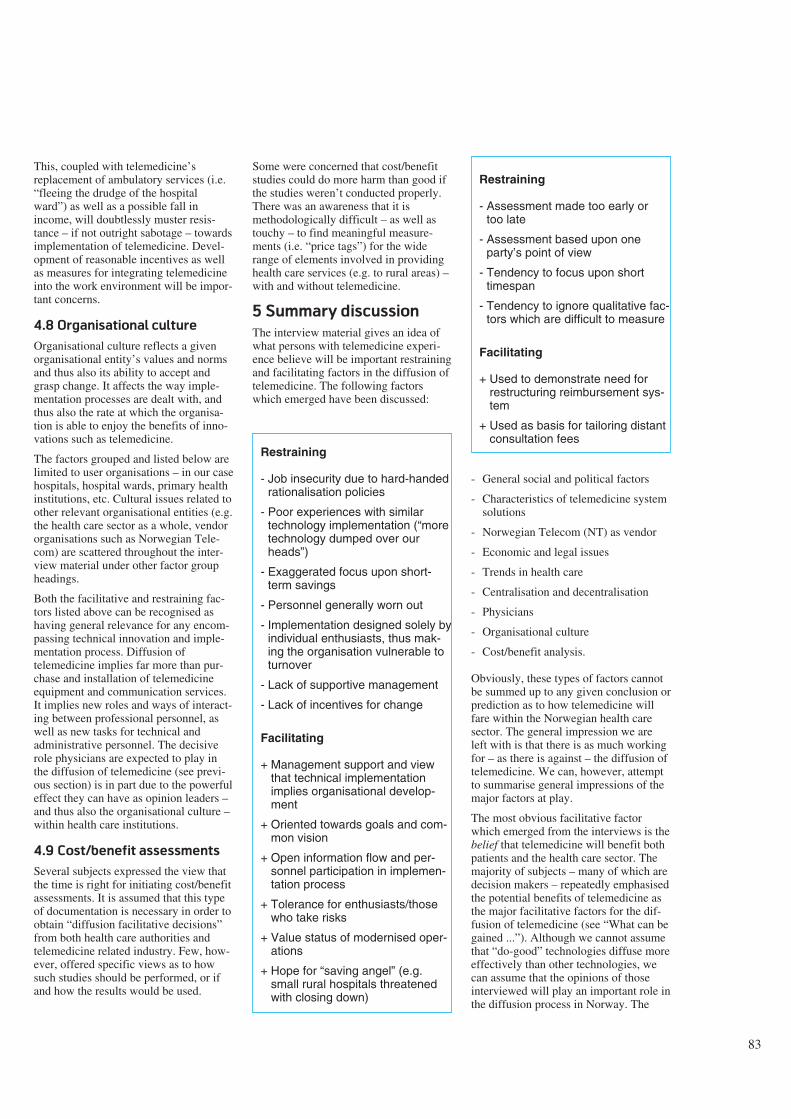
This, coupled with telemedicine’sreplacement of ambulatory services (i.e.“fleeing the drudge of the hospitalward”) as well as a possible fall inincome, will doubtlessly muster resis-tance – if not outright sabotage – towardsimplementation of telemedicine. Devel-opment of reasonable incentives as wellas measures for integrating telemedicineinto the work environment will be impor-tant concerns.
4.8 Organisational culture
Organisational culture reflects a givenorganisational entity’s values and normsand thus also its ability to accept andgrasp change. It affects the way imple-mentation processes are dealt with, andthus also the rate at which the organisa-tion is able to enjoy the benefits of inno-vations such as telemedicine.
The factors grouped and listed below arelimited to user organisations – in our casehospitals, hospital wards, primary healthinstitutions, etc. Cultural issues related toother relevant organisational entities (e.g.the health care sector as a whole, vendororganisations such as Norwegian Tele-com) are scattered throughout the inter-view material under other factor groupheadings.
Both the facilitative and restraining fac-tors listed above can be recognised ashaving general relevance for any encom-passing technical innovation and imple-mentation process. Diffusion oftelemedicine implies far more than pur-chase and installation of telemedicineequipment and communication services.It implies new roles and ways of interact-ing between professional personnel, aswell as new tasks for technical andadministrative personnel. The decisiverole physicians are expected to play inthe diffusion of telemedicine (see previ-ous section) is in part due to the powerfuleffect they can have as opinion leaders –and thus also the organisational culture –within health care institutions.
4.9 Cost/benefit assessments
Several subjects expressed the view thatthe time is right for initiating cost/benefitassessments. It is assumed that this typeof documentation is necessary in order toobtain “diffusion facilitative decisions”from both health care authorities andtelemedicine related industry. Few, how-ever, offered specific views as to howsuch studies should be performed, or ifand how the results would be used.
Some were concerned that cost/benefitstudies could do more harm than good ifthe studies weren’t conducted properly.There was an awareness that it ismethodologically difficult – as well astouchy – to find meaningful measure-ments (i.e. “price tags”) for the widerange of elements involved in providinghealth care services (e.g. to rural areas) –with and without telemedicine.
5 Summary discussion
The interview material gives an idea ofwhat persons with telemedicine experi-ence believe will be important restrainingand facilitating factors in the diffusion oftelemedicine. The following factorswhich emerged have been discussed:
Restraining
- Job insecurity due to hard-handedrationalisation policies
- Poor experiences with similartechnology implementation (“moretechnology dumped over ourheads”)
- Exaggerated focus upon short-term savings
- Personnel generally worn out
- Implementation designed solely byindividual enthusiasts, thus mak-ing the organisation vulnerable toturnover
- Lack of supportive management
- Lack of incentives for change
Facilitating
+ Management support and viewthat technical implementationimplies organisational develop-ment
+ Oriented towards goals and com-mon vision
+ Open information flow and per-sonnel participation in implemen-tation process
+ Tolerance for enthusiasts/thosewho take risks
+ Value status of modernised oper-ations
+ Hope for “saving angel” (e.g.small rural hospitals threatenedwith closing down)
Restraining
- Assessment made too early ortoo late
- Assessment based upon oneparty’s point of view
- Tendency to focus upon shorttimespan
- Tendency to ignore qualitative fac-tors which are difficult to measure
Facilitating
+ Used to demonstrate need forrestructuring reimbursement sys-tem
+ Used as basis for tailoring distantconsultation fees
83
- General social and political factors
- Characteristics of telemedicine systemsolutions
- Norwegian Telecom (NT) as vendor
- Economic and legal issues
- Trends in health care
- Centralisation and decentralisation
- Physicians
- Organisational culture
- Cost/benefit analysis.
Obviously, these types of factors cannotbe summed up to any given conclusion orprediction as to how telemedicine willfare within the Norwegian health caresector. The general impression we areleft with is that there is as much workingfor – as there is against – the diffusion oftelemedicine. We can, however, attemptto summarise general impressions of themajor factors at play.
The most obvious facilitative factorwhich emerged from the interviews is thebelief that telemedicine will benefit bothpatients and the health care sector. Themajority of subjects – many of which aredecision makers – repeatedly emphasisedthe potential benefits of telemedicine asthe major facilitative factors for the dif-fusion of telemedicine (see “What can begained ...”). Although we cannot assumethat “do-good” technologies diffuse moreeffectively than other technologies, wecan assume that the opinions of thoseinterviewed will play an important role inthe diffusion process in Norway. The
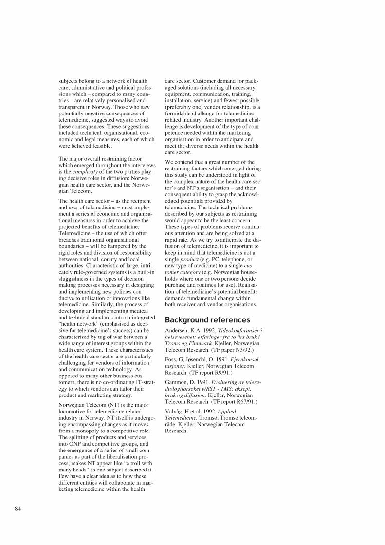
84
subjects belong to a network of healthcare, administrative and political profes-sions which – compared to many coun-tries – are relatively personalised andtransparent in Norway. Those who sawpotentially negative consequences oftelemedicine, suggested ways to avoidthese consequences. These suggestionsincluded technical, organisational, eco-nomic and legal measures, each of whichwere believed feasible.
The major overall restraining factorwhich emerged throughout the interviewsis the complexity of the two parties play-ing decisive roles in diffusion: Norwe-gian health care sector, and the Norwe-gian Telecom.
The health care sector – as the recipientand user of telemedicine – must imple-ment a series of economic and organisa-tional measures in order to achieve theprojected benefits of telemedicine.Telemedicine – the use of which oftenbreaches traditional organisationalboundaries – will be hampered by therigid roles and division of responsibilitybetween national, county and localauthorities. Characteristic of large, intri-cately rule-governed systems is a built-insluggishness in the types of decisionmaking processes necessary in designingand implementing new policies con-ducive to utilisation of innovations liketelemedicine. Similarly, the process ofdeveloping and implementing medicaland technical standards into an integrated“health network” (emphasised as deci-sive for telemedicine’s success) can becharacterised by tug of war between awide range of interest groups within thehealth care system. These characteristicsof the health care sector are particularlychallenging for vendors of informationand communication technology. Asopposed to many other business cus-tomers, there is no co-ordinating IT-strat-egy to which vendors can tailor theirproduct and marketing strategy.
Norwegian Telecom (NT) is the majorlocomotive for telemedicine relatedindustry in Norway. NT itself is undergo-ing encompassing changes as it movesfrom a monopoly to a competitive role.The splitting of products and servicesinto ONP and competitive groups, andthe emergence of a series of small com-panies as part of the liberalisation pro-cess, makes NT appear like “a troll withmany heads” as one subject described it.Few have a clear idea as to how thesedifferent entities will collaborate in mar-keting telemedicine within the health
care sector. Customer demand for pack-aged solutions (including all necessaryequipment, communication, training,installation, service) and fewest possible(preferably one) vendor relationship, is aformidable challenge for telemedicinerelated industry. Another important chal-lenge is development of the type of com-petence needed within the marketingorganisation in order to anticipate andmeet the diverse needs within the healthcare sector.
We contend that a great number of therestraining factors which emerged duringthis study can be understood in light ofthe complex nature of the health care sec-tor’s and NT’s organisation – and theirconsequent ability to grasp the acknowl-edged potentials provided bytelemedicine. The technical problemsdescribed by our subjects as restrainingwould appear to be the least concern.These types of problems receive continu-ous attention and are being solved at arapid rate. As we try to anticipate the dif-fusion of telemedicine, it is important tokeep in mind that telemedicine is not asingle product (e.g. PC, telephone, ornew type of medicine) to a single cus-tomer category (e.g. Norwegian house-holds where one or two persons decidepurchase and routines for use). Realisa-tion of telemedicine’s potential benefitsdemands fundamental change withinboth receiver and vendor organisations.
Background references
Andersen, K A. 1992. Videokonferanser ihelsevesenet: erfaringer fra to års bruk iTroms og Finnmark. Kjeller, NorwegianTelecom Research. (TF paper N3/92.)
Foss, G, Jøsendal, O. 1991. Fjernkonsul-tasjoner. Kjeller, Norwegian TelecomResearch. (TF report R9/91.)
Gammon, D. 1991. Evaluering av telera-diologiforsøket v/RST - TMS; aksept,bruk og diffusjon. Kjeller, NorwegianTelecom Research. (TF report R67/91.)
Valvåg, H et al. 1992. AppliedTelemedicine. Tromsø, Tromsø teleom-råde. Kjeller, Norwegian TelecomResearch.
1 Innledning
På mange måter kan en si at utviklingen innen telekommunika-sjonsmarkedet er eksponentiell. Tidligere var det få tjenester,høye priser og lav servicegrad. I 70-årene og fram til midt på80-tallet var det lange ventelister på primærtjenesten telefon.Det var også en framkommelighet i nettet som etter vår måle-stokk nå var meget dårlig.
Fra kun å ha telegraf-, telefon- og telekstjenesten har markedetnærmest eksplodert. Bare i tilknytning til de digitale sentralenekan det tilbys mange titalls tilleggstjenester. Datatjenestene er isterk utvikling. Dette gjelder blant annet overføring ved ulikehastigheter og ved bruk av en rekke ulike nettkonsepter. Påoverordnet nivå i nettet (intelligent nett-tjeneste) vil det væremulig å definere nye tjenester uten å foreta hardware/softwareutskifting i de underliggende digitale sentralene.
I tillegg har vi fått inntoget av de verdiøkende tjenestene – detjenestene som mange snakket om for 5 år siden, men som fåvisste hva var. Teletorg og andre informasjonstjenester ereksempler på disse.
Fra midt på 80-tallet foretok Televerket store investeringer i for-nyelse av telenettet basert på ny teknologi. Bruk av mikroelek-tronikk, digitale og optiske komponenter har ført til færre feil,bedre framkommelighet, større fleksibilitet, flere tjenester ogstørre kapasitet i telenettet. Den moderniseringen som Tele-verket til nå har foretatt, har vært meget lønnsom og den har gittTeleverket og norsk næringsliv et godt utgangspunkt.
Situasjonen nå er at Televerket gir god service samtidig somprisene den siste tiden har falt til et nivå som er lavere enneuropeisk gjennomsnitt. Fra å være fokusert på servicegrad, måTeleverket nå i stor grad orientere seg mot markedstilpasning,lønnsomhet og konkurranse.
Tidligere var det mange private telefonselskaper i Norge. Dedekket riktignok ulike geografiske områder. Disse ble kjøpt oppog Televerket har i mange år (altfor mange) vært i en monopol-situasjon. Deregulerings- og liberaliseringsprosessen både i ogutenfor Europa fører nå i et akselererende tempo til full kon-kurranse på alle områder innen telekommunikasjon. Dettegjelder også det norske markedet.
Et forbehold kan være at det ikke vil være konkurranse påulønnsomme samfunnspålagte oppgaver. Dersom Televerketikke får nødvendig handlefrihet for å møte den tiltagende kon-kurransen, og som følge av dette taper vesentlige markedsan-deler, vil finansiering og driftstilskudd over statsbudsjettet væreeneste måte å dekke opp ulønnsomme samfunnspålagte opp-gaver og etter hvert også deler av sin primærvirksomhet.
2 Televerket og norsk næringsliv
Det må kunne slås fast at Televerket og norsk næringsliv ergjensidig avhengige av hverandre.
Televerket tar sikte på fortsatt å være den sentrale nettopera-tøren for norsk næringsliv. Televerket skal være en kunderettettelekommunikasjonsbedrift som med framtidsrettet teknologi ogmedarbeidere med høy kompetanse skal dekke kunders behovfor tale-, tekst-, data- og bildekommunikasjon med tilhørendetjenester. Tjenestene skal ha høy kvalitet og et konkurranse-dyktig prisnivå.
Televerkets hovedmål:
- Televerket skal være den ledende norske leverandør av tele-kommunikasjoner i 90-årenes konkurransemarked.
- Televerket skal tilpasse sin teknologi til markedet.
- Televerket skal sammen med datterselskaper og andre samar-beidspartnere dekke kundenes behov for totalløsninger.
- Televerket skal fortsatt prioritere effektiviserings- og rasjon-aliseringsarbeidet for å få kostnadene og dermed prisen påtjenestene ytterligere ned.
- Prisene skal senkes/holdes under europeisk gjennomsnitt.
- Televerket skal være drivkraften i utviklingen av nye lønn-somme forretningsområder i telemarkedet, og bidra til etslagkraftig norsk industri- og forskningsmiljø innen telekom-munikasjon.
En konsekvens av disse hovedmålene er at næringslivet skal til-bys gode, moderne og konkurransedyktige teletjenester. Det erallerede nå lagt vekt på å holde et lavt prisnivå på internasjonaltrafikk. Ikke minst er dette viktig for norsk næringsliv som harstørre avstand til markedene i Europa enn land flest.
85
Liberalisering av telekommunikasjonsområdetA V K J E L L S T O R D A H L
Dette foredraget ble presentert på konferansen “Liberalisering gir store muligheter innen telekommunikasjon”, holdt på Oslo Plaza12 og 13 mai 1992.
Figur 2.1 Televerket understøtter norsk industri
621.39.05
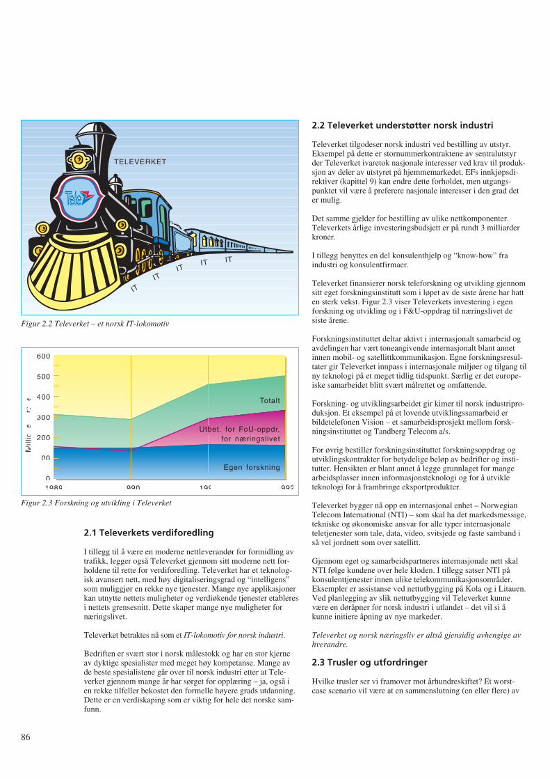
2.1 Televerkets verdiforedling
I tillegg til å være en moderne nettleverandør for formidling avtrafikk, legger også Televerket gjennom sitt moderne nett for-holdene til rette for verdiforedling. Televerket har et teknolog-isk avansert nett, med høy digitaliseringsgrad og “intelligens”som muliggjør en rekke nye tjenester. Mange nye applikasjonerkan utnytte nettets muligheter og verdiøkende tjenester etableresi nettets grensesnitt. Dette skaper mange nye muligheter fornæringslivet.
Televerket betraktes nå som et IT-lokomotiv for norsk industri.
Bedriften er svært stor i norsk målestokk og har en stor kjerneav dyktige spesialister med meget høy kompetanse. Mange avde beste spesialistene går over til norsk industri etter at Tele-verket gjennom mange år har sørget for opplæring – ja, også ien rekke tilfeller bekostet den formelle høyere grads utdanning.Dette er en verdiskaping som er viktig for hele det norske sam-funn.
2.2 Televerket understøtter norsk industri
Televerket tilgodeser norsk industri ved bestilling av utstyr.Eksempel på dette er stornummerkontraktene av sentralutstyrder Televerket ivaretok nasjonale interesser ved krav til produk-sjon av deler av utstyret på hjemmemarkedet. EFs innkjøpsdi-rektiver (kapittel 9) kan endre dette forholdet, men utgangs-punktet vil være å preferere nasjonale interesser i den grad deter mulig.
Det samme gjelder for bestilling av ulike nettkomponenter.Televerkets årlige investeringsbudsjett er på rundt 3 milliarderkroner.
I tillegg benyttes en del konsulenthjelp og “know-how” fraindustri og konsulentfirmaer.
Televerket finansierer norsk teleforskning og utvikling gjennomsitt eget forskningsinstitutt som i løpet av de siste årene har hatten sterk vekst. Figur 2.3 viser Televerkets investering i egenforskning og utvikling og i F&U-oppdrag til næringslivet desiste årene.
Forskningsinstituttet deltar aktivt i internasjonalt samarbeid ogavdelingen har vært toneangivende internasjonalt blant annetinnen mobil- og satellittkommunikasjon. Egne forskningsresul-tater gir Televerket innpass i internasjonale miljøer og tilgang tilny teknologi på et meget tidlig tidspunkt. Særlig er det europe-iske samarbeidet blitt svært målrettet og omfattende.
Forskning- og utviklingsarbeidet gir kimer til norsk industripro-duksjon. Et eksempel på et lovende utviklingssamarbeid erbildetelefonen Vision – et samarbeidsprosjekt mellom forsk-ningsinstituttet og Tandberg Telecom a/s.
For øvrig bestiller forskningsinstituttet forskningsoppdrag ogutviklingskontrakter for betydelige beløp av bedrifter og insti-tutter. Hensikten er blant annet å legge grunnlaget for mangearbeidsplasser innen informasjonsteknologi og for å utvikleteknologi for å frambringe eksportprodukter.
Televerket bygger nå opp en internasjonal enhet – NorwegianTelecom International (NTI) – som skal ha det markedsmessige,tekniske og økonomiske ansvar for alle typer internasjonaleteletjenester som tale, data, video, svitsjede og faste samband iså vel jordnett som over satellitt.
Gjennom eget og samarbeidspartneres internasjonale nett skalNTI følge kundene over hele kloden. I tillegg satser NTI påkonsulenttjenester innen ulike telekommunikasjonsområder.Eksempler er assistanse ved nettutbygging på Kola og i Litauen.Ved planlegging av slik nettutbygging vil Televerket kunnevære en døråpner for norsk industri i utlandet – det vil si åkunne initiere åpning av nye markeder.
Televerket og norsk næringsliv er altså gjensidig avhengige avhverandre.
2.3 Trusler og utfordringer
Hvilke trusler ser vi framover mot århundreskiftet? Et worst-case scenario vil være at en sammenslutning (en eller flere) av
86
TELEVERKET
ITIT
ITIT IT
Figur 2.2 Televerket – et norsk IT-lokomotiv
1989
600
500
400
300
200
100
01990 1991 1992
Mill
ion
er
kro
ne
r
Totalt
Utbet. for FoU-oppdr.for næringslivet
Egen forskning
Figur 2.3 Forskning og utvikling i Televerket
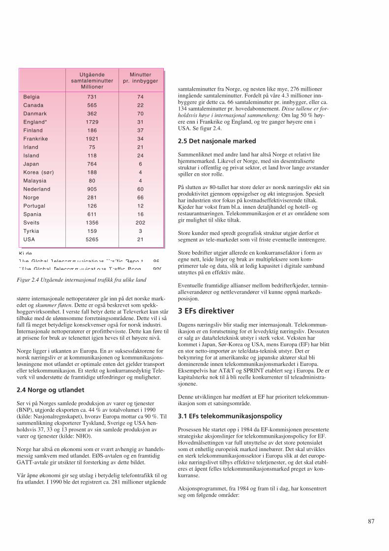
større internasjonale nettoperatører går inn på det norske mark-edet og skummer fløten. Dette er også beskrevet som spekk-hoggervirksomhet. I verste fall betyr dette at Televerket kun stårtilbake med de ulønnsomme forretningsområdene. Dette vil i såfall få meget betydelige konsekvenser også for norsk industri.Internasjonale nettoperatører er profittbevisste. Dette kan føre tilat prisene for bruk av telenettet igjen heves til et høyere nivå.
Norge ligger i utkanten av Europa. En av suksessfaktorene fornorsk næringsliv er at kommunikasjonen og kommunikasjons-løsningene mot utlandet er optimale enten det gjelder transporteller telekommunikasjon. Et sterkt og konkurransedyktig Tele-verk vil understøtte de framtidige utfordringer og muligheter.
2.4 Norge og utlandet
Ser vi på Norges samlede produksjon av varer og tjenester(BNP), utgjorde eksporten ca. 44 % av totalvolumet i 1990(kilde: Nasjonalregnskapet), hvorav Europa mottar ca 90 %. Tilsammenlikning eksporterer Tyskland, Sverige og USA hen-holdsvis 37, 33 og 13 prosent av sin samlede produksjon avvarer og tjenester (kilde: NHO).
Norge har altså en økonomi som er svært avhengig av handels-messig samkvem med utlandet. EØS-avtalen og en framtidigGATT-avtale gir utsikter til forsterking av dette bildet.
Vår åpne økonomi gir seg utslag i betydelig telefontrafikk til ogfra utlandet. I 1990 ble det registrert ca. 281 millioner utgående
samtaleminutter fra Norge, og nesten like mye, 276 millionerinngående samtaleminutter. Fordelt på våre 4.3 millioner inn-byggere gir dette ca. 66 samtaleminutter pr. innbygger, eller ca.134 samtaleminutter pr. hovedabonnement. Disse tallene er for-holdsvis høye i internasjonal sammenheng: Om lag 50 % høy-ere enn i Frankrike og England, og tre ganger høyere enn iUSA. Se figur 2.4.
2.5 Det nasjonale marked
Sammenliknet med andre land har altså Norge et relativt litehjemmemarked. Likevel er Norge, med sin desentralisertestruktur i offentlig og privat sektor, et land hvor lange avstanderspiller en stor rolle.
På slutten av 80-tallet har store deler av norsk næringsliv økt sinproduktivitet gjennom oppsigelser og økt integrasjon. Spesielthar industrien stor fokus på kostnadseffektiviserende tiltak.Kjeder har vokst fram bl.a. innen detaljhandel og hotell- ogrestaurantnæringen. Telekommunikasjon er et av områdene somgir mulighet til slike tiltak.
Store kunder med spredt geografisk struktur utgjør derfor etsegment av tele-markedet som vil friste eventuelle inntrengere.
Store bedrifter utgjør allerede en konkurransefaktor i form avegne nett, leide linjer og bruk av multipleksere som kom-primerer tale og data, slik at ledig kapasitet i digitale sambandutnyttes på en effektiv måte.
Eventuelle framtidige allianser mellom bedrifter/kjeder, termin-alleverandører og nettleverandører vil kunne oppnå markeds-posisjon.
3 EFs direktiver
Dagens næringsliv blir stadig mer internasjonalt. Telekommun-ikasjon er en forutsetning for et levedyktig næringsliv. Dessutener salg av data/teleteknisk utstyr i sterk vekst. Veksten harkommet i Japan, Sør-Korea og USA, mens Europa (EF) har blitten stor netto-importør av tele/data-teknisk utstyr. Det erbekymring for at amerikanske og japanske aktører skal blidominerende innen telekommunikasjonsmarkedet i Europa.Eksempelvis har AT&T og SPRINT etablert seg i Europa. De erkapitalsterke nok til å bli reelle konkurrenter til teleadministra-sjonene.
Denne utviklingen har medført at EF har prioritert telekommun-ikasjon som et satsingsområde.
3.1 EFs telekommunikasjonspolicy
Prosessen ble startet opp i 1984 da EF-kommisjonen presentertestrategiske aksjonslinjer for telekommunikasjonspolicy for EF.Hovedmålsettingen var full utnyttelse av det store potensialetsom et enhetlig europeisk marked innebærer. Det skal utviklesen sterk telekommunikasjonssektor i Europa slik at det europe-iske næringslivet tilbys effektive teletjenester, og det skal etabl-eres et åpent felles telekommunikasjonsmarked preget av kon-kurranse.
Aksjonsprogrammet, fra 1984 og fram til i dag, har konsentrertseg om følgende områder:
87
Belgia
Canada
Danmark
England*
Finland
Frankrike
Irland
Island
Japan
Korea (sør)
Malaysia
Nederland
Norge
Portugal
Spania
Sveits
Tyrkia
USA
731
565
362
1729
186
1921
75
118
764
188
80
905
281
126
611
1356
159
5265
74
22
70
31
37
34
21
24
6
4
4
60
66
12
16
202
3
21
Utgåendesamtaleminutter
Millioner
Minutterpr. innbygger
Kilde:
The Global Telecommunications Traffic Report - 1991
*The Global Telecommunications Traffic Boom - 1990
Figur 2.4 Utgående internasjonal trafikk fra ulike land
- Koordinering av framtidig utvikling av telekommunikasjon
- Etablering av et felles marked for terminaler, utstyr og tjen-ester
- Etablering av felles forskningsprogram
- Styrking av moderne telekommunikasjonstjenester og -nett i mindre utviklede områder
- Adoptering av felles holdninger til internasjonale spørsmål.
I 1987 ble den såkalte “Grønnboken” utgitt. Her ble det fastslåttat televerkene inntil videre tillates å beholde monopol på basist-jenesten telefon, men at alle ikke-basistjenester skal være åpnefor konkurranse. Det skal utarbeides standarder for infrastrukturog tjenester. Forvaltningsdelen skal skilles fra nettoperatøren.Typegodkjenning skal være eneste begrensning for tilkobling ogbruk av terminalutstyr. Kryss-subsidiering av konkurranseutsattvirksomhet fra monopolvirksomhet tillates ikke.
3.2 Rekommandasjoner
For å gjennomføre dette aksjonsprogrammet, er det utarbeideten rekke reguleringer, direktiver og rekommandasjoner.Eksempler på rekommandasjoner er:
- Direktiv om en felles teknisk spesifikasjon av MAC/packet-familien av standarder for direkte satellitt-kringkasting
- Rekommandasjon/MOU om koordinert introduksjon av ISDN
- Rekommandasjon/MOU om koordinert introduksjon av GSM
- TEDIS: Program for introduksjon av et kommunikasjonsnettfor elektronisk utveksling av data for handel
- Rekommandasjoner om koordinering av et pan-europeisklandbasert personsøkersystem.
3.3 EFs direktiver
I 1988 ble “Terminal directive” utarbeidet. Deretter kom “Ser-vice directive” og i 1990 “Open Network Provision” (ONP).Disse direktivene legger forholdene til rette for dereguleringenav telekommunikasjonsmarkedene så langt. Hovedpunktene er:
i) Akseptering av at telekommunikasjons-administrasjoner/offentlige (PTO) fortsatt skal ha eksklusiveog spesielle rettigheter i å tilby og drifte offentlig nettinfra-struktur
ii) Akseptering av at PTO fortsatt skal kunne ha eksklusive ogspesielle rettigheter i å tilby offentlig telefon-tjeneste
iii) Fri konkurranse på alle andre tjenester, spesielt VØT
iv) Strenge krav til å følge standarder (ETSI) for nettinfrastrukturog viktige tjenester som tilbys av PTO og andre tjenestelever-andører for å oppnå full samtrafikk innen EF
v) Fri konkurranse på terminalutstyr innen og mellom EF-land
vi) Utskilling av forvaltnings- og nettoperatørvirksomhet
vii) Klare direktiver om åpne og ikke-diskriminerende beting-elser for aksess til offentlig nett (ONP) pålegges nettopera-tørene for å sikre et fritt tjenestemarked. ONP-direktivenestiller krav til tekniske grensesnitt, leverings- og brukerbe-tingelser og takstprinsipper. Direktivene gjøres gjeldendefor faste samband, telefoni, pakkesvitsjede nett, ISDN, IN-tjenester, tjenester i kabelnett og bredbåndsnett.
I EF er det arbeidet mye for å få fram et ONP på faste samband.Det foreligger nå et utkast som er foreløpig godkjent av minist-errådet for en siste høring i Parlamentet. Ministerrådet forventeså gi en endelig godkjenning innen sommerferien. Televerketstilbud for leide samband og digitaltjenesten vil være tilpassetdette utkastet.
Både i Japan og USA skjer det en tilsvarende utvikling mot etstandardisert åpent grensesnitt. I Japan kalles det OND (OpenNetwork Doctrine), mens det i USA går under navnet ONA(Open Network Architecture). Det satses altså i tre av verdenstyngdepunkter på å legge forholdene bedre til rette for telekom-munikasjonsindustri og for næringslivet som brukere.
ONP-direktivene er utviklet for å standardisere og harmoniseretilgangen til telenettene i Europa. Det tillates for andre operatør-selskaper å gå inn og leie kapasitet av televerkene og videre-selge kapasitet til andre brukere. Det skal være tilgang til deneksisterende infrastruktur på like, ikke-diskriminerende, kost-nadsbaserte betingelser for enhver nettoperatør.
De nasjonale nettoperatørene står tilbake med basistjenestentelefoni samt infrastrukturen hvor også eneretten er i ferd med åsmuldre opp. Når tiden er moden, vil EF også komme meddirektiver på dette punkt.
3.4 Direktiver for satellittkommunikasjon
EF arbeider nå med “Satellite Green Paper”. Hensikten er åendre de reguleringsmessige forhold på satellittsiden gjennom etsett med direktiver. De nye direktivene kan oppsummeres ved:
- Full liberalisering av satellittjordstasjoner
- Fri adgang til satellittkapasitet under forutsetning av et tillat-elsessystem som skal sikre sær- og enerettene som er forenligmed EF-retten
- Full kommersiell frihet for tilbydere av satellittkapasitet,herunder direkte tilbud av satellittkapasitet til tjenestetilbyd-ere og kunder, under visse betingelser
- Harmonisering så langt det er mulig for å lette tilbudet avbruken av Europa-dekkende tjenester.
4 Framtidig konkurransesituasjon
4.1 Internasjonalisering
Det foregår en sterk internasjonalisering av næringslivet. Detsnakkes om bedrifter uten nasjonalitet, med hele verden som sittmarked. Telekommunikasjon er i sterk vekst og den blir stadigviktigere for næringslivet både for å få mer effektiv kommun-ikasjon og for å spare kostnader.
88
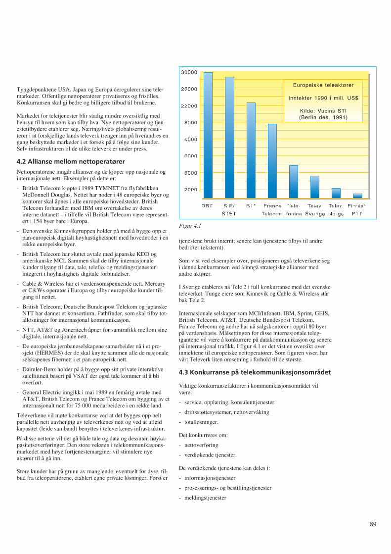
Tyngdepunktene USA, Japan og Europa deregulerer sine tele-markeder. Offentlige nettoperatører privatiseres og fristilles.Konkurransen skal gi bedre og billigere tilbud til brukerne.
Markedet for teletjenester blir stadig mindre oversiktlig medhensyn til hvem som kan tilby hva. Nye nettoperatører og tjen-estetilbydere etablerer seg. Næringslivets globalisering resul-terer i at forskjellige lands televerk trenger inn på hverandres engang beskyttede markeder i et forsøk på å følge sine kunder.Selv infrastrukturen til de ulike televerk er under press.
4.2 Allianse mellom nettoperatører
Nettoperatørene inngår allianser og de kjøper opp nasjonale oginternasjonale nett. Eksempler på dette er:
- British Telecom kjøpte i 1989 TYMNET fra flyfabrikkenMcDonnell Douglas. Nettet har noder i 48 europeiske byer ogkontorer skal åpnes i alle europeiske hovedsteder. BritishTelecom forhandler med IBM om overtakelse av deresinterne datanett – i tilfelle vil British Telecom være represent-ert i 154 byer bare i Europa.
- Den svenske Kinnevikgruppen holder på med å bygge opp etpan-europeisk digitalt høyhastighetsnett med hovednoder i enrekke europeiske byer.
- British Telecom har sluttet avtale med japanske KDD ogamerikanske MCI. Sammen skal de tilby internasjonalekunder tilgang til data, tale, telefax og meldingstjenesterintegrert i høyhastighets digitale forbindelser.
- Cable & Wireless har et verdensomspennende nett. Mercuryer C&Ws operatør i Europa og tilbyr europeiske kunder til-gang til nettet.
- British Telecom, Deutsche Bundespost Telekom og japanskeNTT har dannet et konsortium, Pathfinder, som skal tilby tot-alløsninger for internasjonal kommunikasjon.
- NTT, AT&T og Ameritech åpner for samtrafikk mellom sinedigitale, internasjonale nett.
- De europeiske jernbaneselskapene samarbeider nå i et pro-sjekt (HERMES) der de skal knytte sammen alle de nasjonaleselskapenes fibernett i et pan-europeisk nett.
- Daimler-Benz holder på å bygge opp sitt private interaktivesatellittnett basert på VSAT der også tale kommer til å blioverført.
- General Electric inngikk i mai 1989 en femårig avtale medAT&T, British Telecom og France Telecom om bygging av etinternasjonalt nett for 75 000 medarbeidere i en rekke land.
Televerkene vil møte konkurranse ved at det bygges opp heltparallelle nett uavhengig av televerkenes nett og ved at utleidkapasitet (leide samband) benyttes i televerkenes infrastruktur.
På disse nettene vil det gå både tale og data og dessuten høyka-pasitetsoverføringer. Den store veksten i telekommunikasjons-markedet med høye fortjenestemarginer vil stimulere nyeaktører til å gå inn.
Store kunder har på grunn av manglende, eventuelt for dyre, til-bud fra teleoperatørene, etablert egne private løsninger. Først er
tjenestene brukt internt; senere kan tjenestene tilbys til andrebedrifter (eksternt).
Som vist ved eksempler over, posisjonerer også televerkene segi denne konkurransen ved å inngå strategiske allianser medandre aktører.
I Sverige etableres nå Tele 2 i full konkurranse med det svensketeleverket. Tunge eiere som Kinnevik og Cable & Wireless stårbak Tele 2.
Internasjonale selskaper som MCI/Infonett, IBM, Sprint, GEIS,British Telecom, AT&T, Deutsche Bundespost Telekom,France Telecom og andre har nå salgskontorer i opptil 80 byerpå verdensbasis. Målsettingen for disse internasjonale teleg-igantene vil være å konkurrere på datakommunikasjon og senerepå internasjonal trafikk. I figur 4.1 er det vist en oversikt overinntektene til europeiske nettoperatører. Som figuren viser, harvårt Televerk liten omsetning i forhold til de største.
4.3 Konkurranse på telekommunikasjonsområdet
Viktige konkurransefaktorer i kommunikasjonsområdet vilvære:
- service, opplæring, konsulenttjenester
- driftsstøttesystemer, nettovervåking
- totalløsninger.
Det konkurreres om:
- nettoverføring
- verdiøkende tjenester.
De verdiøkende tjenestene kan deles i:
- informasjonstjenester
- prosesserings- og bestillingstjenester
- meldingstjenester
89
DBT
30000
26000
22000
18000
14000
10000
6000
2000
SIP/
STET
BT* France
Telecom
Tele-
fonica
Telev.
Sverige
Telev.
Norge
Finnish
PTT
Europeiske teleaktører
Inntekter 1990 i mill. US$
Kilde: Vucins STI(Berlin des. 1991)
Figur 4.1
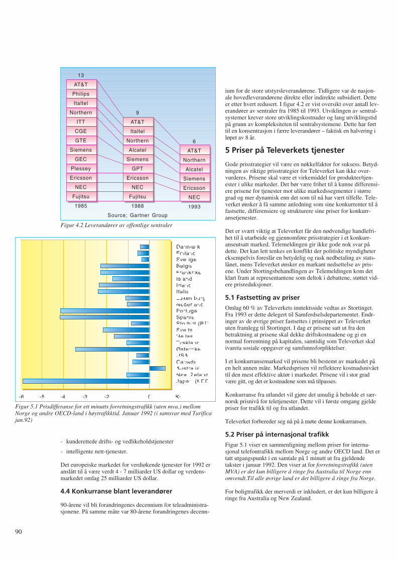
- kunderettede drifts- og vedlikeholdstjenester
- intelligente nett-tjenester.
Det europeiske markedet for verdiøkende tjenester for 1992 eranslått til å være verdt 4 - 7 milliarder US dollar og verdens-markedet omlag 25 milliarder US dollar.
4.4 Konkurranse blant leverandører
90-årene vil bli forandringenes decennium for teleadministra-sjonene. På samme måte var 80-årene forandringenes decenn-
ium for de store utstyrsleverandørene. Tidligere var de nasjon-ale hovedleverandørene direkte eller indirekte subsidiert. Detteer etter hvert redusert. I figur 4.2 er vist oversikt over antall lev-erandører av sentraler fra 1985 til 1993. Utviklingen av sentral-systemer krever store utviklingskostnader og lang utviklingstidpå grunn av kompleksiteten til sentralsystemene. Dette har førttil en konsentrasjon i færre leverandører – faktisk en halvering iløpet av 8 år.
5 Priser på Televerkets tjenester
Gode prisstrategier vil være en nøkkelfaktor for suksess. Betyd-ningen av riktige prisstrategier for Televerket kan ikke over-vurderes. Prisene skal være et virkemiddel for produkter/tjen-ester i ulike markeder. Det bør være frihet til å kunne differensi-ere prisene for tjenester mot ulike markedssegmenter i størregrad og mer dynamisk enn det som til nå har vært tilfelle. Tele-verket ønsker å få samme anledning som sine konkurrenter til åfastsette, differensiere og strukturere sine priser for konkurr-ansetjenester.
Det er svært viktig at Televerket får den nødvendige handlefri-het til å utarbeide og gjennomføre prisstrategier i et konkurr-anseutsatt marked. Telemeldingen gir ikke gode nok svar pådette. Det kan lett tenkes en konflikt der politiske myndighetereksempelvis foreslår en betydelig og rask nedbetaling av stats-lånet, mens Televerket ønsker en markant nedsettelse av pris-ene. Under Stortingsbehandlingen av Telemeldingen kom detklart fram at representantene som deltok i debattene, støttet vid-ere prisreduksjoner.
5.1 Fastsetting av priser
Omlag 60 % av Televerkets inntektsside vedtas av Stortinget.Fra 1993 er dette delegert til Samferdselsdepartementet. Endr-inger av de øvrige priser fastsettes i prinsippet av Televerketuten framlegg til Stortinget. I dag er prisene satt ut fra denbetraktning at prisene skal dekke driftskostnadene og gi ennormal forrentning på kapitalen, samtidig som Televerket skalivareta sosiale oppgaver og samfunnsforpliktelser.
I et konkurransemarked vil prisene bli bestemt av markedet påen helt annen måte. Markedsprisen vil reflektere kostnadsnivåettil den mest effektive aktør i markedet. Prisene vil i stor gradvære gitt, og det er kostnadene som må tilpasses.
Konkurranse fra utlandet vil gjøre det umulig å beholde et sær-norsk prisnivå for teletjenester. Dette vil i første omgang gjeldepriser for trafikk til og fra utlandet.
Televerket forbereder seg nå på å møte denne konkurransen.
5.2 Priser på internasjonal trafikk
Figur 5.1 viser en sammenligning mellom priser for interna-sjonal telefontrafikk mellom Norge og andre OECD land. Det ertatt utgangspunkt i en samtale på 1 minutt ut fra gjeldendetakster i januar 1992. Den viser at for forretningstrafikk (utenMVA) er det kun billigere å ringe fra Australia til Norge ennomvendt.Til alle øvrige land er det billigere å ringe fra Norge.
For boligtrafikk der merverdi er inkludert, er det kun billigere åringe fra Australia og New Zealand.
90
13
AT&T
Philips
Italtel
Northern
ITT
CGE
GTE
Siemens
GEC
Plessey
Ericsson
NEC
Fujitsu
1985
6
AT&T
Northern
Alcatel
Siemens
Ericsson
NEC
1993
9
AT&T
Italtel
Northern
Alcatel
Siemens
GPT
Ericsson
NEC
Fujitsu
1988
Source; Gartner Group
Figur 4.2 Leverandører av offentlige sentraler
DanmarkFinlandSverigeBelgiaFrankrikeIslandIrlandItaliaLuxemburgNederlandPortugalSpaniaStorbrit.(BT)SveitsHellasTysklandØsterrikeUSACanadaAustraliaNew ZelandJapan (KDD)
-6 -5 -4 -3 -2 -1 0 1 Kr.
Figur 5.1 Prisdifferanse for ett minutts forretningstrafikk (uten mva.) mellomNorge og andre OECD-land i høytrafikktid. Januar 1992 (i samsvar med Tarificajan.92)
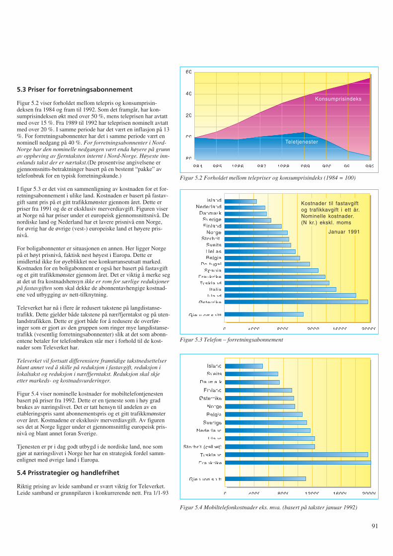
5.3 Priser for forretningsabonnement
Figur 5.2 viser forholdet mellom telepris og konsumprisin-deksen fra 1984 og fram til 1992. Som det framgår, har kon-sumprisindeksen økt med over 50 %, mens teleprisen har avtattmed over 15 %. Fra 1989 til 1992 har teleprisen nominelt avtattmed over 20 %. I samme periode har det vært en inflasjon på 13%. For forretningsabonnenter har det i samme periode vært ennominell nedgang på 40 %. For forretningsabonnenter i Nord-Norge har den nominelle nedgangen vært enda høyere på grunnav oppheving av fjerntaksten internt i Nord-Norge. Høyeste inn-enlands takst der er nærtakst.(De prosentvise angivelsene ergjennomsnitts-betraktninger basert på en bestemt “pakke” avtelefonbruk for en typisk forretningskunde.)
I figur 5.3 er det vist en sammenligning av kostnaden for et for-retningsabonnement i ulike land. Kostnaden er basert på fastav-gift samt pris på et gitt trafikkmønster gjennom året. Dette erpriser fra 1991 og de er eksklusiv merverdiavgift. Figuren viserat Norge nå har priser under et europeisk gjennomsnittsnivå. Denordiske land og Nederland har et lavere prisnivå enn Norge,for øvrig har de øvrige (vest-) europeiske land et høyere pris-nivå.
For boligabonnenter er situasjonen en annen. Her ligger Norgepå et høyt prisnivå, faktisk nest høyest i Europa. Dette erimidlertid ikke for øyeblikket noe konkurranseutsatt marked.Kostnaden for en boligabonnent er også her basert på fastavgiftog et gitt trafikkmønster gjennom året. Det er viktig å merke segat det ut fra kostnadshensyn ikke er rom for særlige reduksjonerpå fastavgiften som skal dekke de abonnentavhengige kostnad-ene ved utbygging av nett-tilknytning.
Televerket har nå i flere år redusert takstene på langdistanse-trafikk. Dette gjelder både takstene på nær/fjerntakst og på uten-landstrafikken. Dette er gjort både for å redusere de overfør-inger som er gjort av den gruppen som ringer mye langdistanse-trafikk (vesentlig forretningsabonnenter) slik at det som abonn-entene betaler for telefonbruken står mer i forhold til de kost-nader som Televerket har.
Televerket vil fortsatt differensiere framtidige takstnedsettelserblant annet ved å skille på reduksjon i fastavgift, reduksjon ilokaltakst og reduksjon i nær/fjerntakst. Reduksjon skal skjeetter markeds- og kostnadsvurderinger.
Figur 5.4 viser nominelle kostnader for mobiltelefontjenestenbasert på priser fra 1992. Dette er en tjeneste som i høy gradbrukes av næringslivet. Det er tatt hensyn til andelen av enetableringspris samt abonnementspris og et gitt trafikkmønsterover året. Kostnadene er eksklusiv merverdiavgift. Av figurenses det at Norge ligger under et gjennomsnittlig europeisk pris-nivå og blant annet foran Sverige.
Tjenesten er pr i dag godt utbygd i de nordiske land, noe somgjør at næringslivet i Norge her har en strategisk fordel samm-enlignet med øvrige land i Europa.
5.4 Prisstrategier og handlefrihet
Riktig prising av leide samband er svært viktig for Televerket.Leide samband er grunnpilaren i konkurrerende nett. Fra 1/1-93
91
160
140
120
100
80
1984 1985 1986 1987 1988 1989 1990 1991 1992
Teletjenester
Konsumprisindeks
Figur 5.2 Forholdet mellom telepriser og konsumprisindeks (1984 = 100)
IslandNederland
DanmarkSverigeFinland
NorgeStorbrit.
SveitsHellasBelgia
PortugalSpania
FrankrikeTyskland
ItaliaIrland
Østerrike
Gjennomsnitt
0 20000160001200080004000
Kostnader til fastavgiftog trafikkavgift i ett år.Nominelle kostnader.(N kr.) ekskl. moms
Januar 1991
Figur 5.3 Telefon – forretningsabonnement
Island
Sveits
Danmark
Finland
Østerrike
Norge
Belgia
Sverige
Nederland
Irland
Storbrit.(cellnet)
Tyskland
Frankrike
Gjennomsnitt
0 20000160001200080004000
Figur 5.4 Mobiltelefonkostnader eks. mva. (basert på takster januar 1992)
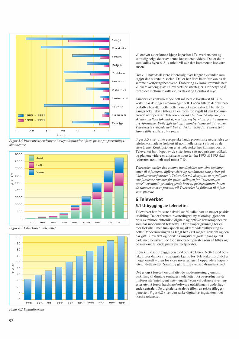
vil enhver aktør kunne kjøpe kapasitet i Televerkets nett ogsamtidig selge deler av denne kapasiteten videre. Det er dettesom kalles bypass. Slik utleie vil øke den kommende konkurr-ansen.
Det vil i hovedsak være videresalg over lengre avstander somutgjør den største trusselen. Det er her flere bedrifter kan ha desamme overføringsbehovene. Etablering av konkurrerende nettvil være avhengig av Televerkets prisstrategier. Her betyr ogsåforholdet mellom lokaltakst, nærtakst og fjerntakst mye.
Kunder i et konkurrerende nett må betale lokaltakst til Tele-verket når de ringer utenom eget nett. I noen tilfelle der eksternebedrifter benytter dette nettet kan det være aktuelt å betale toganger lokaltakst i tillegg til en form for avgift til den konkurr-erende nettoperatør. Televerket er nå i ferd med å utjevne for-skjellen mellom lokaltakst, nærtakst og fjerntakst for å redusereoverføringene. Dette gjør det også mindre lønnsomt å bypasseTeleverkets svitsjede nett Det er derfor viktig for Televerket åkunne differensiere sine priser.
Figur 5.5 viser ulike europeiske lands prosentvise nedsettelse avtelefonkostnadene (relatert til nominelle priser) i løpet av desiste årene. Konklusjonen er at Televerket her kommer best ut.Televerket har i løpet av de siste årene satt ned prisene radikaltog planene videre er at prisene hvert år fra 1993 til 1995 skalreduseres nominelt med minst 7 %.
Televerket ønsker den samme handlefrihet som sine konkurr-enter til å fastsette, differensiere og strukturere sine priser på“konkurransetjenester”. Televerket må akseptere at myndighet-ene fastsetter rammer for prisutviklingen for “enerettstjen-ester”, eventuelt grunnleggende krav til prisstrukturen. Innende rammer som er fastsatt, vil Televerket ha fullmakt til å fast-sette prisene.
6 Televerket6.1 Utbygging av telenettet
Televerket har fra siste halvdel av 80-tallet hatt en meget positivutvikling. Det er foretatt investeringer i ny teknologi gjennombruk av mikroelektronikk, digitale og optiske nettkomponentersom har modernisert telenettet. Dette skaper grunnlag for enmer fleksibel, mer funksjonell og sikrere videreutbygging avnettet. Moderniseringen så langt har vært meget lønnsom og denhar gitt Televerket og norsk næringsliv et godt utgangspunktbåde med hensyn til de topp moderne tjenester som nå tilbys ogde markant fallende priser på teletjenester.
Figur 6.1 viser utbyggingen med optiske fibrer. Nettet med opt-iske fibrer danner en strategisk kjerne for Televerket fordi det ermeget enkelt – uten for store investeringer å oppgradere kapasi-teten i dette nettet. Samtidig går feilfrekvensen dramatisk ned.
Det er også foretatt en omfattende modernisering gjennomutskifting til digitale sentraler i telenettet. På overordnet nivåinnføres nå “intelligent nett-tjeneste” som vil definere nye tjen-ester uten å foreta hardware/software utskiftinger i underligg-ende sentraler. De digitale sentralene tilbyr en rekke tilleggs-tjenester. Figur 6.2 viser den raske digitaliseringstakten i detnorske telenettet.
92
Norge
Frankrike
Sveits
Belgia
Tyskland
Storbrit.
Østerrike
Nederland
Finland
Danmark
Sverige
-60 -50 -40 -30
Prosent
-20 -10 0
1985 - 1991
1990 - 1991
Figur 5.5 Prosentvise endringer i telefonkostnader i faste priser for forretnings-abonnenter
9000
8000
7000
6000
5000
4000
3000
2000
1000
01983
Jord
Luft
Vann
1984 1985 1986 1987 1988 1989 1990 1991
Le
ng
de
(km
)
Figur 6.1 Fiberkabel i telenettet
100
90
80
70
60
50
40
30
20
10
01989 1990 1991
Pro
sent
1992 1993 1994 1995 1996 1997 1998
Figur 6.2 Digitalisering
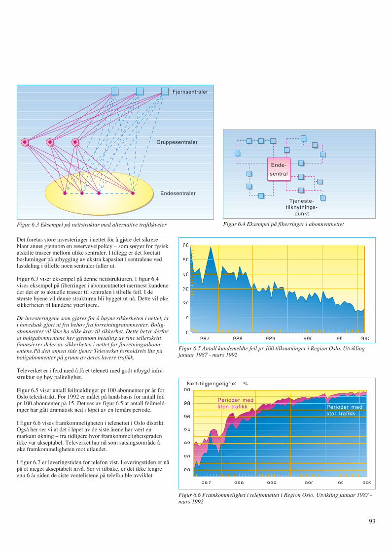
Det foretas store investeringer i nettet for å gjøre det sikrere –blant annet gjennom en reserveveipolicy – som sørger for fysiskatskilte traseer mellom ulike sentraler. I tillegg er det foretattbeslutninger på utbygging av ekstra kapasitet i sentralene vedlastdeling i tilfelle noen sentraler faller ut.
Figur 6.3 viser eksempel på denne nettstrukturen. I figur 6.4vises eksempel på fiberringer i abonnentnettet nærmest kundeneder det er to aktuelle traseer til sentralen i tilfelle feil. I destørste byene vil denne strukturen bli bygget ut nå. Dette vil økesikkerheten til kundene ytterligere.
De investeringene som gjøres for å høyne sikkerheten i nettet, eri hovedsak gjort ut fra behov fra forretningsabonnenter. Bolig-abonnenter vil ikke ha slike krav til sikkerhet. Dette betyr derforat boligabonnentene her gjennom betaling av sine tellerskrittfinansierer deler av sikkerheten i nettet for forretningsabonn-entene.På den annen side tjener Televerket forholdsvis lite påboligabonnenter på grunn av deres lavere trafikk.
Televerket er i ferd med å få et telenett med godt utbygd infra-struktur og høy pålitelighet.
Figur 6.5 viser antall feilmeldinger pr 100 abonnenter pr år forOslo teledistrikt. For 1992 er målet på landsbasis for antall feilpr 100 abonnenter på 15. Det ses av figur 6.5 at antall feilmeld-inger har gått dramatisk ned i løpet av en femårs periode.
I figur 6.6 vises framkommeligheten i telenettet i Oslo distrikt.Også her ser vi at det i løpet av de siste årene har vært enmarkant økning – fra tidligere hvor framkommelighetsgradenikke var akseptabel. Televerket har nå som satsingsområde åøke framkommeligheten mot utlandet.
I figur 6.7 er leveringstiden for telefon vist. Leveringstiden er nåpå et meget akseptabelt nivå. Ser vi tilbake, er det ikke lengreenn 6 år siden de siste ventelistene på telefon ble avviklet.
93
Fjernsentraler
Gruppesentraler
Endesentraler
Figur 6.3 Eksempel på nettstruktur med alternative trafikkveier
Tjeneste-tilknytnings-
punkt
Ende-
sentral
Figur 6.4 Eksempel på fiberringer i abonnentnettet
1987 1988 1989 1990 1991 1992
60
50
40
30
20
10
0
Figur 6.5 Antall kundemeldte feil pr 100 tilknutninger i Region Oslo. Utviklingjanuar 1987 - mars 1992
1987 1988 1989 1990 1991 1992
100
98
96
94
92
90
88
Nett-tilgjengelighet i %
Perioder medliten trafikk Perioder med
stor trafikk
Figur 6.6 Framkommelighet i telefonnettet i Region Oslo. Utvikling januar 1987 -mars 1992
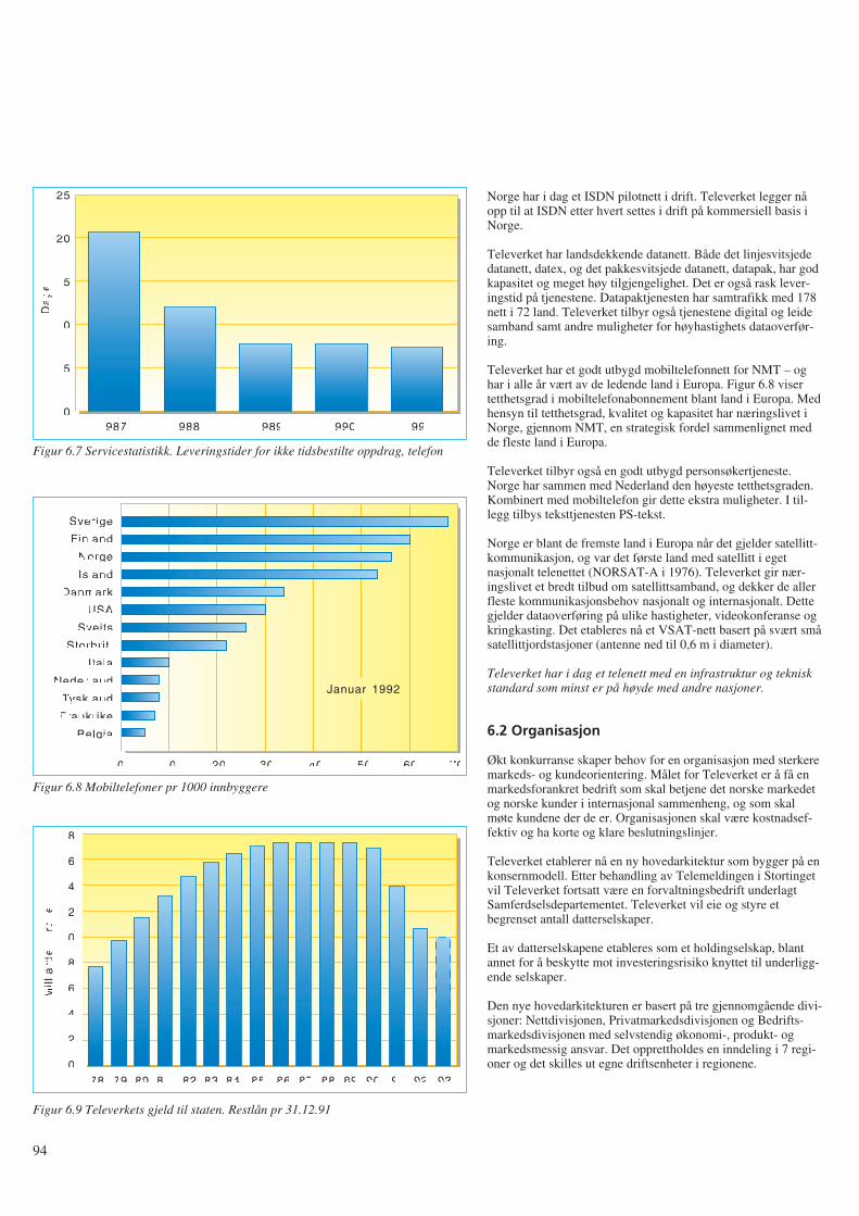
Norge har i dag et ISDN pilotnett i drift. Televerket legger nåopp til at ISDN etter hvert settes i drift på kommersiell basis iNorge.
Televerket har landsdekkende datanett. Både det linjesvitsjededatanett, datex, og det pakkesvitsjede datanett, datapak, har godkapasitet og meget høy tilgjengelighet. Det er også rask lever-ingstid på tjenestene. Datapaktjenesten har samtrafikk med 178nett i 72 land. Televerket tilbyr også tjenestene digital og leidesamband samt andre muligheter for høyhastighets dataoverfør-ing.
Televerket har et godt utbygd mobiltelefonnett for NMT – oghar i alle år vært av de ledende land i Europa. Figur 6.8 visertetthetsgrad i mobiltelefonabonnement blant land i Europa. Medhensyn til tetthetsgrad, kvalitet og kapasitet har næringslivet iNorge, gjennom NMT, en strategisk fordel sammenlignet medde fleste land i Europa.
Televerket tilbyr også en godt utbygd personsøkertjeneste.Norge har sammen med Nederland den høyeste tetthetsgraden.Kombinert med mobiltelefon gir dette ekstra muligheter. I til-legg tilbys teksttjenesten PS-tekst.
Norge er blant de fremste land i Europa når det gjelder satellitt-kommunikasjon, og var det første land med satellitt i egetnasjonalt telenettet (NORSAT-A i 1976). Televerket gir nær-ingslivet et bredt tilbud om satellittsamband, og dekker de allerfleste kommunikasjonsbehov nasjonalt og internasjonalt. Dettegjelder dataoverføring på ulike hastigheter, videokonferanse ogkringkasting. Det etableres nå et VSAT-nett basert på svært småsatellittjordstasjoner (antenne ned til 0,6 m i diameter).
Televerket har i dag et telenett med en infrastruktur og tekniskstandard som minst er på høyde med andre nasjoner.
6.2 Organisasjon
Økt konkurranse skaper behov for en organisasjon med sterkeremarkeds- og kundeorientering. Målet for Televerket er å få enmarkedsforankret bedrift som skal betjene det norske markedetog norske kunder i internasjonal sammenheng, og som skalmøte kundene der de er. Organisasjonen skal være kostnadsef-fektiv og ha korte og klare beslutningslinjer.
Televerket etablerer nå en ny hovedarkitektur som bygger på enkonsernmodell. Etter behandling av Telemeldingen i Stortingetvil Televerket fortsatt være en forvaltningsbedrift underlagtSamferdselsdepartementet. Televerket vil eie og styre etbegrenset antall datterselskaper.
Et av datterselskapene etableres som et holdingselskap, blantannet for å beskytte mot investeringsrisiko knyttet til underligg-ende selskaper.
Den nye hovedarkitekturen er basert på tre gjennomgående divi-sjoner: Nettdivisjonen, Privatmarkedsdivisjonen og Bedrifts-markedsdivisjonen med selvstendig økonomi-, produkt- ogmarkedsmessig ansvar. Det opprettholdes en inndeling i 7 regi-oner og det skilles ut egne driftsenheter i regionene.
94
1987 1988 1989 1990 1991
25
20
15
10
5
0
Da
ge
r
Figur 6.7 Servicestatistikk. Leveringstider for ikke tidsbestilte oppdrag, telefon
Sverige
Finland
Norge
Island
Danmark
USA
Sveits
Storbrit.
Itala
Nederland
Tyskland
Frankrike
Belgia
0 5040302010 60 70
Januar 1992
Figur 6.8 Mobiltelefoner pr 1000 innbyggere
18
16
14
12
10
8
6
4
2
089 90 91
Mill
iard
er
kro
ne
r
92 938887868584838281807978
Figur 6.9 Televerkets gjeld til staten. Restlån pr 31.12.91
I tillegg ønsker Televerket å etablere en egen divisjon som skalivareta overkapasiteten i Televerket gjennom muligheter forvidereutdannelse og opprettelse av nye forretningsområder.
Det er viktig at Televerket blir gitt anledning til å utvikle enorganisasjon som er fullt konkurransedyktig i forhold til storeinternasjonale operatører.
6.3 Økonomi
Televerkets driftsinntekter i 1991 var 14 297 millioner kroner.Dette var omlag 350 milloner kroner lavere enn 1990. Solgtvolum økte med 8,2 %, mens prisene på teletjenester gikk nedmed 8,4 %. Resultat før ekstrordinære poster ble 1 877 millionerkroner.
Figur 6.9 viser Televerkets gjeld til Staten. Gjelden skyldesstore investeringer i en årrekke før Televerket ble selvfinansiert.I 1991 betalte Televerket 2 935 millioner i avdrag til stats-kassen. I 1992 planlegges nedbetaling av ytterligere 3 212 milli-oner kroner. Målet er at Televerket ved utgangen av 1993 skalha en gjeld på 10 milliarder kroner. Dette er fremdeles høytsammenlignet med de øvrige nordiske land.
I 1991 investerte Televerket 3 037 millioner kroner – om lag290 millioner kroner mer enn i 1990. Investeringene er helfi-nansiert gjennom avskrivningsmidler og overskudd.
Den gunstige økonomiske utviklingen har også som vist ikapittel 5, gjort det mulig å sette prisene markant ned de sisteårene.
7 Internasjonalt samarbeid
7.1 Globalt samarbeid
I tråd med EFs initiativ på telekommunikasjonssektoren harogså Televerket blitt lenket nærmere til det europeiske samar-beid. Arbeid innen International Telecommunication Union,ITU (CCITT og CCIR) har pågått i 125 år og fortsetter medøkende effektivitet og volum (målt i antall tekstsider og rekom-mandasjoner!). Det samme gjør arbeidet innen andre interna-sjonale driftsorganisasjoner som INMARSAT, INTELSAT ogEUTELSAT.
Det er imidlertid på det europeiske plan at det skjer store endr-inger på organisasjon og samarbeid. Televerket har i mange årvært engasjert i NORDTEL – samarbeidsorgan mellom nord-iske teleadministrasjoner; likeledes i CEPT – den vest-europe-iske post og telekonferanse, likeledes gjennom COST – tekniskkomité for telekommunikasjoner, og i EBU – European Broad-casting Union.
Liberaliseringen og dereguleringen av det europeiske telemark-edet har nå ført til endringer.
7.2 Nordisk samarbeid
Arbeidet innen NORDTEL har de siste år stagnert. Det har blittgenerert for få prosjekter samtidig som entydig forpliktelse ifelles strategiarbeid savnes. Det er nå nedsatt arbeidsgruppersom skal se på formål, omfang og organisasjonsform samt vurd-ering av strategiske markedsforhold.
7.3 Europeisk samarbeid
CEPT ble etablert i 1959 og bestod hovedsakelig av post/telead-ministrasjoner. Det pågår nå en prosess der teleoperatørdelenskilles ut av CEPT. I tillegg er teleoperatørene skilt fra telefor-valtningene. På denne bakgrunn ble forvaltningsorganet ETSIetablert i 1988. ETSI skal utarbeide telekommunikasjons-stand-arder innen:
- telekommunikasjon
- informasjonsteknologi (i samarbeid med CEN/CENELEC,som er europeisk standardiseringsorganisasjon)
- kringkasting (i samarbeid med EBU).
Norske medlemmer av ETSI er STF, Televerket og Alcatel a/s.De tekniske standardene fastsettes ved stemmegivninger. Stand-ardene er i utgangspunktet frivillige, men kan ved spesielleavtaler (MOU) bli obligatoriske. Mer spesifiserte arbeidsom-råder er standarder for:
- telekommunikasjonsnett
- private nett, utstyr
- signaleringsprotokoller, svitsjingutstyr
- transmisjonsutstyr
- terminalutstyr
- radioutstyr og systemer
- mobilkommunikasjon, GSM
- personsøkersystem
- jordstasjoner
- avanserte testmetoder.
Innen CEPT er det også utarbeidet spesielle MOU blant annetfor GSM og for ISDN.
I 1991 undertegnet 26 offentlige operatører fra 21 land en MOUgjennom grunnlegging av ETNO, som er et organ for å ivaretaoffentlige nettoperatørers interesser. Målsettingen er:
- å utvikle og representere, der det er praktisk mulig, fellesholdninger i forhold til tredjepart, spesielt andre europeiskeinstitusjoner og organisasjoner
- å samarbeide og koordinere aktiviteter mellom medlemmenefor å harmonisere offentlige telekommunikasjonsnett ogbasistjenester i full overensstemmelse med europeiske lover.
Innen CEPT ble det i 1991 også skilt ut et eget institutt,EURESCOM, for forskning og strategisk planlegging. OgsåEURESCOM er forbeholdt offentlige nettoperatører.
Målsettingen med instituttet er å understøtte utvikling ogutbygging av et harmonisert offentlig telenett og med tjenesterbasert på framtidsrettet forskning innen telekommunikasjons-området samt å utnytte dette i den europeiske integrasjonspro-sess.
METRAN (Management European Transmission Network) er etCEPT-prosjekt som har til formål å realisert et digitalt bred-bånds transmisjonsnett over hele Europa. Det skal bygges over
95
synkront digitalt netthierarki (SDH) og med “cross-connect” ialle knutepunkter.
ERMES er et pan-europeisk personsøkersystem som skal reali-seres i 1993. Bak systemet står 27 nettoperatører fra 18 land.
ESPRIT er et europeisk samarbeidsprosjekt fra EF-land. Det bleetablert i 1984. Formålet er:
- å fremme utviklingen av internasjonale standarder
- å skaffe IT-industrien basis teknologi
- å fremme industrielt samarbeid.
I 1985 lanserte EF-kommisjonen sitt forskningsprogram fortelekommunikasjoner. Programmet fikk betegnelsen RACE(Research and development in Advanced Communicationstechnologies in Europe) og har som formål å bane veien for engradvis innføring av integrert bredbåndskommunikasjon (IBC) iEuropa fra midten av 1990-årene. EF-kommisjonen vil gjennomRACE:
- styrke Europas teleindustri
- sette europeiske nettoperatører i stand til å konkurrere underbest mulige betingelser
- sette flest mulig medlemsland i stand til å introdusere kom-mersielle bredbåndstjenester allerede fra 1995
- gi tjenesteleverandørene muligheter til å forbedre eksister-ende tjenester og introdusere nye
- gjøre bredbåndstjenester tilgjengelige til konkurransedyktigepriser
- støtte dannelsen av et enhetlig europeisk marked for bred-båndsutstyr og tjenester.
7.4 EFs tredje rammeprogram
Til slutt nevnes kort en oversikt over EFs tredje rammeprogramfor forskning og teknologi. Totalbudsjettet for programmet er på5.7 milliarder ECU (1 ECU = ca 8 kr). Følgende områder erdekket:
- informasjonsteknologi
- kommunikasjonsteknologi
- telematikksystemer
- industri og materialteknologi
- måling og prøving
- miljø
- havforskning
- bioteknologi
- landbruksforskning
- biomedisin og helseforskning
- biomedisinsk forskning for utviklingsland
- sikkerhet vedrørende fisjonsenergi
- kontrollert fusjonsenergi
- menneskelige ressurser og mobilitet.
8 Stortingsmelding nr 8 “Om televirksomhet i Norge”
Formålet med telemeldingen har vært:
- å gi oversikt over telesektoren i Norge
- å trekke opp utviklingslinjer framover
- å gi rammebetingelser for Televerket og Statens teleforvalt-ning.
8.1 Televerket fortsatt en forvaltningsbedrift
Telemeldingen er preget av den internasjonale utvikling på tele-sektoren og ikke minst EFs direktiver som i dette foredraget eromtalt i kapittel 3. Telemeldingen tar imidlertid ikke de fullekonsekvenser av utviklingen og fastholder at Televerket frem-deles skal være en statlig forvaltningsbedrift.
Situasjonen er da at teleadministrasjonene i kun tre land i Vest-Europa: Norge, Island og Østerrike, så langt forblir forvalt-ningsbedrifter, mens de øvrige land etablerer mer fristilte til-knytningsformer med de klare fordeler dette har i den komm-ende konkurransesituasjon. Østerrike vurderer for tiden annentilknytningsform.
I telemeldingen (kap 1.1.2) er det angitt at “Televerkets øko-nomi og organisering må vurderes på nytt med relativt kortemellomrom”. I kapittel 4.5.2 om tilknytningsform heter det “Detbør skje en evaluering av reformene og omstillingstiltakene ettertre år. Da er det naturlig at erfaringene ..., danner grunnlag foren eventuell tilknytningsform”.
I Stortingsbehandlingen 7 april ble det imidlertid vedtatt atdepartementet løpende kan vurdere om det er behov for endr-inger i Televerkets tilknytningsform eller “forholdet mellommonopol og konkurransedel”.
Televerket har som forvaltningsbedrift gjennom meldingen fåttutvidete fullmakter til å opprette stillinger i høye lønnstrinn, til åopprette aksjeselskaper og tegne aksjer i andre selskaper, til åbelaste reguleringsfondet inntil et fastlagt minimumsnivå, og tilå foreta en viss økning av investeringsutgiftene dersom dette ernødvendig.
8.2 Dereguleringsprosessen i Norge
Norge var tidlig ute med første del av dereguleringen på teleom-rådet. Statens teleforvaltning ble opprettet 1 juli 1987. Fra 1januar 1988 ble det etablert fri konkurranse på terminalutstyr,blant annet telefonapparater og hussentraler. Samtidig ble TBKskilt ut som eget aksjeselskap heleid av Televerket.
Televerket har inntil nå ikke hatt normal styring med sitt datter-selskap TBK slik andre bedrifter har over sine datterselskaper.Dette har hindret en mer enhetlig planlegging av tilbud på hel-hets telematikkløsninger for de større kunder gjennom samar-beid mellom mor- og datterselskap. Telemeldingen fastsetter nåTeleverkets rett til å opprette egne aksjeselskaper på vanligmåte. Dermed vil Televerket få normal styring også over TBK.Dette ligger også inne i forslaget til den nye organiseringen avTeleverket gjennom utforming av Bedriftsmarkedsdivisjonen.
96
I 1988 ble det også etablert fri konkurranse på verdiøkende tjen-ester i Norge.
Videre ble det i 1991 åpnet for full konkurranse på GSMgjennom konsesjon til TeleMobil som nå kan skilles ut i egetaksjeselskap og NetCom.
Den videre tilnærming mot framtidig konkurransesituasjon somfastslås i telemeldingen er:
- Det blir fra 1 januar 1993 tillatt med videresalg av kapasitet ileide samband.
- Det blir 1 januar 1993 full konkurranse på datex og datapak.
- Televerket forplikter imidlertid å opprettholde standardtilbudpå tjenestene også i områder med liten inntjening.
- Televerket skal fortsatt ha enerett på infrastrukturen og påtelefontjenesten.
- Satellitt-tjenester forutsettes å være en del av infrastrukturenog legges dermed fortsatt under forvaltningsområdet.
8.3 Tale- og dataoverføring smelter sammen
Den teknologiske utvikling fører til at tale og data kan overføresparallelt. Dette betyr at taleoverføring kan overføres over leidelinjer i Televerkets egen infrastruktur. Dette er kalt bypass tid-ligere, men dette tillates i full konkurranse med Televerketstelefontjeneste fra primo 1993. Televerket er positive til dettevedtaket blant annet fordi det vil bidra til å løse bedrifters kom-munikasjonsbehov mer effektivt, men ønsker selv å ha handle-frihet til å møte konkurransen.
Det er ingen tvil om at dette vedtaket vil få meget stor betyd-ning for Televerkets konkurransesituasjon i tiden framover.Dette vedtaket er i full harmoni med EFs strategi for full kon-kurranse. Vedtaket legger forholdene til rette for at nettopera-tører – små og store – kan gå inn og kjøpe opp kapasitet i Tele-verkets nett. Kapasiteten vil i første omgang bli tilbudt de storekundene, der den største fortjenesten ligger – altså en form forspekkhoggervirksomhet. Det er akkurat det Mercury har gjort iStorbritannia.
Televerket er nå i ferd med å planlegge og bygge ut det framtid-ige tjenesteintegrerte nettet, ISDN, som vil formidle tale, tekst,data og levende bilde. I kapittel 3.4 i telemeldingen heter det:“Ut fra de forslag Samferdselsdepartementet nå går inn for, skalTeleverket fortsatt ha enerett på de offentlige kommunikasjons-nett og telefontjenesten, men ikke på dataoverføringstjenester.Siden ISDN-tjenester omfatter både telefon- og datatjenester, erdet etter dette lite egnet å nytte ISDN som ramme for enerett”.
Dette betyr at telemeldingen fastslår full konkurranse på ISDNhvor telefontjenester er den viktigste. Det forventes at ISDN fra1994 vil få en sterk vekst spesielt med tilknytninger til nærings-livet og at nettet som vil være integrert med telefonnettet, blir ensvært viktig del av Televerkets infrastruktur.
Det forutsettes videre at satellitt-tjenester skal være en del avinfrastrukturen. Utviklingen her er igjen i liten grad avhengig av
hva norske myndigheter beslutter, men i stedet avhengig avhvilke vedtak som gjøres internasjonalt. Dersom EF nå går innfor full liberalisering av satellittoverføringer, vil dette også i storgrad påvirke norsk telekommunikasjon – ikke minst utenlands-trafikken.
I telemeldingen oppheves nå konsesjonen på kabelfjernsyn ettertelegrafloven. Det anses å skape større frihet for abonnentenemed hensyn til å kunne anlegge egne kabelfjernsynsnett. Unn-taket er i de tilfeller der disse nettene ønskes brukt til overføringav andre tjenester. I slike tilfeller skal det fortsatt søkes konse-sjon etter telegrafloven. Departementet er ikke innstilt på å gikonsesjon til ordinære tjenester som telefon og dataoverføring,men vil utarbeide forskrifter for enkle alarmoverføringstjen-ester.
8.4 Fastsetting av priser på tjenester
I telemeldingen opprettholdes enhetstakster på datex og datapakuavhengig av distanse. Samtidig forpliktes Televerket til å opp-rettholde et geografisk standardtilbud på tjenestene over helelandet. Det skal naturligvis ikke foretas noen former for kryss-subsidiering. Rent logisk må alle forstå at slike vedtak ikke vilføre til lik konkurranse mellom Televerket og andre aktører somlettere kan komme inn og skumme fløten ved å gi tilbud tilstørre kunder i tettbygde strøk og der distansene er korte.
Televerket har foreslått at samfunnspålagte oppgaver innen tele-sektoren dekkes gjennom statsbudsjettet. I telemeldingen slåsdet fast at Televerket med sin sterke posisjon gjennom enerettpå nettet og telefontjenesten og ut fra den økonomiske utvikl-ingen ikke trenger særskilte bevilgninger for samfunnspålagtetjenester. Dette vil imidlertid bli vurdert med jevne mellomrom.
Telemeldingen gir Samferdselsdepartementet fullmakt til å fast-sette hovedtakstene på telefon slik Stortinget tidligere har gjort.I tillegg skal nå departementet også fastsette pris på leide sam-band – et ansvar Televerket tidligere hadde.
Televerket har altså nå mindre handlefrihet til fastsettelse avpriser enn det de hadde tidligere. Som omtalt i kapittel 5 erprisstrategier og prising et svært viktig felt der Televerket må hahandlefrihet for å møte det kommende konkurransemarked.
Telemeldingen gir imidlertid Televerket anledning til å gi vol-umrabatter på sine tjenester.
8.5 Spesielle fullmakter
Televerket vil, innenfor rammer som foreslås i budsjettet, fåutvidede fullmakter til å opprette aksjeselskap, tegne aksjer iandre selskap og avhende virksomhet, aksjer og aksjeselskapsåfremt det ikke gjelder strategisk virksomhet. Strategisk virk-somhet skal være heleid av staten. Det forutsettes fremdeles atbåde drifts- og investeringsbudsjettet er en del av statsbud-sjettet. Televerket vil imidlertid få en viss frihetsgrad til å økeinvesteringsvolumet noe, dersom dette er nødvendig, og til åbelaste reguleringsfondet inntil et fastsatt minimumsnivå.
Televerket har hatt som mål i løpet av en treårsperiode å redus-ere statsgjelden til 10 milliarder (ref kapittel 6). Tidligere hadde
97
Televerket store problemer med å få aksept for denne nedbetal-ingen, som var helt essensiell. Videre nedbetaling må ses isammenheng med forventede inntekter og priser. Det er viktigat Televerket får handlefrihet til å bestemme nedbetalingstempout fra prisstrategier og markedsmessige vurderinger og ikke utfra eksempelvis en saldering på statsbudsjettet.
Telemeldingen trekker fram Televerkets forsknings- og utvikl-ingsinnsats. Det legges vekt på den betydning dette har for raskteknisk utvikling og kommersielt preget utviklingsarbeid medringvirkninger til norsk industri og norsk IT-miljø. Det foreslåsat forsknings- og utviklingsvirksomheten i Televerket økes fra1,7 % av Televerkets driftsinntekter i 1991 til 2,0 % i 1995.Dette er i tråd med forslag fra Televerkets styre.
8.6 STFs oppgaver
Reduksjon av eneretten og større konkurranse stiller de reguler-ende myndigheter overfor nye oppgaver og problemstillinger.Oppgavene til Statens teleforvaltning, STF, blir i større grad ålegge forholdene til rette for effektivt samvirke mellom for-skjellige nett og tjenester basert på standardisering av tjenesterog utstyr både i nettet og hos telebrukerne.
Det skal – gjennom Open Network Provision – sikres at tele-operatørenes infrastruktur tilbys med standardiserte grensesnittog på ikke-diskriminerende måte. Her ligger også bestemtetakstprinsipper, bruksbetingelser og radiotjenester/frekvenser.
Det europeiske standardiseringsinstituttet, ETSI, stiller strengekrav til standarder på nettinfrastruktur og viktige tjenester somvil tilbys fra ulike nettleverandører, for å sikre full samtrafikkinnen EF. STF må derfor kontrollere at krav og standarder tilinfrastrukturen følges.
Statens teleforvaltning står også foran en mulig reduksjon ivirksomheten. Det gjelder områder der gjensidig internasjonaleordninger innføres, eksempelvis på typegodkjenning. Ut fraEFTAs Tampere-konvensjon, som trådte i kraft ultimo 1990, erdet innen EFTA-området åpnet for full konkurranse mellom alletypegodkjenningslaboratorier. Disse prinsippene gjennomføresnå innen EF.
Fortsatt bør STFs totale utgifter dekkes av avgifts- og gebyr-inntekter. Det foreslås nå at frekvensavgiften reduseres og at deti tillegg innføres en nettoperatøravgift.
9 Virkningen av EFs innkjøpsdirektiver
Televerket kjøper materiell for store beløp – i størrelsesorden 3milliarder kroner hvert år. Om lag 75 % av materiellet blir levertav innenlandske bedrifter. En del av verdiskapingen skjer iNorge, og Televerket må betraktes som elektronikkindustriensstørste kunde.
9.1 EFs offentlige innkjøpsregler
Inngåelse av EØS-avtalen vil innebære en endring i de offent-lige innkjøpsregler. Dette kan være både en fordel og en ulempefor norsk industri. EFs direktiver vil åpne proteksjonistiske
markeder i Europa. Dette vil gi norsk industri nye muligheter ogsåledes være en fordel. På den annen side åpnes hjemmemark-edet for mer omfattende konkurranse, hvilket kan være enulempe.
Ifølge EØS-avtalen skal EFs direktiver innføres i perioden1 januar 1993 – 1 januar 1995. Det er opp til norske myndig-heter å velge tidspunkt for innføring. Ikke noe er bestemt fore-løpig, men det er tegn som tyder på at norske myndigheterønsker å innføre direktivene allerede i 1993 av hensyn til norskverkstedsindustri og den mulighet dette gir for konkurranse omoppdrag på britisk sektor i Nordsjøen.
Offentlige innkjøp er definert i EFs direktiver for å fremme kon-kurransereglene i de statlige monopolene. Norge, og følgeligTeleverket, vil bli pålagt å kjøpe til angitte kvalitetskrav for åtilpasse seg de harmoniserte grensesnitt i det europeisketelenettet. Alle televerk må forplikte seg til å legge større kjøput på europeisk anbud og ikke subsidiere nasjonal industri.
Reglene for offentlige innkjøp vil i sterk grad påvirke Tele-verket. For å sikre at direktivene etterleves av offentlige etater,har EF-kommisjonen foreslått et eget direktiv for håndheving ogovervåking. Hovedprinsippene er at anskaffelse skal kunngjøresi EF, at det skal være forbud mot tekniske diskrimineringer ogat objektive kriterier anvendes. CEN/CENELEC og ETSI utar-beider standarder for offentlige innkjøp. Brudd på reglene kanmedføre stopp i anbudsprosedyrene, opphevelse av ulovligevedtak og erstatning.
9.2 Terskelverdier for offentlige innkjøp
Det er angitt terskelverdier for offentlige innkjøp i ulike kate-gorier. Televerket ønsker å beholde sitt gjeldende regelverk –Regelverk for statens anskaffelsesvirksomhet, REFSA – for inn-kjøp under terskelverdiene. For innkjøp over terskelverdienebenyttes EFs direktiver.
Terskelverdiene, som ikke inkluderer merverdiavgift, er 400000 ECU (3,2 mill kr) for varekjøp i sektorene vann- og energi-forsyning samt transport. For telekommunikasjons-sektoren erdet 600 000 ECU (4,8 mill kr) og for bygg- og anleggssektorener terskelverdien 5 mill ECU (40 mill kr). Terskelverdienknytter seg til samlet verdi av prosjekt/leveranse, ikke til verdierav enkeltkontrakter på prosjekt/leveranse stykket opp i flerebiter. Alle offentlige innkjøp med pris over terskelverdier, skallegges ut på anbud i databasen “Tender Electronic Daily(TED)”.
9.3 Fordeler og ulemper ved EFs innkjøpsdirektiver
Fordelen til Televerket ved innføring av EFs direktiver foroffentlige innkjøp ligger i markante kostnadsbesparelser vedinnkjøp på grunn av større konkurranse og på grunn av de sværtstore innkjøp som Televerket årlig gjør.
Ulempen er at det må etableres et betydelig apparat med tilhør-ende systemer for å kunne håndtere det nye regelverket. Inn-kjøpskontoret i Televerket har anslått at et tusentalls personer istørre eller mindre grad kommer i berøring med de nye EF-regl-ene.
Det stilles også krav til forhåndskunngjøring i Europa omkommende anskaffelser. Dette betinger 12 måneders prognoser
98
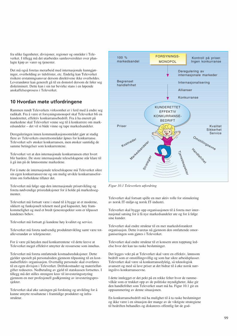
fra ulike fagenheter, divisjoner, regioner og områder i Tele-verket. I tillegg må det utarbeides samleoversikter over plan-lagte kjøp av varer og tjenester.
Det må også foretas merarbeid med internasjonale kunngjør-inger, overholding av tidsfrister, etc. Endelig kan Televerketrisikere erstatningsansvar dersom direktivene ikke overholdes.Leverandører kan generelt gå til en domstol dersom de føler segdiskriminert. Dette kan i sin tur bevirke stans i en løpendeanskaffelsesprosess i Televerket.
10 Hvordan møte utfordringene
Rammen rundt Televerkets virksomhet er i ferd med å endre segradikalt. Fra å være et forsyningsmonopol skal Televerket bli enkunderettet, effektiv konkurransebedrift. Fra å ha enerett påmarkedene skal Televerket venne seg til å konkurrere om mark-edsandeler – det vil si både vinne og tape markedsandeler.
Dereguleringen innen kommunikasjonsområdet gjør at stadigflere av Televerkets enerettsområder åpnes for konkurranse.Televerket selv ønsker konkurransen, men ønsker samtidig desamme betingelser som konkurrentene.
Televerket vet at den internasjonale konkurransen etter hvertblir hardere. De store internasjonale teleselskapene står klare tilå gå inn på de lønnsomme markedene.
For å møte de internasjonale teleselskapene må Televerket sikresin egen konkurranseevne og om mulig utvikle konkurransefor-trinn om forholdene tillater det.
Televerket må følge opp den internasjonale prisutvikling ogforeta nødvendige prisreduksjoner for å holde på markedsseg-menter.
Televerket må fortsatt være i stand til å bygge ut et moderne,sikkert og funksjonelt telenett med god kapasitet, høy fram-kommelighet og med et bredt tjenestespekter som er tilpassetkundenes behov.
Televerket må fortsatt gi kundene høy kvalitet og service.
Televerket må foreta nødvendig produktutvikling samt være tot-alleverandør av teletjenester.
For å være på høyden med konkurrentene vil dette kreve atTeleverket meget effektivt utnytter de ressursene som innehas.
Televerket må foreta omfattende kostnadsreduksjoner. Dettegjelder spesielt på personalsiden gjennom tilpasning til en kost-nadseffektiv organisasjon. Overtallig personale skal overførestil en egen divisjon i Televerket. Driftskostnader og materiellut-gifter reduseres. Nedbetaling av gjeld til statskassen fortsettes. Itillegg må det stilles strengere krav til investeringsstyringgjennom en mer profesjonell godkjenning av investeringspro-sjekter.
Televerket skal øke satsingen på forskning og utvikling for åkunne utnytte resultatene i framtidige produkter og infra-struktur.
Televerket skal fortsatt spille en mer aktiv rolle for stimuleringav norsk IT-miljø og norsk IT-industri.
Televerket skal bygge opp organisasjonen til å foreta mer inter-nasjonal satsing for å få nye markedsandeler ute og for å følgesine kunder.
Televerket skal endre struktur til en mer markedsforankretorganisasjon. Dette ivaretas nå gjennom den omfattende omor-ganiseringen som gjøres i Televerket.
Televerket skal endre struktur til et konsern uten topptung led-else hvor det kan tas raske beslutninger.
Det legges vekt på at Televerket skal være en effektiv, lønnsombedrift som er omstillingsvillig og som har sikre arbeidsplasser.Televerket skal være så konkurransedyktig, så teknologiskavansert og med så lave priser at det bidrar til å øke norsk nær-ingslivs konkurranseevne.
I dette innlegget er det pekt på en rekke felter hvor de ramme-vilkår som er trukket opp av de politiske myndigheter, ikke girden handlefrihet som Televerket snart må ha. Figur 10.1 gir enoppsummering av denne situasjonen.
En konkurransebedrift må ha mulighet til å ta raske beslutningerog ikke være i en situasjon der mange av de viktigste strategienetil bedriften behandles og diskuteres offentlig før de god-
99
FORSYNINGS-
MONOPOL
KUNDERETTETEFFEKTIV
KONKURRANSE-BEDRIFT
100 %markedsandel
Begrensethandlefrihet
Priser KvalitetSikkerhet
Service
Kontroll på priser.Ingen konkurranse
Deregulering avinternasjonale markeder
Internasjonalisering
Allianser
Konkurranse
Tje
ne
stesp
ekte
r
Handlefrihet
Omstillingsevne
Str
ateg
ier
Mark
edsandele
rKostnader
Figur 10.1 Televerkets utfordring
kjennes. Dette er fundamentale forhold som ikke er løst vedTeleverkets nåværende tilknytningsform.
Skal Televerket lykkes, må norsk næringsliv og norske myndig-heter bidra til at forhold og rammevilkår på telekommunika-sjonsområdet legges til rette for en sunn og likeverdig konkurr-anse.
Referanser
1 Stortingsmelding nr 8, 1991-92 (Telemeldingen).
2 Televerkets bidrag til Telemeldingen, 1991.
3 Televerkets kommentarer til Stortingets behandling av Tele-meldingen, 1992.
4 Televerkets pressekonferanse om 1991 m m, 1992.
5 Televerkets styringsdata, 1991-92.
6 Televerkets årsberetning for 1992.
7 Haga, O J. Konkurransesituasjonen, Televerkets plankon-feranse, 1991.
8 Haga, O J. Hva blir Televerkets rolle. Digitalisering avtelenettet, NTH, 1992.
9 Landeide, E. Open Network Provision. Krav til tilknytnings-form, grensesnitt, 1991.
10 Televerkets fremtid, Teleplan, 1992.
11 Knudtzon, N. Prospects of the Telecoms within a newEuropean Telepolicy, 1990.
12 Knudtzon, N. De europeiske initiativ. Digitalisering avtelenettet, NTH, 1992.
13 1991 EURESCOM workprogram, EURESCOM.
14 ETNO Informative Dossier, ETNO, 1991.
15 EF-programmene. Teknisk ukeblad, 1991.
16 Hellesøe, O J. EØS – Virkninger for Televerket av EFs inn-kjøpsdirektiver, 1991.
17 Skrindo, V. Strategianalyse for Televerket vis a vis EF 92.Innkjøpsaktivitetene, 1991.
100
1 Innledning og problemavgrensning
Store driftskostnader er ofte et problem i de eldste deler avtelenettet. I Oslo teledistrikt har det siden 1990 vært lagt nedbetydelig innsats for å redusere driftskostnadene i abonnentnet-tet.
Prognoser for abonnementsutviklingen viser at antall 30B + daksesser vil få en kraftig vekst i perioden fram til år 2000. Slikeaksesser krever 2 Mbit/s samband med tilhørende antall regen-eratorer i det eksisterende nett. Tar en i betraktning at den eldstedel av abonnentnettet (i sentrumsområdet av Oslo) betjener defleste og største kundene, hvor det er flest rapporterte feil oghøyest driftsutgifter, sier det seg selv at en videreutbygging medgammel teknologi er lite ønskelig.
Gruppen som har analysert dette problemet har fått aksept forideen om å “investere seg ut av driftsutgiftene”: En ny infras-truktur for lokalnettet som bygger på fiber, i stjerne eller ringavhengig av hva som er mest lønnsomt i de enkelte områder, vilpå sikt gi så lave driftskostnader at slike investeringer er merlønnsomme enn å fortsette utbyggingen med eksisterendeteknologi og struktur. Dette fordi en med fiberstruktur oppnåren rekke fordeler over dagens struktur:
- Fjerning av så godt som alle regeneratorpunkter (i Oslo).Dette eliminerer evntuelle transmisjons-problemer i tilknyt-ning til ISDN.
- Innføring av desentral svitsjing ved bruk av utskutte abon-nenttrinn gir store besparelser av areal, kjøling og kraft.
- Kraftig reduksjon av antall (gamle) kabler i forhold til dagenstrestruktur. Da får vi også færre feil, lavere ved-likeholdsutgifter og kan yte bedre service.
- Innføring av protectionsvitsjer i fiberringer gir svært godsikkerhet: Ved brudd svitsjes til ny overføringsvei i løpet av 5millisekunder.
- Større fleksibilitet og framtidig lønnsomhet med hensyn til økn-ing av kapasitet og oppgradering av transmisjonsutstyr.
- Bedret tilrettelegging for bredbånds-overføringer: B-ISDNvil direkte kunne benytte denne strukturen.
- Kunder som ønsker det kan få fysisk atskilt reservevei tilnærmeste endesentral.
- Svitsjede tjenester blir billigere og mer konkurransedyktigeoverfor leide samband, fordi svitsjing og konsentrasjon avtrafikken skjer lengre ned i nettet.
- Det blir lettere å optimalisere planleggingen av større nett-områder.
Planene for utbygging av abonnentnettet er basert på et avansertplanverktøy, hvor inngangsdata er prognoser, utstyrs- ogtimepriser og fysiske data fra det aktuelle området.
Utbyggingsstrategien for abonnentnettet som angis iSTRATEK (8), er basert på disse prinsippene. For å kunnelage nettplaner etter disse strategiene, er det nødvendig å haprognoser for etterspørselen etter 2 Mbit/s samband sominngangsdata.
Prognoser for antall 2 Mbit/s samband var imidlertid ikke utar-beidet tidligere og høsten 1991 meldte behovet seg for å lageprognoser for distriktets etterspørsel etter 2 Mbit/s samband iperioden fram til år 2000 (årsprognoser), fordelt på teleområderog sentralområder.
Denne artikkelen viser hvordan vi på relativt kort tid, medtilgjengelig informasjon og data, produserte et utkast til prog-noser i oktober 1991.
I utgangspunktet var det ikke uproblematisk å lage slike prog-noser, fordi:
- kjennskap til data og hvordan registreringssystemene behan-dler slike data var relativt dårlig
- den mest vanlige framgangsmåte når prognoser skal utarbei-des, er å analysere historiske data. Ved hjelp av slike resul-tater og annen relevant informasjon, trekkes så konklusjonerom den mest sannsynlige framtidige utvikling. Eventuelle tid-srekker som beskriver den historiske utvikling vil i dette til-fellet likevel ikke være representative for den framtidigeutvikling: I data-perioden har det vært beskrankninger påantall innvalgslinjer som kan tildeles (sentralenes nummerka-pasitet), mens slike beskrankninger vil forsvinne med nynummerplan.
Disse momentene bidrar, i tillegg til den usikkerhet som ligger ienhver prognose, til betydelig usikkerhet i prognosetallene.
Likevel var det, tross mulige svakheter i det endelige prognose-forslag, behov for utarbeidelse av slike prognoser: Uten prog-noser for etterspørslen etter 2 Mbit/s samband ville det ikkevære mulig å gjennomføre analysen av abonnentnettet!
Beskrivelsen av framgangsmåten er her holdt på teleområ-denivå; data for hvert teleområde er benyttet i utarbeidelse avprognoser for hvert enkelt teleområde. Dette bidrar til proble-mer med inkonsistens når vi skal lage prognoser for hvert sen-tralområde etter samme metode, idet summen av sentralområde-prognosene da ikke er lik de teleområdeprognosene som vi pre-senterer. Dette løses vanligvis på en av to måter. Enten kan viutarbeide sentralprognosene først og siden summere disse opptil teleområde og distrikt (bottom-up prognoser). Eller vi kansplitte allerede utarbeidede teleområde-prognoser ned på sen-tralområder etter en gitt nøkkel (top-down prognoser). En vari-ant som kombinerer disse metodene er å “tvinge” summen avseparat utarbeidede sentralområdeprognoser inn under en påforhånd utarbeidet teleområdeprognose. Dette skal vi imidlertidikke gå inn på her. Det henvises til (4) hvor den siste variantener anvendt på abonnementsprognoser. (7) behandler dette påtrafikkprognoser.
Et raskt overordnet blikk på hva 2 Mbit/s samband benyttes til,viser at vi både finner slike samband på telefoni-siden, bl.a. somrealisering av digitale samband for innvalgslinjer og kombinerteinnvalgs/utvalgslinjer, og på data-siden (DIGITAL-tjenesten).Abonnentnettanalysen hadde således behov for prognoser forbegge disse sidene.
Det vil føre for langt å gå inn på både telefoni- og datasiden her.Vi skal avgrense oss til å se på en framgangsmåte for telefoni-siden.
101
Etterspørsel etter 2 Mbit/s samband for telefoni i Oslo teledistrikt– Utarbeiding av prognoser når datagrunnlaget er sparsomt
A V C A R L O H J E L K R E M
621.39.05
Vi skal siden se at valg av data også medfører visse begrens-ninger på hvilke 2 Mbit/s samband vi lager prognoser for:
Prognoseforslagene som utarbeides gjelder for “rene” digitale 2Mbit/s samband, dvs. hvor det er digitalt grensesnitt i beggeender av sambandet.
Dessuten gjelder prognoseforslagene kun de digitale 2 Mbit/ssamband som går mellom hussentraler og endesentraler (ellertilsvarende). Sett fra sentralsiden, er dette tilknyttinger somkrever DTM / ITM (S-12) /ETC (AXE) eller tilsvarende.
I tillegg er prognosene avgrenset til den etterspørsel som kom-mer fra kundene, dvs. vi har ikke inkludert Televerkets etter-spørsel.
2 DatagrunnlagetDet er tre registrerings-systemer som registrerer 2 Mbit/s sam-band:
1) INSA (telefoni og data)
2) S-013 (telefoni og data)
3) TELSIS
Data fra TELSIS/AB ble valgt som grunnlag for det viderearbeid. Det er flere grunner til dette, hvorav de viktigste er:
- TELSIS/AB er grunnlag for regningsutsending til abonnen-tene som har slike samband og anses derfor som relativtsikker mht. datakvalitet.
- Det er allerede utarbeidet prognoser for 30B + d aksesser, se(3). Disse prognosene bygger på data fra TELSIS/AB. 30B +d aksessene utgjør en viktig del av utviklingen av 2 Mbit/ssamband, da slike aksesser krever slik kapasitet. Prognosenefor etterspørsel etter 2 Mbit/s samband må derfor ses i sam-menheng med prognosene for etterspørsel etter 30B + daksesser.
- Kjennskap til oppbygging av abonnementsdata i TELSIS/ABer bedre enn for de andre databasene. Derfor er det naturlig åta utgangspunkt i denne databasen.
- Utskrift fra de to andre registrerings-systemene viste relativtstore avvik i registrerte 2 Mbit/s samband på teleområdenivå.Disse avvikene var det, på den tid vi hadde til rådighet, ikkemulig å finne forklaring på. Avvikene var likevel små på dis-triktsnivå.
2.1 Registrering av 2 Mbit/s samband i TELSIS/AB
TELSIS/AB registrerer ikke 2 Mbit/s samband direkte, bortsettfra i tilfeller med 30B + d aksesser og eventuelle MAKROTEL-abonnement, som hver krever et 2 Mbit/s samband. MAKRO-TEL er en relativt ny abonnementstype med samme grensesnittsom en 30B + d aksess, men uten fullt ISDN tjenestespekter utover eget sentralområde.
Vi kan likevel komme svært nær en riktig status ved å telle oppde innvalgslinjene som TELSIS/AB har registrert, og så regnedisse om til 2 Mbit/s samband.
Hvis vi tar utgangspunkt i registrerte innkoblede innvalgslinjer,finnes disse som egen post i TELSIS/AB Rapport 35: PosteneHovedabonnement (HA) og Tjenestearbeidstelefoner har “AVDISSE:” “BYLINJER TIL HUSSENTRALER/-APPARATSYSTEMER” og “INNVALGSNR.”. De sistnevnte
er en opptelling av antall innvalgsnummer i sentralene, og disserefererer seg direkte til innvalgslinjene mellom hussentraler ogsentralen i det offentlige telenettet.
Det er i det videre arbeidet valgt å begrense analysen til de2 Mbit/s samband som gjelder abonnementstypen HA. Dettefordi vi da får resultater som direkte er sammenliknbare medISDN-prognosene, hvor Televerkets behov er holdt utenom.
For å analysere hva “innvalgsnr.” i Rapport 35 inneholder, erdet naturlig å gå til de såkalte “tariffkoder” for innvalgslinjer iTELSIS/AB. Kodene er grunnlaget for den avgift som abonnen-ten betaler for sine innvalgslinjer. Slår vi opp i (9), finner vidisse:
- 1031: Innvalgslinje (1 par)
- 1032: Innvalgslinje (2 par)
- 1033: Innvalgslinje (3 par)
- 1036: Innvalgslinje på PCM
- 1037: Innvalg/utvalg, ikke dynamisk.
Tariffkodene 1031, 1032 og 1033 gjelder analoge innvalgslinjerog må skilles ut fra de andre, siden 2 Mbit/s sambandene er dig-itale. I Oslo distrikt finnes kun abonnement på 1031 av disse tretariffkodene.
I tillegg til disse er også to andre tariffkoder interessante, fordide representerer abonnement/aksesser som beslaglegger 2Mbit/s samband. Disse er ikke blant de oppførte innvalgslinjerog må derfor listes ut separat:
- 1038: MAKROTEL (innvalg/utvalg, dynamisk)
- 1076: 30B + d aksess (pilottjenesten).
Status for disse tariffkodene kan listes ut fra TELSIS/AB.
2.2 Beregning av status for antall 2 Mbit/ssamband med utgangspunkt i utlisting fraTELSIS/AB
Som nevnt tidligere er det greit å oppsummere tariffkode 1076,idet hver 30B + d aksess krever et 2 Mbit/s samband.
Dermed gjenstår tariffkodene 1036 og 1037, hvor vi kjennerantall innvalgslinjer som kundene abonnerer på, men ikke hvormange 2 Mbit/s samband dette utgjør.
Vi tar for oss tariffkode 1037 først, og viser hvordan vi(tilnærmet) kan beregne antall 2 Mbit/s samband medutgangspunkt i data fra tabellene over:
For tariffkode 1037, som utgjør både inn- og utvalgslinjer, kansammenhengen mellom antall kanaler/linjer i et 2 Mbit/s sam-band være til hjelp for omregning fra linjer til samband, fordihvert 2 Mbit/s samband har kapasitet til 30 linjer. For abon-nement på tariffkode 1037 kan disse således enten nyttes til lin-jer for innvalg eller til linjer for utvalg. En grov tilnærming tilantall 2 Mbit/s samband for tariffkode 1037, ville derfor være ådividere antall linjer på hver sentral med 30. Imidlertid vil enfinregning på hver kunde gi et noe høyere antall 2 Mbit/s sam-band, idet flere av kundene nok ikke abonnerer på alle kanalenei et slikt samband. Vi må altså gå inn på hver enkelt kunde og tilslutt summere opp antall 2 Mbit/s samband som disse har.Resultatet av dette er vist i tabell 5.1.
102
For tariffkode 1036 er situasjonen svært lik den som erbeskrevet for tariffkode 1037 ovenfor, bortsett fra at dette kungjelder innvalgslinjer. De eventuelle utgående linjer er altsåikke inkludert på samme måte som for utvalgslinjene under tar-iffkode 1037, fordi dette er analoge linjer.
Dette er i seg selv en kilde til dårlig sammenliknbare tall. Selvom analoge utgående linjer og digitale utvalgslinjer teknisk settikke er like, har de fra et økonomisk/nytte-synspunkt svært myetil felles. Om det er utgående linjer i kombinasjon med abon-nement på tariffkode 1036 som er realisert i 2 Mbit/s samband,har vi i denne omgang ikke forsøkt å få svar på i TELSIS/AB.
Vi har altså i gjennomgangen over kun behandlet 2 Mbit/s sam-band som har digitale grensesnitt i begge ender av sambandet.
Våre prognoser må derfor gjelde for “rene” digitale 2 Mbit/ssamband, dvs. hvor det er digitalt grensesnitt i begge ender avsambandet.
Dessuten gjelder prognosene kun de digitale 2 Mbit/s sambandsom går mellom hussentraler og endesentraler (ellertilsvarende), fordi det er dette data fra TELSIS/AB viser. Settfra sentralsiden, er dette tilknyttinger som krever DTM (S-12)/ETC (AXE) eller ITM (S-12)/tilsvarende for AXE.
Summerer vi opp antall 2 Mbit/s samband på tariffkode 1036 påsamme måte som i tilfellet med tariffkode 1037, blir resultatetsom vist i tabell 5.1.
2.3 Status for antall innkoblede 2 Mbit/ssamband og status for total etterspørsel etter antall 2 Mbit/s samband
I utgangspunktet er det prognoser for etterspørsel etter 2 Mbit/ssamband som skal utarbeides. Ser vi på definisjonene sombenyttes for beregning av etterspørsel etter telefoniabonnement,er total etterspørsel etter abonnement definert som antallinstallerte abonnement + netto antall ueffektuerte og ikke opp-daterte abonnement. Se for øvrig (4), som diskuterer definisjonerfor etterspørsel. Den samme definisjonen gjelder i prinsippet for 2Mbit/s samband.
Vi har imidlertid valgt å se bort fra denne definisjonen i denneomgang, og antar i det følgende at antall innkoblede 2 Mbit/ssamband er (og har vært) en rimelig god tilnærming til totaletterspørsel. Tre forhold bekrefter at dette er en rimeligantakelse i denne analysen:
- En rask gjennomgang av ueffektuerte og ikke oppdaterteordrer viser et minimalt antall av slike ordrer.
- Slike ordrer gjelder pr. i dag bedriftskunder av en viss stør-relse, og slike kunder blir som regel raskt behandlet.
- Analysen vil i alle tilfeller måtte gi “grove” prognoseanslagfor etterspørselen.
Dessuten er det påkrevd med en grundig analyse av hva de uef-fektuerte ordrene egentlig inneholder: I en del tilfeller vil dettevære ordrer på utvidelser av allerede eksisterende 2 Mbit/s sam-band, ref. tariffkodene 1036 og 1037. En slik gjennomgang erikke foretatt i denne analysen.
2.4 Korrigering for nummerlån
Når etterspørselen i et sentralområde skal beregnes, er det ogsåviktig å korrigere for nummerlån, dvs. “tilbakeføre” abonnement
som geografisk tilhører en sentrals dekningsområde, men som avulike årsaker er tilkoblet annen sentral.
Slik korrigeringen gjøres ved at slike abonnement blir trukket utav statistikken for den sentral som abonnementet er tilkoblet, også lagt til den sentral hvis dekningsområde dekker abon-nementets adresse. Dette for å få fram den reelle etterspørselenfra hvert (geografiske) sentralområde. Se (4) for en diskusjon avdette.
I dette tilfellet er slik nummerkorrigering ikke helt opplagt,fordi abonnentene i enkelte tilfeller har flyttet fra et sentralom-råde til et annet, men har bedt om å få beholde sine nummer iden fraflyttede sentralen. Dermed har altså abonnenten virkeligetterspurt abonnement i annet sentralområde enn det som abon-nenten geografisk er hjemmehørende i.
En gjennomgang av underlaget for nummerlån mellom sen-traler, fordelt på tariffkodene, viser følgende:
- 1031: 1 stk. analog innvalgslinje
- 1036: 4 stk. 2 Mbit/s samband
- 1037: 1 stk. 2 Mbit/s samband
- 1076: 5 stk. 2 Mbit/s samband.
Det var altså bare 10 stk. 2 Mbit/s samband som hadde nummer-lån mellom sentraler, hvorav hovedtyngden ligger på 30B + daksessene (1076), noe som er naturlig fordi det kun er én ISDN-sentral som betjener hele distriktet.
På bakgrunn av det som er sagt ovenfor om flyttinger mellomsentralområdene, det beskjedne antall tilfeller av nummerlån påtariffkodene 1036 og 1037 og at det i prognosen for 30B + daksessene allerede er korrigert for dette, se (3), er det besluttetikke å korrigere for dette.
2.5 Den historiske utvikling i datamaterialet
Innledningsvis ble det påstått at den historiske utvikling ikke vilvære gyldig som grunnlag for den framtidige utvikling. Hvisdenne påstanden holder, vil vi med andre ord ikke få mye hjelpfra analyse av denne utviklingen. Andre metoder og innfallsvin-kler må dermed tas i bruk.
Et annet punkt er at vi heller ikke kan skaffe til veie den his-toriske utvikling på samme måte som vi har beregnet statusenovenfor. Det nærmeste vi kommer, er utviklingen i antallinnvalgslinjer og 30B + d aksesser fra TELSIS/AB. Omregningtil antall 2 Mbit/s samband på kundenivå – slik som vist ovenfor– er ikke mulig, fordi den detaljerte historiske utvikling på dettenivå ikke tas vare på.
Historiske data vil med andre ord ikke si mye om den fram-tidige utvikling (når ISDN blir kommersielt tilgjengelig) ogdessuten være svært grove. Dette må nødvendigvis reflekteres ivalg av metode og kvaliteten på prognosene.
3 Konseptuell utvikling – antatt sammen-heng mellom de ulike abonnement ogaksesstypers utvikling
Før modellklasse velges, er det viktig å ha en forståelse av sam-menhengen mellom de ulike linje-/abonnements- og
103
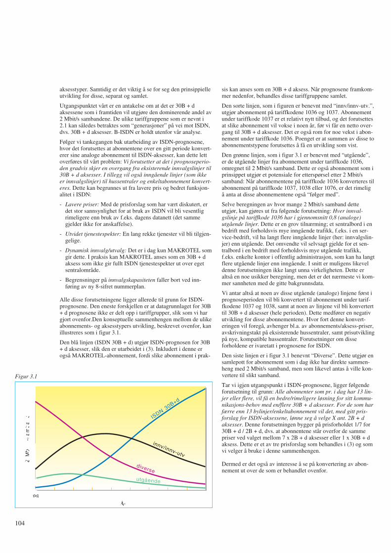
aksesstyper. Samtidig er det viktig å se for seg den prinsippielleutvikling for disse, separat og samlet.
Utgangspunktet vårt er en antakelse om at det er 30B + daksessene som i framtiden vil utgjøre den dominerende andel av2 Mbit/s sambandene. De ulike tariffgruppene som er nevnt i2.1 kan således betraktes som “generasjoner” på vei mot ISDN,dvs. 30B + d aksesser. B-ISDN er holdt utenfor vår analyse.
Følger vi tankegangen bak utarbeiding av ISDN-prognosene,hvor det forutsettes at abonnentene over en gitt periode konvert-erer sine analoge abonnement til ISDN-aksesser, kan dette lettoverføres til vårt problem: Vi forutsetter at det i prognoseperio-den gradvis skjer en overgang fra eksisterende innvalgslinjer til30B + d aksesser. I tillegg vil også inngående linjer (som ikkeer innvalgslinjer) til hussentraler og enkeltabonnement konvert-eres. Dette kan begrunnes ut fra lavere pris og bedret funksjon-alitet i ISDN:
- Lavere priser: Med de prisforslag som har vært diskutert, erdet stor sannsynlighet for at bruk av ISDN vil bli vesentligrimeligere enn bruk av f.eks. dagens datanett (det sammegjelder ikke for anskaffelse).
- Utvidet tjenestespekter: En lang rekke tjenester vil bli tilgjen-gelige.
- Dynamisk innvalg/utvalg: Det er i dag kun MAKROTEL somgir dette. I praksis kan MAKROTEL anses som en 30B + daksess som ikke gir fullt ISDN tjenestespekter ut over egetsentralområde.
- Begrensninger på innvalgskapasiteten faller bort ved inn-føring av ny 8-sifret nummerplan.
Alle disse forutsetningene ligger allerede til grunn for ISDN-prognosene. Den eneste forskjellen er at datagrunnlaget for 30B+ d prognosene ikke er delt opp i tariffgrupper, slik som vi hargjort ovenfor.Den konseptuelle sammenhengen mellom de ulikeabonnements- og aksesstypers utvikling, beskrevet ovenfor, kanillustreres som i figur 3.1.
Den blå linjen (ISDN 30B + d) utgjør ISDN-prognosen for 30B+ d aksesser, slik den er utarbeidet i (3). Inkludert i denne erogså MAKROTEL-abonnement, fordi slike abonnement i prak-
sis kan anses som en 30B + d aksess. Når prognosene framkom-mer nedenfor, behandles disse tariffgruppene samlet.
Den sorte linjen, som i figuren er benevnt med “innv/innv-utv.”,utgjør abonnement på tariffkodene 1036 og 1037. Abonnementunder tariffkode 1037 er et relativt nytt tilbud, og det forutsettesat slike abonnement vil vokse i noen år, før vi får en netto over-gang til 30B + d aksesser. Det er også rom for noe vekst i abon-nement under tariffkode 1036. Poenget er at summen av disse toabonnementstypene forutsettes å få en utvikling som vist.
Den grønne linjen, som i figur 3.1 er benevnt med “utgående”,er de utgående linjer fra abonnement under tariffkode 1036,omregnet til 2 Mbit/s samband. Dette er også abonnement som iprinsippet utgjør et potensiale for etterspørsel etter 2 Mbit/ssamband: Når abonnementene på tariffkode 1036 konverteres tilabonnement på tariffkode 1037, 1038 eller 1076, er det rimeligå anta at disse abonnementene også “følger med”.
Selve beregningen av hvor mange 2 Mbit/s samband detteutgjør, kan gjøres ut fra følgende forutsetning: Hver innval-gslinje på tariffkode 1036 har i gjennomsnitt 0,8 (analoge)utgående linjer. Dette er en grov tilnærming; et sentralbord i enbedrift med forholdsvis mye inngående trafikk, f.eks. i en ser-vice-bedrift, vil ha langt flere inngående linjer (her: innvalgslin-jer) enn utgående. Det omvendte vil selvsagt gjelde for et sen-tralbord i en bedrift med forholdsvis mye utgående trafikk,f.eks. enkelte kontor i offentlig administrasjon, som kan ha langtflere utgående linjer enn inngående. I snitt er muligens likeveldenne forutsetningen ikke langt unna virkeligheten. Dette eraltså en noe usikker beregning, men det er det nærmeste vi kom-mer sannheten med de gitte bakgrunnsdata.
Vi antar altså at noen av disse utgående (analoge) linjene først iprognoseperioden vil bli konvertert til abonnement under tarif-fkodene 1037 og 1038, samt at noen av linjene vil bli konverterttil 30B + d aksesser (hele perioden). Dette medfører en negativutvikling for disse abonnementene. Hvor fort denne konvert-eringen vil foregå, avhenger bl.a. av abonnements/aksess-priser,avskrivningstakt på eksisterende hussentraler, samt prisutviklingpå nye, kompatible hussentraler. Forutsetninger om disseforholdene er ivaretatt i prognosene for ISDN.
Den siste linjen er i figur 3.1 benevnt “Diverse”. Dette utgjør ensamlepott for abonnement som i dag ikke har direkte sammen-heng med 2 Mbit/s samband, men som likevel antas å ville kon-vertere til slikt samband.
Tar vi igjen utgangspunkt i ISDN-prognosene, ligger følgendeforutsetning til grunn: Alle abonnenter som pr. i dag har 13 lin-jer eller flere, vil få en bedre/rimeligere løsning for sitt kommu-nikasjons-behov med en/flere 30B + d aksesser. For de som harfærre enn 13 bylinjer/enkeltabonnement vil det, med gitt pris-forslag for ISDN-aksessene, lønne seg å velge X ant. 2B + daksesser. Denne forutsetningen bygger på prisforholdet 1/7 for30B + d / 2B + d, dvs. at abonnentene står overfor de sammepriser ved valget mellom 7 x 2B + d aksesser eller 1 x 30B + daksess. Dette er et av tre prisforslag som behandles i (3) og somvi velger å bruke i denne sammenhengen.
Dermed er det også av interesse å se på konvertering av abon-nement ut over de som er behandlet ovenfor.
104
1991År
2M
bit
/s-s
am
ba
nd IS
DN30B+d
innv/innv-utv
diverse
utgående
Figur 3.1
Disse abonnementene er omregnet til 2 Mbit/s samband på lik-nende måte som for de utgående linjene under tariffkode 1036.Underlaget for denne beregningen er ikke vist her. Vi vil herkun skissere hvordan tallene er framkommet:
Beregningen tar utgangspunkt i underlaget for ISDN-prog-nosene, som har talt opp alle kunder etter hvor mange abon-nement de har. Status for 30B + d aksesser, omregnet til“analoge ekvivalenter”, er så trukket ut av disse. Likeså er antallabonnement på tariffkodene 1037 og 1036, samt de beregnedeutgående linjer fra abonnement under tariffkode 1036.
Denne “Diverse”-posten utgjør altså den resterende del avpotensialet for ISDN-prognosene, og inneholder analoge innval-gslinjer (tariffkode 1031), bylinjer og enkeltabonnement. Hvorfort konverteringen vil foregå, avhenger også i dette tilfelletbl.a. av abonnements/aksess-priser, avskrivnings-takt på eksis-terende hussentraler, samt prisutvikling på nye, kompatiblehussentraler. Forutsetninger om disse forholdene, samt sammen-hengen mellom priser og de ulike aksessvalg, er som nevntivaretatt i prognosene for ISDN.
Som vi ser, antar vi en avtagende utvikling for “Diverse”-sam-bandene: Disse konverterer til abonnement på tariffkode 1037og 1038 i første del av prognoseperioden, mens det forutsettesen økende konvertering til 30B + d aksesser gjennom hele peri-oden.
4 MetodevalgSom nevnt tidligere, vil det være naturlig å ta utgangspunkt iden allerede eksisterende prognose for ISDN-aksesser, dvs. 30B+ d aksesser, når prognosene for 2 Mbit/s samband skal utarbei-des. Det vil føre for langt å gå inn på detaljer om selve utarbei-delsen av ISDN-prognosene i denne artikkelen. Prinsippene forhvordan denne prognosen er utarbeidet, er det gjort rede for i(3). Vi vil ta de sist oppdaterte prognosene for 30B + d aksessersom gitt i det følgende. Dette er prognoser som er utarbeidet pået senere tidspunkt enn de som ble presentert i (3). Talleneavviker derfor noe. Utgangspunktet er som nevnt den prognosensom er basert på prisforholdet 1/7 for aksesstypene 30B + d/ 2B+ d.
Det er viktig å merke seg metoden som er benyttet i utarbei-delsen av ISDN-prognosene, fordi det er klare likhetstrekk mel-lom datamaterialet for ISDN og for 2 Mbit/s sambandene: Vihar kun en observasjon (i ISDN-prognosene ble et scenario-anslag for observasjon nr. 2 utarbeidet) og dessuten er met-ningspunktet det samme, siden ISDN-aksessene en gang iframtiden vil være den eneste eksisterende tilknyttingsform, ifølge forutsetningene for ISDN-prognosene.
Når vi i tillegg til resonnementet ovenfor tar i betraktning at deter “grove” prognoseanslag som skal utarbeides, er detnærliggende å velge den samme metningsfunksjonen som forISDN-prognosene, som prognosemetode for 2 Mbit/s samban-dene. For en enkel innføring i denne metoden, se (6). Vi velgermed andre ord en modell av formen
(4.1)
hvor Yt er etterspørsel etter 2 Mbit/s samband på tidspunkt t, Mer metningspunktet, t er tiden og α, β og γ er parametre som
beskriver funksjonens forløp. α-parameteren bestemmer nivået påfunksjonen, mens β og γ begge bidrar til å bestemme stigningen(brattheten) på metningsfunksjonen.
Alle de fire parametrene α, β, γ og M bidrar til å bestemme for-men på metnings-funksjonen. I prinsippet er det mulig åestimere alle fire, men det krever relativt avansert estimer-ingsverktøy. I tillegg er det en regel som sier at jo færre data-punkter (observasjoner) som er til rådighet når estimeringenskal utføres, jo færre parametre bør estimeres. Dette har sam-menheng med at det er observasjonene som bidrar med deninformasjon som skal til for å estimere slike parametre, og da erdet lett å se at jo mindre informasjon en har, jo dårligere blirslike estimater. I dette tilfellet har vi minimalt med obser-vasjoner: Vi har i utgangspunktet bare en, og må derfor“økonomisere” antall parametre til et minimum.
Det er relativt vanlig å estimere M utenfor modellen og så brukedenne verdien når de andre parametrene skal estimeres. Det gjørvi også her. I tillegg settes γ = 20 000. For begrunnelse av sist-nevnte, se (2). Vi står dermed tilbake med to parametre somskal estimeres: α og β. Til dette trengs minimum to obser-vasjoner.
Når det gjelder selve metoden for estimering av parametrene αog β, er det minste kvadraters metode som benyttes her. For eninnføring i denne metoden, se f.eks. (1).
Framgangsmåten blir da som følger:1)Ta utgangspunkt i de sist oppdaterte prognoser for etter-
spørsel etter 30B + d aksesser.
2)Legg status for total etterspørsel etter antall 2 Mbit/s sambandpå tariffkode 1036 til prognosen for total etterspørsel etter30B + d aksesser i 1991. Dette utgjør “observasjon nr. 2” iprognosen for etterspørsel etter 2 Mbit/s samband. (Abon-nementene på tariffkode 1037 er allerede tatt med i 1.)
3)Startverdi (observasjon nr. 1) for 2 Mbit/s samband settes til0.
4)Valg av startår gjøres på grunnlag av introduksjonsår forabonnementene på tariffkode 1036.
5)Metningspunktet for 30B + d aksessene beholdes, siden detteer beregnet ut fra det totale behov for 2 Mbit/s samband.
6)La modellen estimere nye verdier for α og β, og kjør prog-nosene fram til år 2000.
7)Ønskes prognoser som viser sammenhengen mellom prog-nosene i pkt. 6) og de “Utgående” linjer, (omregnet til 2Mbit/s samband), kan status for total etterspørsel i 1991“utvides” med disse, på tilsvarende måte som i pkt. 2 ovenfor.Pkt. 3 - 6 følges deretter som ovenfor (startår blir her detsamme, siden de “Utgående” linjene er knyttet til abonnementpå tariffkode 1036).
8)Ønskes prognoser som viser sammenhengen mellom prog-nosene i pkt. 7) og “Diverse”-posten, må denne behandlesspesielt, siden startår ikke er opplagt i dette tilfellet (posteninneholder analoge innvalgs-linjer, bylinjer og enkeltabon-nement). Vi har her valgt, i likhet med ISDN-prognosene, åsette et scenario-anslag for år 2000 som observasjon nr. 2.Observasjon nr. 1 blir dermed status for 1991, med dette årsom startår.
105
Yt =M
(1 + eα+βt)γ
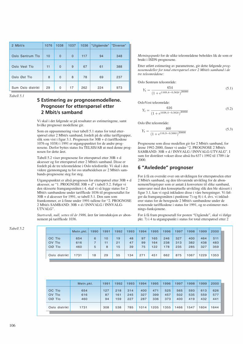
5 Estimering av prognosemodellene.Prognoser for etterspørsel etter2 Mbit/s samband
Vi skal i det følgende se på resultater av estimeringene, samthvilke prognoser modellene gir.
Som en oppsummering viser tabell 5.1 status for total etter-spørsel etter 2 Mbit/s samband, fordelt på de ulike tariffgrupper,slik som vist i figur 3.1. Prognosen for 30B + d (tariffkodene1076 og 1038) i 1991 er utgangspunktet for de andre prog-nosene. Derfor byttes status fra TELSIS/AB ut med denne prog-nosen for dette året.
Tabell 5.2 viser prognosene for etterspørsel etter 30B + daksesser og for etterspørsel etter 2 Mbit/s samband. Disse erfordelt på de tre teleområdene i Oslo teledistrikt. Vi skal i denvidere gjennomgang ta for oss utarbeidelsen av 2 Mbit/s sam-bands-prognosene steg for steg.
Utgangspunktet er altså prognosen for etterspørsel etter 30B + daksesser, se “1. PROGNOSE 30B + d” i tabell 5.2. Følger viden skisserte framgangsmåten i 4, skal vi så legge status for 2Mbit/s sambandene under tariffkode 1036 til prognosetallet for30B + d aksesser for 1991, se tabell 5.1. Den sum somframkommer, er å finne under 1991-tallene for “2. PROGNOSE2 Mbit/s SAMBAND: 30B + d / INNVALG / INNVALG-UTVALG”.
Startverdi, null, settes til år 1986, året før introduksjon av abon-nement på tariffkode 1036.
Metningspunkt for de ulike teleområdene beholdes lik de som erbrukt i ISDN-prognosene.
Etter utført estimering av parametrene, gir dette følgende prog-nosemodeller for total etterspørsel etter 2 Mbit/s samband i detre teleområdene:
Oslo Sentrum teleområde:
(5.1)
OsloVest teleområde:
(5.2)
Oslo Øst teleområde:
(5.3)
Prognosene som disse modellen gir for 2 Mbit/s samband, forårene 1992-2000, finner vi under “2. PROGNOSE 2 Mbit/sSAMBAND: 30B + d / INNVALG / INNVALG-UTVALG”. Isum for distriktet vokser disse altså fra 637 i 1992 til 1709 i år2000.
6 “Avledede” prognoser
For å få en oversikt over om utviklingen for etterspørselen etter2 Mbit/s samband, og den tilsvarende utvikling for de abon-nement/linjetyper som er antatt å konvertere til slike samband,samsvarer med den konseptuelle utvikling slik den ble skissert ifigur 3.1, kan vi også inkludere disse i våre beregninger. Vi føl-ger da framgangsmåten i punktene 7) og 8) i 4, dvs. vi inklud-erer status for de beregnede 2 Mbit/s sambandene under deresterende tariffkodene i status for 1991, og re-estimerer met-nings-funksjonene.
For å få fram prognosetall for posten “Utgående”, skal vi ifølgepkt. 7) i 4 ta utgangspunkt i status for total etterspørsel etter 2
106
2 Mbit/s
Oslo Sentrum Tlo
Oslo Vest Tlo
Oslo Øst Tlo
Sum Oslo distrikt
10
11
8
29
0
0
0
0
0
9
8
17
117
67
78
262
94
61
69
224
348
388
237
973
1076 1038 1037 1036 "Utgående" "Diverse"
Tabell 5.1
OC TloOV TloOØ Tlo
Oslo distrikt
Metn.pkt.
654616460
1731
675
18
1990
10118
29
1991
192115
55
1992
484739
134
1993
979975
271
1994
165164122
451
1995
246238178
662
1996
327313235
875
1997
400382285
1067
1998
464438327
1229
1999
511483359
1353
2000
OC TloOV TloOØ Tlo
Oslo distrikt
Metn.pkt.
654616460
1731
1278794
308
1991
218161159
538
1992
314245227
785
1993
400327287
1014
1994
471399336
1205
1995
525457373
1355
1996
565502400
1466
1997
593535419
1547
1998
613559432
1604
1999
626577441
1644
2000
Tabell 5.2
Yt =654
(1 + e1169,4−0,562t)20000
Yt =616
(1 + e1038,4−0,562t)20000
Yt =460
(1 + e116,9−0,566t)20000
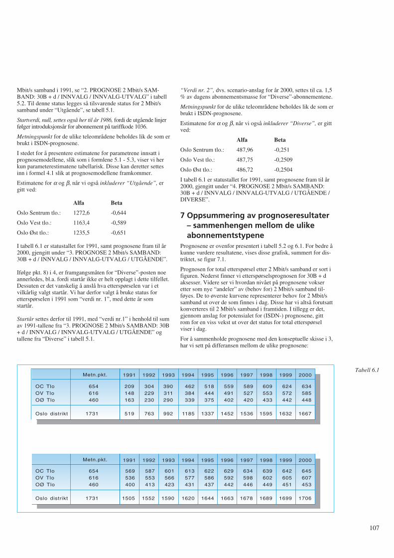
Mbit/s samband i 1991, se “2. PROGNOSE 2 Mbit/s SAM-BAND: 30B + d / INNVALG / INNVALG-UTVALG” i tabell5.2. Til denne status legges så tilsvarende status for 2 Mbit/ssamband under “Utgående”, se tabell 5.1.
Startverdi, null, settes også her til år 1986, fordi de utgående linjerfølger introduksjonsår for abonnement på tariffkode 1036.
Metningspunkt for de ulike teleområdene beholdes lik de som erbrukt i ISDN-prognosene.
I stedet for å presentere estimatene for parametrene innsatt iprognosemodellene, slik som i formlene 5.1 - 5.3, viser vi herkun parameterestimatene tabellarisk. Disse kan deretter settesinn i formel 4.1 slik at prognosemodellene framkommer.
Estimatene for α og β, når vi også inkluderer “Utgående”, ergitt ved:
Alfa Beta
Oslo Sentrum tlo.: 1272,6 -0,644
Oslo Vest tlo.: 1163,4 -0,589
Oslo Øst tlo.: 1235,5 -0,651
I tabell 6.1 er statustallet for 1991, samt prognosene fram til år2000, gjengitt under “3. PROGNOSE 2 Mbit/s SAMBAND:30B + d / INNVALG / INNVALG-UTVALG / UTGÅENDE”.
Ifølge pkt. 8) i 4, er framgangsmåten for “Diverse”-posten noeannerledes, bl.a. fordi startår ikke er helt opplagt i dette tilfellet.Dessuten er det vanskelig å anslå hva etterspørselen var i etvilkårlig valgt startår. Vi har derfor valgt å bruke status foretterspørselen i 1991 som “verdi nr. 1”, med dette år somstartår.
Startår settes derfor til 1991, med “verdi nr.1” i henhold til sumav 1991-tallene fra “3. PROGNOSE 2 Mbit/s SAMBAND: 30B+ d / INNVALG / INNVALG-UTVALG / UTGÅENDE” ogtallene fra “Diverse” i tabell 5.1.
“Verdi nr. 2”, dvs. scenario-anslag for år 2000, settes til ca. 1,5% av dagens abonnementsmasse for “Diverse”-abonnementene.
Metningspunkt for de ulike teleområdene beholdes lik de som erbrukt i ISDN-prognosene.
Estimatene for α og β, når vi også inkluderer “Diverse”, er gittved:
Alfa Beta
Oslo Sentrum tlo.: 487,96 -0,251
Oslo Vest tlo.: 487,75 -0,2509
Oslo Øst tlo.: 486,72 -0,2504
I tabell 6.1 er statustallet for 1991, samt prognosene fram til år2000, gjengitt under “4. PROGNOSE 2 Mbit/s SAMBAND:30B + d / INNVALG / INNVALG-UTVALG / UTGÅENDE /DIVERSE”.
7 Oppsummering av prognoseresultater – sammenhengen mellom de ulikeabonnementstypene
Prognosene er ovenfor presentert i tabell 5.2 og 6.1. For bedre åkunne vurdere resultatene, vises disse grafisk, summert for dis-triktet, se figur 7.1.
Prognosen for total etterspørsel etter 2 Mbit/s samband er sort ifiguren. Nederst finner vi etterspørselsprognosen for 30B + daksesser. Videre ser vi hvordan nivået på prognosene vokseretter som nye “andeler” av (behov for) 2 Mbit/s samband til-føyes. De to øverste kurvene representerer behov for 2 Mbit/ssamband ut over de som finnes i dag. Disse har vi altså forutsattkonverteres til 2 Mbit/s samband i framtiden. I tillegg er det,gjennom anslag for potensialet for (ISDN-) prognosene, gittrom for en viss vekst ut over det status for total etterspørselviser i dag.
For å sammenholde prognosene med den konseptuelle skisse i 3,har vi sett på differansen mellom de ulike prognosene:
107
OC TloOV TloOØ Tlo
Oslo distrikt
Metn.pkt.
654616460
1731
209148163
519
1991
304229230
763
1992
390311290
992
1993
462384339
1185
1994
518444375
1337
1995
559491402
1452
1996
589527420
1536
1997
609553433
1595
1998
624572442
1632
1999
634585448
1667
2000
OC TloOV TloOØ Tlo
Oslo distrikt
Metn.pkt.
654616460
1731
569536400
1505
1991
587553413
1552
1992
601566423
1590
1993
613577431
1620
1994
622586437
1644
1995
629592442
1663
1996
634598446
1678
1997
639602449
1689
1998
642605451
1699
1999
645607453
1706
2000
Tabell 6.1
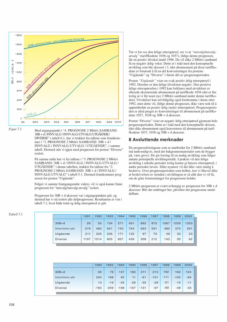
Med utgangspunkt i “4. PROGNOSE 2 Mbit/s SAMBAND:30B + d / INNVALG / INNVALG-UTVALG / UTGÅENDE /DIVERSE” i tabell 6.1, har vi trukket fra tallene som framkom-mer i “3. PROGNOSE 2 Mbit/s SAMBAND: 30B + d /INNVALG / INNVALG-UTVALG / UTGÅENDE”, i sammetabell. Dermed står vi igjen med prognosen for posten “Diverse”isolert.
På samme måte har vi fra tallene i “3. PROGNOSE 2 Mbit/sSAMBAND: 30B + d / INNVALG / INNVALG-UTVALG /UTGÅENDE” i denne tabellen, trukket fra tallene fra “2.PROGNOSE 2 Mbit/s SAMBAND: 30B + d / INNVALG /INNVALG-UTVALG” i tabell 5.1. Dermed framkommer prog-nosen for posten “Utgående”.
Følger vi samme framgangsmåte videre, vil vi også kunne finneprognosen for “innvalg/innvalg-utvalg” isolert.
Prognosen for 30B + d aksesser var i utgangspunktet gitt, ogdermed har vi nå isolert alle delprognosene. Resultatene er vist itabell 7.1, hvor både total og årlig etterspørsel er gitt.
Tar vi for oss den årlige etterspørsel, ser vi at “innvalg/innvalg-utvalg” (tariffkodene 1036 og 1037), ifølge denne prognosen,får en positiv tilvekst inntil 1996. Da vil slike 2 Mbit/s sambandfå en negativ årlig vekst. Dette er i tråd med den konseptuelleutvikling som ble skissert i 3, idet abonnement på disse tariffko-dene er forutsatt å få en del konverteringer fra postene“Utgående” og “Diverse” i første del av prognoseperioden.
Posten “Utgående” viser en svak positiv årlig etterspørsel i1992. Deretter er den årlige tilveksten negativ. Den positiveårlige etterspørselen i 1992 kan forklares med utvidelser avallerede eksisterende abonnement på tariffkode 1036 (det er litetrolig at vi får noen nye 2 Mbit/s samband under denne tariffko-den). Utvidelser kan selvfølgelig også forekomme i årene etter1992, men dette vil, ifølge denne prognosen, ikke være nok til åopprettholde en positiv årlig (netto-)etterspørsel. Prognoseperio-den er altså preget av konverteringer til abonnement på tariffko-dene 1037, 1038 og 30B + d aksesser.
Posten “Diverse” viser en negativ årlig etterspørsel gjennom heleprognoseperioden. Dette er i tråd med den konseptuelle skissen,idet slike abonnement også konverteres til abonnement på tarif-fkodene 1037, 1038 og 30B + d aksesser.
8 Avsluttende merknader
De prognoseforslagene som er utarbeidet for 2 Mbit/s sambandmå nødvendigvis, med det bakgrunnsmaterialet som de byggerpå, være grove: De gir forslag til en mulig utvikling som følgerantatte prinsipielle utviklingstrekk. I praksis vil den årligeutvikling i enkelte perioder trolig kunne gi høyere etterspørsel, iandre perioder lavere. Slike nyanser vil det ikke være mulig åbeskrive. Over prognoseperioden som helhet, tror vi likevel ikkeat beskrivelsen av trenden i utviklingen er så ulik den vi vil få,om de gitte forutsetninger for prognosene holder.
2 Mbit/s-prognosen er svært avhengig av prognosen for 30B + daksesser: Blir det endringer her, påvirker det prognosene umid-delbart.
108
1991
2M
bit
/s-s
am
ba
nd
1800
1600
1400
1200
1000
800
600
400
200
01992 1993 1994 1995 1996 1997 1998 1999 2000
30B+d/innv/innv-utv/utgående/diverse
30B+d/innv/
innv-
utv/u
tgående
30B+d/innv/
innv-
utv
30B+d
Figur 7.1
30B+d
Innv/innv-utv
Utgående
Diverse
1991 1992 1993 1994 1995 1996 1997 1998 1999 2000
29
279
211
1197
55
483
225
1014
134
651
206
805
271
743
171
607
451
754
132
439
662
693
97
308
875
591
70
212
1067
480
49
143
1229
375
33
95
1353
291
23
62
30B+d
Innv/innv-utv
Utgående
Diverse
1992 1993 1994 1995 1996 1997 1998 1999 2000
26
204
13
-183
79
168
-19
-209
137
92
-35
-198
180
11
-39
-167
211
-61
-35
-131
213
-101
-28
-97
192
-111
-21
-69
162
-105
-15
-48
124
-84
-11
-33
Tabell 7.1
Vi har i 2.3 (og 2.4) gjort enkelte forutsetninger og forenklingerunder beregningen av status for total etterspørsel etter 2 Mbit/ssamband. I tillegg er data beheftet med enkelte usikkerheter.
Svakhetene i datamaterialet kan oppsummeres slik:
1)Status for innkoblede 2 Mbit/s samband er benyttet somapproksimasjon til status for total etterspørsel etter 2 Mbit/ssamband. Feilen er minimal. Når ISDN “tar av” må imidlertidframtidige data vise etterspørsel, da ueffektuerte og ikke opp-daterte ordrer på ISDN-aksesser trolig vil vokse betraktelig.
2)Etterspørselstallene er ikke korrigert for nummerlån mellomsentraler. Feilen antas å være liten. Framtidig arbeid målikevel vurdere og evt. bearbeide nummerlånene, da dissetrolig vil vokse med kommersiell lansering av ISDN.
3)Underlagsmaterialet viser at Televerket, Oslo distrikt, ståroppført med 10 linjer under tariffkode 1031. Dette er enfeilkoding. Tariffkoden skulle i dette tilfellet vært 1131, ogderfor ikke vært inkludert i vår liste. Slike feilregistreringer erogså mulige for de andre tariffkodene.
Andre kjente feilregistreringer er f.eks. enkelte av de førstelinjene med tariffkode 1036 som ble registrert. Fordi TEL-SIS/AB ikke var tilrettelagt for registrering av PCM-linjer,ble hver enkelt PCM-linje registrert som en linje under tarif-fkode 1031. Dette skal senere være konvertert til riktig tarif-fkode, men underlagsmaterialet viste at dette i enkelte tilfellerikke var utført.
Underlagsdata er ikke korrigert for slike feil.
4)Fagerborg sentral står i underlagsmaterialet oppført med 4030B + d aksesser. Dette er feil. Under arbeidet med ISDN-prognosene ble det avslørt at TELSIS/AB i gitte tilfeller teller30B + d aksessene feil. Det riktige antall skal være 21. Dettefår imidlertid ikke påvirkning på vår analyse, siden detteallerede er korrigert i den tidligere utarbeidede prognosen for30B + d aksesser.
5)Siden det er årsprognoser som skal lages, burde status fortotal etterspørsel etter 2 Mbit/s samband for årsskiftet værtlagt til grunn. Tidspunktet vi har statustall for er medioseptember 1991, og dermed burde et anslag for perioden utåret gjøres (evt. for perioden fra januar og fram til de avlestestatustall), slik at status for et årsskifte ble utgangspunktet.
Slik beregning er ikke utført. Under det videre arbeidet er denregistrerte totaletterspørsel pr. medio september 1991 bruktsom om dette var status 31.12.91. Dette medfører at tallenefor de fleste av tariffgruppene nok er litt for lave som statusfor årsskiftet. Med henblikk på de grove prognoseanslag somskal utarbeides, er dette ansett som “rimelig”, tatt i betrakt-ning den usikkerhet som likevel ligger i analysen.
Hvis det viser seg å være behov for kontinuerlig oppfølging ogrevidering av disse prognosene, i likhet med abonnementsprog-nosene for telefoni og ISDN, bør det legges vekt på å få framsikrere data for status, samt å følge utvikling framover.
Punktene ovenfor er områder som det ville være naturlig å “fin-pusse” i det framtidige prognosearbeid.
Alle disse momentene medfører at data ikke gir et helt korrektbilde av situasjonen. Likevel vurderes underlaget som “godtnok” til et grovt førsteutkast. Videre arbeid vil måtte innbefatteen rekke forbedringer i datakvaliteten.
Takk
Takk til Johannes Bøe som har kjørt beregningene og kommetmed vesentlige bidrag til artikkelen, Kjell Stordahl for nyttigekommentarer og Jan Andreas Krog som har bearbeidet datama-terialet.
Referanser
1 Bhattacharyya, G K, Johnsen, R A. Statistical Concepts andMethods, John Wiley & Sons Ltd., 1977.
2 Blindheim, E, Rygg M. En modell for å utarbeide prog-noser for nye teletjenester, Rapport nr 13/82, Televerketsforskningsinstitutt.
3 Bøe, J, Hjelkrem, C. Metodebeskrivelse for utarbeidelse avprognoser for ISDN-aksesser i Oslo teledistrikt, Telektron-ikk 1, 1991.
4 Bøe, J, Hjelkrem, C. Utarbeiding av prognoser for etter-spørsel etter telefonabonnement i Oslo teledistrikt, Telek-tronikk 1, 1991.
5 Log, S. Diffusjonsmodeller for nye teletjenester, TF-Rapport14/82, Televerkets forskningsinstitutt.
6 Prognosekontoret, Teledirektoratet. Bruk av metnings-analyse ved langsiktige etterspørselsprognoser etter telet-jenester, Prognosenotat 17, 1979.
7 Stordahl, K, Holden L. Traffic forecasting models based ontop down and bottom up models, ITC 11, Kyoto, 1985.
8 STRATEK 1993. Strategiplan for teknisk utbygging ogdrift, Teledirektoratet mai 1992.
9 TELSIS-gruppen, Øst distrikt. Bestillingstyper, tariffnum-mer m.m. i TELSIS, Utgave 6, oktober 1991.
109
110
Rapport fra “15. Jahrestagung der FKTG”, Berlin 1 - 5 juni 1992A V O L A V G R O V
FKTG (Fernseh- und Kinotechnische Gesellschaft) er en foren-ing av firmaer og institusjoner innen produksjon, vitenskap,forskning, forvaltning og undervisning av fjernsyn ogfilmteknikk i Tyskland. Det er en tung forsamling av ledere ogforskere med masse prestisje.
På FKTGs Jahrestagung som foregår hvert annet år er det særligferske forskningsresultater innen emnet som blir presentert av tildels unge representanter og grundig kommentert av forsamlin-gen. I år ble det lagt fram 55 foredrag.
I denne artikkelen vil jeg trekke fram en del viktige problem-stillinger presentert av Frank Müller-Römer fra BayerischeRundfunk – knyttet til framtidig digitalt jordbundet sendernettfor fjernsyn – og Günther Schamel fra Heinrich-Hertz Institutfür Nachrichtentechnik Berlin GmbH – knyttet til digital jord-bundet koding av HDTV.
Del I: Framtidig digitalt jordbundetsendernett for fjernsyn
I begynnelsen av fjernsynstidsalderen i 50- og deler av 60-åravar det kun ett sendernett for fjernsyn i hvert land i Europa.Siden har det kommet til nye, utbyggingen av program 1, 2 ogmuligens 3, samt nær-TV, flere radioprogram, utbygging avkabel-TV, satellittprogram, for å nevne noen. Med utbygging avtelematikknett som også vil være i stand til å overføre levendebilder, kan en spørre seg om hvor stor rolle jordbundet eter-spredning av fjernsynsprogrammer vil spille i framtida.
Man går ut fra at familiens hovedmottaker i stor grad er knyttettil en fast installasjon i form av kabel-TV, satellittmottakersys-tem eller et telematikknett, og ekstra-apparatet i form av reise-TV fremdeles vil være avhengig av jordbundet eternett. Enmener videre at den tekniske mottakskvalitet fra de jordbundnekringkastere i dag, og særlig i forhold til satellittfjernsynet, ikkelenger holder mål.
Digitalteknikkens innsats på video-området stiller kringkast-ingsselskaper og programprodusenter i framtida foran et grun-nproblem. Er den analoge overføringen (PAL) og eventuelt(PAL-plus) konkurransedyktig i framtida? Vil brukere av jord-bundet overføring havne i den situasjonen at de blir forbikjørtkvalitetsmessig av satellittfjernsyn, videorecordere, osv?
Tar man sikte på en framtidig overgang til digital distribusjons-metode bør man både for DAB (Digital Audio Broadcasting) ogDVB (Digital Video Broadcasting) stille seg følgende spørsmålog diskutere dem seriøst:
1 Antall program som skal sendes
2 Mottaksbetingelser (via telematikknett, via satellitt eller viajordbundet eterspredning)
3 Teknisk kvalitet (HDTV, TV eller noe annet).
Her har de tyske offentlige kringkastingsinstitusjonene ytretseg:
1 Beste bilde og lydkvalitet i en 7 MHz kanal for mottak medvanlig takantenne henholdsvis i en satellittkanal
2 Likekanalbruk må være mulig
3 Myk overgang (graceful degradation = langsom degraderingav bildekvaliteten) ved dekningsområdets grenser
4 Det må bli tatt hensyn til videredistribusjon i kabelnett.
I forslaget til jordbundet digitalt fjernsyns-sendernett ligger deten rekke fordeler for brukerne som er av avgjørende betydning.
- Vedvarende gode mottaksmuligheter også for mobile og bær-bare apparater
- Meget god teknisk overføringskvalitet
- Ingen refleksjonsforstyrrelser
- Mindre antennebehov for brukerne
- Middels programutvalg for brukerne
- Framtidssikret også for videre utvikling av fjernsynssystemer.
Systemoverveielse til Digital Video Broadcasting, DVB
Datareduksjonen blir mulig ved hjelp av spesielle metoder ogalgoritmer der det blir tatt hensyn til den menneskelige iakt-takelsesevnen. Til tross for betydelig datareduksjon kan ikke detmenneskelige øye på mottakeren se noen vesentlig forskjell fraoriginalen. Informasjon som vi ikke er i stand til å iaktta skalikke overføres i datastrømmen.
Konvensjonelle kodingsmetoder for bilde, DCT = Discrete Cos-inus Transformation, SBC = SubBandCoding og beveg-elseskompenserende prediksjon eller en kombinasjon av dissemetoder som i dag blir satt inn, har i de siste årene nådd enmeget høy standard.
Hva kan vi vente oss av disse framtidige systemene? Bortsett fraSuper HDTV (S-HDTV) med 4000 x 4000 bildepunkter og endatarate på ca 10 Gbit/s og med tredimensjonale muligheter, vilman i nær framtid ha to systemer klare:
System 1 625 linjer, 16 : 9 format, 7 MHz båndbredde,feilbeskyttelse og kanalkoding blir utformet ogdet blir mulig å motta ved en liten teleskopan-tenne.
System 2 1250 linjer 16 : 9 format, 7 MHz, kanalkodingfor mottak med retningsantenne.
Diskusjoner om framtidige jordbundne sendernett for fjernsynmå på den andre siden ikke bli uten hensyn til hvermannsmuligheter til å ta inn satellittfjernsyn direkte. I denneforbindelse kom foredragsholderen inn på betraktninger omfamiliens framtidige TV-utrustning. Vil f eks familiens hoved-mottaker, som er en fast innretning og koblet til en fast anten-nekontakt, få sitt program via et jordbundet eternett? Bør HDTVog eventuelt S-HDTV distribueres utenom det jordbundnesendernettet?
Ved fastsettelse av en systemdefinisjon for digitalt jordbundetfjernsyn DVB, må en ta i betraktning følgende spørsmålsstillingog treffe tilsvarende avgjørelser:
- “Normalkvalitet” for mottak med utstyr uten tilkobling tilkabel eller telematikknett (6 Mbit/s i 7 MHz kanal) og/eller
621.397.13
- “Low quality TV” for mottak med bærbart mobilt utstyr (3 til5 program i en 7 MHz-kanal) og/eller
- HDTV via en utendørsantenne (30 Mbit/s i en 7 MHz kanal)og/eller
- 3D-fjernsyn via uteantenne (framtidstanker).
Digitalt jordbundet sendernett for fjernsyn
På grunn av de fysiske betingelser må man ved analogt sender-nett ha stor geografisk avstand eller annen topografiskavskjerming mellom sendere på samme kanal. Bruk av digitaltlikekanal-nettverk vil føre til en betydelig frekvensøkonomiser-ing. Et program krever kun en kanal for det ønskede dekning-sområdet. Det vil si at alle senderne innenfor et dekningsområdesom sender samme program vil bruke samme kanal (frekvens).Hensyn til interferens vil begrense seg til andre dekningsom-råder som skal bruke denne kanalen til et annet program. Dettegjelder både for DAB og DVB.
Det er sannsynlig at det av hensyn til nærliggende dek-ningsområder (andre land) vil være mest hensiktsmessig medsmå og mange sendere heller enn få og store i et slikt system.Det pågår forsøk for å finne ut av dette problemet.
Man må regne med at i et digitalt nett vil det være småmuligheter for mottaking utenfor dekningsområdet, slik som vikjenner det fra vårt nåværende analoge nett. Denne mulighetenmå overlates til satellittkringkasting.
Videre arbeid
På samme måte som for DAB må en ha et frekvensområde åarbeide i (prøveområde). For lang tid tilbake ble kanalene 61 til69 avsatt til slike formål. Ved en båndbredde på 7 MHz for detdigitale jordbundne fjernsynsnettet betyr det for Tysklands ved-kommende at kun 4 - 5 av de ni kanalene vil være tilgjengelige.Dette på grunn av nabolands frekvensbehov i samme anledning.Hvordan en kan tenke seg en senere frigjøring av disse kanalerfor prøving av nye framtidige systemer vil bli avhengig av ihvilken takt en kan ta i bruk de nåværende analoge kanaler tildigitalt bruk.
Avgjørende for innføringen av nye kringkastingssystemer ertilbudet av hjemmemottakere. Universalmottakere er enmulighet. Det kommer an på om en allerede i starten avforsøksperioden kan ordne seg slik at alle apparater som selgesfra et bestemt tidspunkt vil være utrustet også for digital mottak-ing. Merkostnadene vil i forhold til fjernsynsapparatets totalekostnader være minimale.
Nasjonalt og internasjonalt blir det for tiden arbeidet intensivtpå prosjekter for digitale jordbundne fjernsynssystemer:
- VADIS 625: Signalbearbeiding
- RACE T.813: Standardisering
- BMFT (HHI): Digitalt jordbundet HDTV
- Europeisk industri, teleforvaltninger, kringkastingsselskaper:Standardisering
Alle tanker om utvikling og innføring av digitalt jordbundetfjernsynssystem må ha i minne at det for tiden handler kun om
rene forsknings- og utviklingsoppgaver. En innføring kantidligst finne sted omkring årtusenskiftet. Ved alle diskusjonerom forslag og innføring av nye systemer for kringkasting måstandardisering tas med i betraktningen. Her må en ta hensyn til:
- Kringkastingsinstitusjonene
- Industrien
- Abonnentene, publikum.
Bare når alle parter har fordel av innføringen av et system vilresultat kunne gjennomføres med en rimelig grad av suksess.
- Fordeler for kringkastingsselskapene?
⋅ Forbedret overføringskvalitet i en 7 MHz kanal?
⋅ HDTV også i et jordbundet nett?
⋅ Større overføringskapasitet for flere program?
- Fordeler for europeisk industri?
⋅ Masseproduksjon av de mest avanserte integrerte kretser(16 M og 64 M teknologi)
⋅ 200 til 250 mill. nye fjernsynsmottakere (universalmot-takere for analog/digital mottaking)
⋅ 100 - 120 mill. nye videorecordere
⋅ Markedspotensiale 20 til 30 milliarder DM pr år.
- Fordeler for abonnenten (publikum)?
⋅ Nytt bildeformat 16 : 9?
⋅ Forbedret kvalitet?
⋅ Stasjonær og mobil mottaking uten forstyrrelser?
⋅ Større programutvalg (der en må basere seg på mottakingvia jordbundet nett).
Del II: Digital jordbundet overføring
Først generelt om jordbundet overføring:
- Frekvensområdet 47 - 862 MHz, VHF/UHF kanaler med hen-holdsvis 7 og 8 MHz båndbredde
- 1 ... 5 bit/s pro Hz ved digital modulasjon.
Dermed får vi
- TV med 200 Mbit/s 40 - 200 MHz
- HDTV med 1 Gbit/s 200 - 1 GHz
(I denne artikkelen opereres med tre typer TV-systemer: HDTV= High Definition TV, TV = nåværende system og PV = per-sonal TV.)
Vil man overføre en binær datastrøm over en analog kanal mådet resultere i en modulasjon. For øyeblikket blir det diskutertframgangsmåter som i en Hz kan modulere datarate fra 1 til 5bit/sek. Det betyr at vi for TV med ca 200 Mbit/s trenger mel-lom 40 og 200 MHz kanalbredde og for HDTV mellom 200 og1000 MHz kanalbredde. Dermed blir det tvingende nødvendigmed en betydelig datakompresjon av kildesignalet.
111
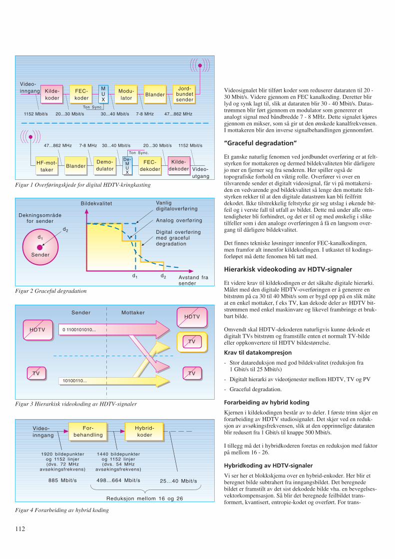
112
Videosignalet blir tilført koder som reduserer dataraten til 20 -30 Mbit/s. Videre gjennom en FEC kanalkoding. Deretter blirlyd og synk lagt til, slik at dataraten blir 30 - 40 Mbit/s. Datas-trømmen blir ført gjennom en modulator som genererer etanalogt signal med båndbredde 7 - 8 MHz. Dette signalet kjøresgjennom en mikser, som så gir ut den ønskede kanalfrekvensen.I mottakeren blir den inverse signalbehandlingen gjennomført.
“Graceful degradation”
Et ganske naturlig fenomen ved jordbundet overføring er at felt-styrken for mottakeren og dermed bildekvaliteten blir dårligerejo mer en fjerner seg fra senderen. Her spiller også detopografiske forhold en viktig rolle. Overfører vi over entilsvarende sender et digitalt videosignal, får vi på mottakersi-den en vedvarende god bildekvalitet så lenge den mottatte felt-styrken rekker til at den digitale datastrøm kan bli feilfrittdekodet. Ikke tilstrekkelig feltstyrke gir seg utslag i økende bit-feil og i verste fall til utfall av bildet. Dette må under alle oms-tendigheter bli forhindret, og det er til og med ønskelig i sliketilfeller som i den analoge overføringen å få en langsom over-gang til dårligere bildekvalitet.
Det finnes tekniske løsninger innenfor FEC-kanalkodingen,men framfor alt innenfor kildekodingen. I utkastet til kodings-forløpet må dette fenomen bli tatt med.
Hierarkisk videokoding av HDTV-signaler
Et videre krav til kildekodingen er det såkalte digitale hierarki.Målet med den digitale HDTV-overføringen er å generere enbitstrøm på ca 30 til 40 Mbit/s som er bygd opp på en slik måteat en enkel mottaker, f eks TV, kan dekode deler av HDTV bit-strømmen med enkel maskinvare og likevel frambringe et bruk-bart bilde.
Omvendt skal HDTV-dekoderen naturligvis kunne dekode etdigitalt TVs bitstrøm og framstille enten et normalt TV-bildeeller oppkonvertere til HDTV bildestørrelse.
Krav til datakompresjon
- Stor datareduksjon med god bildekvalitet (reduksjon fra1 Gbit/s til 25 Mbit/s)
- Digitalt hierarki av videotjenester mellom HDTV, TV og PV
- Graceful degradation.
Forarbeiding av hybrid koding
Kjernen i kildekodingen består av to deler. I første trinn skjer enforarbeiding av HDTV studiosignalet. Det skjer ved en reduk-sjon av avsøkingsfrekvensen, slik at den opprinnelige dataratenblir redusert fra 1 Gbit/s til knappe 500 Mbit/s.
I tillegg må det i hybridkoderen foretas en reduksjon med faktorpå mellom 16 - 26.
Hybridkoding av HDTV-signaler
Vi ser her et blokkskjema over en hybrid-enkoder. Her blir etberegnet bilde subtrahert fra inngangsbildet. Det beregnedebildet er framstilt av det sist dekodede bilde vha. en bevegelses-vektorkompensasjon. Så blir det beregnede feilbildet trans-formert, kvantisert, entropie-kodet og overført. For trans-
Kilde-koder
MUX
FEC-koder
Modu-lator
BlanderJord-
bundetsender
Video-inngang
Video-utgang
BlanderDemo-dulator
De-MUX
FEC-dekoder
Kilde-dekoder
HF-mot-taker
1152 Mbit/s
Ton Sync.
Ton Sync.
20...30 Mbit/s 30...40 Mbit/s 7-8 MHz 47...862 MHz
1152 Mbit/s20...30 Mbit/s30...40 Mbit/s7-8 MHz47...862 MHz
Figur 1 Overføringskjede for digital HDTV-kringkasting
Dekningsområdefor sender
d1
d2
Sender
Vanligdigitaloverføring
Analog overføring
Digital overføringmed gracefuldegradation
d1 d2 Avstand frasender
Bildekvalitet
Figur 2 Graceful degradation
TV
Sender Mottaker
HDTV
HDTV
TV
TV
0 1100101010...
10100110...
Figur 3 Hierarkisk videokoding av HDTV-signaler
For-behandling
Hybrid-koder
Video-inngang
1920 bildepunkterog 1152 linjer(dvs. 72 MHz
avsøkingsfrekvens)
885 Mbit/s
1440 bildepunkterog 1152 linjer(dvs. 54 MHz
avsøkingsfrekvens)
498...664 Mbit/s 25...40 Mbit/s
Reduksjon mellom 16 og 26
Figur 4 Forarbeiding av hybrid koding
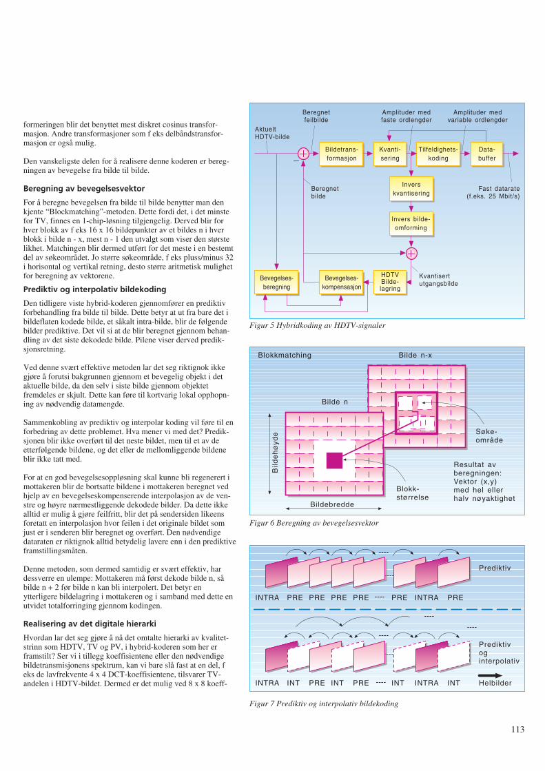
formeringen blir det benyttet mest diskret cosinus transfor-masjon. Andre transformasjoner som f eks delbåndstransfor-masjon er også mulig.
Den vanskeligste delen for å realisere denne koderen er bereg-ningen av bevegelse fra bilde til bilde.
Beregning av bevegelsesvektor
For å beregne bevegelsen fra bilde til bilde benytter man denkjente “Blockmatching”-metoden. Dette fordi det, i det minstefor TV, finnes en 1-chip-løsning tilgjengelig. Derved blir forhver blokk av f eks 16 x 16 bildepunkter av et bildes n i hverblokk i bilde n - x, mest n - 1 den utvalgt som viser den størstelikhet. Matchingen blir dermed utført for det meste i en bestemtdel av søkeområdet. Jo større søkeområde, f eks pluss/minus 32i horisontal og vertikal retning, desto større aritmetisk mulighetfor beregning av vektorene.
Prediktiv og interpolativ bildekoding
Den tidligere viste hybrid-koderen gjennomfører en prediktivforbehandling fra bilde til bilde. Dette betyr at ut fra bare det ibildeflaten kodede bilde, et såkalt intra-bilde, blir de følgendebilder prediktive. Det vil si at de blir beregnet gjennom behan-dling av det siste dekodede bilde. Pilene viser derved predik-sjonsretning.
Ved denne svært effektive metoden lar det seg riktignok ikkegjøre å forutsi bakgrunnen gjennom et bevegelig objekt i detaktuelle bilde, da den selv i siste bilde gjennom objektetfremdeles er skjult. Dette kan føre til kortvarig lokal opphopn-ing av nødvendig datamengde.
Sammenkobling av prediktiv og interpolar koding vil føre til enforbedring av dette problemet. Hva mener vi med det? Predik-sjonen blir ikke overført til det neste bildet, men til et av deetterfølgende bildene, og det eller de mellomliggende bildeneblir ikke tatt med.
For at en god bevegelsesoppløsning skal kunne bli regenerert imottakeren blir de bortsatte bildene i mottakeren beregnet vedhjelp av en bevegelseskompenserende interpolasjon av de ven-stre og høyre nærmestliggende dekodede bilder. Da dette ikkealltid er mulig å gjøre feilfritt, blir det på sendersiden likeensforetatt en interpolasjon hvor feilen i det originale bildet somjust er i senderen blir beregnet og overført. Den nødvendigedataraten er riktignok alltid betydelig lavere enn i den prediktiveframstillingsmåten.
Denne metoden, som dermed samtidig er svært effektiv, hardessverre en ulempe: Mottakeren må først dekode bilde n, såbilde n + 2 før bilde n kan bli interpolert. Det betyr enytterligere bildelagring i mottakeren og i samband med dette enutvidet totalforringing gjennom kodingen.
Realisering av det digitale hierarki
Hvordan lar det seg gjøre å nå det omtalte hierarki av kvalitet-strinn som HDTV, TV og PV, i hybrid-koderen som her erframstilt? Ser vi i tillegg koeffisientene eller den nødvendigebildetransmisjonens spektrum, kan vi bare slå fast at en del, feks de lavfrekvente 4 x 4 DCT-koeffisientene, tilsvarer TV-andelen i HDTV-bildet. Dermed er det mulig ved 8 x 8 koeff-
113
Bildetrans-formasjon
Kvanti-sering
AktueltHDTV-bilde
Tilfeldighets-koding
Data-buffer
Inverskvantisering
Invers bilde-omforming
Bevegelses-kompensasjon
HDTVBilde-lagring
Bevegelses-beregning
Beregnetfeilbilde
Amplituder medfaste ordlengder
Fast datarate(f.eks. 25 Mbit/s)
Beregnetbilde
Kvantisertutgangsbilde
Amplituder medvariable ordlengder
Blokkmatching Bilde n-x
Bilde n
Bild
eh
øyd
e
Bildebredde
Blokk-størrelse
Søke-område
Resultat avberegningen:Vektor (x,y)med hel ellerhalv nøyaktighet
Figur 5 Hybridkoding av HDTV-signaler
Figur 6 Beregning av bevegelsesvektor
Prediktiv
INTRA PRE PRE PRE PRE PRE PREINTRA
INTRA INT PRE INT PRE INT INTINTRA
Prediktivoginterpolativ
Helbilder
Figur 7 Prediktiv og interpolativ bildekoding
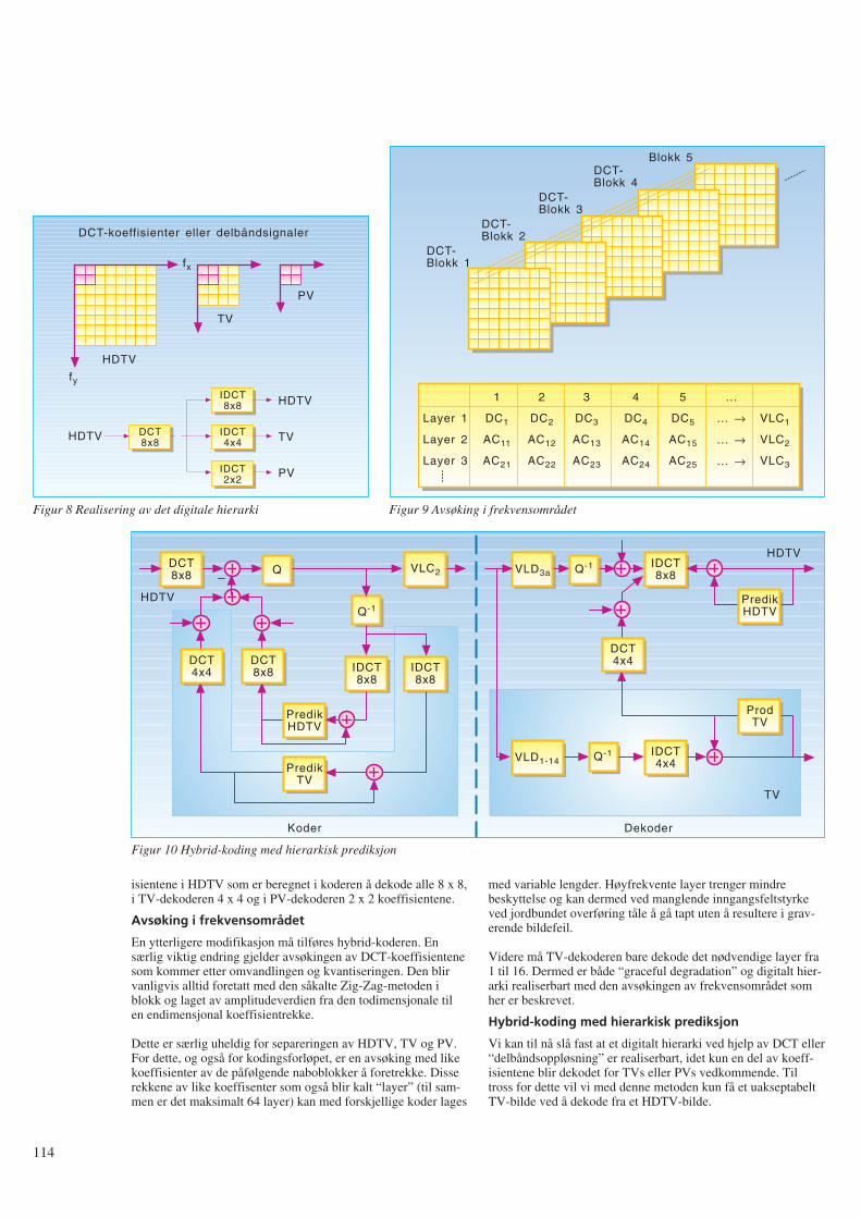
114
isientene i HDTV som er beregnet i koderen å dekode alle 8 x 8,i TV-dekoderen 4 x 4 og i PV-dekoderen 2 x 2 koeffisientene.
Avsøking i frekvensområdet
En ytterligere modifikasjon må tilføres hybrid-koderen. Ensærlig viktig endring gjelder avsøkingen av DCT-koeffisientenesom kommer etter omvandlingen og kvantiseringen. Den blirvanligvis alltid foretatt med den såkalte Zig-Zag-metoden iblokk og laget av amplitudeverdien fra den todimensjonale tilen endimensjonal koeffisientrekke.
Dette er særlig uheldig for separeringen av HDTV, TV og PV.For dette, og også for kodingsforløpet, er en avsøking med likekoeffisienter av de påfølgende naboblokker å foretrekke. Disserekkene av like koeffisenter som også blir kalt “layer” (til sam-men er det maksimalt 64 layer) kan med forskjellige koder lages
med variable lengder. Høyfrekvente layer trenger mindrebeskyttelse og kan dermed ved manglende inngangsfeltstyrkeved jordbundet overføring tåle å gå tapt uten å resultere i grav-erende bildefeil.
Videre må TV-dekoderen bare dekode det nødvendige layer fra1 til 16. Dermed er både “graceful degradation” og digitalt hier-arki realiserbart med den avsøkingen av frekvensområdet somher er beskrevet.
Hybrid-koding med hierarkisk prediksjon
Vi kan til nå slå fast at et digitalt hierarki ved hjelp av DCT eller“delbåndsoppløsning” er realiserbart, idet kun en del av koeff-isientene blir dekodet for TVs eller PVs vedkommende. Tiltross for dette vil vi med denne metoden kun få et uakseptabeltTV-bilde ved å dekode fra et HDTV-bilde.
PV
TV
HDTV
fx
fy
DCT-koeffisienter eller delbåndsignaler
IDCT8x8
IDCT4x4
IDCT2x2
HDTV
HDTV
TV
PV
DCT8x8
Figur 8 Realisering av det digitale hierarki
Blokk 5DCT-Blokk 4
DCT-Blokk 3
DCT-Blokk 2
DCT-Blokk 1
Layer 1
Layer 2
Layer 3
1
DC1
AC11
AC21
2
DC2
AC12
AC22
3
DC3
AC13
AC23
4
DC4
AC14
AC24
5
DC5
AC15
AC25
...
... →
... →
... →
VLC1
VLC2
VLC3
Figur 9 Avsøking i frekvensområdet
DCT8x8 Q VLC2
Q-1
IDCT8x8
IDCT8x8
PredikHDTV
PredikTV
DCT4x4
DCT8x8
HDTV
Koder
VLD3a Q-1 IDCT8x8
HDTV
DCT4x4
PredikHDTV
ProdTV
VLD1-14 Q-1 IDCT4x4
Dekoder
TV
Figur 10 Hybrid-koding med hierarkisk prediksjon
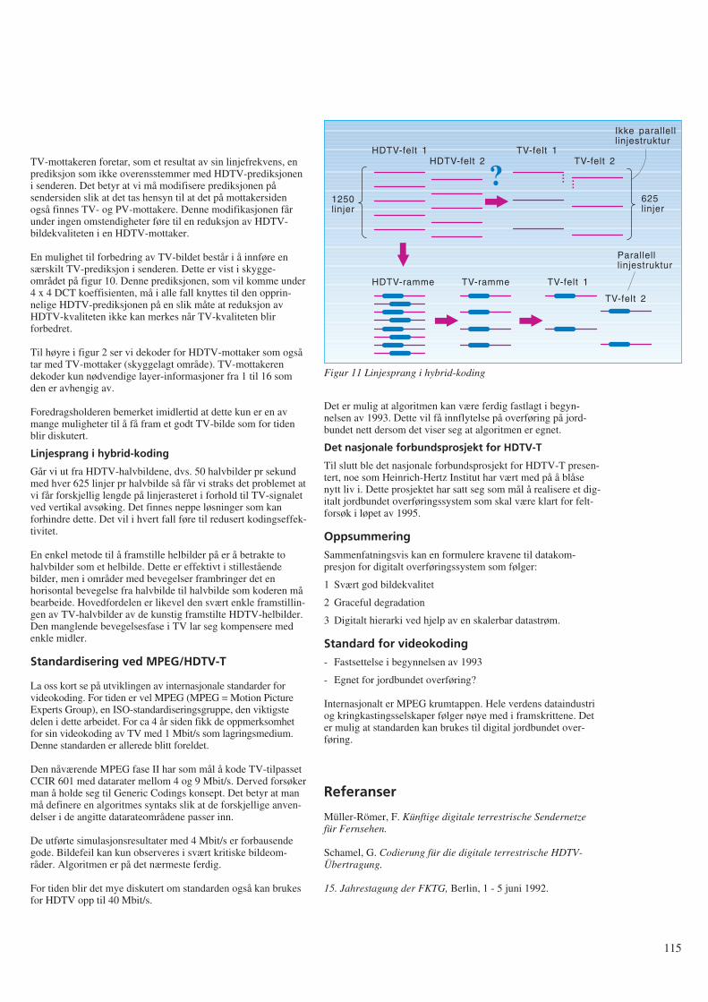
TV-mottakeren foretar, som et resultat av sin linjefrekvens, enprediksjon som ikke overensstemmer med HDTV-prediksjoneni senderen. Det betyr at vi må modifisere prediksjonen påsendersiden slik at det tas hensyn til at det på mottakersidenogså finnes TV- og PV-mottakere. Denne modifikasjonen fårunder ingen omstendigheter føre til en reduksjon av HDTV-bildekvaliteten i en HDTV-mottaker.
En mulighet til forbedring av TV-bildet består i å innføre ensærskilt TV-prediksjon i senderen. Dette er vist i skygge-området på figur 10. Denne prediksjonen, som vil komme under4 x 4 DCT koeffisienten, må i alle fall knyttes til den opprin-nelige HDTV-prediksjonen på en slik måte at reduksjon avHDTV-kvaliteten ikke kan merkes når TV-kvaliteten blirforbedret.
Til høyre i figur 2 ser vi dekoder for HDTV-mottaker som ogsåtar med TV-mottaker (skyggelagt område). TV-mottakerendekoder kun nødvendige layer-informasjoner fra 1 til 16 somden er avhengig av.
Foredragsholderen bemerket imidlertid at dette kun er en avmange muligheter til å få fram et godt TV-bilde som for tidenblir diskutert.
Linjesprang i hybrid-koding
Går vi ut fra HDTV-halvbildene, dvs. 50 halvbilder pr sekundmed hver 625 linjer pr halvbilde så får vi straks det problemet atvi får forskjellig lengde på linjerasteret i forhold til TV-signaletved vertikal avsøking. Det finnes neppe løsninger som kanforhindre dette. Det vil i hvert fall føre til redusert kodingseffek-tivitet.
En enkel metode til å framstille helbilder på er å betrakte tohalvbilder som et helbilde. Dette er effektivt i stilleståendebilder, men i områder med bevegelser frambringer det enhorisontal bevegelse fra halvbilde til halvbilde som koderen måbearbeide. Hovedfordelen er likevel den svært enkle framstillin-gen av TV-halvbilder av de kunstig framstilte HDTV-helbilder.Den manglende bevegelsesfase i TV lar seg kompensere medenkle midler.
Standardisering ved MPEG/HDTV-T
La oss kort se på utviklingen av internasjonale standarder forvideokoding. For tiden er vel MPEG (MPEG = Motion PictureExperts Group), en ISO-standardiseringsgruppe, den viktigstedelen i dette arbeidet. For ca 4 år siden fikk de oppmerksomhetfor sin videokoding av TV med 1 Mbit/s som lagringsmedium.Denne standarden er allerede blitt foreldet.
Den nåværende MPEG fase II har som mål å kode TV-tilpassetCCIR 601 med datarater mellom 4 og 9 Mbit/s. Derved forsøkerman å holde seg til Generic Codings konsept. Det betyr at manmå definere en algoritmes syntaks slik at de forskjellige anven-delser i de angitte datarateområdene passer inn.
De utførte simulasjonsresultater med 4 Mbit/s er forbausendegode. Bildefeil kan kun observeres i svært kritiske bildeom-råder. Algoritmen er på det nærmeste ferdig.
For tiden blir det mye diskutert om standarden også kan brukesfor HDTV opp til 40 Mbit/s.
Det er mulig at algoritmen kan være ferdig fastlagt i begyn-nelsen av 1993. Dette vil få innflytelse på overføring på jord-bundet nett dersom det viser seg at algoritmen er egnet.
Det nasjonale forbundsprosjekt for HDTV-T
Til slutt ble det nasjonale forbundsprosjekt for HDTV-T presen-tert, noe som Heinrich-Hertz Institut har vært med på å blåsenytt liv i. Dette prosjektet har satt seg som mål å realisere et dig-italt jordbundet overføringssystem som skal være klart for felt-forsøk i løpet av 1995.
Oppsummering
Sammenfatningsvis kan en formulere kravene til datakom-presjon for digitalt overføringssystem som følger:
1 Svært god bildekvalitet
2 Graceful degradation
3 Digitalt hierarki ved hjelp av en skalerbar datastrøm.
Standard for videokoding
- Fastsettelse i begynnelsen av 1993
- Egnet for jordbundet overføring?
Internasjonalt er MPEG krumtappen. Hele verdens dataindustriog kringkastingsselskaper følger nøye med i framskrittene. Deter mulig at standarden kan brukes til digital jordbundet over-føring.
Referanser
Müller-Römer, F. Künftige digitale terrestrische Sendernetzefür Fernsehen.
Schamel, G. Codierung für die digitale terrestrische HDTV-Übertragung.
15. Jahrestagung der FKTG, Berlin, 1 - 5 juni 1992.
115
1250linjer
?HDTV-felt 1
HDTV-felt 2TV-felt 1
TV-felt 2
...
...
Ikke parallelllinjestruktur
625linjer
Parallelllinjestruktur
TV-felt 1
TV-felt 2
HDTV-ramme TV-ramme
Figur 11 Linjesprang i hybrid-koding
116
Tale kontra data og videoA V I N G E V A B Ø
I St.prp. nr 1 (1992-1993) er Televerkets budsjett for 1993 lagtfram for Stortinget. Investeringsbudsjettet for 1993 er redusertmed 11,1 % i forhold til 1992 og forslaget lyder på 3,19 mil-liarder kroner. Investeringsmidlene må Televerket selv finan-siere. Investeringene skal gi Televerket inntekter i framtiden.Inntektene vil primært måtte komme fra trafikken som kundenegenererer. I St.prp. nr 1 er volumveksten for innenland-strafikken forventet å stige med ca 5 % pr år og utenland-strafikken med 8 % pr år fram til 1996. Det forventes en gjen-nomsnittlig økning av antall hovedabonnenter på ca 60 000 pr år(under 3 %). I tillegg vil antall mobiltelefonabonnenter øke,men det er ikke anslått noe tall for dette (usikkert pga. konkur-ransen). I tillegg til telefontrafikken vil data og video generereøkning av trafikken i årene framover. Denne trafikken trorTeleverket vil øke mye raskere enn telefontrafikken og planleg-ger derfor et bredbåndsnett for å ta denne. Men hva er det mansnakker om av kapasitet i forhold til telefontrafikken?
Vi skal se litt på dette:
Telefontrafikk
Det er 2,2 millioner abonnenter i Norge i 1992. Hvis vi antar atdet ringes 10 samtaler pr abonnent pr dag (flere brukere pr tele-fon) med 3 minutters varighet pr samtale, blir dette 2,2 ⋅ 106 ⋅ 3 ⋅10 = 66 millioner minutter/dag. Hver samtale krever 64 kbit/s ⋅2 (veis) = 128 kbit/s kapasitet.
Dette skulle da gi pr år: 66 ⋅ 106 ⋅ 128 ⋅ 103 ⋅ 60 ⋅ 365 = 185 ⋅ 1015 bit.(1015 = 1000 billioner)
Vi kan nå sammenlikne denne telefontrafikken med data- ogvideooverføring:
Flyreservasjoner
Det fløy totalt 16 millioner passasjerer innenlands og utenlandsfra Norge i 1990. Terminaler benyttes til reservasjonene. Antaat det kreves 30 bildeskjermer informasjon for hver reservasjon.Hvert skjermbilde inneholder 2500 tegn à 8 bit/tegn.
Dette gir da: 16 ⋅ 106 ⋅ 30 ⋅ 2500 ⋅ 8 = 0,01 ⋅ 1015 bit.
Dette var sørgelig lite sammenliknet med telefontrafikken.
Informasjonsarbeidere
Det er ca 2 millioner arbeidstakere i Norge. Vi antar at i framti-den blir alle informasjonsarbeidere som sitter foran sine termi-naler hele dagen. La oss si at de klarer å “fordøye” 200 skjerm-bilder pr time og hvert bilde inneholder 1000 tegn (bytes) infor-masjon (1 byte = 8 bit). Hvis de arbeider 8 timer pr dag 200 dager i året blir dette: 2 ⋅ 106 ⋅ 200 ⋅ 1000 ⋅ 8 ⋅ 8 ⋅ 200 = 5 ⋅ 1015 bit.
Dette er også lite sammenliknet med telefontrafikken.
Persondata
Det bor 4,2 millioner mennesker i Norge. La oss anta at av alledata samlet om oss (bankdata, forsikringsdata, folkeregisteret,osv), blir det sendt over telenettet 10 000 bytes om dagen.
Dette gir: 4,2 ⋅ 106 ⋅ 10 000 ⋅ 8 ⋅ 365 = 0,12 ⋅ 1015 bit.
Telefontrafikken vinner suverent!
Levende bilder
Dette må vel ta innersvingen på telefontrafikken? La oss anta atvi har 10 TV-kanaler som skal overføres over telenettet 8 timerpr dag. Uten noe særlig koding vil hver TV-kanal kreve 100Mbit/s.
Dette gir: 10 ⋅ 100 ⋅ 106 ⋅ 8 ⋅ 3600 ⋅ 365 = 10,5 ⋅ 1015 bit.
Dette er bare vel 5 % av telefontrafikken!
Aviser
Vi kan tenke oss at avisene i Norge kan bli distribuert gjennomtelenettet. Det er 150 aviser tilsluttet Avisenes Landsforening.Av disse kommer ca 60 ut daglig og 5 kommer også ut omsøndagen. Det er ca 50 aviser i tillegg som kommer ut én ellerto ganger i uken. La oss derfor anta 100 aviser pr dag. La ossanta at hver avis har gjennomsnittlig 20 sider. Skal også bildenei avisen overføres med kvalitet må det overføres minst 2 Mbit/spr side (kodet).
Dette gir: 100 ⋅ 20 ⋅ 2 ⋅ 106 ⋅ 365 = 0,001 ⋅ 1015 bit.
Selv om vi antar at det må retransmitteres pga. feil og korrek-sjoner, blir det et forsvinnende antall bit sammenliknet medtelefontrafikken.
Blader
Blader og tidsskrifter har mer bildestoff og krever derfor 12Mbit/s pr side. De inneholder også flere sider – ca 100 i gjen-nomsnitt. Ifølge Bladsentralen utgis ca 30 pr uke.
Dette skulle gi: 30 ⋅ 12 ⋅ 106 ⋅ 100 ⋅ 52 = 0,02 ⋅ 1015 bit.
Dette er heller ikke mye å skryte av!
Datamaskinoverføringer
La oss anta at det er 600 000 PC-er i Norge. La oss videre antaat disse hver skal ha overført 10 Mbyte med informasjon pr dag.
Dette gir: 600 000 ⋅ 10 ⋅ 106 ⋅ 8 ⋅ 365 = 18 ⋅ 1015 bit.
Dette er fremdeles bare knapt 10 % av telefontrafikken.
Videotelefon
La oss anta at 10 % av telefonabonnentene skaffer segvideotelefon. Da må takstene bli lave! Anta at videobildet er
621.39.05
komprimert til 64 kbit/s. Hvis de ringer like mye som den van-lige telefonabonnent, 10 ganger pr dag med 3 minutter varighetpr gang, blir dette:220 000 (10 %) ⋅ 10 ⋅ 3 ⋅ 64 ⋅ 103 ⋅ 2 ⋅ 60 ⋅ 365 = 18,5 ⋅ 1015 bit.
Det er ikke sikkert at abonnentene vil like å se hverandre hvergang de ringer, så behovet for kapasitet er optimistisk!
Sluttbemerkninger
Ringer vi i 3 minutter genererer vi 11,5 Mbit med informasjonover en 64 kbit/s linje. Dette tilsvarer 1 400 000 tegn!
Hvis vi summerer alle data- og videoinformasjoner ovenfor fårvi: 0,01 + 5 + 0,12 + 10,5 + 0,001 + 0,02 + 18 + 18,5 = 52,15 ⋅ 1015
bit.Dette er bare ca 1/3 av telefontrafikken!
Nesten 80 % av telefontrafikken er lokal trafikk. Fordeling avframtidig data- og videotrafikk mellom lokal- og fjerntrafikk erukjent.
Datatrafikken sendes som kjent i “bursts” (skurer). Kapasitets-behovet kan være stort i korte perioder. Dette vil forårsake atTeleverket må bygge ut “overkapasitet” som går på tomgangmesteparten av tiden. Dette er svært kostbart og er det nød-vendig? Både data- og telefontrafikk kan ved hjelp av kom-presjonsteknikk redusere kapasitetsbehovet. Telefonsamtalerkan i hvert fall overføres med 32 kbit/s uten at man merkerkvalitetsdegradasjon.
Det synes som om det er telefontrafikken som blir den heltdominerende inntekten for televerkene også i framtiden. Derformå transmisjonsnettene dimensjoneres etter veksten i tele-fontrafikken, og vi bør ikke bli lurt til overinvesteringer basertpå video- og dataprognoser som vil gi et nett som går på “tom-gang” mesteparten av tiden.
Vi må ved hjelp av takstpolitikken fordele trafikken over 24timer i døgnet slik at investeringene i nettet kan bli bedre utnyt-tet.
117
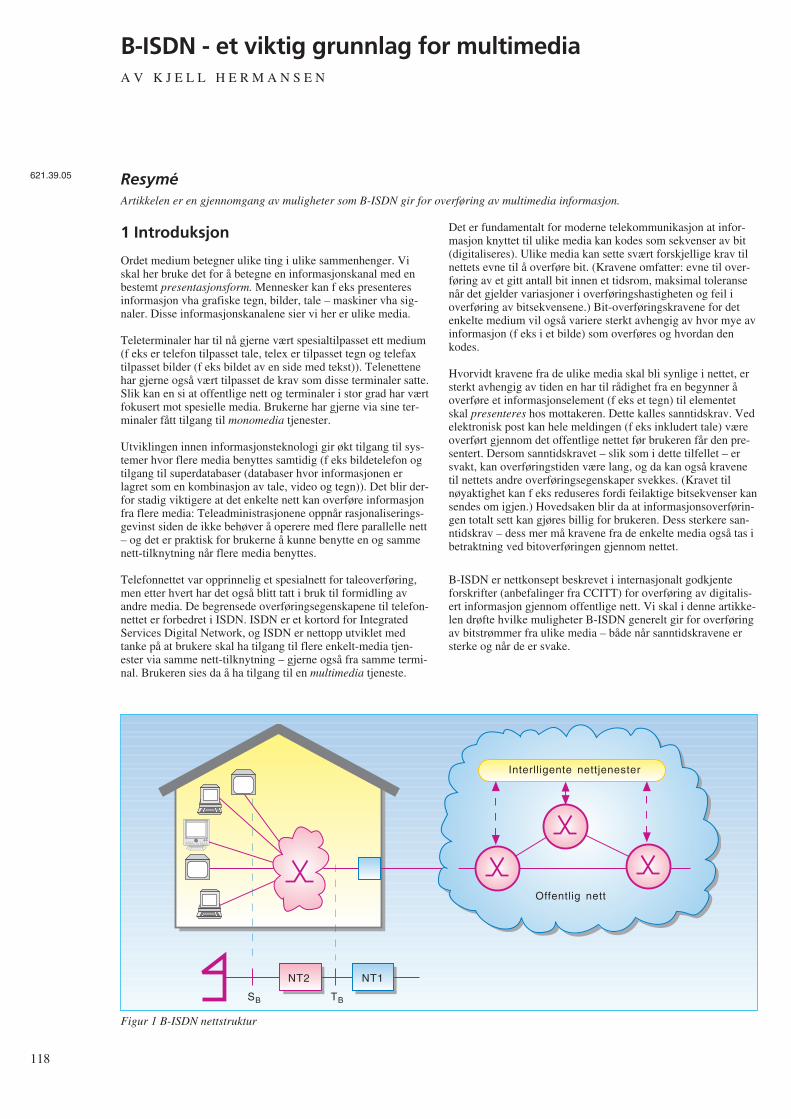
118
B-ISDN - et viktig grunnlag for multimediaA V K J E L L H E R M A N S E N
1 Introduksjon
Ordet medium betegner ulike ting i ulike sammenhenger. Viskal her bruke det for å betegne en informasjonskanal med enbestemt presentasjonsform. Mennesker kan f eks presenteresinformasjon vha grafiske tegn, bilder, tale – maskiner vha sig-naler. Disse informasjonskanalene sier vi her er ulike media.
Teleterminaler har til nå gjerne vært spesialtilpasset ett medium(f eks er telefon tilpasset tale, telex er tilpasset tegn og telefaxtilpasset bilder (f eks bildet av en side med tekst)). Telenettenehar gjerne også vært tilpasset de krav som disse terminaler satte.Slik kan en si at offentlige nett og terminaler i stor grad har værtfokusert mot spesielle media. Brukerne har gjerne via sine ter-minaler fått tilgang til monomedia tjenester.
Utviklingen innen informasjonsteknologi gir økt tilgang til sys-temer hvor flere media benyttes samtidig (f eks bildetelefon ogtilgang til superdatabaser (databaser hvor informasjonen erlagret som en kombinasjon av tale, video og tegn)). Det blir der-for stadig viktigere at det enkelte nett kan overføre informasjonfra flere media: Teleadministrasjonene oppnår rasjonaliserings-gevinst siden de ikke behøver å operere med flere parallelle nett– og det er praktisk for brukerne å kunne benytte en og sammenett-tilknytning når flere media benyttes.
Telefonnettet var opprinnelig et spesialnett for taleoverføring,men etter hvert har det også blitt tatt i bruk til formidling avandre media. De begrensede overføringsegenskapene til telefon-nettet er forbedret i ISDN. ISDN er et kortord for IntegratedServices Digital Network, og ISDN er nettopp utviklet medtanke på at brukere skal ha tilgang til flere enkelt-media tjen-ester via samme nett-tilknytning – gjerne også fra samme termi-nal. Brukeren sies da å ha tilgang til en multimedia tjeneste.
Det er fundamentalt for moderne telekommunikasjon at infor-masjon knyttet til ulike media kan kodes som sekvenser av bit(digitaliseres). Ulike media kan sette svært forskjellige krav tilnettets evne til å overføre bit. (Kravene omfatter: evne til over-føring av et gitt antall bit innen et tidsrom, maksimal toleransenår det gjelder variasjoner i overføringshastigheten og feil ioverføring av bitsekvensene.) Bit-overføringskravene for detenkelte medium vil også variere sterkt avhengig av hvor mye avinformasjon (f eks i et bilde) som overføres og hvordan denkodes.
Hvorvidt kravene fra de ulike media skal bli synlige i nettet, ersterkt avhengig av tiden en har til rådighet fra en begynner åoverføre et informasjonselement (f eks et tegn) til elementetskal presenteres hos mottakeren. Dette kalles sanntidskrav. Vedelektronisk post kan hele meldingen (f eks inkludert tale) væreoverført gjennom det offentlige nettet før brukeren får den pre-sentert. Dersom sanntidskravet – slik som i dette tilfellet – ersvakt, kan overføringstiden være lang, og da kan også kravenetil nettets andre overføringsegenskaper svekkes. (Kravet tilnøyaktighet kan f eks reduseres fordi feilaktige bitsekvenser kansendes om igjen.) Hovedsaken blir da at informasjonsoverførin-gen totalt sett kan gjøres billig for brukeren. Dess sterkere san-ntidskrav – dess mer må kravene fra de enkelte media også tas ibetraktning ved bitoverføringen gjennom nettet.
B-ISDN er nettkonsept beskrevet i internasjonalt godkjenteforskrifter (anbefalinger fra CCITT) for overføring av digitalis-ert informasjon gjennom offentlige nett. Vi skal i denne artikke-len drøfte hvilke muligheter B-ISDN generelt gir for overføringav bitstrømmer fra ulike media – både når sanntidskravene ersterke og når de er svake.
ResyméArtikkelen er en gjennomgang av muligheter som B-ISDN gir for overføring av multimedia informasjon.
Interlligente nettjenester
Offentlig nett
NT2 NT1
SB TB
Figur 1 B-ISDN nettstruktur
621.39.05
2 Nettkonsept for multimedia somomfatter offentlig og privat utstyr
B-ISDN anbefalingene omfatter både regler for utstyr somtilknyttes direkte til det offentlige nettet og utstyr som tilknyttesvia spredenett ute hos abonnentene. B-ISDN beskriver også deninterne nettoppbyggingen.
Figur 1 viser viktige elementer som inngår i B-ISDN – og enmer formell framstilling (referansemodell) for nett-tilknytnin-gen.
Via standardiserte grensesnitt (S-grensesnitt) får terminaler til-gang til B-ISDN nett-tjeneste. Spredenettet (NT2) ute hos bruk-eren kobles også til det offentlige nett via et standardisert grens-esnitt (T-grensesnitt). Det offentlige nett avsluttes med et utstyr(NT1) ute hos abonnenten som overvåker at informasjonsover-føringen skjer korrekt – og eventuelt omformer lavere lags pro-tokoller dersom protokollene på linja inn til abonnenten erforskjellig fra det standardiserte T-grensesnitt.
Både på de nevnte grensesnittene og internt i nettet benyttesAsynchronous Transfer Mode, ATM, som overføringsmetode.Viktige prinsipper er her at informasjonen overføres vha bit-sekvenser (celler) som alle har samme lengde, og at celleneogså inneholder informasjon om hvilken kanal som brukerinfor-masjonen tilhører. B-ISDN gir slik mulighet til å opprette flereinformasjonskanaler over samme fysiske linje.
En er for tiden opptatt med å definere S-grensesnittet i B-ISDN,slik at flere terminaler kan tilknyttes fra samme uttak i NT2. (Denenkelte terminallinje blir da å oppfatte som fellesmediet i et LAN,Local Area Network.) Men det reises også spørsmål omfellesmedium-løsninger vil være kosteffektive ved infor-masjonsoverføring med sterke sanntidskrav.
I tillegg til rene overføringstjenester vil brukeren i B-ISDN ogsåfå tilgang til intelligente nett-tjenester som f eks medflytting avabonnement.
3 Med B-ISDN vil investeringer i fiberkunne utnyttes til å møte utvidedeoverføringskrav fra multimedia
Narrowband ISDN, N-ISDN, er første generasjon av ISDN oggir abonnentene mulighet til å sette opp flere digitaleforbindelser over samme grensesnitt. Disse forbindelsene erbegrenset til 64 kbit/s, og denne kapasiteten beslaglegges i detutstyr i nettet som forbindelsen etableres gjennom. Abonnentenhar også tilgang til en signaleringskanal som kan benyttes til åkommunisere med nettet (f eks for å få satt opp forbindelser).Slik får abonnenten tilgang til flere informasjonskanaler hankan benytte samtidig.
Brukeren kan kommunisere med flere brukere samtidig gjen-nom kanalene ved å koble dem opp til spesielle noder (servere)og benytte en pakkeorientert nettprotokoll (f eks forbindelsesfrinettprotokoll) mot disse.
Den kapasitet som tilbys vanlige brukere er relativt begrenset:to 64 kbit/s kanaler og en 16 kbit/s signaleringskanal. (Ledig
kapasitet i signaleringskanalen kan også benyttes til datatrafikkvia en server.) Allerede i dag ser en at applikasjoner som kreverlevende bilder med god kvalitet – og høyhastighets datakommu-nikasjon, vil kreve høyere overføringskapasitet enn den som N-ISDN kan gi.
Neste generasjon av ISDN, B-ISDN, tar sikte på å gi abonnen-ten mulighet til å benytte flere kanaler (16 777 216) og gir hamstørre overføringskapasitet. Abonnenten kan enten få tilgang til135 631 kbit/s eller 542 526 kbit/s til sin informasjonsover-føring. (Asymmetrisk nett-tilkobling med 135 Mbit/s i den eneretning og 542 Mbit/s i den andre vil også kunne tilbys.) Dennekapasiteten kan abonnenten tilordne kanaler slik han ønsker.
Selv om abonnentene har mulighet til å benytte et utrolig antallkanaler og har en svært høy bitrate tilgjengelig, er det ikkeforutsetningen at alle abonnenter skal gjøre full bruk av dette.Hensikten har vært å sette et så høyt “tak” at flest mulig behovskulle kunne dekkes innenfor de rammer som settes av denteknologi vi har i dag. Tanken er at en slik skal kunne dra nytteav masseproduksjon av utstyr basert på veletablert komponent-teknologi for å lage framtidsrettet nett-tilkobling som etter hvertogså skal bli rimelig.
Riktignok vil B-ISDN kreve abonnentlinjer basert på optiskfiber – noe som vil bli kostbart å etablere. Men selv for å kunnetilby N-ISDN vil en omfattende utbedring av abonnentlinjervære nødvendig i mange land – inkludert Norge. Og også i dettetilfellet ser det ut til å kunne bli regningssvarende å benytte fib-erteknologi helt eller delvis. I de sentrale deler av nettet økesallerede i dag kapasiteten til transmisjonsutstyret ved at fiberte-knologi tas i bruk. B-ISDN gir på denne måte muligheter til åutnytte den ressurs som investeringen i fiber representerer, slikat abonnentene får en best mulig overføringstjeneste ut fra denkomponentteknologi en har tilgjengelig.
4 Overføringskrav fra ulike media kan“garanteres”
For brukeren er det oftest viktig å ha garanti for at han vil fåtilstrekkelig tjenestekvalitet når han starter mediasesjoner. Der-som f eks overføringen av en videosekvens skjemmes av stadigeforstyrrelser fra overføringsnettet, vil det kunne være mer forde-laktig å utsette overføringen eller starte en mindreressurskrevende sesjon.
For at brukeren skal kunne garanteres den overføringskvalitethan har behov for, er det en fordel at han inngår “kontrakt” mednettet om dette; og at bruker og nett overholder kontrakten.Mekanismene som sikrer at kontrakten blir overholdt i B-ISDN,er knyttet til oppretting av forbindelser.
Når en forbindelse skal opprettes, beskriver brukeren sine mini-mumskrav til informasjonsoverføringen til nettet (f eks over-føringskapasitet og maksimal variasjon i forsinkelsen, jitter).Nettet undersøker om det har tilstrekkelige ressurser til dette –sett på bakgrunn av eksisterende forbindelseskontrakter – ogbeslaglegger de ressurser som trengs i nettet for at den tjen-estekvalitet som brukeren har bedt om, kan sikres mensforbindelsen opprettholdes. Dersom netttet ikke har de nød-vendige ressurser tilgjengelig (f eks på grunn av at de er tilord-net andre forbindelser) avvises forespørselen. Brukeren får i så
119
120
fall beskjed om dette og kan ta stilling til om en mindrekrevende overføringskvalitet kan benyttes. (Nettet bør naturlignok dimensjoneres så rikelig at slike avslag ikke må gis for ofte– innen akseptable kostnadsrammer.)
Det er ikke meningen at den enkelte person skal ha detaljertkunnskap om sitt overføringsbehov. Ved bestilling avforbindelser som er direkte styrt av personer, kan det væreaktuelt å benytte standardiserte bærertjenester for media (f eksVideo A – hvor A angir en av et begrenset antall video-over-føringskvaliteter). Men i de fleste tilfeller vil nok informasjonom overføringsbehov lagres som en del av programvaren i ter-minalen for den enkelte applikasjon – kanskje da beskrevet vedminimumskravene for generelle overføringsparametre.
5 Taksering kan tilpasses krav fra ulikemedia
Ut fra den informasjon nettet får fra brukeren om de krav hanstiller til de enkelte informasjonskanaler, reserverer nettet nød-vendige ressurser til forbindelsene som opprettes gjennom nettet(f eks overføringskapasitet på den enkelte link og bufferplass isvitsjenodene). Det er denne ressursreservasjonen kunden børbetale for. For selv om kunden lar være å benytte ressursene iden grad han har beskrevet, vil nettet måtte holde dem i bered-skap for han.
B-ISDN gir likevel anledning til å redusere den totale over-føringskapasitet som må beslaglegges i nettet, ved å dra nytte avat informasjonsstrømmen på den enkelte kanal ikke er densamme hele tiden. (Ved kodet video f eks kan informasjon-sstrømmen reduseres når bildet ikke endres særlig.) Forutsetnin-gen er at kunden indikerer hvordan informasjonsstrømmen vilvariere.
Kanaler fra ulike brukere som er i “aktiv” periode kan internt inettet benytte overføringskapasitet fra kanaler som er i “rolig”periode. Informasjonsoverføringen kan slik gjøres rimeligere forkundene. Nettet kan spare ressurser når brukerens overførings-behov varierer ved enten å benytte statistisk multipleksing ellerved aktivering/deaktivering av kanalen.
Statistisk multipleksing kan benyttes i deler av nettet som formi-dler så mange kanaler at en ut fra statistiske beregninger kanfastslå at sannsynligheten for at alle kanaler skal topp-belasteutstyret samtidig er så liten at dette kan ses bort fra. (Kanalenebruker her samme ressurs – f eks det fysiske medium i en over-føringslink.) Den enkelte kanal kan da tildeles mindre kapasitetenn topp-belastningen tilsier – men kanskje noe mer enn enoppgitt gjennomsnittsbelastning for kanalen.
Første versjon av B-ISDNs bruker/nett-signalering vil ikke gikunden anledning til å beskrive informasjonsoverføringsbehovetfullstendig. Brukeren kan med den bare oppgi topp-belastningen– og nettet må reservere ressurser i henhold til dette. Det vil davære prisgunstig for kunden å utjevne informasjonsstrømmen itid mest mulig. Han vil da redusere toppbelastningen – og kanklare seg med en mindre ressurskrevende – og billigere – kanal.
Ved aktivering/deaktivering gir brukeren beskjed til nettet nårkanalen ikke skal formidle trafikk for en periode. Nettet kan dadisponere overføringskapasiteten til andre forbindelser inntilkanalen aktiveres igjen. Dersom nettet er avhengig av “til-feldigvis” å ha tilgjengelig kapasitet når kanalen skal aktiveres,vil kunden kunne risikere en uakseptabelt lang venting før nettetkan etterkomme aktiveringsforespørsel. Benyttes derimotressursene til overføring av trafikk med lavere prioritet (da helsttrafikk med lave sanntidskrav), vil nettet kunne overføre kapa-siteten tilbake til den deaktiverte kanalen straks brukeren bernettet om å få den aktivert igjen.
I motsetning til aktivering/deaktivering kan nettoperatørenbruke statistisk multipleksing uten at brukerens utstyr erinvolvert i dette. Nettoperatøren kan slik endre sin ressurstildel-ingsstrategi uten at brukeren behøver å gjøre noen tilpasning påsin side – bare han på forhånd oppgir hvilken toppbelastning oghvilken gjennomsnittlig belastning kanalen må kunne tåle.
Fordelen med aktivering og deaktivering framfor statistisk mul-tipleksing er at metoden kan benyttes selv når trafikkendringenepå kanalen er store sett i forhold til totaltrafikken, og en erheller ikke avhengig av at mange kanaler benytter fellesres-sursen. Teknikken vil bl a være nyttig i de tilfeller hvor bruk-eren på forhånd vet at han under multimedia-sesjonen vil fåbruk for informasjonskanaler på et senere tidspunkt – og at dethar liten hensikt å starte multimediasesjonen uten dem. Han kanda reservere kanaler slik at han er sikker på å ha dem tilgjen-gelig og holde dem deaktivert inntil han får bruk for dem – forslik å redusere sine overføringsutgifter. Avhengig av situasjonenvil derfor både statistisk multipleksing og aktivering/deaktiver-ing kunne benyttes – gjerne i kombinasjon – for å utnytte net-tressursene og gi abonnentene rimeligere informasjonsover-føring.
Fordelen med aktivering/deaktivering av en og samme kanal istedet for å opprette og nedkoble kanaler etter behov, er at bruk-eren kan få overføringskapasitet raskt tilgjengelig. Men for atkunden skal være sikker på å få aktivisert kanalen raskt, må somnevnt kanalen ha prioritet. Trafikkmessig vil det være lite åvinne på å la kanalen ha tilordnet sin kapasitet i deaktivert til-stand.
Det er foreløpig noe uklart om aktivering/deaktivering kan skjeraskere med signalering til nettet gjennom kanalene som over-fører informasjon mellom brukerne (refereres til ved denengelske termen “fast reservation”) eller om en like gjerne kanbenytte de aktiverings-/deaktiveringsmekanismer man uansettvil ha i signaleringskanalen. Kanskje vil det da også bli enklereå tildele deaktiverte ressurser til lavprioritets kanaler siden ensignalerer direkte mot mer sentrale deler av signaleringsnettet.
6 Multimedia informasjon kan overførespå en eller flere kanaler
Selv om B-ISDN gir muligheter for å tilpasse kanalene til debehov som de enkelte media stiller, vil det likevel være et kost-nadsspørsmål om det er mest hensiktsmessig for kunden åopprette flere kanaler gjennom det offentlige nettet mellom tomultimedia-stasjoner, eller om alle enkeltmedia skal kommunis-
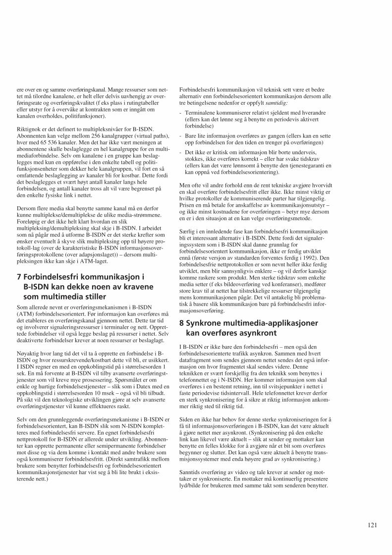
ere over en og samme overføringskanal. Mange ressurser som net-tet må tilordne kanalene, er helt eller delvis uavhengig av over-føringsrate og overføringskvalitet (f eks plass i rutingtabellereller utstyr for å overvåke at kontrakten som er inngått omkanalen overholdes, politifunksjoner).
Riktignok er det definert to multipleksnivåer for B-ISDN.Abonnenten kan velge mellom 256 kanalgrupper (virtual paths),hver med 65 536 kanaler. Men det har ikke vært meningen atabonnentene skulle beslaglegge en hel kanalgruppe for en multi-mediaforbindelse. Selv om kanalene i en gruppe kan beslag-legges med kun en oppførelse i den enkelte tabell og politi-funksjonsenheter som dekker hele kanalgruppen, vil fort en såomfattende beslaglegging av kanaler bli for kostbar. Dette fordidet beslaglegges et svært høyt antall kanaler langs heleforbindelsen, og antall kanaler tross alt vil være begrenset påden enkelte fysiske link i nettet.
Dersom flere media skal benytte samme kanal må en derforkunne multiplekse/demultiplekse de ulike media-strømmene.Foreløpig er det ikke helt klart hvordan en slikmultipleksing/demultipleksing skal skje i B-ISDN. I arbeidetsom nå pågår med å utforme B-ISDN er det sterke krefter somønsker eventuelt å skyve slik multipleksing opp til høyere pro-tokoll-lag (over de karakteristiske B-ISDN informasjonsover-føringsprotokollene (over adapsjonslaget)) – dersom multi-pleksingen ikke kan skje i ATM-laget.
7 Forbindelsesfri kommunikasjon i B-ISDN kan dekke noen av kravenesom multimedia stiller
Som allerede nevnt er overføringsmekanismen i B-ISDN(ATM) forbindelsesorientert. Før informasjon kan overføres mådet etableres en overføringskanal gjennom nettet. Dette tar tidog involverer signaleringsressurser i terminaler og nett. Oppret-tede forbindelser vil også legge beslag på ressurser i nettet. Selvdeaktiverte forbindelser krever at noen ressurser er beslaglagt.
Nøyaktig hvor lang tid det vil ta å opprette en forbindelse i B-ISDN og hvor ressurskrevende/kostbart dette vil bli, er usikkert.I ISDN regner en med en oppkoblingstid på i størrelsesorden 1sek. En må forvente at B-ISDN vil tilby avanserte overføringst-jenester som vil kreve mye prosessering. Spørsmålet er omenkle og hurtige forbindelsestjenester – slik som i Datex med enoppkoblingstid i størrelsesorden 10 msek – også vil bli tilbudt.På sikt vil den teknologiske utviklingen gjøre at selv avanserteoverføringstjenester vil kunne effektueres raskt.
Selv om den grunnleggende overføringsmekanisme i B-ISDN erforbindelsesorientert, kan B-ISDN slik som N-ISDN komplet-teres med forbindelsesfri servere. En egnet forbindelsesfrinettprotokoll for B-ISDN er allerede under utvikling. Abonnen-ter kan opprette permanente eller semipermanente forbindelsermot disse og via dem komme i kontakt med andre brukere somogså kommuniserer forbindelsesfritt. (Direkt samtrafikk mellombrukere som benytter forbindelsesfri og forbindelsesorientertkommunikasjonstjenester har vist seg å bli lite brukt i eksis-terende nett.)
Forbindelsesfri kommunikasjon vil teknisk sett være et bedrealternativ enn forbindelsesorientert kommunikasjon dersom alletre betingelsene nedenfor er oppfylt samtidig:
- Terminalene kommuniserer relativt sjeldent med hverandre(ellers kan det lønne seg å benytte en periodevis aktivertforbindelse)
- Bare lite informasjon overføres av gangen (ellers kan en setteopp forbindelsen for den tiden en trenger på overføringen)
- Det ikke er kritisk om informasjon blir borte underveis,stokkes, ikke overføres korrekt – eller har svake tidskrav(ellers kan det være lønnsomt å benytte den tjenestegaranti enkan oppnå ved forbindelsesorientering).
Men ofte vil andre forhold enn de rent tekniske avgjøre hvorvidten skal overføre forbindelsesfritt eller ikke. Ikke minst viktig erhvilke protokoller de kommuniserende parter har tilgjengelig.Prisen en må betale for anskaffelse av kommunikasjonsutstyr –og ikke minst kostnadene for overføringen – betyr mye dersomen er i den situasjon at en kan velge overføringsmetode.
Særlig i en innledende fase kan forbindelsesfri kommunikasjonbli et interessant alternativ i B-ISDN. Dette fordi det signaler-ingssystem som i B-ISDN skal danne grunnlag forforbindelsesorientert kommunikasjon, ikke er ferdig utvikletennå (første versjon av standarden forventes ferdig i 1992). Denforbindelsesfrie nettprotokollen er som nevnt heller ikke ferdigutviklet, men blir sannsynligvis enklere – og vil derfor kanskjekomme raskere som produkt. Men sterke tidskrav som enkeltemedia setter (f eks bildeoverføring ved konferanser), medførerstore krav til at nettet har tilstrekkelige ressurser tilgjengeligmens kommunikasjonen pågår. Det vil antakelig bli problema-tisk å basere slik kommunikasjon bare på forbindelsesfri infor-masjonsoverføring.
8 Synkrone multimedia-applikasjonerkan overføres asynkront
I B-ISDN er ikke bare den forbindelsesfri – men også denforbindelsesorienterte trafikk asynkron. Sammen med hvertdatafragment som sendes gjennom nettet sendes det også infor-masjon om hvor fragmentet skal sendes videre. Denneteknikken er svært forskjellig fra den teknikk som benyttes itelefonnettet og i N-ISDN. Her kommer informasjon som skaloverføres i en bestemt retning, inn til svitsjepunkter i nettet ifaste periodevise tidsintervall. Hele telefonnettet krever derforen sterk synkronisering for å sikre at riktig informasjon ankom-mer riktig sted til riktig tid.
Siden en ikke har behov for denne sterke synkroniseringen for åfå til informasjonsoverføringen i B-ISDN, kan det være aktueltå gjøre nettet mer asynkront. (Synkronisering på den enkeltelink kan likevel være aktuelt – slik at sender og mottaker kanbenytte en felles klokke for å avgjøre når et bit som overføresbegynner og slutter. Det kan også være aktuelt å benytte trans-misjonssystemer med enda høyere grad av synkronisering.)
Sanntids overføring av video og tale krever at sender og mot-taker er synkroniserte. En mottaker må kontinuerlig presenterelyd/bilde for brukeren med samme takt som senderen benytter.
121
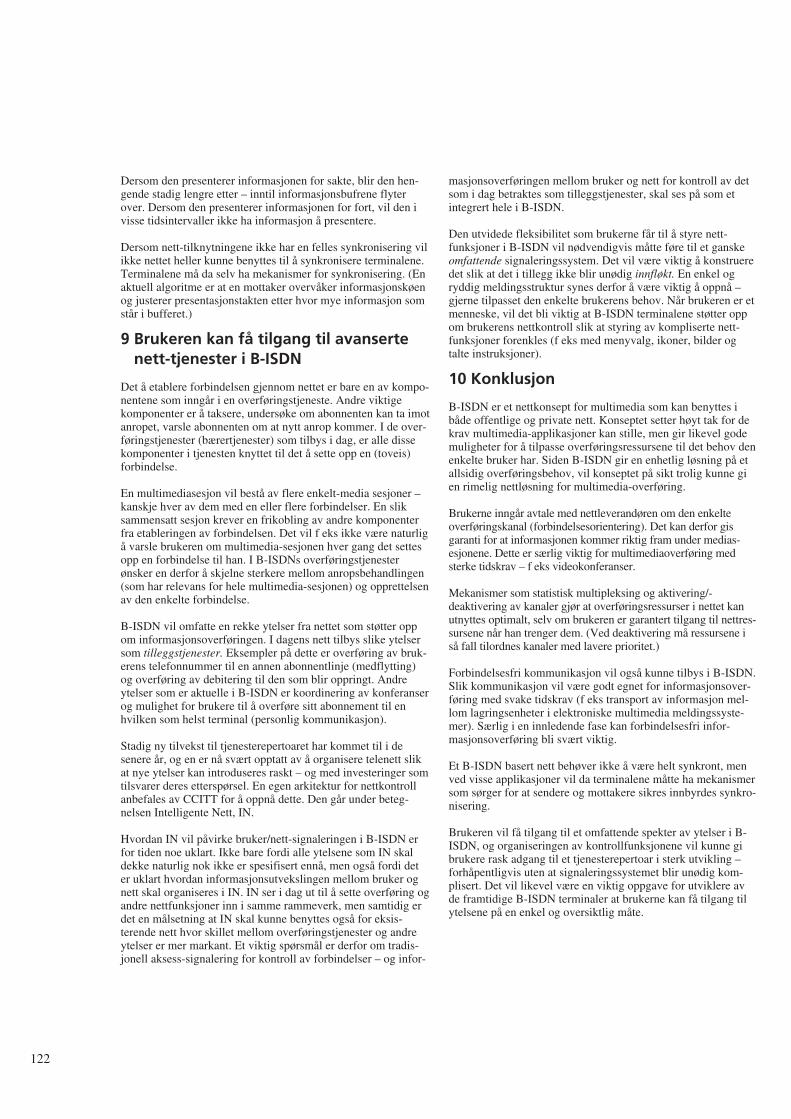
122
Dersom den presenterer informasjonen for sakte, blir den hen-gende stadig lengre etter – inntil informasjonsbufrene flyterover. Dersom den presenterer informasjonen for fort, vil den ivisse tidsintervaller ikke ha informasjon å presentere.
Dersom nett-tilknytningene ikke har en felles synkronisering vilikke nettet heller kunne benyttes til å synkronisere terminalene.Terminalene må da selv ha mekanismer for synkronisering. (Enaktuell algoritme er at en mottaker overvåker informasjonskøenog justerer presentasjonstakten etter hvor mye informasjon somstår i bufferet.)
9 Brukeren kan få tilgang til avansertenett-tjenester i B-ISDN
Det å etablere forbindelsen gjennom nettet er bare en av kompo-nentene som inngår i en overføringstjeneste. Andre viktigekomponenter er å taksere, undersøke om abonnenten kan ta imotanropet, varsle abonnenten om at nytt anrop kommer. I de over-føringstjenester (bærertjenester) som tilbys i dag, er alle dissekomponenter i tjenesten knyttet til det å sette opp en (toveis)forbindelse.
En multimediasesjon vil bestå av flere enkelt-media sesjoner –kanskje hver av dem med en eller flere forbindelser. En sliksammensatt sesjon krever en frikobling av andre komponenterfra etableringen av forbindelsen. Det vil f eks ikke være naturligå varsle brukeren om multimedia-sesjonen hver gang det settesopp en forbindelse til han. I B-ISDNs overføringstjenesterønsker en derfor å skjelne sterkere mellom anropsbehandlingen(som har relevans for hele multimedia-sesjonen) og opprettelsenav den enkelte forbindelse.
B-ISDN vil omfatte en rekke ytelser fra nettet som støtter oppom informasjonsoverføringen. I dagens nett tilbys slike ytelsersom tilleggstjenester. Eksempler på dette er overføring av bruk-erens telefonnummer til en annen abonnentlinje (medflytting)og overføring av debitering til den som blir oppringt. Andreytelser som er aktuelle i B-ISDN er koordinering av konferanserog mulighet for brukere til å overføre sitt abonnement til enhvilken som helst terminal (personlig kommunikasjon).
Stadig ny tilvekst til tjenesterepertoaret har kommet til i desenere år, og en er nå svært opptatt av å organisere telenett slikat nye ytelser kan introduseres raskt – og med investeringer somtilsvarer deres etterspørsel. En egen arkitektur for nettkontrollanbefales av CCITT for å oppnå dette. Den går under beteg-nelsen Intelligente Nett, IN.
Hvordan IN vil påvirke bruker/nett-signaleringen i B-ISDN erfor tiden noe uklart. Ikke bare fordi alle ytelsene som IN skaldekke naturlig nok ikke er spesifisert ennå, men også fordi deter uklart hvordan informasjonsutvekslingen mellom bruker ognett skal organiseres i IN. IN ser i dag ut til å sette overføring ogandre nettfunksjoner inn i samme rammeverk, men samtidig erdet en målsetning at IN skal kunne benyttes også for eksis-terende nett hvor skillet mellom overføringstjenester og andreytelser er mer markant. Et viktig spørsmål er derfor om tradis-jonell aksess-signalering for kontroll av forbindelser – og infor-
masjonsoverføringen mellom bruker og nett for kontroll av detsom i dag betraktes som tilleggstjenester, skal ses på som etintegrert hele i B-ISDN.
Den utvidede fleksibilitet som brukerne får til å styre nett-funksjoner i B-ISDN vil nødvendigvis måtte føre til et ganskeomfattende signaleringssystem. Det vil være viktig å konstrueredet slik at det i tillegg ikke blir unødig innfløkt. En enkel ogryddig meldingsstruktur synes derfor å være viktig å oppnå –gjerne tilpasset den enkelte brukerens behov. Når brukeren er etmenneske, vil det bli viktig at B-ISDN terminalene støtter oppom brukerens nettkontroll slik at styring av kompliserte nett-funksjoner forenkles (f eks med menyvalg, ikoner, bilder ogtalte instruksjoner).
10 Konklusjon
B-ISDN er et nettkonsept for multimedia som kan benyttes ibåde offentlige og private nett. Konseptet setter høyt tak for dekrav multimedia-applikasjoner kan stille, men gir likevel godemuligheter for å tilpasse overføringsressursene til det behov denenkelte bruker har. Siden B-ISDN gir en enhetlig løsning på etallsidig overføringsbehov, vil konseptet på sikt trolig kunne gien rimelig nettløsning for multimedia-overføring.
Brukerne inngår avtale med nettleverandøren om den enkelteoverføringskanal (forbindelsesorientering). Det kan derfor gisgaranti for at informasjonen kommer riktig fram under medias-esjonene. Dette er særlig viktig for multimediaoverføring medsterke tidskrav – f eks videokonferanser.
Mekanismer som statistisk multipleksing og aktivering/-deaktivering av kanaler gjør at overføringsressurser i nettet kanutnyttes optimalt, selv om brukeren er garantert tilgang til nettres-sursene når han trenger dem. (Ved deaktivering må ressursene iså fall tilordnes kanaler med lavere prioritet.)
Forbindelsesfri kommunikasjon vil også kunne tilbys i B-ISDN.Slik kommunikasjon vil være godt egnet for informasjonsover-føring med svake tidskrav (f eks transport av informasjon mel-lom lagringsenheter i elektroniske multimedia meldingssyste-mer). Særlig i en innledende fase kan forbindelsesfri infor-masjonsoverføring bli svært viktig.
Et B-ISDN basert nett behøver ikke å være helt synkront, menved visse applikasjoner vil da terminalene måtte ha mekanismersom sørger for at sendere og mottakere sikres innbyrdes synkro-nisering.
Brukeren vil få tilgang til et omfattende spekter av ytelser i B-ISDN, og organiseringen av kontrollfunksjonene vil kunne gibrukere rask adgang til et tjenesterepertoar i sterk utvikling –forhåpentligvis uten at signaleringssystemet blir unødig kom-plisert. Det vil likevel være en viktig oppgave for utviklere avde framtidige B-ISDN terminaler at brukerne kan få tilgang tilytelsene på en enkel og oversiktlig måte.
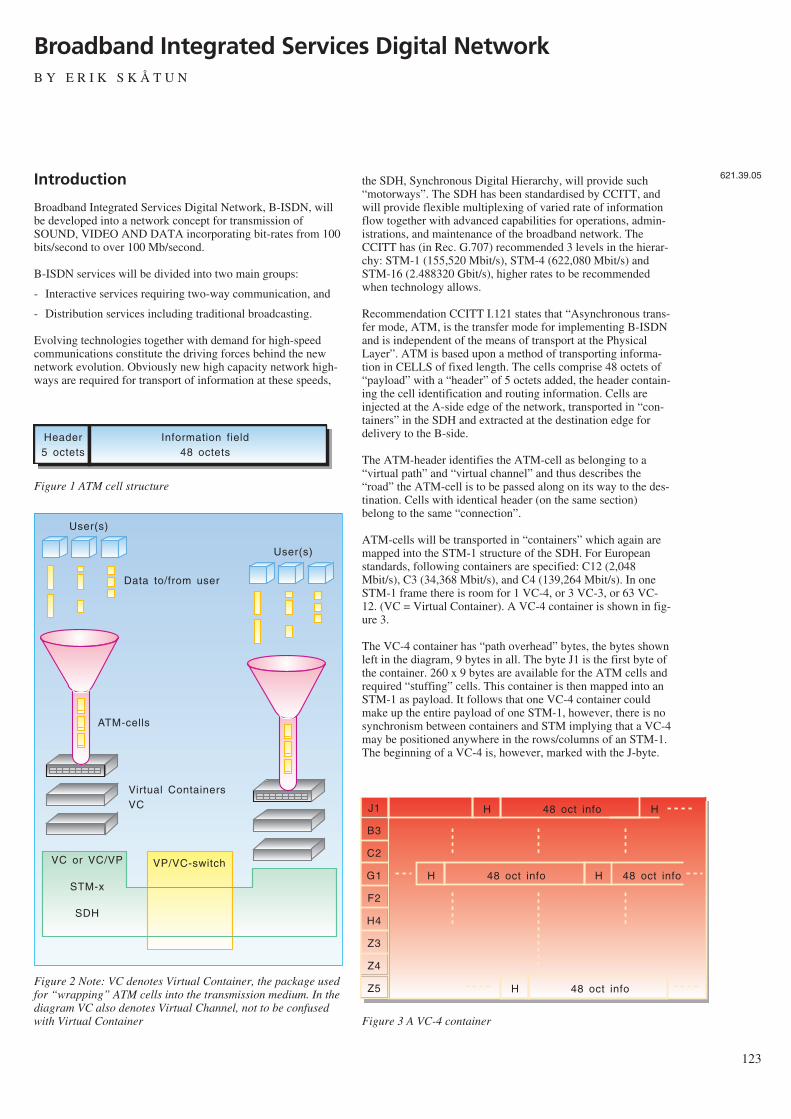
Introduction
Broadband Integrated Services Digital Network, B-ISDN, willbe developed into a network concept for transmission ofSOUND, VIDEO AND DATA incorporating bit-rates from 100bits/second to over 100 Mb/second.
B-ISDN services will be divided into two main groups:
- Interactive services requiring two-way communication, and
- Distribution services including traditional broadcasting.
Evolving technologies together with demand for high-speedcommunications constitute the driving forces behind the newnetwork evolution. Obviously new high capacity network high-ways are required for transport of information at these speeds,
the SDH, Synchronous Digital Hierarchy, will provide such“motorways”. The SDH has been standardised by CCITT, andwill provide flexible multiplexing of varied rate of informationflow together with advanced capabilities for operations, admin-istrations, and maintenance of the broadband network. TheCCITT has (in Rec. G.707) recommended 3 levels in the hierar-chy: STM-1 (155,520 Mbit/s), STM-4 (622,080 Mbit/s) andSTM-16 (2.488320 Gbit/s), higher rates to be recommendedwhen technology allows.
Recommendation CCITT I.121 states that “Asynchronous trans-fer mode, ATM, is the transfer mode for implementing B-ISDNand is independent of the means of transport at the PhysicalLayer”. ATM is based upon a method of transporting informa-tion in CELLS of fixed length. The cells comprise 48 octets of“payload” with a “header” of 5 octets added, the header contain-ing the cell identification and routing information. Cells areinjected at the A-side edge of the network, transported in “con-tainers” in the SDH and extracted at the destination edge fordelivery to the B-side.
The ATM-header identifies the ATM-cell as belonging to a“virtual path” and “virtual channel” and thus describes the“road” the ATM-cell is to be passed along on its way to the des-tination. Cells with identical header (on the same section)belong to the same “connection”.
ATM-cells will be transported in “containers” which again aremapped into the STM-1 structure of the SDH. For Europeanstandards, following containers are specified: C12 (2,048Mbit/s), C3 (34,368 Mbit/s), and C4 (139,264 Mbit/s). In oneSTM-1 frame there is room for 1 VC-4, or 3 VC-3, or 63 VC-12. (VC = Virtual Container). A VC-4 container is shown in fig-ure 3.
The VC-4 container has “path overhead” bytes, the bytes shownleft in the diagram, 9 bytes in all. The byte J1 is the first byte ofthe container. 260 x 9 bytes are available for the ATM cells andrequired “stuffing” cells. This container is then mapped into anSTM-1 as payload. It follows that one VC-4 container couldmake up the entire payload of one STM-1, however, there is nosynchronism between containers and STM implying that a VC-4may be positioned anywhere in the rows/columns of an STM-1.The beginning of a VC-4 is, however, marked with the J-byte.
123
Broadband Integrated Services Digital NetworkB Y E R I K S K Å T U N
621.39.05
Header5 octets
Information field48 octets
Figure 1 ATM cell structure
User(s)
Data to/from user
VP/VC-switch
User(s)
ATM-cells
Virtual ContainersVC
VC or VC/VP
STM-x
SDH
Figure 2 Note: VC denotes Virtual Container, the package usedfor “wrapping” ATM cells into the transmission medium. In thediagram VC also denotes Virtual Channel, not to be confusedwith Virtual Container
48 oct infoJ1
B3
C2
G1
F2
H4
Z3
Z4
Z5
H H
48 oct infoH H 48 oct info
48 oct infoH
Figure 3 A VC-4 container
The position of this J-byte will be identified by the AU-pointersin figure 4 (the bytes preceding the J-byte belonging to anotherC-4 container with its remaining information in the previousSTM-1 frame). The diagram for an STM-1 frame is shown infigure 4.
An STM-1 is either a sole individual element of a transmissionsection or it is multiplexed into higher order STM. The sectionoverhead bytes is divided into two parts: The ROSH = regenera-tor section overhead and the MSOH = the multiplexer sectionoverhead, in addition to the AU-pointers. The significance ofthe various bytes are:
A1, A2: Frame sync. B1, B2: Fault supervision C1: STM identifierD1-D12: Data channels E1, E2: Service channels, speechF1: User channelK1, K2: Automatic protection switching. Some channels are
reserved for national use, nu, others are unused = unor spare Z1, Z2.
B-ISDN Architecture
The major characteristics of ATM are:
- Use of fixed length cell for information transfer, 48 octets oflength
- Identification of each communication unit by cell header, 5octets long.
An ATM label in the header is structured into two fields foridentification of virtual channel (VC) and virtual path (VP).
124
RSOH
AU-pointers
MSOH
3
1
5
9 bytes 261 bytes
STM-1 payload
Figure 4 Diagram for a STM-1 frame
A1
B1
D1
B2
D4
D7
10
Z1
A1
ms
ms
B2
un
un
un
Z1
A1
ms
ms
B2
un
un
un
Z1
A2
E1
D2
K1
D5
D8
11
Z2
A2
un
un
un
un
un
un
Z2
A2
un
un
un
un
un
un
Z2
C1
F1
D3
K2
D6
D9
12
E2
nu
nu
nu
un
un
un
un
nu
nu
nu
nu
un
un
un
un
nu
STM-1-
payload
AU-pointers
Figure 5 STM-1 section overhead (10, 11 and 12 = D10, D11,D12)
VC
VC
VC
Transmission
path
VP
VP
VP
VP
VP
VP
VC
VC
VC
Figure 6 Relations between transmission path, virtual path andvirtual channel
VC
VP VP VP VP
VP ATMswitch
VP/VC ATMswitch
VC VC
Figure 7 Virtual path switching
VC1
VP 1
VP 2
VP 3
VP 4
VP 5
VP 6
3
45
9
6
9
6
45
1
3
VC
VP-switch
Figure 8 Virtual channel/virtual path switching
VC1
VP a
VP b
VP c
VP f
VP d
VP e
2
12
12
1
2
VP-switch
VP g
3
4
12
VP-switch
VC
Figure 9 Virtual channel/virtual path switching
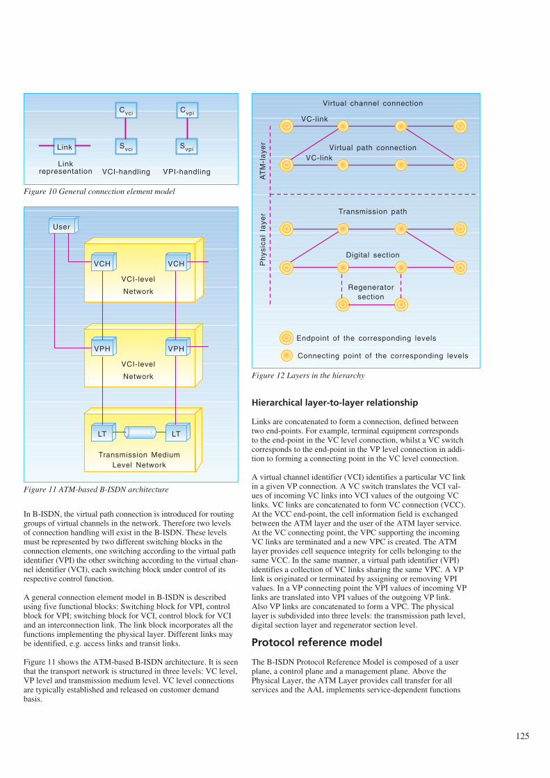
In B-ISDN, the virtual path connection is introduced for routinggroups of virtual channels in the network. Therefore two levelsof connection handling will exist in the B-ISDN. These levelsmust be represented by two different switching blocks in theconnection elements, one switching according to the virtual pathidentifier (VPI) the other switching according to the virtual chan-nel identifier (VCI), each switching block under control of itsrespective control function.
A general connection element model in B-ISDN is describedusing five functional blocks: Switching block for VPI, controlblock for VPI; switching block for VCI, control block for VCIand an interconnection link. The link block incorporates all thefunctions implementing the physical layer. Different links maybe identified, e.g. access links and transit links.
Figure 11 shows the ATM-based B-ISDN architecture. It is seenthat the transport network is structured in three levels: VC level,VP level and transmission medium level. VC level connectionsare typically established and released on customer demandbasis.
Hierarchical layer-to-layer relationship
Links are concatenated to form a connection, defined betweentwo end-points. For example, terminal equipment correspondsto the end-point in the VC level connection, whilst a VC switchcorresponds to the end-point in the VP level connection in addi-tion to forming a connecting point in the VC level connection.
A virtual channel identifier (VCI) identifies a particular VC linkin a given VP connection. A VC switch translates the VCI val-ues of incoming VC links into VCI values of the outgoing VClinks. VC links are concatenated to form VC connection (VCC).At the VCC end-point, the cell information field is exchangedbetween the ATM layer and the user of the ATM layer service.At the VC connecting point, the VPC supporting the incomingVC links are terminated and a new VPC is created. The ATMlayer provides cell sequence integrity for cells belonging to thesame VCC. In the same manner, a virtual path identifier (VPI)identifies a collection of VC links sharing the same VPC. A VPlink is originated or terminated by assigning or removing VPIvalues. In a VP connecting point the VPI values of incoming VPlinks are translated into VPI values of the outgoing VP link.Also VP links are concatenated to form a VPC. The physicallayer is subdivided into three levels: the transmission path level,digital section layer and regenerator section level.
Protocol reference model
The B-ISDN Protocol Reference Model is composed of a userplane, a control plane and a management plane. Above thePhysical Layer, the ATM Layer provides call transfer for allservices and the AAL implements service-dependent functions
125
Link
Linkrepresentation
Cvci
Svci
Cvpi
Svpi
VCI-handling VPI-handling
Figure 10 General connection element model
VCH VCH
VCI-level
Network
VPH VPH
VCI-level
Network
LT LT
Transmission MediumLevel Network
User
Figure 11 ATM-based B-ISDN architecture
VC-link
Virtual channel connection
VC-linkVirtual path connection
Transmission path
Digital section
Regeneratorsection
AT
M-l
aye
rP
hys
ica
lla
yer
Endpoint of the corresponding levels
Connecting point of the corresponding levels
Figure 12 Layers in the hierarchy
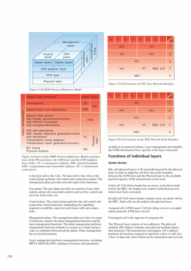
to the layer above the AAL. The layer above the AAL in thecontrol plane performs call control and connection control. Themanagement plane provides network supervision functions.
User plane: The user plane provides for transfer of user infor-mation, along with associated controls such as flow control andrecovery from errors, etc.
Control plane: The control plane performs the call control andconnection control functions; undertaking the signallingrequired to establish, supervise and release calls and connec-tions.
Management plane: The management plane provides two typesof functions, namely the plane management functions and thelayer management functions. The plane management performsmanagement functions related to a system as a whole and pro-vides co-ordination between all the planes. Plane managementhas no layered structure.
Layer management performs management functions, includingMETA-SIGNALLING, relating to resources and parameters
residing in its protocol entities. Layer management also handlesthe OAM-information flows specific to the layer concerned.
Functions of individual layers
Some terms:
Idle cell (physical layer): Cell inserted/extracted by the physicallayer in order to adapt the cell flow rate at the boundarybetween the ATM-layer and the Physical-layer to the availablepayload capacity of the transmission system used.
Valid cell: Cell whose header has no errors, or has been modi-fied by the HEC, the header error control verification process(errors have been corrected).
Invalid cell: Cell whose header contains errors not dealt with bythe HEC. Such cells are discarded at the physical layer.
Assigned cell (ATM-Layer): Cell providing service to an appli-cation using the ATM-layer service.
Unassigned cell is the opposite of assigned cell.
The Physical layer consists of two sublayers. The physicalmedium, PM sublayer includes only physical medium depen-dent functions. The transmission convergence (TC) sublayerperforms all functions required to transform a flow of cells intoa flow of data units (bits) which can be transmitted and received
126
Higher layers
ATM adaption layer
ATM layer
Physical layer
Controlplane
Pla
ne
ma
na
ge
me
nt
Userplane
La
yer
ma
na
ge
me
nt
Managementplane
Higher layers
Figure 13 B-ISDN Protocol Reference Model
Convergence
Higher layer functions
Segmentation and reassembly
Generic flow controlCell header generation/extractionCell VPI/VCI translationCell multiplex/demultiplex
Cell rate decouplingHEC header sequence generation/verificCell delineationTransmission frame adaptionTransmission frame generation/recovery
BIT timingPhysical medium
Higher layers
CS
SARAAL
ATM
TC
PM
Ph
ysic
al
laye
r
La
yer
ma
na
ge
me
nt
Figure 14 Layers of the PRM (Protocol Reference Model) and func-tions of the Physical layer, the ATM layer and the ATM Adaptionlayer (AAL). CS = convergence sublayer, PM = physical medium,SAR = segmentation and reassembly sublayer, TC = transmissionconvergence
bitoct12345678
1
2
3
4
5
VPIGFC
VCIVPI
VCI
VCI PT RES CLP
HEC
bitoct12345678
1
2
3
4
5
VPI
VCIVPI
VCI
VCI PT RES CLP
HEC
Figure 15 Cell structure at UNI, User Network Interface
Figure 16 Cell structure at the NNI, Network Node Interface
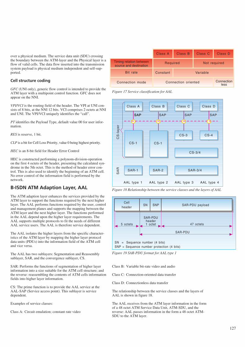
over a physical medium. The service data unit (SDU) crossingthe boundary between the ATM-layer and the Physical layer is aflow of valid cells. The data flow inserted into the transmissionsystem payload is physical medium independent and self-sup-ported.
Cell structure coding
GFC (UNI only), generic flow control is intended to provide theATM layer with a multipoint control function. GFC does notappear on the NNI.
VPI/VCI is the routing field of the header. The VPI at UNI con-sists of 8 bits, at the NNI 12 bits. VCI comprises 2 octets at NNIand UNI. The VPI/VCI uniquely identifies the “call”.
PT identifies the Payload Type, default value 00 for user infor-mation.
RES is reserve, 1 bit.
CLP is a bit for Cell Loss Priority, value 0 being highest priority.
HEC is an 8-bit field for Header Error Control
HEC is constructed performing a polynom-division-operationon the first 4 octets of the header, presenting the calculated syn-drome in the 5th octet. This is the method of header error con-trol. This is also used to identify the beginning of an ATM cell.No error control of the information field is performed by thenetwork.
B-ISDN ATM Adaption Layer, AAL
The ATM adaption layer enhances the services provided by theATM layer to support the functions required by the next higherlayer. The AAL performs functions required by the user, controland management planes and supports the mapping between theATM layer and the next higher layer. The functions performedin the AAL depend upon the higher layer requirements. TheAAL supports multiple protocols to fit the needs of differentAAL service users. The AAL is therefore service dependent.
The AAL isolates the higher layers from the specific character-istics of the ATM layer by mapping the higher layer protocoldata units (PDUs) into the information field of the ATM celland vice versa.
The AAL has two sublayers: Segmentation and Reassemblysublayer, SAR, and the convergence sublayer, CS.
SAR: Performs the functions of segmentation of higher layerinformation into a size suitable for the ATM cell structure; andthe reverse: reassembling the contents of ATM cells informationfields into higher layer information.
CS: The prime function is to provide the AAL service at theAAL-SAP (Service access point). This sublayer is servicedependent.
Examples of service classes:
Class A: Circuit emulation; constant rate video
Class B: Variable bit-rate video and audio
Class C: Connection-oriented data transfer
Class D: Connectionless data transfer
The relationship between the service classes and the layers ofAAL is shown in figure 18.
The AAL receives from the ATM layer information in the formof a 48 octet ATM Service Data Unit, ATM-SDU, and thereverse: AAL passes information in the form a 48 octet ATM-SDU to the ATM layer.
127
Class A Class B Class C Class D
Required Not required
Constant Variable
Connectionless
Connection oriented
Timing relation betweensource and destination
Bit rate
Connection mode
Figure 17 Service classification for AAL
Class A
SAR-2
Class C Class D
SAPSAP SAP SAP SAP
CS-3 CS-4
CS-3/4
CS-1 CS-1
SAR-3/4SAR-1
Class B
AAL type 1 AAL type 2 AAL type 3 AAL type 4
SA
RC
S-l
aye
r
Figure 18 Relationship between the service classes and the layers of AAL
Cellheader
SAR-PDU payload
SAR-PDUheader1 octet
SN SNP
5 octets 47 octets
SAR-PDU
SN = Sequence number (4 bits)SNP = Sequence number protection (4 bits)
Figure 19 SAR-PDU format for AAL type 1
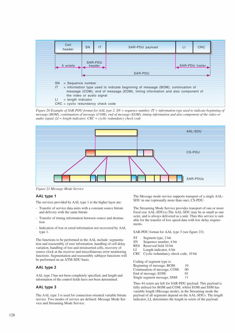
AAL type 1
The services provided by AAL type 1 to the higher layer are:
- Transfer of service data units with a constant source bitrateand delivery with the same bitrate
- Transfer of timing information between source and destina-tion
- Indication of lost or erred information not recovered by AALtype 1.
The functions to be performed in the AAL include: segmenta-tion and reassembly of user information, handling of cell delayvariation, handling of lost and misinserted cells, recovery ofsource clock at the receiver and miscellaneous error monitoringfunctions. Segmentation and reassembly sublayer functions willbe performed on an ATM-SDU basis.
AAL type 2
AAL type 2 has not been completely specified, and length andinformation of the control fields have not been determined.
AAL type 3
The AAL type 3 is used for connection oriented variable bitrateservice. Two modes of service are defined: Message Mode Ser-vice and Streaming Mode Service.
The Message mode service supports transport of a single AAL-SDU in one (optionally more than one), CS-PDU.
The Streaming Mode Service provides transport of one or morefixed size AAL-SDU(s).The AAL-SDU may be as small as oneoctet, and is always delivered as a unit. Thus this service is suit-able for the transfer of low speed data with low delay require-ments.
SAR-PDU format for AAL type 3 (see figure 23):
ST Segment type, 2 bitSN Sequence number, 4 bitRES Reserved field 10 bitLI Length indicator, 6 bitCRC Cyclic redundancy check code, 10 bit
Coding of segment type is:Beginning of message, BOM: 10Continuation of message, COM: 00End of message, EOM: 01Single segment message, SSM: 11
Thus 44 octets are left for SAR-PDU payload. This payload isfully utilised for BOM and COM, whilst EOM and SSM hasvariable length (Message mode), in the Streaming mode thepayload of all segments depend on the AAL-SDUs. The lengthindicator, LI, determines the length in octets of the payload.
128
Cellheader
SAR-PDU payload
SAR-PDUheader
SN IT
5 octets
SAR-PDU
= Sequence number= information type used to indicate beginning of message (BOM), continuation of message (COM), end of message (EOM), timing information and also component of the video or audio signal= length indicator= cyclic redundancy check code
LI CRC
SAR-PDU trailer
SNIT
LICRC
Figure 20 Example of SAR-PDU format for AAL type 2. SN = sequence number, IT = information type used to indicate beginning ofmessage (BOM), continuation of message (COM), end of message (EOM), timing information and also component of the video oraudio signal, LI = length indicator, CRC = cyclic redundancy check code
AAL-SDU
CS-PDU
SAR-PDUs
Figure 21 Message Mode Service
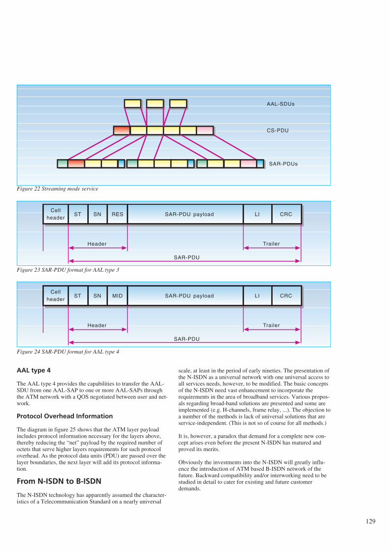
AAL type 4
The AAL type 4 provides the capabilities to transfer the AAL-SDU from one AAL-SAP to one or more AAL-SAPs throughthe ATM network with a QOS negotiated between user and net-work.
Protocol Overhead Information
The diagram in figure 25 shows that the ATM layer payloadincludes protocol information necessary for the layers above,thereby reducing the “net” payload by the required number ofoctets that serve higher layers requirements for such protocoloverhead. As the protocol data units (PDU) are passed over thelayer boundaries, the next layer will add its protocol informa-tion.
From N-ISDN to B-ISDN
The N-ISDN technology has apparently assumed the character-istics of a Telecommunication Standard on a nearly universal
scale, at least in the period of early nineties. The presentation ofthe N-ISDN as a universal network with one universal access toall services needs, however, to be modified. The basic conceptsof the N-ISDN need vast enhancement to incorporate therequirements in the area of broadband services. Various propos-als regarding broad-band solutions are presented and some areimplemented (e.g. H-channels, frame relay, ...). The objection toa number of the methods is lack of universal solutions that areservice-independent. (This is not so of course for all methods.)
It is, however, a paradox that demand for a complete new con-cept arises even before the present N-ISDN has matured andproved its merits.
Obviously the investments into the N-ISDN will greatly influ-ence the introduction of ATM based B-ISDN network of thefuture. Backward compatibility and/or interworking need to bestudied in detail to cater for existing and future customerdemands.
129
AAL-SDUs
CS-PDU
SAR-PDUs
Cellheader
SAR-PDU payload
Header
SN RES
SAR-PDU
LI CRC
Trailer
ST
Cellheader
SAR-PDU payload
Header
SN MID
SAR-PDU
LI CRC
Trailer
ST
Figure 22 Streaming mode service
Figure 23 SAR-PDU format for AAL type 3
Figure 24 SAR-PDU format for AAL type 4
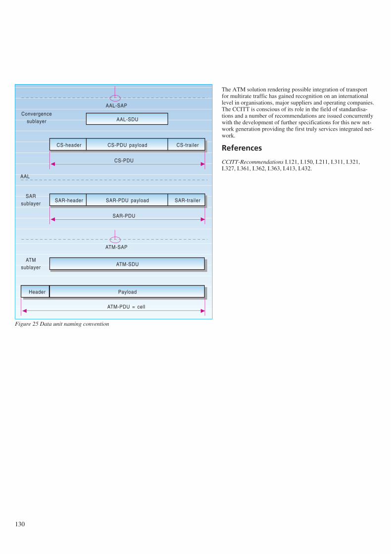
The ATM solution rendering possible integration of transportfor multirate traffic has gained recognition on an internationallevel in organisations, major suppliers and operating companies.The CCITT is conscious of its role in the field of standardisa-tions and a number of recommendations are issued concurrentlywith the development of further specifications for this new net-work generation providing the first truly services integrated net-work.
References
CCITT-Recommendations I.121, I.150, I.211, I.311, I.321,I.327, I.361, I.362, I.363, I.413, I.432.
130
AAL-SDU
CS-PDU payload CS-trailerCS-header
CS-PDU
SAR-PDU payload SAR-trailerSAR-header
SAR-PDU
ATM-SDU
Payload
ATM-PDU = cell
Header
Convergencesublayer
AAL-SAP
AAL
ATM-SAP
ATMsublayer
SARsublayer
Figure 25 Data unit naming convention
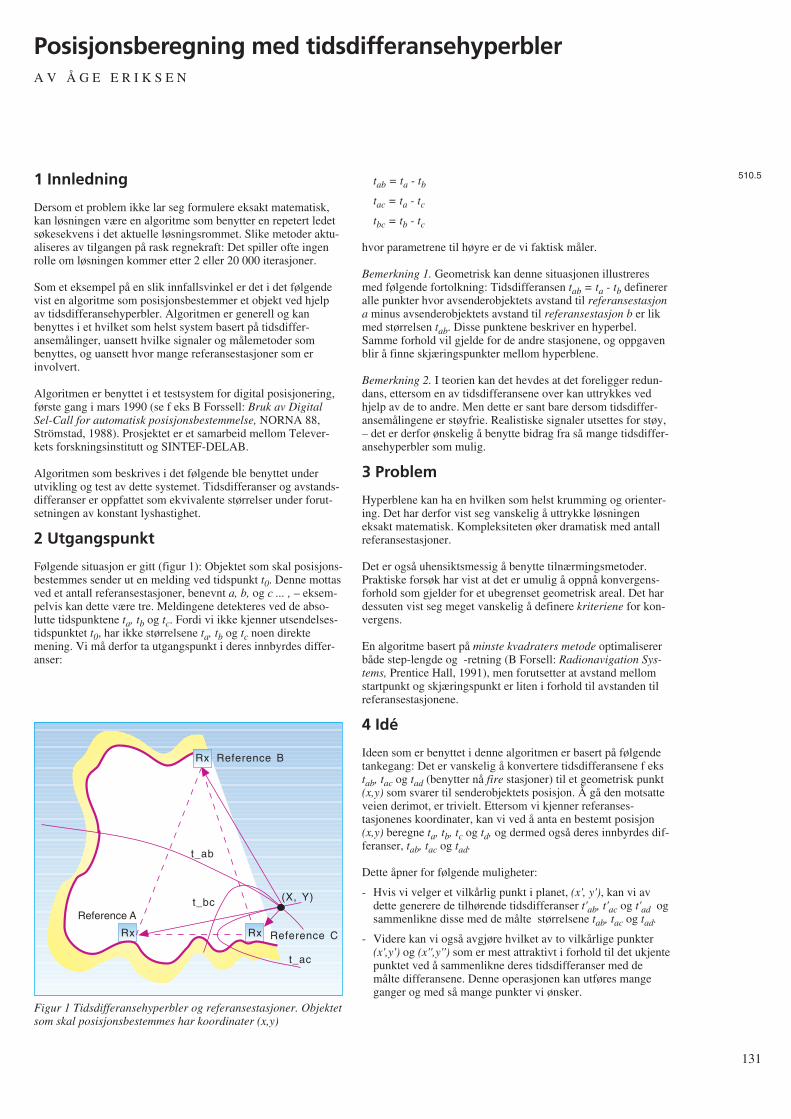
1 Innledning
Dersom et problem ikke lar seg formulere eksakt matematisk,kan løsningen være en algoritme som benytter en repetert ledetsøkesekvens i det aktuelle løsningsrommet. Slike metoder aktu-aliseres av tilgangen på rask regnekraft: Det spiller ofte ingenrolle om løsningen kommer etter 2 eller 20 000 iterasjoner.
Som et eksempel på en slik innfallsvinkel er det i det følgendevist en algoritme som posisjonsbestemmer et objekt ved hjelpav tidsdifferansehyperbler. Algoritmen er generell og kanbenyttes i et hvilket som helst system basert på tidsdiffer-ansemålinger, uansett hvilke signaler og målemetoder sombenyttes, og uansett hvor mange referansestasjoner som erinvolvert.
Algoritmen er benyttet i et testsystem for digital posisjonering,første gang i mars 1990 (se f eks B Forssell: Bruk av DigitalSel-Call for automatisk posisjonsbestemmelse, NORNA 88,Strömstad, 1988). Prosjektet er et samarbeid mellom Telever-kets forskningsinstitutt og SINTEF-DELAB.
Algoritmen som beskrives i det følgende ble benyttet underutvikling og test av dette systemet. Tidsdifferanser og avstands-differanser er oppfattet som ekvivalente størrelser under forut-setningen av konstant lyshastighet.
2 Utgangspunkt
Følgende situasjon er gitt (figur 1): Objektet som skal posisjons-bestemmes sender ut en melding ved tidspunkt t0. Denne mottasved et antall referansestasjoner, benevnt a, b, og c ... , – eksem-pelvis kan dette være tre. Meldingene detekteres ved de abso-lutte tidspunktene ta, tb og tc. Fordi vi ikke kjenner utsendelses-tidspunktet t0, har ikke størrelsene ta, tb og tc noen direktemening. Vi må derfor ta utgangspunkt i deres innbyrdes differ-anser:
tab = ta - tb
tac = ta - tc
tbc = tb - tc
hvor parametrene til høyre er de vi faktisk måler.
Bemerkning 1. Geometrisk kan denne situasjonen illustreresmed følgende fortolkning: Tidsdifferansen tab = ta - tb definereralle punkter hvor avsenderobjektets avstand til referansestasjona minus avsenderobjektets avstand til referansestasjon b er likmed størrelsen tab. Disse punktene beskriver en hyperbel.Samme forhold vil gjelde for de andre stasjonene, og oppgavenblir å finne skjæringspunkter mellom hyperblene.
Bemerkning 2. I teorien kan det hevdes at det foreligger redun-dans, ettersom en av tidsdifferansene over kan uttrykkes vedhjelp av de to andre. Men dette er sant bare dersom tidsdiffer-ansemålingene er støyfrie. Realistiske signaler utsettes for støy,– det er derfor ønskelig å benytte bidrag fra så mange tidsdiffer-ansehyperbler som mulig.
3 Problem
Hyperblene kan ha en hvilken som helst krumming og orienter-ing. Det har derfor vist seg vanskelig å uttrykke løsningeneksakt matematisk. Kompleksiteten øker dramatisk med antallreferansestasjoner.
Det er også uhensiktsmessig å benytte tilnærmingsmetoder.Praktiske forsøk har vist at det er umulig å oppnå konvergens-forhold som gjelder for et ubegrenset geometrisk areal. Det hardessuten vist seg meget vanskelig å definere kriteriene for kon-vergens.
En algoritme basert på minste kvadraters metode optimalisererbåde step-lengde og -retning (B Forsell: Radionavigation Sys-tems, Prentice Hall, 1991), men forutsetter at avstand mellomstartpunkt og skjæringspunkt er liten i forhold til avstanden tilreferansestasjonene.
4 Idé
Ideen som er benyttet i denne algoritmen er basert på følgendetankegang: Det er vanskelig å konvertere tidsdifferansene f ekstab, tac og tad (benytter nå fire stasjoner) til et geometrisk punkt(x,y) som svarer til senderobjektets posisjon. Å gå den motsatteveien derimot, er trivielt. Ettersom vi kjenner referanses-tasjonenes koordinater, kan vi ved å anta en bestemt posisjon(x,y) beregne ta, tb, tc og td, og dermed også deres innbyrdes dif-feranser, tab, tac og tad.
Dette åpner for følgende muligheter:
- Hvis vi velger et vilkårlig punkt i planet, (x', y'), kan vi avdette generere de tilhørende tidsdifferanser t'ab, t'ac og t'ad ogsammenlikne disse med de målte størrelsene tab, tac og tad.
- Videre kan vi også avgjøre hvilket av to vilkårlige punkter(x',y') og (x'',y'') som er mest attraktivt i forhold til det ukjentepunktet ved å sammenlikne deres tidsdifferanser med demålte differansene. Denne operasjonen kan utføres mangeganger og med så mange punkter vi ønsker.
131
Posisjonsberegning med tidsdifferansehyperblerA V Å G E E R I K S E N
510.5
RxRx
Rx
Reference C
Reference A
Reference B
t_ab
t_bc
t_ac
(X, Y)
Figur 1 Tidsdifferansehyperbler og referansestasjoner. Objektetsom skal posisjonsbestemmes har koordinater (x,y)
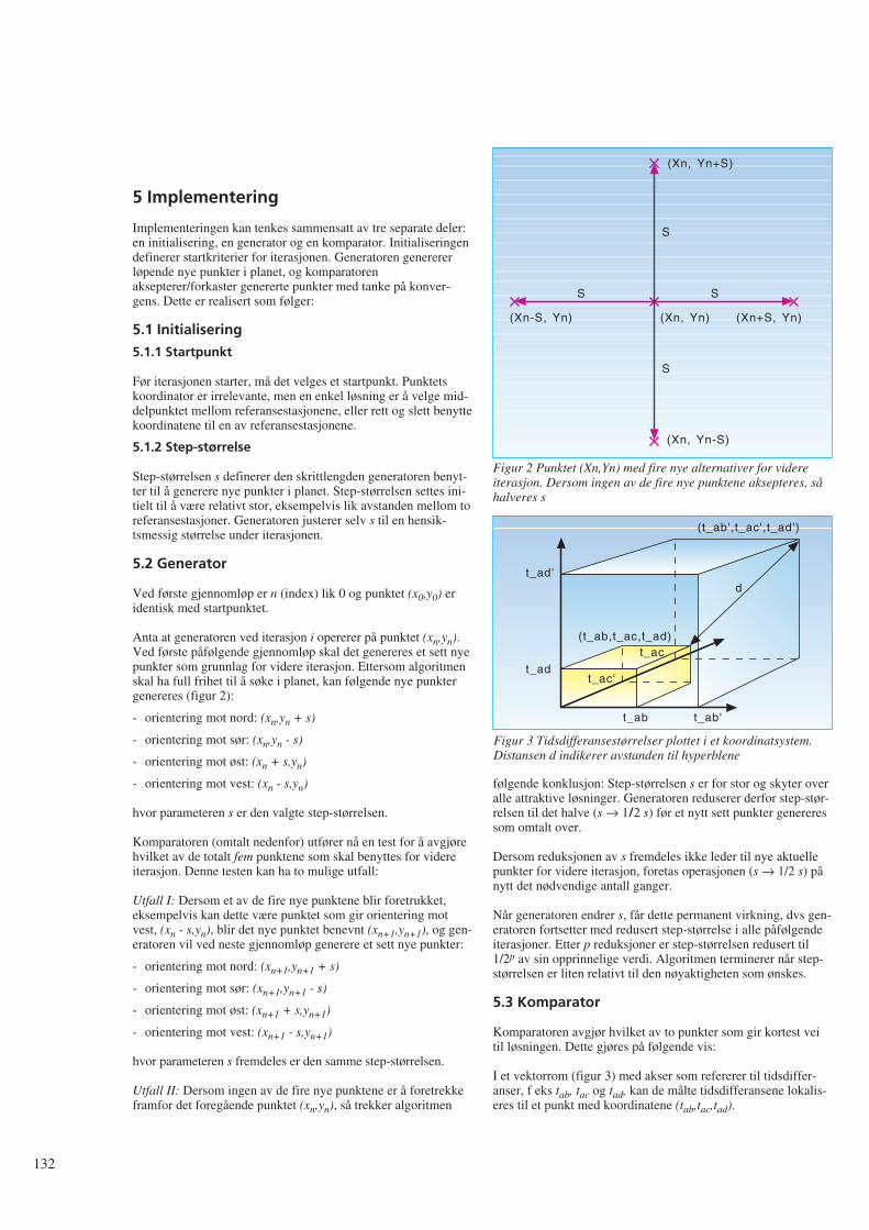
5 Implementering
Implementeringen kan tenkes sammensatt av tre separate deler:en initialisering, en generator og en komparator. Initialiseringendefinerer startkriterier for iterasjonen. Generatoren generererløpende nye punkter i planet, og komparatorenaksepterer/forkaster genererte punkter med tanke på konver-gens. Dette er realisert som følger:
5.1 Initialisering
5.1.1 Startpunkt
Før iterasjonen starter, må det velges et startpunkt. Punktetskoordinator er irrelevante, men en enkel løsning er å velge mid-delpunktet mellom referansestasjonene, eller rett og slett benyttekoordinatene til en av referansestasjonene.
5.1.2 Step-størrelse
Step-størrelsen s definerer den skrittlengden generatoren benyt-ter til å generere nye punkter i planet. Step-størrelsen settes ini-tielt til å være relativt stor, eksempelvis lik avstanden mellom toreferansestasjoner. Generatoren justerer selv s til en hensik-tsmessig størrelse under iterasjonen.
5.2 Generator
Ved første gjennomløp er n (index) lik 0 og punktet (x0,y0) eridentisk med startpunktet.
Anta at generatoren ved iterasjon i opererer på punktet (xn,yn).Ved første påfølgende gjennomløp skal det genereres et sett nyepunkter som grunnlag for videre iterasjon. Ettersom algoritmenskal ha full frihet til å søke i planet, kan følgende nye punktergenereres (figur 2):
- orientering mot nord: (xn,yn + s)
- orientering mot sør: (xn,yn - s)
- orientering mot øst: (xn + s,yn)
- orientering mot vest: (xn - s,yn)
hvor parameteren s er den valgte step-størrelsen.
Komparatoren (omtalt nedenfor) utfører nå en test for å avgjørehvilket av de totalt fem punktene som skal benyttes for videreiterasjon. Denne testen kan ha to mulige utfall:
Utfall I: Dersom et av de fire nye punktene blir foretrukket,eksempelvis kan dette være punktet som gir orientering motvest, (xn - s,yn), blir det nye punktet benevnt (xn+1,yn+1), og gen-eratoren vil ved neste gjennomløp generere et sett nye punkter:
- orientering mot nord: (xn+1,yn+1 + s)
- orientering mot sør: (xn+1,yn+1 - s)
- orientering mot øst: (xn+1 + s,yn+1)
- orientering mot vest: (xn+1 - s,yn+1)
hvor parameteren s fremdeles er den samme step-størrelsen.
Utfall II: Dersom ingen av de fire nye punktene er å foretrekkeframfor det foregående punktet (xn,yn), så trekker algoritmen
følgende konklusjon: Step-størrelsen s er for stor og skyter overalle attraktive løsninger. Generatoren reduserer derfor step-stør-relsen til det halve (s → 1/2 s) før et nytt sett punkter genereressom omtalt over.
Dersom reduksjonen av s fremdeles ikke leder til nye aktuellepunkter for videre iterasjon, foretas operasjonen (s → 1/2 s) pånytt det nødvendige antall ganger.
Når generatoren endrer s, får dette permanent virkning, dvs gen-eratoren fortsetter med redusert step-størrelse i alle påfølgendeiterasjoner. Etter p reduksjoner er step-størrelsen redusert til1/2p av sin opprinnelige verdi. Algoritmen terminerer når step-størrelsen er liten relativt til den nøyaktigheten som ønskes.
5.3 Komparator
Komparatoren avgjør hvilket av to punkter som gir kortest veitil løsningen. Dette gjøres på følgende vis:
I et vektorrom (figur 3) med akser som refererer til tidsdiffer-anser, f eks tab, tac og tad, kan de målte tidsdifferansene lokalis-eres til et punkt med koordinatene (tab,tac,tad).
132
(Xn, Yn+S)
(Xn, Yn-S)
(Xn-S, Yn) (Xn+S, Yn)
S
S
S S
(Xn, Yn)
Figur 2 Punktet (Xn,Yn) med fire nye alternativer for videreiterasjon. Dersom ingen av de fire nye punktene aksepteres, såhalveres s
(t_ab',t_ac',t_ad')
d
t_ab't_ab
t_ac'
t_ac
t_ad'
t_ad
(t_ab,t_ac,t_ad)
Figur 3 Tidsdifferansestørrelser plottet i et koordinatsystem.Distansen d indikerer avstanden til hyperblene
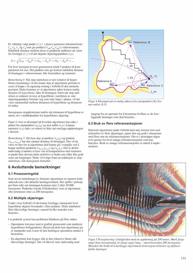
Et vilkårlig valgt punkt (x',y') i planet genererer tidsstørrelsenet'a, t'b, t'c og t'd som gir punktet (t'ab,t'ac,t'ad) i vektorrommet.Euklidisk distanse mellom disse to punktene indikerer nå veienfra forslaget (x',y') til det ukjente skjæringspunktet (x,y).
For hver iterasjon leverer generatoren totalt 5 punkter til kom-paratoren for test. Det punktet som gir kortest euklidisk distansetil løsningen i vektorrommet, blir foretrukket og returnert.
Bemerkning I: Når step-størrelsen er stor (relativt til hyper-blenes krumming) vil det kunne skje at algoritmen periodevissynes å hoppe i en ugunstig retning i forhold til den ønskedeposisjon. Dette kommer av at algoritmen søker kortest muligdistanse til hyperblene, ikke til løsningen. Først når step-stør-relsen er redusert så mye at hyperblene i nærheten av sineskjæringspunkter fortoner seg som rette linjer i planet, vil detvære sammenfall mellom distansen til hyperblene og distansentil målet.
Iterasjonens stoppkriterium innfris når distansen til hyperblene erminst, dvs i middelpunktet for hyperblenes skjæring.
Figur 4 viser et eksempel på hvordan algoritmen kan søke iplanet fra startpunktet (x0,y0) og mot målet (x,y). Linjenenærmest (x,y) (når s er minst) er ikke tatt med pga oppløsningeni skissen.
Bemerkning 2: Det kan skje at punktet (xn,yn) og punktet(xn+1,yn+1) har den samme distanse til løsningen. Det vil davære en fare for at algoritmen skal kunne gå i vranglås ved åhoppe mellom punktene (xn+1,yn+1) og (xn,yn). Det er derfornødvendig å innføre et krav om at komparatoren skal returnereet punkt bare dersom dette definitivt er bedre enn (ikke like godtsom) sin forgjenger. Dette vil tvinge fram en reduksjon av step-størrelsen s før iterasjonen fortsetter.
6 Avsluttende bemerkninger
6.1 Prosesseringstid
Som nevnt innledningsvis, benytter algoritmen en repetert ledetsøkesekvens i det aktuelle løsningsrommet. Det spiller i prinsip-pet liten rolle om løsningen kommer etter 2 eller 20 000iterasjoner. Praktiske forsøk (Oslofjorden) viser at algoritmenofte terminerer etter ca 200 iterasjoner.
6.2 Multiple skjæringer
Under visse forhold vil det kunne foreligge situasjoner hvorhyperblene skjærer hverandre i flere punkter. Dette innebærerflere likeverdige løsninger, uansett hvilke metoder sombenyttes.
I et praktisk system kan problemet håndteres på flere måter:
- Operatøren forsynes med et grafisk grensesnitt som markererhyperblenes beliggenheter. Basert på dette kan algoritmen giset startpunkt som svarer til den løsningen operatøren ønsker åbestemme.
- En algoritme kan bygges slik at den rekursivt finner allelikeverdige løsninger. Det vil likevel være nødvendig med
inngrep fra en operatør for å bestemme hvilken av de fore-liggende løsninger som skal benyttes.
6.3 Bruk av flere referansestasjoner
Ettersom algoritmen under forhold med støy itererer mot mid-delpunktet av flere skjæringer, egner den seg godt i situasjonermed flere enn tre referansestasjoner. Det er i prinsippet ingenøvre grense for hvor mange referansestasjoner som kanbenyttes. Bruk av mange referansestasjoner er enkelt å imple-mentere.
133
RxRx
Rx
Reference C
Reference A
Reference B
t_ab
t_bc
t_ac
(X, Y)
Figur 4 Eksempel på en mulig søkevei fra startpunktet (Xo,Yo)mot målet (X,Y)
Figur 5 Posisjonering i Oslofjorden med en oppløsning på 200 meter. Mørk fargeangir liten iterasjonstid, lys farge angir lang, - størrelsesorden 200 iterasjoner.Metoden ble brukt til å kartlegge algoritmens konvergens-kriterier og definerefalske løsninger
d =√
(tab − t′ab
)2 + (tac − t′ac
)2 + (tbc − t′bc
)2 + ...
134
MMIC - new technology offers new opportunitiesB Y L E I F H A N S S E N A N D C H R I S T I A N F H E I D E
1 Introduction
The development of integrated circuits has had a major impacton our every-day lives. Especially in telecommunications bysupplying more and more complex services to an ever decreas-ing price.
The number of transistors on a chip was previously used as afigure of complexity, and the acronym VLSI was used for themost complex chips with thousands of transistors. Today it ismore common to divide the circuits into two categories, stan-dard circuits and ASICs. Number of transistors is no longer con-sidered as a figure of complexity. In microwave applicationsthis is obvious since the number of transistors usually is verysmall while the complexity can be quite high.
1.1 The concept
MMICs are integrated circuits designed to operate in the GHzfrequency range. The term “monolithic” indicates that the wholecircuit is integrated on a single semiconductor chip. The compo-nents are not soldered to the chip, but formed using the semi-conductor actively. This is contrary to MICs where standardcomponents such as transistors, capacitors and resistors, are sol-dered to a microwave substrate. In MICs components do nothave to be planar which is the case for MMICs.
1.2 History
The idea of monolithic integration of microwave circuits wasgiven birth in 1964. A research programme funded by the USgovernment had as its objective to realise a transmit/receivemodule for an aircraft phased-array antenna (1). The researchersof the programme tried to build this module by using monolithicintegration of components on a semi-insulating silicon substrate.The results were, however, not very encouraging, mainlybecause the semi-insulating properties of silicon were not goodenough. Because of this and other problems, the work onMMICs lay dormant until 1967-68 when Mehal and Wackertried to use gallium arsenide as substrate material with Schottkyand Gunn diodes as the active components (2). This was farmore successful because of the good semi-insulating propertiesof gallium arsenide. However, it was not until 1976, when re-search workers at Plessey applied this approach to an X-bandamplifier based on the MESFET as the active component, thatthe present intense activity began (3).
Today MMICs are made mainly by using gallium arsenide assubstrate material and MESFETs as the active components.There is, however, a growing interest in other transistor struc-tures, especially HEMT and HBT.
1.3 Why monolithic?
Monolithic circuits have several advantages as compared tohybrid ones. One great advantage is the possibility of processinga large number of identical circuits in parallel, which will inturn lower the price per circuit. Another advantage is that thenumber of interconnections and bonding wires required isgreatly reduced. Furthermore, one does not have to do time-con-suming soldering and tuning. MMICs are generally very small
and light-weight, and they can exhibit high reliability and highreproducibility. A relatively large circuit-design flexibility isobtained and there are possibilities for multifunction perfor-mance on a chip. In the future it will be common to have a com-plete transmit/receive-module on a single chip, or, alternatively,as a multichip MMIC module (4).
The production cost for a circuit is given by the size of the cir-cuit and the yield, which means that it is important to get manyfunctions on a small area. Since the number of functions doesnot determine the cost, moving the border of integration by inte-grating more functions on the same chip can give extra func-tions for free. There will be no cost for the extra functionsadded to the chip except for the increase in chip area and a pos-sible decrease of yield. Another reason for monolithic integra-tion is the miniaturisation, to get a smaller size, smallvolume/area and low power consumption. This can improve theperformance of the system since it decreases the length of thesignal paths. Interconnection between different chips do degradethe signal. This means that a monolithic circuit with many inte-grated functions can have a better performance than a discretesystem built with functions where each of these functions have abetter performance.
MMIC has one advantage compared to MIC which is rarelyconsidered. This advantage which it has in common with, andwhich it has adopted from other ASIC-designs, is the fact thatthe specification of the system is developed at the simulator. Intraditional discrete electronics the system was often developedat the test bench and the specification was finished when theprototype system was built and characterised. This procedurecannot be used in ASIC design since the fabrication of circuitstakes a fairly long time and is quite expensive.
The drawbacks associated with the monolithic approach aremainly the difficulties with trouble-shooting and tuning.MMICs generally have low Q-factors. This implies that theywill exhibit good broad-band performance, but make poor res-onators.
2 Transistors
2.1 Properties of gallium arsenide
Gallium arsenide (GaAs) is a so-called III-V semiconductor andis ordered in a zincblende lattice. This means that the material ismade using elements from main group III (gallium) and V(arsenic) in the periodic table of the elements. The resistivity ofundoped gallium arsenide is in the order of 108 Ωcm, which isquite high compared to silicon (about 104 Ωcm) and other semi-conductors (5). Pure GaAs is therefore often referred to as semi-insulating.
A simplified energy band diagram of GaAs is shown in figure2.1 (6). The conduction band has three valleys, named Γ, L, andX. The Γ valley has the lowest minimum of the three, and sodetermines the bandgap which is 1.42 eV as compared to 1.11eV for Si. The larger bandgap implies that GaAs is more resis-tant to radiation and may be operated at higher temperaturesthan Si. It is evident from figure 2.1 that the bandgap is direct,i.e. a transition from the valence band to the Γ valley requires
621.38.049.7
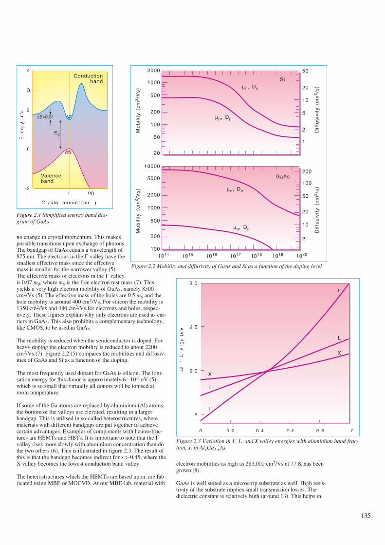
no change in crystal momentum. This makespossible transitions upon exchange of photons.The bandgap of GaAs equals a wavelength of875 nm. The electrons in the Γ valley have thesmallest effective mass since the effectivemass is smaller for the narrower valley (5).The effective mass of electrons in the Γ valleyis 0.07 m0, where m0 is the free electron rest mass (7). Thisyields a very high electron mobility of GaAs, namely 8500cm2/Vs (5). The effective mass of the holes are 0.5 m0 and thehole mobility is around 400 cm2/Vs. For silicon the mobility is1350 cm2/Vs and 480 cm2/Vs for electrons and holes, respec-tively. These figures explain why only electrons are used as car-riers in GaAs. This also prohibits a complementary technology,like CMOS, to be used in GaAs.
The mobility is reduced when the semiconductor is doped. Forheavy doping the electron mobility is reduced to about 2200cm2/Vs (7). Figure 2.2 (5) compares the mobilities and diffusiv-ities of GaAs and Si as a function of the doping.
The most frequently used dopant for GaAs is silicon. The ioni-sation energy for this donor is approximately 6 . 10-3 eV (5),which is so small that virtually all donors will be ionised atroom temperature.
If some of the Ga atoms are replaced by aluminium (Al) atoms,the bottom of the valleys are elevated, resulting in a largerbandgap. This is utilised in so-called heterostructures, wherematerials with different bandgaps are put together to achievecertain advantages. Examples of components with heterostruc-tures are HEMTs and HBTs. It is important to note that the Γvalley rises more slowly with aluminium concentration than dothe two others (6). This is illustrated in figure 2.3. The result ofthis is that the bandgap becomes indirect for x > 0.45, where theX valley becomes the lowest conduction band valley.
The heterostructures which the HEMTs are based upon, are fab-ricated using MBE or MOCVD. At our MBE-lab, material with
electron mobilities as high as 283,000 cm2/Vs at 77 K has beengrown (8).
GaAs is well suited as a microstrip substrate as well. High resis-tivity of the substrate implies small transmission losses. Thedielectric constant is relatively high (around 13). This helps in
135
Figure 2.1 Simplified energy band dia-gram of GaAs
Conductionband
4
3
2
1
0
-1
-2
En
erg
y(e
V)
∆E=0.31
Eg
Valenceband
[111] 0
Crystal momentum, p
[100]
Mo
bili
ty(c
m2/V
s)
2000
1000
500
200
100
50
20
10000
5000
2000
1000
500
200
100
50
20
10
5
2
1
200
100
50
20
10
5
1014 1015 1016 1017 1018 1019 1020
Dif
fusi
vity
(cm
2/s
)
Mo
bili
ty(c
m2/V
s)
Dif
fusi
vity
(cm
2/s
)
Siµn, Dn
µp, Dp
GaAs
µn, Dn
µp, Dp
Figure 2.2 Mobility and diffusivity of GaAs and Si as a function of the doping level
Ba
nd
En
erg
y(e
V)
3.0
2.5
2.0
1.5
0 0.2 0.4 0.6 0.8 1.0
Al mole fraction
X
L
Γ
L
X
Γ
Figure 2.3 Variation in Γ, L, and X valley energies with aluminium band frac-tion, x, in AlxGa1-xAs
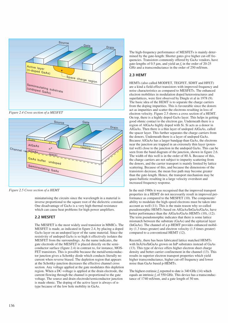
136
miniaturising the circuits since the wavelength in a material isinverse proportional to the square root of the dielectric constant.One disadvantage of GaAs is a very high thermal resistancewhich can cause heat problems for high power amplifiers.
2.2 MESFET
The MESFET is the most widely used transistor in MMICs. TheMESFET is made, as indicated in figure 2.4, by placing a dopedGaAs layer on an undoped layer of the same material. Since theresistivity of undoped GaAs is so high it effectively isolates theMESFET from the surroundings. As the name indicates, thegate electrode of the MESFET is placed directly on the semi-conductor surface (figure 2.4) in contrast to, for instance, MOS-FET transistors. This is possible because the metal/semiconduc-tor junction gives a Schottky diode which conducts literally nocurrent when reverse biased. The depletion region that appearsat the Schottky-junction decreases the effective channel crosssection. Any voltage applied at the gate modulates this depletionregion. When a DC-voltage is applied at the drain electrode, thecurrent flowing through the channel is proportional to the gatevoltage. The source and drain electrode/semiconductor junctionis made ohmic. The doping of the active layer is always of n-type because of the low hole mobility in GaAs.
The high-frequency performance of MESFETs is mainly deter-mined by the gate-length: Shorter gates give higher cut-off fre-quencies. Transistors commonly offered by GaAs vendors, havegate-lengths of 0.5 µm, and yield an ft in the order of 20-25GHz and a transconductance in the order of 250 mS/mm.
2.3 HEMT
HEMTs (also called MODFET, TEGFET, SDHT and HFET)are a kind a field-effect transistors with improved frequency andnoise characteristics as compared to MESFETs. The enhancedelectron mobilities in modulation doped heterostructures andsuperlattices, were first observed by Dingle et al in 1978 (9).The basic idea of the HEMT is to separate the charge carriersfrom the doping impurities. This is favourable since the donorsact as impurities and scatter the electrons resulting in loss ofelectron velocity. Figure 2.5 shows a cross section of a HEMT.On top, there is a highly doped GaAs layer. This helps in gettinggood ohmic contact to the electron gas. Underneath there is aregion of AlGaAs highly doped with Si. Si acts as a donor inAlGaAs. Then there is a thin layer of undoped AlGaAs, calledthe spacer layer. This further separates the charge carriers fromthe donors. Underneath there is a layer of undoped GaAs.Because AlGaAs has a larger bandgap than GaAs, the electronsnear the junction are trapped in an extremely thin layer (poten-tial well) close to the junction in the undoped GaAs. This can beseen from the band diagram of the junction, shown in figure 2.6.The width of this well is in the order of 80 Å. Because of this,the charge carriers are not subject to impurity scattering fromthe donors, and the carrier transport is mainly limited by latticescattering. Because of this, and because the dimensions of thetransistors decrease, the mean free path may become greaterthan the gate-length. Hence, the transport mechanism may bequasi-ballistic resulting in a large velocity overshoot andincreased frequency response.
In the mid-1980s it was recognised that the improved transportproperties in a HEMT do not necessarily result in improved per-formance as compared to the MESFET (10). The components’ability to modulate the high-speed electrons must be taken intoaccount as well (11). This is the main reason why so-calledpseudomorphic HEMTs based on AlGaAs/InGaAs/GaAs, havebetter performance than the AlGaAs/GaAs HEMTs (10), (12).The term pseudomorphic indicates that there is some latticemismatch between the substrate (GaAs) and the epitaxial layer(InGaAs). The channel of a p-HEMT provides enhanced mobil-ity (1.3 times greater) and electron velocity (1.5 times greater)compared to a conventional HEMT (12).
Recently, there has been fabricated lattice matched HEMTswith InAlAs/InGaAs grown on InP substrates instead of GaAs(13). This type of device offers higher electron sheet chargedensity and better carrier confinement in the channel (13). Thisresults in superior electron transport properties which yieldhigher transconductance, higher cut-off frequency and lowernoise than GaAs based p-HEMTs.
The highest extrinsic ft reported to date is 340 GHz (14) whichequals an intrinsic ft of 550 GHz. This device has a transconduc-tance of 1740 mS/mm, and a gate length of 50 nm.
SourceGate Drain
Active layer(n-doped GaAs)Space charge region
Semiinsulating substrate(undoped GaAs)
Source Gate
Drain
GaAs
Semiinsulating GaAs
AlGaAs
AlGaAs
GaAs buffer undoped
capping
n+
n+Channelspacer
Figure 2.4 Cross section of a MESFET
Figure 2.5 Cross section of a HEMT
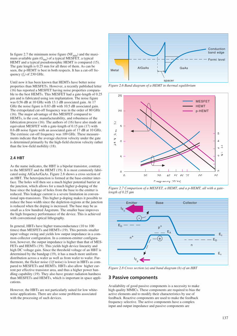
In figure 2.7 the minimum noise figure (NFmin) and the maxi-mum available gain (Gma) of a typical MESFET, a typicalHEMT and a typical pseudomorphic HEMT is compared (15).The gate length is 0.25 mm for all three of them. As can beseen, the p-HEMT is best in both respects. It has a cut-off fre-quency (ft) of 230 GHz.
Until now it has been known that HEMTs have better noiseproperties than MESFETs. However, a recently published letter(16) has reported a MESFET having noise properties compara-ble to the best HEMTs. This MESFET had a gate-length of 0.25µm and is fabricated using ion implantation. The noise figurewas 0.56 dB at 10 GHz with 13.1 dB associated gain. At 17GHz the noise figure is 0.83 dB with 10.5 dB associated gain.The extrapolated cut-off frequency was in the order of 80 GHz(16). The major advantage of this MESFET compared toHEMTs, is the cost, manufacturability, and robustness of thefabrication process (16). The authors of (16) have also made anequivalent MESFET with a gate-length of 0.15 µm (17) with0.6 dB noise figure with an associated gain of 17 dB at 10 GHz.The extrinsic cut-off frequency was 109 GHz. These measure-ments indicate that the average electron velocity under the gateis determined primarily by the high-field electron velocity ratherthan the low-field mobility (18).
2.4 HBT
As the name indicates, the HBT is a bipolar transistor, contraryto the MESFET and the HEMT (19). It is most commonly fabri-cated using AlGaAs/GaAs. Figure 2.8 shows a cross section ofan HBT. The heterojunction is formed at the base-emitter inter-face. The holes will then see a much higher potential barrier atthe junction, which allows for a much higher p-doping of thebase since the leakage of holes from the base to the emitter isreduced. This leakage current is a severe limitation in conven-tional npn-transistors. This higher p-doping makes it possible toreduce the base-width since the depletion-regions at the junctionis reduced when the doping is increased. The base may be assmall as a few hundred Ångstrøm. The smaller base improvesthe high frequency performance of the device. This is achievedwith conventional optical lithography.
In general, HBTs have higher transconductance (10 to 100times) than MESFETs and HEMTs (19). This permits smallerinput voltage swing and yields low output impedance in a com-mon-collector configuration. In a common-emitter configura-tion, however, the output impedance is higher than that of MES-FETs and HEMTs (19). This yields high device linearity andhigh DC voltage gain. Since the threshold voltage of an HBT isdetermined by the bandgap (19), it has a much more uniformdistribution across a wafer as well as from wafer to wafer. Fur-thermore, the flicker noise (1/f noise) is lower in HBTs as com-pared to MESFETs and HEMTs. HBTs also allow higher cur-rent per effective transistor area, and thus a higher power han-dling capability (19). They also have greater radiation hardnessthan MESFETs and HEMTs, which is important in space appli-cations.
However, the HBTs are not particularly suited for low white-noise applications. There are also some problems associatedwith the processing of such devices.
3 Passive components
Availability of good passive components is a necessity to makehigh quality MMICs. These components are required to bias theactive elements and to modify their characteristics by use offeedback. Reactive components are used to make the feedbackfrequency selective. The active components have a complexinput and output impedance and passive components are
137
AlGaAs GaAs
Conductionband edge
Fermi level
Metal
spacer
Figure 2.6 Band diagram of a HEMT in thermal equilibrium
GA
IN(G
ma)
[dB
]
25
20
15
10
5
0
5
4
3
2
1
0
NF
[dB
]
10 20 30 40 50 60 70 100 150
Frequency [GHz]
MESFET
HEMT
p-HEMT
Figure 2.7 Comparison of a MESFET, a HEMT, and a p-HEMT, all with a gate-length of 0.25 µm
Emitter
+
-
Base Collector
IEp
Ec
Ev
n+
n
p+
ED
EA
ED
IEn
Figure 2.8 Cross section (a) and band diagram (b) of an HBT
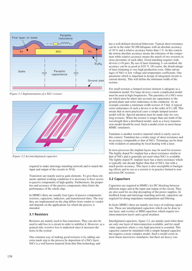
138
required to make interstage matching network and to match theinput and output of the circuits to 50 Ω.
Transistors are mainly used as gain elements. To give these ele-ments optimal working conditions it is necessary to have accessto passive components of high quality. Furthermore, the proper-ties and accuracy of the passive components often limits theperformance of the whole chip.
In MMICs there are usually four types of passive components:resistors, capacitors, inductors, and transmission lines. The waythey are implemented on the chip differs from vendor to vendorand depends on the applications for which the process isintended.
3.1 Resistors
Resistors are mainly used to bias transistors. They can also beused to add loss to a circuit in order to stabilise it. However, as ageneral rule, resistive loss is undesired since it increases thenoise in the system.
One common way of making good resistors is by adding oneextra mask step to the process by deposition of a NiCr layer.NiCr is a well known material from thin film technology and
has a well defined electrical behaviour. Typical sheet resistancecan be in the order 50-200 Ω/square with an absolute accuracyof 10 % and a relative accuracy better than 1 %. In this contextthe notion absolute accuracy means the tolerance of the compo-nent while relative accuracy means the match of two resistors inclose proximity of each other. Good matching requires widedevices (>10 µm). By use of laser trimming, L-cut method, theaccuracy can be as good as 0.01 %. Of course, the disadvantageof laser trimming is very high production costs. Other advan-tages of NiCr is low voltage and temperature coefficients. Oneparameter which is important in design of integrated circuits iscurrent density. This will define the minimum width of theresistor.
For small resistors a lumped resistor element is adequate as asimulation model. For large devices a more complicated modelmust be used at high frequencies. The parasitics of a NiCr resis-tor which must be taken into account are capacitance to theground plane and series inductance in the conductor. As anexample consider a minimum width resistor of 5 kΩ. A typicalseries inductance of such a device is in the order of 0.1 nH. Thismeans that in most practical cases a simple lumped resistormodel will do. Special attention must be made only for verylong resistors. When the resistor is longer than one tenth of thewavelength then a distributed model, such as a lossy transmis-sion model should be used. Such a model exists in most linearMMIC simulators.
Tantalum is another resistive material which is rarely seen inthis context. Tantalum has a wider range of sheet resistance andan accuracy comparable to that of NiCr. Trimming can be donewith oxidation or annealing by local heating with a laser.
In most processes the implant layers may be used for resistors.The highly doped N+ implant has a sheet resistance similar tothat of NiCr and is generally not used when NiCr is available.The lightly doped N- implant layer has a sheet resistance whichis typically one decade higher than that of NiCr, but with amuch poorer accuracy. This layer is also susceptible to backgat-ing effects and its use as a resistor is in practice limited to non-precision DC resistors.
3.2 Capacitors
Capacitors are required in MMICs for DC-blocking betweendifferent stages and at the input and output of the circuit. Theyare also used for on-chip decoupling of the power supplies. Infeedback loops and interstage matching network, capacitors arerequired for doing impedance manipulation and filtering.
In GaAs MMICs there are mainly two ways of realising capaci-tors. These are interdigitated capacitors which can be done inone layer, and overlay or MIM capacitors which require twointerconnection layers and a good insulator.
Interdigitated capacitors, figure 3.2, are mainly used when thereare only one layer of interconnection available, and for smallvalue capacitors where a very high precision is essential. Thiscapacitor cannot be simulated with a simple lumped capacitorbut requires a more complex model. Such a model exists inmost linear microwave simulators, but there are heavy con-
Ground plane
Si3N4
NiCrAu Au
GaAs Parasiticcapacitance
ParasiticinductanceFirst layer of metal
Figure 3.1 Implementation of a NiCr resistor
Figure 3.2 An interdigitated capacitor
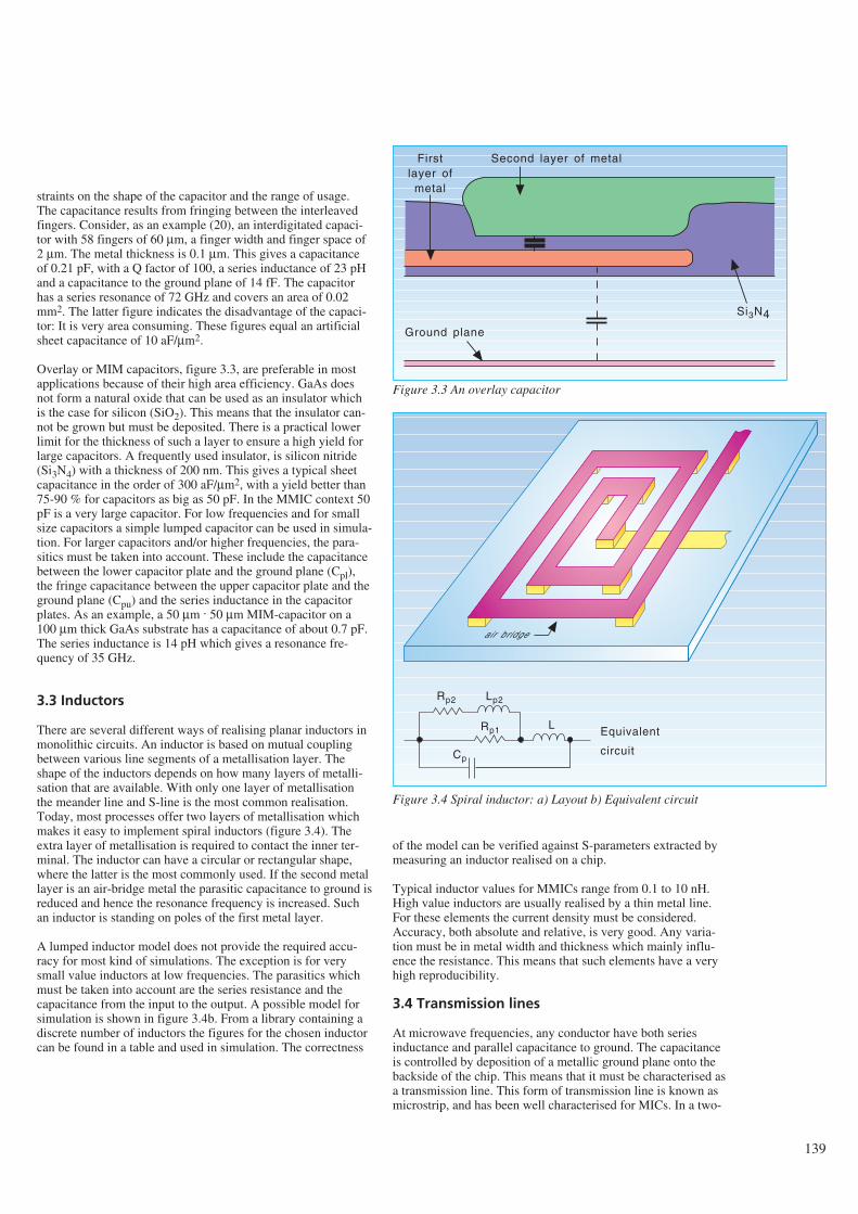
straints on the shape of the capacitor and the range of usage.The capacitance results from fringing between the interleavedfingers. Consider, as an example (20), an interdigitated capaci-tor with 58 fingers of 60 µm, a finger width and finger space of2 µm. The metal thickness is 0.1 µm. This gives a capacitanceof 0.21 pF, with a Q factor of 100, a series inductance of 23 pHand a capacitance to the ground plane of 14 fF. The capacitorhas a series resonance of 72 GHz and covers an area of 0.02mm2. The latter figure indicates the disadvantage of the capaci-tor: It is very area consuming. These figures equal an artificialsheet capacitance of 10 aF/µm2.
Overlay or MIM capacitors, figure 3.3, are preferable in mostapplications because of their high area efficiency. GaAs doesnot form a natural oxide that can be used as an insulator whichis the case for silicon (SiO2). This means that the insulator can-not be grown but must be deposited. There is a practical lowerlimit for the thickness of such a layer to ensure a high yield forlarge capacitors. A frequently used insulator, is silicon nitride(Si3N4) with a thickness of 200 nm. This gives a typical sheetcapacitance in the order of 300 aF/µm2, with a yield better than75-90 % for capacitors as big as 50 pF. In the MMIC context 50pF is a very large capacitor. For low frequencies and for smallsize capacitors a simple lumped capacitor can be used in simula-tion. For larger capacitors and/or higher frequencies, the para-sitics must be taken into account. These include the capacitancebetween the lower capacitor plate and the ground plane (Cpl),the fringe capacitance between the upper capacitor plate and theground plane (Cpu) and the series inductance in the capacitorplates. As an example, a 50 µm . 50 µm MIM-capacitor on a100 µm thick GaAs substrate has a capacitance of about 0.7 pF.The series inductance is 14 pH which gives a resonance fre-quency of 35 GHz.
3.3 Inductors
There are several different ways of realising planar inductors inmonolithic circuits. An inductor is based on mutual couplingbetween various line segments of a metallisation layer. Theshape of the inductors depends on how many layers of metalli-sation that are available. With only one layer of metallisationthe meander line and S-line is the most common realisation.Today, most processes offer two layers of metallisation whichmakes it easy to implement spiral inductors (figure 3.4). Theextra layer of metallisation is required to contact the inner ter-minal. The inductor can have a circular or rectangular shape,where the latter is the most commonly used. If the second metallayer is an air-bridge metal the parasitic capacitance to ground isreduced and hence the resonance frequency is increased. Suchan inductor is standing on poles of the first metal layer.
A lumped inductor model does not provide the required accu-racy for most kind of simulations. The exception is for verysmall value inductors at low frequencies. The parasitics whichmust be taken into account are the series resistance and thecapacitance from the input to the output. A possible model forsimulation is shown in figure 3.4b. From a library containing adiscrete number of inductors the figures for the chosen inductorcan be found in a table and used in simulation. The correctness
of the model can be verified against S-parameters extracted bymeasuring an inductor realised on a chip.
Typical inductor values for MMICs range from 0.1 to 10 nH.High value inductors are usually realised by a thin metal line.For these elements the current density must be considered.Accuracy, both absolute and relative, is very good. Any varia-tion must be in metal width and thickness which mainly influ-ence the resistance. This means that such elements have a veryhigh reproducibility.
3.4 Transmission lines
At microwave frequencies, any conductor have both seriesinductance and parallel capacitance to ground. The capacitanceis controlled by deposition of a metallic ground plane onto thebackside of the chip. This means that it must be characterised asa transmission line. This form of transmission line is known asmicrostrip, and has been well characterised for MICs. In a two-
139
Ground plane
Si3N4
Firstlayer of
metal
Second layer of metal
Figure 3.3 An overlay capacitor
air bridge
Rp2 Lp2
LRp1
Cp
Equivalent
circuit
Figure 3.4 Spiral inductor: a) Layout b) Equivalent circuit
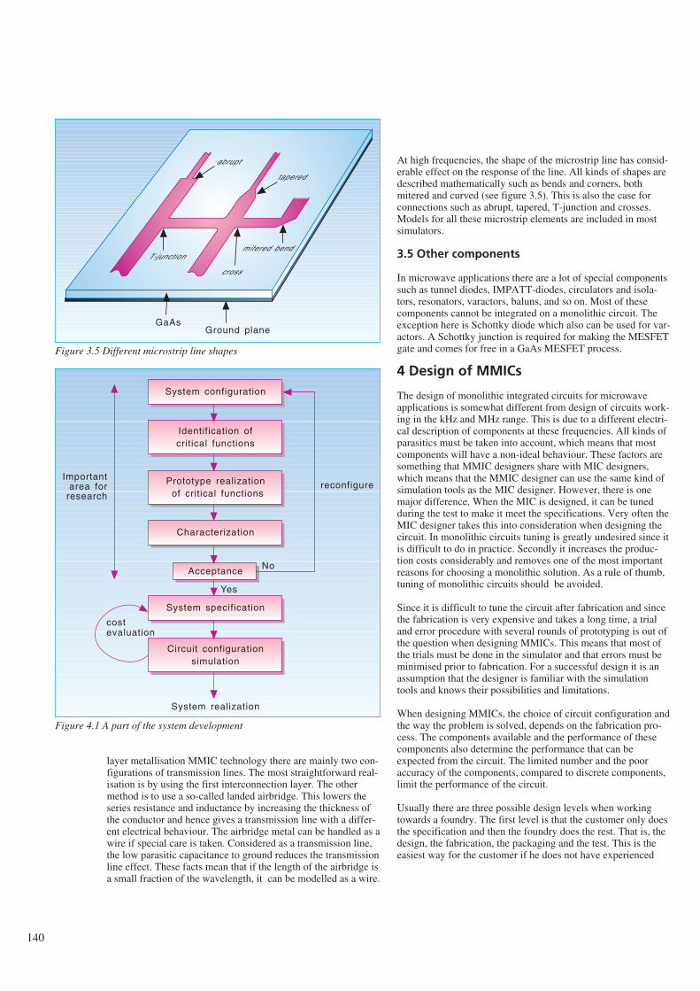
140
layer metallisation MMIC technology there are mainly two con-figurations of transmission lines. The most straightforward real-isation is by using the first interconnection layer. The othermethod is to use a so-called landed airbridge. This lowers theseries resistance and inductance by increasing the thickness ofthe conductor and hence gives a transmission line with a differ-ent electrical behaviour. The airbridge metal can be handled as awire if special care is taken. Considered as a transmission line,the low parasitic capacitance to ground reduces the transmissionline effect. These facts mean that if the length of the airbridge isa small fraction of the wavelength, it can be modelled as a wire.
At high frequencies, the shape of the microstrip line has consid-erable effect on the response of the line. All kinds of shapes aredescribed mathematically such as bends and corners, bothmitered and curved (see figure 3.5). This is also the case forconnections such as abrupt, tapered, T-junction and crosses.Models for all these microstrip elements are included in mostsimulators.
3.5 Other components
In microwave applications there are a lot of special componentssuch as tunnel diodes, IMPATT-diodes, circulators and isola-tors, resonators, varactors, baluns, and so on. Most of thesecomponents cannot be integrated on a monolithic circuit. Theexception here is Schottky diode which also can be used for var-actors. A Schottky junction is required for making the MESFETgate and comes for free in a GaAs MESFET process.
4 Design of MMICs
The design of monolithic integrated circuits for microwaveapplications is somewhat different from design of circuits work-ing in the kHz and MHz range. This is due to a different electri-cal description of components at these frequencies. All kinds ofparasitics must be taken into account, which means that mostcomponents will have a non-ideal behaviour. These factors aresomething that MMIC designers share with MIC designers,which means that the MMIC designer can use the same kind ofsimulation tools as the MIC designer. However, there is onemajor difference. When the MIC is designed, it can be tunedduring the test to make it meet the specifications. Very often theMIC designer takes this into consideration when designing thecircuit. In monolithic circuits tuning is greatly undesired since itis difficult to do in practice. Secondly it increases the produc-tion costs considerably and removes one of the most importantreasons for choosing a monolithic solution. As a rule of thumb,tuning of monolithic circuits should be avoided.
Since it is difficult to tune the circuit after fabrication and sincethe fabrication is very expensive and takes a long time, a trialand error procedure with several rounds of prototyping is out ofthe question when designing MMICs. This means that most ofthe trials must be done in the simulator and that errors must beminimised prior to fabrication. For a successful design it is anassumption that the designer is familiar with the simulationtools and knows their possibilities and limitations.
When designing MMICs, the choice of circuit configuration andthe way the problem is solved, depends on the fabrication pro-cess. The components available and the performance of thesecomponents also determine the performance that can beexpected from the circuit. The limited number and the pooraccuracy of the components, compared to discrete components,limit the performance of the circuit.
Usually there are three possible design levels when workingtowards a foundry. The first level is that the customer only doesthe specification and then the foundry does the rest. That is, thedesign, the fabrication, the packaging and the test. This is theeasiest way for the customer if he does not have experienced
T-junction
cross
mitered bend
tapered
abrupt
GaAsGround plane
Figure 3.5 Different microstrip line shapes
System configuration
Identification ofcritical functions
Prototype realization of critical functions
Characterization
Acceptance
System specification
Circuit configurationsimulation
System realization
costevaluation
reconfigureImportant
area forresearch
No
Yes
Figure 4.1 A part of the system development
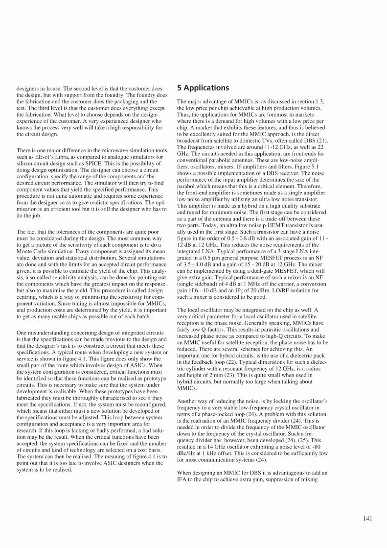
designers in-house. The second level is that the customer doesthe design, but with support from the foundry. The foundry doesthe fabrication and the customer does the packaging and thetest. The third level is that the customer does everything exceptthe fabrication. What level to choose depends on the design-experience of the customer. A very experienced designer whoknows the process very well will take a high responsibility forthe circuit design.
There is one major difference in the microwave simulation toolssuch as EEsof’s Libra, as compared to analogue simulators forsilicon circuit design such as SPICE. This is the possibility ofdoing design optimisation. The designer can choose a circuitconfiguration, specify the range of the components and thedesired circuit performance. The simulator will then try to findcomponent values that yield the specified performance. Thisprocedure is not quite automatic and requires some experiencefrom the designer so as to give realistic specifications. The opti-misation is an efficient tool but it is still the designer who has todo the job.
The fact that the tolerances of the components are quite poormust be considered during the design. The most common wayto get a picture of the sensitivity of each component is to do aMonte Carlo simulation. Every component is assigned its meanvalue, deviation and statistical distribution. Several simulationsare done and with the limits for an accepted circuit performancegiven, it is possible to estimate the yield of the chip. This analy-sis, a so-called sensitivity analysis, can be done for pointing outthe components which have the greatest impact on the response,but also to maximise the yield. This procedure is called designcentring, which is a way of minimising the sensitivity for com-ponent variation. Since tuning is almost impossible for MMICs,and production costs are determined by the yield, it is importantto get as many usable chips as possible out of each batch.
One misunderstanding concerning design of integrated circuitsis that the specifications can be made previous to the design andthat the designer’s task is to construct a circuit that meets thesespecifications. A typical route when developing a new system orservice is shown in figure 4.1. This figure does only show thesmall part of the route which involves design of ASICs. Whenthe system configuration is considered, critical functions mustbe identified so that these functions can be realised as prototypecircuits. This is necessary to make sure that the system underdevelopment is realisable. When these prototypes have beenfabricated they must be thoroughly characterised to see if theymeet the specifications. If not, the system must be reconfigured,which means that either must a new solution be developed orthe specifications must be adjusted. This loop between systemconfiguration and acceptance is a very important area forresearch. If this loop is lacking or badly performed, a bad solu-tion may be the result. When the critical functions have beenaccepted, the system specifications can be fixed and the numberof circuits and kind of technology are selected on a cost basis.The system can then be realised. The meaning of figure 4.1 is topoint out that it is too late to involve ASIC designers when thesystem is to be realised.
5 Applications
The major advantage of MMICs is, as discussed in section 1.3,the low price per chip achievable at high production volumes.Thus, the applications for MMICs are foremost in marketswhere there is a demand for high volumes with a low price perchip. A market that exhibits these features, and thus is believedto be excellently suited for the MMIC approach, is the directbroadcast from satellite to domestic TVs, often called DBS (21).The frequencies involved are around 11-12 GHz, as well as 22GHz. The circuits needed in this application, are front-ends forconventional parabolic antennas. These are low-noise ampli-fiers, oscillators, mixers, IF amplifiers and filters. Figure 5.1shows a possible implementation of a DBS receiver. The noiseperformance of the input amplifier determines the size of theparabol which means that this is a critical element. Therefore,the front-end amplifier is sometimes made as a single amplifierlow noise amplifier by utilising an ultra low noise transistor.This amplifier is made as a hybrid on a high quality substrateand tuned for minimum noise. The first stage can be consideredas a part of the antenna and there is a trade-off between thesetwo parts. Today, an ultra low noise p-HEMT transistor is usu-ally used in the first stage. Such a transistor can have a noisefigure in the order of 0.5 - 0.8 dB with an associated gain of 11 -12 dB at 12 GHz. This reduces the noise requirements of theintegrated LNA. Typical performance of a 3-stage LNA inte-grated in a 0.5 µm general purpose MESFET process is an NFof 3.5 - 4.0 dB and a gain of 15 - 20 dB at 12 GHz. The mixercan be implemented by using a dual-gate MESFET, which willgive extra gain. Typical performance of such a mixer is an NF(single sideband) of 4 dB at 1 MHz off the carrier, a conversiongain of 6 - 10 dB and an IP3 of 20 dBm. LO/RF isolation forsuch a mixer is considered to be good.
The local oscillator may be integrated on the chip as well. Avery critical parameter for a local oscillator used in satellitereception is the phase noise. Generally speaking, MMICs havefairly low Q-factors. This results in parasitic oscillations andincreased phase noise as compared to high-Q circuits. To makean MMIC useful for satellite reception, the phase noise has to bereduced. There are several schemes for achieving this. Animportant one for hybrid circuits, is the use of a dielectric puckin the feedback loop (22). Typical dimensions for such a dielec-tric cylinder with a resonant frequency of 12 GHz, is a radiusand height of 2 mm (23). This is quite small when used inhybrid circuits, but normally too large when talking aboutMMICs.
Another way of reducing the noise, is by locking the oscillator’sfrequency to a very stable low-frequency crystal oscillator interms of a phase-locked loop (24). A problem with this solutionis the realisation of an MMIC frequency divider (24). This isneeded in order to divide the frequency of the MMIC oscillatordown to the frequency of the crystal oscillator. Such a fre-quency divider has, however, been developed (24), (25). Thisresulted in a 14 GHz oscillator exhibiting a noise level of -80dBc/Hz at 1 kHz offset. This is considered to be sufficiently lowfor most communication systems (24).
When designing an MMIC for DBS it is advantageous to add anIFA to the chip to achieve extra gain, suppression of mixing
141
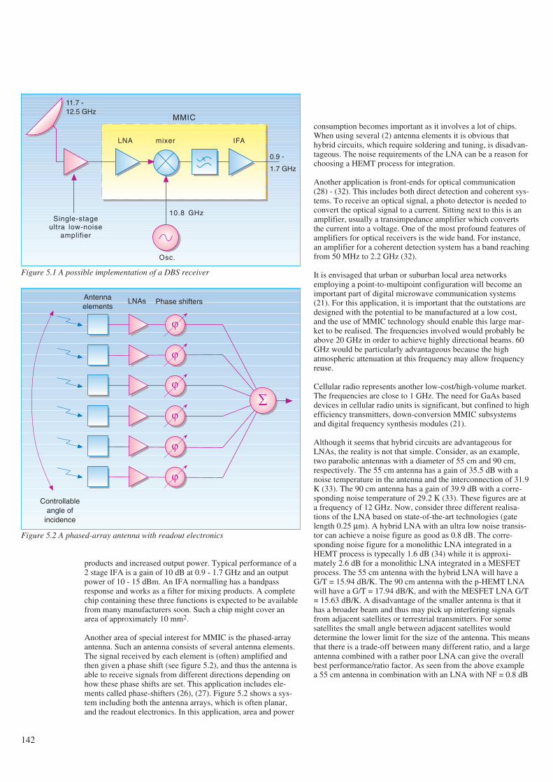
products and increased output power. Typical performance of a2 stage IFA is a gain of 10 dB at 0.9 - 1.7 GHz and an outputpower of 10 - 15 dBm. An IFA normalling has a bandpassresponse and works as a filter for mixing products. A completechip containing these three functions is expected to be availablefrom many manufacturers soon. Such a chip might cover anarea of approximately 10 mm2.
Another area of special interest for MMIC is the phased-arrayantenna. Such an antenna consists of several antenna elements.The signal received by each element is (often) amplified andthen given a phase shift (see figure 5.2), and thus the antenna isable to receive signals from different directions depending onhow these phase shifts are set. This application includes ele-ments called phase-shifters (26), (27). Figure 5.2 shows a sys-tem including both the antenna arrays, which is often planar,and the readout electronics. In this application, area and power
consumption becomes important as it involves a lot of chips.When using several (2) antenna elements it is obvious thathybrid circuits, which require soldering and tuning, is disadvan-tageous. The noise requirements of the LNA can be a reason forchoosing a HEMT process for integration.
Another application is front-ends for optical communication(28) - (32). This includes both direct detection and coherent sys-tems. To receive an optical signal, a photo detector is needed toconvert the optical signal to a current. Sitting next to this is anamplifier, usually a transimpedance amplifier which convertsthe current into a voltage. One of the most profound features ofamplifiers for optical receivers is the wide band. For instance,an amplifier for a coherent detection system has a band reachingfrom 50 MHz to 2.2 GHz (32).
It is envisaged that urban or suburban local area networksemploying a point-to-multipoint configuration will become animportant part of digital microwave communication systems(21). For this application, it is important that the outstations aredesigned with the potential to be manufactured at a low cost,and the use of MMIC technology should enable this large mar-ket to be realised. The frequencies involved would probably beabove 20 GHz in order to achieve highly directional beams. 60GHz would be particularly advantageous because the highatmospheric attenuation at this frequency may allow frequencyreuse.
Cellular radio represents another low-cost/high-volume market.The frequencies are close to 1 GHz. The need for GaAs baseddevices in cellular radio units is significant, but confined to highefficiency transmitters, down-conversion MMIC subsystemsand digital frequency synthesis modules (21).
Although it seems that hybrid circuits are advantageous forLNAs, the reality is not that simple. Consider, as an example,two parabolic antennas with a diameter of 55 cm and 90 cm,respectively. The 55 cm antenna has a gain of 35.5 dB with anoise temperature in the antenna and the interconnection of 31.9K (33). The 90 cm antenna has a gain of 39.9 dB with a corre-sponding noise temperature of 29.2 K (33). These figures are ata frequency of 12 GHz. Now, consider three different realisa-tions of the LNA based on state-of-the-art technologies (gatelength 0.25 µm). A hybrid LNA with an ultra low noise transis-tor can achieve a noise figure as good as 0.8 dB. The corre-sponding noise figure for a monolithic LNA integrated in aHEMT process is typecally 1.6 dB (34) while it is approxi-mately 2.6 dB for a monolithic LNA integrated in a MESFETprocess. The 55 cm antenna with the hybrid LNA will have aG/T = 15.94 dB/K. The 90 cm antenna with the p-HEMT LNAwill have a G/T = 17.94 dB/K, and with the MESFET LNA G/T= 15.63 dB/K. A disadvantage of the smaller antenna is that ithas a broader beam and thus may pick up interfering signalsfrom adjacent satellites or terrestrial transmitters. For somesatellites the small angle between adjacent satellites woulddetermine the lower limit for the size of the antenna. This meansthat there is a trade-off between many different ratio, and a largeantenna combined with a rather poor LNA can give the overallbest performance/ratio factor. As seen from the above examplea 55 cm antenna in combination with an LNA with NF = 0.8 dB
142
10.8 GHz
Osc.
mixerLNA IFA
0.9 -
1.7 GHz
11.7 -12.5 GHz
Single-stageultra low-noise
amplifier
MMIC
Figure 5.1 A possible implementation of a DBS receiver
Antennaelements
LNAs Phase shifters
ϕ
ϕ
ϕ
ϕ
ϕ
ϕ
∑
Controllableangle of
incidence
Figure 5.2 A phased-array antenna with readout electronics
has the same figure of merit as a 90 cm antenna in combinationwith an LNA with NF = 2.45 dB. The performance of the latterLNA is expected to be at hand for a straightforward standardMESFET technology in the near future. This means that thisfunction can be integrated on the complete chip and comesalmost for free.
6 Concluding remarks
The influence which the development of microelectronics hashad on the development of new and improved telecommunica-tion services is obvious and is a matter of no discussion. Boththe complexity of these services and the reduced costs, whichhave increased the availability, is based on the possibility ofintegration of multifunctions on monolithic chips. We believethat the development of new and better microelectronic tech-nologies will continue and further decrease the cost per func-tion, improve the performance of these functions, and also makeit possible to integrate completely new functions.
Microwave frequencies is a new area of applications for mono-lithic circuits. To date this area has been covered by expensivesemiconductor devices and tubes. Monolithic integration hasseveral advantages in the high frequency area such as shortersignal path, lower cost per function, small volume and area, andlow power consumption. Price reduction opens up for a wideruse while improved performance opens up for new applications.One interesting point is that when MMICs come into use in ahigh volume market with a potential for high profit this will be amajor force behind the development of this technology. Webelieve that this is about to happen and that GaAs will be a veryimportant technology through the 1990s. If the development aswe have seen it the last 5 years continues in the same escalatingrate, the very interesting 60 GHz frequency can be utilised inthe near future. Technology with high ft and high reproducibilityis a condition for this to happen. GaAs is the semiconductormaterial with the best properties for use at microwave frequen-cies. Although silicon is moving upwards in frequency due toimprovements in lithography, GaAs will benefit from the samedegree of miniaturisation and stay ahead because of higher car-rier mobility and electron velocity.
GaAs MMIC will become a very important technology by mak-ing it possible to utilise higher frequencies. It offers propertiesrequired for making functions with good performance at a lowcost. Monolithic integration offers reduced costs by reducingthe cost per function considerably. It is important to master thistechnology to be able to anticipate the development of new tele-com services and new possibilities at higher frequencies.
7 References
1 Pucel, R A. Design considerations for monolithicmicrowave circuits. IEEE transactions on microwave theoryand techniques, 29, 513-534, 1981.
2 Mehal, E, Wacker, R W. GaAs integrated microwave cir-cuits. IEEE transactions on microwave theory and tech-niques, 16, 451-454, 1968.
3 Pengelly, R S, Turner, J A. Monolithic broadband GaAsFET amplifiers. Electronics letters, 12, 251-252, 1976.
4 Kato, H et al. A 30 GHz MMIC receiver for satellitetransponders. IEEE transactions on microwave theory andtechniques, 38, 896-902, 1990.
5 Sze, S M. Semiconductor devices: physics and technology.New York, John Wiley & sons, 1985. ISBN 0-471-83704-0.
6 Ladbrooke, P H. MMIC design: GaAs FETs and HEMTs.Boston, Artech House, 1988. ISBN 0-89006-314-1.
7 Tiwari, S. Compound semiconductor device physics.Boston, Academic Press, 1992. ISBN 0-12-691740-X.
8 Sivertsen, R, Paulsen, A. 283,000 cm2/Vs mobility in GaAsgrown by MBE using As4. Sixth European conference onmolecular beam epitaxy and related growth methods, Tam-pere, Finland, 1991.
9 Dingle, R et al. Electron mobilities in modulation dopedsemiconductor heterojunction superlattices. Applied physicsletters, 33, 665-667, 1978.
10 Nguyen, L D, Larson, L E, Mishra, U K. Ultra-high-speedmodulation-doped field-effect transistors: A tutorial review.Proceedings of the IEEE, 80, 494-518, 1992.
11 Foisy, M C et al. The role of inefficient charge modulationin limiting the current gain cutoff frequency of the MOD-FET. IEEE transactions on electron devices, 35, 871-878,1988.
12 Lee, R E et al. Ultra-low noise millimeter-wave pseudomor-phic HEMT’s. IEEE transactions on microwave theory andtechniques, 37, 2086-2092, 1989.
13 Duh, K H G et al. A super low-noise 0.1 µm T-gate InAlAs-InGaAs-InP HEMT. IEEE microwave and guidedwave letters, 1, 114-116, 1991.
14 Nguyen, L D et al. 50-nm self-aligned-gate pseudomorphicAlInAs/GaInAs high electron mobility transistors. IEEEtransactions on electron devices, 39, 2007-2014, 1992.
15 Goyal, R (Ed). Monolithic microwave integrated circuits:Technology & design. Boston, Artech House, 1989. ISBN0-89006-309-5.
16 Feng, M, Laskar, J, Kruse, J. Super-low-noise performanceof direct-ion-implanted 0.25-µm-gate GaAs MESFET’s.IEEE electron device letters, 13, 241-243, 1992.
17 Feng, M et al. Ultra low-noise performance of 0.15-microngate GaAs MESFET’s made by direct ion implantation forlow-cost MMIC’s applications. IEEE microwave andguided wave letters, 2, 194-195, 1992.
18 Feng, M et al. Does the two-dimensional electron gas effectcontribute to high-frequency and high-speed performance offield-effect transistors? Applied physics letters, 57, 1233-1235, 1990.
143
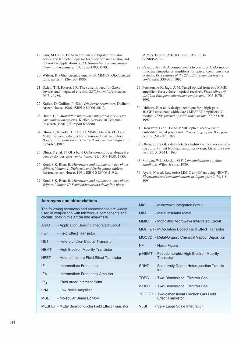
19 Kim, M E et al. GaAs heterojunction bipolar transistordevice and IC technology for high-performance analog andmicrowave applications. IEEE transactions on microwavetheory and techniques, 37, 1286-1303, 1989.
20 Wilson, K. Other circuit elements for MMICs. GEC journalof research, 4, 126-133, 1986.
21 Oxley, T H, Forrest, J R. The systems need for GaAsdevices and integrated circuits. GEC journal of research, 4,66-71, 1986.
22 Kajfez, D, Guillon, P (Eds). Dielectric resonators. Dedham,Artech House, 1986. ISBN 0-89006-201-3.
23 Heide, C F. Monolithic microwave integrated circuits forcommunication systems. Kjeller, Norwegian TelecomResearch, 1990. (TF-report R38/90)
24 Ohira, T, Hiraoka, T, Kato, H. MMIC 14-GHz VCO andMiller frequency divider for low-noise local oscillators.IEEE transactions on microwave theory and techniques, 35,657-662, 1987.
25 Ohira, T et al. 14 GHz band GaAs monolithic analogue fre-quency divider. Electronics letters, 21, 1057-1058, 1985.
26 Koul, S K, Bhat, B. Microwave and millimeter wave phaseshifters. Volume I: Dielectric and ferrite phase shifters.Boston, Artech House, 1991. ISBN 0-89006-319-2.
27 Koul, S K, Bhat, B. Microwave and millimeter wave phaseshifters. Volume II: Semiconductor and delay line phase
shifters. Boston, Artech House, 1992. ISBN 0-89006-585-3.
28 Casao, J A et al. A comparison between three GaAs mono-lithic transimpedance amplifiers for optical communicationsystems. Proceedings of the 22nd European microwaveconference, 330-335, 1992.
29 Petersen, A K, Jagd, A M. Tuned optical front-end MMICamplifiers for a coherent optical receiver. Proceedings ofthe 22nd European microwave conference, 1065-1070,1992.
30 Ishihara, N et al. A design technique for a high-gain, 10-GHz class-bandwidth GaAs MESFET amplifiers ICmodule. IEEE journal of solid-state circuits, 27, 554-561,1992.
31 Darwazeh, I et al. GaAs MMIC optical receiver withembedded signal processing. Proceedings of the IEE, partG, 139, 241-243, 1992.
32 Olsen, T. 2.2 GHz dual-detector lightwave receiver employ-ing current shunt feedback amplifier design. Electronics let-ters, 26, 510-511, 1990.
33 Morgan, W L, Gordon, G P. Communications satellitehandbook. Wiley & sons, 1989.
34 Ayaki, N et al. Low noise MMIC amplifiers using HEMTs.Electronics and communications in Japan, part 2, 74, 1-8,1991.
144
Acronyms and abbreviations
The following acronyms and abbreviations are widelyused in conjunction with microwave components andcircuits, both in this article and elsewhere.
ASIC - Application Specific Integrated Circuit
FET - Field Effect Transistor
HBT - Heterojunction Bipolar Transistor
HEMT - High Electron Mobility Transistor
HFET - Heterostructure Field Effect Transistor
IF - Intermediate Frequency
IFA - Intermediate Frequency Amplifier
IP3 - Third order Intercept Point
LNA - Low Noise Amplifier
MBE - Molecular Beam Epitaxy
MESFET - MEtal Semiconductor Field Effect Transistor
MIC - Microwave Integrated Circuit
MIM - Metal Insulator Metal
MMIC - Monolithic Microwave Integrated Circuit
MODFET - MOdulation Doped Field Effect Transistor
MOCVD - Metal-Organic Chemical Vapour Deposition
NF - Noise Figure
p-HEMT - Pseudomorphic High Electron MobilityTransistor
SDHT - Selectively Doped Heterojunction Transis-tor
TDEG - Two-Dimensional Electron Gas
2-DEG - Two-Dimensional Electron Gas
TEGFET - Two-dimensional Electron Gas FieldEffect Transistor
VLSI - Very Large Scale Integration
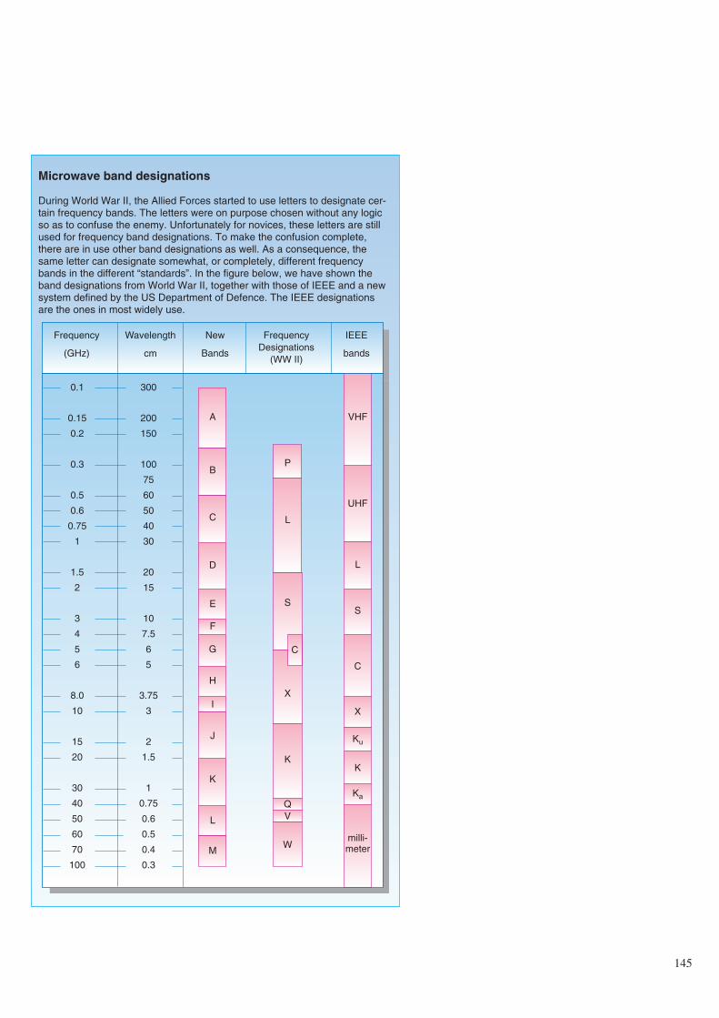
145
Microwave band designations
During World War II, the Allied Forces started to use letters to designate cer-tain frequency bands. The letters were on purpose chosen without any logicso as to confuse the enemy. Unfortunately for novices, these letters are stillused for frequency band designations. To make the confusion complete,there are in use other band designations as well. As a consequence, thesame letter can designate somewhat, or completely, different frequencybands in the different “standards”. In the figure below, we have shown theband designations from World War II, together with those of IEEE and a newsystem defined by the US Department of Defence. The IEEE designationsare the ones in most widely use.
Frequency
(GHz)
Wavelength
cm
New
Bands
FrequencyDesignations
(WW II)
IEEE
bands
0.1
0.15
0.2
0.3
0.5
0.6
0.75
1
1.5
2
3
4
5
6
8.0
10
15
20
30
40
50
60
70
100
300
200
150
100
75
60
50
40
30
20
15
10
7.5
6
5
3.75
3
2
1.5
1
0.75
0.6
0.5
0.4
0.3
A
B
D
C
E
F
G
H
J
I
K
L
M
VHF
UHF
L
S
C
X
Ku
K
Ka
milli-meter
P
L
S
X
C
K
Q
W
V
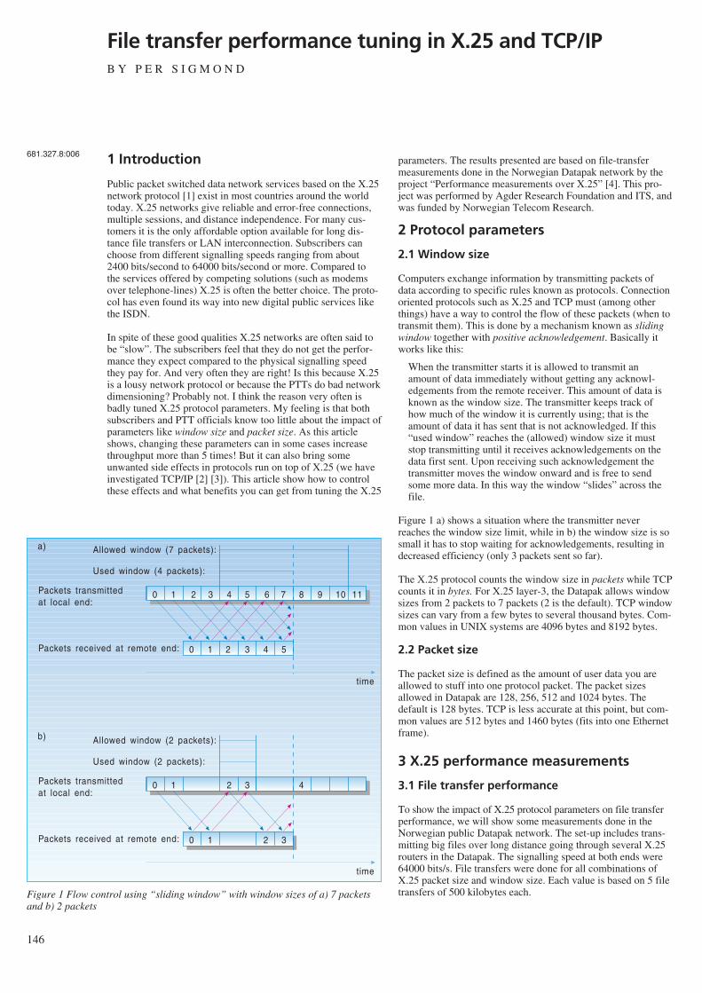
146
File transfer performance tuning in X.25 and TCP/IPB Y P E R S I G M O N D
1 Introduction
Public packet switched data network services based on the X.25network protocol [1] exist in most countries around the worldtoday. X.25 networks give reliable and error-free connections,multiple sessions, and distance independence. For many cus-tomers it is the only affordable option available for long dis-tance file transfers or LAN interconnection. Subscribers canchoose from different signalling speeds ranging from about2400 bits/second to 64000 bits/second or more. Compared tothe services offered by competing solutions (such as modemsover telephone-lines) X.25 is often the better choice. The proto-col has even found its way into new digital public services likethe ISDN.
In spite of these good qualities X.25 networks are often said tobe “slow”. The subscribers feel that they do not get the perfor-mance they expect compared to the physical signalling speedthey pay for. And very often they are right! Is this because X.25is a lousy network protocol or because the PTTs do bad networkdimensioning? Probably not. I think the reason very often isbadly tuned X.25 protocol parameters. My feeling is that bothsubscribers and PTT officials know too little about the impact ofparameters like window size and packet size. As this articleshows, changing these parameters can in some cases increasethroughput more than 5 times! But it can also bring someunwanted side effects in protocols run on top of X.25 (we haveinvestigated TCP/IP [2] [3]). This article show how to controlthese effects and what benefits you can get from tuning the X.25
parameters. The results presented are based on file-transfermeasurements done in the Norwegian Datapak network by theproject “Performance measurements over X.25” [4]. This pro-ject was performed by Agder Research Foundation and ITS, andwas funded by Norwegian Telecom Research.
2 Protocol parameters
2.1 Window size
Computers exchange information by transmitting packets ofdata according to specific rules known as protocols. Connectionoriented protocols such as X.25 and TCP must (among otherthings) have a way to control the flow of these packets (when totransmit them). This is done by a mechanism known as slidingwindow together with positive acknowledgement. Basically itworks like this:
When the transmitter starts it is allowed to transmit anamount of data immediately without getting any acknowl-edgements from the remote receiver. This amount of data isknown as the window size. The transmitter keeps track ofhow much of the window it is currently using; that is theamount of data it has sent that is not acknowledged. If this“used window” reaches the (allowed) window size it muststop transmitting until it receives acknowledgements on thedata first sent. Upon receiving such acknowledgement thetransmitter moves the window onward and is free to sendsome more data. In this way the window “slides” across thefile.
Figure 1 a) shows a situation where the transmitter neverreaches the window size limit, while in b) the window size is sosmall it has to stop waiting for acknowledgements, resulting indecreased efficiency (only 3 packets sent so far).
The X.25 protocol counts the window size in packets while TCPcounts it in bytes. For X.25 layer-3, the Datapak allows windowsizes from 2 packets to 7 packets (2 is the default). TCP windowsizes can vary from a few bytes to several thousand bytes. Com-mon values in UNIX systems are 4096 bytes and 8192 bytes.
2.2 Packet size
The packet size is defined as the amount of user data you areallowed to stuff into one protocol packet. The packet sizesallowed in Datapak are 128, 256, 512 and 1024 bytes. Thedefault is 128 bytes. TCP is less accurate at this point, but com-mon values are 512 bytes and 1460 bytes (fits into one Ethernetframe).
3 X.25 performance measurements
3.1 File transfer performance
To show the impact of X.25 protocol parameters on file transferperformance, we will show some measurements done in theNorwegian public Datapak network. The set-up includes trans-mitting big files over long distance going through several X.25routers in the Datapak. The signalling speed at both ends were64000 bits/s. File transfers were done for all combinations ofX.25 packet size and window size. Each value is based on 5 filetransfers of 500 kilobytes each.
681.327.8:006
0 1 2 3 4 5 6 7 8 9 10 11
0 1 2 3 4 5
Used window (4 packets):
Allowed window (7 packets):
Packets transmittedat local end:
Packets received at remote end:
time
0 1 2 3 4
0 1 2 3
Used window (2 packets):
Allowed window (2 packets):
Packets transmittedat local end:
Packets received at remote end:
time
a)
b)
Figure 1 Flow control using “sliding window” with window sizes of a) 7 packetsand b) 2 packets
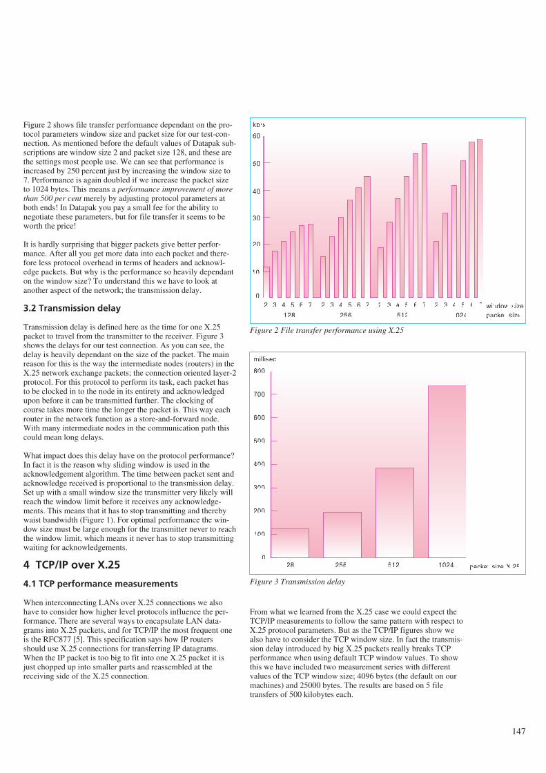
Figure 2 shows file transfer performance dependant on the pro-tocol parameters window size and packet size for our test-con-nection. As mentioned before the default values of Datapak sub-scriptions are window size 2 and packet size 128, and these arethe settings most people use. We can see that performance isincreased by 250 percent just by increasing the window size to7. Performance is again doubled if we increase the packet sizeto 1024 bytes. This means a performance improvement of morethan 500 per cent merely by adjusting protocol parameters atboth ends! In Datapak you pay a small fee for the ability tonegotiate these parameters, but for file transfer it seems to beworth the price!
It is hardly surprising that bigger packets give better perfor-mance. After all you get more data into each packet and there-fore less protocol overhead in terms of headers and acknowl-edge packets. But why is the performance so heavily dependanton the window size? To understand this we have to look atanother aspect of the network; the transmission delay.
3.2 Transmission delay
Transmission delay is defined here as the time for one X.25packet to travel from the transmitter to the receiver. Figure 3shows the delays for our test connection. As you can see, thedelay is heavily dependant on the size of the packet. The mainreason for this is the way the intermediate nodes (routers) in theX.25 network exchange packets; the connection oriented layer-2protocol. For this protocol to perform its task, each packet hasto be clocked in to the node in its entirety and acknowledgedupon before it can be transmitted further. The clocking ofcourse takes more time the longer the packet is. This way eachrouter in the network function as a store-and-forward node.With many intermediate nodes in the communication path thiscould mean long delays.
What impact does this delay have on the protocol performance?In fact it is the reason why sliding window is used in theacknowledgement algorithm. The time between packet sent andacknowledge received is proportional to the transmission delay.Set up with a small window size the transmitter very likely willreach the window limit before it receives any acknowledge-ments. This means that it has to stop transmitting and therebywaist bandwidth (Figure 1). For optimal performance the win-dow size must be large enough for the transmitter never to reachthe window limit, which means it never has to stop transmittingwaiting for acknowledgements.
4 TCP/IP over X.25
4.1 TCP performance measurements
When interconnecting LANs over X.25 connections we alsohave to consider how higher level protocols influence the per-formance. There are several ways to encapsulate LAN data-grams into X.25 packets, and for TCP/IP the most frequent oneis the RFC877 [5]. This specification says how IP routersshould use X.25 connections for transferring IP datagrams.When the IP packet is too big to fit into one X.25 packet it isjust chopped up into smaller parts and reassembled at thereceiving side of the X.25 connection.
From what we learned from the X.25 case we could expect theTCP/IP measurements to follow the same pattern with respect toX.25 protocol parameters. But as the TCP/IP figures show wealso have to consider the TCP window size. In fact the transmis-sion delay introduced by big X.25 packets really breaks TCPperformance when using default TCP window values. To showthis we have included two measurement series with differentvalues of the TCP window size; 4096 bytes (the default on ourmachines) and 25000 bytes. The results are based on 5 filetransfers of 500 kilobytes each.
147
2 3 4 5 6 7 2 3 4 5 6 7 2 3 4 5 6 7 2 3 4 5 6 70
10
20
30
40
50
60
128 256 512 1024
kb/s
window sizepacket size
Figure 2 File transfer performance using X.25
128 256 512 10240
100
200
300
400
500
600
700
800
packet size X.25
millisec
Figure 3 Transmission delay
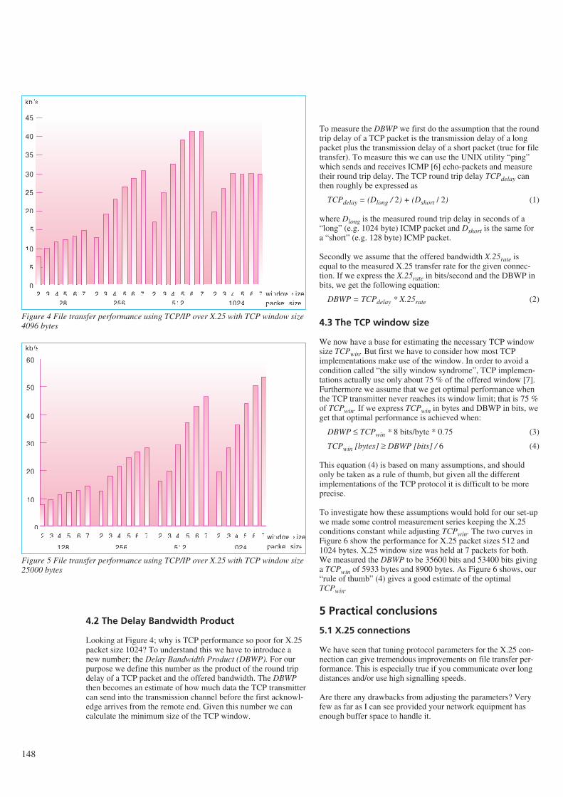
148
4.2 The Delay Bandwidth Product
Looking at Figure 4; why is TCP performance so poor for X.25packet size 1024? To understand this we have to introduce anew number; the Delay Bandwidth Product (DBWP). For ourpurpose we define this number as the product of the round tripdelay of a TCP packet and the offered bandwidth. The DBWPthen becomes an estimate of how much data the TCP transmittercan send into the transmission channel before the first acknowl-edge arrives from the remote end. Given this number we cancalculate the minimum size of the TCP window.
To measure the DBWP we first do the assumption that the roundtrip delay of a TCP packet is the transmission delay of a longpacket plus the transmission delay of a short packet (true for filetransfer). To measure this we can use the UNIX utility “ping”which sends and receives ICMP [6] echo-packets and measuretheir round trip delay. The TCP round trip delay TCPdelay canthen roughly be expressed as
TCPdelay = (Dlong / 2) + (Dshort / 2) (1)
where Dlong is the measured round trip delay in seconds of a“long” (e.g. 1024 byte) ICMP packet and Dshort is the same fora “short” (e.g. 128 byte) ICMP packet.
Secondly we assume that the offered bandwidth X.25rate isequal to the measured X.25 transfer rate for the given connec-tion. If we express the X.25rate in bits/second and the DBWP inbits, we get the following equation:
DBWP = TCPdelay * X.25rate (2)
4.3 The TCP window size
We now have a base for estimating the necessary TCP windowsize TCPwin. But first we have to consider how most TCPimplementations make use of the window. In order to avoid acondition called “the silly window syndrome”, TCP implemen-tations actually use only about 75 % of the offered window [7].Furthermore we assume that we get optimal performance whenthe TCP transmitter never reaches its window limit; that is 75 %of TCPwin. If we express TCPwin in bytes and DBWP in bits, weget that optimal performance is achieved when:
DBWP ≤ TCPwin * 8 bits/byte * 0.75 (3)
TCPwin [bytes] ≥ DBWP [bits] / 6 (4)
This equation (4) is based on many assumptions, and shouldonly be taken as a rule of thumb, but given all the differentimplementations of the TCP protocol it is difficult to be moreprecise.
To investigate how these assumptions would hold for our set-upwe made some control measurement series keeping the X.25conditions constant while adjusting TCPwin. The two curves inFigure 6 show the performance for X.25 packet sizes 512 and1024 bytes. X.25 window size was held at 7 packets for both.We measured the DBWP to be 35600 bits and 53400 bits givinga TCPwin of 5933 bytes and 8900 bytes. As Figure 6 shows, our“rule of thumb” (4) gives a good estimate of the optimalTCPwin.
5 Practical conclusions
5.1 X.25 connections
We have seen that tuning protocol parameters for the X.25 con-nection can give tremendous improvements on file transfer per-formance. This is especially true if you communicate over longdistances and/or use high signalling speeds.
Are there any drawbacks from adjusting the parameters? Veryfew as far as I can see provided your network equipment hasenough buffer space to handle it.
128 256 512 1024
kb/s
window sizepacket size
2 3 4 5 6 7 2 3 4 5 6 7 2 3 4 5 6 7 2 3 4 5 6 70
5
10
15
20
25
30
35
40
45
Figure 4 File transfer performance using TCP/IP over X.25 with TCP window size4096 bytes
128 256 512 1024
kb/s
window sizepacket size
2 3 4 5 6 7 2 3 4 5 6 7 2 3 4 5 6 7 2 3 4 5 6 70
10
20
30
40
50
60
Figure 5 File transfer performance using TCP/IP over X.25 with TCP window size25000 bytes
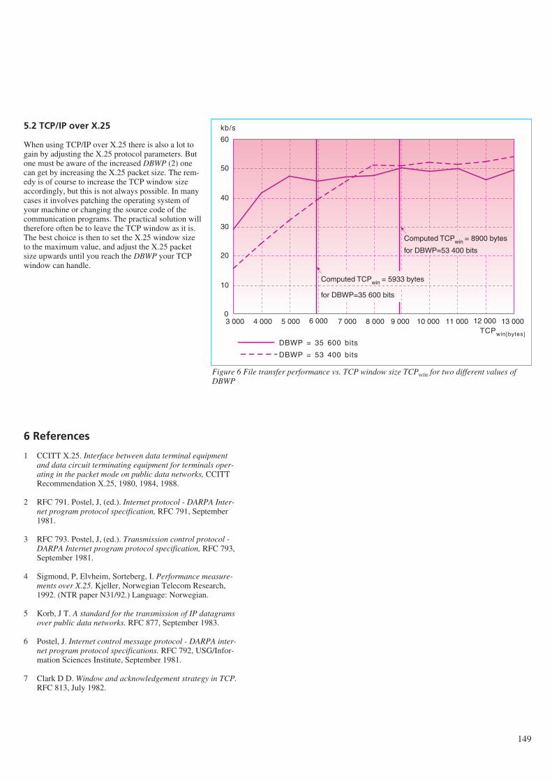
5.2 TCP/IP over X.25
When using TCP/IP over X.25 there is also a lot togain by adjusting the X.25 protocol parameters. Butone must be aware of the increased DBWP (2) onecan get by increasing the X.25 packet size. The rem-edy is of course to increase the TCP window sizeaccordingly, but this is not always possible. In manycases it involves patching the operating system ofyour machine or changing the source code of thecommunication programs. The practical solution willtherefore often be to leave the TCP window as it is.The best choice is then to set the X.25 window sizeto the maximum value, and adjust the X.25 packetsize upwards until you reach the DBWP your TCPwindow can handle.
6 References
1 CCITT X.25. Interface between data terminal equipmentand data circuit terminating equipment for terminals oper-ating in the packet mode on public data networks, CCITTRecommendation X.25, 1980, 1984, 1988.
2 RFC 791. Postel, J, (ed.). Internet protocol - DARPA Inter-net program protocol specification, RFC 791, September1981.
3 RFC 793. Postel, J, (ed.). Transmission control protocol -DARPA Internet program protocol specification, RFC 793,September 1981.
4 Sigmond, P, Elvheim, Sorteberg, I. Performance measure-ments over X.25. Kjeller, Norwegian Telecom Research,1992. (NTR paper N31/92.) Language: Norwegian.
5 Korb, J T. A standard for the transmission of IP datagramsover public data networks. RFC 877, September 1983.
6 Postel, J. Internet control message protocol - DARPA inter-net program protocol specifications. RFC 792, USG/Infor-mation Sciences Institute, September 1981.
7 Clark D D. Window and acknowledgement strategy in TCP.RFC 813, July 1982.
149
Computed TCPwin = 5933 bytes
3 000 4 000 5 000 6 000 7 000 8 000 9 000 10 000 11 000 12 000 13 0000
10
20
30
40
50
60
for DBWP=35 600 bits
Computed TCPwin = 8900 bytes
for DBWP=53 400 bits
TCPwin[bytes]
kb/s
DBWP = 35 600 bits
DBWP = 53 400 bits
Figure 6 File transfer performance vs. TCP window size TCPwin for two different values ofDBWP
150
Software maintainability – on purpose or accidentally?B Y M A G N E J Ø R G E N S E N
“The first step (to face the phenomenon of software systemchange), is to accept the fact of change as a way of life, ratherthan an untoward and annoying exception.” 1)
1 Introduction
During the early days of programming a normal maintenancerate was four boxes of cards per full time maintenance program-mer, (16). A box of cards contained about 2,000 cards and eachcard one line of assembly code. It takes about three assemblylanguage lines of code to produce the functionality of one Cobolline of code (6). A full time maintenance programmer was con-sequently able to maintain the functionality of (4*2000)/3 ≅2700 lines of Cobol code.
Times have changed! In a study I conducted at the systemdevelopment section (ES) at the Norwegian Telecom in1991/92, see (7), I found the average number of lines of Cobolcode maintained per full time maintenance programmer to bemore than 120000. That is about 45 times more. With the sameproductivity as in the “good old days” and the same number oflines of code as today we probably would have no unemployedpeople in Norway. The system development section referred toabove alone would require more than 1000 full time mainte-nance programmers to maintain its 2.7 million lines of code (seefigure 1).
In spite of this enormous productivity increase I believe soft-ware maintenance should be considered a most serious problem
in the software area today. The facts and opinions presented inbox one support this belief.
This article outlines one approach to decrease the maintenanceproblems: preparing the software for software maintenance.Using this approach the maintainability characteristics of thesoftware will be based on rational decisions instead of trustingthat “good software development practice” will result in desiredmaintainability.
2 What is software maintenance?
A search in the literature for definitions of software mainte-nance may be a bit confusing, since there exist many quite dif-ferent and even slightly contradictory definitions and de-scriptions of the term. In addition there are several other termsdenoting almost the same. Even within a homogenous program-ming team maintaining the same software, rather different inter-pretations may be present, see (7). Examples of different soft-ware maintenance definitions and synonyms are collected in boxtwo. In many contexts it is very important to be aware of this“confusion” to avoid misunderstandings.
I do not think software maintenance is a good term, since main-tenance normally is associated with physical degradation androutine work. Nevertheless, I will use the term ‘software main-tenance’ here, since the introduction of a new term, like ‘furtherdevelopment’ may introduce misinterpretations as well.
There is no “best” definition of software maintenance. Person-ally, I prefer definition 2, box two, when speaking generallyabout software maintenance, as I will do in this article. That
Abstract
In spite of an enormous productivity increase among software maintainers the maintenance problem is increasing. One reason forthis may be the fact that it is common to believe that “good programmer practice” and “modern development methods” alone willgive maintainable software. This is a dangerous belief and this article argues for an extensive and problem specific maintenancepreparation. An example and an outline for doing this are presented.
1) Frederick P Brooks Jr., The mythical man-month, p 117.
Figure 1
681.3.06.004.5
definition is not very “operational”. Thus, when conducting anexperiment another definition will probably be more useful, forinstance definition 1 or 6, box two.
3 Preparing for maintenance
Preparing for maintenance should take place in every phase ofthe software life cycle. The objective of the activity is to makethe subsequent maintenance more efficient. The activity is dif-ferent from for instance software testing, which aims at remov-ing faults in the software, not at more maintainable software.
As indicated in box one, the maintenance costs constitute alarge part of the total software costs. It would, for this reason,be natural that activities aiming at more maintainable softwarewould be important in most software development projects. I donot think it is, today. I believe it is rather unusual to make anextensive analysis of how to develop software to achieve thedesired maintainability. This may be due to time pressure orlack of knowledge about what makes software maintainable, butalso due to the two beliefs described below:
- Software easy to develop will be easy to maintain. That is,take care of the development and the maintainability will takecare of itself.
- Choice and use of “modern” software development methodsare sufficient preparation for the maintenance of software.
Of course, none of these beliefs are totally unsupported byempirical evidence. The productivity increase among softwaremaintainers, described in the introduction, may, to a largeextent, have been caused by “modern” development methods,like the method of structured programming. However, thebeliefs are not always correct today and may be even less cor-rect in the future. This is further illustrated in the next two sec-tions.
3.1 The impact of the development method onthe maintainability
When someone, for instance a vendor of software developmentmethods, claims that his method produces more maintainablesoftware than other methods, two assumptions seem underlying:
- Assumption one: The choice of development method has aconsiderable influence on the maintainability of the software.(The method would otherwise be of little interest for themaintenance programmers.)
- Assumption two: All “intended” ways of using the methodproduce more maintainable software than other methodsfaced with the same problem to solve.
Most programmers probably would accept assumption one,although we often do not know! It may be dangerous to acceptapparently obvious beliefs without having enough supportingfacts, or to quote Sherlock Holmes: “It is a capital mistake totheorise before one has data. Insensibly one begins to twist factsto suit theories, instead of theories to suit facts.”2)
Characteristics not part of a method, for instance the experienceand “intelligence” of the programmers, may be the far mostdominant determinators of the maintainability.
Newel and Simon, in (12), propose that “The task environment(plus the intelligence of the problem solver) determines to alarge extent the behaviour of the problem solver ...” This propo-sition is based on a number of experiments where moderatelydifficult problems in chess, symbolic logic and cryptarithmeticpuzzles were solved, and the proposition might support assump-tion one. We should, however, have in mind that softwaredevelopment and maintenance probably are more “compound”activities than the activities studied by Newel and Simon.
Surprisingly, there has been very little empirical research on theimpact of development methods on the maintainability of soft-ware. In addition, the few research results we have are notunambiguous, see for instance (3). This lack of research hasresulted in the unsatisfactory situation where the choice ofdevelopment method cannot be based on “empirical facts”. Thechoice of development method, programming languages andtools is often more like an “act of faith” than a “scientific” deci-sion.
Assumption two is obviously dubious. It is, for instance, easy toconstruct examples where an unstructured C-program withGOTOs looks, in my view, more maintainable than a well struc-tured3) C-program solving the same problem, see box three.This means that even the assertion that structured programmingproduces more maintainable programs than unstructured pro-gramming with GOTOs is not always correct!
The almost total avoidance of GOTO-constructs in many pro-grams developed in the last few years is hence not only a goodsign. There may be a situation where the purpose, that isincrease software maintainability, of a software engineering ruleis forgotten and the rule itself is given the status of a principle;“You shall not use GOTOs”. The situation for structured pro-gramming, object oriented programming and for developmentmethods is much the same.
3.2 The profitability of preparing for maintenance
Software maintenance may be divided into maintenance dealingwith error corrections and maintenance dealing with other pro-gram modifications, e.g. enhancements. The first category, cor-rections of errors, only accounts for around 20 % of the totalmaintenance costs, according to (8) and (13). 80 % of the soft-ware maintenance cost is consequently caused by modificationsnot related to error corrections.
It is commonly accepted that an error detected in the design orrequirement phase normally costs several times less to correctthan the same error detected in later phases, like the system test
2) Sir Arthur Conan Doyle, A scandal in Bohemia.
3) There is a lot of confusion about structuredness. Here I usethe definition from(8) where a structured program is definedas a program with “Essential complexity” = 1.
151
152
phase or the maintenance phase. The German company Siemenshas calculated that the cost of correcting an error in the opera-tion system BS2000 in average amounts to about 2,000 DM inthe development phase, 6,000 DM in the system test phase and20,000 DM in the maintenance phase, that is about ten timesmore in the maintenance phase than in the development phase.
Do we have a similar relation between modifications preparedfor the development phase and modification not prepared for? Ifwe have, it will be profitable to be very concerned with prepara-tions for modifiability. No study, as far as I know, has focusedon this question.
It is, however, rather obvious that a vendor must release newprogram versions quickly, with high quality and low costs tostay in business and to generate profit. This requires a highlymaintainable software, I think.
There are arguments against the profitability of planning forsoftware modifications, as well. A major argument is that if itreally was profitable to plan for future modifications the soft-ware companies probably would have been doing it. The soft-ware companies invest a lot of money in the software and wantthe best possible return on their investment. For this reason thesoftware will, assuming rational investors, adjust to an optimummaintainability, given the time, personnel, and the money avail-able.
Another argument against the planning is that we do not knowwhat the future modifications will be. Preparing for future mod-ifications will thus be planning for the unexpected, a meaning-less activity.
I think the arguments against planning for modifiability are notvalid and in section 3.3 I give argument supporting my opinion.I do this in an outline of how to do the maintenance preparation.
3.3 How to do maintenance preparation
As said earlier, the modification part of software maintenanceconsumes about 80 % of the total software maintenance costs.For this reason, I will mainly focus on the preparation for modi-fications in this chapter. I will first give an example of mainte-nance preparation, section 3.3.1, and then give a brief outline ofa possible maintenance preparation approach in section 3.3.2.
3.3.1 Example of maintenance preparation
Let us say we want to develop a tax calculation program, wherethe tax rates are described as follows:
Tax rate Income limits
0 % of the first 122,00010 % of the next 36,00017 % of the remaining net income
The calculation of the tax can be implemented in several quitedifferent ways, see box four for six different implementations ina Pascal-like language. A programmer not preparing the imple-mentation for subsequent maintenance will probably implement
the tax calculation the way he intuitively feels is the best and inaccordance with “good programmer practice”. For me this wasalternative 1 which, after some analysis, turned out to be one ofthe least maintainable alternatives.
Typical changes in tax rules are changes in the tax rates, theincome limits for the different tax rates and the number of taxrates.
Change of tax rates and income limits can be easily performedon all alternatives, except change of the first tax rate (0 %)!Alternatives 1, 2, 3, and 6 have not prepared for a change of thistax rate. If it is likely that this rate will remain equal to 0 %, it isOK. If not, we should choose another way to implement the taxcalculation.
Changes of the number of tax rates, for instance by introducinga new tax rate and income limit as indicated below, involve sig-nificantly more difficult changes for alternatives 1, 2, and 3 thanalternatives 4, 5, and 6.
Tax rate Income limits
0 % of the first 122,00010 % of the next 36,00017 % of the next 50,00020 % of the remaining net income
Box five illustrates the difference in the modifiability betweenalternatives 1 and 5. The modification of alternative 5 is muchmore difficult and error prone than the same modification ofalternative 1.
Therefore, if it is probable with an introduction of one or moretax rates, alternatives 4, 5, and 6 should not be chosen.
3.3.2 Outline of an approach
The approach may be divided into two parts:
- Part one: Find the most probable and critical changes of thesoftware.
- Part two: Make choices enabling an easy modification of thesoftware for those changes.
The first part consists in “looking to the future” based on studiesof what the typical changes have been, studies of what typicalchanges of similar software have been and “well-qualifiedguesses”. The objective is to find the most probable and criticalchanges of the software, either forced by functionality change,property change (performance, use of memory, etc.), or environ-mental change of the software.
Questions typically to be answered:
- Will the hardware, programming language and tools probablyhave to change during the life of the software?
- To which degree is the capacity, e.g. memory, hard-disk, per-formance, likely to increase/decrease?
- To which degree will the user interface probably have to bechanged?
- What is the most probable and critical extensions to the soft-ware?
The result from part one makes it possible to divide the generalmaintainability objective, that is “the software should be main-tainable”, into more manageable maintainability objectives, like“the change of tax rate in the software should be simple”.Whenever possible, the objectives should be controllable, like“all hardware dependent instruction should be isolated and com-mented” (in order to know what to change when the hardware isgetting changed).
There is no general approach for enabling an easy modificationas desired in part two. I believe, however, that very often thereare approaches for enabling easy modifications in concretecases, like the one indicated in the previous example, see sec-tion 3.3.1.
The approach should be applied in each of the software lifecycle phases.
153
References
1 Bennet, K H. The software maintenance of large softwaresystems: management, methods and tools. Reliability engi-neering and system safety, 32, 135-154, 1991.
2 Boehm, B W, Papaccio, P N. Understanding and controllingsoftware costs. IEEE Transaction on software engineering,11, 1462-1477, 1988.
3 Boehm-Davies, D A et al. The role of program structure insoftware maintenance. International journal of man-machine studies, 1, 21-63. 1982.
4 Freedman, D P, Winberg, G M. A check-list for potentialside effects of a maintenance change. Techniques of pro-gram and system maintenance, 61-68, 1980.
5 IEEE/ANSI. An American national standard IEEE standardglossary of software engineering terminology. ANSI/IEEEStandard 729, 1983.
6 Jones, C. Applied software measurement. New York,McGraw-Hill, 1991. ISBN 0-07-032813-7.
7 Jørgensen, M. Vedlikeholdbarhet til programvare:Forstudie ved seksjon for systemutvikling (ES) i Televerket.Kjeller, Norwegian Telecom Research, 1992. (TF paperN29/92.)
8 Lientz, B P, Swanson, E B. Software maintenance manage-ment. Reading, Massachusetts, 1980. ISBN 0-201-04205-3.
9 McCabe, T. A complexity measure. IEEE Transaction onsoftware engineering, 3, 312-327, 1976.
10 Munson, J B. Software maintainability: A practical concernfor live-cycle costs. IEEE Computer, 103-109, November1981.
11 Foisy, M C et al. The role of inefficient charge modulationin limiting the current gain cutoff frequency of the MOD-FET. IEEE transactions on electron devices, 35, 871-878,1988.
12 Newell, A, Simon, H A. Human problem solving. New Jer-sey, Prentice-Hall, 1972. ISBN 13-445403-0.
13 Nosek, J T, Palvia, P. Software maintenance management:Changes in the last decade. Journal of software mainte-nance, 2, 157-174, 1990.
14 Ogdin, J L. Designing reliable software. Datamation, 18,71-78, 1972.
15 Riggs. Computer system maintenance. Datamation, 15,227-235, 1969.
16 Vick, C R (ed). Handbook in software engineering. NewYork, Van Nostrand, 1984. ISBN 0-442-26251-5.
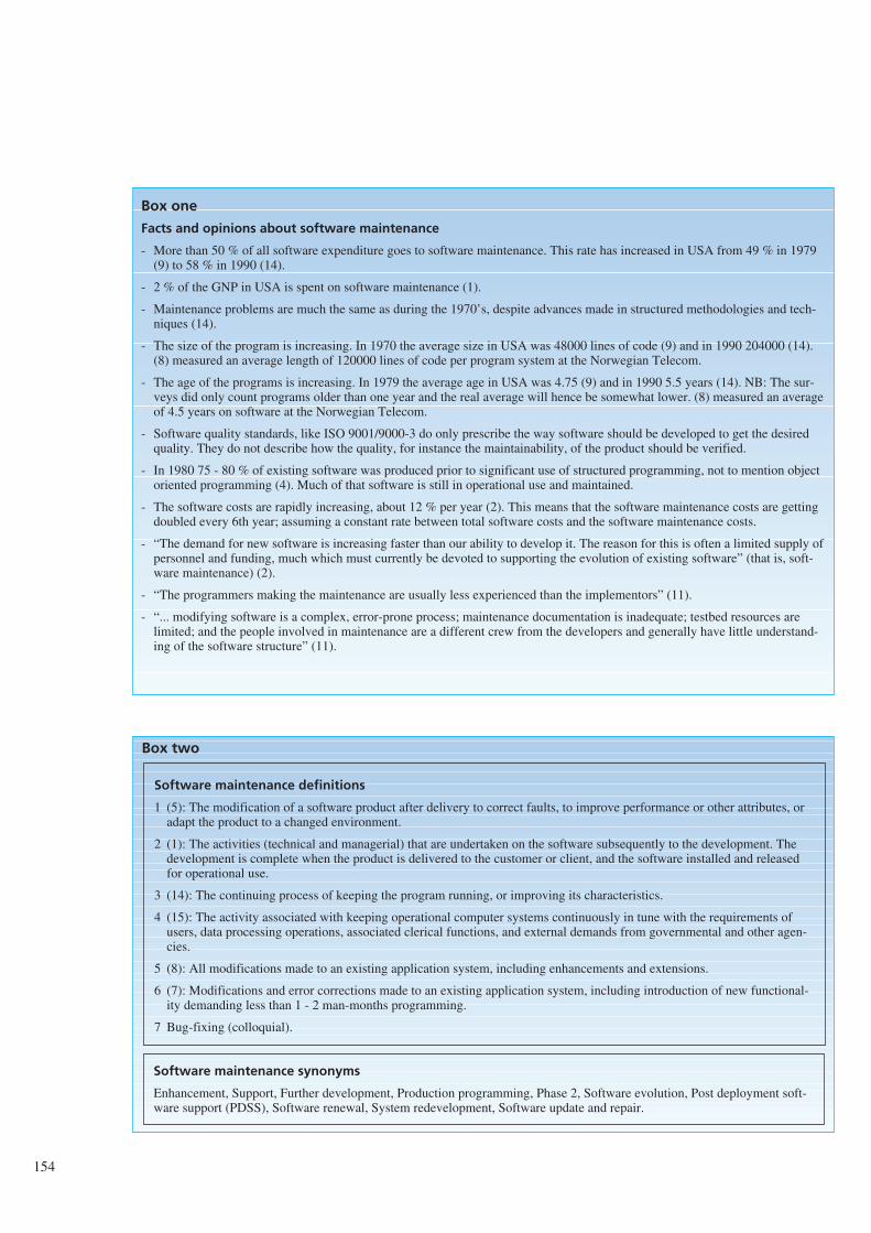
154
Box two
Software maintenance synonyms
Enhancement, Support, Further development, Production programming, Phase 2, Software evolution, Post deployment soft-ware support (PDSS), Software renewal, System redevelopment, Software update and repair.
Software maintenance definitions
1 (5): The modification of a software product after delivery to correct faults, to improve performance or other attributes, oradapt the product to a changed environment.
2 (1): The activities (technical and managerial) that are undertaken on the software subsequently to the development. Thedevelopment is complete when the product is delivered to the customer or client, and the software installed and releasedfor operational use.
3 (14): The continuing process of keeping the program running, or improving its characteristics.
4 (15): The activity associated with keeping operational computer systems continuously in tune with the requirements ofusers, data processing operations, associated clerical functions, and external demands from governmental and other agen-cies.
5 (8): All modifications made to an existing application system, including enhancements and extensions.
6 (7): Modifications and error corrections made to an existing application system, including introduction of new functional-ity demanding less than 1 - 2 man-months programming.
7 Bug-fixing (colloquial).
Box one
Facts and opinions about software maintenance
- More than 50 % of all software expenditure goes to software maintenance. This rate has increased in USA from 49 % in 1979(9) to 58 % in 1990 (14).
- 2 % of the GNP in USA is spent on software maintenance (1).
- Maintenance problems are much the same as during the 1970’s, despite advances made in structured methodologies and tech-niques (14).
- The size of the program is increasing. In 1970 the average size in USA was 48000 lines of code (9) and in 1990 204000 (14).(8) measured an average length of 120000 lines of code per program system at the Norwegian Telecom.
- The age of the programs is increasing. In 1979 the average age in USA was 4.75 (9) and in 1990 5.5 years (14). NB: The sur-veys did only count programs older than one year and the real average will hence be somewhat lower. (8) measured an averageof 4.5 years on software at the Norwegian Telecom.
- Software quality standards, like ISO 9001/9000-3 do only prescribe the way software should be developed to get the desiredquality. They do not describe how the quality, for instance the maintainability, of the product should be verified.
- In 1980 75 - 80 % of existing software was produced prior to significant use of structured programming, not to mention objectoriented programming (4). Much of that software is still in operational use and maintained.
- The software costs are rapidly increasing, about 12 % per year (2). This means that the software maintenance costs are gettingdoubled every 6th year; assuming a constant rate between total software costs and the software maintenance costs.
- “The demand for new software is increasing faster than our ability to develop it. The reason for this is often a limited supply ofpersonnel and funding, much which must currently be devoted to supporting the evolution of existing software” (that is, soft-ware maintenance) (2).
- “The programmers making the maintenance are usually less experienced than the implementors” (11).
- “... modifying software is a complex, error-prone process; maintenance documentation is inadequate; testbed resources arelimited; and the people involved in maintenance are a different crew from the developers and generally have little understand-ing of the software structure” (11).
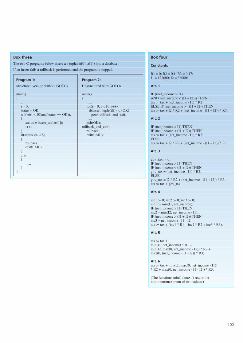
155
Box three
The two C-programs below insert ten tuples (t[0]...t[9]) into a database.
If an insert fails a rollback is performed and the program is stopped.
Program 1:
Structured version without GOTOs.
main()
......i = 0;status = OK;while((i < 10)and(status == OK));
status = insert_tuple(t[i]);i++;
if(status <> OK)
rollback;exit(FAIL);
else
......
Program 2:
Unstructured with GOTOs.
main()
......for(i = 0; i < 10; i++)
if(insert_tuple(t[i]) <> OK)goto rollback_and_exit;
......exit(OK);
rollback_and_exit;rollback;exit(FAIL);
Box four
Constants
R1 = 0; R2 = 0.1; R3 = 0.17;I1 = 122000; I2 = 36000;
Alt. 1
IF ((net_income > I1) AND (net_income < (I1 + I2))) THENtax := tax + (net_income - I1) * R2ELSE IF (net_income >= (I1 + I2)) THENtax := tax + I2 * R2 + (net_income - (I1 + I2)) * R3;
Alt. 2
IF (net_income > I1) THENIF (net_income < (I1 + I2)) THENtax := tax + (net_income - I1) * R2;ELSEtax := tax + I2 * R2 + (net_income - (I1 + I2)) * R3;
Alt. 3
gov_tax := 0;IF (net_income > I1) THENIF (net_income < (I1 + I2)) THENgov_tax = (net_income - I1) * R2;ELSEgov_tax = I2 * R2 + (net_income - (I1 + I2)) * R3;tax := tax + gov_tax;
Alt. 4
inc1 := 0; inc2 := 0; inc3 := 0;inc1 := min(I1, net_income);IF (net_income > I1) THENinc2 = min(I2, net_income - I1);IF (net_income > (I1 + I2)) THENinc3 = net_income - I1 - I2;tax := tax + (inc1 * R1 + inc2 * R2 + inc3 * R3);
Alt. 5
tax := tax +min(I1, net_income) * R1 +min(I2, max(0, net_income - I1)) * R2 +max(0, (net_income - I1 - I2)) * R3;
Alt. 6tax := tax + min(I2, max(0, net_income - I1)) * R2 + max(0, net_income - I1 - I2)) * R3;
(The functions min() / max () return theminimum/maximum of two values.)
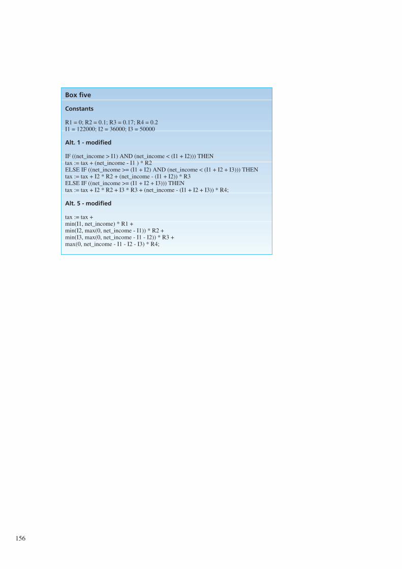
156
Box five
Constants
R1 = 0; R2 = 0.1; R3 = 0.17; R4 = 0.2I1 = 122000; I2 = 36000; I3 = 50000
Alt. 1 - modified
IF ((net_income > I1) AND (net_income < (I1 + I2))) THENtax := tax + (net_income - I1 ) * R2ELSE IF ((net_income >= (I1 + I2) AND (net_income < (I1 + I2 + I3))) THENtax := tax + I2 * R2 + (net_income - (I1 + I2)) * R3ELSE IF ((net_income >= (I1 + I2 + I3))) THENtax := tax + I2 * R2 + I3 * R3 + (net_income - (I1 + I2 + I3)) * R4;
Alt. 5 - modified
tax := tax +min(I1, net_income) * R1 +min(I2, max(0, net_income - I1)) * R2 +min(I3, max(0, net_income - I1 - I2)) * R3 +max(0, net_income - I1 - I2 - I3) * R4;
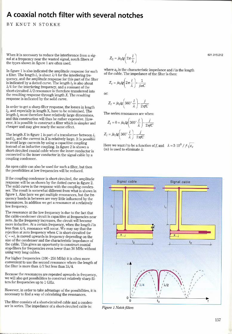
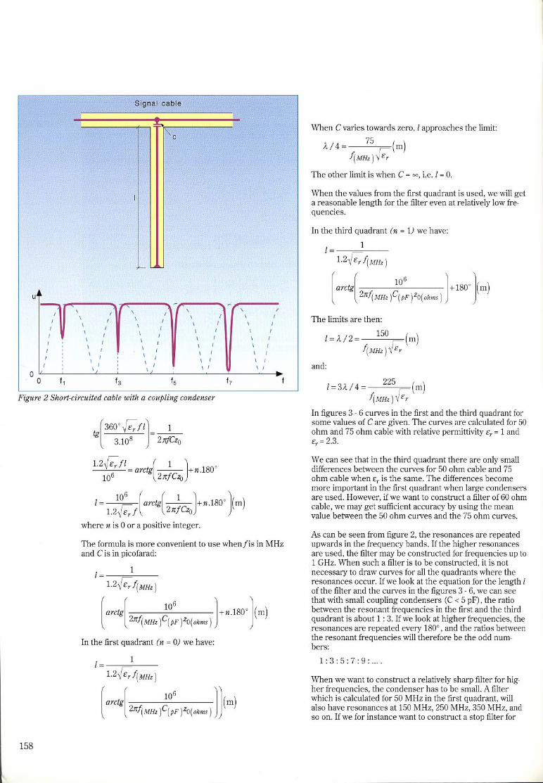

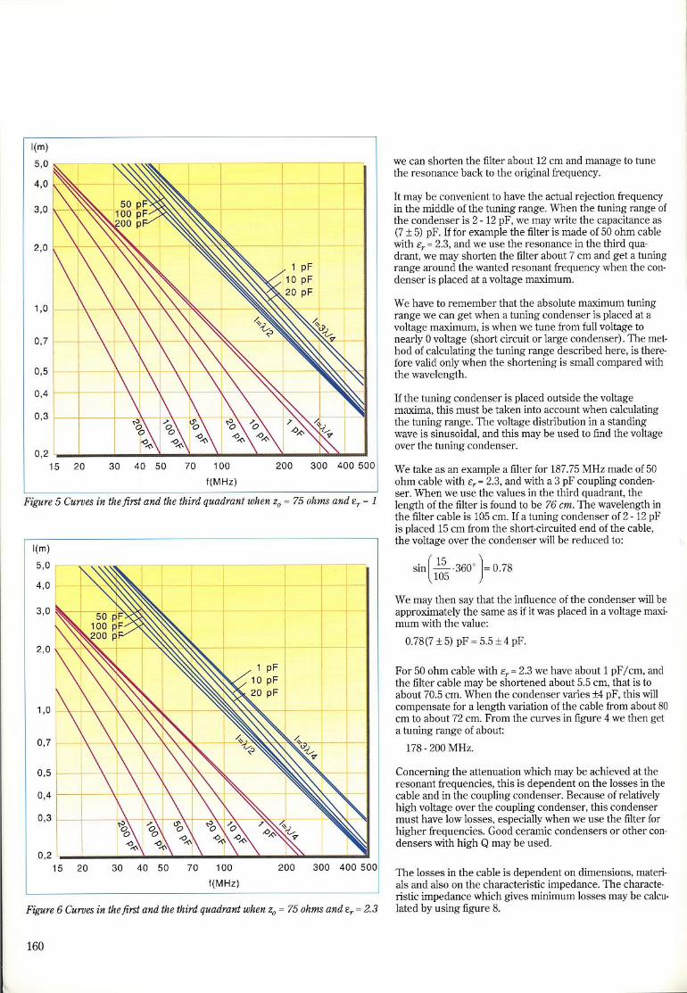
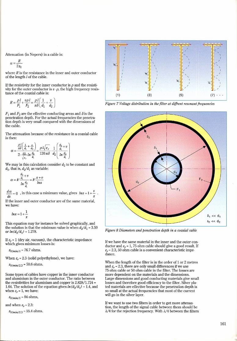
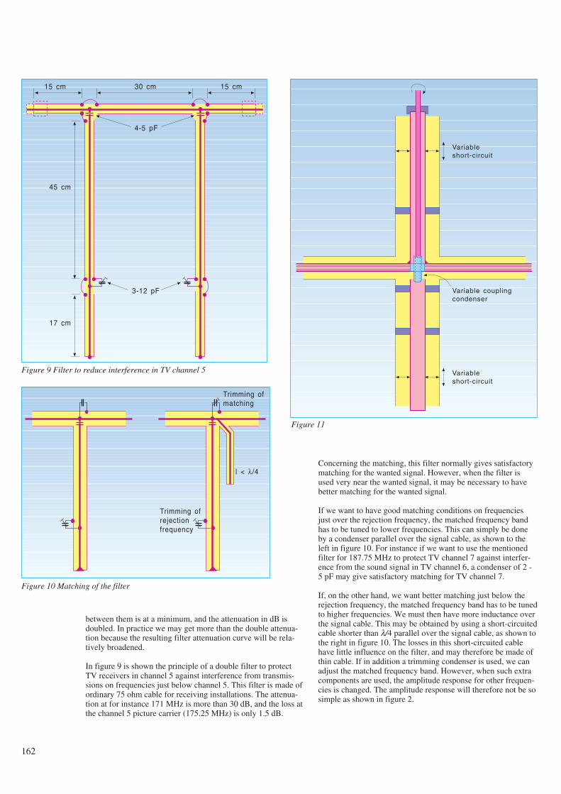
between them is at a minimum, and the attenuation in dB isdoubled. In practice we may get more than the double attenua-tion because the resulting filter attenuation curve will be rela-tively broadened.
In figure 9 is shown the principle of a double filter to protectTV receivers in channel 5 against interference from transmis-sions on frequencies just below channel 5. This filter is made ofordinary 75 ohm cable for receiving installations. The attenua-tion at for instance 171 MHz is more than 30 dB, and the loss atthe channel 5 picture carrier (175.25 MHz) is only 1.5 dB.
Concerning the matching, this filter normally gives satisfactorymatching for the wanted signal. However, when the filter isused very near the wanted signal, it may be necessary to havebetter matching for the wanted signal.
If we want to have good matching conditions on frequenciesjust over the rejection frequency, the matched frequency bandhas to be tuned to lower frequencies. This can simply be doneby a condenser parallel over the signal cable, as shown to theleft in figure 10. For instance if we want to use the mentionedfilter for 187.75 MHz to protect TV channel 7 against interfer-ence from the sound signal in TV channel 6, a condenser of 2 -5 pF may give satisfactory matching for TV channel 7.
If, on the other hand, we want better matching just below therejection frequency, the matched frequency band has to be tunedto higher frequencies. We must then have more inductance overthe signal cable. This may be obtained by using a short-circuitedcable shorter than λ/4 parallel over the signal cable, as shown tothe right in figure 10. The losses in this short-circuited cablehave little influence on the filter, and may therefore be made ofthin cable. If in addition a trimming condenser is used, we canadjust the matched frequency band. However, when such extracomponents are used, the amplitude response for other frequen-cies is changed. The amplitude response will therefore not be sosimple as shown in figure 2.
162
15 cm 30 cm 15 cm
4-5 pF
3-12 pF
45 cm
17 cm
Figure 9 Filter to reduce interference in TV channel 5
Trimming ofmatching
Trimming ofrejectionfrequency
l < λ/4
Figure 10 Matching of the filter
Variableshort-circuit
Variable couplingcondenser
Variableshort-circuit
Figure 11
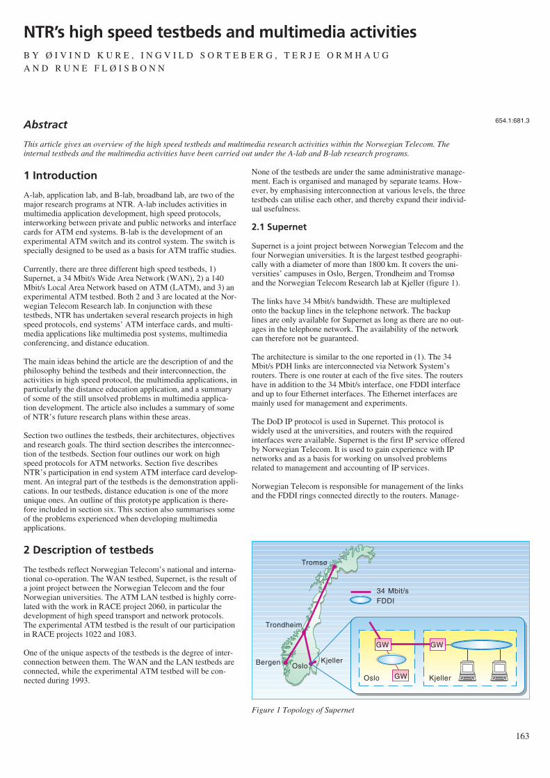
1 Introduction
A-lab, application lab, and B-lab, broadband lab, are two of themajor research programs at NTR. A-lab includes activities inmultimedia application development, high speed protocols,interworking between private and public networks and interfacecards for ATM end systems. B-lab is the development of anexperimental ATM switch and its control system. The switch isspecially designed to be used as a basis for ATM traffic studies.
Currently, there are three different high speed testbeds, 1)Supernet, a 34 Mbit/s Wide Area Network (WAN), 2) a 140Mbit/s Local Area Network based on ATM (LATM), and 3) anexperimental ATM testbed. Both 2 and 3 are located at the Nor-wegian Telecom Research lab. In conjunction with thesetestbeds, NTR has undertaken several research projects in highspeed protocols, end systems’ ATM interface cards, and multi-media applications like multimedia post systems, multimediaconferencing, and distance education.
The main ideas behind the article are the description of and thephilosophy behind the testbeds and their interconnection, theactivities in high speed protocol, the multimedia applications, inparticularly the distance education application, and a summaryof some of the still unsolved problems in multimedia applica-tion development. The article also includes a summary of someof NTR’s future research plans within these areas.
Section two outlines the testbeds, their architectures, objectivesand research goals. The third section describes the interconnec-tion of the testbeds. Section four outlines our work on highspeed protocols for ATM networks. Section five describesNTR’s participation in end system ATM interface card develop-ment. An integral part of the testbeds is the demonstration appli-cations. In our testbeds, distance education is one of the moreunique ones. An outline of this prototype application is there-fore included in section six. This section also summarises someof the problems experienced when developing multimediaapplications.
2 Description of testbeds
The testbeds reflect Norwegian Telecom’s national and interna-tional co-operation. The WAN testbed, Supernet, is the result ofa joint project between the Norwegian Telecom and the fourNorwegian universities. The ATM LAN testbed is highly corre-lated with the work in RACE project 2060, in particular thedevelopment of high speed transport and network protocols.The experimental ATM testbed is the result of our participationin RACE projects 1022 and 1083.
One of the unique aspects of the testbeds is the degree of inter-connection between them. The WAN and the LAN testbeds areconnected, while the experimental ATM testbed will be con-nected during 1993.
None of the testbeds are under the same administrative manage-ment. Each is organised and managed by separate teams. How-ever, by emphasising interconnection at various levels, the threetestbeds can utilise each other, and thereby expand their individ-ual usefulness.
2.1 Supernet
Supernet is a joint project between Norwegian Telecom and thefour Norwegian universities. It is the largest testbed geographi-cally with a diameter of more than 1800 km. It covers the uni-versities’ campuses in Oslo, Bergen, Trondheim and Tromsøand the Norwegian Telecom Research lab at Kjeller (figure 1).
The links have 34 Mbit/s bandwidth. These are multiplexedonto the backup lines in the telephone network. The backuplines are only available for Supernet as long as there are no out-ages in the telephone network. The availability of the networkcan therefore not be guaranteed.
The architecture is similar to the one reported in (1). The 34Mbit/s PDH links are interconnected via Network System’srouters. There is one router at each of the five sites. The routershave in addition to the 34 Mbit/s interface, one FDDI interfaceand up to four Ethernet interfaces. The Ethernet interfaces aremainly used for management and experiments.
The DoD IP protocol is used in Supernet. This protocol iswidely used at the universities, and routers with the requiredinterfaces were available. Supernet is the first IP service offeredby Norwegian Telecom. It is used to gain experience with IPnetworks and as a basis for working on unsolved problemsrelated to management and accounting of IP services.
Norwegian Telecom is responsible for management of the linksand the FDDI rings connected directly to the routers. Manage-
163
NTR’s high speed testbeds and multimedia activitiesB Y Ø I V I N D K U R E , I N G V I L D S O R T E B E R G , T E R J E O R M H A U G
A N D R U N E F L Ø I S B O N N
654.1:681.3
Tromsø
Trondheim
Bergen OsloKjeller
GW
GW
34 Mbit/sFDDI
Oslo Kjeller
GW
Figure 1 Topology of Supernet
Abstract
This article gives an overview of the high speed testbeds and multimedia research activities within the Norwegian Telecom. Theinternal testbeds and the multimedia activities have been carried out under the A-lab and B-lab research programs.
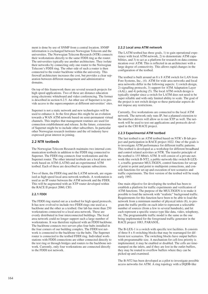
ment is done by use of SNMP from a central location. SNMPinformation is exchanged between Norwegian Telecom and theuniversities. The Norwegian Telecom Research (NTR) connectstheir workstations directly to the same FDDI ring as the router.The universities typically use another architecture. They isolatetheir networks by connecting only one router to the NorwegianTelecom’s FDDI ring. The other side of such a router is thenconnected to the router backbone within the university. Thisfirewall architecture increases the cost, but provides a clear sep-aration between different management and administrativedomains.
On top of this framework there are several research projects forhigh speed applications. Two of these are distance educationusing electronic whiteboard and video conferencing. The formeris described in section 6.2.5. An other use of Supernet is to pro-vide access to the supercomputers at different universities’ sites.
Supernet is not a static network and new technologies will beused to enhance it. In the first phase this might be an evolutiontowards a WAN ATM network based on semi-permanent virtualchannels. This implies that management routines are used forconnection establishment and release. In the future, extensionsof Supernet might be to include other subscribers. In particularother Norwegian research institutes and the oil industry haveexpressed great interest in joining.
2.2 NTR testbeds
The Norwegian Telecom Research maintains two internal com-munication testbeds in addition to the FDDI ring connected toSupernet. The FDDI ring connects four workstations and theSupernet router. The other internal testbeds are a local area net-work based on ATM (LATM) and an experimental ATMtestbed. Each of these are described in separate subsections.
Two of them, the FDDI ring and the LATM network, are organ-ised as high speed local area network testbeds. A workstation isused as an IP router between the ATM network and the FDDI.This will be augmented with an XTP router developed withinthe RACE II project 2060, CIO.
2.2.1 FDDI
The FDDI ring started out as a testbed for high speed protocols.It has now evolved to include two FDDI rings one used as abackbone and the other as a testbed. Our lab has more than 250workstations connected to a local area network. These areevenly distributed in four interconnected buildings. The localarea network could no longer support such a large number ofworkstations. It was therefore replaced with an FDDI backbone.The backbone connects two servers plus four hubs installed inthe four corners of our building complex. The FDDI test net-work is connected to the backbone via the hubs. The Supernetrouter is connected to the testbed FDDI ring. Individual work-stations with FDDI connections are either connected directly tothe test ring or through bridges and routers to the backbone net-work. Currently, only four workstations are connected directlyto the FDDI test network.
2.2.2 Local area ATM network
The LATM testbed has three goals, 1) to gain operational expe-rience with local ATM network, 2) to demonstrate ATM capa-bilities, and 3) to act as a platform for research on data commu-nication over ATM. This is reflected in an architecture with alarge degree of connectivity. This allows rapid changes in theconfiguration of the testbed.
The testbed is built around an 8 x 8 ATM switch for LAN fromFore Systems, Inc., (4). ATM for wide area networks and localarea networks differ in the following aspects: 1) switch design,2) signalling protocols, 3) support for ATM Adaptation Layer(AAL), and 4) policing (5). The local ATM switch design istypically simpler since a switch for LATM does not need to besuper reliable and with only limited ability to scale. The goal ofthe project is not switch design so these particular aspects donot impose any restrictions.
Currently, five workstations are connected to the local ATMnetwork. The network only runs IP, but a planned extension tothe interface drivers will allow us to run XTP as well. The net-work will be used to test out applications and protocols devel-oped in the CIO RACE project.
2.2.3 Experimental ATM testbed
The last testbed is an ATM testbed based on NTR’s B-lab pro-ject and participation in RACE project 1022. One of the goals isto investigate ATM performance for different traffic patterns.This testbed is developed as a workshop for different broadbandand control related activities at NTR. The transfer principle ofthe testbed is 155 Mbit/s ATM. It will consist of a private-net-work-like switch B-NT2, a public-network-like switch B-LEX-1, a traffic generator MULTIGEN, control functions for set-upof point to point and point to multipoint connections, and con-sole functions for set-up and execution of test scenarios andtraffic experiments. The first version of the testbed will be readyearly 1993.
One main objective for developing the testbed has been toestablish a platform for traffic experiments and verification ofATM functions. The purpose of the MULTIGEN is to make itpossible to load the network with “realistic” background traffic.Requirements for this function have been to be able to load thenetwork from a minimum number of physical inlets (8), to pro-gram the traffic profile on each inlet to represent a selectablenumber of sources (from a few to several hundreds), and leteach represent a specific source type like data, video, telephony,etc. The programmable traffic model is the same as the onebeing implemented for the foreground traffic generator in theRACE project 1083, PARASOL.
The B-LEX-1 is a switch with specific test facilities. It consistsof three 8 x 8 switching blocks that may be rearranged for dif-ferent test scenarios. The switching blocks have output bufferswith programmable size. A mechanism for cell-loss priority isimplemented, it may be enabled or disabled. The cells are time-stamped on the inlets, and if they are lost in the outlet buffers,they may be routed to overflow buffers where they can bepicked up and examined.
The B-NT2 has been developed as a pilot to investigate possibleaccess networks for ATM. A ring topology with a DQDB-like
164
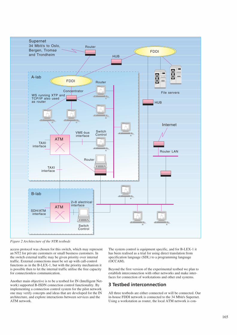
access protocol was chosen for this switch, which may representan NT2 for private customers or small business customers. Inthe switch external traffic may be given priority over internaltraffic. External connections must be set up with call-controlfunctions as in the B-LEX-1, but with the priority mechanism itis possible then to let the internal traffic utilise the free capacityfor connectionless communication.
Another main objective is to be a testbed for IN (Intelligent Net-work) supported B-ISDN connection control functionality. Byimplementing a connection control system for the pilot networkone may verify concepts and ideas that are developed for the INarchitecture, and explore interactions between services and theATM network.
The system control is equipment specific, and for B-LEX-1 ithas been realised as a trial for using direct translation fromspecification language (SDL) to a programming language(OCCAM).
Beyond the first version of the experimental testbed we plan toestablish interconnection with other networks and make inter-faces for connection of workstations and other end systems.
3 Testbed interconnection
All three testbeds are either connected or will be connected. Ourin-house FDDI network is connected to the 34 Mbit/s Supernet.Using a workstation as router, the local ATM network is con-
165
FDDIRouter
FDDI
ATM
ATM
Router
VME-businterface
TAXIinterface
2+8 electricalinterface
SwitchControl
SDH/ATMinterface
TAXIinterface
WS running XTP andTCP/IP also usedas router
Concentrator
SwitchControl
Router
Router LAN
Internet
File servers
Supernet34 Mbit/s to Oslo,Bergen, Tromsøand Trondheim
A-lab
B-lab
HUB
HUB
Figure 2 Architecture of the NTR testbeds
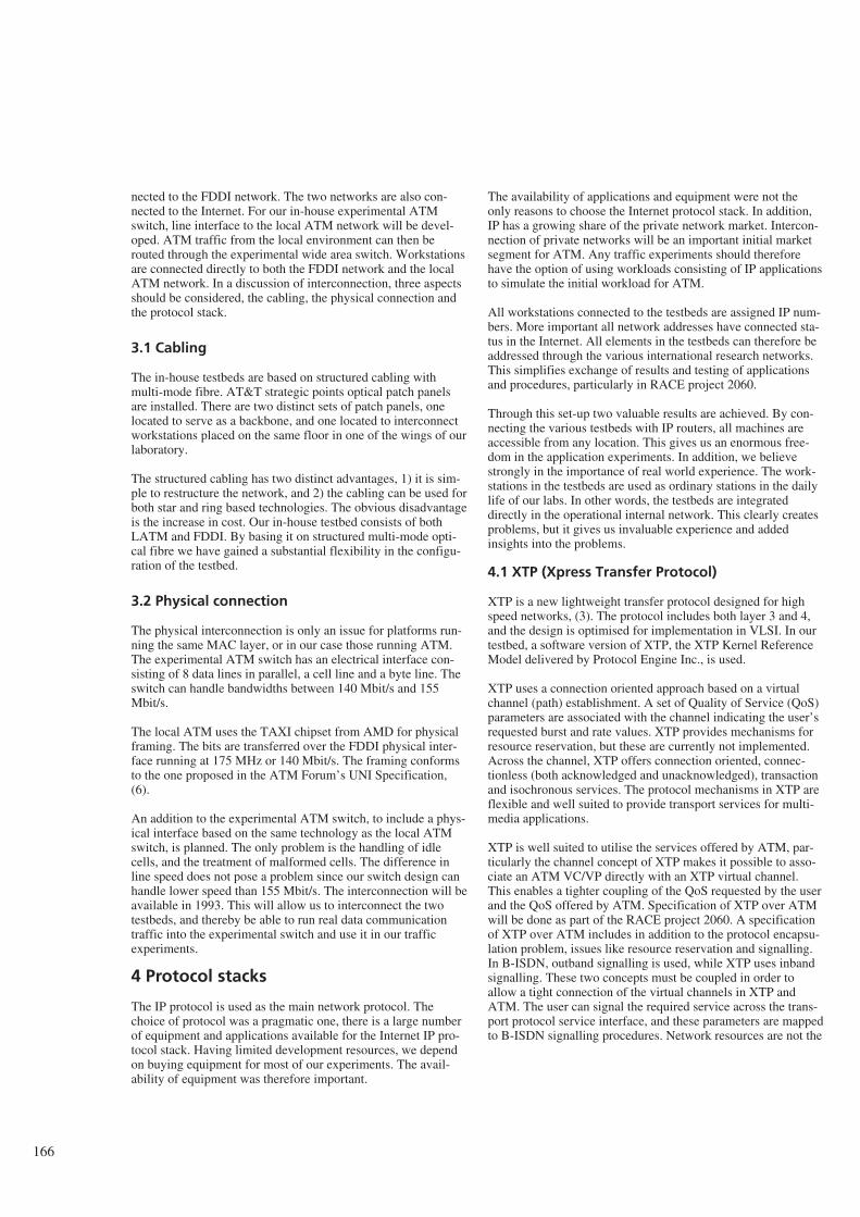
nected to the FDDI network. The two networks are also con-nected to the Internet. For our in-house experimental ATMswitch, line interface to the local ATM network will be devel-oped. ATM traffic from the local environment can then berouted through the experimental wide area switch. Workstationsare connected directly to both the FDDI network and the localATM network. In a discussion of interconnection, three aspectsshould be considered, the cabling, the physical connection andthe protocol stack.
3.1 Cabling
The in-house testbeds are based on structured cabling withmulti-mode fibre. AT&T strategic points optical patch panelsare installed. There are two distinct sets of patch panels, onelocated to serve as a backbone, and one located to interconnectworkstations placed on the same floor in one of the wings of ourlaboratory.
The structured cabling has two distinct advantages, 1) it is sim-ple to restructure the network, and 2) the cabling can be used forboth star and ring based technologies. The obvious disadvantageis the increase in cost. Our in-house testbed consists of bothLATM and FDDI. By basing it on structured multi-mode opti-cal fibre we have gained a substantial flexibility in the configu-ration of the testbed.
3.2 Physical connection
The physical interconnection is only an issue for platforms run-ning the same MAC layer, or in our case those running ATM.The experimental ATM switch has an electrical interface con-sisting of 8 data lines in parallel, a cell line and a byte line. Theswitch can handle bandwidths between 140 Mbit/s and 155Mbit/s.
The local ATM uses the TAXI chipset from AMD for physicalframing. The bits are transferred over the FDDI physical inter-face running at 175 MHz or 140 Mbit/s. The framing conformsto the one proposed in the ATM Forum’s UNI Specification,(6).
An addition to the experimental ATM switch, to include a phys-ical interface based on the same technology as the local ATMswitch, is planned. The only problem is the handling of idlecells, and the treatment of malformed cells. The difference inline speed does not pose a problem since our switch design canhandle lower speed than 155 Mbit/s. The interconnection will beavailable in 1993. This will allow us to interconnect the twotestbeds, and thereby be able to run real data communicationtraffic into the experimental switch and use it in our trafficexperiments.
4 Protocol stacks
The IP protocol is used as the main network protocol. Thechoice of protocol was a pragmatic one, there is a large numberof equipment and applications available for the Internet IP pro-tocol stack. Having limited development resources, we dependon buying equipment for most of our experiments. The avail-ability of equipment was therefore important.
The availability of applications and equipment were not theonly reasons to choose the Internet protocol stack. In addition,IP has a growing share of the private network market. Intercon-nection of private networks will be an important initial marketsegment for ATM. Any traffic experiments should thereforehave the option of using workloads consisting of IP applicationsto simulate the initial workload for ATM.
All workstations connected to the testbeds are assigned IP num-bers. More important all network addresses have connected sta-tus in the Internet. All elements in the testbeds can therefore beaddressed through the various international research networks.This simplifies exchange of results and testing of applicationsand procedures, particularly in RACE project 2060.
Through this set-up two valuable results are achieved. By con-necting the various testbeds with IP routers, all machines areaccessible from any location. This gives us an enormous free-dom in the application experiments. In addition, we believestrongly in the importance of real world experience. The work-stations in the testbeds are used as ordinary stations in the dailylife of our labs. In other words, the testbeds are integrateddirectly in the operational internal network. This clearly createsproblems, but it gives us invaluable experience and addedinsights into the problems.
4.1 XTP (Xpress Transfer Protocol)
XTP is a new lightweight transfer protocol designed for highspeed networks, (3). The protocol includes both layer 3 and 4,and the design is optimised for implementation in VLSI. In ourtestbed, a software version of XTP, the XTP Kernel ReferenceModel delivered by Protocol Engine Inc., is used.
XTP uses a connection oriented approach based on a virtualchannel (path) establishment. A set of Quality of Service (QoS)parameters are associated with the channel indicating the user’srequested burst and rate values. XTP provides mechanisms forresource reservation, but these are currently not implemented.Across the channel, XTP offers connection oriented, connec-tionless (both acknowledged and unacknowledged), transactionand isochronous services. The protocol mechanisms in XTP areflexible and well suited to provide transport services for multi-media applications.
XTP is well suited to utilise the services offered by ATM, par-ticularly the channel concept of XTP makes it possible to asso-ciate an ATM VC/VP directly with an XTP virtual channel.This enables a tighter coupling of the QoS requested by the userand the QoS offered by ATM. Specification of XTP over ATMwill be done as part of the RACE project 2060. A specificationof XTP over ATM includes in addition to the protocol encapsu-lation problem, issues like resource reservation and signalling.In B-ISDN, outband signalling is used, while XTP uses inbandsignalling. These two concepts must be coupled in order toallow a tight connection of the virtual channels in XTP andATM. The user can signal the required service across the trans-port protocol service interface, and these parameters are mappedto B-ISDN signalling procedures. Network resources are not the
166
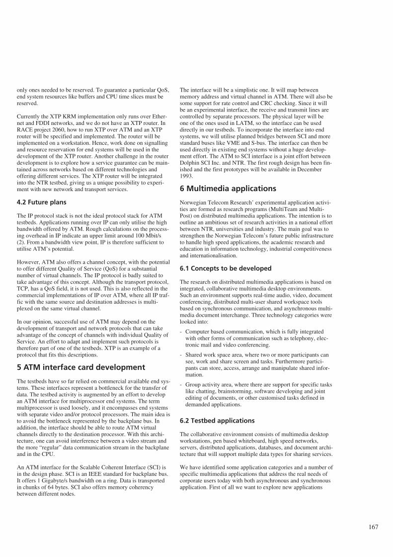
only ones needed to be reserved. To guarantee a particular QoS,end system resources like buffers and CPU time slices must bereserved.
Currently the XTP KRM implementation only runs over Ether-net and FDDI networks, and we do not have an XTP router. InRACE project 2060, how to run XTP over ATM and an XTProuter will be specified and implemented. The router will beimplemented on a workstation. Hence, work done on signallingand resource reservation for end systems will be used in thedevelopment of the XTP router. Another challenge in the routerdevelopment is to explore how a service guarantee can be main-tained across networks based on different technologies andoffering different services. The XTP router will be integratedinto the NTR testbed, giving us a unique possibility to experi-ment with new network and transport services.
4.2 Future plans
The IP protocol stack is not the ideal protocol stack for ATMtestbeds. Applications running over IP can only utilise the highbandwidth offered by ATM. Rough calculations on the process-ing overhead in IP indicate an upper limit around 100 Mbit/s(2). From a bandwidth view point, IP is therefore sufficient toutilise ATM’s potential.
However, ATM also offers a channel concept, with the potentialto offer different Quality of Service (QoS) for a substantialnumber of virtual channels. The IP protocol is badly suited totake advantage of this concept. Although the transport protocol,TCP, has a QoS field, it is not used. This is also reflected in thecommercial implementations of IP over ATM, where all IP traf-fic with the same source and destination addresses is multi-plexed on the same virtual channel.
In our opinion, successful use of ATM may depend on thedevelopment of transport and network protocols that can takeadvantage of the concept of channels with individual Quality ofService. An effort to adapt and implement such protocols istherefore part of one of the testbeds. XTP is an example of aprotocol that fits this descriptions.
5 ATM interface card development
The testbeds have so far relied on commercial available end sys-tems. These interfaces represent a bottleneck for the transfer ofdata. The testbed activity is augmented by an effort to developan ATM interface for multiprocessor end systems. The termmultiprocessor is used loosely, and it encompasses end systemswith separate video and/or protocol processors. The main idea isto avoid the bottleneck represented by the backplane bus. Inaddition, the interface should be able to route ATM virtualchannels directly to the destination processor. With this archi-tecture, one can avoid interference between a video stream andthe more “regular” data communication stream in the backplaneand in the CPU.
An ATM interface for the Scalable Coherent Interface (SCI) isin the design phase. SCI is an IEEE standard for backplane bus.It offers 1 Gigabyte/s bandwidth on a ring. Data is transportedin chunks of 64 bytes. SCI also offers memory coherencybetween different nodes.
The interface will be a simplistic one. It will map betweenmemory address and virtual channel in ATM. There will also besome support for rate control and CRC checking. Since it willbe an experimental interface, the receive and transmit lines arecontrolled by separate processors. The physical layer will beone of the ones used in LATM, so the interface can be useddirectly in our testbeds. To incorporate the interface into endsystems, we will utilise planned bridges between SCI and morestandard buses like VME and S-bus. The interface can then beused directly in existing end systems without a huge develop-ment effort. The ATM to SCI interface is a joint effort betweenDolphin SCI Inc. and NTR. The first rough design has been fin-ished and the first prototypes will be available in December1993.
6 Multimedia applications
Norwegian Telecom Research’ experimental application activi-ties are formed as research programs (MultiTeam and Multi-Post) on distributed multimedia applications. The intention is tooutline an ambitious set of research activities in a national effortbetween NTR, universities and industry. The main goal was tostrengthen the Norwegian Telecom’s future public infrastructureto handle high speed applications, the academic research andeducation in information technology, industrial competitivenessand internationalisation.
6.1 Concepts to be developed
The research on distributed multimedia applications is based onintegrated, collaborative multimedia desktop environments.Such an environment supports real-time audio, video, documentconferencing, distributed multi-user shared workspace toolsbased on synchronous communication, and asynchronous multi-media document interchange. Three technology categories werelooked into:
- Computer based communication, which is fully integratedwith other forms of communication such as telephony, elec-tronic mail and video conferencing.
- Shared work space area, where two or more participants cansee, work and share screen and tasks. Furthermore partici-pants can store, access, arrange and manipulate shared infor-mation.
- Group activity area, where there are support for specific taskslike chatting, brainstorming, software developing and jointediting of documents, or other customised tasks defined indemanded applications.
6.2 Testbed applications
The collaborative environment consists of multimedia desktopworkstations, pen based whiteboard, high speed networks,servers, distributed applications, databases, and document archi-tecture that will support multiple data types for sharing services.
We have identified some application categories and a number ofspecific multimedia applications that address the real needs ofcorporate users today with both asynchronous and synchronousapplication. First of all we want to explore new applications
167
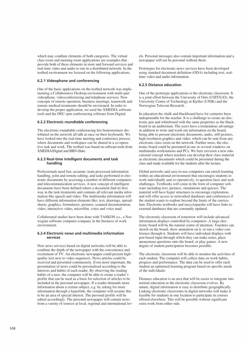
which may combine elements of both categories. The virtualclass room and meeting room applications are examples thatprovide both of these elements in store and forward services andreal-time video and audio to run in a distributed network. In thetestbed environment we focused on the following applications.
6.2.1 Videophone and conferencing
One of the basic applications on the testbed network was imple-menting a Collaborative Desktop environment with multi-partvideophone, videoconferencing and telephone services. Newconcepts of remote operation, business meetings, teamwork andremote medical treatments should be envisioned. In order todevelop the proper application, we used the XMEDIA softwaretools and the DEC-spin conferencing software from Digital.
6.2.2 Electronic roundtable conferencing
The electronic roundtable conferencing lets brainstormers dis-tributed on the network all talk at once on their keyboards. Wehave looked into the real-time meeting and conference processwhere documents and workspace can be shared in a co-opera-tive task and work. The testbed was based on software tools fromXMEDIA/Digital and BBN-Slate.
6.2.3 Real-time intelligent documents and taskhandling
Professionals need fast, accurate, team processed informationhandling, joint and remote editing, and tasks performed in elec-tronic documents by accessing a number of different computersand telecommunication services. A new concept of intelligentdocuments have been defined where a document find its bestway in the task treatments and contains all relevant media infor-mation like speech and video. The multimedia information willhave different information elements like; text, drawings, spread-sheets, graphics, formularies, pictures, scanned documentation,video, interactive video, microfilm, voice and voice mail.
Collaborated studies have been done with TASKON a.s., a Nor-wegian software computer company in the business of workenvironment.
6.2.4 Electronic news and multimedia informationservices
New news services based on digital networks will be able tocombine the depth of the newspaper with the convenience andexcitement of TV. An electronic newspaper could present high-quality text next to video sequences. News articles could bereceived and presented continuously. Even more important, thepresentation of news could be personalised according to theinterests and habits of each reader. By observing the readinghabits of a user, the computer will be able to create a reader’sprofile that can be used as a basis for selection of articles to beincluded in the personal newspaper. If a reader demands moreinformation about a certain subject, e.g. by asking for moreinformation through a hyperlink, the computer will assume thisto be an area of special interest. The personal profile will beedited accordingly. The personal newspaper will contain newsfrom a variety of sources at local, regional and international lev-
els. Personal messages also contain important information and anewspaper will not be personal without them.
Prototypes for electronic news services have been developedusing standard document definition (ODA) including text, real-time video and audio information.
6.2.5 Distance education
One of the prototype applications is the electronic classroom. Itis a joint effort between the University of Oslo (USIT/UiO), theUniversity Centre of Technology at Kjeller (UNIK) and theNorwegian Telecom Research.
In education the chalk and blackboard have for centuries beenindispensable for the teacher. It is a challenge to create an elec-tronic pen and whiteboard with the same properties as the black-board in an auditorium. The users have a tremendous advantagein addition to write and wash out information on the board,being able to present electronic documents, audio, still pictures,high resolution graphics and video, which can be sent from anyelectronic class room on the network. Further more, the elec-tronic board could be presented in one or several windows onmultimedia workstations and PCs. We here envision a new edu-cational concept where teachers can develop their class materialas electronic documents which could be presented during theclass and made available for the students after the lecture.
Global networks and easy-to-use computers can enrich learningwithin an educational environment that encourages students towork individually and co-operatively, to question facts and seekchallenges. Textbooks will come in the form of computer soft-ware including text, pictures, simulations and quizzes. Thematerial will have hyper structures to encourage exploration,and will offer access to networked databases and conferences ifthe student wants to explore beyond the limits of the curricu-lum. Electronic textbooks and encyclopaedia will have links toexternal databases that are constantly updated.
The electronic classroom of tomorrow will include advancedinformation displays controlled by computers. A large elec-tronic board will be the natural centre of attention. Teachers cansketch on the board, show animation on it, or run a video con-ference through it. Students will have individual displays withpen-based input through which they can make notes, placeanonymous questions onto the board, or play games. A newdegree of student participation becomes possible.
The electronic classroom will be able to monitor the activities ofeach student. The computer will collect data on work habits,progress and performance. The data can be used to offer eachstudent an optimised learning program based on specific needsof the individuals.
Distance education is an area that will be easier to integrate intonormal education as the electronic classroom evolves. Bynature, digital information is easy to distribute geographically.Linking electronic classrooms in digital networks will make itfeasible for students in one location to participate in coursesoffered elsewhere. This will be possible without significantextra work from either side.
168
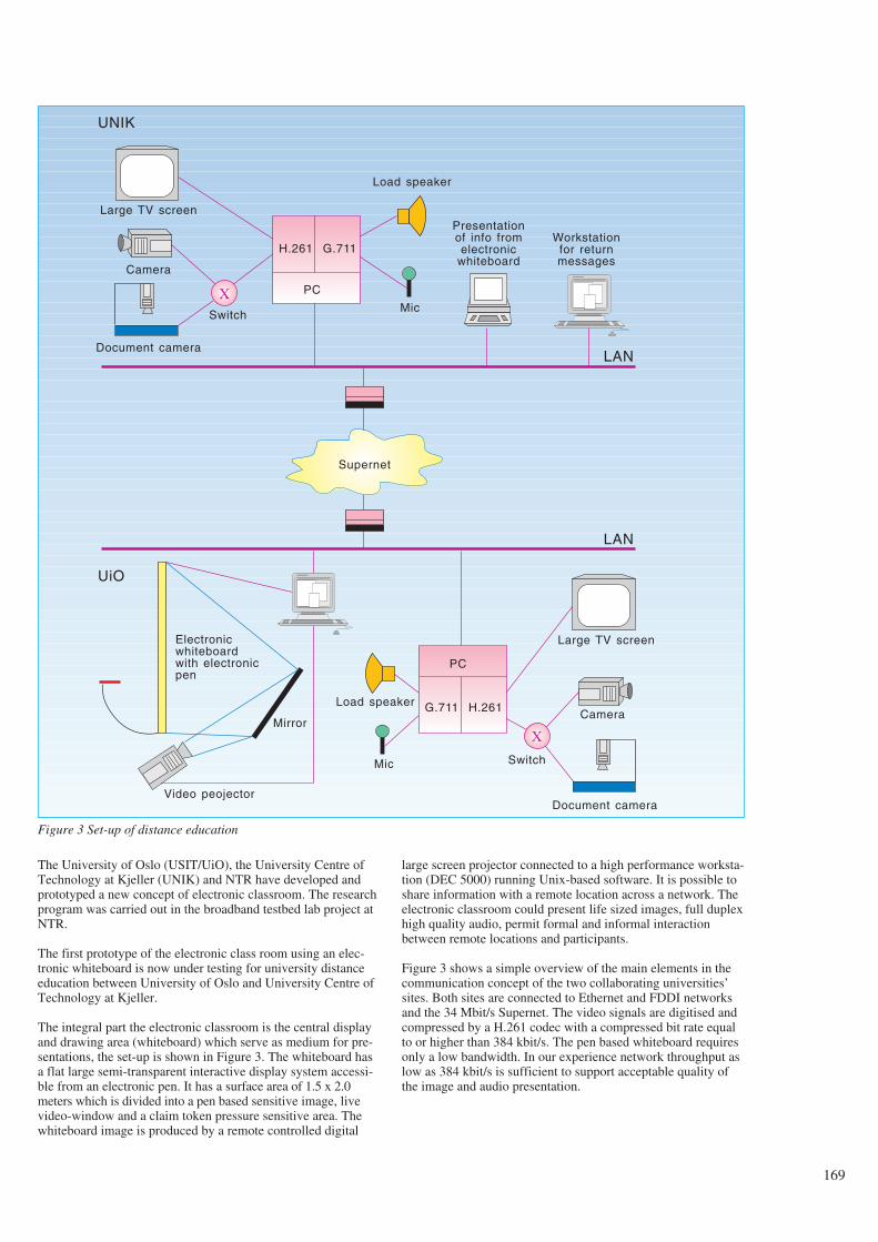
The University of Oslo (USIT/UiO), the University Centre ofTechnology at Kjeller (UNIK) and NTR have developed andprototyped a new concept of electronic classroom. The researchprogram was carried out in the broadband testbed lab project atNTR.
The first prototype of the electronic class room using an elec-tronic whiteboard is now under testing for university distanceeducation between University of Oslo and University Centre ofTechnology at Kjeller.
The integral part the electronic classroom is the central displayand drawing area (whiteboard) which serve as medium for pre-sentations, the set-up is shown in Figure 3. The whiteboard hasa flat large semi-transparent interactive display system accessi-ble from an electronic pen. It has a surface area of 1.5 x 2.0meters which is divided into a pen based sensitive image, livevideo-window and a claim token pressure sensitive area. Thewhiteboard image is produced by a remote controlled digital
large screen projector connected to a high performance worksta-tion (DEC 5000) running Unix-based software. It is possible toshare information with a remote location across a network. Theelectronic classroom could present life sized images, full duplexhigh quality audio, permit formal and informal interactionbetween remote locations and participants.
Figure 3 shows a simple overview of the main elements in thecommunication concept of the two collaborating universities’sites. Both sites are connected to Ethernet and FDDI networksand the 34 Mbit/s Supernet. The video signals are digitised andcompressed by a H.261 codec with a compressed bit rate equalto or higher than 384 kbit/s. The pen based whiteboard requiresonly a low bandwidth. In our experience network throughput aslow as 384 kbit/s is sufficient to support acceptable quality ofthe image and audio presentation.
169
Large TV screen
Supernet
X
H.261 G.711
PC
X
G.711 H.261
PC
Camera
Document camera
Switch
Load speaker
Mic
Presentationof info fromelectronic
whiteboard
Workstationfor returnmessages
LAN
LAN
UNIK
UiO
Electronicwhiteboardwith electronicpen
Mirror
Video peojector
Load speaker
Mic
Large TV screen
Camera
Document camera
Switch
Figure 3 Set-up of distance education
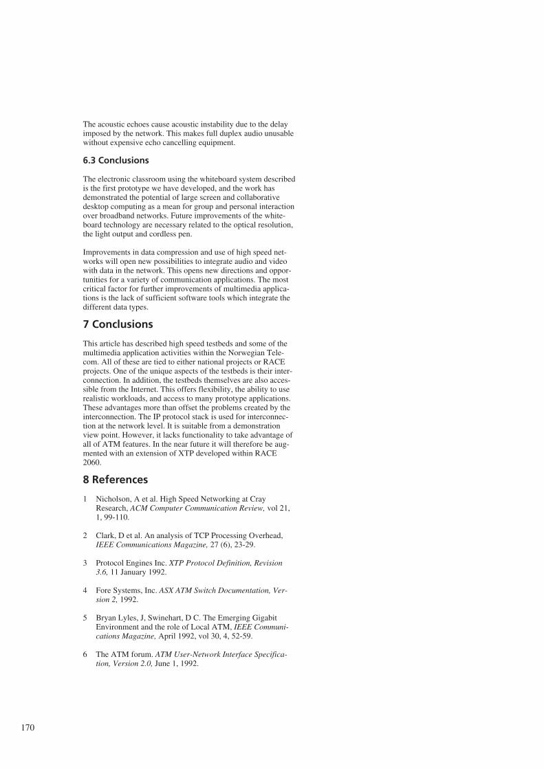
The acoustic echoes cause acoustic instability due to the delayimposed by the network. This makes full duplex audio unusablewithout expensive echo cancelling equipment.
6.3 Conclusions
The electronic classroom using the whiteboard system describedis the first prototype we have developed, and the work hasdemonstrated the potential of large screen and collaborativedesktop computing as a mean for group and personal interactionover broadband networks. Future improvements of the white-board technology are necessary related to the optical resolution,the light output and cordless pen.
Improvements in data compression and use of high speed net-works will open new possibilities to integrate audio and videowith data in the network. This opens new directions and oppor-tunities for a variety of communication applications. The mostcritical factor for further improvements of multimedia applica-tions is the lack of sufficient software tools which integrate thedifferent data types.
7 Conclusions
This article has described high speed testbeds and some of themultimedia application activities within the Norwegian Tele-com. All of these are tied to either national projects or RACEprojects. One of the unique aspects of the testbeds is their inter-connection. In addition, the testbeds themselves are also acces-sible from the Internet. This offers flexibility, the ability to userealistic workloads, and access to many prototype applications.These advantages more than offset the problems created by theinterconnection. The IP protocol stack is used for interconnec-tion at the network level. It is suitable from a demonstrationview point. However, it lacks functionality to take advantage ofall of ATM features. In the near future it will therefore be aug-mented with an extension of XTP developed within RACE2060.
8 References
1 Nicholson, A et al. High Speed Networking at CrayResearch, ACM Computer Communication Review, vol 21,1, 99-110.
2 Clark, D et al. An analysis of TCP Processing Overhead,IEEE Communications Magazine, 27 (6), 23-29.
3 Protocol Engines Inc. XTP Protocol Definition, Revision3.6, 11 January 1992.
4 Fore Systems, Inc. ASX ATM Switch Documentation, Ver-sion 2, 1992.
5 Bryan Lyles, J, Swinehart, D C. The Emerging GigabitEnvironment and the role of Local ATM, IEEE Communi-cations Magazine, April 1992, vol 30, 4, 52-59.
6 The ATM forum. ATM User-Network Interface Specifica-tion, Version 2.0, June 1, 1992.
170


