Embed Size (px)
Citation preview

Tensile Strength of Single Abaca Fibers
KTH, Stockholm, Sweden Last edited: 29.05.2019
Relating the tensile strength of the single fiber to the microfibrilar angle
Victor Waller and Astrid Wilsby
Examiner: Lars Berglund

V. Waller, A. Wilsby Tensile Strength of Single Abaca Fibers KTH, Sweden
2
TableofContent
ABSTRACT........................................................................................................................................................3
INTRODUCTION..............................................................................................................................................4PLANT/WOODMORPHOLOGY:..........................................................................................................................................4CELLULOSECHEMISTRY.....................................................................................................................................................5HEMICELLULOSE,LIGNINANDPECTINCHEMISTRY.....................................................................................................6CHEMICALFIBERDISINTEGRATION.................................................................................................................................7Removingthelignin......................................................................................................................................................7Removinghemicellulose..............................................................................................................................................7
TENSILESTRENGTHMEASURINGOFPLANTFIBERS:....................................................................................................7PURPOSEANDOBJECTIVES............................................................................................................................................10
EXPERIMENTALPROCEDURE:................................................................................................................10MATERIAL.........................................................................................................................................................................10METHOD............................................................................................................................................................................10Obtainingsinglefibers...............................................................................................................................................10Mountingoffibersontopaperframes:...............................................................................................................10Analysis.............................................................................................................................................................................11Tensilestrengthtests..................................................................................................................................................11
RESULTS.........................................................................................................................................................13THESUCCESSRATE..........................................................................................................................................................14
DISCUSSION..................................................................................................................................................14
CONCLUSION.................................................................................................................................................17
ACKNOWLEDGEMENT...............................................................................................................................18
REFERENCES.................................................................................................................................................19
APPENDIX......................................................................................................................................................20

V. Waller, A. Wilsby Tensile Strength of Single Abaca Fibers KTH, Sweden
3
AbstractDue to environmental concerns and to the limited amount of fossil fuel in the world the interest in using renewable material has been and will continue to be on the rise. With the increasing demand for renewable materials such as bio-based fibers, the research around natural fibers is intensifying. Abaca (Musa Texitilis Nee) is a plant endemic to the Philippines which is claimed to contain the strongest natural fiber in the world 1. However, no thorough research on performing tensile strength test on single abaca fibers/cells has been found. By performing tensile strength test on the single abaca fibers and relate this will provide fresh data about the single abaca fiber strength that can be compared with other natural fibers. This can later be a reference tool in order to find the optimal fiber for the product to be made. The purpose of this study is to develop a methodology for performing tensile strength tests on single abaca fibers with the major objective to relate the tensile strength and E-modulus of the fibers with their microfibrillar angle (MFA). The research was done by using Abaca (grade S2) from Camarines Sur (Philippines) that was chemically disintegrated in order to obtain single fibers. The single fibers were mounted to a custom made paper frame for the tensile strength test performed by an Instron 5944. The MFA of each fiber was also retrieved using an optical microscope with a polarized filter. The research showed an indication of an inversely proportional relation between MFA and tensile strength of the fibers. According to the results, the E-modulus of the single abaca fiber was almost constant, independently on the MFA of the fiber.
V. Waller, A. Wilsby Tensile Strength of Single Abaca Fibers KTH, Sweden
4
Introduction
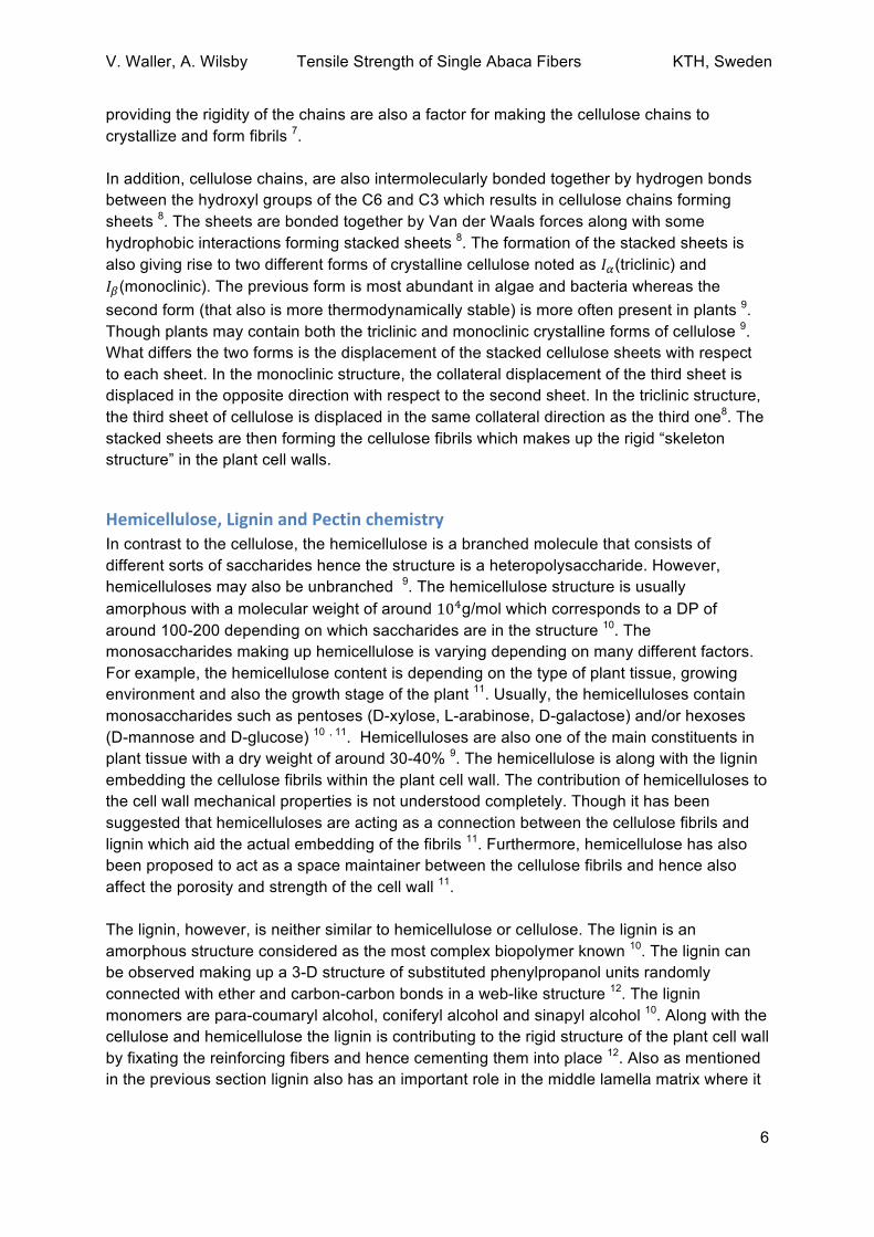
Plant/woodmorphology:Plants (of the Kingdom Plantae) are complex composites built up by a hierarchical structure of natural fibers held together by other complex molecules. Plant fibers can be divided into wood fibers and non-wood fibers whereas the Abaca fibers (Musa textilis Nee) are sorted into the non-wood group and belong to the subcategory of leaf fibers. A big majority of the natural fibers are all lignocellulosic which means that they mainly consist of cellulose, hemicellulose and lignin 2. However, what differs the two main groups is the varying content of lignocellulosic components 3. For example, non-wood plants are known to have a lower lignin content which generally makes them more easy to delignify 4. Today there is no accepted precise molecular model describing the organization of the cellulose, hemicellulose and lignin in plants since the structures vary a lot. Though, plant cell walls consist of cellulose microfibrils held in place by a hemicellulose and lignin matrix. It is the microfibrils that mainly acts as the strengthening reinforcement element within the fiber cell wall which means that they are providing the mechanical strength of the cell3. Besides cellulose, the hemicellulose is one of the most common biopolymers in the cell wall that sometimes even is forming hydrogen bonds with the cellulose fibrils 3. The hemicellulose is an amorphous compound that is aligned with the cellulose fibrils 5. Lignin though is a phenylpropanoid rich complex that acts as the final support holding both the cellulose and hemicellulose together. Lignin is also an important factor for providing rigidity to the cell walls 3. The plant tissue can be compared with a skeleton made up by the cellulose fibrils who are embedded in a hemicellulose and lignin matrix within the cell walls 5. Each individual fibril of cellulose is made up of around 36 cellulose molecules which results in a fibril diameter of around 10-20 nm 5. The individual fibers/cells are forming cylinder-like structures containing a lumen. The fibers with their fibril rich cell wall are then “glued” together by a middle lamella structure with rich content of lignin. Even though the lignin content is high in the middle lamella only around 29% of the total amount of lignin can be found in the middle lamella due to the fineness of the structure 5. Each plant cell consists of two cell walls. The outermost part is the primary wall containing only one layer. The primary wall consists of randomly aligned cellulose microfibrils 5. The secondary cell wall usually consists of three layers called S1, S2 and S3. The S3 layer is the layer facing the lumen of the cell. The S2 layer of the secondary cell wall is relative to the other layers the thickest structure 5. Both the S1 and S3 layers are containing cellulose microfibrils forming almost a 90° angle with the cell axis while the S2 microfibrils are forming a helical shape with much lower angles with respect to the fiber axis 5. Within the S2 layer, the microfibrils form a “clockwise” and an “anticlockwise” with respect to the axial of the fiber 5. The angle formed by the microfibrils within the S2 layer is often referred to as the microfibrillar angle (MFA) (see figure 1). Because of the high thickness of the S2 layer the MFA made up by the fibrils in S2 is considered as one of the most important factors affecting the plant/wood properties 6. The MFA formed by the fibrils in the S2 layer has for example been proved affecting mechanical factors such as extension rate, modulus of elasticity and strain 6. Therefore, an important piece of a fiber strength characterization is relating the MFA

V. Waller, A. Wilsby Tensile Strength of Single Abaca Fibers KTH, Sweden
5
to the measured strength of fibers. Generally speaking the larger the MFA in the S2 layer of the secondary cell wall the higher decrease in tensile strength and stiffness, hence there is an inverse correlation between MFA and tensile strength along with the E-modulus 6. Though the fiber properties are not only depending on the MFA. Other important factors to consider while relating mechanical properties to different factors is the cell dimensions, chemical composition, the geographical location of the plant and also from which part of the plant the fibers have been extracted 4. There are several ways of determining the MFA of fibers. Most common is using XRD or a microscope with a polarizing filter. In this research, a polarized microscope was used.
Figure 1: A schematic overview of the cellulose microfibrils orientation with respect to the fiber axis. Only one layer of microfibrils is shown. Usually, microfibrils in the opposite direction are also overlaping (though with the same MFA).
CellulosechemistryWithin the whole biosphere, the most abundant organic molecule/polymer is cellulose 7. Also, it has been claimed that cellulose fibrils are stronger than steel in the corresponding dimensions 8. Cellulose is a non-branched, non-folded polysaccharide containing D-anhydroglucose rings with covalent linkages made up by β-1-4 glycosidic linkages. The bonds give rise to an alignment of the glucose units where their placement is altering with 180° with respect to the polymer chain axis 7. The linear structure held together by the glycosidic bonds is usually called the primary structure. The glucose residues in the cellulose chain are ordered in their chair configuration and not as flat rings that are sometimes illustrated in the literature 9. Also, the units are possessing their 4𝐶!configuration which is more stable than the 1𝐶!chair configuration 7. Within the secondary structure, intramolecular bonding is stabilizing the β-1-4 glycosidic linkages further. In this structure hydrogen bonds between the C6 and C2 hydroxyl groups together with bonds between the C5 oxygen and C3 hydroxyl group is offering stiffness to the structure 8. The intramolecular hydrogen bonds
V. Waller, A. Wilsby Tensile Strength of Single Abaca Fibers KTH, Sweden
6
providing the rigidity of the chains are also a factor for making the cellulose chains to crystallize and form fibrils 7. In addition, cellulose chains, are also intermolecularly bonded together by hydrogen bonds between the hydroxyl groups of the C6 and C3 which results in cellulose chains forming sheets 8. The sheets are bonded together by Van der Waals forces along with some hydrophobic interactions forming stacked sheets 8. The formation of the stacked sheets is also giving rise to two different forms of crystalline cellulose noted as 𝐼!(triclinic) and 𝐼!(monoclinic). The previous form is most abundant in algae and bacteria whereas the second form (that also is more thermodynamically stable) is more often present in plants 9. Though plants may contain both the triclinic and monoclinic crystalline forms of cellulose 9. What differs the two forms is the displacement of the stacked cellulose sheets with respect to each sheet. In the monoclinic structure, the collateral displacement of the third sheet is displaced in the opposite direction with respect to the second sheet. In the triclinic structure, the third sheet of cellulose is displaced in the same collateral direction as the third one8. The stacked sheets are then forming the cellulose fibrils which makes up the rigid “skeleton structure” in the plant cell walls.
Hemicellulose,LigninandPectinchemistryIn contrast to the cellulose, the hemicellulose is a branched molecule that consists of different sorts of saccharides hence the structure is a heteropolysaccharide. However, hemicelluloses may also be unbranched 9. The hemicellulose structure is usually amorphous with a molecular weight of around 10!g/mol which corresponds to a DP of around 100-200 depending on which saccharides are in the structure 10. The monosaccharides making up hemicellulose is varying depending on many different factors. For example, the hemicellulose content is depending on the type of plant tissue, growing environment and also the growth stage of the plant 11. Usually, the hemicelluloses contain monosaccharides such as pentoses (D-xylose, L-arabinose, D-galactose) and/or hexoses (D-mannose and D-glucose) 10 , 11. Hemicelluloses are also one of the main constituents in plant tissue with a dry weight of around 30-40% 9. The hemicellulose is along with the lignin embedding the cellulose fibrils within the plant cell wall. The contribution of hemicelluloses to the cell wall mechanical properties is not understood completely. Though it has been suggested that hemicelluloses are acting as a connection between the cellulose fibrils and lignin which aid the actual embedding of the fibrils 11. Furthermore, hemicellulose has also been proposed to act as a space maintainer between the cellulose fibrils and hence also affect the porosity and strength of the cell wall 11. The lignin, however, is neither similar to hemicellulose or cellulose. The lignin is an amorphous structure considered as the most complex biopolymer known 10. The lignin can be observed making up a 3-D structure of substituted phenylpropanol units randomly connected with ether and carbon-carbon bonds in a web-like structure 12. The lignin monomers are para-coumaryl alcohol, coniferyl alcohol and sinapyl alcohol 10. Along with the cellulose and hemicellulose the lignin is contributing to the rigid structure of the plant cell wall by fixating the reinforcing fibers and hence cementing them into place 12. Also as mentioned in the previous section lignin also has an important role in the middle lamella matrix where it

V. Waller, A. Wilsby Tensile Strength of Single Abaca Fibers KTH, Sweden
7
is responsible for gluing the individual plant cells together. The content of lignin varies between different types of plants. Pectins occur both in the plant cell walls but also within the middle lamella that is gluing the single fiber/cells together 9. The pectins are usually only making up a few percents of the total plant content. The structure is not understood completely but it seems to often appear as a block copolymer containing galacturonan and rhamnogalacturonan 11.
ChemicalfiberdisintegrationTo obtain single fibers, the fiber bundles need to be disintegrated into their single cells. The lignin and hemicellulose, gluing the cells together, have to be removed in a way that causes minimal damage to the cellulose structure that could decrease the strength of the cell.
RemovingtheligninSodium chlorite is widely used in the delignification process when aiming for protecting the polysaccharides. The oxidative process is selective when removing parts of the lignin. A study on sugar cane, another lignocellulosic material, show that when removing mayor parts of lignin, more than 60%, the polysaccharides are being affected as well since they can be in large structures together with the lignin, as in the cell wall as previously mentioned 13.
RemovinghemicelluloseSince the oxidation with sodium chlorite is selective, hemicellulose is not affected by that treatment. The hemicellulose can instead be removed by alkali treatment using sodium hydroxide. For both the sodium chlorite and sodium hydroxide, time have a small impact on the decline of lignin and hemicellulose, respectively. Instead, temperature and concentration have a greater impact on the result 14. A study on the chemical treatments on flax fiber shows a decline in tensile strength for the treated fibers. The reducing strength corresponded to the severity of the treatment where 5% sodium hydroxide at one hour, the mildest treatment, affected the strength the least. Though the decline was about 25% from the strength of untreated fibers 14.
Tensilestrengthmeasuringofplantfibers:Mechanical testing and characterization of materials are of great importance in order to find the right materials suitable for different applications. With the increasing interest in producing environmentally friendly biocomposites with constituents of natural fibers derived from plants the relevance of understanding the mechanical properties of plant fibers is substantial. No well-motivated experiments on investigating the tensile strength of single abaca fibers have been found. Though, there are several publicated experiments on performing tensile strength test of abaca fiber bundles. The tensile strength of bundles has been reported to be between 600-900 MPa 15. The E-modulus have been measured to around 35 GPa 16. Also, tensile strength tests on other types of natural, single, fibers have been reported. For example, the ultimate tensile strength and modulus of Ramie fibers have been reported to be around 1 000 MPa and 11 GPa respectively 17. Another commonly used fiber is kenaf which has a reported tensile strength of around 980 MPa and a modulus of 14 GPa 17.

V. Waller, A. Wilsby Tensile Strength of Single Abaca Fibers KTH, Sweden
8
The principles behind tensile testing are not very complicated. Within the area of industrial materials, there are standardized ways of performing tensile strength tests. This includes arrangements on specimen dimensions, specimen shape, mounting procedure and many other factors in order to produce reliable results that could be replicated 18. Though, this is not always the case when it comes to performing tensile strength test on single plant cells. The nature, such as dimensions and chemical content, of different plant cells varies between species which makes standardization of specimen dimensions challenging. However, performing mechanical tests such as tensile strength test on single plant fiber could offer a great understanding of the mechanical behavior such as stiffness or ultimate tensile stress of the material 18. One common way for performing tensile strength tests on material is by uniaxial appliement of a pulling force until breakage. This requires gripping the specimen to be measured in two ends and pull it apart in the direction of the cell fiber axis. During the tensile strength measuring procedure factors such as stress and elongation are monitored which then are used to produce what is so called a “stress-strain graph”. The stress, denoted as σ, is defined as the force divided by the cross section area of the specimen (see Equation (1)) 10. The strain, denoted by ε is defined as the extension of the specimen divided by its original length (see Equation (2)) 10. Hence the strain can be interpreted as the percentage increase in length.
𝜎 = !
! (1)
In Equation (1), F is the applied force and A the cross section area of the sample
𝜀 = !!!!!!
(2)
In Equation (2), 𝑙!is the original length of the sample and 𝑙 is the extended length. In Figure 2, a general stress-strain graph is pictured (though, without the plastic region). A general stress-strain graph covers two main regions called the elastic zone and plastic zone. Within the elastic zone, the stress and strain show a linear relationship. From the graph, output data, useful for understanding the mechanical properties of the material can be derived. The Young’s modulus, or simply E-modulus (see Equation 3 ), is a relationship between the stress and strain that gives information about the stiffness of the material and hence its resistance to deformation 10.
𝐸 = !! (3)
Equation (3), The Young’s modulus is obtained by dividing the stress with the strain. Hence the modulus can be interpreted as the slope of linear region of the stress-strain graph (see Figure 2). In the elastic region, the modulus is constant because of the linear relationship between the stress and strain. Within the elastic region, the deformation appears momentaneously when the force is applied. Also, within the elastic region, the deformation is still reversible 10.

V. Waller, A. Wilsby Tensile Strength of Single Abaca Fibers KTH, Sweden
9
However, within the plastic region elastic deformation could still occur but along with irreversible deformation until the point of failure 18. The tensile strength (or the fracture strength), 𝜎!, can also be obtained from the graph, which is, as the name implies, the strength applied to the specimen when the failure occurs. Another region that may occur while doing the tensile strength test is the so called “toe-region” (see Figure 2). The toe region sometimes appears before the elastic region which could be an indicator of an initial straightening of the sample before it is completely linearly aligned 18.
Figure 2: A general stress-strain curve with the plastic region left out since no plastic behavior is considered in this experiment. When performing tensile strength test on any material it is important to understand that the result is not completely accurate due to assumptions that the cross-section area of the specimen is constant throughout the straining. However, materials sometimes show a phenomenon where the cross section area is decreased during apliement of the force 18. One of these phenomena is called Poisson’s effect that is measured by the Poisson’s ratio, v, (see Equation (4)). The Poisson’s effect is describing the process of contraction of the sample in the perpendicular direction of the uniaxially applied force. Many common materials are showing lateral contraction while performing tensile strength which is a factor to be aware of 18.
𝑣 = !!!"#$%"!!!"#!$
(4)
Equation (4) shows the Poisson ratio which is the ratio between the lateral and axial strain. Observe that the lateral strain behaves as a contraction which results in a negative number, therefore Equation (4) will still result in positive numbers. Another phenomenon decreasing the cross section area is necking which occurs mainly in ductile samples (materials who show plastic deformation before breakage) but necking is not common for plant materials 18. Another factor to consider while performing tensile strength test of single plant cells that might differ from larger samples is how to express the cross section area of the specimen. While doing tensile strength test on a plant fiber not all of the cross section area is carrying the load from the force since plant fibers contain a lumen. The cross-section area can be
V. Waller, A. Wilsby Tensile Strength of Single Abaca Fibers KTH, Sweden
10
assumed carrying the whole load. Otherwise, the load carrying area called the effective area can be used to get more correct results by subtracting the lumen area from the total area 18.
PurposeandObjectivesThe purpose of this report is to increase the interest in preforming tensile strength test on single abaca fibers. This based on the small number of reports covering tensile tests on single abaca fibers. The objectives are to develop a method for, and perform, tensile strength test on single abaca fibers and relate the tensile strength and E-modulus to the orientation of cellulose microfibrils (MFA)
Experimentalprocedure:
MaterialThe abaca fiber chosen for this report was obtained from TAG Fibers Inc. (Philippines). on the 1st of Mars 2019. The fiber bundles were classified as S2 and originate from Camarines Sur, Philippines.
Method
ObtainingsinglefibersIn this study, 9.9g of dried fiber bundles were used. For a faster reaction, the fiber bundles were initially soaked in water under vacuum before the treatments. The sample was placed in a vacuum oven four times for 15 min each with a change of water between every set. The fibers bundles were then immersed in a 700ml solution with 1wt% sodium chlorite in an acetate buffer with pH 4,6. The soaking was carried out at in an 80 °C water bath. The treatment was performed twice on two following days for three respectively two hours. In between the treatments, the fibers bundles were washed with water to remove residues. Secondly, the fibers were treated with sodium hydroxide. One liter of 5 wt% sodium hydroxide was used for soaking the fibers at room temperature for one hour. The partly disintegrated fiber bundles were washed with water. Single abaca fibers were obtained from the washing media. The water containing single fibers was diluted to lessen the concentration of fibers before freeze drying.
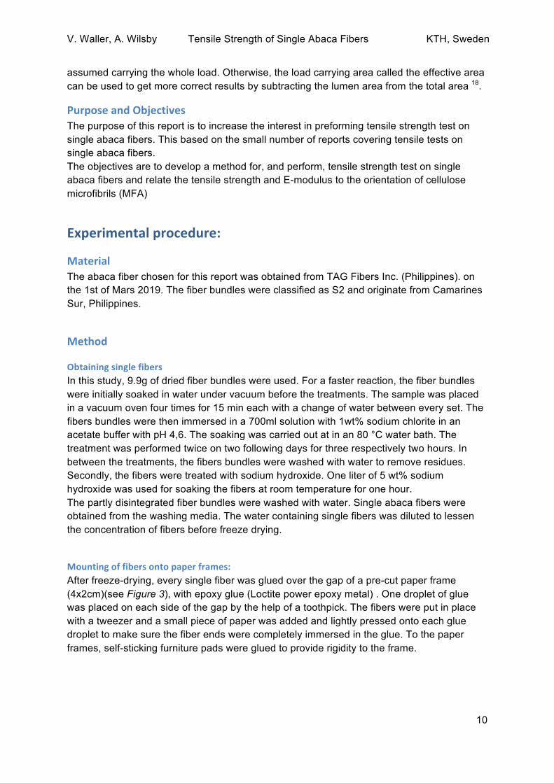
Mountingoffibersontopaperframes:After freeze-drying, every single fiber was glued over the gap of a pre-cut paper frame (4x2cm)(see Figure 3), with epoxy glue (Loctite power epoxy metal) . One droplet of glue was placed on each side of the gap by the help of a toothpick. The fibers were put in place with a tweezer and a small piece of paper was added and lightly pressed onto each glue droplet to make sure the fiber ends were completely immersed in the glue. To the paper frames, self-sticking furniture pads were glued to provide rigidity to the frame.

V. Waller, A. Wilsby Tensile Strength of Single Abaca Fibers KTH, Sweden
11
Figure 3: Mounted fiber on paper frame.
AnalysisThe fibers length and diameter were measured with an optical microscope, (Olympus U-TVO) (10x magnification) connected to a camera. With the help of a scale bar, the fiber length and diameter were obtained with the computer software ImageJ. Also, the fibers were scanned for imperfections and damages by using the microscope. The MFA was measured by a microscope with a polarizing filter (Leitz Ortholux II, Germany). Every individual fiber was rotated under the polarized microscope and the maximum extinction positions were obtained as an angle with respect to the fiber axis. Both angles, clockwise and anticlockwise, with respect to the fiber axis, were measured for each fiber and a mean value was calculated The average ratio of the effective cross-section area and total cross section area of the fibers were determined by using the ImageJ software on a SEM picture of a fiber bundle. The measurement of the effective cross-section area of the fibers was made by using an average radius based on two measured radii for each fiber (see Appendix, Figure 9). Measurements on 10 fibers were made and an average ratio was determined.
TensilestrengthtestsTensile test specimens were placed in a conditioning chamber at 22°C and 53% relative humidity for at least 24 hours. The specimens were then tested in the Instron 5944 machine using a 5N load cell with manual clamps, not driven by pressure air (see Figure 4). Though, For some samples, a 50N load cell was used with clamps driven by pressure air.

V. Waller, A. Wilsby Tensile Strength of Single Abaca Fibers KTH, Sweden
12
The paper frames were clamped into place in the Instron so that the clamps were gripping the ends of the paper frame dressed with the furniture pads. The ends of the paper frame connecting the two ends of the paper were burnt off with a soldering iron.
Figure 4: Tensile test specimens placed in the Instron 5944 machine. Observe that the parts of the paper frame connecting the two pieces of paper have been burnt of with a soldering iron.

V. Waller, A. Wilsby Tensile Strength of Single Abaca Fibers KTH, Sweden
13
Results
Figure 5: A selection of stress-strain curves of single abaca fibers with an MFA within the span of 7-10.5°, 11-13.5°, 14° and larger. To see all stress-strain curves obtained in this research kindly proceed to appendix Figure 7.

V. Waller, A. Wilsby Tensile Strength of Single Abaca Fibers KTH, Sweden
14
Figure 6: Ultimate tensile stress of abaca fibers distributed in the MFA-groups. Standard deviations displayed as error bars. Table 1: The mechanical properties of the distributed specimen (according to their MFA). Standard deviations are included within the parenthesis.
Number of samples MFA (Degree) Ultimate tensile stress (MPa)
E-modulus (GPa)
11 7-10.5 708 (376) 20.9 (12.9)
16 11-13.5 676 (271) 20.1 (11.7)
7 14< 565 (270) 20.9 (11.8)
Thesuccessrate151 samples were mounted on paper frames, this leading up to 34 successful measurements of tensile strength. Therefore the success rate is about 22,5%. 22 specimens were discarded when studied in optical microscope due to glue stains, the fact that there were not single fibers glued on the paper frame or that the fiber was already broken. Yet the mayor loss of specimens was in the mounting in the Instron.
Discussion While doing research, it is important to detect sources of error and also to, somehow, be aware of those while interpreting the results. Sources of error can mainly be associated with the mounting of the fibers to the paper frames, or more precise, the epoxy glue used to mount the fibers. Firstly the fibers were glued in place over the gap in the paper frame using epoxy glue. One important factor to consider is the viscosity of the glue to be used. There is a risk that a low viscosity glue can result in fibers soaking it up. If the fibers are soaking up the glue this would, of course, affect the experimental results and affect both the measured extension, E-module and also ultimate strength of the fibers. However, in this procedure, this did not seem to be a major factor of error since no low viscosity glue was used. Note that the

V. Waller, A. Wilsby Tensile Strength of Single Abaca Fibers KTH, Sweden
15
viscosity was not measured but rather qualitatively examined by eye. Also, no soaking of epoxy into fibers could be detected in the optical microscope. Another related issue is the risk of smearing epoxy glue onto the fibers while mounting it into place. This is also a factor that would produce non-reliable results. To avoid this issue all fibers were examined under an optical microscope to be sure that no glue was stained on the fibers. All of those fibers containing glue-droplets on them were discarded. A third factor that could cause errors, also related to the glue of choice, is the drying of the glue. When the glue dries this results in some shrinkage in volume. Therefore if fibers are glued into place completely straighten out the shrinkage while drying could result in some prior tension of the fiber before actually performing the tensile strength tests. To avoid this the fibers were not glued onto the mounts perfectly straight but rather in a small U-shape. By gluing the fibers into a U-shape no prior tensions are present. Prior tensions also makes the cutting/burning of the paper frame edges very risky. If the fibers are glued straighten out this results in tensions that often break the fibers while cutting the paper frame edges and hence ruins the specimen. Though gluing the fibers into a U-shape will result in a dominant toe region in the stress-strain curve before the fiber is aligned straight. As can be noted by looking at the presented stress-strain curves in the result section, the main parts of the toe region has been trimmed away to make the appearance of them more suitable for this study. There are also several assumptions that have been made to conduct this study. Firstly, the fibers/cells have been assumed to be uniform cylindrical shells. This is one of the true challenges while doing tensile strength tests on plant fibers. Compared to, for example, building materials there are several standards which assure uniformity of the samples which are to be tested. Nature is, however, not producing plant cells according to tensile strength test standards. The plant cells are having different kinds of geometrical shapes that are not ideal when calculating the cross section area and therefore the assumption mentioned has been made. In order to keep the assumed cylindrical structure as intact as possible, this motivates the methodology of freeze-drying the soaked fibers. The soaking of the disintegrated fibers makes sure that the lumen is filled with water preventing the lumen to collapse. Consider the analogy when a liquid is sucked through a straw. The straw is flattened out. This is the reason why the soaked single fibers were freeze dried. The low pressure in the drying chamber results in a sublimation of the ice in the lumen which enables drying of the lumen with minimal risk of collapsing it. This results in dried fibers with an intact lumen structure supporting the assumption that the fibers are to be viewed upon as cylindrical shells. In addition, the fibers are also assumed to maintain their cylindrical structure throughout the appliement of the uniaxial force by the Instron. This means that the Poisson’s ratio is considered to be zero since no lateral strain is assumed to be present. Another factor that could affect the results is the way the mounted fibers were attached to the Instron. There is a possibility that, since the clamps were not clamped right onto the glue, the mounting paper is affecting the measuring of the E-module. Also, since self-sticking furniture pads also were used this could be one issue that causes some slippage between the surfaces of the paper, furniture pads and clamps. Some of the obtained stress-strain

V. Waller, A. Wilsby Tensile Strength of Single Abaca Fibers KTH, Sweden
16
curves have been showing a zig-zag appearance (see Appendix, Figure 8) which most likely has been caused by slippage due to the usage of the furniture pads. Nonetheless, the usage of furniture pads did provide enough rigidity to keep the fiber intact while mounting it into the Instron. This was not the case in tries where paper frames without furniture pads were used. This method leads to snapping of the fibers while attaching it into the Instron almost every time. The tested specimens were divided into the groups based on their MFA. In each group, there are between seven and sixteen successfully measured fibers. The large range of the MFA-span within the groups are based on the uncertainty when measuring the MFA. The methodology of measuring the MFA with a polarized microscope is a fast way of obtaining the MFA for a big quantity of fibers. Nevertheless, the method is not very precise. Based on the obtained results of the measuring of MFA, the difference between the two measurements conducted on each fiber (clockwise and anticlockwise maximum extinction position) could differ up to 13 degrees, proving the large uncertainty for the method. Therefore it is not reasonable to make additional MFA groups with a shorter MFA-span since this should require a more precise method of measuring the MFA. One method that could be used other than using a polarized microscope is XRD. By looking at the results in Figure 6 and Table 1 one can observe an inversely proportional relationship between MFA and tensile strength. When increasing the MFA, the tensile strength of the abaca fibers has shown to decrease. This was an expected result since low MFA are tightly connected to high tensile strength within the literature. Though the inversely proportional relationship between MFA and tensile strength in the single abaca fibers are not very easy to distinguish and a clearer relationship was anticipated. Therefore it is reasonable to think of reasons why the tensile stress is not decreasing more for higher MFA than shown by the results. The obvious factor, connected to the previous section, is the uncertainty of the MFA measuring. With an imprecise MFA, it is of course not easy to find any relationship to the ultimate strength. Another thought is that the number of fibers measured was not enough to provide reliable results. The results could, therefore, be improved by increasing the pool of specimens and using XRD to determine the MFA. Another way to improve the results is to do a more thorough measurement of the cross section area. Instead of measuring an average cross section area, each fiber could be examined, after the tensile test, with the SEM to obtain a unique and exact cross section area. The imprecise measurement of this report could contribute to the big error bars and as well to other errors. The unclear relationship between MFA and tensile strength of the fibers should not only be attributed to an eventual imprecise measuring. There could also be natural factors attributed to the chemical and physical properties playing a role in affecting the final results in a way that was not expected. One explanation could be that MFA is not the main contributor to the fiber tensile strength. It is known that in general, within plant cells, the cell wall layer S2 within the secondary cell wall is were the cellulose microfibrils form helical structures and measurable MFA. Also, it is claimed that the MFA is one of the main contributors to tensile strength within plant cells. This is mainly motivated by the large relative thickness of the S2

V. Waller, A. Wilsby Tensile Strength of Single Abaca Fibers KTH, Sweden
17
layer within the secondary cell wall compared to the other cell wall layers. One explanation to the obtained results, based on the idea that MFA is not the main contributor to the abaca fiber strength, could, therefore, be that the relative thickness of the S2 layer in the secondary cell wall of abaca is not very large compared to other plant fibers. Though, the most probable reason for the unclear relationship between MFA and tensile strength is most likely the imprecise measuring of the MFA. The obtained results are also showing close to no difference in Young’s modulus between the three groups of fibers. This is a bit surprising since this is also a factor that generally has been shown to be inversely proportional to the MFA value. Hence it was expected to observe a decrease in E-modulus along with increasing values for the MFA. This was clearly not the case. The mean ultimate stress of the three MFA-groups shown to be 708, 676 and 565 MPa. Hence compared to the ultimate stress of the Ramie fiber which is about 1000 MPa and Kenaf fiber which is about 950 MPa the abaca fiber is, according to the results obtained in this study, not able to compete with those values. Though, since the fiber strength is depended on both MFA and chemical composition both those factors vary from plant to plant and are also depending in what region the plant is cultivated. For example, different environmental and geographical factors could affect the chemical composition and the MFA that could lead to lower (or higher) strength. Therefore, it is not impossible to find stronger abaca fibers from different regions than the one providing the sample used in this research. One should also be aware that the ultimate stress of fibers could be higher than shown in this report. This is due to the chemical disintegration of the fibers, more precisely, the usage of sodium hydroxide. Since the sodium hydroxide is not selective, there is a risk that the load bearing cellulose microfibrils could be damaged by the NaOH treatment. As can be seen in the section “Chemical fiber disintegration”, studies have shown that using 5wt% NaOH actually decreases the fiber strength of flax with 25%. Even though 5wt% sodium hydroxide treatment is considered as a “mild” treatment it may also lessen the tensile strength of the abaca fibers measured in this report.
Conclusion The methodology of isolating single plant fibers, gluing them onto paper frames and inserting those into the Instron machine is a very challenging and time-consuming process. To get a sufficient population of specimens, one should be aware that the efficiency for trials is around 22.5% and hence it is important to prepare a considerable amount of specimens to be tested. Since the MFA, according to the literature, is inversely correlated to both tensile strength and E-modulus the obtained results were expected to show a clear trend according to this theory. An inverse trend could be indicated considering the tensile strength of the fibers but not the E-modulus. To avoid doing any wild speculations to find reasons explaining the results based on the physical and chemical properties of the abaca, it is better to redo the investigation. A new investigation should include more specimens and perform XRD to

V. Waller, A. Wilsby Tensile Strength of Single Abaca Fibers KTH, Sweden
18
confirm whether MFA is, or is not, the main contributor of the abaca fiber tensile strength and E-modulus.
Acknowledgement Firstly, we would like to express our gratefulness for professor Lars Berglund who has given us the opportunity of participating in this research project and who has been giving us the chance and the trust of being part of the development of the project objectives. We are also grateful for Professor Delia B. Senoro for hosting us at Mapúa University and for making our field study possible. The advice and assistance that have given by our lab supervisor Xuan “Justin” Yang have been deeply appreciated and indispensable for us. We also appreciate Jonas Garemark for being an extra help in the lab. We want to thank Bernice Lorraine Roy and Cyron Custodio for spending time with us in and outside the lab. We wish to thank various people for their help and support during our field trip to the Philippines. The entire office of Professor Senoro who hosted us and provided us with all the possible help we needed. We also wish to thank everyone whom we have interviewed for spending time to help us understand more about abaca.
Finally, we want to express our appreciation to the Linneus Palme program which is funded by the Swedish International Development Cooperation Agency to enable a great exchange between Mapúa University and KTH. We wish that the program will continue and for future students to get the same opportunity for a similar exchange.

V. Waller, A. Wilsby Tensile Strength of Single Abaca Fibers KTH, Sweden
19
References(1) Shahri, W.; Tahir, I.; Ahad, B. Abaca Fiber: A Renewable Bio-Resource for Industrial
Uses and Other Applications. In Biomass and Bioenergy: Processing and Properties; Hakeem, K. R., Jawaid, M., Rashid, U., Eds.; Springer International Publishing: Cham, 2014; pp 47–61. https://doi.org/10.1007/978-3-319-07641-6_3.
(2) Chen, H. 1 - Lignocellulose Biorefinery Engineering: An Overview. In Lignocellulose Biorefinery Engineering; Chen, H., Ed.; Woodhead Publishing, 2015; pp 1–17. https://doi.org/10.1016/B978-0-08-100135-6.00001-6.
(3) Ray, D.; Sain, S. 1 - Plant Fibre Reinforcements. In Biocomposites for High-Performance Applications; Ray, D., Ed.; Woodhead Publishing, 2017; pp 1–21. https://doi.org/10.1016/B978-0-08-100793-8.00001-6.
(4) Henriksson Gunnar; Brännvall Elisabet; Lennholm Helena. 2. The Trees. Wood Chem. Wood Biotechnol. 2009. https://doi.org/10.1515/9783110213409.13.
(5) Daniel Geoffrey. 3. Wood and Fibre Morphology. Wood Chem. Wood Biotechnol. 2009. https://doi.org/10.1515/9783110213409.45.
(6) Tamer A. Tabet. Cellulose Microfibril Angle in Wood and Its Dynamic Mechanical Significance. In Cellulose; Fauziah Abdul Aziz ED1 - Theo van de Ven ED2 - Louis Godbout, Ed.; IntechOpen: Rijeka, 2013; p Ch. 5. https://doi.org/10.5772/51105.
(7) Heinze, T. Cellulose: Structure and Properties. In Cellulose Chemistry and Properties: Fibers, Nanocelluloses and Advanced Materials; Rojas, O. J., Ed.; Springer International Publishing: Cham, 2016; pp 1–52. https://doi.org/10.1007/12_2015_319.
(8) Henriksson Gunnar; Lennholm Helena. 4. Cellulose and Carbohydrate Chemistry. Wood Chem. Wood Biotechnol. 2009. https://doi.org/10.1515/9783110213409.71.
(9) Ansell, M. P.; Mwaikambo, L. Y. 2 - The Structure of Cotton and Other Plant Fibres. In Handbook of Textile Fibre Structure; Eichhorn, S. J., Hearle, J. W. S., Jaffe, M., Kikutani, T., Eds.; Woodhead Publishing, 2009; Vol. 2, pp 62–94. https://doi.org/10.1533/9781845697310.1.62.
(10) Albertsson, Edlund, Odelius. Polymerteknologi Makromolekylär Design; Stockholm; Vol. 2017.
(11) Teleman Anita. 5. Hemicelluloses and Pectins. Wood Chem. Wood Biotechnol. 2009. https://doi.org/10.1515/9783110213409.101.
(12) Henriksson Gunnar. 6. Lignin. Wood Chem. Wood Biotechnol. 2009. https://doi.org/10.1515/9783110213409.121.
(13) Siqueira, G.; Várnai, A.; Ferraz, A.; Milagres, A. M. F. Enhancement of Cellulose Hydrolysis in Sugarcane Bagasse by the Selective Removal of Lignin with Sodium Chlorite. Spec. Issue Adv. Sustain. Biofuel Prod. Use - XIX Int. Symp. Alcohol Fuels - ISAF 2013, 102, 399–402. https://doi.org/10.1016/j.apenergy.2012.07.029.
(14) BILJANA D. LAZIC; SVJETLANA D. JANJIC; TATJANA RIJAVEC4; MIRJANA M. KOSTIC1. Effect of Chemical Treatments on the Chemical Composition and Properties of Flax Fibers. J. Serbian Chem. Soc. 2017, 83–97. https://doi.org/10.2298/JSC160707106L.
(15) Cai, M.; Takagi, H.; Nakagaito, A. N.; Katoh, M.; Ueki, T.; Waterhouse, G. I. N.; Li, Y. Influence of Alkali Treatment on Internal Microstructure and Tensile Properties of Abaca Fibers. Ind. Crops Prod. 2015, 65, 27–35. https://doi.org/10.1016/j.indcrop.2014.11.048.
(16) Shibata, M.; Ozawa, K.; Teramoto, N.; Yosomiya, R.; Takeishi, H. Biocomposites Made from Short Abaca Fiber and Biodegradable Polyesters. Macromol. Mater. Eng. 2003, 288 (1), 35–43. https://doi.org/10.1002/mame.200290031.
(17) Q Shi, S. Tensile Properties of Four Types of Individual Cellulosic Fibers; 2011; Vol. 43.
(18) Bidhendi, A. J.; Geitmann, A. Tensile Testing of Primary Plant Cells and Tissues. In Plant Biomechanics: From Structure to Function at Multiple Scales; Geitmann, A., Gril, J., Eds.; Springer International Publishing: Cham, 2018; pp 321–347. https://doi.org/10.1007/978-3-319-79099-2_15.

V. Waller, A. Wilsby Tensile Strength of Single Abaca Fibers KTH, Sweden
20
Appendix
Figure 7: All obtained stress-strain curves, divided into the MFA groups.

V. Waller, A. Wilsby Tensile Strength of Single Abaca Fibers KTH, Sweden
21
Figure 8: Fluctuating stress curve, probably caused by slippage of the paper and the furniture pads. In order to obtain as reliable results as possible curves showing this behavior were discarded. Table 2: Data and calculations for computing the fiber cell walls part of the total cross-section area of the single fiber cell.

V. Waller, A. Wilsby Tensile Strength of Single Abaca Fibers KTH, Sweden
22
Figure 9: SEM-picture used for measuring the fiber cell wall. B) showing how the measurements were conducted.
A)
B)