Embed Size (px)
Citation preview
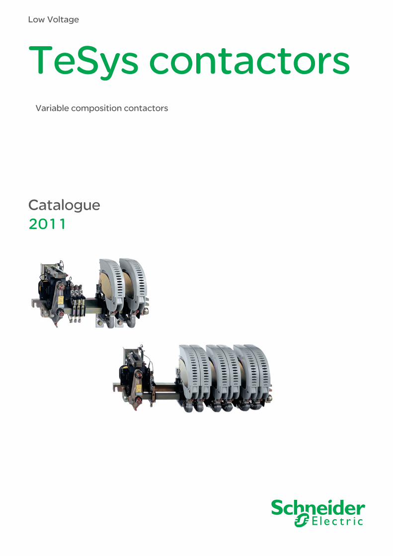
Low Voltage
TeSys contactors
Catalogue2011
Variable composition contactors

Contents TeSys contactors Variable composition contactors
Contactors: generalSelection guide . . . . . . . . . . . . . . . . . . . . . . . . . . . . . . . . . . . . . . . . pages 2 and 3
Definitions and comments . . . . . . . . . . . . . . . . . . . . . . . . . . . . . . . . pages 4 and 5
Product standards and certifications . . . . . . . . . . . . . . . . . . . . . . . . pages 6 and 7
Tests according to standard utilisation categories conforming to IEC 60947-4-1 and 5-1 . . . . . . . . . . . . . . . . . . . . . . . pages 8 and 9
Degrees of protection provided by enclosures . . . . . . . . . . . . . . . pages 10 and 11
Protective treatment of equipment according to climatic environment . . . . . . . . . . . . . . . . . . . . . . . . . . . . . . . . . . . . . . . . pages 12 and 13
TeSys contactors CV1, CV3 and LC1 BSelection guide . . . . . . . . . . . . . . . . . . . . . . . . . . . . . . . . . . . . . . pages 14 and 15
Presentation . . . . . . . . . . . . . . . . . . . . . . . . . . . . . . . . . . . . . . . . . . pages 16 to 19
Selection guide for utilisation categories according to required electrical durability
AC-3 . . . . . . . . . . . . . . . . . . . . . . . . . . . . . . . . . . . . . . . . . . . . . pages 20 and 21AC-1 . . . . . . . . . . . . . . . . . . . . . . . . . . . . . . . . . . . . . . . . . . . . . . .pages 22 to 25AC-2 and AC-4 . . . . . . . . . . . . . . . . . . . . . . . . . . . . . . . . . . . . . pages 26 and 27DC-1 to DC-5 . . . . . . . . . . . . . . . . . . . . . . . . . . . . . . . . . . . . . . . .pages 28 to 31
Selection guide for rotor circuits of slip-ring motors . . . . . . . . . . . . . . . . . .page 32
Contactors for specific applications . . . . . . . . . . . . . . . . . . . . . . . . . . . . . . page 33
Contactors characteristics . . . . . . . . . . . . . . . . . . . . . . . . . . . . . . . pages 34 to 41
CV1 and CV3 contactors references . . . . . . . . . . . . . . . . . . . . . . . pages 42 to 46
Order form CF 452 . . . . . . . . . . . . . . . . . . . . . . . . . . . . . . . . . . . . . . . . . . page 47
LC1 B contactors references . . . . . . . . . . . . . . . . . . . . . . . . . . . . pages 48 and 49
Components, spare parts and mounting accessories references . . pages 50 to 59
Installation and maintenance . . . . . . . . . . . . . . . . . . . . . . . . . . . . . . . . . . . page 60
Setting characteristics . . . . . . . . . . . . . . . . . . . . . . . . . . . . . . . . . . pages 61 to 67
Dimensions . . . . . . . . . . . . . . . . . . . . . . . . . . . . . . . . . . . . . . . . . . pages 68 to 77
Schemes . . . . . . . . . . . . . . . . . . . . . . . . . . . . . . . . . . . . . . . . . . . pages 78 and 79
Coils references and characteristics . . . . . . . . . . . . . . . . . . . . . . . pages 80 to 97
TeSys contactors CRX and CVXPresentation . . . . . . . . . . . . . . . . . . . . . . . . . . . . . . . . . . . . . . . . . . . . . . . . page 98
Characteristics . . . . . . . . . . . . . . . . . . . . . . . . . . . . . . . . . . . . . . . . . . . . . . page 99
References . . . . . . . . . . . . . . . . . . . . . . . . . . . . . . . . . . . . . . . . .pages 100 to 102
Dimensions, schemes . . . . . . . . . . . . . . . . . . . . . . . . . . . . . . . . . . . . . . . page 103
b
b
b
b
b
b
b
vvvv
b
b
b
b
b
b
b
b
b
b
b
b
b
b
b
b
2
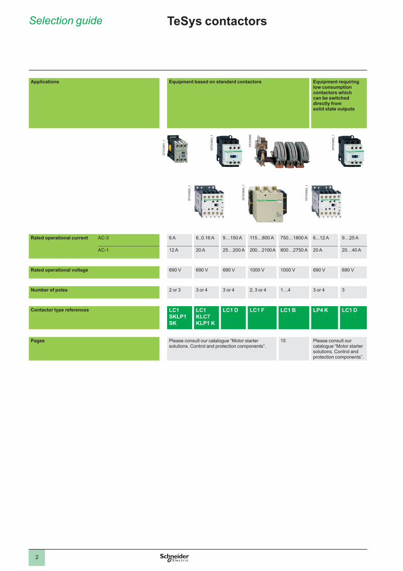
Selection guide
Applications Equipment based on standard contactors Equipment requiring low consumption contactors which can be switched directly from solid state outputs
DF5
3368
1_1
Rated operational current AC-3 6 A 6..0.16 A 9…150 A 115…800 A 750…1800 A 6...12 A 9…25 A
AC-1 12 A 20 A 25…200 A 200…2100 A 800…2750 A 20 A 20…40 A
Rated operational voltage 690 V 690 V 690 V V V 690 V 690 V
Number of poles 2 or 3 3 or 4 3 or 4 2, 3 or 4 1…4 3 or 4 3
Contactor type references LC1 SKLP1 SK
LC1 KLC7 KLP1 K
LC1 D LC1 F LC1 B LP4 K LC1 D
Pages Please consult our catalogue “Motor startersolutions. Control and protection components”.
15 Please consult our catalogue “Motor starter solutions. Control and protection components”.
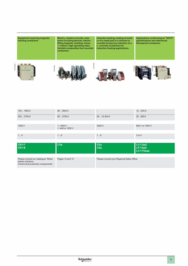
TeSys contactors
Equipment requiring magnetic latching contactors
Motors, resistive circuits, rotor short-circuiting devices, electro lifting magnets, hoisting, mines, c motors, high operating rates. Variable composition bar mounted contactors.
Induction heating, heating of metal or of a metal part in a channel or crucible furnace by induction of a.c. currents.Contactors for induction heating applications.
Applications conforming to “NATO” specifications and references. Shockproof contactors
150…1800 A 80...1800 A – 12…630 A
250…2750 A 80…2750 A 80…16 300 A 25…850 A
V a Vc 440 or 1500 V
3000 V 690 V or 1000 V
1…4 1…6 1…8 3 or 4
CR1 FCR1 B
CVp CEpCSp
LC1 DpGLP1 DpGLC1 FGppp
Please consult our catalogue “Motor starter solutions. Control and protection components”.
Pages 14 and 15 Please consult your Regional Sales Office
DF5
3368
3_1
DF5
3368
2_1
DF5
3368
5
DF5
3368
4_1
DF5
3368
2_1
DF5
3368
3_1
3
Applications Equipment based on standard contactors Equipment requiring low consumption contactors which can be switched directly from solid state outputs
DF5
3368
1_1
Rated operational current AC-3 6 A 6..0.16 A 9…150 A 115…800 A 750…1800 A 6...12 A 9…25 A
AC-1 12 A 20 A 25…200 A 200…2100 A 800…2750 A 20 A 20…40 A
Rated operational voltage 690 V 690 V 690 V V V 690 V 690 V
Number of poles 2 or 3 3 or 4 3 or 4 2, 3 or 4 1…4 3 or 4 3
Contactor type references LC1 SKLP1 SK
LC1 KLC7 KLP1 K
LC1 D LC1 F LC1 B LP4 K LC1 D
Pages Please consult our catalogue “Motor startersolutions. Control and protection components”.
15 Please consult our catalogue “Motor starter solutions. Control and protection components”.
Equipment requiring magnetic latching contactors
Motors, resistive circuits, rotor short-circuiting devices, electro lifting magnets, hoisting, mines, c motors, high operating rates. Variable composition bar mounted contactors.
Induction heating, heating of metal or of a metal part in a channel or crucible furnace by induction of a.c. currents.Contactors for induction heating applications.
Applications conforming to “NATO” specifications and references. Shockproof contactors
150…1800 A 80...1800 A – 12…630 A
250…2750 A 80…2750 A 80…16 300 A 25…850 A
V a Vc 440 or 1500 V
3000 V 690 V or 1000 V
1…4 1…6 1…8 3 or 4
CR1 FCR1 B
CVp CEpCSp
LC1 DpGLP1 DpGLC1 FGppp
Please consult our catalogue “Motor starter solutions. Control and protection components”.
Pages 14 and 15 Please consult your Regional Sales Office
DF5
3368
8_1
DF5
3368
9
DF5
3369
0
DF5
3369
1
DF5
3369
2
4
General
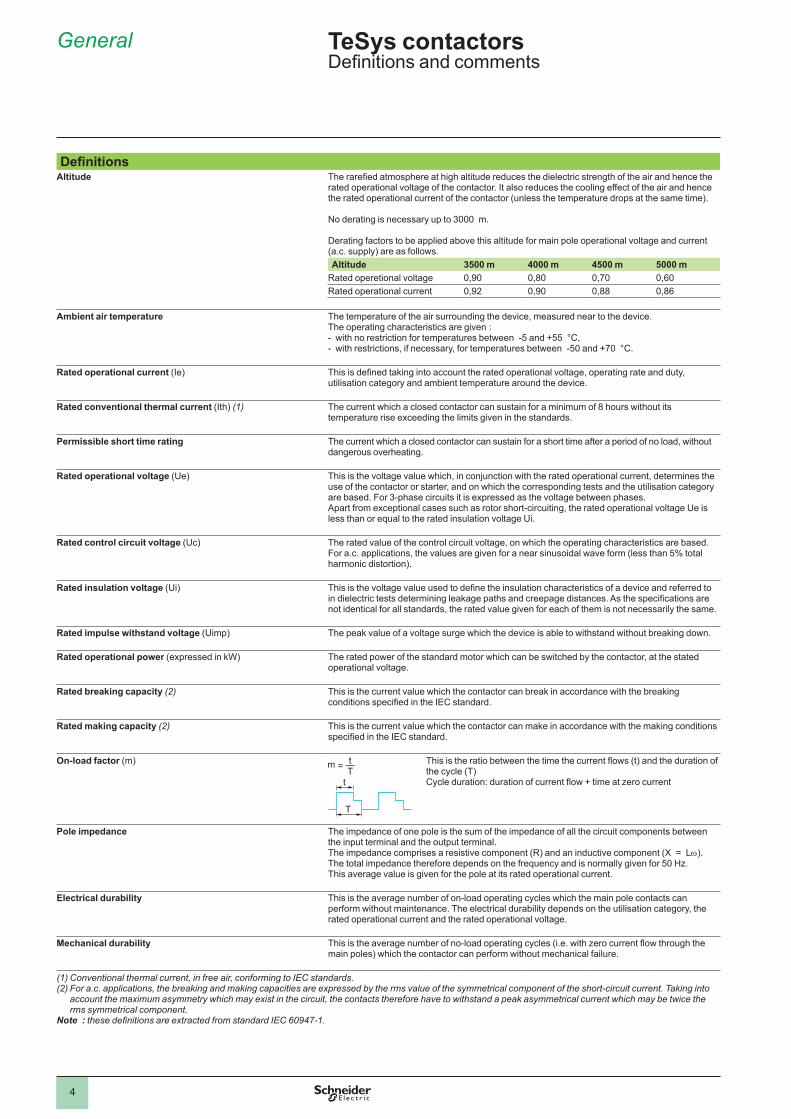
DefinitionsAltitude The rarefied atmosphere at high altitude reduces the dielectric strength of the air and hence the
rated operational voltage of the contactor. It also reduces the cooling effect of the air and hence the rated operational current of the contactor (unless the temperature drops at the same time).
No derating is necessary up to 3000 m.
Derating factors to be applied above this altitude for main pole operational voltage and current (a.c. supply) are as follows. Altitude 3500 m 4000 m 4500 m 5000 m
Rated operetional voltage 0,90 0,80 0,70 0,60Rated operational current 0,92 0,90 0,88 0,86
Ambient air temperature The temperature of the air surrounding the device, measured near to the device. The operating characteristics are given :
with no restriction for temperatures between -5 and +55 °C,with restrictions, if necessary, for temperatures between -50 and +70 °C.
--
Rated operational current (Ie) This is defined taking into account the rated operational voltage, operating rate and duty, utilisation category and ambient temperature around the device.
Rated conventional thermal current (Ith) (1) The current which a closed contactor can sustain for a minimum of 8 hours without its temperature rise exceeding the limits given in the standards.
Permissible short time rating The current which a closed contactor can sustain for a short time after a period of no load, without dangerous overheating.
Rated operational voltage (Ue) This is the voltage value which, in conjunction with the rated operational current, determines the use of the contactor or starter, and on which the corresponding tests and the utilisation category are based. For 3-phase circuits it is expressed as the voltage between phases.Apart from exceptional cases such as rotor short-circuiting, the rated operational voltage Ue is less than or equal to the rated insulation voltage Ui.
Rated control circuit voltage (Uc) The rated value of the control circuit voltage, on which the operating characteristics are based. For a.c. applications, the values are given for a near sinusoidal wave form (less than 5% total harmonic distortion).
Rated insulation voltage (Ui) This is the voltage value used to define the insulation characteristics of a device and referred to in dielectric tests determining leakage paths and creepage distances. As the specifications are not identical for all standards, the rated value given for each of them is not necessarily the same.
Rated impulse withstand voltage (Uimp) The peak value of a voltage surge which the device is able to withstand without breaking down.
Rated operational power (expressed in kW) The rated power of the standard motor which can be switched by the contactor, at the stated operational voltage.
Rated breaking capacity (2) This is the current value which the contactor can break in accordance with the breaking conditions specified in the IEC standard.
Rated making capacity (2) This is the current value which the contactor can make in accordance with the making conditions specified in the IEC standard.
On-load factor (m) This is the ratio between the time the current flows (t) and the duration of the cycle (T)Cycle duration: duration of current flow + time at zero current
Pole impedance The impedance of one pole is the sum of the impedance of all the circuit components between the input terminal and the output terminal.The impedance comprises a resistive component (R) and an inductive component (X = Lw). The total impedance therefore depends on the frequency and is normally given for 50 Hz. This average value is given for the pole at its rated operational current.
Electrical durability This is the average number of on-load operating cycles which the main pole contacts can perform without maintenance. The electrical durability depends on the utilisation category, the rated operational current and the rated operational voltage.
Mechanical durability This is the average number of no-load operating cycles (i.e. with zero current flow through the main poles) which the contactor can perform without mechanical failure.
(1) Conventional thermal current, in free air, conforming to IEC standards. (2) For a.c. applications, the breaking and making capacities are expressed by the rms value of the symmetrical component of the short-circuit current. Taking into
account the maximum asymmetry which may exist in the circuit, the contacts therefore have to withstand a peak asymmetrical current which may be twice the rms symmetrical component.
Note : these definitions are extracted from standard IEC 60947-1.
TeSys contactorsDefinitions and comments
5
General
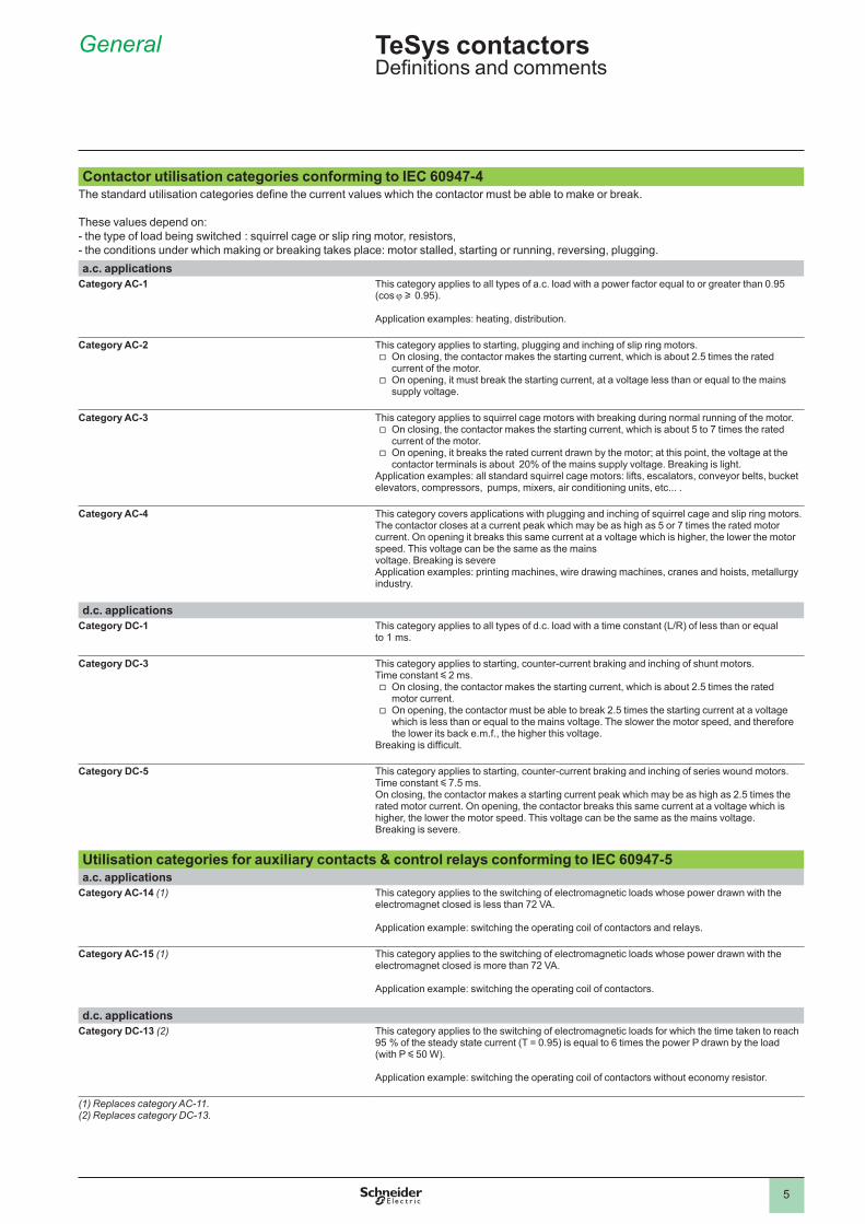
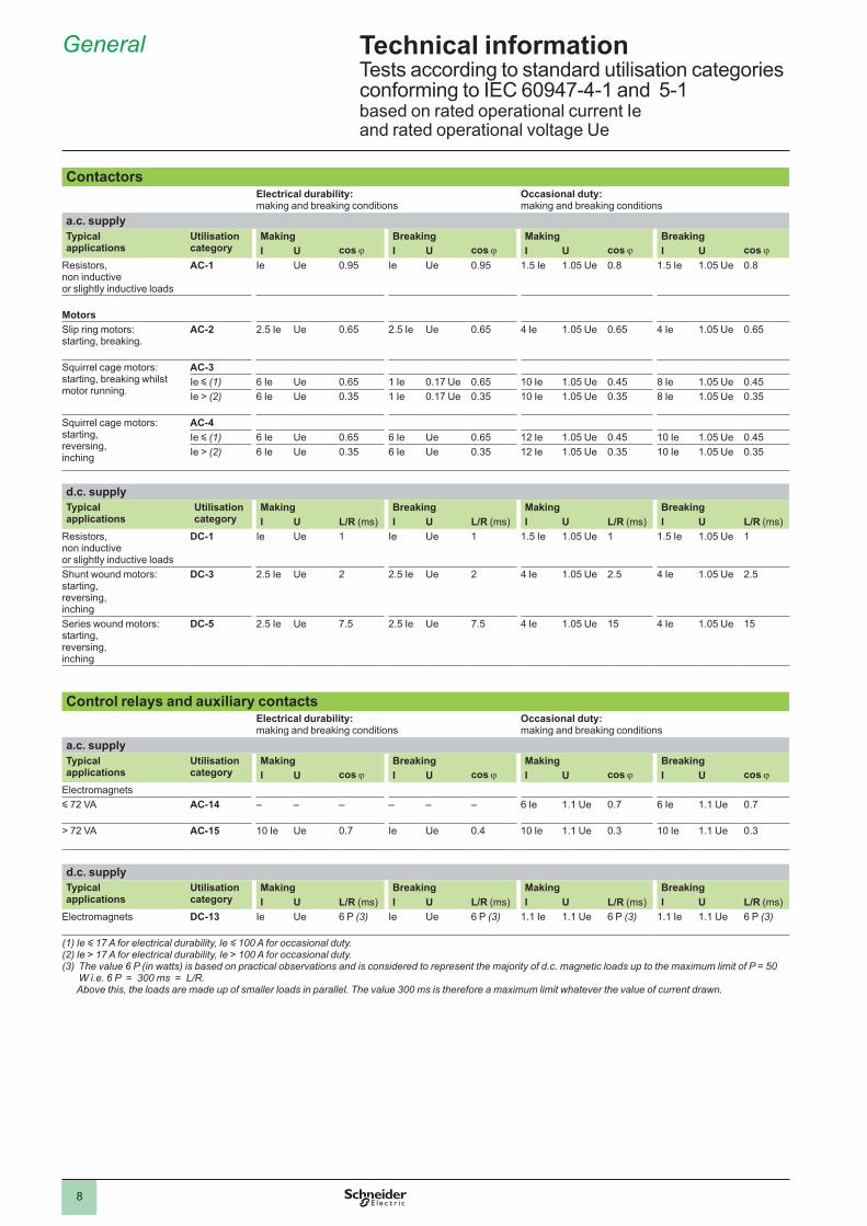
Contactor utilisation categories conforming to IEC 60947-4The standard utilisation categories define the current values which the contactor must be able to make or break.
These values depend on: - the type of load being switched : squirrel cage or slip ring motor, resistors, - the conditions under which making or breaking takes place: motor stalled, starting or running, reversing, plugging. a.c. applications
Category AC-1 This category applies to all types of a.c. load with a power factor equal to or greater than 0.95 (cos j u 0.95).
Application examples: heating, distribution.
Category AC-2 This category applies to starting, plugging and inching of slip ring motors.On closing, the contactor makes the starting current, which is about 2.5 times the rated current of the motor.On opening, it must break the starting current, at a voltage less than or equal to the mains supply voltage.
v
v
Category AC-3 This category applies to squirrel cage motors with breaking during normal running of the motor.On closing, the contactor makes the starting current, which is about 5 to 7 times the rated current of the motor.On opening, it breaks the rated current drawn by the motor; at this point, the voltage at the contactor terminals is about 20% of the mains supply voltage. Breaking is light.
Application examples: all standard squirrel cage motors: lifts, escalators, conveyor belts, bucket elevators, compressors, pumps, mixers, air conditioning units, etc... .
v
v
Category AC-4 This category covers applications with plugging and inching of squirrel cage and slip ring motors.The contactor closes at a current peak which may be as high as 5 or 7 times the rated motor current. On opening it breaks this same current at a voltage which is higher, the lower the motor speed. This voltage can be the same as the mainsvoltage. Breaking is severeApplication examples: printing machines, wire drawing machines, cranes and hoists, metallurgy industry.
d.c. applicationsCategory DC-1 This category applies to all types of d.c. load with a time constant (L/R) of less than or equal
to ms .
Category DC-3 This category applies to starting, counter-current braking and inching of shunt motors.Time constant y 2 ms.
On closing, the contactor makes the starting current, which is about 2.5 times the rated motor current.On opening, the contactor must be able to break 2.5 times the starting current at a voltage which is less than or equal to the mains voltage. The slower the motor speed, and therefore the lower its back e.m.f., the higher this voltage.
Breaking is difficult.
v
v
Category DC-5 This category applies to starting, counter-current braking and inching of series wound motors.Time constant y 7.5 ms.On closing, the contactor makes a starting current peak which may be as high as 2.5 times the rated motor current. On opening, the contactor breaks this same current at a voltage which is higher, the lower the motor speed. This voltage can be the same as the mains voltage. Breaking is severe.
Utilisation categories for auxiliary contacts & control relays conforming to IEC 60947-5a.c. applications
Category AC-14 (1) This category applies to the switching of electromagnetic loads whose power drawn with the electromagnet closed is less than 72 VA.
Application example: switching the operating coil of contactors and relays.
Category AC-15 (1) This category applies to the switching of electromagnetic loads whose power drawn with the electromagnet closed is more than 72 VA.
Application example: switching the operating coil of contactors.
d.c. applicationsCategory DC-13 (2) This category applies to the switching of electromagnetic loads for which the time taken to reach
95 % of the steady state current (T = 0.95) is equal to 6 times the power P drawn by the load (with P y 50 W).
Application example: switching the operating coil of contactors without economy resistor.
(1) Replaces category AC-11.(2) Replaces category DC-13.
TeSys contactorsDefinitions and comments
6
General 8
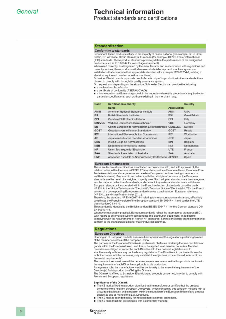
StandardisationConformity to standards
Schneider Electric products satisfy, in the majority of cases, national (for example: BS in Great Britain, NF in France, DIN in Germany), European (for example: CENELEC) or international (IEC) standards. These product standards precisely define the performance of the designated products (such as IEC 60947 for low voltage equipment).When used correctly, as designated by the manufacturer and in accordance with regulations and correct practices, these products will allow users to build equipment, machine systems or installations that conform to their appropriate standards (for example: IEC 60204-1, relating to electrical equipment used on industrial machines).Schneider Electric is able to provide proof of conformity of its production to the standards it has chosen to comply with, through its quality assurance system.On request, and depending on the situation, Schneider Electric can provide the following:
a declaration of conformity,a certificate of conformity (ASEFA/LOVAG),a homologation certificate or approval, in the countries where this procedure is required or for particular specifications, such as those existing in the merchant navy.
Code Certification authority CountryName Abbreviation
ANSI American National Standards Institute ANSI USABS British Standards Institution BSI Great BritainCEI Comitato Elettrotecnico Italiano CEI ItalyDIN/VDE Verband Deutscher Electrotechniker VDE GermanyEN Comité Européen de Normalisation Electrotechnique CENELEC EuropeGOST Gosudarstvenne Komitet Standartov GOST RussiaIEC International Electrotechnical Commission IEC WorldwideJIS Japanese Industrial Standards Committee JISC JapanNBN Institut Belge de Normalisation IBN BelgiumNEN Nederlands Normalisatie Institut NNI NetherlandsNF Union Technique de l’Electricité UTE FranceSAA Standards Association of Australia SAA AustraliaUNE Asociacion Española de Normalizacion y Certificacion AENOR Spain
European EN standardsThese are technical specifications established in conjunction with, and with approval of, the relative bodies within the various CENELEC member countries (European Union, European Free Trade Association and many central and eastern European countries having «member» or «affiliated» status). Prepared in accordance with the principle of consensus, the European standards are the result of a weighted majority vote. Such adopted standards are then integrated into the national collection of standards, and contradictory national standards are withdrawn.European standards incorporated within the French collection of standards carry the prefix NF EN. At the ‘Union Technique de l’Electricité’ (Technical Union of Electricity) (UTE), the French version of a corresponding European standard carries a dual number: European reference (NF EN …) and classification index (C …).Therefore, the standard NF EN 60947-4-1 relating to motor contactors and starters, effectively constitutes the French version of the European standard EN 60947-4-1 and carries the UTE classification C 63-110.This standard is identical to the British standard BS EN 60947-4-1 or the German standard DIN EN 60947-4-1.Whenever reasonably practical, European standards reflect the international standards (IEC).With regard to automation system components and distribution equipment, in addition to complying with the requirements of French NF standards, Schneider Electric brand components conform to the standards of all other major industrial countries.
RegulationsEuropean Directives
Opening up of European markets assumes harmonisation of the regulations pertaining to each of the member countries of the European Union.The purpose of the European Directive is to eliminate obstacles hindering the free circulation of goods within the European Union, and it must be applied in all member countries. Member countries are obliged to transcribe each Directive into their national legislation and to simultaneously withdraw any contradictory regulations. The Directives, in particular those of a technical nature which concern us, only establish the objectives to be achieved, referred to as “essential requirements”.The manufacturer must take all the necessary measures to ensure that his products conform to the requirements of each Directive applicable to his production.As a general rule, the manufacturer certifies conformity to the essential requirements of the Directive(s) for his product by affixing the e mark.The e mark is affixed to Schneider Electric brand products concerned, in order to comply with French and European regulations.
Significance of the e mark The e mark affixed to a product signifies that the manufacturer certifies that the product conforms to the relevant European Directive(s) which concern it; this condition must be met to allow free distribution and circulation within the countries of the European Union of any product subject to one or more of the E.U. Directives.The e mark is intended solely for national market control authorities.The e mark must not be confused with a conformity marking.
bbb
b
bb
Technical information Product standards and certifications
7
General 8
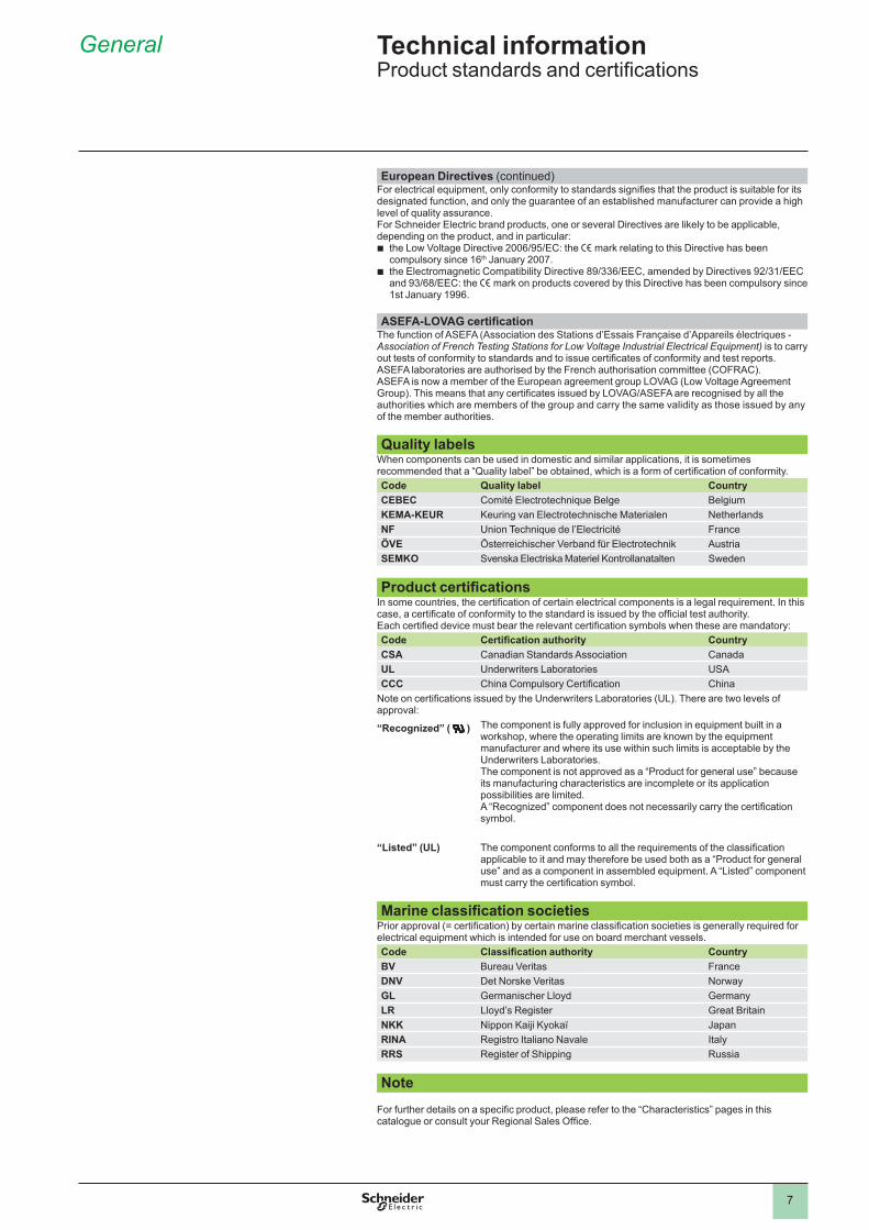
European Directives (continued)For electrical equipment, only conformity to standards signifies that the product is suitable for its designated function, and only the guarantee of an established manufacturer can provide a high level of quality assurance.For Schneider Electric brand products, one or several Directives are likely to be applicable, depending on the product, and in particular:
the Low Voltage Directive 2006/95/EC: the e mark relating to this Directive has been compulsory since 16th January 2007.the Electromagnetic Compatibility Directive 89/336/EEC, amended by Directives 92/31/EEC and 93/68/EEC: the e mark on products covered by this Directive has been compulsory since 1st January 1996.
ASEFA-LOVAG certificationThe function of ASEFA (Association des Stations d’Essais Française d’Appareils électriques - Association of French Testing Stations for Low Voltage Industrial Electrical Equipment) is to carry out tests of conformity to standards and to issue certificates of conformity and test reports. ASEFA laboratories are authorised by the French authorisation committee (COFRAC).ASEFA is now a member of the European agreement group LOVAG (Low Voltage Agreement Group). This means that any certificates issued by LOVAG/ASEFA are recognised by all the authorities which are members of the group and carry the same validity as those issued by any of the member authorities.
Quality labelsWhen components can be used in domestic and similar applications, it is sometimes recommended that a “Quality label” be obtained, which is a form of certification of conformity. Code Quality label CountryCEBEC Comité Electrotechnique Belge BelgiumKEMA-KEUR Keuring van Electrotechnische Materialen NetherlandsNF Union Technique de l’Electricité FranceÖVE Österreichischer Verband für Electrotechnik AustriaSEMKO Svenska Electriska Materiel Kontrollanatalten Sweden
Product certificationsIn some countries, the certification of certain electrical components is a legal requirement. In this case, a certificate of conformity to the standard is issued by the official test authority.Each certified device must bear the relevant certification symbols when these are mandatory: Code Certification authority CountryCSA Canadian Standards Association CanadaUL Underwriters Laboratories USACCC China Compulsory Certification China
Note on certifications issued by the Underwriters Laboratories (UL). There are two levels of approval:
“Recognized” ( ) The component is fully approved for inclusion in equipment built in a workshop, where the operating limits are known by the equipment manufacturer and where its use within such limits is acceptable by the Underwriters Laboratories.The component is not approved as a “Product for general use” because its manufacturing characteristics are incomplete or its application possibilities are limited.A “Recognized” component does not necessarily carry the certification symbol .
“Listed” (UL) The component conforms to all the requirements of the classification applicable to it and may therefore be used both as a “Product for general use” and as a component in assembled equipment. A “Listed” component must carry the certification symbol.
Marine classification societiesPrior approval (= certification) by certain marine classification societies is generally required for electrical equipment which is intended for use on board merchant vessels. Code Classification authority CountryBV Bureau Veritas FranceDNV Det Norske Veritas NorwayGL Germanischer Lloyd GermanyLR Lloyd’s Register Great BritainNKK Nippon Kaiji Kyokaï JapanRINA Registro Italiano Navale ItalyRRS Register of Shipping Russia
Note
For further details on a specific product, please refer to the “Characteristics” pages in this catalogue or consult your Regional Sales Office.
b
b
Technical information Product standards and certifications
8
General 5
ContactorsElectrical durability: making and breaking conditions
Occasional duty: making and breaking conditions
a.c. supplyTypical applications
Utilisation category
Making Breaking Making BreakingI U cos j I U cos j I U cos j I U cos j
Resistors, non inductive or slightly inductive loads
AC-1 Ie Ue 0.95 Ie Ue 0.95 1.5 Ie 1.05 Ue 0.8 1.5 Ie 1.05 Ue 0.8
MotorsSlip ring motors: starting, breaking.
AC-2 2.5 Ie Ue 0.65 2.5 Ie Ue 0.65 4 Ie 1.05 Ue 0.65 4 Ie 1.05 Ue 0.65
Squirrel cage motors: starting, breaking whilst motor running.
AC-3 Ie y (1) 6 Ie Ue 0.65 1 Ie 0.17 Ue 0.65 10 Ie 1.05 Ue 0.45 8 Ie 1.05 Ue 0.45Ie > (2) 6 Ie Ue 0.35 1 Ie 0.17 Ue 0.35 10 Ie 1.05 Ue 0.35 8 Ie 1.05 Ue 0.35
Squirrel cage motors: starting, reversing, inching
AC-4Ie y (1) 6 Ie Ue 0.65 6 Ie Ue 0.65 12 Ie 1.05 Ue 0.45 10 Ie 1.05 Ue 0.45Ie > (2) 6 Ie Ue 0.35 6 Ie Ue 0.35 12 Ie 1.05 Ue 0.35 10 Ie 1.05 Ue 0.35
d.c. supplyTypicalapplications
Utilisation category
Making Breaking Making BreakingI U L/R (ms) I U L/R (ms) I U L/R (ms) I U L/R (ms)
Resistors, non inductive or slightly inductive loads
DC-1 Ie Ue Ie Ue 1.5 Ie 1.05 Ue 1.5 Ie 1.05 Ue
Shunt wound motors: starting, reversing, inching
DC-3 2.5 Ie Ue 2 2.5 Ie Ue 2 4 Ie 1.05 Ue 2.5 4 Ie 1.05 Ue 2.5
Series wound motors: starting, reversing, inching
DC-5 2.5 Ie Ue 7.5 2.5 Ie Ue 7.5 4 Ie 1.05 Ue 15 4 Ie 1.05 Ue 15
Control relays and auxiliary contactsElectrical durability: making and breaking conditions
Occasional duty: making and breaking conditions
a.c. supplyTypical applications
Utilisation category
Making Breaking Making BreakingI U cos j I U cos j I U cos j I U cos j
Electromagnetsy 72 VA AC-14 – – – – – – 6 Ie 1.1 Ue 0.7 6 Ie 1.1 Ue 0.7
> 72 VA AC-15 10 Ie Ue 0.7 Ie Ue 0.4 10 Ie 1.1 Ue 0.3 10 Ie 1.1 Ue 0.3
d.c. supplyTypical applications
Utilisation category
Making Breaking Making BreakingI U L/R (ms) I U L/R (ms) I U L/R (ms) I U L/R (ms)
Electromagnets DC-13 Ie Ue 6 P (3) Ie Ue 6 P (3) 1.1 Ie 1.1 Ue 6 P (3) 1.1 Ie 1.1 Ue 6 P (3)
(1) Ie y 17 A for electrical durability, Ie y 100 A for occasional duty.(2) Ie > 17 A for electrical durability, Ie > 100 A for occasional duty.(3) The value 6 P (in watts) is based on practical observations and is considered to represent the majority of d.c. magnetic loads up to the maximum limit of P = 50
W i.e. 6 P = 300 ms = L/R. Above this, the loads are made up of smaller loads in parallel. The value 300 ms is therefore a maximum limit whatever the value of current drawn.
Technical information Tests according to standard utilisation categories conforming to IEC 60947-4-1 and 5-1based on rated operational current Ie and rated operational voltage Ue
9
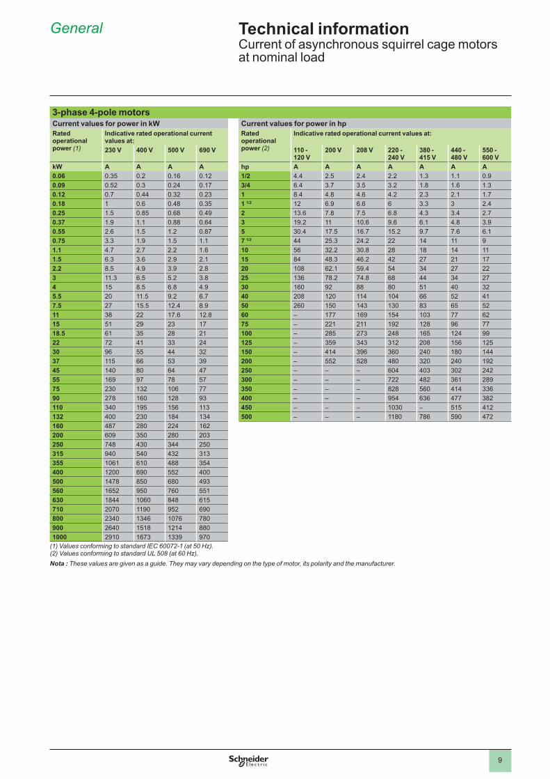
Nota : These values are given as a guide. They may vary depending on the type of motor, its polarity and the manufacturer.
(1) Values conforming to standard IEC 60072-1 (at 50 Hz).(2) Values conforming to standard UL 508 (at 60 Hz).
General 5
3-phase 4-pole motorsCurrent values for power in kW Current values for power in hpRated operational power (1)
Indicative rated operational current values at:
Rated operational power (2)
Indicative rated operational current values at:
230 V 400 V 500 V 690 V 110 -120 V
200 V 208 V 220 -240 V
380 -415 V
440 -480 V
550 -600 V
kW A A A A hp A A A A A A A0.06 0.35 0.2 0.16 0.12 1/2 4.4 2.5 2.4 2.2 1.3 . 0.90.09 0.52 0.3 0.24 0.17 3/4 6.4 3.7 3.5 3.2 1.8 1.6 1.30.12 0.7 0.44 0.32 0.23 1 8.4 4.8 4.6 4.2 2.3 2.1 1.70.18 0.6 0.48 0.35 1 1/2 12 6.9 6.6 6 3.3 3 2.40.25 1.5 0.85 0.68 0.49 2 13.6 7.8 7.5 6.8 4.3 3.4 2.70.37 1.9 . 0.88 0.64 3 19.2 10.6 9.6 6.1 4.8 3.90.55 2.6 1.5 1.2 0.87 5 30.4 17.5 16.7 15.2 9.7 7.6 6.10.75 3.3 1.9 1.5 . 7 1/2 44 25.3 24.2 22 14 91.1 4.7 2.7 2.2 1.6 10 56 32.2 30.8 28 18 14 1.5 6.3 3.6 2.9 2.1 15 84 48.3 46.2 42 27 21 172.2 8.5 4.9 3.9 2.8 20 108 62.1 59.4 54 34 27 223 11.3 6.5 5.2 3.8 25 136 78.2 74.8 68 44 34 274 15 8.5 6.8 4.9 30 160 92 88 80 51 40 325.5 20 11.5 9.2 6.7 40 208 120 114 104 66 52 417.5 27 15.5 12.4 8.9 50 260 150 143 130 83 65 5211 38 22 17.6 12.8 60 – 177 169 154 103 77 6215 51 29 23 17 75 – 221 211 192 128 96 7718.5 61 35 28 21 100 – 285 273 248 165 124 9922 72 41 33 24 125 – 359 343 312 208 156 12530 96 55 44 32 150 – 414 396 360 240 180 14437 115 66 53 39 200 – 552 528 480 320 240 19245 140 80 64 47 250 – – – 604 403 302 24255 169 97 78 57 300 – – – 722 482 361 28975 230 132 106 77 350 – – – 828 560 414 33690 278 160 128 93 400 – – – 954 636 477 382110 340 195 156 113 450 – – – 1030 – 515 412132 400 230 184 134 500 – – – 1180 786 590 472160 487 280 224 162200 609 350 280 203250 748 430 344 250315 940 540 432 313355 1061 610 488 354400 1200 690 552 400500 1478 850 680 493560 1652 950 760 551630 1844 1060 848 615710 2070 1190 952 690800 2340 1346 1076 780900 2640 1518 1214 8801000 2910 1673 1339 970
Technical information Current of asynchronous squirrel cage motors at nominal load
Presentation 8
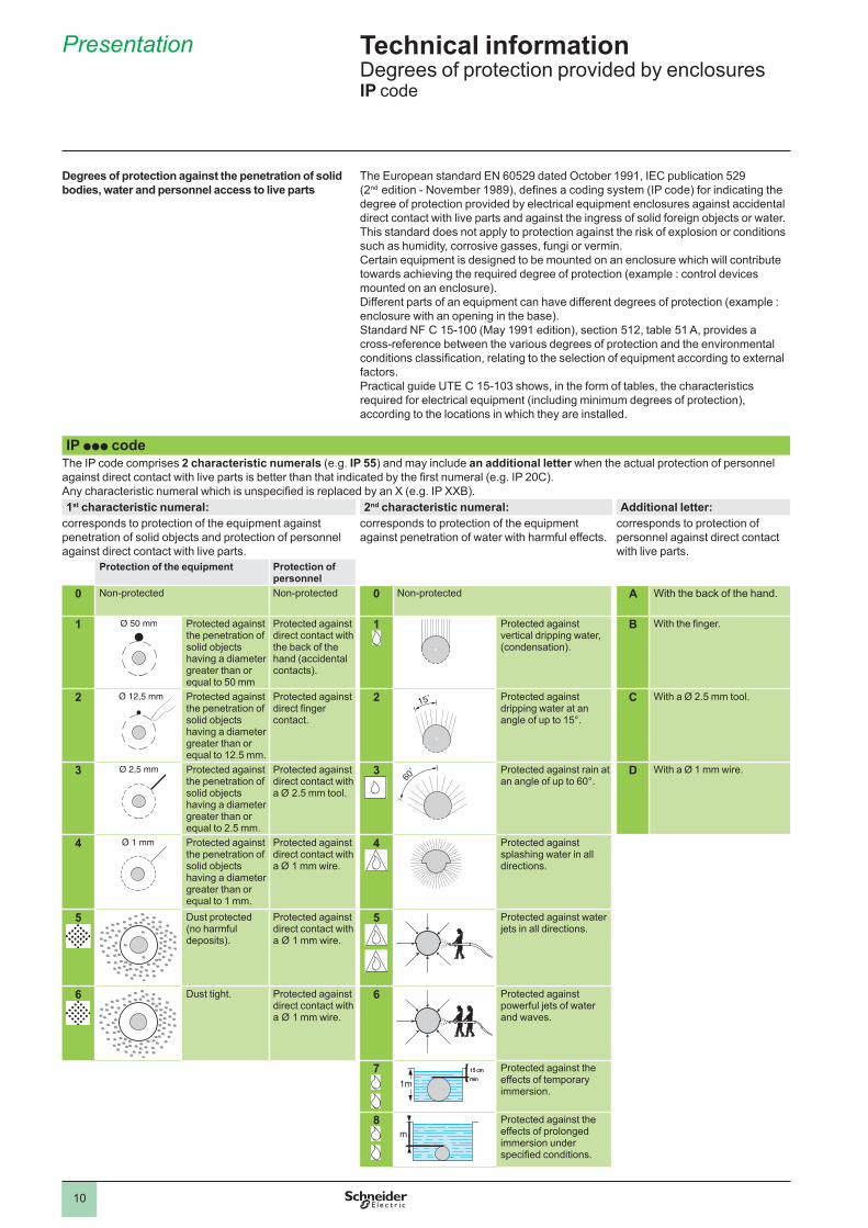
Degrees of protection against the penetration of solid bodies, water and personnel access to live parts
The European standard EN 60529 dated October 1991, IEC publication 529 (2nd edition - November 1989), defines a coding system (IP code) for indicating the degree of protection provided by electrical equipment enclosures against accidental direct contact with live parts and against the ingress of solid foreign objects or water.This standard does not apply to protection against the risk of explosion or conditions such as humidity, corrosive gasses, fungi or vermin.Certain equipment is designed to be mounted on an enclosure which will contribute towards achieving the required degree of protection (example : control devices mounted on an enclosure).Different parts of an equipment can have different degrees of protection (example : enclosure with an opening in the base).Standard NF C 15-100 (May 1991 edition), section 512, table 51 A, provides a cross-reference between the various degrees of protection and the environmental conditions classification, relating to the selection of equipment according to external factors .Practical guide UTE C 15-103 shows, in the form of tables, the characteristics required for electrical equipment (including minimum degrees of protection), according to the locations in which they are installed.
IP ppp codeThe IP code comprises 2 characteristic numerals (e.g. IP 55) and may include an additional letter when the actual protection of personnel against direct contact with live parts is better than that indicated by the first numeral (e.g. IP 20C).Any characteristic numeral which is unspecified is replaced by an X (e.g. IP XXB).1st characteristic numeral: 2nd characteristic numeral: Additional letter:
corresponds to protection of the equipment against penetration of solid objects and protection of personnel against direct contact with live parts.
corresponds to protection of the equipment against penetration of water with harmful effects.
corresponds to protection of personnel against direct contact with live parts.
Protection of the equipment Protection of personnel
0 Non-protected Non-protected 0 Non-protected A With the back of the hand.
1 Protected against the penetration of solid objects having a diameter greater than or equal to 50 mm
Protected against direct contact with the back of the hand (accidental contacts).
1 Protected against vertical dripping water, (condensation).
B With the finger.
2 Protected against the penetration of solid objects having a diameter greater than or equal to 12.5 mm.
Protected against direct finger contact .
2 Protected against dripping water at an angle of up to 15°.
C With a Ø 2.5 mm tool.
3 Protected against the penetration of solid objects having a diameter greater than or equal to 2.5 mm.
Protected against direct contact with a Ø 2.5 mm tool.
3 Protected against rain at an angle of up to 60°.
D With a Ø 1 mm wire.
4 Protected against the penetration of solid objects having a diameter greater than or equal to 1 mm.
Protected against direct contact with a Ø 1 mm wire.
4 Protected against splashing water in all directions.
5 Dust protected (no harmful deposits).
Protected against direct contact with a Ø 1 mm wire.
5 Protected against water jets in all directions.
6 Dust tight. Protected against direct contact with a Ø 1 mm wire.
6 Protected against powerful jets of water and waves.
7 Protected against the effects of temporary immersion .
8 Protected against the effects of prolonged immersion under specified conditions.
15˚15˚
60˚
60˚
1m
15 cm
min 1m
15 cm
min
m m
Technical information Degrees of protection provided by enclosuresIP code
Presentation 8
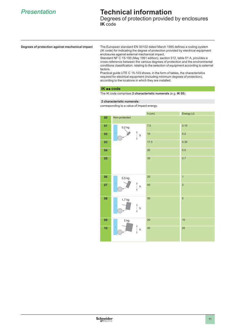
Degrees of protection against mechanical impact The European standard EN 50102 dated March 1995 defines a coding system (IK code) for indicating the degree of protection provided by electrical equipment enclosures against external mechanical impact.Standard NF C 15-100 (May 1991 edition), section 512, table 51 A, provides a cross-reference between the various degrees of protection and the environmental conditions classification, relating to the selection of equipment according to external factors .Practical guide UTE C 15-103 shows, in the form of tables, the characteristics required for electrical equipment (including minimum degrees of protection), according to the locations in which they are installed.
IK pp codeThe IK code comprises 2 characteristic numerals (e.g. IK 05).
2 characteristic numerals:corresponding to a value of impact energy.
h (cm) Energy (J)00 Non-protected
01 7.5 0.15
02 0.2
03 17.5 0.35
04 25 0.5
05 35 0.7
06 20
07 40 2
08 30 5
09 20
10 40 20
0,2 kg
h
0,2 kg
h
0,5 kg
h
0,5 kg
h
1,7 kg
h
1,7 kg
h
5 kg
h
5 kg
h
Technical information Degrees of protection provided by enclosuresIK code
12
General 8
Depending on the climatic and environmental conditions in which the equipment is placed, Schneider Electric can offer specially adapted products to meet your requirements.
In order to make the correct choice of protective finish, two points should be remembered:
the prevailing climate of the country is never the only criteriononly the atmosphere in the immediate vicinity of the equipment need be
considered.
All climates treatment “TC”This is the standard treatment for Schneider-electric brand equipment and is suitable for the vast majority of applications. It is the equivalent of treatments described as “Klimafest”, “Climateproof”.In particular, it meets the requirements specified in the following publications:
Publication UTE C 63-100 (method l), successive cycles of humid heat at: + 40 °C and 95 % relative humidity.
DIN 50016 - Variations of ambient conditions within a climatic chamber: + 23 °C and 83 % relative humidity + 40 °C and 92 % relative humidity.
It also meets the requirements of the following marine classification societies: BV-LR-GL-DNV-RINA.
CharacteristicsSteel components are usually treated with zinc. When they have a mechanical
function, they may also be painted.Insulating materials are selected for their high electrical, dielectric and mechanical
characteristics.Metal enclosures have a stoved paint finish, applied over a primary phosphate
protective coat, or are galvanised (e.g. some prefabricated busbar trunking components).
Limits for use of “TC” (All climates) treatment“TC” treatment is suitable for the following temperatures and humidity:
Temperature (°C) Relative humidity (%)20 9540 8050 50 “TC” treatment is therefore suitable for all latitudes and in particular tropical and equatorial regions where the equipment is mounted in normally ventilated industrial premises. Being sheltered from external climatic conditions, temperature variations are small, the risk of condensation is minimised and the risk of dripping water is virtually non-existent.
Extension of use of “TC” (All climates) treatmentIn cases where the humidity around the equipment exceeds the conditions described above, or in equatorial regions if the equipment is mounted outdoors, or if it is placed in a very humid location (laundries, sugar refineries, steam rooms, etc.), “TC” treatment can still be used if the following precautions are taken:
The enclosure in which the equipment is mounted must be protected with a “TH” finish (see next page) and must be well ventilated to avoid condensation and dripping water (e.g. enclosure base plate mounted on spacers).
Components mounted inside the enclosure must have a “TC” finish.If the equipment is to be switched off for long periods, a heater must be provided
(0.2 to 0.5 kW per square decimetre of enclosure), that switches on automatically when the equipment is turned off. This heater keeps the inside of the enclosure at a temperature slightly higher than the outside surrounding temperature, thereby avoiding any risk of condensation and dripping water (the heat produced by the equipment itself during normal running is sufficient to provide this temperature difference).
Special considerations for “Operator dialog” and “Detection” products: for certain pilot devices, the use of “TC” treatment can be extended to outdoor use provided their enclosure is made of light alloys, zinc alloys or plastic material. In this case, it is also essential to ensure that the degree of protection against penetration of liquids and solid objects is suitable for the applications involved.
bb
b
b
b
b
b
b
b
bb
b
Technical information Protective treatment of equipmentaccording to climatic environment
13
General 8
“TH” treatment for hot and humid environmentsThis treatment is suitable for hot and humid atmospheres where installations are regularly subject to condensation, dripping water and the risk of fungi.
In addition, plastic insulating components are resistant to attacks from insects such as termites and cockroaches. These properties have often led to this treatment being described as “Tropical Finish”, but this does not mean that all equipment installed in tropical and equatorial regions must systematically have undergone “TH” treatment. On the other hand, certain operating conditions in temperate climates may well require the use of “TH” treated equipment (see limitations for use of “TC” treatment).
Special characteristics of “TH” treatmentAll insulating components are made of materials which are either resistant to fungi
or treated with a fungicide, and which have increased resistance to creepage (Standards IEC 60112, NF C 26-220, DIN 5348).
Metal enclosures receive a top-coat of stoved, fungicidal paint, applied over a rust inhibiting undercoat. Components with “TH” treatment may be subject to a surcharge (1). Please consult your Regional Sales Office.
These treatments cover, in particular, the applications defined by methods I and II of guide UTE C 63-100.
Special precautions for electronic equipmentElectronic products always meet the requirements of “TC” treatment. A number of them are “TH” treated as standard.
Some electronic products (for example: programmable controllers, flush mountable controllers CCX and flush mountable operator terminals XBT) require the use of an enclosure providing a degree of protection to at least IP 54, as defined by standards IEC 60664 and NF C 20 040, for use in industrial applications or in environmental conditions requiring “TH” treatment.
These electronic products, including flush mountable products, must have a degree of protection to at least IP 20 (provided either by their own enclosure or by their installation method) for restricted access locations where the degree of pollution does not exceed 2 (a test booth not containing machinery or other dust producing activities, for example).
Special treatmentsFor particularly harsh industrial environments, Schneider Electric is able to offer special protective treatments. Please consult your Regional Sales Office.(1) A large number of the Schneider-electric brand products are “TH” treated as standard and
are, therefore, not subject to a surcharge.
b
b
Protective treatment selection guideSurrounding environment
Duty cycle Internal heating of enclosure when not in use
Type of climate
Protective treatmentof equip-ment
of enclo-sure
IndoorsNo dripping water or condensation
Unimportant Not necessary Unimportant “TC” “TC”
Presence of dripping water or condensation
Frequent switching off for periods of more than 1 day
No Temperate “TC” “TH”Equatorial “TH” “TH”
Yes Unimportant “TC” “TH”
Continuous Not necessary Unimportant “TC” “TH”
Outdoors (sheltered)No dripping water or dew
Unimportant Not necessary Temperate “TC” “TC”Equatorial “TH” “TH”
Exposed outdoors or near the seaFrequent and regular presence of dripping water or dew
Frequent switching off for periods of more than 1 day
No Temperate “TC” “TH”Equatorial “TH” “TH”
Yes Unimportant “TC” “TH”
Continuous Not necessary Unimportant “TC” “TH”
Technical information Protective treatment of equipmentaccording to climatic environment
14
Selection guide
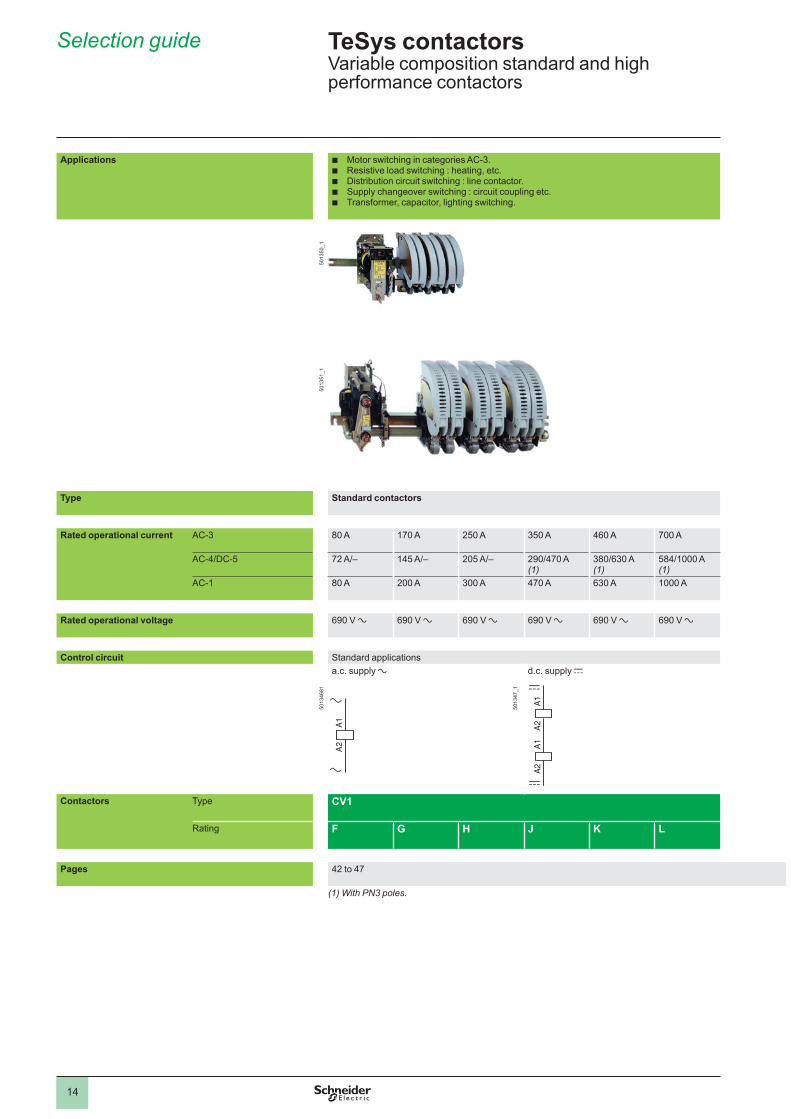
Applications b Motor switching in categories AC-3.b Resistive load switching : heating, etc.b Distribution circuit switching : line contactor.b Supply changeover switching : circuit coupling etc.b Transformer, capacitor, lighting switching.
5013
50_1
5013
51_1
Type Standard contactors
Rated operational current AC-3 80 A 170 A 250 A 350 A 460 A 700 A
AC-4/DC-5 72 A/– 145 A/– 205 A/– 290/470 A (1)
380/630 A (1)
584/1000 A (1)
AC-1 80 A 200 A 300 A 470 A 630 A A
Rated operational voltage 690 V a 690 V a 690 V a 690 V a 690 V a 690 V a
Control circuit Standard applications
5013
4681
a.c. supply a d.c. supply c
Contactors Type CV1
Rating F G H J K L
Pages 42 to 47
(1) With PN3 poles.
A1
A2
A1
A2 A1
A2
A1
A2
A1
A2
A1
A2
TeSys contactors Variable composition standard and high performance contactors
5013
47_1
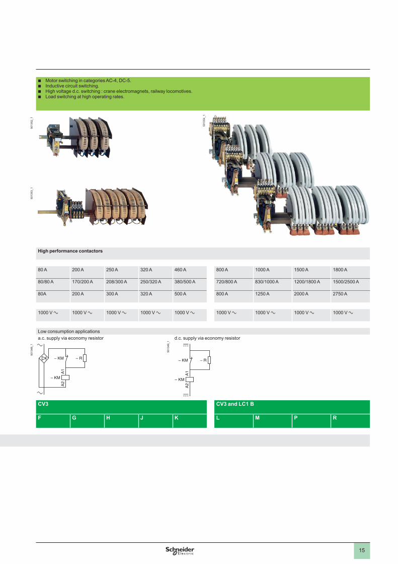
b Motor switching in categories AC-4, DC-5.b Inductive circuit switching.b High voltage d.c. switching : crane electromagnets, railway locomotives.b Load switching at high operating rates.
High performance contactors
80 A 200 A 250 A 320 A 460 A 800 A A 1500 A 1800 A
80/80 A 170/200 A 208/300 A 250/320 A 380/500 A 720/800 A 830/1000 A 1200/1800 A 1500/2500 A
80A 200 A 300 A 320 A 500 A 800 A 1250 A 2000 A 2750 A
V a V a V a V a V a V a V a V a V a
Low consumption applicationsa.c. supply via economy resistor d.c. supply via economy resistor
CV3 CV3 and LC1 B
F G H J K L M P R
– R
– KM
A1
A2
– KM – R
– KM
A1
A2
– KM – R
– KM
A1
A2
– KM – R
– KM
A1
A2
– KM
15
b Motor switching in categories AC-4, DC-5.b Inductive circuit switching.b High voltage d.c. switching : crane electromagnets, railway locomotives.b Load switching at high operating rates.
High performance contactors
80 A 200 A 250 A 320 A 460 A 800 A A 1500 A 1800 A
80/80 A 170/200 A 208/300 A 250/320 A 380/500 A 720/800 A 830/1000 A 1200/1800 A 1500/2500 A
80A 200 A 300 A 320 A 500 A 800 A 1250 A 2000 A 2750 A
V a V a V a V a V a V a V a V a V a
Low consumption applicationsa.c. supply via economy resistor d.c. supply via economy resistor
CV3 CV3 and LC1 B
F G H J K L M P R
– R
– KM
A1
A2
– KM – R
– KM
A1
A2
– KM – R
– KM
A1
A2
– KM – R
– KM
A1
A2
– KM
50
1352
_150
1353
_150
1348
_1
5013
49_1
5013
54_1
16
Presentation
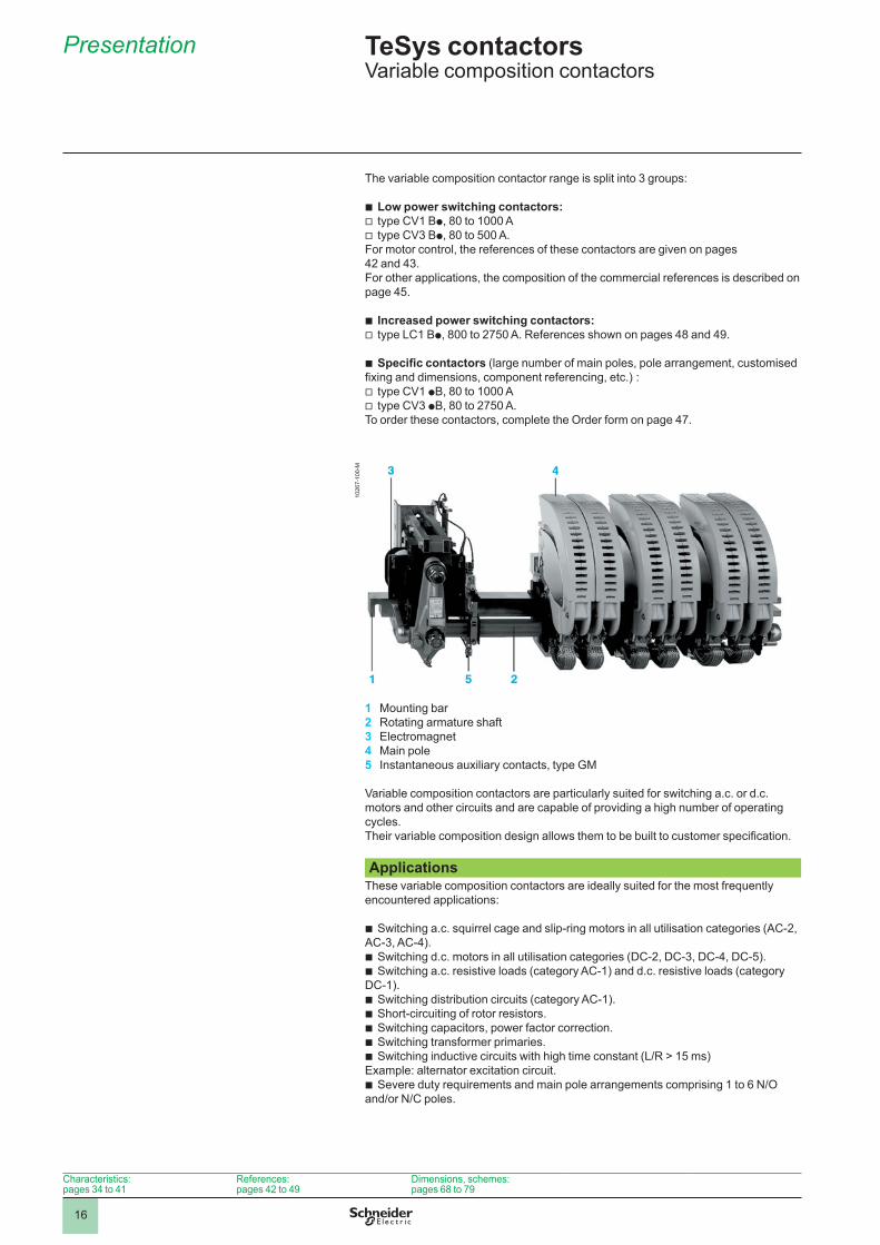
The variable composition contactor range is split into 3 groups:
Low power switching contactors:type CV1 Bp, 80 to 1000 Atype CV3 Bp, 80 to 500 A.
For motor control, the references of these contactors are given on pages 42 and 43 .For other applications, the composition of the commercial references is described on page 45 .
Increased power switching contactors:type LC1 Bp, 800 to 2750 A. References shown on pages 48 and 49 .
Specific contactors (large number of main poles, pole arrangement, customised fixing and dimensions, component referencing, etc.) :
type CV1 pB, 80 to 1000 Atype CV3 pB, 80 to 2750 A.
To order these contactors, complete the Order form on page 47 .
bvv
bv
b
vv
1 Mounting bar2 Rotating armature shaft3 Electromagnet4 Main pole5 Instantaneous auxiliary contacts, type GM
Variable composition contactors are particularly suited for switching a.c. or d.c. motors and other circuits and are capable of providing a high number of operating cycles .Their variable composition design allows them to be built to customer specification.
ApplicationsThese variable composition contactors are ideally suited for the most frequently encountered applications:
Switching a.c. squirrel cage and slip-ring motors in all utilisation categories (AC-2, AC-3, AC-4).
Switching d.c. motors in all utilisation categories (DC-2, DC-3, DC-4, DC-5).Switching a.c. resistive loads (category AC-1) and d.c. resistive loads (category
DC-1).Switching distribution circuits (category AC-1).Short-circuiting of rotor resistors.Switching capacitors, power factor correction.Switching transformer primaries.Switching inductive circuits with high time constant (L/R > 15 ms)
Example: alternator excitation circuit.Severe duty requirements and main pole arrangements comprising 1 to 6 N/O
and/or N/C poles.
b
bb
bbbbb
b
TeSys contactors 0 Variable composition contactors
4.2
Characteristics: pages 34 to 41
References: pages 42 to 49
Dimensions, schemes: pages 68 to 79
1026
7-10
0-M
17
Presentation (continued)
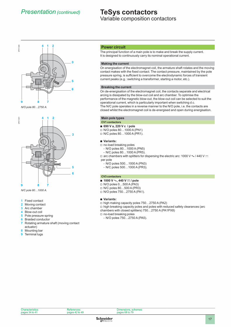
Power circuitThe principal function of a main pole is to make and break the supply current.It is designed to continuously carry its nominal operational current.
Making the currentOn energisation of the electromagnet coil, the armature shaft rotates and the moving contact makes with the fixed contact. The contact pressure, maintained by the pole pressure spring, is sufficient to overcome the electrodynamic forces of transient current peaks (e.g.: switching a transformer, starting a motor, etc.).
Breaking the currentOn de-energisation of the electromagnet coil, the contacts separate and electrical arcing is dissipated by the blow-out coil and arc chamber. To optimise the performance of the magnetic blow-out, the blow-out coil can be selected to suit the operational current, which is particularly important when switching d.c.The N/C pole operates in a reverse manner to the N/O pole, i.e. the contacts are closed whilst the electromagnet coil is de-energised and open during energisation.
Main pole types CV1 contactors
690 V a, 220 V c / poleN/O poles 80…1000 A (PN1)N/C poles 80…1000 A (PR1).
Variants:no-load breaking poles
N/O poles 80…1000 A (PN5)N/C poles 80…1000 A (PR5).
arc chambers with splitters for dispersing the electric arc: 1000 V a / 440 V c per pole
N/O poles 500…1000 A (PN3)N/C poles 500…1000 A (PR3).
bvv
bv
--
v
--
CV3 contactors1000 V a, 440 V c / poleN/O poles 0…500 A (PA3)N/C poles 80…500 A (PR3)N/O poles 750…2750 A (PA1).
Variants:high making capacity poles 750…2750 A (PA2)high breaking capacity poles and poles with reduced safety clearances (arc
chambers with closed splitters) 750…2750 A (PA1PX8)no-load breaking poles
N/O poles 750…2750 A (PA5).
bvvv
bvv
v-
TeSys contactors 0 Variable composition contactors
Characteristics: pages 34 to 41
References: pages 42 to 49
Dimensions, schemes: pages 68 to 79
DF5
1120
0D
F511
201
1 Fixed contact2 Moving contact3 Arc chamber4 Blow-out coil5 Pole pressure spring6 Braided conductor7 Rotating armature shaft (moving contact
actuator)8 Mounting bar9 Terminal lugs
N/C pole 80…1000 A.
N/O pole 80…2750 A.
18
Presentation (continued)
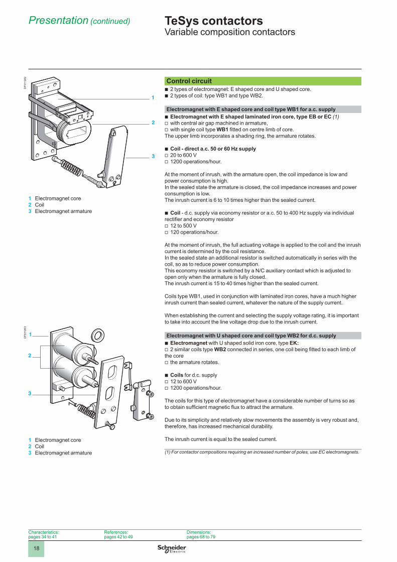
Control circuit2 types of electromagnet: E shaped core and U shaped core.2 types of coil: type WB1 and type WB2.
bb
Electromagnet with E shaped core and coil type WB1 for a.c. supply Electromagnet with E shaped laminated iron core, type EB or EC (1)with central air gap machined in armature,with single coil type WB1 fitted on centre limb of core.
The upper limb incorporates a shading ring, the armature rotates.
Coil - direct a.c. 50 or 60 Hz supply20 to 600 V1200 operations/hour.
At the moment of inrush, with the armature open, the coil impedance is low and power consumption is high.In the sealed state the armature is closed, the coil impedance increases and power consumption is low.The inrush current is 6 to 10 times higher than the sealed current.
Coil - d.c. supply via economy resistor or a.c. 50 to 400 Hz supply via individual rectifier and economy resistor
12 to 500 V120 operations/hour.
At the moment of inrush, the full actuating voltage is applied to the coil and the inrush current is determined by the coil resistance.In the sealed state an additional resistor is switched automatically in series with the coil, so as to reduce power consumption.This economy resistor is switched by a N/C auxiliary contact which is adjusted to open only when the armature is fully closed. The inrush current is 15 to 40 times higher than the sealed current.
Coils type WB1, used in conjunction with laminated iron cores, have a much higher inrush current than sealed current, whatever the nature of the supply current.
When establishing the current and selecting the supply voltage rating, it is important to take into account the line voltage drop due to the inrush current.
bvv
bvv
b
vv
Electromagnet with U shaped core and coil type WB2 for d.c. supply Electromagnet with U shaped solid iron core, type EK:2 similar coils type WB2 connected in series, one coil being fitted to each limb of
the corethe armature rotates.
Coils for d.c. supply 12 to 600 V1200 operations/hour.
The coils for this type of electromagnet have a considerable number of turns so as to obtain sufficient magnetic flux to attract the armature.
Due to its simplicity and relatively slow movements the assembly is very robust and, therefore, has increased mechanical durability.
The inrush current is equal to the sealed current.
bv
v
bvv
(1) For contactor compositions requiring an increased number of poles, use EC electromagnets.
TeSys contactors 0 Variable composition contactors
Characteristics: pages 34 to 41
References: pages 42 to 49
Dimensions: pages 68 to 79
DF5
1120
2D
F511
203
1 Electromagnet core2 Coil3 Electromagnet armature
1 Electromagnet core2 Coil3 Electromagnet armature
19
Presentation (continued)
Instantaneous and time delay auxiliary contactsSignalling, electrical interlocking and slave functions can be achieved by using auxiliary contacts.
Instantaneous auxiliary contacts suitable for use with all contactor types are available in 2 versions:
N/O instantaneous contact, reference ZC4 GM1. N/C instantaneous contact, reference ZC4 GM2.
Time delay auxiliary contacts suitable for use with contactors CV1 and CV3:On-delay 1 C/O, reference ZC2 GG1.Off-delay 1 C/O, reference ZC2 GG5.
Time delay contacts make or break at a specified time after the electromagnet armature closes or opens. This delay may be adjusted between 0.2 and 180 seconds.
bb
bb
Assembling reversing/changeover contactor pairsMounting accessories
For applications involving the switching of reversing motors or changeover circuits, contactors of different ratings can easily be mounted vertically and interlocked.Mechanical interlock kits are available (see page 59) and auxiliary contacts can be used for electrical interlocking.
TeSys contactors 0 Variable composition contactors
Characteristics: pages 34 to 41
References: pages 42 to 49
Dimensions: pages 68 to 79
20
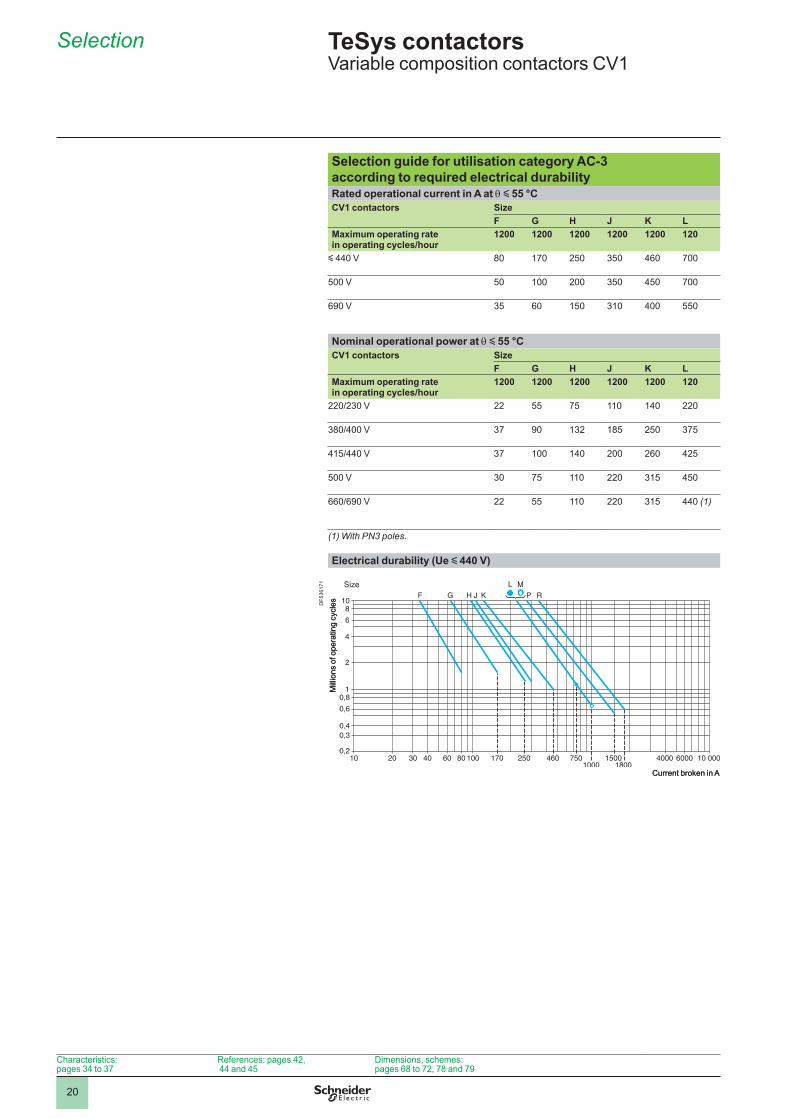
TeSys contactors 0 Variable composition contactors CV1
Selection guide for utilisation category AC-3 according to required electrical durabilityRated operational current in A at q y 55 °CCV1 contactors Size
F G H J K LMaximum operating rate in operating cycles/hour
1200 1200 1200 1200 1200 120
y 440 V 80 170 250 350 460 700
500 V 50 200 350 450 700
690 V 35 60 150 310 400 550
Nominal operational power at q y 55 °CCV1 contactors Size
F G H J K LMaximum operating rate in operating cycles/hour
1200 1200 1200 1200 1200 120
220/230 V 22 55 75 140 220
380/400 V 37 90 132 185 250 375
415/440 V 37 140 200 260 425
500 V 30 75 220 315 450
660/690 V 22 55 220 315 440 (1)
(1) With PN3 poles.
Electrical durability (Ue y 440 V)
Current broken in A
Mill
ions
of o
pera
ting
cycl
es
Size
Current broken in A
Mill
ions
of o
pera
ting
cycl
es
Size
Selection
4.2
Characteristics: pages 34 to 37
References: pages 42, 44 and 45
Dimensions, schemes: pages 68 to 72, 78 and 79
DF5
3617
1
21
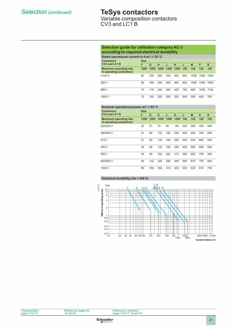
TeSys contactors 0 Variable composition contactors CV3 and LC1 B
Selection guide for utilisation category AC-3 according to required electrical durabilityRated operational current in A at q y 55 °CContactors CV3 and LC1 B
SizeF G H J K L M P R
Maximum operating rate in operating cycles/hour
1200 1200 1200 1200 1200 120 120 120 120
y 440 V 80 200 290 320 460 800 1500 1800
500 V 80 180 250 300 460 800 1500 1800
690 V 70 170 240 300 420 750 900
V 70 140 220 250 320 500 500 600 700
Nominal operational power at q y 55 °CContactors CV3 and LC1 B
SizeF G H J K L M P R
Maximum operating rate in operating cycles/hour
1200 1200 1200 1200 1200 120 120 120 120
220/230 V 22 51 75 90 140 220 280 425 500
380/400 V 37 90 132 160 250 400 500 750 900
415 V 37 90 132 160 250 425 530 800 900
440 V 45 90 132 160 280 450 560 800 900
500 V 45 90 160 220 315 500 600 750 900
660/690 V 55 132 200 280 400 560 670 750 900
V 90 160 250 315 425 530 530 670 750
Electrical durability (Ue y 440 V)
Current broken in A
Mill
ions
of o
pera
ting
cycl
es
Size
Current broken in A
Mill
ions
of o
pera
ting
cycl
es
Size
Selection (continued)
Characteristics: pages 74 to 77
References: pages 42, 44 and 45
Dimensions, schemes: pages 74 to 77, 78 and 79
DF5
3617
2
22
Selection
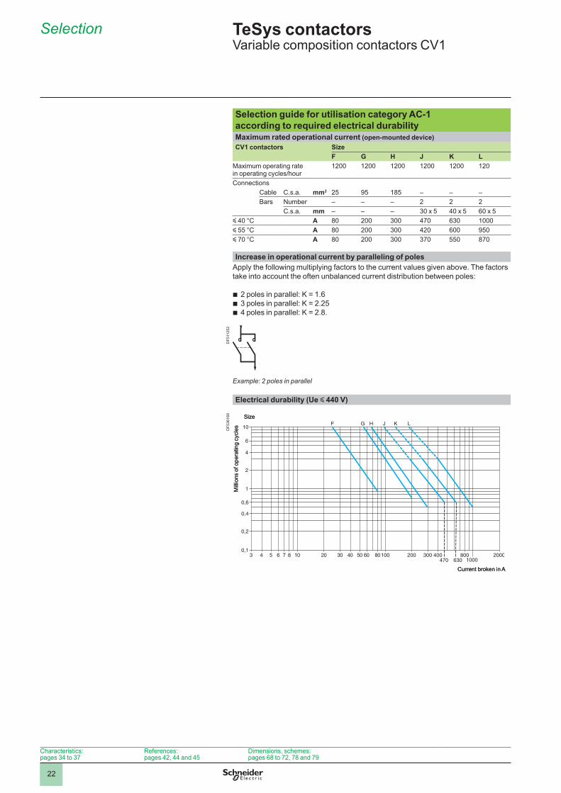
Selection guide for utilisation category AC-1 according to required electrical durabilityMaximum rated operational current (open-mounted device)CV1 contactors Size
F G H J K LMaximum operating rate in operating cycles/hour
1200 1200 1200 1200 1200 120
ConnectionsCable C.s.a. mm2 25 95 185 – – –Bars Number – – – 2 2 2
C.s.a. mm – – – 30 x 5 40 x 5 60 x 5y 40 °C A 80 200 300 470 630 y 55 °C A 80 200 300 420 600 950y 70 °C A 80 200 300 370 550 870
Increase in operational current by paralleling of polesApply the following multiplying factors to the current values given above. The factors take into account the often unbalanced current distribution between poles:
2 poles in parallel: K = 1.63 poles in parallel: K = 2.254 poles in parallel: K = 2.8.
Example: 2 poles in parallel
bbb
Electrical durability (Ue y 440 V)
Current broken in A
Mill
ions
of o
pera
ting
cycl
es
Size
Current broken in A
Mill
ions
of o
pera
ting
cycl
es
Size
TeSys contactors 0 Variable composition contactors CV1
Characteristics: pages 34 to 37
References: pages 42, 44 and 45
Dimensions, schemes: pages 68 to 72, 78 and 79
DF5
1125
2D
F536
169
23
Selection (continued)
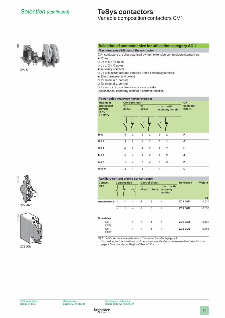
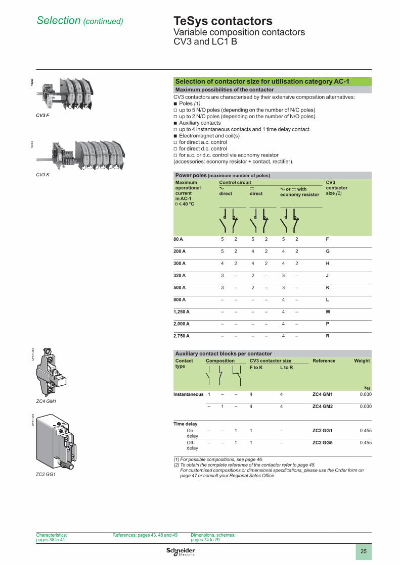
Selection of contactor size for utilisation category AC-1Maximum possibilities of the contactor
CV1 contactors are characterised by their extensive composition alternatives:Polesup to 5 N/O polesup to 2 N/C poles.Auxiliary contactsup to 5 instantaneous contacts and 1 time delay contact.Electromagnet and coil(s)for direct a.c. controlfor direct d.c. controlfor a.c. or d.c. control via economy resistor
(accessories: economy resistor + contact, rectifier).
bvvbvbvvv
Power poles (maximum number of poles)Maximum operational current in AC-1 q y 40 °C
Control circuit CV1 contactor size (1)
a direct
c direct
a or c with economy resistor
80 A 5 2 5 2 5 2 F
200 A 5 2 4 2 5 2 G
300 A 4 2 4 2 4 2 H
470 A 4 2 4 2 4 2 J
630 A 4 2 4 2 4 2 K
1000 A 2 2 4 L
Auxiliary contact blocks per contactorContact type
Composition Control circuit Reference Weight
kg
a direct
c direct
a or c with economy resistor
Instantaneous – – 5 5 4 ZC4 GM1 0.030
– – 5 5 4 ZC4 GM2 0.030
Time delayOn-delay
– – ZC2 GG1 0.455
Off-delay
– – ZC2 GG5 0.455
(1) To obtain the complete reference of the contactor refer to page 45. For customised compositions or dimensional specifications, please use the Order form on page 47 or consult your Regional Sales Office.
1026
3
CV1 K
1026
3
CV1 K
ZC4 GM1ZC4 GM1
ZC2 GG1ZC2 GG1
TeSys contactors 0 Variable composition contactors CV1
Characteristics: pages 34 to 37
References:pages 42, 44 and 45
Dimensions, schemes: pages 68 to 72, 78 and 79
DF5
1126
3D
F511
264
24
Selection (continued)
Selection guide for utilisation category AC-1 according to required electrical durabilityMaximum rated operational current (open-mounted device)Contactors CV3 and LC1 B
SizeF G H J K L M P R
Maximum operating rate in operating cycles/hour
1200 1200 1200 1200 1200 120 120 120 120
ConnectionsCable C.s.a. mm2 25 70 120 185 – – – – –Bars Number – – – – 2 2 2 3 3
C.s.a. mm – – – – 30 x 5 50 x 5 80 x 5 100 x 5 100 x 10y 40 °C A 80 170 250 320 500 800 1250 2000 2750y 55 °C A 80 170 250 320 500 700 1750 2400y 70 °C A 80 160 250 280 440 600 900 1500 2000
Increase in operational current by paralleling of polesApply the following multiplying factors to the current values given above. The factors take into account the often unbalanced current distribution between poles:
2 poles in parallel: K = 1.63 poles in parallel: K = 2.254 poles in parallel: K = 2.8.
Example: 2 poles in parallel
bbb
Electrical durability (Ue y 440 V)
Current broken in A
Mill
ions
of o
pera
ting
cycl
es
Size
Current broken in A
Mill
ions
of o
pera
ting
cycl
es
Size
TeSys contactors 0 Variable composition contactors CV3 and LC1 B
Characteristics: pages 38 to 41
References: pages 43, 48 and 49 Dimensions, schemes: pages 74 to 79
DF5
3617
0D
F511
252
25
Selection (continued)
Selection of contactor size for utilisation category AC-1Maximum possibilities of the contactor
CV3 contactors are characterised by their extensive composition alternatives:Poles (1)up to 5 N/O poles (depending on the number of N/C poles)up to 2 N/C poles (depending on the number of N/O poles).Auxiliary contactsup to 4 instantaneous contacts and 1 time delay contact.Electromagnet and coil(s)for direct a.c. controlfor direct d.c. controlfor a.c. or d.c. control via economy resistor
(accessories: economy resistor + contact, rectifier).
bvvbvbvvv
Power poles (maximum number of poles)Maximum operational current in AC-1 q y 40 °C
Control circuit CV3 contactor size (2)
a direct
c direct
a or c with economy resistor
80 A 5 2 5 2 5 2 F
200 A 5 2 4 2 4 2 G
300 A 4 2 4 2 4 2 H
320 A 3 – 2 – 3 – J
500 A 3 – 2 – 3 – K
800 A – – – – 4 – L
1,250 A – – – – 4 – M
2,000 A – – – – 4 – P
2,750 A – – – – 4 – R
Auxiliary contact blocks per contactorContact type
Composition CV3 contactor size Reference Weight
kg
F to K L to R
Instantaneous – – 4 4 ZC4 GM1 0.030
– – 4 4 ZC4 GM2 0.030
Time delayOn-delay
– – – ZC2 GG1 0.455
Off-delay
– – – ZC2 GG5 0.455
(1) For possible compositions, see page 46.(2) To obtain the complete reference of the contactor refer to page 45.
For customised compositions or dimensional specifications, please use the Order form on page 47 or consult your Regional Sales Office.
1026
6
CV3 F
1026
6
CV3 F
TeSys contactors 0 Variable composition contactors CV3 and LC1 B
Characteristics: pages 38 to 41
References: pages 43, 48 and 49 Dimensions, schemes: pages 74 to 79
DF5
1126
3D
F511
264
ZC4 GM1
ZC2 GG1
1026
4
CV3 K
26
Selection
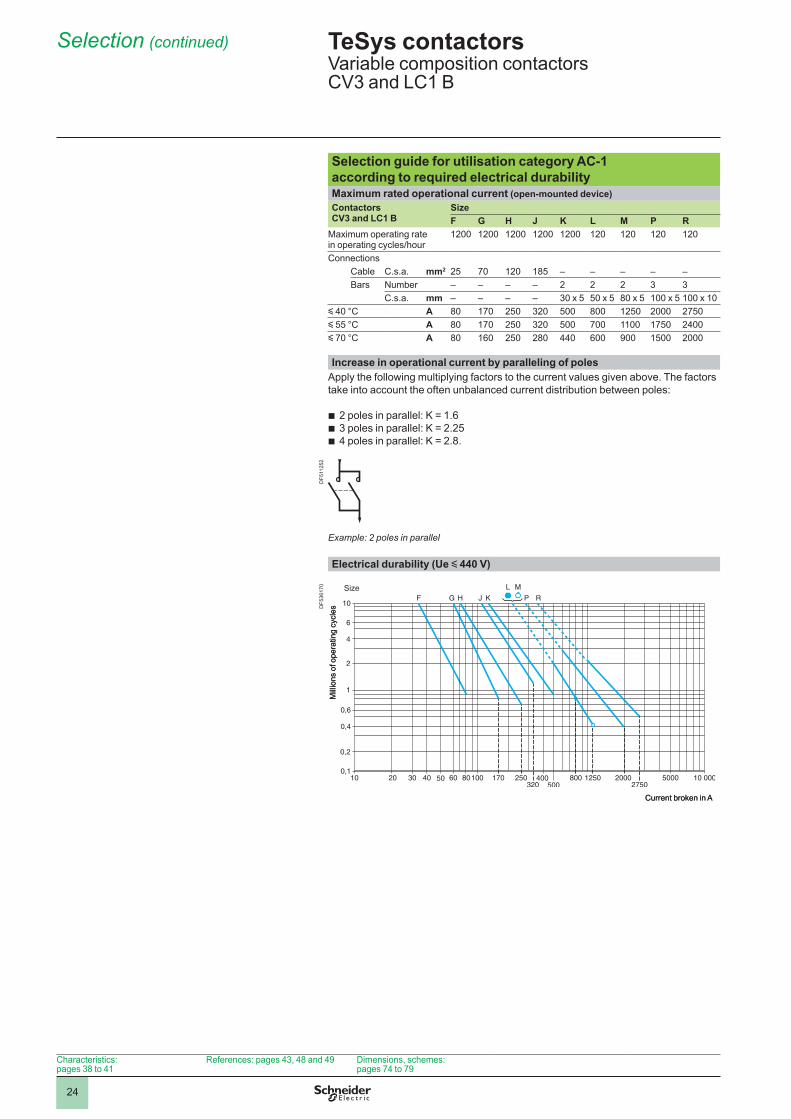
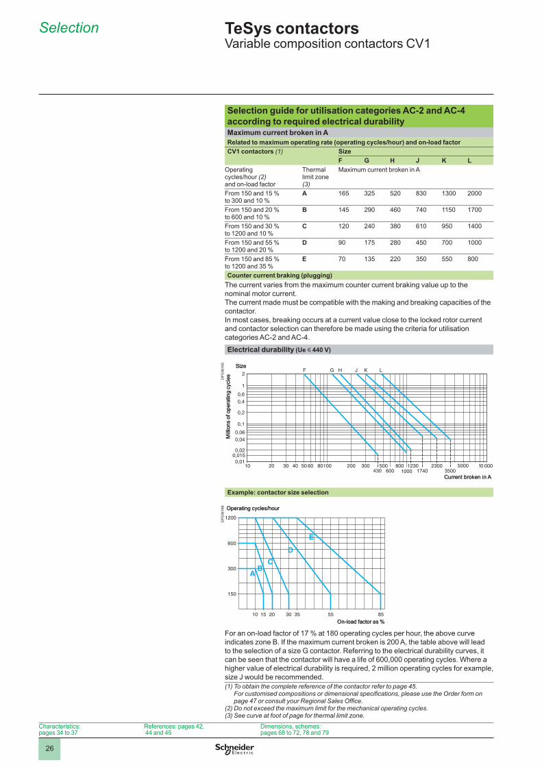
4.2
Selection guide for utilisation categories AC-2 and AC-4 according to required electrical durabilityMaximum current broken in ARelated to maximum operating rate (operating cycles/hour) and on-load factorCV1 contactors (1) Size
F G H J K LOperating cycles/hour (2) and on-load factor
Thermal limit zone (3)
Maximum current broken in A
From 150 and 15 % to 300 and 10 %
A 165 325 520 830 1300 2000
From 150 and 20 % to 600 and 10 %
B 145 290 460 740 1150 1700
From 150 and 30 % to 1200 and 10 %
C 120 240 380 610 950 1400
From 150 and 55 % to 1200 and 20 %
D 90 175 280 450 700
From 150 and 85 % to 1200 and 35 %
E 70 135 220 350 550 800
Counter current braking (plugging)The current varies from the maximum counter current braking value up to the nominal motor current.The current made must be compatible with the making and breaking capacities of the contactor .In most cases, breaking occurs at a current value close to the locked rotor current and contactor selection can therefore be made using the criteria for utilisation categories AC-2 and AC-4.
Electrical durability (Ue y 440 V)
Example: contactor size selection
For an on-load factor of 17 % at 180 operating cycles per hour, the above curve indicates zone B. If the maximum current broken is 200 A, the table above will lead to the selection of a size G contactor. Referring to the electrical durability curves, it can be seen that the contactor will have a life of 600,000 operating cycles. Where a higher value of electrical durability is required, 2 million operating cycles for example, size J would be recommended.(1) To obtain the complete reference of the contactor refer to page 45.
For customised compositions or dimensional specifications, please use the Order form on page 47 or consult your Regional Sales Office.
(2) Do not exceed the maximum limit for the mechanical operating cycles.(3) See curve at foot of page for thermal limit zone.
Current broken in A
Mill
ions
of o
pera
ting
cycl
es
Size
Current broken in A
Mill
ions
of o
pera
ting
cycl
es
Size
On-load factor as %
Operating cycles/hour
On-load factor as %
Operating cycles/hour
TeSys contactors 0 Variable composition contactors CV1
Characteristics: pages 34 to 37
References: pages 42, 44 and 45
Dimensions, schemes: pages 68 to 72, 78 and 79
DF5
3616
5D
F536
166
27
Selection (continued)
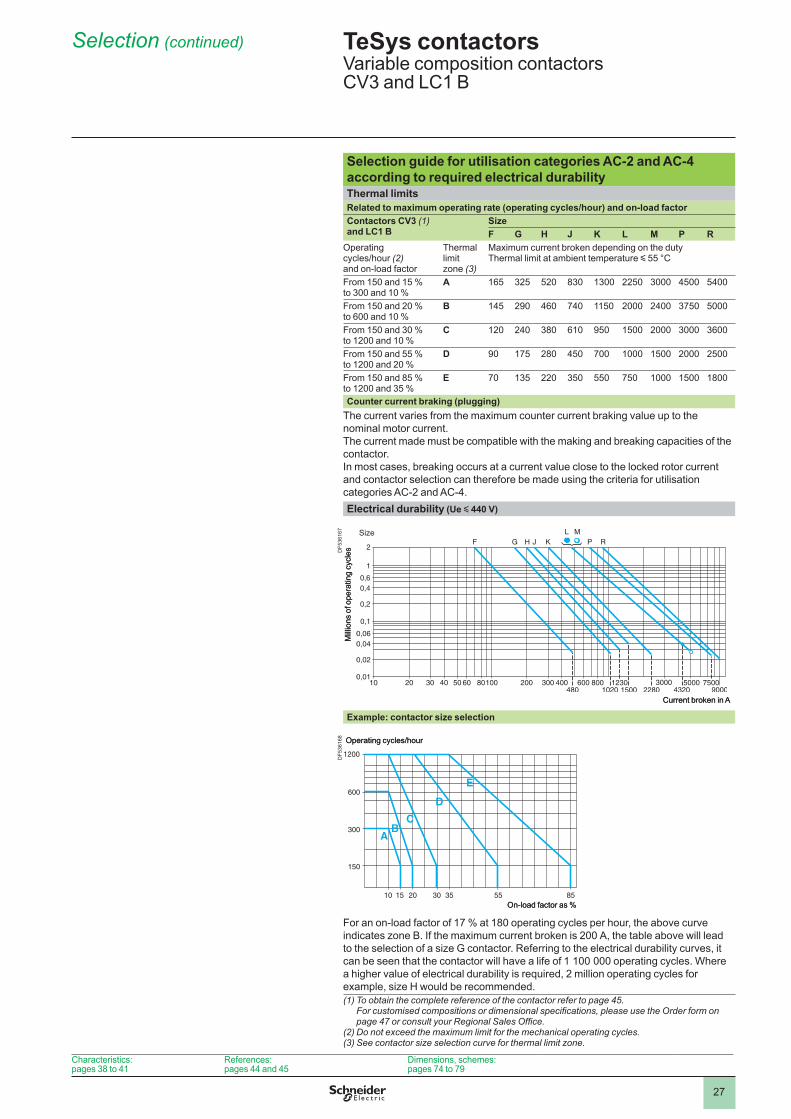
Selection guide for utilisation categories AC-2 and AC-4 according to required electrical durabilityThermal limitsRelated to maximum operating rate (operating cycles/hour) and on-load factorContactors CV3 (1) and LC1 B
SizeF G H J K L M P R
Operating cycles/hour (2) and on-load factor
Thermal limit zone (3)
Maximum current broken depending on the dutyThermal limit at ambient temperature y 55 °C
From 150 and 15 % to 300 and 10 %
A 165 325 520 830 1300 2250 3000 4500 5400
From 150 and 20 % to 600 and 10 %
B 145 290 460 740 1150 2000 2400 3750 5000
From 150 and 30 % to 1200 and 10 %
C 120 240 380 610 950 1500 2000 3000 3600
From 150 and 55 % to 1200 and 20 %
D 90 175 280 450 700 1500 2000 2500
From 150 and 85 % to 1200 and 35 %
E 70 135 220 350 550 750 1500 1800
Counter current braking (plugging)The current varies from the maximum counter current braking value up to the nominal motor current.The current made must be compatible with the making and breaking capacities of the contactor .In most cases, breaking occurs at a current value close to the locked rotor current and contactor selection can therefore be made using the criteria for utilisation categories AC-2 and AC-4.Electrical durability (Ue y 440 V)
Example: contactor size selection
For an on-load factor of 17 % at 180 operating cycles per hour, the above curve indicates zone B. If the maximum current broken is 200 A, the table above will lead to the selection of a size G contactor. Referring to the electrical durability curves, it can be seen that the contactor will have a life of 1 100 000 operating cycles. Where a higher value of electrical durability is required, 2 million operating cycles for example, size H would be recommended. (1) To obtain the complete reference of the contactor refer to page 45.
For customised compositions or dimensional specifications, please use the Order form on page 47 or consult your Regional Sales Office.
(2) Do not exceed the maximum limit for the mechanical operating cycles.(3) See contactor size selection curve for thermal limit zone.
Current broken in A
Mill
ions
of o
pera
ting
cycl
es
Size
Current broken in A
Mill
ions
of o
pera
ting
cycl
es
Size
On-load factor as %
Operating cycles/hour
On-load factor as %
Operating cycles/hour
TeSys contactors 0 Variable composition contactorsCV3 and LC1 B
Characteristics: pages 38 to 41
References: pages 44 and 45
Dimensions, schemes: pages 74 to 79
DF5
3616
7D
F536
168
28
Selection
4.2
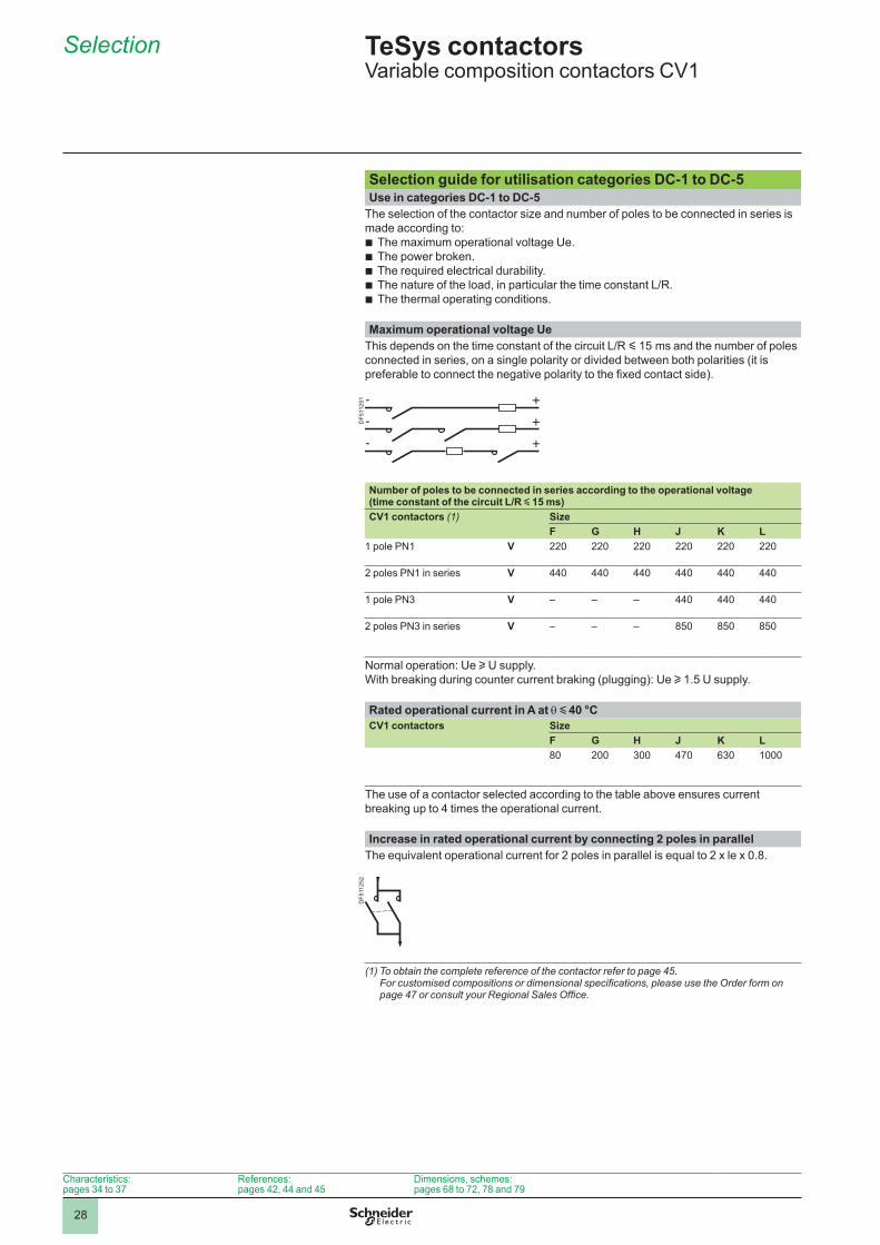
Selection guide for utilisation categories DC-1 to DC-5Use in categories DC-1 to DC-5
The selection of the contactor size and number of poles to be connected in series is made according to:
The maximum operational voltage Ue.The power broken.The required electrical durability.The nature of the load, in particular the time constant L/R.The thermal operating conditions.
bbbbb
Maximum operational voltage UeThis depends on the time constant of the circuit L/R y 15 ms and the number of poles connected in series, on a single polarity or divided between both polarities (it is preferable to connect the negative polarity to the fixed contact side).
Number of poles to be connected in series according to the operational voltage (time constant of the circuit L/R y 15 ms)CV1 contactors (1) Size
F G H J K L pole PN V 220 220 220 220 220 220
2 poles PN1 in series V 440 440 440 440 440 440
1 pole PN3 V – – – 440 440 440
2 poles PN3 in series V – – – 850 850 850
Normal operation: Ue u U supply.With breaking during counter current braking (plugging): Ue u 1.5 U supply.
Rated operational current in A at q y 40 °CCV1 contactors Size
F G H J K L80 200 300 470 630
The use of a contactor selected according to the table above ensures current breaking up to 4 times the operational current.
Increase in rated operational current by connecting 2 poles in parallelThe equivalent operational current for 2 poles in parallel is equal to 2 x le x 0.8.
(1) To obtain the complete reference of the contactor refer to page 45. For customised compositions or dimensional specifications, please use the Order form on page 47 or consult your Regional Sales Office.
TeSys contactors 0 Variable composition contactors CV1
DF5
1125
1D
F511
252
Characteristics: pages 34 to 37
References: pages 42, 44 and 45
Dimensions, schemes: pages 68 to 72, 78 and 79
29
Selection (continued)
15L/R---------
Selection guide for utilisation categories DC-1 to DC-5 according to required electrical durabilityPower brokenUtilisation categories U broken I broken P broken
DC-1: Non inductive or slightly inductive loads Ue Ie Ue x Ie
DC-2: Shunt motors, breaking whilst running 0.1 Ue Ie 0.1 Ue x Ie
DC-3: Shunt motors, reversing, inching Ue 2.5 Ie Ue x 2.5 Ie
DC-4: Shunt motors, breaking whilst running 0.3 Ue Ie 0.3 Ue x Ie
DC-5: Shunt motors, reversing, inching Ue 2.5 Ie Ue x 2.5 Ie
Electrical durability (time constant L/R y 15 ms)The electrical durability can be read directly from the curves below, having previously calculated the power broken as follows: P broken = U broken x l broken.The table gives the values of Uc and Ic for the various utilisation categories.
Two-pole switching (time constant L/R y 15 ms)The required durability can be obtained, depending on the application, by increasing the number of poles in series or in parallel, or by increasing the contactor size.
Example: 30 kW motor, 220 V-150 A in category DC-3: P broken = Ue x 2.5 Ie = 220 x 2.5 x 150 = 83 kW. For a size G contactor with 2 poles in series, the electrical durability curve gives 3.5 x 10 5
operating cycles.
Number of main polesThe curve shows the number of operating cycles according to the power broken by two main poles connected in series. For a single pole, double the value of power broken before using the curves.
Electrical durability depending on the time constantAccording to the time constant L/R.L/R y 15 ms, read the number of operating cycles directly from the curves.15 < L/R y 30 ms,
the number of operating cycles is equal to the number read from the curves x .L/R > 30 ms, please consult your Regional Sales Office.
bbb
b
Thermal limitThe following limits must not be exceeded: 120 operating cycles/hour at 60 % or 300 operating cycles/hour at 30 % on-load factor, at the rated operational current Ie.
9045 160 220 350 1000
F G H J K L
Power broken in kW
Mill
ions
of o
pera
ting
cycl
es
Size
9045 160 220 350 1000
F G H J K L
Power broken in kW
Mill
ions
of o
pera
ting
cycl
es
Size
TeSys contactors 0 Variable composition contactors CV1
Characteristics: pages 34 to 37
References: pages 42, 44 and 45
Dimensions, schemes: pages 68 to 72, 78 and 79
DF5
3653
1
30
Selection (continued)
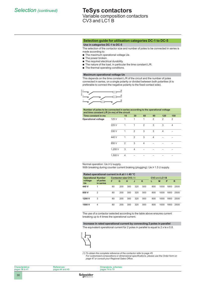
Selection guide for utilisation categories DC-1 to DC-5Use in categories DC-1 to DC-5
The selection of the contactor size and number of poles to be connected in series is made according to:
The maximum operational voltage Ue.The power broken.The required electrical durability.The nature of the load, in particular the time constant L/R.The thermal operating conditions.
bbbbb
Maximum operational voltage UeThis depends on the time constant L/R of the circuit and the number of poles connected in series, on a single polarity or divided between both polarities (it is preferable to connect the negative polarity to the fixed contact side).
Number of poles to be connected in series according to the operational voltage and time constant L/R (in ms) of the circuitTime constant in ms 15 30 60 90 120 150
Operational voltage 125 V 2 2 2
225 V 2 3 3 4
330 V 2 3 3 4 –
440 V 2 3 4 – –
850 V 2 3 4 – – –
1,200 V 3 4 – – – –
1,500 V 4 – – – – –
Normal operation: Ue u U supply.With breaking during counter current braking (plugging): Ue u 1.5 U supply.
Rated operational current in A at q y 40 °COperational voltage Ue
Number of poles in series
Contactor size CV3 (1) CV3 and LC1 BF G H J K L M P R
440 V 80 200 300 320 500 800 1800 2500
850 V 2 80 200 300 320 500 800 1800 2500
1200 V 3 80 200 300 320 500 800 1800 2500
1500 V 4 80 200 300 320 500 800 1800 2500
The use of a contactor selected according to the table above ensures current breaking up to 4 times the operational current.
Increase in rated operational current by connecting 2 poles in parallelThe equivalent operational current for 2 poles in parallel is equal to 2 x le x 0.8.
(1) To obtain the complete reference of the contactor refer to page 45. For customised compositions or dimensional specifications, please use the Order form on page 47 or consult your Regional Sales Office.
TeSys contactors 0 Variable composition contactors CV3 and LC1 B
Characteristics: pages 38 to 41
References: pages 44 and 45
Dimensions, schemes: pages 74 to 79
DF5
1125
1D
F511
252
31
Selection (continued)
15L/R---------
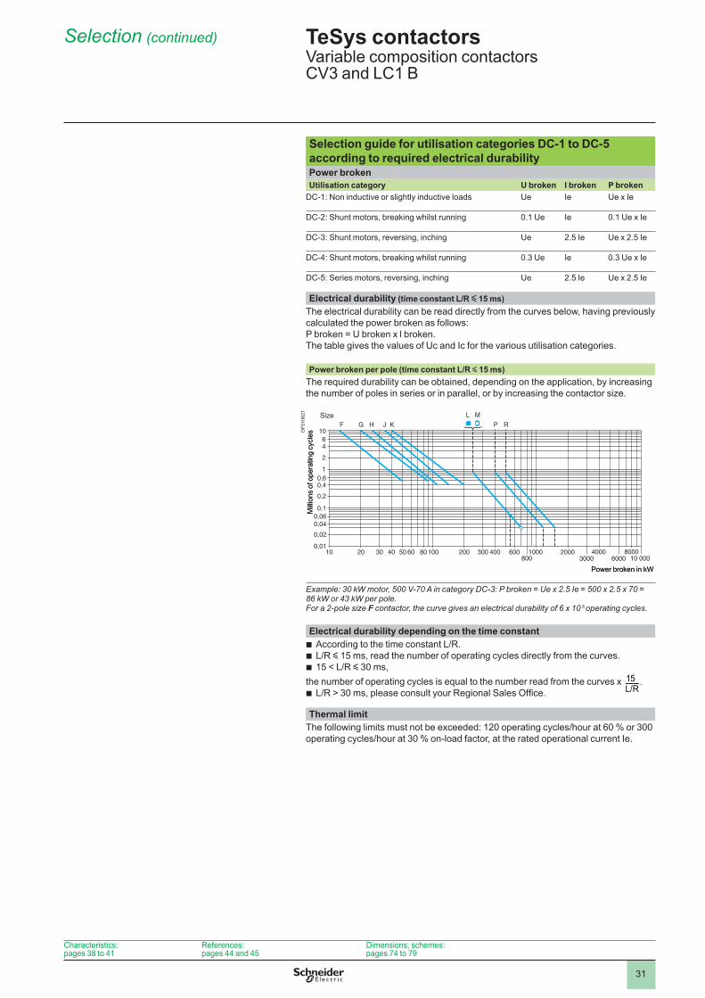
Selection guide for utilisation categories DC-1 to DC-5 according to required electrical durabilityPower brokenUtilisation category U broken I broken P broken
DC-1: Non inductive or slightly inductive loads Ue Ie Ue x Ie
DC-2: Shunt motors, breaking whilst running 0.1 Ue Ie 0.1 Ue x Ie
DC-3: Shunt motors, reversing, inching Ue 2.5 Ie Ue x 2.5 Ie
DC-4: Shunt motors, breaking whilst running 0.3 Ue Ie 0.3 Ue x Ie
DC-5: Series motors, reversing, inching Ue 2.5 Ie Ue x 2.5 Ie
Electrical durability (time constant L/R y 15 ms)The electrical durability can be read directly from the curves below, having previously calculated the power broken as follows: P broken = U broken x l broken.The table gives the values of Uc and Ic for the various utilisation categories.
Power broken per pole (time constant L/R y 15 ms)The required durability can be obtained, depending on the application, by increasing the number of poles in series or in parallel, or by increasing the contactor size.
Example: 30 kW motor, 500 V-70 A in category DC-3: P broken = Ue x 2.5 Ie = 500 x 2.5 x 70 = 86 kW or 43 kW per pole. For a 2-pole size F contactor, the curve gives an electrical durability of 6 x 10 5 operating cycles.
Electrical durability depending on the time constantAccording to the time constant L/R.L/R y 15 ms, read the number of operating cycles directly from the curves.15 < L/R y 30 ms,
the number of operating cycles is equal to the number read from the curves x .L/R > 30 ms, please consult your Regional Sales Office.
bbb
b
Thermal limitThe following limits must not be exceeded: 120 operating cycles/hour at 60 % or 300 operating cycles/hour at 30 % on-load factor, at the rated operational current Ie.
Power broken in kW
Mill
ions
of o
pera
ting
cycl
es
Size
Power broken in kW
Mill
ions
of o
pera
ting
cycl
es
Size
TeSys contactors 0 Variable composition contactors CV3 and LC1 B
Characteristics: pages 38 to 41
References: pages 44 and 45
Dimensions, schemes: pages 74 to 79
DF5
1062
1
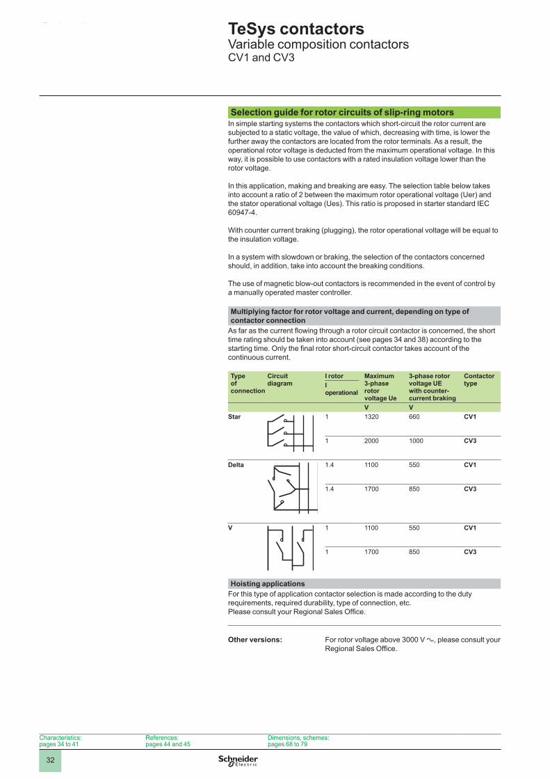
32
Selection
5.1
Selection guide for rotor circuits of slip-ring motorsIn simple starting systems the contactors which short-circuit the rotor current are subjected to a static voltage, the value of which, decreasing with time, is lower the further away the contactors are located from the rotor terminals. As a result, the operational rotor voltage is deducted from the maximum operational voltage. In this way, it is possible to use contactors with a rated insulation voltage lower than the rotor voltage.
In this application, making and breaking are easy. The selection table below takes into account a ratio of 2 between the maximum rotor operational voltage (Uer) and the stator operational voltage (Ues). This ratio is proposed in starter standard IEC 60947-4.
With counter current braking (plugging), the rotor operational voltage will be equal to the insulation voltage.
In a system with slowdown or braking, the selection of the contactors concerned should, in addition, take into account the breaking conditions.
The use of magnetic blow-out contactors is recommended in the event of control by a manually operated master controller.
Multiplying factor for rotor voltage and current, depending on type of contactor connection
As far as the current flowing through a rotor circuit contactor is concerned, the short time rating should be taken into account (see pages 34 and 38) according to the starting time. Only the final rotor short-circuit contactor takes account of the continuous current.
Type of connection
Circuit diagram
I rotor Maximum 3-phase rotor voltage Ue
3-phase rotor voltage UE with counter-current braking
Contactor typeI
operational
V VStar 1320 660 CV1
2000 CV3
Delta 1.4 550 CV1
1.4 1700 850 CV3
V 550 CV1
1700 850 CV3
Hoisting applicationsFor this type of application contactor selection is made according to the duty requirements, required durability, type of connection, etc. Please consult your Regional Sales Office.
Other versions: For rotor voltage above 3000 V a, please consult your Regional Sales Office.
TeSys contactors 0 Variable composition contactors CV1 and CV3
Characteristics: pages 34 to 41
References: pages 44 and 45
Dimensions, schemes: pages 68 to 79
33
Presentation
PresentationContactors CV1-KB fitted with special polesApplications: telephone exchanges, electroplating works
Normally open coupler poles, without blow-out:Insulation voltage 1000 V.Operational current.
bbNumber of fingers Operational current in A
min. max.1 800 10402 1340 18003 2000 27004 2700 36005 3300 4400
Small voltage drop: 30 mV at minimum operational current, 40 mV at maximum operational current. b
Magnetic latching contactors, CR1These contactors prevent unwanted opening of the poles in the event of a control circuit supply failure.The holding-in of a contactor is often necessary so as to avoid on-load breaking (for example an excitation circuit).Furthermore, the fact that no power is consumed by the coil when the contactor is latched leads to energy savings on a separate control circuit supply (particularly useful when using a battery supply). These contactors incorporate an electromagnet with a core made of non-aging magnetic steel and the coil supply can be d.c. or rectified a.c.The contactor latches in the operated position following energisation of the electromagnetic coil and remains latched when the coil is de-energised, the contactor armature being held closed by remanent magnetism.The contactor is unlatched by the application of a reversed polarity current, at a value less than the pull-in current, which neutralises the remanent magnetism. CR1 contactors are available in all sizes from 80 to 2750 A.The control supply can be d.c. or rectified a.c. Please refer to our “Motor starter solutions - Control and protection components” catalogue.
Contactors for furnaces and induction heating applicationsInduction heating covers all applications where metals (or a metal part) are heated in crucible or “channel” furnaces, or in dies, by the induction of a.c. currents at various frequencies.There are several frequency ranges which, for industrial purposes, can be grouped as follows:
50 Hz to 400 Hz:industrial mains power frequencies from 50 to 250 Hzintermediate frequencies of 350 Hz and 400 Hz.Maximum operating limits for contactors (single-pole and 6-pole):frequency range up to 500 Hzsupply voltage up to 3000 Vcurrents up to 16 300 A.
Please refer to our “Contactors for furnaces and induction heating applications” catalogue
bvvbvvv
TeSys contactors 0 Contactors for specific applications
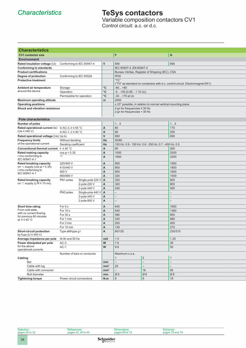
34
CharacteristicsCV1 contactor size F GEnvironment
Rated insulation voltage (Ui) Conforming to IEC 60947-4 V 690 690Conforming to standards IEC 60947-4, EN 60947-4Product certifications Bureau Véritas, Register of Shipping (IEC), CSADegree of protection Conforming to IEC 60529 IP00Protective treatment “TC”
(“TH” as standard on contactors with d.c. control circuit. Electromagnet EK1)Ambient air temperature around the device
Storage °C -60…+80Operation °C -5…+55 (0.85…1.10 Uc)Permissible for operation °C -30…+70 at Uc
Maximum operating altitude m 2000Operating positions ± 23° possible, in relation to normal vertical mounting planeShock and vibration resistance 4 gn for frequencies y 30 Hz
2 gn for frequencies > 30 Hz
Pole characteristicsNumber of poles 1…5 1…5Rated operational current (le) (Ue y 440 V)
In AC-3, q y 55 °C A 80 170In AC-1, q y 40 °C A 80 200
Rated operational voltage (Ue) Up to V 690 690Frequency limits of the operational current
Without derating Hz 50/60Derating coefficient Hz 100 Hz: 0.9 - 150 Hz: 0.8 - 250 Hz: 0.7 - 400 Hz: 0.5
Conventional thermal current q y 40 °C A 80 200Rated making capacity I rms conforming to IEC 60947-4-1
cos φ = 0.35 A 2000c A 1600 3200
Rated breaking capacity on a supply (cos φ = 0.35) I rms conforming to IEC 60947-4-1
220/400 V A 900 1900415/440 V A 800 1800500 V A 800 1600660/690 V A 320
Rated breaking capacity on c supply (L/R y 15 ms)
PN poles Single-pole 220 V A 320 8002-pole 220 V A 320 8002-pole 440 V A 240 500
PN3 poles Single-pole 440 V A – –2-pole 440 V A – –2-pole 850 V A – –
Short time rating From cold state, with no current flowing for previous 60 minutes at q y 40 °C
For 5 s A 640 1600For 10 s A 640 1360For 30 s A 380 800For 1 min A 320 680For 3 min A 200 400For 10 min A 130 270
Short-circuit protection by fuse (U y 440 V)
Type aM/type g1 A 80/125 230/315
Average impedance per pole At lth and 50 Hz mΩ 1.5 1.25Power dissipated per pole for the above operational currents
AC-3 W 7.6 36AC-1 W 9.6 50
CablingNumber of bars or conductor Maximum c.s.a.
2 Bar mm – – –Cable with lug mm2 25 – –Cable with connector mm2 – 16 95Bolt diameter mm Ø 6 Ø 6 Ø 8
Tightening torque Power circuit connections N.m 9 9 18
TeSys contactors 0 Variable composition contactors CV1Control circuit: a.c. or d.c.
CharacteristicsCharacteristics
Selection : pages 20 to 32
References: pages 42, 44 to 45
Dimensions: pages 68 to 72
Schemes: pages 78 and 79
H J K L
1…4 1…4 1…4 1…4250 350 460 700300 470 630 690 690 690 690
300 470 630 2500 3500 4600 7000
4000 5200 6500
2400 3200 4200 62002200 3000 4100 61002000 2800 3800 57001800 2300 3200 45001200 1800 2500 32001200 1900 2520 4000900 1200 1500 1800
– 1800 2500 3200– 1900 2520 4000– 1800 2500 3200
2400 3750 5000 80002000 2800 3600 57501200 1700 2260 3600 1450 1900 3000600 950 1280 2150410 620 880 1400
315/400 500/630 630/800 1000/1250
0.57 0.30 0.26 0.2235 36 55 10751 66 103 220
– – 63 x 6 80 x 8185 50 x 6 185 x 2 –185 150 x 2 – –Ø 10 Ø 10 Ø 12 2 x Ø 835 35 58 18
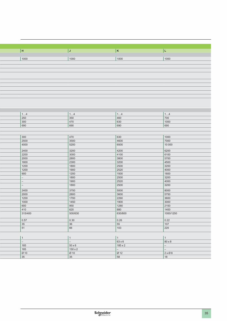
35
CharacteristicsCV1 contactor size F GEnvironment
Rated insulation voltage (Ui) Conforming to IEC 60947-4 V 690 690Conforming to standards IEC 60947-4, EN 60947-4Product certifications Bureau Véritas, Register of Shipping (IEC), CSADegree of protection Conforming to IEC 60529 IP00Protective treatment “TC”
(“TH” as standard on contactors with d.c. control circuit. Electromagnet EK1)Ambient air temperature around the device
Storage °C -60…+80Operation °C -5…+55 (0.85…1.10 Uc)Permissible for operation °C -30…+70 at Uc
Maximum operating altitude m 2000Operating positions ± 23° possible, in relation to normal vertical mounting planeShock and vibration resistance 4 gn for frequencies y 30 Hz
2 gn for frequencies > 30 Hz
Pole characteristicsNumber of poles 1…5 1…5Rated operational current (le) (Ue y 440 V)
In AC-3, q y 55 °C A 80 170In AC-1, q y 40 °C A 80 200
Rated operational voltage (Ue) Up to V 690 690Frequency limits of the operational current
Without derating Hz 50/60Derating coefficient Hz 100 Hz: 0.9 - 150 Hz: 0.8 - 250 Hz: 0.7 - 400 Hz: 0.5
Conventional thermal current q y 40 °C A 80 200Rated making capacity I rms conforming to IEC 60947-4-1
cos φ = 0.35 A 2000c A 1600 3200
Rated breaking capacity on a supply (cos φ = 0.35) I rms conforming to IEC 60947-4-1
220/400 V A 900 1900415/440 V A 800 1800500 V A 800 1600660/690 V A 320
Rated breaking capacity on c supply (L/R y 15 ms)
PN poles Single-pole 220 V A 320 8002-pole 220 V A 320 8002-pole 440 V A 240 500
PN3 poles Single-pole 440 V A – –2-pole 440 V A – –2-pole 850 V A – –
Short time rating From cold state, with no current flowing for previous 60 minutes at q y 40 °C
For 5 s A 640 1600For 10 s A 640 1360For 30 s A 380 800For 1 min A 320 680For 3 min A 200 400For 10 min A 130 270
Short-circuit protection by fuse (U y 440 V)
Type aM/type g1 A 80/125 230/315
Average impedance per pole At lth and 50 Hz mΩ 1.5 1.25Power dissipated per pole for the above operational currents
AC-3 W 7.6 36AC-1 W 9.6 50
CablingNumber of bars or conductor Maximum c.s.a.
2 Bar mm – – –Cable with lug mm2 25 – –Cable with connector mm2 – 16 95Bolt diameter mm Ø 6 Ø 6 Ø 8
Tightening torque Power circuit connections N.m 9 9 18
H J K L
1…4 1…4 1…4 1…4250 350 460 700300 470 630 690 690 690 690
300 470 630 2500 3500 4600 7000
4000 5200 6500
2400 3200 4200 62002200 3000 4100 61002000 2800 3800 57001800 2300 3200 45001200 1800 2500 32001200 1900 2520 4000900 1200 1500 1800
– 1800 2500 3200– 1900 2520 4000– 1800 2500 3200
2400 3750 5000 80002000 2800 3600 57501200 1700 2260 3600 1450 1900 3000600 950 1280 2150410 620 880 1400
315/400 500/630 630/800 1000/1250
0.57 0.30 0.26 0.2235 36 55 10751 66 103 220
– – 63 x 6 80 x 8185 50 x 6 185 x 2 –185 150 x 2 – –Ø 10 Ø 10 Ø 12 2 x Ø 835 35 58 18
0
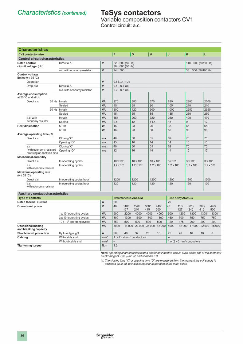
36
CharacteristicsCV1 contactor size F G H J K LControl circuit characteristics
Rated control circuit voltage (Uc)
Direct a .c . V 22…600 (50 Hz) 28…600 (60 Hz)
110…600 (50/60 Hz)
a.c. with economy resistor V 24…500 36…500 (50/400 Hz)Control voltage limits (q y 55 °C)
Operation V 0.85…1.1 UcDrop-out Direct a .c . V 0.5…0.7 Uc
a.c. with economy resistor V 0.2…0.5 UcAverage consumption at 20 °C and at Uc
Direct a .c . 50 Hz Inrush VA 270 380 570 830 2300 2300Sealed VA 45 65 80 105 210 210
60 Hz Inrush VA 300 420 600 2650 2650Sealed VA 45 65 85 135 260 260
a.c. with economy resistor
Inrush VA 155 260 320 260 420 470Sealed VA 9.5 12 14.5 13 9 12
Heat dissipation 50 Hz W 16 23 26 38 65 6560 Hz W 16 23 30 50 90 90
Average operating time (1)Direct a .c . Closing “C” ms 40 30 35 62 75 75
Opening “O” ms 15 16 14 14 15 15a .c . (with economy resistor) breaking on rectified side
Closing “C” ms 40 30 35 62 75 75Opening “O” ms 12 16 14 14 15 15
Mechanical durabilityDirect a .c . In operating cycles 10 x 106 10 x 106 10 x 106 3 x 10⁶ 3 x 10⁶ 3 x 10⁶
a .c . with economy resistor
In operating cycles 1.2 x 10⁶ 1.2 x 10⁶ 1.2 x 10⁶ 1.2 x 10⁶ 1.2 x 10⁶ 1.2 x 10⁶
Maximum operating rate (q y 55 °C)
Direct a .c . In operating cycles/hour 1200 1200 1200 1200 1200 1200a .c . with economy resistor
In operating cycles/hour 120 120 120 120 120 120
Auxiliary contact characteristicsType of contacts Instantaneous ZC4 GM Time delay ZC2 GG
Rated thermal current A 20 20Operational power V 48 110/
127220/ 240
380/ 415
440/ 500
48 110/ 127
220/ 240
380/ 415
440/ 500
1 x 10⁶ operating cycles VA 900 2200 4000 4000 4000 500 1200 1300 1300 13003 x 106 operating cycles VA 800 1300 1500 1500 1500 450 700 750 750 75010 x 106 operating cycles VA 450 500 500 500 500 120 175 200 200 200
Occasional making and breaking capacity
VA 5000 14 000 23 000 35 000 45 000 4000 12 000 17 000 22 000 25 000
Short-circuit protection By fuse type gG A 50 40 32 20 16 25 20 16 8Cabling With cable end mm2 1 or 2 x 4 mm2 conductors –
Without cable end mm2 – 1 or 2 x 6 mm2 conductorsTightening torque N.m 1.2
Note: operating characteristics stated are for an inductive circuit, such as the coil of the contactor electromagnet. Cos j inrush and sealed = 0.3.(1) The closing time “C” or opening time “O” are measured from the moment the coil supply is
switched on or off, to initial contact or separation of the main poles.
TeSys contactors 0 Variable composition contactors CV1Control circuit: a.c.
Characteristics (continued)Characteristics (continued)
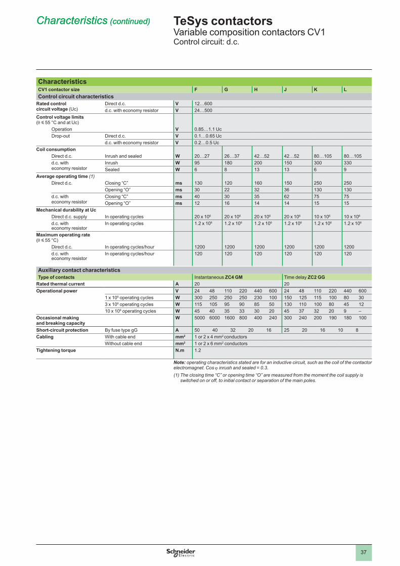
37
CharacteristicsCV1 contactor size F G H J K LControl circuit characteristics
Rated control circuit voltage (Uc)
Direct d.c. V 12…600d.c. with economy resistor V 24…500
Control voltage limits (q y 55 °C and at Uc)
Operation V 0.85…1.1 UcDrop-out Direct d.c. V 0.1…0.65 Uc
d.c. with economy resistor V 0.2…0.5 UcCoil consumption
Direct d.c. Inrush and sealed W 20…27 26…37 42…52 42…52 80…105 80…105d.c. with economy resistor
Inrush W 95 180 200 150 300 330Sealed W 6 8 13 13 6 9
Average operating time (1)Direct d.c. Closing “C” ms 130 120 160 150 250 250
Opening “O” ms 30 22 32 36 130 130d.c. with economy resistor
Closing “C” ms 40 30 35 62 75 75Opening “O” ms 12 16 14 14 15 15
Mechanical durability at UcDirect d.c. supply In operating cycles 20 x 106 20 x 106 20 x 106 20 x 106 10 x 106 10 x 106
d.c. with economy resistor
In operating cycles 1.2 x 10⁶ 1.2 x 10⁶ 1.2 x 10⁶ 1.2 x 10⁶ 1.2 x 10⁶ 1.2 x 10⁶
Maximum operating rate (q y 55 °C)
Direct d.c. In operating cycles/hour 1200 1200 1200 1200 1200 1200d.c. with economy resistor
In operating cycles/hour 120 120 120 120 120 120
Auxiliary contact characteristicsType of contacts Instantaneous ZC4 GM Time delay ZC2 GG
Rated thermal current A 20 20Operational power V 24 48 220 440 600 24 48 220 440 600
1 x 10⁶ operating cycles W 300 250 250 250 230 150 125 115 80 303 x 106 operating cycles W 115 105 95 90 85 50 130 80 45 1210 x 106 operating cycles W 45 40 35 33 30 20 45 37 32 20 9 –
Occasional making and breaking capacity
W 5000 6000 1600 800 400 240 300 240 200 190 180
Short-circuit protection By fuse type gG A 50 40 32 20 16 25 20 16 8Cabling With cable end mm2 1 or 2 x 4 mm2 conductors
Without cable end mm2 1 or 2 x 6 mm2 conductorsTightening torque N.m 1.2
Note: operating characteristics stated are for an inductive circuit, such as the coil of the contactor electromagnet. Cos j inrush and sealed = 0.3.(1) The closing time “C” or opening time “O” are measured from the moment the coil supply is
switched on or off, to initial contact or separation of the main poles.
TeSys contactors 0 Variable composition contactors CV1Control circuit: d.c.
Characteristics (continued)Characteristics (continued)
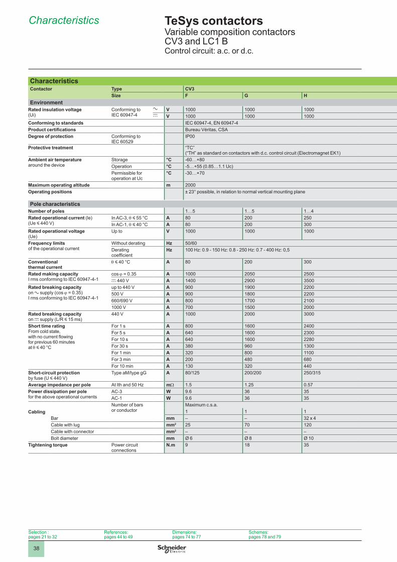
38
Characteristics
CharacteristicsContactor Type CV3
Size F G HEnvironment
Rated insulation voltage (Ui)
Conforming to IEC 60947-4
a V c V
Conforming to standards IEC 60947-4, EN 60947-4Product certifications Bureau Véritas, CSADegree of protection Conforming to
IEC 60529IP00
Protective treatment “TC” (“TH” as standard on contactors with d.c. control circuit (Electromagnet EK1)
Ambient air temperature around the device
Storage °C -60…+80Operation °C -5…+55 (0.85…1.1 Uc)Permissible for operation at Uc
°C -30…+70
Maximum operating altitude m 2000Operating positions ± 23° possible, in relation to normal vertical mounting plane
Pole characteristicsNumber of poles 1…5 1…5 1…4Rated operational current (le) (Ue y 440 V)
In AC-3, q y 55 °C A 80 200 250In AC-1, q y 40 °C A 80 200 300
Rated operational voltage (Ue)
Up to V
Frequency limits of the operational current
Without derating Hz 50/60Derating coefficient
Hz 100 Hz: 0.9 - 150 Hz: 0.8 - 250 Hz: 0.7 - 400 Hz: 0,5
Conventional thermal current
q y 40 °C A 80 200 300
Rated making capacity I rms conforming to IEC 60947-4-1
cos j = 0.35 A 2050 2500c 440 V A 1400 2900 3500
Rated breaking capacity on a supply (cos j = 0.35) I rms conforming to IEC 60947-4-1
up to 440 V A 900 1900 2200500 V A 900 1800 2200660/690 V A 800 1700 2100 V A 700 1500 2000
Rated breaking capacity on c supply (L/R y 15 ms)
440 V A 2000 3000
Short time rating From cold state, with no current flowing for previous 60 minutes at q y 40 °C
For 1 s A 800 1600 2400For 5 s A 640 1600 2300For 10 s A 640 1600 2280For 30 s A 380 960 1300For 1 min A 320 800 For 3 min A 200 480 680For 10 min A 130 320 440
Short-circuit protection by fuse (U y 440 V)
Type aM/type gG A 80/125 200/200 250/315
Average impedance per pole At lth and 50 Hz mW 1.5 1.25 0.57Power dissipation per pole for the above operational currents
AC-3 W 9.6 36 35AC-1 W 9.6 36 35
CablingNumber of bars or conductor
Maximum c.s.a.
Bar mm – – 32 x 4Cable with lug mm2 25 70 120Cable with connector mm2 – – –Bolt diameter mm Ø 6 Ø 8 Ø 10
Tightening torque Power circuit connections
N.m 9 18 35
TeSys contactors 0 Variable composition contactors CV3 and LC1 BControl circuit: a.c. or d.c.
3.5
Selection : pages 21 to 32
References: pages 44 to 49
Dimensions: pages 74 to 77
Schemes: pages 78 and 79
CV3 and LC1 BJ K L M P R
1500 1500 1500 1500
CSA Bureau Véritas, German Lloyd, Register of Shipping (IEC)
1…3 1…3 1…4 1…4 1…4 1…4320 460 800 1500 1800320 500 800 1250 2000 2750
320 500 800 1250 2000 2750
3200 4600 15 000 18 0004200 5500 – – – –2600 3800 8000 9000 12 000 16 0002400 3700 7000 8000 12 000 14 0002400 3600 6000 7000 9000 2000 2600 4000 4000 5000 6000
2200 3200 3200 4400 7200
2600 4000 9600 9600 12 000 15 0002600 4000 9600 9600 12 000 15 0002560 3680 7000 8000 9600 12 0001500 2200 4800 5200 6400 80001200 1800 3500 3800 5200 6300750 2100 2400 3600 4400500 720 1200 1800 2800 3600
315/400 500/630 800/1000 1200/1500 2 x 800/2 x 1000 2 x 1000/2 x 1250
0.54 0.30 0.18 0.18 0.13 0.0948 63 88 180 290 36055 75 115 280 520 680
2 2 3 440 x 6 50 x 6 50 x 5 80 x 5 100 x 5 100 x 5185 – – – – –– – – – – –Ø 10 Ø 12 4 x Ø 8 4 x Ø 10 4 x Ø 10 4 x Ø 10
35 58 18 35 35 35
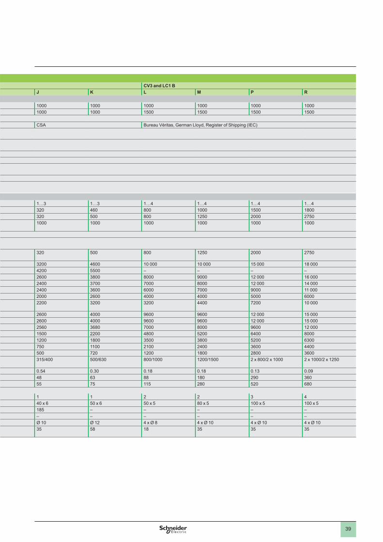
39
CharacteristicsContactor Type CV3
Size F G HEnvironment
Rated insulation voltage (Ui)
Conforming to IEC 60947-4
a V c V
Conforming to standards IEC 60947-4, EN 60947-4Product certifications Bureau Véritas, CSADegree of protection Conforming to
IEC 60529IP00
Protective treatment “TC” (“TH” as standard on contactors with d.c. control circuit (Electromagnet EK1)
Ambient air temperature around the device
Storage °C -60…+80Operation °C -5…+55 (0.85…1.1 Uc)Permissible for operation at Uc
°C -30…+70
Maximum operating altitude m 2000Operating positions ± 23° possible, in relation to normal vertical mounting plane
Pole characteristicsNumber of poles 1…5 1…5 1…4Rated operational current (le) (Ue y 440 V)
In AC-3, q y 55 °C A 80 200 250In AC-1, q y 40 °C A 80 200 300
Rated operational voltage (Ue)
Up to V
Frequency limits of the operational current
Without derating Hz 50/60Derating coefficient
Hz 100 Hz: 0.9 - 150 Hz: 0.8 - 250 Hz: 0.7 - 400 Hz: 0,5
Conventional thermal current
q y 40 °C A 80 200 300
Rated making capacity I rms conforming to IEC 60947-4-1
cos j = 0.35 A 2050 2500c 440 V A 1400 2900 3500
Rated breaking capacity on a supply (cos j = 0.35) I rms conforming to IEC 60947-4-1
up to 440 V A 900 1900 2200500 V A 900 1800 2200660/690 V A 800 1700 2100 V A 700 1500 2000
Rated breaking capacity on c supply (L/R y 15 ms)
440 V A 2000 3000
Short time rating From cold state, with no current flowing for previous 60 minutes at q y 40 °C
For 1 s A 800 1600 2400For 5 s A 640 1600 2300For 10 s A 640 1600 2280For 30 s A 380 960 1300For 1 min A 320 800 For 3 min A 200 480 680For 10 min A 130 320 440
Short-circuit protection by fuse (U y 440 V)
Type aM/type gG A 80/125 200/200 250/315
Average impedance per pole At lth and 50 Hz mW 1.5 1.25 0.57Power dissipation per pole for the above operational currents
AC-3 W 9.6 36 35AC-1 W 9.6 36 35
CablingNumber of bars or conductor
Maximum c.s.a.
Bar mm – – 32 x 4Cable with lug mm2 25 70 120Cable with connector mm2 – – –Bolt diameter mm Ø 6 Ø 8 Ø 10
Tightening torque Power circuit connections
N.m 9 18 35
CV3 and LC1 BJ K L M P R
1500 1500 1500 1500
CSA Bureau Véritas, German Lloyd, Register of Shipping (IEC)
1…3 1…3 1…4 1…4 1…4 1…4320 460 800 1500 1800320 500 800 1250 2000 2750
320 500 800 1250 2000 2750
3200 4600 15 000 18 0004200 5500 – – – –2600 3800 8000 9000 12 000 16 0002400 3700 7000 8000 12 000 14 0002400 3600 6000 7000 9000 2000 2600 4000 4000 5000 6000
2200 3200 3200 4400 7200
2600 4000 9600 9600 12 000 15 0002600 4000 9600 9600 12 000 15 0002560 3680 7000 8000 9600 12 0001500 2200 4800 5200 6400 80001200 1800 3500 3800 5200 6300750 2100 2400 3600 4400500 720 1200 1800 2800 3600
315/400 500/630 800/1000 1200/1500 2 x 800/2 x 1000 2 x 1000/2 x 1250
0.54 0.30 0.18 0.18 0.13 0.0948 63 88 180 290 36055 75 115 280 520 680
2 2 3 440 x 6 50 x 6 50 x 5 80 x 5 100 x 5 100 x 5185 – – – – –– – – – – –Ø 10 Ø 12 4 x Ø 8 4 x Ø 10 4 x Ø 10 4 x Ø 10
35 58 18 35 35 35
0
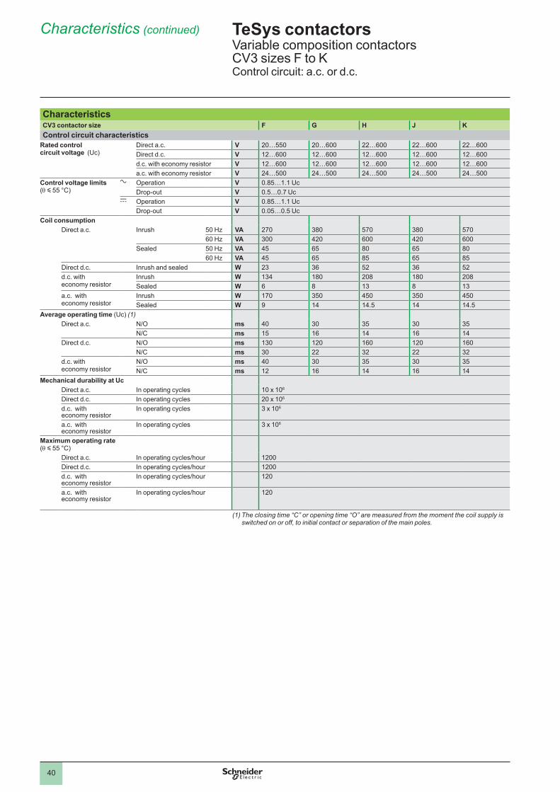
40
Characteristics (continued)
CharacteristicsCV3 contactor size F G H J KControl circuit characteristics
Rated control circuit voltage (Uc)
Direct a .c . V 20…550 20…600 22…600 22…600 22…600Direct d.c. V 12…600 12…600 12…600 12…600 12…600d.c. with economy resistor V 12…600 12…600 12…600 12…600 12…600a.c. with economy resistor V 24…500 24…500 24…500 24…500 24…500
Control voltage limits (q y 55 °C)
a Operation V 0.85…1.1 UcDrop-out V 0.5…0.7 Uc
c Operation V 0.85…1.1 UcDrop-out V 0.05…0.5 Uc
Coil consumptionDirect a .c . Inrush 50 Hz VA 270 380 570 380 570
60 Hz VA 300 420 600 420 600Sealed 50 Hz VA 45 65 80 65 80
60 Hz VA 45 65 85 65 85Direct d.c. Inrush and sealed W 23 36 52 36 52d.c. with economy resistor
Inrush W 134 180 208 180 208Sealed W 6 8 13 8 13
a.c. with economy resistor
Inrush W 170 350 450 350 450Sealed W 9 14 14.5 14 14.5
Average operating time (Uc) (1)Direct a .c . N/O ms 40 30 35 30 35
N/C ms 15 16 14 16 14Direct d.c. N/O ms 130 120 160 120 160
N/C ms 30 22 32 22 32d.c. with economy resistor
N/O ms 40 30 35 30 35N/C ms 12 16 14 16 14
Mechanical durability at UcDirect a .c . In operating cycles 10 x 106
Direct d.c. In operating cycles 20 x 106
d.c. with economy resistor
In operating cycles 3 x 10⁶
a.c. with economy resistor
In operating cycles 3 x 10⁶
Maximum operating rate (q y 55 °C)
Direct a .c . In operating cycles/hour 1200Direct d.c. In operating cycles/hour 1200d.c. with economy resistor
In operating cycles/hour 120
a.c. with economy resistor
In operating cycles/hour 120
(1) The closing time “C” or opening time “O” are measured from the moment the coil supply is switched on or off, to initial contact or separation of the main poles.
TeSys contactors 0 Variable composition contactors CV3 sizes F to KControl circuit: a.c. or d.c.
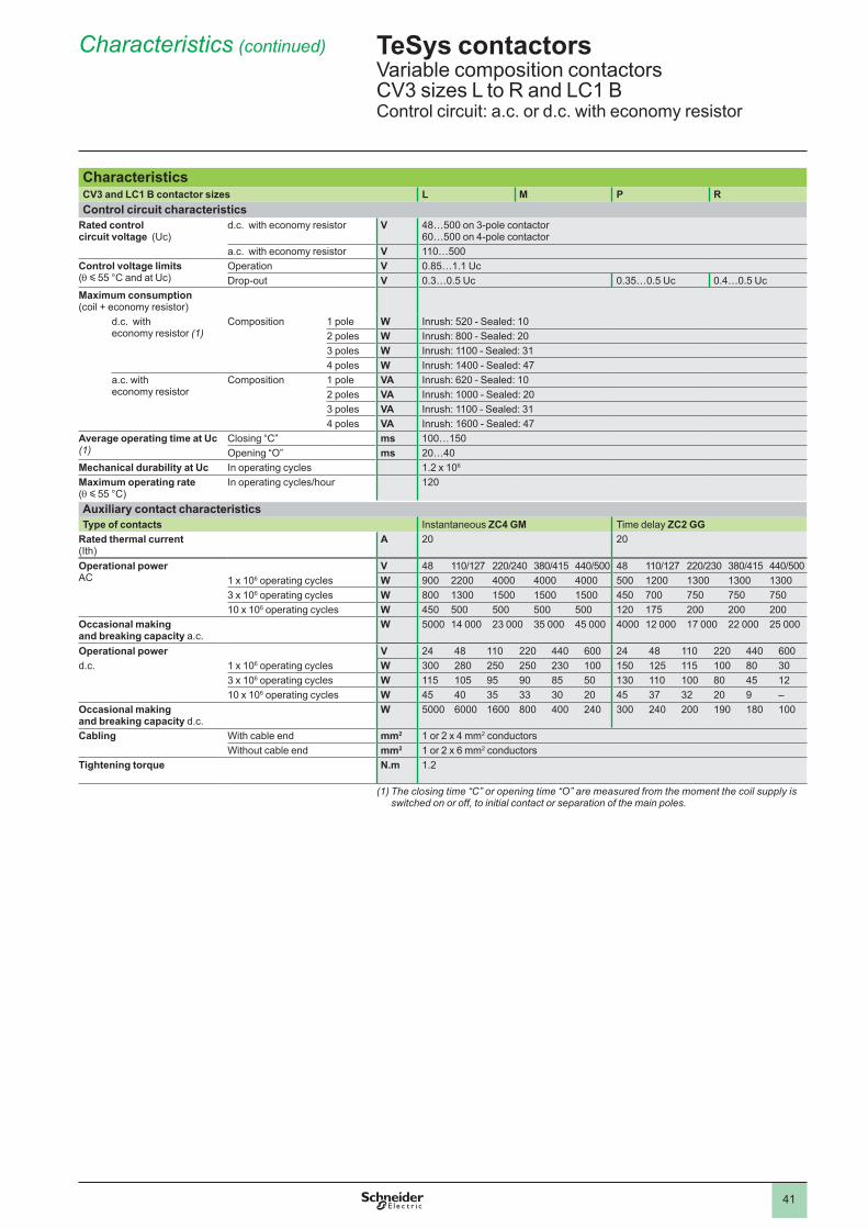
41
Characteristics (continued)
CharacteristicsCV3 and LC1 B contactor sizes L M P RControl circuit characteristics
Rated control circuit voltage (Uc)
d.c. with economy resistor V 48…500 on 3-pole contactor60…500 on 4-pole contactor
a.c. with economy resistor V 110…500Control voltage limits (q y 55 °C and at Uc)
Operation V 0.85…1.1 UcDrop-out V 0.3…0.5 Uc 0.35…0.5 Uc 0.4…0.5 Uc
Maximum consumption (coil + economy resistor)
d.c. with economy resistor (1)
Composition pole W Inrush: 520 - Sealed: 102 poles W Inrush: 800 - Sealed: 203 poles W Inrush: 1100 - Sealed: 314 poles W Inrush: 1400 - Sealed: 47
a.c. with economy resistor
Composition pole VA Inrush: 620 - Sealed: 102 poles VA Inrush: 1000 - Sealed: 203 poles VA Inrush: 1100 - Sealed: 314 poles VA Inrush: 1600 - Sealed: 47
Average operating time at Uc (1)
Closing “C” ms 100…150Opening “O” ms 20…40
Mechanical durability at Uc In operating cycles 1.2 x 10⁶
Maximum operating rate (q y 55 °C)
In operating cycles/hour 120
Auxiliary contact characteristicsType of contacts Instantaneous ZC4 GM Time delay ZC2 GG
Rated thermal current (Ith)
A 20 20
Operational powerAC
V 48 110/127 220/240 380/415 440/500 48 110/127 220/230 380/415 440/5001 x 106 operating cycles W 900 2200 4000 4000 4000 500 1200 1300 1300 13003 x 106 operating cycles W 800 1300 1500 1500 1500 450 700 750 750 75010 x 106 operating cycles W 450 500 500 500 500 120 175 200 200 200
Occasional making and breaking capacity a .c .
W 5000 14 000 23 000 35 000 45 000 4000 12 000 17 000 22 000 25 000
Operational power V 24 48 220 440 600 24 48 220 440 600d.c. 1 x 10⁶ operating cycles W 300 280 250 250 230 150 125 115 80 30
3 x 10⁶ operating cycles W 115 105 95 90 85 50 130 80 45 1210 x 106 operating cycles W 45 40 35 33 30 20 45 37 32 20 9 –
Occasional making and breaking capacity d.c.
W 5000 6000 1600 800 400 240 300 240 200 190 180
Cabling With cable end mm2 1 or 2 x 4 mm2 conductorsWithout cable end mm2 1 or 2 x 6 mm2 conductors
Tightening torque N.m 1.2
(1) The closing time “C” or opening time “O” are measured from the moment the coil supply is switched on or off, to initial contact or separation of the main poles.
TeSys contactors 0 Variable composition contactors CV3 sizes L to R and LC1 BControl circuit: a.c. or d.c. with economy resistor
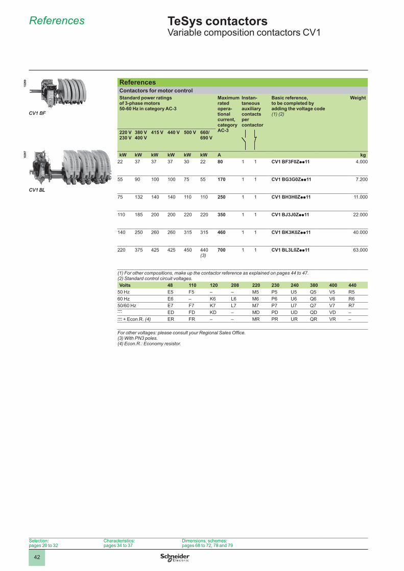
42
References
4.2
Selection: pages 20 to 32
Characteristics: pages 34 to 37
Dimensions, schemes: pages 68 to 72, 78 and 79
ReferencesContactors for motor control Standard power ratings of 3-phase motors 50-60 Hz in category AC-3
Maximum rated opera-tional current, category AC-3
Instan-taneous auxiliary contacts per contactor
Basic reference, to be completed by adding the voltage code (1) (2)
Weight
220 V230 V
380 V400 V
415 V 440 V 500 V 660/690 V
kW kW kW kW kW kW A kg22 37 37 37 30 22 80 CV1 BF3F0Zpp11 4.000
55 90 75 55 170 CV1 BG3G0Zpp11 7.200
75 132 140 140 250 CV1 BH3H0Zpp11 .
185 200 200 220 220 350 CV1 BJ3J0Zpp11 22.000
140 250 260 260 315 315 460 CV1 BK3K0Zpp11 40.000
220 375 425 425 450 440 (3)
700 CV1 BL3L0Zpp11 63.000
(1) For other compositions, make up the contactor reference as explained on pages 44 to 47.(2) Standard control circuit voltages.Volts 48 110 120 208 220 230 240 380 400 440
50 Hz E5 F5 – – M5 P5 U5 Q5 V5 R560 Hz E6 – K6 L6 M6 P6 U6 Q6 V6 R650/60 Hz E7 F7 K7 L7 M7 P7 U7 Q7 V7 R7c ED FD KD – MD PD UD QD VD –c + Econ.R. (4) ER FR – – MR PR UR QR VR –
For other voltages: please consult your Regional Sales Office.(3) With PN3 poles.(4) Econ.R.: Economy resistor.
CV1 BF
1026
9
CV1 BF
1026
9
CV1 BL
1026
7
CV1 BL
1026
7TeSys contactors 0 Variable composition contactors CV1
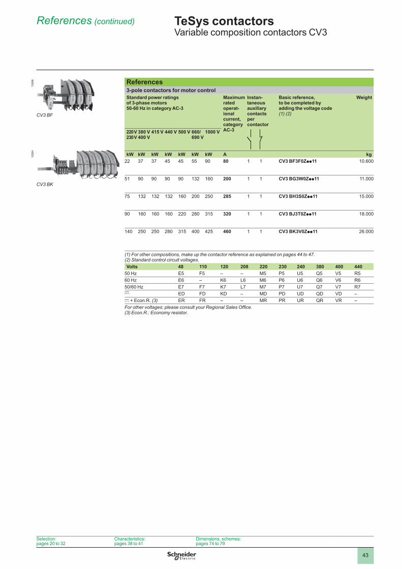
43
References (continued)
Selection: pages 20 to 32
Characteristics: pages 38 to 41
Dimensions, schemes: pages 74 to 79
References3-pole contactors for motor control Standard power ratings of 3-phase motors 50-60 Hz in category AC-3
Maximum rated operat-ional current, category AC-3
Instan-taneous auxiliary contacts per contactor
Basic reference, to be completed by adding the voltage code (1) (2)
Weight
220 V230 V
380 V400 V
415 V 440 V 500 V 660/690 V
1000 V
kW kW kW kW kW kW kW A kg22 37 37 45 45 55 90 80 CV3 BF3F0Zpp11 10.600
51 90 90 90 90 132 160 200 CV3 BG3W0Zpp11 .
75 132 132 132 160 200 250 285 CV3 BH3S0Zpp11 15.000
90 160 160 160 220 280 315 320 CV3 BJ3T0Zpp11 18.000
140 250 250 280 315 400 425 460 CV3 BK3V0Zpp11 26.000
(1) For other compositions, make up the contactor reference as explained on pages 44 to 47.(2) Standard control circuit voltages.Volts 48 110 120 208 220 230 240 380 400 440
50 Hz E5 F5 – – M5 P5 U5 Q5 V5 R560 Hz E6 – K6 L6 M6 P6 U6 Q6 V6 R650/60 Hz E7 F7 K7 L7 M7 P7 U7 Q7 V7 R7c ED FD KD – MD PD UD QD VD –c + Econ.R. (3) ER FR – – MR PR UR QR VR –For other voltages: please consult your Regional Sales Office.(3) Econ.R.: Economy resistor.
TeSys contactors 0 Variable composition contactors CV3
CV3 BK
1026
4
CV3 BF
1026
6
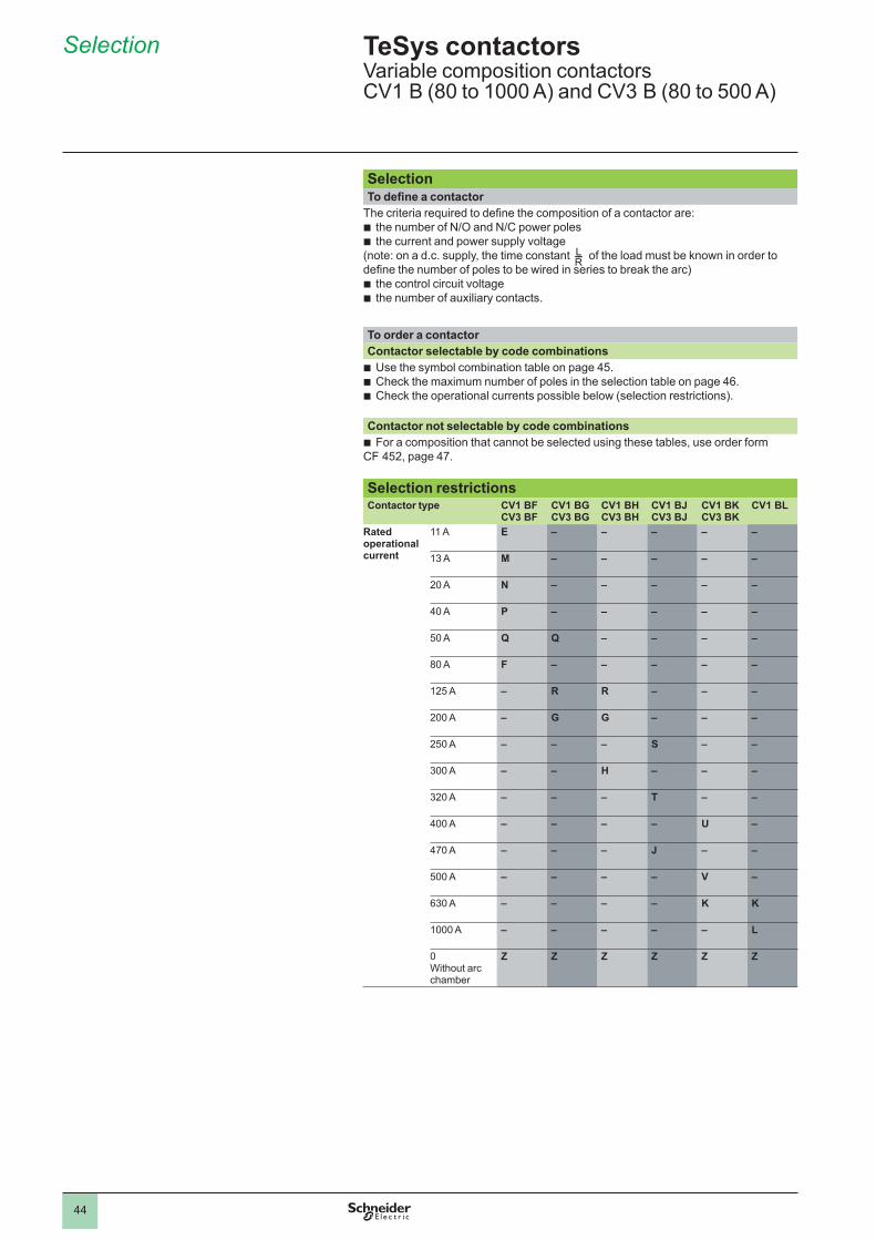
44
SelectionTo define a contactor
The criteria required to define the composition of a contactor are:the number of N/O and N/C power polesthe current and power supply voltage
(note: on a d.c. supply, the time constant of the load must be known in order to define the number of poles to be wired in series to break the arc)
the control circuit voltagethe number of auxiliary contacts.
bb
bb
To order a contactor Contactor selectable by code combinations
Use the symbol combination table on page 45 .Check the maximum number of poles in the selection table on page 46 .Check the operational currents possible below (selection restrictions).
bbb
Contactor not selectable by code combinationsFor a composition that cannot be selected using these tables, use order form
CF 452, page 47 . b
Selection restrictionsContactor type CV1 BF
CV3 BFCV1 BG CV3 BG
CV1 BH CV3 BH
CV1 BJ CV3 BJ
CV1 BK CV3 BK
CV1 BL
Rated operational current
A E – – – – –
13 A M – – – – –
20 A N – – – – –
40 A P – – – – –
50 A Q Q – – – –
80 A F – – – – –
125 A – R R – – –
200 A – G G – – –
250 A – – – S – –
300 A – – H – – –
320 A – – – T – –
400 A – – – – U –
470 A – – – J – –
500 A – – – – V –
630 A – – – – K K
A – – – – – L
Without arc chamber
Z Z Z Z Z Z
LR----
TeSys contactorsVariable composition contactors CV1 B (80 to 1000 A) and CV3 B (80 to 500 A)
Selection
7.1
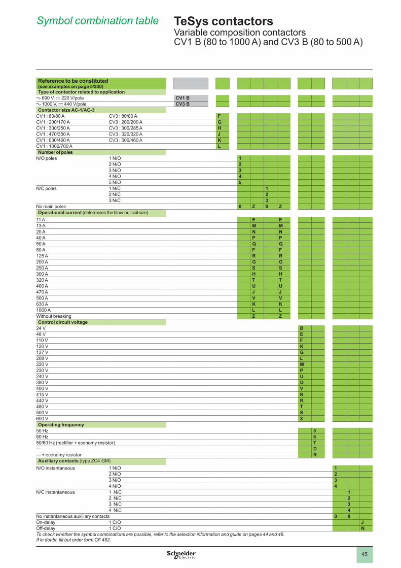
45
Reference to be constituted (see examples on page 5/230)Type of contactor related to application
a 690 V, c 220 V/pole CV1 Ba 1000 V, c 440 V/pole CV3 BContactor size AC-1/AC-3
CV1 : 80/80 A CV3 : 80/80 A FCV1 : 200/170 A CV3 : 200/200 A GCV1 : 300/250 A CV3 : 300/285 A HCV1 : 470/350 A CV3 : 320/320 A JCV1 : 630/460 A CV3 : 500/460 A KCV1 : 1000/700 A LNumber of poles
N/O poles 1 N/O 12 N/O 23 N/O 34 N/O 45 N/O 5
N/C poles 1 N/C 1 2 N/C 23 N/C 3
No main poles 0 Z 0 ZOperational current (determines the blow-out coil size)
A E E13 A M M20 A N N40 A P P50 A Q Q80 A F F125 A R R200 A G G250 A S S300 A H H320 A T T400 A U U470 A J J500 A V V630 A K K A L LWithout breaking Z ZControl circuit voltage
24 V B48 V E V F120 V K127 V G208 V L220 V M230 V P240 V U380 V Q400 V V415 V N440 V R480 V T500 V S600 V XOperating frequency
50 Hz 560 Hz 650/60 Hz (rectifier + economy resistor) 7c Dc + economy resistor RAuxiliary contacts (type ZC4 GM)
N/O instantaneous 1 N/O 12 N/O 23 N/O 34 N/O 4
N/C instantaneous 1 N/C 12 N/C 23 N/C 34 N/C 4
No instantaneous auxiliary contacts 0 0On-delay 1 C/O JOff-delay 1 C/O NTo check whether the symbol combinations are possible, refer to the selection information and guide on pages 44 and 46.If in doubt, fill out order form CF 452.
TeSys contactorsVariable composition contactors CV1 B (80 to 1000 A) and CV3 B (80 to 500 A)
Symbol combination table
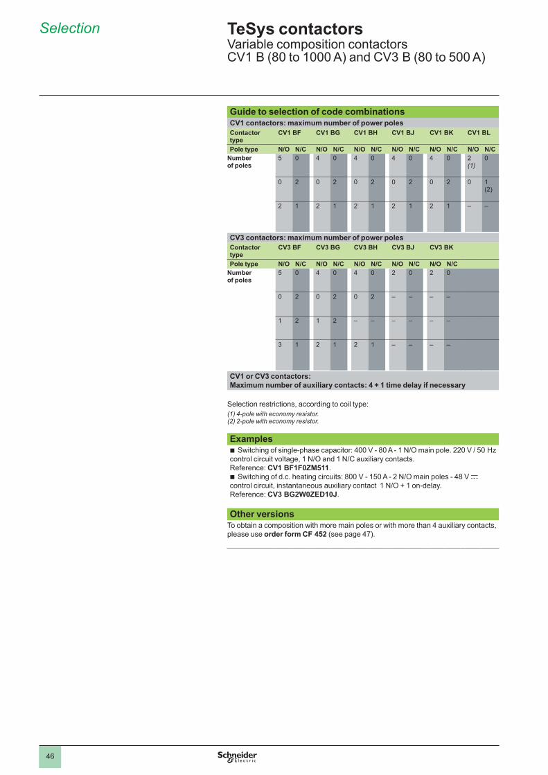
46
Guide to selection of code combinationsCV1 contactors: maximum number of power polesContactor type
CV1 BF CV1 BG CV1 BH CV1 BJ CV1 BK CV1 BL
Pole type N/O N/C N/O N/C N/O N/C N/O N/C N/O N/C N/O N/CNumber of poles
5 4 4 4 4 2(1)
2 2 2 2 2 (2)
2 2 2 2 2 – –
CV3 contactors: maximum number of power polesContactor type
CV3 BF CV3 BG CV3 BH CV3 BJ CV3 BK
Pole type N/O N/C N/O N/C N/O N/C N/O N/C N/O N/CNumber of poles
5 4 4 2 2
2 2 2 – – – –
2 2 – – – – – –
3 2 2 – – – –
CV1 or CV3 contactors: Maximum number of auxiliary contacts: 4 + 1 time delay if necessary
Selection restrictions, according to coil type:(1) 4-pole with economy resistor.(2) 2-pole with economy resistor.
ExamplesSwitching of single-phase capacitor: 400 V - 80 A - 1 N/O main pole. 220 V / 50 Hz
control circuit voltage, 1 N/O and 1 N/C auxiliary contacts. Reference: CV1 BF1F0ZM511 .
Switching of d.c. heating circuits: 800 V - 150 A - 2 N/O main poles - 48 V c control circuit, instantaneous auxiliary contact 1 N/O + 1 on-delay. Reference: CV3 BG2W0ZED10J .
b
b
Other versionsTo obtain a composition with more main poles or with more than 4 auxiliary contacts, please use order form CF 452 (see page 47).
TeSys contactorsVariable composition contactors CV1 B (80 to 1000 A) and CV3 B (80 to 500 A)
Selection
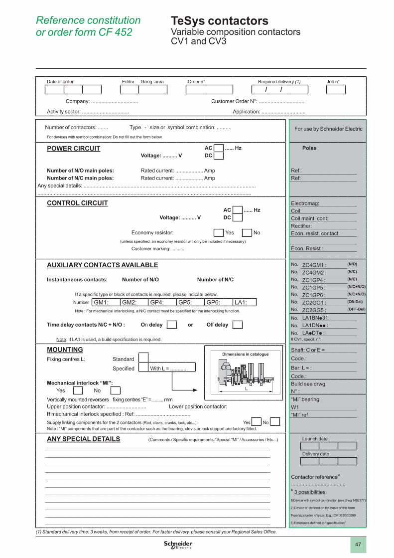
47
(1) Standard delivery time: 3 weeks, from receipt of order. For faster delivery, please consult your Regional Sales Office.
Date of order Editor Geog. area Order n° Required delivery (1) Job n°
/ /Company: ................................ Customer Order N°: ...............................
Activity sector: ................................ Application: ..............................
Number of contactors: ....... Type - size or symbol combination: .......... For use by Schneider Electric For devices with symbol combination: Do not fill out the form below
POWER CIRCUIT AC ...... Hz PolesVoltage: .......... V DC
Number of N/O main poles: Rated current: ................... Amp Ref:Number of N/C main poles: Rated current: ................... Amp Ref:
Any special details: ..................................................................................................................... . . . . . . . . . . . . . . . . . . . . . . . . . . . . . . . . . . . . . . . . . . . . . . . . . . . . . . . . . . . . . . . . . . . . . . . . . . . . . . . . . . . . . . . . . . . . . . . . . . . . . . . . . . . . . . . . . . . . . . . . . . . . . . . . . . . . . . . . . . . . . . . . .
CONTROL CIRCUIT Electromag:AC ...... Hz Coil:
Voltage: .......... V DC Coil maint. cont:Rectifier:
Economy resistor: Yes No Econ. resist. contact:(unless specified, an economy resistor will only be included if necessary)
Customer marking: .......... Econ. Resist.:
AUXILIARY CONTACTS AVAILABLE No . ZC4GM1 : (N/O)
No . ZC4GM2 : (N/C)
Instantaneous contacts: Number of N/O Number of N/C No . ZC1GP4 : (N/C)
No . ZC1GP5 : (N/C+N/O)
If a specific type or block of contacts is required, please indicate below. No . ZC1GP6 : (N/O+N/O)
Number GM1: GM2: GP4: GP5: GP6: LA1: No . ZC2GG1 : (ON-Del)
Note : For mechanical interlocking, a N/C contact must be specified for the interlocking function. No . ZC2GG5 : (OFF-Del)
No . LA1BNp31 :Time delay contacts N/C + N/O : On delay or Off delay No . LADNpp :
No . LApDTp :Note: If LA1 is used, a build specification is required. If CV1, specif. n°:
MOUNTING Shaft: C or E =
Fixing centres L: Standard Code.:
Specified With L = ............ Bar: L = :Code.:
Mechanical interlock “MI”: Build see drwg.Yes No N° :
Vertically mounted reversers fixing centres “E” =.......... mm “MI” bearingUpper position contactor: ........................... Lower position contactor: W1If mechanical interlock specified : Ref: ..................................... “MI” refSupply linking components for the 2 contactors (Rod, clevis, cranks, lock, etc...) : Yes No
Note : “MI” components that are part of the contactor such as the bearing, clevis or lock support are factory fitted.
ANY SPECIAL DETAILS (Comments / Specific requirements / Special “MI” / Accessories / Etc...) Launch date
Delivery date
Contactor reference* . . . . . . . . . . . . . . . . . . . . . . . . . . . . . . . . . . . . .* 3 possibilities1) Device with symbol combination (see drwg 1492177)
2) Device n° defined on the basis of this form
Type/size/order n°/year. E.g.: CV1GB000599
3) Reference defined to “specification”
L
Dimensions in catalogue
L
Dimensions in catalogue
TeSys contactorsVariable composition contactors CV1 and CV3
Reference constitution or order form CF 452
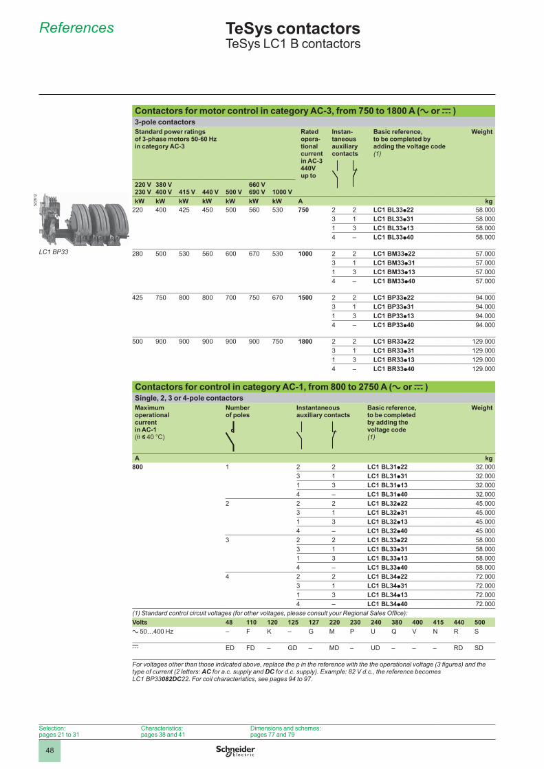
48
References 5
Contactors for motor control in category AC-3, from 750 to 1800 A (a or c )3-pole contactorsStandard power ratings of 3-phase motors 50-60 Hz in category AC-3
Rated opera-tional current in AC-3 440V up to
Instan-taneous auxiliary contacts
Basic reference, to be completed by adding the voltage code(1)
Weight
220 V230 V
380 V400 V 415 V 440 V 500 V
660 V690 V 1000 V
kW kW kW kW kW kW kW A kg220 400 425 450 500 560 530 750 2 2 LC1 BL33p22 58.000
3 LC1 BL33p31 58.000 3 LC1 BL33p13 58.0004 – LC1 BL33p40 58.000
280 500 530 560 600 670 530 1000 2 2 LC1 BM33p22 57.0003 LC1 BM33p31 57.000 3 LC1 BM33p13 57.0004 – LC1 BM33p40 57.000
425 750 800 800 700 750 670 1500 2 2 LC1 BP33p22 94.0003 LC1 BP33p31 94.000 3 LC1 BP33p13 94.0004 – LC1 BP33p40 94.000
500 900 900 900 900 900 750 1800 2 2 LC1 BR33p22 129.0003 LC1 BR33p31 129.000 3 LC1 BR33p13 129.0004 – LC1 BR33p40 129.000
Contactors for control in category AC-1, from 800 to 2750 A (a or c )Single, 2, 3 or 4-pole contactorsMaximum operational current in AC-1 (q y 40 °C)
Number of poles
Instantaneous auxiliary contacts
Basic reference, to be completed by adding the voltage code (1)
Weight
A kg800 2 2 LC1 BL31p22 32.000
3 LC1 BL31p31 32.000 3 LC1 BL31p13 32.0004 – LC1 BL31p40 32.000
2 2 2 LC1 BL32p22 45.0003 LC1 BL32p31 45.000 3 LC1 BL32p13 45.0004 – LC1 BL32p40 45.000
3 2 2 LC1 BL33p22 58.0003 LC1 BL33p31 58.000 3 LC1 BL33p13 58.0004 – LC1 BL33p40 58.000
4 2 2 LC1 BL34p22 72.0003 LC1 BL34p31 72.000 3 LC1 BL34p13 72.0004 – LC1 BL34p40 72.000
(1) Standard control circuit voltages (for other voltages, please consult your Regional Sales Office): Volts 48 110 120 125 127 220 230 240 380 400 415 440 500a 50…400 Hz – F K – G M P U Q V N R S
c ED FD – GD – MD – UD – – – RD SD
For voltages other than those indicated above, replace the p in the reference with the the operational voltage (3 figures) and the type of current (2 letters: AC for a.c. supply and DC for d.c. supply). Example: 82 V d.c., the reference becomes LC1 BP33082DC22. For coil characteristics, see pages 94 to 97.
TeSys contactors 5 TeSys LC1 B contactors
Selection: pages 21 to 31
Characteristics: pages 38 and 41
Dimensions and schemes:pages 77 and 79
LC1 BP33
5226
12
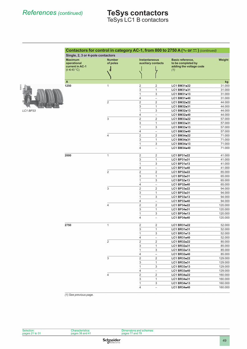
49
References (continued) 5
Contactors for control in category AC-1, from 800 to 2750 A (a or c ) (continued)Single, 2, 3 or 4-pole contactors Maximum operational current in AC-1 (q y 40 °C)
Number of poles
Instantaneous auxiliary contacts
Basic reference, to be completed by adding the voltage code (1)
Weight
A kg1250 2 2 LC1 BM31p22 31.000
3 LC1 BM31p31 31.000 3 LC1 BM31p13 31.0004 – LC1 BM31p40 31.000
2 2 2 LC1 BM32p22 44.0003 LC1 BM32p31 44.000 3 LC1 BM32p13 44.0004 – LC1 BM32p40 44.000
3 2 2 LC1 BM33p22 57.0003 LC1 BM33p31 57.000 3 LC1 BM33p13 57.0004 – LC1 BM33p40 57.000
4 2 2 LC1 BM34p22 71.0003 LC1 BM34p31 71.000 3 LC1 BM34p13 71.0004 – LC1 BM34p40 71.000
2000 2 2 LC1 BP31p22 41.0003 LC1 BP31p31 41.000 3 LC1 BP31p13 41.0004 – LC1 BP31p40 41.000
2 2 2 LC1 BP32p22 65.0003 LC1 BP32p31 65.000 3 LC1 BP32p13 65.0004 – LC1 BP32p40 65.000
3 2 2 LC1 BP33p22 94.0003 LC1 BP33p31 94.000 3 LC1 BP33p13 94.0004 – LC1 BP33p40 94.000
4 2 2 LC1 BP34p22 120.0003 LC1 BP34p31 120.000 3 LC1 BP34p13 120.0004 – LC1 BP34p40 120.000
2750 2 2 LC1 BR31p22 52.0003 LC1 BR31p31 52.000 3 LC1 BR31p13 52.0004 – LC1 BR31p40 52.000
2 2 2 LC1 BR32p22 85.0003 LC1 BR32p31 85.000 3 LC1 BR32p13 85.0004 – LC1 BR32p40 85.000
3 2 2 LC1 BR33p22 129.0003 LC1 BR33p31 129.000 3 LC1 BR33p13 129.0004 – LC1 BR33p40 129.000
4 2 2 LC1 BR34p22 160.0003 LC1 BR34p31 160.000 3 LC1 BR34p13 160.0004 – LC1 BR34p40 160.000
(1) See previous page.
TeSys contactors 5 TeSys LC1 B contactors
LC1 BP33
5226
12
Selection: pages 21 to 31
Characteristics: pages 38 and 41
Dimensions and schemes:pages 77 and 79
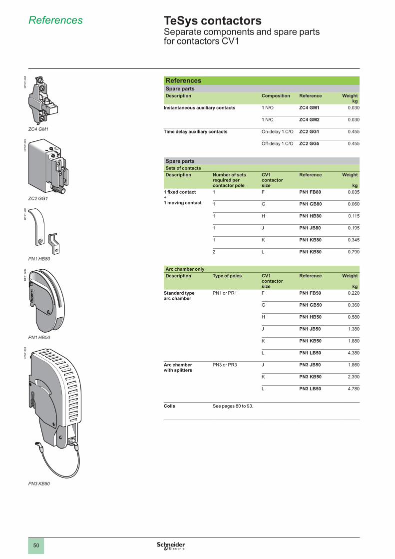
50
References
4.2
ReferencesSpare partsDescription Composition Reference Weight
kgInstantaneous auxiliary contacts 1 N/O ZC4 GM1 0.030
1 N/C ZC4 GM2 0.030
Time delay auxiliary contacts On-delay 1 C/O ZC2 GG1 0.455
Off-delay 1 C/O ZC2 GG5 0.455
Spare partsSets of contactsDescription Number of sets
required per contactor pole
CV1 contactor size
Reference Weight
kg1 fixed contact + 1 moving contact
F PN1 FB80 0.035
G PN1 GB80 0.060
H PN1 HB80 0.115
J PN1 JB80 0.195
K PN1 KB80 0.345
2 L PN1 KB80 0.790
Arc chamber onlyDescription Type of poles CV1
contactor size
Reference Weight
kgStandard type arc chamber
PN or PR F PN1 FB50 0.220
G PN1 GB50 0.360
H PN1 HB50 0.580
J PN1 JB50 1.380
K PN1 KB50 1.880
L PN1 LB50 4.380
Arc chamber with splitters
PN3 or PR3 J PN3 JB50 1.860
K PN3 KB50 2.390
L PN3 LB50 4.780
Coils See pages 80 to 93 .
TeSys contactors 0 Separate components and spare parts for contactors CV1
DF5
1120
4D
F511
205
DF5
1120
6D
F511
207
DF5
1120
8
ZC4 GM1
ZC2 GG1
PN1 HB80
PN1 HB50
PN3 KB50
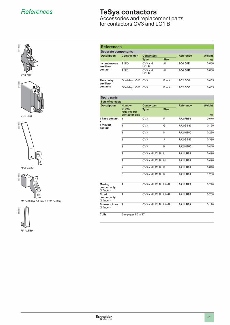
51
References
ReferencesSeparate componentsDescription Composition Contactors Reference Weight
Type Size kgInstantaneous auxiliary contact
1 N/O CV3 and LC1 B
All ZC4 GM1 0.030
1 N/C CV3 and LC1 B
All ZC4 GM2 0.030
Time delay auxiliary contacts
On-delay 1 C/O CV3 F to K ZC2 GG1 0.455
Off-delay 1 C/O CV3 F to K ZC2 GG5 0.455
Spare partsSets of contactsDescription Number
of sets required per contactor pole
Contactors Reference WeightType Size
kg1 fixed contact + 1 moving contact
CV3 F PA2 FB80 0.070
CV3 G PA2 GB80 0.160
CV3 H PA2 HB80 0.220
2 CV3 J PA2 GB80 0.320
2 CV3 K PA2 HB80 0.440
CV3 and LC1 B L PA1 LB80 0.420
CV3 and LC1 B M PA1 LB80 0.420
2 CV3 and LC1 B P PA1 LB80 0.840
3 CV3 and LC1 B R PA1 LB80 1.260
Moving contact only (1 finger)
CV3 and LC1 B L to R PA1 LB75 0.220
Fixed contact only (1 finger)
CV3 and LC1 B L to R PA1 LB76 0.200
Blow-out horn (1 finger)
CV3 and LC1 B L to R PA1 LB89 0.120
Coils See pages 80 to 97 .
TeSys contactors 0 Accessories and replacement parts for contactors CV3 and LC1 B
DF5
1126
3D
F511
264
DF5
1126
5D
F511
266
DF5
1126
7
ZC4 GM1
ZC2 GG1
PA2 GB80
PA1 LB80 (PA1 LB76 + PA1 LB75)
PA1 LB89
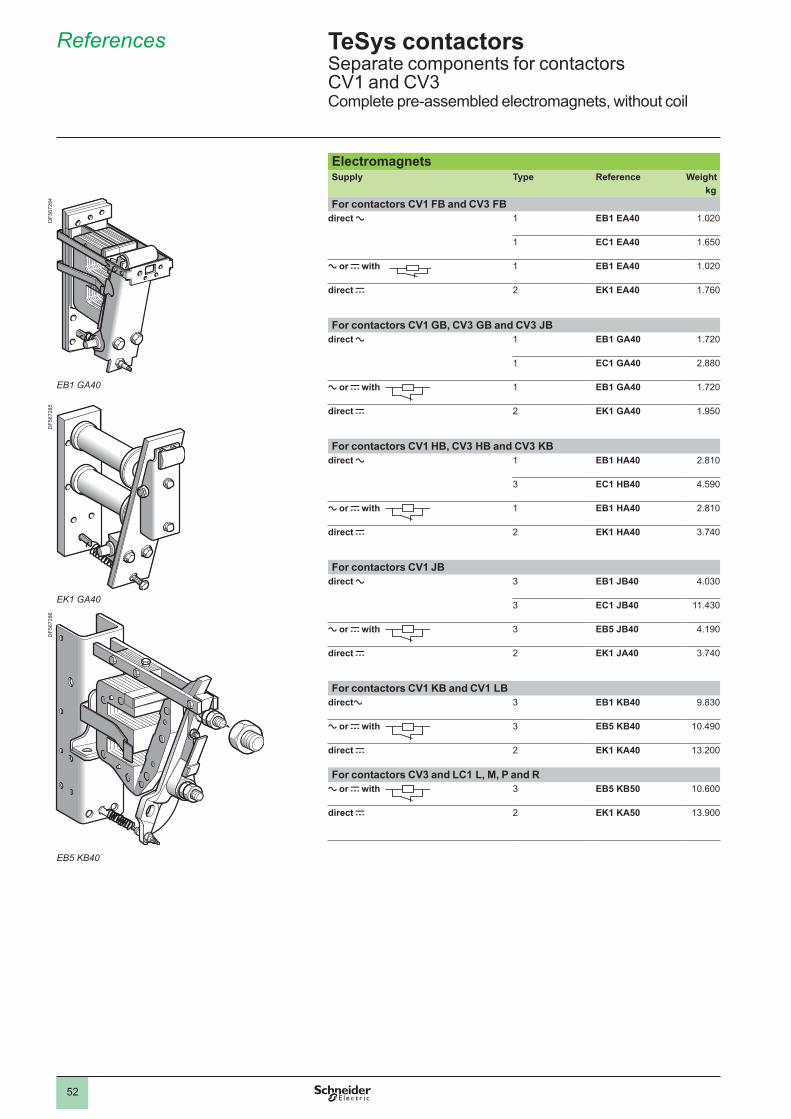
52
References
ElectromagnetsSupply Type Reference Weight
kgFor contactors CV1 FB and CV3 FB
direct a EB1 EA40 1.020
EC1 EA40 1.650
a or c with EB1 EA40 1.020
direct c 2 EK1 EA40 1.760
For contactors CV1 GB, CV3 GB and CV3 JBdirect a EB1 GA40 1.720
EC1 GA40 2.880
a or c with EB1 GA40 1.720
direct c 2 EK1 GA40 1.950
For contactors CV1 HB, CV3 HB and CV3 KBdirect a EB1 HA40 2.810
3 EC1 HB40 4.590
a or c with EB1 HA40 2.810
direct c 2 EK1 HA40 3.740
For contactors CV1 JBdirect a 3 EB1 JB40 4.030
3 EC1 JB40 11.430
a or c with 3 EB5 JB40 4.190
direct c 2 EK1 JA40 3.740
For contactors CV1 KB and CV1 LBdirecta 3 EB1 KB40 9.830
a or c with 3 EB5 KB40 10.490
direct c 2 EK1 KA40 13.200
For contactors CV3 and LC1 L, M, P and Ra or c with 3 EB5 KB50 10.600
direct c 2 EK1 KA50 13.900
TeSys contactors 0 Separate components for contactors CV1 and CV3 Complete pre-assembled electromagnets, without coil
EB1 GA40
EK1 GA40
EB5 KB40
DF5
6728
4D
F567
285
DF5
6728
6
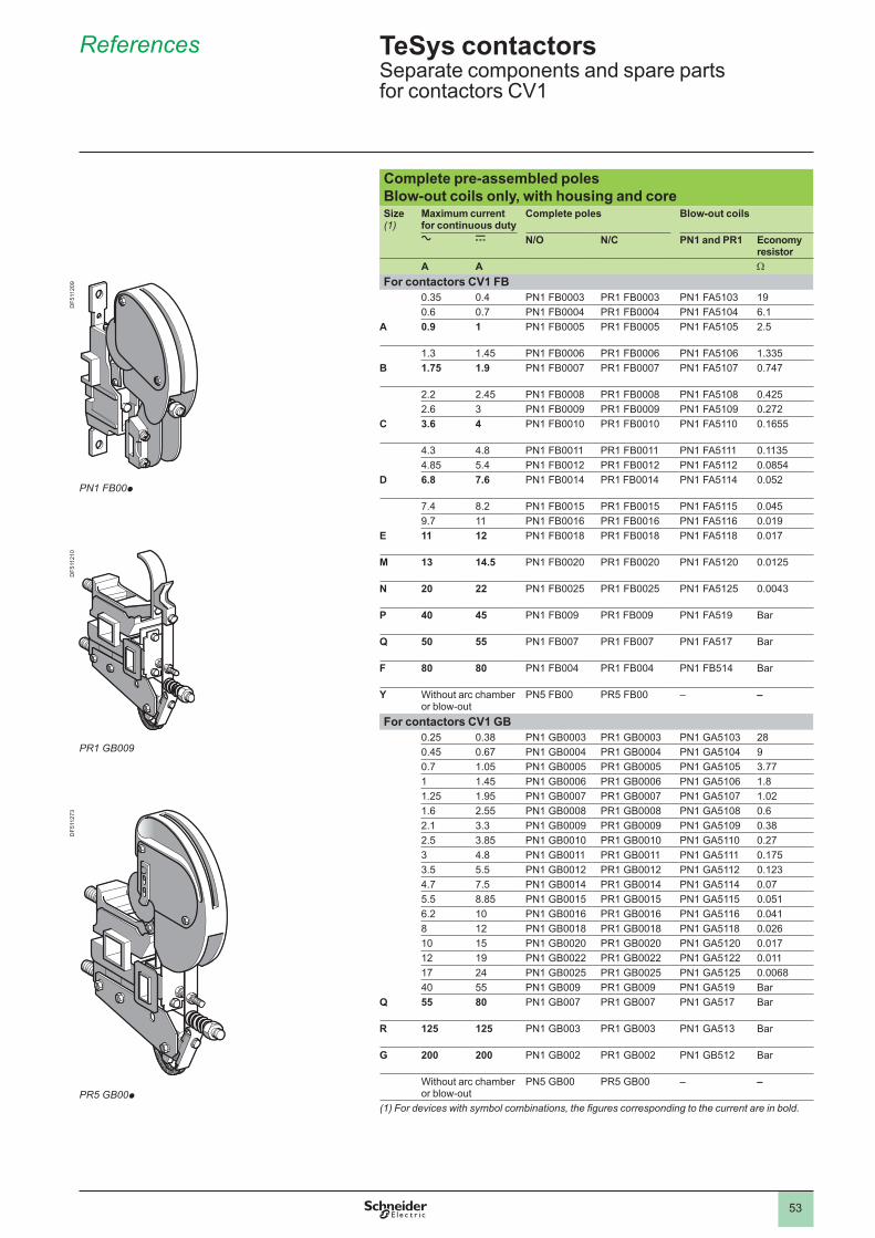
53
References
Complete pre-assembled polesBlow-out coils only, with housing and coreSize (1)
Maximum current for continuous duty
Complete poles Blow-out coils
a c N/O N/C PN1 and PR1 Economy resistor
A A W
For contactors CV1 FB0.35 0.4 PN1 FB0003 PR1 FB0003 PN1 FA5103 190.6 0.7 PN1 FB0004 PR1 FB0004 PN1 FA5104 6.1
A 0.9 1 PN1 FB0005 PR1 FB0005 PN1 FA5105 2.5
1.3 1.45 PN1 FB0006 PR1 FB0006 PN1 FA5106 1.335B 1.75 1.9 PN1 FB0007 PR1 FB0007 PN1 FA5107 0.747
2.2 2.45 PN1 FB0008 PR1 FB0008 PN1 FA5108 0.4252.6 3 PN1 FB0009 PR1 FB0009 PN1 FA5109 0.272
C 3.6 4 PN1 FB0010 PR1 FB0010 PN1 FA5110 0.1655
4.3 4.8 PN1 FB0011 PR1 FB0011 PN1 FA5111 0.11354.85 5.4 PN1 FB0012 PR1 FB0012 PN1 FA5112 0.0854
D 6.8 7.6 PN1 FB0014 PR1 FB0014 PN1 FA5114 0.052
7.4 8.2 PN1 FB0015 PR1 FB0015 PN1 FA5115 0.0459.7 PN1 FB0016 PR1 FB0016 PN1 FA5116 0.019
E 11 12 PN1 FB0018 PR1 FB0018 PN1 FA5118 0.017
M 13 14.5 PN1 FB0020 PR1 FB0020 PN1 FA5120 0.0125
N 20 22 PN1 FB0025 PR1 FB0025 PN1 FA5125 0.0043
P 40 45 PN1 FB009 PR1 FB009 PN1 FA519 Bar
Q 50 55 PN1 FB007 PR1 FB007 PN1 FA517 Bar
F 80 80 PN1 FB004 PR1 FB004 PN1 FB514 Bar
Y Without arc chamber or blow-out
PN5 FB00 PR5 FB00 – –
For contactors CV1 GB0.25 0.38 PN1 GB0003 PR1 GB0003 PN1 GA5103 280.45 0.67 PN1 GB0004 PR1 GB0004 PN1 GA5104 90.7 1.05 PN1 GB0005 PR1 GB0005 PN1 GA5105 3.77 1.45 PN1 GB0006 PR1 GB0006 PN1 GA5106 1.81.25 1.95 PN1 GB0007 PR1 GB0007 PN1 GA5107 1.021.6 2.55 PN1 GB0008 PR1 GB0008 PN1 GA5108 0.62.1 3.3 PN1 GB0009 PR1 GB0009 PN1 GA5109 0.382.5 3.85 PN1 GB0010 PR1 GB0010 PN1 GA5110 0.273 4.8 PN1 GB0011 PR1 GB0011 PN1 GA5111 0.1753.5 5.5 PN1 GB0012 PR1 GB0012 PN1 GA5112 0.1234.7 7.5 PN1 GB0014 PR1 GB0014 PN1 GA5114 0.075.5 8.85 PN1 GB0015 PR1 GB0015 PN1 GA5115 0.0516.2 PN1 GB0016 PR1 GB0016 PN1 GA5116 0.0418 12 PN1 GB0018 PR1 GB0018 PN1 GA5118 0.026 15 PN1 GB0020 PR1 GB0020 PN1 GA5120 0.01712 19 PN1 GB0022 PR1 GB0022 PN1 GA5122 .17 24 PN1 GB0025 PR1 GB0025 PN1 GA5125 0.006840 55 PN1 GB009 PR1 GB009 PN1 GA519 Bar
Q 55 80 PN1 GB007 PR1 GB007 PN1 GA517 Bar
R 125 125 PN1 GB003 PR1 GB003 PN1 GA513 Bar
G 200 200 PN1 GB002 PR1 GB002 PN1 GB512 Bar
Without arc chamber or blow-out
PN5 GB00 PR5 GB00 – –
(1) For devices with symbol combinations, the figures corresponding to the current are in bold.
TeSys contactors 0 Separate components and spare parts for contactors CV1
PN1 FB00p
PR1 GB009
PR5 GB00p
DF5
1120
9D
F511
210
DF5
1127
3
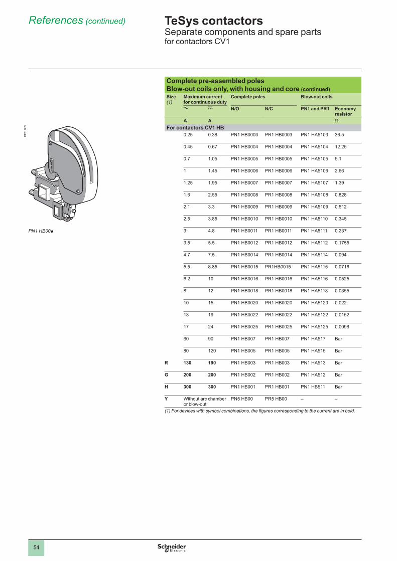
54
References (continued)
Complete pre-assembled polesBlow-out coils only, with housing and core (continued)Size(1)
Maximum current for continuous duty
Complete poles Blow-out coils
a c N/O N/C PN1 and PR1 Economy resistor
A A W
For contactors CV1 HB0.25 0.38 PN1 HB0003 PR1 HB0003 PN1 HA5103 36.5
0.45 0.67 PN1 HB0004 PR1 HB0004 PN1 HA5104 12.25
0.7 1.05 PN1 HB0005 PR1 HB0005 PN1 HA5105 5.1
1.45 PN1 HB0006 PR1 HB0006 PN1 HA5106 2.66
1.25 1.95 PN1 HB0007 PR1 HB0007 PN1 HA5107 1.39
1.6 2.55 PN1 HB0008 PR1 HB0008 PN1 HA5108 0.828
2.1 3.3 PN1 HB0009 PR1 HB0009 PN1 HA5109 0.512
2.5 3.85 PN1 HB0010 PR1 HB0010 PN1 HA5110 0.345
3 4.8 PN1 HB0011 PR1 HB0011 PN1 HA5111 0.237
3.5 5.5 PN1 HB0012 PR1 HB0012 PN1 HA5112 0.1755
4.7 7.5 PN1 HB0014 PR1 HB0014 PN1 HA5114 0.094
5.5 8.85 PN1 HB0015 PR1HB0015 PN1 HA5115 0.0716
6.2 PN1 HB0016 PR1 HB0016 PN1 HA5116 0.0525
8 12 PN1 HB0018 PR1 HB0018 PN1 HA5118 0.0355
15 PN1 HB0020 PR1 HB0020 PN1 HA5120 0.022
13 19 PN1 HB0022 PR1 HB0022 PN1 HA5122 0.0152
17 24 PN1 HB0025 PR1 HB0025 PN1 HA5125 0.0096
60 90 PN1 HB007 PR1 HB007 PN1 HA517 Bar
80 120 PN1 HB005 PR1 HB005 PN1 HA515 Bar
R 130 190 PN1 HB003 PR1 HB003 PN1 HA513 Bar
G 200 200 PN1 HB002 PR1 HB002 PN1 HA512 Bar
H 300 300 PN1 HB001 PR1 HB001 PN1 HB511 Bar
Y Without arc chamber or blow-out
PN5 HB00 PR5 HB00 – –
(1) For devices with symbol combinations, the figures corresponding to the current are in bold.
TeSys contactors 0 Separate components and spare parts for contactors CV1
PN1 HB00p
DF5
1127
4
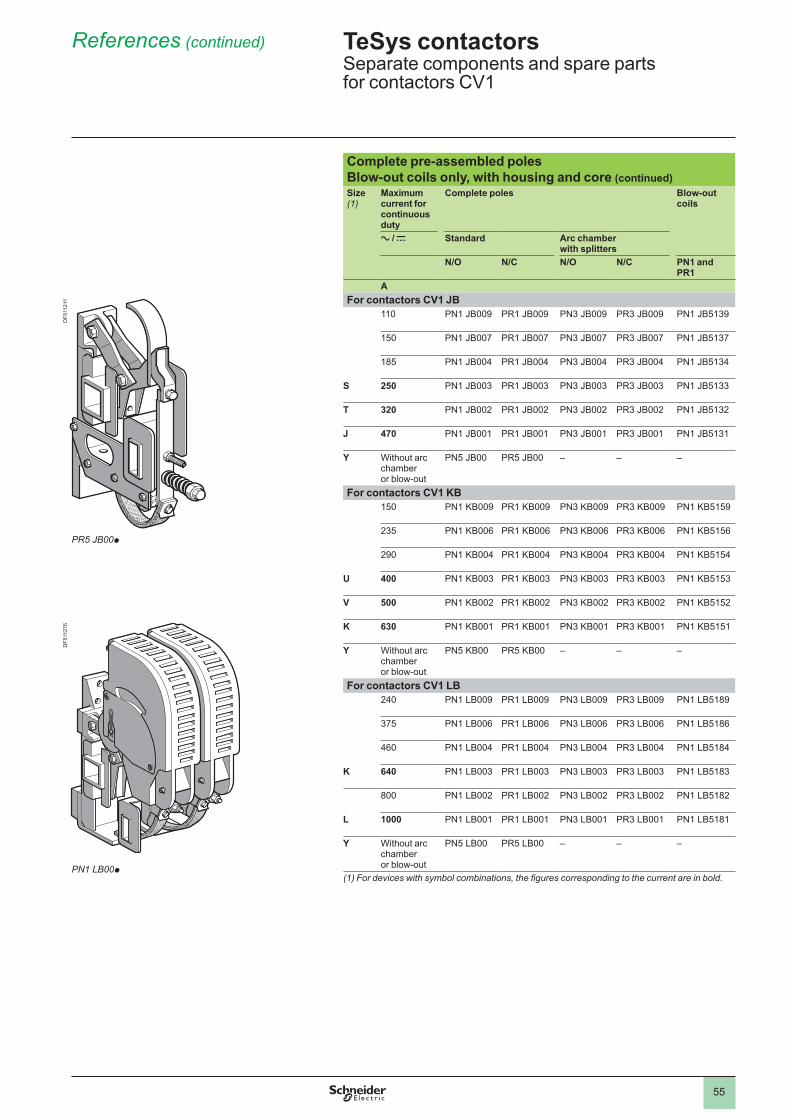
55
References (continued)
Complete pre-assembled polesBlow-out coils only, with housing and core (continued)Size (1)
Maximum current for continuous duty
Complete poles Blow-out coils
a / c Standard Arc chamber with splitters
N/O N/C N/O N/C PN1 and PR1
AFor contactors CV1 JB
PN1 JB009 PR1 JB009 PN3 JB009 PR3 JB009 PN1 JB5139
150 PN1 JB007 PR1 JB007 PN3 JB007 PR3 JB007 PN1 JB5137
185 PN1 JB004 PR1 JB004 PN3 JB004 PR3 JB004 PN1 JB5134
S 250 PN1 JB003 PR1 JB003 PN3 JB003 PR3 JB003 PN1 JB5133
T 320 PN1 JB002 PR1 JB002 PN3 JB002 PR3 JB002 PN1 JB5132
J 470 PN1 JB001 PR1 JB001 PN3 JB001 PR3 JB001 PN1 JB5131
Y Without arc chamber or blow-out
PN5 JB00 PR5 JB00 – – –
For contactors CV1 KB150 PN1 KB009 PR1 KB009 PN3 KB009 PR3 KB009 PN1 KB5159
235 PN1 KB006 PR1 KB006 PN3 KB006 PR3 KB006 PN1 KB5156
290 PN1 KB004 PR1 KB004 PN3 KB004 PR3 KB004 PN1 KB5154
U 400 PN1 KB003 PR1 KB003 PN3 KB003 PR3 KB003 PN1 KB5153
V 500 PN1 KB002 PR1 KB002 PN3 KB002 PR3 KB002 PN1 KB5152
K 630 PN1 KB001 PR1 KB001 PN3 KB001 PR3 KB001 PN1 KB5151
Y Without arc chamber or blow-out
PN5 KB00 PR5 KB00 – – –
For contactors CV1 LB240 PN1 LB009 PR1 LB009 PN3 LB009 PR3 LB009 PN1 LB5189
375 PN1 LB006 PR1 LB006 PN3 LB006 PR3 LB006 PN1 LB5186
460 PN1 LB004 PR1 LB004 PN3 LB004 PR3 LB004 PN1 LB5184
K 640 PN1 LB003 PR1 LB003 PN3 LB003 PR3 LB003 PN1 LB5183
800 PN1 LB002 PR1 LB002 PN3 LB002 PR3 LB002 PN1 LB5182
L 1000 PN1 LB001 PR1 LB001 PN3 LB001 PR3 LB001 PN1 LB5181
Y Without arc chamber or blow-out
PN5 LB00 PR5 LB00 – – –
(1) For devices with symbol combinations, the figures corresponding to the current are in bold.
TeSys contactors 0 Separate components and spare parts for contactors CV1
PR5 JB00p
PN1 LB00p
DF5
1121
1D
F511
276
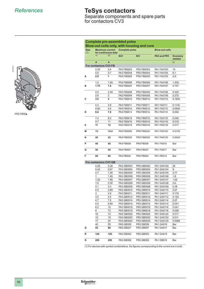
56
References
Complete pre-assembled polesBlow-out coils only, with housing and coreSize (1)
Maximum current for continuous duty
Complete poles Blow-out coils
a c N/O N/C PA3 and PR3 Economy resistor
A A W
For contactors CV3 FB0.35 0.4 PA3 FB0003 PR3 FB0003 PA1 FA5103 190.6 0.7 PA3 FB0004 PR3 FB0004 PA1 FA5104 6.1
A 0.9 1 PA3 FB0005 PR3 FB0005 PA1 FA5105 2.5
1.3 1.45 PA3 FB0006 PR3 FB0006 PA1 FA5106 1.335B 1.75 1.9 PA3 FB0007 PR3 FB0007 PA1 FA5107 0.747
2.2 2.45 PA3 FB0008 PR3 FB0008 PA1 FA5108 0.4252.6 3 PA3 FB0009 PR3 FB0009 PA1 FA5109 0.272
C 3.6 4 PA3 FB0010 PR3 FB0010 PA1 FA5110 0.1655
4.3 4.8 PA3 FB0011 PR3 FB0011 PA1 FA5111 0.11354.85 5.4 PA3 FB0012 PR3 FB0012 PA1 FA5112 0.0854
D 6.8 7.6 PA3 FB0014 PR3 FB0014 PA1 FA5114 0.052
7.4 8.2 PA3 FB0015 PR3 FB0015 PA1 FA5115 0.0459.7 PA3 FB0016 PR3 FB0016 PA1 FA5116 0.019
E 11 12 PA3 FB0018 PR3 FB0018 PA1 FA5118 0.017
M 13 14.5 PA3 FB0020 PR3 FB0020 PA1 FA5120 0.0125
N 20 22 PA3 FB0025 PR3 FB0025 PA1 FA5125 0.0043
P 40 45 PA3 FB009 PR3 FB009 PA1 FA519 Bar
Q 50 55 PA3 FB007 PR3 FB007 PA1 FA517 Bar
F 80 80 PA3 FB004 PR3 FB004 PA1 FB514 Bar
For contactors CV3 GB0.25 0.38 PA3 GB0003 PR3 GB0003 PA1 GA5103 280.45 0.67 PA3 GB0004 PR3 GB0004 PA1 GA5104 90.7 1.05 PA3 GB0005 PR3 GB0005 PA1 GA5105 3.77 1.45 PA3 GB0006 PR3 GB0006 PA1 GA5106 1.81.25 1.95 PA3 GB0007 PR3 GB0007 PA1 GA5107 1.021.6 2.55 PA3 GB0008 PR3 GB0008 PA1 GA5108 0.62.1 3.3 PA3 GB0009 PR3 GB0009 PA1 GA5109 0.382.5 3.85 PA3 GB0010 PR3 GB0010 PA1 GA5110 0.273 4.8 PA3 GB0011 PR3 GB0011 PA1 GA5111 0.1753.5 5.5 PA3 GB0012 PR3 GB0012 PA1 GA5112 0.1234.7 7.5 PA3 GB0014 PR3 GB0014 PA1 GA5114 0.075.5 8.85 PA3 GB0015 PR3 GB0015 PA1 GA5115 0.0516.2 PA3 GB0016 PR3 GB0016 PA1 GA5116 0.0418 12 PA3 GB0018 PR3 GB0018 PA1 GA5118 0.026 15 PA3 GB0020 PR3 GB0020 PA1 GA5120 0.01712 19 PA3 GB0022 PR3 GB0022 PA1 GA5122 .17 24 PA3 GB0025 PR3 GB0025 PA1 GA5125 0.006840 55 PA3 GB009 PR3 GB009 PA1 GA519 Bar
Q 55 80 PA3 GB007 PR3 GB007 PA1 GA517 Bar
R 125 125 PA3 GB003 PR3 GB003 PA1 GA513 Bar
G 200 200 PA3 GB002 PR3 GB002 PA1 GB512 Bar
(1) For devices with symbol combinations, the figures corresponding to the current are in bold.
TeSys contactors 0 Separate components and spare parts for contactors CV3
PR3 FB00p
DF5
1127
1
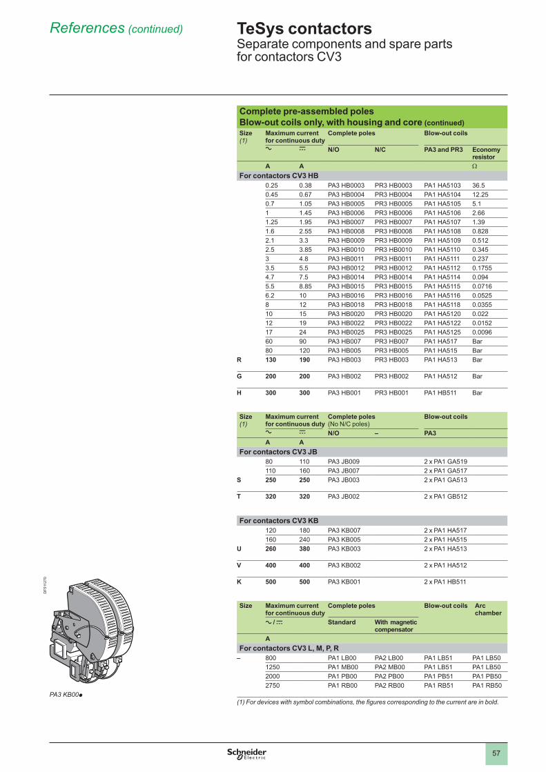
57
References (continued)
Complete pre-assembled polesBlow-out coils only, with housing and core (continued)Size (1)
Maximum current for continuous duty
Complete poles Blow-out coils
a c N/O N/C PA3 and PR3 Economy resistor
A A W
For contactors CV3 HB0.25 0.38 PA3 HB0003 PR3 HB0003 PA1 HA5103 36.50.45 0.67 PA3 HB0004 PR3 HB0004 PA1 HA5104 12.250.7 1.05 PA3 HB0005 PR3 HB0005 PA1 HA5105 5.1 1.45 PA3 HB0006 PR3 HB0006 PA1 HA5106 2.661.25 1.95 PA3 HB0007 PR3 HB0007 PA1 HA5107 1.391.6 2.55 PA3 HB0008 PR3 HB0008 PA1 HA5108 0.8282.1 3.3 PA3 HB0009 PR3 HB0009 PA1 HA5109 0.5122.5 3.85 PA3 HB0010 PR3 HB0010 PA1 HA5110 0.3453 4.8 PA3 HB0011 PR3 HB0011 PA1 HA5111 0.2373.5 5.5 PA3 HB0012 PR3 HB0012 PA1 HA5112 0.17554.7 7.5 PA3 HB0014 PR3 HB0014 PA1 HA5114 0.0945.5 8.85 PA3 HB0015 PR3 HB0015 PA1 HA5115 0.07166.2 PA3 HB0016 PR3 HB0016 PA1 HA5116 0.05258 12 PA3 HB0018 PR3 HB0018 PA1 HA5118 0.0355 15 PA3 HB0020 PR3 HB0020 PA1 HA5120 0.02212 19 PA3 HB0022 PR3 HB0022 PA1 HA5122 0.015217 24 PA3 HB0025 PR3 HB0025 PA1 HA5125 0.009660 90 PA3 HB007 PR3 HB007 PA1 HA517 Bar80 120 PA3 HB005 PR3 HB005 PA1 HA515 Bar
R 130 190 PA3 HB003 PR3 HB003 PA1 HA513 Bar
G 200 200 PA3 HB002 PR3 HB002 PA1 HA512 Bar
H 300 300 PA3 HB001 PR3 HB001 PA1 HB511 Bar
Size (1)
Maximum current for continuous duty
Complete poles(No N/C poles)
Blow-out coils
a c N/O – PA3A A
For contactors CV3 JB80 PA3 JB009 2 x PA1 GA519 160 PA3 JB007 2 x PA1 GA517
S 250 250 PA3 JB003 2 x PA1 GA513
T 320 320 PA3 JB002 2 x PA1 GB512
For contactors CV3 KB120 180 PA3 KB007 2 x PA1 HA517 160 240 PA3 KB005 2 x PA1 HA515
U 260 380 PA3 KB003 2 x PA1 HA513
V 400 400 PA3 KB002 2 x PA1 HA512
K 500 500 PA3 KB001 2 x PA1 HB511
Size Maximum current for continuous duty
Complete poles Blow-out coils Arc chamber
a / c Standard With magnetic compensator
AFor contactors CV3 L, M, P, R
– 800 PA1 LB00 PA2 LB00 PA1 LB51 PA1 LB50 1250 PA1 MB00 PA2 MB00 PA1 LB51 PA1 LB502000 PA1 PB00 PA2 PB00 PA1 PB51 PA1 PB50 2750 PA1 RB00 PA2 RB00 PA1 RB51 PA1 RB50
(1) For devices with symbol combinations, the figures corresponding to the current are in bold.
TeSys contactors 0 Separate components and spare parts for contactors CV3
PA3 KB00p
DF5
1127
0
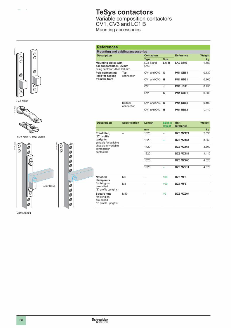
58
References
4.2
ReferencesMounting and cabling accessoriesDescription Contactors Reference Weight
Type Size kgMounting plates with bar support block, 36 mm fixing centres 120 or 150 mm
LC1 B and CV3
L to R LA9 B103 1.650
Pole connecting links for cabling from the front
Top connection
CV1 and CV3 G PN1 GB81 0.130
CV1 and CV3 H PN1 HB81 0.160
CV1 J PN1 JB81 0.250
CV1 K PN1 KB81 0.500
Bottom connection
CV1 and CV3 G PN1 GB82 .
CV1 and CV3 H PN1 HB82 .
Description Specification Length Sold in lots of
Unit reference
Weight
mm kgPre-drilled, “Z” profile uprights suitable for building chassis for variable composition contactors
– 1020 – DZ6 MZ121 2.590
1320 – DZ6 MZ151 3.350
1420 DZ6 MZ161 3.600
1620 DZ6 MZ181 4.110
1820 DZ6 MZ200 4.620
1920 – DZ6 MZ211 4.870
Notched clamp nuts for fixing on pre-drilled “Z” profile uprights
M6 – DZ5 MF6 –
M8 – DZ5 MF8 –
Square nuts for fixing on pre-drilled “Z” profile uprights
M10 – DZ6 MZ904 –
TeSys contactors 0 Variable composition contactors CV1, CV3 and LC1 BMounting accessories
LA9 B103
PN1 GB81 - PN1 GB82
DF5
1062
2D
F510
623
DF5
6728
2
DF5
6728
3
LA9 B103
DZ6 MZppp
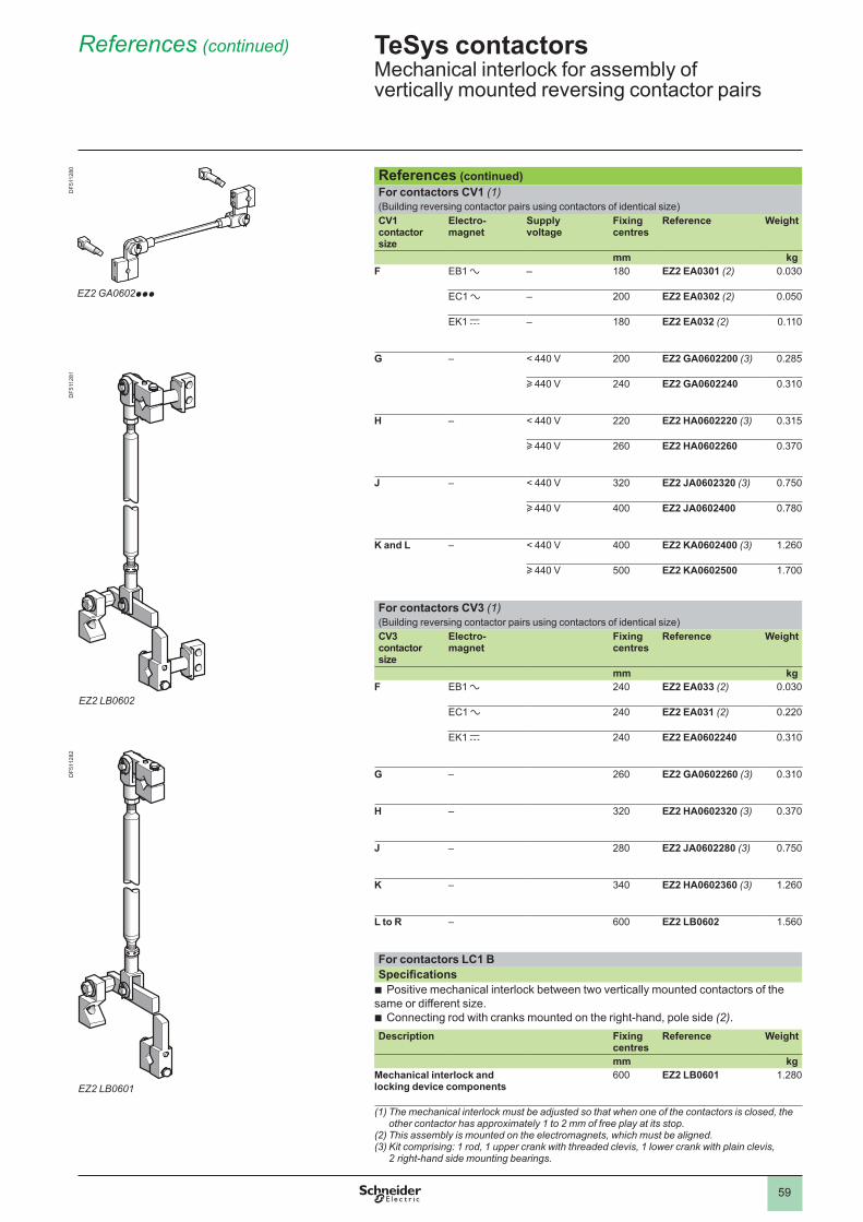
59
References (continued)
References (continued)For contactors CV1 (1) (Building reversing contactor pairs using contactors of identical size)CV1 contactor size
Electro- magnet
Supply voltage
Fixing centres
Reference Weight
mm kgF EB1 a – 180 EZ2 EA0301 (2) 0.030
EC1 a – 200 EZ2 EA0302 (2) 0.050
EK1 c – 180 EZ2 EA032 (2) .
G – < 440 V 200 EZ2 GA0602200 (3) 0.285
u 440 V 240 EZ2 GA0602240 0.310
H – < 440 V 220 EZ2 HA0602220 (3) 0.315
u 440 V 260 EZ2 HA0602260 0.370
J – < 440 V 320 EZ2 JA0602320 (3) 0.750
u 440 V 400 EZ2 JA0602400 0.780
K and L – < 440 V 400 EZ2 KA0602400 (3) 1.260
u 440 V 500 EZ2 KA0602500 1.700
For contactors CV3 (1) (Building reversing contactor pairs using contactors of identical size)CV3 contactor size
Electro- magnet
Fixing centres
Reference Weight
mm kgF EB1 a 240 EZ2 EA033 (2) 0.030
EC1 a 240 EZ2 EA031 (2) 0.220
EK1 c 240 EZ2 EA0602240 0.310
G – 260 EZ2 GA0602260 (3) 0.310
H – 320 EZ2 HA0602320 (3) 0.370
J – 280 EZ2 JA0602280 (3) 0.750
K – 340 EZ2 HA0602360 (3) 1.260
L to R – 600 EZ2 LB0602 1.560
For contactors LC1 BSpecifications
Positive mechanical interlock between two vertically mounted contactors of the same or different size.
Connecting rod with cranks mounted on the right-hand, pole side (2) .
b
b
Description Fixing centres
Reference Weight
mm kgMechanical interlock and locking device components
600 EZ2 LB0601 1.280
(1) The mechanical interlock must be adjusted so that when one of the contactors is closed, the other contactor has approximately 1 to 2 mm of free play at its stop.
(2) This assembly is mounted on the electromagnets, which must be aligned.(3) Kit comprising: 1 rod, 1 upper crank with threaded clevis, 1 lower crank with plain clevis,
2 right-hand side mounting bearings.
TeSys contactors 0 Mechanical interlock for assembly of vertically mounted reversing contactor pairs
EZ2 GA0602ppp
EZ2 LB0602
EZ2 LB0601
DF5
1128
0D
F511
281
DF5
1128
2
60
Installation, maintenance
5.2
Installation and maintenance of CV1, CV3 and LC1 B contactorsInstallationFixing
In general, bar mounted contactors are fixed on 2 vertical uprights.
The fixing dimensions of the support bars are standardised as is the diameter of the fixing holes.
At each end of each bar there is a cut-out with notches, one vertical, the other horizontal.
For contactors:CV3, sizes L to RLC1 BCV1 KB and CV1 LB
the use of LA9 B103 bar mounting brackets is recommended, see page 58 .
bbb
TighteningIn order to obtain good mechanical resistance to vibration, we recommend that the bar be fixed directly to the 2 uprights using screws of diameter recommended for the contactor size.
MaintenanceBar mounted contactors require no special mechanical maintenance.
We recommend a periodic check of the main contacts.
Contacts which have performed numerous breaks may look as if they are worn. It is only by checking the compression gap that the degree of wear can be evaluated.
Never make adjustments to the compression gap before the contacts are replaced.
When the compression gap has reduced to 20-50% of its initial value, replace all of the contactor’s contacts.
After each change of contacts:Align the contacts to the initial compression dimension.Check the contact pressure of each contact (contactor closed electrically or
wedged mechanically).Clean the inner side walls of the arc chambers by scraping.Check tightness of the adjustment screws and nuts.
Note : d the contacts must never be filed, cleaned or greased.
bb
bb
Replacement partsWe recommend that the following spare parts be held in stock for servicing worn parts:
Electromagnet coils, pages 80 to 97 .Arc chambers and complete poles, pages 50 to 57 .Sets of contacts, pages 50 and 51 .Instantaneous and time delay auxiliary contacts, pages 50 and 51 .
bbbb
Setting characteristicsSee pages 61 to 67 .
TeSys contactors 0 Variable composition contactors
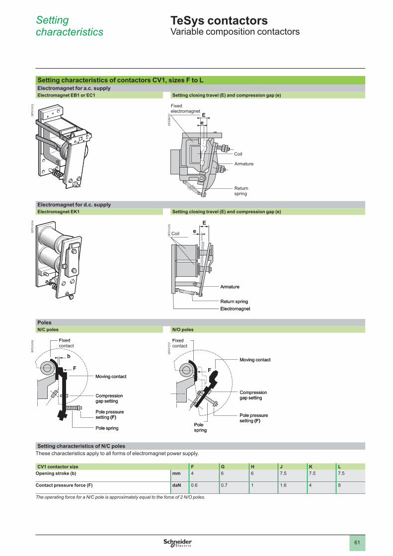
61
Setting characteristics
Setting characteristics of contactors CV1, sizes F to LElectromagnet for a.c. supplyElectromagnet EB1 or EC1 Setting closing travel (E) and compression gap (e)
DF5
3872
1
Fixedelectromagnet
Coil
Armature
Return spring
Electromagnet for d.c. supplyElectromagnet EK1 Setting closing travel (E) and compression gap (e)
DF5
1121
5
PolesN/C poles N/O poles
DF5
1121
7
Setting characteristics of N/C poles These characteristics apply to all forms of electromagnet power supply.
CV1 contactor size F G H J K LOpening stroke (b) mm 4 6 6 7.5 7.5 7.5
Contact pressure force (F) daN 0.6 0.7 1.6 4 8
The operating force for a N/C pole is approximately equal to the force of 2 N/O poles.
Coil
Armature
Return springElectromagnet
Coil
Armature
Return springElectromagnet
Fixed contact
Moving contact
Compression gap setting
Pole pressure setting (F)
Pole spring
Fixed contact
Moving contact
Compression gap setting
Pole pressure setting (F)
Pole spring
Fixed contact
Pole spring
Moving contact
Compression gap setting
Pole pressure setting (F)
Fixed contact
Pole spring
Moving contact
Compression gap setting
Pole pressure setting (F)
TeSys contactors 0 Variable composition contactors
DF5
1121
2D
F511
214
DF5
1121
6
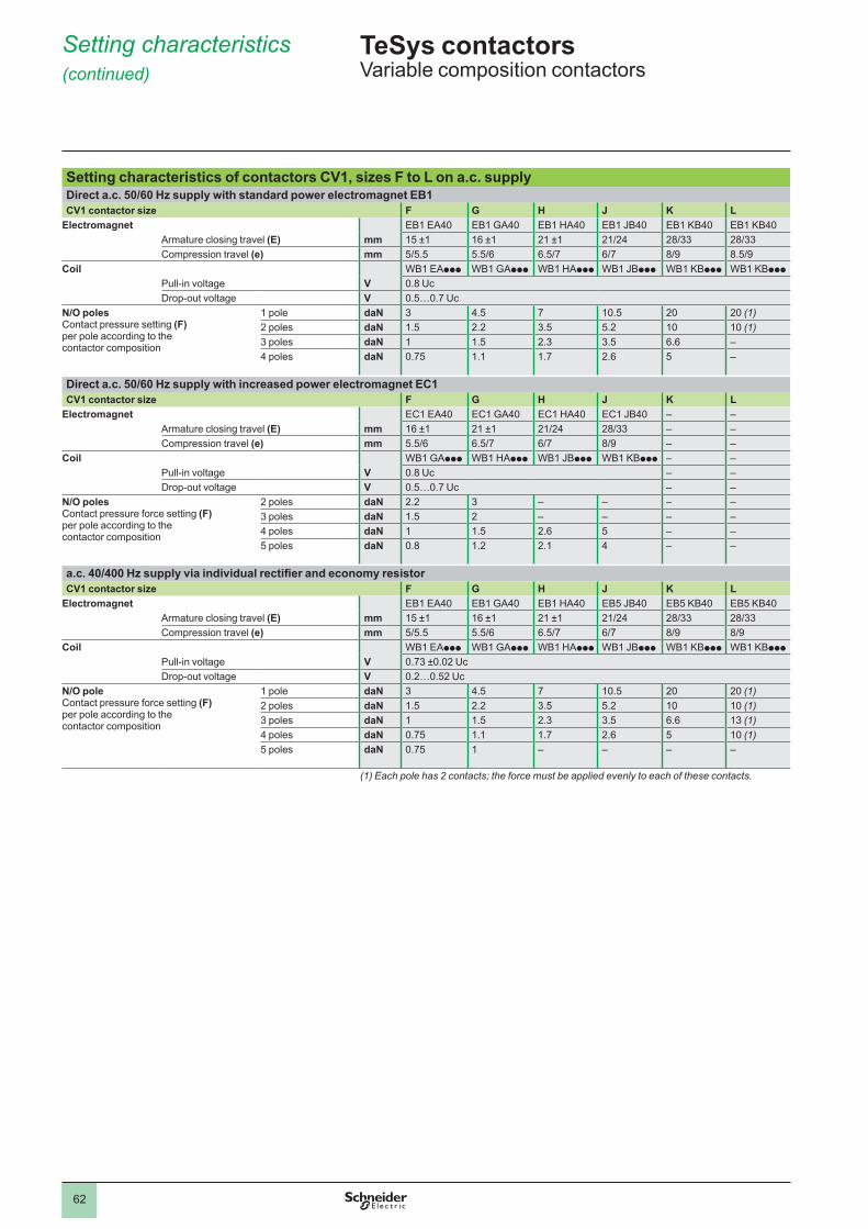
62
Setting characteristics (continued)
Setting characteristics of contactors CV1, sizes F to L on a.c. supplyDirect a.c. 50/60 Hz supply with standard power electromagnet EB1CV1 contactor size F G H J K L
Electromagnet EB1 EA40 EB1 GA40 EB1 HA40 EB1 JB40 EB1 KB40 EB1 KB40Armature closing travel (E) mm 15 ±1 16 ±1 21 ±1 21/24 28/33 28/33Compression travel (e) mm 5/5.5 5.5/6 6.5/7 6/7 8/9 8.5/9
Coil WB1 EAppp WB1 GAppp WB1 HAppp WB1 JBppp WB1 KBppp WB1 KBppp
Pull-in voltage V 0.8 UcDrop-out voltage V 0.5…0.7 Uc
N/O polesContact pressure setting (F) per pole according to the contactor composition
pole daN 3 4.5 7 10.5 20 20 (1)2 poles daN 1.5 2.2 3.5 5.2 (1)3 poles daN 1.5 2.3 3.5 6.6 –4 poles daN 0.75 . 1.7 2.6 5 –
Direct a.c. 50/60 Hz supply with increased power electromagnet EC1CV1 contactor size F G H J K L
Electromagnet EC1 EA40 EC1 GA40 EC1 HA40 EC1 JB40 – –Armature closing travel (E) mm 16 ±1 21 ±1 21/24 28/33 – –Compression travel (e) mm 5.5/6 6.5/7 6/7 8/9 – –
Coil WB1 GAppp WB1 HAppp WB1 JBppp WB1 KBppp – –Pull-in voltage V 0.8 Uc – –Drop-out voltage V 0.5…0.7 Uc – –
N/O polesContact pressure force setting (F) per pole according to the contactor composition
2 poles daN 2.2 3 – – – –3 poles daN 1.5 2 – – – –4 poles daN 1.5 2.6 5 – –5 poles daN 0.8 1.2 2.1 4 – –
a.c. 40/400 Hz supply via individual rectifier and economy resistorCV1 contactor size F G H J K L
Electromagnet EB1 EA40 EB1 GA40 EB1 HA40 EB5 JB40 EB5 KB40 EB5 KB40Armature closing travel (E) mm 15 ±1 16 ±1 21 ±1 21/24 28/33 28/33Compression travel (e) mm 5/5.5 5.5/6 6.5/7 6/7 8/9 8/9
Coil WB1 EAppp WB1 GAppp WB1 HAppp WB1 JBppp WB1 KBppp WB1 KBppp
Pull-in voltage V 0.73 ±0.02 UcDrop-out voltage V 0.2…0.52 Uc
N/O poleContact pressure force setting (F) per pole according to the contactor composition
pole daN 3 4.5 7 10.5 20 20 (1)2 poles daN 1.5 2.2 3.5 5.2 (1)3 poles daN 1.5 2.3 3.5 6.6 13 (1)4 poles daN 0.75 . 1.7 2.6 5 (1)5 poles daN 0.75 – – – –
(1) Each pole has 2 contacts; the force must be applied evenly to each of these contacts.
TeSys contactors 0 Variable composition contactors
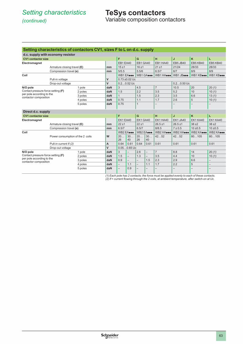
63
Setting characteristics (continued)
Setting characteristics of contactors CV1, sizes F to L on d.c. supplyd.c. supply with economy resistorCV1 contactor size F G H J K L
Electromagnet EB1 EA40 EB1 GA40 EB1 HA40 EB5 JB40 EB5 KB40 EB5 KB40Armature closing travel (E) mm 15 ±1 16 ±1 21 ±1 21/24 28/33 28/33Compression travel (e) mm 5/5.5 5.5/6 6.5/7 6/7 8/9 8/9
Coil WB1 EAppp WB1 GAppp WB1 HAppp WB1 JBppp WB1 KBppp WB1 KBppp
Pull-in voltage V 0.73 ±0.02 UcDrop-out voltage V 0.2…0.52 Uc 0.2…0.50 Uc
N/O poleContact pressure force setting (F) per pole according to the contactor composition
pole daN 3 4.5 7 10.5 20 20 (1)2 poles daN 1.5 2.2 3.5 5.2 (1)3 poles daN 1.5 2.3 3.5 6.6 13 (1)4 poles daN 0.75 . 1.7 2.6 5 (1)5 poles daN 0.75 – – – –
Direct d.c. supplyCV1 contactor size F G H J K L
Electromagnet EK1 EA40 EK1 GA40 EK1 HA40 EK1 JA40 EK1 KA40 EK1 KA40Armature closing travel (E) mm 22 ±1 22 ±1 26.5 ±1 26.5 ±1 38 ±2 38 ±2Compression travel (e) mm 6.5/7 6.5/7 8/8.5 7 ± 0.5 10 ±0.5 10 ±0.5
Coil WB2 EAppp WB2 EAppp WB2 HAppp WB2 HAppp WB2 KAppp WB2 KAppp
Power consumption of the 2 coils W 20… 26
30… 40
20… 26
30… 40
42…52 42…52 80…105 80…105
Pull-in current If (2) A 0.64 0.61 0.64 0.61 0.61 0.61 0.61 0.61Drop-out voltage V 0.05…0.65 Uc
N/O poleContact pressure force setting (F) per pole according to the contactor composition
pole daN 3 – 2.6 – 7 8.8 14 20 (1)2 poles daN 1.5 – 1.3 – 3.5 4.4 (1)3 poles daN 0.9 – – 1.5 2.3 2.9 6.6 –4 poles daN – . – . 1.7 2.2 5 –5 poles daN – 0.9 – – – – – –
(1) Each pole has 2 contacts; the force must be applied evenly to each of these contacts.(2) If = current flowing through the 2 coils, at ambient temperature, after switch-on at Uc.
TeSys contactors 0 Variable composition contactors
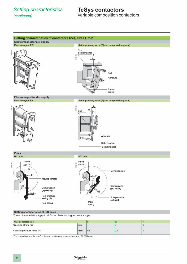
64
Setting characteristics (continued)
Setting characteristics of contactors CV3, sizes F to KElectromagnet for a.c. supplyElectromagnet EB1 Setting closing travel (E) and compression gap (e)
Fixedelectromagnet
Coil
Armature
Return spring
Electromagnet for d.c. supplyElectromagnet EK1 Setting closing travel (E) and compression gap (e)
PolesN/C pole N/O pole
Setting characteristics of N/C polesThese characteristics apply to all forms of electromagnet power supply.
CV3 contactor size F G HOpening stroke (b) mm 4 6 6
Contact pressure force (F) daN 0.6 0.7
The operating force for a N/C pole is approximately equal to the force of 2 N/O poles.
Coil
Armature
Return spring
Electromagnet
Coil
Armature
Return spring
Electromagnet
Fixed contact
Moving contact
Compression gap setting
Pole pressure setting (F)
Pole spring
Fixed contact
Moving contact
Compression gap setting
Pole pressure setting (F)
Pole spring
Fixed contact
Pole spring
Moving contact
Compression gap setting
Pole pressure setting (F)
Fixed contact
Pole spring
Moving contact
Compression gap setting
Pole pressure setting (F)
TeSys contactors 0 Variable composition contactors
DF5
1121
2
DF5
3872
1
DF5
1121
4
DF5
1121
5
DF5
1121
6
DF5
1121
7
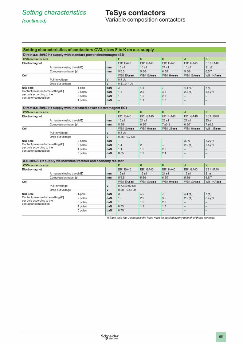
65
Setting characteristics (continued)
Setting characteristics of contactors CV3, sizes F to K on a.c. supplyDirect a.c. 50/60 Hz supply with standard power electromagnet EB1CV3 contactor size F G H J K
Electromagnet EB1 EA40 EB1 GA40 EB1 HA40 EB1 GA40 EB1 KA40Armature closing travel (E) mm 15 ±1 16 ±1 21 ±1 16 ±1 21 ±2Compression travel (e) mm 5/5.5 5.5/6 6.5/7 5.5/6 6.5/7
Coil WB1 EAppp WB1 GAppp WB1 HAppp WB1 GAppp WB1 HAppp
Pull-in voltage V 0.8 UcDrop-out voltage V 0.4…0.7 Uc
N/O poleContact pressure force setting (F) per pole according to the contactor composition
pole daN 3 4.5 7 4.4 (1) 7 (1)2 poles daN 1.5 2.2 3.5 2.2 (1) 3.4 (1)3 poles daN 1.5 2.3 – –4 poles daN – . 1.7 – –
Direct a.c. 50/60 Hz supply with increased power electromagnet EC1CV3 contactor size F G H J K
Electromagnet EC1 EA40 EC1 GA40 EC1 HA40 EC1 GA40 EC1 HB40Armature closing travel (E) mm 16 ±1 21 ±1 23 ±1 21 ±1 23 ±1Compression travel (e) mm 5.5/6 6.5/7 7 ±0.3 6.5/7 7 ±0.3
Coil WB1 GAppp WB1 HAppp WB1 JBppp WB1 HAppp WB1 JBppp
Pull-in voltage V 0.8 UcDrop-out voltage V 0.25…0.7 Uc
N/O poleContact pressure force setting (F) per pole according to the contactor composition
2 poles daN – – – 3 (1) 5.2 (1)3 poles daN 1.4 2 – 2.2 (1) 3.5 (1)4 poles daN . 1.5 2.6 – –5 poles daN 0.85 1.2 2.1 – –
a.c. 50/400 Hz supply via individual rectifier and economy resistorCV3 contactor size F G H J K
Electromagnet EB1 EA40 EB1 GA40 EB1 HA40 EB1 GA40 EB1 HA40Armature closing travel (E) mm 15 ±1 16 ±1 21 ±1 16 ±1 21 ±1Compression travel (e) mm 5/5.5 5.5/6 6.5/7 5.5/6 6.5/7
Coil WB1 EAppp WB1 GAppp WB1 HAppp WB1 GAppp WB1 HAppp
Pull-in voltage V 0.73 ±0.02 UcDrop-out voltage V 0.20…0.52 Uc
N/O poleContact pressure force setting (F) per pole according to the contactor composition
1-pole daN 3 4.5 7 4.4 (1) 7 (1)2 poles daN 1.5 2.2 3.5 2.2 (1) 3.4 (1)3 poles daN 1.5 2.3 – –4 poles daN 0.75 . 1.7 – –5 poles daN 0.75 – – –
(1) Each pole has 2 contacts; the force must be applied evenly to each of these contacts.
TeSys contactors 0 Variable composition contactors
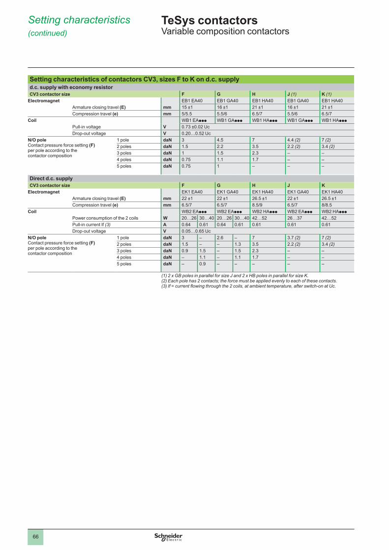
66
Setting characteristics (continued)
Setting characteristics of contactors CV3, sizes F to K on d.c. supplyd.c. supply with economy resistorCV3 contactor size F G H J (1) K (1)
Electromagnet EB1 EA40 EB1 GA40 EB1 HA40 EB1 GA40 EB1 HA40Armature closing travel (E) mm 15 ±1 16 ±1 21 ±1 16 ±1 21 ±1Compression travel (e) mm 5/5.5 5.5/6 6.5/7 5.5/6 6.5/7
Coil WB1 EAppp WB1 GAppp WB1 HAppp WB1 GAppp WB1 HAppp
Pull-in voltage V 0.73 ±0.02 UcDrop-out voltage V 0.20…0.52 Uc
N/O poleContact pressure force setting (F) per pole according to the contactor composition
pole daN 3 4.5 7 4.4 (2) 7 (2)2 poles daN 1.5 2.2 3.5 2.2 (2) 3.4 (2)3 poles daN 1.5 2.3 – –4 poles daN 0.75 . 1.7 – –5 poles daN 0.75 – – –
Direct d.c. supplyCV3 contactor size F G H J K
Electromagnet EK1 EA40 EK1 GA40 EK1 HA40 EK1 GA40 EK1 HA40 Armature closing travel (E) mm 22 ±1 22 ±1 26.5 ±1 22 ±1 26.5 ±1Compression travel (e) mm 6.5/7 6.5/7 8.5/9 6.5/7 8/8.5
Coil WB2 EAppp WB2 EAppp WB2 HAppp WB2 EAppp WB2 HAppp
Power consumption of the 2 coils W 20…26 30…40 20…26 30…40 42…52 26…37 42…52 Pull-in current If (3) A 0.64 0.61 0.64 0.61 0.61 0.61 0.61Drop-out voltage V 0.05…0.65 Uc
N/O poleContact pressure force setting (F) per pole according to the contactor composition
pole daN 3 – 2.6 – 7 3.7 (2) 7 (2)2 poles daN 1.5 – – 1.3 3.5 2.2 (2) 3.4 (2)3 poles daN 0.9 1.5 – 1.5 2.3 – –4 poles daN – . – . 1.7 – –5 poles daN – 0.9 – – – – –
(1) 2 x GB poles in parallel for size J and 2 x HB poles in parallel for size K.(2) Each pole has 2 contacts; the force must be applied evenly to each of these contacts.(3) If = current flowing through the 2 coils, at ambient temperature, after switch-on at Uc.
TeSys contactors 0 Variable composition contactors
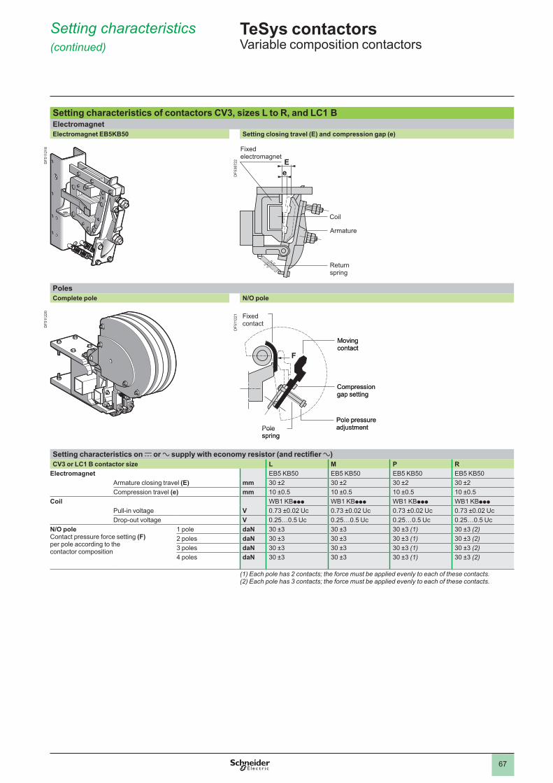
67
Setting characteristics (continued)
Setting characteristics of contactors CV3, sizes L to R, and LC1 B ElectromagnetElectromagnet EB5KB50 Setting closing travel (E) and compression gap (e)
Fixedelectromagnet
Coil
Armature
Return spring
PolesComplete pole N/O pole
Setting characteristics on c or a supply with economy resistor (and rectifier a)CV3 or LC1 B contactor size L M P R
Electromagnet EB5 KB50 EB5 KB50 EB5 KB50 EB5 KB50Armature closing travel (E) mm 30 ±2 30 ±2 30 ±2 30 ±2Compression travel (e) mm 10 ±0.5 10 ±0.5 10 ±0.5 10 ±0.5
Coil WB1 KBppp WB1 KBppp WB1 KBppp WB1 KBppp
Pull-in voltage V 0.73 ±0.02 Uc 0.73 ±0.02 Uc 0.73 ±0.02 Uc 0.73 ±0.02 UcDrop-out voltage V 0.25…0.5 Uc 0.25…0.5 Uc 0.25…0.5 Uc 0.25…0.5 Uc
N/O poleContact pressure force setting (F) per pole according to the contactor composition
pole daN 30 ±3 30 ±3 30 ±3 (1) 30 ±3 (2)2 poles daN 30 ±3 30 ±3 30 ±3 (1) 30 ±3 (2)3 poles daN 30 ±3 30 ±3 30 ±3 (1) 30 ±3 (2)4 poles daN 30 ±3 30 ±3 30 ±3 (1) 30 ±3 (2)
(1) Each pole has 2 contacts; the force must be applied evenly to each of these contacts.(2) Each pole has 3 contacts; the force must be applied evenly to each of these contacts.
Fixed contact
Pole spring
Moving contact
Compression gap setting
Pole pressure adjustment
Fixed contact
Pole spring
Moving contact
Compression gap setting
Pole pressure adjustment
TeSys contactors 0 Variable composition contactors
DF5
1121
8D
F511
220
DF5
3872
2D
F511
221
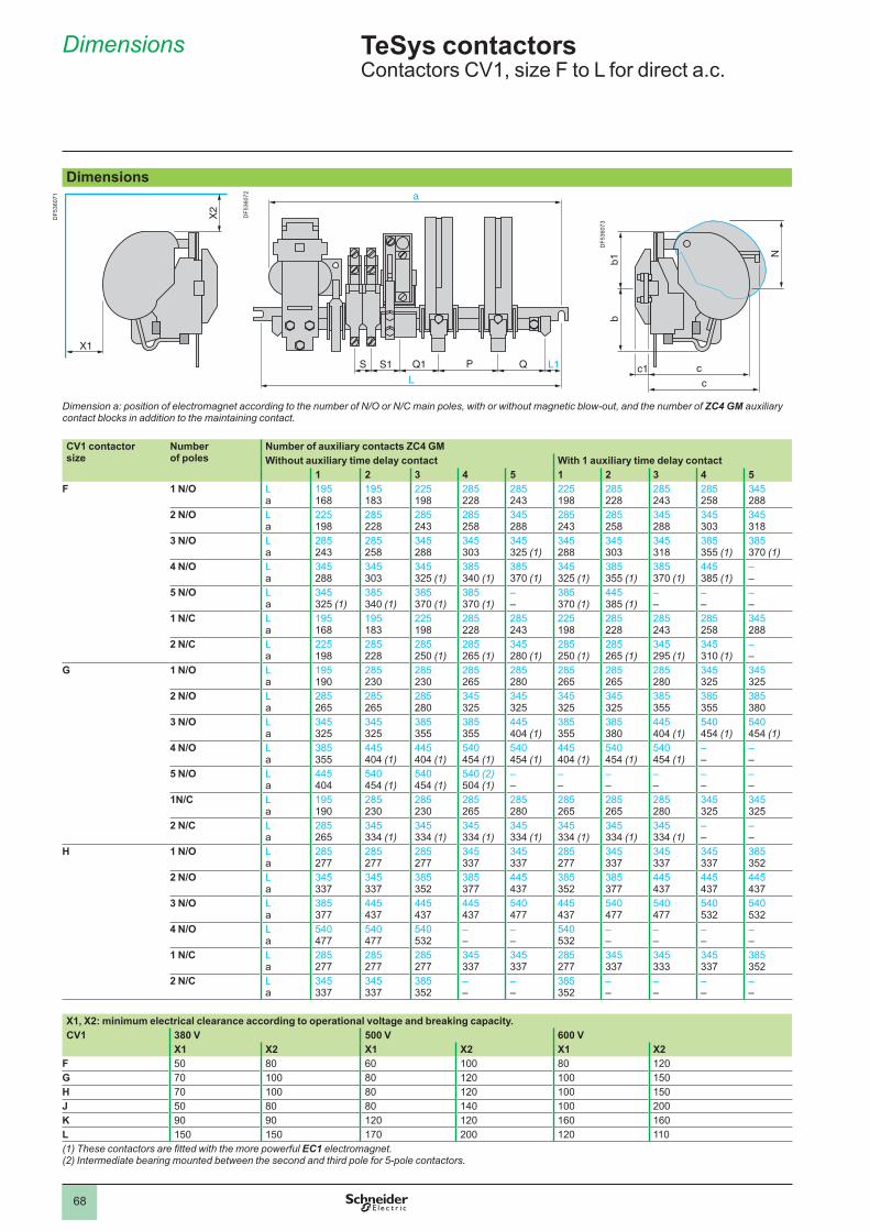
68
Dimensions
4.3
Dimensions
Dimension a: position of electromagnet according to the number of N/O or N/C main poles, with or without magnetic blow-out, and the number of ZC4 GM auxiliary contact blocks in addition to the maintaining contact.
CV1 contactor size
Number of poles
Number of auxiliary contacts ZC4 GMWithout auxiliary time delay contact With 1 auxiliary time delay contact
1 2 3 4 5 1 2 3 4 5F 1 N/O L
a195 168
195 183
225 198
285 228
285 243
225 198
285 228
285 243
285 258
345 288
2 N/O L a
225 198
285 228
285 243
285 258
345 288
285 243
285 258
345 288
345 303
345 318
3 N/O L a
285 243
285 258
345 288
345 303
345 325 (1)
345 288
345 303
345 318
385 355 (1)
385 370 (1)
4 N/O L a
345 288
345 303
345 325 (1)
385 340 (1)
385 370 (1)
345 325 (1)
385 355 (1)
385 370 (1)
445 385 (1)
– –
5 N/O L a
345 325 (1)
385 340 (1)
385 370 (1)
385 370 (1)
– –
385 370 (1)
445 385 (1)
– –
– –
– –
1 N/C L a
195 168
195 183
225 198
285 228
285 243
225 198
285 228
285 243
285 258
345 288
2 N/C L a
225 198
285 228
285 250 (1)
285 265 (1)
345 280 (1)
285 250 (1)
285 265 (1)
345 295 (1)
345 310 (1)
– –
G 1 N/O L a
195 190
285 230
285 230
285 265
285 280
285 265
285 265
285 280
345 325
345 325
2 N/O L a
285 265
285 265
285 280
345 325
345 325
345 325
345 325
385 355
385 355
385 380
3 N/O L a
345 325
345 325
385 355
385 355
445 404 (1)
385 355
385 380
445 404 (1)
540 454 (1)
540 454 (1)
4 N/O L a
385 355
445 404 (1)
445 404 (1)
540 454 (1)
540 454 (1)
445 404 (1)
540 454 (1)
540 454 (1)
– –
– –
5 N/O L a
445 404
540 454 (1)
540 454 (1)
540 (2) 504 (1)
– –
– –
– –
– –
– –
– –
1N/C L a
195 190
285 230
285 230
285 265
285 280
285 265
285 265
285 280
345 325
345 325
2 N/C L a
285 265
345 334 (1)
345 334 (1)
345 334 (1)
345 334 (1)
345 334 (1)
345 334 (1)
345 334 (1)
– –
– –
H 1 N/O L a
285 277
285 277
285 277
345 337
345 337
285 277
345 337
345 337
345 337
385 352
2 N/O L a
345 337
345 337
385 352
385 377
445 437
385 352
385 377
445 437
445 437
445 437
3 N/O L a
385 377
445 437
445 437
445 437
540 477
445 437
540 477
540 477
540 532
540 532
4 N/O L a
540 477
540 477
540 532
– –
– –
540 532
– –
– –
– –
– –
1 N/C L a
285 277
285 277
285 277
345 337
345 337
285 277
345 337
345 333
345 337
385 352
2 N/C L a
345 337
345 337
385 352
– –
– –
385 352
– –
– –
– –
– –
X1, X2: minimum electrical clearance according to operational voltage and breaking capacity. CV1 380 V 500 V 600 V
X1 X2 X1 X2 X1 X2F 50 80 60 80 120G 70 80 120 150H 70 80 120 150J 50 80 80 140 200K 90 90 120 120 160 160L 150 150 170 200 120 (1) These contactors are fitted with the more powerful EC1 electromagnet.(2) Intermediate bearing mounted between the second and third pole for 5-pole contactors.
X1
X2
X1
X2
S S1 Q1 P Q
L
L1
a
S S1 Q1 P Q
L
L1
a
bb1
N
c
cc1
bb1
N
c
cc1
TeSys contactors 0 Contactors CV1, size F to L for direct a.c.
DF5
3607
1
DF5
3607
2
DF5
3607
3
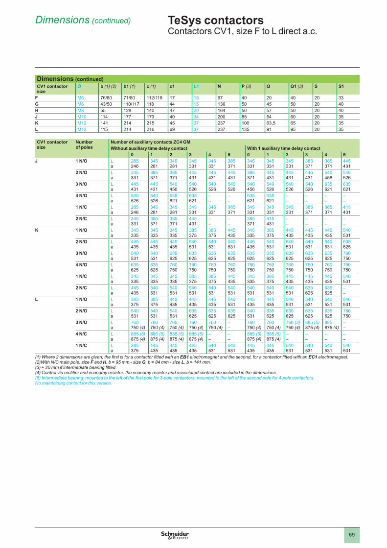
69
Dimensions (continued)
Dimensions (continued)CV1 contactor size
Ø b (1) (2) b1 (1) c (1) c1 L1 N P (3) Q Q1 (3) S S1
F M6 76/80 71/80 112/118 17 15 97 40 20 40 20 33G M6 43/50 110/117 118 44 15 136 50 45 50 20 40H M8 55 128 140 47 20 164 50 57 50 20 40J M10 114 177 173 40 34 200 85 54 60 20 35K M12 141 214 215 45 37 237 63,5 65 20 35L M12 115 214 216 69 37 237 135 91 95 20 35
CV1 contactor size
Numberof poles
Number of auxiliary contacts ZC4 GMWithout auxiliary time delay contact With 1 auxiliary time delay contact
0 1 2 3 4 5 0 1 2 3 4 5J 1 N/O L
a285 246
345 281
345 281
345 331
345 331
385 371
345 331
345 331
345 331
385 371
385 371
445 431
2 N/O L a
345 331
385 371
385 371
445 431
445 431
445 431
385 371
445 431
445 431
445 431
540 456
540 526
3 N/O L a
445 431
445 431
540 456
540 526
540 526
540 526
540 456
540 526
540 526
540 526
635 621
635 621
4 N/O L a
540 526
540 526
635 621
635 621
– –
– –
635 621
635 621
– –
– –
– –
– –
1 N/C L a
285 246
345 281
345 281
345 331
345 331
385 371
345 331
345 331
345 331
385 371
385 371
415 431
2 N/C L a
345 331
385 371
385 371
445 431
– –
– –
385 371
415 431
– –
– –
– –
– –
K 1 N/O L a
345 335
345 335
345 335
385 375
385 375
445 435
345 335
385 375
445 435
445 435
445 435
540 531
2 N/O L a
445 435
445 435
445 435
540 531
540 531
540 531
445 435
540 531
540 531
540 531
540 531
635 625
3 N/O L a
540 531
540 531
635 625
635 625
635 625
635 625
635 625
635 625
635 625
635 625
635 625
760 750
4 N/O L a
635 625
635 625
760 750
760 750
760 750
760 750
760 750
760 750
760 750
760 750
760 750
760 750
1 N/C L a
345 335
345 335
345 335
385 375
385 375
445 435
345 335
385 375
445 435
445 435
445 435
540 531
2 N/C L a
445 435
540 531
540 531
540 531
540 531
540 531
540 531
540 531
540 531
635 625
635 625
– –
L 1 N/O L a
385 375
385 375
445 435
445 435
445 435
540 531
445 435
445 435
540 531
540 531
540 531
540 531
2 N/O L a
540 531
540 531
540 531
635 625
635 625
635 625
540 531
635 625
635 625
635 625
635 625
760 750
3 N/O L a
760 750 (4)
760 750 (4)
760 750 (4)
760 750 (4)
760 750 (4)
– –
760 750 (4)
760 750 (4)
760 (3) 750 (4)
885 (5) 875 (4)
885 875 (4)
– –
4 N/C L a
885 (5) 875 (4)
885 (5) 875 (4)
885 (5) 875 (4)
885 (5) 875 (4)
– –
– –
885 (5) 875 (4)
885 (5) 875 (4)
– –
– –
– –
– –
1 N/C L a
385 375
445 435
445 435
445 435
540 531
540 531
445 435
445 435
540 531
540 531
540 531
540 531
(1) Where 2 dimensions are given, the first is for a contactor fitted with an EB1 electromagnet and the second, for a contactor fitted with an EC1 electromagnet.(2)With N/C main pole: size F and H, b = 95 mm - size G, b = 84 mm - size L, b = 141 mm.(3) + 20 mm if intermediate bearing fitted. (4) Control via rectifier and economy resistor: the economy resistor and associated contact are included in the dimensions.(5) Intermediate bearing: mounted to the left of the first pole for 3-pole contactors, mounted to the left of the second pole for 4-pole contactors.No maintaining contact for this version.
TeSys contactors 0 Contactors CV1, size F to L direct a.c.
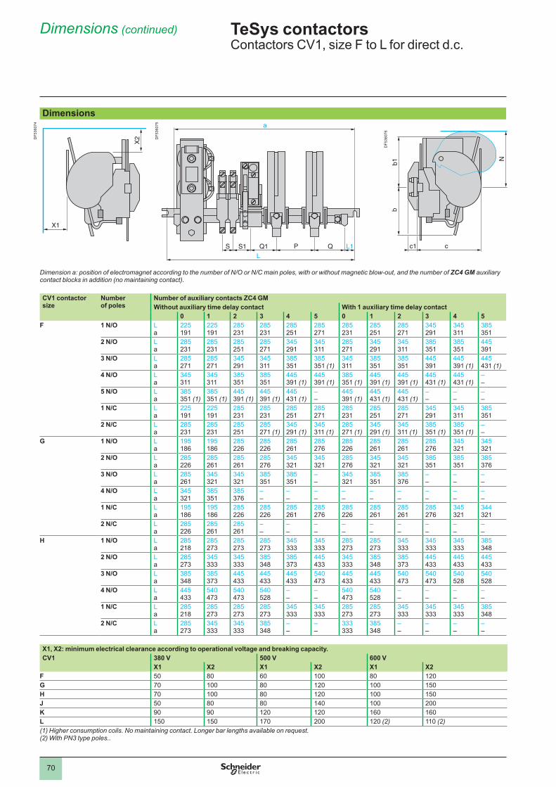
70
Dimensions (continued)
Dimensions
Dimension a: position of electromagnet according to the number of N/O or N/C main poles, with or without magnetic blow-out, and the number of ZC4 GM auxiliary contact blocks in addition (no maintaining contact).
CV1 contactor size
Number of poles
Number of auxiliary contacts ZC4 GMWithout auxiliary time delay contact With 1 auxiliary time delay contact
0 1 2 3 4 5 0 1 2 3 4 5F 1 N/O L
a225 191
225 191
285 231
285 231
285 251
285 271
285 231
285 251
285 271
345 291
345 311
385 351
2 N/O L a
285 231
285 231
285 251
285 271
345 291
345 311
285 271
345 291
345 311
385 351
385 351
445 391
3 N/O L a
285 271
285 271
345 291
345 311
385 351
385 351 (1)
345 311
385 351
385 351
445 391
445 391 (1)
445 431 (1)
4 N/O L a
345 311
345 311
385 351
385 351
445 391 (1)
445 391 (1)
385 351 (1)
445 391 (1)
445 391 (1)
445 431 (1)
445 431 (1)
– –
5 N/O L a
385 351 (1)
385 351 (1)
445 391 (1)
445 391 (1)
445 431 (1)
– –
445 391 (1)
445 431 (1)
445 431 (1)
– –
– –
– –
1 N/C L a
225 191
225 191
285 231
285 231
285 251
285 271
285 231
285 251
285 271
345 291
345 311
385 351
2 N/C L a
285 231
285 231
285 251
285 271 (1)
345 291 (1)
345 311 (1)
285 271 (1)
345 291 (1)
345 311 (1)
385 351 (1)
385 351 (1)
– –
G 1 N/O L a
195 186
195 186
285 226
285 226
285 261
285 276
285 226
285 261
285 261
285 276
345 321
345 321
2 N/O L a
285 226
285 261
285 261
285 276
345 321
345 321
285 276
345 321
345 321
385 351
385 351
385 376
3 N/O L a
285 261
345 321
345 321
385 351
385 351
– –
345 321
385 351
385 376
– –
– –
– –
4 N/O L a
345 321
385 351
385 376
– –
– –
– –
– –
– –
– –
– –
– –
– –
1 N/C L a
195 186
195 186
285 226
285 226
285 261
285 276
285 226
285 261
285 261
285 276
345 321
344 321
2 N/C L a
285 226
285 261
285 261
– –
– –
– –
– –
– –
– –
– –
– –
– –
H 1 N/O L a
285 218
285 273
285 273
285 273
345 333
345 333
285 273
285 273
345 333
345 333
345 333
385 348
2 N/O L a
285 273
345 333
345 333
385 348
385 373
445 433
345 333
385 348
385 373
445 433
445 433
445 433
3 N/O L a
385 348
385 373
445 433
445 433
445 433
540 473
445 433
445 433
540 473
540 473
540 528
540 528
4 N/O L a
445 433
540 473
540 473
540 528
– –
– –
540 473
540 528
– –
– –
– –
– –
1 N/C L a
285 218
285 273
285 273
285 273
345 333
345 333
285 273
285 273
345 333
345 333
345 333
385 348
2 N/C L a
285 273
345 333
345 333
385 348
– –
– –
333 333
385 348
– –
– –
– –
– –
X1, X2: minimum electrical clearance according to operational voltage and breaking capacity. CV1 380 V 500 V 600 V
X1 X2 X1 X2 X1 X2F 50 80 60 80 120G 70 80 120 150H 70 80 120 150J 50 80 80 140 200K 90 90 120 120 160 160L 150 150 170 200 120 (2) (2)(1) Higher consumption coils. No maintaining contact. Longer bar lengths available on request.(2) With PN3 type poles..
X1
X2
X1
X2
S S1 Q1 P Q
L
L1
a
S S1 Q1 P Q
L
L1
a
c1 c
b1b
N
c1 c
b1b
N
TeSys contactors 0 Contactors CV1, size F to L for direct d.c.
DF5
3607
4
DF5
3607
5
DF5
3607
6
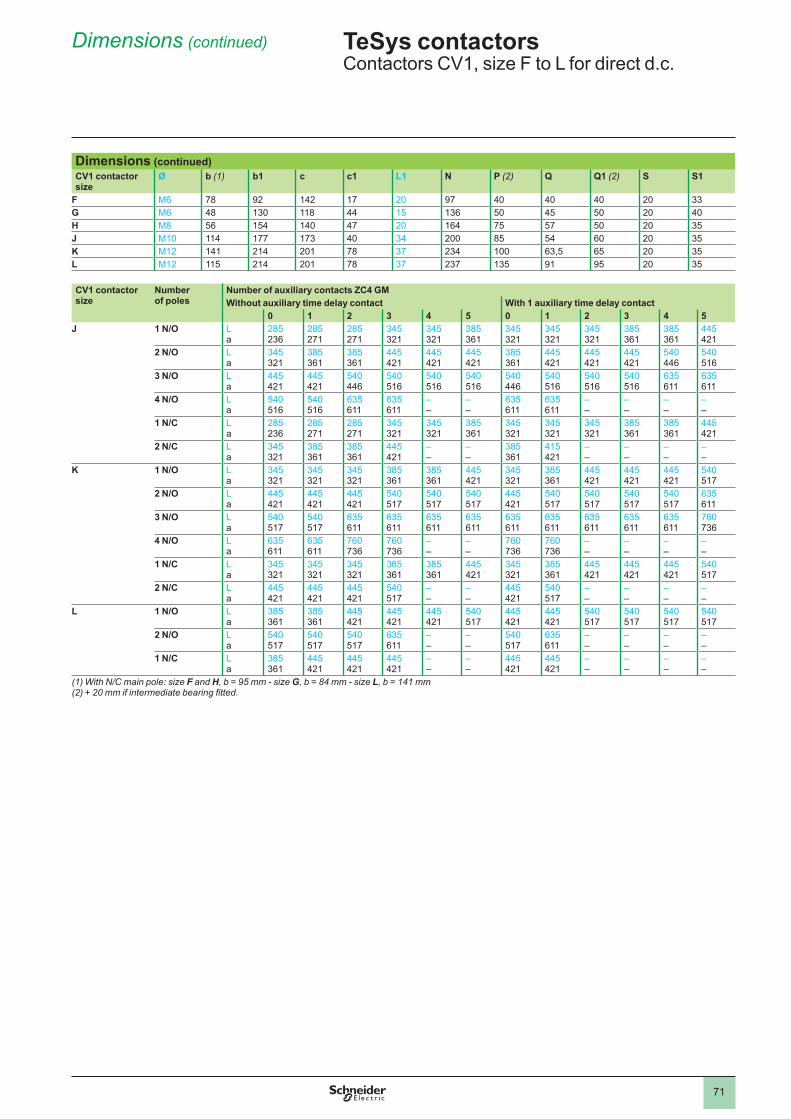
71
Dimensions (continued)
Dimensions (continued)CV1 contactor size
Ø b (1) b1 c c1 L1 N P (2) Q Q1 (2) S S1
F M6 78 92 142 17 20 97 40 40 40 20 33G M6 48 130 118 44 15 136 50 45 50 20 40H M8 56 154 140 47 20 164 75 57 50 20 35J M10 114 177 173 40 34 200 85 54 60 20 35K M12 141 214 201 78 37 234 63,5 65 20 35L M12 115 214 201 78 37 237 135 91 95 20 35
CV1 contactor size
Numberof poles
Number of auxiliary contacts ZC4 GMWithout auxiliary time delay contact With 1 auxiliary time delay contact
0 1 2 3 4 5 0 1 2 3 4 5J 1 N/O L
a285 236
285 271
285 271
345 321
345 321
385 361
345 321
345 321
345 321
385 361
385 361
445 421
2 N/O L a
345 321
385 361
385 361
445 421
445 421
445 421
385 361
445 421
445 421
445 421
540 446
540 516
3 N/O L a
445 421
445 421
540 446
540 516
540 516
540 516
540 446
540 516
540 516
540 516
635 611
635 611
4 N/O L a
540 516
540 516
635 611
635 611
– –
– –
635 611
635 611
– –
– –
– –
– –
1 N/C L a
285 236
285 271
285 271
345 321
345 321
385 361
345 321
345 321
345 321
385 361
385 361
445 421
2 N/C L a
345 321
385 361
385 361
445 421
– –
– –
385 361
415 421
– –
– –
– –
– –
K 1 N/O L a
345 321
345 321
345 321
385 361
385 361
445 421
345 321
385 361
445 421
445 421
445 421
540 517
2 N/O L a
445 421
445 421
445 421
540 517
540 517
540 517
445 421
540 517
540 517
540 517
540 517
635 611
3 N/O L a
540 517
540 517
635 611
635 611
635 611
635 611
635 611
635 611
635 611
635 611
635 611
760 736
4 N/O L a
635 611
635 611
760 736
760 736
– –
– –
760 736
760 736
– –
– –
– –
– –
1 N/C L a
345 321
345 321
345 321
385 361
385 361
445 421
345 321
385 361
445 421
445 421
445 421
540 517
2 N/C L a
445 421
445 421
445 421
540 517
– –
– –
445 421
540 517
– –
– –
– –
– –
L 1 N/O L a
385 361
385 361
445 421
445 421
445 421
540 517
445 421
445 421
540 517
540 517
540 517
540 517
2 N/O L a
540 517
540 517
540 517
635 611
– –
– –
540 517
635 611
– –
– –
– –
– –
1 N/C L a
385 361
445 421
445 421
445 421
– –
– –
445 421
445 421
– –
– –
– –
– –
(1) With N/C main pole: size F and H, b = 95 mm - size G, b = 84 mm - size L, b = 141 mm(2) + 20 mm if intermediate bearing fitted.
TeSys contactors 0 Contactors CV1, size F to L for direct d.c.
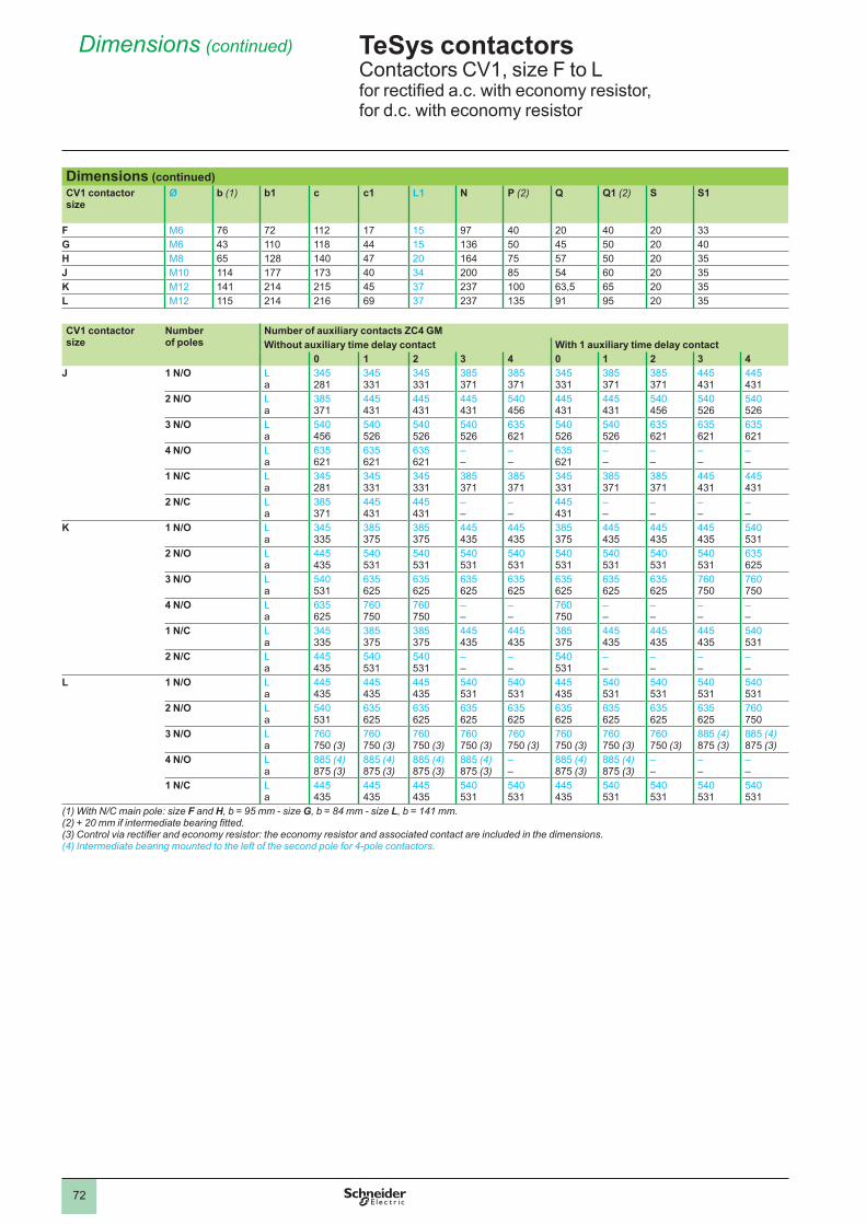
72
Dimensions (continued)
Dimensions (continued)CV1 contactor size
Ø b (1) b1 c c1 L1 N P (2) Q Q1 (2) S S1
F M6 76 72 112 17 15 97 40 20 40 20 33G M6 43 118 44 15 136 50 45 50 20 40H M8 65 128 140 47 20 164 75 57 50 20 35J M10 114 177 173 40 34 200 85 54 60 20 35K M12 141 214 215 45 37 237 63,5 65 20 35L M12 115 214 216 69 37 237 135 91 95 20 35
CV1 contactor size
Numberof poles
Number of auxiliary contacts ZC4 GMWithout auxiliary time delay contact With 1 auxiliary time delay contact
0 1 2 3 4 0 1 2 3 4J 1 N/O L
a345 281
345 331
345 331
385 371
385 371
345 331
385 371
385 371
445 431
445 431
2 N/O L a
385 371
445 431
445 431
445 431
540 456
445 431
445 431
540 456
540 526
540 526
3 N/O L a
540 456
540 526
540 526
540 526
635 621
540 526
540 526
635 621
635 621
635 621
4 N/O L a
635 621
635 621
635 621
– –
– –
635 621
– –
– –
– –
– –
1 N/C L a
345 281
345 331
345 331
385 371
385 371
345 331
385 371
385 371
445 431
445 431
2 N/C L a
385 371
445 431
445 431
– –
– –
445 431
– –
– –
– –
– –
K 1 N/O L a
345 335
385 375
385 375
445 435
445 435
385 375
445 435
445 435
445 435
540 531
2 N/O L a
445 435
540 531
540 531
540 531
540 531
540 531
540 531
540 531
540 531
635 625
3 N/O L a
540 531
635 625
635 625
635 625
635 625
635 625
635 625
635 625
760 750
760 750
4 N/O L a
635 625
760 750
760 750
– –
– –
760 750
– –
– –
– –
– –
1 N/C L a
345 335
385 375
385 375
445 435
445 435
385 375
445 435
445 435
445 435
540 531
2 N/C L a
445 435
540 531
540 531
– –
– –
540 531
– –
– –
– –
– –
L 1 N/O L a
445 435
445 435
445 435
540 531
540 531
445 435
540 531
540 531
540 531
540 531
2 N/O L a
540 531
635 625
635 625
635 625
635 625
635 625
635 625
635 625
635 625
760 750
3 N/O L a
760 750 (3)
760 750 (3)
760 750 (3)
760 750 (3)
760 750 (3)
760 750 (3)
760 750 (3)
760 750 (3)
885 (4) 875 (3)
885 (4) 875 (3)
4 N/O L a
885 (4) 875 (3)
885 (4) 875 (3)
885 (4) 875 (3)
885 (4) 875 (3)
– –
885 (4) 875 (3)
885 (4) 875 (3)
– –
– –
– –
1 N/C L a
445 435
445 435
445 435
540 531
540 531
445 435
540 531
540 531
540 531
540 531
(1) With N/C main pole: size F and H, b = 95 mm - size G, b = 84 mm - size L, b = 141 mm.(2) + 20 mm if intermediate bearing fitted.(3) Control via rectifier and economy resistor: the economy resistor and associated contact are included in the dimensions.(4) Intermediate bearing mounted to the left of the second pole for 4-pole contactors.
TeSys contactors 0 Contactors CV1, size F to L for rectified a.c. with economy resistor,for d.c. with economy resistor
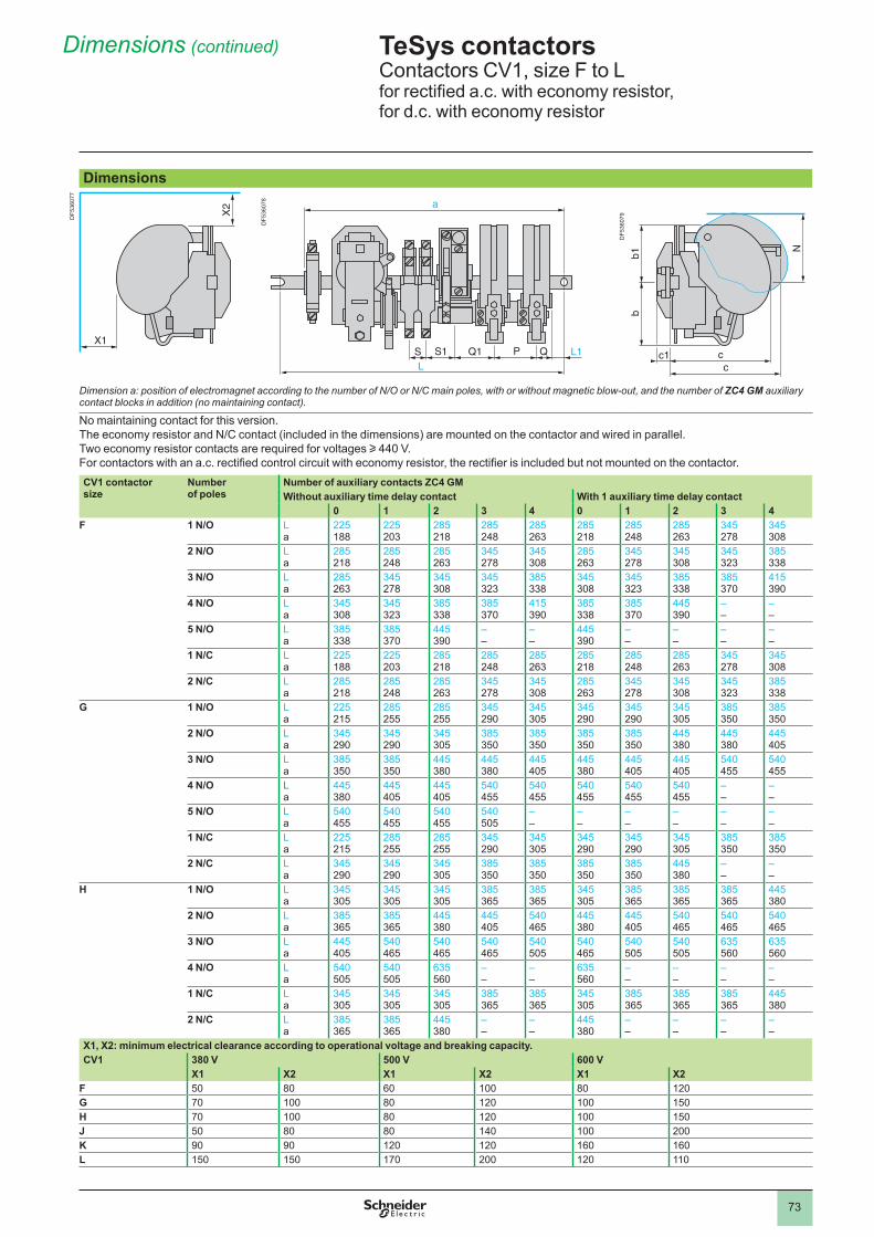
73
Dimensions (continued)
Dimensions
Dimension a: position of electromagnet according to the number of N/O or N/C main poles, with or without magnetic blow-out, and the number of ZC4 GM auxiliary contact blocks in addition (no maintaining contact).
No maintaining contact for this version.The economy resistor and N/C contact (included in the dimensions) are mounted on the contactor and wired in parallel.Two economy resistor contacts are required for voltages u 440 V.For contactors with an a.c. rectified control circuit with economy resistor, the rectifier is included but not mounted on the contactor.CV1 contactor size
Numberof poles
Number of auxiliary contacts ZC4 GMWithout auxiliary time delay contact With 1 auxiliary time delay contact
0 1 2 3 4 0 1 2 3 4F 1 N/O L
a225 188
225 203
285 218
285 248
285 263
285 218
285 248
285 263
345 278
345 308
2 N/O L a
285 218
285 248
285 263
345 278
345 308
285 263
345 278
345 308
345 323
385 338
3 N/O L a
285 263
345 278
345 308
345 323
385 338
345 308
345 323
385 338
385 370
415 390
4 N/O L a
345 308
345 323
385 338
385 370
415 390
385 338
385 370
445 390
– –
– –
5 N/O L a
385 338
385 370
445 390
– –
– –
445 390
– –
– –
– –
– –
1 N/C L a
225 188
225 203
285 218
285 248
285 263
285 218
285 248
285 263
345 278
345 308
2 N/C L a
285 218
285 248
285 263
345 278
345 308
285 263
345 278
345 308
345 323
385 338
G 1 N/O L a
225 215
285 255
285 255
345 290
345 305
345 290
345 290
345 305
385 350
385 350
2 N/O L a
345 290
345 290
345 305
385 350
385 350
385 350
385 350
445 380
445 380
445 405
3 N/O L a
385 350
385 350
445 380
445 380
445 405
445 380
445 405
445 405
540 455
540 455
4 N/O L a
445 380
445 405
445 405
540 455
540 455
540 455
540 455
540 455
– –
– –
5 N/O L a
540 455
540 455
540 455
540 505
– –
– –
– –
– –
– –
– –
1 N/C L a
225 215
285 255
285 255
345 290
345 305
345 290
345 290
345 305
385 350
385 350
2 N/C L a
345 290
345 290
345 305
385 350
385 350
385 350
385 350
445 380
– –
– –
H 1 N/O L a
345 305
345 305
345 305
385 365
385 365
345 305
385 365
385 365
385 365
445 380
2 N/O L a
385 365
385 365
445 380
445 405
540 465
445 380
445 405
540 465
540 465
540 465
3 N/O L a
445 405
540 465
540 465
540 465
540 505
540 465
540 505
540 505
635 560
635 560
4 N/O L a
540 505
540 505
635 560
– –
– –
635 560
– –
– –
– –
– –
1 N/C L a
345 305
345 305
345 305
385 365
385 365
345 305
385 365
385 365
385 365
445 380
2 N/C L a
385 365
385 365
445 380
– –
– –
445 380
– –
– –
– –
– –
X1, X2: minimum electrical clearance according to operational voltage and breaking capacity.CV1 380 V 500 V 600 V
X1 X2 X1 X2 X1 X2F 50 80 60 80 120G 70 80 120 150H 70 80 120 150J 50 80 80 140 200K 90 90 120 120 160 160L 150 150 170 200 120
X2
X1
X2
X1S S1 Q1 P Q L1L
a
S S1 Q1 P Q L1L
a
bb1
N
cc
c1
bb1
N
cc
c1
TeSys contactors 0 Contactors CV1, size F to Lfor rectified a.c. with economy resistor,for d.c. with economy resistor
DF5
3607
7
DF5
3607
8
DF5
3607
9
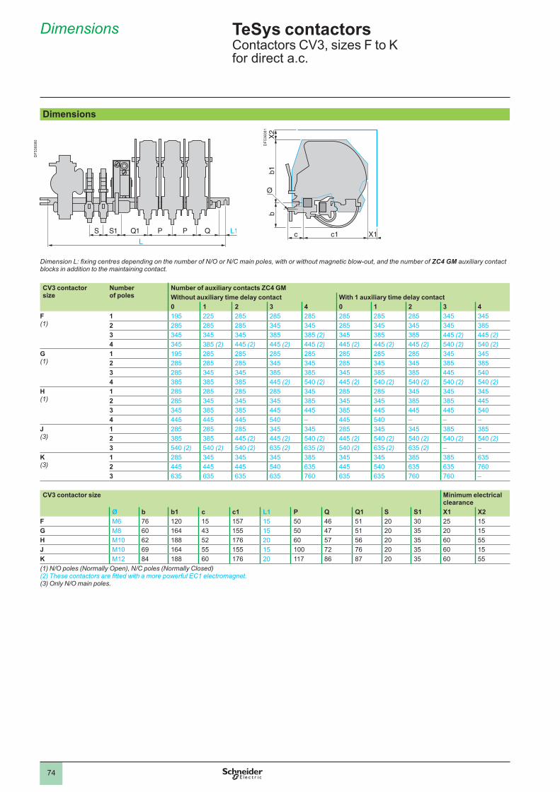
74
Dimensions
4.2
Dimensions
DF5
3608
1Dimension L: fixing centres depending on the number of N/O or N/C main poles, with or without magnetic blow-out, and the number of ZC4 GM auxiliary contact blocks in addition to the maintaining contact.
CV3 contactor size
Number of poles
Number of auxiliary contacts ZC4 GMWithout auxiliary time delay contact With 1 auxiliary time delay contact0 1 2 3 4 0 1 2 3 4
F (1)
1 195 225 285 285 285 285 285 285 345 3452 285 285 285 345 345 285 345 345 345 3853 345 345 345 385 385 (2) 345 385 385 445 (2) 445 (2)4 345 385 (2) 445 (2) 445 (2) 445 (2) 445 (2) 445 (2) 445 (2) 540 (2) 540 (2)
G (1)
1 195 285 285 285 285 285 285 285 345 3452 285 285 285 345 345 285 345 345 385 3853 285 345 345 385 385 345 385 385 445 5404 385 385 385 445 (2) 540 (2) 445 (2) 540 (2) 540 (2) 540 (2) 540 (2)
H (1)
1 285 285 285 285 345 285 285 345 345 3452 285 345 345 345 385 345 345 385 385 4453 345 385 385 445 445 385 445 445 445 5404 445 445 445 540 – 445 540 – – –
J (3)
1 285 285 285 345 345 285 345 345 385 3852 385 385 445 (2) 445 (2) 540 (2) 445 (2) 540 (2) 540 (2) 540 (2) 540 (2)3 540 (2) 540 (2) 540 (2) 635 (2) 635 (2) 540 (2) 635 (2) 635 (2) – –
K (3)
1 285 345 345 345 385 345 345 385 385 6352 445 445 445 540 635 445 540 635 635 7603 635 635 635 635 760 635 635 760 760 –
CV3 contactor size Minimum electrical clearance
Ø b b1 c c1 L1 P Q Q1 S S1 X1 X2F M6 76 120 15 157 15 50 46 51 20 30 25 15G M8 60 164 43 155 15 50 47 51 20 35 20 15H M10 62 188 52 176 20 60 57 56 20 35 60 55J M10 69 164 55 155 15 72 76 20 35 60 15K M12 84 188 60 176 20 117 86 87 20 35 60 55(1) N/O poles (Normally Open), N/C poles (Normally Closed)(2) These contactors are fitted with a more powerful EC1 electromagnet.(3) Only N/O main poles.
TeSys contactors 0 Contactors CV3, sizes F to K for direct a.c.
DF5
3608
0
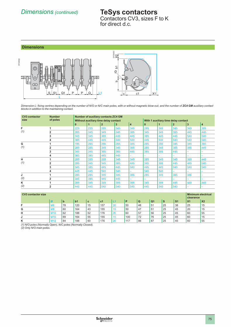
75
Dimensions (continued)
Dimensions
DF5
3608
3
Dimension L: fixing centres depending on the number of N/O or N/C main poles, with or without magnetic blow-out, and the number of ZC4 GM auxiliary contact blocks in addition to the maintaining contact.
CV3 contactor size
Number of poles
Number of auxiliary contacts ZC4 GMWithout auxiliary time delay contact With 1 auxiliary time delay contact0 1 2 3 4 0 1 2 3 4
F (1)
1 225 225 285 345 345 285 345 345 345 3852 285 345 345 345 385 345 345 385 445 4453 345 345 385 445 445 385 445 445 540 5404 385 445 445 540 540 445 540 540 540 540
G (1)
1 195 285 285 285 345 285 285 345 345 3852 285 285 345 345 385 285 345 385 385 4453 345 345 385 385 445 385 385 445 – –4 385 385 445 445 – – – – – –
H (1)
1 285 285 285 345 345 285 345 345 385 4452 285 345 345 385 445 345 385 445 445 5403 345 385 445 445 540 445 445 540 540 5404 445 445 540 540 – 540 540 – – –
J (2)
1 285 285 345 345 385 285 345 385 385 –2 345 385 445 445 – – – – – –
K (2)
1 285 345 345 385 385 345 385 445 445 4452 445 445 540 540 540 445 540 540 – –
CV3 contactor size Minimum electrical clearance
Ø b b1 c c1 L1 P Q Q1 S S1 X1 X2F M6 78 120 15 157 20 50 48 51 25 38 25 15G M8 60 164 43 155 15 50 47 51 25 45 20 15H M10 62 188 52 176 20 60 57 56 25 45 60 55J M10 69 164 55 155 15 72 76 25 45 60 15K M12 84 188 60 176 20 117 86 87 25 45 60 55(1) N/O poles (Normally Open), N/C poles (Normally Closed).(2) Only N/O main poles.
TeSys contactors 0 Contactors CV3, sizes F to K for direct d.c.
DF5
3608
2
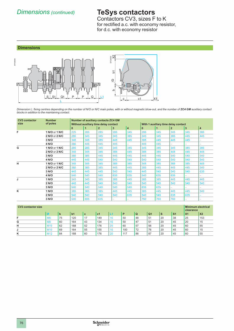
76
Dimensions (continued)
Dimensions
DF5
3608
5Dimension L: fixing centres depending on the number of N/O or N/C main poles, with or without magnetic blow-out, and the number of ZC4 GM auxiliary contact blocks in addition to the maintaining contact.
CV3 contactor size
Number of poles
Number of auxiliary contacts ZC4 GMWithout auxiliary time delay contact With 1 auxiliary time delay contact0 1 2 3 4 0 1 2 3 4
F 1 N/O or 1 N/C 225 285 285 285 345 285 345 345 345 3852 N/O or 2 N/C 285 345 345 345 385 345 345 385 445 4453 N/O 345 345 385 445 445 385 445 445 445 –4 N/O 385 445 445 445 – 445 445 – – –
G 1 N/O or 1 N/C 285 285 345 345 345 345 345 345 385 3852 N/O or 2 N/C 345 345 345 385 445 385 385 445 445 4453 N/O 385 385 445 445 445 445 445 540 540 5404 N/O 445 445 540 540 540 540 540 540 540 540
H 1 N/O or 1 N/C 345 345 345 385 385 345 385 385 385 4452 N/O or 2 N/C 385 385 385 445 445 385 445 445 445 5403 N/O 445 445 445 540 540 445 540 540 540 6354 N/O 540 540 540 635 635 540 635 635 – –
J 1 N/O 345 345 385 385 445 385 385 445 445 4452 N/O 445 445 540 540 540 540 540 540 540 5403 N/O 540 540 540 540 540 635 635 – – –
K 1 N/O 385 385 385 445 445 385 445 445 445 5402 N/O 540 540 540 540 635 540 540 635 635 –3 N/O 540 635 635 – – 760 760 760 – –
CV3 contactor size Minimum electrical clearance
Ø b b1 c c1 L1 P Q Q1 S S1 X1 X2F M6 75 120 17 149 15 50 48 51 20 38 25 153G M8 60 164 43 134 15 50 47 51 20 45 20 15H M10 62 188 52 176 20 60 57 56 20 45 60 55J M10 69 164 55 155 15 72 76 20 45 60 15K M12 84 188 60 176 20 117 86 87 20 45 60 55
TeSys contactors 0 Contactors CV3, sizes F to Kfor rectified a.c. with economy resistor, for d.c. with economy resistor
DF5
3608
4
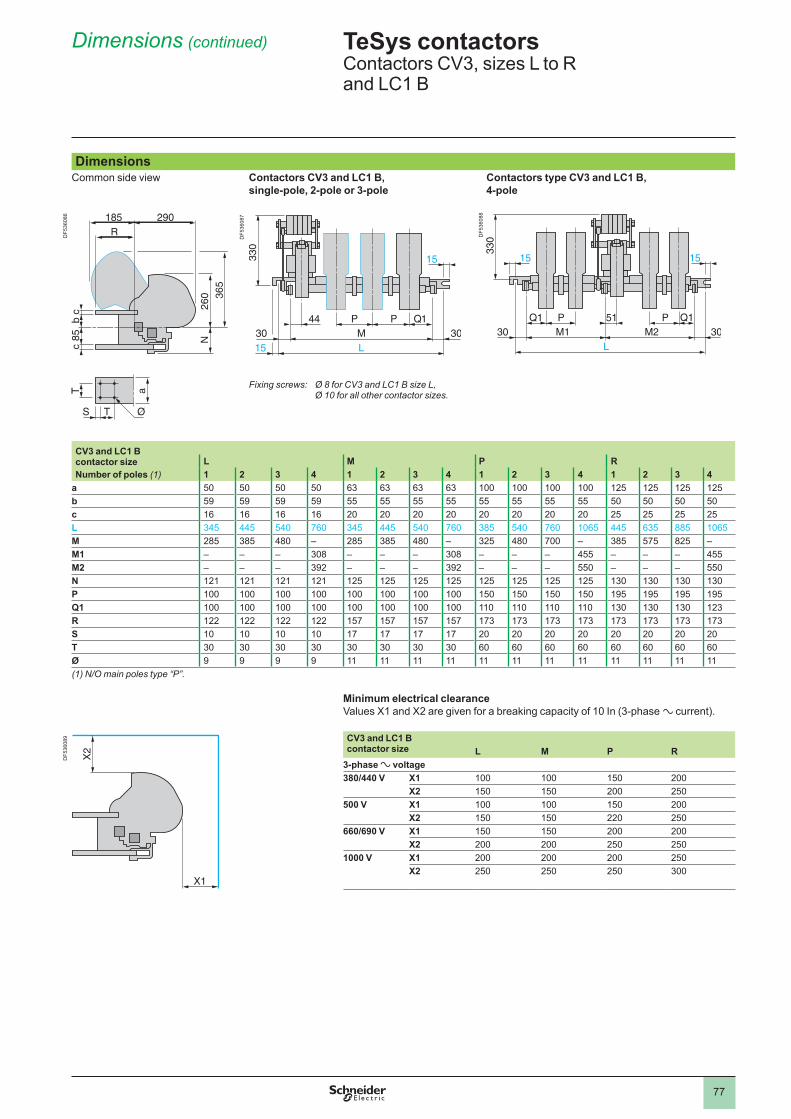
77
Dimensions (continued)
DimensionsCommon side view Contactors CV3 and LC1 B,
single-pole, 2-pole or 3-poleContactors type CV3 and LC1 B, 4-pole
Fixing screws: Ø 8 for CV3 and LC1 B size L, Ø 10 for all other contactor sizes.
CV3 and LC1 B contactor size L M P RNumber of poles (1) 1 2 3 4 1 2 3 4 1 2 3 4 1 2 3 4
a 50 50 50 50 63 63 63 63 125 125 125 125b 59 59 59 59 55 55 55 55 55 55 55 55 50 50 50 50c 16 16 16 16 20 20 20 20 20 20 20 20 25 25 25 25L 345 445 540 760 345 445 540 760 385 540 760 1065 445 635 885 1065M 285 385 480 – 285 385 480 – 325 480 700 – 385 575 825 –M1 – – – 308 – – – 308 – – – 455 – – – 455M2 – – – 392 – – – 392 – – – 550 – – – 550N 121 121 121 121 125 125 125 125 125 125 125 125 130 130 130 130P 150 150 150 150 195 195 195 195Q1 130 130 130 123R 122 122 122 122 157 157 157 157 173 173 173 173 173 173 173 173S 17 17 17 17 20 20 20 20 20 20 20 20T 30 30 30 30 30 30 30 30 60 60 60 60 60 60 60 60Ø 9 9 9 9 (1) N/O main poles type “P”.
Minimum electrical clearanceValues X1 and X2 are given for a breaking capacity of 10 In (3-phase a current).
CV3 and LC1 B contactor size L M P R
3-phase a voltage380/440 V X1 150 200
X2 150 150 200 250500 V X1 150 200
X2 150 150 220 250660/690 V X1 150 150 200 200
X2 200 200 250 2501000 V X1 200 200 200 250
X2 250 250 250 300
TeSys contactors 0 Contactors CV3, sizes L to Rand LC1 B
DF5
3608
6
DF5
3608
7
DF5
3608
8
DF5
3608
9
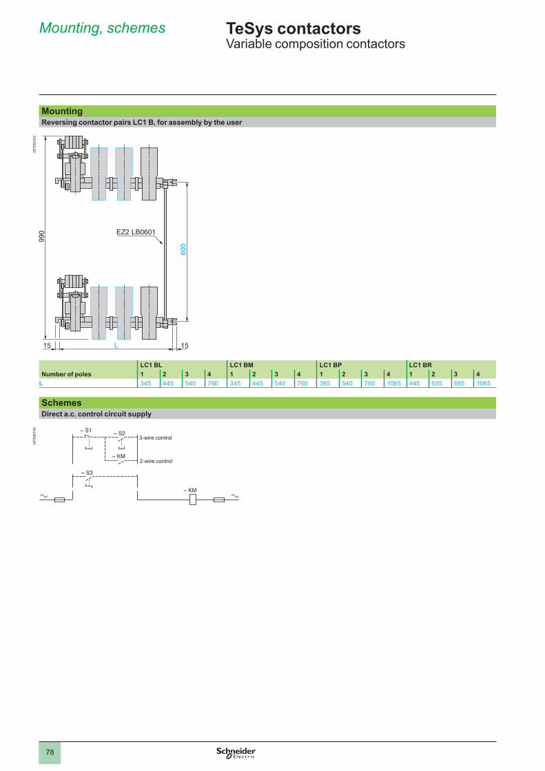
78
Mounting, schemes
4.2
MountingReversing contactor pairs LC1 B, for assembly by the user
LC1 BL LC1 BM LC1 BP LC1 BRNumber of poles 1 2 3 4 1 2 3 4 1 2 3 4 1 2 3 4
L 345 445 540 760 345 445 540 760 385 540 760 1065 445 635 885 1065
SchemesDirect a.c. control circuit supply
3-wire control
2-wire control
3-wire control
2-wire control
TeSys contactors Variable composition contactors
DF5
3610
3D
F536
105
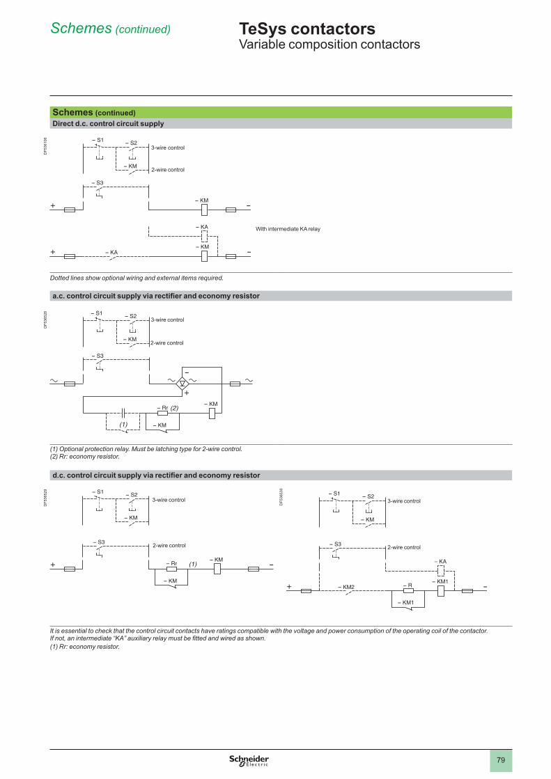
79
With intermediate KA relay
Schemes (continued)
(1)
3-wire control
2-wire control
Schemes (continued)Direct d.c. control circuit supply
Dotted lines show optional wiring and external items required.
a.c. control circuit supply via rectifier and economy resistor
(1) Optional protection relay. Must be latching type for 2-wire control.(2) Rr: economy resistor.
d.c. control circuit supply via rectifier and economy resistor
It is essential to check that the control circuit contacts have ratings compatible with the voltage and power consumption of the operating coil of the contactor.If not, an intermediate “KA” auxiliary relay must be fitted and wired as shown.(1) Rr: economy resistor.
3-wire control
2-wire control
3-wire control
2-wire control
(1)
(2)
3-wire control
2-wire control
(1)
(2)
3-wire control
2-wire control
3-wire control
2-wire control
3-wire control
2-wire control
TeSys contactors Variable composition contactors
DF5
3610
6D
F536
528
DF5
3652
9
DF5
3653
0
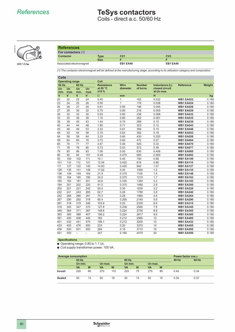
80
References
4.2
ReferencesFor contactors (1)Contactor Type CV1 CV3
Size F FAssociated electromagnet EB1 EA40 EB1 EA40
(1) The contactor electromagnet will be defined at the manufacturing stage, according to its utilisation category and composition.
CoilsOperating range Coil50 Hz 60 Hz Resistance
at 20 °C ±10 %
Wire diameter
Number of turns
Inductance (L) closed circuit at Un max.
Reference WeightUn min.
Un max.
Un min.
Un max.
V V V V W mm H kg20 22 22 24 0.45 162 0.032 WB1 EA022 0.18023 24 25 26 0.50 178 0.038 WB1 EA024 0.18025 26 27 29 0.61 0.95 196 0.045 WB1 EA026 0.18027 29 30 32 0.75 0.90 216 0.055 WB1 EA029 0.18030 32 33 35 0.93 0.85 238 0.068 WB1 EA032 0.18033 35 36 39 1.15 0.80 262 0.081 WB1 EA035 0.18036 39 40 43 1.44 0.75 289 . WB1 EA039 0.18040 44 44 48 1.80 0.71 323 0.12 WB1 EA043 0.18045 48 49 53 2.22 0.67 356 0.15 WB1 EA048 0.18049 53 54 58 2.75 0.63 392 0.18 WB1 EA053 0.18054 58 59 64 3.33 0.60 430 0.220 WB1 EA058 0.18059 64 65 70 3.72 0.60 472 0.27 WB1 EA064 0.18065 70 71 77 4.67 0.56 520 0.32 WB1 EA070 0.18071 78 78 85 5.73 0.53 572 0.39 WB1 EA077 0.18079 85 86 93 7.06 0.50 630 0.408 WB1 EA085 0.18086 92 94 8.49 0.475 685 0.560 WB1 EA092 0.18093 102 . 0.45 740 0.66 WB1 EA100 0.180 112 121 12.54 0.425 816 0.80 WB1 EA110 0.180 127 122 140 14.83 0.425 940 1.07 WB1 EA127 0.180128 135 141 148 17.62 0.40 1.2 WB1 EA135 0.180136 149 149 164 21.9 0.375 1.4 WB1 EA148 0.180150 164 165 180 24.5 0.375 1210 1.7 WB1 EA163 0.180165 183 181 201 33.6 0.335 1350 2.2 WB1 EA182 0.180184 201 202 220 41.5 0.315 1480 2.6 WB1 EA200 0.180202 221 221 242 50.4 0.30 1630 3.2 WB1 EA220 0.180222 241 243 265 62.7 0.28 1780 3.8 WB1 EA240 0.180242 266 266 291 70.3 0.28 1960 4.6 WB1 EA264 0.180267 290 292 318 85.4 0.265 2140 5.6 WB1 EA290 0.180291 318 319 346 103.9 0.25 2330 6.6 WB1 EA315 0.180319 345 347 370 127.8 0.236 2560 7.9 WB1 EA345 0.180346 364 371 387 148.6 0.224 2700 8.8 WB1 EA365 0.180365 380 388 407 156.2 0.224 2817 9.6 WB1 EA380 0.180381 400 408 440 182 0.212 2965 WB1 EA400 0.180401 432 441 475 199.1 0.212 3200 12 WB1 EA432 0.180433 455 476 500 233 0.20 3370 14 WB1 EA455 0.180456 500 501 550 284 0.19 3710 16 WB1 EA500 0.180501 550 – – 347 0,180 4070 20 WB1 EA550 0.180
SpecificationsOperating range: 0.85 to 1.1 Uc.Coil supply transformer power: 100 VA.
bb
Average consumption Power factor cos j50 Hz 60 Hz 50 Hz 60 HzUn min. Un max. Un min. Un max.VA W VA W VA W VA W
Inrush 220 90 270 225 75 275 95 0.40 0.34
Sealed 35 13 55 19 35 13 55 0.35 0.37
TeSys contactors 0 Coils - direct a.c. 50/60 Hz
WB1 EAp
DF5
3617
4
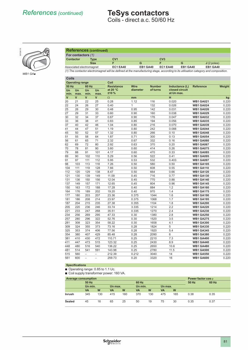
81
References (continued)
References (continued)For contactors (1)Contactor Type CV1 CV3
Size F G F G J (2 poles)Associated electromagnet EC1 EA40 EB1 GA40 EC1 EA40 EB1 GA40 EB1 GA40(1) The contactor electromagnet will be defined at the manufacturing stage, according to its utilisation category and composition.
CoilsOperating range Coil50 Hz 60 Hz Resistance
at 20 °C ±10 %
Wire diameter
Number of turns
Inductance (L) closed circuit at Un max.
Reference WeightUn min.
Un max.
Un min.
Un max.
V V V V W mm H kg20 21 22 25 0.28 1.12 116 0.020 WB1 GA021 0.22022 24 26 27 0.40 132 0.026 WB1 GA024 0.22025 26 29 30 0.48 0.95 142 0.031 WB1 GA026 0.22027 29 31 33 0.60 0.90 160 0.038 WB1 GA029 0.22030 32 34 37 0.67 0.90 176 0.047 WB1 GA032 0.22033 36 38 41 0.83 0.85 194 0.056 WB1 GA035 0.22037 40 42 46 1.04 0.80 216 0.070 WB1 GA039 0.22041 44 47 51 1.19 0.80 242 0.088 WB1 GA044 0.22045 50 52 57 1.32 0.80 266 . WB1 GA048 0.22051 55 58 64 1.87 0.71 300 0.13 WB1 GA054 0.22056 61 65 71 2.32 0.67 332 0.16 WB1 GA060 0.22062 69 72 80 2.92 0.63 370 0.20 WB1 GA067 0.22070 78 81 90 3.60 0.60 414 0.26 WB1 GA075 0.22079 88 91 4.17 0.60 470 0.33 WB1 GA085 0.22089 90 102 5.29 0.56 522 0.41 WB1 GA095 0.22091 97 112 5.95 0.53 532 0.403 WB1 GA097 0.22098 103 113 118 7.26 0.50 580 0.50 WB1 GA105 0.220104 119 128 7.66 0.50 608 0.55 WB1 GA110 0.220112 120 129 138 8.47 0.50 664 0.66 WB1 GA120 0.220121 130 139 149 11.09 0.45 716 0.77 WB1 GA130 0.220131 136 150 156 12.04 0.45 770 0.88 WB1 GA140 0.220137 149 157 171 12.65 0.45 804 0.96 WB1 GA145 0.220150 163 172 188 17.28 0.40 884 1.2 WB1 GA160 0.220164 176 189 202 19.20 0.40 970 1.4 WB1 GA175 0.220177 180 203 207 23.36 0.375 1044 1.6 WB1 GA190 0.220181 186 208 214 23.97 0.375 1068 1.7 WB1 GA195 0.220187 204 215 235 27.38 0.355 1104 1.8 WB1 GA200 0.220205 220 236 246 33.74 3.335 1214 2.2 WB1 GA220 0.220221 233 247 268 35.51 0.335 1270 2.4 WB1 GA230 0.220234 256 269 295 47.33 0.30 1380 2.8 WB1 GA250 0.220257 280 296 322 52.76 0.30 1520 3.5 WB1 GA275 0.220281 308 323 354 58.22 0.30 1658 4.1 WB1 GA300 0.220309 324 355 373 73.16 0.28 1824 5 WB1 GA330 0.220325 353 374 406 77.56 0.28 1920 5.4 WB1 GA345 0.220354 380 407 429 85.48 0.28 2090 6 WB1 GA380 0.220381 410 430 472 110.71 0.25 2210 7.3 WB1 GA400 0.220411 447 473 515 123.32 0.25 2430 8.9 WB1 GA440 0.220448 480 516 540 136.22 0.25 2650 10.6 WB1 GA480 0.220481 514 541 591 143.98 0.25 2780 11.5 WB1 GA500 0.220515 560 – – 212.39 0.212 3040 14 WB1 GA550 0.220561 600 – – 259.73 0.20 3320 16 WB1 GA600 0.220
SpecificationsOperating range: 0.85 to 1.1 Uc.Coil supply transformer power: 160 VA.
bb
Average consumption Power factor cos j50 Hz 60 Hz 50 Hz 60 HzUn min. Un max. Un min. Un max.VA W VA W VA W VA W
Inrush 345 130 415 160 370 130 475 165 0.38 0.35
Sealed 45 16 65 25 50 19 75 30 0.35 0.37
TeSys contactors 0 Coils - direct a.c. 50/60 Hz
WB1 GAp
DF5
3617
5
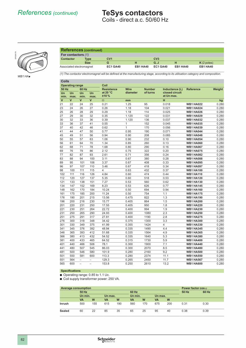
82
References (continued)
References (continued)For contactors (1)Contactor Type CV1 CV3
Size G H G, J H K (2 poles)Associated electromagnet EC1 GA40 EB1 HA40 EC1 GA40 EB1 HA40 EB1 HA40
(1) The contactor electromagnet will be defined at the manufacturing stage, according to its utilisation category and composition.
CoilsOperating range Coil50 Hz 60 Hz Resistance
at 20 °C ±10 %
Wire diameter
Number of turns
Inductance (L) closed circuit at Un max.
Reference WeightUn min.
Un max.
Un min.
Un max.
V V V V W mm H kg21 22 24 25 0.21 1.25 95 0.018 WB1 HA022 0.28023 24 26 27 0.26 1.18 104 0.021 WB1 HA024 0.28025 26 28 29 0.29 1.18 114 0.025 WB1 HA026 0.28027 29 30 32 0.35 1.120 122 0.031 WB1 HA029 0.28030 32 33 36 0.39 1.120 136 0.037 WB1 HA032 0.28033 36 37 41 0.55 152 0.045 WB1 HA035 0.28037 40 42 46 0.62 170 0.056 WB1 HA039 0.28041 44 47 50 0.77 0.95 190 0.071 WB1 HA044 0.28045 49 51 56 0.94 0.90 208 0.085 WB1 HA048 0.28050 55 57 63 1.06 0.90 232 . WB1 HA054 0.28056 61 64 70 1.34 0.85 260 0.13 WB1 HA060 0.28062 68 71 78 1.68 0.80 290 0.16 WB1 HA067 0.28069 76 79 86 2.12 0.75 322 0.20 WB1 HA075 0.28077 82 87 93 2.61 0.71 356 0.24 WB1 HA082 0.28083 88 94 3.11 0.67 380 0.28 WB1 HA088 0.28089 95 106 3.37 0.67 408 0.33 WB1 HA095 0.28096 97 107 3.46 0.67 418 0.34 WB1 HA097 0.28098 115 4 0.63 432 0.37 WB1 HA100 0.280102 116 126 4.84 0.60 474 0.44 WB1 HA110 0.280112 120 127 137 5.35 0.60 518 0.53 WB1 HA120 0.280121 133 138 151 7.27 0.53 560 0.62 WB1 HA130 0.280134 147 152 169 8.23 0.53 626 0.77 WB1 HA145 0.280148 162 170 184 10.24 0.50 694 0.94 WB1 HA160 0.280161 175 185 200 11.24 0.50 754 . WB1 HA175 0.280176 190 201 215 13.56 0.475 822 1.3 WB1 HA190 0.280196 200 216 230 15.77 0.405 864 1.5 WB1 HA200 0.280201 220 231 250 17.55 0.405 950 1.8 WB1 HA220 0.280221 230 251 264 22.72 0.400 994 1.9 WB1 HA230 0.280231 250 265 290 24.93 0.400 1080 2.3 WB1 HA250 0.280251 275 291 317 27.81 0.400 1190 2.8 WB1 HA275 0.280276 300 318 348 34.42 0.375 1300 3.3 WB1 HA300 0.280301 330 349 375 41.99 0.355 1424 4 WB1 HA330 0.280341 345 376 392 48.94 0.335 1490 4.4 WB1 HA345 0.280346 365 393 412 51.68 0.335 1564 4.9 WB1 HA365 0.280366 380 413 432 54.52 0.335 1640 5.3 WB1 HA380 0.280381 400 433 465 64.52 0.315 1730 5.9 WB1 HA400 0.280401 440 466 506 78.1 0.300 1900 7.1 WB1 HA440 0.280441 480 507 545 86.03 0.300 2070 8.5 WB1 HA480 0.280481 500 546 580 101.9 0.280 2160 9.2 WB1 HA500 0.280501 550 581 600 113.3 0.280 2374 . WB1 HA550 0.280551 564 – – 129.3 0.265 2450 11.7 WB1 HA567 0.280565 600 – – 153.8 0.250 2610 13.2 WB1 HA600 0.280
SpecificationsOperating range: 0.85 to 1.1 Uc.Coil supply transformer power: 250 VA.
bb
Average consumption Power factor cos j50 Hz 60 Hz 50 Hz 60 HzUn min. Un max. Un min. Un max.VA W VA W VA W VA W
Inrush 500 155 615 190 560 170 675 200 0.31 0.30
Sealed 60 22 85 35 65 25 95 40 0.38 0.39
TeSys contactors 0 Coils - direct a.c. 50/60 Hz
WB1 HAp
DF5
3617
6
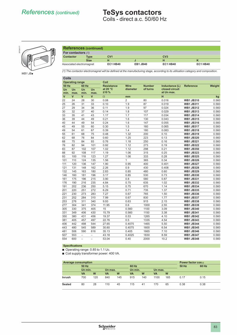
83
References (continued)
References (continued)For contactors (1)Contactor Type CV1 CV3
Size H J H KAssociated electromagnet EC1 HB40 EB1 JB40 EC1 HB40 EC1 HB40
(1) The contactor electromagnet will be defined at the manufacturing stage, according to its utilisation category and composition.
CoilsOperating range Coil50 Hz 60 Hz Resistance
at 20 °C ±10 %
Wire diameter
Number of turns
Inductance (L) closed circuit at Un max.
Reference WeightUn min.
Un max.
Un min.
Un max.
V V V V W mm H kg22 24 28 30 0.08 2 80 0.016 WB1 JB310 0.56025 26 31 33 . 1.9 87 0.019 WB1 JB311 0.56027 29 34 36 . 1.9 97 0.024 WB1 JB312 0.56030 32 37 40 0.14 1.8 107 0.029 WB1 JB313 0.56033 35 41 43 1.17 1.7 117 0.034 WB1 JB314 0.56036 39 44 49 0.21 1.6 130 0.043 WB1 JB315 0.56040 44 49 54 0.24 1.6 147 0.055 WB1 JB316 0.56045 49 55 60 0.30 1.5 160 0.065 WB1 JB317 0.56049 54 61 67 0.39 1.4 180 0.083 WB1 JB318 0.56055 61 68 75 0.48 1.32 200 . WB1 JB319 0.56062 68 76 84 0.60 1.25 223 0.13 WB1 JB320 0.56068 75 84 93 0.76 1.18 250 0.16 WB1 JB321 0.56076 82 94 0.92 1.12 273 0.19 WB1 JB322 0.56083 87 102 107 1.02 1.12 298 0.21 WB1 JB350 0.56088 92 108 117 1.19 1.06 315 0.25 WB1 JB323 0.56093 118 123 1.27 1.06 333 0.28 WB1 JB325 0.560 124 135 1.56 365 0.34 WB1 JB326 0.560 120 136 147 1.90 0.95 400 0.401 WB1 JB327 0.560121 131 148 162 2.26 0.9 430 0.408 WB1 JB328 0.560132 145 163 180 2.83 0.85 480 0.60 WB1 JB329 0.560146 160 181 196 3.17 0.85 530 0.73 WB1 JB330 0.560161 175 196 215 3.90 0.8 580 0.87 WB1 JB331 0.560176 190 216 235 4.84 0.75 635 1.02 WB1 JB332 0.560191 202 236 250 5.15 0.75 670 1.14 WB1 JB334 0.560201 220 251 272 6.29 0.71 735 1.37 WB1 JB335 0.560221 230 273 283 7.27 0.67 765 1.50 WB1 JB336 0.560231 252 284 310 7.99 0.67 830 1.77 WB1 JB337 0.560253 276 311 340 9.93 0.63 915 2.15 WB1 JB338 0.560277 304 341 374 11.95 0.6 2.55 WB1 JB339 0.560305 330 375 405 15 0.560 3.09 WB1 JB340 0.560331 349 406 430 15.79 0.560 1150 3.38 WB1 JB341 0.560350 380 431 456 19.37 0.53 1265 4.10 WB1 JB342 0.560381 405 457 497 22.76 0.5 1335 4.54 WB1 JB343 0.560406 442 498 544 27.65 0.4075 1465 5.50 WB1 JB344 0.560443 480 545 589 30.60 0.4075 1600 6.54 WB1 JB345 0.560481 506 590 616 35.13 0.405 1665 7.10 WB1 JB346 0.560507 553 – – 43.18 0.4025 1830 8.59 WB1 JB347 0.560554 600 – – 53.04 0.40 2000 10.2 WB1 JB348 0.560
SpecificationsOperating range: 0.85 to 1.1 Uc.Coil supply transformer power: 400 VA.
bb
Average consumption Power factor cos j50 Hz 60 Hz 50 Hz 60 HzUn min. Un max. Un min. Un max.VA W VA W VA W VA W
Inrush 700 120 840 145 915 140 165 0.17 0.15
Sealed 80 28 45 115 41 170 65 0.38 0.38
TeSys contactors 0 Coils - direct a.c. 50/60 Hz
WB1 JBp
DF5
3617
7
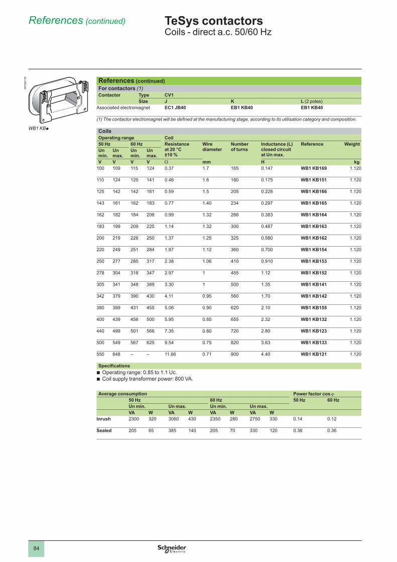
84
References (continued)
References (continued)For contactors (1)Contactor Type CV1
Size J K L (2 poles)Associated electromagnet EC1 JB40 EB1 KB40 EB1 KB40
(1) The contactor electromagnet will be defined at the manufacturing stage, according to its utilisation category and composition.
CoilsOperating range Coil50 Hz 60 Hz Resistance
at 20 °C ±10 %
Wire diameter
Number of turns
Inductance (L) closed circuit at Un max.
Reference WeightUn min.
Un max.
Un min.
Un max.
V V V V W mm H kg 109 115 124 0.37 1.7 165 0.147 WB1 KB169 1.120
124 125 141 0.46 1.6 180 0.175 WB1 KB151 1.120
125 142 142 161 0.59 1.5 205 0.228 WB1 KB166 1.120
143 161 162 183 0.77 1.40 234 0.297 WB1 KB165 1.120
162 182 184 208 0.99 1.32 266 0.383 WB1 KB164 1.120
183 199 209 225 1.14 1.32 300 0.487 WB1 KB163 1.120
200 219 226 250 1.37 1.25 325 0.580 WB1 KB162 1.120
220 249 251 284 1.87 1.12 360 0.700 WB1 KB154 1.120
250 277 285 317 2.38 1.06 410 0.910 WB1 KB153 1.120
278 304 318 347 2.97 455 1.12 WB1 KB152 1.120
305 341 348 389 3.30 500 1.35 WB1 KB141 1.120
342 379 390 430 4.11 0.95 560 1.70 WB1 KB142 1.120
380 399 431 455 5.06 0.90 620 2.10 WB1 KB155 1.120
400 439 456 500 5.95 0.85 655 2.32 WB1 KB132 1.120
440 499 501 566 7.35 0.80 720 2.80 WB1 KB123 1.120
500 549 567 625 9.54 0.75 820 3.63 WB1 KB133 1.120
550 648 – – 11.66 0.71 900 4.40 WB1 KB121 1.120
SpecificationsOperating range: 0.85 to 1.1 Uc.Coil supply transformer power: 800 VA.
bb
Average consumption Power factor cos j50 Hz 60 Hz 50 Hz 60 HzUn min. Un max. Un min. Un max.VA W VA W VA W VA W
Inrush 2300 320 3060 430 2350 280 2750 330 0.14 0.12
Sealed 205 65 385 140 205 70 330 120 0.36 0.36
TeSys contactors 0 Coils - direct a.c. 50/60 Hz
WB1 KBp
DF5
3617
8
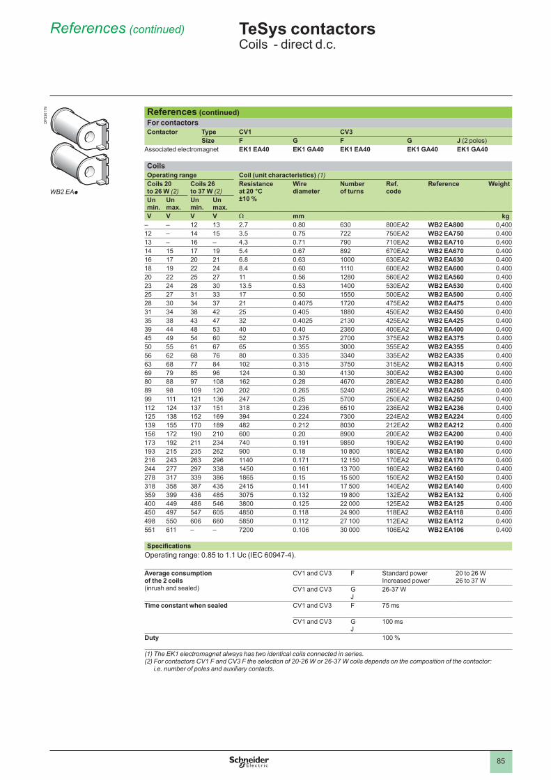
85
References (continued)
References (continued)For contactorsContactor Type CV1 CV3
Size F G F G J (2 poles)Associated electromagnet EK1 EA40 EK1 GA40 EK1 EA40 EK1 GA40 EK1 GA40
CoilsOperating range Coil (unit characteristics) (1)Coils 20 to 26 W (2)
Coils 26 to 37 W (2)
Resistance at 20 °C ±10 %
Wire diameter
Number of turns
Ref. code
Reference Weight
Un min.
Un max.
Un min.
Un max.
V V V V W mm kg– – 12 13 2.7 0.80 630 800EA2 WB2 EA800 0,40012 – 14 15 3.5 0.75 722 750EA2 WB2 EA750 0.40013 – 16 – 4.3 0.71 790 710EA2 WB2 EA710 0.40014 15 17 19 5.4 0.67 892 670EA2 WB2 EA670 0.40016 17 20 21 6.8 0.63 630EA2 WB2 EA630 0.40018 19 22 24 8.4 0.60 600EA2 WB2 EA600 0.40020 22 25 27 0.56 1280 560EA2 WB2 EA560 0.40023 24 28 30 13.5 0.53 1400 530EA2 WB2 EA530 0.40025 27 31 33 17 0.50 1550 500EA2 WB2 EA500 0.40028 30 34 37 21 0.4075 1720 475EA2 WB2 EA475 0.40031 34 38 42 25 0.405 1880 450EA2 WB2 EA450 0.40035 38 43 47 32 0.4025 2130 425EA2 WB2 EA425 0.40039 44 48 53 40 0.40 2360 400EA2 WB2 EA400 0.40045 49 54 60 52 0.375 2700 375EA2 WB2 EA375 0.40050 55 61 67 65 0.355 3000 355EA2 WB2 EA355 0.40056 62 68 76 80 0.335 3340 335EA2 WB2 EA335 0.40063 68 77 84 102 0.315 3750 315EA2 WB2 EA315 0.40069 79 85 96 124 0.30 4130 300EA2 WB2 EA300 0.40080 88 97 108 162 0.28 4670 280EA2 WB2 EA280 0.40089 98 109 120 202 0.265 5240 265EA2 WB2 EA265 0.40099 121 136 247 0.25 5700 250EA2 WB2 EA250 0.400112 124 137 151 318 0.236 6510 236EA2 WB2 EA236 0.400125 138 152 169 394 0.224 7300 224EA2 WB2 EA224 0.400139 155 170 189 482 0.212 8030 212EA2 WB2 EA212 0.400156 172 190 210 600 0.20 8900 200EA2 WB2 EA200 0.400173 192 211 234 740 0.191 9850 190EA2 WB2 EA190 0.400193 215 235 262 900 0.18 10 800 180EA2 WB2 EA180 0.400216 243 263 296 1140 0.171 12 150 170EA2 WB2 EA170 0.400244 277 297 338 1450 0.161 13 700 160EA2 WB2 EA160 0.400278 317 339 386 1865 0.15 15 500 150EA2 WB2 EA150 0.400318 358 387 435 2415 0.141 17 500 140EA2 WB2 EA140 0.400359 399 436 485 3075 0.132 19 800 132EA2 WB2 EA132 0.400400 449 486 546 3800 0.125 22 000 125EA2 WB2 EA125 0.400450 497 547 605 4850 0.118 24 900 118EA2 WB2 EA118 0.400498 550 606 660 5850 0.112 27 100 112EA2 WB2 EA112 0.400551 611 – – 7200 0.106 30 000 106EA2 WB2 EA106 0.400
SpecificationsOperating range: 0.85 to 1.1 Uc (IEC 60947-4).
Average consumption of the 2 coils (inrush and sealed)
CV1 and CV3 F Standard power Increased power
20 to 26 W 26 to 37 W
CV1 and CV3 G J
26-37 W
Time constant when sealed CV1 and CV3 F 75 ms
CV1 and CV3 G J
ms
Duty 100 %
(1) The EK1 electromagnet always has two identical coils connected in series.(2) For contactors CV1 F and CV3 F the selection of 20-26 W or 26-37 W coils depends on the composition of the contactor:
i.e. number of poles and auxiliary contacts.
TeSys contactors 0 Coils - direct d.c.
DF5
3617
9
WB2 EAp
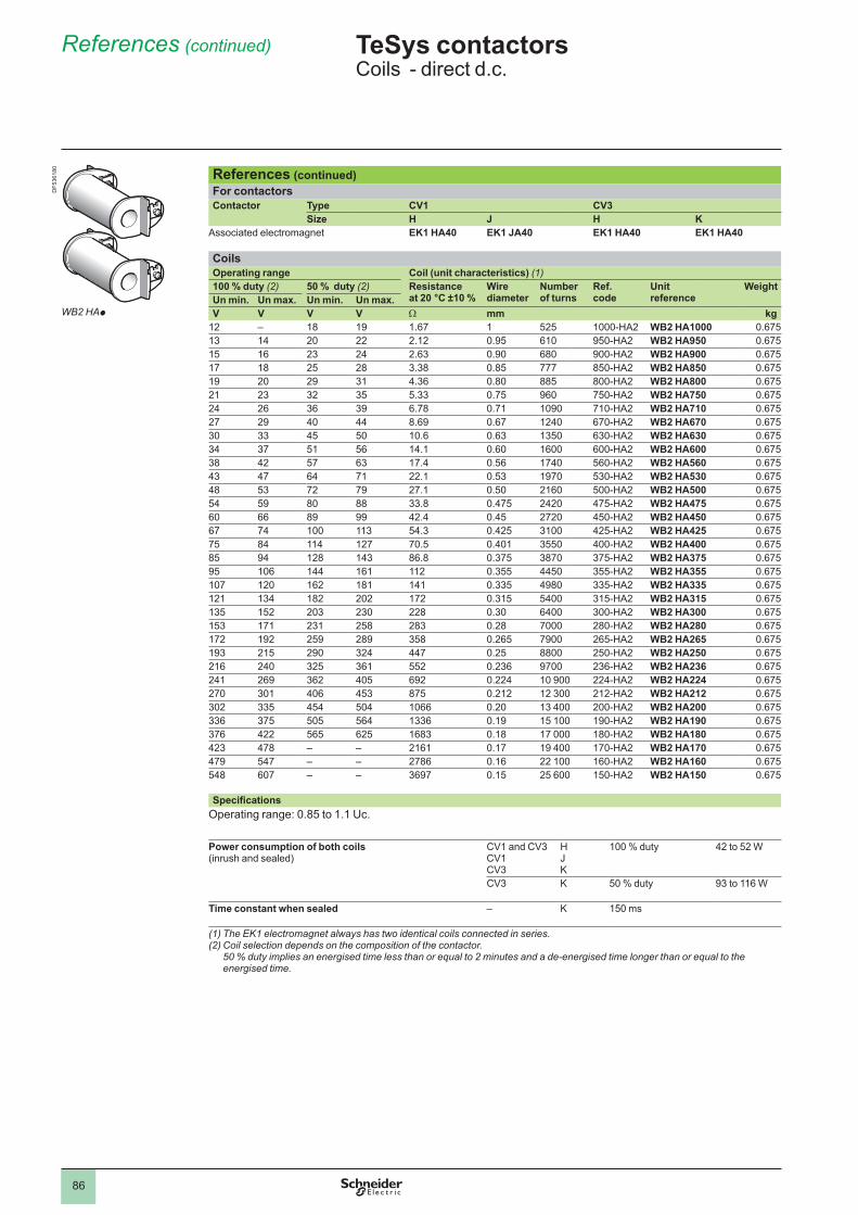
86
References (continued)
References (continued)For contactorsContactor Type CV1 CV3
Size H J H KAssociated electromagnet EK1 HA40 EK1 JA40 EK1 HA40 EK1 HA40
CoilsOperating range Coil (unit characteristics) (1)100 % duty (2) 50 % duty (2) Resistance
at 20 °C ±10 %Wire diameter
Number of turns
Ref. code
Unit reference
WeightUn min. Un max. Un min. Un max.V V V V W mm kg
12 – 18 19 1.67 525 1000-HA2 WB2 HA1000 0.67513 14 20 22 2.12 0.95 610 950-HA2 WB2 HA950 0.67515 16 23 24 2.63 0.90 680 900-HA2 WB2 HA900 0.67517 18 25 28 3.38 0.85 777 850-HA2 WB2 HA850 0.67519 20 29 31 4.36 0.80 885 800-HA2 WB2 HA800 0.67521 23 32 35 5.33 0.75 960 750-HA2 WB2 HA750 0.67524 26 36 39 6.78 0.71 1090 710-HA2 WB2 HA710 0.67527 29 40 44 8.69 0.67 1240 670-HA2 WB2 HA670 0.67530 33 45 50 10.6 0.63 1350 630-HA2 WB2 HA630 0.67534 37 51 56 14.1 0.60 1600 600-HA2 WB2 HA600 0.67538 42 57 63 17.4 0.56 1740 560-HA2 WB2 HA560 0.67543 47 64 71 22.1 0.53 1970 530-HA2 WB2 HA530 0.67548 53 72 79 27.1 0.50 2160 500-HA2 WB2 HA500 0.67554 59 80 88 33.8 0.475 2420 475-HA2 WB2 HA475 0.67560 66 89 99 42.4 0.45 2720 450-HA2 WB2 HA450 0.67567 74 113 54.3 0.425 3100 425-HA2 WB2 HA425 0.67575 84 114 127 70.5 0.401 3550 400-HA2 WB2 HA400 0.67585 94 128 143 86.8 0.375 3870 375-HA2 WB2 HA375 0.67595 106 144 161 112 0.355 4450 355-HA2 WB2 HA355 0.675107 120 162 181 141 0.335 4980 335-HA2 WB2 HA335 0.675121 134 182 202 172 0.315 5400 315-HA2 WB2 HA315 0.675135 152 203 230 228 0.30 6400 300-HA2 WB2 HA300 0.675153 171 231 258 283 0.28 7000 280-HA2 WB2 HA280 0.675172 192 259 289 358 0.265 7900 265-HA2 WB2 HA265 0.675193 215 290 324 447 0.25 8800 250-HA2 WB2 HA250 0.675216 240 325 361 552 0.236 9700 236-HA2 WB2 HA236 0.675241 269 362 405 692 0.224 10 900 224-HA2 WB2 HA224 0.675270 301 406 453 875 0.212 12 300 212-HA2 WB2 HA212 0.675302 335 454 504 1066 0.20 13 400 200-HA2 WB2 HA200 0.675336 375 505 564 1336 0.19 15 100 190-HA2 WB2 HA190 0.675376 422 565 625 1683 0.18 17 000 180-HA2 WB2 HA180 0.675423 478 – – 2161 0.17 19 400 170-HA2 WB2 HA170 0.675479 547 – – 2786 0.16 22 100 160-HA2 WB2 HA160 0.675548 607 – – 3697 0.15 25 600 150-HA2 WB2 HA150 0.675
SpecificationsOperating range: 0.85 to 1.1 Uc.
Power consumption of both coils (inrush and sealed)
CV1 and CV3 CV1 CV3
H J K
100 % duty 42 to 52 W
CV3 K 50 % duty 93 to 116 W
Time constant when sealed – K 150 ms
(1) The EK1 electromagnet always has two identical coils connected in series.(2) Coil selection depends on the composition of the contactor.
50 % duty implies an energised time less than or equal to 2 minutes and a de-energised time longer than or equal to the energised time.
TeSys contactors 0 Coils - direct d.c.
DF5
3618
0
WB2 HAp
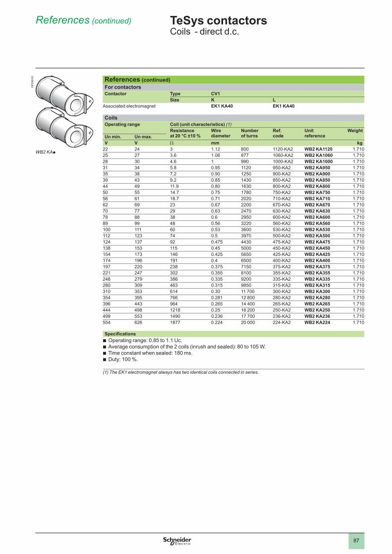
87
References (continued)
References (continued)For contactorsContactor Type CV1
Size K LAssociated electromagnet EK1 KA40 EK1 KA40
CoilsOperating range Coil (unit characteristics) (1)
Resistance at 20 °C ±10 %
Wire diameter
Number of turns
Ref. code
Unit reference
WeightUn min. Un max.V V W mm kg
22 24 3 1.12 800 1120-KA2 WB2 KA1120 1.71025 27 3.6 1.06 877 1060-KA2 WB2 KA1060 1.71028 30 4.6 990 1000-KA2 WB2 KA1000 1.71031 34 5.8 0.95 1120 950-KA2 WB2 KA950 1.71035 38 7.2 0.90 1250 900-KA2 WB2 KA900 1.71039 43 9.2 0.85 1430 850-KA2 WB2 KA850 1.71044 49 11.9 0.80 1630 800-KA2 WB2 KA800 1.71050 55 14.7 0.75 1780 750-KA2 WB2 KA750 1.71056 61 18.7 0.71 2020 710-KA2 WB2 KA710 1.71062 69 23 0.67 2200 670-KA2 WB2 KA670 1.71070 77 29 0.63 2470 630-KA2 WB2 KA630 1.71078 88 38 0.6 2950 600-KA2 WB2 KA600 1.71089 99 48 0.56 3220 560-KA2 WB2 KA560 1.710 60 0.53 3600 530-KA2 WB2 KA530 1.710112 123 74 0.5 3970 500-KA2 WB2 KA500 1.710124 137 92 0.475 4430 475-KA2 WB2 KA475 1.710138 153 115 0.45 5000 450-KA2 WB2 KA450 1.710154 173 146 0.425 5650 425-KA2 WB2 KA425 1.710174 196 191 0.4 6500 400-KA2 WB2 KA400 1.710197 220 238 0.375 7150 375-KA2 WB2 KA375 1.710221 247 302 0.355 8100 355-KA2 WB2 KA355 1.710248 279 386 0.335 9200 335-KA2 WB2 KA335 1.710280 309 463 0.315 9850 315-KA2 WB2 KA315 1.710310 353 614 0.30 11 700 300-KA2 WB2 KA300 1.710354 395 766 0.281 12 800 280-KA2 WB2 KA280 1.710396 443 964 0.265 14 400 265-KA2 WB2 KA265 1.710444 498 1218 0.25 16 200 250-KA2 WB2 KA250 1.710499 553 1490 0.236 17 700 236-KA2 WB2 KA236 1.710554 626 1877 0.224 20 000 224-KA2 WB2 KA224 1.710
SpecificationsOperating range: 0.85 to 1.1 Uc.Average consumption of the 2 coils (inrush and sealed): 80 to 105 W.Time constant when sealed: 180 ms.Duty: 100 %.
bbbb
(1) The EK1 electromagnet always has two identical coils connected in series.
TeSys contactors 0 Coils - direct d.c.
WB2 KAp
DF5
3618
1
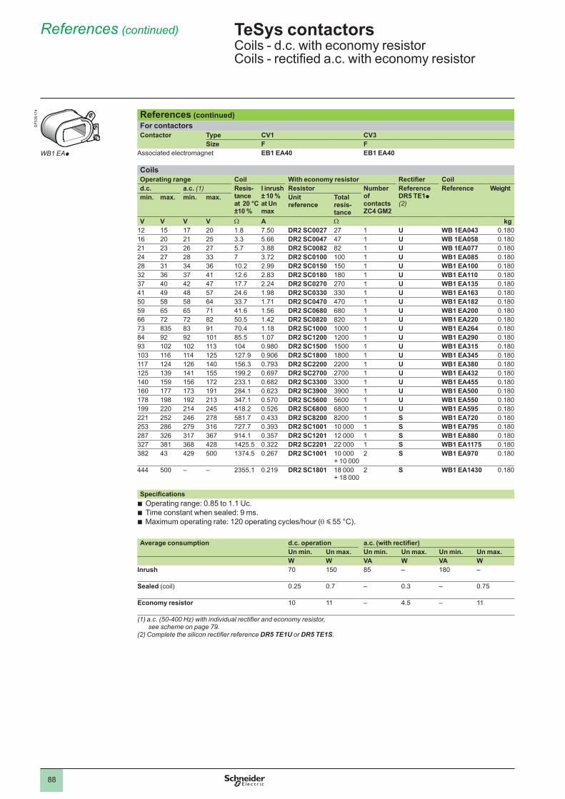
88
References (continued)
References (continued)For contactorsContactor Type CV1 CV3
Size F FAssociated electromagnet EB1 EA40 EB1 EA40
CoilsOperating range Coil With economy resistor Rectifier Coild.c. a.c. (1) Resis-
tance at 20 °C ±10 %
I inrush ± 10 % at Un max
Resistor Number of contacts ZC4 GM2
Reference DR5 TE1p (2)
Reference Weightmin. max. min. max. Unit
referenceTotal resis- tance
V V V V W A W kg12 15 17 20 1.8 7.50 DR2 SC0027 27 U WB 1EA043 0.18016 20 21 25 3.3 5.66 DR2 SC0047 47 U WB 1EA058 0.18021 23 26 27 5.7 3.88 DR2 SC0082 82 U WB 1EA077 0.18024 27 28 33 7 3.72 DR2 SC0100 U WB1 EA085 0.18028 31 34 36 10.2 2.99 DR2 SC0150 150 U WB1 EA100 0.18032 36 37 41 12.6 2.83 DR2 SC0180 180 U WB1 EA110 0.18037 40 42 47 17.7 2.24 DR2 SC0270 270 U WB1 EA135 0.18041 49 48 57 24.6 1.98 DR2 SC0330 330 U WB1 EA163 0.18050 58 58 64 33.7 1.71 DR2 SC0470 470 U WB1 EA182 0.18059 65 65 71 41.6 1.56 DR2 SC0680 680 U WB1 EA200 0.18066 72 72 82 50.5 1.42 DR2 SC0820 820 U WB1 EA220 0.18073 835 83 91 70.4 1.18 DR2 SC1000 U WB1 EA264 0.18084 92 92 85.5 1.07 DR2 SC1200 1200 U WB1 EA290 0.18093 102 102 113 104 0.980 DR2 SC1500 1500 U WB1 EA315 0.180103 116 114 125 127.9 0.906 DR2 SC1800 1800 U WB1 EA345 0.180117 124 126 140 156.3 0.793 DR2 SC2200 2200 U WB1 EA380 0.180125 139 141 155 199.2 0.697 DR2 SC2700 2700 U WB1 EA432 0.180140 159 156 172 233.1 0.682 DR2 SC3300 3300 U WB1 EA455 0.180160 177 173 191 284.1 0.623 DR2 SC3900 3900 U WB1 EA500 0.180178 198 192 213 347.1 0.570 DR2 SC5600 5600 U WB1 EA550 0.180199 220 214 245 418.2 0.526 DR2 SC6800 6800 U WB1 EA595 0.180221 252 246 278 581.7 0.433 DR2 SC8200 8200 S WB1 EA720 0.180253 286 279 316 727.7 0.393 DR2 SC1001 S WB1 EA795 0.180287 326 317 367 914.1 0.357 DR2 SC1201 12 000 S WB1 EA880 0.180327 381 368 428 1425.5 0.322 DR2 SC2201 22 000 S WB1 EA1175 0.180382 43 429 500 1374.5 0.267 DR2 SC1001
+ 10 0002 S WB1 EA970 0.180
444 500 – – 2355.1 0.219 DR2 SC1801 18 000 + 18 000
2 S WB1 EA1430 0.180
SpecificationsOperating range: 0.85 to 1.1 Uc.Time constant when sealed: 9 ms.Maximum operating rate: 120 operating cycles/hour (q y 55 °C).
bbb
Average consumption d.c. operation a.c. (with rectifier)Un min. Un max. Un min. Un max. Un min. Un max.W W VA W VA W
Inrush 70 150 85 – 180 –
Sealed (coil) 0.25 0.7 – 0.3 – 0.75
Economy resistor – 4.5 –
(1) a.c. (50-400 Hz) with individual rectifier and economy resistor, see scheme on page 79.
(2) Complete the silicon rectifier reference DR5 TE1U or DR5 TE1S.
TeSys contactors 0 Coils - d.c. with economy resistorCoils - rectified a.c. with economy resistor
WB1 EAp
DF5
3617
4
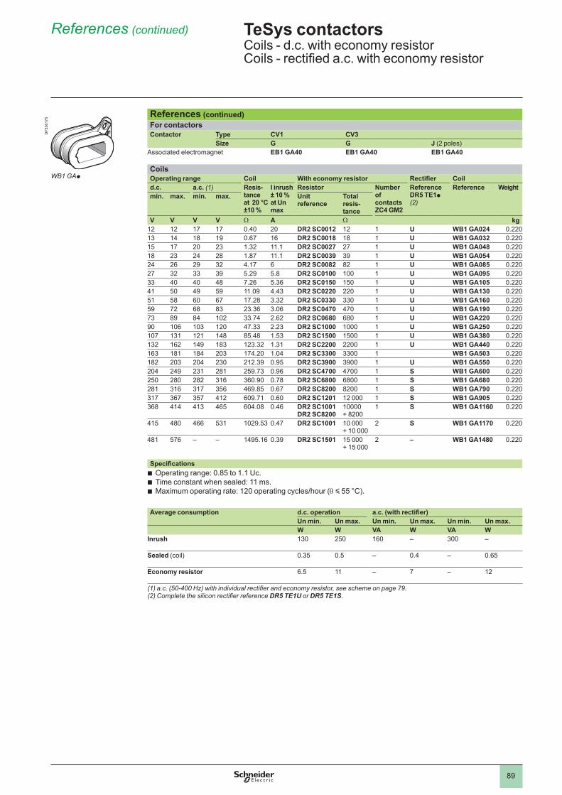
89
References (continued)
References (continued)For contactorsContactor Type CV1 CV3
Size G G J (2 poles)Associated electromagnet EB1 GA40 EB1 GA40 EB1 GA40
CoilsOperating range Coil With economy resistor Rectifier Coild.c. a.c. (1) Resis-
tance at 20 °C ±10 %
I inrush ± 10 % at Un max
Resistor Number of contacts ZC4 GM2
Reference DR5 TE1p (2)
Reference Weightmin. max. min. max. Unit
referenceTotal resis- tance
V V V V W A W kg12 12 17 17 0.40 20 DR2 SC0012 12 U WB1 GA024 0.22013 14 18 19 0.67 16 DR2 SC0018 18 U WB1 GA032 0.22015 17 20 23 1.32 . DR2 SC0027 27 U WB1 GA048 0.22018 23 24 28 1.87 . DR2 SC0039 39 U WB1 GA054 0.22024 26 29 32 4.17 6 DR2 SC0082 82 U WB1 GA085 0.22027 32 33 39 5.29 5.8 DR2 SC0100 U WB1 GA095 0.22033 40 40 48 7.26 5.36 DR2 SC0150 150 U WB1 GA105 0.22041 50 49 59 11.09 4.43 DR2 SC0220 220 U WB1 GA130 0.22051 58 60 67 17.28 3.32 DR2 SC0330 330 U WB1 GA160 0.22059 72 68 83 23.36 3.06 DR2 SC0470 470 U WB1 GA190 0.22073 89 84 102 33.74 2.62 DR2 SC0680 680 U WB1 GA220 0.22090 106 103 120 47.33 2.23 DR2 SC1000 U WB1 GA250 0.220107 131 121 148 85.48 1.53 DR2 SC1500 1500 U WB1 GA380 0.220132 162 149 183 123.32 1.31 DR2 SC2200 2200 U WB1 GA440 0.220163 181 184 203 174.20 1.04 DR2 SC3300 3300 WB1 GA503 0.220182 203 204 230 212.39 0.95 DR2 SC3900 3900 U WB1 GA550 0.220204 249 231 281 259.73 0.96 DR2 SC4700 4700 S WB1 GA600 0.220250 280 282 316 360.90 0.78 DR2 SC6800 6800 S WB1 GA680 0.220281 316 317 356 469.85 0.67 DR2 SC8200 8200 S WB1 GA790 0.220317 367 357 412 609.71 0.60 DR2 SC1201 12 000 S WB1 GA905 0.220368 414 413 465 604.08 0.46 DR2 SC1001
DR2 SC8200 + 8200
S WB1 GA1160 0.220
415 480 466 531 1029.53 0.47 DR2 SC1001 + 10 000
2 S WB1 GA1170 0.220
481 576 – – 1495.16 0.39 DR2 SC1501 15 000 + 15 000
2 – WB1 GA1480 0.220
SpecificationsOperating range: 0.85 to 1.1 Uc.Time constant when sealed: 11 ms.Maximum operating rate: 120 operating cycles/hour (q y 55 °C).
bbb
Average consumption d.c. operation a.c. (with rectifier)Un min. Un max. Un min. Un max. Un min. Un max.W W VA W VA W
Inrush 130 250 160 – 300 –
Sealed (coil) 0.35 0.5 – 0.4 – 0.65
Economy resistor 6.5 – 7 – 12
(1) a.c. (50-400 Hz) with individual rectifier and economy resistor, see scheme on page 79.(2) Complete the silicon rectifier reference DR5 TE1U or DR5 TE1S.
TeSys contactors 0 Coils - d.c. with economy resistorCoils - rectified a.c. with economy resistor
WB1 GAp
DF5
3617
5
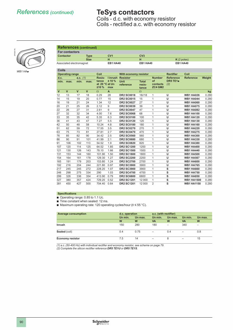
90
References (continued)
References (continued)For contactorsContactor Type CV1 CV3
Size H H K (2 poles)Associated electromagnet EB1 HA40 EB1 HA40 EB1 HA40
CoilsOperating range Coil With economy resistor Rectifier Coild.c. a.c. (1) Resis-
tance at 20 °C ±10 %
I inrush ± 10 % at Un max
Resistor Number of contacts ZC4 GM2
Reference DR5 TE1p (2)
Reference Weightmin. max. min. max. Unit
referenceTotal resis-tance
V V V V W A W kg12 13 17 18 0.29 28 DR2 SC0018 18//18 U WB1 HA026 0.28014 15 19 20 0.77 15 DR2 SC0015 15 U WB1 HA044 0.28016 19 21 24 1.34 12 DR2 SC0027 27 U WB1 HA060 0.28020 21 25 26 2.12 9 DR2 SC0039 39 U WB1 HA075 0.28022 26 27 31 2.61 9 DR2 SC0047 47 U WB1 HA082 0.28027 32 32 34 4.00 7.6 DR2 SC0068 68 U WB1 HA100 0.28033 35 35 42 5.35 6.3 DR2 SC0100 U WB1 HA120 0.28036 41 43 47 7.27 5.5 DR2 SC0120 120 U WB1 HA130 0.28042 50 48 58 10.24 4.8 DR2 SC0180 180 U WB1 HA160 0.28051 62 59 72 17.55 3.5 DR2 SC0270 270 U WB1 HA220 0.28063 75 73 81 27.81 2.7 DR2 SC0470 470 U WB1 HA275 0.28076 85 82 90 34.42 2.5 DR2 SC0560 560 U WB1 HA300 0.28086 90 91 41.99 2.1 DR2 SC0680 680 U WB1 HA330 0.28091 106 102 113 54.52 1.9 DR2 SC0820 820 U WB1 HA380 0.280107 120 114 125 64.52 1.85 DR2 SC1200 1200 U WB1 HA400 0.280121 130 126 143 78.10 1.66 DR2 SC1500 1500 U WB1 HA440 0.280131 153 144 160 101.90 1.50 DR2 SC1800 1800 U WB1 HA500 0.280154 164 161 178 129.30 1.27 DR2 SC2200 2200 U WB1 HA567 0.280165 191 179 203 153.80 1.24 DR2 SC2700 2700 U WB1 HA600 0.280192 216 204 244 221.80 0.97 DR2 SC3900 3900 U WB1 HA765 0.280217 245 245 272 228.20 1.07 DR2 SC3900 3900 S WB1 HA660 0.280246 298 275 334 290 1.03 DR2 SC4700 4700 S WB1 HA750 0.280299 326 336 354 413.90 0.79 DR2 SC6800 6800 S WB1 HA850 0.280327 380 357 424 729.20 0.52 DR2 SC1201 12 000 S WB1 HA1500 0.280381 450 427 500 704.40 0.64 DR2 SC1201 12 000 2 S WB1 HA1150 0.280
SpecificationsOperating range: 0.85 to 1.1 Uc.Time constant when sealed: 12 ms.Maximum operating rate: 120 operating cycles/hour (q y 55 °C).
bbb
Average consumption d.c. operation a.c. (with rectifier)Un min. Un max. Un min. Un max. Un min. Un max.W W VA W VA W
Inrush 150 280 180 – 340 –
Sealed (coil) 0.4 0.75 – 0.4 – 0.8
Economy resistor 7.5 14 – 8 – 15
(1) a.c. (50-400 Hz) with individual rectifier and economy resistor, see scheme on page 79.(2) Complete the silicon rectifier reference DR5 TE1U or DR5 TE1S.
TeSys contactors 0 Coils - d.c. with economy resistorCoils - rectified a.c. with economy resistor
WB1 HAp
DF5
3617
6
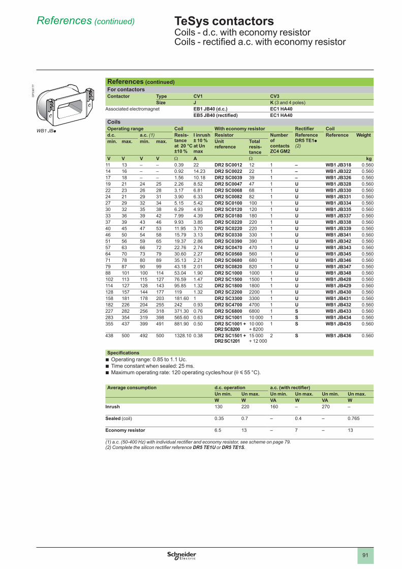
91
References (continued)
References (continued)For contactorsContactor Type CV1 CV3
Size J K (3 and 4 poles)Associated electromagnet EB1 JB40 (d.c.) EC1 HA40
EB5 JB40 (rectified) EC1 HA40CoilsOperating range Coil With economy resistor Rectifier Coild.c. a.c. (1) Resis-
tance at 20 °C ±10 %
I inrush ± 10 % at Un max
Resistor Number of contacts ZC4 GM2
Reference DR5 TE1p (2)
Reference Weightmin. max. min. max. Unit
referenceTotal resis-tance
V V V V W A W kg 13 – – 0.39 22 DR2 SC0012 12 – WB1 JB318 0.56014 16 – – 0.92 14.23 DR2 SC0022 22 – WB1 JB322 0.56017 18 – – 1.56 10.18 DR2 SC0039 39 – WB1 JB326 0.56019 21 24 25 2.26 8.52 DR2 SC0047 47 U WB1 JB328 0.56022 23 26 28 3.17 6.81 DR2 SC0068 68 U WB1 JB330 0.56024 21 29 31 3.90 6.33 DR2 SC0082 82 U WB1 JB331 0.56027 29 32 34 5.15 5.42 DR2 SC0100 U WB1 JB334 0.56030 32 35 38 6.29 4.93 DR2 SC0120 120 U WB1 JB335 0.56033 36 39 42 7.99 4.39 DR2 SC0180 180 U WB1 JB337 0.56037 39 43 46 9.93 3.85 DR2 SC0220 220 U WB1 JB338 0.56040 45 47 53 11.95 3.70 DR2 SC0220 220 U WB1 JB339 0.56046 50 54 58 15.79 3.13 DR2 SC0330 330 U WB1 JB341 0.56051 56 59 65 19.37 2.86 DR2 SC0390 390 U WB1 JB342 0.56057 63 66 72 22.76 2.74 DR2 SC0470 470 U WB1 JB343 0.56064 70 73 79 30.60 2.27 DR2 SC0560 560 U WB1 JB345 0.56071 78 80 89 35.13 2.21 DR2 SC0680 680 U WB1 JB346 0.56079 87 90 99 43.18 2.01 DR2 SC0820 820 U WB1 JB347 0.56088 114 53.04 1.90 DR2 SC1000 U WB1 JB348 0.560102 113 115 127 76.59 1.47 DR2 SC1500 1500 U WB1 JB428 0.560114 127 128 143 95.85 1.32 DR2 SC1800 1800 U WB1 JB429 0.560128 157 144 177 119 1.32 DR2 SC2200 2200 U WB1 JB430 0.560158 181 178 203 181.60 DR2 SC3300 3300 U WB1 JB431 0.560182 226 204 255 242 0.93 DR2 SC4700 4700 U WB1 JB432 0.560227 282 256 318 371.30 0.76 DR2 SC6800 6800 S WB1 JB433 0.560283 354 319 398 565.60 0.63 DR2 SC1001 S WB1 JB434 0.560355 437 399 491 881.90 0.50 DR2 SC1001 +
DR2 SC8200 + 8200
S WB1 JB435 0.560
438 500 492 500 1328.10 0.38 DR2 SC1501 + DR2 SC1201
15 000 + 12 000
2 S WB1 JB436 0.560
SpecificationsOperating range: 0.85 to 1.1 Uc.Time constant when sealed: 25 ms.Maximum operating rate: 120 operating cycles/hour (q y 55 °C).
bbb
Average consumption d.c. operation a.c. (with rectifier)Un min. Un max. Un min. Un max. Un min. Un max.W W VA W VA W
Inrush 130 220 160 – 270 –
Sealed (coil) 0.35 0.7 – 0.4 – 0.765
Economy resistor 6.5 13 – 7 – 13
(1) a.c. (50-400 Hz) with individual rectifier and economy resistor, see scheme on page 79.(2) Complete the silicon rectifier reference DR5 TE1U or DR5 TE1S.
TeSys contactors 0 Coils - d.c. with economy resistorCoils - rectified a.c. with economy resistor
WB1 JBp
DF5
3617
7
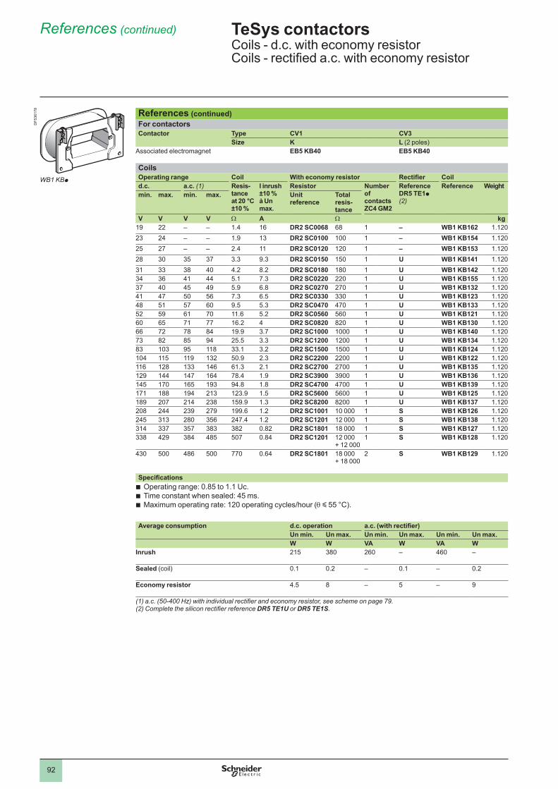
92
References (continued)
References (continued)For contactorsContactor Type CV1 CV3
Size K L (2 poles)Associated electromagnet EB5 KB40 EB5 KB40
CoilsOperating range Coil With economy resistor Rectifier Coild.c. a.c. (1) Resis-
tance at 20 °C ±10 %
I inrush ±10 % à Un max.
Resistor Number of contacts ZC4 GM2
Reference DR5 TE1p (2)
Reference Weightmin. max. min. max. Unit
referenceTotal resis-tance
V V V V W A W kg19 22 – – 1.4 16 DR2 SC0068 68 – WB1 KB162 1.12023 24 – – 1.9 13 DR2 SC0100 – WB1 KB154 1.12025 27 – – 2.4 DR2 SC0120 120 – WB1 KB153 1.12028 30 35 37 3.3 9.3 DR2 SC0150 150 U WB1 KB141 1.12031 33 38 40 4.2 8.2 DR2 SC0180 180 U WB1 KB142 1.12034 36 41 44 5.1 7.3 DR2 SC0220 220 U WB1 KB155 1.12037 40 45 49 5.9 6.8 DR2 SC0270 270 U WB1 KB132 1.12041 47 50 56 7.3 6.5 DR2 SC0330 330 U WB1 KB123 1.12048 51 57 60 9.5 5.3 DR2 SC0470 470 U WB1 KB133 1.12052 59 61 70 11.6 5.2 DR2 SC0560 560 U WB1 KB121 1.12060 65 71 77 16.2 4 DR2 SC0820 820 U WB1 KB130 1.12066 72 78 84 19.9 3.7 DR2 SC1000 U WB1 KB140 1.12073 82 85 94 25.5 3.3 DR2 SC1200 1200 U WB1 KB134 1.12083 103 95 118 33.1 3.2 DR2 SC1500 1500 U WB1 KB124 1.120104 115 119 132 50.9 2.3 DR2 SC2200 2200 U WB1 KB122 1.120116 128 133 146 61.3 2.1 DR2 SC2700 2700 U WB1 KB135 1.120129 144 147 164 78.4 1.9 DR2 SC3900 3900 U WB1 KB136 1.120145 170 165 193 94.8 1.8 DR2 SC4700 4700 U WB1 KB139 1.120171 188 194 213 123.9 1.5 DR2 SC5600 5600 U WB1 KB125 1.120189 207 214 238 159.9 1.3 DR2 SC8200 8200 U WB1 KB137 1.120208 244 239 279 199.6 1.2 DR2 SC1001 S WB1 KB126 1.120245 313 280 356 247.4 1.2 DR2 SC1201 12 000 S WB1 KB138 1.120314 337 357 383 382 0.82 DR2 SC1801 18 000 S WB1 KB127 1.120338 429 384 485 507 0.84 DR2 SC1201 12 000
+ 12 000 S WB1 KB128 1.120
430 500 486 500 770 0.64 DR2 SC1801 18 000 + 18 000
2 S WB1 KB129 1.120
SpecificationsOperating range: 0.85 to 1.1 Uc.Time constant when sealed: 45 ms.Maximum operating rate: 120 operating cycles/hour (q y 55 °C).
bbb
Average consumption d.c. operation a.c. (with rectifier)Un min. Un max. Un min. Un max. Un min. Un max.W W VA W VA W
Inrush 215 380 260 – 460 –
Sealed (coil) . 0.2 – . – 0.2
Economy resistor 4.5 8 – 5 – 9
(1) a.c. (50-400 Hz) with individual rectifier and economy resistor, see scheme on page 79.(2) Complete the silicon rectifier reference DR5 TE1U or DR5 TE1S.
TeSys contactors 0 Coils - d.c. with economy resistorCoils - rectified a.c. with economy resistor
WB1 KBp
DF5
3617
8
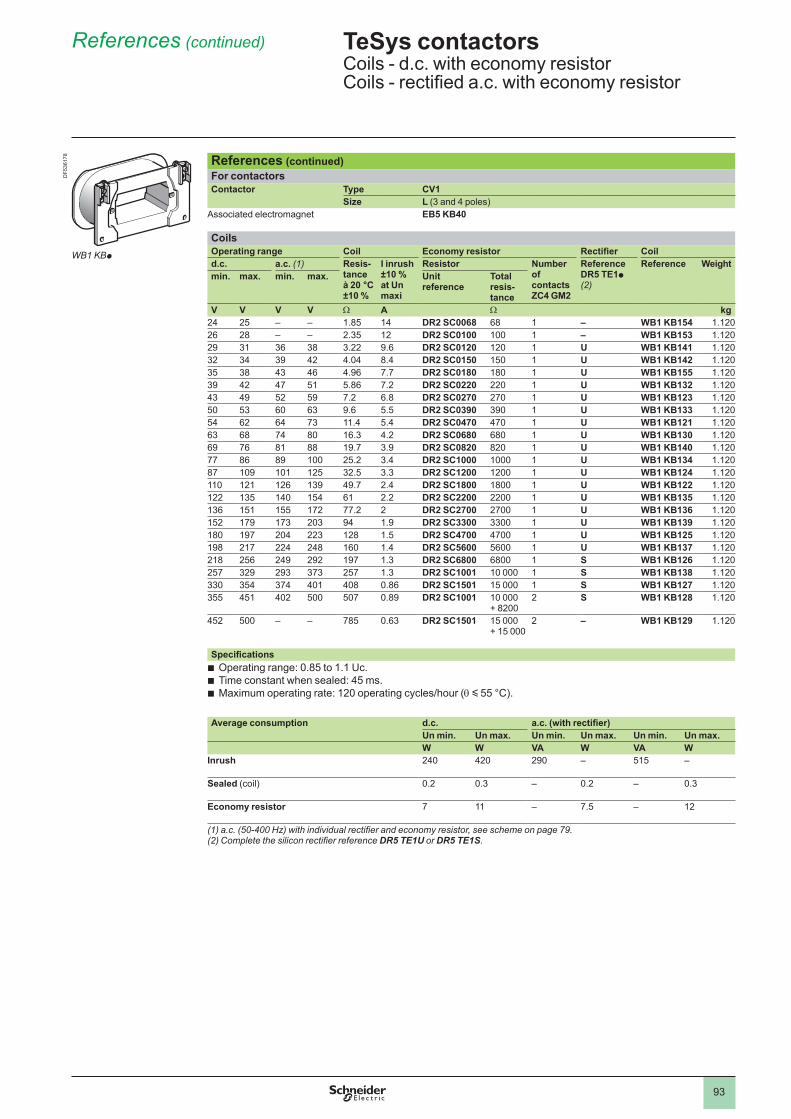
93
References (continued)
References (continued)For contactorsContactor Type CV1
Size L (3 and 4 poles)Associated electromagnet EB5 KB40
CoilsOperating range Coil Economy resistor Rectifier Coild.c. a.c. (1) Resis-
tance à 20 °C ±10 %
I inrush ±10 % at Un maxi
Resistor Number of contacts ZC4 GM2
Reference DR5 TE1p (2)
Reference Weightmin. max. min. max. Unit
referenceTotal resis-tance
V V V V W A W kg24 25 – – 1.85 14 DR2 SC0068 68 – WB1 KB154 1.12026 28 – – 2.35 12 DR2 SC0100 – WB1 KB153 1.12029 31 36 38 3.22 9.6 DR2 SC0120 120 U WB1 KB141 1.12032 34 39 42 4.04 8.4 DR2 SC0150 150 U WB1 KB142 1.12035 38 43 46 4.96 7.7 DR2 SC0180 180 U WB1 KB155 1.12039 42 47 51 5.86 7.2 DR2 SC0220 220 U WB1 KB132 1.12043 49 52 59 7.2 6.8 DR2 SC0270 270 U WB1 KB123 1.12050 53 60 63 9.6 5.5 DR2 SC0390 390 U WB1 KB133 1.12054 62 64 73 11.4 5.4 DR2 SC0470 470 U WB1 KB121 1.12063 68 74 80 16.3 4.2 DR2 SC0680 680 U WB1 KB130 1.12069 76 81 88 19.7 3.9 DR2 SC0820 820 U WB1 KB140 1.12077 86 89 25.2 3.4 DR2 SC1000 U WB1 KB134 1.12087 109 125 32.5 3.3 DR2 SC1200 1200 U WB1 KB124 1.120 121 126 139 49.7 2.4 DR2 SC1800 1800 U WB1 KB122 1.120122 135 140 154 61 2.2 DR2 SC2200 2200 U WB1 KB135 1.120136 151 155 172 77.2 2 DR2 SC2700 2700 U WB1 KB136 1.120152 179 173 203 94 1.9 DR2 SC3300 3300 U WB1 KB139 1.120180 197 204 223 128 1.5 DR2 SC4700 4700 U WB1 KB125 1.120198 217 224 248 160 1.4 DR2 SC5600 5600 U WB1 KB137 1.120218 256 249 292 197 1.3 DR2 SC6800 6800 S WB1 KB126 1.120257 329 293 373 257 1.3 DR2 SC1001 S WB1 KB138 1.120330 354 374 401 408 0.86 DR2 SC1501 15 000 S WB1 KB127 1.120355 451 402 500 507 0.89 DR2 SC1001
+ 82002 S WB1 KB128 1.120
452 500 – – 785 0.63 DR2 SC1501 15 000 + 15 000
2 – WB1 KB129 1.120
SpecificationsOperating range: 0.85 to 1.1 Uc.Time constant when sealed: 45 ms.Maximum operating rate: 120 operating cycles/hour (q y 55 °C).
bbb
Average consumption d.c. a.c. (with rectifier)Un min. Un max. Un min. Un max. Un min. Un max.W W VA W VA W
Inrush 240 420 290 – 515 –
Sealed (coil) 0.2 0.3 – 0.2 – 0.3
Economy resistor 7 – 7.5 – 12
(1) a.c. (50-400 Hz) with individual rectifier and economy resistor, see scheme on page 79.(2) Complete the silicon rectifier reference DR5 TE1U or DR5 TE1S.
TeSys contactors 0 Coils - d.c. with economy resistorCoils - rectified a.c. with economy resistor
DF5
3617
8
WB1 KBp
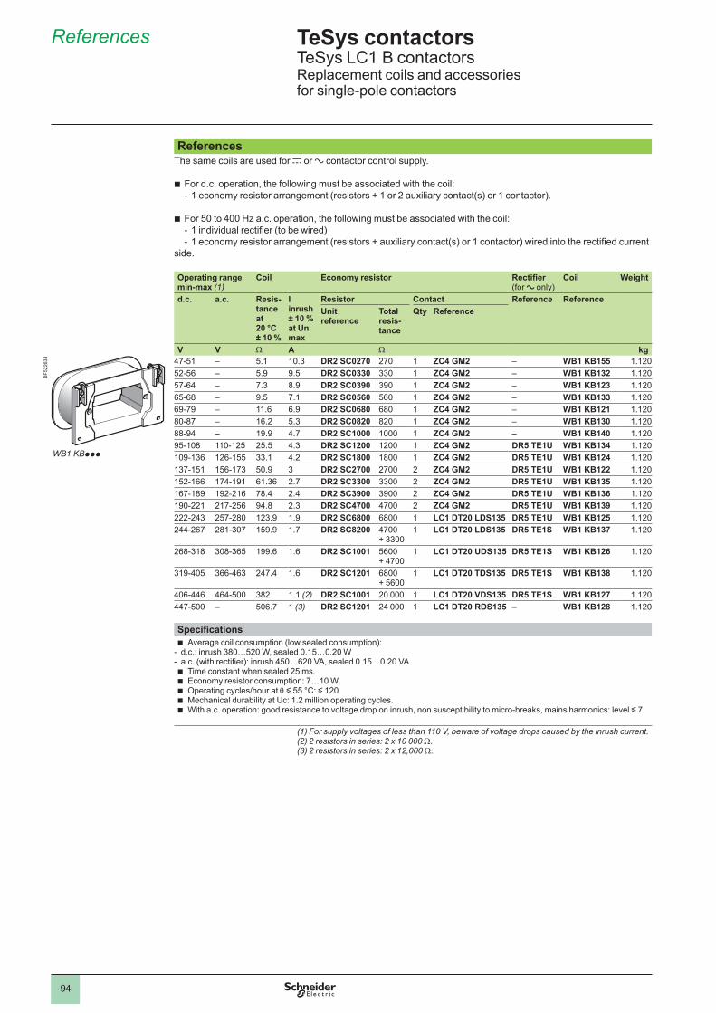
94
TeSys contactors 5 TeSys LC1 B contactorsReplacement coils and accessories for single-pole contactors
ReferencesThe same coils are used for c or a contactor control supply.
For d.c. operation, the following must be associated with the coil:1 economy resistor arrangement (resistors + 1 or 2 auxiliary contact(s) or 1 contactor).
For 50 to 400 Hz a.c. operation, the following must be associated with the coil: 1 individual rectifier (to be wired)1 economy resistor arrangement (resistors + auxiliary contact(s) or 1 contactor) wired into the rectified current
side.
b-
b--
Operating range min-max (1)
Coil Economy resistor Rectifier (for a only)
Coil Weight
d.c. a.c. Resis-tance at 20 °C ± 10 %
I inrush ± 10 % at Un max
Resistor Contact Reference ReferenceUnitreference
Total resis-tance
Qty Reference
V V W A W kg47-51 – 5.1 10.3 DR2 SC0270 270 ZC4 GM2 – WB1 KB155 1.12052-56 – 5.9 9.5 DR2 SC0330 330 ZC4 GM2 – WB1 KB132 1.12057-64 – 7.3 8.9 DR2 SC0390 390 ZC4 GM2 – WB1 KB123 1.12065-68 – 9.5 7.1 DR2 SC0560 560 ZC4 GM2 – WB1 KB133 1.12069-79 – 11.6 6.9 DR2 SC0680 680 ZC4 GM2 – WB1 KB121 1.12080-87 – 16.2 5.3 DR2 SC0820 820 ZC4 GM2 – WB1 KB130 1.12088-94 – 19.9 4.7 DR2 SC1000 ZC4 GM2 – WB1 KB140 1.12095-108 110-125 25.5 4.3 DR2 SC1200 1200 ZC4 GM2 DR5 TE1U WB1 KB134 1.120109-136 126-155 33.1 4.2 DR2 SC1800 1800 ZC4 GM2 DR5 TE1U WB1 KB124 1.120137-151 156-173 50.9 3 DR2 SC2700 2700 2 ZC4 GM2 DR5 TE1U WB1 KB122 1.120152-166 174-191 61.36 2.7 DR2 SC3300 3300 2 ZC4 GM2 DR5 TE1U WB1 KB135 1.120167-189 192-216 78.4 2.4 DR2 SC3900 3900 2 ZC4 GM2 DR5 TE1U WB1 KB136 1.120190-221 217-256 94.8 2.3 DR2 SC4700 4700 2 ZC4 GM2 DR5 TE1U WB1 KB139 1.120222-243 257-280 123.9 1.9 DR2 SC6800 6800 LC1 DT20 LDS135 DR5 TE1U WB1 KB125 1.120244-267 281-307 159.9 1.7 DR2 SC8200 4700
+ 3300 LC1 DT20 LDS135 DR5 TE1S WB1 KB137 1.120
268-318 308-365 199.6 1.6 DR2 SC1001 5600 + 4700
LC1 DT20 UDS135 DR5 TE1S WB1 KB126 1.120
319-405 366-463 247.4 1.6 DR2 SC1201 6800 + 5600
LC1 DT20 TDS135 DR5 TE1S WB1 KB138 1.120
406-446 464-500 382 . (2) DR2 SC1001 20 000 LC1 DT20 VDS135 DR5 TE1S WB1 KB127 1.120447-500 – 506.7 (3) DR2 SC1201 24 000 LC1 DT20 RDS135 – WB1 KB128 1.120
SpecificationsAverage coil consumption (low sealed consumption):
d.c.: inrush 380…520 W, sealed 0.15…0.20 Wa.c. (with rectifier): inrush 450…620 VA, sealed 0.15…0.20 VA.
Time constant when sealed 25 ms.Economy resistor consumption: 7…10 W.Operating cycles/hour at q y 55 °C: y 120.Mechanical durability at Uc: 1.2 million operating cycles.With a.c. operation: good resistance to voltage drop on inrush, non susceptibility to micro-breaks, mains harmonics: level y 7.
b--bbbbb
(1) For supply voltages of less than 110 V, beware of voltage drops caused by the inrush current.(2) 2 resistors in series: 2 x 10 000 W.(3) 2 resistors in series: 2 x 12,000 W.
References 5
WB1 KBppp
DF5
2263
4
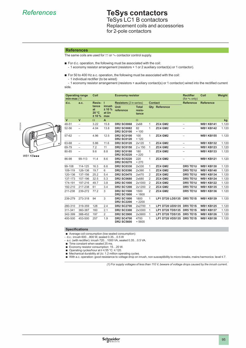
95
TeSys contactors 5 TeSys LC1 B contactorsReplacement coils and accessories for 2-pole contactors
ReferencesThe same coils are used for c or a contactor control supply.
For d.c. operation, the following must be associated with the coil:1 economy resistor arrangement (resistors + 1 or 2 auxiliary contact(s) or 1 contactor).
For 50 to 400 Hz a.c. operation, the following must be associated with the coil: 1 individual rectifier (to be wired)1 economy resistor arrangement (resistors + auxiliary contact(s) or 1 contactor) wired into the rectified current
side.
b-
b--
Operating range min-max (1)
Coil Economy resistor Rectifier (for a only)
Coil Weight
d.c. a.c. Resis-tance at 20 °C ± 10 %
I inrush ± 10 % at Un max
Resistors (2 in series) Contact Reference ReferenceUnitreference
Total resis-tance
Qty Reference
V V W A W kg48-51 – 3.22 15.8 DR2 SC0068 2x68 ZC4 GM2 – WB1 KB141 1.12052-56 – 4.04 13.8 DR2 SC0082
DR2 SC010082 + 100
ZC4 GM2 – WB1 KB142 1.120
57-62 – 4.96 12.5 DR2 SC0100 DR2 SC0120
+ 120
ZC4 GM2 – WB1 KB155 1.120
63-68 – 5.86 11.6 DR2 SC0120 2x120 ZC4 GM2 – WB1 KB132 1.12069-79 – 7.2 DR2 SC0150 2 x 150 ZC4 GM2 – WB1 KB123 1.12080-85 – 9.6 8.8 DR2 SC0180
DR2 SC0220180 + 220
ZC4 GM2 – WB1 KB133 1.120
86-98 99-113 11.4 8.6 DR2 SC0220 DR2 SC0270
220 + 270
ZC4 GM2 – WB1 KB121 1.120
99-108 114-125 16.3 6.6 DR2 SC0330 2x330 ZC4 GM2 DR5 TE1U WB1 KB130 1.120109-119 126-136 19.7 6 DR2 SC0390 2x390 ZC4 GM2 DR5 TE1U WB1 KB140 1.120120-136 137-156 25.2 5.4 DR2 SC0470 2x470 2 ZC4 GM2 DR5 TE1U WB1 KB134 1.120137-173 157-196 32.5 5.3 DR2 SC0680 2x680 2 ZC4 GM2 DR5 TE1U WB1 KB124 1.120174-191 197-216 49.7 3.8 DR2 SC1000 2x1000 2 ZC4 GM2 DR5 TE1U WB1 KB122 1.120192-210 217-238 61 3.4 DR2 SC1200 2x1200 2 ZC4 GM2 DR5 TE1U WB1 KB135 1.120211-238 239-272 77.2 3 DR2 SC1500
DR2 SC18001500 + 1800
2 ZC4 GM2 DR5 TE1U WB1 KB136 1.120
239-279 273-318 94 3 DR2 SC1800 DR2 SC2200
1800 + 2200
LP1 DT20 LDS135 DR5 TE1S WB1 KB139 1.120
280-310 319-359 128 2.4 DR2 SC2700 2x2700 LP1 DT20 UDS135 DR5 TE1S WB1 KB125 1.120311-341 360-387 160 2.1 DR2 SC3300 2x3300 LP1 DT20 TDS135 DR5 TE1S WB1 KB137 1.120342-399 388-452 197 2 DR2 SC3900 2x3900 LP1 DT20 TDS135 DR5 TE1S WB1 KB126 1.120400-500 453-500 257 1.9 DR2 SC4700
DR2 SC56004700 + 5600
LP1 DT20 VDS135 DR5 TE1S WB1 KB138 1.120
SpecificationsAverage coil consumption (low sealed consumption):
d.c.: inrush 600…800 W, sealed 0.35…0.5 Wa.c. (with rectifier): inrush 720…1000 VA, sealed 0.35…0.5 VA.
Time constant when sealed 25 ms.Economy resistor consumption: 15…20 W.Operating cycles/hour at q y 55 °C: y 120.Mechanical durability at Uc: 1.2 million operating cycles.With a.c. operation: good resistance to voltage drop on inrush, non susceptibility to micro-breaks, mains harmonics: level y 7.
b--bbbbb
(1) For supply voltages of less than 110 V, beware of voltage drops caused by the inrush current.
References 5
WB1 KBppp
DF5
2263
4
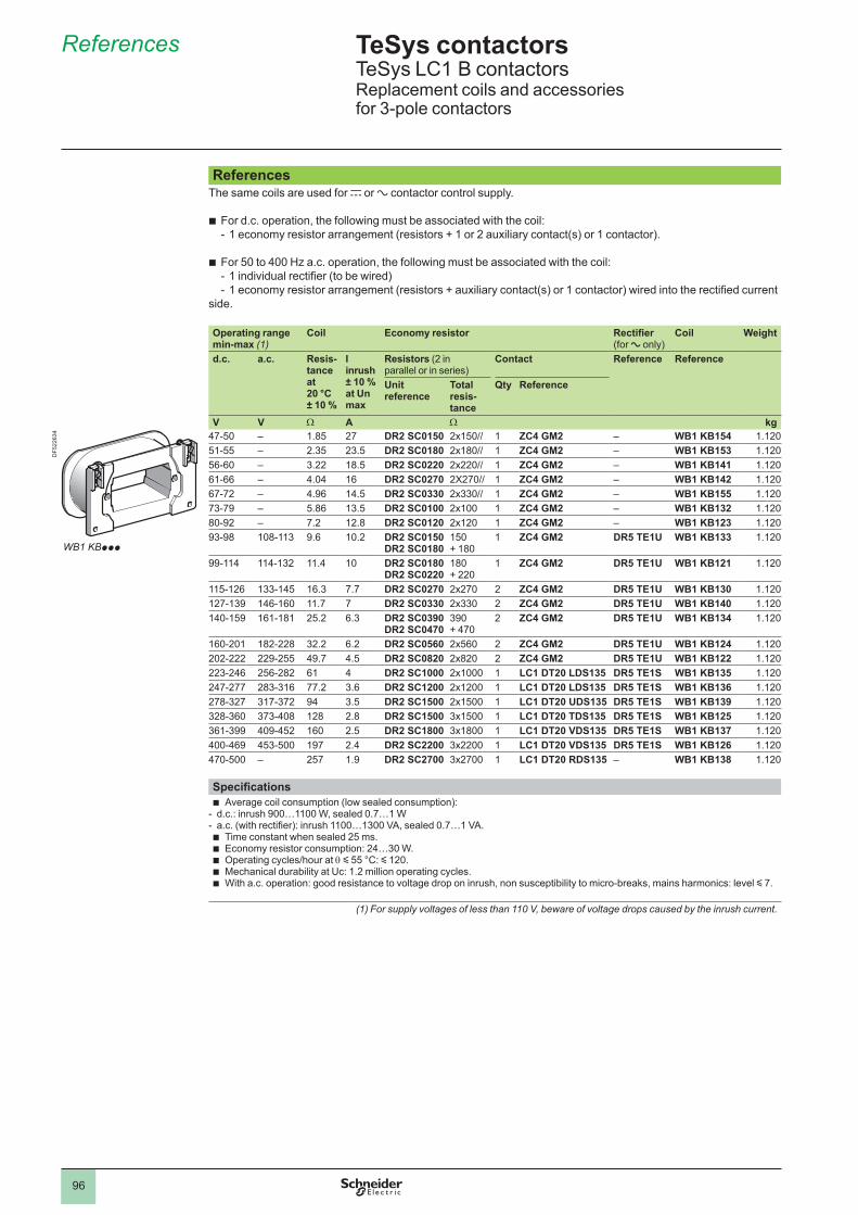
96
TeSys contactors 5 TeSys LC1 B contactorsReplacement coils and accessories for 3-pole contactors
ReferencesThe same coils are used for c or a contactor control supply.
For d.c. operation, the following must be associated with the coil:1 economy resistor arrangement (resistors + 1 or 2 auxiliary contact(s) or 1 contactor).
For 50 to 400 Hz a.c. operation, the following must be associated with the coil: 1 individual rectifier (to be wired)1 economy resistor arrangement (resistors + auxiliary contact(s) or 1 contactor) wired into the rectified current
side.
b-
b--
Operating range min-max (1)
Coil Economy resistor Rectifier (for a only)
Coil Weight
d.c. a.c. Resis-tance at 20 °C ± 10 %
I inrush ± 10 % at Un max
Resistors (2 in parallel or in series)
Contact Reference Reference
Unitreference
Total resis-tance
Qty Reference
V V W A W kg47-50 – 1.85 27 DR2 SC0150 2x150// ZC4 GM2 – WB1 KB154 1.12051-55 – 2.35 23.5 DR2 SC0180 2x180// ZC4 GM2 – WB1 KB153 1.12056-60 – 3.22 18.5 DR2 SC0220 2x220// ZC4 GM2 – WB1 KB141 1.12061-66 – 4.04 16 DR2 SC0270 2X270// ZC4 GM2 – WB1 KB142 1.12067-72 – 4.96 14.5 DR2 SC0330 2x330// ZC4 GM2 – WB1 KB155 1.12073-79 – 5.86 13.5 DR2 SC0100 2x100 ZC4 GM2 – WB1 KB132 1.12080-92 – 7.2 12.8 DR2 SC0120 2x120 ZC4 GM2 – WB1 KB123 1.12093-98 108-113 9.6 10.2 DR2 SC0150
DR2 SC0180150 + 180
ZC4 GM2 DR5 TE1U WB1 KB133 1.120
99-114 114-132 11.4 DR2 SC0180 DR2 SC0220
180 + 220
ZC4 GM2 DR5 TE1U WB1 KB121 1.120
115-126 133-145 16.3 7.7 DR2 SC0270 2x270 2 ZC4 GM2 DR5 TE1U WB1 KB130 1.120127-139 146-160 11.7 7 DR2 SC0330 2x330 2 ZC4 GM2 DR5 TE1U WB1 KB140 1.120140-159 161-181 25.2 6.3 DR2 SC0390
DR2 SC0470390 + 470
2 ZC4 GM2 DR5 TE1U WB1 KB134 1.120
160-201 182-228 32.2 6.2 DR2 SC0560 2x560 2 ZC4 GM2 DR5 TE1U WB1 KB124 1.120202-222 229-255 49.7 4.5 DR2 SC0820 2x820 2 ZC4 GM2 DR5 TE1U WB1 KB122 1.120223-246 256-282 61 4 DR2 SC1000 2x1000 LC1 DT20 LDS135 DR5 TE1S WB1 KB135 1.120247-277 283-316 77.2 3.6 DR2 SC1200 2x1200 LC1 DT20 LDS135 DR5 TE1S WB1 KB136 1.120278-327 317-372 94 3.5 DR2 SC1500 2x1500 LC1 DT20 UDS135 DR5 TE1S WB1 KB139 1.120328-360 373-408 128 2.8 DR2 SC1500 3x1500 LC1 DT20 TDS135 DR5 TE1S WB1 KB125 1.120361-399 409-452 160 2.5 DR2 SC1800 3x1800 LC1 DT20 VDS135 DR5 TE1S WB1 KB137 1.120400-469 453-500 197 2.4 DR2 SC2200 3x2200 LC1 DT20 VDS135 DR5 TE1S WB1 KB126 1.120470-500 – 257 1.9 DR2 SC2700 3x2700 LC1 DT20 RDS135 – WB1 KB138 1.120
SpecificationsAverage coil consumption (low sealed consumption):
d.c.: inrush 900…1100 W, sealed 0.7…1 Wa.c. (with rectifier): inrush 1100…1300 VA, sealed 0.7…1 VA.
Time constant when sealed 25 ms.Economy resistor consumption: 24…30 W.Operating cycles/hour at q y 55 °C: y 120.Mechanical durability at Uc: 1.2 million operating cycles.With a.c. operation: good resistance to voltage drop on inrush, non susceptibility to micro-breaks, mains harmonics: level y 7.
b--bbbbb
(1) For supply voltages of less than 110 V, beware of voltage drops caused by the inrush current.
References 5
WB1 KBppp
DF5
2263
4
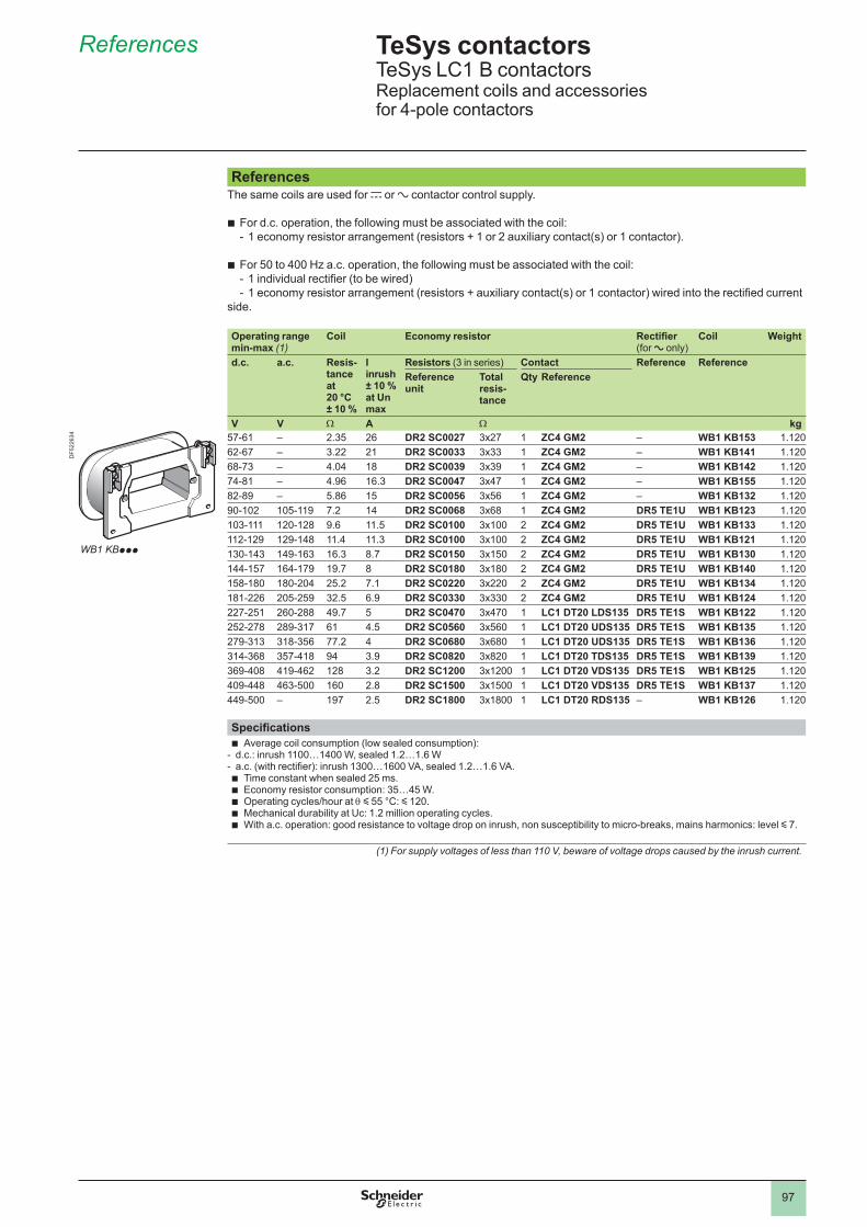
97
TeSys contactors 5 TeSys LC1 B contactorsReplacement coils and accessories for 4-pole contactors
ReferencesThe same coils are used for c or a contactor control supply.
For d.c. operation, the following must be associated with the coil:1 economy resistor arrangement (resistors + 1 or 2 auxiliary contact(s) or 1 contactor).
For 50 to 400 Hz a.c. operation, the following must be associated with the coil: 1 individual rectifier (to be wired)1 economy resistor arrangement (resistors + auxiliary contact(s) or 1 contactor) wired into the rectified current
side.
b-
b--
Operating range min-max (1)
Coil Economy resistor Rectifier (for a only)
Coil Weight
d.c. a.c. Resis-tance at 20 °C ± 10 %
I inrush ± 10 % at Un max
Resistors (3 in series) Contact Reference ReferenceReferenceunit
Total resis-tance
Qty Reference
V V W A W kg57-61 – 2.35 26 DR2 SC0027 3x27 ZC4 GM2 – WB1 KB153 1.12062-67 – 3.22 21 DR2 SC0033 3x33 ZC4 GM2 – WB1 KB141 1.12068-73 – 4.04 18 DR2 SC0039 3x39 ZC4 GM2 – WB1 KB142 1.12074-81 – 4.96 16.3 DR2 SC0047 3x47 ZC4 GM2 – WB1 KB155 1.12082-89 – 5.86 15 DR2 SC0056 3x56 ZC4 GM2 – WB1 KB132 1.12090-102 105-119 7.2 14 DR2 SC0068 3x68 ZC4 GM2 DR5 TE1U WB1 KB123 1.120103-111 120-128 9.6 11.5 DR2 SC0100 3x100 2 ZC4 GM2 DR5 TE1U WB1 KB133 1.120112-129 129-148 11.4 11.3 DR2 SC0100 3x100 2 ZC4 GM2 DR5 TE1U WB1 KB121 1.120130-143 149-163 16.3 8.7 DR2 SC0150 3x150 2 ZC4 GM2 DR5 TE1U WB1 KB130 1.120144-157 164-179 19.7 8 DR2 SC0180 3x180 2 ZC4 GM2 DR5 TE1U WB1 KB140 1.120158-180 180-204 25.2 7.1 DR2 SC0220 3x220 2 ZC4 GM2 DR5 TE1U WB1 KB134 1.120181-226 205-259 32.5 6.9 DR2 SC0330 3x330 2 ZC4 GM2 DR5 TE1U WB1 KB124 1.120227-251 260-288 49.7 5 DR2 SC0470 3x470 LC1 DT20 LDS135 DR5 TE1S WB1 KB122 1.120252-278 289-317 61 4.5 DR2 SC0560 3x560 LC1 DT20 UDS135 DR5 TE1S WB1 KB135 1.120279-313 318-356 77.2 4 DR2 SC0680 3x680 LC1 DT20 UDS135 DR5 TE1S WB1 KB136 1.120314-368 357-418 94 3.9 DR2 SC0820 3x820 LC1 DT20 TDS135 DR5 TE1S WB1 KB139 1.120369-408 419-462 128 3.2 DR2 SC1200 3x1200 LC1 DT20 VDS135 DR5 TE1S WB1 KB125 1.120409-448 463-500 160 2.8 DR2 SC1500 3x1500 LC1 DT20 VDS135 DR5 TE1S WB1 KB137 1.120449-500 – 197 2.5 DR2 SC1800 3x1800 LC1 DT20 RDS135 – WB1 KB126 1.120
SpecificationsAverage coil consumption (low sealed consumption):
d.c.: inrush 1100…1400 W, sealed 1.2…1.6 Wa.c. (with rectifier): inrush 1300…1600 VA, sealed 1.2…1.6 VA.
Time constant when sealed 25 ms.Economy resistor consumption: 35…45 W.Operating cycles/hour at q y 55 °C: y 120.Mechanical durability at Uc: 1.2 million operating cycles.With a.c. operation: good resistance to voltage drop on inrush, non susceptibility to micro-breaks, mains harmonics: level y 7.
b--bbbbb
(1) For supply voltages of less than 110 V, beware of voltage drops caused by the inrush current.
References 5
WB1 KBppp
DF5
2263
4
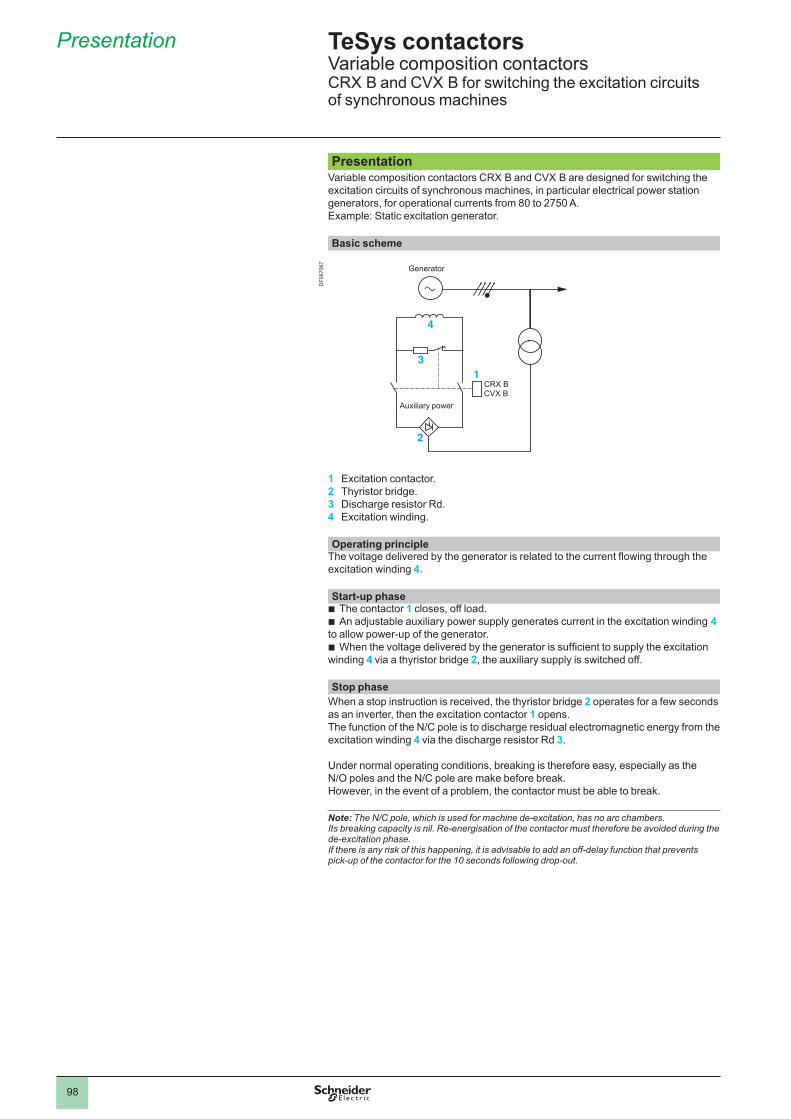
98
Presentation
CRX BCVX B
1
2
3
4
Generator
Auxiliary power
2.2
PresentationVariable composition contactors CRX B and CVX B are designed for switching the excitation circuits of synchronous machines, in particular electrical power station generators, for operational currents from 80 to 2750 A.Example: Static excitation generator.
Basic scheme
1 Excitation contactor.2 Thyristor bridge.3 Discharge resistor Rd.4 Excitation winding.
Operating principleThe voltage delivered by the generator is related to the current flowing through the excitation winding 4 .
Start-up phaseThe contactor 1 closes, off load.An adjustable auxiliary power supply generates current in the excitation winding 4
to allow power-up of the generator.When the voltage delivered by the generator is sufficient to supply the excitation
winding 4 via a thyristor bridge 2, the auxiliary supply is switched off. Stop phase
When a stop instruction is received, the thyristor bridge 2 operates for a few seconds as an inverter, then the excitation contactor 1 opens .The function of the N/C pole is to discharge residual electromagnetic energy from the excitation winding 4 via the discharge resistor Rd 3 .
Under normal operating conditions, breaking is therefore easy, especially as the N/O poles and the N/C pole are make before break.However, in the event of a problem, the contactor must be able to break.
Note: The N/C pole, which is used for machine de-excitation, has no arc chambers. Its breaking capacity is nil. Re-energisation of the contactor must therefore be avoided during the de-excitation phase. If there is any risk of this happening, it is advisable to add an off-delay function that prevents pick-up of the contactor for the 10 seconds following drop-out.
bb
b
TeSys contactors Variable composition contactorsCRX B and CVX B for switching the excitation circuits of synchronous machines
DF5
6706
7
99
Characteristics
Contactor descriptionCRX and CVX B contactors comprise:
2 N/O poles with magnetic blow-out (80…2750 A at c 850 V).1 N/C pole without blow-out (80…630 A).1 electromagnet with d.c. supplyeither magnetic latching (CRX Bp21pp)or with economy resistor (CVX Bp21pp).2 instantaneous auxiliary contact heads (6 N/O contacts + 2 N/C contacts).1 mounting bar, 1 rotary drive shaft.
The following can be added:1 or 2 blocks of 4 instantaneous auxiliary contacts LAD Npp, without increasing
the overall size of the contactor.or 1 time delay block LAD Tp or LAD Rp .
Note: it is not possible to fit a mechanical latch block LA6 DKpp on these contactors.
bbbvvbb
b
b
CharacteristicsCRX B and CVX B contactor sizes F G H J K L M P RN/O pole
Rated current q y 40 °C A 80 170 250 470 630 800 1250 2000 2750
Maximum operational voltaged.c.
2 poles in series V 850
Rated insulation voltageConforming to IEC 60664-1
d.c. V
Making capacity d.c. A 1400 2900 3500 5200 6500 14 000 14 000 21 000 25 000
Breaking capacity d.c. L/R = 15 ms A 500 1200 1200 1500 3200 4400 7200
Overlap time with the N/C pole
ms 2
N/C poleRated current q y 40 °C A 80 200 300 470 630 630 630 630 630
Making capacity d.c. A 1600 3200 4000 5200 6500 6500 6500 6500 6500
Breaking capacity d.c. L/R = 15 ms A
Permissible current For 10 seconds A 480 960 1400 2700 3600 3600 3600 3600 3600
TeSys contactors Variable composition contactorsCRX B and CVX B for switching the excitation circuits of synchronous machines
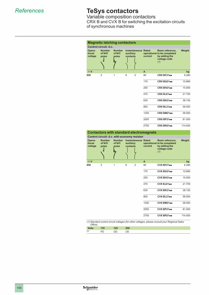
References
Magnetic latching contactorsControl circuit: d.c.Opera-tional voltage
Number of N/O poles
Number of N/C poles
Instantaneous auxiliary contacts
Rated operational current
Basic reference, to be completed by adding the voltage code(1)
Weight
c V A kg850 2 6 2 80 CRX BF21pp 6.280
170 CRX BG21pp 10.890
250 CRX BH21pp 15.000
470 CRX BJ21pp 21.700
630 CRX BK21pp 38.150
800 CRX BL21pp 58.000
1250 CRX BM21pp 58.000
2000 CRX BP21pp 81.000
2750 CRX BR21pp 114.000
Contactors with standard electromagnetsControl circuit: d.c. with economy resistorOpera-tional voltage
Number of N/O poles
Number of N/C poles
Instantaneous auxiliary contacts
Rated operational current
Basic reference, to be completed by adding the voltage code(1)
Weight
c V A kg850 2 6 2 80 CVX BF21pp 6.280
170 CVX BG21pp 10.890
250 CVX BH21pp 15.000
470 CVX BJ21pp 21.700
630 CVX BK21pp 38.150
800 CVX BL21pp 58.000
1250 CVX BM21pp 58.000
2000 CVX BP21pp 81.000
2750 CVX BR21pp 114.000
(1) Standard control circuit voltages (for other voltages, please consult your Regional Sales Offi ce).
Volts 110 125 250c FD GD UD
TeSys contactors Variable composition contactorsCRX B and CVX B for switching the excitation circuits of synchronous machines
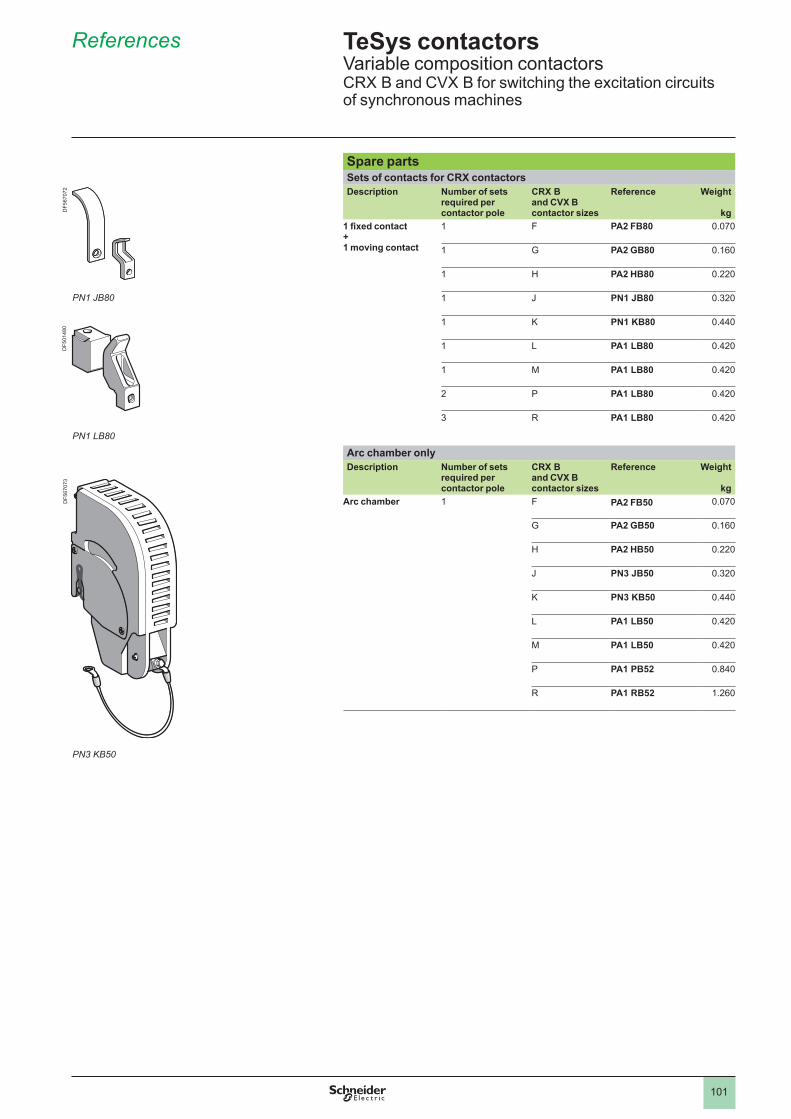
References
Spare partsSets of contacts for CRX contactorsDescription Number of sets
required per contactor pole
CRX B and CVX B contactor sizes
Reference Weight
kg1 fixed contact + 1 moving contact
F PA2 FB80 0.070
G PA2 GB80 0.160
H PA2 HB80 0.220
J PN1 JB80 0.320
K PN1 KB80 0.440
L PA1 LB80 0.420
M PA1 LB80 0.420
2 P PA1 LB80 0.420
3 R PA1 LB80 0.420
Arc chamber onlyDescription Number of sets
required per contactor pole
CRX B and CVX B contactor sizes
Reference Weight
kgArc chamber F PA2 FB50 0.070
G PA2 GB50 0.160
H PA2 HB50 0.220
J PN3 JB50 0.320
K PN3 KB50 0.440
L PA1 LB50 0.420
M PA1 LB50 0.420
P PA1 PB52 0.840
R PA1 RB52 1.260
TeSys contactors Variable composition contactors CRX B and CVX B for switching the excitation circuits of synchronous machines
PN1 JB80
DF5
6707
2
PN1 LB80
PN3 KB50
DF5
0148
0D
F567
073
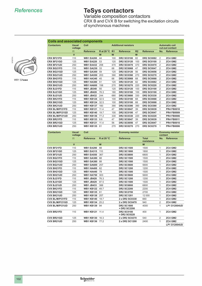
102
References
Coils and associated componentsContactors Usual
voltageCoil Additional resistors Automatic coil
cut-out contactc Reference R at 20 °C R1 Reference R2 Reference No. ReferenceV W W W
CRX BF21FD WB1 EA200 44 DR2 SC0100 82 DR2 SC0082 2 ZC4 GM2CRX BF21GD 125 WB1 EA220 53 120 DR2 SC0120 DR2 SC0100 2 ZC4 GM2CRX BF21UD 250 WB1 EA432 208 470 DR2 SC0470 470 DR2 SC0470 2 ZC4 GM2CRX BG21FD WB1 GA230 33 68 DR2 SC0068 47 DR2 SC0047 2 ZC4 GM2CRX BG21GD 125 WB1 GA300 59 120 DR2 SC0120 56 DR2 SC0056 2 ZC4 GM2CRX BG21UD 250 WB1 GA550 203 390 DR2 SC0390 270 DR2 SC0270 2 ZC4 GM2CRX BH21FD WB1 HA340 45 68 DR2 SC0068 68 DR2 SC0068 2 ZC4 GM2CRX BH21GD 125 WB1 HA380 51 120 DR2 SC0120 82 DR2 SC0082 2 ZC4 GM2CRX BH21UD 250 WB1 HA600 158 270 DR2 SC0270 220 DR2 SC0220 2 ZC4 GM2CRX BJ21FD WB1 JB348 55 120 DR2 SC0120 DR2 SC0100 2 ZC4 GM2CRX BJ21GD 125 WB1 JB428 76.3 180 DR2 SC0180 DR2 SC0100 2 ZC4 GM2CRX BJ21UD 250 WB1 JB432 244 680 DR2 SC0680 330 DR2 SC0330 2 ZC4 GM2CRX BK21FD WB1 KB124 32.5 DR2 SC0100 68 DR2 SC0068 2 ZC4 GM2CRX BK21GD 125 WB1 KB124 32.5 DR2 SC0100 68 DR2 SC0068 2 ZC4 GM2CRX BK21UD 250 WB1 KB137 160 390 DR2 SC0390 390 DR2 SC0390 2 ZC4 GM2CRX BL/M/P/21FD WB1 KB121 11.4 47 DR2 SC0047 39 DR2 SC0039 PR4 FB0010CRX BL/M/P/21GD 125 WB1 KB140 19.7 DR2 SC0100 47 DR2 SC0047 PR4 FB0009CRX BL/M/P/21UD 250 WB1 KB136 77.2 330 DR2 SC0330 220 DR2 SC0220 PR4 FB0006CRX BR21FD WB1 KB133 9.6 47 DR2 SC0047 39 DR2 SC0039 PR4 FB0011CRX BR21GD 125 WB1 KB121 11.4 56 DR2 SC0056 47 DR2 SC0047 PR4 FB0010CRX BR21UD 250 WB1 KB135 61 270 DR2 SC0270 270 DR2 SC0270 PR4 FB0006
Contactors Usual voltage
Coil Economy resistor Economy resistor contact
c Reference R at 20 °C Reference Total resistance
No. Reference
V W WCVX BF21FD WB1 EA290 88 DR2 SC1500 1500 ZC4 GM2CVX BF21GD 125 WB1 EA315 DR2 SC1800 1800 ZC4 GM2CVX BF21UD 250 WB1 EA550 367 DR2 SC6800 6800 ZC4 GM2CVX BG21FD WB1 GA380 88 DR2 SC1500 1500 ZC4 GM2CVX BG21GD 125 WB1 GA380 88 DR2 SC1500 1500 ZC4 GM2CVX BG21UD 250 WB1 GA600 257 DR2 SC5600 5600 ZC4 GM2CVX BH21FD WB1 HA400 62 DR2 SC1200 1200 ZC4 GM2CVX BH21GD 125 WB1 HA440 79 DR2 SC1500 1500 ZC4 GM2CVX BH21UD 250 WB1 HA750 303 DR2 SC5600 5600 ZC4 GM2CVX BJ21FD WB1 JB428 76.3 DR2 SC1200 1200 ZC4 GM2CVX BJ21GD 125 WB1 JB429 97.5 DR2 SC1500 1500 ZC4 GM2CVX BJ21UD 250 WB1 JB433 388 DR2 SC6800 6800 ZC4 GM2CVX BK21FD WB1 KB122 49.7 DR2 SC2200 2200 ZC4 GM2CVX BK21GD 125 WB1 KB135 61 DR2 SC2700 2700 ZC4 GM2CVX BK21UD 250 WB1 KB138 257 DR2 SC1201 12 000 ZC4 GM2CVX BL/M/P/21FD WB1 KB140 19.7 2 x DR2 SC0330 660 ZC4 GM2CVX BL/M/P/21GD 125 WB1 KB134 25.2 2 x DR2 SC0470 940 2 ZC4 GM2CVX BL/M/P/21UD 250 WB1 KB139 94 DR2 SC1800
+ DR2 SC22004000 LP1 D12004UD
CVX BR21FD WB1 KB121 11.4 DR2 SC0180 + DR2 SC0220
400 ZC4 GM2
CVX BR21GD 125 WB1 KB130 16.3 2 x DR2 SC0270 540 2 ZC4 GM2CVX BR21UD 250 WB1 KB136 77.2 2 x DR2 SC1200 2400 ZC4 GM2
LP1 D12004UD
TeSys contactors Variable composition contactorsCRX B and CVX B for switching the excitation circuits of synchronous machines
WB1 GAppp
DF5
6707
4
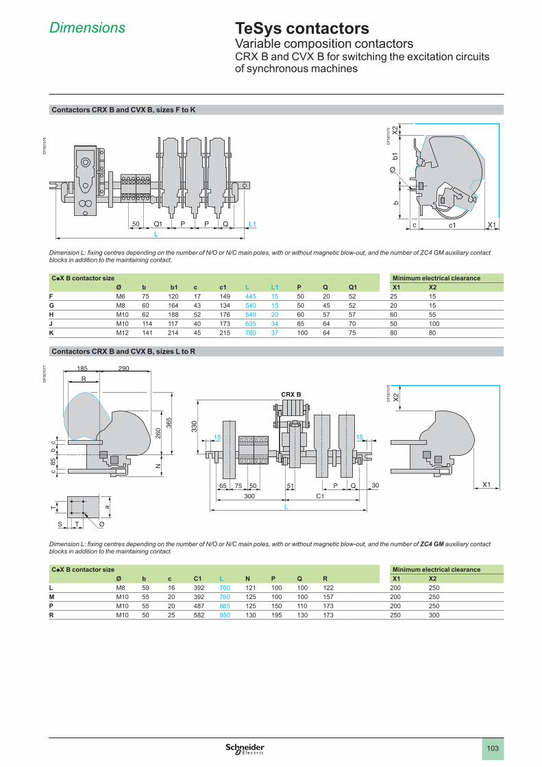
103
Dimensions
Contactors CRX B and CVX B, sizes F to K
DF5
6707
5
Dimension L: fixing centres depending on the number of N/O or N/C main poles, with or without magnetic blow-out, and the number of ZC4 GM auxiliary contact blocks in addition to the maintaining contact.
CpX B contactor size Minimum electrical clearanceØ b b1 c c1 L L1 P Q Q1 X1 X2
F M6 75 120 17 149 445 15 50 20 52 25 15G M8 60 164 43 134 540 15 50 45 52 20 15H M10 62 188 52 176 540 20 60 57 57 60 55J M10 114 117 40 173 635 34 85 64 70 50 K M12 141 214 45 215 760 37 64 75 80 80
Contactors CRX B and CVX B, sizes L to R
DF5
6707
8
Dimension L: fixing centres depending on the number of N/O or N/C main poles, with or without magnetic blow-out, and the number of ZC4 GM auxiliary contact blocks in addition to the maintaining contact.
CpX B contactor size Minimum electrical clearanceØ b c C1 L N P Q R X1 X2
L M8 59 16 392 760 121 122 200 250M M10 55 20 392 760 125 157 200 250P M10 55 20 487 885 125 150 173 200 250R M10 50 25 582 950 130 195 130 173 250 300
5050
CRX B
50 51 P Q
300
365
260
N
30
C1
7565
ØS T
R
185 290
Tc
cb
85
a
15 15
L
CRX B
50 51 P Q
300
365
260
N
30
C1
7565
ØS T
R
185 290
Tc
cb
85
a
15 15
L
TeSys contactors Variable composition contactorsCRX B and CVX B for switching the excitation circuits of synchronous machines
DF5
6707
6D
F567
077

104


Schneider Electric Industries SAS35, rue Joseph MonierCS 30323F- 92506 Rueil Malmaison Cedex
RCS Nanterre 954 503 439Capital social 896 313 776 €www.schneider-electric.com
© 2
011
- Sch
neid
er E
lect
ric -
Tous
dro
its ré
serv
és
02-2011
As standards, specifications and designs change from time to time, please ask for confirmation of the information given in this publication.
This document has been printed on ecological paper.
Design: Schneider ElectricPhotos: Schneider ElectricPrinted:


