Embed Size (px)
Citation preview

GerätehandbuchManual
Industrial ControlsSwitching DevicesSIRIUS - SIRIUS 3RT Contactors / Contactor assemblies
Edition
siemens.com
09/2016

SIRIUS - SIRIUS 3RT
Contactors/Contactor assemblies
___________________
___________________
___________________
___________________
___________________
___________________
___________________
___________________
___________________
___________________
___________________
___________________
___________________
Industrial Controls
Switching devices SIRIUS - SIRIUS 3RT Contactors/Contactor assemblies
Manual
09/2016 A5E03656507120A/RS-AC/004
Introduction 1
Standards 2
Product description 3
Product combinations 4
Configuration 5
Mounting 6
Connection 7
Accessories 8
Technical data 9
Circuit diagrams 10
Types of coordination A
References B
Dimension drawings (dimensions in mm)
C
Siemens AG Division Digital Factory Postfach 48 48 90026 NÜRNBERG GERMANY
3ZX1012-0RT20-5AC1 Ⓟ 09/2016 Subject to change
Copyright © Siemens AG 2011. All rights reserved
Legal information Warning notice system
This manual contains notices you have to observe in order to ensure your personal safety, as well as to prevent damage to property. The notices referring to your personal safety are highlighted in the manual by a safety alert symbol, notices referring only to property damage have no safety alert symbol. These notices shown below are graded according to the degree of danger.
DANGER indicates that death or severe personal injury will result if proper precautions are not taken.
WARNING indicates that death or severe personal injury may result if proper precautions are not taken.
CAUTION indicates that minor personal injury can result if proper precautions are not taken.
NOTICE indicates that property damage can result if proper precautions are not taken.
If more than one degree of danger is present, the warning notice representing the highest degree of danger will be used. A notice warning of injury to persons with a safety alert symbol may also include a warning relating to property damage.
Qualified Personnel The product/system described in this documentation may be operated only by personnel qualified for the specific task in accordance with the relevant documentation, in particular its warning notices and safety instructions. Qualified personnel are those who, based on their training and experience, are capable of identifying risks and avoiding potential hazards when working with these products/systems.
Proper use of Siemens products Note the following:
WARNING Siemens products may only be used for the applications described in the catalog and in the relevant technical documentation. If products and components from other manufacturers are used, these must be recommended or approved by Siemens. Proper transport, storage, installation, assembly, commissioning, operation and maintenance are required to ensure that the products operate safely and without any problems. The permissible ambient conditions must be complied with. The information in the relevant documentation must be observed.
Trademarks All names identified by ® are registered trademarks of Siemens AG. The remaining trademarks in this publication may be trademarks whose use by third parties for their own purposes could violate the rights of the owner.
Disclaimer of Liability We have reviewed the contents of this publication to ensure consistency with the hardware and software described. Since variance cannot be precluded entirely, we cannot guarantee full consistency. However, the information in this publication is reviewed regularly and any necessary corrections are included in subsequent editions.
SIRIUS - SIRIUS 3RT Contactors/Contactor assemblies Manual, 09/2016, A5E03656507120A/RS-AC/004 5
Table of contents
1 Introduction ........................................................................................................................................... 13
1.1 Responsibility of the user for system configuration and functionality ..................................... 13
1.2 Purpose of the manual ............................................................................................................ 14
1.3 Advantages through energy efficiency .................................................................................... 15
1.4 Required basic knowledge ...................................................................................................... 15
1.5 Scope of the manual ............................................................................................................... 15
1.6 Siemens Industry Online Support ........................................................................................... 16
1.7 Further documentation ............................................................................................................ 17
1.8 DataMatrix code ...................................................................................................................... 18
1.9 Siemens Industry Online Support app .................................................................................... 18
1.10 Recycling and disposal ........................................................................................................... 19
1.11 Technical Assistance .............................................................................................................. 19
2 Standards ............................................................................................................................................. 21
2.1 Standards and product approvals ........................................................................................... 21
2.2 Protective separation .............................................................................................................. 22
2.3 Positively driven contact elements/Mirror contacts ................................................................. 23
2.4 IE3 / IE4 ready ........................................................................................................................ 25
2.5 Applications ............................................................................................................................. 26
3 Product description ............................................................................................................................... 29
3.1 Overview of the contactor range ............................................................................................. 29
3.2 Device versions ....................................................................................................................... 33 3.2.1 3RT2 power contactors ........................................................................................................... 34 3.2.2 3RT10 / 3RT14 power contactors and 3RT12 vacuum contactors ........................................ 39 3.2.3 3RH2 contactor relays ............................................................................................................ 45 3.2.4 3RT26 capacitor contactors .................................................................................................... 48 3.2.5 3RA23 reversing contactor assemblies .................................................................................. 53 3.2.6 3RA24 contactor assemblies for star-delta (wye-delta) start .................................................. 56 3.2.7 Drive options ........................................................................................................................... 60
4 Product combinations ............................................................................................................................ 61
Table of contents
SIRIUS - SIRIUS 3RT Contactors/Contactor assemblies 6 Manual, 09/2016, A5E03656507120A/RS-AC/004
5 Configuration ........................................................................................................................................ 63
5.1 Overview of applications for contactors and contactor assemblies ....................................... 63
5.2 SIRIUS system configurator ................................................................................................... 64
5.3 Operating mechanism system / coil selection 3RT contactors and 3RH2 contactor relays ...................................................................................................................................... 65
5.3.1 Operating mechanism system / coil selection 3RT2 contactors and 3RH2 contactor relays ...................................................................................................................................... 65
5.3.2 Operating mechanism system / coil selection 3RT1 contactors ............................................ 66 5.3.2.1 Conventional and electronic operating mechanism types ..................................................... 66 5.3.2.2 Operating modes of electronic operating mechanism ........................................................... 70 5.3.2.3 Electronic operating mechanism with remaining lifetime signal ............................................ 73 5.3.2.4 Typical circuit diagrams ......................................................................................................... 77 5.3.2.5 Remaining lifetime signal (RLT) ............................................................................................. 78
5.4 Application environment ......................................................................................................... 81 5.4.1 3RH2 contactor relays ........................................................................................................... 81 5.4.2 3RT power contactors ............................................................................................................ 82 5.4.3 Contactors for railway applications ........................................................................................ 85 5.4.4 Installation altitude ................................................................................................................. 86
5.5 Switching motorized loads ..................................................................................................... 87
5.6 Switching resistive loads ........................................................................................................ 92
5.7 Changing the polarity of hoisting gear motors ....................................................................... 95
5.8 Switching in the auxiliary circuit ............................................................................................. 97
5.9 Switching of capacitive loads ................................................................................................. 98
5.10 Contactors with extended operating range .......................................................................... 105 5.10.1 Contactors for railway applications ...................................................................................... 105 5.10.1.1 Contactors for rail applications according to IEC 60077-2 .................................................. 105 5.10.1.2 Operating modes of electronic operating mechanism ......................................................... 107 5.10.2 Coupling relays .................................................................................................................... 109 5.10.2.1 Technical background information ....................................................................................... 111
5.11 Operation of a motor in two directions of rotation (reversing contactor assembly) ............. 112 5.11.1 Reference ............................................................................................................................. 118
5.12 Starting three-phase motors with reduced starting current peaks (contactor assembly for star-delta (wye- delta) start) ........................................................................................................................... 119
5.12.1 Reference ............................................................................................................................. 124 5.12.2 Technical background information ....................................................................................... 125
5.13 Using long control cables ..................................................................................................... 130
5.14 Configuration information for use downstream of frequency converters ............................. 136
5.15 Contact service life of auxiliary and main contacts .............................................................. 138 5.15.1 3RT2 power contactors (sizes S00 to S3) ........................................................................... 138 5.15.1.1 Contact service life of auxiliary and main contacts (sizes S00 and S0) .............................. 138 5.15.1.2 Contact service life of auxiliary and main contacts (size S2) ............................................... 141 5.15.1.3 Contact service life of auxiliary and main contacts (size S3) ............................................... 143 5.15.2 3RT26 capacitor contactors (sizes S00 to S2) .................................................................... 145 5.15.2.1 Contact service life of auxiliary and main contacts .............................................................. 145
Table of contents
SIRIUS - SIRIUS 3RT Contactors/Contactor assemblies Manual, 09/2016, A5E03656507120A/RS-AC/004 7
5.15.3 3RT10 power contactors and 3RT12 vacuum contactors (sizes S6 to S12) ........................ 147 5.15.3.1 Mechanical endurance .......................................................................................................... 147 5.15.3.2 Electrical endurance ............................................................................................................. 147
6 Mounting ............................................................................................................................................. 151
6.1 Mounting ............................................................................................................................... 151 6.1.1 Mounting options ................................................................................................................... 151 6.1.2 Mounting position .................................................................................................................. 152 6.1.3 Mounting on mounting plate / wall mounting ........................................................................ 153 6.1.4 Snapping onto DIN rail (snap-on mounting) ......................................................................... 156
6.2 Replacing solenoid coils ....................................................................................................... 159 6.2.1 Replacing solenoid coils for size S0 ..................................................................................... 159 6.2.2 Replacing solenoid coils for size S2 ..................................................................................... 162 6.2.3 Replacing solenoid coils for size S3 ..................................................................................... 167 6.2.4 Replacing solenoid coils for sizes S6-S12 ............................................................................ 173
6.3 Contact piece replacement (sizes S2 to S12) ...................................................................... 176 6.3.1 Contact piece replacement (size S2) .................................................................................... 176 6.3.2 Contact piece replacement (size S3) .................................................................................... 182 6.3.3 Contact piece replacement (size S6) .................................................................................... 188 6.3.4 Contact piece replacement (size S10 and S12) ................................................................... 190
6.4 Replacing the vacuum interrupters (sizes S10 and S12) ..................................................... 193
7 Connection ......................................................................................................................................... 197
7.1 Conductor cross-sections ..................................................................................................... 200 7.1.1 Conductor cross-sections for screw-type connection systems ............................................. 200 7.1.2 Conductor cross-sections for spring-loaded connection systems ........................................ 206 7.1.3 Conductor cross-sections for ring cable lug connection system .......................................... 208
8 Accessories ........................................................................................................................................ 211
8.1 Overview of accessories for 3RT2 contactors ...................................................................... 211 8.1.1 Overview of accessories for 3RT2 contactors ...................................................................... 211
8.2 Overview of accessories for 3RT1 contactors ...................................................................... 221 8.2.1 Overview of accessories for 3RT1 contactors ...................................................................... 221
8.3 Auxiliary switch blocks .......................................................................................................... 223 8.3.1 Auxiliary switch block for 3RT2 power contactors and 3RH2 contactor relays .................... 223 8.3.1.1 Description ............................................................................................................................ 223 8.3.1.2 Configuration ......................................................................................................................... 226 8.3.1.3 Selection guide for mountable auxiliary switch blocks for power contactors and
contactor relays ..................................................................................................................... 232 8.3.1.4 Mounting/Disassembly .......................................................................................................... 252 8.3.2 Auxiliary switch blocks for 3RT1 power contactors .............................................................. 255 8.3.2.1 Description ............................................................................................................................ 255 8.3.2.2 Configuration ......................................................................................................................... 258 8.3.2.3 Terminal designations and identification numbers for auxiliary contacts ............................. 260 8.3.2.4 Mounting/Disassembly .......................................................................................................... 261
8.4 Surge suppressor .................................................................................................................. 264 8.4.1 Description ............................................................................................................................ 264 8.4.2 Configuration ......................................................................................................................... 268 8.4.3 Mounting ............................................................................................................................... 276
Table of contents
SIRIUS - SIRIUS 3RT Contactors/Contactor assemblies 8 Manual, 09/2016, A5E03656507120A/RS-AC/004
8.5 EMC suppression module .................................................................................................... 282 8.5.1 Description ........................................................................................................................... 282 8.5.2 Configuration ........................................................................................................................ 284 8.5.3 Mounting .............................................................................................................................. 286
8.6 OFF-delay device ................................................................................................................. 287 8.6.1 Description ........................................................................................................................... 287 8.6.2 Configuration ........................................................................................................................ 287 8.6.3 Mounting .............................................................................................................................. 288
8.7 Mechanical latch .................................................................................................................. 290 8.7.1 Description ........................................................................................................................... 290 8.7.2 Mounting/Disassembly ......................................................................................................... 291 8.7.3 Operation ............................................................................................................................. 293
8.8 Additional load module ......................................................................................................... 294 8.8.1 Description ........................................................................................................................... 294 8.8.2 Mounting .............................................................................................................................. 294
8.9 Control kit for manual operation of contactor contacts ........................................................ 295 8.9.1 Description ........................................................................................................................... 295 8.9.2 Mounting .............................................................................................................................. 296
8.10 Coupling link for PLC ........................................................................................................... 298 8.10.1 Description ........................................................................................................................... 298 8.10.2 Mounting the 3RH2924-1GP11 coupling link ....................................................................... 301 8.10.3 Mounting and disassembling the 3RH2926-1AP1 coupling module.................................... 302
8.11 LED display indicator module .............................................................................................. 305 8.11.1 Description ........................................................................................................................... 305 8.11.2 Mounting .............................................................................................................................. 306
8.12 Solder pin adapter ................................................................................................................ 307 8.12.1 Description ........................................................................................................................... 307 8.12.2 Mounting .............................................................................................................................. 308
8.13 Coil terminal module ............................................................................................................ 310 8.13.1 Description ........................................................................................................................... 310 8.13.2 Mounting .............................................................................................................................. 311
8.14 Cover for ring cable lug ........................................................................................................ 313 8.14.1 Description ........................................................................................................................... 313
8.15 Sealable cover ..................................................................................................................... 314 8.15.1 Description ........................................................................................................................... 314 8.15.2 Mounting .............................................................................................................................. 314
8.16 3-phase infeed terminal ....................................................................................................... 315 8.16.1 Description ........................................................................................................................... 315 8.16.2 Mounting .............................................................................................................................. 315
8.17 1-phase infeed terminal ....................................................................................................... 316 8.17.1 Description ........................................................................................................................... 316 8.17.2 Mounting .............................................................................................................................. 316
8.18 Parallel switching connectors ............................................................................................... 317 8.18.1 Description ........................................................................................................................... 317 8.18.2 Configuration ........................................................................................................................ 318 8.18.3 Mounting .............................................................................................................................. 320
Table of contents
SIRIUS - SIRIUS 3RT Contactors/Contactor assemblies Manual, 09/2016, A5E03656507120A/RS-AC/004 9
8.19 Link module for two contactors in series ............................................................................... 321 8.19.1 Description ............................................................................................................................ 321 8.19.2 Mounting ............................................................................................................................... 321
8.20 Link module for motor starter protector ................................................................................. 323 8.20.1 Description ............................................................................................................................ 323
8.21 Pneumatically delayed auxiliary switch................................................................................. 324 8.21.1 Description ............................................................................................................................ 324 8.21.2 Mounting/Disassembly .......................................................................................................... 325 8.21.3 Operation .............................................................................................................................. 326
8.22 Insulating stop ....................................................................................................................... 327 8.22.1 Description ............................................................................................................................ 327
8.23 Terminal module for contactors with screw connections ...................................................... 328 8.23.1 Description ............................................................................................................................ 328 8.23.2 Mounting ............................................................................................................................... 329
8.24 3RA27 function modules for connection to the automation level (AS-Interface or IO-Link) ...................................................................................................................................... 330
8.24.1 Description ............................................................................................................................ 330
8.25 3RA28 function modules for mounting on 3RT2 contactors ................................................. 331 8.25.1 Description ............................................................................................................................ 331
8.26 Assembly kit for reversing contactor assemblies (sizes S00 to S3) ..................................... 333 8.26.1 Description ............................................................................................................................ 333 8.26.2 Mounting size S00 ................................................................................................................ 335 8.26.3 Mounting size S0 .................................................................................................................. 338 8.26.4 Mounting size S2 .................................................................................................................. 342 8.26.5 Mounting size S3 .................................................................................................................. 346
8.27 Wiring kit for reversing contactor assemblies (sizes S6 to S12) .......................................... 351 8.27.1 Description ............................................................................................................................ 351 8.27.2 Mounting size S6 .................................................................................................................. 352 8.27.3 Mounting sizes S10 and S12 ................................................................................................ 355
8.28 Assembly kit for contactor assemblies for star-delta (wye-delta) start (sizes S00 to S3) ..... 357 8.28.1 Description ............................................................................................................................ 357 8.28.2 Mounting size S00 ................................................................................................................ 361 8.28.3 Mounting size S0 .................................................................................................................. 365 8.28.4 Mounting size S2 .................................................................................................................. 370 8.28.5 Mounting size S3 .................................................................................................................. 381
8.29 Wiring kit for contactor assemblies for star-delta (wye-delta) start (sizes S6 to S12). ......... 393 8.29.1 Description ............................................................................................................................ 393 8.29.2 Mounting size S6 .................................................................................................................. 395 8.29.3 Mounting sizes S10 and S12 ................................................................................................ 401
8.30 Terminal cover for cable lug connection and busbar connection ......................................... 405 8.30.1 Description ............................................................................................................................ 405 8.30.2 Mounting ............................................................................................................................... 407
8.31 Terminal covers for box terminal block ................................................................................. 416 8.31.1 Description ............................................................................................................................ 416 8.31.2 Mounting ............................................................................................................................... 416
Table of contents
SIRIUS - SIRIUS 3RT Contactors/Contactor assemblies 10 Manual, 09/2016, A5E03656507120A/RS-AC/004
8.32 Main current path surge attenuation module for vacuum contactors ................................... 417 8.32.1 Description ........................................................................................................................... 417 8.32.2 Mounting .............................................................................................................................. 418
8.33 Box terminal block (size S6 to S12) ..................................................................................... 420 8.33.1 Description ........................................................................................................................... 420 8.33.2 Mounting .............................................................................................................................. 421
8.34 Solid-state time-delay auxiliary switch blocks (size S6 to S12) ........................................... 422 8.34.1 Description ........................................................................................................................... 422 8.34.2 Configuration ........................................................................................................................ 425 8.34.3 Mounting/Disassembly ......................................................................................................... 425
9 Technical data ..................................................................................................................................... 427
9.1 Technical data in Siemens Industry Online Support ............................................................ 427
9.2 Overview tables.................................................................................................................... 427
10 Circuit diagrams ................................................................................................................................... 429
10.1 CAx data .............................................................................................................................. 429
10.2 Contactors and contactor accessories ................................................................................. 430
10.3 Capacitor contactors (S00 / S0 / S2) ................................................................................... 446
10.4 Reversing contactor assemblies (S00 / S0 / S2 / S3) .......................................................... 450
10.5 Reversing contactor assemblies (S6 / S10 / S12) ............................................................... 451
10.6 Contactor assemblies for star-delta (wye-delta) start (S00 / S0 / S2 / S3) .......................... 453
10.7 Contactor assemblies for star-delta (wye-delta) start (S6 / S10 / S12) ............................... 456
A Types of coordination ........................................................................................................................... 459
B References .......................................................................................................................................... 461
B.1 References ........................................................................................................................... 461
B.2 Manuals - SIRIUS Modular System ..................................................................................... 463
B.3 More information .................................................................................................................. 465
C Dimension drawings (dimensions in mm) ............................................................................................. 467
C.1 CAx data .............................................................................................................................. 467
C.2 3RT2.1 contactors and 3RH2 contactor relays (size S00) .................................................. 468
C.3 3RT2.2 contactors (size S0) ................................................................................................ 474
C.4 3RT2.3 contactors (size S2) ................................................................................................ 480
C.5 3RT2.4 contactors (size S3) ................................................................................................ 484
C.6 3RT1.5 contactors (size S6) ................................................................................................ 488
C.7 3RT1.6 contactors (size S10) .............................................................................................. 489
C.8 3RT1.7 contactors (size S12) .............................................................................................. 490
Table of contents
SIRIUS - SIRIUS 3RT Contactors/Contactor assemblies Manual, 09/2016, A5E03656507120A/RS-AC/004 11
C.9 3RT26 capacitor contactors .................................................................................................. 491 C.9.1 3RT261 capacitor contactors (size S00)............................................................................... 491 C.9.2 3RT262 capacitor contactors (size S0) ................................................................................. 492 C.9.3 3RT263 capacitor contactors (size S2) ................................................................................. 495
C.10 3RA23 reversing contactor assemblies ................................................................................ 496 C.10.1 3RA231 reversing contactor assemblies (size S00) ............................................................. 496 C.10.2 3RA232 reversing contactor assemblies (size S0) ............................................................... 498 C.10.3 3RA233 reversing contactor assemblies (size S2) ............................................................... 502 C.10.4 3RA234 reversing contactor assemblies (size S3) ............................................................... 503 C.10.4.1 3RA234.-8X.30-1 reversing contactor assemblies (size S3) ................................................ 503 C.10.4.2 Drilling diagram for 3RA234.-8X.30-1 reversing contactor assemblies (size S3)................. 503
C.11 3RA24 contactor assemblies for star-delta (wye-delta) start ................................................ 504 C.11.1 3RA241 contactor assemblies for star-delta (wye-delta) start (size S00) ............................ 504 C.11.2 3RA242 contactor assemblies for star-delta (wye-delta) start (size S0) .............................. 506 C.11.2.1 3RA242.-8X.3.-1 contactor assemblies for star-delta (wye-delta) start (size S0, screw-
type connection system) ....................................................................................................... 506 C.11.2.2 Drilling diagram for 3RA242.-8X.3.-1 contactor assemblies for star-delta (wye-delta)
start (size S0, screw-type connection system) ..................................................................... 506 C.11.2.3 3RA242.-8X.3.-2 contactor assemblies for star-delta (wye-delta) start (size S0, spring-
loaded connection system) ................................................................................................... 507 C.11.2.4 Drilling diagram for 3RA242.-8X.3.-2 contactor assemblies for star-delta (wye-delta)
start (size S0, spring-loaded connection system) ................................................................. 507 C.11.3 3RA243 contactor assemblies for star-delta (wye-delta) start (size S2) .............................. 508 C.11.4 3RA244 contactor assemblies for star-delta (wye-delta) start (size S3) .............................. 510 C.11.4.1 3RA244.-8X.32-1 contactor assemblies for star-delta (wye-delta) start (size S3) ............... 510 C.11.4.2 Drilling diagram for 3RA244.-8X.32-1 contactor assemblies for star-delta (wye-delta)
start (size S3) ........................................................................................................................ 511
Index................................................................................................................................................... 513

Table of contents
SIRIUS - SIRIUS 3RT Contactors/Contactor assemblies 12 Manual, 09/2016, A5E03656507120A/RS-AC/004
SIRIUS - SIRIUS 3RT Contactors/Contactor assemblies Manual, 09/2016, A5E03656507120A/RS-AC/004 13
Introduction 1 1.1 Responsibility of the user for system configuration and functionality
The SIRIUS portfolio offers various switching devices for the safe and functional switching of electrical loads. 3RT2 contactors are available in sizes S00 to S3. 3RT1 contactors are available in sizes S6 to S12.
● 3RT.0 power contactors and 3RT12 vacuum contactors for switching motorized loads
● 4-pole 3RT23 contactors for switching resistive loads
● 3-pole 3RT24 / 3RT14 contactors for switching resistive loads
● 4-pole 3RT25 contactors for changing the polarity of hoisting gear motors
● 3RH2 contactor relays for switching in the control circuit
● 3RT26 capacitor contactors for switching capacitive loads (AC-6b)
● 3RT1 / 3RT2 / 3RH2 contactors with extended operating range
– 3RT10 / 3RT20 / 3RH21 contactors for rail applications
– 3RT20 / 3RH21 coupling relays for system-compliant interaction with electronic controllers
● Operation of a motor in two directions of rotation (reversing contactor assembly)
● Starting three-phase motors with reduced starting current peaks (contactor assemblies for star-delta (wye-delta) start)
Siemens AG, its regional offices, and associated companies (hereinafter referred to as "Siemens") cannot guarantee all the properties of an overall installation or machine that has not been designed by Siemens.
Nor can Siemens assume liability for recommendations that appear or are implied in the following description. No new guarantee, warranty, or liability claims beyond the scope of the Siemens general terms of supply are to be derived or inferred from the following description.
Note
When designing a system, comply with all valid national installation specifications and standards.
Introduction 1.2 Purpose of the manual
SIRIUS - SIRIUS 3RT Contactors/Contactor assemblies 14 Manual, 09/2016, A5E03656507120A/RS-AC/004
1.2 Purpose of the manual This manual describes 3RT2 contactors (up to 55 kW), 3RT1 contactors (from 55 kW), 3RH21 contactor relays, reversing contactor assemblies, and contactor assemblies for star-delta (wye-delta) start, and it supplies the following information:
● Information about integrating the contactors and contactor assemblies into the system environment.
● Information on necessary hardware components.
● Information about installing and connecting the contactors.
● Technical information such as dimension drawings and unit wiring diagrams.
The information in this manual enables you to configure and commission the contactors.
Introduction 1.3 Advantages through energy efficiency
SIRIUS - SIRIUS 3RT Contactors/Contactor assemblies Manual, 09/2016, A5E03656507120A/RS-AC/004 15
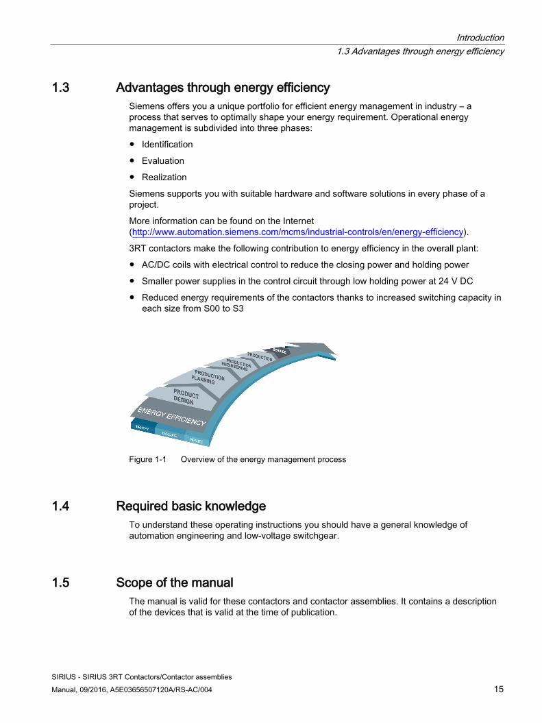
1.3 Advantages through energy efficiency Siemens offers you a unique portfolio for efficient energy management in industry – a process that serves to optimally shape your energy requirement. Operational energy management is subdivided into three phases:
● Identification
● Evaluation
● Realization
Siemens supports you with suitable hardware and software solutions in every phase of a project.
More information can be found on the Internet (http://www.automation.siemens.com/mcms/industrial-controls/en/energy-efficiency).
3RT contactors make the following contribution to energy efficiency in the overall plant:
● AC/DC coils with electrical control to reduce the closing power and holding power
● Smaller power supplies in the control circuit through low holding power at 24 V DC
● Reduced energy requirements of the contactors thanks to increased switching capacity in each size from S00 to S3
Figure 1-1 Overview of the energy management process
1.4 Required basic knowledge To understand these operating instructions you should have a general knowledge of automation engineering and low-voltage switchgear.
1.5 Scope of the manual The manual is valid for these contactors and contactor assemblies. It contains a description of the devices that is valid at the time of publication.
Introduction 1.6 Siemens Industry Online Support
SIRIUS - SIRIUS 3RT Contactors/Contactor assemblies 16 Manual, 09/2016, A5E03656507120A/RS-AC/004
1.6 Siemens Industry Online Support
Information and Service In Siemens Industry Online Support, you can obtain up-to-date information from our global support database quickly and simply. To accompany our products and systems, we offer a wealth of information and services that provide support in every phase of the lifecycle of your machine or plant – from planning and implementation, through commissioning, up to maintenance and modernization:
● Product support
● Application examples
● Services
● Forum
● mySupport
Link: Siemens Industry Online Support (https://support.industry.siemens.com/cs/ww/en)
Product support You will find here all the information and comprehensive know-how covering all aspects of your product:
● FAQs
Our answers to frequently asked questions.
● Manuals/operating instructions
Read online or download, available as PDF or individually configurable.
● Certificates
Clearly sorted according to approving authority, type and country.
● Characteristic curves
For support in planning and configuring your system.
● Product announcements
The latest information and news concerning our products.
● Downloads
You can find here updates, service packs, HSPs and much more for your product.
● Application examples
Function blocks, background and system descriptions, performance statements, demonstration systems, and application examples, clearly explained and represented.
● Technical data
Technical product data for support in planning and implementing your project.
Link: Product support (https://support.industry.siemens.com/cs/ww/en/ps)
Introduction 1.7 Further documentation
SIRIUS - SIRIUS 3RT Contactors/Contactor assemblies Manual, 09/2016, A5E03656507120A/RS-AC/004 17
mySupport With "mySupport", your personal workspace, you get the very best out of your Industry Online Support. Everything to enable you to find the right information every time.
The following functions are now available:
● Personal messages Your personal mailbox for exchanging information and managing your contacts
● Inquiries Use our online form for specific solution suggestions, or send your technical inquiry directly to a specialist in Technical Support
● Notifications Make sure you always have the latest information - individually tailored to your needs
● Filters Simple management and re-use of your filter settings from Product Support and the Technical Forum
● Favorites / Tags Create your own knowledge database by assigning "Favorites" and "Tags" to documents – simply and efficiently
● Entries last viewed Clear presentation of your last viewed entries
● Documentation Configure your individual documentation from different manuals – quickly and without complications
● Personal data Change personal data and contact information here
● CAx data Simple access to thousands of items of CAx data such as 3D models, 2D dimension drawings, EPLAN macros and much more
1.7 Further documentation To install and connect the contactors and contactor assemblies, you require the operating instructions of the contactors and contactor assemblies used.
You can find a list of operating instructions and an overview of the manuals pertaining to the SIRIUS modular system in the Appendix "References (Page 461)".
Introduction 1.8 DataMatrix code
SIRIUS - SIRIUS 3RT Contactors/Contactor assemblies 18 Manual, 09/2016, A5E03656507120A/RS-AC/004
1.8 DataMatrix code A Data Matrix code has been lasered onto the contactors and contactor assembly enclosures.
The Data Matrix codes are standardized in ISO/IEC 16022. The Data Matrix codes on Siemens devices use ECC200 coding for powerful error correction.
The following information is stored in the Data Matrix code: 1P Article number + S Loca-
tion / Date Serial number
Data iden-tifier
User content Separa-tor
User content Separa-tor
User content User content
Note
The information content is displayed without spaces.
This machine-readable information simplifies and accelerates handling of the respective devices. As well as fast access to the serial numbers of the respective devices for unique identification, the Data Matrix codes simplify communication with Siemens Technical Support.
1.9 Siemens Industry Online Support app
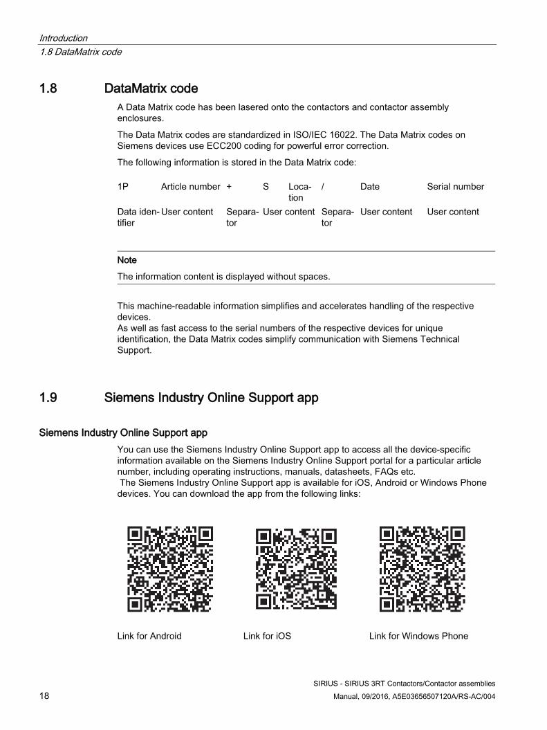
Siemens Industry Online Support app You can use the Siemens Industry Online Support app to access all the device-specific information available on the Siemens Industry Online Support portal for a particular article number, including operating instructions, manuals, datasheets, FAQs etc. The Siemens Industry Online Support app is available for iOS, Android or Windows Phone devices. You can download the app from the following links:
Link for Android Link for iOS Link for Windows Phone
Introduction 1.10 Recycling and disposal
SIRIUS - SIRIUS 3RT Contactors/Contactor assemblies Manual, 09/2016, A5E03656507120A/RS-AC/004 19
1.10 Recycling and disposal These devices can be recycled thanks to their low pollutant content. For environmentally-friendly recycling and disposal of your electronic waste, please contact a company certified for the disposal of electronic waste.
1.11 Technical Assistance
Up-to-the-minute information You can obtain further assistance by calling the following numbers:
Technical Assistance:
Telephone: +49 (911) 895-5900 (8 a.m. to 5 p.m. CET)
Fax: +49 (911) 895-5907
or on the Internet at:
E-mail: (mailto:[email protected])
Internet: (http://www.siemens.com/sirius/technical-assistance)
Introduction 1.11 Technical Assistance
SIRIUS - SIRIUS 3RT Contactors/Contactor assemblies 20 Manual, 09/2016, A5E03656507120A/RS-AC/004
SIRIUS - SIRIUS 3RT Contactors/Contactor assemblies Manual, 09/2016, A5E03656507120A/RS-AC/004 21
Standards 2 2.1 Standards and product approvals
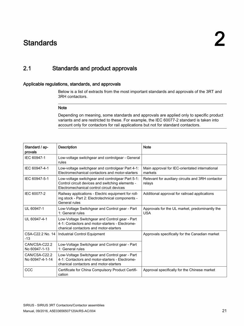
Applicable regulations, standards, and approvals Below is a list of extracts from the most important standards and approvals of the 3RT and 3RH contactors.
Note
Depending on meaning, some standards and approvals are applied only to specific product variants and are restricted to these. For example, the IEC 60077-2 standard is taken into account only for contactors for rail applications but not for standard contactors.
Standard / ap-provals
Description Note
IEC 60947-1 Low-voltage switchgear and controlgear - General rules
IEC 60947-4-1 Low-voltage switchgear and controlgear Part 4-1: Electromechanical contactors and motor-starters
Main approval for IEC-orientated international markets
IEC 60947-5-1 Low-voltage switchgear and controlgear Part 5-1: Control circuit devices and switching elements - Electromechanical control circuit devices
Relevant for auxiliary circuits and 3RH contactor relays
IEC 60077-2 Railway applications - Electric equipment for roll-ing stock - Part 2: Electrotechnical components - General rules
Additional approval for railroad applications
UL 60947-1 Low-Voltage Switchgear and Control gear - Part 1: General rules
Approvals for the UL market, predominantly the USA
UL 60947-4-1 Low-Voltage Switchgear and Control gear - Part 4-1: Contactors and motor-starters - Electrome-chanical contactors and motor-starters
CSA-C22.2 No. 14-13
Industrial Control Equipment Approvals specifically for the Canadian market
CAN/CSA-C22.2 No 60947-1-13
Low-Voltage Switchgear and Control gear - Part 1: General rules
CAN/CSA-C22.2 No 60947-4-1-14
Low-Voltage Switchgear and Control gear - Part 4-1: Contactors and motor-starters - Electrome-chanical contactors and motor-starters
CCC Certificate for China Compulsory Product Certifi-cation
Approval specifically for the Chinese market
Standards 2.2 Protective separation
SIRIUS - SIRIUS 3RT Contactors/Contactor assemblies 22 Manual, 09/2016, A5E03656507120A/RS-AC/004
Reference SIRIUS components have been approved by a whole range of bodies for various sectors (shipbuilding, etc.). More information and certificates for download are available on the Internet (https://support.industry.siemens.com/cs/ww/en/ps/16131/cert).
Reference You can find all the technical data and other information regarding the products in the Siemens Industry Online Support (https://support.industry.siemens.com/cs/ww/en/ps/16132/td).
2.2 Protective separation
Definition In order for the "protective separation" of circuits to be achieved, an individual fault must not be able to trigger a voltage overspill from one circuit into another. The kinds of fault to be taken into account include twisted or loose conductive parts, twisted solder pins, broken winding wires, missing screws, or broken barriers within a device.
Protective separation for 3RT10, 3RT20 and 3RH2 contactor relays The term "protective separation" is used in relation to safety extra low voltage (SELV/PELV) and functional extra low voltage (FELV). Protective separation reliably prevents a dangerous contact voltage from spilling over to the voltage which has been protectively separated (e.g. to a safety extra low voltage which is present or switched in the same device). If the current paths of a contactor are operated at different voltages, "protective separation" requirements must be met. With 3RT1 and 3RT2 contactors, and 3RH2 contactor relays, "protective separation" is ensured up to a certain voltage.
Regulations "Protective separation" between circuits within equipment is achieved by complying with the basic requirements contained in the IEC 60947-1 standard.
Basic requirements include, for example:
● Double or reinforced insulation
● Electrically protective shielding
● Combination of double or reinforced insulation and electrically protective shielding
The insulation must be resistant to aging for the duration of the expected service life.
Circuits without a safety extra low voltage or a functional extra low voltage do not require protective separation.
Standards 2.3 Positively driven contact elements/Mirror contacts
SIRIUS - SIRIUS 3RT Contactors/Contactor assemblies Manual, 09/2016, A5E03656507120A/RS-AC/004 23
2.3 Positively driven contact elements/Mirror contacts
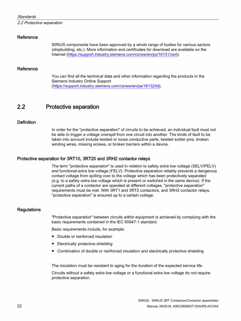
Positively driven contacts for contactor relays according to IEC 60947-5-1 Positively-driven contact elements according to IEC 60947-5-1 are a combination of "n" NO contacts and "m" NC contacts which are designed in such a way that they cannot be closed simultaneously. "Positively driven operation" may only apply to auxiliary switch elements which are contained in switching devices and whose actuating forces are generated internally. An example of such elements are the SIRIUS 3RH2 contactor relays.
All SIRIUS 3RH2 contactor relays (with at least 1 NC contact) are tested to IEC 60947-5-1, and ever since the product was launched, they have featured positively driven contact elements in the basic device, or in the basic device in conjunction with auxiliary switches.
Figure 2-1 Symbol for positively driven contact elements in a switching device
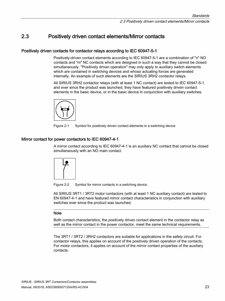
Mirror contact for power contactors to IEC 60947-4-1 A mirror contact according to IEC 60947-4-1 is an auxiliary NC contact that cannot be closed simultaneously with an NO main contact.
Figure 2-2 Symbol for mirror contacts in a switching device
All SIRIUS 3RT1 / 3RT2 motor contactors (with at least 1 NC auxiliary contact) are tested to EN 60947-4-1 and have featured mirror contact characteristics in conjunction with auxiliary switches ever since the product was launched.
Note
Both contact characteristics, the positively driven contact element in the contactor relay as well as the mirror contact in the power contactor, meet the same technical requirements.
The 3RT1 / 3RT2 / 3RH2 contactors are suitable for applications in the safety circuit. For contactor relays, this applies on account of the positively driven operation of the contacts. For motor contactors, it applies on account of the mirror contact properties of the auxiliary contacts.
Standards 2.3 Positively driven contact elements/Mirror contacts
SIRIUS - SIRIUS 3RT Contactors/Contactor assemblies 24 Manual, 09/2016, A5E03656507120A/RS-AC/004
Employer's Liability Insurance Association / SUVA In addition to the standards IEC 60947-4-1 and IEC 60947-5-1, the requirements of the German Employer's Liability Insurance Associations or the Swiss Accident Insurance Institute (SUVA) also apply in the case of safety circuits for the protection of personnel. These requirements set stricter conditions for devices with mirror contacts or positively driven contact elements. The basic SUVA requirement is that all auxiliary switches must be mounted on the basic device at the factory in such a way that they cannot be removed. Manual actuation of the contactor must not be possible.
A SUVAPro type-examination certificate confirms that the switching device meets the basic health and safety requirements and that this requirement agreement has been assessed by an accredited European Notified Body.
Note
The SUVA certificate is required if products or systems are operated in Switzerland.
All SIRIUS 3RH2 contactor relays (with at least 1 NC auxiliary contact) are tested according to EN 60947-5-1 and have possessed the SUVA type-examination certificate since product launch.
All SIRIUS 3RT2 motor contactors (with at least 1 NC contact) are tested according to EN 60947-4-1 and can be supplied in accordance with SUVA requirements.
Thanks to the use of a double bridge for the contacts, all 3RT2 motor contactors and 3RH2 contactor relays feature contact redundancy and optimization of the contact surface. This crucially enhances the contactors' contact reliability.
Standards 2.4 IE3 / IE4 ready
SIRIUS - SIRIUS 3RT Contactors/Contactor assemblies Manual, 09/2016, A5E03656507120A/RS-AC/004 25
2.4 IE3 / IE4 ready Ambitious climate protection goals in Europe call for increasingly energy-efficient components.
With this in mind, the energy efficiency class IE3 / IE4 has been mandatory since January 2015 (with exceptions) for three-phase asynchronous motors, and this will have an effect on motors, low-voltage power distribution systems, and industrial controls.
This applies:
● Since January 1, 2015 for motors from 7.5 kW to 375 kW
● From January 1, 2017 for motors from 0.75 kW to 375 kW
You will be optimally equipped for the current motor generation with the SIRIUS modular system components and 3VA molded case circuit breakers.
You will find information on IE3 / IE4 at: Information IE3 (http://www.siemens.com/IE3ready)
Note Using 3RT contactors with IE3 / IE4 motors
For the use of 3RT contactors in conjunction with highly energy-efficient IE3 / IE4 motors, please observe the information on dimensioning and configuring in the "Application Manual - SIRIUS Controls with IE3 / IE4 Motors (https://support.industry.siemens.com/cs/ww/en/view/94770820)".
Standards 2.5 Applications
SIRIUS - SIRIUS 3RT Contactors/Contactor assemblies 26 Manual, 09/2016, A5E03656507120A/RS-AC/004
2.5 Applications
Use and application areas Various different switching devices are available for switching electrical loads. When frequent switching is necessary, the contactor is the ideal device.
Contactors are the most commonly used switching devices in industry, mechanical engineering and switchgear construction. The progressive automation of production plants has increased the significance of contactors, but this is also associated with higher and sometimes different requirements.
An automatic production system is significantly more sensitive to operating faults than manually operated systems. Every fault on an electrical device means a standstill, production downtime, and often substantial costs for recommissioning.
For this reason, value was placed on high operational reliability in the development of the SIRIUS contactor series. High service life, high contact reliability, and the option of using the contactors in the control cabinet at higher ambient temperatures are among the factors contributing to this. The contactors can be used at up to 60 °C and without derating even with side-by-side mounting.
Due to the diverse range application options, the range of contactors also encompasses versions for special applications such as switching resistive loads or switching capacitors, as well as the main 3RT20 and 3RT10 series for switching motorized loads.
The different contactor series with their possible application areas are explained in the following subsections.
Standards 2.5 Applications
SIRIUS - SIRIUS 3RT Contactors/Contactor assemblies Manual, 09/2016, A5E03656507120A/RS-AC/004 27
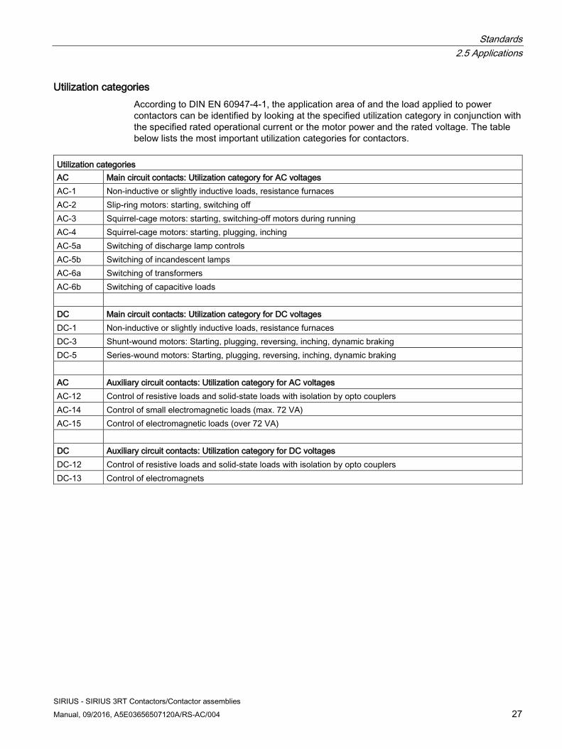
Utilization categories According to DIN EN 60947-4-1, the application area of and the load applied to power contactors can be identified by looking at the specified utilization category in conjunction with the specified rated operational current or the motor power and the rated voltage. The table below lists the most important utilization categories for contactors.
Utilization categories AC Main circuit contacts: Utilization category for AC voltages AC-1 Non-inductive or slightly inductive loads, resistance furnaces AC-2 Slip-ring motors: starting, switching off AC-3 Squirrel-cage motors: starting, switching-off motors during running AC-4 Squirrel-cage motors: starting, plugging, inching AC-5a Switching of discharge lamp controls AC-5b Switching of incandescent lamps AC-6a Switching of transformers AC-6b Switching of capacitive loads DC Main circuit contacts: Utilization category for DC voltages DC-1 Non-inductive or slightly inductive loads, resistance furnaces DC-3 Shunt-wound motors: Starting, plugging, reversing, inching, dynamic braking DC-5 Series-wound motors: Starting, plugging, reversing, inching, dynamic braking AC Auxiliary circuit contacts: Utilization category for AC voltages AC-12 Control of resistive loads and solid-state loads with isolation by opto couplers AC-14 Control of small electromagnetic loads (max. 72 VA) AC-15 Control of electromagnetic loads (over 72 VA) DC Auxiliary circuit contacts: Utilization category for DC voltages DC-12 Control of resistive loads and solid-state loads with isolation by opto couplers DC-13 Control of electromagnets

Standards 2.5 Applications
SIRIUS - SIRIUS 3RT Contactors/Contactor assemblies 28 Manual, 09/2016, A5E03656507120A/RS-AC/004
SIRIUS - SIRIUS 3RT Contactors/Contactor assemblies Manual, 09/2016, A5E03656507120A/RS-AC/004 29
Product description 3 3.1 Overview of the contactor range
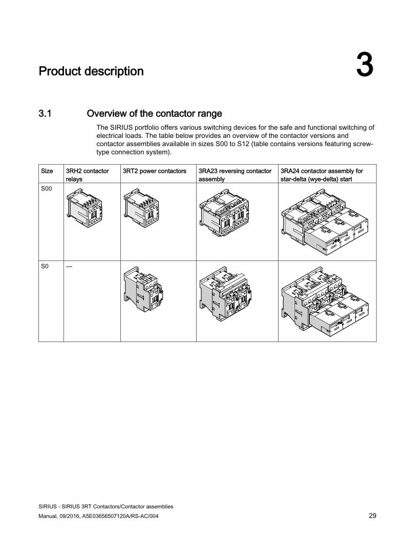
The SIRIUS portfolio offers various switching devices for the safe and functional switching of electrical loads. The table below provides an overview of the contactor versions and contactor assemblies available in sizes S00 to S12 (table contains versions featuring screw-type connection system).
Size 3RH2 contactor
relays 3RT2 power contactors 3RA23 reversing contactor
assembly 3RA24 contactor assembly for star-delta (wye-delta) start
S00
S0 ---
Product description 3.1 Overview of the contactor range
SIRIUS - SIRIUS 3RT Contactors/Contactor assemblies 30 Manual, 09/2016, A5E03656507120A/RS-AC/004
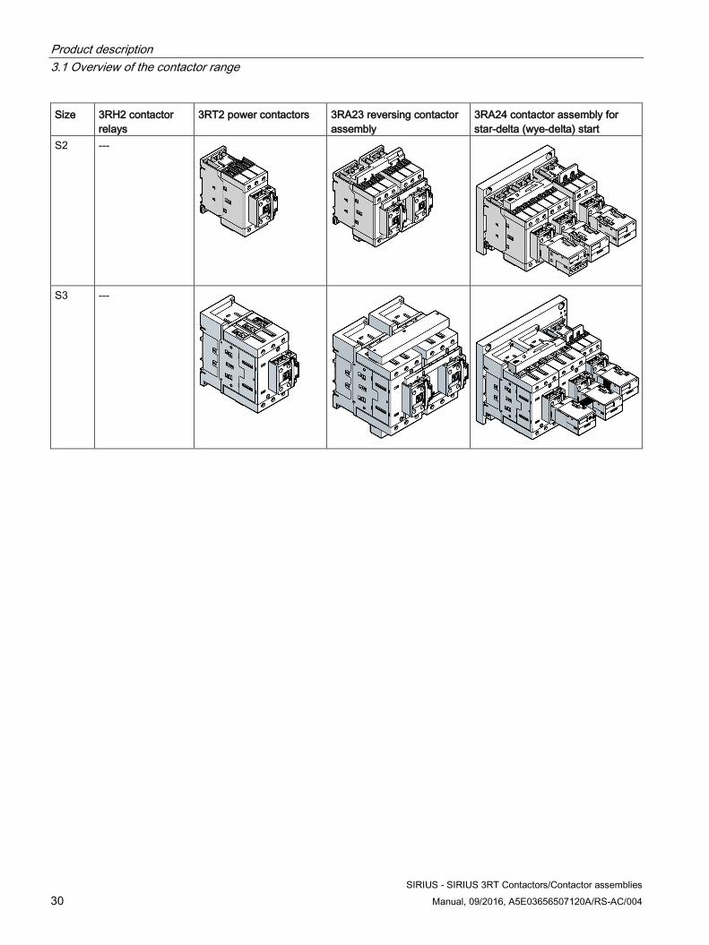
Size 3RH2 contactor relays
3RT2 power contactors 3RA23 reversing contactor assembly
3RA24 contactor assembly for star-delta (wye-delta) start
S2 ---
S3 ---
Product description 3.1 Overview of the contactor range
SIRIUS - SIRIUS 3RT Contactors/Contactor assemblies Manual, 09/2016, A5E03656507120A/RS-AC/004 31
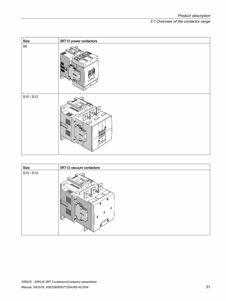
Size 3RT10 power contactors S6
S10 / S12
Size 3RT12 vacuum contactors S10 / S12
Product description 3.1 Overview of the contactor range
SIRIUS - SIRIUS 3RT Contactors/Contactor assemblies 32 Manual, 09/2016, A5E03656507120A/RS-AC/004
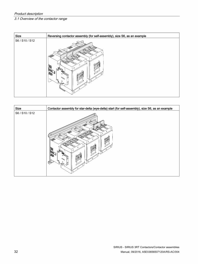
Size Reversing contactor assembly (for self-assembly), size S6, as an example S6 / S10 / S12
Size Contactor assembly for star-delta (wye-delta) start (for self-assembly), size S6, as an example S6 / S10 / S12
Product description 3.2 Device versions
SIRIUS - SIRIUS 3RT Contactors/Contactor assemblies Manual, 09/2016, A5E03656507120A/RS-AC/004 33
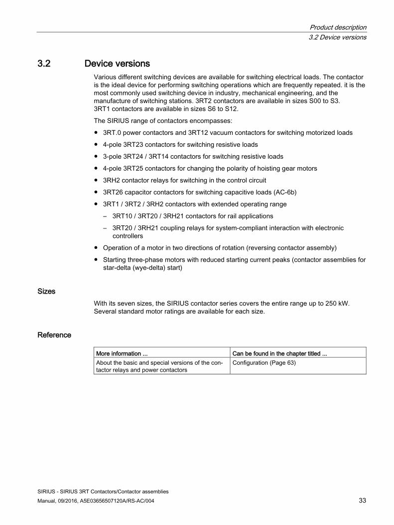
3.2 Device versions Various different switching devices are available for switching electrical loads. The contactor is the ideal device for performing switching operations which are frequently repeated. it is the most commonly used switching device in industry, mechanical engineering, and the manufacture of switching stations. 3RT2 contactors are available in sizes S00 to S3. 3RT1 contactors are available in sizes S6 to S12.
The SIRIUS range of contactors encompasses:
● 3RT.0 power contactors and 3RT12 vacuum contactors for switching motorized loads
● 4-pole 3RT23 contactors for switching resistive loads
● 3-pole 3RT24 / 3RT14 contactors for switching resistive loads
● 4-pole 3RT25 contactors for changing the polarity of hoisting gear motors
● 3RH2 contactor relays for switching in the control circuit
● 3RT26 capacitor contactors for switching capacitive loads (AC-6b)
● 3RT1 / 3RT2 / 3RH2 contactors with extended operating range
– 3RT10 / 3RT20 / 3RH21 contactors for rail applications
– 3RT20 / 3RH21 coupling relays for system-compliant interaction with electronic controllers
● Operation of a motor in two directions of rotation (reversing contactor assembly)
● Starting three-phase motors with reduced starting current peaks (contactor assemblies for star-delta (wye-delta) start)
Sizes With its seven sizes, the SIRIUS contactor series covers the entire range up to 250 kW. Several standard motor ratings are available for each size.
Reference More information ... Can be found in the chapter titled ... About the basic and special versions of the con-tactor relays and power contactors
Configuration (Page 63)
Product description 3.2 Device versions
SIRIUS - SIRIUS 3RT Contactors/Contactor assemblies 34 Manual, 09/2016, A5E03656507120A/RS-AC/004
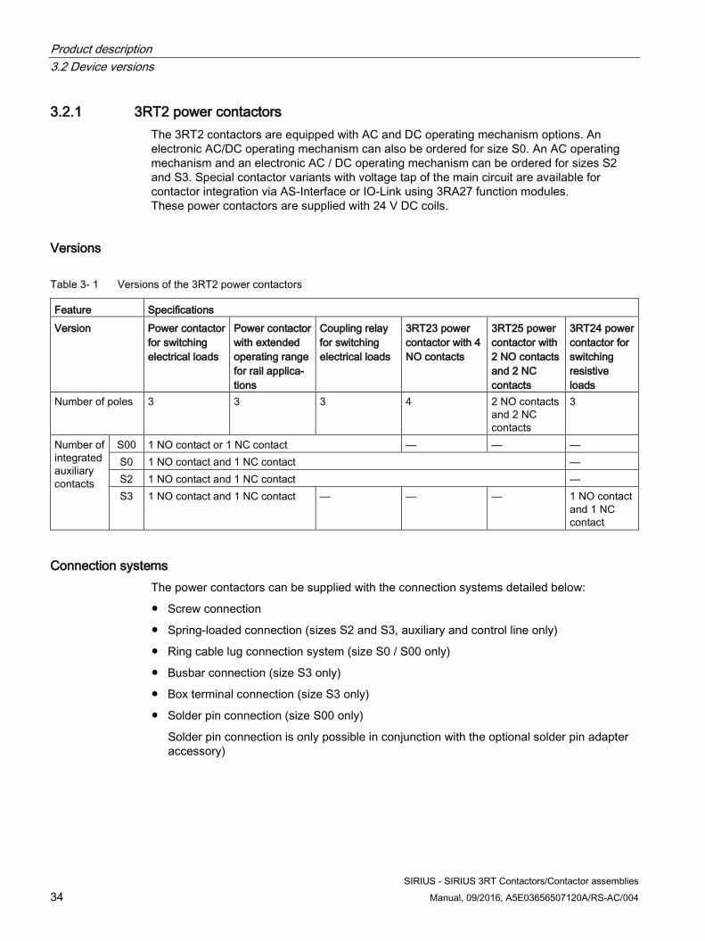
3.2.1 3RT2 power contactors The 3RT2 contactors are equipped with AC and DC operating mechanism options. An electronic AC/DC operating mechanism can also be ordered for size S0. An AC operating mechanism and an electronic AC / DC operating mechanism can be ordered for sizes S2 and S3. Special contactor variants with voltage tap of the main circuit are available for contactor integration via AS-Interface or IO-Link using 3RA27 function modules. These power contactors are supplied with 24 V DC coils.
Versions
Table 3- 1 Versions of the 3RT2 power contactors
Feature Specifications Version Power contactor
for switching electrical loads
Power contactor with extended operating range for rail applica-tions
Coupling relay for switching electrical loads
3RT23 power contactor with 4 NO contacts
3RT25 power contactor with 2 NO contacts and 2 NC contacts
3RT24 power contactor for switching resistive loads
Number of poles 3 3 3 4 2 NO contacts and 2 NC contacts
3
Number of integrated auxiliary contacts
S00 1 NO contact or 1 NC contact — — — S0 1 NO contact and 1 NC contact — S2 1 NO contact and 1 NC contact — S3 1 NO contact and 1 NC contact — — — 1 NO contact
and 1 NC contact
Connection systems The power contactors can be supplied with the connection systems detailed below:
● Screw connection
● Spring-loaded connection (sizes S2 and S3, auxiliary and control line only)
● Ring cable lug connection system (size S0 / S00 only)
● Busbar connection (size S3 only)
● Box terminal connection (size S3 only)
● Solder pin connection (size S00 only)
Solder pin connection is only possible in conjunction with the optional solder pin adapter accessory)
Product description 3.2 Device versions
SIRIUS - SIRIUS 3RT Contactors/Contactor assemblies Manual, 09/2016, A5E03656507120A/RS-AC/004 35
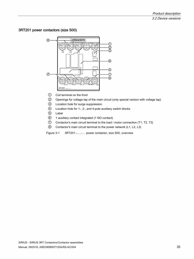
3RT201 power contactors (size S00)
① Coil terminal on the front ② Openings for voltage tap of the main circuit (only special version with voltage tap) ③ Location hole for surge suppression ④ Location hole for 1-, 2-, and 4-pole auxiliary switch blocks ⑤ Label ⑥ 1 auxiliary contact integrated (1 NO contact) ⑦ Contactor's main circuit terminal to the load / motor connection (T1, T2, T3) ⑧ Contactor's main circuit terminal to the power network (L1, L2, L3)
Figure 3-1 3RT201.-.....-.... power contactor, size S00, overview
Product description 3.2 Device versions
SIRIUS - SIRIUS 3RT Contactors/Contactor assemblies 36 Manual, 09/2016, A5E03656507120A/RS-AC/004
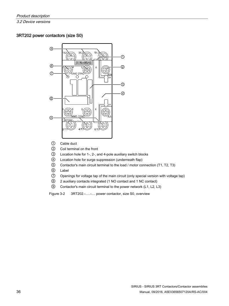
3RT202 power contactors (size S0)
① Cable duct ② Coil terminal on the front ③ Location hole for 1-, 2-, and 4-pole auxiliary switch blocks ④ Location hole for surge suppression (underneath flap) ⑤ Contactor's main circuit terminal to the load / motor connection (T1, T2, T3) ⑥ Label ⑦ Openings for voltage tap of the main circuit (only special version with voltage tap) ⑧ 2 auxiliary contacts integrated (1 NO contact and 1 NC contact) ⑨ Contactor's main circuit terminal to the power network (L1, L2, L3)
Figure 3-2 3RT202.-.....-.... power contactor, size S0, overview
Product description 3.2 Device versions
SIRIUS - SIRIUS 3RT Contactors/Contactor assemblies Manual, 09/2016, A5E03656507120A/RS-AC/004 37
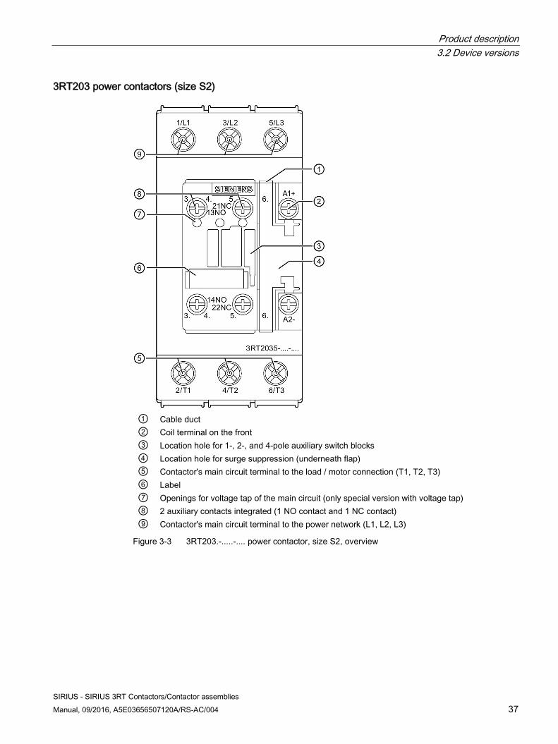
3RT203 power contactors (size S2)
① Cable duct ② Coil terminal on the front ③ Location hole for 1-, 2-, and 4-pole auxiliary switch blocks ④ Location hole for surge suppression (underneath flap) ⑤ Contactor's main circuit terminal to the load / motor connection (T1, T2, T3) ⑥ Label ⑦ Openings for voltage tap of the main circuit (only special version with voltage tap) ⑧ 2 auxiliary contacts integrated (1 NO contact and 1 NC contact) ⑨ Contactor's main circuit terminal to the power network (L1, L2, L3)
Figure 3-3 3RT203.-.....-.... power contactor, size S2, overview
Product description 3.2 Device versions
SIRIUS - SIRIUS 3RT Contactors/Contactor assemblies 38 Manual, 09/2016, A5E03656507120A/RS-AC/004
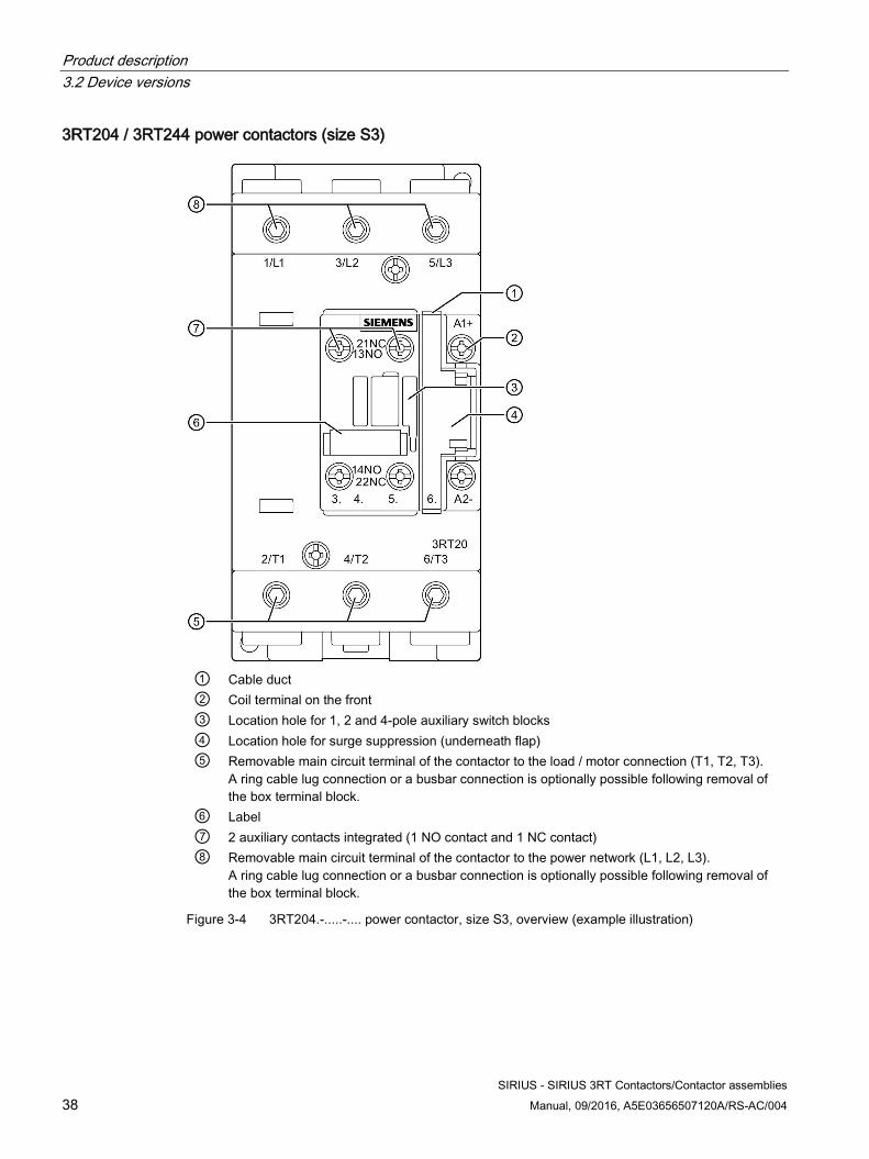
3RT204 / 3RT244 power contactors (size S3)
① Cable duct ② Coil terminal on the front ③ Location hole for 1, 2 and 4-pole auxiliary switch blocks ④ Location hole for surge suppression (underneath flap) ⑤ Removable main circuit terminal of the contactor to the load / motor connection (T1, T2, T3).
A ring cable lug connection or a busbar connection is optionally possible following removal of the box terminal block.
⑥ Label ⑦ 2 auxiliary contacts integrated (1 NO contact and 1 NC contact) ⑧ Removable main circuit terminal of the contactor to the power network (L1, L2, L3).
A ring cable lug connection or a busbar connection is optionally possible following removal of the box terminal block.
Figure 3-4 3RT204.-.....-.... power contactor, size S3, overview (example illustration)
Product description 3.2 Device versions
SIRIUS - SIRIUS 3RT Contactors/Contactor assemblies Manual, 09/2016, A5E03656507120A/RS-AC/004 39
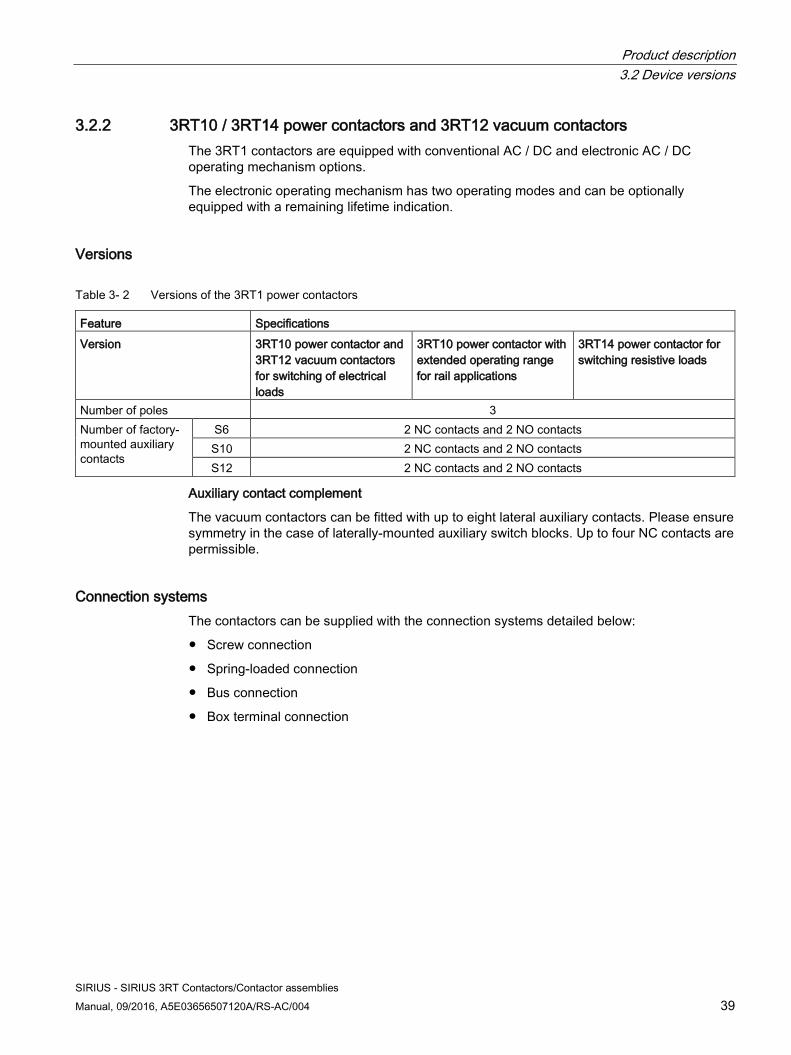
3.2.2 3RT10 / 3RT14 power contactors and 3RT12 vacuum contactors The 3RT1 contactors are equipped with conventional AC / DC and electronic AC / DC operating mechanism options.
The electronic operating mechanism has two operating modes and can be optionally equipped with a remaining lifetime indication.
Versions
Table 3- 2 Versions of the 3RT1 power contactors
Feature Specifications Version 3RT10 power contactor and
3RT12 vacuum contactors for switching of electrical loads
3RT10 power contactor with extended operating range for rail applications
3RT14 power contactor for switching resistive loads
Number of poles 3 Number of factory-mounted auxiliary contacts
S6 2 NC contacts and 2 NO contacts S10 2 NC contacts and 2 NO contacts S12 2 NC contacts and 2 NO contacts
Auxiliary contact complement
The vacuum contactors can be fitted with up to eight lateral auxiliary contacts. Please ensure symmetry in the case of laterally-mounted auxiliary switch blocks. Up to four NC contacts are permissible.
Connection systems The contactors can be supplied with the connection systems detailed below:
● Screw connection
● Spring-loaded connection
● Bus connection
● Box terminal connection
Product description 3.2 Device versions
SIRIUS - SIRIUS 3RT Contactors/Contactor assemblies 40 Manual, 09/2016, A5E03656507120A/RS-AC/004
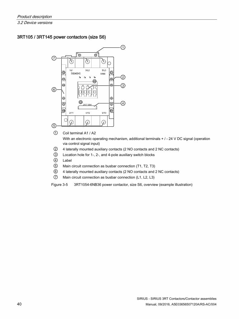
3RT105 / 3RT145 power contactors (size S6)
① Coil terminal A1 / A2
With an electronic operating mechanism, additional terminals + / - 24 V DC signal (operation via control signal input)
② 4 laterally mounted auxiliary contacts (2 NO contacts and 2 NC contacts) ③ Location hole for 1-, 2-, and 4-pole auxiliary switch blocks ④ Label ⑤ Main circuit connection as busbar connection (T1, T2, T3) ⑥ 4 laterally mounted auxiliary contacts (2 NO contacts and 2 NC contacts) ⑦ Main circuit connection as busbar connection (L1, L2, L3)
Figure 3-5 3RT1054-6NB36 power contactor, size S6, overview (example illustration)
Product description 3.2 Device versions
SIRIUS - SIRIUS 3RT Contactors/Contactor assemblies Manual, 09/2016, A5E03656507120A/RS-AC/004 41
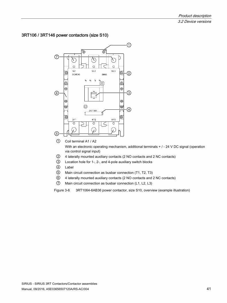
3RT106 / 3RT146 power contactors (size S10)
① Coil terminal A1 / A2
With an electronic operating mechanism, additional terminals + / - 24 V DC signal (operation via control signal input)
② 4 laterally mounted auxiliary contacts (2 NO contacts and 2 NC contacts) ③ Location hole for 1-, 2-, and 4-pole auxiliary switch blocks ④ Label ⑤ Main circuit connection as busbar connection (T1, T2, T3) ⑥ 4 laterally mounted auxiliary contacts (2 NO contacts and 2 NC contacts) ⑦ Main circuit connection as busbar connection (L1, L2, L3)
Figure 3-6 3RT1064-6AB36 power contactor, size S10, overview (example illustration)
Product description 3.2 Device versions
SIRIUS - SIRIUS 3RT Contactors/Contactor assemblies 42 Manual, 09/2016, A5E03656507120A/RS-AC/004
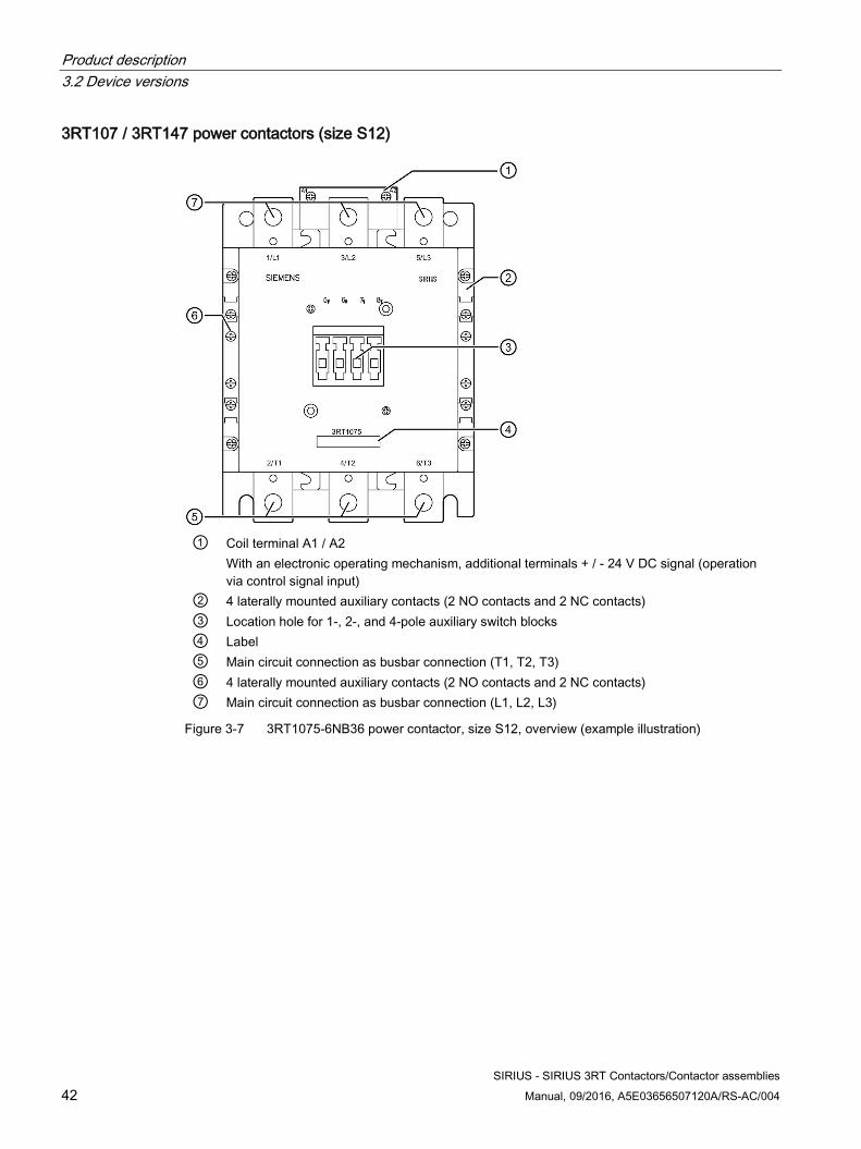
3RT107 / 3RT147 power contactors (size S12)
① Coil terminal A1 / A2
With an electronic operating mechanism, additional terminals + / - 24 V DC signal (operation via control signal input)
② 4 laterally mounted auxiliary contacts (2 NO contacts and 2 NC contacts) ③ Location hole for 1-, 2-, and 4-pole auxiliary switch blocks ④ Label ⑤ Main circuit connection as busbar connection (T1, T2, T3) ⑥ 4 laterally mounted auxiliary contacts (2 NO contacts and 2 NC contacts) ⑦ Main circuit connection as busbar connection (L1, L2, L3)
Figure 3-7 3RT1075-6NB36 power contactor, size S12, overview (example illustration)
Product description 3.2 Device versions
SIRIUS - SIRIUS 3RT Contactors/Contactor assemblies Manual, 09/2016, A5E03656507120A/RS-AC/004 43
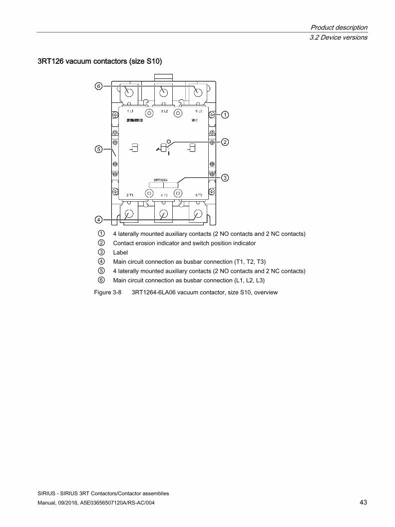
3RT126 vacuum contactors (size S10)
① 4 laterally mounted auxiliary contacts (2 NO contacts and 2 NC contacts) ② Contact erosion indicator and switch position indicator ③ Label ④ Main circuit connection as busbar connection (T1, T2, T3) ⑤ 4 laterally mounted auxiliary contacts (2 NO contacts and 2 NC contacts) ⑥ Main circuit connection as busbar connection (L1, L2, L3)
Figure 3-8 3RT1264-6LA06 vacuum contactor, size S10, overview
Product description 3.2 Device versions
SIRIUS - SIRIUS 3RT Contactors/Contactor assemblies 44 Manual, 09/2016, A5E03656507120A/RS-AC/004
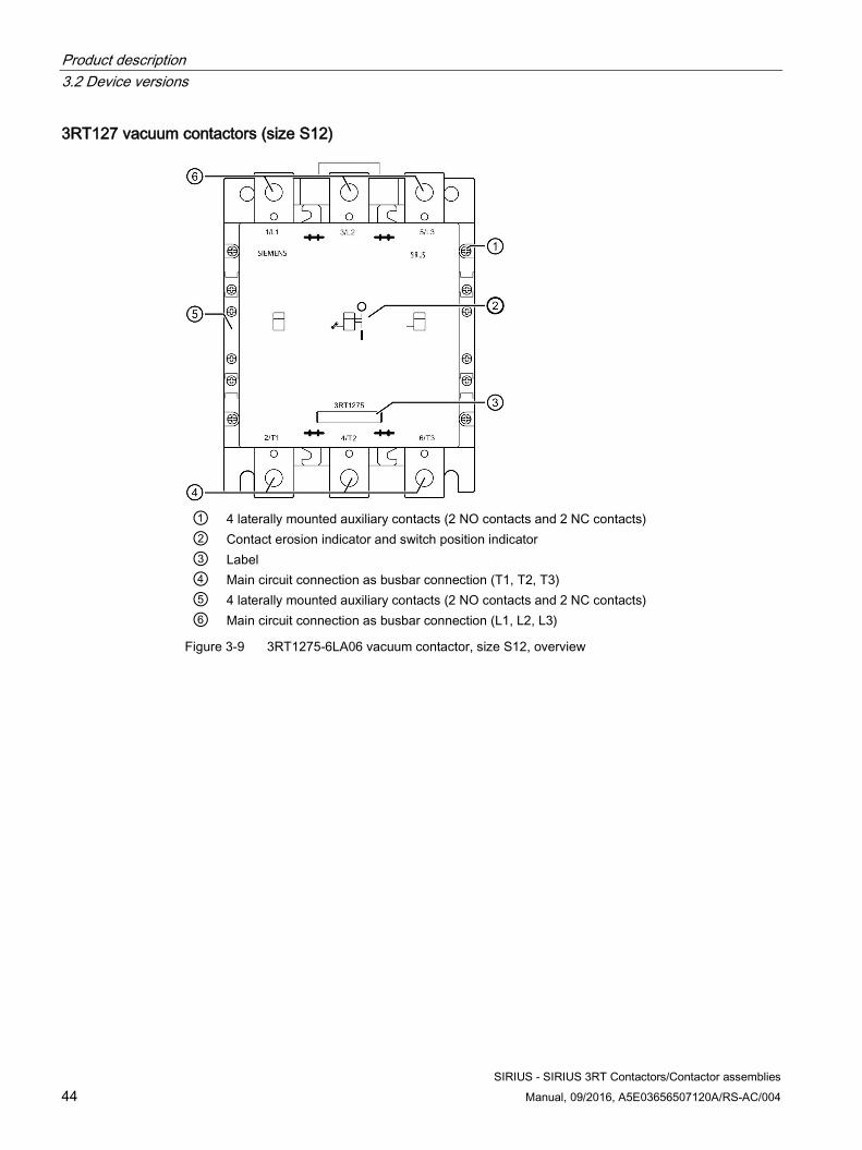
3RT127 vacuum contactors (size S12)
① 4 laterally mounted auxiliary contacts (2 NO contacts and 2 NC contacts) ② Contact erosion indicator and switch position indicator ③ Label ④ Main circuit connection as busbar connection (T1, T2, T3) ⑤ 4 laterally mounted auxiliary contacts (2 NO contacts and 2 NC contacts) ⑥ Main circuit connection as busbar connection (L1, L2, L3)
Figure 3-9 3RT1275-6LA06 vacuum contactor, size S12, overview
Product description 3.2 Device versions
SIRIUS - SIRIUS 3RT Contactors/Contactor assemblies Manual, 09/2016, A5E03656507120A/RS-AC/004 45
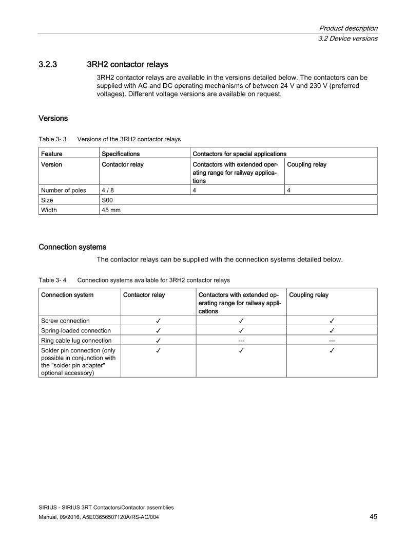
3.2.3 3RH2 contactor relays 3RH2 contactor relays are available in the versions detailed below. The contactors can be supplied with AC and DC operating mechanisms of between 24 V and 230 V (preferred voltages). Different voltage versions are available on request.
Versions
Table 3- 3 Versions of the 3RH2 contactor relays
Feature Specifications Contactors for special applications Version Contactor relay Contactors with extended oper-
ating range for railway applica-tions
Coupling relay
Number of poles 4 / 8 4 4 Size S00 Width 45 mm
Connection systems The contactor relays can be supplied with the connection systems detailed below.
Table 3- 4 Connection systems available for 3RH2 contactor relays
Connection system Contactor relay Contactors with extended op-erating range for railway appli-cations
Coupling relay
Screw connection ✓ ✓ ✓ Spring-loaded connection ✓ ✓ ✓ Ring cable lug connection ✓ --- --- Solder pin connection (only possible in conjunction with the "solder pin adapter" optional accessory)
✓ ✓ ✓
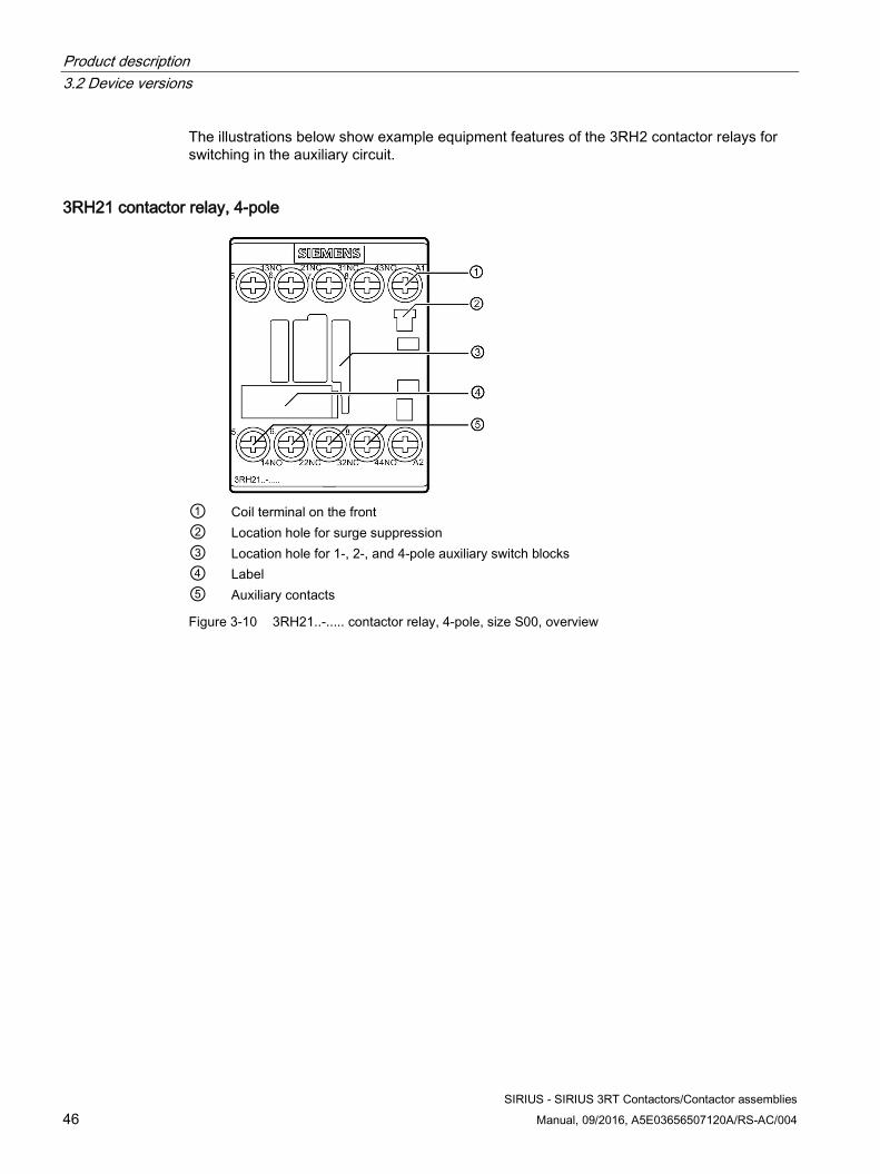
Product description 3.2 Device versions
SIRIUS - SIRIUS 3RT Contactors/Contactor assemblies 46 Manual, 09/2016, A5E03656507120A/RS-AC/004
The illustrations below show example equipment features of the 3RH2 contactor relays for switching in the auxiliary circuit.
3RH21 contactor relay, 4-pole
① Coil terminal on the front ② Location hole for surge suppression ③ Location hole for 1-, 2-, and 4-pole auxiliary switch blocks ④ Label ⑤ Auxiliary contacts
Figure 3-10 3RH21..-..... contactor relay, 4-pole, size S00, overview
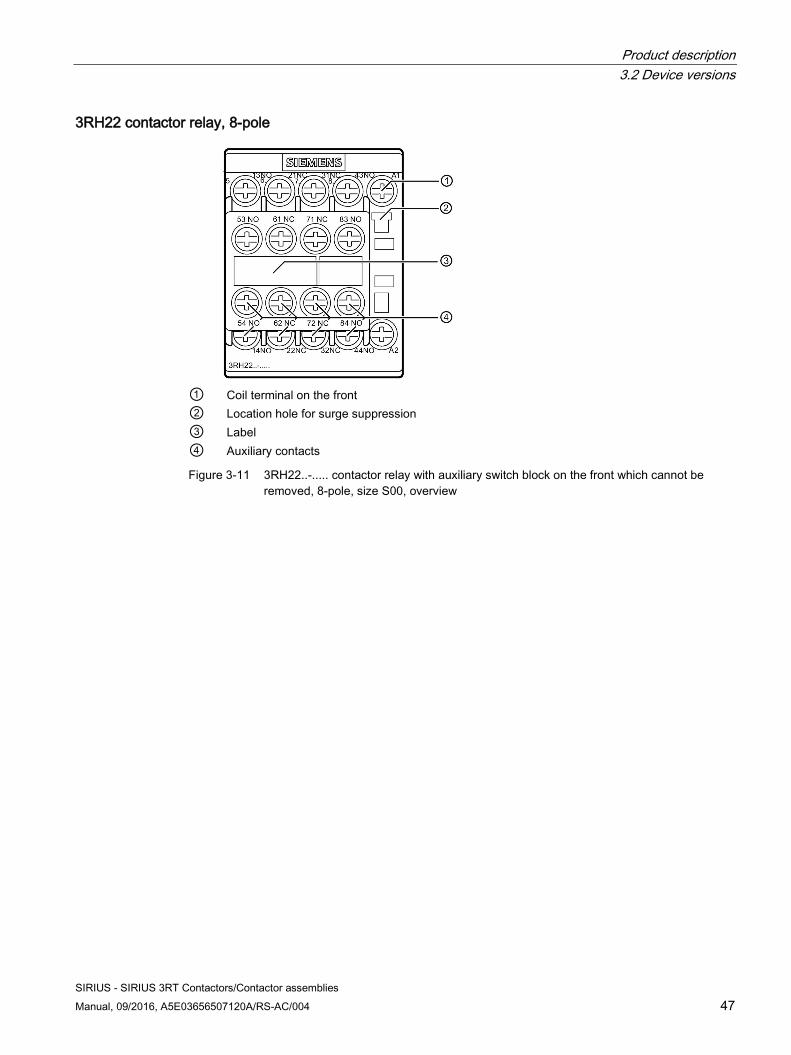
Product description 3.2 Device versions
SIRIUS - SIRIUS 3RT Contactors/Contactor assemblies Manual, 09/2016, A5E03656507120A/RS-AC/004 47
3RH22 contactor relay, 8-pole
① Coil terminal on the front ② Location hole for surge suppression ③ Label ④ Auxiliary contacts
Figure 3-11 3RH22..-..... contactor relay with auxiliary switch block on the front which cannot be removed, 8-pole, size S00, overview
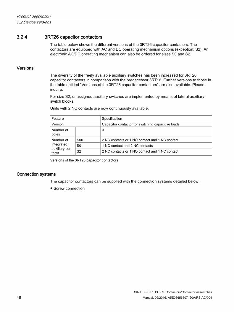
Product description 3.2 Device versions
SIRIUS - SIRIUS 3RT Contactors/Contactor assemblies 48 Manual, 09/2016, A5E03656507120A/RS-AC/004
3.2.4 3RT26 capacitor contactors The table below shows the different versions of the 3RT26 capacitor contactors. The contactors are equipped with AC and DC operating mechanism options (exception: S2). An electronic AC/DC operating mechanism can also be ordered for sizes S0 and S2.
Versions The diversity of the freely available auxiliary switches has been increased for 3RT26 capacitor contactors in comparison with the predecessor 3RT16. Further versions to those in the table entitled "Versions of the 3RT26 capacitor contactors" are also available. Please inquire.
For size S2, unassigned auxiliary switches are implemented by means of lateral auxiliary switch blocks.
Units with 2 NC contacts are now continuously available. Feature Specification Version Capacitor contactor for switching capacitive loads Number of poles
3
Number of integrated auxiliary con-tacts
S00 2 NC contacts or 1 NO contact and 1 NC contact S0 1 NO contact and 2 NC contacts S2 2 NC contacts or 1 NO contact and 1 NC contact
Versions of the 3RT26 capacitor contactors
Connection systems The capacitor contactors can be supplied with the connection systems detailed below:
● Screw connection
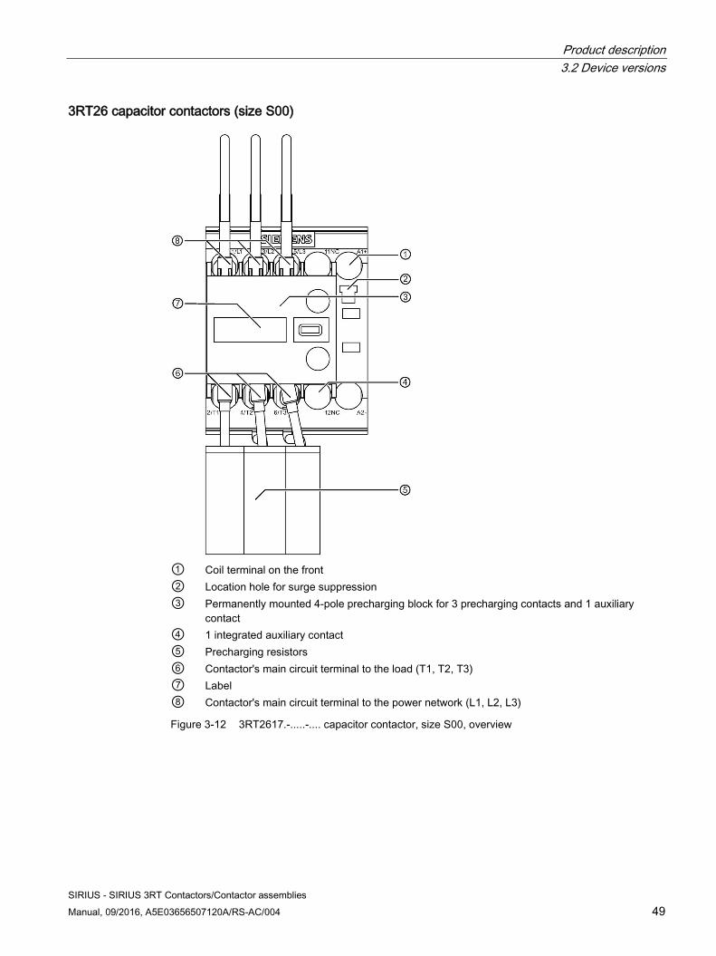
Product description 3.2 Device versions
SIRIUS - SIRIUS 3RT Contactors/Contactor assemblies Manual, 09/2016, A5E03656507120A/RS-AC/004 49
3RT26 capacitor contactors (size S00)
① Coil terminal on the front ② Location hole for surge suppression ③ Permanently mounted 4-pole precharging block for 3 precharging contacts and 1 auxiliary
contact ④ 1 integrated auxiliary contact ⑤ Precharging resistors ⑥ Contactor's main circuit terminal to the load (T1, T2, T3) ⑦ Label ⑧ Contactor's main circuit terminal to the power network (L1, L2, L3)
Figure 3-12 3RT2617.-.....-.... capacitor contactor, size S00, overview
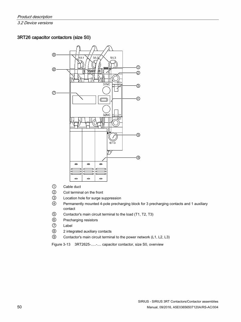
Product description 3.2 Device versions
SIRIUS - SIRIUS 3RT Contactors/Contactor assemblies 50 Manual, 09/2016, A5E03656507120A/RS-AC/004
3RT26 capacitor contactors (size S0)
① Cable duct ② Coil terminal on the front ③ Location hole for surge suppression ④ Permanently mounted 4-pole precharging block for 3 precharging contacts and 1 auxiliary
contact ⑤ Contactor's main circuit terminal to the load (T1, T2, T3) ⑥ Precharging resistors ⑦ Label ⑧ 2 integrated auxiliary contacts ⑨ Contactor's main circuit terminal to the power network (L1, L2, L3)
Figure 3-13 3RT2625-.....-.... capacitor contactor, size S0, overview
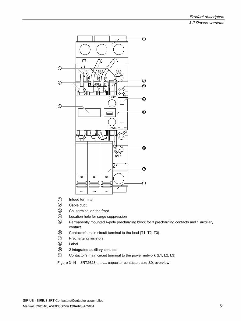
Product description 3.2 Device versions
SIRIUS - SIRIUS 3RT Contactors/Contactor assemblies Manual, 09/2016, A5E03656507120A/RS-AC/004 51
① Infeed terminal ② Cable duct ③ Coil terminal on the front ④ Location hole for surge suppression ⑤ Permanently mounted 4-pole precharging block for 3 precharging contacts and 1 auxiliary
contact ⑥ Contactor's main circuit terminal to the load (T1, T2, T3) ⑦ Precharging resistors ⑧ Label ⑨ 2 integrated auxiliary contacts ⑩ Contactor's main circuit terminal to the power network (L1, L2, L3)
Figure 3-14 3RT2628-.....-.... capacitor contactor, size S0, overview
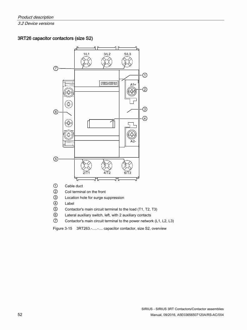
Product description 3.2 Device versions
SIRIUS - SIRIUS 3RT Contactors/Contactor assemblies 52 Manual, 09/2016, A5E03656507120A/RS-AC/004
3RT26 capacitor contactors (size S2)
① Cable duct ② Coil terminal on the front ③ Location hole for surge suppression ④ Label ⑤ Contactor's main circuit terminal to the load (T1, T2, T3) ⑥ Lateral auxiliary switch, left, with 2 auxiliary contacts ⑦ Contactor's main circuit terminal to the power network (L1, L2, L3)
Figure 3-15 3RT263.-.....-.... capacitor contactor, size S2, overview
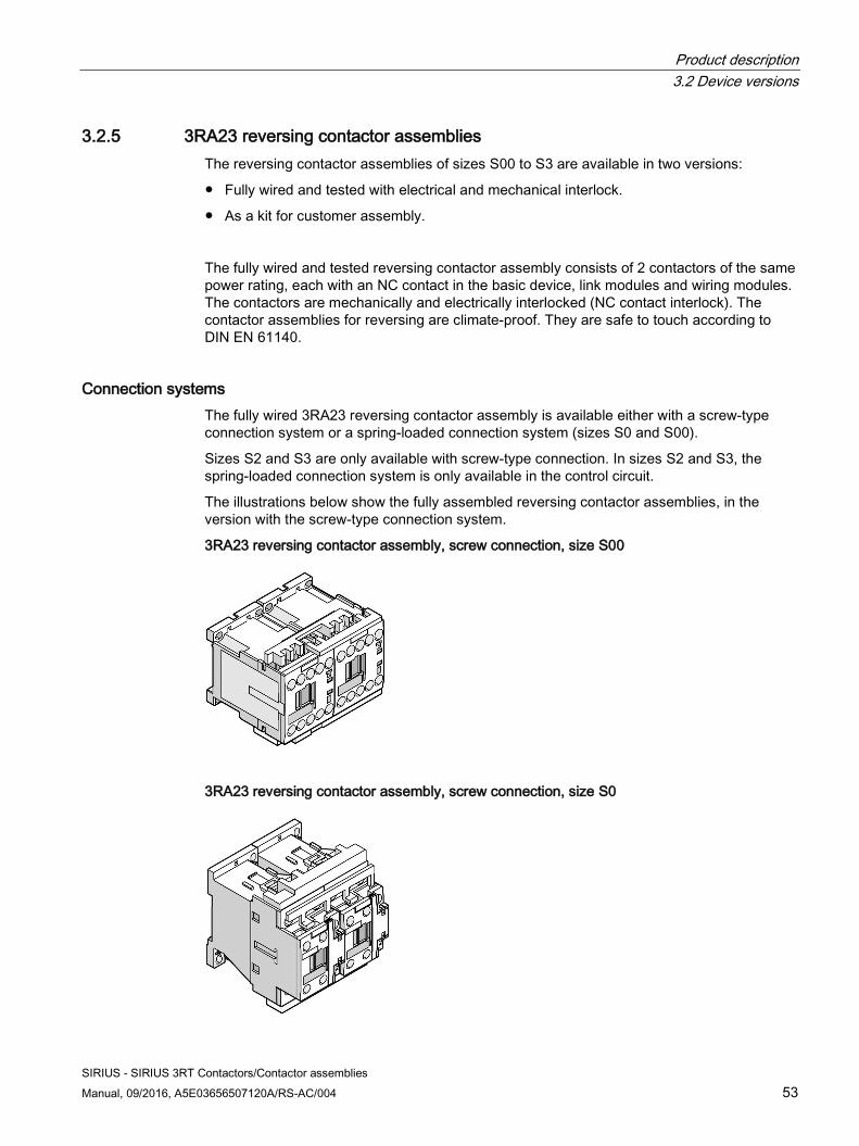
Product description 3.2 Device versions
SIRIUS - SIRIUS 3RT Contactors/Contactor assemblies Manual, 09/2016, A5E03656507120A/RS-AC/004 53
3.2.5 3RA23 reversing contactor assemblies The reversing contactor assemblies of sizes S00 to S3 are available in two versions:
● Fully wired and tested with electrical and mechanical interlock.
● As a kit for customer assembly.
The fully wired and tested reversing contactor assembly consists of 2 contactors of the same power rating, each with an NC contact in the basic device, link modules and wiring modules. The contactors are mechanically and electrically interlocked (NC contact interlock). The contactor assemblies for reversing are climate-proof. They are safe to touch according to DIN EN 61140.
Connection systems The fully wired 3RA23 reversing contactor assembly is available either with a screw-type connection system or a spring-loaded connection system (sizes S0 and S00).
Sizes S2 and S3 are only available with screw-type connection. In sizes S2 and S3, the spring-loaded connection system is only available in the control circuit.
The illustrations below show the fully assembled reversing contactor assemblies, in the version with the screw-type connection system.
3RA23 reversing contactor assembly, screw connection, size S00
3RA23 reversing contactor assembly, screw connection, size S0
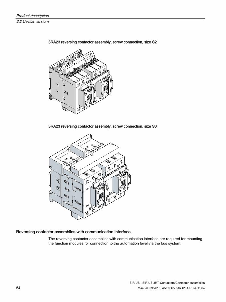
Product description 3.2 Device versions
SIRIUS - SIRIUS 3RT Contactors/Contactor assemblies 54 Manual, 09/2016, A5E03656507120A/RS-AC/004
3RA23 reversing contactor assembly, screw connection, size S2
3RA23 reversing contactor assembly, screw connection, size S3
Reversing contactor assemblies with communication interface The reversing contactor assemblies with communication interface are required for mounting the function modules for connection to the automation level via the bus system.
Product description 3.2 Device versions
SIRIUS - SIRIUS 3RT Contactors/Contactor assemblies Manual, 09/2016, A5E03656507120A/RS-AC/004 55
Reference More information ... Can be found in the chapter titled ... About the 3RA23 reversing contactor assemblies Operation of a motor in two directions of rotation
(reversing contactor assembly) (Page 112). About the components for self-assembly of the reversing contactor assemblies
Assembly kit for reversing contactor assembly (sizes S00 to S3) (Page 333) and wiring kit for reversing contactor assemblies (sizes S6 to S12) (Page 351).
About the function modules that can be attached to a reversing contactor assembly with communi-cation interface
3RA27 function modules for connection to the controller (AS-Interface or IO-Link). (Page 330)
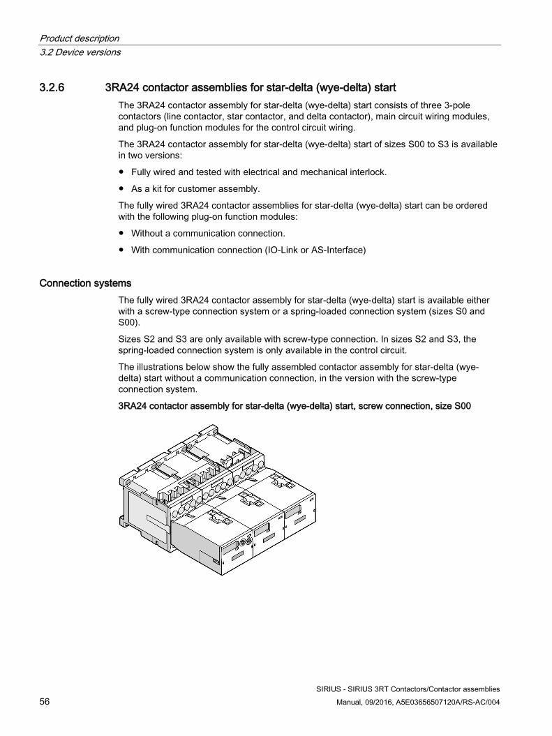
Product description 3.2 Device versions
SIRIUS - SIRIUS 3RT Contactors/Contactor assemblies 56 Manual, 09/2016, A5E03656507120A/RS-AC/004
3.2.6 3RA24 contactor assemblies for star-delta (wye-delta) start The 3RA24 contactor assembly for star-delta (wye-delta) start consists of three 3-pole contactors (line contactor, star contactor, and delta contactor), main circuit wiring modules, and plug-on function modules for the control circuit wiring.
The 3RA24 contactor assembly for star-delta (wye-delta) start of sizes S00 to S3 is available in two versions:
● Fully wired and tested with electrical and mechanical interlock.
● As a kit for customer assembly.
The fully wired 3RA24 contactor assemblies for star-delta (wye-delta) start can be ordered with the following plug-on function modules:
● Without a communication connection.
● With communication connection (IO-Link or AS-Interface)
Connection systems The fully wired 3RA24 contactor assembly for star-delta (wye-delta) start is available either with a screw-type connection system or a spring-loaded connection system (sizes S0 and S00).
Sizes S2 and S3 are only available with screw-type connection. In sizes S2 and S3, the spring-loaded connection system is only available in the control circuit.
The illustrations below show the fully assembled contactor assembly for star-delta (wye-delta) start without a communication connection, in the version with the screw-type connection system.
3RA24 contactor assembly for star-delta (wye-delta) start, screw connection, size S00
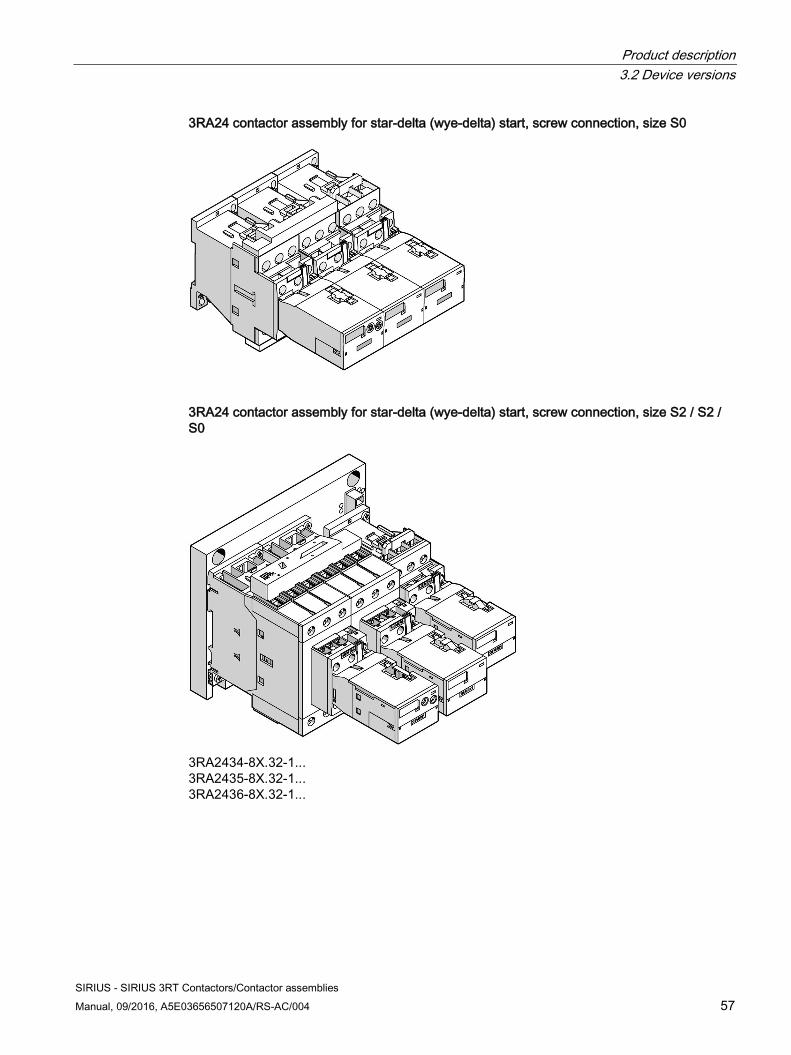
Product description 3.2 Device versions
SIRIUS - SIRIUS 3RT Contactors/Contactor assemblies Manual, 09/2016, A5E03656507120A/RS-AC/004 57
3RA24 contactor assembly for star-delta (wye-delta) start, screw connection, size S0
3RA24 contactor assembly for star-delta (wye-delta) start, screw connection, size S2 / S2 / S0
3RA2434-8X.32-1... 3RA2435-8X.32-1... 3RA2436-8X.32-1...
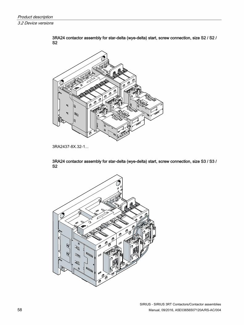
Product description 3.2 Device versions
SIRIUS - SIRIUS 3RT Contactors/Contactor assemblies 58 Manual, 09/2016, A5E03656507120A/RS-AC/004
3RA24 contactor assembly for star-delta (wye-delta) start, screw connection, size S2 / S2 / S2
3RA2437-8X.32-1...
3RA24 contactor assembly for star-delta (wye-delta) start, screw connection, size S3 / S3 / S2
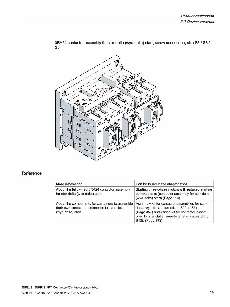
Product description 3.2 Device versions
SIRIUS - SIRIUS 3RT Contactors/Contactor assemblies Manual, 09/2016, A5E03656507120A/RS-AC/004 59
3RA24 contactor assembly for star-delta (wye-delta) start, screw connection, size S3 / S3 / S3
Reference More information ... Can be found in the chapter titled ... About the fully wired 3RA24 contactor assembly for star-delta (wye-delta) start
Starting three-phase motors with reduced starting current peaks (contactor assembly for star-delta (wye-delta) start) (Page 119)
About the components for customers to assemble their own contactor assemblies for star-delta (wye-delta) start
Assembly kit for contactor assemblies for star-delta (wye-delta) start (sizes S00 to S3) (Page 357) and Wiring kit for contactor assem-blies for star-delta (wye-delta) start (sizes S6 to S12). (Page 393).
Product description 3.2 Device versions
SIRIUS - SIRIUS 3RT Contactors/Contactor assemblies 60 Manual, 09/2016, A5E03656507120A/RS-AC/004
3.2.7 Drive options
Operating mechanism options The following operating mechanism types are available for 3RH2 contactor relays and 3RT2 power contactors:
● AC operating mechanism (sizes S0, S2 and S3)
● DC operating mechanism (sizes S00 and S0)
● AC / DC operating mechanism (sizes S0, S2 and S3)
The following operating mechanism types are available for 3RT1 contactor relays and 3RT12 power contactors (size S6 to S12):
● AC / DC operating mechanism (conventionally controlled)
● AC / DC operating mechanism (electronically controlled)
– For 24 V DC PLC output
– For 24 V DC PLC output, with remaining lifetime signal (RLT)
Reference More information ... Can be found in the chapter titled ... About contactor relay and power contactor appli-cations
Configuration (Page 63)
SIRIUS - SIRIUS 3RT Contactors/Contactor assemblies Manual, 09/2016, A5E03656507120A/RS-AC/004 61
Product combinations 4
The SIRIUS contactors are part of the SIRIUS modular system and offer all the advantages which SIRIUS users have come to expect in terms of the ability to combine any of the system's products together with any others. These benefits are thanks to the uniform mechanical and electrical properties used throughout the modular system and are also due to the interplay with the higher control level.
As well as the contactor accessories, 3RT2 contactors can also be combined with the following other SIRIUS devices for direct mounting:
● 3RV2 motor starter protectors (with 3RA29 link module)
● Thermal (3RU2) or electronic overload relays (3RB3)
● 3RR2 current monitoring relays
● 3RA28 function modules and 3RA27 function modules with a communication connection
Reference More information ... Can be found in the appendix ... About the possible combinations of standard products from the SIRIUS modular system
"References" under "Manuals - SIRIUS Modular System (Page 463)"

Product combinations
SIRIUS - SIRIUS 3RT Contactors/Contactor assemblies 62 Manual, 09/2016, A5E03656507120A/RS-AC/004
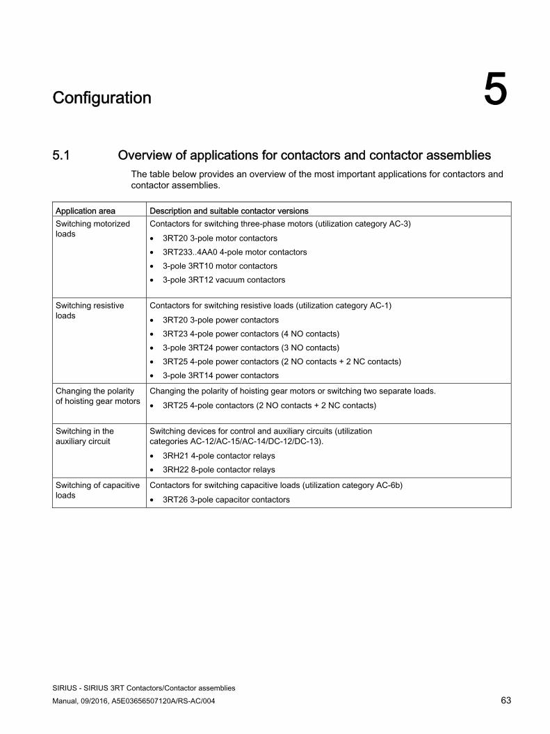
SIRIUS - SIRIUS 3RT Contactors/Contactor assemblies Manual, 09/2016, A5E03656507120A/RS-AC/004 63
Configuration 55.1 Overview of applications for contactors and contactor assemblies
The table below provides an overview of the most important applications for contactors and contactor assemblies.
Application area Description and suitable contactor versionsSwitching motorized loads
Contactors for switching three-phase motors (utilization category AC-3) • 3RT20 3-pole motor contactors • 3RT233..4AA0 4-pole motor contactors • 3-pole 3RT10 motor contactors • 3-pole 3RT12 vacuum contactors
Switching resistive loads
Contactors for switching resistive loads (utilization category AC-1) • 3RT20 3-pole power contactors • 3RT23 4-pole power contactors (4 NO contacts) • 3-pole 3RT24 power contactors (3 NO contacts) • 3RT25 4-pole power contactors (2 NO contacts + 2 NC contacts) • 3-pole 3RT14 power contactors
Changing the polarity of hoisting gear motors
Changing the polarity of hoisting gear motors or switching two separate loads. • 3RT25 4-pole contactors (2 NO contacts + 2 NC contacts)
Switching in the auxiliary circuit
Switching devices for control and auxiliary circuits (utilization categories AC-12/AC-15/AC-14/DC-12/DC-13). • 3RH21 4-pole contactor relays • 3RH22 8-pole contactor relays
Switching of capacitive loads
Contactors for switching capacitive loads (utilization category AC-6b) • 3RT26 3-pole capacitor contactors
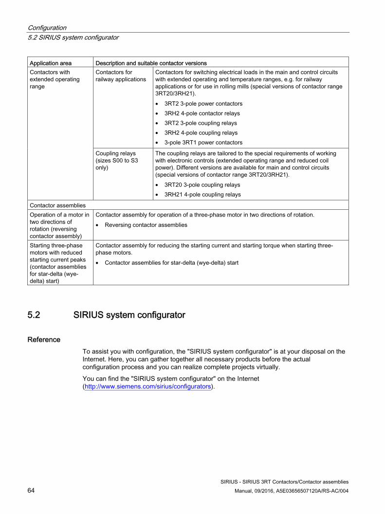
Configuration 5.2 SIRIUS system configurator
SIRIUS - SIRIUS 3RT Contactors/Contactor assemblies 64 Manual, 09/2016, A5E03656507120A/RS-AC/004
Application area Description and suitable contactor versionsContactors with extended operating range
Contactors for railway applications
Contactors for switching electrical loads in the main and control circuits with extended operating and temperature ranges, e.g. for railway applications or for use in rolling mills (special versions of contactor range 3RT20/3RH21). • 3RT2 3-pole power contactors • 3RH2 4-pole contactor relays • 3RT2 3-pole coupling relays • 3RH2 4-pole coupling relays • 3-pole 3RT1 power contactors
Coupling relays (sizes S00 to S3 only)
The coupling relays are tailored to the special requirements of working with electronic controls (extended operating range and reduced coil power). Different versions are available for main and control circuits (special versions of contactor range 3RT20/3RH21). • 3RT20 3-pole coupling relays • 3RH21 4-pole coupling relays
Contactor assemblies Operation of a motor in two directions of rotation (reversing contactor assembly)
Contactor assembly for operation of a three-phase motor in two directions of rotation. • Reversing contactor assemblies
Starting three-phase motors with reduced starting current peaks (contactor assemblies for star-delta (wye-delta) start)
Contactor assembly for reducing the starting current and starting torque when starting three-phase motors. • Contactor assemblies for star-delta (wye-delta) start
5.2 SIRIUS system configurator
Reference To assist you with configuration, the "SIRIUS system configurator" is at your disposal on the Internet. Here, you can gather together all necessary products before the actual configuration process and you can realize complete projects virtually.
You can find the "SIRIUS system configurator" on the Internet (http://www.siemens.com/sirius/configurators).
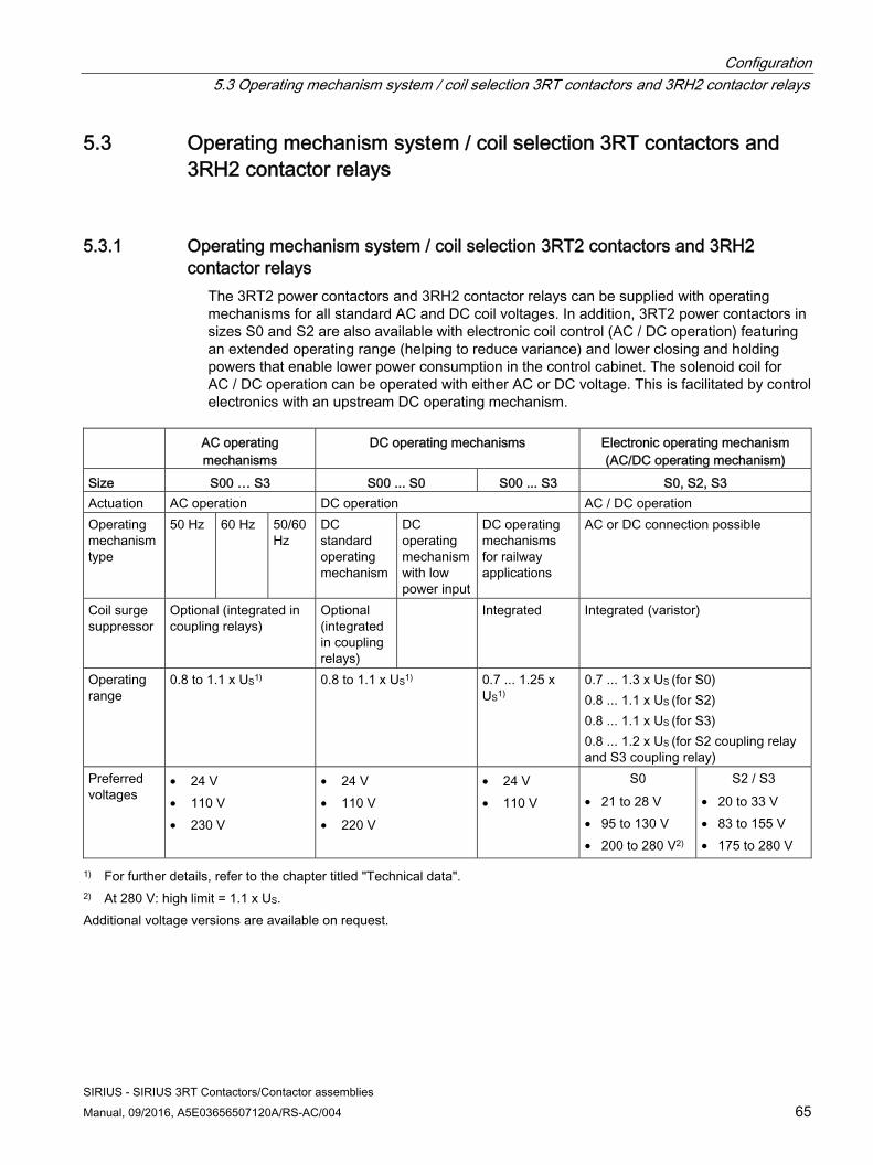
Configuration 5.3 Operating mechanism system / coil selection 3RT contactors and 3RH2 contactor relays
SIRIUS - SIRIUS 3RT Contactors/Contactor assemblies Manual, 09/2016, A5E03656507120A/RS-AC/004 65
5.3 Operating mechanism system / coil selection 3RT contactors and 3RH2 contactor relays
5.3.1 Operating mechanism system / coil selection 3RT2 contactors and 3RH2 contactor relays
The 3RT2 power contactors and 3RH2 contactor relays can be supplied with operating mechanisms for all standard AC and DC coil voltages. In addition, 3RT2 power contactors in sizes S0 and S2 are also available with electronic coil control (AC / DC operation) featuring an extended operating range (helping to reduce variance) and lower closing and holding powers that enable lower power consumption in the control cabinet. The solenoid coil for AC / DC operation can be operated with either AC or DC voltage. This is facilitated by control electronics with an upstream DC operating mechanism.
AC operating
mechanisms DC operating mechanisms Electronic operating mechanism
(AC/DC operating mechanism)Size S00 … S3 S00 ... S0 S00 ... S3 S0, S2, S3Actuation AC operation DC operation AC / DC operation Operating mechanism type
50 Hz 60 Hz 50/60 Hz
DC standard operating mechanism
DC operating mechanism with low power input
DC operating mechanisms for railway applications
AC or DC connection possible
Coil surge suppressor
Optional (integrated in coupling relays)
Optional (integrated in coupling relays)
Integrated Integrated (varistor)
Operating range
0.8 to 1.1 x US1) 0.8 to 1.1 x US1) 0.7 ... 1.25 x US1)
0.7 ... 1.3 x US (for S0) 0.8 ... 1.1 x US (for S2) 0.8 ... 1.1 x US (for S3) 0.8 ... 1.2 x US (for S2 coupling relay and S3 coupling relay)
Preferred voltages
• 24 V • 110 V • 230 V
• 24 V • 110 V • 220 V
• 24 V • 110 V
S0 • 21 to 28 V • 95 to 130 V • 200 to 280 V2)
S2 / S3 • 20 to 33 V • 83 to 155 V • 175 to 280 V
1) For further details, refer to the chapter titled "Technical data". 2) At 280 V: high limit = 1.1 x US. Additional voltage versions are available on request.
Configuration 5.3 Operating mechanism system / coil selection 3RT contactors and 3RH2 contactor relays
SIRIUS - SIRIUS 3RT Contactors/Contactor assemblies 66 Manual, 09/2016, A5E03656507120A/RS-AC/004
5.3.2 Operating mechanism system / coil selection 3RT1 contactors
5.3.2.1 Conventional and electronic operating mechanism types The common features of both operating mechanism types are: UC operation, that is, the contactors can be operated with AC (50 to 60 Hz) as well as with DC.
Integrated coil circuit with varistor In most application cases, this is sufficient for a circuit that is adequate to shutdown overvoltages of the solenoid coil. To the extent that especially fault-prone applications make further attenuation measures necessary, RC elements (accessories) can be additionally attached.
Exception: No additional RC elements can be mounted on the versions with remaining lifetime signal.
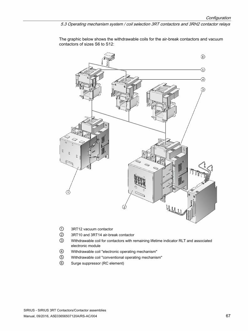
Configuration 5.3 Operating mechanism system / coil selection 3RT contactors and 3RH2 contactor relays
SIRIUS - SIRIUS 3RT Contactors/Contactor assemblies Manual, 09/2016, A5E03656507120A/RS-AC/004 67
The graphic below shows the withdrawable coils for the air-break contactors and vacuum contactors of sizes S6 to S12:
① 3RT12 vacuum contactor② 3RT10 and 3RT14 air-break contactor ③ Withdrawable coil for contactors with remaining lifetime indicator RLT and associated
electronic module ④ Withdrawable coil "electronic operating mechanism"⑤ Withdrawable coil "conventional operating mechanism" ⑥ Surge suppressor (RC element)
Configuration 5.3 Operating mechanism system / coil selection 3RT contactors and 3RH2 contactor relays
SIRIUS - SIRIUS 3RT Contactors/Contactor assemblies 68 Manual, 09/2016, A5E03656507120A/RS-AC/004
The conventional operating mechanism The control supply voltage is run direct to the solenoid coil via terminals A1/A2, and the contactor is switched on and off. After switching on, the solenoid operating mechanism is switched from pick-up excitation to holder excitation (DC economy circuit) by an in-built change-over contact.
Control supply voltage
The contactors are equipped with wide-range operating mechanisms and can thus cover a wide range of control supply voltages, for example rated operating range (Usmin - Usmax) of 110 V ... 127 V or 220 V ... 240 V. In addition, both voltage types, AC as well as DC, are covered by the same operating mechanism.
Working range
The working range is 0.8 x Us min - 1.1 x Us max, for the example, this means: 0.8 x 220 V - 1.1 x 240 V.
The electronic operating mechanism The solenoid coil is controlled by internal upstream control electronics. With the electronic operating mechanism, two different operating modes are possible. Version 1 is the classic supply and control of the contactor via the control supply voltage applied to A1/A2. In the case of version 2, only a supply voltage is applied at A1/A2. The control can be applied to the additional terminals +/- as a 24 V DC signal. This operating mode is suitable for controlling via higher-level PLC semiconductor outputs.
NOTICE
EMERGENCY OFF disconnection
Control of the coil via a semiconductor element means the control inputs (PLC) must not be used for EMERGENCY OFF purposes. For EMERGENCY OFF, the contactor must be switched off via A1/A2.
The contactors are equipped with wide-range operating mechanisms and can thus cover an even wider range of control supply voltages, for example rated operating ranges (Usmin - Usmax) of 96 V ... 127 V or 200 V ... 277 V. Both voltage types, AC as well as DC, are covered by the same operating mechanism.
Extended operating range
Compared to the conventional operating mechanism, the operating range of the control supply voltage is extended again to 0.7 ... 1.25 x Us
Configuration 5.3 Operating mechanism system / coil selection 3RT contactors and 3RH2 contactor relays
SIRIUS - SIRIUS 3RT Contactors/Contactor assemblies Manual, 09/2016, A5E03656507120A/RS-AC/004 69
Defined ON and OFF thresholds:
The control electronics monitor the applied control supply voltage for permissible lower limits within which the contactors reliably switch.
● Switching on at control supply voltage 0.8×Us min
● Switching off at control supply voltage ≤ 0.5×Us min
The hysteresis in the switching thresholds prevents the main contacts from chattering and thus prevents increased wear or welding when operated in weak, unstable networks.
The ON threshold prevents thermal overload of the coil if an excessively low control supply voltage is applied.
Bridging temporary voltage dips
Control voltage failures dipping to 0 V (at A1/A2) are bridged for up to approx. 25 ms to avoid unintentional tripping.
Note Configuration note
When in operation in or around converter circuits, it must be noted that the control wiring to the contactor should be installed separately from the load side wiring of the converter.
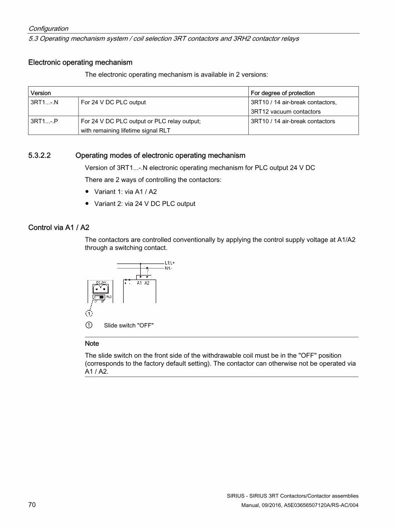
Configuration 5.3 Operating mechanism system / coil selection 3RT contactors and 3RH2 contactor relays
SIRIUS - SIRIUS 3RT Contactors/Contactor assemblies 70 Manual, 09/2016, A5E03656507120A/RS-AC/004
Electronic operating mechanism The electronic operating mechanism is available in 2 versions:
Version For degree of protection 3RT1...-.N For 24 V DC PLC output 3RT10 / 14 air-break contactors,
3RT12 vacuum contactors 3RT1...-.P For 24 V DC PLC output or PLC relay output;
with remaining lifetime signal RLT 3RT10 / 14 air-break contactors
5.3.2.2 Operating modes of electronic operating mechanism Version of 3RT1...-.N electronic operating mechanism for PLC output 24 V DC
There are 2 ways of controlling the contactors:
● Variant 1: via A1 / A2
● Variant 2: via 24 V DC PLC output
Control via A1 / A2 The contactors are controlled conventionally by applying the control supply voltage at A1/A2 through a switching contact.
① Slide switch "OFF"
Note
The slide switch on the front side of the withdrawable coil must be in the "OFF" position (corresponds to the factory default setting). The contactor can otherwise not be operated via A1 / A2.
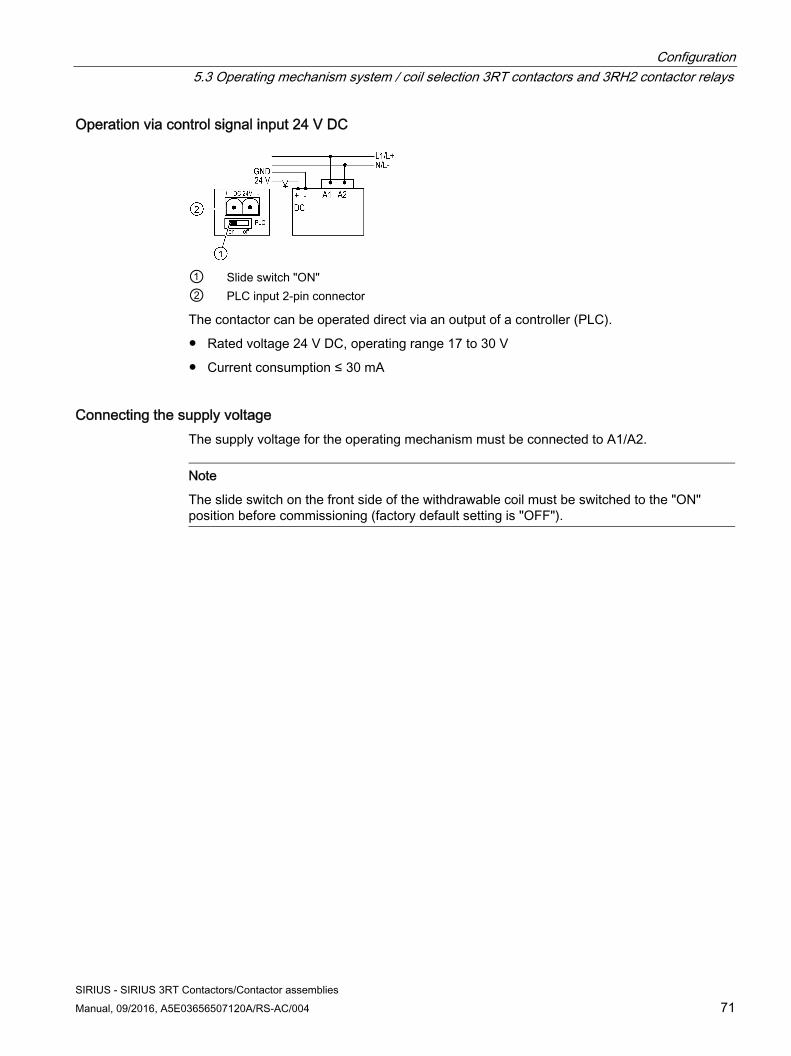
Configuration 5.3 Operating mechanism system / coil selection 3RT contactors and 3RH2 contactor relays
SIRIUS - SIRIUS 3RT Contactors/Contactor assemblies Manual, 09/2016, A5E03656507120A/RS-AC/004 71
Operation via control signal input 24 V DC
① Slide switch "ON" ② PLC input 2-pin connector
The contactor can be operated direct via an output of a controller (PLC).
● Rated voltage 24 V DC, operating range 17 to 30 V
● Current consumption ≤ 30 mA
Connecting the supply voltage The supply voltage for the operating mechanism must be connected to A1/A2.
Note
The slide switch on the front side of the withdrawable coil must be switched to the "ON" position before commissioning (factory default setting is "OFF").
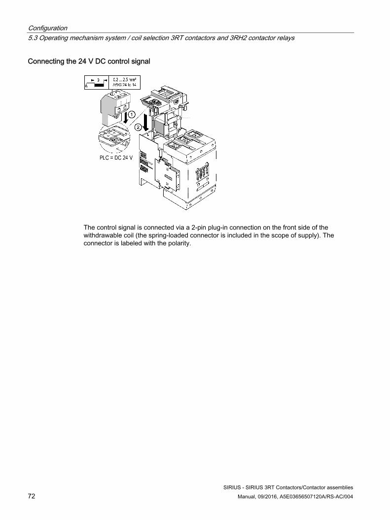
Configuration 5.3 Operating mechanism system / coil selection 3RT contactors and 3RH2 contactor relays
SIRIUS - SIRIUS 3RT Contactors/Contactor assemblies 72 Manual, 09/2016, A5E03656507120A/RS-AC/004
Connecting the 24 V DC control signal
The control signal is connected via a 2-pin plug-in connection on the front side of the withdrawable coil (the spring-loaded connector is included in the scope of supply). The connector is labeled with the polarity.
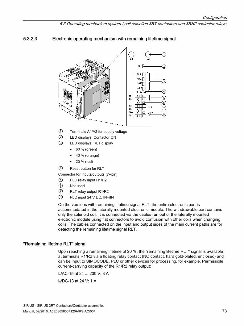
Configuration 5.3 Operating mechanism system / coil selection 3RT contactors and 3RH2 contactor relays
SIRIUS - SIRIUS 3RT Contactors/Contactor assemblies Manual, 09/2016, A5E03656507120A/RS-AC/004 73
5.3.2.3 Electronic operating mechanism with remaining lifetime signal
① Terminals A1/A2 for supply voltage② LED displays: Contactor ON ③ LED displays: RLT display
• 60 % (green) • 40 % (orange) • 20 % (red)
④ Reset button for RLTConnector for inputs/outputs (7--pin) ⑤ PLC relay input H1/H2⑥ Not used ⑦ RLT relay output R1/R2 ⑧ PLC input 24 V DC, IN+/IN
On the versions with remaining lifetime signal RLT, the entire electronic part is accommodated in the laterally mounted electronic module. The withdrawable part contains only the solenoid coil. It is connected via the cables run out of the laterally mounted electronic module using flat connectors to avoid confusion with other coils when changing coils. The cables connected on the input and output sides of the main current paths are for detecting the remaining lifetime signal RLT.
"Remaining lifetime RLT" signal Upon reaching a remaining lifetime of 20 %, the "remaining lifetime RLT" signal is available at terminals R1/R2 via a floating relay contact (NO contact, hard gold-plated, enclosed) and can be input to SIMOCODE, PLC or other devices for processing, for example. Permissible current-carrying capacity of the R1/R2 relay output:
Ie/AC-15 at 24 ... 230 V: 3 A
Ie/DC-13 at 24 V: 1 A
Configuration 5.3 Operating mechanism system / coil selection 3RT contactors and 3RH2 contactor relays
SIRIUS - SIRIUS 3RT Contactors/Contactor assemblies 74 Manual, 09/2016, A5E03656507120A/RS-AC/004
Control The contactors can be controlled as follows:
● via a 24 V DC control signal
● via relay outputs, e.g. of PLC, SIMOCODE.
Power supply To supply the solenoid operating mechanism and the remaining lifetime signal with power, the control supply voltage Us must be connected to terminals A1/A2 of the laterally mounted electronic module.
Control inputs The control inputs of the contactor are connected to a 7-pole plug-in connection (the spring-loaded connector is part of the scope of supply).
Changeover from automatic to local control Automatic control can be changed over to local control via inputs H1/H2. During commissioning or in the event of a fault, for example, automatic control via PLC or SIMOCODE can be deactivated and the contactor can be controlled manually.
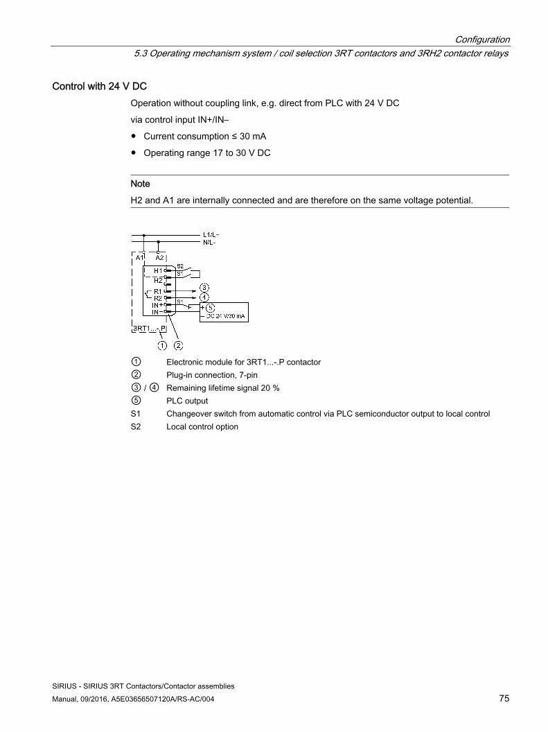
Configuration 5.3 Operating mechanism system / coil selection 3RT contactors and 3RH2 contactor relays
SIRIUS - SIRIUS 3RT Contactors/Contactor assemblies Manual, 09/2016, A5E03656507120A/RS-AC/004 75
Control with 24 V DC Operation without coupling link, e.g. direct from PLC with 24 V DC
via control input IN+/IN–
● Current consumption ≤ 30 mA
● Operating range 17 to 30 V DC
Note
H2 and A1 are internally connected and are therefore on the same voltage potential.
① Electronic module for 3RT1...-.P contactor② Plug-in connection, 7-pin ③ / ④ Remaining lifetime signal 20 %⑤ PLC output S1 Changeover switch from automatic control via PLC semiconductor output to local control S2 Local control option
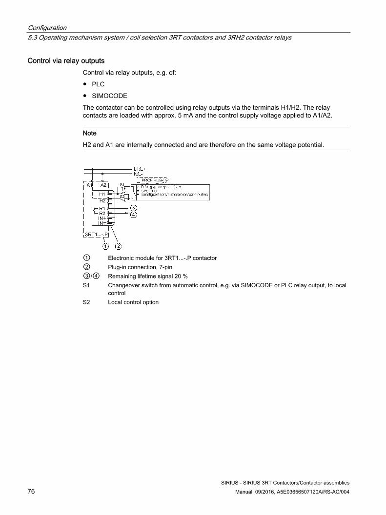
Configuration 5.3 Operating mechanism system / coil selection 3RT contactors and 3RH2 contactor relays
SIRIUS - SIRIUS 3RT Contactors/Contactor assemblies 76 Manual, 09/2016, A5E03656507120A/RS-AC/004
Control via relay outputs Control via relay outputs, e.g. of:
● PLC
● SIMOCODE
The contactor can be controlled using relay outputs via the terminals H1/H2. The relay contacts are loaded with approx. 5 mA and the control supply voltage applied to A1/A2.
Note
H2 and A1 are internally connected and are therefore on the same voltage potential.
① Electronic module for 3RT1...-.P contactor ② Plug-in connection, 7-pin③/④ Remaining lifetime signal 20 %S1 Changeover switch from automatic control, e.g. via SIMOCODE or PLC relay output, to local
control S2 Local control option
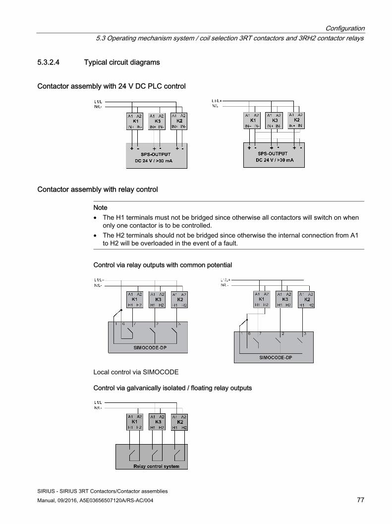
Configuration 5.3 Operating mechanism system / coil selection 3RT contactors and 3RH2 contactor relays
SIRIUS - SIRIUS 3RT Contactors/Contactor assemblies Manual, 09/2016, A5E03656507120A/RS-AC/004 77
5.3.2.4 Typical circuit diagrams
Contactor assembly with 24 V DC PLC control
Contactor assembly with relay control
Note • The H1 terminals must not be bridged since otherwise all contactors will switch on when
only one contactor is to be controlled. • The H2 terminals should not be bridged since otherwise the internal connection from A1
to H2 will be overloaded in the event of a fault.
Control via relay outputs with common potential
Local control via SIMOCODE
Control via galvanically isolated / floating relay outputs
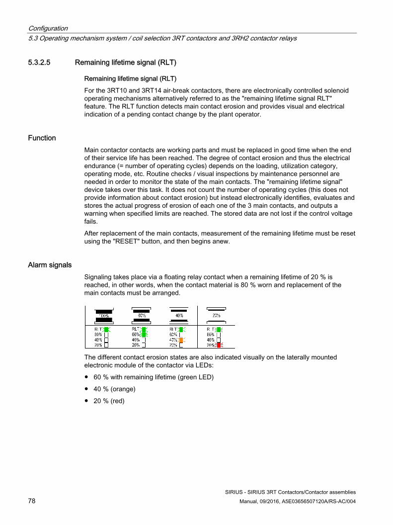
Configuration 5.3 Operating mechanism system / coil selection 3RT contactors and 3RH2 contactor relays
SIRIUS - SIRIUS 3RT Contactors/Contactor assemblies 78 Manual, 09/2016, A5E03656507120A/RS-AC/004
5.3.2.5 Remaining lifetime signal (RLT)
Remaining lifetime signal (RLT)
For the 3RT10 and 3RT14 air-break contactors, there are electronically controlled solenoid operating mechanisms alternatively referred to as the "remaining lifetime signal RLT" feature. The RLT function detects main contact erosion and provides visual and electrical indication of a pending contact change by the plant operator.
Function Main contactor contacts are working parts and must be replaced in good time when the end of their service life has been reached. The degree of contact erosion and thus the electrical endurance (= number of operating cycles) depends on the loading, utilization category, operating mode, etc. Routine checks / visual inspections by maintenance personnel are needed in order to monitor the state of the main contacts. The "remaining lifetime signal" device takes over this task. It does not count the number of operating cycles (this does not provide information about contact erosion) but instead electronically identifies, evaluates and stores the actual progress of erosion of each one of the 3 main contacts, and outputs a warning when specified limits are reached. The stored data are not lost if the control voltage fails.
After replacement of the main contacts, measurement of the remaining lifetime must be reset using the "RESET" button, and then begins anew.
Alarm signals Signaling takes place via a floating relay contact when a remaining lifetime of 20 % is reached, in other words, when the contact material is 80 % worn and replacement of the main contacts must be arranged.
The different contact erosion states are also indicated visually on the laterally mounted electronic module of the contactor via LEDs:
● 60 % with remaining lifetime (green LED)
● 40 % (orange)
● 20 % (red)
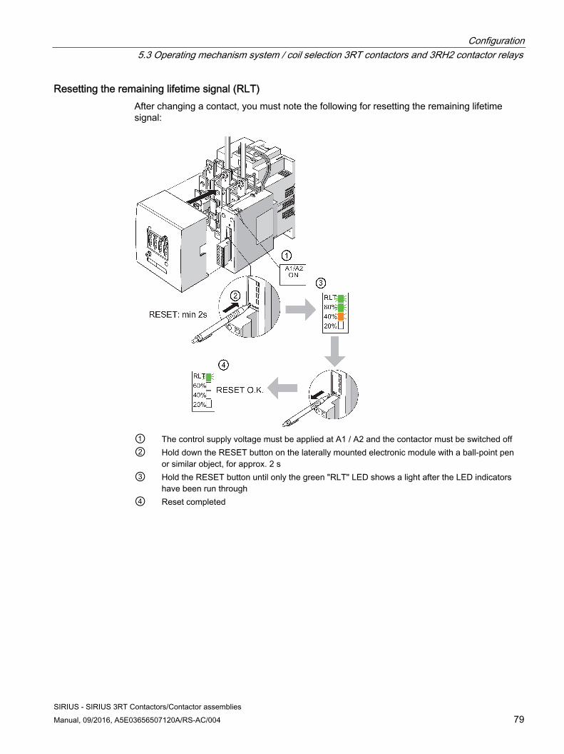
Configuration 5.3 Operating mechanism system / coil selection 3RT contactors and 3RH2 contactor relays
SIRIUS - SIRIUS 3RT Contactors/Contactor assemblies Manual, 09/2016, A5E03656507120A/RS-AC/004 79
Resetting the remaining lifetime signal (RLT) After changing a contact, you must note the following for resetting the remaining lifetime signal:
① The control supply voltage must be applied at A1 / A2 and the contactor must be switched off② Hold down the RESET button on the laterally mounted electronic module with a ball-point pen
or similar object, for approx. 2 s③ Hold the RESET button until only the green "RLT" LED shows a light after the LED indicators
have been run through ④ Reset completed
Configuration 5.3 Operating mechanism system / coil selection 3RT contactors and 3RH2 contactor relays
SIRIUS - SIRIUS 3RT Contactors/Contactor assemblies 80 Manual, 09/2016, A5E03656507120A/RS-AC/004
Use in rotor circuits of slip-ring motors
Note Notes on the use of contactors with remaining lifetime signal (RLT)
For detecting contact erosion, a typical measuring parameter of the RLT function is the voltage over the main contacts of the contactor when switching off the contactor. However, depending on slip, voltage values arise in the rotor circuits that are not suitable for evaluation and that result in premature signaling of RLT.
Residual current via the main contacts The resistance of the individual measuring circuits via the main contacts is 4.8 Mohms per current path. This high-resistance value excludes dangerous body currents or touch voltages on the load side when the contactor is switched off.
Functional switching via A1/A2 Functional switching via A1/A2 results in signaling of RLT. The control inputs (PLC) must be used for this. The system circuits are an exception here; the measured values remain saved (E²PROM). The control inputs via PLC/AS-Interface must be used for functional switching.
Configuration 5.4 Application environment
SIRIUS - SIRIUS 3RT Contactors/Contactor assemblies Manual, 09/2016, A5E03656507120A/RS-AC/004 81
5.4 Application environment
5.4.1 3RH2 contactor relays The following information must be taken into account when planning applications involving 3RH2 contactor relays.
Degree of protection and resistance to extreme climates 3RH2 contactor relays are suitable for use in any climate. They are finger-safe according to IEC 60529. 3RH2 contactor relays have degree of protection IP 20.
Shock load and vibratory load The 3RH2 contactor relays have been tested in terms of their shock resistance to sine pulses and rectangular pulses for AC and DC operation.
Ambient temperature The 3RH2 contactor relays are dimensioned for operation at ambient temperatures of between -25 °C and +60 °C. The devices can be stored at temperatures within the range from -55 °C to +80 °C.
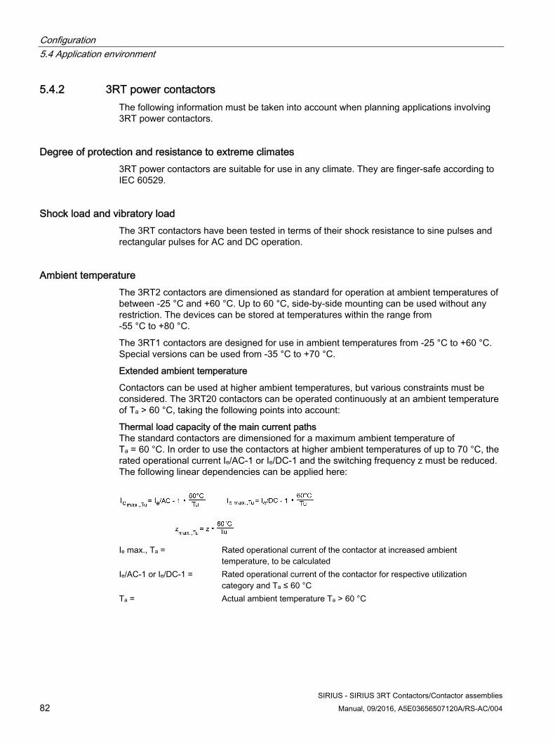
Configuration 5.4 Application environment
SIRIUS - SIRIUS 3RT Contactors/Contactor assemblies 82 Manual, 09/2016, A5E03656507120A/RS-AC/004
5.4.2 3RT power contactors The following information must be taken into account when planning applications involving 3RT power contactors.
Degree of protection and resistance to extreme climates 3RT power contactors are suitable for use in any climate. They are finger-safe according to IEC 60529.
Shock load and vibratory load The 3RT contactors have been tested in terms of their shock resistance to sine pulses and rectangular pulses for AC and DC operation.
Ambient temperature The 3RT2 contactors are dimensioned as standard for operation at ambient temperatures of between -25 °C and +60 °C. Up to 60 °C, side-by-side mounting can be used without any restriction. The devices can be stored at temperatures within the range from -55 °C to +80 °C.
The 3RT1 contactors are designed for use in ambient temperatures from -25 °C to +60 °C. Special versions can be used from -35 °C to +70 °C.
Extended ambient temperature
Contactors can be used at higher ambient temperatures, but various constraints must be considered. The 3RT20 contactors can be operated continuously at an ambient temperature of Ta > 60 °C, taking the following points into account:
Thermal load capacity of the main current paths The standard contactors are dimensioned for a maximum ambient temperature of Ta = 60 °C. In order to use the contactors at higher ambient temperatures of up to 70 °C, the rated operational current Ie/AC-1 or Ie/DC-1 and the switching frequency z must be reduced. The following linear dependencies can be applied here:
Ie max., Ta = Rated operational current of the contactor at increased ambient
temperature, to be calculatedIe/AC-1 or Ie/DC-1 = Rated operational current of the contactor for respective utilization
category and Ta ≤ 60 °CTa = Actual ambient temperature Ta > 60 °C
Configuration 5.4 Application environment
SIRIUS - SIRIUS 3RT Contactors/Contactor assemblies Manual, 09/2016, A5E03656507120A/RS-AC/004 83
The contactors may be operated for 1 hour at an ambient temperature of up to Ta ≤ 80 °C without reducing the permissible currents. Nevertheless, the average ambient temperature must not exceed Ta ≤ 60 °C for any 24 hour period. Note, however, that Contactors that contain electronic components or are combined with electronic accessories (e.g. integrated overvoltage attenuation, etc.) may only be operated at an ambient temperature of up to Ta ≤ 60 °C.
Minimum clearances from adjacent components The 3RT2 contactors are dimensioned for side-by-side mounting at temperatures of up to +60 °C. At higher temperatures a clearance of 10 mm may be required in order to ensure better heat dissipation with side-by-side mounting. With capacitor contactors, a lateral clearance of 10 mm is required for side-by-side mounting.
Operating range of the solenoid coils All SIRIUS contactors comply with the operating range limits of 0.85 ... 1.1 x US (rated control supply voltage) stipulated in the standard IEC EN 60947. The majority of the devices feature an operating range from 0.8 ... 1.1 x US; on some versions it is 0.7 ... 1.3 x US. Some versions of the contactors for railway applications have an operating range from 0.7 ... 1.25 x Us at an ambient temperature of +70 °C.
The electronics remain functional at ambient temperatures between -40 °C and +70 °C. This cannot be extended, even with reduced duty factor or lower current.
The reason for this is that some components are approved only to -40 °C, and below this they can be destroyed.
At the other extreme, with a switching transistor at the maximum permissible voltage (36.4 V or 169 V or 305 V), the temperature is already just under the destruction limit. A further increase in the ambient temperature can cause irreparable damage to the component (in the case of a transistor: short-circuit).
A microcontroller in the circuit measures the chip temperature and switches the device off if it is too high.
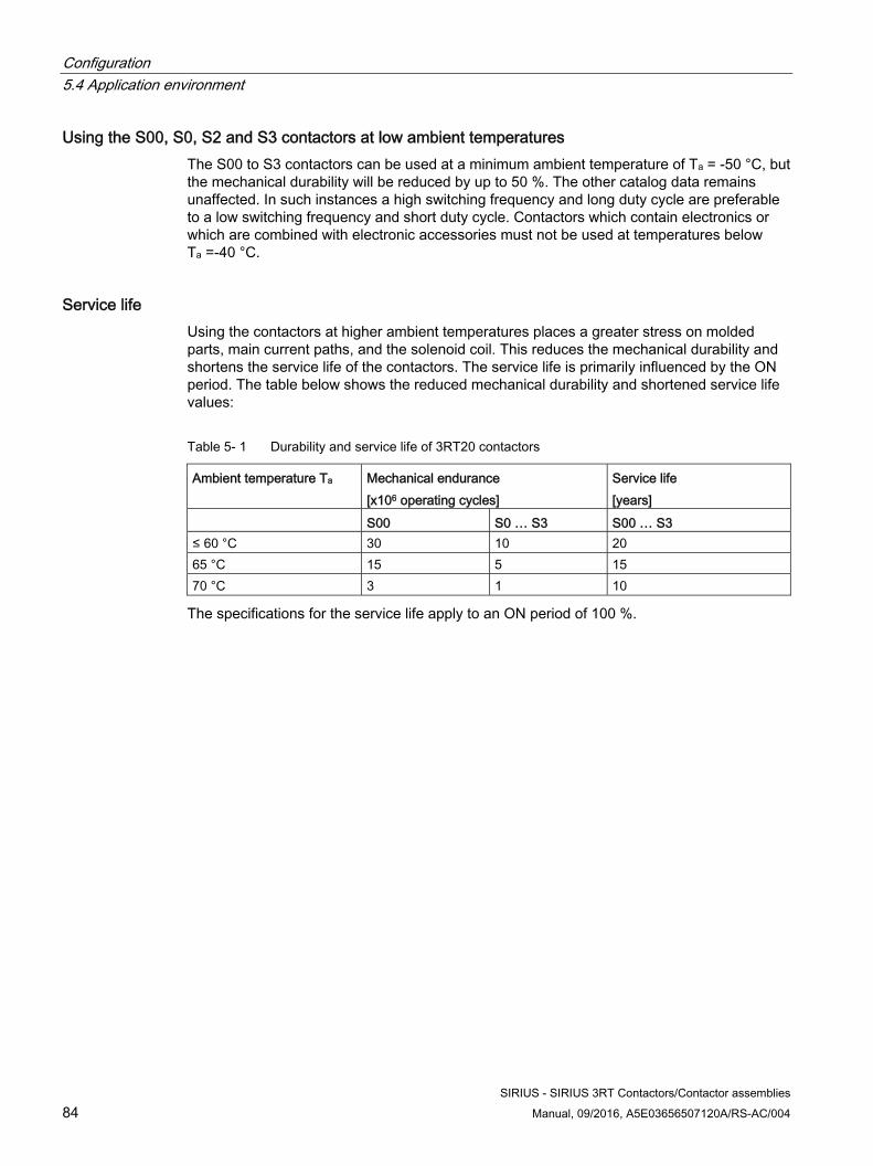
Configuration 5.4 Application environment
SIRIUS - SIRIUS 3RT Contactors/Contactor assemblies 84 Manual, 09/2016, A5E03656507120A/RS-AC/004
Using the S00, S0, S2 and S3 contactors at low ambient temperatures The S00 to S3 contactors can be used at a minimum ambient temperature of Ta = -50 °C, but the mechanical durability will be reduced by up to 50 %. The other catalog data remains unaffected. In such instances a high switching frequency and long duty cycle are preferable to a low switching frequency and short duty cycle. Contactors which contain electronics or which are combined with electronic accessories must not be used at temperatures below Ta =-40 °C.
Service life Using the contactors at higher ambient temperatures places a greater stress on molded parts, main current paths, and the solenoid coil. This reduces the mechanical durability and shortens the service life of the contactors. The service life is primarily influenced by the ON period. The table below shows the reduced mechanical durability and shortened service life values:
Table 5- 1 Durability and service life of 3RT20 contactors
Ambient temperature Ta Mechanical endurance [x106 operating cycles]
Service life [years]
S00 S0 … S3 S00 … S3 ≤ 60 °C 30 10 20 65 °C 15 5 15 70 °C 3 1 10
The specifications for the service life apply to an ON period of 100 %.
Configuration 5.4 Application environment
SIRIUS - SIRIUS 3RT Contactors/Contactor assemblies Manual, 09/2016, A5E03656507120A/RS-AC/004 85
5.4.3 Contactors for railway applications The following information must be taken into account when planning applications involving contactors for rail applications (versions of the 3RT2 power contactors, 3RH2 contactor relays, and 3RT1 power contactors in sizes S6 to S12). All other data corresponds to that of the standard 3RT1 / 3RT2 contactors and 3RH2 contactor relays.
Touch protection SIRIUS 3RT20 / 3RH2 and 3RT1 contactors (sizes S6 to S12) are finger-safe according to IEC 60529.
Ambient temperature When operating contactors for railway applications (versions of the 3RT20 power contactors, 3RH21 contactor relays and 3RT10 power contactors) at the full solenoid coil operating range, the permissible ambient temperature is between -40 °C and +70 °C.
Note
Continuous operation at temperatures > +60 °C reduces the mechanical durability, the current carrying capacity of the current paths, and the switching frequency.
Extended operating range of the solenoid coil An important railway requirement as regards SIRIUS contactors is the extended operating range of the solenoid coil (0.7 ... 1.25 x US). This must be taken into account when selecting devices for railway applications.
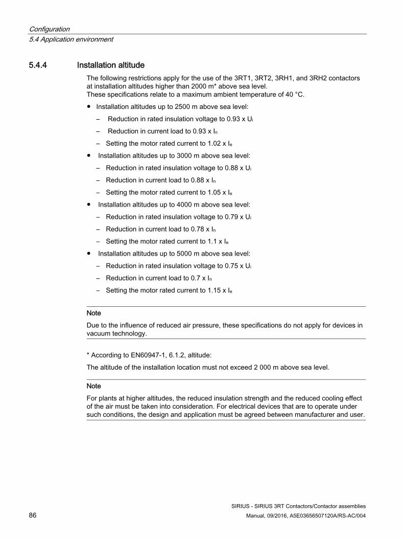
Configuration 5.4 Application environment
SIRIUS - SIRIUS 3RT Contactors/Contactor assemblies 86 Manual, 09/2016, A5E03656507120A/RS-AC/004
5.4.4 Installation altitude The following restrictions apply for the use of the 3RT1, 3RT2, 3RH1, and 3RH2 contactors at installation altitudes higher than 2000 m* above sea level. These specifications relate to a maximum ambient temperature of 40 °C.
● Installation altitudes up to 2500 m above sea level:
– Reduction in rated insulation voltage to 0.93 x Ui
– Reduction in current load to 0.93 x In
– Setting the motor rated current to 1.02 x Ie
● Installation altitudes up to 3000 m above sea level:
– Reduction in rated insulation voltage to 0.88 x Ui
– Reduction in current load to 0.88 x In
– Setting the motor rated current to 1.05 x Ie
● Installation altitudes up to 4000 m above sea level:
– Reduction in rated insulation voltage to 0.79 x Ui
– Reduction in current load to 0.78 x In
– Setting the motor rated current to 1.1 x Ie
● Installation altitudes up to 5000 m above sea level:
– Reduction in rated insulation voltage to 0.75 x Ui
– Reduction in current load to 0.7 x In
– Setting the motor rated current to 1.15 x Ie
Note
Due to the influence of reduced air pressure, these specifications do not apply for devices in vacuum technology.
* According to EN60947-1, 6.1.2, altitude:
The altitude of the installation location must not exceed 2 000 m above sea level.
Note
For plants at higher altitudes, the reduced insulation strength and the reduced cooling effect of the air must be taken into consideration. For electrical devices that are to operate under such conditions, the design and application must be agreed between manufacturer and user.
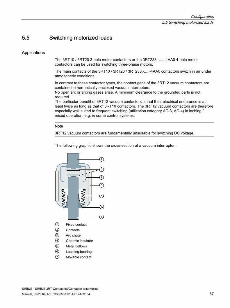
Configuration 5.5 Switching motorized loads
SIRIUS - SIRIUS 3RT Contactors/Contactor assemblies Manual, 09/2016, A5E03656507120A/RS-AC/004 87
5.5 Switching motorized loads
Applications The 3RT10 / 3RT20 3-pole motor contactors or the 3RT233.-.....-4AA0 4-pole motor contactors can be used for switching three-phase motors.
The main contacts of the 3RT10 / 3RT20 / 3RT233.-.....-4AA0 contactors switch in air under atmospheric conditions.
In contrast to these contactor types, the contact gaps of the 3RT12 vacuum contactors are contained in hermetically enclosed vacuum interrupters. No open arc or arcing gases arise. A minimum clearance to the grounded parts is not required. The particular benefit of 3RT12 vacuum contactors is that their electrical endurance is at least twice as long as that of 3RT10 contactors. The 3RT12 vacuum contactors are therefore especially well suited to frequent switching (utilization category AC-3, AC-4) in inching / mixed operation, e.g. in crane control systems.
Note
3RT12 vacuum contactors are fundamentally unsuitable for switching DC voltage.
The following graphic shows the cross-section of a vacuum interrupter.
① Fixed contact ② Contacts ③ Arc chute ④ Ceramic insulator ⑤ Metal bellows ⑥ Locating bearing ⑦ Movable contact
Configuration 5.5 Switching motorized loads
SIRIUS - SIRIUS 3RT Contactors/Contactor assemblies 88 Manual, 09/2016, A5E03656507120A/RS-AC/004
Connection to the automation level 3RA28 or 3RA27 function modules can be mounted on the front of 3RT20 power contactors to provide additional functionalities (e.g. star-delta (wye-delta) functionality) and enable a connection to be established with a controller via IO-Link or AS-Interface. If 3RA27 function modules are used, special versions of the 3RT2 power contactors (3RT2...-....-0CC0 at the 13th and 16th digits of the article number) that facilitate direct voltage tapping of the main current paths must be used. These contactors with voltage tapping are available with a 24 V DC solenoid coil. The coil is controlled via the function module.
Variants The performance range of 3 to 55 kW / 400 V (utilization category AC-3) is covered by the 3RT2 contactors (sizes S00 to S3) with a width of 45 mm to 70 mm. In size S0, the installation depth for contactors with DC and AC/DC solenoid systems is 10 mm larger than for versions with an AC solenoid system. The performance range of 55 to 250 kW / 400 V (utilization category AC-2, AC-3 and AC-4) is covered by the 3RT1 contactors (sizes S6 to S12) with a width of 120 mm to 160 mm.
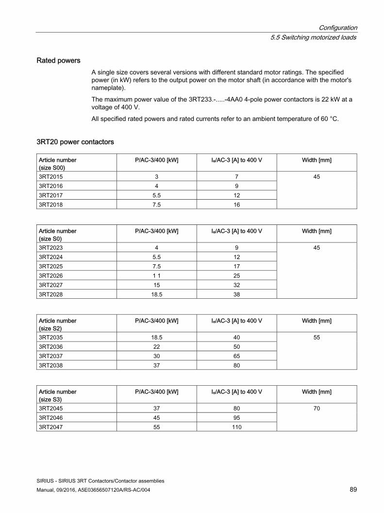
Configuration 5.5 Switching motorized loads
SIRIUS - SIRIUS 3RT Contactors/Contactor assemblies Manual, 09/2016, A5E03656507120A/RS-AC/004 89
Rated powers A single size covers several versions with different standard motor ratings. The specified power (in kW) refers to the output power on the motor shaft (in accordance with the motor's nameplate).
The maximum power value of the 3RT233.-.....-4AA0 4-pole power contactors is 22 kW at a voltage of 400 V.
All specified rated powers and rated currents refer to an ambient temperature of 60 °C.
3RT20 power contactors Article number (size S00)
P/AC-3/400 [kW] Ie/AC-3 [A] to 400 V Width [mm]
3RT2015 3 7 45 3RT2016 4 9 3RT2017 5.5 12 3RT2018 7.5 16
Article number (size S0)
P/AC-3/400 [kW] Ie/AC-3 [A] to 400 V Width [mm]
3RT2023 4 9 45 3RT2024 5.5 12 3RT2025 7.5 17 3RT2026 1 1 25 3RT2027 15 32 3RT2028 18.5 38
Article number (size S2)
P/AC-3/400 [kW] Ie/AC-3 [A] to 400 V Width [mm]
3RT2035 18.5 40 55 3RT2036 22 50 3RT2037 30 65 3RT2038 37 80
Article number (size S3)
P/AC-3/400 [kW] Ie/AC-3 [A] to 400 V Width [mm]
3RT2045 37 80 70 3RT2046 45 95 3RT2047 55 110
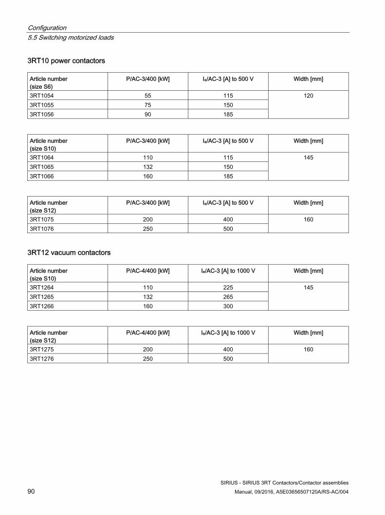
Configuration 5.5 Switching motorized loads
SIRIUS - SIRIUS 3RT Contactors/Contactor assemblies 90 Manual, 09/2016, A5E03656507120A/RS-AC/004
3RT10 power contactors Article number (size S6)
P/AC-3/400 [kW] Ie/AC-3 [A] to 500 V Width [mm]
3RT1054 55 115 120 3RT1055 75 150 3RT1056 90 185
Article number (size S10)
P/AC-3/400 [kW] Ie/AC-3 [A] to 500 V Width [mm]
3RT1064 110 115 145 3RT1065 132 150 3RT1066 160 185
Article number (size S12)
P/AC-3/400 [kW] Ie/AC-3 [A] to 500 V Width [mm]
3RT1075 200 400 160 3RT1076 250 500
3RT12 vacuum contactors Article number (size S10)
P/AC-4/400 [kW] Ie/AC-3 [A] to 1000 V Width [mm]
3RT1264 110 225 145 3RT1265 132 265 3RT1266 160 300
Article number (size S12)
P/AC-4/400 [kW] Ie/AC-3 [A] to 1000 V Width [mm]
3RT1275 200 400 160 3RT1276 250 500
Configuration 5.5 Switching motorized loads
SIRIUS - SIRIUS 3RT Contactors/Contactor assemblies Manual, 09/2016, A5E03656507120A/RS-AC/004 91
Performance increase The easy expansion option when it comes to controller building is of advantage when configuring. In many application cases, when the motor power rating is increased, the space is also sufficient for the contactor with the next-higher performance level.
Attenuation of the switching overvoltage of the 3RT vacuum contactors To attenuate overvoltages and to protect the insulation of the motor winding from multiple re-ignitions when switching off three-phase motors, we recommend you connect 3RT12 vacuum contactors (2T1 / 4T2 / 6T3) on the outgoing side with the main current path attenuation module (RC element and varistor). This circuit is not necessary when using motors whose insulation is designed for operation on converters.
NOTICE
The main current path circuit is not required for operation in circuits with converters. The circuit can be destroyed by the voltage peaks and harmonics, resulting in phase-to-phase short circuits.
Main current path surge attenuation module for vacuum contactors The main current path attenuation module is available for the following rated operational voltages:
● Ue <= 690 V: 3RT1966-1PV3
● Ue <= 1000 V: 3RT1966-1PV4
The main current path attenuation module is connected separately from the contactor over a cable of a length of approximately 35 cm on the outgoing terminal of the 2T1 / 4T2 / 6T3 contactor.
Configuration 5.6 Switching resistive loads
SIRIUS - SIRIUS 3RT Contactors/Contactor assemblies 92 Manual, 09/2016, A5E03656507120A/RS-AC/004
5.6 Switching resistive loads
Applications The following contactor versions can be used to switch resistive loads according to utilization category AC-1:
● 3-pole 3RT20 contactors (sizes S00 to S3)
● 4-pole 3RT23 contactors (sizes S00 to S2)
● 3-pole 3RT24 contactors (size S3) and 3RT14 (size S6 to S12)
These contactors feature 3 / 4 NO contacts as their main contacts.
Typical applications:
● Switching resistive loads
● Isolation of systems with ungrounded or poorly grounded neutral conductors.
● System switchover, where alternative AC power supplies are present.
● For inductive loads as contactors which conduct the current but do not have to perform switching (e.g. if used in the vicinity of frequency converters).
● Switching mixed loads in distribution systems.
Configuration note The 3RT10 contactor series for switching motors also has utilization category AC-1. However, the 3RT14 AC-1 contactor is the more cost-effective alternative for this special application.
Versions The device bases are identical within each device size. In size S0, the installation depth for contactors with a DC solenoid system is 10 mm larger than that for versions with an AC solenoid system. Within the respective size (S2 to S12) all operating mechanism types have the same installation depth.
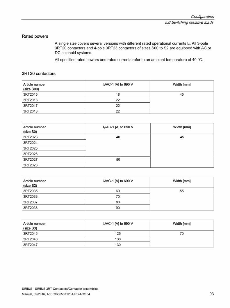
Configuration 5.6 Switching resistive loads
SIRIUS - SIRIUS 3RT Contactors/Contactor assemblies Manual, 09/2016, A5E03656507120A/RS-AC/004 93
Rated powers A single size covers several versions with different rated operational currents Ie. All 3-pole 3RT20 contactors and 4-pole 3RT23 contactors of sizes S00 to S2 are equipped with AC or DC solenoid systems.
All specified rated powers and rated currents refer to an ambient temperature of 40 °C.
3RT20 contactors Article number (size S00)
Ie/AC-1 [A] to 690 V Width [mm]
3RT2015 18 45 3RT2016 22 3RT2017 22 3RT2018 22
Article number (size S0)
Ie/AC-1 [A] to 690 V Width [mm]
3RT2023 40
45 3RT2024 3RT2025 3RT2026 3RT2027 50 3RT2028
Article number (size S2)
Ie/AC-1 [A] to 690 V Width [mm]
3RT2035 60 55 3RT2036 70 3RT2037 80 3RT2038 90
Article number (size S3)
Ie/AC-1 [A] to 690 V Width [mm]
3RT2045 125 70 3RT2046 130 3RT2047 130
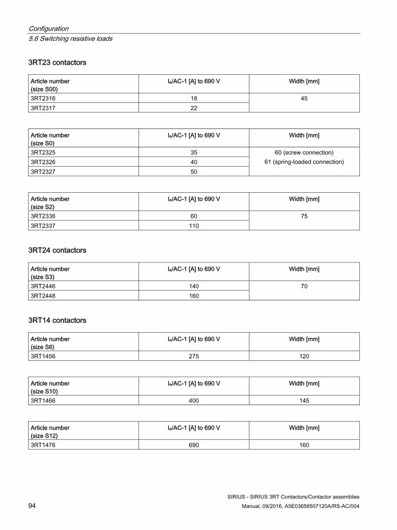
Configuration 5.6 Switching resistive loads
SIRIUS - SIRIUS 3RT Contactors/Contactor assemblies 94 Manual, 09/2016, A5E03656507120A/RS-AC/004
3RT23 contactors Article number (size S00)
Ie/AC-1 [A] to 690 V Width [mm]
3RT2316 18 45 3RT2317 22
Article number (size S0)
Ie/AC-1 [A] to 690 V Width [mm]
3RT2325 35 60 (screw connection) 61 (spring-loaded connection) 3RT2326 40
3RT2327 50
Article number (size S2)
Ie/AC-1 [A] to 690 V Width [mm]
3RT2336 60 75 3RT2337 110
3RT24 contactors Article number (size S3)
Ie/AC-1 [A] to 690 V Width [mm]
3RT2446 140 70 3RT2448 160
3RT14 contactors Article number (size S6)
Ie/AC-1 [A] to 690 V Width [mm]
3RT1456 275 120
Article number (size S10)
Ie/AC-1 [A] to 690 V Width [mm]
3RT1466 400 145
Article number (size S12)
Ie/AC-1 [A] to 690 V Width [mm]
3RT1476 690 160
Configuration 5.7 Changing the polarity of hoisting gear motors
SIRIUS - SIRIUS 3RT Contactors/Contactor assemblies Manual, 09/2016, A5E03656507120A/RS-AC/004 95
5.7 Changing the polarity of hoisting gear motors
Applications The 4-pole 3RT25 contactors (2 NO contacts and 2 NC contacts) can be used for changing the polarity of hoisting gear motors.
Note
The individual device for pole changing is not suitable for reversing operation.
Versions The entire performance range of 3 to 11 kW/400 V (utilization category AC-3) is covered by two sizes, S00 and S0, each with a width of 45 mm. The performance range of 18.5 kW to 22 kW/400 V (utilization category AC-3) is covered by size S2. All 4-pole 3RT25 contactors of sizes S00 to S2 are equipped with AC or DC solenoid systems. The device footprints are the same for all operating mechanism types. In size S0, the installation depth for contactors with a DC solenoid system is 10 mm larger than that for versions with an AC solenoid system. In the case of size S2, all operating mechanism types have the same installation depth.
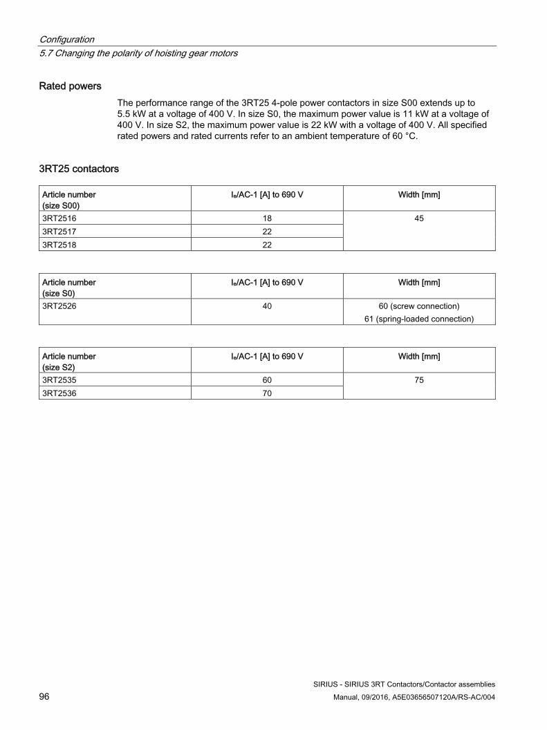
Configuration 5.7 Changing the polarity of hoisting gear motors
SIRIUS - SIRIUS 3RT Contactors/Contactor assemblies 96 Manual, 09/2016, A5E03656507120A/RS-AC/004
Rated powers The performance range of the 3RT25 4-pole power contactors in size S00 extends up to 5.5 kW at a voltage of 400 V. In size S0, the maximum power value is 11 kW at a voltage of 400 V. In size S2, the maximum power value is 22 kW with a voltage of 400 V. All specified rated powers and rated currents refer to an ambient temperature of 60 °C.
3RT25 contactors Article number (size S00)
Ie/AC-1 [A] to 690 V Width [mm]
3RT2516 18 45 3RT2517 22 3RT2518 22
Article number (size S0)
Ie/AC-1 [A] to 690 V Width [mm]
3RT2526 40 60 (screw connection) 61 (spring-loaded connection)
Article number (size S2)
Ie/AC-1 [A] to 690 V Width [mm]
3RT2535 60 75 3RT2536 70
Configuration 5.8 Switching in the auxiliary circuit
SIRIUS - SIRIUS 3RT Contactors/Contactor assemblies Manual, 09/2016, A5E03656507120A/RS-AC/004 97
5.8 Switching in the auxiliary circuit
Applications The 3RH2 contactor relays can be used for switching in the auxiliary circuit (controlling, signaling, interlocking).
Thanks to their high contact reliability at low voltages and currents, the 3RH2 contactor relays are suitable for solid-state circuits down to a lower limit of 1 mA at 17 V.
Versions 3RH2 contactor relays are available in a width of 45 mm (size S00) and can be ordered with solenoid coils for AC or DC operation. The external design of the 4-pole 3RH21 contactor relay is identical to that of the motor contactor in size S00 (45 mm width). In addition, 8-pole 3RH22 contactor relays can be supplied with a permanently mounted auxiliary switch block on the front.
Rated powers The performance range of the 4-pole 3RH21 contactor relays in size S00 extends up to 10 A at a voltage of up to 230 V in utilization category AC-15/AC-14 and up to 10 A at 24 V DC in utilization category DC-12/DC-13.
Auxiliary switch blocks The 3RH2 contactor relays can be expanded by up to 4 contacts via attachable auxiliary switch blocks.
Special version: 3RH24 latched contactor relays In the event of a short circuit in the low-voltage system or if large drive motors are switched on directly, the control supply voltage for the contactor relays may drop out or fall below the permissible tolerance for a brief period. To guarantee continued operation, the 3RH24 special version of the contactor relays, with mechanical latching, may be used. These contactor relays latch mechanically following switch-on and then remain switched on even if there is a voltage failure. The contactor relay can be released either electrically by means of a release solenoid, or manually by actuating the latched contactor. When the voltage is recovered, the storage properties of the contactor relays mean that the production program can be resumed straightaway without any resetting time. The contactor coil and the coil of the release solenoid are both dimensioned for continuous operation. The power input is the same for the contactor coil and the release coil. The number of auxiliary contacts can be extended by means of auxiliary switch blocks on the front (up to 4 poles).
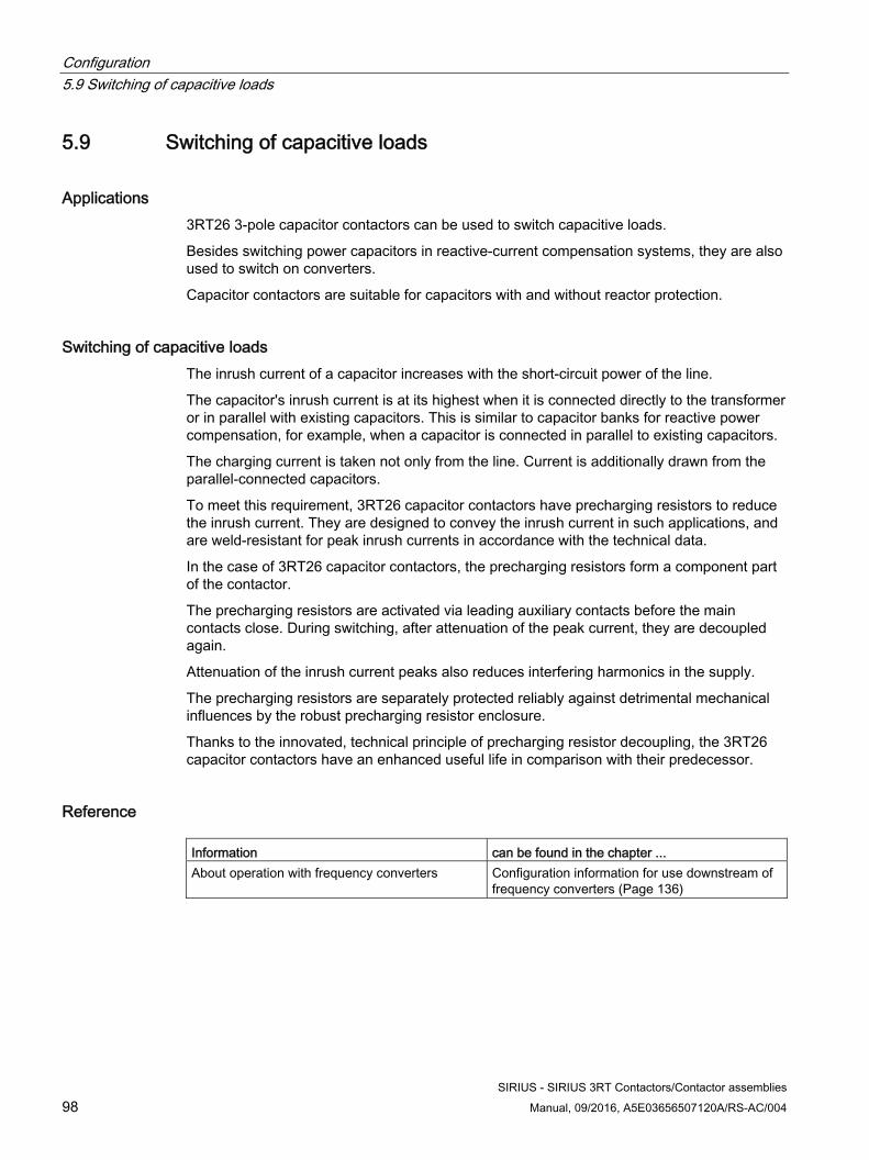
Configuration 5.9 Switching of capacitive loads
SIRIUS - SIRIUS 3RT Contactors/Contactor assemblies 98 Manual, 09/2016, A5E03656507120A/RS-AC/004
5.9 Switching of capacitive loads
Applications 3RT26 3-pole capacitor contactors can be used to switch capacitive loads.
Besides switching power capacitors in reactive-current compensation systems, they are also used to switch on converters.
Capacitor contactors are suitable for capacitors with and without reactor protection.
Switching of capacitive loads The inrush current of a capacitor increases with the short-circuit power of the line.
The capacitor's inrush current is at its highest when it is connected directly to the transformer or in parallel with existing capacitors. This is similar to capacitor banks for reactive power compensation, for example, when a capacitor is connected in parallel to existing capacitors.
The charging current is taken not only from the line. Current is additionally drawn from the parallel-connected capacitors.
To meet this requirement, 3RT26 capacitor contactors have precharging resistors to reduce the inrush current. They are designed to convey the inrush current in such applications, and are weld-resistant for peak inrush currents in accordance with the technical data.
In the case of 3RT26 capacitor contactors, the precharging resistors form a component part of the contactor.
The precharging resistors are activated via leading auxiliary contacts before the main contacts close. During switching, after attenuation of the peak current, they are decoupled again.
Attenuation of the inrush current peaks also reduces interfering harmonics in the supply.
The precharging resistors are separately protected reliably against detrimental mechanical influences by the robust precharging resistor enclosure.
Thanks to the innovated, technical principle of precharging resistor decoupling, the 3RT26 capacitor contactors have an enhanced useful life in comparison with their predecessor.
Reference Information can be found in the chapter ... About operation with frequency converters Configuration information for use downstream of
frequency converters (Page 136)
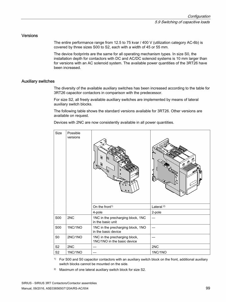
Configuration 5.9 Switching of capacitive loads
SIRIUS - SIRIUS 3RT Contactors/Contactor assemblies Manual, 09/2016, A5E03656507120A/RS-AC/004 99
Versions The entire performance range from 12.5 to 75 kvar / 400 V (utilization category AC-6b) is covered by three sizes S00 to S2, each with a width of 45 or 55 mm.
The device footprints are the same for all operating mechanism types. In size S0, the installation depth for contactors with DC and AC/DC solenoid systems is 10 mm larger than for versions with an AC solenoid system. The available power quantities of the 3RT26 have been increased.
Auxiliary switches The diversity of the available auxiliary switches has been increased according to the table for 3RT26 capacitor contactors in comparison with the predecessor.
For size S2, all freely available auxiliary switches are implemented by means of lateral auxiliary switch blocks.
The following table shows the standard versions available for 3RT26. Other versions are available on request.
Devices with 2NC are now consistently available in all power quantities.
Size Possible versions
On the front1) Lateral 2) 4-pole 2-pole
S00 2NC 1NC in the precharging block, 1NC in the basic unit
---
S00 1NC/1NO 1NC in the precharging block, 1NO in the basic device
---
S0 2NC/1NO 1NC in the precharging block, 1NC/1NO in the basic device
---
S2 2NC --- 2NC S2 1NC/1NO --- 1NC/1NO
1) For S00 and S0 capacitor contactors with an auxiliary switch block on the front, additional auxiliary switch blocks cannot be mounted on the side.
2) Maximum of one lateral auxiliary switch block for size S2.
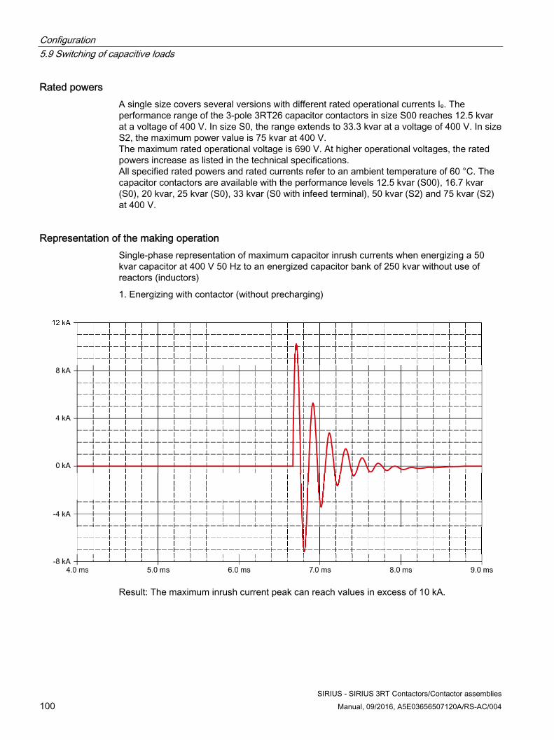
Configuration 5.9 Switching of capacitive loads
SIRIUS - SIRIUS 3RT Contactors/Contactor assemblies 100 Manual, 09/2016, A5E03656507120A/RS-AC/004
Rated powers A single size covers several versions with different rated operational currents Ie. The performance range of the 3-pole 3RT26 capacitor contactors in size S00 reaches 12.5 kvar at a voltage of 400 V. In size S0, the range extends to 33.3 kvar at a voltage of 400 V. In size S2, the maximum power value is 75 kvar at 400 V. The maximum rated operational voltage is 690 V. At higher operational voltages, the rated powers increase as listed in the technical specifications. All specified rated powers and rated currents refer to an ambient temperature of 60 °C. The capacitor contactors are available with the performance levels 12.5 kvar (S00), 16.7 kvar (S0), 20 kvar, 25 kvar (S0), 33 kvar (S0 with infeed terminal), 50 kvar (S2) and 75 kvar (S2) at 400 V.
Representation of the making operation Single-phase representation of maximum capacitor inrush currents when energizing a 50 kvar capacitor at 400 V 50 Hz to an energized capacitor bank of 250 kvar without use of reactors (inductors)
1. Energizing with contactor (without precharging)
Result: The maximum inrush current peak can reach values in excess of 10 kA.
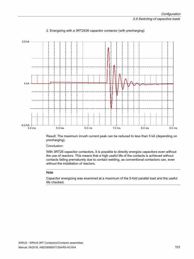
Configuration 5.9 Switching of capacitive loads
SIRIUS - SIRIUS 3RT Contactors/Contactor assemblies Manual, 09/2016, A5E03656507120A/RS-AC/004 101
2. Energizing with a 3RT2636 capacitor contactor (with precharging)
Result: The maximum inrush current peak can be reduced to less than 5 kA (depending on precharging).
Conclusion:
With 3RT26 capacitor contactors, it is possible to directly energize capacitors even without the use of reactors. This means that a high useful life of the contacts is achieved without contacts failing prematurely due to contact welding, as conventional contactors can, even without the installation of reactors.
Note
Capacitor energizing was examined at a maximum of the 5-fold parallel load and the useful life checked.
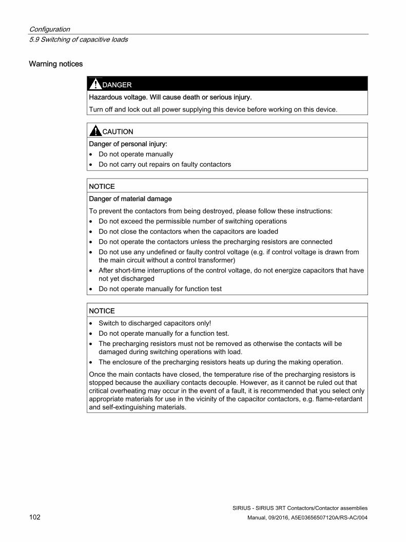
Configuration 5.9 Switching of capacitive loads
SIRIUS - SIRIUS 3RT Contactors/Contactor assemblies 102 Manual, 09/2016, A5E03656507120A/RS-AC/004
Warning notices
DANGER
Hazardous voltage. Will cause death or serious injury.
Turn off and lock out all power supplying this device before working on this device.
CAUTION
Danger of personal injury: • Do not operate manually • Do not carry out repairs on faulty contactors
NOTICE
Danger of material damage
To prevent the contactors from being destroyed, please follow these instructions: • Do not exceed the permissible number of switching operations • Do not close the contactors when the capacitors are loaded • Do not operate the contactors unless the precharging resistors are connected • Do not use any undefined or faulty control voltage (e.g. if control voltage is drawn from
the main circuit without a control transformer) • After short-time interruptions of the control voltage, do not energize capacitors that have
not yet discharged • Do not operate manually for function test
NOTICE
• Switch to discharged capacitors only! • Do not operate manually for a function test. • The precharging resistors must not be removed as otherwise the contacts will be
damaged during switching operations with load. • The enclosure of the precharging resistors heats up during the making operation.
Once the main contacts have closed, the temperature rise of the precharging resistors is stopped because the auxiliary contacts decouple. However, as it cannot be ruled out that critical overheating may occur in the event of a fault, it is recommended that you select only appropriate materials for use in the vicinity of the capacitor contactors, e.g. flame-retardant and self-extinguishing materials.
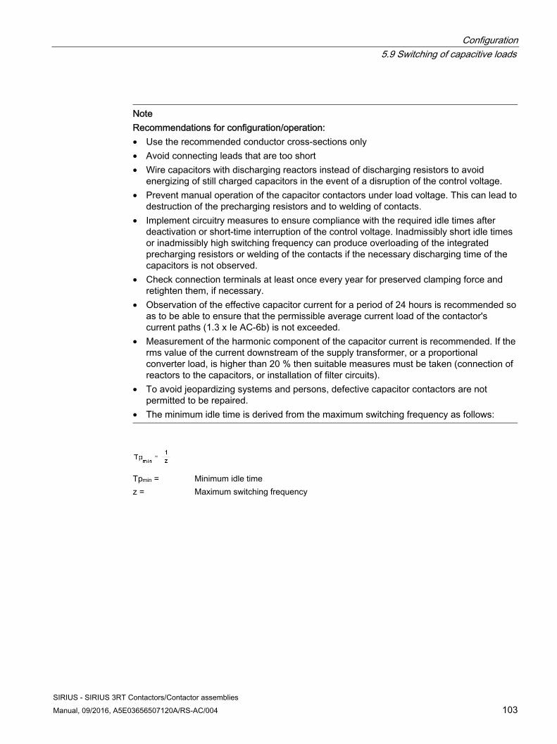
Configuration 5.9 Switching of capacitive loads
SIRIUS - SIRIUS 3RT Contactors/Contactor assemblies Manual, 09/2016, A5E03656507120A/RS-AC/004 103
Note Recommendations for configuration/operation: • Use the recommended conductor cross-sections only • Avoid connecting leads that are too short • Wire capacitors with discharging reactors instead of discharging resistors to avoid
energizing of still charged capacitors in the event of a disruption of the control voltage. • Prevent manual operation of the capacitor contactors under load voltage. This can lead to
destruction of the precharging resistors and to welding of contacts. • Implement circuitry measures to ensure compliance with the required idle times after
deactivation or short-time interruption of the control voltage. Inadmissibly short idle times or inadmissibly high switching frequency can produce overloading of the integrated precharging resistors or welding of the contacts if the necessary discharging time of the capacitors is not observed.
• Check connection terminals at least once every year for preserved clamping force and retighten them, if necessary.
• Observation of the effective capacitor current for a period of 24 hours is recommended so as to be able to ensure that the permissible average current load of the contactor's current paths (1.3 x Ie AC-6b) is not exceeded.
• Measurement of the harmonic component of the capacitor current is recommended. If the rms value of the current downstream of the supply transformer, or a proportional converter load, is higher than 20 % then suitable measures must be taken (connection of reactors to the capacitors, or installation of filter circuits).
• To avoid jeopardizing systems and persons, defective capacitor contactors are not permitted to be repaired.
• The minimum idle time is derived from the maximum switching frequency as follows:
Tpmin = Minimum idle timez = Maximum switching frequency
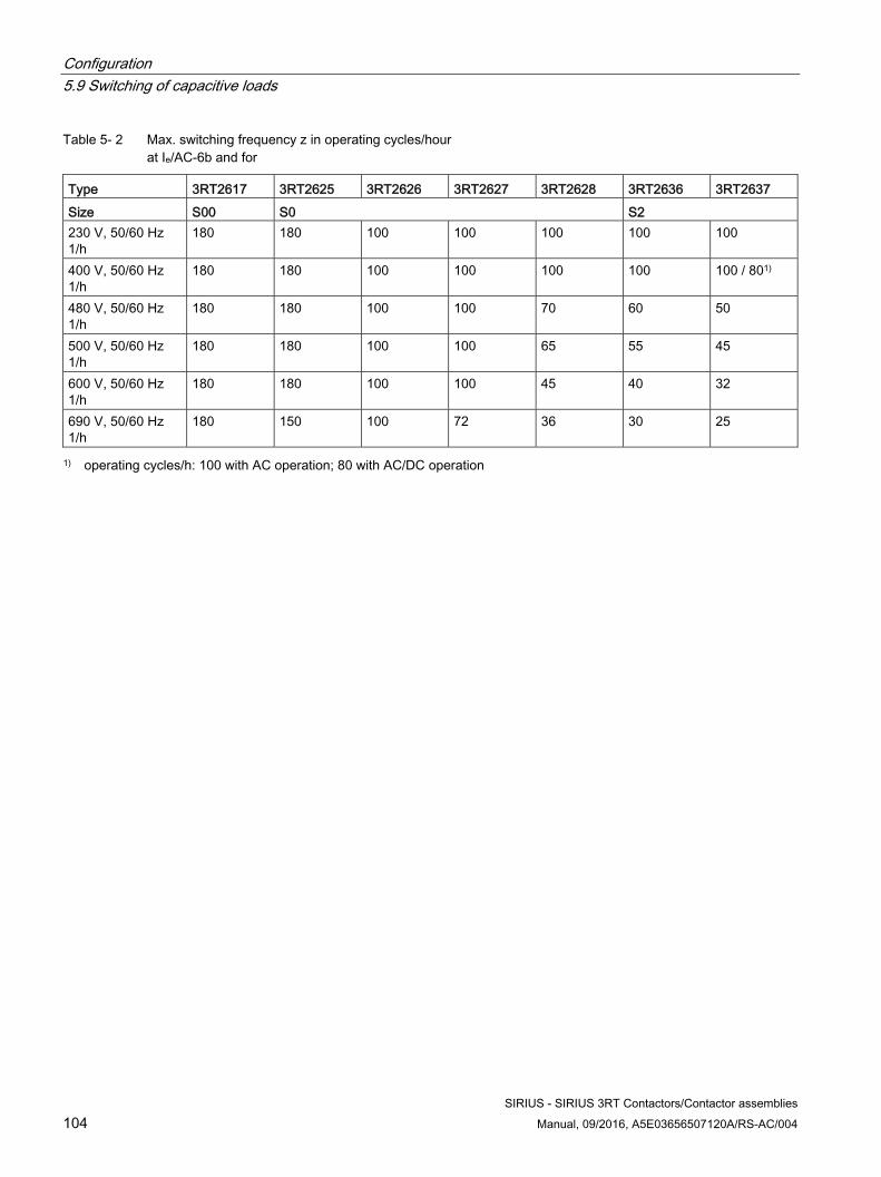
Configuration 5.9 Switching of capacitive loads
SIRIUS - SIRIUS 3RT Contactors/Contactor assemblies 104 Manual, 09/2016, A5E03656507120A/RS-AC/004
Table 5- 2 Max. switching frequency z in operating cycles/hour at Ie/AC-6b and for
Type 3RT2617 3RT2625 3RT2626 3RT2627 3RT2628 3RT2636 3RT2637Size S00 S0 S2 230 V, 50/60 Hz 1/h
180 180 100 100 100 100 100
400 V, 50/60 Hz 1/h
180 180 100 100 100 100 100 / 801)
480 V, 50/60 Hz 1/h
180 180 100 100 70 60 50
500 V, 50/60 Hz 1/h
180 180 100 100 65 55 45
600 V, 50/60 Hz 1/h
180 180 100 100 45 40 32
690 V, 50/60 Hz 1/h
180 150 100 72 36 30 25
1) operating cycles/h: 100 with AC operation; 80 with AC/DC operation
Configuration 5.10 Contactors with extended operating range
SIRIUS - SIRIUS 3RT Contactors/Contactor assemblies Manual, 09/2016, A5E03656507120A/RS-AC/004 105
5.10 Contactors with extended operating range
5.10.1 Contactors for railway applications
5.10.1.1 Contactors for rail applications according to IEC 60077-2 These contactor types are equipped with electronic coil control.
The following conditions of use apply:
● They are approved for operation within the temperature range -40 °C to +70 °C.
● The operating range of the contactor operating mechanism is 0.7 - 1.25 x Us referred to the rated value for operation on DC voltage.
● The operating mechanisms with rated voltages of 24 V DC, 72 V DC and 110 V DC are available by preference.
● Compared to the electronic operating mechanisms of the 3RT1 standard contactors, the operating mechanisms of sizes S6-S12 are equipped with 2 operating modes for direct control.
Size Article number Power rating of three-phase motors [kW]
at 400 V S00 3RT2.1.-.X...-0LA2 5.5 S0 3RT2.2.-.X...-0LA2 18.5 S2 3RT2.3.-.X...-0LA2 37 S3 3RT2.4.-.X...-0LA2 55 S6 3RT1.5.-.X...-0LA2 90 S10 3RT1.6.-.X...-0LA2 160 S12 3RT1.7.-.X...-0LA2 250
The above-listed contactors have a supplementary approval according to IEC 60077 and are thus optimized for use in rail applications.
The following contactor relays have the described approval and operating mechanism configuration:
● Article No.: 3RH2…-.X...-0LA2
The switching capacity data correspond to those of the 3RH2 standard coupling relays.
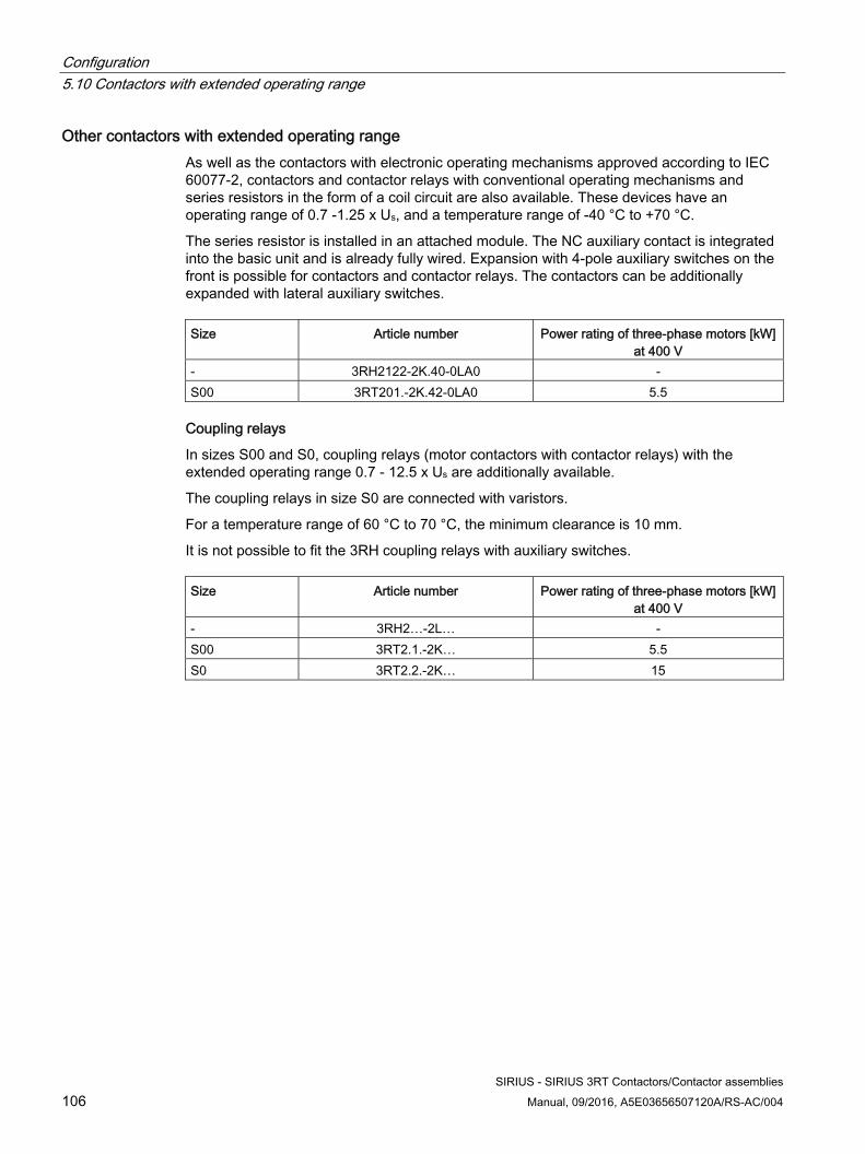
Configuration 5.10 Contactors with extended operating range
SIRIUS - SIRIUS 3RT Contactors/Contactor assemblies 106 Manual, 09/2016, A5E03656507120A/RS-AC/004
Other contactors with extended operating range As well as the contactors with electronic operating mechanisms approved according to IEC 60077-2, contactors and contactor relays with conventional operating mechanisms and series resistors in the form of a coil circuit are also available. These devices have an operating range of 0.7 -1.25 x Us, and a temperature range of -40 °C to +70 °C.
The series resistor is installed in an attached module. The NC auxiliary contact is integrated into the basic unit and is already fully wired. Expansion with 4-pole auxiliary switches on the front is possible for contactors and contactor relays. The contactors can be additionally expanded with lateral auxiliary switches. Size Article number Power rating of three-phase motors [kW]
at 400 V - 3RH2122-2K.40-0LA0 - S00 3RT201.-2K.42-0LA0 5.5
Coupling relays
In sizes S00 and S0, coupling relays (motor contactors with contactor relays) with the extended operating range 0.7 - 12.5 x Us are additionally available.
The coupling relays in size S0 are connected with varistors.
For a temperature range of 60 °C to 70 °C, the minimum clearance is 10 mm.
It is not possible to fit the 3RH coupling relays with auxiliary switches. Size Article number Power rating of three-phase motors [kW]
at 400 V - 3RH2…-2L… - S00 3RT2.1.-2K… 5.5 S0 3RT2.2.-2K… 15
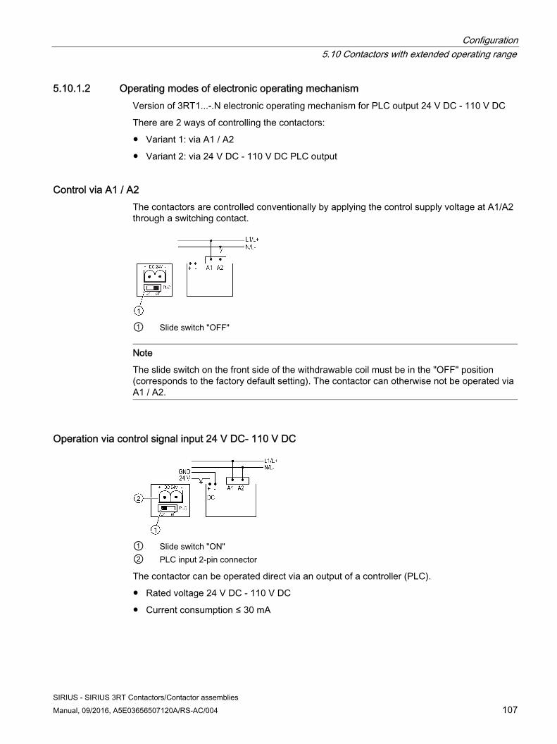
Configuration 5.10 Contactors with extended operating range
SIRIUS - SIRIUS 3RT Contactors/Contactor assemblies Manual, 09/2016, A5E03656507120A/RS-AC/004 107
5.10.1.2 Operating modes of electronic operating mechanism Version of 3RT1...-.N electronic operating mechanism for PLC output 24 V DC - 110 V DC
There are 2 ways of controlling the contactors:
● Variant 1: via A1 / A2
● Variant 2: via 24 V DC - 110 V DC PLC output
Control via A1 / A2 The contactors are controlled conventionally by applying the control supply voltage at A1/A2 through a switching contact.
① Slide switch "OFF"
Note
The slide switch on the front side of the withdrawable coil must be in the "OFF" position (corresponds to the factory default setting). The contactor can otherwise not be operated via A1 / A2.
Operation via control signal input 24 V DC- 110 V DC
① Slide switch "ON" ② PLC input 2-pin connector
The contactor can be operated direct via an output of a controller (PLC).
● Rated voltage 24 V DC - 110 V DC
● Current consumption ≤ 30 mA
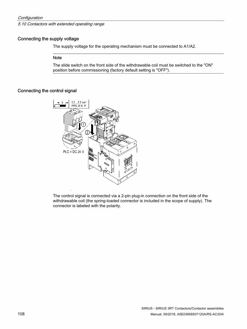
Configuration 5.10 Contactors with extended operating range
SIRIUS - SIRIUS 3RT Contactors/Contactor assemblies 108 Manual, 09/2016, A5E03656507120A/RS-AC/004
Connecting the supply voltage The supply voltage for the operating mechanism must be connected to A1/A2.
Note
The slide switch on the front side of the withdrawable coil must be switched to the "ON" position before commissioning (factory default setting is "OFF").
Connecting the control signal
The control signal is connected via a 2-pin plug-in connection on the front side of the withdrawable coil (the spring-loaded connector is included in the scope of supply). The connector is labeled with the polarity.
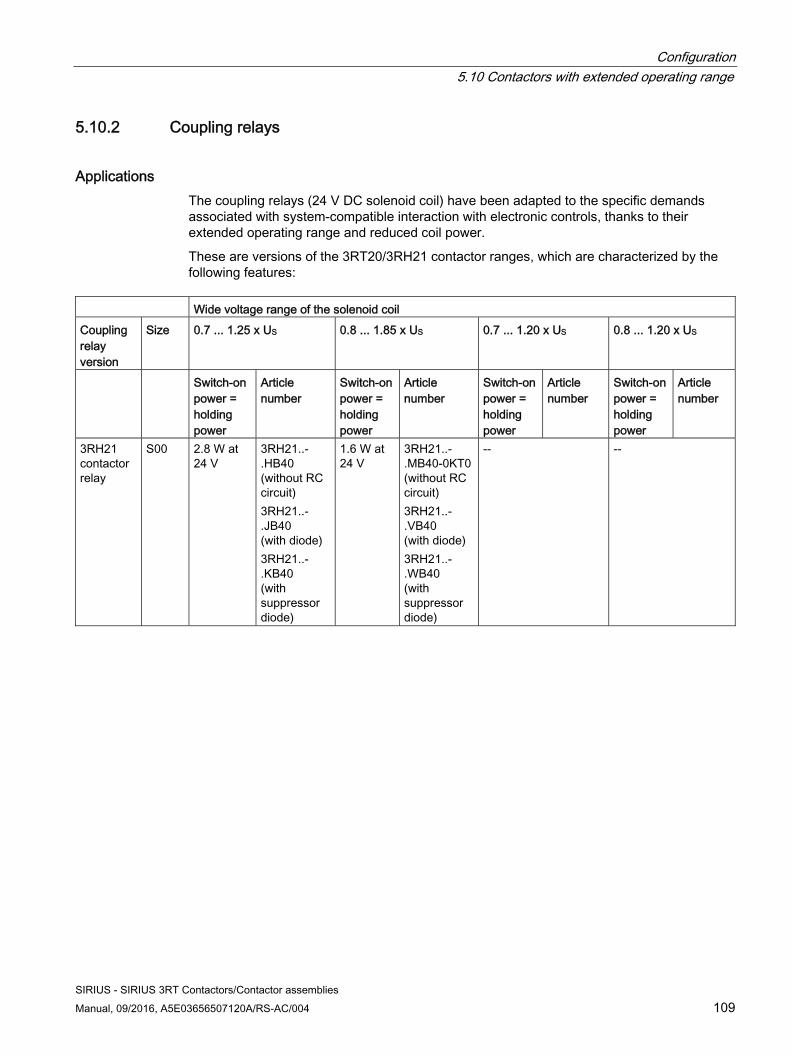
Configuration 5.10 Contactors with extended operating range
SIRIUS - SIRIUS 3RT Contactors/Contactor assemblies Manual, 09/2016, A5E03656507120A/RS-AC/004 109
5.10.2 Coupling relays
Applications The coupling relays (24 V DC solenoid coil) have been adapted to the specific demands associated with system-compatible interaction with electronic controls, thanks to their extended operating range and reduced coil power.
These are versions of the 3RT20/3RH21 contactor ranges, which are characterized by the following features:
Wide voltage range of the solenoid coilCoupling relay version
Size 0.7 ... 1.25 x US 0.8 ... 1.85 x US 0.7 ... 1.20 x US 0.8 ... 1.20 x US
Switch-on power = holding power
Article number
Switch-on power = holding power
Article number
Switch-on power = holding power
Article number
Switch-on power = holding power
Article number
3RH21 contactor relay
S00 2.8 W at 24 V
3RH21..- .HB40 (without RC circuit) 3RH21..- .JB40 (with diode) 3RH21..- .KB40 (with suppressor diode)
1.6 W at 24 V
3RH21..- .MB40-0KT0 (without RC circuit) 3RH21..- .VB40 (with diode) 3RH21..- .WB40 (with suppressor diode)
-- --
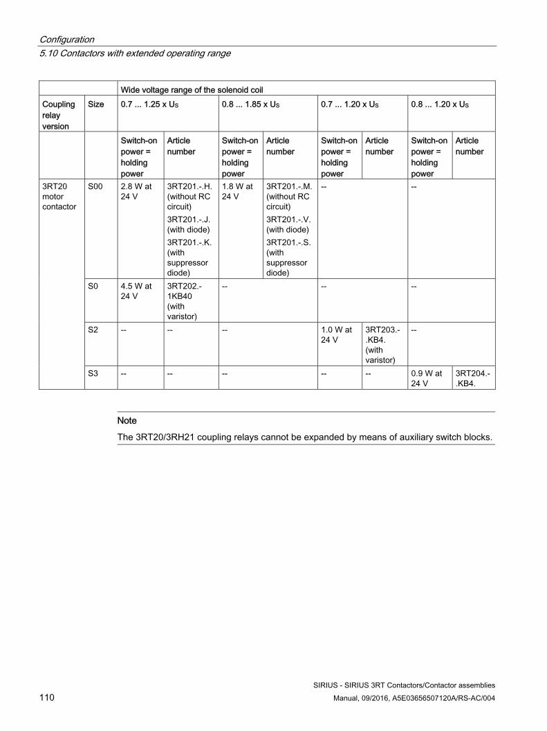
Configuration 5.10 Contactors with extended operating range
SIRIUS - SIRIUS 3RT Contactors/Contactor assemblies 110 Manual, 09/2016, A5E03656507120A/RS-AC/004
Wide voltage range of the solenoid coilCoupling relay version
Size 0.7 ... 1.25 x US 0.8 ... 1.85 x US 0.7 ... 1.20 x US 0.8 ... 1.20 x US
Switch-on power = holding power
Article number
Switch-on power = holding power
Article number
Switch-on power = holding power
Article number
Switch-on power = holding power
Article number
3RT20 motor contactor
S00 2.8 W at 24 V
3RT201.-.H. (without RC circuit) 3RT201.-.J. (with diode) 3RT201.-.K. (with suppressor diode)
1.8 W at 24 V
3RT201.-.M.(without RC circuit) 3RT201.-.V.(with diode) 3RT201.-.S.(with suppressor diode)
-- --
S0 4.5 W at 24 V
3RT202.-1KB40 (with varistor)
-- -- --
S2 -- -- -- 1.0 W at 24 V
3RT203.-.KB4. (with varistor)
--
S3 -- -- -- -- -- 0.9 W at 24 V
3RT204.-.KB4.
Note
The 3RT20/3RH21 coupling relays cannot be expanded by means of auxiliary switch blocks.
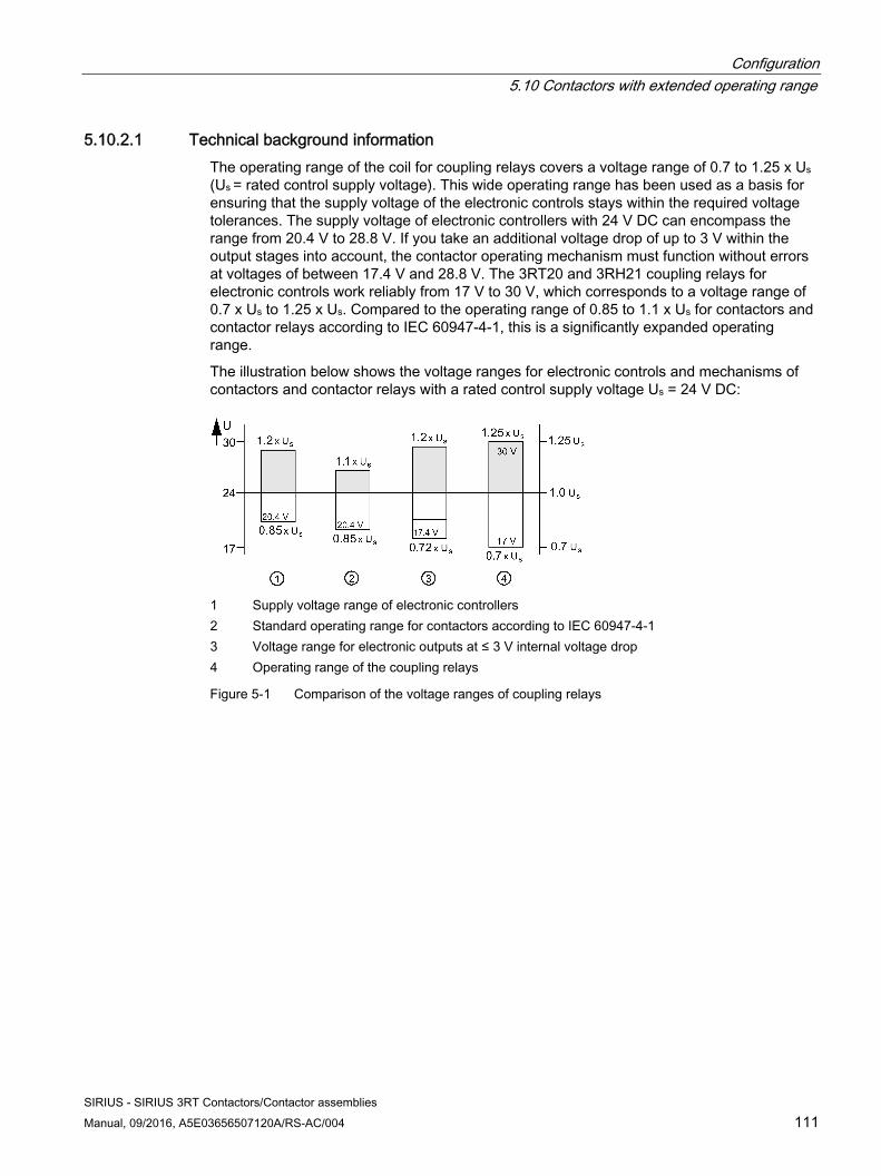
Configuration 5.10 Contactors with extended operating range
SIRIUS - SIRIUS 3RT Contactors/Contactor assemblies Manual, 09/2016, A5E03656507120A/RS-AC/004 111
5.10.2.1 Technical background information The operating range of the coil for coupling relays covers a voltage range of 0.7 to 1.25 x Us (Us = rated control supply voltage). This wide operating range has been used as a basis for ensuring that the supply voltage of the electronic controls stays within the required voltage tolerances. The supply voltage of electronic controllers with 24 V DC can encompass the range from 20.4 V to 28.8 V. If you take an additional voltage drop of up to 3 V within the output stages into account, the contactor operating mechanism must function without errors at voltages of between 17.4 V and 28.8 V. The 3RT20 and 3RH21 coupling relays for electronic controls work reliably from 17 V to 30 V, which corresponds to a voltage range of 0.7 x Us to 1.25 x Us. Compared to the operating range of 0.85 to 1.1 x Us for contactors and contactor relays according to IEC 60947-4-1, this is a significantly expanded operating range.
The illustration below shows the voltage ranges for electronic controls and mechanisms of contactors and contactor relays with a rated control supply voltage Us = 24 V DC:
1 Supply voltage range of electronic controllers2 Standard operating range for contactors according to IEC 60947-4-1 3 Voltage range for electronic outputs at ≤ 3 V internal voltage drop 4 Operating range of the coupling relays
Figure 5-1 Comparison of the voltage ranges of coupling relays
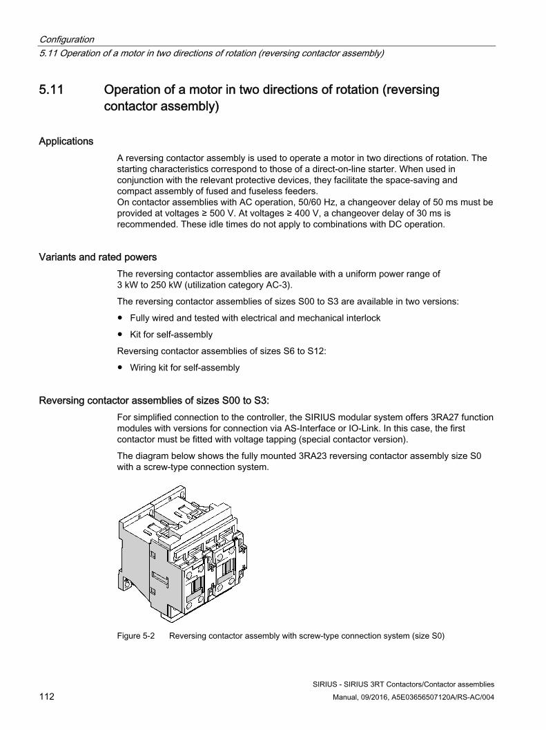
Configuration 5.11 Operation of a motor in two directions of rotation (reversing contactor assembly)
SIRIUS - SIRIUS 3RT Contactors/Contactor assemblies 112 Manual, 09/2016, A5E03656507120A/RS-AC/004
5.11 Operation of a motor in two directions of rotation (reversing contactor assembly)
Applications A reversing contactor assembly is used to operate a motor in two directions of rotation. The starting characteristics correspond to those of a direct-on-line starter. When used in conjunction with the relevant protective devices, they facilitate the space-saving and compact assembly of fused and fuseless feeders. On contactor assemblies with AC operation, 50/60 Hz, a changeover delay of 50 ms must be provided at voltages ≥ 500 V. At voltages ≥ 400 V, a changeover delay of 30 ms is recommended. These idle times do not apply to combinations with DC operation.
Variants and rated powers The reversing contactor assemblies are available with a uniform power range of 3 kW to 250 kW (utilization category AC-3).
The reversing contactor assemblies of sizes S00 to S3 are available in two versions:
● Fully wired and tested with electrical and mechanical interlock
● Kit for self-assembly
Reversing contactor assemblies of sizes S6 to S12:
● Wiring kit for self-assembly
Reversing contactor assemblies of sizes S00 to S3: For simplified connection to the controller, the SIRIUS modular system offers 3RA27 function modules with versions for connection via AS-Interface or IO-Link. In this case, the first contactor must be fitted with voltage tapping (special contactor version).
The diagram below shows the fully mounted 3RA23 reversing contactor assembly size S0 with a screw-type connection system.
Figure 5-2 Reversing contactor assembly with screw-type connection system (size S0)
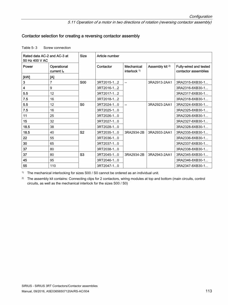
Configuration 5.11 Operation of a motor in two directions of rotation (reversing contactor assembly)
SIRIUS - SIRIUS 3RT Contactors/Contactor assemblies Manual, 09/2016, A5E03656507120A/RS-AC/004 113
Contactor selection for creating a reversing contactor assembly
Table 5- 3 Screw connection
Rated data AC-2 and AC-3 at 50 Hz 400 V AC
Size Article number
Power Operational current Ie
Contactor Mechanical interlock 1)
Assembly kit 2) Fully-wired and tested contactor assemblies
[kW] [A] 3 7 S00 3RT2015-1...2 --
3RA2913-2AA1
3RA2315-8XB30-1... 4 9 3RT2016-1...2 3RA2316-8XB30-1... 5.5 12 3RT2017-1...2 3RA2317-8XB30-1... 7.5 16 3RT2018-1...2 3RA2318-8XB30-1... 5.5 12 S0 3RT2024-1...0 --
3RA2923-2AA1
3RA2324-8XB30-1... 7.5 16 3RT2025-1...0 3RA2325-8XB30-1... 11 25 3RT2026-1...0 3RA2326-8XB30-1... 15 32 3RT2027-1...0 3RA2327-8XB30-1... 18.5 38 3RT2028-1...0 3RA2328-8XB30-1... 18.5 40 S2 3RT2035-1...0 3RA2934-2B 3RA2933-2AA1 3RA2335-8XB30-1... 22 55 3RT2036-1...0 3RA2336-8XB30-1... 30 65 3RT2037-1...0 3RA2337-8XB30-1... 37 80 3RT2038-1...0 3RA2338-8XB30-1... 37 80 S3 3RT2045-1...0 3RA2934-2B 3RA2943-2AA1 3RA2345-8XB30-1... 45 95 3RT2046-1...0 3RA2346-8XB30-1... 55 110 3RT2047-1...0 3RA2347-8XB30-1...
1) The mechanical interlocking for sizes S00 / S0 cannot be ordered as an individual unit. 2) The assembly kit contains: Connecting clips for 2 contactors, wiring modules at top and bottom (main circuits, control
circuits, as well as the mechanical interlock for the sizes S00 / S0)
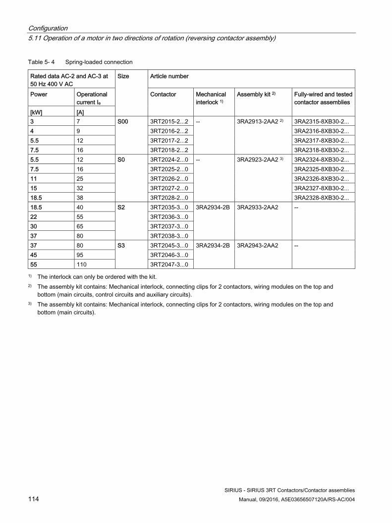
Configuration 5.11 Operation of a motor in two directions of rotation (reversing contactor assembly)
SIRIUS - SIRIUS 3RT Contactors/Contactor assemblies 114 Manual, 09/2016, A5E03656507120A/RS-AC/004
Table 5- 4 Spring-loaded connection
Rated data AC-2 and AC-3 at 50 Hz 400 V AC
Size Article number
Power Operational current Ie
Contactor Mechanical interlock 1)
Assembly kit 2) Fully-wired and tested contactor assemblies
[kW] [A] 3 7 S00 3RT2015-2...2 --
3RA2913-2AA2 2)
3RA2315-8XB30-2... 4 9 3RT2016-2...2 3RA2316-8XB30-2... 5.5 12 3RT2017-2...2 3RA2317-8XB30-2... 7.5 16 3RT2018-2...2 3RA2318-8XB30-2... 5.5 12 S0 3RT2024-2...0 --
3RA2923-2AA2 3)
3RA2324-8XB30-2... 7.5 16 3RT2025-2...0 3RA2325-8XB30-2... 11 25 3RT2026-2...0 3RA2326-8XB30-2... 15 32 3RT2027-2...0 3RA2327-8XB30-2... 18.5 38 3RT2028-2...0 3RA2328-8XB30-2... 18.5 40 S2 3RT2035-3...0 3RA2934-2B 3RA2933-2AA2 -- 22 55 3RT2036-3...0 30 65 3RT2037-3...0 37 80 3RT2038-3...0 37 80 S3 3RT2045-3...0 3RA2934-2B 3RA2943-2AA2 -- 45 95 3RT2046-3...0 55 110 3RT2047-3...0
1) The interlock can only be ordered with the kit. 2) The assembly kit contains: Mechanical interlock, connecting clips for 2 contactors, wiring modules on the top and
bottom (main circuits, control circuits and auxiliary circuits). 3) The assembly kit contains: Mechanical interlock, connecting clips for 2 contactors, wiring modules on the top and
bottom (main circuits).
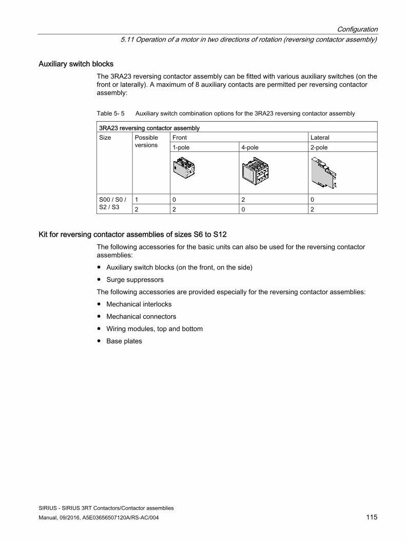
Configuration 5.11 Operation of a motor in two directions of rotation (reversing contactor assembly)
SIRIUS - SIRIUS 3RT Contactors/Contactor assemblies Manual, 09/2016, A5E03656507120A/RS-AC/004 115
Auxiliary switch blocks The 3RA23 reversing contactor assembly can be fitted with various auxiliary switches (on the front or laterally). A maximum of 8 auxiliary contacts are permitted per reversing contactor assembly:
Table 5- 5 Auxiliary switch combination options for the 3RA23 reversing contactor assembly
3RA23 reversing contactor assemblySize Possible
versions Front Lateral 1-pole 4-pole 2-pole
S00 / S0 / S2 / S3
1 0 2 0 2 2 0 2
Kit for reversing contactor assemblies of sizes S6 to S12 The following accessories for the basic units can also be used for the reversing contactor assemblies:
● Auxiliary switch blocks (on the front, on the side)
● Surge suppressors
The following accessories are provided especially for the reversing contactor assemblies:
● Mechanical interlocks
● Mechanical connectors
● Wiring modules, top and bottom
● Base plates
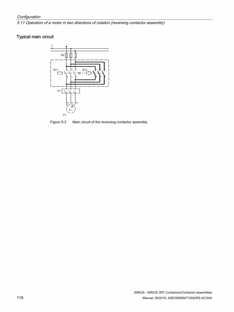
Configuration 5.11 Operation of a motor in two directions of rotation (reversing contactor assembly)
SIRIUS - SIRIUS 3RT Contactors/Contactor assemblies 116 Manual, 09/2016, A5E03656507120A/RS-AC/004
Typical main circuit
Figure 5-3 Main circuit of the reversing contactor assembly
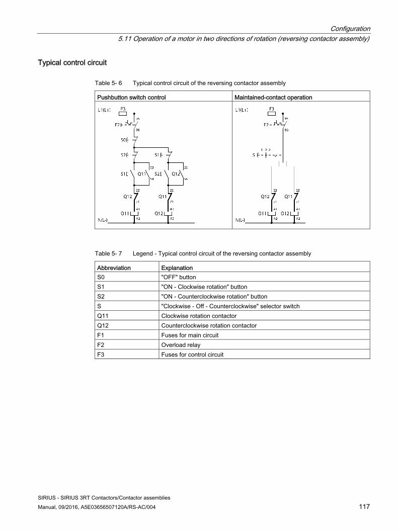
Configuration 5.11 Operation of a motor in two directions of rotation (reversing contactor assembly)
SIRIUS - SIRIUS 3RT Contactors/Contactor assemblies Manual, 09/2016, A5E03656507120A/RS-AC/004 117
Typical control circuit
Table 5- 6 Typical control circuit of the reversing contactor assembly
Pushbutton switch control Maintained-contact operation
Table 5- 7 Legend - Typical control circuit of the reversing contactor assembly
Abbreviation ExplanationS0 "OFF" button S1 "ON - Clockwise rotation" button S2 "ON - Counterclockwise rotation" button S "Clockwise - Off - Counterclockwise" selector switch Q11 Clockwise rotation contactor Q12 Counterclockwise rotation contactor F1 Fuses for main circuit F2 Overload relay F3 Fuses for control circuit
Configuration 5.11 Operation of a motor in two directions of rotation (reversing contactor assembly)
SIRIUS - SIRIUS 3RT Contactors/Contactor assemblies 118 Manual, 09/2016, A5E03656507120A/RS-AC/004
5.11.1 Reference
Reference More information ... Can be found in the chapter titled ... About the components for self-assembly of the reversing contactor assemblies
Assembly kit for reversing contactor assembly (sizes S00 to S3) (Page 333) and wiring kit for reversing contactor assemblies (sizes S6 to S12) (Page 351).
About the function modules that can be attached to a reversing contactor assembly with communication interface
3RA27 function modules for connection to the controller (AS-Interface or IO-Link). (Page 330)
Configuration 5.12 Starting three-phase motors with reduced starting current peaks (contactor assembly for star-delta (wye-delta) start)
SIRIUS - SIRIUS 3RT Contactors/Contactor assemblies Manual, 09/2016, A5E03656507120A/RS-AC/004 119
5.12 Starting three-phase motors with reduced starting current peaks (contactor assembly for star-delta (wye-delta) start)
Applications A contactor assembly for star-delta (wye-delta) start is used for starting three-phase motors requiring a reduction in system load and prevention of false tripping of protection equipment as a result of excessively high current peaks. With this circuit type, the motor's starting current is reduced by 1/3 (proportional load torque) compared with direct startup.
Note Increased current peaks
When switching over from star operation to delta operation, the motor may be subjected to compensation processes (fueled by an unfavorable line frequency/rotor field constellation), which would result in higher current peaks than would be the case if the stationary motor were connected directly in the delta circuit. This must be taken into account when configuring a contactor assembly for star-delta (wye-delta) start.
For detailed information, please refer to section "Technical background information (Page 125)"
Note
The preferred wiring for the 3RA24 contactor assembly minimizes this effect.
The 3RA24 contactor assemblies for star-delta (wye-delta) start described below have been dimensioned for standard applications.
Note
Contactor assemblies for star-delta (wye-delta) start for special applications, such as very heavy starting or star-delta (wye-delta) startup of special motors, must be customized. When dimensioning contactor assemblies for special applications such as these you can obtain support from Technical Assistance (http://www.siemens.com/sirius/technical-assistance).
Configuration 5.12 Starting three-phase motors with reduced starting current peaks (contactor assembly for star-delta (wye-delta) start)
SIRIUS - SIRIUS 3RT Contactors/Contactor assemblies 120 Manual, 09/2016, A5E03656507120A/RS-AC/004
Variants and rated powers The contactor assemblies for star-delta (wye-delta) start are available with a uniform power range of 5.5 kW to 55 kW (utilization category AC-3).
The 3RA24 contactor assembly for star-delta (wye-delta) start of sizes S00 to S3 is available in two versions:
● Fully wired and tested with electrical and mechanical interlock
● Kit for self-assembly
Contactor assemblies for star-delta (wye-delta) start of sizes S6 to S12:
● Wiring kit for self-assembly
The SIRIUS modular system offers 3RA27 function modules for connection to the automation level; they are fitted with terminals for connection to AS-Interface or IO-Link.
Note
We recommend installing contactor assemblies on a mounting plate. The mounting plate can be ordered as an individual unit. (Extension can be used for 3RP25 / 3RP15).
Note
If the contactor assembly for star-delta (wye-delta) start is to be connected to a control for communication capability, a contactor must be selected (3RT2...-.....-0CC0).
Note
With the 3RA24 contactor assembly for star-delta (wye-delta) start, the auxiliary switches integrated in the contactor can still be used. Additional auxiliary switch blocks cannot be fitted with the function modules attached.
The function module replaces all the wiring in the control circuit and can be used in the voltage range from 24 to 240 V AC/DC. The changeover delay of 50 ms (timing relay functionality) is already integrated in the star-delta (wye-delta) function module.
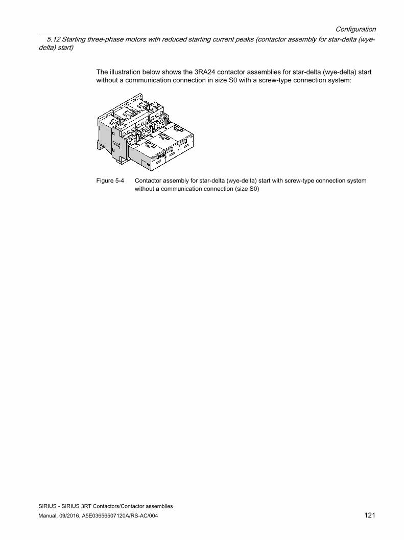
Configuration 5.12 Starting three-phase motors with reduced starting current peaks (contactor assembly for star-delta (wye-delta) start)
SIRIUS - SIRIUS 3RT Contactors/Contactor assemblies Manual, 09/2016, A5E03656507120A/RS-AC/004 121
The illustration below shows the 3RA24 contactor assemblies for star-delta (wye-delta) start without a communication connection in size S0 with a screw-type connection system:
Figure 5-4 Contactor assembly for star-delta (wye-delta) start with screw-type connection system
without a communication connection (size S0)
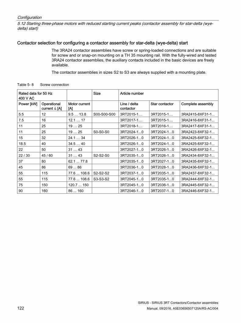
Configuration 5.12 Starting three-phase motors with reduced starting current peaks (contactor assembly for star-delta (wye-delta) start)
SIRIUS - SIRIUS 3RT Contactors/Contactor assemblies 122 Manual, 09/2016, A5E03656507120A/RS-AC/004
Contactor selection for configuring a contactor assembly for star-delta (wye-delta) start The 3RA24 contactor assemblies have screw or spring-loaded connections and are suitable for screw and or snap-on mounting on a TH 35 mounting rail. With the fully-wired and tested 3RA24 contactor assemblies, the auxiliary contacts included in the basic devices are freely available.
The contactor assemblies in sizes S2 to S3 are always supplied with a mounting plate.
Table 5- 8 Screw connection
Rated data for 50 Hz 400 V AC
Size Article number
Power [kW] Operational current Ie [A]
Motor current [A]
Line / delta contactor
Star contactor Complete assembly
5.5 12 9.5 … 13.8 S00-S00-S00 3RT2015-1.... 3RT2015-1.... 3RA2415-8XF31-1... 7.5 16 12.1 … 17 3RT2017-1.... 3RT2015-1.... 3RA2416-8XF31-1... 11 25 19 … 25 3RT2018-1.... 3RT2016-1.... 3RA2417-8XF31-1... 11 25 19 … 25 S0-S0-S0 3RT2024-1...0 3RT2024-1...0 3RA2423-8XF32-1... 15 32 24.1 … 34 3RT2026-1...0 3RT2024-1...0 3RA2425-8XF32-1... 18.5 40 34.5 … 40 3RT2026-1...0 3RT2024-1...0 3RA2425-8XF32-1... 22 50 31 … 43 3RT2027-1...0 3RT2026-1...0 3RA2426-8XF32-1... 22 / 30 45 / 60 31 … 43 S2-S2-S0 3RT2035-1...0 3RT2026-1...0 3RA2434-8XF32-1... 37 80 62.1 ... 77.8 3RT2035-1...0 3RT2027-1...0 3RA2435-8XF32-1... 45 86 69 ... 86 3RT2036-1...0 3RT2028-1...0 3RA2436-8XF32-1... 55 115 77.6 ... 108.6 S2-S2-S2 3RT2037-1...0 3RT2035-1...0 3RA2437-8XF32-1... 55 115 77.6 ... 108.6 S3-S3-S2 3RT2045-1...0 3RT2035-1...0 3RA2444-8XF32-1... 75 150 120.7 ... 150 3RT2045-1...0 3RT2036-1...0 3RA2445-8XF32-1... 90 160 86 ... 160 3RT2046-1...0 3RT2037-1...0 3RA2446-8XF32-1...
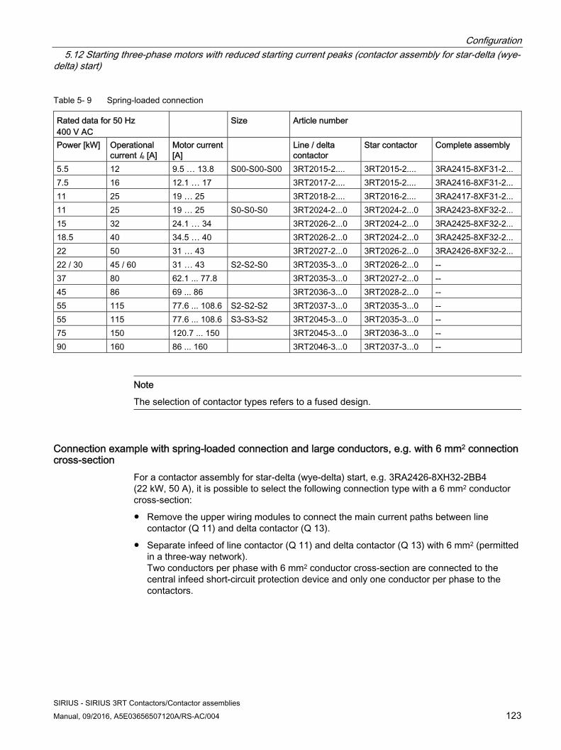
Configuration 5.12 Starting three-phase motors with reduced starting current peaks (contactor assembly for star-delta (wye-delta) start)
SIRIUS - SIRIUS 3RT Contactors/Contactor assemblies Manual, 09/2016, A5E03656507120A/RS-AC/004 123
Table 5- 9 Spring-loaded connection
Rated data for 50 Hz 400 V AC
Size Article number
Power [kW] Operational current Ie [A]
Motor current [A]
Line / delta contactor
Star contactor Complete assembly
5.5 12 9.5 … 13.8 S00-S00-S00 3RT2015-2.... 3RT2015-2.... 3RA2415-8XF31-2... 7.5 16 12.1 … 17 3RT2017-2.... 3RT2015-2.... 3RA2416-8XF31-2... 11 25 19 … 25 3RT2018-2.... 3RT2016-2.... 3RA2417-8XF31-2... 11 25 19 … 25 S0-S0-S0 3RT2024-2...0 3RT2024-2...0 3RA2423-8XF32-2... 15 32 24.1 … 34 3RT2026-2...0 3RT2024-2...0 3RA2425-8XF32-2... 18.5 40 34.5 … 40 3RT2026-2...0 3RT2024-2...0 3RA2425-8XF32-2... 22 50 31 … 43 3RT2027-2...0 3RT2026-2...0 3RA2426-8XF32-2... 22 / 30 45 / 60 31 … 43 S2-S2-S0 3RT2035-3...0 3RT2026-2...0 -- 37 80 62.1 ... 77.8 3RT2035-3...0 3RT2027-2...0 -- 45 86 69 ... 86 3RT2036-3...0 3RT2028-2...0 -- 55 115 77.6 ... 108.6 S2-S2-S2 3RT2037-3...0 3RT2035-3...0 -- 55 115 77.6 ... 108.6 S3-S3-S2 3RT2045-3...0 3RT2035-3...0 -- 75 150 120.7 ... 150 3RT2045-3...0 3RT2036-3...0 -- 90 160 86 ... 160 3RT2046-3...0 3RT2037-3...0 --
Note
The selection of contactor types refers to a fused design.
Connection example with spring-loaded connection and large conductors, e.g. with 6 mm2 connection cross-section
For a contactor assembly for star-delta (wye-delta) start, e.g. 3RA2426-8XH32-2BB4 (22 kW, 50 A), it is possible to select the following connection type with a 6 mm2 conductor cross-section:
● Remove the upper wiring modules to connect the main current paths between line contactor (Q 11) and delta contactor (Q 13).
● Separate infeed of line contactor (Q 11) and delta contactor (Q 13) with 6 mm2 (permitted in a three-way network). Two conductors per phase with 6 mm2 conductor cross-section are connected to the central infeed short-circuit protection device and only one conductor per phase to the contactors.
Configuration 5.12 Starting three-phase motors with reduced starting current peaks (contactor assembly for star-delta (wye-delta) start)
SIRIUS - SIRIUS 3RT Contactors/Contactor assemblies 124 Manual, 09/2016, A5E03656507120A/RS-AC/004
Kit for contactor assemblies for star-delta (wye-delta) start, sizes S6 to S12 The contactor assemblies for star-delta (wye-delta) start are available as kits for self-assembly.
The same accessories as for the basic units of the corresponding size can be used.
The kit for contactor assemblies for star-delta (wye-delta) start contains the following:
● Neutral bridges
● Wiring module on the bottom (wiring module on the top is not included in the scope of supply. (A double infeed between the line contactor and the delta contactor is recommended.)
The following accessories for the basic units can also be used for the contactor assemblies for star-delta (wye-delta) starting:
● Auxiliary switch blocks (on the front, on the side)
● Surge suppressors
● Solid-state time-delay auxiliary switch blocks with star-delta (wye-delta) function (timing relay)
In addition, special accessories are available for the contactor assemblies for star-delta (wye-delta) start:
● Neutral bridges (parallel connectors)
● Mechanical connectors
● Wiring modules
● Base plates for contactor assemblies for star-delta (wye-delta) start
5.12.1 Reference
Reference More information ... Can be found in the chapter titled ... About the components for customers to assemble their own contactor assemblies for star-delta (wye-delta) start
Assembly kit for contactor assemblies for star-delta (wye-delta) start (sizes S00 to S3) (Page 357) and Wiring kit for contactor assemblies for star-delta (wye-delta) start (sizes S6 to S12). (Page 393).
Configuration 5.12 Starting three-phase motors with reduced starting current peaks (contactor assembly for star-delta (wye-delta) start)
SIRIUS - SIRIUS 3RT Contactors/Contactor assemblies Manual, 09/2016, A5E03656507120A/RS-AC/004 125
5.12.2 Technical background information
Starting current ratio Star-delta (wye-delta) startup can only be used if the motor normally operates in a delta connection or starts softly, or if the load torque is low and does not rise sharply during star startup. In the star (wye) stage motors can be subjected to around 50% (class CL16) or 30% (CL10) of their rated torque. The starting torque falls to about 1/3 of the relevant value during direct switch-on. The starting current is approximately 2 to 2.7 times the rated motor current.
Switching over The switchover from star (wye) to delta cannot be carried out until the motor has been fully accelerated to the rated speed. The necessary changeover delay and interlock are integrated in the contactor assembly; drives which require this switchover to be performed earlier are not suitable for star-delta (wye-delta) start.
Reducing the switchover current peak by means of preferred wiring During star-delta (wye-delta) switching of three-phase motors, the motor may be subjected to compensation processes, which would result in higher current peaks than would be the case if the stationary motor were connected directly in the delta circuit.
The worst-case scenario would lead to the following problems, which can be minimized by using preferred wiring:
● Tripping of short-circuit protection devices
● Welding or substantial contact erosion of the delta contactor
● High dynamic load on the motor
Using a favorable method of connection for the main circuit will reduce the equalizing currents and current peaks which occur when switching over from a star to a delta circuit.
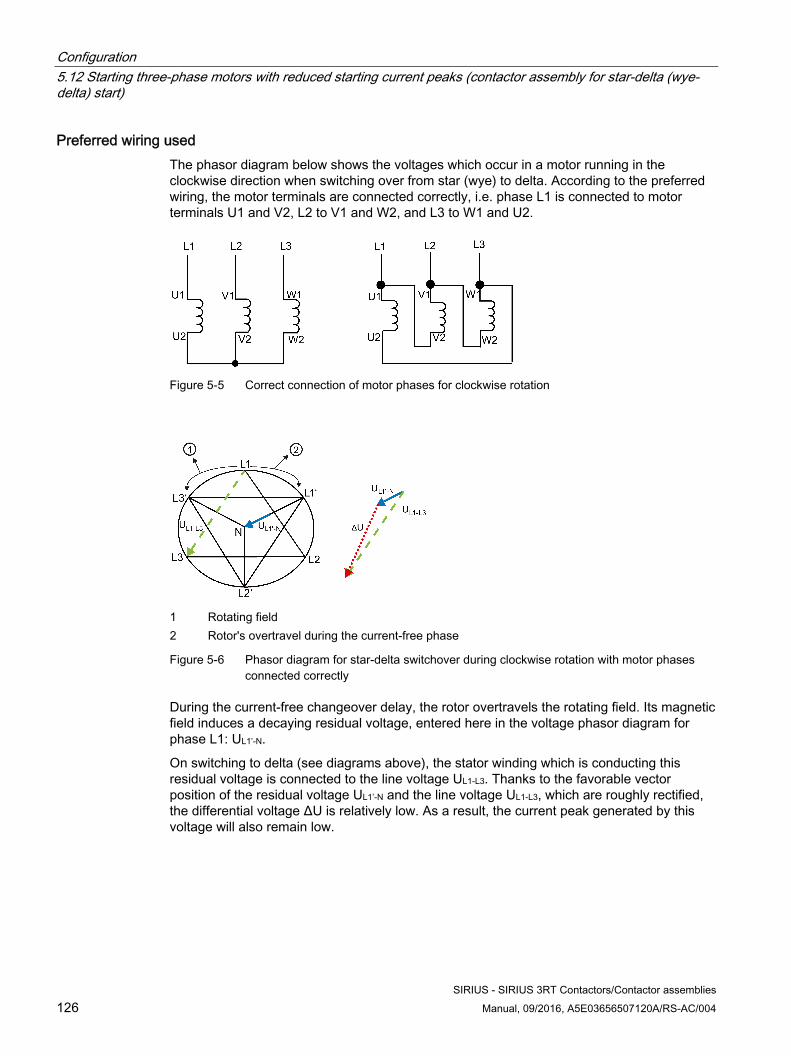
Configuration 5.12 Starting three-phase motors with reduced starting current peaks (contactor assembly for star-delta (wye-delta) start)
SIRIUS - SIRIUS 3RT Contactors/Contactor assemblies 126 Manual, 09/2016, A5E03656507120A/RS-AC/004
Preferred wiring used The phasor diagram below shows the voltages which occur in a motor running in the clockwise direction when switching over from star (wye) to delta. According to the preferred wiring, the motor terminals are connected correctly, i.e. phase L1 is connected to motor terminals U1 and V2, L2 to V1 and W2, and L3 to W1 and U2.
Figure 5-5 Correct connection of motor phases for clockwise rotation
1 Rotating field 2 Rotor's overtravel during the current-free phase
Figure 5-6 Phasor diagram for star-delta switchover during clockwise rotation with motor phases connected correctly
During the current-free changeover delay, the rotor overtravels the rotating field. Its magnetic field induces a decaying residual voltage, entered here in the voltage phasor diagram for phase L1: UL1’-N.
On switching to delta (see diagrams above), the stator winding which is conducting this residual voltage is connected to the line voltage UL1-L3. Thanks to the favorable vector position of the residual voltage UL1’-N and the line voltage UL1-L3, which are roughly rectified, the differential voltage ΔU is relatively low. As a result, the current peak generated by this voltage will also remain low.
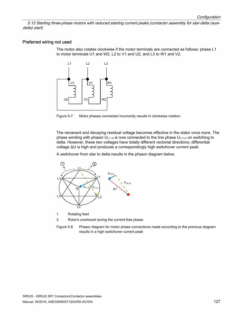
Configuration 5.12 Starting three-phase motors with reduced starting current peaks (contactor assembly for star-delta (wye-delta) start)
SIRIUS - SIRIUS 3RT Contactors/Contactor assemblies Manual, 09/2016, A5E03656507120A/RS-AC/004 127
Preferred wiring not used The motor also rotates clockwise if the motor terminals are connected as follows: phase L1 to motor terminals U1 and W2, L2 to V1 and U2, and L3 to W1 and V2.
Figure 5-7 Motor phases connected incorrectly results in clockwise rotation
The remanent and decaying residual voltage becomes effective in the stator once more. The phase winding with phasor UL1’-N is now connected to the line phase UL1-L2 on switching to delta. However, these two voltages have totally different vectorial directions; differential voltage ΔU is high and produces a correspondingly high switchover current peak.
A switchover from star to delta results in the phasor diagram below.
1 Rotating field 2 Rotor's overtravel during the current-free phase
Figure 5-8 Phasor diagram for motor phase connections made according to the previous diagram results in a high switchover current peak
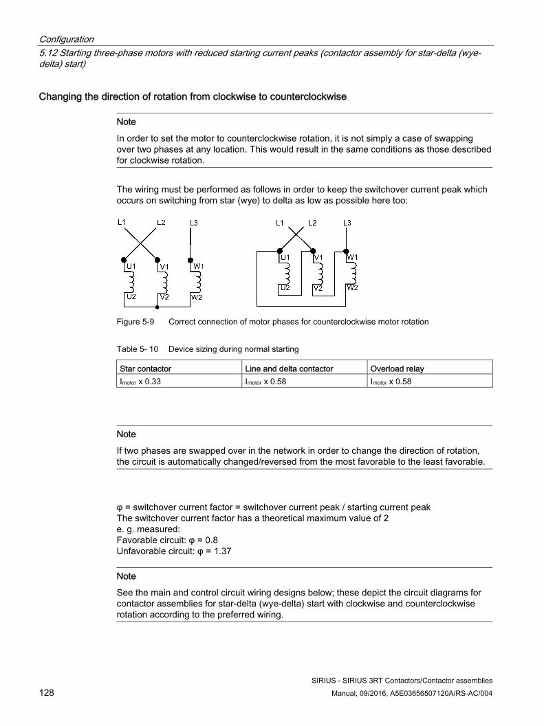
Configuration 5.12 Starting three-phase motors with reduced starting current peaks (contactor assembly for star-delta (wye-delta) start)
SIRIUS - SIRIUS 3RT Contactors/Contactor assemblies 128 Manual, 09/2016, A5E03656507120A/RS-AC/004
Changing the direction of rotation from clockwise to counterclockwise
Note
In order to set the motor to counterclockwise rotation, it is not simply a case of swapping over two phases at any location. This would result in the same conditions as those described for clockwise rotation.
The wiring must be performed as follows in order to keep the switchover current peak which occurs on switching from star (wye) to delta as low as possible here too:
Figure 5-9 Correct connection of motor phases for counterclockwise motor rotation
Table 5- 10 Device sizing during normal starting
Star contactor Line and delta contactor Overload relay Imotor x 0.33 Imotor x 0.58 Imotor x 0.58
Note
If two phases are swapped over in the network in order to change the direction of rotation, the circuit is automatically changed/reversed from the most favorable to the least favorable.
φ = switchover current factor = switchover current peak / starting current peak The switchover current factor has a theoretical maximum value of 2 e. g. measured: Favorable circuit: φ = 0.8 Unfavorable circuit: φ = 1.37
Note
See the main and control circuit wiring designs below; these depict the circuit diagrams for contactor assemblies for star-delta (wye-delta) start with clockwise and counterclockwise rotation according to the preferred wiring.
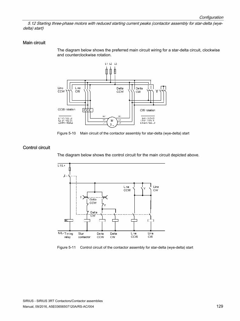
Configuration 5.12 Starting three-phase motors with reduced starting current peaks (contactor assembly for star-delta (wye-delta) start)
SIRIUS - SIRIUS 3RT Contactors/Contactor assemblies Manual, 09/2016, A5E03656507120A/RS-AC/004 129
Main circuit The diagram below shows the preferred main circuit wiring for a star-delta circuit, clockwise and counterclockwise rotation.
Figure 5-10 Main circuit of the contactor assembly for star-delta (wye-delta) start
Control circuit The diagram below shows the control circuit for the main circuit depicted above.
Figure 5-11 Control circuit of the contactor assembly for star-delta (wye-delta) start
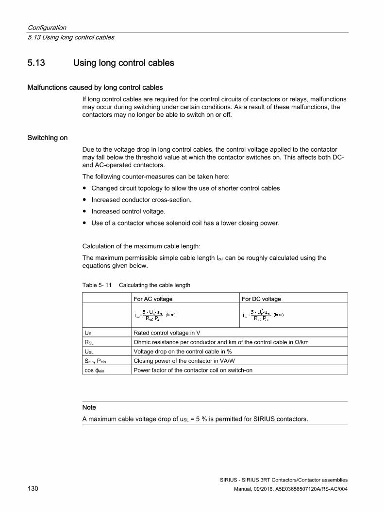
Configuration 5.13 Using long control cables
SIRIUS - SIRIUS 3RT Contactors/Contactor assemblies 130 Manual, 09/2016, A5E03656507120A/RS-AC/004
5.13 Using long control cables
Malfunctions caused by long control cables If long control cables are required for the control circuits of contactors or relays, malfunctions may occur during switching under certain conditions. As a result of these malfunctions, the contactors may no longer be able to switch on or off.
Switching on Due to the voltage drop in long control cables, the control voltage applied to the contactor may fall below the threshold value at which the contactor switches on. This affects both DC- and AC-operated contactors.
The following counter-measures can be taken here:
● Changed circuit topology to allow the use of shorter control cables
● Increased conductor cross-section.
● Increased control voltage.
● Use of a contactor whose solenoid coil has a lower closing power.
Calculation of the maximum cable length:
The maximum permissible simple cable length lzul can be roughly calculated using the equations given below.
Table 5- 11 Calculating the cable length
For AC voltage For DC voltage
US Rated control voltage in V RSL Ohmic resistance per conductor and km of the control cable in Ω/km USL Voltage drop on the control cable in % Sein, Pein Closing power of the contactor in VA/W cos ϕein Power factor of the contactor coil on switch-on
Note
A maximum cable voltage drop of uSL = 5 % is permitted for SIRIUS contactors.
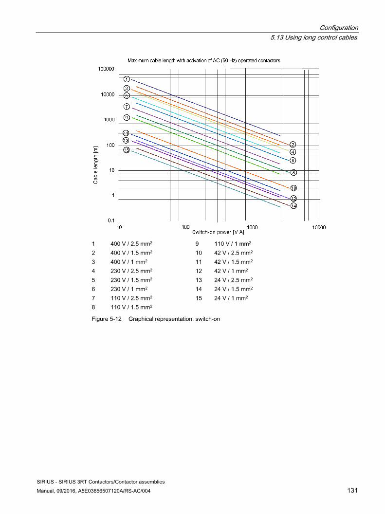
Configuration 5.13 Using long control cables
SIRIUS - SIRIUS 3RT Contactors/Contactor assemblies Manual, 09/2016, A5E03656507120A/RS-AC/004 131
1 400 V / 2.5 mm2 9 110 V / 1 mm2 2 400 V / 1.5 mm2 10 42 V / 2.5 mm2
3 400 V / 1 mm2 11 42 V / 1.5 mm2
4 230 V / 2.5 mm2 12 42 V / 1 mm2 5 230 V / 1.5 mm2 13 24 V / 2.5 mm2
6 230 V / 1 mm2 14 24 V / 1.5 mm2
7 110 V / 2.5 mm2 15 24 V / 1 mm2 8 110 V / 1.5 mm2
Figure 5-12 Graphical representation, switch-on
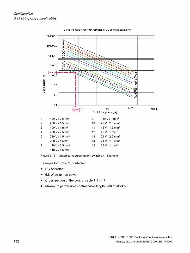
Configuration 5.13 Using long control cables
SIRIUS - SIRIUS 3RT Contactors/Contactor assemblies 132 Manual, 09/2016, A5E03656507120A/RS-AC/004
1 400 V / 2.5 mm2 9 110 V / 1 mm2
2 400 V / 1.5 mm2 10 42 V / 2.5 mm2 3 400 V / 1 mm2 11 42 V / 1.5 mm2
4 230 V / 2.5 mm2 12 42 V / 1 mm2
5 230 V / 1.5 mm2 13 24 V / 2.5 mm2 6 230 V / 1 mm2 14 24 V / 1.5 mm2
7 110 V / 2.5 mm2 15 24 V / 1 mm2
8 110 V / 1.5 mm2
Figure 5-13 Graphical representation, switch-on - Example
Example for 3RT202. contactor:
● DC-operated
● 5.8 W switch-on power
● Cross-section of the control cable 1.5 mm2
● Maximum permissible control cable length: 200 m at 24 V
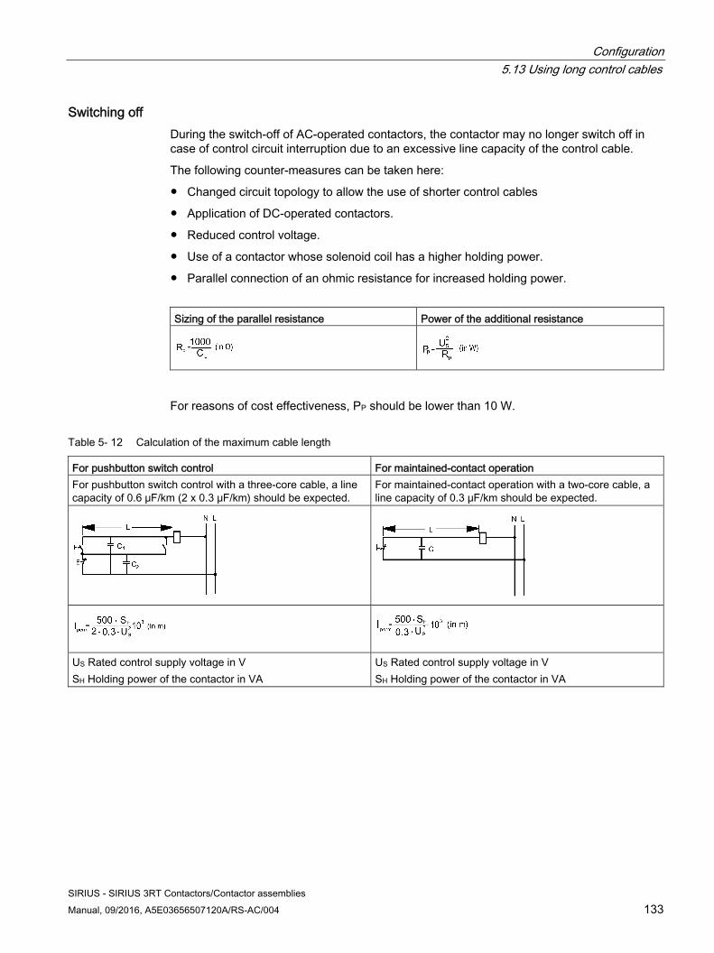
Configuration 5.13 Using long control cables
SIRIUS - SIRIUS 3RT Contactors/Contactor assemblies Manual, 09/2016, A5E03656507120A/RS-AC/004 133
Switching off During the switch-off of AC-operated contactors, the contactor may no longer switch off in case of control circuit interruption due to an excessive line capacity of the control cable.
The following counter-measures can be taken here:
● Changed circuit topology to allow the use of shorter control cables
● Application of DC-operated contactors.
● Reduced control voltage.
● Use of a contactor whose solenoid coil has a higher holding power.
● Parallel connection of an ohmic resistance for increased holding power.
Sizing of the parallel resistance Power of the additional resistance
For reasons of cost effectiveness, PP should be lower than 10 W.
Table 5- 12 Calculation of the maximum cable length
For pushbutton switch control For maintained-contact operation For pushbutton switch control with a three-core cable, a line capacity of 0.6 μF/km (2 x 0.3 μF/km) should be expected.
For maintained-contact operation with a two-core cable, a line capacity of 0.3 μF/km should be expected.
US Rated control supply voltage in V SH Holding power of the contactor in VA
US Rated control supply voltage in V SH Holding power of the contactor in VA
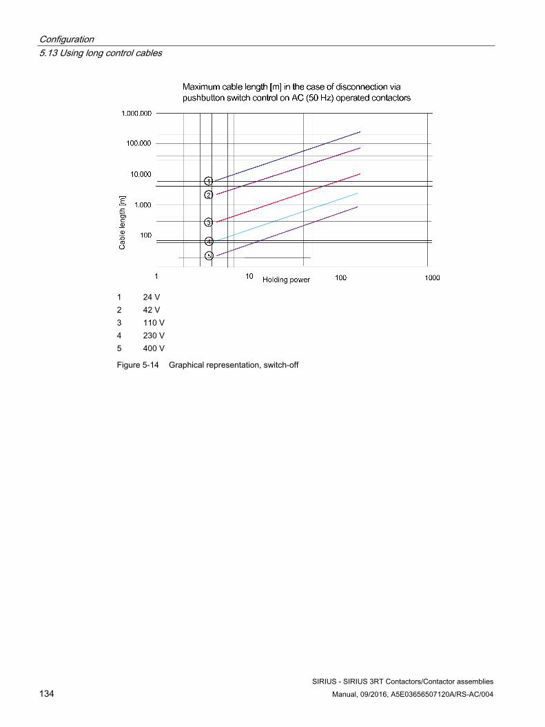
Configuration 5.13 Using long control cables
SIRIUS - SIRIUS 3RT Contactors/Contactor assemblies 134 Manual, 09/2016, A5E03656507120A/RS-AC/004
1 24 V2 42 V 3 110 V4 230 V5 400 V
Figure 5-14 Graphical representation, switch-off
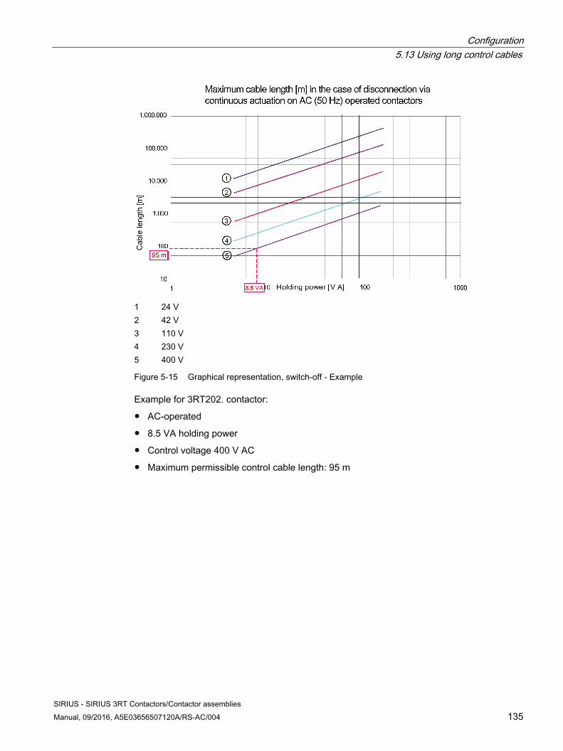
Configuration 5.13 Using long control cables
SIRIUS - SIRIUS 3RT Contactors/Contactor assemblies Manual, 09/2016, A5E03656507120A/RS-AC/004 135
1 24 V 2 42 V 3 110 V 4 230 V 5 400 V
Figure 5-15 Graphical representation, switch-off - Example
Example for 3RT202. contactor:
● AC-operated
● 8.5 VA holding power
● Control voltage 400 V AC
● Maximum permissible control cable length: 95 m
Configuration 5.14 Configuration information for use downstream of frequency converters
SIRIUS - SIRIUS 3RT Contactors/Contactor assemblies 136 Manual, 09/2016, A5E03656507120A/RS-AC/004
5.14 Configuration information for use downstream of frequency converters
There are important criteria for the selection of switching devices when operating with converters.
The following general rule applies: Frequency converters comprise DC link capacitors that cause high inrush current peaks if no attenuation measures have been taken inside the converter using reactors or precharging resistors. The non-attenuated charging current is almost the equivalent of a short-circuit and thus a heavy load on the contacts.
Use of 3RT2 contactors on the primary side of a frequency converter If these current peaks are higher than the making capacity of the contactors, the contactor contacts can bounce. The arcs created in this way liquefy the contact material with subsequent contact sticking and welding. Since the level of the actual current peaks at the installation location of the frequency converter depends essentially on the series impedance of the power system and on the instant of closing, the following must be noted when selecting a suitable contactor.
Converter without precharging resistors If the current peak value is known: on converters without precharging resistors and where the current peak value is known, the 3RT20 contactor can be used in accordance with its making capacity (10 x Ie AC-3). This making capacity must not be lower than the current peaks.
If the current peak value is not known: on converters without precharging resistors and where the current peak value is unknown, capacitor contactors are recommended on the primary side. The use of capacitor contactors attenuates inrush currents to non-critical levels. In addition, losses must be minimized, particularly in standby periods, but also during operation. In the case of frequency converters, losses occur up to the DC link due to input circuits with filters or reactors. These frequency converter standby losses can be reduced to almost zero by disconnection with a contactor on the main current supply side.
The following 3RT26 capacitor contactors are suitable for use on the primary side of frequency converters:
● 3RT2617: Suitable for the performance range to 5.5 kW/400 V
● 3RT2627: Suitable for the performance range of 7.5 kW to 15 kW/400 V
● 3RT2637: Suitable for the performance range of 22 kW to 37 kW/400 V
This depends on the information provided by the frequency converter manufacturer.
Configuration 5.14 Configuration information for use downstream of frequency converters
SIRIUS - SIRIUS 3RT Contactors/Contactor assemblies Manual, 09/2016, A5E03656507120A/RS-AC/004 137
Converters with precharging resistors Siemens converters (SINAMICS / Masterdrives) have precharging resistors. This is why the charging current is restricted to the rated current of the converter. For this reason, the contactor itself can be dimensioned in accordance with utilization category AC-1 (resistive load).
Ultimately, the manufacturer of the frequency converter is responsible for naming the criteria for contactor selection, because only the manufacturer knows the operating characteristics of the product precisely enough to be able to make responsible product recommendations or define product requirements for the contactors.
Use of 3RT2 contactors on the secondary side of a frequency converter An output contactor is usually not required. Only if specifically requested by the customer, is an output contactor supplied. An output contactor is required in the following cases:
● Operation of the frequency converter in bypass mode
● Disconnection of the motor in the case of EMERGENCY-STOP
● Use of the frequency converter for several motors that are to be connected optionally
On the output side of frequency converters, contactors are usually dimensioned in accordance with utilization category AC-3 corresponding to the motor rated current and the associated voltage (as with direct-on-line starting). Since voltage and frequency are almost always proportional in frequency converters, shutdown of the load at low frequencies is not critical for the contactor.
Example A voltage of only 40 V would apply at 5 Hz with respect to a 400 V / 50 Hz power supply system. This can be handled by an AC-3-rated contactor without any problem during the breaking operation.
NOTICE
These statements do not apply to vacuum contactors that are not suitable for low frequencies.
Procedure when shutting down Siemens converters 1. EMERGENCY-OFF (disconnect drive from power as quickly as possible)
Before the contactor is opened, the converter must shut down via inverter enable / pulse disable (command OFF 2).
2. EMERGENCY-OFF (controlled ramp-down of the drive) If a quick stop is to take place, the drive is ramped down (command OFF 3). The pulse disable must take place before the contactor is opened (command OFF 2).
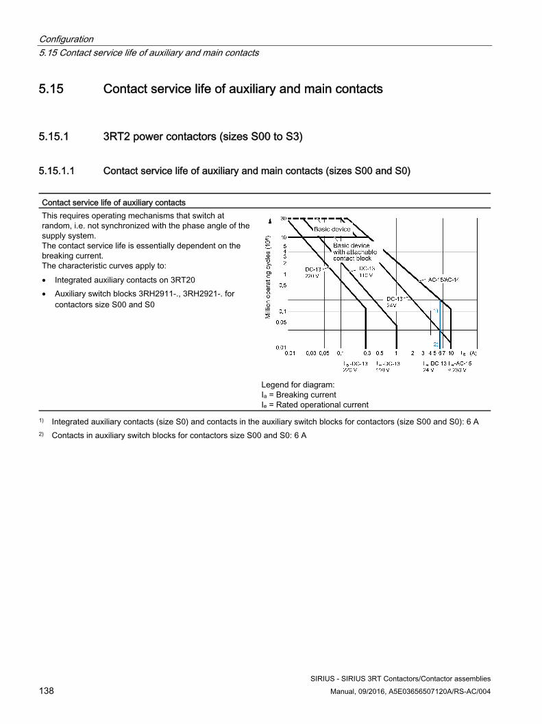
Configuration 5.15 Contact service life of auxiliary and main contacts
SIRIUS - SIRIUS 3RT Contactors/Contactor assemblies 138 Manual, 09/2016, A5E03656507120A/RS-AC/004
5.15 Contact service life of auxiliary and main contacts
5.15.1 3RT2 power contactors (sizes S00 to S3)
5.15.1.1 Contact service life of auxiliary and main contacts (sizes S00 and S0)
Contact service life of auxiliary contacts This requires operating mechanisms that switch at random, i.e. not synchronized with the phase angle of the supply system. The contact service life is essentially dependent on the breaking current. The characteristic curves apply to: • Integrated auxiliary contacts on 3RT20 • Auxiliary switch blocks 3RH2911-., 3RH2921-. for
contactors size S00 and S0
Legend for diagram: Ia = Breaking current Ie = Rated operational current
1) Integrated auxiliary contacts (size S0) and contacts in the auxiliary switch blocks for contactors (size S00 and S0): 6 A 2) Contacts in auxiliary switch blocks for contactors size S00 and S0: 6 A
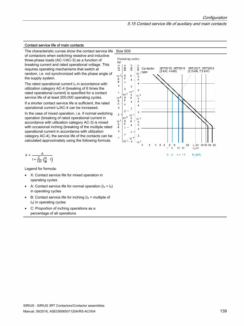
Configuration 5.15 Contact service life of auxiliary and main contacts
SIRIUS - SIRIUS 3RT Contactors/Contactor assemblies Manual, 09/2016, A5E03656507120A/RS-AC/004 139
Contact service life of main contacts The characteristic curves show the contact service life of contactors when switching resistive and inductive three-phase loads (AC-1/AC-3) as a function of breaking current and rated operational voltage. This requires operating mechanisms that switch at random, i.e. not synchronized with the phase angle of the supply system. The rated operational current Ie in accordance with utilization category AC-4 (breaking of 6 times the rated operational current) is specified for a contact service life of at least 200,000 operating cycles. If a shorter contact service life is sufficient, the rated operational current Ie/AC-4 can be increased. In the case of mixed operation, i.e. if normal switching operation (breaking of rated operational current in accordance with utilization category AC-3) is mixed with occasional inching (breaking of the multiple rated operational current in accordance with utilization category AC-4), the service life of the contacts can be calculated approximately using the following formula:
Legend for formula: • X: Contact service life for mixed operation in
operating cycles • A: Contact service life for normal operation (Ia = Ie)
in operating cycles • B: Contact service life for inching (Ia = multiple of
Ie) in operating cycles • C: Proportion of inching operations as a
percentage of all operations
Size S00
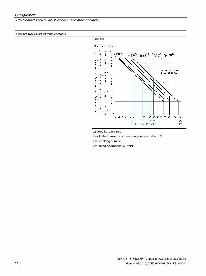
Configuration 5.15 Contact service life of auxiliary and main contacts
SIRIUS - SIRIUS 3RT Contactors/Contactor assemblies 140 Manual, 09/2016, A5E03656507120A/RS-AC/004
Contact service life of main contacts Size S0
Legend for diagram: PN= Rated power of squirrel-cage motors at 400 V Ia= Breaking current Ie= Rated operational current

Configuration 5.15 Contact service life of auxiliary and main contacts
SIRIUS - SIRIUS 3RT Contactors/Contactor assemblies Manual, 09/2016, A5E03656507120A/RS-AC/004 141
5.15.1.2 Contact service life of auxiliary and main contacts (size S2)
Contact service life of auxiliary contacts This requires operating mechanisms that switch at random, i.e. not synchronized with the phase angle of the supply system. The contact service life is essentially dependent on the breaking current. The characteristic curves apply to: • Integrated auxiliary contacts on 3RT20 • Auxiliary switch blocks 3RH2911-., 3RH2921-. for
contactors size S2.
Legend for diagram: Ia = Breaking current Ie = Rated operational current
1) Integrated auxiliary contacts and contacts in the auxiliary switch blocks for contactors (size S2): 6 A 2) Contacts in auxiliary switch blocks for contactors size S2: 6 A
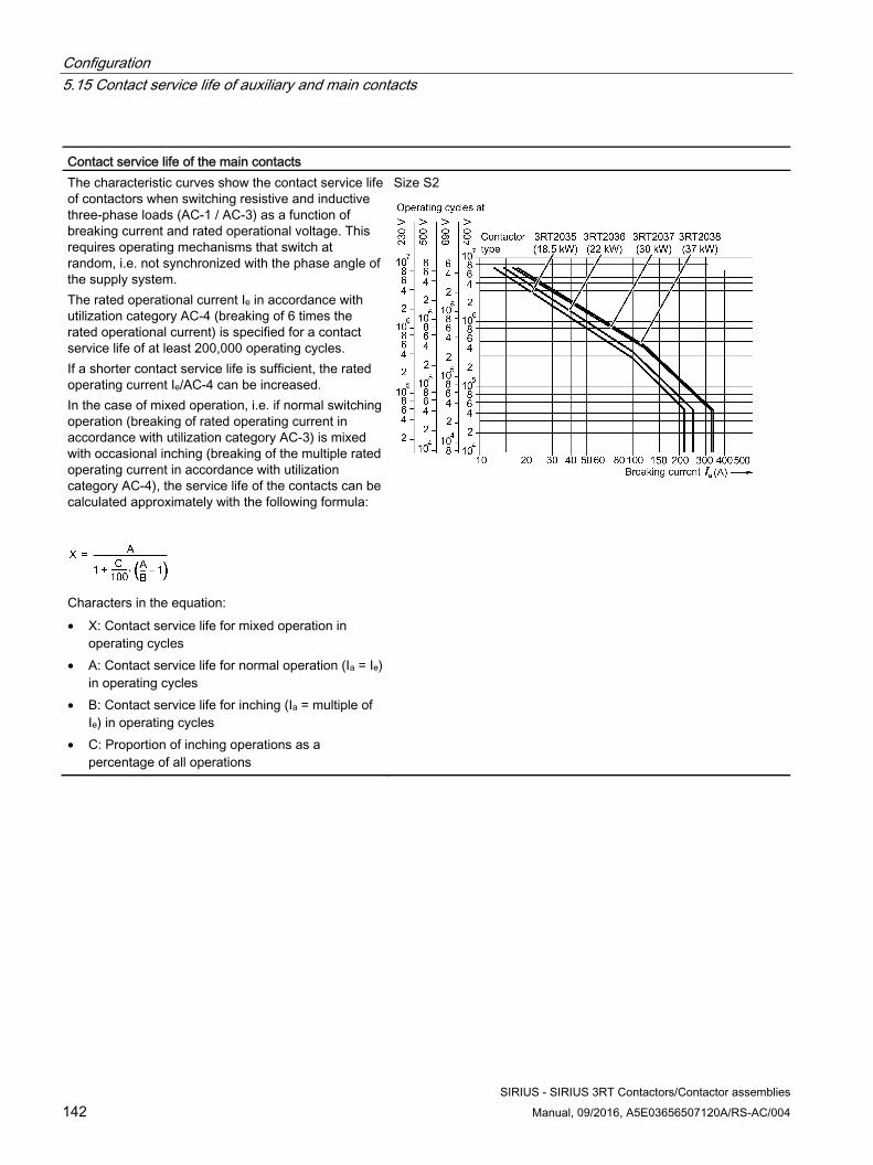
Configuration 5.15 Contact service life of auxiliary and main contacts
SIRIUS - SIRIUS 3RT Contactors/Contactor assemblies 142 Manual, 09/2016, A5E03656507120A/RS-AC/004
Contact service life of the main contacts The characteristic curves show the contact service life of contactors when switching resistive and inductive three-phase loads (AC-1 / AC-3) as a function of breaking current and rated operational voltage. This requires operating mechanisms that switch at random, i.e. not synchronized with the phase angle of the supply system. The rated operational current Ie in accordance with utilization category AC-4 (breaking of 6 times the rated operational current) is specified for a contact service life of at least 200,000 operating cycles. If a shorter contact service life is sufficient, the rated operating current Ie/AC-4 can be increased. In the case of mixed operation, i.e. if normal switching operation (breaking of rated operating current in accordance with utilization category AC-3) is mixed with occasional inching (breaking of the multiple rated operating current in accordance with utilization category AC-4), the service life of the contacts can be calculated approximately with the following formula:
Characters in the equation: • X: Contact service life for mixed operation in
operating cycles • A: Contact service life for normal operation (Ia = Ie)
in operating cycles • B: Contact service life for inching (Ia = multiple of
Ie) in operating cycles • C: Proportion of inching operations as a
percentage of all operations
Size S2
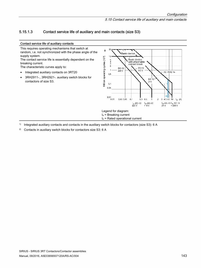
Configuration 5.15 Contact service life of auxiliary and main contacts
SIRIUS - SIRIUS 3RT Contactors/Contactor assemblies Manual, 09/2016, A5E03656507120A/RS-AC/004 143
5.15.1.3 Contact service life of auxiliary and main contacts (size S3)
Contact service life of auxiliary contacts This requires operating mechanisms that switch at random, i.e. not synchronized with the phase angle of the supply system. The contact service life is essentially dependent on the breaking current. The characteristic curves apply to: • Integrated auxiliary contacts on 3RT20 • 3RH2911-., 3RH2921-. auxiliary switch blocks for
contactors of size S3.
Legend for diagram: Ia = Breaking current Ie = Rated operational current
1) Integrated auxiliary contacts and contacts in the auxiliary switch blocks for contactors (size S3): 6 A 2) Contacts in auxiliary switch blocks for contactors size S3: 6 A

Configuration 5.15 Contact service life of auxiliary and main contacts
SIRIUS - SIRIUS 3RT Contactors/Contactor assemblies 144 Manual, 09/2016, A5E03656507120A/RS-AC/004
Contact service life of the main contacts The characteristic curves show the contact service life of contactors when switching resistive and inductive three-phase loads (AC-1 / AC-3) as a function of breaking current and rated operational voltage. This requires operating mechanisms that switch at random, i.e. not synchronized with the phase angle of the supply system. The rated operational current Ie in accordance with utilization category AC-4 (breaking of 6 times the rated operational current) is specified for a contact service life of at least 200,000 operating cycles. If a shorter contact service life is sufficient, the rated operating current Ie/AC-4 can be increased. In the case of mixed operation, i.e. if normal switching operation (breaking of rated operating current in accordance with utilization category AC-3) is mixed with occasional inching (breaking of the multiple rated operating current in accordance with utilization category AC-4), the service life of the contacts can be calculated approximately with the following formula:
Characters in the equation: • X: Contact service life for mixed operation in
operating cycles • A: Contact service life for normal operation (Ia = Ie)
in operating cycles • B: Contact service life for inching (Ia = multiple of
Ie) in operating cycles • C: Proportion of inching operations as a
percentage of all operations
Size S3
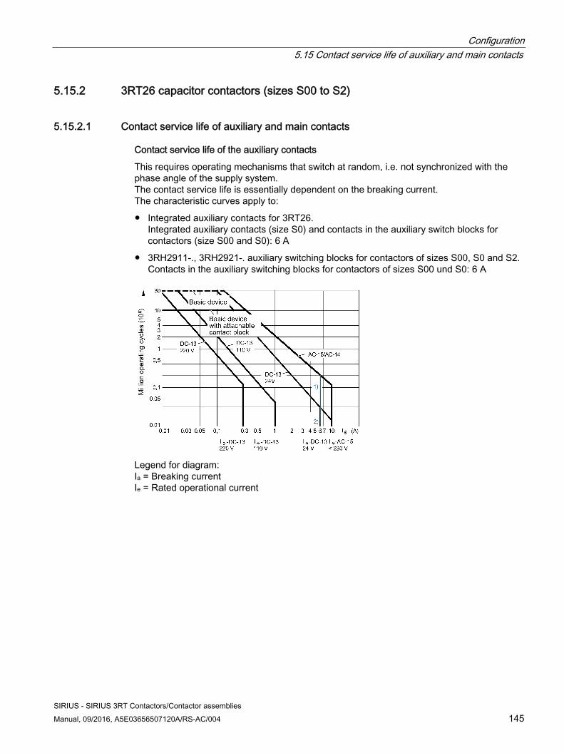
Configuration 5.15 Contact service life of auxiliary and main contacts
SIRIUS - SIRIUS 3RT Contactors/Contactor assemblies Manual, 09/2016, A5E03656507120A/RS-AC/004 145
5.15.2 3RT26 capacitor contactors (sizes S00 to S2)
5.15.2.1 Contact service life of auxiliary and main contacts
Contact service life of the auxiliary contacts
This requires operating mechanisms that switch at random, i.e. not synchronized with the phase angle of the supply system. The contact service life is essentially dependent on the breaking current. The characteristic curves apply to:
● Integrated auxiliary contacts for 3RT26. Integrated auxiliary contacts (size S0) and contacts in the auxiliary switch blocks for contactors (size S00 and S0): 6 A
● 3RH2911-., 3RH2921-. auxiliary switching blocks for contactors of sizes S00, S0 and S2. Contacts in the auxiliary switching blocks for contactors of sizes S00 und S0: 6 A
Legend for diagram: Ia = Breaking current Ie = Rated operational current
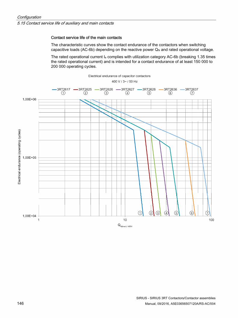
Configuration 5.15 Contact service life of auxiliary and main contacts
SIRIUS - SIRIUS 3RT Contactors/Contactor assemblies 146 Manual, 09/2016, A5E03656507120A/RS-AC/004
Contact service life of the main contacts
The characteristic curves show the contact endurance of the contactors when switching capacitive loads (AC-6b) depending on the reactive power QN and rated operational voltage.
The rated operational current Ie complies with utilization category AC-6b (breaking 1.35 times the rated operational current) and is intended for a contact endurance of at least 150 000 to 200 000 operating cycles.
Configuration 5.15 Contact service life of auxiliary and main contacts
SIRIUS - SIRIUS 3RT Contactors/Contactor assemblies Manual, 09/2016, A5E03656507120A/RS-AC/004 147
5.15.3 3RT10 power contactors and 3RT12 vacuum contactors (sizes S6 to S12)
5.15.3.1 Mechanical endurance The mechanical service life of contactors is a crucial criterion for their cost-effective use. This is expressed as the number of operating cycles achieved without loading the current path. While you cannot demand an excessively long service life from breakers that have to work with relatively high contact loads, such as disconnectors and circuit breakers, without impairing their cost effectiveness, contactors are available as specific switching devices for extremely high numbers of switching operations and switching frequencies.
Mechanical service life of the 3RT1 contactors:
● Basic units, sizes S6 to S12: 10 million operating cycles
5.15.3.2 Electrical endurance
Electrical service life of main contacts The service life of the contact pieces is as follows:
● In the case of rated operational current Ie in accordance with utilization category AC-4 (breaking of 6 times the rated operating current): 200,000 operating cycles
● In the case of mixed operation, i.e. if normal switching operation (breaking of rated operating current in accordance with utilization category AC-3) is mixed with occasional inching (breaking of the multiple rated operating current in accordance with utilization category AC-4): Operating cycles can be calculated approximately with the following formula:
Characters in the equation:
● X: contact endurance for mixed operation in operating cycles
● A: Contact service life for normal operation (Ia = Ie) in operating cycles
● B: Contact service life for inching (Ia = multiple of Ie) in operating cycles
● C: Inching operations as a percentage of total switching operations
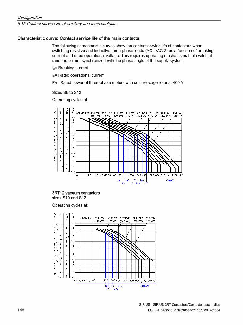
Configuration 5.15 Contact service life of auxiliary and main contacts
SIRIUS - SIRIUS 3RT Contactors/Contactor assemblies 148 Manual, 09/2016, A5E03656507120A/RS-AC/004
Characteristic curve: Contact service life of the main contacts The following characteristic curves show the contact service life of contactors when switching resistive and inductive three-phase loads (AC-1/AC-3) as a function of breaking current and rated operational voltage. This requires operating mechanisms that switch at random, i.e. not synchronized with the phase angle of the supply system.
Ia= Breaking current
Ie= Rated operational current
PN= Rated power of three-phase motors with squirrel-cage rotor at 400 V
Sizes S6 to S12
Operating cycles at:
3RT12 vacuum contactors sizes S10 and S12
Operating cycles at:
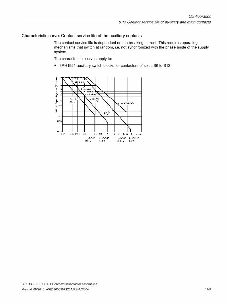
Configuration 5.15 Contact service life of auxiliary and main contacts
SIRIUS - SIRIUS 3RT Contactors/Contactor assemblies Manual, 09/2016, A5E03656507120A/RS-AC/004 149
Characteristic curve: Contact service life of the auxiliary contacts The contact service life is dependent on the breaking current. This requires operating mechanisms that switch at random, i.e. not synchronized with the phase angle of the supply system.
The characteristic curves apply to:
● 3RH1921 auxiliary switch blocks for contactors of sizes S6 to S12
Configuration 5.15 Contact service life of auxiliary and main contacts
SIRIUS - SIRIUS 3RT Contactors/Contactor assemblies 150 Manual, 09/2016, A5E03656507120A/RS-AC/004
SIRIUS - SIRIUS 3RT Contactors/Contactor assemblies Manual, 09/2016, A5E03656507120A/RS-AC/004 151
Mounting 6 6.1 Mounting
6.1.1 Mounting options Note the following information when mounting contactors:
● If foreign bodies (such as drillings) can reach the devices, the contactors must be covered during mounting.
● If there is a risk of pollution, heavy dust deposits, or an aggressive atmosphere at the mounting location, the contactors must be installed in an enclosure.
● Dust deposits must be vacuumed away.
Mounting options The following mounting types are available for the contactors:
● Snapping onto a 35 mm standard mounting rail according to EN 60715. (Sizes S00 ... S3 only)
● Screwing onto a mounting plate
Side-by-side mounting Up to an ambient temperature of 60 °C, derating is not necessary for all contactors even in the case of side-by-side mounting. In the case of contactors with extended operating range (0.7 to 1.25 x Us) that operate via a series resistor, side-by-side mounting is permissible up to an ambient temperature of +70 °C.
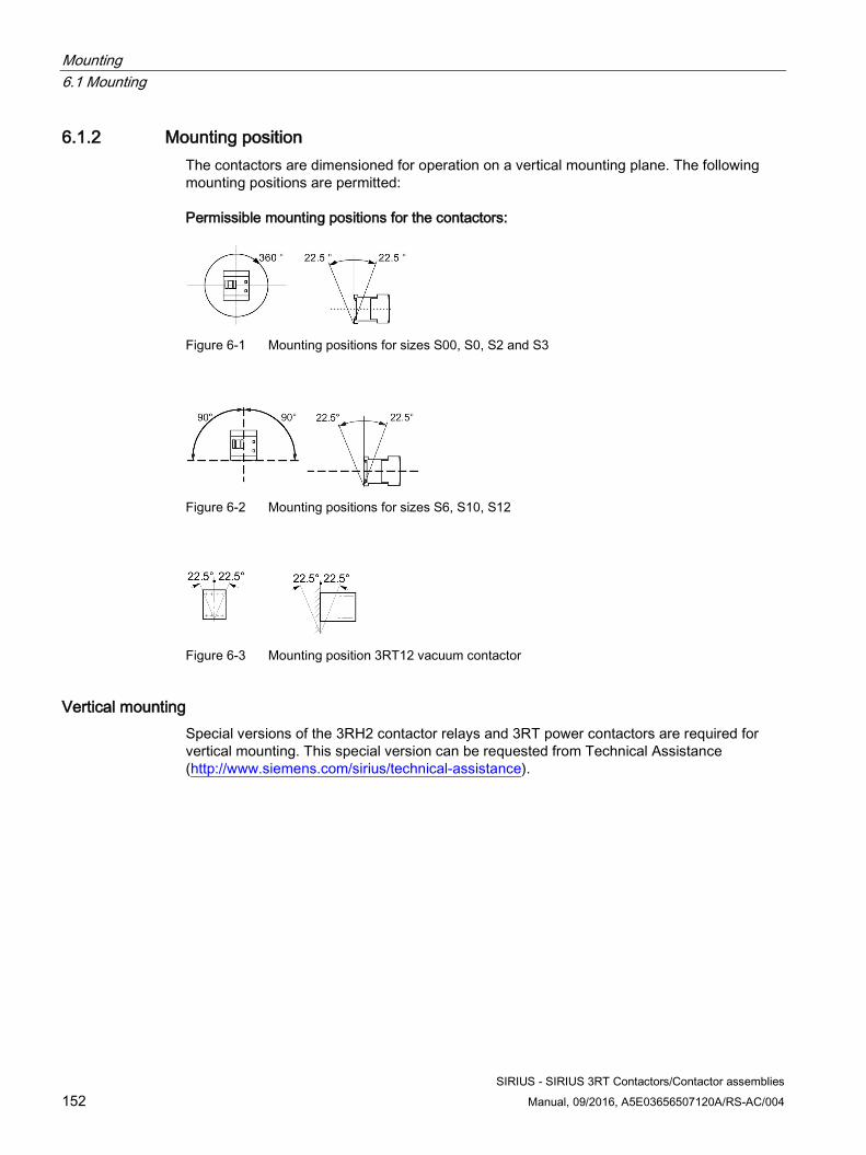
Mounting 6.1 Mounting
SIRIUS - SIRIUS 3RT Contactors/Contactor assemblies 152 Manual, 09/2016, A5E03656507120A/RS-AC/004
6.1.2 Mounting position The contactors are dimensioned for operation on a vertical mounting plane. The following mounting positions are permitted:
Permissible mounting positions for the contactors:
Figure 6-1 Mounting positions for sizes S00, S0, S2 and S3
Figure 6-2 Mounting positions for sizes S6, S10, S12
Figure 6-3 Mounting position 3RT12 vacuum contactor
Vertical mounting Special versions of the 3RH2 contactor relays and 3RT power contactors are required for vertical mounting. This special version can be requested from Technical Assistance (http://www.siemens.com/sirius/technical-assistance).
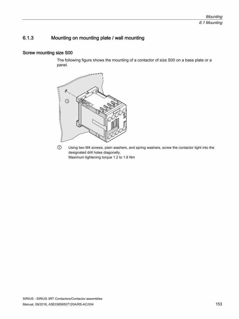
Mounting 6.1 Mounting
SIRIUS - SIRIUS 3RT Contactors/Contactor assemblies Manual, 09/2016, A5E03656507120A/RS-AC/004 153
6.1.3 Mounting on mounting plate / wall mounting
Screw mounting size S00 The following figure shows the mounting of a contactor of size S00 on a base plate or a panel.
① Using two M4 screws, plain washers, and spring washers, screw the contactor tight into the
designated drill holes diagonally. Maximum tightening torque 1.2 to 1.6 Nm
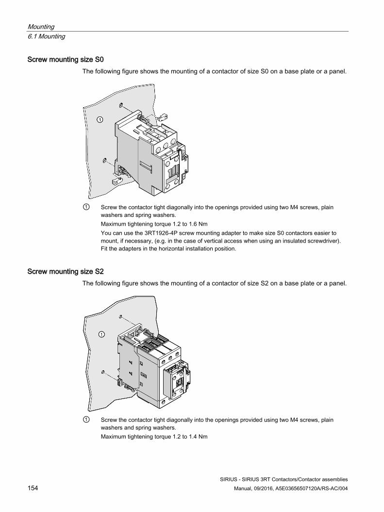
Mounting 6.1 Mounting
SIRIUS - SIRIUS 3RT Contactors/Contactor assemblies 154 Manual, 09/2016, A5E03656507120A/RS-AC/004
Screw mounting size S0 The following figure shows the mounting of a contactor of size S0 on a base plate or a panel.
① Screw the contactor tight diagonally into the openings provided using two M4 screws, plain
washers and spring washers. Maximum tightening torque 1.2 to 1.6 Nm You can use the 3RT1926-4P screw mounting adapter to make size S0 contactors easier to mount, if necessary, (e.g. in the case of vertical access when using an insulated screwdriver). Fit the adapters in the horizontal installation position.
Screw mounting size S2 The following figure shows the mounting of a contactor of size S2 on a base plate or a panel.
① Screw the contactor tight diagonally into the openings provided using two M4 screws, plain
washers and spring washers. Maximum tightening torque 1.2 to 1.4 Nm
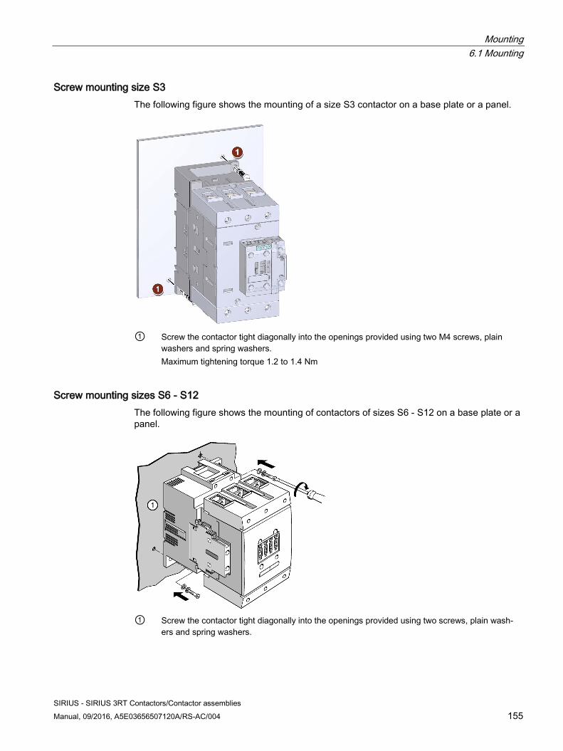
Mounting 6.1 Mounting
SIRIUS - SIRIUS 3RT Contactors/Contactor assemblies Manual, 09/2016, A5E03656507120A/RS-AC/004 155
Screw mounting size S3 The following figure shows the mounting of a size S3 contactor on a base plate or a panel.
① Screw the contactor tight diagonally into the openings provided using two M4 screws, plain
washers and spring washers. Maximum tightening torque 1.2 to 1.4 Nm
Screw mounting sizes S6 - S12 The following figure shows the mounting of contactors of sizes S6 - S12 on a base plate or a panel.
① Screw the contactor tight diagonally into the openings provided using two screws, plain wash-
ers and spring washers.
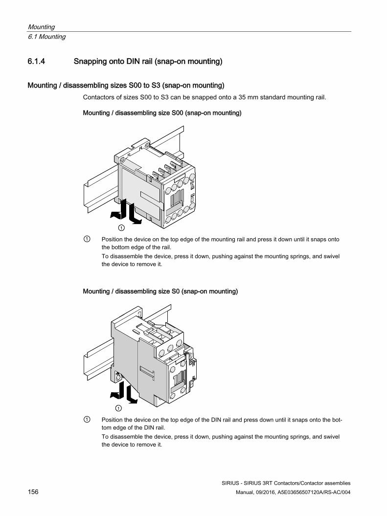
Mounting 6.1 Mounting
SIRIUS - SIRIUS 3RT Contactors/Contactor assemblies 156 Manual, 09/2016, A5E03656507120A/RS-AC/004
6.1.4 Snapping onto DIN rail (snap-on mounting)
Mounting / disassembling sizes S00 to S3 (snap-on mounting) Contactors of sizes S00 to S3 can be snapped onto a 35 mm standard mounting rail.
Mounting / disassembling size S00 (snap-on mounting)
① Position the device on the top edge of the mounting rail and press it down until it snaps onto
the bottom edge of the rail. To disassemble the device, press it down, pushing against the mounting springs, and swivel the device to remove it.
Mounting / disassembling size S0 (snap-on mounting)
① Position the device on the top edge of the DIN rail and press down until it snaps onto the bot-
tom edge of the DIN rail. To disassemble the device, press it down, pushing against the mounting springs, and swivel the device to remove it.
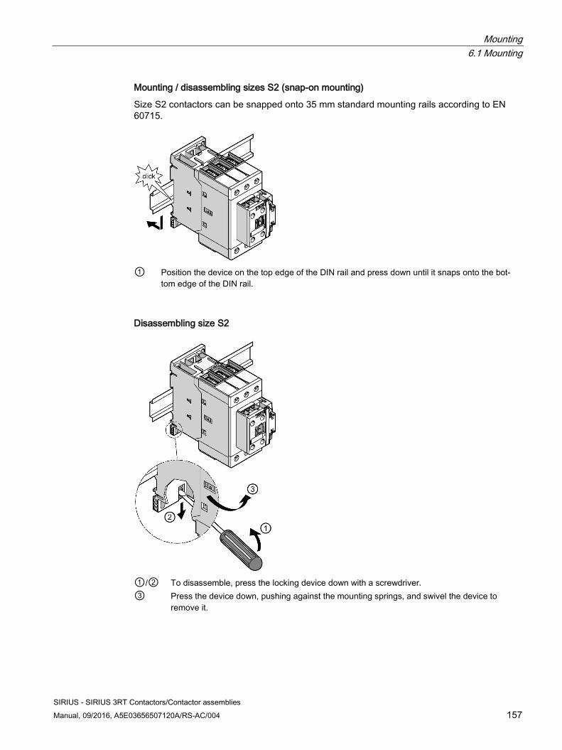
Mounting 6.1 Mounting
SIRIUS - SIRIUS 3RT Contactors/Contactor assemblies Manual, 09/2016, A5E03656507120A/RS-AC/004 157
Mounting / disassembling sizes S2 (snap-on mounting)
Size S2 contactors can be snapped onto 35 mm standard mounting rails according to EN 60715.
① Position the device on the top edge of the DIN rail and press down until it snaps onto the bot-
tom edge of the DIN rail.
Disassembling size S2
①/② To disassemble, press the locking device down with a screwdriver. ③ Press the device down, pushing against the mounting springs, and swivel the device to
remove it.
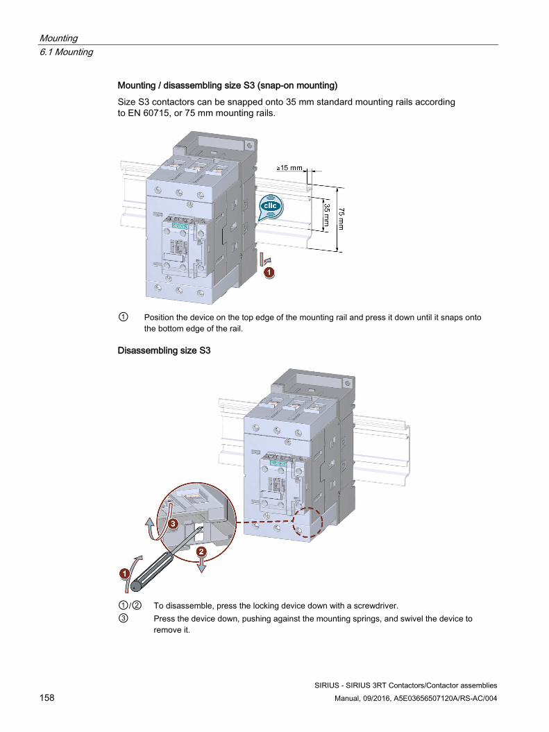
Mounting 6.1 Mounting
SIRIUS - SIRIUS 3RT Contactors/Contactor assemblies 158 Manual, 09/2016, A5E03656507120A/RS-AC/004
Mounting / disassembling size S3 (snap-on mounting)
Size S3 contactors can be snapped onto 35 mm standard mounting rails according to EN 60715, or 75 mm mounting rails.
① Position the device on the top edge of the mounting rail and press it down until it snaps onto
the bottom edge of the rail.
Disassembling size S3
①/② To disassemble, press the locking device down with a screwdriver. ③ Press the device down, pushing against the mounting springs, and swivel the device to
remove it.
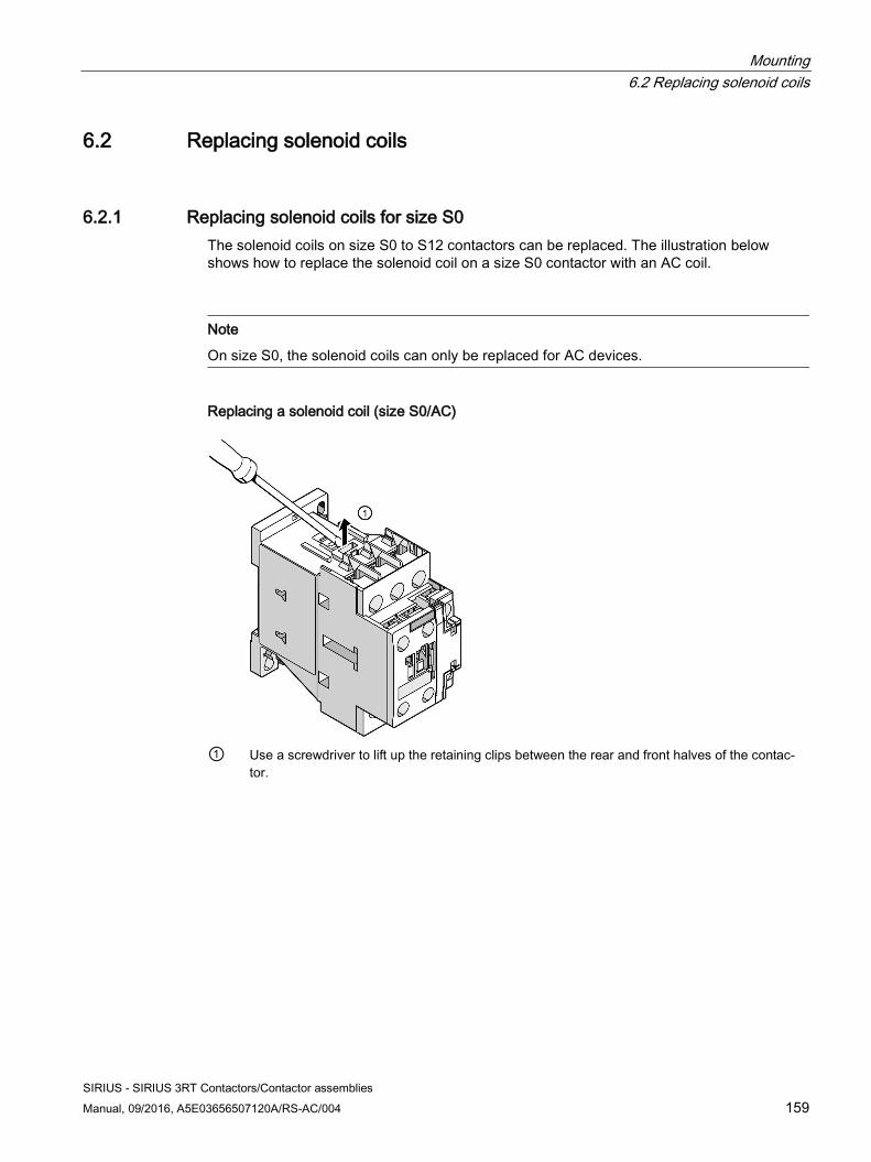
Mounting 6.2 Replacing solenoid coils
SIRIUS - SIRIUS 3RT Contactors/Contactor assemblies Manual, 09/2016, A5E03656507120A/RS-AC/004 159
6.2 Replacing solenoid coils
6.2.1 Replacing solenoid coils for size S0 The solenoid coils on size S0 to S12 contactors can be replaced. The illustration below shows how to replace the solenoid coil on a size S0 contactor with an AC coil.
Note
On size S0, the solenoid coils can only be replaced for AC devices.
Replacing a solenoid coil (size S0/AC)
① Use a screwdriver to lift up the retaining clips between the rear and front halves of the contac-
tor.
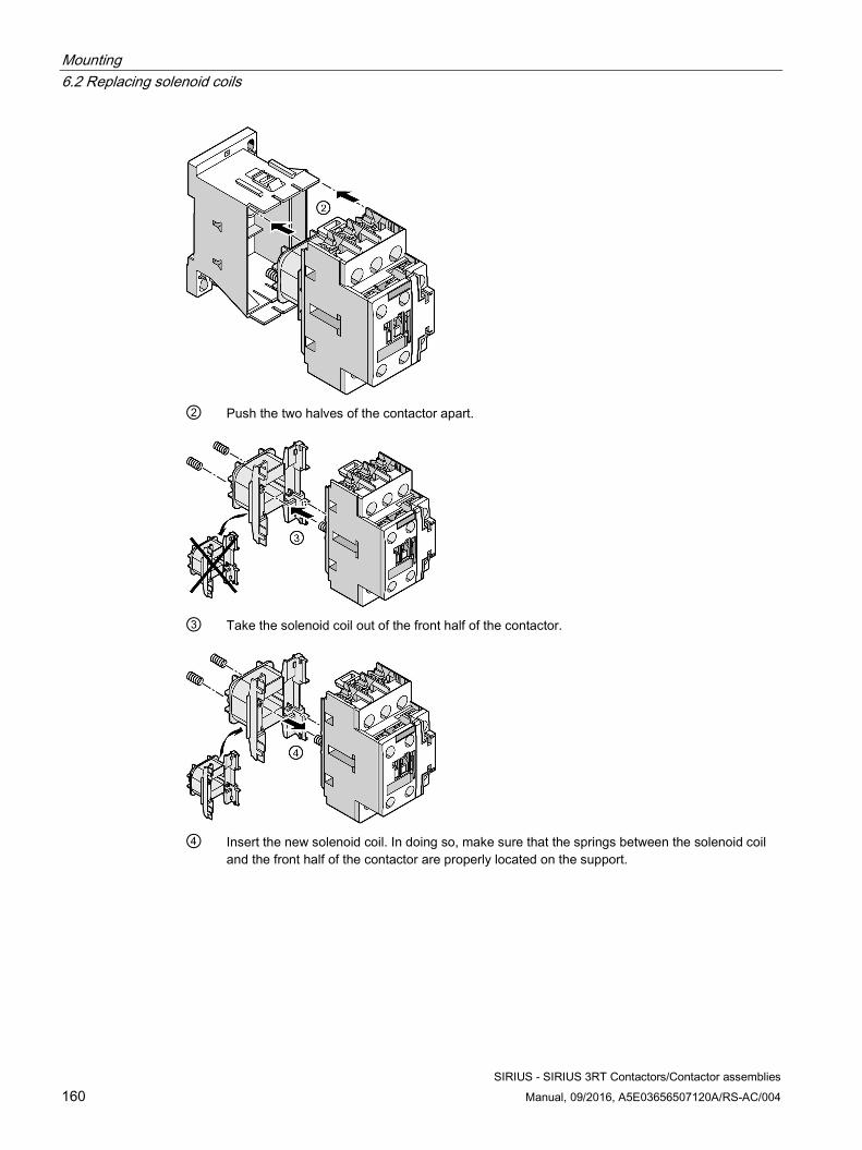
Mounting 6.2 Replacing solenoid coils
SIRIUS - SIRIUS 3RT Contactors/Contactor assemblies 160 Manual, 09/2016, A5E03656507120A/RS-AC/004
② Push the two halves of the contactor apart.
③ Take the solenoid coil out of the front half of the contactor.
④ Insert the new solenoid coil. In doing so, make sure that the springs between the solenoid coil
and the front half of the contactor are properly located on the support.
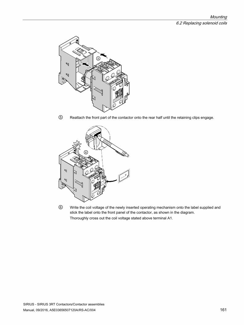
Mounting 6.2 Replacing solenoid coils
SIRIUS - SIRIUS 3RT Contactors/Contactor assemblies Manual, 09/2016, A5E03656507120A/RS-AC/004 161
⑤ Reattach the front part of the contactor onto the rear half until the retaining clips engage.
⑥ Write the coil voltage of the newly inserted operating mechanism onto the label supplied and
stick the label onto the front panel of the contactor, as shown in the diagram. Thoroughly cross out the coil voltage stated above terminal A1.
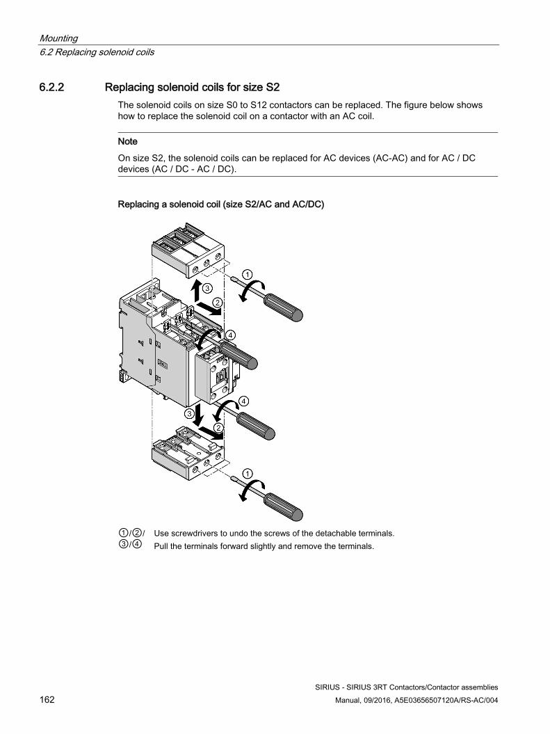
Mounting 6.2 Replacing solenoid coils
SIRIUS - SIRIUS 3RT Contactors/Contactor assemblies 162 Manual, 09/2016, A5E03656507120A/RS-AC/004
6.2.2 Replacing solenoid coils for size S2 The solenoid coils on size S0 to S12 contactors can be replaced. The figure below shows how to replace the solenoid coil on a contactor with an AC coil.
Note
On size S2, the solenoid coils can be replaced for AC devices (AC-AC) and for AC / DC devices (AC / DC - AC / DC).
Replacing a solenoid coil (size S2/AC and AC/DC)
①/②/ ③/④
Use screwdrivers to undo the screws of the detachable terminals. Pull the terminals forward slightly and remove the terminals.
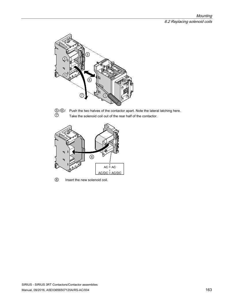
Mounting 6.2 Replacing solenoid coils
SIRIUS - SIRIUS 3RT Contactors/Contactor assemblies Manual, 09/2016, A5E03656507120A/RS-AC/004 163
⑤/⑥/⑦
Push the two halves of the contactor apart. Note the lateral latching here. Take the solenoid coil out of the rear half of the contactor.
⑧ Insert the new solenoid coil.
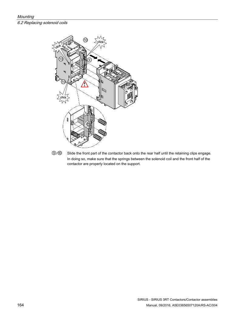
Mounting 6.2 Replacing solenoid coils
SIRIUS - SIRIUS 3RT Contactors/Contactor assemblies 164 Manual, 09/2016, A5E03656507120A/RS-AC/004
⑨/⑩ Slide the front part of the contactor back onto the rear half until the retaining clips engage.
In doing so, make sure that the springs between the solenoid coil and the front half of the contactor are properly located on the support.
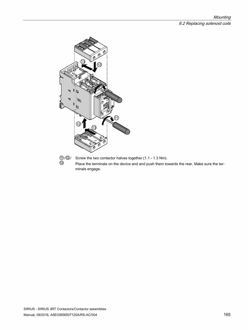
Mounting 6.2 Replacing solenoid coils
SIRIUS - SIRIUS 3RT Contactors/Contactor assemblies Manual, 09/2016, A5E03656507120A/RS-AC/004 165
⑪/⑫/⑬
Screw the two contactor halves together (1.1 - 1.3 Nm). Place the terminals on the device and and push them towards the rear. Make sure the ter-minals engage.
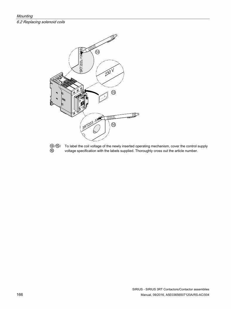
Mounting 6.2 Replacing solenoid coils
SIRIUS - SIRIUS 3RT Contactors/Contactor assemblies 166 Manual, 09/2016, A5E03656507120A/RS-AC/004
⑭/⑮/⑯
To label the coil voltage of the newly inserted operating mechanism, cover the control supply voltage specification with the labels supplied. Thoroughly cross out the article number.
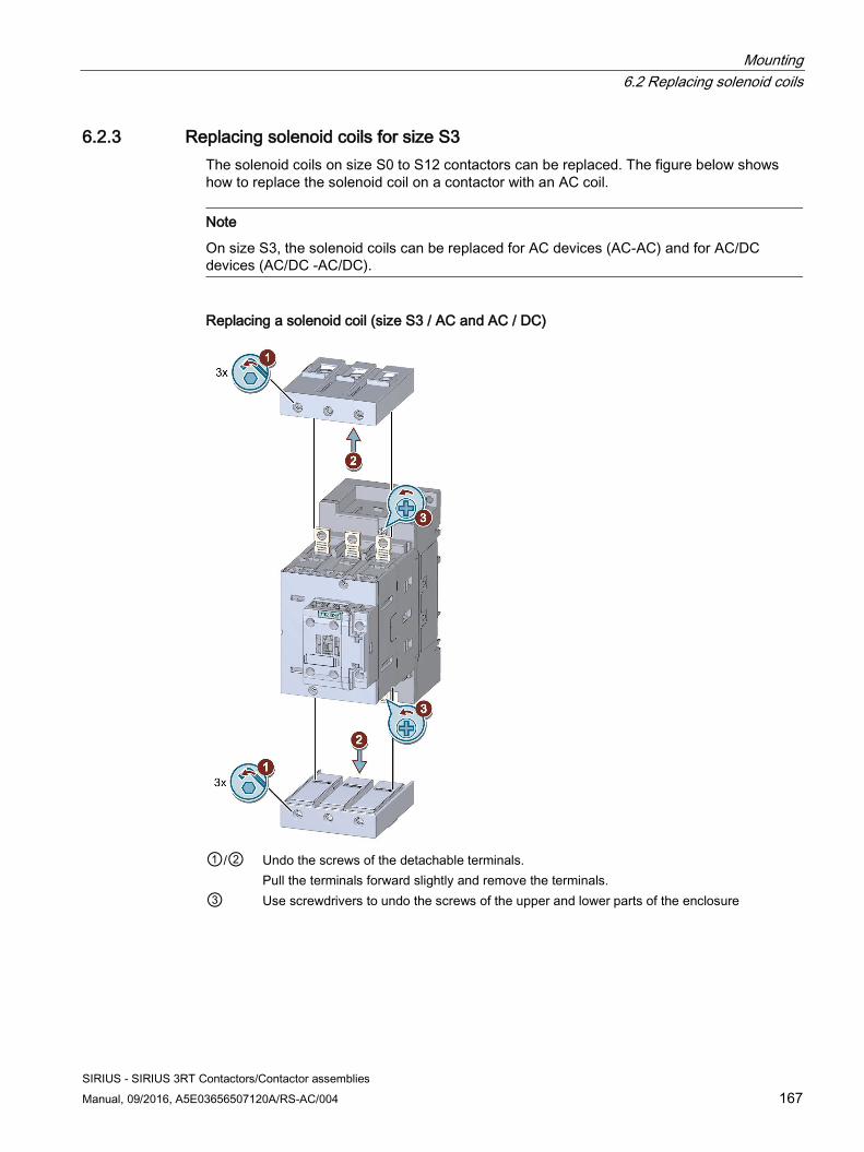
Mounting 6.2 Replacing solenoid coils
SIRIUS - SIRIUS 3RT Contactors/Contactor assemblies Manual, 09/2016, A5E03656507120A/RS-AC/004 167
6.2.3 Replacing solenoid coils for size S3 The solenoid coils on size S0 to S12 contactors can be replaced. The figure below shows how to replace the solenoid coil on a contactor with an AC coil.
Note
On size S3, the solenoid coils can be replaced for AC devices (AC-AC) and for AC/DC devices (AC/DC -AC/DC).
Replacing a solenoid coil (size S3 / AC and AC / DC)
①/②
Undo the screws of the detachable terminals. Pull the terminals forward slightly and remove the terminals.
③ Use screwdrivers to undo the screws of the upper and lower parts of the enclosure
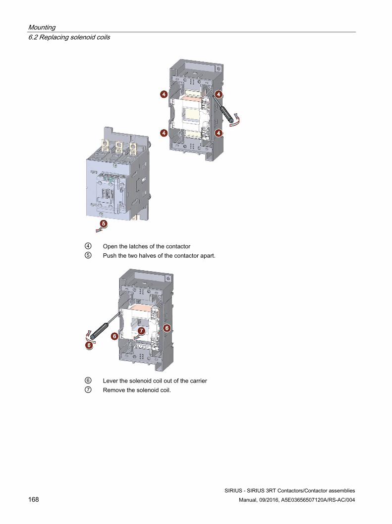
Mounting 6.2 Replacing solenoid coils
SIRIUS - SIRIUS 3RT Contactors/Contactor assemblies 168 Manual, 09/2016, A5E03656507120A/RS-AC/004
④ Open the latches of the contactor ⑤ Push the two halves of the contactor apart.
⑥ Lever the solenoid coil out of the carrier ⑦ Remove the solenoid coil.
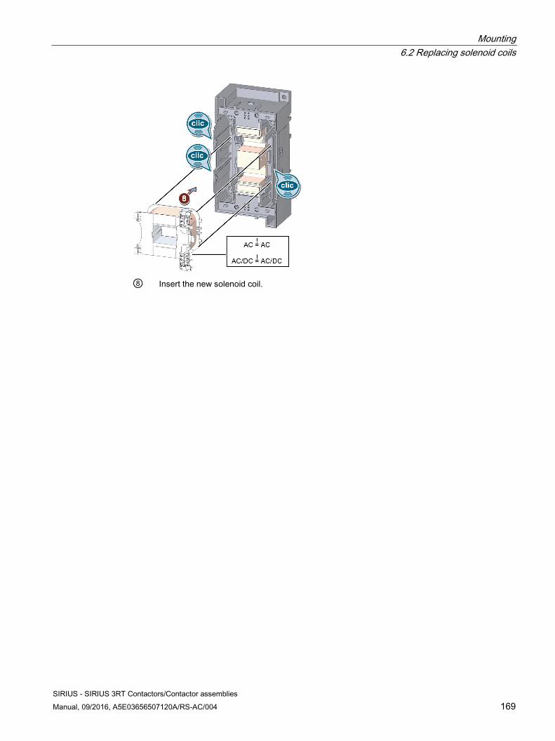
Mounting 6.2 Replacing solenoid coils
SIRIUS - SIRIUS 3RT Contactors/Contactor assemblies Manual, 09/2016, A5E03656507120A/RS-AC/004 169
⑧ Insert the new solenoid coil.
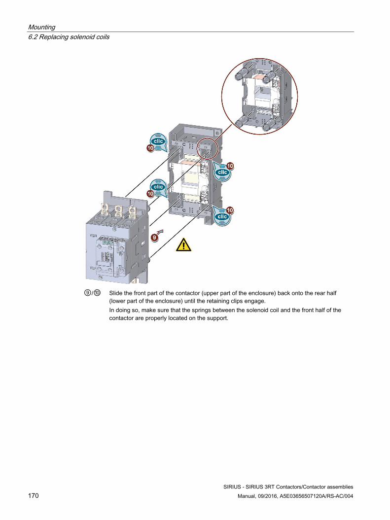
Mounting 6.2 Replacing solenoid coils
SIRIUS - SIRIUS 3RT Contactors/Contactor assemblies 170 Manual, 09/2016, A5E03656507120A/RS-AC/004
⑨/⑩ Slide the front part of the contactor (upper part of the enclosure) back onto the rear half
(lower part of the enclosure) until the retaining clips engage. In doing so, make sure that the springs between the solenoid coil and the front half of the contactor are properly located on the support.
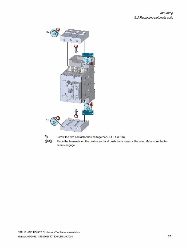
Mounting 6.2 Replacing solenoid coils
SIRIUS - SIRIUS 3RT Contactors/Contactor assemblies Manual, 09/2016, A5E03656507120A/RS-AC/004 171
⑪ Screw the two contactor halves together (1.1 - 1.3 Nm). ⑫/⑬ Place the terminals on the device and and push them towards the rear. Make sure the ter-
minals engage.
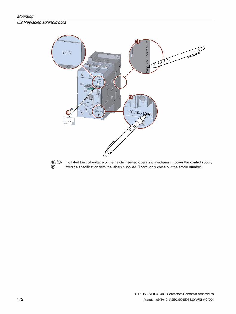
Mounting 6.2 Replacing solenoid coils
SIRIUS - SIRIUS 3RT Contactors/Contactor assemblies 172 Manual, 09/2016, A5E03656507120A/RS-AC/004
⑭/⑮/⑯
To label the coil voltage of the newly inserted operating mechanism, cover the control supply voltage specification with the labels supplied. Thoroughly cross out the article number.
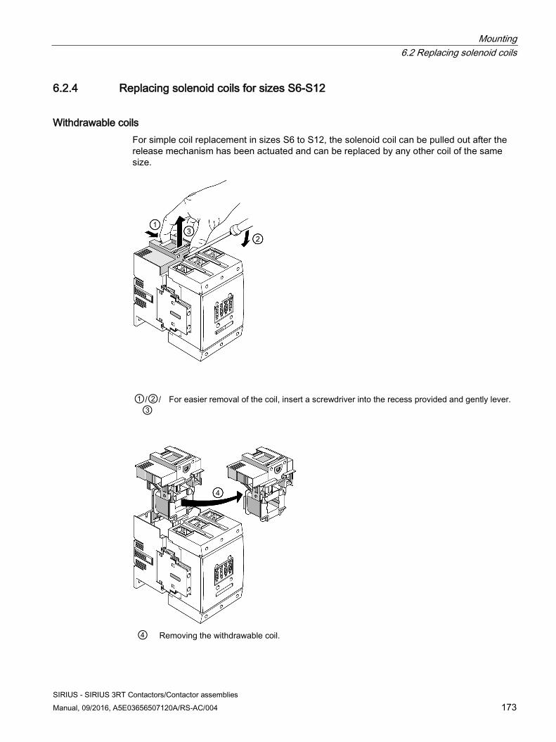
Mounting 6.2 Replacing solenoid coils
SIRIUS - SIRIUS 3RT Contactors/Contactor assemblies Manual, 09/2016, A5E03656507120A/RS-AC/004 173
6.2.4 Replacing solenoid coils for sizes S6-S12
Withdrawable coils For simple coil replacement in sizes S6 to S12, the solenoid coil can be pulled out after the release mechanism has been actuated and can be replaced by any other coil of the same size.
①/②/
③ For easier removal of the coil, insert a screwdriver into the recess provided and gently lever.
④ Removing the withdrawable coil.
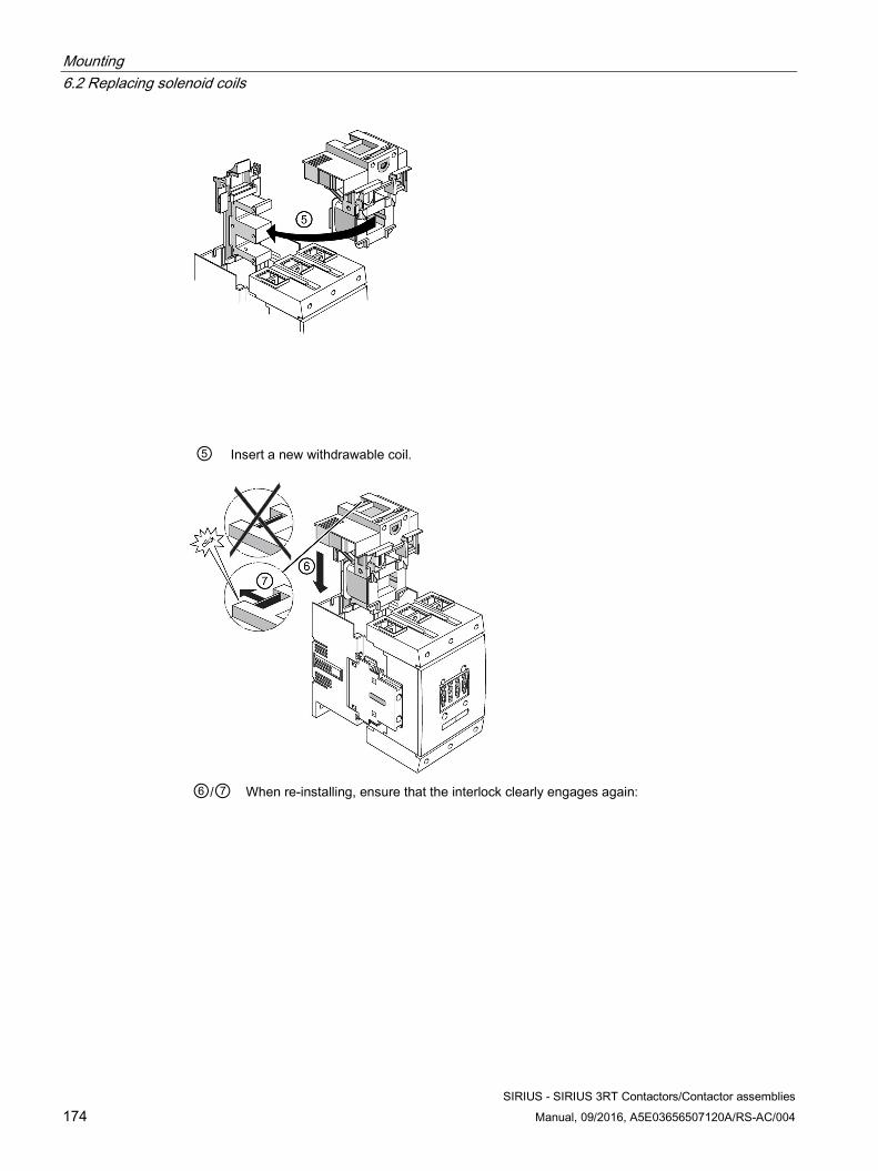
Mounting 6.2 Replacing solenoid coils
SIRIUS - SIRIUS 3RT Contactors/Contactor assemblies 174 Manual, 09/2016, A5E03656507120A/RS-AC/004
⑤ Insert a new withdrawable coil.
⑥/⑦ When re-installing, ensure that the interlock clearly engages again:
Mounting 6.2 Replacing solenoid coils
SIRIUS - SIRIUS 3RT Contactors/Contactor assemblies Manual, 09/2016, A5E03656507120A/RS-AC/004 175
Configuration note If the coil is also to be replaced when the contactor is installed, a clearance upwards of approximately 120 mm (for contactors of size S6) or 150 mm (size S10 and S12) must be taken into account when configuring.
Identical solenoid operating mechanisms Regardless of the performance level, the solenoid operating mechanisms and thus the withdrawable coils within one size are identical, and in the case of size S12 also between air-break contactors and vacuum contactors.
Identical solenoid operating mechanisms / withdrawable coils (×): Size Type
3RT10 and 3RT14 air-break contactors 3RT12 vacuum contactors S6 X S10 X X S12 X X
"Contactors without coil" version The air-break contactors and vacuum contactors are available across the entire performance range, even without a coil. Depending on requirements, they can be supplemented on-site with coils of the desired actuator type and control circuit voltage (article number of this contactor version: 3RT1...-.LA06).
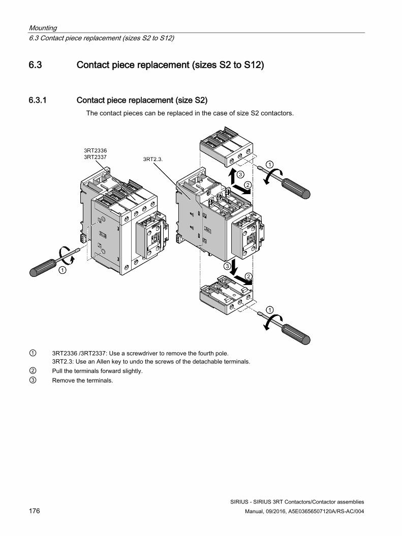
Mounting 6.3 Contact piece replacement (sizes S2 to S12)
SIRIUS - SIRIUS 3RT Contactors/Contactor assemblies 176 Manual, 09/2016, A5E03656507120A/RS-AC/004
6.3 Contact piece replacement (sizes S2 to S12)
6.3.1 Contact piece replacement (size S2) The contact pieces can be replaced in the case of size S2 contactors.
① 3RT2336 /3RT2337: Use a screwdriver to remove the fourth pole.
3RT2.3: Use an Allen key to undo the screws of the detachable terminals. ② Pull the terminals forward slightly. ③ Remove the terminals.
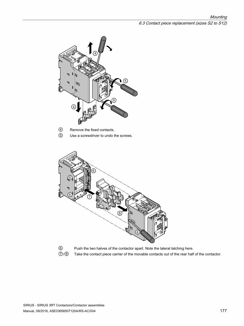
Mounting 6.3 Contact piece replacement (sizes S2 to S12)
SIRIUS - SIRIUS 3RT Contactors/Contactor assemblies Manual, 09/2016, A5E03656507120A/RS-AC/004 177
④ Remove the fixed contacts. ⑤ Use a screwdriver to undo the screws.
⑥ Push the two halves of the contactor apart. Note the lateral latching here. ⑦/⑧ Take the contact piece carrier of the movable contacts out of the rear half of the contactor.
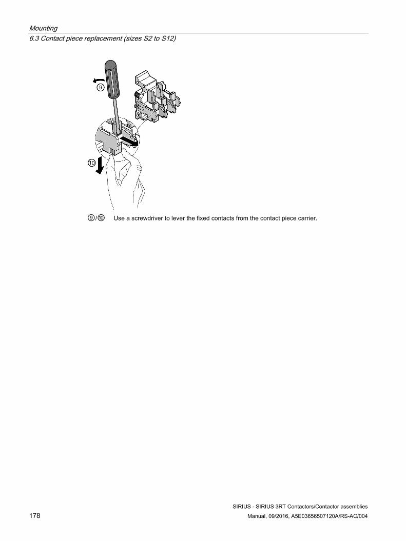
Mounting 6.3 Contact piece replacement (sizes S2 to S12)
SIRIUS - SIRIUS 3RT Contactors/Contactor assemblies 178 Manual, 09/2016, A5E03656507120A/RS-AC/004
⑨/⑩ Use a screwdriver to lever the fixed contacts from the contact piece carrier.
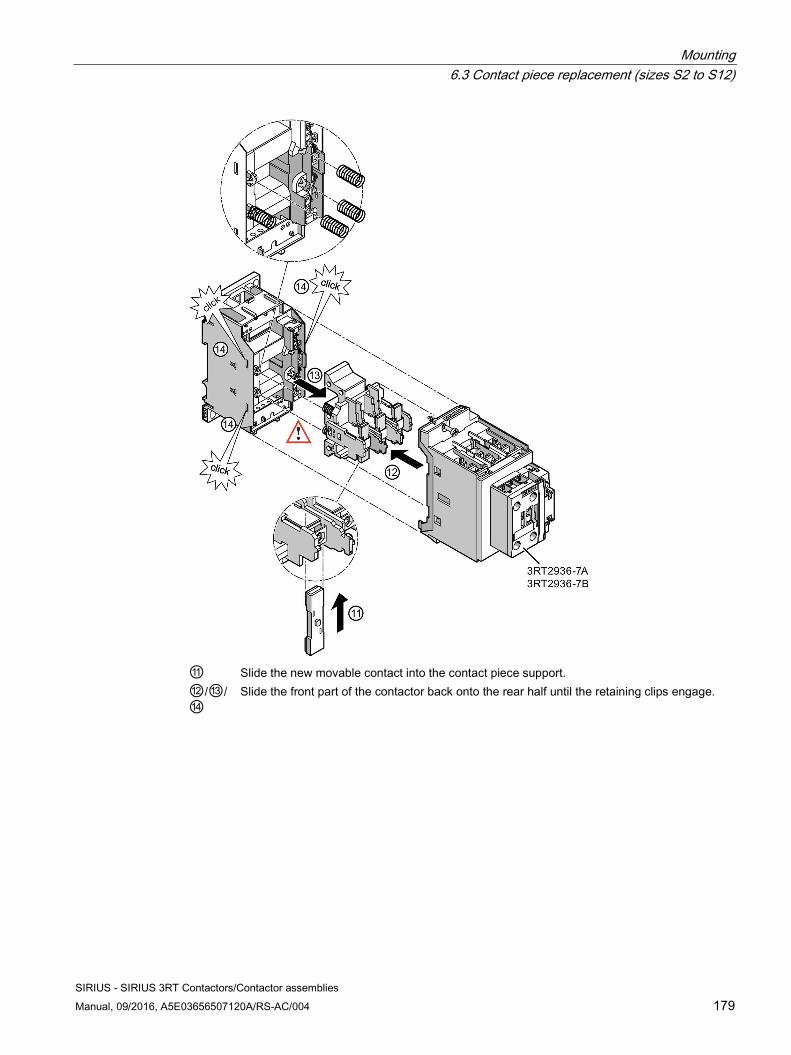
Mounting 6.3 Contact piece replacement (sizes S2 to S12)
SIRIUS - SIRIUS 3RT Contactors/Contactor assemblies Manual, 09/2016, A5E03656507120A/RS-AC/004 179
⑪ Slide the new movable contact into the contact piece support. ⑫/⑬/⑭
Slide the front part of the contactor back onto the rear half until the retaining clips engage.
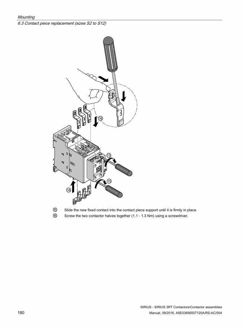
Mounting 6.3 Contact piece replacement (sizes S2 to S12)
SIRIUS - SIRIUS 3RT Contactors/Contactor assemblies 180 Manual, 09/2016, A5E03656507120A/RS-AC/004
⑮ Slide the new fixed contact into the contact piece support until it is firmly in place. ⑯ Screw the two contactor halves together (1.1 - 1.3 Nm) using a screwdriver.
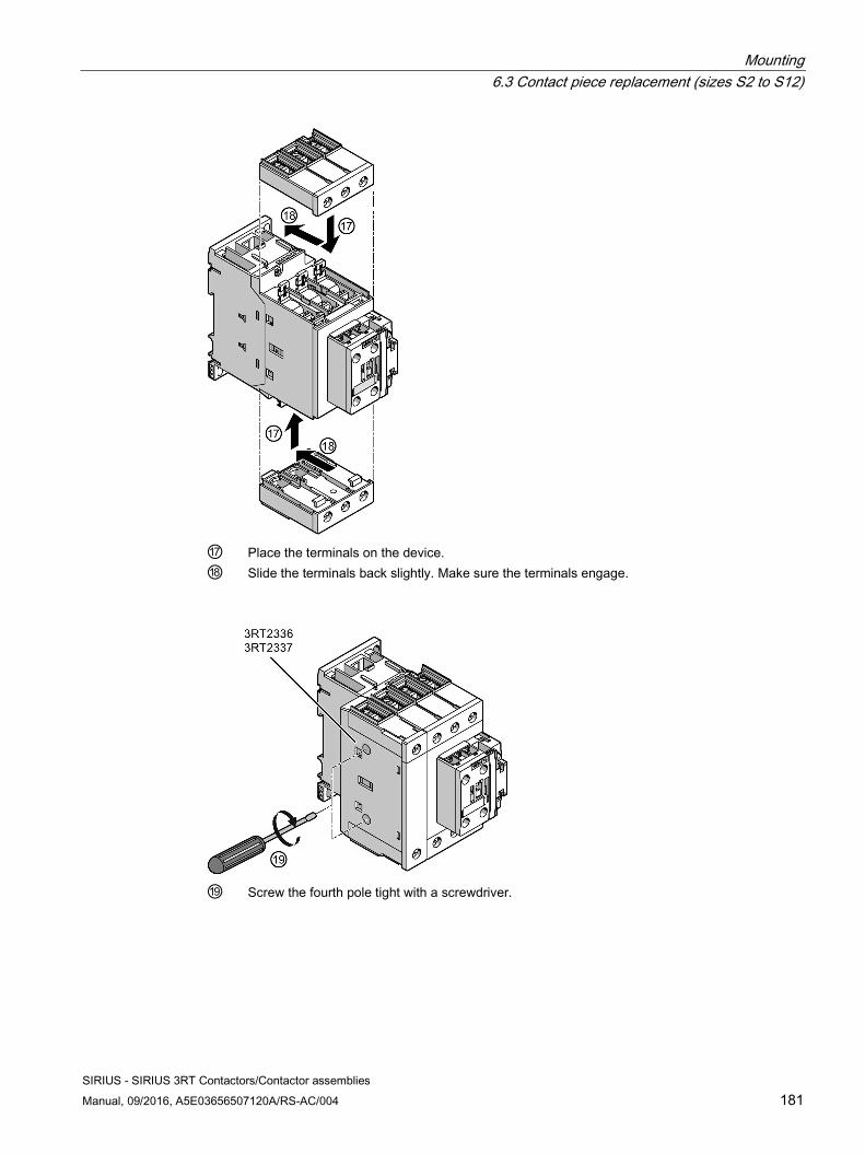
Mounting 6.3 Contact piece replacement (sizes S2 to S12)
SIRIUS - SIRIUS 3RT Contactors/Contactor assemblies Manual, 09/2016, A5E03656507120A/RS-AC/004 181
⑰ Place the terminals on the device. ⑱ Slide the terminals back slightly. Make sure the terminals engage.
⑲ Screw the fourth pole tight with a screwdriver.
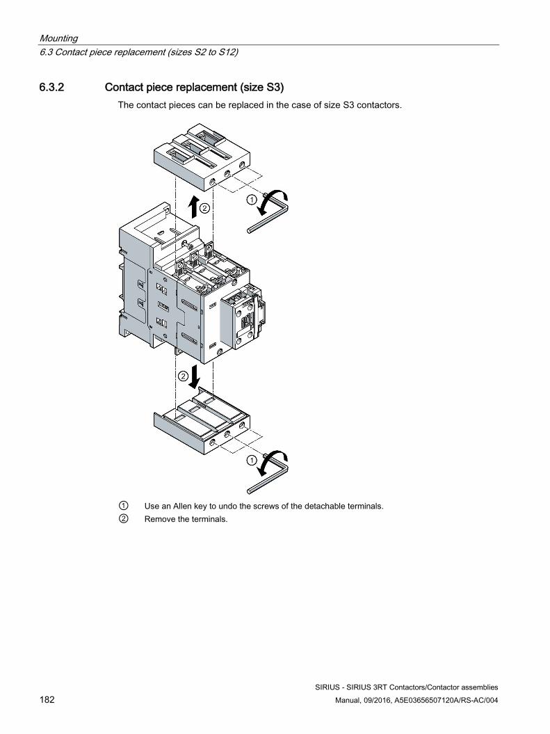
Mounting 6.3 Contact piece replacement (sizes S2 to S12)
SIRIUS - SIRIUS 3RT Contactors/Contactor assemblies 182 Manual, 09/2016, A5E03656507120A/RS-AC/004
6.3.2 Contact piece replacement (size S3) The contact pieces can be replaced in the case of size S3 contactors.
① Use an Allen key to undo the screws of the detachable terminals. ② Remove the terminals.
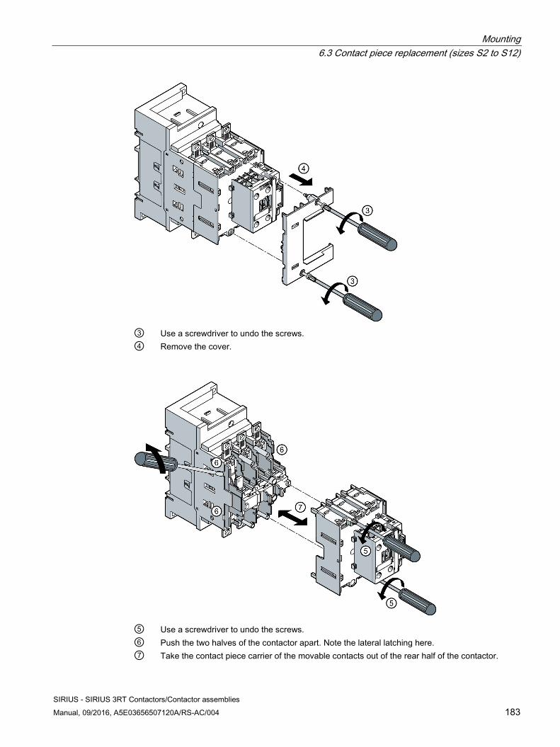
Mounting 6.3 Contact piece replacement (sizes S2 to S12)
SIRIUS - SIRIUS 3RT Contactors/Contactor assemblies Manual, 09/2016, A5E03656507120A/RS-AC/004 183
③ Use a screwdriver to undo the screws. ④ Remove the cover.
⑤ Use a screwdriver to undo the screws. ⑥ Push the two halves of the contactor apart. Note the lateral latching here. ⑦ Take the contact piece carrier of the movable contacts out of the rear half of the contactor.
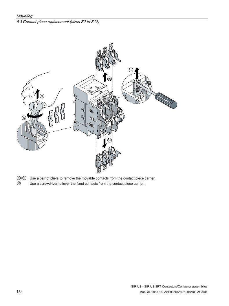
Mounting 6.3 Contact piece replacement (sizes S2 to S12)
SIRIUS - SIRIUS 3RT Contactors/Contactor assemblies 184 Manual, 09/2016, A5E03656507120A/RS-AC/004
⑧/⑨ Use a pair of pliers to remove the movable contacts from the contact piece carrier. ⑩ Use a screwdriver to lever the fixed contacts from the contact piece carrier.
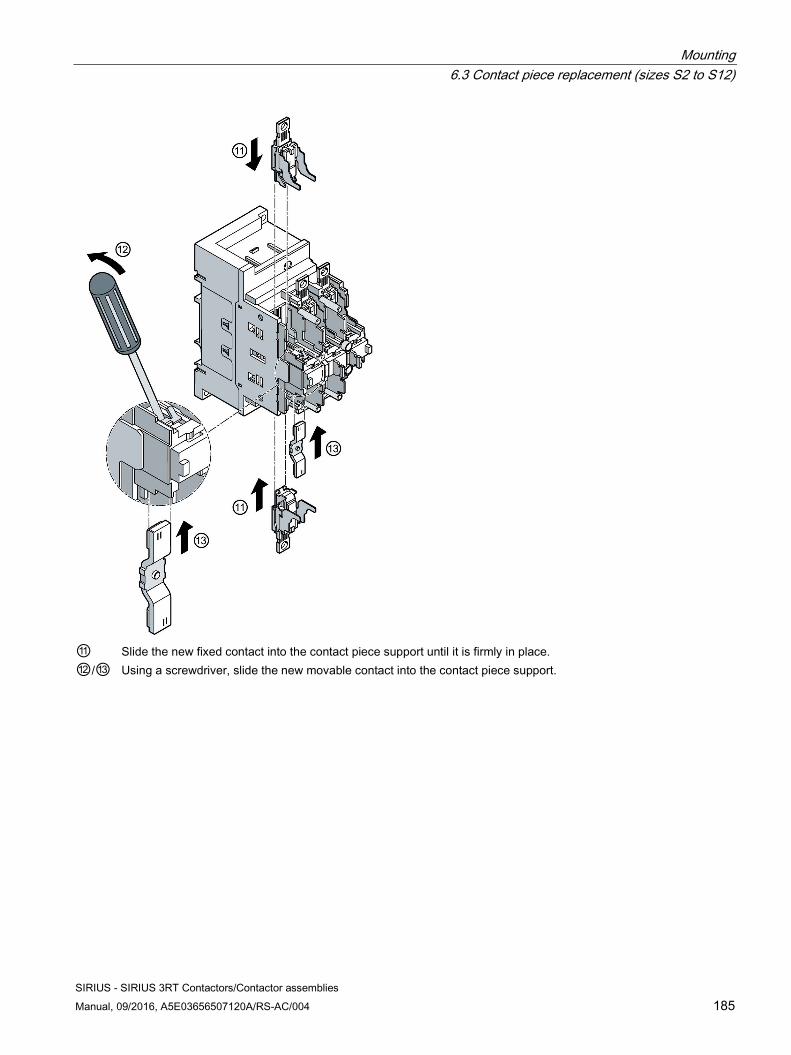
Mounting 6.3 Contact piece replacement (sizes S2 to S12)
SIRIUS - SIRIUS 3RT Contactors/Contactor assemblies Manual, 09/2016, A5E03656507120A/RS-AC/004 185
⑪ Slide the new fixed contact into the contact piece support until it is firmly in place. ⑫/⑬ Using a screwdriver, slide the new movable contact into the contact piece support.
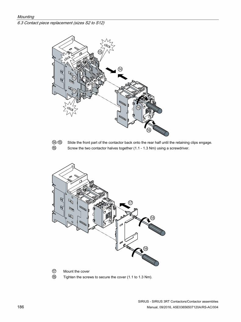
Mounting 6.3 Contact piece replacement (sizes S2 to S12)
SIRIUS - SIRIUS 3RT Contactors/Contactor assemblies 186 Manual, 09/2016, A5E03656507120A/RS-AC/004
⑭/⑮ Slide the front part of the contactor back onto the rear half until the retaining clips engage. ⑯ Screw the two contactor halves together (1.1 - 1.3 Nm) using a screwdriver.
⑰ Mount the cover ⑱ Tighten the screws to secure the cover (1.1 to 1.3 Nm).
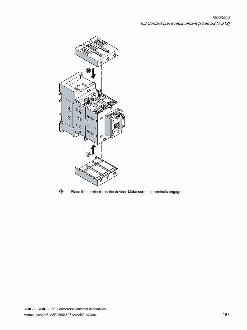
Mounting 6.3 Contact piece replacement (sizes S2 to S12)
SIRIUS - SIRIUS 3RT Contactors/Contactor assemblies Manual, 09/2016, A5E03656507120A/RS-AC/004 187
⑲ Place the terminals on the device. Make sure the terminals engage.
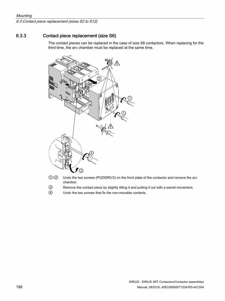
Mounting 6.3 Contact piece replacement (sizes S2 to S12)
SIRIUS - SIRIUS 3RT Contactors/Contactor assemblies 188 Manual, 09/2016, A5E03656507120A/RS-AC/004
6.3.3 Contact piece replacement (size S6) The contact pieces can be replaced in the case of size S6 contactors. When replacing for the third time, the arc chamber must be replaced at the same time.
①/② Undo the two screws (POZIDRIV2) on the front plate of the contactor and remove the arc
chamber. ③ Remove the contact piece by slightly tilting it and pulling it out with a swivel movement. ④ Undo the two screws that fix the non-movable contacts.
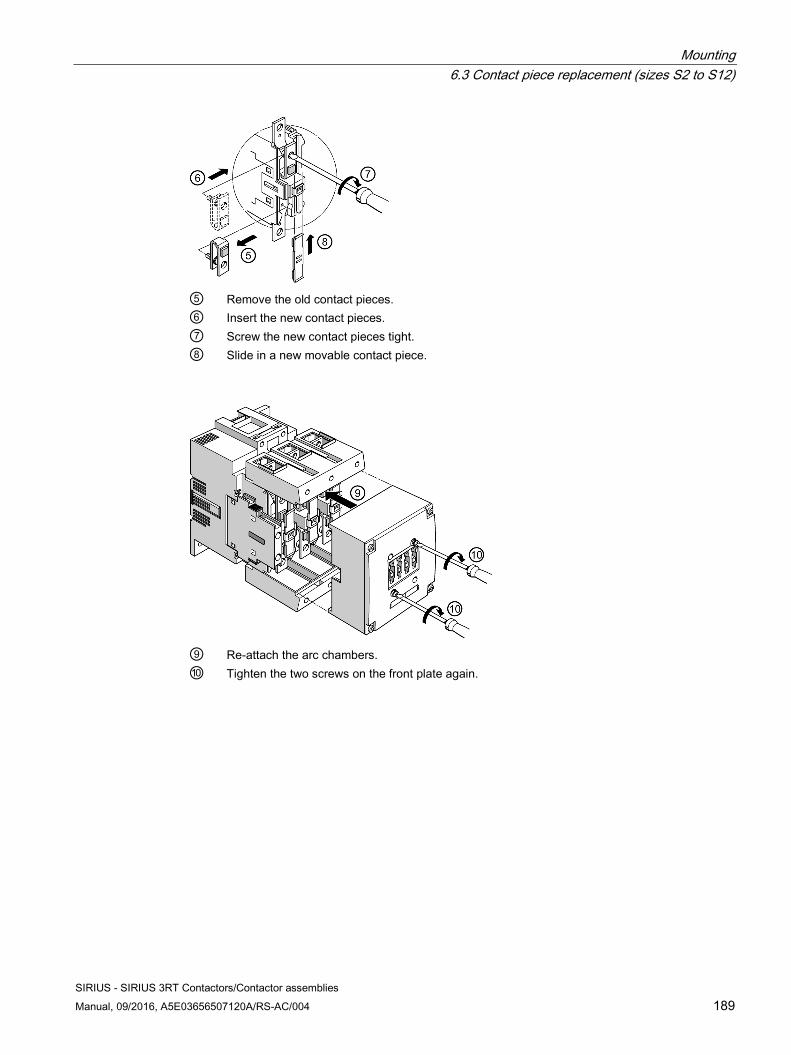
Mounting 6.3 Contact piece replacement (sizes S2 to S12)
SIRIUS - SIRIUS 3RT Contactors/Contactor assemblies Manual, 09/2016, A5E03656507120A/RS-AC/004 189
⑤ Remove the old contact pieces. ⑥ Insert the new contact pieces. ⑦ Screw the new contact pieces tight. ⑧ Slide in a new movable contact piece.
⑨ Re-attach the arc chambers. ⑩ Tighten the two screws on the front plate again.
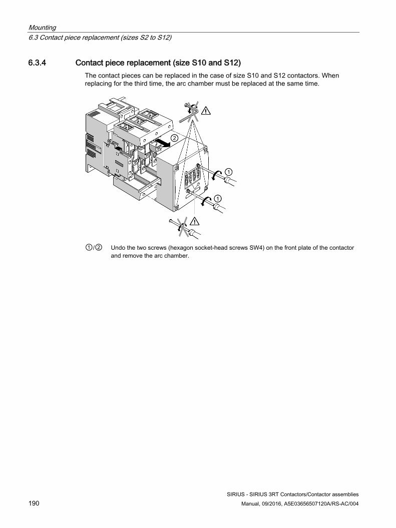
Mounting 6.3 Contact piece replacement (sizes S2 to S12)
SIRIUS - SIRIUS 3RT Contactors/Contactor assemblies 190 Manual, 09/2016, A5E03656507120A/RS-AC/004
6.3.4 Contact piece replacement (size S10 and S12) The contact pieces can be replaced in the case of size S10 and S12 contactors. When replacing for the third time, the arc chamber must be replaced at the same time.
①/② Undo the two screws (hexagon socket-head screws SW4) on the front plate of the contactor
and remove the arc chamber.
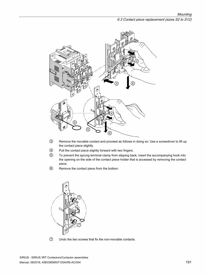
Mounting 6.3 Contact piece replacement (sizes S2 to S12)
SIRIUS - SIRIUS 3RT Contactors/Contactor assemblies Manual, 09/2016, A5E03656507120A/RS-AC/004 191
③ Remove the movable contact and proceed as follows in doing so: Use a screwdriver to lift up
the contact piece slightly. ④ Pull the contact piece slightly forward with two fingers. ⑤ To prevent the sprung terminal clamp from slipping back, insert the accompanying hook into
the opening on the side of the contact piece holder that is accessed by removing the contact piece.
⑥ Remove the contact piece from the bottom.
⑦ Undo the two screws that fix the non-movable contacts.
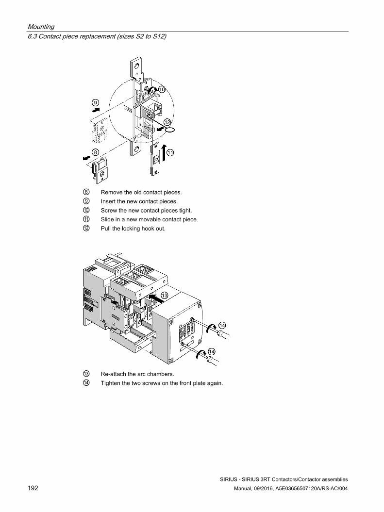
Mounting 6.3 Contact piece replacement (sizes S2 to S12)
SIRIUS - SIRIUS 3RT Contactors/Contactor assemblies 192 Manual, 09/2016, A5E03656507120A/RS-AC/004
⑧ Remove the old contact pieces. ⑨ Insert the new contact pieces. ⑩ Screw the new contact pieces tight. ⑪ Slide in a new movable contact piece. ⑫ Pull the locking hook out.
⑬ Re-attach the arc chambers. ⑭ Tighten the two screws on the front plate again.
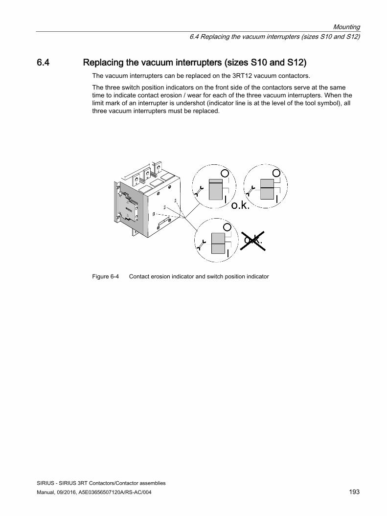
Mounting 6.4 Replacing the vacuum interrupters (sizes S10 and S12)
SIRIUS - SIRIUS 3RT Contactors/Contactor assemblies Manual, 09/2016, A5E03656507120A/RS-AC/004 193
6.4 Replacing the vacuum interrupters (sizes S10 and S12) The vacuum interrupters can be replaced on the 3RT12 vacuum contactors.
The three switch position indicators on the front side of the contactors serve at the same time to indicate contact erosion / wear for each of the three vacuum interrupters. When the limit mark of an interrupter is undershot (indicator line is at the level of the tool symbol), all three vacuum interrupters must be replaced.
Figure 6-4 Contact erosion indicator and switch position indicator
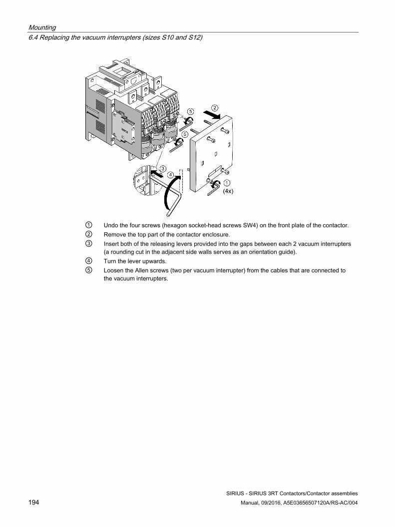
Mounting 6.4 Replacing the vacuum interrupters (sizes S10 and S12)
SIRIUS - SIRIUS 3RT Contactors/Contactor assemblies 194 Manual, 09/2016, A5E03656507120A/RS-AC/004
① Undo the four screws (hexagon socket-head screws SW4) on the front plate of the contactor. ② Remove the top part of the contactor enclosure. ③ Insert both of the releasing levers provided into the gaps between each 2 vacuum interrupters
(a rounding cut in the adjacent side walls serves as an orientation guide). ④ Turn the lever upwards. ⑤ Loosen the Allen screws (two per vacuum interrupter) from the cables that are connected to
the vacuum interrupters.
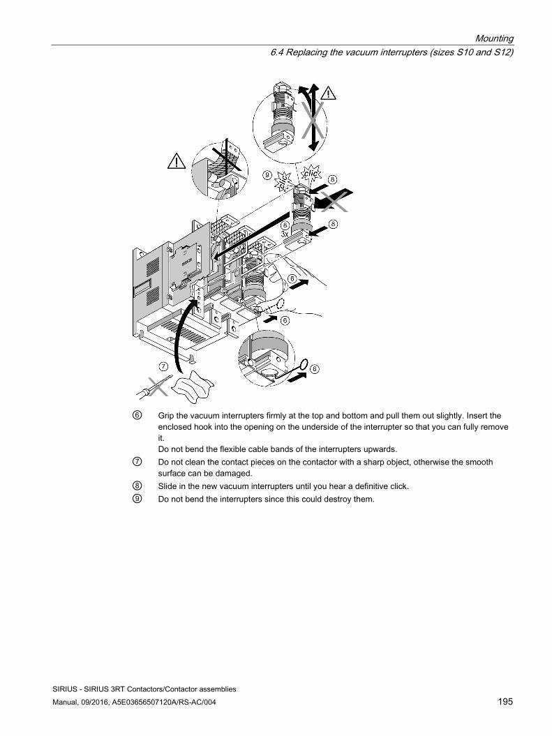
Mounting 6.4 Replacing the vacuum interrupters (sizes S10 and S12)
SIRIUS - SIRIUS 3RT Contactors/Contactor assemblies Manual, 09/2016, A5E03656507120A/RS-AC/004 195
⑥ Grip the vacuum interrupters firmly at the top and bottom and pull them out slightly. Insert the
enclosed hook into the opening on the underside of the interrupter so that you can fully remove it. Do not bend the flexible cable bands of the interrupters upwards.
⑦ Do not clean the contact pieces on the contactor with a sharp object, otherwise the smooth surface can be damaged.
⑧ Slide in the new vacuum interrupters until you hear a definitive click. ⑨ Do not bend the interrupters since this could destroy them.
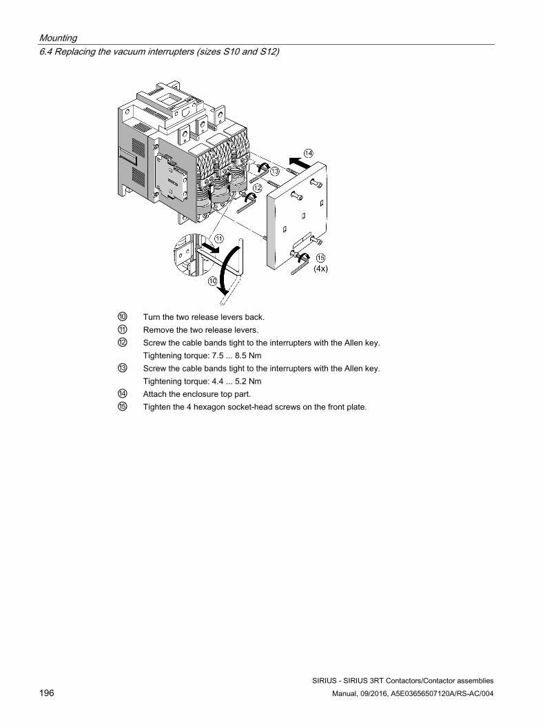
Mounting 6.4 Replacing the vacuum interrupters (sizes S10 and S12)
SIRIUS - SIRIUS 3RT Contactors/Contactor assemblies 196 Manual, 09/2016, A5E03656507120A/RS-AC/004
⑩ Turn the two release levers back. ⑪ Remove the two release levers. ⑫ Screw the cable bands tight to the interrupters with the Allen key.
Tightening torque: 7.5 ... 8.5 Nm ⑬ Screw the cable bands tight to the interrupters with the Allen key.
Tightening torque: 4.4 ... 5.2 Nm ⑭ Attach the enclosure top part. ⑮ Tighten the 4 hexagon socket-head screws on the front plate.
SIRIUS - SIRIUS 3RT Contactors/Contactor assemblies Manual, 09/2016, A5E03656507120A/RS-AC/004 197
Connection 7
Connection systems The SIRIUS contactors are available with the following connection types:
● Screw-type connection system
● Spring-loaded connection system
In size S2 to S12, the spring-loaded connection system is used only in the control circuit.
● Ring cable lug connection system
The ring cable lug connection system is not used in sizes S2 to S12.
● Solder pin connection (only possible for size S00, in conjunction with a solder pin adapter)
Terminal designations Terminal Designation A1 Coil terminal + A2 Coil terminal - L1, L2, L3 Contactor's main circuit terminal to the power network T1, T2, T3 Contactor's main circuit terminal to the load/motor connection 13, 14 Auxiliary contact, closing 21, 22 Auxiliary contact, opening
The auxiliary/control contacts have a two-digit designation:
● First digit: Consecutive number of the auxiliary contacts (sequence number).
● Second digit: Task of the respective auxiliary contact (function number). E. g. 1-2 for NC contacts or 3-4 for NO contacts
Terminal designations of the auxiliary contacts The terminal designations as per EN 50012 apply to size S00 contactors with an integrated auxiliary (NO) contact. Auxiliary contacts are fitted and arranged on size S0 contactors (integrated in the basic device) in accordance with the terminal designations contained in DIN EN 50012.
Additionally, for sizes S00 and S0, complete devices with permanently mounted auxiliary switch blocks (2 NO contacts + 2 NC contacts in accordance with DIN EN 50012) are available.
Connection
SIRIUS - SIRIUS 3RT Contactors/Contactor assemblies 198 Manual, 09/2016, A5E03656507120A/RS-AC/004
Coil terminals Size S00 to S3 contactors feature a coil terminal on the front. An adapter (3RT2926-4R./. coil terminal module) can be used to move the coil terminal up or down on size S0 / S2 / S3 contactors (compatible with 3RT102 / 3RT103).
Reference More information ... Can be found in the chapter ... About the coil terminal module and how to mount it on a 3RT20 contactor (size S0)
Coil terminal module (Page 310)
Screw connection The devices with screw connections have the following features:
● All connections are equipped with captive screws
● All connection points are supplied open
● Screwdriver guides enable the use of machine screwdrivers
● On size S00, all connecting screws for main and auxiliary circuits have a uniform screw size (POZIDRIV cross-tip screw size 2) and thus require the same tightening torque.
● On all sizes (S00 to S12), the connecting screws for the auxiliary conductor connections are identical (POZIDRIV size 2, no bit replacement, uniform tightening torque)
Spring-loaded connection Devices with spring-loaded connection system have the following properties:
● The contactors are recommended when powerful shaking or vibration is to be expected at the location of use.
● The terminals are suitable for 2-conductor connection.
● All connections can be accessed from the front and are clearly arranged.
● A maximum of 2 conductors with a cross-section of 0.25 mm2 to max. 2.5 mm2 can be used at each connection point.
Connection
SIRIUS - SIRIUS 3RT Contactors/Contactor assemblies Manual, 09/2016, A5E03656507120A/RS-AC/004 199
Solder pin connection For applications where the contactors are to be soldered onto a PCB directly, a solder pin adapter is available for SIRIUS size S00 contactors up to 5.5 kW or 12 A.
Devices with a solder pin connection have the following properties:
● The terminals are suitable for a 1-conductor connection.
● All connections can be accessed from the front and are clearly arranged.
● A maximum of 2 conductors with a cross-section of 0.25 mm2 to max. 2.5 mm2 can be used at each connection point.
Reference More information ... Can be found in the chapter ... About the solder pin adapter and how to mount it on a motor/contactor relay (size S00)
Solder pin adapter (Page 307)
2-conductor connection 2 conductor ends can be connected to every main, auxiliary, and control circuit connection. These connections are also suitable for untreated conductors, which may have varying cross-sections. This connection system offers numerous benefits, including laying the foundations for problem-free looping through and parallel connection without intermediate terminals.
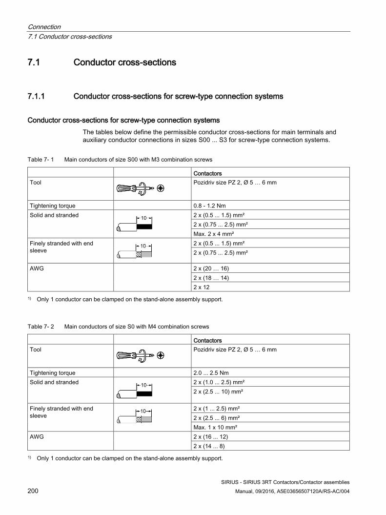
Connection 7.1 Conductor cross-sections
SIRIUS - SIRIUS 3RT Contactors/Contactor assemblies 200 Manual, 09/2016, A5E03656507120A/RS-AC/004
7.1 Conductor cross-sections
7.1.1 Conductor cross-sections for screw-type connection systems
Conductor cross-sections for screw-type connection systems The tables below define the permissible conductor cross-sections for main terminals and auxiliary conductor connections in sizes S00 ... S3 for screw-type connection systems.
Table 7- 1 Main conductors of size S00 with M3 combination screws
Contactors Tool
Pozidriv size PZ 2, Ø 5 … 6 mm
Tightening torque 0.8 - 1.2 Nm Solid and stranded
2 x (0.5 ... 1.5) mm² 2 x (0.75 ... 2.5) mm² Max. 2 x 4 mm²
Finely stranded with end sleeve
2 x (0.5 ... 1.5) mm² 2 x (0.75 ... 2.5) mm²
AWG 2 x (20 … 16) 2 x (18 … 14) 2 x 12
1) Only 1 conductor can be clamped on the stand-alone assembly support.
Table 7- 2 Main conductors of size S0 with M4 combination screws
Contactors Tool
Pozidriv size PZ 2, Ø 5 … 6 mm
Tightening torque 2.0 ... 2.5 Nm Solid and stranded
2 x (1.0 ... 2.5) mm² 2 x (2.5 ... 10) mm²
Finely stranded with end sleeve
2 x (1 ... 2.5) mm² 2 x (2.5 ... 6) mm² Max. 1 x 10 mm²
AWG 2 x (16 ... 12) 2 x (14 ... 8)
1) Only 1 conductor can be clamped on the stand-alone assembly support.
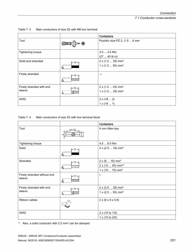
Connection 7.1 Conductor cross-sections
SIRIUS - SIRIUS 3RT Contactors/Contactor assemblies Manual, 09/2016, A5E03656507120A/RS-AC/004 201
Table 7- 3 Main conductors of size S2 with M6 box terminal
Contactors Tool
Pozidriv size PZ 2, ∅ 5 ... 6 mm
Tightening torque 3.0 ... 4.5 Nm (27 ... 40 lb in)
Solid and stranded
2 x (1.0 ... 35) mm2 1 x (1.0 ... 50) mm2
Finely stranded
---
Finely stranded with end sleeve
2 x (1.0 ... 25) mm2 1 x (1.0 ... 35) mm2
AWG 2 x (18 ... 2) 1 x (18 ... 1)
Table 7- 4 Main conductors of size S3 with box terminal block
Contactors Tool
4 mm Allen key
Tightening torque 4.5 ... 6.0 Nm Solid
2 x (2.5 ... 16) mm²
Stranded
2 x (6 ... 16) mm² 2 x (10 ... 50) mm²1) 1 x (10 ... 70) mm²
Finely stranded without end sleeve
–
Finely stranded with end sleeve
2 x (2.5 ... 35) mm² 1 x (2.5 ... 50) mm²
Ribbon cables
2 x (6 x 9 x 0.8)
AWG 2 x (10 to 1/0) 1 x (10 to 2/0)
1) Also, a solid conductor with 2.5 mm2 can be clamped
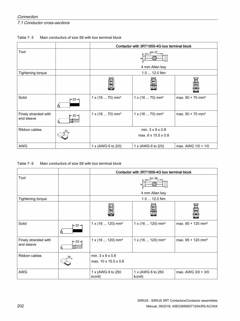
Connection 7.1 Conductor cross-sections
SIRIUS - SIRIUS 3RT Contactors/Contactor assemblies 202 Manual, 09/2016, A5E03656507120A/RS-AC/004
Table 7- 5 Main conductors of size S6 with box terminal block
Contactor with 3RT1955-4G box terminal block Tool
4 mm Allen key
Tightening torque 1.0 ... 12.0 Nm
Solid
1 x (16 ... 70) mm² 1 x (16 ... 70) mm² max. 50 + 70 mm²
Finely stranded with end sleeve
1 x (16 ... 70) mm² 1 x (16 ... 70) mm² max. 50 + 70 mm²
Ribbon cables
min. 3 x 9 x 0.8 max. 6 x 15.5 x 0.8
AWG 1 x (AWG 6 to 2/0) 1 x (AWG 6 to 2/0) max. AWG 1/0 + 1/0
Table 7- 6 Main conductors of size S6 with box terminal block
Contactor with 3RT1956-4G box terminal block Tool
4 mm Allen key
Tightening torque 1.0 ... 12.0 Nm
Solid
1 x (16 ... 120) mm² 1 x (16 ... 120) mm² max. 95 + 120 mm²
Finely stranded with end sleeve
1 x (16 ... 120) mm² 1 x (16 ... 120) mm² max. 95 + 120 mm²
Ribbon cables
min. 3 x 9 x 0.8 max. 10 x 15.5 x 0.8
AWG 1 x (AWG 6 to 250 kcmil)
1 x (AWG 6 to 250 kcmil)
max. AWG 3/0 + 3/0
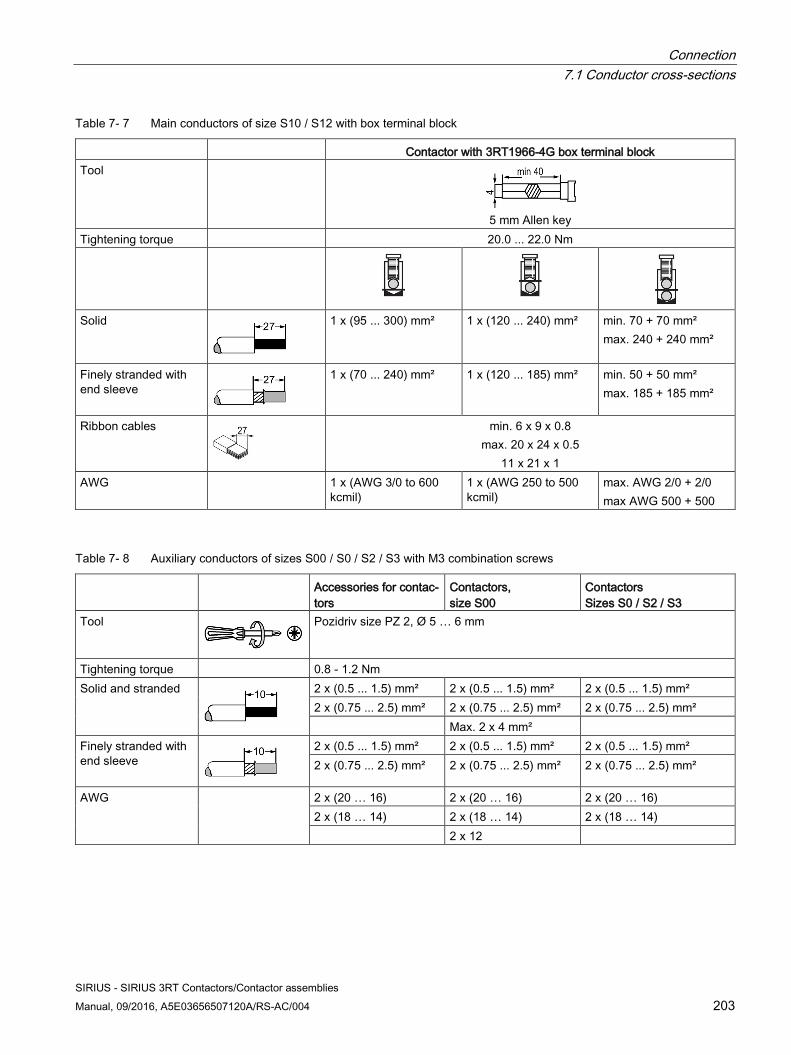
Connection 7.1 Conductor cross-sections
SIRIUS - SIRIUS 3RT Contactors/Contactor assemblies Manual, 09/2016, A5E03656507120A/RS-AC/004 203
Table 7- 7 Main conductors of size S10 / S12 with box terminal block
Contactor with 3RT1966-4G box terminal block Tool
5 mm Allen key
Tightening torque 20.0 ... 22.0 Nm
Solid
1 x (95 ... 300) mm² 1 x (120 ... 240) mm² min. 70 + 70 mm² max. 240 + 240 mm²
Finely stranded with end sleeve
1 x (70 ... 240) mm² 1 x (120 ... 185) mm² min. 50 + 50 mm² max. 185 + 185 mm²
Ribbon cables
min. 6 x 9 x 0.8 max. 20 x 24 x 0.5
11 x 21 x 1 AWG 1 x (AWG 3/0 to 600
kcmil) 1 x (AWG 250 to 500 kcmil)
max. AWG 2/0 + 2/0 max AWG 500 + 500
Table 7- 8 Auxiliary conductors of sizes S00 / S0 / S2 / S3 with M3 combination screws
Accessories for contac-tors
Contactors, size S00
Contactors Sizes S0 / S2 / S3
Tool
Pozidriv size PZ 2, Ø 5 … 6 mm
Tightening torque 0.8 - 1.2 Nm Solid and stranded
2 x (0.5 ... 1.5) mm² 2 x (0.5 ... 1.5) mm² 2 x (0.5 ... 1.5) mm² 2 x (0.75 ... 2.5) mm² 2 x (0.75 ... 2.5) mm² 2 x (0.75 ... 2.5) mm² Max. 2 x 4 mm²
Finely stranded with end sleeve
2 x (0.5 ... 1.5) mm² 2 x (0.5 ... 1.5) mm² 2 x (0.5 ... 1.5) mm² 2 x (0.75 ... 2.5) mm² 2 x (0.75 ... 2.5) mm² 2 x (0.75 ... 2.5) mm²
AWG 2 x (20 … 16) 2 x (20 … 16) 2 x (20 … 16) 2 x (18 … 14) 2 x (18 … 14) 2 x (18 … 14) 2 x 12
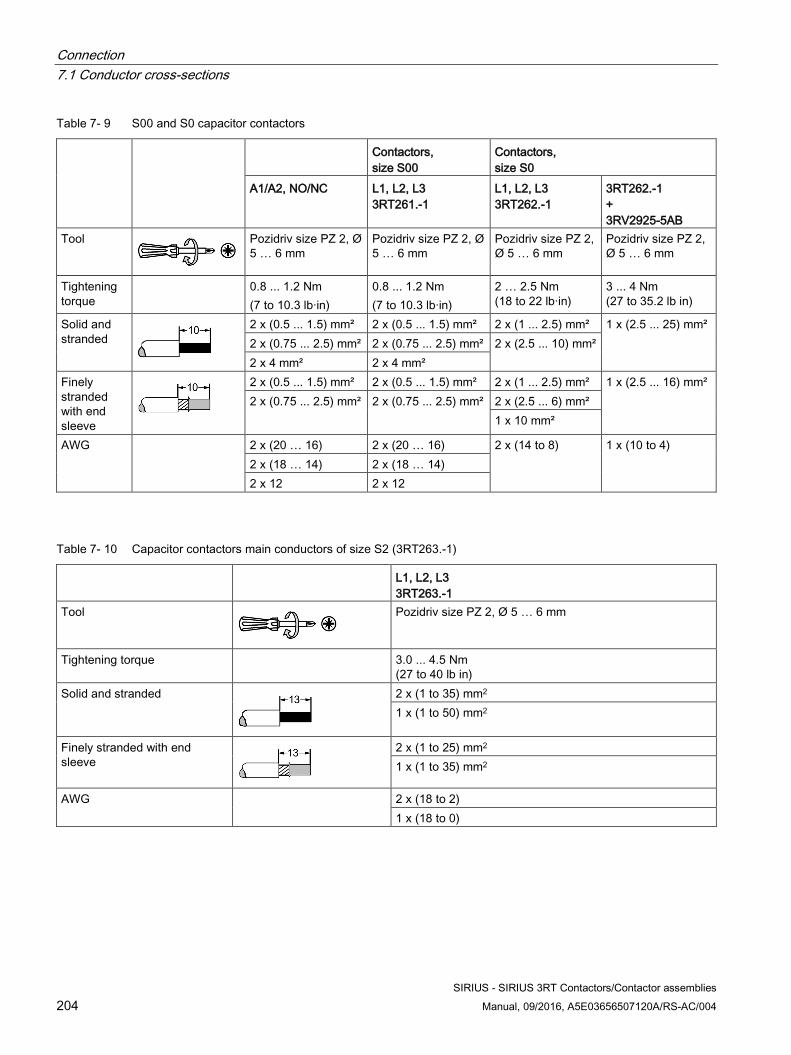
Connection 7.1 Conductor cross-sections
SIRIUS - SIRIUS 3RT Contactors/Contactor assemblies 204 Manual, 09/2016, A5E03656507120A/RS-AC/004
Table 7- 9 S00 and S0 capacitor contactors
Contactors, size S00
Contactors, size S0
A1/A2, NO/NC L1, L2, L3 3RT261.-1
L1, L2, L3 3RT262.-1
3RT262.-1 + 3RV2925-5AB
Tool
Pozidriv size PZ 2, Ø 5 … 6 mm
Pozidriv size PZ 2, Ø 5 … 6 mm
Pozidriv size PZ 2, Ø 5 … 6 mm
Pozidriv size PZ 2, Ø 5 … 6 mm
Tightening torque
0.8 ... 1.2 Nm (7 to 10.3 lb·in)
0.8 ... 1.2 Nm (7 to 10.3 lb·in)
2 … 2.5 Nm (18 to 22 lb·in)
3 ... 4 Nm (27 to 35.2 lb in)
Solid and stranded
2 x (0.5 ... 1.5) mm² 2 x (0.5 ... 1.5) mm² 2 x (1 ... 2.5) mm² 1 x (2.5 ... 25) mm² 2 x (0.75 ... 2.5) mm² 2 x (0.75 ... 2.5) mm² 2 x (2.5 ... 10) mm²
2 x 4 mm² 2 x 4 mm² Finely stranded with end sleeve
2 x (0.5 ... 1.5) mm² 2 x (0.5 ... 1.5) mm² 2 x (1 ... 2.5) mm² 1 x (2.5 ... 16) mm² 2 x (0.75 ... 2.5) mm² 2 x (0.75 ... 2.5) mm² 2 x (2.5 ... 6) mm²
1 x 10 mm²
AWG 2 x (20 … 16) 2 x (20 … 16) 2 x (14 to 8) 1 x (10 to 4) 2 x (18 … 14) 2 x (18 … 14) 2 x 12 2 x 12
Table 7- 10 Capacitor contactors main conductors of size S2 (3RT263.-1)
L1, L2, L3 3RT263.-1
Tool
Pozidriv size PZ 2, Ø 5 … 6 mm
Tightening torque 3.0 ... 4.5 Nm (27 to 40 lb in)
Solid and stranded
2 x (1 to 35) mm2 1 x (1 to 50) mm2
Finely stranded with end sleeve
2 x (1 to 25) mm2 1 x (1 to 35) mm2
AWG 2 x (18 to 2) 1 x (18 to 0)
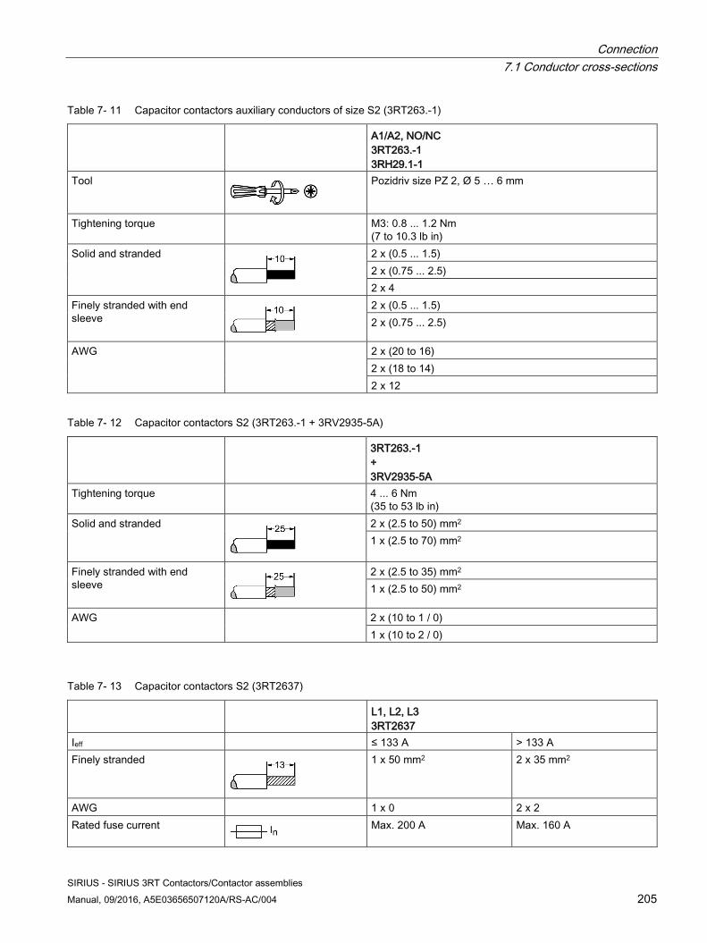
Connection 7.1 Conductor cross-sections
SIRIUS - SIRIUS 3RT Contactors/Contactor assemblies Manual, 09/2016, A5E03656507120A/RS-AC/004 205
Table 7- 11 Capacitor contactors auxiliary conductors of size S2 (3RT263.-1)
A1/A2, NO/NC 3RT263.-1 3RH29.1-1
Tool
Pozidriv size PZ 2, Ø 5 … 6 mm
Tightening torque M3: 0.8 ... 1.2 Nm (7 to 10.3 lb in)
Solid and stranded
2 x (0.5 ... 1.5) 2 x (0.75 ... 2.5) 2 x 4
Finely stranded with end sleeve
2 x (0.5 ... 1.5) 2 x (0.75 ... 2.5)
AWG 2 x (20 to 16) 2 x (18 to 14) 2 x 12
Table 7- 12 Capacitor contactors S2 (3RT263.-1 + 3RV2935-5A)
3RT263.-1 + 3RV2935-5A
Tightening torque 4 ... 6 Nm (35 to 53 lb in)
Solid and stranded
2 x (2.5 to 50) mm2 1 x (2.5 to 70) mm2
Finely stranded with end sleeve
2 x (2.5 to 35) mm2 1 x (2.5 to 50) mm2
AWG 2 x (10 to 1 / 0) 1 x (10 to 2 / 0)
Table 7- 13 Capacitor contactors S2 (3RT2637)
L1, L2, L3 3RT2637
Ieff ≤ 133 A > 133 A Finely stranded
1 x 50 mm2 2 x 35 mm2
AWG 1 x 0 2 x 2 Rated fuse current
Max. 200 A Max. 160 A
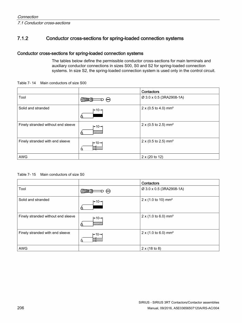
Connection 7.1 Conductor cross-sections
SIRIUS - SIRIUS 3RT Contactors/Contactor assemblies 206 Manual, 09/2016, A5E03656507120A/RS-AC/004
7.1.2 Conductor cross-sections for spring-loaded connection systems
Conductor cross-sections for spring-loaded connection systems The tables below define the permissible conductor cross-sections for main terminals and auxiliary conductor connections in sizes S00, S0 and S2 for spring-loaded connection systems. In size S2, the spring-loaded connection system is used only in the control circuit.
Table 7- 14 Main conductors of size S00
Contactors Tool
Ø 3.0 x 0.5 (3RA2908-1A)
Solid and stranded
2 x (0.5 to 4.0) mm²
Finely stranded without end sleeve
2 x (0.5 to 2.5) mm²
Finely stranded with end sleeve
2 x (0.5 to 2.5) mm²
AWG 2 x (20 to 12)
Table 7- 15 Main conductors of size S0
Contactors Tool
Ø 3.0 x 0.5 (3RA2908-1A)
Solid and stranded
2 x (1.0 to 10) mm²
Finely stranded without end sleeve
2 x (1.0 to 6.0) mm²
Finely stranded with end sleeve
2 x (1.0 to 6.0) mm²
AWG 2 x (18 to 8)
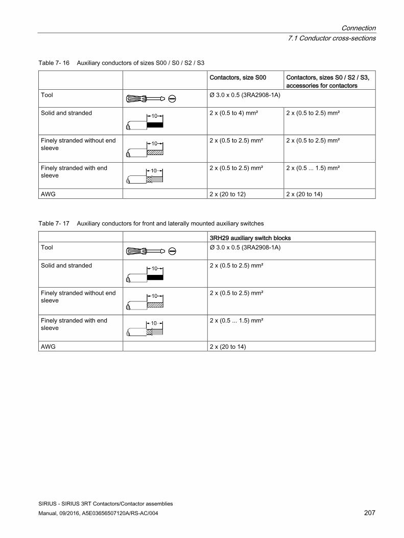
Connection 7.1 Conductor cross-sections
SIRIUS - SIRIUS 3RT Contactors/Contactor assemblies Manual, 09/2016, A5E03656507120A/RS-AC/004 207
Table 7- 16 Auxiliary conductors of sizes S00 / S0 / S2 / S3
Contactors, size S00 Contactors, sizes S0 / S2 / S3, accessories for contactors
Tool
Ø 3.0 x 0.5 (3RA2908-1A)
Solid and stranded
2 x (0.5 to 4) mm² 2 x (0.5 to 2.5) mm²
Finely stranded without end sleeve
2 x (0.5 to 2.5) mm² 2 x (0.5 to 2.5) mm²
Finely stranded with end sleeve
2 x (0.5 to 2.5) mm² 2 x (0.5 ... 1.5) mm²
AWG 2 x (20 to 12) 2 x (20 to 14)
Table 7- 17 Auxiliary conductors for front and laterally mounted auxiliary switches
3RH29 auxiliary switch blocks Tool
Ø 3.0 x 0.5 (3RA2908-1A)
Solid and stranded
2 x (0.5 to 2.5) mm²
Finely stranded without end sleeve
2 x (0.5 to 2.5) mm²
Finely stranded with end sleeve
2 x (0.5 ... 1.5) mm²
AWG 2 x (20 to 14)
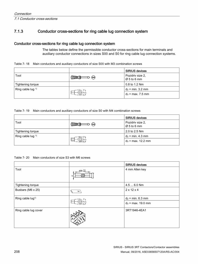
Connection 7.1 Conductor cross-sections
SIRIUS - SIRIUS 3RT Contactors/Contactor assemblies 208 Manual, 09/2016, A5E03656507120A/RS-AC/004
7.1.3 Conductor cross-sections for ring cable lug connection system
Conductor cross-sections for ring cable lug connection system The tables below define the permissible conductor cross-sections for main terminals and auxiliary conductor connections in sizes S00 and S0 for ring cable lug connection systems.
Table 7- 18 Main conductors and auxiliary conductors of size S00 with M3 combination screws
SIRIUS devices Tool
Pozidriv size 2, Ø 5 to 6 mm
Tightening torque 0.8 to 1.2 Nm Ring cable lug 1)
d2 = min. 3.2 mm d3 = max. 7.5 mm
Table 7- 19 Main conductors and auxiliary conductors of size S0 with M4 combination screws
SIRIUS devices Tool
Pozidriv size 2, Ø 5 to 6 mm
Tightening torque 2.0 to 2.5 Nm Ring cable lug 1)
d2 = min. 4.3 mm d3 = max. 12.2 mm
Table 7- 20 Main conductors of size S3 with M6 screws
SIRIUS devices Tool
4 mm Allen key
Tightening torque 4.5 ... 6.0 Nm Busbars (M6 x 25)
2 x 12 x 4
Ring cable lug1)
d2 = min. 6.3 mm d3 = max. 19.0 mm
Ring cable lug cover
3RT1946-4EA1
Connection 7.1 Conductor cross-sections
SIRIUS - SIRIUS 3RT Contactors/Contactor assemblies Manual, 09/2016, A5E03656507120A/RS-AC/004 209
1) The following ring cable lugs are approved for achieving the required clearances and creepage distances:
● For applications according to IEC 60947-1:
– DIN 46237 (with insulating sleeve)
– JIS CS805 type RAV (with insulating sleeve)
– JIS CS805 type RAP (with insulating sleeve)
● For applications according to UL 508:
– DIN 46 234 (without insulating sleeve)
– DIN 46225 (without insulating sleeve)
– JIS CS805 (without insulating sleeve)
A shrink-on sleeve must be used to insulate ring cable lugs without an insulating sleeve. The following conditions must be met:
● Operating temperature: -55 °C to +155 °C
● UL 224 approved
● Flame-protected
DANGER
Hazardous voltage.
Will cause death or serious injury.
Only use approved ring cable lugs to meet the required clearances and creepage distances.
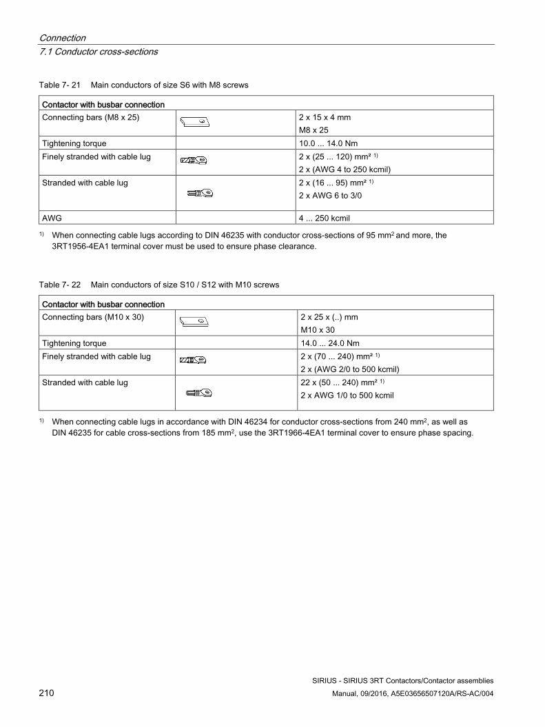
Connection 7.1 Conductor cross-sections
SIRIUS - SIRIUS 3RT Contactors/Contactor assemblies 210 Manual, 09/2016, A5E03656507120A/RS-AC/004
Table 7- 21 Main conductors of size S6 with M8 screws
Contactor with busbar connection Connecting bars (M8 x 25)
2 x 15 x 4 mm M8 x 25
Tightening torque 10.0 ... 14.0 Nm Finely stranded with cable lug 2 x (25 ... 120) mm² 1)
2 x (AWG 4 to 250 kcmil) Stranded with cable lug
2 x (16 ... 95) mm² 1) 2 x AWG 6 to 3/0
AWG 4 ... 250 kcmil 1) When connecting cable lugs according to DIN 46235 with conductor cross-sections of 95 mm2 and more, the
3RT1956-4EA1 terminal cover must be used to ensure phase clearance.
Table 7- 22 Main conductors of size S10 / S12 with M10 screws
Contactor with busbar connection Connecting bars (M10 x 30)
2 x 25 x (..) mm M10 x 30
Tightening torque 14.0 ... 24.0 Nm Finely stranded with cable lug 2 x (70 ... 240) mm² 1)
2 x (AWG 2/0 to 500 kcmil) Stranded with cable lug
22 x (50 ... 240) mm² 1) 2 x AWG 1/0 to 500 kcmil
1) When connecting cable lugs in accordance with DIN 46234 for conductor cross-sections from 240 mm2, as well as DIN 46235 for cable cross-sections from 185 mm2, use the 3RT1966-4EA1 terminal cover to ensure phase spacing.
SIRIUS - SIRIUS 3RT Contactors/Contactor assemblies Manual, 09/2016, A5E03656507120A/RS-AC/004 211
Accessories 8 8.1 Overview of accessories for 3RT2 contactors
8.1.1 Overview of accessories for 3RT2 contactors SIRIUS contactors with a width of 45 mm (size S00/S0), 55 mm (size S2), and 70 mm (size S3) come with a uniform, versatile range of auxiliary switches and accessories, which are quick to retrofit and replace. The accessories for contactor relays and power contactors are identical in design. The accessories can be attached on the front or the sides of devices.
The 3RH2 contactor relays can be expanded to give versions with a maximum of 8 poles by attaching 2-pole or 4-pole auxiliary switch blocks.
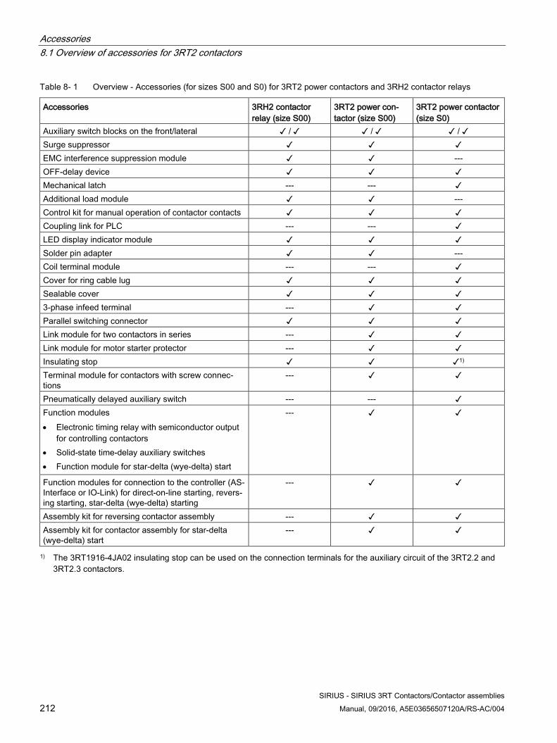
Accessories 8.1 Overview of accessories for 3RT2 contactors
SIRIUS - SIRIUS 3RT Contactors/Contactor assemblies 212 Manual, 09/2016, A5E03656507120A/RS-AC/004
Table 8- 1 Overview - Accessories (for sizes S00 and S0) for 3RT2 power contactors and 3RH2 contactor relays
Accessories 3RH2 contactor relay (size S00)
3RT2 power con-tactor (size S00)
3RT2 power contactor (size S0)
Auxiliary switch blocks on the front/lateral ✓ / ✓ ✓ / ✓ ✓ / ✓ Surge suppressor ✓ ✓ ✓ EMC interference suppression module ✓ ✓ --- OFF-delay device ✓ ✓ ✓ Mechanical latch --- --- ✓ Additional load module ✓ ✓ --- Control kit for manual operation of contactor contacts ✓ ✓ ✓ Coupling link for PLC --- --- ✓ LED display indicator module ✓ ✓ ✓ Solder pin adapter ✓ ✓ --- Coil terminal module --- --- ✓ Cover for ring cable lug ✓ ✓ ✓ Sealable cover ✓ ✓ ✓ 3-phase infeed terminal --- ✓ ✓ Parallel switching connector ✓ ✓ ✓ Link module for two contactors in series --- ✓ ✓ Link module for motor starter protector --- ✓ ✓ Insulating stop ✓ ✓ ✓1) Terminal module for contactors with screw connec-tions
--- ✓ ✓
Pneumatically delayed auxiliary switch --- --- ✓ Function modules • Electronic timing relay with semiconductor output
for controlling contactors • Solid-state time-delay auxiliary switches • Function module for star-delta (wye-delta) start
--- ✓ ✓
Function modules for connection to the controller (AS-Interface or IO-Link) for direct-on-line starting, revers-ing starting, star-delta (wye-delta) starting
--- ✓ ✓
Assembly kit for reversing contactor assembly --- ✓ ✓ Assembly kit for contactor assembly for star-delta (wye-delta) start
--- ✓ ✓
1) The 3RT1916-4JA02 insulating stop can be used on the connection terminals for the auxiliary circuit of the 3RT2.2 and 3RT2.3 contactors.
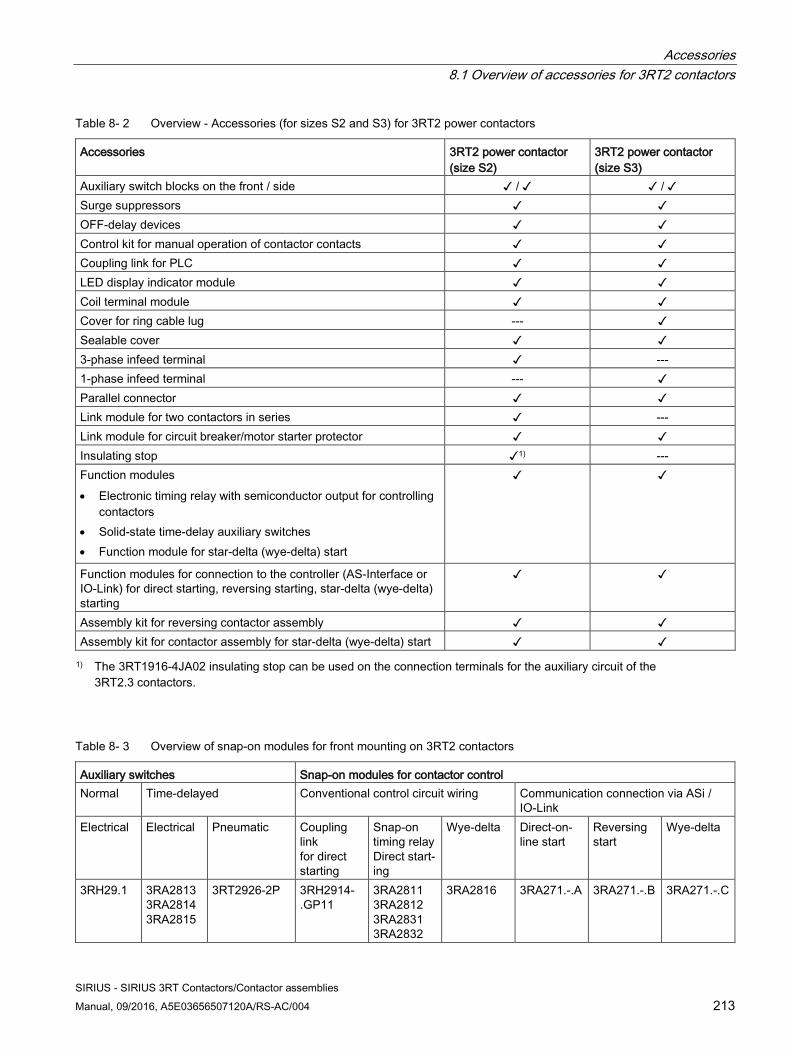
Accessories 8.1 Overview of accessories for 3RT2 contactors
SIRIUS - SIRIUS 3RT Contactors/Contactor assemblies Manual, 09/2016, A5E03656507120A/RS-AC/004 213
Table 8- 2 Overview - Accessories (for sizes S2 and S3) for 3RT2 power contactors
Accessories 3RT2 power contactor (size S2)
3RT2 power contactor (size S3)
Auxiliary switch blocks on the front / side ✓ / ✓ ✓ / ✓ Surge suppressors ✓ ✓ OFF-delay devices ✓ ✓ Control kit for manual operation of contactor contacts ✓ ✓ Coupling link for PLC ✓ ✓ LED display indicator module ✓ ✓ Coil terminal module ✓ ✓ Cover for ring cable lug --- ✓ Sealable cover ✓ ✓ 3-phase infeed terminal ✓ --- 1-phase infeed terminal --- ✓ Parallel connector ✓ ✓ Link module for two contactors in series ✓ --- Link module for circuit breaker/motor starter protector ✓ ✓ Insulating stop ✓1) --- Function modules • Electronic timing relay with semiconductor output for controlling
contactors • Solid-state time-delay auxiliary switches • Function module for star-delta (wye-delta) start
✓ ✓
Function modules for connection to the controller (AS-Interface or IO-Link) for direct starting, reversing starting, star-delta (wye-delta) starting
✓ ✓
Assembly kit for reversing contactor assembly ✓ ✓ Assembly kit for contactor assembly for star-delta (wye-delta) start ✓ ✓ 1) The 3RT1916-4JA02 insulating stop can be used on the connection terminals for the auxiliary circuit of the
3RT2.3 contactors.
Table 8- 3 Overview of snap-on modules for front mounting on 3RT2 contactors
Auxiliary switches Snap-on modules for contactor control Normal Time-delayed Conventional control circuit wiring Communication connection via ASi /
IO-Link Electrical Electrical Pneumatic Coupling
link for direct starting
Snap-on timing relay Direct start-ing
Wye-delta Direct-on-line start
Reversing start
Wye-delta
3RH29.1 3RA2813 3RA2814 3RA2815
3RT2926-2P 3RH2914-.GP11
3RA2811 3RA2812 3RA2831 3RA2832
3RA2816 3RA271.-.A 3RA271.-.B 3RA271.-.C
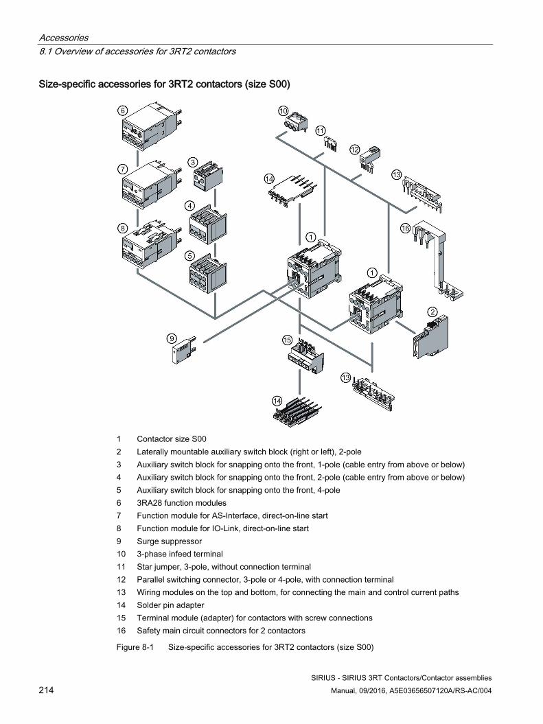
Accessories 8.1 Overview of accessories for 3RT2 contactors
SIRIUS - SIRIUS 3RT Contactors/Contactor assemblies 214 Manual, 09/2016, A5E03656507120A/RS-AC/004
Size-specific accessories for 3RT2 contactors (size S00)
1 Contactor size S00 2 Laterally mountable auxiliary switch block (right or left), 2-pole 3 Auxiliary switch block for snapping onto the front, 1-pole (cable entry from above or below) 4 Auxiliary switch block for snapping onto the front, 2-pole (cable entry from above or below) 5 Auxiliary switch block for snapping onto the front, 4-pole 6 3RA28 function modules 7 Function module for AS-Interface, direct-on-line start 8 Function module for IO-Link, direct-on-line start 9 Surge suppressor 10 3-phase infeed terminal 11 Star jumper, 3-pole, without connection terminal 12 Parallel switching connector, 3-pole or 4-pole, with connection terminal 13 Wiring modules on the top and bottom, for connecting the main and control current paths 14 Solder pin adapter 15 Terminal module (adapter) for contactors with screw connections 16 Safety main circuit connectors for 2 contactors
Figure 8-1 Size-specific accessories for 3RT2 contactors (size S00)
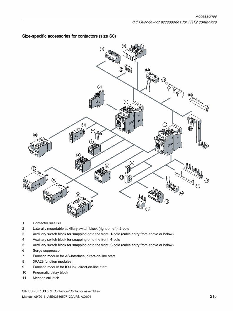
Accessories 8.1 Overview of accessories for 3RT2 contactors
SIRIUS - SIRIUS 3RT Contactors/Contactor assemblies Manual, 09/2016, A5E03656507120A/RS-AC/004 215
Size-specific accessories for contactors (size S0)
1 Contactor size S0 2 Laterally mountable auxiliary switch block (right or left), 2-pole 3 Auxiliary switch block for snapping onto the front, 1-pole (cable entry from above or below) 4 Auxiliary switch block for snapping onto the front, 4-pole 5 Auxiliary switch block for snapping onto the front, 2-pole (cable entry from above or below) 6 Surge suppressor 7 Function module for AS-Interface, direct-on-line start 8 3RA28 function modules 9 Function module for IO-Link, direct-on-line start 10 Pneumatic delay block 11 Mechanical latch
Accessories 8.1 Overview of accessories for 3RT2 contactors
SIRIUS - SIRIUS 3RT Contactors/Contactor assemblies 216 Manual, 09/2016, A5E03656507120A/RS-AC/004
12 Parallel switching connector 13 Terminal module (adapter) for contactors with screw connections 14 Coil terminal module, top and bottom 15 Wiring modules, top and bottom, for connecting the control current paths 16 Wiring modules, top and bottom, for connecting the main current paths 17 Star jumper, 3-pole, without connection terminal 18 3-phase infeed terminal 19 Link module for two contactors in series (safety main circuit connectors for two contactors) 20 Link module for motor starter protector 21 LED display indicator module 22 Control kit for manual operation of contactor contacts
Figure 8-2 Size-specific accessories for 3RT2 contactors (size S0)
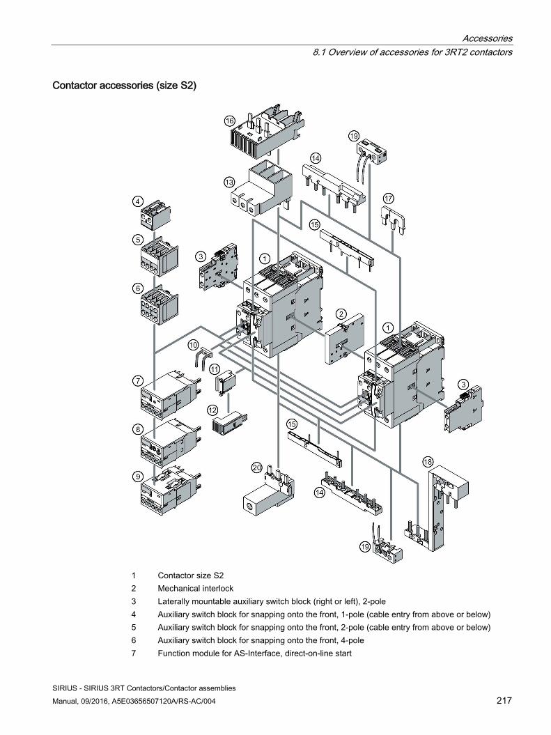
Accessories 8.1 Overview of accessories for 3RT2 contactors
SIRIUS - SIRIUS 3RT Contactors/Contactor assemblies Manual, 09/2016, A5E03656507120A/RS-AC/004 217
Contactor accessories (size S2)
1 Contactor size S2 2 Mechanical interlock 3 Laterally mountable auxiliary switch block (right or left), 2-pole 4 Auxiliary switch block for snapping onto the front, 1-pole (cable entry from above or below) 5 Auxiliary switch block for snapping onto the front, 2-pole (cable entry from above or below) 6 Auxiliary switch block for snapping onto the front, 4-pole 7 Function module for AS-Interface, direct-on-line start
Accessories 8.1 Overview of accessories for 3RT2 contactors
SIRIUS - SIRIUS 3RT Contactors/Contactor assemblies 218 Manual, 09/2016, A5E03656507120A/RS-AC/004
8 3RA28 function modules 9 Function module for IO-Link, direct-on-line start 10 LED display indicator module 11 Surge suppressor 12 Control kit for manual operation of contactor contacts 13 3-phase infeed terminal (type E) 14 Wiring modules, top and bottom, for connecting the main current paths 15 Wiring modules, top and bottom, for connecting the control current paths 16 Link module for motor starter protector 17 Star jumper, 3-pole, without connection terminal 18 Link module for two contactors in series (safety main circuit connectors for two contactors) 19 Coil terminal module, top and bottom 20 Parallel switching connector
Figure 8-3 Accessories for 3RT2 contactors (size S2)
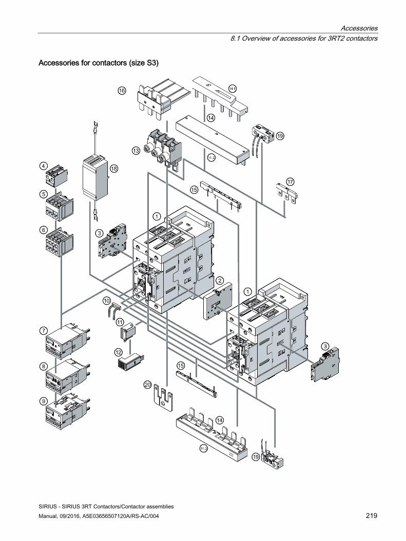
Accessories 8.1 Overview of accessories for 3RT2 contactors
SIRIUS - SIRIUS 3RT Contactors/Contactor assemblies Manual, 09/2016, A5E03656507120A/RS-AC/004 219
Accessories for contactors (size S3)
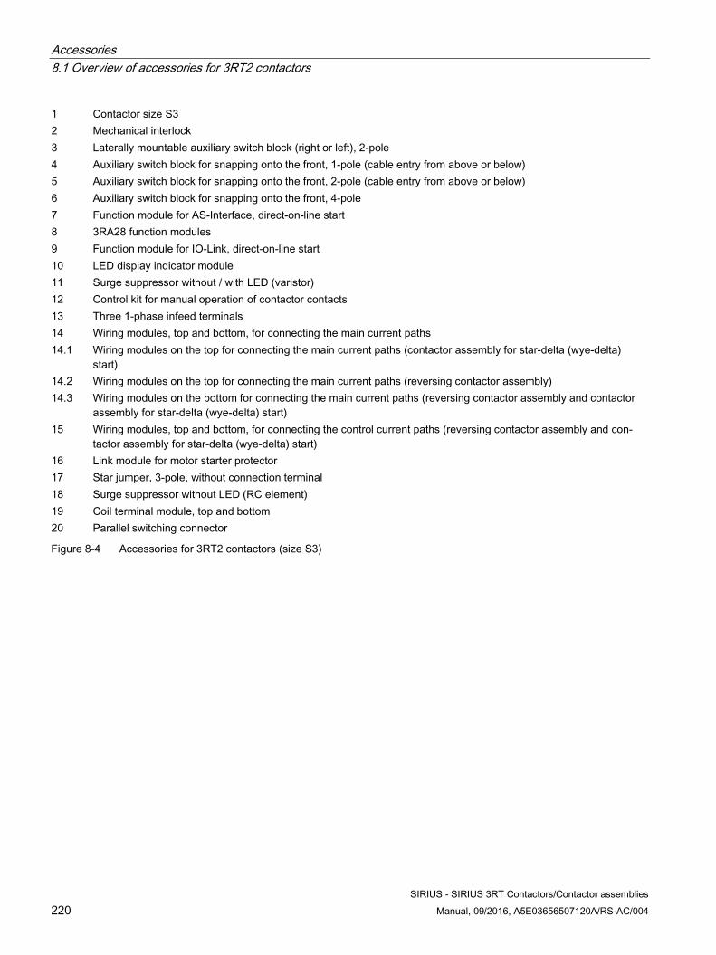
Accessories 8.1 Overview of accessories for 3RT2 contactors
SIRIUS - SIRIUS 3RT Contactors/Contactor assemblies 220 Manual, 09/2016, A5E03656507120A/RS-AC/004
1 Contactor size S3 2 Mechanical interlock 3 Laterally mountable auxiliary switch block (right or left), 2-pole 4 Auxiliary switch block for snapping onto the front, 1-pole (cable entry from above or below) 5 Auxiliary switch block for snapping onto the front, 2-pole (cable entry from above or below) 6 Auxiliary switch block for snapping onto the front, 4-pole 7 Function module for AS-Interface, direct-on-line start 8 3RA28 function modules 9 Function module for IO-Link, direct-on-line start 10 LED display indicator module 11 Surge suppressor without / with LED (varistor) 12 Control kit for manual operation of contactor contacts 13 Three 1-phase infeed terminals 14 Wiring modules, top and bottom, for connecting the main current paths 14.1 Wiring modules on the top for connecting the main current paths (contactor assembly for star-delta (wye-delta)
start) 14.2 Wiring modules on the top for connecting the main current paths (reversing contactor assembly) 14.3 Wiring modules on the bottom for connecting the main current paths (reversing contactor assembly and contactor
assembly for star-delta (wye-delta) start) 15 Wiring modules, top and bottom, for connecting the control current paths (reversing contactor assembly and con-
tactor assembly for star-delta (wye-delta) start) 16 Link module for motor starter protector 17 Star jumper, 3-pole, without connection terminal 18 Surge suppressor without LED (RC element) 19 Coil terminal module, top and bottom 20 Parallel switching connector
Figure 8-4 Accessories for 3RT2 contactors (size S3)
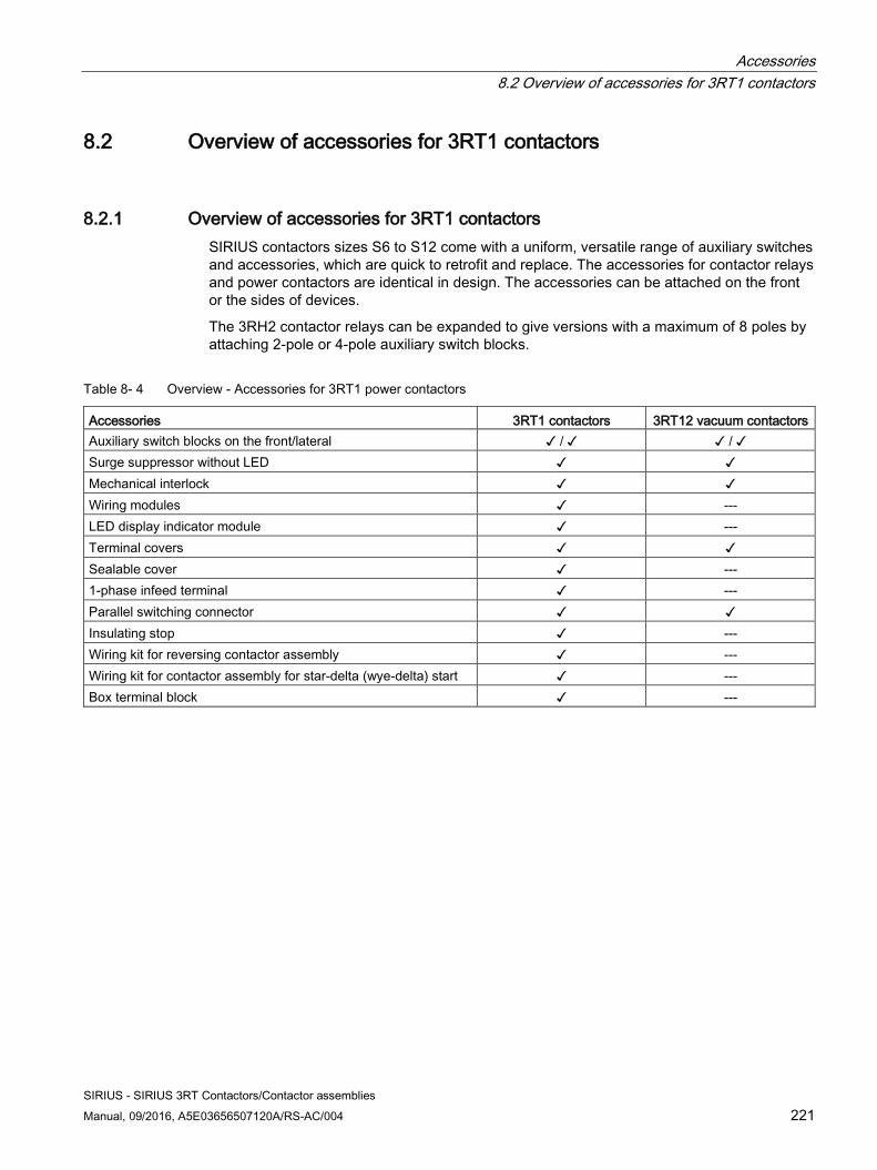
Accessories 8.2 Overview of accessories for 3RT1 contactors
SIRIUS - SIRIUS 3RT Contactors/Contactor assemblies Manual, 09/2016, A5E03656507120A/RS-AC/004 221
8.2 Overview of accessories for 3RT1 contactors
8.2.1 Overview of accessories for 3RT1 contactors SIRIUS contactors sizes S6 to S12 come with a uniform, versatile range of auxiliary switches and accessories, which are quick to retrofit and replace. The accessories for contactor relays and power contactors are identical in design. The accessories can be attached on the front or the sides of devices.
The 3RH2 contactor relays can be expanded to give versions with a maximum of 8 poles by attaching 2-pole or 4-pole auxiliary switch blocks.
Table 8- 4 Overview - Accessories for 3RT1 power contactors
Accessories 3RT1 contactors 3RT12 vacuum contactors Auxiliary switch blocks on the front/lateral ✓ / ✓ ✓ / ✓ Surge suppressor without LED ✓ ✓ Mechanical interlock ✓ ✓ Wiring modules ✓ --- LED display indicator module ✓ --- Terminal covers ✓ ✓ Sealable cover ✓ --- 1-phase infeed terminal ✓ --- Parallel switching connector ✓ ✓ Insulating stop ✓ --- Wiring kit for reversing contactor assembly ✓ --- Wiring kit for contactor assembly for star-delta (wye-delta) start ✓ --- Box terminal block ✓ ---
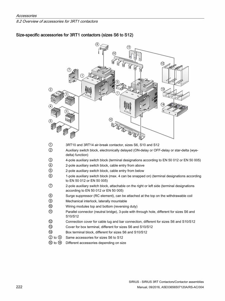
Accessories 8.2 Overview of accessories for 3RT1 contactors
SIRIUS - SIRIUS 3RT Contactors/Contactor assemblies 222 Manual, 09/2016, A5E03656507120A/RS-AC/004
Size-specific accessories for 3RT1 contactors (sizes S6 to S12)
① 3RT10 and 3RT14 air-break contactor, sizes S6, S10 and S12 ② Auxiliary switch block, electronically delayed (ON-delay or OFF-delay or star-delta (wye-
delta) function) ③ 4-pole auxiliary switch block (terminal designations according to EN 50 012 or EN 50 005) ④ 2-pole auxiliary switch block, cable entry from above ⑤ 2-pole auxiliary switch block, cable entry from below ⑥ 1-pole auxiliary switch block (max. 4 can be snapped on) (terminal designations according
to EN 50 012 or EN 50 005) ⑦ 2-pole auxiliary switch block, attachable on the right or left side (terminal designations
according to EN 50 012 or EN 50 005) ⑧ Surge suppressor (RC element), can be attached at the top on the withdrawable coil ⑨ Mechanical interlock, laterally mountable ⑩ Wiring modules top and bottom (reversing duty) ⑪ Parallel connector (neutral bridge), 3-pole with through hole, different for sizes S6 and
S10/S12 ⑫ Connection cover for cable lug and bar connection, different for sizes S6 and S10/S12 ⑬ Cover for box terminal, different for sizes S6 and S10/S12 ⑭ Box terminal block, different for sizes S6 and S10/S12 ② to ⑨ Same accessories for sizes S6 to S12 ⑩ to ⑭ Different accessories depending on size
Accessories 8.3 Auxiliary switch blocks
SIRIUS - SIRIUS 3RT Contactors/Contactor assemblies Manual, 09/2016, A5E03656507120A/RS-AC/004 223
8.3 Auxiliary switch blocks
8.3.1 Auxiliary switch block for 3RT2 power contactors and 3RH2 contactor relays
8.3.1.1 Description
Function The 3RH21 contactor relays and 3RT2 power contactors in size S00 feature an integrated auxiliary contact. The 3RT2 power contactors in sizes S0 to S3 have an integrated NO contact and an NC contact. Attachable auxiliary switch blocks can be used to add up to four further contacts to the auxiliary contacts already integrated in the basic devices.
Versions and designs The auxiliary switch blocks for expanding the auxiliary contacts are available with screw-type, spring-loaded, and ring cable lug connections, in the following designs:
● On the front (uniform for sizes S00 to S3)
● Lateral (size-specific)
To facilitate wiring in the load feeder, 1-pole and 2-pole auxiliary switch blocks for mounting on the front are offered. Optionally, devices with connection from above or below are available. The 1-pole or 2-pole auxiliary switch blocks mounted on the front with connection option from below or above have fixed location identifiers. These auxiliary switch blocks are only supplied with screw connections. For spring-loaded connection, 4-pole auxiliary switch blocks are offered that are only fitted with auxiliary contacts 1 and 2.
The 3RT2 power contactors and the 3RH21 contactor relays can be expanded by means of auxiliary switch blocks mounted on the front or the side.
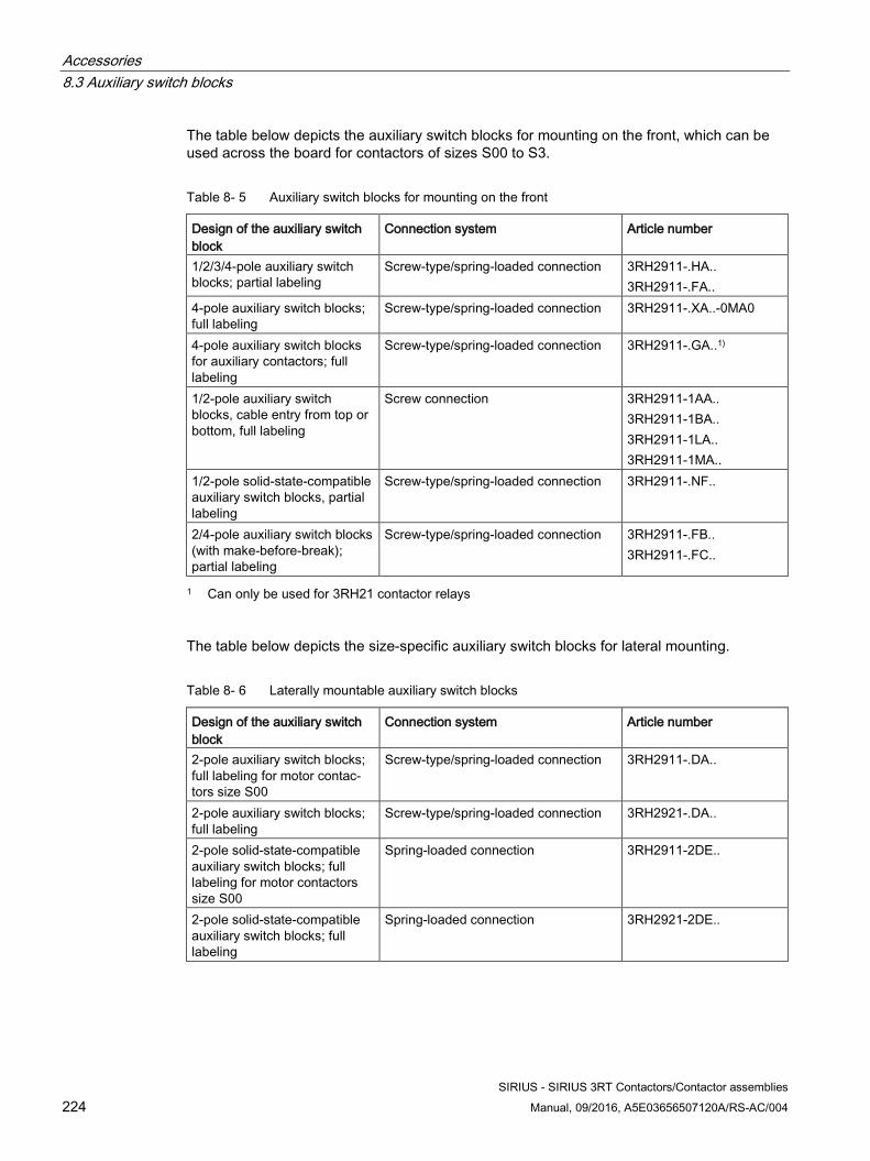
Accessories 8.3 Auxiliary switch blocks
SIRIUS - SIRIUS 3RT Contactors/Contactor assemblies 224 Manual, 09/2016, A5E03656507120A/RS-AC/004
The table below depicts the auxiliary switch blocks for mounting on the front, which can be used across the board for contactors of sizes S00 to S3.
Table 8- 5 Auxiliary switch blocks for mounting on the front
Design of the auxiliary switch block
Connection system Article number
1/2/3/4-pole auxiliary switch blocks; partial labeling
Screw-type/spring-loaded connection 3RH2911-.HA.. 3RH2911-.FA..
4-pole auxiliary switch blocks; full labeling
Screw-type/spring-loaded connection 3RH2911-.XA..-0MA0
4-pole auxiliary switch blocks for auxiliary contactors; full labeling
Screw-type/spring-loaded connection 3RH2911-.GA..1)
1/2-pole auxiliary switch blocks, cable entry from top or bottom, full labeling
Screw connection 3RH2911-1AA.. 3RH2911-1BA.. 3RH2911-1LA.. 3RH2911-1MA..
1/2-pole solid-state-compatible auxiliary switch blocks, partial labeling
Screw-type/spring-loaded connection 3RH2911-.NF..
2/4-pole auxiliary switch blocks (with make-before-break); partial labeling
Screw-type/spring-loaded connection 3RH2911-.FB.. 3RH2911-.FC..
1 Can only be used for 3RH21 contactor relays
The table below depicts the size-specific auxiliary switch blocks for lateral mounting.
Table 8- 6 Laterally mountable auxiliary switch blocks
Design of the auxiliary switch block
Connection system Article number
2-pole auxiliary switch blocks; full labeling for motor contac-tors size S00
Screw-type/spring-loaded connection 3RH2911-.DA..
2-pole auxiliary switch blocks; full labeling
Screw-type/spring-loaded connection 3RH2921-.DA..
2-pole solid-state-compatible auxiliary switch blocks; full labeling for motor contactors size S00
Spring-loaded connection 3RH2911-2DE..
2-pole solid-state-compatible auxiliary switch blocks; full labeling
Spring-loaded connection 3RH2921-2DE..
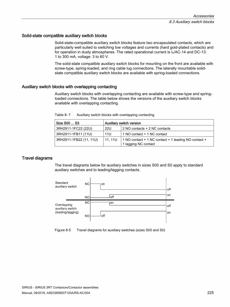
Accessories 8.3 Auxiliary switch blocks
SIRIUS - SIRIUS 3RT Contactors/Contactor assemblies Manual, 09/2016, A5E03656507120A/RS-AC/004 225
Solid-state compatible auxiliary switch blocks Solid-state-compatible auxiliary switch blocks feature two encapsulated contacts, which are particularly well suited to switching low voltages and currents (hard gold-plated contacts) and for operation in dusty atmospheres. The rated operational current is Ie/AC-14 and DC-13: 1 to 300 mA, voltage: 3 to 60 V.
The solid-state compatible auxiliary switch blocks for mounting on the front are available with screw-type, spring-loaded, and ring cable lug connections. The laterally mountable solid-state compatible auxiliary switch blocks are available with spring-loaded connections.
Auxiliary switch blocks with overlapping contacting Auxiliary switch blocks with overlapping contacting are available with screw-type and spring-loaded connections. The table below shows the versions of the auxiliary switch blocks available with overlapping contacting.
Table 8- 7 Auxiliary switch blocks with overlapping contacting
Size S00 ... S3 Auxiliary switch version 3RH2911-1FC22 (22U) 22U 2 NO contacts + 2 NC contacts 3RH2911-1FB11 (11U) 11U 1 NO contact + 1 NC contact 3RH2911-1FB22 (11, 11U) 11, 11U 1 NO contact + 1 NC contact + 1 leading NO contact +
1 lagging NC contact
Travel diagrams The travel diagrams below for auxiliary switches in sizes S00 and S0 apply to standard auxiliary switches and to leading/lagging contacts.
Figure 8-5 Travel diagrams for auxiliary switches (sizes S00 and S0)
Accessories 8.3 Auxiliary switch blocks
SIRIUS - SIRIUS 3RT Contactors/Contactor assemblies 226 Manual, 09/2016, A5E03656507120A/RS-AC/004
8.3.1.2 Configuration
Maximum number of auxiliary switch blocks The maximum number of auxiliary switch blocks which can be attached is determined by technical constraints and by the applicable standard.
Note
A maximum of four NC contacts is possible (from integrated and laterally mounted auxiliary switch blocks combined).
For 3RT23 and 3RT25 contactors in size S0, auxiliary switches can only be fitted by means of a lateral auxiliary switch block. In the case of the 4-pole variant, you can only fit the auxiliary switch block on one side. With capacitor contactors, you can mount an additional lateral auxiliary switch block on the right side for size S2.
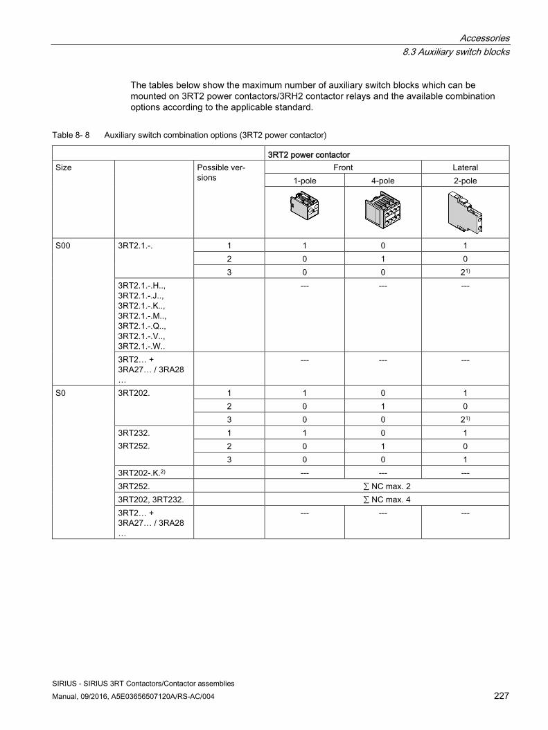
Accessories 8.3 Auxiliary switch blocks
SIRIUS - SIRIUS 3RT Contactors/Contactor assemblies Manual, 09/2016, A5E03656507120A/RS-AC/004 227
The tables below show the maximum number of auxiliary switch blocks which can be mounted on 3RT2 power contactors/3RH2 contactor relays and the available combination options according to the applicable standard.
Table 8- 8 Auxiliary switch combination options (3RT2 power contactor)
3RT2 power contactor Size Possible ver-
sions Front Lateral
1-pole 4-pole 2-pole
S00 3RT2.1.-. 1 1 0 1 2 0 1 0 3 0 0 21)
3RT2.1.-.H.., 3RT2.1.-.J.., 3RT2.1.-.K.., 3RT2.1.-.M.., 3RT2.1.-.Q.., 3RT2.1.-.V.., 3RT2.1.-.W..
--- --- ---
3RT2… + 3RA27… / 3RA28…
--- --- ---
S0 3RT202. 1 1 0 1 2 0 1 0 3 0 0 21)
3RT232. 3RT252.
1 1 0 1 2 0 1 0 3 0 0 1
3RT202-.K.2) --- --- --- 3RT252. ∑ NC max. 2 3RT202, 3RT232. ∑ NC max. 4 3RT2… + 3RA27… / 3RA28…
--- --- ---
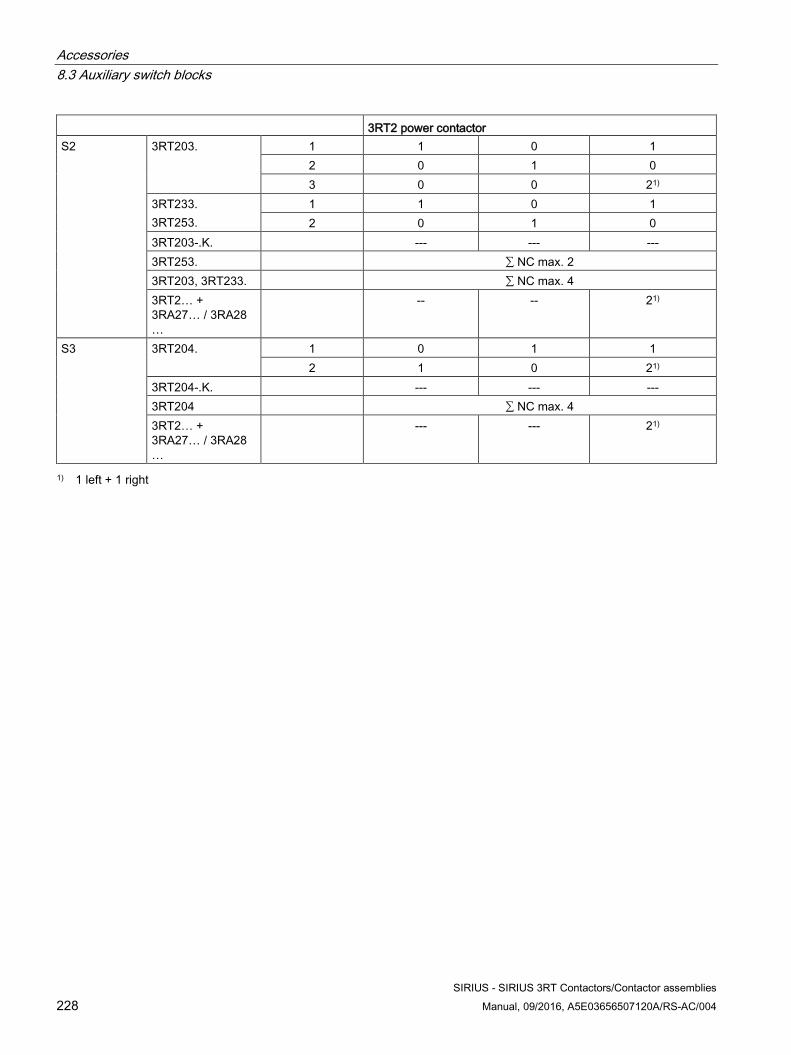
Accessories 8.3 Auxiliary switch blocks
SIRIUS - SIRIUS 3RT Contactors/Contactor assemblies 228 Manual, 09/2016, A5E03656507120A/RS-AC/004
3RT2 power contactor S2 3RT203. 1 1 0 1
2 0 1 0 3 0 0 21)
3RT233. 3RT253.
1 1 0 1 2 0 1 0
3RT203-.K. --- --- --- 3RT253. ∑ NC max. 2 3RT203, 3RT233. ∑ NC max. 4 3RT2… + 3RA27… / 3RA28…
-- -- 21)
S3 3RT204. 1 0 1 1 2 1 0 21)
3RT204-.K. --- --- --- 3RT204 ∑ NC max. 4 3RT2… + 3RA27… / 3RA28…
--- --- 21)
1) 1 left + 1 right
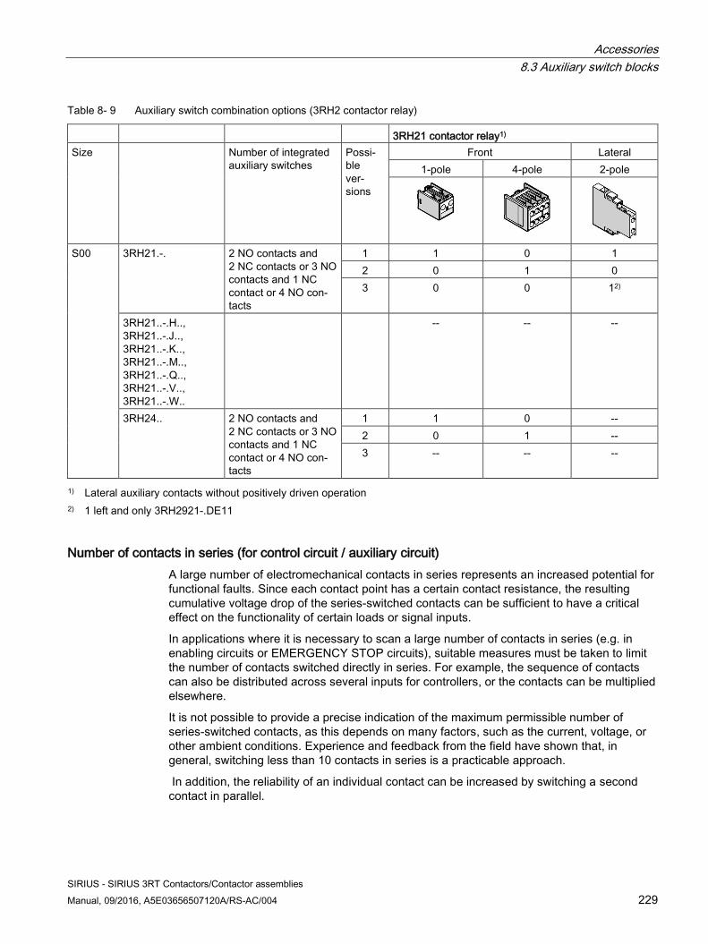
Accessories 8.3 Auxiliary switch blocks
SIRIUS - SIRIUS 3RT Contactors/Contactor assemblies Manual, 09/2016, A5E03656507120A/RS-AC/004 229
Table 8- 9 Auxiliary switch combination options (3RH2 contactor relay)
3RH21 contactor relay1) Size Number of integrated
auxiliary switches Possi-ble ver-sions
Front Lateral 1-pole 4-pole 2-pole
S00 3RH21.-. 2 NO contacts and 2 NC contacts or 3 NO contacts and 1 NC contact or 4 NO con-tacts
1 1 0 1 2 0 1 0 3 0 0 12)
3RH21..-.H.., 3RH21..-.J.., 3RH21..-.K.., 3RH21..-.M.., 3RH21..-.Q.., 3RH21..-.V.., 3RH21..-.W..
-- -- --
3RH24.. 2 NO contacts and 2 NC contacts or 3 NO contacts and 1 NC contact or 4 NO con-tacts
1 1 0 -- 2 0 1 -- 3 -- -- --
1) Lateral auxiliary contacts without positively driven operation 2) 1 left and only 3RH2921-.DE11
Number of contacts in series (for control circuit / auxiliary circuit) A large number of electromechanical contacts in series represents an increased potential for functional faults. Since each contact point has a certain contact resistance, the resulting cumulative voltage drop of the series-switched contacts can be sufficient to have a critical effect on the functionality of certain loads or signal inputs.
In applications where it is necessary to scan a large number of contacts in series (e.g. in enabling circuits or EMERGENCY STOP circuits), suitable measures must be taken to limit the number of contacts switched directly in series. For example, the sequence of contacts can also be distributed across several inputs for controllers, or the contacts can be multiplied elsewhere.
It is not possible to provide a precise indication of the maximum permissible number of series-switched contacts, as this depends on many factors, such as the current, voltage, or other ambient conditions. Experience and feedback from the field have shown that, in general, switching less than 10 contacts in series is a practicable approach.
In addition, the reliability of an individual contact can be increased by switching a second contact in parallel.
Accessories 8.3 Auxiliary switch blocks
SIRIUS - SIRIUS 3RT Contactors/Contactor assemblies 230 Manual, 09/2016, A5E03656507120A/RS-AC/004
Applicable standards The auxiliary switch blocks can be fitted according to the following standards:
● DIN EN 50005: Definition of terminal designations; however, the order of the terminal designations and the positions of the contacts can be determined by the user.
● DIN EN 50011 for contactor relays: Defined order for terminal designations and position of contacts.
● DIN EN 50012 for power contactors: Defined order for terminal designations. The positions of the contacts can be freely selected.
Note
Standard DIN EN 50012 is no longer valid, but is still used.
Definition: DIN EN 50005 The terminal designations for contactors are defined in DIN EN 50005, which contains general rules. The following basic rules are defined therein for the contacts of auxiliary circuits:
● The terminals of auxiliary contacts are identified by two-digit numbers.
● The units digit is a function number (NC contact: 1 and 2, NO contact: 3 and 4)
● The tens digit is a sequence number (all contacts with the same function must have different sequence numbers)
Switching devices with a fixed number of auxiliary contacts (NO or NC contacts) may have a two-digit identification number assigned to them. The first digit specifies the number of NO contacts, the second the number of NC contacts. No rules have been defined as regards the order of NO and NC contacts in the contactor/contactor relay.
Note
The identification numbers on the auxiliary switch blocks only apply to the attached auxiliary switches.
Definition: DIN EN 50011 The main standard as regards the designations of contacts for auxiliary contactors is DIN EN 50 011, which defines the terminal designations, identification numbers, and codes of certain contactor relays, with a specified contact layout. The number, type, and position of the contacts must be defined by means of an identification number and a subsequent code. For 8-pole contactor relays, the code "E" means that four NO contacts must be arranged in the bottom (rear) contact area.
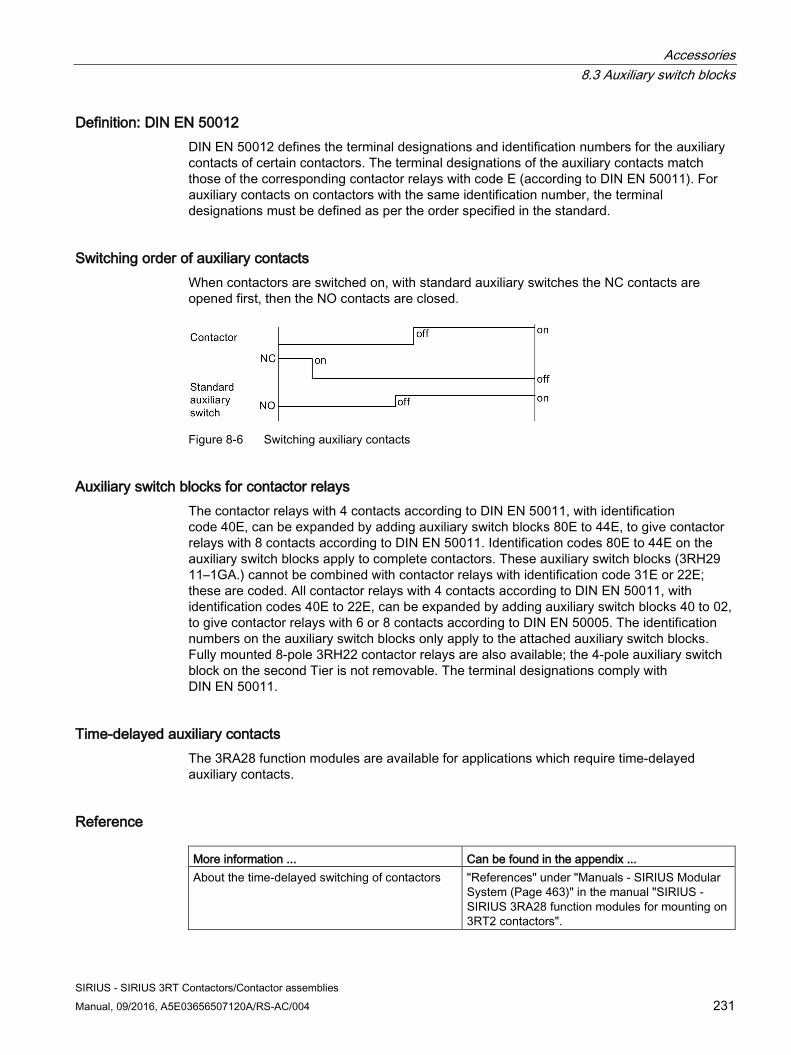
Accessories 8.3 Auxiliary switch blocks
SIRIUS - SIRIUS 3RT Contactors/Contactor assemblies Manual, 09/2016, A5E03656507120A/RS-AC/004 231
Definition: DIN EN 50012 DIN EN 50012 defines the terminal designations and identification numbers for the auxiliary contacts of certain contactors. The terminal designations of the auxiliary contacts match those of the corresponding contactor relays with code E (according to DIN EN 50011). For auxiliary contacts on contactors with the same identification number, the terminal designations must be defined as per the order specified in the standard.
Switching order of auxiliary contacts When contactors are switched on, with standard auxiliary switches the NC contacts are opened first, then the NO contacts are closed.
Figure 8-6 Switching auxiliary contacts
Auxiliary switch blocks for contactor relays The contactor relays with 4 contacts according to DIN EN 50011, with identification code 40E, can be expanded by adding auxiliary switch blocks 80E to 44E, to give contactor relays with 8 contacts according to DIN EN 50011. Identification codes 80E to 44E on the auxiliary switch blocks apply to complete contactors. These auxiliary switch blocks (3RH29 11–1GA.) cannot be combined with contactor relays with identification code 31E or 22E; these are coded. All contactor relays with 4 contacts according to DIN EN 50011, with identification codes 40E to 22E, can be expanded by adding auxiliary switch blocks 40 to 02, to give contactor relays with 6 or 8 contacts according to DIN EN 50005. The identification numbers on the auxiliary switch blocks only apply to the attached auxiliary switch blocks. Fully mounted 8-pole 3RH22 contactor relays are also available; the 4-pole auxiliary switch block on the second Tier is not removable. The terminal designations comply with DIN EN 50011.
Time-delayed auxiliary contacts The 3RA28 function modules are available for applications which require time-delayed auxiliary contacts.
Reference More information ... Can be found in the appendix ... About the time-delayed switching of contactors "References" under "Manuals - SIRIUS Modular
System (Page 463)" in the manual "SIRIUS - SIRIUS 3RA28 function modules for mounting on 3RT2 contactors".
Accessories 8.3 Auxiliary switch blocks
SIRIUS - SIRIUS 3RT Contactors/Contactor assemblies 232 Manual, 09/2016, A5E03656507120A/RS-AC/004
8.3.1.3 Selection guide for mountable auxiliary switch blocks for power contactors and contactor relays
Terminal designations and identification numbers for auxiliary contacts
Terminal designations
The terminal designations are 2-digit, e.g. 13, 14, 21, 22:
● Tens digit: Sequence number
– Related terminals have the same sequence number
● Units digit: Function number
– 1 to 2 for NC contact
– 3 to 4 for NO contacts
Identification numbers
The identification number indicates the number and type of the auxiliary contacts, e.g. 40, 31, 22, 13:
● First digit: Number of NO contacts
● Second digit: Number of NC contacts
Examples:
● 31 = 3 NO contacts + 1 NC contact
● 40 = 4 NO contacts
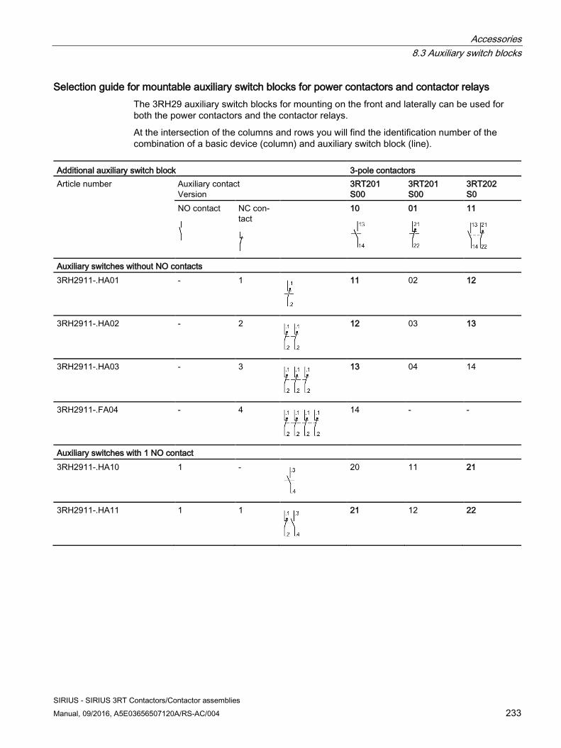
Accessories 8.3 Auxiliary switch blocks
SIRIUS - SIRIUS 3RT Contactors/Contactor assemblies Manual, 09/2016, A5E03656507120A/RS-AC/004 233
Selection guide for mountable auxiliary switch blocks for power contactors and contactor relays The 3RH29 auxiliary switch blocks for mounting on the front and laterally can be used for both the power contactors and the contactor relays.
At the intersection of the columns and rows you will find the identification number of the combination of a basic device (column) and auxiliary switch block (line).
Additional auxiliary switch block 3-pole contactors Article number Auxiliary contact
Version 3RT201 S00
3RT201 S00
3RT202 S0
NO contact
NC con-tact
10
01
11
Auxiliary switches without NO contacts 3RH2911-.HA01 - 1
11 02 12
3RH2911-.HA02 - 2
12 03 13
3RH2911-.HA03 - 3
13 04 14
3RH2911-.FA04 - 4
14 - -
Auxiliary switches with 1 NO contact 3RH2911-.HA10 1 -
20 11 21
3RH2911-.HA11 1 1
21 12 22
Accessories 8.3 Auxiliary switch blocks
SIRIUS - SIRIUS 3RT Contactors/Contactor assemblies 234 Manual, 09/2016, A5E03656507120A/RS-AC/004
Example 1
Basic device: 3-pole 3RT2017 motor contactor with 1 NO contact Desired: 1 NO contact and 4 NC contacts (Ident. No. 14) Result: 3RH2911-.FA04 auxiliary switch block
Example 2
Basic device: 3-pole 3RT2023 motor contactor with 1 NO contact and 1 NC contact Desired: 1 NO contact and 4 NC contacts (Ident. No. 14) Result: 3RH2911-.HA03 auxiliary switch block
Note
The same auxiliary switches can be fitted to size S2/S3 contactors as to size S0.
Example 2 can also be used for sizes S2/S3.
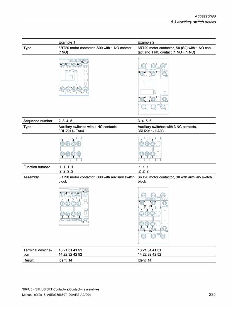
Accessories 8.3 Auxiliary switch blocks
SIRIUS - SIRIUS 3RT Contactors/Contactor assemblies Manual, 09/2016, A5E03656507120A/RS-AC/004 235
Example 1 Example 2 Type 3RT20 motor contactor, S00 with 1 NO contact
(1NO) 3RT20 motor contactor, S0 (S2) with 1 NO con-tact and 1 NC contact (1 NO + 1 NC)
Sequence number 2. 3. 4. 5. 3. 4. 5. 6. Type Auxiliary switches with 4 NC contacts,
3RH2911-.FA04 Auxiliary switches with 3 NC contacts, 3RH2911-.HA03
Function number .1 .1 .1 .1 .2 .2 .2 .2
.1 .1 .1
.2 .2 .2 Assembly 3RT20 motor contactor, S00 with auxiliary switch
block 3RT20 motor contactor, S0 with auxiliary switch block
Terminal designa-tion
13 21 31 41 51 14 22 32 42 52
13 21 31 41 51 14 22 32 42 52
Result Ident. 14 Ident. 14
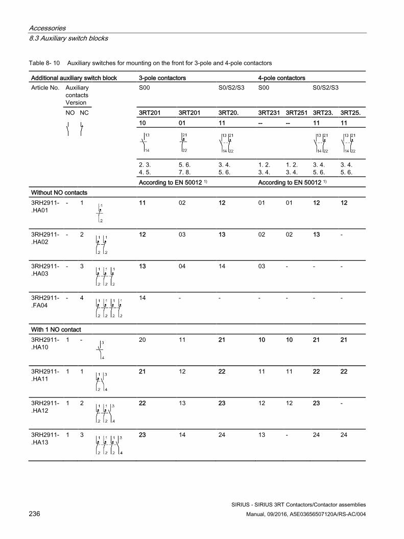
Accessories 8.3 Auxiliary switch blocks
SIRIUS - SIRIUS 3RT Contactors/Contactor assemblies 236 Manual, 09/2016, A5E03656507120A/RS-AC/004
Table 8- 10 Auxiliary switches for mounting on the front for 3-pole and 4-pole contactors
Additional auxiliary switch block 3-pole contactors 4-pole contactors Article No. Auxiliary
contacts Version
S00 S0/S2/S3 S00 S0/S2/S3
NO
NC
3RT201 3RT201 3RT20. 3RT231 3RT251 3RT23. 3RT25. 10 01 11 -- -- 11 11
2. 3. 4. 5.
5. 6. 7. 8.
3. 4. 5. 6.
1. 2. 3. 4.
1. 2. 3. 4.
3. 4. 5. 6.
3. 4. 5. 6.
According to EN 50012 1) According to EN 50012 1) Without NO contacts 3RH2911-.HA01
- 1
11 02 12 01 01 12 12
3RH2911-.HA02
- 2
12 03 13 02 02 13 -
3RH2911-.HA03
- 3
13 04 14 03 - - -
3RH2911-.FA04
- 4
14 - - - - - -
With 1 NO contact 3RH2911-.HA10
1 -
20 11 21 10 10 21 21
3RH2911-.HA11
1 1
21 12 22 11 11 22 22
3RH2911-.HA12
1 2
22 13 23 12 12 23 -
3RH2911-.HA13
1 3
23 14 24 13 - 24 24
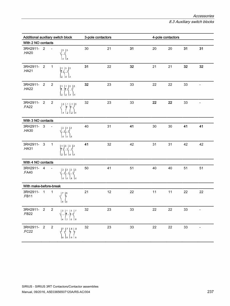
Accessories 8.3 Auxiliary switch blocks
SIRIUS - SIRIUS 3RT Contactors/Contactor assemblies Manual, 09/2016, A5E03656507120A/RS-AC/004 237
Additional auxiliary switch block 3-pole contactors 4-pole contactors With 2 NO contacts 3RH2911-.HA20
2 -
30 21 31 20 20 31 31
3RH2911-.HA21
2 1
31 22 32 21 21 32 32
3RH2911-.HA22
2 2
32 23 33 22 22 33 -
3RH2911-.FA22
2 2
32 23 33 22 22 33 -
With 3 NO contacts 3RH2911-.HA30
3 -
40 31 41 30 30 41 41
3RH2911-.HA31
3 1
41 32 42 31 31 42 42
With 4 NO contacts 3RH2911-.FA40
4 -
50 41 51 40 40 51 51
With make-before-break 3RH2911-.FB11
1 1
21 12 22 11 11 22 22
3RH2911-.FB22
2 2
32 23 33 22 22 33 -
3RH2911-.FC22
2 2
32 23 33 22 22 33 -
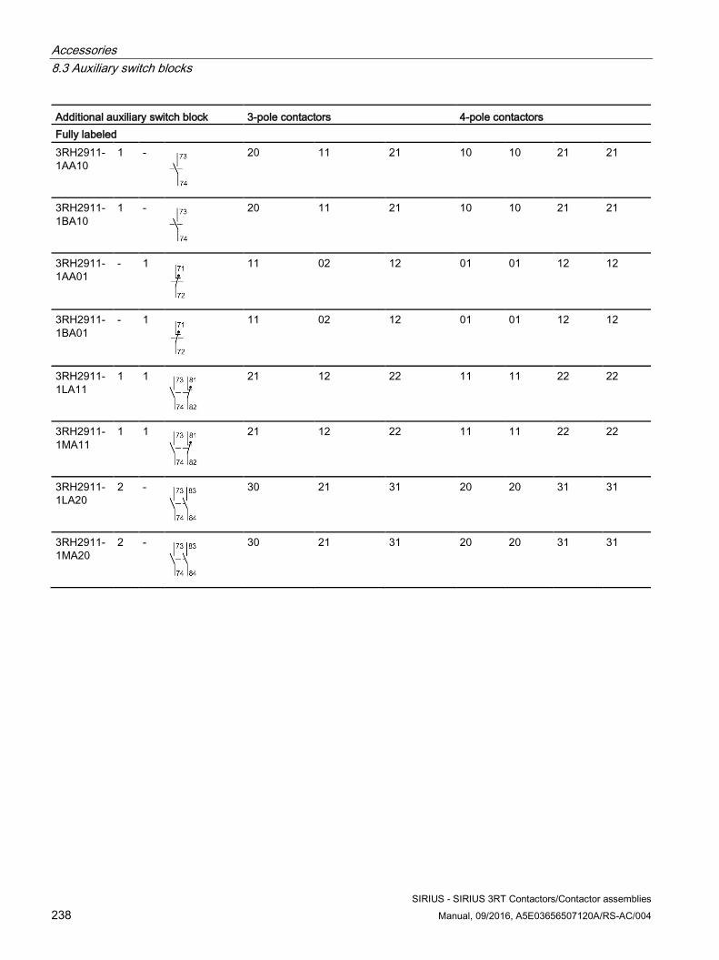
Accessories 8.3 Auxiliary switch blocks
SIRIUS - SIRIUS 3RT Contactors/Contactor assemblies 238 Manual, 09/2016, A5E03656507120A/RS-AC/004
Additional auxiliary switch block 3-pole contactors 4-pole contactors Fully labeled 3RH2911-1AA10
1 -
20 11 21 10 10 21 21
3RH2911-1BA10
1 -
20 11 21 10 10 21 21
3RH2911-1AA01
- 1
11 02 12 01 01 12 12
3RH2911-1BA01
- 1
11 02 12 01 01 12 12
3RH2911-1LA11
1 1
21 12 22 11 11 22 22
3RH2911-1MA11
1 1
21 12 22 11 11 22 22
3RH2911-1LA20
2 -
30 21 31 20 20 31 31
3RH2911-1MA20
2 -
30 21 31 20 20 31 31
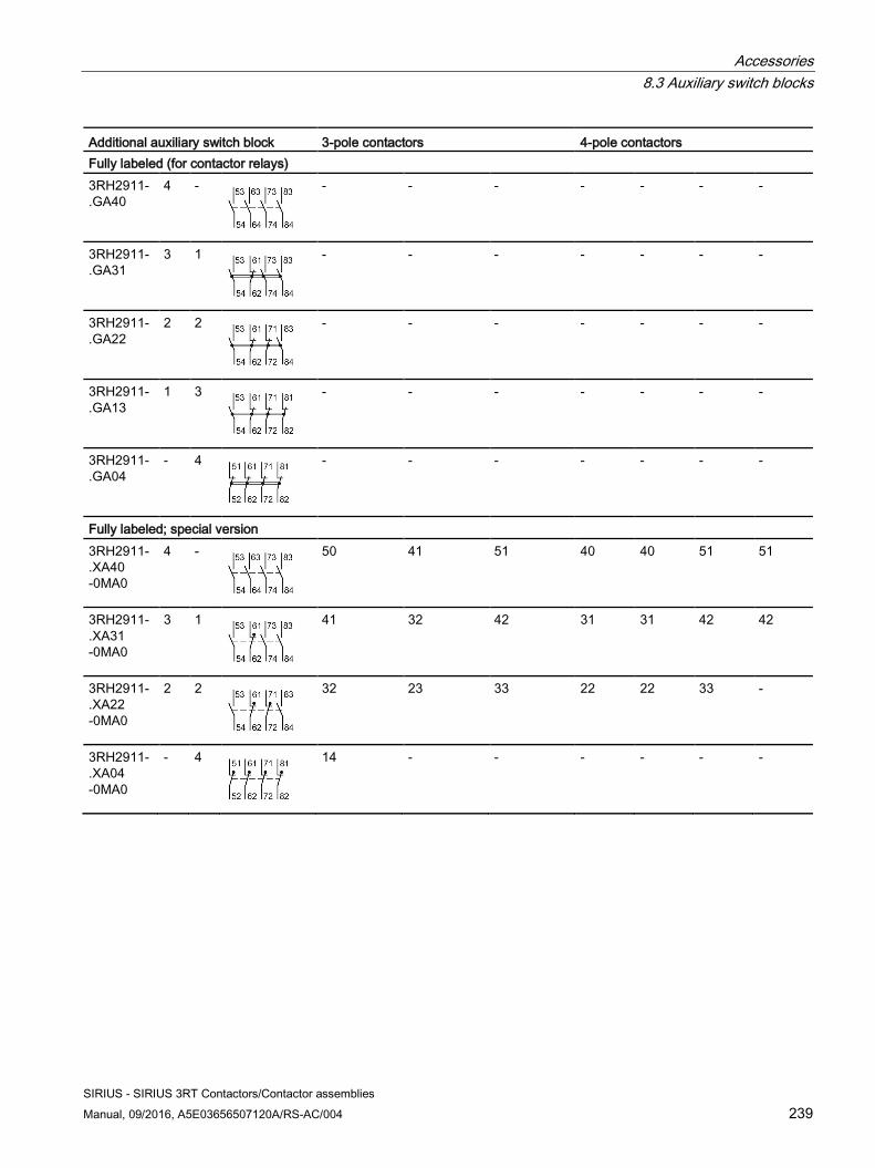
Accessories 8.3 Auxiliary switch blocks
SIRIUS - SIRIUS 3RT Contactors/Contactor assemblies Manual, 09/2016, A5E03656507120A/RS-AC/004 239
Additional auxiliary switch block 3-pole contactors 4-pole contactors Fully labeled (for contactor relays) 3RH2911-.GA40
4 -
- - - - - - -
3RH2911-.GA31
3 1
- - - - - - -
3RH2911-.GA22
2 2
- - - - - - -
3RH2911-.GA13
1 3
- - - - - - -
3RH2911-.GA04
- 4
- - - - - - -
Fully labeled; special version 3RH2911-.XA40 -0MA0
4 -
50 41 51 40 40 51 51
3RH2911-.XA31 -0MA0
3 1
41 32 42 31 31 42 42
3RH2911-.XA22 -0MA0
2 2
32 23 33 22 22 33 -
3RH2911-.XA04 -0MA0
- 4
14 - - - - - -
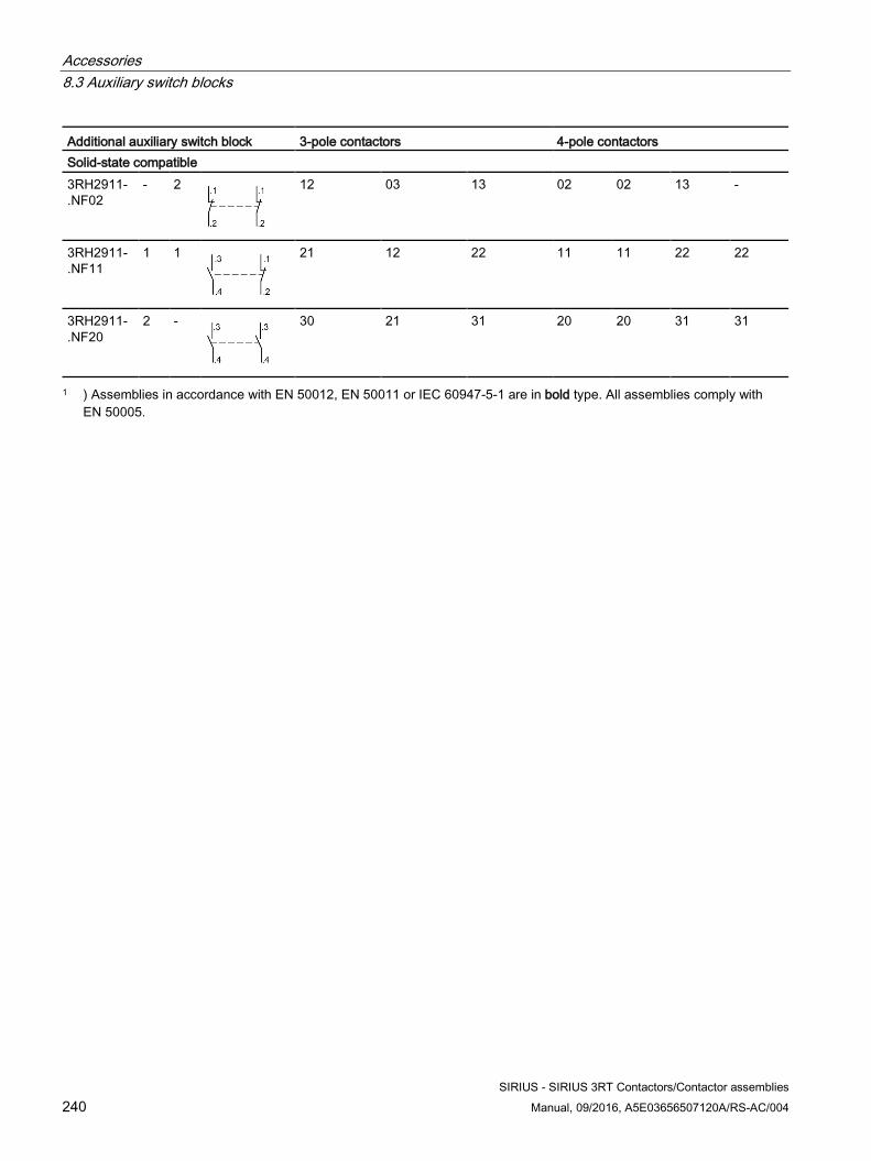
Accessories 8.3 Auxiliary switch blocks
SIRIUS - SIRIUS 3RT Contactors/Contactor assemblies 240 Manual, 09/2016, A5E03656507120A/RS-AC/004
Additional auxiliary switch block 3-pole contactors 4-pole contactors Solid-state compatible 3RH2911-.NF02
- 2
12 03 13 02 02 13 -
3RH2911-.NF11
1 1
21 12 22 11 11 22 22
3RH2911-.NF20
2 -
30 21 31 20 20 31 31
1 ) Assemblies in accordance with EN 50012, EN 50011 or IEC 60947-5-1 are in bold type. All assemblies comply with EN 50005.
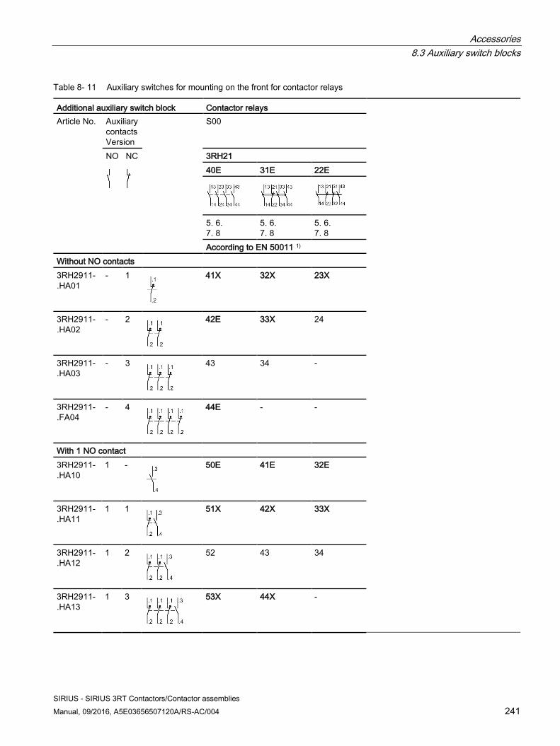
Accessories 8.3 Auxiliary switch blocks
SIRIUS - SIRIUS 3RT Contactors/Contactor assemblies Manual, 09/2016, A5E03656507120A/RS-AC/004 241
Table 8- 11 Auxiliary switches for mounting on the front for contactor relays
Additional auxiliary switch block Contactor relays Article No. Auxiliary
contacts Version
S00
NO
NC
3RH21 40E 31E 22E
5. 6. 7. 8
5. 6. 7. 8
5. 6. 7. 8
According to EN 50011 1) Without NO contacts 3RH2911-.HA01
- 1
41X 32X 23X
3RH2911-.HA02
- 2
42E 33X 24
3RH2911-.HA03
- 3
43 34 -
3RH2911-.FA04
- 4
44E - -
With 1 NO contact 3RH2911-.HA10
1 -
50E 41E 32E
3RH2911-.HA11
1 1
51X 42X 33X
3RH2911-.HA12
1 2
52 43 34
3RH2911-.HA13
1 3
53X 44X -
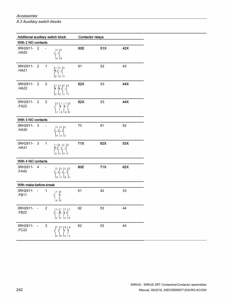
Accessories 8.3 Auxiliary switch blocks
SIRIUS - SIRIUS 3RT Contactors/Contactor assemblies 242 Manual, 09/2016, A5E03656507120A/RS-AC/004
Additional auxiliary switch block Contactor relays With 2 NO contacts 3RH2911-.HA20
2 -
60E 51X 42X
3RH2911-.HA21
2 1
61 52 43
3RH2911-.HA22
2 2
62X 53 44X
3RH2911-.FA22
2 2
62X 53 44X
With 3 NO contacts 3RH2911-.HA30
3 -
70 61 52
3RH2911-.HA31
3 1
71X 62X 53X
With 4 NO contacts 3RH2911-.FA40
4 -
80E 71X 62X
With make-before-break 3RH2911-.FB11
- 1
51 42 33
3RH2911-.FB22
- 2
62 53 44
3RH2911-.FC22
- 3
62 53 44
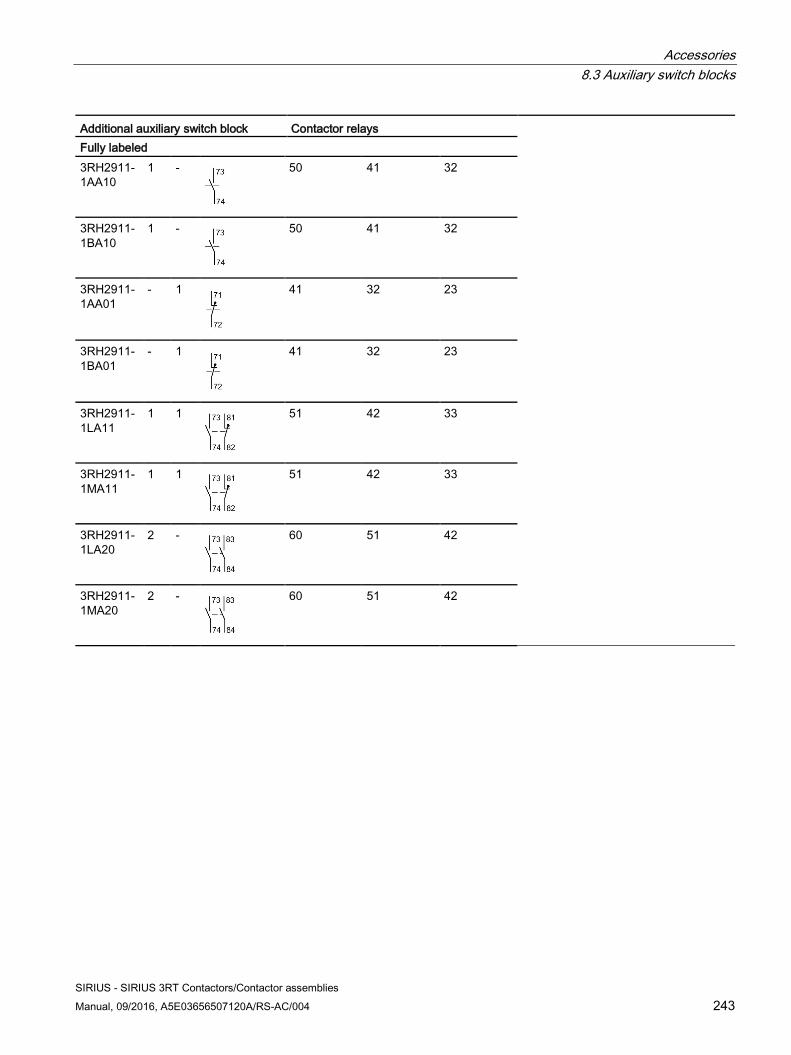
Accessories 8.3 Auxiliary switch blocks
SIRIUS - SIRIUS 3RT Contactors/Contactor assemblies Manual, 09/2016, A5E03656507120A/RS-AC/004 243
Additional auxiliary switch block Contactor relays Fully labeled 3RH2911-1AA10
1 -
50 41 32
3RH2911-1BA10
1 -
50 41 32
3RH2911-1AA01
- 1
41 32 23
3RH2911-1BA01
- 1
41 32 23
3RH2911-1LA11
1 1
51 42 33
3RH2911-1MA11
1 1
51 42 33
3RH2911-1LA20
2 -
60 51 42
3RH2911-1MA20
2 -
60 51 42
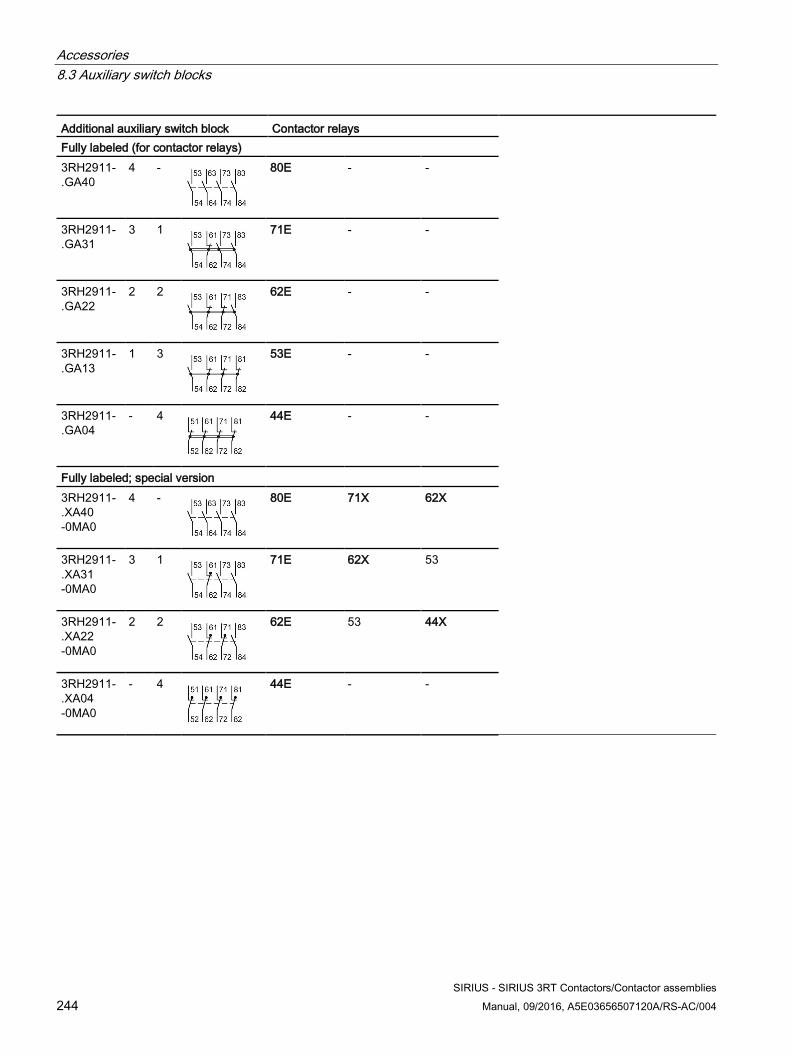
Accessories 8.3 Auxiliary switch blocks
SIRIUS - SIRIUS 3RT Contactors/Contactor assemblies 244 Manual, 09/2016, A5E03656507120A/RS-AC/004
Additional auxiliary switch block Contactor relays Fully labeled (for contactor relays) 3RH2911-.GA40
4 -
80E - -
3RH2911-.GA31
3 1
71E - -
3RH2911-.GA22
2 2
62E - -
3RH2911-.GA13
1 3
53E - -
3RH2911-.GA04
- 4
44E - -
Fully labeled; special version 3RH2911-.XA40 -0MA0
4 -
80E 71X 62X
3RH2911-.XA31 -0MA0
3 1
71E 62X 53
3RH2911-.XA22 -0MA0
2 2
62E 53 44X
3RH2911-.XA04 -0MA0
- 4
44E - -
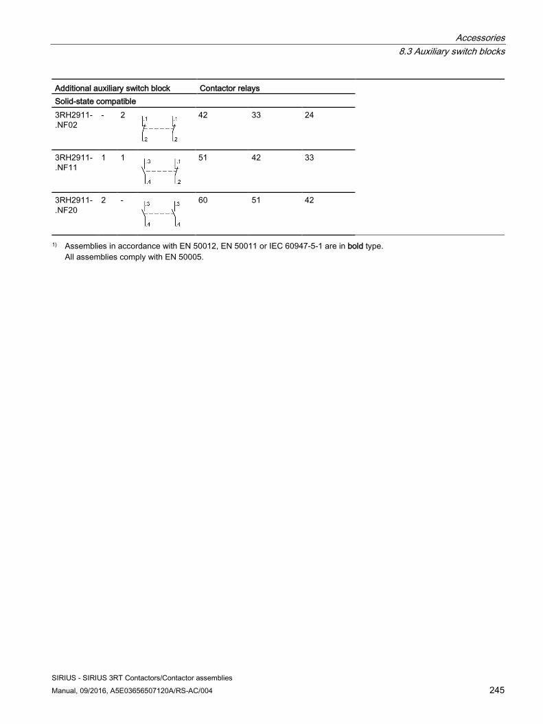
Accessories 8.3 Auxiliary switch blocks
SIRIUS - SIRIUS 3RT Contactors/Contactor assemblies Manual, 09/2016, A5E03656507120A/RS-AC/004 245
Additional auxiliary switch block Contactor relays Solid-state compatible 3RH2911-.NF02
- 2
42 33 24
3RH2911-.NF11
1 1
51 42 33
3RH2911-.NF20
2 -
60 51 42
1) Assemblies in accordance with EN 50012, EN 50011 or IEC 60947-5-1 are in bold type. All assemblies comply with EN 50005.
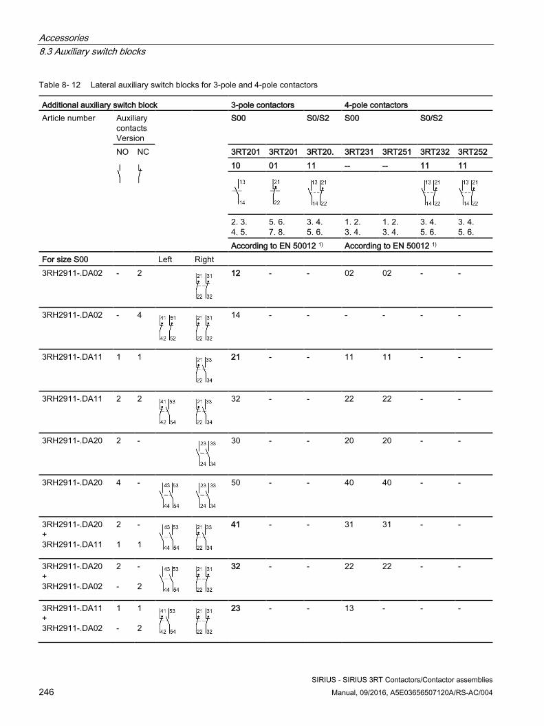
Accessories 8.3 Auxiliary switch blocks
SIRIUS - SIRIUS 3RT Contactors/Contactor assemblies 246 Manual, 09/2016, A5E03656507120A/RS-AC/004
Table 8- 12 Lateral auxiliary switch blocks for 3-pole and 4-pole contactors
Additional auxiliary switch block 3-pole contactors 4-pole contactors Article number Auxiliary
contacts Version
S00 S0/S2 S00 S0/S2
NO
NC
3RT201 3RT201 3RT20. 3RT231 3RT251 3RT232 3RT252 10 01 11 -- -- 11 11
2. 3. 4. 5.
5. 6. 7. 8.
3. 4. 5. 6.
1. 2. 3. 4.
1. 2. 3. 4.
3. 4. 5. 6.
3. 4. 5. 6.
According to EN 50012 1) According to EN 50012 1) For size S00 Left Right 3RH2911-.DA02 - 2
12 - - 02 02 - -
3RH2911-.DA02 - 4
14 - - - - - -
3RH2911-.DA11 1 1
21 - - 11 11 - -
3RH2911-.DA11 2 2
32 - - 22 22 - -
3RH2911-.DA20 2 -
30 - - 20 20 - -
3RH2911-.DA20 4 -
50 - - 40 40 - -
3RH2911-.DA20 + 3RH2911-.DA11
2 1
- 1
41 - - 31 31 - -
3RH2911-.DA20 + 3RH2911-.DA02
2 -
- 2
32 - - 22 22 - -
3RH2911-.DA11 + 3RH2911-.DA02
1 -
1 2
23 - - 13 - - -
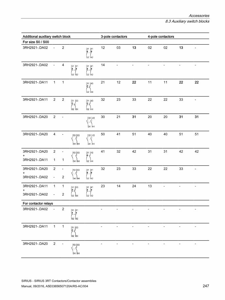
Accessories 8.3 Auxiliary switch blocks
SIRIUS - SIRIUS 3RT Contactors/Contactor assemblies Manual, 09/2016, A5E03656507120A/RS-AC/004 247
Additional auxiliary switch block 3-pole contactors 4-pole contactors For size S0 / S00 3RH2921-.DA02 - 2
12 03 13 02 02 13 -
3RH2921-.DA02 - 4
14 - - - - - -
3RH2921-.DA11 1 1
21 12 22 11 11 22 22
3RH2921-.DA11 2 2
32 23 33 22 22 33 -
3RH2921-.DA20 2 -
30 21 31 20 20 31 31
3RH2921-.DA20 4 -
50 41 51 40 40 51 51
3RH2921-.DA20 + 3RH2921-.DA11
2 1
- 1
41 32 42 31 31 42 42
3RH2921-.DA20 + 3RH2921-.DA02
2 -
- 2
32 23 33 22 22 33 -
3RH2921-.DA11 + 3RH2921-.DA02
1 -
1 2
23 14 24 13 - - -
For contactor relays 3RH2921-.DA02 - 2
- - - - - - -
3RH2921-.DA11 1 1
- - - - - - -
3RH2921-.DA20 2 -
- - - - - - -
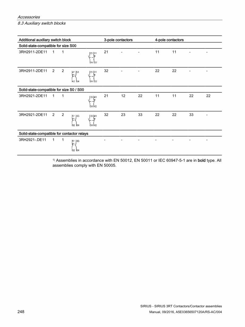
Accessories 8.3 Auxiliary switch blocks
SIRIUS - SIRIUS 3RT Contactors/Contactor assemblies 248 Manual, 09/2016, A5E03656507120A/RS-AC/004
Additional auxiliary switch block 3-pole contactors 4-pole contactors Solid-state-compatible for size S00 3RH2911-2DE11 1 1
21 - - 11 11 - -
3RH2911-2DE11 2 2
32 - - 22 22 - -
Solid-state-compatible for size S0 / S00 3RH2921-2DE11 1 1
21 12 22 11 11 22 22
3RH2921-2DE11 2 2
32 23 33 22 22 33 -
Solid-state-compatible for contactor relays 3RH2921-.DE11 1 1
- - - - - - -
1) Assemblies in accordance with EN 50012, EN 50011 or IEC 60947-5-1 are in bold type. All assemblies comply with EN 50005.
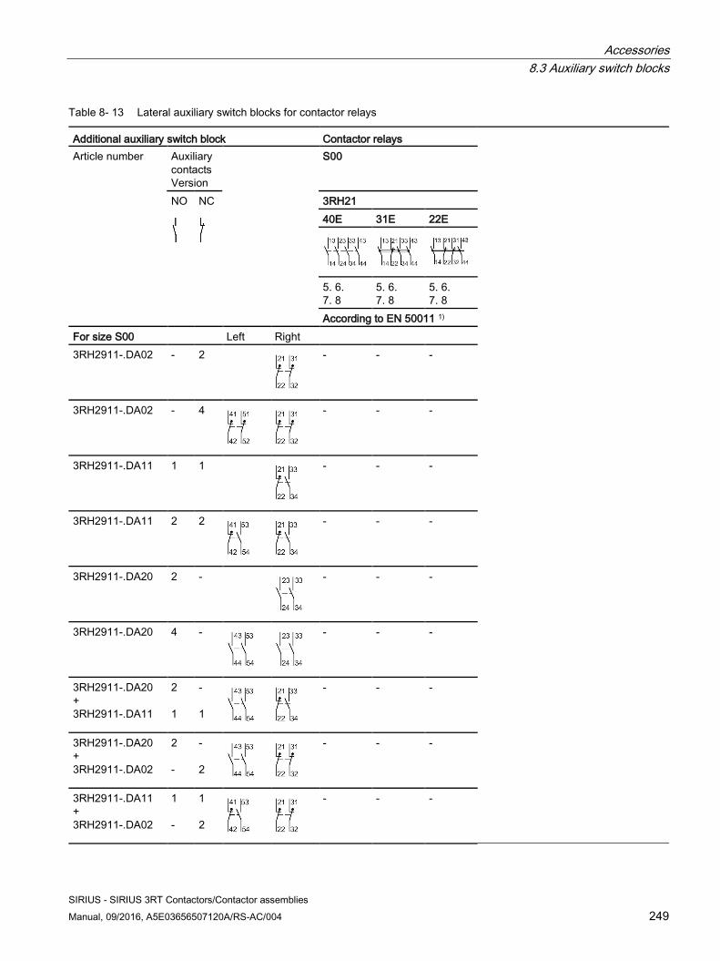
Accessories 8.3 Auxiliary switch blocks
SIRIUS - SIRIUS 3RT Contactors/Contactor assemblies Manual, 09/2016, A5E03656507120A/RS-AC/004 249
Table 8- 13 Lateral auxiliary switch blocks for contactor relays
Additional auxiliary switch block Contactor relays Article number Auxiliary
contacts Version
S00
NO
NC
3RH21 40E 31E 22E
5. 6. 7. 8
5. 6. 7. 8
5. 6. 7. 8
According to EN 50011 1) For size S00 Left Right 3RH2911-.DA02 - 2
- - -
3RH2911-.DA02 - 4
- - -
3RH2911-.DA11 1 1
- - -
3RH2911-.DA11 2 2
- - -
3RH2911-.DA20 2 -
- - -
3RH2911-.DA20 4 -
- - -
3RH2911-.DA20 + 3RH2911-.DA11
2 1
- 1
- - -
3RH2911-.DA20 + 3RH2911-.DA02
2 -
- 2
- - -
3RH2911-.DA11 + 3RH2911-.DA02
1 -
1 2
- - -
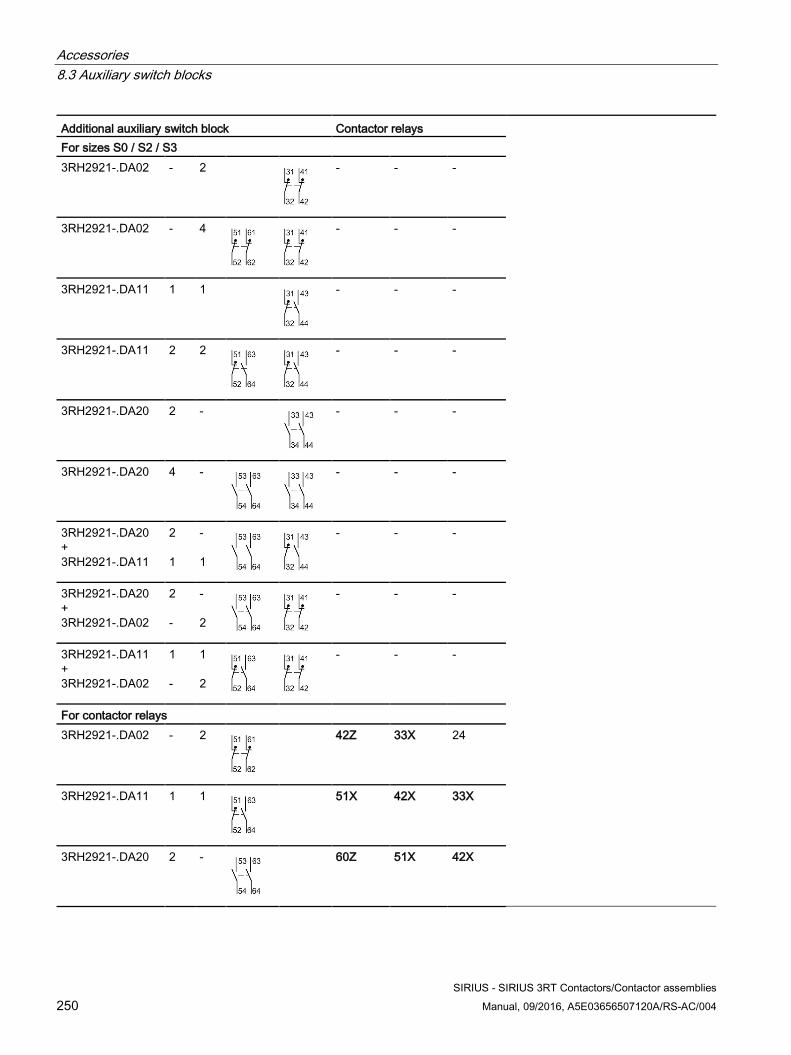
Accessories 8.3 Auxiliary switch blocks
SIRIUS - SIRIUS 3RT Contactors/Contactor assemblies 250 Manual, 09/2016, A5E03656507120A/RS-AC/004
Additional auxiliary switch block Contactor relays For sizes S0 / S2 / S3 3RH2921-.DA02 - 2
- - -
3RH2921-.DA02 - 4
- - -
3RH2921-.DA11 1 1
- - -
3RH2921-.DA11 2 2
- - -
3RH2921-.DA20 2 -
- - -
3RH2921-.DA20 4 -
- - -
3RH2921-.DA20 + 3RH2921-.DA11
2 1
- 1
- - -
3RH2921-.DA20 + 3RH2921-.DA02
2 -
- 2
- - -
3RH2921-.DA11 + 3RH2921-.DA02
1 -
1 2
- - -
For contactor relays 3RH2921-.DA02 - 2
42Z 33X 24
3RH2921-.DA11 1 1
51X 42X 33X
3RH2921-.DA20 2 -
60Z 51X 42X
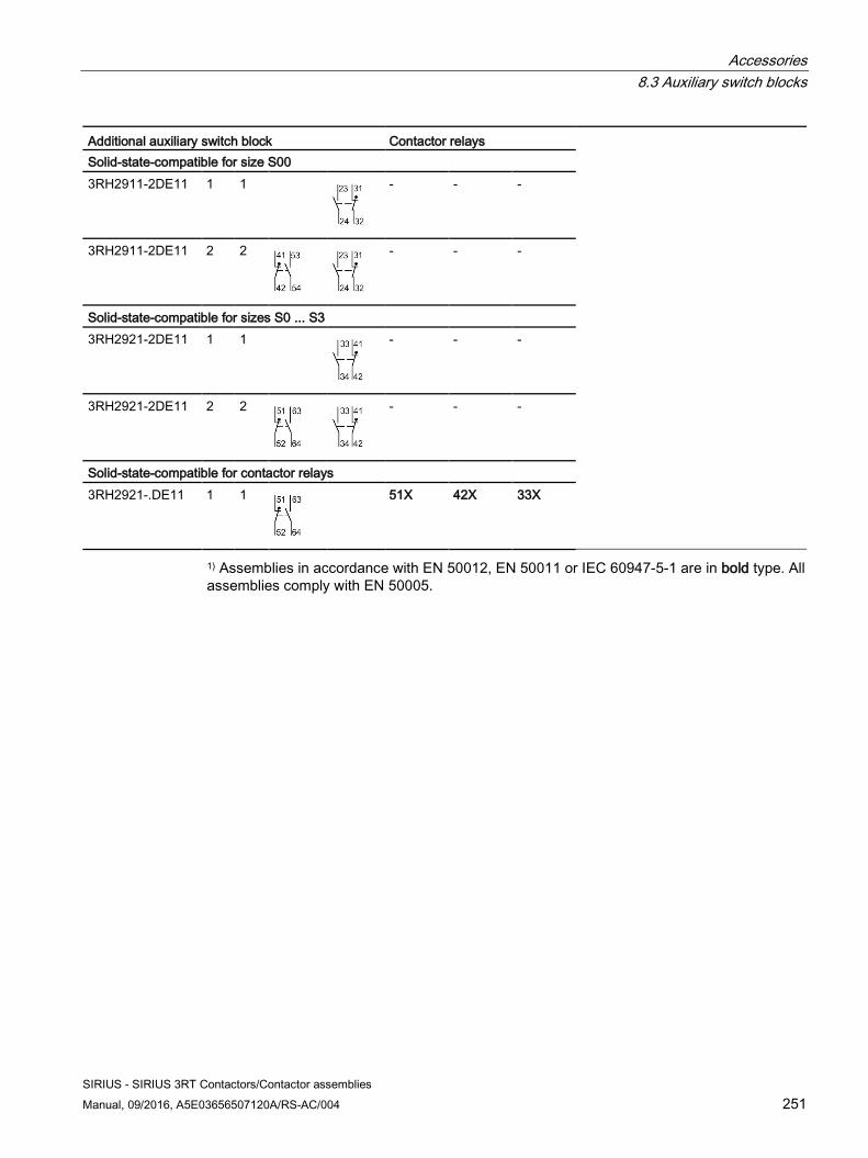
Accessories 8.3 Auxiliary switch blocks
SIRIUS - SIRIUS 3RT Contactors/Contactor assemblies Manual, 09/2016, A5E03656507120A/RS-AC/004 251
Additional auxiliary switch block Contactor relays Solid-state-compatible for size S00 3RH2911-2DE11 1 1
- - -
3RH2911-2DE11 2 2
- - -
Solid-state-compatible for sizes S0 ... S3 3RH2921-2DE11 1 1
- - -
3RH2921-2DE11 2 2
- - -
Solid-state-compatible for contactor relays 3RH2921-.DE11 1 1
51X 42X 33X
1) Assemblies in accordance with EN 50012, EN 50011 or IEC 60947-5-1 are in bold type. All assemblies comply with EN 50005.
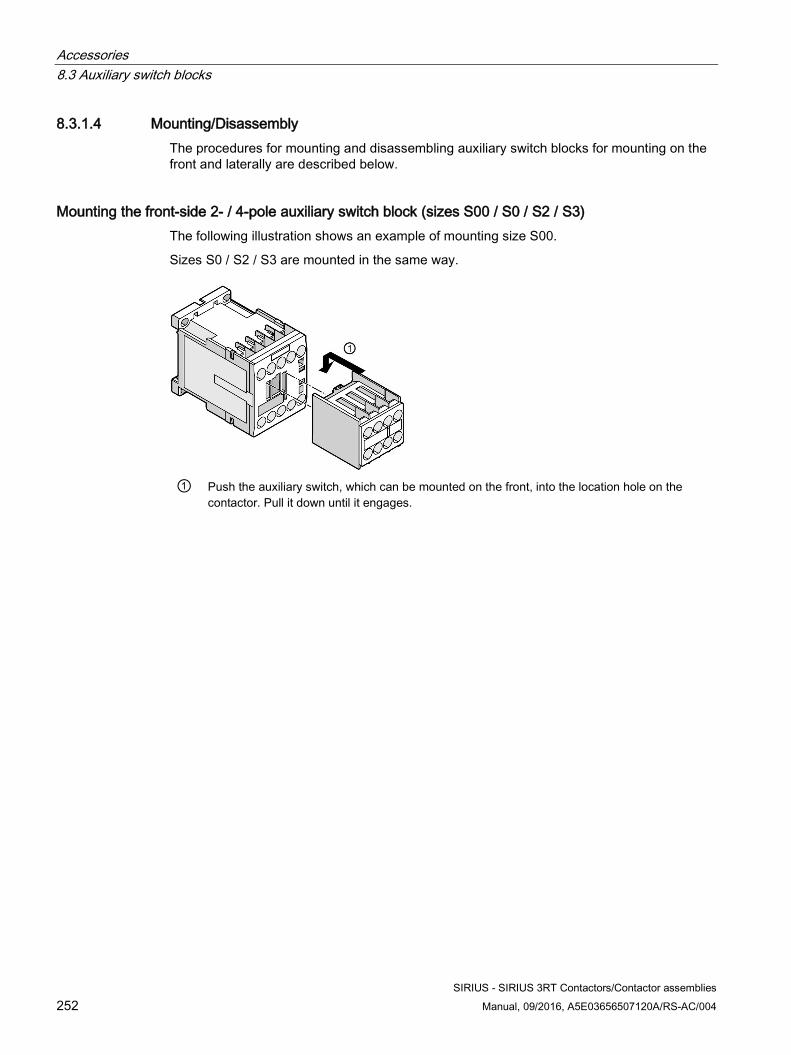
Accessories 8.3 Auxiliary switch blocks
SIRIUS - SIRIUS 3RT Contactors/Contactor assemblies 252 Manual, 09/2016, A5E03656507120A/RS-AC/004
8.3.1.4 Mounting/Disassembly The procedures for mounting and disassembling auxiliary switch blocks for mounting on the front and laterally are described below.
Mounting the front-side 2- / 4-pole auxiliary switch block (sizes S00 / S0 / S2 / S3) The following illustration shows an example of mounting size S00.
Sizes S0 / S2 / S3 are mounted in the same way.
① Push the auxiliary switch, which can be mounted on the front, into the location hole on the
contactor. Pull it down until it engages.
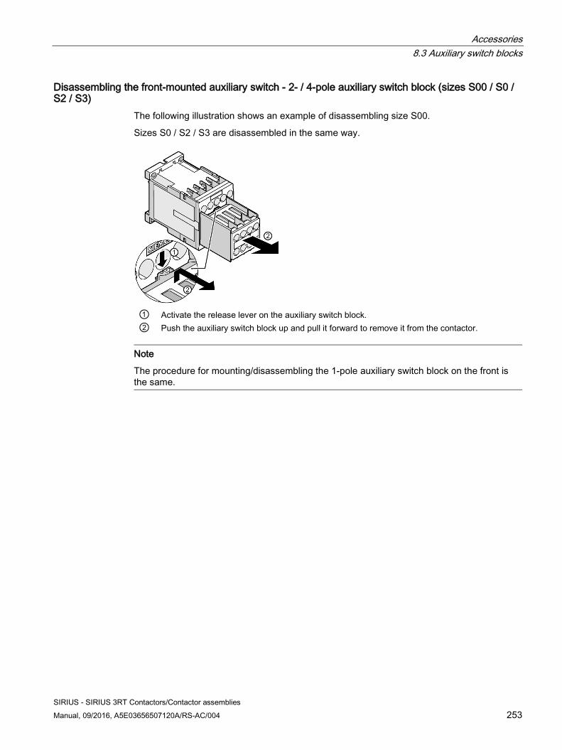
Accessories 8.3 Auxiliary switch blocks
SIRIUS - SIRIUS 3RT Contactors/Contactor assemblies Manual, 09/2016, A5E03656507120A/RS-AC/004 253
Disassembling the front-mounted auxiliary switch - 2- / 4-pole auxiliary switch block (sizes S00 / S0 / S2 / S3)
The following illustration shows an example of disassembling size S00.
Sizes S0 / S2 / S3 are disassembled in the same way.
① Activate the release lever on the auxiliary switch block. ② Push the auxiliary switch block up and pull it forward to remove it from the contactor.
Note
The procedure for mounting/disassembling the 1-pole auxiliary switch block on the front is the same.
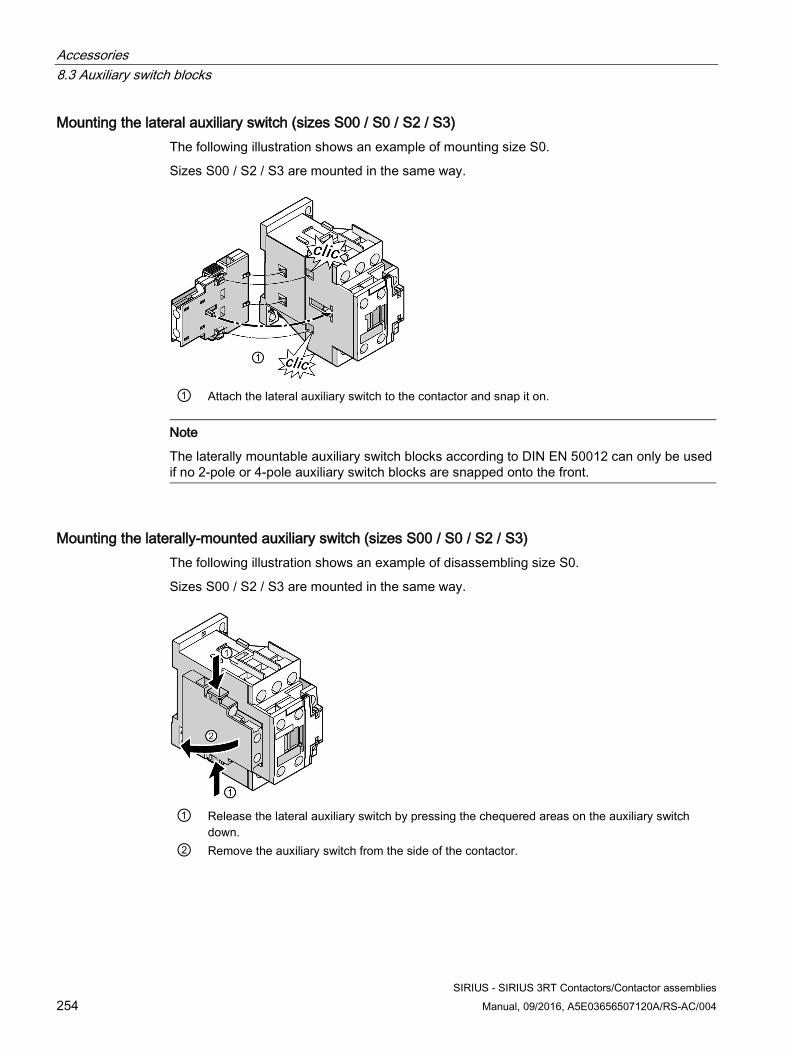
Accessories 8.3 Auxiliary switch blocks
SIRIUS - SIRIUS 3RT Contactors/Contactor assemblies 254 Manual, 09/2016, A5E03656507120A/RS-AC/004
Mounting the lateral auxiliary switch (sizes S00 / S0 / S2 / S3) The following illustration shows an example of mounting size S0.
Sizes S00 / S2 / S3 are mounted in the same way.
① Attach the lateral auxiliary switch to the contactor and snap it on.
Note
The laterally mountable auxiliary switch blocks according to DIN EN 50012 can only be used if no 2-pole or 4-pole auxiliary switch blocks are snapped onto the front.
Mounting the laterally-mounted auxiliary switch (sizes S00 / S0 / S2 / S3) The following illustration shows an example of disassembling size S0.
Sizes S00 / S2 / S3 are mounted in the same way.
① Release the lateral auxiliary switch by pressing the chequered areas on the auxiliary switch
down. ② Remove the auxiliary switch from the side of the contactor.
Accessories 8.3 Auxiliary switch blocks
SIRIUS - SIRIUS 3RT Contactors/Contactor assemblies Manual, 09/2016, A5E03656507120A/RS-AC/004 255
8.3.2 Auxiliary switch blocks for 3RT1 power contactors
8.3.2.1 Description
Function Size S6 to S12 contactors feature a laterally mounted auxiliary switch fitted at the factory.
Versions and designs The auxiliary switches are available with screw-type or spring-loaded connection system in the following versions:
● On the front 1-pole to 4-pole
● Lateral, 2-pole
Optionally, auxiliary switches with connection from above or below are available. These auxiliary switch blocks have fixed location identifiers and are supplied with screw connections only. For spring-loaded connection, 4-pole auxiliary switch blocks are offered that are only fitted with auxiliary contacts 1 and 2.
2-pole auxiliary switches can be mounted on the side in addition to the auxiliary switches already mounted at the factory. If 1-pole auxiliary switch blocks are used, the location identifiers on the contactor must be noted when making a selection for ordering.
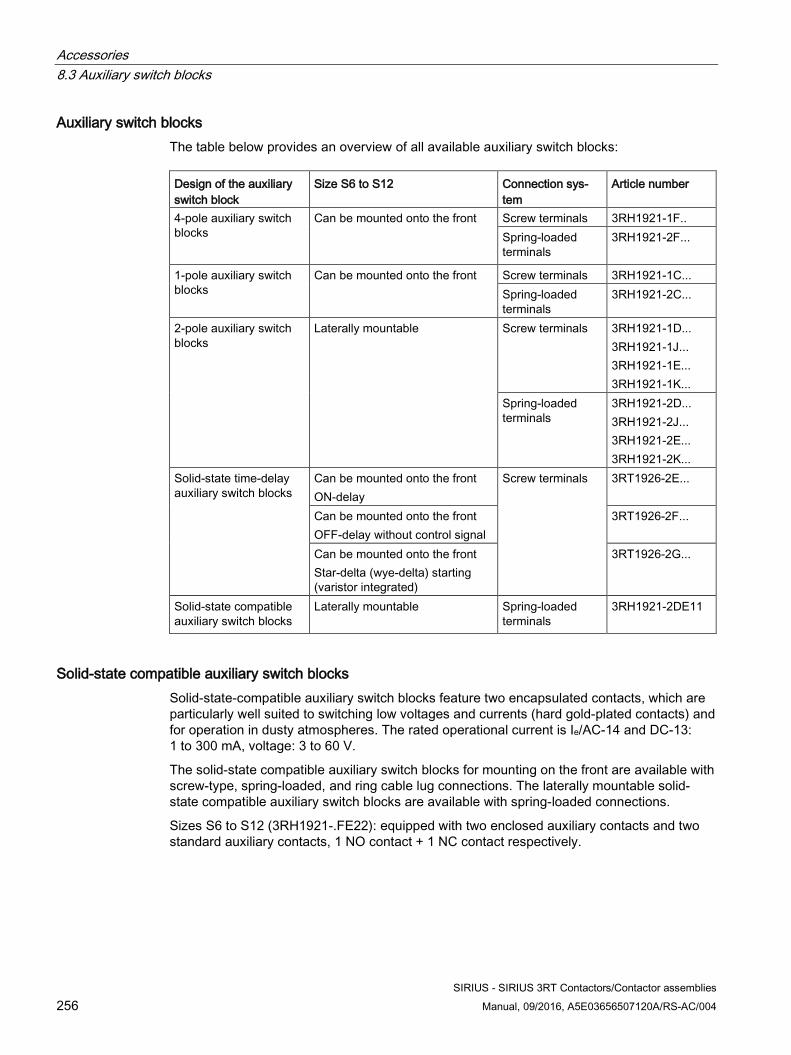
Accessories 8.3 Auxiliary switch blocks
SIRIUS - SIRIUS 3RT Contactors/Contactor assemblies 256 Manual, 09/2016, A5E03656507120A/RS-AC/004
Auxiliary switch blocks The table below provides an overview of all available auxiliary switch blocks: Design of the auxiliary switch block
Size S6 to S12 Connection sys-tem
Article number
4-pole auxiliary switch blocks
Can be mounted onto the front Screw terminals 3RH1921-1F.. Spring-loaded terminals
3RH1921-2F...
1-pole auxiliary switch blocks
Can be mounted onto the front Screw terminals 3RH1921-1C... Spring-loaded terminals
3RH1921-2C...
2-pole auxiliary switch blocks
Laterally mountable Screw terminals 3RH1921-1D... 3RH1921-1J... 3RH1921-1E... 3RH1921-1K...
Spring-loaded terminals
3RH1921-2D... 3RH1921-2J... 3RH1921-2E... 3RH1921-2K...
Solid-state time-delay auxiliary switch blocks
Can be mounted onto the front ON-delay
Screw terminals 3RT1926-2E...
Can be mounted onto the front OFF-delay without control signal
3RT1926-2F...
Can be mounted onto the front Star-delta (wye-delta) starting (varistor integrated)
3RT1926-2G...
Solid-state compatible auxiliary switch blocks
Laterally mountable
Spring-loaded terminals
3RH1921-2DE11
Solid-state compatible auxiliary switch blocks Solid-state-compatible auxiliary switch blocks feature two encapsulated contacts, which are particularly well suited to switching low voltages and currents (hard gold-plated contacts) and for operation in dusty atmospheres. The rated operational current is Ie/AC-14 and DC-13: 1 to 300 mA, voltage: 3 to 60 V.
The solid-state compatible auxiliary switch blocks for mounting on the front are available with screw-type, spring-loaded, and ring cable lug connections. The laterally mountable solid-state compatible auxiliary switch blocks are available with spring-loaded connections.
Sizes S6 to S12 (3RH1921-.FE22): equipped with two enclosed auxiliary contacts and two standard auxiliary contacts, 1 NO contact + 1 NC contact respectively.
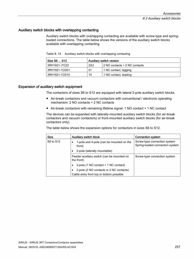
Accessories 8.3 Auxiliary switch blocks
SIRIUS - SIRIUS 3RT Contactors/Contactor assemblies Manual, 09/2016, A5E03656507120A/RS-AC/004 257
Auxiliary switch blocks with overlapping contacting Auxiliary switch blocks with overlapping contacting are available with screw-type and spring-loaded connections. The table below shows the versions of the auxiliary switch blocks available with overlapping contacting.
Table 8- 14 Auxiliary switch blocks with overlapping contacting
Size S6 ... S12 Auxiliary switch version 3RH1921-.FC22 22U 2 NO contacts + 2 NC contacts 3RH1921-1CD01 01 1 NC contact, lagging 3RH1921-1CD10 10 1 NO contact, leading
Expansion of auxiliary switch equipment The contactors of sizes S6 to S12 are equipped with lateral 2-pole auxiliary switch blocks.
● Air-break contactors and vacuum contactors with conventional / electronic operating mechanism: 2 NO contacts + 2 NC contacts
● Air-break contactors with remaining lifetime signal: 1 NO contact + 1 NC contact
The devices can be expanded with laterally-mounted auxiliary switch blocks (for air-break contactors and vacuum contactors) or front-mounted auxiliary switch blocks (for air-break contactors only).
The table below shows the expansion options for contactors in sizes S6 to S12. Size Auxiliary switch block Connection system S6 to S12 • 1-pole and 4-pole (can be mounted on the
front) • 2-pole (laterally mountable)
Screw-type connection system Spring-loaded connection system
Feeder auxiliary switch (can be mounted on the front): • 2-pole (1 NO contact + 1 NC contact) • 2-pole (2 NO contacts or 2 NC contacts) Cable entry from top or bottom possible
Screw-type connection system
Accessories 8.3 Auxiliary switch blocks
SIRIUS - SIRIUS 3RT Contactors/Contactor assemblies 258 Manual, 09/2016, A5E03656507120A/RS-AC/004
8.3.2.2 Configuration
Maximum number of auxiliary switch blocks The maximum number of auxiliary switch blocks which can be attached is determined by technical constraints and by the applicable standard.
The tables below show the maximum number of auxiliary contacts that can be mounted on 3RT1 power contactors. Operating mechanism type
Contactor type
In the lower operating range 0.8 x USmin 0.85 x USmin
3RT1...-.A conventional 3RT10 / 3RT14 air-break contactors
8, of which max. 4 NC contacts
9, of which max. 6 NC contacts
3RT12 vacuum contac-tors
8, of which max. 4 NC contacts
8, of which max. 6 NC contacts
3RT1...-.N electronic Air-break contactors / vacuum contactors
8, of which max. 4 NC contacts
with RLT 3RT1...-.P/Q 3RT10 / 3RT14 air-break contactors
8, of which max. 4 NC contacts
Note
When two 2-pole laterally mountable auxiliary switch blocks are used, one block must be attached on the right and one on the left for reasons of symmetry.
Note about fitting auxiliary switches When using the 3RA1954-2A mechanical interlock:
● In the case of contactors with conventional / electronic operating mechanism 3RT1...-.A/N: an additional auxiliary switch block can be attached between the contactors
● In the case of contactors with remaining lifetime signal RLT 3RT1...-.P/Q: the left mounted auxiliary contact block of the right contactor must be removed.
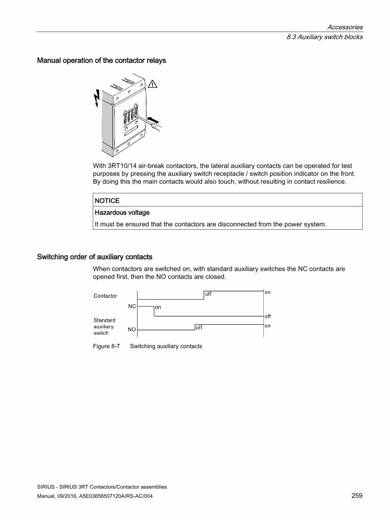
Accessories 8.3 Auxiliary switch blocks
SIRIUS - SIRIUS 3RT Contactors/Contactor assemblies Manual, 09/2016, A5E03656507120A/RS-AC/004 259
Manual operation of the contactor relays
With 3RT10/14 air-break contactors, the lateral auxiliary contacts can be operated for test purposes by pressing the auxiliary switch receptacle / switch position indicator on the front. By doing this the main contacts would also touch, without resulting in contact resilience.
NOTICE
Hazardous voltage
It must be ensured that the contactors are disconnected from the power system.
Switching order of auxiliary contacts When contactors are switched on, with standard auxiliary switches the NC contacts are opened first, then the NO contacts are closed.
Figure 8-7 Switching auxiliary contacts
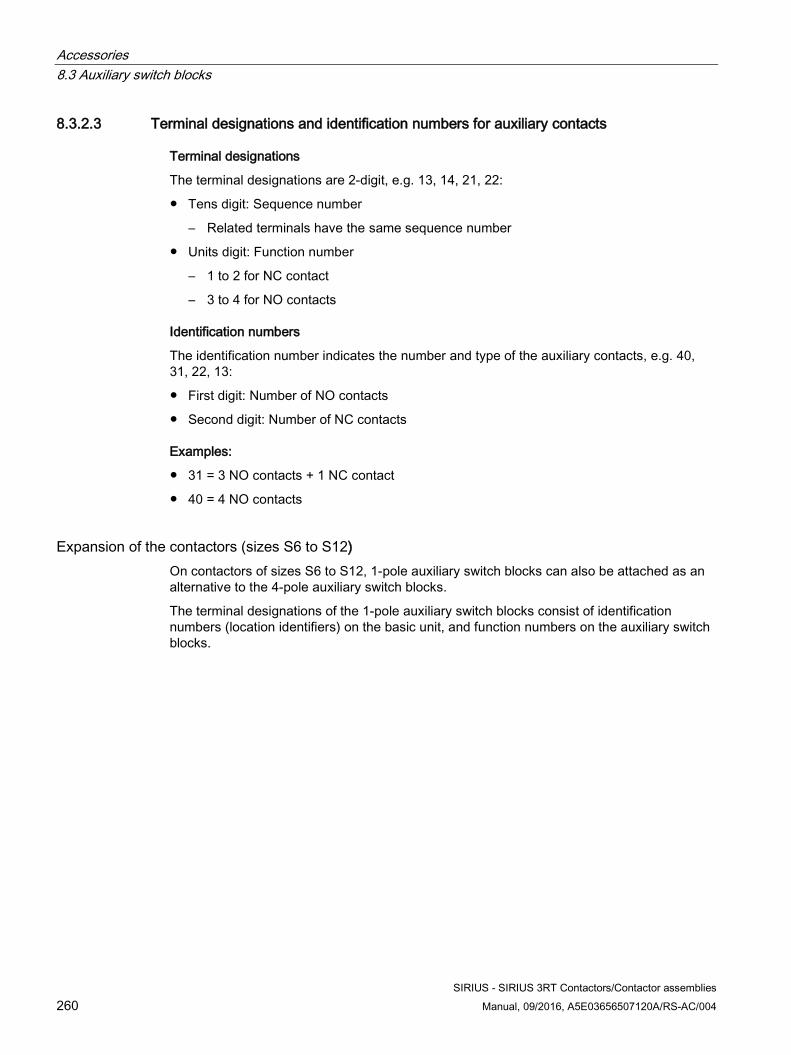
Accessories 8.3 Auxiliary switch blocks
SIRIUS - SIRIUS 3RT Contactors/Contactor assemblies 260 Manual, 09/2016, A5E03656507120A/RS-AC/004
8.3.2.3 Terminal designations and identification numbers for auxiliary contacts
Terminal designations
The terminal designations are 2-digit, e.g. 13, 14, 21, 22:
● Tens digit: Sequence number
– Related terminals have the same sequence number
● Units digit: Function number
– 1 to 2 for NC contact
– 3 to 4 for NO contacts
Identification numbers
The identification number indicates the number and type of the auxiliary contacts, e.g. 40, 31, 22, 13:
● First digit: Number of NO contacts
● Second digit: Number of NC contacts
Examples:
● 31 = 3 NO contacts + 1 NC contact
● 40 = 4 NO contacts
Expansion of the contactors (sizes S6 to S12) On contactors of sizes S6 to S12, 1-pole auxiliary switch blocks can also be attached as an alternative to the 4-pole auxiliary switch blocks.
The terminal designations of the 1-pole auxiliary switch blocks consist of identification numbers (location identifiers) on the basic unit, and function numbers on the auxiliary switch blocks.
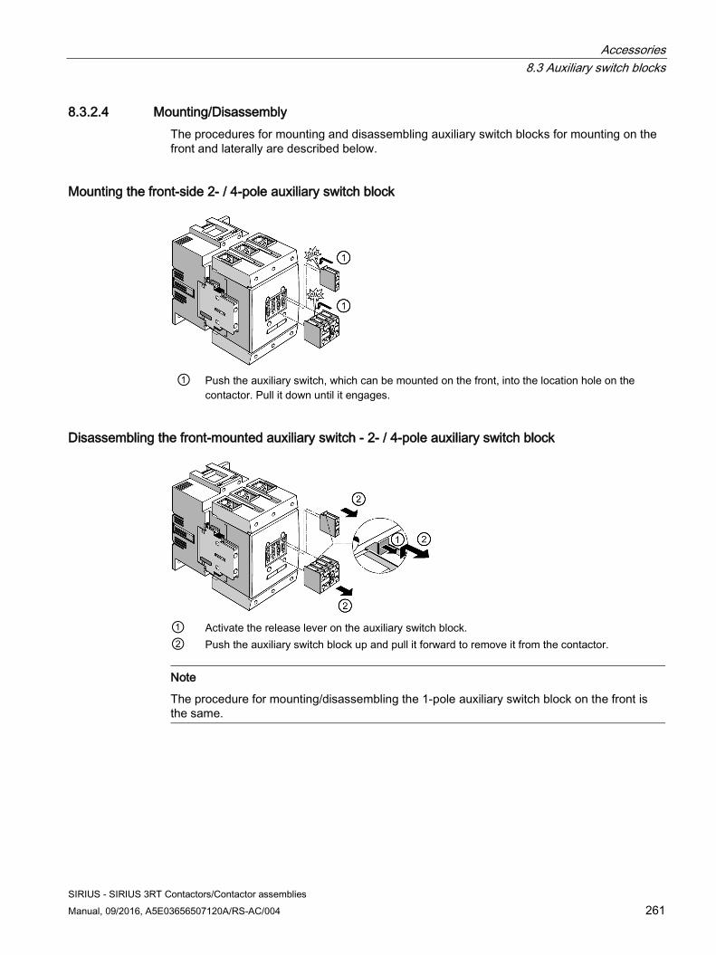
Accessories 8.3 Auxiliary switch blocks
SIRIUS - SIRIUS 3RT Contactors/Contactor assemblies Manual, 09/2016, A5E03656507120A/RS-AC/004 261
8.3.2.4 Mounting/Disassembly The procedures for mounting and disassembling auxiliary switch blocks for mounting on the front and laterally are described below.
Mounting the front-side 2- / 4-pole auxiliary switch block
① Push the auxiliary switch, which can be mounted on the front, into the location hole on the
contactor. Pull it down until it engages.
Disassembling the front-mounted auxiliary switch - 2- / 4-pole auxiliary switch block
① Activate the release lever on the auxiliary switch block. ② Push the auxiliary switch block up and pull it forward to remove it from the contactor.
Note
The procedure for mounting/disassembling the 1-pole auxiliary switch block on the front is the same.
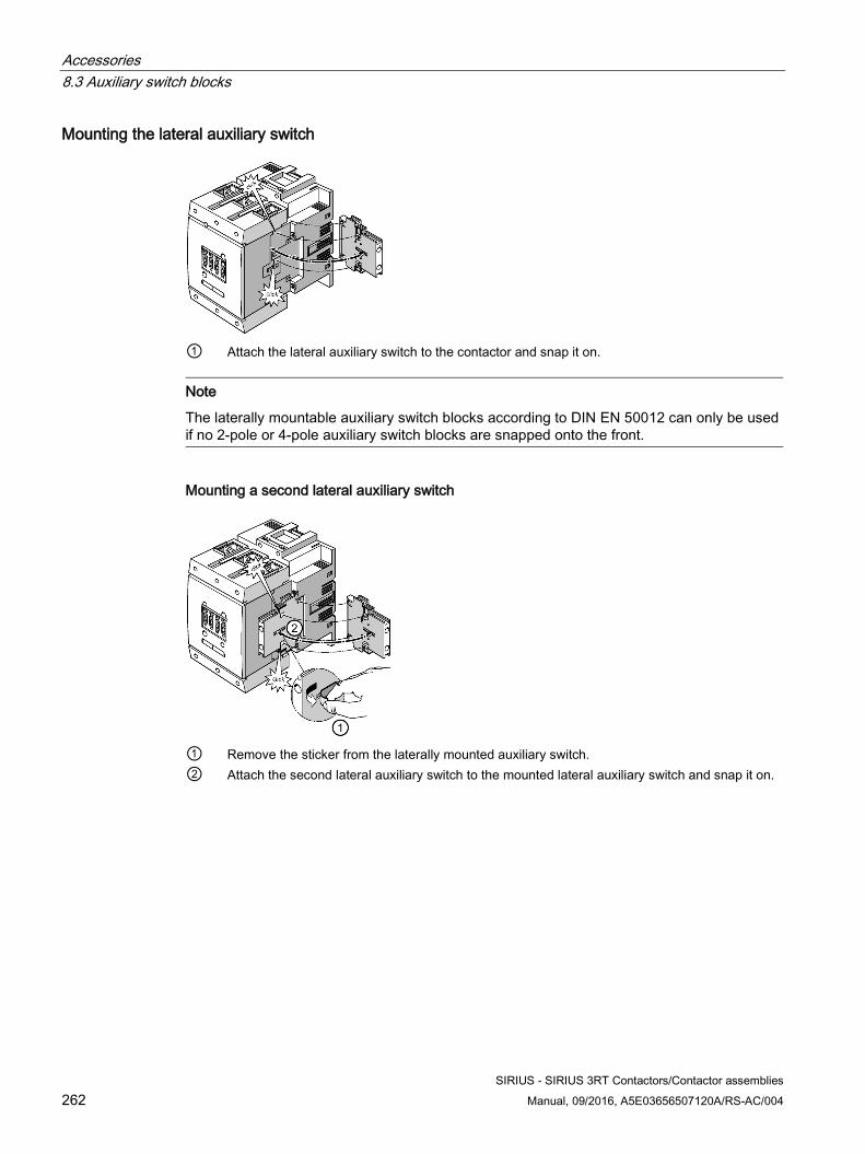
Accessories 8.3 Auxiliary switch blocks
SIRIUS - SIRIUS 3RT Contactors/Contactor assemblies 262 Manual, 09/2016, A5E03656507120A/RS-AC/004
Mounting the lateral auxiliary switch
① Attach the lateral auxiliary switch to the contactor and snap it on.
Note
The laterally mountable auxiliary switch blocks according to DIN EN 50012 can only be used if no 2-pole or 4-pole auxiliary switch blocks are snapped onto the front.
Mounting a second lateral auxiliary switch
① Remove the sticker from the laterally mounted auxiliary switch. ② Attach the second lateral auxiliary switch to the mounted lateral auxiliary switch and snap it on.
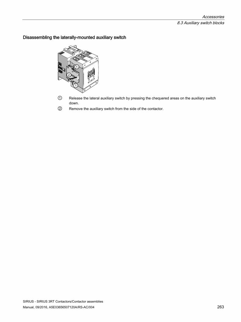
Accessories 8.3 Auxiliary switch blocks
SIRIUS - SIRIUS 3RT Contactors/Contactor assemblies Manual, 09/2016, A5E03656507120A/RS-AC/004 263
Disassembling the laterally-mounted auxiliary switch
① Release the lateral auxiliary switch by pressing the chequered areas on the auxiliary switch
down. ② Remove the auxiliary switch from the side of the contactor.
Accessories 8.4 Surge suppressor
SIRIUS - SIRIUS 3RT Contactors/Contactor assemblies 264 Manual, 09/2016, A5E03656507120A/RS-AC/004
8.4 Surge suppressor
8.4.1 Description When contactor coils are disconnected, overvoltages occur (inductive loads). Voltage peaks of up to 4 kV can occur at a rate of rise of voltage of 1 kV/microsecond (shower discharges). This leads to:
● Substantial erosion and, as a result, premature wear of the contacts which switch the coil.
● Injection of interfering signals, which lead to fault signals in electronic controls.
Therefore, all contactor coils should be attenuated against switching overvoltages, particularly when working in conjunction with electronic controls.
Furthermore, the high rate of rise of the voltage waveforms generated can lead to the capacitive coupling of significant interfering signals with adjacent systems. They necessitate an RC circuit directly at the location where the source of interference originated, i.e. at the contactor coil. This prevents overvoltages from occurring directly at the place of origin and protects the electronic components which are sensitive to voltage too. It also prevents the capacitive coupling of interfering signals with the control cables of electronic circuits.
Types of attenuation The following RC circuit elements are commonly used for overvoltage attenuation; they are connected in parallel with the contactor coil:
● RC element
● Freewheel diode, diode combination
● Varistors
All 3RT1 / 3RT2 contactors and 3RH21 contactor relays can be subsequently connected to RC elements or varistors for damping opening surges in the coil. Diodes or diode combinations can also be used.
Coupling relays, on the other hand, do not require any additional surge suppressor and can be used directly with electronic controls.
Reference More information ... Can be found in the chapter ... About coupling relays Coupling relays (Page 109)
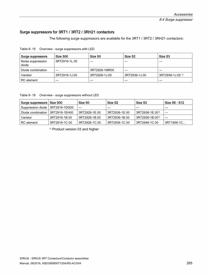
Accessories 8.4 Surge suppressor
SIRIUS - SIRIUS 3RT Contactors/Contactor assemblies Manual, 09/2016, A5E03656507120A/RS-AC/004 265
Surge suppressors for 3RT1 / 3RT2 / 3RH21 contactors The following surge suppressors are available for the 3RT1 / 3RT2 / 3RH21 contactors:
Table 8- 15 Overview - surge suppressors with LED
Surge suppressors Size S00 Size S0 Size S2 Size S3 Noise suppression diode
3RT2916-1L.00 --- --- ---
Diode combination --- 3RT2926-1MR00 --- --- Varistor 3RT2916-1J.00 3RT2926-1J.00 3RT2936-1J.00 3RT2936-1J.00 1) RC element --- --- --- ---
Table 8- 16 Overview - surge suppressors without LED
Surge suppressors Size S00 Size S0 Size S2 Size S3 Size S6 - S12 Suppression diode 3RT2916-1DG00 --- --- --- --- Diode combination 3RT2916-1EH00 3RT2926-1E.00 3RT2936-1E.00 3RT2936-1E.001) --- Varistor 3RT2916-1B.00 3RT2926-1B.00 3RT2936-1B.00 3RT2936-1B.001) --- RC element 3RT2916-1C.00 3RT2926-1C.00 3RT2936-1C.00 3RT2946-1C.00 3RT1956-1C...
1) Product version 03 and higher
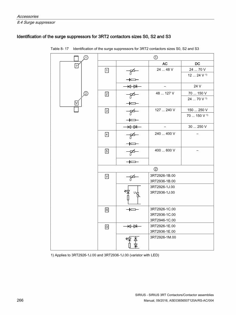
Accessories 8.4 Surge suppressor
SIRIUS - SIRIUS 3RT Contactors/Contactor assemblies 266 Manual, 09/2016, A5E03656507120A/RS-AC/004
Identification of the surge suppressors for 3RT2 contactors sizes S0, S2 and S3
Table 8- 17 Identification of the surge suppressors for 3RT2 contactors sizes S0, S2 and S3
① AC DC
24 ... 48 V 24 ... 70 V 12 ... 24 V 1)
– 24 V
48 ... 127 V 70 ... 150 V 24 ... 70 V 1)
127 ... 240 V 150 ... 250 V 70 ... 150 V 1)
– 30 ... 250 V
240 ... 400 V –
400 ... 600 V –
②
3RT2926-1B.00 3RT2936-1B.00
3RT2926-1J.00 3RT2936-1J.00
3RT2926-1C.00 3RT2936-1C.00 3RT2946-1C.00
3RT2926-1E.00 3RT2936-1E.00
3RT2926-1M.00
1) Applies to 3RT2926-1J.00 and 3RT2936-1J.00 (varistor with LED)
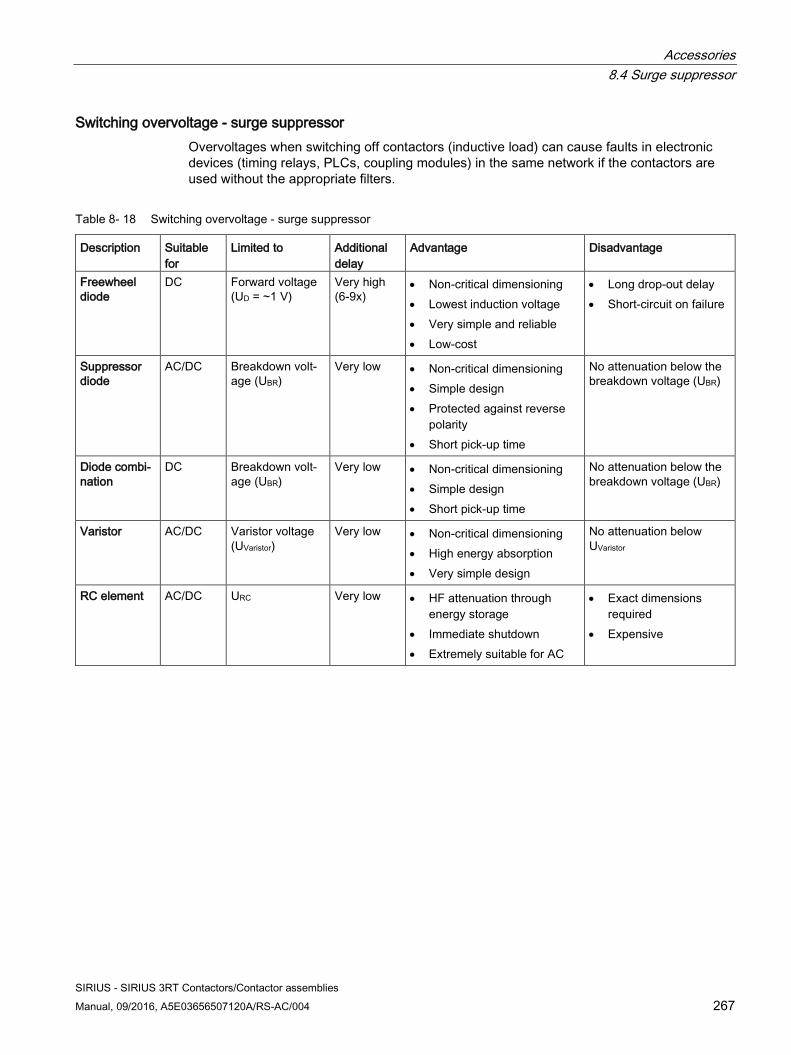
Accessories 8.4 Surge suppressor
SIRIUS - SIRIUS 3RT Contactors/Contactor assemblies Manual, 09/2016, A5E03656507120A/RS-AC/004 267
Switching overvoltage - surge suppressor Overvoltages when switching off contactors (inductive load) can cause faults in electronic devices (timing relays, PLCs, coupling modules) in the same network if the contactors are used without the appropriate filters.
Table 8- 18 Switching overvoltage - surge suppressor
Description Suitable for
Limited to Additional delay
Advantage Disadvantage
Freewheel diode
DC Forward voltage (UD = ~1 V)
Very high (6-9x)
• Non-critical dimensioning • Lowest induction voltage • Very simple and reliable • Low-cost
• Long drop-out delay • Short-circuit on failure
Suppressor diode
AC/DC Breakdown volt-age (UBR)
Very low • Non-critical dimensioning • Simple design • Protected against reverse
polarity • Short pick-up time
No attenuation below the breakdown voltage (UBR)
Diode combi-nation
DC Breakdown volt-age (UBR)
Very low • Non-critical dimensioning • Simple design • Short pick-up time
No attenuation below the breakdown voltage (UBR)
Varistor AC/DC Varistor voltage (UVaristor)
Very low • Non-critical dimensioning • High energy absorption • Very simple design
No attenuation below UVaristor
RC element AC/DC URC Very low • HF attenuation through energy storage
• Immediate shutdown • Extremely suitable for AC
• Exact dimensions required
• Expensive
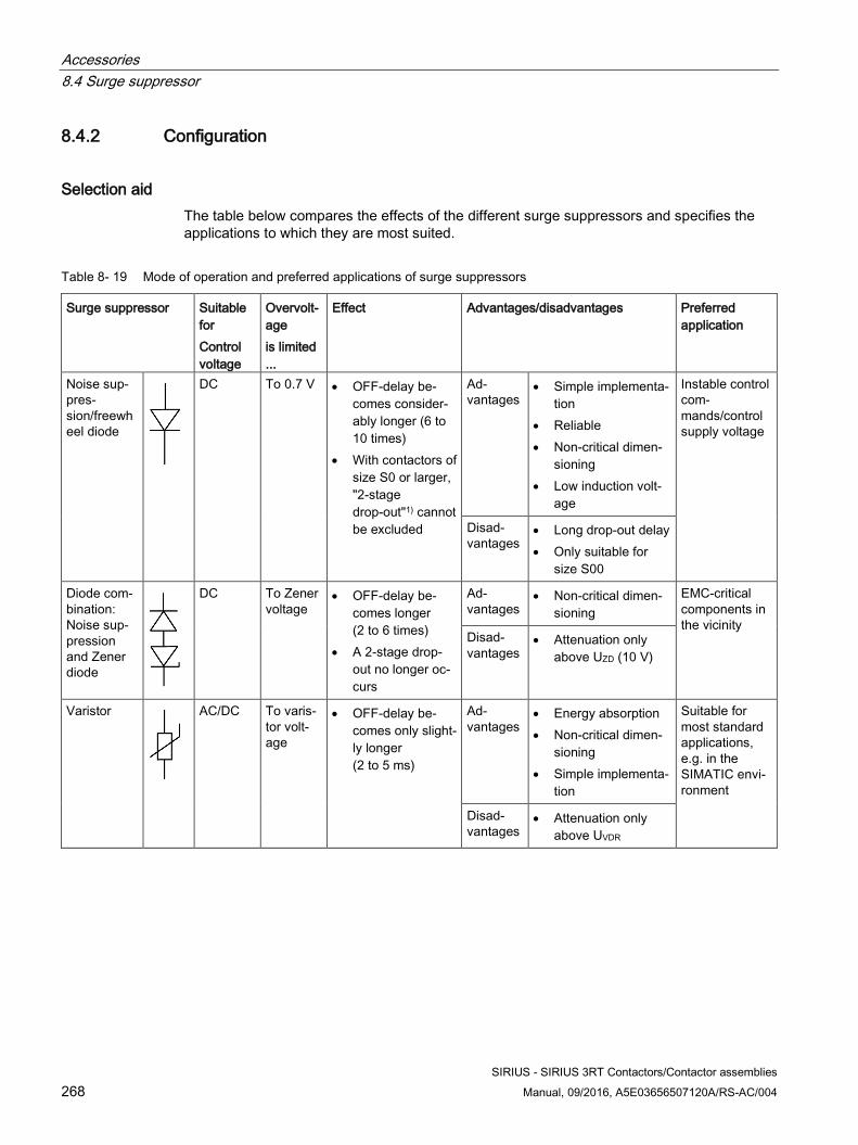
Accessories 8.4 Surge suppressor
SIRIUS - SIRIUS 3RT Contactors/Contactor assemblies 268 Manual, 09/2016, A5E03656507120A/RS-AC/004
8.4.2 Configuration
Selection aid The table below compares the effects of the different surge suppressors and specifies the applications to which they are most suited.
Table 8- 19 Mode of operation and preferred applications of surge suppressors
Surge suppressor Suitable for Control voltage
Overvolt-age is limited ...
Effect Advantages/disadvantages Preferred application
Noise sup-pres-sion/freewheel diode
DC To 0.7 V • OFF-delay be-comes consider-ably longer (6 to 10 times)
• With contactors of size S0 or larger, "2-stage drop-out"1) cannot be excluded
Ad-vantages
• Simple implementa-tion
• Reliable • Non-critical dimen-
sioning • Low induction volt-
age
Instable control com-mands/control supply voltage
Disad-vantages
• Long drop-out delay • Only suitable for
size S00
Diode com-bination: Noise sup-pression and Zener diode
DC To Zener voltage
• OFF-delay be-comes longer (2 to 6 times)
• A 2-stage drop-out no longer oc-curs
Ad-vantages
• Non-critical dimen-sioning
EMC-critical components in the vicinity
Disad-vantages
• Attenuation only above UZD (10 V)
Varistor
AC/DC To varis-tor volt-age
• OFF-delay be-comes only slight-ly longer (2 to 5 ms)
Ad-vantages
• Energy absorption • Non-critical dimen-
sioning • Simple implementa-
tion
Suitable for most standard applications, e.g. in the SIMATIC envi-ronment
Disad-vantages
• Attenuation only above UVDR
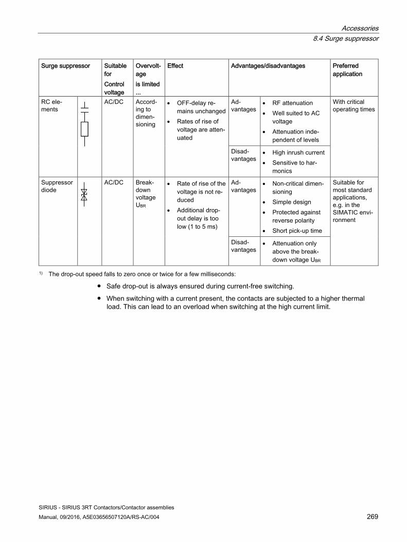
Accessories 8.4 Surge suppressor
SIRIUS - SIRIUS 3RT Contactors/Contactor assemblies Manual, 09/2016, A5E03656507120A/RS-AC/004 269
Surge suppressor Suitable for Control voltage
Overvolt-age is limited ...
Effect Advantages/disadvantages Preferred application
RC ele-ments
AC/DC Accord-ing to dimen-sioning
• OFF-delay re-mains unchanged
• Rates of rise of voltage are atten-uated
Ad-vantages
• RF attenuation • Well suited to AC
voltage • Attenuation inde-
pendent of levels
With critical operating times
Disad-vantages
• High inrush current • Sensitive to har-
monics
Suppressor diode
AC/DC Break-down voltage UBR
• Rate of rise of the voltage is not re-duced
• Additional drop-out delay is too low (1 to 5 ms)
Ad-vantages
• Non-critical dimen-sioning
• Simple design • Protected against
reverse polarity • Short pick-up time
Suitable for most standard applications, e.g. in the SIMATIC envi-ronment
Disad-vantages
• Attenuation only above the break-down voltage UBR
1) The drop-out speed falls to zero once or twice for a few milliseconds:
● Safe drop-out is always ensured during current-free switching.
● When switching with a current present, the contacts are subjected to a higher thermal load. This can lead to an overload when switching at the high current limit.
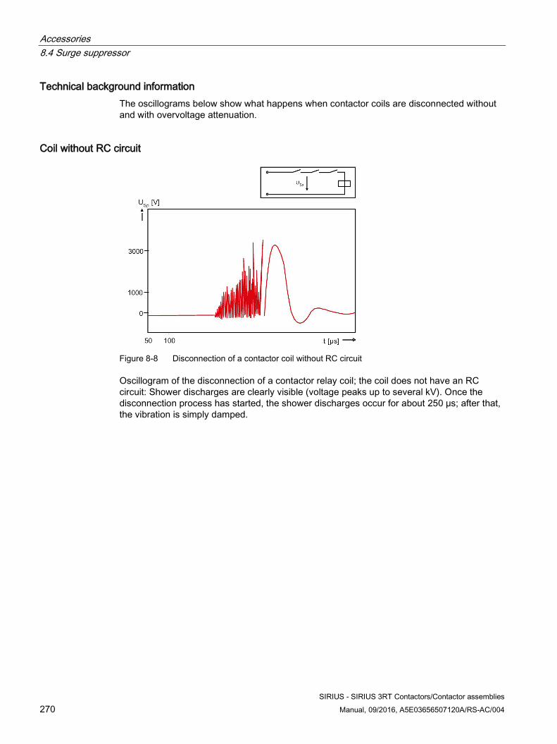
Accessories 8.4 Surge suppressor
SIRIUS - SIRIUS 3RT Contactors/Contactor assemblies 270 Manual, 09/2016, A5E03656507120A/RS-AC/004
Technical background information The oscillograms below show what happens when contactor coils are disconnected without and with overvoltage attenuation.
Coil without RC circuit
Figure 8-8 Disconnection of a contactor coil without RC circuit
Oscillogram of the disconnection of a contactor relay coil; the coil does not have an RC circuit: Shower discharges are clearly visible (voltage peaks up to several kV). Once the disconnection process has started, the shower discharges occur for about 250 μs; after that, the vibration is simply damped.
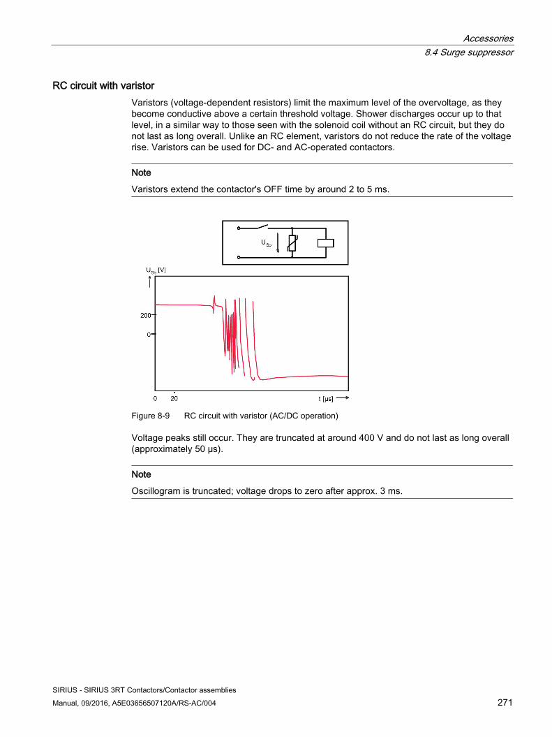
Accessories 8.4 Surge suppressor
SIRIUS - SIRIUS 3RT Contactors/Contactor assemblies Manual, 09/2016, A5E03656507120A/RS-AC/004 271
RC circuit with varistor Varistors (voltage-dependent resistors) limit the maximum level of the overvoltage, as they become conductive above a certain threshold voltage. Shower discharges occur up to that level, in a similar way to those seen with the solenoid coil without an RC circuit, but they do not last as long overall. Unlike an RC element, varistors do not reduce the rate of the voltage rise. Varistors can be used for DC- and AC-operated contactors.
Note
Varistors extend the contactor's OFF time by around 2 to 5 ms.
Figure 8-9 RC circuit with varistor (AC/DC operation)
Voltage peaks still occur. They are truncated at around 400 V and do not last as long overall (approximately 50 μs).
Note
Oscillogram is truncated; voltage drops to zero after approx. 3 ms.
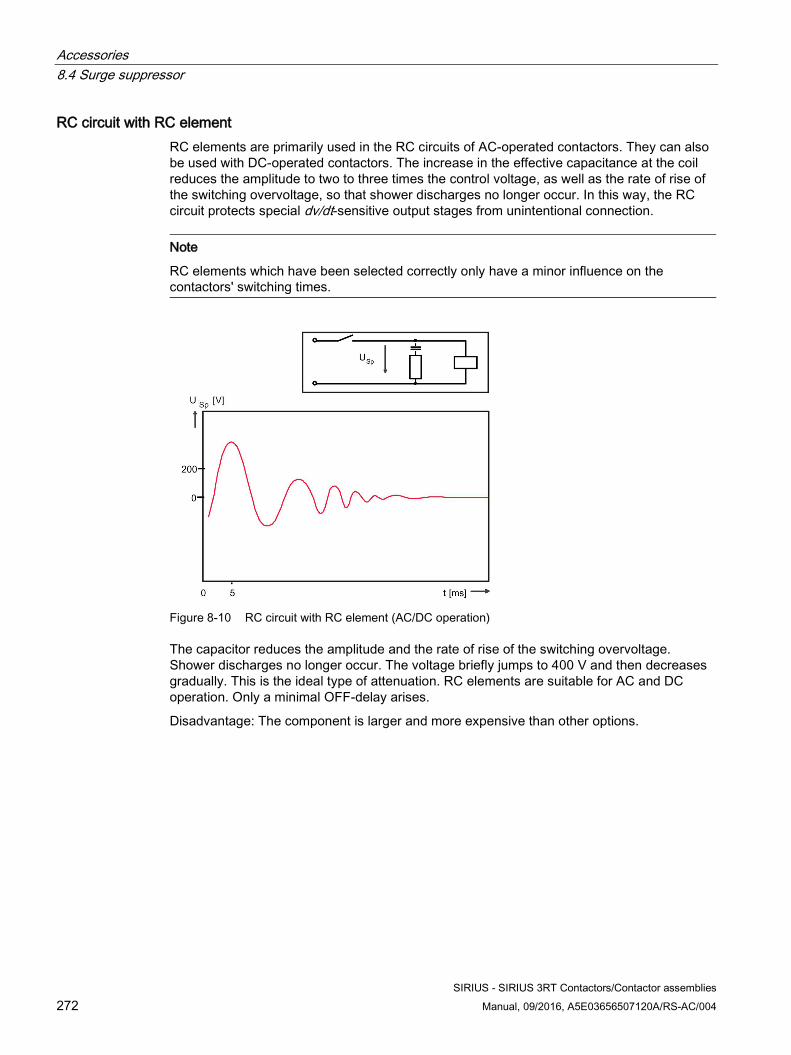
Accessories 8.4 Surge suppressor
SIRIUS - SIRIUS 3RT Contactors/Contactor assemblies 272 Manual, 09/2016, A5E03656507120A/RS-AC/004
RC circuit with RC element RC elements are primarily used in the RC circuits of AC-operated contactors. They can also be used with DC-operated contactors. The increase in the effective capacitance at the coil reduces the amplitude to two to three times the control voltage, as well as the rate of rise of the switching overvoltage, so that shower discharges no longer occur. In this way, the RC circuit protects special dv/dt-sensitive output stages from unintentional connection.
Note
RC elements which have been selected correctly only have a minor influence on the contactors' switching times.
Figure 8-10 RC circuit with RC element (AC/DC operation)
The capacitor reduces the amplitude and the rate of rise of the switching overvoltage. Shower discharges no longer occur. The voltage briefly jumps to 400 V and then decreases gradually. This is the ideal type of attenuation. RC elements are suitable for AC and DC operation. Only a minimal OFF-delay arises.
Disadvantage: The component is larger and more expensive than other options.
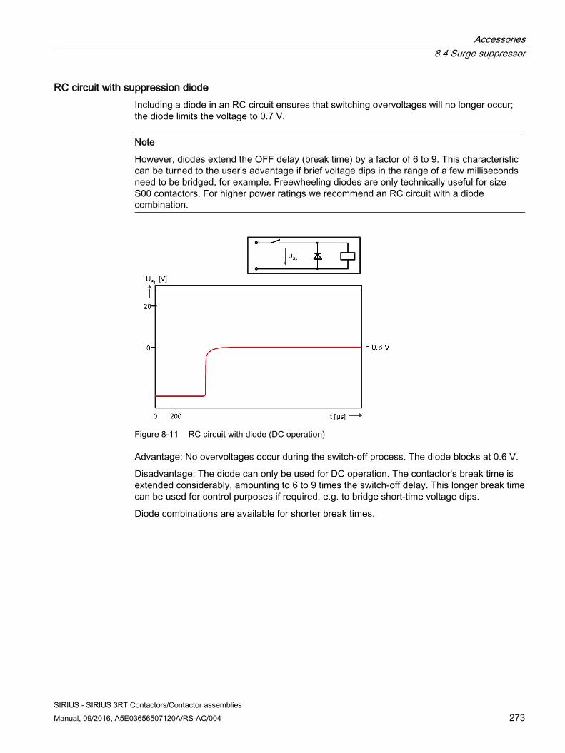
Accessories 8.4 Surge suppressor
SIRIUS - SIRIUS 3RT Contactors/Contactor assemblies Manual, 09/2016, A5E03656507120A/RS-AC/004 273
RC circuit with suppression diode Including a diode in an RC circuit ensures that switching overvoltages will no longer occur; the diode limits the voltage to 0.7 V.
Note
However, diodes extend the OFF delay (break time) by a factor of 6 to 9. This characteristic can be turned to the user's advantage if brief voltage dips in the range of a few milliseconds need to be bridged, for example. Freewheeling diodes are only technically useful for size S00 contactors. For higher power ratings we recommend an RC circuit with a diode combination.
Figure 8-11 RC circuit with diode (DC operation)
Advantage: No overvoltages occur during the switch-off process. The diode blocks at 0.6 V.
Disadvantage: The diode can only be used for DC operation. The contactor's break time is extended considerably, amounting to 6 to 9 times the switch-off delay. This longer break time can be used for control purposes if required, e.g. to bridge short-time voltage dips.
Diode combinations are available for shorter break times.
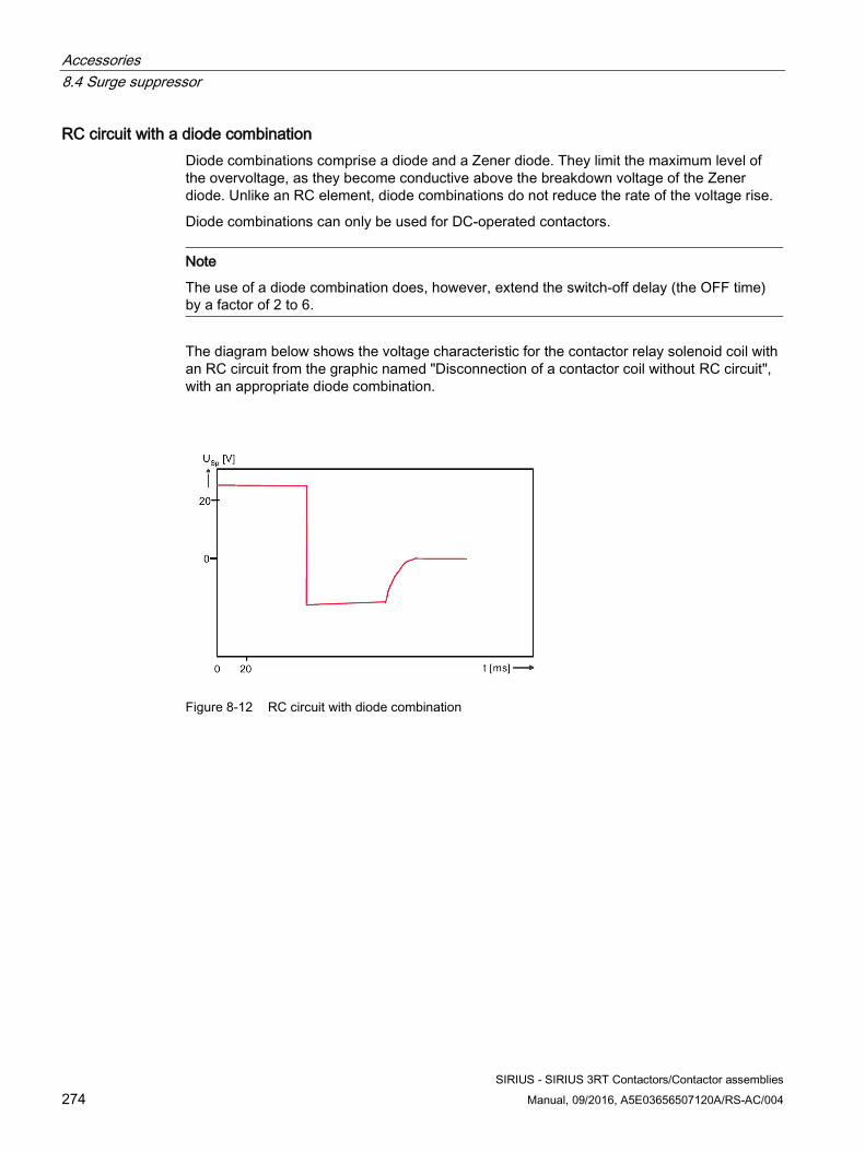
Accessories 8.4 Surge suppressor
SIRIUS - SIRIUS 3RT Contactors/Contactor assemblies 274 Manual, 09/2016, A5E03656507120A/RS-AC/004
RC circuit with a diode combination Diode combinations comprise a diode and a Zener diode. They limit the maximum level of the overvoltage, as they become conductive above the breakdown voltage of the Zener diode. Unlike an RC element, diode combinations do not reduce the rate of the voltage rise.
Diode combinations can only be used for DC-operated contactors.
Note
The use of a diode combination does, however, extend the switch-off delay (the OFF time) by a factor of 2 to 6.
The diagram below shows the voltage characteristic for the contactor relay solenoid coil with an RC circuit from the graphic named "Disconnection of a contactor coil without RC circuit", with an appropriate diode combination.
Figure 8-12 RC circuit with diode combination
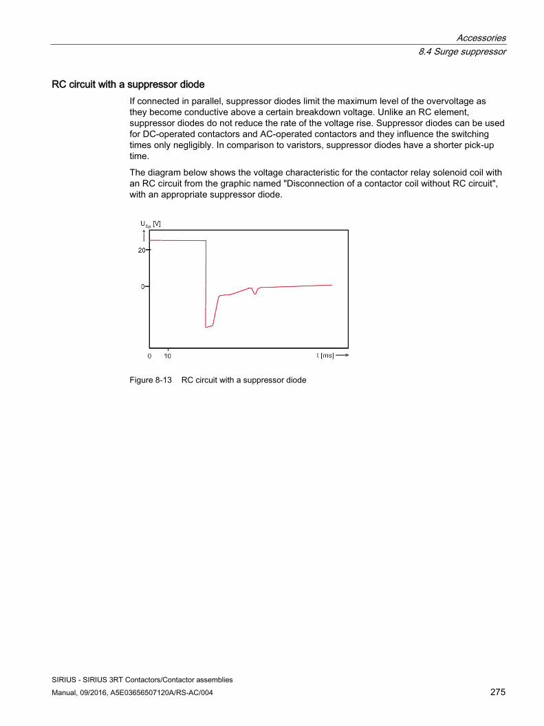
Accessories 8.4 Surge suppressor
SIRIUS - SIRIUS 3RT Contactors/Contactor assemblies Manual, 09/2016, A5E03656507120A/RS-AC/004 275
RC circuit with a suppressor diode If connected in parallel, suppressor diodes limit the maximum level of the overvoltage as they become conductive above a certain breakdown voltage. Unlike an RC element, suppressor diodes do not reduce the rate of the voltage rise. Suppressor diodes can be used for DC-operated contactors and AC-operated contactors and they influence the switching times only negligibly. In comparison to varistors, suppressor diodes have a shorter pick-up time.
The diagram below shows the voltage characteristic for the contactor relay solenoid coil with an RC circuit from the graphic named "Disconnection of a contactor coil without RC circuit", with an appropriate suppressor diode.
Figure 8-13 RC circuit with a suppressor diode
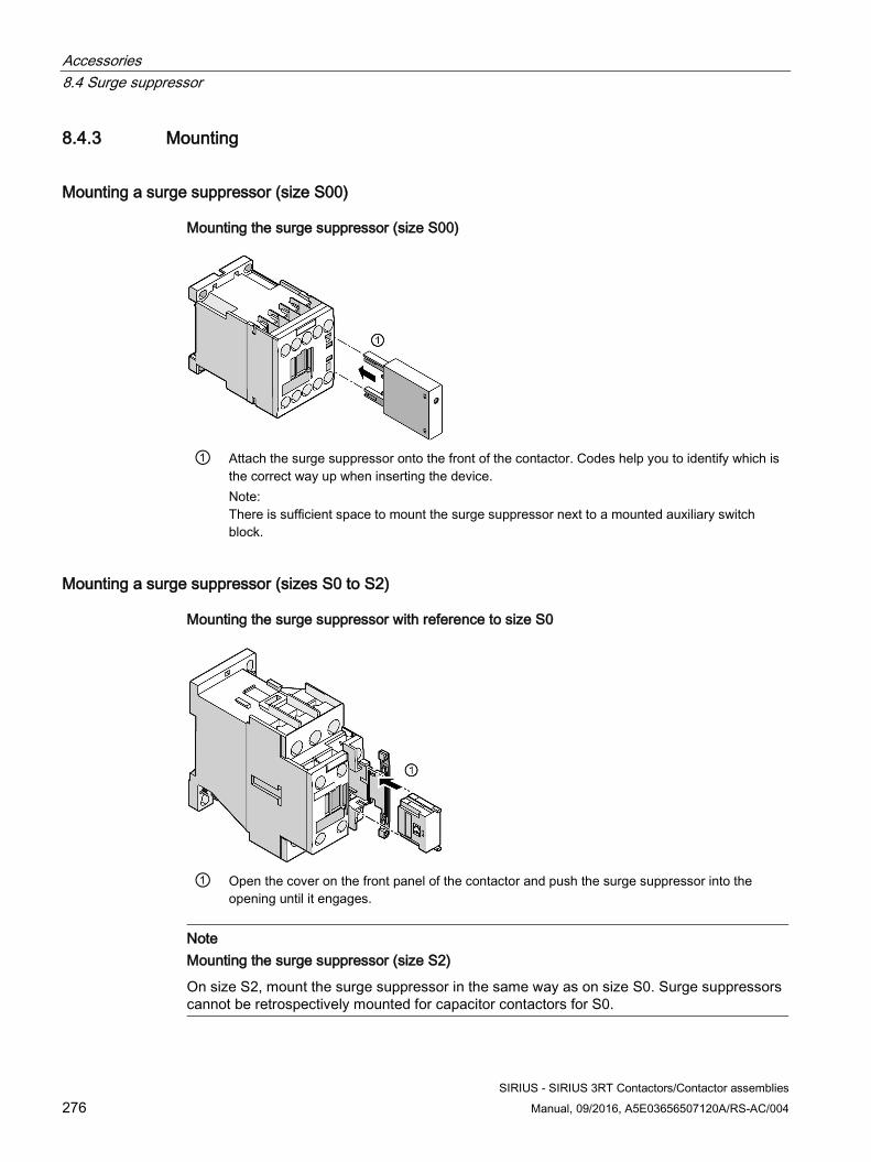
Accessories 8.4 Surge suppressor
SIRIUS - SIRIUS 3RT Contactors/Contactor assemblies 276 Manual, 09/2016, A5E03656507120A/RS-AC/004
8.4.3 Mounting
Mounting a surge suppressor (size S00)
Mounting the surge suppressor (size S00)
① Attach the surge suppressor onto the front of the contactor. Codes help you to identify which is
the correct way up when inserting the device. Note: There is sufficient space to mount the surge suppressor next to a mounted auxiliary switch block.
Mounting a surge suppressor (sizes S0 to S2)
Mounting the surge suppressor with reference to size S0
① Open the cover on the front panel of the contactor and push the surge suppressor into the
opening until it engages.
Note Mounting the surge suppressor (size S2)
On size S2, mount the surge suppressor in the same way as on size S0. Surge suppressors cannot be retrospectively mounted for capacitor contactors for S0.
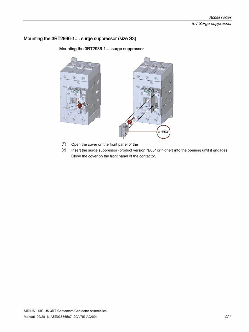
Accessories 8.4 Surge suppressor
SIRIUS - SIRIUS 3RT Contactors/Contactor assemblies Manual, 09/2016, A5E03656507120A/RS-AC/004 277
Mounting the 3RT2936-1.... surge suppressor (size S3)
Mounting the 3RT2936-1.... surge suppressor
① Open the cover on the front panel of the ② Insert the surge suppressor (product version *E03* or higher) into the opening until it engages.
Close the cover on the front panel of the contactor.
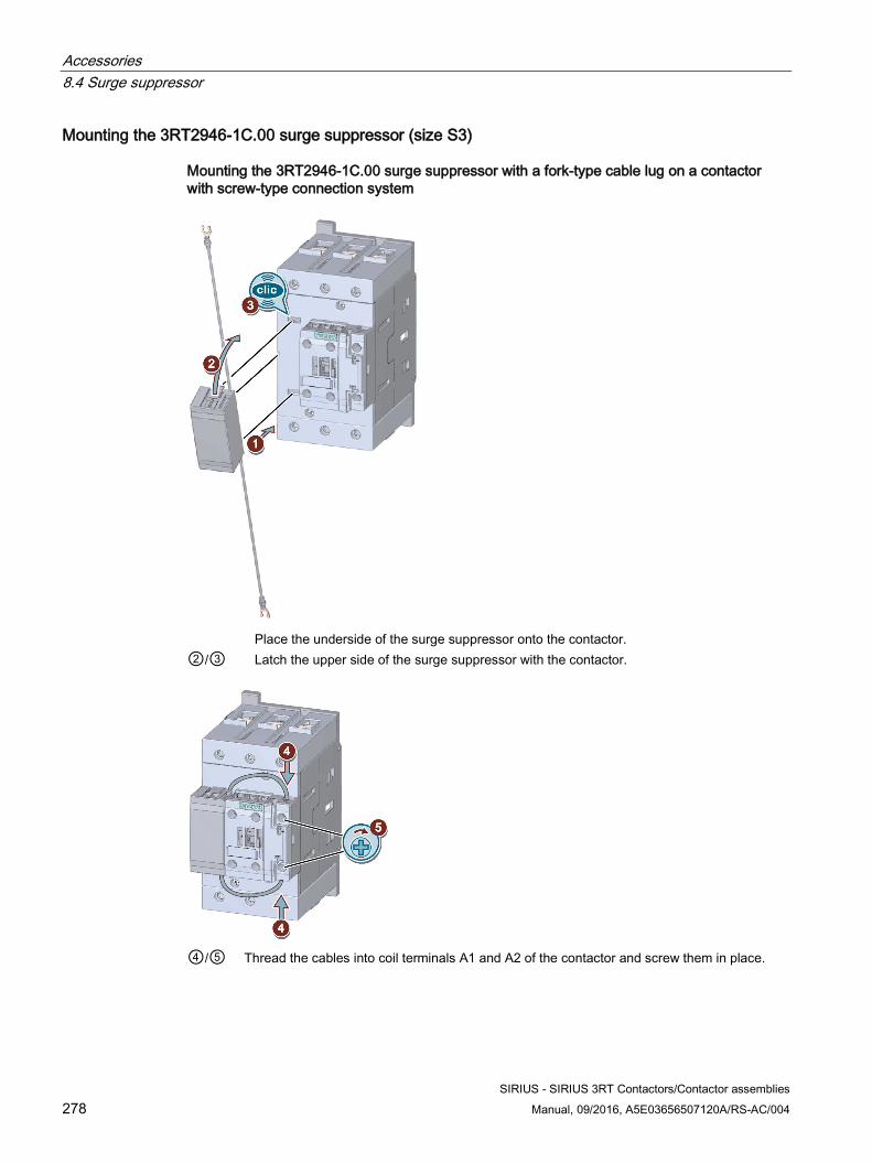
Accessories 8.4 Surge suppressor
SIRIUS - SIRIUS 3RT Contactors/Contactor assemblies 278 Manual, 09/2016, A5E03656507120A/RS-AC/004
Mounting the 3RT2946-1C.00 surge suppressor (size S3)
Mounting the 3RT2946-1C.00 surge suppressor with a fork-type cable lug on a contactor with screw-type connection system
Place the underside of the surge suppressor onto the contactor. ②/③ Latch the upper side of the surge suppressor with the contactor.
④/⑤ Thread the cables into coil terminals A1 and A2 of the contactor and screw them in place.
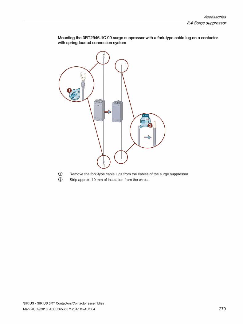
Accessories 8.4 Surge suppressor
SIRIUS - SIRIUS 3RT Contactors/Contactor assemblies Manual, 09/2016, A5E03656507120A/RS-AC/004 279
Mounting the 3RT2946-1C.00 surge suppressor with a fork-type cable lug on a contactor with spring-loaded connection system
① Remove the fork-type cable lugs from the cables of the surge suppressor. ② Strip approx. 10 mm of insulation from the wires.
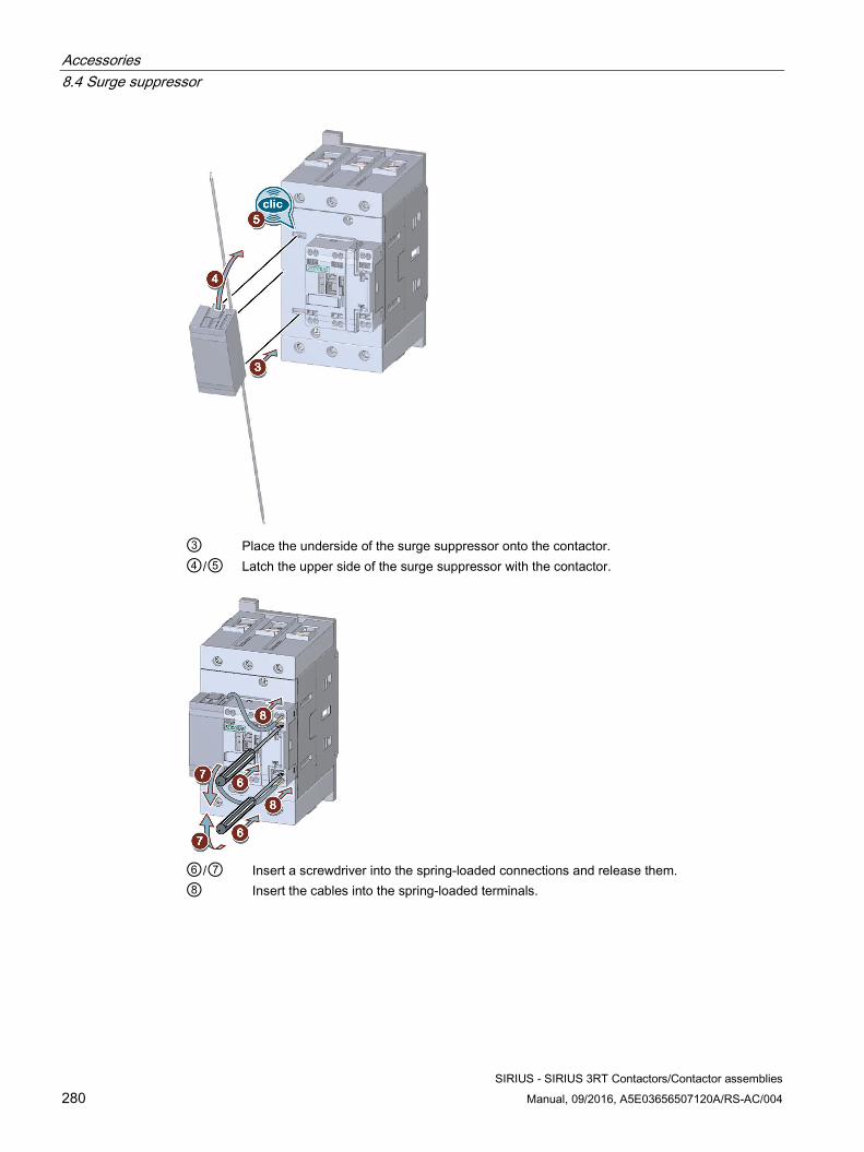
Accessories 8.4 Surge suppressor
SIRIUS - SIRIUS 3RT Contactors/Contactor assemblies 280 Manual, 09/2016, A5E03656507120A/RS-AC/004
③ Place the underside of the surge suppressor onto the contactor. ④/⑤ Latch the upper side of the surge suppressor with the contactor.
⑥/⑦ Insert a screwdriver into the spring-loaded connections and release them. ⑧ Insert the cables into the spring-loaded terminals.
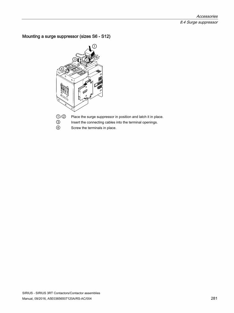
Accessories 8.4 Surge suppressor
SIRIUS - SIRIUS 3RT Contactors/Contactor assemblies Manual, 09/2016, A5E03656507120A/RS-AC/004 281
Mounting a surge suppressor (sizes S6 - S12)
①/② Place the surge suppressor in position and latch it in place. ③ Insert the connecting cables into the terminal openings. ④ Screw the terminals in place.
Accessories 8.5 EMC suppression module
SIRIUS - SIRIUS 3RT Contactors/Contactor assemblies 282 Manual, 09/2016, A5E03656507120A/RS-AC/004
8.5 EMC suppression module
8.5.1 Description The EMC interference suppression module for size S00 contactors reduces the high-frequency components and the voltage level of a "counter-source voltage" in three phases. This results in the following advantages:
● Reduction of arcing: The connection between the main current path and the EMC suppression module enables arcing, which is responsible for contact erosion and the majority of clicking noises, to be reduced; this in turn ensures an EMC-compliant design.
● Increased operational reliability: Since the EMC suppression module achieves a significant reduction in radio-frequency components and the voltage level in three phases, the contact durability is extended considerably. This makes an important contribution towards enhancing the reliability and availability of the system as a whole.
● Omission of fine graduation: There is no need for fine graduations within each power class, as smaller motors inherently have a higher inductance, so that one solution is adequate for all fixed-speed operating mechanisms up to 5.5 kW.
Versions Two electrical versions of the EMC suppression module are available.
Table 8- 20 Versions of the EMC suppression module
Design of the EMC suppression module Article number RC circuit 3RT2916-1PA Varistor circuit 3RT2916-1PB
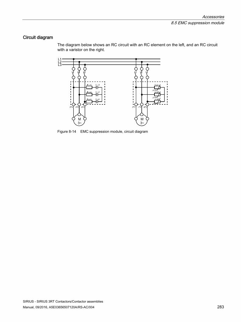
Accessories 8.5 EMC suppression module
SIRIUS - SIRIUS 3RT Contactors/Contactor assemblies Manual, 09/2016, A5E03656507120A/RS-AC/004 283
Circuit diagram The diagram below shows an RC circuit with an RC element on the left, and an RC circuit with a varistor on the right.
Figure 8-14 EMC suppression module, circuit diagram
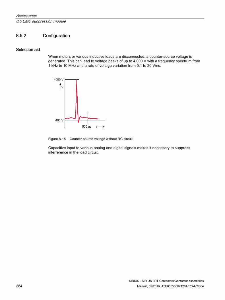
Accessories 8.5 EMC suppression module
SIRIUS - SIRIUS 3RT Contactors/Contactor assemblies 284 Manual, 09/2016, A5E03656507120A/RS-AC/004
8.5.2 Configuration
Selection aid When motors or various inductive loads are disconnected, a counter-source voltage is generated. This can lead to voltage peaks of up to 4,000 V with a frequency spectrum from 1 kHz to 10 MHz and a rate of voltage variation from 0.1 to 20 V/ns.
Figure 8-15 Counter-source voltage without RC circuit
Capacitive input to various analog and digital signals makes it necessary to suppress interference in the load circuit.
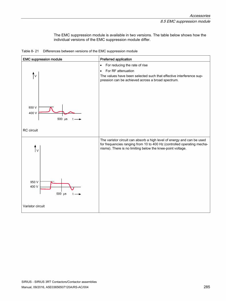
Accessories 8.5 EMC suppression module
SIRIUS - SIRIUS 3RT Contactors/Contactor assemblies Manual, 09/2016, A5E03656507120A/RS-AC/004 285
The EMC suppression module is available in two versions. The table below shows how the individual versions of the EMC suppression module differ.
Table 8- 21 Differences between versions of the EMC suppression module
EMC suppression module Preferred application
RC circuit
• For reducing the rate of rise • For RF attenuation The values have been selected such that effective interference sup-pression can be achieved across a broad spectrum.
Varistor circuit
The varistor circuit can absorb a high level of energy and can be used for frequencies ranging from 10 to 400 Hz (controlled operating mecha-nisms). There is no limiting below the knee-point voltage.
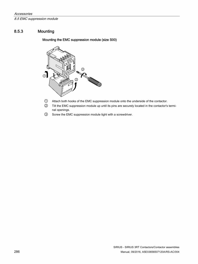
Accessories 8.5 EMC suppression module
SIRIUS - SIRIUS 3RT Contactors/Contactor assemblies 286 Manual, 09/2016, A5E03656507120A/RS-AC/004
8.5.3 Mounting
Mounting the EMC suppression module (size S00)
① Attach both hooks of the EMC suppression module onto the underside of the contactor. ② Tilt the EMC suppression module up until its pins are securely located in the contactor's termi-
nal openings. ③ Screw the EMC suppression module tight with a screwdriver.
Accessories 8.6 OFF-delay device
SIRIUS - SIRIUS 3RT Contactors/Contactor assemblies Manual, 09/2016, A5E03656507120A/RS-AC/004 287
8.6 OFF-delay device
8.6.1 Description The OFF-delay device prevents a contactor from dropping out unintentionally when there is a short-time voltage dip or voltage failure. The OFF-delay device supplies a downstream, DC-operated contactor with the necessary energy during a voltage dip, ensuring that the contactor does not drop out. The 3RT2916-. OFF-delay devices have been specially adapted to the 3RT contactors (sizes S00 to S3) and the 3RH21 contactor relays (size S00), and are available in the versions shown below.
Note OFF-delay device requires DC contactor or an AC/DC contactor
The OFF-delay device can be controlled with AC or with DC. However, it always requires a DC contactor or an AC/DC contactor
Table 8- 22 Versions of the OFF-delay device
Control voltage of the OFF-delay device Article number 24 V DC 3RT2916-2BE01 110 V AC/DC 3RT2916-2BK01 220/230 V AC/DC 3RT2916-2BL01
8.6.2 Configuration The OFF-delay device operates without external voltage on a capacitive basis and can be energized with either AC or DC (24 V version for DC operation only). Voltage matching is only required for AC operation and is performed using a rectifier bridge.
A contactor opens after a delay when the capacitors integrated in the OFF-delay device are switched in parallel to the contactor's magnet coil. In the event of voltage failures, the capacitors discharge via the magnet coil, thus delaying opening of the contactor.
If the command devices are located upstream of the OFF-delay device in the circuit, the device will be activated with every opening operation. If the activation takes place downstream of the OFF-delay device, an OFF-delay only applies if the line voltage fails. The mean OFF-delay value is around 1.5 times the specified minimum time.
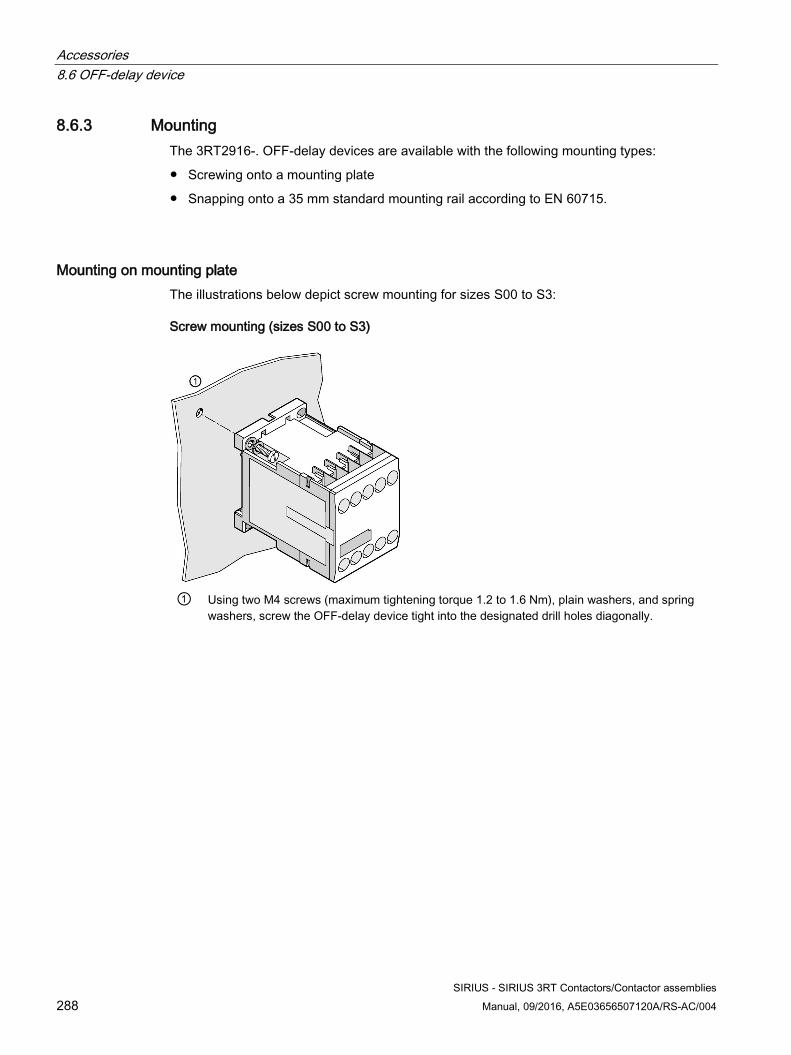
Accessories 8.6 OFF-delay device
SIRIUS - SIRIUS 3RT Contactors/Contactor assemblies 288 Manual, 09/2016, A5E03656507120A/RS-AC/004
8.6.3 Mounting The 3RT2916-. OFF-delay devices are available with the following mounting types:
● Screwing onto a mounting plate
● Snapping onto a 35 mm standard mounting rail according to EN 60715.
Mounting on mounting plate The illustrations below depict screw mounting for sizes S00 to S3:
Screw mounting (sizes S00 to S3)
① Using two M4 screws (maximum tightening torque 1.2 to 1.6 Nm), plain washers, and spring
washers, screw the OFF-delay device tight into the designated drill holes diagonally.
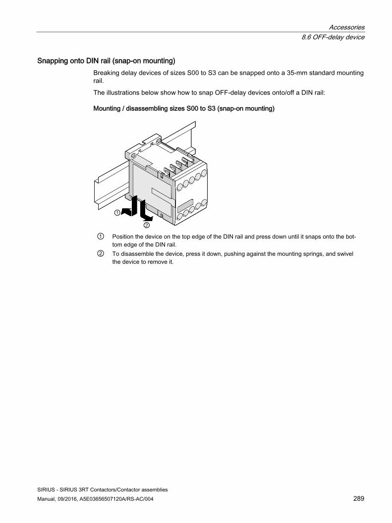
Accessories 8.6 OFF-delay device
SIRIUS - SIRIUS 3RT Contactors/Contactor assemblies Manual, 09/2016, A5E03656507120A/RS-AC/004 289
Snapping onto DIN rail (snap-on mounting) Breaking delay devices of sizes S00 to S3 can be snapped onto a 35-mm standard mounting rail.
The illustrations below show how to snap OFF-delay devices onto/off a DIN rail:
Mounting / disassembling sizes S00 to S3 (snap-on mounting)
① Position the device on the top edge of the DIN rail and press down until it snaps onto the bot-
tom edge of the DIN rail. ② To disassemble the device, press it down, pushing against the mounting springs, and swivel
the device to remove it.
Accessories 8.7 Mechanical latch
SIRIUS - SIRIUS 3RT Contactors/Contactor assemblies 290 Manual, 09/2016, A5E03656507120A/RS-AC/004
8.7 Mechanical latch
8.7.1 Description The mechanical latch for the 3RT2.2 power contactors ensures that the contactor remains switched on even if there is a voltage failure. The release coil has an ON period of 100%.
Table 8- 23 Versions of the mechanical latch
Design of the mechanical latch Article number 24 V AC/DC 3RT2926-3AB31 110 V AC/DC 3RT2926-3AF31 230 V AC/DC 3RT2926-3AP31
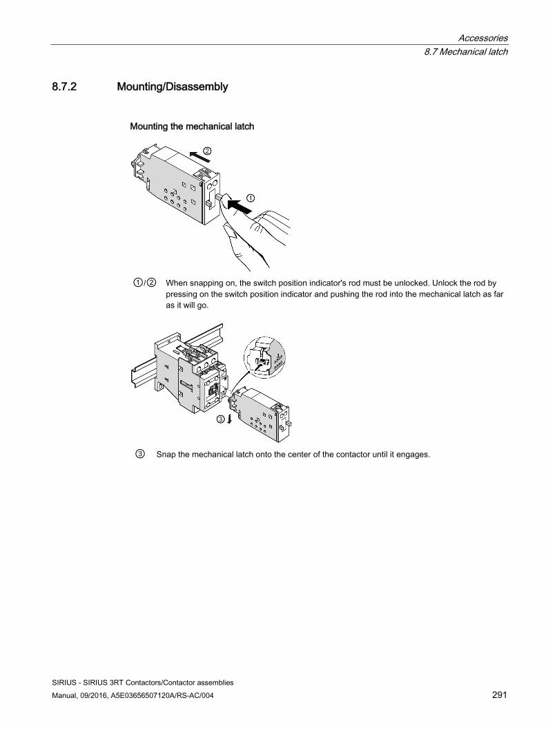
Accessories 8.7 Mechanical latch
SIRIUS - SIRIUS 3RT Contactors/Contactor assemblies Manual, 09/2016, A5E03656507120A/RS-AC/004 291
8.7.2 Mounting/Disassembly
Mounting the mechanical latch
①/② When snapping on, the switch position indicator's rod must be unlocked. Unlock the rod by
pressing on the switch position indicator and pushing the rod into the mechanical latch as far as it will go.
③ Snap the mechanical latch onto the center of the contactor until it engages.
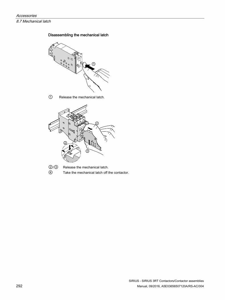
Accessories 8.7 Mechanical latch
SIRIUS - SIRIUS 3RT Contactors/Contactor assemblies 292 Manual, 09/2016, A5E03656507120A/RS-AC/004
Disassembling the mechanical latch
① Release the mechanical latch.
②/③ Release the mechanical latch. ④ Take the mechanical latch off the contactor.
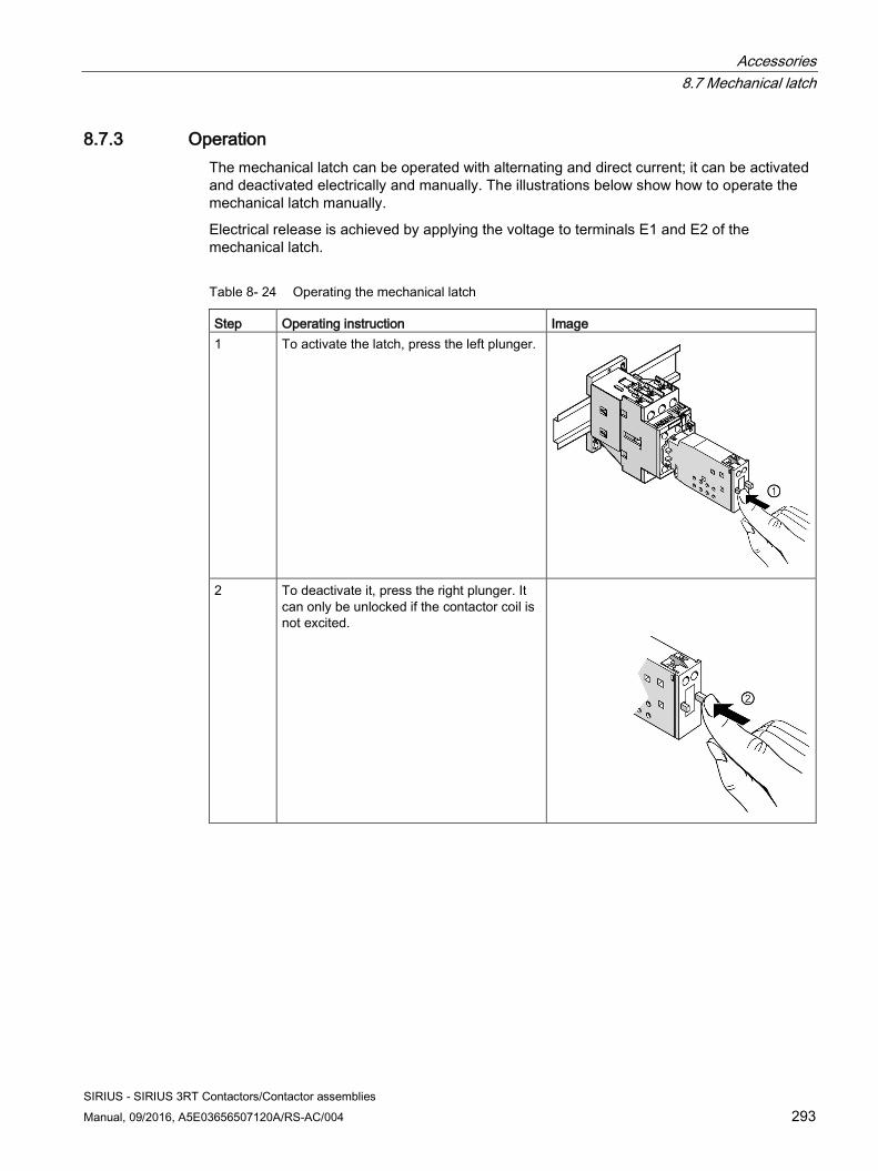
Accessories 8.7 Mechanical latch
SIRIUS - SIRIUS 3RT Contactors/Contactor assemblies Manual, 09/2016, A5E03656507120A/RS-AC/004 293
8.7.3 Operation The mechanical latch can be operated with alternating and direct current; it can be activated and deactivated electrically and manually. The illustrations below show how to operate the mechanical latch manually.
Electrical release is achieved by applying the voltage to terminals E1 and E2 of the mechanical latch.
Table 8- 24 Operating the mechanical latch
Step Operating instruction Image 1 To activate the latch, press the left plunger.
2 To deactivate it, press the right plunger. It can only be unlocked if the contactor coil is not excited.
Accessories 8.8 Additional load module
SIRIUS - SIRIUS 3RT Contactors/Contactor assemblies 294 Manual, 09/2016, A5E03656507120A/RS-AC/004
8.8 Additional load module
8.8.1 Description The 3RT2916-1GA00 additional load module for size S00 contactors is used to increase the permissible residual current and to limit the residual voltage of SIMATIC semiconductor outputs.
If SIRIUS contactors and SIRIUS contactor relays of size S00 are used in conjunction with SIMATIC output modules whose residual current on signal "0" is higher than that which is permissible for size S00 contactors, this can sometimes result in malfunctions. The maximum permissible residual current of the electronics for size S00 contactors with a 230 V AC drive is 3 mA; at higher residual currents the contactors will not drop out. The additional load module is used to ensure that size S00 contactors which are directly controlled via 230 V AC semiconductor outputs are disconnected safely by programmable logic controllers. The additional load module also performs the function of an overvoltage attenuation circuit.
Technical data Rated voltage AC 50/60 Hz
180 V to 255 V Power loss 2.4 W at 230 V Permissible contactor types 3RT2.1 (size S00)
8.8.2 Mounting The 3RT2916-1GA00 additional load module is connected in parallel with the contactor coil. Its design is identical to that of the surge suppressor and it is attached to the front of the contactor, with or without an auxiliary switch block.
Reference More information ... Can be found in the chapter titled ... About mounting the additional load module Surge suppressor (Page 264)
Accessories 8.9 Control kit for manual operation of contactor contacts
SIRIUS - SIRIUS 3RT Contactors/Contactor assemblies Manual, 09/2016, A5E03656507120A/RS-AC/004 295
8.9 Control kit for manual operation of contactor contacts
8.9.1 Description The control kit is a tool used for manual operation (closing) of the auxiliary contacts of the 3RT20 power contactors and the main contacts (load-free switching) during commissioning. This way, for example, the auxiliary contact circuit or also a high-voltage test for commissioning can be carried out even without a fully configured control circuit. The following control kits are available for the different sizes:
● S00: 3RT2916-4MC00 (color: yellow): Use on front connection point
● S0: 3RT2926-4MC00 (color: orange): Use on front connection point
● S2 / S3 3RT2936-4MC00 (color: yellow): Use in the slot of the surge suppressor
The module is used to check the wiring and the motor direction of rotation under conditions of short-circuit protection. The control kit also enables simple and user-friendly use and support for high-voltage tests according to IEC 60294.
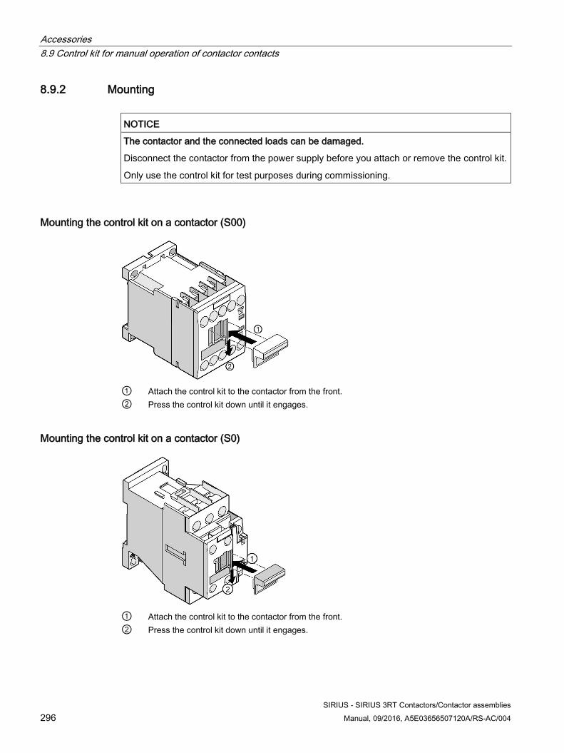
Accessories 8.9 Control kit for manual operation of contactor contacts
SIRIUS - SIRIUS 3RT Contactors/Contactor assemblies 296 Manual, 09/2016, A5E03656507120A/RS-AC/004
8.9.2 Mounting
NOTICE
The contactor and the connected loads can be damaged.
Disconnect the contactor from the power supply before you attach or remove the control kit.
Only use the control kit for test purposes during commissioning.
Mounting the control kit on a contactor (S00)
① Attach the control kit to the contactor from the front. ② Press the control kit down until it engages.
Mounting the control kit on a contactor (S0)
① Attach the control kit to the contactor from the front. ② Press the control kit down until it engages.
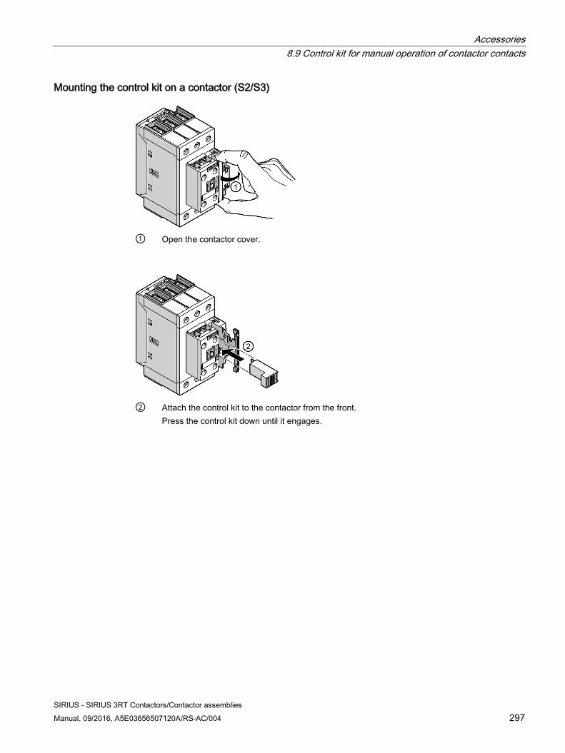
Accessories 8.9 Control kit for manual operation of contactor contacts
SIRIUS - SIRIUS 3RT Contactors/Contactor assemblies Manual, 09/2016, A5E03656507120A/RS-AC/004 297
Mounting the control kit on a contactor (S2/S3)
① Open the contactor cover.
② Attach the control kit to the contactor from the front.
Press the control kit down until it engages.
Accessories 8.10 Coupling link for PLC
SIRIUS - SIRIUS 3RT Contactors/Contactor assemblies 298 Manual, 09/2016, A5E03656507120A/RS-AC/004
8.10 Coupling link for PLC
8.10.1 Description Thanks to a low control power (< 0.5 W) and an operating range of 17 to 30 V DC, the coupling link enables a size S0 contactor with a 24 V DC operating mechanism to be connected directly to the PLC output. The control voltage for the coupling link and the rated control supply voltage for the contactor are galvanically isolated. An LED indicates the switching state of the coupling link. The coupling link features an integrated surge suppressor (varistor) for the contactor coil being switched.
The coupling link is available in the following versions:
● 3RH2914-.GP11: Can be mounted onto the front on 3RT2 contactors (size S00 to S3); spring-loaded connection or screw-type connection
● 3RH2924-1GP11: Can be mounted from above on 3RT2 contactors (size S0) without increasing the installation depth; screw-type connection; comprises 3RT2926-4RA11 coil terminal module and coupling link
Note
The 3RH2914-1GP11 coupling link is also suitable for front-mounting on 3RH2 contactor relays (size S00).
Scope of supply The following components ship with the 3RH2914-1GP11 coupling link:
● Coupling link
● 3RT2926-4RA11 coil terminal module with coil terminal from above (screw-type connection system)
The following components ship with the 3RH2926-1AP11/12 coupling module:
● Coupling link
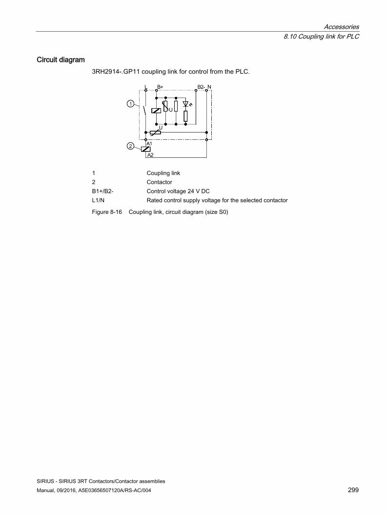
Accessories 8.10 Coupling link for PLC
SIRIUS - SIRIUS 3RT Contactors/Contactor assemblies Manual, 09/2016, A5E03656507120A/RS-AC/004 299
Circuit diagram 3RH2914-.GP11 coupling link for control from the PLC.
1 Coupling link 2 Contactor B1+/B2- Control voltage 24 V DC L1/N Rated control supply voltage for the selected contactor
Figure 8-16 Coupling link, circuit diagram (size S0)
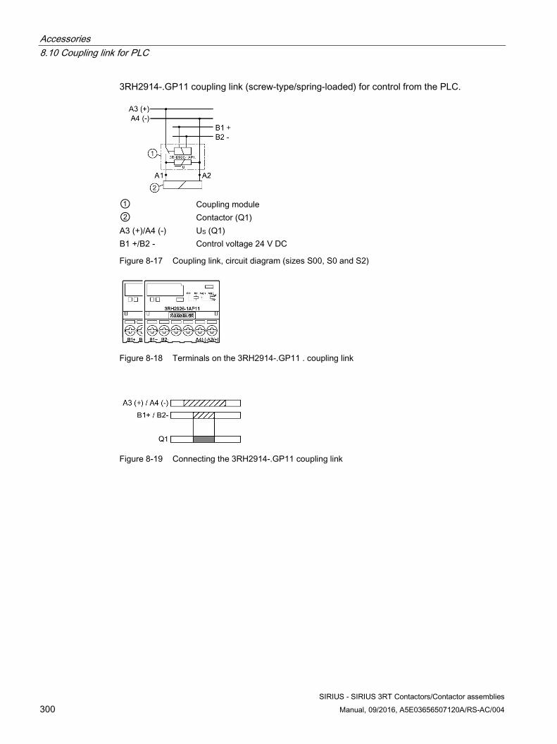
Accessories 8.10 Coupling link for PLC
SIRIUS - SIRIUS 3RT Contactors/Contactor assemblies 300 Manual, 09/2016, A5E03656507120A/RS-AC/004
3RH2914-.GP11 coupling link (screw-type/spring-loaded) for control from the PLC.
① Coupling module ② Contactor (Q1) A3 (+)/A4 (-) US (Q1) B1 +/B2 - Control voltage 24 V DC
Figure 8-17 Coupling link, circuit diagram (sizes S00, S0 and S2)
Figure 8-18 Terminals on the 3RH2914-.GP11 . coupling link
Figure 8-19 Connecting the 3RH2914-.GP11 coupling link
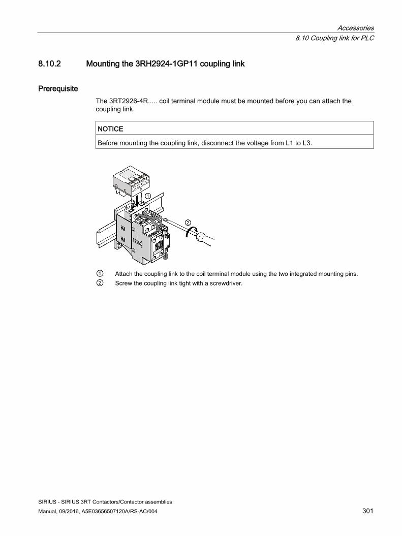
Accessories 8.10 Coupling link for PLC
SIRIUS - SIRIUS 3RT Contactors/Contactor assemblies Manual, 09/2016, A5E03656507120A/RS-AC/004 301
8.10.2 Mounting the 3RH2924-1GP11 coupling link
Prerequisite The 3RT2926-4R..... coil terminal module must be mounted before you can attach the coupling link.
NOTICE
Before mounting the coupling link, disconnect the voltage from L1 to L3.
① Attach the coupling link to the coil terminal module using the two integrated mounting pins. ② Screw the coupling link tight with a screwdriver.
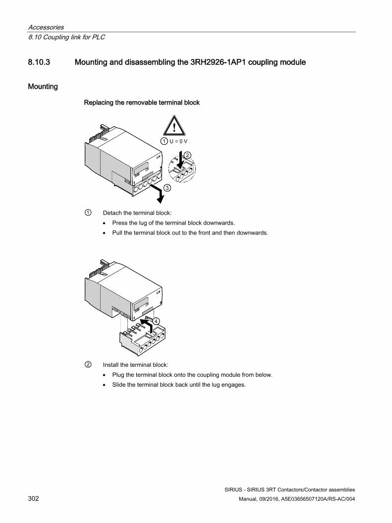
Accessories 8.10 Coupling link for PLC
SIRIUS - SIRIUS 3RT Contactors/Contactor assemblies 302 Manual, 09/2016, A5E03656507120A/RS-AC/004
8.10.3 Mounting and disassembling the 3RH2926-1AP1 coupling module
Mounting
Replacing the removable terminal block
① Detach the terminal block:
• Press the lug of the terminal block downwards. • Pull the terminal block out to the front and then downwards.
② Install the terminal block:
• Plug the terminal block onto the coupling module from below. • Slide the terminal block back until the lug engages.
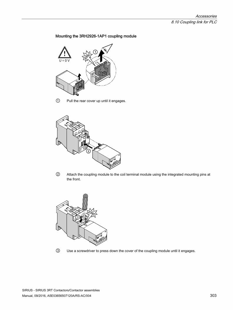
Accessories 8.10 Coupling link for PLC
SIRIUS - SIRIUS 3RT Contactors/Contactor assemblies Manual, 09/2016, A5E03656507120A/RS-AC/004 303
Mounting the 3RH2926-1AP1 coupling module
① Pull the rear cover up until it engages.
② Attach the coupling module to the coil terminal module using the integrated mounting pins at
the front.
③ Use a screwdriver to press down the cover of the coupling module until it engages.
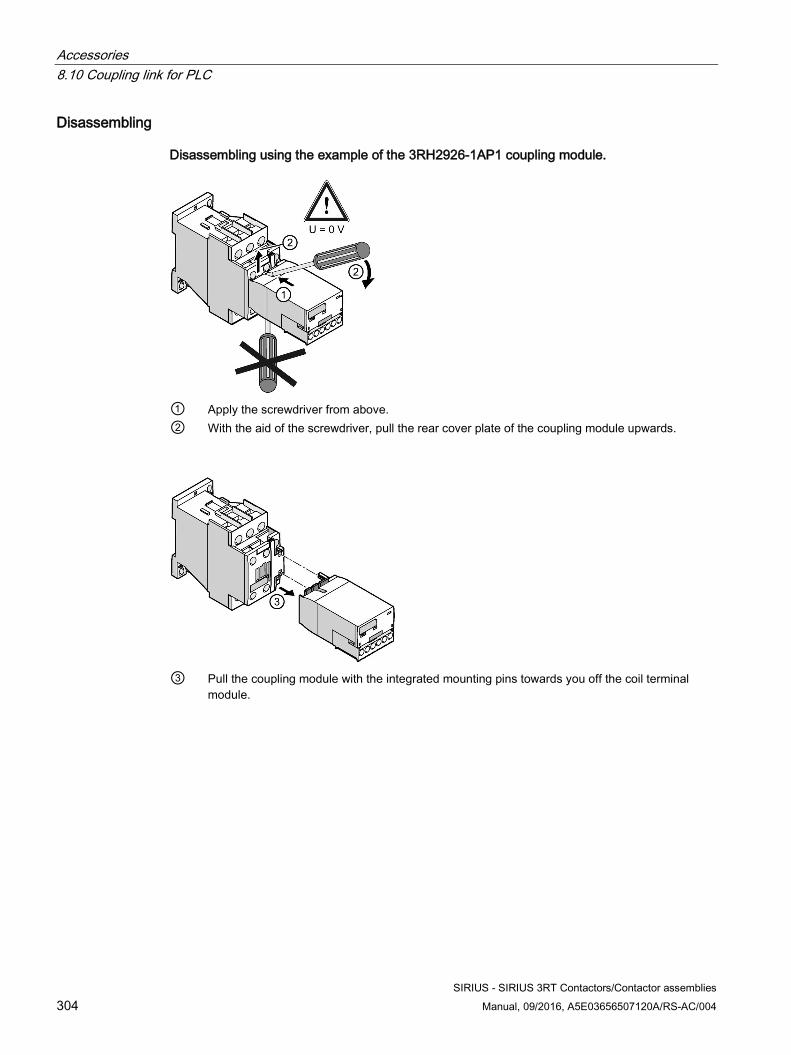
Accessories 8.10 Coupling link for PLC
SIRIUS - SIRIUS 3RT Contactors/Contactor assemblies 304 Manual, 09/2016, A5E03656507120A/RS-AC/004
Disassembling
Disassembling using the example of the 3RH2926-1AP1 coupling module.
① Apply the screwdriver from above. ② With the aid of the screwdriver, pull the rear cover plate of the coupling module upwards.
③ Pull the coupling module with the integrated mounting pins towards you off the coil terminal
module.
Accessories 8.11 LED display indicator module
SIRIUS - SIRIUS 3RT Contactors/Contactor assemblies Manual, 09/2016, A5E03656507120A/RS-AC/004 305
8.11 LED display indicator module
8.11.1 Description The LED display module can be connected to the coil terminals of size S00 to S3 contactors; it indicates the energized state of the contactors via yellow LEDs. In practice the LED display indicator module is primarily used for 3RT2 power contactors in size S0.
Table 8- 25 LED display indicator module
Size Article number S00 / S0 / S2 / S3 3RT2926-1QT00
The LED display module can be used for voltages of 24 to 240 V AC/DC. The LEDs are switched on a bidirectional basis to prevent polarity reversal. With AC control both LEDs light up and with DC control just one LED lights up, depending on the polarity.
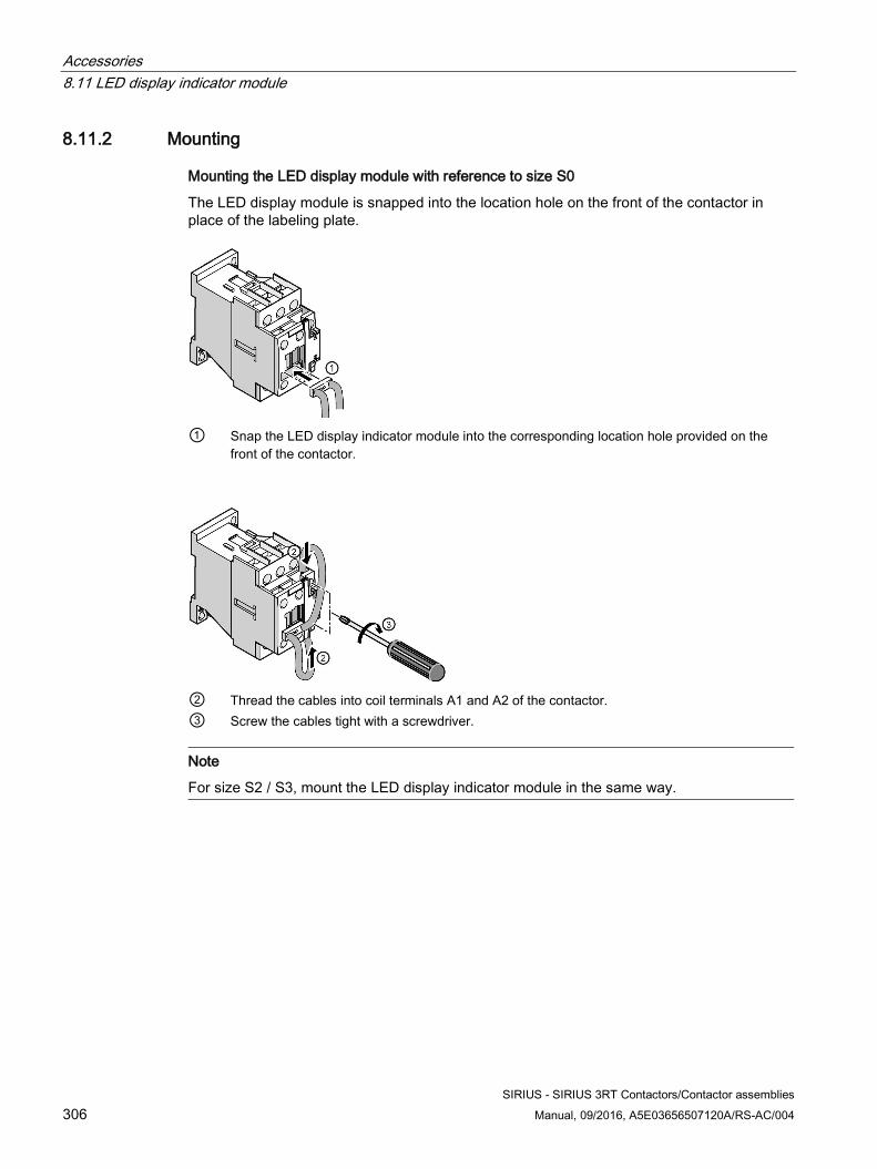
Accessories 8.11 LED display indicator module
SIRIUS - SIRIUS 3RT Contactors/Contactor assemblies 306 Manual, 09/2016, A5E03656507120A/RS-AC/004
8.11.2 Mounting
Mounting the LED display module with reference to size S0
The LED display module is snapped into the location hole on the front of the contactor in place of the labeling plate.
① Snap the LED display indicator module into the corresponding location hole provided on the
front of the contactor.
② Thread the cables into coil terminals A1 and A2 of the contactor. ③ Screw the cables tight with a screwdriver.
Note
For size S2 / S3, mount the LED display indicator module in the same way.
Accessories 8.12 Solder pin adapter
SIRIUS - SIRIUS 3RT Contactors/Contactor assemblies Manual, 09/2016, A5E03656507120A/RS-AC/004 307
8.12 Solder pin adapter
8.12.1 Description The solder pin adapter can be used to solder standard contactors in size S00 up to 5.5 kW/12 A onto PCBs.
Table 8- 26 Versions of the solder pin connection
Version of the solder pin connection Article number Without auxiliary switch block 3RT1916-4KA1 With auxiliary switch block 3RT1916-4KA2
Solder pin connection can be used:
● For motor contactors and contactor relays in size S00.
● For contactors in size S00 with an attached 4-pole auxiliary switch block.
● For the reversing wiring of S00 contactors; in this case, the reversing wiring must be carried out before the contactors are soldered onto the PCB.
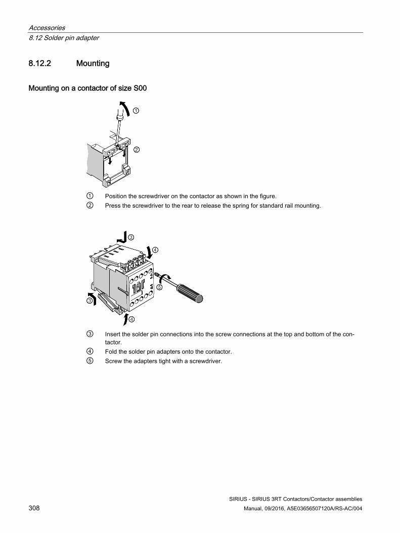
Accessories 8.12 Solder pin adapter
SIRIUS - SIRIUS 3RT Contactors/Contactor assemblies 308 Manual, 09/2016, A5E03656507120A/RS-AC/004
8.12.2 Mounting
Mounting on a contactor of size S00
① Position the screwdriver on the contactor as shown in the figure. ② Press the screwdriver to the rear to release the spring for standard rail mounting.
③ Insert the solder pin connections into the screw connections at the top and bottom of the con-
tactor. ④ Fold the solder pin adapters onto the contactor. ⑤ Screw the adapters tight with a screwdriver.
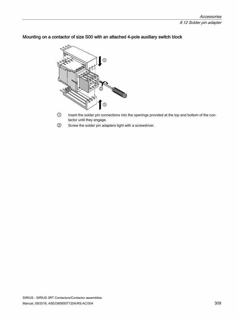
Accessories 8.12 Solder pin adapter
SIRIUS - SIRIUS 3RT Contactors/Contactor assemblies Manual, 09/2016, A5E03656507120A/RS-AC/004 309
Mounting on a contactor of size S00 with an attached 4-pole auxiliary switch block
① Insert the solder pin connections into the openings provided at the top and bottom of the con-
tactor until they engage. ② Screw the solder pin adapters tight with a screwdriver.
Accessories 8.13 Coil terminal module
SIRIUS - SIRIUS 3RT Contactors/Contactor assemblies 310 Manual, 09/2016, A5E03656507120A/RS-AC/004
8.13 Coil terminal module
8.13.1 Description The 3RT2926-4R. coil terminal module for mounting on 3RT20 power contactors in size S0 serves as an adapter for the coil and ensures the coil wiring is correct for 3RT102 contactors (e.g. for retrofitting a 3RT10 device).
The following versions of the coil terminal module are available (only screw connection available for sizes S2 / S3).
Table 8- 27 Versions of the coil terminal module
Connection system Design of the coil terminal mod-ule
Article number
Screw connection Coil terminal from above 3RT2926-4RA11 Coil terminal from below 3RT2926-4RB11 Coil terminal diagonal 3RT2926-4RC11
Spring-loaded connection1) Coil terminal from above 3RT2926-4RA12 Coil terminal from below 3RT2926-4RB12
1) For size S0 only.
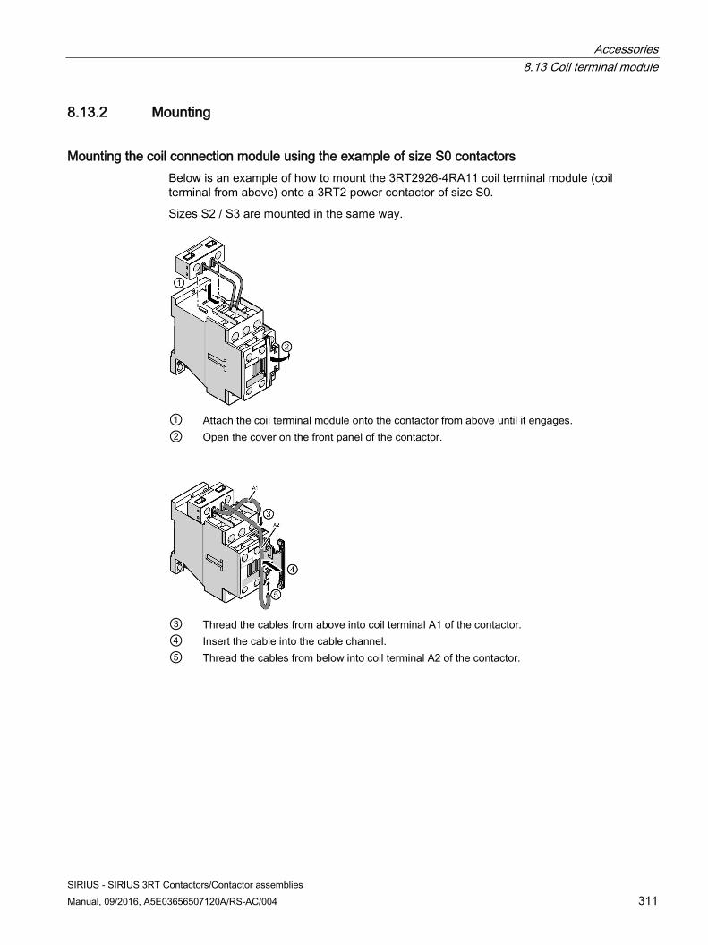
Accessories 8.13 Coil terminal module
SIRIUS - SIRIUS 3RT Contactors/Contactor assemblies Manual, 09/2016, A5E03656507120A/RS-AC/004 311
8.13.2 Mounting
Mounting the coil connection module using the example of size S0 contactors Below is an example of how to mount the 3RT2926-4RA11 coil terminal module (coil terminal from above) onto a 3RT2 power contactor of size S0.
Sizes S2 / S3 are mounted in the same way.
① Attach the coil terminal module onto the contactor from above until it engages. ② Open the cover on the front panel of the contactor.
③ Thread the cables from above into coil terminal A1 of the contactor. ④ Insert the cable into the cable channel. ⑤ Thread the cables from below into coil terminal A2 of the contactor.
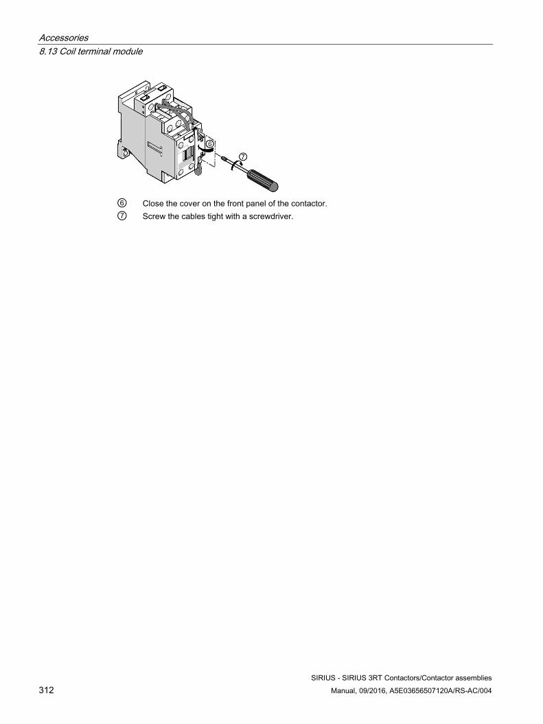
Accessories 8.13 Coil terminal module
SIRIUS - SIRIUS 3RT Contactors/Contactor assemblies 312 Manual, 09/2016, A5E03656507120A/RS-AC/004
⑥ Close the cover on the front panel of the contactor. ⑦ Screw the cables tight with a screwdriver.
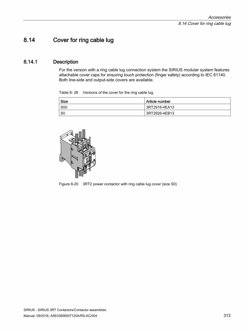
Accessories 8.14 Cover for ring cable lug
SIRIUS - SIRIUS 3RT Contactors/Contactor assemblies Manual, 09/2016, A5E03656507120A/RS-AC/004 313
8.14 Cover for ring cable lug
8.14.1 Description For the version with a ring cable lug connection system the SIRIUS modular system features attachable cover caps for ensuring touch protection (finger safety) according to IEC 61140. Both line-side and output-side covers are available.
Table 8- 28 Versions of the cover for the ring cable lug
Size Article number S00 3RT2916-4EA13 S0 3RT2926-4EB13
Figure 8-20 3RT2 power contactor with ring cable lug cover (size S0)
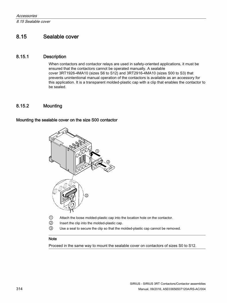
Accessories 8.15 Sealable cover
SIRIUS - SIRIUS 3RT Contactors/Contactor assemblies 314 Manual, 09/2016, A5E03656507120A/RS-AC/004
8.15 Sealable cover
8.15.1 Description When contactors and contactor relays are used in safety-oriented applications, it must be ensured that the contactors cannot be operated manually. A sealable cover 3RT1926-4MA10 (sizes S6 to S12) and 3RT2916-4MA10 (sizes S00 to S3) that prevents unintentional manual operation of the contactors is available as an accessory for this application. It is a transparent molded-plastic cap with a clip that enables the contactor to be sealed.
8.15.2 Mounting
Mounting the sealable cover on the size S00 contactor
① Attach the loose molded-plastic cap into the location hole on the contactor. ② Insert the clip into the molded-plastic cap. ③ Use a seal to secure the clip so that the molded-plastic cap cannot be removed.
Note
Proceed in the same way to mount the sealable cover on contactors of sizes S0 to S12.
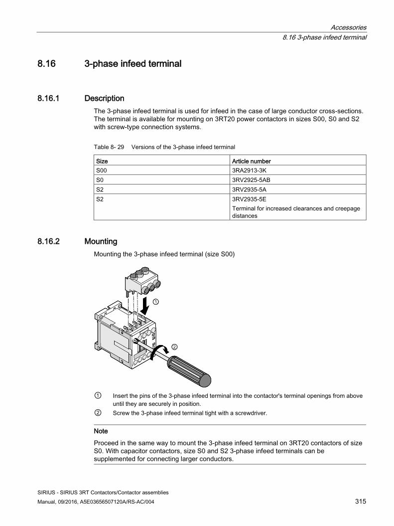
Accessories 8.16 3-phase infeed terminal
SIRIUS - SIRIUS 3RT Contactors/Contactor assemblies Manual, 09/2016, A5E03656507120A/RS-AC/004 315
8.16 3-phase infeed terminal
8.16.1 Description The 3-phase infeed terminal is used for infeed in the case of large conductor cross-sections. The terminal is available for mounting on 3RT20 power contactors in sizes S00, S0 and S2 with screw-type connection systems.
Table 8- 29 Versions of the 3-phase infeed terminal
Size Article number S00 3RA2913-3K S0 3RV2925-5AB S2 3RV2935-5A S2 3RV2935-5E
Terminal for increased clearances and creepage distances
8.16.2 Mounting Mounting the 3-phase infeed terminal (size S00)
① Insert the pins of the 3-phase infeed terminal into the contactor's terminal openings from above
until they are securely in position. ② Screw the 3-phase infeed terminal tight with a screwdriver.
Note
Proceed in the same way to mount the 3-phase infeed terminal on 3RT20 contactors of size S0. With capacitor contactors, size S0 and S2 3-phase infeed terminals can be supplemented for connecting larger conductors.
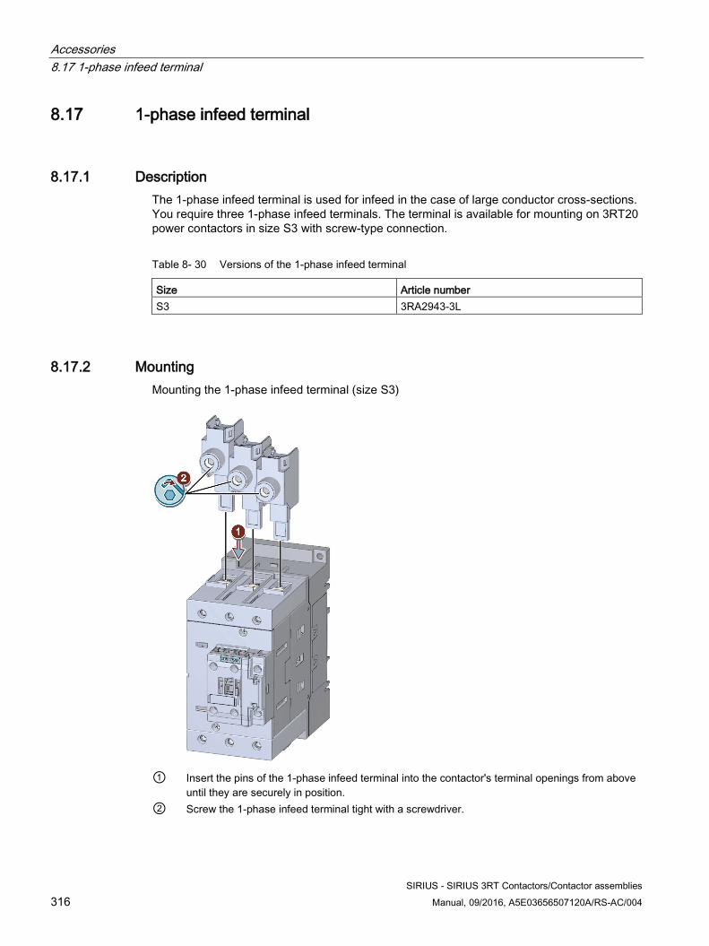
Accessories 8.17 1-phase infeed terminal
SIRIUS - SIRIUS 3RT Contactors/Contactor assemblies 316 Manual, 09/2016, A5E03656507120A/RS-AC/004
8.17 1-phase infeed terminal
8.17.1 Description The 1-phase infeed terminal is used for infeed in the case of large conductor cross-sections. You require three 1-phase infeed terminals. The terminal is available for mounting on 3RT20 power contactors in size S3 with screw-type connection.
Table 8- 30 Versions of the 1-phase infeed terminal
Size Article number S3 3RA2943-3L
8.17.2 Mounting Mounting the 1-phase infeed terminal (size S3)
① Insert the pins of the 1-phase infeed terminal into the contactor's terminal openings from above
until they are securely in position. ② Screw the 1-phase infeed terminal tight with a screwdriver.
Accessories 8.18 Parallel switching connectors
SIRIUS - SIRIUS 3RT Contactors/Contactor assemblies Manual, 09/2016, A5E03656507120A/RS-AC/004 317
8.18 Parallel switching connectors
8.18.1 Description The parallel connection is used for parallel infeed of an L1 cable on L1 - L3. The parallel connectors (insulated) can be reduced by one pole.
The following versions of parallel switching connections are available:
Table 8- 31 Versions of the parallel switching connectors
Size Design of the parallel switching connector
Connection system Article number
S00 3-pole, without connection terminal Screw connection 3RT1916-4BA31 Spring-loaded connec-tion
3RT2916-4BA32
3-pole, with connection terminal Screw connection 3RT1916-4BB31 4-pole, with connection terminal Screw connection 3RT1916-4BB41
S0 3-pole, without connection terminal Screw connection 3RT1926-4BA31 Spring-loaded connec-tion
3RT2926-4BA32
3-pole, with connection terminal Screw connection 3RT2926-4BB31 S2 3-pole, with connection terminal Screw connection 3RT1936-4BB31 S3 3-pole, without terminal Screw connection 3RT1946-4BB31 S6 3-pole, without terminal, with
through hole for contactors Screw connection 3RT1956-4BA31
S10 / S12 3-pole, without terminal, with through hole for contactors
Screw connection 3RT1966-4BA31
Accessories 8.18 Parallel switching connectors
SIRIUS - SIRIUS 3RT Contactors/Contactor assemblies 318 Manual, 09/2016, A5E03656507120A/RS-AC/004
8.18.2 Configuration If the current paths of multi-pole switching devices are connected in parallel, the total current is distributed across the individual current paths in accordance with their ohmic resistance and their inductive interactions. The ohmic resistance is primarily generated by the contact resistance at the contacts, the value of which can vary as a result of erosion and oxidation. This means that the current distribution is neither even nor stable: Individual current paths may be overloaded and the overload releases or relays will trip too early (tripping error).
Permanent load with parallel connection Provided that the relevant catalogs do not contain any information to the contrary, the following applies for a permanent load with parallel connection:
● If three current paths are connected in parallel, 2.5 times the continuous current can be conducted; if two current paths are connected in parallel, 1.8 times the continuous current can be conducted. However, it should be noted that the making and breaking capacities do not increase, since the contacts do not close and open simultaneously, so the contacts of one current path have to switch the entire inrush or breaking current.
● The cables should be routed such that the same cable lengths are used for each current path.
● If a short-circuit current arises, it is divided up in accordance with the ratio of the current path resistances. Notice: The operating current of electromagnetic instantaneous short-circuit releases cannot be reached in such cases.
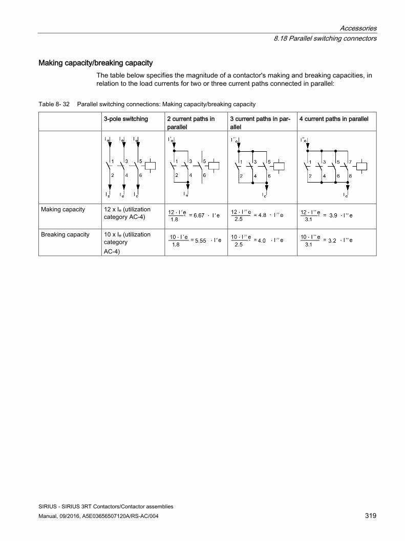
Accessories 8.18 Parallel switching connectors
SIRIUS - SIRIUS 3RT Contactors/Contactor assemblies Manual, 09/2016, A5E03656507120A/RS-AC/004 319
Making capacity/breaking capacity The table below specifies the magnitude of a contactor's making and breaking capacities, in relation to the load currents for two or three current paths connected in parallel:
Table 8- 32 Parallel switching connections: Making capacity/breaking capacity
3-pole switching 2 current paths in parallel
3 current paths in par-allel
4 current paths in parallel
Making capacity 12 x Ie (utilization category AC-4)
Breaking capacity 10 x Ie (utilization category AC-4)
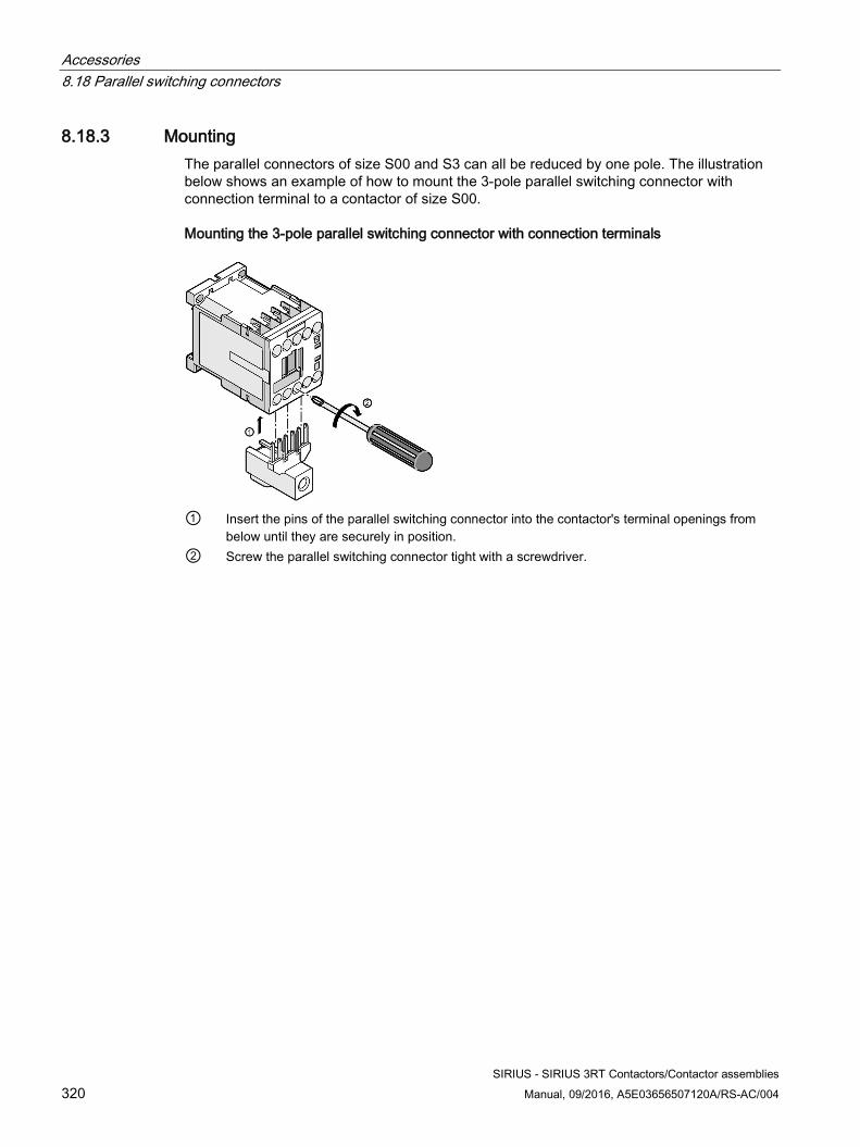
Accessories 8.18 Parallel switching connectors
SIRIUS - SIRIUS 3RT Contactors/Contactor assemblies 320 Manual, 09/2016, A5E03656507120A/RS-AC/004
8.18.3 Mounting The parallel connectors of size S00 and S3 can all be reduced by one pole. The illustration below shows an example of how to mount the 3-pole parallel switching connector with connection terminal to a contactor of size S00.
Mounting the 3-pole parallel switching connector with connection terminals
① Insert the pins of the parallel switching connector into the contactor's terminal openings from
below until they are securely in position. ② Screw the parallel switching connector tight with a screwdriver.
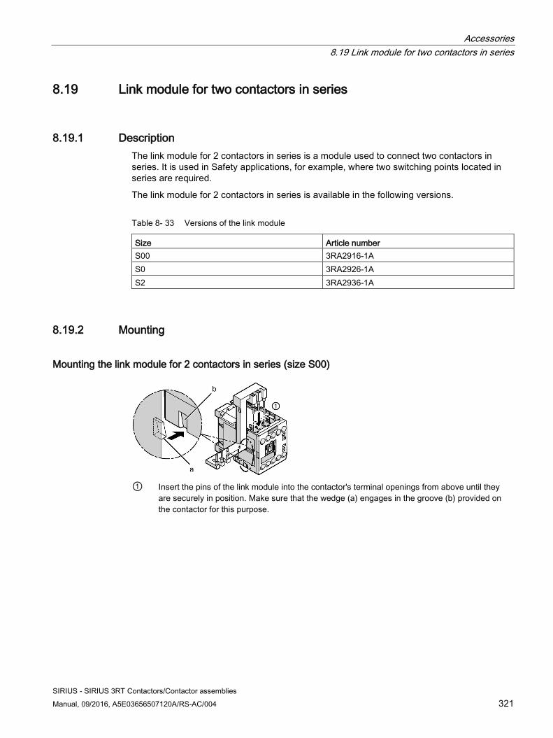
Accessories 8.19 Link module for two contactors in series
SIRIUS - SIRIUS 3RT Contactors/Contactor assemblies Manual, 09/2016, A5E03656507120A/RS-AC/004 321
8.19 Link module for two contactors in series
8.19.1 Description The link module for 2 contactors in series is a module used to connect two contactors in series. It is used in Safety applications, for example, where two switching points located in series are required.
The link module for 2 contactors in series is available in the following versions.
Table 8- 33 Versions of the link module
Size Article number S00 3RA2916-1A S0 3RA2926-1A S2 3RA2936-1A
8.19.2 Mounting
Mounting the link module for 2 contactors in series (size S00)
① Insert the pins of the link module into the contactor's terminal openings from above until they
are securely in position. Make sure that the wedge (a) engages in the groove (b) provided on the contactor for this purpose.
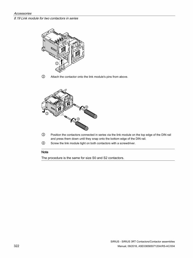
Accessories 8.19 Link module for two contactors in series
SIRIUS - SIRIUS 3RT Contactors/Contactor assemblies 322 Manual, 09/2016, A5E03656507120A/RS-AC/004
② Attach the contactor onto the link module's pins from above.
③ Position the contactors connected in series via the link module on the top edge of the DIN rail
and press them down until they snap onto the bottom edge of the DIN rail. ④ Screw the link module tight on both contactors with a screwdriver.
Note
The procedure is the same for size S0 and S2 contactors.

Accessories 8.20 Link module for motor starter protector
SIRIUS - SIRIUS 3RT Contactors/Contactor assemblies Manual, 09/2016, A5E03656507120A/RS-AC/004 323
8.20 Link module for motor starter protector
8.20.1 Description
Link module for motor starter protector - contactor Link modules can be used to quickly and reliably mount a motor starter protector onto the contactor. In this case, the link modules serve to establish an electrical and mechanical connection between the motor starter protector and the contactor.
Table 8- 34 Versions of the link module for motor starter protector - contactor
Connection system Version of the link module Article number Screw-type Motor starter protector – contactor in size S00 3RA1921-1DA00
Motor starter protector – contactor in size S0 AC 3RA2921-1AA00 Motor starter protector – contactor in size S0 DC 3RA2921-1BA00 Motor starter protector – contactor in size S2 3RA2931-1AA00 Motor starter protector – contactor in size S3 3RA1941-1AA00
Spring-loaded Motor starter protector – contactor in size S00 3RA2911-2AA00 Motor starter protector – contactor in size S0 3RA2921-2AA00
Reference More information ... Can be found in the appendix ... About link modules "List of references" under "Manuals - SIRIUS
Modular System (Page 463)" in the "SIRIUS - SIRIUS 3RA load feeders" manual.
About mounting contactors and motor starter protectors
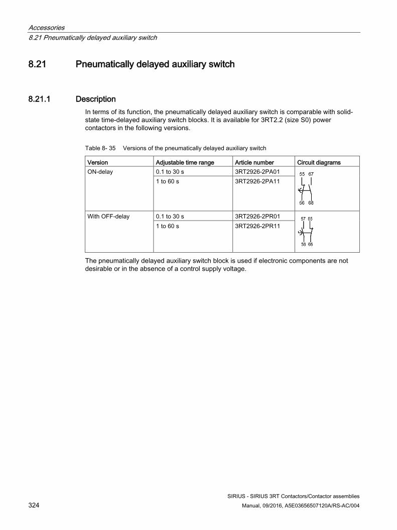
Accessories 8.21 Pneumatically delayed auxiliary switch
SIRIUS - SIRIUS 3RT Contactors/Contactor assemblies 324 Manual, 09/2016, A5E03656507120A/RS-AC/004
8.21 Pneumatically delayed auxiliary switch
8.21.1 Description In terms of its function, the pneumatically delayed auxiliary switch is comparable with solid-state time-delayed auxiliary switch blocks. It is available for 3RT2.2 (size S0) power contactors in the following versions.
Table 8- 35 Versions of the pneumatically delayed auxiliary switch
Version Adjustable time range Article number Circuit diagrams ON-delay 0.1 to 30 s 3RT2926-2PA01
1 to 60 s 3RT2926-2PA11
With OFF-delay 0.1 to 30 s 3RT2926-2PR01
1 to 60 s 3RT2926-2PR11
The pneumatically delayed auxiliary switch block is used if electronic components are not desirable or in the absence of a control supply voltage.
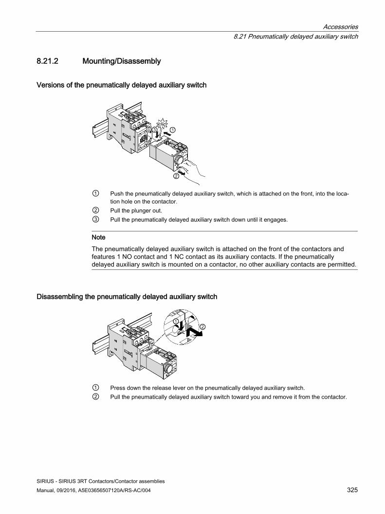
Accessories 8.21 Pneumatically delayed auxiliary switch
SIRIUS - SIRIUS 3RT Contactors/Contactor assemblies Manual, 09/2016, A5E03656507120A/RS-AC/004 325
8.21.2 Mounting/Disassembly
Versions of the pneumatically delayed auxiliary switch
① Push the pneumatically delayed auxiliary switch, which is attached on the front, into the loca-
tion hole on the contactor. ② Pull the plunger out. ③ Pull the pneumatically delayed auxiliary switch down until it engages.
Note
The pneumatically delayed auxiliary switch is attached on the front of the contactors and features 1 NO contact and 1 NC contact as its auxiliary contacts. If the pneumatically delayed auxiliary switch is mounted on a contactor, no other auxiliary contacts are permitted.
Disassembling the pneumatically delayed auxiliary switch
① Press down the release lever on the pneumatically delayed auxiliary switch. ② Pull the pneumatically delayed auxiliary switch toward you and remove it from the contactor.
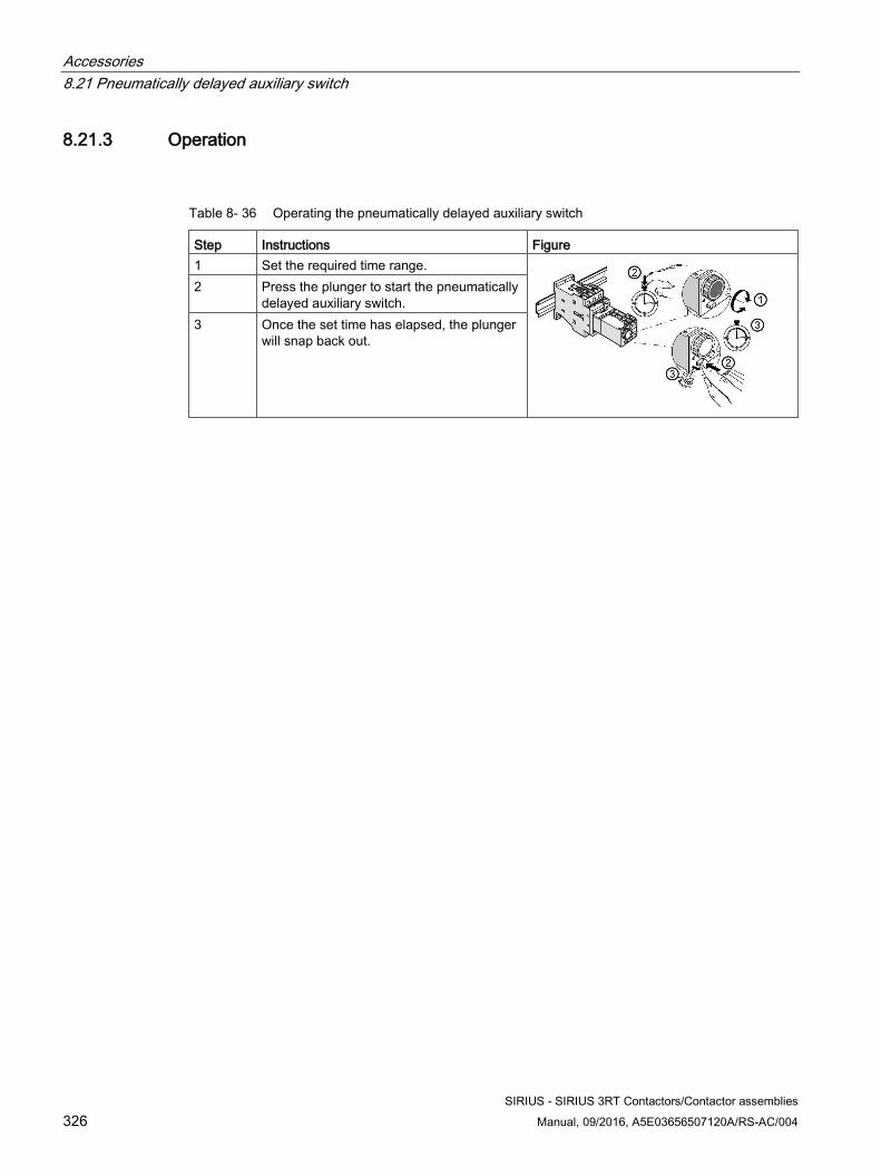
Accessories 8.21 Pneumatically delayed auxiliary switch
SIRIUS - SIRIUS 3RT Contactors/Contactor assemblies 326 Manual, 09/2016, A5E03656507120A/RS-AC/004
8.21.3 Operation
Table 8- 36 Operating the pneumatically delayed auxiliary switch
Step Instructions Figure 1 Set the required time range.
2 Press the plunger to start the pneumatically delayed auxiliary switch.
3 Once the set time has elapsed, the plunger will snap back out.
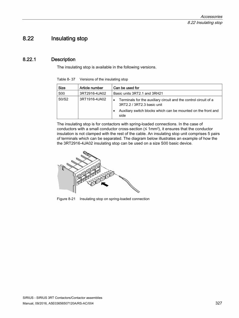
Accessories 8.22 Insulating stop
SIRIUS - SIRIUS 3RT Contactors/Contactor assemblies Manual, 09/2016, A5E03656507120A/RS-AC/004 327
8.22 Insulating stop
8.22.1 Description The insulating stop is available in the following versions.
Table 8- 37 Versions of the insulating stop
Size Article number Can be used for S00 3RT2916-4JA02 Basic units 3RT2.1 and 3RH21 S0/S2 3RT1916-4JA02 • Terminals for the auxiliary circuit and the control circuit of a
3RT2.2 / 3RT2.3 basic unit • Auxiliary switch blocks which can be mounted on the front and
side
The insulating stop is for contactors with spring-loaded connections. In the case of conductors with a small conductor cross-section (≤ 1mm2), it ensures that the conductor insulation is not clamped with the rest of the cable. An insulating stop unit comprises 5 pairs of terminals which can be separated. The diagram below illustrates an example of how the the 3RT2916-4JA02 insulating stop can be used on a size S00 basic device.
Figure 8-21 Insulating stop on spring-loaded connection
Accessories 8.23 Terminal module for contactors with screw connections
SIRIUS - SIRIUS 3RT Contactors/Contactor assemblies 328 Manual, 09/2016, A5E03656507120A/RS-AC/004
8.23 Terminal module for contactors with screw connections
8.23.1 Description The terminal module for contactors with screw connections is available in the following versions.
Table 8- 38 Versions of the terminal module for contactors with screw connections
Size Article number Version S00 and S0 3RT1900-4RE01 Plug for contactor S00 3RT1916-4RD01 Adapter for contactor S0 3RT1926-4RD01 Adapter for contactor
The terminal module can be used to connect contactors with screw connections in size S00 or S0 to a motor.
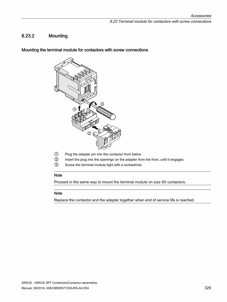
Accessories 8.23 Terminal module for contactors with screw connections
SIRIUS - SIRIUS 3RT Contactors/Contactor assemblies Manual, 09/2016, A5E03656507120A/RS-AC/004 329
8.23.2 Mounting
Mounting the terminal module for contactors with screw connections
① Plug the adapter pin into the contactor from below. ② Insert the plug into the openings on the adapter from the front, until it engages. ③ Screw the terminal module tight with a screwdriver.
Note
Proceed in the same way to mount the terminal module on size S0 contactors.
Note
Replace the contactor and the adapter together when end of service life is reached.
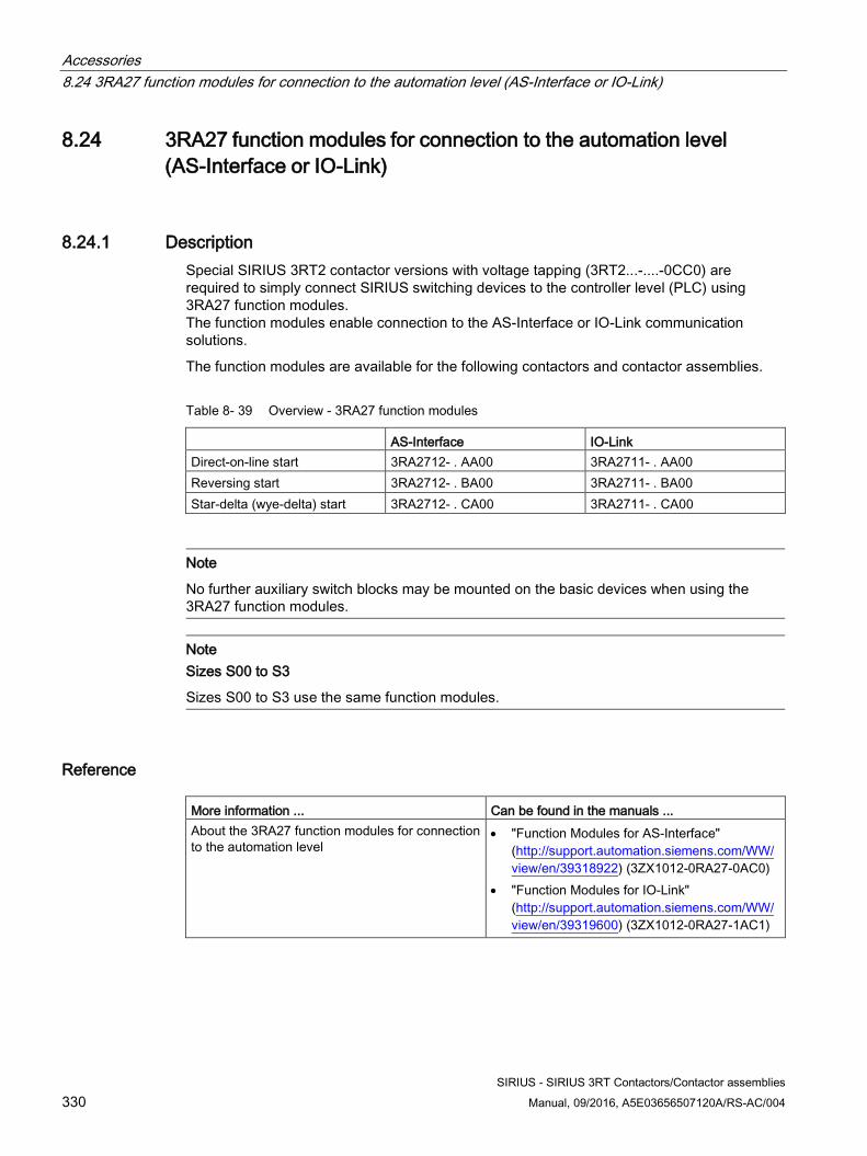
Accessories 8.24 3RA27 function modules for connection to the automation level (AS-Interface or IO-Link)
SIRIUS - SIRIUS 3RT Contactors/Contactor assemblies 330 Manual, 09/2016, A5E03656507120A/RS-AC/004
8.24 3RA27 function modules for connection to the automation level (AS-Interface or IO-Link)
8.24.1 Description Special SIRIUS 3RT2 contactor versions with voltage tapping (3RT2...-....-0CC0) are required to simply connect SIRIUS switching devices to the controller level (PLC) using 3RA27 function modules. The function modules enable connection to the AS-Interface or IO-Link communication solutions.
The function modules are available for the following contactors and contactor assemblies.
Table 8- 39 Overview - 3RA27 function modules
AS-Interface IO-Link Direct-on-line start 3RA2712- . AA00 3RA2711- . AA00 Reversing start 3RA2712- . BA00 3RA2711- . BA00 Star-delta (wye-delta) start 3RA2712- . CA00 3RA2711- . CA00
Note
No further auxiliary switch blocks may be mounted on the basic devices when using the 3RA27 function modules.
Note Sizes S00 to S3
Sizes S00 to S3 use the same function modules.
Reference
More information ... Can be found in the manuals ... About the 3RA27 function modules for connection to the automation level
• "Function Modules for AS-Interface"(http://support.automation.siemens.com/WW/view/en/39318922) (3ZX1012-0RA27-0AC0)
• "Function Modules for IO-Link"(http://support.automation.siemens.com/WW/view/en/39319600) (3ZX1012-0RA27-1AC1)
Accessories 8.25 3RA28 function modules for mounting on 3RT2 contactors
SIRIUS - SIRIUS 3RT Contactors/Contactor assemblies Manual, 09/2016, A5E03656507120A/RS-AC/004 331
8.25 3RA28 function modules for mounting on 3RT2 contactors
8.25.1 Description The SIRIUS modular system features 3RA28 function modules for the delayed switching of contactors and auxiliary switches (e.g. for switching from star operation to delta operation).
3RA28 function modules are available with screw-type or spring-loaded connections in the following versions:
● Solid-state time-delay auxiliary switches 3RA281.-..W10 With ON-delay or OFF-delay, without auxiliary voltage
● Solid-state timing relays with semiconductor output 3RA2811-.CW10 and 3RA2812-.DW10 With ON-delay or OFF-delay, with auxiliary voltage
● Star-delta (wye-delta) function module 3RA2816-0EW20 Complete module kit for star-delta (wye-delta) start
Note
No further auxiliary switch blocks may be mounted on the basic devices when using the 3RA28 function modules.
Note
When using the 3RA2816-0EW20 function module for star-delta (wye-delta) start, the following exception applies:
No more than one 3RH29 lateral auxiliary switch block (product version E03 and higher) may be mounted onto the line contactor (Q11) and onto the star (wye) contactor (Q12).
Note Sizes S00 to S3
Sizes S00 to S3 use the same function modules. From product version *E04* and higher, the 3RA2813/14/15/16 function modules can be used for mounting on 3RT2.4 contactors (size S3). The 3RA2811/12 function modules can be used for mounting on 3RT2.1 / 3RT2.2 contactors (sizes S00 and S0). The 3RA2831/32 function modules of product version *E03* and higher can be used for mounting on 3RT2.4 contactors (size S3).
Accessories 8.25 3RA28 function modules for mounting on 3RT2 contactors
SIRIUS - SIRIUS 3RT Contactors/Contactor assemblies 332 Manual, 09/2016, A5E03656507120A/RS-AC/004
Reference More information ... Can be found in the appendix ... About the different versions of the 3RA28 function modules
"List of references" under "Manuals - SIRIUS Modular System (Page 463)" in the manual "SIRIUS - SIRIUS 3RA28 function modules for mounting on 3RT2 contactors".
About mounting 3RA28 function modules on 3RT2 contactors
Accessories 8.26 Assembly kit for reversing contactor assemblies (sizes S00 to S3)
SIRIUS - SIRIUS 3RT Contactors/Contactor assemblies Manual, 09/2016, A5E03656507120A/RS-AC/004 333
8.26 Assembly kit for reversing contactor assemblies (sizes S00 to S3)
8.26.1 Description Users can mount the 3RA23 reversing contactor assembly using various assembly kits for screw and spring-loaded connections.
Note
The 3RT201. / 3RT202. / 3RT203. / 3RT204. power contactors required for installing the 3RA23 reversing contactor assembly in sizes S00 to S3 have to be ordered separately.
Assembly kit for 3RA23 reversing contactor assembly The following components are included in delivery with the assembly kit for 3RA23 reversing contactor assembly:
● Sizes S00 / S0
– Mechanical interlock
– 2 connecting clips for 2 contactors
– Wiring modules, top and bottom
– Auxiliary wiring module top and bottom
● Sizes S2 / S3
– 2 connecting pins
– Wiring modules, top and bottom
– Auxiliary wiring modules top and bottom with screw connection only
– 3 cables with spring-loaded connection
Note
The mechanical interlock for sizes S2 / S3 must be ordered separately as an accessory.
Accessories 8.26 Assembly kit for reversing contactor assemblies (sizes S00 to S3)
SIRIUS - SIRIUS 3RT Contactors/Contactor assemblies 334 Manual, 09/2016, A5E03656507120A/RS-AC/004
Table 8- 40 Versions of the assembly kit for 3RA23 reversing contactor assembly
Connection system Size Article number Screw connection S00 3RA2913-2AA1
S0 3RA2923-2AA1 S2 3RA2933-2AA1 S3 3RA2943-2AA1
Spring-loaded connection1) S00 3RA2913-2AA2 S0 3RA2923-2AA2 S2 3RA2933-2AA2 S3 3RA2943-2AA2
1) For size S2, spring-loaded connection is only available in the control circuit.
Electrical interlock The assembly kit for contactors (size S00 to S3) with screw-type connections contains wiring modules for connecting the main and control current paths. The assembly kit for contactors (size S00) with screw-type connections contains wiring modules for connecting the main and control current paths. For contactors (size S0) with spring-loaded connections the kit only contains wiring modules for connecting the main circuit. If the control circuit wiring (electrical interlock) is also required, the auxiliary switches must be wired separately as necessary. The procedure is described in the chapter titled Mounting (Page 335).
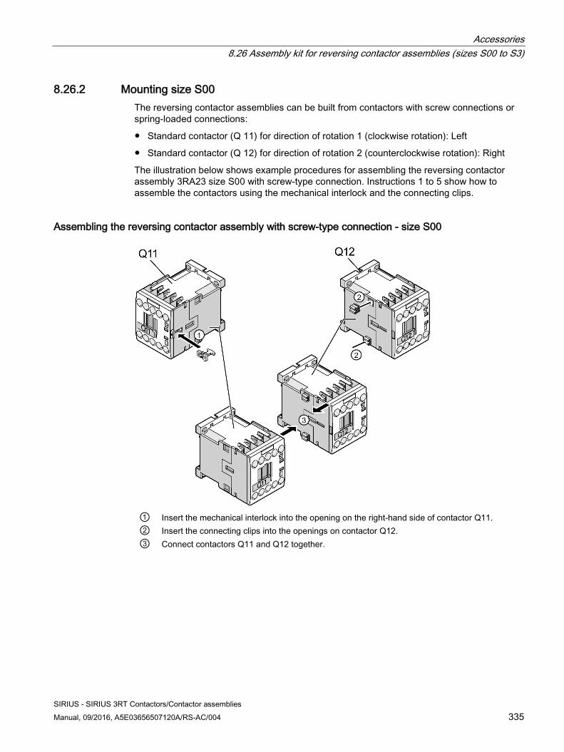
Accessories 8.26 Assembly kit for reversing contactor assemblies (sizes S00 to S3)
SIRIUS - SIRIUS 3RT Contactors/Contactor assemblies Manual, 09/2016, A5E03656507120A/RS-AC/004 335
8.26.2 Mounting size S00 The reversing contactor assemblies can be built from contactors with screw connections or spring-loaded connections:
● Standard contactor (Q 11) for direction of rotation 1 (clockwise rotation): Left
● Standard contactor (Q 12) for direction of rotation 2 (counterclockwise rotation): Right
The illustration below shows example procedures for assembling the reversing contactor assembly 3RA23 size S00 with screw-type connection. Instructions 1 to 5 show how to assemble the contactors using the mechanical interlock and the connecting clips.
Assembling the reversing contactor assembly with screw-type connection - size S00
① Insert the mechanical interlock into the opening on the right-hand side of contactor Q11. ② Insert the connecting clips into the openings on contactor Q12. ③ Connect contactors Q11 and Q12 together.
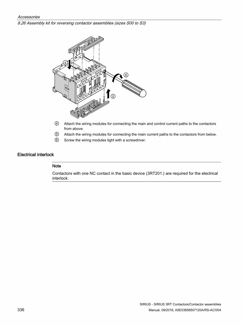
Accessories 8.26 Assembly kit for reversing contactor assemblies (sizes S00 to S3)
SIRIUS - SIRIUS 3RT Contactors/Contactor assemblies 336 Manual, 09/2016, A5E03656507120A/RS-AC/004
④ Attach the wiring modules for connecting the main and control current paths to the contactors
from above. ⑤ Attach the wiring modules for connecting the main current paths to the contactors from below. ⑥ Screw the wiring modules tight with a screwdriver.
Electrical interlock
Note
Contactors with one NC contact in the basic device (3RT201.) are required for the electrical interlock.
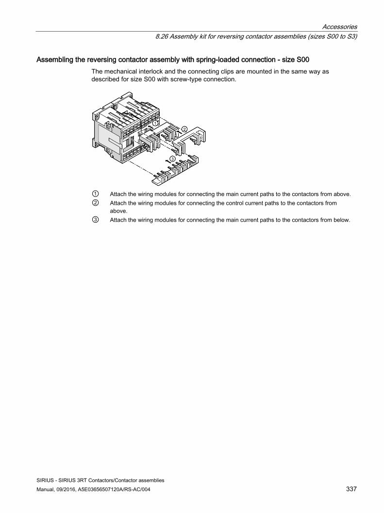
Accessories 8.26 Assembly kit for reversing contactor assemblies (sizes S00 to S3)
SIRIUS - SIRIUS 3RT Contactors/Contactor assemblies Manual, 09/2016, A5E03656507120A/RS-AC/004 337
Assembling the reversing contactor assembly with spring-loaded connection - size S00 The mechanical interlock and the connecting clips are mounted in the same way as described for size S00 with screw-type connection.
① Attach the wiring modules for connecting the main current paths to the contactors from above. ② Attach the wiring modules for connecting the control current paths to the contactors from
above. ③ Attach the wiring modules for connecting the main current paths to the contactors from below.
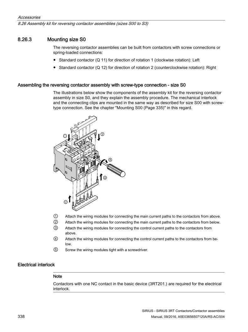
Accessories 8.26 Assembly kit for reversing contactor assemblies (sizes S00 to S3)
SIRIUS - SIRIUS 3RT Contactors/Contactor assemblies 338 Manual, 09/2016, A5E03656507120A/RS-AC/004
8.26.3 Mounting size S0 The reversing contactor assemblies can be built from contactors with screw connections or spring-loaded connections:
● Standard contactor (Q 11) for direction of rotation 1 (clockwise rotation): Left
● Standard contactor (Q 12) for direction of rotation 2 (counterclockwise rotation): Right
Assembling the reversing contactor assembly with screw-type connection - size S0 The illustrations below show the components of the assembly kit for the reversing contactor assembly in size S0, and they explain the assembly procedure. The mechanical interlock and the connecting clips are mounted in the same way as described for size S00 with screw-type connection. See the chapter "Mounting S00 (Page 335)" in this regard.
① Attach the wiring modules for connecting the main current paths to the contactors from above. ② Attach the wiring modules for connecting the main current paths to the contactors from below. ③ Attach the wiring modules for connecting the control current paths to the contactors from
above. ④ Attach the wiring modules for connecting the control current paths to the contactors from be-
low. ⑤ Screw the wiring modules tight with a screwdriver.
Electrical interlock
Note
Contactors with one NC contact in the basic device (3RT201.) are required for the electrical interlock.
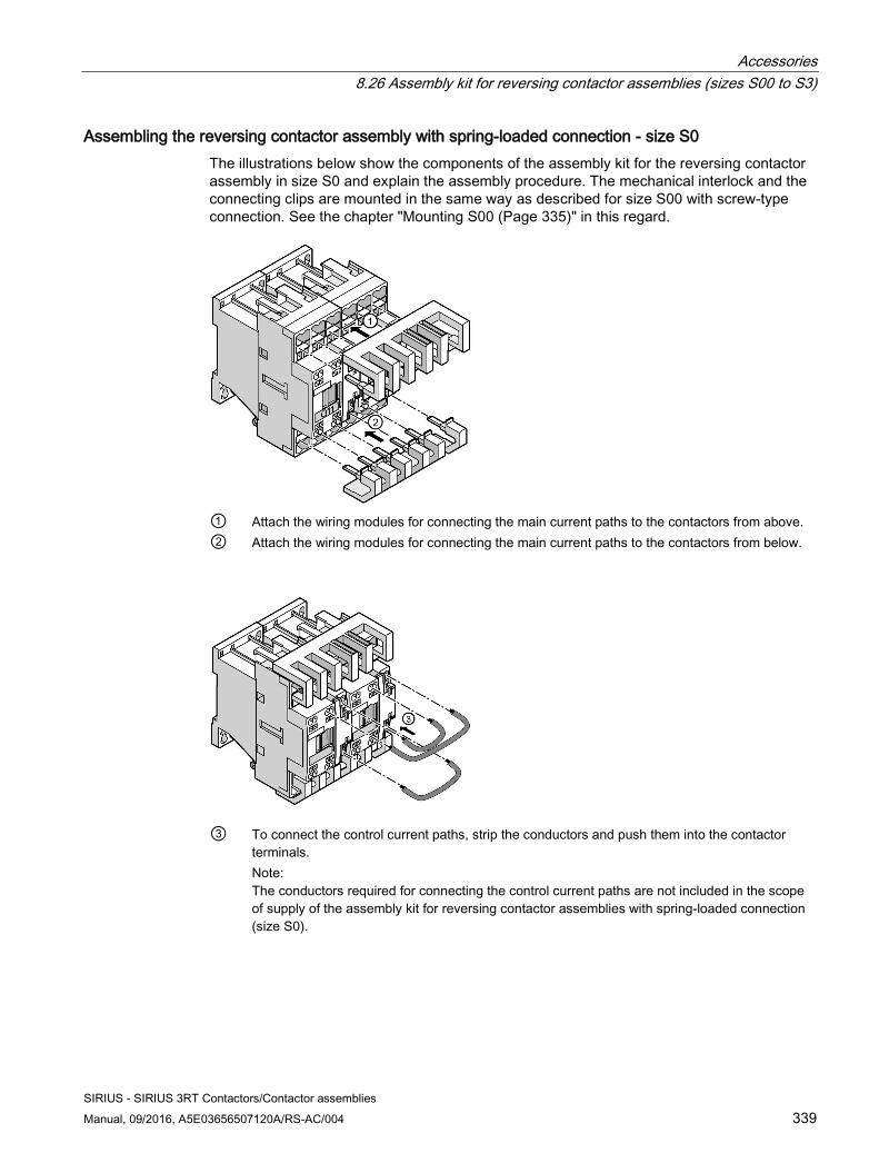
Accessories 8.26 Assembly kit for reversing contactor assemblies (sizes S00 to S3)
SIRIUS - SIRIUS 3RT Contactors/Contactor assemblies Manual, 09/2016, A5E03656507120A/RS-AC/004 339
Assembling the reversing contactor assembly with spring-loaded connection - size S0 The illustrations below show the components of the assembly kit for the reversing contactor assembly in size S0 and explain the assembly procedure. The mechanical interlock and the connecting clips are mounted in the same way as described for size S00 with screw-type connection. See the chapter "Mounting S00 (Page 335)" in this regard.
① Attach the wiring modules for connecting the main current paths to the contactors from above. ② Attach the wiring modules for connecting the main current paths to the contactors from below.
③ To connect the control current paths, strip the conductors and push them into the contactor
terminals. Note: The conductors required for connecting the control current paths are not included in the scope of supply of the assembly kit for reversing contactor assemblies with spring-loaded connection (size S0).
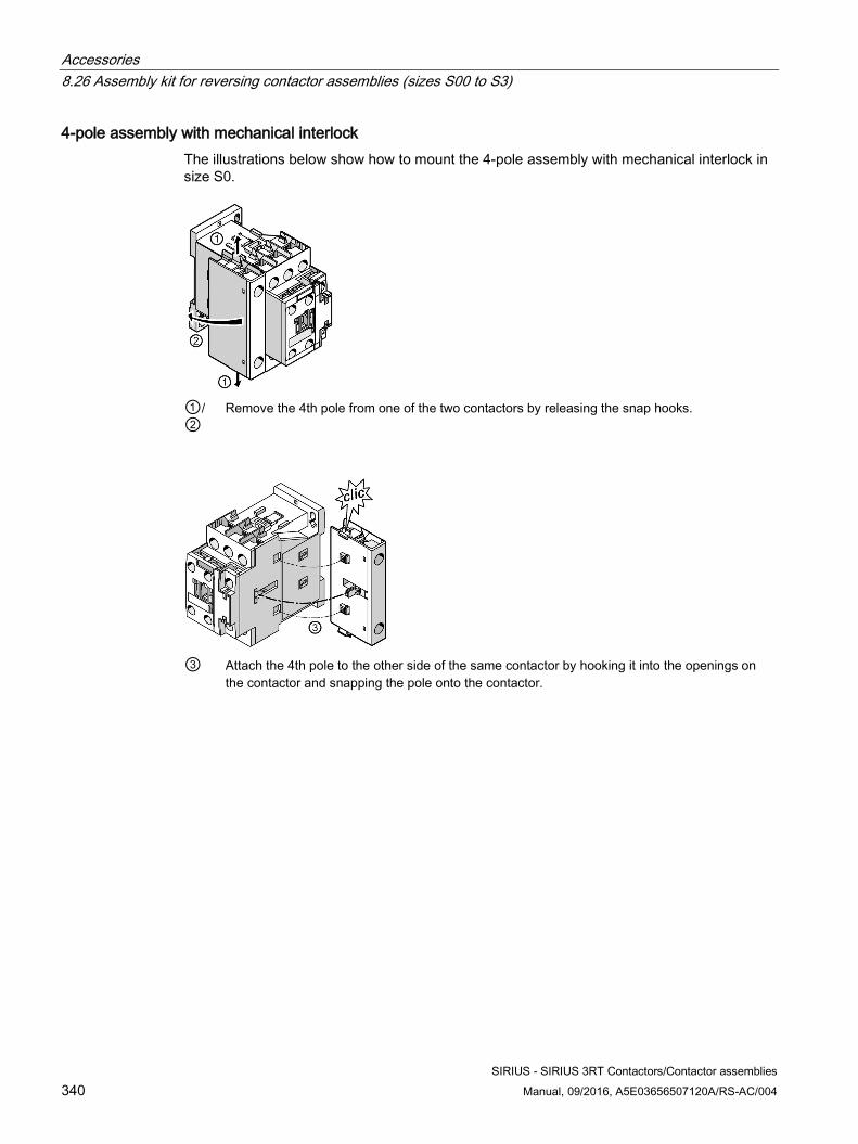
Accessories 8.26 Assembly kit for reversing contactor assemblies (sizes S00 to S3)
SIRIUS - SIRIUS 3RT Contactors/Contactor assemblies 340 Manual, 09/2016, A5E03656507120A/RS-AC/004
4-pole assembly with mechanical interlock The illustrations below show how to mount the 4-pole assembly with mechanical interlock in size S0.
①/②
Remove the 4th pole from one of the two contactors by releasing the snap hooks.
③ Attach the 4th pole to the other side of the same contactor by hooking it into the openings on
the contactor and snapping the pole onto the contactor.
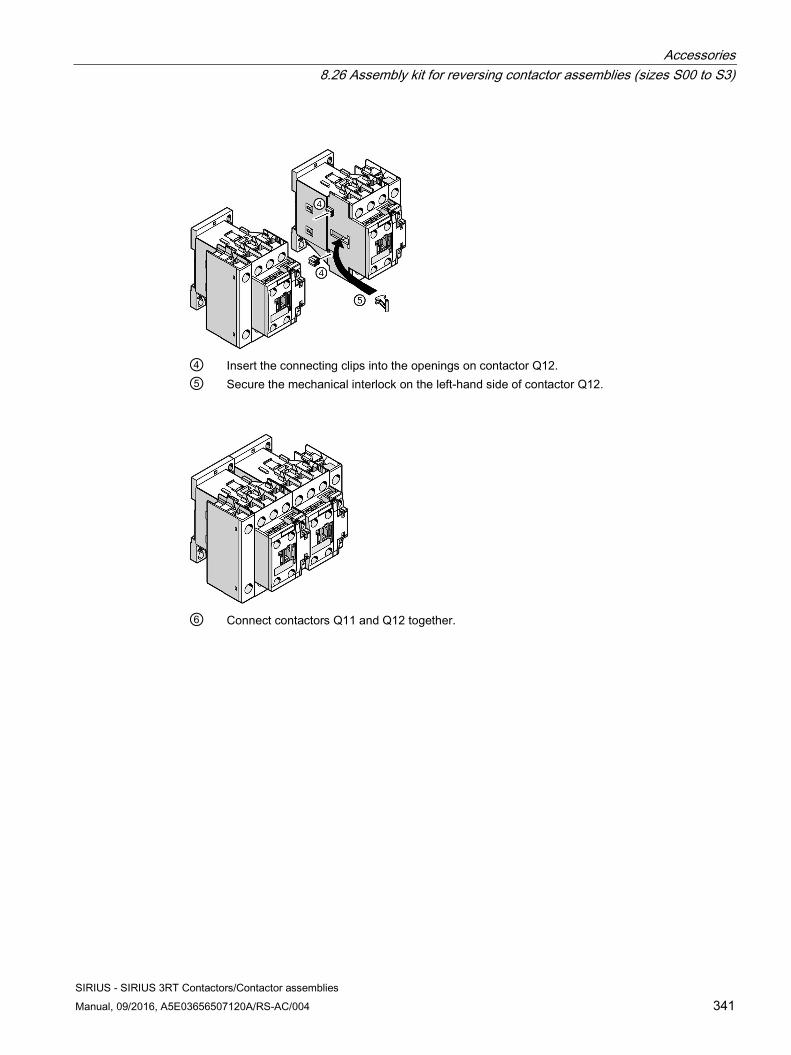
Accessories 8.26 Assembly kit for reversing contactor assemblies (sizes S00 to S3)
SIRIUS - SIRIUS 3RT Contactors/Contactor assemblies Manual, 09/2016, A5E03656507120A/RS-AC/004 341
④ Insert the connecting clips into the openings on contactor Q12. ⑤ Secure the mechanical interlock on the left-hand side of contactor Q12.
⑥ Connect contactors Q11 and Q12 together.
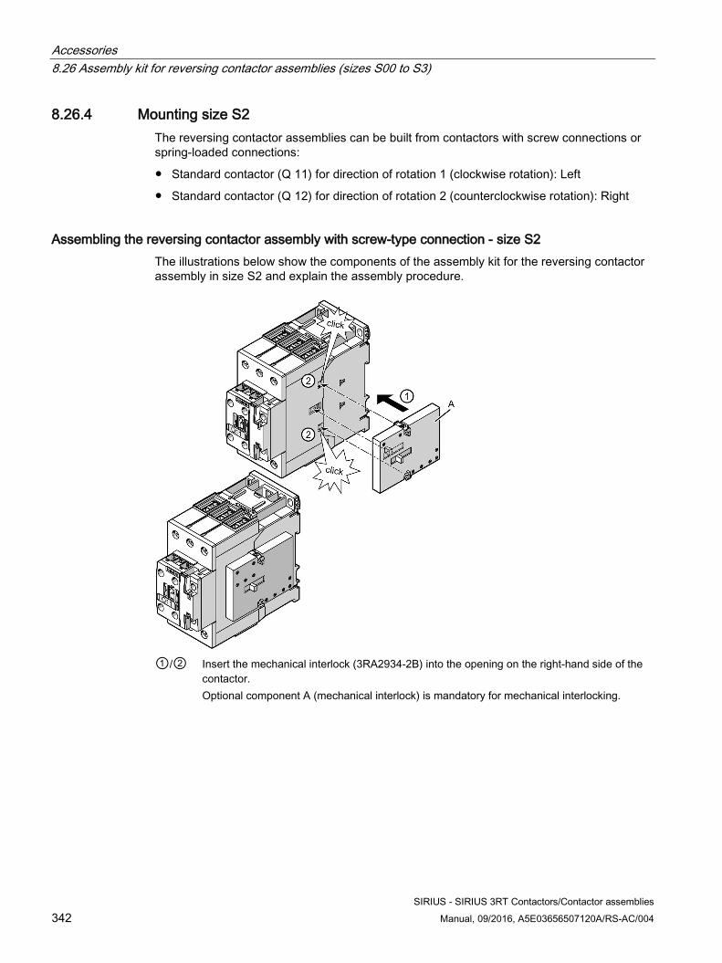
Accessories 8.26 Assembly kit for reversing contactor assemblies (sizes S00 to S3)
SIRIUS - SIRIUS 3RT Contactors/Contactor assemblies 342 Manual, 09/2016, A5E03656507120A/RS-AC/004
8.26.4 Mounting size S2 The reversing contactor assemblies can be built from contactors with screw connections or spring-loaded connections:
● Standard contactor (Q 11) for direction of rotation 1 (clockwise rotation): Left
● Standard contactor (Q 12) for direction of rotation 2 (counterclockwise rotation): Right
Assembling the reversing contactor assembly with screw-type connection - size S2 The illustrations below show the components of the assembly kit for the reversing contactor assembly in size S2 and explain the assembly procedure.
①/② Insert the mechanical interlock (3RA2934-2B) into the opening on the right-hand side of the
contactor. Optional component A (mechanical interlock) is mandatory for mechanical interlocking.
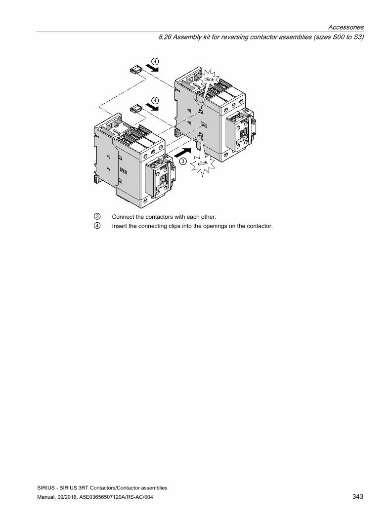
Accessories 8.26 Assembly kit for reversing contactor assemblies (sizes S00 to S3)
SIRIUS - SIRIUS 3RT Contactors/Contactor assemblies Manual, 09/2016, A5E03656507120A/RS-AC/004 343
③ Connect the contactors with each other. ④ Insert the connecting clips into the openings on the contactor.
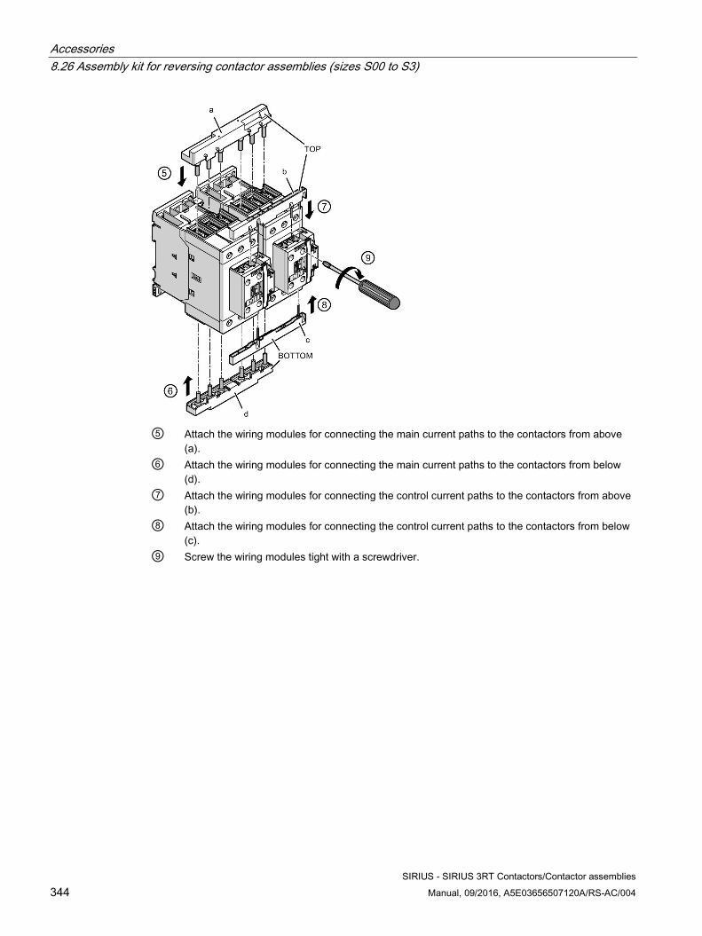
Accessories 8.26 Assembly kit for reversing contactor assemblies (sizes S00 to S3)
SIRIUS - SIRIUS 3RT Contactors/Contactor assemblies 344 Manual, 09/2016, A5E03656507120A/RS-AC/004
⑤ Attach the wiring modules for connecting the main current paths to the contactors from above
(a). ⑥ Attach the wiring modules for connecting the main current paths to the contactors from below
(d). ⑦ Attach the wiring modules for connecting the control current paths to the contactors from above
(b). ⑧ Attach the wiring modules for connecting the control current paths to the contactors from below
(c). ⑨ Screw the wiring modules tight with a screwdriver.
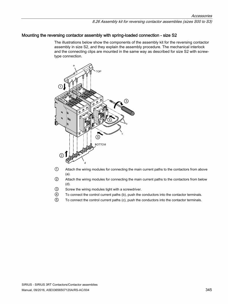
Accessories 8.26 Assembly kit for reversing contactor assemblies (sizes S00 to S3)
SIRIUS - SIRIUS 3RT Contactors/Contactor assemblies Manual, 09/2016, A5E03656507120A/RS-AC/004 345
Mounting the reversing contactor assembly with spring-loaded connection - size S2 The illustrations below show the components of the assembly kit for the reversing contactor assembly in size S2, and they explain the assembly procedure. The mechanical interlock and the connecting clips are mounted in the same way as described for size S2 with screw-type connection.
① Attach the wiring modules for connecting the main current paths to the contactors from above
(a). ② Attach the wiring modules for connecting the main current paths to the contactors from below
(d). ③ Screw the wiring modules tight with a screwdriver. ④ To connect the control current paths (b), push the conductors into the contactor terminals. ⑤ To connect the control current paths (c), push the conductors into the contactor terminals.
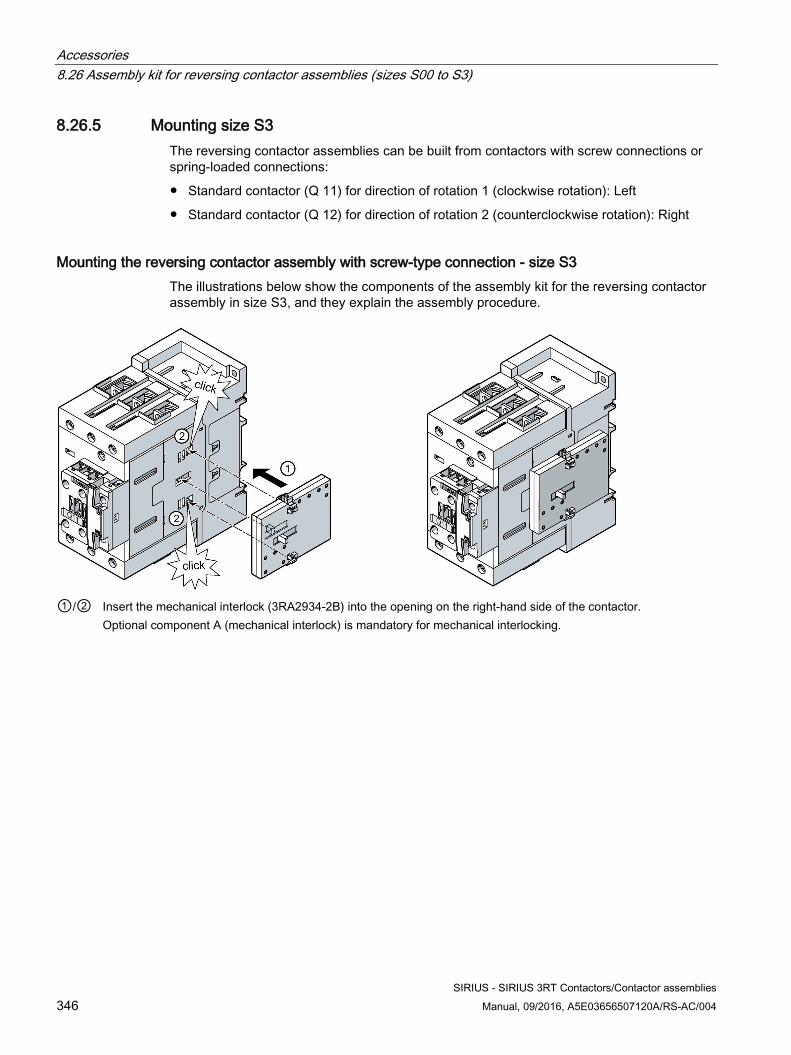
Accessories 8.26 Assembly kit for reversing contactor assemblies (sizes S00 to S3)
SIRIUS - SIRIUS 3RT Contactors/Contactor assemblies 346 Manual, 09/2016, A5E03656507120A/RS-AC/004
8.26.5 Mounting size S3 The reversing contactor assemblies can be built from contactors with screw connections or spring-loaded connections:
● Standard contactor (Q 11) for direction of rotation 1 (clockwise rotation): Left
● Standard contactor (Q 12) for direction of rotation 2 (counterclockwise rotation): Right
Mounting the reversing contactor assembly with screw-type connection - size S3 The illustrations below show the components of the assembly kit for the reversing contactor assembly in size S3, and they explain the assembly procedure.
①/② Insert the mechanical interlock (3RA2934-2B) into the opening on the right-hand side of the contactor.
Optional component A (mechanical interlock) is mandatory for mechanical interlocking.
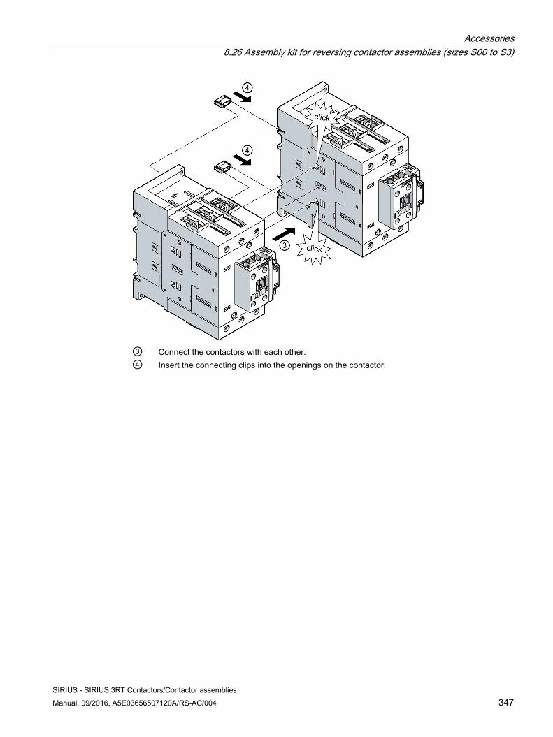
Accessories 8.26 Assembly kit for reversing contactor assemblies (sizes S00 to S3)
SIRIUS - SIRIUS 3RT Contactors/Contactor assemblies Manual, 09/2016, A5E03656507120A/RS-AC/004 347
③ Connect the contactors with each other. ④ Insert the connecting clips into the openings on the contactor.
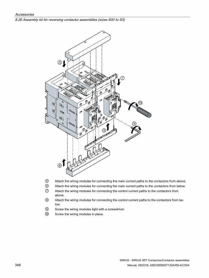
Accessories 8.26 Assembly kit for reversing contactor assemblies (sizes S00 to S3)
SIRIUS - SIRIUS 3RT Contactors/Contactor assemblies 348 Manual, 09/2016, A5E03656507120A/RS-AC/004
⑤ Attach the wiring modules for connecting the main current paths to the contactors from above. ⑥ Attach the wiring modules for connecting the main current paths to the contactors from below. ⑦ Attach the wiring modules for connecting the control current paths to the contactors from
above. ⑧ Attach the wiring modules for connecting the control current paths to the contactors from be-
low. ⑨ Screw the wiring modules tight with a screwdriver. ⑩ Screw the wiring modules in place.
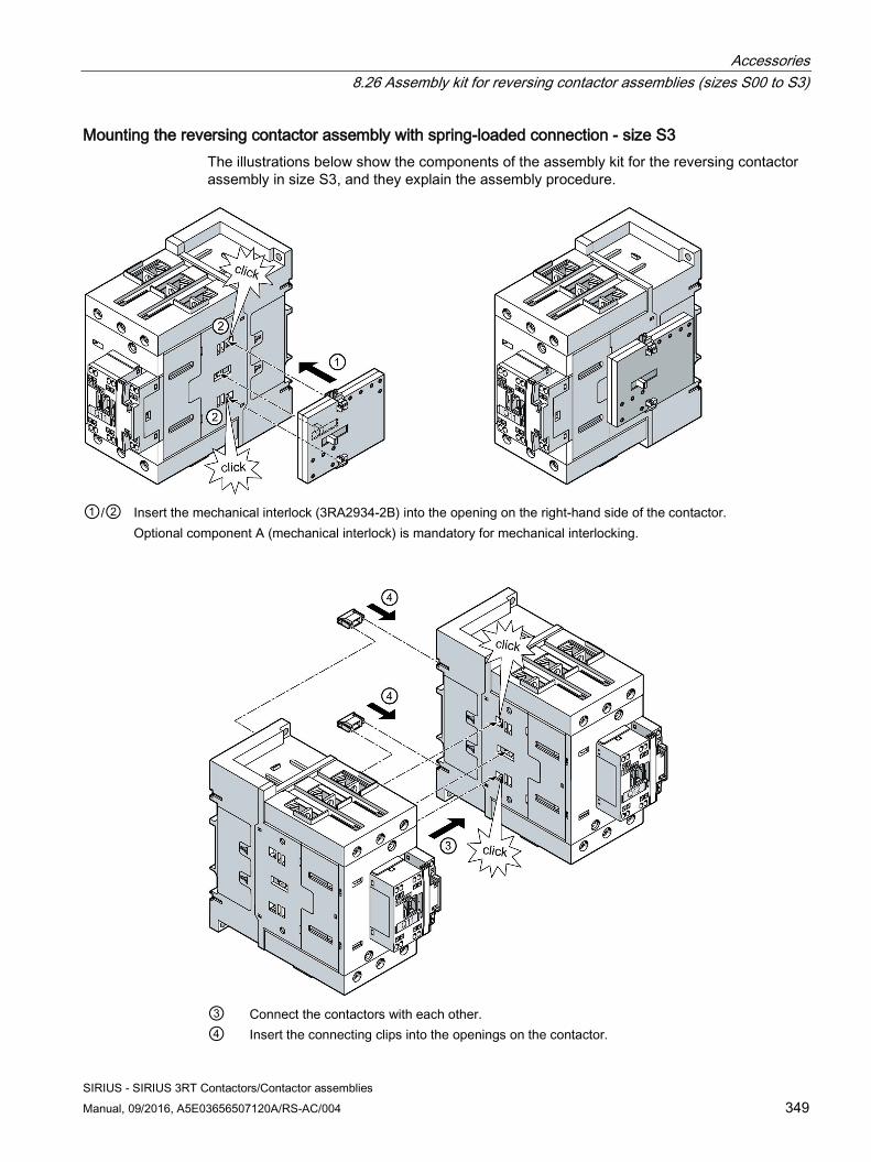
Accessories 8.26 Assembly kit for reversing contactor assemblies (sizes S00 to S3)
SIRIUS - SIRIUS 3RT Contactors/Contactor assemblies Manual, 09/2016, A5E03656507120A/RS-AC/004 349
Mounting the reversing contactor assembly with spring-loaded connection - size S3 The illustrations below show the components of the assembly kit for the reversing contactor assembly in size S3, and they explain the assembly procedure.
①/② Insert the mechanical interlock (3RA2934-2B) into the opening on the right-hand side of the contactor.
Optional component A (mechanical interlock) is mandatory for mechanical interlocking.
③ Connect the contactors with each other. ④ Insert the connecting clips into the openings on the contactor.
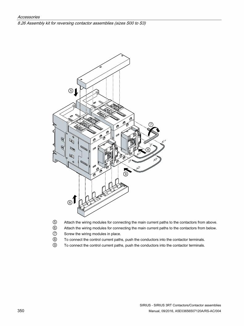
Accessories 8.26 Assembly kit for reversing contactor assemblies (sizes S00 to S3)
SIRIUS - SIRIUS 3RT Contactors/Contactor assemblies 350 Manual, 09/2016, A5E03656507120A/RS-AC/004
⑤ Attach the wiring modules for connecting the main current paths to the contactors from above. ⑥ Attach the wiring modules for connecting the main current paths to the contactors from below. ⑦ Screw the wiring modules in place. ⑧ To connect the control current paths, push the conductors into the contactor terminals. ⑨ To connect the control current paths, push the conductors into the contactor terminals.
Accessories 8.27 Wiring kit for reversing contactor assemblies (sizes S6 to S12)
SIRIUS - SIRIUS 3RT Contactors/Contactor assemblies Manual, 09/2016, A5E03656507120A/RS-AC/004 351
8.27 Wiring kit for reversing contactor assemblies (sizes S6 to S12)
8.27.1 Description Users can mount the reversing contactor assembly using various assembly kits.
The following accessories for the basic units can also be used for the reversing contactor assemblies:
● Auxiliary switch blocks (on the front, on the side)
● Surge suppressors
The following accessories are provided especially for the reversing contactor assemblies:
● Mechanical interlocks (article number: 3RA1954-2A)
● Mechanical connector (article number: 3RA1932-2D)
● Wiring modules, top and bottom
– S6 (article number: 3RA1953-2A, 3RA1953-2M)
– S10 (article number: 3RA1963-2A)
– S12 (article number: 3RA1973-2A)
● Base plates
– S6 (article number: 3RA1952-2A)
– S10 (article number: 3RA1962-2A)
– S12 (article number: 3RA1972-2A)
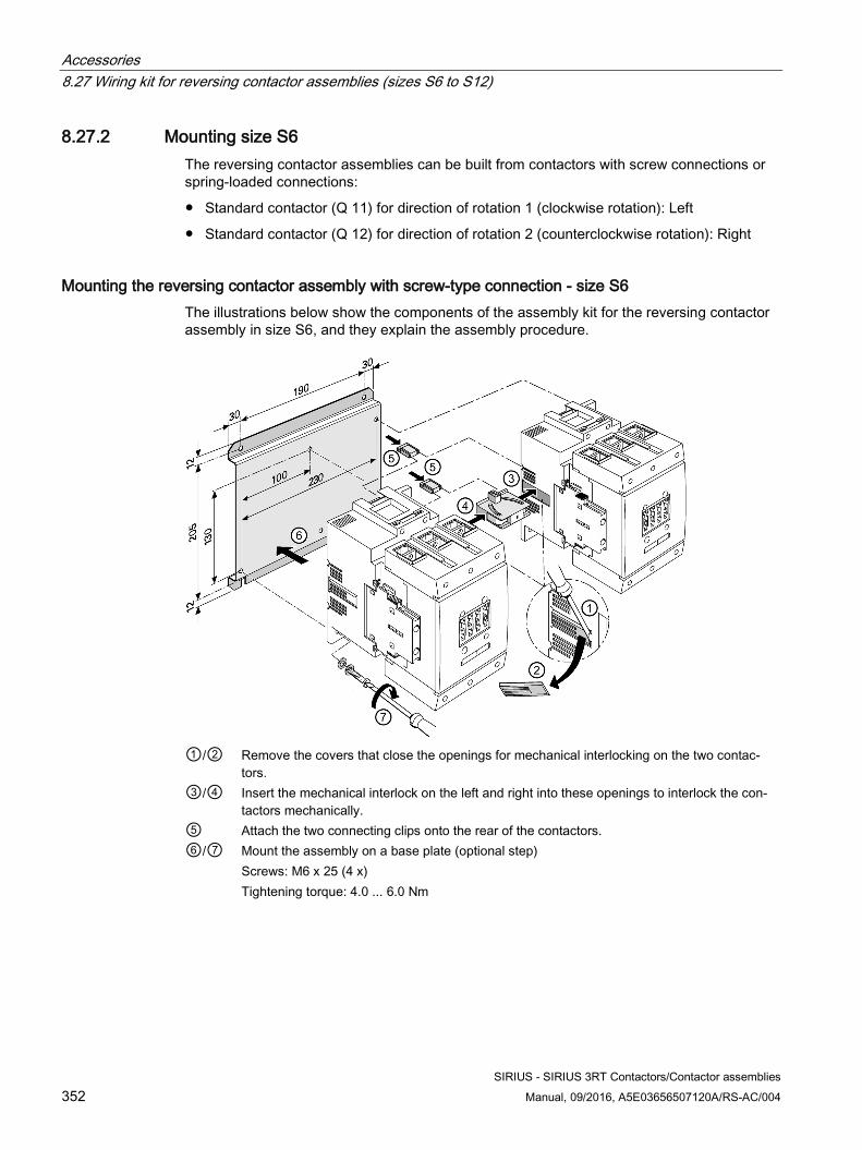
Accessories 8.27 Wiring kit for reversing contactor assemblies (sizes S6 to S12)
SIRIUS - SIRIUS 3RT Contactors/Contactor assemblies 352 Manual, 09/2016, A5E03656507120A/RS-AC/004
8.27.2 Mounting size S6 The reversing contactor assemblies can be built from contactors with screw connections or spring-loaded connections:
● Standard contactor (Q 11) for direction of rotation 1 (clockwise rotation): Left
● Standard contactor (Q 12) for direction of rotation 2 (counterclockwise rotation): Right
Mounting the reversing contactor assembly with screw-type connection - size S6 The illustrations below show the components of the assembly kit for the reversing contactor assembly in size S6, and they explain the assembly procedure.
①/② Remove the covers that close the openings for mechanical interlocking on the two contac-
tors. ③/④ Insert the mechanical interlock on the left and right into these openings to interlock the con-
tactors mechanically. ⑤ Attach the two connecting clips onto the rear of the contactors. ⑥/⑦ Mount the assembly on a base plate (optional step)
Screws: M6 x 25 (4 x) Tightening torque: 4.0 ... 6.0 Nm
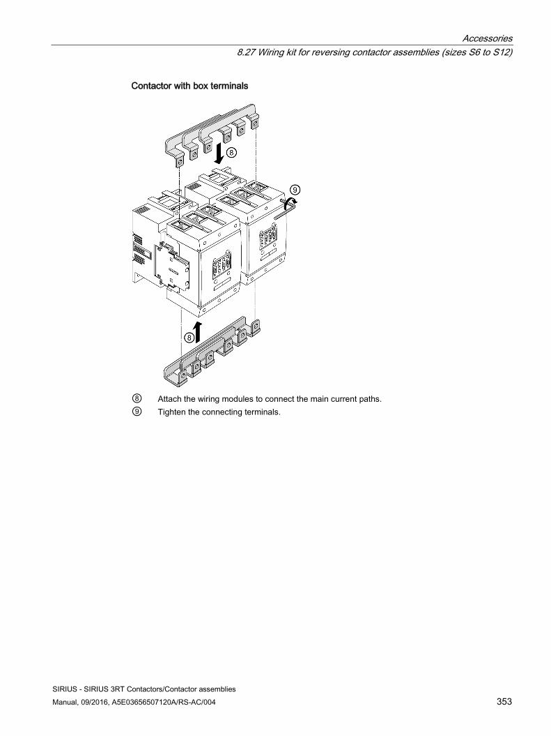
Accessories 8.27 Wiring kit for reversing contactor assemblies (sizes S6 to S12)
SIRIUS - SIRIUS 3RT Contactors/Contactor assemblies Manual, 09/2016, A5E03656507120A/RS-AC/004 353
Contactor with box terminals
⑧ Attach the wiring modules to connect the main current paths. ⑨ Tighten the connecting terminals.
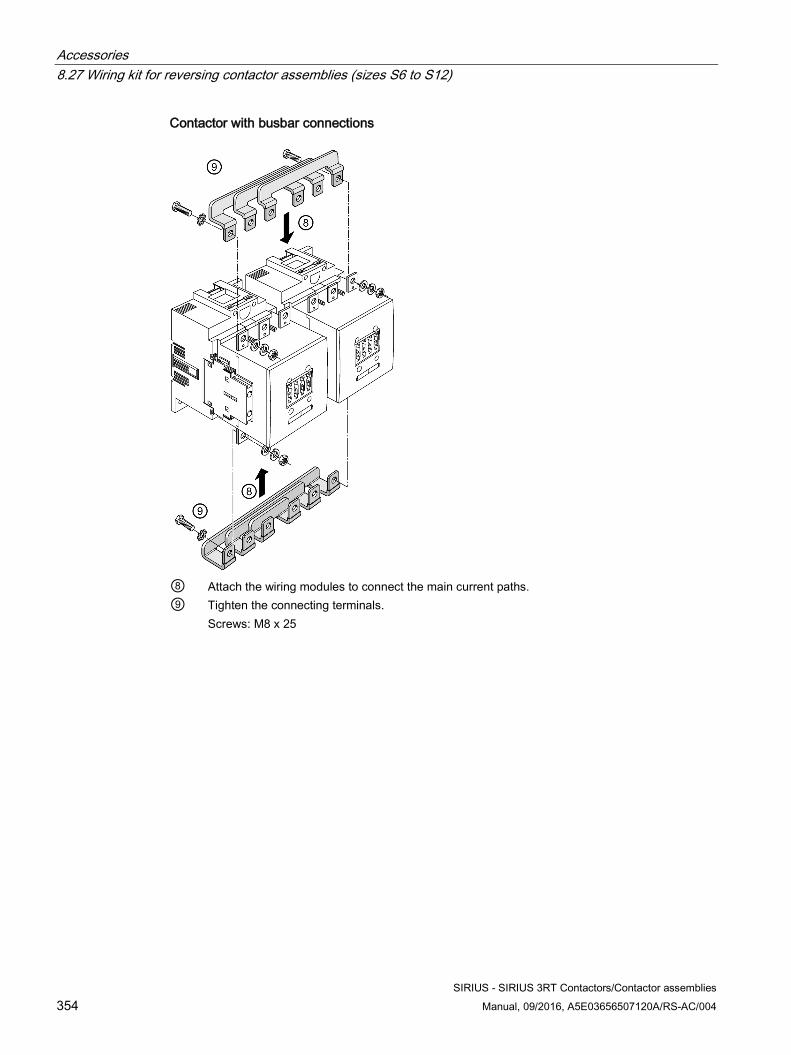
Accessories 8.27 Wiring kit for reversing contactor assemblies (sizes S6 to S12)
SIRIUS - SIRIUS 3RT Contactors/Contactor assemblies 354 Manual, 09/2016, A5E03656507120A/RS-AC/004
Contactor with busbar connections
⑧ Attach the wiring modules to connect the main current paths. ⑨ Tighten the connecting terminals.
Screws: M8 x 25
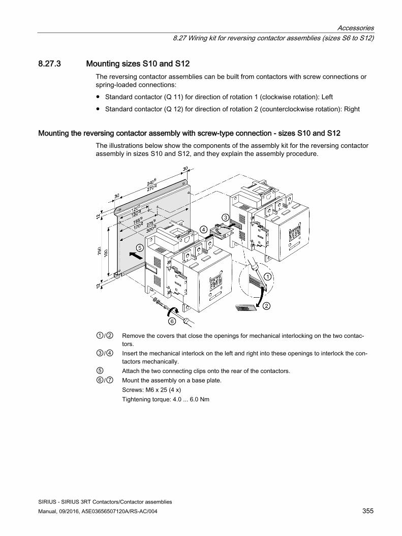
Accessories 8.27 Wiring kit for reversing contactor assemblies (sizes S6 to S12)
SIRIUS - SIRIUS 3RT Contactors/Contactor assemblies Manual, 09/2016, A5E03656507120A/RS-AC/004 355
8.27.3 Mounting sizes S10 and S12 The reversing contactor assemblies can be built from contactors with screw connections or spring-loaded connections:
● Standard contactor (Q 11) for direction of rotation 1 (clockwise rotation): Left
● Standard contactor (Q 12) for direction of rotation 2 (counterclockwise rotation): Right
Mounting the reversing contactor assembly with screw-type connection - sizes S10 and S12 The illustrations below show the components of the assembly kit for the reversing contactor assembly in sizes S10 and S12, and they explain the assembly procedure.
①/② Remove the covers that close the openings for mechanical interlocking on the two contac-
tors. ③/④ Insert the mechanical interlock on the left and right into these openings to interlock the con-
tactors mechanically. ⑤ Attach the two connecting clips onto the rear of the contactors. ⑥/⑦ Mount the assembly on a base plate.
Screws: M6 x 25 (4 x) Tightening torque: 4.0 ... 6.0 Nm
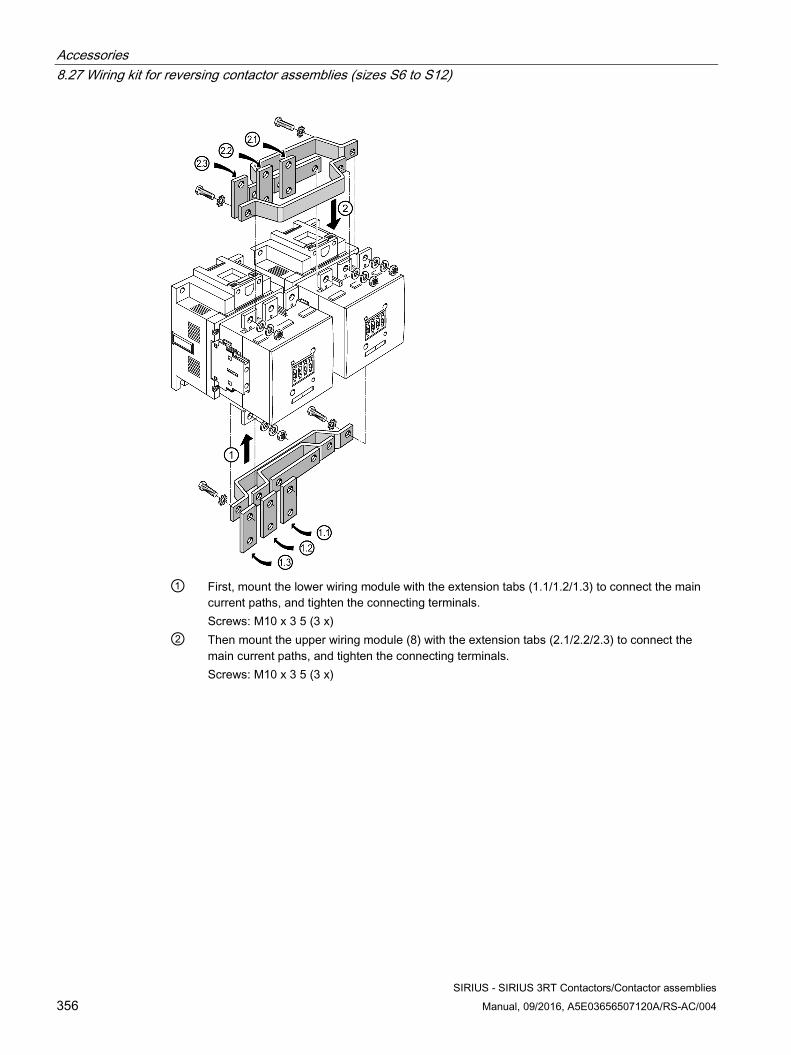
Accessories 8.27 Wiring kit for reversing contactor assemblies (sizes S6 to S12)
SIRIUS - SIRIUS 3RT Contactors/Contactor assemblies 356 Manual, 09/2016, A5E03656507120A/RS-AC/004
① First, mount the lower wiring module with the extension tabs (1.1/1.2/1.3) to connect the main
current paths, and tighten the connecting terminals. Screws: M10 x 3 5 (3 x)
② Then mount the upper wiring module (8) with the extension tabs (2.1/2.2/2.3) to connect the main current paths, and tighten the connecting terminals. Screws: M10 x 3 5 (3 x)
Accessories 8.28 Assembly kit for contactor assemblies for star-delta (wye-delta) start (sizes S00 to S3)
SIRIUS - SIRIUS 3RT Contactors/Contactor assemblies Manual, 09/2016, A5E03656507120A/RS-AC/004 357
8.28 Assembly kit for contactor assemblies for star-delta (wye-delta) start (sizes S00 to S3)
8.28.1 Description
Prerequisite The following components, which have to be ordered separately, are required to mount the contactor assembly for star-delta (wye-delta) start:
● Assembly kit for the 3RA24 contactor assembly for star-delta (wye-delta) start
● Function modules with or without communication connection.
● Three power contactors 3RT20
Note For size S2 / S3, spring-loaded connection only in the control circuit
The following assemblies for spring-loaded connection are available for sizes S00 and S0 only.
Note
If the function modules are used, they take over the tasks associated with control circuit wiring and the timing relay. However, an installation without function modules and with an additional external timing relay continues to be possible. Accordingly, the scope of supply of the assembly kit includes the wiring modules for the control circuit wiring (these are not required if function modules are being used).
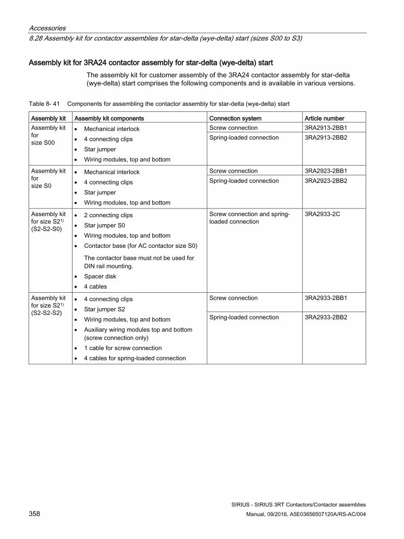
Accessories 8.28 Assembly kit for contactor assemblies for star-delta (wye-delta) start (sizes S00 to S3)
SIRIUS - SIRIUS 3RT Contactors/Contactor assemblies 358 Manual, 09/2016, A5E03656507120A/RS-AC/004
Assembly kit for 3RA24 contactor assembly for star-delta (wye-delta) start The assembly kit for customer assembly of the 3RA24 contactor assembly for star-delta (wye-delta) start comprises the following components and is available in various versions.
Table 8- 41 Components for assembling the contactor assembly for star-delta (wye-delta) start
Assembly kit Assembly kit components Connection system Article number Assembly kit for size S00
• Mechanical interlock • 4 connecting clips • Star jumper • Wiring modules, top and bottom
Screw connection 3RA2913-2BB1 Spring-loaded connection 3RA2913-2BB2
Assembly kit for size S0
• Mechanical interlock • 4 connecting clips • Star jumper • Wiring modules, top and bottom
Screw connection 3RA2923-2BB1 Spring-loaded connection 3RA2923-2BB2
Assembly kit for size S21) (S2-S2-S0)
• 2 connecting clips • Star jumper S0 • Wiring modules, top and bottom • Contactor base (for AC contactor size S0)
The contactor base must not be used for DIN rail mounting.
• Spacer disk • 4 cables
Screw connection and spring-loaded connection
3RA2933-2C
Assembly kit for size S21)
(S2-S2-S2)
• 4 connecting clips • Star jumper S2 • Wiring modules, top and bottom • Auxiliary wiring modules top and bottom
(screw connection only) • 1 cable for screw connection • 4 cables for spring-loaded connection
Screw connection
3RA2933-2BB1
Spring-loaded connection 3RA2933-2BB2
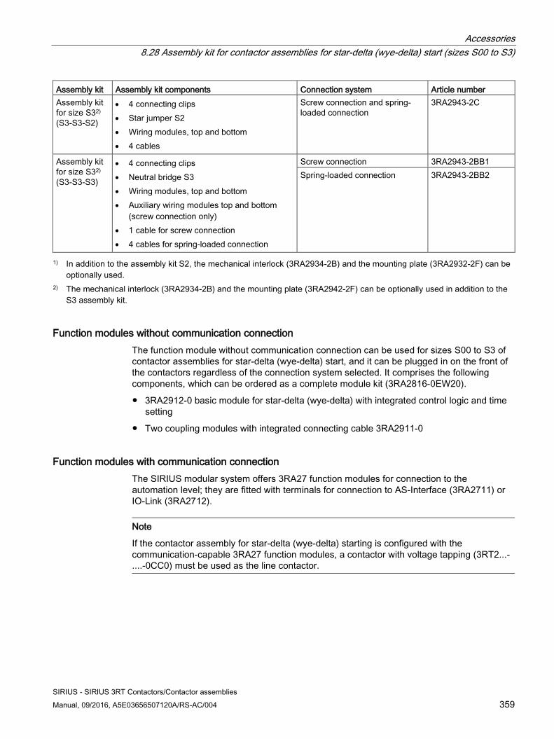
Accessories 8.28 Assembly kit for contactor assemblies for star-delta (wye-delta) start (sizes S00 to S3)
SIRIUS - SIRIUS 3RT Contactors/Contactor assemblies Manual, 09/2016, A5E03656507120A/RS-AC/004 359
Assembly kit Assembly kit components Connection system Article number Assembly kit for size S32)
(S3-S3-S2)
• 4 connecting clips • Star jumper S2 • Wiring modules, top and bottom • 4 cables
Screw connection and spring-loaded connection
3RA2943-2C
Assembly kit for size S32) (S3-S3-S3)
• 4 connecting clips • Neutral bridge S3 • Wiring modules, top and bottom • Auxiliary wiring modules top and bottom
(screw connection only) • 1 cable for screw connection • 4 cables for spring-loaded connection
Screw connection 3RA2943-2BB1 Spring-loaded connection 3RA2943-2BB2
1) In addition to the assembly kit S2, the mechanical interlock (3RA2934-2B) and the mounting plate (3RA2932-2F) can be optionally used.
2) The mechanical interlock (3RA2934-2B) and the mounting plate (3RA2942-2F) can be optionally used in addition to the S3 assembly kit.
Function modules without communication connection The function module without communication connection can be used for sizes S00 to S3 of contactor assemblies for star-delta (wye-delta) start, and it can be plugged in on the front of the contactors regardless of the connection system selected. It comprises the following components, which can be ordered as a complete module kit (3RA2816-0EW20).
● 3RA2912-0 basic module for star-delta (wye-delta) with integrated control logic and time setting
● Two coupling modules with integrated connecting cable 3RA2911-0
Function modules with communication connection The SIRIUS modular system offers 3RA27 function modules for connection to the automation level; they are fitted with terminals for connection to AS-Interface (3RA2711) or IO-Link (3RA2712).
Note
If the contactor assembly for star-delta (wye-delta) starting is configured with the communication-capable 3RA27 function modules, a contactor with voltage tapping (3RT2...-....-0CC0) must be used as the line contactor.
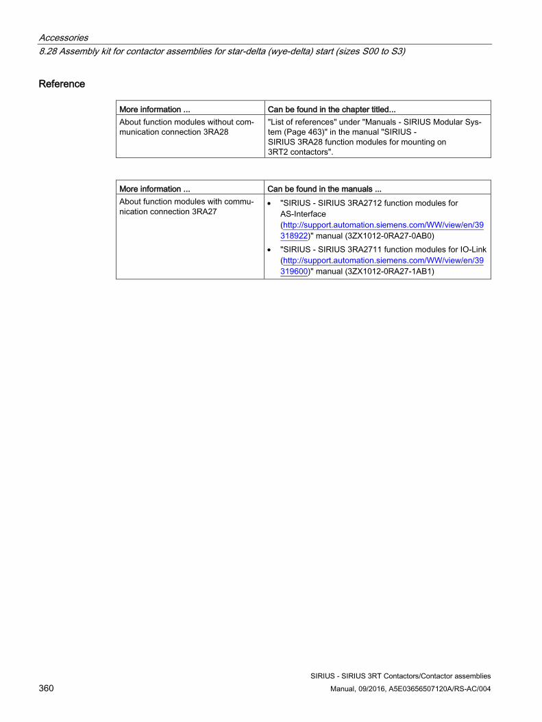
Accessories 8.28 Assembly kit for contactor assemblies for star-delta (wye-delta) start (sizes S00 to S3)
SIRIUS - SIRIUS 3RT Contactors/Contactor assemblies 360 Manual, 09/2016, A5E03656507120A/RS-AC/004
Reference More information ... Can be found in the chapter titled... About function modules without com-munication connection 3RA28
"List of references" under "Manuals - SIRIUS Modular Sys-tem (Page 463)" in the manual "SIRIUS - SIRIUS 3RA28 function modules for mounting on 3RT2 contactors".
More information ... Can be found in the manuals ... About function modules with commu-nication connection 3RA27
• "SIRIUS - SIRIUS 3RA2712 function modules for AS-Interface (http://support.automation.siemens.com/WW/view/en/39318922)" manual (3ZX1012-0RA27-0AB0)
• "SIRIUS - SIRIUS 3RA2711 function modules for IO-Link (http://support.automation.siemens.com/WW/view/en/39319600)" manual (3ZX1012-0RA27-1AB1)
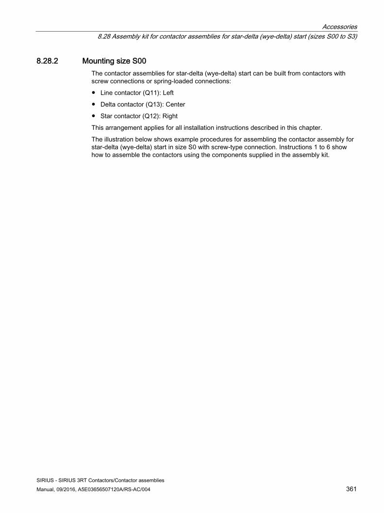
Accessories 8.28 Assembly kit for contactor assemblies for star-delta (wye-delta) start (sizes S00 to S3)
SIRIUS - SIRIUS 3RT Contactors/Contactor assemblies Manual, 09/2016, A5E03656507120A/RS-AC/004 361
8.28.2 Mounting size S00 The contactor assemblies for star-delta (wye-delta) start can be built from contactors with screw connections or spring-loaded connections:
● Line contactor (Q11): Left
● Delta contactor (Q13): Center
● Star contactor (Q12): Right
This arrangement applies for all installation instructions described in this chapter.
The illustration below shows example procedures for assembling the contactor assembly for star-delta (wye-delta) start in size S0 with screw-type connection. Instructions 1 to 6 show how to assemble the contactors using the components supplied in the assembly kit.
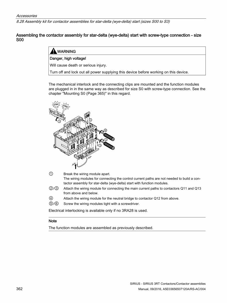
Accessories 8.28 Assembly kit for contactor assemblies for star-delta (wye-delta) start (sizes S00 to S3)
SIRIUS - SIRIUS 3RT Contactors/Contactor assemblies 362 Manual, 09/2016, A5E03656507120A/RS-AC/004
Assembling the contactor assembly for star-delta (wye-delta) start with screw-type connection - size S00
WARNING
Danger, high voltage!
Will cause death or serious injury.
Turn off and lock out all power supplying this device before working on this device.
The mechanical interlock and the connecting clips are mounted and the function modules are plugged in in the same way as described for size S0 with screw-type connection. See the chapter "Mounting S0 (Page 365)" in this regard.
① Break the wiring module apart.
The wiring modules for connecting the control current paths are not needed to build a con-tactor assembly for star-delta (wye-delta) start with function modules.
②/③ Attach the wiring module for connecting the main current paths to contactors Q11 and Q13 from above and below.
④ Attach the wiring module for the neutral bridge to contactor Q12 from above. ⑤/⑥ Screw the wiring modules tight with a screwdriver.
Electrical interlocking is available only if no 3RA28 is used.
Note
The function modules are assembled as previously described.
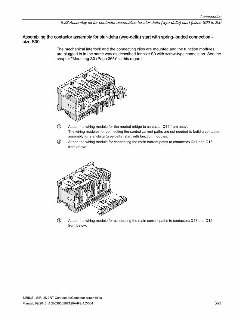
Accessories 8.28 Assembly kit for contactor assemblies for star-delta (wye-delta) start (sizes S00 to S3)
SIRIUS - SIRIUS 3RT Contactors/Contactor assemblies Manual, 09/2016, A5E03656507120A/RS-AC/004 363
Assembling the contactor assembly for star-delta (wye-delta) start with spring-loaded connection - size S00
The mechanical interlock and the connecting clips are mounted and the function modules are plugged in in the same way as described for size S0 with screw-type connection. See the chapter "Mounting S0 (Page 365)" in this regard.
① Attach the wiring module for the neutral bridge to contactor Q12 from above.
The wiring modules for connecting the control current paths are not needed to build a contactor assembly for star-delta (wye-delta) start with function modules.
② Attach the wiring module for connecting the main current paths to contactors Q11 and Q13 from above.
③ Attach the wiring module for connecting the main current paths to contactors Q13 and Q12
from below.
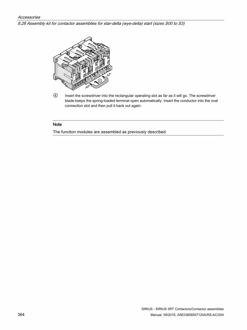
Accessories 8.28 Assembly kit for contactor assemblies for star-delta (wye-delta) start (sizes S00 to S3)
SIRIUS - SIRIUS 3RT Contactors/Contactor assemblies 364 Manual, 09/2016, A5E03656507120A/RS-AC/004
④ Insert the screwdriver into the rectangular operating slot as far as it will go. The screwdriver
blade keeps the spring-loaded terminal open automatically. Insert the conductor into the oval connection slot and then pull it back out again.
Note
The function modules are assembled as previously described.
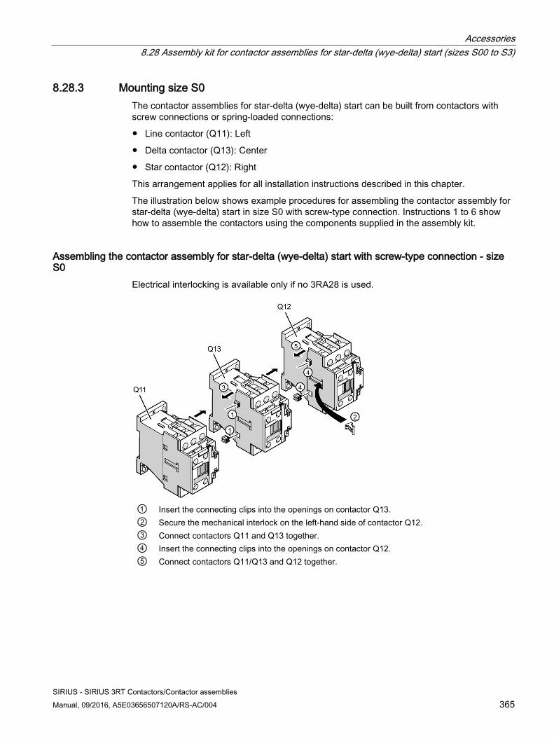
Accessories 8.28 Assembly kit for contactor assemblies for star-delta (wye-delta) start (sizes S00 to S3)
SIRIUS - SIRIUS 3RT Contactors/Contactor assemblies Manual, 09/2016, A5E03656507120A/RS-AC/004 365
8.28.3 Mounting size S0 The contactor assemblies for star-delta (wye-delta) start can be built from contactors with screw connections or spring-loaded connections:
● Line contactor (Q11): Left
● Delta contactor (Q13): Center
● Star contactor (Q12): Right
This arrangement applies for all installation instructions described in this chapter.
The illustration below shows example procedures for assembling the contactor assembly for star-delta (wye-delta) start in size S0 with screw-type connection. Instructions 1 to 6 show how to assemble the contactors using the components supplied in the assembly kit.
Assembling the contactor assembly for star-delta (wye-delta) start with screw-type connection - size S0
Electrical interlocking is available only if no 3RA28 is used.
① Insert the connecting clips into the openings on contactor Q13. ② Secure the mechanical interlock on the left-hand side of contactor Q12. ③ Connect contactors Q11 and Q13 together. ④ Insert the connecting clips into the openings on contactor Q12. ⑤ Connect contactors Q11/Q13 and Q12 together.
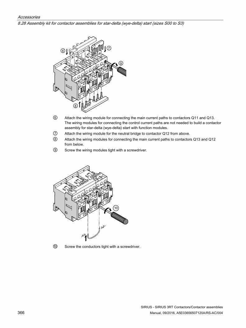
Accessories 8.28 Assembly kit for contactor assemblies for star-delta (wye-delta) start (sizes S00 to S3)
SIRIUS - SIRIUS 3RT Contactors/Contactor assemblies 366 Manual, 09/2016, A5E03656507120A/RS-AC/004
⑥ Attach the wiring module for connecting the main current paths to contactors Q11 and Q13.
The wiring modules for connecting the control current paths are not needed to build a contactor assembly for star-delta (wye-delta) start with function modules.
⑦ Attach the wiring module for the neutral bridge to contactor Q12 from above. ⑧ Attach the wiring modules for connecting the main current paths to contactors Q13 and Q12
from below. ⑨ Screw the wiring modules tight with a screwdriver.
⑩ Screw the conductors tight with a screwdriver.
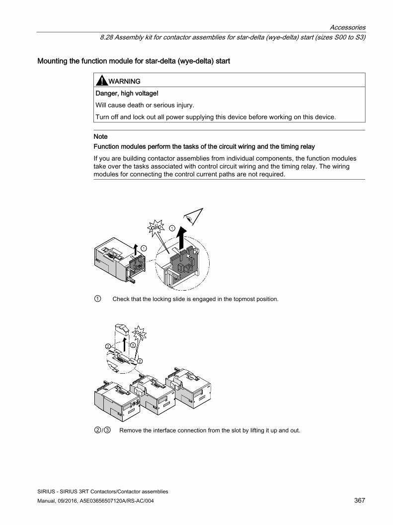
Accessories 8.28 Assembly kit for contactor assemblies for star-delta (wye-delta) start (sizes S00 to S3)
SIRIUS - SIRIUS 3RT Contactors/Contactor assemblies Manual, 09/2016, A5E03656507120A/RS-AC/004 367
Mounting the function module for star-delta (wye-delta) start
WARNING
Danger, high voltage!
Will cause death or serious injury.
Turn off and lock out all power supplying this device before working on this device.
Note Function modules perform the tasks of the circuit wiring and the timing relay
If you are building contactor assemblies from individual components, the function modules take over the tasks associated with control circuit wiring and the timing relay. The wiring modules for connecting the control current paths are not required.
① Check that the locking slide is engaged in the topmost position.
②/③ Remove the interface connection from the slot by lifting it up and out.
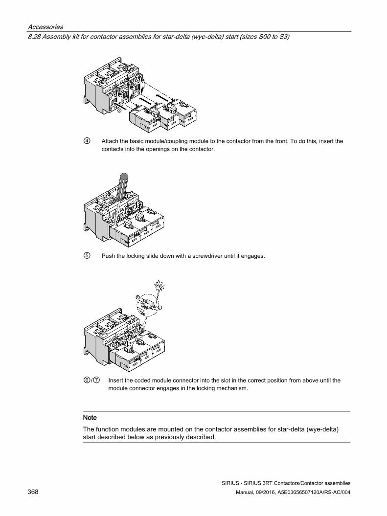
Accessories 8.28 Assembly kit for contactor assemblies for star-delta (wye-delta) start (sizes S00 to S3)
SIRIUS - SIRIUS 3RT Contactors/Contactor assemblies 368 Manual, 09/2016, A5E03656507120A/RS-AC/004
④ Attach the basic module/coupling module to the contactor from the front. To do this, insert the
contacts into the openings on the contactor.
⑤ Push the locking slide down with a screwdriver until it engages.
⑥/⑦ Insert the coded module connector into the slot in the correct position from above until the
module connector engages in the locking mechanism.
Note
The function modules are mounted on the contactor assemblies for star-delta (wye-delta) start described below as previously described.
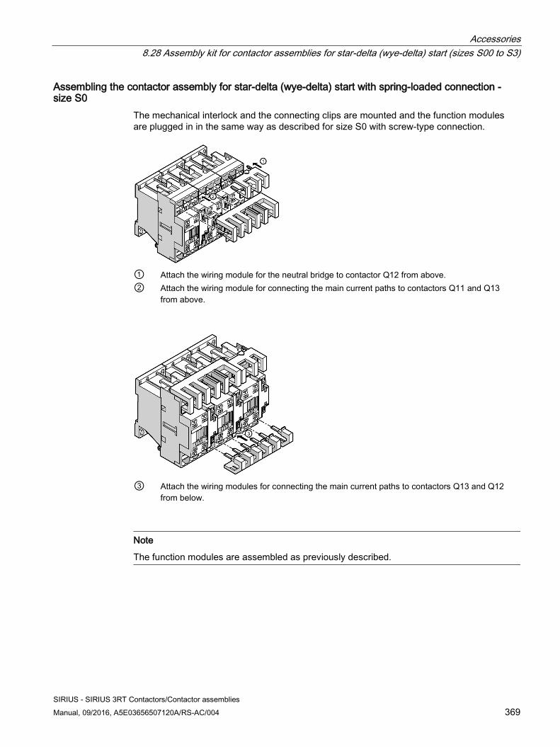
Accessories 8.28 Assembly kit for contactor assemblies for star-delta (wye-delta) start (sizes S00 to S3)
SIRIUS - SIRIUS 3RT Contactors/Contactor assemblies Manual, 09/2016, A5E03656507120A/RS-AC/004 369
Assembling the contactor assembly for star-delta (wye-delta) start with spring-loaded connection - size S0
The mechanical interlock and the connecting clips are mounted and the function modules are plugged in in the same way as described for size S0 with screw-type connection.
① Attach the wiring module for the neutral bridge to contactor Q12 from above. ② Attach the wiring module for connecting the main current paths to contactors Q11 and Q13
from above.
③ Attach the wiring modules for connecting the main current paths to contactors Q13 and Q12
from below.
Note
The function modules are assembled as previously described.
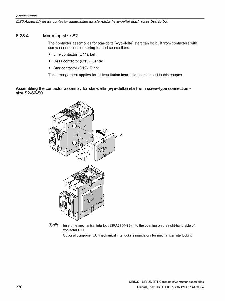
Accessories 8.28 Assembly kit for contactor assemblies for star-delta (wye-delta) start (sizes S00 to S3)
SIRIUS - SIRIUS 3RT Contactors/Contactor assemblies 370 Manual, 09/2016, A5E03656507120A/RS-AC/004
8.28.4 Mounting size S2 The contactor assemblies for star-delta (wye-delta) start can be built from contactors with screw connections or spring-loaded connections:
● Line contactor (Q11): Left
● Delta contactor (Q13): Center
● Star contactor (Q12): Right
This arrangement applies for all installation instructions described in this chapter.
Assembling the contactor assembly for star-delta (wye-delta) start with screw-type connection - size S2-S2-S0
①/② Insert the mechanical interlock (3RA2934-2B) into the opening on the right-hand side of
contactor Q11. Optional component A (mechanical interlock) is mandatory for mechanical interlocking.
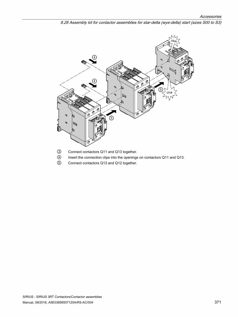
Accessories 8.28 Assembly kit for contactor assemblies for star-delta (wye-delta) start (sizes S00 to S3)
SIRIUS - SIRIUS 3RT Contactors/Contactor assemblies Manual, 09/2016, A5E03656507120A/RS-AC/004 371
③ Connect contactors Q11 and Q13 together. ④ Insert the connection clips into the openings on contactors Q11 and Q13. ⑤ Connect contactors Q13 and Q12 together.
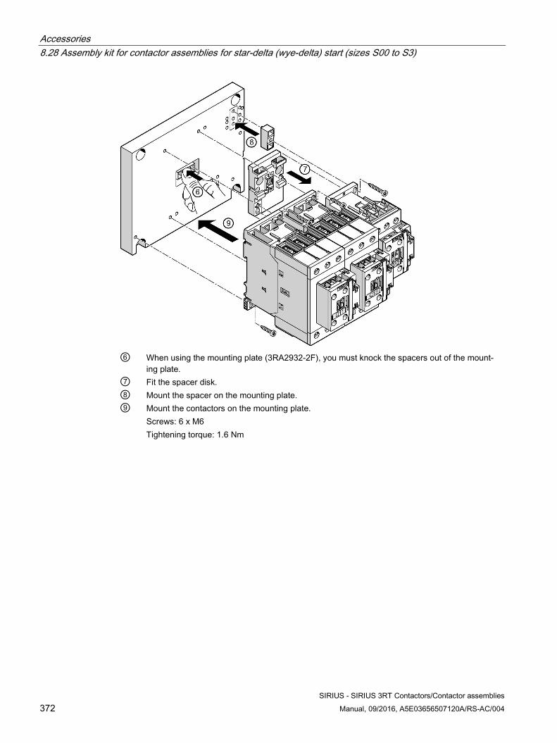
Accessories 8.28 Assembly kit for contactor assemblies for star-delta (wye-delta) start (sizes S00 to S3)
SIRIUS - SIRIUS 3RT Contactors/Contactor assemblies 372 Manual, 09/2016, A5E03656507120A/RS-AC/004
⑥ When using the mounting plate (3RA2932-2F), you must knock the spacers out of the mount-
ing plate. ⑦ Fit the spacer disk. ⑧ Mount the spacer on the mounting plate. ⑨ Mount the contactors on the mounting plate.
Screws: 6 x M6 Tightening torque: 1.6 Nm
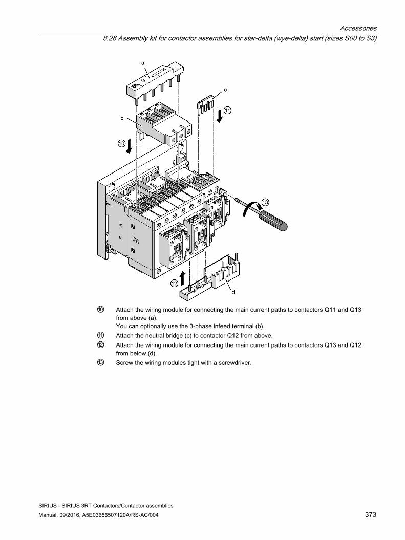
Accessories 8.28 Assembly kit for contactor assemblies for star-delta (wye-delta) start (sizes S00 to S3)
SIRIUS - SIRIUS 3RT Contactors/Contactor assemblies Manual, 09/2016, A5E03656507120A/RS-AC/004 373
⑩ Attach the wiring module for connecting the main current paths to contactors Q11 and Q13
from above (a). You can optionally use the 3-phase infeed terminal (b).
⑪ Attach the neutral bridge (c) to contactor Q12 from above. ⑫ Attach the wiring module for connecting the main current paths to contactors Q13 and Q12
from below (d). ⑬ Screw the wiring modules tight with a screwdriver.
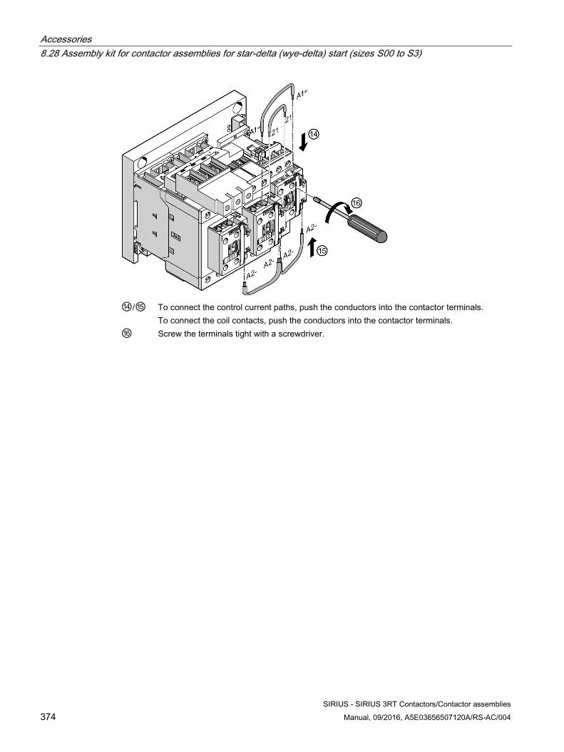
Accessories 8.28 Assembly kit for contactor assemblies for star-delta (wye-delta) start (sizes S00 to S3)
SIRIUS - SIRIUS 3RT Contactors/Contactor assemblies 374 Manual, 09/2016, A5E03656507120A/RS-AC/004
⑭/⑮ To connect the control current paths, push the conductors into the contactor terminals.
To connect the coil contacts, push the conductors into the contactor terminals. ⑯ Screw the terminals tight with a screwdriver.
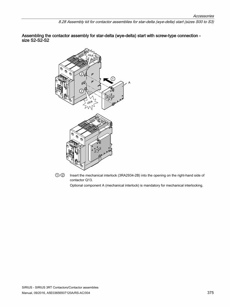
Accessories 8.28 Assembly kit for contactor assemblies for star-delta (wye-delta) start (sizes S00 to S3)
SIRIUS - SIRIUS 3RT Contactors/Contactor assemblies Manual, 09/2016, A5E03656507120A/RS-AC/004 375
Assembling the contactor assembly for star-delta (wye-delta) start with screw-type connection - size S2-S2-S2
①/② Insert the mechanical interlock (3RA2934-2B) into the opening on the right-hand side of
contactor Q13. Optional component A (mechanical interlock) is mandatory for mechanical interlocking.
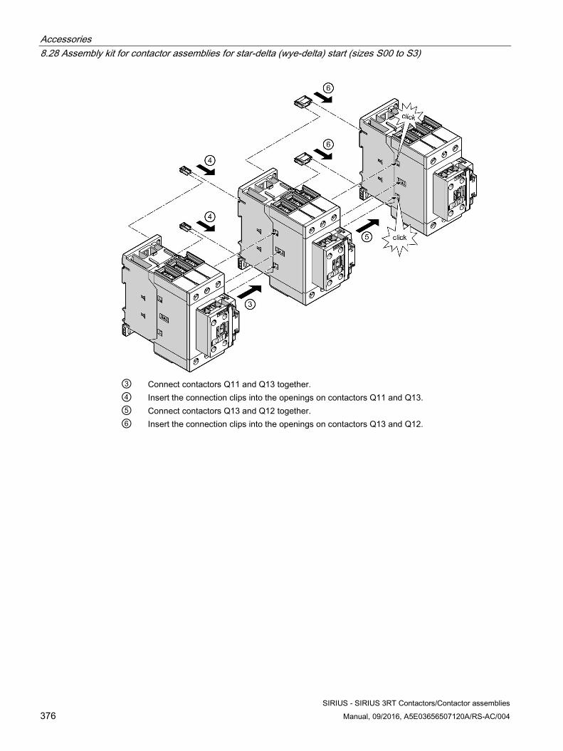
Accessories 8.28 Assembly kit for contactor assemblies for star-delta (wye-delta) start (sizes S00 to S3)
SIRIUS - SIRIUS 3RT Contactors/Contactor assemblies 376 Manual, 09/2016, A5E03656507120A/RS-AC/004
③ Connect contactors Q11 and Q13 together. ④ Insert the connection clips into the openings on contactors Q11 and Q13. ⑤ Connect contactors Q13 and Q12 together. ⑥ Insert the connection clips into the openings on contactors Q13 and Q12.
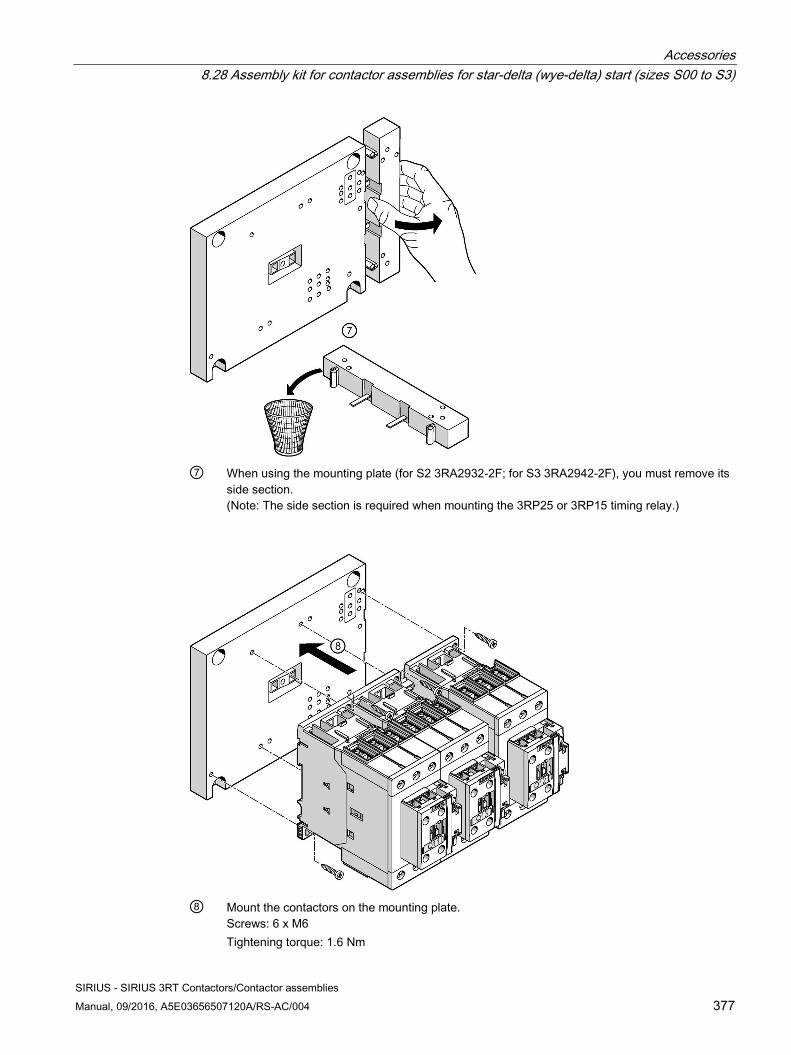
Accessories 8.28 Assembly kit for contactor assemblies for star-delta (wye-delta) start (sizes S00 to S3)
SIRIUS - SIRIUS 3RT Contactors/Contactor assemblies Manual, 09/2016, A5E03656507120A/RS-AC/004 377
⑦ When using the mounting plate (for S2 3RA2932-2F; for S3 3RA2942-2F), you must remove its
side section. (Note: The side section is required when mounting the 3RP25 or 3RP15 timing relay.)
⑧ Mount the contactors on the mounting plate.
Screws: 6 x M6 Tightening torque: 1.6 Nm
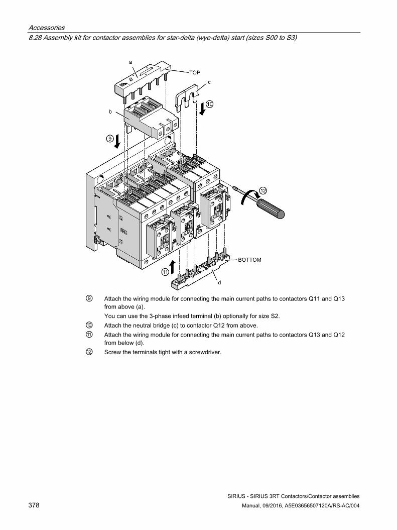
Accessories 8.28 Assembly kit for contactor assemblies for star-delta (wye-delta) start (sizes S00 to S3)
SIRIUS - SIRIUS 3RT Contactors/Contactor assemblies 378 Manual, 09/2016, A5E03656507120A/RS-AC/004
⑨ Attach the wiring module for connecting the main current paths to contactors Q11 and Q13
from above (a). You can use the 3-phase infeed terminal (b) optionally for size S2.
⑩ Attach the neutral bridge (c) to contactor Q12 from above. ⑪ Attach the wiring module for connecting the main current paths to contactors Q13 and Q12
from below (d). ⑫ Screw the terminals tight with a screwdriver.
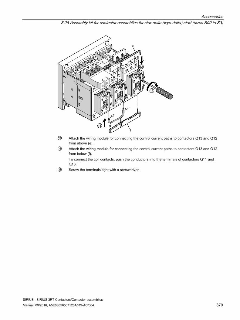
Accessories 8.28 Assembly kit for contactor assemblies for star-delta (wye-delta) start (sizes S00 to S3)
SIRIUS - SIRIUS 3RT Contactors/Contactor assemblies Manual, 09/2016, A5E03656507120A/RS-AC/004 379
⑬ Attach the wiring module for connecting the control current paths to contactors Q13 and Q12
from above (e). ⑭ Attach the wiring module for connecting the control current paths to contactors Q13 and Q12
from below (f). To connect the coil contacts, push the conductors into the terminals of contactors Q11 and Q13.
⑮ Screw the terminals tight with a screwdriver.
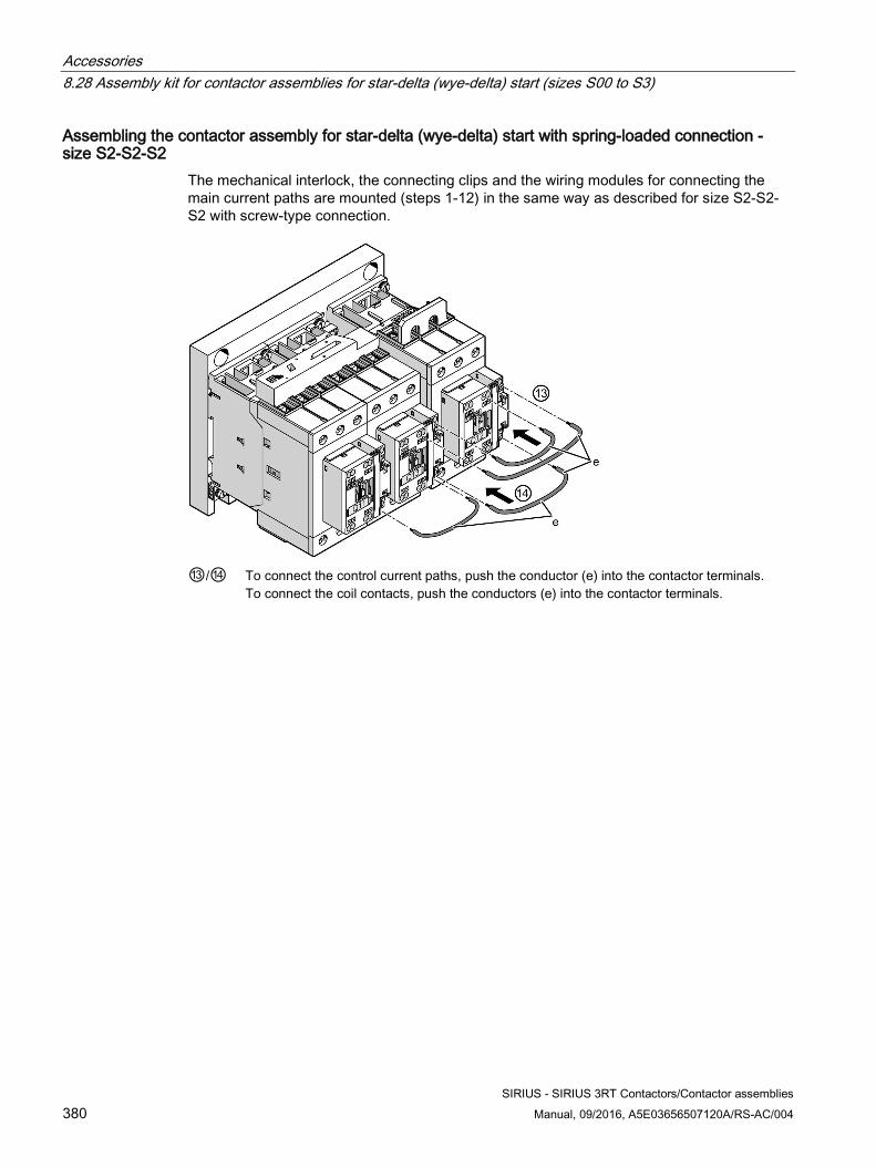
Accessories 8.28 Assembly kit for contactor assemblies for star-delta (wye-delta) start (sizes S00 to S3)
SIRIUS - SIRIUS 3RT Contactors/Contactor assemblies 380 Manual, 09/2016, A5E03656507120A/RS-AC/004
Assembling the contactor assembly for star-delta (wye-delta) start with spring-loaded connection - size S2-S2-S2
The mechanical interlock, the connecting clips and the wiring modules for connecting the main current paths are mounted (steps 1-12) in the same way as described for size S2-S2-S2 with screw-type connection.
⑬/⑭ To connect the control current paths, push the conductor (e) into the contactor terminals.
To connect the coil contacts, push the conductors (e) into the contactor terminals.
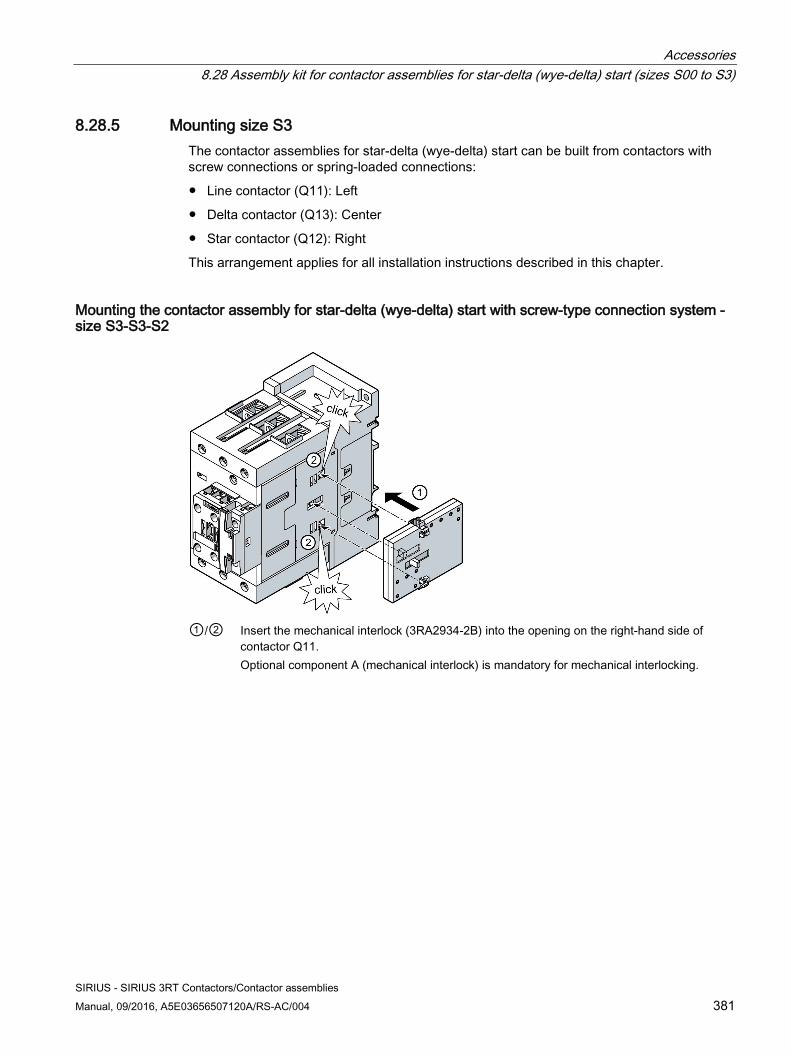
Accessories 8.28 Assembly kit for contactor assemblies for star-delta (wye-delta) start (sizes S00 to S3)
SIRIUS - SIRIUS 3RT Contactors/Contactor assemblies Manual, 09/2016, A5E03656507120A/RS-AC/004 381
8.28.5 Mounting size S3 The contactor assemblies for star-delta (wye-delta) start can be built from contactors with screw connections or spring-loaded connections:
● Line contactor (Q11): Left
● Delta contactor (Q13): Center
● Star contactor (Q12): Right
This arrangement applies for all installation instructions described in this chapter.
Mounting the contactor assembly for star-delta (wye-delta) start with screw-type connection system - size S3-S3-S2
①/② Insert the mechanical interlock (3RA2934-2B) into the opening on the right-hand side of
contactor Q11. Optional component A (mechanical interlock) is mandatory for mechanical interlocking.
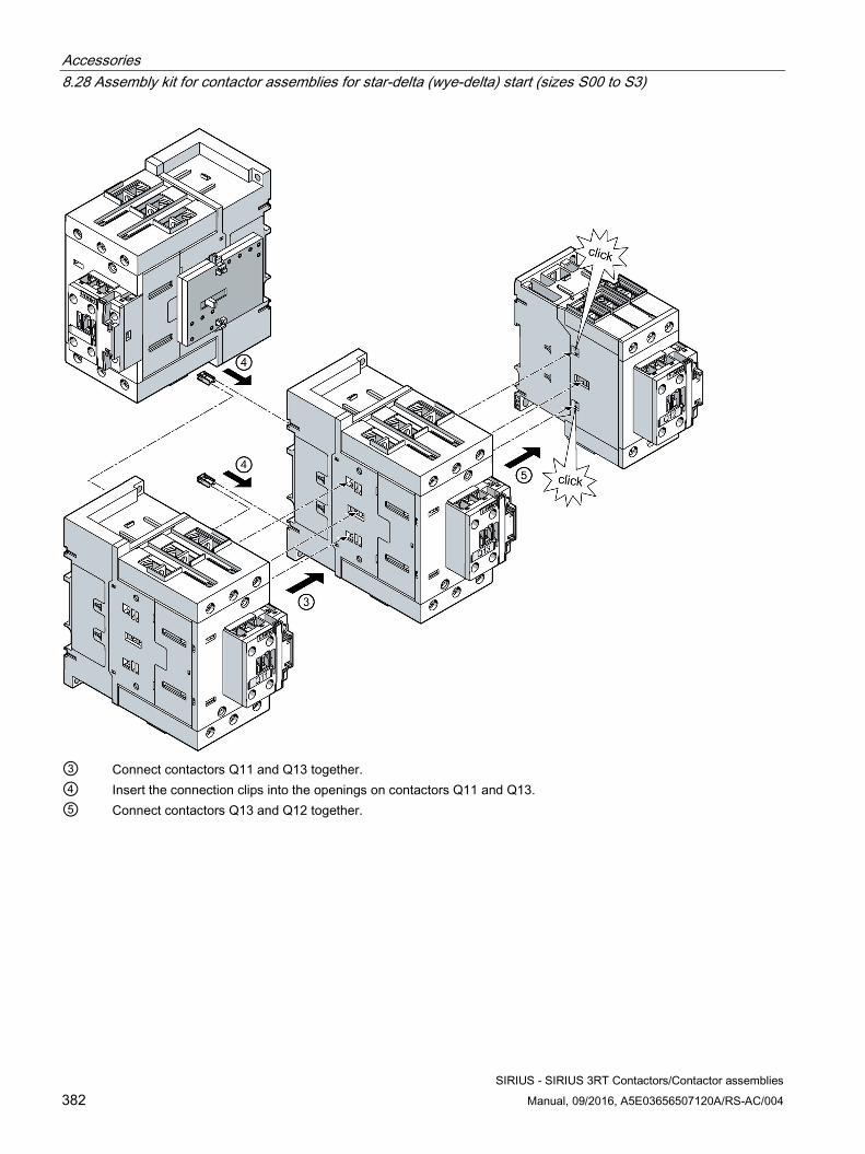
Accessories 8.28 Assembly kit for contactor assemblies for star-delta (wye-delta) start (sizes S00 to S3)
SIRIUS - SIRIUS 3RT Contactors/Contactor assemblies 382 Manual, 09/2016, A5E03656507120A/RS-AC/004
③ Connect contactors Q11 and Q13 together. ④ Insert the connection clips into the openings on contactors Q11 and Q13. ⑤ Connect contactors Q13 and Q12 together.
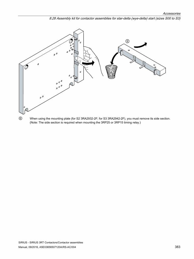
Accessories 8.28 Assembly kit for contactor assemblies for star-delta (wye-delta) start (sizes S00 to S3)
SIRIUS - SIRIUS 3RT Contactors/Contactor assemblies Manual, 09/2016, A5E03656507120A/RS-AC/004 383
⑥ When using the mounting plate (for S2 3RA2932-2F; for S3 3RA2942-2F), you must remove its side section.
(Note: The side section is required when mounting the 3RP25 or 3RP15 timing relay.)
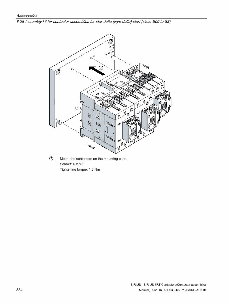
Accessories 8.28 Assembly kit for contactor assemblies for star-delta (wye-delta) start (sizes S00 to S3)
SIRIUS - SIRIUS 3RT Contactors/Contactor assemblies 384 Manual, 09/2016, A5E03656507120A/RS-AC/004
⑦ Mount the contactors on the mounting plate.
Screws: 6 x M6 Tightening torque: 1.6 Nm
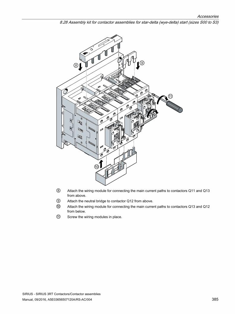
Accessories 8.28 Assembly kit for contactor assemblies for star-delta (wye-delta) start (sizes S00 to S3)
SIRIUS - SIRIUS 3RT Contactors/Contactor assemblies Manual, 09/2016, A5E03656507120A/RS-AC/004 385
⑧ Attach the wiring module for connecting the main current paths to contactors Q11 and Q13
from above. ⑨ Attach the neutral bridge to contactor Q12 from above. ⑩ Attach the wiring module for connecting the main current paths to contactors Q13 and Q12
from below. ⑪ Screw the wiring modules in place.
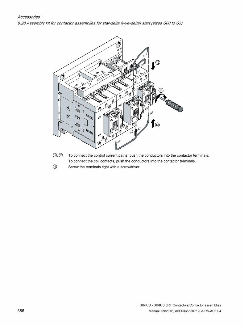
Accessories 8.28 Assembly kit for contactor assemblies for star-delta (wye-delta) start (sizes S00 to S3)
SIRIUS - SIRIUS 3RT Contactors/Contactor assemblies 386 Manual, 09/2016, A5E03656507120A/RS-AC/004
⑫/⑬ To connect the control current paths, push the conductors into the contactor terminals.
To connect the coil contacts, push the conductors into the contactor terminals. ⑭ Screw the terminals tight with a screwdriver.
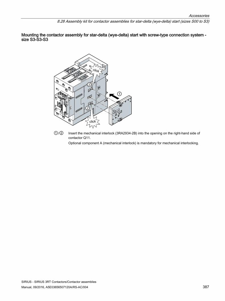
Accessories 8.28 Assembly kit for contactor assemblies for star-delta (wye-delta) start (sizes S00 to S3)
SIRIUS - SIRIUS 3RT Contactors/Contactor assemblies Manual, 09/2016, A5E03656507120A/RS-AC/004 387
Mounting the contactor assembly for star-delta (wye-delta) start with screw-type connection system - size S3-S3-S3
①/② Insert the mechanical interlock (3RA2934-2B) into the opening on the right-hand side of
contactor Q11. Optional component A (mechanical interlock) is mandatory for mechanical interlocking.
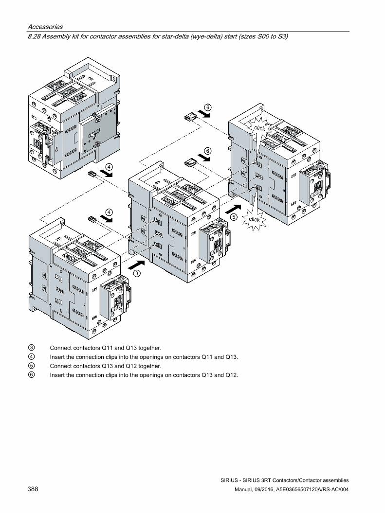
Accessories 8.28 Assembly kit for contactor assemblies for star-delta (wye-delta) start (sizes S00 to S3)
SIRIUS - SIRIUS 3RT Contactors/Contactor assemblies 388 Manual, 09/2016, A5E03656507120A/RS-AC/004
③ Connect contactors Q11 and Q13 together. ④ Insert the connection clips into the openings on contactors Q11 and Q13. ⑤ Connect contactors Q13 and Q12 together. ⑥ Insert the connection clips into the openings on contactors Q13 and Q12.
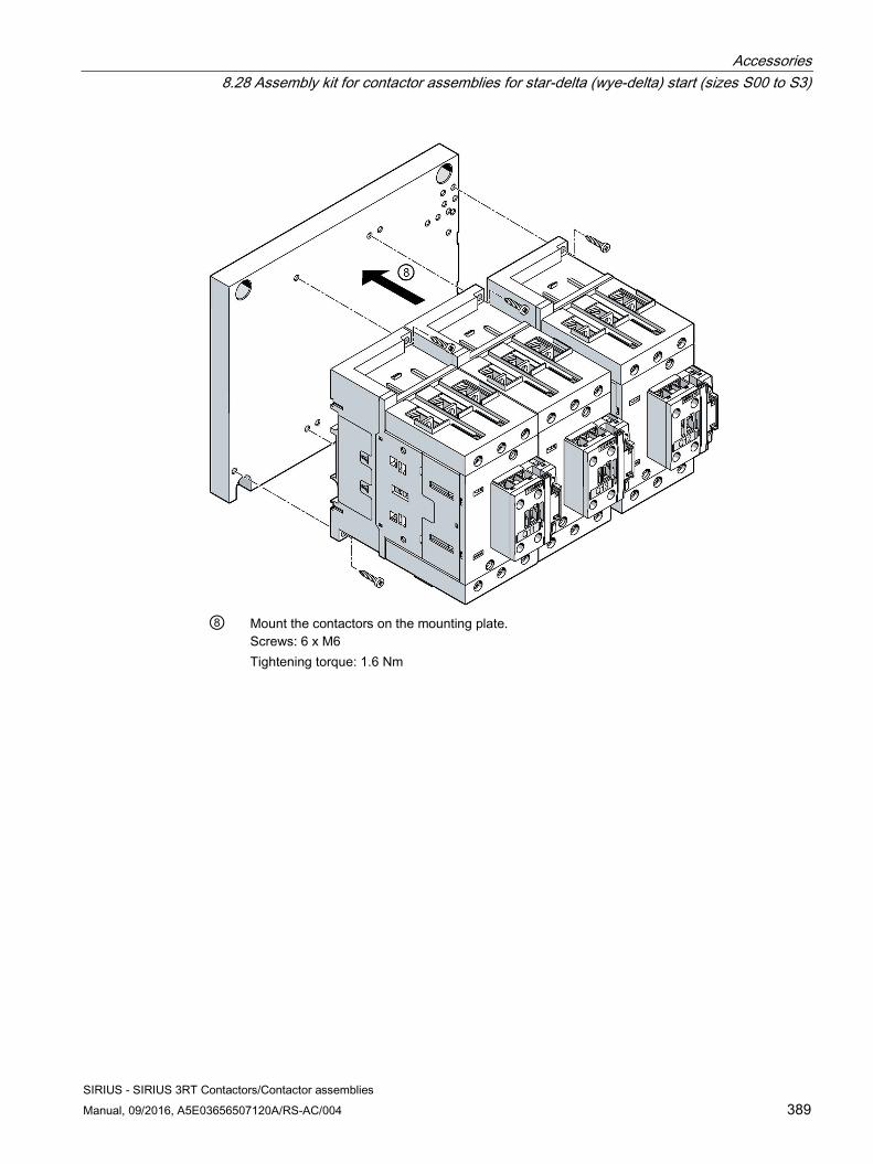
Accessories 8.28 Assembly kit for contactor assemblies for star-delta (wye-delta) start (sizes S00 to S3)
SIRIUS - SIRIUS 3RT Contactors/Contactor assemblies Manual, 09/2016, A5E03656507120A/RS-AC/004 389
⑧ Mount the contactors on the mounting plate.
Screws: 6 x M6 Tightening torque: 1.6 Nm
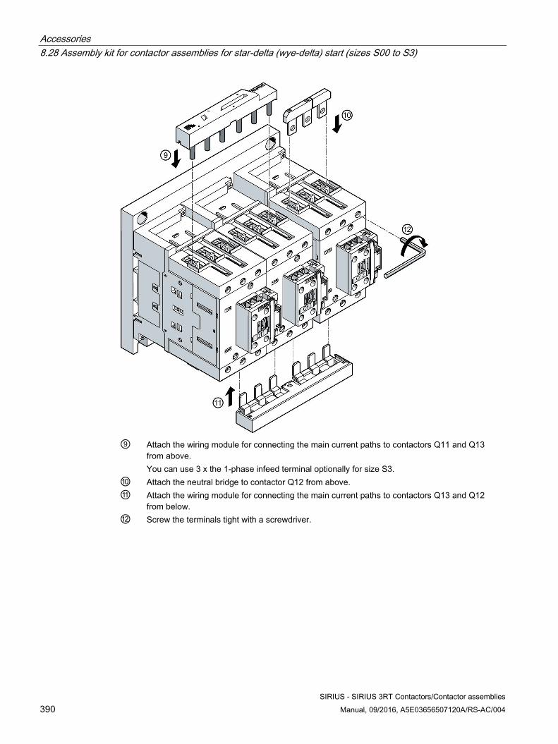
Accessories 8.28 Assembly kit for contactor assemblies for star-delta (wye-delta) start (sizes S00 to S3)
SIRIUS - SIRIUS 3RT Contactors/Contactor assemblies 390 Manual, 09/2016, A5E03656507120A/RS-AC/004
⑨ Attach the wiring module for connecting the main current paths to contactors Q11 and Q13
from above. You can use 3 x the 1-phase infeed terminal optionally for size S3.
⑩ Attach the neutral bridge to contactor Q12 from above. ⑪ Attach the wiring module for connecting the main current paths to contactors Q13 and Q12
from below. ⑫ Screw the terminals tight with a screwdriver.
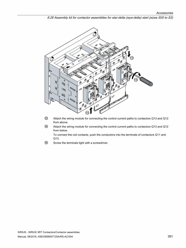
Accessories 8.28 Assembly kit for contactor assemblies for star-delta (wye-delta) start (sizes S00 to S3)
SIRIUS - SIRIUS 3RT Contactors/Contactor assemblies Manual, 09/2016, A5E03656507120A/RS-AC/004 391
⑬ Attach the wiring module for connecting the control current paths to contactors Q13 and Q12
from above. ⑭ Attach the wiring module for connecting the control current paths to contactors Q13 and Q12
from below. To connect the coil contacts, push the conductors into the terminals of contactors Q11 and Q13.
⑮ Screw the terminals tight with a screwdriver.
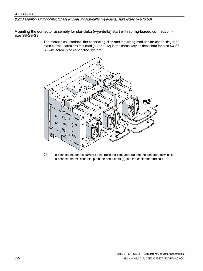
Accessories 8.28 Assembly kit for contactor assemblies for star-delta (wye-delta) start (sizes S00 to S3)
SIRIUS - SIRIUS 3RT Contactors/Contactor assemblies 392 Manual, 09/2016, A5E03656507120A/RS-AC/004
Mounting the contactor assembly for star-delta (wye-delta) start with spring-loaded connection - size S3-S3-S3
The mechanical interlock, the connecting clips and the wiring modules for connecting the main current paths are mounted (steps 1-12) in the same way as described for size S3-S3-S3 with screw-type connection system.
⑬ To connect the control current paths, push the conductor (e) into the contactor terminals.
To connect the coil contacts, push the conductors (e) into the contactor terminals.
Accessories 8.29 Wiring kit for contactor assemblies for star-delta (wye-delta) start (sizes S6 to S12).
SIRIUS - SIRIUS 3RT Contactors/Contactor assemblies Manual, 09/2016, A5E03656507120A/RS-AC/004 393
8.29 Wiring kit for contactor assemblies for star-delta (wye-delta) start (sizes S6 to S12).
8.29.1 Description The contactor assemblies for star-delta (wye-delta) start are available as kits for self-assembly.
The same accessories as for the basic units of the corresponding size can be used.
The kit for contactor assemblies for star-delta (wye-delta) start contains the following:
● Neutral bridges
● Wiring module on the bottom (wiring module on the top is not included in the scope of supply. A double infeed between the line contactor and the delta contactor is recommended.)
Article numbers:
● S6-S6-S6: 3RA1953-2B
● S6-S6-S6: 3RA1953-2N
● S10-S10-S10: 3RA1963-2B
● S12-S12-S12: 3RA1973-2B
Accessories 8.29 Wiring kit for contactor assemblies for star-delta (wye-delta) start (sizes S6 to S12).
SIRIUS - SIRIUS 3RT Contactors/Contactor assemblies 394 Manual, 09/2016, A5E03656507120A/RS-AC/004
The following accessories for the basic units can also be used for the contactor assemblies for star-delta (wye-delta) starting:
● Auxiliary switch blocks (on the front, on the side)
● Surge suppressors
● Solid-state time-delay auxiliary switch blocks with star-delta (wye-delta) function (timing relay)
In addition, special accessories are available for the contactor assemblies for star-delta (wye-delta) start:
● Neutral bridges (parallel connectors)
– S6 (article number: 3RT1956-4BA31)
– S10, S12 (article number: 3RT1966-4BA31)
● Mechanical connector (article number: 3RA1932-2D)
● Wiring modules
– S6 (article number: 3RA1953-3D)
● Base plates for contactor assemblies for star-delta (wye-delta) start
– S6-S6-S3: (Article number: 3RA1952-2E)
– S6-S6-S6: (Article number: 3RA1952-2F)
– S10-S10-S6: (Article number: 3RA1962-2E)
– S10-S10-S10: (Article number: 3RA1962-2F)
– S12-S12-S10: (Article number: 3RA1972-2E)
– S12-S12-S12: (Article number: 3RA1972-2F)
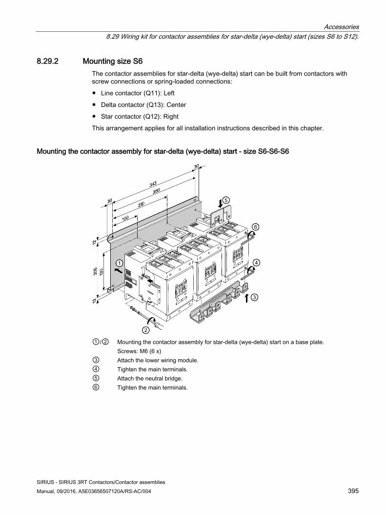
Accessories 8.29 Wiring kit for contactor assemblies for star-delta (wye-delta) start (sizes S6 to S12).
SIRIUS - SIRIUS 3RT Contactors/Contactor assemblies Manual, 09/2016, A5E03656507120A/RS-AC/004 395
8.29.2 Mounting size S6 The contactor assemblies for star-delta (wye-delta) start can be built from contactors with screw connections or spring-loaded connections:
● Line contactor (Q11): Left
● Delta contactor (Q13): Center
● Star contactor (Q12): Right
This arrangement applies for all installation instructions described in this chapter.
Mounting the contactor assembly for star-delta (wye-delta) start - size S6-S6-S6
①/② Mounting the contactor assembly for star-delta (wye-delta) start on a base plate.
Screws: M6 (6 x) ③ Attach the lower wiring module. ④ Tighten the main terminals. ⑤ Attach the neutral bridge. ⑥ Tighten the main terminals.
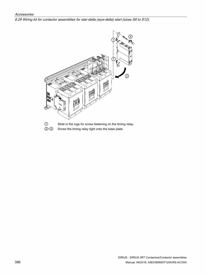
Accessories 8.29 Wiring kit for contactor assemblies for star-delta (wye-delta) start (sizes S6 to S12).
SIRIUS - SIRIUS 3RT Contactors/Contactor assemblies 396 Manual, 09/2016, A5E03656507120A/RS-AC/004
① Slide in the lugs for screw fastening on the timing relay. ②/③ Screw the timing relay tight onto the base plate.
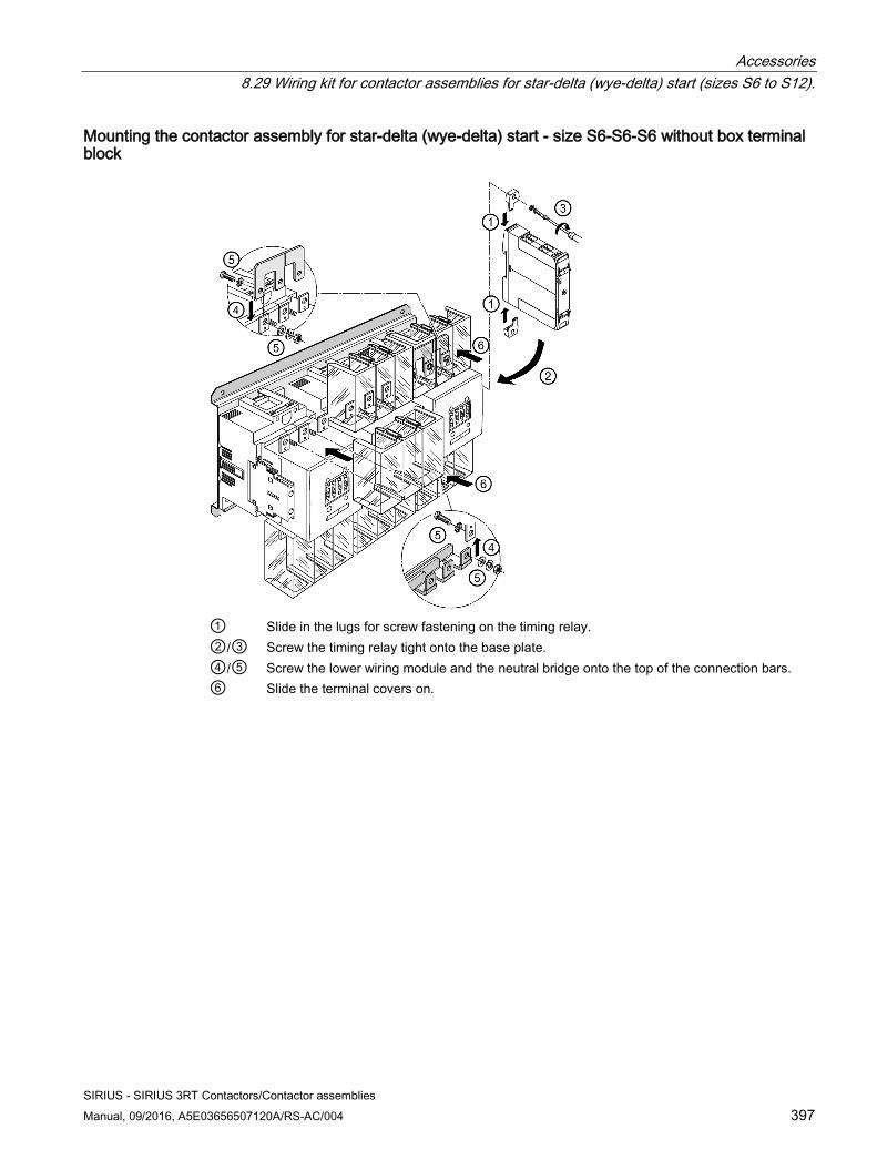
Accessories 8.29 Wiring kit for contactor assemblies for star-delta (wye-delta) start (sizes S6 to S12).
SIRIUS - SIRIUS 3RT Contactors/Contactor assemblies Manual, 09/2016, A5E03656507120A/RS-AC/004 397
Mounting the contactor assembly for star-delta (wye-delta) start - size S6-S6-S6 without box terminal block
① Slide in the lugs for screw fastening on the timing relay. ②/③ Screw the timing relay tight onto the base plate. ④/⑤ Screw the lower wiring module and the neutral bridge onto the top of the connection bars. ⑥ Slide the terminal covers on.
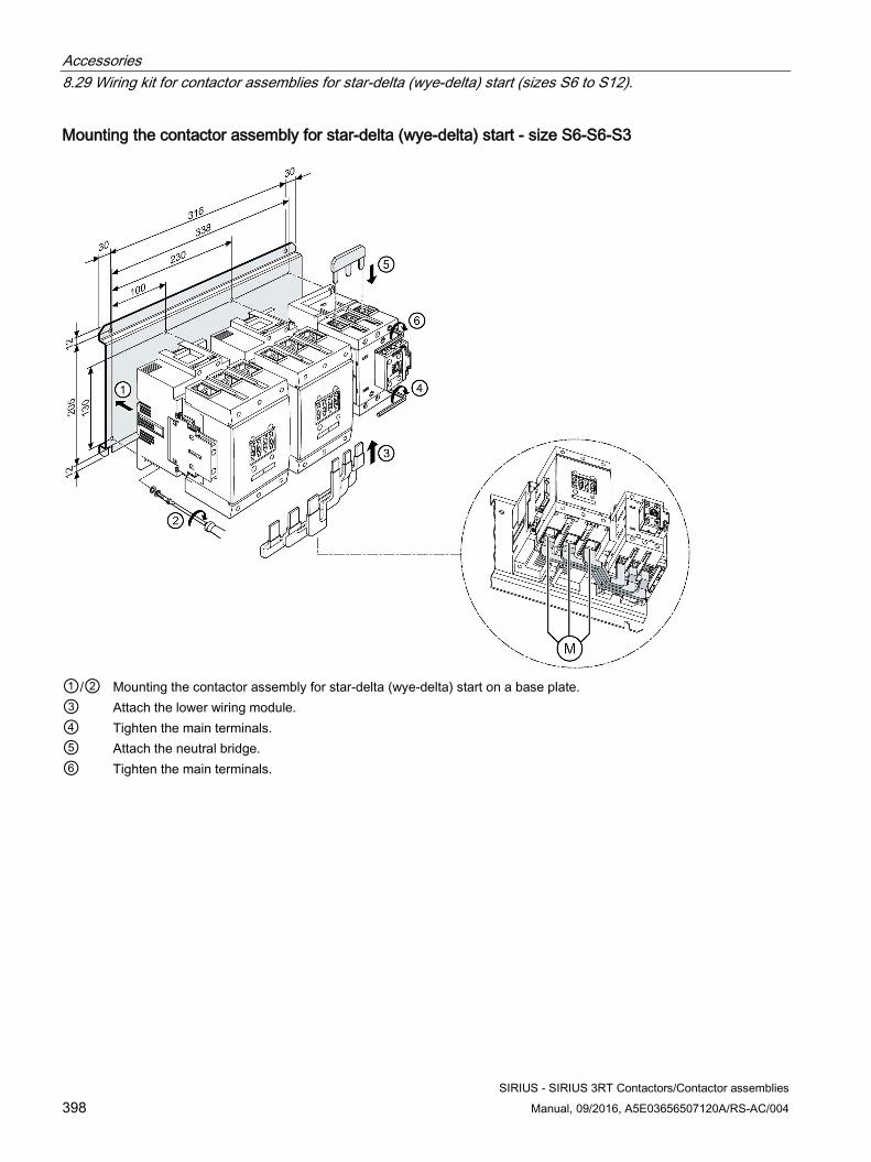
Accessories 8.29 Wiring kit for contactor assemblies for star-delta (wye-delta) start (sizes S6 to S12).
SIRIUS - SIRIUS 3RT Contactors/Contactor assemblies 398 Manual, 09/2016, A5E03656507120A/RS-AC/004
Mounting the contactor assembly for star-delta (wye-delta) start - size S6-S6-S3
①/② Mounting the contactor assembly for star-delta (wye-delta) start on a base plate. ③ Attach the lower wiring module. ④ Tighten the main terminals. ⑤ Attach the neutral bridge. ⑥ Tighten the main terminals.
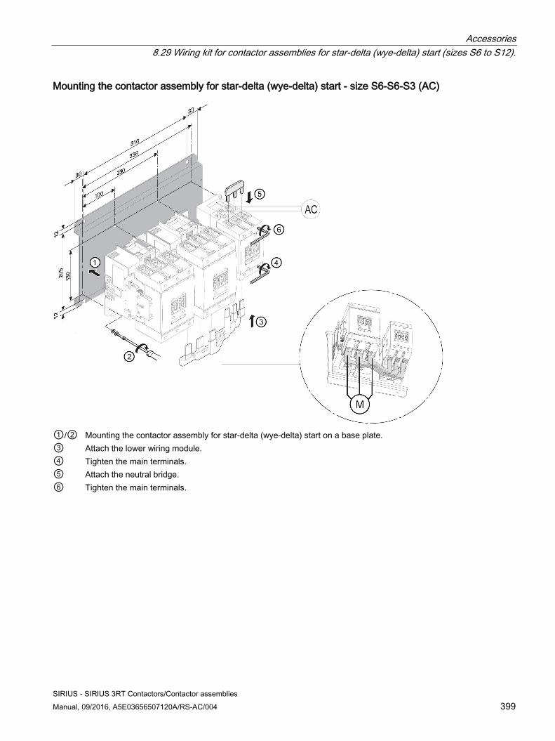
Accessories 8.29 Wiring kit for contactor assemblies for star-delta (wye-delta) start (sizes S6 to S12).
SIRIUS - SIRIUS 3RT Contactors/Contactor assemblies Manual, 09/2016, A5E03656507120A/RS-AC/004 399
Mounting the contactor assembly for star-delta (wye-delta) start - size S6-S6-S3 (AC)
①/② Mounting the contactor assembly for star-delta (wye-delta) start on a base plate. ③ Attach the lower wiring module. ④ Tighten the main terminals. ⑤ Attach the neutral bridge. ⑥ Tighten the main terminals.
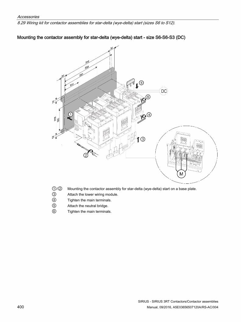
Accessories 8.29 Wiring kit for contactor assemblies for star-delta (wye-delta) start (sizes S6 to S12).
SIRIUS - SIRIUS 3RT Contactors/Contactor assemblies 400 Manual, 09/2016, A5E03656507120A/RS-AC/004
Mounting the contactor assembly for star-delta (wye-delta) start - size S6-S6-S3 (DC)
①/② Mounting the contactor assembly for star-delta (wye-delta) start on a base plate. ③ Attach the lower wiring module. ④ Tighten the main terminals. ⑤ Attach the neutral bridge. ⑥ Tighten the main terminals.
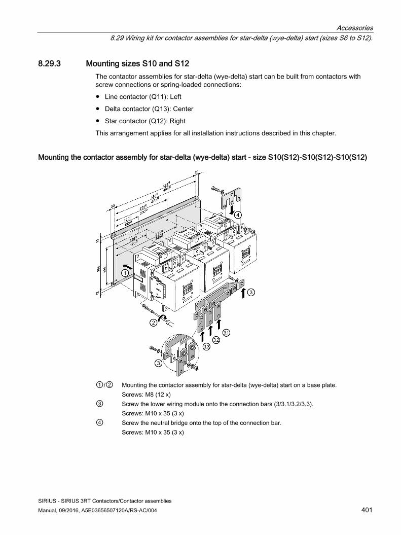
Accessories 8.29 Wiring kit for contactor assemblies for star-delta (wye-delta) start (sizes S6 to S12).
SIRIUS - SIRIUS 3RT Contactors/Contactor assemblies Manual, 09/2016, A5E03656507120A/RS-AC/004 401
8.29.3 Mounting sizes S10 and S12 The contactor assemblies for star-delta (wye-delta) start can be built from contactors with screw connections or spring-loaded connections:
● Line contactor (Q11): Left
● Delta contactor (Q13): Center
● Star contactor (Q12): Right
This arrangement applies for all installation instructions described in this chapter.
Mounting the contactor assembly for star-delta (wye-delta) start - size S10(S12)-S10(S12)-S10(S12)
①/② Mounting the contactor assembly for star-delta (wye-delta) start on a base plate.
Screws: M8 (12 x) ③ Screw the lower wiring module onto the connection bars (3/3.1/3.2/3.3).
Screws: M10 x 35 (3 x) ④ Screw the neutral bridge onto the top of the connection bar.
Screws: M10 x 35 (3 x)
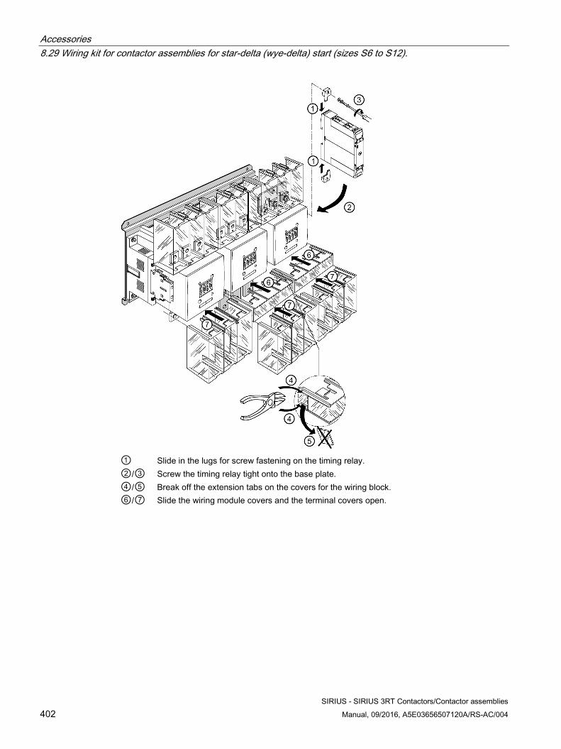
Accessories 8.29 Wiring kit for contactor assemblies for star-delta (wye-delta) start (sizes S6 to S12).
SIRIUS - SIRIUS 3RT Contactors/Contactor assemblies 402 Manual, 09/2016, A5E03656507120A/RS-AC/004
① Slide in the lugs for screw fastening on the timing relay. ②/③ Screw the timing relay tight onto the base plate. ④/⑤ Break off the extension tabs on the covers for the wiring block. ⑥/⑦ Slide the wiring module covers and the terminal covers open.
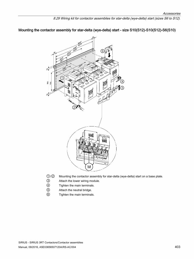
Accessories 8.29 Wiring kit for contactor assemblies for star-delta (wye-delta) start (sizes S6 to S12).
SIRIUS - SIRIUS 3RT Contactors/Contactor assemblies Manual, 09/2016, A5E03656507120A/RS-AC/004 403
Mounting the contactor assembly for star-delta (wye-delta) start - size S10(S12)-S10(S12)-S6(S10)
①/② Mounting the contactor assembly for star-delta (wye-delta) start on a base plate. ③ Attach the lower wiring module. ④ Tighten the main terminals. ⑤ Attach the neutral bridge. ⑥ Tighten the main terminals.
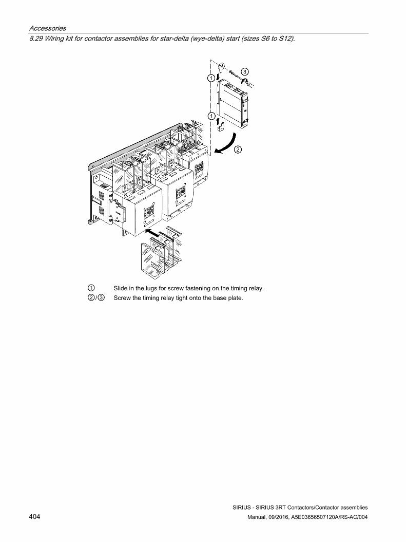
Accessories 8.29 Wiring kit for contactor assemblies for star-delta (wye-delta) start (sizes S6 to S12).
SIRIUS - SIRIUS 3RT Contactors/Contactor assemblies 404 Manual, 09/2016, A5E03656507120A/RS-AC/004
① Slide in the lugs for screw fastening on the timing relay. ②/③ Screw the timing relay tight onto the base plate.
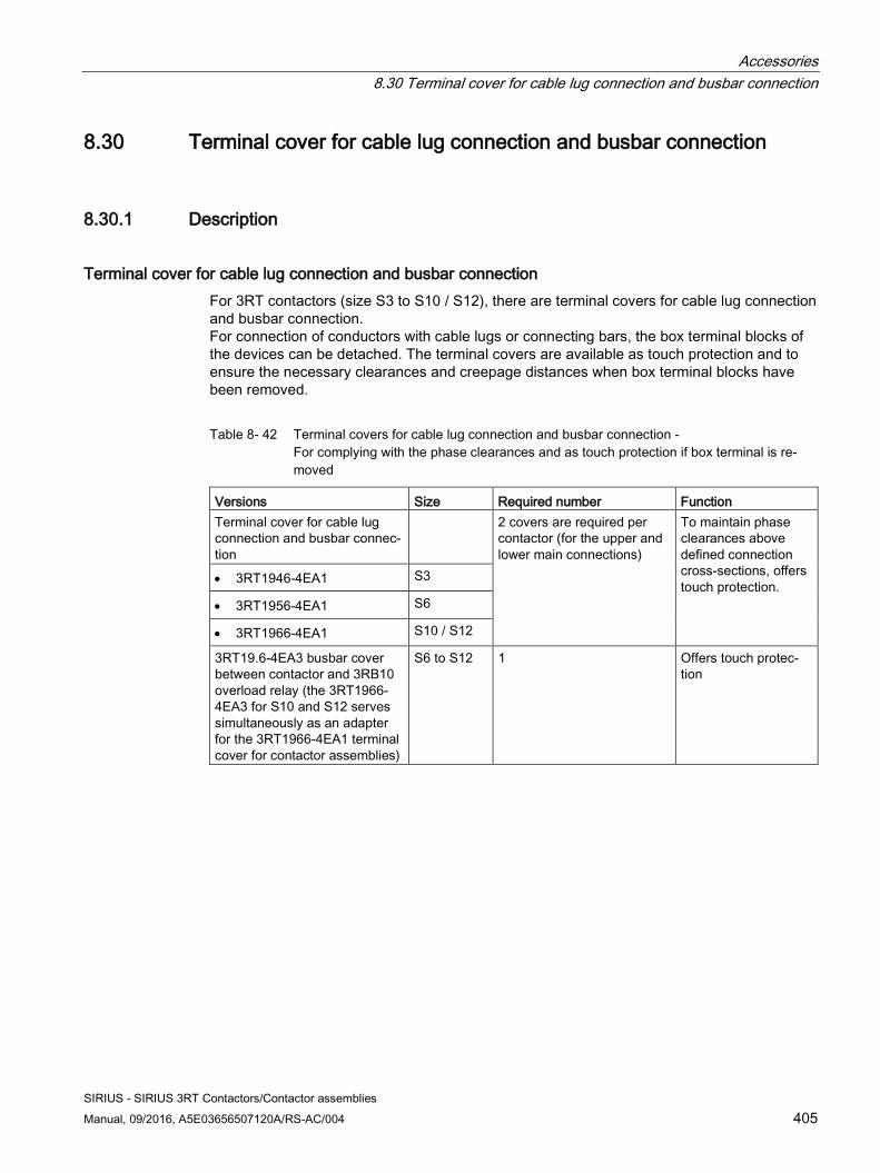
Accessories 8.30 Terminal cover for cable lug connection and busbar connection
SIRIUS - SIRIUS 3RT Contactors/Contactor assemblies Manual, 09/2016, A5E03656507120A/RS-AC/004 405
8.30 Terminal cover for cable lug connection and busbar connection
8.30.1 Description
Terminal cover for cable lug connection and busbar connection For 3RT contactors (size S3 to S10 / S12), there are terminal covers for cable lug connection and busbar connection. For connection of conductors with cable lugs or connecting bars, the box terminal blocks of the devices can be detached. The terminal covers are available as touch protection and to ensure the necessary clearances and creepage distances when box terminal blocks have been removed.
Table 8- 42 Terminal covers for cable lug connection and busbar connection - For complying with the phase clearances and as touch protection if box terminal is re-moved
Versions Size Required number Function Terminal cover for cable lug connection and busbar connec-tion
2 covers are required per contactor (for the upper and lower main connections)
To maintain phase clearances above defined connection cross-sections, offers touch protection. • 3RT1946-4EA1 S3
• 3RT1956-4EA1 S6
• 3RT1966-4EA1 S10 / S12
3RT19.6-4EA3 busbar cover between contactor and 3RB10 overload relay (the 3RT1966-4EA3 for S10 and S12 serves simultaneously as an adapter for the 3RT1966-4EA1 terminal cover for contactor assemblies)
S6 to S12 1 Offers touch protec-tion
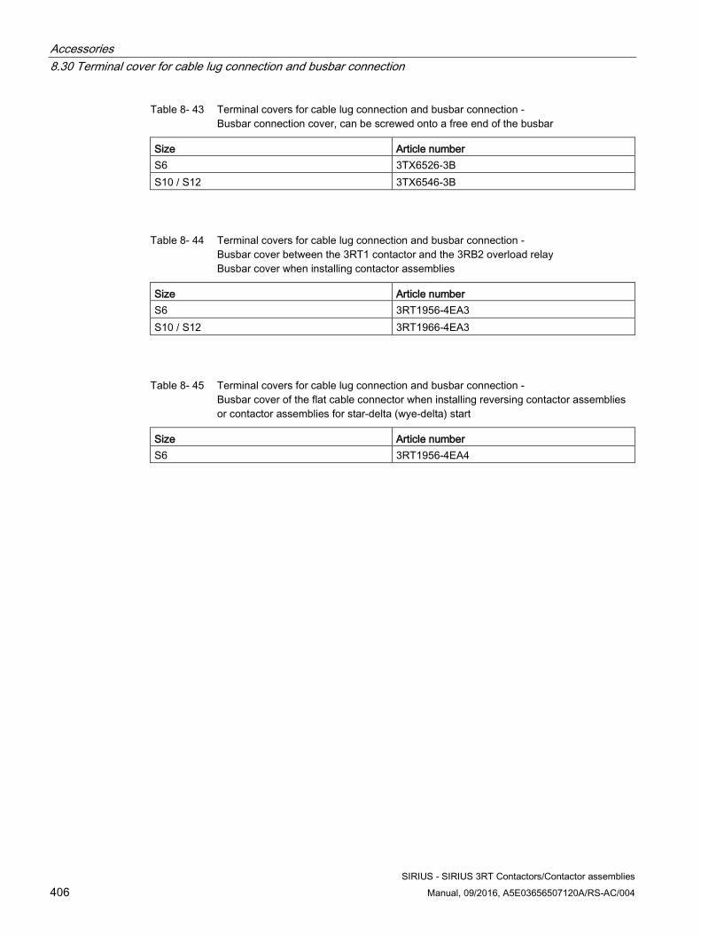
Accessories 8.30 Terminal cover for cable lug connection and busbar connection
SIRIUS - SIRIUS 3RT Contactors/Contactor assemblies 406 Manual, 09/2016, A5E03656507120A/RS-AC/004
Table 8- 43 Terminal covers for cable lug connection and busbar connection - Busbar connection cover, can be screwed onto a free end of the busbar
Size Article number S6 3TX6526-3B S10 / S12 3TX6546-3B
Table 8- 44 Terminal covers for cable lug connection and busbar connection - Busbar cover between the 3RT1 contactor and the 3RB2 overload relay Busbar cover when installing contactor assemblies
Size Article number S6 3RT1956-4EA3 S10 / S12 3RT1966-4EA3
Table 8- 45 Terminal covers for cable lug connection and busbar connection - Busbar cover of the flat cable connector when installing reversing contactor assemblies or contactor assemblies for star-delta (wye-delta) start
Size Article number S6 3RT1956-4EA4
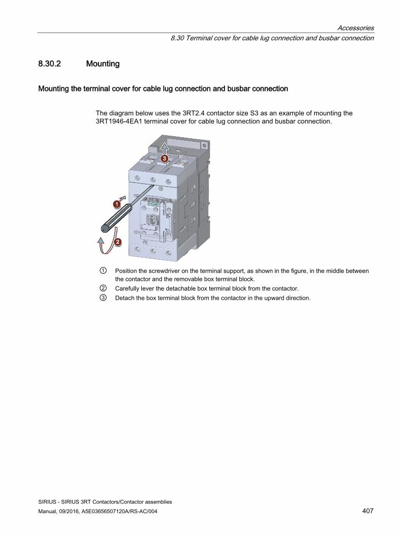
Accessories 8.30 Terminal cover for cable lug connection and busbar connection
SIRIUS - SIRIUS 3RT Contactors/Contactor assemblies Manual, 09/2016, A5E03656507120A/RS-AC/004 407
8.30.2 Mounting
Mounting the terminal cover for cable lug connection and busbar connection
The diagram below uses the 3RT2.4 contactor size S3 as an example of mounting the 3RT1946-4EA1 terminal cover for cable lug connection and busbar connection.
① Position the screwdriver on the terminal support, as shown in the figure, in the middle between
the contactor and the removable box terminal block. ② Carefully lever the detachable box terminal block from the contactor. ③ Detach the box terminal block from the contactor in the upward direction.
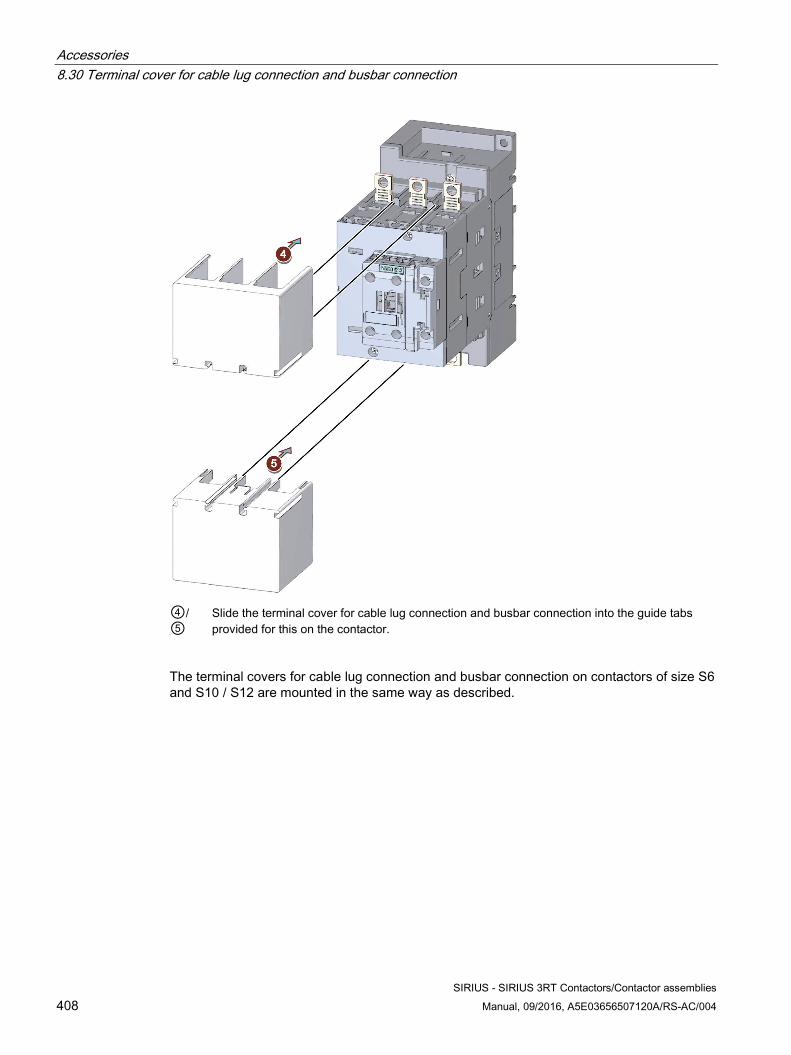
Accessories 8.30 Terminal cover for cable lug connection and busbar connection
SIRIUS - SIRIUS 3RT Contactors/Contactor assemblies 408 Manual, 09/2016, A5E03656507120A/RS-AC/004
④/ ⑤
Slide the terminal cover for cable lug connection and busbar connection into the guide tabs provided for this on the contactor.
The terminal covers for cable lug connection and busbar connection on contactors of size S6 and S10 / S12 are mounted in the same way as described.
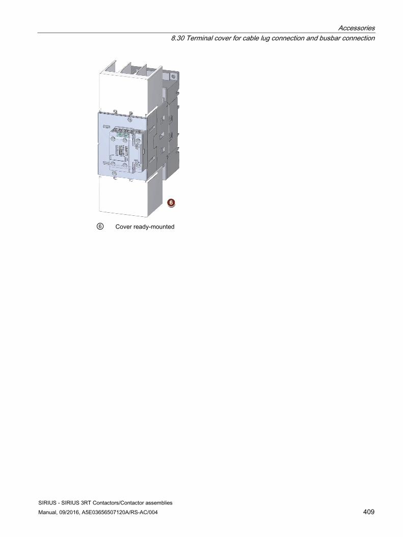
Accessories 8.30 Terminal cover for cable lug connection and busbar connection
SIRIUS - SIRIUS 3RT Contactors/Contactor assemblies Manual, 09/2016, A5E03656507120A/RS-AC/004 409
⑥ Cover ready-mounted
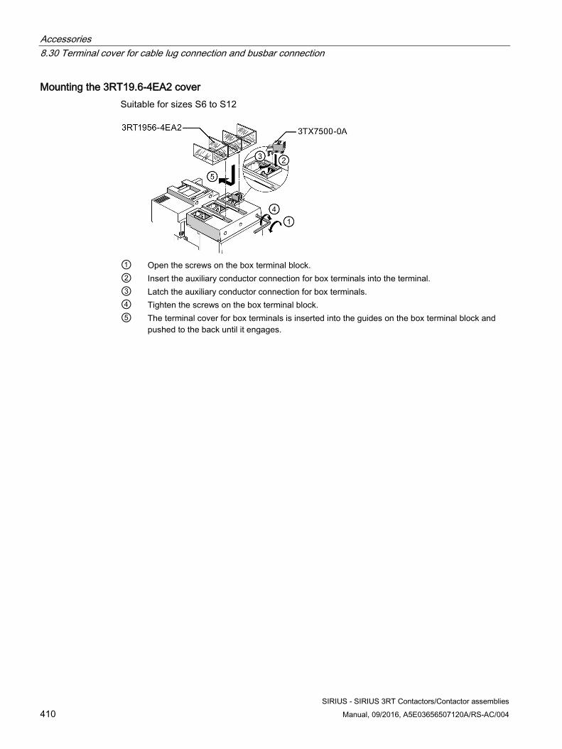
Accessories 8.30 Terminal cover for cable lug connection and busbar connection
SIRIUS - SIRIUS 3RT Contactors/Contactor assemblies 410 Manual, 09/2016, A5E03656507120A/RS-AC/004
Mounting the 3RT19.6-4EA2 cover Suitable for sizes S6 to S12
① Open the screws on the box terminal block. ② Insert the auxiliary conductor connection for box terminals into the terminal. ③ Latch the auxiliary conductor connection for box terminals. ④ Tighten the screws on the box terminal block. ⑤ The terminal cover for box terminals is inserted into the guides on the box terminal block and
pushed to the back until it engages.
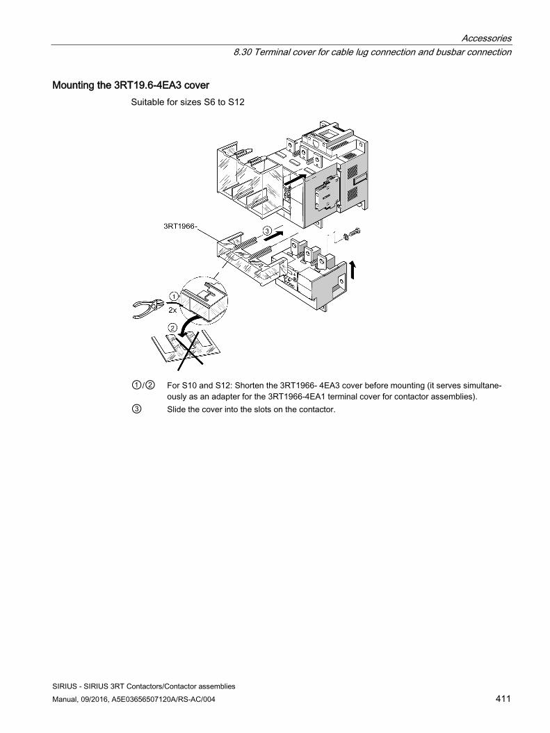
Accessories 8.30 Terminal cover for cable lug connection and busbar connection
SIRIUS - SIRIUS 3RT Contactors/Contactor assemblies Manual, 09/2016, A5E03656507120A/RS-AC/004 411
Mounting the 3RT19.6-4EA3 cover Suitable for sizes S6 to S12
①/② For S10 and S12: Shorten the 3RT1966- 4EA3 cover before mounting (it serves simultane-
ously as an adapter for the 3RT1966-4EA1 terminal cover for contactor assemblies). ③ Slide the cover into the slots on the contactor.
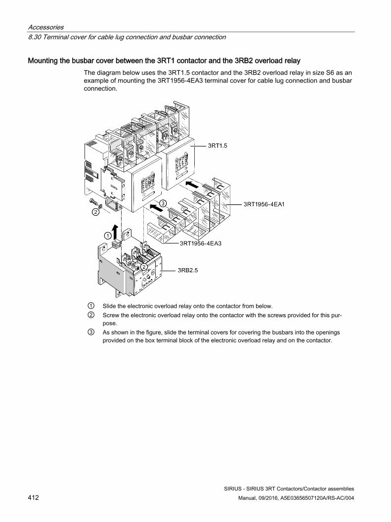
Accessories 8.30 Terminal cover for cable lug connection and busbar connection
SIRIUS - SIRIUS 3RT Contactors/Contactor assemblies 412 Manual, 09/2016, A5E03656507120A/RS-AC/004
Mounting the busbar cover between the 3RT1 contactor and the 3RB2 overload relay The diagram below uses the 3RT1.5 contactor and the 3RB2 overload relay in size S6 as an example of mounting the 3RT1956-4EA3 terminal cover for cable lug connection and busbar connection.
① Slide the electronic overload relay onto the contactor from below. ② Screw the electronic overload relay onto the contactor with the screws provided for this pur-
pose. ③ As shown in the figure, slide the terminal covers for covering the busbars into the openings
provided on the box terminal block of the electronic overload relay and on the contactor.
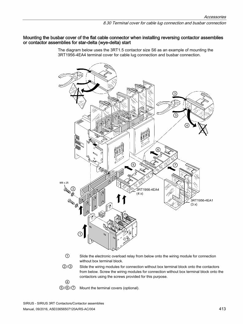
Accessories 8.30 Terminal cover for cable lug connection and busbar connection
SIRIUS - SIRIUS 3RT Contactors/Contactor assemblies Manual, 09/2016, A5E03656507120A/RS-AC/004 413
Mounting the busbar cover of the flat cable connector when installing reversing contactor assemblies or contactor assemblies for star-delta (wye-delta) start
The diagram below uses the 3RT1.5 contactor size S6 as an example of mounting the 3RT1956-4EA4 terminal cover for cable lug connection and busbar connection.
① Slide the electronic overload relay from below onto the wiring module for connection
without box terminal block. ②/③ Slide the wiring modules for connection without box terminal block onto the contactors
from below. Screw the wiring modules for connection without box terminal block onto the contactors using the screws provided for this purpose.
④ ⑤/⑥/⑦ Mount the terminal covers (optional).
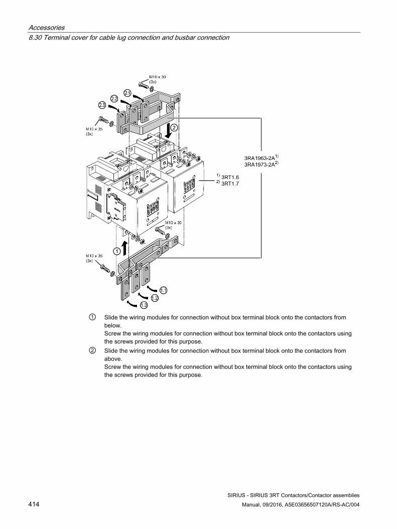
Accessories 8.30 Terminal cover for cable lug connection and busbar connection
SIRIUS - SIRIUS 3RT Contactors/Contactor assemblies 414 Manual, 09/2016, A5E03656507120A/RS-AC/004
① Slide the wiring modules for connection without box terminal block onto the contactors from
below. Screw the wiring modules for connection without box terminal block onto the contactors using the screws provided for this purpose.
② Slide the wiring modules for connection without box terminal block onto the contactors from above. Screw the wiring modules for connection without box terminal block onto the contactors using the screws provided for this purpose.
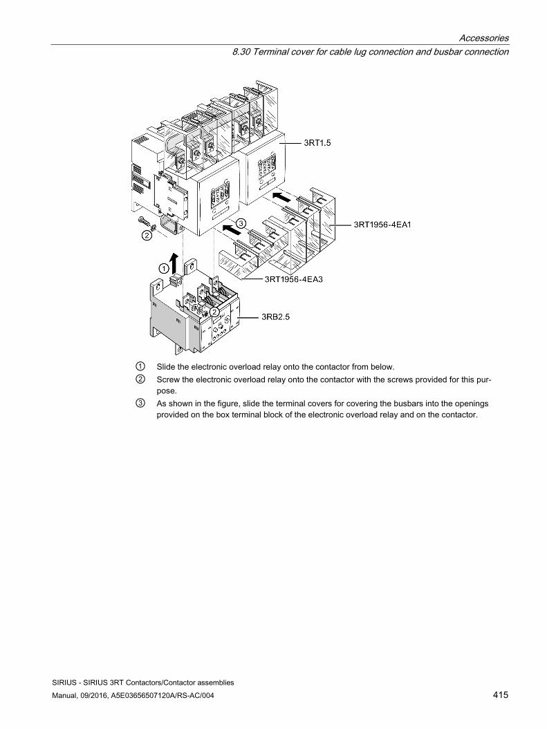
Accessories 8.30 Terminal cover for cable lug connection and busbar connection
SIRIUS - SIRIUS 3RT Contactors/Contactor assemblies Manual, 09/2016, A5E03656507120A/RS-AC/004 415
① Slide the electronic overload relay onto the contactor from below. ② Screw the electronic overload relay onto the contactor with the screws provided for this pur-
pose. ③ As shown in the figure, slide the terminal covers for covering the busbars into the openings
provided on the box terminal block of the electronic overload relay and on the contactor.
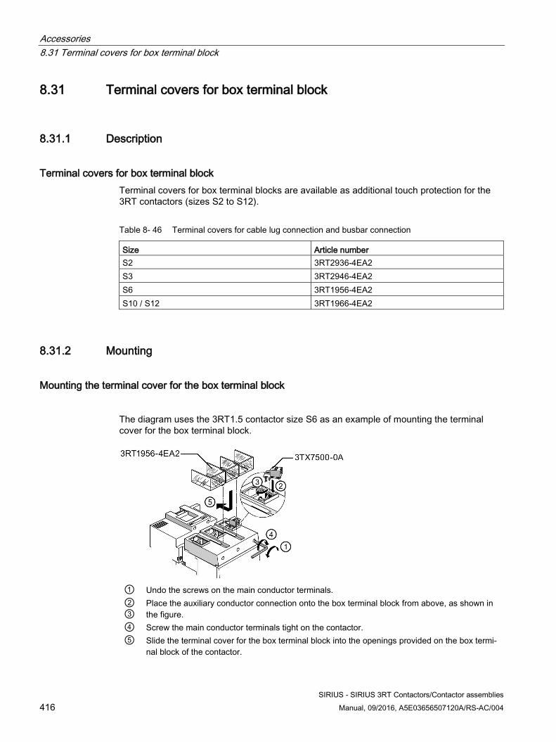
Accessories 8.31 Terminal covers for box terminal block
SIRIUS - SIRIUS 3RT Contactors/Contactor assemblies 416 Manual, 09/2016, A5E03656507120A/RS-AC/004
8.31 Terminal covers for box terminal block
8.31.1 Description
Terminal covers for box terminal block Terminal covers for box terminal blocks are available as additional touch protection for the 3RT contactors (sizes S2 to S12).
Table 8- 46 Terminal covers for cable lug connection and busbar connection
Size Article number S2 3RT2936-4EA2 S3 3RT2946-4EA2 S6 3RT1956-4EA2 S10 / S12 3RT1966-4EA2
8.31.2 Mounting
Mounting the terminal cover for the box terminal block
The diagram uses the 3RT1.5 contactor size S6 as an example of mounting the terminal cover for the box terminal block.
① Undo the screws on the main conductor terminals. ② ③
Place the auxiliary conductor connection onto the box terminal block from above, as shown in the figure.
④ Screw the main conductor terminals tight on the contactor. ⑤ Slide the terminal cover for the box terminal block into the openings provided on the box termi-
nal block of the contactor.
Accessories 8.32 Main current path surge attenuation module for vacuum contactors
SIRIUS - SIRIUS 3RT Contactors/Contactor assemblies Manual, 09/2016, A5E03656507120A/RS-AC/004 417
8.32 Main current path surge attenuation module for vacuum contactors
8.32.1 Description
Main current path surge attenuation module for vacuum contactors The main current path attenuation module is available for the following rated operational voltages:
● Ue <= 690 V: 3RT1966-1PV3
● Ue <= 1000 V: 3RT1966-1PV4
The main current path attenuation module is connected separately from the contactor over a cable length of approximately 35 cm on the outgoing terminal of the 2T1 / 4T2 / 6T3 contactor.
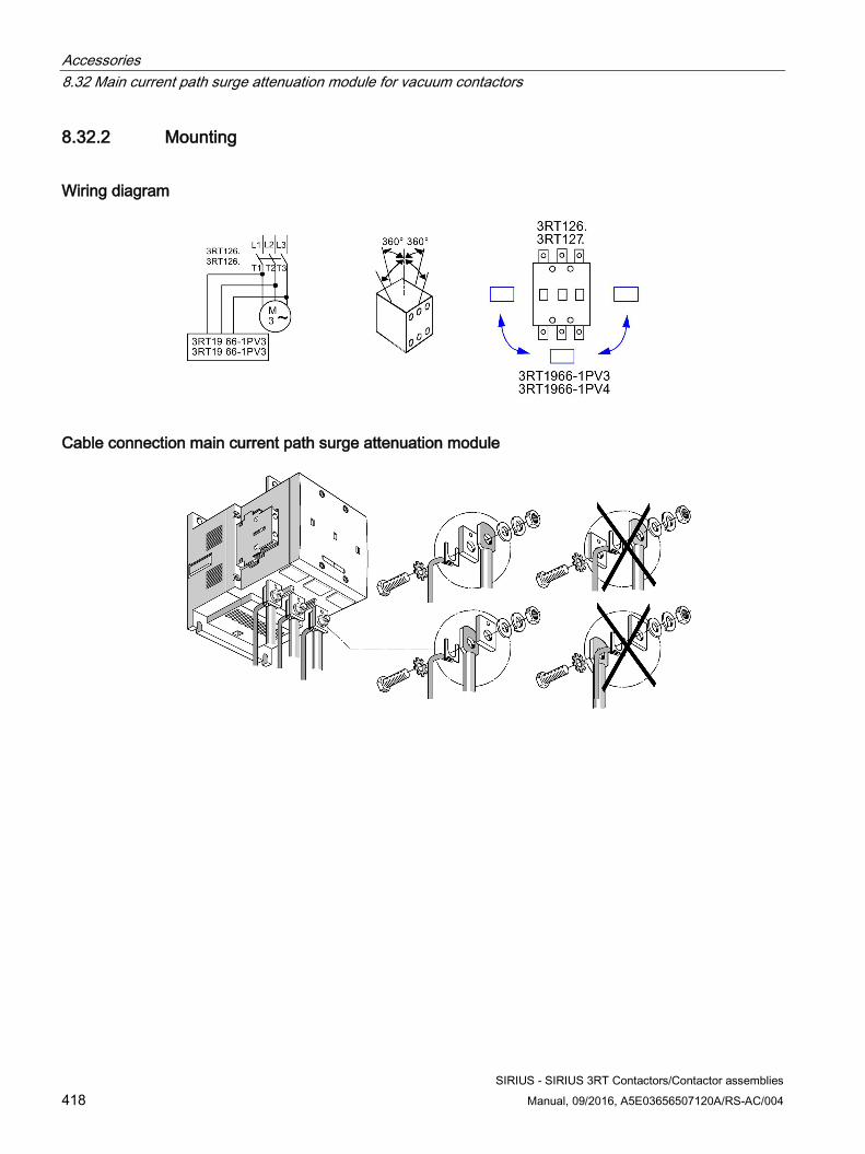
Accessories 8.32 Main current path surge attenuation module for vacuum contactors
SIRIUS - SIRIUS 3RT Contactors/Contactor assemblies 418 Manual, 09/2016, A5E03656507120A/RS-AC/004
8.32.2 Mounting
Wiring diagram
Cable connection main current path surge attenuation module
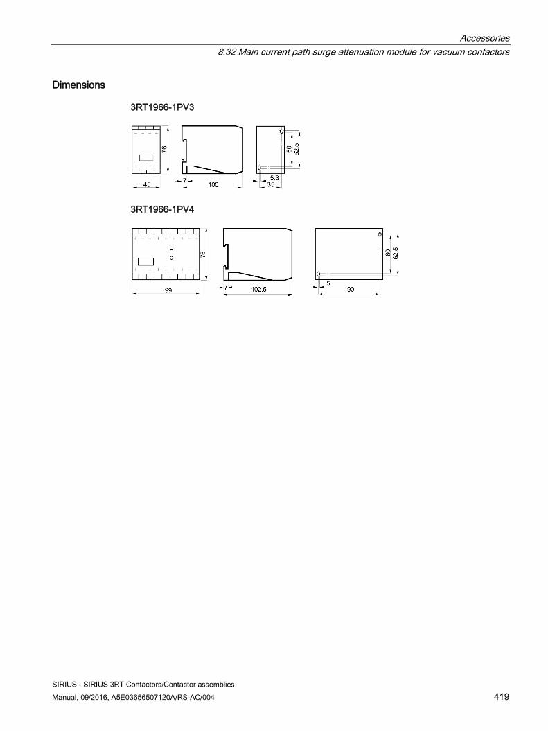
Accessories 8.32 Main current path surge attenuation module for vacuum contactors
SIRIUS - SIRIUS 3RT Contactors/Contactor assemblies Manual, 09/2016, A5E03656507120A/RS-AC/004 419
Dimensions
3RT1966-1PV3
3RT1966-1PV4
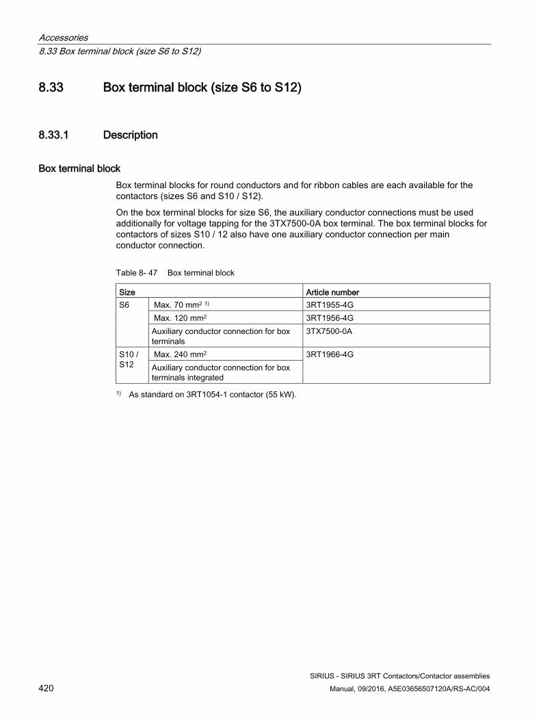
Accessories 8.33 Box terminal block (size S6 to S12)
SIRIUS - SIRIUS 3RT Contactors/Contactor assemblies 420 Manual, 09/2016, A5E03656507120A/RS-AC/004
8.33 Box terminal block (size S6 to S12)
8.33.1 Description
Box terminal block Box terminal blocks for round conductors and for ribbon cables are each available for the contactors (sizes S6 and S10 / S12).
On the box terminal blocks for size S6, the auxiliary conductor connections must be used additionally for voltage tapping for the 3TX7500-0A box terminal. The box terminal blocks for contactors of sizes S10 / 12 also have one auxiliary conductor connection per main conductor connection.
Table 8- 47 Box terminal block
Size Article number S6
Max. 70 mm2 1) 3RT1955-4G Max. 120 mm2 3RT1956-4G Auxiliary conductor connection for box terminals
3TX7500-0A
S10 / S12
Max. 240 mm2 3RT1966-4G Auxiliary conductor connection for box terminals integrated
1) As standard on 3RT1054-1 contactor (55 kW).
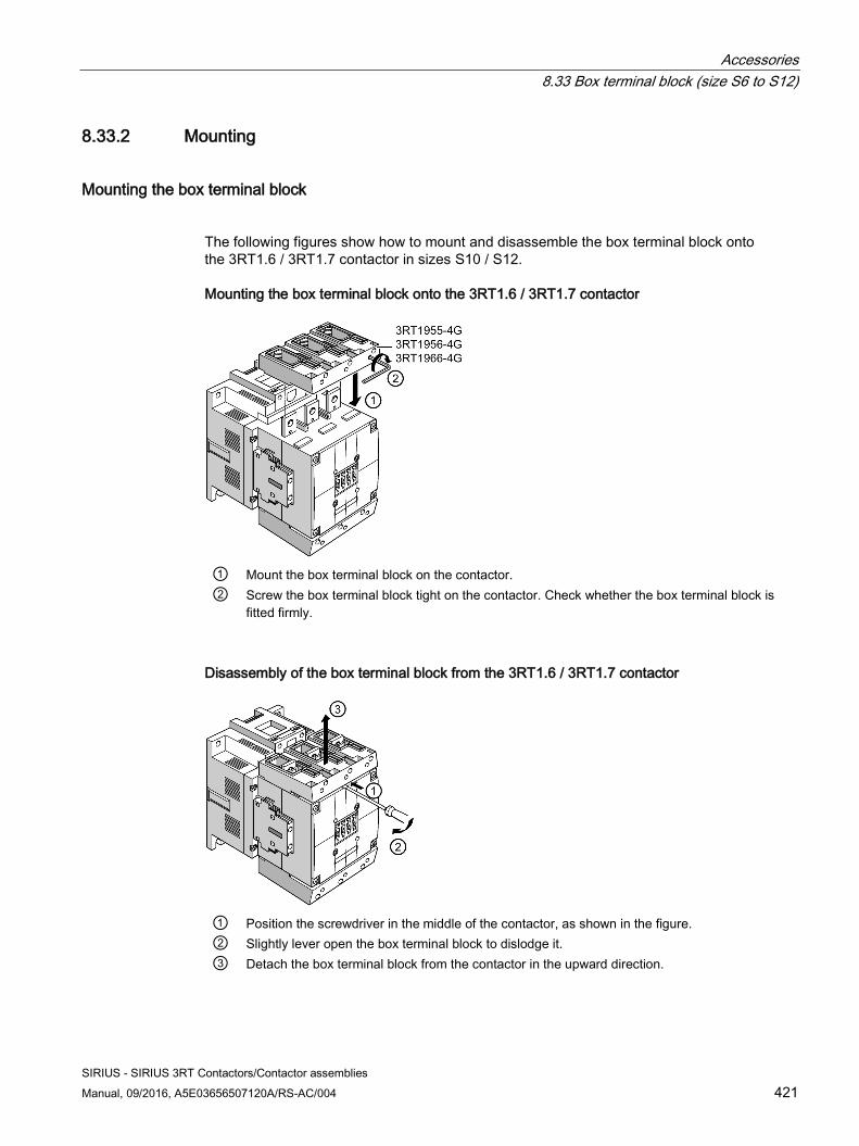
Accessories 8.33 Box terminal block (size S6 to S12)
SIRIUS - SIRIUS 3RT Contactors/Contactor assemblies Manual, 09/2016, A5E03656507120A/RS-AC/004 421
8.33.2 Mounting
Mounting the box terminal block
The following figures show how to mount and disassemble the box terminal block onto the 3RT1.6 / 3RT1.7 contactor in sizes S10 / S12.
Mounting the box terminal block onto the 3RT1.6 / 3RT1.7 contactor
① Mount the box terminal block on the contactor. ② Screw the box terminal block tight on the contactor. Check whether the box terminal block is
fitted firmly.
Disassembly of the box terminal block from the 3RT1.6 / 3RT1.7 contactor
① Position the screwdriver in the middle of the contactor, as shown in the figure. ② Slightly lever open the box terminal block to dislodge it. ③ Detach the box terminal block from the contactor in the upward direction.
Accessories 8.34 Solid-state time-delay auxiliary switch blocks (size S6 to S12)
SIRIUS - SIRIUS 3RT Contactors/Contactor assemblies 422 Manual, 09/2016, A5E03656507120A/RS-AC/004
8.34 Solid-state time-delay auxiliary switch blocks (size S6 to S12)
8.34.1 Description
The solid-state time-delay auxiliary switch blocks sizes S6 to S12 have the following features:
● The solid-state time-delay auxiliary switch block is supplied with power via two terminals (A1 / A2).
● The time delay of the solid-state time-delay auxiliary switch block can be activated either by a parallel link to any contactor coil or by any power source.
● The OFF-delay version operates without an auxiliary voltage
● The minimum ON duration is 200 ms.
● A 1-pole auxiliary switch block can be snapped onto the front of the contactor in addition to the solid-state time-delay auxiliary switch block.
● The solid-state time-delay auxiliary switch block has no integrated overvoltage attenuation for the connected contactor.
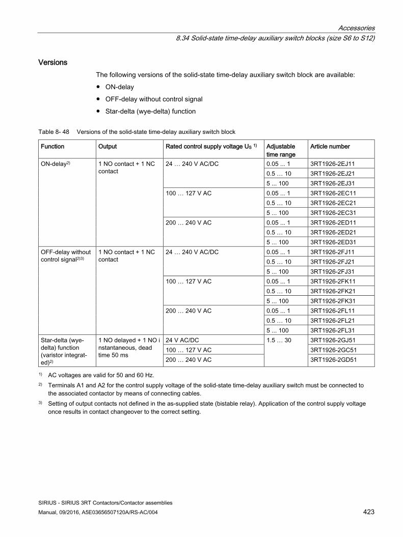
Accessories 8.34 Solid-state time-delay auxiliary switch blocks (size S6 to S12)
SIRIUS - SIRIUS 3RT Contactors/Contactor assemblies Manual, 09/2016, A5E03656507120A/RS-AC/004 423
Versions The following versions of the solid-state time-delay auxiliary switch block are available:
● ON-delay
● OFF-delay without control signal
● Star-delta (wye-delta) function
Table 8- 48 Versions of the solid-state time-delay auxiliary switch block
Function Output Rated control supply voltage US 1) Adjustable time range
Article number
ON-delay2) 1 NO contact + 1 NC contact
24 … 240 V AC/DC
0.05 ... 1 3RT1926-2EJ11 0.5 … 10 3RT1926-2EJ21 5 ... 100 3RT1926-2EJ31
100 … 127 V AC 0.05 ... 1 3RT1926-2EC11 0.5 … 10 3RT1926-2EC21 5 ... 100 3RT1926-2EC31
200 … 240 V AC 0.05 ... 1 3RT1926-2ED11 0.5 … 10 3RT1926-2ED21 5 ... 100 3RT1926-2ED31
OFF-delay without control signal2)3)
1 NO contact + 1 NC contact
24 … 240 V AC/DC
0.05 ... 1 3RT1926-2FJ11 0.5 … 10 3RT1926-2FJ21 5 ... 100 3RT1926-2FJ31
100 … 127 V AC 0.05 ... 1 3RT1926-2FK11 0.5 … 10 3RT1926-2FK21 5 ... 100 3RT1926-2FK31
200 … 240 V AC 0.05 ... 1 3RT1926-2FL11 0.5 … 10 3RT1926-2FL21 5 ... 100 3RT1926-2FL31
Star-delta (wye-delta) function (varistor integrat-ed)2)
1 NO delayed + 1 NO instantaneous, dead time 50 ms
24 V AC/DC 1.5 … 30 3RT1926-2GJ51 100 … 127 V AC 3RT1926-2GC51 200 … 240 V AC 3RT1926-2GD51
1) AC voltages are valid for 50 and 60 Hz. 2) Terminals A1 and A2 for the control supply voltage of the solid-state time-delay auxiliary switch must be connected to
the associated contactor by means of connecting cables. 3) Setting of output contacts not defined in the as-supplied state (bistable relay). Application of the control supply voltage
once results in contact changeover to the correct setting.
Accessories 8.34 Solid-state time-delay auxiliary switch blocks (size S6 to S12)
SIRIUS - SIRIUS 3RT Contactors/Contactor assemblies 424 Manual, 09/2016, A5E03656507120A/RS-AC/004
ON-delay and OFF-delay functions The solid-state time-delay auxiliary switch block in the "ON-delay" and "OFF-delay" versions has the following features:
● Allows time-delayed functions up to 100 s.
● 3 setting ranges
● Contains a relay with 1 NO contact + 1 NC contact; depending on the version, the relay is switched either after an ON-delay or after an OFF-delay.
Star-delta (wye-delta) function The solid-state time-delay auxiliary switch with "star-delta (wye-delta)" function has the following features:
● It is equipped with one delayed and one instantaneous NO contact, with a dead time of 50 ms between the two.
● The delay time of the NO contact can be adjusted between 1.5 s and 30 s.
● The contactor on which the solid-state time-delay auxiliary switch block is mounted operates without a delay.
Connection The terminals A1 and A2 for the rated control supply voltage of the solid-state time-delay auxiliary switch block are connected to the corresponding contactor by connecting cables.
Terminal designation Another auxiliary switch block can be snapped onto the contactor beside the solid-state time-delay auxiliary switch block. The terminals of the delayed contacts are designated -5 / -6 (NC contactors) and -7 / -8 (NO contacts).
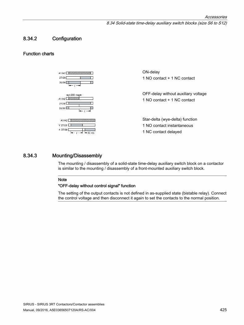
Accessories 8.34 Solid-state time-delay auxiliary switch blocks (size S6 to S12)
SIRIUS - SIRIUS 3RT Contactors/Contactor assemblies Manual, 09/2016, A5E03656507120A/RS-AC/004 425
8.34.2 Configuration
Function charts
ON-delay 1 NO contact + 1 NC contact
OFF-delay without auxiliary voltage 1 NO contact + 1 NC contact
Star-delta (wye-delta) function 1 NO contact instantaneous 1 NC contact delayed
8.34.3 Mounting/Disassembly The mounting / disassembly of a solid-state time-delay auxiliary switch block on a contactor is similar to the mounting / disassembly of a front-mounted auxiliary switch block.
Note "OFF-delay without control signal" function
The setting of the output contacts is not defined in as-supplied state (bistable relay). Connect the control voltage and then disconnect it again to set the contacts to the normal position.
Accessories 8.34 Solid-state time-delay auxiliary switch blocks (size S6 to S12)
SIRIUS - SIRIUS 3RT Contactors/Contactor assemblies 426 Manual, 09/2016, A5E03656507120A/RS-AC/004
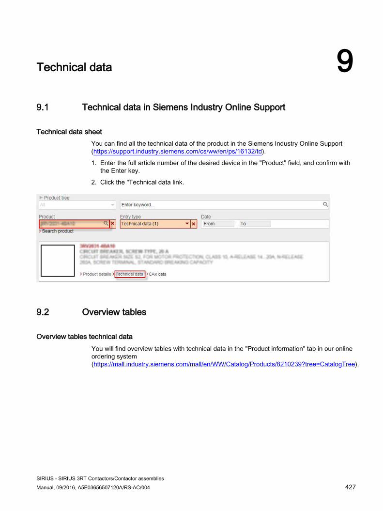
SIRIUS - SIRIUS 3RT Contactors/Contactor assemblies Manual, 09/2016, A5E03656507120A/RS-AC/004 427
Technical data 99.1 Technical data in Siemens Industry Online Support
Technical data sheet You can find all the technical data of the product in the Siemens Industry Online Support (https://support.industry.siemens.com/cs/ww/en/ps/16132/td).
1. Enter the full article number of the desired device in the "Product" field, and confirm withthe Enter key.
2. Click the "Technical data link.
9.2 Overview tables
Overview tables technical data You will find overview tables with technical data in the "Product information" tab in our online ordering system (https://mall.industry.siemens.com/mall/en/WW/Catalog/Products/8210239?tree=CatalogTree).
Technical data 9.2 Overview tables
SIRIUS - SIRIUS 3RT Contactors/Contactor assemblies 428 Manual, 09/2016, A5E03656507120A/RS-AC/004
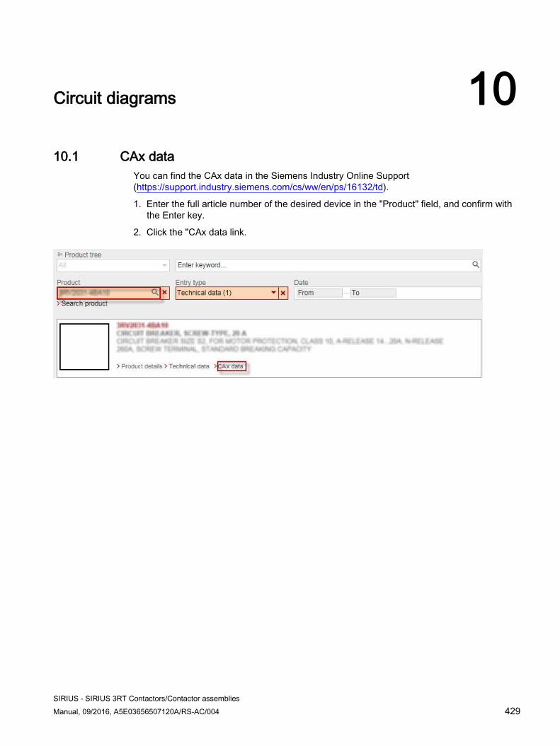
SIRIUS - SIRIUS 3RT Contactors/Contactor assemblies Manual, 09/2016, A5E03656507120A/RS-AC/004 429
Circuit diagrams 10 10.1 CAx data
You can find the CAx data in the Siemens Industry Online Support (https://support.industry.siemens.com/cs/ww/en/ps/16132/td).
1. Enter the full article number of the desired device in the "Product" field, and confirm with the Enter key.
2. Click the "CAx data link.
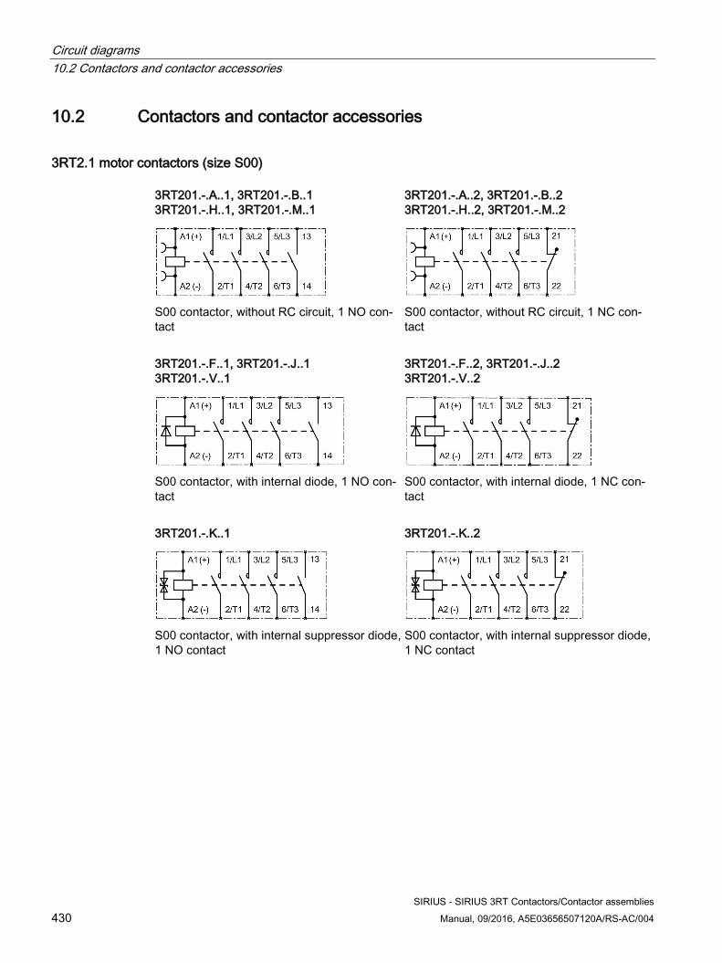
Circuit diagrams 10.2 Contactors and contactor accessories
SIRIUS - SIRIUS 3RT Contactors/Contactor assemblies 430 Manual, 09/2016, A5E03656507120A/RS-AC/004
10.2 Contactors and contactor accessories
3RT2.1 motor contactors (size S00) 3RT201.-.A..1, 3RT201.-.B..1 3RT201.-.H..1, 3RT201.-.M..1
S00 contactor, without RC circuit, 1 NO con-tact
3RT201.-.A..2, 3RT201.-.B..2 3RT201.-.H..2, 3RT201.-.M..2
S00 contactor, without RC circuit, 1 NC con-tact
3RT201.-.F..1, 3RT201.-.J..1 3RT201.-.V..1
S00 contactor, with internal diode, 1 NO con-tact
3RT201.-.F..2, 3RT201.-.J..2 3RT201.-.V..2
S00 contactor, with internal diode, 1 NC con-tact
3RT201.-.K..1
S00 contactor, with internal suppressor diode, 1 NO contact
3RT201.-.K..2
S00 contactor, with internal suppressor diode, 1 NC contact

Circuit diagrams 10.2 Contactors and contactor accessories
SIRIUS - SIRIUS 3RT Contactors/Contactor assemblies Manual, 09/2016, A5E03656507120A/RS-AC/004 431
3RT201.-.S..1
S00 contactor, with internal diode combina-tion, 1 NO contact
3RT201.-.S..2
S00 contactor, with internal diode combina-tion, 1 NC contact
3RT201.-.Q..1, 3RT201.-.W..1
S00 contactor, with varistor connected on the front, 1 NO contact
3RT201.-.Q..2, 3RT201.-.W..2
S00 contactor, with varistor connected on the front, 1 NC contact
Traction contactor 3RT201.-2K..2-0LA0 (size S00) 3RT201.-2K..2-0LA0
S00 traction contactor, with internal suppressor diode, 1 NC contact
3RT201.-2L.42-0LA0
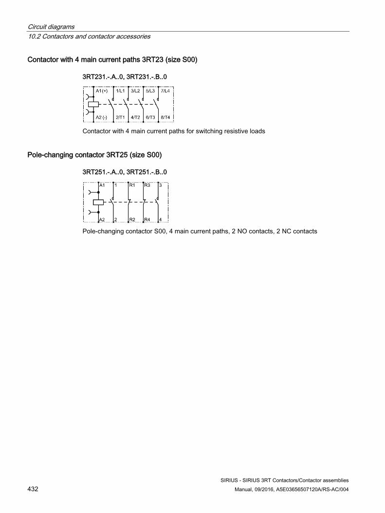
Circuit diagrams 10.2 Contactors and contactor accessories
SIRIUS - SIRIUS 3RT Contactors/Contactor assemblies 432 Manual, 09/2016, A5E03656507120A/RS-AC/004
Contactor with 4 main current paths 3RT23 (size S00) 3RT231.-.A..0, 3RT231.-.B..0
Contactor with 4 main current paths for switching resistive loads
Pole-changing contactor 3RT25 (size S00) 3RT251.-.A..0, 3RT251.-.B..0
Pole-changing contactor S00, 4 main current paths, 2 NO contacts, 2 NC contacts
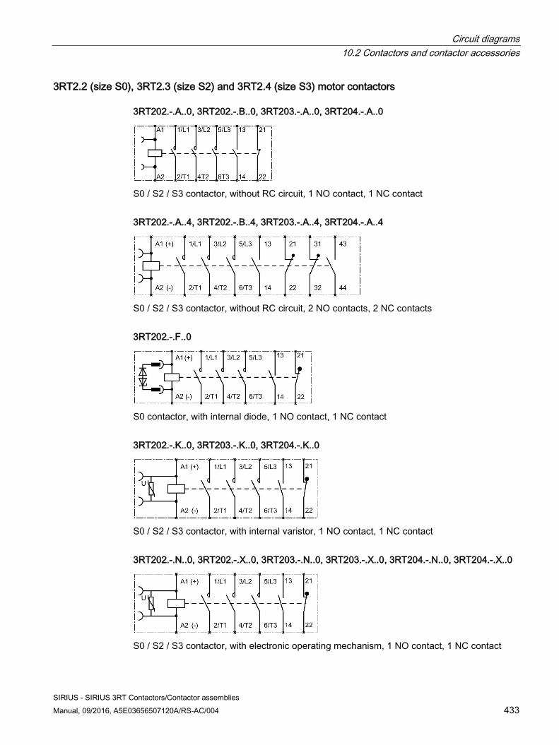
Circuit diagrams 10.2 Contactors and contactor accessories
SIRIUS - SIRIUS 3RT Contactors/Contactor assemblies Manual, 09/2016, A5E03656507120A/RS-AC/004 433
3RT2.2 (size S0), 3RT2.3 (size S2) and 3RT2.4 (size S3) motor contactors 3RT202.-.A..0, 3RT202.-.B..0, 3RT203.-.A..0, 3RT204.-.A..0
S0 / S2 / S3 contactor, without RC circuit, 1 NO contact, 1 NC contact 3RT202.-.A..4, 3RT202.-.B..4, 3RT203.-.A..4, 3RT204.-.A..4
S0 / S2 / S3 contactor, without RC circuit, 2 NO contacts, 2 NC contacts 3RT202.-.F..0
S0 contactor, with internal diode, 1 NO contact, 1 NC contact 3RT202.-.K..0, 3RT203.-.K..0, 3RT204.-.K..0
S0 / S2 / S3 contactor, with internal varistor, 1 NO contact, 1 NC contact 3RT202.-.N..0, 3RT202.-.X..0, 3RT203.-.N..0, 3RT203.-.X..0, 3RT204.-.N..0, 3RT204.-.X..0
S0 / S2 / S3 contactor, with electronic operating mechanism, 1 NO contact, 1 NC contact
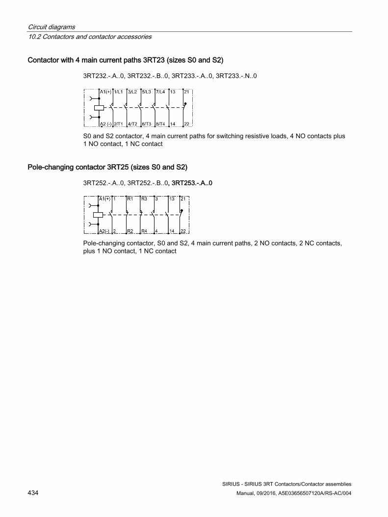
Circuit diagrams 10.2 Contactors and contactor accessories
SIRIUS - SIRIUS 3RT Contactors/Contactor assemblies 434 Manual, 09/2016, A5E03656507120A/RS-AC/004
Contactor with 4 main current paths 3RT23 (sizes S0 and S2)
3RT232.-.A..0, 3RT232.-.B..0, 3RT233.-.A..0, 3RT233.-.N..0
S0 and S2 contactor, 4 main current paths for switching resistive loads, 4 NO contacts plus 1 NO contact, 1 NC contact
Pole-changing contactor 3RT25 (sizes S0 and S2)
3RT252.-.A..0, 3RT252.-.B..0, 3RT253.-.A..0
Pole-changing contactor, S0 and S2, 4 main current paths, 2 NO contacts, 2 NC contacts, plus 1 NO contact, 1 NC contact
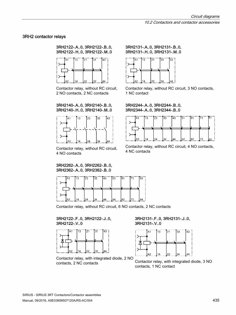
Circuit diagrams 10.2 Contactors and contactor accessories
SIRIUS - SIRIUS 3RT Contactors/Contactor assemblies Manual, 09/2016, A5E03656507120A/RS-AC/004 435
3RH2 contactor relays 3RH2122-.A..0, 3RH2122-.B..0, 3RH2122-.H..0, 3RH2122-.M..0
Contactor relay, without RC circuit, 2 NO contacts, 2 NC contacts
3RH2131-.A..0, 3RH2131-.B..0, 3RH2131-.H..0, 3RH2131-.M..0
Contactor relay, without RC circuit, 3 NO contacts, 1 NC contact
3RH2140-.A..0, 3RH2140-.B..0, 3RH2140-.H..0, 3RH2140-.M..0
Contactor relay, without RC circuit, 4 NO contacts
3RH2244-.A..0, 3RH2244-.B..0, 3RH2344-.A..0, 3RH2344-.B..0
Contactor relay, without RC circuit, 4 NO contacts, 4 NC contacts
3RH2262-.A..0, 3RH2262-.B..0, 3RH2362-.A..0, 3RH2362-.B..0
Contactor relay, without RC circuit, 6 NO contacts, 2 NC contacts 3RH2122-.F..0, 3RH2122-.J..0, 3RH2122-.V..0
Contactor relay, with integrated diode, 2 NO contacts, 2 NC contacts
3RH2131-.F..0, 3RH2131-.J..0, 3RH2131-.V..0
Contactor relay, with integrated diode, 3 NO contacts, 1 NC contact
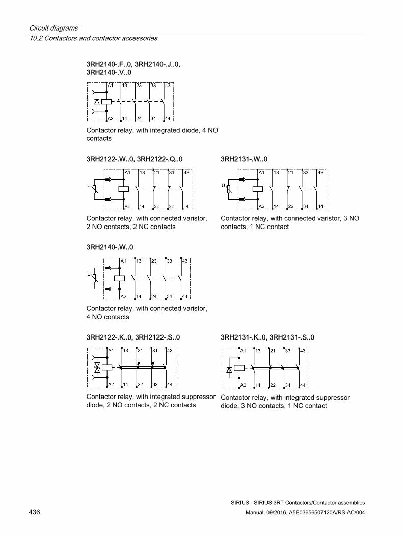
Circuit diagrams 10.2 Contactors and contactor accessories
SIRIUS - SIRIUS 3RT Contactors/Contactor assemblies 436 Manual, 09/2016, A5E03656507120A/RS-AC/004
3RH2140-.F..0, 3RH2140-.J..0, 3RH2140-.V..0
Contactor relay, with integrated diode, 4 NO contacts
3RH2122-.W..0, 3RH2122-.Q..0
Contactor relay, with connected varistor, 2 NO contacts, 2 NC contacts
3RH2131-.W..0
Contactor relay, with connected varistor, 3 NO contacts, 1 NC contact
3RH2140-.W..0
Contactor relay, with connected varistor, 4 NO contacts
3RH2122-.K..0, 3RH2122-.S..0
Contactor relay, with integrated suppressor diode, 2 NO contacts, 2 NC contacts
3RH2131-.K..0, 3RH2131-.S..0
Contactor relay, with integrated suppressor diode, 3 NO contacts, 1 NC contact
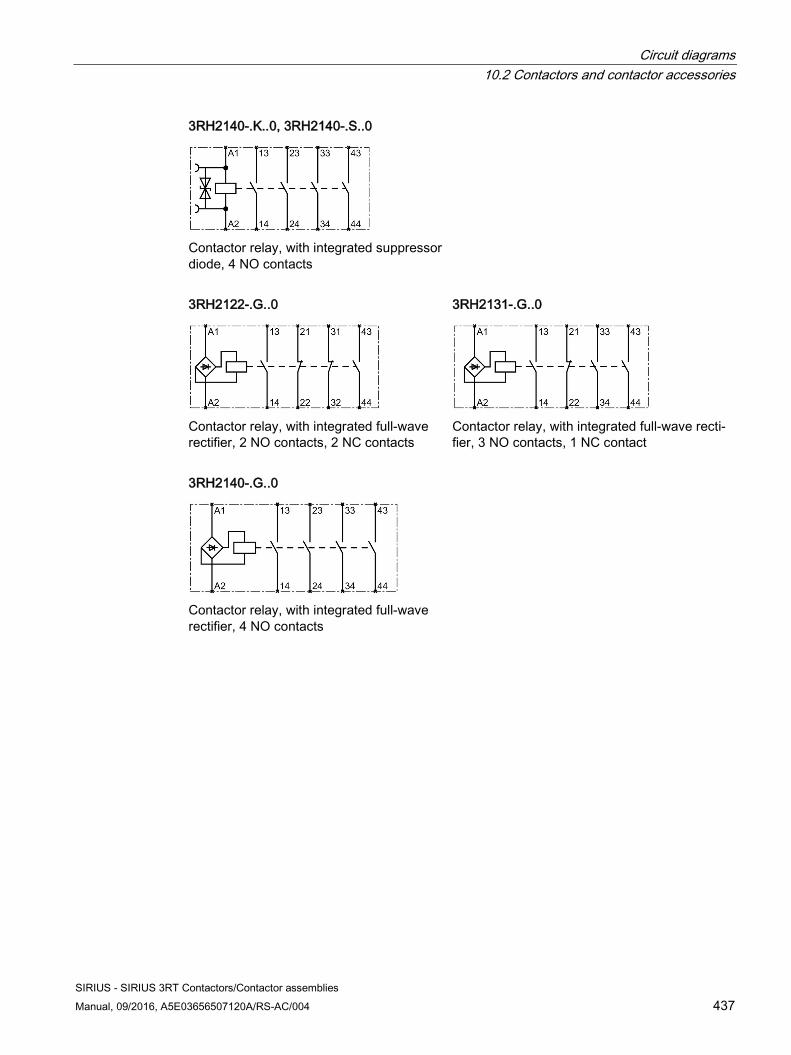
Circuit diagrams 10.2 Contactors and contactor accessories
SIRIUS - SIRIUS 3RT Contactors/Contactor assemblies Manual, 09/2016, A5E03656507120A/RS-AC/004 437
3RH2140-.K..0, 3RH2140-.S..0
Contactor relay, with integrated suppressor diode, 4 NO contacts
3RH2122-.G..0
Contactor relay, with integrated full-wave rectifier, 2 NO contacts, 2 NC contacts
3RH2131-.G..0
Contactor relay, with integrated full-wave recti-fier, 3 NO contacts, 1 NC contact
3RH2140-.G..0
Contactor relay, with integrated full-wave rectifier, 4 NO contacts
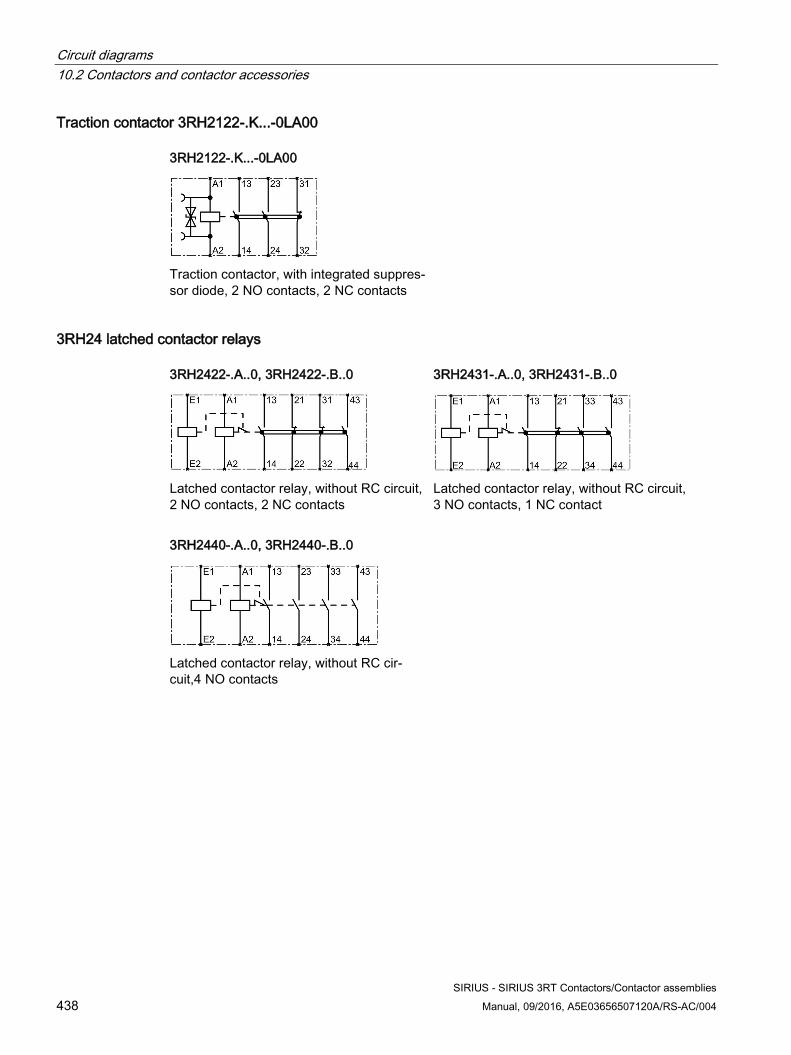
Circuit diagrams 10.2 Contactors and contactor accessories
SIRIUS - SIRIUS 3RT Contactors/Contactor assemblies 438 Manual, 09/2016, A5E03656507120A/RS-AC/004
Traction contactor 3RH2122-.K...-0LA00 3RH2122-.K...-0LA00
Traction contactor, with integrated suppres-sor diode, 2 NO contacts, 2 NC contacts
3RH24 latched contactor relays 3RH2422-.A..0, 3RH2422-.B..0
Latched contactor relay, without RC circuit, 2 NO contacts, 2 NC contacts
3RH2431-.A..0, 3RH2431-.B..0
Latched contactor relay, without RC circuit, 3 NO contacts, 1 NC contact
3RH2440-.A..0, 3RH2440-.B..0
Latched contactor relay, without RC cir-cuit,4 NO contacts
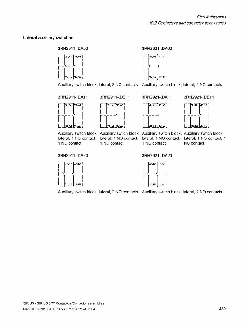
Circuit diagrams 10.2 Contactors and contactor accessories
SIRIUS - SIRIUS 3RT Contactors/Contactor assemblies Manual, 09/2016, A5E03656507120A/RS-AC/004 439
Lateral auxiliary switches 3RH2911-.DA02
Auxiliary switch block, lateral, 2 NC contacts
3RH2921-.DA02
Auxiliary switch block, lateral, 2 NC contacts
3RH2911-.DA11
Auxiliary switch block, lateral, 1 NO contact, 1 NC contact
3RH2911-.DE11
Auxiliary switch block, lateral, 1 NO contact, 1 NC contact
3RH2921-.DA11
Auxiliary switch block, lateral, 1 NO contact, 1 NC contact
3RH2921-.DE11
Auxiliary switch block, lateral, 1 NO contact, 1 NC contact
3RH2911-.DA20
Auxiliary switch block, lateral, 2 NO contacts
3RH2921-.DA20
Auxiliary switch block, lateral, 2 NO contacts
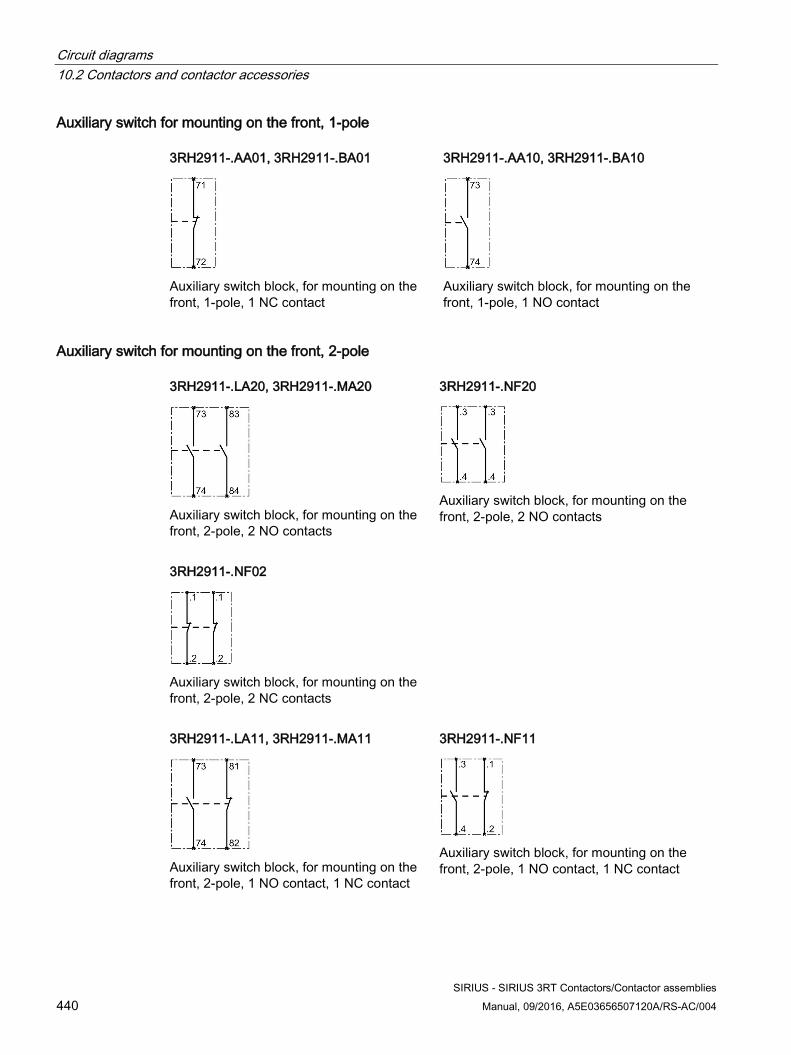
Circuit diagrams 10.2 Contactors and contactor accessories
SIRIUS - SIRIUS 3RT Contactors/Contactor assemblies 440 Manual, 09/2016, A5E03656507120A/RS-AC/004
Auxiliary switch for mounting on the front, 1-pole 3RH2911-.AA01, 3RH2911-.BA01
Auxiliary switch block, for mounting on the front, 1-pole, 1 NC contact
3RH2911-.AA10, 3RH2911-.BA10
Auxiliary switch block, for mounting on the front, 1-pole, 1 NO contact
Auxiliary switch for mounting on the front, 2-pole 3RH2911-.LA20, 3RH2911-.MA20
Auxiliary switch block, for mounting on the front, 2-pole, 2 NO contacts
3RH2911-.NF20
Auxiliary switch block, for mounting on the front, 2-pole, 2 NO contacts
3RH2911-.NF02
Auxiliary switch block, for mounting on the front, 2-pole, 2 NC contacts
3RH2911-.LA11, 3RH2911-.MA11
Auxiliary switch block, for mounting on the front, 2-pole, 1 NO contact, 1 NC contact
3RH2911-.NF11
Auxiliary switch block, for mounting on the front, 2-pole, 1 NO contact, 1 NC contact
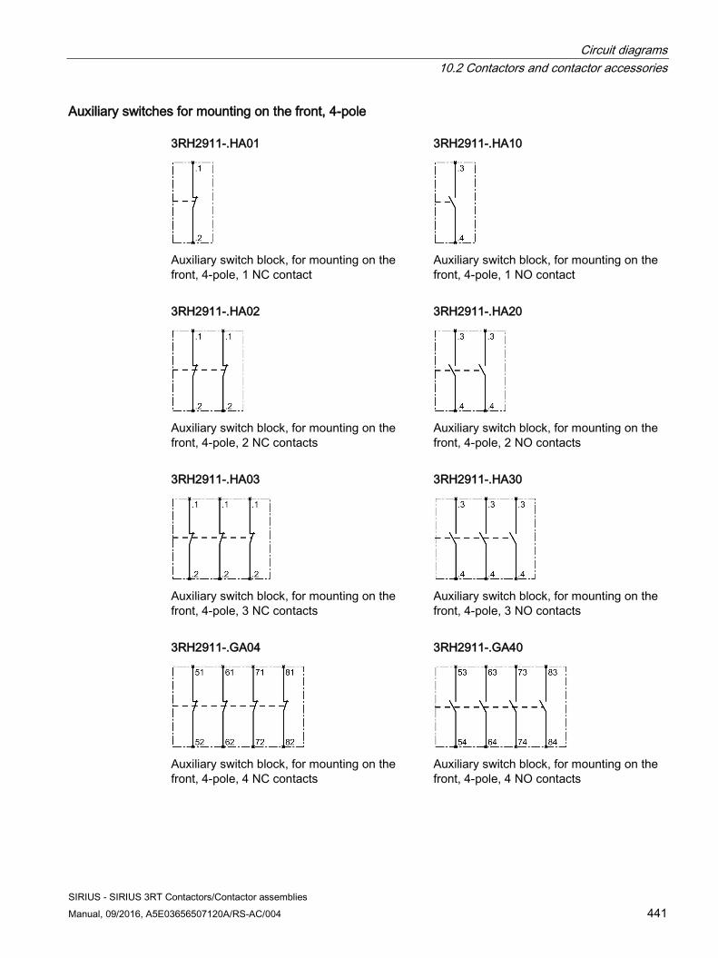
Circuit diagrams 10.2 Contactors and contactor accessories
SIRIUS - SIRIUS 3RT Contactors/Contactor assemblies Manual, 09/2016, A5E03656507120A/RS-AC/004 441
Auxiliary switches for mounting on the front, 4-pole 3RH2911-.HA01
Auxiliary switch block, for mounting on the front, 4-pole, 1 NC contact
3RH2911-.HA10
Auxiliary switch block, for mounting on the front, 4-pole, 1 NO contact
3RH2911-.HA02
Auxiliary switch block, for mounting on the front, 4-pole, 2 NC contacts
3RH2911-.HA20
Auxiliary switch block, for mounting on the front, 4-pole, 2 NO contacts
3RH2911-.HA03
Auxiliary switch block, for mounting on the front, 4-pole, 3 NC contacts
3RH2911-.HA30
Auxiliary switch block, for mounting on the front, 4-pole, 3 NO contacts
3RH2911-.GA04
Auxiliary switch block, for mounting on the front, 4-pole, 4 NC contacts
3RH2911-.GA40
Auxiliary switch block, for mounting on the front, 4-pole, 4 NO contacts
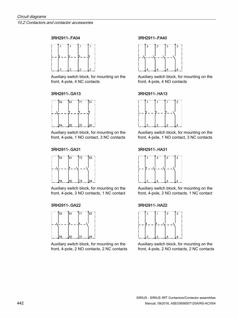
Circuit diagrams 10.2 Contactors and contactor accessories
SIRIUS - SIRIUS 3RT Contactors/Contactor assemblies 442 Manual, 09/2016, A5E03656507120A/RS-AC/004
3RH2911-.FA04
Auxiliary switch block, for mounting on the front, 4-pole, 4 NC contacts
3RH2911-.FA40
Auxiliary switch block, for mounting on the front, 4-pole, 4 NO contacts
3RH2911-.GA13
Auxiliary switch block, for mounting on the front, 4-pole, 1 NO contact, 3 NC contacts
3RH2911-.HA13
Auxiliary switch block, for mounting on the front, 4-pole, 1 NO contact, 3 NC contacts
3RH2911-.GA31
Auxiliary switch block, for mounting on the front, 4-pole, 3 NO contacts, 1 NC contact
3RH2911-.HA31
Auxiliary switch block, for mounting on the front, 4-pole, 3 NO contacts, 1 NC contact
3RH2911-.GA22
Auxiliary switch block, for mounting on the front, 4-pole, 2 NO contacts, 2 NC contacts
3RH2911-.HA22
Auxiliary switch block, for mounting on the front, 4-pole, 2 NO contacts, 2 NC contacts
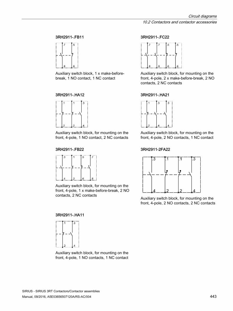
Circuit diagrams 10.2 Contactors and contactor accessories
SIRIUS - SIRIUS 3RT Contactors/Contactor assemblies Manual, 09/2016, A5E03656507120A/RS-AC/004 443
3RH2911-.FB11
Auxiliary switch block, 1 x make-before-break, 1 NO contact, 1 NC contact
3RH2911-.FC22
Auxiliary switch block, for mounting on the front, 4-pole, 2 x make-before-break, 2 NO contacts, 2 NC contacts
3RH2911-.HA12
Auxiliary switch block, for mounting on the front, 4-pole, 1 NO contact, 2 NC contacts
3RH2911-.HA21
Auxiliary switch block, for mounting on the front, 4-pole, 2 NO contacts, 1 NC contact
3RH2911-.FB22
Auxiliary switch block, for mounting on the front, 4-pole, 1 x make-before-break, 2 NO contacts, 2 NC contacts
3RH2911-2FA22
Auxiliary switch block, for mounting on the front, 4-pole, 2 NO contacts, 2 NC contacts
3RH2911-.HA11
Auxiliary switch block, for mounting on the front, 4-pole, 1 NO contacts, 1 NC contact
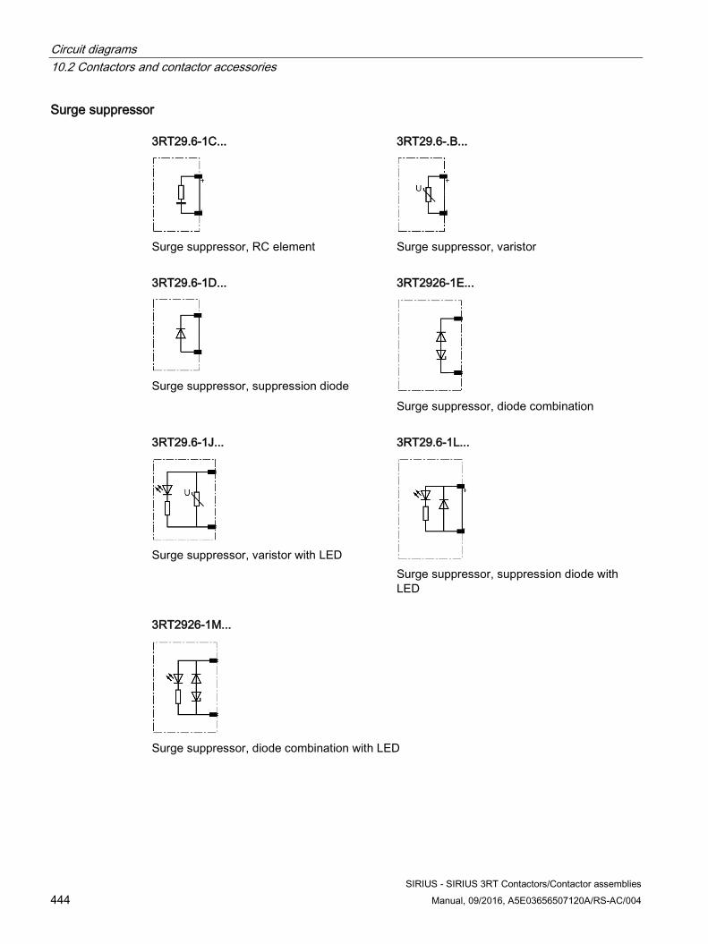
Circuit diagrams 10.2 Contactors and contactor accessories
SIRIUS - SIRIUS 3RT Contactors/Contactor assemblies 444 Manual, 09/2016, A5E03656507120A/RS-AC/004
Surge suppressor 3RT29.6-1C...
Surge suppressor, RC element
3RT29.6-.B...
Surge suppressor, varistor
3RT29.6-1D...
Surge suppressor, suppression diode
3RT2926-1E...
Surge suppressor, diode combination
3RT29.6-1J...
Surge suppressor, varistor with LED
3RT29.6-1L...
Surge suppressor, suppression diode with LED
3RT2926-1M...
Surge suppressor, diode combination with LED
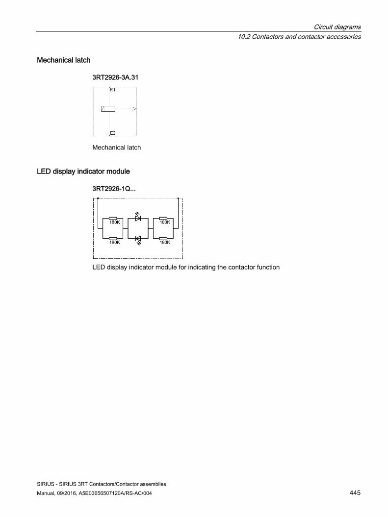
Circuit diagrams 10.2 Contactors and contactor accessories
SIRIUS - SIRIUS 3RT Contactors/Contactor assemblies Manual, 09/2016, A5E03656507120A/RS-AC/004 445
Mechanical latch 3RT2926-3A.31
Mechanical latch
LED display indicator module 3RT2926-1Q...
LED display indicator module for indicating the contactor function
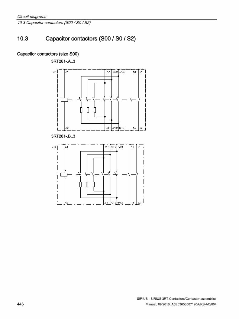
Circuit diagrams 10.3 Capacitor contactors (S00 / S0 / S2)
SIRIUS - SIRIUS 3RT Contactors/Contactor assemblies 446 Manual, 09/2016, A5E03656507120A/RS-AC/004
10.3 Capacitor contactors (S00 / S0 / S2)
Capacitor contactors (size S00) 3RT261-.A..3
3RT261-.B..3
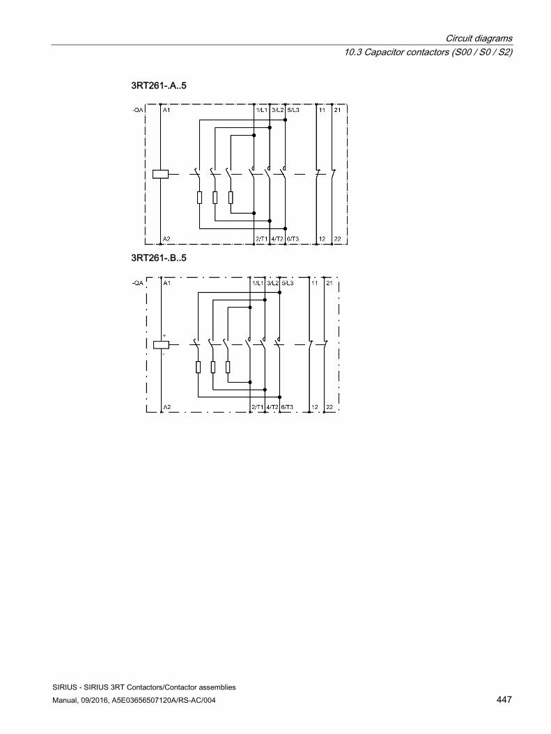
Circuit diagrams 10.3 Capacitor contactors (S00 / S0 / S2)
SIRIUS - SIRIUS 3RT Contactors/Contactor assemblies Manual, 09/2016, A5E03656507120A/RS-AC/004 447
3RT261-.A..5
3RT261-.B..5
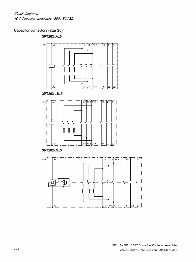
Circuit diagrams 10.3 Capacitor contactors (S00 / S0 / S2)
SIRIUS - SIRIUS 3RT Contactors/Contactor assemblies 448 Manual, 09/2016, A5E03656507120A/RS-AC/004
Capacitor contactors (size S0) 3RT262-.A..5
3RT262-..B..5
3RT262-.N..5
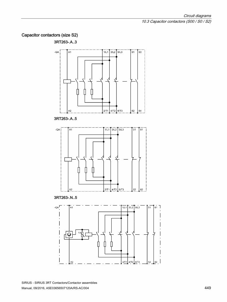
Circuit diagrams 10.3 Capacitor contactors (S00 / S0 / S2)
SIRIUS - SIRIUS 3RT Contactors/Contactor assemblies Manual, 09/2016, A5E03656507120A/RS-AC/004 449
Capacitor contactors (size S2) 3RT263-.A..3
3RT263-.A..5
3RT263-.N..5
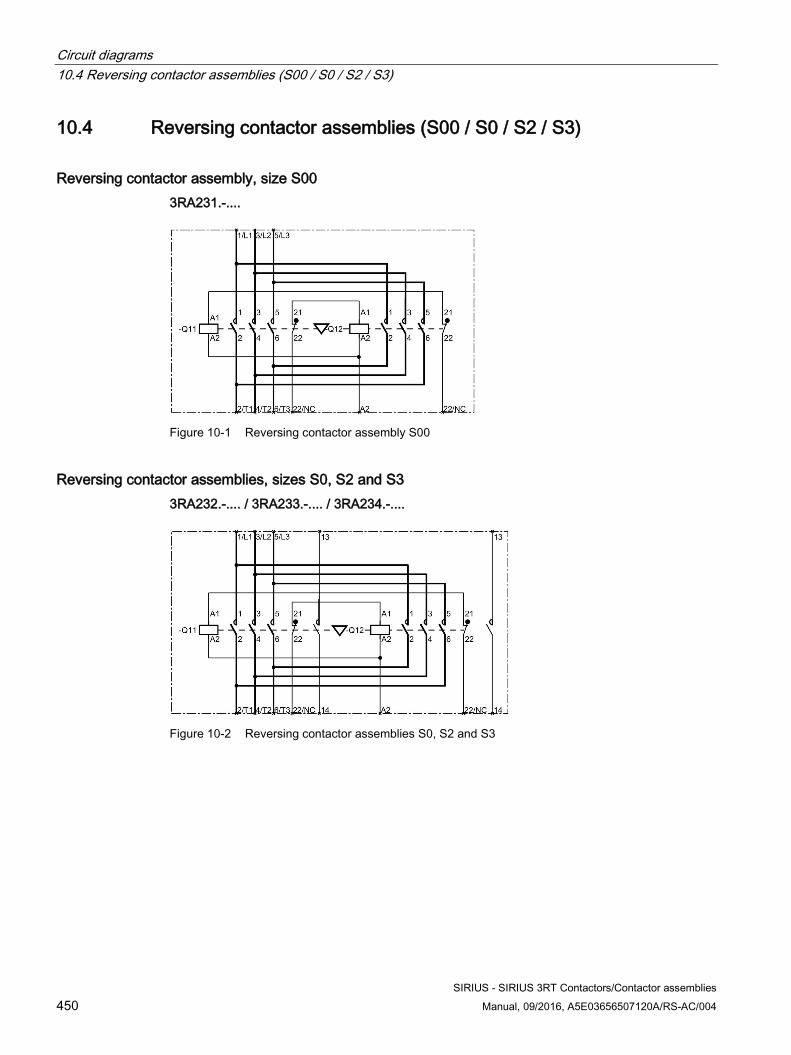
Circuit diagrams 10.4 Reversing contactor assemblies (S00 / S0 / S2 / S3)
SIRIUS - SIRIUS 3RT Contactors/Contactor assemblies 450 Manual, 09/2016, A5E03656507120A/RS-AC/004
10.4 Reversing contactor assemblies (S00 / S0 / S2 / S3)
Reversing contactor assembly, size S00 3RA231.-....
Figure 10-1 Reversing contactor assembly S00
Reversing contactor assemblies, sizes S0, S2 and S3 3RA232.-.... / 3RA233.-.... / 3RA234.-....
Figure 10-2 Reversing contactor assemblies S0, S2 and S3
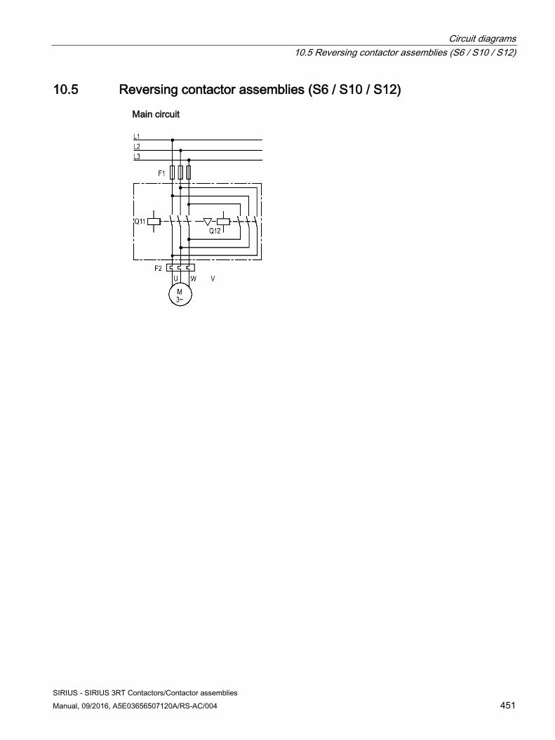
Circuit diagrams 10.5 Reversing contactor assemblies (S6 / S10 / S12)
SIRIUS - SIRIUS 3RT Contactors/Contactor assemblies Manual, 09/2016, A5E03656507120A/RS-AC/004 451
10.5 Reversing contactor assemblies (S6 / S10 / S12)
Main circuit
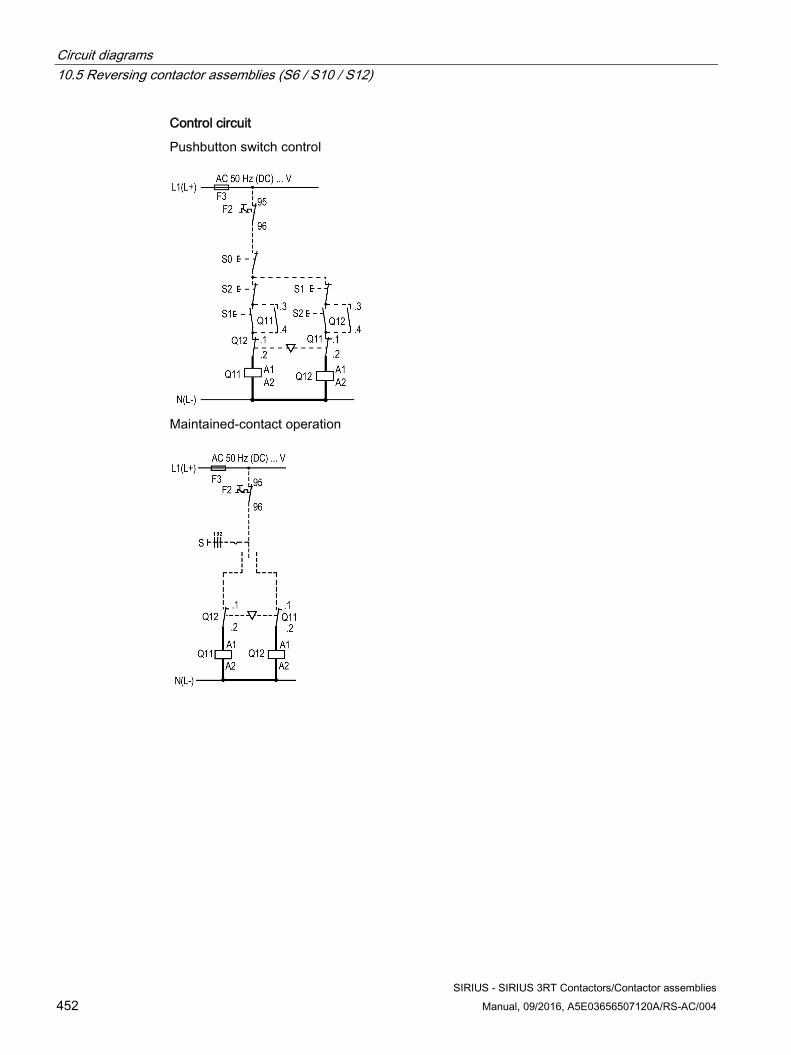
Circuit diagrams 10.5 Reversing contactor assemblies (S6 / S10 / S12)
SIRIUS - SIRIUS 3RT Contactors/Contactor assemblies 452 Manual, 09/2016, A5E03656507120A/RS-AC/004
Control circuit
Pushbutton switch control
Maintained-contact operation
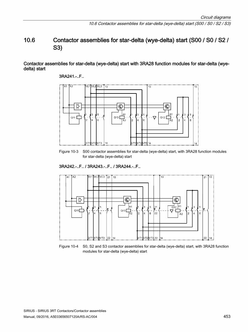
Circuit diagrams 10.6 Contactor assemblies for star-delta (wye-delta) start (S00 / S0 / S2 / S3)
SIRIUS - SIRIUS 3RT Contactors/Contactor assemblies Manual, 09/2016, A5E03656507120A/RS-AC/004 453
10.6 Contactor assemblies for star-delta (wye-delta) start (S00 / S0 / S2 / S3)
Contactor assemblies for star-delta (wye-delta) start with 3RA28 function modules for star-delta (wye-delta) start
3RA241.-..F..
Figure 10-3 S00 contactor assemblies for star-delta (wye-delta) start, with 3RA28 function modules
for star-delta (wye-delta) start
3RA242.-..F.. / 3RA243.-..F.. / 3RA244.-..F..
Figure 10-4 S0, S2 and S3 contactor assemblies for star-delta (wye-delta) start, with 3RA28 function
modules for star-delta (wye-delta) start
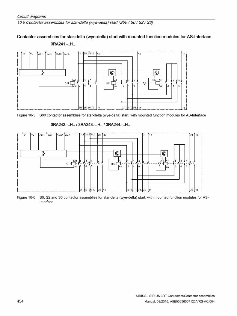
Circuit diagrams 10.6 Contactor assemblies for star-delta (wye-delta) start (S00 / S0 / S2 / S3)
SIRIUS - SIRIUS 3RT Contactors/Contactor assemblies 454 Manual, 09/2016, A5E03656507120A/RS-AC/004
Contactor assemblies for star-delta (wye-delta) start with mounted function modules for AS-Interface 3RA241.-..H..
Figure 10-5 S00 contactor assemblies for star-delta (wye-delta) start, with mounted function modules for AS-Interface
3RA242.-..H.. / 3RA243.-..H.. / 3RA244.-..H..
Figure 10-6 S0, S2 and S3 contactor assemblies for star-delta (wye-delta) start, with mounted function modules for AS-
Interface
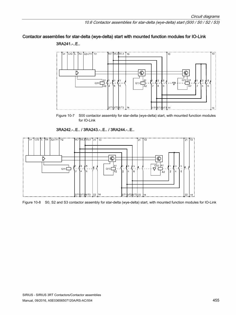
Circuit diagrams 10.6 Contactor assemblies for star-delta (wye-delta) start (S00 / S0 / S2 / S3)
SIRIUS - SIRIUS 3RT Contactors/Contactor assemblies Manual, 09/2016, A5E03656507120A/RS-AC/004 455
Contactor assemblies for star-delta (wye-delta) start with mounted function modules for IO-Link 3RA241.-..E..
Figure 10-7 S00 contactor assembly for star-delta (wye-delta) start, with mounted function modules
for IO-Link
3RA242.-..E.. / 3RA243.-..E.. / 3RA244.-..E..
Figure 10-8 S0, S2 and S3 contactor assembly for star-delta (wye-delta) start, with mounted function modules for IO-Link
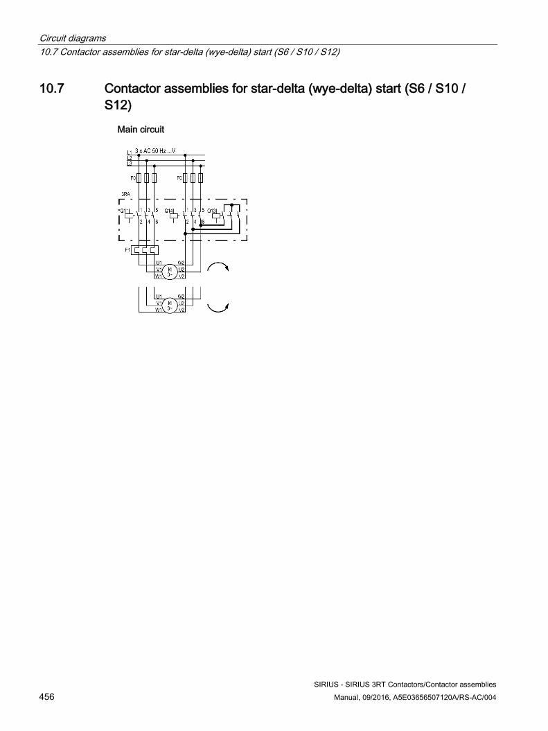
Circuit diagrams 10.7 Contactor assemblies for star-delta (wye-delta) start (S6 / S10 / S12)
SIRIUS - SIRIUS 3RT Contactors/Contactor assemblies 456 Manual, 09/2016, A5E03656507120A/RS-AC/004
10.7 Contactor assemblies for star-delta (wye-delta) start (S6 / S10 / S12)
Main circuit
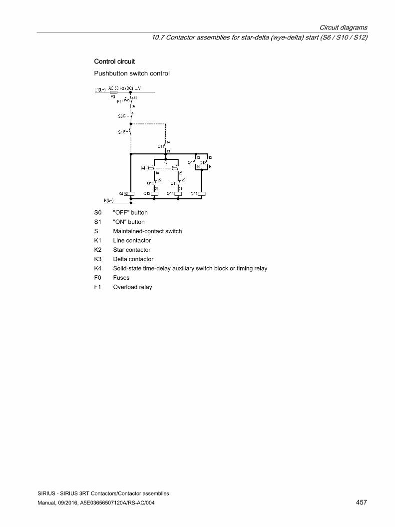
Circuit diagrams 10.7 Contactor assemblies for star-delta (wye-delta) start (S6 / S10 / S12)
SIRIUS - SIRIUS 3RT Contactors/Contactor assemblies Manual, 09/2016, A5E03656507120A/RS-AC/004 457
Control circuit
Pushbutton switch control
S0 "OFF" button S1 "ON" button S Maintained-contact switch K1 Line contactor K2 Star contactor K3 Delta contactor K4 Solid-state time-delay auxiliary switch block or timing relay F0 Fuses F1 Overload relay
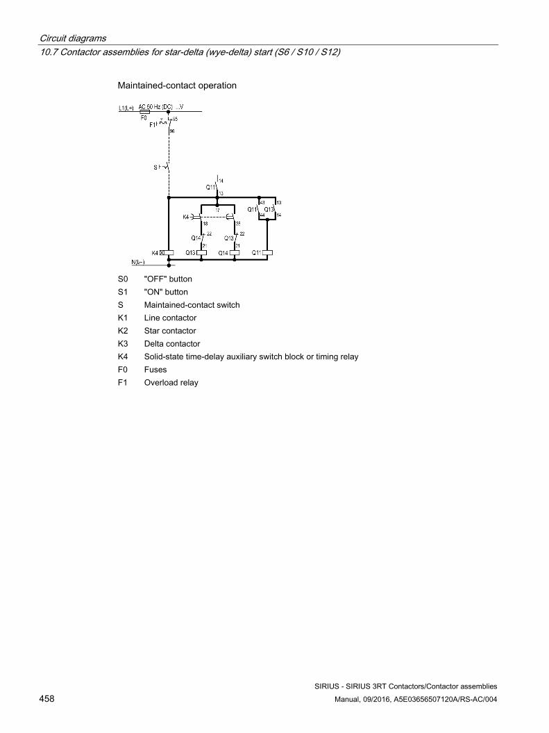
Circuit diagrams 10.7 Contactor assemblies for star-delta (wye-delta) start (S6 / S10 / S12)
SIRIUS - SIRIUS 3RT Contactors/Contactor assemblies 458 Manual, 09/2016, A5E03656507120A/RS-AC/004
Maintained-contact operation
S0 "OFF" button S1 "ON" button S Maintained-contact switch K1 Line contactor K2 Star contactor K3 Delta contactor K4 Solid-state time-delay auxiliary switch block or timing relay F0 Fuses F1 Overload relay
SIRIUS - SIRIUS 3RT Contactors/Contactor assemblies Manual, 09/2016, A5E03656507120A/RS-AC/004 459
Types of coordination A
Types of coordination Standard DIN EN 60947-4-1 (VDE 0660 Part 102) or IEC 60947-4-1 distinguishes between two types of coordination (type of coordination), which are referred to as coordination type "1" and coordination type "2". In the case of both types of coordination, the short-circuit is reliably mastered. the only differences are in the extent of the damage sustained by the device following a short circuit.
Type of coordination 1 The load feeder may be non-operational after a short circuit has been cleared. Damage to the contactor and the overload release is also permissible.
Type of coordination 2 After short-circuit disconnection, there must be no damage to the overload release or to any other part. The load feeder can resume operation without needing to be renewed. Welding of the contactor contacts only is permitted if these can be separated easily without significant deformation.

Types of coordination
SIRIUS - SIRIUS 3RT Contactors/Contactor assemblies 460 Manual, 09/2016, A5E03656507120A/RS-AC/004
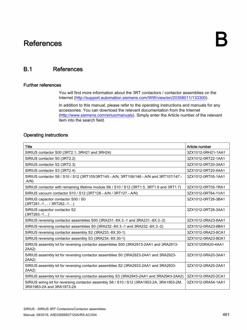
SIRIUS - SIRIUS 3RT Contactors/Contactor assemblies Manual, 09/2016, A5E03656507120A/RS-AC/004 461
References B B.1 References
Further references You will find more information about the 3RT contactors / contactor assemblies on the Internet (http://support.automation.siemens.com/WW/view/en/20358011/133300).
In addition to this manual, please refer to the operating instructions and manuals for any accessories. You can download the relevant documentation from the Internet (http://www.siemens.com/sirius/manuals). Simply enter the Article number of the relevant item into the search field.
Operating instructions Title Article number SIRIUS contactor S00 (3RT2.1, 3RH21 and 3RH24) 3ZX1012-0RH21-1AA1 SIRIUS contactor S0 (3RT2.2) 3ZX1012-0RT22-1AA1 SIRIUS contactor S2 (3RT2.3) 3ZX1012-0RT20-3AA1 SIRIUS contactor S3 (3RT2.4) 3ZX1012-0RT20-4AA1 SIRIUS contactor S6 / S10 / S12 (3RT105/3RT145.-.A/N, 3RT106/146.-.A/N and 3RT107/147.-.A/N)
3ZX1012-0RT05-1AA1
SIRIUS contactor with remaining lifetime module S6 / S10 / S12 (3RT1.5, 3RT1.6 and 3RT1.7) 3ZX1012-0RT05-1RA1 SIRIUS vacuum contactor S10 / S12 (3RT126.-.A/N / 3RT127.-.A/N) 3ZX1012-0RT64-1VA1 SIRIUS capacitor contactor S00 / S0 (3RT261.-1.... / 3RT262.-1....)
3ZX1012-0RT26-3BA1
SIRIUS capacitor contactor S2 (3RT263.-1....)
3ZX1012-0RT26-3AA1
SIRIUS reversing contactor assemblies S00 (3RA231.-8X.3.-1 and 3RA231.-8X.3.-2) 3ZX1012-0RA23-8AA1 SIRIUS reversing contactor assemblies S0 (3RA232.-8X.3.-1 and 3RA232.-8X.3.-2) 3ZX1012-0RA23-8BA1 SIRIUS reversing contactor assembly S2 (3RA233.-8X.30-1) 3ZX1012-0RA23-8CA1 SIRIUS reversing contactor assembly S3 (3RA234.-8X.30-1) 3ZX1012-0RA23-8DA1 SIRIUS assembly kit for reversing contactor assemblies S00 (3RA2913-2AA1 and 3RA2913-2AA2)
3ZX10120RA20-4AA1
SIRIUS assembly kit for reversing contactor assemblies S0 (3RA2923-2AA1 and 3RA2923-2AA2)
3ZX1012-0RA20-3AA1
SIRIUS assembly kit for reversing contactor assemblies S2 (3RA2933-2AA1 and 3RA2933-2AA2)
3ZX1012-0RA20-2AA1
SIRIUS assembly kit for reversing contactor assembly S3 (3RA2943-2AA1 and 3RA2943-2AA2) 3ZX1012-0RA20-2CA1 SIRIUS wiring kit for reversing contactor assembly S6 / S10 / S12 (3RA1953-2A, 3RA1953-2M, 3RA1963-2A and 3RA1973-2A
3ZX1012-0RA54-1AA1
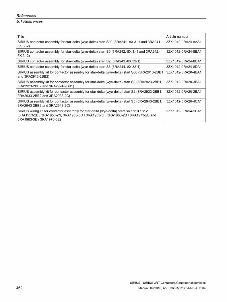
References B.1 References
SIRIUS - SIRIUS 3RT Contactors/Contactor assemblies 462 Manual, 09/2016, A5E03656507120A/RS-AC/004
Title Article number SIRIUS contactor assembly for star-delta (wye-delta) start S00 (3RA241.-8X.3.-1 and 3RA241.-8X.3.-2)
3ZX1012-0RA24-8AA1
SIRIUS contactor assembly for star-delta (wye-delta) start S0 (3RA242.-8X.3.-1 and 3RA242.-8X.3.-2)
3ZX1012-0RA24-8BA1
SIRIUS contactor assembly for star-delta (wye-delta) start S2 (3RA243.-8X.32-1) 3ZX1012-0RA24-8CA1 SIRIUS contactor assembly for star-delta (wye-delta) start S3 (3RA244.-8X.32-1) 3ZX1012-0RA24-8DA1 SIRIUS assembly kit for contactor assembly for star-delta (wye-delta) start S00 (3RA2913-2BB1 and 3RA2913-2BB2)
3ZX1012-0RA20-4BA1
SIRIUS assembly kit for contactor assembly for star-delta (wye-delta) start S0 (3RA2923-2BB1, 3RA2923-2BB2 and 3RA2924-2BB1)
3ZX1012-0RA20-3BA1
SIRIUS assembly kit for contactor assembly for star-delta (wye-delta) start S2 (3RA2933-2BB1, 3RA2933-2BB2 and 3RA2933-2C)
3ZX1012-0RA20-2BA1
SIRIUS assembly kit for contactor assembly for star-delta (wye-delta) start S3 (3RA2943-2BB1, 3RA2943-2BB2 and 3RA2943-2C)
3ZX1012-0RA20-4CA1
SIRIUS wiring kit for contactor assembly for star-delta (wye-delta) start S6 / S10 / S12 (3RA1953-2B / 3RA1953-2N, 3RA1953-3G / 3RA1953-3F, 3RA1963-2B / 3RA1973-2B and 3RA1963-3E / 3RA1973-3E)
3ZX1012-0RA54-1CA1
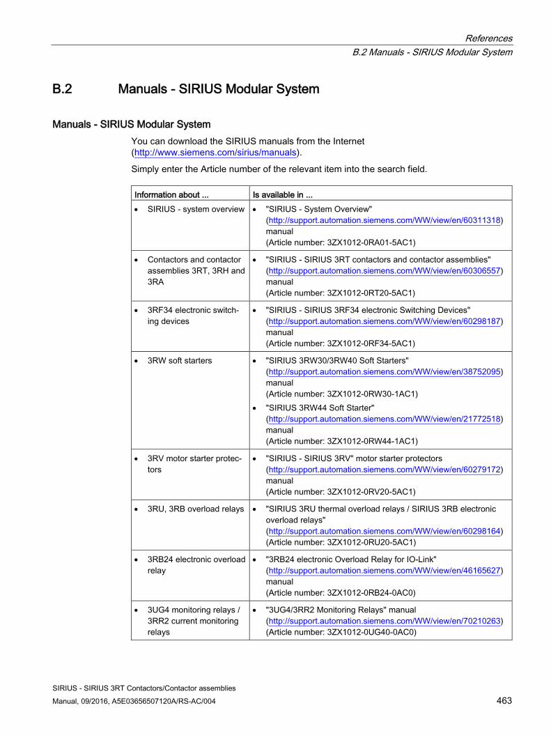
References B.2 Manuals - SIRIUS Modular System
SIRIUS - SIRIUS 3RT Contactors/Contactor assemblies Manual, 09/2016, A5E03656507120A/RS-AC/004 463
B.2 Manuals - SIRIUS Modular System
Manuals - SIRIUS Modular System You can download the SIRIUS manuals from the Internet (http://www.siemens.com/sirius/manuals).
Simply enter the Article number of the relevant item into the search field. Information about ... Is available in ... • SIRIUS - system overview • "SIRIUS - System Overview"
(http://support.automation.siemens.com/WW/view/en/60311318) manual (Article number: 3ZX1012-0RA01-5AC1)
• Contactors and contactor assemblies 3RT, 3RH and 3RA
• "SIRIUS - SIRIUS 3RT contactors and contactor assemblies" (http://support.automation.siemens.com/WW/view/en/60306557) manual (Article number: 3ZX1012-0RT20-5AC1)
• 3RF34 electronic switch-ing devices
• "SIRIUS - SIRIUS 3RF34 electronic Switching Devices" (http://support.automation.siemens.com/WW/view/en/60298187) manual (Article number: 3ZX1012-0RF34-5AC1)
• 3RW soft starters • "SIRIUS 3RW30/3RW40 Soft Starters" (http://support.automation.siemens.com/WW/view/en/38752095) manual (Article number: 3ZX1012-0RW30-1AC1)
• "SIRIUS 3RW44 Soft Starter" (http://support.automation.siemens.com/WW/view/en/21772518) manual (Article number: 3ZX1012-0RW44-1AC1)
• 3RV motor starter protec-tors
• "SIRIUS - SIRIUS 3RV" motor starter protectors (http://support.automation.siemens.com/WW/view/en/60279172) manual (Article number: 3ZX1012-0RV20-5AC1)
• 3RU, 3RB overload relays • "SIRIUS 3RU thermal overload relays / SIRIUS 3RB electronic overload relays" (http://support.automation.siemens.com/WW/view/en/60298164) (Article number: 3ZX1012-0RU20-5AC1)
• 3RB24 electronic overload relay
• "3RB24 electronic Overload Relay for IO-Link" (http://support.automation.siemens.com/WW/view/en/46165627) manual (Article number: 3ZX1012-0RB24-0AC0)
• 3UG4 monitoring relays / 3RR2 current monitoring relays
• "3UG4/3RR2 Monitoring Relays" manual (http://support.automation.siemens.com/WW/view/en/70210263) (Article number: 3ZX1012-0UG40-0AC0)
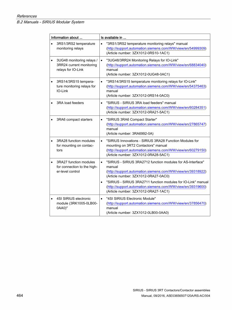
References B.2 Manuals - SIRIUS Modular System
SIRIUS - SIRIUS 3RT Contactors/Contactor assemblies 464 Manual, 09/2016, A5E03656507120A/RS-AC/004
Information about ... Is available in ... • 3RS1/3RS2 temperature
monitoring relays • "3RS1/3RS2 temperature monitoring relays" manual
(http://support.automation.siemens.com/WW/view/en/54999309) (Article number: 3ZX1012-0RS10-1AC1)
• 3UG48 monitoring relays / 3RR24 current monitoring relays for IO-Link
• "3UG48/3RR24 Monitoring Relays for IO-Link" (http://support.automation.siemens.com/WW/view/en/68834040) manual (Article number: 3ZX1012-0UG48-0AC1)
• 3RS14/3RS15 tempera-ture monitoring relays for IO-Link
• "3RS14/3RS15 temperature monitoring relays for IO-Link" (http://support.automation.siemens.com/WW/view/en/54375463) manual (Article number: 3ZX1012-0RS14-0AC0)
• 3RA load feeders • "SIRIUS - SIRIUS 3RA load feeders" manual (http://support.automation.siemens.com/WW/view/en/60284351) (Article number: 3ZX1012-0RA21-5AC1)
• 3RA6 compact starters • "SIRIUS 3RA6 Compact Starter" (http://support.automation.siemens.com/WW/view/en/27865747) manual (Article number: 3RA6992-0A)
• 3RA28 function modules for mounting on contac-tors
• "SIRIUS Innovations - SIRIUS 3RA28 Function Modules for mounting on 3RT2 Contactors" manual (http://support.automation.siemens.com/WW/view/en/60279150) (Article number: 3ZX1012-0RA28-5AC1)
• 3RA27 function modules for connection to the high-er-level control
• "SIRIUS - SIRIUS 3RA2712 function modules for AS-Interface" manual (http://support.automation.siemens.com/WW/view/en/39318922) (Article number: 3ZX1012-0RA27-0AC0)
• "SIRIUS - SIRIUS 3RA2711 function modules for IO-Link" manual (http://support.automation.siemens.com/WW/view/en/39319600) (Article number: 3ZX1012-0RA27-1AC1)
• 4SI SIRIUS electronic module (3RK1005-0LB00-0AA0)"
• "4SI SIRIUS Electronic Module" (http://support.automation.siemens.com/WW/view/en/37856470) manual (Article number: 3ZX1012-0LB00-0AA0)
References B.3 More information
SIRIUS - SIRIUS 3RT Contactors/Contactor assemblies Manual, 09/2016, A5E03656507120A/RS-AC/004 465
B.3 More information
More information More information is available from Siemens on the Internet via the following links.
● Product documentation You will find a list of manuals/operating instructions, characteristic curves, and certificates on the Internet (www.siemens.com/industrial-controls/support).
● Product information Catalogs and other informative documents can be obtained from the Information Center and Download Center (www.siemens.com/industrial-controls/infomaterial).
● Online ordering system You will find the online ordering system with all the latest data on the ordering and information platform (www.siemens.com/industrial-controls/mall).
● Technical Assistance Siemens supports you with all technical product and system enquiries – both before and after delivery. You can access our Service & Support Portal on the Internet (www.siemens.com/industrial-controls/technical-assistance). You can also submit your question directly to a technical consultant using our support request service.
References B.3 More information
SIRIUS - SIRIUS 3RT Contactors/Contactor assemblies 466 Manual, 09/2016, A5E03656507120A/RS-AC/004
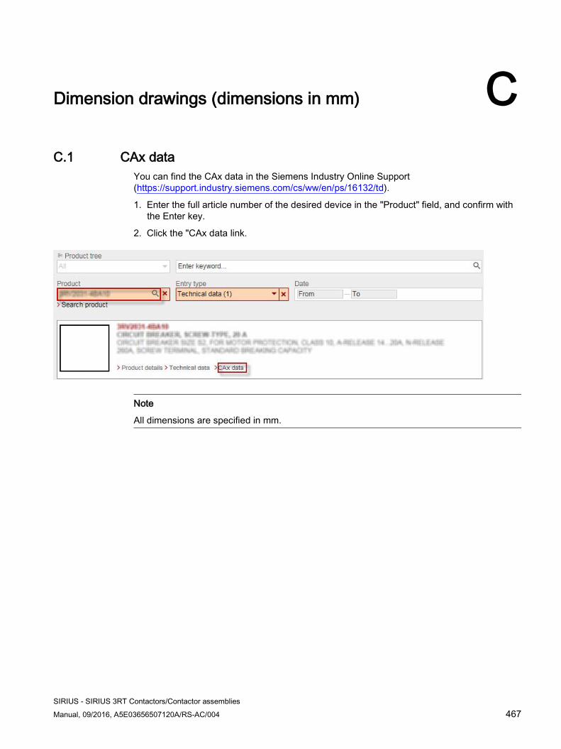
SIRIUS - SIRIUS 3RT Contactors/Contactor assemblies Manual, 09/2016, A5E03656507120A/RS-AC/004 467
Dimension drawings (dimensions in mm) C C.1 CAx data
You can find the CAx data in the Siemens Industry Online Support (https://support.industry.siemens.com/cs/ww/en/ps/16132/td).
1. Enter the full article number of the desired device in the "Product" field, and confirm with the Enter key.
2. Click the "CAx data link.
Note
All dimensions are specified in mm.
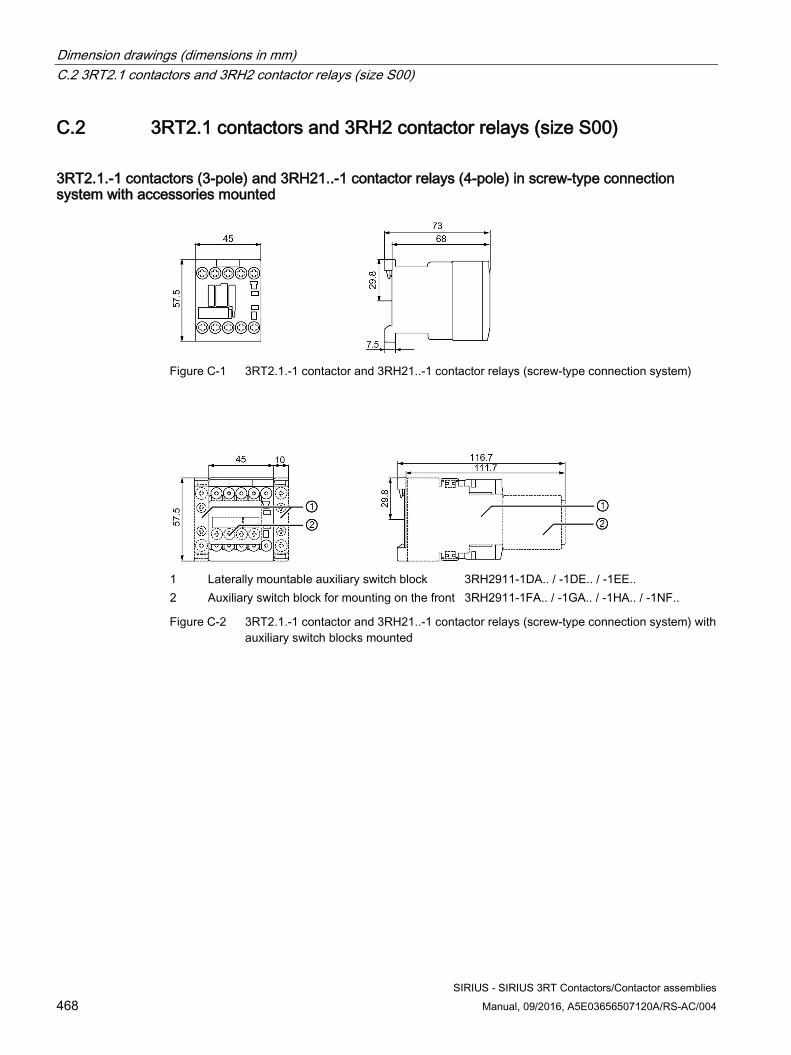
Dimension drawings (dimensions in mm) C.2 3RT2.1 contactors and 3RH2 contactor relays (size S00)
SIRIUS - SIRIUS 3RT Contactors/Contactor assemblies 468 Manual, 09/2016, A5E03656507120A/RS-AC/004
C.2 3RT2.1 contactors and 3RH2 contactor relays (size S00)
3RT2.1.-1 contactors (3-pole) and 3RH21..-1 contactor relays (4-pole) in screw-type connection system with accessories mounted
Figure C-1 3RT2.1.-1 contactor and 3RH21..-1 contactor relays (screw-type connection system)
1 Laterally mountable auxiliary switch block 3RH2911-1DA.. / -1DE.. / -1EE.. 2 Auxiliary switch block for mounting on the front 3RH2911-1FA.. / -1GA.. / -1HA.. / -1NF..
Figure C-2 3RT2.1.-1 contactor and 3RH21..-1 contactor relays (screw-type connection system) with auxiliary switch blocks mounted
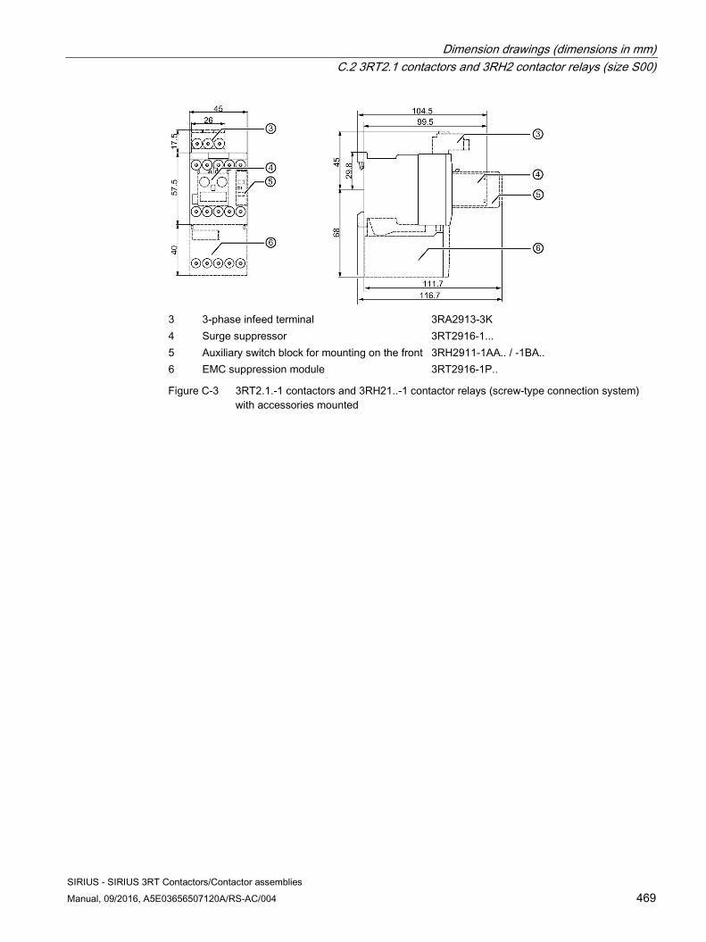
Dimension drawings (dimensions in mm) C.2 3RT2.1 contactors and 3RH2 contactor relays (size S00)
SIRIUS - SIRIUS 3RT Contactors/Contactor assemblies Manual, 09/2016, A5E03656507120A/RS-AC/004 469
3 3-phase infeed terminal 3RA2913-3K 4 Surge suppressor 3RT2916-1... 5 Auxiliary switch block for mounting on the front 3RH2911-1AA.. / -1BA.. 6 EMC suppression module 3RT2916-1P..
Figure C-3 3RT2.1.-1 contactors and 3RH21..-1 contactor relays (screw-type connection system) with accessories mounted
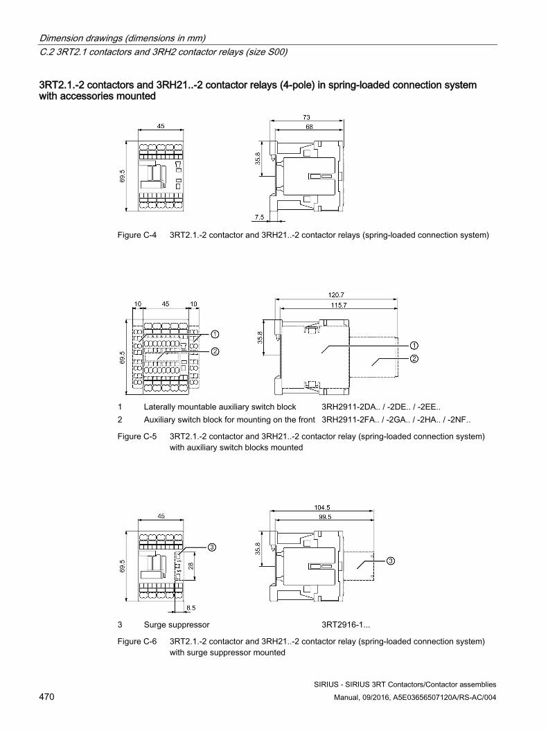
Dimension drawings (dimensions in mm) C.2 3RT2.1 contactors and 3RH2 contactor relays (size S00)
SIRIUS - SIRIUS 3RT Contactors/Contactor assemblies 470 Manual, 09/2016, A5E03656507120A/RS-AC/004
3RT2.1.-2 contactors and 3RH21..-2 contactor relays (4-pole) in spring-loaded connection system with accessories mounted
Figure C-4 3RT2.1.-2 contactor and 3RH21..-2 contactor relays (spring-loaded connection system)
1 Laterally mountable auxiliary switch block 3RH2911-2DA.. / -2DE.. / -2EE.. 2 Auxiliary switch block for mounting on the front 3RH2911-2FA.. / -2GA.. / -2HA.. / -2NF..
Figure C-5 3RT2.1.-2 contactor and 3RH21..-2 contactor relay (spring-loaded connection system) with auxiliary switch blocks mounted
3 Surge suppressor 3RT2916-1...
Figure C-6 3RT2.1.-2 contactor and 3RH21..-2 contactor relay (spring-loaded connection system) with surge suppressor mounted
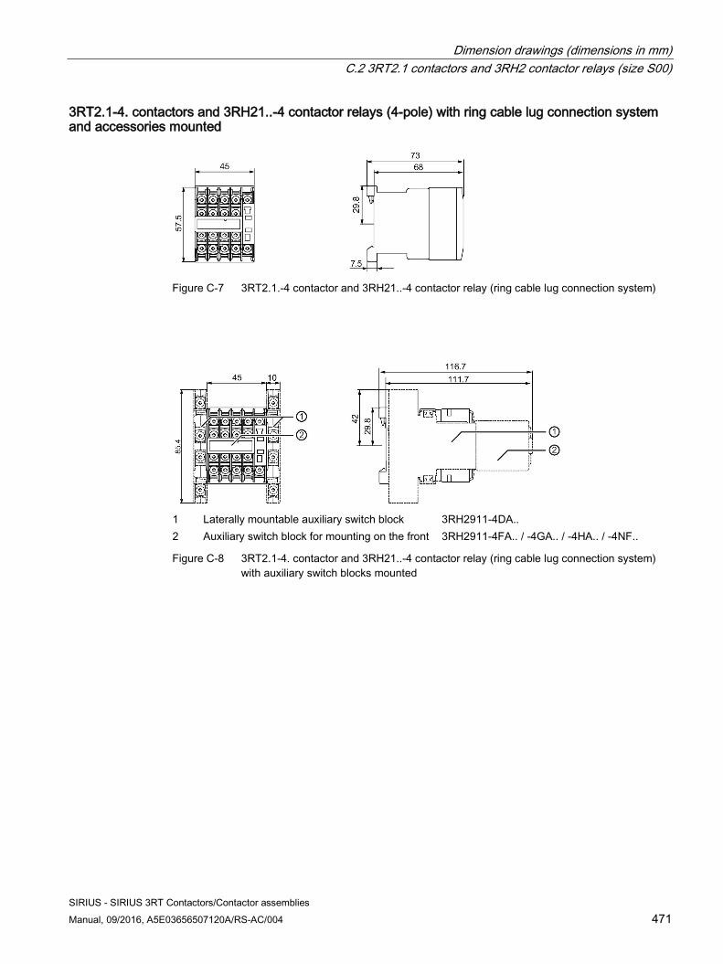
Dimension drawings (dimensions in mm) C.2 3RT2.1 contactors and 3RH2 contactor relays (size S00)
SIRIUS - SIRIUS 3RT Contactors/Contactor assemblies Manual, 09/2016, A5E03656507120A/RS-AC/004 471
3RT2.1-4. contactors and 3RH21..-4 contactor relays (4-pole) with ring cable lug connection system and accessories mounted
Figure C-7 3RT2.1.-4 contactor and 3RH21..-4 contactor relay (ring cable lug connection system)
1 Laterally mountable auxiliary switch block 3RH2911-4DA.. 2 Auxiliary switch block for mounting on the front 3RH2911-4FA.. / -4GA.. / -4HA.. / -4NF..
Figure C-8 3RT2.1-4. contactor and 3RH21..-4 contactor relay (ring cable lug connection system) with auxiliary switch blocks mounted
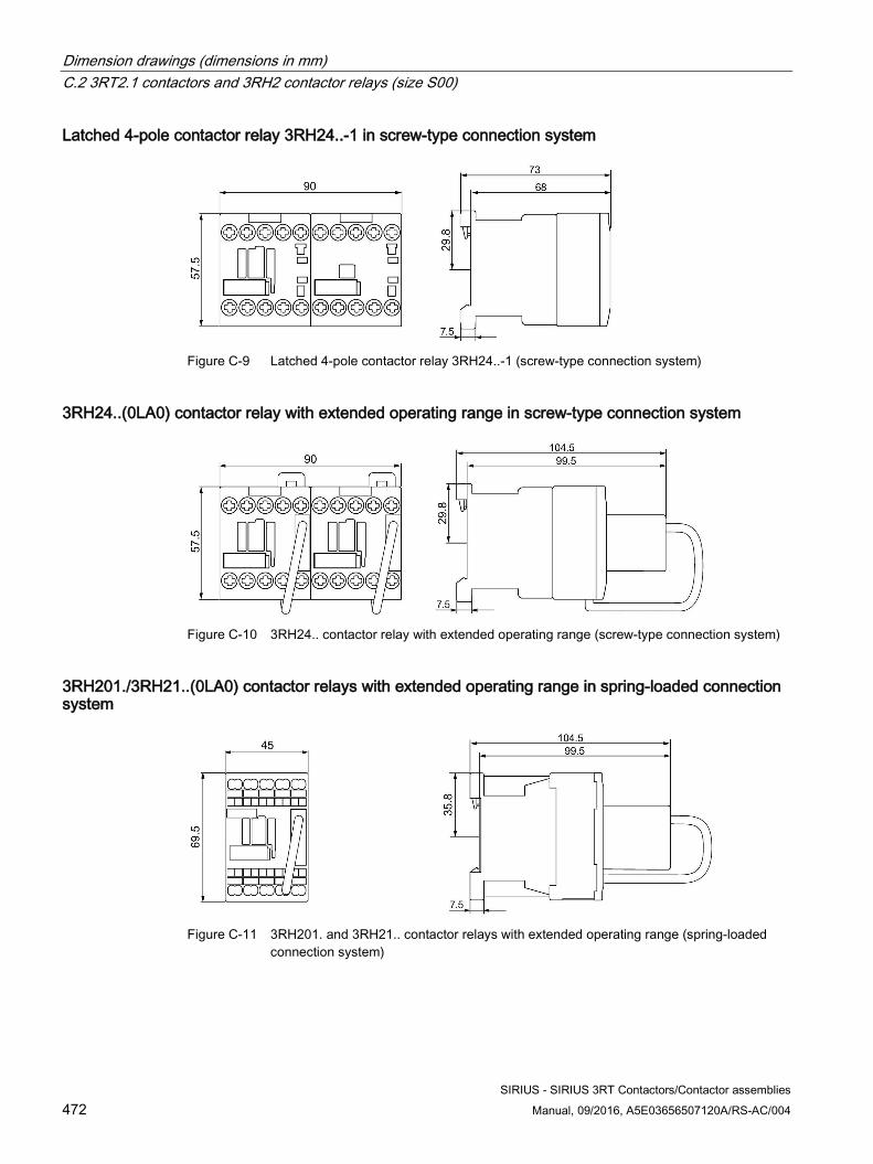
Dimension drawings (dimensions in mm) C.2 3RT2.1 contactors and 3RH2 contactor relays (size S00)
SIRIUS - SIRIUS 3RT Contactors/Contactor assemblies 472 Manual, 09/2016, A5E03656507120A/RS-AC/004
Latched 4-pole contactor relay 3RH24..-1 in screw-type connection system
Figure C-9 Latched 4-pole contactor relay 3RH24..-1 (screw-type connection system)
3RH24..(0LA0) contactor relay with extended operating range in screw-type connection system
Figure C-10 3RH24.. contactor relay with extended operating range (screw-type connection system)
3RH201./3RH21..(0LA0) contactor relays with extended operating range in spring-loaded connection system
Figure C-11 3RH201. and 3RH21.. contactor relays with extended operating range (spring-loaded
connection system)
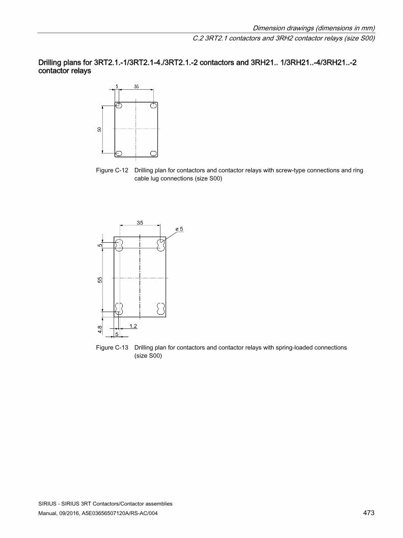
Dimension drawings (dimensions in mm) C.2 3RT2.1 contactors and 3RH2 contactor relays (size S00)
SIRIUS - SIRIUS 3RT Contactors/Contactor assemblies Manual, 09/2016, A5E03656507120A/RS-AC/004 473
Drilling plans for 3RT2.1.-1/3RT2.1-4./3RT2.1.-2 contactors and 3RH21.. 1/3RH21..-4/3RH21..-2 contactor relays
Figure C-12 Drilling plan for contactors and contactor relays with screw-type connections and ring
cable lug connections (size S00)
Figure C-13 Drilling plan for contactors and contactor relays with spring-loaded connections
(size S00)
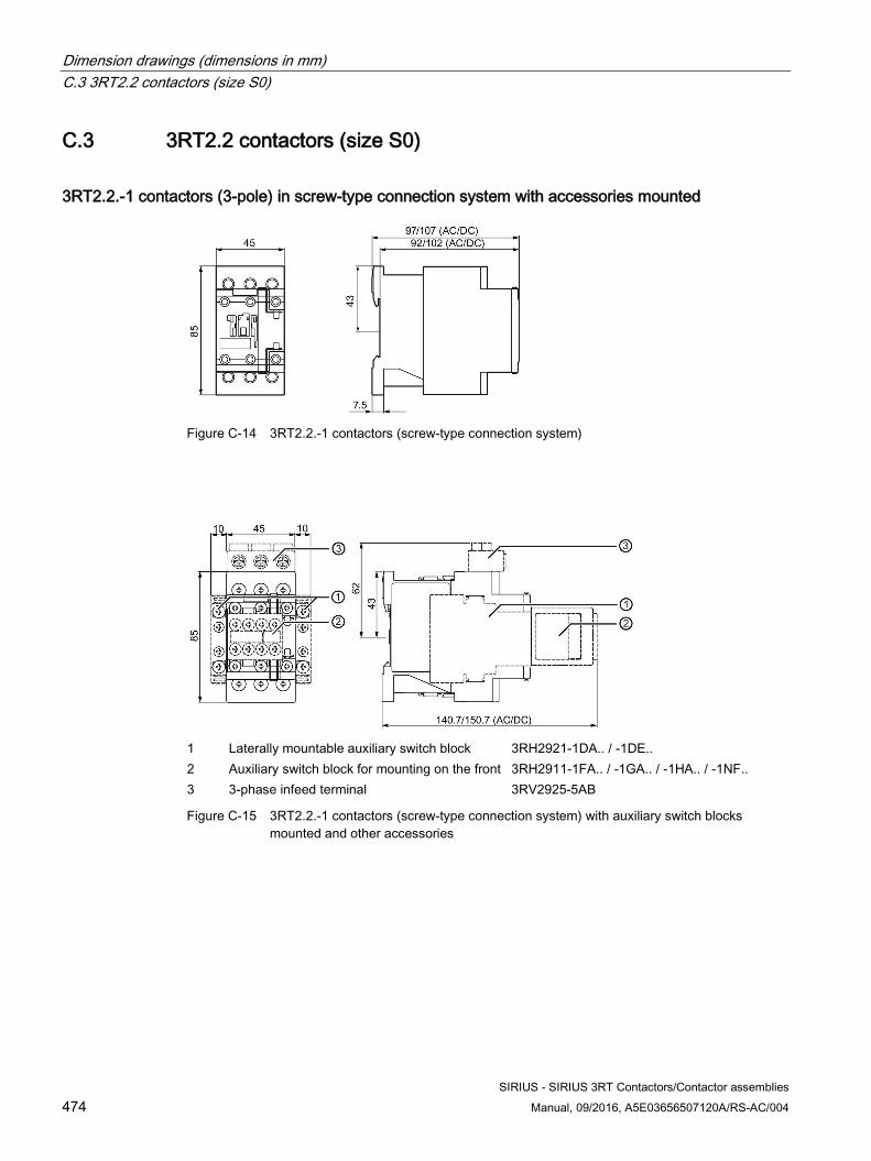
Dimension drawings (dimensions in mm) C.3 3RT2.2 contactors (size S0)
SIRIUS - SIRIUS 3RT Contactors/Contactor assemblies 474 Manual, 09/2016, A5E03656507120A/RS-AC/004
C.3 3RT2.2 contactors (size S0)
3RT2.2.-1 contactors (3-pole) in screw-type connection system with accessories mounted
Figure C-14 3RT2.2.-1 contactors (screw-type connection system)
1 Laterally mountable auxiliary switch block 3RH2921-1DA.. / -1DE.. 2 Auxiliary switch block for mounting on the front 3RH2911-1FA.. / -1GA.. / -1HA.. / -1NF.. 3 3-phase infeed terminal 3RV2925-5AB
Figure C-15 3RT2.2.-1 contactors (screw-type connection system) with auxiliary switch blocks mounted and other accessories
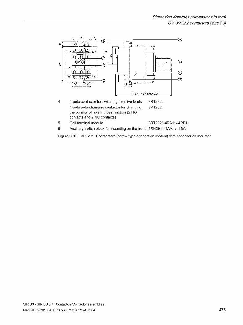
Dimension drawings (dimensions in mm) C.3 3RT2.2 contactors (size S0)
SIRIUS - SIRIUS 3RT Contactors/Contactor assemblies Manual, 09/2016, A5E03656507120A/RS-AC/004 475
4 4-pole contactor for switching resistive loads 3RT232.
4-pole pole-changing contactor for changing the polarity of hoisting gear motors (2 NO contacts and 2 NC contacts)
3RT252.
5 Coil terminal module 3RT2926-4RA11/-4RB11 6 Auxiliary switch block for mounting on the front 3RH2911-1AA.. / -1BA
Figure C-16 3RT2.2.-1 contactors (screw-type connection system) with accessories mounted
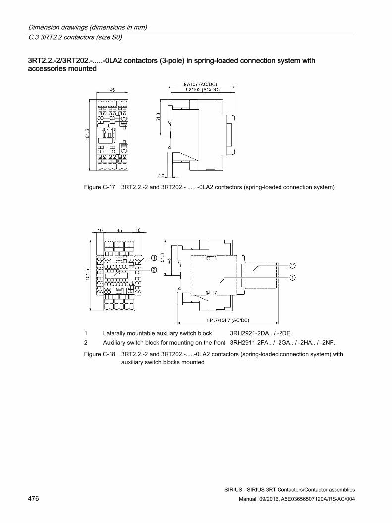
Dimension drawings (dimensions in mm) C.3 3RT2.2 contactors (size S0)
SIRIUS - SIRIUS 3RT Contactors/Contactor assemblies 476 Manual, 09/2016, A5E03656507120A/RS-AC/004
3RT2.2.-2/3RT202.-.....-0LA2 contactors (3-pole) in spring-loaded connection system with accessories mounted
Figure C-17 3RT2.2.-2 and 3RT202.- ..... -0LA2 contactors (spring-loaded connection system)
1 Laterally mountable auxiliary switch block 3RH2921-2DA.. / -2DE.. 2 Auxiliary switch block for mounting on the front 3RH2911-2FA.. / -2GA.. / -2HA.. / -2NF..
Figure C-18 3RT2.2.-2 and 3RT202.-.....-0LA2 contactors (spring-loaded connection system) with auxiliary switch blocks mounted
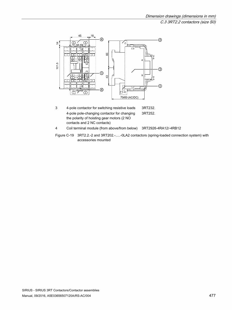
Dimension drawings (dimensions in mm) C.3 3RT2.2 contactors (size S0)
SIRIUS - SIRIUS 3RT Contactors/Contactor assemblies Manual, 09/2016, A5E03656507120A/RS-AC/004 477
3 4-pole contactor for switching resistive loads 3RT232.
4-pole pole-changing contactor for changing the polarity of hoisting gear motors (2 NO contacts and 2 NC contacts)
3RT252.
4 Coil terminal module (from above/from below) 3RT2926-4RA12/-4RB12
Figure C-19 3RT2.2.-2 and 3RT202.-.....-0LA2 contactors (spring-loaded connection system) with accessories mounted
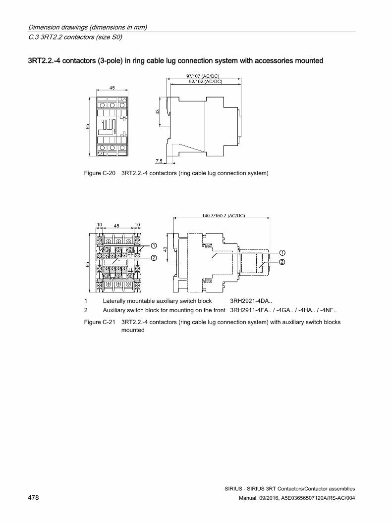
Dimension drawings (dimensions in mm) C.3 3RT2.2 contactors (size S0)
SIRIUS - SIRIUS 3RT Contactors/Contactor assemblies 478 Manual, 09/2016, A5E03656507120A/RS-AC/004
3RT2.2.-4 contactors (3-pole) in ring cable lug connection system with accessories mounted
Figure C-20 3RT2.2.-4 contactors (ring cable lug connection system)
1 Laterally mountable auxiliary switch block 3RH2921-4DA.. 2 Auxiliary switch block for mounting on the front 3RH2911-4FA.. / -4GA.. / -4HA.. / -4NF..
Figure C-21 3RT2.2.-4 contactors (ring cable lug connection system) with auxiliary switch blocks mounted
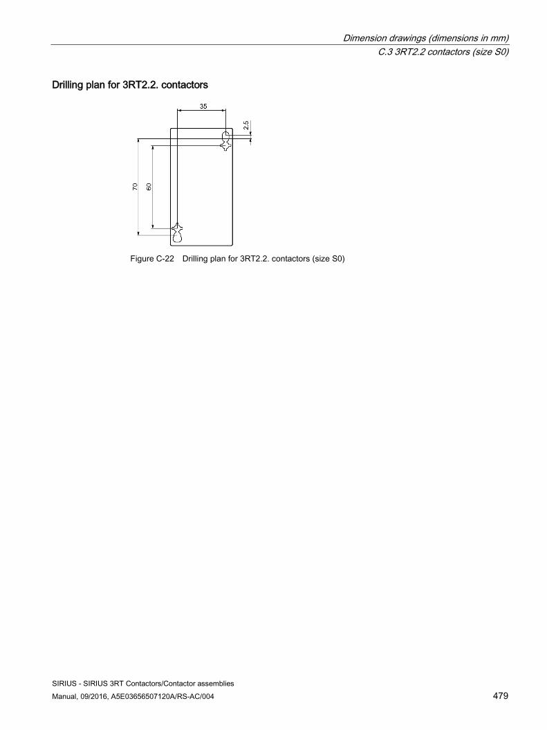
Dimension drawings (dimensions in mm) C.3 3RT2.2 contactors (size S0)
SIRIUS - SIRIUS 3RT Contactors/Contactor assemblies Manual, 09/2016, A5E03656507120A/RS-AC/004 479
Drilling plan for 3RT2.2. contactors
Figure C-22 Drilling plan for 3RT2.2. contactors (size S0)
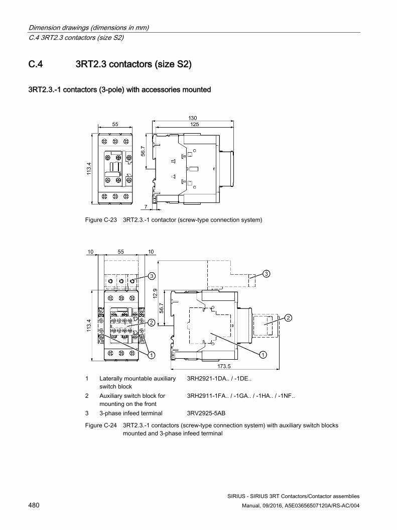
Dimension drawings (dimensions in mm) C.4 3RT2.3 contactors (size S2)
SIRIUS - SIRIUS 3RT Contactors/Contactor assemblies 480 Manual, 09/2016, A5E03656507120A/RS-AC/004
C.4 3RT2.3 contactors (size S2)
3RT2.3.-1 contactors (3-pole) with accessories mounted
Figure C-23 3RT2.3.-1 contactor (screw-type connection system)
1 Laterally mountable auxiliary
switch block 3RH2921-1DA.. / -1DE..
2 Auxiliary switch block for mounting on the front
3RH2911-1FA.. / -1GA.. / -1HA.. / -1NF..
3 3-phase infeed terminal 3RV2925-5AB
Figure C-24 3RT2.3.-1 contactors (screw-type connection system) with auxiliary switch blocks mounted and 3-phase infeed terminal
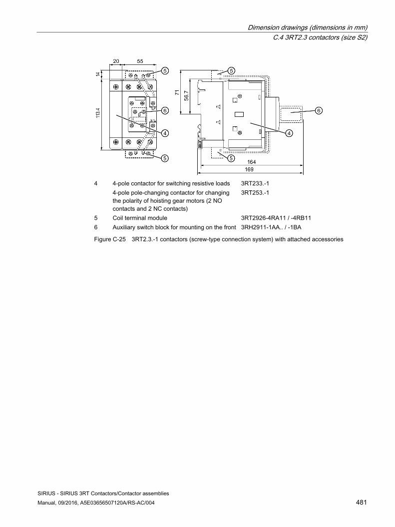
Dimension drawings (dimensions in mm) C.4 3RT2.3 contactors (size S2)
SIRIUS - SIRIUS 3RT Contactors/Contactor assemblies Manual, 09/2016, A5E03656507120A/RS-AC/004 481
4 4-pole contactor for switching resistive loads 3RT233.-1
4-pole pole-changing contactor for changing the polarity of hoisting gear motors (2 NO contacts and 2 NC contacts)
3RT253.-1
5 Coil terminal module 3RT2926-4RA11 / -4RB11 6 Auxiliary switch block for mounting on the front 3RH2911-1AA.. / -1BA
Figure C-25 3RT2.3.-1 contactors (screw-type connection system) with attached accessories
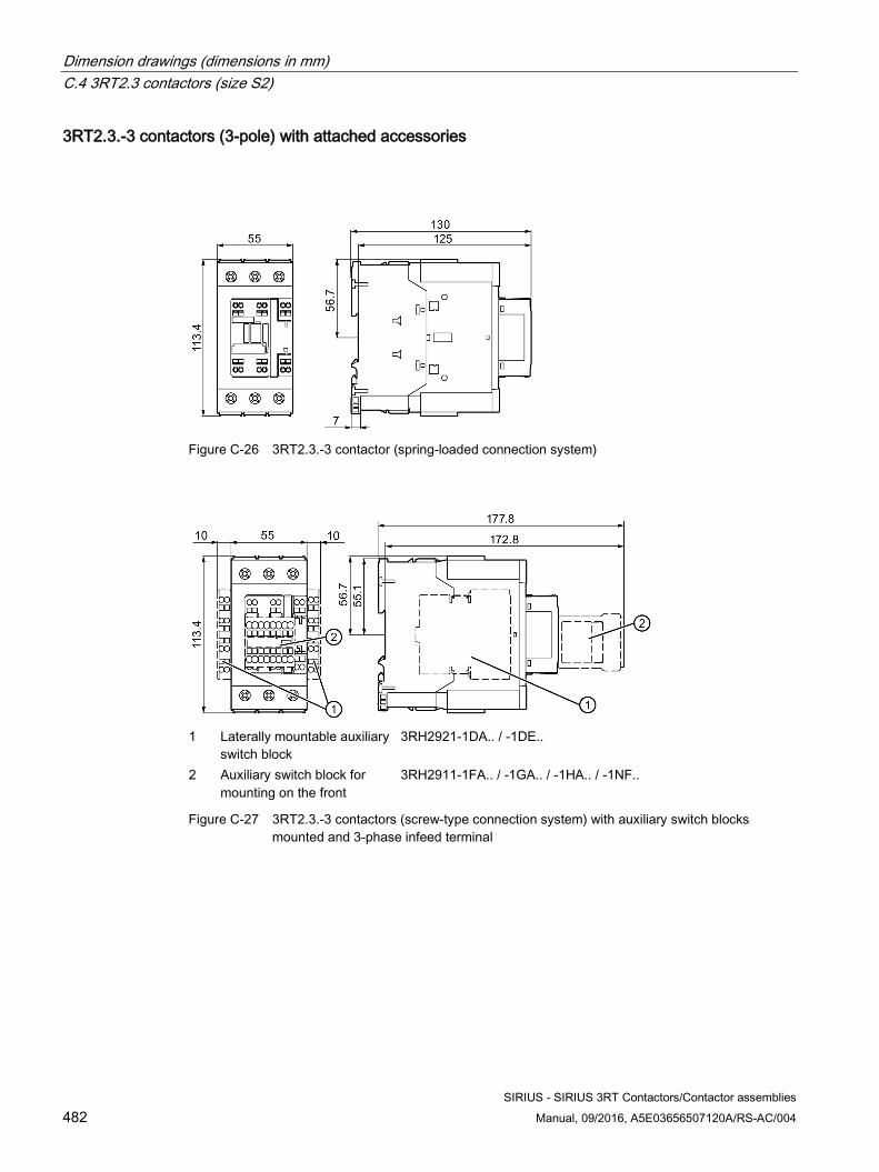
Dimension drawings (dimensions in mm) C.4 3RT2.3 contactors (size S2)
SIRIUS - SIRIUS 3RT Contactors/Contactor assemblies 482 Manual, 09/2016, A5E03656507120A/RS-AC/004
3RT2.3.-3 contactors (3-pole) with attached accessories
Figure C-26 3RT2.3.-3 contactor (spring-loaded connection system)
1 Laterally mountable auxiliary
switch block 3RH2921-1DA.. / -1DE..
2 Auxiliary switch block for mounting on the front
3RH2911-1FA.. / -1GA.. / -1HA.. / -1NF..
Figure C-27 3RT2.3.-3 contactors (screw-type connection system) with auxiliary switch blocks mounted and 3-phase infeed terminal
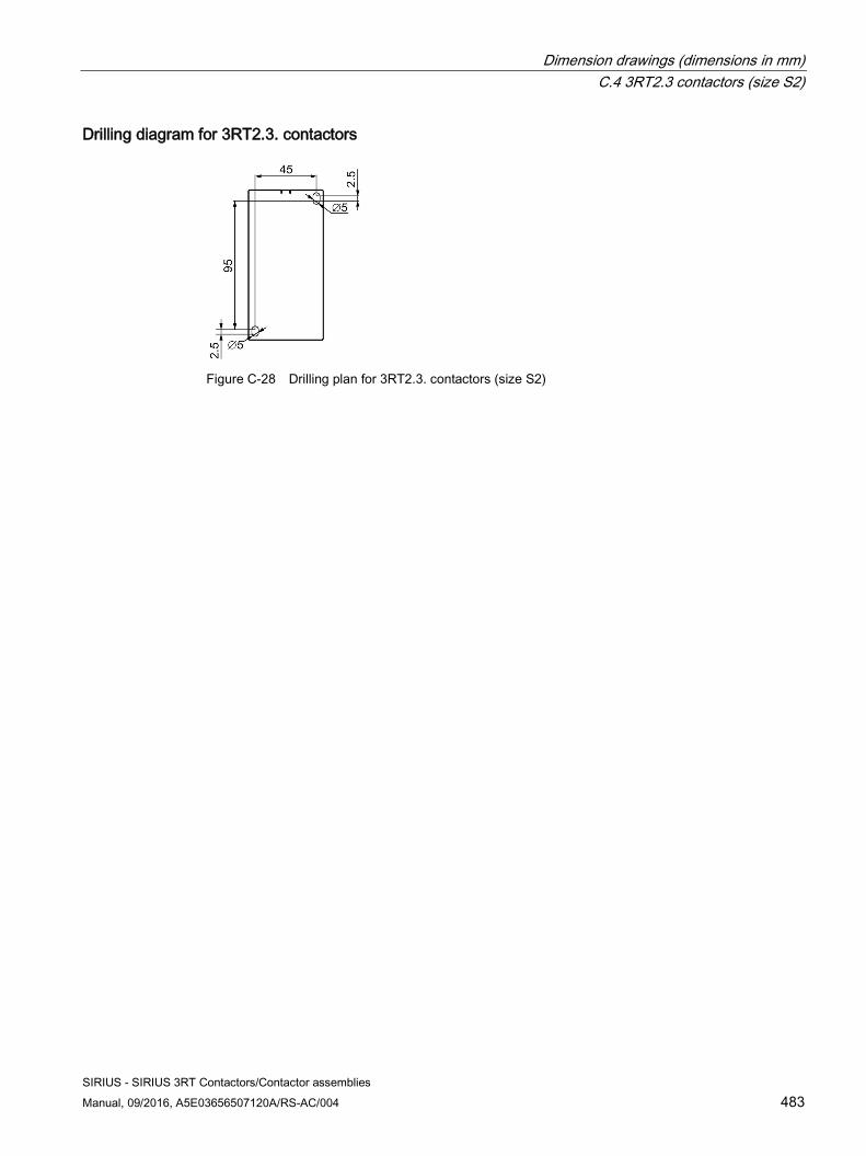
Dimension drawings (dimensions in mm) C.4 3RT2.3 contactors (size S2)
SIRIUS - SIRIUS 3RT Contactors/Contactor assemblies Manual, 09/2016, A5E03656507120A/RS-AC/004 483
Drilling diagram for 3RT2.3. contactors
Figure C-28 Drilling plan for 3RT2.3. contactors (size S2)
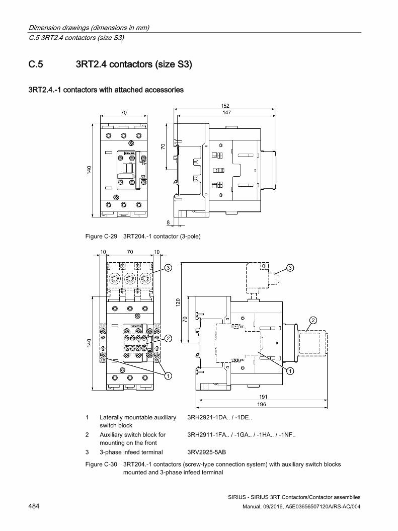
Dimension drawings (dimensions in mm) C.5 3RT2.4 contactors (size S3)
SIRIUS - SIRIUS 3RT Contactors/Contactor assemblies 484 Manual, 09/2016, A5E03656507120A/RS-AC/004
C.5 3RT2.4 contactors (size S3)
3RT2.4.-1 contactors with attached accessories
Figure C-29 3RT204.-1 contactor (3-pole)
1 Laterally mountable auxiliary
switch block 3RH2921-1DA.. / -1DE..
2 Auxiliary switch block for mounting on the front
3RH2911-1FA.. / -1GA.. / -1HA.. / -1NF..
3 3-phase infeed terminal 3RV2925-5AB
Figure C-30 3RT204.-1 contactors (screw-type connection system) with auxiliary switch blocks mounted and 3-phase infeed terminal
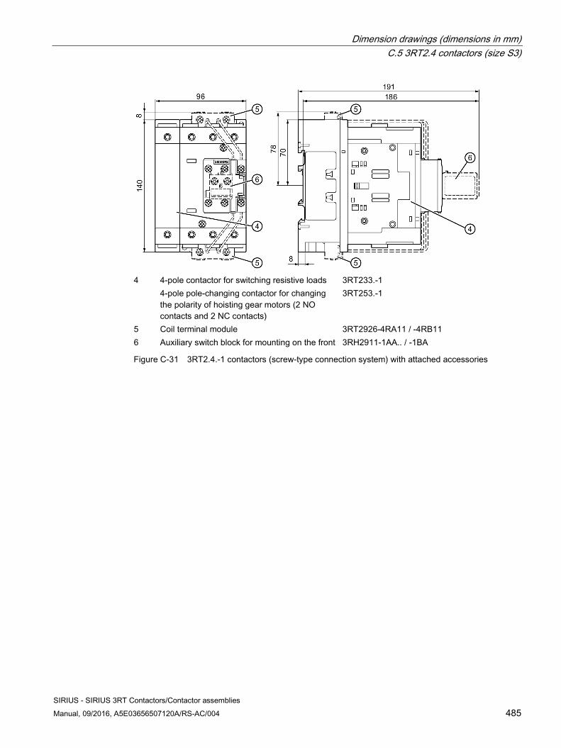
Dimension drawings (dimensions in mm) C.5 3RT2.4 contactors (size S3)
SIRIUS - SIRIUS 3RT Contactors/Contactor assemblies Manual, 09/2016, A5E03656507120A/RS-AC/004 485
4 4-pole contactor for switching resistive loads 3RT233.-1
4-pole pole-changing contactor for changing the polarity of hoisting gear motors (2 NO contacts and 2 NC contacts)
3RT253.-1
5 Coil terminal module 3RT2926-4RA11 / -4RB11 6 Auxiliary switch block for mounting on the front 3RH2911-1AA.. / -1BA
Figure C-31 3RT2.4.-1 contactors (screw-type connection system) with attached accessories
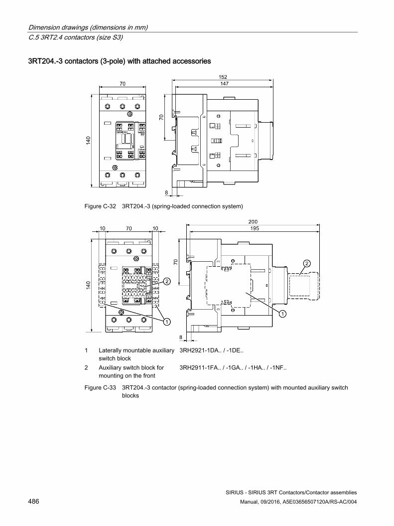
Dimension drawings (dimensions in mm) C.5 3RT2.4 contactors (size S3)
SIRIUS - SIRIUS 3RT Contactors/Contactor assemblies 486 Manual, 09/2016, A5E03656507120A/RS-AC/004
3RT204.-3 contactors (3-pole) with attached accessories
Figure C-32 3RT204.-3 (spring-loaded connection system)
1 Laterally mountable auxiliary
switch block 3RH2921-1DA.. / -1DE..
2 Auxiliary switch block for mounting on the front
3RH2911-1FA.. / -1GA.. / -1HA.. / -1NF..
Figure C-33 3RT204.-3 contactor (spring-loaded connection system) with mounted auxiliary switch blocks
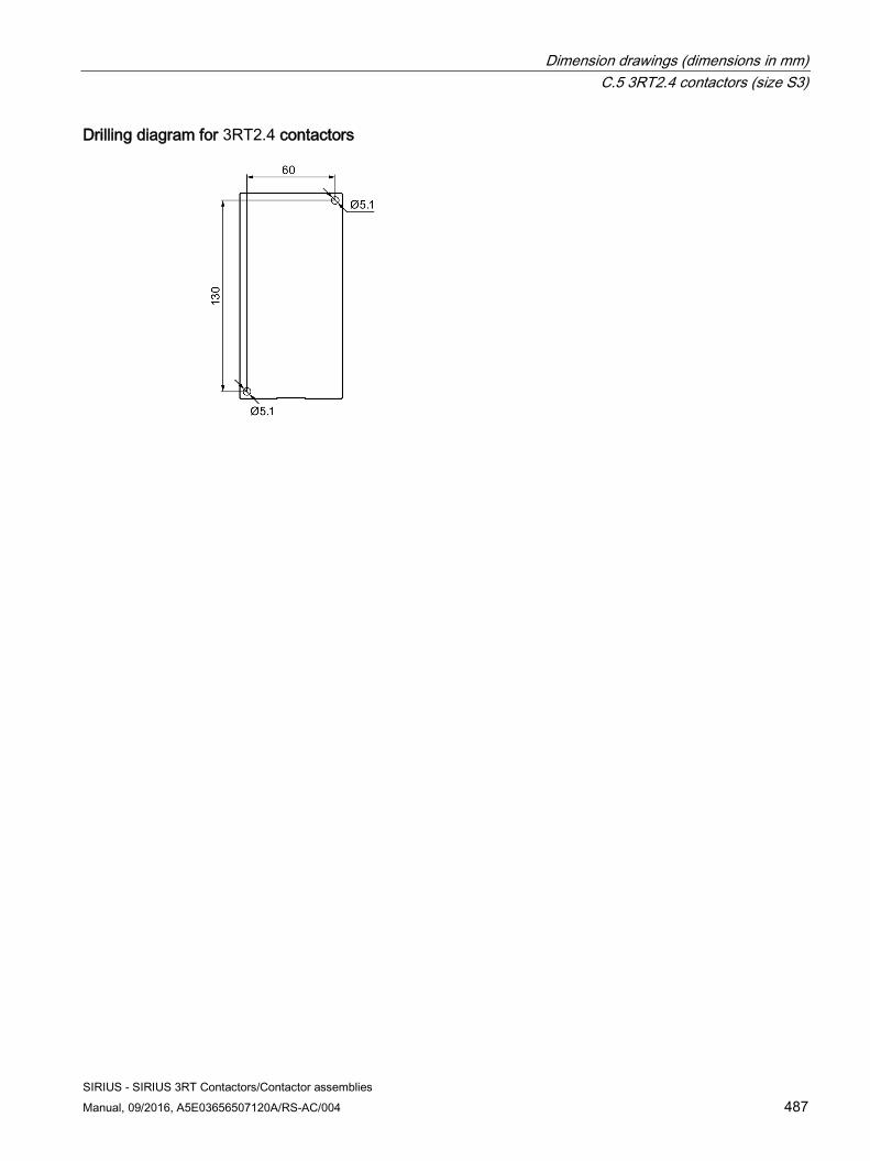
Dimension drawings (dimensions in mm) C.5 3RT2.4 contactors (size S3)
SIRIUS - SIRIUS 3RT Contactors/Contactor assemblies Manual, 09/2016, A5E03656507120A/RS-AC/004 487
Drilling diagram for 3RT2.4 contactors
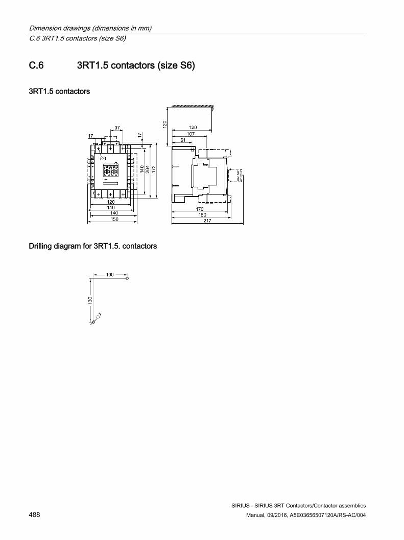
Dimension drawings (dimensions in mm) C.6 3RT1.5 contactors (size S6)
SIRIUS - SIRIUS 3RT Contactors/Contactor assemblies 488 Manual, 09/2016, A5E03656507120A/RS-AC/004
C.6 3RT1.5 contactors (size S6)
3RT1.5 contactors
Drilling diagram for 3RT1.5. contactors
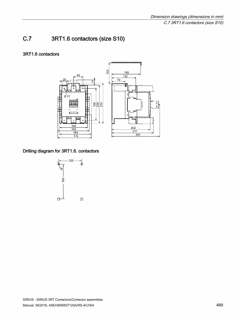
Dimension drawings (dimensions in mm) C.7 3RT1.6 contactors (size S10)
SIRIUS - SIRIUS 3RT Contactors/Contactor assemblies Manual, 09/2016, A5E03656507120A/RS-AC/004 489
C.7 3RT1.6 contactors (size S10)
3RT1.6 contactors
Drilling diagram for 3RT1.6. contactors
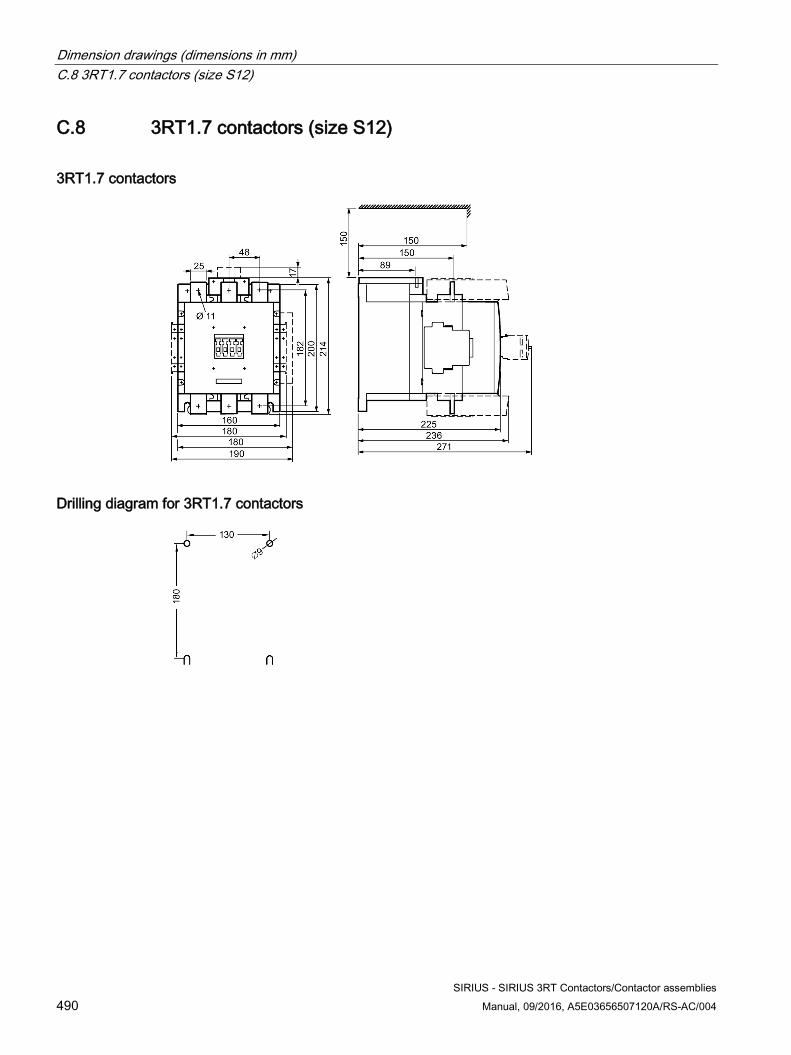
Dimension drawings (dimensions in mm) C.8 3RT1.7 contactors (size S12)
SIRIUS - SIRIUS 3RT Contactors/Contactor assemblies 490 Manual, 09/2016, A5E03656507120A/RS-AC/004
C.8 3RT1.7 contactors (size S12)
3RT1.7 contactors
Drilling diagram for 3RT1.7 contactors
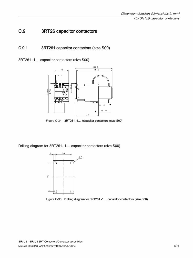
Dimension drawings (dimensions in mm) C.9 3RT26 capacitor contactors
SIRIUS - SIRIUS 3RT Contactors/Contactor assemblies Manual, 09/2016, A5E03656507120A/RS-AC/004 491
C.9 3RT26 capacitor contactors
C.9.1 3RT261 capacitor contactors (size S00)
3RT261.-1.... capacitor contactors (size S00)
Figure C-34 3RT261.-1.... capacitor contactors (size S00)
Drilling diagram for 3RT261.-1.... capacitor contactors (size S00)
Figure C-35 Drilling diagram for 3RT261.-1.... capacitor contactors (size S00)
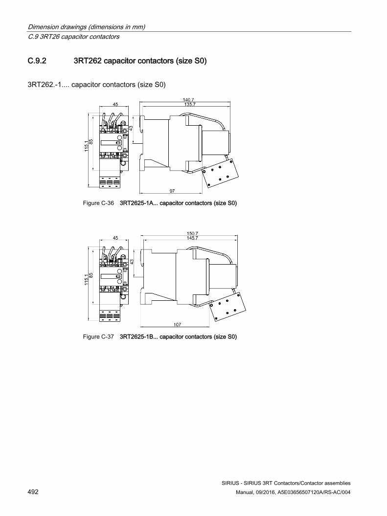
Dimension drawings (dimensions in mm) C.9 3RT26 capacitor contactors
SIRIUS - SIRIUS 3RT Contactors/Contactor assemblies 492 Manual, 09/2016, A5E03656507120A/RS-AC/004
C.9.2 3RT262 capacitor contactors (size S0)
3RT262.-1.... capacitor contactors (size S0)
Figure C-36 3RT2625-1A... capacitor contactors (size S0)
Figure C-37 3RT2625-1B... capacitor contactors (size S0)
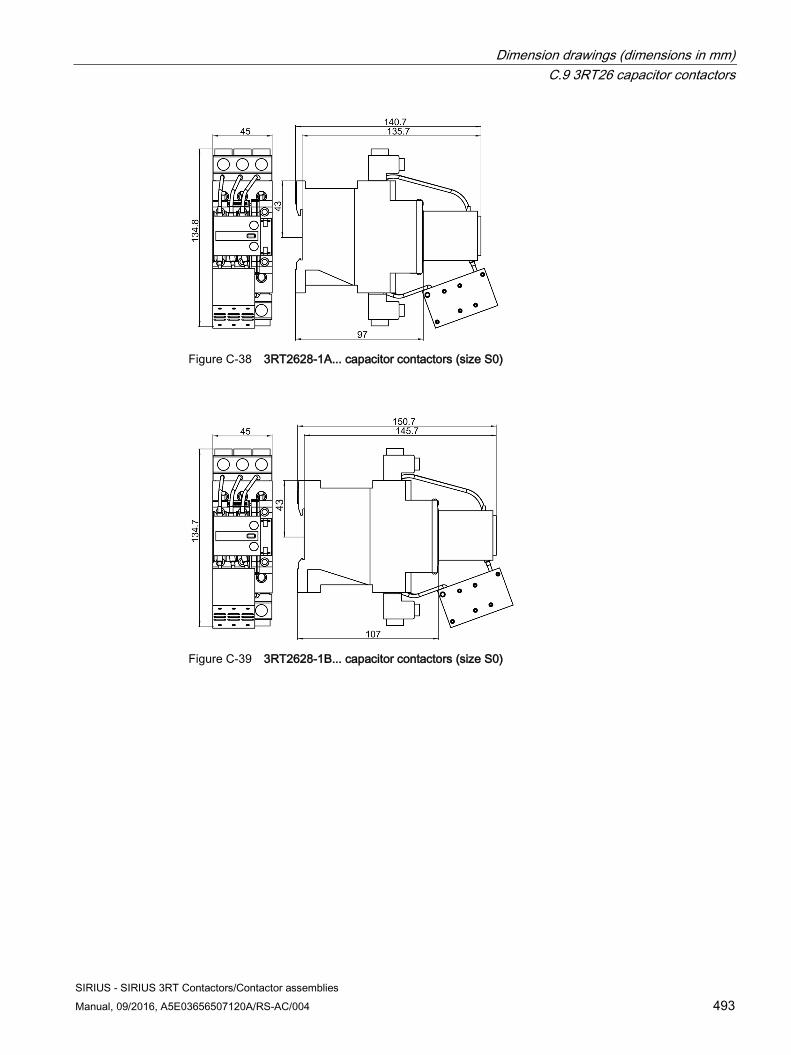
Dimension drawings (dimensions in mm) C.9 3RT26 capacitor contactors
SIRIUS - SIRIUS 3RT Contactors/Contactor assemblies Manual, 09/2016, A5E03656507120A/RS-AC/004 493
Figure C-38 3RT2628-1A... capacitor contactors (size S0)
Figure C-39 3RT2628-1B... capacitor contactors (size S0)
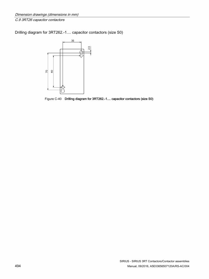
Dimension drawings (dimensions in mm) C.9 3RT26 capacitor contactors
SIRIUS - SIRIUS 3RT Contactors/Contactor assemblies 494 Manual, 09/2016, A5E03656507120A/RS-AC/004
Drilling diagram for 3RT262.-1.... capacitor contactors (size S0)
Figure C-40 Drilling diagram for 3RT262.-1.... capacitor contactors (size S0)
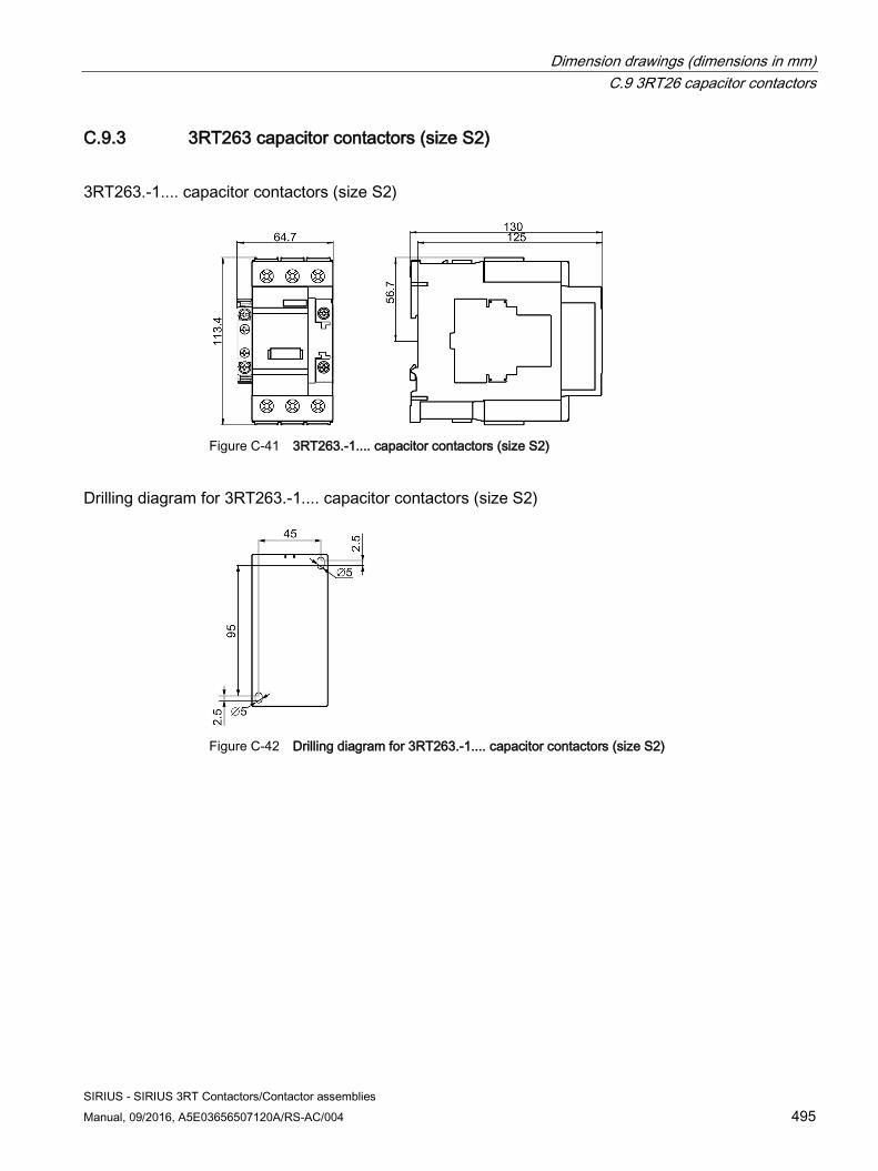
Dimension drawings (dimensions in mm) C.9 3RT26 capacitor contactors
SIRIUS - SIRIUS 3RT Contactors/Contactor assemblies Manual, 09/2016, A5E03656507120A/RS-AC/004 495
C.9.3 3RT263 capacitor contactors (size S2)
3RT263.-1.... capacitor contactors (size S2)
Figure C-41 3RT263.-1.... capacitor contactors (size S2)
Drilling diagram for 3RT263.-1.... capacitor contactors (size S2)
Figure C-42 Drilling diagram for 3RT263.-1.... capacitor contactors (size S2)
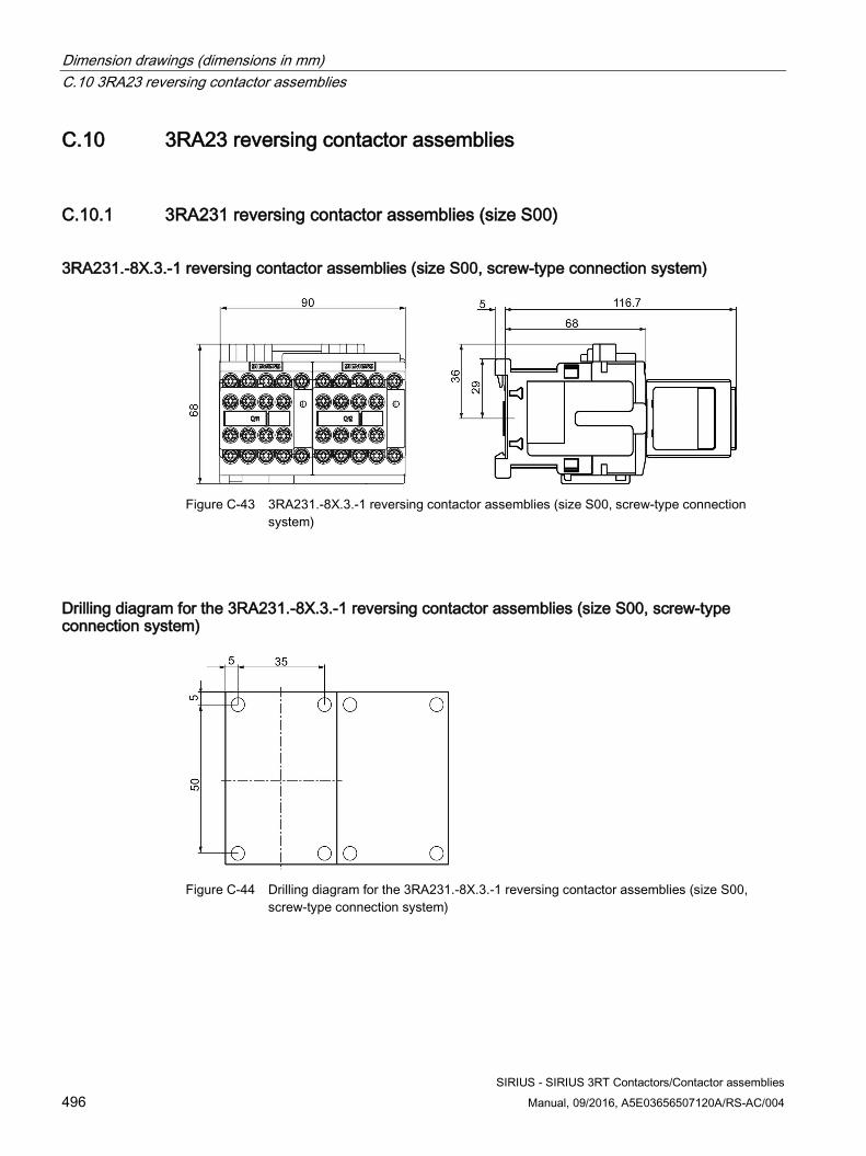
Dimension drawings (dimensions in mm) C.10 3RA23 reversing contactor assemblies
SIRIUS - SIRIUS 3RT Contactors/Contactor assemblies 496 Manual, 09/2016, A5E03656507120A/RS-AC/004
C.10 3RA23 reversing contactor assemblies
C.10.1 3RA231 reversing contactor assemblies (size S00)
3RA231.-8X.3.-1 reversing contactor assemblies (size S00, screw-type connection system)
Figure C-43 3RA231.-8X.3.-1 reversing contactor assemblies (size S00, screw-type connection
system)
Drilling diagram for the 3RA231.-8X.3.-1 reversing contactor assemblies (size S00, screw-type connection system)
Figure C-44 Drilling diagram for the 3RA231.-8X.3.-1 reversing contactor assemblies (size S00,
screw-type connection system)
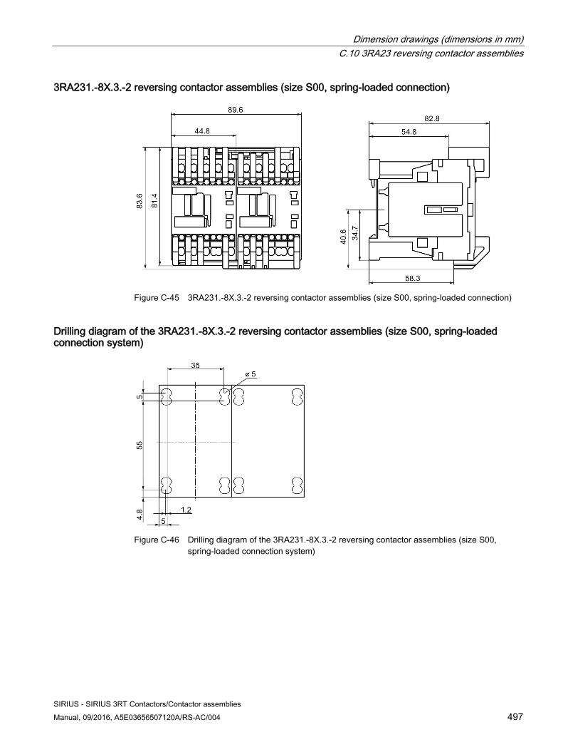
Dimension drawings (dimensions in mm) C.10 3RA23 reversing contactor assemblies
SIRIUS - SIRIUS 3RT Contactors/Contactor assemblies Manual, 09/2016, A5E03656507120A/RS-AC/004 497
3RA231.-8X.3.-2 reversing contactor assemblies (size S00, spring-loaded connection)
Figure C-45 3RA231.-8X.3.-2 reversing contactor assemblies (size S00, spring-loaded connection)
Drilling diagram of the 3RA231.-8X.3.-2 reversing contactor assemblies (size S00, spring-loaded connection system)
Figure C-46 Drilling diagram of the 3RA231.-8X.3.-2 reversing contactor assemblies (size S00,
spring-loaded connection system)
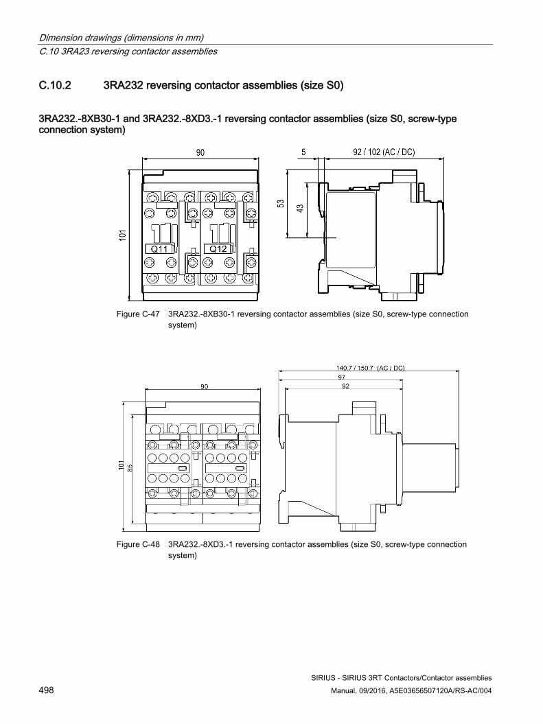
Dimension drawings (dimensions in mm) C.10 3RA23 reversing contactor assemblies
SIRIUS - SIRIUS 3RT Contactors/Contactor assemblies 498 Manual, 09/2016, A5E03656507120A/RS-AC/004
C.10.2 3RA232 reversing contactor assemblies (size S0)
3RA232.-8XB30-1 and 3RA232.-8XD3.-1 reversing contactor assemblies (size S0, screw-type connection system)
Figure C-47 3RA232.-8XB30-1 reversing contactor assemblies (size S0, screw-type connection
system)
Figure C-48 3RA232.-8XD3.-1 reversing contactor assemblies (size S0, screw-type connection
system)
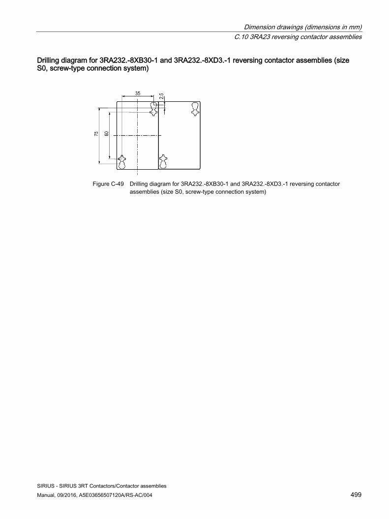
Dimension drawings (dimensions in mm) C.10 3RA23 reversing contactor assemblies
SIRIUS - SIRIUS 3RT Contactors/Contactor assemblies Manual, 09/2016, A5E03656507120A/RS-AC/004 499
Drilling diagram for 3RA232.-8XB30-1 and 3RA232.-8XD3.-1 reversing contactor assemblies (size S0, screw-type connection system)
Figure C-49 Drilling diagram for 3RA232.-8XB30-1 and 3RA232.-8XD3.-1 reversing contactor
assemblies (size S0, screw-type connection system)
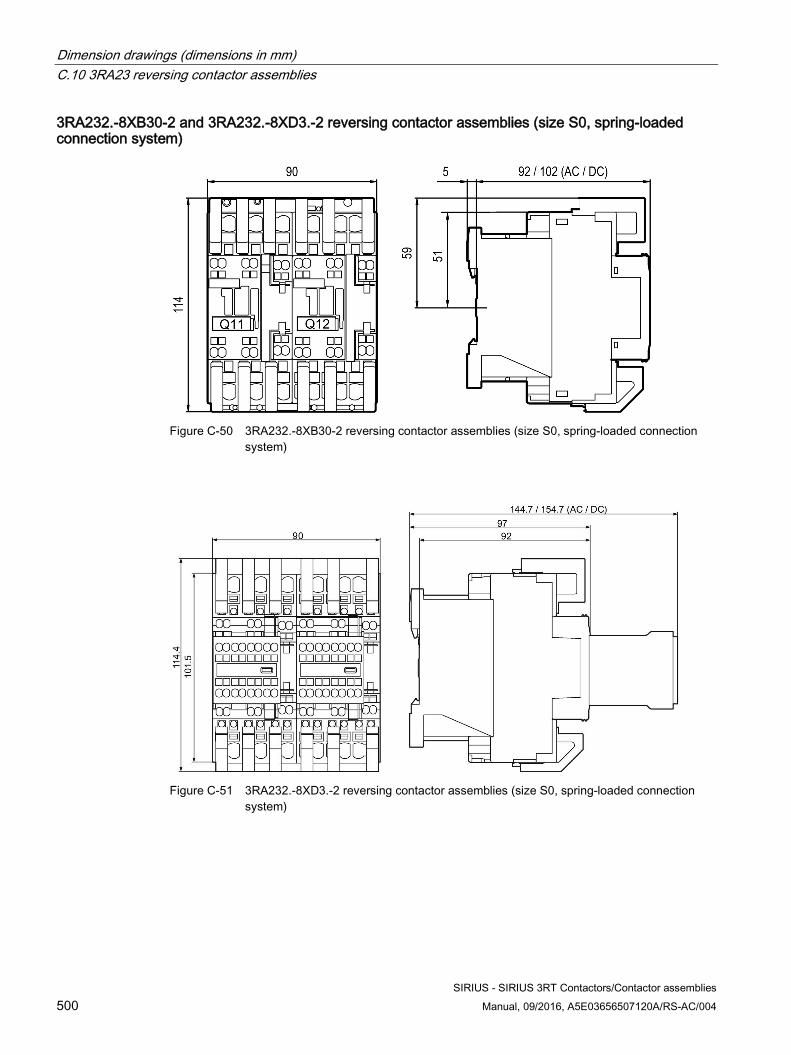
Dimension drawings (dimensions in mm) C.10 3RA23 reversing contactor assemblies
SIRIUS - SIRIUS 3RT Contactors/Contactor assemblies 500 Manual, 09/2016, A5E03656507120A/RS-AC/004
3RA232.-8XB30-2 and 3RA232.-8XD3.-2 reversing contactor assemblies (size S0, spring-loaded connection system)
Figure C-50 3RA232.-8XB30-2 reversing contactor assemblies (size S0, spring-loaded connection
system)
Figure C-51 3RA232.-8XD3.-2 reversing contactor assemblies (size S0, spring-loaded connection
system)
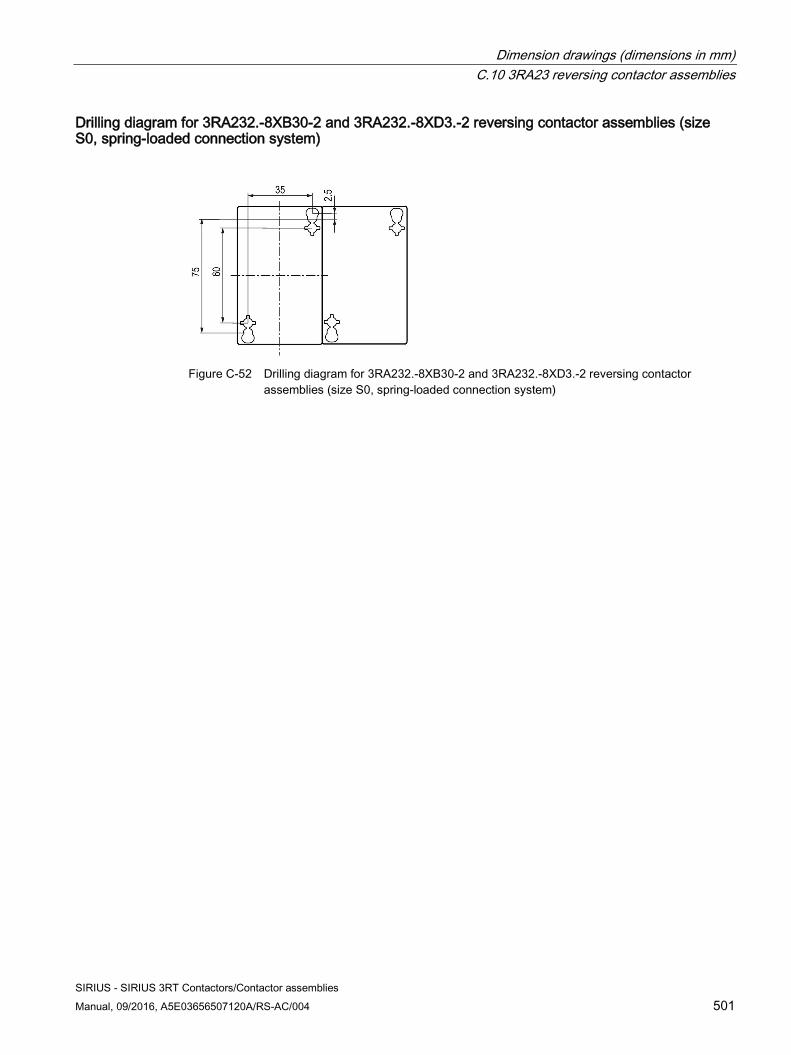
Dimension drawings (dimensions in mm) C.10 3RA23 reversing contactor assemblies
SIRIUS - SIRIUS 3RT Contactors/Contactor assemblies Manual, 09/2016, A5E03656507120A/RS-AC/004 501
Drilling diagram for 3RA232.-8XB30-2 and 3RA232.-8XD3.-2 reversing contactor assemblies (size S0, spring-loaded connection system)
Figure C-52 Drilling diagram for 3RA232.-8XB30-2 and 3RA232.-8XD3.-2 reversing contactor
assemblies (size S0, spring-loaded connection system)
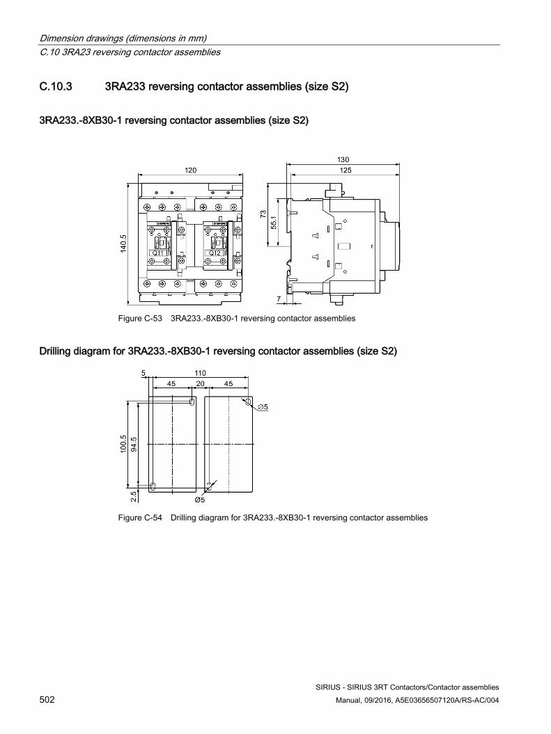
Dimension drawings (dimensions in mm) C.10 3RA23 reversing contactor assemblies
SIRIUS - SIRIUS 3RT Contactors/Contactor assemblies 502 Manual, 09/2016, A5E03656507120A/RS-AC/004
C.10.3 3RA233 reversing contactor assemblies (size S2)
3RA233.-8XB30-1 reversing contactor assemblies (size S2)
Figure C-53 3RA233.-8XB30-1 reversing contactor assemblies
Drilling diagram for 3RA233.-8XB30-1 reversing contactor assemblies (size S2)
Figure C-54 Drilling diagram for 3RA233.-8XB30-1 reversing contactor assemblies
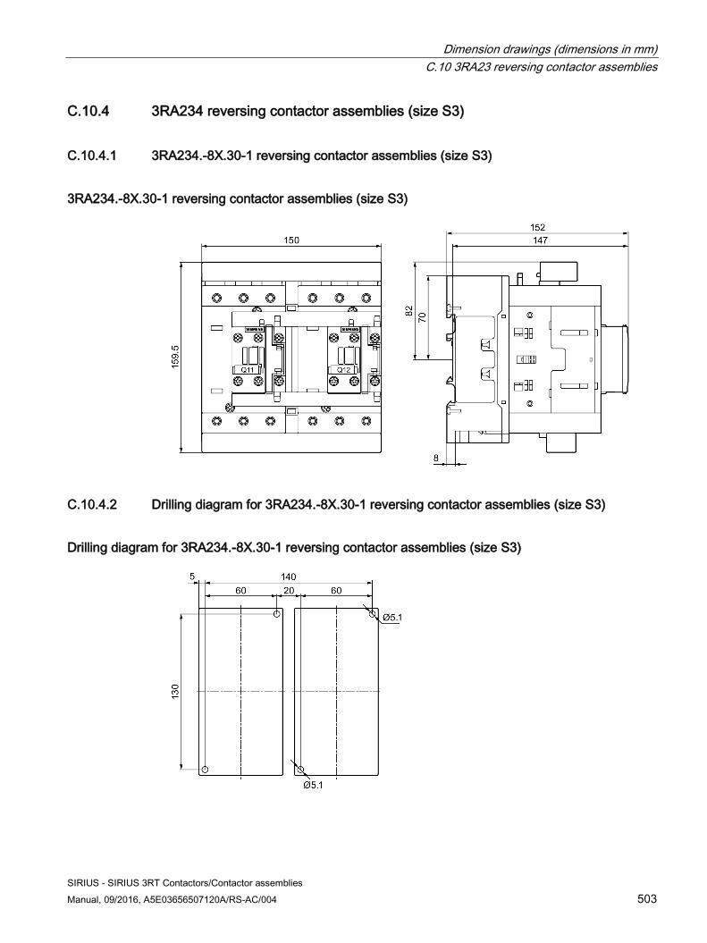
Dimension drawings (dimensions in mm) C.10 3RA23 reversing contactor assemblies
SIRIUS - SIRIUS 3RT Contactors/Contactor assemblies Manual, 09/2016, A5E03656507120A/RS-AC/004 503
C.10.4 3RA234 reversing contactor assemblies (size S3)
C.10.4.1 3RA234.-8X.30-1 reversing contactor assemblies (size S3)
3RA234.-8X.30-1 reversing contactor assemblies (size S3)
C.10.4.2 Drilling diagram for 3RA234.-8X.30-1 reversing contactor assemblies (size S3)
Drilling diagram for 3RA234.-8X.30-1 reversing contactor assemblies (size S3)
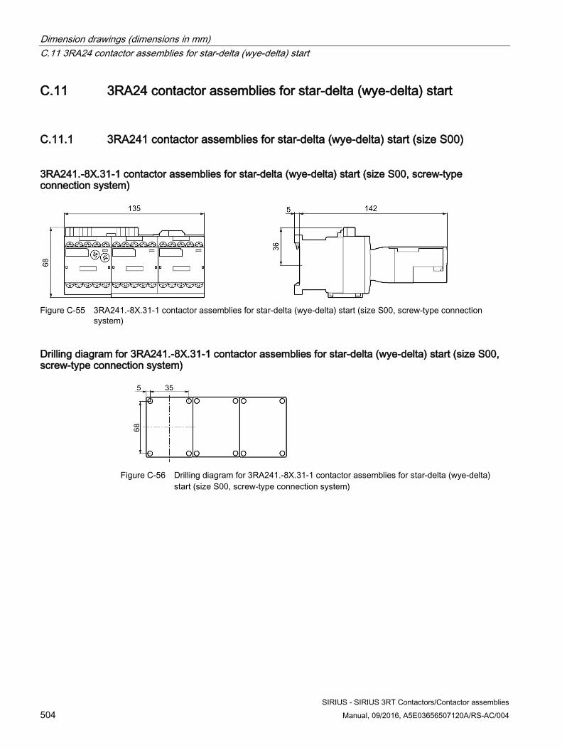
Dimension drawings (dimensions in mm) C.11 3RA24 contactor assemblies for star-delta (wye-delta) start
SIRIUS - SIRIUS 3RT Contactors/Contactor assemblies 504 Manual, 09/2016, A5E03656507120A/RS-AC/004
C.11 3RA24 contactor assemblies for star-delta (wye-delta) start
C.11.1 3RA241 contactor assemblies for star-delta (wye-delta) start (size S00)
3RA241.-8X.31-1 contactor assemblies for star-delta (wye-delta) start (size S00, screw-type connection system)
Figure C-55 3RA241.-8X.31-1 contactor assemblies for star-delta (wye-delta) start (size S00, screw-type connection
system)
Drilling diagram for 3RA241.-8X.31-1 contactor assemblies for star-delta (wye-delta) start (size S00, screw-type connection system)
Figure C-56 Drilling diagram for 3RA241.-8X.31-1 contactor assemblies for star-delta (wye-delta)
start (size S00, screw-type connection system)
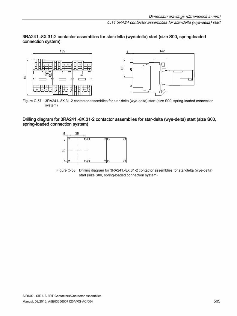
Dimension drawings (dimensions in mm) C.11 3RA24 contactor assemblies for star-delta (wye-delta) start
SIRIUS - SIRIUS 3RT Contactors/Contactor assemblies Manual, 09/2016, A5E03656507120A/RS-AC/004 505
3RA241.-8X.31-2 contactor assemblies for star-delta (wye-delta) start (size S00, spring-loaded connection system)
Figure C-57 3RA241.-8X.31-2 contactor assemblies for star-delta (wye-delta) start (size S00, spring-loaded connection
system)
Drilling diagram for 3RA241.-8X.31-2 contactor assemblies for star-delta (wye-delta) start (size S00, spring-loaded connection system)
Figure C-58 Drilling diagram for 3RA241.-8X.31-2 contactor assemblies for star-delta (wye-delta)
start (size S00, spring-loaded connection system)
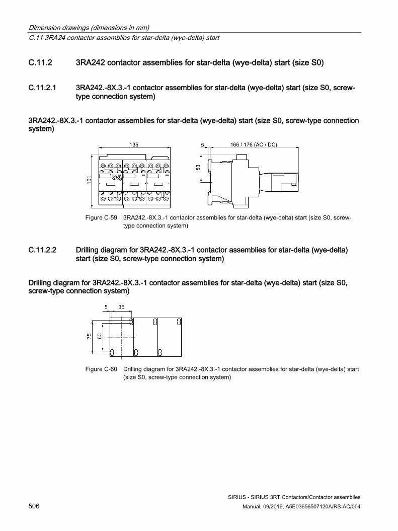
Dimension drawings (dimensions in mm) C.11 3RA24 contactor assemblies for star-delta (wye-delta) start
SIRIUS - SIRIUS 3RT Contactors/Contactor assemblies 506 Manual, 09/2016, A5E03656507120A/RS-AC/004
C.11.2 3RA242 contactor assemblies for star-delta (wye-delta) start (size S0)
C.11.2.1 3RA242.-8X.3.-1 contactor assemblies for star-delta (wye-delta) start (size S0, screw-type connection system)
3RA242.-8X.3.-1 contactor assemblies for star-delta (wye-delta) start (size S0, screw-type connection system)
Figure C-59 3RA242.-8X.3.-1 contactor assemblies for star-delta (wye-delta) start (size S0, screw-
type connection system)
C.11.2.2 Drilling diagram for 3RA242.-8X.3.-1 contactor assemblies for star-delta (wye-delta) start (size S0, screw-type connection system)
Drilling diagram for 3RA242.-8X.3.-1 contactor assemblies for star-delta (wye-delta) start (size S0, screw-type connection system)
Figure C-60 Drilling diagram for 3RA242.-8X.3.-1 contactor assemblies for star-delta (wye-delta) start
(size S0, screw-type connection system)
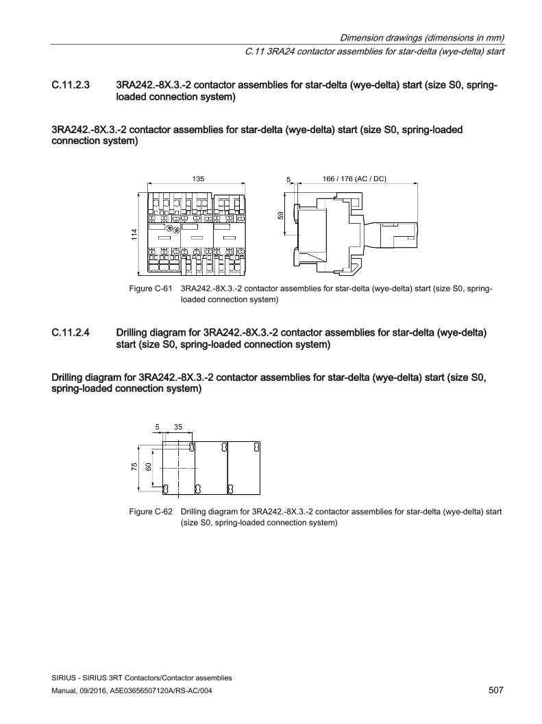
Dimension drawings (dimensions in mm) C.11 3RA24 contactor assemblies for star-delta (wye-delta) start
SIRIUS - SIRIUS 3RT Contactors/Contactor assemblies Manual, 09/2016, A5E03656507120A/RS-AC/004 507
C.11.2.3 3RA242.-8X.3.-2 contactor assemblies for star-delta (wye-delta) start (size S0, spring-loaded connection system)
3RA242.-8X.3.-2 contactor assemblies for star-delta (wye-delta) start (size S0, spring-loaded connection system)
Figure C-61 3RA242.-8X.3.-2 contactor assemblies for star-delta (wye-delta) start (size S0, spring-
loaded connection system)
C.11.2.4 Drilling diagram for 3RA242.-8X.3.-2 contactor assemblies for star-delta (wye-delta) start (size S0, spring-loaded connection system)
Drilling diagram for 3RA242.-8X.3.-2 contactor assemblies for star-delta (wye-delta) start (size S0, spring-loaded connection system)
Figure C-62 Drilling diagram for 3RA242.-8X.3.-2 contactor assemblies for star-delta (wye-delta) start
(size S0, spring-loaded connection system)
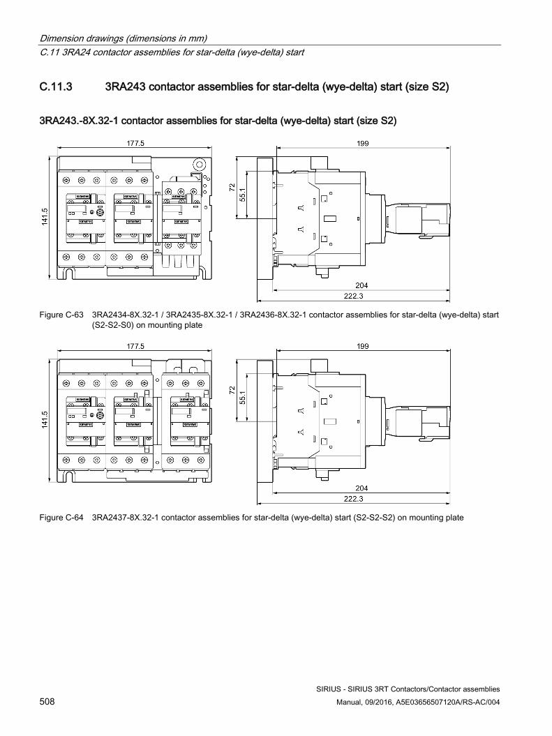
Dimension drawings (dimensions in mm) C.11 3RA24 contactor assemblies for star-delta (wye-delta) start
SIRIUS - SIRIUS 3RT Contactors/Contactor assemblies 508 Manual, 09/2016, A5E03656507120A/RS-AC/004
C.11.3 3RA243 contactor assemblies for star-delta (wye-delta) start (size S2)
3RA243.-8X.32-1 contactor assemblies for star-delta (wye-delta) start (size S2)
Figure C-63 3RA2434-8X.32-1 / 3RA2435-8X.32-1 / 3RA2436-8X.32-1 contactor assemblies for star-delta (wye-delta) start
(S2-S2-S0) on mounting plate
Figure C-64 3RA2437-8X.32-1 contactor assemblies for star-delta (wye-delta) start (S2-S2-S2) on mounting plate
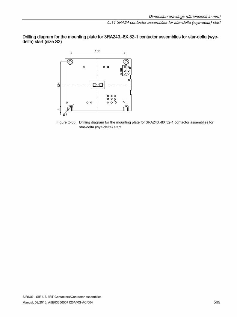
Dimension drawings (dimensions in mm) C.11 3RA24 contactor assemblies for star-delta (wye-delta) start
SIRIUS - SIRIUS 3RT Contactors/Contactor assemblies Manual, 09/2016, A5E03656507120A/RS-AC/004 509
Drilling diagram for the mounting plate for 3RA243.-8X.32-1 contactor assemblies for star-delta (wye-delta) start (size S2)
Figure C-65 Drilling diagram for the mounting plate for 3RA243.-8X.32-1 contactor assemblies for
star-delta (wye-delta) start
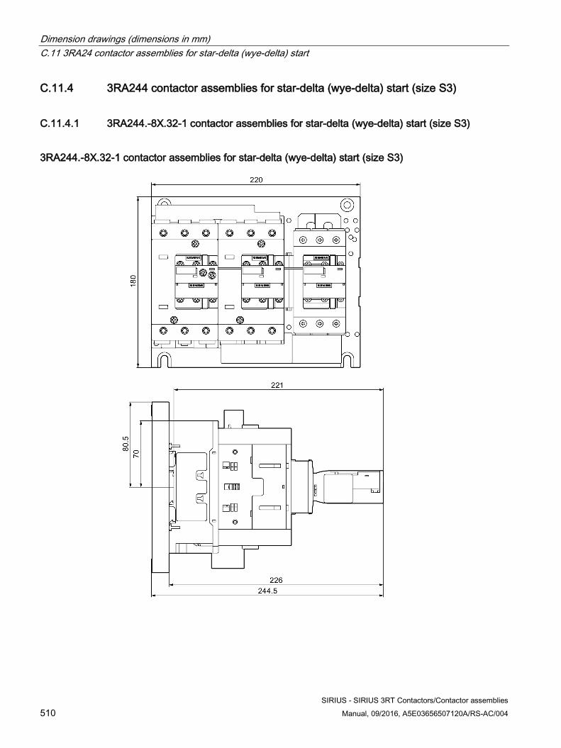
Dimension drawings (dimensions in mm) C.11 3RA24 contactor assemblies for star-delta (wye-delta) start
SIRIUS - SIRIUS 3RT Contactors/Contactor assemblies 510 Manual, 09/2016, A5E03656507120A/RS-AC/004
C.11.4 3RA244 contactor assemblies for star-delta (wye-delta) start (size S3)
C.11.4.1 3RA244.-8X.32-1 contactor assemblies for star-delta (wye-delta) start (size S3)
3RA244.-8X.32-1 contactor assemblies for star-delta (wye-delta) start (size S3)
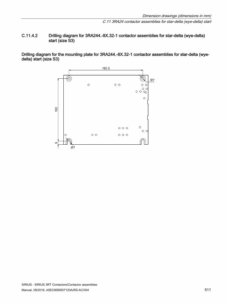
Dimension drawings (dimensions in mm) C.11 3RA24 contactor assemblies for star-delta (wye-delta) start
SIRIUS - SIRIUS 3RT Contactors/Contactor assemblies Manual, 09/2016, A5E03656507120A/RS-AC/004 511
C.11.4.2 Drilling diagram for 3RA244.-8X.32-1 contactor assemblies for star-delta (wye-delta) start (size S3)
Drilling diagram for the mounting plate for 3RA244.-8X.32-1 contactor assemblies for star-delta (wye-delta) start (size S3)
Dimension drawings (dimensions in mm) C.11 3RA24 contactor assemblies for star-delta (wye-delta) start
SIRIUS - SIRIUS 3RT Contactors/Contactor assemblies 512 Manual, 09/2016, A5E03656507120A/RS-AC/004
SIRIUS - SIRIUS 3RT Contactors/Contactor assemblies Manual, 09/2016, A5E03656507120A/RS-AC/004 513
Index
1
1-phase infeed terminal Contactors, 316
2
2-conductor connection, 199
3
3D model, 17 3-phase infeed terminal
Contactors, 315
4
4-pole contactors, 92, 95
A
Accessories Contactors, 211, 221
Accessories - Contactors 1-phase infeed terminal, 316 3-phase infeed terminal, 315 Additional load module, 294, 294 Assembly kit for contactor assembly for star-delta (wye-delta) start, 358, 361, 365, 370, 381, 395, 401 Assembly kit for reversing contactor assembly, 333, 335 Auxiliary switch blocks, 223, 226, 252, 258, 261 Box terminal block, 420, 421 Coil terminal module, 298, 310, 311 Connection modules, 329 Control kit, 295, 296 Coupling link, 298, 301 Cover for ring cable lug, 313 EMC suppression module, 282, 284, 286 Function modules for connection to the automation level, 330 Function modules for mounting on contactors, 331 Insulating stop, 327 LED display indicator module, 305, 306 Link module for motor starter protector, 323
Link module for two contactors in series, 321, 321 Mechanical latch, 290, 291, 293 OFF-delay device, 287, 287, 288 Parallel switching connector, 318, 320 Parallel switching connector, 318, 320 Pneumatically delayed auxiliary switch, 324, 326 Pneumatically delayed auxiliary switches, 325 Sealable cover, 314, 314 Solder pin adapter, 307, 308 Solid-state time-delay auxiliary switch blocks, 422, 425, 425 Surge suppressor, 264, 268, 276 Terminal cover for cable lug connection and busbar connection, 405, 407 Terminal covers for box terminal block, 416, 416 Terminal module, 328
Additional load module Contactors, 294, 294
Ambient temperature Contactor relays, 81 Contactors for railway applications, 85 Power contactors, 82, 84
App Siemens Industry Online Support, 18
Applications Contactors, 27, 63
Approvals, 21 Contactors, 21
AS-Interface, 88, 120, 359 Assembly kit for contactor assembly for star-delta (wye-delta) start
Contactors, 358, 361, 365, 370, 381, 395, 401 Assembly kit for reversing contactor assembly
Contactors, 333, 335 Assembly with mechanical interlock
4-pole, 340 Auxiliary contacts (contactors), 197, 223
Integrated, 34, 223 Time-delayed, 231
Auxiliary switch blocks Contactor relays, 97 Contactors, 223, 226, 252, 258, 261 Reversing contactor assemblies, 115
Auxiliary switch blocks (contactors) Fitting according to standards, 230 Fitting rules, 227 For contactor relays, 231 Maximum number, 226, 258
Index
SIRIUS - SIRIUS 3RT Contactors/Contactor assemblies 514 Manual, 09/2016, A5E03656507120A/RS-AC/004
Solid-state compatible, 225, 256 With overlapping contacting, 225, 257
Auxiliary switches (contactors) Solid-state time delay, 331
B
Basic knowledge, 15 Basic module, 359, 368 Box terminal block
Contactors, 420, 421
C
CAx data, 17, 429, 467 CCW rotation
Contactor assemblies for star-delta (wye-delta) start, 128
Changeover delay Contactor assemblies for star-delta (wye-delta) start, 120, 125 Reversing contactor assemblies, 112
Class, 125 Clockwise rotation
Reversing contactor assemblies, 117, 335, 338, 342, 346, 352, 355
Closed, 109, 109, 109 Coil surge suppressor, 65 Coil terminal, 198 Coil terminal module
Contactors, 298, 310, 311 Communication
Power contactors, 88 Configuration information (contactor)
Frequency converter, 136 Connection
Contactor assemblies for star-delta (wye-delta) start, clockwise rotation, 126 Contactor assemblies for star-delta (wye-delta) start, counterclockwise rotation, 128
Connection systems 3RT1 power contactors, 39 3RT12 vacuum contactors, 39 3RT2 power contactors, 34 Contactor assembly for star-delta (wye-delta) start, 56 Contactor relays, 45 Contactors, 197 Reversing contactor assembly, 53
Contactor assemblies, 64
Contactor assemblies for star-delta (wye-delta) start, 29, 56, 64, 119, 128
Changing the direction of rotation, 128 Control circuit, 129 Control circuit wiring, 120, 357, 367 Main circuit, 129
Contactor relays, 29, 45, 97 Contactors
Switching, 63 Control kit
Contactors, 295, 296 Counterclockwise rotation
Reversing contactor assemblies, 117, 335, 338, 342, 346, 352, 355
Coupling link Contactors, 298, 301
Coupling module, 359, 368 Coupling relays, 64, 109, 264 Cover for ring cable lug
Contactors, 313 CW rotation
Contactor assemblies for star-delta (wye-delta) start, 128
D
Device versions Contactors, 33
Dimension drawings, 17 DIN EN 50005, 230 DIN EN 50011, 230 DIN EN 50012, 231 Diode combination, 264, 273 Direct-on-line starter, 112 Disposal, 19
E
EMC suppression module Contactors, 282, 284, 286
EPLAN macros, 17 Equipment features
Contactor relay, 4-pole, 46 Contactor relay, 8-pole, 47
F
Freewheel diode, 264, 273 Frequency converter
Contactor, 136, 136
Index
SIRIUS - SIRIUS 3RT Contactors/Contactor assemblies Manual, 09/2016, A5E03656507120A/RS-AC/004 515
Function modules Contactor assemblies for star-delta (wye-delta) start, 56, 357, 367
Function modules for connection to the automation level
Contactors, 330 Function modules for connection to the automation level, 88, 120 Function modules for connection to the automation level
Contactor assemblies for star-delta (wye-delta) start, 359
Function modules for mounting on contactors Contactors, 331
Function modules for mounting on contactors Contactor assemblies for star-delta (wye-delta) start, 331, 359
Function modules for mounting on contactors Contactor assemblies for star-delta (wye-delta) start, 331, 359
H
Holding power, 109
I Inductive loads, 264, 284 Insulating stop
Contactors, 327 Interfering signals, 264 Interlock
Contactor assemblies for star-delta (wye-delta) start, 125 Electrical, 334, 336, 338 Mechanical, 333, 335, 358
IO-Link, 88, 120, 359
L
Latched contactor relays, 97 LED display indicator module
Contactors, 305, 306 Line capacity, 133 Link module for motor starter protector
Contactors, 323 Link module for two contactors in series
Contactors, 321, 321 Long control cables, 130
Long control cables (contactors) Switching off, 133 Switching on, 130
M
Main entry, 159 Mechanical latch
Contactors, 290, 291, 293 Minimum clearance
Power contactors, 83 Mirror contacts, 23 Modular System, 463 Mounting position
Contactors, 152
O
OFF-delay device Contactors, 287, 287, 288
ON period Power contactors, 84, 290
Operating instructions, 461 Operating mechanism types
Contactors, 65 Operating range, 65 Overvoltage attenuation, 264, 270
P
Parallel switching connector Contactors, 318, 320
Parallel switching connector Contactors, 318, 320
Permanent load with parallel connection, 318 Permissible residual current, 294 Pneumatically delayed auxiliary switch
Contactors, 324, 326 Pneumatically delayed auxiliary switch (contactors)
With OFF-delay, 324 With ON-delay, 324
Pneumatically delayed auxiliary switches Contactors, 325
Positively driven contact elements, 23 Power contactor, 29, 31
Communication-capable, 35, 36, 120, 359 Preferred voltages, 65 Preferred wiring, 119, 125 Product data sheet, 429, 467 Programmable logic controller (PLC), 294, 298, 330 Protective separation, 22
Index
SIRIUS - SIRIUS 3RT Contactors/Contactor assemblies 516 Manual, 09/2016, A5E03656507120A/RS-AC/004
R
Railway applications Contactors, 64, 85
RC element, 264, 272 Recycling, 19 References, 461 Reversing contactor assemblies, 29, 53, 64, 112
Typical control circuit, 117 Typical main circuit, 116
Ring cable lug connection system, 208
S
Scope of validity Manual, 15
Screw mounting Contactors, 151
Screw-type connection system, 200 Sealable cover
Contactors, 314, 314 Service life
Power contactors, 84 SIRIUS system configurator, 64 Snap-on mounting
Contactors, 151, 156 Solder pin adapter
Contactors, 307, 308 Solder pin connection, 45, 199, 307 Solenoid coil operating range
Contactors for railway applications, 85 Power contactors, 83
Solid-state time-delay auxiliary switch blocks Contactors, 422, 425, 425
Source voltage, 282 Spring-loaded connection system, 206 Standards, 21
Contactors, 21 Star-delta (wye-delta) start
Contactors, 119 Starting current, 119, 125 Starting three-phase motors, 119 Suppression diode, 273 Surge suppression
Integrated, 298 Surge suppressor
Contactors, 264, 268, 276 Surge suppressors (contactors)
Selection aid, 268 Switching
Contactors, 63 Motorized load, 87
Switching frequency Power contactors, 82, 84
Switching overvoltage, 264 Switch-off delay, 273 Switchover current peak, 125, 127
T
Technical Assistance, 19 Terminal cover for cable lug connection and busbar connection
Contactors, 405, 407 Terminal covers for box terminal block
Contactors, 416, 416 Terminal designations
Contactors, 197 Terminal module
Contactors, 328, 329 Thermal load capacity
Power contactors, 82 Time-delayed switching of contactors, 425 Timing relays, 120, 331, 357, 367 Types of coordination, 459
U
Utilization categories Contactors, 27, 88, 92, 97
V
Vacuum contactor, 31 Varistor, 264, 271


