Embed Size (px)
Citation preview
TeSyS TMotor ManagementSystem Catalogue
August 2009
2
1
3
4
5
6
7
8
9
10
��
“TeSys protection components” selection guide . . . . . . . . . . . . . . . . . . . .page 2
General: motor and machine protection . . . . . . . . . . . . . . . . . . . . . . . . . . page 4
“TeSys T Motor Management System” selection guide . . . . . . . . . . . . . .page 10
TeSys T Motor Management System
Presentation. . . . . . . . . . . . . . . . . . . . . . . . . . . . . . . . . . . . . . . . . . . . . . . page 12Description. . . . . . . . . . . . . . . . . . . . . . . . . . . . . . . . . . . . . . . . . . . . . . . . page 14Functions. . . . . . . . . . . . . . . . . . . . . . . . . . . . . . . . . . . . . . . . . . . . . . . . . page 17Topology . . . . . . . . . . . . . . . . . . . . . . . . . . . . . . . . . . . . . . . . . . . . . . . . . page 19Programming. . . . . . . . . . . . . . . . . . . . . . . . . . . . . . . . . . . . . . . . . . . . . . page 21Characteristics. . . . . . . . . . . . . . . . . . . . . . . . . . . . . . . . . . . . . . . . . . . . . page 23Tripping.curves. . . . . . . . . . . . . . . . . . . . . . . . . . . . . . . . . . . . . . . . . . . . . page 27References . . . . . . . . . . . . . . . . . . . . . . . . . . . . . . . . . . . . . . . . . . . . . . . page 28Dimensions,.mounting. . . . . . . . . . . . . . . . . . . . . . . . . . . . . . . . . . . . . . . page 32Schemes. . . . . . . . . . . . . . . . . . . . . . . . . . . . . . . . . . . . . . . . . . . . . . . . . page 34Combinations.for.customer.assembly . . . . . . . . . . . . . . . . . . . . . . . . . . . page 38Substitution.table. . . . . . . . . . . . . . . . . . . . . . . . . . . . . . . . . . . . . . . . . . . page 40
b
b
v
v
v
v
v
v
v
v
v
v
v
v
TeSys T Motor Management System
Contents
�
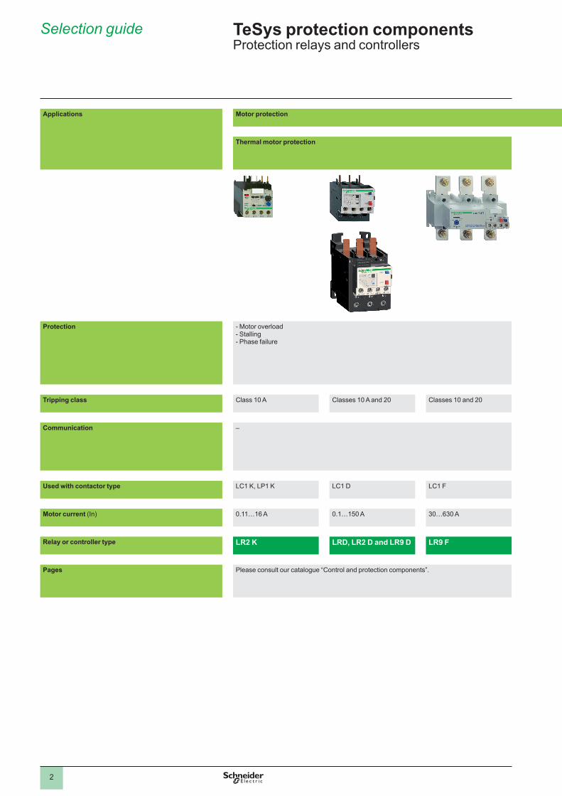
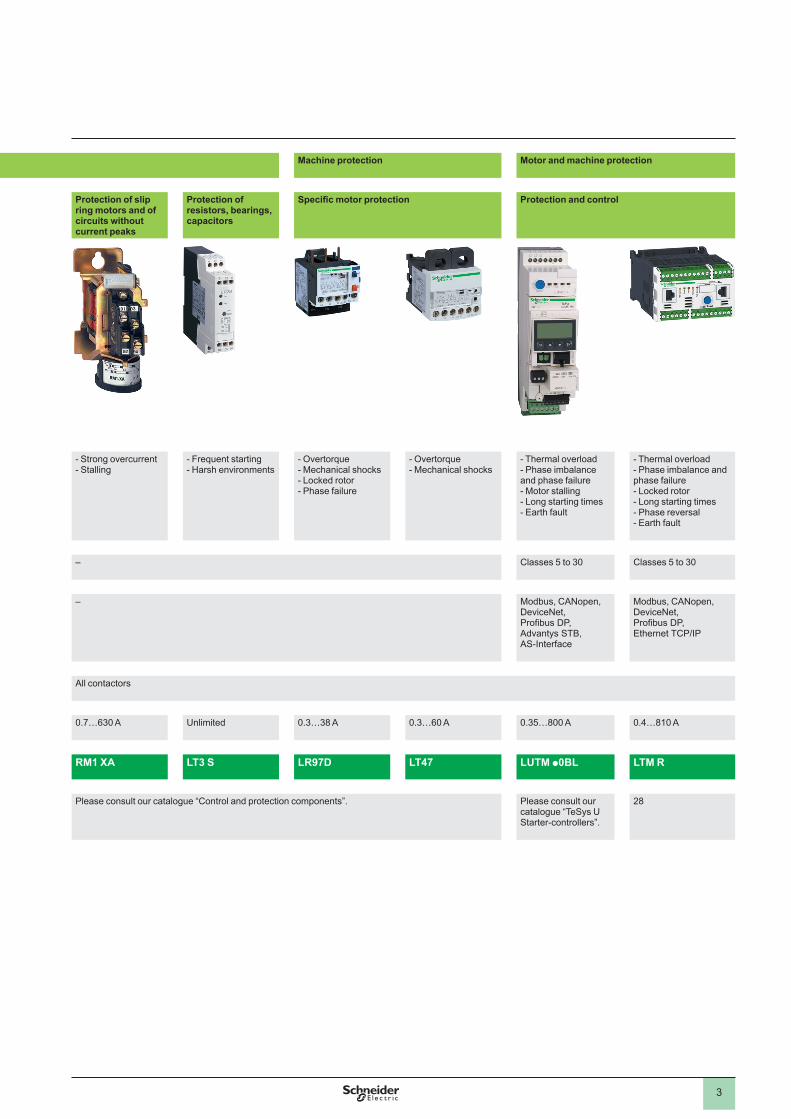
Applications Motor protection Machine protection Motor and machine protection
Thermal motor protection Protection of slip ring motors and of circuits without current peaks
Protection of resistors, bearings, capacitors
Specific motor protection Protection and control
Protection -.Motor.overload-.Stalling-.Phase.failure
-.Strong.overcurrent-.Stalling
-.Frequent.starting-.Harsh.environments
-.Overtorque-.Mechanical.shocks-.Locked.rotor-.Phase.failure
-.Overtorque-.Mechanical.shocks
-.Thermal.overload-.Phase.imbalance.and.phase.failure-.Motor.stalling-.Long.starting.times-.Earth.fault
-.Thermal.overload.-.Phase.imbalance.and.phase.failure-.Locked.rotor-.Long.starting.times-.Phase.reversal.-.Earth.fault
Tripping class Class.�0.A Classes.�0.A.and.�0 Classes.�0.and.�0 – Classes.5.to.30 Classes.5.to.30
Communication – – Modbus,.CANopen,.DeviceNet,.Profibus DP, Advantys.STB,.AS-Interface
Modbus,.CANopen,.DeviceNet,.Profibus DP, Ethernet.TCP/IP
Used with contactor type LC�.K,.LP�.K LC�.D LC�.F All.contactors
Motor current (In) 0 .��…�6.A 0 .�…�50.A 30…630.A 0 .7…630.A Unlimited 0 .3…38.A 0 .3…60.A 0 .35…800.A 0 .4…8�0.A
Relay or controller type LR2 K LRD, LR2 D and LR9 D LR9 F RM1 XA LT3 S LR97D LT47 LUTM p0BL LTM R
Pages Please.consult.our.catalogue.“Control.and.protection.components” . Please.consult.our.catalogue.“Control.and.protection.components” . Please.consult.our.catalogue.“TeSys.UStarter-controllers” .
�8
Selection guide TeSys protection componentsProtection.relays.and.controllers
3
Applications Motor protection Machine protection Motor and machine protection
Thermal motor protection Protection of slip ring motors and of circuits without current peaks
Protection of resistors, bearings, capacitors
Specific motor protection Protection and control
Protection -.Motor.overload-.Stalling-.Phase.failure
-.Strong.overcurrent-.Stalling
-.Frequent.starting-.Harsh.environments
-.Overtorque-.Mechanical.shocks-.Locked.rotor-.Phase.failure
-.Overtorque-.Mechanical.shocks
-.Thermal.overload-.Phase.imbalance.and.phase.failure-.Motor.stalling-.Long.starting.times-.Earth.fault
-.Thermal.overload.-.Phase.imbalance.and.phase.failure-.Locked.rotor-.Long.starting.times-.Phase.reversal.-.Earth.fault
Tripping class Class.�0.A Classes.�0.A.and.�0 Classes.�0.and.�0 – Classes.5.to.30 Classes.5.to.30
Communication – – Modbus,.CANopen,.DeviceNet,.Profibus DP, Advantys.STB,.AS-Interface
Modbus,.CANopen,.DeviceNet,.Profibus DP, Ethernet.TCP/IP
Used with contactor type LC�.K,.LP�.K LC�.D LC�.F All.contactors
Motor current (In) 0 .��…�6.A 0 .�…�50.A 30…630.A 0 .7…630.A Unlimited 0 .3…38.A 0 .3…60.A 0 .35…800.A 0 .4…8�0.A
Relay or controller type LR2 K LRD, LR2 D and LR9 D LR9 F RM1 XA LT3 S LR97D LT47 LUTM p0BL LTM R
Pages Please.consult.our.catalogue.“Control.and.protection.components” . Please.consult.our.catalogue.“Control.and.protection.components” . Please.consult.our.catalogue.“TeSys.UStarter-controllers” .
�8
2
1
3
4
5
6
7
8
9
10
2
1
3
4
5
6
7
8
9
10
4
General Protection components Motor.and.machine.protection
IntroductionExceeding.the.operating.limits.of.an.electric.motor.will.lead,.eventually,.not.only.to.destruction.of.the.motor.itself.but.also.of.the.mechanisms.it.drives .
This.type.of.load.can.be.the.cause.of..electrical.or.mechanical.faults .Electrical.faults:.overvoltage,.voltage.drop,.imbalance.and.phase.failure.which.cause.variations.in.
the.current.drawn,short-circuits.which.can.cause.the.current.to.reach.levels.capable.of.destroying.
the.load .
Mechanical.faults:.locked.rotor,.brief.or.prolonged.overload.which.leads.to.an.increase.in.the.current.drawn.by.the.
motor,.and.therefore.overheating ...The.cost.of.these.faults.must.take.into.account.loss.of.production,.loss.of.raw.materials,.repair.of.the.production.tool,.poor.quality.of.production.and.delays.in.delivery .
These.faults.can.also.have.dramatic.consequences.on.the.safety.of.persons.in.direct.or.indirect.contact.with.the.motor .
To.prevent.these.faults,.protection.measures.are.necessary ..They.make.it.possible.to.isolate.the.equipment.to.be.protected.from.the.mains.supply.by.measuring..variations.in.electrical.values.(voltage,.current,.etc…) .
Each motor starter must therefore have:
short-circuit protection,.to.detect.and.break,.as.quickly.as.possible,.abnormal.currents.generally.greater.than.�0.times.the.rated.current.(In) .
overload protection,.to.detect.increases.in.current.up.to.about.�0.In.and.switch.off.the.starter.before.overheating.of.the.motor.and.conductors.damages.the.insulation .
This protection is provided by specific devices such as fuses, circuit-breakers and thermal.overload.relays,.or.by.more.integrated.devices.offering.several.types.of.protection .
bv
v
bvv
b
b
2
1
3
4
5
6
7
8
9
10
2
1
3
4
5
6
7
8
9
10
5
Causes, effects and consequences of various faults There.are.two.types.of.fault:.
Internal.faults.within.the.motor .External.faults:.these.are.located.outside.the.electric.motor.but.their.
consequences.can.lead.to.damage.inside.the.motor .
bb
Faults Causes Effects Consequences on the motor and on the machine
Short-circuit Contact.between.several.phases,.or.between.one.phase.and.neutral.or.between.several.turns.of.the.same.phase .
Current.peakElectrodynamic.forces.on.the.
conductors
bb
Destruction.of.windings
Overvoltage LightningElectrostatic.dischargeOperation
bbb
Dielectric.breakdown.in.the.windings Destruction.of.the.windings.due.to.loss.of.insulation
Phase imbalance and phase failure
Opening.of.a.phaseSingle-phase.load.upstream.of.the.
motorShort-circuit.between.the.turns.of.
the.same.winding
bb
b
Reduction of usable torque, efficiency and.speed
Increase.in.lossesStarting.impossible.if.phase.failure
b
bb
Overheating.(1)
High starting frequency
Failure.of.the.automation.systemToo.many.manual.control.
operationsNumerous.fault.trips
bb
b
High.stator.and.rotor.temperature.rise.due.to.the.frequent.start.current
Overheating.(1)Consequences.on.the.process
Voltage variations
Instability.of.the.mains.voltageConnection.of.heavy.loads
bb
Reduction.of.usable.torqueIncrease.in.losses
bb
Overheating. (1)
Harmonics Pollution.of.the.mains.supply.by.variable.speed.drives,.inverters,.etc . . .b Reduction.of.usable.torque
Increase.in.lossesbb
Overheating.(1)
Long starting time
Resistive.torque.too.high.(load.too.heavy)
Voltage.drop
b
b
Increase.in.starting.time Overheating.1)
Jamming Mechanical.problem.(crusher)Seizures
bb
Overcurrent Overheating.(1).Consequences.on.the.process
No-load running Pump.running.emptyMechanical.break.in.drive.to.the.
load
bb
Drop.in.current.drawn Consequences.on.the.process
Frequency fluctuations
Overload.of.a.supply.powered.by.limited.independent.sources
Faulty.alternator.speed.regulator
b
b
Increase.in.lossesInterferes.with.synchronous.devices.
(clock,.recorder,. . . .)
bb
–
Overload Increase.in.resistive.torqueVoltage.dropDrop.in.power.factor
bbb
Increase.in.current.consumption Overheating. (1)
Loss of machine excitation
Significant drop in excitation current
Break.in.rotor.winding
b
b
Increase.in.active.powerDrop.in.power.factor
bb
Significant overheating of rotor and cage
Phase-Earth fault Accidental.Phase-Earth.contactsAccidental.Phase-machine.casing.
contacts.(casing.connected.to.earth)
bb
Overvoltage.developed.in.the.mains.supply
Rise.in.earth.potential.(safety.of.persons)
b
b
Consequences.on.safety.of.persons
(1) Then, in the longer or shorter term, depending on the seriousness of the fault and/or its frequency, short-circuit and destruction of the windings.
General (continued) Protection components Motor.and.machine.protection
2
1
3
4
5
6
7
8
9
10
2
1
3
4
5
6
7
8
9
10
6
General (continued) Protection components Motor.and.machine.protection
Protection functions .Short-circuit protectionGeneral
A.short-circuit.results.in.a.very.rapid.rise.in.current.which.can.reach.several.hundred.times.the.value.of.the.operational.current ..The.consequences.of.a.short-circuit.are.dangerous.to.both.equipment.and.persons ..It.is.therefore.imperative.to.use.protection.devices.to.detect.the.fault.and.very.quickly.break.the.circuit ...Two.types.of.protection.are.commonly.used:
fuses.(cutout).which.break.the.circuit.by.melting,.which.then.requires.their.replacement,
magnetic.trip.circuit-breakers,.often.more.simply.called."magnetic.circuit-breakers",.which.only.require.re-setting.to.put.them.back.into.service .Short-circuit.protection.can.also.be.built-into.multifunction.devices.such.as.motor.circuit-breakers.and.contactor-breakers .
The.main.characteristics.of.short-circuit.protection.devices.are:their.breaking.capacity:.this.is.the.highest.prospective.short-circuit.current.value.
that.a.protection.device.can.break.at.a.given.voltage .their.making.capacity:.this.is.the.highest.current.value.that.the.protection.device.
can make at its rated voltage in specified conditions. .The.making.capacity.is.equal.to.k.times.the.breaking.capacity .
b
b
b
b
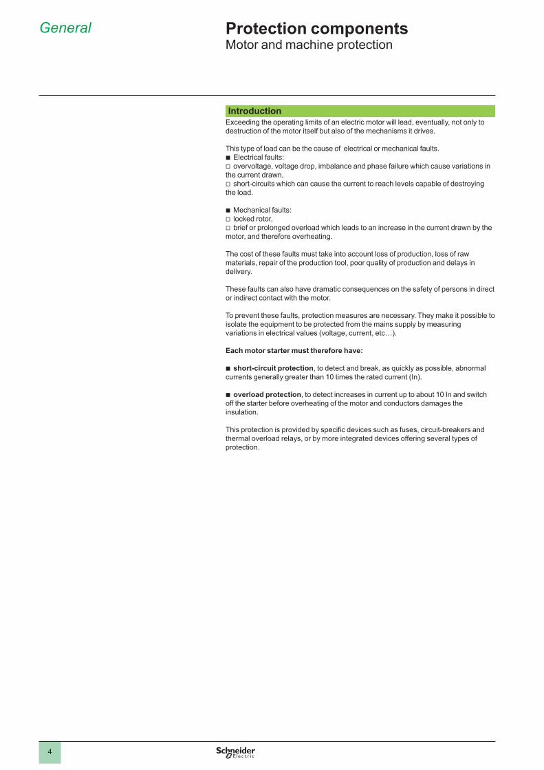
Fuses (cutouts) Fuses.provide.individual.phase.protection.(single-pole),.with.a.high.breaking.capacity.in.a.compact.size:
mounted.either.in.fuse.carriers,or.in.isolators,.replacing.the.original.links.or.shunt.bars .
For.motor.protection,.aM.type.fuses.are.used ..Their.design.characteristics.allow.them.to.conduct.the.high.magnetising.currents.that.occur.when.motors.are.switched.on ..They.are.therefore.unsuitable.for.overload.protection.(unlike.gG.type.fuses) ..This.is.why.an.overload.relay.must.be.included.in.the.motor.power.supply.circuit .
bb
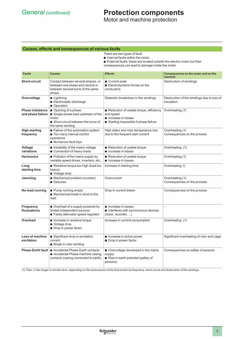
Magnetic circuit-breakers ..These.circuit-breakers.protect.installations.against.short-circuits,.within.the.limit.of.their.breaking.capacity ..Magnetic.circuit-breakers.provide.omnipole.breaking.as.standard ..For.relatively.low.short-circuit.currents,.the.operation.of.a.circuit-breaker.is.faster.than.that.of.fuses ..This.protection.conforms.to.standard.IEC.60947-� ...The.thermal.and.electrodymanic.effects.are.also.limited,.therefore.ensuring.better.protection.of.cables.and.equipment .
.
5�6�
79
GV2 Lmagnetic circuit-breraker
5�6�
79
GV2 Lmagnetic circuit-breraker
TeSys U LUB 12 power base with LUCApp control unit
5�6�
80
TeSys U LUB 12 power base with LUCApp control unit
5�6�
80
LS1 D32fuse carrier
5�6�
77
GS2 N3switch disconnectors
5�6�
78
2
1
3
4
5
6
7
8
9
10
2
1
3
4
5
6
7
8
9
10
7
Protection functions (continued) Overload protectionGeneral
An.overload.condition.is.the.most.frequently.encountered.fault ..The.symptoms.are.a.rise.in.the.current.drawn.by.the.motor.and.thermal.effects ..A.rapid.return.to.normal.operating.conditions.is.important .The.actual.operating.conditions.(ambient.temperature,.operating.altitude.and.type.of.standard.duty).are.essential.to.determine.the.operating.values.of.the.motor.(power,.current).and.to.be.able.to.select.effective.overload.protection ..These.operational.values.are.given.by.the.motor.manufacturer .
According.to.the.level.required,.protection.can.be.provided.by:overload.relays.and.thermal.overload.relays.(bi-metallic.or.electronic.type).which.
protect.motors.in.the.event.of:overload,.by.monitoring.the.current.drawn.by.each.phase,phase.imbalance.or.failure,.by.their.differential.mechanism .relays with PTC thermistor probes (Positive Temperature Coefficient). overtorque.relays,multifunction.relays .
b
vvbbb
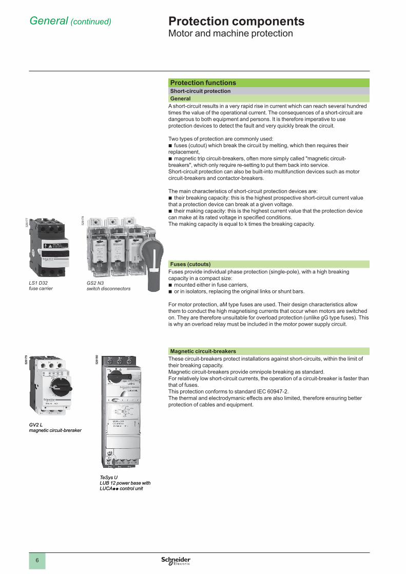
Overload relaysThese.relays.protect.motors.against.overload ..They.must.allow.the.temporary.overload.that.occurs.on.starting.and.must.only.trip.if.the.starting.time.is.abnormally.long .The.overload.relay.will.be.selected.according.to.the.length.of.the.starting.time.(tripping.class).and.the.motor.rating .These.relays.have.a.thermal.memory.(except.for.certain.electronic.overload.relays,.indicated.by.their.manufacturers).and.can.be.connected:
either.in.series.with.the.load,.or.to.current.transformers.placed.in.series.with.the.load ..
Bi-metallic thermal overload relays.Combined.with.a.contactor,.these.relays.protect.the.line.and.the.equipment.against.small.and.prolonged.overloads ..They.must.be.protected.against.strong.overcurrent.by.a.circuit-breaker.or.fuses ..These.relays.may.be.used.on.an.a .c ..or.d .c ..system.and.are.generally:
3-pole,compensated,.i .e ..insensitive.to.ambient.temperature.variations,.with.manual.or.automatic.reset,graduated.with.a."motor.FLC".scale:.allowing.direct.setting.to.the.full.load.current.
as.shown.on.the.motor.rating.plate ..They.can.also.be.sensitive.to.phase.failure:.this.is.known.as..'differential' ..This.function.conforms.to.standards.IEC.60947-4-�.and.60947-6-�.This.type.of..relay.is.extremely.reliable.and.is.a.relatively.low.cost.device .
Electronic thermal overload relays.Electronic.thermal.overload.relays.have.the.advantage.of.electronics.which.allow.a.more.complex.thermal.image.of.the.motor.to.be.created .They.can.be.combined.with.products.having.complementary.functions,.such.as:
temperature.sensing.via.PTC.probes,protection.against.jamming.and.overtorque,protection.against.phase.reversal,earth.fault.protection,protection.against.no-load.running,.alarm.function .
bb
bbbb
bbbbbb
5�6�
8�
LRD 02thermal overload relay
5�6�
845�
6�83
RM4 JA current measurement relay
TeSys U starter-controller with “thermal overload alarm” function module
LRD 365thermal overload relay
5�6�
8�
General (continued) Protection components Motor.and.machine.protection
2
1
3
4
5
6
7
8
9
10
2
1
3
4
5
6
7
8
9
10
8
General (continued) Protection components Motor.and.machine.protection...
Protection functions (continued) Overload protection (continued)Relays for use with PTC thermistor probes
With.direct.sensing.of.the.stator.windings,.these.relays.can.be.used.to.protect.motors.against:.
overload,.a.rise.in.ambient.temperature,.a.ventilation.circuit.fault,.a.high.starting.frequency,.mechanical.shocks,.etc . . .
bbbbb
Overload (or overtorque) relays These.relays.protect.the.drive.line.in.the.event.of.a.locked.rotor,.seizure.or.mechanical.shocks ..This.is.an.additional.protection .Unlike.thermal.overload.relays,.these.relays.do.not.have.a.thermal.memory ..They.have definite time characteristics (adjustable current threshold and time delay).The.overtorque.relay.can.be.used.as.overload.protection.for.motors.with.long.starting.times.or.very.frequent.starting.(for.example,.lifting.hoists) ..
Multifunction relays Overcurrent.relays.are.limited.when.it.is.necessary.to.take.into.account.problems.
associated.with.voltage,.temperature.or.special.applications ..New.production.or.maintenance.management.needs.have.prompted.manufacturers.to.offer.products.which.provide.not.only.adaptable.protection,.but.also.complete.management.of.the.motor.and.its.load ..They.incorporate:
current.and.voltage.sensors.(TeSys.T.controllers),hybrid.analog.and.digital.electronic.technology,the.use.of.communication.buses.for.data.exchange.and.control,.powerful.motor.modelling.algorithms,integrated.application.programs.whose.parameters.can.be.set .
These.products.make.it.possible.to.reduce.installation.and.operating.costs.by.reducing.maintenance.and.downtime .
TeSys U starters:The.multifunction.relay.is.incorporated.in.the.motor.starter ..This.solution.is.very.compact.with.reduced.wiring ..It.is.limited.to.3�.A .
TeSys U controllers: The.multifunction.relay.is.separate.from.the.power.line.and.reuses.the.function.blocks.from.the.TeSys.U.solution ..It.can.be.used.in.conjunction.with.a.contactor.up.to.8�0.A .
TeSys T controllers: The.multifunction.relay.is.separate.from.the.power.line.and.incorporates.inputs.and.outputs ..It.can.be.used.in.conjunction.with.a.contactor.up.to.8�0.A .
b
bbbbb
5�6�
85
LT3 S relays for use with thermistor probes
5�6�
85
LT3 S relays for use with thermistor probes
5�6�
86
LR97 D07instantaneous electronic overcurrent relays
5�6�
86
LR97 D07instantaneous electronic overcurrent relays
5�6�
87
TeSys Ustarter-controller LUB 32 with multifunction control unit LUC M
5�6�
87
TeSys Ustarter-controller LUB 32 with multifunction control unit LUC M
5�6�
88
TeSys U controller LUTM 20BL
5�6�
88
TeSys U controller LUTM 20BL
5�6�
89
TeSys T controller LTM R08MBD
5�6�
89
TeSys T controller LTM R08MBD
2
1
3
4
5
6
7
8
9
10
2
1
3
4
5
6
7
8
9
10
9
Protection relay selection table .Motor protection Machine
protectionMotor and machine protection
Relay type Thermal overload relay
LR2 K, LRD,LRD 3, LR9 F, LR9 D (1)
Relays for use with PTC probes LT3 S
Overtorque relays
LR97 D, LT47
TeSys U controller
LUT M
TeSys T controller
LTM R
Causes of overheating (2) (2) (2) (3)Slight overload
Locked rotor
No-load running
Supply phase failure LR9.7D
Ventilation fault With.probes
Abnormal temperature rise
With.probes
Shaft bearing seizure With.probes
Insulation fault
Protracted starting time
Severe duty With.probes
Voltage variation
Frequency fluctuations
Loss of machine excitation
Ideally.suited
Possible.solution
Not.suitable.(no.protection)
(1) for motor circuit-breaker type GV2ME.(2) Protection based on current.(3) Protection based on current and voltage.
General (continued) Protection components Motor.and.machine.protection
�0
Selection guide Protection componentsTeSys.T.Motor.Management.System
Applications Multifunction motor and machine protection
Device type Controllers Input extension modules, for.all.LTM.R.controllers
Operator control unit
For network/bus Modbus CANopen DeviceNet Profibus DP Ethernet.TCP/IP – –
Current range 0 .4…�00.A.(with.internal.current.transformer)�00…8�0.A.(with.external.current.transformer)
– –
Control voltage c.�4.V.a �00…�40.V
c.�4.V.(1) a.�00…�40.V.(1) Powered.via.the.LTM.R.controller..or.via.the.LTM.E.extension.module .
Number of I/O 6.inputs.4.outputs
4.independent.inputs –
Measurements -.Current.between.phases-.Earth.fault ..-.Motor.temperature .
Voltage.between.phases –
Functions Protection and monitoring functions:-.thermal.overload,..-.motor.temperature.monitoring,..-.phase.imbalance.and.phase.failure,.-.locked.rotor,..-.long.starting.times,..-.phase.reversal,..-.earth.fault .
Monitoring functions:-.voltage,.-.power,-.Cos jj (power.factor)
Display functions:-.measurements,.-.faults.and.alarms,-.statistics,.etc . . j .
Device type LTM RppMpp LTM RppCpp LTM RppDpp LTM RppPpp LTM RppEpp LTM EV40BD LTM EV40FM LTM CU
Pages �8 �9 �9
(1) Input control voltage. The electronics are powered via the controller.
��
Protection componentsTeSys.T.Motor.Management.System
....
PresentationTeSys.T.is.a.motor.management.system.that.provides.protection,.metering.and.monitoring.functions.for.single-phase.and.3-phase,.constant.speed,.a .c ..motors.up.to.8�0.A ...Suitable.for.the.harshest.applications,.this.product.range.offers:
high-performance.multifunction.protection,.independent.of.the.automation.system,a.local.HMI.control.unit.for.reading,.displaying.and.modifying.the.parameters.
monitored,.diagnostics,.etc . . . . .configuration of the application using PowerSuite software,connection.to.the.automation.system.via.a.communication.network.(selection.
according.to.various.protocols) .....Application
The.TeSys.T.motor.management.system.is.used.for.motor.control.and.protection.in.harsh.industrial.applications,.in.which.downtime.must.be.avoided.because.it.is.very.costly:..Oil.&.Gas,.chemical.industry,.water.treatment,.metal,.minerals.and.mining,.pharmaceutical.industry,.microelectronics,.tunnels,.airports.etc ..
With.TeSys.T,.untimely.stoppages.of.a.process.or.manufacturing,.associated.with.a.motor,.are.anticipated.via.predictive.analysis.of.fault.situations ..Fault.tripping.is.therefore.reduced.to.a.minimum ..
Its.use.in.motor.control.panels.makes.it.possible.to:.increase.the.operational.availability.of.installations,improve flexibility from project design through to implementation,increase.productivity.by.making.available.all.information.needed.to.run.the.
system .
The.TeSys.motor.management.system.integrates.perfectly.with.Schneider.Electric.low.voltage.equipment,.such.as.Okken,.Blokset.and.Prisma .
bbb
........
bb
bb
5�63
78
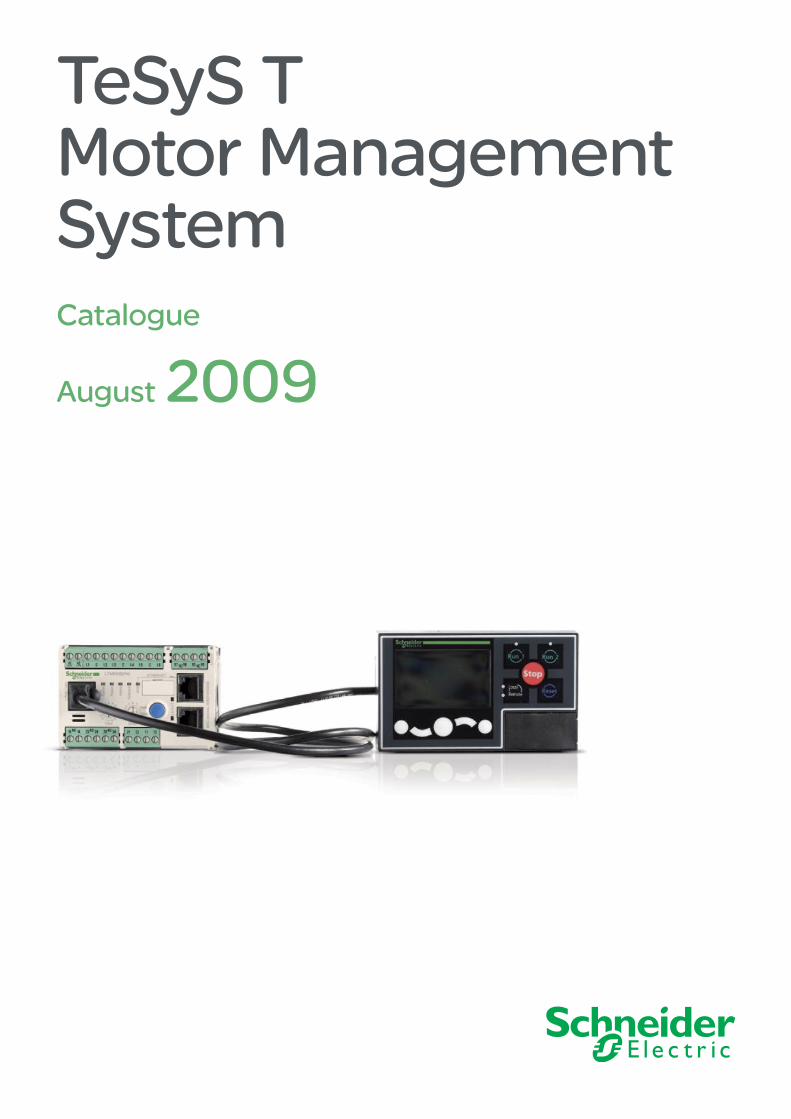
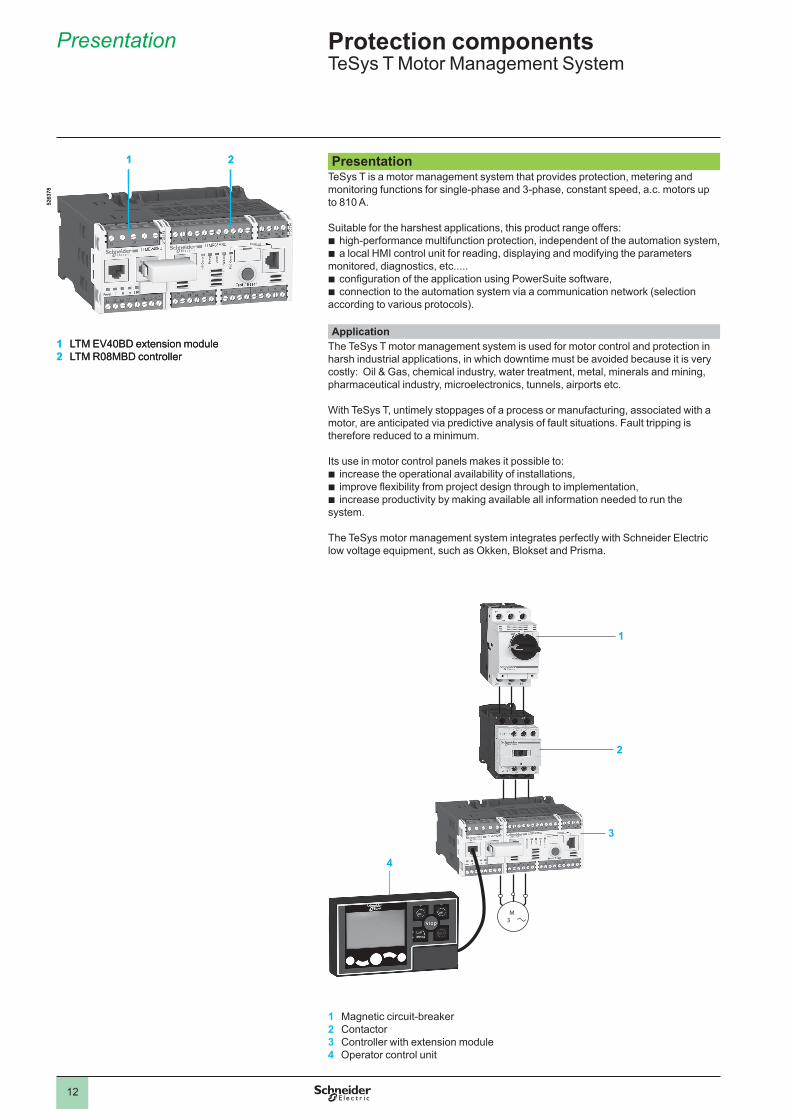
1 LTM.EV40BD.extension.module2 LTM.R08MBD.controller
1 2
5�63
78
1 LTM.EV40BD.extension.module2 LTM.R08MBD.controller
1 2
3
M 3
1
2
4
1 Magnetic.circuit-breaker2 Contactor3 Controller.with.extension.module4 Operator.control.unit.
Presentation
1
2
3
4
5
6
7
8
9
10
�3
Presentation (continued)Composition of the motor management system ...
The.system.comprises:an.LTM.R..motor.management.controller.with.integral.current.transformer.up.to.�00.A,above.�00.A,.by.external.current.transformer.up.to.8�0.A,an.LTM.E.extension.module,an.LTM.CU.operator.control.unit,configuration software incorporated in the PowerSuite software application,accessories.for.system.set-up ..
CommunicationThe.LTM.R.controller.is.equipped.with.a.communication.interface.to.allow.remote.monitoring.and.control.of.the.motor ..All.motor.information.is.then.available.at.automation.system.level ..
The.following.networks.are.available:.Modbus, CANopen, DeviceNet, ProfiBus DP and Ethernet TCP/IP.
TeSys T system functions......Protection functions:
against.thermal.overload,against.phase.imbalance.and.phase.failure,thermal.motor.protection.via.PTC.probes,against.phase.reversal,against.earth.faults,against.long.starting.times.and.motor.stalling,against.automatic.load.shedding.and.restarting,against load fluctuations (I, U, P),against.variations.of.Cos.j (power.factor) .
Metering functionsMeasurements.(rms.values):current.on.the.3.phases,voltage.on.the.3.phases.(shedding),motor.temperature,earth.fault,Values.calculated:average.current,frequency,Cos.j (power.factor),.power,.power.consumption . . .
Motor control functionsA.motor.managed.by.TeSys.T.can.be.controlled:
locally,.using.the.logic.inputs.present.on.the.product,.or.via.the.HMI.terminalremotely,.via.the.network.(connection.by.terminal.block.or.connector.except.for.
DeviceNet:.terminal.block.only) .,
Motor control modes5 predefined motor control modes are incorporated in the controller:
overload.mode:.monitoring.of.motors.whose.control.is.not.managed.by.the.controller,
independent.mode:.starting.of.non-reversing.motors,reverser.mode:.starting.of.reversing.motors,�-step.mode:.�-step.starting.of.motors.(star-delta,.by.autotransformer.and.by.
resistor),�-speed.mode:.�-speed.starting.of.motors.(Dahlander,.pole.changer) .
A.6th “Custom” mode is available to allow the user to create a specific motor control mode that is not predefined in the controller.
Statistical and diagnostic functionsfault.statistics:.counters.per.type.of.protection.and.history.of.the.last.5.faults,motor.statistics:.saving.of.motor.statistics.values,diagnosis.of.faults.affecting.correct.operation.of.the.product .
bvvbbbb
b
bbbbbbbbb
bvvvvbvvv
bb
b
bbb
b
bbb
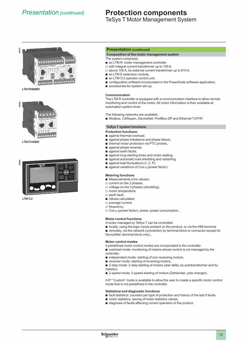
LTM R08MBD
5�63
79
LTM R08MBD
5�63
79
LTM EV40BD
5�63
80
LTM EV40BD
5�63
80
LTM CU
5686
05
LTM CU
5686
05
Presentation (continued) Protection componentsTeSys.T.Motor.Management.System
........
1
2
3
4
5
6
7
8
9
10
�4
Description
DescriptionThe LTM R controller
The.controller.is.the.central.component.in.the.motor.management.system .It.manages.the.basic.functions.such.as:
measurement.of.3-phase.current.via.integral.current.transformers.from.0 .4.to.�00.A.(up.to.8�0.A.by.external.current.transformers),
measurement.of.earth.current.by.external.earth.fault.toroid .measurement.of.motor.temperature.by.PTC.probe,inputs.and.outputs.for.the.various.motor.control.modes,.fault.management.and.
associated.functions .....CharacteristicsAs standard, the controller manages the following predefined control mode functions:
overload.mode,independent.mode,reverser.mode,�-speed.mode,�-step.mode,"Custom".mode .
Supply�.types.of.controller.power.supply.are.available:
c.�4.V,a.�00…�40.V .
Current ranges3.current.ranges.allow.measurement.of.motor.current.from.0 .4.to.�00.A:
0 .4…8.A,� .35…�7.A,5…�00.A .
For.use.with.external.current.transformers,.choose.the.0 .4…8.A.range.(�.or.5.A.current.transformer.secondary) .Inputs
6.discrete.logic.inputs .Outputs
3.relay.logic.outputs.(�N/O)�.relay.output.for.fault.signalling.(�N/O.+.�N/C))
Measurementsconnections.for.a.temperature.probe,connections.for.an.earth.fault.toroid .
....LTM E extension module
The.extension.module.adds.the.following.functionalities.to.the.TeSys.T.controller:voltage.measurement.on.the.3.phases ..This.enables.it.to.calculate.numerous.
engine.monitoring.parameters.(power,.frequency,.Cos j …),4.additional.inputs .
....Characteristics
Inputs4.discrete.logic.inputs.(independent) .
Power supplies�.types.of.power.supply.for.the.inputs:..c.�4.V.and.a.�00…�40.V ...
A.c.�4.V.controller.can.be.assembled.with.an.a.�00…�40.V.extension.module.and.vice.versa .Voltage measurement between phases up to 690 V nominal....
b
bbb
bbbbbb
bb
bbb
b
bb
bb
b
b
b
b
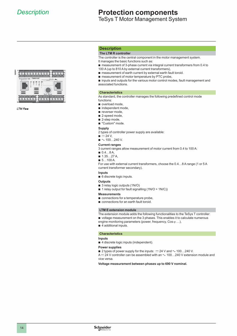
LTM Rpp
5�63
8�
LTM Rpp
5�63
8�Protection componentsTeSys.T.Motor.Management.System
........
1
2
3
4
5
6
7
8
9
10
�5
Description (continued)Human/Machine Interfaces (HMI)
Depending.on.the.application,.�.types.of.HMI.can.be.used.with.the.LTM.R.controller .The.LTM.CU.operator.control.unit:Entirely.dedicated.to.the.TeSys.T.range,Only.for.control/monitoring.of.an.LTM.R.controller .
A.Magelis.XBT.N4�0.terminalFor.control/monitoring.of.�.to.8.LTM.R.controllers .
LTM CU operator control unit Dedicated.exclusively.to.TeSys.T.controllers,.control.unit.LTM.CU.makes.it.possible.to:Configure the parameters of the LTM R controllerDisplay information on controller configuration and operation.Monitor.the.alarms.and.faults.generated.by.the.controller .Local.control.of.the.motor.via.the.local.control.interface.(keys.can.be.customised) ..
Three.different.languages.can.be.loaded.into.the.LTM.CU.controller.at.the.same.time ..By.default,.these.3.languages.are:.English,.French.and.Spanish .Note: English is the only compulsory language.
A.language.download.utility.(LangTool),.together.with.all.the.other.languages,.are.available.on.the.website.“www .schneider-electric .com” .This.tool.allows.the.languages.present.in.the.LTM.CU.control.unit.to.be.adapted .
The LTM CU HMI control unit has an RJ45 port, protected by a flexible cover to provide.a.good.level.of.protection.(IP54) ..This.port.on.the.front.panel.allows.connection.to.a.PC,.via.a.connecting.cable,.in.order.to.use.PowerSuite.software ..In.this.case,.the.control.unit.acts.as.a.transmitter.and.all.information.can.then.be.viewed.in.PowerSuite ..
bbbb
The Magelis XBT N410 HMI terminal Two applications have been predefined for TeSys T. Depending on the application loaded,.the.HMI.terminal.makes.it.possible.to:configure and monitor a motor starter (LTM_1T1_V1.dop).monitor.and.modify.certain.parameters.on.up.to.8.motor.starters
(LTM_1T8_X_V1.dop) (1) .
XBT.L�000.programming.software.is.needed.for.loading.applications.into.the.HMI.terminal ..These.applications.are.available.on.the.website.“www .schneider-electric .com” .
bb
(1) Replace the X with an E for the English version, or an F for the French version.
bvv
bv
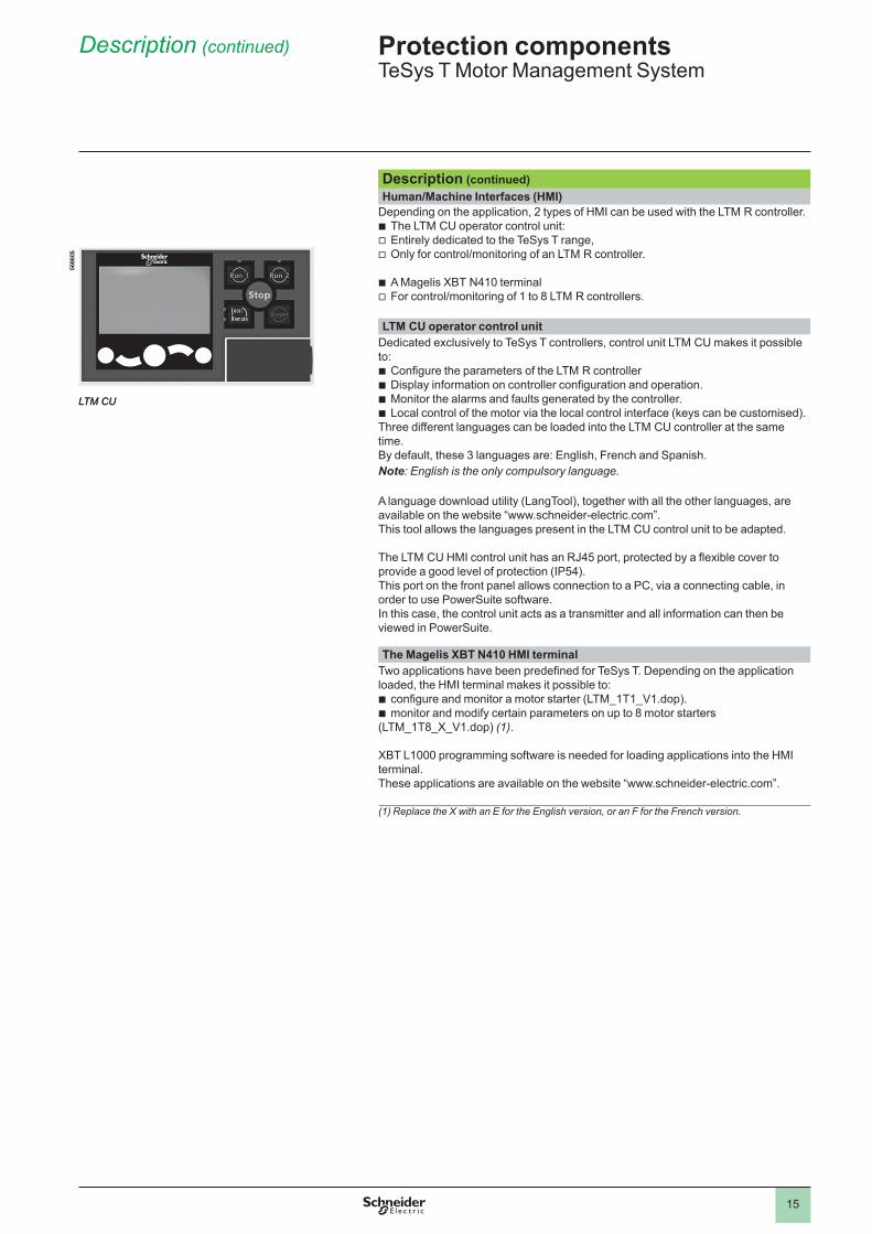
LTM CU
5686
05
LTM CU
5686
05
Description (continued) Protection componentsTeSys.T.Motor.Management.System
1
2
3
4
5
6
7
8
9
10
�6
Protection componentsTeSys.T.Motor.Management.System
........
Description (continued)
LTM R controllersModbus DeviceNet
2 3
4
67
10
8
1
9
5
2 3
4
7
10
8
1
9
5
Controllers.feature.the.following.on.their.front.panel:
1 Controller.power.supply .2 Input.connections .3 Fault.outputs.(N/O+N/C) .4 Port.for.connection.to.the.
HMI.terminal,.a.PC.or.an.extension.module.(RJ45) .
5 Controller.status.LEDs .6 Network.port.for.
connection.to.the.network.by.connector.(except.DeviceNet).(1) .
7 Test/Reset.button .8 Connection.to.the.network.
by.terminal.block.(except.Ethernet.TCP/IP) .
9 Connection.for.an.earth.fault..toroid.and.temperature.probes .
10 Outputs.for.motor.control.mode.function .
Profibus DP CANopen2 3
4
67
10
8
1
9
5
2 3
4
67
10
8
1
9
5
Ethernet TCP/IP2 3
4
6
10
1
9
5
76
(1) Connection using power extension (daisy-chaining) is possible for Ethernet TCP/IP.
LTM EV40pp extension modules LTM CU operator control unit
1
2
3
5
4
1
2
3
4
Extension.modules.have.the.following.on.their.front.face:1 Inputs.for.voltage.measurement .2 Port.for.connection.to.the.HMI.terminal.or.to.the.PC .3 Port.for.connection.to.the.controller .4 Extension.module.status.LEDs .5 Connection.of.additional.inputs .
The.control.unit.has.the.following.on.its.front.face:1 Screen ..LCD.display2 Local.control.interface.including.control.keys.and.LEDs .3 RJ45.port.on.front.panel.for.connection.to.a.PC.(protected.by.a.cover) .4 Contextual.navigation.keys .
1
2
3
4
5
6
7
8
9
10
�7
Thermal and current protection functionsFunctions Setting range Controller
LTM RController and extension module (LTM R + LTM E)
Alarm threshold
Fault thresholdDescription
Thermal overload:..thermal.protection.of.motor.by.monitoring.current.consumption
Class:.5,.�0,.�5,.�0,.�5,.30 .Inverse ther/definite time
.
Motor temperature:...thermal.monitoring.of.the.motor.using.temperature.probes.(winding,.paper . . .) ..Up.to.3.sensors.in.series .
PTC.binary.PTC/NTC.analogue:..�0.…6500.Ohm.
Phase imbalance:...monitors.the.symmetry.of.currents ..To.be.used.for.imbalance.<.80%..of.the.average.current.(1) .
�0…70%.I.average.0 .�…�0.s
Phase failure:...monitors.the.symmetry.of.currents ..To.be.used.for.imbalance.<.80%..of.the.average.current.(1) .
0 .�…30.s
Phase reversal: signals when the phase sequence is different from the defined sequence.(motor.running) .
A-B-C.A-C-B
Long starting time:..monitors.the.motor.starting.time
�00…800.%.of.FLC.(2) �…�00.s
Locked rotor: .locking.detected.by.a.sudden.increase.in.current..after.the.start.phase
�00…800.%.of.FLC.(2) �…30.s
Min/max current load limit variations:..monitors.motor.load.through.variations.of.current..around.preset.thresholds .
min.: 30…�00.%.of.FLC.(2) �…�00.smax.: �0…800.%.of.FLC.(2) �…�50.s
Earth fault:..signals.internal.insulation.faults,.by.vectorial.summing..of.external.currents,.via.earth.fault.toroid .
internal: �0…500.%.min.FLC.(2) 0 .05…�5.sexternal: 0 .0�…�0.A.0 .05…�5.s
Frequent starting: Protects.the.motor.against.overheating.due.to.frequent.starting .
0…999 .9.s
Voltage and power protection functionsPhase imbalance:..monitors.the.symmetry.of.voltage.between.phases ...To.be.used.for.imbalance..<.40.%..of.the.average.voltage.(3) .
3…�5.%.0 .�…�0.s
Phase failure:..monitors.the.symmetry.of.voltage.between.phases ...To.be.used.for.imbalance.>.40.%..of.the.average.voltage.(3) .
0 .�…30.s
Phase reversal: signals when the phase sequence is different from the defined sequence.(motor.stopped) .
A-B-C.A-C-B
Voltage variations. Min/max voltage limits: monitors.voltage.variations.around.preset.thresholds .
min.: 70…99.%.0 .�…�5.s..max.: �0�…��5.%.0 .�…�5.s
Load shedding: opens.outputs.O .�.and.O .�.if.voltage.drops.below.a.preset.threshold .
68…��5.%.�…9999.s
Power variations. Min/max power limits: monitors.power.variations.around.preset.thresholds .
�0…800.%.0…�00.s
Variations of Cos j. Min/max limits of Cos j : monitors.variations.of.Cos j.around.preset.thresholds .
0…�0…�5.s
Function.performed .. (1) Average current value measured on the 3 phases.(2) FLC: Full Load Current (setting current).(3) Average voltage value measured on the 3 phases.
Protection componentsTeSys.T.Motor.Management.System
....
Functions
1
2
3
4
5
6
7
8
9
10
�8
Functions (continued)
Motor control functionsFunctions Description With controller
LTM RWith controller LTM R and extension module LTM E
Control modes Local,.via.terminal.block X XLocal,.via.HMI.terminal.(1) X XRemote,.via.network X X
Operating modes Overload X XIndependent X XReverser X X�-step X X�-speed X X"Custom".mode X X
Fault management Manual.reset X XAutomatic.reset X XRemote.reset X X
Metering functions and statisticsFunctions Description Measurement range With controller
LTM RWith controller LTM R and extension module LTM E
Measurements (2) Current/Phase 0 .08…�000.A X XEarth.current 0 .�633.x.CT.ratio X XAverage.current 0 .08…�000.A X XCurrent.imbalance.between.phases
0…�00.% X X
Thermal.capacity.level 0…�00.% X XMotor.temperature.rise 0…6500.Ohm X XFrequency 0….�00.Hz XVoltage.between.phases a.0…830.V XVoltage.imbalance.between.phases
0…�00.% X
Active.power 0…6553 .5.kW XReactive.power 0…6553 .5.kWr XCos.j.(power.factor) 0…�00 XActive.power.consumption 0…400.kWh XReactive.power.consumption 0…400.kWrh X
Fault statistics Protection.fault.counters X XProtection.alarm.counters X XDiagnostic.fault.counters X XMotor.control.function.counters X XFault.history X X
Fault diagnostics Internal.watchdog.fault X XController.internal.temperature X XTemperature.sensor.connection X XCurrent.connection X XVoltage.connection XMotor.control.commands.(start,.stop,.run.check.back.and.stop.check.back)
X X
Control configuration checksum X XLoss.of.communication X X
Motor statistics Number.of.motor.control.commands.(O .�/O .�.starts) X XOperating.time X XNumber.of.starts/hour X XLast.start.I.max . X XDuration.of.last.start X X
Thermal overload statistics Time.to.trip X XTime.to.restart X X
System operating statistics Run,.ON,.Start,.alarm,.fault . X X
(1) HMI: Human Machine Interface.See measurement details page 24.
Protection componentsTeSys.T.Motor.Management.System
........
1
2
3
4
5
6
7
8
9
10
�9
Service classes offered by the Ethernet TCI/IP versionClass A.�0.ETH�0/�00.+.FTP.server
Basic Web server None
Basic communications servicesEthernet TCP/IP
Modbus.messaging.(read/write.of.data.words)
Ethernet TCP/IP communication advanced management services
I/O.Scanning Yes
Global.Data No
Client.FDR.(1) Automatic.monitoring.and.updating.of.product parameter configuration.Automatic.assignment.of.IP.address.and.network.parameters .
SNMP.network.administrator.(2)
Yes
Ethernet: different network topologiesStar topology
In.a.star.topology,.all.the.peripherals.are.linked.via.an.intermediate.peripheral.(hub.or.switch) . ..In.industrial.Ethernet.applications,.the.use.of.full.duplex.switches.(instead.of.hubs).as.central.peripherals.is.strongly.recommended .
Power extension (Daisy chain) topologyPower.extension.(or.Daisy chaining),.at.bus.level,.is.another.connection.topology.commonly.used..in.traditional,.industrial.automation.system.networks ..The.cable.segments.link.several.peripherals.to.each.other,.constituting.the.peripheral."section".of.the.network.cable ...
Ethernet Power extension (Daisy chain)Power.extension.is.not.yet.a.very.commonly.used.Ethernet.connection.topology,.but.will.quickly.become.so.when.a.large.number.of.peripherals.are.made.available.in.the.market .In.an.Ethernet.power.extension.topology,.the.peripherals.have:
2 Ethernet ports and.an.integrated switch .
Schneider.Electric.is.progressively.introducing,.into.the.industrial.market,.Ethernet.peripherals.that.can.be.used.in.daisy.chain.type.architectures ..
Implementation of a power extension topologyNo.hub.or.switch.is.required.for.using.a.power.extension.topology ..Each.peripheral.must.have.an.integrated.switch.(two.ports) ..A.port.on.the.peripheral.is.connected.to.a.port.on.the.neighbouring.upstream.and.downstream.peripherals ..These.consecutive.connections.constitute.the.power.extension.(daisy.chain) ..
Ethernet.switches.may.be.included.in.a.power.extension.(daisy.chain).topology.when.several.scan.chains.are.used.by.the.monitoring.peripheral ..The.Ethernet.switch.must.be.installed.close.to.the.monitoring.peripheral,.with.the.various.scan.chains.coming.from.the.switch .
bb
(1) FDR: Faulty Device Replacement.(2) SNMP: Simple Network Management Protocol.
Functions (continued), Topology
Protection componentsTeSys.T.Motor.Management.System
TeSys T TeSys T
TeSys T TeSys T
TeSys T TeSys TTeSys T
Star topology
Daisy chain topology
1
2
3
4
5
6
7
8
9
10
�0
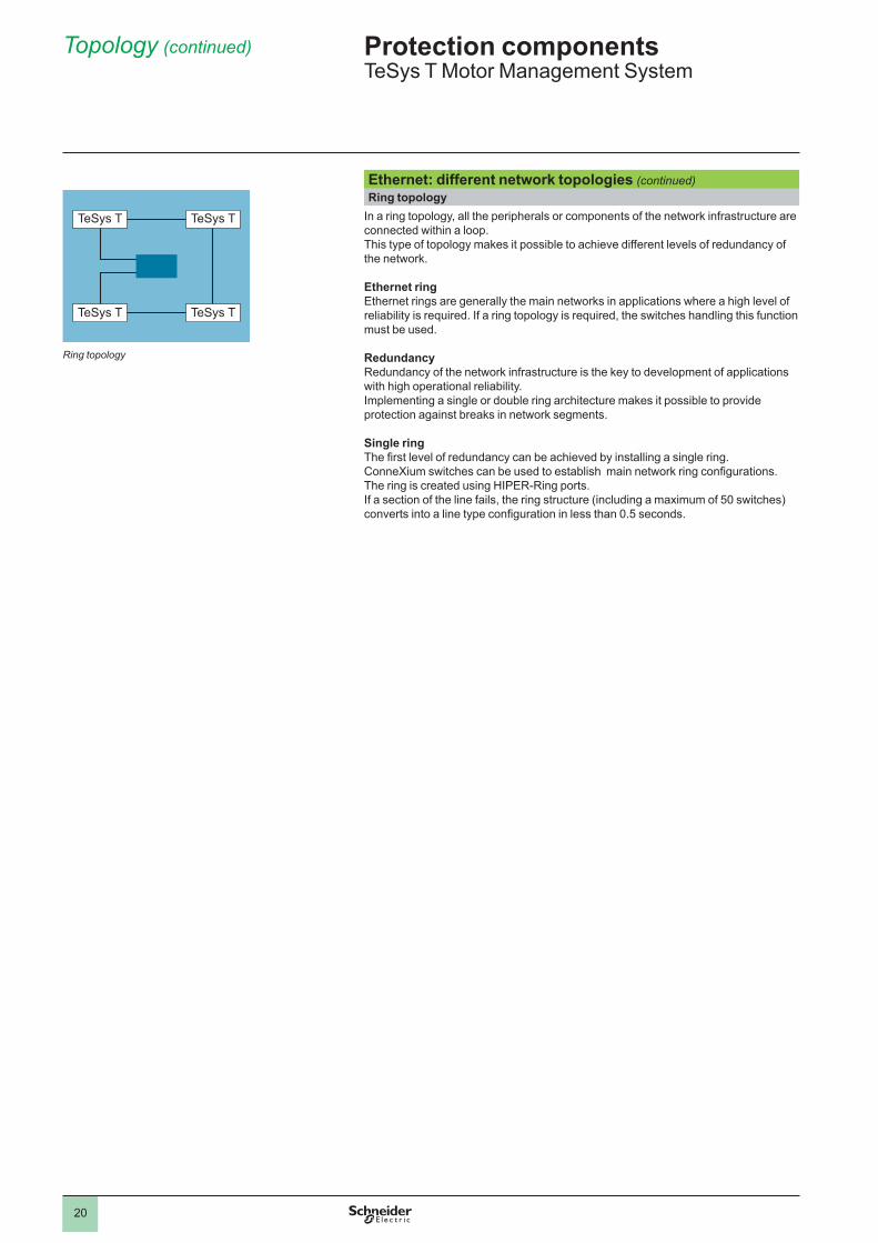
Ethernet: different network topologies (continued)Ring topology
In.a.ring.topology,.all.the.peripherals.or.components.of.the.network.infrastructure.are.connected.within.a.loop ..This.type.of.topology.makes.it.possible.to.achieve.different.levels.of.redundancy.of.the.network .
Ethernet ring Ethernet.rings.are.generally.the.main.networks.in.applications.where.a.high.level.of.reliability.is.required ..If.a.ring.topology.is.required,.the.switches.handling.this.function.must.be.used .
RedundancyRedundancy.of.the.network.infrastructure.is.the.key.to.development.of.applications.with.high.operational.reliability ..Implementing.a.single.or.double.ring.architecture.makes.it.possible.to.provide.protection.against.breaks.in.network.segments .
Single ringThe first level of redundancy can be achieved by installing a single ring.ConneXium switches can be used to establish main network ring configurations.The.ring.is.created.using.HIPER-Ring.ports ..If.a.section.of.the.line.fails,.the.ring.structure.(including.a.maximum.of.50.switches).converts into a line type configuration in less than 0.5 seconds.
Topology (continued) Protection componentsTeSys.T.Motor.Management.System
TeSys T TeSys T
TeSys T TeSys T
Ring topology
1
2
3
4
5
6
7
8
9
10
��
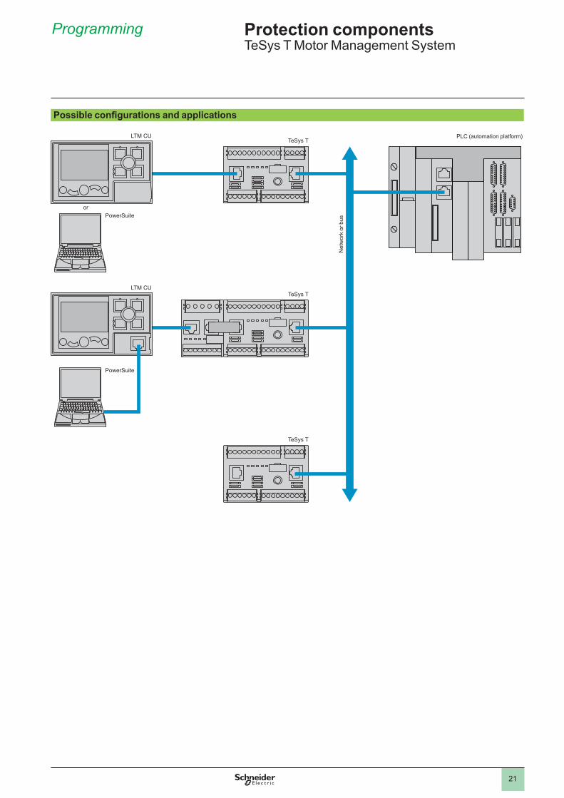
Possible configurations and applications
LTM CUTeSys T
TeSys T
TeSys T
PowerSuite
LTM CU
PowerSuite
PLC.(automation.platform)
Net
wor
k.or
.bus
or
Programming Protection componentsTeSys.T.Motor.Management.System
....
1
2
3
4
5
6
7
8
9
10
��
Protection componentsTeSys.T.Motor.Management.System
Programming (continued)
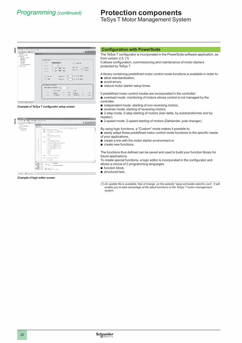
Configuration with PowerSuite The TeSys T configurator is incorporated in the PowerSuite software application, as from.version.� .5 ..(1)It allows configuration, commissioning and maintenance of motor startersprotected.by.TeSys.T .
A library containing predefined motor control mode functions is available in order to:allow.standardisation,.avoid.errors,reduce.motor.starter.setup.times ..
5 predefined motor control modes are incorporated in the controller:overload.mode:.monitoring.of.motors.whose.control.is.not.managed.by.the.
controller,independent.mode:.starting.of.non-reversing.motors,reverser.mode:.starting.of.reversing.motors,�-step.mode:.�-step.starting.of.motors.(star-delta,.by.autotransformer.and.by.
resistor),�-speed.mode:.�-speed.starting.of.motors.(Dahlander,.pole.changer) .
By.using.logic.functions,.a."Custom".mode.makes.it.possible.to:easily adapt these predefined motor control mode functions to the specific needs
of.your.applications,.create.a.link.with.the.motor.starter.environment.or.create.new.functions ..
.The functions thus defined can be saved and used to build your function library for future.applications .To create special functions, a logic editor is incorporated in the configurator and allows.a.choice.of.�.programming.languages:
function.block,structured.text .
bbb
b
bbb
b
b
bb
bb
(1)Anupdatefileisavailable,freeofcharge,onthewebsite“www.schneider-electric.com”.Itwillenable you to take advantage of the latest functions in the TeSys T motor management system.
5686
09
ExampleofTeSysTconfiguratorsetupscreen
5686
09
ExampleofTeSysTconfiguratorsetupscreen
536�
96
Example of logic editor screen.
536�
96
Example of logic editor screen.
1
2
3
4
5
6
7
8
9
10
�3
Protection componentsTeSys.T.Motor.Management.System
Characteristics
EnvironmentProduct type LTM R controllers LTM EV40pp extension modules
Conforming to standards IEC/EN.60947-4-�,.UL.508,.CSA.��-�.n°�4,.IACS.E�0.
Product certifications UL,.CSA,BV,.LROS,.DNV,.GL,.RINA,.ABS,.RMRos,.NOM,.CCC,.C-TIC’K,.ATEX,.GOST,.KERI.(1)
Rated insulation voltage of the outputs (Ui)
Conforming.to.IEC/EN.60947-�,.overvoltage.category.III,.degree.of.pollution.3
V 690
Conforming.to.UL.508,..CSA.C���.n°.�4
V 690
Rated impulse withstand voltage (Uimp)
Conforming.to.IEC/EN.60947-4-�a.�00…�40.V.supply,.inputs.and.outputs
kV 4 4
c.�4.V.supply,.inputs.and.outputs
kV 0 .8 0 .8
Communication.circuits kV 0 .8 –Current.or.voltage.measurement.circuit
kV 6 6
Short-circuit withstand Conforming.to..IEC/EN.60947-4-�
kA �00
Protective treatment Conforming.to.IEC/EN.60068 “TH”Conforming.to.IEC/EN.60068-�-30 ��.x.�4.hour.cyclesConforming.to.IEC/EN.60070-�-�� h 48
Ambient air temperature around the device
Storage °C -.40…+80Operation °C -.�0…+60
Operating positionwithout dating
In.relation.to.normal.vertical.mounting.plane
±.30°.in.relation.to.mounting.plate,.±.90°...
Flame resistance Conforming.to.UL.94 °C 960..(for.parts.supporting.live.components)Conforming.to.IEC/EN.60695-�-�� °C 650.(for.other.parts)
Shock resistance (�/�.sine.wave,.��.ms)
Conforming.to..IEC/EN.60068-�-�7.(2)
�5.gn
Vibration resistance Conforming.to..IEC/EN.60068-�-6.(2)5…300.Hz
4.gn.(plate.mounted)�.gn.(mounted.on.5 rail)
Resistance to electrostatic discharge
Conforming.to..IEC/EN.6�000-4-�
kV In.open.air:.8.-.Level.3On.contact:.6.-.Level.3
Immunity to radiated electromagnetic interference
Conforming.to..IEC.6�000-4-3
V/m �0.-.Level.3
Immunity to fast transient bursts
Conforming.to..IEC.6�000-4-4.
kV On.supply.and.relay.outputs:.4.-.Level.4Other.circuits:.�.-.Level.3
Immunity to radioelectric fields
Conforming.to..IEC/EN.6�000-4-6
V �0.-.Level.3
Immunity to dissipated shock waves
Conforming.to.IEC/EN.6�000-4-5 Common mode Serial mode Common mode Serial modeRelay.outputs.and.supply kV 4 � – –c �4.V.inputs kV � � � �a �00…�40.V.inputs kV � � � �Voltage.inputs kV – – 4 �Communication kV � – � –Temperature.sensor..(IT�/IT�)
kV � 0 .5 – –
Altitude derating 2000 m 3000 m 3500 m 4000 m 4500 mRated.operational.voltage.(Ui) � 0 .93 0 .87 0 .8 0 .7Max ..operating.temperature � 0 .93 0 .9� 0 .9 0 .88
(1)Certaincertificationsarepending:pleaseconsultyourCustomerCareCentre.1) Without modifying the contact states, in the most unfavourable direction.
1
2
3
4
5
6
7
8
9
10
�4
Characteristics (continued)
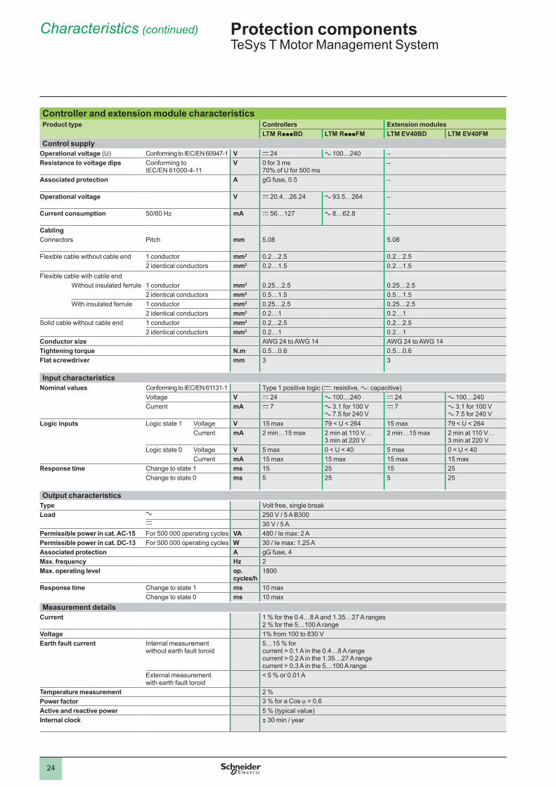
Controller and extension module characteristicsProduct type Controllers Extension modules
LTM RpppBD LTM RpppFM LTM EV40BD LTM EV40FMControl supply
Operational voltage (U) Conforming.to.IEC/EN.60947-� V c �4 a.�00…�40 –Resistance to voltage dips Conforming.to..
IEC/EN.6�000-4-��V 0.for.3.ms.
70%.of.U.for.500.ms–
Associated protection A gG.fuse,.0 .5 –
Operational voltage V c.�0 .4…�6 .�4 a.93 .5…�64 –
Current consumption 50/60.Hz mA c.56…��7 a.8…6� .8 –
CablingConnectors Pitch mm 5 .08 5 .08
Flexible.cable.without.cable.end �.conductor mm2 0 .�…� .5 0 .�…� .5�.identical.conductors mm2 0 .�…� .5 0 .�…� .5
Flexible.cable.with.cable.endWithout.insulated.ferrule �.conductor mm2 0 .�5…� .5 0 .�5…� .5
�.identical.conductors mm2 0 .5…� .5 0 .5…� .5With.insulated.ferrule �.conductor mm2 0 .�5…� .5 0 .�5…� .5
�.identical.conductors mm2 0 .�…� 0 .�…�Solid.cable.without.cable.end �.conductor mm2 0 .�…� .5 0 .�…� .5
�.identical.conductors mm2 0 .�…� 0 .�…�Conductor size AWG.�4.to.AWG.�4 AWG.�4.to.AWG.�4Tightening torque N.m 0 .5…0 .6 0 .5…0 .6Flat screwdriver mm 3 3
Input characteristicsNominal values Conforming.to.IEC/EN.6��3�-� Type.�.positive.logic.(c:.resistive,.a:.capacitive)
Voltage V c �4 a.�00…�40 c �4 a.�00…�40Current mA c 7 a 3 .�.for.�00.V.
a 7 .5.for.�40.Vc 7 a 3 .�.for.�00.V.
a 7 .5.for.�40.VLogic inputs Logic.state.� Voltage V �5.max 79.<.U.<.�64 �5.max 79.<.U.<.�64
Current mA �.min…�5.max �.min.at.��0.V….3.min.at.��0.V
�.min…�5.max �.min.at.��0.V….3.min.at.��0.V
Logic.state.0 Voltage V 5.max 0.<.U.<.40 5.max 0.<.U.<.40Current mA �5.max �5.max �5.max �5.max
Response time Change.to.state.� ms �5 �5 �5 �5Change.to.state.0 ms 5 �5 5 �5
Output characteristicsType Volt.free,.single.breakLoad a �50.V./.5.A.B300
c 30.V./.5.APermissible power in cat. AC-15 For.500.000.operating.cycles VA 480./.Ie.max:.�.APermissible power in cat. DC-13 For.500.000.operating.cycles W 30./.Ie.max:.� .�5.AAssociated protection A gG.fuse,.4Max. frequency Hz �Max. operating level op.
cycles/h�800
Response time Change.to.state.� ms �0.maxChange.to.state.0 ms �0.max
Measurement detailsCurrent �.%.for.the.0 .4…8.A.and.� .35…�7.A.ranges.
�.%.for.the.5…�00.A.rangeVoltage �%.from.�00.to.830.VEarth fault current Internal.measurement.
without.earth.fault.toroid5…�5.%.for..current.>.0 .�.A.in.the.0 .4…8.A.range.current.>.0 .�.A.in.the.� .35…�7.A.range.current.>.0 .3.A.in.the.5…�00.A.range
External.measurement..with.earth.fault.toroid
<.5.%.or.0 .0�.A
Temperature measurement �.%Power factor 3.%.for.a.Cos.j.>.0 .6Active and reactive power 5.%.(typical.value)Internal clock ±.30.min./.year
Protection componentsTeSys.T.Motor.Management.System
1
2
3
4
5
6
7
8
9
10
�5
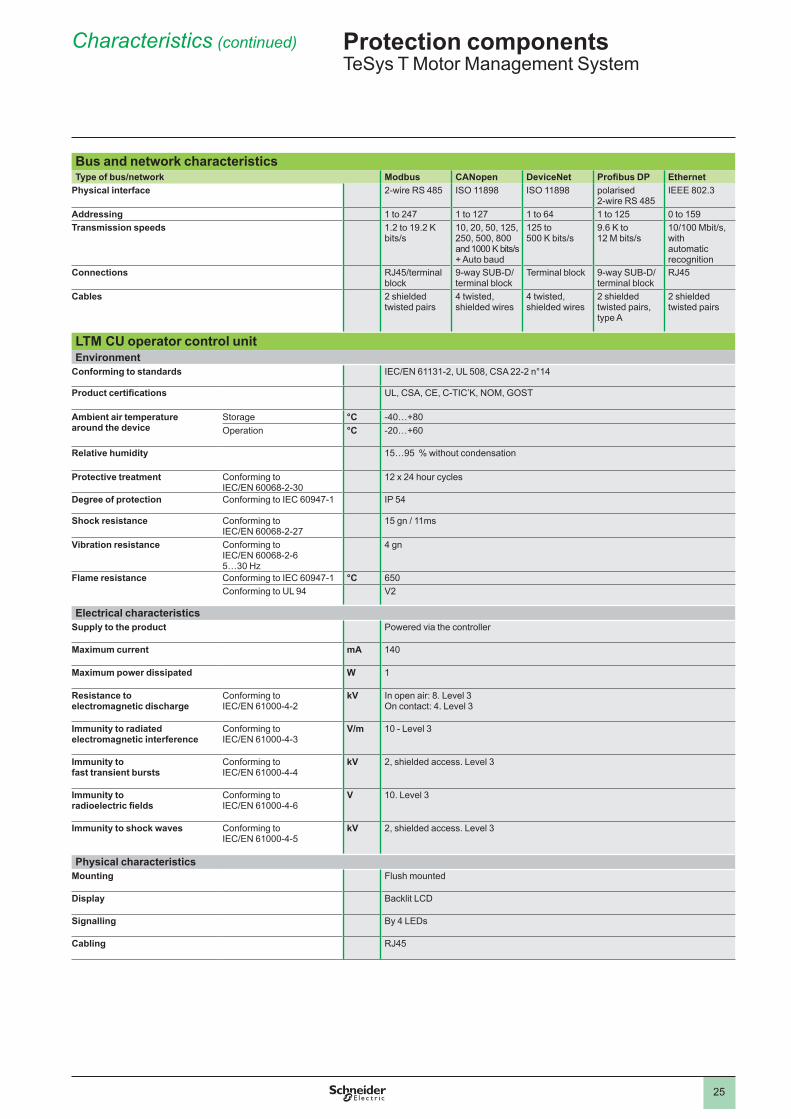
Bus and network characteristicsType of bus/network Modbus CANopen DeviceNet Profibus DP Ethernet
Physical interface �-wire.RS.485 ISO.��898 ISO.��898 polarised..�-wire.RS.485
IEEE.80� .3
Addressing �.to.�47 �.to.��7 �.to.64 �.to.��5 0.to.�59Transmission speeds � .�.to.�9 .�.K.
bits/s�0,.�0,.50,.��5,.�50,.500,.800.and.�000.K.bits/s..+.Auto.baud
��5.to..500.K.bits/s
9 .6.K.to..��.M.bits/s
�0/�00.Mbit/s,.with..automatic.recognition
Connections RJ45/terminal.block
9-way.SUB-D/terminal.block
Terminal.block 9-way.SUB-D/terminal.block
RJ45
Cables �.shielded.twisted.pairs
4.twisted,.shielded.wires
4.twisted,.shielded.wires
�.shielded.twisted.pairs,.type.A
�.shielded.twisted.pairs
LTM CU operator control unitEnvironment
Conforming to standards IEC/EN.6��3�-�,.UL.508,.CSA.��-�.n°�4
Product certifications UL,.CSA,.CE,.C-TIC’K,.NOM,.GOST
Ambient air temperature around the device
Storage °C -40…+80Operation °C -�0…+60
Relative humidity �5…95..%.without.condensation
Protective treatment Conforming.to..IEC/EN.60068-�-30
��.x.�4.hour.cycles
Degree of protection Conforming.to.IEC.60947-� IP.54
Shock resistance Conforming.to..IEC/EN.60068-�-�7
�5.gn./.��ms
Vibration resistance Conforming.to..IEC/EN.60068-�-65…30.Hz
4.gn
Flame resistance Conforming.to.IEC.60947-� °C 650Conforming.to.UL.94 V�
Electrical characteristicsSupply to the product Powered.via.the.controller
Maximum current mA �40
Maximum power dissipated W �
Resistance to electromagnetic discharge
Conforming.to..IEC/EN.6�000-4-�
kV In.open.air:.8 ..Level.3On.contact:.4 ..Level.3
Immunity to radiated electromagnetic interference
Conforming.to..IEC/EN.6�000-4-3
V/m �0.-.Level.3
Immunity to fast transient bursts
Conforming.to..IEC/EN.6�000-4-4
kV �,.shielded.access ..Level.3
Immunity to radioelectric fields
Conforming.to..IEC/EN.6�000-4-6
V �0 ..Level.3
Immunity to shock waves Conforming.to..IEC/EN.6�000-4-5
kV �,.shielded.access ..Level.3
Physical characteristicsMounting Flush.mounted
Display Backlit.LCD
Signalling By.4.LEDs
Cabling RJ45
Characteristics (continued) Protection componentsTeSys.T.Motor.Management.System
1
2
3
4
5
6
7
8
9
10
�6
Characteristics(continued)
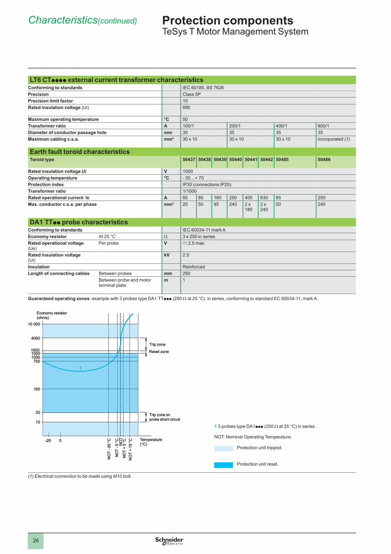
LT6 CTpppp external current transformer characteristicsConforming to standards IEC.60�85,.BS.76�6Precision Class.5PPrecision limit factor �5Rated insulation voltage.(Ui) 690
Maximum operating temperature °C 50Transformer ratio A �00/� �00/� 400/� 800/�Diameter of conductor passage hole mm 35 35 35 35Maximum cabling c.s.a. mm2 30.x.�0 30.x.�0 30.x.�0 incorporated.(1)
Earth fault toroid characteristicsToroid type 50437 50438 50439 50440 50441 50442 50485 50486
Rated insulation voltage Ui V �000Operating temperature °C -.35…+.70Protection index IP30.(connections.IP�0)Transformer ratio �/�000Rated operational current le A 65 85 �60 �50 400 630 85 �50Max. conductor c.s.a. per phase mm2 �5 50 95 �40 �.x.
�85�.x.�40
50 �40
DA1 TTpp probe characteristicsConforming to standards IEC.60034-��.mark.AEconomy resistor At.�5.°C W 3.x.�50.in.seriesRated operational voltage (Ue)
Per.probe V c.� .5.max
Rated insulation voltage..(Ui)
kV � .5
Insulation ReinforcedLength of connecting cables Between.probes mm �50
Between.probe.and.motor.terminal.plate
m �
Guaranteed operating zones:.example.with.3.probes.type.DA�.TTppp.(�50.W.at.�5.°C)..in.series,.conforming.to.standard.EC.60034-��,.mark.A .
1.3.probes.type.DA�ppp.(�50.W.at.�5.°C).in.series .
NOT:.Nominal.Operating.Temperature .
Protection.unit.tripped .
Protection.unit.reset .
(1) Electrical connection to be made using M10 bolt.
10 000
4000
100
10
-20
20
7501000
16501500
0
1
Economy.resistor(ohms)
Trip.zone
Reset.zone
Trip.zone.on..probe.short-circuit
Temperature.(°C)
NO
T.+.
�5.°C
NO
T.+.
5.°C
NO
T.-.�
0.°C
NO
T.-.5
.°C NO
T
10 000
4000
100
10
-20
20
7501000
16501500
0
1
Economy.resistor(ohms)
Trip.zone
Reset.zone
Trip.zone.on..probe.short-circuit
Temperature.(°C)
NO
T.+.
�5.°C
NO
T.+.
5.°C
NO
T.-.�
0.°C
NO
T.-.5
.°C NO
T
Protection componentsTeSys.T.Motor.Management.System
1
2
3
4
5
6
7
8
9
10
�7
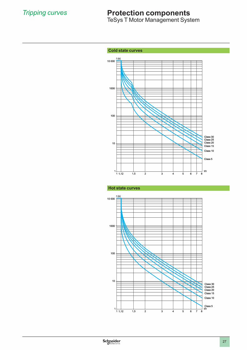
Tripping curves
Cold state curves..
..
Hot state curves..
�0.000
�000
�00
�0
�
t.(s)
I/Ir� �,�� �,5 � 3 4 5 6 7 8
Class.5
Class.�0
Class.�5Class.�0Class.�5Class.30
�0.000
�000
�00
�0
�
t.(s)
I/Ir� �,�� �,5 � 3 4 5 6 7 8
Class.5
Class.�0
Class.�5Class.�0Class.�5Class.30
�0.000
�000
�00
�0
�
t.(s)
I/Ir� �,�� �,5 � 3 4 5 6 7 8
Class.5
Class.�0
Class.�5Class.�0Class.�5Class.30
�0.000
�000
�00
�0
�
t.(s)
I/Ir� �,�� �,5 � 3 4 5 6 7 8
Class.5
Class.�0
Class.�5Class.�0Class.�5Class.30
Protection componentsTeSys.T.Motor.Management.System
1
2
3
4
5
6
7
8
9
10
�8
ControllersSetting range
Control voltage
Current range
Reference Weight
A V A kgFor Modbus
8 .c �4 0 .4…8 LTM R08MBD ... 0 .530a.�00…�40.V 0 .4…8 LTM R08MFM 0 .530
27 .c �4 � .35…�7 LTM R27MBD 0 .530a.�00…�40.V � .35…�7 LTM R27MFM 0 .530
100 .c �4 5…�00 LTM R100MBD 0 .530a.�00…�40.V 5…�00 LTM R100MFM 0 .530
For CANopen8 .c �4 0 .4…8 LTM R08CBD ... 0 .530
a.�00…�40.V 0 .4…8 LTM R08CFM 0 .530
27 .c �4 � .35…�7 LTM R27CBD 0 .530a.�00…�40.V � .35…�7 LTM R27CFM 0 .530
100 .c �4 5…�00 LTM R100CBD 0 .530a.�00…�40.V 5…�00 LTM R100CFM 0 .530
For DeviceNet8 .c �4 0 .4…8 LTM R08DBD ... 0 .530
a.�00…�40.V 0 .4…8 LTM R08DFM 0 .530
27 .c �4 � .35…�7 LTM R27DBD 0 .530a.�00…�40.V � .35…�7 LTM R27DFM 0 .530
100 .c �4 5…�00 LTM R100DBD 0 .530a.�00…�40.V 5…�00 LTM R100DFM 0 .530
For Profibus DP8 .c �4 0 .4…8 LTM R08PBD ... 0 .530
a.�00…�40.V 0 .4…8 LTM R08PFM 0 .530
27 .c �4 � .35…�7 LTM R27PBD 0 .530a.�00…�40.V � .35…�7 LTM R27PFM 0 .530
100 .c �4 5…�00 LTM R100PBD 0 .530a.�00…�40.V 5…�00 LTM R100PFM 0 .530
For Ethernet TCP/IP8 .c �4 0 .4…8 LTM R08EBD 0 .530
a.�00…�40.V 0 .4…8 LTM R08EFM 0 .530
27 .c �4 � .35…�7 LTM R27EBD 0 .530a.�00…�40.V � .35…�7 LTM R27EFM 0 .530
100 .c �4 5…�00 LTM R100EBD 0 .530a.�00…�40.V 5…�00 LTM R100EFM 0 .530
LTM R08MBD
5�63
87
LTM R08MBD
5�63
87
LTM R08CBD
5�63
88
LTM R08CBD
5�63
88
LTM R08DBD
5�63
89
LTM R08DBD
5�63
89
LTM R08PBD
5�63
90
LTM R08PBD
5�63
90References Protection components
TeSys.T.Motor.Management.System
LTM R08EBD
5�63
9�
1
2
3
4
5
6
7
8
9
10
�9
References (continued)
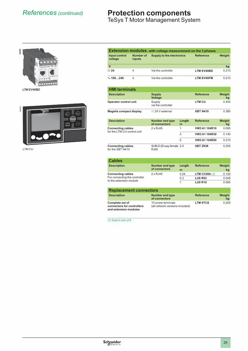
Extension modules. with voltage measurement on the 3 phasesInput control voltage
Number of inputs
Supply to the electronics Reference Weight
V kgc 24 4 Via.the.controller LTM EV40BD ... 0 .��0
a 100…240 4 Via.the.controller LTM EV40FM 0 .��0
HMI terminalsDescription Supply
VoltageReference Weight
kgOperator control unit Supply.
via.the.controllerLTM CU 0 .400
Magelis compact display . c.�4.V.external XBT N410 0 .380
Description Number and type of connectors
Lengthm
Reference Weightkg
Connecting cablesfor.the.LTM.CU.control.unit
�.x.RJ45 � VW3 A1 104R10 0 .065
3 VW3 A1 104R30 0 .�40
5 VW3 A1 104R50 0 .��0
Connecting cablesfor.the.XBT.N4�0
SUB-D.�5-way.female.RJ45
� .5 XBT Z938 0 .�00
CablesDescription Number and type
of connectorsLength Reference Weightm kg
Connecting cables For.connecting.the.controller..to.the.extension.module
�.x.RJ45 0 .04 LTM CC004 (1) 0 .��00 .3 LU9 R03 0 .045� LU9 R10 0 .065
Replacement connectorsDescription Number and type
of connectorsReference Weight
kgComplete set of connectors for controllers and extension modules
�0.screw.terminals.(all.network.versions.included)
LTM 9TCS 0 .�00
(1) Sold in lots of 6.
LTM EV40BD
5�63
80
LTM EV40BD
5�63
80
Protection componentsTeSys.T.Motor.Management.System
LTM CU
5686
05
1
2
3
4
5
6
7
8
9
10
30
References (continued)
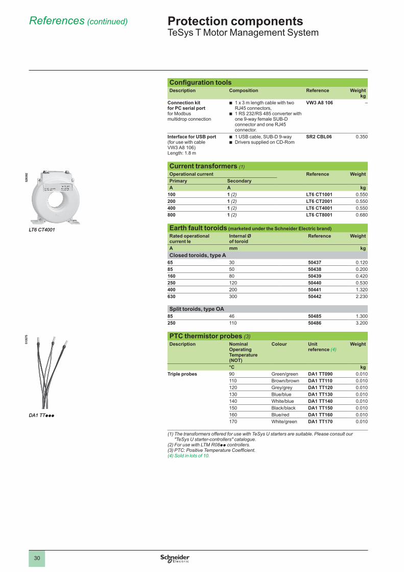
Configuration toolsDescription Composition Reference Weight
kgConnection kit for PC serial portfor.Modbus..multidrop.connection
�.x.3.m.length.cable.with.two.RJ45.connectors,�.RS.�3�/RS.485.converter.with.one.9-way.female.SUB-D.connector.and.one.RJ45.connector .
b
b
VW3 A8 106 –
Interface for USB port (for.use.with.cable.VW3.A8.�06)Length:.� .8.m
�.USB.cable,.SUB-D.9-wayDrivers.supplied.on.CD-Rom
bb
SR2 CBL06 0 .350
Current transformers (1)Operational current Reference WeightPrimary SecondaryA A kg
100 1 (2) LT6 CT1001 0 .550200 1 (2) LT6 CT2001 0 .550400 1 (2) LT6 CT4001 0 .550800 1 (2) LT6 CT8001 0 .680
Earth fault toroids (marketed under the Schneider Electric brand)Rated operational current Ie
Internal Ø of toroid
Reference Weight
A mm kgClosed toroids, type A
65 30 50437 0 .��085 50 50438 0 .�00160 80 50439 0 .4�0250 ��0 50440 0 .530400 �00 50441 � .3�0630 300 50442 � .�30
Split toroids, type OA85 46 50485 � .300250 ��0 50486 3 .�00
PTC thermistor probes (3)Description Nominal
Operating Temperature (NOT)
Colour Unit reference (4)
Weight
°C kgTriple probes 90 Green/green DA1 TT090 0 .0�0
��0 Brown/brown DA1 TT110 0 .0�0��0 Grey/grey DA1 TT120 0 .0�0�30 Blue/blue DA1 TT130 0 .0�0�40 White/blue DA1 TT140 0 .0�0�50 Black/black DA1 TT150 0 .0�0�60 Blue/red DA1 TT160 0 .0�0�70 White/green DA1 TT170 0 .0�0
(1) The transformers offered for use with TeSys U starters are suitable. Please consult our "TeSys U starter-controllers" catalogue.
(2) For use with LTM R08pp controllers.(3)PTC:PositiveTemperatureCoefficient.(4) Sold in lots of 10.
LT6 CT4001
5�63
9�
LT6 CT4001
5�63
9�
DA1 TTppp
5�05
75
DA1 TTppp
5�05
75Protection componentsTeSys.T.Motor.Management.System
1
2
3
4
5
6
7
8
9
10
3�
References (continued)
Marking accessories (to be ordered separately)Description Composition Sold in
lots ofUnit reference
Weight
kgClip-in markers.(maximum.of.5.per.unit)
Strips.of.�0.identical.numbers.(0.to.9)
25 AB1 Rp (1) 0 .00�
Strips.of.�0.identical.capital.letters.(A.to.Z)
25 AB1 Gp (1) 0 .00�
Connection accessoriesDescription Length Reference Weight
m kgFor Modbus connection
Cables fitted with 2 x RJ45 connectors
0 .3 VW3 A8 306 R03 0 .045� VW3 A8 306 R10 0 .0653 VW3 A8 306 R30 0 .��5
T-junctions 0 .3 VW3 A8 306 TF03 0 .03�� VW3 A8 306 TF10 0 .03�
RS 485 line terminator – VW3 A8 306 R 0 .0��
For CANopen connectionCables 50 TSX CAN CA50 4 .930
�00 TSX CAN CA100 8 .800300 TSX CAN CA300 �4 .560
IP20 connectorsSUB-D.9-way.femaleLine.end.adapter.switch
Elbowed.(90°) – TSX CAN KCDF 90T 0 .046Straight – TSX CAN KCDF 180T 0 .049Elbowed.(90°).with.SUB-D.9-way.connector.for.connection.to..PC.or.diagnostic.tool
– TSX CAN KCDF 90TP 0 .05�
For DeviceNet connectionCables 50 TSX CAN CA50 4 .930
�00 TSX CAN CA100 8 .800300 TSX CAN CA300 �4 .560
For Profibus DP connection (2)Cables �00 TSX PBSCA100 –
400 TSX PBSCA400 –Connectors With.line.terminator – 490 NAD 911 03 –
Without.line.terminator – 490 NAD 911 04 –
With.line.terminator.and.terminal.port
– 490 NAD 911 05 –
For Ethernet TCP/IP connectionShielded twisted pair cables to standard EIA/TIA568
Cables fitted with 2 x RJ45 connectors for.connection.to..terminal.equipment
Straight �. 490 NTW 000 02 –5 490 NTW 000 05 –�� 490 NTW 000 12 –40 490 NTW 000 40 –80 490 NTW 000 80 –
Shielded twisted pair cables, UL and CSA 22.1 approvedCables fitted with 2 x RJ45 connectorsfor.connection.to..terminal.equipment
Straight � 490 NTW 000 02U –5 490 NTW 000 05U –�� 490 NTW 000 12U –40 490 NTW 000 40U –80 490 NTW 000 80U –
(1) When ordering, replace the p in the reference with the number or letter required.(2) To order other connectors and cables (UL cables for harsh environments, etc.), please
consult your Customer Care Centre.
Protection componentsTeSys.T.Motor.Management.System
1
2
3
4
5
6
7
8
9
10
3�
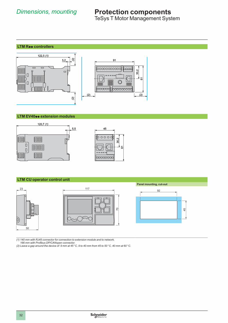
Dimensions, mounting
LTM Rpp controllers...
LTM EV40pp extension modules...
LTM CU operator control unitPanel mounting, cut-out
23
50
117
70
92
45
(1) 140 mm with RJ45 connector for connection to extension module and to network, 166mmwithProfibusDP/CANopenconnector.
(2) Leave a gap around the device of: 9 mm at 45 °C, 9 to 40 mm from 45 to 50 °C, 40 mm at 60 °C.
5,2 91
(2) (2)
122,5 (1)
6130
,2
(2)
(2)
5,2 91
(2) (2)
122,5 (1)
6130
,2
(2)
(2)
5,5 45120,7 (1)
6130
,2
5,5 45120,7 (1)
6130
,2
Protection componentsTeSys.T.Motor.Management.System
............
1
2
3
4
5
6
7
8
9
10
33
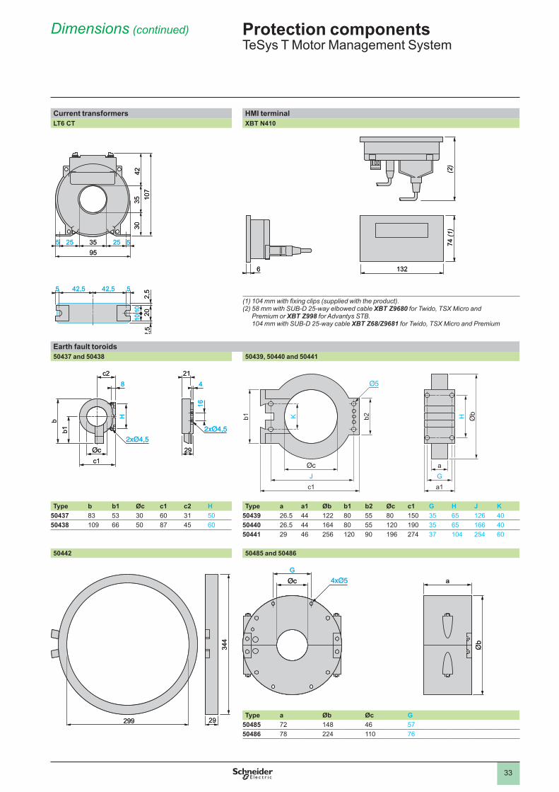
Dimensions (continued)
Current transformers HMI terminalLT6 CT XBT N410
.... ....
(1)104mmwithfixingclips(suppliedwiththeproduct).(2) 58 mm with SUB-D 25-way elbowed cable XBT Z9680 for Twido, TSX Micro and
Premium or XBT Z998 for Advantys STB. 104 mm with SUB-D 25-way cable XBT Z68/Z9681 for Twido, TSX Micro and Premium
Earth fault toroids50437 and 50438 50439, 50440 and 50441
.... ....
Type b b1 Øc c1 c2 H Type a a1 Øb b1 b2 Øc c1 G H J K50437 83 53 30 60 3� 50 50439 �6 .5 44 ��� 80 55 80 �50 35 65 ��6 4050438 �09 66 50 87 45 60 50440 �6 .5 44 �64 80 55 ��0 �90 35 65 �66 40
50441 �9 46 �56 ��0 90 �96 �74 37 �04 �54 60
50442 50485 and 50486.... ....
Type a Øb Øc G50485 7� �48 46 5750486 78 ��4 ��0 76
2,5
35255 52595
35 107
3042
1010
2,5
20
42,5 42,55 5
2,5
35255 52595
35 107
3042
1010
2,5
20
42,5 42,55 5
132
74 (1)
6
(2)
132
74 (1)
6
(2)
c1
c28
H
b1b
29
214
16
c1
c28
H
b1b
29
214
16
HaGa1
Jc1
b2Kb1 HaGa1
Jc1
b2Kb1
344
29299
344
29299
aG
aG
Protection componentsTeSys.T.Motor.Management.System
............
1
2
3
4
5
6
7
8
9
10
34
Schemes
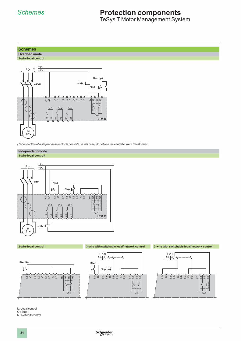
SchemesOverload mode3-wire local-control
....
(1) Connection of a single-phase motor is possible. In this case, do not use the central current transformer.
Independent mode3-wire local-control\
....
2-wire local-control 3-wire with switchable local/network control 2-wire with switchable local/network control....
L.:.Local.controlO.:.StopN.:.Network.control
LTM R24 33 3413 14 23
96959897I.6CI.5I.4CI.3I.2CI.1A2
A1
– KM1 – KM1
O.1 O.2 O.3
O.4
M 3
Stop
Start
LTM R24 33 3413 14 23
96959897I.6CI.5I.4CI.3I.2CI.1A2
A1
– KM1 – KM1
O.1 O.2 O.3
O.4
M 3
Stop
Start
LTM R24 33 3413 14 23
96959897I.6CI.5I.4CI.3I.2CI.1A2
A1
– KM1
O.1 O.2 O.3
O.4
M 3
– KM1
Stop
Start
LTM R24 33 3413 14 23
96959897I.6CI.5I.4CI.3I.2CI.1A2
A1
– KM1
O.1 O.2 O.3
O.4
M 3
– KM1
Stop
Start
96959897I.6CI.5I.4CI.3I.2CI.1
O.4
Start/Stop
96959897I.6CI.5I.4CI.3I.2CI.1
O.4
Start/Stop
96959897I.6CI.5I.4CI.3I.2CI.1
O.4
NL O
Start
Stop
96959897I.6CI.5I.4CI.3I.2CI.1
O.4
NL O
Start
Stop
96959897I.6CI.5I.4CI.3I.2CI.1
O.4
NL O
96959897I.6CI.5I.4CI.3I.2CI.1
O.4
NL O
Protection componentsTeSys.T.Motor.Management.System
........
(1)
1
2
3
4
5
6
7
8
9
10
35
Schemes (continued)
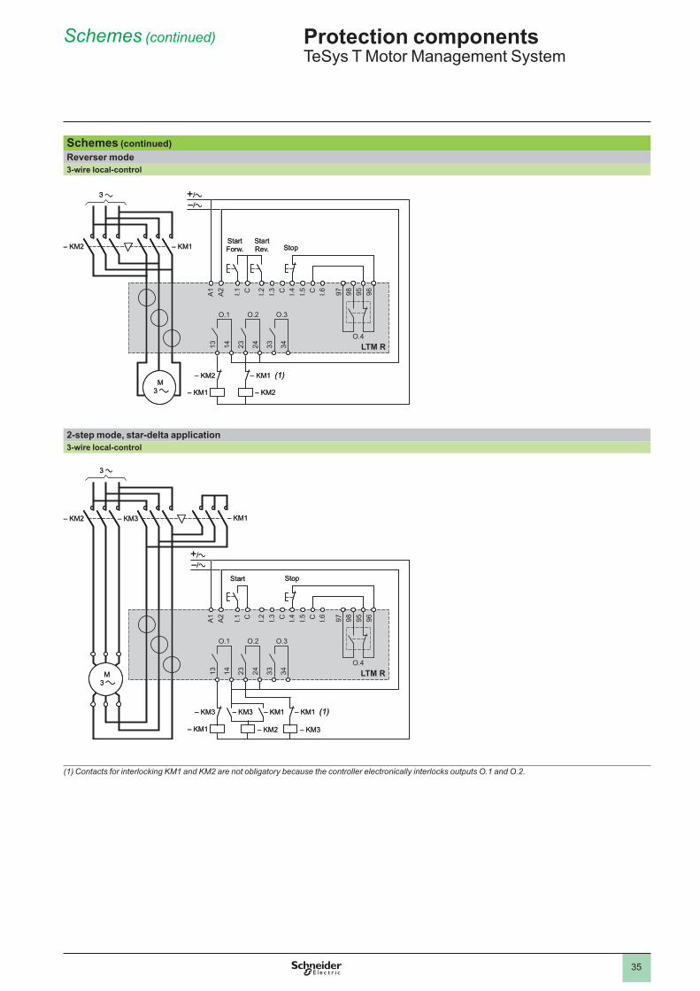
Schemes (continued)Reverser mode3-wire local-control
....
2-step mode, star-delta application3-wire local-control
....
(1) Contacts for interlocking KM1 and KM2 are not obligatory because the controller electronically interlocks outputs O.1 and O.2.
LTM R24 33 3413 14 23
96959897I.6CI.5I.4CI.3I.2CI.1A2
A1
– KM2 – KM1
– KM1
– KM2
– KM2
– KM1 (1)
O.1 O.2 O.3
O.4
M 3
StopStartForw .
StartRev .
LTM R24 33 3413 14 23
96959897I.6CI.5I.4CI.3I.2CI.1A2
A1
– KM2 – KM1
– KM1
– KM2
– KM2
– KM1 (1)
O.1 O.2 O.3
O.4
M 3
StopStartForw .
StartRev .
LTM R24 33 3413 14 23
96959897I.6CI.5I.4CI.3I.2CI.1A2
A1
– KM2 – KM3
– KM1
– KM3 – KM3
– KM2 – KM3
– KM1– KM1 (1)
O.1 O.2 O.3
O.4
– KM1
M 3
StopStart
LTM R24 33 3413 14 23
96959897I.6CI.5I.4CI.3I.2CI.1A2
A1
– KM2 – KM3
– KM1
– KM3 – KM3
– KM2 – KM3
– KM1– KM1 (1)
O.1 O.2 O.3
O.4
– KM1
M 3
StopStart
Protection componentsTeSys.T.Motor.Management.System
....
1
2
3
4
5
6
7
8
9
10
36
Schemes (continued)
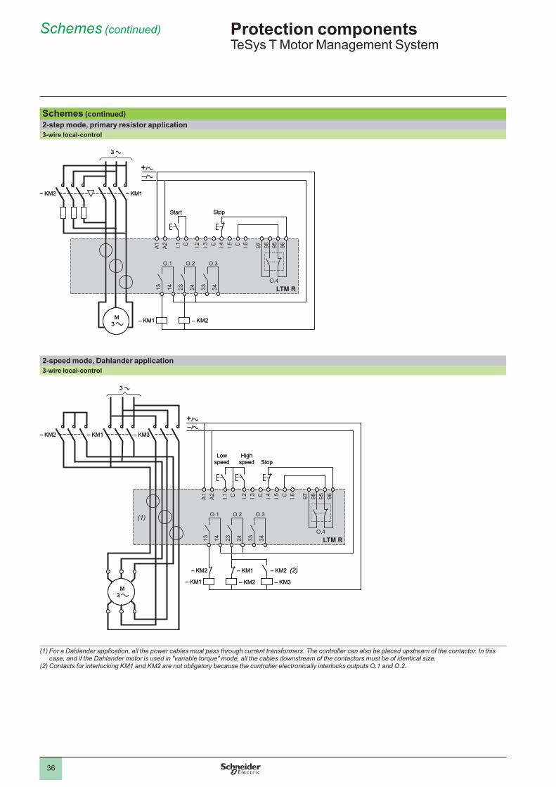
Schemes (continued)2-step mode, primary resistor application3-wire local-control
....
2-speed mode, Dahlander application3-wire local-control
....
(1) For a Dahlander application, all the power cables must pass through current transformers. The controller can also be placed upstream of the contactor. In this case, and if the Dahlander motor is used in "variable torque" mode, all the cables downstream of the contactors must be of identical size.
(2) Contacts for interlocking KM1 and KM2 are not obligatory because the controller electronically interlocks outputs O.1 and O.2.
LTM R24 33 3413 14 23
96959897I.6CI.5I.4CI.3I.2CI.1A2
A1
– KM2 – KM1
– KM1 – KM2
O.1 O.2 O.3
O.4
M 3
StopStart
LTM R24 33 3413 14 23
96959897I.6CI.5I.4CI.3I.2CI.1A2
A1
– KM2 – KM1
– KM1 – KM2
O.1 O.2 O.3
O.4
M 3
StopStart
LTM R24 33 3413 14 23
96959897I.6CI.5I.4CI.3I.2CI.1A2
A1
– KM1 – KM3
O.1 O.2 O.3
O.4
– KM1
– KM2
– KM2 – KM3
– KM2– KM1 (2)
(1)
– KM2
M 3
Low.speed
High.speed Stop
LTM R24 33 3413 14 23
96959897I.6CI.5I.4CI.3I.2CI.1A2
A1
– KM1 – KM3
O.1 O.2 O.3
O.4
– KM1
– KM2
– KM2 – KM3
– KM2– KM1 (2)
(1)
– KM2
M 3
Low.speed
High.speed Stop
Protection componentsTeSys.T.Motor.Management.System
.....
1
2
3
4
5
6
7
8
9
10
37
Schemes (continued)
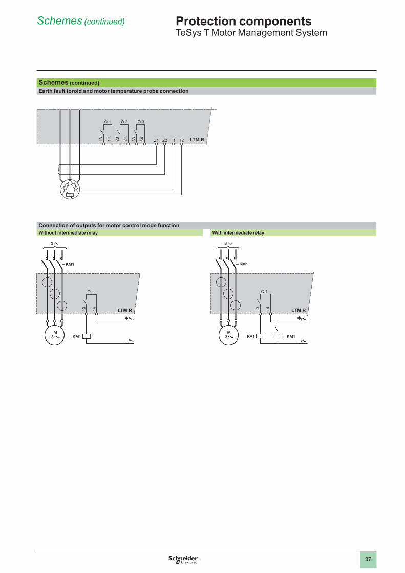
Schemes (continued)Earth fault toroid and motor temperature probe connection
....
Connection of outputs for motor control mode functionWithout intermediate relay With intermediate relay
...
24 33 3413 14 23O.1 O.2
Z1 Z2 T1 T2
O.3
LTM R24 33 3413 14 23O.1 O.2
Z1 Z2 T1 T2
O.3
LTM R
M 3
LTM R13 14
– KM1
O.1
– KM1 M
3
LTM R13 14
– KM1
O.1
– KM1 M
3
LTM R13 14– KM1
O.1
– KA1 – KM1 M
3
LTM R13 14– KM1
O.1
– KA1 – KM1
Protection componentsTeSys.T.Motor.Management.System
..
1
2
3
4
5
6
7
8
9
10
3838
Combinations for customer assembly
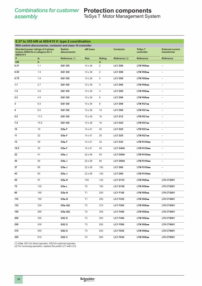
Protection componentsTeSys.T..Motor.Management.System
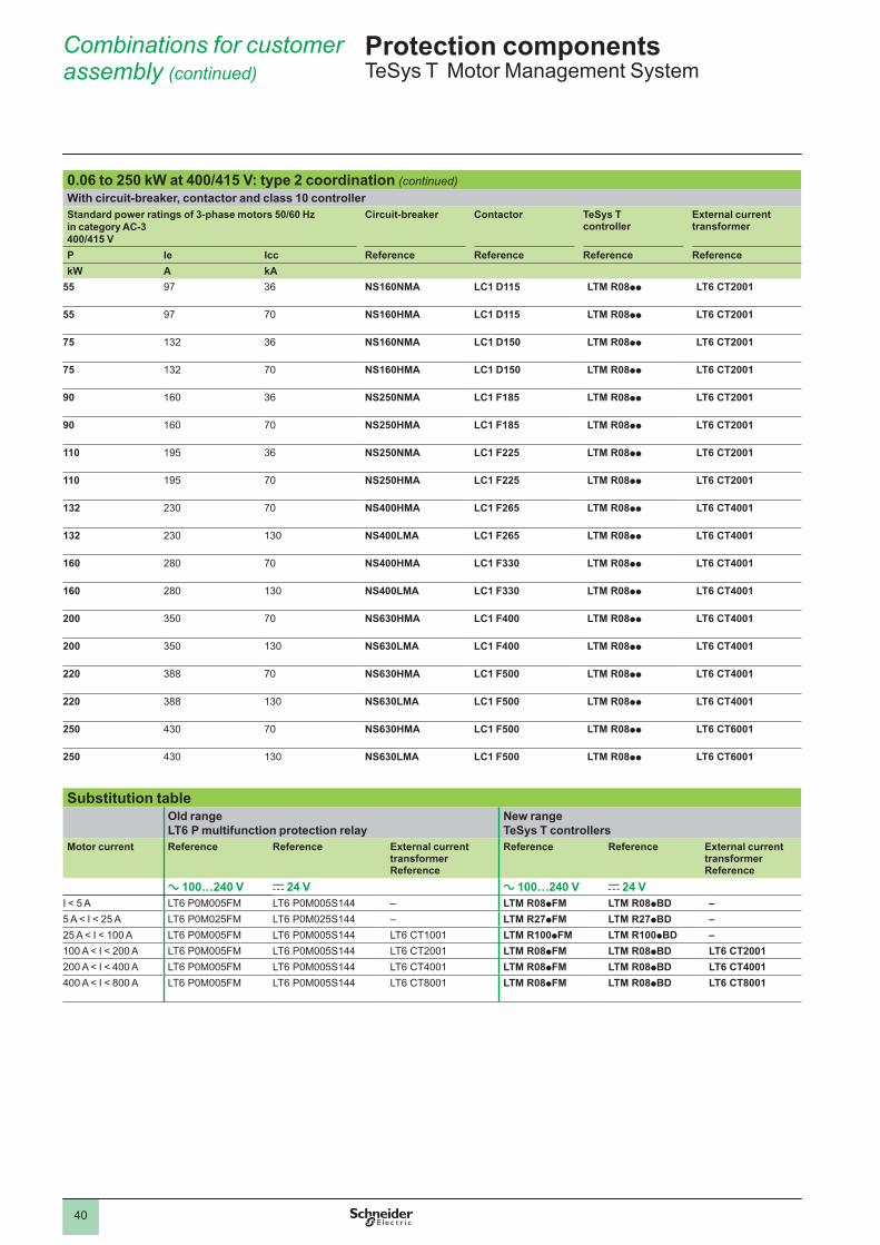
0.37 to 355 kW at 400/415 V: type 2 coordinationWith switch-disconnector, contactor and class 10 controllerStandard power ratings of 3-phase motors 50/60 Hz in category AC-3 400/415 V
Switch-disconnector
aM fuses Contactor TeSys T controller
External current transformer
P Ie Reference (1) Size Rating Reference (2) Reference ReferencekW A A
0.37 � .� GS1 DD �0.x.38 � LC1 D09 LTM R08pp –
0.55 � .5 GS1 DD �0.x.38 � LC1 D09 LTM R08pp –
0.75 � .9 GS1 DD �0.x.38 4 LC1 D09 LTM R08pp –
1.1 � .7 GS1 DD �0.x.38 4 LC1 D09 LTM R08pp –
1.5 3 .6 GS1 DD �0.x.38 4 LC1 D09 LTM R08pp –
2.2 4 .9 GS1 DD �0.x.38 6 LC1 D09 LTM R08pp –
3 6 .5 GS1 DD �0.x.38 8 LC1 D09 LTM R27pp –
4 8 .5 GS1 DD �0.x.38 �0 LC1 D09 LTM R27pp –
5.5 �� .5 GS1 DD �0.x.38 �6 LC1 D12 LTM R27pp –
7.5 �5 .5 GS1 DD �0.x.38 �6 LC1 D25 LTM R27pp –
10 �9 GSp F �4.x.5� �5 LC1 D25 LTM R27pp –
11 �� GSp F �4.x.5� �5 LC1 D25 LTM R27pp –
15 �9 GSp F �4.x.5� 3� LC1 D32 LTM R100pp –
18.5 35 GSp F �4.x.5� 40 LC1 D40A LTM R100pp –
22 4� GSp J ��.x.58 50 LC1 D50A LTM R100pp –
30 55 GSp J ��.x.58 80 LC1 D65A LTM R100pp –
37 66 GSp J ��.x.58 �00 LC1 D80 LTM R100pp –
45 80 GSp J ��.x.58 �00 LC1 D95 LTM R100pp –
55 97 GSp K T00 ��5 LC1 D115 LTM R08pp LT6 CT2001
75 �3� GSp L T0 �60 LC1 D150 LTM R08pp LT6 CT2001
90 �60 GSp N T� �00 LC1 F185 LTM R08pp LT6 CT2001
110 �95 GSp N T� �50 LC1 F225 LTM R08pp LT6 CT4001
132 �30 GSp QQ T� 3�5 LC1 F265 LTM R08pp LT6 CT4001
160 �80 GSp QQ T� 355 LC1 F400 LTM R08pp LT6 CT4001
200 350 GS2 S T3 500 LC1 F400 LTM R08pp LT6 CT8001
250 430 GS2 S T3 500 LC1 F500 LTM R08pp LT6 CT8001
315 540 GS2 S T3 630 LC1 F630 LTM R08pp LT6 CT8001
355 6�0 GS2 V T4 800 LC1 F630 LTM R08pp LT6 CT8001
(1) GSp: GS1 for direct operator, GS2 for external operator.(2)Forreversingoperation,replacetheprefixLC1withLC2.
3939
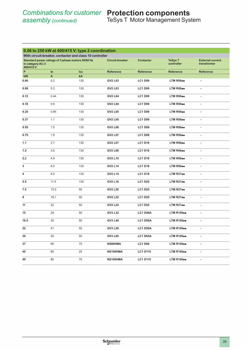
Combinations for customer assembly (continued)
Protection componentsTeSys.T..Motor.Management.System
0.06 to 250 kW at 400/415 V: type 2 coordinationWith circuit-breaker, contactor and class 10 controllerStandard power ratings of 3-phase motors 50/60 Hzin category AC-3400/415 V
Circuit-breaker Contactor TeSys T controller
External current transformer
P Ie Icc Reference Reference Reference ReferencekW A kA
0.06 0 .� �30 GV2 L03 LC1 D09 LTM R08pp –
0.09 0 .3 �30 GV2 L03 LC1 D09 LTM R08pp –
0.12 0 .44 �30 GV2 L04 LC1 D09 LTM R08pp –
0.18 0 .6 �30 GV2 L04 LC1 D09 LTM R08pp –
0.25 0 .85 �30 GV2 L05 LC1 D09 LTM R08pp –
0.37 � .� �30 GV2 L05 LC1 D09 LTM R08pp –
0.55 � .5 �30 GV2 L06 LC1 D09 LTM R08pp –
0.75 � .9 �30 GV2 L07 LC1 D09 LTM R08pp –
1.1 � .7 �30 GV2 L07 LC1 D18 LTM R08pp –
1.5 3 .6 �30 GV2 L08 LC1 D18 LTM R08pp –
2.2 4 .9 �30 GV2 L10 LC1 D18 LTM R08pp –
3 6 .5 �30 GV2 L14 LC1 D18 LTM R08pp –
4 8 .5 �30 GV2 L14 LC1 D18 LTM R27pp –
5.5 �� .5 �30 GV2 L16 LC1 D25 LTM R27pp –
7.5 �5 .5 50 GV2 L20 LC1 D25 LTM R27pp –
9 �8 .� 50 GV2 L22 LC1 D25 LTM R27pp –
11 �� 50 GV2 L22 LC1 D25 LTM R27pp –
15 �9 50 GV3 L32 LC1 D40A LTM R100pp –
18.5 35 50 GV3 L40 LC1 D50A LTM R100pp –
22 4� 50 GV3 L50 LC1 D50A LTM R100pp –
30 55 50 GV3 L65 LC1 D65A LTM R100pp –
37 66 70 NS80HMA LC1 D80 LTM R100pp –
45 80 �5 NS100HMA LC1 D115 LTM R100pp –
45 80 70 NS100HMA LC1 D115 LTM R100pp –
4040
Combinations for customer assembly (continued)
Protection componentsTeSys.T..Motor.Management.System
0.06 to 250 kW at 400/415 V: type 2 coordination (continued)With circuit-breaker, contactor and class 10 controllerStandard power ratings of 3-phase motors 50/60 Hzin category AC-3400/415 V
Circuit-breaker Contactor TeSys T controller
External current transformer
P Ie Icc Reference Reference Reference ReferencekW A kA
55 97 36 NS160NMA LC1 D115 LTM R08pp LT6 CT2001
55 97 70 NS160HMA LC1 D115 LTM R08pp LT6 CT2001
75 �3� 36 NS160NMA LC1 D150 LTM R08pp LT6 CT2001
75 �3� 70 NS160HMA LC1 D150 LTM R08pp LT6 CT2001
90 �60 36 NS250NMA LC1 F185 LTM R08pp LT6 CT2001
90 �60 70 NS250HMA LC1 F185 LTM R08pp LT6 CT2001
110 �95 36 NS250NMA LC1 F225 LTM R08pp LT6 CT2001
110 �95 70 NS250HMA LC1 F225 LTM R08pp LT6 CT2001
132 �30 70 NS400HMA LC1 F265 LTM R08pp LT6 CT4001
132 �30 �30 NS400LMA LC1 F265 LTM R08pp LT6 CT4001
160 �80 70 NS400HMA LC1 F330 LTM R08pp LT6 CT4001
160 �80 �30 NS400LMA LC1 F330 LTM R08pp LT6 CT4001
200 350 70 NS630HMA LC1 F400 LTM R08pp LT6 CT4001
200 350 �30 NS630LMA LC1 F400 LTM R08pp LT6 CT4001
220 388 70 NS630HMA LC1 F500 LTM R08pp LT6 CT4001
220 388 �30 NS630LMA LC1 F500 LTM R08pp LT6 CT4001
250 430 70 NS630HMA LC1 F500 LTM R08pp LT6 CT6001
250 430 �30 NS630LMA LC1 F500 LTM R08pp LT6 CT6001
Substitution tableOld range LT6 P multifunction protection relay
New range TeSys T controllers
Motor current Reference Reference External current transformer Reference
Reference Reference External current transformer Reference
a 100…240 V c 24 V a 100…240 V c 24 VI.<.5.A LT6.P0M005FM LT6.P0M005S�44 – LTM R08pFM LTM R08pBD –5.A.<.I.<.�5.A LT6.P0M0�5FM LT6.P0M0�5S�44 – LTM R27pFM LTM R27pBD –�5.A.<.I.<.�00.A LT6.P0M005FM LT6.P0M005S�44 LT6.CT�00� LTM R100pFM LTM R100pBD –�00.A.<.I.<.�00.A LT6.P0M005FM LT6.P0M005S�44 LT6.CT�00� LTM R08pFM LTM R08pBD LT6 CT2001�00.A.<.I.<.400.A LT6.P0M005FM LT6.P0M005S�44 LT6.CT400� LTM R08pFM LTM R08pBD LT6 CT4001400.A.<.I.<.800.A LT6.P0M005FM LT6.P0M005S�44 LT6.CT800�. LTM R08pFM LTM R08pBD LT6 CT8001
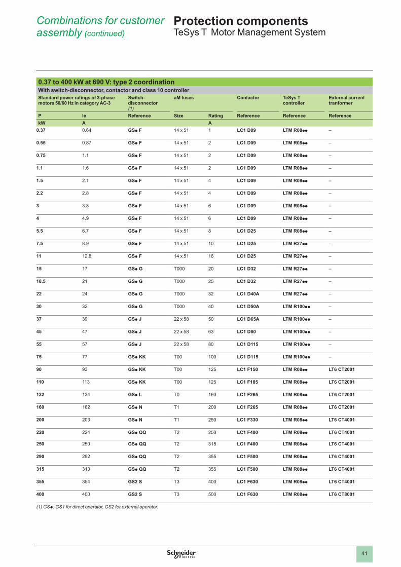
4�4�
Combinations for customer assembly (continued)
Protection componentsTeSys.T..Motor.Management.System
0.37 to 400 kW at 690 V: type 2 coordinationWith switch-disconnector, contactor and class 10 controllerStandard power ratings of 3-phase motors 50/60 Hz in category AC-3
Switch-disconnector(1)
aM fuses Contactor TeSys T controller
External current tranformer
P Ie Reference Size Rating Reference Reference ReferencekW A A
0.37 0 .64 GSp F �4.x.5� � LC1 D09 LTM R08pp –
0.55 0 .87 GSp F �4.x.5� � LC1 D09 LTM R08pp –
0.75 � .� GSp F �4.x.5� � LC1 D09 LTM R08pp –
1.1 � .6 GSp F �4.x.5� � LC1 D09 LTM R08pp –
1.5 � .� GSp F �4.x.5� 4 LC1 D09 LTM R08pp –
2.2 � .8 GSp F �4.x.5� 4 LC1 D09 LTM R08pp –
3 3 .8 GSp F �4.x.5� 6 LC1 D09 LTM R08pp –
4 4 .9 GSp F �4.x.5� 6 LC1 D09 LTM R08pp –
5.5 6 .7 GSp F �4.x.5� 8 LC1 D25 LTM R08pp –
7.5 8 .9 GSp F �4.x.5� �0 LC1 D25 LTM R27pp –
11 �� .8 GSp F �4.x.5� �6 LC1 D25 LTM R27pp –
15 �7 GSp G T000 �0 LC1 D32 LTM R27pp –
18.5 �� GSp G T000 �5 LC1 D32 LTM R27pp –
22 �4 GSp G T000 3� LC1 D40A LTM R27pp –
30 3� GSp G T000 40 LC1 D50A LTM R100pp –
37 39 GSp J ��.x.58 50 LC1 D65A LTM R100pp –
45 47 GSp J ��.x.58 63 LC1 D80 LTM R100pp –
55 57 GSp J ��.x.58 80 LC1 D115 LTM R100pp –
75 77 GSp KK T00 �00 LC1 D115 LTM R100pp –
90 93 GSp KK T00 ��5 LC1 F150 LTM R08pp LT6 CT2001
110 ��3 GSp KK T00 ��5 LC1 F185 LTM R08pp LT6 CT2001
132 �34 GSp L T0 �60 LC1 F265 LTM R08pp LT6 CT2001
160 �6� GSp N T� �00 LC1 F265 LTM R08pp LT6 CT2001
200 �03 GSp N T� �50 LC1 F330 LTM R08pp LT6 CT4001
220 ��4 GSp QQ T� �50 LC1 F400 LTM R08pp LT6 CT4001
250 �50 GSp QQ T� 3�5 LC1 F400 LTM R08pp LT6 CT4001
290 �9� GSp QQ T� 355 LC1 F500 LTM R08pp LT6 CT4001
315 3�3 GSp QQ T� 355 LC1 F500 LTM R08pp LT6 CT4001
355 354 GS2 S T3 400 LC1 F630 LTM R08pp LT6 CT4001
400 400 GS2 S T3 500 LC1 F630 LTM R08pp LT6 CT8001
(1) GSp: GS1 for direct operator, GS2 for external operator.


August 2009 - V2.0
DIA
1ED
2090
814E
N
ART. 960394
The information provided in this documentation contains general descriptions and/or technical characteristics of the performance of the products contained herein. This documentation is not intended as a substitute for and is not to be used for determining suitability or reliability of these products for specifi c user applications. It is the duty of any such user or integrator to perform the appropriate and complete risk analysis, evaluation and testing of the products with respect to the relevant specifi c application or use thereof. Neither Schneider Electric nor any of its affi liates or subsidiaries shall be responsible or liable for misuse of the information contained herein.
Design: Schneider ElectricPhotos: Schneider ElectricPrinted by:
Head Offi ce35, rue Joseph MonierF-92500 Rueil-MalmaisonFrance
Schneider Electric Industries SAS www.schneider-electric.com
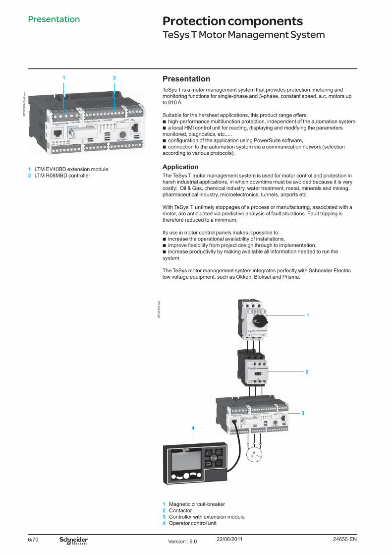
6/70
PresentationTeSys T is a motor management system that provides protection, metering and monitoring functions for single-phase and 3-phase, constant speed, a.c. motors up to 810 A. Suitable for the harshest applications, this product range offers:b high-performance multifunction protection, independent of the automation system,b a local HMI control unit for reading, displaying and modifying the parameters monitored, diagnostics, etc.....b configuration of the application using PowerSuite software,b connection to the automation system via a communication network (selection according to various protocols).
ApplicationThe TeSys T motor management system is used for motor control and protection in harsh industrial applications, in which downtime must be avoided because it is very costly: Oil & Gas, chemical industry, water treatment, metal, minerals and mining, pharmaceutical industry, microelectronics, tunnels, airports etc.
With TeSys T, untimely stoppages of a process or manufacturing, associated with a motor, are anticipated via predictive analysis of fault situations. Fault tripping is therefore reduced to a minimum.
Its use in motor control panels makes it possible to: b increase the operational availability of installations,b improve flexibility from project design through to implementation,b increase productivity by making available all information needed to run the system.
The TeSys motor management system integrates perfectly with Schneider Electric low voltage equipment, such as Okken, Blokset and Prisma.
1 Magnetic circuit-breaker2 Contactor3 Controller with extension module4 Operator control unit
Presentation Protection componentsTeSys T Motor Management System
1 LTM EV40BD extension module2 LTM R08MBD controller
1 2
PF5
2637
8-63
-M.e
ps
3
M 3
1
2
4
DF5
2639
2.ep
s
24656-ENVersion : 6.0 22/06/2011
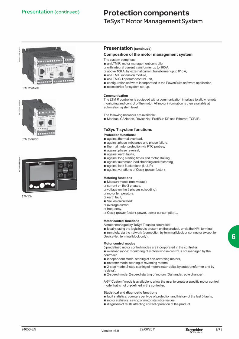
6/71
Presentation (continued)
Composition of the motor management system The system comprises:b an LTM R motor management controller v with integral current transformer up to 100 A,v above 100 A, by external current transformer up to 810 A,b an LTM E extension module,b an LTM CU operator control unit,b configuration software incorporated in the PowerSuite software application,b accessories for system set-up.
CommunicationThe LTM R controller is equipped with a communication interface to allow remote monitoring and control of the motor. All motor information is then available at automation system level.
The following networks are available: b Modbus, CANopen, DeviceNet, ProfiBus DP and Ethernet TCP/IP.
TeSys T system functions Protection functions:b against thermal overload,b against phase imbalance and phase failure,b thermal motor protection via PTC probes,b against phase reversal,b against earth faults,b against long starting times and motor stalling,b against automatic load shedding and restarting,b against load fluctuations (I, U, P),b against variations of Cos ϕ (power factor).
Metering functionsb Measurements (rms values):v current on the 3 phases,v voltage on the 3 phases (shedding),v motor temperature,v earth fault,b Values calculated:v average current,v frequency,v Cos ϕ (power factor), power, power consumption...
Motor control functionsA motor managed by TeSys T can be controlled:b locally, using the logic inputs present on the product, or via the HMI terminalb remotely, via the network (connection by terminal block or connector except for DeviceNet: terminal block only).,
Motor control modes5 predefined motor control modes are incorporated in the controller:b overload mode: monitoring of motors whose control is not managed by the controller,b independent mode: starting of non-reversing motors,b reverser mode: starting of reversing motors,b 2-step mode: 2-step starting of motors (star-delta, by autotransformer and by resistor),b 2-speed mode: 2-speed starting of motors (Dahlander, pole changer).
A 6th “Custom” mode is available to allow the user to create a specific motor control mode that is not predefined in the controller.
Statistical and diagnostic functionsb fault statistics: counters per type of protection and history of the last 5 faults,b motor statistics: saving of motor statistics values,b diagnosis of faults affecting correct operation of the product.
Presentation (continued) Protection componentsTeSys T Motor Management System
LTM R08MBD
PF5
2637
9-47
-M.e
ps
LTM EV40BD
PF5
2638
0-30
-M.e
ps
LTM CU
PF5
6860
5-44
-M.e
ps
24656-EN Version : 6.0 22/06/2011
66
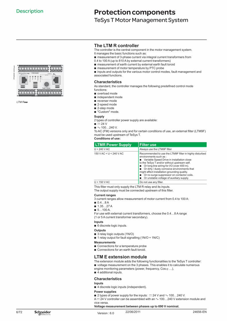
6/72
Description
The LTM R controllerThe controller is the central component in the motor management system.It manages the basic functions such as:b measurement of 3-phase current via integral current transformers from 0.4 to 100 A (up to 810 A by external current transformers)b measurement of earth current by external earth fault toroidb measurement of motor temperature by PTC probeb inputs and outputs for the various motor control modes, fault management and associated functions.
CharacteristicsAs standard, the controller manages the following predefined control mode functions:b overload modeb independent modeb reverser modeb 2-speed modeb 2-step modeb "Custom" mode.Supply2 types of controller power supply are available:b c 24 Vb a 100…240 V.To AC (FM) versions only and for certain conditions of use, an external filter (LTM9F) must be used upstream of TeSys T.Conditions of use:
LTMR Power Supply Filter useU > 240 V AC Always use the LTM9F filter150 V AC < U < 240 V AC Recommended to use the LTM9F filter in highly disturbed
environments such as : b Variable Speed Drive in installation close to the TeSys T and/or without upstream self.b Or long line wiring for I/O (over 400 m).b Or dirty / dusty corrosive environments that might affect installation grounding quality.b Or no surge suppressor on contactor coils.b Or unstable voltage of auxiliary supply.
U < 150 V AC Do not use any filter.
This filter must only supply the LTM R relay and its inputs. The output supply must be connected upstream of this filter. Current ranges3 current ranges allow measurement of motor current from 0.4 to 100 A:b 0.4…8 Ab 1.35…27 Ab 5…100 A.For use with external current transformers, choose the 0.4…8 A range (1 or 5 A current transformer secondary).Inputsb 6 discrete logic inputs.Outputsb 3 relay logic outputs (1N/O)b 1 relay output for fault signalling (1N/O + 1N/C)Measurementsb Connections for a temperature probeb Connections for an earth fault toroid.
LTM E extension moduleThe extension module adds the following functionalities to the TeSys T controller:b voltage measurement on the 3 phases. This enables it to calculate numerous engine monitoring parameters (power, frequency, Cos ϕ …),b 4 additional inputs.
CharacteristicsInputsb 4 discrete logic inputs (independent).Power suppliesb 2 types of power supply for the inputs: c 24 V and a 100…240 V. A c 24 V controller can be assembled with an a 100…240 V extension module and vice versa.Voltage measurement between phases up to 690 V nominal.
Protection componentsTeSys T Motor Management System
LTM Rpp
PF5
2638
1-44
-M.e
ps
24656-ENVersion : 6.0 22/06/2011
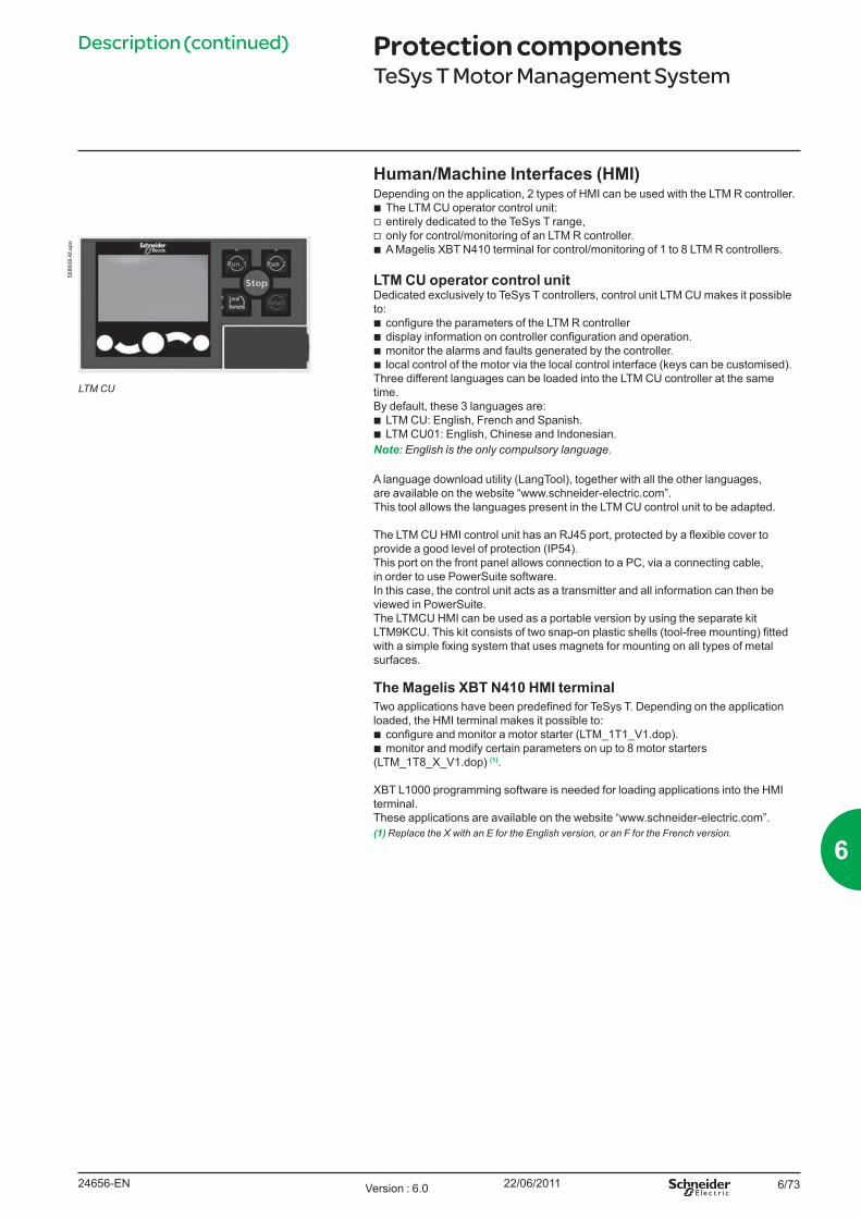
6/73
Human/Machine Interfaces (HMI)Depending on the application, 2 types of HMI can be used with the LTM R controller.
b The LTM CU operator control unit: v entirely dedicated to the TeSys T range, v only for control/monitoring of an LTM R controller. b A Magelis XBT N410 terminal for control/monitoring of 1 to 8 LTM R controllers.
LTM CU operator control unit Dedicated exclusively to TeSys T controllers, control unit LTM CU makes it possible to:
b configure the parameters of the LTM R controller b display information on controller configuration and operation. b monitor the alarms and faults generated by the controller. b local control of the motor via the local control interface (keys can be customised).
Three different languages can be loaded into the LTM CU controller at the same time. By default, these 3 languages are:
b LTM CU: English, French and Spanish. b LTM CU01: English, Chinese and Indonesian.
Note: English is the only compulsory language.
A language download utility (LangTool), together with all the other languages, are available on the website “www.schneider-electric.com”.This tool allows the languages present in the LTM CU control unit to be adapted.
The LTM CU HMI control unit has an RJ45 port, protected by a flexible cover to provide a good level of protection (IP54). This port on the front panel allows connection to a PC, via a connecting cable, in order to use PowerSuite software. In this case, the control unit acts as a transmitter and all information can then be viewed in PowerSuite. The LTMCU HMI can be used as a portable version by using the separate kit LTM9KCU. This kit consists of two snap-on plastic shells (tool-free mounting) fitted with a simple fixing system that uses magnets for mounting on all types of metal surfaces.
The Magelis XBT N410 HMI terminalTwo applications have been predefined for TeSys T. Depending on the application loaded, the HMI terminal makes it possible to:b configure and monitor a motor starter (LTM_1T1_V1.dop).b monitor and modify certain parameters on up to 8 motor starters(LTM_1T8_X_V1.dop) (1).
XBT L1000 programming software is needed for loading applications into the HMI terminal. These applications are available on the website “www.schneider-electric.com”.(1) Replace the X with an E for the English version, or an F for the French version.
Description (continued) Protection componentsTeSys T Motor Management System
LTM CU
5686
06-M
.eps
24656-EN Version : 6.0 22/06/2011
6
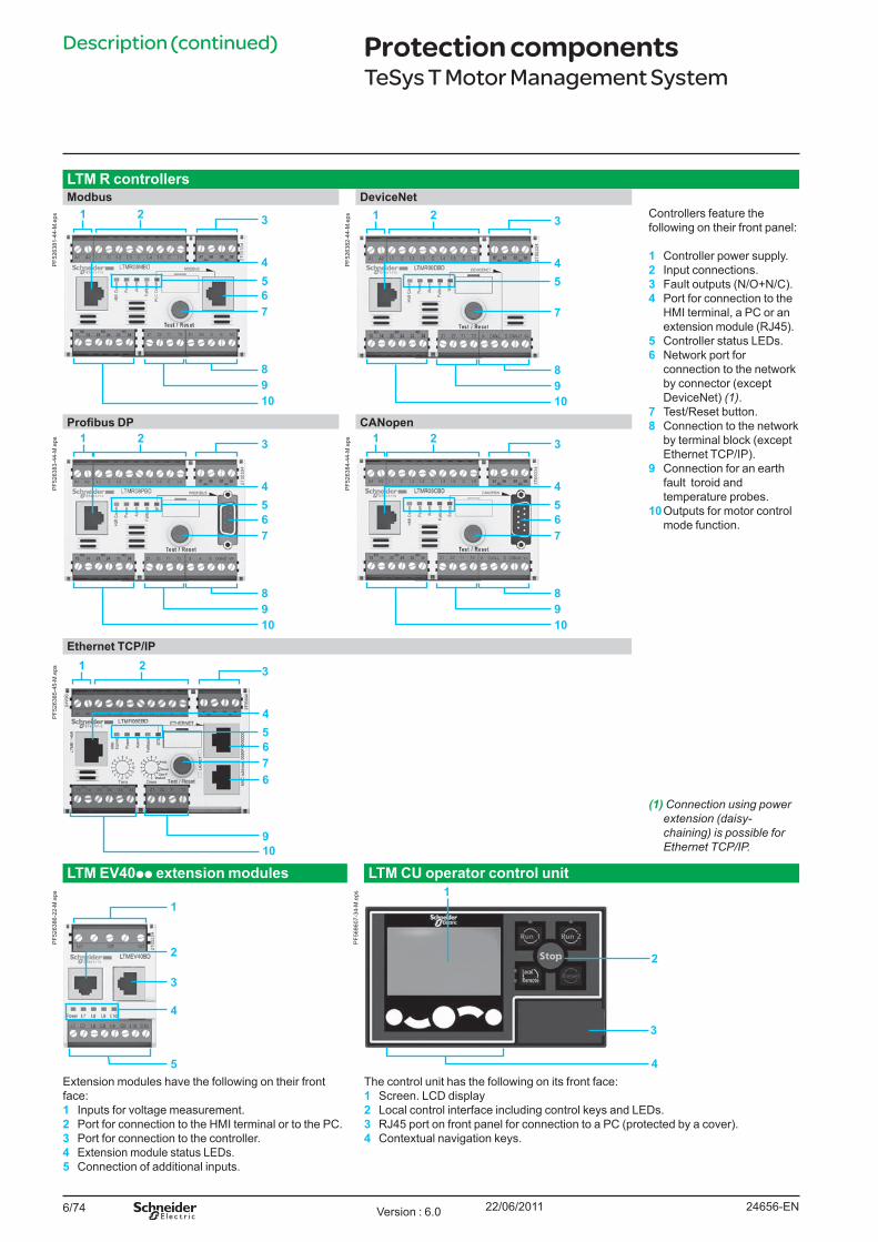
6/74
Description (continued)
LTM R controllersModbus DeviceNet
2 3
4
67
10
8
1
9
5
PF5
2638
1-44
-M.e
ps 2 3
4
7
10
8
1
9
5
PF5
2638
2-44
-M.e
ps Controllers feature the following on their front panel:
1 Controller power supply.2 Input connections.3 Fault outputs (N/O+N/C).4 Port for connection to the
HMI terminal, a PC or an extension module (RJ45).
5 Controller status LEDs.6 Network port for
connection to the network by connector (except DeviceNet) (1).
7 Test/Reset button.8 Connection to the network
by terminal block (except Ethernet TCP/IP).
9 Connection for an earth fault toroid and temperature probes.
10 Outputs for motor control mode function.
Profibus DP CANopen2 3
4
67
10
8
1
9
5
PF5
2638
3-44
-M.e
ps 2 3
4
67
10
8
1
9
5
PF5
2638
4-44
-M.e
ps
Ethernet TCP/IP2 3
4
6
10
1
9
5
76
PF5
2638
5-45
-M.e
ps
(1) Connection using power extension (daisy-chaining) is possible for Ethernet TCP/IP.
LTM EV40pp extension modules LTM CU operator control unit
1
2
3
5
4
PF5
2638
6-22
-M.e
ps 1
2
3
4
PF5
6860
7-34
-M.e
ps
Extension modules have the following on their front face:1 Inputs for voltage measurement.2 Port for connection to the HMI terminal or to the PC.3 Port for connection to the controller.4 Extension module status LEDs.5 Connection of additional inputs.
The control unit has the following on its front face:1 Screen. LCD display2 Local control interface including control keys and LEDs.3 RJ45 port on front panel for connection to a PC (protected by a cover).4 Contextual navigation keys.
Protection componentsTeSys T Motor Management System
24656-ENVersion : 6.0 22/06/2011
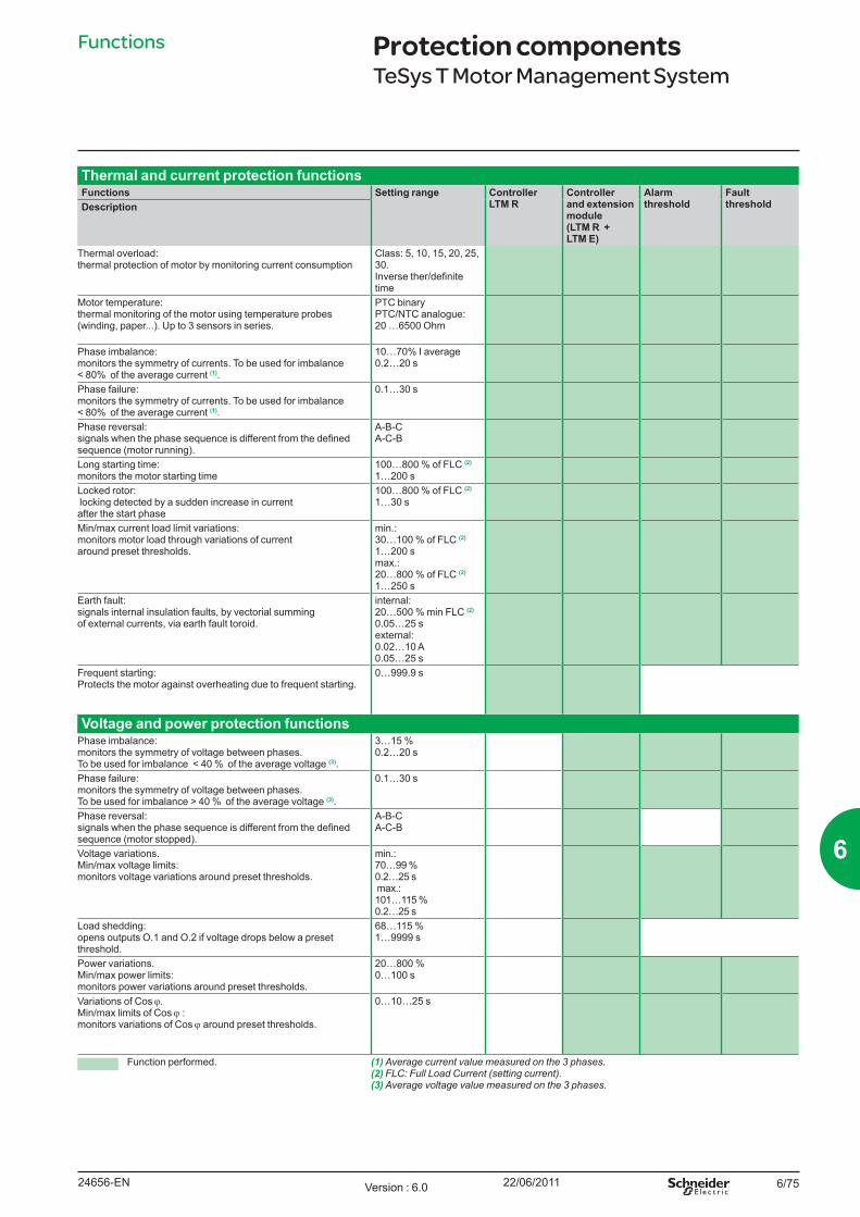
6/75
Thermal and current protection functionsFunctions Setting range Controller
LTM RController and extension module (LTM R + LTM E)
Alarm threshold
Fault thresholdDescription
Thermal overload: thermal protection of motor by monitoring current consumption
Class: 5, 10, 15, 20, 25, 30.Inverse ther/definite time
Motor temperature: thermal monitoring of the motor using temperature probes (winding, paper...). Up to 3 sensors in series.
PTC binary PTC/NTC analogue: 20 …6500 Ohm
Phase imbalance: monitors the symmetry of currents. To be used for imbalance < 80% of the average current (1).
10…70% I average 0.2…20 s
Phase failure: monitors the symmetry of currents. To be used for imbalance < 80% of the average current (1).
0.1…30 s
Phase reversal: signals when the phase sequence is different from the defined sequence (motor running).
A-B-C A-C-B
Long starting time: monitors the motor starting time
100…800 % of FLC (2)
1…200 sLocked rotor: locking detected by a sudden increase in current after the start phase
100…800 % of FLC (2) 1…30 s
Min/max current load limit variations: monitors motor load through variations of current around preset thresholds.
min.: 30…100 % of FLC (2) 1…200 smax.: 20…800 % of FLC (2) 1…250 s
Earth fault: signals internal insulation faults, by vectorial summing of external currents, via earth fault toroid.
internal: 20…500 % min FLC (2) 0.05…25 sexternal: 0.02…10 A 0.05…25 s
Frequent starting: Protects the motor against overheating due to frequent starting.
0…999.9 s
Voltage and power protection functionsPhase imbalance: monitors the symmetry of voltage between phases. To be used for imbalance < 40 % of the average voltage (3).
3…15 % 0.2…20 s
Phase failure: monitors the symmetry of voltage between phases. To be used for imbalance > 40 % of the average voltage (3).
0.1…30 s
Phase reversal: signals when the phase sequence is different from the defined sequence (motor stopped).
A-B-C A-C-B
Voltage variations. Min/max voltage limits: monitors voltage variations around preset thresholds.
min.: 70…99 % 0.2…25 s max.: 101…115 % 0.2…25 s
Load shedding: opens outputs O.1 and O.2 if voltage drops below a preset threshold.
68…115 % 1…9999 s
Power variations. Min/max power limits: monitors power variations around preset thresholds.
20…800 % 0…100 s
Variations of Cos ϕ. Min/max limits of Cos ϕ : monitors variations of Cos ϕ around preset thresholds.
0…10…25 s
Function performed. (1) Average current value measured on the 3 phases.(2) FLC: Full Load Current (setting current).(3) Average voltage value measured on the 3 phases.
Functions Protection componentsTeSys T Motor Management System
24656-EN Version : 6.0 22/06/2011
6
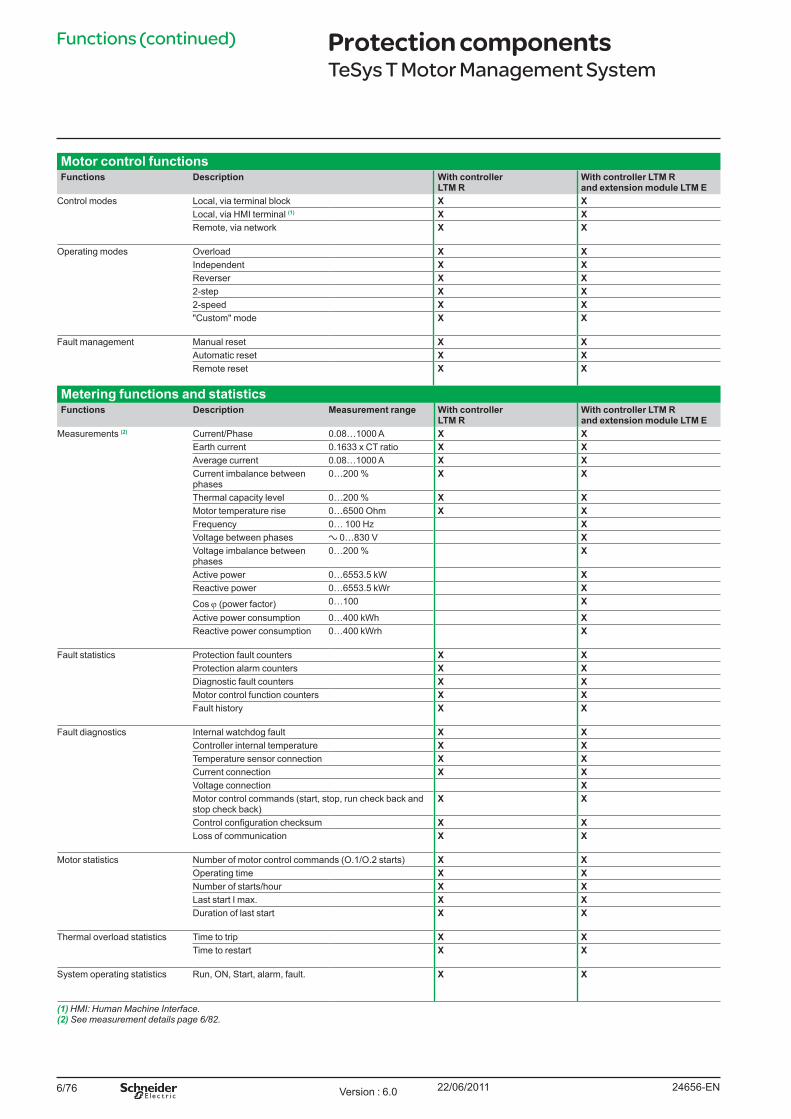
6/76
Functions (continued)
Motor control functionsFunctions Description With controller
LTM RWith controller LTM R and extension module LTM E
Control modes Local, via terminal block X XLocal, via HMI terminal (1) X XRemote, via network X X
Operating modes Overload X XIndependent X XReverser X X2-step X X2-speed X X"Custom" mode X X
Fault management Manual reset X XAutomatic reset X XRemote reset X X
Metering functions and statisticsFunctions Description Measurement range With controller
LTM RWith controller LTM R and extension module LTM E
Measurements (2) Current/Phase 0.08…1000 A X XEarth current 0.1633 x CT ratio X XAverage current 0.08…1000 A X XCurrent imbalance between phases
0…200 % X X
Thermal capacity level 0…200 % X XMotor temperature rise 0…6500 Ohm X XFrequency 0… 100 Hz XVoltage between phases a 0…830 V XVoltage imbalance between phases
0…200 % X
Active power 0…6553.5 kW XReactive power 0…6553.5 kWr XCos ϕ (power factor) 0…100 X
Active power consumption 0…400 kWh XReactive power consumption 0…400 kWrh X
Fault statistics Protection fault counters X XProtection alarm counters X XDiagnostic fault counters X XMotor control function counters X XFault history X X
Fault diagnostics Internal watchdog fault X XController internal temperature X XTemperature sensor connection X XCurrent connection X XVoltage connection XMotor control commands (start, stop, run check back and stop check back)
X X
Control configuration checksum X XLoss of communication X X
Motor statistics Number of motor control commands (O.1/O.2 starts) X XOperating time X XNumber of starts/hour X XLast start I max. X XDuration of last start X X
Thermal overload statistics Time to trip X XTime to restart X X
System operating statistics Run, ON, Start, alarm, fault. X X
(1) HMI: Human Machine Interface.(2) See measurement details page 6/82.
Protection componentsTeSys T Motor Management System
24656-ENVersion : 6.0 22/06/2011
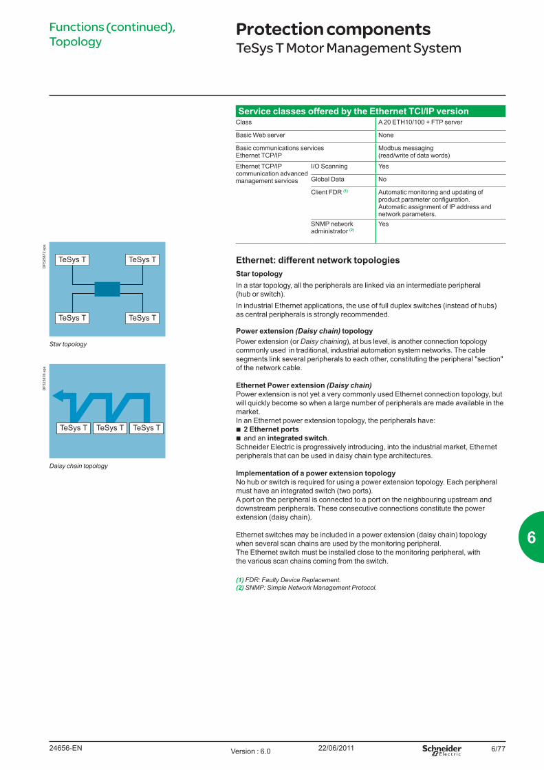
6/77
Service classes offered by the Ethernet TCI/IP versionClass A 20 ETH10/100 + FTP server
Basic Web server None
Basic communications servicesEthernet TCP/IP
Modbus messaging (read/write of data words)
Ethernet TCP/IP communication advanced management services
I/O Scanning Yes
Global Data No
Client FDR (1) Automatic monitoring and updating of product parameter configuration.Automatic assignment of IP address and network parameters.
SNMP network administrator (2)
Yes
Ethernet: different network topologiesStar topology In a star topology, all the peripherals are linked via an intermediate peripheral (hub or switch).In industrial Ethernet applications, the use of full duplex switches (instead of hubs) as central peripherals is strongly recommended.
Power extension (Daisy chain) topologyPower extension (or Daisy chaining), at bus level, is another connection topology commonly used in traditional, industrial automation system networks. The cable segments link several peripherals to each other, constituting the peripheral "section" of the network cable.
Ethernet Power extension (Daisy chain)Power extension is not yet a very commonly used Ethernet connection topology, but will quickly become so when a large number of peripherals are made available in the market.In an Ethernet power extension topology, the peripherals have:b 2 Ethernet ports b and an integrated switch.Schneider Electric is progressively introducing, into the industrial market, Ethernet peripherals that can be used in daisy chain type architectures.
Implementation of a power extension topologyNo hub or switch is required for using a power extension topology. Each peripheral must have an integrated switch (two ports). A port on the peripheral is connected to a port on the neighbouring upstream and downstream peripherals. These consecutive connections constitute the power extension (daisy chain).
Ethernet switches may be included in a power extension (daisy chain) topology when several scan chains are used by the monitoring peripheral. The Ethernet switch must be installed close to the monitoring peripheral, with the various scan chains coming from the switch.
(1) FDR: Faulty Device Replacement.(2) SNMP: Simple Network Management Protocol.
Functions (continued), Topology
Protection componentsTeSys T Motor Management System
TeSys T TeSys T
TeSys T TeSys T
Star topology
DF5
2587
2.ep
s
TeSys T TeSys TTeSys T
Daisy chain topology
DF5
2587
8.ep
s
24656-EN Version : 6.0 22/06/2011
6
6/78
Ethernet: different network topologies (continued)
Ring topologyIn a ring topology, all the peripherals or components of the network infrastructure are connected within a loop. This type of topology makes it possible to achieve different levels of redundancy of the network.
Ethernet ring Ethernet rings are generally the main networks in applications where a high level of reliability is required. If a ring topology is required, the switches handling this function must be used.
RedundancyRedundancy of the network infrastructure is the key to development of applications with high operational reliability. Implementing a single or double ring architecture makes it possible to provide protection against breaks in network segments.
Single ringThe first level of redundancy can be achieved by installing a single ring.ConneXium switches can be used to establish main network ring configurations.The ring is created using HIPER-Ring ports. If a section of the line fails, the ring structure (including a maximum of 50 switches) converts into a line type configuration in less than 0.5 seconds.
Topology (continued) Protection componentsTeSys T Motor Management System
TeSys T TeSys T
TeSys T TeSys T
Ring topology
DF5
2587
1.ep
s
24656-ENVersion : 6.0 22/06/2011
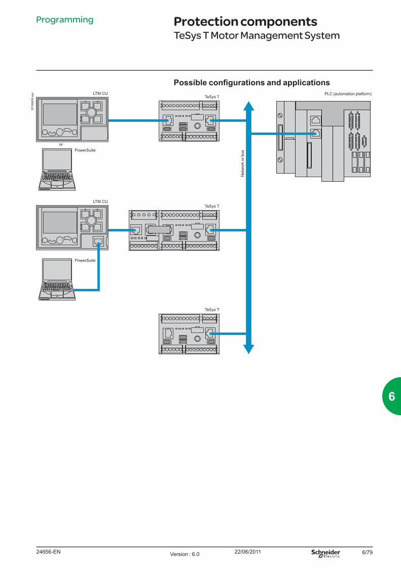
6/79
Possible configurations and applicationsLTM CU
TeSys T
TeSys T
TeSys T
PowerSuite
LTM CU
PowerSuite
PLC (automation platform)
Net
wor
k or
bus
or
DF5
6860
8.ep
s
Programming Protection componentsTeSys T Motor Management System
24656-EN Version : 6.0 22/06/2011
6
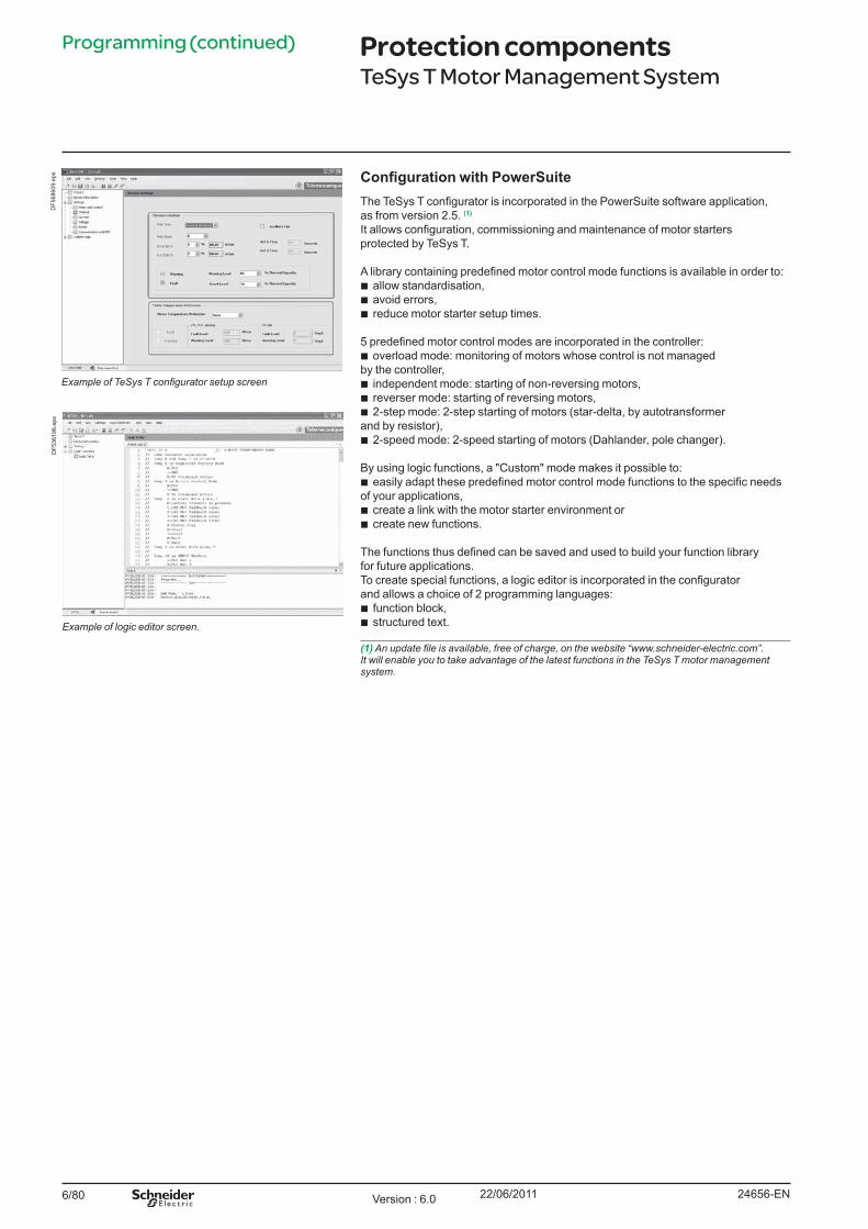
6/80
Programming (continued)
Configuration with PowerSuiteThe TeSys T configurator is incorporated in the PowerSuite software application, as from version 2.5. (1)
It allows configuration, commissioning and maintenance of motor startersprotected by TeSys T.
A library containing predefined motor control mode functions is available in order to:b allow standardisation, b avoid errors,b reduce motor starter setup times.
5 predefined motor control modes are incorporated in the controller:b overload mode: monitoring of motors whose control is not managed by the controller,b independent mode: starting of non-reversing motors,b reverser mode: starting of reversing motors,b 2-step mode: 2-step starting of motors (star-delta, by autotransformer and by resistor),b 2-speed mode: 2-speed starting of motors (Dahlander, pole changer).
By using logic functions, a "Custom" mode makes it possible to:b easily adapt these predefined motor control mode functions to the specific needs of your applications, b create a link with the motor starter environment or b create new functions. The functions thus defined can be saved and used to build your function library for future applications.To create special functions, a logic editor is incorporated in the configurator and allows a choice of 2 programming languages:b function block,b structured text.
(1)Anupdatefileisavailable,freeofcharge,onthewebsite“www.schneider-electric.com”. It will enable you to take advantage of the latest functions in the TeSys T motor management system.
Protection componentsTeSys T Motor Management System
ExampleofTeSysTconfiguratorsetupscreen
DF5
6860
9.ep
s
Example of logic editor screen.
DF5
3619
6.ep
s
24656-ENVersion : 6.0 22/06/2011
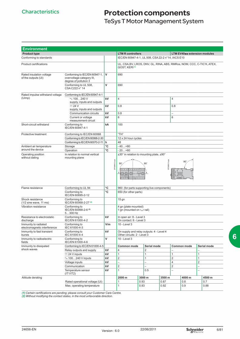
6/81
Characteristics
EnvironmentProduct type LTM R controllers LTM EV40pp extension modules
Conforming to standards IEC/EN 60947-4-1, UL 508, CSA 22-2 n°14, IACS E10
Product certifications UL, CSA,BV, LROS, DNV, GL, RINA, ABS, RMRos, NOM, CCC, C-TIC’K, ATEX, GOST, KERI (1)
Rated insulation voltage of the outputs (Ui)
Conforming to IEC/EN 60947-1, overvoltage category III, degree of pollution 3
V 690
Conforming to UL 508, CSA C222 n° 14
V 690
Rated impulse withstand voltage (Uimp)
Conforming to IEC/EN 60947-4-1a 100…240 V supply, inputs and outputs
kV 4 4
c 24 V supply, inputs and outputs
kV 0.8 0.8
Communication circuits kV 0.8 –Current or voltage measurement circuit
kV 6 6
Short-circuit withstand Conforming to IEC/EN 60947-4-1
kA 100
Protective treatment Conforming to IEC/EN 60068 “TH”Conforming to IEC/EN 60068-2-30 12 x 24 hour cyclesConforming to IEC/EN 60070-2-11 h 48
Ambient air temperature around the device
Storage °C - 40…+80Operation °C - 20…+60
Operating position without dating
In relation to normal vertical mounting plane
±30° in relation to mounting plate, ±90°
DF5
6861
2.ep
s
DF5
6861
3.ep
s
Flame resistance Conforming to UL 94 °C 960 (for parts supporting live components)Conforming to IEC/EN 60695-2-12
°C 650 (for other parts)
Shock resistance (1/2 sine wave, 11 ms)
Conforming to IEC/EN 60068-2-27 (2)
15 gn
Vibration resistance Conforming to IEC/EN 60068-2-6 (2)
5…300 Hz
4 gn (plate mounted)1 gn (mounted on 5 rail)
Resistance to electrostatic discharge
Conforming to IEC/EN 61000-4-2
kV In open air: 8 - Level 3On contact: 6 - Level 3
Immunity to radiated electromagnetic interference
Conforming to IEC 61000-4-3
V/m 10 - Level 3
Immunity to fast transient bursts
Conforming to IEC 61000-4-4
kV On supply and relay outputs: 4 - Level 4Other circuits: 2 - Level 3
Immunity to radioelectric fields
Conforming to IEC/EN 61000-4-6
V 10 - Level 3
Immunity to dissipated shock waves
Conforming to IEC/EN 61000-4-5 Common mode Serial mode Common mode Serial modeRelay outputs and supply kV 4 2 – –c 24 V inputs kV 1 1 1 1a 100…240 V inputs kV 2 1 2 1Voltage inputs kV – – 4 2Communication kV 2 – 2 –Temperature sensor (IT1/IT2)
kV 1 0.5 – –
Altitude derating 2000 m 3000 m 3500 m 4000 m 4500 mRated operational voltage (Ui) 1 0.93 0.87 0.8 0.7Max. operating temperature 1 0.93 0.92 0.9 0.88
(1)Certaincertificationsarepending;pleaseconsultyourCustomerCareCentre.(2) Without modifying the contact states, in the most unfavorable direction.
Protection componentsTeSys T Motor Management System
24656-EN Version : 6.0 22/06/2011
6
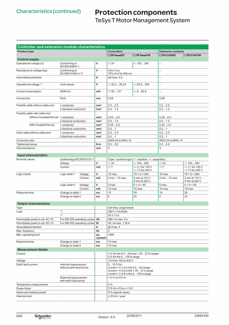
6/82
Characteristics (continued)
Controller and extension module characteristicsProduct type Controllers Extension modules
LTM RpppBD LTM RpppFM LTM EV40BD LTM EV40FMControl supply
Operational voltage (U) Conforming to IEC/EN 60947-1
V c 24 a 100…240 –
Resistance to voltage dips Conforming to IEC/EN 61000-4-11
V 0 for 3 ms 70% of U for 500 ms
–
Associated protection A gG fuse, 0.5 –
Operational voltage (1) Limit values V c 20.4…26.24 a 93.5…264 –
Current consumption 50/60 Hz mA c 56…127 a 8…62.8 –
Connectors Pitch mm 5.08 5.08
Flexible cable without cable end 1 conductor mm2 0.2…2.5 0.2…2.52 identical conductors mm2 0.2…1.5 0.2…1.5
Flexible cable with cable endWithout insulated ferrule 1 conductor mm2 0.25…2.5 0.25…2.5
2 identical conductors mm2 0.5…1.5 0.5…1.5With insulated ferrule 1 conductor mm2 0.25…2.5 0.25…2.5
2 identical conductors mm2 0.2…1 0.2…1Solid cable without cable end 1 conductor mm2 0.2…2.5 0.2…2.5
2 identical conductors mm2 0.2…1 0.2…1Conductor size AWG 24 to AWG 14 AWG 24 to AWG 14Tightening torque N.m 0.5…0.6 0.5…0.6Flat screwdriver mm 3 3
Input characteristicsNominal values Conforming to IEC/EN 61131-1 Type 1 positive logic (c: resistive, a: capacitive)
Voltage V c 24 a 100…240 c 24 a 100…240Current mA c 7 a 3.1 for 100 V
a 7.5 for 240 Vc 7 a 3.1 for 100 V
a 7.5 for 240 VLogic inputs Logic state 1 Voltage V 15 max 79 < U < 264 15 max 79 < U < 264
Current mA 2 min…15 max 2 min at 110 V… 3 min at 220 V
2 min…15 max 2 min at 110 V… 3 min at 220 V
Logic state 0 Voltage V 5 max 0 < U < 40 5 max 0 < U < 40Current mA 15 max 15 max 15 max 15 max
Response time Change to state 1 ms 15 25 15 25Change to state 0 ms 5 25 5 25
Output characteristicsType Volt free, single breakLoad a 250 V / 5 A B300
c 30 V / 5 APermissible power in cat. AC-15 For 500 000 operating cycles VA 480 / Ie max: 2 APermissible power in cat. DC-13 For 500 000 operating cycles W 30 / Ie max: 1.25 AAssociated protection A gG fuse, 4Max. frequency Hz 2Max. operating level op.
cycles/h1800
Response time Change to state 1 ms 10 maxChange to state 0 ms 10 max
Measurement detailsCurrent 1 % for the 0.4…8 A and 1.35…27 A ranges
2 % for the 5…100 A rangeVoltage 1% from 100 to 830 VEarth fault current Internal measurement
without earth fault toroid5…15 % for current > 0.1 A in the 0.4…8 A range current > 0.2 A in the 1.35…27 A range current > 0.3 A in the 5…100 A range
External measurement with earth fault toroid
< 5 % or 0.01 A
Temperature measurement 2 %Power factor 3 % for a Cos ϕ > 0.6Active and reactive power 5 % (typical value)Internal clock ± 30 min / year
Protection componentsTeSys T Motor Management System
24656-ENVersion : 6.0 22/06/2011
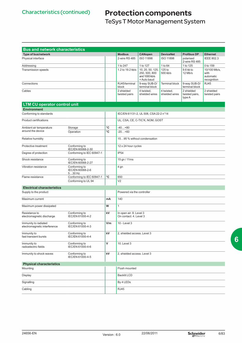
6/83
Bus and network characteristicsType of bus/network Modbus CANopen DeviceNet Profibus DP Ethernet
Physical interface 2-wire RS 485 ISO 11898 ISO 11898 polarised 2-wire RS 485
IEEE 802.3
Addressing 1 to 247 1 to 127 1 to 64 1 to 125 0 to 159Transmission speeds 1.2 to 19.2 kb/s 10, 20, 50, 125,
250, 500, 800 and 1000 kb/s + Auto baud
125 to 500 kb/s
9.6 kb to 12 Mb/s
10/100 Mb/s, with automatic recognition
Connections RJ45/terminal block
9-way SUB-D/terminal block
Terminal block 9-way SUB-D/terminal block
RJ45
Cables 2 shielded twisted pairs
4 twisted, shielded wires
4 twisted, shielded wires
2 shielded twisted pairs, type A
2 shielded twisted pairs
LTM CU operator control unitEnvironment
Conforming to standards IEC/EN 61131-2, UL 508, CSA 22-2 n°14
Product certifications UL, CSA, CE, C-TIC’K, NOM, GOST
Ambient air temperature around the device
Storage °C -40…+80Operation °C -20…+60
Relative humidity 15…95 % without condensation
Protective treatment Conforming to IEC/EN 60068-2-30
12 x 24 hour cycles
Degree of protection Conforming to IEC 60947-1 IP54
Shock resistance Conforming to IEC/EN 60068-2-27
15 gn / 11ms
Vibration resistance Conforming to IEC/EN 60068-2-65…30 Hz
4 gn
Flame resistance Conforming to IEC 60947-1 °C 650Conforming to UL 94 V2
Electrical characteristicsSupply to the product Powered via the controller
Maximum current mA 140
Maximum power dissipated W 1
Resistance to electromagnetic discharge
Conforming to IEC/EN 61000-4-2
kV In open air: 8. Level 3On contact: 4. Level 3
Immunity to radiated electromagnetic interference
Conforming to IEC/EN 61000-4-3
V/m 10 - Level 3
Immunity to fast transient bursts
Conforming to IEC/EN 61000-4-4
kV 2, shielded access. Level 3
Immunity to radioelectric fields
Conforming to IEC/EN 61000-4-6
V 10. Level 3
Immunity to shock waves Conforming to IEC/EN 61000-4-5
kV 2, shielded access. Level 3
Physical characteristicsMounting Flush mounted
Display Backlit LCD
Signalling By 4 LEDs
Cabling RJ45
Characteristics (continued) Protection componentsTeSys T Motor Management System
24656-EN Version : 6.0 22/06/2011
6
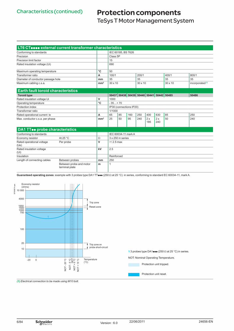
6/84
Characteristics (continued)
LT6 CTpppp external current transformer characteristicsConforming to standards IEC 60185, BS 7626Precision Class 5PPrecision limit factor 15Rated insulation voltage (Ui) 690
Maximum operating temperature °C 50Transformer ratio A 100/1 200/1 400/1 800/1Diameter of conductor passage hole mm 35 35 35 35Maximum cabling c.s.a. mm2 30 x 10 30 x 10 30 x 10 incorporated (1)
Earth fault toroid characteristicsToroid type 50437 50438 50439 50440 50441 50442 50485 50486
Rated insulation voltage Ui V 1000Operating temperature °C - 35…+ 70Protection index IP30 (connections IP20)Transformer ratio 1/1000Rated operational current le A 65 85 160 250 400 630 85 250Max. conductor c.s.a. per phase mm2 25 50 95 240 2 x
1852 x 240
50 240
DA1 TTpp probe characteristicsConforming to standards IEC 60034-11 mark AEconomy resistor At 25 °C W 3 x 250 in seriesRated operational voltage (Ue)
Per probe V c 2.5 max
Rated insulation voltage (Ui)
kV 2.5
Insulation ReinforcedLength of connecting cables Between probes mm 250
Between probe and motor terminal plate
m 1
Guaranteed operating zones: example with 3 probes type DA1 TTppp (250 W at 25 °C) in series, conforming to standard EC 60034-11, mark A.
1 3 probes type DA1ppp (250 W at 25 °C) in series.
NOT: Nominal Operating Temperature.
Protection unit tripped.
Protection unit reset.
(1) Electrical connection to be made using M10 bolt.
Protection componentsTeSys T Motor Management System
10 000
4000
100
10
-20
20
7501000
16501500
0
1
Economy resistor(ohms)
Trip zone
Reset zone
Trip zone on probe short-circuit
Temperature (°C)
NO
T +
15 °C
NO
T +
5 °C
NO
T - 2
0 °C
NO
T - 5
°C NO
T
DF5
6861
4.ep
s
24656-ENVersion : 6.0 22/06/2011
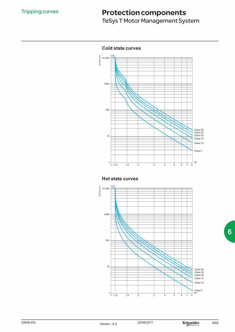
6/85
Tripping curves
Cold state curves
Hot state curves
Protection componentsTeSys T Motor Management System
10 000
1000
100
10
1
t (s)
I/Ir1 1,12 1,5 2 3 4 5 6 7 8
Class 5
Class 10
Class 15Class 20Class 25Class 30
DF5
6861
6.ep
s
10 000
1000
100
10
1
t (s)
I/Ir1 1,12 1,5 2 3 4 5 6 7 8
Class 5
Class 10
Class 15Class 20Class 25Class 30
DF5
6861
5.ep
s
24656-EN Version : 6.0 22/06/2011
6
6/86
ControllersSettingrange
Controlvoltage
Currentrange
Reference Weight
A V A kgFor Modbus
8 c 24 0.4...8 LTM R08MBD 0.530a 100...240 V 0.4...8 LTM R08MFM 0.530
27 c 24 1.35...27 LTM R27MBD 0.530a 100...240 V 1.35...27 LTM R27MFM 0.530
100 c 24 5...100 LTM R100MBD 0.530a 100...240 V 5...100 LTM R100MFM 0.530
For CANopen8 c 24 0.4...8 LTM R08CBD 0.530
a 100...240 V 0.4...8 LTM R08CFM 0.53027 c 24 1.35...27 LTM R27CBD 0.530
a 100...240 V 1.35...27 LTM R27CFM 0.530100 c 24 5...100 LTM R100CBD 0.530
a 100...240 V 5...100 LTM R100CFM 0.530For DeviceNet
8 c 24 0.4...8 LTM R08DBD 0.530a 100...240 V 0.4...8 LTM R08DFM 0.530
27 c 24 1.35...27 LTM R27DBD 0.530a 100...240 V 1.35...27 LTM R27DFM 0.530
100 c 24 5...100 LTM R100DBD 0.530a 100...240 V 5...100 LTM R100DFM 0.530
For Profibus DP8 c 24 0.4...8 LTM R08PBD 0.530
a 100...240 V 0.4...8 LTM R08PFM 0.53027 c 24 1.35...27 LTM R27PBD 0.530
a 100...240 V 1.35...27 LTM R27PFM 0.530100 c 24 5...100 LTM R100PBD 0.530
a 100...240 V 5...100 LTM R100PFM 0.530For Ethernet TCP/IP
8 c 24 0.4...8 LTM R08EBD 0.530a 100...240 V 0.4...8 LTM R08EFM 0.530
27 c 24 1.35...27 LTM R27EBD 0.530a 100...240 V 1.35...27 LTM R27EFM 0.530
100 c 24 5...100 LTM R100EBD 0.530a 100...240 V 5...100 LTM R100EFM 0.530
FilterControl voltage Current max Reference WeightV mA kg
a 150...240 V 130 mA LTM9F 0.110
References Protection componentsTeSys T Motor Management System
LTM R08EBD
PF5
2639
1-47
-M.e
psP
F526
387-
47-M
.eps
LTM R08MBD
PF5
2638
8-47
-M.e
ps
LTM R08CBD
PF5
2638
9-47
-M.e
ps
LTM R08DBD
PF5
2639
0-47
-M.e
ps
LTM R08PBD
24656-ENVersion : 6.0 22/06/2011
6/87
References (continued)
Extension modules. (with voltage measurement on the 3 phases)Input control voltage
Number of inputs
Supply to the electronics Reference Weight
V kgc 24 4 Via the controller LTM EV40BD 0.210a 100…240 4 Via the controller LTM EV40FM 0.210
HMI terminalsDescription Supply
VoltageReference Weight
kgOperator control unitLanguages
EnglishFrenchSpanish
Supply via the controller
LTM CU 0.400
EnglishChineseIndonesian
Supply via the controller
LTM CU01 0.400
Kit for portable LTM CU LTM 9KCU 0,250Magelis compact display. c 24 V external XBT N410 0.380Description Number and type
of connectorsLengthm
Reference Weightkg
Connecting cables for the LTM CU control unit
2 x RJ45 1 VW3 A1 104R10 0.0653 VW3 A1 104R30 0.1405 VW3 A1 104R50 0.210
Connecting cablesfor the XBT N410
SUB-D 25-way female RJ45
2.5 XBT Z938 0.200
CablesDescription Number and type
of connectorsLength Reference Weightm kg
Connecting cables For connecting the controller to the extension module
2 x RJ45 0.04 LTM CC004 (1) 0.1200.3 LU9 R03 0.0451 LU9 R10 0.065
Replacement connectorsDescription Number and type
of connectorsReference Weight
kgComplete set of connectors for controllers and extension modules
10 screw terminals (all network versions included)
LTM 9TCS 0.200
Connector extraction tool LTM 9CTC (2) 0.180(1) Sold in lots of 6.(2) Sold in packs of 3.
Protection componentsTeSys T Motor Management System
LTM EV40BD
PF5
2638
0-30
-M.e
ps
LTM CU
PF5
6860
5-54
-M.e
ps
24656-EN Version : 6.0 22/06/2011
6
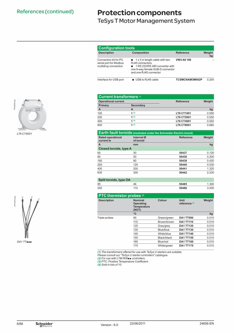
6/88
References (continued)
Configuration toolsDescription Composition Reference Weight
kgConnection kit for PC serial port for Modbus multidrop connection
b 1 x 3 m length cable with two RJ45 connectors,b 1 RS 232/RS 485 converter with one 9-way female SUB-D connector and one RJ45 connector.
VW3 A8 106 –
Interface for USB port b USB to RJ45 cable TCSMCNAM3M002P 0.200
Current transformers (1)
Operational current Reference WeightPrimary SecondaryA A kg
100 1 (2) LT6 CT1001 0.550200 1 (2) LT6 CT2001 0.550400 1 (2) LT6 CT4001 0.550800 1 (2) LT6 CT8001 0.680
Earth fault toroids (marketed under the Schneider Electric brand)Rated operational current Ie
Internal Ø of toroid
Reference Weight
A mm kgClosed toroids, type A
65 30 50437 0.12085 50 50438 0.200160 80 50439 0.420250 120 50440 0.530400 200 50441 1.320630 300 50442 2.230
Split toroids, type OA85 46 50485 1.300250 110 50486 3.200
PTC thermistor probes (3)
Description Nominal Operating Temperature (NOT)
Colour Unit reference (4)
Weight
°C kgTriple probes 90 Green/green DA1 TT090 0.010
110 Brown/brown DA1 TT110 0.010120 Grey/grey DA1 TT120 0.010130 Blue/blue DA1 TT130 0.010140 White/blue DA1 TT140 0.010150 Black/black DA1 TT150 0.010160 Blue/red DA1 TT160 0.010170 White/green DA1 TT170 0.010
(1) The transformers offered for use with TeSys U starters are suitable. Please consult our "TeSys U starter-controllers" catalogue.(2) For use with LTM R08pp controllers.(3)PTC:PositiveTemperatureCoefficient.(4) Sold in lots of 10.
Protection componentsTeSys T Motor Management System
LT6 CT4001
PF5
2639
3.ep
s
DA1 TTppp
PF5
1057
5.ep
s
24656-ENVersion : 6.0 22/06/2011
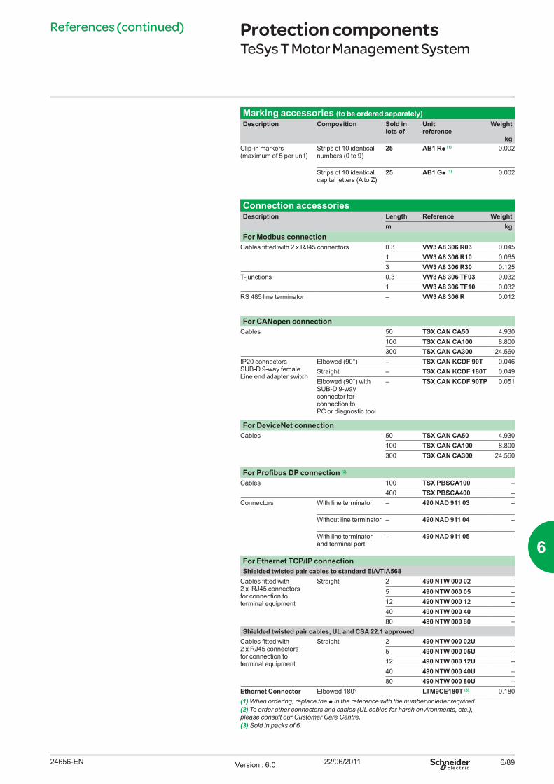
6/89
References (continued)
Marking accessories (to be ordered separately)Description Composition Sold in
lots ofUnit reference
Weight
kgClip-in markers (maximum of 5 per unit)
Strips of 10 identical numbers (0 to 9)
25 AB1 Rp (1) 0.002
Strips of 10 identical capital letters (A to Z)
25 AB1 Gp (1) 0.002
Connection accessoriesDescription Length Reference Weight
m kgFor Modbus connection
Cables fitted with 2 x RJ45 connectors 0.3 VW3 A8 306 R03 0.0451 VW3 A8 306 R10 0.0653 VW3 A8 306 R30 0.125
T-junctions 0.3 VW3 A8 306 TF03 0.0321 VW3 A8 306 TF10 0.032
RS 485 line terminator – VW3 A8 306 R 0.012
For CANopen connectionCables 50 TSX CAN CA50 4.930
100 TSX CAN CA100 8.800300 TSX CAN CA300 24.560
IP20 connectorsSUB-D 9-way femaleLine end adapter switch
Elbowed (90°) – TSX CAN KCDF 90T 0.046Straight – TSX CAN KCDF 180T 0.049Elbowed (90°) with SUB-D 9-way connector for connection to PC or diagnostic tool
– TSX CAN KCDF 90TP 0.051
For DeviceNet connectionCables 50 TSX CAN CA50 4.930
100 TSX CAN CA100 8.800300 TSX CAN CA300 24.560
For Profibus DP connection (2)
Cables 100 TSX PBSCA100 –400 TSX PBSCA400 –
Connectors With line terminator – 490 NAD 911 03 –
Without line terminator – 490 NAD 911 04 –
With line terminator and terminal port
– 490 NAD 911 05 –
For Ethernet TCP/IP connectionShielded twisted pair cables to standard EIA/TIA568
Cables fitted with 2 x RJ45 connectors for connection to terminal equipment
Straight 2 490 NTW 000 02 –5 490 NTW 000 05 –12 490 NTW 000 12 –40 490 NTW 000 40 –80 490 NTW 000 80 –
Shielded twisted pair cables, UL and CSA 22.1 approvedCables fitted with 2 x RJ45 connectorsfor connection to terminal equipment
Straight 2 490 NTW 000 02U –5 490 NTW 000 05U –12 490 NTW 000 12U –40 490 NTW 000 40U –80 490 NTW 000 80U –
Ethernet Connector Elbowed 180° LTM9CE180T (3) 0.180(1) When ordering, replace the p in the reference with the number or letter required.(2) To order other connectors and cables (UL cables for harsh environments, etc.), please consult our Customer Care Centre.(3) Sold in packs of 6.
Protection componentsTeSys T Motor Management System
24656-EN Version : 6.0 22/06/2011
6
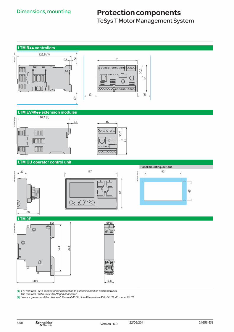
6/90
Dimensions, mounting
LTM Rpp controllers
5,2 91
(2) (2)
122,5 (1)
6130
,2
(2)
(2)
DF5
6861
7.ep
s
LTM EV40pp extension modules
5,5 45120,7 (1)
6130
,2
DF5
6861
8.ep
s
LTM CU operator control unitPanel mounting, cut-out
23
50
117
70
DF5
6861
0.ep
s 92
45
DF5
6861
1.ep
s
LTM 9F
68,9 17,8
84,4
95,4
DB
4033
66.e
ps
(1) 140 mm with RJ45 connector for connection to extension module and to network, 166mmwithProfibusDP/CANopenconnector.
(2) Leave a gap around the device of: 9 mm at 45 °C, 9 to 40 mm from 45 to 50 °C, 40 mm at 60 °C.
Protection componentsTeSys T Motor Management System
24656-ENVersion : 6.0 22/06/2011
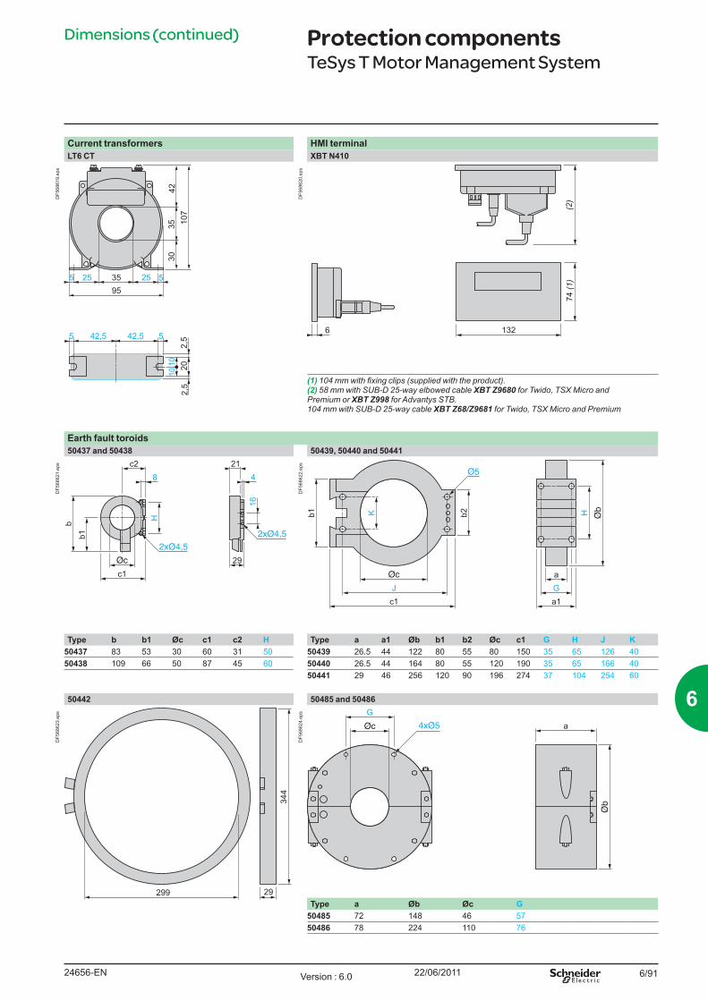
6/91
Dimensions (continued)
Current transformers HMI terminalLT6 CT XBT N410
2,5
35255 52595
35 107
3042
1010
2,5
20
42,5 42,55 5
DF5
6861
9.ep
s
132
74 (1)
6
(2)D
F568
620.
eps
(1)104mmwithfixingclips(suppliedwiththeproduct).(2) 58 mm with SUB-D 25-way elbowed cable XBT Z9680 for Twido, TSX Micro and Premium or XBT Z998 for Advantys STB. 104 mm with SUB-D 25-way cable XBT Z68/Z9681 for Twido, TSX Micro and Premium
Earth fault toroids50437 and 50438 50439, 50440 and 50441
c1
c28
H
b1b
29
214
16
DF5
6862
1.ep
s
HaGa1
Jc1
b2Kb1D
F568
622.
eps
Type b b1 Øc c1 c2 H Type a a1 Øb b1 b2 Øc c1 G H J K50437 83 53 30 60 31 50 50439 26.5 44 122 80 55 80 150 35 65 126 4050438 109 66 50 87 45 60 50440 26.5 44 164 80 55 120 190 35 65 166 40
50441 29 46 256 120 90 196 274 37 104 254 60
50442 50485 and 50486
344
29299
DF5
6862
3.ep
s
aG
DF5
6862
4.ep
s
Type a Øb Øc G50485 72 148 46 5750486 78 224 110 76
Protection componentsTeSys T Motor Management System
24656-EN Version : 6.0 22/06/2011
6
6/92
Schemes
SchemesLTMRppFM wiring with LTM 9F filter
KM1
O.1 O.2 O.3LTMR
A1
13 14 23 24 33 34 Z1 Z2 T1 T2
A2 I.1 I.2 I.3 I.4 I.5 I.6 97 98 95 96C C C
Start
O.4
Stop
I7 C7 I8 C8 I9 C9 I10 C10
LV1 LV2 LV3
3a
KM1
La
Na
I7 I8 I9 I10
LTM9F
A2 A1
N L
N L
Ie 0.13 A Ue 150-240 V 50/60 Hz
LTME
DB
4033
67.e
ps
Note: inputs MUST be connected across the common terminals (C).
Overload mode Independent mode3-wire local-control 3-wire local-control\
LTM R24 33 3413 14 23
96959897I.6CI.5I.4CI.3I.2CI.1A2
A1
– KM1 – KM1
O.1 O.2 O.3
O.4
M 3
KM1
Stop
Start
(1)
DB
4033
68.e
ps
LTM R24 33 3413 14 23
96959897I.6CI.5I.4CI.3I.2CI.1A2
A1
– KM1
O.1 O.2 O.3
O.4
M 3
– KM1
Stop
Start
DF5
6862
6.ep
s
(1) Connection of a single-phase motor is possible. In this case, do not use the central current transformer.
2-wire local-control 3-wire with switchable local/network control 2-wire with switchable local/network control
96959897I.6CI.5I.4CI.3I.2CI.1
O.4
Start/StopDF5
6862
7.ep
s
96959897I.6CI.5I.4CI.3I.2CI.1
O.4
NL O
Start
Stop
DF5
6862
8.ep
s
96959897I.6CI.5I.4CI.3I.2CI.1
O.4
NL O
DF5
6862
9.ep
s
L : Local controlO : StopN : Network control
Protection componentsTeSys T Motor Management System
24656-ENVersion : 6.0 22/06/2011
6/93
Schemes (continued)
Schemes (continued)Reverser mode3-wire local-control
LTM R24 33 3413 14 23
96959897I.6CI.5I.4CI.3I.2CI.1A2
A1
– KM2 – KM1
– KM1
– KM2
– KM2
– KM1 (1)
O.1 O.2 O.3
O.4
M 3
StopStartForw.
StartRev.
DF5
1075
0.ep
s
2-step mode, star-delta application3-wire local-control
LTM R24 33 3413 14 23
96959897I.6CI.5I.4CI.3I.2CI.1A2
A1
– KM2 – KM3
– KM1
– KM3 – KM3
– KM2 – KM3
– KM1– KM1 (1)
O.1 O.2 O.3
O.4
– KM1
M 3
StopStart
DF5
6863
1.ep
s
(1) Contacts for interlocking KM1 and KM2 are not obligatory because the controller electronically interlocks outputs O.1 and O.2.
Protection componentsTeSys T Motor Management System
24656-EN Version : 6.0 22/06/2011
6
6/94
Schemes (continued)
Schemes (continued)2-step mode, primary resistor application3-wire local-control
LTM R24 33 3413 14 23
96959897I.6CI.5I.4CI.3I.2CI.1A2
A1
– KM2 – KM1
– KM1 – KM2
O.1 O.2 O.3
O.4
M 3
StopStart
DF5
1075
1.ep
s
2-speed mode, Dahlander application3-wire local-control
LTM R24 33 3413 14 23
96959897I.6CI.5I.4CI.3I.2CI.1A2
A1
– KM1 – KM3
O.1 O.2 O.3
O.4
– KM1
– KM2
– KM2 – KM3
– KM2– KM1 (2)
(1)
– KM2
M 3
Low speed
High speed Stop
DF5
6863
3.ep
s
(1) For a Dahlander application, all the power cables must pass through current transformers. The controller can also be placed upstream of the contactor. In this case, and if the Dahlander motor is used in "variable torque" mode, all the cables downstream of the contactors must be of identical size. (2) Contacts for interlocking KM1 and KM2 are not obligatory because the controller electronically interlocks outputs O.1 and O.2.
Protection componentsTeSys T Motor Management System
24656-ENVersion : 6.0 22/06/2011
6/95
Schemes (continued)
Schemes (continued)Earth fault toroid and motor temperature probe connection
24 33 3413 14 23O.1 O.2
Z1 Z2 T1 T2
O.3
LTM R
DF5
6863
4.ep
s
Connection of outputs for motor control mode functionWithout intermediate relay With intermediate relay
M 3
LTM R13 14
– KM1
O.1
– KM1
DF5
6863
5.ep
s
M 3
LTM R13 14– KM1
O.1
– KA1 – KM1
DF5
6863
6.ep
s
Protection componentsTeSys T Motor Management System
24656-EN Version : 6.0 22/06/2011
6