Embed Size (px)
Citation preview


THAUMASITE SULFATE ATTACK: CASE STUDIES AND IMPLICATIONS
Hugh (Xiaoqiang) Hou, Laura J. Powers, John Lawler, Koray Tureyen
Wiss, Janney, Elstner Associates, Inc.
330 Pfingsten Road, Northbrook, Illinois 60062
ABSTRACT
The thaumasite form of sulfate attack (TSA) is a unique distress mechanism in portland cement
concrete in which thaumasite formation (TF) alters the primary binder, calcium silicate hydrate
(CSH), in addition to calcium hydroxide and calcium aluminate hydrates. TSA in concrete may
cause loss of paste-aggregate bond, strength, coherence, and eventually serviceability. The time
frame of TSA can be as short as a couple of years. Reported TSA cases have mostly involved
sulfate from external sources. This paper presents two less common TSA cases, in which sulfate
was determined to be from an internal source: in one case, from dolostone coarse aggregate and in
the second case from the cementing material. Characteristics of TSA distress and the composition
and texture of the concrete are discussed, and these cases are compared with other reported internal
and external TSA cases. It is concluded that petrographic examination of the concrete, particularly
using thin-sections, provides the most definitive diagnosis of TSA. Significant implications of
findings from the two case studies regarding mechanisms of thaumasite formation and potential
propensity of portland-limestone cement for TSA are also discussed.
KEYWORDS: Thaumasite, sulfate attack, TSA, concrete, durability, deterioration, limestone, dolomite,
petrography, gypsum

INTRODUCTION
Thaumasite is a rare mineral in nature and had only been scholarly or intellectually interesting
before it was identified in concrete in the 1960s (1, 2). Thaumasite is one of few minerals with a
six-coordinated silicon octahedral structural unit (3, 4), as expressed in its repeating structural unit
formula Ca3Si(OH)6(CO3)(SO4)·12H2O, or stoichiometrically CaSiO3·CaCO3·CaSO4·15H2O.
Six-coordinated silicate minerals such as stishovite typically form at high pressure and high
temperature. However, thaumasite in concrete was generally believed to form in a moist, cool
environment, favorably near 5oC (5).
Thaumasite drew the attention of the concrete industry because it involves a unique form of sulfate
attack, in which the formation of thaumasite alters the primary binder and causes concrete to
progressively lose paste-aggregate bond, strength, coherence and eventually serviceability.
Reactions involved in TSA are not limited by the amount of aluminate in cement (as is delayed
ettringite formation, DEF) nor suppressed by the consumption or absence of portlandite. Internal
sulfate TSA can develop progressively and aggressively once it occurs, and the affected concrete
may become “mushy” or even fluid as described in the technical literature (5, 6). Thus, there are
sufficient reasons to call thaumasite the “true concrete cancer.”
TSA was initially identified in concrete in the 1960s (1, 2), and had been occasionally reported
thereafter in the next thirty years. More than ten high-profile cases of deteriorated bridge
foundations and columns due to TSA found in the UK had prompted the British authorities to
convene a Thaumasite Expert Group (TEG) in 1998 to investigate the issue and provide
recommendations to mitigate or prevent TSA in new construction (6, 7). An interim report by the
TEG, which summarized risks, diagnosis, remedial works and guidance, was published in January
1999. The significance of this unique distress mechanism has since been increasingly recognized,
thanks largely to the work by the TEG. Following this interim report, an International Conference
on Thaumasite in Cementitious Materials was held at the British Research Establishment (BRE)
in Garston, UK, in June 2002. Approximately sixty papers presented at the conference were
published in a special issue of Cement & Concrete Composites (Volume 25 No. 8 2003). Since
then, the number of TSA-related papers has increased steadily.
Reported TSA cases mainly involved sulfate from external sources associated with soils,
groundwater, sulfate-bearing clay bricks, and gypsum plaster, and mortars containing gypsum or
sulfides (5-8). This paper presents two internal TSA cases, in which sulfate was determined to be
from the cementitious material in the floor slab deterioration of the first case, and from the
dolostone coarse aggregate in the foundation wall deterioration of the second case.
CASE 1 - FLOOR SLAB DETERIORATION
The first case involved concrete floor slab deterioration at a meat processing facility located in
Pleasant Prairie, Wisconsin. Floor repair concrete in the production area of the facility reportedly
exhibited spalls within five years, compelling the investigation. The floor and production
equipment were exposed to a rigorous cleaning process on a daily basis. The temperature of the

space where the deterioration had occurred was maintained at approximately 45°F (7oC), which is
considered nearly optimal for thaumasite formation based on the technical literature (5, 6, 7).
Constituents and General Characteristics of The Concrete: The appearance of saw-cut and
lapped surfaces of a representative core from a deteriorated region is shown in Figure 1. The
concrete is composed of pea-gravel coarse aggregate (top size of 3/8 inch) and natural sand fine
aggregate dispersed in a non-air entrained hardened paste of portland cement (and possibly minor
calcium aluminate cement). The pea gravel mainly consisted of dolomite with small amounts of
sandstone and cherty dolostone. The sand is siliceous and composed mainly of quartz.
Microscopical observations and physical characteristics of the paste are indicative of a moderate
water-to-cementitious materials ratio. The aggregates did not contain gypsum and generally
appeared to be sound.
Distress Characteristics and Thaumasite: The concrete contains many discontinuous transverse
cracks throughout the three-inch depth of the core (Figures 1, 2 and 3). Concrete at greater depth
reportedly deteriorated into rubble and only small fragments were recovered. The transverse cracks
extended mainly around aggregate particles; however, a few cracks went through the aggregate
particles. Rims or halos around aggregate or portions of aggregate particles are abundant. These
rims usually occurred above, below, or both above and below aggregate particles; they occur less
commonly surrounding whole particles. They may also connect to the transverse cracks. These
rims or halos were often filled or partially filled with white secondary deposits. The secondary
deposits were soft and powdery. Paste-aggregate bond was weak or absent. Gravel particles readily
came off from cored or saw-cut surfaces.
A polarized-light microscopical examination revealed that the white deposits in the rims or halos
are predominantly thaumasite (Figures 4 and 5), as characterized by the feather or needle-like
crystals, refractive indexes less than 1.54, and yellow to blue birefringence colors. The
birefringence colors are distinctively different from that of ettringite, which typically exhibits gray
color. Thaumasite in plane-polarized light is colorless, light brown, or light hay-yellow. In the
thaumasite halos, residual cement and fine aggregate particles were observed. The abundances of
residual cement particles and sand increased towards the paste side and decreased towards the
aggregate side within the thaumasite halos. Overall, the abundances were lower than in a general
area of paste, suggesting some cement particles may have dissolved and participated reactions,
been forced apart by expansion, or both of these processes. We believe that in a halo, thaumasite
adjacent to the aggregate forms later than the thaumasite on the paste side of the halo. A dark, less
transparent paste band surrounding a thaumasite halo (Figure 4) was often observed. The band
appeared to contain more abundant residual cement particles.
Some rims or halos were partially open or unfilled, typically at the aggregate side, exhibiting an
appearance of adhesion cracks or plastic gaps (Figures 1 through 6). Microscopical evidence,
however, indicates they were not plastic adhesion cracks. Small broken portions of aggregate were
attached to the thaumasite side, indicating the separation occurred after the precipitation of
thaumasite (Figure 5). The features may also suggest multiple, intermittent expansion events.
Localized drying shrinkage during sample preparation may have contributed to the gapping but
was considered to be a minor factor based on observations of freshly sawed surfaces and the
general shapes and textures of the separations.
Thaumasite also fills or partially fills cracks and voids (Figures 1, 2 and 3). Paste away from the
peripheral regions also appeared to be substantially altered and often replaced by thaumasite
(Figure 4).
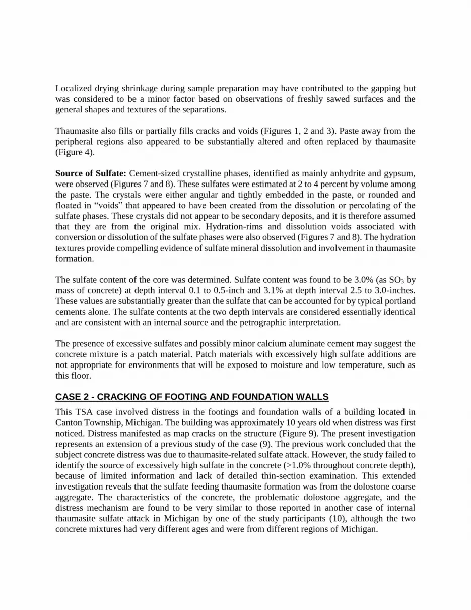
Source of Sulfate: Cement-sized crystalline phases, identified as mainly anhydrite and gypsum,
were observed (Figures 7 and 8). These sulfates were estimated at 2 to 4 percent by volume among
the paste. The crystals were either angular and tightly embedded in the paste, or rounded and
floated in “voids” that appeared to have been created from the dissolution or percolating of the
sulfate phases. These crystals did not appear to be secondary deposits, and it is therefore assumed
that they are from the original mix. Hydration-rims and dissolution voids associated with
conversion or dissolution of the sulfate phases were also observed (Figures 7 and 8). The hydration
textures provide compelling evidence of sulfate mineral dissolution and involvement in thaumasite
formation.
The sulfate content of the core was determined. Sulfate content was found to be 3.0% (as SO3 by
mass of concrete) at depth interval 0.1 to 0.5-inch and 3.1% at depth interval 2.5 to 3.0-inches.
These values are substantially greater than the sulfate that can be accounted for by typical portland
cements alone. The sulfate contents at the two depth intervals are considered essentially identical
and are consistent with an internal source and the petrographic interpretation.
The presence of excessive sulfates and possibly minor calcium aluminate cement may suggest the
concrete mixture is a patch material. Patch materials with excessively high sulfate additions are
not appropriate for environments that will be exposed to moisture and low temperature, such as
this floor.
CASE 2 - CRACKING OF FOOTING AND FOUNDATION WALLS
This TSA case involved distress in the footings and foundation walls of a building located in
Canton Township, Michigan. The building was approximately 10 years old when distress was first
noticed. Distress manifested as map cracks on the structure (Figure 9). The present investigation
represents an extension of a previous study of the case (9). The previous work concluded that the
subject concrete distress was due to thaumasite-related sulfate attack. However, the study failed to
identify the source of excessively high sulfate in the concrete (>1.0% throughout concrete depth),
because of limited information and lack of detailed thin-section examination. This extended
investigation reveals that the sulfate feeding thaumasite formation was from the dolostone coarse
aggregate. The characteristics of the concrete, the problematic dolostone aggregate, and the
distress mechanism are found to be very similar to those reported in another case of internal
thaumasite sulfate attack in Michigan by one of the study participants (10), although the two
concrete mixtures had very different ages and were from different regions of Michigan.
Constituents and General Characteristics: The concrete is composed of crushed dolostone
coarse aggregate (top size of 3/4 inch) and natural sand fine aggregate dispersed in a non-air
entrained hardened paste of portland cement and fly ash (Figure 10). Microscopical and physical
characteristics of the paste are indicative of a moderate to moderately high water-to-cementitious
materials ratio.
Distress Characteristics and Thaumasite: General distress characteristics can be found in the
list of references (9, 10). In summary, these include: 1) thaumasite secondary deposits surrounding
or partially surrounding aggregate particles (Figures 10 and 11); 2) frequent cracks in both paste
and aggregates; 3) paste being significantly softened locally and paste-aggregate bond being weak;
and 4) thaumasite filling voids and cracks and replacing a portion of paste.
Source of Sulfate: Sulfate feeding the thaumasite formation was determined to have been derived
from the dolostone coarse aggregate. The problematic dolostone is somewhat porous, composed
of equi-granular dolomite rhombs or irregular crystals several tens of microns in size. The rock
often contained large patches of gypsum (Figures 11 and 12) or interstitial gypsum and small
amounts of anhydrite (Figure 13 and 14). Voids suggesting dissolution of gypsum or anhydrite
were observed. Initial formation of small amounts of thaumasite immediately adjacent gypsum in
dolostone particles was also observed (Figure 12). A previous SEM-EDX study (9) had also
identified the presence of gypsum but gypsum was interpreted as a void-filling secondary deposit,
rather than properly as an inherent portion of the aggregate (Figure 15, and the Figure 8 in reference
9). When these gypsum-containing particles are crushed, a portion of the gypsum embedded in the
particles is liberated and readily accessible to prime thaumasite formation. The total sulfate
content, expressed as percent SO3 by mass of the concrete, ranged from 1.0 to 1.6 percent at various
depths up to 17 inches (core interior end), greater than can be accounted for by the portland cement
alone. The total sulfate content of a local soil sample was low (<0.01% or 40 ppm).
SUMMARY AND DISCUSSION
1. Petrographic Examination
Petrographic examination, particularly using polarized-light microscopy, is the most effective
method to identify TSA distress. When TSA deterioration is suspected, the first technique to utilize
for investigators should be petrography. Petrographic examination consists of a systematic
sequence of observations carried out at increasingly higher levels of magnification from visual and
low-magnification (0 to ~50X) examinations of as-received, lapped, and freshly broken samples,
to high-magnification (50 to 500X) petrographic microscope examination of thin sections and
polished sections, and to higher magnifications (100X to greater than 5,000X) with the scanning
electron microscope (SEM) when needed.

The petrographic microscope examination of thin sections is critical in differentiating thaumasite
from ettringite. Thaumasite has a much higher birefringent color than ettringite due to a higher
birefringence (0.036 vs. 0.06). XRD analysis would be the most definitive technique to positively
identify thaumasite. However, XRD patterns of thaumasite and ettringite overlap to a certain extent
(Figure 16), and if thaumasite is small in quantity, dilution due to aggregate and paste may make
the positive identification difficult.
2. Carbonate Rock
Carbonate rock, principally limestone and dolostone, are the most widely used crushed rock types
for aggregate production for portland cement concrete (PCC), due to its abundance, ease of
processing, and typically satisfactory performance. However, cases of concrete deterioration have
frequently occurred in our concrete troubleshooting practice, including alkali-carbonate reaction
(ACR), alkali-silica reaction (ASR), D-cracking, popouts, general freeze-thaw damage, surface
dusting, and thaumasite sulfate attack (TSA) as reported here, all due to differences in the quality
of the carbonate aggregate.
Geologically, the formation of carbonate rock involves complicated physical, chemical, and
biological processes, resulting in substantial variability in mineralogical composition and
petrological fabric that affect carbonate aggregate performance. More often than not, mined
carbonate aggregate (including natural carbonate gravel) contains many rock types transitioning
between ideal limestone (all calcite) and dolostone (all dolomite). Many other rock types,
commonly including shale, clay/mudstone/ironstone, sandstone, and chert are present, and there is
a wide range in porosity, induration, and other characteristics. Sulfide and sulfate minerals,
carbonaceous organic matter, coal, and other impurities are also common. The compositional and
textural variability of carbonate and associated rocks has been shown to significantly affect their
performance as aggregate. Petrographic examination, combined with other analyses when
necessary, may effectively evaluate the abundance of gypsum, sulfides, and other potentially
deleterious components in aggregate. To date, published studies appear to have emphasized the
role of carbonate aggregates providing carbonate in TSA but have often ignored the potential role
of aggregate supplying sulfate. The second case study reveals the general texture of a dolostone in
Michigan that contains excessively high gypsum. Petrographic examination of the aggregate
would have prevented the use of the aggregate, or at least recommended additional chemical tests.
3. Portland-Limestone Cement (PLC)
Limestone is also being increasingly used in portland-limestone cement (PLC). Greater scrutiny
of the mineralogical, chemical, and physical complexity of this widely-used construction material
and the effects of their variability on PLC performance is needed in practice and in research. The
PLC might be potentially vulnerable to TSA, although conflicting results have been reported
regarding the durability of PLC concrete (11, 12) depending on the replacement rate and many
other factors. This paper demonstrates the unique capabilities and usefulness of aggregate and
concrete petrography, a method that is strongly recommended to contractors and manufacturers

before a “limestone” is mixed in concrete mixtures or blended in clinker/cement and causing
problems.
4. External vs. Internal TSA
Internal TSA is considered more deleterious and little can be done once it initiates. The required
components are all conveniently available or within readily accessible distance, generally
throughout the concrete, in contrast to external TSA. Supplementary cementitious materials such
as fly ash may not be helpful preventing the reactions; effectiveness of low w/c may also be limited.
Fly ash is present in both of the Michigan cases and fly ash apparently did not prevent TSA.
Internal TSA causes the concrete to deteriorate fairly uniformly throughout and at a fast pace. The
reported external TSA in England motorway bridges exhibited a deteriorated depth of
approximately 1.5 inch in 30 years (13). Concrete in these two internal TSA cases has exhibited
deterioration throughout the depth of the cores up to a foot in five or ten years. A zoning texture,
increasingly severe damage toward the exterior surface as reported for external TSA (5, 6), is
typically not observed for internal TSA. In addition, TSA may be more widespread than generally
perceived because of buried structures and misidentification of thaumasite as ettringite, as
acknowledged by other workers. It appears that TSA is easy to duplicate in laboratory experiments
provided that several parameters including sulfate levels, pH levels, and low storage temperature
are met. We strongly believe that other similar internal TSA cases exist in the state of Michigan
and probably in nearby Ohio and Indiana. Inspection is recommended for buried structures under
similar conditions in the state. However, it should also be noted that the formation of thaumasite
does not necessarily cause distress. We have observed thaumasite formation in some historic
mortars and concrete without significant associated deterioration (14).
5. Topochemical vs. Through-Solution Mechanism
Two major mechanisms of thaumasite formation, a topochemical mechanism and a through-
solution mechanism, have been proposed (5, 6). These two mechanisms seem to correlate with an
indirect route and a direct route (15). Observation of residual cement and sand within a thaumasite
halo may indicate that the formation of thaumasite was not simply the filling of an empty space
(at least at certain stage) but was likely a result of replacement of existing in-situ paste. This feature
suggests the hypothesis of topochemical formation of thaumasite (6) (under the broad definition
and in a less strict sense (8)) is relevant. Features associated with a thaumasite halo also appear to
be different from ettringite surrounding aggregate particles in DEF-affected concrete. In our
experience, ettringite lining the peripheral gaps or cracks often appear to be pure and free of
residual cement and aggregate. In addition, ettringite tended to surround various aggregate
particles indiscriminately whereas thaumasite appeared to occur more often around carbonate
aggregate particles. Thaumasite rims were absent or far less developed around siliceous aggregate
(either black or white gravel in this concrete) than dolomitic ones (brown, yellow or gray, Figures
1 and 6), even though the aggregate particles were of similar sizes. The observation may imply
roles of carbonate or even magnesium (5) from the dolomite. The observed dark band surrounding
a thaumasite halo, however, appeared to be more supportive of a through-solution mechanism, in

which residual cement particles freed in solution were accumulating into the band. Nevertheless,
thaumasite occurring in voids must have formed through solution and precipitation processes.
ACKNOWLEDGEMENT
The authors greatly appreciate the clients who provided opportunities for us to work on these
interesting projects and help them troubleshoot their concrete problems. The authors thank
Margaret Reed and Susanne Papas for their assistance with petrographic and chemical analyses
and Brookelynn Schmeck for her exhaustive efforts in editing and formatting this manuscript.
REFERENCES
1. Erlin, B., and Stark, D. C. (1966). Identification and occurrence of thaumasite in concrete.
Highway Research Record, No. 113, pp 108–113. Publisher: Highway Research Board.
2. Stark, David C. (2003). Occurrence of thaumasite in deteriorated concrete. Cement &
Concrete Composites, 25(8), pp 1119-1121.
3. Edge, R. A., and Taylor, H. F. W. (1969). Crystal structure of thaumasite, a mineral
containing [Si(OH)6]2− groups. Nature, 224, pp 363-364.
4. Martucci, A., and Cruciani, G. (2006). In situ time resolved synchrotron powder diffraction
study of thaumasite. Phys. Chem. Minerals, 33, pp 723-731.
5. Sharp, J. H. (2006). Surely we know all about cement – don't we? Advances in Applied
Ceramics, 105 (4), pp 162-174.
6. Crammond, N. J. (2003). The thaumasite form of sulfate attack in the UK. Cement &
Concrete Composites, 25(8), 809–818.
7. TEG Report Department of Environment, Transport and the Regions (1999). The
thaumasite form of sulfate attack: Risks, diagnosis, remedial works and guidance on new
construction. Report of the Thaumasite Expert Group. DETR, January 1999. London.
8. Sulfate Attack on Concrete, Jan Skalny, Jacques Marchand and Ivan Odler ed. 2002, pp.
53-54.
9. Marusin S. L., Reed, M. H. (2007). Thaumasite in concrete - a case study. Proceedings of
the Twenty-Nine International Conference on Cement Microscopy, Quebec City, PQ,
Canada, May 20 -24, pp 70-90.
10. Hou, H., and Daugherty A. (2011). Petrographic study of concrete: two case studies
involving internal and external sulfate attacks. Proceedings of the Thirty-Third

International Conference on Cement Microscopy, April 17 – 20, 2011. San Francisco,
California, U.S.A.
11. Ramezanianpour, A. M., and Hooton, R. (2013). Thaumasite sulfate attack in portland and
portland-limestone cement mortars exposed to sulfate solution. Construction and Building
Materials 40, pp 162–173.
12. Gaze, M. E. (1997). The effects of varying gypsum content on thaumasite formation in a
cement: lime: sand mortar at 5 °C. Cem. Conc. Res. 27 (2) pp 259-265.
13. Slater, D., Floyd, M., and Wimpenny, D.E. (2003). A summary of the Highways Agency
Thaumasite Investigation in Gloucestershire: the scope of work and main findings. Cement
& Concrete Composites 25, pp 1067-1076.
14. Powers, L.J., and Walsh, J. (2005). A new look at an old cement. Proceedings of the 27th
International Conference on Cement Microscopy, p 118-131, April 24-28, 2005, Victoria,
British Columbia, Canada.
15. Rahman, M.M., and Bassuoni, M.T. (2014). Thaumasite sulfate attack on concrete:
mechanisms, influential factors and mitigation, Construction and Building Materials 73,
pp 652–662.

Figure 1. The pea gravel concrete and its topping. Abundant narrow,
discontinuous, transverse cracks and white halos surround aggregate
particles. Black and white siliceous particles tend less frequently to
exhibit white halos or secondary deposits than gray and yellow
carbonate aggregates.

Figure 2. Close-up view of thaumasite rims (arrows).
Distinct rims or halos above or below aggregate
particles. Thaumsite rims in upper photo absorbed epoxy
from sample preparation and exhibited darkened color.

Figure 3. Close-up view of cracks in paste.

Figure 4. Thin-section photomicrographs illustrating thaumasite
surrounding aggregate particles and locally replacing paste. A few
residual cement particles were present in the thaumasite halos. A
dark band presented at the outer edge of the halo (arrows). Upper
photo: plane-polarized light; lower photo: cross-polarized light.

Figure 5. Thin-section photomicrographs illustrating opened rims
and thaumasite surrounding aggregate particles. Arrows show small
detached portions of the aggregate particle, suggesting the gap was
probably further opened after the thaumasite had formed and
therefore was not new or recent. Upper photo: plane-polarized light;
lower photo: cross-polarized light.

Figure 6. Thin-section photomicrographs illustrating thaumasite
surrounding a dolostone coarse aggregate particle (upper left) but
not a siliceous particle of similar size (lower right). Upper photo:
plane-polarized light; lower photo: cross-polarized light.

Figure 7. Thin-section photomicrographs illustrating rounded
sulfate, likely anhydrate (arrows). The texture is consistent with
dissolution of preexisting material rather than secondary deposits.
Upper photo: plane-polarized light; lower photo: cross-polarized
light.
Figure 8. Thin-section photomicrographs illustrating rounded sulfate
(arrows). Again, the texture is consistent with dissolution of
preexisting material instead of secondary precipitation. Upper:
plane-polarized light; lower: cross-polarized light.

Figure 9. Footing/foundation wall exhibited cracks.
Figure 10. Saw-cut and lapped section of a
segment of a concrete core subjected to
thaumasite form sulfate attack.

Figure 11. Thin-section photomicrographs illustrating thaumasite
rims surrounding aggregate particles. Arrows show gypsum and
anhydrite (top) within a dolostone aggregate particle. Upper: plane-
polarized light; lower: cross-polarized light.

Figure 12. Thin-section photomicrograph illustrating gypsum and
anhydrite at edge of a dolostone aggregate particle, appearing to
exhibit localized dissolution. Minor amounts of thaumasite formed
surrounding the particle (arrows). Cross-polarized light.
Figure 13. Thin-section photomicrograph illustrating gypsum and
anhydrite within a dolostone aggregate particle, appearing to exhibit
localized dissolution. Cross-polarized light.

Figure 14. Thin-section photomicrograph illustrating
anhydrite within a dolostone aggregate particle. Cross-
polarized light.
Figure 15. Unpublished data from ref [9]. Gypsum within a
dolostone aggregate particle (lower left) surrounded by
thaumasite. Similar data was reported in Figure 8 of the
referenced paper. The round portion at lower left corner of the
left photo appears also to be gypsum.

Figure 16. XRD powder pattern of secondary deposits from aggregate sockets in TSA-affected concrete.
Upper: full scanned 2Ɵ range; Lower: expanded 2Ɵ ranges from 8 to 10.5 degrees and 15 to 17 degrees
illustrating that diffraction peaks are bettered resolved at higher 2Ɵ range 15 to 17 degrees. The third
order diffractions are even better resolved (arrow). Data presented at ICMA.10
5 15 25 35 45 55
15 15.5 16 16.5 178 8.5 9 9.5 10 10.5
Ettringite
Thaumasite
2Ɵ KαCu 2Ɵ KαCu
Ettringite
Th.+Ett. Dol
Th.+Ett.


![Bis[diamino(ethoxycarbonylamino)methylium] sulfate](https://img.pdfslide.net/doc/110x75/6323db435f71497ea90487bd/bisdiaminoethoxycarbonylaminomethylium-sulfate.jpg)


