Embed Size (px)
Citation preview
The Computer Aided Design of Microprograms
William Graham Wood
Ph. D.
University of Edinburgh
1979
"--.-

I declare that this thesis was composed by myself
and that the work reported in it is my own.
Abstract
Chapter 1 Introduction 1
1.1) Background, Motivation and Goals 2 1.2) Outline of MDS - Microprogram Design 13
System 1.3) Related Work 22
Chapter 2 Describing the Processor 28
2.1) The Processor Level of Description 28 2.2) Desirable Properties of a 32
Processor Description Language 2.3) MDL - Microprogram Design Language 44 2.4) Generating a Maximally Parallel 52
Representation of the Source Microprogram
2.5) ANALYSE - A Program to Generate a 76 Canonical Microprogram from a Modular Sequential Description
Chapter 3 Defining the Microprogram Level 90 Host Machine
3.1) Considerations for Describing 91 Microinstruction Formats
3.2) MFM - Microinstruction Format Model 102
Chapter 4 Generating the Microprogram 121
4.1) Packing Micro-operations into 122 Microinstruction Words
4.2) Implementing Micro-operations by 154 Micro-orders in the Defined Microinstruction Format
4.3) Generating Microprogram Sequencing 177 Information
Chapter 5 Results, Conclusions and Extensions 183
5.1) Results - A Worked Example 183 5.2) Conclusions 190 5.3) Future Extensions 201

References
Appendix Listing of MDL Source Microprogram 213 Appendix Canonical Microprogram for 1(a) 217 Appendix MFM Format Description 221 Appendix Output from MICROMAP 226 Appendix Next Instruction Information from 241
MICROMAP
Appendix 2 MDL Reference Manual 243
Abstract
The design of the microprogram control for a digital
system is an intricate and error-prone task. This thesis
examines the feasibility of partially automating the
process of microprogram design through translation of a
high level description of the behaviour of a system into a
microprogram in a defined format which will effect that
behaviour. A design suite which performs this function is
described.
Within the suite, the behaviour of a digital system is
expressed in terms of register transfer operations in a
sequential, block-structured description. A maximally
parallel representation of the behaviour is generated
automatically through analysis of the control structure of
the sequential description and the data dependency
relationships defined between the register transfer
operations. The maximally parallel representation takes
the form of a partially ordered graph whose nodes may be
simple, representing the primitive operations of the
description, or composite, representing the control
blocks. The microinstruction format in which control of
the system should be implemented is described in terms of
a model defining the field structure and constituent
control signals of the chosen format. The operations.of
the behavioural description are mapped automatically into
a microprogram of this format in an order determined by

the maximally parallel representation which preserves the
defined behaviour while minimizing the size of the
microprogram generated.
—qi.j.xrr4ti1
The concept of microprogramming was first proposed by
Wilkes [61] in 1951 as a systematic method for
implementing the control unit of a computer. Over the
last fifteen years (since the introduction of the IBM
System/360 125, 571 in 1961) its usage for just that
purpose has become increasingly more common; but the
practice of microprogram design is essentially the same
today as it was fifteen years ago.
This chapter considers the practice of microprogram
design. The first section examines its current status,
reasons why this should be improved upon, and identifies
what can be done to improve it. The product of this
motivation, a system intended to expedite the practice of
microprogram design, is introduced in the second section
and the efforts of others toward related goals are
reviewed in the third.
1
This thesis is concerned with microprogram design,
which hereafter will be held to denote
"The design of the microprogram control of a digital
system dedicated to the implementation of a specified
processor organization and behaviour."
This definition will be qualified and refined
throughout the sections that follow, but will suffice as
stated for the present. The definition does not exclude
the writing of a microprogram to execute on a predefined,
general purpose processor. This simply represents a
restriction, with one less degree of freedom, on the
subject primarily under consideration - which is to
generate an implementation that is tailored in all its
aspects, specifically the microinstruction format, to one
target architecture.
To the systems designer, microprogram design exhibits
some interesting attributes. The most obvious of these is
that it involves parallelism. The primitive operations
which are evoked at the microprogram level are evoked
concurrently - and how best to design systems for a
concurrent implementation is not yet well understood. The
parallelism inherent in microprogramming is different from
2
the parallelism involved in a multi-processor computer
architecture, where the scheduling of operations is
performed dynamically on the basis of which operations are
"ready" to be executed at any given time. The scheduling
of micro-operations in a microprogram entails packing
them, perhaps together, into microinstruction words. This
task must be performed statically at design time. It is
based upon two factors: the ordering between the
microinstructions which must be observed in order to
effect the desired behaviour, and the resources employed
by each. The scheduling of micro-operations is
significant with respect to both the size and the speed of
the resultant microprogram. The scheduling algorithm
itself and the influence of the microinstruction format on
the performance characteristics of the microprogram are
both topics of interest, the latter having been studied
little. Related to it is the question of how, in a
dedicated implementation, the choice of microinstruction
format should be influenced by the "style" of the system
being implemented. That is, what is the most appropriate
microinstruction format in which to effect the control of
a given processor architecture?
These particular questions are not the specific subject
of this research, but are touched on to varying degree in
the text that follows.
It is convenient to attach a label to the class of
3

digital systems for which it is desired to generate a
microprogram controlled implementation. The term
processor will be used for this purpose (as it has been
already without comment), where the immediate connotation
with the instruction set processor of a computer is
intentional (this being the subject to which the concept
of microprogramming was originally applied), but extension
of the scope of the term to encompass a more general set
of systems is encouraged.
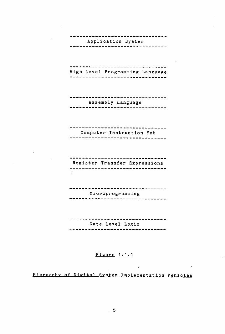
Microprogramming exists as one of a hierarchy of
digital system implementation vehicles f521, associated
with conceptual levels at which a digital system may be
represented (see figure 1.1.1). Each level is
characterized by the relative complexity of the data
structures represented and the operations performed on
them, and may be thought of as defining a "soft machine"
on which systems described at that level are conceptually
implemented. The data structures which are defined at the
microprogram level are simple registers and data lines
carrying vectors of bits. The operations performed are
transfers of data between such data structures plus simple
combinatorial functions on the data held by them.
Application System
High Level Programming Language
Assembly Language
Computer Instruction Set
Register Transfer Expressions
Microprogramming
Gate Level Logic
Figure 1.1.1
5
The "soft machine" associated with the microprogram
level may be considered a real, "hard" machine in the
sense that it is defined in terms of resources which are
realizable as available physical components - such as
latches, multiplexors, functional units and physical
interconnexions. This may be contrasted with the purely
conceptual soft machine associated with, for example, a
symbolic mathematical notation. If it were desired to
implement a system conceived in such terms, it would be
necessary either to translate the system description into
a representation for which a realization of the associated
soft machine exists (cf. compilation of a high level
language program to machine code), or else to implement in
terms of already existing machines, a soft machine which
interprets systems described In that notation (of. machine
code by microprogram).
Conceptual representation schema for which soft machine
implementations are available are exceptional: normally it
is necessary to translate one's original conception of a
design, possibly through many intermediary stages, to a
representation with this property. The provision of a
mechanism for the automatic translation of a description
in one representation to an equivalent description in
another representation for which a soft machine
implementation is available (cf. compilation of a high
level language) effectively makes available a soft machine
implementation of the original representation.
[1
In a hierarchical structure, at each level of
representation a system may be described in terms of its
behaviour with respect to the resources defined at that
level. For any level, there may exist many possible
implementations of such a behaviour in terms of the
resources defined at the next lowest level in the
hierarchy. The low level framework of resources is said
to define a host machine which, through ordered execution
of the primitive operations defined at that level,
emulates the operations which comprise the behavioural
description at the higher level, the target machine;
thereby implementing the behaviour. For example, a system
expressed in terms of the statements of a high level
language may be implemented by many different sequences of
machine code instructions.
The philosophy of the top-down, design of systems
reflects this hierarchical structure. A system is
initially described at the highest level of representation
appropriate to the complexity of its natural components
and structure. This description is then successively
refined at lower levels until the system is expressed in a
representation for which direct implementation is
possible, le. for which a realization of the soft machine
so defined is available.
Consistent with the loose notion of processor employed
above, the term processor level will be defined to denote
7

simply that level of representation in which it is
appropriate, regardful of its complexity, to express the
behavioural description of a system to be implemented
under control of microprogram. It is to be hoped that
this expression will stimulate intuitive prejudices
sufficient to bear the reader as far as chapter 2 when the
definition will be put on a sounder footing.
No realization of the soft machine associated with the
processor level of representation is currently available
to designers. Consequently, top-down microprogram design
is not a straightforward exercise; and it is this
observation that provides the major motivation behind the
work reported in this thesis.
Microprogram design, as currently practised, is
normally performed in a single step: through the direct
implementation of the structure and conceptual function of
a processor in terms of the primitive operations at the
microprogram level. That is, the designer devises a
microprogram level organization and microinstruction
format which is appropriate to the system in question and
then directly utilizes the low level operations so defined
to effect a behaviour at the microprogram level which will
implement the function conceived for the processor. The
term "function" is used here as a notion of the behaviour
of the system with respect to its external environment,
its inputs and outputs, only. A processor level
behavioural description of the system may be implicitly
assumed in this process, but rarely is it used explicitly
as an integral part of the design practice.
(Care must be taken here to distinguish between the
programming of a single chip, or small chip set, so-called
microprocessor, eg. Intel 8086, Zilog Z 80 etc. whose
instruction set closely resembles that of a typical
minicomputer and for which ample programming aids are
available, and microprogram design as defined above which
implies the dedicated microprogram level implementation of
some particular processor architecture).
As described, microprogram design is an intricate and
error-prone task. It is little wonder that it tends to be
regarded as a specialist skill.
The reasons for this state of affairs are probably
twofold. The application of microprogramming has
traditionally been in the control of the processing units
of computers (central and peripheral), where every effort
has been made to make microprograms execute as fast as
possible while at the same time endeavouring to minimize
the amount of very expensive control memory required to
store the microprogram. Hence low level design was deemed
mandatory. The second reason, of debatable significarce,
arises from the evolutionary path of microprogramming.
Microprograms were introduced as a replacement for random
logic. As a result they tended to be designed in the same
style as random logic; by designers who did not have a
background in programming and had not yet learned the
lessons that software experience had wrought several years
earlier of the advantages of structured programming and
top-down design.
Indeed the status of microprogram design today may be
seen as closely analogous to the status of computer
programming two machine generations ago: when systems were
growing exceedingly more complex and many more people
wanted to use computers; out of which grew the necessity
for high level programming languages.
In the past, the limited scope for microprogram design
has tolerated the difficulty of this task, and the
specialists have been proficient in practising their
skill. However two factors, both born out of the current
trends toward cheaper and more complex hardware
components, mitigate against continued universal
acceptance of this situation.
First, the availability of cheap hardware components,
in particular bit slice microprocessor integerated circuit
chips and fast memory suitable for use as control store,
has at last made the custom built processor controlled by
microprogram a realistic alternative for the
implementation of many digital system designs. Hence many
more people will have the opportunity to design complete
10
systems integrating hardware and software. But these
people lack the specialist skills of the microprogram
designer. If the potential offered by cheap hardware
components is to be realized, then microprogram design
must be made less difficult.
The second motivation for change arises from the fact
that inicroprograms themselves are growing increasingly,
more complex as more system functions are pushed into
microcode. And just as it proved necessary to adopt high
level programming languages to master the complexity of
large scale software systems, so higher level design jaids,
perhaps sacrificing some implementation efficiency, must
be made available for microprogram design. This is
particularly true for the microprogrammed control of very
large scale integrated (VLSI) systems, where the various
criteria of vast complexity, volume production, and design
time minimization all serve to promote the emphasis on
structured microprogram design as a means of generating
correct inicroprograms within reasonable time scales.
These observations constitute the principal motivating
factors behind the research which this thesis documents.
The primary goal is:
"To facilitate the practice of good microprogram design."
With this overall objective in mind (and a hint of the
11
approach adopted to meet it) the following specific goals
may then be identified:
To separate the tasks of design and implementation at
the processor level.
To use to maximum effect the human designer's skill
by performing automatically as much of the
microprogram design process as is possible and
sensible.
To generate efficient microprograms.
(14) To encourage the production of well structured
microprograms.
To facilitate verification of microprograms.
To facilitate alteration of microprograms.
To facilitate alteration of micro-architectures.
To facilitate experimentation with different
micro-architectures.
To produce a useful and usable microprogram design
aid.
12

In the light of the arguments of the preceding section,
microprogram design may now be viewed as comprising three
separate sub-tasks:
The design of a processor level target machine.
The design of a microprogram level host machine.
The implementation of (1) on (2) through emulation.
It is fundamental to the approach described herein
toward providing a practical aid in each of these three
tasks that the skill of the designer should not be
ignored. On the contrary, it should be exploited to
maximum advantage by relieving the designer of the more
tedious aspects of the task in hand, leaving him to
concentrate on the creative aspects.
One such creative task is the design of the processor
behaviour, where that term denotes an ordered set of
operations on the resources defined at the processor level
which implements the conceptual functional specified for
the processor. It might be possible, given a suitable
specification of the function and organization of the
processor, to generate automatically a behaviour to
13
realize that function; but it is not desirable to do so.
Design essentially involves the selection of one from
an infinite number of alternatives. Despite the advances
being made in the field of artificial intelligence, this
is a task that is performed far more successfully by the
practised human than by any computer program, whose forte
is the evaluation of a large but finite number of
alternatives. It would be impossible to incorporate in a
program all the intuition and experience that the human
designer calls upon in order to shape a design for the
desired balance of the implementation parameters of the
system: speed, size, cost of components etc., and all of
the factors which affect them. In addition, the processor
behaviour in practice is developed in conjunction with the
organization of the processor resources necessary to
support that behaviour. It would be unrealistic to
propose a processor organization without giving thought to
the processor behaviour, and it certainly would not be
practical to generate automatically an organization as
well as a behaviour for a processor to implement a
specified function.
It is much more sensible from a practical point of view
to provide the designer with a suitable representation
medium in which to express the design of a behavioural
description of the processor, rather than trying to do the
design for him.
The same view is taken concerning the design of a
1
microprogram level host machine to implement the processor
behaviour. This is another creative task where the skill
and experience of the designer may be applied to
beneficial effect. Again, the microprogram level
organization of the processor greatly influences the
implementation parameters for the system: the amount of
control store required, the speed of execution of the
microprogram, the cost of necessary components such as
multiplexors, and so on. The designer should be given
total control over the shape of the design and, that shape
having been provided, where possible the body should be
filled in automatically. That is, the designer should
specify the organization of the microprogram level host
machine for the processor and then, in the framework of
that host machine organization, the emulation of the
operations which describe the processor behaviour may be
performed automatically..
What must be described about the microprogram level
host machine? The designer's objective is to generate a
microprogram which implements a defined behaviour. It
does so by Issuing control signals to the microprogram
level components of the system organization, causing each
to effect a simple action; and the composition of these
simple actions realizes a more complex action. The
operations which express the behaviour of the processor
may be seen as complex actions. What must be described in
15
order that the realization of these by the control signals
at the microprogram level might be performed
automatically?
The microprogram level view of a processor may be seen
as comprising two parts. There is the detailed
organization of the physical data path and there is the
control organization which governs the actions executed on
the data path. The latter is of interest for microprogram
design. It reflects the micro-architecture of the
processor: the organization of the system as seen by the
microprogrammer. This is what must be defined in order to
write a microprogram. And it is this which must be
defined in order to make possible the realization of the
operations of the processor level description in terms of
the control signals of the microprogram level host
machine.
MDS - Microprogram Design System - is a suite of three
computer programs and two descriptive models which has
been designed to perform the task outlined above. It
facilitates the expression of a behavioural processor
description and the specification of the control
organization of a microprogram level host machine, and it
automatically generates a microprogram to implement that
processor behaviour according to the constraints of the
specified organization.
MDS is introduced here for the purpose both of setting
16
the scene for the succeeding three chapters which describe
in detail the three major components of the design
process, and of defining a context for the review of the
efforts of others in related fields of endeavour, which is
given in the following section.
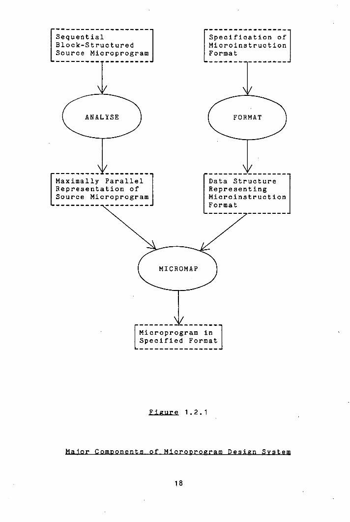
The relationship between the components of MDS is
illustrated in figure 1.2.1.
17
Sequential
Specification of Block-Structured
Microinstruction Source Microprogram
Format
FORMAT
Maximally Parallel Representation of Source Microprogram
r Data Structure Representing Microinstruction
1-
I Microprogram in L Specified Format
Figure 1.2.1
18
In MDS, the processor behaviour (source microprogram)
is represented in a block structured sequential
description expressed in Microprogram Design Language -
MDL. This is translated by the ANALYSE program into a
canonical microprogram: a partial ordering on the
statements of the MDL description which defines a
maximally parallel representation of the processor
behaviour.
The control organization of the microprogram level host
machine on which the processor behaviour is to be
implemented is represented in terms of the
Microinstruction Format Model (MFM). This model defines
the action of the primitive operations at the microprogram
level, the micro-orders, together with their
inter-relationship with respect to the field structure of
the microinstruction words from which they are activated.
Descriptions expressed in the notation associated with MFM
are processed by the FORMAT program and transformed into
data structures suitable for subsequent processing.
The canonical microprogram output by ANALYSE and the
data structure representing the microprogram level control
organization which is output by FORMAT are used as inputs
to the MICROMAP program. MICROMAP generates a
microprogram in the specified format to implement the
described processor behaviour. There are two parts to
this task: for each processor level operation, it must
generate a set of micro-orders supported by the
19
microprogram level host machine which will effect the
action described by that operation. Second, it must
exploit any capability for parallelism in the
microinstruction format by packing operations together
into the same microinstruction word. This must be
performed in such a fashion as to minimize the total
number of microinstruction words in the microprogram while
still preserving the specified behaviour.
MICROMAP's function is rendered practicable by two
factors. First, the microprogram level host machine is
sympathetic to the processor behaviour description. That
is, it is designed expressly t-o implement that processor
behaviour. It contains as the framework of its structure
the processor level components and their logical
interconnexions which are defined by the processor
description. So the micro-orders at the microprogram
level which are relevant to the resources in question are
described in terms of their effect on precisely the same
processor level resources as are referred to in the
behavioural description of the processor.
The second factor is the level of the operations used
to describe the processor behaviour. This is such that
all micro-orders required to emulate each processor level
operation may be activated in parallel, ie. from the same
microinstruction word. Consequently, it is possible for
the mapping function from the processor description to an
equivalent microprogram to be maintained at manageable
20

complexity.
The three components of the microprogram design process
will be discussed in detail in chapters 2, 3 and 14
respectively.
21
Relatively little has been published on the topic of
microprogram design. This reflects the fact that for many
Years the subject has received scant innovative attention.
Hence its current status.
Recently, however, the goal of machine independent
microprogram design has aroused some general interest. De
Witt's work [21] is closest to MDS in conception. He has
designed EMPL, a high level microprogramming language with
a machine independent kernel and the capability for
extension to describe machine dependent features. A
microprogram description expressed in EMPL is translated,
by a compiler specific to the host machine in question, to
a machine dependent intermediate language description.
This is then mapped by a machine independent compiler into
microinstructions as described by a "Control Word Model".
The Control Word Model is more limited in descriptive
power than the Microinstruction Format Model of MDS.
Since the Control Word Model does not directly model the
field structure of the microinstruction format, De Witt's
system is unable to generate actual microcode for the host
machine. It is capable only of producing a listing of the
microprogram In terms of the occupancy of the
microinstructions by intermediate language statements. No
details of an implementation of the work have been
presented.
22
Lewis, Ma and Malik 135, 381 are also endeavouring to
generate microprogrammed emulators in a host machine
independent fashion. This project is ambitious in its
attempt to synthesize a microprogrammed emulation of a
target machine, described in a machine independent
language [39], on a host machine whose description is
represented in a "Macro Expansion Table" and "Field
Description Model". Their approach to microcode
generation is similar to that of Baba [7] and Hodges and
Edwards [30] in essentially "hand compiling" each
intermediate language operation into the appropriate
micro-orders of the host machine as a prelude to
generating microprograms for execution on the host
machine.
The compaction of microprograms through the automatic
packing of micro-operations Into microinstructions of a
defined format is a subject that has commanded substantial
attention [2, 6, 17, 19, 20, 40, 53, 53, 55, 631. A
description of the four major algorithms that have been
proposed to perform this task is included In chapter 4 of
this thesis when MDS's treatment of the topic is
described. Mallett [0] has Implemented versions of each
of the major algorithms and has pronounced clearly In
favour of a version of Dasgupta and Tartar's method [20),
although it is not clear from the statistics which he
presents why this method should be preferred to a version
23
of Yau, Schowe and Tsuchiya's method [63]. All the
methods cited above partition the uncompacted microprogram
into strpjht line segments and with two exceptions
confine themselves to compaction within the straight line
segments. The two exceptions are Dasgupta [17] and Tokoro
et al [531, both of whom employ somewhat ad hoc techniques
to optimize over the boundaries of straight line segments.
Dasgupta searches for symmetric pairs of straight line
segments, that is two segments the execution of one of
which is a necessary and sufficient condition for the
execution of the other, and looks for possibilities of
code movement between them. Because of the computational
complexity of the search for these symmetric pairs he is
confined to detecting those which are separated by no more
than one intervening straight line segment. Tokoro et al
extend this notion to various identifiable specific
conditions where compaction may be effected across the
boundaries of straight line segments. It is not clear
from the literature whether the techniques reported in
[53) have been implemented, or are practical.
None of these methods take a global view of compaction
as is performed by MDS through exploitation of the clean
block structure of the MDL language, although the same
principles have been used in the design of optimizing
compilers for high level languages [62].
Very many proposals have been presented for high level
24
microprogramming languages and for hardware description
languages. In [41], Mallett and Lewis survey some of the
issues involved in implementing a high level language for
microprogramming. Lloyd and Van Dam have also produced a
survey paper on the topic [36]. Dasgupta [18] argues
convincingly that high level microprogramming languages
should be capable of expressing low level, machine
dependent features and has proposed a language schema with
this property. The principle is not shared by some other
microprogramming languages that have been proposed, eg.
SIMPL [17] and MPL [24]. Hardware description languages
have been used extensively to describe machine
architectures at various levels and Chu, for one, has
argued their use for microprogram specification [15].
Barbacci summarizes the main classes of such languages in
[8].
ISPS [9] is probably the best known hardware
description language, largely through its use in the
widely reported Computer Family Architecture project [13]
in which it was used to describe several different machine
architectures on to which a defined set of test programs
were mapped (by hand) for simulated execution. The
purpose of this was to compare the suitability of the
various machine architectures for the particular task in
question, a use to which MDS might well be put at the,
microprogram level.
ISPS is also employed in another project of some
25
related significance to MDS. This is the RT-CAD project
at Carnegie-Mellon University [51]. In [42], Nagle
describes an attempt to generate automatically a
microprogram level implementation of a system described at
the register transfer level. His approach is to
synthesize automatically a minimal horizontal
microinstruction format which will support the necessary
control signals required to implement the desired
behaviour on the data path whose description is provided.
This approach is in direct contrast to the philosophy
behind MDS. MDS attempts to assist the designer to the
maximum possible extent, but not to eliminate him. To the
author's knowledge, no implementation of the ideas
suggested In [42] has been produced.
Design, as such, is all about the effective balancing
of conflicting influences to achieve a desired end -
product. Very little work has been carried out on the
evaluation of the parameters of microprogram design.
O'Loughlin [145] offers an interesting pragmatic account of
the design trade-offs involved in microprogramming several
of the PD? 11 family of computers. Vanneschi et al have
produced a series of papers [28, 29, 58, 591 in which they
evaluate, on the basis of a model of different types of
microprogram implementation, the trade-offs between
microprogram execution speed and memory size. They also
examine the relationship between different computer
26
architectures and the most appropriate type of
microprogram implementation for controlling them. In
[11], Barr et al report on the utilization of the various
fields of a wide, horizontally structured microinstruction
format; but little else has been published on this topic.
It is to be hoped that MDS will be able to offer a
significant contribution here since it provides the
facility for easy experimentation with different
microprogram level implementations of a processor design.
27
011717
chapter is concerned with the task of describing a
digital system at the processor level with a view to
generating automatically an implementation of the system
at the microprogram level.
This section seeks to reason the intuitively obvious:
to establish an identity for the "processor level" of
description, which heretofore has been defined simply as
that level of representation in which it is appropriate to
express the design of a digital system to be implemented
at the microprogram level. (The microprogram level is
readily identifiable because It corresponds to a physical
implementation). MDS is an attempt to facilitate top-down
microprogram design; and it was observed in section 1.1
that the process of top-down design entails the selection
of one particular low level implementation of a
description expressed at a higher level out of many
possible such implementations. It therefore seems
reasonable to propose that the level of representation in
which it is most appropriate to express the description of
a processor to be implemented at the microprogram level
should be that level at which all of the essential
28

features of the processor organization may be defined, but
at which a single processor description may be implemented
by many possible microprogram level host machines.
Under the above definition, the following essential
features of a processor organization may be identified.
They fall into three categories:
The directly addressable memory components of the
processor: flip-flops, registers and main memory
elements. At this level, these entities all have a
defined use and, in the case of registers and
flip-flops, a unique name. (The allocation of
registers to names is assumed to have performed
prior to description of the processor).
The functional capability of the processor, le. the
arithmetic and logical operations supported by this
processor architecture.
The data paths interconnecting memory elements and
functional units necessary to perform the desired
transfers and transformations of data. Nothing is
implied about the physical realization of these
resources in this specification. For example,
specifying that there must exist a data path
between two registers does not differentiate
between a dedicated line, a shared bus, or a
devious route through many functional units.
29
The fundamental unit of time at this level of the
systems hierarchy is the processor clock cycle. Each
memory resource may be loaded once only during each clock
cycle (although some may not be loaded on every clock
cycle). The term processor context will be employed to
denote the contents of all of the memory resources of the
processor at the end of a clock cycle. Then the processor
behaviour will be totally defined by an ordered set of
changes of processor context: describing how the contents
of each memory resource should be altered during each
clock cycle. This implies that the behavioural
description of a processor should be represented as a
collection of register transfer expressions to be executed
in a defined order (with some necessary mechanism for
conditional execution on the basis of tested data).
This may be contrasted with possible alternative levels
of representation for describing systems to be implemented
through microprogram control: the higher level
conventional computer machine instruction or assembly
language statement and the lower level micro-order. The
former may specify an operation the execution of which is
performed over several processor cycles, while the latter
controls the flow of data between unstable resources over
a single section of the processor data path. It would be
inappropriate for the purpose of microprogram design to
attempt to describe a processor behaviour in either of
these forms; the first because it is too gross to define
sufficiently an effect on the processor resources and the
second because it is too detailed and utilizes resources
which do not properly belong to the processor level, eg.
multiplexors, decoders and sequencing controllers.
That this one-to-one relationship between the primitive
statements of the processor description and •processor
clock cycles is fundamental to the capability for
effective generation of a microprogram implementation of
the defined processor behaviour will be demonstrated
throughout subsequent sections.
• This chapter proceeds with an examination of the
necessary properties for a language for processor
description.
31
Having determined that the register transfer level is
appropriate for the statements expressing a behavioural
processor description, what other properties should a
processor description language exhibit?
Intelligibility is a requisite common to all forms of
representation. In this context it implies simple syntax,
familiar semantics, mnemonic names, clear sequencing rules
and similar such issues which are well known and have been
expounded often in relation to high level programming
languages.
Of more particular significance with respect to the
intended use of the language are the issues of
parallelism, efficiency of microcode generated, and
suitability of the language for design and specification.
Each of these considerations will be examined in turn.
Parallelism. An inherent property of the microprogram
level view of digital systems is that operations are
executed concurrently. It is therefore to be expected
that languages for describing systems to be implemented at
this level might be influenced by this feature.
The definition of processor behaviour exacted in the
preceding section was a very rigid one. It required the
explicit specification of the clock cycle during which
32
each register transfer operation should be activated.
This may be shown to be an unrealistic imposition for
three reasons.
In the first case, the relative timing of operations is
a relationship which is not properly defined at the
processor level. It is dependent partially on the
availability of sub-processor level resources, such as the
physical realization of logical data paths. For example,
two logically distinct data paths may each be implemented
through a single shared bus, thereby precluding the
concurrent execution of any pair of operations which
utilize these distinct logical resources.
The second reason is that the ruling is too
restrictive, in that it severely limits the scope for
performing optimization in the generation of
microinstructions. By specifying exactly what operations -
each microinstruction should contain, it leaves no room
for the possibility of reducing the size of the
microprogram. This might otherwise be achieved through
packing the operations into microinstruction words in a
different order from that specified. It also may preclude
the selection of a microinstruction format capable of
realizing the same overall behaviour more efficiently in
terms of microprogram space, but not capable of supporting
the specific concurrency of operations demanded.
Third, the professed goal of this project was to ease
the task of microprogram design. If efficient
33
microprograms can be generated without the designer having
to specify the relative synchronization of all the
operations in the processor level description, then we
shall have progressed a significant way toward that goal.
The top-down approach to design generally entails
selecting, from many, one particular low level
implementation of a high level behavioural description.
In prac.tice, where this process is wholly or partially
automated, it becomes necessary that the designer be able
to -intervene and apply some direction to the process of
generating an implementation. Such intervention may be
motivated by interest either in the efficiency or the
correctness on the implementation being generated. It
would be foolish to expect to anticipate all of the
- designer's requirements. Therefore a language for
processor level description of digital systems in this
context must encapsulate the facility for specifying
critical parameters of the microprogram implementation.
In particular, it must be capable of expressing explicit
synchronization between the register transfer operations
of the processor description - just the requirement argued
above that it should not enforce.
Timing relationships between two operations, A and B,
which a language should support would be:
34
A and B should be executed concurrently. (A=B)
B should not be executed until A has completed. (A>B)
B should not be executed before A. (A>=B)
Efficiency j microcode generated. Microprograms
provide the low level control of processors, which often
operate as the critical component of other machines. This
implies that microprograms should execute the function
which they are designed to perform as efficiently as
possible. A language for describing systems to be
implemented at the microprogram level must therefore
attempt to facilitate the generation of efficient
microcode.
In general terms, the process of the design and
implementation of a digital system comprises three phases:
the conception of the design, the modelling of the design
in the representation of the system description language
and the translation of that model into an implementation
of the system. Where the implementation is carried out on
a general purpose host machine designed to perform many
functions, such as the instruction set level of a
computer, compromises must be made. In order to generate
efficient code in the implementation, the system
description language (eg. high level programming language)
must constrain the model of the system to being
represented in a limited set of operations: those which
may be reasonably efficiently translated into the host
35
machine instruction set. (There is a high degree of
commonality in the operations performed at the instruction
set level by a wide range of computers).
Microprogram design, as defined in section 1.1, is
different however. The host machine is not general
purpose. It is designed specifically to implement the
digital system in question; and so the system description
language in this case is not obliged to constrain the
behavioural description of the processor to a limited set
of operations reflecting the host machine instruction set.
The system description language has no "knowledge" of the
host machine on which to base such a constraint, since the
host machine is different for each description. The best
strategy that can be adopted in order to ensure an
efficient implementation is for the system description
language to provide a representation in which the
conception of the system may be modelled as closely as
possible. In doing so it will also be closest to the host
machine.
That is, the system description language should be
capable of expressing directly any operation which a
processor architecture might support directly. Doing
otherwise would be the cause of inefficiences in
implementation.
Just as it should not exclude any idiosyncratic
processor operations, for the same reason the system
description language should not exclude any sequencing
36

mechanisms which might be implemented by the host machine.
In particular, it should be capable of supporting
multi-way conditional branching.
These are just two examples of machine dependent
constructs which a processor description language in this
context should support. Ideally, it should be capable of
controlling exactly what microcode will be generated.
The arguments advanced in this section are perhaps more
subjective, and perhaps therefore less critical than in
the preceding sections. These are the properties which
give a language its "flavour" and, in practice, determine
the extent to whiôh it gets used. The two headings are
inter-related, but at the same time may generate
conflicting requirements, the balancing of which depends
on the projected applications for the language.
Suitabilty as g design language concerns what features
make a language attractive to the designer for expressing
the conception of a design, as opposed to rigorously
specifying all of its details. What is sought is a
representation in which the designer finds it easy to
frame his thoughts.
The issues overlap to a degree with those associated
37
with language intelligibility, discussed above. It is
probably true that a procedural language is a more
conducive medium to most designers for expressing a design
than a non-procedural language - particularly if the
designer has a programming background. The provision of
modular control structures in the language: "While" loops
and conditional blocks, is a further merit of the
procedural approach. For a microprogram controlled
system, a description expressed in a procedural language
reflects more faithfully the processor behaviour as
implemented, a microprogram itself being procedural in
conception and execution.
The language should be concise without being
restrictive. It should allow the designer to express his
design in the terms in which it has been conceived, rather
than constraining the representation to a limited set of
constructions built in to the language. This aspect ties
in with the concerns for code generating efficiency of the
language, discussed above. It also argues for simplicity
of syntax and implies a non-declarative language, although
this property might be relinquished for the sake of
precision of specification.
Suitability .Lj System Specification. Many hardware
description languages are designed primarily for the
purpose of providing a vehicle for formal specification of
hardware systems; and, while this function is not the
38
principal requirement of a language for microprogram
design, it still is a very desirable property of any
language. Obviously, the language adopted, whatever its
features, must be capable of expressing all of the
information about a system which is necessary in order to
generate an implementation. To that extent, it will
provide a formal definition of at least part of the
system. But it is intended in this section to distinguish
those features of a language which conduce to the function
of formal system specification.
The single stipulation which encompasses all such
features is that all information apposite to the design be
stated explicitly within the description in a concise
fashion; and the major implication of this policy is that
it argues for a declarative style of language. Each
processor resource should be declared before use and,
ideally, fully qualified - the size of registers, side
effects of functions, width of data paths etc. all should
be explicitly stated. As noted above, this runs contrary
to the "need to know" principle underlying the use of a
language for expressing a design, where much information
remains unstated or implicit within the description.
The balance between the cases advanced for design and
specification considerations is a matter for judgement
based on the relative importance of each in prospective
language applications.
39

To summarize the requirements expressed above, we are
looking for a procedural, register transfer language with
simple syntax and structured sequencing constructs which
supports machine dependent operations and allows explicit
synchronization between statements, but does not enforce
the same. In regard to the emphasis on the language as a
medium for expressing designs, we should prefer that it
not be necessary to pre-declare all entities occurring in
a description.
It will come as no surprise to discover that these
stipulations rule out all so-called hardware description
languages and machine independent microprogramming
languages known to the author (see [8]and [41) for an
overview of these); but, before going ahead to describe
the language implemented, let us review the implications
of this decision.
Assuming a roughly equivalent amount of effort to be
required in each case there are, generally speaking, two
principal reasons why one might adopt an existing language
with all its concomitant restrictions in preferance to
using a language tailored to one's own purpose. These
are:
(2) Familiarity Notation
Portability is normally a strong motivation for
40
expressing a system description in a standard notation.
The reason for this is that often there are available a
variety of implementations of the "soft machine" defined
by that standard notation. Target machines described in
the notation may be implemented immediately on a variety
of existing host machines.
But this is not relevant to microprogram design.
Microprogram design, as defined in section 1.1, is
concerned with the design of a host machine, dedicated to
implementing the behaviour defined in the processor
description. The processor itself is a host machine which
may be used to implement a variety of higher level digital
system functions. Portability of descriptions is an issue
to be taken into consideration when one is designing
target machines. It is not meaningful when it is a host
machine which is being designed.
Familiarity is a worthy reason for adopting a standard
notation: familiarity both for the designer in writing the
description and for the reader in understanding it.
However the strength of this argument is weakened in the
context under consideration because there exists no
standard notations for processor level description of
digital systems. A plethora of hardware description
languages have been expounded, but very few have ever been
used outwith the application for which they were
originally generated.
41

The most serious contender for being accepted as a
standard "system description language", by virtue of the
fact that it has been used quite substantially for some
significant, and well-reported research ([10, 51]), is
ISPS [91; and serious consideration has been given to the
possibility of using this language in MDS. If the rather
verbose appearance of descriptions expressed in ISPS was
the only adverse circumstance associated with adopting the
language, then this probably would not have been
sufficient to compensate for the advantages to be gained
from its reasonable familiarity. But it is the crucial
aspects of specification of timing of operations and
capability for generating efficient code which cause ISPS
to be deemed unacceptable. ISPS insists on explicit
definition of the relative synchronization of all
operations contained in a description. Also, it supports
no mechanism for a simple branch in control sequence on
the basis of a tested condition (ie. a GOTO construct). A
simple conditional branch is necessary in some situations
in order to generate the most efficient posssible code -
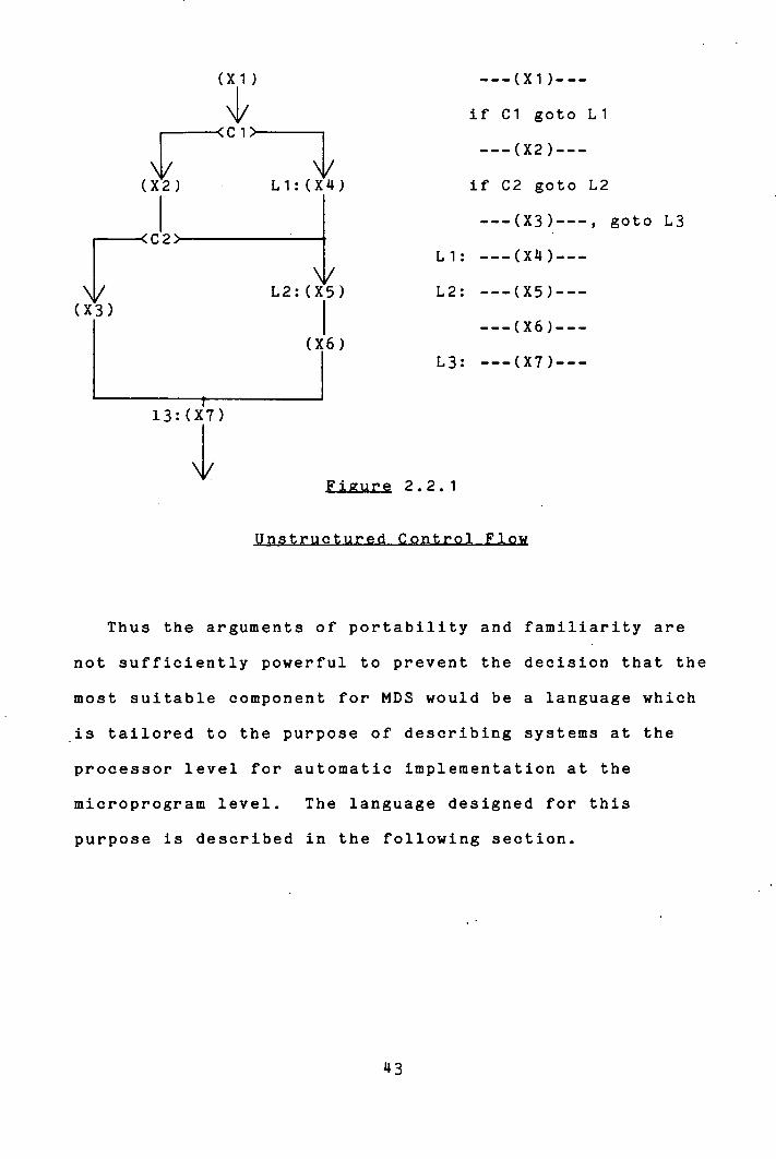
see figure 2.2.1. It is therefore an essential feature of
a language for microprogram design under the requirement
stated above that the language should be capable of
expressing all sequencing constructs performed by a
processor.
42
(Xi)
C i \1/
<C2)
L2: (X5
(X3)
(X6)
13: (X7)
--- (Xi)---
if Ci goto Li
---(X2)---
if C2 goto L2
---(X3)---, goto L3
Li: --- (X's.) ---
---(X5)---
---(X6)---
---(X7)---
Figure 2.2.1
Thus the arguments of portability and familiarity are
not sufficiently powerful to prevent the decision that the
most suitable component for MDS would be a language which
is tailored to the purpose of describing systems at the
processor level for automatic implementation at the
microprogram level. The language designed for this
purpose is described in the following section.
43
This section describes the essential features of MDL -
Microprogram Design Language. A reference guide for the
language is given in Appendix 2. A simple example
illustrating the use of MDL is given in figure 2.3.1 at
the end of this section.
A processor description is expressed in MDL as a
sequential list of register transfer type operations,
hereafter referred to as micro-operations (since each will
be realized by part of a single microinstruction), each
optionally preceded by a label.
There is no declaration part to a description. Each
new name encountered as the description is processed Is
assumed to be a processor level operand name associated
with a particular processor memory resource - data
register, control register, or main memory word. Comments
may be inserted between micro-operations at any point in
the description.
A micro-operation may be of one of three types:
control, register transfer, or miscellaneous.
A register transfer type micro-operation is expressed
in the form DEST <- EXPRESSION, where DEST is the name of
a single operand and EXPRESSSION is a list of operands
separated by symbols denoting operators,
44
eg. ACC <- ACC+COUNT.
"<-" is the only operator in the language of any semantic
consequence. It is used to denote the transfer of the
data value generated by the expression on the right of the
arrow to the operand on the left and its significance lies
in the fact that it serves to distinguish when an operand
is used as a source of data and when it is used as a
destination. The necessity for this differentiation is
explained in the following section. The operators used to
separate operands in the •source expression have no
inherent meaning. The meaning of the operations performed
by the processor is global to the context of both
descriptions: of its behaviour and of the sympathetic
specification of a microprogram level implementation of
that behaviour - and is therefore irrelevant.
This applies also to the miscellaneous type
micro-operations. Any statement which is not recognized
as a control type micro-operation and does not contain an
arrow ("<-") is interpreted as a miscellaneous type
micro-operation (not involving the transfer of data into
processor registers), which is accepted as a valid
statement in the language on the assumption that it
corresponds to some particular processor function, eg. in
communication with its external environment.
Register transfer and miscellaneous type
micro-operations are grouped together under the heading of
45
executive micro-operations.
Control type micro-operations serve to regulate the
order of execution of the micro-operations constituting
the strictly sequential procedural description of the
processor. Control constructs provided in the language
are for simple conditional branching, conditional blocks,
looping on a condition and waiting for a condition.
Simple branching is effected by micro-operations of the
form
"If" COND "Goto" LABEL
where COND may be any list of operands separated by
symbols denoting operators or relationships - again no
semantics is assumed; it is expected that the processor
implementation will be capable of generating and testing
whatever function that expression might denote. LABEL is
the name of a label associated with some other statement
in the description (preceding the statement and separated
from it by "::") to which control should be transferred if
the evaluated condition is true.
Multi-way branching (le. a "Case" statement) may be
effected via the same syntax by specifying a COND which
evaluates to an n-tuple and a list of 2n labels as
possible successor statements.
Conditional block constructs are expressed in
micro-operations of the form
"If" COND "Then"
46

followed by a block of statements to be executed only if
COND is evaluated to be true. Following this block, and
separated from it by the statement "Else", may be a block
of statements to be executed only if COND is false.
"Finish" terminates the whole construct.
Conditional loops are bounded by "Loop" and "Repeat"
micro-operations, either (or both) of which may be
qualified by "While" COND. The statements inside the loop
block are executed until COND is evaluated to be false.
Conditional loops may be jumped out of, to the
statement succeeding the relevant "Repeat"
micro-operation, by an "Exit" directive, optionally
accompanied by "If" COND. "Exit" may be suffixed by "_"N,
where N is an integer denoting the number of nested loops
to be jumped out of.
A micro-operation of the form "Wait For" COND is
repeated indefinitely until the expression denoted by COND
becomes true.
Subroutining capability is supported in MDL by the
"Call" LABEL and "Return" micro-operations, each
optionally followed by "If" COND. No assumptions about
details of implementation are inherent in the support of
this capability in the language. The directives are
provided to represent a function performed by many
microprogram controllers and, if they are used within . a
particular description, it is in the assumption that the
chosen implementation will support them - this is checked
47
at the time of generating the implementation.
The control directives associated with conditional
blocks and loops are translated by the ANALYSE program
into simple branch micro-operations to the relevant
successor statements, as will be described fully in the
next section.
It was noted in the preceding section that a language
for describing the behaviour of a processor should support
the explicit specification of three different
synchronization relationships between micro-operations.
To recap, these were:
Equivalence: The two must be activated concurrently.
'Strong Dependency: One must not be activated until
the other has terminated.
Weak Denendency: One must not be activated before
the other is.
MDL syntax supports the explicit synchronization of
these three relationships in two ways.
If A and B are adjacent micro-operations in the
sequential description of a processor, A preceding B, then
a comma, a semi-colon, and a comma and a semi-colon (in
either order) terminating A respectively represent these
three relationships.
48
Alternatively, if A and B are not adjacent, B may be
terminated by a semi-colon followed by a list of integers
enclosed within square brackets. These integers denote
the "distance", in statements, from B to the preceding
micro-operations to which B is related by (2) or (3)
above. The list is in the form of a group of integers
separated by commas for all those statements to which B is
related by strong dependency, followed by a bar character
( ' '), followed by another group of integers for the
micro-operations to which B is related by weak dependency.
Thus a statement of the form:
(B) ---- ;[1, 3 1 21
means that micro-operation B is strongly dependent on the
immediately preceding micro-operation in the description
as well as the one two before that, and it is weakly
dependent on the micro-operation two before itself in the
description.
A similar syntactic construct, introduced here for
completeness, but not explained properly until section
4.1, is used for specifying resources affected by the
action of a micro-operation but not referenced explicitly
in the micro-operation itself. In this case it is a list
of operand names which is included in the square brackets
following A and the bar separates those operands which are
used as destinations from those used as sources.
49
To summarize the main features of MDL; it is an
extremely simple language tailored specifically for
microprogram design. It has few built in features, but
few restrictions as to what may be expressed in it.
Statements are expressed sequentially and the behaviour so
defined is never violated, but the order of the statements
may well be varied in execution. Its modular sequencing
constructs facilitate structured design, while the low
level control devices it provides enable the designer to
exploit machine dependent features whenever required.
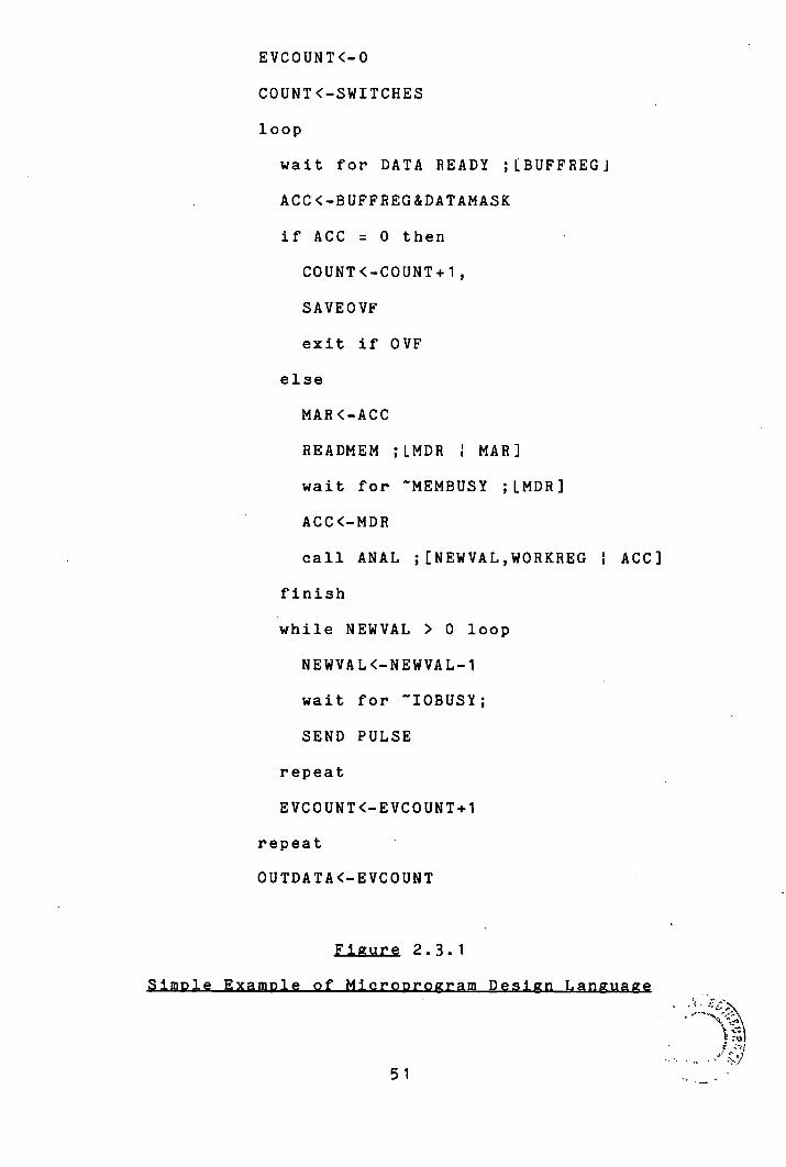
Figure 2.3.1 presents a simple MDL microprogram
description illustrating some of the features of the
language. A more comprehensive example is given in
Appendix 1(a).
EVCOUNT<-O
COUNT <-SWITCHES
loop
wait for DATA READY ;LBUFFREGJ
ACC<-BUFFREG&DATAMASK
if ACC = 0 then
COUNT <-COUNT+1,
SAVEOVF
exit if OVF
else
MAR<-ACC
READMEM ;LMDR 1 MAR]
wait for ~MEMBUSY ;LMDR]
ACC<-MDR
call ANAL ;ENEWVAL,WORKREG I ACC]
finish
while NEWVAL > 0 loop
NEWVAL<-NEWVAL-1
wait for IOBUSY;
SEND PULSE
repeat
EVCOUNT<-EVCOUNT+1
repeat
OUTDATA<-EVCOUNT
Fiaure 2.3.1
51

of the Source Microgrggram
It was stipulated in section 2.2 that a language for
describing processors should not enforce the rigid
synchronization of micro-operations. This section is
concerned with how to determine automatically which
micro-operations may safely be activated in parallel.
If the micro-operations constituting a processor
description in MDL are executed in the sequential order in
which they appear in the description, then they may be
thought of as defining a function which acts on the
processor resources and system inputs to alter the
contents of these resources and produce an output. This
may be expressed more formally: in section 2.1 the term
orocessor context was introduced to denote the contents of
all of the memory resources of a processor at the end of a
clock cycle. Then, with the implicit ordering
relationship between the micro-operations defined by the
textual order of the statements, the MDL description of a
processor defines a function
F se q(PrOceSSOr Context x Input Sequence) ->
(Processor Context x Output Sequence).
We seek to discover the conditions determining the set
P0 of all partial orderings between micro-operations
(where the ordering relationship corresponds to order of
52

execution) which defines F, the set of determinate
functions from (Processor Context Input Sequence) ->
(Processor Context Output Sequence) such that for each
F1 in F, for any initial processor context PC and any
input sequence I, F 1 (PC,I) = F 3q (PCI). That is,
intuitively, F 1 has the same overall behaviour. as F s e q .
In particular, we seek to discover POmin in P0 such that
for any micro-operation M in the description, the number
of ancestors of M under POminis no greater than the
number of ancestors of M under any other PO j in P0. That
is, intuitively, we are looking for the maximally narallel
representation of the processor description which
preserves the determinacy and behaviour of the initial
specification. The term canonical microprogram will be
used to denote the microprogram under this ordering
relationship.
Two type of dependency relationships between
micro-operations may be distinguished, namely control
dependency and data dependency. These will be dealt with
in turn, deferring consideration of conditional blocks and
loops to be returned to later.
Control dependency is concerned with ensuring that the
same (and no other) history of control flow which results
in the execution of a micro-operation in the MDL source
microprogram will also result in the execution of that
53
micro-operation in any other ordering of the
micro-operations with an equivalent behaviour. Enforcing
this condition requires that no branch type
micro-operation may be allowed to precede any non-branch
(executive) type operation when the latter precedes the
former in the MDL description, and that no operation which
succeeds either a branch or a merge (label) in the MDL
description may be allowed to precede the branch or merge
in any other ordering. The two together imply that, for
each executive micro-operation, the relative position of
that operation to the most immediately preceding and most
immediately succeeding branch or label in the MDL
description must be preserved in any other equivalent
ordering.
This Is a sufficient condition for preserving the
defined relationship between a micro-operation and the
pattern of control flow which will result in its
execution. In individual examples, by tracing the control
flow defined by the particular values for the labels and
branches, it may be found that the condition is not always
necessary. For example, if both legs of a branch
subsequently merge, it may be possible that a
micro-operation succeeding the merge in the source
microprogram may be executed prior to the branch - the
pattern of control flow associated with its execution is
the same, but the history is different. (The pattern of
control flow is bounded only by termination of the
54
microprogram. At any given point, it encompasses "future"
control flow as well as history). However, as
demonstrated by Dasgupta [17], the cost of detecting and
exploiting such circumstances is not warranted in a
practical system, particularly when modular control
constructs are available in the source microprogram
language, as will be considered later. Hence (explicit)
labels and branches will always be considered as absolute
barriers to code movement in the following.
These relationships serve to partition the sequential
processor description into disjoint straight line segments
of micro-operations, with the members of each straight
line segment being all those micro-operations whose
execution is dependent on the same control flow history.
The limit of each segment is defined by there being a
label on the following statement or a branch operation as
the final statement. If the final micro-operation of any
straight line segment is a branch operation, then it must
be marked as dependent on all the executive
micro-operations in the segment in order to preserve their
relative orderings as required above. Control dependency
implies that no statement in one straight line segment may
precede any statement in a preceding straight line
segment. This in turn implies that each straight line
segment must remain totally indivisible and the relative
ordering of the straight line segthents defined by the MDL
55
description must be preserved in any equivalent ordering.
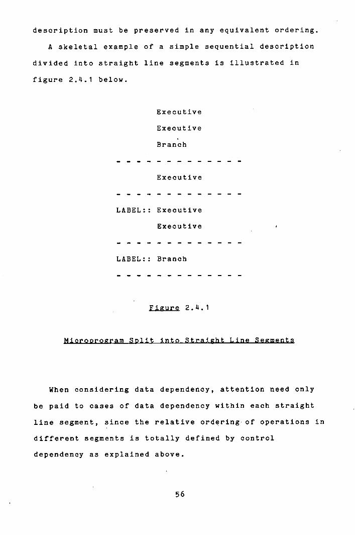
A skeletal example of a simple sequential description
divided into straight line segments is illustrated in
figure 2.4.1 below.
Executive
Executive
Branch
Executive
LABEL:: Executive
Executive
LABEL:: Branch
Figure 2.4L1
When considering data dependency, attention need only
be paid to cases of data dependency within each straight
line segment, since the relative ordering of operations in
different segments is totally defined by control
dependency as explained above.
56
Two micro-operations, A and B, are said to be mutually
independent if, for any initial processor context, the
resultant processor context after executing A and B is
always the same, irrespective of the order in which they
are executed.
In determining a partial ordering among the
micro-operations of a description there is no reason to be
concerned with micro-operations which are mutually
independent, since no ordering need be imposed between
them. In order to guarantee to generate the same final
processor context as would result from sequential
execution of the MDL description, it is necessary to
preserve the relative ordering defined by the MDL
description of those micro-operations which are not
mutually independent, ie. of those operations which
generate a different processor context depending on the
order in which they are executed. (Concurrent execution is
equivalent to arbitrarily selecting an ordering and does
not guarantee determinacy when the micro-operations are
not mutually independent).
Such a situation may arise through two possible
circumstances, first noted formally by Bernstein [12):
either when one operation writes to an operan.d which the
other uses as a source of data, or when both attempt to
write to the same operand.
If micro-operation B follows micro-operation A in a
straight line segment and either of the circumstances
57
identified above holds, then B is said to be data
Note that two micro-operations which both use the same
operand as a source of data do not necessarily violate the
conditions for mutual independence. Note also that, by
definition, the destination operand is always considered
to be defined - the action of one operation may not alter
which operands are referenced by the other. For example,
in the expression "Mem(MAR) <- MDR", the destination
operand is defined to be "Mem". "MAR" is designated a
source operand.
These rules for control dependency and data dependency
are the relationships which define POmin, a partial
ordering on the micro-operations of the MDL description
which, it is claimed, produces an equivalent behaviour to
that associated with the sequential ordering defined by
the MDL description. This will be shown by informal proof
of the following theorem.
Theorem 2.4.1 F m i n , the function defined by the partial
ordering POmin is eqivalent to Fseql the function defined
by the sequential ordering of micro-operations in the MDL
description.
Proof (Informal). Consider two micro-operations A and B,
B following A, such that under Fseq B will always be
58
U
executed whenever A is, there being no branch in control
flow between them and B will never be executed without A
having been, there being no merge of control flow between
them. Then the rules for composition of straight line
segments ensure that A and B will always be included in
the same straight line segment. Further, the stipulation
that the relative ordering of straight line segments as
defined by Fseq is preserved under Fmjn and the
association of the labels of the MDL description with
entry points of straig-ht line - segments ensures that flow
of control between straight line segmentsis the same in
Fmi n as if Fs eq .
The proof of the theorem then follows from the proof of
the following lemma:
Lemma 2.4.1 The function defined by PO m i n mon each straight
line segment is equivalent to the function defined by the
sequential execution of that straight line segment.
Proof (Informal). The control dependency of branch type
micro-operations on all of the executive micro-operations
in the same straight line segment ensures that under Fm j n
all micro-operations in a straight line segment are, in
fact, executed. We must show that, for any initial
processor context, any processor context resulting from
execution of the micro-operations in the partially defined
order associated with POmin is the same as that resulting
59
from sequential execution of the micro-operations. Let us
recall the three situations in which micro-operation B
will be data dependent on micro-operation A under POmin
(where A and B are in the same straight line segment, A
preceding B in the sequential description):
A writes to an operand which B also writes to.
A writes to an operand which B reads from.
A reads from an operand which B writes to.
°min will preserve the ordering defined by the
sequential MDS description of any pair of micro-operations
so related. It will impose no relative ordering on any
pair of micro-operations for which none of these
relationships hold. The proof of the lemma will follow
from demonstration that processor context cannot be
affected by the order of execution of any pair of
micro-operations not related by data dependency.
Consider two such micro-operations, A and B, and let
them be executed in both possible orders. The only
operands which can have their values changed as a result
of the execution of A and B, and therefore the only ones
which can show a different value under the different
orderings, are the two written to by A and B. They must
be distinct since otherwise DD(1) would hold. Without
loss of generality, consider one of these operands, say
the one written to by A. The only way that it could show
a different final value under the two orderings of
execution of A and B would be if the data loaded into it
by A was different in each case, ie. if that data had been
changed from its original value. But that would only be
possible if it had been written to by B, which is not
possible if DD(3) does not hold. (At least consistent
behaviour of expressions such as "A <- A + Z" in which the
same operand is used as source and destination is
assumed)
Therefore the two operands written to by A and B must
be the same after each order of execution and, since these
are the only two operands whose values could possibly
change during the execution of the two micro-operations,
the resulting processor context must be the same in both
cases.
Which proves the lemma.
Which proves the theorem.
Lemma 2.14.1 is a particular example of a general
theorem concerning computation schema which states that:
"An Elementary Schema that is Conflict Free is also
Determinate."
This is formally proved in [27].
Figure 2.14.2 illustrates the necessary data dependency
relationships inherent in a straight line segment of
register transfer micro-operations.
61

(1) (14) (1) LABEL: SAVEACC <- ACC
(2) ACC <- ACC&MASK1 (2)
(3) ACC <- ACC+R2 (3)
(14) R3 <- R2&MASK5<<15
R2<- R3&MASK2 / () ACC <- SAVEACC I
(6) if R2< 0 goto AGAIN
(7)
Figure 2.14.2
As noted in section 2.2, dependency may be strong or
weak. Strong dependency is exhibited between two
micro-operations when the execution of one must precede
the execution of the other, for example when one writes to
an operand used as a source of data by the other. Weak
dependency occurs between two micro-operations where one
must not precede the other, for example the control
dependency of a branch micro-operation on an otherwise
independent executive micro-operation in the same straight
line segment.
There are, however, two situations where the strength
of a dependency relationship cannot be ascertained at the
processor level - it may be different in different
microprogram level implementations. These are:
Destination-Source dependency. In some processor
implementations, the clock cycle is divided up into
sub-cycles with data read out of registers at an earlier
phase than that during which registers are loaded. This
allows two micro-operations, one of which reads from an
operand to which the other subsequently writes data, to be
executed in the same processor cycle, ie. it permits a
weak dependency relationship to exist between them. Where
the processor implementation does not operate in this
manner, the dependency relationship must be strong.
ComDuted data dependency. In many microprogram
level processor implementations, the execution of the
current microinstruction is overlapoed with the fetching
from control store of the next microinstruction. In such
cases, data generated during the execution of the current
microinstruction cannot be used in determining from which
control store address the next microinstruction should be
fetched. Therefore any branch in the flow of control
based on computed data must take place in a subsequent
processor cycle (ie. different microinstruction) from that
in which the data is actually generated. This contrasts
with secuential implementations where the data may be
computed and tested to determine the successor
microinstruction in the same processor cycle.
63
For example, consider the micro-operations:
A <- A + 1
.il A = 0 Roto LABEL
The dependency of the second on the first should be
strong in an overlapped implementation, but weak in a
sequential implementation.
These are two examples of dependency relationships the
strength of which is undecidable at the processor level.
It would be perfectly simple to take a pessimistic
viewpoint and always classify such occurrences as strong
dependency, but one of the specified goals of MDS was to
generate efficient microcode, and so ANALYSE must be made
to allow the possibility of weak dependency in these
situations. How it does so is explained in the following
section.
The minimality of the partial ordering POmin within
straight line segments may now be deduced. It follows
from the readily observable fact that, discounting those
arcs which are redundant through the transitivity of the
dependency relationship, each are in the data dependency
graph - each data dependency relationship between two
micro-operations - is necessary in order to ensure the
desired behaviour and determinacy for the function so
defined..
64

The concept of control dependency was seen to be
necessary in ensuring that each micro-operation in the
source microprogram is executed the same number of times
under any ordering of execution equivalent to that defined
by the sequential MDL description. Labels and branches
define critical Doints in the microprogram which
effectively limit the independence, the "freedom of
movement", of executive type micro-operations. The source
microprogram description was partitioned into straight
line segments delimited by these critical points. These
are equivalence classes of operations which have in common
that their execution depends on the same history of flow
of control through the system.
Each straight line segment thus forms an indivisible
and inviolable entity with a single entry point and a
single exit point, which guarantees the bond between the
component micro-operations.
The groups of micro-operations which constitute a
conditional block or a conditional loop similarly form an
indivisible and inviolable entity: if one micro-operation
of the group is executed then all must be, and no other
may be executed with them. These constructs could be
incorporated into the language simply by treating each
such block as a single straight line segment (two in the
case of the If...Then ... Else construct). This would
exactly replicate the treatment which would be afforded
65

the constructs were they expressed explicitly in terms of
labels and branches in MDL. But it does not take
advantage of the fact that these are modular entities, the
fundamental control constructs of structured programming.
The labels and branches associated with If ... Then ... Else
blocks and conditional While loops are well-behaved, in
the sense that they reflect a well-defined control
structure. If a conditional block or loop is wholly
incorporated into an existing straight line segment then
the essential feature of that straight line segment is
preserved: it still has only one entry point and only one
exit point. This is illustrated in figure 2.4.3
Straight Line Segment
--------------- -------
Single Entry Point
Modular Control Block
Single Exit Point
Figure 2.4.3

Incorporating modular control blocks into straight line
segments in this way does not impose unnecessary
restrictions on the independence of the other
micro-operations inside the straight line segment, as
would be the case were a new segment to be created for
each such block.
For example, consider the sequence of MDL microprogram
illustrated in figure 2.4.4. If micro-operation B is
independent of all of the micro-operations inside the
loop, then there would be no difference to the behaviour
of the sequence were B executed before the loop, perhaps
concurrently with A if they are independent.
---(A)---
While COND Loop
---(Li)---
---(L2)---
---(L3)---
Repeat
---(B)---
Figure 2.4.4
67
However, special care must be taken in situations such
as this to preserve the indivisibility and inviolabilty of
the control block. Micro-operations should be allowed to
"migrate" over a control block, but they must be prevented
from "landing" in the block, just as they must be
restrained from migrating outwith the confines of their
own block. The concept of levels of micro-operations
within the canonical microprogram is now introduced to
secure the necessary protection.
For the purpose of determining its data dependency
relationships with the other micro-operations, a modular
control block is treated as a single micro-operation in
the canonical microprogram. It is a block type
micro-operation which at one level assumes the identity of
a single micro-operation, but which is expandable to its
component micro-operations at one level lower. These
component micro-operations, which correspond to the
micro-operations contained in the control block, may
themselves be of block type - this would be the case when
the source microprogram contained nested control blocks -
or they may be orimitive.
Indivisibility and inviolability of control blocks may
now be secured by insisting that data dependency should be
marked only between micro-operations at the same level.
Consider for example, as illustrated in figure 2.4.5, a
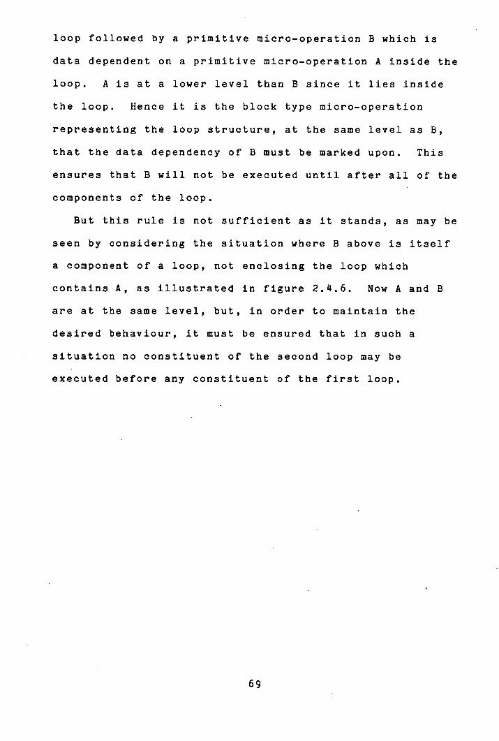
loop followed by a primitive micro-operation B which is
data dependent on a primitive micro-operation A inside the
loop. A is at a lower level than B since it lies inside
the loop. Hence it is the block type micro-operation
representing the loop structure, at the same level as B,
that the data dependency of B must be marked upon. This
ensures that B will not be executed until after all of the
components of the loop.
But this rule is not sufficient as it stands, as may be
seen by considering the situation where B above is itself
a component of a loop, not enclosing the loop which
contains A, as illustrated in figure 2.4.6. Now A and B
are at the same level, but, in order to maintain the
desired behaviour, it must be ensured that in such a
situation no constituent of the second loop may be
executed before any constituent of the first loop.
W.
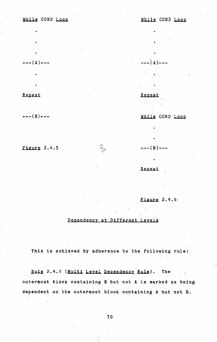
While COND L000 While COND Loop
---(A)---
Repeat Repeat Reoeat
---(B)--- While COND LooD
Figure 2.4.5
Repeat
Figure Figure 2.4.6
This is achieved by adherence to the following rule:
Rule 2.4.1 (Multi Level Deoendenoy Rule). The
outermost block containing B but not A is marked as being
dependent on the outermost block containing A but not B.
70
Figure 2.4.7.(a) presents a skeletal example of a block
structured MDL microprogram and figure 2.47.(b) shows a
set of data dependency relationships which might exist
between the primitive micro-operations of 2.L7.(a).
Figure 2.4.7.(c) illustrates the dependency relationships
between micro-operations which result from application of
the Multi Level Dependency Rule to this example. (Each
micro-operation is depicted as a box with the level of the
micro-operation displayed at the top right corner of the
box).
71

---(1)--- (1)
---(2)---
---(3)--- (2)
.j. COND Then A\ (4) (3)
/\ ---(7)--- (5) (6)
Else
(8) (7)
_
Fin ish
LooD (11) (9) (10)
---(10)---
---(11)--- (12) (13)
Repeat
---(12)--- Figure 2.4.7..(b)
---(13)---
Figure 2..4.7.(a)
72

Whole Microprogram
-----1
r (2) I Loop
------------------------------1
(3)_j
Cond block ---------2
Ifblook 3
[-R;.;.- [i ;-
[_.:._i
Elseblock
j
[:IEI:i
oop :::: ----------- IL ---- 2
(9) - j c::1
[- -(12) _ i
Figure 2.4.7.(c)
VIX4F,r~PrM4 IsnWvol-Kell To= In
73
The whole reason for establishing dependency
relationships between micro-operations is to determine
which micro-operations may be executed concurrently or in
any order and for which a defined order of execution must
be observed. At the microprogram level, the order of
execution will be defined by the order in the microprogram
of the microinstructions into which the micro-operations
are packed. The algorithm used to perform the packing of
the micro-operations of a canonical microprogram will be
described in chapter 4 when it will become more obvious
just how the Multi Level Dependency Rule is used to effect
a behaviour in implementation equivalent to that defined
by the sequential MDL description.
We are now lead back to the question of how, within
this framework, to cope with explicit labels and branches,
perhaps occurring inside modular control blocks? - The
solution to this problem is derived from rational
development of the concept of block type micro-operations
and levels within the microprogram and leads us to discard
the explicit demarcation of straight line segments for a
unified approach to control and data dependency throughout
the whole source microprogram. In essence, each straight
line segment - each critical point - is associated with a
block type micro-operation whose components are all those
micro-operations which succeed the critical point in the
sequential MDL description. These exist at a lower level
74

than the block type micro-operation and so their control
dependency on the critical point is ensured. The details
are explained in the following section.
75
This section explains in detail the-implementation of
the algorithm outlined in the previous section for
generating a maximally parallel representation of an MDL
microprogram. This is performed by ANALYSE - a program
which accepts as input an MDL description of a processor
behaviour and outputs a multi level partially ordered
graph of micro-operations representing the same processor
behaviour.
ANALYSE processes the MDL source microprogram serially,
line by line. Ignoring comments, it classifies each line
as a primitive micro-operation of one of the following
types:
(1) Executive - all register transfer
and miscellaneous micro-operations.
('I) Subroutine Call
As well, as these micro-operation types, it also
generates, where appropriate, additional block type
micro-operations of the following type:
76
(5) Label Generated by each explicit label or
branch micro-operation
Svncblock Generated for a group of
micro-operations which have been
designated explicitly for concurrent
execution. (see section 2.2)
Loot
Generated on recognition of "Loop"
directive in current line.
(S) Ifheader generated on recognition of "If ... Then"
construct. Composed of Ifblock and
Elseblock type micro-operations - see
(9) and (10) below.
Ifblock Generated at same time as Ifheader
micro-operation to contain the
micro-operations in the block associated
with the evaluation to true of the
tested condition.
Elseblock
Generated on recognition of "Else"
directive - contains the
micro-operations to be executed when the
tested condition is false.
77

Notes on the above:
The two levels of block type micro-operations
associated with an "If ... Then...Else" construct are
necessary to ensure both the indivisibility of the
total block and the separation of the Ifblock and
Elseblock parts. Although they are logically
independent, the latter is marked dependent on the
former in order to guarantee consistently valid
implicit succession from the testing of the condition
at the head of the block. This is necessary in order
to generate the correct sequencing information for the
final microprogram - discussed in section 4.3.
The reason for distinguishing between conditional and
unconditional branch type micro-operations is
concerned with the optimization of the microcode as
will be explained in section 4 • 3 •
A "Wait For..." type micro-operation is treated as a
degenerate conditional loop.
ANALYSE maintains a record of the level associated with
the current line being processed and drops down one level
each time it has cause to generate one of the above block
type micro-operations (5)-(10). It keeps track of the
block header micro-operation for each level and marks each
micro-operation processed as a component of the
appropriate block header for that level. It steps up a
level each time it encounters a block terminating
78
directive, namely "Repeat", "Finish", or "Else" ("Else"
causes the termination of an Ifblock and the immediate
initiation of an Elseblock). In fact, it also steps up by
as many levels as there are Label blocks immediately
inside the modular control block appropriate to the
terminator. That is, Label blocks are also 'terminated by
control block terminating directives. Thus consistency of
level of the micro-operations before and after the
enclosing control block is maintained. This is necessary
for dealing with "Exit" statements as will be explained
below.
ANALYSE generates a branch type micro-operation to
replace the conditional statement heading each conditional
block or loop (or at the tail of the loop), reversing the
expressed condition where appropriate (this is the
exception which proves the "no semantics" rule). For
example the statement:
"While A >= 0 Loop"
would be replaced by:
"If A < 0 Goto Label"
where "Label" is a computed index into a label table
calculated on the basis of the value of the current level.
There are two label positions associated with Loop and
Ifheader blocks (see figure 2.5.1): in the former there is
one at the head of the loop jumped back to to repeat the
loop and one beyond the tail of the loop jumped to if the
79

condition at the head is false. For the Ifheader block
there is one beyond the Ifblock (this will be at the start
of the Elseblock if such exists) and one after the
Elseblock which is the destination of a jump round that
block on completion of the Ifblock.
j COND Then
if COND goto Li
Else goto L2
Li:
Finish
L2:
While COND Loop
Exit If COND =
Repeat
L2: if COND goto Li
if COND goto Li
goto L2
Li:
Figure 2.5.1
Explicit labels are also entered into the label table
and branches referring to those labels are converted to
refer to the label table entry. This is for the purpose
of generating the sequencing information which will ensure
correct control flow in the microprogram, as will be
explained in section 4.3.
"Exit" statements (jumps out of loops) are also
converted into branch micro-operations. The label for the
branch destination is that implicitly associated with the
tail of the loop ultimately being exited from, as
illustrated in figure 2.5.1 above. The index for this
label is calculated on the basis of the level of the loop
and this is the value inserted Into the branch
micro-operation with which ANALYSE replaces the Exit
statement.
This initial processing stage completed, ANALYSE now
has each micro-operation in a form suitable for
establishing the dependency relationships which it must be
made to observe.
In order to determine the data dependency relationships
between micro-operations, ANALYSE associates with each
operand It encounters in the processing of the MDL source
microprogram two data items: a pointer to the last
micro-operation to use that operand as the destination of
an expression and a list of all those micro-operations
81

which have used it as a source of data subsequent to its
last having been written to. ANALYSE isolates the
operands referenced in each primitive micro-operation and
determines their usage - destination or source. It is
then able to establish data dependencies on preceding
(primitive) micro-operations according to the rules DD1 to
DD3 (section 2.3) using those data associated with the
operand names, which it updates as it does so.
The complexity of this algorithm is linearly
proportional to the number of micro-operations in the MDL
description input to the program, contrasting with other
proposed methods for detecting the same type of dependency
[55, 401 - outlined in chapter 4 - which compare each
micro-operation with all its predecessors in the straight
line segment: an algorithm of complexity proportional to
the square of the number of micro-operations in the
straight line segment.
On the basis of the data dependency relationships
between primitive micro-operations which it calculates in
this way, together with the block structure of the input
microprogram, ANALYSE applies the Multi Level Dependency
Rule (rule 2.4.1) to generate the correct dependency
relationships to be marked between the appropriate
micro-operations.
At this point we recall the syntactic construct in MDL
introduced without explanation in section 2.2 which
enables explicit specification of the resources which are
affected by the action of a micro-operation, but which may
not be expressed in the micro-operation itself. For
example, in some implementations, the micro-operation
"Read Memory" may implicitly reference a Memory Address
Register (MAR) and a Memory Data Register (MDR). If this
is the case, then no other micro-operations also using
those registers should be classed as independent of the
"Read Memory" micro-operation. For this reason, MDL
allows the designer to specify explicitly the fact that
those operands are referenced by the action of this
micro-operation in the following manner:
Read Memory ; I MDR 1 MAR ]
where the vertical bar separates the list of those
operands written to (MDR in this case) from those used
only as data sources (MAR in this case).
This same construction may be used beneficially in
accompaniment with a subroutine "Call" statement, in
effect to specify the parameters of the subroutine. Here,
"parameters" denotes all operands referenced inside the
subroutine body, there being no such concept as scope of
names for operands. If the construction is used in this
way, then ANALYSE treats the statement as an executive
type micro-operation which references the specified
83

operands, and data dependency is marked accordingly. If
it is absent, then the "Call" statement is treated as a
simple conditional branch micro-operation imposing an
absolute barrier to the independence of other
micro-operations. In using this construction, the
designer may be seen as providing some sort of "guarantee"
about the behaviour of the subroutine which ANALYSE
accepts in order to enhance the potential for
optimization.
As described at the end of section 2., control
dependency of all micro-operations on the most immediately
preceding explicit branch or label. must be enforced. This
follows automatically when the Label block type
micro-operation associated with the critical point has not
been terminated at the time at which the subsequent
micro-operation is processed. That is, if that
micro-operation is also inside the control block which
immediately encloses the critical point, since then the
latter will be marked as a component of the former. But
if the critical point is inside a modular control
construct the terminating directive for which precedes the
micro-operation in question, then the latter will not be a
component of the Label block and measures must be taken to
enforce the dependency - no micro-operation must be
allowed to migrate over a control block which contains a
critical point.
84
Control dependency of this nature is checked for in
ANALYSE whenever data dependency is being determined
according to the Multi Level Dependency Rule. If it is
seen that the parent in a data dependency relationship
precedes the critical point (ie. if a critical point
intervenes between a micro-operation and another which is
data dependent on it), then the critical point assumes the
role of parent in the relationship and dependency of the
child is generated according to the Multi Level Dependency
Rule. Any micro-operation which is found not to be data
dependent on any preceding micro-operation is marked as
dependent on the block at the same level as itself which
contains the most immediately preceding critical point
block, if such exists.
To a limited extent, this consideration must also be
applied to "Exit" statements: for any micro-operation
which lies between an Exit micro-operation and its
associated loop tail, the Exit micro-operation acts as a
critical point, limiting the range of movement of that
micro-operation. For micro-operations lying outwith that
range, the Exit micro-operation carries no effect. Figure
2.5.2 illustrates several examples of such situations.
SM
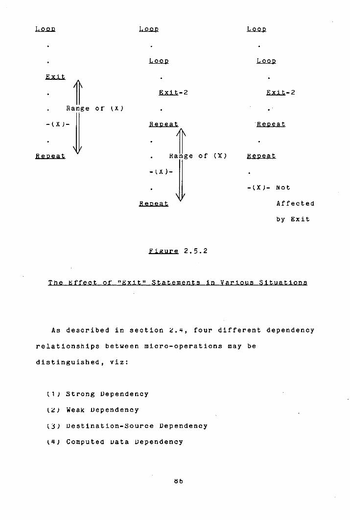
L0OD Loon Loop
• Loon Loop
Exit
• Exit-2 Exit-2
• Range of X)
-(X)-
Repeat Repeat
Reneat . Range of (X) Repeat
-(x)-
• Not
Rene at Affected
by Exit
Figure 2.5.2
diT1U3Urn
As described in section 2.4, four different dependency
relationships between micro-operations may be
distinguished, viz:
(1) Strong Dependency
() Weak Dependency
(3) Destination-Source Dependency
(Li) Computed Data Dependency

Types (3) and (14) are resolved to either of types (1)
or (2) at implementation time, but ANALYSE must retain the
distinction at this stage. The various situations which
give rise to the several types of dependency relationship
marked by ANALYSE between two micro-operations A and B (A
preceding B) are classified below.
B writes to the same operand that A writes to.
B reads from an operand that A has written to.
B is a Label block type micro-operation. A is a
childless micro-operation at the same level
preceding B.
A Is the conditional branch micro-operation at the
head of a loop or conditional block. B is a
parentless micro-operation inside the block.
A is an Ifblock block type micro-operation. B is
the corresponding Elseblock.
B is a branch micro-operation not data dependent on
A. A is a childless micro-operation preceding .
B is a Subroutine Call micro-operation incorporating
explicit specification of operands which render it
87
data dependent on A.
(3) B is an Ifheader block type micro-operation data
dependent on A on account of a component
micro-operation of B (But not the conditional branch
micro-operation at the head of the block - this
causes a Computed Data Dependency relationship of B
on the parent).
(1) B writes to an operand that A has read from.
(1) B is a conditional branch or subroutine call (or
return) micro-operation which is data dependent on
A.
These then are the relationships constructed by ANALYSE
to realize POmin, the partial ordering defining the
maximally parallel representation of the MDL source
microprogram input to it.
One qualification must be put on the term "maximally
parallel" as used above, however. The canonical
microprogram is the maximally parallel representation of
the source microprogram that may be generated without
tracing the control flow associated with explicit labels
MMI

and branches. Explicit labels and branches serve as
absolute barriers to code movement and effectively
partition the canonical microprogram into disjoint
segments (not straight line segments, because critical
points may occur inside a modular control block). As
noted previously, it could be the case the actual control
structure defined by the explicit labels and branches in a
particular example would permit some code movement between
the segments, but this would not be reflected in the
canonical microprogram for that example. The rewards to
be gained in attempting to detect such situations are far
outweighed by the amount of extra effort that would have
to be invested to do so; particularly when modular control
constructs are available in the microprogram description
language.
With this qualification implicit, the canonical
microprogram generated by ANALYSE is a maximally parallel
representation of the MDL source microprogram description.
ANALYSE outputs a representation of this canonical
microprogram for use as input to MICROMAP, the program
which generates the final implementation of the
microprogram as will be described in chapter LI, .
ME
IsIFUIILp__
This chapter is concerned with describing the control
organization of the microprogram level host machine on
which a processor behaviour will be implemented.
Control organization at the microprogram level is
defined by the microinstruction format of the
implementation, which term is taken here to encompass both
the field structure of microinstructions and the action of
the micro-orders that may be evoked from them.
The first section of this chapter examines the features
of microprogram level control which must be described and
the second introduces a model of microinstruction formats
which has been designed with the automatic generation of
microprograms specifically in mind.
dij
To the author's knowledge, the only previous attempt to
design a formal notation for the description of
microinstructions is De Witt's Control Word Model [221,
noted in section 1.3. Although it is capable of
specifying what operations may be realized from a single
microinstruction word over quite a wide variety of
formats, there are three major reasons why the Control
Word Model is not capable of achieving the objectives of
MDS. Namely:
The model is not complete. It does not provide
sufficient information about the microinstruction
format to permit the automatic generation of
microcode for microinstructions described in the
notation.
It assumes that each micro-operation to be
implemented in the particular microinstruction format
being described may be associated with a unique block
in the description which will realize it. This is
not a valid assumption in all circumstances.
The notation is difficult to use - a description
expressed in the Control Word Model notation does not
reflect the actual format of the microinstruction.
Also, the user is obliged to specify explicitly all
possible microinstruction configurations.
91
In terms of existing notations, one other alternative
exists. That is the encapsulation of the behaviour
associated with a particular microinstruction format
inside the general description of the microprogram level
organization of the system, this being represented in a
standard hardware description language. Although this
approach may be made to convey all of the information that
is necessary for the purposes of microprogram design, it
entails a complicated, detailed description incorporating
much additional information about the organization of the
system which is not relevant to the subject. Consequently
it obscures that which is relevant.
It is the professed goal of this research effort to
construct a tool that will be practical use for the design
of the microprogram control of digital systems. A
fundamental implication of this tenet is that the system
should be easy to use. Hence we seek a notation in which
it is convenient for the microprogram designer to express
that which he wishes to describe - in this case the
microinstruction format for the control of a given
processor design. The absence of an existing notation
with this property compels the design of a new one. This
is the motivation behind MFM - Microinstruction Format
Model - a model of microinstruction formats defining an
associated notation in which descriptions of the control
organization of microprogram level systems may be
expressed.
92

The rest of this section examines the type of features
which a model for this purpose must be capable of
representing. The following section presents the details
of MFM, with an example of its use.
There are two aspects to the description of
microinstruction formats that must be taken account of.
There is the functional aspect: specifying the operations
that may be performed at the microprogram level; and there
is the structural aspect: the organization of the fields
within the microinstruction word. Both are necessary
integral parts of a description for the purpose of
microprogram design; the first in the synthesis of the
specified behaviour for the microprogram level
implementation of the processor; the second in recognizing
resource conflict between micro-operations and in enabling
the generation of complete microcode. A suitable model
should be capable of reflecting both these aspects.
The following properties for a model for describing
microinstruction formats for the purpose of microprogram
design will be assumed as axiomatic and from these will be
derived the properties to be exhibited by MFM and its
associated notation.
(1) The model should be capable of describing completely
a wide diversity of formats - not just "conventional"
or "well behaved" examples.
93

The model should carry sufficient information to
allow generation of complete microcode in the
described format.
The notation should be convenient to use.
Descriptions expressed in the notation should be easy
to understand.
The model should be conducive to the automatic
transformation of descriptions into data structures
suitable for subsequent machine processing.
Two alternative approaches may be taken to the
modelling of a microinstruction format: either a function
based approach or a field based approach. In the former,
all of the micro-operations that a processor may perform
are listed. The particular microinstruction configuration
which realizes each is then calculated explicitly by the
designer and is associated with that micro-operation in
the format description (the "hand compiling" method
mentioned in section 1.3). This exhaustive method may
well lend itself to machine processing, condition (5)
above, but quite clearly violates condition (3), that a
description be easy to write.
In contrast, with a field based model each constituent
field of the microinstruction format is defined in terms
94
of the micro-orders supported by that field. In addition
to providing a simpler description, this model is closer
to the designer's conceptual view of the microinstruction
format and its conformity to the structure of the
microinstruction renders this style of description more
intelligible. These advantages override any extra effort
which might be required (once only) to process
descriptions represented in this model.
The requirement that MFMshould be field based is
therefore deduced.
Typically, the specification of a microinstruction
format as it appears in both the manufacturers' literature
and the technical journals comprises a diagram depicting a
box which represents the microinstruction word, subdivided
into several sections representing the fields. (Or perhaps
several boxes divided into different sections). Lengthy
annotation is attached to each section and the description
is accompanied by numerous footnotes covering
contingencies which are not uniquely associated with a
single field. MFM must be capable of representing all of
the information conveyed in this model, but in a more
formal manner. Identified below are particular features
which must be given express consideration.
Incorporated into these diagrams of the boxes
representing microinstructions is information expressing
95
the length of the microinstruction word and of the fields
contained therein, as well as the position of the fields
within the word.
The depiction of the microinstruction format as many
boxes each of different field structure, as illustrated in
figure 3.1.1, reflects the property exhibited by many
control word organizations of variable format (or two
level encoding) , in which the interpretation of the field
structure of the (rest of the) microinstruction word is
dependent on the value held in a single field common to
all structures. The archetypal example of this feature is
the "Opoode" field of a vertically structured format.
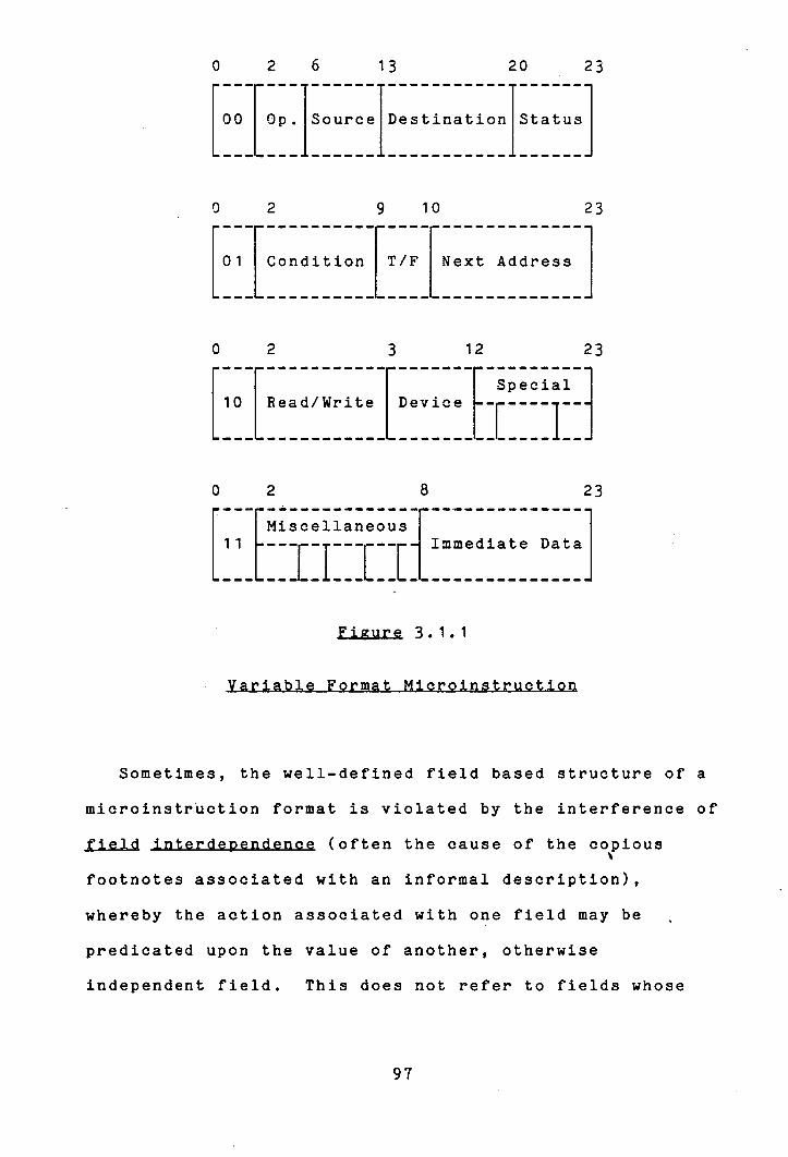
[EEI[IIEIEIEi
[EI[EEI[EEEI[IEI1 0 2 3 12 23
rr r Special 10 __ Read/Write __ Device---
I ---- E - 0 2 8 23
Miscellaneous r :: ::i::ci::::::::::
Figure 3.1.1
Sometimes, the well-defined field based structure of a
microinstruction format is violated by the interference of
field interdeoendence (often the cause of the copious
footnotes associated with an informal description),
whereby the action associated with one field may be
predicated upon the value of another, otherwise
independent field. This does not refer to fields whose
97
action involves transferring data determined by another
field, or over a data path determined by another field,
which is the normal course of events, but concerns fields
the actual action of which is affected by the value held
in other fields. This situation may be exemplified by the
microinstruction format of the IBM 360 model 40 (see 1311)
in which the interpretation of the CE field is determined
by the values held in the CH, CN, and CQ fields. The CE
field acts either as an immediate source of data for
loading into one of the registers or else - if the CN
field has the value 15 - it determines the function which
is performed on the stat registers and loaded into the
function register. The microinstruction format of the
Varian 73 central processor [60, 51 also exhibits this
feature extensively.
Another violation of the normal "good behaviour" of
microinstruction formats is presented by the mechanism
known as residual control [49, 31. This breaks the rule
stipulating that the action of a single microinstruction
should be totally defined within a single processor cycle
(discounting actions, such as memory references, the
duration of execution of which lasts longer). It does so
by "setting up" a register during one clock cycle from one
microinstruction word and then using the contents of that
register to determine the action activated by a subsequent
microinstruction word. For example, the Fstore registers
of the Nanodata QM-1 processor E43, 501 implement this
WE

feature, being used among other things to select the
register to be connected to a bus.
Associated with each field in the microinstruction
format is a set of micro-orders. The micro-orders that
are grouped together in one field are mutually exclusive:
only one may be activated from the field at any one time,
and the corresponding control signals are encoded within
the field to reduce the length of the microinstruction
word. This means that each micro-order has associated
with it a value which must be bound to the field to cause
that micro-order to be activated from a particular
microinstruction. Also, each action has an associated
duration. Normally it will be completed inside a single
processor cycle, but some actions, such as memory
references, may be exceptional. In the event of none of
the micro-orders belonging to a field being explicitly
included in the action of a microinstruction word, a value
must still be bound to that field in the microinstruction.
Rather than this being determined arbitrarily, it should
be possible to specify such a default binding explicitly.
In addition to the function of providing control
signals to the p rocessor data paths, part of any
microinstruction format is taken up with the sequencing of
the microprogram itself - in selecting the conditions to
be tested and in deciding from what location the next.
microinstruction should be fetched. Another part of the
microinstruction word is taken up with providing Immediate
data to either the data path or sequencing mechanisms of
the implementation. For the sake of clarity and
consistency, a model which represents all functions of a
microinstruction format in a unified form is to be
preferred.
These then are the major requirements which MFM must be
capable of representing. Before describing the model and
demonstrating how it satisfies these requirements, one
further observation concerning the interDretation of
format descriptions may be made.
In section 2.2, arguments were advanced explaining the
reasons for MDS not attaching any semantic interpretation
to the statements of an MDL microprogram description.
These arguments are applicable to format descriptions
also. In the context of microprogram design, there is no
necessity to associate any connotation of semantic
significance with the actions of the micro-orders
described in a specification of a microinstruction format,
when this is svmoathetic to the high level description of
the system being implemented. The memory elements which
are the sources and destinations of data for all
micro-operations have names which are unique throughout
the processor level description and the microprogram level
description of the system - they are the names of
processor level resources. Exactly the same is true of
the operations performed by the processor. The format
iII
specification defines how the microinstruction word
controls the operations performed by the processor, but it
does not need to define what these operations are. As
long as there is consistency of naming between the two
descriptions of the processor at different levels,
definition of their semantics is unnecessary. When the
format specification is directed specifically toward
implementing the processor defined by the MDL description,
this consistency of naming is maintained naturally.
101
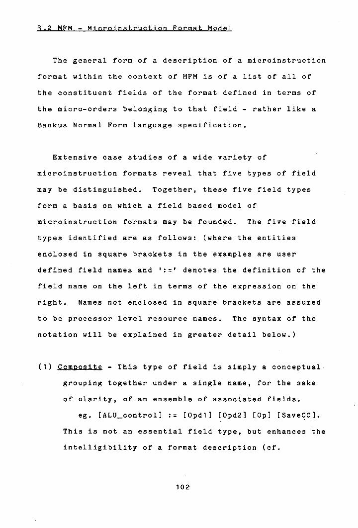
ICIW41C
general form of a description of a microinstruction
format within the context of MFM is of a list of all of
the constituent fields of the format defined in terms of
the micro-orders belonging to that field - rather like a
Backus Normal Form language specification.
Extensive case studies of a wide variety of
microinstruction formats reveal that five types of field
may be distinguished. Together, these five field types
form a basis on which a field based model of
microinstruction formats may be founded. The five field
types identified are as follows: (where the entities
enclosed in square brackets in the examples are user
defined field names and ':' denotes the definition of the
field name on the left in terms of the expression on the
right. Names not enclosed in square brackets are assumed
to be processor level resource names. The syntax of the
notation will be explained in greater detail below.)
(1) Composite - This type of field is simply a conceptual
grouping together under a single name, for the sake
of clarity, of an ensemble of associated fields.
eg. [ALU_control] := [Opdl] [Opd2] [Op] [SaveCC].
This is not, an essential field type, but enhances the
intelligibility of a format description (of.
102

"Special" and "Miscellaneous" in figure 3.1.1).
Mode Interpretation (Bit Steering) - This type of
field determines the interpretation of the field
structure of the rest of the microinstruction in a
variable format organization.
eg. [Instmode] :: <0>: [ALutype];
<1>: [Condbranch].
The field names on the right of the '::' denote
alternative composite type fields representing the
field structure associated with the two alternative
values for [Instmode].
Select - This type of field, the most common in most
descriptions, defines the micro-orders used to
control the propagation of dataalong the internal
data paths of the processor, typically by issuing the
selector control signals to a multiplexor orgating
data on to a bus. The name of the field will
normally be chosen to be a mnemonic name for the
microprogram level resource, eg. section of data
path, controlled by the field. This name will be
used in the expansion of other fields when the
sections of data path associated with each are
connected.
eg. [ALU_input] :: <0>: Ace;
<1>: [GPReg);
103
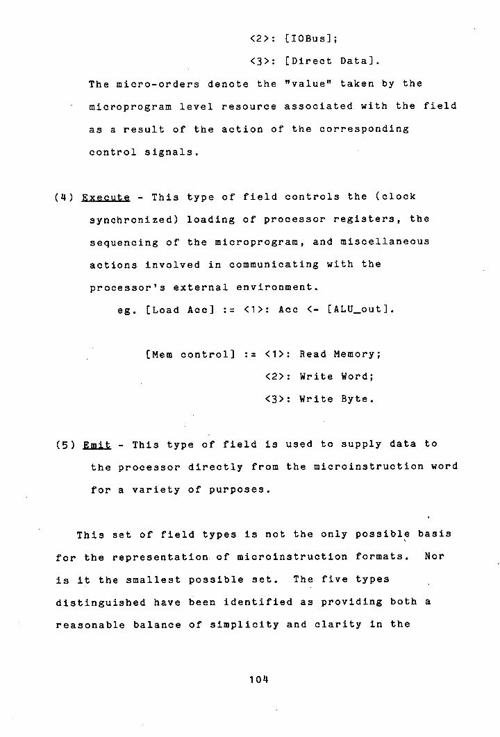
<2>: [lOBus];
<3>: [Direct Data].
The micro-orders denote the "value" taken by the
microprogram level resource associated with the field
as a result of the action of the corresponding
control signals.
(14) Execute - This type of field controls the (clock
synchronized) loading of processor registers, the
sequencing of the microprogram, and miscellaneous
actions involved in communicating with the
processor's external environment.
eg. [Load Ace] := <1>: Ace <- [ALU_out].
[Mem control] :: <1>: Read Memory;
<2>: Write Word;
<3>: Write Byte.
(5) Emit - This type of field is used to supply data to
the processor directly from the microinstruction word
for a variety of purposes.
This set of field types is not the only possible basis
for the representation of microinstruction formats. Nor
is it the smallest possible set. The five types
distinguished have been identified as providing both a
reasonable balance of simplicity and clarity in the
104

descriptions, together with sufficient information to
facilitate the interpretation of the described format
which is necessary for subsequent processing. Were the
latter consideration not pertinent, it would not be
necessary to distinguish Select and Execute type fields.
The latter type is just a special case of the former, a
symptom of which is that Execute type fields are never
referenced as part of the expansion of other fields.. This
matter will be explained further in section 14.2.
In order to keep descriptions simple in MFM, and hence
make the model usable, the designer is required to specify
the type of each field defined in the MFM description of a
microinstruction format. The whole microinstruction word
is considered as a single Composite type field and is
specified in terms of Its constituent fields. Thereafter
each field supported In the format is defined by its
expansion, that Is all of the micro-orders belonging to
the field, which are expressed as a combination of literal
terms and other field names.
The general form for the specification of a field is as
follows:
[Fleidname] (Type) <from:to> := Expansion.
The "fieldname" is a user defined Identifier for the field
which normally will be unique within the description,
105
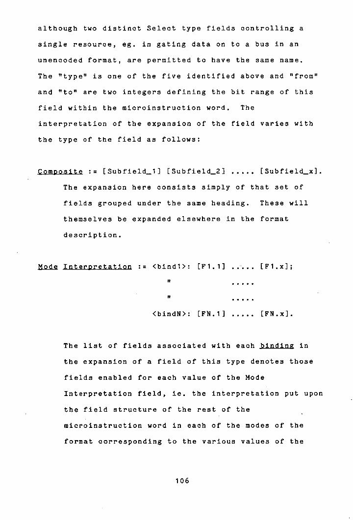
although two distinct Select type fields controlling a
single resource, eg. in gating data on to a bus in an
unencoded format, are permitted to have the same name.
The "type" is one of the five identified above and "from"
and "to" are two integers defining the bit range of this
field within the microinstruction word. The
interpretation of the expansion of the field varies with
the type of the field as follows:
Composite : [Subfield_i] [Subfield_2] ..... [Subfield_x].
The expansion here consists simply of that set of
fields grouped under the same heading. These will
themselves be expanded elsewhere in the format
description.
Mode Interpretation := <bindi>: [F1.1] ..... [F1.x];
I,
'I
<bindN>: [FN.1] ..... [FN.x].
The list of fields associated with each binding in
the expansion of a field of this type denotes those
fields enabled for each value of the Mode
Interpretation field, ie. the interpretation put upon
the field structure of the rest of the
microinstruction word in each of the modes of the
format corresponding to the various values of the
106

Mode Interpretation type field. These fields will
all be expanded later in the format description.
Explicit specification of the binding is optional,
with the default being zero initially and incremented
by one after each field list (which are separated by
semi-colons).
Emit Low limit : High limit
The expansion for this type of field lists two values
denoting the lower and upper bounds for the integral
number which may be held by the field. The lower
bound may be omitted, in which case zero is assumed.
Select and Execute := <bindi>: Orderl.1, ... ,Orderl.x;
<bindN>: OrderN.1, ... ,OrderN.x.
Associated with each value for each Select and
Execute type field is a list of the micro-orders
evoked by that value for the field. The micro-orders
take the form of a string of literal names and field
names. For the Select type fields, the micro-orders
denote the resources (processor or microprogram
level) that may be "bound" to that field name. For
Execute type fields, the micro-orders specify the
107
actions that may be evoked from that field. The
possibility of more than one micro-order being
associated with a single binding is entertained.
This is a situation which often occurs in practice as
a method of reducing the length of the control word
whenever two actions may always be activated at the
same time as each other. This feature is also used
commonly in MDS as a consequence of the lack of
semantic interpretation put upon operations in MFM
descriptions. It is necessary to specify twice an
expression which involves a binary commutative
operation: once for each order of the operands.
eg. [.ALU_out] (select) := [Opdl]+Acc,
Acc+[Opdl].
Since there is no way of "knowing" in the notation
that these two expressions are the same, "both"
actions must be evoked simultaneously.
There are three further parameters which may be
associated with a field description in the MFM model,
namely Default, Duration and Phase.
Each field definition in the MFM description with which
a binding may be associated may be followed by a
directive, " DEFAULT = X". X is an integer specifying
the value to be bound to the field in the event that no
micro-order belonging to that field is explicitly selected
for activation in a microinstruction word. Zero is
assumed as the default binding for a field when the
directive is not included in the field definition.
The duration of the actions associated with each field
described may be specified by the directive
DURATION = X", where X is the number of processor
cycles taken to complete the actions associated with the
field. If this is omitted (which is the normal case),
then it is assumed that the actions can be completed
inside a single processor cycle.
Similarly, the phase of the processor cycle in which
the micro-orders belonging to a field are activated may be
specified using the directive "' PHASE = X". Zero is
assumed as default value for X. (This feature is not used
in MDS, but is included in the model for completeness).
In addition to the five basic types of field described
above, two further types are included in the model. These
are used in connexion with two of the contingencies
identified in the preceding section.
The first additional type is the Register type which in
effect is a cross between the Select and Execute field
types. It is used to control the loading of a
microprogram level register incorporated within the
processor data path. That is, it controls an internal
part of the data path, just like a Select field, but in
this case the section of data path retains its data
between processor cycles. Hence any transfer of data by a
109
micro-operation from a processor level source register to
a processor level destination register over a data path
including such a register must be split up into actions:
one to load the register with the source data and another
to pass the data on to the destination. The
differentiation between a processor level register and a
microprogram level register is purely conceptual, but the
availability of this feature is extremely useful,
especially when experimenting with different microprogram
level organizations for the implementation of a processor,
when the behavioural description of the processor may
remain invariant. It is of particular usefulness in
modelling residual control, defined in the previous
section, and in overlaDoed implementations (see section
2.14) in which data generated in an arithmetic expression
and then tested to determine branching must be split over
two microinstructions. Register type fields may also be
used like Execute type fields in explicitly loading the
associated register as if it was a processor level
resource. This will be explained further in chapter 14.
Note that the requirement to distinguish Register type
fields exists only through the use of the model for
describing micro-architectures into which a processor
description will be mapped automatically. Were the model
not used for this purpose, then all Register types fields
would simply be classed as Execute type (which itself is
just a special case of Select which need not be
110
distinguished in all contexts).
The second additional field type, the Conjunction type,
strictly speaking is not a field type at all, nor is it
specified in the format definition as such. A dummy field
of this type is generated in the internal representation
of the format whenever a case of field interdeDendence is
encountered: whenever a micro-order is specified whose
activation is dependent on the value of more than one
field (but not where one of the fields is exclusively for
this purpose, of type Mode Interpretation). Field
interdependence may occur within Select, Register or
Execute field types in a format description and is
expressed within the expansion of one of these with a
construction of the form:
%When [Field] = Binding: list of micro-orders
The "field" is the other field involved in activating
the micro-orders, apart from the one in whose expansion
the construction is included. The list of micro-orders is
of the same form as for Select and Execute type fields and
carries the same interpretation as the other micro-orders
of the field in which the Conjuntion field occurs. Like
the notion of multiple actions evoked from the same
control signal, this device is used quite commonly asa
consequence of the absence of semantic interpretation in
the model. For example, one field might be used to
111
control the Carry-in bit to an arithmetic unit. Then the
field which controls the arithmetic operation to be
performed may be considered as implementing two different
functions depending on the value of the Carry field.
Thus: -
[Carry Control] (select) := <0>: Carry in;
<1>: No carry.
[Acc_Add] (execute) := <1>: when [Carry Control] = 1:
Acc<-Acc+[ALU_in]
Acc<-[ALU_in]+Acc;
%when [Carry Control] = 0:
Acc<-Acc+[ALU_in]+1,
Acc<-[ALU_in]+Acc+1.
It is often found to be the case that the
intelligibility of a microinstruction description may be
enhanced by the inclusion of dummy fields. These do not
correspond to any bit positions in the actual
microinstruction word, but may be included in a
description for two alternative reasons. They may be used
to impart information about the action of the
micro-architecture not explicitly conveyed by any of the
real fields - in effect "pretending" to control some
action which in fact is not totally under the control of
the microprogram but is relevant to the microprogram level
description, such as [Seq Op) in figure 3.2.1 (to follow).
112
Alternatively, they may simply be used for notational
convenience, such as [Opdl] and [Opd2] in the same
example.
No field may assume more than one type in the
Microinstruction Format Model. Where such a behaviour
arises in practice, it may be represented in the model as
two fields of different type occupying the same portion of
the microinstruction word, ie. overlaid on top of each
other.
For example:-
[Load Dest] (Execute) <4:4> := <1>:
[Dest Reg] <- [ALU_Result].
[Output Bus] (Select) <:1> := <0>: [Input Bus];
<1>: [ALU_Result].
[Output] (Execute) <5:5> := <1>: Out Reg <-. [Output bus].
A format description need not be unique in MFM. A
particular microinstruction format may be represented in
the model by several different descriptions, each
conveying the same information. For example, the above
example could also be expressed as:
113
[Load Dest] (Execute) <14:4> := <1>:
[Dest Reg] <- [ALU_Result].
[Output] (Execute) <5:5> := <1>:
%When [Load Dest] = 0: Out Reg <- [Input bus].,
%When [Load Dest] = 1: Out Reg <- [ALU_Result].
In order to avoid duplication of effort on the part of
the designer in the description of formats, the Alias
feature is provided in MFM. This facilitates the
generation and use of a library of descriptions of common
microprogrammable components, such as bit slice
microprocessor chips. These descriptions may be included
in the microinstruction format descriptions for processors
in whose implementation the components are incorporated.
It was noted above that the names referred to in the
field expansions of a format description were the names of
processor level resources, specific to the particular
processor being implemented. This implies that some
provision should be made in the notation for mapping the
names used within the description of the library component
to the specific names associated with the given processor
when the Alias feature is used. This is achieved by
issuing the directive "%NAMEALIAS" within the format
description, followed by a list of pairs of names of the
form:
LIBNAME = PROCNAME
LIBNAME is a name occurring in the library component
114

format description and PROCNAME is the corresponding
processor resource name, as referenced in the MDL
processor description. There is a similar requirement in
interfacing the component description with the rest of the
description where fields defined in one part are
referenced from within the other part. This is dealt with
by the "%FIELDPLLIAS 11 directive which, like %NAMEALIAS, is
followed by a list of pairs of names; this time field
names. The first of the pair is the name of the field as
it is referred to. in the library component description and
the second is the name given to that field in the part of
the description specific to the processor.
In order to facilitate the integration of a component
description from a library into a complete
microinstruction description, the component description
must be allowed to be situated anywhere within the
microinstruction word. Provision must therefore be made
for the alteration of the bit range specifications
associated with the fields defined in the component
description. The "%ALIASINDEX=X" directive achieves this.
"X" is an integer which is added to the bit positions of
all the fields defined in the component description.
The scope of the %NAMEALIAS, %FIELDALIAS and
%ALIASINDEX directives, ie. of the format description of
the library component, is terminated by the directive
"%ENDALIAS". Thereafter, further library components may
be included in the description using, if desired, the same
115
names as were used in the previous component.
Chapter 2 referred to the existence of two
implementation dependent parameters which affect the order
in which micro-orders are allowed to be executed. To
recap, these were:
Whether microinstruction fetch and execution is
overlanoed or sequential.
Whether it is possible to write data into a
register at a later phase of the same clock cycle as
that in which data is read out of the register.
In addition to describing the microinstruction format,
an MFM description may specify a value for these two
parameters. This is expressed using the directives
"%SEQUENTIAL", 0 %OVERLAPPED", tt%OUT-AND-IN" and
"%OUT-OR-IN", where in the absence of any explicit
direction, %Sequential and %Out-Or-In are assumed as
default.
A short example illustrating the use of some of the
features of MFM is presented in figure 3.2.1. A more
comprehensive example is given in Appendix 1(c).
116
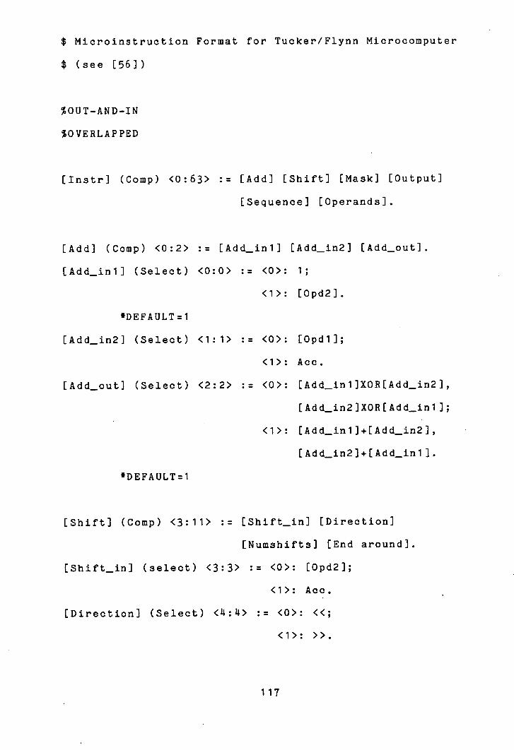
$ Microinstruction Format for Tucker/Flynn Microcomputer
$ (see [561)
%OUT-AND-IN
%OVERLAPPED
[Instr] (Comp) <0:63> := [Add] [Shift] [Mask] [Output]
[Sequence] [Operands].
[Add] (Comp) <0:2> : [Add—mil [Add_in2] [Add_out].
[Add_mi] (Select) <0:0> := <0>: 1;
<1>: [Opd2].
DEFAULT:1
[Add_in2] (Select) <1:1> := <0>: [Opdl];
<1>: Acc.
[Add—out] (Select) <2:2> := <0>: [Add_inl]XOR[Add_in2],
[Add_in21XOR[Add_in1 );
<1>: [Add_in1]+[Add_1n2),
[Add_in2)+[Add_ini].
'DEFAULT=l
[Shift] (Comp) <3:11> := [Shift—in] [Direction]
[Numshifts] [End around].
(Shift—in] (select) <3:3> := <0>: [Opd2];
<1>: Acc.
[Direction] (Select) <:4> := <0>: <<;
<1>: >>.
117

[Numshifts] (Emit) <5:10> := 63.
[End around] (select) <11:11> :: <0>: ; $ Null micro-order
<1>: (ea).
[Shift—out] (Select) := [Shift_in][Direction]
[End around][Numshifts],
%When [Numshifts] = 0: [Shift_in]..
[Mask] (Comp) <12:16> := [Maskreg] [Clear].
[Maskreg] (Select) <12:15> := M0;M1;M2;M3;M4;M5;M6;M7;M8;
M9;M10 ;M1 1 ;M12;M13;M1 11;M15.
'DEFAULT = 15
$ M15=X'FFFFFFFF'
[Clear] (Select) <16:16> := <0>: Or;
<1>: Add. $ Clear dest reg?
[Mask_out] (Select) := [Shift_out]&[Maskreg],
%When [Maskreg] = 15: [Shift—out]..
[Output] (Execute) <17:17> := <0>: Acc<-[Add_out],
%When [Clear]=1: [Opdl]<-[Maskout].,
%When [Clear]=0:
[Opdl ]<-[Opdl ][Mask_out],
[Op1]<_[Mask_out][Opd1].;
<1>: Acc<-[Mask_out],
%When [Clear]=1: [Opdl]<-[Add_out].,
%When [Clear]=O:
[0pd1]<_[Opd1][Add_out],
[Opd1]<-[Add_out][Opd1]..
118

[operands] (Comp) <32:63> := [Regl][Displ][Reg2][Disp2].
ERegi] (Select) <32:35> := R0;R1;R2;R3;R4;R5;R6;R7;R8;
R9;R 10 ;R11;R 12 ;R 13 ;R 1i ;R 15.
[Dispi] (Emit) <36:47> 4047.
[Reg2] (Select) <48:51> := {[Regl]}. $ same as Regi
[Disp2] (Emit) <52:63> : 4047.
[Opdl] (Select) := [Displ]([Regl]).
[Opd2] (Select) := EDisp2]([Reg2]).
[Sequence] (Comp) <18:31> := [Cond] [PC—index].
[Cond] (Select) <18:22> := <1>: u/f;
<2>: minus;
<'1>: plus;
<8>: zero;
<16>: o/f.
(PC—index] (Emit)<23:31> : -256:255.
[Seqop] (Execute) := if ECond] goto [PC—index], $ (+PC)
%When [Cond]=0: goto [PC—index]..
Figure 3.2.1
119
In MDS, the FORMAT program processes MFM format
descriptions and transforms each into an internal data
structure which reflects the same field based structure as
the MFM model. For each field in the format a record is
generated which specifies its type, duration, phase, bit
range, default binding, and an index into a table which
contains its expansion details expressed as literal terms
and pointers to the records for other fields. The data
structure is presented as input to the MICROMAP program
which generates a microprogram in the defined format.
This is described in the following chapter.
120
Chaoter U - Generating the Microprogram
This chapter discusses the problem of generating an
implementation of a canonical microprogram in
microinstructions of a defined format. How this is
performed by the MICROMAP program on the outputs of
ANALYSE and FORMAT is described.
As observed in section 1.2, there are two major aspects
to this problem: there is the task of exploiting the
capability for parallelism in the microinstruction format
in such a way as to pack the micro-operations together, in
a suitable order, into the fewest number of
microinstruction words; and there is the task of actually
realizing the effect of each micro-operation in terms of
the actions that may be performed in the given
microinstruction format. The first two sections of this
chapter deal with these two topics and the third considers
the issue of maintaining the correct flow of control
between the microinstructions generated.
121
At the processor level, the potential for concurrency
between two micro-operations is determined by two factors:
the control flow which necessarily results in the
execution of each, and the operands referended by each.
These factors are taken into account by ANALYSE in
generating the canonical microprogram for a processor
description. But at the microprogram level, further
factors affect which micro-operations may be activated
concurrently. Just as data dependency results from two
micro-operations referencing the same operand (the same
processor level resource) in an incompatible manner, so
resource contention results from two incompatible attempts
to reference a microprogram level resource; trying to gate
different registers on to a single physical bus for
instance. Microprogram level resources are unstable
memory elements. That is, they do not retain the data
which passes through them. They are used as intermediate
points across which the register transfer actions of the
micro-operations are implemented. Hence the order in
which different micro-operations reference microprogram
level resources is not significant. Resource contention
does not define dependency. It only defines when two
micro-operations may not be activated concurrently.
This section addresses the problem of minimizing the
number of microinstruction words required to implement a
122
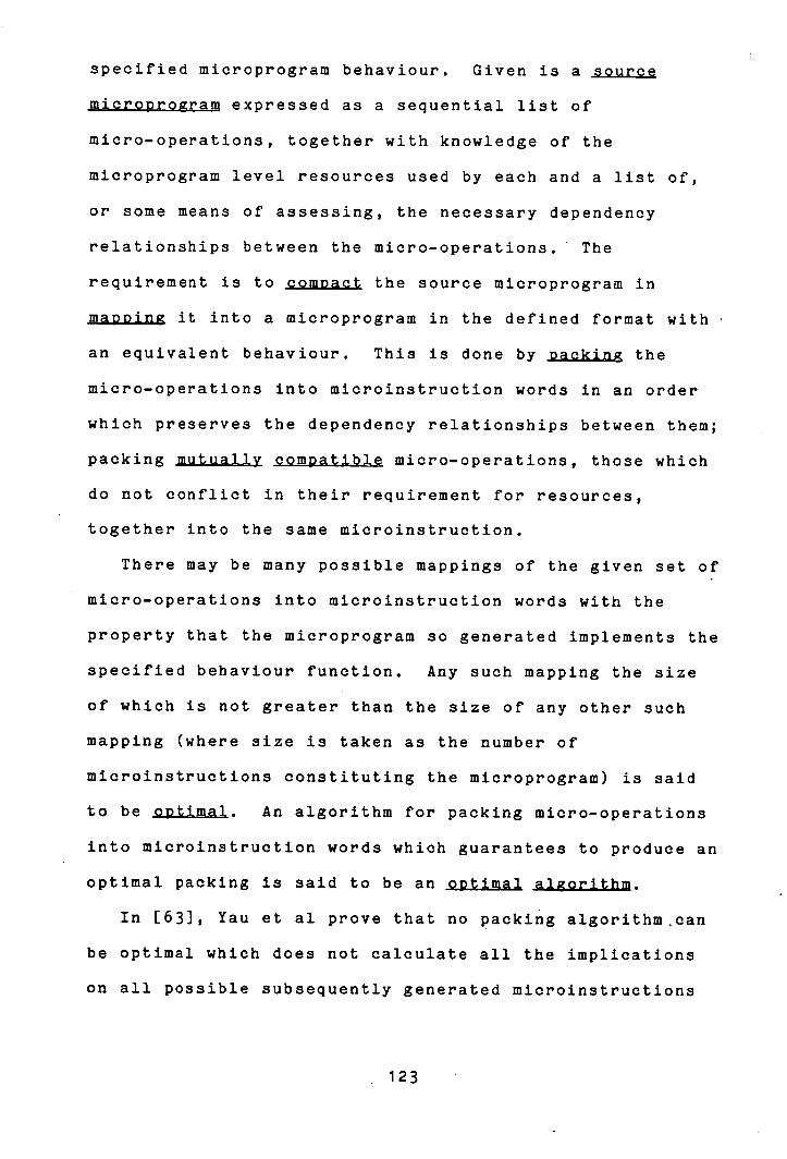
specified microprogram behaviour. Given is a source
micropro gram expressed as a sequential list of
micro-operations, together with knowledge of the
microprogram level resources used by each and a list of,
or some means of assessing, the necessary dependency
relationships between the micro-operations. The
requirement is to compact the source microprogram in
ma2ping it into a microprogram in the defined format with
an equivalent behaviour. This is done by Dacking the
micro-operations into microinstruction words in an order
which preserves the dependency relationships between them;
packing mutually comoati.bl micro-operations, those which
do not conflict in their requirement for resources,
together into the same microinstruction.
There may be many possible mappings of the given set of
micro-operations into microinstruction words with the
property that the microprogram so generated implements the
specified behaviour function. Any such mapping the size
of which is not greater than the size of any other such
mapping (where size is taken as the number of
microinstructions constituting the microprogram) is said
to be optimal. An algorithm for packing micro-operations
into microinstruction words which guarantees to produce an
optimal packing is said to be an optimal algorithm.
In [63], Yau et al prove that no packing algorithm .can
be optimal which does not calculate all the implications
on all possible subsequently generated microinstructions
123

of packing a particular micro-operation into a particular
microinstruction word. That is, in effect, in order to
guarantee to generate an optimal packing it is necessary
to generate all possible mappings of micro-operations to
microinstruction words (employing pruning techniques
wherever possible) and to select the best one generated.
De Witt [21] has proved that the complexity of this task
is exponential in the number of micro-operations to be
packed.
The problem of packing micro-operations from straight
line segments into microinstruction words is one that has
commanded substantial attention in the literature in
recent years [2, 6, 17, 19, 20, kO, 53, 54, 55, 631. To
the author's knowledge, four different methods, with
several minor variations, have been proposed to tackle the
problem. These four methods are:
(1) Astonas and Plukas [6] present a matrix based
representation for micro-operations. They employ matrix
operations to generate all possible orderings;of
micro-operations complying with the pre-defined dependency
rules and explicitly eliminate all those configurations
not supported by the particular format under consideration
before selecting the best mapping. This proposal is of
purely theoretical interest, since it is too costly to
attempt to put into practice.
124

(2) Yau. Schowe and Tsuchiya [63] report an optimal
algorithmic method for generating all possible mappings of
micro-operations to comDlete microinstruction words
consistent with the ordering and resource contention
constraints imposed on the implementation. A complete
microinstruction is one into which no more
micro-operations may be packed - either because the
microinstruction is "full" or because the dependency and
resource contention relationships between micro-operations
are such that no other micro-operations could be included
in the word without violating these relationships. This
method generates microinstructions sequentially from a
Data Available (DAS.) of micro-operations whose parent
micro-operations in the dependency graph representation of
the microprogram have all previously been packed. From
the initial DAS it generates all possible complete
microinstructions and calculates the DAS resulting from
each. These are considered exhaustively in turn as
sources from which the second microinstruction is
generated, and so on. The process is illustrated in
figure 4.1.1
125

C Initial DAS
All Possible Complete £ 3 Microinstructions
J from Initial DAS
I ') C') I DAS Resulting
C ) C C ) from Each
All Possible Complete
J Microinstructions from Each DAS
C) C) C) C) C) C) from Each - DAS Resulting
Figure 4..1.1
Recognizing that this optimal method is too complex for
practical implementation, in the same report they also
present a simplified heuristic version of the algorithm.
Rather than calculating a new DAS from each complete
126

microinstruction generated from the previous DAS, as the
exhaustive algorithm does, this version selects out of the
set of complete microinstructions generated from the DAS a
single one "most likely" to lead to a minimal
microprogram, discarding the rest. The selected
microinstruction is used to produce a single new DAS from
which the next set of complete microinstructions is
generated, from which one is selected, and so on. Figure
4.1.2 illustrates the process.
Determination of the microinstruction to be selected
for inclusion in the microprogram out of the set generated
from the DAS is based upon a weighting factor calculated
for each member of the set. This is the sum of the
weights of all the micro-operations packed into the
microinstruction, where the weight of a micro-operation is
defined to be the number of descendants of that
micro-operation in the microprogram graph, ie. the total
number of micro-operations which cannot be packed before
this one has been. This strategy endeavours to take a
global view of the obvious desire to make each
micro-operation in the source microprogram "available" for
packing as early as possible.
The method is non-optimal, but is considerably less
complex than the optimal version.
127
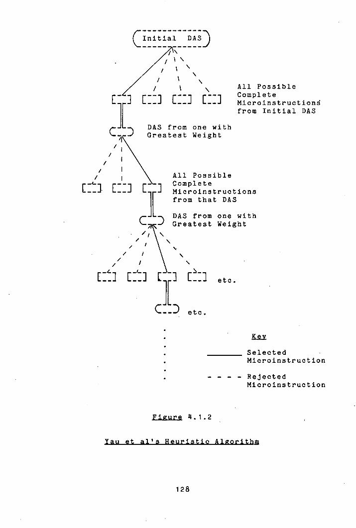
CInitialDASD /
r L
c DAS from one with jçGreatest Weight
All Possible Complete Microinstruction from Initial DAS
\ All Possible Complete Microinstructions from that DAS
C DAS from one with Greatest Weight
, / \
etc.
etc.
•
• ________ Selected • Microinstruction
• - - - - Rejected Microinstruction
Figure 11.1.2
128

(3) Tsuchiya and Gonzales [55] present a more
optimizing version of an algorithm first described by
Ramamoorthy and Tsuchiya [117] in which they partition the
source microprogram description into early and late
partitions on the basis of control and data dependency
between the micro-operations. The early partition class
for each micro-operation corresponds to the length of the
shortest path on the (conceptual in this case) dependency
graph representation of the microprogram from a start node
to the node representing that micro-operation. This is
the minimum number of microinstructions which must precede
the one into which the micro-operation in question is
packed, assuming an ancestor packed into each of them.
The late partition is calculated as the total number of
classes in the early partition (the depth of the
microprogram) minus the distance of the longest path from
the node representing the micro-operation in question to a
terminal node. This corresponds to the last possible
microinstruction into which that micro-operation could be
packed in a microprogram of minimal size; ie. one whose
size is equal to its depth. Figure 11.1.3 illustrates the
partitioning of a microprogram into early and late
partitions on the basis of dependency between the
micro-operations. Some micro-operations fall into the
same class in both the early and late partitions (marked
with an asterisk in figure 11.1.3). These are the
micro-operations which are part of a path in the
129
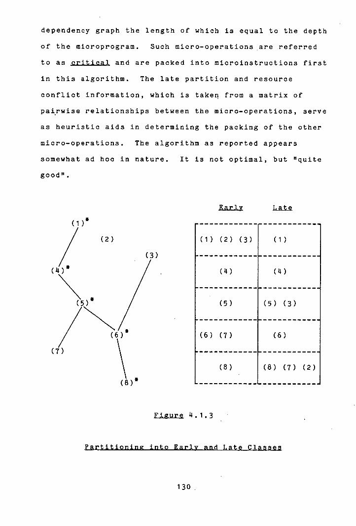
dependency graph the length of which is equal to the depth
of the microprogram. Such micro-operations .are referred
to as critical and are packed into microinstructions first
in this algorithm. The late partition and resource
conflict information, which is taken from a matrix of
pairwise relationships between the micro-operations, serve
as heuristic aids in determining the packing of the other
micro-operations. The algorithm as reported appears
somewhat ad hoc in nature. It is not optimal, but "quite
good".
(1) '
(2)
(3)
(5) *
(7)
(1) (2) (3) I (1)
a -----------
() 1 (14,)
(5) I (5) (3)
(6) (7) I (6)
(8) I (8) (7) (2)
Figure 14.1.3
130

It should be pointed out that in some instances the
matrix of pairwise resource contention relationships
between the micro-operations which this algorithm uses
cannot provide sufficient information to ensure correct
packing. For example, consider the three operations:
RA<-SPO (3)
SPO(4)<-SPO(4)+1
SPE (5) <-RB
as implemented on the Argonne AMP microcomputer [11].
Each of these micro-operations is pairwise independent of
each of the other two, since that machine has two general
purpose buses for transporting data to destination
registers, but the three cannot be implemented together -
as the resource contention matrix used in this packing
method would suggest they could.
(11) Dasuota and Tartar [19] propose an algorithm which
is a refinement of an earlier one presented by Dasgupta
and Jackson [20]. This takes a different approach to (2)
and (3) above in that it selects micro-operations
sequentially from the source microprogram without having
constructed a dependency graph. It assigns each
micro-operation to the earliest possible microinstruction
compatible with its relationships with those earlier
micro-operations which are already packed. It is a simple
131

algorithm which uses no heuristics whatsoever. In
particular, it takes no account of the dependants of each
micro-operation as it is packed and so, as shown by Yau et
al, cannot be optimal.
The two optimal algorithms of (1) and (2) above have
complexity exponential in N, where N is the number of
micro-operations in the straight line segment being
packed. The Dasgupta-Tartar method (D-T) has worst case
complexity proportional to N 2 , this being when each new
micro-operation added to the microprogram must be compared
for contention or dependency with each of the
micro-operations already packed. Its average complexity
is significantly less. The Tsuchiya-Gonzales method (T-G)
always requires in the order of N 2 comparisons to generate
the matrix of resource contention relationships between
the micro-operations and this dominates the complexity of
the actual packing algorithm. The Yau et al heuristic
algorithm (Y-S-T(h)) is considerably more complex than
either D-T or T-G, particularly in the worst case
situation. The average complexity appears to be of the
order of N 2 , although the details of the algorithm are not
described.
From the point of view of practical implementation s the
two optimal methods may be ignored and only D-T, T-G and
Y-S-T(h) need be considered further. D-T is more general
132
than the other two in that it expects poly-phase
implementations of microprograms (where the "time
validity" of each micro-operation is specified with the
micro-operation in the source microprogram) and therefore
handles with ease the situations of destination-source and
computed data dependencies identified in section 2.4. The
descriptions of the other two methods make no specific
mention of timing considerations. T-G assumes that two
micro-operations related by destination-source or computed
data dependencies may be packed together in the same
microinstruction word. Y-S-T(h), on the other hand, rules
that operations related by computed data dependency may be
packed together in the same word, but a micro-operation
dependent on a predecessor through destination-source
dependency must be packed in a subsequent microinstruction
word.
Mallett [40] compares these algorithms in further
detail and has implemented a version of all three. His
results indicate •that, in practice, there is no
significant difference between the algorithms with respect
to the actual number of microinstructions generated, which
is near optimal in each case. This bears out the
conclusions derived from an earlier version of MICHOMAP
concerning the packing of straight line segments of
micro-operations. Straight line segments usually are S
short, more than about six micro-operations in a single
segment being uncommon, and, where not, exhibit a high
133
degree of data dependency between the micro-operations,
thus restricting the scope for parallelism between them.
Each of the algorithms discussed above operates on
straight line segments of microprogram only (discounting
the minor extensions to the D-T algorithm noted in section
1.3). None can be imported directly for use in an
extended context such as required for packing the multiple
level canonical microprogram generated by ANALYSE.
MICROMAP implements a derivation of Yau et al's
heuristic algorithm. This choice has been influenced by
two factors. The first is the observation noted above
that a simple algorithm performs as well in practice as an
optimal one in packing straight line segments. The second
is that generating microinstructions sequentially from
micro-operations selected heuristically, as opposed to
selecting micro-operations sequentially and asigning each
to an appropriate microinstruction word, is better suited
to the goal of preserving the indivisibility and
inviolability of blocks of micro-operations demanded in
section 2.4. (It should be pointed out in passing that
the work on identifying potential parallelism between
micro-operations reported in chapter 2 could not possibly
proceed independently of consideration for the method of
packing the micro-operations. In fact, the policy
decisions to generate a dependency graph representation of
the microprogram as described in chapter 2 and to adopt a
134
packing algorithm in the style described below were
developed conjointly.)
Just as the Yau et al heuristic method is an order of
magnitude simplification on their optimal exhaustive
algorithm, so the algorithm which has been implemented in
MICROMAP is an order of magnitude simplification of the
former. It advances the pruning approach instituted by
Y-S-T(h) one step further to generate only a single
complete microinstruction word from the Data Available Set
at each step in the algorithm. Using the same weighting
factor that Y-S-T(h) uses to select a microinstruction out
of the set generated from the DAS, MICROMAP chooses
micro-operations out of the DAS for inclusion in the
current microinstruction word. Figure 4.1.4 illustrates
the process.
Figure 11.1.5 outlines the algorithm performed by
MICROMAP on the canonical microprogram representation
provided by ANALYSE and the format specification generated
by FORMAT. The basic algorithm for packing out of
straight line segments is described first before
illustrating how it may be extended to deal with the
non-primitive micro-operations of the canonical
microprogram that represent the modular control blocks of
the MDL description.
135
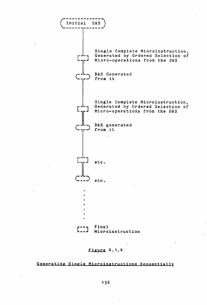
Initial DAS
Single Complete Microinstruction, Generated by Ordered Selection of
L 1 Micro-operations from the DAS
,.- - DAS Generated from it
Single Complete Microinstruction, r -i Generated by Ordered Selection of L J Micro-operations from the DAS
D DAS generated '- ---' from it
etc.
etc.
ri Final Microinstruction
Figure 11.1. 11
136
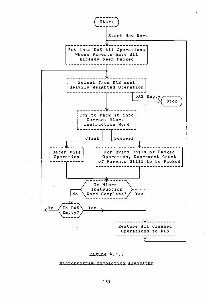
CEEED Start New Word
Put into DAS All Operations Whose Parents have All Already been Packed
[ Select from DAS most
L Heavily Weighted Operation I
I
rDAS Empty
>CstopD
---------- Try to Pack it into
Current Micro- instruction Word
Clash Success J__ -----------------------------
[Defer this For Every Child of Packed
I Operation I Operation, Decrement Count L-----of Parents Still to be Packed 1_____________
' Is Micro- instruction
No
(
Word Complete? Yes
No
Is DAS\es \ Empty? /
[Restore All Clashed
L Operations to DAS
Figure 4.1.5
137
The first action taken by MICROMAP on reading the
outputs of ANALYSE and FORMAT is to take note of the
parameters defined in the format specification. These
concern whether the implementation supports
micro-operations related by computed data or destination-
source dependency in the same microinstruction word or
whether it enforces strict succession. On the basis of
this, MICROMAP treats as either weak or strong dependants
respectively the lists associated with each
micro-operation of the children related to it by these
dependencies.
MICROMAP maintains a Data Available Set of those
micro-operations all of whose parents in the dependency
graph representation of the microprogram have been packed
already. Initially, the DAS will contain those
micro-operations with no parents in the graph. ANALYSE'S
construction of the dependency graph ensures that all
micro-operations in the DAS at any one time are mutually
independent, so they are all candidates for inclusion in
the current microinstruction word. The microinstruction
format, reflecting as it does the microprogram level
organization of the processor implementation, is the only
limitation on the degree of their coincident placement.
Each micro-operation in the dependency graph is
assigned a weight which is calculated on the basis of-the
number of descendants of that node in the graph, as
explained above. (This is performed by ANALYSE while it
138

assesses dependencies - the calculation of weights for the
micro-operations involves minimal overheads). This weight
is the determining factor in the selection of
micro-operations from the DAS: the most heavily weighted
micro-operation held in the DAS is picked out for packing
into the current microinstruction word. It 'is tested for
resource contention with the other micro-operations
already packed into the word (the mechanism for this will
be described in section 11.2) and, as a result of this
test, is either packed into the current microinstruction
or else deferred for possible inclusion in the next word.
Once a micro-operation has been assigned to a
microinstruction word, it remains there.
When a micro-operation is successfully packed into the
current microinstruction word, all micro-operations which
are related to it by weak dependency are checked to
ascertain whether they might be brought immediately into
the DAS for possible inclusion in the current word. This
would be the case for a particular child if the
micro-operation just packed was the last of its parents to
be packed and the child was related to any other parents
also packed in the current word by weak dependency only.
The children of a micro-operation related by strong
dependency are checked on the completion of the packing of
the microinstruction in which the parent is included.
The selection and attempted packing of micro-operations
continues in this fashion until either there are no longer
139

any micro-operations left in the DAS or it is detected
that the current microinstruction can accommodate no more
micro-operations. A new microinstruction is started when
this happens. The DAS is refilled from two sources: with
all those micro-operations which were unable to find a
place in the previous microinstruction through clashing
over resource contention with micro-operations already
packed; and with those micro-operations newly made
available by the last of their parents being packed in the
previous microinstruction. (Or at least when the
appearance is given of the last of their parents having
just been packed - the duration of each micro-operation,
as defined in the format specification in terms of
processor cycles, is allowed to elapse before the effect
of the packing of the micro-operation is transmitted to
its dependants.)
Microinstructions are generated sequentially in this
manner until all micro-operations in the source
microprogram have been packed.
Before describing the extensions to the algorithm which
allow it to handle the block structured canonical
microprogram output by ANALYSE, it is instructive to
compare its performance in the context of straight line
segments against the other compaction methods which
operate solely in this environment.
The worst case complexity of the algorithm is in the
140
order of N 2 , this being in the situation where all N
micro-operations are potentially concurrent, but all clash
with each other over resource contention. In practice,
the complexity is close to being linearly proportional to
N with deviation from linearity being dependent on the
number of clashes generated in attempted packings. Its
capability to cope with the different possibilities for
the implementation of destination-source and computed data
dependency relationships and its permitting of
user-specified synchronization renders the algorithm
implemented by MICROMAP •in practice at least as general as
the Dasgupta-Tartar method and more so than the Tsuchiya-
Gonzales or Yau et al heuristics methods.
In assessing the relative optimality of the algorithm,
it may be observed that the weighting factor used in
determining the micro-operation to be selected from the
DAS for inclusion in the current microinstruction serves
to promote a "well filled" DAS for future
microinstructions. This decreases the likelihood of
leaving any "holes" in the microinstruction words which
might have been filled by a micro-operation were it
available. The late partition class used by the Tsuchiya-
Gonzales algorithm as a heuristic aid for packing
non-critical micro-operations denotes the length of the
longest path from the micro-operation in question to a
terminal node in the dependency graph. This represents an
approximation to the same weighting factor, but it is not
141
as sensitive since it reflects only one dimension of the
dependency relationship. For instance, T-G would pack a
micro-operation with one child and one grandchild in
preference to another micro-operation with twelve children
but no grandchildren, despite the intuitively obvious fact
that in almost all situations the former is more likely to
leave "holes".
The Dasgupta-Tartar algorithm takes no account of the
dependants of micro-operations when determining whether
one should be placed before another. For two
micro-operations which are mutually independent but in
contention over resources, the relative ordering of their
placement is determined solely by their relative ordering
in the source microprogram; in other words, totally
arbitrarily, affording ample opportunity for loss of
optimality.
The Yau et al heuristic algorithm (Y-S-T(h)) is, a
priori, more likely to produce an optimal packing than
MICROMAP. Each microinstruction which MICROMAP generates
from a given DAS would also be generated from the same DAS
by Y-S-T(h) which has the opportunity of later rejecting
that one and selecting another in preference to it.
Y-S-T(h) will choose a different microinstruction to that
generated by MICROMAP from the same DAS only in the case
where the choice of the most heavily weighted operation,
as selected by the latter, precludes the packing of two or
more subsequent selections whose combined weights are
142
greater than that of the first choice. But empirical
evidence reveals this to be an uncommon situation.
Resource contention between micro-operations implemented
in a horizontally structured microinstruction format
usually is a transitive relationship. For three
potentially concurrent micro-operations, A, B and C, when
A contends with both B and C it is rare for B and C not to
contend. This arises from the fact that a set of
micro-operations often may be partitioned into several
disjoint classes, each associated with a distinct set of
fields in the microinstruction format. No resource
contention is exhibited between micro-operations belonging
to different classes, but there is universal contention
among those micro-operations belonging to the same class.
The only common situation where this rule does not
apply is with a so-called "dippnp1" microinstruction
format [n]. Here the microinstruction may assume one of
several mutually exclusive modes (determined by a Mode
Interpretation type field - see section 3.2) with
horizontal parallelism within each mode. It is then
possible that the selection of the most heavily weighted
micro-operation from the DAS by MICROMAP may define a
choice of mode incompatible with that required by the rest
of the micro-operations in the DAS, thus giving rise to a
poorly filled microinstruction word. Two points about
this situation should be noted, however. The first is
that the choice by Y-S-T(h) of a microinstruction in a
143
different mode from, and with a greater total weight than
that generated by MICROtMAP will prove superior only if it
furnishes to the DAS more micro-operations compatible with
that one initially selected by MICROMAP - otherwise it is
only deferring the necessary generation of that
"unpopular" microinstruction. This particular occurrence
is uncomon precisely because of the categorization of
micro-operations observed above: micro-operations tend to
be dependent on other micro-operations in their own class.
It is probable that in the case under consideration
micro-operations furnished to the DAS will be associated
with the same mode as their parent and the singularity of
the exceptional one will be preserved. The second point
to be noted simply is that Y-S-T(h) is not optimal. There
is no guarantee that a microinstruction which it rejects
may not turn out to lead to a better packing than the one
which it selects. It may therefore be concluded that the
expected difference in optimizing capability between the
algorithm implemented by MICROMAP and Y-S-T(h) is slight -
not enough to justify the increased complexity of the
latter.
Notwithstanding this analysis of the expected
performance of the different packing algorithms, the
observation recorded above should be recollected: in
practice the properties of micro-operations within
straight line segments leave little scope for gainful
144
optimization. Straight line segments tend to be short
and, where not, tend to exhibit a high degree of data
dependency. It is clear that optimization of the packing
of micro-operations from straight line segments into
microinstruction words is not the most critical factor in
determining the efficacy of a microprogram implementation.
Simplicity and generality of the packing algorithm and
congeniality of the design medium then assume enhanced
significance. This evidence reinforces the arguments
advocating an integrated approach to the problem of
microprogram design which provides increased scope for
optimization at the same time as expediting the task of
actually designing the system to be implemented.
The rest of this section describes how MICROMAP handles
the packing of the non-primitive micro-operations
generated by ANALYSE to represent the modular control
blocks of the MDL language. The algorithm is outlined in
figure 4.1.6.
145

CartD
[ Select Micro-operation from DAS at Current Level
[
•
Descend 1 - - -------
Attempt to Pack
One Level] in to Current Word
All Micro-operation s \ Put Components K at Current Level of Block into \ have been Packed? WAITING List I "- ------------------
at New Level Yes No
Ascend One Level
I -------
eed to Start New Word __C_N - -- -_ -_ -_ -_ -_ -_ -- - - - - - - - - - -_ -_ -_ ~__ Yes No
Set up DAS with Clashed Micro-operations Plus Ones Newly Available
Figure 'Ll.b
146
The basic structure of the algorithm remains the same
as described above for the compaction of straight line
segments. A separate Data Available Set and "WAITING"
list is maintained for each level of micro-operation in
the canonical microprogram. The DAS for each level is
employed in the manner as described before: containing
those micro-operations at that level whose parents (if
any) have already been packed. The WAITING list is a list
of the micro-operations at that level which have not yet
been made available for packing. MICROMAP executes
recursively in implementing the algorithm. Conceptually
it packs the single micro-operation which exists at level
zero. This is a block type micro-operation constituting
the complete microprogram. All of the components of the
block are brought into the WAITING list for the level one
lower than the level of the block. When a micro-operation
selected from the DAS at any level is found to be of block
type, the plane of operation of the algorithm descends one
level and all of the block's component micro-operations
are brought into the WAITING list at the lower level.
Packing then proceeds on the micro-operations at that
level. Only when the WAITING list and the DAS at the
current level have been exhausted, ie. all of the
component micro-operations of the block have been packed,
is the level of operation ascended. When this happens -
when all of its components have been packed - the block
type micro-operation itself is considered packed and,
147
where appropriate, its children may be made available for
packing (once the "duration" of each of its components has
elapsed, that is).
This disciplined, hierarchical approach to the packing
of micro-operations follows and preserves the structured
separation of blocks imposed by ANALYSE through
enforcement of the "Multi Level Dependency Rule" (see
section 2.4). This ensures that all components of a block
are packed together and that the pre-defined ordering
between micro-operations at all levels is observed in
implementation.
One further difference between the basic and the
extended algorithms for packing concerns the selection of
micro-operations from the Data Available Set. Primitive
micro-operations are ascribed the same weighting factor
and are selected on this basis, but some policy must be
formulated for deciding between a primitive and a block
type micro-operation in the same DAS. It would be
perfectly possible to ascribe a weight to non-primitive
micro-operations on exactly the same basis as for
primitive micro-operations and to select between them
accordingly, but consideration reveals this strategy not
to be reasonable. Primitive micro-operations are selected
according to weight in an attempt to furnish more
micro-operations into the DAS. The purpose of this
strategy is to afford increased opportunity for the joint
packing of mutually compatible micro-operations in later
148
microinstruction words. But block type micro-operations
are inviolable and so, in general, cannot be packed
jointly with any primitive micro-operations which are not
part of the block. Consider the case of a Loop block type
micro-operation and a primitive micro-operation being the
only two members of a DAS. The components Of the loop
must be packed in separate microinstructions from all
other micro-operations, no matter what else is available
for packing at the same time; whereas the primitive
micro-operation could possibly be packed beside other
primitive micro-operations were there any available. It
therefore makes sense, irrespective of the weight of the
primitive micro-operation, to pack the loop before it in
the hope of furnishing further primitive micro-operations
(the children of the loop) for possible packing with that
one. That is, packing primitive micro-operations before
block type ones will not prevent any "holes" in subsequent
microinstruction words, but vice versa may do.
Inevitably however, this rule is not quite universally
true. Loop blocks have an implicit label associated with
the head of the block and a branch micro-operation at the
tail and so must be packed totally separately from all
micro-operations which are not included, within the loop.
Conditional blocks on the other hand, do not have a label
associated with the head of the block. They have a label
at the tail and a branch as the first micro-operation of
the block. There is no reason why that branch
149

micro-operation should not coexist in the same
microinstruction word as primitive micro-operations which
are not themselves part of the block. (Recall in section
2.5 the observation that data dependency of all but the
initial branch micro-operation at the head of the block on
any preceding micro-operations outside of the block
resulted in the block itself being marked as weakly
dependent on the appropriate parent). it is necessary
therefore to formulate a further policy to be enacted when
a conditional block micro-operation and primitive
micro-operations are available for selection from the same
DAS. No matter what weight is the primitive
micro-operation, it must be remembered that only the first
micro-operation of the block may coexist with primitive
micro-operations outside the block, and so there is
nothing to be gained from packing a primitive
micro-operation at the expense of the conditional block.
The conditional block should be packed - thus perhaps
releasing primitive type children - and as many as
possible of the currently available primitive
micro-operations should be packed along with the initial
branch micro-operation of the block.
This is the policy which MICROMAP implements, but doing
so causes irregularities in the execution of the algorithm
described in figure 4.1.6. Normally, whenever a block
type micro-operation is selected, one level of operation
is descended immediately and all components of the block
150
are packed before further higher level micro-operations
are selected. When a conditional block type
micro-operation is selected, however, after packing the
first of its components - the branch, on which all the
rest of its components are dependent - the algorithm
temporarily returns to the level of the block itself to
try to pack in the same microinstruction any available
primitive micro-operations at that level.
This exemplifies the efforts that have been made in
MICROMAP to optimize packing within the constraints of the
minimal complexity of the algorithm.
Figure 4.1.7 summarizes the policy for selection of
micro-operations from the DAS when it may contain
primitive and non-primitive types. Note that block type
micro-operations which have a label explicitly or
implicitly associated with the head of the block are
selected only at the initiation of a new microinstruction
word (and, similarly, a new microinstruction word is
always started after completion of packing of a block
succeeded by a label - Loop, Ifblock or Elseblock).
151
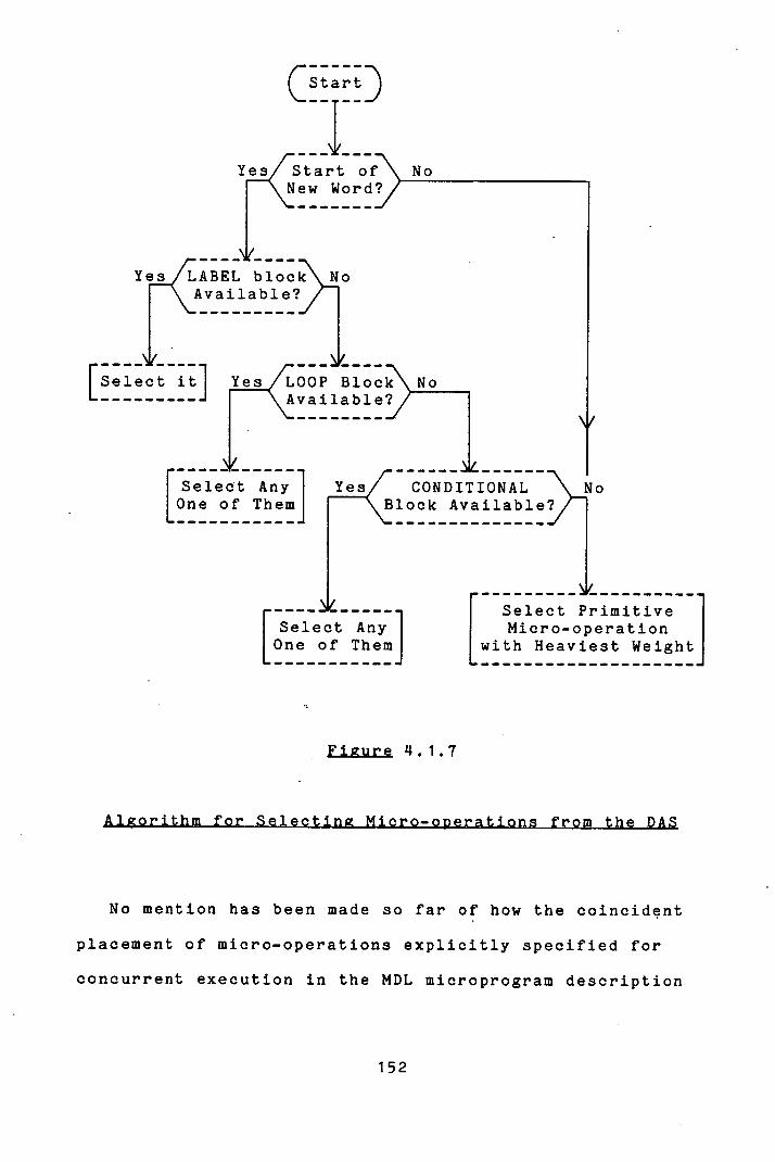
C Start D
Y!,/Start of No New Word 1,/
Ye,/ABEL bloc"\jo Available?
[Select itJf/ LOOP Block .a.......j Avai able?
r Select Any 1 CONDITIONALNo
L °' of Them] 'B1ock Avai1ab1e/
- I Pm1r
Select Any One of Them
Figure 4.1.7
No mention has been made so far of how the coincident
placement of micro-operations explicitly specified for
concurrent execution in the MDL microprogram description
I Micro-operation
L with Heaviest Weight
152

is accomplished. Such micro-operations are included by
ANALYSE in a single block type micro-operation (of type
Syncblock) the normal treatment of which is sufficient to
preserve their indivisibility when packed. But more than
indivisibility must be guaranteed: they must be
indivisible within a single microinstruction word.
Therefore, when a Syncblock type micro-operation is
selected from the DAS - it is treated exactly as a
primitive micro-operation for this purpose - MICROMAP must
pack all the component micro-operations of the block into
the current microinstruction, or else pack none at all.
This requires the use of a duplicate record of the current
microinstruction word. Into this are packed one by one
the component micro-operations of the Syncblock until
either they are all packed, in which case the Syricblock is
deemed packed into the current word., or else one of the
component micro-operations clashes with a micro-operation
already packed into the word, in which case the whole
Syncblook is deferred for attempted packing into a
subsequent microinstruction. (If one of the component
micro-operations of the Syncblock clashes with another
component of the same block then an error is signalled,
since the designer's specification is unachievable).
This concludes the description of how MICROMAP pacIs a
block structured representation of a microprogram into
microinstruction words.
153
Defined Microinstruction Format
This section considers the question of how to generate
the appropriate micro-orders in the specified
microinstruction format which will realize the behaviour
defined by the given register transfer level
micro-operations.
A micro-operation is a primitive action at the
processor level which may be realized by the composition
of primitive actions at the microprogram, level. In MDS,
an MFM format description details the micro-orders which
may be evoked from microinstructions in the chosen format.
It also defines the structural relationship between the
micro-orders, governed by the field organization of the
format. This determines which micro-orders may be evoked
from the same microinstruction word. The problem
investigated here is, given a micro-operation and a
microinstruction format, how to recognize those
micro-orders that may all be evoked from the same
microinstruction whose combined effect is to realize the
action of the micro-operation.
In the preceding two chapters, much emphasis was laid
on the fact that neither the micro-operations described in
MDL nor the micro-orders specified in MFM connote any
particular semantic interpretation in MDS. How then may
154
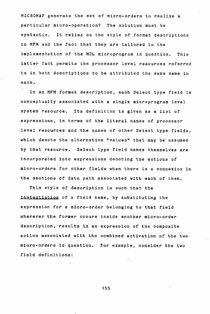
MICROMAP generate the set of micro-orders to realize a
particular micro-operation? The solution must be
syntactic. It relies on the style of format descriptions
in MFM and the fact that they are tailored to the
implementation of the MDL microprogram in question. This
latter fact permits the processor level resources referred
-to in both descriptions to be attributed the same name in
each.
In an MFM format description, each Select type field is
conceptually associated with a single microprogram level
system resource. Its definition is given as a list of
expressions, in terms of the literal names of processor
level resources and the names of other Select type fields,
which denote the alternative "values" that may be assumed
by that resource. Select type field names themselves are
incorporated into expressions denoting the actions of
micro-orders for other fields when there is a connexion in
the sections of data path associated with each of them.
This style of description is such that the
instantiation of a field name, by substituting the
expression for a micro-order belonging to that field
wherever the former occurs Inside another micro-order
description, results in an expression of the composite
action associated with the combined activation of the two
micro-orders In question. For example, consider the two
field definitions:
155
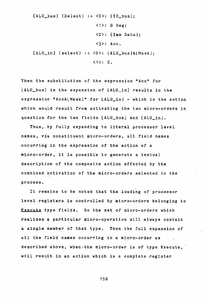
[ALU_bus] (Select) := <0>: 110_bus];
<1>: B Reg;
<2>: [1mm Data];
<3>: Ace.
[ALU_in] (select) := <0>: LALU_busj&LMaskJ;
<1>: 0.
Then the substitution of the expression "Ace" for
LALU_bus] in the expansion of LALU_in] results in the
expression "Acc&LMask]" for LALU_ini - which is the action
which would result from activating the two micro-orders in
question for the two fields [ALU_busi and [ALU_ini.
Thus, by fully expanding to literal processor level
names, via constituent micro-orders, all field names
occurring in the expression of the action of a
micro-order, it is possible to generate a textual
description of the composite action effected by the
combined activation of the micro-orders selected in the
process.
It remains to be noted that the loading of processor
level registers is controlled by micro-orders belonging to
Execute type fields. So the set of micro-orders which
realizes a particular micro-operation will always contain
a single member of that type. Then the full expansion of
all the field names occurring in a micro-order as
described above, when-the micro-order is of type Execute,
will result in an action which is a complete register
156
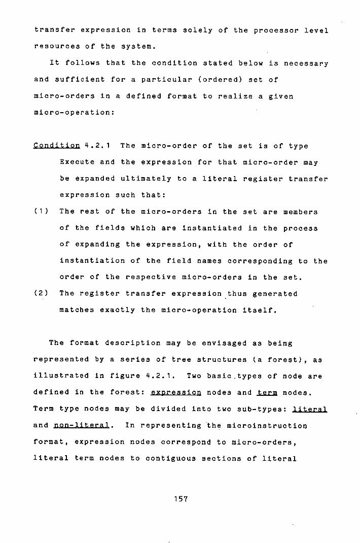
transfer expression in terms solely of the processor level
resources of the system.
It follows that the condition stated below is necessary
and sufficient for a particular (ordered) set of
micro-orders in a defined format to realize a given
micro-operation:
Condition 4.2.1 The micro-order of the set is of type
Execute and the expression for that micro-order may
be expanded ultimately to a literal register transfer
expression such that:
The rest of the micro-orders in the set are members
of the fields which are instantiated in the process
of expanding the expression, with the order of
instantiation of the field names corresponding to the
order of the respective micro-orders in the set.
The register transfer expression thus generated
matches exactly the micro-operation itself.
The format description may be envisaged as being
represented by a series of tree structures (a forest), as
illustrated in figure 4.2.1. Two basic.types of node are
defined in the forest: expression nodes and term nodes.
Term type nodes may be divided into two sub-types: literal
and non-literal. In representing the microinstruction
format, expression nodes correspond to micro-orders,
literal term nodes to contiguous sections of literal
157

characters in the micro-order description, and non-literal
term nodes to field names. The tree structure
representation of the microinstruction consists of
alternate layers of expression and term type nodes. The
children of each non-literal term are expression nodes
corresponding to all the micro-orders belonging to that
field. The children for each expression node are are
literal and non-literal term nodes corresponding
respectively to the strings of symbols and field names
comprising the description of the micro-order, in the
order in which they occur in the description. Literal
term nodes have no children. At the root of each of the
trees in the forest is a non-literal term node
corresponding to one of the Execute type fields in the
format description. There are as many trees in the forest
as Execute type fields in the format description. The
leaves of each tree are all literal term nodes. (There is
nothing to prevent the format specification from
containing recursive field definitions, a physical
impossibility which would be modelled as a tree of
infinite depth, but this is detected by MICROMAP as will
be described below.)
158
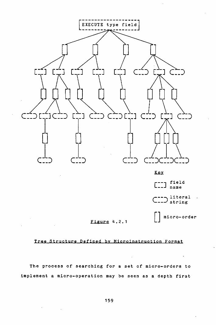
c:: c::
c::c::c::
[EXECUTE type field]
c4::~c:::Jp
r---i field L...._J name
,.---- literal string
Figure 4L2.1
[]
micro-order
The process of searching for a set of micro-orders to
implement a micro -operation may be seen as a depth first
159
"AND/OR" search L4 111 through the tree structure (selecting
one child from each field node and all children of each
micro-order node) for a set of terminal nodes the
expressions for which may be concatenated to synthesize
the expression of the micro-operation.
This model serves as a framework for the 'approach
adopted by MICROMAP for generating an implementation of a
micro-operation in terms, of the micro-orders of the
defined format. Using the technique of "recursive
descent" 137, 161, it performs a depth first search
through the trees defined by the data structure
representing the microinstruction format passed to it by
FORMAT.
The algorithm, as outlined in figure 4.2.2, basically
consists of two mutually recursive modules: PARSE FIELD
and PARSE ENTRY. PARSE FIELD attempts to match each of
the micro-orders belonging to the field in question with
an initial substring of the micro-operation presented to
it. It performs this by calling PARSE ENTRY on behalf of
each micro-order. If any of the micro-orders are matched
by PARSE ENTRY with an initial substring of the
micro-operation then PARSE FIELD is deemed successful and
returns to its calling point with that final substring of
the micro-operation which has still to be matched with the
micro-orders of the format. This corresponds to the best
of the possibly multiple matchings recorded by its
micro-orders. If no such matching is recorded, then PARSE
160
FIELD returns with failure.
PARSE ENTRY attempts to match the expression for the
micro-order on whose behalf it is called, which consists
of a mixed string of literal characters and field names,
with an initial substring of the micro-operation presented
to it. It first checks for compatibility between the
literal terms of the micro-order and the micro-operation.
If matching is seen to be impossible it immediately
returns with failure. Otherwise, it strips the
micro-operation of the initial substring which has been
matched by the literals of the micro-order preceding the
first field name, and calls PARSE FIELD for the
appropriate field, passing the reduced micro-operation to
it. If PARSE FIELD returns with success, then this
matching continues. (Hence the requirement for matching
micro-orders with only an initial string of the
micro-operation). It continues until the whole
micro-order has been matched with an initial substring of
the micro-operation. If PARSE FIELD fails, then PARSE
ENTRY immediately returns with failure.
161
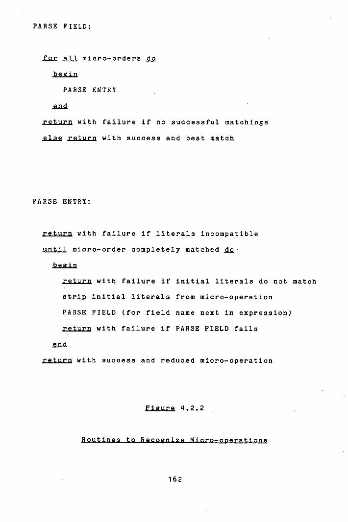
PARSE FIELD:
for all micro-orders
PARSE ENTRY
return with failure if no successful matchings
else return with success and best match
PARSE ENTRY:
return with failure if literals incompatible
until micro-order completely matched
return with failure if initial literals do not match
strip initial literals from micro-operation
PARSE FIELD (for field name next in expression)
return with failure if PARSE FIELD fails
return with success and reduced micro-operation
Figure 4.2.2
162
During this search through the tree structures of the
microinstruction format, MICROMAP is able to detect any
field which has been defined recursively in terms of
itself. If it does detect this, a warning message is
issued and the search of that branch of the tree is
abandoned.
The algorithm uses each of the Execute type fields of
the format as the root node of successive search trees in
this manner (the micro-orders of these fields must match
the whole micro-operation). The path down the tree which
results In a successful matching of a micro-operation -
the recognition path - identifies the fields, and the
micro-orders belonging to thOse fields, which are involved
in the implementation of that micro-operation, as
illustrated in figure 4.2.3.
By binding the value associated with each of these
micro-orders to the field to which it belongs, it is
possible to begin to generate the actual microcode
required to realize each micro-operation. (MICROMAP
maintains a bit map of the microinstruction word to which
it binds those field values as they are generated.) To do
this completely requires more account to be taken of the
structural relationships between the fields. If a Mode
Interpretation type field governs the structure of thç
microinstruction format, then the involvement of
micro-orders belonging to particular fields might carry
163

further implications about the format structure and hence
about the value that the Mode Interpretation field must
take in order to "authorize" that structure. Similar
factors must be considered when a micro-order involved in
realizing a micro-operation is associated with a
Conjunction construct. In this case a value has to be
bound to more than one field to evoke that micro-order.
The data structure representing the microinstruction
format which is presented by FORMAT to MICROMAP contains
all the structural information about the dependencies of
certain fields on the values of other fields. So MICROMAP
is able to bind the appropriate values to all the affected
fields in such situations, thus reflecting completely the
ramifications of effecting micro-operations with the
particular set of micro-orders which are supported in the
specified microinstruction format.
164
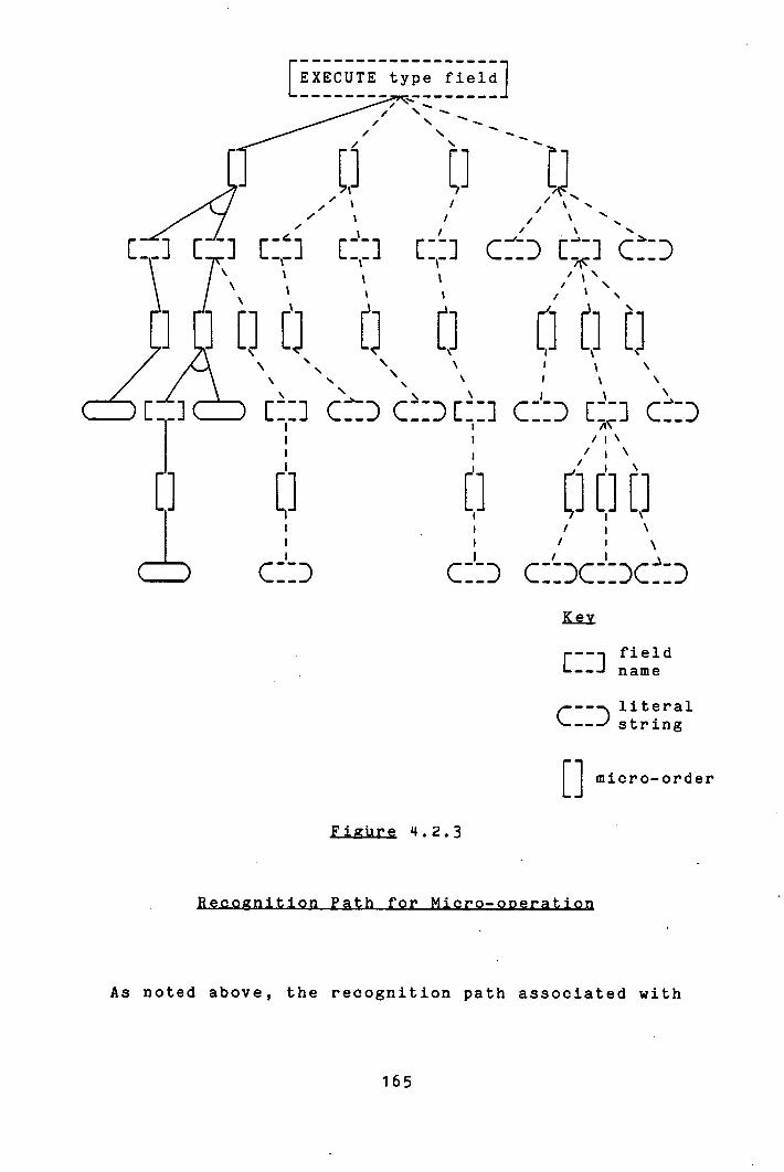
EXECUTE type field
' '-c ----
:
/ /
,
C cj c:
U
1 -1 - 1 c:': r - J cE -
/
cJ C] ] t] I / i
c5 c:':D c3c±x: RM
field name
C literal -' string
11 micro-order Figure 4.2.3
As noted above, the recognition path associated with
165
the successful matching of a micro-operation with the
micro-orders of a particular format identifies the values
which should be bound to the relevant fields in order to
select those micro-orders. The physical counterpart to
this is that it identifies the particular usage, by the
micro-operation in question, of the microprogram level
system resource controlled by each field so affected. Any
other micro-operation which required a different
utilization of one such resource would cause a different
value to be bound to the appropriate field.
This observation prompts the insight that, by comparing
the recognition paths for two micro-operations in a
particular microinstruction format, whether or not they
will clash over resource contention is made immediately
clear. That is, if having packed one micro-operation into
a microinstruction word, MICROMAP then attempts to pack
another, then comparison of the value caused to be bound
to each field by the second micro-operation with that
value already bound to it by'the first facilitates the
immediate detection of resource contention. The attempt
to pack the second micro-operation may then be aborted.
Contention for physical system resources is not the
only barrier to the joint inclusion of logically
independent micro-operations in the same microinstruction
word. Their implementations might generate different S and
incompatible format structures in a multiple format
microinstruction, ie. format contention. If this is the
case, then its detection by MICROMAP is performed in a
manner absolutely consistent with the algorithm's
detection of contention for physical resources. Format
contention is manifest in MICROMAP by each micro-operation
involved attempting to cause a different value to be bound
to a Mode Interpretation field.
In this way, MICROMAP is able to check for resource
contention only where necessary: between micro-operations
which are under consideration for packing into the same
microinstruction word. Further, it does this extremely
efficiently: essentially receiving the information "for
nothing" from the micro-operation recognition algorithm as
the latter builds up a bit map for the microinstruction
being generated.
Note that the detection of resource contention by
MICROMAP, as described above, does not prevent any
combination of micro-orders that the microinstruction
format permits. That is, if the microinstruction format
permits the designer to generate illogical combinations of
control signals, then so will MICROMAP. MICROMAP also
provides the designer with the capability to prevent any
combination of control signals that is not desirable.
167
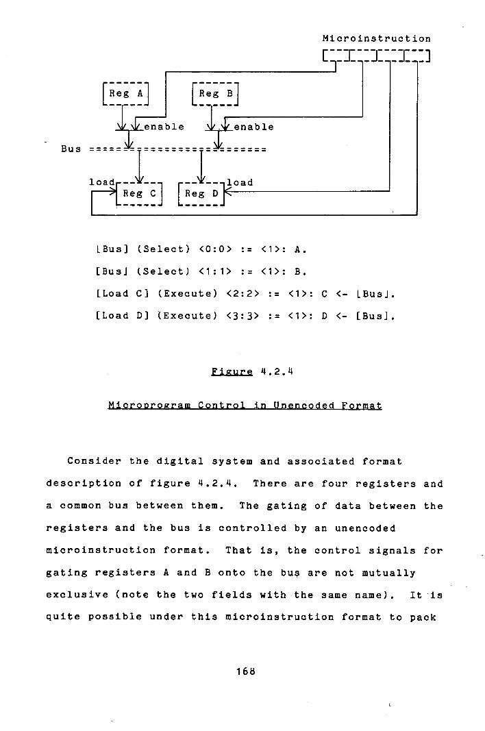
Microinstruction
- Bus
LBus] (Select) <0:0> := <1>: A.
[Bus] (Select) <1:1> := <1>: B.
[Load C] (Execute) <2:2> := <1>: C <- LBusi.
[Load Di (Execute) <3:3> := <1>: D <- [Bus].
Figure 4.2.4
Consider the digital system and associated format
description of figure 4.2.4. There are four registers and
a common bus between them. The gating of data between the
registers and the bus is controlled by an unencoded
microinstruction format. That is, the control signals for
gating registers A and B onto the bus are not mutually
exclusive (note the two fields with the same name). It is
quite possible under this microinstruction format to pack
168
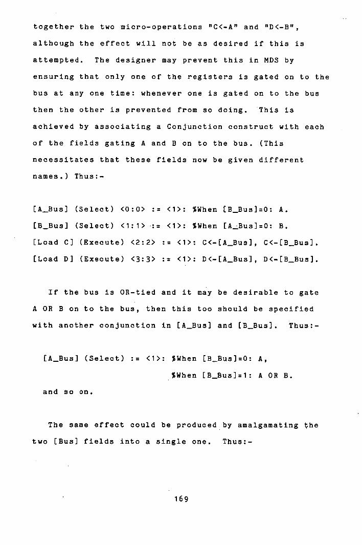
together the two micro-operations "C<-A" and "D<-B",
although the effect will not be as desired if this is
attempted. The designer may prevent this in MDS by
ensuring that only one of the registers is gated on to the
bus at any one time: whenever one is gated on to the bus
then the other is prevented from so doing. This is
achieved by associating a Conjunction construct with each
of the fields gating A and B on to the bus. (This
necessitates that these fields now be given different
names.) Thus:-
[A_Bus] (Select) <0:0> := <1>: %When [B_Bus]=O:
[B_Bus] (Select) <1:1>-:= <1>: %When [A_Bus]=O:
[Load C] (Execute) <2:2> :: <1>: C<-[A—Bus], C<-[B—Bus].
[Load D] (Execute) <3:3> : <1>: D<-[A—Bus], D<-[B_Bus].
If the bus is OR-tied and it may be desirable to gate
A OR B on to the bus, then this too should be specified
with another conjunction in [A_Bus] and [B_Bus]. Thus:-
[A_Bus] (Select) := <1>: %When EB_Bus]:O: A,
%When [B_Bus]:1: A OR B.
and so on.
The same effect could be produced by amalgamating the
two [Bus] fields into a single one. Thus:-
169
[Bus] (Select) <0:1> := <1>: B;
<2>: A;
<3>: A OR B,
B OR A.
Thus MDS reflects exactly the properties of the control
organization modelled in MFM. If the microinstruction
format prevents resource contention (as normally is the
case), then it will be prevented by MICROMAP. But if the
chosen format leaves it up to the designer to prevent
undesirable combinations of micro-orders, then the
designer is given this responsibility in MDS also.
The seven field types introduced in chapter 3 included
the Register type field. This, it was stated, controls
access to registers named at the microprogram level, and
requires the bisection of any micro-operations implemented
thereby.
MICROMAP must be capable of dealing with two different
aspects of the use of this type of field. First, it must
be capable of recognizing when a micro-operation, as
specified in the MDL description, must be split into two
parts at such a register. Second, it must be able to deal
with the two resultant micro-operations when they are
rephrased in terms of the microprogram level register.
name.
The Register type field in the first instance is
170

treated exactly as a Select type field which is defined in
terms of possible sources of data that may be loaded into
the register. The checks which MICROMAP makes for field
recursion and resource contention have to be suppressed in
this case for the recognition of the second half of the
micro-operation, since this will be implemented in a
different microinstruction from the first. On recognition
of a micro-operation which must be split, MICROMAP prints
out a message declaring how the micro-operation should be
split to be implemented as two separate actions.
This is left to the designer to perform. The
microprogram may then be resubmitted containing
micro-operations which refer to the microprogram level
register as if it was a processor level resource. This
time MICROMAP treats the Register type field as an Execute
type for the loading of the register and must recognize
the Register field name when the register is used as a
source of data in the micro-operation.
It was originally hoped that the separation of the two
halves of the micro-operation and their packing could all
be performed completely automatically when this
circumstance arose. However, the difficulty of this task
(which involves the generation of a new micro-operation
and its insertion into the microprogram) was seen not to
be justifiable. This is because degradation in the
optimality of packing as a result would be very likely.
This is most easily illustrated by example.
171
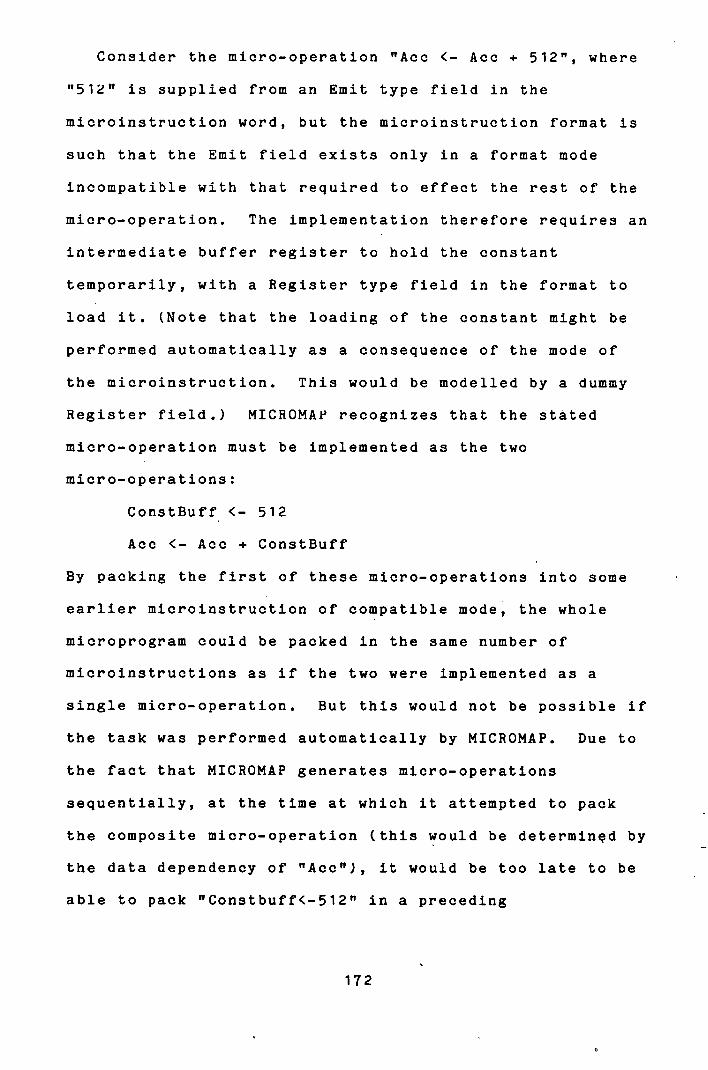
Consider the micro-operation "Ace <- Ace + 512", where
"512" is supplied from an Emit type field in the
microinstruction word, but the microinstruction format is
such that the Emit field exists only in a format mode
incompatible with that required to effect the rest of the
micro-operation. The implementation therefore requires an
intermediate buffer register to hold the constant
temporarily, with a Register type field in the format to
load it. (Note that the loading of the constant might be
performed automatically as a consequence of the mode of
the microinstruction. This would be modelled by a dummy
Register field.) MICROMAP recognizes that the stated
micro-operation must be implemented as the two
micro-operations:
ConstBuff <- 512
Ace <- Ace + ConstBuff
By packing the first of these micro-operations into some
earlier microinstruction of compatible mode, the whole
microprogram could be packed in the same number of
microinstructions as if the two were implemented as a
single micro-operation. But this would not be possible if
the task was performed automatically by MICROMAP. Due to
the fact that MICROMAP generates micro-operations
sequentially, at the time at which it attempted to pack
the composite micro-operation (this would be determined by
the data dependency of "Ace"), it would be too late to be
able to pack "Constbuff<-512" in a preceding
172

microinstruction.
It is felt that the facility provided, the detection
and notification of micro-operations which should be
implemented over more than one microinstruction,
represents a useful and realistic assistance to the
designer which is of greater practical value than vain
attempts to perform every function automatically. Again,
this approach adheres to the philosophy of providing
maximum assistance to the designer while taking due regard
of his innate capability to perform some functions more
easily, or better, than a totally automated system.
Implicit in the preceding discussions has been an
assumption: that to each micro-operation being implemented
in the specified microinstruction format there will
correspond a unique set of micro-orders, defining a unique
microinstruction configuration, which will realize that
micro-operation. In many circumstances this Is an invalid
assumption. It is as a consequence of the encoding of
functions in some processor organizations (eg. the AMD
2901A bit slice microprocessor lii) and it is. the
deliberate design philosophy of others (eg. the Xerox
Maxc2 processor L261 or the Argonne AMP microcomputer
[111) that some micro-operations may be implemented by
more than one microinstruction configuration. These two
situations are manifest respectively as a particular set
of micro-orders being supported by more than one
173
configuration of the various fields involved, and more
than one set of micro-orders being capable of realizing
the given micro-operation. This latter situation reflects
the duplicity of resources that sometimes may be provided
in a processor implementation.
In such a situation, it is quite feasible that some
other micro-operation, logically independent of one
exhibiting this property, may clash over resource
contention with one or several of the possible
microinstruction configurations for that micro-operation,
but may be capable of being Implemented in conjunction
with one other of its possible configurations.
This is perfectly exemplified by the AMD 2901A
microprocessor chip. It has sixteen Internal registers
and a single output port and Its function encodings
require that the operands for arithmetic and logical
operations be selected in pairs. Sometimes one operand of
the pair is zero. As a result, there are seventy one
different configurations for the relevant microinstruction
fields which will cause the contents of one of the
Internal registers to be passed to the output port. There
are also four different configurations to increment by one
one of the sixteen internal registers. But there is only
one single configuration for the relevant fields which
will cause both of these operations to be effected from
the same microinstruction word.
This demonstrates the necessity for MICROMAP to
174
generate all possible sets of micro-orders and associated
bindings of values to fields which may realize each
micro-operation implemented in the specified
microinstruction format. Then, when attempting to pack
further micro-operations into a microinstruction word
which already has a micro-operation packed into it, those
configurations for the original micro-operation with which
the subsequent micro-operations are in contention may be
discarded. Only those resultant composite configurations
which are capable of implementing the micro-operations in
conjunction need be retained. (Note that it is only when a
subsequent micro-operation conflicts with all possible
configurations for previously packed micro-operations that
it is deemed to have "Clashed" and is deferred for
possible inclusion in a later microinstruction, as
described previously.)
There remains two further points to be observed
regarding the realization of micro-operations by the
micro-orders of a particular microinstruction format.
MICROMAP may have generated several possible
configurations for a microinstruction to implement the
micro-operations packed into it. Which should it choose
to generate as output? And what about the fields to which
no micro-orders have been explicitly bound - what value
should they take? These two questions are related, and
the answer to them both is to be found in the default
175

values ascribed to fields in the MFM format specification,
as described in section 3.2. To all fields not involved
in the realization of micro-operations MICROMAP binds the
default value for that field. Then the microinstruction
configuration selected for inclusion in the microprogram
is that one with the highest number of fields assuming
their default values. MICROMAP outputs the actual binary
bit pattern for the microinstructions generated to effect
the behaviour defined by the micro-operations packed into
them, it also produces a listing of these
micro-operations and the values bound to the fields in
realizing them. An example of this is given in Appendix
1(d)
176
C iN p
The microinstructions generated by MICROMAP are
intended to implement the behaviour defined by an MDL
microprogram description. That behaviour depends on an
assumed ordering of execution of the constituent
micro-operations which is based on the implicit sequential
ordering of executive micro-operations together with the
properties of altering the sequential order of execution
identified with control micro-operations. Associated with
each branch control statement is a well defined set of
destination statements to which control should be
transferred after the execution of the branch
micro-operation.
This ordering of the flow of control was taken into
account by ANALYSE in partitioning the microprogram, but
so far no mention has been made of it with respect to the
microinstructions generated, which are intended to follow
the same control flow.
Branch type micro-operations are recognized and matched
to micro-orders by MICROMAP just like all other
micro-operations, except for the field which determines
from which control store address the next microinstruction
should be fetched. MICROMAP fills this with an index into
a label table - to the position associated with the label
which is the destination of the branch (this has been
identified by ANALYSE). But, in order to enable the
177
generation of complete microcode, MICHOMAP must associate
a destination address with each branch micro-operation.
Two types of branch destination (label) occur in an MDL
microprogram: explicit and implicit. Explicit labels are
recognized by ANALYSE which associates with each a block
type micro-operation containing all of the
micro-operations succeeding that label in the
microprogram. This relieves the label from being
identified with one particular micro-operation and allows
the micro-operations to be packed in the most suitable
order. Then the address associated with that label in the
microprogram generated simply is the first
microinstruction into which the block type micro-operation
corresponding to the label is packed. This is entered in
the appropriate label table position.
It was noted in section 2.5 that each conditional block
and loop has associated with it two positions to which
jumps are made, as illustrated again in figure 14.3.1.
178
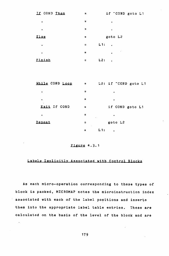
COND Then if COND goto Li
Else goto L2
Li:
Finish = L2:
While COND Loop =
Exit If COND =
Reoeat =
L2: if COND goto Li
if COND goto Li
goto L2
Li:
Figure 4.3.1
As each micro-operation corresponding to these types of
block is packed, t4ICROMAP notes the microinstruction index
associated with each of the label positions and inserts
them into the appropriate label table entries. These are
calculated on the basis of the level of the block and are
179
the entries to which the corresponding branch
micro-operations are made to refer to.
At this point, a simple optimization performed by
MICROMAP might be pointed out. If a microinstruction is
generated which contains only an unconditional branch
micro-operation, then any microinstruction which causes a
branch to that one is redirected to the destination of the
unconditional branch. This situation commonly arises when
a conditional block or a loop is the final micro-operation
inside a loop. When this redirection of branch
destinations is effected, it then becomes true that the
only micro-operations whose execution will immediately
precede the unconditional branch are those packed in the
immediately preceding microinstruction. So that the
unconditional branch need not occupy a separate
microinstruction: it is no longer the destination of other
branch operations. It may be packed into the preceding
microinstruction if compatibility considerations permit.
But MICROt4AP is not capable of performing this type of
optimization. It is not capable of altering
microinstructions once they have been generated. Thus it
is able to prevent unnecessary double jumps, but it is not
able to reclaim the microinstruction which may become
unnecessary as a result of this optimization.
In this way, MICROMAP determines the successor
instruction(s) of each microinstruction it generates.
Where there is no explicit branch micro-operation in the
180
microinstruction then the sequentially following
microinstruction is assumed as successor. It produces a
table of the absolute addresses (based on the first one
generated having address one) for the next instruction
associated with each microinstruction in the microprogram.
It would be a simple task in a second pass to fill
these values, possibly offset by some index, into the Emit
type field(s) in the microinstruction which determine the
next microinstruction to be fetched. But, for two
reasons, this is not a sensible action. The first is the
obvious point that the start address of the microprogram
in control store may not be known. Therefore absolute
addressing is not warranted. The second point is that
sequencing of microinstructions typically is the most
intricate feature of a microprogram controlled system.
Often it involves idiosyncratic mechanisms for generating
the next address. In such cases the value to be filled in
the Emit field need not be the actual address of the
microinstruction to be fetched next: it may be the key to
some computation which ultimately generates that address.
And in such cases it may transpire that the placement of
microinstructions - the actual addresses assigned to them
- assumes great significance in order that the address of
a microinstruction may be generated by calculation from
each of the microinstructions which may branch to it. The
Intel 3001 microprogram control unit E481 and the DEC PD?
11/40 processor 1233 microprogram control exhibit the
181

property of complicated next address generation schemes in
which microinstruction placement is significant. Indeed,
in the latter, some microinstructions are duplicated at
different addresses for precisely this reason.
For these reasons, the information that MICROMAP
generates is the nearest to complete microcode that may be
expected. It requires a final machine dependent linkage
process to take the information provided and produce
complete microcode. This may either be in the form of a
separate program for each processor for which
microprograms are generated, or else a universal version
which accepts a description of the next addressing
conventions of the processor in question together with the
control flow information provided by MICROMAP and produces
the complete microprogram from that.
This task remains to be accomplished.
182
5.1) Results Results - A Worked Example
This section, in conjunction with the figures presented
in Appendix 1, documents a worked example which has been
used to provide a realistic exercise to the MDS suite.
The various inputs to and outputs from the programs of the
suite are listed in Appendices 1(a) to 1(e).
A processor is described in the Microprogram Design
Language which purports to perform some sort of hardware
monitoring function. The details are unimportant. The
MDL source microprogram is listed In Appendix 1(a). The
numbers accompanying the statements in the description are
the indices of the corresponding micro-operations after
the insertion of the appropriate block type
micro-operations by ANALYSE. The block structured style
of the description makes its comprehension much simpler
than would otherwise be the case. Note the use of
explicit synchronization between micro-operations and
explicit declaration of operands affected by
micro-operations where insufficient information to that
effect is conveyed in the micro-operations themselves.
For example, the statement (76) in the source microprogram
listing has nothing logically to do with the subroutine
183

"READ WORD", but it is desirable that that statement
should succeed the subroutine call, and so it is
explicitly marked as dependent on it.
This source microprogram is processed by ANALYSE. As
well as generating the listing discussed above, ANALYSE
also produces for MICROMAP and separately for the designer
a representation of the microprogram in canonical form.
This details the level of each micro-operation, the type
of block type micro-operations together with a list of
their components, and the dependency relationships marked
between the micro-operations. This listing is presented
in Appendix 1(b). (A more detailed listing of the type of
each dependency relationship is available optionally.)
Several points may be noted. The scope for movement of
micro-operations is, in general, relatively small. This
results from almost all of these micro-operations being
contained in short control blocks and there being long
chains of data dependencies throughout. This is quite
typical. In this particular example there is not much
scope for the movement of micro-operations over control
blocks. This is due to the fact that many of the control
blocks contain "Return" statements which act as critical
points: absolute barriers to code movement. An example of
a situation where such code movement is possible is
between statements (3) and () in the source microprogram,
where a primitive micro-operation and a loop are
1 84

independent. It will be seen below that this is exploited
by the packing algorithm to save one microinstruction
compared to the necessary restrictions entailed by
straight line segments. The subroutine calls with
"parameters" are worthy of note. These are used
frequently, and the qualification of the call with the
operands referenced within the subroutine body enables a
substantial amount of code movement over that "Call"
statement.
Appendix 1(b) conveys some idea of the structure of the
canonical microprogram generated by ANALYSE. The major
inference that should be drawn from it is not of the
potential that exists for dramatic optimization, but of
the potential that exists for making errors in
endeavouring to achieve optimization in an undisciplined
approach to the problem.
Appendix 1(c) lists a Microinstruction Format Model
description of a control organization designed to
implement the microprogram description. The
micro-architecture it reflects is based upon an AMD 2901A
bit slice microprocessor Lii and the major part of the
description is taken up by that component. The
description of the control signals associated with the
microprocessor is held in a library of descriptions of
such general purpose components and is drawn from there to
be included in this description by use of the Alias
185
feature. (One line has been added to the component
description after its inclusion in the complete format
description. A Conjunction construct has been added to
the LA Reg] field, field (3), to enable direct selection
of one of the microprocessor's internal registers from a
field of the command register.)
Several points about the format description may be
noted. The LSourcei field, field (6), controls two
microprogram level resources: the two operands input to
the ALU. To reflect this, the description includes two
separate fields, LRJ and LSJ, occupying the same position
in the microinstruction word. One controls each operand.
These are referred to separately elsewhere in the format
description. The LSourcei field itself is also included
in the description because it is referred to in the
exceptional cases of the ALU function field LFJ. (It is
not necessary to refer to LSourcei here.. LRJ or LSJ, as
appropriate, would have done just as well.) The field LFJ
(which is aliased to "LALU_Resulti" in this format
description) illustrates the use of the Conjunction
construct to represent semantically equivalent but
syntactically different functions. In this case it is
associated with the presence or otherwise of a Carry bit
and with one of the operands to the function being zero.
The "Q" register is an auxiliary register in the
microprocessor which is considered in this description as
a microprogram level resource, controlled by a Register
186

type field. No example arises in the microprogram
description under consideration, but if a micro-operation
of the form ttA<...B+Ct, where A, B and C are all internal
microprocessor registers, was presented for implementation
in this format description, then MICROMAP would detect
that it would have to be implemented as "Q<-B+C" and
"A <-Q
The use of the dummy fields IZJ, LNZJ, IN], IPJ and LOJ
is noteworthy. These simply are the boolean signals that
may be detected from the ALU in the microprocessor. They
are used to determine branching in the microprogram. It
is not necessary to name them as fields at all. But
consider the situation if it were desired to overlap the
fetching and execution of microinstructions. Then the
only alteration that would be required in the format
description would be to change these fields to type
Register: for the purpose of controlling the loading of
the flip-flops that would have to be added to the
micro-architecture to store the values of the boolean
signals between procesor cycles. (These fields would still
be dummy fields if the flip-flops were loaded
automatically each processor cycle. They would all occupy
the same single bit field if the status register
comprising the five flip-flops was loaded explicitly and
they would occupy five distinct fields if it were posib1e
to load each one individually.)
187

MICROMAP packs the 106 primitive micro-operations in
the source microprogram into 73 microinstruction words of
the specified format. The output which it generates while
doing so is listed in Appendix 1(d). This reveals the
order in which the micro-operations are selected for
packing as well as the fields which are involved in
implementing those which are packed. It also generates a
binary representation of the microinstructions with the
appropriate values bound to the fields involved and
default values bound to the rest. Note that the fields
used to hold a microinstruction address for the purpose of
sequencing the microprogram are filled with just an index
to the label table. Microinstructions (1) and (2) give an
example of compaction through the independence of a
primitive micro-operation and a loop. Microinstructions
(61) and(62) illustrate the reasoning behind the order of
selectiOn of micro-operations from the. Data Available Set,
as explained in section 4.1. At instruction (61), the
only two micro-operations in the DAS are the Loop block
type micro-operation (136 in the source microprogram) and
"INTERVAL<-INHIGH.INLOW 0 . The former is selected in
preference to the latter and turns out to furnish children
into the DAS alongside which the existing primitive
micro-operation may be packed.
The "CLASH" information provided by MICROMAP makesit
obvious how the chosen microinstruction format may be
improved upon. In this case, by setting "ERRBIT" in the
188
status register from the same micro-orders that set
"OVERFLOW" and "CLOCKERR" (since the setting of these two
is always accompanied by the setting of ERRBIT) the
microprogram may be implemented in two fewer
microinstructions. This simple example serves to
illustrate the helpfulnes of MDS in evolving a reasonable
final microprogram.
After having generated the microinstructions, MICROMAP
issues a table listing the successor instructions
associated with each microinstruction which effects a
break in the normal sequential control flow assumed for
the microprogram. The table associated with the worked
example is listed in Appendix 1(e). Mote the successor
microinstruction to microinstruction (LI) which contains
the branch micro-operation heading the conditional block
which is micro-operation (11) in the source microprogram.
This has been optimized by MICROMAP to avoid a double jump
to the head of the enclosing loop via the tail, as
described in section £4.3. As a result, the unconditional
branch micro-operation in microinstruction (10) need no
longer be included in a separate microinstruction, since
it no longer acts as the destination of a branch.
Microinstruction (10) could be merged with
microinstruction (9) to save a further word in the
microprogram. But MICROMAP is unable to do this
automatically.
189

How far have the goals for a microprogram design aid
identified in section 1.1 been met by MDS?
The principal goal was that it should "facilitate the
practice of good microprogram design", and the bulk of
this thesis has been taken up in arguing that MDS does
just that. It makes the task of microprogram design
easier by relieving the designer from concern with
implementation details when designing a behaviour for the
microprogram; and it assists his concern with those
implementation details when it is appropriate to consider
them. That is, MDS separates the tasks of design and
implementation, as goal 1.1.1 in section 1.1 required. It
encourages the production of "good", well structured
microprograms by exploiting the block structure of MDL
descriptions to effect global optimization on the
microprogram.
By automatically generating a maximally parallel
representation of the source microprogram and
automatically mapping that into a microprogram in the
specified microinstruction format, as well as providing
congenial descriptive mediums, MDS allows the designer to
make best use of his talents so that he may concentrate on
the creative aspects of the task. This was the
requirement of goal 1.1.2.
190
Goal 1.1.3 stated that the system should produce
efficient microcode. Microprogram Design Language,
described in section 2.3, was designed with this criterion
in mind, and the packing algorithm implemented in MICROMAP
goes to great lengths to ensure efficient implementation
of the behaviour specified in MDL. Because 'the initial
stage of the microprogram design process under MDS is
abstracted away from the microprogram level view of the
system, it is almost inevitable that the microprogram
generated by MICROMAP could be improved upon, in terms of
size and execution speed, by a carefully "hand coded"
microprogram. But the efforts that are made throughout
MDS to attain efficiency in the microprogram finally
generated serve to minimize the adverse effects of this
approach, while the comprehensive approach taken to the
detection of the potential for concurrency between
micro-operations and to their packing in microinstructions
effects a measure of optimization of which the human
designer is incapable. On balance therefore, the
efficiency of microprograms generated by MDS is high
compared to "standard" hand implementations, but not as
high compared to carefully tuned implementations where
much effort has been invested into making the microprogram
as efficient as possible.
Goals 1.1.7 and 1.1.8 also have a bearing on this
issue. By facilitating experimentation with different
control organizations on which to implement a microprogram
191

behaviour, MDS is able to assist the designer in finding a
micro-architecture which is particularly conducive to
efficient implementation of the behaviour in question.
The search for an efficient microprogram implementation
covers two dimensions: the design of the control
organization and the design of the microprogram to execute
under that control organization. The superiority of MDS
in the first may fully compensate for its relative
inferiority in the second in terms of the efficiency of
the microprogram finally generated. Of coure, improving
efficiency is not the only reason for altering a
micro-architecture. The functional specification of a
design is often slightly altered many times during the
evolution of the design. MDS is able to accommodate such
-changes with ease. This is of particular significance to
the "occasional" microprogram designer to whom the most
appropriate format in which to implement a design is not
as obvious as it might be to an experienced specialist.
The features of MDS which particularly contribute to ease
in altering micro-architectures are the separation of the
behavioural design and its implementation, and the fact
that the Microinstruction Format Model maps clearly on to
the micro-architecture of the implementation. A simple
ckiange in the latter induces a simple change in the
corresponding part of the former.
Normally, the alteration of a microprogram is a
complicated task. Due to resource contentions and
192
interlinked chains of data dependencies, changing a single
operation in the microprogram may generate an extensive
"shock wave" through the rest of the microinstructions
which follow it. So that a large portion of the completed
microprogram may have to be changed as a result of an
alteration to a single micro-operation. And the tracking
of the necessary changes in the microinstructions in such
instances is an inherently unsystematic process which is
bound to be error prone. By virtue of the fact that
detection of dependency and resource contention is
performed automatically, alteration of microprograms in
MDS is simple. Only the MDL source microprogram
description need be changed explicitly; from which a
completely new microprogram may be readily generated.
Thus MDS meets goal 1.1.5.
Microprogram verification has not been mentioned as
yet. This is a topic of growing significance [14] which
in some aspects is simpler than high level language proof
but in other aspects is not as simple. It is simple in
that the operations performed and the data structures
which are defined at the microprogram level are simple,
but it is complicated by the concurrency of these
operations. MDS could offer distinct advantages in this
field. The operations and data structures which are used
to describe the microprogram behaviour in MDL are simple,
and the order of execution of the operations in the
description is sequential. Proving an assertion about a
193
source microrogram in MDL is much simpler than proving an
assertion about a microprogram in terms of the
microinstructions of a particular format. But the two are
equivalent if the various components of MDS are trusted to
preserve the behaviour of the source microprogram and the
properties of the specified microinstruction in generating
the completed microprogram. This thesis has attempted to
justify the placing of that trust. Further formal
validation of the integrity of the transformations
performed by MDS would ideally be required. This
once-only step would then make the task of microprogram
verification a practical possibilty.
Thus, MDS may be seen to have met the design goals set
for it. As an incidental by-product it also contributed
one further achievement of major significance. The
Microinstruction Format Model provides a general formalism
for the representation of microinstruction formats: a
facility which has hitherto been unavailable and a worthy
product in its own right.
Of equal importance in the appraisal of MDS is what it
does not do.
It does not yet generate executable microcode. A
further linkage phase is necessary for that, as explained
in section 14.3.
It does not design. The design which it implements is
wholly the designer's. This is deliberate policy for the
194

reasons argued in section 1.1.
It is not "intelligent": it is only able to map an MDL
source microprogram into a microinstruction format
described in MFM when the latter is tailored to
implementing the former.
It does not attempt to perform tasks which are not
appropriate to the level at which it functions. In
particular, it does not allocate addresses and registers
for conceptual variable names.
At the more detailed level, it is lacking in some minor
features. In MDL it is possible, but only clumsily, to
specify that micro-operation B should be executed X
microinstructions later than micro-operation A. This can
be achieved only by explicitly contriving the dependency
relationships of the intervening operations such that the
desired packing is the only one possible. This
contrivance is feasible and quite simple where it is
desired to ensure that micro-operations are packed into
successive microinstructions: not an uncommon requirement.
It becomes progressively more difficult and restrictive as
the "distance" between A and B increases; the frequency of
requirement for the feature diminishes proportionately.
Related to the topic of computed data dependency where
microinstruction fetch and execute are overlapped is
another feature, sometimes occurring in the same
circumstances. This is the phenomenon of the delayed
effect of branch micro-operations, and MDS is unable to
195

deal with it adequately. Due to the fact that possibly
many activities are being performed concurrently in a
ioe1ined implementation, by the time a microinstruction
comes to be executed one or more succeeding
microinstructions may already have been fetched. This
causes problems with branch operations since these may
disrupt the implicit sequential order of execution of the
microinstructions. Two alternative solutions to the
problem exist: enacted either in the pipeline or the
microprogram. The first, as implemented in several
computer instruction set processors 1331, is simply to
"flush" the pipeline when an operation which causes a
branch in the control flow is encountered, so that the
instructions that have been fetched after that one are not
executed. This solution causes no difficulties in MDS.
The alternative solution, as implemented for example in
the microprogram of the PDP 11/40 processor L231, is to
execute those microinstructions which have already been
fetched. This means that the effect of a branch
micro-operation is not felt until after the execution of
one or more microinstructions succeeding it in the
microprogram. In MDS, since micro-operations are not
packed into microinstructions until all micro-operations
on which they are dependent have been packed, and since
microinstructions are generated sequentially, this
situation cannot be exploited to advantage. Rather than
anticipating the delayed effect of branch micro-operations
196
by packing them in a preceding microinstruction to other
micro-operations whose execution they must succeed, all
that MICROMAP can do is to follow the branch
microinstruction in the microprogram with one or more
empty microinstructions. This feature could be properly
handled if MDS were to generate the microprogram in
reverse order, so that it would be possible to stipulate
in the control organization description the extent of the
delayed effect of branches and to act on this in MICROMAP
by delaying the packing of branch micro-operations by this
amount. However, this method would cause problems in
dealing with micro-operations with extended duration. It
is not clear where the advantage would lie.
As noted in section 4.3, MICROMAP may fail to optimize
fully in the situation where an unconditional branch
operation is the sole occupant of a microinstruction word.
MICROMAP performs the speed optimization of redirecting
branches to that microinstruction, but it is not capable
of performing the space optimization that may be possible
as a result of the redirecting of branches.
Finally, as was pointed out in section 4.2, MICROMAP is
not able to automatically pack micro-operations which it
recognizes as requiring to be split into two in order to
be implemented in the specified format. This might be
desirable, but is not practicable for the reasons
explained in that section.
197
What general lessons should be drawn from the
experience of this research effort?
Perhaps the principal lesson that has been highlighted
is that human talents should not be ignored. It is
counter-productive to attempt to perform a task
automatically just for the sake of performing it
automatically. MDS has demonstrated that real achievement
is possible by confining one's attention to a reasonably
limited objective and endeavouring to provide a complete
solution to that objective. It is not sufficient to
provide a partial solution which handles only simple, or
well behaved, or contrived hypothetical examples. To be
usable, a design aid system must handle a wide range of
real world examples. If it does so, and yet there are
examples which it cannot handle, this possibly may be used
as evidence against the design style of these examples.
Two further factors contributing significantly to the
success of MDS may be generalized and are noteworthy.
First, it has applied concepts which are not novel in a
novel context; and second, it has exploited the singular
"local" characteristics of the context in which it is
operating to achieve a simple solution.
On a more particular front; encouragement for block
strutured microprogram design has been advocated elsewhere
[34]. MDS has demonstrated not only the practicality of
designing in such a block structured language, but also of
retaining that structure in implementation as a means of
198
generating an optimized microprogram.
To summarize, the major achievements of this research
effort are seen to be as follows:
A package has been designed and implemented which
facilitates the generation of microprograms.
How the design and implementation of microprograms
may be separated has been identified.
The creative aspects of microprogram design have been
identified and assistance has been provided to the
designer to perform these tasks. The less creative
aspects have been automated.
(LI) The properties of block structured languages have
been exploited advantageously in the detection of
potential parallelism between micro-operations.
A general formalism for the representation of
microinstruction formats has been designed.
The properties of block structured languages have
been exploited to effect global optimization in
microprogram compaction simply and effectively.
199
(7) The particular properties of designing for the
microprogram level (ie. dedicated host machines, all
operations being executed in a single processor
cycle) have been exploited to effect simple automatic
emulation of register transfer target machine
operations by microprogram level host machine
operations.
() How resource contention between micro-operations may
be detected simply and efficiently at the
microprogram level has been identified.
The generation of multiple configurations for
microinstructions has ensured that resource
contention is never falsely recognized.
The synthesis of the sequencing information necessary
to produce executable microprograms has been
achieved.
Microprogram verification has been facilitated by
providing transformation functions from sequential
register transfer descriptions to complete
micro programs.
200

A research project of this nature never answers all the
questions or explores all the avenues that lie open to it.
Identified below are some of the principal unexplored
problem areas that have been uncovered during this
research or that follow on as natural extensions to the
work that has been initiated.
The most obvious extension that may be applied to the
work reported herein is to proceed to generate executable
microcode by completing a linkage phase for the design
suite. As reported in section 4.3, this may be
accomplished in one of two ways: either by writing a
separate program to perform the task for each different
micro-architecture, or else by designing a universal
linker which accepts a description of the sequencing
mechanisms of the chosen micro-architecture together with
the next instruction information output by MICROMAP and
generates the executable microprogram from that. This
latter approach is consistent with the rest of MDS and is
to be preferred. It should be quite straightforward to
handle in this way the majority of the examples which may
be encountered, but it would be very difficult to be truly
general: to cope with all existing sequencing mechanisms.
As mentioned previously, these may be extremely
201
convoluted. This probably is one situation where the
dictates of expedience must exclude a general solution.
It is a corollary of this conclusion that strong pressure
is brought to bear against any micro-architecture design
which is thus excluded. The arguments in its favour must
be very strong to outweigh the benefits accruing from the
capability to generate microprograms in that format
automatically.
The next logical extension of MDS is to simulation.
The desire to test a design in all ways possible before
adopting full commitment to it is reasonable, and
simulation is a valuable tool in this respect. Like
microprogram linking, simulation may be performed either
dedicatedly or machine independently. The former is of
little interest with respect to MDS. A machine
independent simulation could be based upon a
Microinstruction Format Model description together with
the microprogram which is output by MICROMAP. It would
have to go further than MICROMAP in attaching an
interpretation to the actions of the micro-orders
described in the MFM format description, and it may also
benefit from a declarative preamble to the description
specifying the memory resources referenced by the
micro-orders.
Simulation at the microprogram level would be used to
evaluate the detailed performance characteristics of the
202
chosen implementation. It is to be hoped that
verification of the behaviour of the microprogram could be
attained by more formal methods. As mentioned in the
preceding section, MDS offers a powerful facility in the
search for viable microprogram verification techniques.
It may be that extra features added to the language could
enhance this facility, as has been suggested by Patterson
[116]. This certainly bears further investigation.
Husso.n [32] claims that the design of the
microinstruction format and sequencing mechanisms of the
Honeywell H11200 computer was based on the actual behaviour
required of the data path in question. The original seed
of motivation from which the concept of MDS eventually
germinated was the question "What is the optimum
microinstruction format in which to implement the
microprogram control of a given system?" That there was no
ready answer to this question prompted the desire to
experiment with different formats, from which ultimately
descended the observation that there existed a requirement
for a general facility to assist with the task of
microprogram design. MDS provides a tool with which to
return to that original enquiry. The rules which govern
the relationship between a processor level target machine
architecture and the most appropriate microprogram level
implementation of it in the context of specified values
for cost and performance parameters may just prove
203

tractable. It is worth investigating. And MDS is the
ideal tool for the job.
Returning to the subject of the sequencing of
microprograms., another interesting topic which might be
investigated is evident. It is related to the preceding
question in that it is concerned with the relationship
between the characteristics of a processor behaviour and
an optimal microprogram controlled implementation of that
processor behaviour. Specifically, it is for the
automatic generation of a customized microprogram
sequencer for a given microprogram behaviour. That is,
given the next instruction information output byMICROMAP,
the aim is to synthesize a programmable logic array (PLA)
(or ULA or equivalent) configuration which will effect the
desired control flow in the microprogram. In this way,
the natural (maximally parallel) control flow of the
behavioural description of the processor, perhaps
incorporating multi-way branching for example, could be
reflected in the microprogram and implemented easily and
efficiently. As well as helping to increase the execution
speed of the microprogram, this method of sequencing would
eliminate the necessity for complicated next address
generation schemes which are borne out of the desire for
maximum generality in minimum microinstruction space..
Conspicuous by its absence from the foregoing
204
suggestions has been any proposal to extend the concepts
of MDS to higher levels. A corresponding framework for
machine independent compilation to the computer
instruction set level may be envisaged, which function has
been a goal of long standing. But the techniques of MDS
are not applicable to this level. MDS is simple to the
point of naivete. Its success, as previously noted,
derives from its exploitation of the singular properties
of microprogram design: the sympathetic target machine and
the simplicity of the instructions being emulated. Any
attempt to extrapolate these techniques to a higher level
would lead a prohibitive increase in complexity and a
corresponding dramatic decrease in quality of code
produced.
205
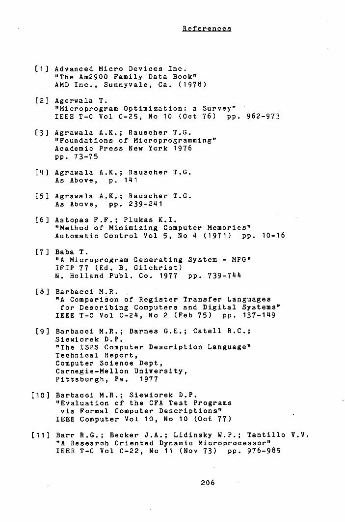
Advanced Micro Devices Inc. "The Am2900 Family Data Book" AMD Inc., Sunnyvale, Ca. (1978)
Agerwala T. "Microprogram Optimization: a Survey" IEEE T-C Vol C-25, No 10 (Oct 76) pp. 962-973
Agrawala A.K.; Rauscher T.G. "Foundations of Microprogramming" Academic Press New York 1976 pp. 73-75
[LI] Agrawala A.K.; Rauscher T.G. As Above, p. 1111
Agrawala A.K.; Rauseher T.G. As Above, pp. 239-2I1
Astopas F.F.; Plukas K.I. "Method of Minimizing Computer Memories" Automatic Control Vol 5, No k (1971) pp. 10-16
[7) Baba T. "A Microprogram Generating System - MPG" IFIP 77 (Ed. B. Gilchrist) N. Holland Pubi. Co. 1977 pp. 739-744
Barbacci M.R. "A Comparison of Register Transfer Languages for Describing Computers and Digital Systems"
IEEE T-C Vol C-24, No 2 (Feb 75) pp. 137-149
Barbacci M.R.; Barnes G.E.; Catell R.C.; Siewiorek D.P. "The ISPS Computer Description Language" Technical Report, Computer Science Dept, Carnegie-Mellon University, Pittsburgh, Pa. 1977
[10) Barbacci M.R.; Siewiorek D.P. "Evaluation of the CFA Test Programs via Formal Computer Descriptions" IEEE Computer Vol 10, No 10 (Oct 77)
[11] Barr R.G.; Becker J.A.; Lidinsky W.P.; Tantillo V.V. "A Research Oriented Dynamic Microprocessor" IEEE T-C Vol C-22, No 11 (Nov 73) pp. 976-985
206

Bernstein A.J. "Analysis of Programs for Parallel Processing" IEEE T-C Vol C-15, No 10 (Oct 66) PP. 757-762
Burr W.E.; Coleman A.H.; Smith W.R. "Overview of the Military Computer Family Architecture Selection" Proc. AFIPS NCC Vol 46 1977
Carter W.C.; Ellozy H.A.; Joyner W.H.Jr.; Brand D. "Microprogram Verification Considered Necessary" Proc. AFIPS NCC Vol 47 (1978) pp. 657-66'4
Chu Y. "Computer Organization and Microprogramming" Prentice-Hall Englewood-Cliffs NJ 1972
Conway M.E. "Design of a Separable Transition-Diagram Compiler" CACM Vol 6, No 7 (July 63) pp. 396 1408
Dasgupta S. "Parallelism in Loop Free Microprograms" IFIP 77 (Ed. B. Gilchrist) N. Holland Publ. Co. pp. 745-750
Dasgupta S. "Towards a Microprogramming Language Schema" Proc. 11th Annual Workshop on Microprogramming, Pacific Grove, Ca. (Nov 78) pp. 1144_153
Dasgupta S.; Jackson L.W. "An Algorithm for Identifying Parallel Micro-operations"
Technical Report TR73-20 (Dec 73), Computing Science Dept, Univ. of Alberta, Edmonton, Alberta, Canada
Dasgupta S.; Tartar J. "Automatic Identification of Maximal Parallelism in Straight Line Microprograms"
IEEE T-C Vol C-25, No 10 (Oct 76) pp. 986-991 See also comments on above in IEEE T-C Vol C-27, No 3 (March 78)
De Witt D.J. "A Machine Independent Approach to the Production of Optimized Horizontal Microcode" Ph.D. Dissertation Computer Science Dept, Univ. of Michigan, Ann Arbor. 1976
207
De Witt D.J. "A Control Word Model for Detecting Conflicts between Micro-operations"
Proc. 8th Annual Workshop on Microprogramming (Oct 75) pp. 6-12
Digital Equipment Corporation "PDP 11/0 System - KD11 A Processor Maintenance Manual" Technical Document EK-KD11A-MM-001 (1973) DEC, Maynard, Mass.
Eckhouse R.H.Jr. "A High Level Microprogramming Language" Proc. AFIPS SJCC Vol 36 (1971) pp. 169-177
Fagg P.; Brown J.L.; Hipp J.A.; Doody D.T.; Fairciough J.W.; Greene J. "IBM System/360 Engineering" Proc. AFIPS FJCC Vol 22 (1964) pp. 205-231
Fiala E.R. "The Maxc Systems" IEEE Computer Vol 11, No 5 (May 78) pp. 57-67
Flynn M.J. "Lecture Notes on Data Flow - Chapter 3: Computation Schema"
Massachusetts Institute of Technology, Cambridge, Mass. (1971) pp. 15-18
[28j Gerace G.,B.; Vanneschi M. "Processing Speed of Microprogrammed Systems - Evaluation and System Design"
Scientific Note 8-75-2 (Jan 75) Universita degli Studi di Pisa, Instituto di Scienze deli' Informazione, Pisa, Italy
L291 Gerace G.B.; Vanneschi M.; Casaglia G.F. "Models and Comparisons of Microprogrammed Systems" Scientific Note S-74-18 (Dec 74) Universita degli Studi di Pisa, Instituto di Scienze deli' Informazione, Pisa, Italy
130] Hodges B.C.; Edwards A.J. "Software Support for Microprogram Development" ACM SlGmicro Newsletter Vol 5 (Jan 75) pp. 17-24
131J Husson S.S. "Microprogramming: Principles and Practice" Prentice-Hall Englewood-Cliffs NJ 1970 p.240
208
L32i Husson S.S. As Above, p.493
L331 Ibbett R.N. "The MU5 Instruction Pipeline" Computer Journal Vol 15, No 1 (1972) pp. 42-50
L341 Jones L.H. "Instruction Sequencing in Microprogrammed Computers" Proc. AFIPS NCC Vol 44 (1975) pp. 91-9
[35] Lewis T.G.; Malik K.; Ma P-I. "Firmware Engineering Using a High Level Microprogramming System to Implement Instruction Set Processors" (Unpublished) Technical Report Computer Science Dept. Oregon State Univ. Corvallis, Oregon 97331
L361 Lloyd G.R.; Van Dam A. "Design Considerations for Microprogramming Languages"
ACM SlGmicro Newsletter Vol 5, No 1 (April 74) pp. 15-44
L371 Lucas P. "Die Strukturanalyse van Formelubersetzern" Electron. Rechenanl 3 (1961) pp. 159-167
L381 Ma P-Y.; Lewis T.G. "A Portable, Efficient Microprogramming System for Emulator Development" (Unpublished) Technical Report Computer Science Dept. Oregon State Univ. Corvallis, Oregon 97331
1391 Malik K. "Optimizing the Design of a High Level Language for Microprogramming"
Ph.D. Dissertation Computer Science Dept. Oregon State Univ. Corvallis, Oregon 97331
140] Mallett P.W. "Methods for Compacting Microprograms" Ph.D. Dissertation (Dec 7) Computer Science Dept. Univ. of Southwestern Louisiana Lafayette, La 75401
209
L41J Mallett P.W.; Lewis T.G. "Considerations for Implementing a High Level Microprogramming Language Translation System" IEEE Computer Vol b, No 8 (Aug 75) pp. 40-52
L42J Nagle A. "Automated Design of Micro Controllers" Proc. 11th Annual Workshop on Microprogramming Pacific Grove, Ca. (Nov 78) pp. 112-117
[ 143J Nanodata Corporation "QM-1 Hardware Level User's Manual" 2nd edition, revised Aug 74
L441 Nilsson N.J. "Problem Solving Methods in Artificial Intelligence" McGraw-Hill New York 1971 pp. 87-90
L451 O'Loughlin J.F. "Microprogramming a Fixed Architecture Machine" Infotech State of the Art Report, No 23. pp. 205-224 Infotech Information Ltd. Maidenhead, England 1975
L461 Patterson D.A. "STRUM - Structured Microprogramming System for Correct Firmware"
IEEE T-C Vol C-25, No 10 (Oct 76) pp. 974-986
L471 Ramamoorthy C.V.; Tsuchiya M. "A High Level Language for Horizontal Microprogramming" IEEE T-C Vol C-23, No ö (Aug 74) pp. 791-801
148J Rattner J.; Cornet J-C.; Hoff M.E.Jr. "Bipolar LSI Computing Elements Usher in New Era of Digital Design" Electronics Sept 1974
L49J Salisbury A.B. "Mi croprogrammable Computer Architectures" American Elsevier New York 1976 pp. 47-49
[50j Salisbury A.B. As Above, pp. 112-135
151J Siewiorek D.P.; Barbacci M.R. "The CMU RT-CAD System - An Innovative Approach to Computer Aided Design"
Proc. AFIPS NCC Vol 45 (1976) pp. b43-65
[521 Tanenbaum A.J. "Structured Computer Organization" Prentice-Hall Englewood-Cliffs NJ 1976
210
1531 Tokoro M.; Takizuka T.; Tamura E.; Yamaura I. "A Technique of Global Optimization of Microprograms" Proc. 11th Annual Workshop on Microprogramming Pacific Grove, Ca. (Nov 78) pp. I1-50
L541 Tokoro M.; Tamura E.; Takase K.; Tamaru K. "An Approach to Microprogram Optimization Considering Resource Occupancy and Instruction Formats" Proc. 10th Annual Workshop on Microprogramming (Oct 77) pp. 92-108
[55J Tsuchiya M.; Gonzales M.J. "An Approach to the Optimization of Horizontal Microprograms"
Proc. 7th Annual Workshop on Microprogramming, Palo Alto, Ca. (Sept-Oct 7) pp. 85-90
[56] Tucker A.B.; Flynn M.J. "Dynamic Microprogramming: Processor Organization and Programming" CACM Vol 1, No 11 (April 71) pp. 240-250
[57J Tucker S.G. "Microprogram Control for the System/360" IBM Systems Journal Vol 6, No 4 (1967) pp. 222_241
L581 Vanneschi M. "Implementation of Microprograms and Processing Speed"
Scientific Note S-76-18 (Oct 76) Universita degli Studi di Pisa Instituto di Scienze deli' Informazione Pisa, Italy
1591 Vanneschi M. "On the Microprogrammed Implementation of Some Computer Architectures"
Scientific Note S-76-3 (April 76) Universita degli Studi di Pisa Instituto di Scienze deli' Informazione Pisa, Italy
1601 Varian Data Machines "Varian Microprogramming Guide" Irvine, Ca., (1973)
[61] Wilkes M.V. "The Best Way to Design an Automatic Calculating Machine"
Report of Manchester University Computer Inaugural Conference (July 1951) pp. 16-18
211
L62J Wolf W.; Johnsson R.K.; Hobbs S.O.; Geschke C.M. "The Design of an Optimizing Compiler" Elsevier, North Holland Inc. New York 1975
[631 Yau S.S.; Schowe A.C.; Tsuchiya M. "On Storage Optimization of Horizontal Microprograms" Proc. 7th Annual Workshop on Microprogramming Pala Alto, Ca. (Sept-Oct 74) pp. 98-106
212
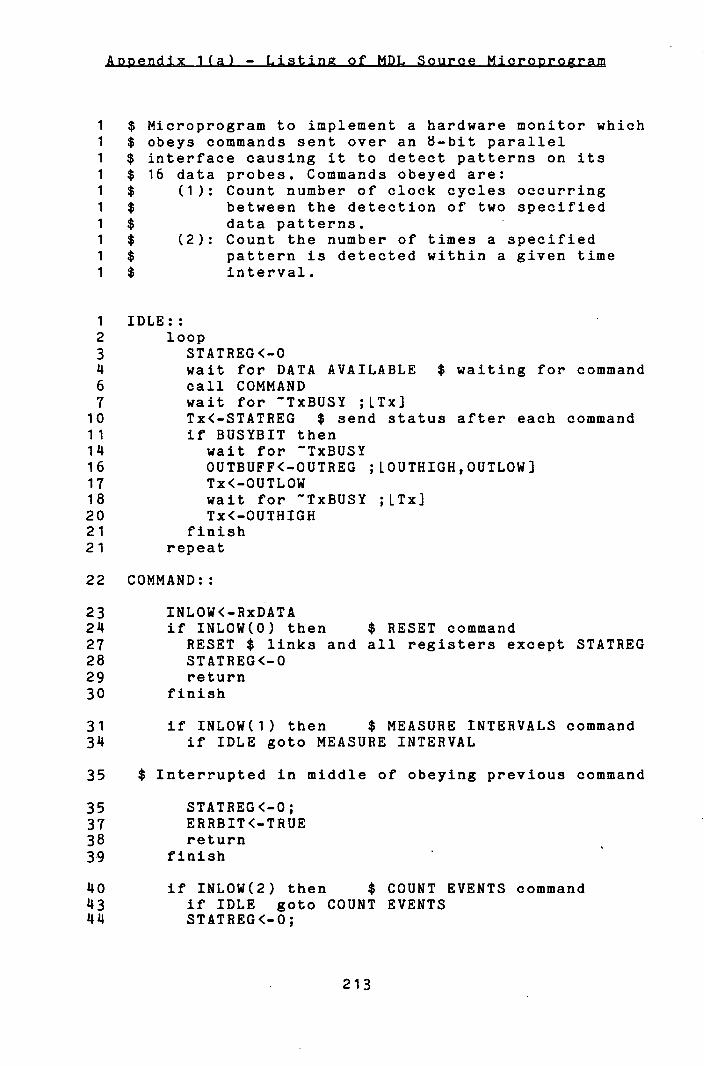
,J.ZIIFcIr1__
1 $ Microprogram to implement a hardware monitor which 1 $ obeys commands sent over an 8-bit parallel 1 $ interface causing it to detect patterns on its 1 $ 16 data probes. Commands obeyed are:
1 $ (1): Count number of clock cycles occurring
1 $ between the detection of two specified
1 $ data patterns.
1 $ (2): Count the number of times a specified
1 $ pattern is detected within a given time
1 $ interval.
1 IDLE::
2 loop
3 STATREG<-O wait for DATA AVAILABLE $ waiting for command
6 call COMMAND
7 wait for TxBUSY ;LTx]
10 Tx<-STATREG $ send status after each command
11 if BUSYBIT then
14 wait for TxBUSY
16 OUTBUFF<-OUTREG ; LOUTHIGH,OUTLOW]
17 Tx<-OUTLOW
18 wait for TxBUSY ;LTx]
20 Tx<-OUTHIGH
21 finish
21 repeat
22 COMMAND:
23 INLOW<-RxDATA
24 if INLOW(0) then $ RESET command
27 RESET $ links and all registers except STATREG
28 STATREG<-O
29 return
30 finish
31 if INLOW(1) then $ MEASURE INTERVALS command
34 if IDLE goto MEASURE INTERVAL
35 $ Interrupted in middle of obeying previous command
35 STATREG<-O;
37 ERRBIT<-TRUE
38 return
39 finish
ZO if INLOW(2) then $ COUNT EVENTS command
113 if IDLE goto COUNT EVENTS
1111 STATREG<-0;
213
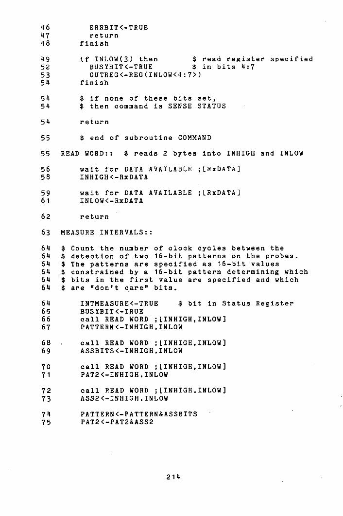
46
ERRBIT<-TRUE 147 return
'18
finish
149 if INLOW(3) then $ read register specified 52
BUSYBIT<-TRUE $ in bits 14:7 53
OUTREG<-REG(INLOW<14:7>) 514 finish
514
$ if none of these bits set, 514 $ then command is SENSE STATUS
return
55
$ end of subroutine COMMAND
55 READ WORD:: $ reads 2 bytes into INHIGH and INLOW
56
wait for DATA AVAILABLE ;LRxDATA) 58
INHIGH <-RxDATA
59 wait for DATA AVAILABLE ;LRxDATA]
61
INLOW<-RxDATA
62 return
63 MEASURE INTERVALS::
614 $ Count the number of clock cycles between the 614 $ detection of two 16-bit patterns on the probes. 614 $ The patterns are specified as 16-bit values 614 $ constrained by a 16-bit pattern determining which 614 $ bits in the first value are specified and which 614 $ are "don't care" bits.
614 INTMEASURE<-TRUE $ bit in Status Register 65 BUSYBIT<-TRUE 66 call READ WORD ;LINHIGH,INLOW] 67 PATTERN<-INHIGH.INLOW
68 call READ WORD ;LINHIGH,INLOW] 69 ASSBITS<-INHIGH.INLOW
70 call READ WORD ;LINHIGH,INLOW] 71 PAT2<-INHIGH.INLOW
72 call READ WORD ;LINHIGH.INLOW] 73 ASS2<-INHIGH.INLOW
714 PATTERN<-PATTERN&ASSBITS 75 PAT2<-PAT2&ASS2
214

76 $ Try to match PATTERN with observed data on probes
76 CLOCKFF<-0 ;[k]
77 wait for CLOCKFF $ Synchronize with clock
79 CLOCKFF<-0
80 loop
81 call READ DATA ;[DATA,CLOCKFF]
82 return if BUSYBIT $ interrupt has been taken
83 repeat while DATA-PATTERN # 0
85 $ 1st pattern observed,
85 $ start counting cycles until 2nd pattern.
85 SEEN1<-TRUE $ in Status Register
86 COUNT<-0
87 ASSBITS<-ASS2 $ used by READ DATA
88 loop
89 COUNT<-COUNT+1
90 if OVF then ;[!COUNT]
93 STATREG<-O;
94 OVERFLOW<-TRUE
95 ERRBIT<-TRUE ;[2]
96 else
98 call READ DATA
99 finish
100 return if BUSYBIT $ due either to OVF above
101 $ or else interrupt
101 $ inside READ DATA
101 repeat while DATA-PAT2 # 0
103 SEEN2<-TRUE
104 OUTREG<-COUNT
105 return
106 READ DATA:: $ Reads a 16-bit pattern from the probes
107 if INTERRUPT call COMMAND
108 return if IDLE $ forced by interrupt
110 if CLOCKFF then $ Clock has already pulsed -
ilk $ cannot keep up.
ilk STATREG<-0;
115 ERRBIT<-TRUE
116 CLOCKERR<-TRUE ;[2]
117 return
118 finish
119 wait for CLOCKFF ;[PROBEDATA]
121 $ Clock has set flip-flop and latched data.
121 CLOCKFF<-O
122 DATA<-PROBEDATA&ASSBITS
123 return
215
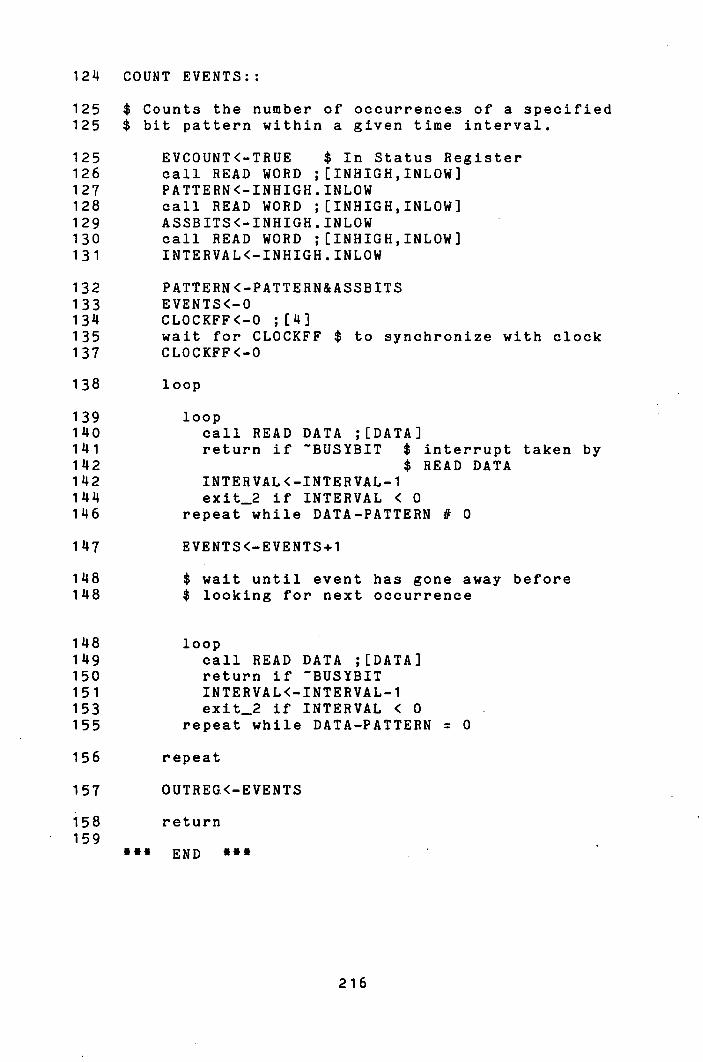
124 COUNT EVENTS::
125 $ Counts the number of occurrence,s of a specified 125 $ bit pattern within a given time interval.
125 EVCOUNT<-TRUE $ In Status Register 126 call READ WORD ;[INHIGH,INLOW] 127 PATTERN<-INHIGH.INLOW 128 call READ WORD ;(INHIGH,INLOW] 129 ASSBITS<-INHIGH.INLOW 130 call READ WORD ;[INHIGH,INLOW] 131 INTERVAL<-INHIGH.INLOW
132 PATTERN<-PATTERN&ASSBITS 133 EVENTS<-O 134 CLOCKFF<-O ;[14] 135 wait for CLOCKFF $ to synchronize with clock 137 CLOCKFF<-O
138 loop
139 loop 1140 call READ DATA ;[DATA] 1141 return if BUSYBIT $ interrupt taken by 1142 $ READ DATA 1142 INTERVAL<-INTERVAL-1 11414 exit-2 if INTERVAL < 0 146 repeat while DATA-PATTERN # 0
1147 EVENTS<-EVENTS+1
148 $ wait until event has gone away before 148 $ looking for next occurrence
148 loop 149 call READ DATA ;[DATA] 150 return if BUSYBIT 151 INTERVAL<-INTERVAL-1 153 exit-2 if INTERVAL < 0 155 repeat while DATA-PATTERN 0
156 repeat
157 OUTREG.<-EVENTS
158 return 159
*** END ***
216
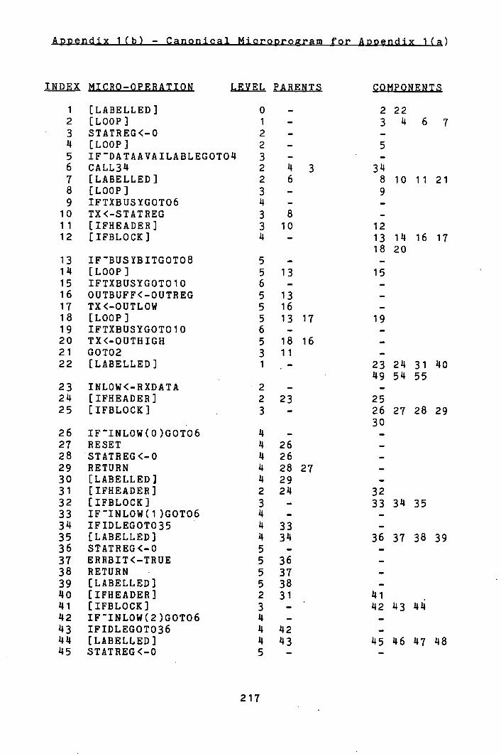
INDEX MICRO-OPERATION LEVEL PARENTS COMPONENTS
1 [LABELLED] 0 - 2 22 2 [LOOP] 1 - 3 14 6 7 3 STATREG<-O 2 - -
14 [LOOP] 2 - 5 5 IFDATAAVAILABLEGOTOU 3 - -
6 CALL314 2 14 3 314 7 [LABELLED] 2 6 8 10 11 21 8 [LOOP] 3 - 9 9 IFTXBUSYGOT06 14 - -
10 TX<-STATREG 3 8 -
11 [IFHEADER] 3 10 12 12 EIFBLOCK] 14 - 13 114 16 17
18 20 13 IFBUSYBITGOT08 5 - -
114 [LOOP] 5 13 15 15 IFTXBUSYGOT010 6 - -
16 OUTBUFF<-OUTREG 5 13 -
17 TX<-OUTLOW 5 16 -
18 [LOOP] 5 13 17 19 19 IFTXBUSYGOT010 6 - -
20 TX<-OUTHIGH 5 18 16 -
21 GOT02 3 11 -
22 [LABELLED] 1 - 23 211 31 40 149 514 55
23 INLOW<-RXDATA 2 - -
24 EIFHEADER] 2 23 25 25 [IFBLOCK) 3 - 26 27 28 29
30 26 IFINLOW(0)GOT06 14 - -
27 RESET 14 26 -
28 STATREG<-O 14 26 -
29 RETURN 14 28 27 -
30 [LABELLED] II 29 -
31 [IFHEADER] 2 214 32 32 [IFBLOCK] 3 - 33 314 35 33 IFINLOW(1)GOTO6 14 - -
314 IFIDLEGOT035 14 33 -
35 [LABELLED] 14 314 36 37 38 39 36 STATREG<-O 5 - -
37 ERRBIT<-TRUE 5 36 -
38 RETURN 5 37 -
39 [LABELLED] 5 38 -
140 [IFHEADER] 2 31 141 141 [IFBLOCK] 3 - 142 143 1414 142 IFINLOW(2)GOT06 14 - -
143 IFIDLEGOT036 14 112 -
14 11 [LABELLED] 11 143 145 116 147 148 145 STATREG<-0 5 - -
217
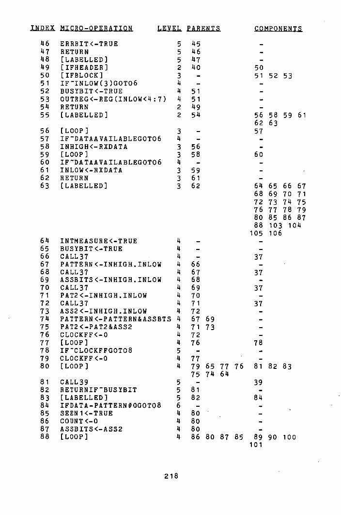
.Ls1sJIEkfl
46 ERRBIT<—TRUE 5 145 -
47 RETURN 5 116 -
118 [LABELLED] 5 147 -
119 [IFHEADER] 2 110 50 50 [IFBLOCK] 3 - 51 52 53 51 IFINLOW(3)GOT06 11 - -
52 BUSYBIT<—TRUE 11 51 -
53 OUTREG<—REG(INLOW< 11:7) 11 51 -
54 RETURN 2 119 -
55 [LABELLED] 2 511 56 58 59 61 62 63
56 [LOOP] 3 - 57 57 IFDATAAVAILABLEGOT06 11 - -
58 INHIGH<—RXDATA 3 56 -
59 [LOOP] 3 58 60 60 IFDATAAVAILABLEGOT06 11 - -
61 INLOW<—RXDATA 3 59 -
62 RETURN 3 61 -
63 [LABELLED] 3 62 614 65 66 67 68 69 70 71 72 73 74 75 76 77 78 79 80 85 86 87 88 103 10 11
105 106 611 INTMEASURE<—TRUE 11 - -
65 BUSYBIT<..-TRUE 11 - -
66 CALL37 11 - 37 67 PATTERN<—INHIGH.INLOW II 66 -
68 CALL37 11 67 37 69 ASSBITS<—INHIGH.INLOW 11 68 -
70 CALL37 11 69 37 71 PAT2<—INHIGH.INLOW II 70 -
72 CALL37 II 71 37 73 ASS2<—INHIGFI.INLOW 11 72 -
711 PATTERN<—PATTERN&ASSBTS 14 67 69 -
75 PAT2<—PAT2&ASS2 11 71 73 -
76 CLOCKFF<-0 14 72 -
77 [LOOP] 11 76 78 78 IFCLOCKFFGOT08 5 - -
79 CLOCKFF<—O 4 77 -
80 [LOOP] 14 79 65 77 76 81 82 83 75 714 611
81 CALL39 5 - 39 82 RETURNIFBUSYBIT 5 81 -
83 [LABELLED] 5 82 814 84 IFDATA—PATTERN#OGOT08 6 - -
85 SEEN 1<—TRUE 11 80 -
86 COUNT<—O 11 80 -
87 ASSBITS<—ASS2 11 80 -
88 [LOOP] 11 86 80 87 85 89 90 100 101
218
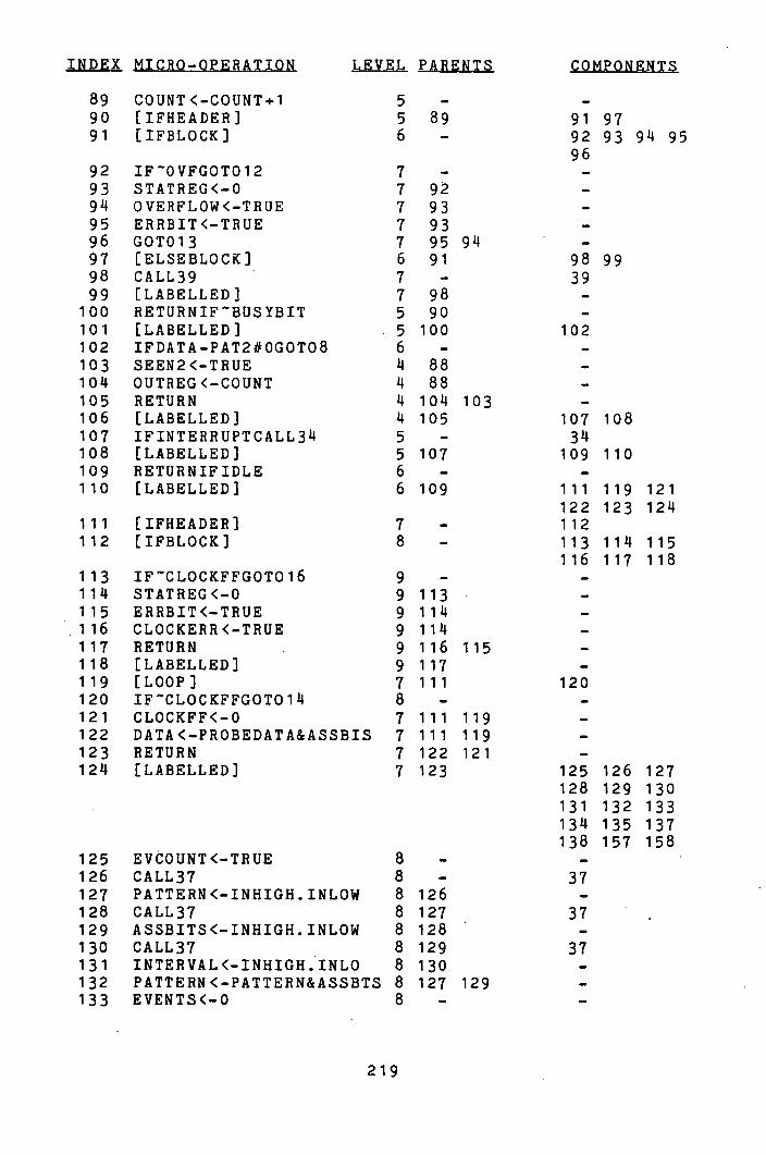
INDEX MICRO-OPERATION LEVEL PARENTS COMPONENTS
89 COUNT<-COUNT+1 5 - -
90 [IFHEADER) 5 89 91 97 91 [IFBLOCK] 6 - 92 93 94 95
96 92 IFOVFGOT012 7 - -
93 STATREG<-0 7 92 -
94 OVERFLOW<-TRUE 7 93 -
95 ERRBIT<-TRUE 7 93 -
96 GOT013 7 95 94 -
97 [ELSEBLOCK] 6 91 98 99 98 CALL39 7 - 39 99 [LABELLED] 7 98 -
100 RETURNIFBUSYBIT 5 90 -
101 [LABELLED] 5 100 102 102 IFDATA-PAT2#OGOT08 6 - -
103 SEEN2<-TRUE k 88 -
104 OUTREG<-COUNT 11 88 -
105 RETURN k 104 103 -
106 [LABELLED] 11 105 107 108 107 IFINTERRUPTCALL34 5 - 34 108 [LABELLED] 5 107 109 110 109 RETURNIFIDLE 6 - -
110 [LABELLED] 6 109 111 119 121 122 123 124
111 EIFHEADER] 7 - 112 112 [IFBLOCK] 8 - 113 ilk 115
116 117 118 113 IFCLOCKFFGOT016 9 - -
ilk STATREG<-0 9 113 -
115 ERRBIT<-TRUE 9 ilk -
116 CLOCKERR<-TRUE 9 ilk -
117 RETURN 9 116 115 -
118 [LABELLED] 9 117 -
119 [LOOP] 7 111 120 120 IFCLOCKFFGOT014 8 - -
121 CLOCKFF<-0 7 111 119 -
122 DATA<-PROBEDATA&ASSBIS 7 111 119 -
123 RETURN 7 122 121 -
124 [LABELLED] 7 123 125 126 127 128 129 130 131 132 133 134 135 137 138 157 158
125 EVCOUNT<-TRUE 8 - -
126 CALL37 8 - 37 127 PATTERN<-INHIGFI.INLOW 8 126 -
128 CALL37 8 127 37 129 ASSBITS<-INHIGH.INLOW 8 128 -
130 CALL37 8 129 37 131 INTERVAL<-INHIGH.INLO 8 130 -
132 PATTERN<-PATTERN&ASSBTS 8 127 129 -
133 EVENTS<-0 8 - -
219
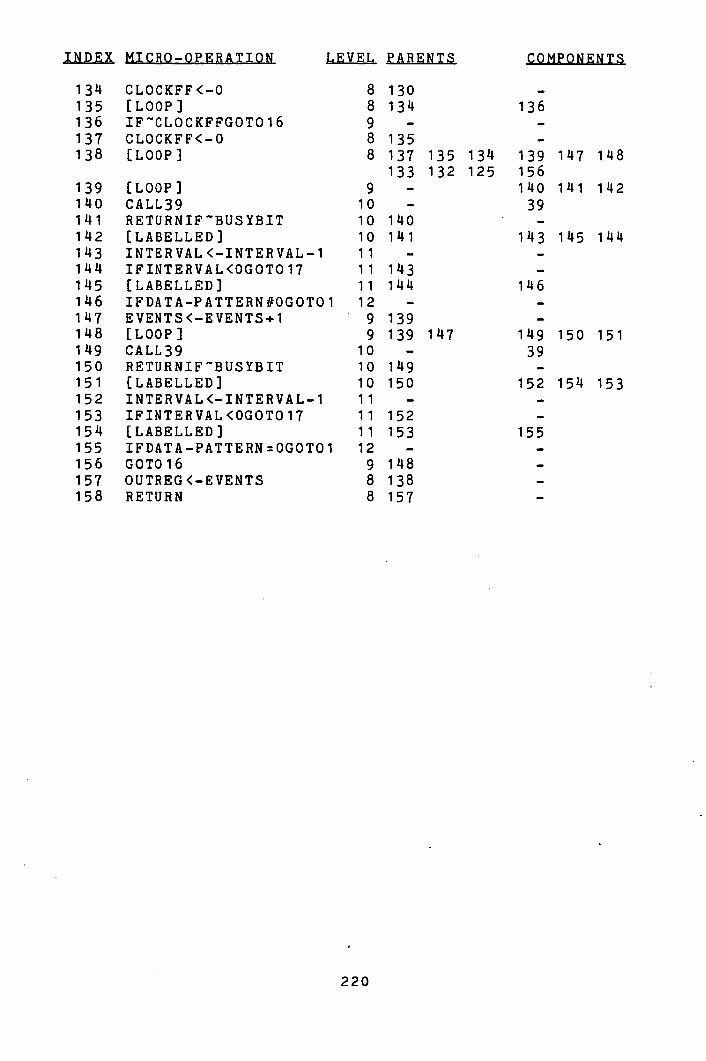
INDEX MICRO—OPERATION LEVEL PARENTS
134 CLOCKFF<-0 8 130 135 [LOOP] 8 134 136 IFCLOCKFFGOT016 9 -
137 CLOCKFF<-0 8 135 138 [LOOP] 8 137 135 134
133 132 125 139 [LOOP] 9 -
140 CALL39 10 -
141 RETURNIFBUSYBIT 10 140 142 [LABELLED] 10 lli 143 INTERVAL<—INTERVAL-1 11 -
144 IFINTERVAL<0G0T017 11 143 145 [LABELLED] 11 144 146 IFDATA—PATTERN#OGOT01 12 -
147 EVENTS<—EVENTS+1 9 139 148 [LOOP] 9 139 147 149 CALL39 10 -
150 RETURNIFBUSYBIT 10 149 151 [LABELLED] 10 150 152 INTERVAL<—INTERVAL-1 11 -
153 IFINTERVAL<0G0T017 11 152 154 [LABELLED] 11 153 155 IFDATA—PATTERN0GOT01 12 -
156 GOT016 9 148 157 OUTREG<—EVENTS 8 138 158 RETURN 8 157
KerwMeIrk
136
139 147 148 156 140 141 142 39
143 145 144
146
149 150 151 39
152 1514 153
155
220
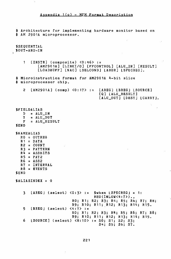
t!'i.iiiJ!(I-
$ Architecture for implementing hardware monitor based on $ AM 2901A microprocessor.
%SEQUENTIAL %OUT-AND-IN
1 [INSTR] (composite) <0:46> : [AM2901A] [LINKI/O] [FFCONTROL] LALU_IN] [RESULT] [LOADBUFF] [NAC] LSELCONDJ LADDR] LSPECREGJ.
$ Microinstruction format for AM2901A 4-bit slice $ microprocessor chip.
2 [AM2901A] (comp) <0:17> := [AREGJ IBREGJ ISOURCE] [Q] [ALU_RESULT] [ALU_OUT] LDEST] LCARRYJ.
%FIELDALIAS D = ALU_IN Y = ALU_OUT F = ALU_RESULT
%END
%NAMEALIAS RO = OUTREG Ri = DATA R2 = COUNT R3 = PATTERN Rk = ASSBITS R5 = PAT2 R6 = ASS2 R7 = INTERVAL R8 = EVENTS
%END
%ALIASINDEX = 0
3 LAREGJ (select) <0:3> := %when LSPECREGJ = 1: REG(INL0W<4:7>).,
HO; Ri; R2; R3; RLI; R5; Rb; Ri; Ho; R9; RIO; Ru; R12; R13; R1 11; R15.
5 [BREGJ (select) <4:7> := RO; Hi; R2; R3; Rk; R5; R6; R7; R8; R9; RIO; Ru; R12; R13; R14; R15.
6 ISOURCE] (select) <:10> :: SO; Si; S2; S3; S4; 55; Sb; 57.
221
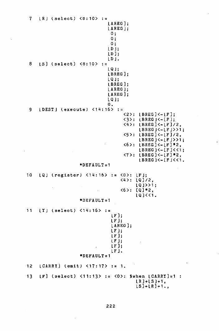
7 LRJ (select) <d:10> LAREG); LAREGJ; 0; 0; 0;
LDJ; ID]; LDJ.
8 is] (select) <ö:lO> := LQJ; LBREG]; L i; LEREG]; LAREGJ; LAREG]; IQi; 0.
9 LDESTJ (execute) <14:16> : <2>: LBREG]<-LF]; <3>: LBREGJ<-[FJ;. < 14>: LBREG]<-LF]/2,
IBREGJ<-LFJ>>1 <5>: IBREG]<-LF]/2,
LBREGi<-LFJ>>1 <6>: LBREG]<-LF]'2,
LBREGJ<-[F]<<1; <7>: LBREG]<-LF]'2,
LBREGJ<-[FJ<<1 'DEFAULT=l
10 IQJ (register) <114:16> := <0>: LFJ; <4>: LQ]/2,
LQJ>>l; <6>: [Q]'2,
LQJ<<l 'DEFAULT = 1
11 LYJ (select) <114:16> := IF]; LF]; LAREG]; LF]; IF]; IF j; LF]; IF .1.
'DEFAULT :1
12 LCARRYJ (emit) <17:17> := 1.
13 LF] (select) <11:13> := <0>: %when LCARRY)=1 LRJ+LSJ+1, is )+ LR ] +1.
222
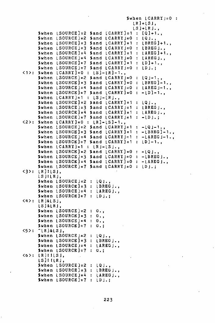
%when LCARRYJ0 LR]+LSJ LS]+IRJ.
when LSOURCE]=2 %and ICARRY]=1 : [Q]+1., %when ISOURCEJ=2 sand LCARRYJ=O : IQJ., %when LSOURCE]3 %and LCARRY]=1 : LBREG]+1., %when ISOURCEJ=3 %and LCARRYJ=O : IBREGJ., %wheri LSOURCE]4 %and LCARRY]1 : LAREG]+1., %when LSOURCEJ4 %and LCARRYJ=O : LAREGJ.,
when LSOURCE]=7 %and LCARRY]=1 : LD]+1., when LSOURCEj=7 %and LCARRYJ=O : LDJ.;
<1>: %when LCARRY]=O : LS]-LR]-1. 1 %when LSOURCEJ=2 %and LCARRYJ=O : LQJ-1., %when LSOURCE]=3 %and LCARRY]=O : LBREG]-1., %when LSOURCEi= %and LCARRYJ=O : LAREGJ-1., %when LSOURCE]7 %and LCARRY]:O : -LD]-1., %when LCARRYJ=1 : LSJ-[Ri., %when LSOURCE]=2 'and LCARRY]=1 : IQJ., %when LSOURCEJ=3 %and LCARRYJ=1 : LBREGJ., %when LSOURCE]= 14 %and LCARRY]=1 : LAREGJ., %when LSOURCEJ=7 sand LCARRYJ=1 : -LDJ.;
<2>: %when LCARRY]=O : LR]-LS]-1., %when LSOURCE]2 %and LCARRYk1 : -LQJ-1., %wheri LSOURCE)=3 %and LCARRY]=1 : -LBREG)-1., %when LSOURCEJ: %and LCARRYJ1 : -LAREGJ-1., %wheri ISOURCE]=7 %and LCARRY]=1 : LD]-1.,
when ICARRYJ=1 : LRJ-LSJ., %when LSOURCE]=2 'and LCARRY]=O : -LQJ., %when LSOURCE]=3 %and LCARRYJ=O : -LBREGJ.,
when LSOURCE]= 14 %and LCARRY]=O : -LAREGJ., %when LSOURCEJ=7 sand LCARRYJ=O : LDJ.;
<3>: LR]!LSJ, L S J I LRJ, when LSOURCEJ.=2 : LQJ.,
%when LSOURCE)=3 : LBREGJ., when LSOURCEJ= : LAREGJ.,
%when ISOURCE):7 : IDJ.; <M>: LRJ&LSJ,
LS]&LRJ %when LSOURCE.k2 : 0., %when LSOURCE]=3 : 0., %wheri LSOURCEJ=4 : 0., %wberi LSOURCE]=7 : 0.;
<5>: LRJ&LSJ., %when ISOURCEJ=2 : IQJ.,
when LSOURCE)=3 : LBREGJ., %when LSOURCEJ=4 : LAREG.J., %when LSOURCE]=7 : 0.;
<b>: LRJHLSJ, S
IS]! !LRJ, %when LSOURCEJ2 : LQJ., %when LSOURCE]=3 : IBREGJ., %when LSOURCEJ=l : LAREGJ., %when LSOURCE]7 : LDJ.;
223
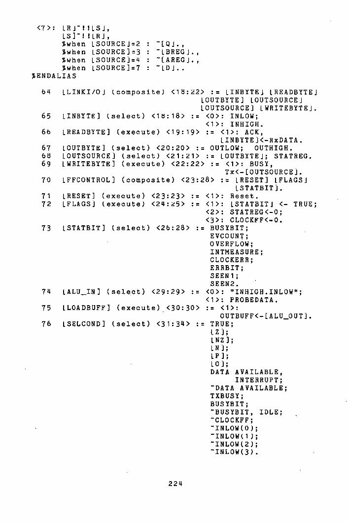
<7>: LRJI!LSJ, LS]! !LRJ, when LSOURCE.k2 : when LS0URCE13 : LBREGJ., when LSOURCEJ=4 : [AREGJ., when LSOURCE1=7 : - 1DJ..
%ENDALIAS
611 LLINKI/0J (composite) <18:22> := LINBYTEJ LREADBYTEJ LOUTBYTE] LOUTSOURCEJ LOUTSOURCEJ LWRITEBYTEJ.
65 LINBYTE] (select) <16:18> := <0>: INLOW; <1>: INHIGH.
66 LREADBYTE] (execute) <19:19> := <1>: ACK, LINBiTEJ<-RxDATA.
67 LOUTBYTE) (select) <20:20> := OUTLOW; OUTHIGH. 68 LOUTSOURCEJ (select) <21:21> := LOUTBYTEJ; STATREG. 69 LWRITEBYTE] (execute) <22:22> : <1>: BUSY,
Tx<-[OUTSOURCEJ. 70 LFFCONTROL] (composite) <23:28> := LRESET] LFLAGSJ
LSTATBITJ. 71 IRESET] (execute) <23:23> : <1>: Reset. 72 LFLAGSJ (execute) <214:25> : <1>: LSTATBITJ <- TRUE;
<2>: STATREG<-0; <3>: CLOCKFF<-0.
73 ISTATBIT] (select) <26:28> := BUSYBIT; EVCOUNT; OVERFLOW; INTMEASURE; CLOCKER H; ERRBIT; SEEN 1; SEEN2.
711 LALU_IN] (select) <29:29> := <0>: TTINHIGH.INLOW"; <1>: PROBEDATA.
75 LLOADBUFF) (execute) <30:30> := <1>: OUTBUFF<- [ALU_OUTJ.
76 LSELCOND] (select) <31:3 14> := TRUE; IZJ; LNZJ; IN]; LP]; I0J; DATA AVAILABLE,
INTERRUPT; DATA AVAILABLE;
TXBUSY; BUSYBIT; BUSYBIT, IDLE; CLOCKFF; INLOW(0); INLOW(1); INLOW(2); INLOW(3).
224

77 LZJ (Select) : LRESULTJ = 0. 78 LNZ] (Select) := IRESULT] # 0. 79 LNJ (Select) := IRESULTJ < 0. 80 LP] (Select) := LRESULT] > 0. öl LOJ (Select) - OVF. 82 IRESULT] (select) <14:16> := LALU_RESULT];
LALU_RESIJLTJ; LBREG]; LBREG]; IBREGJ; LBREGJ; LBREG]; IBREG]. *DEFAULT1
83 LNAC] (execute) <35:38> := <1>: if LSELCONDJ call LADDRJ,
%when LSELCOND] = 0: call LADDRJ.; <3>: if LSELCOND] goto LADDRJ
%when LSELCONDJ = 0: goto IADDRJ.; <10): if LSELCOND] return,
return if LSELCONDJ, %when LSELCOND] = 0: return.;
<14>: continue; <15>: goto LADDRJ.
*DEFAULT1 4 7 LADDRJ (address) <39:45> := 127.
$ "Address" field type is just "Emit" used for special $ purpose of holding microinstruction address $ (asterisked on output).
8 LSPECREGJ (select) <46:46> := normal; forcereg.
*** END ***
225

SELECTED OP OP = IFDATAAVAILABLEG0T04 (5) - PACKED
00000000000000001000000000000000111001100001000 SELCOND - 7 NAC - 3 ADDR - 4*
SELECTED OP = STATREG<-0 (3) - PACKED
SELECTED OP = CALL34 (6) - PACKED
00000000000000001000000010000000000000101000100 FLAGS - 2 SELCOND - 0 NAC - 1 ADDR - 34'
SELECTED OP = IFTXBUSYGOTOb (9) - PACKED
00000000000000001000000000000001000001100001100 SELCOND - NAC - 3 ADDR -
SELECTED OP = TX<-STATREG (10) - PACKED
SELECTED OP = IF - BUSYBITGOT08 (13) - PACKED
.00000000000000001000011000000001O10001100010000 OUTSOURCE - 1 WRITEBYTE - 1 SELCOND - 10 NAC - 3 ADDR - 5'
SELECTED OP = IFTXBUSYGOT010 (15) - PACKED
00000000000000001000000000000001000001100010100 SELCOND - NAC - 3 ADDR - 10'
SELECTED OP = OUTBUFF<-OUTREG (16) - PACKED
00000000011000001000000000000010000111000000000
226

BREG - 0 SOURCE - 3 Y-1 CARRY - 0 F - O LOADBUFF - 1
SELECTED OP = TX<-OUTLOW (17) - PACKED
000000000000000010000010000000000001 11000000000 OUTBYTE - 0 OUTSOURCE - 0 WRITEBYTE - 1
SELECTED OP = IFTXBUSYGOT010 (19) - PACKED
0000000000000000100000000000000100000110001O100 SELCOND - NAC-3 ADDR - 10'
SELECTED OP = TX<-OUTHIGH (20) - PACKED
00000000000000001000101000000000000111000000000 OUTBYTE - 1 OUTSOURCE - 0 WRITEBYTE - 1
SELECTED OP = GOT02 (21) - PACKED
00000000000000001000000000000000000001 100000100 SELCOND - 0 NAC - 3 ADDR - 2*
SELECTED OP = INLOW<-RXDATA (23) - PACKED
SELECTED OP = IFINLOW(0)GOT06 (26) - PACKED
00000000000000001001000000000001100001100001100 INBYTE - 0 READBYTE - 1 SELCOND - 12 MAC - 3 ADDR - 6'
SELECTED OP = STATREG<-0 (28) - PACKED
227
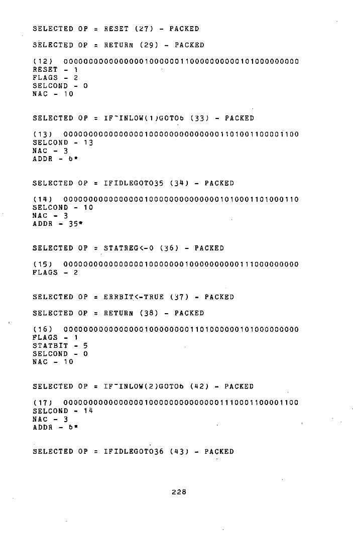
SELECTED OP = RESET (27) - PACKED
SELECTED OP = RETURN (29) - PACKED
00000000000000001000000110000000000101000000000 RESET - 1 FLAGS - 2 SELCOND - 0 NAC - 10
SELECTED OP = IFINLOW(1)GOT06 (33) - PACKED
00000000000000001000000000000001101001100001100 SELCOND - 13 MAC - 3 ADDR -
SELECTED OP = IFIDLEGOT035 (34) - PACKED
00000000000000001000000000000001010001101000110 SELCOND - 10 NAG ADDR - 35'
SELECTED OP = STATREG<-O (36) - PACKED
00000000000000001000000010000000000111000000000 FLAGS - 2
SELECTED OP = ERRBIT<-TRUE (37) - PACKED
SELECTED OP = RETURN (38) - PACKED
00000000000000001000000001101000000101000000000 FLAGS - 1 STATBIT - 5 SELCOND - 0 MAC - 10
SELECTED OP = IFINLOW(2)GOT06 (42) - PACKED
00000000000000001000000000000001110001100001100 SELCOND - 14 NAG ADDR - b'
SELECTED OP = IFIDLEGOT036 (43) - PACKED
228
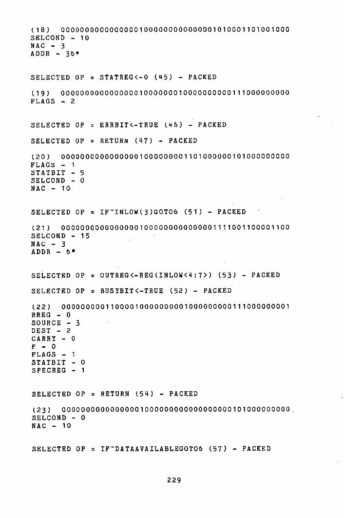
00000000000000001000000000000001010001101001000 SELCOND - 10 NAG - 3 ADDR - 36*
SELECTED OP = STATREG<-O (45) - PACKED
00000000000000001000000010000000000111000000000 FLAGS - 2
SELECTED OP = ERRBIT(-TRUE (46) - PACKED
SELECTED OP = RETURN (47) - PACKED
00000000000000001000000001101000000101000000000 FLAGS - 1 STATBIT - 5 SELCOND - 0 NAC - 10
SELECTED OP = IFINLOW(3)GOT06 (51) - PACKED
00000000000000001000000000000001111001100001100 SELCOND - 15 NAG ADDR - bt
SELECTED OP = OUTREG<-REG(INLOW<4:7>) (53) - PACKED
SELECTED OP = BUSYBIT<-TRUE (52) - PACKED
00000000011000010000000001000000000111000000001 BREG - 0 SOURCE - 3 DEST - 2 CARRY - 0 F - O FLAGS - 1 STATBIT - 0 SPECREG - 1
SELECTED OP = RETURN (54) - PACKED
00000000000000001000000000000000000101000000000. SELCOND - 0 NAG - 10
SELECTED OP = IFDATAAVAILABLEGOTOb (57) - PACKED
229
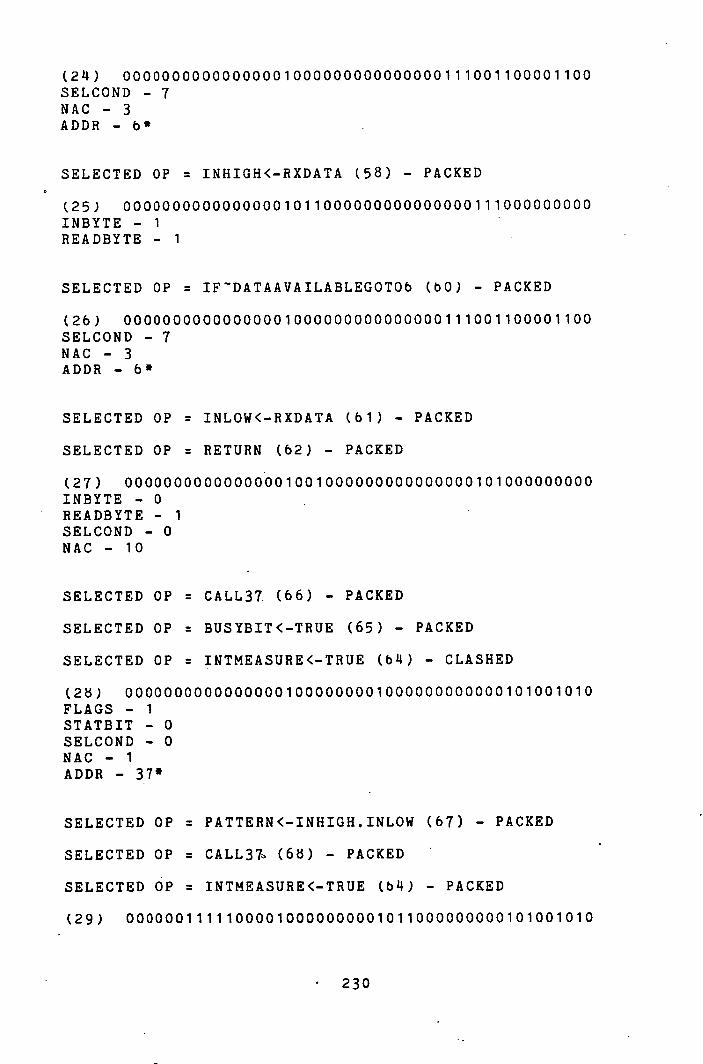
00000000000000001000000000000000111001100001100 SELCOND - 7 NAG - 3 ADDH - b'
SELECTED OP = INHIGH<-RXDATA (58) - PACKED
0000000000000000101100000 0000000000111000000000 INBYTE - 1 READBYTE - 1
SELECTED OP = IFDATAAVAILABLEGOTOb (bO) - PACKED
00000000000000001000000000000000111001100001100 SELCOND - 7 NAG - 3 ADDR - 6*
SELECTED OP = INLOW<-RXDATA (61) - PACKED
SELECTED OP = RETURN (62) - PACKED
00000000000000001001000000000000000101000000000 INBYTE - 0 READBYTE - 1 SELCOND - 0 NAG - 10
SELECTED OP = CALL37. (66) - PACKED
SELECTED OP = BUSYBIT<-TRUE (65) - PACKED
SELECTED OP = INTMEASURE<-TRUE (b'I) - CLASHED
(2) 00000000000000001000000001000000000000101001010 FLAGS - 1 STATBIT - 0 SELCOND - 0 NAG - 1 ADDR - 37'
SELECTED OP = PATTERN<-INHIGH.INLOW (67) - PACKED
SELECTED OP = CALL37 (63) - PACKED
SELECTED OP = INTMEASURE<-TRUE (b's) - PACKED
(29) 00000011111000010000000001011000000000101001010
230
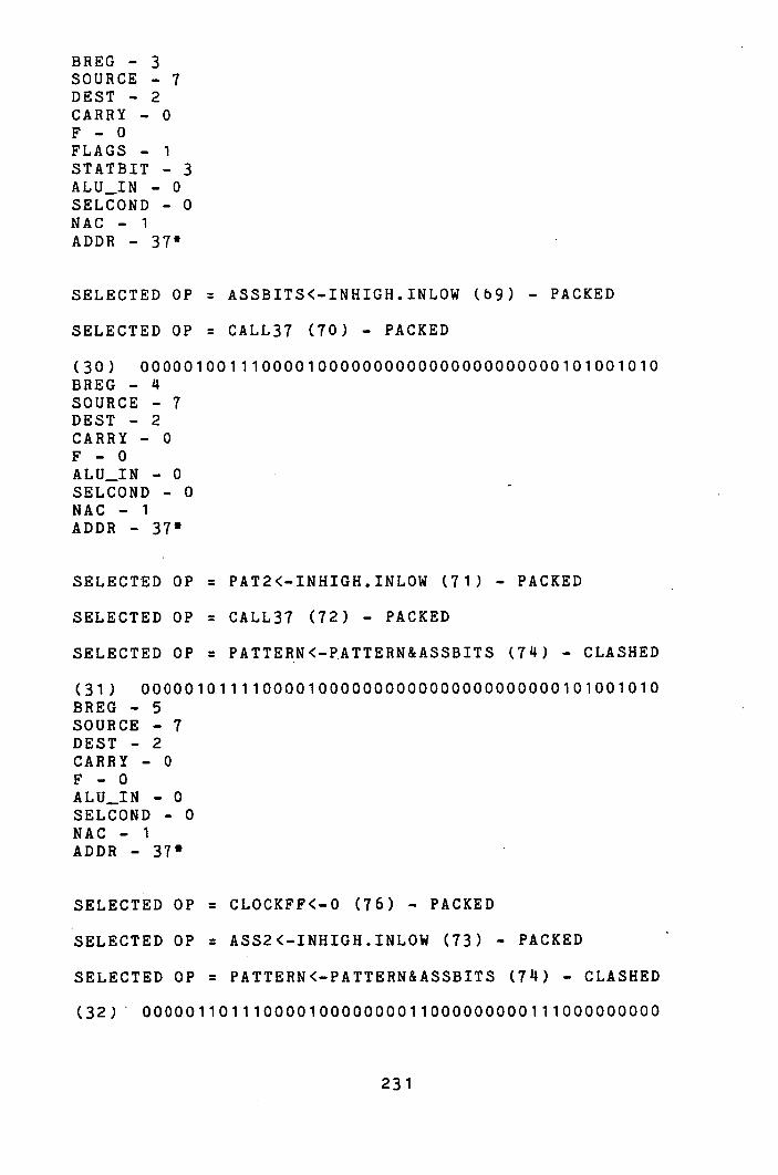
DREG - 3 SOURCE - 7 DEST - 2 CARRY - 0 F - O FLAGS - 1 STATBIT - 3 ALU_IN - 0 SELCOND - 0 NAC - 1 ADDR - 37*
SELECTED OP = ASSBITS<-INHIGH.INLOW (69) - PACKED
SELECTED OP = CALL37 (70) - PACKED
000001001110000100000000000000000 0 0 000101001010 BREG - SOURCE - 7 DEST - 2 CARRY - 0 F - O ALU_IN - 0 SELCOND - 0 NAC - 1 ADDR - 37*
SELECTED OP = PAT2<-INHIGH.INLOW (71) - PACKED
SELECTED OP = CALL37 (72) - PACKED
SELECTED OP = PATTERN<-PATTERN&ASSBITS (74) - CLASHED
0000010111100001 00 000 00000000000000000101001010 DREG - 5 SOURCE - 7 DEST - 2 CARRY - 0 F-0 ALU_IN - 0 SELCOND - 0 NAC - 1 ADDR - 37'
SELECTED OP = CLOCKFF<-O (76) - PACKED
SELECTED OP = ASS2<-INHIGH.INLOW (73) - PACKED
SELECTED OP = PATTERN<-PATTERN&ASSBITS (74) - CLASHED
00000110111000010000000011000000000111000000000
231
BREG - 6 SOURCE - 7 DEST - 2 CARRY - 0 F - O FLAGS - 3 ALU_IN - 0
SELECTED OP = IFCLOCKFFGOT08 (78) - PACKED
0000000000000 0001000000000000001011001100010000 SELCOND - 11 NAC - 3 ADDR - B'
SELECTED OP = PATTERN<-PATTERN&ASSBITS (74) - PACKED
SELECTED OP = PAT2<-PAT2&ASS2 (75) - CLASHED
SELECTED OP = CLOCKFF<-O (79) - PACKED
01000011001100010000000011000000000111000000000 AREG - LI
BREG - 3 R-1 S-i DEST - 2 F - k FLAGS - 3
SELECTED OP = PAT2<-PAT2&ASS2 (75) - PACKED
0110010100110001000000000000000000011 1 00 0000000 AREG - 6 BREG - 5 R-1 S DEST - 2 F - k
SELECTED OP = CALL39 (81) - PACKED
0000000000000000100000000000000000000010100111 0 SELCOND - 0 NAC-1 ADDR - 39'
SELECTED OP = RETURNIFBUSYBIT (82) - PACKED
232
(37) 00000000000000001000000000000001010101000000000 SELCOND - 10 NAC - 10
SELECTED OP = IFDATA-PATTERN#OGOTO (84) - PACKED
(38) 001100010010010 01100000000000000010001100010000 AREG - 3 BREG - 1 R S CARRY - 1 F - i SELCOND - 2 RESULT - 1 NAC - 3 ADDR - 8*
SELECTED OP = ASSBITS<-ASS2 (87) - PACKED
SELECTED OP = SEEN1<-TRUE (85) - PACKED
SELECTED OP = COUNT<-0 (86) - CLASHED
(39) 0110 0100100000010000000001110000000111000000000
AREG - 6 BREG - SOURCE - 4 DEST-2 CARRY - 0 F-0 FLAGS STATBIT - 6
SELECTED OP = COUNT<-0 (86) - PACKED
(40) 0000001001010001000000000000000000011100000000 0
BREG - 2 SOURCE - 2 DEST-2 F-4
SELECTED OP = COUNT<-COUNT+1 (89) - PACKED
SELECTED OP = IFOVFGOT012 (92) - PACKED
(41) 0000001001100001010000000000000010100110001100 10 BREG - 2 SOURCE - 3 DEST - 2
233
CARRY - 1 F - O SELCOND - 5 NAC - 3 ADDR - 12'
SELECTED OP = STATREG<-0 (93) - PACKED
000000000000000010000000100000000001 11000000000 FLAGS - 2
SELECTED OP = ERRBIT<-TRUE (95) - PACKED
SELECTED OP = OVERFLOW<-TRUE (94) - CLASHED
0000000000000000100000000110 1000000111000000000 FLAGS - 1 STATBIT - 5
SELECTED OP = OVERFLOW<-TRUE (94) - PACKED
SELECTED OP = GOT013 (96) - PACKED
(414) 00000000000000001000000001010000000001100011010 FLAGS - 1 STATBIT - 2 SELCOND - 0 NAC - 3 ADDR - 13'
SELECTED OP = CALL39 (98) - PACKED
(45) 00000000000000001000000000000000000000 1 0100 11 1 0 SELCOND - 0 NAC - 1 ADDR - 39*
SELECTED OP = RETURNIFBUSYBIT (100) - PACKED
00000000000000001000000000000001010101000000000 SELCOND - 10 NAC - 10
SELECTED OP = IFDATA-PAT2#0GOTO8 (102) - PACKED
01010001001001001100000000000000010001100010000 AREG - 5 BREG - 1
234
R-i s-i CARRY - 1 F - i SELCOND - 2 RESULT - 1
NAC - 3 ADDR - 8*
SELECTED OP = OUTREG<-COUNT (10 11) - PACKED
SELECTED OP = SEEN2<-TRUE (103) - PACKED
SELECTED OP = RETURN (105) - PACKED
(118) 00100000100000010000000001111000000101000000000 AREG - 2 BREG - 0 SOURCE - DEST - 2 CARRY -C F-0 FLAGS - 1 STATBIT - 7 SELCOND - 0 NAC - lO
SELECTED OP = IFINTERRUPTCALL311 (107) - PACKED
(149) 00000000000000001000000000000000110000101000100 SELCOND - 6 NAC-1 ADDR - 34*
SELECTED OP = RETURNIFIDLE (109) - PACKED
00000000000000001000000000000001010101000000000 SELCOND - 10 NAG - 10
SELECTED OP = IFCLOCKFFGOT016 (113) - PACKED
00000000000000001000000 000000001011001100100000 SELCOND - 11 NAG - 3 ADDR - 16*
SELECTED OP = STATREG<-O (1111) - PACKED
235
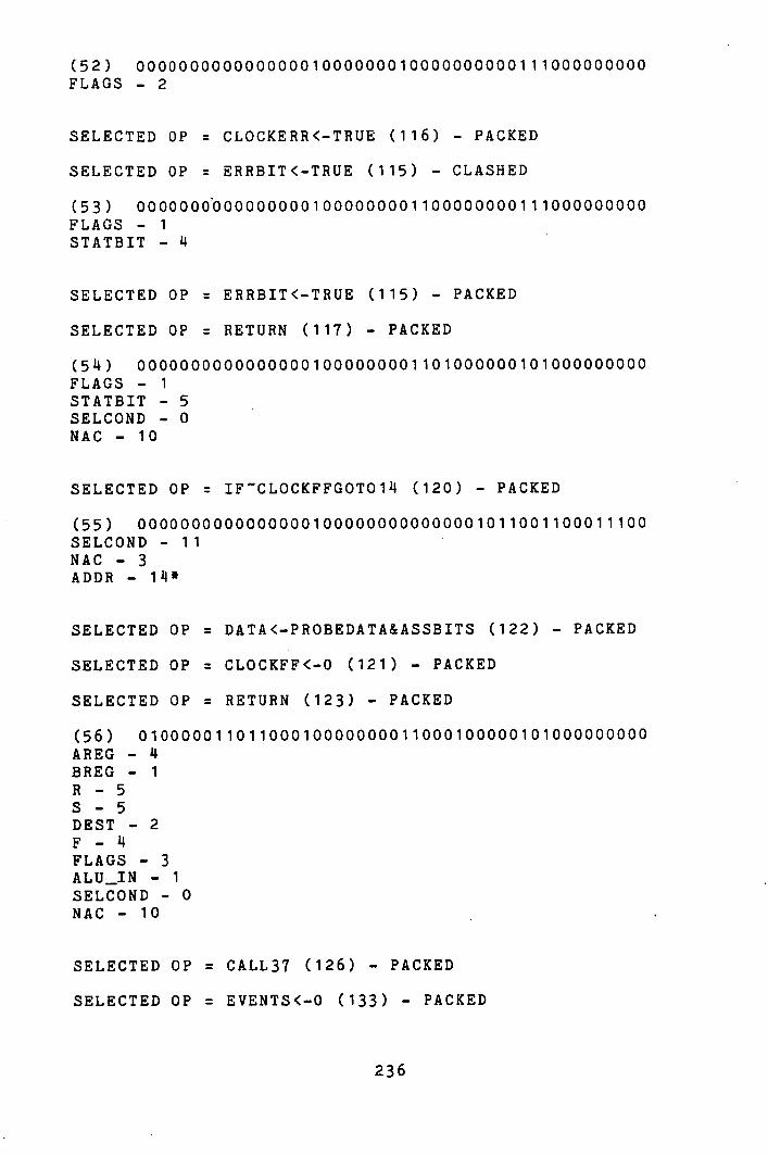
00000000000000001000000010000000000l 11000000000 FLAGS - 2
SELECTED OP = CLOCKERR<-TRUE (116) - PACKED
SELECTED OP = ERRBIT<-TRUE (115) - CLASHED
0000000'OOOOOOOOOlOOOOOOO011O0000000111000000000 FLAGS - 1 STATBIT - LI
SELECTED OP = ERRBIT<-TRUE (115) - PACKED
SELECTED OP = RETURN (117) - PACKED
00000000000000001000000001101000000101000000000 FLAGS - 1 STATBIT - 5 SELCOND - 0 NAC - 10
SELECTED OP = IFCLOCKFFGOT014 (120) - PACKED
00000000000000001000000000 000001011001100011100 SELCOND - 11 NAC - 3 ADDR - 14*
SELECTED OP = DATA<-PROBEDATA&ASSBITS (122) - PACKED
SELECTED OP = CLOCKFF<-0 (121) - PACKED
SELECTED OP = RETURN (123) - PACKED
01000001101100010000000011000100000101000000000 AREG - BREG - 1 R-5 S-5 DEST - 2 F - LI FLAGS - 3 ALU_IN - 1 SELCOND - 0 NAC - lO
SELECTED OP = CALL37 (126) - PACKED
SELECTED OP = EVENTS<-0 (133) - PACKED
236
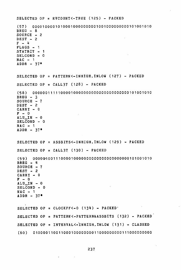
SELECTED OP = EVCOUNT<-TRUE (125) - PACKED
00001000010100010000000001001000000000101001010 BREG - 8 SOURCE - 2 DEST-2 F - FLAGS - 1 STATBIT - 1 SELCOND - 0 NAC - 1 ADDR - 37'
SELECTED OP = PATTERN<-INHIGH.INLOW (127) - PACKED
SELECTED OP = CALL37 (128) - PACKED
00000011111000010000000000000000000000101001010 BREG - 3 SOURCE - 7 DEST - 2 CARRY - 0 F - O ALU_IN - 0 SELCOND - 0 NAC - 1 ADDR - 37*
SELECTED OP = ASSBITS<-INHIGH.INLOW (129) - PACKED
SELECTED OP = CALL37 (130) - PACKED
0000GIOO1110000100000000000000000000001O1001O1O BREG - SOURCE - 7 DEST - 2 CARRY - 0 F - O ALU_IN - 0 SELCOND - 0 NAC - 1 ADDR - 37'
SELECTED OP = CLOCKFF<-0 (1314) - PACKED
SELECTED OP = PATTERN<-PATTERN&ASSBITS (132) - PACKED
SELECTED OP = INTERVAL<-'INHIGH.INLOW (131) - CLASHED
01000011001100010000000011000000000111000000000
237

AREG - BREG - 3 R-1 3-1 DEST - 2 F - k FLAGS - 3
SELECTED OP = IFCLOCKFFGOT016 (136) - PACKED
00000000000000001000000000000001011001100100000 SELCOND - 11 NAC-3 ADDR - 16*
SELECTED OP = INTERVAL<-INHIGH.INLOW (131) - PACKED
SELECTED OP = CLOCKFF<-O (137) - PACKED
00000111111000010000000011000000000111000000000 BREG - 7 SOURCE - 7 DEST-2 CARRY -C F - O FLAGS - 3 ALU_IN - 0
SELECTED OP = CALL39 (lkO) - PACKED
00000000000000.00100 0000000000000000000101001110 SELCOND - 0 NAC - 1 ADDR - 39'
SELECTED OP = RETURNIFBUSYBIT (141) - PACKED
00000000000000001000000000000001010101000000000 SELCOND - 10 NAC - 10
SELECTED OP = INTERVAL<-INTERVAL-1 (1 113) - PACKED
SELECTED OP IFINTERVAL<0G0T017 (1411) - PACKED
0000011101100101000000000000 00 0 0011001100100010 BREG - 7 SOURCE - 3 DEST - 2
238

CARRY - 0 F - i SELCOND - 3 RESULT - 2 NAC - 3 ADDR - 17'
SELECTED OP = IFDATA-PATTERN#OGOT018 (1 1 6) - PACKED
(66) 00110001001001001100000000000000010001100100100 AREG - 3 BREG - 1 R S CARRY - 1 F - i SELCOND - 2 RESULT - 1 NAC - 3 ADDR - 18'
SELECTED OP = EVENTS<-EVENTS+i (147) - PACKED
(67) 000010000110000 1 010 00000000000000 0 0111000000000 BREG - 8 SOURCE - 3 DEST - 2 CARRY F - O
SELECTED OP = CALL39 (149) - PACKED
(68) 00000000000000001000000000000000000000101001110 SELCOND - 0 NAC-i ADDR - 39'
SELECTED OP = RETURNIFBUSYBIT (150) - PACKED
(69) 00000000000000001000000000000001010101000000000 SELCOND - 10 NAC - 10
SELECTED OP = INTERVAL<-INTERVAL-1 (152) - PACKED
SELECTED OP = IFINTERVAL<0G0T017 (153) - PACKED
(70) 00000111011001010000000000000000011001100100010 BREG - 7
239
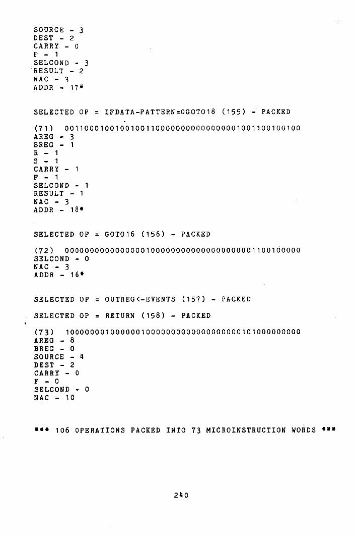
SOURCE - 3 DEST - 2 CARRY - 0 F - i SELCOND - 3 RESULT - 2 NAC - 3 ADDR - 17*
SELECTED OP = IFDATA-PATTERN=OGOT018 (155) PACKED
00110001001001001100000000000000001001100100100 AREG - 3 BREG - i R 3-1 CARRY - 1 F - i SELCOND - 1 RESULT - i NAC-3 ADDR - 18*
SELECTED OP = GOT016 (156) - PACKED
0000000000000000i000000000000000000001 100100000 SELCOND - 0 NAC - 3 ADDR - 16*
SELECTED OP = OUTREG<-EVENTS (157) - PACKED
SELECTED OP = RETURN (158) - PACKED
10000000100000010000000000000000000101000000000 AREG - 8 BREG - 0 SOURCE - DEST - 2 CARRY - 0 F - O SELCOND - 0 NAC - 10
*** 106 OPERATIONS PACKED INTO 73 MICROINSTRUCTION WORDS
20
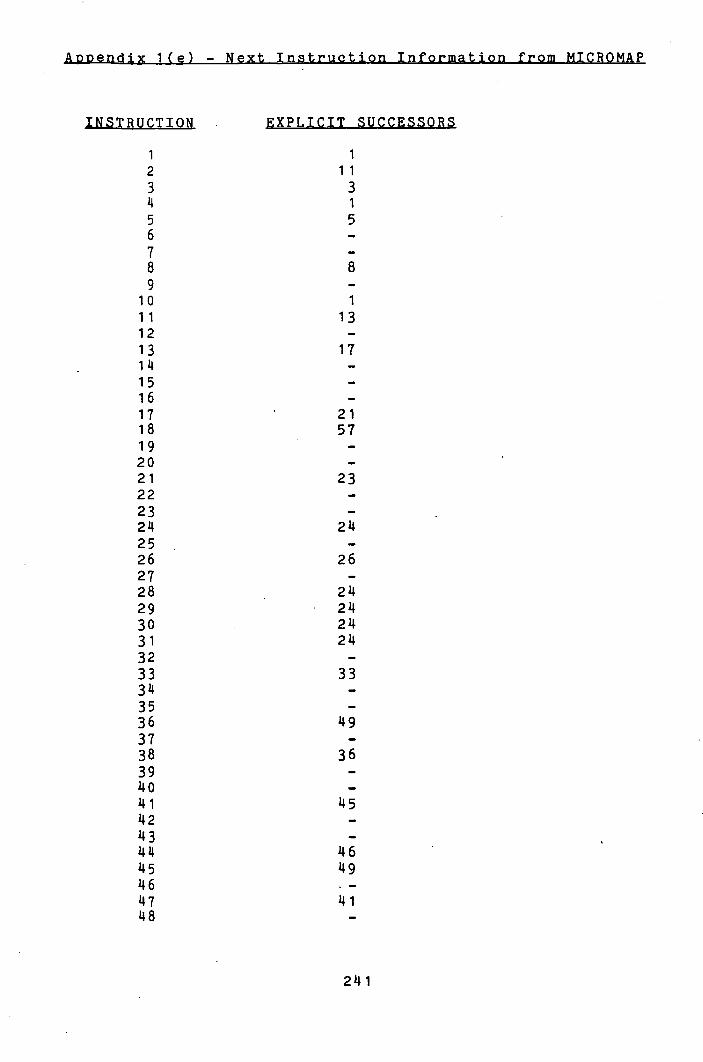
1I.IbT4cIfI-
INSTRUCTION EXPLICIT SUCCESSORS
1 1 2 11 3 3 14 1 5 5 6 -
7 -
8 8 9 -
10 1 11 13 12 -
13 17 114 -
15 -
16 -
17 21 18 57 19 -
20 -
21 23 22 -
23 -
214 214 25 -
26 26 27 -
28 214 29 214 30 214 31 214 32 -
33 33 314 -
35 -
36 149 37 -
38 36 39 -
140 -
141 145 142 -
143 -
1414 146 145 149 146 -
147 141 148 -
241
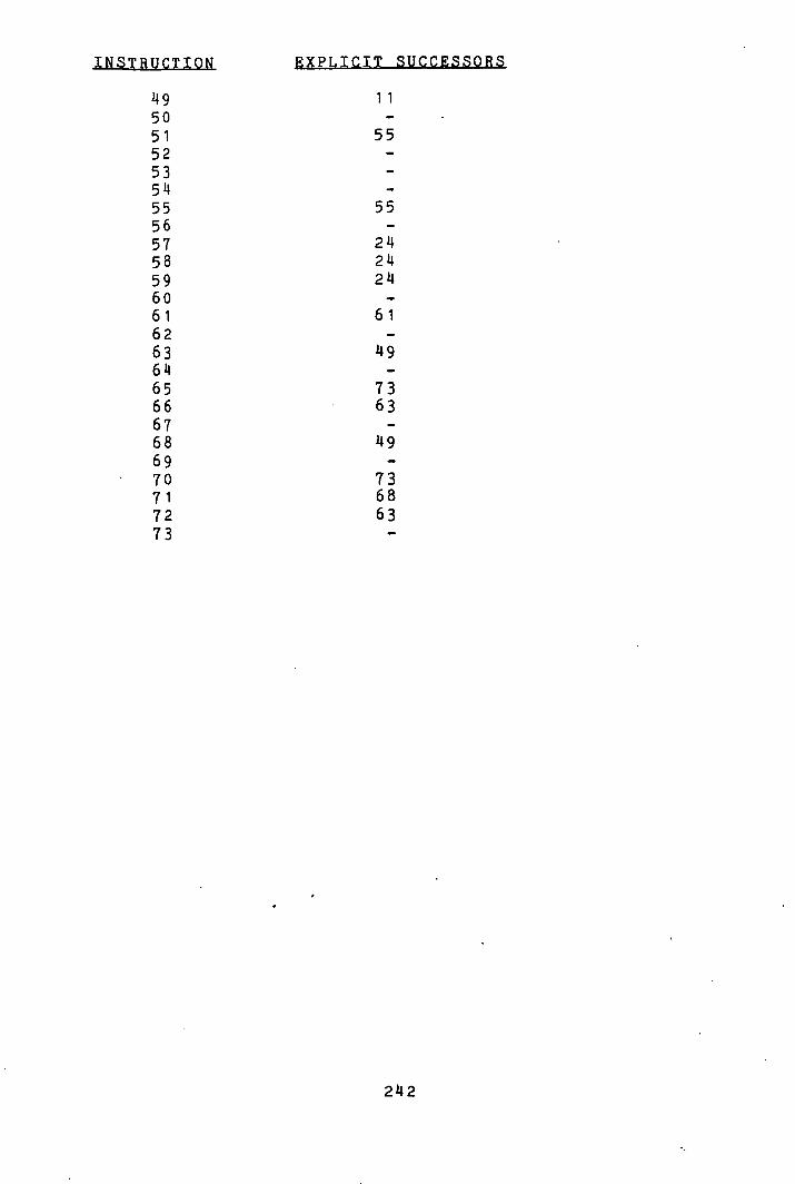
EXPLICIT SUCCESSORS
49 50 51 52 53 514 55 56 57 58 59 60 61 62 63 614 65 66 67 68 69 70 71 72 73
11
55
55
214 214 214
61
73 63
1 9
73 68 63
22
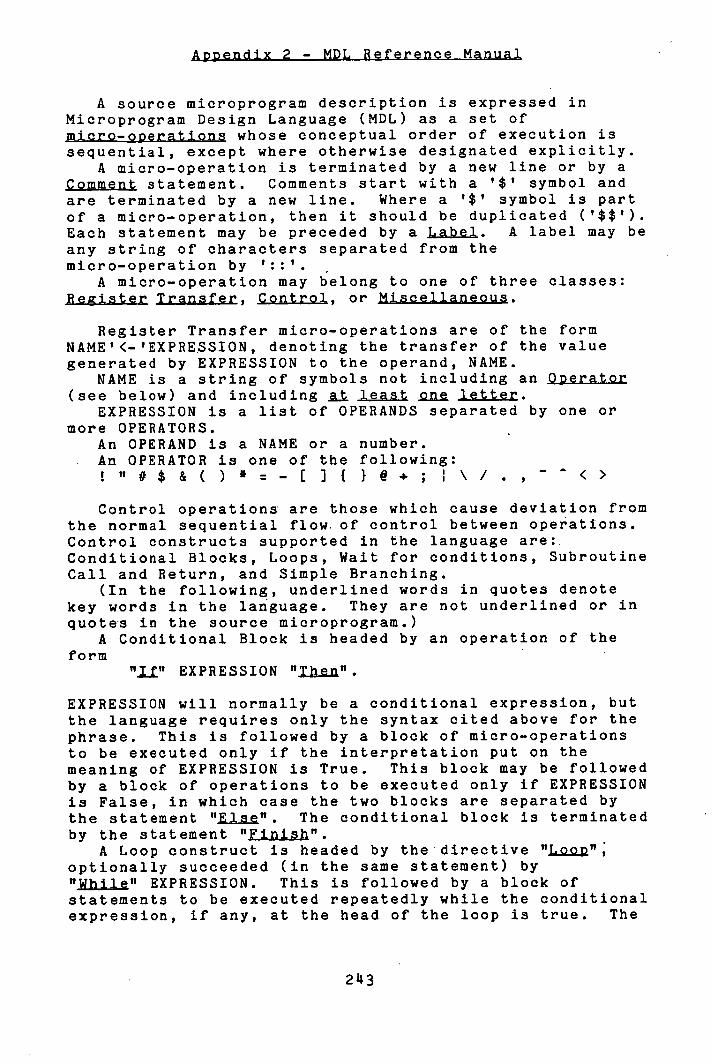
A source microprogram description is expressed in Microprogram Design Language (MDL) as a set of micro-oDeratlons whose conceptual order of execution is sequential, except where otherwise designated explicitly.
A micro-operation is terminated by a new line or by a Comment statement. Comments start with a '$' symbol and are terminated by a new line. Where a '$' symbol is part of a micro-operation, then it should be duplicated (?$$'). Each statement may be preceded by a Label. A label may be any string of characters separated from the micro-operation by '::'.
A micro-operation may belong to one of three classes: Reister Transfer, Control, or Miscellaneous.
Register Transfer micro-operations are of the form NAME'<-'EXPRESSION, denoting the transfer of the value generated by EXPRESSION to the operand, NAME.
NAME is a string of symbols not including an Operator (see below) and including g. least one letter.
EXPRESSION is a list of OPERANDS separated by one or more OPERATORS.
An OPERAND is a NAME or a number. An OPERATOR is one of the following:
" # $ & ( ) * = - i: ] { } @ + ; I \ / . , - < >
Control operations are those which cause deviation from the normal sequential flow, of control between operations. Control constructs supported in the language are:. Conditional Blocks, Loops, Wait for conditions, Subroutine Call and Return, and Simple Branching.
(In the following, underlined words in quotes denote key words in the language. They are not underlined or in quotes in the source microprogram.)
A Conditional Block is headed by an operation of the form
EXPRESSION "Then".
EXPRESSION will normally be a conditional expression, but the language requires only the syntax cited above for the phrase. This is followed by a block of micro-operations to be executed only if the interpretation put on the meaning of EXPRESSION is True. This block may be followed by a block of operations to be executed only if EXPRESSION is False, in which case the two blocks are separated by the statement "Else". The conditional block is terminated by the statement "Finish".
A Loop construct is headed by the directive "Loop" ; optionally succeeded (in the same statement) by "While" EXPRESSION. This is followed by a block of statements to be executed repeatedly while the conditional expression, if any, at the head of the loop is true. The
243
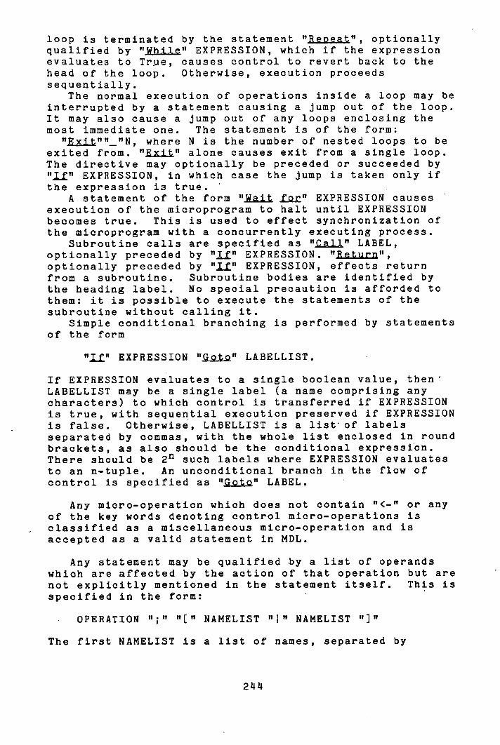
loop is terminated by the statement "Repeat", optionally qualified by "While" EXPRESSION, which if the expression evaluates to True, causes control to revert back to the head of the loop. Otherwise, execution proceeds sequentially.
The normal execution of operations inside a loop may be interrupted by a statement causing a jump out of the loop. It may also cause a jump out of any loops enclosing the most immediate one. The statement is of the form:
"Exit""_"N, where N is the number of nested loops to be exited from. "Exit" alone causes exit from a single loop. The directive may optionally be preceded or succeeded by "11" EXPRESSION, in which case the jump is taken only if the expression is true.
A statement of the form "Wait jj" EXPRESSION causes execution of the microprogram to halt until EXPRESSION becomes true. This is used to effect synchronization of the microprogram with a concurrently executing process.
Subroutine calls are specified as "Call" LABEL, optionally preceded by "j" EXPRESSION. "Return", optionally preceded by "Jj" EXPRESSION, effects return from a subroutine. Subroutine bodies are identified by the heading label. No special precaution is afforded to them: it is possible to execute the statements of the subroutine without calling it.
Simple conditional branching is performed by statements of the form
"j" EXPRESSION "Goto" LABELLIST.
If EXPRESSION evaluates to a single boolean value, then' LABELLIST may be a single label (a name comprising any characters) to which control is transferred if EXPRESSION is true, with sequential execution preserved if EXPRESSION is false. Otherwise, LABELLIST is a list of labels separated by commas, with the whole list enclosed in round brackets, as also should be the conditional expression. There should be 2' such labels where EXPRESSION evaluates to an n-tuple. An unconditional branch in the flow of control Is specified as "Goto" LABEL.
Any micro-operation which does not contain "<-" or any of the key words denoting control micro-operations is classified as a miscellaneous micro-operation and is accepted as a valid statement in MDL.
Any statement may be qualified by a list of operands which are affected by the action of that operation but are not explicitly mentioned in the statement itself. This is specified in the form:
OPERATION ";" "[" NAMELIST "" NAMELIST "]"
The first NAMELIST is a list of names, separated by
244
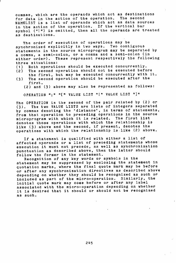
commas, which are the operands which act as destinations for data in the action of the operation. The second NAMELIST is a list of operands which act as data sources in the action of the operation. If the vertical bar symbol ("") is omitted, then all the operands are treated as destinations.
The order of execution of operations may be synchronized explicitly in two ways. Two contiguous statements in the source microprogram may be separated by a comma, a semi-colon, or a comma and a semi-colon (in either order). These represent respectively the following three situations:
Both operations should be executed concurrently. The second operation should not be executed before the first, but may be executed concurrently with It. The second operation should be executed after the first.
(2) and (3) above may also be represented as follows:
OPERATION ";" "[" VALUE LIST "1," VALUE LIST "]"
The OPERATION is the second of the pair related by (2) or (3). The two VALUE LISTS are lists of integers separated by commas denoting the 'distance', in terms of statements, from that operation to preceding operations in the source microprogram with which it is related. The first list denotes those operations with which the relationship is like (3)above and the second, if present, denotes the operations with which the relationship is-like (2) above.
If a statement Is qualified with either a list of affected operands or a list of preceding statements whose execution it must not precede, as well as synchronization punctuation as described above, then the latter should follow the former in the statement.
Recognition of any key words or symbols in the statement may be suppressed by enclosing the statement in quotation marks, where the final quote mark may be before or after any synchronization directives as described above depending on whether they should be recognized as such or Included as part of the micro-operation. Similarly, the initial quote mark may come before or after any label associated with the micro-operation depending on whether it is desired that it should or should not be recognized as such.
245


