Embed Size (px)
Citation preview

EN1740 Computer Aided Visualization and Design
Spring 2012
EN1740, S2012BCB – Feb. 14, 2012
2/14/2012
Brian C. P. Burke

Last time:
• Parent – Child
Tonight:
• Measuring within Pro/E
• 2D representation
• Orthographic projection
• 3rd Angle vs. 1st Angle
• Creating engineering drawings
EN1740, S2012BCB – Feb. 14, 2012
• Creating engineering drawings
READING ASSIGNMENT:
Please read Chapt. 3 in Wilson

Measure
• Analysis >
Measure
• There are a
number of measure
options available
EN1740, S2012BCB – Feb. 14, 2012
options available

Measure - Length
• Analysis > Measure > Length
• Select a line entity
EN1740, S2012BCB – Feb. 14, 2012

Measure – DistanceThis options gives the most options
• Analysis > Measure >
Distance
• Any entity can be selected
=> Curve, Plane, Axis,
EN1740, S2012BCB – Feb. 14, 2012
Edge, Surface
• NOTE: UNLESS GOING
PLANE TO PLANE,
SHORTEST DISTANCE IS
REPORTED

Measure – DistanceThis options gives the most options
• At times, a projection
reference is required
EN1740, S2012BCB – Feb. 14, 2012
Measuring from top to edge of through hole without projection reference

Measure – DistanceThis options gives the most options
• Adding the center axis as
a projection reference gives
the vertical distance
EN1740, S2012BCB – Feb. 14, 2012
Measure – Angle
EN1740, S2012BCB – Feb. 14, 2012

Measure – DiameterVery useful
EN1740, S2012BCB – Feb. 14, 2012

H P la n e
V Plane
Orthographic Views
Projection Planes and Quadrants
EN1740, S2012BCB – Feb. 14, 2012
R ig h t P ro fi leP la n e

vertical projection plane
ObserverFirst Angle Projectionstandard in EU/Asia
Orthographic Views
EN1740, S2012BCB – Feb. 14, 2012
Q I Q II
Q IV Q IIIObserver
horizontal projection plane
Third Angle Projectionstandard in US

Flipping of planes into Front View (Vertical) Planefor drawing onto a sheet of paper
Orthographic Views
THIRD ANGLE FIRST ANGLE
EN1740, S2012BCB – Feb. 14, 2012

Top
Third Angle Views of an Object
Orthographic Views
EN1740, S2012BCB – Feb. 14, 2012
Front Right

TOP ViewPerspective orany other view
Engineering Drawing in third angle projection
Orthographic Views
EN1740, S2012BCB – Feb. 14, 2012
TOP View
FRONT View RIGHT View
any other view
PART xyz

FRONT View RIGHT View
Engineering Drawing in first angle projection
Orthographic Views
EN1740, S2012BCB – Feb. 14, 2012
TOP ViewPerspective orany other view
PART xyz

Orthographic Views
Third Angle Views
EN1740, S2012BCB – Feb. 14, 2012
First Angle Views

EXERCISE – Create a drawing
Open piston.prt
EN1740, S2012BCB – Feb. 14, 2012

EXERCISE – Create a drawingCreate a new drawing:
• File > New
• Select the Drawing radio button
• Type the name of the part
(piston) so the files can be easily
associated
EN1740, S2012BCB – Feb. 14, 2012
associated

EXERCISE – Create a drawing
Make sure you’ve got the right part
Select “Empty with Format”
Click the Browse button
Select c.frm
Click Open
2
3
4
5
1
1
2
EN1740, S2012BCB – Feb. 14, 2012
Click Ok62
34
5
6

EXERCISE – Create a drawingCreate a General View:
• RMB
• Insert General View…
• LMB where the center of
the first view should appear
EN1740, S2012BCB – Feb. 14, 2012

EXERCISE – Create a drawingOur component appears with the Drawing View dialog box
EN1740, S2012BCB – Feb. 14, 2012

EXERCISE – Create a drawing
In Drawing View dialog:
• Select View Type
• In the View Orientation
section select the FRONT
model view
• Select Apply
EN1740, S2012BCB – Feb. 14, 2012
• Select Apply

EXERCISE – Create a drawing
Click on View Display
Select No Hidden from Display
style
Select Dimmed from the Tangent
edges display style
2
3
4
1
1
2
3
EN1740, S2012BCB – Feb. 14, 2012
Click Ok1
4

EXERCISE – Create a drawing
Create a Projected View:
• RMB and Hold on original
view
• Scroll down and LMB on
Insert Projection View…
• LMB on location where
EN1740, S2012BCB – Feb. 14, 2012
• LMB on location where
center of Project View
should be
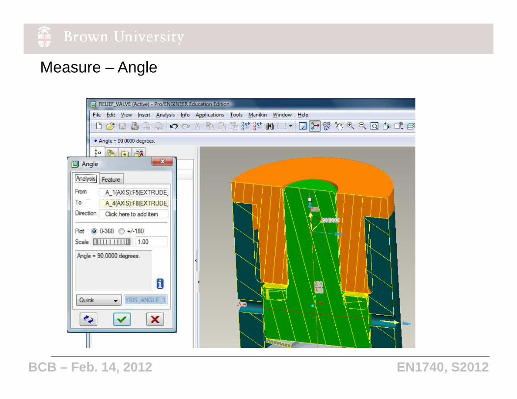
EXERCISE – Create a drawing
Set view properties:
• View display
• Set Display style to No
Hidden
• Set Tangent edges
display style to Dimmed
EN1740, S2012BCB – Feb. 14, 2012
display style to Dimmed
• Click OK

EXERCISE – Create a drawing
Create ANOTHER Projected View:
• RMB and Hold on second view
• Scroll down and LMB on Insert
Projection View…
• LMB on location where center of
Project View should be
EN1740, S2012BCB – Feb. 14, 2012
Project View should be

EXERCISE – Create a drawing
Set view properties again:
• RMB, Properties
• View display
• Set Display style to No
Hidden
• Set Tangent edges
EN1740, S2012BCB – Feb. 14, 2012
• Set Tangent edges
display style to Dimmed
• Click OK

EXERCISE – Create a drawing
• Turn off the display of:
• Datum Planes
• Datum Axes
• Datum Points
• Coordinate Systems
• Repaint
EN1740, S2012BCB – Feb. 14, 2012
• Repaint
YOUR SCREEN SHOULD
LOOK LIKE THIS.

View > Show and Erase
In the Show/Erase dialog:
Click Show
Click the dimension icon
Click the Axis icon
2
3
4
1
EXERCISE – Create a drawing2
34
1
EN1740, S2012BCB – Feb. 14, 2012
Click Show All
Answer Yes….. (cont.)
5
6
5
6

EXERCISE – Create a drawing
• Click Accept All
• Click Close
• Click anywhere in the graphics
window to deselect dimensions and
axes
EN1740, S2012BCB – Feb. 14, 2012

EXERCISE – Create a drawing
• Move dimension, clip witness lines
and erase unnecessary dimensions
EN1740, S2012BCB – Feb. 14, 2012