Embed Size (px)
Citation preview
The effects of electron thermal radiation on laser ablative shock waves from aluminumplasma into ambient airS. Sai Shiva, Ch. Leela, P. Prem Kiran, C. D. Sijoy, and S. Chaturvedi Citation: Physics of Plasmas 23, 053107 (2016); doi: 10.1063/1.4948491 View online: http://dx.doi.org/10.1063/1.4948491 View Table of Contents: http://scitation.aip.org/content/aip/journal/pop/23/5?ver=pdfcov Published by the AIP Publishing Articles you may be interested in Dynamics of plasma expansion and shockwave formation in femtosecond laser-ablated aluminum plumes inargon gas at atmospheric pressures Phys. Plasmas 21, 043111 (2014); 10.1063/1.4873701 Understanding plume splitting of laser ablated plasma: A view from ion distribution dynamics Phys. Plasmas 20, 113512 (2013); 10.1063/1.4835255 Ultraviolet versus infrared: Effects of ablation laser wavelength on the expansion of laser-induced plasma intoone-atmosphere argon gas J. Appl. Phys. 111, 053301 (2012); 10.1063/1.3689300 Analysis of laser ablation: Contribution of ionization energy to the plasma and shock wave properties J. Appl. Phys. 102, 043103 (2007); 10.1063/1.2761827 Laser absorption, mass ablation rate, and shock heating in direct-drive inertial confinement fusiona) Phys. Plasmas 14, 056305 (2007); 10.1063/1.2671690
Reuse of AIP Publishing content is subject to the terms at: https://publishing.aip.org/authors/rights-and-permissions. Downloaded to IP: 14.139.69.168 On: Fri, 27 May
2016 08:51:23

The effects of electron thermal radiation on laser ablative shock waves fromaluminum plasma into ambient air
S. Sai Shiva,1 Ch. Leela,1 P. Prem Kiran,1,a) C. D. Sijoy,2,b) and S. Chaturvedi21Advanced Centre of Research in High Energy Materials (ACRHEM), University of Hyderabad,Prof. C. R. Rao Road, Gachibowli, Hyderabad 500046, India2Computational Analysis Division, Bhabha Atomic Research Centre (BARC), Visakhapatnam, India
(Received 3 February 2016; accepted 18 April 2016; published online 10 May 2016)
The effect of electron thermal radiation on 7 ns laser ablative shock waves from aluminum (Al)
plasma into an ambient atmospheric air has been numerically investigated using a one-
dimensional, three-temperature (electron, ion, and radiation) radiation hydrodynamic code MULTI.
The governing equations in Lagrangian form are solved using an implicit scheme for planar,
cylindrical, and spherical geometries. The shockwave velocities (Vsw) obtained numerically are
compared with our experimental values obtained over the intensity range of 2.0� 1010 to
1.4� 1011 W/cm2. It is observed that the numerically obtained Vsw is significantly influenced by
the thermal radiation effects which are found to be dominant in the initial stage up to 2 ls depend-
ing on the input laser energy. Also, the results are found to be sensitive to the co-ordinate geometry
used in the simulation (planar, cylindrical, and spherical). Moreover, it is revealed that shock wave
undergoes geometrical transitions from planar to cylindrical nature and from cylindrical to spheri-
cal nature with time during its propagation into an ambient atmospheric air. It is also observed that
the spatio-temporal evolution of plasma electron and ion parameters such as temperature, specific
energy, pressure, electron number density, and mass density were found to be modified signifi-
cantly due to the effects of electron thermal radiation. Published by AIP Publishing.[http://dx.doi.org/10.1063/1.4948491]
I. INTRODUCTION
The interaction of pulsed lasers with solid targets leads
to the ablation of material followed by the generation of
shock waves (SW) into an ambient atmosphere. The ablation
of materials had proven to be a promising technique for the
applications such as deposition of thin films,1 generation of
nanoparticles,2 and study of elemental and chemical analysis
of materials using laser induced breakdown spectroscopy
(LIBS).3 Similarly, the laser generated SW found applica-
tions, such as strengthening of material, using laser shock
peening (LSP)4 test the response of bulk materials to gener-
ate Equation-of-State (EOS) using dynamical loading,5
micro-propulsion,6 inertial confinement fusion (ICF),7 and
also in medicine.8 In the SW based applications, it is very
important to understand the spatio-temporal behavior of the
SW under different ambient conditions. In contrast to the
conventional impact experiments, where the material
responses are investigated at longer times with LISW, the
investigations may be done for shorter (ns to ls) time scales.
The ablative shockwave expanding into ambient air
launches a compression wave through the material due to
momentum conservation. Hence, understanding of laser ab-
lative shock wave (LASW) will help get an insight into the
shock propagation through target material. The challenge of
the laser induced dynamic loading is to understand the pla-
narity of the SW propagating into the target material. As the
imaging of shockwaves through an opaque target is challeng-
ing, understanding the evolution of ablative SW into the am-
bient atmospheric medium to estimate the propagation of
SW launched into the target of interest is an alternative
method. The investigation of shock planarity is important for
the generation of EOS of different materials based on which
novel materials can be designed for the applications of space
science, ICF, and material science. In all these applications
except in medicine, the incident laser energies range over
few J to kJ with the intensity >1013 W/cm2, and the SW gen-
erated are in few MPa–GPa. Due to very high intensity
range, the radiation effects may strongly influence the SW
propagation. Many authors9–14 have obtained the scaling
laws for ablative pressures that are observed to be largely de-
pendent on the laser Intensity, wavelength, and material
properties. Such scaling laws proved to be very useful to
estimate the laser ablative implosion and explosion pressures
of different materials. Of course, these studies are based on
several assumptions and have certain limitations. For exam-
ple, the radiation losses and its influence on SW evolution
are discussed sparsely. Despite these, a decent agreement of
the experiments results with the scaling laws is observed. In
medicinal applications for the ns pulse widths and the mate-
rial considered, laser energies (few mJ) and intensities
(<1010 W/cm2) are very low compared to that used for ICF
and EOS applications. The SW generated in this case will be
weak (few MPa) with almost negligible radiation influence.
The expansion dynamics of laser ablated plasma and
shock waves depends on various parameters, such as the
input laser intensity, wavelength, pulse duration, ablated
a)Author to whom correspondence should be addressed. Electronic
addresses: [email protected] and [email protected])Electronic addresses: [email protected] and [email protected].
1070-664X/2016/23(5)/053107/14/$30.00 Published by AIP Publishing.23, 053107-1
PHYSICS OF PLASMAS 23, 053107 (2016)
Reuse of AIP Publishing content is subject to the terms at: https://publishing.aip.org/authors/rights-and-permissions. Downloaded to IP: 14.139.69.168 On: Fri, 27 May
2016 08:51:23

material properties, and on the pressure and mass concentra-
tions of the ambient atmosphere. Due to transient nature of
the laser pulse intensity, various physical processes occur dur-
ing laser interaction, viz., target heating, melting, evaporation,
ionization,15 phase explosion,16–18 and formation of plasma.
After the termination of the laser pulse, the plasma expands
adiabatically leading to the generation of shock wave (SW)
that propagates supersonically into ambient gas. Due to multi-
ple physical processes occurring during and after the laser
pulse, the physics of laser generated plasma and SW has
become a complex subject to understand. Numerous reports
have experimentally demonstrated the ablated plasma dynam-
ics in vacuum and by taking into account the effects of differ-
ent background gases (He, N, O2, Ar, air)19–23 over a pressure
range of 1–105 Pa.24–38 These experiments revealed some of
the important physical phenomena such as the free or adia-
batic expansion39 of the plume into vacuum, splitting and
sharpening23,24,40 of plume into different species at moderate
pressures (low pressures) with low and high mass particles
moving with different velocities, generation and confinement
of SW and plume29–32,34 at ambient pressures due to collisions
between the plasma particles and ambient gas.
Intensive numerical efforts have been made using models
based on the thermo-optics or hydrodynamics or the combina-
tion of both38,39,41–44 to understand the fundamentals of
laser–target, laser–plasma interaction, and ablation processes
occurring during and after the termination of laser pulse.
Bogaerts and Chen38 had numerically investigated the influ-
ence of laser parameters on target melting, evaporation, plume
dynamics, and compared with the experimental results. Jeong
et al.44 studied the effects of the ambient pressure and the
laser fluence on the vapor expansion. Singh and Narayan39
studied the physical phenomena involved in the laser–target
interaction process and demonstrated that the ablated material
undergoes isothermal and adiabatic processes during and after
the termination of laser pulse. Amoruso42 had investigated the
ablation of material by taking into consideration of photo-
ionization and inverse bremsstrahlung (IB). Gragossian
et al.18 had revealed that at intensities higher than the break-
down thresholds, the ablated material undergoes phase explo-
sion.18 Overall, in the initial laser–target–plasma interaction,
the plasma dynamics was observed to be strongly dependent
on the laser wavelength, laser fluence, and ambient gas condi-
tions. Few reports30–32 examined the plasma expansion and
Yoh et al. has provided a trivial solution to the expansion of
SW such as planar (hemi-spherical) expansion during the ini-
tial times and spherical expansion at later times. The impor-
tance of the electron thermal radiation (ETR), the amount of
radiation emitting, and different types of emissions occurring
from laser produced plasma show that the ETR from ablated
plasma increases proportionally with increasing laser energy.
Moreover, due to radiation emissions, the plasma temperature
was found to decrease to that without ETR effects.30,37,45–49
Though, the effects of ETR on the plasma parameters such as
the electron number density and temperature (ne and Te) are
explained, but the deeper insight of the spatial and temporal
behavior of the plasma dynamics and the influence of electron
thermal radiation (ETR) on SW evolution for longer durations
of time were not reported so far.
In this paper, a detailed study of the plasma dynamics,
SW evolution with and without ETR effects, and its influ-
ence on the geometrical transitions of SWs for longer dura-
tions of time will be discussed. The expansion features of the
plasma and laser ablative shockwaves (LASW), from alumi-
num target into ambient atmospheric air, were numerically
studied using modified 1D-RHD MULTI-fs50 code. This
Lagrangian code is widely used for laser ablation studies
from nanosecond to femtosecond duration of pulses which
has the option to perform simulations in three different geo-
metries, viz., planar, cylindrical, and spherical. Hence, simu-
lations have been carried out using three geometries for the
intensities ranging from 2.0� 1010 to 1.4� 1011 W/cm2 and
time durations of up to 8.0 ls. The temporal evolution of
shock velocity Vsw is compared using three geometries by
considering with and without ETR effects. This is followed
by studying the influence of ETR on the spatial evolution of
the flow properties of electron and ion temperatures (Te, Ti),
specific energies (Ee, Ei), pressures (Pe, Pi), electron number
density (ne), and mass density (q). Finally, the temporal evo-
lution of plasma parameters such as ne, Te with and without
ETR and the temporal evolution of the mass density in the
core plasma and across the shock front (SF) are presented.
II. NUMERICAL MODEL AND METHODOLOGY
The schematic of laser–target and laser–plasma interac-
tion (Fig. 1(a)) shows the expansion of internal plasma core
and outer region, contact front (CF), shock wave (SW) into
ambient air, radiation emission from the ablated plasma and
its interaction with SWs. The sequential order of different
physical processes occurring during the laser pulse (up to 15
ns) and post the laser pulse (>15 ns) is depicted in Fig. 1(b).
For a self-consistent simulation of these physical proc-
esses, we have used a one dimensional, Lagrangian, three
temperature (electron, ion, and radiation) radiation hydrody-
namic (1D–RHD) MULTI-fs50 code. The code considers
electrons and ions as different species with different energy
equations. However, plasma is assumed to have a single fluid
velocity (u) and mass density (q).50
The governing RHD equations to describe the temporal
evolution of laser ablated plasma and SW are given by
DqDt¼ �q�$:�u; (1)
qD�u
Dt¼ ��$ Pe þ Pi þ Pvð Þ; (2)
qDEe
Dt¼ �Pe
�$:�u � Kth�$Te þ uei þ kIBIL � �Qrad; (3)
qDEi
Dt¼ � Pi þ Pvð Þ�$:�u � uei þ kIBIL: (4)
The operator DDt� @
@tþ �u:�$ denotes the time derivation in a
fluid frame of reference (Lagrangian derivative). This repre-
sents the material derivative of the fluid. The variables in
Equations (1)–(4) account for mass density (q), fluid velocity
ð�uÞ, viscous pressure (Pv) acting on ions, electron and ion
pressures (Pe & Pi), electron and ion specific energies (Ee &
Ei), and electron and ion temperatures (Te & Ti). Different
053107-2 Sai Shiva et al. Phys. Plasmas 23, 053107 (2016)
Reuse of AIP Publishing content is subject to the terms at: https://publishing.aip.org/authors/rights-and-permissions. Downloaded to IP: 14.139.69.168 On: Fri, 27 May
2016 08:51:23

physical mechanisms involved during the laser–matter inter-
action and after termination of laser pulse are incorporated in
energy equations (3) and (4). kIB accounts for laser absorp-
tion coefficient due to inverse-bremsstrahlung of electro-
n–ion (e-i) collisions, Kth is the heat conduction coefficient
due to electron–ion (e-i)50 and electron to neutrals (e-n) col-
lisions (Kth¼KeiþKen),42,51,52 �Qrad accounts for radiation
losses, and uei is the energy relaxation between electron and
ion. The radiation term is solved by the multi-group approxi-
mation method. The Planck and Rosseland mean opacities,
charge state, and QEOS data of Al50,53 target provided in the
original code are used. The initial total electron number den-
sity (ne) and mass density (q) of Al are taken as
1.39� 1029 m�3 as 2700 kg/m3, respectively.
A. Modifications to MULTI-fs code
The original MULTI-fs code was developed for laser abla-
tion studies of different materials in vacuum. As our experi-
ments were carried out in ambient atmospheric air, the code has
been modified according to the experimental conditions, and a
separate routine for air is introduced as the background medium.
In order to close those equations an EOS model for each mate-
rial is required. We have assumed air as ideal gas with charge
state ionization taking into account. So, the EOS is given by51
P ¼ Nð1þ aÞkbT: (5)
The equation will have two contributions: one for the elec-
tron pressure Pe and the other for ion pressure Pi
Pe ¼ NakbTe; (6)
Pi ¼ NkbTi: (7)
Assuming air to be ionized thermally and singly ionized, we
have adopted Saha51 relation to obtain the charge state a,given by
a2
1� a¼ 1
N2AT3=2
e exp�Ip
kBTe
� �; (8)
where N is the local neutral number density, A ¼ 2pmekb
h2
� �3=2
is a constant, and Ip is the first ionization potential of oxygen
taken to be equal to 14.56 eV (Ref. 51) by assuming the con-
tribution of nitrogen atoms is negligible. The electron and
ion temperatures (Te and Ti) of the gas, are obtained, respec-
tively, from the electron and ion pressures (Pe and Pi)
Te ¼Pe
Nakb; (9)
Ti ¼Pi
Nkb: (10)
The deposition of laser energy into Al is modeled following
the WKB approximation.50
III. EXPERIMENTAL DATA AND RESULTS
The experimental setup for capturing spatio-temporal
evolution of plasma plume and LASW from laser ablation of
aluminum is described elsewhere.54–56 The target is ablated
using 7 ns (FWHM) second harmonic of Q-switched Nd:YAG
at 532 nm. The beam was focused onto the target surface
using a plano-convex lens with f/10 focusing geometry. The
experiments were carried out for laser energies varied in the
range of 25 mJ–175 mJ that are focused to a diameter of
approximately 140 6 10lm giving rise to intensities in the
range of 2.0� 1010 to 1.4� 1011W/cm2. All experiments
were carried out in ambient air at room temperature and
atmospheric pressure.
Figures 2(a) and 2(b) show the shadowgraph images of
the spatio-temporal evolution of the shock front (SF) along
normal to the target and in the radial direction into ambient
air at 2.2 ls and 5.4 ls, after the laser pulse interaction at
FIG. 1. (a) Schematic of laser–target
interaction and SW propagation in an
ambient air. (b) Different processes
occurring during and following the
laser pulse leading to geometrical tran-
sitions in SW during its evolution.
053107-3 Sai Shiva et al. Phys. Plasmas 23, 053107 (2016)
Reuse of AIP Publishing content is subject to the terms at: https://publishing.aip.org/authors/rights-and-permissions. Downloaded to IP: 14.139.69.168 On: Fri, 27 May
2016 08:51:23

25 mJ. The velocity (Vsw) of the SF with respect to the target
position was measured over the time scales 0.4 ls–8.0 ls.
The 2D self-emission representing the expansion of ablative
plasma into ambient atmospheric air at 50 ns and 2 ls is
shown in Figs. 2(c) and 2(d). The correlation between the
evolution of the SW and the ablative plasma decay is shown
in Fig. 2.
IV. COMPARISON OF SIMULATIONS WITHEXPERIMENTS
A. Effects of electron thermal radiation (ETR) on SWevolution and geometrical transitions
Figures 3(a)–3(d) compare the shock front (SF) velocity,
Vsw, of experiments with numerical simulations with and
without ETR effects for lower (25 mJ and 75 mJ) and higher
(125 mJ and 175 mJ) laser energies used in our study. The
compared velocities show that the SF undergoes geometrical
transitions from planar to cylindrical (PN-CN) and from
cylindrical to spherical nature (CN-SN) during its evolution.
Table I summarizes the timesscales SF undergoes transition
from PN-CN and CN-SN during the evolution.
The existence of PN is observed dominantly up to
�0.8 ls for 25 mJ and �0.6 ls for 75 mJ without electron
thermal radiation (NO-ETR) effects, whereas with ETR, PN
existed up to �0.6 ls for 25 mJ and �0.4 ls for 75 mJ. The
shock velocity (Vsw) for 25 mJ at 1 ls with ETR is found to
be higher �4.5 km/s than that of without ETR �3.5 km/s.
Similarly, at 75 mJ, this is observed to be �7.0 and �5.5 km/
s, respectively. This significant difference in the shock veloc-
ity shows that ETR plays a crucial role in driving the SW
into ambient air during its evolution. The existence of PN at
higher energies was not observed for the longer times
(>0.4 ls). This nature may exist at even lower timescales.31
The PN of the SF is followed by the CN which is
observed to exist for both lower (Figs. 3(a) and 3(b)) and
higher (Figs. 3(c) and 3(d)) energies. At lower energies, the
CN exists between 1 and 1.5 ls, while at higher energies, it
FIG. 2. (a) and (b) Shadowgrams of spatio-temporal evolution of shock front (SF) and contact front (CF) at 2.2 ls and 5.4 ls, respectively. (c) and (d) 2D Self-
emission images of Al II (466.3) species at 50 ns and 2 ls delay for input laser energy of 25 mJ. Figures were taken from Refs. 55 and 56. Solid arrow indicates
the laser propagation direction (a) and (c), and dashed arrows indicate SF and CF evolution (in Fig. 2(a)).
053107-4 Sai Shiva et al. Phys. Plasmas 23, 053107 (2016)
Reuse of AIP Publishing content is subject to the terms at: https://publishing.aip.org/authors/rights-and-permissions. Downloaded to IP: 14.139.69.168 On: Fri, 27 May
2016 08:51:23

exists up to �2.0 ls. The difference in the shock velocity
with and without ETR at lower energies is observed to be
very small indicating that the radiation losses have become
negligible. However, at higher energies, a clear difference in
the Vsw is seen with and without ETR effects. At 2 ls, Vsw
values for 125 mJ with and without ETR have �3.5 and
�2.7 km/s, respectively, whereas for 175 mJ, the Vsw� 4.0
and �3.0 km/s, respectively. With increasing laser energy,
the difference in shock velocities shows that radiation plays
a crucial role even up to longer time scales (up to 2.0 ls).
The influence of ETR up to longer times resulting in the
increase of laser energy absorption by the ablated plasma.44
The CN of the SF is observed to instantaneously become SN
for all the laser energies considered. This nature is found to
originate around 2 ls for lower energies and around
1.5–1.6 ls for higher energies. The difference in Vsw during
this nature is observed to be small at higher and lower ener-
gies indicating that the radiation becoming negligible after
2 ls. The SN of the SF signifies that the plasma and SF evo-
lution have become symmetric and expand with uniform ve-
locity in all the directions.
The existence of PN at lower energies is due to low
absorption of laser energy by the ablated plasma as a result
the plasma occupies small volume and mostly resides on the
target surface. Moreover, due to high expansion speed
towards normal to the target direction, the SF appears to be
of PN. The plasma and SF expansion may be assumed as the
1D flow. However, at later times due to confinement of the
plasma and SF by the ambient gas, the expansion speed nor-
mal to the target becomes comparable to the radial direction
and expands uniformly in 2D and 3D giving rise to CN
and SN.
At higher energies due to increase in the laser energy
absorption, the ablated plasma occupies higher volume com-
pared to that of lower energies. Due to this, the expansion of
the SF becomes significant in both directions, and as a result,
FIG. 3. Comparison of experimentally
obtained shock wave velocity(open
circles) with numerical data with and
without ETR effects for the input laser
energies of (a) 25 mJ, (b) 75 mJ, (c)
125 mJ, and (d) 175 mJ using planar,
cylindrical, and spherical geometries.
TABLE I. SW transition times from PN-CN and from CN-SN with ETR effects.
Laser
energy (mJ)
Existence
of PN, tPN (ns)
Time taken to transit
from PN-CN (tPN-tCN) (ns)
Existence
of CN, tCN (ls)
Time taken to transit
from CN-SN (tCN-tSN) (ls)
Existence
of SN, tSN (ls)
% of absorptions
taken in simulations
% of threshold
absorption (Ath)
25 �600 �600 �1.2–2.2 Instantaneous �2.2 15–18 12
75 �400 �600 �1.2–2.0 Instantaneous �2.0 23–25 9
125 <100 �400 <1.2 Instantaneous �1.2 35–38 8
175 <100 �400 <1.2 Instantaneous �1.2 45–48 8
053107-5 Sai Shiva et al. Phys. Plasmas 23, 053107 (2016)
Reuse of AIP Publishing content is subject to the terms at: https://publishing.aip.org/authors/rights-and-permissions. Downloaded to IP: 14.139.69.168 On: Fri, 27 May
2016 08:51:23

the SF appears to follow CN from 0.4 to 1.6 ls and SN after
2 ls. The plasma and SF expansion will have 2D or 3D flow.
The similar flow field conditions are also observed from
shadowgraph images (not given in this paper) taken experi-
mentally.56 Due to increase in the laser energy absorption,
the ETR also increases and lasts for longer timescales (up to
2 ls). The increase in the shock velocity with ETR is due to
rise in the temperature of the surrounding gas. The radiation
emitting from the plasma interacts with the surrounding air
resulting in pre-heating of the gas. Due to this process, the
SF moves quickly because the propagation speed of the SF is
proportional to the temperature. This process continues as
long as the radiation is dominant.
The fraction of laser energy absorbed to the total laser
energy taken in the simulations is summarized in Table I for
incident laser energies 25–175 mJ. These values were in
agreement with the values given by Kundu57 where the time
dependent electron–ion collision frequency of underdense
plasma (closer to our experimental conditions) is observed to
affect the mass ablation rate and its scaling. Table I also
summarizes the fraction of threshold absorptions where the
radiation heating starts affecting the SW propagation. Figs.
4(a) and 4(b) show the comparison of shock velocities (VSW)
with and without radiation effect for 25 and 175 mJ energies,
respectively. At 25 mJ, for 10% absorption, the radiation is
not observed to influence the shock velocity (Vsw), but as the
absorption is increased to 12%, a slight increase in Vsw with
radiation can be seen (Fig. 4(a)). Similarly, for 175 mJ, the
radiation heating starts affecting from 8% onwards, and with
the increased absorption (12%), the radiation heating
becomes dominant (Fig. 4(b)). At 25 mJ, the radiation heat-
ing shows its influence on the shock velocity at >12% of
absorption. At 75 mJ, the radiation effects can be seen from
9% onwards. Similarly at higher laser energies (125 and
175 mJ), this can be seen at even low absorptions �8%. This
is obvious because with increasing laser energy, the peak in-
tensity also increases and the breakdown threshold of the tar-
get material occurs at the very initial part of the laser pulse.
Hence, with the increasing laser energy, the radiation heating
effects starts occurring at lower threshold absorptions.
As given in Table I, the transition in SF from PN to CN
is not continuous at lower laser energies, that is, SW has
taken certain time to convert from PN to CN while the transi-
tion from CN to SN is observed to be instantaneous for all
the energies considered. Overall, the effect of ETR has
played a crucial role in the evolution of SF. This effect is
predominant at higher laser energies and lasts up to longer
timescales (2 ls). The ETR effect on the evolution of the SF
was found to be dominant for planar evolution compared to
that of cylindrical and spherical evolution. The influence of
radiation on SF evolution is dominant as long as the radiation
emissions are dominant.
The shift of SW from planar to spherical nature can be
explained using (i) the ratio of characteristic plasma length
(L) to the laser spot size (2x0),12 (ii) the dependence of laser
absorption coefficient on the excitation wavelength,29 and
(iii) lateral transport of thermal energy and the lateral flow of
mass.14 According to Mora,12 the initial plasma expansion is
decided by the absorbed laser energy, pulse duration, and the
focal spot diameter. For a plane, self-similar expansion of
isothermal plasma in vacuum is determined by the character-
istic scale length (L) with the condition that L is less than the
spot diameter (2x0)
L ¼ Css ¼ZTe
mi
� �12
s; (11)
where Cs is the ion acoustic velocity, Te is the electron tem-
perature in eV, mi is the ion mass, A is the mass number, mp
is the proton mass, and s is the laser pulse width.
FIG. 4. Shock velocity comparison at
and above threshold fraction of laser
absorption for (a) 25 mJ and (b) 175
mJ laser energies.
053107-6 Sai Shiva et al. Phys. Plasmas 23, 053107 (2016)
Reuse of AIP Publishing content is subject to the terms at: https://publishing.aip.org/authors/rights-and-permissions. Downloaded to IP: 14.139.69.168 On: Fri, 27 May
2016 08:51:23
In the simulations, the electron temperatures (Te) and
charge state (Z) for 25 mJ were found to be �12 eV and
Z� 1, respectively. These values give an estimated plasma
length, L� 0.09 mm, which is less than the spot diameter
(2x0) 0.14 mm used in our experiments. The characteristic
length L, in this case, may be even small because the expan-
sion is considered in ambient air at atmospheric pressure.
Similarly, for 125 mJ, Te� 80 eV and Z� 8 give the plasma
length of �0.7 mm which is greater than 2x0. So, as the
energy increases, the expansion becomes cylindrical or
spherical. The similar expansion features with respect to the
increasing laser energy were reported by Yoh et al., where
instantaneous transition of SW from planar to spherical na-
ture is observed during 1064 nm wavelength excitation.
Hussein et al.29 investigated the plasma and shock wave
evolution with 1064 nm, 532 nm, and 266 nm, and found that
the expansion is dependent on the excitation wavelength. The
laser absorption coefficient kabs / k3 is observed to play a
major role in the SW evolution with three different laser wave-
length excitations. The ablative pressure Pabl in turn varies with
absorbed laser intensity and the wavelength as Pabl / (Iabs)2/3
k�2/3. With longer wavelength excitation (1064 nm), the expan-
sion is spherical, while at lower wavelength (532 nm) excita-
tion, planar SW expansion is observed. Moreover, for a given
excitation wavelength, higher laser energies have resulted in
cylindrical SW expansion.
Batani et al.14 gives the scaling for the time dependent
mass ablation rate and shows that the mass ablation rate
increases up to the critical number density of the plasma is
reached. In our case, the electron densities for the highest laser
energy (175 mJ) were found to be ne� 1026 m�3 which is low
compared to the critical number density, nc¼ 4� 1027 m�3.
So, the mass ablation rate increases with increasing laser
energy. Hence, lateral transport of thermal energy and lateral
flow of mass into ambient air will determine the planar to
spherical nature which is given by the condition L/2x0> 1. In
the results for 25 mJ, the condition L < spot diameter is valid;
hence, the plasma expansion can be treated as planar in the
initial times. Due to the self-similar nature, the expansion con-
tinues to be in the planar for some time of the order of 10 sp.
After the planar nature, the SW attains the cylindrical
and finally spherical nature. During the transition from pla-
nar to cylindrical and to spherical, the kinetic energy of the
SW decreases rapidly. This decreased energy is utilized in
expanding the SW through the ambient air. The expansion
takes place due to the collision between particles at the shock
front and ambient air interface; as a result, the energy is
transferred to the ambient air. Since the kinetic energy of the
SW at the initial stages is very high, it is capable of pushing
large areas ahead of it as a result it lost most of its energy;
hence, the energy drops suddenly (shown in Fig. 3 shock ve-
locity) during the transition from planar to cylindrical and
then to spherical. Thus, the change in the kinetic energy and
momentum is equal to the change in the total volume of the
SW expansion. Once the expansion becomes spherical in na-
ture, it means that the SW has achieved equal velocity in all
the directions; hence, the expansion becomes spherical self-
similar. One of the interesting aspects observed from the
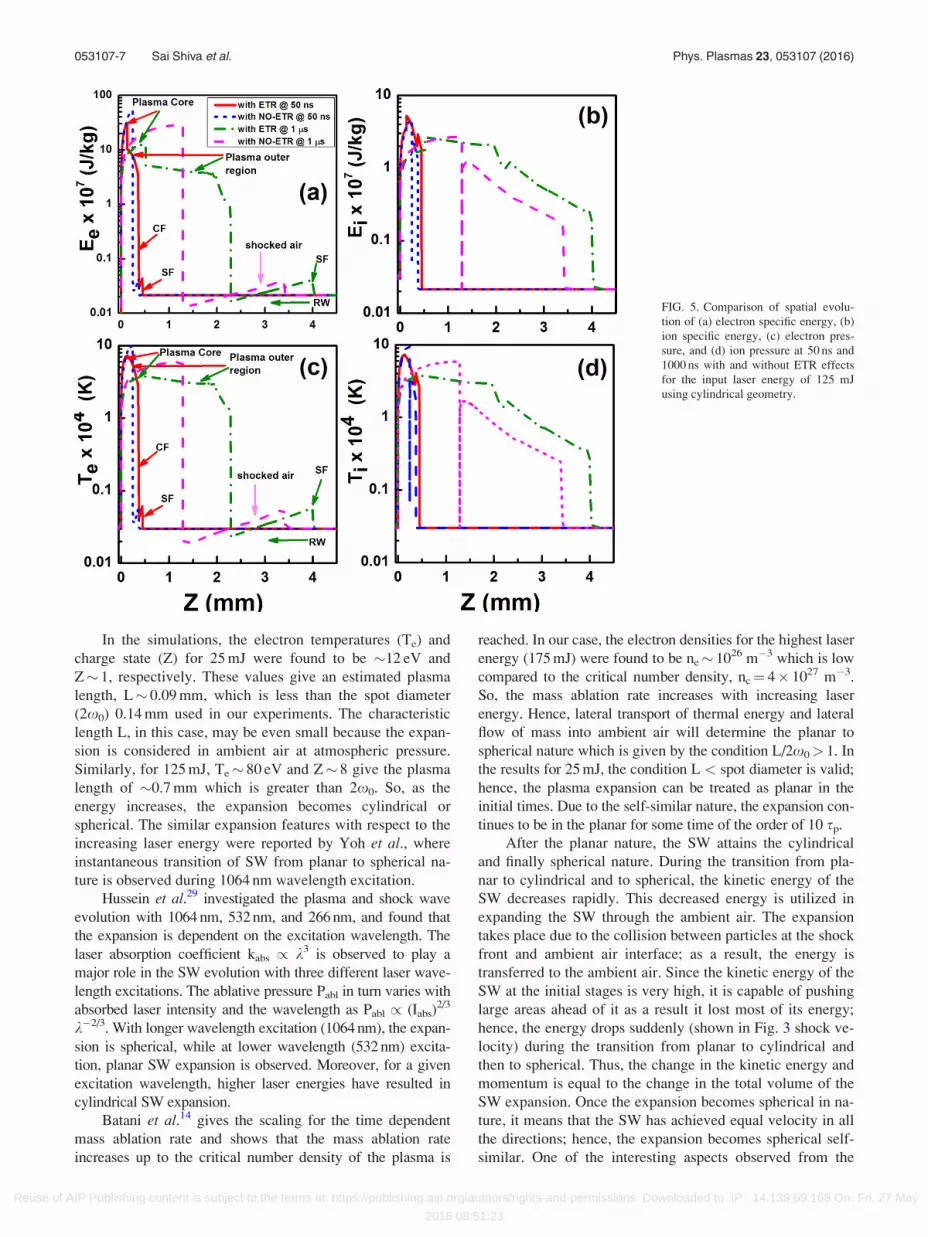
FIG. 5. Comparison of spatial evolu-
tion of (a) electron specific energy, (b)
ion specific energy, (c) electron pres-
sure, and (d) ion pressure at 50 ns and
1000 ns with and without ETR effects
for the input laser energy of 125 mJ
using cylindrical geometry.
053107-7 Sai Shiva et al. Phys. Plasmas 23, 053107 (2016)
Reuse of AIP Publishing content is subject to the terms at: https://publishing.aip.org/authors/rights-and-permissions. Downloaded to IP: 14.139.69.168 On: Fri, 27 May
2016 08:51:23

numerical simulations is that the SW expansion is following
the cylindrical expansion in between planar and spherical
expansions. Moreover, the transition from planar to cylindri-
cal is not instantaneous, but there exists certain time gap in
contrast to Yoh et al. report.31
V. EFFECTS OF ELECTRON THERMAL RADIATION ONSPATIAL EVOLUTION OF PLASMA VARIABLES ANDSW
The influence of ETR on the plasma and SW evolution
is explained by comparing spatial evolution of different vari-
ables such as electron and ion specific energies (Ee and Ei),
temperatures (Te and Ti), electron number density (ne), mass
density (q), and electron and ion pressures (Pe and Pi) with
and without ETR. The evolution is considered for 125 mJ
using the cylindrical geometry at 50 and 1000 ns to see the
effects of ETR at different times.
A. Spatial evolution of Ee, Ei, Te, and Ti
The spatial expansion of electron and ion specific energies
(Ee and Ei) is given in Figs. 5(a) and 5(b), and the spatial expan-
sion of temperatures (Te and Ti) is given in Figs. 5(c) and 5(d).
An interesting feature of the plasma dynamics is observed
with ETR effects. That is, the internal structure of the plasma
is observed to split into two parts: the plasma core (PC) and
the plasma outer region (POR). The PC region at 50 and
1000 ns exists around 0.15 mm and 0.5 mm from target sur-
face. Similarly, the POR exists between 0.15–0.4 mm and
0.5–2.3 mm, respectively, for the same time scales. Various
regions formed in the plasma and in the shocked region are
shown in Fig. 5(a).
B. Spatial evolution of ne, q, Pe, and Pi
The spatial evolution of electron number density (ne)
and mass density (q) (Figs. 6(a) and 6(b)) and electron and
ion pressures (Pe and Pi) (Figs. 6(c) and 6(d)) is given.
A similar splitting of plasma into core and outer region is
observed in all the profiles given in Figures 5(a)–5(d) and
6(a)–6(d). The plasma nearer to the target surface is the core
part, and at positions slightly away from the target surface, the
POR is formed. The SW generated from the plasma moves
quickly by compressing the surrounding ambient air. The
front portion of the SW is the SF that moves with high veloc-
ity. Behind the SF, the compressed gas relaxes and tries to
come back to its normal ambient conditions. During the relax-
ation, a rarefaction wave (RW) is formed that moves opposite
to the SF direction (Fig. 6). The region between the POR and
SF is the shocked region in which the CF and POR propagate
FIG. 6. Comparison of spatial evolu-
tion of (a) electron number density, (b)
mass density, (c) electron, and (d) ion
pressures at 50 ns and 1000 ns with and
without radiation effects using the cy-
lindrical geometry for input laser
energy of 125 mJ.
TABLE II. Positions and velocities of SF and CF at 50 ns and 1000 ns
observed with and without ETR effects at 125 mJ with cylindrical geometry.
Time (ns) ZSF (mm) VSF (km/s) ZCF (mm) VCF (km/s) EFFECT
50 0.48 9.6 0.4 5.25 ETR
50 0.40 8.0 0.3 4.5 NO-ETR
1000 4.0 4.0 2.3 2.3 ETR
1000 3.4 3.4 1.3 1.3 NO-ETR
053107-8 Sai Shiva et al. Phys. Plasmas 23, 053107 (2016)
Reuse of AIP Publishing content is subject to the terms at: https://publishing.aip.org/authors/rights-and-permissions. Downloaded to IP: 14.139.69.168 On: Fri, 27 May
2016 08:51:23
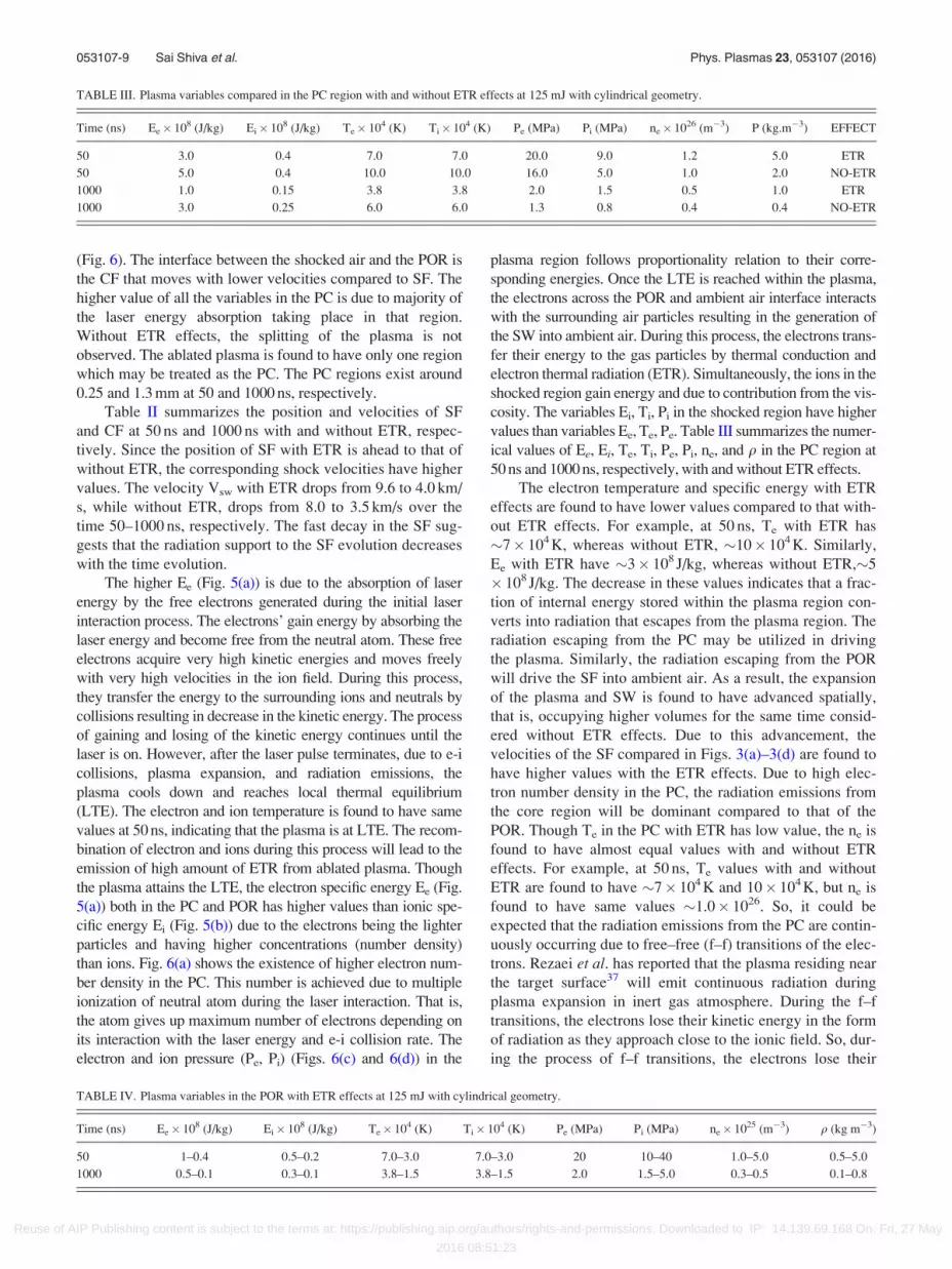
(Fig. 6). The interface between the shocked air and the POR is
the CF that moves with lower velocities compared to SF. The
higher value of all the variables in the PC is due to majority of
the laser energy absorption taking place in that region.
Without ETR effects, the splitting of the plasma is not
observed. The ablated plasma is found to have only one region
which may be treated as the PC. The PC regions exist around
0.25 and 1.3 mm at 50 and 1000 ns, respectively.
Table II summarizes the position and velocities of SF
and CF at 50 ns and 1000 ns with and without ETR, respec-
tively. Since the position of SF with ETR is ahead to that of
without ETR, the corresponding shock velocities have higher
values. The velocity Vsw with ETR drops from 9.6 to 4.0 km/
s, while without ETR, drops from 8.0 to 3.5 km/s over the
time 50–1000 ns, respectively. The fast decay in the SF sug-
gests that the radiation support to the SF evolution decreases
with the time evolution.
The higher Ee (Fig. 5(a)) is due to the absorption of laser
energy by the free electrons generated during the initial laser
interaction process. The electrons’ gain energy by absorbing the
laser energy and become free from the neutral atom. These free
electrons acquire very high kinetic energies and moves freely
with very high velocities in the ion field. During this process,
they transfer the energy to the surrounding ions and neutrals by
collisions resulting in decrease in the kinetic energy. The process
of gaining and losing of the kinetic energy continues until the
laser is on. However, after the laser pulse terminates, due to e-i
collisions, plasma expansion, and radiation emissions, the
plasma cools down and reaches local thermal equilibrium
(LTE). The electron and ion temperature is found to have same
values at 50 ns, indicating that the plasma is at LTE. The recom-
bination of electron and ions during this process will lead to the
emission of high amount of ETR from ablated plasma. Though
the plasma attains the LTE, the electron specific energy Ee (Fig.
5(a)) both in the PC and POR has higher values than ionic spe-
cific energy Ei (Fig. 5(b)) due to the electrons being the lighter
particles and having higher concentrations (number density)
than ions. Fig. 6(a) shows the existence of higher electron num-
ber density in the PC. This number is achieved due to multiple
ionization of neutral atom during the laser interaction. That is,
the atom gives up maximum number of electrons depending on
its interaction with the laser energy and e-i collision rate. The
electron and ion pressure (Pe, Pi) (Figs. 6(c) and 6(d)) in the
plasma region follows proportionality relation to their corre-
sponding energies. Once the LTE is reached within the plasma,
the electrons across the POR and ambient air interface interacts
with the surrounding air particles resulting in the generation of
the SW into ambient air. During this process, the electrons trans-
fer their energy to the gas particles by thermal conduction and
electron thermal radiation (ETR). Simultaneously, the ions in the
shocked region gain energy and due to contribution from the vis-
cosity. The variables Ei, Ti, Pi in the shocked region have higher
values than variables Ee, Te, Pe. Table III summarizes the numer-
ical values of Ee, Ei, Te, Ti, Pe, Pi, ne, and q in the PC region at
50 ns and 1000 ns, respectively, with and without ETR effects.
The electron temperature and specific energy with ETR
effects are found to have lower values compared to that with-
out ETR effects. For example, at 50 ns, Te with ETR has
�7� 104 K, whereas without ETR, �10� 104 K. Similarly,
Ee with ETR have �3� 108 J/kg, whereas without ETR,�5
� 108 J/kg. The decrease in these values indicates that a frac-
tion of internal energy stored within the plasma region con-
verts into radiation that escapes from the plasma region. The
radiation escaping from the PC may be utilized in driving
the plasma. Similarly, the radiation escaping from the POR
will drive the SF into ambient air. As a result, the expansion
of the plasma and SW is found to have advanced spatially,
that is, occupying higher volumes for the same time consid-
ered without ETR effects. Due to this advancement, the
velocities of the SF compared in Figs. 3(a)–3(d) are found to
have higher values with the ETR effects. Due to high elec-
tron number density in the PC, the radiation emissions from
the core region will be dominant compared to that of the
POR. Though Te in the PC with ETR has low value, the ne is
found to have almost equal values with and without ETR
effects. For example, at 50 ns, Te values with and without
ETR are found to have �7� 104 K and 10� 104 K, but ne is
found to have same values �1.0� 1026. So, it could be
expected that the radiation emissions from the PC are contin-
uously occurring due to free–free (f–f) transitions of the elec-
trons. Rezaei et al. has reported that the plasma residing near
the target surface37 will emit continuous radiation during
plasma expansion in inert gas atmosphere. During the f–f
transitions, the electrons lose their kinetic energy in the form
of radiation as they approach close to the ionic field. So, dur-
ing the process of f–f transitions, the electrons lose their
TABLE III. Plasma variables compared in the PC region with and without ETR effects at 125 mJ with cylindrical geometry.
Time (ns) Ee� 108 (J/kg) Ei� 108 (J/kg) Te� 104 (K) Ti� 104 (K) Pe (MPa) Pi (MPa) ne� 1026 (m�3) P (kg.m�3) EFFECT
50 3.0 0.4 7.0 7.0 20.0 9.0 1.2 5.0 ETR
50 5.0 0.4 10.0 10.0 16.0 5.0 1.0 2.0 NO-ETR
1000 1.0 0.15 3.8 3.8 2.0 1.5 0.5 1.0 ETR
1000 3.0 0.25 6.0 6.0 1.3 0.8 0.4 0.4 NO-ETR
TABLE IV. Plasma variables in the POR with ETR effects at 125 mJ with cylindrical geometry.
Time (ns) Ee� 108 (J/kg) Ei� 108 (J/kg) Te� 104 (K) Ti� 104 (K) Pe (MPa) Pi (MPa) ne� 1025 (m�3) q (kg m�3)
50 1–0.4 0.5–0.2 7.0–3.0 7.0–3.0 20 10–40 1.0–5.0 0.5–5.0
1000 0.5–0.1 0.3–0.1 3.8–1.5 3.8–1.5 2.0 1.5–5.0 0.3–0.5 0.1–0.8
053107-9 Sai Shiva et al. Phys. Plasmas 23, 053107 (2016)
Reuse of AIP Publishing content is subject to the terms at: https://publishing.aip.org/authors/rights-and-permissions. Downloaded to IP: 14.139.69.168 On: Fri, 27 May
2016 08:51:23

kinetic energy without recombining to the ions; hence, the
number density is found to have remained same. Though the
electron, ion specific energies, and temperature in the PC
with ETR have lower values, but the mass density (q) is
found to have higher values (Fig. 6(b)). At 50 ns, q has a
higher value of �5 kg/m3 with ETR than �2 kg/m3 without
ETR. The higher mass density is due to the low Te and Ti
existing and due to the less volume occupied by PC region.
The mass density in the PC region evolves inversely with
temperatures and volume. The electron and ion pressures in
the PC region follow the proportionality relation with the
corresponding energies. The similar feature is also observed
at 1000 ns of timescales as summarized in Table III.
Table IV summarizes the range of the variables existing in
the POR. Since the ablated plasma outer region is away from
the target surface, the variables ne, Te, Ee, and Ei are found to
have lower values compared to PC region. Due to the forma-
tion of the POR, the overall plasma expansion was observed to
be higher compared to that without ETR effects. Hence, the SF
expansion was also observed to be higher with ETR effects.
One may infer from the above observations that the loss in the
plasma internal energy is converted into the radiation which in
turn is utilized in driving the plasma and SF. Due to this mech-
anism, the plasma was observed to occupy larger dimensions
with radiation. Hence, it is confirmed that the radiation signifi-
cantly modifies the internal plasma structure, plasma, and SF
dynamics during its evolution.
Table V compares the mass density (q) in the PC, and
across the SF at 50 ns and 1000 ns, respectively. Across the SF,
q is found to have higher values compared to that in the PC
due to high compression of the background air by the SF.
Similarly, lower q values occurring in the PC are due to the ex-
istence of very high Te and Ti values. Behind the SF, a rarefac-
tion wave (RW) is generated that counterpropagates in the
shocked air and releases the compressed gas to come back to its
ambient condition. So, in region behind the SF, the mass den-
sity, Pe and Pi, was observed to fall off linearly up to the POR
due to RW propagation. The propagation direction of the RW is
indicated (Figs. 6(a)–6(d)) with arrow directed towards POR. In
the region ahead of the PC (Fig. 6(b)), the mass density was
observed to rise up linearly towards the SF direction up to CF
region. This nature is due to the decay of Te and Ti in the POR.
C. Evolution of plasma, generation, and detachment ofSF and CF from the ablated plasma
In Figs. 7(a)–7(c), the detachment of SF and CF from the
ablated plasma into an ambient air is shown for 25 mJ,
TABLE V. Mass density at the SF and PC region with and without ETR
effects for 125 mJ with cylindrical geometry.
Time (ns) q at SF (kg m�3) q at PC (kg m�3) EFFECT
50 8.5 5.0 ETR
50 8.5 1.5 NO-ETR
1000 6.0 1.0 ETR
1000 6.0 0.4 NO-ETR
FIG. 7. Detachment of the SF and CF
from ablated plasma and their propaga-
tion into ambient air for laser energies
of (a) 25 mJ, (b) 125 mJ, and (c) 175
mJ using planar geometry with ETR
effects.
053107-10 Sai Shiva et al. Phys. Plasmas 23, 053107 (2016)
Reuse of AIP Publishing content is subject to the terms at: https://publishing.aip.org/authors/rights-and-permissions. Downloaded to IP: 14.139.69.168 On: Fri, 27 May
2016 08:51:23

125 mJ, and 175 mJ laser energies. The CF gives an insight of
the propagation distance of the ejected mass and is known to
be a source of SF. The detachments are given for planar ge-
ometry with ETR effects considered. At initial timescales,
only ablated plasma is observed to expand into ambient air as
CF, and as the time passed, the SF is observed detaching from
the expanding plasma. Before the detachment, the SF accumu-
lates enough energy through collisions of particles from the
ablated plasma, and once detached, it moves quickly through
the ambient air compressing the ambient gas ahead of it. The
mass density, ion specific energy, and temperatures across the
SF will have very high values. The detachment time of the SF
was found to be dependent on the input laser energy. At
25 mJ, SF detaches at around 50 ns, at 125 mJ around 200 ns,
and at 175 mJ around 400 ns. The detachment time is found to
increase with increasing laser energy.
During the SF formation, simultaneously, the CF is also
formed which follows the SF with a lower velocity. The sep-
aration between the SF and CF (ZSF–ZCF) increases with
respect to time and with the increasing laser energy. Fig. 8
compares ZSF–ZCF for 25 mJ and 175 mJ laser energies using
planar, cylindrical, and spherical geometries considering the
radiation effects.
Similarly, the separation was found to be more in case
of PN and least in case of SN. Insets in Figs. 8(a)–8(c) show
the separation between ZSF–ZCF at lower timescales up to
1 ls for 25 mJ, 125 mJ, and 175 mJ, respectively. With planar
geometry, the separation at 25 mJ is found to exist from
50 ns of time, whereas with 125 mJ and 175 mJ, the separa-
tion could be seen from 200 ns indicating that the SF accu-
mulating more energy from the ablated plasma before the
detachment. Similarly, with cylindrical and spherical geome-
tries, the separation can be seen from 50 ns of time. Though
the detachment with the planar nature starts late, the SF
accumulates high energy; as a result, it crosses over the SF
generated using the cylindrical and spherical geometries.
VI. TEMPORAL EVOLUTION OF PLASMA VARIABLES
A. Comparison of ne and Te with and without ETR
The temporal evolution of peak ne and Te extracted in
the PC region over the timescales of 0.05–8.0 ls is given for
25 mJ (Figs. 9(a) and 9(b)), for 125 mJ (Figs. 9(c) and 9(d)),
and for 175 mJ (Figs. 9(e) and 9(f)) laser energies with and
without ETR effects. Variables ne and Te with planar geome-
try have higher values followed by the cylindrical and spher-
ical geometries. Table VI summarizes comparison of ne and
Te at 50 ns with and without ETR for planar, cylindrical, and
spherical geometries. At 25 mJ and 125 mJ with PN, ne has
higher values with ETR, whereas at 175 mJ, ne is found to
have same values compared to that without ETR. Similarly,
Te with ETR has lower values with 25 and 125 mJ and
slightly lower values with 175 mJ. As discussed previously,
due to f–f transitions occurring from the PC region, Te
evolves inversely with ne. The similar values in ne at 175 mJ
may indicate that the large amount of radiation emissions
occur during the initial plasma formation and expansion.
With cylindrical geometry, the difference in ne, Te will be
small compared to that of planar geometry. With the
spherical geometry, ne and Te have same values with and
without ETR effects. Since ne has high values with PN, the
radiation emissions will be dominant in this geometry.
The decay nature of ne and Te is same for the three geo-
metries. The sudden fall-off of ne and Te during the initial
times (<2 ls) is due to the occurrence of simultaneous proc-
esses such as the radiation emissions and fast expansion of
the plasma. Due to these processes, the electrons recombine
with the ions, and the plasma cools down quickly resulting
in faster decay of ne and Te. However, at later times during
CN and SN, the plasma expansion slows down and the
recombination decreases due to plasma cooling, resulting in
slower decay or almost constant in ne and Te over 2–8 ls
time scales. During the fast decay process, the nature of the
SF is observed to have converted from planar to cylindrical
(PN-CN) at lower energies (Figs. 3(a) and 3(b)) and from cy-
lindrical to spherical (CN-SN) (Figs. 3(c) and 3(d)) at higher
energies for 0.4–2 ls time scales.
FIG. 8. Separation between SF and CF with respect to time for planar, cylindri-
cal, and spherical geometries for input laser energies of (a) 25 mJ, (b) 125 mJ,
and (c) 175 mJ, respectively, with ETR effects. The lines are guide to the eye.
053107-11 Sai Shiva et al. Phys. Plasmas 23, 053107 (2016)
Reuse of AIP Publishing content is subject to the terms at: https://publishing.aip.org/authors/rights-and-permissions. Downloaded to IP: 14.139.69.168 On: Fri, 27 May
2016 08:51:23

B. Mass density comparison in the PC and across theSF with ETR effects
Fig. 10 compares the temporal evolution of peak mass
density (q) in the PC and across the SF during the evolution.
The mass density across the SF for all energies and geometries
is found to have higher values than at the PC. Since the gas
across the SF is highly compressed, q have higher values.
As seen from Figs. 10(a)–10(c) with PN, q across SF has
higher values compared to CN and SN, signifying that the
compression is more during the early SF evolution and
decreases with time due to decrease in the kinetic energy of
the SF by the confinement. The compression of the back-
ground gas increases with increasing laser energy that is
clearly seen in Figs. 10(a)–10(c). Due to the presence of very
high temperatures inside the PC, q in this region is observed
to be small compared to that at the SF. However, due to the
expansion of the plasma, q values inside the PC decreases
with time. As can be seen from Figs. 10(a)–10(c), the mass
density is observed to reduce with respect to time which fol-
lows somewhat the decay trend of ne and Te (Figs. 9(a)–9(f)).
VII. SUMMARY AND CONCLUSIONS
Laser ablation of aluminum and the subsequent genera-
tion and propagation of shock wave into ambient air were
simulated using the 1D radiation hydrodynamic code. The
experimentally obtained Vsw values from shadowgraphy
technique were compared with the numerical simulated data
by considering the ETR and non-ETR effects using planar,
cylindrical, and spherical geometries over the time scales of
0.4 ls–8.0 ls. The nature of the SF and its evolution was
found to be influenced by the radiation emitting from the
plasma. The SF was observed to move quickly with ETR
effects, indicating that the radiation emissions from the
ablated plasma drive the SW during its propagation into
FIG. 9. Comparison of the temporal
evolution of electron number density
and electron temperature for energies
of (a) and (b) 25 mJ, (c) and (d) 125
mJ, and (e) and (f) 175 mJ with and
without radiation effects using planar,
cylindrical, and spherical geometries,
respectively. The lines are guide to the
eye.
TABLE VI. Peak values of ne and Te compared with and without ETR effects at 50 ns.
Planar Cylindrical Spherical
Energy (mJ) ne� 1026 (m�3) Te� 104 (K) ne� 1026 (m�3) Te� 104 (K) ne� 1026 (m�3) Te� 104 (K) EFFECT
25 2.5 8.2 0.8 3.0 0.36 1.35 ETR
25 1.2 12.0 0.7 2.7 0.18 1.4 NO-ETR
125 4.4 28.0 2.0 7.2 0.7 3.4 ETR
125 3.0 36.0 1.0 10.0 0.6 3.3 NO-ETR
175 5.0 31.0 1.8 7.8 1.0 3.3 ETR
175 5.0 33.0 0.9 10.0 1.0 4.2 NO-ETR
053107-12 Sai Shiva et al. Phys. Plasmas 23, 053107 (2016)
Reuse of AIP Publishing content is subject to the terms at: https://publishing.aip.org/authors/rights-and-permissions. Downloaded to IP: 14.139.69.168 On: Fri, 27 May
2016 08:51:23

ambient air. The radiation effects were observed to be domi-
nant typically up to 2 ls depending on the input laser energy.
The radiation influence on the SW evolution was observed to
be dominant at earlier time scales and decreased with time.
So, at times up to 2.0 ls, the SW was observed to be driven
mostly by the radiation heat transfer mechanism. The simu-
lation results also predicted that the SW will undergo transi-
tions from initial PN-CN and CN-SN for all the laser
energies used in our study. During the transition from PN-
CN, it is observed that the SW has taken certain time to
transfer from PN to CN possibly due to the expansion of the
plasma and SW. The transition from CN to SN was observed
to be instantaneous for all the laser energies considered.
After 1.5 ls, the SN is observed to be dominant. The spatial
evolution of different plasma variables (Ee, Ei, Te, Ti, ne, q,
and Pe, Pi) is analyzed by considering ETR effects. The anal-
ysis showed that due to ETR, the internal plasma structure is
modified by splitting into two parts: the PC and POR,
whereas without ETR, only one plasma region, that is, PC, is
observed. Due to high absorption of the laser energy by the
PC, the plasma variables in that region have very high values
compared to that of the POR. The detachment times of the
SF were observed to be laser energy dependent. The SF was
observed to detach late from the ablated plasma with increas-
ing laser energy. The separation between the SF and CF was
observed to increase with time indicating that the SF moves
off very quickly from the ambient air. The temporal
evolution of ne and Te compared with planar, cylindrical,
and spherical geometries showed that with PN, ne and Te
have higher values followed by CN and SN. During the early
times (<2.0 ls), ne and Te were observed to fall off very
quickly due to sudden expansion of the plasma and recombi-
nation of large number of electrons to the ions. Due to these
processes, the plasma cools down and the number density
falls drastically. The decay of ne and Te after 2.0 ls was
found to be slower, indicating negligible emission of radia-
tion from the plasma core. Due to dominance in the radiation
emissions up to 2.0 ls, the SF was observed to move quickly
(during PN and CN with ETR); however, at later time due to
negligible radiation effects, the SF is found to move with the
same velocity (during SN with and without ETR).
ACKNOWLEDGMENTS
Authors from ACRHEM (S. Sai Shiva, Ch. Leela, and
P. Prem Kiran) would like to thank DRDO for Grants-in-Aid
funding.
1D. B. Chrisey and G. K. Hubler, Pulsed Laser Deposition of Thin Films(Wiley, 1994).
2S. C. Singh and R. Gopal, J. Phys. Chem. C 112(8), 2812–2819 (2008).3L. J. Radziemski, Spectrochim. Acta Part B 57(7), 1109–1113 (2002).4H. Chen, Microscale Laser Shock Peening: Experiment, Modeling andSpatially Resolved Material Characterization (Columbia University,
2004).
FIG. 10. Temporal evolution of mass
density for laser energies of (a) 25 mJ,
(b) 125 mJ, and (c) 175 mJ with ETR
effects using planar, cylindrical, and
spherical geometries, respectively. The
lines are guide to the eye. X-axis scale
is the same for all the plots.
053107-13 Sai Shiva et al. Phys. Plasmas 23, 053107 (2016)
Reuse of AIP Publishing content is subject to the terms at: https://publishing.aip.org/authors/rights-and-permissions. Downloaded to IP: 14.139.69.168 On: Fri, 27 May
2016 08:51:23

5N. K. Bourne, J. C. F. Millett, and G. T. Gray, J. Mater. Sci. 44(13),
3319–3343 (2009).6C. Phipps, M. Birkan, W. Bohn, H.-A. Eckel, H. Horisawa, T. Lippert, M.
Michaelis, Y. Rezunkov, A. Sasoh, W. Schall, S. Scharring, and J. Sinko,
J. Propul. Power 26(4), 609–637 (2010).7A. Benuzzi-Mounaix, M. Koenig, A. Ravasio, T. Vinci, N. Ozaki, M. R. l.
Gloahec, B. Loupias, G. Huser, E. Henry, S. Bouquet, C. Michaut, D.
Hicks, A. MacKinnon, P. Patel, H. S. Park, S. L. Pape, T. Boehly, M.
Borghesi, C. Cecchetti, M. Notley, R. Clark, S. Bandyopadhyay, S.
Atzeni, A. Schiavi, Y. Aglitskiy, A. Faenov, T. Pikuz, D. Batani, R.
Dezulian, and K. Tanaka, Plasma Phys. Controlled Fusion 48(12B), B347
(2006).8A. Vogel and V. Venugopalan, Chem. Rev. 103(2), 577–644 (2003).9A. Caruso and R. Gratton, Plasma Phys. 10(9), 867 (1968).
10C. E. Max, C. F. McKee, and W. C. Mead, Phys. Rev. Lett. 45(1), 28–31
(1980).11C. E. Max, C. F. McKee, and W. C. Mead, Phys. Fluids 23(8), 1620–1645
(1980).12P. Mora, Phys. Fluids 25(6), 1051–1056 (1982).13B. Meyer and G. Thiell, Phys. Fluids 27(1), 302–311 (1984).14D. Batani, H. Stabile, A. Ravasio, G. Lucchini, F. Strati, T. Desai, J.
Ullschmied, E. Krousky, J. Skala, L. Juha, B. Kralikova, M. Pfeifer, C.
Kadlec, T. Mocek, A. Pr€ag, H. Nishimura, and Y. Ochi, Phys. Rev. E
68(6), 067403 (2003).15D. Marla, U. V. Bhandarkar, and S. S. Joshi, J. Appl. Phys. 109(2), 021101
(2011).16P. Cristian and A. W. David, J. Phys. D: Appl. Phys. 42(15), 155503
(2009).17C. Porneala and D. A. Willis, Appl. Phys. Lett. 89(21), 211121 (2006).18A. Gragossian, S. H. Tavassoli, and B. Shokri, J. Appl. Phys. 105(10),
103304 (2009).19A. E. Wynne and B. C. Stuart, Appl. Phys. A 76(3), 373–378 (2003).20M. Capitelli, A. Casavola, G. Colonna, and A. De Giacomo, Spectrochim.
Acta Part B 59(3), 271–289 (2004).21V. I. Mazhukin, V. V. Nossov, and I. Smurov, Appl. Surf. Sci. 253(19),
7686–7691 (2007).22F. J. Gordillo-V�azquez, A. Perea, and C. N. Afonso, Appl. Spectrosc.
56(3), 381–385 (2002).23S. Gurlui, M. Agop, P. Nica, M. Ziskind, and C. Focsa, Phys. Rev. E
78(2), 026405 (2008).24S. Mahmood, R. S. Rawat, M. S. B. Darby, M. Zakaullah, S. V.
Springham, T. L. Tan, and P. Lee, Phys. Plasmas 17(10), 103105
(2010).25A. K. Sharma and R. K. Thareja, Appl. Surf. Sci. 243(1–4), 68–75
(2005).26Y. Tao, M. S. Tillack, S. S. Harilal, K. L. Sequoia, B. O. Shay, and F.
Najmabadi, J. Phys. D: Appl. Phys. 39(18), 4027 (2006).27T. Moscicki, J. Hoffman, and Z. Szymanski, Arch. Mech. 63(2), 99–116
(2011).28M. Cirisan, J. M. Jouvard, L. Lavisse, L. Hallo, and R. Oltra, J. Appl.
Phys. 109(10), 103301 (2011).
29A. E. Hussein, P. K. Diwakar, S. S. Harilal, and A. Hassanein, J. Appl.
Phys. 113(14), 143305 (2013).30S. Laville, F. Vidal, T. W. Johnston, M. Chaker, B. Le Drogoff, O. Barth�elemy,
J. Margot, and M. Sabsabi, Phys. Plasmas 11(5), 2182–2190 (2004).31J. J. Yoh, H. Lee, J. Choi, K.-C. Lee, and K.-H. Kim, J. Appl. Phys.
103(4), 043511 (2008).32A. Gomes, A. Aubreton, J. J. Gonzalez, and S. Vacqui�e, J. Phys. D: Appl.
Phys. 37(5), 689 (2004).33H. Mohammad and A. W. David, J. Phys. D: Appl. Phys. 44(14), 145501
(2011).34S. S. Harilal, G. V. Miloshevsky, P. K. Diwakar, N. L. LaHaye, and A.
Hassanein, Phys. Plasmas 19(8), 083504 (2012).35M. Owens and V. Majidi, Appl. Spectrosc. 45(9), 1463–1467 (1991).36Y.-I. Lee, K. Song, H.-K. Cha, J.-M. Lee, M.-C. Park, G.-H. Lee, and J.
Sneddon, Appl. Spectrosc. 51(7), 959–964 (1997).37F. Rezaei and S. H. Tavassoli, Phys. Plasmas 20(1), 013301 (2013).38A. Bogaerts and Z. Chen, Spectrochim. Acta Part B 60(9–10), 1280–1307
(2005).39R. K. Singh and J. Narayan, Phys. Rev. B 41(13), 8843–8859 (1990).40R. F. Wood, J. N. Leboeuf, K. R. Chen, D. B. Geohegan, and A. A.
Puretzky, Appl. Surf. Sci. 127–129, 151–158 (1998).41J. R. Ho, C. P. Grigoropoulos, and J. A. C. Humphrey, J. Appl. Phys.
78(7), 4696–4709 (1995).42S. Amoruso, Appl. Phys. A 69(3), 323–332 (1999).43S. Amoruso, R. Bruzzese, N. Spinelli, and R. Velotta, J. Phys. B 32(14),
R131 (1999).44S. H. Jeong, R. Greif, and R. E. Russo, Appl. Surf. Sci. 127–129, 177–183
(1998).45V. I. Mazhukin, V. V. Nossov, I. Smurov, and G. Flamant, J. Phys. D:
Appl. Phys. 37(2), 185 (2004).46V. I. Mazhukin, V. V. Nossov, G. Flamant, and I. Smurov, J. Quant.
Spectrosc. Radiat. Transfer 73(2–5), 451–460 (2002).47H. Borchert, K. Dar�ee, and M. Hugenschmidt, J. Phys. D: Appl. Phys.
38(2), 300 (2005).48E. A. Ershov-Pavlov, K. Y. Katsalap, K. L. Stepanov, and Y. A.
Stankevich, Spectrochim. Acta Part B 63(10), 1024–1037 (2008).49I. B. Gornushkin, A. Y. Kazakov, N. Omenetto, B. W. Smith, and J. D.
Winefordner, Spectrochim. Acta Part B 59(4), 401–418 (2004).50R. Ramis, K. Eidmann, J. Meyer-ter-Vehn, and S. H€uller, Comput. Phys.
Commun. 183(3), 637–655 (2012).51Y. B. Zel’dovich and Y. P. Raizer, Physics of Shock Waves and High-
Temperature Hydrodynamic Phenomena (Dover Publications, 2012).52Y. T. Lee and R. M. More, Phys. Fluids 27(5), 1273–1286 (1984).53R. M. More, K. H. Warren, D. A. Young, and G. B. Zimmerman, Phys.
Fluids 31(10), 3059–3078 (1988).54C. Leela, S. Bagchi, V. R. Kumar, S. P. Tewari, and P. P. Kiran, Laser
Part. Beams 31(02), 263–272 (2013).55C. Leela, P. Venkateshwarlu, R. V. Singh, P. Verma, and P. P. Kiran, Opt.
Express 22(S2), A268–A275 (2014).56C. Leela, Ph. D. thesis, University of Hyderabad, India, 2014.57M. Kundu, Phys. Plasmas 21(1), 013302 (2014).
053107-14 Sai Shiva et al. Phys. Plasmas 23, 053107 (2016)
Reuse of AIP Publishing content is subject to the terms at: https://publishing.aip.org/authors/rights-and-permissions. Downloaded to IP: 14.139.69.168 On: Fri, 27 May
2016 08:51:23