Embed Size (px)
Citation preview

Leading-Edge Motorsport Technology Since 1990The leading motorsport technology publication since 1990
Formula 1Formula 1 2018 • Digital edition • www.racecar-engineering.com
2018
F1 Digi Cover_MB.indd 1 22/03/2018 12:44

Book now for the best rates and stand location: www.advancedengineeringuk.com
“A fantastic opportunity to support our industry partners in meeting new clients. This year was no exception, and indeed has been the most successful ever, delivering more leads, more contact with suppliers and, as importantly, the ability to meet strong existing customers and partners.”John Darlington, TenCate’s Global Directorfor Product and Market Strategy
The UK’s largest exhibition for advanced engineering professionals
NUCLEARENGINEERING
AEROENGINEERING
COMPOSITESENGINEERING
CONNECTEDMANUFACTURING
PERFORMANCE METALSENGINEERING
AUTOMOTIVEENGINEERING
NEW FOR 2018
10thANNIVERSARY
YEAR
BOOKYOUR STAND
TODAY
CONTENTS/COMMENT
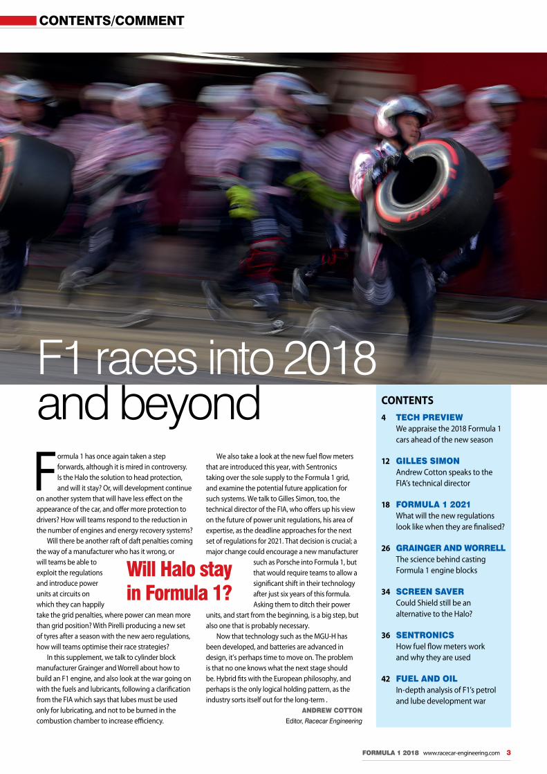
Formula 1 has once again taken a step forwards, although it is mired in controversy. Is the Halo the solution to head protection, and will it stay? Or, will development continue
on another system that will have less eff ect on the appearance of the car, and off er more protection to drivers? How will teams respond to the reduction in the number of engines and energy recovery systems?
Will there be another raft of daft penalties coming the way of a manufacturer who has it wrong, or will teams be able to exploit the regulations and introduce power units at circuits on which they can happily take the grid penalties, where power can mean more than grid position? With Pirelli producing a new set of tyres after a season with the new aero regulations, how will teams optimise their race strategies?
In this supplement, we talk to cylinder block manufacturer Grainger and Worrell about how to build an F1 engine, and also look at the war going on with the fuels and lubricants, following a clarifi cation from the FIA which says that lubes must be used only for lubricating, and not to be burned in the combustion chamber to increase effi ciency.
We also take a look at the new fuel fl ow meters that are introduced this year, with Sentronics taking over the sole supply to the Formula 1 grid, and examine the potential future application for such systems. We talk to Gilles Simon, too, the technical director of the FIA, who off ers up his view on the future of power unit regulations, his area of expertise, as the deadline approaches for the next set of regulations for 2021. That decision is crucial; a major change could encourage a new manufacturer
such as Porsche into Formula 1, but that would require teams to allow a signifi cant shift in their technology after just six years of this formula. Asking them to ditch their power
units, and start from the beginning, is a big step, but also one that is probably necessary.
Now that technology such as the MGU-H has been developed, and batteries are advanced in design, it’s perhaps time to move on. The problem is that no one knows what the next stage should be. Hybrid fi ts with the European philosophy, and perhaps is the only logical holding pattern, as the industry sorts itself out for the long-term .
ANDREW COTTON
Editor, Racecar Engineering
FORMULA 1 2018 www.racecar-engineering.com 3
CONTENTS4 TECH PREVIEW We appraise the 2018 Formula 1 cars ahead of the new season
12 GILLES SIMON Andrew Cotton speaks to the FIA’s technical director
18 FORMULA 1 2021 What will the new regulations look like when they are fi nalised?
26 GRAINGER AND WORRELL The science behind casting Formula 1 engine blocks
34 SCREEN SAVER Could Shield still be an alternative to the Halo?
36 SENTRONICS How fuel fl ow meters work and why they are used
42 FUEL AND OIL In-depth analysis of F1’s petrol and lube development war
F1 races into 2018
Will Halo stay in Formula 1?
and beyond
F1_Contents_MBAC.indd 3 22/03/2018 12:33

FORMULA 1 2018 – TESTING
4 www.racecar-engineering.com FORMULA 1 2018
The reigning champion, Mercedes, has taken a conservative approach to Halo, even though the regulations allow a small degree of freedom here
F1_2018_MBAC.indd 4 22/03/2018 14:58

The Halo effectFormula 1 testing in Barcelona saw the debut of all-new Pirelli tyre compounds, new aero solutions and the controversial Halo systemBy GEMMA HATTON and SAM COLLINS
FORMULA 1 2018 www.racecar-engineering.com 5
F ormula 1 has ushered in a host of changes for the 2018 season. The new head protection system, known as Halo, is the most obvious from a visual
point of view, and has already attracted a lot of negative feedback from the teams. It has also had a significant effect on the rest of the car, in terms of weight and design thanks to a late introduction of the regulation, leading in some cases to an all-new chassis design. With new tyres from Pirelli, offering teams a new challenge of working them at different circuits, and longer life power units for this season, teams have had anything but an easy preparation for 2018.
The Additional Frontal Protection-Halo (AFP-Halo, or just Halo) is without doubt the biggest visual change between the 2018 grand prix cars and those used in 2017. In design terms the Halo is governed by its own specific appendix to the FIA technical regulations. Everything from the shape and dimensions of the device to the material it is made from (titanium alloy Ti6Al4V Grade 5) is defined. However, there is still scope for different manufacturers to supply their own products into the category, though each must be homologated independently at the Cranfield Impact Centre. At the time of writing three companies had homologated Halos; CP Autosport of Germany, SST Technology in England and a third company, V System, from which each team must purchase its Halos.
Airflow impactAs can be imagined for such a visually obvious addition to the car, the aerodynamic impact of Halo is noteworthy, and the teams are doing what they can to deal with it, particularly on the airflow over the whole car.
‘It has a significant downstream effect, especially round the rear wing area,’ highlights Andy Green, technical director of the Sahara Force India F1 Team. ‘It is not designed to be an aerodynamic device, so it doesn’t do us any favours in that department and it requires a lot of work to mitigate the issues that it causes. In testing we will make sure we understand that the losses coming off the halo are where we think they are from our modelling tools. If that is confirmed we’re confident that the parts we’ll bring to the car will sort out those losses.’
It is something being worked on right up and down the pit lane with lots of airflow sensors fitted to cars around the Halo structure and downstream of it. ‘Aerodynamically speaking, Halo is certainly not penalty free and I think there is a challenge there to either cope with it in the first instance, let’s call it damage limitation, and thereafter think about opportunity and exploitation,’ Peter Prodromou, McLaren’s chief technical officer for aerodynamics adds. ‘It does open up some avenues which are possibly interesting to look at. I am sure there will be a variety of different solutions out there but the scope is quite limited to the allowance around the basic shape, but there is opportunity.’
Aesthetic gainThe rules allow a 20mm area of freedom around the titanium structure, introduced partly for aesthetic reasons but predictably these fairings are being used for aerodynamic gain, as some teams have added winglets and in one case airliner style vortex generators to their Halos. ‘It has effects on the cockpit because it is local to that opening. You have got the driver in
there and so you’ve got to make sure you don’t have the negative effects there,’ Toro Rosso technical director James Key says. ‘You’ve got effects on the engine air intake and effects after that towards the back, so there are a number of different things you have to think about. None of them are massive effects but they all require some level of attention.’
Fitting the Halo is no easy challenge either; not only does the Halo have to be homologated independently, it also has to pass crash tests as part of the chassis homologation procedure. This has proved to be a major issue for teams.
‘We always knew it was going to be a challenge so have invested time and money
Toro Rosso is one of several teams to try to increase aero efficiency with its Halo design; others also chose this approach
As might be imagined with such a visually obvious addition to the car, the aerodynamic impact of Halo is noteworthy
F1_2018_MBAC.indd 5 22/03/2018 14:58

FORMULA 1 2018 – TESTING
6 www.racecar-engineering.com FORMULA 1 2018
‘It takes the weight of a London bus and when you see that test going with that amount of load, it is a bit scary’
up front to do a lot of test pieces,’ McLaren chief technical officer Matt Morris admits. ‘Obviously, you don’t want to build a complete chassis but we built a few test pieces with dummy Halos and parts of Halos to test how the interfaces would behave and we found some issues. It was close, we didn’t breeze through and there were some heart-stopping moments with particular static tests coming in from an oblique angle. It takes the weight of a London bus and when you see that test going on with that amount of load and everything that moves around – which it is designed to do – it is a bit scary.’
During the chassis homologation tests the Halo has to withstand various loads without it or the monocoque failing. The biggest load applied to the structure is 116kN from above, which has to be endured for five seconds. Longitudinal forces of 46kN and 83kN are applied from the front as well as a lateral load of 93kN from the side. For comparison, the roll structure on top of the car has to withstand 50kN laterally, 60kN longitudinally and 90kN from above.
Weighty issueTo survive these severe loads, the Halo itself has become quite a substantial structure, weighing by regulation 7kg (+0.05kg, -0.15kg). In addition, the monocoque has also had to increase in strength significantly to cope with these tests. This has further increased the weight of the chassis by approximately 12-13kg. The 2018 technical regulations have allowed a minimum weight increase of 5kg to 733kg, forcing teams to save weight in other areas of the car. At the start of a race a 2018 F1 car will be of similar weight to a non-hybrid LMP1 in qualifying trim.
‘From a design perspective, weight is a big part of it. The weight limit did go up, but not by nearly as much as the installation weight of the halo so it put additional stress on all the other parts of the car,’ Green continues. ‘We had to try to optimise the weight in those areas to try and keep the weight limit below the minimum so that we can run ballast because the other area that we have to bear in mind is we have to hit a weight distribution target as well.’
The 20mm area at the top of the Halo has been exploited differently by the teams. The Haas team has adopted this toothy solution while others have mounted a wing
New rubber from Pirelli is designed to help drivers and teams at particular tracks. Pressure sensors were all the rage in Barcelona as teams completed their aero maps during pre-season testing
F1_2018_MBAC.indd 6 22/03/2018 14:59

FORMULA 1 2018 www.racecar-engineering.com 7
Although it was originally introduced as a temporary measure to help Pirelli develop tyres when it became the sole tyre supplier in 2011, the technical regulations still limit every car in terms of weight distribution, with just a 7kg window of freedom. This means that while some teams may be able to build a car under the minimum weight, they cannot get it fully within the distribution window.
Window dressing‘You only have a very small window of weight distribution so the actual architecture of the car needs to be correct to start with, otherwise you’re adding ballast to a car that doesn’t need ballast just to get the weight distribution right,’ Green says. ‘We would have loved to have added a huge safety margin to the whole design so that we would happily sail through the crash and load tests without any issues but that wasn’t possible because the weight limit of the car didn’t go up enough. We couldn’t afford to increase the base weight of the car more than a few kilogrammes because we knew we only had a few kg that we could take out of the car. It was, structurally, incredibly challenging.’
This weight challenge has seen at least one team, Renault, substantially rework the rear end of its car as a result, abandoning its cast titanium gearbox casing (something it
Short sidepod concept
In 2017 Ferrari introduced a new short sidepod concept, relocating the upper side impact structure (a single specification design shared by all teams) and moving
the main cooling aperture rearward. A set of box shape aerodynamic elements forward of the duct ensure rules compliance. Ferrari took this approach for aerodynamic reasons rather than those of cooling. In 2018, half the grid featured the same solution, but not all teams agree that it is the right route, with Mercedes, Renault, Force India and others all opting against adopting the concept.
Conservative approach ‘Everything you do in aerodynamics has an opportunity cost; there is much more opportunity to make the car worse than better,’ claims Mercedes technical director, James Allison. ‘If you want to pursue a new and different concept, you will expect to find a fair amount of loss before you get back into positive territory. We looked at that concept and felt it would spend too much time being in negative territory before it would perhaps offer any gain at all. If you are a [team] that is a long way down the grid the situation is different, it is worth taking that gamble, as you have less to lose and you know that the path you are on is not right.’
It is likely that the relocation of the side impact structure would require a substantial change to the monocoque design, while getting adequate airflow into the cooling system, with such a complex arrangement of aerodynamic elements around the leading edge of the sidepod duct, is also likely to be a major challenge.
Sidepod design seems to be led by Ferrari, with impact structure relocation for efficient aerodynamic effect
Mercedes has not adopted this same approach, believing that too much time would be lost in development
‘You have a small window of weight distribution so the architecture of the car needs to be correct’
The loss of the T-wing is not total; some of the teams are trying to recover some of the effect with lower mounted winglets
has evolved over many seasons) in favour of a slightly lighter composite transmission.
While the price of the Halo itself is relatively modest, the cost of developing a chassis to fit it is higher than some of the smaller teams would like. This was made worse by the late decision to adopt the Halo as the 2018 AFP solution, with teams only informed of this final decision in September 2017 after a long discussion process.
F1_2018_MBAC.indd 7 22/03/2018 14:59

FORMULA 1 2018 – TESTING
8 www.racecar-engineering.com FORMULA 1 2018
‘We used the 2017 Soft as a baseline because last year the Soft had a wider working range compared with the other compounds’
‘Expense-wise it’s huge because we had to do a new chassis. We wouldn’t have anticipated doing a new chassis this year given the number of changes we made last year. For a team like us we would look to try and get two years out of the chassis if possible. So in that respect it cost us a huge amount to redevelop and redesign the new chassis. It is in the hundreds of thousands, if not million dollar mark, to put the Halo on the car for us,’ says Green.
Screening processThe Halo has had a largely negative reception from drivers, teams, the media and fans. This has led to work continuing on alternative additional frontal protection systems. In 2017 a brief test run was conducted with a clear windscreen fitted to a Ferrari, but while this solution solved the frontal impact requirements, the driver complained of visual distortion. However, Indycar is now experimenting with a similar aeroscreen solution. Teams prefer the windscreen option not only for aesthetic reasons but also as it is much lighter than Halo with lower requirements on the chassis structure.
The weight increase as a result of the Halo also places an additional demand on the four power unit suppliers, and they have had to increase the life of their power units. Teams can now only use three combustion engines (ICE), three MGU-H’s and three turbochargers (TC) during the season, compared to four last year. That’s 2100km of racing mileage not including practice sessions or qualifying. Whereas the energy stores (ES), control electronics (CE) and MGU-Ks are all limited to two per season, or 3150km of racing. This demand for increased reliability will no doubt have forced the suppliers to manufacture more robust units, yet they have had to minimise weight to help teams comply with the minimum weight regulations which have been challenging to achieve with the consequences of Halo. It remains to be seen how successful they have been.
Tyre dilemmaThe other major changes for this year come from the tyres. To encourage overtaking and pit stops, Pirelli have added two more colours, and therefore compounds, to their tyre compound rainbow, the Superhard and the Hypersoft, as well as making the entire range a step softer, and introducing new allocation rules. The Superhard is now the hardest compound, adopting the conventional orange colour of the Hard, which has now become the light blue, and the Hypersoft is the softest compound and is light pink in colour. However, to gain a full understanding of these additional compounds we need to reflect on 2017.
The significant aerodynamic changes of the 2017 regulations resulted in an increase in loads
of over 20 per cent, demanding the tyres to be extremely robust, leading Pirelli to ramp up the stiffness of their entire compound range. Pirelli also had to develop tyres with little knowledge of the potential performance that the teams could achieve in 2017. Despite 12,000km of testing, the 2014 adapted ‘mule’ cars that Pirelli used to develop the 2017 compounds only achieved a 10 per cent increase in downforce and therefore the results were unrepresentative and inconclusive. To cope with this, Pirelli went for a conservative approach last year, and having tried and tested their designs for an entire season, the 2018 range is a slightly more aggressive evolution of 2017.
Compounding issues‘The 2018 compounds are from the same family of compounds as 2017,’ explains Mario Isola, sporting director of Pirelli. ‘The reason why degradation was so low last year was because these compounds have less surface overheating and in general behave in a different way. In particular we used the 2017 Soft as a baseline [for 2018] because last year the Soft had a wider working range compared to the other compounds. Last year’s Soft is now the Medium.’
From there, the 2017 Soft ‘baseline’ was then developed and used to create this year’s softer compounds (Soft, Supersoft, Ultrasoft and Hypersoft), each decreasing in stiffness in relatively consecutive steps. Although Pirelli, along with some drivers, have commented that the softer compounds of the 2018 range, tested at Abu Dhabi last year, were ‘much closer together’ in terms of the performance delta, the Hypersoft is much more aggressive.
With only a 7kg weight distribution the teams have struggled to get the weight down and remain in the window; Renault adopted a composite gearbox casing to reduce mass
F1_2018_MBAC.indd 8 22/03/2018 14:59

Be in Control of Your Systems!
Increase Effi ciency Save Ressources
BLDC motors - Impellers - Preheaters - Mixing valves - Pumps - Sensored or self-sensing
Discover our product range of Intelligent Flow Control (IFC) productsDiscover our product range of Intelligent Flow Control (IFC) productsDiscover our product range of Intelligent Flow Control (IFC) productsDiscover our product range of Intelligent Flow Control (IFC) productsDiscover our product range of Intelligent Flow Control (IFC) productsDiscover our product range of Intelligent Flow Control (IFC) productsDiscover our product range of Intelligent Flow Control (IFC) productsDiscover our product range of Intelligent Flow Control (IFC) productsDiscover our product range of Intelligent Flow Control (IFC) products
IntelligentFlow Control
Battery temperature control
Combustion engine cooling
KERS temperature control Electric motor cooling
Gear box cooling
Brake-by-wire
www.sobek-motorsporttechnik.de
Only the best is good enough for the best!
Call +44 (0) 1932 225777Fax +44 (0) 1932 [email protected]
PERFORMANCE UNDER PRESSURE
Fully Synthetic Lubricants
As used by Formula 1 , IndyCar, WRC and Le Mans Champions. ® ®
• GEAR OIL• ENGINE OIL• BRAKE FLUID• BEARING GREASE• CV JOINT GREASE

FORMULA 1 2018 – TESTING
10 www.racecar-engineering.com FORMULA 1 2018
‘The Hypersoft is quite a step softer compared to the Ultrasoft,’ highlights Isola. ‘We don’t have a lot of data but at Abu Dhabi, which is a low severity circuit and not that far from a street circuit, the Hypersoft was behaving like a very soft compound. It was about 0.9-1.0 seconds per lap quicker than the Ultrasoft and it was able to run for eight laps on average.’ However, Valtteri Bottas at this year’s Mercedes launch highlighted how the Hypersoft was only suitable for two to three laps at Abu Dhabi.
Similar to when Pirelli introduced the Ultrasoft in 2016, the pink Hypersoft has been predominantly designed to give drivers that extra level of grip at street circuits. Depending on the results from Monaco, however, teams might just see the pink tyres at other low severity tracks towards the end of the season.
The aggressive nature of the softer compounds has also led Pirelli to modify the front tyre construction. Not only do this year’s tyres feature a rounder profile, incorporating new materials, but the distribution of forces over the contact patch have also improved.
‘The other difference for this year is that the working range now decreases consecutively
from the Medium to the Hypersoft,’ says Isola. ‘We don’t have this alternating between low working range and high working range compounds. The harder compounds are high working range and the softer compounds are low working range.’ Previously, the high working range compounds were the Hard and Soft with the low working range compounds the Medium and Supersoft. The Ultrasoft was Medium to High working range. ‘This is important to make the compounds more predictable,’ says Isola. ‘Teams complained that they would set up the car for the Soft and it was difficult to manage when they put the Supersoft on. Now, with this change in working range, it will be much better.’
Insurance coverWith regard to the Superhard; ‘Forget it,’ laughs Isola. ‘We’re not going to use it. The Superhard compound is an insurance for us in case we have underestimated the development of this year’s cars. It’s much better to homologate an additional compound to keep in our pocket, rather than introduce a new one. From our simulations we are quite confident that we are not going to use this compound.’
HARD SUPERHARD
MEDIUM HARD
SOFT MEDIUM
SUPERSOFT SOFTSUPERSOFT
ULTRASOFT ULTRASOFT
HYPERSOFT
20182017
Working range temperature➤
Com
poun
d st
iffne
ss➤
Above: A simplified diagram illustrating the compound changes from 2017 to 2018. This year’s compounds are all a step softer, with the 2017 Soft and its wider working range becoming the 2018 Medium. The delta between the Soft, Supersoft and Ultrasoft are much closer, and the Hypersoft is an aggressive step, based on running at the Abu Dhabi test last year Right: Pirelli’s new tyres on display in Barcelona – the colours were chosen by the marketing department
This year’s softer tyres are not only going to make the drivers happier, but hopefully the fans as well. Softer compounds lead to higher degradation, resulting in larger performance differences between drivers out on track, so promoting more overtaking. To encourage this further, Pirelli has changed its tyre allocation rules. Rather than teams choosing their allocation from three consecutive compounds specified by Pirelli, teams can pick a double step in compound. For example, instead of running the Medium, Soft and Supersoft, teams can use the Medium, Soft and Ultrasoft, as is the case for this year’s Chinese Grand Prix, which takes place mid-April. This opens up the options for some interesting strategic decisions, which again could result in more exciting racing.
Although 2018 is an evolutionary year in terms of regulation, once the effects of Halo have been validated on track, teams will be bringing plenty of further performance upgrades throughout the season. This, together with the unknown performance of the new tyres and the increased pressure on power units, gives 2018 all the ingredients for yet another exciting season.
Look out for next month’s Racecar Engineering magazineThe next issue of Racecar Engineering (May, V28N5) is due to hit the news-stands in the UK on April 6 – it will be hard to miss as it features the new Bentley Continental GT3 on the cover.
The new Bentley is examined in depth within the magazine in a feature that shows just what it takes to produce a successful GT3 car – in terms of sales as much as performance – in this modern balance of performance era. But more than anything, this Bentley is simply a great looking racecar.
Elsewhere in the magazine we have talked to the movers and shakers in the Formula 1 paddock to discover where the development war will be fought this year, while also getting their views on the new
regulations that are set to come in in 2021. One thing’s for sure, as ever in F1, there’s controversy brewing.
Far away from Formula 1, yet linked in a very nice way, Nelson Hartley – the brother of Toro Rosso driver Brendon – has built an awesome V12 engine from scratch at his New Zealand base. The unit produces around 900bhp, but in twin-turbo form it could make much more than this. It currently sits in a drift car, but Hartley Engines has some big ambitions for this phenomenal powerplant. If you want to know how a pukka race engineering company goes about its business, then you really need to read this piece.
While Hartley’s approach is pretty old school, in its outcome at least, the thinking behind the SEAT
Cupra e-Racer is very much of the now. Built for the new e-TCR series, which TCR plans to have up and running by next season, the new electric racer is a great example of how electric power – and particularly the weight it entails – presents problems that only ingenious racecar design and packaging can solve.
Endurance racing has not been forgotten, either, and we attended the recent tyre test at Aragon to discover how Dunlop goes about the business of developing race-winning rubber for the Le Mans 24 hours and other long distance races.
If that’s not enough, there are also features on metrology technology; aerodynamic pressure sensors; Formula Student; and much more. Don’t miss it.
F1_2018_MBAC.indd 10 22/03/2018 15:00

CP autosport GmbHDornierstraße 733142 BürenGermany
Phone +49 2955 4849 500 Fax +49 2955 4849 950 Email [email protected] Website www.cp-autosport.com
Fast is our DNAReliable and durable components are the foundation of any vehicle. Particularly in the racing industry.
That is where our 20+ years of engineering know-how
come into play. We have specialized in the development
and production of high-performance materials and
parts like driveshafts, roll cages and wheel alignment
systems, and we are also experienced in complete
vehicle prototyping and manufacturing. With our full
service portfolio we serve professional motorsport
teams as well as a variety of original equipment car
manufacturers. In-practice application examples of
our solutions range anywhere from the 24 Hours of
Le Mans and the Nürburgring to the WRC and even
Formula 1, as we are the first FIA approved supplier
of the Halo cockpit protection system.
INTERVIEW – GILLES SIMON
12 www.racecar-engineering.com FORMULA 1 2018
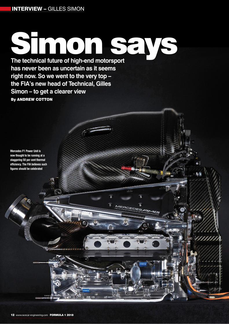
Simon says The technical future of high-end motorsport has never been as uncertain as it seems right now. So we went to the very top – the FIA’s new head of Technical, Gilles Simon – to get a clearer viewBy ANDREW COTTON
Mercedes F1 Power Unit is now thought to be running at a staggering 50 per cent thermal efficiency. The FIA believes such figures should be celebrated
Gilles_MBAC.indd 12 22/03/2018 10:00

Simon says
There was no fanfare, just a statement put out in September by the FIA that Gilles Simon would take on the responsibility of head of Technical
at the organisation. The Frenchman is a long-time associate of FIA President Jean Todt, and has previously worked at the FIA as technical and powertrain director, until he moved to stillborn engine manufacturer PURE. He was then, until recently, working with Honda in Formula 1 as a consultant.
It’s fair to say that Simon has stepped into the position at a very difficult time. Formula 1 is currently looking to finalise its 2021 engine regulations and there are disputes over how these might finally look. The WEC has lost Porsche and Audi, Peugeot has decided not to return and Toyota has
yet to commit to the 2018 season. The regulations that were announced at Le Mans are now rescinded, and there are no new manufacturers on the horizon.
Meanwhile, the World Touring Car Championship has failed, and its TC1 formula has been replaced by TCR regulations for now, while Formula E appears to be an electro-magnet for motor manufacturers.
At the heart of it all sits the conflict between technical development and entertainment. Formula E offers the manufacturers what they need in terms of showcasing their electric capability, but cannot be described as exciting racing, while back of the grid Formula 1 teams, and the WEC manufacturers, are drowning under the cost of hybrid development. Poor organisation, along
with the high cost of machinery, has led to manufacturers walking away from the WTCC in favour of the customer-focussed TCR formula. And it is now Simon’s responsibility to bring order to all this chaos.
His job is to chart a clear path for top-level series – as well as the feeder formulae – that keeps racing road relevant with innovative technology, while maintaining some level of cost control that allows private teams to compete. He also has to keep up fan engagement at a time when the car industry is itself having to adapt to a changing world following the 2015 dieselgate scandal, and the rise of electric mobility.
Hybrid technology was introduced into Formula 1 as a means to give manufacturers corporate responsibility within their racing a
LMP1 gave Audi an opportunity to both develop and promote cutting-edge technology (2015 engine pictured) but its very successful programme was axed within a year of the emissions scandal that shook the VW Group
FORMULA 1 2018 www.racecar-engineering.com 13
‘I don’t feel that entertainment and technology are against each other’
Gilles_MBAC.indd 13 22/03/2018 10:00

INTERVIEW – GILLES SIMON
14 www.racecar-engineering.com FORMULA 1 2018
programmes and the gains made, since 2014, in engine efficiency have been truly extraordinary. Thermal efficiency has risen from an estimated sub 30 per cent to over 50 per cent in F1 test conditions as development continues.
School of hard NOxHowever, the costs associated with running these power units has put customer teams in particular in a difficult financial position. For the manufacturers, life is similarly complicated, but for other reasons. One of the main issues facing the motor industry today is the shifting sand beneath the feet of the manufacturers that has left them uncertain of the ground on which they are standing. Previous governments have targeted CO2 emissions as the Holy Grail of engine efficiency, until they noticed that low CO2 producing diesel was in fact emitting high NOx levels. With the dieselgate scandal, in which Volkswagen was found to have installed a ‘cheat’ device to pass emissions tests, the world decided that diesel is effectively poison.
Arguably, it was this case that has started the debate on our future mobility, as trust in the manufacturers has suffered. In the UK, new tax regulations coupled with the above has seen a drop in the number of new cars sold, although electric cars are clearly on the rise. They still form a small part of the market, but the trend is clear; the consumers are after electric. Advertisements have changed from promoting lifestyle to air quality, particularly in towns, which is where electric mobility is so strong and where governments are looking to ban combustion cars. It seems that Formula E was ahead of the curve in predicting this rise in electric.
Plugging in to E‘Formula E had been thought of well before [dieselgate], in 2010 when the FIA was trying to put together what could be an electric racing car, and that led to a championship that is successful today,’ says Simon, speaking to us in the vast meeting room on the fourth floor of the FIA building in Geneva. ‘[We were]
trying to look a little forward. The FIA has put in place regulations of the championship that at the beginning people were asking “why? What is the scope of the formula?” Today many manufacturers are interested in this championship and it is a good showcase for the electric technology that they need to sell.’
Show businessWith governments jumping onto the bandwagon and targeting an end to the sale of new ICE cars, the FIA has to write technical regulations that keep the sport relevant and lead the development of technology while also driving up fan engagement.
‘I don’t feel that entertainment and technology are against each other,’ says Simon. ‘As a promoter in any of our championships, they want the championship to be interesting to the last minute, to be spectacular and provide a good show. This is the best way to catch fans and keep them interested, and is generally the case for all sport and all entertainment. What is
While all Formula E cars look the same there are plenty of different manufacturers involved in the championship. The FIA is content with the progress of its all-electric race series
Emissions are an issue everywhere and some cities could ban ICE cars in the future. Little wonder EVs are gaining ground
‘We have to explain it properly so that anybody sensible can understand good performance from a technical point of view’
Gilles_MBAC.indd 14 22/03/2018 10:00

FORMULA 1 2018 www.racecar-engineering.com 15
specific to motorsport is that there is a motor, so you have already technology there. Part of the fan interest is about the cars. It is about the fight, but it is also the beauty of these cars. It is about having spectacular and fast cars, and also anyone of us looking at any kind of race, it is about the engineering of these cars. Why is this one faster, and behaving like this? Part of the show is due to the technology.’
Racing’s essence While the sport has always been about the drivers who can extract the maximum from a car, it is the technology and, Simon argues, the efficiency of the racecar that leads to championship victories. ‘The fact that someone reaches 50 per cent efficiency and someone else is not at that figure, let’s say 49, one will be in front of the other,’ he says. ‘The only way, with the fuel flow control, to have more power is you have higher efficiency and this has always been the case. When you are engineering a racecar, you always care about fuel consumption. In an endurance race you want to have a longer stint, and in a shorter race you want to start with the least amount of fuel. If you could start a race with 10kg of fuel less than your competitors, you have an advantage. This is
part of the engineering of a racecar, in any formula. I believe this was already the case when Bugatti was fighting the Bentleys. One had a small displacement high efficiency, another raw power, and that is the basis of motorsport.’
Road relevanceThe burning question is; who decides what is road relevant? Is it the FIA taking a lead in its rule writing, or is it the manufacturers who have a vested interest in their own technologies? For Simon, it is a negotiation that reaches a common agreement, although outlining the framework and then distributing it is not always the best policy. Releasing its roadmap for the 2021 F1 engine regulations was met with criticism from teams and manufacturers, but he would not be drawn into a discussion on the public statements that have been made.
However, Simon is pleased with the way that hybrid technology has been integrated into Formula 1 and the WEC, and says that it has allowed companies to start the development of such technology that, if not transferable immediately, will be in the future.
‘Turbocharger manufacturers had some experience with energy recovery with a turbocharger, but it was limited, and a one-off
project to see if it could work,’ explains Simon. ‘They concluded that it could work in the right conditions, and they were keen to work on the F1 project because this helped them with the resources that they needed to develop the idea to the point that they can say that they can do it, produce it, and they know the limits. They have invested some resource and now they have the technology actually on the shelf. When it will be applied I don’t know, but this is part of their catalogue on the shelf. They have no fear to push it into production if the need comes and this is what I expect from motor racing.
‘In June, I was at a congress on gasoline engines, discussing this with other people, and I understood that at least two big OEMs started a programme on energy recovery on the exhaust, because they knew this was a potential solution. They never had the ability to get the
‘When you are engineering a racecar you always care about fuel consumption’
Formula E has attracted good crowds at many of its city-centre events but there are some who question whether the level of spectacle is quite on a par with the level of technology
Gilles_MBAC.indd 15 22/03/2018 10:01

INTERVIEW – GILLES SIMON
16 www.racecar-engineering.com FORMULA 1 2018
budget to research it. As soon as they said “it’s the system that they use in F1”, they got the budget. This effect of leading has always been so, and I believe that it remains important for our industry and for our sport.’
Development costsThe issue, of course, is the cost of developing such experimental systems, particularly for the privateer teams. Their criticism is that the power unit supply costs have risen by a factor of four, but there has certainly not been four times the return on their investment. It has led to disquiet at the back of the grid, and the FIA is by no means ignorant of their plight.
‘The tricky question for us from a technical regulations side is to find a balance between the cost and the maximum technology that you can fit into [the racecar] for that price,’ says Simon. ‘We are facing some difficulties but we have to find a compromise. The question is simple; we have to find the right balance. It is tricky [to do so] and you have different opinions, but we have to discuss it at length to find what is reasonable and the right direction. So our approach is to sit down with interested parties rather than to simply say “this is the regulation’’.’
Ulrich Baretzky, head of powertrain at Audi Motorsport and a man who is known to be an advocate of future technologies (and diesel), has said that motor racing could consider publishing its consumption figures. Although these would be frightening at first, it could be a way forwards for the FIA and the ACO to promote efficient motorsport, but Simon was not in favour. The Frenchman prefers that the communication of the technology improves, and that the fans have the engineering explained to them in a way that gets them excited, and more importantly, they understand what racing is trying to achieve.
Selling technology‘The best engine in Formula 1 is at 50 per cent efficiency, say, but what does this mean?’ he asks. ‘If you had this efficiency on your road car, your consumption would be around two litres per 100km, or something in this range, and that’s spectacular. But how do you translate this to a car that is above 800bhp and 70 per cent of the time under full load? If you try to do this with your car, the fuel consumption will be up, but the efficiency, the fuel you burn for the horsepower you need, is very high. I think some figures can be difficult to explain, while
others can be translated. If you speak about fuel consumption in a race, in a lap, or per 100km, it is high because it is very fast, but if you try to go that fast with any other car, it will be at least twice that, and maybe you are as fast. We have to explain it properly so that anybody sensible can understand good performance from a technical point of view.’
Hi-tech highwaySo, it seems that the FIA is going to stay on its high-technology route, and be a leader in the development of road relevant components. It will, with negotiation, decide how the regulations should work in top-level motorsport within a cost framework.
‘There is no antagonism between technology and entertainment, there is just balance for each championship,’ Simon concludes. ‘The costs have to remain in a window that is acceptable. The issue is probably more to have a sustainable model in each formula of motorsport, so to understand what kind of budget makes sense in Formula 1, endurance, GT or touring cars. Once you define this, then you have to identify the technology within this window.’
‘Motor racing is about the fight, but it is also about the engineering of the racecars; why is one car faster, and behaving like it is?’
Toyota leads Porsche and Audi in the WEC. Manufacturers like the hi-tech, but they can also walk away. Toyota is the last remaining car maker in LMP1-H after Porsche and Audi left
Gilles_MBAC.indd 16 22/03/2018 10:01

www.crp-group.com www.crp-usa.net
www.windform.com [email protected]
ADV-WF-F1-210x297-feb2017.indd 1 20/02/2017 10:15:11

FORMULA 1 – POWER UNIT REGULATIONS
18 www.racecar-engineering.com FORMULA 1 2018
Engine mappingThe FIA’s recently released ‘roadmap’ outlining the key aspects of the 2021 Formula 1 power unit rules has not been well-received by all in the F1 paddock – but what exactly does the plan entail and what are the key objections? Racecar investigates this on-going story
From the fi rst publication of the 2014 Formula 1 power unit regulations it was made clear that a new set of rules would be introduced in 2021. What
those rules would be was, until very recently, entirely unclear. A large number of diff erent and often confl icting ideas and opinions were being discussed by diff erent parties with diff erent motivations, everything from a 3.4-litre V6 twin turbo engine to some kind of large capacity V12 were suggested at diff erent times. But what was clear was that many in the sport felt that the current generation of power units were simply not right for Formula 1.
‘For me, these engines have done nothing but damage F1. They’ve done nothing to contribute to the sport,’ Red Bull Racing team principal Christian Horner says. ‘They have taken away the sound, the passion and they have added too much complexity; they have become far removed from road car technology and they are eff ectively turning into diesel
engines in some cases. I can’t see anything that they have contributed that’s been positive. So the sooner it goes, the better.’
Although Horner’s sentiments are not universally held, some of the issues he raises are of concern to the sport’s governing body, the FIA, and also its new promoter, Liberty Media. So, after seemingly endless discussions, the FIA came up with a set of key goals for the new generation of power units to achieve, aiming to address the criticism, these are: ‘A desire to maintain F1 as the pinnacle of motorsport technology, and as a laboratory for developing technology that is relevant to road cars. Striving for future power units to be powerful, while becoming simpler and less costly to develop and produce. Improving the sound of the power units. A desire to allow drivers to drive harder at all times.’
Those objectives were issued part way through the 2017 Formula 1 season, and were then used as a basis for debate and discussion among the manufacturers, teams and a number
of suppliers. Then, following the Mexican Grand Prix in late October, a more detailed plan was revealed for 2021. This ‘roadmap’ laid out the core elements of the new power unit formula.
At a superfi cial level what was presented is very similar to what is in use today, with a turbocharged 1.6-litre V6 engine at the core of a hybrid power unit. But within the six bullet points that make up the roadmap there is also substantial scope for change.
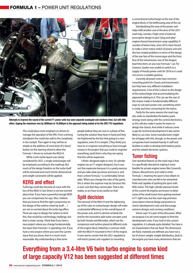
Volume controlPerhaps the most criticised element of the current 2014-2020 generation of power units is the sound they produce, or rather the lack of it, while what sound there is, is clearly not to the taste of many fans. As a result there have been various eff orts to improve it and increase its volume, notably giving the wastegates a separate exit pipe, though this has had only a minor impact. A project to add a sound generator to the exhaust system was also under
F1 2021_MBAC.indd 18 22/03/2018 10:18

Engine mapping
FORMULA 1 2018 www.racecar-engineering.com 19
development at one point but to date has not been seen out on the race track.
A new attempt to improve the sound is included in the 2021 roadmap, namely increasing the maximum revs of the V6 engine. Currently the maximum speed is set at 15,000rpm but this will be raised to 18,000rpm in 2021. However, there is some debate about whether this will have any eff ect. These days the cars almost never hit the peak RPM, as in an effi ciency based formula it is simply not the optimum way of operating the engine.
But FIA engine boss Gilles Simon says this will be addressed: ‘I think that the fi rst natural idea to discuss in detail is that we will just follow the fuel fl ow curve 3000rpm higher, so you will have higher fuel fl ow,’ he says, which leads to the thought that bigger fuel tanks might then need to be fi tted. ‘Not necessarily. What I believe can be agreed is that the race fuel allocation is seen as a limit to race fi ghting, so while we continue to impose a fuel fl ow maximum [we could] also
have an agreement to allow for free race [fuel] allocation, but someone will have a bigger tank than others, maybe. But it will be a choice, and fuel effi ciency [will still be] important to manage the race properly,’ Simon says.
The H bombPerhaps the part of the roadmap which will have the biggest impact of all, though, on not only the sound of the power unit but also the overall layout and design of the engine, is the plan to no longer use an MGU-H. The use of the MGU-H under the current rules means that the V6 engines are designed partly to have recoverable energy in the exhaust, something which means that the best power unit is not always the best combustion engine, but the best compromise between ICE and ERS. ‘What counts at the end is the overall effi ciency of the system. If you take off the MGU-H you reduce the effi ciency, so we will not be at 50 per cent.’ Simon says. ‘We are discussing that. It is a proposal, but today we
are trying to fi nd a good balance between the cost, complexity, show and technology and it is not easy. In this compromise we thought it necessary to make a step with the MGU-H, and I think that it is an important point. It gives good effi ciency, but it is a complex system and to have it with quite a wide freedom in F1, it leads to serious cost issues, so we had to address that.’
Special KRemoving the MGU-H will obviously have a performance implication for the whole power unit. So in order to restore any loss in overall car performance that will come as a result, a new more potent MGU-K will be employed. Its exact performance level is not clear, but it will certainly produce more than the current maximum of 120kW. Additionally, according to the roadmap, there will be a ‘focus on manual driver deployment in race together with option to save up energy over several laps to give a driver controlled tactical element to racing’.
Perhaps the part of the roadmap that will have the biggest impact of all is the plan to no longer use an MGU-H
F1 2021_MBAC.indd 19 22/03/2018 10:19
FORMULA 1 – POWER UNIT REGULATIONS
20 www.racecar-engineering.com FORMULA 1 2018
Attempts to improve the sound of the current F1 power units has seen separate wastegate exit solutions tried, but with little effect. Upping the maximum revs by 3000rpm to 18,000rpm is the approach being looked at for the 2021 PU regulations
This could place more emphasis on drivers to manage the operation of the ERS. From a driving standpoint this could also add to the complexity in the cockpit. Then again it may well be as simple as the addition of some kind of ‘e-boost’ button on the steering wheel to allow the Formula 1 drivers to activate the MGU-K.
While a twin turbo layout was clearly considered for 2021, a single turbocharger will be employed, according to the roadmap. But much of the design freedom on the turbo itself will be removed and much stricter dimensional and weight constraints will be applied.
KERS and effect Turbo lag could also become an issue with the loss of the MGU-H, but Simon is not too worried about that. ‘If you have a powerful enough KERS you can compensate,’ he says. ‘Also, I believe that you have to find the right compromise on the design of the turbine wheel by itself … I am not so worried about the turbo lag effect. There are ways to design the turbine to limit this, that would be a technology challenge, but that is motor racing. I think that if you have a new project where you change fundamentally the input then Formula 1 is spending a lot. If you have a new project where you tune the current input that you know, then it is much more reasonable. My understanding is that some
people believe they are now in a phase of fine tuning the solution they have in hand and they are frightened by the fact that going to a new regulation, even if it is simpler. [They think] you have to re-engineer everything or have enough money in the project that you could re-engineer everything, [and] that is why they are saying that this will be expensive.
‘I think I designed eight or nine 10-cylinder engines [as an F1 engine designer], but it was not that expensive because it is a yearly exercise and you take what you know and tune it, and that is where Formula 1 is comfortable,’ Simon adds. ‘When you change the rules of the game, this is where the expense may be, because this is over-cost that they cannot plan. That is the reality, so we have to be careful on that.’
Split decisionThe removal of the MGU-H and the tightening up of the rules on turbocharger design will make a substantial difference to the overall layout of the power unit, and it is almost certainly the end for the innovative split turbo concepts used by both Honda and Mercedes, which see the compressor and turbine placed at different ends of the engine block, linked by a common shaft, with the MGU-H mounted in the V of the engine. It now seems certain that the 2021 regulations will restrict power unit suppliers to mounting
Everything from a 3.4-litre V6 twin turbo engine to some kind of large capacity V12 has been suggested at different times
a conventional turbocharger at the rear of the engine block, in the bellhousing area of the car.
Standardising this area of the power unit helps fulfil another one of the aims of the 2021 road map, namely a ‘high Level of external prescriptive design to give “plug-and-play” engine/chassis/transmission swap capability.’ A number of teams have, since 2014, been forced to make a short notice switch of power unit and this has created problems in terms of the design of the rear face of the monocoque and the front face of the transmission, two of the longest lead time items on any new Formula 1 car. For instance, Sauber was unable to switch to a supply of Honda power units for 2018 as it could not secure a suitable gearbox.
Currently all power units have common mounting points for chassis and transmission but they have very different installation requirements. A lot of this is down to the design of the turbocharger and accommodating the pipework relating to it. This can see the rear of the chassis made in fundamentally different ways to suit each power unit, something which is costly and time consuming for the teams.
Partly for the same reasons the road map also seeks to standardise the battery pack (energy store) along with the control electronics, as this will also make it easier for teams to design the chassis. And while it reduces some scope for technical development it also seems likely to cut costs. Some manufacturers might be unhappy with this, though, as the power unit companies have invested heavily in staff and facilities in order to develop both battery packs and the related electronic systems.
Tuner fishingOne standout feature on the road map is that it is specifically directed at making it more feasible for private engine tuners like Cosworth, Gibson, Mecachrome and Judd to enter Formula 1, meaning the sport is less reliant on manufacturers who are felt to be somewhat fickle and capable of quitting the sport with little notice. The high cylinder pressure levels of the current V6 engines are known to deter some of the small tuners from getting involved in F1 right now, but the road map promises ‘prescriptive internal design parameters to restrict development costs and discourage extreme designs and running conditions’.
Simon says: ‘It is part of the discussion. What we propose is to set some targets to limit the development costs. If you look to the current regulation, it is already quite detailed. You have a lot of parameters that are fixed. The dimensions are fixed, materials are defined; you have not a lot of choice: weight, weight distribution, [but] in the engine you have many dimensions that are
F1 2021_MBAC.indd 20 22/03/2018 10:19

To find out more about our love of motorsports, and see our most popular automotive packages, visit www.HaasCNC.com/RE
+1-805-278-1800 | www.HaasCNC.com | Made with pride in the USA
HIGH PERFORMANCEIN EVERYTHING WE DOThere’s a reason Haas F1 and NASCAR race teams use Haas machines. Not only are we a top innovator in the machine tool industry, but our close involvement in motorsports also means that Haas machines are uniquely suited for the OE and aftermarket automotive industries.
The Haas UMC-750P

FORMULA 1 – POWER UNIT REGULATIONS
22 www.racecar-engineering.com FORMULA 1 2018
fixed. You can design [an engine] for an LMP1 car with any displacement, with any number of cylinders. This is not the case in Formula 1. The engine in Formula 1 is quite controlled, but controlling the dimensions does not have a lot of cost implication. [But] this is the output that has the cost implication – the balance between high cost and high efficiency, because the higher the efficiency, then the higher the cost, and we have to balance this.’
Indeed, there are already quite a few regulations limiting the internal design of the V6
Removing the MGU-H could reduce the complexity of power units and spell the end of the split turbo concepts used on some designs such as this 2017 Honda. To make up the power deficit from losing the MGU-H a more potent MGU-K will be used
In 2014 and 2015 Mercedes and Honda (pictured) used exhaust layouts designed to allow the MGU-H to recover maximum energy. The new regulations should switch focus on to maximising the ICE
‘I am not really so worried about the turbo lag effect, there are ways the teams can design the turbine to limit this’
engine, including the bore, crankshaft centreline position and height – which are all tightly defined – while other components have size and weight limitations, including the valve stem, main bearings, crank pin, piston and conrod. The overall centre of gravity of the power unit is also defined in the current regulations.
Fuel’s paradiseAnother barrier for private tuners coming into Formula 1 is fuel. All of the current power unit manufacturers work closely with fuel partners who will develop bespoke fuel for each update to the ICE, something generally beyond the reach of private tuners. To address this the road map promises an ‘intention to investigate tighter fuel regulations and limits on the number of fuels used’. But could this mean a single fuel spec, as is the case in the WEC?
‘This has to be discussed,’ Simon says. ‘The fact is that to develop a bespoke fuel for each engine is not realistic … [but] it is a very good tool for the development of technology because by doing specific fuels, and mixture of chemicals, you can understand exactly the effect of combustion. It is very useful.
‘I have worked with different fuel companies and they have all the understanding and it is interesting knowledge for their fuel and combustion experts,’ Simon adds. ‘I have had good experiences developing the engine and
the fuel, and understanding it together with the fuel specialists. This is the best way to progress in understanding combustion, and this is useful for the industry. The fuel specialists in Formula 1, they are involved in other projects, so for them to understand the specifics of combustion is of interest. By this way, you justify it. It is not just about finance [sponsorship] – that is important – but it is also a good technology enhancement. I believe that we have to be cautious on that, and you have to do something with more accurate definition of what should the fuel be, with less possibility of variability, to define better, or have less difference in performance due to the fuels.’
Cry WolffPerhaps not surprisingly, on the publication of the road map not everyone in Formula 1 was delighted with what it contained. ‘This is the FIA’s vision and proposal and we haven’t accepted it,’ Mercedes team boss Toto Wolff said following the meeting where it was presented. ‘The flaw of the concept is that it’s a completely new engine and new investment. It portrays it in a way of this is how we’re going forward and none of the current manufacturers was particularly impressed.’
Renault managing director Cyril Abiteboul had similar reservations, claiming that rather than a simple re-work of the current 1.6-litre V6 engines what is being proposed in the road map constitutes ‘a new engine on which we would have to make substantial development and substantial financial commitment without an understanding of the broader picture of what Formula 1 would look like past 2020.’
Abiteboul went on to claim that the roadmap does little for private tuners wanting to enter the sport. ‘I don’t see how what has been presented would be offering a model for an independent engine manufacturer. It lowers the cost of access for a car maker, but you would still need a substantial amount of dollars to spend into research and development to make any business plan work for the new engine. That is actually our problem, that we need to spend again, just like a new entrant would have to spend. But I don’t think an Ilmor or a Cosworth will be able to go for it independently without the [backing] of another car company.’
Horse playFerrari, too, was unhappy with the proposals, to the point where its chairman and CEO Sergio Marchionne make a thinly veiled threat to quit Formula 1 if the roadmap was not amended. ‘There are things we don’t necessarily agree with in the roadmap. One of which is the fact that somehow powertrain uniqueness is not
F1 2021_MBAC.indd 22 22/03/2018 10:19

www.pankl.com
Pankl Systems Austria GmbHEngine Systems
A-8600 Bruck/Mur, Kaltschmidstraße 2-6Phone: +43(0)3862 51 250 0Fax: +43(0)3862 51 250 290e-mail: [email protected]
High Tech | High Speed | High Quality

going to be one of the drivers of distinctiveness of the participants line-up,’ Marchionne said. ‘I would not countenance this going forward. But if we change the sandbox to the point where it becomes an unrecognisable sandbox, I don’t want to play any more. I don’t want to play NASCAR globally, I just don’t.’
Positive feedbackBut not everyone thinks the roadmap is flawed. Both Cosworth and Ilmor have stated that they feel that it puts them in a position where they could consider returning to the sport, and Aston Martin has said it is willing to consider developing its own power unit, while some already working in the Formula 1 paddock certainly see it as a useful starting point.
‘I think they’ve thrown out a good concept to start off with. Now the details can be worked out by the technical people. The concept is out there and I don’t think the concept will be
changed,’ Guenther Steiner of the Haas F1 team says. ‘Now they need to work on the detail of the concept to achieve the goals they’ve set themselves with more noise, more equality, and lower costs for the customer teams. Hopefully, they can achieve it.’
False premiseSome, including Williams technical director Paddy Lowe, feel that the route to improving Formula 1 has nothing to do with power units anyway. ‘The more you leave things alone the closer the racing becomes. You see that with the engines today, as they are a lot closer than they were three years ago. I think the new regulation change has to be done with great care. I find it curious that people place emphasis on new regulations needed to create convergence when it does the opposite.’
Crucially, the road map has been left deliberately vague in some areas, so that well
FORMULA 1 – POWER UNIT REGULATIONS
24 www.racecar-engineering.com FORMULA 1 2018
Toto Wolff‘The flaw of the concept is that it’s a completely new engine and new investment … None of the current manufacturers was particularly impressed’
Cyril Abiteboul‘I don’t see how what has been presented would be offering a model for an independent engine manufacturer’
Guenther Steiner‘They need to work on the detail of the concept to achieve the goals they’ve set themselves; with more noise, more equality, and lower costs’
funded manufacturers cannot get a head start on smaller concerns. ‘Work will continue over the next 12 months to define certain elements of the power unit, but the design and development of the complete power unit will not be possible until all the information is released at the end of 2018. This aims to ensure that manufacturers continue to work on the current specification power unit,’ an official FIA statement read. ‘During the remaining part of 2017 and 2018, the FIA and F1 will also work with the teams to establish power unit test and development restrictions as well as other cost containment measures.’
But is that time-scale realistic? ‘I think that if we have a reasonable discussion we should be able to have a good understanding of where we are going in the first quarter of next year, and then refining it towards the end of the year, but the target of having the regulation set next year is really possible,’ Simon insists.
The design and development of the power unit will not be possible until all of the information is released’Fuel flow meters are set
to still play an important part in F1 power units beyond 2021
F1 2021_MBAC.indd 24 22/03/2018 10:19

Untitled-61 1 30/06/2016 13:22

TECHNOLOGY – GRAINGER AND WORRALL
26 www.racecar-engineering.com FORMULA 1 2018
Cast awayThere’s much more to casting high performance engine parts than simply pouring liquid metal into a mould – as Racecar discovered on a visit to Formula 1 supplier Grainger and Worrall By GEMMA HATTON
In a Formula 1 engine during the combustion process the instantaneous gas temperature reaches 2600degC, which is half as hot as the sun’s surface, and the gas
pressure forces are equivalent to four elephants acting on each of the pistons. Within a blink of an eye an F1 engine completes 200 ignitions, with 43 trillion calculations over a race distance. And it only takes one combustion error in 37 million to cause a terminal failure.
With these figures in mind we can maybe start to appreciate the phenomenal challenge facing motorsport engine manufacturers. ‘The shift towards small capacity turbocharged
engines that we’ve seen in F1 and, are starting to see in other championships, results in the engine stresses and temperatures reaching new levels,’ explains Phil Ward, director of performance products at Grainger and Worrall, which is a world leader in manufacturing structural engine castings. ‘The increase in temperature is more of a challenge than the increase in stress, because the aluminium alloys within the engine experience a dramatic drop off in strength once a threshold temperature has been exceeded. A material that is perfectly strong at 160 to 180degC will behave like toffee above 250degC, so the alloys we used in the
V8 era, which was only three years ago, are now no longer strong enough.’
This is one factor that has driven Grainger and Worrall to develop new casting processes, new material chemistries and new tooling. ‘An additional consequence of these high engine running temperatures are the demands on the cooling circuits,’ Ward adds. ‘In previous engine generations the water jackets, for example, had relatively simple internal shapes, now their complexity means it’s almost impossible to use traditional tooling methods without compromising the design. However, with our sand printing capabilities
Two different types of sand are used to manufacture the sand cores and the moulds of the casting. The regular sand has grains of 0.2mm thickness but for the more complex and intricate shapes a finer, partly synthetic, sand with grains of just 0.1mm is used in a hot curing process, so that the printed layers of sand are more compact and therefore stronger
Grainger and Worrall_MBAC.indd 26 22/03/2018 10:59

Cast away
FORMULA 1 2018 www.racecar-engineering.com 27
we have more freedom to achieve this required complexity because we can effectively print these shapes as a single piece.’
Every championship that races bespoke engines, including the likes of F1, LMP1, LMP2, WRC, WRX and Moto GP, utilise Grainger and Worrall cast parts such as cylinder heads and engine blocks, as well as transmission and gearbox housings. The technology at the heart of Grainger and Worrall is sand printing, which is used in over 75 per cent of its motorsport products. It allows the manufacture of intricate and complex shapes within a part which cannot be achieved through machining.
‘We use sand printing because it gives us an almost infinite capability to derive shape and size, with minimal constraints,’ says Keith Denholm, engineering and technology director at Grainger and Worrall. ‘It’s also a relatively low investment cost process so we can very quickly go from a drawing to a product because we
don’t need to make steel tools or buy large machines. Both motorsport and automotive are adding levels of complexity in terms of the shapes, physical and mechanical performance, and sand printing does a particularly good job of allowing us to optimise that.’
Sand printingEssentially, sand printing is where a layer of sand, 0.25mm thick, is printed onto a ‘jobbox’, followed by a layer of chemical binder and then a further layer of sand. In this way, complex 3D shapes can be gradually generated, slice by slice. This type of rapid prototyping technology is used to manufacture ‘cores’ which are then secured within the moulds of a casting. Molten metal is poured into the cast and, once solidified, the sand cores are shaken out; leaving the desired and intricate holes and passageways inside the part. This process of casting with 3D printed sand cores may seem a relatively simple
Once the sand cores have been printed they are assembled into the final mould. Coolers and feeders are made to help control rate of solidification so that the tightest micro-structures are formed for high strength
‘We use sand printing because it gives us an almost infinite capability to derive shape and size, with minimal constraints’
concept. However, every stage demands a detailed engineering and scientific approach to ensure the final product is of the highest quality to meet the high demands of motorsport.
Like all processes in modern engineering, the first step is to generate a 3D CAD model. As is the case with most components, this tends to be a battle between the designers who want their optimised shape and the manufacturers who want a design they can actually make. ‘This is the first engagement we have with our customers and in most cases the customers desires lack manufacturing ability,’ Denholm says. ‘We then work simultaneously with them within the virtual world where we have the maximum opportunity to make changes with no time or cost implication. We also use simulations to analyse the casting process and how the moulds and the cores behave when in contact with liquid metal. The aim is to arrive at a product, in the shortest time possible, that meets their functional requirements and our manufacturing requirements.’
Design freedomThe capabilities of sand printing already offers advantages at this initial stage because it removes many physical constraints associated with traditional tooling, allowing more design freedom. ‘We can now make the ship in the bottle, which we couldn’t before,’ Denholm says.
Once the design has been finalised in the virtual world, Grainger and Worrall engineers then have to think inside-out, because to manufacture a cast part you also have to manufacture the parts that aren’t there, such as the voids. This is why the sand cores are used and they can be manufactured in two ways. The first is similar to building a sandcastle – a pattern is machined and filled with sand and the desired shape formed – or 3D sand printing is used.
‘We have two printers that produce sand in a similar mechanical way, but have very different chemical systems,’ Denholm says. ‘The first is a cold curing process, where the binder fixes the layers of sand at ambient temperature, as they are printed. Therefore, once the part is finished, it is already glazed which makes it robust and
Grainger and Worrall_MBAC.indd 27 22/03/2018 10:59

TECHNOLOGY – GRAINGER AND WORRALL
28 www.racecar-engineering.com FORMULA 1 2018
suitable for large moulds. But for the more intricate cores we need a stiffer, more accurate sand, so we use a hot curing process. Here, the infrared lamp in the printer heats the layers of binder in between the sand to initiate the curing process and evaporate any moisture, before the parts are placed in a microwave for a final cure.’
Finer grains The hot curing process enables the binder to retain its strength for longer by compacting the sand, which is essential for parts such as the cooling jackets which sit between two cylinder bores in an engine block. The sand core for a cooling jacket at its thinnest cross section is 1.8mm and with a grain of conventional sand at 0.2mm, only nine grains of sand will make up that cross section. Not only is this inherently weak, but the liquid metal could actually penetrate between these grains, resulting in a blockage. Therefore, a partly synthetic sand is used for the hot curing process, which has grains at 0.1mm to ensure that more grains are packed into these thinner cross sections. Essentially, the sand has to be strong enough to withstand the thermal loads of 700degC liquid metal during casting, but weak enough to shake out of the mould once the part has been cast.
‘When in contact with the molten metal, the sand will want to expand by approximately one per cent, which is not dimensionally accurate,’
Main pic and above: sand printing has allowed the manufacture of the intricate shapes needed for modern race engines while maintaining the strength for the sand cores to survive 700degC of molten aluminium
says Denholm. ‘This is why we not only have several types of sand with different chemistries, but also different curing mechanisms as well. With these two printers we can mix and match the sands and select what is appropriate in terms of time, feature and cost.’
Multi-taskingAnother advantage to sand printing is that many parts can be arranged on the same jobbox, as long as they are separated. Volumetrically, up to 80 per cent of the space is utilised, which can equate to six to eight pieces for an eight to 10 hour cycle on the hot curing printer, which hasn’t been switched off for the last three months. The jobbox of the cold cure printer is 16 times larger than the hot cure
printer and due to its size it is only used four times a week for 20-hour cycles, because it generates so many parts.
Unlike other additive manufacturing processes, sand printing does not require any supports to be printed to hold the piece together during printing. This is because the sand is so compact within the cured layers, it actually provides structure for itself. However, other structural features may be necessary to ensure the cores are held together and assembled in the correct positions within the mould. You may wonder why several cores are used, as opposed to a single core. ‘Technically, we can produce a monoblock of sand, which replaces several cores, but you would never do that from a manufacturing standpoint,’
‘We can now make the ship in the bottle, which we couldn’t before’
Grainger and Worrall_MBAC.indd 28 22/03/2018 11:00

FORMULA 1 2018 www.racecar-engineering.com 29
Denholm says. ‘Firstly, how can you be sure that everything is right and that all the powdered sand is removed? Also, when the metal is poured in, the air has to displace out, so we don’t want it to be hermetically sealed. There are obvious benefits to a single core as the loads are more uniformly distributed as opposed to gluing an assembly together and it also reduces the variability in position. However, we might aim to make fewer cores, but never just one lump of sand as that’s not the end goal.’
Mass flow rateOnce all the moulds and cores are in position, molten metal, usually aluminium alloy, is poured and the casting is born. However, this pouring process has the potential to significantly reduce the quality of the aluminium. Therefore, precisely engineered gating systems are used to manage the mass flow rate of the metal at every point as it fills the mould. This avoids any velocities exceeding a critical criteria which could induce turbulence, reducing quality.
‘We also ensure that we fill a mould uphill. If you pour metal in from the top, the metal will cascade down from layer to layer and backfill, similar to a shower. The water coming out of a shower head has a much larger surface area exposed to air than if you were to fill the bath up through the plughole. The latter will expose the water to the area of the bath, roughly a square metre. If you drop that amount of water in through droplets in a shower, the combined
surface area could be as large as a tennis court,’ explains Denholm. ‘Bear in mind that aluminium loves oxygen, and aluminium oxide is a ceramic which doesn’t weld together with metal in a casting, so you end up with different materials distributed within the structure. As they are not connected, they cannot transfer thermal or mechanical stress, creating cracks which are the basis of fatigue, and fatigue is the biggest failure mode of aluminium parts in an engine. That is why we invest in technologies that limit the opportunity for aluminium to grab oxygen throughout the entire process.’
The next step is solidification. The rate and distribution of solidification can be manipulated to suit the performance requirements of specific areas of the casting. Theoretically, molten metal solidifies by transferring heat to its surroundings, which in most cases is the sand. If the sand was inert and thermally inactive, the metal would stay liquid forever. Naturally, the rate at which the heat conducts from the metal depends on the surrounding media. Therefore, areas of the casting can either be insulated to keep the metal liquid, or placed next to a heat sink, which has a high heat capacity (usually iron or steel) and conducts heat away quickly. This is how Grainger and Worrall can precisely control the growth of the crystalline structure as the metal transitions from liquid to solid.
‘Unfortunately, this process doesn’t happen instantaneously, it’s like the growth of a snowflake,’ Denholm says. ‘Take the gas face of
The molten aluminium needs to avoid exposure to air as much as possible and this is why the flow of the metal in the mould is controlled through some very complex gating systems
‘Sometimes we deliberately manufacture parts not to be straight, because during solidification the part will straighten itself’
a cylinder head where the explosion happens. This is typically an area where fatigue is most likely to occur and so we need to solidify that first to initiate a tighter microstructure with smaller grains. Therefore, we use coolers because the metal will have less time to grow before it solidifies. If you stop a snowflake from growing, it will remain small, which is why on cold snowy days the snow is more like frost, whereas on warmer days you get much bigger snowflakes.’ This rapid solidification not only increases the inherent strength of the material, but also reduces the gas porosity within the structure because gas simply doesn’t have time to escape during solidification.
As well as initialising solidification in particular areas, the aim is to also solidify the part in a consistent way. However, the varying
Grainger and Worrall_MBAC.indd 29 22/03/2018 11:00
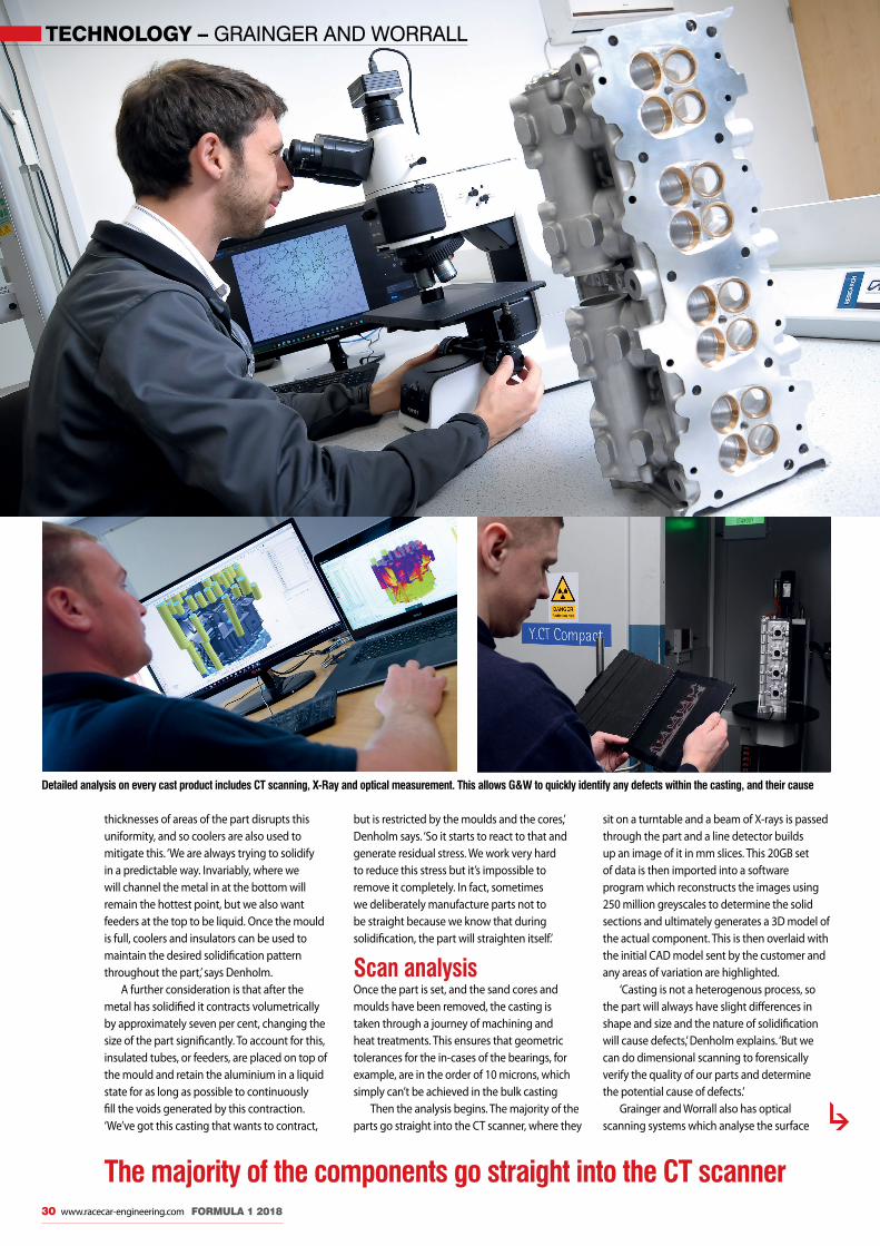
TECHNOLOGY – GRAINGER AND WORRALL
30 www.racecar-engineering.com FORMULA 1 2018
Detailed analysis on every cast product includes CT scanning, X-Ray and optical measurement. This allows G&W to quickly identify any defects within the casting, and their cause
thicknesses of areas of the part disrupts this uniformity, and so coolers are also used to mitigate this. ‘We are always trying to solidify in a predictable way. Invariably, where we will channel the metal in at the bottom will remain the hottest point, but we also want feeders at the top to be liquid. Once the mould is full, coolers and insulators can be used to maintain the desired solidification pattern throughout the part,’ says Denholm.
A further consideration is that after the metal has solidified it contracts volumetrically by approximately seven per cent, changing the size of the part significantly. To account for this, insulated tubes, or feeders, are placed on top of the mould and retain the aluminium in a liquid state for as long as possible to continuously fill the voids generated by this contraction. ‘We’ve got this casting that wants to contract,
but is restricted by the moulds and the cores,’ Denholm says. ‘So it starts to react to that and generate residual stress. We work very hard to reduce this stress but it’s impossible to remove it completely. In fact, sometimes we deliberately manufacture parts not to be straight because we know that during solidification, the part will straighten itself.’
Scan analysis Once the part is set, and the sand cores and moulds have been removed, the casting is taken through a journey of machining and heat treatments. This ensures that geometric tolerances for the in-cases of the bearings, for example, are in the order of 10 microns, which simply can’t be achieved in the bulk casting
Then the analysis begins. The majority of the parts go straight into the CT scanner, where they
sit on a turntable and a beam of X-rays is passed through the part and a line detector builds up an image of it in mm slices. This 20GB set of data is then imported into a software program which reconstructs the images using 250 million greyscales to determine the solid sections and ultimately generates a 3D model of the actual component. This is then overlaid with the initial CAD model sent by the customer and any areas of variation are highlighted.
‘Casting is not a heterogenous process, so the part will always have slight differences in shape and size and the nature of solidification will cause defects,’ Denholm explains. ‘But we can do dimensional scanning to forensically verify the quality of our parts and determine the potential cause of defects.’
Grainger and Worrall also has optical scanning systems which analyse the surface
The majority of the components go straight into the CT scanner
Grainger and Worrall_MBAC.indd 30 22/03/2018 11:01

CMA_Claytex ad A4 FP_March 2018.indd 2 15/03/2018 17:55
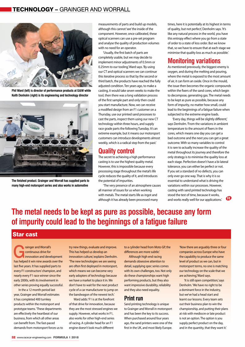
TECHNOLOGY – GRAINGER AND WORRALL
32 www.racecar-engineering.com FORMULA 1 2018
Star cast
Grainger and Worrall’s continuous drive for innovation and development
has helped it win nine awards over the last five years. It has supplied parts to every F1 constructors’ champion, and nearly every F1 race winner since the early 2000s, with its involvement in other series proving equally successful.
In the a 12 month period last year, Grainger and Worrall estimates it has completed 400 turnkey products within the motorsport and prototype teams. ‘These departments are effectively the heartbeat of our business, from which all other areas can benefit from. The fast-paced demands from motorsport forces us to
try new things, evaluate and improve. This has helped us develop an innovation culture,’ explains Denholm. ‘The new technologies we are seeing are often first deployed in motorsport, which means we can become very early adopters of technology because we have a market to place it in. We don’t have to wait for the next product cycle of a car manufacturer to jump on the bandwagon of the newest tech.’
Ward adds: ‘F1 is at the forefront of that drive for innovation, because they are the most stressed engines we supply. However, what works in F1, also works for other high-end series of racing. A cylinder head for an F1 engine doesn’t look much different
to a cylinder head from Moto GP, the differences are more subtle.’
Although high end racing demands obsessive attention to detail, supplying spec series comes with its own challenges, too. Not only do these championships want high performing products, but they also want impressive durability, reliability and they also need equality.
Print runSand printing technology is unique to Grainger and Worrall in motorsport and has been the key to its success. When purchased around four years ago, the sand printers were one of the first in the UK, and most likely Europe.
‘Now there are arguably three or four companies across Europe who have the capability to produce the same level of product as we can, but in motorsport terms, no one is matching our technology on the scale that we are achieving,’ Ward says.
‘It is still open competition,’ says Denholm. ‘We have no right to be a dominant force in the industry, but we’ve had a head start and learnt our lessons. Every team sets out their business plan to win the championship, and putting their plans at risk with mediocre or late product is not an option. The option is you supply perfect product on the day, and in the quantity, that they want it.’
measurements of parts and build up models, although this cannot ‘see’ the inside of the component. However, once calibrated, these optical scanners can use a pre-set program and analyse the quality of production volumes with no need for an operator.
‘Usually, the first batch of parts are completely usable, but we may decide to implement minor adjustments of 0.5mm or 0.25mm to our tooling,’ Ward says. ‘By using our CT and optical scanners we can continue this iterative process so that by the second or third batch, the products have reached the fully adjusted condition. Ten years ago, to make a casting, it would take seven weeks to make the tool, then there was a long validation process of the first sample part and only then could you start manufacture. Now, we can receive a modified design from an F1 customer on a Thursday, use our printed sand processes to cast the parts, inspect them using our new CT technology within three hours, and supply race grade parts the following Tuesday. It’s an extreme example, but it means our motorsport customers can introduce developments almost weekly, which is a radical step from the past.’
Quality controlThe secret to achieving a high performance casting is to use the highest quality metal. However, this is impossible because every processing stage throughout the metal’s life cycle reduces the quality of it, and introduces the potential of impurities.
‘The very presence of an atmosphere causes all manner of issues for us when working with metals. The metal starts life as ingot and although it has already been processed many
times, here it is potentially at its highest in terms of quality, but not perfect,’ Denholm says. ‘It’s like any natural process in the world, you have this entropy effect where you go from a state of order to a state of less order. But we know that, so we have to ensure that at each stage we minimise that quality loss as much as possible.’
Monitoring variationsAs mentioned previously, the biggest enemy is oxygen, and during the melting and pouring, where the metal is exposed to the most amount of air, it can form an oxide. Once in the mould, the issue then becomes the organic compounds within the fixers of the sand cores, which begin to decompose, generating gas. The metal needs to be kept as pure as possible, because any form of impurity, no matter how small, could lead to the beginnings of a fatigue failure when subjected to the extreme engine loads.
‘Every day, things will be slightly different,’ says Denholm. ‘From the variations in ambient temperature to the amount of fixers in the cores, which means one day you can get a bad outcome and the next you can get a great outcome. With so many variables to control it is rare to actually increase the quality of the metal throughout its journey and therefore the only strategy is to minimise the quality loss at each stage. Perfection doesn’t have a bi-lateral tolerance, you can either be perfect or not. If you set a standard of no defects, you can only ever go one way. That is why it is so essential to understand what is driving the variations within our processes. However, casting with sand printed technology has stood the test of time, because it works, and works really well for our applications.’
Phil Ward (left) is director of performance products at G&W while Keith Denholm (right) is its engineering and technology director
The finished product. Grainger and Worrall has supplied parts to many high-end motorsport series and also works in automotive
The metal needs to be kept as pure as possible, because any form of impurity could lead to the beginnings of a fatigue failure
Grainger and Worrall_MBAC.indd 32 22/03/2018 11:01

NATIONALMOTORSPORTACADEMY
All subject to contract. Please ask for details. All prices +VAT*
Untitled-245 1 21/02/2018 13:55

FORMULA 1 – SAFETY
34 www.racecar-engineering.com FORMULA 1 2018
Agents of ShieldAn alternative F1 cockpit protection device was aired in practice at the British GP last year – but a disappointing test, and lack of time, resulted in the decision to go with the HaloBy SAM COLLINS
Before the British Grand Prix 2017, the latest in a line of experimental cockpit safety systems was trialled on a Ferrari SF70H during free practice.
Dubbed the Shield, the device is designed to protect a driver’s head from flying debris, such as that which killed Henry Surtees in F2 in 2009 and Justin Wilson in IndyCar in 2015.
The new device was developed following the mixed response to the steel Halo device trialled in 2016, and also the Aeroscreen tested by Red Bull. Early in 2017 it was announced that a cockpit protection system would definitely be introduced for 2018 and for a while the Shield looked to be best solution. But, F1 opted for the controversial Halo, which saw some interesting variations at pre-season testing, 2018.
Shield revealedSilverstone was the first chance for most of the paddock, the media and indeed the public to see the Shield, which when revealed did not
look nearly as sleek as the concept renderings circulated when it was announced. However, the design did seem to get a generally positive response in terms of its aesthetics.
Made up of an as yet undisclosed polymeric material from the polycarbonate family, the prototype weighed in at around 4kg, with another 2kg for its mounting plate. Four variants of the Shield were developed, two different shapes with two different thicknesses available for each of the two. The version used at its Silverstone test was the thinner of the two, the thicker version weighs an additional 2kg.
Dizzy spellOne of the reasons for the two different thicknesses was that the Shield had yet to be subjected to all of the impact tests, which have previously involved a complete 20kg wheel and tyre assembly being fired at the cockpit protection device at 225kph. IndyCar is now going through this process with its aeroscreen.
The design of the Shield immediately raised concerns over its impact on driver visibility during a race, with reflections, the build up of dirt and indeed water during wet conditions a factor. Understanding some of these issues was part of the reason for the short test at Silverstone. But the test was not a success. Sebastian Vettel, the driver who tried it out on track, actually cut the run short as he disliked it so much. ‘We had more runs planned with it, but I didn’t like it so we took it off. I got a bit dizzy and forward vision is not very good. I think it’s because of the curvature, you get quite a bit of distortion, plus you get quite a bit of downwash down the straights, pushing the helmet forwards,’ he said.
Wind ShieldThe design would clearly have an impact on the overall aerodynamics of the car, but according to one team engineer the effect ‘is not huge, it does not seem to have a big hit on the rear
Questions were raised about driver egress from the tight cockpit opening created by the sloping sides of the Shield. Two different shaped versions of the device had been produced
F1_Shield_MBAC.indd 34 22/03/2018 11:46

FORMULA 1 2018 www.racecar-engineering.com 35
wing, but of the two shapes we found that both had an impact on the airbox; one shape was a bit of a positive impact, the other had a bit of a negative impact, so we will need to work around that once we know what shape we will get. There is a small overall drag reduction too.’
Visual distortion caused by the relatively tight curvature seems a hard challenge to overcome, it is less of an issue in Le Mans Prototypes, for example, as the screens are not as curved, while in fighter aircraft (such as the F16) reference points are much further away so the effect of the distortion is lessened.
Another issue which has been raised is driver extrication, not just in an accident but in normal circumstances. The design effectively raises the height of the side of the cockpit making it much harder for a driver to get out. Indeed, former Formula 1 driver and television pundit Martin Brundle, watching the Ferrari driver climbing out of the car, pointed out that should he stumble at the wrong moment he may well find himself in quite considerable pain if he were to land with his legs either side of the narrow upper edge of the Shield.
Vettel did not comment on that exact point, while he down played the extrication issue, too: ‘It doesn’t help getting out of the car, but that is probably getting used to it more than anything,’ he said.
One of the reasons that there were two different shapes of Shield in development, and
that neither looked exactly like the renderings, is that time was too short to change the design of the 2018 monocoques to accommodate it as originally envisaged. As the teams began to finalise their monocoque designs around August time last year, it was not possible for them to use the somewhat sleeker concept and instead a more upright version was created.
‘It helped a bit that we knew that it will be a single spec component supplied by the FIA to all of us, so that would have helped us define things a lot. We wouldn’t have needed to experiment ourselves with shapes and getting it through tests and things,’ explained one Formula 1 team’s chassis designer.
Time constraint‘The problem we had was that there was just no time,’ he added. ‘We needed to know the details before the summer break, otherwise it was just too late.’ Further testing of the Shield had been planned at both the Hungarian Grand Prix and at the Italian Grand Prix in September. However, ultimately, the Formula 1 Strategy Group decided that the time was too tight to implement the Shield for 2018, so as a result the unloved Halo device has now been employed,
though that has some very different mounting point challenges which needed to be carefully defined in the technical regulations.
Weighty issues The varying weights of the Halo (over 15kg) and Shield (6 to 10kg) would have also have had an impact on the overall layout of the car in terms of centre of gravity height and overall weight distribution. In Formula 1 there is only a very small window allowed for weight distribution and the introduction of the cockpit protection system will require other components to be moved. While the Halo decision is unpopular, teams were relieved a decision was taken, and the discussion continues for the best solution.
However, not everyone believes that any additional cockpit protection system is required at all and perhaps the most outspoken critic of them all is, ironically enough, one of the drivers these devices have been designed to protect: Romain Grosjean. ‘I’ve made myself clear since the beginning: we don’t need anything, I’m against every Halo or Shield or whatever, it’s not F1,’ he says. ‘This is as bad as the Halo. I tried the Halo last year, I hated it, it made me sick, so we haven’t yet found a good solution.’
The Formula 1 Strategy Group ultimately made the decision to introduce the Halo device to F1 in 2018, despite it being unpopular with fans. It also provided big aero and structural challenges to overcome
Vettel ran with the Shield fitted in FP1 at Silverstone. He was not impressed, criticising the reduced vision and the aero downwash
‘I got a bit dizzy and forward vision is not very good. I think it’s because of the curvature’
F1_Shield_MBAC.indd 35 22/03/2018 11:47

INSIGHT – FUEL FLOW METERS
36 www.racecar-engineering.com FORMULA 1 2018
In full flowLeading fuel flow meter producer Sentronics talks us through the intensive product development programme that has helped it scoop the Formula 1 supply contract for 2018/19By GEMMA HATTON
Motorsport engineers are notorious for going to any length to gain performance. For example, the latest fuel flow meter (FFM)
variants can achieve accuracies of better than one per cent and yet teams have still invested time and money to find a small advantage here. In some cases they’ve purchased several fuel flow sensors for testing and established which one under-reads the most. By fitting this they can squeeze an extra few tenths of a per cent of fuel into the engine, while still complying with the regulations. It’s quite clear, then, why these devices need to be as accurate as possible.
Mechanical flow meters traditionally use an impeller located between the inlet and outlet of a pipe. The flow of the fluid spins the impeller and the number of revolutions are counted; measuring the flow rate. However, in a racing engine a mechanical system cannot keep up with the highly dynamic changes in flow rate caused by moving from zero to maximum throttle within a fraction of a second.
‘An impeller has mass by its very nature,’ says Neville Meech, director of Sentronics. ‘As a result of this, when the impeller attempts to rotate at a rate matching fuel consumption the inertial effects will cause the device to overshoot and then undershoot, resulting in immediate measurement errors.’
Solid state‘The other problem with most mechanical devices is they do not respond well with rapid reverse flows,’ Meech adds. ‘When the brakes are applied and the engine revs drop, typically a water hammer effect is momentarily created within the fuel system due to the fuel column coming to an abrupt stop. An impeller flow meter cannot stop quickly enough, and then reverse its direction, so once again you introduce significant errors. These fundamental problems were identified many years ago during potential technology assessments and this is why the core technology at the heart of our fuel flow meter is solid-state.’
Solid state essentially means no moving parts and, in principle, the most suitable non-
invasive alternative to measure fuel flow is ultrasonic technology. The challenge, however, was to take the concept of ultrasonic flow measurement that had traditionally been used in large oil and gas pipelines, and develop an accurate meter which could then be packaged for use on a racecar.
‘At the time, highly accurate ultrasonic devices were limited to six-inch pipe diameters and greater, and the technology was not suited or robust enough for motorsport,’ says Meech. ‘Some said that it would never work, especially as we needed to achieve measurements within +/- 0.25 per cent error, which was at least four times better than any similar sized ultrasonic equipment could achieve back then. As engineers we questioned the scientific reason behind this – was it because no one had ever tried to develop it before? Because if so, we wanted to pioneer the technology to make it happen.’ The latest Sentronics Fuel Flow Elite Sensor, which will be used in Formula 1 next year, is specified to achieve accuracies of +/- 0.25 per cent of reading across operating conditions, which conforms to the technical specification set out by the FIA since 2014. Mission accomplished, then. But how?
Quickened pulseLocated at either end of a thin tube are two piezoelectric transducers. These are effectively ceramic discs, suspended in a fuel resistant housing, which convert electrical energy into ultrasound pulses. In principle, a pulse is sent from one transducer to the other, in the direction of flow. This is then followed by another pulse sent back to the original transducer in the opposite direction. With the distance between transducers known, the time of flight of both pulses is measured and then subtracted to determine the velocity. As the tube diameter is also known, the flow rate of the fuel can be easily calculated.
‘One problem with ultrasonic flow measurement is its fundamental principle is volumetric, this means to calculate mass flow accurately a density measurement is required. Very accurate density measurement is typically
The challenge was to take the concept of ultrasonic flow measurement and develop an accurate meter that could be used on a racecar
Reventec_MBAC.indd 36 22/03/2018 12:02

Sentronics is an industry leader in the development and manufacture of solid state ultrasonic fuel flow meters
FORMULA 1 2018 www.racecar-engineering.com 37
performed using a Coriolis or tuning fork densitometer, which just don’t work when subjected to vehicle NVH (Noise, Vibration and Harshness). Hopefully this will change as densitometer technology advances but the best option at present is to calculate density using a very accurate temperature measurement, and calculate density based on fuel samples which have had the density properties very accurately measured under laboratory conditions,’ explains Meech. ‘If you were 3degC out on temperature you could end up with a 0.5 per cent error within the sensor.’
Once the temperature of the fuel has been identified, the necessary look-up is performed
and mass flow rate is calculated, which is the final figure all the engineers are after.
But what is the optimum strategy for sending the ultrasound pulses to achieve the highest accuracy? How often and how quickly should the signals be sent? And is it better to send the signals together or one at a time?
‘The biggest complexity comes when you have to measure the flow rate faster than 200 times a second, which is generally the industry standard for ultrasonic flow meters,’ Meech says. ‘Acoustic energy takes time to decay away, less time between measurements means you need techniques and algorithms to deal with any unwanted ultrasonic signals that have not had time to fully decay. Our patented technology allows us to achieve highly accurate time of flight measurements even with all these interfering signals being present.
‘It was established early on in development that the industry standard measurement rates were just not going to give accurate readings for on-vehicle applications, we needed to
Low flow technology could be particularly useful in a sportscar series that requires refuelling
Reventec_MBAC.indd 37 22/03/2018 12:02
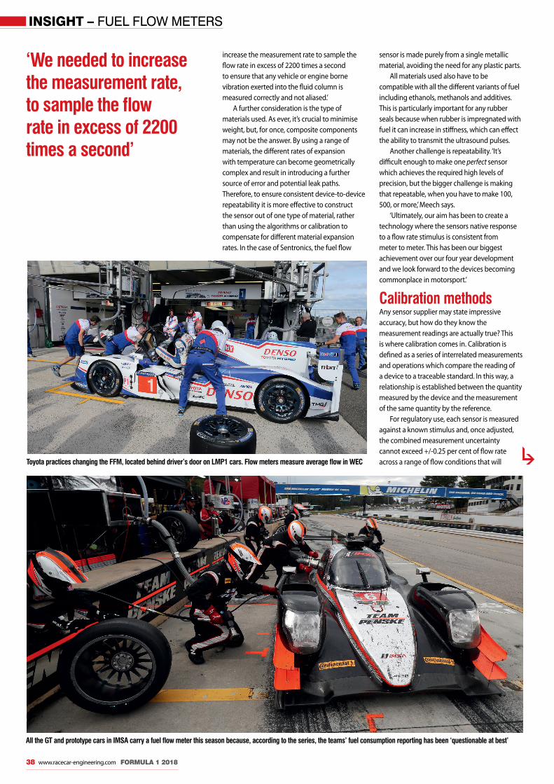
INSIGHT – FUEL FLOW METERS
38 www.racecar-engineering.com FORMULA 1 2018
Toyota practices changing the FFM, located behind driver’s door on LMP1 cars. Flow meters measure average flow in WEC
‘We needed to increase the measurement rate, to sample the flow rate in excess of 2200 times a second’
sensor is made purely from a single metallic material, avoiding the need for any plastic parts.
All materials used also have to be compatible with all the different variants of fuel including ethanols, methanols and additives. This is particularly important for any rubber seals because when rubber is impregnated with fuel it can increase in stiffness, which can effect the ability to transmit the ultrasound pulses.
Another challenge is repeatability. ‘It’s difficult enough to make one perfect sensor which achieves the required high levels of precision, but the bigger challenge is making that repeatable, when you have to make 100, 500, or more,’ Meech says.
‘Ultimately, our aim has been to create a technology where the sensors native response to a flow rate stimulus is consistent from meter to meter. This has been our biggest achievement over our four year development and we look forward to the devices becoming commonplace in motorsport.’
Calibration methodsAny sensor supplier may state impressive accuracy, but how do they know the measurement readings are actually true? This is where calibration comes in. Calibration is defined as a series of interrelated measurements and operations which compare the reading of a device to a traceable standard. In this way, a relationship is established between the quantity measured by the device and the measurement of the same quantity by the reference.
For regulatory use, each sensor is measured against a known stimulus and, once adjusted, the combined measurement uncertainty cannot exceed +/-0.25 per cent of flow rate across a range of flow conditions that will
increase the measurement rate to sample the flow rate in excess of 2200 times a second to ensure that any vehicle or engine borne vibration exerted into the fluid column is measured correctly and not aliased.’
A further consideration is the type of materials used. As ever, it’s crucial to minimise weight, but, for once, composite components may not be the answer. By using a range of materials, the different rates of expansion with temperature can become geometrically complex and result in introducing a further source of error and potential leak paths. Therefore, to ensure consistent device-to-device repeatability it is more effective to construct the sensor out of one type of material, rather than using the algorithms or calibration to compensate for different material expansion rates. In the case of Sentronics, the fuel flow
All the GT and prototype cars in IMSA carry a fuel flow meter this season because, according to the series, the teams’ fuel consumption reporting has been ‘questionable at best’
Reventec_MBAC.indd 38 22/03/2018 12:03

00 44 (0)116 232 2335 [email protected] www.eec-ltd.com/performance-shop
WE HAVE CUSTOMERS IN Formula 1 - Formula 2 - GP3
World Endurance Championship
European Le Mans Series
Asian Le Mans Series
Porsche Super Cup
Porsche Carrera Cup
Blancpain - European GT4 - V de V
British GT - British Touring Cars
Chinese Touring Cars - Korean TCR
Euro Formula 3 - Formula 4
Call +44 (0) 1932 225777Fax +44 (0) 1932 [email protected]
• Stiffest PTFE liner (minimal side-to-side movement, known as Deflection Under Load)• Reduced friction under load (ball misaligns, adjusts to angles smoothly)• Higher Radial Loads - up to 35% above alternative manufacturers• Higher Operating Temperature: 180°C compared to 121°C for standard items• High Angle, Narrow and Wide available in chamfered and V-stake versions• Sizes range from 3/16 to 3/4 and Metric sizes
The E-Type Liner - F1, WRC & LMP
Call +44 (0) 1932 225777Fax +44 (0) 1932 [email protected]
ABT6

INSIGHT – FUEL FLOW METERS
40 www.racecar-engineering.com FORMULA 1 2018
A brief history of FFM
While Sentronics was not the original supplier of the fuel flow meter (FFM) back in
2014, it is worth noting here that the introduction of the technology into Formula 1 and the World Endurance Championship was controversial.
The original plan was to use the restriction of fuel to balance cars, rather than an air restrictor which had been common for many years.
While the FIA required an accuracy of +/-0.25 per cent of reading, and this was largely achieved, some teams identified a problem with aliasing, where information was being lost due to under-sampling of the flow rate. At the Australian Grand Prix in 2014, Red Bull Racing attempted to prove that its measurements were more accurate than that of the FFM, but it lost its case as the FFM was judged
to be the tool by which the FIA measured the rate of flow.
The aliasing issue remained a problem for some teams, despite numerous upgrades from the original supplier, but now will finally be eradicated with the introduction of the Sentronics 2018 FFM.
In the WEC, meanwhile, an accuracy problem was identified and unfortunately amplified in the
diesel engine, where flow and return sensors were required. With its high diesel return temperatures the Audi R18s suffered with accuracy. The FIA subsequently homologated a high-temperature sensor to particularly help the diesel engines, which was developed and supplied by Sentronics. Unfortunately, these sensors never saw action, as Audi quit the WEC before they were used.
Cash flowToday, the sensors are infinitely more accurate than in 2014, but having improved the accuracy, the challenge now is to reduce the costs to make the technology more accessible (and useful) to other race series throughout the world. With this in mind Sentronics says it has been able to reduce the price of the sensor itself, due to an increase in demand, and is now actively offering the benefits of the technology to lower formula series. When it was in the WEC Audi’s R18 suffered with fuel flow meter accuracy problems caused by the high diesel return temperatures
To ensure consistent device-to-device repeatability it’s more effective to construct the sensor out of one type of material
Top left: Sentronics has won the tender to supply the Formula 1 grid with its fuel flow meter for 2018
Above: The front half of the fuel flow meter contains the tube where the ultrasound pulses are transmitted and the rear half houses the electronics
Left: The modular design of Sentronics’ FFM has allowed it to adapt the technology to both low flow and high flow applications
Reventec_MBAC.indd 40 22/03/2018 12:03
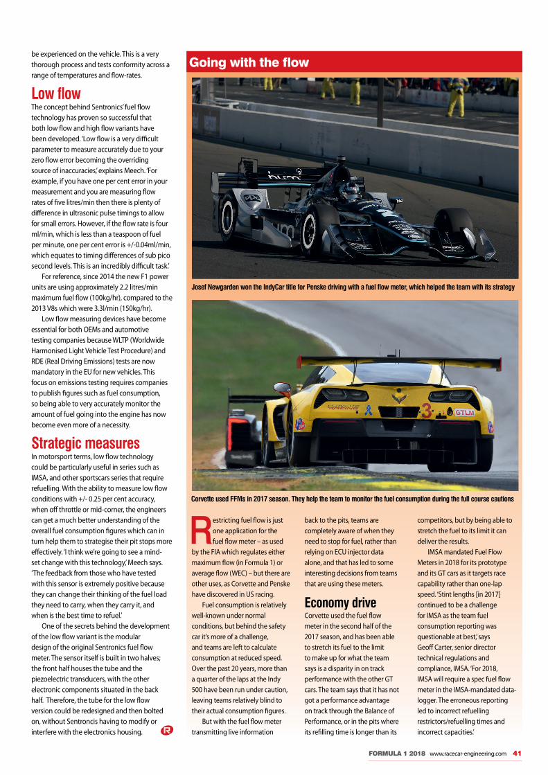
FORMULA 1 2018 www.racecar-engineering.com 41
be experienced on the vehicle. This is a very thorough process and tests conformity across a range of temperatures and flow-rates.
Low flowThe concept behind Sentronics’ fuel flow technology has proven so successful that both low flow and high flow variants have been developed. ‘Low flow is a very difficult parameter to measure accurately due to your zero flow error becoming the overriding source of inaccuracies,’ explains Meech. ‘For example, if you have one per cent error in your measurement and you are measuring flow rates of five litres/min then there is plenty of difference in ultrasonic pulse timings to allow for small errors. However, if the flow rate is four ml/min, which is less than a teaspoon of fuel per minute, one per cent error is +/-0.04ml/min, which equates to timing differences of sub pico second levels. This is an incredibly difficult task.’
For reference, since 2014 the new F1 power units are using approximately 2.2 litres/min maximum fuel flow (100kg/hr), compared to the 2013 V8s which were 3.3l/min (150kg/hr).
Low flow measuring devices have become essential for both OEMs and automotive testing companies because WLTP (Worldwide Harmonised Light Vehicle Test Procedure) and RDE (Real Driving Emissions) tests are now mandatory in the EU for new vehicles. This focus on emissions testing requires companies to publish figures such as fuel consumption, so being able to very accurately monitor the amount of fuel going into the engine has now become even more of a necessity.
Strategic measuresIn motorsport terms, low flow technology could be particularly useful in series such as IMSA, and other sportscars series that require refuelling. With the ability to measure low flow conditions with +/- 0.25 per cent accuracy, when off throttle or mid-corner, the engineers can get a much better understanding of the overall fuel consumption figures which can in turn help them to strategise their pit stops more effectively. ‘I think we’re going to see a mind- set change with this technology,’ Meech says. ‘The feedback from those who have tested with this sensor is extremely positive because they can change their thinking of the fuel load they need to carry, when they carry it, and when is the best time to refuel.’
One of the secrets behind the development of the low flow variant is the modular design of the original Sentronics fuel flow meter. The sensor itself is built in two halves; the front half houses the tube and the piezoelectric transducers, with the other electronic components situated in the back half. Therefore, the tube for the low flow version could be redesigned and then bolted on, without Sentroncis having to modify or interfere with the electronics housing.
Going with the flow
Restricting fuel flow is just one application for the fuel flow meter – as used
by the FIA which regulates either maximum flow (in Formula 1) or average flow (WEC) – but there are other uses, as Corvette and Penske have discovered in US racing.
Fuel consumption is relatively well-known under normal conditions, but behind the safety car it’s more of a challenge, and teams are left to calculate consumption at reduced speed. Over the past 20 years, more than a quarter of the laps at the Indy 500 have been run under caution, leaving teams relatively blind to their actual consumption figures.
But with the fuel flow meter transmitting live information
back to the pits, teams are completely aware of when they need to stop for fuel, rather than relying on ECU injector data alone, and that has led to some interesting decisions from teams that are using these meters.
Economy driveCorvette used the fuel flow meter in the second half of the 2017 season, and has been able to stretch its fuel to the limit to make up for what the team says is a disparity in on track performance with the other GT cars. The team says that it has not got a performance advantage on track through the Balance of Performance, or in the pits where its refilling time is longer than its
competitors, but by being able to stretch the fuel to its limit it can deliver the results.
IMSA mandated Fuel Flow Meters in 2018 for its prototype and its GT cars as it targets race capability rather than one-lap speed. ‘Stint lengths [in 2017] continued to be a challenge for IMSA as the team fuel consumption reporting was questionable at best,’ says Geoff Carter, senior director technical regulations and compliance, IMSA. ‘For 2018, IMSA will require a spec fuel flow meter in the IMSA-mandated data-logger. The erroneous reporting led to incorrect refuelling restrictors/refuelling times and incorrect capacities.’
Josef Newgarden won the IndyCar title for Penske driving with a fuel flow meter, which helped the team with its strategy
Corvette used FFMs in 2017 season. They help the team to monitor the fuel consumption during the full course cautions
Reventec_MBAC.indd 41 22/03/2018 12:04

FORMULA 1 – FUELS AND LUBRICANTS
42 www.racecar-engineering.com FORMULA 1 2018
A largely unreported, yet hugely signifi cant, fuel and lubricant development war was waged in Formula 1 last season – Racecar spoke to those on the front line to fi nd out more By SAM COLLINS
It was all change for F1 fuel suppliers at the start of the 2017 season. ExxonMobil, a former partner to McLaren, switched to supplying the Renault-powered Red Bull
Racing and Toro Rosso teams with its Esso and Mobil 1 products. Meanwhile, BP-Castrol opted to supply McLaren and the Renault works team, while Total quit F1 in favour of the WEC for 2018.
This supplier reshuffl e came at very short notice for the teams, the oil companies and the power unit manufacturers, especially considering that the Renault power unit, which had been designed around products from Total, would suddenly now be running both Mobil 1 and BP-Castrol, while Honda, which had developed its V6 with ExxonMobil, would now also be using BP products.
This switch came so late in the day, in fact, that there were rumours that both Renault and McLaren were unable to use their offi cial
Tank battle
Fuels_MBAC.indd 42 22/03/2018 12:25

Red Bull estimates that fuel and lubricant development can help to fi nd around a quarter of a second in lap time by the close of a season, with the majority of that improvement coming from the lubrication
FORMULA 1 2018 www.racecar-engineering.com 43
partners’ products at the fi rst test in Barcelona and had to rely on those from ExxonMobil.
David Tsurusaki, Global Motorsports Technology manager at ExxonMobil, says: ‘It was a ridiculously short amount of time, that was the biggest challenge. Even though we had an F1 product the timeline was way too short, because we really need the previous year to work on the next year. From the fuel standpoint, we started out with a baseline and we quickly adjusted it after the fi rst couple of tests and then, by the time of Barcelona testing, we had it well dialled in by the second week.’
Pump actionAccording to Tsurusaki, that initial baseline was not just 2016’s Honda fuel, but was something new, due to the diff ering demands of the two V6 engines. ‘It’s not the same product at all,’ he says. ‘We started with a baseline from what we
understood about a current F1 engine already, and once we understood how the Renault engines ran we made our adjustments from there. The chemistry is diff erent, and while I can’t really go into details, I can say that of the things we look at with fuel one is obviously getting the power and reducing the knock. We want to try and minimise the knock as much as we can with adjustments in the chemistry.
‘But it has to change as the year goes on and as the compression ratio changes,’ Tsurusaki adds. ‘As Renault do diff erent things to the engine, we have to modify our product. The unique thing with Formula 1 fuels is that it is so experimental, you’re using in some cases chemicals and concentrations of chemicals that are not typical in an everyday fuel.’
Indeed, while Formula 1’s fuel specifi cation is broadly based on EU fuel regulations the actual diff erence between the product used
by F1 teams and that available at the pump is substantial. But they are still fuels, and the track is a useful development arena for the road.
‘Our R&D department’s workload is split equally between road fuels and race fuels, so techniques and solutions learnt in racing can be transferred to the road fuels,’ says Mike Frost, ExxonMobil technical adviser. ‘That is the biggest reason for a company like this to sponsor a racing team. It allows the team to improve performance on track while we can improve our commercial product.
‘If you looked at a road fuel, it is far more complex,’ Frost adds. ‘There are a lot more components and it is a lot more uncontrolled. It comes off a refi nery stream, the key four or fi ve components will get you the RON or MON number and that will be good enough for a road car. Every time you fi ll up, if you tested the fuel, then the trace you would see on the gas
Fuels_MBAC.indd 43 22/03/2018 12:25

FORMULA 1 – FUELS AND LUBRICANTS
44 www.racecar-engineering.com FORMULA 1 2018
ExxonMobil had limited time to get to grips with 2017 Renault PU (above) pre-season; 2016 unit was developed with Total
chromatograph would probably be completely different, that is the biggest thing. But the race fuel is always the same; it is far more precise, and it has fewer components.’
The reason for this precision is that the fuel used is tested for compliance not only with the technical regulations but also for the specific specification used, as teams are limited on the number of different fuels they can use each season. ‘The fuel is designed in conjunction with Renault,’ Frost says. ‘Once they are happy with the performance it is sent to the FIA, they then check it conforms to the regulations and if it does then we are clear to use it at the track. The FIA also has a gas chromatograph and will check our fuels against the trace.’
While fuel specifications are limited, some teams have gone as far as saying that it is one of the biggest areas of performance development through the year, though others disagree and
point to the lubricants instead. ‘At an engine sensitive circuit the improvement was about a tenth of a second from the fuel; the oil brings more,’ says Paul Monaghan, chief engineer at Red Bull Racing. ‘I think, all things considered, the Mobil 1 [and Esso] products will have improved our pace by a quarter of a second at season’s end, and that is a big improvement.’
Science frictionMuch of that performance development with lubricants comes from simple track running. The more running the power units get in the cars the more the suppliers learn about them. ‘You can get some performance gains if you minimise wear. So if you can minimise friction where you can get a rateable measured horsepower improvement, if you’re doing the combination of that and wear protection, you can reduce wear metals which is something we’re monitoring closely right now,’ Tsurusaki says. ‘We’re looking at small amounts of wear metals; we’re testing for parts per million of various materials. If we can reduce those wear metal amounts, that means we’re protecting the engine better, it means it’s going to last longer, it means there’s less friction, so more horsepower. We track it by engine; by every start, every practice session, every qualifying and race;
Mike Frost (left) and David Tsurusaki from ExxonMobil. Its Esso brand continues to be aligned with the Red Bull team in 2018
we’re doing analysis at all the tyre tests too. You can get small incremental steps, and that’s what we’re trying to do. It all adds up.’
But the gains in performance do not just come from the engine oil, Tsurusaki says. Many other fluids and greases play a role all over the car. ‘One of the first changes we made with this partnership was the lubricant on the wheel bearings. We actually use a commercial product there, and going to the synthetic grease over what the team had used previously resulted in the temperature of the bearings going down. That means that there was a friction reduction which, in turn, should mean improved performance. It’s hard to measure the effect of small things like that, but they do all add up.’
For all PU suppliers in F1 the lubricants used in the V6 engines also play a key role in preventative maintenance, through that same process of studying the oil itself, with samples being analysed in the garages after every run.
‘We have a spectrographic analyser in the Red Bull garage,’ Frost says. ‘It has two electrodes, rather like an arcing welder. The oil sample is passed through the electrodes and in about 30 seconds you get a result. It excites all the molecules in the oil and that produces light, each component in the oil has its own signature in light, and that includes the metals. From that we can see what metals are found in the oil.’
Monitoring wearThe oil samples post-run can give a clear indication of what is going on inside a Formula 1 power unit, which is otherwise sealed by regulation. ‘From working with Renault you know what components are made of what materials, and that can give you a very clear indication of the wear of components in the engine,’ Frost says. ‘Sodium is something we look at a lot. That is a marker of an additive in the coolant, so if there is a water leak in the race, the water will boil off, then you start to see elevated levels of sodium in the oil. So if you have sodium showing in this result then you can make the assumption that there is water in the oil.
‘We want to minimise the knock as much as we can with adjustments in the chemistry’
Fuels_MBAC.indd 44 22/03/2018 12:26

FORMULA 1 2018 www.racecar-engineering.com 45
‘Lead and Indium we look for as they are the bearing materials, aluminium is the pistons, iron is the bores, gears, crankshaft so all of those act as a tell-tale of what is going on inside the engine,’ Frost adds. ‘You know what the engine’s appetite for oil is and you keep an eye out for potential problems. You tend to see the issues in the practice sessions when the older engines are used, and over the years, before the car has even left the garage, I have identified issues which I knew would cause the car to stop on track, and as a result I have condemned engines. It can be the only way to see inside the engine.’
Oil coolerUnlike most production car engines the lubricant in some F1 V6s also has to act as a coolant for some components within the power unit. ‘Copper is the material for the squash plates for the bearings, and some of the cages for things like the bearings in the MGU-K,’ Frost says. ‘The problems people have had with the MGU are well known, that is an electric motor cooled by oil, and so you can start seeing high levels of copper in the oil when there are issues.’
But perhaps Frost will not be looking out for copper as much as he used to in the lubricants used in the current Renault V6, due to a change in the design of the power unit. ‘At one point this season we had the MGU-K being cooled by the engine oil, so our oil had to be able to not only lubricate the engine but also act as a coolant,’ Tsurusaki says. ‘So, we started out with one product and we ended up with a different product because of that. [But] now it’s separate.’
Hot oilThe properties of the lubricants used by teams can also play a significant role in the overall car design, especially in terms of the cooling system, so teams work very closely with partners to get the products exactly right. ‘You have to consider ambient temperatures,’ Monaghan says. ‘We race in Singapore and Malaysia where it is very hot; we also race in China and Silverstone where it is not, so we need the oil to be able to deal with that variation. We want an oil that weighs nothing, has zero pumping losses, needs no radiator and pushes us up 50bhp!’ he jokes.
‘The heat rejection of the engine is to some extent influenced by the efficiency of the lubrication system,’ Monaghan adds. ‘So the more friction there is the more heat you have to take out. The question is then how do you take it out; by the water system, the oil system or just general radiant heat to the surroundings? Once you have established a heat rejection into the oil system the temperature delta becomes about the specific heat capacity of the oil. In other words, how much energy does it take to warm up 1kg of oil by 1degC; from that you know how much oil you should need, its flow rate, and the area required for the cooler.’
But the individual properties of the oil, such as its cooling requirements, cannot be
Red Bull garage lab has spectrographic analyser that picks up light signals from oil components and from metals in the oil
Analysing the fuel and lubricants can give a vital insight into what is actually happening inside the sealed F1 power units
‘If we can reduce those wear metal amounts it means there’s less friction, so more horsepower’
The oil tank is located at the front of the V6 block on Renault PU. The lubrication system plays a largely unsung role in the cooling of a modern Formula 1 racecar
Fuels_MBAC.indd 45 22/03/2018 12:26
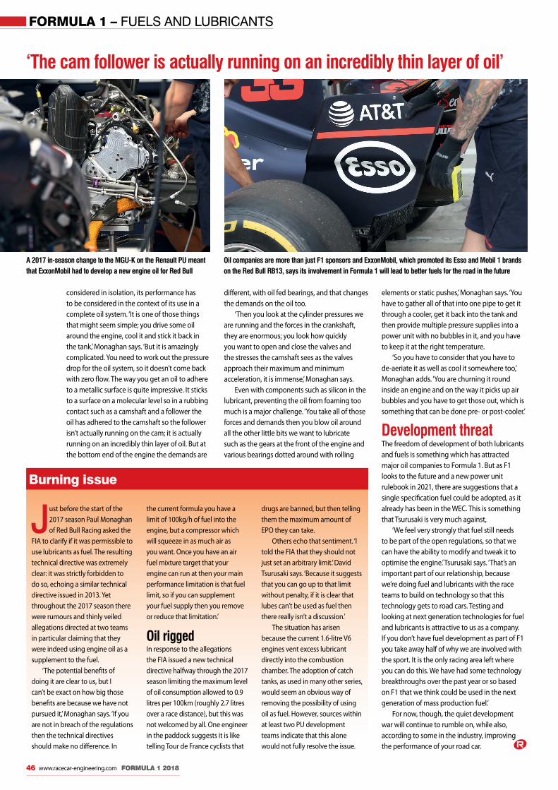
FORMULA 1 – FUELS AND LUBRICANTS
46 www.racecar-engineering.com FORMULA 1 2018
A 2017 in-season change to the MGU-K on the Renault PU meant that ExxonMobil had to develop a new engine oil for Red Bull
Burning issue
Just before the start of the 2017 season Paul Monaghan of Red Bull Racing asked the
FIA to clarify if it was permissible to use lubricants as fuel. The resulting technical directive was extremely clear: it was strictly forbidden to do so, echoing a similar technical directive issued in 2013. Yet throughout the 2017 season there were rumours and thinly veiled allegations directed at two teams in particular claiming that they were indeed using engine oil as a supplement to the fuel.
‘The potential benefits of doing it are clear to us, but I can’t be exact on how big those benefits are because we have not pursued it,’ Monaghan says. ‘If you are not in breach of the regulations then the technical directives should make no difference. In
the current formula you have a limit of 100kg/h of fuel into the engine, but a compressor which will squeeze in as much air as you want. Once you have an air fuel mixture target that your engine can run at then your main performance limitation is that fuel limit, so if you can supplement your fuel supply then you remove or reduce that limitation.’
Oil rigged In response to the allegations the FIA issued a new technical directive halfway through the 2017 season limiting the maximum level of oil consumption allowed to 0.9 litres per 100km (roughly 2.7 litres over a race distance), but this was not welcomed by all. One engineer in the paddock suggests it is like telling Tour de France cyclists that
drugs are banned, but then telling them the maximum amount of EPO they can take.
Others echo that sentiment. ‘I told the FIA that they should not just set an arbitrary limit.’ David Tsurusaki says. ‘Because it suggests that you can go up to that limit without penalty, if it is clear that lubes can’t be used as fuel then there really isn’t a discussion.’
The situation has arisen because the current 1.6-litre V6 engines vent excess lubricant directly into the combustion chamber. The adoption of catch tanks, as used in many other series, would seem an obvious way of removing the possibility of using oil as fuel. However, sources within at least two PU development teams indicate that this alone would not fully resolve the issue.
considered in isolation, its performance has to be considered in the context of its use in a complete oil system. ‘It is one of those things that might seem simple; you drive some oil around the engine, cool it and stick it back in the tank,’ Monaghan says. ‘But it is amazingly complicated. You need to work out the pressure drop for the oil system, so it doesn’t come back with zero flow. The way you get an oil to adhere to a metallic surface is quite impressive. It sticks to a surface on a molecular level so in a rubbing contact such as a camshaft and a follower the oil has adhered to the camshaft so the follower isn’t actually running on the cam; it is actually running on an incredibly thin layer of oil. But at the bottom end of the engine the demands are
different, with oil fed bearings, and that changes the demands on the oil too.
‘Then you look at the cylinder pressures we are running and the forces in the crankshaft, they are enormous; you look how quickly you want to open and close the valves and the stresses the camshaft sees as the valves approach their maximum and minimum acceleration, it is immense,’ Monaghan says.
Even with components such as silicon in the lubricant, preventing the oil from foaming too much is a major challenge. ‘You take all of those forces and demands then you blow oil around all the other little bits we want to lubricate such as the gears at the front of the engine and various bearings dotted around with rolling
‘The cam follower is actually running on an incredibly thin layer of oil’
elements or static pushes,’ Monaghan says. ‘You have to gather all of that into one pipe to get it through a cooler, get it back into the tank and then provide multiple pressure supplies into a power unit with no bubbles in it, and you have to keep it at the right temperature.
‘So you have to consider that you have to de-aeriate it as well as cool it somewhere too,’ Monaghan adds. ‘You are churning it round inside an engine and on the way it picks up air bubbles and you have to get those out, which is something that can be done pre- or post-cooler.’
Development threatThe freedom of development of both lubricants and fuels is something which has attracted major oil companies to Formula 1. But as F1 looks to the future and a new power unit rulebook in 2021, there are suggestions that a single specification fuel could be adopted, as it already has been in the WEC. This is something that Tsurusaki is very much against,
‘We feel very strongly that fuel still needs to be part of the open regulations, so that we can have the ability to modify and tweak it to optimise the engine.’ Tsurusaki says. ‘That’s an important part of our relationship, because we’re doing fuel and lubricants with the race teams to build on technology so that this technology gets to road cars. Testing and looking at next generation technologies for fuel and lubricants is attractive to us as a company. If you don’t have fuel development as part of F1 you take away half of why we are involved with the sport. It is the only racing area left where you can do this. We have had some technology breakthroughs over the past year or so based on F1 that we think could be used in the next generation of mass production fuel.’
For now, though, the quiet development war will continue to rumble on, while also, according to some in the industry, improving the performance of your road car.
Oil companies are more than just F1 sponsors and ExxonMobil, which promoted its Esso and Mobil 1 brands on the Red Bull RB13, says its involvement in Formula 1 will lead to better fuels for the road in the future
Fuels_MBAC.indd 46 22/03/2018 12:26

MiniMax: ultra-miniature USB 3.0 connector, 12 mm diameter
■ Ultra-compact and lightweight■ Signal & power■ Up to 10 Gb/s data transmission
USB 3.0 Rugged Flash Drive for the safe storage of sensitive data
■ Up to 100 MB/s read speed ■ Up to 128 GB memory size■ Withstands corrosion, vibration, shock and extreme temperatures
IP68 SEALED UNMATED
MMi iM lt i i t
www.fi scherconnectors.com THE RELIABLE EXPERT
NEW USB 3.0
HIGH SPEEDCONNECTIVITYSOLUTIONSMINIATURE
IP68 SEALED
RUGGED
RELIABLE
Connect with us @Drives & Controls, Stand D377
or call +44 23 9245 9600
Woodford Trailers Limited 14 Great Central Way
Daventry • Woodford Halse Northants • NN11 3PZ
Telephone: 01327 263384Email: [email protected]
• Bodywork/Panel Protection• Cockpit Temperature Control• Lithium Battery Protection & Thermal Event Protection for
Hybrid Vehicles
Teknofi bra Heat Resistant Material
Competition Specification Wheel Studs and Nuts

SUBSCRIBE TO MOTORSPORT’S LEADING TECHNOLOGY MAGAZINE
TO ORDERwww.chelseamagazines.com/CRCEPP87
+44 (0) 1858 438 443 (quote code CRCEPP87)AVAILABLE WORLDWIDE
• Unrivalled analysis of major events including Formula One, the World Rally Championship and the World Endurance Championship
• Detailed racecar design and innovation
• Features from leading industry engineers and the latest product development
INSIDE EACH ISSUE
Keep pace with news, the latest technical developments, products and performance analysis from engineers and industry experts.
DIGITAL EDITION ALSO AVAILABLE WORLDWIDEfor tablet, smartphone and desktop. To order go to:
www.chelseamagazines.com/CRCEPD87
print or digital access