Embed Size (px)
Citation preview
LHC Project Report 170
Administrative SecretariatLHC DivisionCERNCH - 1211 Geneva 23Switzerland
Geneva, 12 March 1998
LHC and SL Divisions
As a continuation of the experimental program carried-out with String 1, projectmanagement decided towards the end of 1995 to construct an LHC prototype Full-Cell,also known as String 2. The present document reports on the outcome of the one-yeardesign effort (see Annex 1) by the community of specialists contributing to the LHCPrototype Full-Cell: it informs specialists on the boundary areas with other systems andconveys to the general public a description of the facility.
Abstract
EUROPEAN ORGANIZATION FOR NUCLEAR RESEARCHEuropean Laboratory for Particle Physics
Large Hadron Collider Project
The LHC Prototype Full-Cell: Design Study
F.Bordry, JC.Brunet, J.Casas-Cubillos, P.Cruikshank, K.Dahlerup-Petersen, N.Delruelle,D.Hagedorn, J.Kragh, R.Lauckner, J.Pett, P.Proudlock, G.Riddone, F.Rodriguez-Mateos,
P.Rohmig, R.Saban, L.Serio, C.Wyss

2
The LHC Prototype Full-Cell: Design Study
Edited by R.Saban with contributions from F.Bordry, JC.Brunet, J.Casas-Cubillos,P.Cruikshank, K.Dahlerup-Petersen, N.Delruelle, D.Hagedorn, J.Kragh, R.Lauckner,J.Pett, P.Proudlock, G.Riddone, F.Rodriguez-Mateos, P.Rohmig, R.Saban, L.Serio,C.Wyss.
LHC and SL Divisions
Keywords: controls, cryogenics, magnet protection, powering, quench detection, energy extraction,superconducting magnets, vacuum.
Summary
As a continuation of the experimental program carried-out with String 1, projectmanagement decided towards the end of 1995 to construct an LHC prototype Full-Cell,also known as String 2. The present document reports on the outcome of the one-yeardesign effort (see Annex 1) by the community of specialists contributing to the LHCPrototype Full-Cell: it informs specialists on the boundary areas with other systems andconveys to the general public a description of the facility.
Objectives
The LHC Prototype Full-Cell constitutes the last opportunity, before installation in thetunnel, to validate individually the LHC systems and to investigate their collectivebehaviour in normal and exceptional conditions as well as during transients. Thereforeduring the design, the guideline of installing the systems in their final or close to finalversion has been adopted. This has resulted in an experimental facility which will be asclose as it can be to a full-cell situated in the regular part of the arc, assembled five years inadvance of the collider.
String 1, the predecessor of the LHC Prototype Full-Cell, has yielded large amounts of dataand precious information. This information is however limited by the version of thecomponents (eg 10-m long dipoles, prototype quench relief valves) available at the time ofconstruction and to its configuration (eg. cryogenic lines traversing the magnet cryostats,half-cell). For the first time, experiments at the LHC Prototype Full-Cell will offer thepossibility of investigating final design choices for key components and on a larger scale.
The performance of the cryogenic system with the separate line and its connection everycell to the collider will be measured for the first time with real loads, with the newcylindrical bayonet heat exchanger and in a portion of the machine which is installed in ahorizontal plane. The thermo-hydraulics of quenches with the new design andconfiguration (two per cell) of the quench relief valves will be observed.
The presence, for the first time, of several independently powered electrical circuits willallow the investigation of their mutual influence during normal operation and in case ofquench. Furthermore, techniques for tracking the main dipole magnets as well as theircorrectors during transients will be studied. The final design of the tube external to themagnet cold mass routing the auxiliary bus-bars will be tested in real operating conditionsand installation aspects of the cables inside the tube will be verified.
Operational experience will be gained with a prototype of the d.c. breaker facility which isforeseen for the LHC machine.
The final design of the magnet protection system with individual magnet quench detectionand heater control will be validated.
3
Results of dipole to dipole quench propagation experiments performed with String 1 willbe verified with the different and final dipole-to-dipole mechanical and hydraulic interfaceas well as with the larger inductance of the final coils. Quench propagation from mainmagnet to corrector, dipole to quadrupole, central dipole to neighbouring dipoles and half-cell to half-cell will be studied for the first time.
Experiment with vacuum barriers present within the separate cryogenic line, in the magnetstring and between the string and the cryogenic line will be carried-out. The cooling of thebeam screens installed in each half-cell and independently controlled will be studied andvalidated.
Last but not least, the LHC Prototype Full-Cell will offer a unique occasion to rehearse theassembly and exchange sequences and to verify the assembly procedures foreseen for eachstep of the interconnection of magnets as well as the exchange of a diode orinstrumentation. Transport and installation equipment designed to operate in the tunnel willbe tested for the first time in the real operating environment.
In addition to these studies which will all be carried-out for the first time, a number ofexperiments, measurements or exercises which already took place with String 1 will berepeated either to confirm the results obtained or to test newly developed versions of analready verified/tested component. These include
− for cryogenics, the measurement of the overall performance of the system (cool-down and warm-up times, temperature stability during steady state and transientoperation, heat loads) and the verification of the advanced control techniquesfor the superfluid helium loop,
− for vacuum, the evaluation of the final instrumentation.
In addition to the results expected from the experiments, String 2 will provide the futureoperations crews with valuable experience in the fields related to running asuperconducting collider.
Schedule
The assembly of String 2 will extend from the second half of 1999 to the first half of 2000(see Annex 2). The commissioning of String 2 is foreseen for June of the year 2000.Experimental runs are scheduled until the human resources are redeployed for preparationof LHC commissioning; these runs are interspersed with shutdowns, when modifications orupgrades are carried-out.
Conclusions
Following the identification of the areas to investigate with the facility, the design of String2 has progressed to a point where all the requirements for the component systems havebeen stated. Altough for some of the systems some prototyping effort is still required, thedesign, the technical specifications for tendering and, in some cases, the manufacturing ofmost of the components have already started.
The construction schedule of the facility has been adjusted to be early enough to allowexperimental results to still influence the design of the final components, but late enough topermit to test close-to-final versions of each component.
The sections that follow describe the layout and the component systems of the facility.

4
TABLE OF CONTENTS
1 Layout and Main Components
2 Magnets
2.1 The Short Straight Sections2.1.1 SSS for the first half-cell (SSS3)2.1.2 SSS for the second half-cell (SSS4)
2.2 The Dipoles
2.3 The Magnet Interconnects
3 Cryogenics
3.1 The Cryogenic Flow-scheme
3.2 The Cryogenic plant
3.3 The Cryogenic Feed Box
3.4 The String Return Box
3.5 The Cryogenic Distribution Line
3.6 The Ancillary systems
3.7 Instrumentation
4 Powering and Magnet Protection
4.1 The Electrical Circuits
4.2 Power Converters
4.3 The Electrical Feed Box (DFB)
4.4 The Magnet Protection System
4.5 Quench Detection4.5.1 Quench detection in Main Magnets4.5.2 Quench detection in corrector magnets4.5.3 The Test Controller
4.6 Cold By-pass Diodes
4.7 Quench Heaters and Power Supplies
4.8 Discharge Elements: D.C. Circuit Breakers and Dump Resistors
5 Vacuum
5.1 Insulation Vacuum
5.2 Beam Vacuum
5.3 Beam screen and BPM measurements
5.4 Leak detection
6 Monitoring and Control

5
6.1 Data Acquisition
6.2 Data Storage System
6.3 Process Control6.3.1 Process Control for the String Cryogenics6.3.2 Process Control of the Cryogenic Plant6.3.3 Controls for Vacuum6.3.4 Deterministic Control of the Power Converters
Annex 1: Design Meetings and ParticipantsAnnex 2: ScheduleAnnex 3: LayoutAnnex 4: Cross-Section of the quadrupole in its cryostatAnnex 5: Coil cross sectionAnnex 6: InterconnectsAnnex 7 Cryogenic Flow SchemeAnnex 8: Cryogenic PlantAnnex 9: Cryogenic Distribution LineAnnex 10: Electrical Circuit DiagramAnnex 11: Magnet Protection SystemAnnex 12: Process Control Software for the Cryoplant
6
1 Layout and Main Components
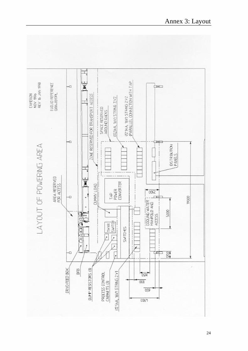
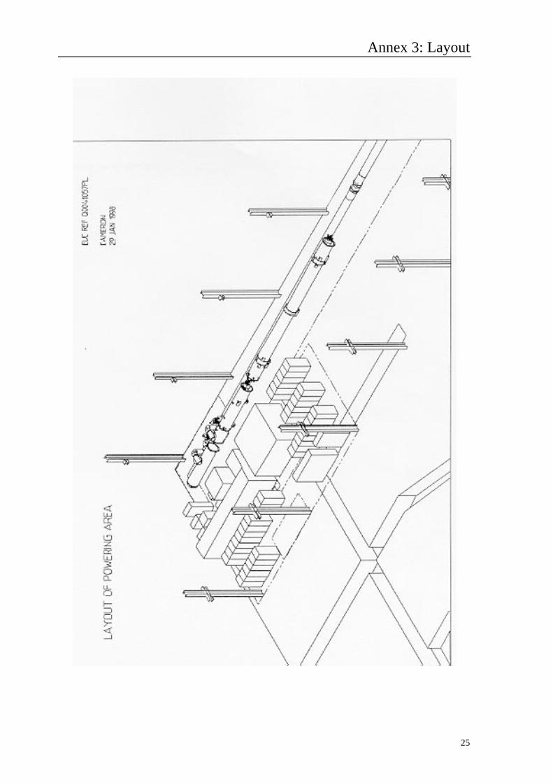
The LHC Prototype Full-Cell, also called String 2, has the same layout of an LHC cellsituated in the regular part of an arc (See Annex 3) and also follows the curvature of thetunnel. It is situated in bay 4 of building 2173 (SM18). With its 114 meters, it coversalmost the whole length of the building (120 m).
String 2 is composed of two half-cells. The first half-cell starts with a short straight section(SSS3), which is connected to the cryogenic line (QRL) via a jumper connection and isfollowed by three 15-m dipoles. The second half-cell starts with SSS4 that is not connectedto the QRL and is followed by a second set of three 15-m dipoles.
The first half-cell is preceded by an electrical feed box (DFB) which supplies the current tothe 15 electrical circuits of String 2. A String Return Box (SRB), which is connected to theQRL, ends the string of magnets.
2 Magnets
2.1 The Short Straight Sections
As their main magnetic component the Short Straight Sections (SSS) contain a 3.10 m.twin aperture quadrupole. It generates a gradient of 223 T/m at 11870 A.
The super-conducting cable of the quadrupole magnets will be the same as the key-stonedcable used for the outer coil layer in the main dipole magnets.
Each short straight section will have on the end opposite to the connections, the sextupole-dipole corrector magnets. The sextupole coils of these combined units will be powered inseries to currents up to 500 A nominal. The corrector dipole magnets, alternatively eitherhorizontally or vertically deflecting, will be powered individually. This means that theircurrent feeding between 1.9 K and room temperature is required in every short straightsection. Their maximum operational current will be 32 A. The yoke length of these unitswill be 1.26 m. The sextupole strength is 1500 T/m2 over a magnetic length of 1.10 m. Thecorrector dipole field is 1.5 T over 1.03 m. These coils will be assembled in a commonyoke and fixed inside the inertia tube similar by to the main quadrupoles.
On the connection side of the quadrupole two octupole corrector magnets of 380 mmoverall length will be mounted. Their strength will be 6.7 · 104 T/m3 over a magnetic lengthof 320 mm. Their outer diameter will not be more than 117 mm and thus they will bemounted separately and fixed by a pair of plates inside the inertia tube. The nominalcurrent will be 600 A.
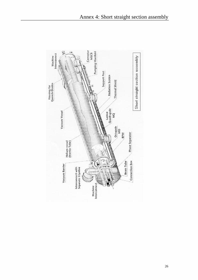
The technical service module of the SSS is placed on the connection side of the magnets.This module contains the beam position monitors, the protection diodes for the quadrupole
7
magnets and the cold mass instrumentation capillaries. In the first SSS, the technicalservice module contains the jumper connection to the separate cryogenic line and thehelium phase separator.
2.1.1 SSS for the first half-cell (SSS31)
SSS3 includes the quadrupole with its diodes and lattice correctors, a fully equipped beamposition monitor, a standard beam vacuum pumping port and a cryo-cooled beam screen ineach beam tube. A vacuum barrier for the longitudinal subdivision of the insulationvacuum of the magnet cryostat chain is also mounted in this SSS. Furthermore, bus-barplugs, which hydraulically separate every two cells in LHC, are also mounted. Thisparticular configuration, DFB followed by a SSS with bus-bar plugs, will never be presentin the collider; however, the assembly of the most complex SSS and its test justifies thisdeviation. However, in order to allow the testing in nominal operating conditions (end boxof DFB hydraulically connected to the HeII bath of the arc) of the DFB, the bus-bar plugsare by passed in the DFB-QQS interconnect.
The technical service module (QQS) of SSS3 is similar to the one in the SSS of half-cell27 of an arc situated at the left-hand side of an insertion. It is on one side interfaced to theelectrical feed box (DFB) and on the other one to the QRL via a standard jumperconnection. This jumper connection, which is of type B, provides the supplies and most ofthe returns of the cryogens servicing a standard cell. Annex 4 shows the SSS3 assembly.
The magnetic components of SSS3 are MQF/D, MO and MSCBH/V.
2.1.2 SSS for the second half-cell (SSS4)
Following the simplified cryogenic scheme, SSS4 is not connected to the QRL. It is similarto the one in the SSS of half-cell 26 of an arc situated at the left-hand side of an insertion.It includes the quadrupole with its diodes and lattice correctors, a fully equipped beamposition monitor, a standard beam vacuum pumping port and a cryo-cooled beam screen ineach beam tube.
The magnetic components of SSS4 are MQD/F, MO and MSCV/H.
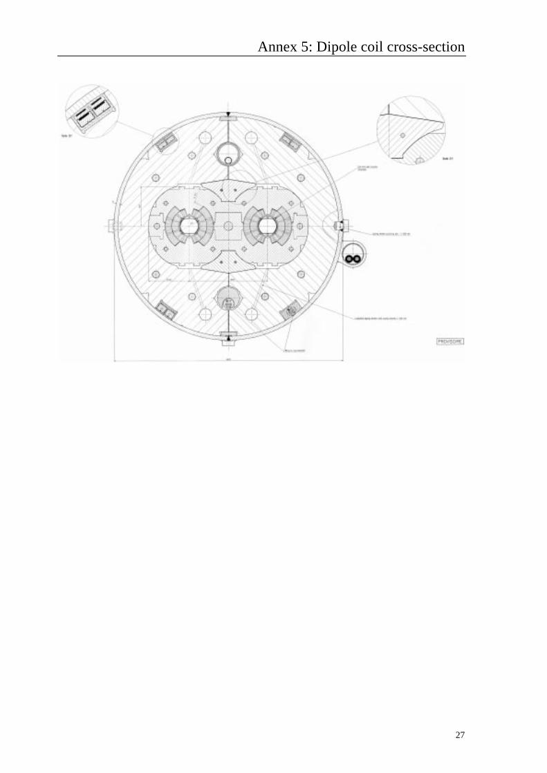
2.2 The Dipoles
It is planned to equip String 2 with six 15-m long dipoles prototypes of the secondgeneration, featuring a 6-block coil cross-section and aluminium collars without magneticinserts. The coil cross-section, as defined at the price inquiry stage, is shown in Annex 5(Drawing LHCMBPA_0013). The inner and outer coil layers are separated by an interlayerspacer providing helium distribution channels also between the collaring shim and the turnof the inner layer next to it.
For scheduling reasons (availability of the fine blanking tooling), the first two dipolemagnets will be assembled with collars and yoke laminations not fully optimised for fieldquality and will have an interbeam distance of 194 mm at 300 K. The following four dipolemagnets will feature fully optimised collars and yoke laminations with an interbeamdistance of 194 mm at 1.8 K.
1 This numbering reflects the order of manufacturing of the quadrupole cold masses. SSS1 was mounted onString 1 and the second quadrupole, which was tested in Saclay, was never assembled in a SSS.
8
The dipole cold masses weight about 25 t and are curved with the nominal bending radiusof 2804 m, corresponding to a sagitta of about 10 mm, between endplates.
The nominal filling factor of the yoke lamination packs is 98%. The cylindrical bayonet HeII heat exchanger will be of the smooth-wall type, made out of a 1/4-hard copper tube withbrazed-on austenitic-steel ends, one end being equipped with a bellows.
The cold-bore tubes (53/50 mm) in these magnets will be welded directly to the endcapswithout bellows.
The six dipole magnets will be equipped with so-called flux-loop coils to measure the mainfield. These coils consist of 0.5mm wide, 0.018 mm thick Cu tracks deposited on a0.125 mm thick polyimide foil, which is then placed around the cold bore tube.
The quench heaters equipping the prototype dipoles will be of the type foreseen for seriesproduction, see section 4.7.
The prototype dipole and quadrupole bus-bars have a Cu stabilising cross-section of about260 mm2 and 160 mm2, respectively. The dipole bus-bars are in addition provided with ahole of 5 mm diameter, to keep a sufficient mass of He II in close contact with thestabilising copper. Should it be experimentally proven that this hole is not necessary to stopquench propagation, it will be suppressed.
The collared coils will be produced by industry (three firms producing two assemblieseach). The assembly of the first collared coils from each firm into cold masses will becarried out at the Magnet Assembly Facility at CERN, whereas the assembly of theremaining cold mass will be entrusted as much as possible to the firms themselves. As inthe past, all cold mass major components will be procured by CERN.
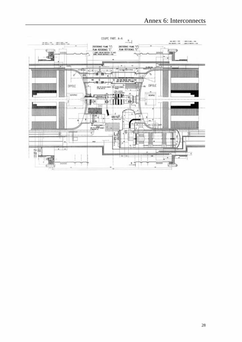
2.3 The Magnet Interconnects
All three types (MB-MB, SSS-MB, MB-SSS) of interconnects are present on String 2 (seedrawings in Annex 6). The interconnects will implement all the functions foreseen forLHC. The dimensions of the cryomagnets follow rigorously the final design values2.
The installation and the interconnection (soldering, welding) procedures will be thoseforeseen for LHC. Each operation will be accompanied by a quality insurance protocol andexecuted by certified welders.
The external routing of a multi-strand superconducting cable feeding the SSS correctors(octupoles, sextupoles) will be implemented. Electrical connections (connectors) will bedone in accordance with the final machine design choices.
3 Cryogenics
The cryogenic system is based on the Yellow Book updated by the report on theSimplification of the Cryogenic Scheme (LHC Project Note 106). It is designed to allow alltransient modes (cool-down, warm-up, current ramping/de-ramping and quenches) as wellas steady-state operation of String 2. The system comprises the cryoplant, a CryogenicFeed Box (CFB), the Cryogenic Distribution Line (QRL), the Electrical Feed Box (DFB),the cryogenic piping and modules inside the magnet string and the ancillary systems.
2 See LHC Project Note 50

9
String 2 is installed on a horizontal plane in order to investigate the behaviour of thesuperfluid helium loop in the worst configuration with respect to the thermohydraulicphenomena. Other slope configurations have already been tested with String 1 and arecurrently under investigation at a dedicated test loop in Grenoble.
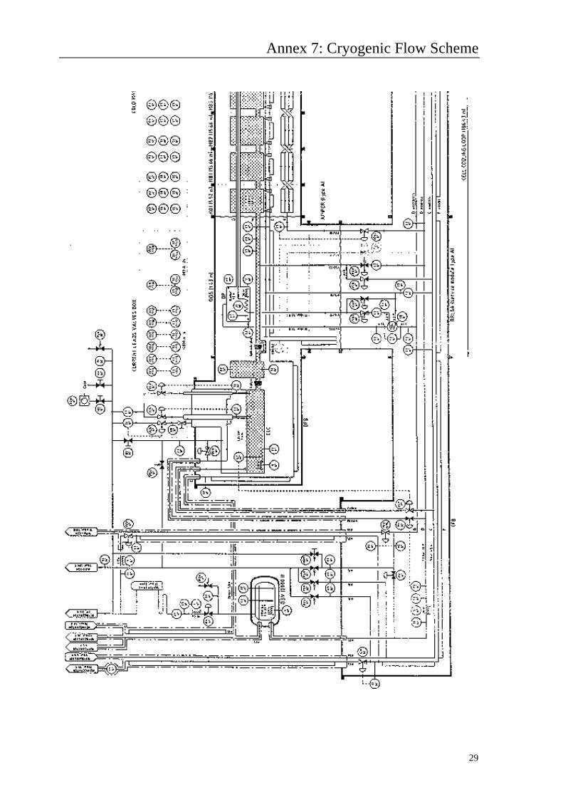
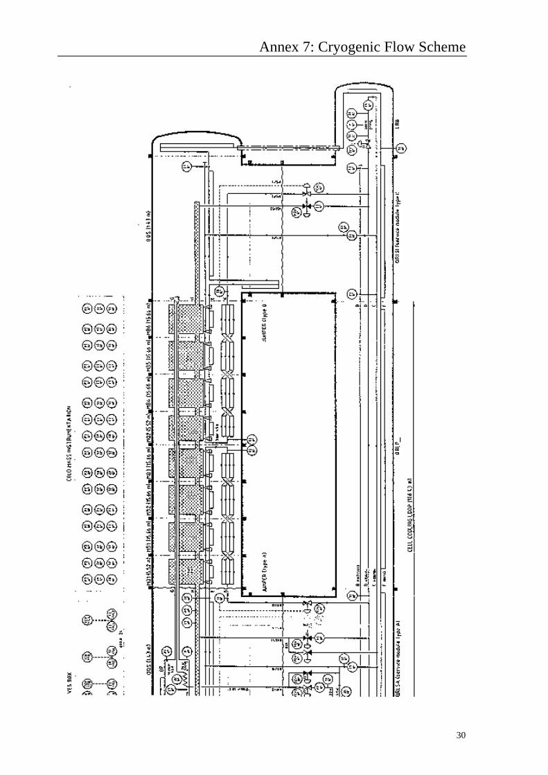
3.1 The Cryogenic Flow-scheme
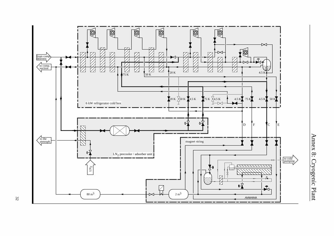
The Cryogenic Flow-scheme is given in Annex 7. Two separate and thermally shieldedtransfer lines connect the 6 kW refrigerator to the String via the Cryogenic Feed Box.
During normal operation, three loops are fed by the Cryogenic Feed Box and extend overthe whole of the string:
1. Line E feeds the thermal shields and heat interception at 50 K and returns viathe QRL thermal screen line,
2. Line C feeds two separate loops with supercritical helium (3 bar, 4.5K) :
a) the bayonet heat exchanger in the cold mass via the very low pressure heatexchanger. The expansion of the supercritical helium in the Joule-Thomsonvalves provides cooling of the pressurised superfluid helium inside the coldmass. Superfluid helium is fed to the far end of the string via the heatexchanger inner tube. Line B provides the pumping to the saturationpressure of the superfluid helium loop.
b) the heat intercept at 4.5 K and the beam screens. Line D recovers the returngas.
Line C is also used for cool-down and warm-up of the cold mass with a forced flow ofgaseous helium and to fill the cold mass with the liquid helium. Gaseous helium isrecovered in line D.
After a resistive transition, the helium expelled from the cold mass via the Quench ReliefValves at each end of the string into line D, is buffered through the Quench Buffer Vesseland transported to the low pressure recovery and the Warm Buffer.
The DFB is fed with 4.5 K liquid helium and 20 K gaseous helium. The bottom part of thehigh critical temperature superconductor (HTcS) current leads are immersed in a 4.5 Kliquid helium bath supplied by line C via a Joule-Thomson valve. The 20 K gaseous heliumcools the classical part of the current leads from the return of line D. Warm gas recoveredfrom the DFB is sent directly to the warm recovery line of the refrigerator.
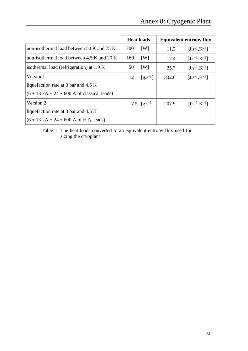
3.2 The Cryogenic plant
An existing 6 kW helium refrigerator manufactured by Linde will be re-used for String 2.In order to supply the large liquefaction capacity required and to reduce the cool-downtime, the 6 kW cold box has to be boosted by the addition of a liquid nitrogen (LN2)precooler unit.
The total equivalent entropy flux with HTCS current leads is 347.4 J.s-1.K-1. This
corresponds to a refrigerator with an equivalent cooling capacity of about 1.6 kW at 4.5 K(see Annex 8).
Although the 6 kW refrigerator would be sufficient to ensure the steady-state operation ofString 2, the LN2 precooler becomes necessary in order to reduce the cool-down time from300 K to 90 K of the 160 t of low-carbon steel and aluminium used in String 2.
10
The 6 kW refrigerator and String 2 will be cooled-down and warmed-up together. Fouroperating modes are thus foreseen: a cool-down phase from 300 K to 90 K, a second cool-down phase from 90 K to 4.5 K, a third phase corresponding to steady-state at 4.5 K, andfinally, a fourth phase for the warm-up from 4.5 K to 300 K.
The synoptic diagram of the 6 kW refrigerator cold box, the LN2 precooler and the stringof magnet is given in Annex 8.
3.3 The Cryogenic Feed Box
The Cryogenic Feed Box is an interconnection module between the transfer lines comingfrom the refrigerator and the Cryogenic Distribution Line (QRL). It contains a minimum ofinstrumentation and valves to distribute helium in the various circuits and retrieve theexhausted gases back to the refrigerator or pumping group depending on their temperatureand pressure.
It also includes a jumper connection to provide and recover helium at 4.5 and 20 K to theElectrical Feed Box as well as the thermal-screen cooling loop which is fed into the stringof magnets via the CFB and the DFB.
3.4 The String Return Box
The main functions of this unit are to provide the second quench relief valve for String 2(line D), the connections for the beam screen cooling (lines C and C’) for the second half-cell and the return of line F to the separate cryogenic line. Installed just after MB6, itterminates the string of magnets and is connected to the QRL via a type I jumperconnection.
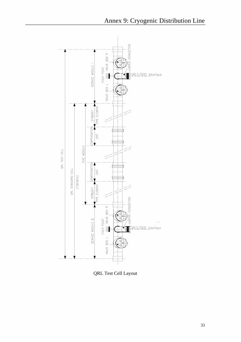
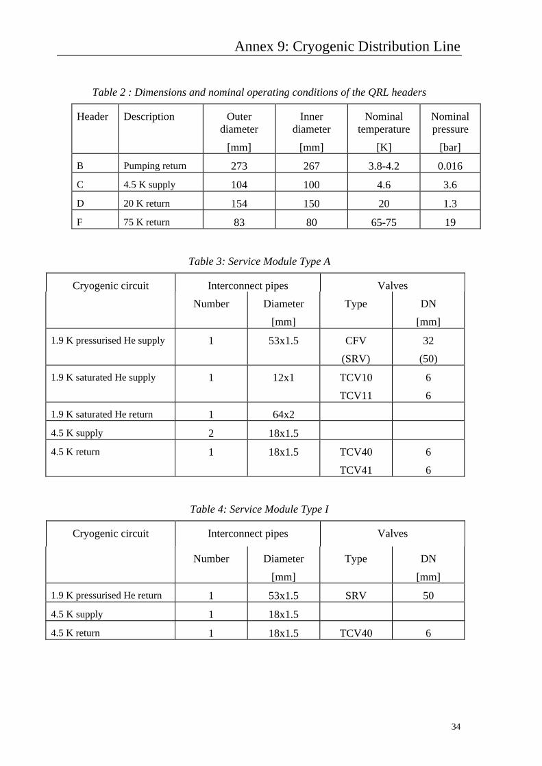
3.5 The Cryogenic Distribution Line
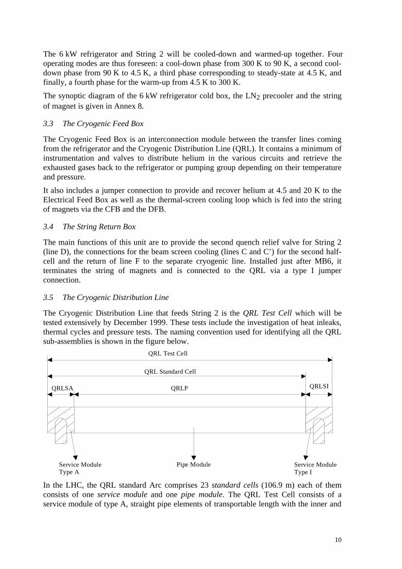
The Cryogenic Distribution Line that feeds String 2 is the QRL Test Cell which will betested extensively by December 1999. These tests include the investigation of heat inleaks,thermal cycles and pressure tests. The naming convention used for identifying all the QRLsub-assemblies is shown in the figure below.
Service ModuleType A
Service ModuleType I
Pipe Module
QRLSA QRLP QRLSI
QRL Standard Cell
QRL Test Cell
In the LHC, the QRL standard Arc comprises 23 standard cells (106.9 m) each of themconsists of one service module and one pipe module. The QRL Test Cell consists of aservice module of type A, straight pipe elements of transportable length with the inner and

11
outer bellows systems and a service module of type I. The main parameters of the QRLheaders together with a layout of the QRL Test Cell are given in the Annex 9.
In order to follow the LHC curvature, the QRL Test Cell will have the same polygonalshape as needed later in the tunnel. As a consequence the QRL inner and outerdisplacement compensation must be able to take a total angle of ~0.6°. The installation,alignment, assembling and leak testing procedures of the QRL Test Cell will follow thesame procedure envisaged for the QRL in the tunnel.
The approximate total length of the QRL Test Cell is 110 m and the vacuum jacket outerdiameter is 610 mm.
The service module type A houses the interconnecting pipes and valves (see Table 3 inAnnex 9) needed for the magnet string cool down, for the beam-screen cooling loop andfor the 1.9 K circuit. With respect to the LHC machine, only one beam screen supply willbe used for String 2.
The Service Module type I (see Table 4 in Annex 9) is used for returning the gaseoushelium during cool-down and for the beam screen cooling loop.
3.6 The Ancillary systems
The ancillary systems include the Quench Buffer Vessel, the Warm Buffer Vessel, thepumping group and all interconnecting piping and valves.
The Quench Buffer Vessel acts as a liquid helium decanter. It replaces part of the buffervolume that would be available in the 3.3 km-long line D of a sector. Liquid helium andgaseous helium expelled after a quench from the magnets will be separated here and thegas will be discharged via a long external line, acting as a natural heater, in the WarmBuffer Vessel capable of containing almost all the helium inventory of the string (20 bar,80 m3).
The pumping group provides 16-mbar pumping for the superfluid helium loop. It consistsof a Cold Compressor and the Warm pumping group. It will be shared among other usersin SM18 but it can provide up to 18 g/s pumping capacity at 16 mbar. It will be connectedto the Cryogenic Feed Box via a thermally screened line to keep the gas at the inlet of theCold Compressor below 5 K.
During cool-down, the warm gas will be pumped first to the refrigerator before switchingto the Cold Compressor once they are at 5 K.
3.7 Instrumentation
String 2 will be used to investigate the long term behaviour in operation of various types ofsensors, the ease with which they can be interfaced to control and diagnostics equipmentand their maintenance requirements. Therefore, an effort has been made to install onString 2 instrumentation that is as close as possible to the one that will be installed in LHC:a preliminary description of this instrumentation is given in the Yellow Book. At presentmuch effort is devoted to the study of cryogenic thermometers, cryogenic pressure sensors,cryogenic flow meters and in general radiation tolerant instrumentation to be installedinside the LHC tunnel.

12
4 Powering and Magnet Protect ion
String 2 will be equipped with a full set of corrector magnets and the main quadrupolecircuits will be separated from the dipoles. This was not the case for String 1. This willallow the validation of the overall powering configuration and in particular the bus-bardimensions and routings as well as the interconnection procedures during installation. ThePower Converters will be the same as those proposed for the machine and will include theregulation and control philosophy that will be used in the machine.
In order to balance the inductance of the main dipoles between the go and return busbars inthe LHC machine, the dipoles are connected in alternate ½ cells to either the go or returnbusbar. This will also be done in String 2 and will therefore require three magnets of eachconnection type. Likewise, String 2 will need one FD quadrupole and one DF quadrupoleto satisfy the full cell requirements.
4.1 The Electrical Circuits
The electrical circuit diagram for String 2 is shown in Annex 10. It reflects the poweringconfiguration of the machine as so far as it is possible with one cell of the machine. The sixmain dipoles and their correctors (total of 24 connected in four families) are split betweenthe go and return bus-bars so as to balance the inductance. A third bus-bar is used for eachfamily of dipole magnet correctors connected to the centre point of the circuit. This isforeseen to allow the immediate powering of half the corrector circuits in case of acorrector failure and later it can be used to bypass the faulty magnet during a “shortintervention”. It also provides a convenient measuring point for quench detection purposes.
The two main quadrupoles are powered separately for each aperture to form one focusingand one defocusing circuit. The eight correctors of the short straight sections are connectedindividually to the electrical feed box that will allow any combination of connection to bemade on the warm side.
4.2 Power Converters
The main dipoles will be powered in series by the existing 2-quadrant converter ofString 1. This converter [20kA, ±14V] is a conventional 12-pulse thyristor converter, madeup of four 5000A modules connected in parallel.
To power the main quadrupoles, two new switch-mode power converters will be installed.These converters will also be made up using a modular concept, where several high-currentsources [3.25kA, 16V] are placed in parallel.
This concept provides operational redundancy, since 5 modules will be installed for eachconverter. These modules (50 kW) will use soft-switching technology, working at afrequency greater than 20 kHz. Each module will employ water-cooled and plug-in sub-assemblies, thus improving availability and repair time (fast exchange and off-line repair).
A third high-current low voltage switch-mode power converter will be installed to test thedefinitive topology to be used for the main LHC dipole converters, namely a SCR boosterconverter [13kA, ±180V] for the ramp up and the ramp down, in parallel (or in series),with a low voltage 1-quadrant switch-mode power converter [13kA, 16V].
All the corrector magnets will be fed by 4-quadrant switch-mode power converters (±600Aand ±60A). New designs are under development to improve the efficiency and volume ofthese converters.
13
For the power converters and their control, String 2 will be an important place to test andvalidate all the new concepts needed in the LHC machine. The requirement to track thedipole converters and the reference magnet converter currents to 5 ppm, places newconstraints on permissible error in many areas. Equally, the techniques for on-linecorrection need such new methods to be fully evaluated before series production of controlelectronics can be envisaged.
The main areas which will be evaluated include all the power related aspects mentionedabove, the current measurement systems including their calibration methods andinstrumentation, digital regulation loops, reference waveform generation with on-linecorrections and methods for data transmission and machine timing. Many of these areaswill be developed using the magnet test benches, but String 2 is a full-scale model for test.
4.3 The Electrical Feed Box (DFB)
The DFB provides a thermal transition between an electric current source operating at 300K and a string of cryomagnets operating at 1.9 K. The DFB is, on one hand connected tothe cryogenic line for the supply and return of cryogens and, on the other hand to the SSSof the first half-cell. Three 13 kA circuits and twelve 600A circuits (See Annex 10)traverse the DFB to supply the main magnets and their correctors.
The water-cooled cables at room temperature are connected to the warm end of the currentleads. As for LHC, the String 2 DFB is equipped with high temperature superconducting(HTcS) current leads. The temperature of the leads decreases from 300 K to 4.5 K whenthey reach the helium vessel. At this point the current leads are connected to the magnetbus-bars which traverse the λ-plate separating the 4.5 K bath from the 1.9 K bath of themagnets. The level of the LHe bath is regulated to cover the HTcS part of the current leadsand their temperature is controlled by a forced flow of GHe. Externally, a series of warmvalves maintain the current leads at their operating temperature and the gas is recovered viaa warm line to the recovery line of the refrigerator.
The DFB for String 2 is a prototype similar in size to one of the two types (short) of DFBsthat will be present in LHC. The design (mechanical, cryogenic flow scheme, current leads,etc) of the String 2 DFB follows the design of the DFBs which will be present in LHC. TheDFB has to withstand the 6.3 ton atmospheric pressure on the endcap.
4.4 The Magnet Protection System
String 2 will be used to :
− qualify the proposed schemes for the protection and discharge of two families oflattice quadrupoles and one of dipole magnets (including their bus-bars) in the LHCmachine,
− study magnet-to-magnet quench propagation in a wide sense (dipole-to-dipole,quadrupole-to-dipole, corrector to main magnet, etc.) and,
− study quench detection in the corrector magnet circuits.
Other aspects such as space and installation of equipment as well as choice of theequipment itself will also be investigated.
As for the other components of String 2, all efforts will be deployed to install equipmentand components which are as close as possible to the ones which will be finally installed inthe collider. In addition, in order to be able to configure the protection system for studies, a

14
certain flexibility that will not be present in the final installation has been foreseen.
Both the fast hardware programmable logic following a quench and the slow time-basedcontrollers for generating the interlocks, which are used in String 1, are taken as reference.
4.5 Quench Detection
As for the collider, the protection of the main magnets of String 2 will be decentralised:each magnet will have its own protection system, fully redundant and independent of allother magnets. When a quench occurs in one of the magnets, the protection system of thatmagnet will fire the heaters in that particular magnet, shut down the power converters andopen the switches across the dump resistors.
Main bus-bars will be divided into half-cell sections and monitored by a redundant self-contained system. If a quench occurs in a bus-bar, the protection system will shut down thepower converters and open the switches across the dump resistors, but no heaters will befired.
A simplified sketch of the Quench Detection System foreseen for the LHC machine isshown in Annex 11. The signal loop named PC loop contains all the hardwired loops toshut down the power converters and open the dump resistor switches.
4.5.1 Quench detection in Main Magnets
The quench detection system for the main dipole and quadrupole magnets will be based onfloating bridge detectors where two apertures of each magnet are compared to each other: aquench is detected if the absolute voltage difference between the two apertures increasesabove a preset threshold. For the quadrupoles, the comparison will be made between twosets of two poles, treating each aperture of the quadrupole as a separate circuit.
In addition to this, the protection system of String 2 includes a programmable matrix,which allows the firing of heaters in all or selected magnets in addition to the heaters of thequenching magnet. The matrix is also capable of providing output signals to, and receiveinput signals from other String 2 equipment. The matrix is also equipped with a circuitmemorising the event or sequence of events leading to a quench.
4.5.2 Quench detection in corrector magnets
The quench detection of the corrector magnets will be carried-out at the cold side of thecurrent leads connected to the circuit. Therefore no signal coming from the voltage taps inthe corrector magnets participates to the detection of the quench.
This function is carried out by electronics situated in the power converter racks. However,for the dipole spool pieces, the mid-point of the circuit is connected to a third bus-bar andcurrent lead. This allows, in addition, a bridge detection of a quench.
4.5.3 The Test Controller
The quench detection system of String 2 will also be equipped with an automatic testsystem, capable of testing the functionality of the whole system including the cabling to themagnets. This test system will make minimal interference with the hardwired nature of thequench detection system.
15
4.6 Cold By-pass Diodes
The firing of the heaters provokes the commutation of the current towards the parallel colddiodes. Across each double aperture dipole, one diffusion type diode will be installed.There will be three diffusion type diodes from one manufacturer in one half cell and threediffusion type diodes from another manufacturer in the second half-cell.
The maximum reverse voltage Ur across one diode occurs when all dipoles are quenchedexcept one and the magnet chain is de-excited by opening the circuit breaker across thedump resistor. This voltage will not exceed 120 V and is well within the acceptable limitsfor the diodes. The turn on voltages Vto are somewhat higher than for the diffusion diodesused in String 1.
4.7 Quench Heaters and Power Supplies
In order to obtain an even distribution of the energy dissipated in the magnet, both types ofmain magnets (dipole and quadrupole) are equipped with quench heaters to enhance thenormal zone propagation throughout the coils after a quench. Radiation tolerant heatersupplies power the resistors by discharging banks of capacitors.
4.8 Discharge Elements: D.C. Circuit Breakers and Dump Resistors
The introduction of two separate 13 kA power circuit for the quadrupole magnets will notrequire an additional energy extraction system. In fact, the stored magnetic energy of asingle quadrupole can be absorbed within its coils in the case of a quench or in the powercables and the free-wheel system in case of a natural current decay.
The existing (String 1) thyristor and mechanical switches and associated dump resistorswould meet the demands also for the String 2 dipole chain. However, String 2 represents aunique occasion to obtain operational experience with a prototype of the d.c. breakerfacility which is foreseen for the LHC machine. Therefore, this new system will beinstalled on String 2. The system is composed of:
− eight single-pole, 4 kA-1500 V mechanical circuit breakers, configured in fourparallel branches with two series-connected switches. The breakers aremanufactured in Russia
− an associated powering and control system, designed and built at CERN
− a current-equalizing power busway for feeding the breaker assembly
An extended test program has been set up in Russia and at CERN for individual testing ofthe breakers. However, as for most systems, String 2 remains the first and only place,where operational experience can be acquired.
The energy extraction system will be made using a thyristor switch in series with amechanical switch and a discharge resistor. The value of this resistor can be changed togive different discharge time constants.
The eight breakers of the Russian prototype switch will be delivered mid 1999 and will beinstalled in String 2 towards the end of that year.
5 Vacuum
The String 2 vacuum systems will be manufactured for the most part from LHC pre-seriescomponents. Whilst the LHC-VAC group is not responsible for the procurement of the
16
majority of components making up the vacuum enclosures, it is however responsible forthe definition or approval of all vacuum specifications and procedures concerning materialselection, cleaning and leak detection.
In order to be representative, the String 2 assembly process should be as close as possibleto the foreseen operations in the LHC tunnel, implying a minimum of on-site tasks.Therefore, as for the LHC installation, all String 2 sub-assemblies shall be delivered to thesite cleaned and fully vacuum tested.
Vacuum instrumentation will be classified as ‘standard LHC’ or ‘dedicated String 2’.
5.1 Insulation Vacuum
The insulation vacuum of the String 2 will be divided by vacuum barriers into threevolumes: the main cryostat containing 8 magnet coldmasses, the QRL, the DFB and theCFB. For the main cryostat and QRL, all LHC insulation vacuum instrumentation will belocated at the cryostats of the SSS and the longitudinally adjacent QRL module. Otherdedicated String 2 vacuum instrumentation will be distributed along the 107-metre length.As for the String 1, the standard instrumentation flange remains the ISO-K 100. Each ofthe ports, whether for vacuum or other instrumentation, will be coded and have apredefined use. The permanently installed vacuum instrumentation shall be similar for eachvolume and will include a turbomolecular pumping group, total pressure gauges, isolationvalves, and over pressure safety valve. By-pass manifolds equipped with remote controlvalves will be installed at each vacuum barrier. For dedicated String 2 experiments,additional vacuum instrumentation will installed. This will include helium leak simulatorsat magnet interconnects, activated charcoal, pressure gauges within the MLI blankets, andresidual gas analyser (RGA). Mobile vacuum instrumentation is also required for cryostatevacuation and leak detection, and will conform to LHC tunnel stay clear zones.
5.2 Beam Vacuum
The beam vacuum system consists of two independent cold bores. In-line with the presentbeam vacuum baseline design, all of the cold system will be welded. The room temperaturepumping manifold at the SSS will remain all-metal, based upon Conflat demountableflanges.
Unlike String 1, the beam vacuum will be fully equipped with beam screens andintermagnet RF junctions, and will be assembled according to UHV procedures. Twelve 15metre dipole beam screens and four 6 metre SSS beam screens are foreseen, the latter beingan integrated unit with the beam position monitor. In order to simulate proton beam heatingeffects, heaters will be attached to the beam screens and BPMs.
The permanent beam vacuum instrumentation will be located on the pumping manifold atthe SSS, with a set of total pressure gauges, ion pump, rupture disc, isolation valve androughing valve for each beam tube. For dedicated String 2 experiments a massspectrometer (RGA) will be installed.
5.3 Beam screen and BPM measurements
Thermal and mechanical measurements of the beam screens and the BPMs will benecessary. At least two dipole beam screens, two SSS beam screens, one magnetinterconnect and one BPM will be equipped with dedicated sensors. The integration of thesensors required for the measurements may imply minor design deviations for some of the
17
vacuum component. Similar to the two prototype beam screens installed on String 1, themeasurements will concern component performance during cool down, warm up, currentramping, steady state operation, and magnet quenches.
5.4 Leak detection
Leak detection of the vacuum systems will be achieved in 3 stages; individual testing ofeach new in-situ joint, global testing per vacuum enclosure with helium circuitspressurised, and global testing per vacuum enclosure during the cooldown. Unlike String 1,clam shell tooling will be available for individual leak testing the welds of pressurisedhelium lines, giving greater sensitivity and saving time. In addition, a method tolongitudinally locate helium leaks to an interconnect during global leak testing is underelaboration and will be employed on String 2.
The leak testing operations require collaboration between many groups including LHC-ACR, LHC-CRI, LHC-VAC and TIS/GS. The written procedures adopted for String 1 willbe further elaborated.
6 Monitor ing and Control
As it was the case for String 1, the String 2 experimental facility will be equipped with acontrol system and a separate data acquisition system.
The control architecture of String 2 will be mixed: for all the aspects related to thedeterministic control of the power converters it is based on in-house developments inspiredon commercial products whereas, for process control and supervision it is based onindustrial control system architecture.
6.1 Data Acquisition
The data acquisition system of String 1, which provides archiving and transient recordingwill be re-used for String 2. The channel number will be increased to 860. Each channel isan independently configurable 16-bit ADC that can run up to 1 kHz and acquire up to 3500samples per event. Additional hardware to push the sample size to 14000 per channel canbe installed.
The data acquisition system also includes a configurable cluster of 20 channels at 50 kHzfor special magnet protection studies.
The data from the sensors is converted to physical units via a variety of conversionfunctions (polynomials, exponential functions, etc) and conversion tables providing linearinterpolation between points.
The data acquisition system is synchronised to the millisecond with the LHC controlsystem and to the second with the process control system for cryogenics and vacuum.
6.2 Data Storage System
Following the experience on String 1, a central data storage system, based on acombination of flat files and Oracle® tables, serves as repository for all the data acquired bydifferent systems (general data acquisition, process supervision, special data acquisitionsystems, LHC control system) connected to String 2.
A standard network interface provides the means to retrieve raw and converted data forprocessing and display.

18
6.3 Process Control
Both the process control and the supervision of the cryogenic and the vacuum systems willbe based on industrial control systems.
6.3.1 Process Control for the String Cryogenics
The main control parameter of the ring cryogenic system is the magnet temperatures. Thiscontrol is difficult because the physical process is involved strongly non-linear andcryogenic thermometers exhibit many undesirable characteristics that affect their long-termperformance. The requirements on the thermometer accuracy will define the periodicity ofin-situ re-calibration campaigns during which the LHC will not available for physics. Inorder to increase the operational margins either on the temperature measurement or on thecooling system capacity more advanced controllers are being studied, if these technique aresuccessful they should result in a narrower temperature control band when compared to astandard PID controller. The type of controllers that are being investigated include grey orblack box system identification and model based predictive controllers. These techniquesproduce a simplified model of the process that is then used to generate the optimumfeedback control signal.
In addition to the magnets temperature control, several other closed control loops exist andthey will be implemented by using standard PID controllers. The transient behaviour willalso be investigated in order to develop fast cool-down, warm-up and quench recovery.
A large number of cryogenic sensors will be distributed around the 27 km of thecircumference of LHC. String 2 will be used to demonstrate, test and validate the differentsignal conditioning units and their data transmission system feeding the programmablelogic controllers.
6.3.2 Process Control of the Cryogenic Plant
The software methodology that has been adopted to control the external cryogenics forString 2 (i.e. compressors, cold box, LN2 precooler and Cryogenic Feed Box) is based onan object-oriented approach, similar to the one already used for SPS and LEP2 cryoplants.
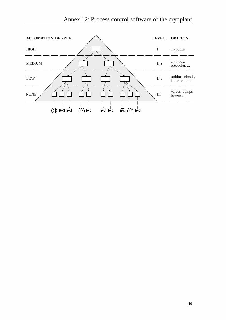
The software will be structured in four different levels: I, IIa, IIb and III. Control level I isthe highest one, while control level III is the lowest. The philosophy is that every high-level object links a group of lower-level objects to obtain a certain degree of automation.
The pyramidal structure of the software is shown in Annex 12. Level III objects are simplephysical entities like valves, vacuum pumps, heaters, etc. They do not need any operationallogic since they can function on their own. Actually, most of the cryoplant logic iscontained in the two intermediate levels called IIa and IIb. But, while level IIb links objectsof level III to constitute sub-components of the cryoplant (the vacuum system, the turbinescircuits, the Joule-Thomson circuit, etc.), level IIa controls the main components like thecompressors, the cold box and the precooler. Finally, the supervision of the entire cryoplantis performed by the highest level I.
6.3.3 Controls for Vacuum
For String 1, a vacuum Programmable Logic Controller (PLC) was used to acquire thestatus and data values of the vacuum instrumentation and provide an interface with thesupervision software. For String 2, the vacuum PLC will provide the additional functions

19
of process control and remote operations. The PLC will be positioned under the centraldipole of a half-cell in accordance with current recommendations.
6.3.4 Deterministic Control of the Power Converters
The LHC Dynamic Effects Working Group has brought attention to the requirement fordeterministic control facilities for the LHC. Potential areas where such techniques may beemployed include:
− tracking of the main dipole powering circuits,
− closed orbit control during snapback at the early part of the ramp,
− compensation of non reproducible sources of tune and chromaticity variation on theramp.
The response of the power converter control loops is chosen such that an error signal,derived from the above effects, can be introduced with a useful bandwidth of 50 Hz.Prototype development for the power converter control electronics is based upon thepremise that all converters will accept such an error signal.

Annex 1: Design Meetings
20
Plenary
Date of Meeting Topics DiscussedApril 16th 1996 First Meeting : Setting the SceneJune 20th 1996 Magnetic Measurements on String 2August 29th 1996 ReviewFebruary 13th 1997 Simplification du Schéma Cryogénique
String 2 ScheduleApril 24th 1997 String 2 Version 1 challanged
Powering & Magnet Protection (Chairman : P.Proudlock)
Date of Meeting Topics DiscussedApril 25th 1996 Functionalities of the Powering System for Version 1
Floor Space for Power ConvertersJuly 4th 1996 Electrical Circuits for Version 1 and String 2000September 12th 1996 HTCSCurrent Leads: State of the ArtNovember 21st 1996 Electrical Circuit Diagram for String 2000
Floor SpaceDFB
March 27th 1997 Quench Detection and Magnet protection for String 2
Cryogenics & Vacuum (Chairman : W.Erdt)
Date of Meeting Topics DiscussedMay 9th 1996 Description of the Vacuum and Cryogenic Systems for String 2September 26th 1996 The QRL for String 2December 5th 1996 The Cryogenic Scheme for String 2March 13th 1997 The Vacuum of String 2000
Magnets & Mechanics (Chairman : A.Poncet)
Date of Meeting Topics DiscussedMay 23rd 1996 Dipoles, SSS’s and DFBsAugust 1st 1996 Magnet InterconnectsDecember 19th 1996 Status of the Dipoles, the SSS’s and the DFBsMarch 27th 1997 Layout of String 2000
Instrumentation & Controls (Chairman : R.Saban)
Date of Meeting Topics DiscussedJune 6th 1996 Review of the Instrumentation of String 2August 15th 1996 Controls & Fast FeedbackJanuary 16th 1997 The 6kW Linde Cold BoxApril 10th 1997 The Data Acquisition System for String 2000
The Data Storage System

Annex 1: Participants
21
A.Ballarino
A.Bézaguet
JC.Billy
H.Blessing
M.Bona
P.Bonnal
F.Bordry
JC.Brunet
W.Cameron
J.Casas-Cubillos
L.Coull
P.Cruikshank
K.Dahlerup-Petersen
JP.Dauvergne
N.Delruelle
W.Erdt
P.Faugeras
G.Fernqvist
H.Gaillard
R.Gavaggio
T.Goiffon
P.Gomes
M.Granier
D.Hagedorn
K.Henrichsen
B.Hilbert
A.Ijspeert
B.Jenninger
S.Knoops
W.Koelemeijer
JP.Koutchouk
J.Kragh
HK.Kuhn
R.Lauckner
P.Lebrun
D.Leroy
A.Mathewson
D.Missiaen
F.Momal
L.Oberli
R.Parker
V.Parma
J.Pedersen
JL.Perinet-Marquet
D.Perini
M.Peryt
J.Pett
A.Poncet
P.Proudlock
P.Provenaz
JP.Quesnel
M.Rabany
D.Richter
F.Rodriguez-Mateos
P.Rohmig
G.Riddone
A.Rijllart
R.Saban
Ph.Sacré
R.Schmidt
L.Serio
CH.Sicard
A.Siemko
P.Sievers
P.Strubin
A.Suraci
L.Tavian
U.Wagner
L.Walckiers
R.van Weelderen
L.Williams.
Annex 2: Schedule
22
Annex 3: Layout
23
Annex 3: Layout
24
Annex 3: Layout
25
Annex 4: Short straight section assembly
26
Annex 5: Dipole coil cross-section
27
Annex 6: Interconnects
28
Annex 7: Cryogenic Flow Scheme
29
Annex 7: Cryogenic Flow Scheme
30
Annex 8: Cryogenic Plant
31
Heat loads Equivalent entropy flux
non-isothermal load between 50 K and 75 K 700 [W] 11.3 [J.s-1.K-1]
non-isothermal load between 4.5 K and 20 K 160 [W] 17.4 [J.s-1.K-1]
isothermal load (refrigeration) at 1.9 K 50 [W] 25.7 [J.s-1.K-1]
Version1
liquefaction rate at 3 bar and 4.5 K
(6 * 13 kA + 24 * 600 A of classical leads)
12 [g.s-1] 332.6 [J.s-1.K-1]
Version 2
liquefaction rate at 3 bar and 4.5 K
(6 * 13 kA + 24 * 600 A of HTc leads)
7.5 [g.s-1] 207.9 [J.s-1.K-1]
Table 1: The heat loads converted to an equivalent entropy flux used forsizing the cryoplant
An
ne
x 8: C
ryog
en
ic Pla
nt
32
75 K 50 K20 K 4.5 K
20 K 50 K50 K 75 K75 K4.5 K 4.5 K4.5 K 4.5 K
from comp.delivery
to comp.suction
to theatmosph.
LN
2
to coldpumping
80 m3 2 m3
6 kW refrigerator cold box
LN2 precooler / adsorber unit
magnet string
D F C E
Annex 9: Cryogenic Distribution Line
33
QRL Test Cell Layout
Annex 9: Cryogenic Distribution Line
34
Table 2 : Dimensions and nominal operating conditions of the QRL headers
Header Description Outerdiameter
[mm]
Innerdiameter
[mm]
Nominaltemperature
[K]
Nominalpressure
[bar]
B Pumping return 273 267 3.8-4.2 0.016
C 4.5 K supply 104 100 4.6 3.6
D 20 K return 154 150 20 1.3
F 75 K return 83 80 65-75 19
Table 3: Service Module Type A
Cryogenic circuit Interconnect pipes Valves
Number Diameter
[mm]
Type DN
[mm]
1.9 K pressurised He supply 1 53x1.5 CFV
(SRV)
32
(50)
1.9 K saturated He supply 1 12x1 TCV10
TCV11
6
6
1.9 K saturated He return 1 64x2
4.5 K supply 2 18x1.5
4.5 K return 1 18x1.5 TCV40
TCV41
6
6
Table 4: Service Module Type I
Cryogenic circuit Interconnect pipes Valves
Number Diameter
[mm]
Type DN
[mm]
1.9 K pressurised He return 1 53x1.5 SRV 50
4.5 K supply 1 18x1.5
4.5 K return 1 18x1.5 TCV40 6
Annex 9: Cryogenic Distribution Line
35
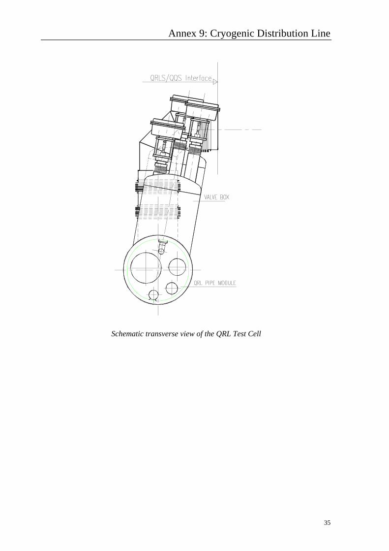
Schematic transverse view of the QRL Test Cell
Annex 10: Electrical Circuit Diagram
36
Annex 10: Electrical Circuit Diagram
37
Annex 10: Electrical Circuit Diagram
38
Annex 10: Electrical Circuit Diagram
39
Annex 12: Process control software of the cryoplant
40
NONE
LOW
MEDIUM
HIGH
AUTOMATION DEGREE LEVEL
I
II a
II b
III
cryoplant
cold box,precooler, ...
turbines circuit,J-T circuit, ...
valves, pumps,heaters, ...
OBJECTS


![[VHDN] FULL](https://img.pdfslide.net/doc/110x75/633391eab94d6238420243b4/vhdn-full.jpg)


