Embed Size (px)
Citation preview

1
The new MarkIII/IRST-Light microphone array
Claudio Bertotti1, Luca Brayda2, Luca Cristoforetti3, Maurizio Omologo3, Piergiorgio Svaizer3
1ITC, Trento, Italy
2Institut Eurecom, France 3ITC-irst, Povo, Trento, Italy
1. INTRODUCTION The purpose of this document is to describe a new modified version of the MarkIII microphone array realized at IRST. In [1] we realized a first modified version (from now on: “MarkIII/IRST”), solving all the problems which affected the original MarkIII device [2,3]: though it reaches very good performances, the modifications would have been difficult to replicate in the other labs of the CHIL consortium [4]. Furthermore, in order to provide a power supply free from disturbances, an efficient but heavy power-supplier (battery-box) was designed and built. For further details about the problems observed in the Original MarkIII and the steps that led to the MarkIII/IRST, please refer to [1]. We then decided to design a new set of modifications to make the array lighter and easier to replicate. The main advantages of this modified device (from now on ”Mark/IRST-Light”) are: 1) The lightness. The motherboard is almost untouched, while we changed or inserted few components on the microboards. We added an additional microboard to provide a battery-driven power supply only to the microphones and only in the acquisition phase. No additional battery-based power supply is needed to feed the analogue devices. 2) The performance. The MarkIII/IRST-Light is not a compromise between performance and replicability: after the tests the MarkIII/IRST-Light is even outperforming the MarkIII/IRST in terms of common noise. 3) The replicability. Few capacitors and resistors have been placed on the microboards. An additional microboard connects together a relay, a pilot transistor and some resistors, thus being easy to build. The intervention can thus be made quickly (i.e. one working week of an expert in the field). 4) The cost. We minimized the number of additional components: modifying the original NIST-MIII[5] to get the MarkIII/IRST-Light would cost less then 100 euros. 2. DESCRIPTION As discussed in [1], the MarkIII/IRST was designed to face and solve the following hardware problems: 1) Early saturation effect of microphones 2) 50 Hz disturbance 3) Device noise 4) 8 and 16 kHz common ground noise 5) Potential microboard breakdown
2
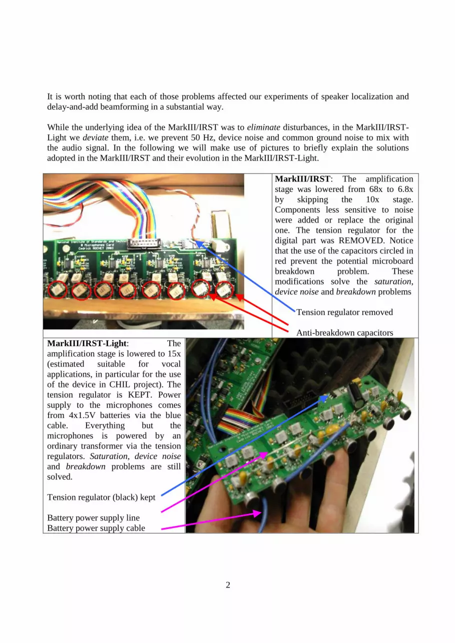
It is worth noting that each of those problems affected our experiments of speaker localization and delay-and-add beamforming in a substantial way. While the underlying idea of the MarkIII/IRST was to eliminate disturbances, in the MarkIII/IRST-Light we deviate them, i.e. we prevent 50 Hz, device noise and common ground noise to mix with the audio signal. In the following we will make use of pictures to briefly explain the solutions adopted in the MarkIII/IRST and their evolution in the MarkIII/IRST-Light.
MarkIII/IRST: The amplification stage was lowered from 68x to 6.8x by skipping the 10x stage. Components less sensitive to noise were added or replace the original one. The tension regulator for the digital part was REMOVED. Notice that the use of the capacitors circled in red prevent the potential microboard breakdown problem. These modifications solve the saturation, device noise and breakdown problems
Tension regulator removed
Anti-breakdown capacitors MarkIII/IRST-Light: The amplification stage is lowered to 15x (estimated suitable for vocal applications, in particular for the use of the device in CHIL project). The tension regulator is KEPT. Power supply to the microphones comes from 4x1.5V batteries via the blue cable. Everything but the microphones is powered by an ordinary transformer via the tension regulators. Saturation, device noise and breakdown problems are still solved. Tension regulator (black) kept Battery power supply line Battery power supply cable

3
The high impedance microphone power supply stage
DEVIATES the noise sources. The 6V battery put aside of the microboards, inside the Faraday cage.
MarkIII/IRST: Power supply box (about 10 Kg) designed ad-hoc. 4 Ni-Cd batteries feed each microboard; a transformer feeds the digital circuits of the microboards when acquiring data and recharges the batteries when not. Front of the power supply box

4
MarkIII/IRST-Light: An additional microboard, driven by the acquisition led on the motherboard, feeds the 64 microphones when acquiring data ONLY. This makes batteries last approximately 150 hours of acquisition. Blue cables going to the microboards. One cable going to the battery charge indicator installed in the chassis. All the boards are now fed with an ordinary, light, non-switching power supplier.
3. CONCLUSIONS This document described briefly the most recent modifications done at ITC-irst to further improve the usability of MarkIII as well as the quality of the acquired signals. The MarkIII/ IRST-Light can be derived from an original MarkIII with a reasonable cost in terms of new hardware and time-effort. To resume the two interventions, the problems as well as the type of solution are reported in the following for what concerns the MarkIII/IRST and the MarkIII/IRST-Light device.

5
Problem MarkIII/IRST solution MarkIII/IRST-Light solution
Early saturation effect Decreasing the ampli gain from 68x to 6.8x
Decreasing the ampli gain from 68x to 15x
50 Hz disturbance Battery power supply Light high impedance stage to power microphones + ordinary power supply
Device Noise Removed one tension regulator, battery power supply
Light high impedance stage to power microphones + ordinary power supply
8-16 kHz common ground noise
4 batteries per microboard power supply
Light high impedance stage to power microphones + ordinary power supply
Potential microboard breakdown
1 uF polarized capacitor replaced by a 0.47 uF polyester capacitor
1 uF polarized capacitor replaced by a 0.22 uF polyester capacitor
It is worth noting (see more details in [1]) that the array operates correctly at 44.1 kHz, as the inconsistency that was found when operating at 22 kHz depends on the firmware, which obviously could not be fixed during this intervention. For any other question or request to fix the original array, please contact Maurizio Omologo ([email protected]) Bibliography [1] C. Bertotti, L. Brayda, L. Cristoforeti, M. Omologo and P. Svaizer, “The MarkIII microphone array: the modified version realized at ITC-irst”, URL: http://www.eurecom.fr/~brayda/MarkIII-IRST.pdf [2] L. Brayda, C. Bertotti, L. Cristoforeti, M. Omologo and P. Svaizer, “On Calibration and Coherence Signal Analysis of the CHIL Microphone Network at IRST”, Workshop on Hands Free Speech Communication with Microphone Arrays 2005, Piscataway, New Jersey, USA. (accepted) [3] L. Brayda, C. Bertotti, L. Cristoforeti, M. Omologo and P. Svaizer, “Modifications on NIST MarkIII array to improve coherence properties among input signals”, 118th Convention of the Audio Engineering Society 2005, Barcelona, Spain. (accepted) [4] J. R. Casas, R. Stiefelhagen, “Multi-camera/multi-microphone system design for continuous room monitoring “ CHIL-WP4-D4.1-V2.0-2004-07-08-CO [5] C.Rochet, “Documentation of the Microphone Array MarkIII”, URL: http://www.nist.gov/smartspace/toolChest/cmaiii/userg/Microphone_Array_Mark_III.pdf The present document is available at the following webpage: http://www.eurecom.fr/~brayda/MarkIII-IRST-Light.pdf

6
APPENDIX A
A1. Cedrick Rochet analysing the modifications of the new MarkIII/IRST-Light.
A2. M. Omologo, C. Rochet and C. Bertotti in the IRST CHIL room.
A3. Luca. Brayda and Claudio Bertotti in the IRST CHIL room.

7
APPENDIX B Hereunder we show the new circuitries, which are necessary to modify the microboards in order to get the MarkIII/IRST-Light:
Figure B.1: The amplification stage after the microphones: corrected scheme. Notice the high impedance microphone power supply stage, which connect each group of 8 microphones on the same microboard to a double positive-negative power supply. This is more evident in figure B.2

8
Figure B.2: The High impedence microphone power supply layout connects eight microphone to the same power supply, provided with a 6V battery.

9
Figure B.3: The circuitry around the A/D.
Figure B.4: Incorrect microphone power supply and correct microboard power supply

10
Figure B.5: Corrected microphone power supply


