Embed Size (px)
Citation preview
2005 February • JOM52
High-Performance FibersOverview
This paper reviews the processing, properties, and structure of carbon fi bers. Carbon fi bers are derived from several precursors, with polyacrylonitrile being the predominant precursor used today. Carbon fi bers have high strength (3–7 GPa), high modulus (200–500 GPa), compressive strength (1–3 GPa), shear modulus (10–15 GPa), and low density (1.75–2.00 g/cm3). Carbon fi bers made from pitch can have modulus, thermal, and electrical conductivities as high as 900 GPa, 1,000 W/mK, and 106 S/m, respectively. These fi bers have become a dominant material in the aerospace industry and their use in the automotive and other industries is growing as their cost continues to come down.
INTRODUCTION
Carbon fi bers contain at least 90% carbon by weight obtained by pyrolysis of an appropriate precursor fi ber.1 Graph-ite is one form of carbon. In graphite, the sp2 hybridized carbon atoms are arranged in two-dimensional hexago-nal planes.1 These graphitic planes are highly anisotropic due to the difference between in-plane and out-of-plane bond-ing of carbon atoms. The elastic modulus is much higher in the plane than it is perpendicular to the plane. The bond-ing between graphitic planes is van der Waals bonding so the planes can slide with respect to each another. Alignment of the graphitic planes parallel to the fi ber axis leads to high tensile modulus and electrical and thermal conductivity parallel to the fi ber axis.2
Polymeric materials, which leave a carbon residue and do not melt upon pyrolysis in an inert atmosphere, are generally considered candidates for carbon-fi ber production.3 The historical development of carbon fi ber has been traced extensively.4 The fi rst carbon
The Processing, Properties, and Structure of Carbon Fibers
Marilyn L. Minus and Satish Kumar
fi bers were produced by T. Edison in the United States and J.W. Swan in England from a cellulose precursor for light-bulb fi laments.5 Modern carbon fi bers were
developed in the late 1950s and early 1960s by W. Watt in England,6 A. Shindo in Japan,7 and R. Bacon in the United States.8 Though cellulose was the early precursor used for carbon fi bers, today polyacrylonitrile (PAN) is the predomi-nant carbon-fi ber precursor, followed by petroleum pitch. Carbon fi bers are also produced by decomposing gaseous hydrocarbons at high temperatures. The fi rst account of vapor-grown carbon fi ber (VGCF) production was in 1890.9
PROCESSING OF CARBON FIBERS
PAN-Based Carbon Fibers
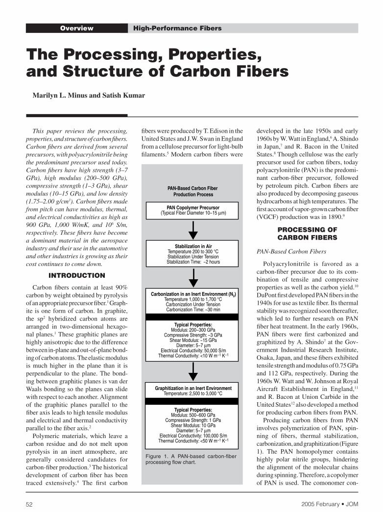
Polyacrylonitrile is favored as a carbon-fi ber precursor due to its com-bination of tensile and compressive properties as well as the carbon yield.10 DuPont fi rst developed PAN fi bers in the 1940s for use as textile fi ber. Its thermal stability was recognized soon thereafter, which led to further research on PAN fi ber heat treatment. In the early 1960s, PAN fi bers were fi rst carbonized and graphitized by A. Shindo7 at the Gov-ernment Industrial Research Institute, Osaka, Japan, and these fi bers exhibited tensile strength and modulus of 0.75 GPa and 112 GPa, respectively. During the 1960s W. Watt and W. Johnson at Royal Aircraft Establishment in England,11 and R. Bacon at Union Carbide in the United States12 also developed a method for producing carbon fi bers from PAN. Producing carbon fi bers from PAN involves polymerization of PAN, spin-ning of fi bers, thermal stabilization, carbonization, and graphitization (Figure 1). The PAN homopolymer contains highly polar nitrile groups, hindering the alignment of the molecular chains during spinning. Therefore, a copolymer of PAN is used. The comonomer con-
Figure 1. A PAN-based carbon-fi ber processing fl ow chart.
2005 February • JOM 53
tent generally ranges from 2% to 15%; typical comonomers are acrylic acid, methacrylic acid, and methacrylate. The use of comonomers partially disrupts the nitrile-nitrile interactions, allowing for better chain alignment. Typical carbon yield from PAN-based precursors is 50–60%. The PAN fi bers can be spun by wet, melt, dry, gel, and dry-jet wet spinning. In wet spinning, which is commonly used,13 the polymer is directly extruded in the coagulation bath and the fi ber is subsequently drawn at ~100ºC. Wet-spun PAN precursor fi bers typically have a circular or dog-bone-shaped cross sec-tion depending upon fi ber-coagulation conditions. Using specially shaped spin-nerets, other cross-sectional shapes, such as “C,” “T,” star, and trilobal shapes have also been processed to infl uence micro-structure and properties of the resulting carbon fi bers. The cross-sectional shape of the ultimate carbon fi ber resembles the shape of the precursor fi ber. The typical diameter of the PAN precursor fi ber is about 15 µm, which ultimately results in a carbon fi ber of
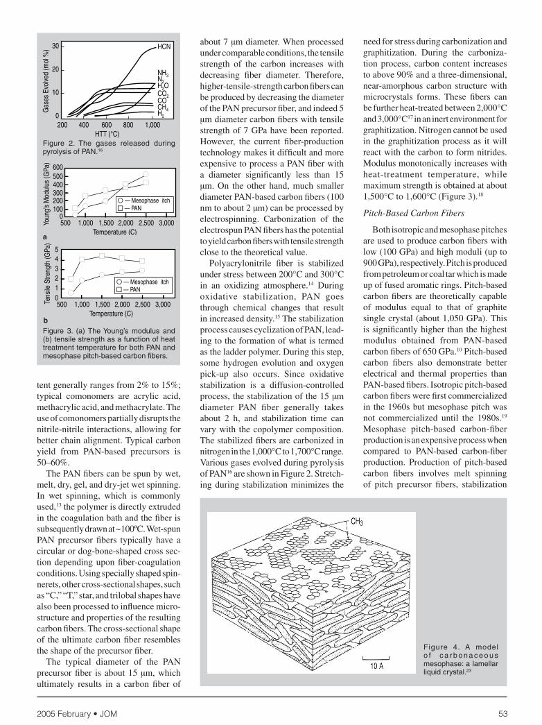
about 7 µm diameter. When processed under comparable conditions, the tensile strength of the carbon increases with decreasing fi ber diameter. Therefore, higher-tensile-strength carbon fi bers can be produced by decreasing the diameter of the PAN precursor fi ber, and indeed 5 µm diameter carbon fi bers with tensile strength of 7 GPa have been reported. However, the current fi ber-production technology makes it diffi cult and more expensive to process a PAN fi ber with a diameter signifi cantly less than 15 µm. On the other hand, much smaller diameter PAN-based carbon fi bers (100 nm to about 2 µm) can be processed by electrospinning. Carbonization of the electrospun PAN fi bers has the potential to yield carbon fi bers with tensile strength close to the theoretical value. Polyacrylonitrile fi ber is stabilized under stress between 200°C and 300°C in an oxidizing atmosphere.14 During oxidative stabilization, PAN goes through chemical changes that result in increased density.15 The stabilization process causes cyclization of PAN, lead-ing to the formation of what is termed as the ladder polymer. During this step, some hydrogen evolution and oxygen pick-up also occurs. Since oxidative stabilization is a diffusion-controlled process, the stabilization of the 15 µm diameter PAN fi ber generally takes about 2 h, and stabilization time can vary with the copolymer composition. The stabilized fi bers are carbonized in nitrogen in the 1,000°C to 1,700°C range. Various gases evolved during pyrolysis of PAN16 are shown in Figure 2. Stretch-ing during stabilization minimizes the
need for stress during carbonization and graphitization. During the carboniza-tion process, carbon content increases to above 90% and a three-dimensional, near-amorphous carbon structure with microcrystals forms. These fi bers can be further heat-treated between 2,000°C and 3,000°C17 in an inert environment for graphitization. Nitrogen cannot be used in the graphitization process as it will react with the carbon to form nitrides. Modulus monotonically increases with heat-treatment temperature, while maximum strength is obtained at about 1,500°C to 1,600°C (Figure 3).18
Pitch-Based Carbon Fibers
Both isotropic and mesophase pitches are used to produce carbon fi bers with low (100 GPa) and high moduli (up to 900 GPa), respectively. Pitch is produced from petroleum or coal tar which is made up of fused aromatic rings. Pitch-based carbon fi bers are theoretically capable of modulus equal to that of graphite single crystal (about 1,050 GPa). This is signifi cantly higher than the highest modulus obtained from PAN-based carbon fi bers of 650 GPa.10 Pitch-based carbon fi bers also demonstrate better electrical and thermal properties than PAN-based fi bers. Isotropic pitch-based carbon fi bers were fi rst commercialized in the 1960s but mesophase pitch was not commercialized until the 1980s.19 Mesophase pitch-based carbon-fi ber production is an expensive process when compared to PAN-based carbon-fi ber production. Production of pitch-based carbon fi bers involves melt spinning of pitch precursor fi bers, stabilization
Figure 2. The gases released during pyrolysis of PAN.16
Figure 4. A model o f c a r b o n a c e o u s mesophase: a lamellar liquid crystal.23
a
bFigure 3. (a) The Young’s modulus and (b) tensile strength as a function of heat treatment temperature for both PAN and mesophase pitch-based carbon fi bers.
2005 February • JOM54
Table I. Structural Parameters of Various Carbon Fibers*
Lc La (0°) La (90°C) Z 3-D SEMFiber (nm) (nm) (nm) (°) d(002) Order Morphology
P-25 2.6 4 6 31.9 0.344 No Sheet-likeP-55 12.4 11 30 14.1 0.342 Maybe Sheet-likeP-100 22.7 49 80 5.6 0.3382 Yes Sheet-likeP-120 25.1 64 88 5.6 0.3376 Yes Sheet-likeT-300 1.5 2.2 4.1 35.1 0.342 No NoIM-8 1.9 3.1 5.1 — 0.343 No No
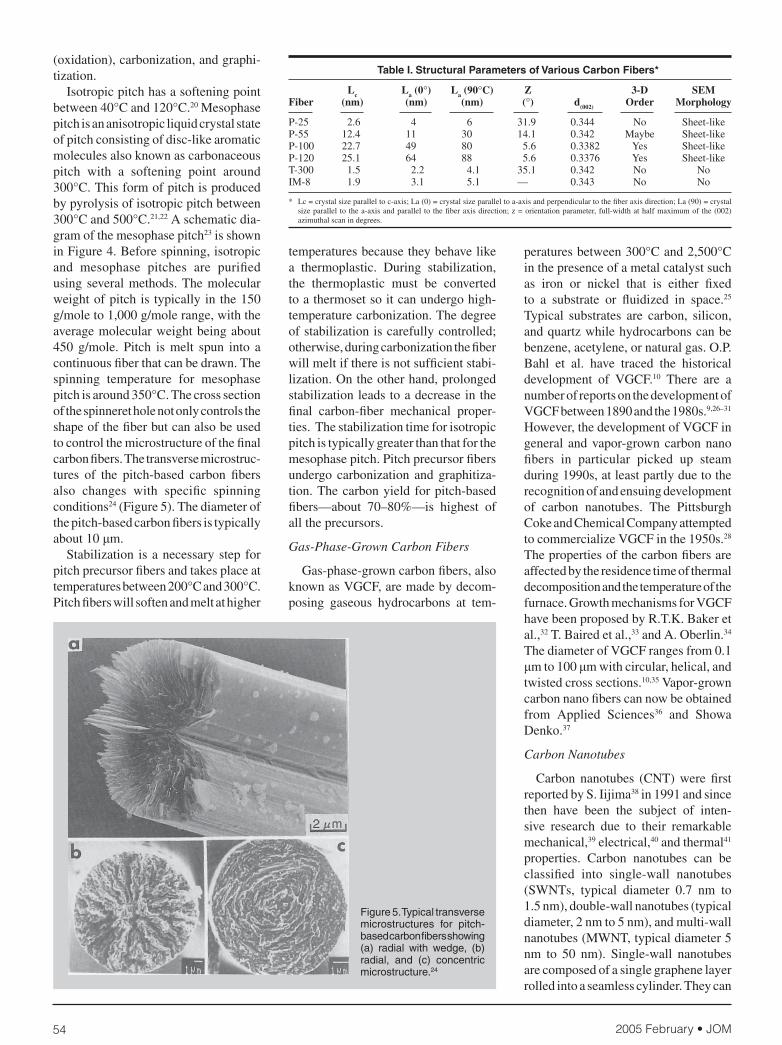
(oxidation), carbonization, and graphi-tization. Isotropic pitch has a softening point between 40°C and 120°C.20 Mesophase pitch is an anisotropic liquid crystal state of pitch consisting of disc-like aromatic molecules also known as carbonaceous pitch with a softening point around 300°C. This form of pitch is produced by pyrolysis of isotropic pitch between 300°C and 500°C.21,22 A schematic dia-gram of the mesophase pitch23 is shown in Figure 4. Before spinning, isotropic and mesophase pitches are purifi ed using several methods. The molecular weight of pitch is typically in the 150 g/mole to 1,000 g/mole range, with the average molecular weight being about 450 g/mole. Pitch is melt spun into a continuous fi ber that can be drawn. The spinning temperature for mesophase pitch is around 350°C. The cross section of the spinneret hole not only controls the shape of the fi ber but can also be used to control the microstructure of the fi nal carbon fi bers. The transverse microstruc-tures of the pitch-based carbon fi bers also changes with specifi c spinning conditions24 (Figure 5). The diameter of the pitch-based carbon fi bers is typically about 10 μm. Stabilization is a necessary step for pitch precursor fi bers and takes place at temperatures between 200°C and 300°C. Pitch fi bers will soften and melt at higher
temperatures because they behave like a thermoplastic. During stabilization, the thermoplastic must be converted to a thermoset so it can undergo high-temperature carbonization. The degree of stabilization is carefully controlled; otherwise, during carbonization the fi ber will melt if there is not suffi cient stabi-lization. On the other hand, prolonged stabilization leads to a decrease in the fi nal carbon-fi ber mechanical proper-ties. The stabilization time for isotropic pitch is typically greater than that for the mesophase pitch. Pitch precursor fi bers undergo carbonization and graphitiza-tion. The carbon yield for pitch-based fi bers—about 70–80%—is highest of all the precursors.
Gas-Phase-Grown Carbon Fibers
Gas-phase-grown carbon fi bers, also known as VGCF, are made by decom-posing gaseous hydrocarbons at tem-
peratures between 300°C and 2,500°C in the presence of a metal catalyst such as iron or nickel that is either fi xed to a substrate or fl uidized in space.25 Typical substrates are carbon, silicon, and quartz while hydrocarbons can be benzene, acetylene, or natural gas. O.P. Bahl et al. have traced the historical development of VGCF.10 There are a number of reports on the development of VGCF between 1890 and the 1980s.9,26–31 However, the development of VGCF in general and vapor-grown carbon nano fi bers in particular picked up steam during 1990s, at least partly due to the recognition of and ensuing development of carbon nanotubes. The Pittsburgh Coke and Chemical Company attempted to commercialize VGCF in the 1950s.28
The properties of the carbon fi bers are affected by the residence time of thermal decomposition and the temperature of the furnace. Growth mechanisms for VGCF have been proposed by R.T.K. Baker et al.,32 T. Baired et al.,33 and A. Oberlin.34 The diameter of VGCF ranges from 0.1 μm to 100 μm with circular, helical, and twisted cross sections.10,35 Vapor-grown carbon nano fi bers can now be obtained from Applied Sciences36 and Showa Denko.37
Carbon Nanotubes
Carbon nanotubes (CNT) were fi rst reported by S. Iijima38 in 1991 and since then have been the subject of inten-sive research due to their remarkable mechanical,39 electrical,40 and thermal41 properties. Carbon nanotubes can be classifi ed into single-wall nanotubes (SWNTs, typical diameter 0.7 nm to 1.5 nm), double-wall nanotubes (typical diameter, 2 nm to 5 nm), and multi-wall nanotubes (MWNT, typical diameter 5 nm to 50 nm). Single-wall nanotubes are composed of a single graphene layer rolled into a seamless cylinder. They can
Figure 5. Typical transverse microstructures for pitch-based carbon fi bers showing (a) radial with wedge, (b) radial, and (c) concentric microstructure.24
* Lc = crystal size parallel to c-axis; La (0) = crystal size parallel to a-axis and perpendicular to the fi ber axis direction; La (90) = crystal size parallel to the a-axis and parallel to the fi ber axis direction; z = orientation parameter, full-width at half maximum of the (002) azimuthal scan in degrees.
2005 February • JOM 55
Table II. Properties of Various High-Performance Fibers*
Tensile Tensile Elongation Thermal Electrical Strength Modulus to Break Density, ρ Conductivity ConductivityFiber (GPa) (GPa) (%) (g/cm3) (W/mK) (S/m)
Hexcel Magnamite® PAN-based AS4 4.27 228 1.87 1.79 — 6.5 × 10⁴
AS4C 4.34 231 1.88 1.78 — — IM4 4.79 276 1.74 1.78 — — IM8 5.58 304 1.84 1.79 — — PV42/850 5.76 292 1.97 1.79 — —Cytec Thornel® PAN-based T300 3.75 231 1.4 1.76 8 5.56 × 10⁴
T650/35 4.28 255 1.7 1.77 14 6.67 × 10⁴
T300 3.75 231 1.4 1.76 8 5.56 × 10⁴
Toray Torayca® PAN-based T300 3.53 230 1.5 1.76 — — T700SC 4.90 230 2.1 1.80 — — M35JB 4.70 343 1.4 1.75 — — M50JB 4.12 475 0.9 1.88 — — M55J 4.02 540 0.8 1.91 — — M30SC 5.49 294 1.9 1.73 — —Cytec Thornel® pitch-based P-25 1.38 159 0.9 1.90 22 7.69 × 10⁴
P-55S 1.90 379 0.5 1.90 120 1.18 × 10⁵
P-100S 2.41 758 0.3 2.16 520 4.00 × 10⁵
P-120S 2.41 827 0.3 2.17 640 4.55 × 15
K-800X 2.34 896 — 2.20 900–1,000 6.67 × 10⁵ – 8.33 × 10⁵
K-1100 3.10 965 — 2.20 900–1,100 7.69 × 10⁵ – 9.09 × 10⁵
*Source: Toray, Hexcel, Cytec
be semiconducting or metallic, depend-ing on the diameter and chiral angle42 (0° to 30°) of the tube. Double-wall nanotubes consist of two concentric tubes while MWNT are made of more than two concentric tubes. Nanotubes are synthesized by several methods includ-ing arc discharge,43 catalytic chemical-vapor deposition, and the high-pressure carbon monoxide process.44
Single-wall carbon nanotubes can be thought of as the ultimate carbon fi ber because of their perfect graphitic structure, low density, and alignment with respect to each layer giving them
exceptional engineering properties and light weight. The elastic modulus paral-lel to the nanotube axis is estimated to be ~640 GPa45 and the tensile strength, ~37 GPa.46 The electrical and thermal conductivity of SWNTs at 300 K are 106 S/m47 and ~3,000 W/mK,48 respectively. The combination of density (1.3 g/cm3) and mechanical, thermal, and electrical properties of SWNTs is unmatched, as there are no other materials with this combination of properties. The transla-tion of these properties into macroscopic structures is the current challenge for the material scientists and engineers.
STRUCTURE, PROPERTIES, AND MORPHOLOGY OF
CARBON FIBERS
Structure and Morphology
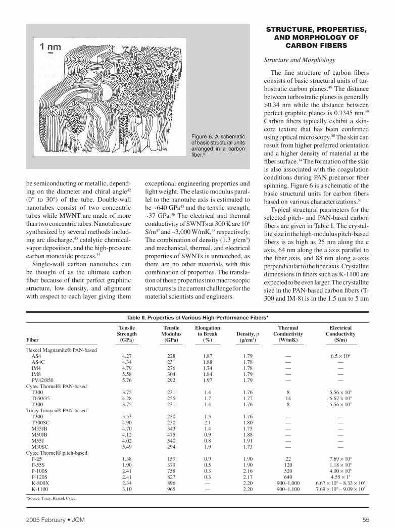
The fi ne structure of carbon fi bers consists of basic structural units of tur-bostratic carbon planes.49 The distance between turbostratic planes is generally >0.34 nm while the distance between perfect graphite planes is 0.3345 nm.49 Carbon fi bers typically exhibit a skin-core texture that has been confi rmed using optical microscopy.50 The skin can result from higher preferred orientation and a higher density of material at the fi ber surface.14 The formation of the skin is also associated with the coagulation conditions during PAN precursor fi ber spinning. Figure 6 is a schematic of the basic structural units for carbon fi bers based on various characterizations.51
Typical structural parameters for the selected pitch- and PAN-based carbon fi bers are given in Table I. The crystal-lite size in the high-modulus pitch-based fi bers is as high as 25 nm along the c axis, 64 nm along the a axis parallel to the fi ber axis, and 88 nm along a-axis perpendicular to the fi ber axis. Crystallite dimensions in fi bers such as K-1100 are expected to be even larger. The crystallite size in the PAN-based carbon fi bers (T-300 and IM-8) is in the 1.5 nm to 5 nm
Figure 6. A schematic of basic structural units arranged in a carbon fi ber.51
2005 February • JOM56
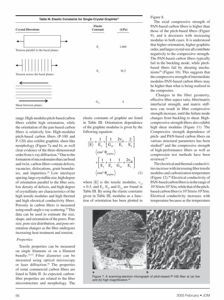
Table III. Elastic Constants for Single-Crystal Graphite57
Elastic Crystal Directions Constant (GPa)
E1 1,060
Tension parallel to the basal planes
E2 36.5
Tension across the basal planes
G12
4Shear between planes
range. High-modulus pitch-based carbon fi bers exhibit high orientation, while the orientation of the pan-based carbon fi bers is relatively low. High-modulus pitch-based carbon fi bers (P-100 and P-120) also exhibit graphitic sheet-like morphology (Figure 7a and b), as well clear evidence of the three-dimensional order from x-ray diffraction.52 Due to the formation of microdomains that can bend and twist, carbon fi bers contain defects, vacancies, dislocations, grain boundar-ies, and impurities.19 Low interlayer spacing, large crystallite size, high degree of orientation parallel to the fi ber axis, low density of defects, and high degree of crystallinity are characteristics of the high tensile modulus and high thermal and high electrical conductivity fi bers. Porosity in carbon fi bers is measured using small-angle x-ray scattering.53 This data can be used to estimate the size, shape, and orientation of the pores. Pore size, pore size distribution, and pore ori-entation changes as the fi ber undergoes increasing heat treatment and tension.
Properties
Tensile properties can be measured on single fi laments or on a fi lament bundle.54,55 Fiber diameter can be measured using optical microscopy or laser diffraction.56 The properties of some commercial carbon fi bers are listed in Table II. As expected, carbon-fi ber properties are related to the fi ber microstructure and morphology. The
elastic constants of graphite are listed in Table III. Orientation dependence of the graphite modulus is given by the following equation:
(1)
where E is the tensile modulus, v12
= 0.3, and E
1, E
2, and G
12 are found in
Table III. By using the elastic constants given in Table III, modulus as a func-tion of orientation has been plotted in
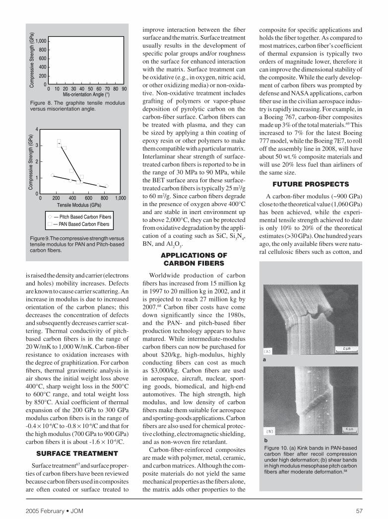
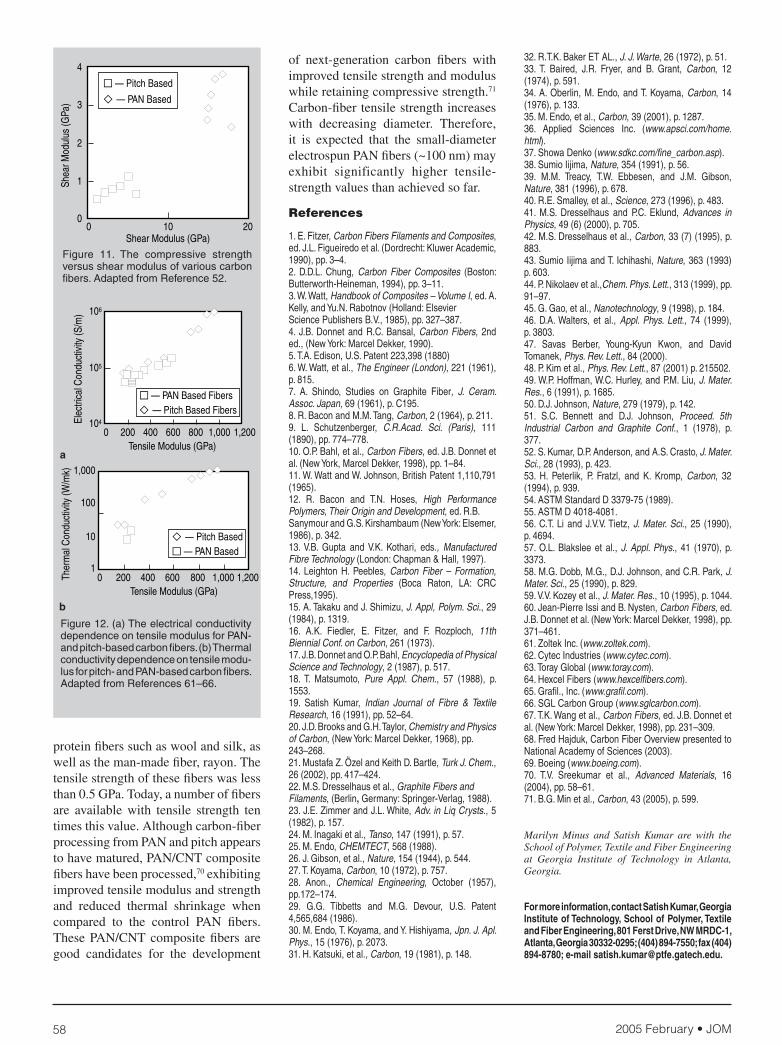
Figure 8. The axial compressive strength of PAN-based carbon fi bers is higher than those of the pitch-based fi bers (Figure 9), and it decreases with increasing modulus in both cases. It is understood that higher orientation, higher graphitic order, and larger crystal size all contribute negatively to the compressive strength. The PAN-based carbon fi bers typically fail in the buckling mode, while pitch-based fi bers fail by shearing mecha-nisms58 (Figure 10). This suggests that the compressive strength of intermediate modulus PAN-based carbon fi bers may be higher than what is being realized in the composites. Changes in the fiber geometry, effective fi ber aspect ratio, fi ber/matrix interfacial strength, and matrix stiff-ness can result in fi ber compressive strength increase, until the failure mode changes from buckling to shear. High-compressive-strength fi bers also exhibit high shear modulus (Figure 11). The Compressive strength dependence of pitch- and PAN-based carbon fi bers on various structural parameters has been studied52 and the compressive strength of high-performance fi bers as well as compression test methods have been reviewed.59
The electrical and thermal conductivi-ties increase with increasing fi ber tensile modulus and carbonization temperature (Figure 12).60 Electrical conductivity of PAN-based carbon fi bers is in the range of 104 S/m to 105 S/m, while that of the pitch-based carbon fi bers is 105 S/m to 106 S/m. Electrical conductivity increases with temperature because as the temperature
Figure 7. A scanning-electron micrograph of pitch-based P-100 fi ber at (a) low and (b) high magnifi cation.52
a b
1 1 1 2 2
1 1 1 2
2 12
12
1 2
2
1 2 12
1
E E G E E
E E G
graphite
= + − −⎡
⎣⎢
⎤
⎦⎥
+ + − +
ν
θ
ν
cos
22
1
4
E
graphite
⎡
⎣⎢
⎤
⎦⎥
cos θ
2005 February • JOM 57
is raised the density and carrier (electrons and holes) mobility increases. Defects are known to cause carrier scattering. An increase in modulus is due to increased orientation of the carbon planes; this decreases the concentration of defects and subsequently decreases carrier scat-tering. Thermal conductivity of pitch-based carbon fi bers is in the range of 20 W/mK to 1,000 W/mK. Carbon-fi ber resistance to oxidation increases with the degree of graphitization. For carbon fi bers, thermal gravimetric analysis in air shows the initial weight loss above 400°C, sharp weight loss in the 500°C to 600°C range, and total weight loss by 850°C. Axial coeffi cient of thermal expansion of the 200 GPa to 300 GPa modulus carbon fi bers is in the range of -0.4 × 10⁻⁶/C to -0.8 × 10⁻⁶/C and that for the high modulus (700 GPa to 900 GPa) carbon fi bers it is about -1.6 × 10⁻⁶/C.
SURFACE TREATMENT
Surface treatment67 and surface proper-ties of carbon fi bers have been reviewed because carbon fi bers used in composites are often coated or surface treated to
improve interaction between the fi ber surface and the matrix. Surface treatment usually results in the development of specifi c polar groups and/or roughness on the surface for enhanced interaction with the matrix. Surface treatment can be oxidative (e.g., in oxygen, nitric acid, or other oxidizing media) or non-oxida-tive. Non-oxidative treatment includes grafting of polymers or vapor-phase deposition of pyrolytic carbon on the carbon-fi ber surface. Carbon fi bers can be treated with plasma, and they can be sized by applying a thin coating of epoxy resin or other polymers to make them compatible with a particular matrix. Interlaminar shear strength of surface-treated carbon fi bers is reported to be in the range of 30 MPa to 90 MPa, while the BET surface area for these surface-treated carbon fi bers is typically 25 m2/g to 60 m2/g. Since carbon fi bers degrade in the presence of oxygen above 400°C and are stable in inert environment up to above 2,000°C, they can be protected from oxidative degradation by the appli-cation of a coating such as SiC, Si
3N
4,
BN, and Al2O
3.
APPLICATIONS OF CARBON FIBERS
Worldwide production of carbon fi bers has increased from 15 million kg in 1997 to 20 million kg in 2002, and it is projected to reach 27 million kg by 2007.68 Carbon fi ber costs have come down signifi cantly since the 1980s, and the PAN- and pitch-based fi ber production technology appears to have matured. While intermediate-modulus carbon fi bers can now be purchased for about $20/kg, high-modulus, highly conducting fi bers can cost as much as $3,000/kg. Carbon fi bers are used in aerospace, aircraft, nuclear, sport-ing goods, biomedical, and high-end automotives. The high strength, high modulus, and low density of carbon fi bers make them suitable for aerospace and sporting-goods applications. Carbon fi bers are also used for chemical protec-tive clothing, electromagnetic shielding, and as non-woven fi re retardant. Carbon-fi ber-reinforced composites are made with polymer, metal, ceramic, and carbon matrices. Although the com-posite materials do not yield the same mechanical properties as the fi bers alone, the matrix adds other properties to the
composite for specifi c applications and holds the fi ber together. As compared to most matrices, carbon fi ber’s coeffi cient of thermal expansion is typically two orders of magnitude lower, therefore it can improve the dimensional stability of the composite. While the early develop-ment of carbon fi bers was prompted by defense and NASA applications, carbon fi ber use in the civilian aerospace indus-try is rapidly increasing. For example, in a Boeing 767, carbon-fi ber composites made up 3% of the total materials.69 This increased to 7% for the latest Boeing 777 model, while the Boeing 7E7, to roll off the assembly line in 2008, will have about 50 wt.% composite materials and will use 20% less fuel than airliners of the same size.
FUTURE PROSPECTS
A carbon-fi ber modulus (~900 GPa) close to the theoretical value (1,060 GPa) has been achieved, while the experi-mental tensile strength achieved to date is only 10% to 20% of the theoretical estimates (>30 GPa). One hundred years ago, the only available fi bers were natu-ral cellulosic fi bers such as cotton, and
Figure 9. The compressive strength versus tensile modulus for PAN and Pitch-based carbon fi bers.
Figure 10. (a) Kink bands in PAN-based carbon fi ber after recoil compression under high deformation; (b) shear bands in high modulus mesophase pitch carbon fi bers after moderate deformation.58
b
a
Figure 8. The graphite tensile modulus versus misorientation angle.
2005 February • JOM58
protein fi bers such as wool and silk, as well as the man-made fi ber, rayon. The tensile strength of these fi bers was less than 0.5 GPa. Today, a number of fi bers are available with tensile strength ten times this value. Although carbon-fi ber processing from PAN and pitch appears to have matured, PAN/CNT composite fi bers have been processed,70 exhibiting improved tensile modulus and strength and reduced thermal shrinkage when compared to the control PAN fi bers. These PAN/CNT composite fi bers are good candidates for the development
of next-generation carbon fi bers with improved tensile strength and modulus while retaining compressive strength.71 Carbon-fi ber tensile strength increases with decreasing diameter. Therefore, it is expected that the small-diameter electrospun PAN fi bers (~100 nm) may exhibit significantly higher tensile-strength values than achieved so far.
References
1. E. Fitzer, Carbon Fibers Filaments and Composites, ed. J.L. Figueiredo et al. (Dordrecht: Kluwer Academic, 1990), pp. 3–4.2. D.D.L. Chung, Carbon Fiber Composites (Boston: Butterworth-Heineman, 1994), pp. 3–11.3. W. Watt, Handbook of Composites – Volume I, ed. A. Kelly, and Yu.N. Rabotnov (Holland: ElsevierScience Publishers B.V., 1985), pp. 327–387.4. J.B. Donnet and R.C. Bansal, Carbon Fibers, 2nd ed., (New York: Marcel Dekker, 1990).5. T.A. Edison, U.S. Patent 223,398 (1880)6. W. Watt, et al., The Engineer (London), 221 (1961), p. 815.7. A. Shindo, Studies on Graphite Fiber, J. Ceram. Assoc. Japan, 69 (1961), p. C195.8. R. Bacon and M.M. Tang, Carbon, 2 (1964), p. 211.9. L. Schutzenberger, C.R.Acad. Sci. (Paris), 111 (1890), pp. 774–778.10. O.P. Bahl, et al., Carbon Fibers, ed. J.B. Donnet et al. (New York, Marcel Dekker, 1998), pp. 1–84.11. W. Watt and W. Johnson, British Patent 1,110,791 (1965).12. R. Bacon and T.N. Hoses, High Performance Polymers, Their Origin and Development, ed. R.B.Sanymour and G.S. Kirshambaum (New York: Elsemer, 1986), p. 342.13. V.B. Gupta and V.K. Kothari, eds., Manufactured Fibre Technology (London: Chapman & Hall, 1997).14. Leighton H. Peebles, Carbon Fiber – Formation, Structure, and Properties (Boca Raton, LA: CRC Press,1995).15. A. Takaku and J. Shimizu, J. Appl, Polym. Sci., 29 (1984), p. 1319.16. A.K. Fiedler, E. Fitzer, and F. Rozploch, 11th Biennial Conf. on Carbon, 261 (1973).17. J.B. Donnet and O.P. Bahl, Encyclopedia of Physical Science and Technology, 2 (1987), p. 517.18. T. Matsumoto, Pure Appl. Chem., 57 (1988), p. 1553.19. Satish Kumar, Indian Journal of Fibre & Textile Research, 16 (1991), pp. 52–64.20. J.D. Brooks and G.H. Taylor, Chemistry and Physics of Carbon, (New York: Marcel Dekker, 1968), pp.243–268.21. Mustafa Z. Özel and Keith D. Bartle, Turk J. Chem., 26 (2002), pp. 417–424.22. M.S. Dresselhaus et al., Graphite Fibers andFilaments, (Berlin, Germany: Springer-Verlag, 1988).23. J.E. Zimmer and J.L. White, Adv. in Liq Crysts., 5 (1982), p. 157.24. M. Inagaki et al., Tanso, 147 (1991), p. 57.25. M. Endo, CHEMTECT, 568 (1988).26. J. Gibson, et al., Nature, 154 (1944), p. 544.27. T. Koyama, Carbon, 10 (1972), p. 757.28. Anon., Chemical Engineering, October (1957), pp.172–174.29. G.G. Tibbetts and M.G. Devour, U.S. Patent 4,565,684 (1986).30. M. Endo, T. Koyama, and Y. Hishiyama, Jpn. J. Apl. Phys., 15 (1976), p. 2073.31. H. Katsuki, et al., Carbon, 19 (1981), p. 148.
32. R.T.K. Baker ET AL., J. J. Warte, 26 (1972), p. 51.33. T. Baired, J.R. Fryer, and B. Grant, Carbon, 12 (1974), p. 591.34. A. Oberlin, M. Endo, and T. Koyama, Carbon, 14 (1976), p. 133.35. M. Endo, et al., Carbon, 39 (2001), p. 1287.36. Applied Sciences Inc. (www.apsci.com/home.html).37. Showa Denko (www.sdkc.com/fi ne_carbon.asp).38. Sumio Iijima, Nature, 354 (1991), p. 56.39. M.M. Treacy, T.W. Ebbesen, and J.M. Gibson, Nature, 381 (1996), p. 678.40. R.E. Smalley, et al., Science, 273 (1996), p. 483.41. M.S. Dresselhaus and P.C. Eklund, Advances in Physics, 49 (6) (2000), p. 705.42. M.S. Dresselhaus et al., Carbon, 33 (7) (1995), p. 883.43. Sumio Iijima and T. Ichihashi, Nature, 363 (1993) p. 603.44. P. Nikolaev et al.,Chem. Phys. Lett., 313 (1999), pp. 91–97.45. G. Gao, et al., Nanotechnology, 9 (1998), p. 184.46. D.A. Walters, et al., Appl. Phys. Lett., 74 (1999), p. 3803.47. Savas Berber, Young-Kyun Kwon, and David Tomanek, Phys. Rev. Lett., 84 (2000).48. P. Kim et al., Phys. Rev. Lett., 87 (2001) p. 215502.49. W.P. Hoffman, W.C. Hurley, and P.M. Liu, J. Mater. Res., 6 (1991), p. 1685.50. D.J. Johnson, Nature, 279 (1979), p. 142.51. S.C. Bennett and D.J. Johnson, Proceed. 5th Industrial Carbon and Graphite Conf., 1 (1978), p. 377.52. S. Kumar, D.P. Anderson, and A.S. Crasto, J. Mater. Sci., 28 (1993), p. 423.53. H. Peterlik, P. Fratzl, and K. Kromp, Carbon, 32 (1994), p. 939.54. ASTM Standard D 3379-75 (1989).55. ASTM D 4018-4081.56. C.T. Li and J.V.V. Tietz, J. Mater. Sci., 25 (1990), p. 4694.57. O.L. Blakslee et al., J. Appl. Phys., 41 (1970), p. 3373.58. M.G. Dobb, M.G., D.J. Johnson, and C.R. Park, J. Mater. Sci., 25 (1990), p. 829.59. V.V. Kozey et al., J. Mater. Res., 10 (1995), p. 1044.60. Jean-Pierre Issi and B. Nysten, Carbon Fibers, ed. J.B. Donnet et al. (New York: Marcel Dekker, 1998), pp. 371–461.61. Zoltek Inc. (www.zoltek.com).62. Cytec Industries (www.cytec.com).63. Toray Global (www.toray.com).64. Hexcel Fibers (www.hexcelfi bers.com).65. Grafi l., Inc. (www.grafi l.com).66. SGL Carbon Group (www.sglcarbon.com).67. T.K. Wang et al., Carbon Fibers, ed. J.B. Donnet et al. (New York: Marcel Dekker, 1998), pp. 231–309.68. Fred Hajduk, Carbon Fiber Overview presented to National Academy of Sciences (2003).69. Boeing (www.boeing.com).70. T.V. Sreekumar et al., Advanced Materials, 16 (2004), pp. 58–61.71. B.G. Min et al., Carbon, 43 (2005), p. 599.
Marilyn Minus and Satish Kumar are with the School of Polymer, Textile and Fiber Engineering at Georgia Institute of Technology in Atlanta, Georgia.
For more information, contact Satish Kumar, Georgia Institute of Technology, School of Polymer, Textile and Fiber Engineering, 801 Ferst Drive, NW MRDC-1, Atlanta, Georgia 30332-0295; (404) 894-7550; fax (404) 894-8780; e-mail [email protected].
Figure 11. The compressive strength versus shear modulus of various carbon fi bers. Adapted from Reference 52.
a
b
Figure 12. (a) The electrical conductivity dependence on tensile modulus for PAN- and pitch-based carbon fi bers. (b) Thermal conductivity dependence on tensile modu-lus for pitch- and PAN-based carbon fi bers. Adapted from References 61–66.


