Embed Size (px)
Citation preview
Composites: Part A 42 (2011) 337–344
Contents lists available at ScienceDirect
Composites: Part A
journal homepage: www.elsevier .com/locate /composi tesa
Processing and characterization of multi-scale hybrid composites reinforcedwith nanoscale carbon reinforcements and carbon fibers
Sang-Bok Lee a,b, Oyoung Choi a, Wonoh Lee a, Jin-Woo Yi a, Byung-Sun Kim a, Joon-Hyung Byun a,⇑,Myung-Keun Yoon b, Hao Fong c, Erik T. Thostenson d, Tsu-Wei Chou d
a Composite Materials Research Group, Korea Institute of Materials Science, Changwon, Gyeongnam, 641-831, Republic of Koreab Department of Mechanical Engineering, South Dakota School of Mines and Technology, 501 East Saint Joseph Street Rapid City, SD 57701, United Statesc Department of Chemistry, South Dakota School of Mines and Technology, 501 East Saint Joseph Street Rapid City, SD 57701, United Statesd Center for Composite Materials and Department of Mechanical Engineering, University of Delaware, Newark, DE 19716, United States
a r t i c l e i n f o
Article history:Received 11 May 2010Received in revised form 31 August 2010Accepted 27 October 2010Available online 2 November 2010
Keywords:A. Carbon fiberA. Particle-reinforcementB. Mechanical propertiesB. Electrical properties
1359-835X/$ - see front matter � 2010 Elsevier Ltd. Adoi:10.1016/j.compositesa.2010.10.016
⇑ Corresponding author. Tel.: +82 55 280 3312; faxE-mail address: [email protected] (J.-H. Byun).
a b s t r a c t
Composites with multi-scale reinforcements consisting of multi-walled carbon nanotubes (MWCNTs) orcarbon nanofibers (CNFs), along with micron-sized advanced carbon fibers, were processed using electro-phoretic deposition (EPD) technique. Both anodic and cathodic electrophoretic deposition processes havebeen utilized for the deposition of nanoscale reinforcements on carbon fibers. Through hybridization ofthe reinforcement scales, we have demonstrated significantly improved electrical conductivity and inter-laminar mechanical properties. In particular, the multi-scale composites manufactured with the cathodicEPD process where MWCNTs and copper nano-particles are co-deposited show an increase of thethrough-thickness electrical conductivity by 15 times along with an improvement in interlaminar shearstrength by 13% when compared to the plain woven composites. The unique microstructure based on theconcurrent deposition of nanoscale carbon and nano-sized Cu particles on carbon fibers shows greatpotential in being able to tailor the structural and functional performance of advanced fiber composites.
� 2010 Elsevier Ltd. All rights reserved.
1. Introduction
Various nanoscale reinforcements have been introduced to tra-ditional laminated composites to try and exploit their excellentmechanical, thermal and electrical properties [1–3]. Nanoscale car-bon reinforcements, such as carbon nanotubes (CNTs) and carbonnanofibers (CNFs) have attracted broad interest for improving thematrix-dominated properties and/or functionalities of compositematerials related to their unique properties, such as high aspect ra-tio, low mass density, high chemical stability, high modulus andstrength, and high conductivity [4–7]. To evaluate the effectivenessof these reinforcements, it is necessary to develop viable hybridiza-tion processing methods and to assess the properties of the as-manufactured composites. Substantial research efforts have beendevoted to ensure uniform distribution of CNTs and CNFs in thematrix resins through various processing methods [8–11]. Oftenthe properties of the resulting composites, however, do not im-prove as much as expected due to the difficulties in achieving auniform dispersion of the nanoscale reinforcements in highly vis-cous resins. In addition, variations in viscosity during the curingprocess can involve re-agglomeration and/or precipitation of thereinforcement. Therefore, it is essentially needed to establish tech-
ll rights reserved.
: +82 55 280 3498.
niques for a uniform dispersion of the nanoscale reinforcementswith strong reinforcement/matrix interfacial bonding so that theycan contribute to the enhancement of mechanical and functionalproperties. The present study introduces an electrophoretic depo-sition method that allows the reinforcement of nanoscale rein-forcements directly onto carbon fabric without first dispersingthe nanoscale reinforcement in the matrix resin.
Electrophoretic deposition is an industrially scalable process forthe deposition of nanoscale reinforcements with good homogeneity[1]. In this process, charged particles in a suitable suspension movetoward an electrode and get deposited under an applied electric fieldbetween the anode and cathode [12,13]. Depending on the particlecharge, EPD can be either an anodic or a cathodic process. For anodicEPD, particles become negatively charged and get deposited onto thepositively charged substrates and vice versa for the case of cathodicEPD. There are a number of reports of the EPD processes using CNTsand highly functional and conductive films have been fabricated[14,15]. It has been shown that carbon/epoxy composites incorpo-rated with exfoliated graphite nano-platelets showed improvedmechanical and electrical properties [16].
In the present study, two kinds of surface functionalizationwere employed. A nitric acid (HNO3) oxidation and also polyethyl-eneimine (PEI) treatment were applied to impart different chargeon the surface of MWCNTs and CNFs in an aqueous suspension.The nanoscale carbon reinforcements were then deposited onto
338 S.-B. Lee et al. / Composites: Part A 42 (2011) 337–344
carbon fabric using both anodic and cathodic EPD processes andcomposites were fabricated by using a vacuum-assisted resintransfer molding (VARTM) process. To understand the effect ofthe nanoscale reinforcements on the bulk properties of the fibercomposite, mechanical and electrical properties of the compositeswere evaluated. The short beam test was performed to determinethe interlaminar shear properties and electrical conductivitieswere measured in both in-plane and through-thickness directions.Optical and scanning electron microscopy (SEM) were employed toexamine the micro and nano-scale morphologies, the uniformity ofdeposition and the composite failure mechanisms.
2. Experimental
2.1. Materials
MWCNTs (CM95 – Hanwha Nanotech, Korea), and CNFs (Pyrog-raf III� PR-24 – Applied Science Inc., OH, USA) were used as thenano-sized reinforcements to fabricate hybrid composites. Plainwoven carbon fabric (Mitsubishi TR30, 3k) was used as the conven-tional micron-sized advanced fiber reinforcement. An epoxy poly-mer matrix was utilized for all specimens (YD128 epoxy and KBH1089 curing agent – Kukdo Chemicals, Korea).
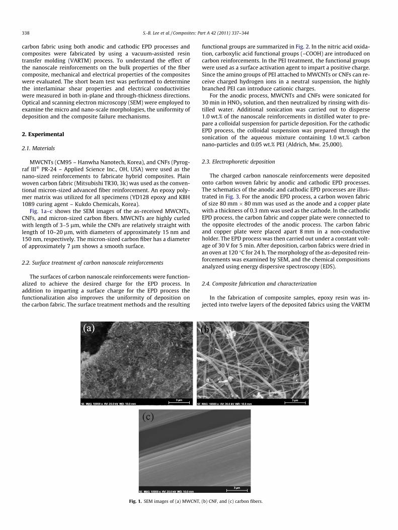
Fig. 1a–c shows the SEM images of the as-received MWCNTs,CNFs, and micron-sized carbon fibers. MWCNTs are highly curledwith length of 3–5 lm, while the CNFs are relatively straight withlength of 10–20 lm, with diameters of approximately 15 nm and150 nm, respectively. The micron-sized carbon fiber has a diameterof approximately 7 lm shows a smooth surface.
2.2. Surface treatment of carbon nanoscale reinforcements
The surfaces of carbon nanoscale reinforcements were function-alized to achieve the desired charge for the EPD process. Inaddition to imparting a surface charge for the EPD process thefunctionalization also improves the uniformity of deposition onthe carbon fabric. The surface treatment methods and the resulting
Fig. 1. SEM images of (a) MWCNT,
functional groups are summarized in Fig. 2. In the nitric acid oxida-tion, carboxylic acid functional groups (–COOH) are introduced oncarbon reinforcements. In the PEI treatment, the functional groupswere used as a surface activation agent to impart a positive charge.Since the amino groups of PEI attached to MWCNTs or CNFs can re-ceive charged hydrogen ions in a neutral suspension, the highlybranched PEI can introduce cationic charges.
For the anodic process, MWCNTs and CNFs were sonicated for30 min in HNO3 solution, and then neutralized by rinsing with dis-tilled water. Additional sonication was carried out to disperse1.0 wt.% of the nanoscale reinforcements in distilled water to pre-pare a colloidal suspension for particle deposition. For the cathodicEPD process, the colloidal suspension was prepared through thesonication of the aqueous mixture containing 1.0 wt.% carbonnano-particles and 0.05 wt.% PEI (Aldrich, Mw. 25,000).
2.3. Electrophoretic deposition
The charged carbon nanoscale reinforcements were depositedonto carbon woven fabric by anodic and cathodic EPD processes.The schematics of the anodic and cathodic EPD processes are illus-trated in Fig. 3. For the anodic EPD process, a carbon woven fabricof size 80 mm � 80 mm was used as the anode and a copper platewith a thickness of 0.3 mm was used as the cathode. In the cathodicEPD process, the carbon fabric and copper plate were connected tothe opposite electrodes of the anodic process. The carbon fabricand copper plate were placed apart 8 mm in a non-conductiveholder. The EPD process was then carried out under a constant volt-age of 30 V for 5 min. After deposition, carbon fabrics were dried inan oven at 120 �C for 24 h. The morphology of the as-deposited rein-forcements was examined by SEM, and the chemical compositionsanalyzed using energy dispersive spectroscopy (EDS).
2.4. Composite fabrication and characterization
In the fabrication of composite samples, epoxy resin was in-jected into twelve layers of the deposited fabrics using the VARTM
(b) CNF, and (c) carbon fibers.
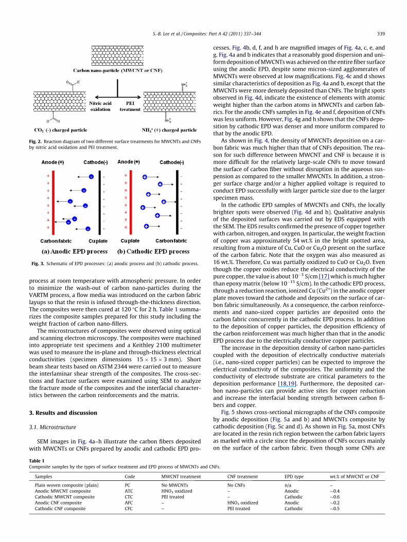
Fig. 2. Reaction diagram of two different surface treatments for MWCNTs and CNFsby nitric acid oxidation and PEI treatment.
Fig. 3. Schematic of EPD processes: (a) anodic process and (b) cathodic process.
S.-B. Lee et al. / Composites: Part A 42 (2011) 337–344 339
process at room temperature with atmospheric pressure. In orderto minimize the wash-out of carbon nano-particles during theVARTM process, a flow media was introduced on the carbon fabriclayups so that the resin is infused through-the-thickness direction.The composites were then cured at 120 �C for 2 h. Table 1 summa-rizes the composite samples prepared for this study including theweight fraction of carbon nano-fillers.
The microstructures of composites were observed using opticaland scanning electron microscopy. The composites were machinedinto appropriate test specimens and a Keithley 2100 multimeterwas used to measure the in-plane and through-thickness electricalconductivities (specimen dimensions 15 � 15 � 3 mm). Shortbeam shear tests based on ASTM 2344 were carried out to measurethe interlaminar shear strength of the composites. The cross-sec-tions and fracture surfaces were examined using SEM to analyzethe fracture mode of the composites and the interfacial character-istics between the carbon reinforcements and the matrix.
3. Results and discussion
3.1. Microstructure
SEM images in Fig. 4a–h illustrate the carbon fibers depositedwith MWCNTs or CNFs prepared by anodic and cathodic EPD pro-
Table 1Composite samples by the types of surface treatment and EPD process of MWCNTs and C
Samples Code MWCNT treatment
Plain woven composite (plain) PC No MWCNTsAnodic MWCNT composite ATC HNO3 oxidizedCathodic MWCNT composite CTC PEI treatedAnodic CNF composite AFC –Cathodic CNF composite CFC –
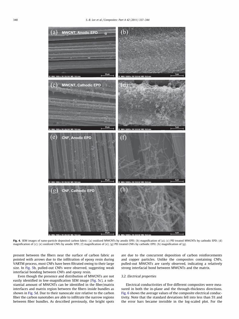
cesses. Fig. 4b, d, f, and h are magnified images of Fig. 4a, c, e, andg. Fig. 4a and b indicates that a reasonably good dispersion and uni-form deposition of MWCNTs was achieved on the entire fiber surfaceusing the anodic EPD, despite some micron-sized agglomerates ofMWCNTs were observed at low magnifications. Fig. 4c and d showssimilar characteristics of deposition as Fig. 4a and b, except that theMWCNTs were more densely deposited than CNFs. The bright spotsobserved in Fig. 4d, indicate the existence of elements with atomicweight higher than the carbon atoms in MWCNTs and carbon fab-rics. For the anodic CNFs samples in Fig. 4e and f, deposition of CNFswas less uniform. However, Fig. 4g and h shows that the CNFs depo-sition by cathodic EPD was denser and more uniform compared tothat by the anodic EPD.
As shown in Fig. 4, the density of MWCNTs deposition on a car-bon fabric was much higher than that of CNFs deposition. The rea-son for such difference between MWCNT and CNF is because it ismore difficult for the relatively large-scale CNFs to move towardthe surface of carbon fiber without disruption in the aqueous sus-pension as compared to the smaller MWCNTs. In addition, a stron-ger surface charge and/or a higher applied voltage is required toconduct EPD successfully with larger particle size due to the largerspecimen mass.
In the cathodic EPD samples of MWCNTs and CNFs, the locallybrighter spots were observed (Fig. 4d and h). Qualitative analysisof the deposited surfaces was carried out by EDS equipped withthe SEM. The EDS results confirmed the presence of copper togetherwith carbon, nitrogen, and oxygen. In particular, the weight fractionof copper was approximately 54 wt.% in the bright spotted area,resulting from a mixture of Cu, CuO or Cu2O present on the surfaceof the carbon fabric. Note that the oxygen was also measured as16 wt.%. Therefore, Cu was partially oxidized to CuO or Cu2O. Eventhough the copper oxides reduce the electrical conductivity of thepure copper, the value is about 10�3 S/cm [17] which is much higherthan epoxy matrix (below 10�15 S/cm). In the cathodic EPD process,through a reduction reaction, ionized Cu (Cu2+) in the anodic copperplate moves toward the cathode and deposits on the surface of car-bon fabric simultaneously. As a consequence, the carbon reinforce-ments and nano-sized copper particles are deposited onto thecarbon fabric concurrently in the cathodic EPD process. In additionto the deposition of copper particles, the deposition efficiency ofthe carbon reinforcement was much higher than that in the anodicEPD process due to the electrically conductive copper particles.
The increase in the deposition density of carbon nano-particlescoupled with the deposition of electrically conductive materials(i.e., nano-sized copper particles) can be expected to improve theelectrical conductivity of the composites. The uniformity and theconductivity of electrode substrate are critical parameters to thedeposition performance [18,19]. Furthermore, the deposited car-bon nano-particles can provide active sites for copper reductionand increase the interfacial bonding strength between carbon fi-bers and copper.
Fig. 5 shows cross-sectional micrographs of the CNFs compositeby anodic deposition (Fig. 5a and b) and MWCNTs composite bycathodic deposition (Fig. 5c and d). As shown in Fig. 5a, most CNFsare located in the resin rich region between the carbon fabric layersas marked with a circle since the deposition of CNFs occurs mainlyon the surface of the carbon fabric. Even though some CNFs are
NFs.
CNF treatment EPD type wt.% of MWCNT or CNF
No CNFs n/a –– Anodic �0.4– Cathodic �0.6HNO3 oxidized Anodic �0.2PEI treated Cathodic �0.5
MWCNT, Anodic EPD
MWCNT, Cathodic EPD
CNF, Anodic EPD
CNF, Cathodic EPD
Fig. 4. SEM images of nano-particle deposited carbon fabric: (a) oxidized MWCNTs by anodic EPD; (b) magnification of (a); (c) PEI treated MWCNTs by cathodic EPD; (d)magnification of (c); (e) oxidized CNFs by anodic EPD; (f) magnification of (e); (g) PEI treated CNFs by cathodic EPD; (h) magnification of (g).
340 S.-B. Lee et al. / Composites: Part A 42 (2011) 337–344
present between the fibers near the surface of carbon fabric aspointed with arrows due to the infiltration of epoxy resin duringVARTM process, most CNFs have been filtrated owing to their largesize. In Fig. 5b, pulled-out CNFs were observed, suggesting weakinterfacial bonding between CNFs and epoxy resin.
Even though the presence and distribution of MWCNTs are noteasily identified in low-magnification SEM image (Fig. 5c), a sub-stantial amount of MWCNTs can be identified in the fiber/matrixinterfaces and matrix region between the fibers inside bundles asshown in Fig. 5d. Due to their nanoscale size relative to the carbonfiber the carbon nanotubes are able to infiltrate the narrow regionsbetween fiber bundles. As described previously, the bright spots
are due to the concurrent deposition of carbon reinforcementsand copper particles. Unlike the composites containing CNFs,pulled-out MWCNTs are rarely observed, indicating a relativelystrong interfacial bond between MWCNTs and the matrix.
3.2. Electrical properties
Electrical conductivities of five different composites were mea-sured in both the in-plane and the through-thickness directions.Fig. 6 shows the average values of the composite electrical conduc-tivity. Note that the standard deviations fell into less than 5% andthe error bars became invisible in the log-scaled plot. For the
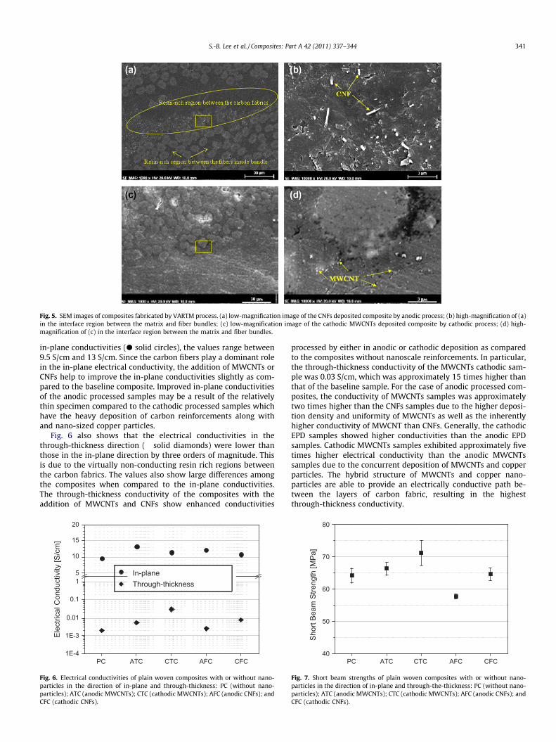
Fig. 5. SEM images of composites fabricated by VARTM process. (a) low-magnification image of the CNFs deposited composite by anodic process; (b) high-magnification of (a)in the interface region between the matrix and fiber bundles; (c) low-magnification image of the cathodic MWCNTs deposited composite by cathodic process; (d) high-magnification of (c) in the interface region between the matrix and fiber bundles.
S.-B. Lee et al. / Composites: Part A 42 (2011) 337–344 341
in-plane conductivities (d solid circles), the values range between9.5 S/cm and 13 S/cm. Since the carbon fibers play a dominant rolein the in-plane electrical conductivity, the addition of MWCNTs orCNFs help to improve the in-plane conductivities slightly as com-pared to the baseline composite. Improved in-plane conductivitiesof the anodic processed samples may be a result of the relativelythin specimen compared to the cathodic processed samples whichhave the heavy deposition of carbon reinforcements along withand nano-sized copper particles.
Fig. 6 also shows that the electrical conductivities in thethrough-thickness direction (� solid diamonds) were lower thanthose in the in-plane direction by three orders of magnitude. Thisis due to the virtually non-conducting resin rich regions betweenthe carbon fabrics. The values also show large differences amongthe composites when compared to the in-plane conductivities.The through-thickness conductivity of the composites with theaddition of MWCNTs and CNFs show enhanced conductivities
1E-4
1E-3
0.01
0.1
15
10
15
20
Elec
trica
l Con
duct
ivity
[S/c
m]
PC ATC CTC AFC CFC
In-planeThrough-thickness
Fig. 6. Electrical conductivities of plain woven composites with or without nano-particles in the direction of in-plane and through-thickness: PC (without nano-particles); ATC (anodic MWCNTs); CTC (cathodic MWCNTs); AFC (anodic CNFs); andCFC (cathodic CNFs).
processed by either in anodic or cathodic deposition as comparedto the composites without nanoscale reinforcements. In particular,the through-thickness conductivity of the MWCNTs cathodic sam-ple was 0.03 S/cm, which was approximately 15 times higher thanthat of the baseline sample. For the case of anodic processed com-posites, the conductivity of MWCNTs samples was approximatelytwo times higher than the CNFs samples due to the higher deposi-tion density and uniformity of MWCNTs as well as the inherentlyhigher conductivity of MWCNT than CNFs. Generally, the cathodicEPD samples showed higher conductivities than the anodic EPDsamples. Cathodic MWCNTs samples exhibited approximately fivetimes higher electrical conductivity than the anodic MWCNTssamples due to the concurrent deposition of MWCNTs and copperparticles. The hybrid structure of MWCNTs and copper nano-particles are able to provide an electrically conductive path be-tween the layers of carbon fabric, resulting in the highestthrough-thickness conductivity.
40
50
60
70
80
PC ATC CTC AFC CFC
Shor
t Bea
m S
treng
th [M
Pa]
Fig. 7. Short beam strengths of plain woven composites with or without nano-particles in the direction of in-plane and through-the-thickness: PC (without nano-particles); ATC (anodic MWCNTs); CTC (cathodic MWCNTs); AFC (anodic CNFs); andCFC (cathodic CNFs).
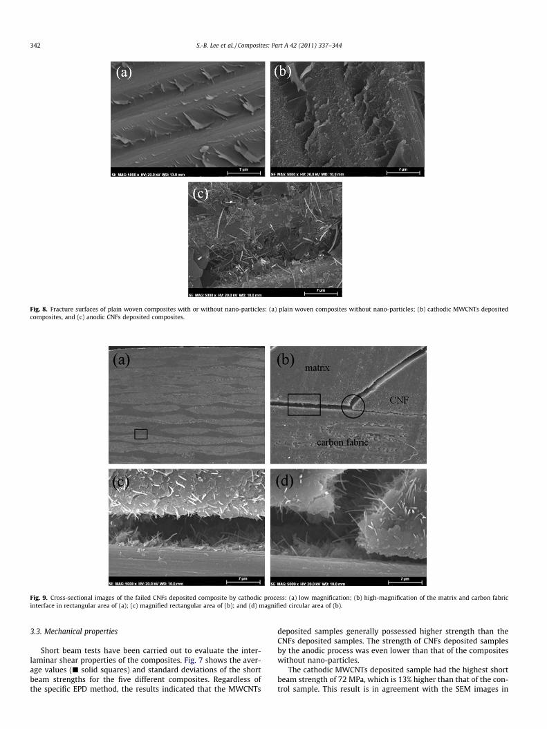
Fig. 8. Fracture surfaces of plain woven composites with or without nano-particles: (a) plain woven composites without nano-particles; (b) cathodic MWCNTs depositedcomposites, and (c) anodic CNFs deposited composites.
Fig. 9. Cross-sectional images of the failed CNFs deposited composite by cathodic process: (a) low magnification; (b) high-magnification of the matrix and carbon fabricinterface in rectangular area of (a); (c) magnified rectangular area of (b); and (d) magnified circular area of (b).
342 S.-B. Lee et al. / Composites: Part A 42 (2011) 337–344
3.3. Mechanical properties
Short beam tests have been carried out to evaluate the inter-laminar shear properties of the composites. Fig. 7 shows the aver-age values (j solid squares) and standard deviations of the shortbeam strengths for the five different composites. Regardless ofthe specific EPD method, the results indicated that the MWCNTs
deposited samples generally possessed higher strength than theCNFs deposited samples. The strength of CNFs deposited samplesby the anodic process was even lower than that of the compositeswithout nano-particles.
The cathodic MWCNTs deposited sample had the highest shortbeam strength of 72 MPa, which is 13% higher than that of the con-trol sample. This result is in agreement with the SEM images in
S.-B. Lee et al. / Composites: Part A 42 (2011) 337–344 343
Figs. 4 and 5, which show a dense deposition of MWCNTs andstrong interfacial bonding between MWCNTs and epoxy resin.The concurrent depositions of MWCNTs and nano-sized Cu parti-cles have favorable effect on the interlaminar fracture behaviorby suppressing the initiation and propagation of cracks in resin richregion and at the interface between the carbon fibers and theepoxy resin.
The CNFs deposited sample by anodic process showed a 10%reduction in the short beam strength compared to the baselinesample. This can be explained by the partial damage on CNFsthrough the nitric acid which introduced some structural defects.On the other hand, the PEI treatment does not result in the surfacedamage of the carbon nano-particles and the composites possessrelatively higher mechanical properties. In addition, the surfacecharge density of CNFs was much lower than that of MWCNTs,likely resulting in weak bonding of the CNFs to the epoxy resin.
Fig. 8a–c shows the fracture surfaces of the baseline, MWCNTsdeposited, and CNFs deposited samples, respectively. Fig. 8a showsthe smooth surface of micron-sized carbon fibers, indicating thatthe carbon fibers were easily detached from the resin due to thelow fiber/matrix interfacial bonding. As shown in Fig. 8b, the pres-ence of MWCNTs on the surface of carbon fiber confirms the rela-tively strong interfacial bonding between the matrix resin andreinforcement. In Fig. 8c pulled-out CNFs due to fiber/matrix deb-onding can be observed. As a result of this poor interfacial bondingbetween the CNFs and matrix resin, the strengths of the compos-ites are reduced. Furthermore, the relative deposited amount ofCNTs was higher than CNFs as shown in Table 1. Because the sizeof CNF is much higher than CNT, the number of CNT-particles inthe matrix is larger than CNFs. Therefore, CNTs may provide morereinforcing sites resulting in the better mechanical strength.
Fig. 9 clearly shows the CNFs as defects inducing the failure andcrack propagation of composites. As shown in Fig. 9a and b, thecrack initiates in a resin rich region before propagating into thelaminate. It then changed direction along the carbon fiber bundlealthough many CNFs were introduced on the carbon fabric. Thissuggests that the CNF did not hinder the crack propagation butacted as a defect due to the poor interfacial bonding. This can alsobe confirmed through the observations in Fig. 9c and d that theCNFs were pulled out perpendicularly to the crack plane. Therefore,it is further required to improve the interfacial bonding betweenCNFs deposited carbon structure and polymer matrix by introduc-ing novel treatment techniques without the structural damage ofcarbon nano-fillers [20,21].
4. Conclusions
In order to improve the electrical conductivity and themechanical property of carbon fabric composites, hybrid rein-forcements with micron-sized carbon fibers and carbon nano-particles such as MWCNTs and CNFs were prepared by anodicand cathodic EPD processes. The composites containing four dif-ferent hybrid reinforcements have been fabricated by VARTM.Based on the experimental results, the following conclusionscan be drawn.
(1) Through the cathodic EPD process, carbon nanoscale rein-forcements and nano-sized copper particles were depositedon the carbon fabric concurrently, leading to the synergiceffect on the enhancement of the electrical and mechanicalproperties.
(2) The nano/micro hybridization substantially improves thethrough-thickness electrical conductivity. In particular, theMWCNTs deposited composite through cathodic EPD
showed approximately 15 times higher electrical conductiv-ity than the plain woven composites without the addition ofnanoscale reinforcement.
(3) The interlaminar mechanical properties were also enhancedconsiderably in the case of MWCNTs deposited compositeby cathodic EPD. Due to the good interfacial bonding betweenMWCNTs and matrix as well as the hybrid structure ofMWCNTs and copper nano-particles, the short beam strengthof the hybrid composite increased by 13% (72 MPa) comparedto that of the composite without nano-particles.
(4) The electrical conductivities and the short beam strength ofCNFs deposited composites were lower than for the MWCNTsdeposited composites. The reduction of mechanical proper-ties is likely due to the relatively poor interfacial structurebetween CNFs deposited carbon fibers and the matrix as wellas less deposition amount in the composite.
Acknowledgements
The authors would like to acknowledge the financial supportfrom (1) the Korea Foundation for International Cooperation of Sci-ence & Technology (KICOS) through a grant provided by the KoreanMinistry of Education, Science & Technology (MEST) in 2007 (No.K20704000090), (2) the Principal Research Program in the KoreaInstitute of Materials Science (KIMS), and (3) the National Aero-nautics and Space Administration (NASA) through a grant providedby the Experimental Program to Stimulate Competitive Research(EPSCoR) program in 2008 (No. NNX07AT52A).
References
[1] Bekyarova E, Thostenson ET, Yu A, Kim H, Gao J, Tang J, et al. Multiscale carbonnanotube–carbon fiber reinforcement for advanced epoxy composites.Langmuir 2007;23:3970–4.
[2] Thostenson ET, Gangloff JJ, Li CY, Byun JH. Electrical anisotropy in multi-scalenanotube/fiber composites. Appl Phys Lett 2009;97:073111.
[3] Thostenson ET, Li WZ, Wang DZ, Ren ZF, Chou TW. Carbon nanotube/carbonfiber hybrid multiscale composites. J Appl Phys 2002;91:6034–7.
[4] Ebbesen TW, Lezec HJ, Hiura H, Bennett JW, Ghaemi HF, Thio T. Electricalconductivity of individual carbon nanotubes. Nature 1996;384:147–50.
[5] Allaoui A, Bai S, Cheng HM, Bai JB. Mechanical and electrical properties of aMWNT/epoxy composite. Compos Sci Technol 2002;62(15):1993–8.
[6] Endo M, Kim YA, Hayashi T, Nishimura K, Matusita T, Miyashita K, et al. Vapor-grown carbon fibers (VGCFs): basic properties and their battery applications.Carbon 2001;39:1287–9.
[7] Hung MT, Choi O, Ju YS, Hahn HT. Heat conduction in graphite-nanoplatelet-reinforced polymer nanocomposites. Appl Phys Lett 2006;89:023117.
[8] Thostenson ET, Ren Z, Chou TW. Advances in the science and technology ofcarbon nanotubes and their composites: a review. Compos Sci Technol2001;61:1899–912.
[9] Thostenson ET, Li C, Chou TW. Nanocomposites in context. Compos Sci Technol2005;65:491–516.
[10] Cipriano BH, Kota AK, Gershon AL, Laskowski CJ, Kashiwagi T, Bruck HA, et al.Conductivity enhancement of carbon nanotube and nanofibers-based polymernanocomposites by melt annealing. Polymer 2008;49:4848–51.
[11] Thostenson ET, Chou TW. Processing-structure-multi-functional propertyrelationship in carbon nanotube/epoxy composites. Carbon 2006;44:3022–9.
[12] Delgado AV. Interfacial electrokinetics and electrophoresis. 1st ed. Surfacescience series, vol. 106. Taylor & Francis; 2001.
[13] Elimelech M, Gregory J, Jia X, Williams RA. Particle deposition andagglomeration. Butterworth-Heinemann; 1995.
[14] Du C, Heldbrant D, Pang N. Preparation and preliminary property study ofcarbon nanotubes films by electrophoretic deposition. Mater Lett2002;57:434–8.
[15] Boccaccini AR, Cho J, Roether JA, Thomas BJC, Minay EJ, Sjaffer MSP.Electrophoretic deposition of carbon nanotubes. Carbon 2006;44:3149–60.
[16] Park JK, Do IH, Askeland P, Drzal LT. Electrodeposition of exfoliated graphitenanoplatelets onto carbon fibers and properties of their epoxy composites.Compos Sci Technol 2008;68:1734–41.
[17] Nair NTS, Guerreo L, Arenas OL, Nair PK. Chemically deposited copper oxidethin film: structural, optical and electrical characteristics. Appl Surf Sci1999;150:143–51.

344 S.-B. Lee et al. / Composites: Part A 42 (2011) 337–344
[18] Peng Z, Liu M. Preparation of dense platinum-yttria stabilized zirconia andyttria stabilized zirconia films on porous La0.9Sr0.1MnO3 (LSM) substrates. J AmCeram Soc 2001;84:283–8.
[19] Chen F, Liu M. Preparation of yttria-stabilized zirconia (YSZ) films onLa0.85Sr0.15MnO3 (LSM) and LSM–YSZ substrates using an electrophoreticdeposition (EPD) process. J Eur Ceram Soc 2001;21:127–34.
[20] Vaisman L, Wagner HD, Marom G. The role of surfactants indispersion of carbon nanotubes. Adv Colloid Interface Sci 2006;128–130:37–46.
[21] Geng Y, Liu MY, Li J, Shi XM, Kim JK. Effects of surfactant treatment onmechanical and electrical properties of CNT/epoxy nanocomposites. ComposPart A 2008;39:1876–83.


