Embed Size (px)
Citation preview
DRAFT VERSION MAY 30, 2014Preprint typeset using LATEX style emulateapj v. 5/2/11
THE SOFIA OBSERVATORY AT THE START OF ROUTINE SCIENCE OPERATIONS : MISSION CAPABILITIES ANDPERFORMANCE
PASQUALE TEMI1 , PAMELA M. MARCUM1 , ERICK YOUNG2 , JOSEPH D. ADAMS2 , SYBIL ADAMS2 , B.-G. ANDERSSON2 , ERIC E.BECKLIN2 , ADWIN BOOGERT2 , RICK BREWSTER3 , ERIC BURGH2 , BRENT R. COBLEIGH4 , STEVEN CULP3 , JIM DE BUIZER2 , EDWARD
W. DUNHAM5 , CHRISTIAN ENGFER6 , GEOFFREY EDISS2 , MAURA FUJIEH1 , RANDY GRASHUIS2 , MICHAEL GROSS2 , EDWARDHARMON1 , ANDREW HELTON2 , DOUGLAS HOFFMAN3 , JEFF HOMAN3 , MICHAEL HÜTWOHL6 , HOLGER JAKOB6 , STEPHEN C.JENSEN4 , CHARLES KAMINSKI2 , DANIEL KOZARSKY1 , ALFRED KRABBE7 , RANDOLF KLEIN2 , YANNICK LAMMEN6 , ULRICH
LAMPATER6 , WILLIAM B. LATTER2 , JEANETTE LE4 , NANCY MCKOWN2 , RICCARDO MELCHIORRI2 , ALLAN W. MEYER2 , JOHNMILES2 , WALTER E. MILLER3 , SCOTT MILLER1 , ELIZABETH MOORE2 , DONALD J. NICKISON 1 , KORTNEY OPSHAUG2 , ENRICO
PFÜELLER6 , JAMES RADOMSKI2 , JOHN RASMUSSEN8 , WILLIAM REACH2 , ANDREAS REINACHER6 , THOMAS L. ROELLIG1 , GÖRANSANDELL2 , RAVI SANKRIT2 , MAUREEN L. SAVAGE2 , SACHINDEV SHENOY2 , JULIE E. SCHONFELD1 , RALPH Y. SHUPING2 , ERIN C.
SMITH1 , EHSAN TALEBI3 , STEFAN TEUFEL6 , TING C. TSENG4 , WILLIAM D. VACCA2 , JOHN VAILLANCOURT2 , JEFFREY E. VANCLEVE2 , MANUEL WIEDEMANN6 , JÜRGEN WOLF 6 , EDDIE ZAVALA4 , OLIVER ZEILE6 , PETER T. ZELL1 , HANS ZINNECKER6
1 NASA - Ames Research Center, Moffett Field, CA 94035, USA2 USRA - SOFIA Science Center, NASA Ames Research Center, Moffett Field, CA 94035, USA
3 Orbital Science Corp., Moffett Field, CA 94035, USA4 NASA - Armstrong Flight Research Center, Edwards, CA 93523, USA
5 Lowell Observatory , 1400 W. Mars Hill Road, Flagstaff, AZ 86001, USA6 SOFIA Science Center, Deutsches SOFIA Institut, NASA Ames Research Center, Moffett Field, CA 94035, USA
7 Deutsches SOFIA Institut, University of Stuttgart Pfaffenwaldring 29, 70569 Stuttgart, Germany8 Critical Realm Corp., 4848 San Felipe Road #150-133, San Jose, CA 95135, USA
Draft version May 30, 2014
ABSTRACTThe Stratospheric Observatory for Infrared Astronomy (SOFIA) has recently concluded a set of engineering
flights for Observatory performance evaluation. These in-flight opportunities are viewed as a first comprehen-sive assessment of the Observatory’s performance and are used to guide future development activities, as wellas to identify additional Observatory upgrades. Pointing stability was evaluated, including the image motiondue to rigid-body and flexible-body telescope modes as well as possible aero-optical image motion. We reporton recent improvements in pointing stability by using an active mass damper system installed on the telescope.Measurements and characterization of the shear layer and cavity seeing, as well as image quality evaluation as afunction of wavelength have also been performed. Additional tests targeted basic Observatory capabilities andrequirements, including pointing accuracy, chopper evaluation and imager sensitivity. This paper reports on thedata collected during these flights and presents current SOFIA Observatory performance and characterization.
1. INTRODUCTIONThe Stratospheric Observatory for Infrared Astronomy
(SOFIA) program was initiated by NASA and the GermanAerospace Center, Deutsches Zentrum für Luft-und Raum-fahrt (DLR) to support the international astronomical com-munity in scientific investigations of the nature and evolutionof the universe, the origin and evolution of galaxies, stars, andplanetary systems, as well as conditions that led to the originsof life. As the successor to the Kuiper Airborne Observatory,SOFIA and its science instruments provide astronomers withimaging and spectroscopic capabilities over a large spectralrange (0.3 µm to 1.6 mm), but most notably at infrared andsubmillimeter wavelengths not available from ground-basedobservatories. Data acquisition is made through frequentflight missions in the Earth’s stratosphere at observing alti-tudes between 11.3 km and 13.7 km (37,000 and 45,000 feet),above 99% atmospheric water vapor, allowing greater atmo-spheric transmission than available from ground-based obser-vatories. Generally, SOFIA excels at those observations thatdemand some combination of good mid– and/or far–infraredatmospheric transmission, reasonably high spatial resolution,very high spectral resolution, and/or the ability to rapidly de-ploy to a specific location on the Earth.
The SOFIA observatory consists of a 2.5 m effective aper-ture telescope developed by DLR mounted inside a uniquely
modified Boeing 747SP aircraft. The aircraft was originallyacquired by Pan American World Airways in 1977 May. The"SP" designates a special short-body version of the 747, de-signed for longer flights than the original -100 series of theBoeing 747. The 747SP is 14.6 m shorter than a standard747-100, but with the same engines, wingspan, and fuel tanks,making the aircraft lighter and thus extending its range andaltitude performance. The increased range made the SP anideal choice for the extended-duration missions required forSOFIA observations. In 1986 February, United Airlines pur-chased the plane and eventually removed it from active ser-vice in 1995 December. After NASA acquired the 747SP in1997, the aircraft was substantially modified for its new roleas a flying astronomical observatory by L-3 CommunicationsIntegrated Systems of Waco, Texas.
The telescope views astronomical objects through a largearticulating open cavity on the port side of the aircraft fuse-lage, aft of the wing. A pressure bulkhead separates the un-pressurized telescope optics compartment from the forwardpassenger cabin; the telescope extends through this pressurebarrier with a science instrument (SI) mounted in the pres-surized passenger section, providing hands-on access for as-tronomical investigators and control of the SI during flight.The fuselage was further modified by the installation of doorsthat move in concert with the telescope to minimize the sur-face area of the cavity exposed to the aircraft slipstream. To
arX
iv:1
405.
7390
v1 [
astr
o-ph
.IM
] 2
8 M
ay 2
014
2 Temi et al.
meet the challenges of accurate telescope pointing and vibra-tion suppression in a challenging environment, telescope sys-tems isolate, dampen, and actively suppress vibration, whilethe telescope itself is inertially stabilized by a combination ofgyroscopes and guide cameras. Access to the telescope cavityis provided through a door in the aft section when the aircraftis on the ground. A cutaway schematic of the SOFIA obser-vatory is presented in Young et al. (2012).
SOFIA has six first-generation instruments, both imagersand spectrographs, covering a wide range in wavelength andspectral resolution. An additional second-generation instru-ment will add the unique provision of far infrared polarime-try. Four facility science instruments, FORCAST (Herter etal. 2012; Adams et al. 2012b; Deen et al. 2008), FLITE-CAM (McLean et al. 2006; Smith et al. 2008; McLeanet al. 2012), FIFI–LS (Colditz et al. 2012; Klein et al.2012; Schweitzer et al. 2008) and HAWC+ 1 (Harper et al.2004; Vaillancourt et al. 2007; Dowell et al. 2010), will bemaintained and operated by SOFIA staff, while two principalinvestigator-class science instruments, GREAT (Heyminck etal. 2012; Pütz et al. 2012; Hübers et al. 2012) and EXES(Richter et al. 2006, 2010; DeWitt et al. 2012), and a specialpurpose principal investigator-class science instrument, HIPO(Dunham et al. 2004, 2008, 2012), are maintained by theirrespective instrument teams.General characteristics of the current suite of SOFIA scienceinstruments, their capabilities and performance are summa-rized in a recent publication by Miles et al. (2014)
Key to successful operations of the SOFIA Observatory isthe optimized planning of various operational and develop-mental activities. This includes observatory operations plan-ning, science call and selection, and observing cycle planningand scheduling. The most distinctive aspect of SOFIA flightplanning is the interdependency of the targets observed in aflight. Because the azimuthal pointing is controlled primarilyby the aircraft heading and because, in normal operations, thetake-off and landing air fields are the same, efficient flightplans balance East-bound with West-bound flight legs andSouth-bound with North-bound legs. A consequential con-straint is that only a limited fraction of the observing can beperformed in a given region of the sky during a flight.
The SOFIA observatory achieved first light in 2010 Mayand is planning to eventually make more than 120 scientificflights per year, with an expected operational life of at least20 yr. SOFIA operates primarily from NASA ArmstrongFlight Research Center’s aircraft operations facility in Palm-dale, CA. SOFIA leverages its mobility by occasionally op-erating from other locations around the world, particularlyin the Southern Hemisphere, to access targets not observableduring flights from Palmdale. SOFIA also is capable of de-ploying for targets of opportunity, such as occultations, flyingto a particular latitude and longitude to best observe an event.Except for the combination of HIPO and FLITECAM, whichcan be flown together, only one science instrument is flownat a time. Observations with a given instrument are typicallyconducted in two-week flight series comprised of up to eightscience flights.
SOFIA began early science operations in 2010 December,demonstrating the observatory’s potential to make discoveries
1 SOFIA issues a science instrument call for proposals regarding instru-ment upgrades and new instruments every few years. HAWC+ was selectedin 2012 April as the first second-generation instrument, upgrading the HAWCinstrument.
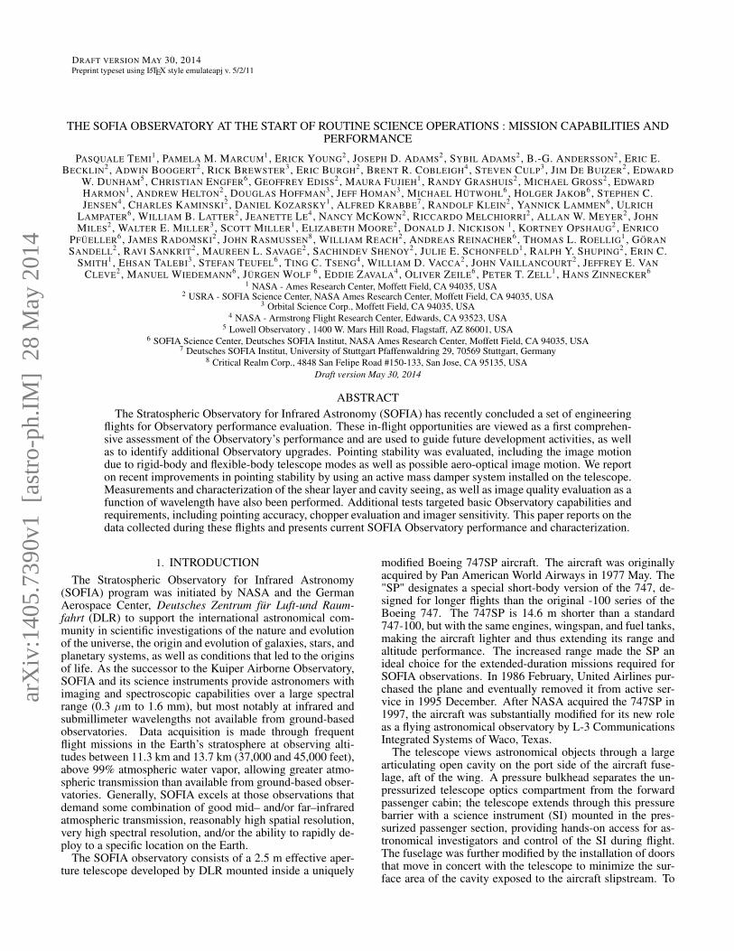
FIG. 1.— Composite plot of all flight plans executed by SOFIA in 2013.Individual science legs are shown as green tracks. The maximum length offlight legs is determined by the need for efficient flight plans as well as thetypical requirement that SOFIA take-off and land in Palmdale, California. Inmost cases, the longest possible observing leg on a given target is ∼ 4 hr.Therefore, observations of targets requiring long integrations may have to bedone over multiple flights and flight legs. SOFIA performed 9 science flightsduring its three week deployment to Christchurch, New Zealand from 2012July 12 to August 2.
about the infrared universe, with observations made by sci-ence instrument teams as well as through peer-reviewed pro-posals selected through a competed international solicitation.An overview of SOFIA system characteristics and high levelrequirements is presented in Table 1. Figure 1 shows com-bined flight plans flown during the early science phase, in-cluding a Southern Hemisphere deployment to New Zealand.Additional details on the aircraft and mission operations canbe found in Young et al. (2012) and Becklin et al. (2012).
2. TELESCOPE ASSEMBLYThe SOFIA telescope is a Cassegrain telescope with a Nas-
myth focus. It was supplied by DLR as the major part of theGerman developmental contribution to the observatory. Theoptical layout, as well as the optical parameters of the tele-scope are presented in Krabbe (2000). This section illustrateskey elements of the telescope system design that have beenspecifically developed for the airborne observatory.
2.1. Mechanical Design of the Telescope AssemblyThe design of the Telescope Assembly (TA) is based on the
idea of a perfectly balanced dumbbell with a central support(Figure 2). This arrangement allows the whole TA to be ro-tated quickly, by minimizing the required torque. This designalso allows a simple interface with the bulkhead which sup-ports the TA via a low-friction hydrostatic oil spherical bear-ing. In order to keep the center of gravity of the TA alignedwith the center of rotation (the middle of a spherical bearingwithin the bulkhead), a number of fixed weights are mounted

The SOFIA Observatory 3
TABLE 1SOFIA System Characteristics
Nominal Operational Wavelength 0.3 to 1600 µm Chopper Frequencies 1 to 20 Hz for 2–point squarewave chop
Primary Mirror Diameter 2.7 m Maximum Chop Throw onSky
± 4 arcmin (unvignetted)
System clear Aperture 2.5 m Diffraction Limited Wave-length
≥ 20µm
Nominal System f–ratio 19.6 Pointing Accuracy 0.3′′ rms with on–axis focalplane tracking
Primary Mirror f–ratio 1.28 Pointing Stability 0.4′′ rms in operationsTelescope’s Unvignetted Eleva-tion Range
23◦ to 57◦ Observatory Pointing Drift ≤ 0.3′′ hr−1 while guiding
Unvignetted FOV Diameter 8′ Observatory Effective Emis-sivity
≤14.5% at 8.4-8.75µm withdichroic tertiary; ≤12% at 8.4-8.75µm with flat tertiary mirror
Optical Configuration Bent Cassegrain with chop-ping secondary mirror
Air Temperature in Cavityand Optics Temperature
240◦ K
on the balancing plate, counteracting the weight of the pri-mary mirror and the metering structure. Four motorized finebalancing weight drives are available, two for the Elevation(EL) axis, one for the Cross Elevation (XEL) axis, and one forthe Line Of Sight (LOS) axis. The vibration and temperatureenvironment in an airborne observatory pose high demandson the telescope, therefore, the design goal was to keep thesystem simple and robust. Almost all electrical systems of theTA are located on the cabin side, where the temperature en-vironment is benign. Only the secondary mirror mechanism,the 2 guide cameras on the headring and a few other systemsare located on the cavity side of the TA. A primary design goalfor the structural assemblies was to provide a dimensionallystable structure under mechanical and thermal loads. All mir-rors are mounted in a quasi-rigid way (using bipods or supportrods), there are no adaptive optical components. The struc-ture was also designed to reduce the aerodynamic and aero-acoustic loads on the TA as much as possible, therefore themajority of the structural components on the cavity side aredesigned as truss work.
A baffle plate is available on the aft structure of the TA toprovide a uniform and stable background for science instru-ments that may be able to pick up stray light from behind thetertiary mirror. However, the baffle plate interacts with thewind loads in the cavity, transmitting energy into telescope jit-ter and degrading image quality. Commissioned instrumentsso far have not seen a background penalty and therefore pre-fer the improved image quality without it. However, the baffleplate remains an option for instruments (in particular, long-wavelength instruments) that could benefit more from reducedbackground than reduced jitter.
The light-weighted Zerodur primary mirror has a mass ofapproximately 880 kg. The structural assembly which holdsthe primary mirror assembly is a shell structure made of car-bon fiber reinforced plastic (CFRP). The other assemblies ofthe metering structure are also mostly CFRP shell structures.This construction leads to a high specific stiffness and a lowweight of the telescope assemblies, which are located on thecavity side of the TA. Furthermore, CFRP has a very lowcoefficient of thermal expansion compared with other struc-tural materials; therefore very little distortion exists between
!"#$%&'("$)
*+",()
-+#'.$/)
$&0()
12/(%34+5))
0(+%3",)
630%+78")3#85+78"))
#.#$(')
9&3:3",)4+'(%+#)
;84+5)25+"()3'+,(%)
FIG. 2.— Strutural assembly of the SOFIA telescope showing the locationof key sub-system elements.
the optical components during flight and between ground andflight conditions.
The TA structure is supported on the aircraft bulkhead witha vibration isolation system, which is the only physical con-nection of the telescope to the aircraft (Krabbe 2000). Theisolation system consists of 12 air springs in the axial direc-tion, 12 air springs in the tangential direction, and three vis-cous dampers. The air pressure in the springs is controlled toposition the telescope within the bulkhead depending on thedifferential pressure between the cabin and the cavity (Sustet al. 2002). The main telescope structure with the Nas-myth tube, the metering structure and the instrument flange issupported by a 1.2 m spherical hydrostatic oil bearing withbrushless three-axis spherical torque motors as drives (seeFigure 2).
Pointing control of the telescope during science observa-tions is enabled by an array of sensors. Three precisionfiberoptic gyroscopes provide angular rate information of the
4 Temi et al.
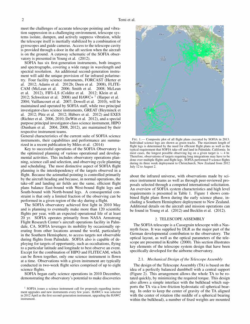
FIG. 3.— Cutaway schematic of the telescope and bulkhead with simplifiedrepresentation of the thermal (red dashed line) and pressure (blue dashed line)barriers.
telescope. The gyroscopes are installed at the Nasmyth tubeon the side of the pressurized cabin close to the bearing. Ad-ditionally, there are three accelerometers installed in the gy-roscope box, as well as another set of three accelerometerson the flange assembly. These acceleration measurements areused to compensate for the pointing errors due to the flexi-bility of the telescope structure (Wandner & Kaercher 2000).Finally, there are three distinct cameras (visible light CCD de-tectors) that provide tracking and pointing information to thetelescope control system:• Focal Plane Imager (FPI): The FPI is a 1024 × 1024
pixel CCD camera with a 8 arc-minute circular field-of-view(FOV) that shares the telescope’s focal plane with the SI viathe telescope’s dichroic tertiary mirror. In this configurationthe optical light is reflected by a second tertiary (behind thedichroic) and sent to the visible Nasmyth focus. The FPI ismounted rigidly to the flange assembly, near the inside of theinstrument flange (see Figure 2), and its mechanism includesa back-focus adjustment to make this imager parafocal withthe SI. Centroid position information from the imaged starsis fed to the attitude control loop to define a reference on thesky and to correct for pointing errors introduced by bias andrandom walk of the gyroscopes and other long term effects.• Fine Field Imager (FFI): The FFI is mounted on the head
ring of the telescope metering structure in the cavity with a1024× 1024 pixel CCD and 67′× 67′ FOV. The FFI can beused in addition to or instead of the FPI for pointing setupand tracking. If the dichroic tertiary is replaced with a fullyreflective tertiary mirror the FPI becomes unavailable, and theFFI would become the primary tracking imager.• Wide Field Imager (WFI): The WFI is also mounted on
the head ring of the telescope metering structure in the cavitywith a 1024× 1024 pixel CCD and 6◦× 6◦ FOV. The WFIis primarily used for sky-field recognition and to monitor theimage rotation caused by the alt–az–like mount of the tele-scope.
The telescope optical assembly on the cavity side of the TAand the instrument flange assembly on the cabin side of theTA are connected by the Nasmyth tube. A star-frame struc-ture rigidly interconnects the telescope optical metering struc-ture to the Nasmyth tube. A gate valve maintains the pressurebarrier within the Nasmyth tube between the open port tele-scope cavity and the pressurized aircraft cabin. The gate valve
is opened to allow light from the telescope to enter the sci-ence instrument bolted onto the instrument flange. When thegate valve is opened, the pressure barrier lies either within thesealed science instrument, or at an optical window mountedin front of the gate valve.
Electrical units that do not have to be located on the ro-tating part of the telescope are distributed on the main deck,and the oil supply and cooling unit of the TA are located in aforward cargo compartment of the aircraft, so that the weightis distributed to maintain the aircraft center of gravity withinaerodynamic limits. The total mass of TA rotating subassem-blies is about 10 metric tons, the TA subassemblies mountedto the bulkhead (bearing cradle, vibration isolation system,subassemblies of the rotation drive assembly, etc.) have amass of about 7 metric tons, and other aircraft-mounted TAsubassemblies (power units, control racks, the oil and coolingsupply units, etc.) have a mass of about 3 metric tons.
2.2. Thermal Design of the Telescope AssemblyThe TA is divided into two areas: a cold area in the cavity
and a warm area on the cabin side of the bulkhead, as shownin Figure 3. Hard foam insulation panels are mounted on allmajor components on the cavity side of the TA to form a ther-mal barrier between the two thermal regimes. The typical airtemperature in the cavity during flight is between -35 and -45◦C. The TA is specified to work without degradation at tem-peratures as low as -54 ◦C, to ensure that the telescope canoperate in the open port cavity at stratospheric altitudes.
The hydrostatic spherical bearing is very sensitive to tem-perature gradients, therefore the bearing sphere suspensionassembly is located on the cabin side of the thermal barrier.A closed–cycle oil cooling system controls the temperatureof the bearing. The Nasmyth tube is equipped with a forced–air circulation system to minimize convection air currents thatdisturb seeing. The instrument flange has a port to attach avacuum pump, so that the space between the flange and thegate valve (the ‘tub’) can be evacuated on the ground to pro-tect hygroscopic entrance windows on science instruments.
The telescope cavity is lined with soft insulation foam toreduce heat transfer from the cavity into other areas of theaircraft. An aft cavity environmental control system forcescabin air through a desiccant dryer and into the cavity duringdescent and after landing to prevent condensation on the tele-scope due to intrusion of moist warm air while the telescopeis still at stratospheric temperatures. A cavity pre-coolingsystem is currently under development, in order to minimizethermal variations when the cavity door is opened at altitude.In the current configuration of the observatory, however, theTA is cooled only after the cavity door is opened. The timerequired to achieve thermal equilibrium depends mainly onthe thermal time constant (approximately 40 minutes) of thelight-weighted Zerodur primary mirror. Frequent focus ad-justments via the adjustable secondary mirror must be madeduring the first few hours of the flight until thermal equilib-rium is reached.
2.3. The Secondary Mirror AssemblyThe secondary mirror assembly consists of the focus-
centering-mechanism, the tilt-chopping-mechanism and thesecondary mirror itself. The secondary mirror has a diame-ter of 35 cm, a weight of about 2 kg and is made of siliconcarbide with stiffening ribs on its backside, for high stiffnessand low weight. The mirror also quickly adjusts to temper-ature changes. The focus-centering-mechanism is used for
The SOFIA Observatory 5
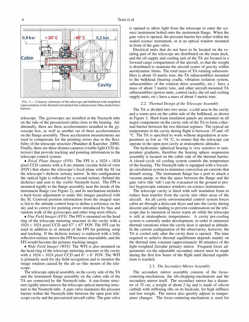
FIG. 4.— Simplified command sequence for commanding telescope mo-tion.
alignment and focus of the secondary mirror. It consists ofa hexapod mechanism with 5 degrees of freedom. The tilt-chopping-mechanism provides for fast tip-tilt and choppingactuation. It consists of three identical actuator mechanisms.Each mechanism has a linear motor, a lever and pivots totransfer the movement, a position sensor and a load cell. Themotion is transmitted to the secondary mirror via some ofthese pivots and an isostatic mirror holder, while other piv-ots move a reaction compensation ring to reduce the dynamicangular momentum. The requirement for the maximum chop-ping frequency during the design phase of the tilt-chopping-mechanism was 20 Hz. In addition to the scientific driventilt-chopping purpose, this system is also used for compensa-tion of telescope pointing errors, which cannot be addressedby the feedback control system with the fine drive actuators.
3. MISSION COMMUNICATIONS AND CONTROLSYSTEM (MCCS)
The MCCS is a NASA system of systems responsible fordiverse functions onboard SOFIA including power control,network functionality, flight management, archival services,video distribution, water vapor monitoring, and supervisorycontrol to the TA. Workstations are installed for the tele-scope operator, mission director, science instruments, and ed-ucation outreach staff. The TA distributes its control algo-rithms among three sub-systems: the TA Servo ControllerUnit (TASCU), the Tracker and the secondary controller sub-system. The TASCU drives actual attitude to match an exter-nally defined desired attitude described in an inertial referenceframe constructed from integrated gyro signals. The Trackerguides and/or corrects the inertial reference frame using oneof three cameras (FPI, FFI, or WFI) Areas of Interest (AOI)defined by the user around objects suitable for tracking. Thesecondary controller subsystem controls focus as well as tip,tilt and chopping action of the secondary mirror.
3.1. MCCS and Telescope Assembly CoordinationA primary responsibility of the MCCS is to assist the tele-
scope in pointing by accepting an observer’s target specifiedin a sky reference frame and converting the request into na-tive telescope inertial reference frame coordinates. To accom-plish this coordinate conversion, a MCCS process known asXFORMS models and refines each science instrument ref-erence frame such that the desired target is centered on an
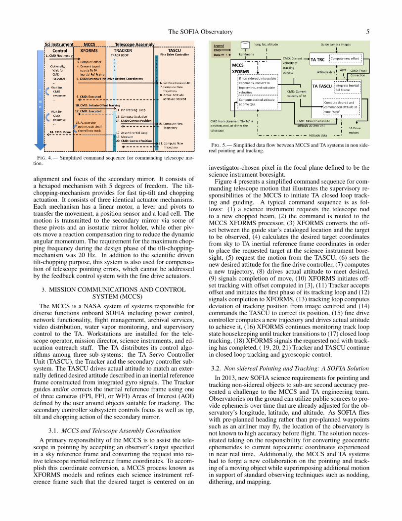
FIG. 5.— Simplified data flow between MCCS and TA systems in non side-real pointing and tracking.
investigator-chosen pixel in the focal plane defined to be thescience instrument boresight.
Figure 4 presents a simplified command sequence for com-manding telescope motion that illustrates the supervisory re-sponsibilities of the MCCS to initiate TA closed loop track-ing and guiding. A typical command sequence is as fol-lows: (1) a science instrument requests the telescope nodto a new chopped beam, (2) the command is routed to theMCCS XFORMS processor, (3) XFORMS converts the off-set between the guide star’s cataloged location and the targetto be observed, (4) calculates the desired target coordinatesfrom sky to TA inertial reference frame coordinates in orderto place the requested target at the science instrument bore-sight, (5) request the motion from the TASCU, (6) sets thenew desired attitude for the fine drive controller, (7) computesa new trajectory, (8) drives actual attitude to meet desired,(9) signals completion of move, (10) XFORMS initiates off-set tracking with offset computed in [3], (11) Tracker acceptsoffset and initiates the first phase of its tracking loop and (12)signals completion to XFORMS, (13) tracking loop computesdeviation of tracking position from image centroid and (14)commands the TASCU to correct its position, (15) fine drivecontroller computes a new trajectory and drives actual attitudeto achieve it, (16) XFORMS continues monitoring track loopstate housekeeping until tracker transitions to (17) closed looptracking, (18) XFORMS signals the requested nod with track-ing has completed, ( 19, 20, 21) Tracker and TASCU continuein closed loop tracking and gyroscopic control.
3.2. Non sidereal Pointing and Tracking: A SOFIA SolutionIn 2013, new SOFIA science requirements for pointing and
tracking non-sidereal objects to sub-arc second accuracy pre-sented a challenge to the MCCS and TA engineering team.Observatories on the ground can utilize public sources to pro-vide ephemeris over time that are already adjusted for the ob-servatory’s longitude, latitude, and altitude. As SOFIA flieswith pre-planned heading rather than pre-planned waypointssuch as an airliner may fly, the location of the observatory isnot known to high accuracy before flight. The solution neces-sitated taking on the responsibility for converting geocentricephemerides to current topocentric coordinates experiencedin near real time. Additionally, the MCCS and TA systemshad to forge a new collaboration on the pointing and track-ing of a moving object while superimposing additional motionin support of standard observing techniques such as nodding,dithering, and mapping.
6 Temi et al.
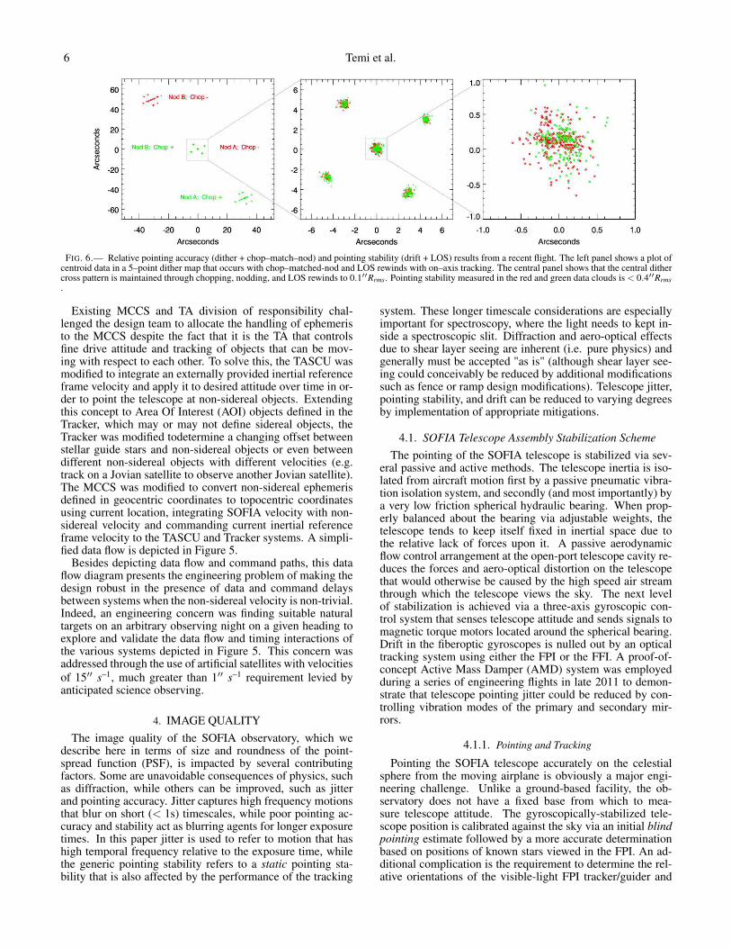
FIG. 6.— Relative pointing accuracy (dither + chop–match–nod) and pointing stability (drift + LOS) results from a recent flight. The left panel shows a plot ofcentroid data in a 5–point dither map that occurs with chop–matched-nod and LOS rewinds with on–axis tracking. The central panel shows that the central dithercross pattern is maintained through chopping, nodding, and LOS rewinds to 0.1′′Rrms. Pointing stability measured in the red and green data clouds is < 0.4′′Rrms.
Existing MCCS and TA division of responsibility chal-lenged the design team to allocate the handling of ephemeristo the MCCS despite the fact that it is the TA that controlsfine drive attitude and tracking of objects that can be mov-ing with respect to each other. To solve this, the TASCU wasmodified to integrate an externally provided inertial referenceframe velocity and apply it to desired attitude over time in or-der to point the telescope at non-sidereal objects. Extendingthis concept to Area Of Interest (AOI) objects defined in theTracker, which may or may not define sidereal objects, theTracker was modified todetermine a changing offset betweenstellar guide stars and non-sidereal objects or even betweendifferent non-sidereal objects with different velocities (e.g.track on a Jovian satellite to observe another Jovian satellite).The MCCS was modified to convert non-sidereal ephemerisdefined in geocentric coordinates to topocentric coordinatesusing current location, integrating SOFIA velocity with non-sidereal velocity and commanding current inertial referenceframe velocity to the TASCU and Tracker systems. A simpli-fied data flow is depicted in Figure 5.
Besides depicting data flow and command paths, this dataflow diagram presents the engineering problem of making thedesign robust in the presence of data and command delaysbetween systems when the non-sidereal velocity is non-trivial.Indeed, an engineering concern was finding suitable naturaltargets on an arbitrary observing night on a given heading toexplore and validate the data flow and timing interactions ofthe various systems depicted in Figure 5. This concern wasaddressed through the use of artificial satellites with velocitiesof 15′′ s−1, much greater than 1′′ s−1 requirement levied byanticipated science observing.
4. IMAGE QUALITYThe image quality of the SOFIA observatory, which we
describe here in terms of size and roundness of the point-spread function (PSF), is impacted by several contributingfactors. Some are unavoidable consequences of physics, suchas diffraction, while others can be improved, such as jitterand pointing accuracy. Jitter captures high frequency motionsthat blur on short (< 1s) timescales, while poor pointing ac-curacy and stability act as blurring agents for longer exposuretimes. In this paper jitter is used to refer to motion that hashigh temporal frequency relative to the exposure time, whilethe generic pointing stability refers to a static pointing sta-bility that is also affected by the performance of the tracking
system. These longer timescale considerations are especiallyimportant for spectroscopy, where the light needs to kept in-side a spectroscopic slit. Diffraction and aero-optical effectsdue to shear layer seeing are inherent (i.e. pure physics) andgenerally must be accepted "as is" (although shear layer see-ing could conceivably be reduced by additional modificationssuch as fence or ramp design modifications). Telescope jitter,pointing stability, and drift can be reduced to varying degreesby implementation of appropriate mitigations.
4.1. SOFIA Telescope Assembly Stabilization SchemeThe pointing of the SOFIA telescope is stabilized via sev-
eral passive and active methods. The telescope inertia is iso-lated from aircraft motion first by a passive pneumatic vibra-tion isolation system, and secondly (and most importantly) bya very low friction spherical hydraulic bearing. When prop-erly balanced about the bearing via adjustable weights, thetelescope tends to keep itself fixed in inertial space due tothe relative lack of forces upon it. A passive aerodynamicflow control arrangement at the open-port telescope cavity re-duces the forces and aero-optical distortion on the telescopethat would otherwise be caused by the high speed air streamthrough which the telescope views the sky. The next levelof stabilization is achieved via a three-axis gyroscopic con-trol system that senses telescope attitude and sends signals tomagnetic torque motors located around the spherical bearing.Drift in the fiberoptic gyroscopes is nulled out by an opticaltracking system using either the FPI or the FFI. A proof-of-concept Active Mass Damper (AMD) system was employedduring a series of engineering flights in late 2011 to demon-strate that telescope pointing jitter could be reduced by con-trolling vibration modes of the primary and secondary mir-rors.
4.1.1. Pointing and Tracking
Pointing the SOFIA telescope accurately on the celestialsphere from the moving airplane is obviously a major engi-neering challenge. Unlike a ground-based facility, the ob-servatory does not have a fixed base from which to mea-sure telescope attitude. The gyroscopically-stabilized tele-scope position is calibrated against the sky via an initial blindpointing estimate followed by a more accurate determinationbased on positions of known stars viewed in the FPI. An ad-ditional complication is the requirement to determine the rel-ative orientations of the visible-light FPI tracker/guider and
The SOFIA Observatory 7
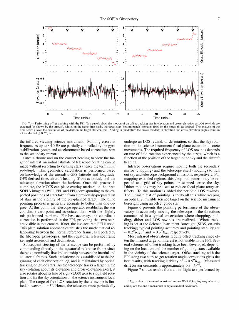
FIG. 7.— Performing offset tracking with the FPI: Top panels show the motion of an offset tracking star in elevation and cross–elevation as LOS rewinds areexecuted (as shown by the arrows), while, on the same time basis, the target star (bottom panels) remains fixed on the boresight as desired. The analysis of thetime series allows the evaluation of the drift on the target star centroid. Adding in quadrature the measured drift in elevation and cross-elevation angles result ina total drift of ≤ 0.3′′/hr.
the infrared-viewing science instrument. Pointing errors atfrequencies up to ∼10 Hz are partially controlled by the gyrostabilization system and accelerometer-based corrections sentto the secondary mirror.
Once airborne and on the correct heading to view the tar-get of interest, an initial estimate of telescope pointing can bemade without resorting to viewing stars (hence the term blindpointing). This geometric calculation is performed basedon knowledge of the aircraft’s GPS latitude and longitude,GPS-derived time, aircraft heading (from avionics), and thetelescope elevation above the horizon. Once this process iscomplete, the MCCS can place overlay markers on the threeSOFIA imagers (WFI, FFI, and FPI) corresponding to the ex-pected positions of stars taken from a previously-prepared listof stars in the vicinity of the pre-planned target. The blindpointing process is generally accurate to better than one de-gree. At this point, the telescope operator establishes the starcoordinate zero-point and associates them with the slightlymis-positioned markers. For best accuracy, the coordinatecorrection is performed in the FPI, providing that two starsare visible in that camera. If not, the less accurate FFI is used.This plate solution approach establishes the mathematical re-lationship between the inertial reference frame, as reported bythe fiberoptic gyroscopes, and the equatorial reference framei.e. right ascension and declination.
Subsequent steering of the telescope can be performed bycommanding directly in the equatorial reference frame sincethere is a nominally fixed relationship between the inertial andequatorial frames. Such a relationship is established at the be-ginning of each observation leg, and is maintained by opticaltracking on guide stars. As the telescope tracks a target in thesky (rotating about its elevation and cross–elevation axes), italso rotates about its line of sight (LOS) axis to stop field rota-tion and fix the sky orientation on the science instrument focalplan. The range of free LOS rotation by the telescope is lim-ited, however, to ±3◦. Hence, the telescope must periodically
undergo an LOS rewind, or de-rotation, so that the sky rota-tion on the science instrument focal plane occurs in discretemovements. The required frequency of LOS rewinds dependson rate of field rotation experienced by the target, which is afunction of the position of the target in the sky and the aircraftheading.
Infrared observations require moving both the secondarymirror (chopping) and the telescope itself (nodding) to nullout sky and telescope background emissions, respectively. Formapping extended regions, this chop-nod pattern may be re-peated at a grid of sky points, or scanned across the sky.Dither motions may be used to reduce focal plane array ar-tifacts. To this motion is added the periodic LOS rewinds.The ultimate test of pointing is to do all this while keepingan optically invisible science target on the science instrumentboresight using an offset guide star.
Figure 6 presents the pointing performance of the obser-vatory in accurately moving the telescope in the directionscommanded in a typical observation where chopping, nod-ding, dither and LOS rewinds are realized. When track-ing is set at the Science Instrument Boresight (SIBS, on-axistracking) typical pointing accuracy and pointing stability are∼ 0.2′′Rrms
2 and ∼ 0.3′′Rrms respectively.Most infrared observations require offset tracking since of-
ten the infrared target of interest is not visible in the FPI. Sev-eral schemes of offset tracking have been developed, depend-ing on the location and the number of guiding stars availablein the vicinity of the science target. Offset tracking with theFPI using two stars to get rotation angle corrections gives thebest results, with tracking stability of ∼ 0.5′′Rrms. Measureddrift on star centroids is approximately 0.3′′ hr−1.
Figure 7 shows results from an in–flight test performed by
2 Rrms refers to the two-dimensional rms or 2D-RMS=√
σ2x +σ2
y where σx
and σy are the one dimensional sample standard deviations.
8 Temi et al.
!"#$%&'()*+#"+,%&#-.&,/&&01#
234&/#5/6
0#-(/70&7*+.01#
899:;##<6#"%)=>.&#
!"#$%&'()*+#"+,%&#-.&,/&&01#
234&/#5/6
0#-(/70&7*+.01#
89:;<##=6#"%)>?.&#
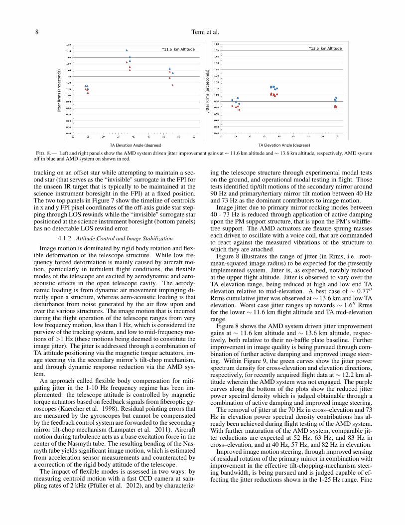
FIG. 8.— Left and right panels show the AMD system driven jitter improvement gains at ∼ 11.6 km altitude and ∼ 13.6 km altitude, respectively, AMD systemoff in blue and AMD system on shown in red.
tracking on an offset star while attempting to maintain a sec-ond star (that serves as the “invisible" surrogate in the FPI forthe unseen IR target that is typically to be maintained at thescience instrument boresight in the FPI) at a fixed position.The two top panels in Figure 7 show the timeline of centroidsin x and y FPI pixel coordinates of the off-axis guide star step-ping through LOS rewinds while the “invisible" surrogate starpositioned at the science instrument boresight (bottom panels)has no detectable LOS rewind error.
4.1.2. Attitude Control and Image Stabilization
Image motion is dominated by rigid body rotation and flex-ible deformation of the telescope structure. While low fre-quency forced deformation is mainly caused by aircraft mo-tion, particularly in turbulent flight conditions, the flexiblemodes of the telescope are excited by aerodynamic and aero-acoustic effects in the open telescope cavity. The aerody-namic loading is from dynamic air movement impinging di-rectly upon a structure, whereas aero-acoustic loading is thatdisturbance from noise generated by the air flow upon andover the various structures. The image motion that is incurredduring the flight operation of the telescope ranges from verylow frequency motion, less than 1 Hz, which is considered thepurview of the tracking system, and low to mid-frequency mo-tions of >1 Hz (these motions being deemed to constitute theimage jitter). The jitter is addressed through a combination ofTA attitude positioning via the magnetic torque actuators, im-age steering via the secondary mirror’s tilt-chop mechanism,and through dynamic response reduction via the AMD sys-tem.
An approach called flexible body compensation for miti-gating jitter in the 1-10 Hz frequency regime has been im-plemented: the telescope attitude is controlled by magnetictorque actuators based on feedback signals from fiberoptic gy-roscopes (Kaercher et al. 1998). Residual pointing errors thatare measured by the gyroscopes but cannot be compensatedby the feedback control system are forwarded to the secondarymirror tilt-chop mechanism (Lampater et al. 2011). Aircraftmotion during turbulence acts as a base excitation force in thecenter of the Nasmyth tube. The resulting bending of the Nas-myth tube yields significant image motion, which is estimatedfrom acceleration sensor measurements and counteracted bya correction of the rigid body attitude of the telescope.
The impact of flexible modes is assessed in two ways: bymeasuring centroid motion with a fast CCD camera at sam-pling rates of 2 kHz (Pfüller et al. 2012), and by characteriz-
ing the telescope structure through experimental modal testson the ground, and operational modal testing in flight. Thosetests identified tip/tilt motions of the secondary mirror around90 Hz and primary/tertiary mirror tilt motion between 40 Hzand 73 Hz as the dominant contributors to image motion.
Image jitter due to primary mirror rocking modes between40 - 73 Hz is reduced through application of active dampingupon the PM support structure, that is upon the PM’s whiffle-tree support. The AMD actuators are flexure-sprung masseseach driven to oscillate with a voice coil, that are commandedto react against the measured vibrations of the structure towhich they are attached.
Figure 8 illustrates the range of jitter (in Rrms, i.e. root-mean-squared image radius) to be expected for the presentlyimplemented system. Jitter is, as expected, notably reducedat the upper flight altitude. Jitter is observed to vary over theTA elevation range, being reduced at high and low end TAelevation relative to mid-elevation. A best case of ∼ 0.77′′Rrms cumulative jitter was observed at ∼ 13.6 km and low TAelevation. Worst case jitter ranges up towards ∼ 1.6′′ Rrmsfor the lower ∼ 11.6 km flight altitude and TA mid-elevationrange.
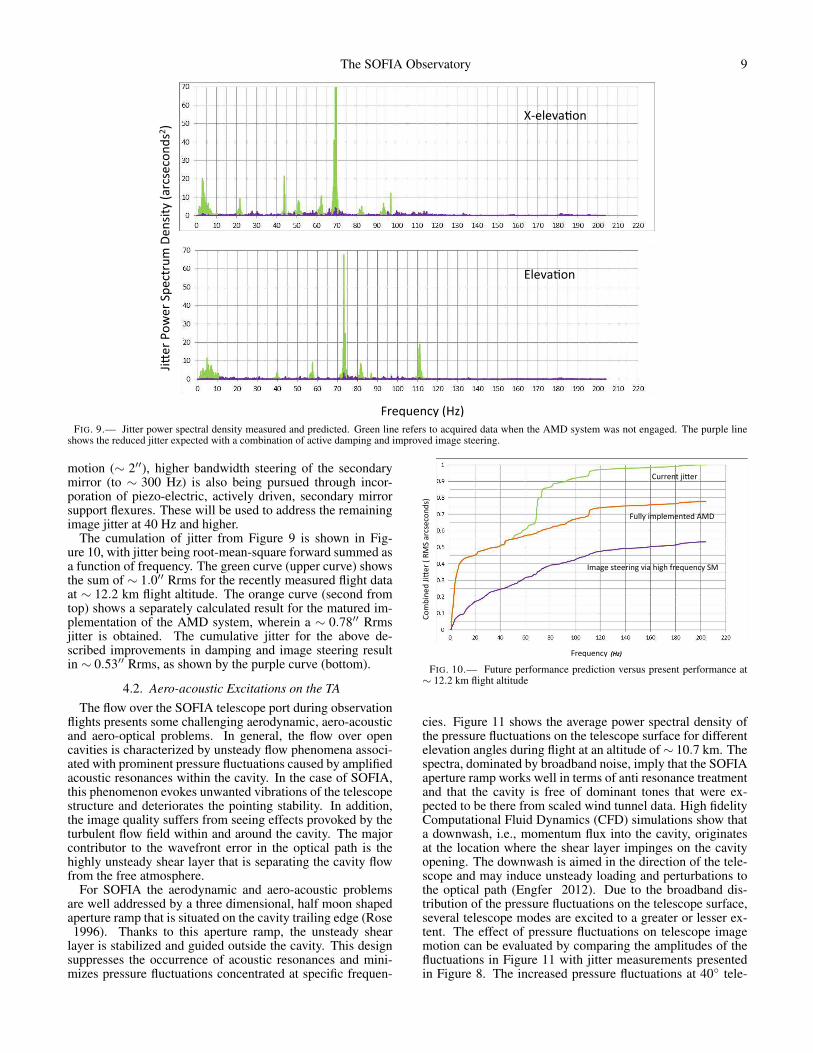
Figure 8 shows the AMD system driven jitter improvementgains at ∼ 11.6 km altitude and ∼ 13.6 km altitude, respec-tively, both relative to their no-baffle plate baseline. Furtherimprovement in image quality is being pursued through com-bination of further active damping and improved image steer-ing. Within Figure 9, the green curves show the jitter powerspectrum density for cross-elevation and elevation directions,respectively, for recently acquired flight data at ∼ 12.2 km al-titude wherein the AMD system was not engaged. The purplecurves along the bottom of the plots show the reduced jitterpower spectral density which is judged obtainable through acombination of active damping and improved image steering.
The removal of jitter at the 70 Hz in cross–elevation and 73Hz in elevation power spectral density contributions has al-ready been achieved during flight testing of the AMD system.With further maturation of the AMD system, comparable jit-ter reductions are expected at 52 Hz, 63 Hz, and 83 Hz incross–elevation, and at 40 Hz, 57 Hz, and 82 Hz in elevation.
Improved image motion steering, through improved sensingof residual rotation of the primary mirror in combination withimprovement in the effective tilt-chopping-mechanism steer-ing bandwidth, is being pursued and is judged capable of ef-fecting the jitter reductions shown in the 1-25 Hz range. Fine
The SOFIA Observatory 9
!"#$%#&'()*+,-)
./0#")123#")45#'6"%7)8#&9/6()*:"'9#'2&;9<-)
=>#?#@:A2&))
B?#@:A2&)
FIG. 9.— Jitter power spectral density measured and predicted. Green line refers to acquired data when the AMD system was not engaged. The purple lineshows the reduced jitter expected with a combination of active damping and improved image steering.
motion (∼ 2′′), higher bandwidth steering of the secondarymirror (to ∼ 300 Hz) is also being pursued through incor-poration of piezo-electric, actively driven, secondary mirrorsupport flexures. These will be used to address the remainingimage jitter at 40 Hz and higher.
The cumulation of jitter from Figure 9 is shown in Fig-ure 10, with jitter being root-mean-square forward summed asa function of frequency. The green curve (upper curve) showsthe sum of ∼ 1.0′′ Rrms for the recently measured flight dataat ∼ 12.2 km flight altitude. The orange curve (second fromtop) shows a separately calculated result for the matured im-plementation of the AMD system, wherein a ∼ 0.78′′ Rrmsjitter is obtained. The cumulative jitter for the above de-scribed improvements in damping and image steering resultin ∼ 0.53′′ Rrms, as shown by the purple curve (bottom).
4.2. Aero-acoustic Excitations on the TAThe flow over the SOFIA telescope port during observation
flights presents some challenging aerodynamic, aero-acousticand aero-optical problems. In general, the flow over opencavities is characterized by unsteady flow phenomena associ-ated with prominent pressure fluctuations caused by amplifiedacoustic resonances within the cavity. In the case of SOFIA,this phenomenon evokes unwanted vibrations of the telescopestructure and deteriorates the pointing stability. In addition,the image quality suffers from seeing effects provoked by theturbulent flow field within and around the cavity. The majorcontributor to the wavefront error in the optical path is thehighly unsteady shear layer that is separating the cavity flowfrom the free atmosphere.
For SOFIA the aerodynamic and aero-acoustic problemsare well addressed by a three dimensional, half moon shapedaperture ramp that is situated on the cavity trailing edge (Rose1996). Thanks to this aperture ramp, the unsteady shear
layer is stabilized and guided outside the cavity. This designsuppresses the occurrence of acoustic resonances and mini-mizes pressure fluctuations concentrated at specific frequen-
!"#$%&'()*%+',)-)./0)1,23'2"&(34)
5,'67'&28!!"#$%!
!7,,'&9):%+',)
57;;8)%#<;'#'&9'()=/>)
?#1@')39'',%&@)A%1)B%@B)C,'67'&28)0/)
FIG. 10.— Future performance prediction versus present performance at∼ 12.2 km flight altitude
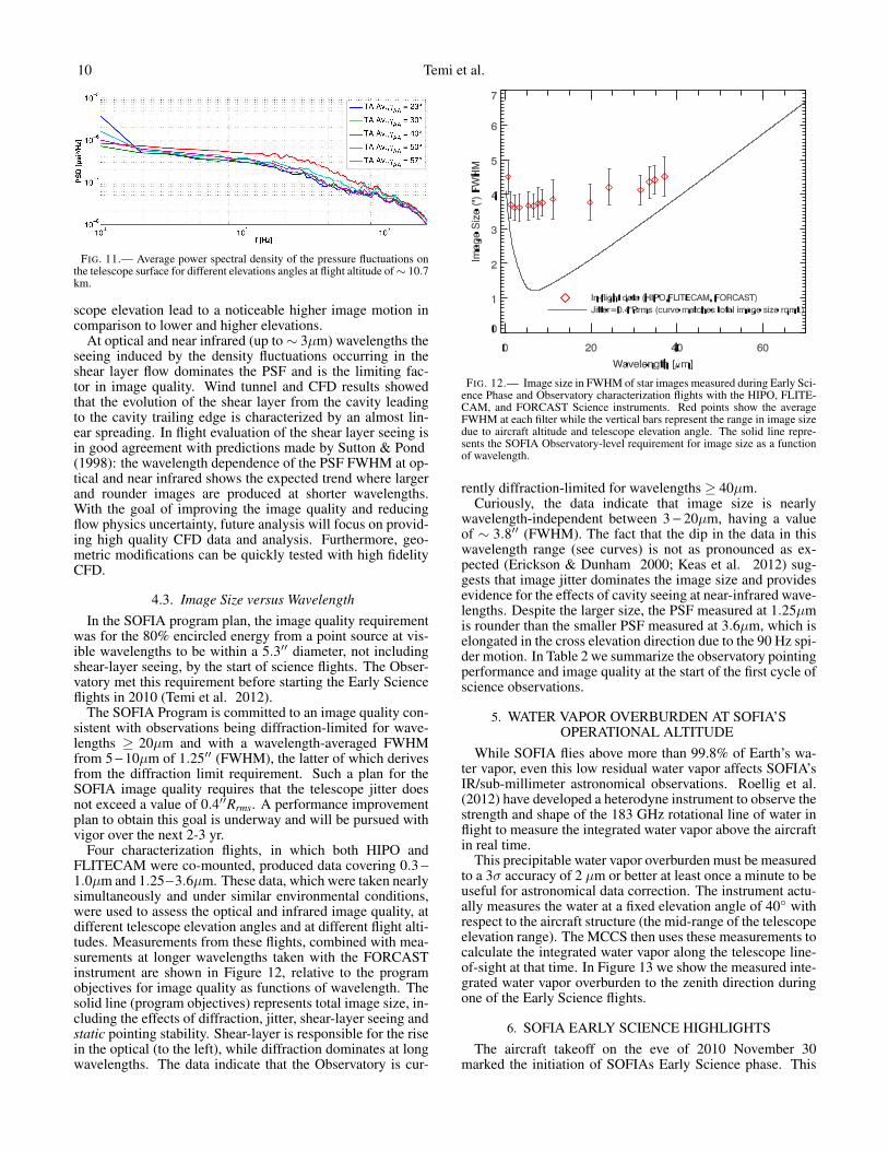
cies. Figure 11 shows the average power spectral density ofthe pressure fluctuations on the telescope surface for differentelevation angles during flight at an altitude of ∼ 10.7 km. Thespectra, dominated by broadband noise, imply that the SOFIAaperture ramp works well in terms of anti resonance treatmentand that the cavity is free of dominant tones that were ex-pected to be there from scaled wind tunnel data. High fidelityComputational Fluid Dynamics (CFD) simulations show thata downwash, i.e., momentum flux into the cavity, originatesat the location where the shear layer impinges on the cavityopening. The downwash is aimed in the direction of the tele-scope and may induce unsteady loading and perturbations tothe optical path (Engfer 2012). Due to the broadband dis-tribution of the pressure fluctuations on the telescope surface,several telescope modes are excited to a greater or lesser ex-tent. The effect of pressure fluctuations on telescope imagemotion can be evaluated by comparing the amplitudes of thefluctuations in Figure 11 with jitter measurements presentedin Figure 8. The increased pressure fluctuations at 40◦ tele-
10 Temi et al.
FIG. 11.— Average power spectral density of the pressure fluctuations onthe telescope surface for different elevations angles at flight altitude of ∼ 10.7km.
scope elevation lead to a noticeable higher image motion incomparison to lower and higher elevations.
At optical and near infrared (up to ∼ 3µm) wavelengths theseeing induced by the density fluctuations occurring in theshear layer flow dominates the PSF and is the limiting fac-tor in image quality. Wind tunnel and CFD results showedthat the evolution of the shear layer from the cavity leadingto the cavity trailing edge is characterized by an almost lin-ear spreading. In flight evaluation of the shear layer seeing isin good agreement with predictions made by Sutton & Pond(1998): the wavelength dependence of the PSF FWHM at op-tical and near infrared shows the expected trend where largerand rounder images are produced at shorter wavelengths.With the goal of improving the image quality and reducingflow physics uncertainty, future analysis will focus on provid-ing high quality CFD data and analysis. Furthermore, geo-metric modifications can be quickly tested with high fidelityCFD.
4.3. Image Size versus WavelengthIn the SOFIA program plan, the image quality requirement
was for the 80% encircled energy from a point source at vis-ible wavelengths to be within a 5.3′′ diameter, not includingshear-layer seeing, by the start of science flights. The Obser-vatory met this requirement before starting the Early Scienceflights in 2010 (Temi et al. 2012).
The SOFIA Program is committed to an image quality con-sistent with observations being diffraction-limited for wave-lengths ≥ 20µm and with a wavelength-averaged FWHMfrom 5 − 10µm of 1.25′′ (FWHM), the latter of which derivesfrom the diffraction limit requirement. Such a plan for theSOFIA image quality requires that the telescope jitter doesnot exceed a value of 0.4′′Rrms. A performance improvementplan to obtain this goal is underway and will be pursued withvigor over the next 2-3 yr.
Four characterization flights, in which both HIPO andFLITECAM were co-mounted, produced data covering 0.3 −
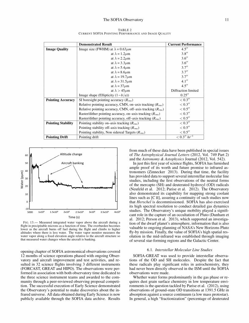
1.0µm and 1.25−3.6µm. These data, which were taken nearlysimultaneously and under similar environmental conditions,were used to assess the optical and infrared image quality, atdifferent telescope elevation angles and at different flight alti-tudes. Measurements from these flights, combined with mea-surements at longer wavelengths taken with the FORCASTinstrument are shown in Figure 12, relative to the programobjectives for image quality as functions of wavelength. Thesolid line (program objectives) represents total image size, in-cluding the effects of diffraction, jitter, shear-layer seeing andstatic pointing stability. Shear-layer is responsible for the risein the optical (to the left), while diffraction dominates at longwavelengths. The data indicate that the Observatory is cur-
FIG. 12.— Image size in FWHM of star images measured during Early Sci-ence Phase and Observatory characterization flights with the HIPO, FLITE-CAM, and FORCAST Science instruments. Red points show the averageFWHM at each filter while the vertical bars represent the range in image sizedue to aircraft altitude and telescope elevation angle. The solid line repre-sents the SOFIA Observatory-level requirement for image size as a functionof wavelength.
rently diffraction-limited for wavelengths ≥ 40µm.Curiously, the data indicate that image size is nearly
wavelength-independent between 3 − 20µm, having a valueof ∼ 3.8′′ (FWHM). The fact that the dip in the data in thiswavelength range (see curves) is not as pronounced as ex-pected (Erickson & Dunham 2000; Keas et al. 2012) sug-gests that image jitter dominates the image size and providesevidence for the effects of cavity seeing at near-infrared wave-lengths. Despite the larger size, the PSF measured at 1.25µmis rounder than the smaller PSF measured at 3.6µm, which iselongated in the cross elevation direction due to the 90 Hz spi-der motion. In Table 2 we summarize the observatory pointingperformance and image quality at the start of the first cycle ofscience observations.
5. WATER VAPOR OVERBURDEN AT SOFIA’SOPERATIONAL ALTITUDE
While SOFIA flies above more than 99.8% of Earth’s wa-ter vapor, even this low residual water vapor affects SOFIA’sIR/sub-millimeter astronomical observations. Roellig et al.(2012) have developed a heterodyne instrument to observe thestrength and shape of the 183 GHz rotational line of water inflight to measure the integrated water vapor above the aircraftin real time.
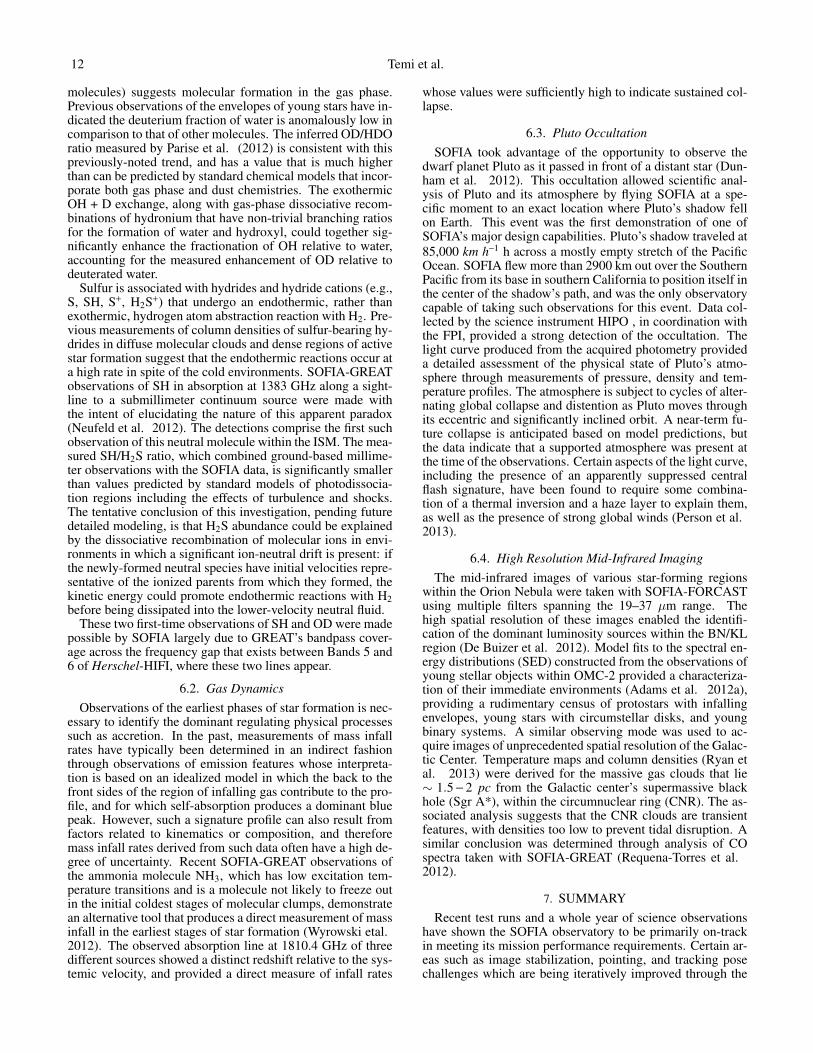
This precipitable water vapor overburden must be measuredto a 3σ accuracy of 2 µm or better at least once a minute to beuseful for astronomical data correction. The instrument actu-ally measures the water at a fixed elevation angle of 40◦ withrespect to the aircraft structure (the mid-range of the telescopeelevation range). The MCCS then uses these measurements tocalculate the integrated water vapor along the telescope line-of-sight at that time. In Figure 13 we show the measured inte-grated water vapor overburden to the zenith direction duringone of the Early Science flights.
6. SOFIA EARLY SCIENCE HIGHLIGHTSThe aircraft takeoff on the eve of 2010 November 30
marked the initiation of SOFIAs Early Science phase. This
The SOFIA Observatory 11
TABLE 2CURRENT SOFIA POINTING PERFORMANCE AND IMAGE QUALITY
Demonstrated Result Current PerformanceImage Quality Image size (FWHM) at λ = 0.63µm 4.5′′
at λ = 1.2µm 3.8′′
at λ = 2.2µm 3.6′′
at λ = 3.3µm 3.6′′
at λ = 5.4µm 3.7′′
at λ = 8.6µm 3.7′′
at λ = 19.7µm 3.7′′
at λ = 31.5µm 4.1′′
at λ = 37µm 4.5′′
at λ> 45µm Diffraction limitedImage shape (Ellipticity (1 − b/a)) 0.25′′
Pointing Accuracy SI boresight pointing accuracy (Rrms) < 0.3′′
Relative pointing accuracy, CMN, on–axis tracking (Rrms) < 0.3′′
Relative pointing accuracy, CMN, off–axis tracking (Rrms) < 0.5′′
Raster/dither pointing accuracy, on–axis tracking (Rrms) < 0.3′′
Raster/dither pointing accuracy, off–axis tracking (Rrms) < 0.5′′
Pointing Stability Pointing stability on–axis tracking (Rrms) < 0.3′′
Pointing stability off–axis tracking (Rrms) < 0.5′′
Pointing stability, Non sidereal Targets (Rrms) < 0.5′′
Pointing Drift Pointing drift < 0.3′′ hr−1
!"#$%&'()*+,-'(
!./)/+0(1+,2.,-(
34(
54(
64(
74(
84(
94(
4(
:94(
9;5<946(9<946( 8<946( 7<946(8;5<946( 7;5<946( 6<946(5444(
=.>'(?@A(
B+$'/(?C!>A(
FIG. 13.— Measured integrated water vapor above the aircraft during aflight in precipitable microns as a function of time. The overburden becomeslower as the aircraft burns off fuel during the flight and climbs to higheraltitudes where there is less water. The water vapor monitor measures thewater vapor along a fixed elevation angle relative to the aircraft structure sothat measured water changes when the aircraft is banking.
opening chapter of SOFIA astronomical observations covered12 months of science operations phased with ongoing Obser-vatory and aircraft improvement and test activities, and re-sulted in 32 science flights involving 3 different instruments(FORCAST, GREAT and HIPO). The observations were per-formed in association with both observatory time dedicated tothe three science instrument teams and awarded to the com-munity through a peer-reviewed observing proposal competi-tion. The successful execution of Early Science demonstratedthe Observatory’s potential to make discoveries about the in-frared universe. All data obtained during Early Science is nowpublicly available through the SOFIA data archive. Results
from much of these data have been published in special issuesof The Astrophysical Journal Letters (2012, Vol. 749 Part 2)and the Astronomy & Astophysics Journal (2012, Vol. 542).
In just this first year of science flights, SOFIA has furnishedample proof of its worth and future promise to infrared as-tronomers (Zinnecker 2013). During that time, the facilityhas provided data to support several interstellar molecular linestudies, including the first observations of the neutral formsof the mercapto (SH) and deuterated hydroxyl (OD) radicals(Neufeld et al. 2012; Parise et al. 2012). The Observatoryalso demonstrated its capability for mapping strong coolantlines such as [C II], assuring a continuity of such studies nowthat Herschel is decommissioned. SOFIA has also exercisedits high spectral resolution to conduct detailed gas dynamicsstudies. The Observatory’s unique mobility played a signifi-cant role in the capture of an occultation of Pluto (Dunham etal. 2012; Person et al. 2013), which supported an investiga-tion of the dwarf planet’s atmosphere, information that is alsovaluable to ongoing planning of NASA’s New Horizons Plutofly-by mission. Finally, the value of SOFIA’s high spatial res-olution in the mid-infrared was established through imagingof several star-forming regions and the Galactic Center.
6.1. Interstellar Molecular Line StudiesSOFIA-GREAT was used to provide interstellar observa-
tions of the OD and SH molecules. Despite the fact thatthese radicals play significant roles in astrochemistry, theyhad never been directly observed in the ISM until the SOFIAobservations were made.
Whether water forms predominantly in the gas phase or re-quires dust grain surface chemistry in low temperature envi-ronments is the question tackled by Parise et al. (2012), usingobservations of ground-state OD transitions at 1391.5 GHz inabsorption against a source continuum (a low mass protostar).In general, a high “fractionization” (percentage of deuterated
12 Temi et al.
molecules) suggests molecular formation in the gas phase.Previous observations of the envelopes of young stars have in-dicated the deuterium fraction of water is anomalously low incomparison to that of other molecules. The inferred OD/HDOratio measured by Parise et al. (2012) is consistent with thispreviously-noted trend, and has a value that is much higherthan can be predicted by standard chemical models that incor-porate both gas phase and dust chemistries. The exothermicOH + D exchange, along with gas-phase dissociative recom-binations of hydronium that have non-trivial branching ratiosfor the formation of water and hydroxyl, could together sig-nificantly enhance the fractionation of OH relative to water,accounting for the measured enhancement of OD relative todeuterated water.
Sulfur is associated with hydrides and hydride cations (e.g.,S, SH, S+, H2S+) that undergo an endothermic, rather thanexothermic, hydrogen atom abstraction reaction with H2. Pre-vious measurements of column densities of sulfur-bearing hy-drides in diffuse molecular clouds and dense regions of activestar formation suggest that the endothermic reactions occur ata high rate in spite of the cold environments. SOFIA-GREATobservations of SH in absorption at 1383 GHz along a sight-line to a submillimeter continuum source were made withthe intent of elucidating the nature of this apparent paradox(Neufeld et al. 2012). The detections comprise the first suchobservation of this neutral molecule within the ISM. The mea-sured SH/H2S ratio, which combined ground-based millime-ter observations with the SOFIA data, is significantly smallerthan values predicted by standard models of photodissocia-tion regions including the effects of turbulence and shocks.The tentative conclusion of this investigation, pending futuredetailed modeling, is that H2S abundance could be explainedby the dissociative recombination of molecular ions in envi-ronments in which a significant ion-neutral drift is present: ifthe newly-formed neutral species have initial velocities repre-sentative of the ionized parents from which they formed, thekinetic energy could promote endothermic reactions with H2before being dissipated into the lower-velocity neutral fluid.
These two first-time observations of SH and OD were madepossible by SOFIA largely due to GREAT’s bandpass cover-age across the frequency gap that exists between Bands 5 and6 of Herschel-HIFI, where these two lines appear.
6.2. Gas DynamicsObservations of the earliest phases of star formation is nec-
essary to identify the dominant regulating physical processessuch as accretion. In the past, measurements of mass infallrates have typically been determined in an indirect fashionthrough observations of emission features whose interpreta-tion is based on an idealized model in which the back to thefront sides of the region of infalling gas contribute to the pro-file, and for which self-absorption produces a dominant bluepeak. However, such a signature profile can also result fromfactors related to kinematics or composition, and thereforemass infall rates derived from such data often have a high de-gree of uncertainty. Recent SOFIA-GREAT observations ofthe ammonia molecule NH3, which has low excitation tem-perature transitions and is a molecule not likely to freeze outin the initial coldest stages of molecular clumps, demonstratean alternative tool that produces a direct measurement of massinfall in the earliest stages of star formation (Wyrowski etal.2012). The observed absorption line at 1810.4 GHz of threedifferent sources showed a distinct redshift relative to the sys-temic velocity, and provided a direct measure of infall rates
whose values were sufficiently high to indicate sustained col-lapse.
6.3. Pluto OccultationSOFIA took advantage of the opportunity to observe the
dwarf planet Pluto as it passed in front of a distant star (Dun-ham et al. 2012). This occultation allowed scientific anal-ysis of Pluto and its atmosphere by flying SOFIA at a spe-cific moment to an exact location where Pluto’s shadow fellon Earth. This event was the first demonstration of one ofSOFIA’s major design capabilities. Pluto’s shadow traveled at85,000 km h−1 h across a mostly empty stretch of the PacificOcean. SOFIA flew more than 2900 km out over the SouthernPacific from its base in southern California to position itself inthe center of the shadow’s path, and was the only observatorycapable of taking such observations for this event. Data col-lected by the science instrument HIPO , in coordination withthe FPI, provided a strong detection of the occultation. Thelight curve produced from the acquired photometry provideda detailed assessment of the physical state of Pluto’s atmo-sphere through measurements of pressure, density and tem-perature profiles. The atmosphere is subject to cycles of alter-nating global collapse and distention as Pluto moves throughits eccentric and significantly inclined orbit. A near-term fu-ture collapse is anticipated based on model predictions, butthe data indicate that a supported atmosphere was present atthe time of the observations. Certain aspects of the light curve,including the presence of an apparently suppressed centralflash signature, have been found to require some combina-tion of a thermal inversion and a haze layer to explain them,as well as the presence of strong global winds (Person et al.2013).
6.4. High Resolution Mid-Infrared ImagingThe mid-infrared images of various star-forming regions
within the Orion Nebula were taken with SOFIA-FORCASTusing multiple filters spanning the 19–37 µm range. Thehigh spatial resolution of these images enabled the identifi-cation of the dominant luminosity sources within the BN/KLregion (De Buizer et al. 2012). Model fits to the spectral en-ergy distributions (SED) constructed from the observations ofyoung stellar objects within OMC-2 provided a characteriza-tion of their immediate environments (Adams et al. 2012a),providing a rudimentary census of protostars with infallingenvelopes, young stars with circumstellar disks, and youngbinary systems. A similar observing mode was used to ac-quire images of unprecedented spatial resolution of the Galac-tic Center. Temperature maps and column densities (Ryan etal. 2013) were derived for the massive gas clouds that lie∼ 1.5 − 2 pc from the Galactic center’s supermassive blackhole (Sgr A*), within the circumnuclear ring (CNR). The as-sociated analysis suggests that the CNR clouds are transientfeatures, with densities too low to prevent tidal disruption. Asimilar conclusion was determined through analysis of COspectra taken with SOFIA-GREAT (Requena-Torres et al.2012).
7. SUMMARYRecent test runs and a whole year of science observations
have shown the SOFIA observatory to be primarily on-trackin meeting its mission performance requirements. Certain ar-eas such as image stabilization, pointing, and tracking posechallenges which are being iteratively improved through the
The SOFIA Observatory 13
application of several passive and active technologies suchas mechanical dampers, upgraded and more sensitive guidecameras, and refined pointing feedback software. In other ar-eas, such as the demonstration of deployment readiness andability to acquire a transient observation such as an occul-tation, the Observatory performance has leapt far ahead ofits scheduled capabilities. The topics of early science in-vestigations were diverse, ranging from the development ofnew tools to measure the mass accretion rate on protostars intheir most nascent phases of formation, to studies assessingthe fate of features within the circumnuclear ring surrounding
the Galaxy’s supermassive black hole, to "first discoveries"of common yet elusive diatomic molecules in the interstel-lar medium whose measurements will bear on highly relevanttopics such as the formation and evolution of water in pro-toplanetary systems and thermo-dynamic processes in coldmolecular clouds. These recent successes of the SOFIA ob-servatory provide substantial credence to SOFIA’s ability andreadiness to serve the world’s scientific community for a widerange of unique observations in its anticipated extensive 20yr-lifespan.
REFERENCES
Adams, J.D., Herter, T.L., Osorio, M., et al. 2012a, ApJL, 749, L24Adams, J.D., Herter, T.L., Gull, G. E., et al. 2012b, Proc. SPIE, 8446, 16Beklin, E. E., Gehrz, P., and Roellig, T. 2012, ApJL, 749, L23Colditz, S., Fumi, F., Geis, N., et al. 2012, Proc. SPIE, 8446, 17De Buizer, J. M., Morris, M. R., Becklin, E. E., et al. 2012, ApJ, 749, 23Deen, C. P., Keller, L., Ennico, K. A., et al. 2008, Proc. SPIE, 7014, 77DeWitt, C., Richter, M. J., et al. 2012, Proc. SPIE, 8446, 1Dowell, C. D., Cook, B. T., Harper, D. A., et al. 2010, Proc. SPIE, 7735, 213Dunham, E. W., Elliot, J. L., Bida, T. A., Collins, P. L., Taylor, B. W., 2004,
Proc. SPIE 5492Dunham, E. W., Elliot, J. L., Bida, T. A., Collins, P. L., Taylor, B. W., 2008,
Proc. SPIE 7014Dunham, E. W., Bida, T. A., Collins, P. L., et al. 2012, Proc. SPIE 8444, 36Erickson, E. & Dunham, E. 2000, Proc. SPIE 4014,2Engfer, C. , Pfuller, E., Wiedemann, M., 2012, Proc. SPIE, 8444, 36Harper, D. A., Bartels, A. E., Casey, S. C., et al. 2004, Proc. SPIE, 5492,
1064Heyminck, S., Graf, U. U., Güsten, R., Stutzki, J., Hübers, H. W., Hartogh,
P., 2012, A&A, 542, L1Herter, T. L., Adams, J. D., De Buizer, J. M., Gull, G. E., Schoenwald, J.,
Henderson, C. P., Keller, L. D., Nikola, T., Stacey, G., Vacca, W. D., 2012,ApJL, 749, L18
Hübers, H.-W., Richter, H., Pavlov, S. G., et al., 2012, InternationalSymposium on Space Terahertz Technology (ISSTT), held in Tokyo, 2-4April 2012, Curran Associates, Inc. 23, 1.
Kaercher, H. J., Eisentraeger, P., Wandner, K., Nordmann, R., & Schoenhoff,U. 1998, Proc. SPIE 3351, 84
Keas, P., Dunham, E., Lampater, U., et al. 2012, Proc. SPIE, 8444, 36Klein, R.; Poglitsch, A.; Raab, W.; Geis, N.; Hamidouche, M.; Looney, L.
W.; Hönle, R.; Nishikida, K.; Genzel, R.; Henning, Th. K, 2010, In Proc.SPIE 7735, 61
Krabbe, A. 2000, Proc SPIE 4014, 276Lampater, U., Keas, P., Brewster, R. et al. 2011, Proc. SPIE, 8336, 7Miles, J., Helton, L. A., Sankrit, R., et al. et al. 2014, Proc. SPIE, 8867, In
Press
McLean, I. S., Smith, E. C., Aliado, T., et al. 2006, Proc. SPIE, 6269, 168McLean, I. S., Smith, E. C., Becklin, E. E. et al. 2012, Proc. SPIE, 8446Neufeld, D.A., Falgarone, E., Gerin, M., et al. 2012, A&A, 542, L6Parise, B., Du, F., Liu, F.-C., et al. 2012, A&A, 542, L5)Person, M.J., Dunham,E.W., Bosh, A.S., et al. 2013, AJ, 146, 83Pfüller, E.m Wolf, J., Hall, H., &R’́oser, H.-P. 2012, Proc SPIE 8444, 13Pütz, P., Honingh, C. E., Jacobs, K., Justen, M., Schultz, M., Stutzki, J.,
2012, A&A, 542, L2.Requena-Torres, M.A., Güsten, R., Weiss, A., et al. 2012, A&A, 542, L21Richter, M. J., Lacy, J. H., Jaffe, D. T. et al. 2006, Proc. SPIE, 6269, 49Richter, M. J., Ennico, K. A., McKelvey, M. E., Seifahrt, A., 2010, Proc.
SPIE 7735Roellig, Thomas L., Yuen, L., Sisson, D., Hang, R., 2012, American
Astronomical Society, Meeting #220, #135.08Rose, W., 1996, SOFIA conceptual door design and aero-optics wind tunnel
test, final report, Rose Eng. And Research.Ryan, R.M., Herter, T.K., Morris, M.R., Becklin, E.E., & Adams, J.D.,
American Astronomical Society Meeting #221, #254.01Smith, E. C., McLean, I. S., 2008, Proc. SPIE 7014Schweitzer, M.; Poglitsch, A.; Raab, W., et al. 2008, Proc. SPIE.7014, 32Sust, E., Weis, U., Bremers, E., Schubbach, W. 2012, Proc. SPIE 4857, 300Sutton, G. W. & Pond, J. E. 1998, Optical Engineering, 37, 2872Temi, P., Marcum, P. M.; Miller, W. E., et al. et al. 2012, Proc. SPIE 8444, 14Vaillancourt, J. E., Chuss, D. T., Crutcher, R. M., et al. et al. 2007, Proc.
SPIE, 6678, 9Wandner, K. & Kaercher, H. J. 2000, Proc. SPIE 4014, 360Wyrowski, F., Güsten, R., Menten, K.M., Wiesemeyer, H., & Klein, B. 2012,
A&A, 542, L15Young, E. T.; Becklin, E. E.; Marcum, P. M., et al. 2012, ApJ, 749, L17Zinnecker, H. 2013, Astronomische Nachrichten, 334, 558