Embed Size (px)
Citation preview
Final Year Project carried out in BMS College of Engineering May-2014
Department of Electronics and Communication, BMSCE
1
Solar Based Wireless Electric Vehicle Charging and
Transmitting Extra Power to Electricity Mains
Gopala K R, Basavaraj Gunadal, Gautam Hegde, Kiran Singh R
Department of Electronics and Communication
BMS College of Engineering, Basavanagudi, Bangalore-19
ABSTRACT
The solar based Wireless Electric Vehicle Charging (WEVC) and Transmitting Extra power to Electricity
Mains has several advantages over conventional energy transmission using wires and connectors,
such as flexibility, convenience, safety, reliability and all-weather operation, etc. The development
of this system will certainly promote the popularization and industrialization of EVs, and also an
individual can earn by transmitting extra power to electricity mains. In this project we will be
implementing a system for charging electric vehicles wirelessly by using the solar power. In order to
design and implement we divide our project into two parts, in the first section we are trying to optimize
the existing solar power system by transmitting extra power to electricity mains. In the second section we
are designing the wireless power transmission system based on inductively coupled power transmission
technology using the optimized solar power as input.
1. INTRODUCTION
In the last few decades, world has been facing the
effects caused by the climate changes. This
problem, commonly known as the global
warming, has been pointed out as being caused by
burning carbon, oil or derivatives. Worldwide, the
production of electrical energy through carbon
(coal) and the usage of petrol to power personal
and public transportation is responsible for
majority of carbon dioxide emission. In the
Portuguese case the emissions caused by
transportation sector rounds the 36% of the overall
emissions.
With rising fuel costs, increasing concerns for
global climate change and a growing demand for
electricity, utilizing renewable energy sources
such as solar power becomes a necessity rather
than a luxury. One of the proposed solutions to
reduce the emissions in the transportation sector
was the replacement of internal combustion
engines (ICE) by electrical engines [1]-[5]. Taking
into account the referred concerns, this project
addresses precisely the problem of charging an
electric vehicle, the necessary support structure to
do it and use of renewable energy sources for
charging electric vehicles.
The non-existence of a standard solution to the
charging system that will equip the future electric
vehicles increases the importance of this issue.
The solution proposed in this project is the
Final Year Project carried out in BMS College of Engineering May-2014
Department of Electronics and Communication, BMSCE
2
adoption of an inductively coupled power transfer
system (ICPT) to charge the batteries on board the
electrical vehicle [6]-[7], for this we are using
solar power as the source of energy. The total
solar energy absorbed by Earth's atmosphere,
oceans and landmasses is approximately 3,850,000
exajoules (EJ) per year but only a fraction of that
is captured for electrical power production [8].
However to utilize this energy efficiently we have
designed our project.
1.1.PROBLEM STATEMENT
Electric vehicles are not a new phenomenon and
have been around since the beginning of
automotive era in early 1900s [9] .However with
the advent of internal combustion engine and
cheap oil in the early 20th century, the EVs went
out of mass production. The EVs also grew
unpopular because of their very limited driving
range. But the idea of an environment friendly,
affordable and silent EV has not died and several
attempts have been made by car manufacturers to
come up with new technologies and make EV
more affordable and popular. But glacial pace of
advancements in battery technology has been a
major setback in broad introduction of EVs on
roads. Limited range, slow energy replenishment
and cost have been major bottlenecks that limit the
use of EVs on a large scale [10]. However, with
the development of Li-ion batteries and fast
charging infrastructure, and lower cost of
production, EVs can become a realistic alternative
to conventional vehicles.
Already there are several commercially available
products that use conductive charging technology
which are simple and reliable solutions. However,
one major disadvantage of this is that connection
will have to be made manually between the EV
and the charging station. This is a source of
inconvenience and may also cause safety risks in
wet and damp conditions [13]. Another
disadvantage of this is that easy automation cannot
be achieved with this charging process. In solar
vehicles we need to install the solar panel on the
top of vehicle which is adding more weight and
leads to ineffective utilization of solar power once
the battery is completely charged. A solution to
these problems is to use ICPT technology for
charge replenishment of EVs.
If large numbers of Electric vehicles are connected
to the electric grid randomly, peak load will be
very high. The use of conventional thermal power
plants will be economically expensive and
environmentally unfriendly to sustain the
electrified transportation. Intelligent scheduling
and control of elements of energy systems have
great potential for evolving a sustainable
integrated electricity and transportation
infrastructure. The maximum utilization of
renewable energy sources using EVs for
sustainable minimum cost and emission is very
essential.
1.2. LITERATURE SURVEY
Several studies on Hybrid vehicles, solar vehicles
and systems applied to electric vehicle battery
charging and integration of electric vehicle with
renewable energy sources have been carried out.
Current status of electric vehicle industry, present
charging technologies and problems associated
with hybrid and solar vehicles has been explained
in [1]-[5].
A control mechanism for renewable energy
sources, problems associated with the efficiency,
reliable delivery and use of electricity obtained
from renewable resources and the integration of
renewable sources is proposed in [5], it also
addresses need for advanced control strategies to
solve these issues effectively. The efficient
utilization of renewable energy sources using
electric vehicles at minimum cost and reduced
emission is presented in [28], but methods used in
this paper applies only for hybrid electric vehicles
and solar vehicles.
A novel contactless inductive charging system
with its circuit topology for electric vehicles is
proposed, and the equivalent models for the
primary and secondary circuits are built based on
the theory of mutual induction [12]. However in
our project we are going to design a system for
charging EVs wirelessly, for this we use solar
power as source and also design a technique for
Final Year Project carried out in BMS College of Engineering May-2014
Department of Electronics and Communication, BMSCE
3
effective utilization of solar power by transmitting
extra power to electricity mains. Most of the new
electric vehicles require about the same electrical
usage – about 200-250 kWh / month which is
cheaper than the cost of fuel for vehicles [30], So
by using an economical and environmental
friendly solar energy as source we can charge our
electrical vehicle [31].
1.3.SOLAR AND ICPT AS SOLUTION
TECHNIQUES:
ICPT charging technology has the potential to
bring about a positive change in mindset of people
regarding EVs. EVs have traditionally been
expensive, with limited driving range,
inconvenient with respect to the charging process.
However, with introduction of ICPT technology
for charge replenishment, EVs can become an
attractive option. ICPT charging has the advantage
that it can make the charging process automated,
convenient and safe for users and large scale
introduction of ICPT charging infrastructure can
help reduce the battery pack size and in turn make
the EVs more efficient [11].
In this project we will be implementing a system
for charging electric vehicles wirelessly by using
the solar power. In order to design and implement
we divided our project into two parts, in the first
section we are trying to optimize the existing solar
power. In the second section we are designing the
wireless power transmission system based on
inductively coupled power transmission
technology using the optimized solar power as
input.
As we know how the solar inverter or solar
charger works, i.e solar energy falls on to the solar
panels then it induces electricity and the energy is
stored in a battery, later that energy is being
utilized for charging electric vehicle wirelessly
and running the home appliances. Now the
condition is, if the battery which is used to store
the charges gets charged earlier , then rest of the
time when sun is available and solar panel which
can generate the charges will not be utilized as the
battery is fully charged. So to utilize this energy
without wasting it in anyway we have designed
this project.
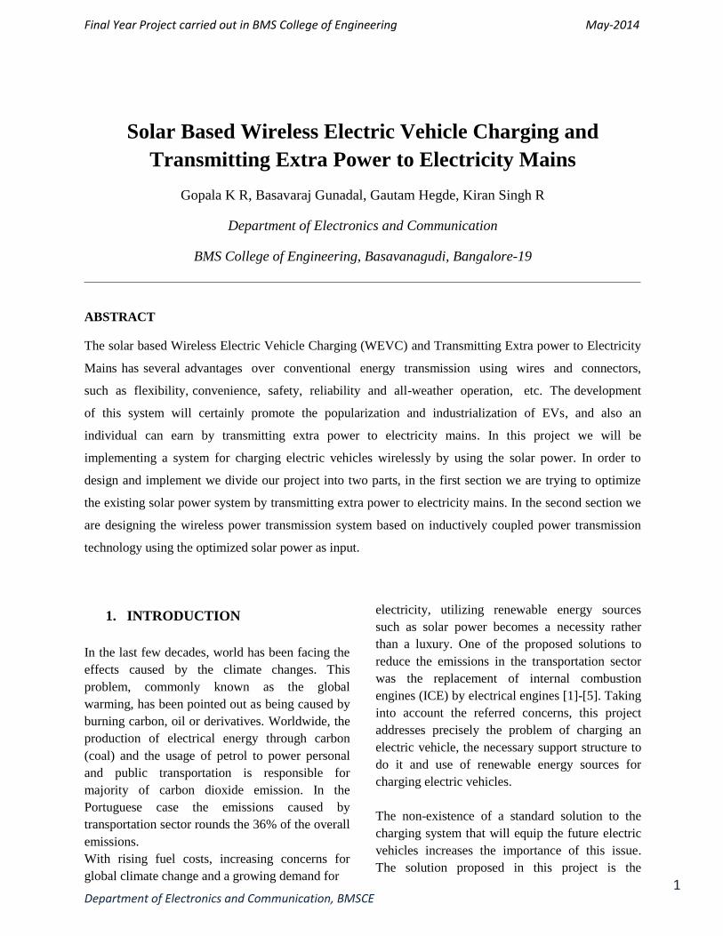
Figure 1.1 Fundamental Structure of the Solar based
WEVC and Transmitting Extra Power to Mains.
When battery is fully charged then the next stage
is to shift the charging point or the power line
towards the grid or Electricity board so that
wastage can be minimized and the power can be
delivered to the Electricity Board (EB). In this
section we will be monitoring the numbers of units
we are transferring to the EB and the total amount
we are going to earn from that.
Fig.1.1 shows the fundamental structure
(Prototype) of WEVC system using solar power
[8]. Power convertor takes power from the solar
battery supply to generate a high frequency current
in the primary energy emission unit (underground
track or coil array), around which high frequency
magnetic field is formed. In the pick-up unit,
which is located in the high frequency magnetic
field, high frequency current is induced and
conditioned to produce stable supply to battery
charging.
Final Year Project carried out in BMS College of Engineering May-2014
Department of Electronics and Communication, BMSCE
4
2. OVERVIEW OF ICPT
This concept of transferring energy without the
need of using wires to connect the load to the
source is based in the magnetic induction [12]-
[17]. This technology have been considered a
valid alternative to the classic charging system, by
contact, due to the numerous advantages, some of
them, very appellative to an electric vehicle
charging system.
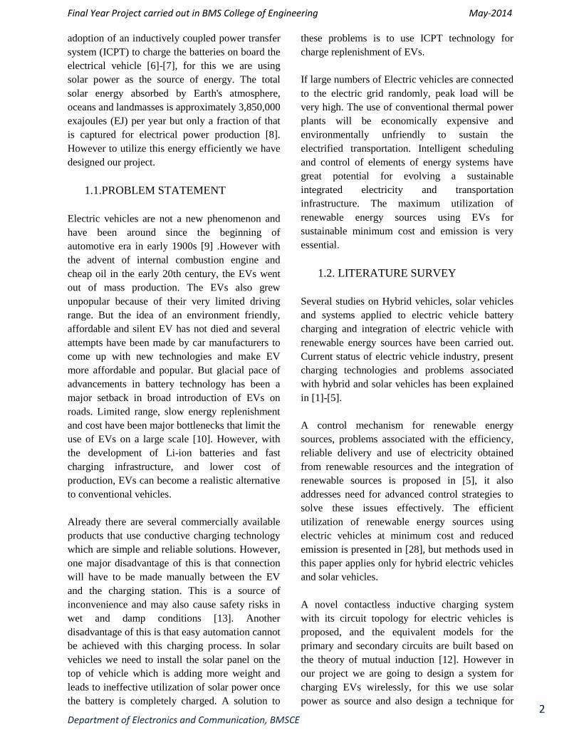
Figure 2.1: Main blocks of an ICPT vehicle charging
system
The basic circuit of an ICPT vehicle charging
system is constituted by four major blocks: a
power source, a magnetic link, a resonant circuit
and a battery charger (Fig. 2.1) [12]. The power
source is responsible for the connection between
the power grid and the magnetic link. It is usually
composed by and rectifier followed by an inverter.
With this topology, the frequency and current
amplitude may be controlled allowing controlling
the power flow of the system. The magnetic
linkage is responsible for the transfer of the power
between the power source and the battery charger
and is composed by two coils that can have an iron
core or be coreless. The resonant circuit is used to
compensate the reactive part of total impedance
increasing the power transfer efficiency.
The battery charger allows to control the charging
process and to control the changing voltage to the
levels accepted by each type of battery. It is also
responsible by making the connection between the
ICPT system and the battery set to be charged,
which is on- board of the car.
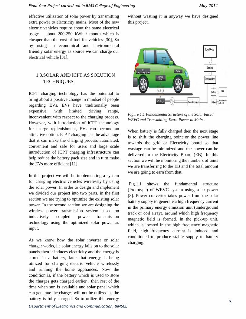
A simplified ICPT system diagram is presented in
Fig. 3.2 The most important parts of an ICPT
system, as it is well-known, are the magnetic
linkage and the resonant circuit.
Figure 2.2: Simplified ICPT system diagram
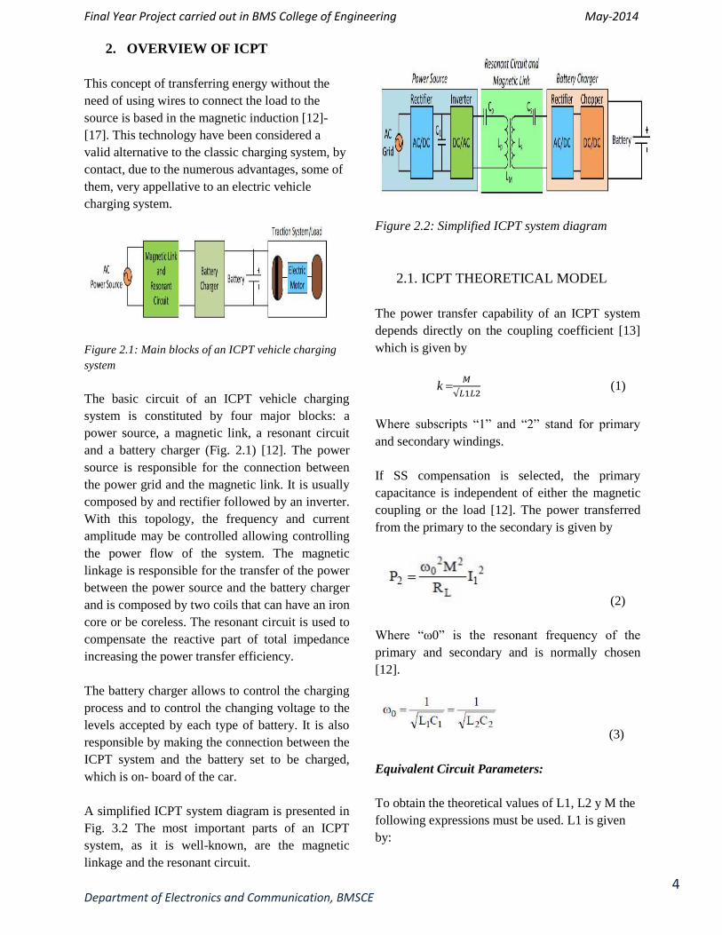
2.1. ICPT THEORETICAL MODEL
The power transfer capability of an ICPT system
depends directly on the coupling coefficient [13]
which is given by
k
(1)
Where subscripts “1” and “2” stand for primary
and secondary windings.
If SS compensation is selected, the primary
capacitance is independent of either the magnetic
coupling or the load [12]. The power transferred
from the primary to the secondary is given by
(2)
Where “ω0” is the resonant frequency of the
primary and secondary and is normally chosen
[12].
(3)
Equivalent Circuit Parameters:
To obtain the theoretical values of L1, L2 y M the
following expressions must be used. L1 is given
by:

Final Year Project carried out in BMS College of Engineering May-2014
Department of Electronics and Communication, BMSCE
5
(4)
And L2 is given by
(5)
Where R1 and R2 are the equivalent radius of the
windings
(6)
And the mutual inductance coefficient M when the
two coils have the same dimensions is given by
(7)
Considering a case where the primary track is
longer than the secondary pick up, L >> a; the
mutual inductance can be approximated by
(8)
The resistive values of the windings can be
calculated by
(9)
Operational Frequency:
Working at secondary resonance frequency, the
efficiency of the system is given by
(10)
In order to achieve maximum efficiency
(11)
As can be seen in (12) the better the coupling
between the two coils, the lower the design
frequency.
Capacitors C 1 and C 2 must be selected at the
secondary resonant frequency [26] in order to
achieve maximum power transfer capability.
(12)
Final Year Project carried out in BMS College of Engineering May-2014
Department of Electronics and Communication, BMSCE
6
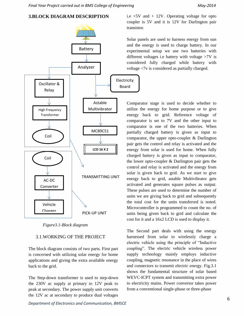
3.BLOCK DIAGRAM DESCRIPTION
Figure3.1-Block diagram
3.1.WORKING OF THE PROJECT
The block diagram consists of two parts. First part
is concerned with utilizing solar energy for home
applications and giving the extra available energy
back to the grid.
The Step-down transformer is used to step-down
the 230V ac supply at primary to 12V peak to
peak at secondary. The power supply unit converts
the 12V ac at secondary to produce dual voltages
i.e +5V and + 12V. Operating voltage for opto
coupler is 5V and it is 12V for Darlington pair
transistor.
Solar panels are used to harness energy from sun
and the energy is used to charge battery. In our
experimental setup we use two batteries with
different voltages i.e battery with voltage >7V is
considered fully charged while battery with
voltage <7v is considered as partially charged.
Comparator stage is used to decide whether to
utilize the energy for home purpose or to give
energy back to grid. Reference voltage of
comparator is set to 7V and the other input to
comparator is one of the two batteries. When
partially charged battery is given as input to
comparator, the upper opto-coupler & Darlington
pair gets the control and relay is activated and the
energy from solar is used for home. When fully
charged battery is given as input to comparator,
the lower opto-coupler & Darlington pair gets the
control and relay is activated and the energy from
solar is given back to grid. As we start to give
energy back to grid, astable Multivibrator gets
activated and generates square pulses as output.
These pulses are used to determine the number of
units we are giving back to grid and subsequently
the total cost for the units transferred is noted.
Microcontroller is programmed to count the no. of
units being given back to grid and calculate the
cost for it and a 16x2 LCD is used to display it.
The Second part deals with using the energy
harnessed from solar to wirelessly charge a
electric vehicle using the principle of “Inductive
coupling”. The electric vehicle wireless power
supply technology mainly employs inductive
coupling, magnetic resonance in the place of wires
and connectors to transmit electric energy. Fig.3.1
shows the fundamental structure of solar based
WEVC-ICPT system and transmitting extra power
to electricity mains. Power convertor takes power
from a conventional single-phase or three-phase
Battery
Analyzer
Astable
Multivibrator
MC89C51
Oscillator &
Relay
High Frequency Transformer
Coil
Coil
AC-DC
Converter
Vehicle
Charger
Electricity
Board
LCD 16 X 2
PICK-UP UNIT
TRANSMITTING UNIT
Final Year Project carried out in BMS College of Engineering May-2014
Department of Electronics and Communication, BMSCE
7
power supply to generate a high frequency current
in the primary energy emission unit (underground
track or coil array), around which high frequency
magnetic field is formed. In the pick-up unit,
which is located in the high frequency magnetic
field, high frequency current is induced and
conditioned to produce stable supply to battery
charging. At pick-up unit the ac voltage obtained
by inductive coupling is given to rectifier stage to
get DC voltage which is used for charging battery.
4. PROGNOSIS
Over the course of project, a large number of
domains were found that could be investigated
particularly in relation to inductive power transfer
and grid connected solar. Some of the problems
that could be identified for future research are
listed in the following paragraphs.
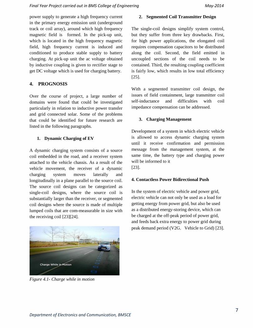
1. Dynamic Charging of EV
A dynamic charging system consists of a source
coil embedded in the road, and a receiver system
attached to the vehicle chassis. As a result of the
vehicle movement, the receiver of a dynamic
charging system moves laterally and
longitudinally in a plane parallel to the source coil.
The source coil designs can be categorized as
single-coil designs, where the source coil is
substantially larger than the receiver, or segmented
coil designs where the source is made of multiple
lumped coils that are com-measurable in size with
the receiving coil [23][24].
Figure 4.1- Charge while in motion
2. Segmented Coil Transmitter Design
The single-coil designs simplify system control,
but they suffer from three key drawbacks. First,
for high power applications, the elongated coil
requires compensation capacitors to be distributed
along the coil. Second, the field emitted in
uncoupled sections of the coil needs to be
contained. Third, the resulting coupling coefficient
is fairly low, which results in low total efficiency
[25].
With a segmented transmitter coil design, the
issues of field containment, large transmitter coil
self-inductance and difficulties with coil
impedance compensation can be addressed.
3. Charging Management
Development of a system in which electric vehicle
is allowed to access dynamic charging system
until it receive confirmation and permission
message from the management system, at the
same time, the battery type and charging power
will be informed to it
[23].
4. Contactless Power Bidirectional Push
In the system of electric vehicle and power grid,
electric vehicle can not only be used as a load for
getting energy from power grid, but also be used
as a distributed energy-storing device, which can
be charged at the off-peak period of power grid,
and feeds back extra energy to power grid during
peak demand period (V2G,Vehicle to Grid) [23].
Final Year Project carried out in BMS College of Engineering May-2014
Department of Electronics and Communication, BMSCE
8
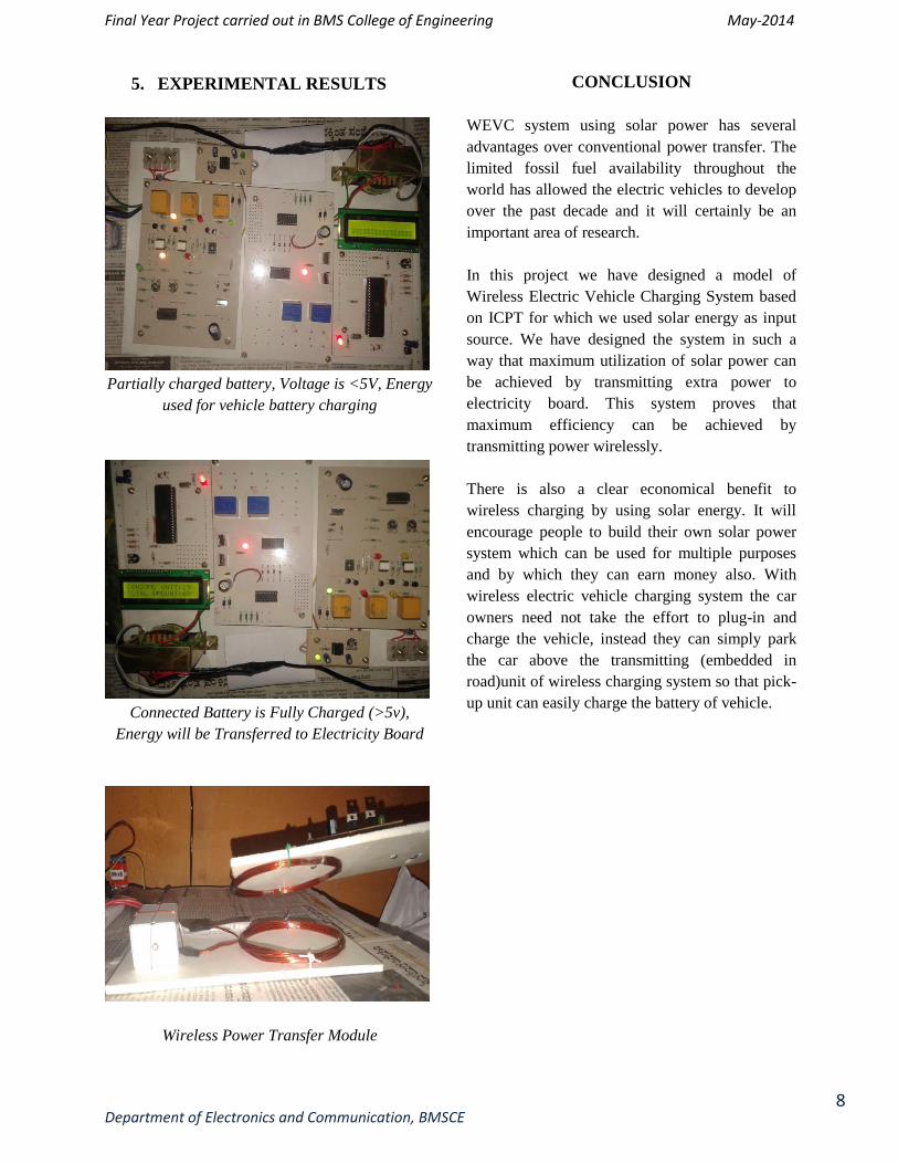
5. EXPERIMENTAL RESULTS
Partially charged battery, Voltage is <5V, Energy
used for vehicle battery charging
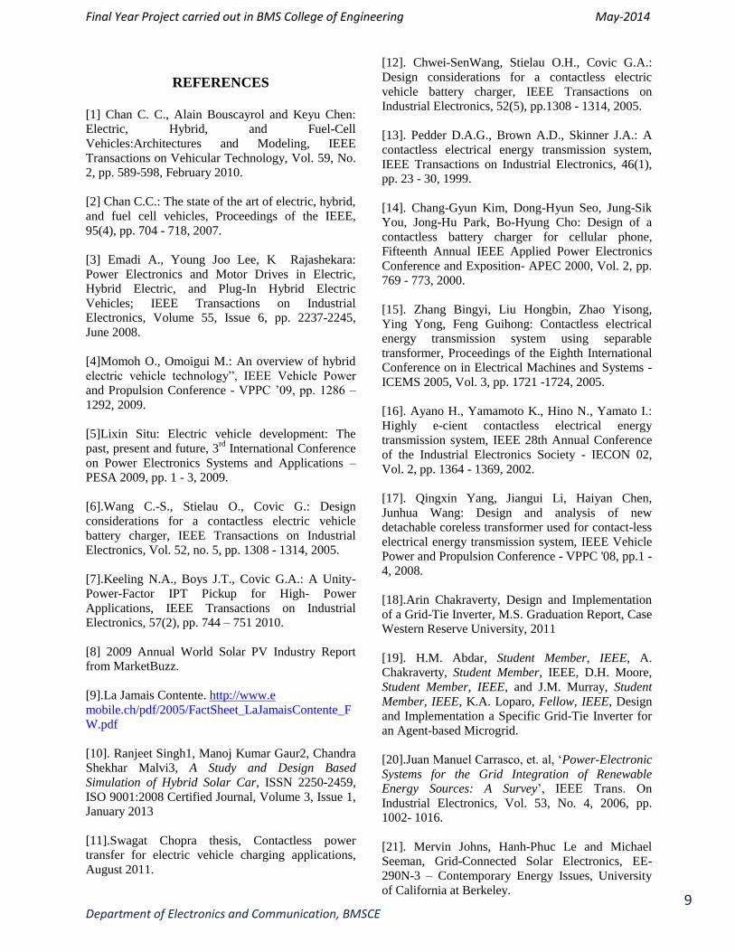
Connected Battery is Fully Charged (>5v),
Energy will be Transferred to Electricity Board
Wireless Power Transfer Module
CONCLUSION
WEVC system using solar power has several
advantages over conventional power transfer. The
limited fossil fuel availability throughout the
world has allowed the electric vehicles to develop
over the past decade and it will certainly be an
important area of research.
In this project we have designed a model of
Wireless Electric Vehicle Charging System based
on ICPT for which we used solar energy as input
source. We have designed the system in such a
way that maximum utilization of solar power can
be achieved by transmitting extra power to
electricity board. This system proves that
maximum efficiency can be achieved by
transmitting power wirelessly.
There is also a clear economical benefit to
wireless charging by using solar energy. It will
encourage people to build their own solar power
system which can be used for multiple purposes
and by which they can earn money also. With
wireless electric vehicle charging system the car
owners need not take the effort to plug-in and
charge the vehicle, instead they can simply park
the car above the transmitting (embedded in
road)unit of wireless charging system so that pick-
up unit can easily charge the battery of vehicle.
Final Year Project carried out in BMS College of Engineering May-2014
Department of Electronics and Communication, BMSCE
9
REFERENCES
[1] Chan C. C., Alain Bouscayrol and Keyu Chen:
Electric, Hybrid, and Fuel-Cell
Vehicles:Architectures and Modeling, IEEE
Transactions on Vehicular Technology, Vol. 59, No.
2, pp. 589-598, February 2010.
[2] Chan C.C.: The state of the art of electric, hybrid,
and fuel cell vehicles, Proceedings of the IEEE,
95(4), pp. 704 - 718, 2007.
[3] Emadi A., Young Joo Lee, K Rajashekara:
Power Electronics and Motor Drives in Electric,
Hybrid Electric, and Plug-In Hybrid Electric
Vehicles; IEEE Transactions on Industrial
Electronics, Volume 55, Issue 6, pp. 2237-2245,
June 2008.
[4]Momoh O., Omoigui M.: An overview of hybrid
electric vehicle technology”, IEEE Vehicle Power
and Propulsion Conference - VPPC ’09, pp. 1286 –
1292, 2009.
[5]Lixin Situ: Electric vehicle development: The
past, present and future, 3rd
International Conference
on Power Electronics Systems and Applications –
PESA 2009, pp. 1 - 3, 2009.
[6].Wang C.-S., Stielau O., Covic G.: Design
considerations for a contactless electric vehicle
battery charger, IEEE Transactions on Industrial
Electronics, Vol. 52, no. 5, pp. 1308 - 1314, 2005.
[7].Keeling N.A., Boys J.T., Covic G.A.: A Unity-
Power-Factor IPT Pickup for High- Power
Applications, IEEE Transactions on Industrial
Electronics, 57(2), pp. 744 – 751 2010.
[8] 2009 Annual World Solar PV Industry Report
from MarketBuzz.
[9].La Jamais Contente. http://www.e
mobile.ch/pdf/2005/FactSheet_LaJamaisContente_F
W.pdf
[10]. Ranjeet Singh1, Manoj Kumar Gaur2, Chandra
Shekhar Malvi3, A Study and Design Based
Simulation of Hybrid Solar Car, ISSN 2250-2459,
ISO 9001:2008 Certified Journal, Volume 3, Issue 1,
January 2013
[11].Swagat Chopra thesis, Contactless power
transfer for electric vehicle charging applications,
August 2011.
[12]. Chwei-SenWang, Stielau O.H., Covic G.A.:
Design considerations for a contactless electric
vehicle battery charger, IEEE Transactions on
Industrial Electronics, 52(5), pp.1308 - 1314, 2005.
[13]. Pedder D.A.G., Brown A.D., Skinner J.A.: A
contactless electrical energy transmission system,
IEEE Transactions on Industrial Electronics, 46(1),
pp. 23 - 30, 1999.
[14]. Chang-Gyun Kim, Dong-Hyun Seo, Jung-Sik
You, Jong-Hu Park, Bo-Hyung Cho: Design of a
contactless battery charger for cellular phone,
Fifteenth Annual IEEE Applied Power Electronics
Conference and Exposition- APEC 2000, Vol. 2, pp.
769 - 773, 2000.
[15]. Zhang Bingyi, Liu Hongbin, Zhao Yisong,
Ying Yong, Feng Guihong: Contactless electrical
energy transmission system using separable
transformer, Proceedings of the Eighth International
Conference on in Electrical Machines and Systems -
ICEMS 2005, Vol. 3, pp. 1721 -1724, 2005.
[16]. Ayano H., Yamamoto K., Hino N., Yamato I.:
Highly e-cient contactless electrical energy
transmission system, IEEE 28th Annual Conference
of the Industrial Electronics Society - IECON 02,
Vol. 2, pp. 1364 - 1369, 2002.
[17]. Qingxin Yang, Jiangui Li, Haiyan Chen,
Junhua Wang: Design and analysis of new
detachable coreless transformer used for contact-less
electrical energy transmission system, IEEE Vehicle
Power and Propulsion Conference - VPPC '08, pp.1 -
4, 2008.
[18].Arin Chakraverty, Design and Implementation
of a Grid-Tie Inverter, M.S. Graduation Report, Case
Western Reserve University, 2011
[19]. H.M. Abdar, Student Member, IEEE, A.
Chakraverty, Student Member, IEEE, D.H. Moore,
Student Member, IEEE, and J.M. Murray, Student
Member, IEEE, K.A. Loparo, Fellow, IEEE, Design
and Implementation a Specific Grid-Tie Inverter for
an Agent-based Microgrid.
[20].Juan Manuel Carrasco, et. al, ‘Power-Electronic
Systems for the Grid Integration of Renewable Energy Sources: A Survey’, IEEE Trans. On
Industrial Electronics, Vol. 53, No. 4, 2006, pp.
1002- 1016.
[21]. Mervin Johns, Hanh-Phuc Le and Michael
Seeman, Grid-Connected Solar Electronics, EE-
290N-3 – Contemporary Energy Issues, University
of California at Berkeley.

Final Year Project carried out in BMS College of Engineering May-2014
Department of Electronics and Communication, BMSCE
10
[22]. J.L.Villa, A. Llombart, J.F.Sanz , J.Sallan,
Development of an inductively coupled power
transfer system (ICPT) for electric vehicles with a
large airgap-2013
[23]. Yong Tian, Yue Sun, Yugang Su, Xin Dai,
Zhihui Wang, Study on the Electric Vehicle Wireless
Power Supply Technology and System Based on
ICPT, World Electric Vehicle Journal Vol. 4 - ISSN
2032-6653 - © 2010 WEVA
[24]. Jaegue Shin, Member, IEEE, Seungyong Shin,
IEEE, Design and Implementation of Shaped
Magnetic-Resonance-Based Wireless Power
Transfer System for Roadway- Powered Moving,
Electric Vehicles, IEEE TRANSACTIONS ON
INDUSTRIAL ELECTRONICS, VOL. 61, NO. 3,
MARCH 2014
[25]. P.Meyer, P. Germano, and Y. Perriard.
Modeling of Inductive Contactless Energy Transfer
Systems, THÈSE NO 5486 (2012) ÉCOLE
POLYTECHNIQUE FÉDÉRALE DE LAUSANNE
PRÉSENTÉE le 25 septembre 2012
[26]. T. Bieler, M. Perrotter, V. Nguyen and Y.
Perriard, “Contactless power and information
transmission” Conf. Rec. IEEE-IAS Annual
Meeting, vol. 1, pp. 83- 88, 2001.
[27]. MUHAMMAD H. RASHID, POWER
ELECTRONICS: CIRCUITS, DEVICES AND
APPLICATIONS, 3RD EDITION
[28].Saber, A.Y. ; Electr. & the uter Eng. Dept. of
Sci. & Technol., Rolla, MO, USA ;
Venayagamoorthy, Efficient Utilization of
Renewable Energy Sources by Gridable Vehicles in
Cyber-Physical Energy Systems G.K. Systems
Journal, IEEE (Volume:4 , Issue: 3, sept 2010 )
[29]. Tarak Salmi, Mounir Bouzguenda, Adel Gastli,
Ahmed Masmoudi, MATLAB/Simulink Based
Modelling of Solar Photovoltaic Cell
INTERNATIONAL JOURNAL of RENEWABLE
ENERGY RESEARCH Tarak Salmi et al., Vol.2,
No.2, 2012
[30]. http://1bog.org/blog/charging-an-electric-car-
at-home-how-many-more-solarpanels-
do-i-need/
[31]. Sedghisigarchi, K. ; Electr. & Comput. Eng.
Dept., West Virginia Univ. Inst. of
Technol., Montgomery, WV, USA, Residential solar
systems: Technology, netmetering,
and financial payback.