Embed Size (px)
Citation preview
1
THE USE OF MASONRY INFILLS IN SEISMIC REHABILITATION OF REINFORCED CONCRETE FRAME STRUCTURES
Georgia E. THERMOU1, Stylianos I. PARDALOPOULOS2 and Stavroula J.
PANTAZOPOULOU3
ABSTRACT
Seismic damage in frame structures often localizes in areas of stiffness deficiency such as soft-storeys. A common remedy in such situations is the addition of stiffness in the structure to limit drift demands thereby controlling the extent of damage. From among the available alternatives, addition of masonry infills is a low-cost, easily replaceable in the event of damage alternative that combines the advantage of not burdening the foundation with excessive flexural strength demands as would occur in the case of infill R.C. structural walls. To facilitate the design of such retrofit solutions, practical design charts have been derived in the paper, linking drift demand to the area ratios of infills in the critical floor of the structure; the number of floors and the strength characteristics of the infills are parameters of the charts. Using the charts dimensioning masonry infills in existing reinforced concrete structures is controlled by performance criteria such as target distributions of interstorey drift demand, a target estimate of the fundamental period as required by the designer, and a limit on acceptable displacement ductility for the retrofitted structure. Application of the retrofit design through infills is demonstrated on example case studies. Behavioral mechanisms mobilized by masonry infills in successful retrofits are shown to emulate confined masonry behaviour. It is also shown that despite their brittleness, well connected infills can successfully mitigate the occurrence of catastrophic damage by diverting damage localization from the vulnerable regions of the building.
INTRODUCTION
Collapse of structures in severe earthquakes is synonymous with loss of vertical load bearing capacity in the columns and walls of the structural system. From a review of recent failures it appears that the most vulnerable are buildings with stiffness discontinuities height-wise such as pilotis and partially infilled frames with short column formations (Fig. 1). It has been shown from basic mechanics that the seismic vulnerability of a given structure can be quantified by the height-wise distribution of the area ratios in the floor plan of the vertical elements including both reinforced concrete members and masonry infills, ρc and ρmw, respectively (Thermou and Pantazopoulou 2011). Simple quantitative criteria have been derived from first principles which link interstorey drift demand in the design
1 Lecturer, Dept. of Civil Engineering, Aristotle University of Thessaloniki, 54124 Thessaloniki, Greece, [email protected] 2 Dr Civil Engineer, Special Scientist, Dept. of Civil & Environmental Engineering, University of Cyprus, [email protected] 3 Professor, Dept. of Civil & Environmental Engineering, University of Cyprus, P.O. Box 20537, 1678 Nicosia, Cyprus, [email protected]

2
earthquake to ρc and ρmw; these are used not only for rapid seismic assessment of existing structures, but also in order to guide inexpensive and fast retrofit solutions that involve masonry infilling to supplement lateral stiffness in soft storey formations. To this end, the paper presents a practical design methodology in the form of practical design charts. Using this device, dimensioning and detailing of masonry infills in existing reinforced concrete structures is controlled by target distributions of interstorey drift demand, a target estimate of the fundamental period as required by the designer, and a limit on acceptable displacement ductility for the structure in consideration.
Using this retrofit method in existing structures with deficiencies due to stiffness discontinuities offers the advantage that it is reversible (not necessarily invasive), whereas it moderates the magnitude of forces transferred to the foundation resulting from the stiffness enhancement, so that excessive foundation retrofit may not even be necessary – a situation that cannot be avoided with other more thorough interventions such as reinforced concrete jacketing and/or addition of reinforced concrete walls. Although it has gained significant popularity owing to the versatility and low cost, a number of lingering issues need be resolved before the method may be accepted as a legitimate engineering intervention in established retrofit design codes: these are related to the uncertainties necessarily associated with the masonry infill panel’s resistance curve, its resilience and dependable ductility. Field observations underscore the dramatic difference in moderating seismic response achieved by confined masonry buildings as compared with the less effective addition of masonry infills after scaffold-removal in common reinforced concrete construction.
The paper discusses the effects of detailing during practical implementation of infills, on the essential characteristics of the basic resistance curve, placing particular emphasis on the different behavioural mechanisms mobilized during seismic response that could be rendered to emulate the characteristics of confined masonry behaviour in successful retrofits. It is also shown that despite their brittleness, well connected infills can successfully mitigate the occurrence of catastrophic damage by diverting damage localization from the vulnerable regions of the building.
Figure 1. (a); (b) Pilotis-type multi-storey buildings; (c) Soft-storey formation in a 2-storey frame building (Varthlomio, M6.5R Andravida Earthquake 2008) (d.1,2) Livadi (M6.1R Cefalonia Earthquake 2014)
SEISMIC REHABILITATION OF RC FRAME BUILDINGS WITH THE USE OF MASONRY INFILLS
The beneficial effect of masonry infills especially in the case of old substandard construction with no seismic detailing has been demonstrated by many earthquake events. In Greece, thousands of pre 1970 buildings which were poorly reinforced survived the Athens 1999 earthquake with little or no damage due to the fact that their first storey had infills. The contribution of masonry infills to the lateral resistance of the structural system depends on the degree of engagement of the masonry to the vertical and horizontal components of the bay frame. Earthquake-resistant confined masonry comprises a discrete category where masonry walls are the main load bearing elements expected to resist both gravity and lateral loads (Brzev 2007). Masonry walls are constructed first and subsequently the
(d.1)
(d.2)

G.E. Thermou, S.I. Pardalopoulos, S.J. Pantazopoulou 3
confining elements (tie-columns and tie-beams), which are much smaller in size than regular RC columns and beams, are cast in place encasing the pre-constructed masonry walls (Fig. 2). In the case of RC frame construction, RC columns and beams are the primary load-bearing elements whereas masonry infills are constructed at a later stage. Thus the degree of engagement between masonry and the surrounding frame is limited at best, or negligible. When the masonry walls are not bonded to the frame members (i.e. gaps exist with the surrounding frame that weaken the interaction) they may be considered as non-structural components and their contribution to the lateral resistance of the building could be ignored. However, there are construction techniques (e.g. RC laces or chainages (fr.), shear connectors, wedged bricks in the top layer) that improve integration between the infill walls and the surrounding load carrying components (Fig. 3). In that case a certain degree of connection is provided with the surrounding structural elements, and thus, in these cases, infill walls are considered to contribute to the lateral load resistance of the buildings.
Figure 2. (a) Confined masonry; (b) Non-engineered masonry infills
Figure 3. Construction techniques that strengthen the connection of the masonry infills to the surrounding structural elements emulating the confined masonry type of construction
EC8 – Part I ((§4.3.6.1(1)) defines specifically the conditions that ought to be fulfilled by non-
engineered masonry infills. Thus, they should be constructed after the hardening of the concrete frames, be in contact with the frame but without structural connection to it and be considered in principle as non-structural elements. Moreover, EC8– Part I ((§4.3.6.1(5)) mentions that if engineered masonry infills constitute part of the seismic resistant structural system (implying that structural connection is provided between the masonry and the surrounding frame members), analysis and design should be carried out in accordance with the criteria and rules given for confined masonry. The
Tie-columns RC columns
RC laces
Inclined bricks (wedges)

4
contribution of masonry infill walls seems to be more pronounced in case of frame buildings designed for high ductility class where the lateral force stiffness (and strength) are low, whereas the ductility and deformation capacity high (Fardis et al. 2005). Masonry infills should be explicitly included in the model for the seismic analysis of the building. Any irregularity in plan and elevation as well as the possible adverse local effects due to the frame-infill-interaction shall be taken into account (EC8-Part I 2004). One other aspect that needs to be considered in detail is the high uncertainty related to the mechanical properties, the degree of attachment to the surrounding frame and the non-uniform degree of damage suffered during the earthquake. Last but not least is the influence of the shape, size and location of the openings in the axial stiffness and strength capacity of the masonry walls. EC8-Part I (2004) mentions that strongly irregular, unsymmetrical or non-uniform arrangements of infills in plan should be avoided. Spatial models should be used for the analysis of the structure in the case of severe irregularities in plan due to the unsymmetrical arrangement of the infills. The Greek Code for Structural Interventions (KANEPE 2013) provides some practical rules on how the masonry infills should be modelled when openings exist. Function of Infills as a Retrofit Scheme Seismic damage often localizes in areas of stiffness deficiency such as soft-storeys in frame structures. A common remedy in such situations is the addition of stiffness in the structure to limit drift demands thereby controlling the extent of damage. From among the available alternatives, addition of masonry infills is a low-cost, easily replaceable in the event of damage alternative that combines the advantage of not burdening the foundation with excessive flexural strength demands as would occur in the case of infill R.C. structural walls.
The translational stiffness of an infill masonry wall deforming in its plane is estimated with reference to a diagonal strut used to idealize the infills’ function as a stiffening link (EC8-Part I 2004, EC8-Part III 2005). The stiffness value is a secant measure, obtained from the ratio of the estimated wall lateral force to the corresponding storey distortion. The applied lateral force is equal to the horizontal component of the strut:
αcosfA10.0αcosNV j,mwj,mwjjmax, ; j
j,mw
Lαcos
; 2
i,cl2
j,mwj hL (1)
Vmax,j is obtained from the product of the compressive strength of the masonry, fmw,j, by the effective area of the strut taken equal to 10% of the wall area Amw,j. ℓmw,j is the masonry wall length and hcl,j is the clear storey height. Storey distortion is given by the interstorey lateral displacement, θihi. Storey drift θi is expressed as a multiple of the infill wall’s yield distortion, θy
mw, through the level of ductility attained by the infill wall at the point of yielding of the surrounding RC frame, which is denoted here by parameter μy
mw. Therefore,
j,mw2j,mw
2i,cl
mwj,y
mwj,y
j,mw
i
f
imwy
mwy
jmax,mwj ρ
h1θμ
f10.0
h
A
hμθ
VK
(2)
where Afl is the floor area of the critical storey, hi is the storey height, fmw,j is the compressive strength of the masonry, ρmw,j is the dimensionless area of masonry infill walls at i-th storey, θy,j
mw is drift at yield of the infill wall and μy,j
mw the level of ductility attained by the infill wall at the point of yielding of the surrounding RC frame.
As illustrated in Fig. 4 secant stiffness of wall infills decays with imposed drift demand. The wall’s distortion at yield and ultimate may be defined according to KANEPE (2013) by the following set of equations:
3
mw
i,cl
i,cl
j,mwmwj,y
mwj,y 105.10.1
h
hγθ
(3a)

G.E. Thermou, S.I. Pardalopoulos, S.J. Pantazopoulou 5
3
j,mw
j,cl
j,cl
j,mwmwj,u
mwj,u 105.30.2
h
hγθ
(3b)
where ℓmw,j is the masonry wall length and hcl,j is the clear storey height. Figure 4. (a) Behavioral model; (b) Resistance curve for masonry wall element suggested by KANEPE
(2013)
INTERSTOREY DRIFT ENVELOPES FOR RETROFITTING WITH MASONRY INFILL WALLS
The Interstorey Drift Spectra (IDS) representation is a practical design tool that facilitates direct insight into the relationships between drift demand and the required stiffness under lateral sway of the building. It was developed by Thermou and Pantazopoulou (2011) and may used both for assessment and rehabilitation of existing buildings (Thermou et al. 2012, Pardalopoulos et al. 2013).
The elastic value of the i-th storey interstorey-drift, IDi, is given by:
d*
*
i
ii
i
1iii S
M
L
h
ΔΦΔ
h
ΦΦID
(4)
where ΔΦi is the difference in the lateral response shape between two successive storeys, hi is the storey height, Sd is the spectral displacement of the equivalent SDOF system, corresponding to the top floor of the structure (where the fundamental model of vibration is normalized to 1). For any chosen target response shape, Φ, the values of L*, M* are calculated from the storey masses, mi, as:
2i
n
1ii
* ΦmM
, i
n
1ii
* ΦmL
(5)
Considering that nonlinear behavior of the retrofit is often limited by the existing reinforcement
anchorages, which may remain a weak zone of behavior even after rehabilitation, it is generally advisable that the ductility demand targeted for the structural system should not exceed the value of 3. Having eliminated the risk of localization through proper selection of the target response shape for re-engineering the structure through retrofit, individual target member rotation demand is given by:
Columns: q
S
M
L
h
ΔΦλID d
*
*
i
ic
ci,y ; Beams:
q
S
M
L
h
ΔΦλID d
*
*
i
ib
bi,y (6)
where q is the behaviour factor and λc =λ/(1+λ), λb =λ/(1+λ)=1- λc with λ equal to:
α
V
N γ=θ
ℓmw
hi
γymw
γumw
Vmax
V
0.25Vmax
γredmw
Ksec

6
bcc
ibb
LEIn
hEInλ
(7)
where nb and nc are the beams and columns that converge to a typical floor joint, EIb and EIc the stiffness of beams and columns, hi is the storey height and Lb is the beam span. Coefficients c and b distribute the frame joint rotations to members that converge in each joint (to beams and columns) according to the individual member stiffness.
Type I elastic spectrum of Eurocode 8 (2004) is used to define spectral displacement demand for a design region 0.15s < T < 2.00 s for subsoil of class B with S=1.20, β0=2.50, TB=0.15 s, TC=0.50 s, q=1.00. Demand in terms of spectral displacement is defined as follows:
2
gd T α076.0)T( S:50.0T15.0 (8a)
T α038.0)T( S:00.2T50.0 gd (8b)
where ag is the peak ground acceleration (pga) and T is the period of an n-storey building. In case of constant distribution of storey plan geometry along the height of the building and adequate storey stiffness distribution so as to produce the shear response shape, period T is defined as:
Q1n25.276.1QAK
mA
K
Mπ2T
1*
*
(9)
where m is the mass of each storey and K1 is the lateral stiffness of the first storey. A is a parameter that takes into account the type of the lateral response shape and is related to the number of stories n. The term Q is defined as:
5.0
1c
i
5.0
1 ρD
hγ
K
mQ
(10)
where m is the mass of each storey taken equal to γ·Afl with γ the mass per unit area of the floor, Dc is the stiffness coefficient of the first storey (K1=AflD
cρ1/hi, see below Eq. (16) for further explanation), 1 is composite area ratio of the vertical members of the first storey (see Eq. (16)), and hi is the storey height.
After algebraic manipulation of the above expressions and assuming that the critical storey is the first storey, drift demand in the first floor of the structure, ID1, is related to the composite area ratio of the vertical floor members, 1. Derivations are based on the assumption that the fundamental shape of lateral vibration may be approximated by a shear response shape according with:
H2
xπsin)x(Φ i
i (11)
Using this definition, the seismic demand may be specified according with the following set of
equations:
1
cs2
g1 ρ
1
D
γB1n25.2a235.0DI :50.0T15.0 (12a)
5.0
1
5.0
icsg1 ρ
1
hD
γB1n25.2α067.0DI :00.2T50.0
(12b)
G.E. Thermou, S.I. Pardalopoulos, S.J. Pantazopoulou 7
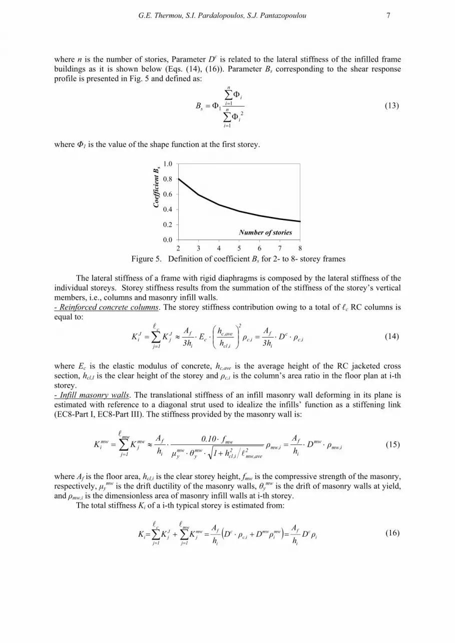
where n is the number of stories, Parameter Dc is related to the lateral stiffness of the infilled frame buildings as it is shown below (Eqs. (14), (16)). Parameter Bs corresponding to the shear response profile is presented in Fig. 5 and defined as:
n
ii
n
ii
sB
1
2
11 (13)
where Φ1 is the value of the shape function at the first storey.
0.0
0.2
0.4
0.6
0.8
1.0
2 3 4 5 6 7 8
Number of stories
Coe
ffic
ient
Bs
Figure 5. Definition of coefficient Bs for 2- to 8- storey frames
The lateral stiffness of a frame with rigid diaphragms is composed by the lateral stiffness of the
individual storeys. Storey stiffness results from the summation of the stiffness of the storey’s vertical members, i.e., columns and masonry infill walls. - Reinforced concrete columns. The storey stiffness contribution owing to a total of ℓc RC columns is equal to:
i,cc
i
fi,c
2
i,cl
ave,cc
i
fc
1j
Jj
Ji ρD
h3
Aρ
h
hE
h3
AKK
(14)
where Ec is the elastic modulus of concrete, hc,ave is the average height of the RC jacketed cross section, hcl,I is the clear height of the storey and ρc,i is the column’s area ratio in the floor plan at i-th storey. - Infill masonry walls. The translational stiffness of an infill masonry wall deforming in its plane is estimated with reference to a diagonal strut used to idealize the infills’ function as a stiffening link (EC8-Part I, EC8-Part III). The stiffness provided by the masonry wall is:
i,mwmw
i
fi,mw2
ave,mw2
i,clmwy
mwy
mw
i
fmw
1j
mwj
mwi ρD
h
Aρ
h1θμ
f10.0
h
AKK
(15)
where Af is the floor area, hcl,i is the clear storey height, fmw is the compressive strength of the masonry, respectively, μy
mw is the drift ductility of the masonry walls, θymw is the drift of masonry walls at yield,
and ρmw,i is the dimensionless area of masonry infill walls at i-th storey. The total stiffness Κi of a i-th typical storey is estimated from:
ic
i
fmwi
mwi,c
c
i
fmw
1j
mwj
c
1j
Jji ρD
h
AρDρD
h
AKKK
(16)

8
with
i,mwc
mw
i,ci ρD
Dρρ and
2
i,cl
ave,ccc
h
h
3
ED
,
2ave,mw
2i,cl
mwy
mwy
mwmw
h1θμ
f10.0D
In the above, Ec is the elastic modulus of concrete, Af is the floor area, hi is the storey height and
ℓmw,ave is the average length of the masonry walls. fmw is the compressive strength of the masonry, μymw
is the drift ductility of the masonry walls, θymw is the drift of masonry walls at yield, and ρmw,i is the
dimensionless area of masonry infill walls in the i-th storey.
Figure 6. Design charts that relate the required composite floor area ratio of vertical members to interstorey drift demand ratio for a mass per unit area of the floor, γ=1 t/m2 for pga=0.16g, 0.20g, 0.24g, 0.3g and 0.36g.
DESIGN CHARTS FOR VARIOUS RETROFIT SCENARIOS
From the above, two alternative types of design charts may be derived as depicted in Figs. 6 and 7. The graphs in Fig. 6 relate the interstorey drift demand of the 1st storey, ID1, to the composite area ratio of the vertical floor members of the first storey (i.e. columns and masonry walls), ρ1, whereas the graphs in Fig. 7 present the various combinations between ρc and ρmw for a target interstorey drift and a specific number of floors (Fig. 7 was drawn for n=2 and for pga values of 0.16g and 0.30g). The
0.0%
0.2%
0.4%
0.6%
0.8%
1.0%
0% 4% 8% 12% 16% 20%
n=2, 3, 4
n=5, 6, 7, 8
ρ1
ID1 0.16g
0.0%
0.2%
0.4%
0.6%
0.8%
1.0%
0% 4% 8% 12% 16% 20%
n=2, 3, 4
n=5, 6, 7, 8
ρ1
ID1 0.24g
0.0%
0.2%
0.4%
0.6%
0.8%
1.0%
0% 4% 8% 12% 16% 20%
n=2, 3, 4
n=5, 6, 7, 8
ρ1
ID1 0.20g
0.0%
0.2%
0.4%
0.6%
0.8%
1.0%
0% 4% 8% 12% 16% 20%
n=2, 3, 4
n=5, 6, 7, 8
ρ1
ID1 0.36g
0.0%
0.2%
0.4%
0.6%
0.8%
1.0%
0% 4% 8% 12% 16% 20%
n=2, 3, 4
n=5, 6, 7, 8
ρ1
ID1 0.30g
3.8 %

G.E. Thermou, S.I. Pardalopoulos, S.J. Pantazopoulou 9
selected pga values in Fig. 6 correspond to the three seismicity zones in Greece (Zone 1: 0.16g, Zone 2: 0.24g, Zone 3: 0.36g) and the in between values that correspond to frequently reported field acceleration values in earthquakes throughout Greece (0.20g and 0.30g). The expression for determining the interstorey drift demand is modified depending on the period range (see Eq. 12(a) and Eq. 12(b)). The fundamental period was approximated using the EC8-Part I (2004) expression for R.C. Structures (T=0.075H(3/4), where H is the total height of the buiding). Thus, for the 2-, 3- and 4-storey frame building Eq. 8(a) was utilized, whereas for the rest of the cases it was based on Eq. 8(b).
The curves of Figs. 6 and 7 were derived assuming a common concrete grade, i.e., C12/15 which corresponds to B160 commonly used in the era of construction, a mass per unit area of the floor, γ=1 t/m2, and a compressive strength of the masonry fmw=4 MPa. The storey clear height, hi, was taken equal to 2.7 m. The average length of the masonry walls was ℓmw,ave=3 m, whereas the column cross section height was determined by the following rule: hc,ave=0.30+(n-2)·0.05 for 2≤n≤4 (n is the number of storeys). For n>4 the column cross section height was taken equal to 0.50 m. For a different value of mass per unit area, γ, the ID1 should be multiplied by this value (without the units).
The design charts presented in Figs. 6 and 7 may be used either for assessment of the existing frame building or for determining the retrofit scenario. In the latter case, for a 2-storey building subjected to a pga=0.30g, if the demand in terms of interstorey drift of the first storey is to be limited by ID1=0.4%, then, the required composite floor area ratio of the vertical members would be 1=3.8%. This value is defined by the intersection of the horizontal black dashed line and the green curve (Fig. 6). For the scenario that the existing column’s area ratio is ρc,1=2%, then the required masonry infill walls’ area ratio is ρmw,1=2.7%. In case of assessment, the existing composite floor area ratio of the vertical members, 1, is evaluated, and by utilizing the charts of Fig. 6 the drift demand is determined, ID1. This value is compared with the nominal drift capacity at yielding for the existing building, ID1,ex, and in case that ID1>ID1,ex failure is anticipated, otherwise the building survives.
Figure 7. Design charts that relate the various combinations between ρc and ρmw for a target interstorey drift for n=2 and pga=0.16g and 0.30g.
ILLUSTRATIVE EXAMPLE
The retrofit design procedure utilizing the design charts that were derived in the preceding is illustrated in this section through application to a residential, two-storey R.C. building in Vartholomio, Western Peloponesse, Greece (Fig. 8a). The building was constructed in the early 1980’s, having external dimensions in plan 12.80 m by 14.20 m, whereas the heights of the first and the second storey were 4.00 m and 3.50 m, respectively. The structural system was formed as an orthogonal grid of columns, beams and slabs, according to typical construction practice of R.C. frame structures in Southern Europe. All columns comprised a 300 mm by 300 mm square cross section, except of the first storey columns C5, C6, C7 and C8, whose cross section was 350 mm by 350 mm. Details of the column geometry and longitudinal reinforcement are presented in Table 1. Column stirrups were approximately categorized based on site reconnaissance as 6/200 mm. Slab thickness was 140 mm in both storeys. All beams parallel to the X direction in plan were 200 mm (width) by 500 mm (height, including the slab thickness), whereas beams parallel to the Y direction in plan were 100 mm higher (200 mm 600 mm). Beams in the X direction had 4 12 mm reinforcing bars both at top and at
0%
2%
4%
6%
8%
10%
12%
14%
16%
18%
20%
0% 1% 2% 3% 4% 5% 6% 7% 8% 9% 10%
0.10%
0.20%
0.30%
0.40%
0.50%
ρmw
ρc 0.16g
0%
2%
4%
6%
8%
10%
12%
14%
16%
18%
20%
0% 1% 2% 3% 4% 5% 6% 7% 8% 9% 10%
0.10%
0.20%
0.30%
0.40%
0.50%
ρmw
ρc 0.30g
2.7 %

10
bottom, whereas beams in the Y direction had 4 14 mm reinforcing bars top and an equal amount at bottom of their cross section. The examined building had masonry infills only in its upper storey (hatched areas in Fig. 8a) which led to the formation of a soft first storey during the 6.5R Magnitude 06-08-2008 Andravida earthquake (Fig. 8c-8d) and consequently to the collapse of the entire structure (Fig. 8b). After tests conducted on building’s material samples, the concrete was classified as B160 (corresponding to contemporary concrete category C12/15 according to EC2, 2003), while longitudinal reinforcement and stirrups were found to have smooth surface and were classified as St I (fyk = 220 MPa, fuk = 500 MPa).
Figure 8. (a) Plan configuration of the 2nd floor of the house in Vartholomio; (b) Photos of the collapsed building; (c); (d) Andravida (Pyrgos, Greece) Earthq. (8th June 2008), elastic response spectra (total Acceler., relative Displac.) of horizontal components.
Application of the Rapid Seismic Assessment Procedure (RASP), which was recently introduced by the authors (Pardalopoulos et al. 2013a-b) indicated that due to its small size the base shear attracted by the building was not excessive; the collapsed structure failed at a low displacement, ranging between 36% to 56% of the yield value, i.e. while still in the elastic range. Table 2 shows the
00.10.20.30.40.50.60.7
010203040506070
0 0.5 1 1.5 2 2.5 3
S a(g
)
L-component, Vartholomio T-component, Vartholomio
Period, T (sec)
Andravida Earthquake (2008), M=6.5, Elastic response spectra of horizontal components
S d (
mm
)
(d)
(c)
(b)
(a)
Direction X
C1 C2 C3 C4
C5 C6 C7 C8
C9 C1 C1 C1
C1 C1 C1
3.55 3.55 3.30
0.80 12.80
3.45
Dir
ecti
on Y
3.30
4.
92
3.38
14.2
0 2.
50

G.E. Thermou, S.I. Pardalopoulos, S.J. Pantazopoulou 11
estimated values of ID in X and Y plan directions of the 1st and the 2nd storey of the examined building. Given the geometric characteristics of the columns and the masonry infills of the building (Fig. 8a), the columns’ and the masonry walls area ratios in the floor plan, ρc and ρmw, respectively, as well as the composite area ratio of the vertical floor members, ρi, in X and Y directions of the 1st and the 2nd storey were calculated (Table 2). Fig. 9a depicts the design chart that relates the required composite floor area ratio of vertical members to the interstorey drift demand ratio at the 1st storey of the building for pga=0.20g, the same pga value recorded in the 06/08/2008 Andravida earthquake. In this chart the blue colour square and triangle represent the available values of ρi in X and Y plan directions of the 1st floor with respect to the value of interstorey drift at failure that the storey could develop. Clearly the drift capacity of the columns due to poor arrangement of transverse reinforcement was excessively low (in the range of 0.2%).
Table 1. Column dimensions and reinforcement of the residential house
Storey Columns Section Dimensions
(mm)
Long. Reinforcement
(mm)
Stirrups (mm)
1st C1 – C4, C9 – C15 300 300 4 20 6 / 200 C5 – C8 350 350 4 20 + 4 18 6 / 200
2nd C1, C4, C9, C12 300 300 4 20 6 / 200 C2 – C3, C5 – C8, C10 – C11, C13 – C15 300 300 4 16 6 / 200
Table 2. Estimated values of ID, ρ, ρc and ρmw of the examined building.
Storey Plan Direction ID (%)
ρ (%)
ρc (%)
ρmw (%)
1st X 0.19 0.86 0.86 0.00 Y 0.19 0.86 0.86 0.00
2nd X 0.28 5.94 0.86 3.33 Y 0.20 7.63 0.86 3.59
Figure 9. Design charts for the examined building based on the Andravida earthquake characteristics (pga 0.20g): (a) Relationships between the composite area ratio of the vertical floor members, ρ1, and the interstorey drift, ID1, for the 1st floor; (b) Relationships between ρc,1 and ρmw,1 for the interstorey drift at failure of the 1st storey; (c) Proposed arrangement of masonry infills layout at the 1st floor.
Retrofit of such a structure to avoid collapse would have to follow one of two alternatives: (a) either to increase the deformation capacity of the soft storey columns to levels beyond the demand through confinement (e.g. jacketing), or (b) to reduce the deformation demand to levels below 0.2% so that collapse would be avoided, through stiffness increase in the soft storey (e.g. addition of infills). The second option is pursued here. As illustrated in Fig. 9, for the given value of ID1 (=0.19%, Table 2) at failure of the first storey, the composite area ratio of the vertical floor had to be much greater than the provided one as to avoid collapse. The seismic demand values of ρ1 in both plan directions of the 1st storey was estimated equal to 18.86%, which is approximately 21 times greater than the
(c)
0.0%
0.2%
0.4%
0.6%
0.8%
1.0%
0% 6% 12% 18% 24%
Floor 1 - Dir. X Floor 1 - Dir. Y
(b)
0.0%
0.4%
0.8%
1.2%
1.6%
0% 3% 6% 9% 12%
Required ρmw
ρmw,1 demand
ρmw,1
ρc,1
(b) (a)
ρ1,X & ρ1,Y demand
ρ1
ID1

12
corresponding values of the available ρ1 (=ρc=0.86%). Given the existing values of the columns’ area ratio, ρc, at both plan directions of the 1st floor of the building, the additional area ratio of masonry infills needed for the building to remain intact is 7.53% in both X and Y plan directions of the first floor. A possible arrangement is to use in the first floor the masonry infill layout of the second floor, while at the same time increasing the thickness of the interior walls from 100 mm to 200 mm, as shown in Fig. 9(c).
CONCLUSIONS
Motivation for this paper is the need for simple rehabilitation solutions that may be used easily to upgrade existing reinforced concrete structures that do not conform with the current Code Seismic design standards. The best option is to mitigate localization of deformation through addition of stiffness in potential soft-storeys of R.C. frames. From among the many alternatives to achieve that objective, the most cost effective is through masonry infills in strategically chosen open bays of frames. This option also has other advantages (it may be easily replaced after damage, and through its low strength it prevents the transfer of large forces in the foundation).
The proposed procedure attempts to optimize the distribution of interstorey drift demand height-wise in the structure, so as to control the extent of anticipated damage. The procedure is developed in the form of practical design charts that link drift demand to the area ratios of infills of the critical floors of the structure, so that it may be used easily by practitioners. Design parameters of the charts is the drift demand of the retrofitted structure. Application and relevance of the proposed procedure is demonstrated on an example case study of a two-storey residential R.C. building that collapsed during the 2008 Andravida earthquake in Greece.
REFERENCES
Brzev S (2007) Earthquake-resistant confined masonry construction, National Information Center of Earthquake Engineering, Indian Institute of Technology, Kanpur, India.
Eurocode 8 (2004). “Design of structures for earthquake resistance - Part 1: General rules, seismic actions and rules for buildings.” EN1998-1-2004:E, European Committee for Standardization (CEN), Brussels.
Eurocode 8 (2005). “Design of structures for earthquake resistance. Part 3: Assessment and retrofitting of buildings.” EN 1998-3:2005(E), European Committee for Standardization (CEN), Brussels.
Fardis MN, Carvalho E, Elnashai A, Faccioli E, Pinto P and Plumier A (2005) Designers’ guide to EN 1998-I and EN 1998-5 Eurocode 8: Design of structures for earthquake resistance. General rules, seismic actions, design rules for buidlings, foundations and retaining structures, 1st Ed., Thomas Telford ltd.
KANEPE (2013) Greek Code for Interventions,Earthquake Planning and Protection Organization, Athens. Pardalopoulos, S.J., Thermou, G.E. and Pantazopoulou S.J. (2013). “Screening Criteria to Identify Brittle R.C.
Structural Failures in Earthquakes.” Bulletin of Earthquake Engineering, 11(2), 607–636 (DOI 10.1007/s10518-012-9390-7).
Pardalopoulos, S., Thermou, G.E. and Pantazopoulou S.J. (2013). “Preliminary Seismic Assessment Method for Identifying R.C. Structural Failures.” Computational Methods in Earthquake engineering, Computational Methods in applied sciences 30, 111–128 (DOI 10.1007/978-94-007-6573-3_6).
Thermou, G. E. and Pantazopoulou, S. J. (2011) “Assessment indices for the seismic vulnerability of existing R.C. buildings”, Journal of Earthquake Engineering and Structural Dynamics, 40 (3), 293-313.
Thermou, G. E., Pantazopoulou, S. J., and Elnashai, A. S. (2012) “Global interventions for seismic upgrading of substandard RC buildings.” Journal of Structural Engineering, ASCE, 138(3), 387-401.
Thermou, G.E., Elnashai, A.S. and Pantazopoulou, S.J. (2012). “Retrofit Yield Spectra–a practical device in seismic rehabilitation.”, Earthquake and Structures, 3(2) , 141-168
Eurocode 2 (2003). “Design of concrete structures – Part 1-1: General rules and rules for buildings.” EN1992-1-1-2003:E, European Committee for Standardization (CEN), Brussels.


