Embed Size (px)
Citation preview
Americas Headquarters:Cisco Systems, Inc., 170 West Tasman Drive, San Jose, CA 95134-1706 USA
Configuring Frame Relay
First Published: January 01, 2005Last Updated: June 09, 2010
Frame Relay is a high-performance WAN protocol that operates at the physical and data link layers. The Cisco IOS XE Frame Relay implementation currently supports routing for IPv4, IPv6, and MPLS.
Finding Feature InformationFor the latest feature information and caveats, see the release notes for your platform and software release. To find information about the features documented in this module, and to see a list of the releases in which each feature is supported, see the “Feature Information for Configuring Frame Relay” section on page 27.
Use Cisco Feature Navigator to find information about platform support and Cisco IOS XE software image support. To access Cisco Feature Navigator, go to http://www.cisco.com/go/cfn. An account on Cisco.com is not required.
Contents• Restrictions for Configuring Frame Relay, page 2
• Information About Frame Relay, page 2
• How to Configure Frame Relay, page 11
• Configuration Examples for Frame Relay, page 18
• Additional References, page 25
• Feature Information for Configuring Frame Relay, page 27
2
Restrictions for Configuring Frame RelayCisco IOS XE software does not support the following:
• Multipoint permanent virtual circuits (PVCs)
• Switched virtual circuits (SVCs)
• Frame relay switching
• 4-byte extended addresses
• End-to-end keepalives
• FRF.9 payload compression
• Legacy frame-relay traffic shaping (Cisco IOS XE software only supports policy map based MQC)
The LMI of type “cisco” does not support fragmentation of status messages (FRF1.2). So, the maximum number of PVCs that can be supported by an interface with LMI of type “cisco” is restricted to the MTU size.
• For T1 serial interfaces—LMI of type “cisco” supports up to 186 subinterfaces (using default MTU).
• For POS interfaces—LMI of type “cisco” supports up to 557 subinterfaces (using default MTU).
Information About Frame Relay• Frame Relay Hardware Configurations, page 2
Frame Relay Hardware ConfigurationsYou can create Frame Relay connections using one of the following hardware configurations:
• Routers connected directly to the Frame Relay switch
• Routers and access servers connected directly to a channel service unit/digital service unit (CSU/DSU), which then connects to a remote Frame Relay switch
Note Routers can connect to Frame Relay networks either by direct connection to a Frame Relay switch, through a direct connection to a POS interface or a T1/T3 interface, or through CSU/DSUs. However, a single router interface configured for Frame Relay can be configured for only one of these methods.
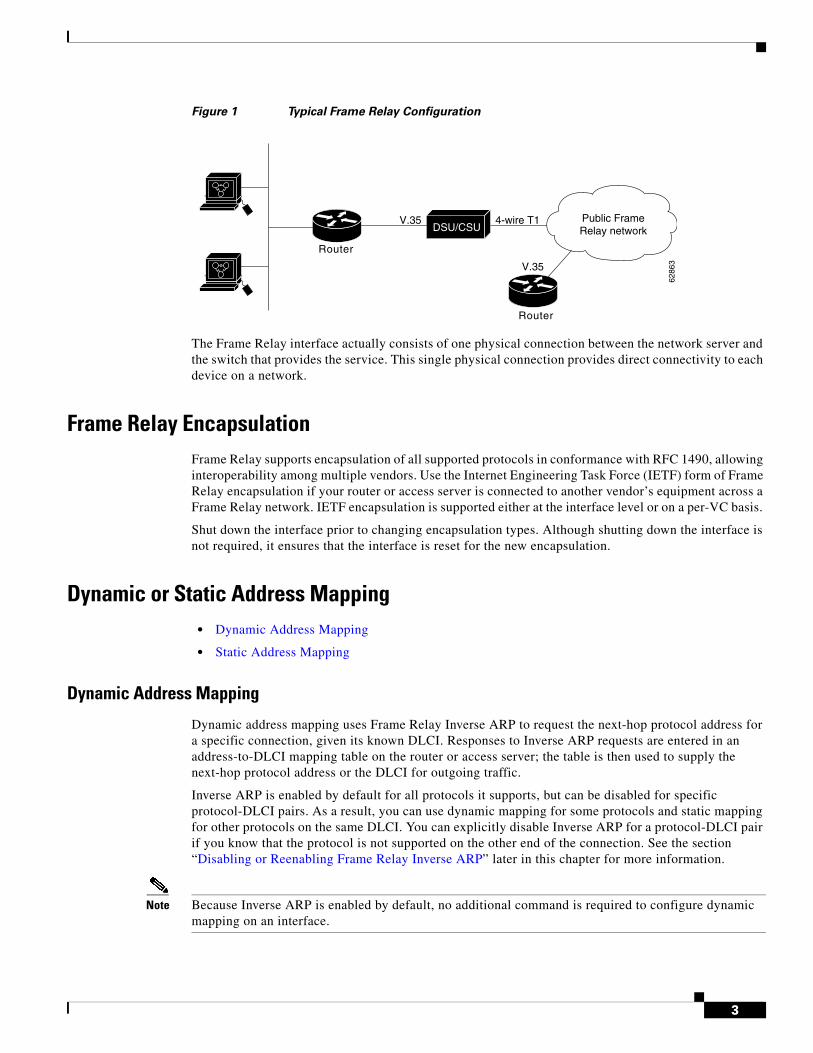
The CSU/DSU converts V.35 or RS-449 signals to the properly coded T1 transmission signal for successful reception by the Frame Relay network. Figure 1 illustrates the connections among the components.
3
Figure 1 Typical Frame Relay Configuration
The Frame Relay interface actually consists of one physical connection between the network server and the switch that provides the service. This single physical connection provides direct connectivity to each device on a network.
Frame Relay EncapsulationFrame Relay supports encapsulation of all supported protocols in conformance with RFC 1490, allowing interoperability among multiple vendors. Use the Internet Engineering Task Force (IETF) form of Frame Relay encapsulation if your router or access server is connected to another vendor’s equipment across a Frame Relay network. IETF encapsulation is supported either at the interface level or on a per-VC basis.
Shut down the interface prior to changing encapsulation types. Although shutting down the interface is not required, it ensures that the interface is reset for the new encapsulation.
Dynamic or Static Address Mapping• Dynamic Address Mapping
• Static Address Mapping
Dynamic Address Mapping
Dynamic address mapping uses Frame Relay Inverse ARP to request the next-hop protocol address for a specific connection, given its known DLCI. Responses to Inverse ARP requests are entered in an address-to-DLCI mapping table on the router or access server; the table is then used to supply the next-hop protocol address or the DLCI for outgoing traffic.
Inverse ARP is enabled by default for all protocols it supports, but can be disabled for specific protocol-DLCI pairs. As a result, you can use dynamic mapping for some protocols and static mapping for other protocols on the same DLCI. You can explicitly disable Inverse ARP for a protocol-DLCI pair if you know that the protocol is not supported on the other end of the connection. See the section “Disabling or Reenabling Frame Relay Inverse ARP” later in this chapter for more information.
Note Because Inverse ARP is enabled by default, no additional command is required to configure dynamic mapping on an interface.
Router
DSU/CSUV.35
6286
3
Public FrameRelay network
4-wire T1
Router
V.35
4
Static Address Mapping
A static map links a specified next-hop protocol address to a specified DLCI. Static mapping removes the need for Inverse ARP requests; when you supply a static map, Inverse ARP is automatically disabled for the specified protocol on the specified DLCI.
You must use static mapping if the router at the other end either does not support Inverse ARP at all or does not support Inverse ARP for a specific protocol that you want to use over Frame Relay.
You can greatly simplify the configuration for the Open Shortest Path First (OSPF) protocol by adding the optional broadcast keyword when doing this task. Refer to the frame-relay map command description in the Cisco IOS Wide-Area Networking Command Reference and the examples at the end of this module for more information about using the broadcast keyword.
LMIThe Cisco IOS XE software supports Local Management Interface (LMI) autosense, which enables the interface to determine the LMI type supported by the switch. Support for LMI autosense means that you are no longer required to configure the LMI explicitly.
LMI autosense is active in the following situations:
• The router is powered up or the interface changes state to up.
• The line protocol is down but the line is up.
• The interface is a Frame Relay DTE.
• The LMI type is not explicitly configured.
Activating LMI Autosense
• Status Request
• Status Messages
• LMI Autosense
• Configuration Options
Status Request
When LMI autosense is active, it sends out a full status request, in all three LMI types, to the switch. The order is ANSI, ITU, cisco, but it is done in rapid succession. Cisco IOS XE software provides the ability to listen in on both DLCI 1023 (cisco LMI) and DLCI 0 (ANSI and ITU) simultaneously.
Status Messages
One or more of the status requests will elicit a reply (status message) from the switch. The router will decode the format of the reply and configure itself automatically. If more than one reply is received, the router will configure itself with the type of the last received reply. This is to accommodate intelligent switches that can handle multiple formats simultaneously.
5
LMI Autosense
If LMI autosense is unsuccessful, an intelligent retry scheme is built in. Every N391 interval (default is 60 seconds, which is 6 keep exchanges at 10 seconds each), LMI autosense will attempt to ascertain the LMI type.
The only visible indication to the user that LMI autosense is under way is that debug frame lmi is turned on. At every N391 interval, the user will now see three rapid status inquiries coming out of the serial interface: one in ANSI, one in ITU, and one in cisco LMI-type.
Configuration Options
No configuration options are provided; LMI autosense is transparent to the user. You can turn off LMI autosense by explicitly configuring an LMI type. The LMI type must be written into NVRAM so that next time the router powers up, LMI autosense will be inactive. At the end of autoinstall, a frame-relay lmi-type xxx statement is included within the interface configuration. This configuration is not automatically written to NVRAM; you must explicitly write the configuration to NVRAM by using the copy system:running-config or copy nvram:startup-config command.
MQC-Based Frame Relay Traffic ShapingLegacy frame-relay traffic shaping is not supported. Cisco IOS XE software only supports policy map based MQC.
• Traffic-Shaping Map Class for the Interface
• Defining Access Lists
• Defining Priority Queue Lists for the Map Class
• Defining Custom Queue Lists for the Map Class
Traffic-Shaping Map Class for the Interface
If you specify a Frame Relay map class for a main interface, all the VCs on its subinterfaces inherit all the traffic-shaping parameters defined for the class. You can override the default for a specific DLCI on a specific subinterface by using the class VC configuration command to assign the DLCI explicitly to a different class. See the section “Configuring Frame Relay Subinterfaces” for information about setting up subinterfaces.
Specifying Map Class with Queueing and Traffic-Shaping Parameters
When defining a map class for Frame Relay, you can specify the average and peak rates (in bits per second) allowed on VCs associated with the map class. You can also specify either a custom queue list or a priority queue group to use on VCs associated with the map class.
Defining Access Lists
You can specify access lists and associate them with the custom queue list defined for any map class. The list number specified in the access list and the custom queue list tie them together. See the appropriate protocol chapters for information about defining access lists for the protocols you want to transmit on the Frame Relay network.
6
Defining Priority Queue Lists for the Map Class
You can define a priority list for a protocol and you can also define a default priority list. The number used for a specific priority list ties the list to the Frame Relay priority group defined for a specified map class.
For example, if you enter the frame relay priority-group 2 command for the map class “fast_vcs” and then you enter the priority-list 2 protocol decnet high command, that priority list is used for the “fast_vcs” map class. The average and peak traffic rates defined for the “fast_vcs” map class are used for DECnet traffic.
Defining Custom Queue Lists for the Map Class
You can define a queue list for a protocol and a default queue list. You can also specify the maximum number of bytes to be transmitted in any cycle. The number used for a specific queue list ties the list to the Frame Relay custom queue list defined for a specified map class.
For example, if you enter the frame relay custom-queue-list 1 command for the map class “slow_vcs” and then you enter the queue-list 1 protocol ip list 100 command, that queue list is used for the “slow_vcs” map class; access-list 100 definition is also used for that map class and queue. The average and peak traffic rates defined for the “slow_vcs” map class are used for IP traffic that meets the access list 100 criteria.
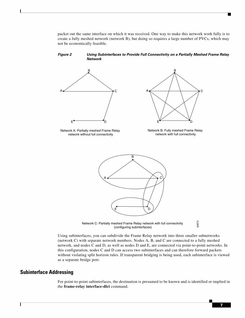
Understanding Frame Relay Subinterfaces Frame Relay subinterfaces provide a mechanism for supporting partially meshed Frame Relay networks. Most protocols assume transitivity on a logical network; that is, if station A can talk to station B, and station B can talk to station C, then station A should be able to talk to station C directly. Transitivity is true on LANs, but not on Frame Relay networks unless A is directly connected to C.
Additionally, certain protocols such as AppleTalk and transparent bridging cannot be supported on partially meshed networks because they require split horizon. Split horizon is a routing technique in which a packet received on an interface cannot be sent from the same interface even if received and transmitted on different VCs.
Configuring Frame Relay subinterfaces ensures that a single physical interface is treated as multiple virtual interfaces. This treatment allows you to overcome split horizon rules. Packets received on one virtual interface can be forwarded to another virtual interface even if they are configured on the same physical interface.
Subinterfaces address the limitations of Frame Relay networks by providing a way to subdivide a partially meshed Frame Relay network into a number of smaller, fully meshed (or point-to-point) subnetworks. Each subnetwork is assigned its own network number and appears to the protocols as if it were reachable through a separate interface. (Note that point-to-point subinterfaces can be unnumbered for use with IP, reducing the addressing burden that might otherwise result.)
Note Cisco IOS XE software supports configuration of point-to-point subinterfaces.
Figure 2 shows a five-node Frame Relay network that is partially meshed (network A). If the entire network is viewed as a single subnetwork (with a single network number assigned), most protocols assume that node A can transmit a packet directly to node E, when in fact it must be relayed through nodes C and D. This network can be made to work with certain protocols (for example, IP), but will not work at all with other protocols (for example, AppleTalk) because nodes C and D will not relay the
7
packet out the same interface on which it was received. One way to make this network work fully is to create a fully meshed network (network B), but doing so requires a large number of PVCs, which may not be economically feasible.
Figure 2 Using Subinterfaces to Provide Full Connectivity on a Partially Meshed Frame Relay
Network
Using subinterfaces, you can subdivide the Frame Relay network into three smaller subnetworks (network C) with separate network numbers. Nodes A, B, and C are connected to a fully meshed network, and nodes C and D, as well as nodes D and E, are connected via point-to-point networks. In this configuration, nodes C and D can access two subinterfaces and can therefore forward packets without violating split horizon rules. If transparent bridging is being used, each subinterface is viewed as a separate bridge port.
Subinterface Addressing
For point-to-point subinterfaces, the destination is presumed to be known and is identified or implied in the frame-relay interface-dlci command.
A
B
C
DE
Network B: Fully meshed Frame Relay network with full connectivity
A
B
C
DE
Network A: Partially meshed Frame Relay network without full connectivity
Network C: Partially meshed Frame Relay network with full connectivity (configuring subinterfaces) 62
873
B
A C
DE
8
Note The frame-relay interface-dlci command is typically used on subinterfaces; however, it can also be applied to main interfaces. The command is used to enable routing protocols on main interfaces that are configured to use Inverse ARP. This command is also helpful for assigning a specific class to a single PVC on a multipoint subinterface.
If you define a subinterface for point-to-point communication, you cannot reassign the same subinterface number to be used for multipoint communication without first rebooting the router or access server. Instead, you can simply avoid using that subinterface number and use a different subinterface number.
Backup Interface for a Subinterface
Both point-to-point and multipoint Frame Relay subinterfaces can be configured with a backup interface. This approach allows individual PVCs to be backed up in case of failure rather than depending on the entire Frame Relay connection to fail before the backup takes over. You can configure a subinterface for backup on failure only, not for backup based on loading of the line.
If the main interface has a backup interface, it will have precedence over the subinterface’s backup interface in the case of complete loss of connectivity with the Frame Relay network. As a result, a subinterface backup is activated only if the main interface is up, or if the interface is down and does not have a backup interface defined. If a subinterface fails while its backup interface is in use, and the main interface goes down, the backup subinterface remains connected.
Disabling or Reenabling Frame Relay Inverse ARPFrame Relay Inverse ARP is a method of building dynamic address mappings in Frame Relay networks running DECnet, IP, and Novell IPX. Inverse ARP allows the router or access server to discover the protocol address of a device associated with the VC.
Inverse ARP creates dynamic address mappings, as contrasted with the frame-relay map command, which defines static mappings between a specific protocol address and a specific DLCI (see the section Configuring Static Address Mapping for more information).
Inverse ARP is enabled by default but can be disabled explicitly for a given protocol and DLCI pair. Disable or reenable Inverse ARP under the following conditions:
• Disable Inverse ARP for a selected protocol and DLCI pair when you know that the protocol is not supported at the other end of the connection.
• Reenable Inverse ARP for a protocol and DLCI pair if conditions or equipment change and the protocol is then supported at the other end of the connection.
Note If you change from a point-to-point subinterface to a multipoint subinterface, change the subinterface number. Frame Relay Inverse ARP will be on by default, and no further action is required.
You do not need to enable or disable Inverse ARP if you have a point-to-point interface, because there is only a single destination and discovery is not required.
Frame Relay Fragmentation• End-to-End FRF.12 Fragmentation
9
End-to-End FRF.12 Fragmentation
The purpose of end-to-end FRF.12 fragmentation is to support real-time and non-real-time data packets on lower-speed links without causing excessive delay to the real-time data. FRF.12 fragmentation is defined by the FRF.12 Implementation Agreement. This standard was developed to allow long data frames to be fragmented into smaller pieces (fragments) and interleaved with real-time frames. In this way, real-time and non-real-time data frames can be carried together on lower-speed links without causing excessive delay to the real-time traffic.
End-to-end FRF.12 fragmentation is recommended for use on permanent virtual circuits (PVCs) that share links with other PVCs that are transporting voice and on PVCs transporting Voice over IP (VoIP). Although VoIP packets should not be fragmented, they can be interleaved with fragmented packets.
FRF.12 is configured on a per-PVC basis using a Frame Relay map class. The map class can be applied to one or many PVCs. Frame Relay traffic shaping must be enabled on the interface in order for fragmentation to work.
Note When Frame Relay fragmentation is configured, WFQ or LLQ is mandatory. If a map class is configured for Frame Relay fragmentation and the queueing type on that map class is not WFQ or LLQ, the configured queueing type is automatically overridden by WFQ with the default values. To configure LLQ for Frame Relay, refer to the Cisco IOS XE Quality of Service Solutions Configuration Guide.
Setting the Fragment Size
Set the fragment size so that voice packets are not fragmented and do not experience a serialization delay greater than 20 ms.
To set the fragment size, the link speed must be taken into account. The fragment size should be larger than the voice packets, but small enough to minimize latency on the voice packets. Turn on fragmentation for low speed links (less than 768 kb/s).
Set the fragment size based on the lowest port speed between the routers. For example, if there is a hub and spoke Frame Relay topology where the hub has a T1 speed and the remote routers have 64 kb/s port speeds, the fragment size needs to be set for the 64 kb/s speed on both routers. Any other PVCs that share the same physical interface need to configure the fragmentation to the size used by the voice PVC.
If the lowest link speed in the path is 64 kb/s, the recommended fragment size (for 10 ms serialization delay) is 80 bytes. If the lowest link speed is 128 kb/s, the recommended fragment size is 160 bytes.
For more information, refer to the “Fragmentation (FRF.12)” section in the VoIP over Frame Relay with Quality of Service (Fragmentation, Traffic Shaping, LLQ / IP RTP Priority) document.
TCP IP Header Compression TCP/IP header compression, as described by RFC 1144, is designed to improve the efficiency of bandwidth utilization over low-speed serial links. A typical TCP/IP packet includes a 40-byte datagram header. Once a connection is established, the header information is redundant and need not be repeated in every packet that is sent. Reconstructing a smaller header that identifies the connection and indicates the fields that have changed and the amount of change reduces the number of bytes transmitted. The average compressed header is 10 bytes long.
For this algorithm to function, packets must arrive in order. If packets arrive out of order, the reconstruction will appear to create regular TCP/IP packets but the packets will not match the original. Because priority queueing changes the order in which packets are transmitted, enabling priority queueing on the interface is not recommended.
10
• Specifying an Individual IP Map for TCP IP Header Compression
• Specifying an Interface for TCP IP Header Compression
Note If you configure an interface with Cisco-proprietary encapsulation and TCP/IP header compression, Frame Relay IP maps inherit the compression characteristics of the interface. However, if you configure the interface with IETF encapsulation, the interface cannot be configured for compression. Frame Relay maps will have to be configured individually to support TCP/IP header compression.
Specifying an Individual IP Map for TCP IP Header Compression
Note An interface configured to support TCP/IP header compression cannot also support priority queueing or custom queueing.
TCP/IP header compression requires Cisco-proprietary encapsulation. If you need to have IETF encapsulation on an interface as a whole, you can still configure a specific IP map to use Cisco-proprietary encapsulation and TCP header compression. In addition, even if you configure the interface to perform TCP/IP header compression, you can still configure a specific IP map not to compress TCP/IP headers.
You can specify whether TCP/IP header compression is active or passive. Active compression subjects every outgoing packet to TCP/IP header compression. Passive compression subjects an outgoing TCP/IP packet to header compression only if a packet had a compressed TCP/IP header when it was received.
Specifying an Interface for TCP IP Header Compression
You can configure the interface with active or passive TCP/IP header compression. Active compression, the default, subjects all outgoing TCP/IP packets to header compression. Passive compression subjects an outgoing packet to header compression only if the packet had a compressed TCP/IP header when it was received on that interface.
Note If an interface configured with Cisco-proprietary encapsulation is later configured with IETF encapsulation, all TCP/IP header compression characteristics are lost. To apply TCP/IP header compression over an interface configured with IETF encapsulation, you must configure individual IP maps, as described in the section “Configuring an Individual IP Map for TCP/IP Header Compression.”
Real-Time Header Compression with Frame Relay EncapsulationReal-time Transport Protocol (RTP) is a protocol used for carrying packetized audio and video traffic over an IP network, providing end-to-end network transport functions intended for these real-time traffic applications and multicast or unicast network services. RTP is described in RFC 1889. RTP is not intended for data traffic, which uses TCP or UDP.
For configuration tasks for and examples of RTP header compression using Frame Relay encapsulation, see the Cisco IOS XE IP Multicast Configuration Guide.
The commands for configuring this feature appear in the Cisco IOS IP Multicast Command Reference.
11
Discard EligibilitySome Frame Relay packets can be set with low priority or low time sensitivity. These will be the first to be dropped when a Frame Relay switch is congested. The mechanism that allows a Frame Relay switch to identify such packets is the discard eligibility (DE) bit.
Discard eligibility requires the Frame Relay network to be able to interpret the DE bit. Some networks take no action when the DE bit is set, and others use the DE bit to determine which packets to discard. The best interpretation is to use the DE bit to determine which packets should be dropped first and also which packets have lower time sensitivity.
You can create DE lists that identify the characteristics of packets to be eligible for discarding, and you can also specify DE groups to identify the DLCI that is affected.
You can create DE lists based on the protocol or the interface, and on characteristics such as fragmentation of the packet, a specific TCP or User Datagram Protocol (UDP) port, an access list number, or a packet size.
DLCI Priority LevelsDLCI priority levels allow you to separate different types of traffic and provides a traffic management tool for congestion problems caused by following situations:
• Mixing batch and interactive traffic over the same DLCI
• Queueing traffic from sites with high-speed access at destination sites with lower-speed access
Before you configure the DLCI priority levels, perform the following tasks:
• Define a global priority list.
• Enable Frame Relay encapsulation.
• Define dynamic or static address mapping.
• Make sure that you define each of the DLCIs to which you intend to apply levels. You can associate priority-level DLCIs with subinterfaces.
• Configure the LMI.
Note DLCI priority levels provide a way to define multiple parallel DLCIs for different types of traffic. DLCI priority levels do not assign priority queues within the router or access server. In fact, they are independent of the device’s priority queues. However, if you enable queueing and use the same DLCIs for queueing, then high-priority DLCIs can be put into high-priority queues.
How to Configure Frame Relay• Enabling Frame Relay Encapsulation on an Interface (Required)
• Configuring Static Address Mapping (Required)
• Explicitly Configuring the LMI (Optional)
• Configuring MQC-Based Frame Relay Traffic Shaping (Optional)
• Customizing Frame Relay for Your Network (Optional)
• Monitoring and Maintaining the Frame Relay Connections (Optional)
12
Enabling Frame Relay Encapsulation on an Interface
Note Frame Relay encapsulation is a prerequisite for any Frame Relay commands on an interface.
To enable Frame Relay encapsulation on the interface level, use the following commands beginning in global configuration mode:
Configuring Static Address MappingTo establish static mapping according to your network needs, use the following command in interface configuration mode:
Explicitly Configuring the LMI • Setting the LMI Type (Required)
• Setting the LMI Keepalive Interval (Required)
• Setting the LMI Polling and Timer Intervals (Optional)
Setting the LMI Type
If the router or access server is attached to a public data network (PDN), the LMI type must match the type used on the public network. Otherwise, the LMI type can be set to suit the needs of your private Frame Relay network.
You can set one of the following three types of LMIs on Cisco devices: ANSI T1.617 Annex D, Cisco, and ITU-T Q.933 Annex A. To do so, use the following commands beginning in interface configuration mode:
Command or Action Purpose
Step 1 Router(config)# interface type number
Specifies the interface, and enters interface configuration mode.
Step 2 Router(config-if)# encapsulation frame-relay [ietf]
Enables and specifies the Frame Relay encapsulation method.
Command or Action Purpose
Step 1 Router(config-if)# frame-relay map protocol protocol-address dlci [broadcast] [ietf] [cisco]
Enables and specifies the Frame Relay encapsulation method.
Command or Action Purpose
Step 1 Router(config-if)# frame-relay lmi-type {ansi | cisco | q933a}
Sets the LMI type.
Step 2 Router# copy nvram:startup-config destination Writes the LMI type to NVRAM.
13
Setting the LMI Keepalive Interval
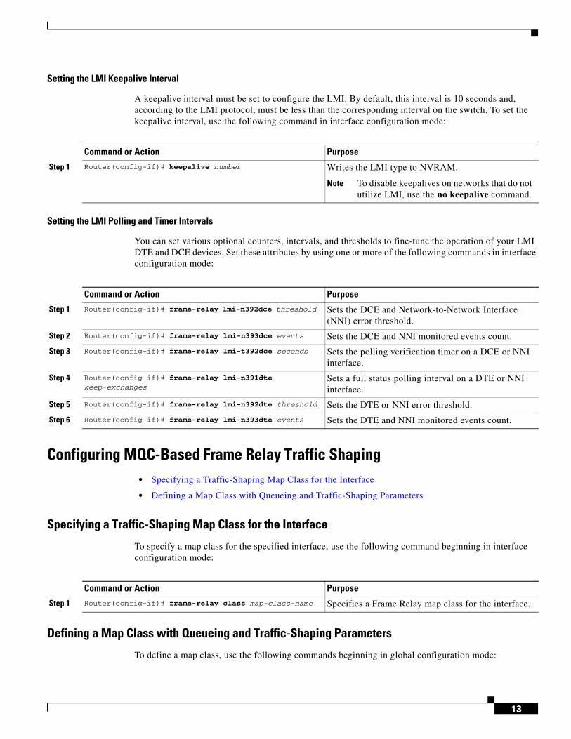
A keepalive interval must be set to configure the LMI. By default, this interval is 10 seconds and, according to the LMI protocol, must be less than the corresponding interval on the switch. To set the keepalive interval, use the following command in interface configuration mode:
Setting the LMI Polling and Timer Intervals
You can set various optional counters, intervals, and thresholds to fine-tune the operation of your LMI DTE and DCE devices. Set these attributes by using one or more of the following commands in interface configuration mode:
Configuring MQC-Based Frame Relay Traffic Shaping• Specifying a Traffic-Shaping Map Class for the Interface
• Defining a Map Class with Queueing and Traffic-Shaping Parameters
Specifying a Traffic-Shaping Map Class for the Interface
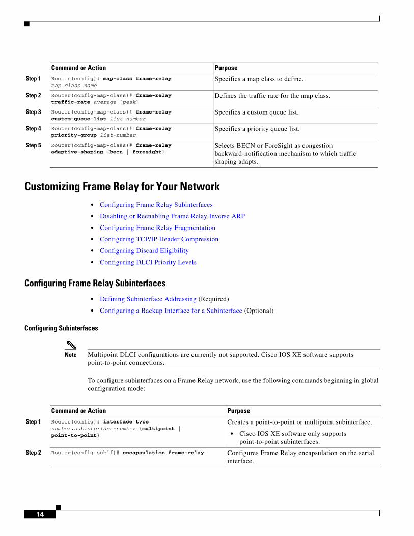
To specify a map class for the specified interface, use the following command beginning in interface configuration mode:
Defining a Map Class with Queueing and Traffic-Shaping Parameters
To define a map class, use the following commands beginning in global configuration mode:
Command or Action Purpose
Step 1 Router(config-if)# keepalive number Writes the LMI type to NVRAM.
Note To disable keepalives on networks that do not utilize LMI, use the no keepalive command.
Command or Action Purpose
Step 1 Router(config-if)# frame-relay lmi-n392dce threshold Sets the DCE and Network-to-Network Interface (NNI) error threshold.
Step 2 Router(config-if)# frame-relay lmi-n393dce events Sets the DCE and NNI monitored events count.
Step 3 Router(config-if)# frame-relay lmi-t392dce seconds Sets the polling verification timer on a DCE or NNI interface.
Step 4 Router(config-if)# frame-relay lmi-n391dte keep-exchanges
Sets a full status polling interval on a DTE or NNI interface.
Step 5 Router(config-if)# frame-relay lmi-n392dte threshold Sets the DTE or NNI error threshold.
Step 6 Router(config-if)# frame-relay lmi-n393dte events Sets the DTE and NNI monitored events count.
Command or Action Purpose
Step 1 Router(config-if)# frame-relay class map-class-name Specifies a Frame Relay map class for the interface.
14
Customizing Frame Relay for Your Network• Configuring Frame Relay Subinterfaces
• Disabling or Reenabling Frame Relay Inverse ARP
• Configuring Frame Relay Fragmentation
• Configuring TCP/IP Header Compression
• Configuring Discard Eligibility
• Configuring DLCI Priority Levels
Configuring Frame Relay Subinterfaces
• Defining Subinterface Addressing (Required)
• Configuring a Backup Interface for a Subinterface (Optional)
Configuring Subinterfaces
Note Multipoint DLCI configurations are currently not supported. Cisco IOS XE software supports point-to-point connections.
To configure subinterfaces on a Frame Relay network, use the following commands beginning in global configuration mode:
Command or Action Purpose
Step 1 Router(config)# map-class frame-relay map-class-name
Specifies a map class to define.
Step 2 Router(config-map-class)# frame-relay traffic-rate average [peak]
Defines the traffic rate for the map class.
Step 3 Router(config-map-class)# frame-relay custom-queue-list list-number
Specifies a custom queue list.
Step 4 Router(config-map-class)# frame-relay priority-group list-number
Specifies a priority queue list.
Step 5 Router(config-map-class)# frame-relay adaptive-shaping {becn | foresight}
Selects BECN or ForeSight as congestion backward-notification mechanism to which traffic shaping adapts.
Command or Action Purpose
Step 1 Router(config)# interface type number.subinterface-number {multipoint | point-to-point}
Creates a point-to-point or multipoint subinterface.
• Cisco IOS XE software only supports point-to-point subinterfaces.
Step 2 Router(config-subif)# encapsulation frame-relay Configures Frame Relay encapsulation on the serial interface.
15
Defining Subinterface Addressing
• Addressing on Point-to-Point Subinterfaces
Addressing on Point-to-Point Subinterfaces
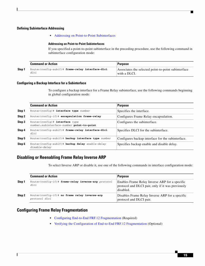
If you specified a point-to-point subinterface in the preceding procedure, use the following command in subinterface configuration mode:
Configuring a Backup Interface for a Subinterface
To configure a backup interface for a Frame Relay subinterface, use the following commands beginning in global configuration mode:
Disabling or Reenabling Frame Relay Inverse ARP
To select Inverse ARP or disable it, use one of the following commands in interface configuration mode:
Configuring Frame Relay Fragmentation
• Configuring End-to-End FRF.12 Fragmentation (Required)
• Verifying the Configuration of End-to-End FRF.12 Fragmentation (Optional)
Command or Action Purpose
Step 1 Router(config-subif)# frame-relay interface-dlci dlci
Associates the selected point-to-point subinterface with a DLCI.
Command or Action Purpose
Step 1 Router(config)# interface type number Specifies the interface.
Step 2 Router(config-if)# encapsulation frame-relay Configures Frame Relay encapsulation.
Step 3 Router(config)# interface type number.subinterface-number point-to-point
Configures the subinterface.
Step 4 Router(config-subif)# frame-relay interface-dlci dlci
Specifies DLCI for the subinterface.
Step 5 Router(config-subif)# backup interface type number Configures backup interface for the subinterface.
Step 6 Router(config-subif)# backup delay enable-delay disable-delay
Specifies backup enable and disable delay.
Command or Action Purpose
Step 1 Router(config-if)# frame-relay inverse-arp protocol dlci
Enables Frame Relay Inverse ARP for a specific protocol and DLCI pair, only if it was previously disabled.
Step 2 Router(config-if)# no frame relay inverse-arp protocol dlci
Disables Frame Relay Inverse ARP for a specific protocol and DLCI pair.
16
Configuring End-to-End FRF.12 Fragmentation
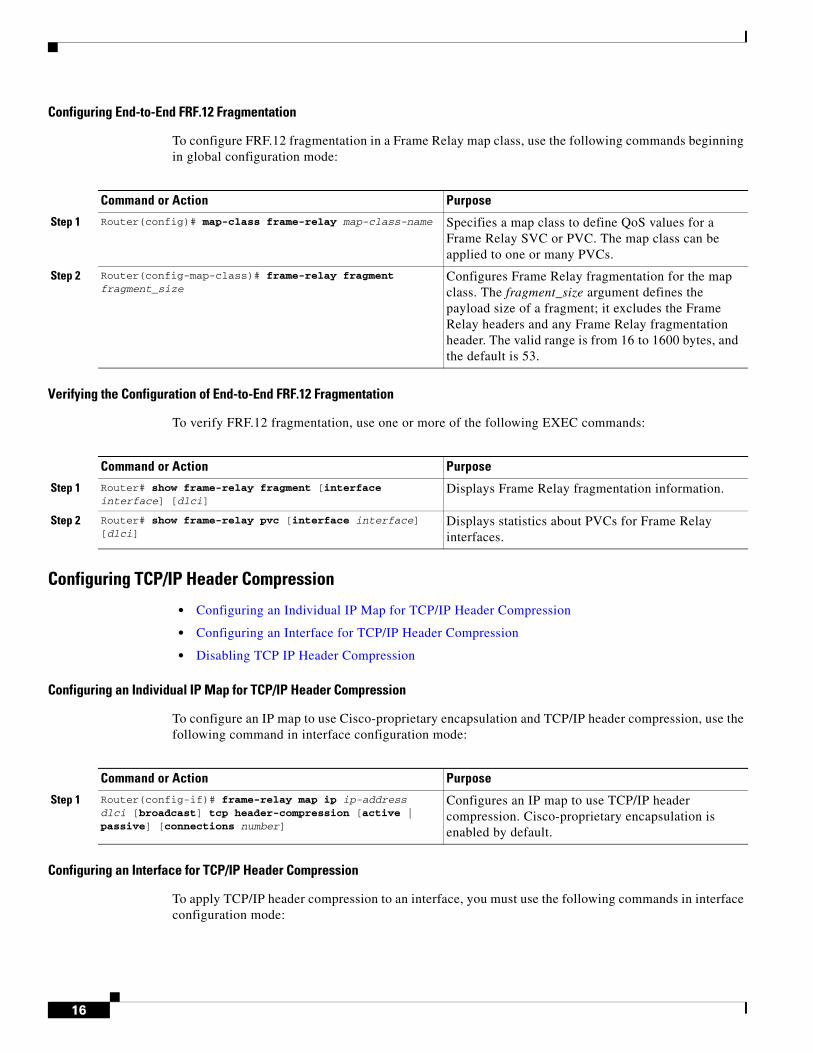
To configure FRF.12 fragmentation in a Frame Relay map class, use the following commands beginning in global configuration mode:
Verifying the Configuration of End-to-End FRF.12 Fragmentation
To verify FRF.12 fragmentation, use one or more of the following EXEC commands:
Configuring TCP/IP Header Compression
• Configuring an Individual IP Map for TCP/IP Header Compression
• Configuring an Interface for TCP/IP Header Compression
• Disabling TCP IP Header Compression
Configuring an Individual IP Map for TCP/IP Header Compression
To configure an IP map to use Cisco-proprietary encapsulation and TCP/IP header compression, use the following command in interface configuration mode:
Configuring an Interface for TCP/IP Header Compression
To apply TCP/IP header compression to an interface, you must use the following commands in interface configuration mode:
Command or Action Purpose
Step 1 Router(config)# map-class frame-relay map-class-name Specifies a map class to define QoS values for a Frame Relay SVC or PVC. The map class can be applied to one or many PVCs.
Step 2 Router(config-map-class)# frame-relay fragment fragment_size
Configures Frame Relay fragmentation for the map class. The fragment_size argument defines the payload size of a fragment; it excludes the Frame Relay headers and any Frame Relay fragmentation header. The valid range is from 16 to 1600 bytes, and the default is 53.
Command or Action Purpose
Step 1 Router# show frame-relay fragment [interface interface] [dlci]
Displays Frame Relay fragmentation information.
Step 2 Router# show frame-relay pvc [interface interface] [dlci]
Displays statistics about PVCs for Frame Relay interfaces.
Command or Action Purpose
Step 1 Router(config-if)# frame-relay map ip ip-address dlci [broadcast] tcp header-compression [active | passive] [connections number]
Configures an IP map to use TCP/IP header compression. Cisco-proprietary encapsulation is enabled by default.
17
Disabling TCP IP Header Compression
You can disable TCP/IP header compression by using either of two commands that have different effects, depending on whether Frame Relay IP maps have been explicitly configured for TCP/IP header compression or have inherited their compression characteristics from the interface.
Frame Relay IP maps that have explicitly configured TCP/IP header compression must also have TCP/IP header compression explicitly disabled.
To disable TCP/IP header compression, use one of the following commands in interface configuration mode:
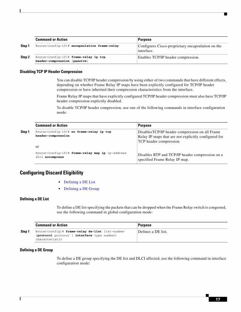
Configuring Discard Eligibility
• Defining a DE List
• Defining a DE Group
Defining a DE List
To define a DE list specifying the packets that can be dropped when the Frame Relay switch is congested, use the following command in global configuration mode:
Defining a DE Group
To define a DE group specifying the DE list and DLCI affected, use the following command in interface configuration mode:
Command or Action Purpose
Step 1 Router(config-if)# encapsulation frame-relay Configures Cisco-proprietary encapsulation on the interface.
Step 2 Router(config-if)# frame-relay ip tcp header-compression [passive]
Enables TCP/IP header compression.
Command or Action Purpose
Step 1 Router(config-if)# no frame-relay ip tcp header-compression
or
Router(config-if)# frame-relay map ip ip-address dlci nocompress
DisablesTCP/IP header compression on all Frame Relay IP maps that are not explicitly configured for TCP header compression.
Disables RTP and TCP/IP header compression on a specified Frame Relay IP map.
Command or Action Purpose
Step 1 Router(config)# frame-relay de-list list-number {protocol protocol | interface type number} characteristic
Defines a DE list.
18
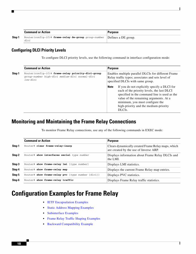
Configuring DLCI Priority Levels
To configure DLCI priority levels, use the following command in interface configuration mode:
Monitoring and Maintaining the Frame Relay Connections To monitor Frame Relay connections, use any of the following commands in EXEC mode:
Configuration Examples for Frame Relay• IETF Encapsulation Examples
• Static Address Mapping Examples
• Subinterface Examples
• Frame Relay Traffic Shaping Examples
• Backward Compatibility Example
Command or Action Purpose
Step 1 Router(config-if)# frame-relay de-group group-number dlci
Defines a DE group.
Command or Action Purpose
Step 1 Router(config-if)# frame-relay priority-dlci-group group-number high-dlci medium-dlci normal-dlci low-dlci
Enables multiple parallel DLCIs for different Frame Relay traffic types; associates and sets level of specified DLCIs with same group.
Note If you do not explicitly specify a DLCI for each of the priority levels, the last DLCI specified in the command line is used as the value of the remaining arguments. At a minimum, you must configure the high-priority and the medium-priority DLCIs.
Command or Action Purpose
Step 1 Router# clear frame-relay-inarp Clears dynamically created Frame Relay maps, which are created by the use of Inverse ARP.
Step 2 Router# show interfaces serial type number Displays information about Frame Relay DLCIs and the LMI.
Step 3 Router# show frame-relay lmi [type number] Displays LMI statistics.
Step 4 Router# show frame-relay map Displays the current Frame Relay map entries.
Step 5 Router# show frame-relay pvc [type number [dlci]] Displays PVC statistics.
Step 6 Router# show frame-relay traffic Displays Frame Relay traffic statistics.
19
• Booting from a Network Server over Frame Relay Example
• Frame Relay Fragmentation Configuration Examples
• TCP IP Header Compression Examples
IETF Encapsulation Examples • IETF Encapsulation on the Interface Example
• IETF Encapsulation on a Per-DLCI Basis Example
IETF Encapsulation on the Interface Example
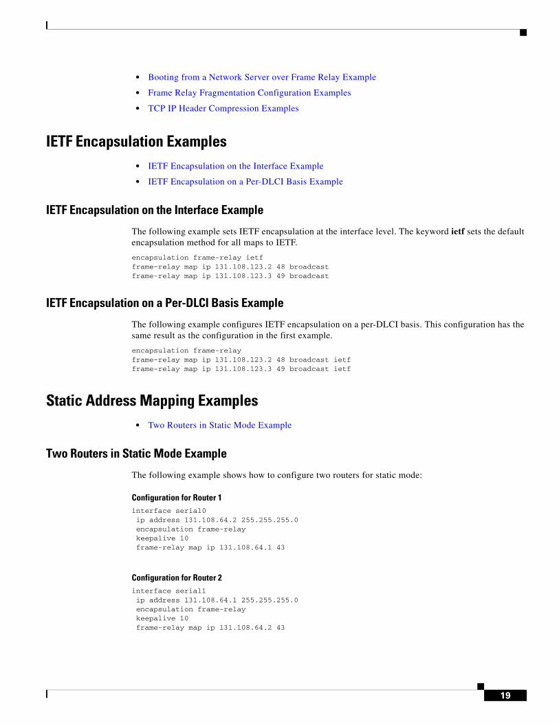
The following example sets IETF encapsulation at the interface level. The keyword ietf sets the default encapsulation method for all maps to IETF.
encapsulation frame-relay ietfframe-relay map ip 131.108.123.2 48 broadcastframe-relay map ip 131.108.123.3 49 broadcast
IETF Encapsulation on a Per-DLCI Basis Example
The following example configures IETF encapsulation on a per-DLCI basis. This configuration has the same result as the configuration in the first example.
encapsulation frame-relay frame-relay map ip 131.108.123.2 48 broadcast ietfframe-relay map ip 131.108.123.3 49 broadcast ietf
Static Address Mapping Examples• Two Routers in Static Mode Example
Two Routers in Static Mode Example
The following example shows how to configure two routers for static mode:
Configuration for Router 1interface serial0ip address 131.108.64.2 255.255.255.0encapsulation frame-relaykeepalive 10frame-relay map ip 131.108.64.1 43
Configuration for Router 2interface serial1ip address 131.108.64.1 255.255.255.0encapsulation frame-relaykeepalive 10frame-relay map ip 131.108.64.2 43
20
Subinterface Examples • Basic Subinterface Example
• Frame Relay Traffic Shaping Examples
Basic Subinterface Example
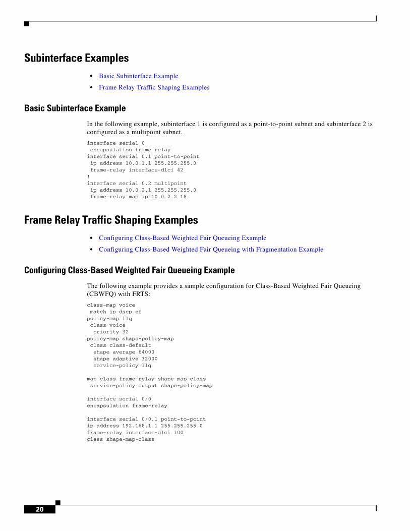
In the following example, subinterface 1 is configured as a point-to-point subnet and subinterface 2 is configured as a multipoint subnet.
interface serial 0encapsulation frame-relay
interface serial 0.1 point-to-pointip address 10.0.1.1 255.255.255.0frame-relay interface-dlci 42
!interface serial 0.2 multipointip address 10.0.2.1 255.255.255.0frame-relay map ip 10.0.2.2 18
Frame Relay Traffic Shaping Examples • Configuring Class-Based Weighted Fair Queueing Example
• Configuring Class-Based Weighted Fair Queueing with Fragmentation Example
Configuring Class-Based Weighted Fair Queueing Example
The following example provides a sample configuration for Class-Based Weighted Fair Queueing (CBWFQ) with FRTS:
class-map voice match ip dscp efpolicy-map llq class voice priority 32policy-map shape-policy-map class class-default shape average 64000 shape adaptive 32000 service-policy llq
map-class frame-relay shape-map-classservice-policy output shape-policy-map
interface serial 0/0encapsulation frame-relay
interface serial 0/0.1 point-to-pointip address 192.168.1.1 255.255.255.0frame-relay interface-dlci 100class shape-map-class
21
Configuring Class-Based Weighted Fair Queueing with Fragmentation Example
The following example provides a sample configuration for CBWFQ and fragmentation with FRTS. This configuration example is the same as the example shown in the section “Configuring Class-Based Weighted Fair Queueing Example” with the addition of the frame-relay fragment command to configure fragmentation.
class-map voice match ip dscp ef policy-map llq class voice priority 32policy-map shape-policy-map class class-default shape average 64000 shape adaptive 32000 service-policy llq
map-class frame-relay shape-map-class frame-relay fragment 80 service-policy output shape-policy-map
interface serial 0/0 encapsulation frame-relay
interface serial 0/0.1 point-to-point ip address 192.168.1.1 255.255.255.0 frame-relay interface-dlci 100class shape-map-class
Backward Compatibility ExampleThe following configuration provides backward compatibility and interoperability with versions not compliant with RFC 1490. The ietf keyword is used to generate RFC 1490 traffic. This configuration is possible because of the flexibility provided by separately defining each map entry.
encapsulation frame-relayframe-relay map ip 131.108.123.2 48 broadcast ietf! interoperability is provided by IETF encapsulationframe-relay map ip 131.108.123.3 49 broadcast ietfframe-relay map ip 131.108.123.7 58 broadcast ! this line allows the router to connect with a ! device running an older version of softwareframe-relay map decnet 21.7 49 broadcast
Booting from a Network Server over Frame Relay ExampleWhen booting from a TFTP server over Frame Relay, you cannot boot from a network server via a broadcast. You must boot from a specific TFTP host. Also, a frame-relay map command must exist for the host from which you will boot.
For example, if file “gs3-bfx” is to be booted from a host with IP address 131.108.126.2, the following commands would need to be in the configuration:
boot system gs3-bfx 131.108.126.2!interface Serial 0encapsulation frame-relayframe-relay map IP 131.108.126.2 100 broadcast
22
The frame-relay map command is used to map an IP address into a DLCI address. To boot over Frame Relay, you must explicitly give the address of the network server to boot from, and a frame-relay map entry must exist for that site. For example, if file “gs3-bfx.83-2.0” is to be booted from a host with IP address 131.108.126.111, the following commands must be in the configuration:
boot system gs3-bfx.83-2.0 131.108.13.111!interface Serial 1ip address 131.108.126.200 255.255.255.0encapsulation frame-relayframe-relay map ip 131.108.126.111 100 broadcast
In this case, 100 is the DLCI that can get to host 131.108.126.111.
The remote router must be configured with the following command:
frame-relay map ip 131.108.126.200 101 broadcast
This entry allows the remote router to return a boot image (from the network server) to the router booting over Frame Relay. Here, 101 is a DLCI of the router being booted.
Frame Relay Fragmentation Configuration Examples• FRF.12 Fragmentation Example
FRF.12 Fragmentation Example
The following example shows the configuration of pure end-to-end FRF.12 fragmentation and weighted fair queueing in the map class called “frag”. The fragment payload size is set to 40 bytes. The “frag” map class is associated with DLCI 100 on serial interface 1.
router(config)# interface serial 1router(config-if)# frame-relay traffic-shapingrouter(config-if)# frame-relay interface-dlci 100router(config-fr-dlci)# class fragrouter(config-fr-dlci)# exit
router(config)# map-class frame-relay fragrouter(config-map-class)# frame-relay cir 128000router(config-map-class)# frame-relay bc 1280router(config-map-class)# frame-relay fragment 40router(config-map-class)# frame-relay fair-queue
TCP IP Header Compression Examples • IP Map with Inherited TCP IP Header Compression Example
• Using an IP Map to Override TCP IP Header Compression Example
• Disabling Inherited TCP IP Header Compression Example
• Disabling Explicit TCP IP Header Compression Example
23
IP Map with Inherited TCP IP Header Compression Example
Note Shut down the interface or subinterface prior to adding or changing compression techniques. Although shutdown is not required, shutting down the interface ensures that it is reset for the new data structures.
The following example shows an interface configured for TCP/IP header compression and an IP map that inherits the compression characteristics. Note that the Frame Relay IP map is not explicitly configured for header compression.
interface serial 1encapsulation frame-relayip address 131.108.177.178 255.255.255.0frame-relay map ip 131.108.177.177 177 broadcastframe-relay ip tcp header-compression passive
Use of the show frame-relay map command will display the resulting compression and encapsulation characteristics; the IP map has inherited passive TCP/IP header compression:
Router> show frame-relay map
Serial 1 (administratively down): ip 131.108.177.177 dlci 177 (0xB1,0x2C10), static, broadcast, CISCO TCP/IP Header Compression (inherited), passive (inherited)
This example also applies to dynamic mappings achieved with the use of Inverse ARP on point-to-point subinterfaces where no Frame Relay maps are configured.
Using an IP Map to Override TCP IP Header Compression Example
The following example shows the use of a Frame Relay IP map to override the compression set on the interface:
interface serial 1encapsulation frame-relayip address 131.108.177.178 255.255.255.0frame-relay map ip 131.108.177.177 177 broadcast nocompressframe-relay ip tcp header-compression passive
Use of the show frame-relay map command will display the resulting compression and encapsulation characteristics; the IP map has not inherited TCP header compression:
Router> show frame-relay map
Serial 1 (administratively down): ip 131.108.177.177 dlci 177 (0xB1,0x2C10), static, broadcast, CISCO
Disabling Inherited TCP IP Header Compression Example
In this example, the following is the initial configuration:
interface serial 1encapsulation frame-relayip address 131.108.177.179 255.255.255.0frame-relay ip tcp header-compression passive
24
frame-relay map ip 131.108.177.177 177 broadcastframe-relay map ip 131.108.177.178 178 broadcast tcp header-compression
Enter the following commands to enable inherited TCP/IP header compression:
serial interface 1no frame-relay ip tcp header-compression
Use of the show frame-relay map command will display the resulting compression and encapsulation characteristics:
Router> show frame-relay map
Serial 1 (administratively down): ip 131.108.177.177 177 dlci 177(0xB1, 0x2C10), static, broadcast CISCOSerial 1 (administratively down): ip 131.108.177.178 178 dlci 178(0xB2,0x2C20), static broadcast CISCO TCP/IP Header Compression (enabled)
As a result, header compression is disabled for the first map (with DLCI 177), which inherited its header compression characteristics from the interface. However, header compression is not disabled for the second map (DLCI 178), which is explicitly configured for header compression.
Disabling Explicit TCP IP Header Compression Example
In this example, the initial configuration is the same as in the preceding example, but you must enter the following set of commands to enable explicit TCP/IP header compression:
serial interface 1no frame-relay ip tcp header-compressionframe-relay map ip 131.108.177.178 178 nocompress
Use of the show frame-relay map command will display the resulting compression and encapsulation characteristics:
Router> show frame-relay map
Serial 1 (administratively down): ip 131.108.177.177 177 dlci 177(0xB1,0x2C10), static, broadcast CISCOSerial 1 (administratively down): ip 131.108.177.178 178 dlci 178(0xB2,0x2C20), static broadcast CISCO
The result of the commands is to disable header compression for the first map (with DLCI 177), which inherited its header compression characteristics from the interface, and also explicitly to disable header compression for the second map (with DLCI 178), which was explicitly configured for header compression.
25
Additional References
Related Documents
Standards
MIBs
RFCs
Related Topic Document Title
Cisco IOS XE Wide-Area Networking configuration tasks
Cisco IOS XE Wide-Area Networking Configuration Guide, Release 2
Wide-Area networking commands Cisco IOS Wide-Area Networking Command Reference
Standard Title
None —
MIB MIBs Link
None To locate and download MIBs for selected platforms, Cisco IOS XE software releases, and feature sets, use Cisco MIB Locator found at the following URL:
http://www.cisco.com/go/mibs
RFC Title
None —
26
Technical Assistance
Description Link
The Cisco Support website provides extensive online resources, including documentation and tools for troubleshooting and resolving technical issues with Cisco products and technologies.
To receive security and technical information about your products, you can subscribe to various services, such as the Product Alert Tool (accessed from Field Notices), the Cisco Technical Services Newsletter, and Really Simple Syndication (RSS) Feeds.
Access to most tools on the Cisco Support website requires a Cisco.com user ID and password.
http://www.cisco.com/techsupport
27
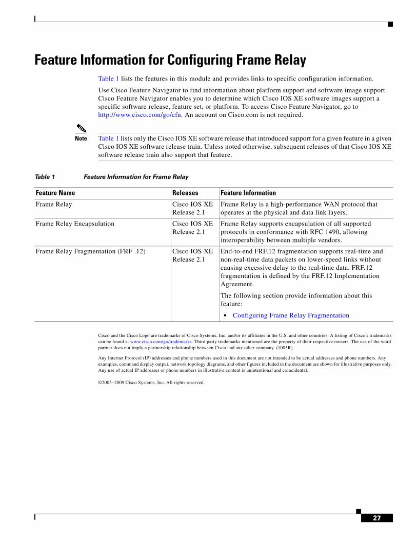
Feature Information for Configuring Frame RelayTable 1 lists the features in this module and provides links to specific configuration information.
Use Cisco Feature Navigator to find information about platform support and software image support. Cisco Feature Navigator enables you to determine which Cisco IOS XE software images support a specific software release, feature set, or platform. To access Cisco Feature Navigator, go to http://www.cisco.com/go/cfn. An account on Cisco.com is not required.
Note Table 1 lists only the Cisco IOS XE software release that introduced support for a given feature in a given Cisco IOS XE software release train. Unless noted otherwise, subsequent releases of that Cisco IOS XE software release train also support that feature.
Cisco and the Cisco Logo are trademarks of Cisco Systems, Inc. and/or its affiliates in the U.S. and other countries. A listing of Cisco's trademarks can be found at www.cisco.com/go/trademarks. Third party trademarks mentioned are the property of their respective owners. The use of the word partner does not imply a partnership relationship between Cisco and any other company. (1005R)
Any Internet Protocol (IP) addresses and phone numbers used in this document are not intended to be actual addresses and phone numbers. Any examples, command display output, network topology diagrams, and other figures included in the document are shown for illustrative purposes only. Any use of actual IP addresses or phone numbers in illustrative content is unintentional and coincidental.
©2005–2009 Cisco Systems, Inc. All rights reserved.
Table 1 Feature Information for Frame Relay
Feature Name Releases Feature Information
Frame Relay Cisco IOS XE Release 2.1
Frame Relay is a high-performance WAN protocol that operates at the physical and data link layers.
Frame Relay Encapsulation Cisco IOS XE Release 2.1
Frame Relay supports encapsulation of all supported protocols in conformance with RFC 1490, allowing interoperability between multiple vendors.
Frame Relay Fragmentation (FRF .12) Cisco IOS XE Release 2.1
End-to-end FRF.12 fragmentation supports real-time and non-real-time data packets on lower-speed links without causing excessive delay to the real-time data. FRF.12 fragmentation is defined by the FRF.12 Implementation Agreement.
The following section provide information about this feature:
• Configuring Frame Relay Fragmentation

28