Embed Size (px)
Citation preview
12 January 2022
POLITECNICO DI TORINORepository ISTITUZIONALE
APPLICATIONS OF ULTRAVIOLET RADIATIONS IN DYEING PROCESSES OF YARNS AND FABRICS / Migliavacca,Gianluca. - (2014).
Original
APPLICATIONS OF ULTRAVIOLET RADIATIONS IN DYEING PROCESSES OF YARNS ANDFABRICS
Publisher:
PublishedDOI:10.6092/polito/porto/2526333
Terms of use:Altro tipo di accesso
Publisher copyright
(Article begins on next page)
This article is made available under terms and conditions as specified in the corresponding bibliographic description inthe repository
Availability:This version is available at: 11583/2526333 since:
Politecnico di Torino
POLITECNICO DI TORINO
Ph.D. IN CHEMICAL ENGINEERING
CYCLE XXVI
APPLICATIONS OF ULTRAVIOLET RADIATIONS IN DYEING PROCESSES OF YARNS AND FABRICS
GIANLUCA MIGLIAVACCA
Tutor: Prof. FRANCO FERRERO External Reviewer: Prof. GIUSEPPE ROSACE
Defended on 21/01/2014


Go to the ant, sluggard; consider her ways, and be wise!
(Proverbs 6, 6)

Acknowledgements
With great pleasure I would like to thank all people who made possible the writing of this thesis.
I had the luck to collaborate with good people, undoubtedly from a professional point of view but
also from a personal perspective. With some of them I could couple the fruitful work relationship
with a deep friendship and, in my opinion, it is the most important condition to reach good results.
I owe my deepest gratitude to my tutor, prof. Franco Ferrero, undoubtedly the person who taught
me more during my degree thesis and during this PhD period. With his wide wisdom, he has been a
valuable support in the difficulties. It has been a new great opportunity for me to work again under
his knowledgeable guide.
A special thank to prof. Giuseppe Rosace for the valuable work of external reviewer with many
suggestions and useful reports.
A big thank to ing. Monica Periolatto for her patience and willingness in many stages of my
research; she was the ideal colleague that I would always find in future job opportunities!
I would like to show my gratitude to prof. Giorgio Rovero for my involvement in FILIDEA
Research Projects, supplying my research fellows.
For this research work the collaboration with Filidea group of Magnonevolo was crucial. I thank ing.
Luca Cinguino. and Mr. Davide Rossetti for the opportunity they gave me to spend profitable
periods in their company, with all the people working at Magnonevolo plant , and above all I thank
ing. Sara Gavignano From her deep competency and contagious enthusiasm I could learn the right
way to approach a research work, keeping the mind always open to novelties and experimentation.
I would like to thank my colleagues of Politecnico di Torino, in particular ing. Mirco Giansetti and
ing. Giuseppe Actis Grande for their valuable contribution to the research on dyeing techniques.
Also thank to ing. S. Andreoli, who choose my research field for their degree thesis.
And now, I owe my loving thanks to my family (thanks Milvia and Giovanni for your constant
emotional and material support!)
But there is a but…
a special thank to all those people (and they are many, and they are too many) who have hoped and
tried to stop this goal. I could say many things, but I will not. One thing you will allow me: I would
like them to know that their hostility towards me gave me even more strength to the achievement of
this goal; their hatred towards me has made me stronger and more stubborn! Thank you all!
Finally I thank everybody will read my thesis, maybe finding something of interest.
Gianluca Migliavacca
Summary
Introduction…………………………………………………………………………………………12
Abstract……………………………………………………………………………………………...14
1ST
PART: LITERATURE REVIEW…………………………………………………………...15
Chapter 1: Update of bibliography on the subject………………………………………………17
1.1 Introduction………………………………………………………………………………...19
1.2 Established textile UV treatments………………………………………………………...20
1.2.1 Enhanced wool shrinkage resistance………………………………………………………………21
1.2.2 Enhanced pilling resistance on wool and cotton fabric…………………………………………22
1.2.3 Improvement of wool dyeability…………………………………………………………………….23
1.2.4 Preparation for wool printing………………………………………………………………………26
1.2.5 Alternative proposed cotton mercerization……………………………………………………….27
1.3 References…………………………………………………………………………………..28
Chapter 2: Use of UV radiation on pretreatment/finishing of textiles.
Study of different wavelengths and their interaction with different kind of fibres…29
2.1 Introduction………………………………………………………………………………...31
2.2 Mechanisms of interactions……………………………………………………………….33
2.2.1 Influence of wavelength……………………………………………………………………………...33
2.2.2 Influence of moisture…………………………………………………………………………………36
2.2.3 Influence of temperature…………………………………………………………………………….38
2.3 References…………………………………………………………………………………..39
Chapter 3: Study of interaction of UV radiation on different fibres: naturally present
chromophores and related photomodifications……………………………………...42
3.1 Introduction………………………………………………………………………………...44
3.2 Properties of chromophores……………………………………………………………….45
3.2.1 About wool……………………………………………………………………………………………..45
3.2.2 About cotton…………………………………………………………………………………………...45
3.3 Interaction between wool chromophores and radiation………………………………...46
3.4 Interaction between cotton chromophores and radiation………………………………56
3.5 References………………………………………………………………………………….59
2nd
PART: EXPERIMENTAL WORK………………………………………………………….60
Chapter 4: Instrumental methods and equipments………………………………………………62
4.1 Instrumental methods……………………………………………………………………..64
4.1.1 Reflectance colorimetry……………………………………………………………………………..64
4.1.2 UV-VIS spectrophotometry………………………………………………………………………….68
4.1.3 FTIR-ATR spectroscopy……………………………………………………………………………..69
4.1.4 SEM analysis………………………………………………………………………………………….70
4.2 Technical methods: fastnesses tests……………………………………………………….72
4.3 Equipments…………………………………………………………………………………74
4.3.1 UV static apparatus…………………………………………………………………………………..74
4.3.2 UV dynamic apparatus……………………………………………………………………………….75
4.3.3 UV radiometer………………………………………………………………………………………...76
4.3.4 Minox…………………………………………………………………………………………………...77
4.3.5 OBEM API/O/1………………………………………………………………………………………..78
4.3.6 Teintolab……………………………………………………………………………………………….79
4.3.7 Crockmeter…………………………………………………………………………………………….80
4.4 References…………………………………………………………………………………..81
Chapter 5: Adjustment and optimization of the available tests of degree of treatment, for a fast
evaluation of the intensity and uniformity of the treatment…………………………82
5.1 Introduction……………………………………………………………………………...…84
5.2 Available tests…………………………………………………………………………..….86
5.3 Proposed test…………………………………………………………………………….....88
5.4 Comparison between old and new tests………………………………………………..…90
5.5 References………………………………………………………………………………..…92
Chapter 6: Characterization of wool fibres after UV treatment…………………………94
6.1 Introduction………………………………………………………………………………...95
6.2 Scanning electron microscopy…………………………………………………………….97
6.3 FTIR-ATR………………………………………………………………………………….98
6.4 References…………………………………………………………………………………..99
Chapter 7: Wool and Cotton dyeing…………………………………………………………...100
7.1 Introduction………………………………………………………………………………102
7.2 Common dyeing operations ……………………………………………………………..102
7.3 Wool dyeing………………………………………………………………………………103
7.3.1 Acid dyes…………………………………………………………………………………………….103
7.3.2 1:1 Metal complex dyes……………………………………………………………………………104
7.3.3 1:2 Metal complex dyes……………………………………………………………………………106
7.3.4 Reactive dyes…………………………………………………………………………………………107
7.4 Cotton dyeing……………………………………………………………………………..109
7.4.1 Direct dyes……………………………………………………………………………………………109
7.4.2 Reactive dyes…………………………………………………………………………………………110
7.5 Proposed procedures……………………………………………………………………..111
7.6 References…………………………………………………………………………………112
Chapter 8: UV treatment of wool for differential dyeing with commercial dyestuffs………...113
8.1 Wool pretreatment by UV radiations………………………………………...…………115
8.1.1 Static assessment……………………………………………………………………..………….….115
8.1.2 Continuous assessment……………………………………………………………………………..116
8.2 Differential dyeing on wool…………………………………………………………..….118
8.2.1 1:2 Metal complex dyes……………………………………………………………………..……..118
8.2.2 Reactive dyes……………………………………………………………………………….…..……121
8.2.3 Acid dyes…………………………………………………………………………………….……….123
8.2.4 1:1 Metal complex dyes…………………………………………………………………….………125
8.2.5 Kinetic behavior……………………………………………………………………………..………129
8.3 Differential dyeing on cotton……………………………………………………….……135
8.3.1 Direct dyes……………………………………………………………………………………..…….135
8.3.2 Reactive dyes…………………………………………………………………………………………137
8.4 Fading of dyed cotton yarns……………………………………………………………..143
8.5 References…………………………………………………………………………………146
Chapter 9: Industrial scale up of the treatments……………………………………………….147
9.1 Introduction……………………………………………………………………………….149
9.2 Discontinuous/continuous treatments…………………………………………………...149
9.2.1 Industrial applications……………………………………………………………………………..150
9.2.2 Proposals…………………………………………………………………………………………….153
9.3 References…………………………………………………………………………………154
Chapter 10: Study of a technique that permits to achieve a sun-bleached look on fabrics……..158
10.1 Introduction……………………………………………………………………………….158
10.2 Wool dyeing with special effects…………………………………………………………158
10.2.1 Fastnesses…………………………………………………………………………………………….161
10.3 References…………………………………………………………………………………162
Chapter 11: Economical evaluation of the process……………………………………………...164
11.1 Feasibility………………………………………………………………………………….166
11.2 Reliability……………………………………………………………………………...…..167
11.3 Effective costs……………………………………………………………………………..168
11.4 References…………………………………………………………………………………182
Conclusions.....................................................................................................................................183

Introduction
Considering the aim of the present PhD thesis research work, the application of UV technology to
textiles seemed the right choice: it is in fact an environmental friendly process, economical and
easily implementable at industrial level.
After thousands of years of dyer technology, apparently started by pioneering work of the Egyptians,
Chaldeans and Babylonians, a major boost was recorded in the nineteenth century, when by the
work of young Perkin appeared the first synthetic dye, thus giving rise to a science-technology, that
especially in the last century, has made great strides. There has been a radical change both at the
level of chemical knowledge, and at industrial level. The textile finishing recipes have moved from
an initial alchemical connotation to a well defined periodic and rational approach; disappeared
mysterious "ingredients" have disappeared for well-defined compounds having a clear structure,
easily reproducible even after a long time and in very different places. Even the "landscape" related
to the fibers has been clarified with the ability to perform analyzes, that revealed the real units
constituent of natural macromolecules; then after having properly investigated the polymer chains
of natural fibres, man has "copied" the nature producing “technofibres”. Appeared first man-made
fibers, having repeating units equal to those already present in nature, but with slightly different
characteristics. Relatively little later appeared synthetic fibers, which starting from simple
monomers, are able to generate polymers with different characteristics and therefore
"programmable" for the needs of the market. In this scenario, today the textile finishing has
achieved a remarkable complexity, just think of the many varieties of yarns and fabrics for
countless destinations and uses. Alongside this way, different chromatic effects of are, both of
special finishes, always careful to meet various commercial needs. Despite this wide variety of
solutions proposed today, the market (stylists, designers, etc.) are always looking for something
new, that can find the preference of the final user; ecology also has a role today finally equal, as the
new finishing processes must meet the requirements of environmental compatibility, especially with
end users (combination of increasingly stringent textile-human health point of view).
In recent times have been developed techniques for obtaining so-called differential dyeings, ie
dyeings can provide special color effects; normally contrasting tone (light / dark) are produced
playing on different dye affinities of the fibers, which are obtained by application of specific
chemicals after normal dyeing operations.
In the past differential dyeings on wool were made pre-treating part of wool fibers with a suitable
accelerating agent (compared to the traditional dyeing), or by applying a retardant agent to another
part of the textile material; the final effect consisted of a same tone coloring in, but with different
intensity on variously treated parts. These applications, not easily controllable in function of their
intensity, however, had to be produced with accelerators agents or retarder agents against dyes, then
further addition of chemicals were proceeded (effluent problem).
Faced with this situation, collaboration between research institutions, universities and industry is
and will be increasingly crucial to ensure the possibility of innovative, high-performance and green
technologies, with attention both to environment of to end users. In our case, the input was to
propose special effects, going to modify partially consolidated dyeing technologies of wool and
cotton, through the use of ultraviolet radiation, rarely used in the textile industry; the final results
are then new technological possibilities of textile finishing, both at the level of yarn that of fabric
for natural fibers (wool and cotton), thanks to the pre-treatment (in the case of wool) or to the post-
treatment (in the case of cotton) in order to achieve color effects not otherwise obtainable without
use of additional chemicals to those normally used.
The purposed goal was the possibility, as consequence of the treatment, to dye wool with good
fastness, at temperature lower than 98°C, actually used at industrial level, with the practical
advantages of a real energy saving and no fibers damage due to high temperature.
Another application was to apply UV for fading effect (on a dyed cotton substrate with commercial
dyestuffs) and this technique was carried out in the actual use conditions of the textile treatment.
The study begun with a deep investigation about the state of the art of the application of the chosen
techniques, not only in textile field. Process parameters were then optimized, considering both the
process feasibility and the properties conferred to treated yarn and fabric. It was followed by a wide
characterization of the treated fabrics in order to evaluate not only the quality of the finish but also
to understand the chemical and physical modifications occurred on the substrates surfaces.
Abstract
Not dyed wool yarns and fabrics were treated by ultraviolet radiations, using a medium pressure Hg
lamp, in order to obtain a modification onto fibre surface. As consequence, UV treated wool
showed increase in metal ions absorption and hydrophilicity, together with improved kinetics of dye
absorption under the same dyeing conditions as untreated wool. The surface modification of wool
due to UV radiations was confirmed by FTIR-ATR analysis, nevertheless the fibre morphology by
SEM analysis was unaffected.
Experimental results showed that different kind of dyes are able to give differential dyeing after
irradiation, but not all members of the same dyeing class have similar behaviour. Then, a selection
of 1:1 metal-complex dyes was chosen to evidence the maximum of difference between irradiated
and not irradiated areas.
The main interests on wool fabrics were focused on two effects:
a) one shade, double face with different depth, higher on treated side;
b) two shades, double face with different colour and depth.
Moreover it was found that UV pretreatment can be useful to obtain the same dyeing with lower
temperature conditions (85°C).
Fastness evaluations towards dry rubbing and machine washing at 50°C were also carried out to
confirm the feasibility of this alternative dyeing technique; in all experiments carried out with
selected 1:1 metal-complex dyes the same score of conventional premetallized 1:1 dyeings was
obtained.
Dyed cotton yarns and fabrics were treated by ultraviolet radiations, using a medium pressure Hg
lamp, in order to obtain a fading of coloured fibre surface. As consequence, UV-treated dyed cotton
showed different resistances to discoloration as a function of the selections of reactive dyes used; a
selection of cold-reactive dyes (applicable at 60 ° C on cellulosic fibers), having good contrast
between UV treated part and untreated, was presented.
Industrial applications for discontinuous and continuous treatments (yarns or fabrics) and new
proposal are also presented, with an economical evaluation of the processes (feasibility, reliability
and effective costs).

1ST
PART LITERATURE REVIEW


Chapter 1 Update of bibliography on the subject

1.1 Introduction
Dyeing processes are known from ancient times; they have been more and more refined over the
centuries, from knowledge of alchemical type to physical-chemical concepts, enabling the
achievement of high quality standards. The introduction of synthetic dyes, since the mid –twentieth
century, and the progress of chemical industry in general (auxiliaries and inorganic products)
greatly enhanced this development. The challenge of textile dyers and finishers of the twenty-first
century to confer new functionalities to textile products, both yarns and fabrics; we are so looking
for new dyeing and/or finishing effects to propose to an even more demanding market, new
environment sustainable and energetically advantageous solutions bringing together, where
possible, the greatest number of benefits to the final textile object.
The goal of the present research work, in particular, was aimed at dyeing improvement on different
textiles through the application of ultraviolet radiations.
A preliminary investigation on the state of the art in this field evidenced that UV radiations can act
in different ways on the functionalization of textiles, through pre- or post-treatments, in order to
modify their behaviour in dyeing and finishing processes.
Specific photomodification can occur in a particular textile substrate due to UV irradiation, so the
effect of UV exposure was investigated, focusing principally on wool and cotton as textile
substrates.
These are typical steps of Textile Engineering; moreover the evaluation of the new properties
obtained and the discussion of the applied technologies for these special effects were faced based on
an usual approach of Chemical Engineering.
1.2 Established textile UV treatments
The UV treatments applied in textile field, in addition to required specific effects, should also have
the following requirements:
easy application, as not needing of technical or sophisticated equipments;
durability and fastness of the degree of treatment on the basis of future uses;
limited treatment costs, so as not to preclude any market segment;
environmentally friendly requirements, for a sustainable textile.
In the following paragraphs existing UV procedures and/or recent proposals, with its consequent
conferred functionalities, will be described.
1.2.1 Enhanced wool shrinkage resistance
Wool shrinkage resistance is a sought feature, especially in recent decades, when the customs
usually wash and dry wool cloths by washing machines. The hosiery field, both internally and
externally, has amended to the possible extent some characteristic of handmade wool.
In the mid-60 s numerous chemical processes have been proposed about the degradation of
cuticular structure of wool, in order to limit felting, allowing to finished garments to bear ordinary
washing/drying cycles.
Shrinkage resistance is often obtained using chemical reagents, expecially oxidizing, with a
significant impact on wastewater treatment; for this reason, further researches were aimed to
introduce alternative treatments not based on chlorine and its compounds, but based on other
oxidant agents, even in combination with suitable polymers.
Dodd, Carr and Byrne[1]
proposed a method based on curing of a photoreactive silicon monomer
onto wool fabrics by exposure to UV radiations followed by a post-cure steam treatment.; the result
was a machine washable fabric obtained with low monomer add ons.
El-Sayed and El-Khatib[2]
focused on a modification of wool fabric using ecologically acceptable
treatments: previously UV-irradiated wool fabrics were then treated with an oxidizing agent
(hydrogen peroxide or sodium monoperoxyphthalate) or a protease enzyme in order to lower its
shrinkage
Shao, Liu and Carr[3]
investigated the synergistic effect of UV/ozone exposure and peroxide pad–
batch bleaching on wool fabrics, confirming the beneficial effect of UV/ozone treatment on wool
shrink-resist properties.
1.2.2 Enhanced pilling resistance on wool and cotton fabrics
Pilling is mainly due to rubbing, principally for knitted fabrics rather than woven ones, and can be
related to the slack fabric structure. From an esthetic point of view it is necessary to reduce this
effect; since it is not possible to modify the structure of the fabrics, it is necessary to choose the
best process conditions to control the pilling, in particular for wet treatments such as dyeing and
finishing procedures.
Mansouri, Khoddami and Rezaei Do[4]
claim that cotton fabric padded in a solution of hydrogen
peroxide and then irradiated with UV lamp show a significant pilling reduction, comparable to that
obtained with industrial system of biopolishing, (finishing process that improve fabric quality by
mainly reducing fuzziness and pilling property of cellulosic fibres).
Millington[5]
says that its Siroflash
treatment, based on UV irradiation coupled with mild wet
oxidation by H2O2, is highly effective against pilling formation; in fact, wool and cotton fiber
surfaces result much weaker after the treatment and no anchor fibres are available to secure pills to
the fabric surface, limiting the unpleasant effect.
1.2.3 Improvement of wool dyeability
The wool dyeability is governed by many factors; firstly, the cuticle, that is the external structure of
wool fibre, is hydrophobic, due to lipids naturally contained in it, ), so it is opposed to hydration
and therefore also to penetration of dissolved dyes in aqueous bath. To this purpose auxiliaries are
commonly introduced in the dyebath: these are surfactants of different ionicity necessary to modify
the surface wettability and to form, with particular dyes, micelles. The dye molecules, suitably
incorporated in the micelles, will then be gradually released as a function of temperature, allowing a
regular absorption and equalized dyeings.
Typically, the wool fibre is little affected by the dyebath at temperature below 70°C while above
this temperature the dye transfer becomes important; for this reason conventional dyeings are
carried out near the boil. Dyeing temperature is maintained for 30’ – 45’ or 60’ in accordance with
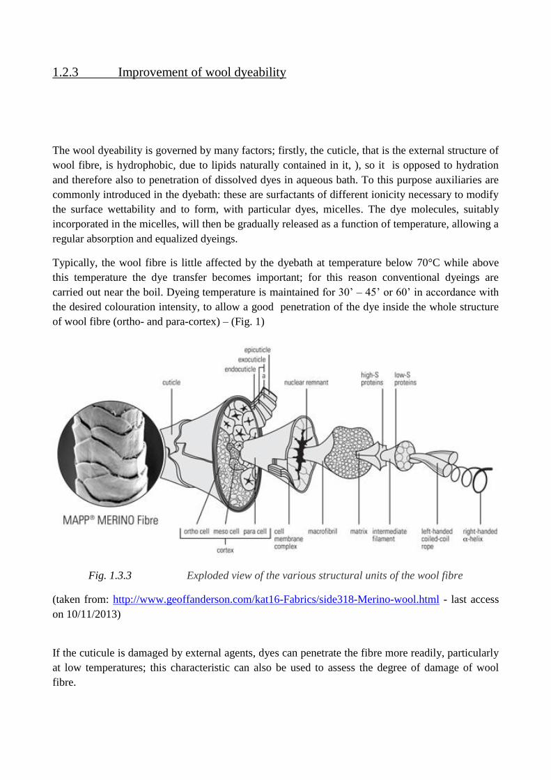
the desired colouration intensity, to allow a good penetration of the dye inside the whole structure
of wool fibre (ortho- and para-cortex) – (Fig. 1)
Fig. 1.3.3 Exploded view of the various structural units of the wool fibre
(taken from: http://www.geoffanderson.com/kat16-Fabrics/side318-Merino-wool.html - last access
on 10/11/2013)
If the cuticule is damaged by external agents, dyes can penetrate the fibre more readily, particularly
at low temperatures; this characteristic can also be used to assess the degree of damage of wool
fibre.
In this case it is advisable to pay attention during dyeing, especially in the first step, because the
fiber was modified at the cuticular region and its affinity is increased;
A modification of the wool fiber at cuticolar level, maybe due to an ultraviolet radiation exposure,
undoubtedly increases its affinity toward dyes, even if the fiber can be damaged in some extent. It’s
therefore appropriate to provide a thermal profile, during the dyeing process, taking into account
this greater ability of the fibre to accept dye molecules from the aqueous media. On the other hand,
it will be possible to dye at temperature below boiling, having regard to this energy will be used
only to permit the dye migration inside the cortical cells.
As suggested by Stoot[6]
, in general UV irradiation enables wool fibres to absorb dyes at a greater
rate than normal and apparently to obtain higher concentration of dye at the equilibrium. Similar
effects are achieved after wool chlorination under acidic conditions.
El-Zaher and Micheal[7]
proved that UV-C radiations produce wool fibre modification; both when
molecular oxygen is subjected to radiation at 184.9 nm and when ozone is irradiated at 253.7 nm
atomic oxygen is generated. Hydrocarbons and ozone absorb the 253.7 nm radiation and react with
atomic oxygen to form simpler volatile molecules that away distance from the surfaces. So, oxygen
is generated, ozone is formed continuously and the latter is destroyed .The modification is carried
out under mild conditions - low temperature.
Beneficial improvements to wool dyeability may be achieved, because after a long exposure time
the amorphous region dominates over the crystalline one, permitting a more easy penetration of
dyes molecules Moreover, the photo-oxidation of cystine linkage into a free-radical species
promotes covalent bond formation between the fibre and the dye. Also, the sulfurous smell, which
occurs after exposure, disappears after some days.
Gupta and Basak[8]
improved the wool dyeability using a 172 nm UV excimer lamp; in this case,
SEM images show ablation and etching of the surface. In case of samples exposed to O2 atmosphere
in particular, micropores can be seen on the surface. Treated wool shows increased saturation dye
uptake as well as improved rate of dyeing. These changes are restricted to surface and do not affect
the bulk properties. XPS analysis shows the presence of polar groups, such as cysteic acid and
sulphonic acid, created by cleavage of cystine linkages. An anionic dye was chosen for dyeing and
the dye uptake was significantly increased in wool fabrics UV treated in air; at 60°C as dyeing
temperature, an irradiated sample showed a dye uptake more than 95%, a good result if compared
with a value of 70% for an untreated sample.
Improved dye uptake by all treated samples can be attributed to the destruction of the lipid barrier
layer and decrease in the number of disulphide groups in the keratin, that act as a barrier to the
diffusion of aqueous solutions.
Xin, Zhu, Hua and Shen[9]
instead worked with different dyeing temperatures (45, 50, 55 and 60 °C)
using Acid Blue 7 on UV treated wool fabrics (Hg vapour lamp Philips TUV 36 W, operating at
253.7 nm and fixed a distance of 16 cm). The UV-treated wool samples showed greater levels of
dye uptake compared with those of the untreated ones. Increases in dye uptake rate and colour yield ,
in terms of K/S, were observed on UV treated fabrics, especially at relatively low dyeing
temperature; the adsorption behavior and diffusion coefficients were also studied.
Shao, Hawkyard and Carr[10]
confirmed the extensive fibre surface modification due to UV rays and
obtained increased rates of exhaustion for acid- milling, metal-complex and reactive dyestuffs;
comparison of the behavior of chlorinated wool and UV treated wool showed little differences
related to total fixation efficiency for reactive dyes.
An accurate work was conducted by Millington[5]
about synergistic interaction between UV
exposure and wet oxidation; in the first step, carried out with low-pressure mercury arc, he
demonstrated high degree of contrast between dyed samples UV irradiated and not irradiated; he
found great dependence of the dye class and suggested that the notable colour differences are
obtainable using 1:1 metal-complex dyes. Differences in colour yields (K/S) are possible with many
class of dyestuffs: acid milling dyes, 1:2 metal-complex dyes, 1:1 metal-complex dyes and reactive
dyes, but the use of 1:l metal-complex dyes is particularly effective.
1.2.4 Preparation for wool printing
Preparation for wool printing is an essential operation because without this step it is very difficult
get full colors yields, levelness and brightness; usually this procedure is carried out with oxidative
processes: chlorination with or without polymer addition, such as chlorination-Hercosett
, rarely
using a “sulphitolysis” process or application of tetraethylenepentamine before printing.
It’s necessary to modify the external structure of fibres, increasing polarity and accessibility, in
order to obtain a quick wettability with printing paste and easy swellability in water, preferably
maintaining the original colour of the fibres.
Shao, Hawkyard and Carr[10]
found that UV irradiated wool fabrics have similar behavior of
chlorinated ones during printing steps but UV treated fabrics showed more yellowing in comparison
with chlorinated).
Always Millington[5]
faced also the problem of printing, and highlighted that UV-C irradiation
before printing gave much better colour yields on wool fabrics regard to untreated ones; he
remarked an initial green colouration of wool fibres, which turns at yellow under ambient
conditions, probably due to the cystinyl radical cation. To overcome the yellowing problem, he
advised a mild wet oxidation with hydrogen peroxide or permonosulfate, that are able, in aqueous
media, to easily remove the chromophores produced by UV-C; this procedure is patented under the
name of Siroflash
.
It was shown that the UVC region in the medium-pressure mercury arc spectrum are the most
important component for increasing colour yields in printing, mainly with reactive dyes, providing
the brightest hues and the best fastness properties.
The rubbing fastness of dyed UV treated fabrics showed slightly lower values to untreated ones for
a given dye concentration; generally, the UV irradiated samples dyed with 1:1 metal-complex dyes
displayed more colour strength (for example, a 3% o.w.f. dyeing on UV-treated fabric can produce
a better depth of shade than a 5% dyeing on untreated fabric).
Then, Siroflash
treatment is uniform across the fabric surface, can be limited to one fabric face,
and has less impact on handle than chlorination. Moreover, the fastness properties of printed
fabrics easily meet Woolmark standards. Also, for quick UV irradiations, the treatment cannot
penetrate into the fabric, thus the loss of strength of fibres is minimal.
1.2.5 Alternative proposed cotton mercerization
The finishing operations performed on weaving fabrics include all the operations carried out to
provide a fabric with those properties that the customer desires after the fabrics leave the textile
factories. With the modern textile finishing operations, it is possible to provide cotton fiber with a
structure similar to the superior properties of synthetic fibers.
Mercerization is a treatment for cellulosic materials, like cotton, that gives fabric or yarns a
lustrous appearance and strengthens them.
Mercerization is carried out by cold, strong caustic soda liquor under tension; it is an important
operation for cotton finishing, to achieve a resistant silk shine and good handle, even if without all
the fundamental processes being understood.
Zuber, Zia, Bhatti, Ali, Arshad and Saif[11]
demonstrated that UV rays have a similar effect, on
cellulosic fibres , of alkaline treatment (mercerization); irradiated cellulosic fibres showed higher
swelling in comparison with any concentration of NaOH treatment, but tear and tensile strength
were worse if compared to the untreated or alkali treated ones. They emphasized that UV rays don’t
produce loss in weight after exposition on cotton fabrics while dye affinity is slightly enhanced if
dyeing was carried out with direct dyes.
These new properties can be useful for cellulose products in special applications (dialysis
membranes, wound dressings, etc.) and for not conventional uses of cellulosic fibres such as
adsorption of heavy metals.
1.3 References
[1] K.J. Dodd, C.M. Carr et K. Byrne, Textile Res. J. 68 (1) 10-16 (1998).
[2] El-Sayed et El-Khatib, J Chem Technol Biotechnol 80 1111–1117 (2005).
[3] J. Shao, J. Liu et C. M. Carr, Color. Technol., 117 (2001).
[4] A. H. Mansouri, A. Khoddami et A. Rezaei Do, FIBRES & TEXTILES in Eastern Europe 2011,
Vol. 19, No. 3 (86).
[5] K. R. Millington, J.S.D.C. 114 (1998) 286.
[6] G. L. Stoot, J.S.D.C. 77 (1961) 206.
[7] N. A. El-Zaher et M. N. Micheal, J Appl Polym Sci Vol. 85: 1469–1476, (2002).
[8] D. Gupta et S. Basak, J Appl Polym Sci, Vol. 117, 3448–3453 (2010).
[9] J. H. Xin, R. Zhu, J. Hua et J. Shen, Color. Technol., 118 (2002) 169.
[10] J. Shao, C. J. Hawkyard et C. M. Carr, J.S.D.C. 113 (1997) 126.
[11] M. Zuber, K. M. Zia, I. A. Bhatti, Z. Ali, M. U. Arshad et M. J. Saif, International Journal of
Biological Macromolecules 51 (2012) 743– 748.
Chapter 2 Use of UV radiation on pretreatment/finishing of
textiles.
Study of different wavelengths and their
interaction with different kinds of fibres.

2.1 Introduction
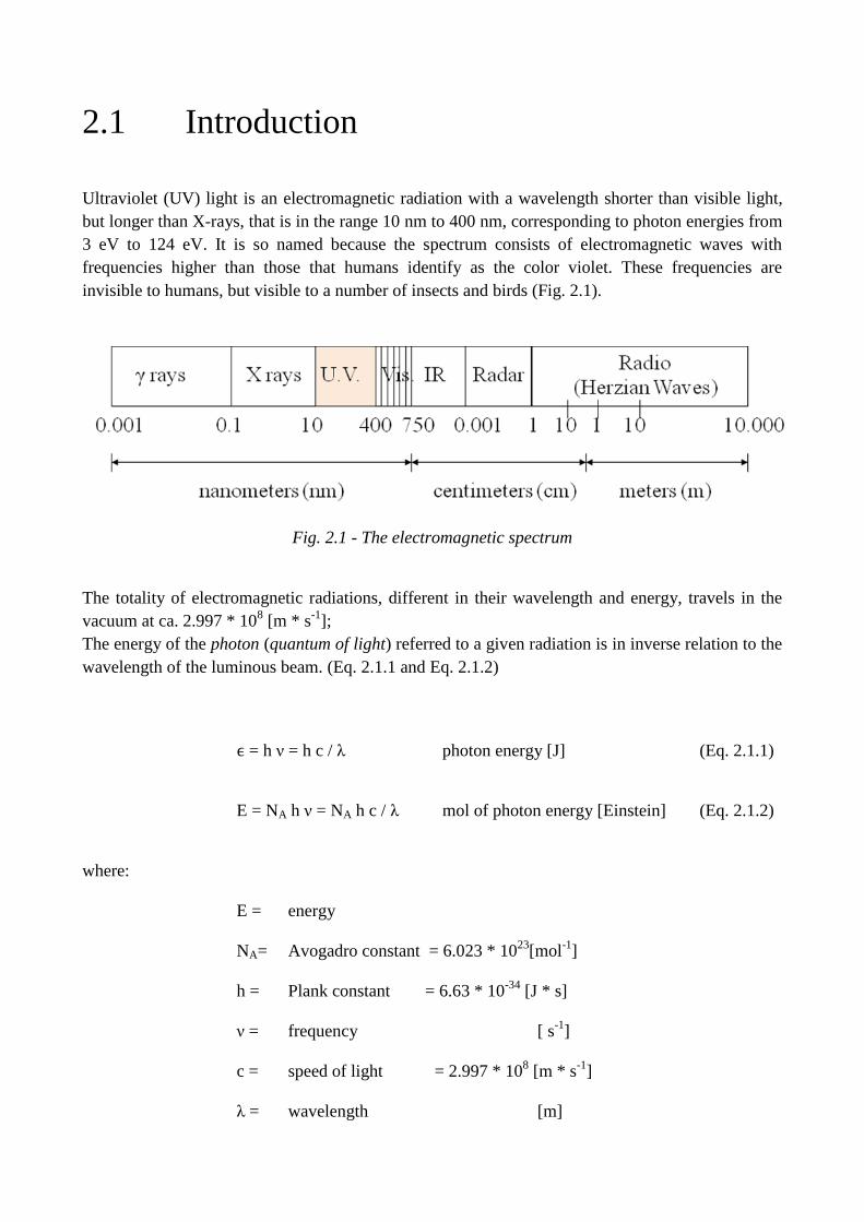
Ultraviolet (UV) light is an electromagnetic radiation with a wavelength shorter than visible light,
but longer than X-rays, that is in the range 10 nm to 400 nm, corresponding to photon energies from
3 eV to 124 eV. It is so named because the spectrum consists of electromagnetic waves with
frequencies higher than those that humans identify as the color violet. These frequencies are
invisible to humans, but visible to a number of insects and birds (Fig. 2.1).
Fig. 2.1 - The electromagnetic spectrum
The totality of electromagnetic radiations, different in their wavelength and energy, travels in the
vacuum at ca. 2.997 * 108 [m * s
-1];
The energy of the photon (quantum of light) referred to a given radiation is in inverse relation to the
wavelength of the luminous beam. (Eq. 2.1.1 and Eq. 2.1.2)
ϵ = h ν = h c / λ photon energy [J] (Eq. 2.1.1)
E = NA h ν = NA h c / λ mol of photon energy [Einstein] (Eq. 2.1.2)
where:
E = energy
NA= Avogadro constant = 6.023 * 1023
[mol-1
]
h = Plank constant = 6.63 * 10-34
[J * s]
ν = frequency [ s-1
]
c = speed of light = 2.997 * 108 [m * s
-1]
λ = wavelength [m]
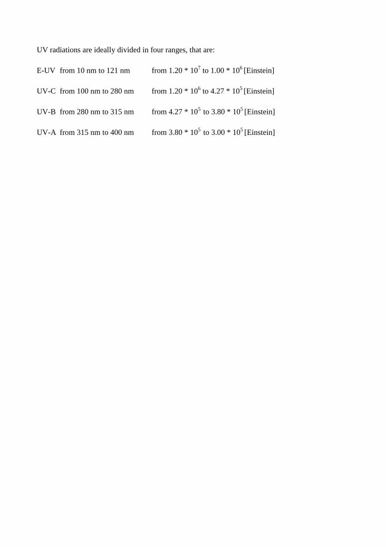
UV radiations are ideally divided in four ranges, that are:
E-UV from 10 nm to 121 nm from 1.20 * 107 to 1.00 * 10
6 [Einstein]
UV-C from 100 nm to 280 nm from 1.20 * 106 to 4.27 * 10
5 [Einstein]
UV-B from 280 nm to 315 nm from 4.27 * 105
to 3.80 * 105 [Einstein]
UV-A from 315 nm to 400 nm from 3.80 * 105
to 3.00 * 105 [Einstein]
2.2 Mechanisms of interactions
2.2.1 Influence of wavelength
There are two basic principles of photochemistry:
electromagnetic radiation must be absorbed, in order to initiate a photochemical process;
absorption takes place in discrete quanta (photons) whose energy is determined by the
frequency of the radiation.
These groundwork led research laboratories to devote extensive attention to
wavelengths that are responsible for the deterioration of specific materials.
As potentially fruitful as this approach is in principle, the quest has not always yielded results
as significant as initially expected.
Berger [1], [2]
clearly states: “Absorption curves need not always be identical with the pertaining
curves of damage, for not every type of absorption causes changes in the material.”
One reason for misdirection is that determination of the activation spectrum may show an apparent
wavelength of peak activity, not because of the maximum absorption of a particular component, but
simply because the available energy of the light source falls off rapidly at the lower wavelengths.
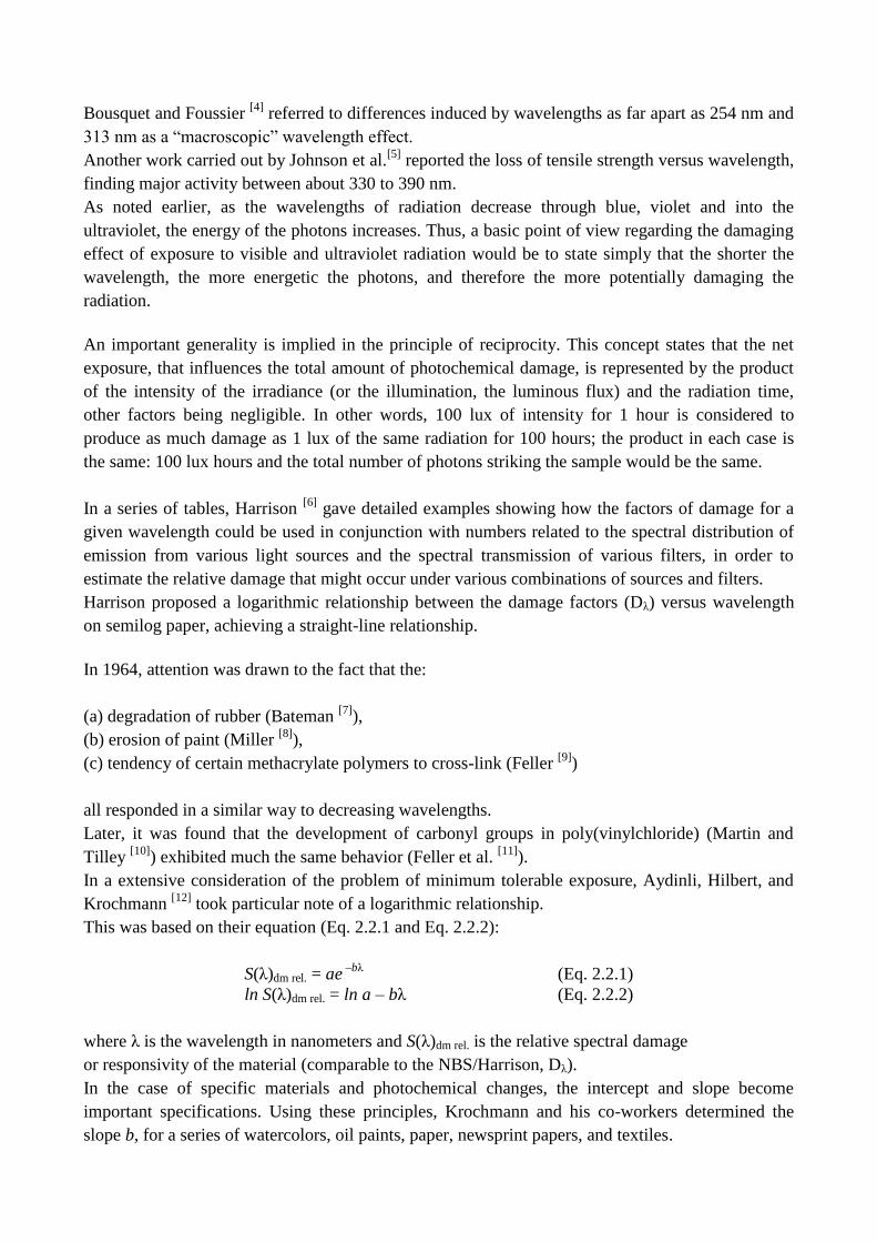
When the range of wavelengths considered is extensive (from 254 nm or lower to 450
nm or greater) it is expected that differences in photodegradative behavior will be observed.
The gases emitted by wool specifically, studied over a wide range of wavelengths by Launer and
Black [3]
, provide an example:distinctly different combinations of gases were generated by 254, 365,
or 436 nm radiation. (Table 2.2.1)
wavelength Mass Spectrum, Percent Gaseous Products
[nm] CO2 CO H2 H2O COS H2S CH4
254 34 28 23 11 4 trace -
365 75 - - - - - -
436 100 - - - - - -
546 - - - - - - -
(160 °C dark) 22 2 - 63 1 2 8
Table 2.2.1. Gases produced from wool in vacuo by the light of various wavelengths and by heat
(data of Launer and Black 1971).
Bousquet and Foussier [4]
referred to differences induced by wavelengths as far apart as 254 nm and
313 nm as a “macroscopic” wavelength effect.
Another work carried out by Johnson et al.[5]
reported the loss of tensile strength versus wavelength,
finding major activity between about 330 to 390 nm.
As noted earlier, as the wavelengths of radiation decrease through blue, violet and into the
ultraviolet, the energy of the photons increases. Thus, a basic point of view regarding the damaging
effect of exposure to visible and ultraviolet radiation would be to state simply that the shorter the
wavelength, the more energetic the photons, and therefore the more potentially damaging the
radiation.
An important generality is implied in the principle of reciprocity. This concept states that the net
exposure, that influences the total amount of photochemical damage, is represented by the product
of the intensity of the irradiance (or the illumination, the luminous flux) and the radiation time,
other factors being negligible. In other words, 100 lux of intensity for 1 hour is considered to
produce as much damage as 1 lux of the same radiation for 100 hours; the product in each case is
the same: 100 lux hours and the total number of photons striking the sample would be the same.
In a series of tables, Harrison [6]
gave detailed examples showing how the factors of damage for a
given wavelength could be used in conjunction with numbers related to the spectral distribution of
emission from various light sources and the spectral transmission of various filters, in order to
estimate the relative damage that might occur under various combinations of sources and filters.
Harrison proposed a logarithmic relationship between the damage factors (Dλ) versus wavelength
on semilog paper, achieving a straight-line relationship.
In 1964, attention was drawn to the fact that the:
(a) degradation of rubber (Bateman [7]
),
(b) erosion of paint (Miller [8]
),
(c) tendency of certain methacrylate polymers to cross-link (Feller [9]
)
all responded in a similar way to decreasing wavelengths.
Later, it was found that the development of carbonyl groups in poly(vinylchloride) (Martin and
Tilley [10]
) exhibited much the same behavior (Feller et al. [11]
).
In a extensive consideration of the problem of minimum tolerable exposure, Aydinli, Hilbert, and
Krochmann [12]
took particular note of a logarithmic relationship.
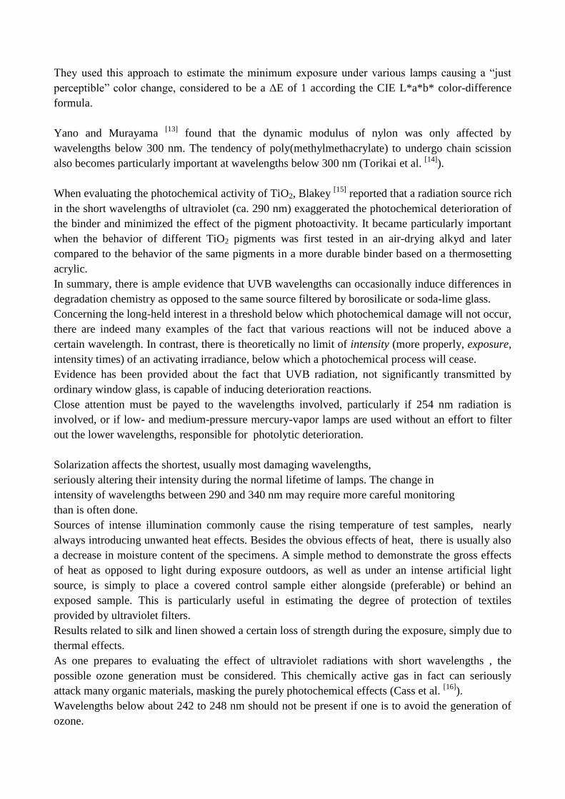
This was based on their equation (Eq. 2.2.1 and Eq. 2.2.2):
S(λ)dm rel. = ae –bλ
(Eq. 2.2.1)
ln S(λ)dm rel. = ln a – bλ (Eq. 2.2.2)
where λ is the wavelength in nanometers and S(λ)dm rel. is the relative spectral damage
or responsivity of the material (comparable to the NBS/Harrison, Dλ).
In the case of specific materials and photochemical changes, the intercept and slope become
important specifications. Using these principles, Krochmann and his co-workers determined the
slope b, for a series of watercolors, oil paints, paper, newsprint papers, and textiles.
They used this approach to estimate the minimum exposure under various lamps causing a “just
perceptible” color change, considered to be a ΔE of 1 according the CIE L*a*b* color-difference
formula.
Yano and Murayama [13]
found that the dynamic modulus of nylon was only affected by
wavelengths below 300 nm. The tendency of poly(methylmethacrylate) to undergo chain scission
also becomes particularly important at wavelengths below 300 nm (Torikai et al. [14]
).
When evaluating the photochemical activity of TiO2, Blakey [15]
reported that a radiation source rich
in the short wavelengths of ultraviolet (ca. 290 nm) exaggerated the photochemical deterioration of
the binder and minimized the effect of the pigment photoactivity. It became particularly important
when the behavior of different TiO2 pigments was first tested in an air-drying alkyd and later
compared to the behavior of the same pigments in a more durable binder based on a thermosetting
acrylic.
In summary, there is ample evidence that UVB wavelengths can occasionally induce differences in
degradation chemistry as opposed to the same source filtered by borosilicate or soda-lime glass.
Concerning the long-held interest in a threshold below which photochemical damage will not occur,
there are indeed many examples of the fact that various reactions will not be induced above a
certain wavelength. In contrast, there is theoretically no limit of intensity (more properly, exposure,
intensity times) of an activating irradiance, below which a photochemical process will cease.
Evidence has been provided about the fact that UVB radiation, not significantly transmitted by
ordinary window glass, is capable of inducing deterioration reactions.
Close attention must be payed to the wavelengths involved, particularly if 254 nm radiation is
involved, or if low- and medium-pressure mercury-vapor lamps are used without an effort to filter
out the lower wavelengths, responsible for photolytic deterioration.
Solarization affects the shortest, usually most damaging wavelengths,
seriously altering their intensity during the normal lifetime of lamps. The change in
intensity of wavelengths between 290 and 340 nm may require more careful monitoring
than is often done.
Sources of intense illumination commonly cause the rising temperature of test samples, nearly
always introducing unwanted heat effects. Besides the obvious effects of heat, there is usually also
a decrease in moisture content of the specimens. A simple method to demonstrate the gross effects
of heat as opposed to light during exposure outdoors, as well as under an intense artificial light
source, is simply to place a covered control sample either alongside (preferable) or behind an
exposed sample. This is particularly useful in estimating the degree of protection of textiles
provided by ultraviolet filters.
Results related to silk and linen showed a certain loss of strength during the exposure, simply due to
thermal effects.
As one prepares to evaluating the effect of ultraviolet radiations with short wavelengths , the
possible ozone generation must be considered. This chemically active gas in fact can seriously
attack many organic materials, masking the purely photochemical effects (Cass et al. [16]
).
Wavelengths below about 242 to 248 nm should not be present if one is to avoid the generation of
ozone.
2.2.2 Influence of moisture
It is generally agreed that oxidative degradation will be speeded up by the presence of moisture.
Nonetheless, Lemaire et al. [17]
take the position that “the chemical role of water in weathering is far
from being understood.”
Kamal and Saxon [18]
point out that water can have at least three kinds of important effects in the
degradation of polymers:
chemical: hydrolysis of the ester or amide bonds.
physical: loss of the bond between the vehicle and a substrate or pigment.
photochemical: generation of hydroxyl radicals or other chemical species.
Another influence of moisture could be the help in ionization and mobility of ionic entities, an
important aspect of corrosion chemistry.
Polymer formation by condensation reactions with loss of water can be reversed. Ester groups in
cellulose acetate-butyrate polymers hydrolzye, yielding destructive acidity (Allen et al. [19]
).
The effect of moisture should always be checked. Moreover, the elevated temperatures achieved in
samples exposed to high-intensity light sources tend to reduce the moisture content of samples.
Graminski et al. [20]
note that, when the atmosphere was desiccated, little if any change in physical
properties of paper occurred at temperatures between 60 °C and 90 °C. There are nonetheless
notable examples in which increased levels of moisture have a negligible effect on the rate of
deterioration.
Some workers, therefore, consider their results to be more fundamentally significant if expressed in
terms of the moisture content of the material under test, inappropriately named “object humidity”,
rather than of relative humidity.
The response of cellulose to decreasing moisture content does not decrease monotonically, but goes
through a minimum at about 0.8% moisture content (DuPlooy [21]
). At this point the absorbed
moisture is zero and the only water remaining is the so-called bound water. Further reduction of
water content begins to eliminate the bound water generally leading to an increased rate of
deterioration. Graminski et al [20]
also state that the minimum occurs because a portion of the water
in cellulose, namely the bound water fraction, is chemically inactive.
Hon[22]
has pointed out that below a water content of 5–7%, the opportunity to form free radicals is
reduced. Instead, as stated by Holt and Waters [23]
, “In the photodegradation of wool, humidity is a
relatively unimportant parameter”.
On the question of 100% RH, Calvini [24]
emphasized the fact that there can be differences in
behavior between situations that principally involve absorbed water vapor, and situations that
involve water in the condensed liquid phase. If the latter occurs, contact with water may cause
leaching and cracking effects that lead to distinctly different results than that would occur when
only the absorption of water vapor were affecting behavior (Abeysinghe et al. [25]
).
Instances are also known in which the hydrolysis of bonds, thought to be the principal process of
degradation in a polymer, did not take place in the absence of oxygen. The diversity of these
possible modes of action led authorities to assert that the role of water in weathering remains far
from being understood. The action of moisture in deterioration, difficult to predict, must be verified
in each specific situation.

Because reactions initiated by ultraviolet and short wavelength visible radiation are likely to be
more rapid than thermally initiated reactions, it is usually the case that samples need to be much
thinner for photochemical aging tests than for thermal (Cunliffe and Davis [26]
). This general
circumstance is further supported by the fact that the diffusion of oxygen is likely to be greater at
the higher temperatures customarily employed in the thermal degradation studies; hence, thicker
samples can be tolerated at higher temperatures.
2.2.3 Influence of temperature
The direct breaking of chemical bonds upon exposure to ultraviolet and visible light in absence of
oxygen is termed photolysis. There are also pyrolytic chemical changes that can be induced by high
temperatures in the absence of oxygen.
Vachon et al. [27]
claimed that the degradation of nylon was not a purely hydrolytic process as might
be expected. They found instead that the scission of the amide linkages did not occur in the absence
of oxygen. Measurement of the rate of deterioration of nylon and Kevlar versus relative humidity
allowed Auerbach [28]
to conclude that at 150–170 °C there was a purely thermal reaction that took
place in the absence of moisture.
There are some limitation:
if the mechanism of the reaction at higher or lower temperatures should differ,
this, too, would alter the slope of the curve.
it is necessary that the energy of activation is independent by temperature, that is constant
over the range of temperatures of interest.
the Arrhenius equation applies to homogeneous reaction conditions while it has little
significance in solid-state reactions.
Agrawal [29 ]
cites two reasons for nonlinearity between log k and 1/T: a change in reaction
mechanism, as just mentioned, but also the existence of a temperature gradient within the sample,
due to heat and mass transfer effects.
Day et al. [30]
describe an example where the rate of oxidation became diffusion-controlled at lower
temperatures.
Kelly et al. [31]
report nonlinear Arrhenius plots for the fading of certain dyes on acrylic and
poly(vinylalcohol) substrates.
It is necessary to consider also if the reactions take place above or below the Second-Order
Transition Temperature, Tg; in general, if irradiation tests are carried out solely at temperatures
above the second-order transition temperature, the rate of certain key reactions may be sufficiently
altered that Arrhenius-based extrapolations of possible behavior down to room temperature
(specifically to temperatures below Tg) can be in error.
The effect of stress may become important in the case of materials on exhibition, perhaps a
textile hung or draped over a frame; the greatest rate of deterioration should occur where the textile,
or leather work, experiences the greatest stress of bending or tension.
The reason the applied stress leads to a more rapid rate of reaction is that mechanical tension
contributes to chemical bond scission. The thermal energy of activation( E) is lowered by the
potential energy of the stress, δ σ.
Thus, the familiar Arrhenius equation (Eq. 2.2.3) becomes:
K= Ko exp [-(E – δσ) / RT] (Eq. 2.2.3)
2.3 References
[1] W. Berger, Comparative studies on light resistance test instruments. Farbe und Lack 77:16–26.
[2] W. Berger, Comparison of light stability testers. Paint Manufacture. May 1971:30–35.
[3] H. F. Launer, D. Black, 1971 Gases produced from wool by light and heat. Applied Polymer
Symposium No. 18: 347–52. New York: J. Wiley & Sons.
[4] J. A. Bousquet, J. P. Foussier, 1984 Hydroperoxides as intermediates responsible for wavelength
effects in photooxidation reactions. Journal Polymer Science, Polymer Chemistry Edition 22:3865–
76.
[5] L. D. Johnson, W. C. Tincher, and H. C. Bach, 1969 Photodegradative wavelength dependence
of thermally resistant organic polymers. Journal Applied Polymer Science 13:1825–32.
[6] L. S. Harrison, 1954a Report on the deteriorating effects of modern light sources. New York:
The Metropolitan Museum of Art.
1954b An Investigation of the damage hazard in spectral energy. Illuminating Engineering 48:253–
57.
[7] L. Bateman, 1947 Photolysis of rubber. Journal Polymer Science 2:1–9.
[8] C. D. Miller, 1958 Kinetics and mechanism of alkyd photooxidation. Industrial Engineering
Chemistry 50:125–28.
[9] R. L. Feller, 1963 New solvent-type varnishes. In Recent Advances in Conservation. G.
Thomson, ed. London 171–75.
[10] K. C. Martin, and K. I. Tilley, 1971 Influence of radiation wavelengths on photooxidation of
unstabilized PVC. British Polymer Journal 3:36–40.
[11] R. L. Feller, M. Curran, and C. Bailie, 1981 Photochemical studies of methacrylate coatings for
the conservation of museum objects. In Photo-degradation and Photostabilization of Coatings. S. P.
Pappas and F. H. Winslow, eds. American Chemical Society Symposium Series 151:182–96.
[12] S. Aydinli, G. S. Hilbert, and J. Krochmann 1983 Über die gefährdung von
ausstellungsgegenständen durch optische strahlung (On the damage hazard of art objects by optical
radiation). Licht-Forshung 5:35–47. In German.
[13] S. Yano, and M. Murayama, 1980 Effect of photodegradation on dynamic mechanical
properties of nylon 6. Journal Applied Polymer Science 25:433–47.
[14] A. Torikai, M. Ohno, and K. Fueki, 1990 Photodegradation of poly(methyl methacrylate) by
monochromatic light: quantum yield, effect of wavelengths, and light intensity. Journal Applied
Polymer Science 41:1023–32.
[15] R. R. Blakey, 1985 Evaluation of paint durability—natural and accelerated. Progress in
Organic Coatings 13:279–96.
[16] G. R. Cass, J. R. Druzik, D. Grosjean, W. W. Nazaroff, P. M. Whitmore, and G. L. Wittman
1990 Protection of Works of Art from Atmospheric Ozone. Research in Conservation 5. Marina
del Rey: The Getty Conservation Institute.
[17] J. R. Lemaire, R. Arnand, and J.-L. Gardette, 1991 Low temperature thermo-oxidation of
thermoplastics in the solid state. Polymer Degradation and Stability 33:277–94.
[18] M. R. Kamal, and R. Saxon 1967 Recent developments in the analysis and prediction of the
weatherability of plastics. Applied Polymer Symposia 4:1–28.
[19] N. S. Allen, M. Edge, J. H. Appleyard, T. S. Jewitt, C. V. Horie, and D. Francis 1987
Degradation of historic cellulose triacetate cinematographic film: the vinegar syndrome.
Polymer Degradation and Stability 19:379–87.
1988 Degradation of cellulose triacetate cinematographic film: prediction of archival life.
Polymer Degradation and Stability 23:43–50.
[20] E. L. Graminski, E. J. Parks, and E. E. Toth, 1979 The effects of temperature and moisture on
the accelerated aging of paper in durability of macromolecular materials. American Chemical
Society Symposium Series 95, 341–55. R. K. Eby, ed. See also NBSIR78-1443 (1978), National
Bureau of Standards, Washington, D.C.
[21] A. B. J. DuPlooy, 1981 The influence of moisture content and temperature on the aging rate of
paper. Australian Pulp & Paper Industry Technical Association 34:287–92.
[22] D. N.-S. Hon, 1975 Formation of free radicals in photoirradiated cellulose II. Effect of
moisture. Journal of Polymer Science 13:955–59.
[23] L. A. Holt, and P. J. Waters, 1985 Factors affecting the degradation of wool by light,
wavelength, temperature, moisture content. Proceedings of the 7th International Wool Textile
Research Conference, Tokyo 4:1–10.
[24] P. Calvini, 1987 A two-dimensional equation of state of water absorbed on the surface of
cellulose: A tool to better understand the artificial ageing of cellulosic materials. ICOM Committee
for Conservation, 8th Triennial Meeting, Sydney, Australia 353–56
[25] H. P. Abeysinghe, W. Edwards, G. Prichard, and G. L. Swanysillai, 1982 Degradation of
crosslinked resins in water and electrolyte solutions. Polymer 23: 1785–90.
[26] A. V. Cunliffe, and A. Davis, 1982 Photo-oxidation of thick polymer samples—Part II: The
influence of oxygen diffusion on the natural and artificial weathering of polyolefins. Polymer
Degradation and Stability 4:17–37.
[27] R. N. Vachon, L. Rebenfeld, and H. S. Taylor, 1968 Oxidative degradation of nylon 66
filaments. Textile Research Journal 38:716–28.
[28] I. Auerbach, 1989 Kinetics for the tensile strength degradation of nylon and Kevlar yarns.
Journal Applied Polymer Science 37:2213–27.
[29] R. K. Agrawal, 1985 On the use of the Arrhenius equation to describe cellulose and wood
pyrolysis. Thermochemica Acta 91:343–49.
[30] M. Day, J. D. Cooney, and D. M. Wiles, 1989 The thermal stability of poly(aryl-ether-ether-
ketone) as assessed by thermogravimetry. Journal Applied Polymer Science 38:323–37.
[31] S. E. Kelly, C. H. Nicholls, and M. T. Pailthorpe, 1982 Temperature dependence of the fading
of basic dyes on acrylic and nylon substrates. Polymer Photochemistry 2:321–29.
Chapter 3 Study of interaction of UV radiation on different
fibres: naturally present chromophores and
related photomodifications.

3.1 Introduction
When a dyed or pigmented material fades, it may not be the absorption of light by the colored
substance, the most obvious absorber, that represents the wavelengths principally responsible for its
deterioration (ISO R105 blue-wool fading cloth No. 7 provides a case in point [McLaren 1956][1]
).
Instead, it may be that absorption by chromophoric groups, in a trace of impurity, activates the
vehicle leading to the degradation of the colorant.
Occasionally, the discoloration of specimens apparently will be reversed by removal from exposure.
It can pose a problem if the fading on samples is not measured either immediately or after precisely
the same period of time following their exposure to heat or light. (Morris et al. 1985)[2]
In the darkening or intentional bleaching of oils and paper, both changes can go on at the same time:
the result after a period of accelerated aging will be the net effect of the equilibrium state between
the two processes. It is particularly true if certain components react in one fashion and other
components in another or if the light source emitted both visible and ultraviolet radiation inducing
opposite reactions.
3.2 Properties of chromophores
3.2.1 About wool
In wool fibers there are several UV-absorbing chromophores, present in the form of the aromatic
amino acid residues (Trp, Tyr, Phe and also Cys), absorbing in the UV region between 250 and 320
nm. There are also visible chromophores, that absorb from the near UV into the visible region of the
spectrum (350–500 nm), resulting in the cream colour of natural undyed wool.
Surprisingly, little is known about the identity of the natural yellow chromophores in wool; it is
likely that they are a complex mixture of compounds, including wool protein oxidation products.
Because wool has a very high absorption coefficient for high-energy UV, a wool fabric exposed
only to UV-B (or UV-C) wavelengths is oxidised and discoloured specifically at the surface, to a
depth of 1–2 μm.
Exposure of dry wool to high-energy UV-C wavelengths results in a green colour because of
formation of two species: one absorbing blue light and one absorbing in the red region at 600 nm.
The presence of oxygen is not necessary for the green coloration to occur, thanks to free radicals
derived from cystine residues, quite stable in the absence of oxygen and water. UV radiation in the
presence of atmospheric oxygen results in rapid wool photoyellowing, accelerated in the presence
of water, whereas exposure of natural cream wool to blue light causes photobleaching.
3.2.2 About cotton
In cotton, the precise origin of the UV absorption ,which is not due to any of the structural groups
which make up the normal cellulosic chains, is uncertain and can only be attributed tentatively to
“impurities” or “faults” bearing carbonyl and/or carboxyl groups.
Naturally-pigmented green cotton derives its color from caffeic-acid, a derivative of cinnamic acid,
found in the suberin (wax) layer surrounding, with cellulose, the fiber. The isolated compound is
fluorescent (287 nm and 310 nm) and it is supposed that its purpose is to absorb UV radiation in
order to protect the seed. On the other hand, brown and tan cottons derive their color from tannin
vacuoles in the lumen of the fiber cells. TLC analysis revealed the pigment to be a tannin precursor,
catechin, and tannin derivatives (absorption near 278 nm).
The brown color does not form until the fibers are exposed to oxygen and sunlight, which happens
when the seed pod opens.
Naturally-pigmented cottons offer better UV protection than conventional bleached or unbleached
cotton, then it has better UPF.
3.3 Interaction between wool chromophores
and radiation
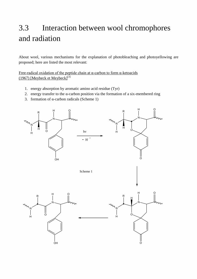
About wool, various mechanisms for the explanation of photobleaching and photoyellowing are
proposed; here are listed the most relevant:
Free-radical oxidation of the peptide chain at α-carbon to form α-ketoacids
(1967) [Meybeck et Meybeck][3]
1. energy absorption by aromatic amino acid residue (Tyr)
2. energy transfer to the α-carbon position via the formation of a six-membered ring
3. formation of α-carbon radicals (Scheme 1)
N
H
R
HO
N
H O
OH
N
H
R
HO
N
H O
O
hv
- H .
N
H
R
O
N
O
OH
H
N
H
R
O
N
OH
OH
Scheme 1
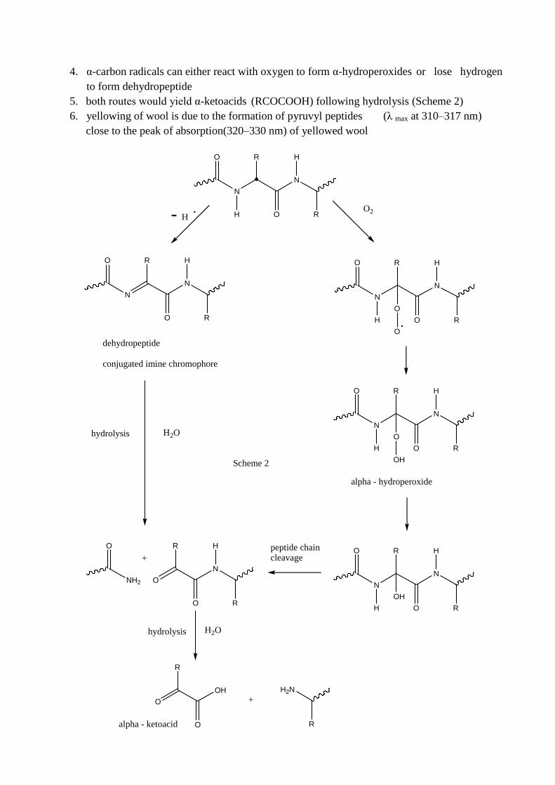
4. α-carbon radicals can either react with oxygen to form α-hydroperoxides or lose hydrogen
to form dehydropeptide
5. both routes would yield α-ketoacids (RCOCOOH) following hydrolysis (Scheme 2)
6. yellowing of wool is due to the formation of pyruvyl peptides (λ max at 310–317 nm)
close to the peak of absorption(320–330 nm) of yellowed wool
O
N
H
R
O
N
H
R
O
N
H
R
O
N
H
R
O
N
R
O
N
H
R
O2- H .
O
O.
O
N
H
R
O
N
H
R
O
OH
alpha - hydroperoxide
dehydropeptide
conjugated imine chromophore
O
N
H
R
O
N
H
R
OH
O
NH2
R
O
N
H
R
hydrolysis H2O
peptide chaincleavage
H2Ohydrolysis
R
O
H2N
R
O
O
OH
+
+
alpha - ketoacid
Scheme 2
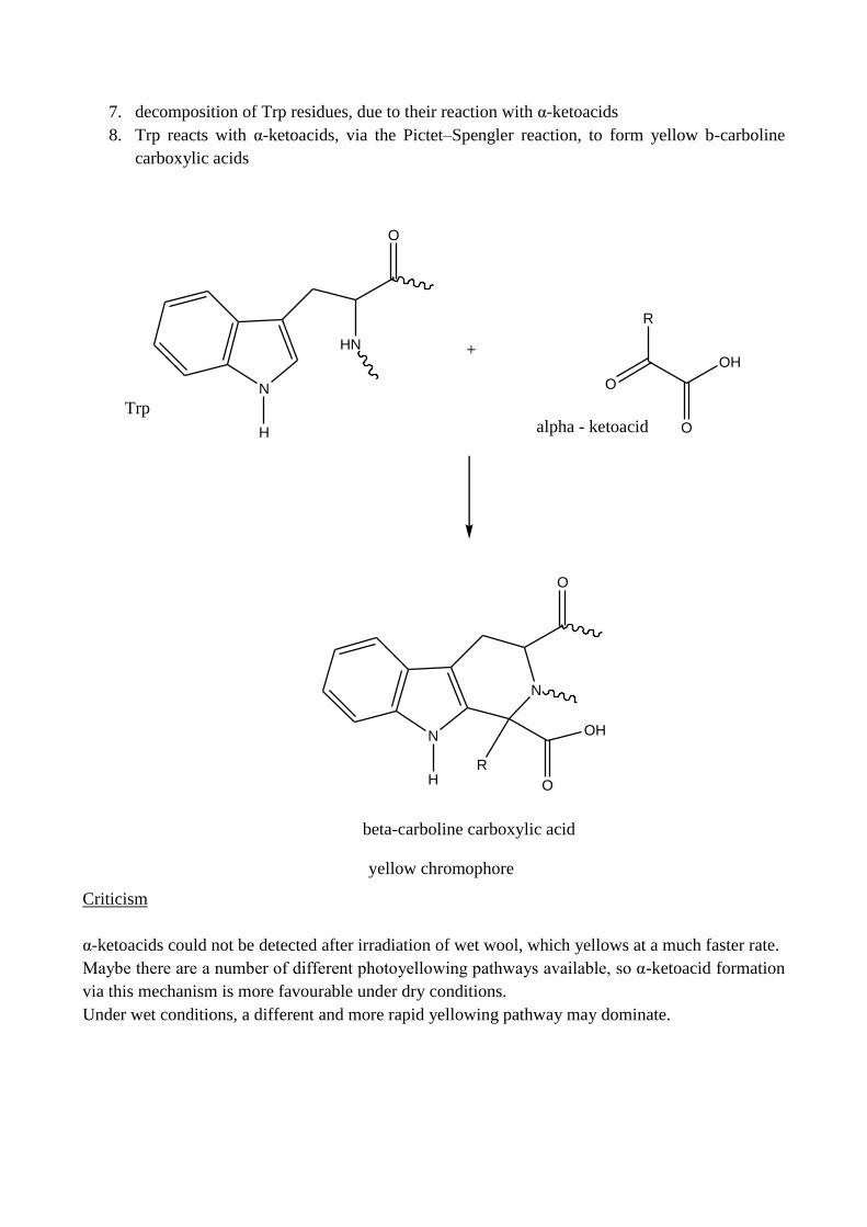
7. decomposition of Trp residues, due to their reaction with α-ketoacids
8. Trp reacts with α-ketoacids, via the Pictet–Spengler reaction, to form yellow b-carboline
carboxylic acids
Criticism
α-ketoacids could not be detected after irradiation of wet wool, which yellows at a much faster rate.
Maybe there are a number of different photoyellowing pathways available, so α-ketoacid formation
via this mechanism is more favourable under dry conditions.
Under wet conditions, a different and more rapid yellowing pathway may dominate.
N
H
HN
O
R
O
O
OH
alpha - ketoacid
+
N
H
O
R
N
O
OH
beta-carboline carboxylic acid
Trp
yellow chromophore
Chromophore formation via increased conjugation: semiconductor theory,
(1974) [Hoare][4]
During irradiation, wool keratin produces mobile-free electrons that are promoted into a conduction
band, similar to the known behaviour of semiconductor biomaterials, such as
melanin. The theory is that the removal of electrons from single bonds increases the level of
unsaturation and conjugation in the keratin structure (for example, dehydropeptides and conjugated
imines as shown in Scheme 2) leading to the formation of new chromophores.
Criticism
The conjugation theory is that if the yellow chromophores in wool are due to the conjugation of
unsaturated double bonds, then on mild hydrolysis, when the conjugated protein is cleaved, the
colour should be removed. It is difficult to determine whether any loss of colour occurs under such
conditions, but yellow solutions are formed showing the presence of chromophores formed via
other mechanisms.
Oxidation by singlet oxygen 1Δg
(1976) [Nicholls and Pailthorpe][5]
The singlet oxygen mechanism involves absorption of the UV components of sunlight by the
aromatic amino acid residues in wool protein, followed by energy transfer through the protein chain
to tryptophan residues. Tryptophan residues in the singlet excited state then undergo intersystem
crossing to an excited, long-lived triplet state which can react with ground state oxygen to produce
singlet oxygen.
hν
Trp 1Trp
*
1Trp
* 3Trp
*
3
Trp* +
3Σg
- Trp +
1Δg
wool + 1Δg yellow products
Criticism
One major criticism of a singlet oxygen mechanism is that it fails to explain the observed increase
in the photoyellowing rate of wet wool. The lifetime of singlet oxygen in water is 4.2 μs, compared
with 14 ms in the gas phase and any singlet oxygen is therefore rapidly deactivated. A study also
showed that hydroxyl radicals are produced when wet wool is irradiated with both UV-A (366 nm)
and blue (425 nm) light using a fluorescent probe. Another problem for this theory arises from
studies on Trp-depleted wool. Removal of 80% of the Trp from wool had surprisingly little effect
on the rate of yellowing of natural or bleached wool under wet and dry conditions over short
irradiation periods (2 h wet, 24 h dry).
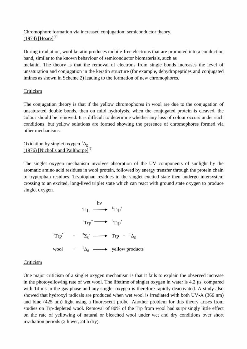
Graph 3.3 - Potential energy curves for the three low-lying electronic states of molecular oxygen.
Smith[6]
has detected singlet oxygen in dry-irradiated wool directly by measuring
its luminescence emission at 1269 nm (Graph.3.3).
He found that, when wool is irradiated at 265 and 350 nm, 1Δg was detected at the higher
wavelength only, and therefore suggested it causes photobleaching of wool, rather than
photoyellowing. He also postulated that photoyellowing of wool by sunlight is much faster in the
wet state because any 1Δg generated by visible wavelengths, which would lead to concurrent
photobleaching in the dry state, is rapidly quenched by water.
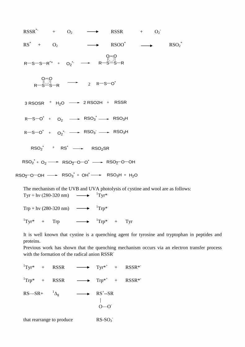
Oxidation
(1996) [Millington et Church.][7]
The formation of both oxidized and reduced sulphur species in wool keratin after exposure to UV
light is rationalized by two alternative mechanisms which are dependent on the irradiation
wavelength.
Both mechanisms involve the formation of the radical anion RSSR- as a key transient species, with
the formation of the radical cation RSSR+ involved only in UVC exposure.
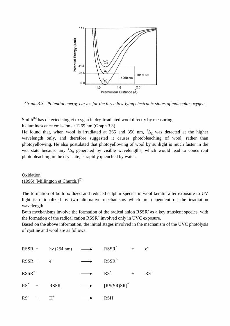
Based on the above information, the initial stages involved in the mechanism of the UVC photolysis
of cystine and wool are as follows:
RSSR + hν (254 nm) RSSR*+
+ e-
RSSR + e-
RSSR*-
RSSR*-
RS* + RS
-
RS* + RSSR [RS(SR)SR]
*
RS-
+ H+ RSH
RSSR*-
+ O2 RSSR + O2-
RS* + O2 RSOO
* RSO2
*
The mechanism of the UVB and UVA photolysis of cystine and wool are as follows:
Tyr + hν (280-320 nm) 1Tyr*
Trp + hv (280-320 nm) 1Trp*
1Tyr* + Trp
1Trp* + Tyr
It is well known that cystine is a quenching agent for tyrosine and tryptophan in peptides and
proteins.
Previous work has shown that the quenching mechanism occurs via an electron transfer process
with the formation of the radical anion RSSR-
1Tyr* + RSSR Tyr*
+ + RSSR*
-
1Trp* + RSSR Trp*
+ + RSSR*
-
RS—SR+ 1Δg RS
+--SR
|
O—O-
that rearrange to produce RS-SO3-
R S S R*+ + O2*- R S S R
O O
R S S R
O O
2 R S O*
3 RSOSR + H2O 2 RSO2H + RSSR
R S O* + O2RSO3
* RSO3H
R S O* + O2*- RSO3
- RSO3H
RSO2* RS*+ RSO2SR
RSO2*
+ O2 RSO2 O O* RSO2 O OH
RSO2 O OH RSO3* + OH* RSO3H + H2O
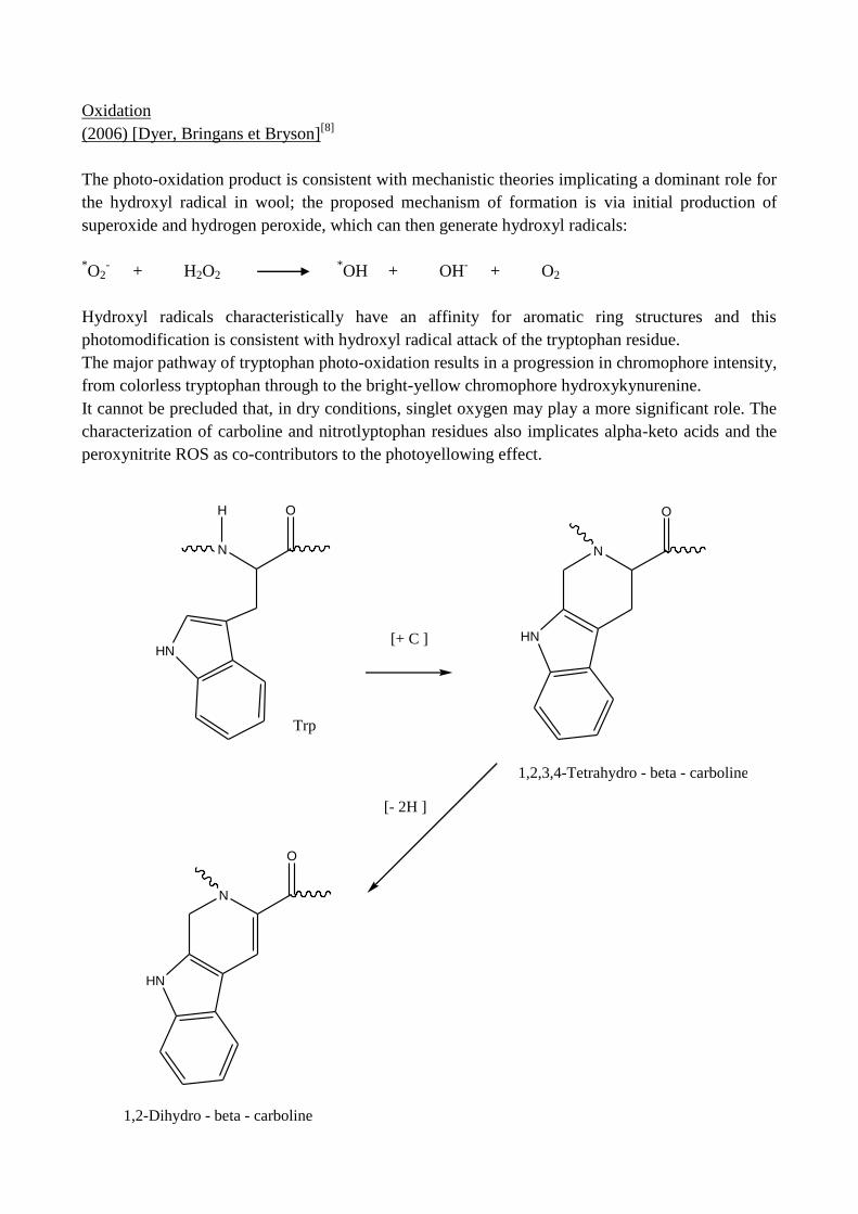
Oxidation
(2006) [Dyer, Bringans et Bryson][8]
The photo-oxidation product is consistent with mechanistic theories implicating a dominant role for
the hydroxyl radical in wool; the proposed mechanism of formation is via initial production of
superoxide and hydrogen peroxide, which can then generate hydroxyl radicals:
*O2
- + H2O2
*OH + OH
- + O2
Hydroxyl radicals characteristically have an affinity for aromatic ring structures and this
photomodification is consistent with hydroxyl radical attack of the tryptophan residue.
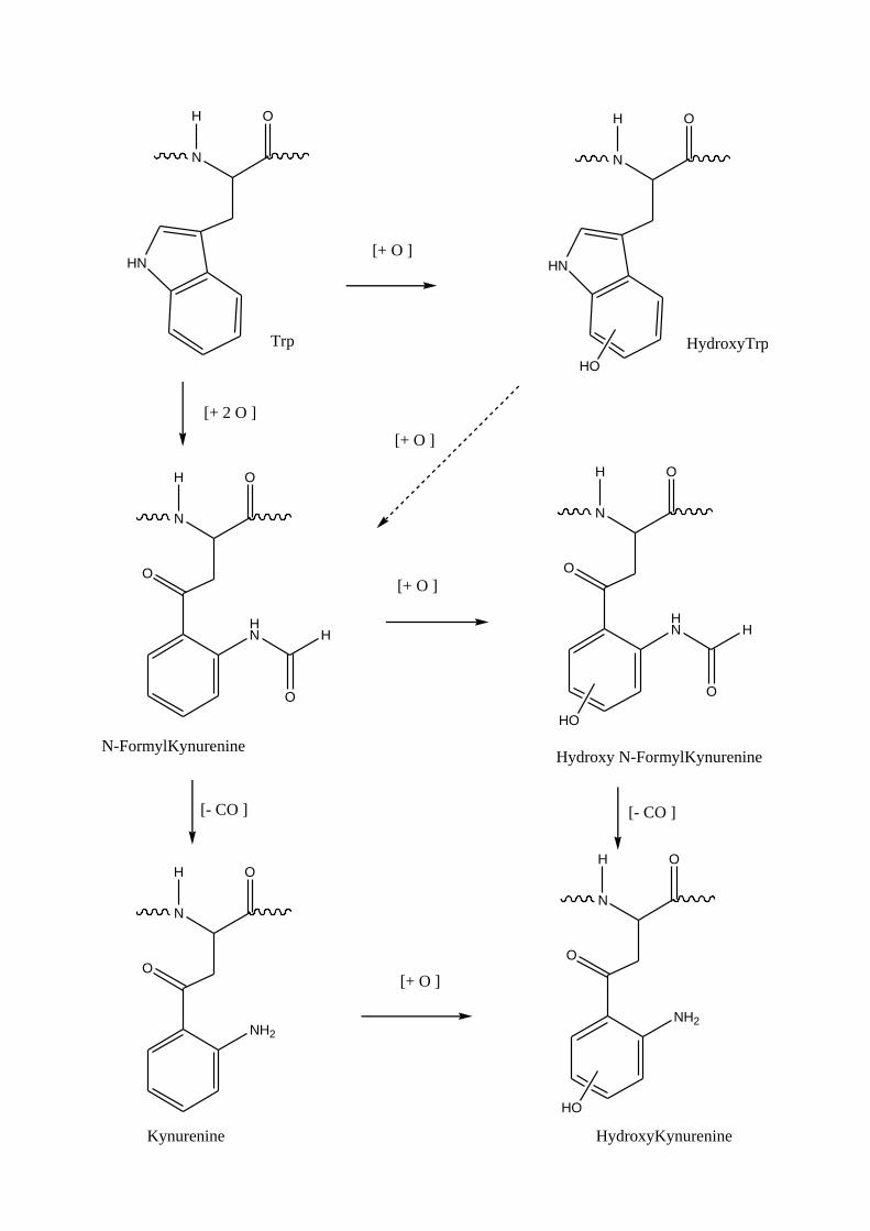
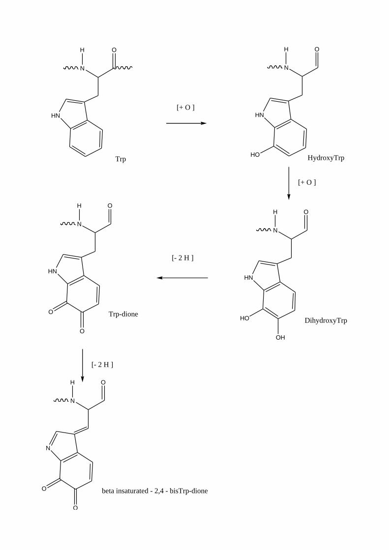
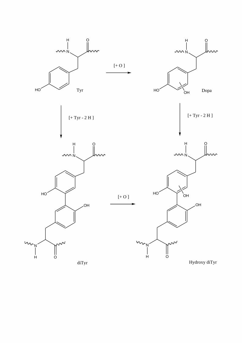
The major pathway of tryptophan photo-oxidation results in a progression in chromophore intensity,
from colorless tryptophan through to the bright-yellow chromophore hydroxykynurenine.
It cannot be precluded that, in dry conditions, singlet oxygen may play a more significant role. The
characterization of carboline and nitrotlyptophan residues also implicates alpha-keto acids and the
peroxynitrite ROS as co-contributors to the photoyellowing effect.
N
OH
HN[+ C ]
Trp
N
O
HN
N
O
HN
[- 2H ]
1,2-Dihydro - beta - carboline
1,2,3,4-Tetrahydro - beta - carboline
N
OH
HN
N
OH
HN
HO
N
OH
O
HN
O
H
N
OH
O
HN
O
H
HO
N
OH
O
NH2
HO
N
OH
O
NH2
[+ O ]
[+ O ]
[+ O ]
[+ O ]
[+ 2 O ]
[- CO ] [- CO ]
Trp HydroxyTrp
N-FormylKynurenineHydroxy N-FormylKynurenine
Kynurenine HydroxyKynurenine
N
OH
HN
[+ O ]
Trp
N
OH
HN
HydroxyTrp
[+ O ]
N
OH
HN
DihydroxyTrp
HO
HO
OH
[- 2 H ]
N
OH
HN
Trp-dioneO
O
[- 2 H ]
N
OH
N
beta insaturated - 2,4 - bisTrp-dioneO
O
N
OH
[+ O ]
HO
N
OH
HOTyrOH
Dopa
[+ Tyr - 2 H ]
N
OH
HOOH
OH
N
OH
Hydroxy diTyr
N
OH
HO
OH
N
OH
diTyr
[+ O ]
[+ Tyr - 2 H ]
3.4 Interaction between cotton chromophores
and radiation
About cotton, the situation is doubtful because the chromophores are not yet well identified;
a proposed mechanism involving lignin is presented (Scheme 3).
On “pure” cellulose there are 2 behaviors:
λ exc < 300 nm produce yellowing of the substrate and weight loss due to the formation of volatile
photoproducts;
λ exc > 300 nm leads to bleaching without any weight loss following a photochromic phenomenon.
It is suggested the presence in cellulose of a “family” of absorbing centres, with chromophores
characterized by absorption bands which partially overlap.
The irradiation of the material with λ exc > 300 nm induces the selective disappearance of the
chromophores whose absorption maxima are centered at the irradiation wavelength, but also the
partial bleaching of those possessing a weaker absorption cross section at this wavelength.
The reversibility of the colouration-decolouration cycles, over the whole range of studied
wavelengths, demonstrates that the photochromism of cellulose is a general phenomenon.
This photochromism is not fully reversible, because several processes are involved during the non-
radiative deactivation of excited states, only some of them being reversible during a thermal dark
reaction.
The origin of this behaviour is tentatively attributed to the specific destruction and restoration of
homologous chromophores.
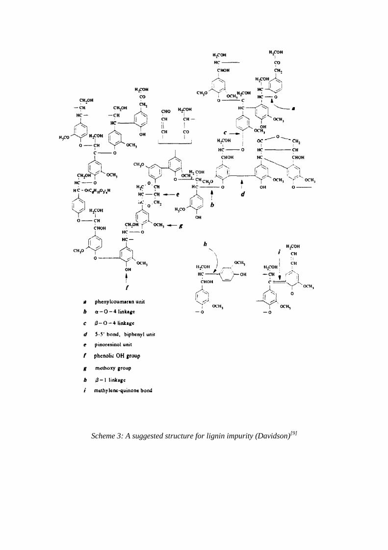
Scheme 3: A suggested structure for lignin impurity (Davidson)[9]
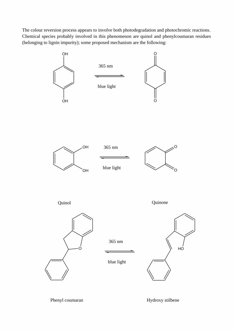
The colour reversion process appears to involve both photodegradation and photochromic reactions.
Chemical species probably involved in this phenomenon are quinol and phenylcoumaran residues
(belonging to lignin impurity); some proposed mechanism are the following:
OH
OH
O
O
365 nm
blue light
365 nm
blue light
OH
OH
O
O
Quinol Quinone
O
365 nm
blue light
HO
Phenyl coumaran Hydroxy stilbene
3.5 References
[1] K. McLaren, 1956 The spectral regions of daylight which cause fading. Journal Society of Dyers
and Colourists 72:86–99.
[2] R. A. Morris, T. G. Prejean, and J. G. Green, 1985
Dark time yellowing of white rigid vinyl outdoor weatherable compounds.
Society of Plastics Engineers ANTEC ‘85:1046–55.
[3] A Meybeck and J Meybeck, Photochem. Photobiol., 6 (1967) 355.
[4] J. L. Hoare, J. Text. Inst., 65 (1974) 503.
[5] C. H. Nicholls and M T Pailthorpe, J. Text. Inst., 67 (1976) 397.
[6] G. J. Smith, Singlet oxygen produced by UV irradiation of wool keratin.
J. Photochem. Photobiol., B 12(2): 173-8 (1992).
[7] K.R. Millington, J.S. Church, Journal of Photochemistry and Photobiology B: Biology 39 (1997)
204-212.
[8] Dyer, Bringans et Bryson, Photochemistry and Photobiology, 2006, 82: 551-557.
[9] R.S. Davidson, Journal of Photochemistry and Photobiology B: Biology 33 (1996) 3-25.
[10] Choudhury, Collins et Davidson, J. Photochem. Photobiol. A: Chem. 69 (1992) 109-119.

2nd
PART EXPERIMENTAL WORK


Chapter 4 Instrumental methods and equipments

4.1 Instrumental methods
4.1.1 Reflectance colorimetry
To characterize dyeings and their chromatic effects objective methods universally recognized are
needed; for this purpose instrumental methods were used.
Those methods belong mainly to the colorimetry, based on the measuring of reflectance and
absorbance / transmittance; any dyed textile substrate presents a colour (tone) belonging to the
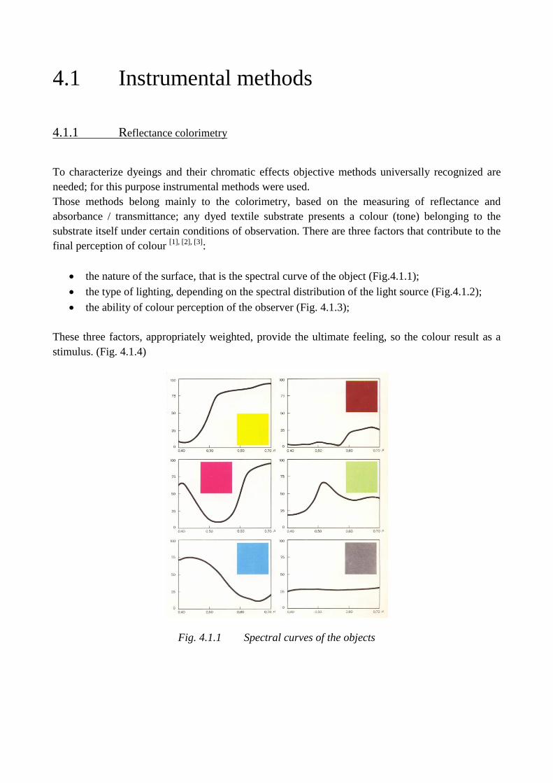
substrate itself under certain conditions of observation. There are three factors that contribute to the
final perception of colour [1], [2], [3]
:
the nature of the surface, that is the spectral curve of the object (Fig.4.1.1);
the type of lighting, depending on the spectral distribution of the light source (Fig.4.1.2);
the ability of colour perception of the observer (Fig. 4.1.3);
These three factors, appropriately weighted, provide the ultimate feeling, so the colour result as a
stimulus. (Fig. 4.1.4)
Fig. 4.1.1 Spectral curves of the objects
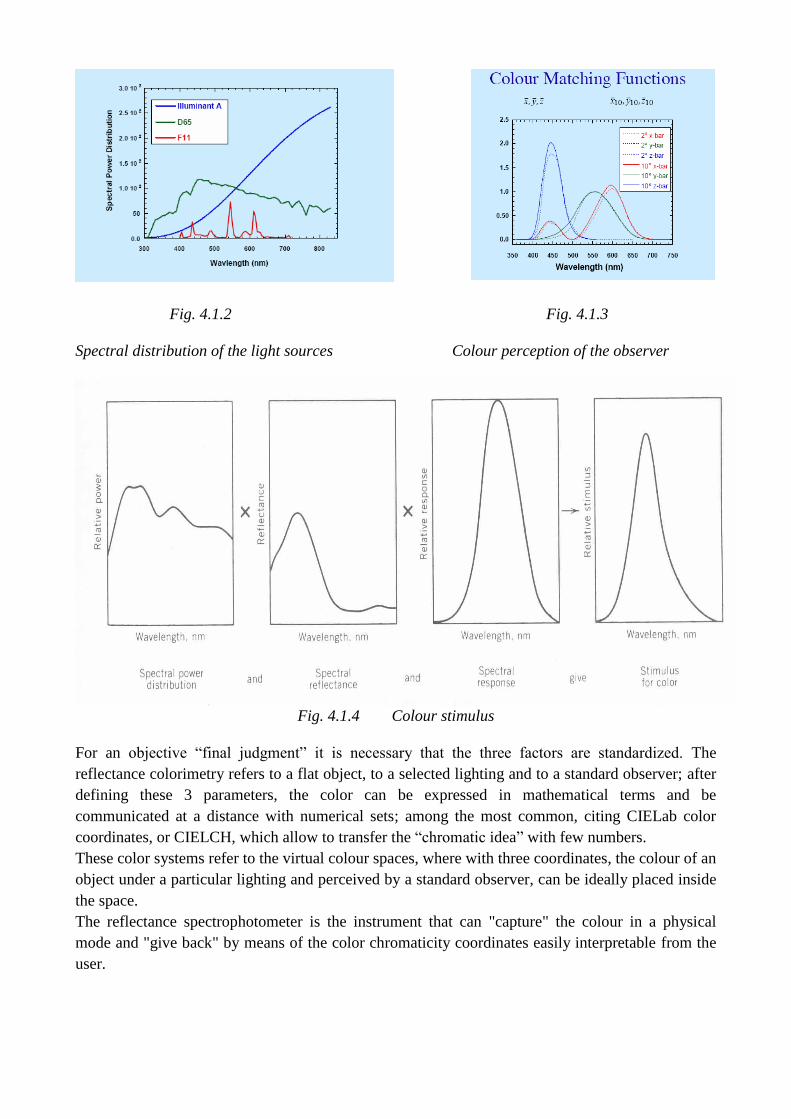
Fig. 4.1.2 Fig. 4.1.3
Spectral distribution of the light sources Colour perception of the observer
Fig. 4.1.4 Colour stimulus
For an objective “final judgment” it is necessary that the three factors are standardized. The
reflectance colorimetry refers to a flat object, to a selected lighting and to a standard observer; after
defining these 3 parameters, the color can be expressed in mathematical terms and be
communicated at a distance with numerical sets; among the most common, citing CIELab color
coordinates, or CIELCH, which allow to transfer the “chromatic idea” with few numbers.
These color systems refer to the virtual colour spaces, where with three coordinates, the colour of an
object under a particular lighting and perceived by a standard observer, can be ideally placed inside
the space.
The reflectance spectrophotometer is the instrument that can "capture" the colour in a physical
mode and "give back" by means of the color chromaticity coordinates easily interpretable from the
user.
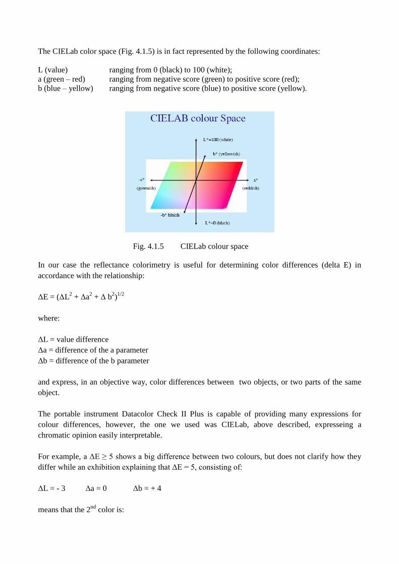
The CIELab color space (Fig. 4.1.5) is in fact represented by the following coordinates:
L (value) ranging from 0 (black) to 100 (white);
a (green – red) ranging from negative score (green) to positive score (red);
b (blue – yellow) ranging from negative score (blue) to positive score (yellow).
Fig. 4.1.5 CIELab colour space
In our case the reflectance colorimetry is useful for determining color differences (delta E) in
accordance with the relationship:
ΔE = (ΔL2 + Δa
2 + Δ b
2)1/2
where:
ΔL = value difference
Δa = difference of the a parameter
Δb = difference of the b parameter
and express, in an objective way, color differences between two objects, or two parts of the same
object.
The portable instrument Datacolor Check II Plus is capable of providing many expressions for
colour differences, however, the one we used was CIELab, above described, expresseing a
chromatic opinion easily interpretable.
For example, a ΔE ≥ 5 shows a big difference between two colours, but does not clarify how they
differ while an exhibition explaining that ΔE = 5, consisting of:
ΔL = - 3 Δa = 0 Δb = + 4
means that the 2nd
color is:
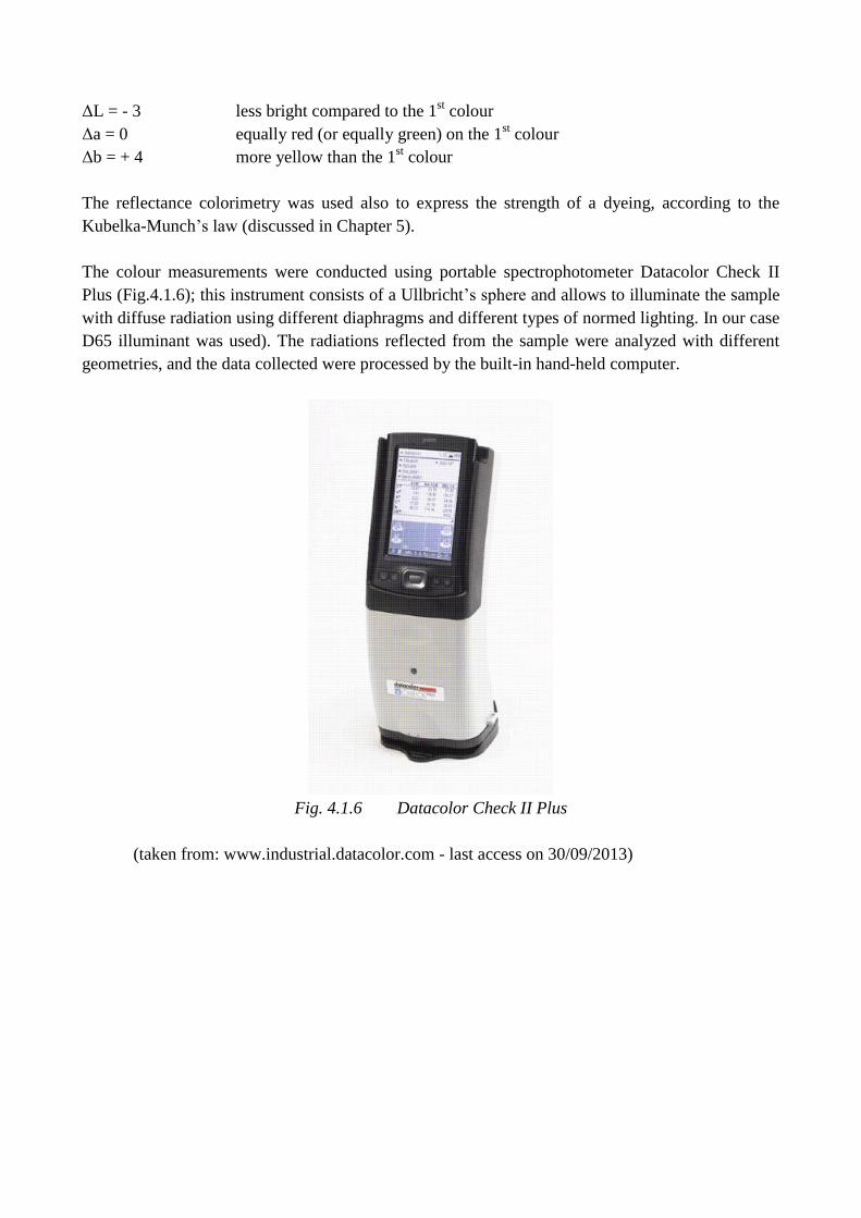
ΔL = - 3 less bright compared to the 1st colour
Δa = 0 equally red (or equally green) on the 1st colour
Δb = + 4 more yellow than the 1st colour
The reflectance colorimetry was used also to express the strength of a dyeing, according to the
Kubelka-Munch’s law (discussed in Chapter 5).
The colour measurements were conducted using portable spectrophotometer Datacolor Check II
Plus (Fig.4.1.6); this instrument consists of a Ullbricht’s sphere and allows to illuminate the sample
with diffuse radiation using different diaphragms and different types of normed lighting. In our case
D65 illuminant was used). The radiations reflected from the sample were analyzed with different
geometries, and the data collected were processed by the built-in hand-held computer.
Fig. 4.1.6 Datacolor Check II Plus
(taken from: www.industrial.datacolor.com - last access on 30/09/2013)
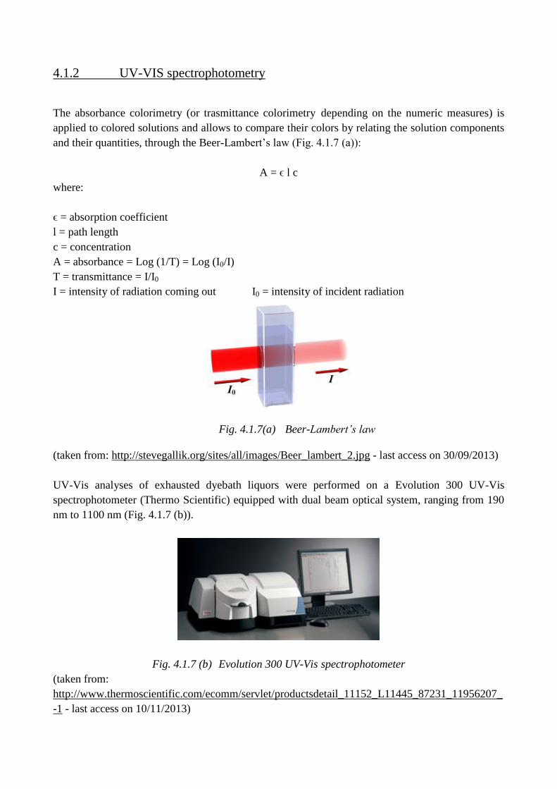
4.1.2 UV-VIS spectrophotometry
The absorbance colorimetry (or trasmittance colorimetry depending on the numeric measures) is
applied to colored solutions and allows to compare their colors by relating the solution components
and their quantities, through the Beer-Lambert’s law (Fig. 4.1.7 (a)):
A = ϵ l c
where:
ϵ = absorption coefficient
l = path length
c = concentration
A = absorbance = Log (1/T) = Log (I0/I)
T = transmittance = I/I0
I = intensity of radiation coming out I0 = intensity of incident radiation
Fig. 4.1.7(a) Beer-Lambert’s law
(taken from: http://stevegallik.org/sites/all/images/Beer_lambert_2.jpg - last access on 30/09/2013)
UV-Vis analyses of exhausted dyebath liquors were performed on a Evolution 300 UV-Vis
spectrophotometer (Thermo Scientific) equipped with dual beam optical system, ranging from 190
nm to 1100 nm (Fig. 4.1.7 (b)).
Fig. 4.1.7 (b) Evolution 300 UV-Vis spectrophotometer
(taken from:
http://www.thermoscientific.com/ecomm/servlet/productsdetail_11152_L11445_87231_11956207_
-1 - last access on 10/11/2013)
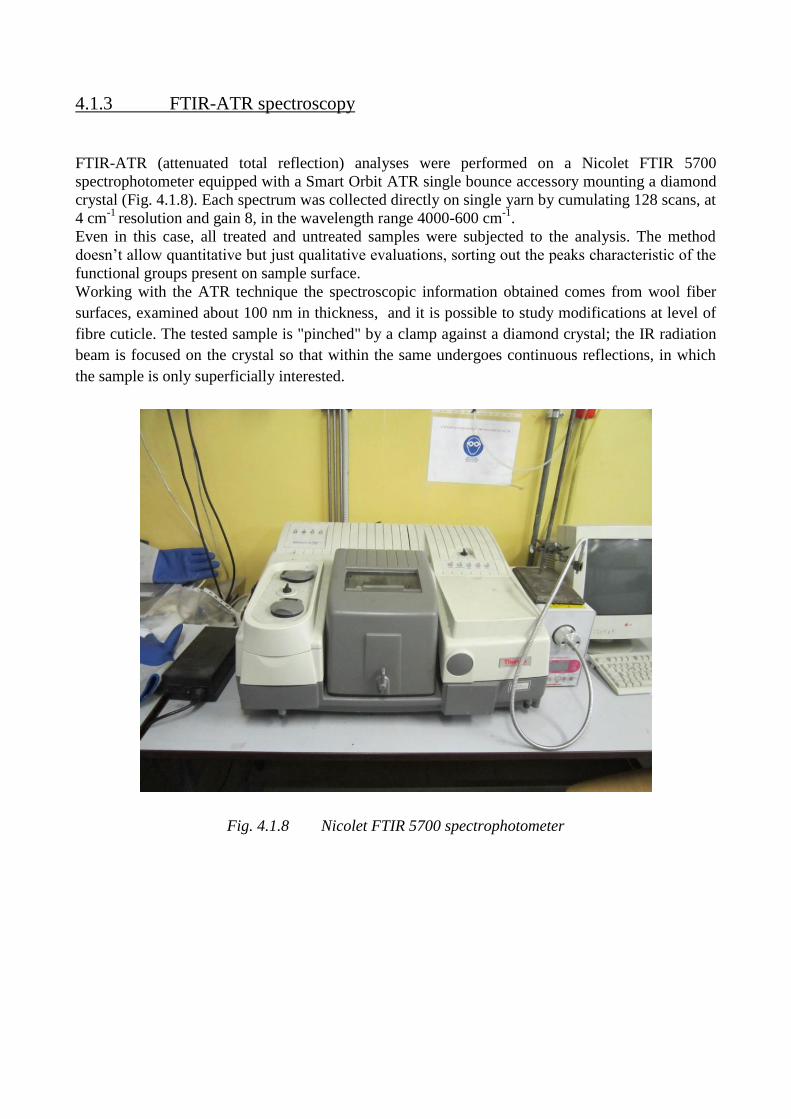
4.1.3 FTIR-ATR spectroscopy
FTIR-ATR (attenuated total reflection) analyses were performed on a Nicolet FTIR 5700
spectrophotometer equipped with a Smart Orbit ATR single bounce accessory mounting a diamond
crystal (Fig. 4.1.8). Each spectrum was collected directly on single yarn by cumulating 128 scans, at
4 cm-1
resolution and gain 8, in the wavelength range 4000-600 cm-1
.
Even in this case, all treated and untreated samples were subjected to the analysis. The method
doesn’t allow quantitative but just qualitative evaluations, sorting out the peaks characteristic of the
functional groups present on sample surface.
Working with the ATR technique the spectroscopic information obtained comes from wool fiber
surfaces, examined about 100 nm in thickness, and it is possible to study modifications at level of
fibre cuticle. The tested sample is "pinched" by a clamp against a diamond crystal; the IR radiation
beam is focused on the crystal so that within the same undergoes continuous reflections, in which
the sample is only superficially interested.
Fig. 4.1.8 Nicolet FTIR 5700 spectrophotometer
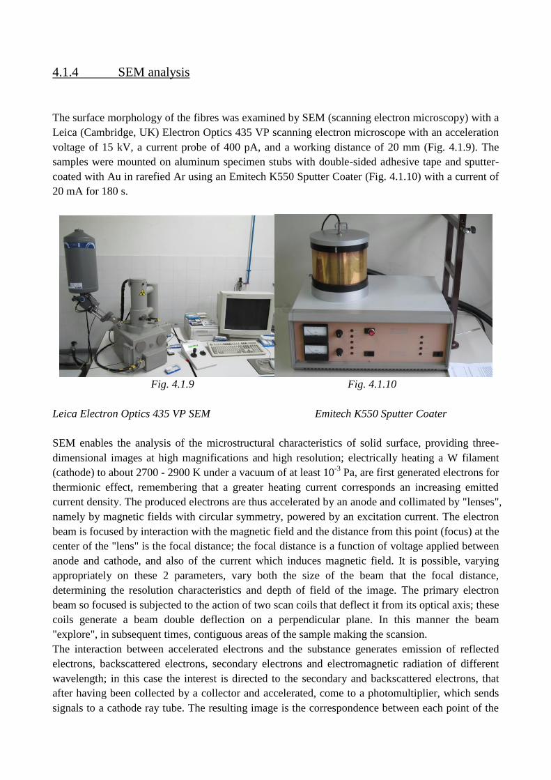
4.1.4 SEM analysis
The surface morphology of the fibres was examined by SEM (scanning electron microscopy) with a
Leica (Cambridge, UK) Electron Optics 435 VP scanning electron microscope with an acceleration
voltage of 15 kV, a current probe of 400 pA, and a working distance of 20 mm (Fig. 4.1.9). The
samples were mounted on aluminum specimen stubs with double-sided adhesive tape and sputter-
coated with Au in rarefied Ar using an Emitech K550 Sputter Coater (Fig. 4.1.10) with a current of
20 mA for 180 s.
Fig. 4.1.9 Fig. 4.1.10
Leica Electron Optics 435 VP SEM Emitech K550 Sputter Coater
SEM enables the analysis of the microstructural characteristics of solid surface, providing three-
dimensional images at high magnifications and high resolution; electrically heating a W filament
(cathode) to about 2700 - 2900 K under a vacuum of at least 10-3
Pa, are first generated electrons for
thermionic effect, remembering that a greater heating current corresponds an increasing emitted
current density. The produced electrons are thus accelerated by an anode and collimated by "lenses",
namely by magnetic fields with circular symmetry, powered by an excitation current. The electron
beam is focused by interaction with the magnetic field and the distance from this point (focus) at the
center of the "lens" is the focal distance; the focal distance is a function of voltage applied between
anode and cathode, and also of the current which induces magnetic field. It is possible, varying
appropriately on these 2 parameters, vary both the size of the beam that the focal distance,
determining the resolution characteristics and depth of field of the image. The primary electron
beam so focused is subjected to the action of two scan coils that deflect it from its optical axis; these
coils generate a beam double deflection on a perpendicular plane. In this manner the beam
"explore", in subsequent times, contiguous areas of the sample making the scansion.
The interaction between accelerated electrons and the substance generates emission of reflected
electrons, backscattered electrons, secondary electrons and electromagnetic radiation of different
wavelength; in this case the interest is directed to the secondary and backscattered electrons, that
after having been collected by a collector and accelerated, come to a photomultiplier, which sends
signals to a cathode ray tube. The resulting image is the correspondence between each point of the
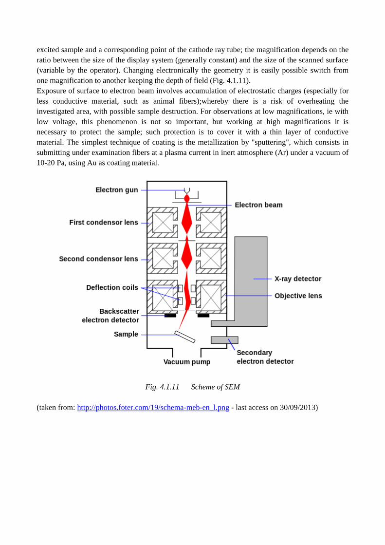
excited sample and a corresponding point of the cathode ray tube; the magnification depends on the
ratio between the size of the display system (generally constant) and the size of the scanned surface
(variable by the operator). Changing electronically the geometry it is easily possible switch from
one magnification to another keeping the depth of field (Fig. 4.1.11).
Exposure of surface to electron beam involves accumulation of electrostatic charges (especially for
less conductive material, such as animal fibers);whereby there is a risk of overheating the
investigated area, with possible sample destruction. For observations at low magnifications, ie with
low voltage, this phenomenon is not so important, but working at high magnifications it is
necessary to protect the sample; such protection is to cover it with a thin layer of conductive
material. The simplest technique of coating is the metallization by "sputtering", which consists in
submitting under examination fibers at a plasma current in inert atmosphere (Ar) under a vacuum of
10-20 Pa, using Au as coating material.
Fig. 4.1.11 Scheme of SEM
(taken from: http://photos.foter.com/19/schema-meb-en_l.png - last access on 30/09/2013)
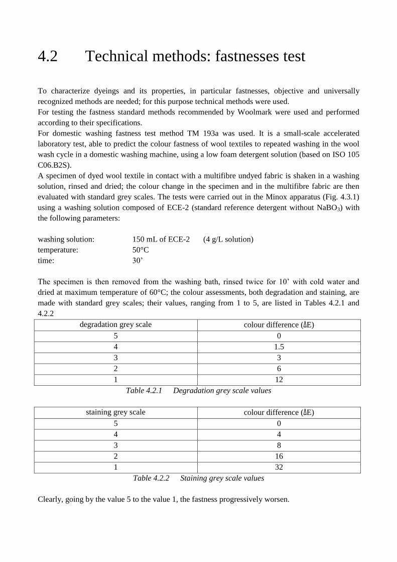
4.2 Technical methods: fastnesses test
To characterize dyeings and its properties, in particular fastnesses, objective and universally
recognized methods are needed; for this purpose technical methods were used.
For testing the fastness standard methods recommended by Woolmark were used and performed
according to their specifications.
For domestic washing fastness test method TM 193a was used. It is a small-scale accelerated
laboratory test, able to predict the colour fastness of wool textiles to repeated washing in the wool
wash cycle in a domestic washing machine, using a low foam detergent solution (based on ISO 105
C06.B2S).
A specimen of dyed wool textile in contact with a multifibre undyed fabric is shaken in a washing
solution, rinsed and dried; the colour change in the specimen and in the multifibre fabric are then
evaluated with standard grey scales. The tests were carried out in the Minox apparatus (Fig. 4.3.1)
using a washing solution composed of ECE-2 (standard reference detergent without NaBO3) with
the following parameters:
washing solution: 150 mL of ECE-2 (4 g/L solution)
temperature: 50°C
time: 30’
The specimen is then removed from the washing bath, rinsed twice for 10’ with cold water and
dried at maximum temperature of 60°C; the colour assessments, both degradation and staining, are
made with standard grey scales; their values, ranging from 1 to 5, are listed in Tables 4.2.1 and
4.2.2
degradation grey scale colour difference (ΔE)
5 0
4 1.5
3 3
2 6
1 12
Table 4.2.1 Degradation grey scale values
staining grey scale colour difference (ΔE)
5 0
4 4
3 8
2 16
1 32
Table 4.2.2 Staining grey scale values
Clearly, going by the value 5 to the value 1, the fastness progressively worsen.

For rubbing fastness (dry and wet) test method TM 165 was used, It is a test able to predict the
colour fastness of wool textiles to rubbing on bleached and undyed cotton fabric, (based on ISO 105
X12).
The tests were carried out by Crockmeter apparatus (Fig. 4.3.2). A specimen of dyed wool textile in
rubbed on (dry or wet) bleached and undyed cotton fabric (the specimen is fixed on the testing
device and there are made 10 runs in 10”) are then evaluated with staining standard grey scale:
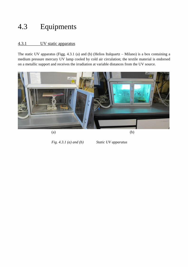
4.3 Equipments
4.3.1 UV static apparatus
The static UV apparatus (Figg. 4.3.1 (a) and (b) (Helios Italquartz – Milano) is a box containing a
medium pressure mercury UV lamp cooled by cold air circulation; the textile material is endorsed
on a metallic support and receives the irradiation at variable distances from the UV source.
(a) (b)
Fig. 4.3.1 (a) and (b) Static UV apparatus
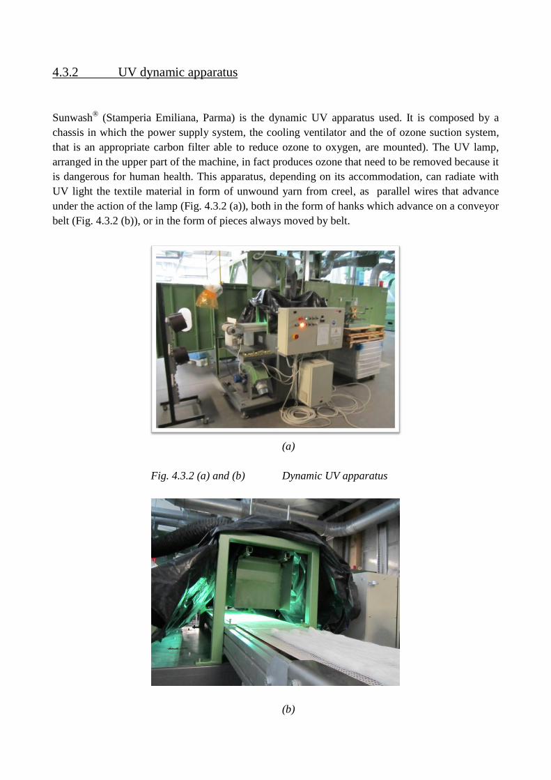
4.3.2 UV dynamic apparatus
Sunwash® (Stamperia Emiliana, Parma) is the dynamic UV apparatus used. It is composed by a
chassis in which the power supply system, the cooling ventilator and the of ozone suction system,
that is an appropriate carbon filter able to reduce ozone to oxygen, are mounted). The UV lamp,
arranged in the upper part of the machine, in fact produces ozone that need to be removed because it
is dangerous for human health. This apparatus, depending on its accommodation, can radiate with
UV light the textile material in form of unwound yarn from creel, as parallel wires that advance
under the action of the lamp (Fig. 4.3.2 (a)), both in the form of hanks which advance on a conveyor
belt (Fig. 4.3.2 (b)), or in the form of pieces always moved by belt.
(a)
Fig. 4.3.2 (a) and (b) Dynamic UV apparatus
(b)
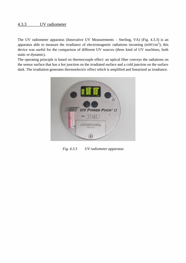
4.3.3 UV radiometer
The UV radiometer apparatus (Innovative UV Measurements – Sterling, VA) (Fig. 4.3.3) is an
apparatus able to measure the irradiance of electromagnetic radiations incoming (mW/cm2); this
device was useful for the comparison of different UV sources (three kind of UV machines, both
static or dynamic).
The operating principle is based on thermocouple effect: an optical fiber conveys the radiations on
the sensor surface that has a hot junction on the irradiated surface and a cold junction on the surface
dark. The irradiation generates thermoelectric effect which is amplified and linearized as irradiance.
Fig. 4.3.3 UV radiometer apparatus
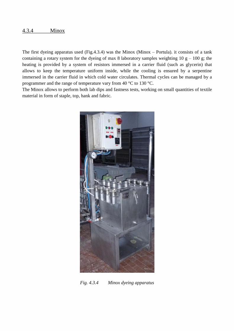
4.3.4 Minox
The first dyeing apparatus used (Fig.4.3.4) was the Minox (Minox – Portula). it consists of a tank
containing a rotary system for the dyeing of max 8 laboratory samples weighting 10 g – 100 g; the
heating is provided by a system of resistors immersed in a carrier fluid (such as glycerin) that
allows to keep the temperature uniform inside, while the cooling is ensured by a serpentine
immersed in the carrier fluid in which cold water circulates. Thermal cycles can be managed by a
programmer and the range of temperature vary from 40 °C to 130 °C.
The Minox allows to perform both lab dips and fastness tests, working on small quantities of textile
material in form of staple, top, hank and fabric.
Fig. 4.3.4 Minox dyeing apparatus
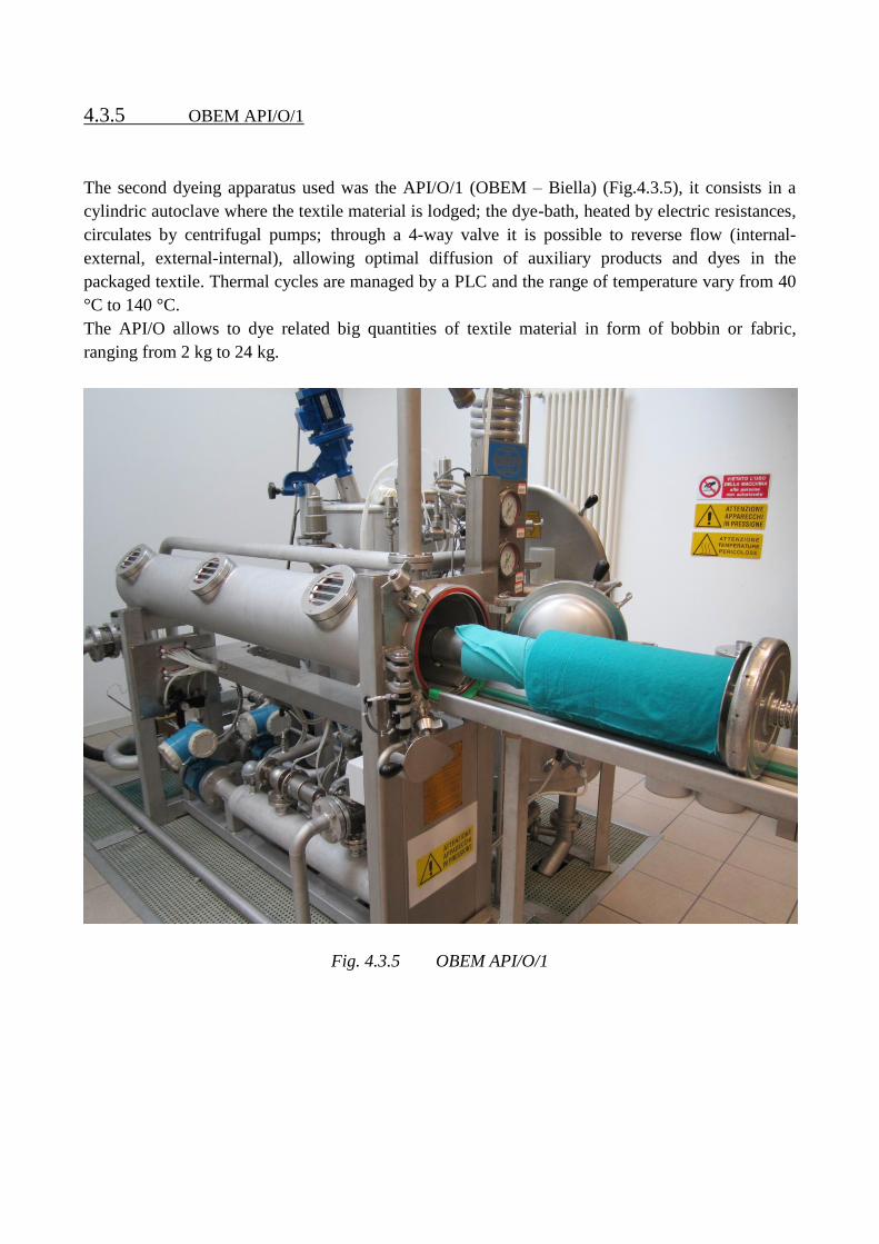
4.3.5 OBEM API/O/1
The second dyeing apparatus used was the API/O/1 (OBEM – Biella) (Fig.4.3.5), it consists in a
cylindric autoclave where the textile material is lodged; the dye-bath, heated by electric resistances,
circulates by centrifugal pumps; through a 4-way valve it is possible to reverse flow (internal-
external, external-internal), allowing optimal diffusion of auxiliary products and dyes in the
packaged textile. Thermal cycles are managed by a PLC and the range of temperature vary from 40
°C to 140 °C.
The API/O allows to dye related big quantities of textile material in form of bobbin or fabric,
ranging from 2 kg to 24 kg.
Fig. 4.3.5 OBEM API/O/1
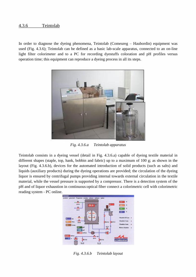
4.3.6 Teintolab
In order to diagnose the dyeing phenomena, Teintolab (Comeureg – Haubordin) equipment was
used (Fig. 4.3.6); Teintolab can be defined as a basic lab-scale apparatus, connected to an on-line
light filter colorimeter and to a PC for recording dyestuffs coloration and pH profiles versus
operation time; this equipment can reproduce a dyeing process in all its steps.
Fig. 4.3.6.a Teintolab apparatus
Teintolab consists in a dyeing vessel (detail in Fig. 4.3.6.a) capable of dyeing textile material in
different shapes (staple, top, hank, bobbin and fabric) up to a maximum of 100 g; as shown in the
layout (Fig. 4.3.6.b), devices for the automated introduction of solid products (such as salts) and
liquids (auxiliary products) during the dyeing operations are provided; the circulation of the dyeing
liquor is ensured by centrifugal pumps providing internal towards external circulation in the textile
material, while the vessel pressure is supported by a compressor. There is a detection system of the
pH and of liquor exhaustion in continuous:optical fiber connect a colorimetric cell with colorimetric
reading system - PC online.
Fig. 4.3.6.b Teintolab layout
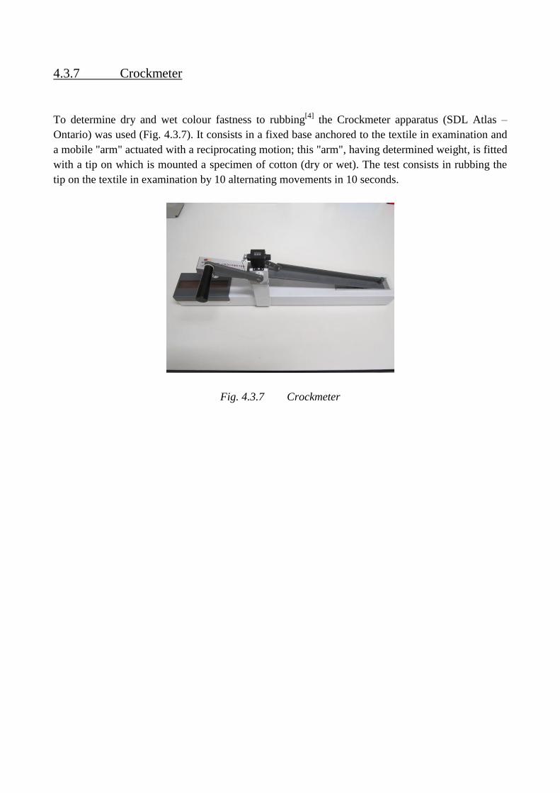
4.3.7 Crockmeter
To determine dry and wet colour fastness to rubbing[4]
the Crockmeter apparatus (SDL Atlas –
Ontario) was used (Fig. 4.3.7). It consists in a fixed base anchored to the textile in examination and
a mobile "arm" actuated with a reciprocating motion; this "arm", having determined weight, is fitted
with a tip on which is mounted a specimen of cotton (dry or wet). The test consists in rubbing the
tip on the textile in examination by 10 alternating movements in 10 seconds.
Fig. 4.3.7 Crockmeter
4.4 References
[1] H. Zollinger, Color Chemistry: Syntheses, Properties and Applications of Organic Dyes and
Pigments, Zürich, 2003.
[2] E. Barni, Lecture notes “Chimica dei Coloranti”, academic year 1992/’93.
[3] F. Ferrero, Lecture notes “Processi Industriali della Chimica Fine”, academic year 1993/’94.
[4] J. Cegarra, P. Puente et J. Valldeperas, The dyeing of textile materials, the scientific bases and
the techniques of application, 1992,Texilia, Biella.
Chapter 5 Adjustment and optimization of the available
tests of degree of treatment, for a fast evaluation
of the intensity and uniformity of the treatment.

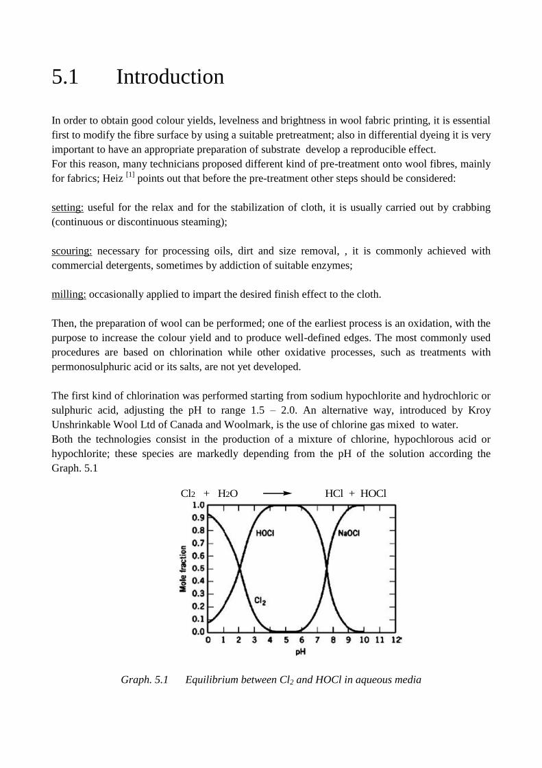
5.1 Introduction
In order to obtain good colour yields, levelness and brightness in wool fabric printing, it is essential
first to modify the fibre surface by using a suitable pretreatment; also in differential dyeing it is very
important to have an appropriate preparation of substrate develop a reproducible effect.
For this reason, many technicians proposed different kind of pre-treatment onto wool fibres, mainly
for fabrics; Heiz [1]
points out that before the pre-treatment other steps should be considered:
setting: useful for the relax and for the stabilization of cloth, it is usually carried out by crabbing
(continuous or discontinuous steaming);
scouring: necessary for processing oils, dirt and size removal, , it is commonly achieved with
commercial detergents, sometimes by addiction of suitable enzymes;
milling: occasionally applied to impart the desired finish effect to the cloth.
Then, the preparation of wool can be performed; one of the earliest process is an oxidation, with the
purpose to increase the colour yield and to produce well-defined edges. The most commonly used
procedures are based on chlorination while other oxidative processes, such as treatments with
permonosulphuric acid or its salts, are not yet developed.
The first kind of chlorination was performed starting from sodium hypochlorite and hydrochloric or
sulphuric acid, adjusting the pH to range 1.5 – 2.0. An alternative way, introduced by Kroy
Unshrinkable Wool Ltd of Canada and Woolmark, is the use of chlorine gas mixed to water.
Both the technologies consist in the production of a mixture of chlorine, hypochlorous acid or
hypochlorite; these species are markedly depending from the pH of the solution according the
Graph. 5.1
Cl2 + H2O HCl + HOCl
Graph. 5.1 Equilibrium between Cl2 and HOCl in aqueous media
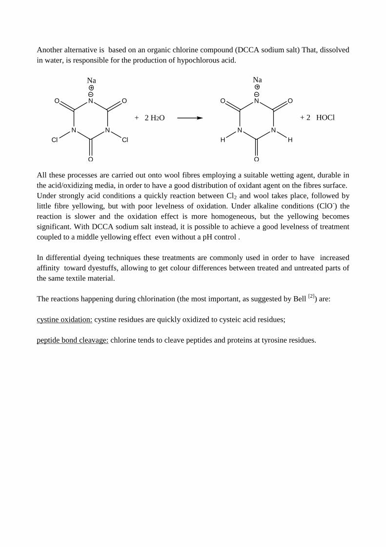
Another alternative is based on an organic chlorine compound (DCCA sodium salt) That, dissolved
in water, is responsible for the production of hypochlorous acid.
N
N N
O O
O
Cl Cl
N
N N
O O
O
H H
+ 2 H2O + 2 HOCl
Na Na
All these processes are carried out onto wool fibres employing a suitable wetting agent, durable in
the acid/oxidizing media, in order to have a good distribution of oxidant agent on the fibres surface.
Under strongly acid conditions a quickly reaction between Cl2 and wool takes place, followed by
little fibre yellowing, but with poor levelness of oxidation. Under alkaline conditions (ClO-) the
reaction is slower and the oxidation effect is more homogeneous, but the yellowing becomes
significant. With DCCA sodium salt instead, it is possible to achieve a good levelness of treatment
coupled to a middle yellowing effect even without a pH control .
In differential dyeing techniques these treatments are commonly used in order to have increased
affinity toward dyestuffs, allowing to get colour differences between treated and untreated parts of
the same textile material.
The reactions happening during chlorination (the most important, as suggested by Bell [2]
) are:
cystine oxidation: cystine residues are quickly oxidized to cysteic acid residues;
peptide bond cleavage: chlorine tends to cleave peptides and proteins at tyrosine residues.
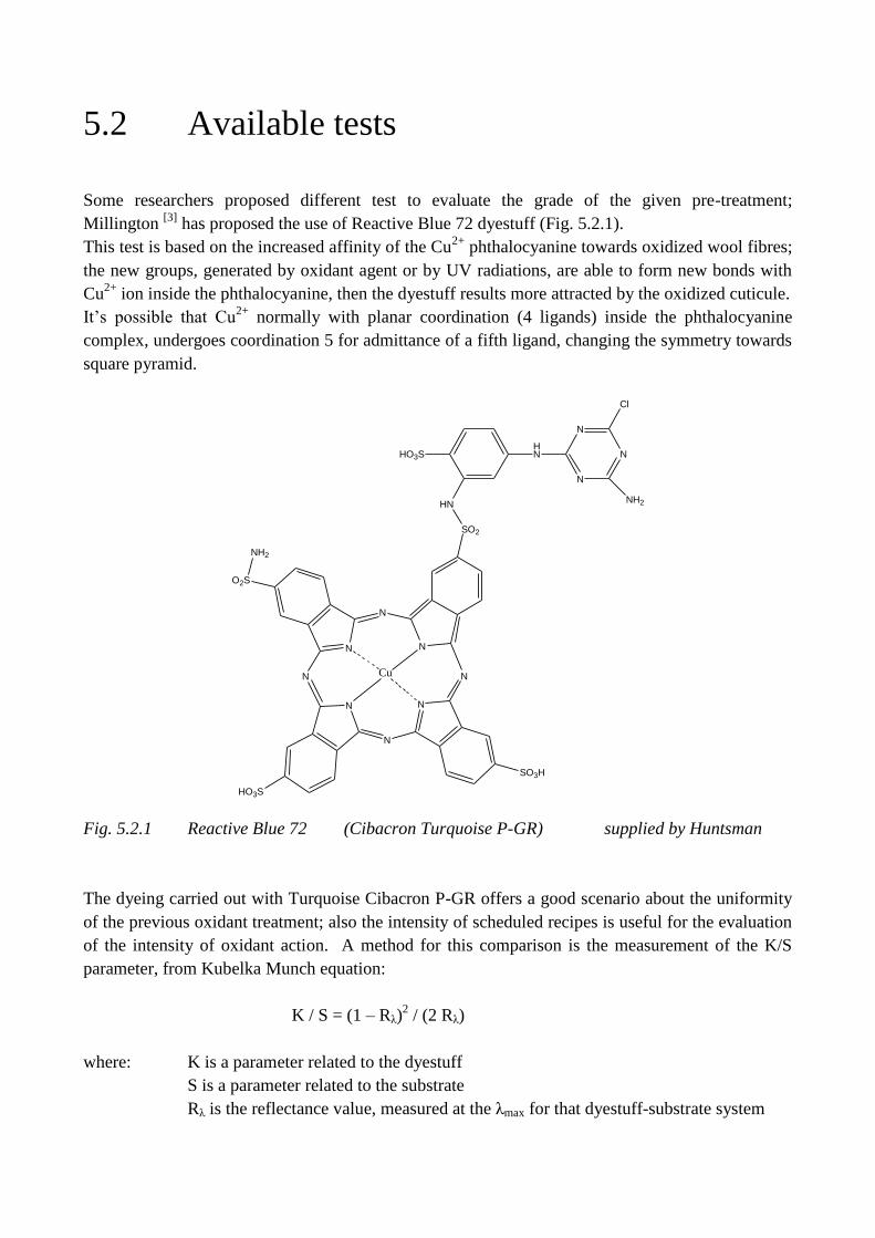
5.2 Available tests
Some researchers proposed different test to evaluate the grade of the given pre-treatment;
Millington [3]
has proposed the use of Reactive Blue 72 dyestuff (Fig. 5.2.1).
This test is based on the increased affinity of the Cu2+
phthalocyanine towards oxidized wool fibres;
the new groups, generated by oxidant agent or by UV radiations, are able to form new bonds with
Cu2+
ion inside the phthalocyanine, then the dyestuff results more attracted by the oxidized cuticule.
It’s possible that Cu2+
normally with planar coordination (4 ligands) inside the phthalocyanine
complex, undergoes coordination 5 for admittance of a fifth ligand, changing the symmetry towards
square pyramid.
HN
N
N
N
Cl
NH2
HO3S
HN
SO2
N
N
N
N
N
N
Cu
O2S
NH2
HO3S
SO3H
N N
Fig. 5.2.1 Reactive Blue 72 (Cibacron Turquoise P-GR) supplied by Huntsman
The dyeing carried out with Turquoise Cibacron P-GR offers a good scenario about the uniformity
of the previous oxidant treatment; also the intensity of scheduled recipes is useful for the evaluation
of the intensity of oxidant action. A method for this comparison is the measurement of the K/S
parameter, from Kubelka Munch equation:
K / S = (1 – Rλ)2 / (2 Rλ)
where: K is a parameter related to the dyestuff
S is a parameter related to the substrate
Rλ is the reflectance value, measured at the λmax for that dyestuff-substrate system
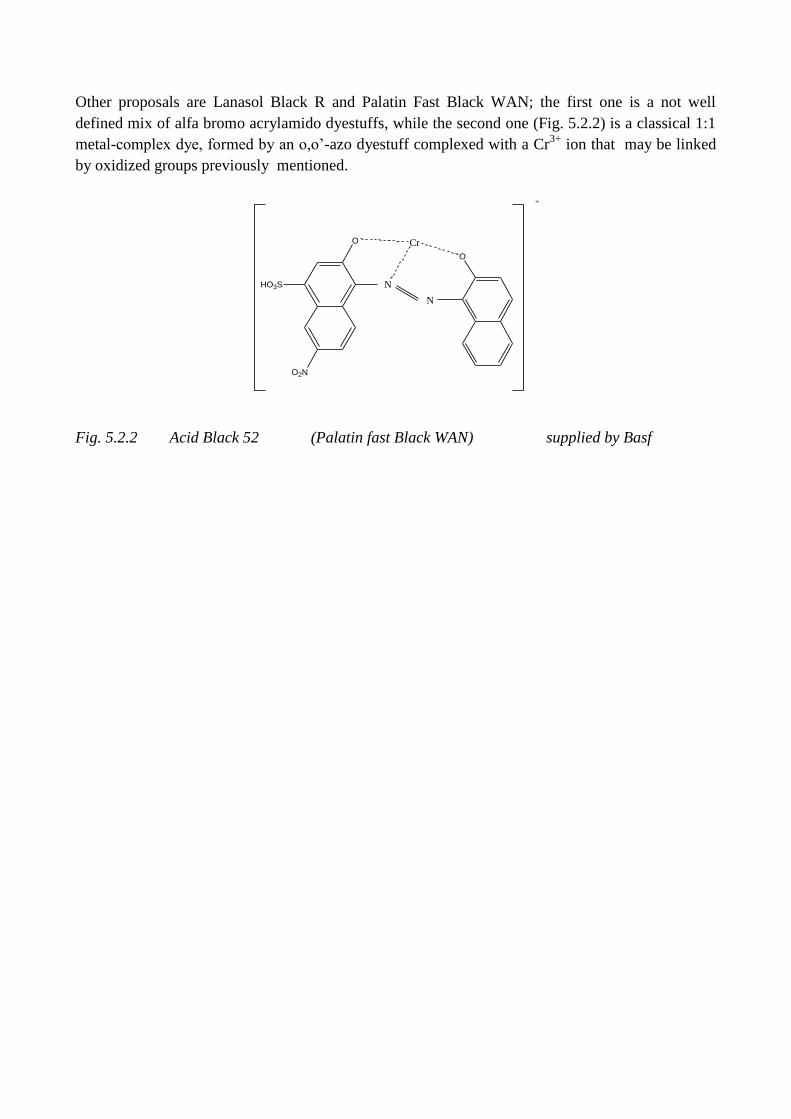
Other proposals are Lanasol Black R and Palatin Fast Black WAN; the first one is a not well
defined mix of alfa bromo acrylamido dyestuffs, while the second one (Fig. 5.2.2) is a classical 1:1
metal-complex dye, formed by an o,o’-azo dyestuff complexed with a Cr3+
ion that may be linked
by oxidized groups previously mentioned.
O
HO3S N
N
O
Cr
+
O2N
Fig. 5.2.2 Acid Black 52 (Palatin fast Black WAN) supplied by Basf
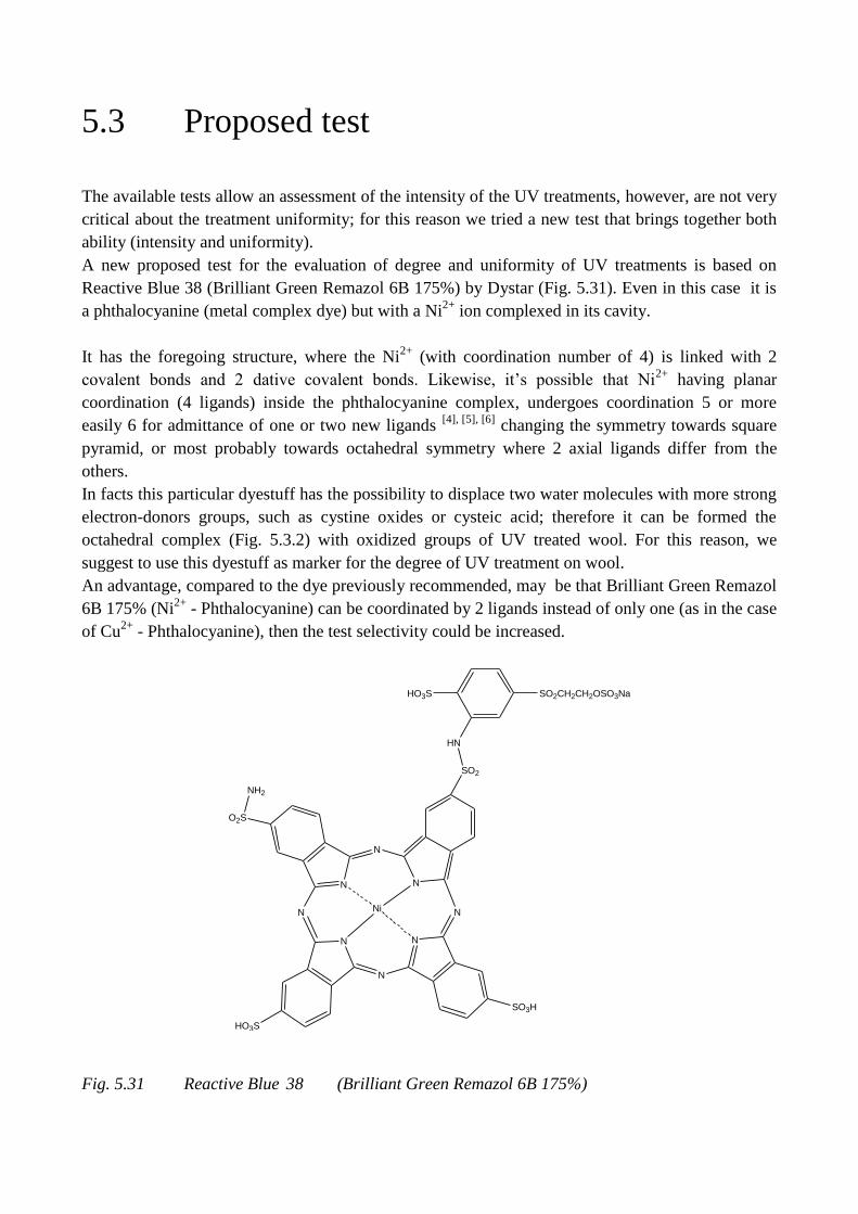
5.3 Proposed test
The available tests allow an assessment of the intensity of the UV treatments, however, are not very
critical about the treatment uniformity; for this reason we tried a new test that brings together both
ability (intensity and uniformity).
A new proposed test for the evaluation of degree and uniformity of UV treatments is based on
Reactive Blue 38 (Brilliant Green Remazol 6B 175%) by Dystar (Fig. 5.31). Even in this case it is
a phthalocyanine (metal complex dye) but with a Ni2+
ion complexed in its cavity.
It has the foregoing structure, where the Ni2+
(with coordination number of 4) is linked with 2
covalent bonds and 2 dative covalent bonds. Likewise, it’s possible that Ni2+
having planar
coordination (4 ligands) inside the phthalocyanine complex, undergoes coordination 5 or more
easily 6 for admittance of one or two new ligands [4], [5], [6]
changing the symmetry towards square
pyramid, or most probably towards octahedral symmetry where 2 axial ligands differ from the
others.
In facts this particular dyestuff has the possibility to displace two water molecules with more strong
electron-donors groups, such as cystine oxides or cysteic acid; therefore it can be formed the
octahedral complex (Fig. 5.3.2) with oxidized groups of UV treated wool. For this reason, we
suggest to use this dyestuff as marker for the degree of UV treatment on wool.
An advantage, compared to the dye previously recommended, may be that Brilliant Green Remazol
6B 175% (Ni2+
- Phthalocyanine) can be coordinated by 2 ligands instead of only one (as in the case
of Cu2+
- Phthalocyanine), then the test selectivity could be increased.
SO2
N
N
N
N
N
N
Ni
O2S
NH2
HO3S
SO3H
N N
HN
HO3S SO2CH2CH2OSO3Na
Fig. 5.31 Reactive Blue 38 (Brilliant Green Remazol 6B 175%)
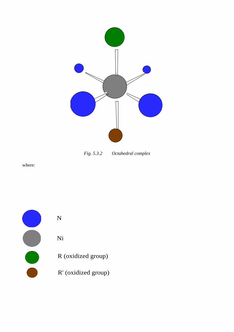
Fig. 5.3.2 Octahedral complex
where:
N
Ni
R (oxidized group)
R' (oxidized group)
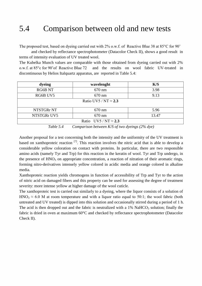
5.4 Comparison between old and new tests
The proposed test, based on dyeing carried out with 2% o.w.f. of Reactive Blue 38 at 85°C for 90’
and checked by reflectance spectrophotometer (Datacolor Check II), shows a good result in
terms of intensity evaluation of UV treated wool.
The Kubelka Munch values are comparable with those obtained from dyeing carried out with 2%
o.w.f. at 85°c for 90’of Reactive Blue 72 and the results on wool fabric UV-treated in
discontinuous by Helios Italquartz apparatus, are reported in Table 5.4:
dyeing wavelenght K/S
RG6B NT 670 nm 3.98
RG6B UV5 670 nm 9.13
Ratio UV5 / NT ≈ 2.3
NTSTGRr NT 670 nm 5.96
NTSTGRr UV5 670 nm 13.47
Ratio UV5 / NT ≈ 2.3
Table 5.4 Comparison between K/S of two dyeings (2% dye)
Another proposal for a test concerning both the intensity and the uniformity of the UV treatment is
based on xanthoproteic reaction [7]
. This reaction involves the nitric acid that is able to develop a
considerable yellow coloration on contact with proteins. In particular, there are two responsible
amino acids (namely Tyr and Trp) for this reaction in the keratin of wool. Tyr and Trp undergo, in
the presence of HNO3 on appropriate concentration, a reaction of nitration of their aromatic rings,
forming nitro-derivatives intensely yellow colored in acidic media and orange colored in alkaline
media.
Xanthoproteic reaction yields chromogens in function of accessibility of Trp and Tyr to the action
of nitric acid on damaged fibers and this property can be used for assessing the degree of treatment
severity: more intense yellow at higher damage of the wool cuticle.
The xanthoproteic test is carried out similarly to a dyeing, where the liquor consists of a solution of
HNO3 ≈ 6.0 M at room temperature and with a liquor ratio equal to 50:1; the wool fabric (both
untreated and UV treated) is dipped into this solution and occasionally stirred during a period of 1 h.
The acid is then dropped out and the fabric is neutralized with a 1% NaHCO3 solution; finally the
fabric is dried in oven at maximum 60°C and checked by reflectance spectrophotometer (Datacolor
Check II).
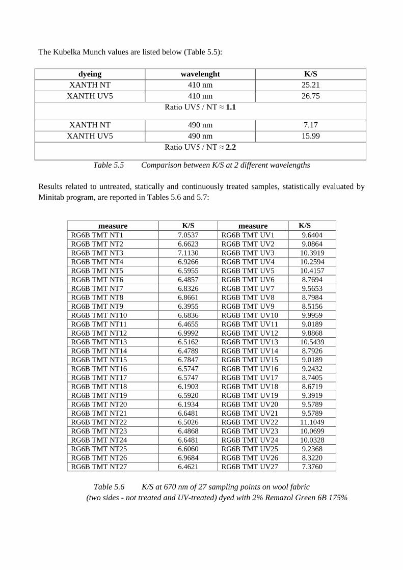
The Kubelka Munch values are listed below (Table 5.5):
dyeing wavelenght K/S
XANTH NT 410 nm 25.21
XANTH UV5 410 nm 26.75
Ratio UV5 / NT ≈ 1.1
XANTH NT 490 nm 7.17
XANTH UV5 490 nm 15.99
Ratio UV5 / NT ≈ 2.2
Table 5.5 Comparison between K/S at 2 different wavelengths
Results related to untreated, statically and continuously treated samples, statistically evaluated by
Minitab program, are reported in Tables 5.6 and 5.7:
measure K/S measure K/S
RG6B TMT NT1 7.0537 RG6B TMT UV1 9.6404
RG6B TMT NT2 6.6623 RG6B TMT UV2 9.0864
RG6B TMT NT3 7.1130 RG6B TMT UV3 10.3919
RG6B TMT NT4 6.9266 RG6B TMT UV4 10.2594
RG6B TMT NT5 6.5955 RG6B TMT UV5 10.4157
RG6B TMT NT6 6.4857 RG6B TMT UV6 8.7694
RG6B TMT NT7 6.8326 RG6B TMT UV7 9.5653
RG6B TMT NT8 6.8661 RG6B TMT UV8 8.7984
RG6B TMT NT9 6.3955 RG6B TMT UV9 8.5156
RG6B TMT NT10 6.6836 RG6B TMT UV10 9.9959
RG6B TMT NT11 6.4655 RG6B TMT UV11 9.0189
RG6B TMT NT12 6.9992 RG6B TMT UV12 9.8868
RG6B TMT NT13 6.5162 RG6B TMT UV13 10.5439
RG6B TMT NT14 6.4789 RG6B TMT UV14 8.7926
RG6B TMT NT15 6.7847 RG6B TMT UV15 9.0189
RG6B TMT NT16 6.5747 RG6B TMT UV16 9.2432
RG6B TMT NT17 6.5747 RG6B TMT UV17 8.7405
RG6B TMT NT18 6.1903 RG6B TMT UV18 8.6719
RG6B TMT NT19 6.5920 RG6B TMT UV19 9.3919
RG6B TMT NT20 6.1934 RG6B TMT UV20 9.5789
RG6B TMT NT21 6.6481 RG6B TMT UV21 9.5789
RG6B TMT NT22 6.5026 RG6B TMT UV22 11.1049
RG6B TMT NT23 6.4868 RG6B TMT UV23 10.0699
RG6B TMT NT24 6.6481 RG6B TMT UV24 10.0328
RG6B TMT NT25 6.6060 RG6B TMT UV25 9.2368
RG6B TMT NT26 6.9684 RG6B TMT UV26 8.3220
RG6B TMT NT27 6.4621 RG6B TMT UV27 7.3760
Table 5.6 K/S at 670 nm of 27 sampling points on wool fabric
(two sides - not treated and UV-treated) dyed with 2% Remazol Green 6B 175%
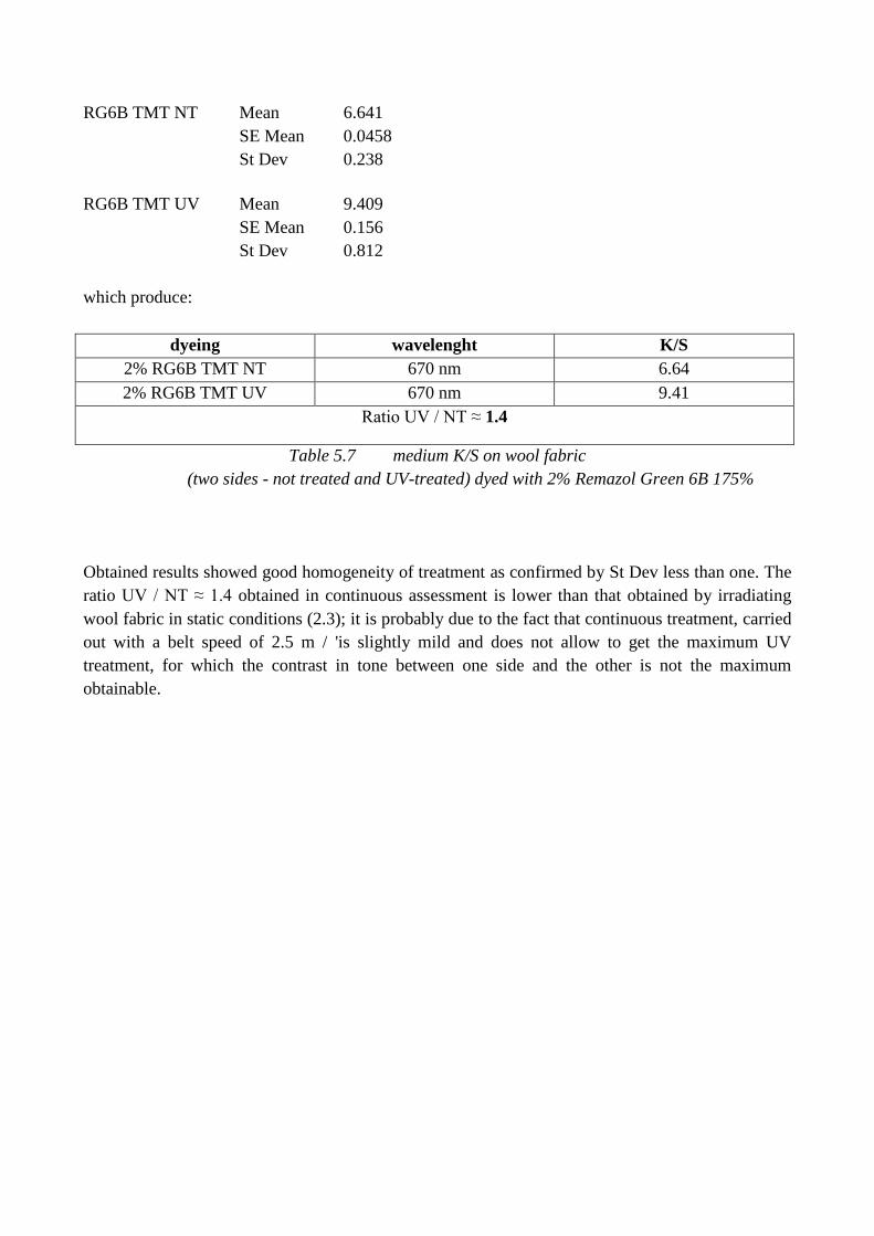
RG6B TMT NT Mean 6.641
SE Mean 0.0458
St Dev 0.238
RG6B TMT UV Mean 9.409
SE Mean 0.156
St Dev 0.812
which produce:
dyeing wavelenght K/S
2% RG6B TMT NT 670 nm 6.64
2% RG6B TMT UV 670 nm 9.41
Ratio UV / NT ≈ 1.4
Table 5.7 medium K/S on wool fabric
(two sides - not treated and UV-treated) dyed with 2% Remazol Green 6B 175%
Obtained results showed good homogeneity of treatment as confirmed by St Dev less than one. The
ratio UV / NT ≈ 1.4 obtained in continuous assessment is lower than that obtained by irradiating
wool fabric in static conditions (2.3); it is probably due to the fact that continuous treatment, carried
out with a belt speed of 2.5 m / 'is slightly mild and does not allow to get the maximum UV
treatment, for which the contrast in tone between one side and the other is not the maximum
obtainable.
5.5 References
[1] H. Heiz, Textilveredlung, 13 (1978) 205.
[2] V.A. Bell, Wool Dyeing, SDC, Ed. D. M. Lewis, 10, Wool printing, 332.
[3] K. R. Millington, J.S.D.C. 114 (1998) 286.
[4 ] C. Furlani, Coordin. Chem. Rev., 3, 141 (1968).
[5] J. E. Huheey, Chimica Inorganica, Piccin, Padova 1977, pp. 449-450.
[6] C. L. Spiro, S. L. Lambert, T.J. Smith, E. N. Duesler, R.R. Gagné et D. N. Hendrickson,
Inorg. Chem. 1981, 20, 1229-1237.
[7] G. Migliavacca, F. Ferrero, C. Tonin, Xanthoproteic reaction for the evaluation of wool
antifelting treatments, submitted to Coloration Technology on 2013.
Chapter 6 Characterization of wool fibres after UV
treatment

6.1 Introduction
To characterize in an exhaustive manner wool fibers subjected to the action of UV radiation, SEM
and FTIR-ATR analysis were carried out.
From previous work [1] we know that as consequence of the surface modification, values of water
contact angle decreased from 130° to 110° on treated fabrics with respect to untreated ones,
denouncing an increased hydrophilicity regardless the radiation parameters.
Bursting test revealed a reinforcement of mechanical properties on treated fabrics, probably due to
some crosslinking between the chains of wool fibers, not affecting the soft hand of the fabrics.
Wool fibers were not weakened by UV radiations, confirming that the fibers modification is
confined to the surface, not involving the bulk.
Also a pilling test was carried out finding, on treated sample, a grade 4 of pilling after 7000
abrasion cycles, a good result if compared with the grade 2/3 on the untreated sample. UV exposure
makes wool surface fibers weaker, so no anchor fibers are available to secure pills to the fabric
surface. Hence it was found that the UV treatment can also prevent pilling in knitwear, without
severe loss in weight and strength of the fabric.
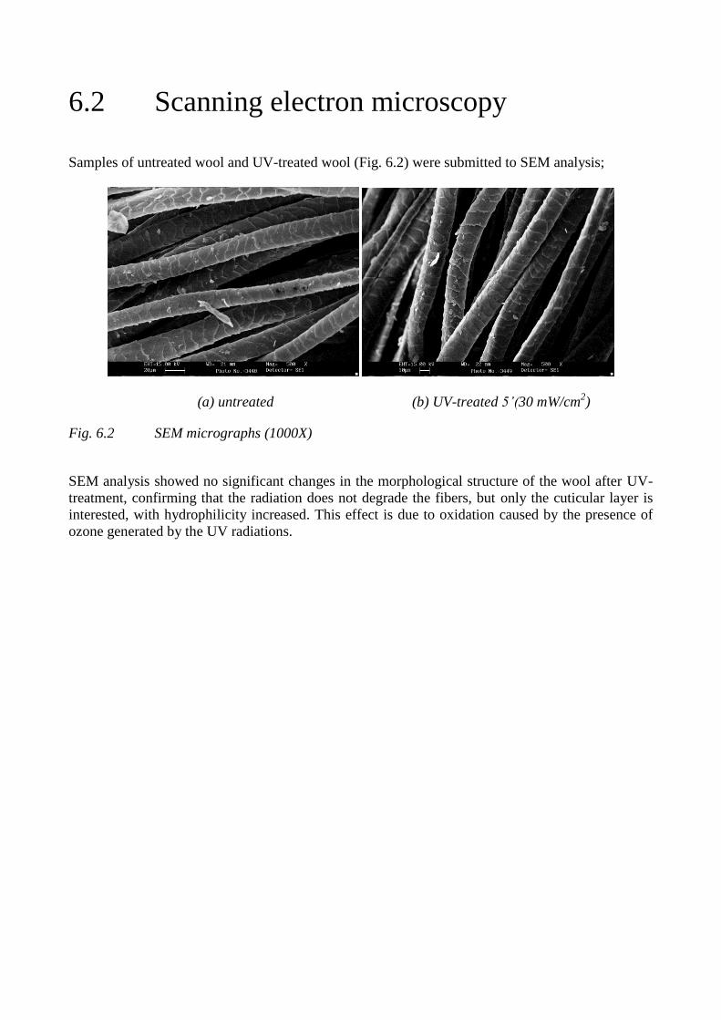
6.2 Scanning electron microscopy
Samples of untreated wool and UV-treated wool (Fig. 6.2) were submitted to SEM analysis;
(a) untreated (b) UV-treated 5’(30 mW/cm2)
Fig. 6.2 SEM micrographs (1000X)
SEM analysis showed no significant changes in the morphological structure of the wool after UV-
treatment, confirming that the radiation does not degrade the fibers, but only the cuticular layer is
interested, with hydrophilicity increased. This effect is due to oxidation caused by the presence of
ozone generated by the UV radiations.
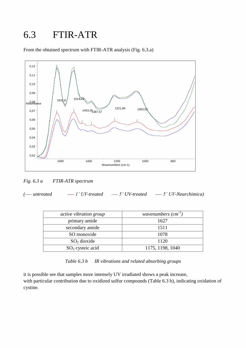
6.3 FTIR-ATR
From the obtained spectrum with FTIR-ATR analysis (Fig. 6.3.a)
Fig. 6.3 a FTIR-ATR spectrum
(---- untreated ---- 1’ UV-treated ---- 5’ UV-treated ---- 5’ UV-Nearchimica)
active vibration group wavenumbers (cm-1
)
primary amide 1627
secondary amide 1511
SO monoxide 1078
SO2 dioxide 1120
SO3 cysteic acid 1175, 1198, 1040
Table 6.3 b IR vibrations and related absorbing groups
it is possible see that samples more intensely UV irradiated shows a peak increase,
with particular contribution due to oxidized sulfur compounds (Table 6.3 b), indicating oxidation of
cystine.
1063,52 1221,86 1387,57 1453,26
1514,29 1632,8
0,02
0,03
0,04
0,05
0,06
0,07
0,08
0,09
0,10
0,11
0,12
Absorbance
800 1000 1200 1400 1600 Wavenumbers (cm-1)
6.4 References
[1] M. Periolatto, G. Migliavacca, F. Ferrero,
XXIII IFATCC International Congress, 8-10 May 2013, Budapest "Wool fabric dyeing with
acid dye after UV irradiation",

Chapter 7 Wool and cotton dyeings

7.1 Introduction
Before considering guidelines for application of UV radiation on both wool and cotton, in pre-or
post-treatment, it is good to spend a few words about dyeing in general and to review the main
classes of suitable dyes. The proposed applications and their optimization follow.
7.2 Common dyeing operations
Dyeing is defined as the process of adding colour to textile products like staples, tops, hanks, yarns
and fabrics. Dyeing is normally carried out in aqueous medium containing chemicals, auxiliary
products and dyes. As consequence of this complex operation, dye molecules are differently bound
to the fibres. Temperature, special products and time are key factors in dyeing processes.
Since the mid-18th century, synthetic dyes were produced to achieve a broader range of colours and
to keep the dyeings more stable and fast toward washing and general use. Different classes of dyes
are used for different types of fiber and at different stages of the textile production process, from
loose fibers (staple) through yarn and cloth to completed garments.
The common operations of dyeing are in general:
1. preparation of the substrate, to obtain a material as homogenous as possible, particularly
with regard to an increased hydrophilicity, such as to allow a regular distribution of both
dyeing auxiliaries and dyes, achieving a leveled and uniform coloring;
2. real dyeing, performed with respect to the chemical-physical characteristics of the textile
material, according the recommendations of the manufacturers of auxiliaries and dyes;
3. finishing of the dyed textile with the purpose to confer those features required by the end
user (eg. softness, mothproofing, perfume, etc.).
Clearly, any textile fiber can be dyed in different presentations (staple, top, bobbin, hank, piece),
and for each of these modes it is necessary to take into account chemical nature and needs of the
textile packaging; the dyer then operate selections of auxiliaries and dyes in order to meet the
demands of the customer, trying as much as possible, to proceed according to the path less "risky"
and more cost effective.
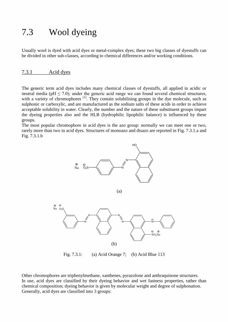
7.3 Wool dyeing
Usually wool is dyed with acid dyes or metal-complex dyes; these two big classes of dyestuffs can
be divided in other sub-classes, according to chemical differences and/or working conditions.
7.3.1 Acid dyes
The generic term acid dyes includes many chemical classes of dyestuffs, all applied in acidic or
neutral media (pH ≤ 7.0); under the generic acid range we can found several chemical structures,
with a variety of chromophores [1]
. They contain solubilising groups in the dye molecule, such as
sulphonic or carboxylic, and are manufactured as the sodium salts of these acids in order to achieve
acceptable solubility in water. Clearly, the number and the nature of these substituent groups impart
the dyeing properties also and the HLB (hydrophilic lipophilic balance) is influenced by these
groups.
The most popular chromophore in acid dyes is the azo group: normally we can meet one or two,
rarely more than two in acid dyes. Structures of monoazo and disazo are reported in Fig. 7.3.1.a and
Fig. 7.3.1.b
N
N
HO
O3SNa
(a)
N
N
Na O3S
N
NHN
SO3 Na
(b)
Fig. 7.3.1: (a) Acid Orange 7; (b) Acid Blue 113
Other chromophores are triphenylmethane, xanthenes, pyrazolone and anthraquinone structures.
In use, acid dyes are classified by their dyeing behavior and wet fastness properties, rather than
chemical composition; dyeing behavior is given by molecular weight and degree of sulphonation.
Generally, acid dyes are classified into 3 groups:
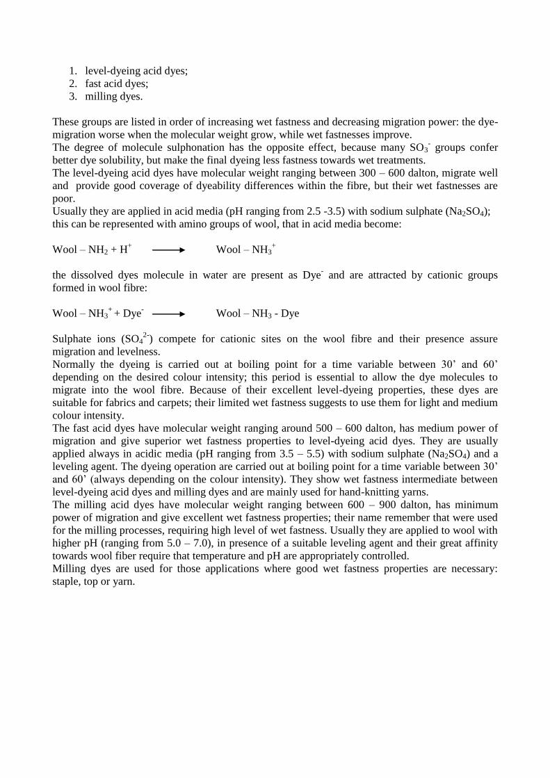
1. level-dyeing acid dyes;
2. fast acid dyes;
3. milling dyes.
These groups are listed in order of increasing wet fastness and decreasing migration power: the dye-
migration worse when the molecular weight grow, while wet fastnesses improve.
The degree of molecule sulphonation has the opposite effect, because many SO3- groups confer
better dye solubility, but make the final dyeing less fastness towards wet treatments.
The level-dyeing acid dyes have molecular weight ranging between 300 – 600 dalton, migrate well
and provide good coverage of dyeability differences within the fibre, but their wet fastnesses are
poor.
Usually they are applied in acid media (pH ranging from 2.5 -3.5) with sodium sulphate (Na2SO4);
this can be represented with amino groups of wool, that in acid media become:
Wool – NH2 + H+ Wool – NH3
+
the dissolved dyes molecule in water are present as Dye- and are attracted by cationic groups
formed in wool fibre:
Wool – NH3+
+ Dye- Wool – NH3 - Dye
Sulphate ions (SO42-
) compete for cationic sites on the wool fibre and their presence assure
migration and levelness.
Normally the dyeing is carried out at boiling point for a time variable between 30’ and 60’
depending on the desired colour intensity; this period is essential to allow the dye molecules to
migrate into the wool fibre. Because of their excellent level-dyeing properties, these dyes are
suitable for fabrics and carpets; their limited wet fastness suggests to use them for light and medium
colour intensity.
The fast acid dyes have molecular weight ranging around 500 – 600 dalton, has medium power of
migration and give superior wet fastness properties to level-dyeing acid dyes. They are usually
applied always in acidic media (pH ranging from 3.5 – 5.5) with sodium sulphate (Na2SO4) and a
leveling agent. The dyeing operation are carried out at boiling point for a time variable between 30’
and 60’ (always depending on the colour intensity). They show wet fastness intermediate between
level-dyeing acid dyes and milling dyes and are mainly used for hand-knitting yarns.
The milling acid dyes have molecular weight ranging between 600 – 900 dalton, has minimum
power of migration and give excellent wet fastness properties; their name remember that were used
for the milling processes, requiring high level of wet fastness. Usually they are applied to wool with
higher pH (ranging from 5.0 – 7.0), in presence of a suitable leveling agent and their great affinity
towards wool fiber require that temperature and pH are appropriately controlled.
Milling dyes are used for those applications where good wet fastness properties are necessary:
staple, top or yarn.
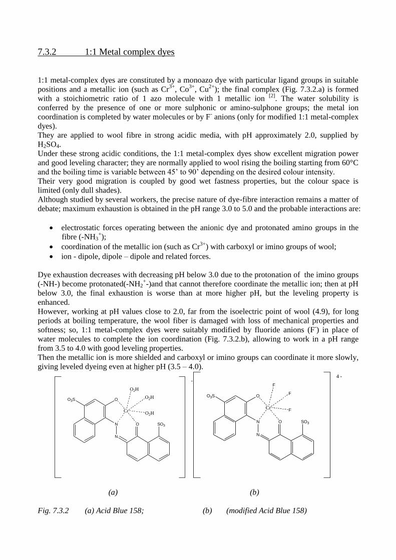
7.3.2 1:1 Metal complex dyes
1:1 metal-complex dyes are constituted by a monoazo dye with particular ligand groups in suitable
positions and a metallic ion (such as Cr3+
, Co3+
, Cu2+
); the final complex (Fig. 7.3.2.a) is formed
with a stoichiometric ratio of 1 azo molecule with 1 metallic ion [2]
. The water solubility is
conferred by the presence of one or more sulphonic or amino-sulphone groups; the metal ion
coordination is completed by water molecules or by F- anions (only for modified 1:1 metal-complex
dyes).
They are applied to wool fibre in strong acidic media, with pH approximately 2.0, supplied by
H2SO4.
Under these strong acidic conditions, the 1:1 metal-complex dyes show excellent migration power
and good leveling character; they are normally applied to wool rising the boiling starting from 60°C
and the boiling time is variable between 45’ to 90’ depending on the desired colour intensity.
Their very good migration is coupled by good wet fastness properties, but the colour space is
limited (only dull shades).
Although studied by several workers, the precise nature of dye-fibre interaction remains a matter of
debate; maximum exhaustion is obtained in the pH range 3.0 to 5.0 and the probable interactions are:
electrostatic forces operating between the anionic dye and protonated amino groups in the
fibre (-NH3+);
coordination of the metallic ion (such as Cr3+
) with carboxyl or imino groups of wool;
ion - dipole, dipole – dipole and related forces.
Dye exhaustion decreases with decreasing pH below 3.0 due to the protonation of the imino groups
(-NH-) become protonated(-NH2+-)and that cannot therefore coordinate the metallic ion; then at pH
below 3.0, the final exhaustion is worse than at more higher pH, but the leveling property is
enhanced.
However, working at pH values close to 2.0, far from the isoelectric point of wool (4.9), for long
periods at boiling temperature, the wool fiber is damaged with loss of mechanical properties and
softness; so, 1:1 metal-complex dyes were suitably modified by fluoride anions (F-) in place of
water molecules to complete the ion coordination (Fig. 7.3.2.b), allowing to work in a pH range
from 3.5 to 4.0 with good leveling properties.
Then the metallic ion is more shielded and carboxyl or imino groups can coordinate it more slowly,
giving leveled dyeing even at higher pH (3.5 – 4.0).
N
N
SO3O
OO3S
Cr
O2H
O2H
O2H
-
N
N
SO3O
OO3S
Cr
F
F
F
4 -
(a) (b)
Fig. 7.3.2 (a) Acid Blue 158; (b) (modified Acid Blue 158)
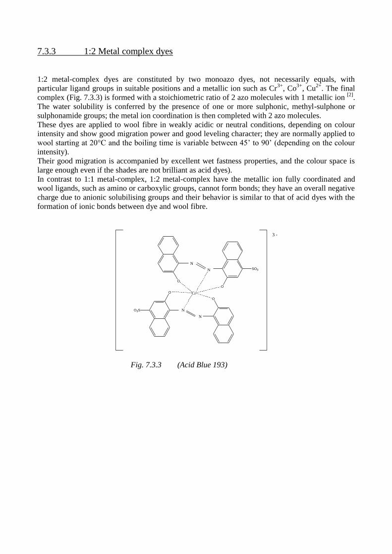
7.3.3 1:2 Metal complex dyes
1:2 metal-complex dyes are constituted by two monoazo dyes, not necessarily equals, with
particular ligand groups in suitable positions and a metallic ion such as Cr3+
, Co3+
, Cu2+
. The final
complex (Fig. 7.3.3) is formed with a stoichiometric ratio of 2 azo molecules with 1 metallic ion [2]
.
The water solubility is conferred by the presence of one or more sulphonic, methyl-sulphone or
sulphonamide groups; the metal ion coordination is then completed with 2 azo molecules.
These dyes are applied to wool fibre in weakly acidic or neutral conditions, depending on colour
intensity and show good migration power and good leveling character; they are normally applied to
wool starting at 20°C and the boiling time is variable between 45’ to 90’ (depending on the colour
intensity).
Their good migration is accompanied by excellent wet fastness properties, and the colour space is
large enough even if the shades are not brilliant as acid dyes).
In contrast to 1:1 metal-complex, 1:2 metal-complex have the metallic ion fully coordinated and
wool ligands, such as amino or carboxylic groups, cannot form bonds; they have an overall negative
charge due to anionic solubilising groups and their behavior is similar to that of acid dyes with the
formation of ionic bonds between dye and wool fibre.
O
O3S N
N
O
Cr
N
N
O
O
SO3
3 -
Fig. 7.3.3 (Acid Blue 193)
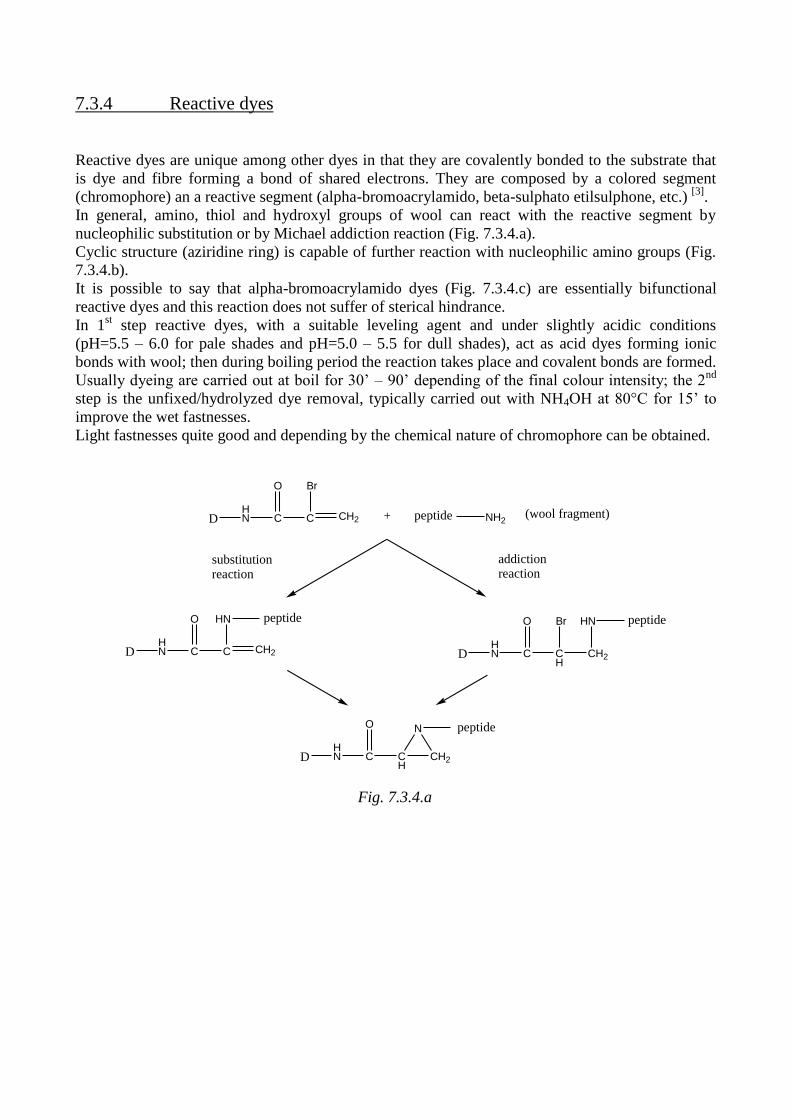
7.3.4 Reactive dyes
Reactive dyes are unique among other dyes in that they are covalently bonded to the substrate that
is dye and fibre forming a bond of shared electrons. They are composed by a colored segment
(chromophore) an a reactive segment (alpha-bromoacrylamido, beta-sulphato etilsulphone, etc.) [3]
.
In general, amino, thiol and hydroxyl groups of wool can react with the reactive segment by
nucleophilic substitution or by Michael addiction reaction (Fig. 7.3.4.a).
Cyclic structure (aziridine ring) is capable of further reaction with nucleophilic amino groups (Fig.
7.3.4.b).
It is possible to say that alpha-bromoacrylamido dyes (Fig. 7.3.4.c) are essentially bifunctional
reactive dyes and this reaction does not suffer of sterical hindrance.
In 1st step reactive dyes, with a suitable leveling agent and under slightly acidic conditions
(pH=5.5 – 6.0 for pale shades and pH=5.0 – 5.5 for dull shades), act as acid dyes forming ionic
bonds with wool; then during boiling period the reaction takes place and covalent bonds are formed.
Usually dyeing are carried out at boil for 30’ – 90’ depending of the final colour intensity; the 2nd
step is the unfixed/hydrolyzed dye removal, typically carried out with NH4OH at 80°C for 15’ to
improve the wet fastnesses.
Light fastnesses quite good and depending by the chemical nature of chromophore can be obtained.
DHN C
O
C
Br
CH2 + peptide NH2(wool fragment)
DHN C
O
C
HN
CH2
peptide
DHN C
O
CH
Br
CH2
HN peptide
DHN C
O
CH
CH2
N peptide
substitutionreaction
addiction reaction
Fig. 7.3.4.a
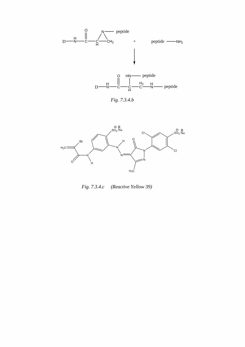
DHN C
O
CH
CH2
N peptide
+ peptide NH2
DHN C
O
CH
H2C
HN
HN peptide
peptide
Fig. 7.3.4.b
Br
H2C
O
N
H
SO3 Na
N
H
N
N
N
H3C
O
Cl
Cl
SO3 Na
Fig. 7.3.4.c (Reactive Yellow 39)
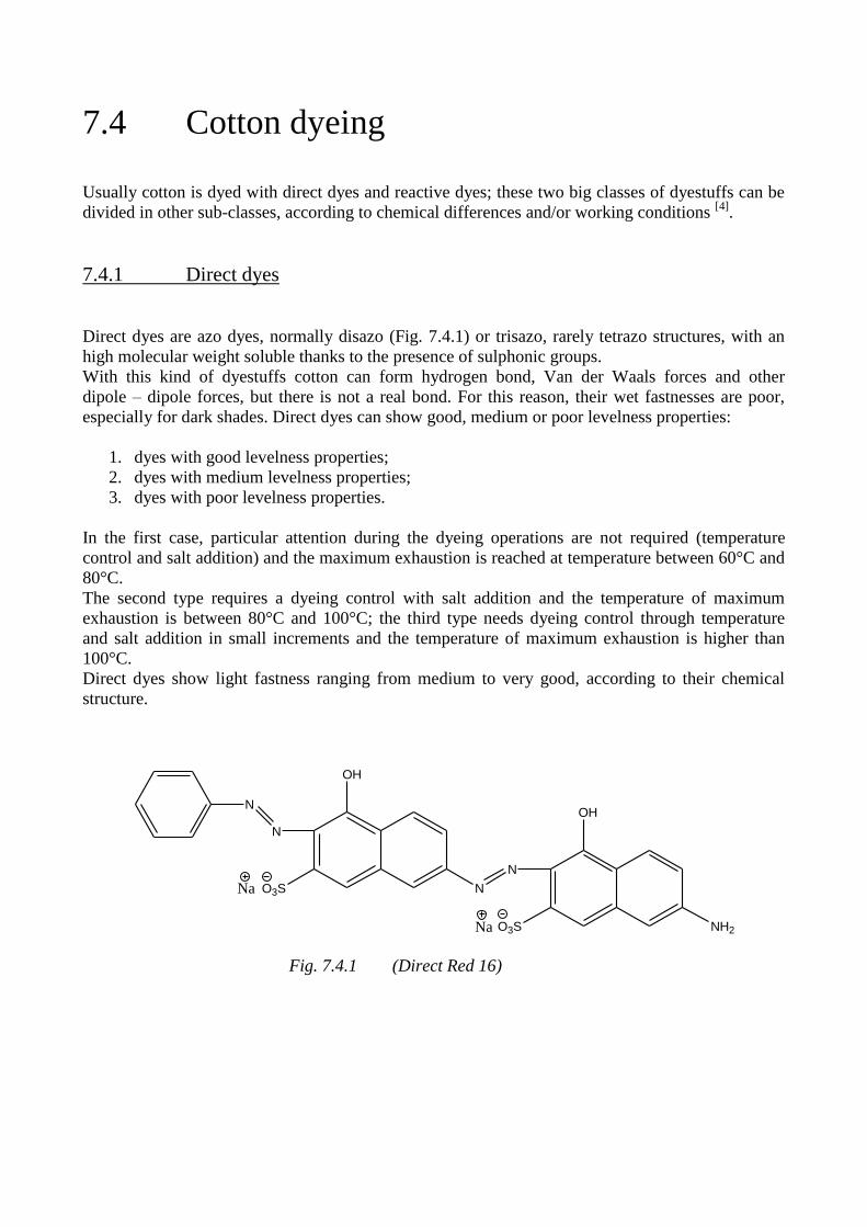
7.4 Cotton dyeing
Usually cotton is dyed with direct dyes and reactive dyes; these two big classes of dyestuffs can be
divided in other sub-classes, according to chemical differences and/or working conditions [4]
.
7.4.1 Direct dyes
Direct dyes are azo dyes, normally disazo (Fig. 7.4.1) or trisazo, rarely tetrazo structures, with an
high molecular weight soluble thanks to the presence of sulphonic groups.
With this kind of dyestuffs cotton can form hydrogen bond, Van der Waals forces and other
dipole – dipole forces, but there is not a real bond. For this reason, their wet fastnesses are poor,
especially for dark shades. Direct dyes can show good, medium or poor levelness properties:
1. dyes with good levelness properties;
2. dyes with medium levelness properties;
3. dyes with poor levelness properties.
In the first case, particular attention during the dyeing operations are not required (temperature
control and salt addition) and the maximum exhaustion is reached at temperature between 60°C and
80°C.
The second type requires a dyeing control with salt addition and the temperature of maximum
exhaustion is between 80°C and 100°C; the third type needs dyeing control through temperature
and salt addition in small increments and the temperature of maximum exhaustion is higher than
100°C.
Direct dyes show light fastness ranging from medium to very good, according to their chemical
structure.
N
N
OH
O3S NNa
N
OH
NH2O3SNa
Fig. 7.4.1 (Direct Red 16)
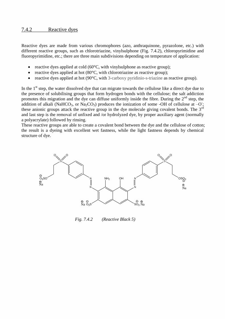
7.4.2 Reactive dyes
Reactive dyes are made from various chromophores (azo, anthraquinone, pyrazolone, etc.) with
different reactive groups, such as chlorotriazine, vinylsulphone (Fig. 7.4.2), chloropyrimidine and
fluoropyrimidine, etc.; there are three main subdivisions depending on temperature of application:
reactive dyes applied at cold (60°C, with vinylsulphone as reactive group);
reactive dyes applied at hot (80°C, with chlorotriazine as reactive group);
reactive dyes applied at hot (90°C, with 3-carboxy pyridinio-s-triazine as reactive group).
In the 1st step, the water dissolved dye that can migrate towards the cellulose like a direct dye due to
the presence of solubilising groups that form hydrogen bonds with the cellulose; the salt addiction
promotes this migration and the dye can diffuse uniformly inside the fibre. During the 2nd
step, the
addition of alkali (NaHCO3, or Na2CO3) produces the ionization of some -OH of cellulose at –O-;
these anionic groups attack the reactive group in the dye molecule giving covalent bonds. The 3rd
and last step is the removal of unfixed and /or hydrolyzed dye, by proper auxiliary agent (normally
a polyacrylate) followed by rinsing.
These reactive groups are able to create a covalent bond between the dye and the cellulose of cotton;
the result is a dyeing with excellent wet fastness, while the light fastness depends by chemical
structure of dye.
S
N
N N
N
S
O O OO
OHNH2
O3S SO3 NaNa
O3SO OSO3
NaNa
Fig. 7.4.2 (Reactive Black 5)
7.5 Proposed procedures
In the case of wool fiber, several experimental tests carried out on UV treated fabrics, with different
dyes showed the best results with 1:1 metal-complex dyes. In fact, 1:1 metal-complex dyes
provided differences of more than 5 score points, in terms of delta E color differences between UV-
treated and untreated fibers, with a contrast clearly visible. Worst effect were obtained both with
reactive dyes and 1:2 metal-complex dyes.
Therefore we proceeded to a selection of the above dyes, rejecting those elements not ensuring
adequate colour difference. We also carried out a comparison between classical 1:1 metal-complex
dyes and modified 1:1 metal-complex dyes, showing that the latter exert a lower action than the
previous.
In the case of cotton fiber, the most advantageous technique appears to dye the cellulosic substrate
with directs or reactives dyes with limited light fastness, subsequently exposed to UV radiation.
Indeed, the UV-treated cellulose does not produce exploitable effects to obtain acceptable
differential dyeings; then dyeing before and fading after, due to the action of chromogens
degradation by UV radiation, acceptable effects of colour differences were achieved. These
differences increase in value through yellow shades, to orange shades, to red shades, and have their
delta E maximum in blue shades, navy shades and black shades.
7.6 References
[1] P. A. Duffield, Wool Dyeing, SDC, Ed. D. M. Lewis, 6, Dyeing wool with acid and chrome
dyes, 176.
[2] S. M. Burkinshaw, Wool Dyeing, SDC, Ed. D. M. Lewis, 7, Dyeing wool with metal-complex
dyes, 196.
[3] D.M. Lewis, Wool Dyeing, SDC, Ed. D. M. Lewis, 8, Dyeing wool with reactive dyes, 222.
[4] J. Cegarra, P. Puente et J. Valldeperas, The dyeing of textile materials, the scientific bases and
the techniques of application, 1992,Texilia, Biella.
Chapter 8 UV treatment of wool for differential dyeing with
commercial dyestuffs

8.1 Wool pretreatment by UV radiations
The main topic of my doctoral research work was the study about a treatment of wool yarns or
fabrics (previously washed) by UV radiation to confer peculiar dyeing effects.
Pure wool knitted fabrics with a density of about 160 g/ m2 or pure wool yarns with Nm = 2/28
were used as textile substrates. Both were previously washed at 60 °C for 30' with ECE detergent 1
g/L solution, rinsed and dried in oven at 100°C.
The UV radiation has a well-defined irradiance Ee:
Ee = dΦe / dA
where: Φe is the radiant flux that impact on the surface [W]
A is the surface [m2]
This radiometric parameter is defined as the radiant flux per unit area and can be measured in W/m2
or mW/cm2.
More precisely, in the present study it was considered another parameter, the radiant exposure He,
related to the accumulated amount of incident "light" energy per area, expressed in [J/m2], or
[J/cm2] (in our case):
He = Ee * t
where: Ee is the irradiance [W/m2]
t is the time of exposure [s]
8.1.1 Static assessment
For static irradiation test, samples were UV irradiated by a medium pressure Hg vapor lamp c/o
Politecnico di Torino (Helios Italquartz). The radiant exposure relative to the UVA component
resulted of ≈ 37 mW/cm2 provided positioning the samples at a distance of ≈ 15 cm from the lamp.
Wool samples were half-exposed to UV light, covering the unexposed part with a paper sheet, on
both sides for different times; namely, samples I, II, III, IV, V were exposed for 1, 2, 3, 4 or 5
minutes respectively. In this way, the effect of UV radiation can be easily evaluated after the dyeing,
simply comparing the 2 halves of the sample.
On the other hand, the immediate effect of radiation on wool fabrics was evaluated from
spectrophotometer readings, by Datacolor, of the various samples referred to the untreated ones.
From obtained results, reported in Table 8.1.1, a difference of color with respect to the untreated
sample was revealed; it was mainly due to a Δ b increase, related to a certain yellowing of the
sample.
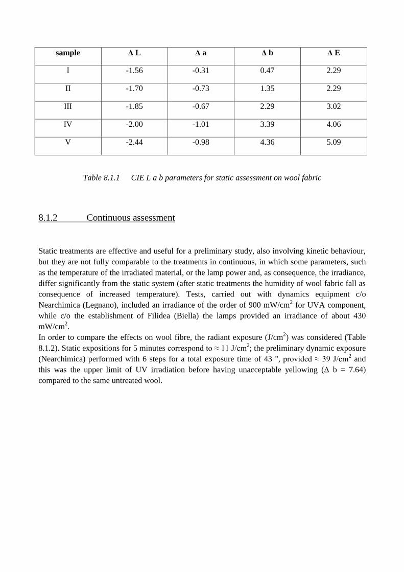
sample Δ L Δ a Δ b Δ E
I -1.56 -0.31 0.47 2.29
II -1.70 -0.73 1.35 2.29
III -1.85 -0.67 2.29 3.02
IV -2.00 -1.01 3.39 4.06
V -2.44 -0.98 4.36 5.09
Table 8.1.1 CIE L a b parameters for static assessment on wool fabric
8.1.2 Continuous assessment
Static treatments are effective and useful for a preliminary study, also involving kinetic behaviour,
but they are not fully comparable to the treatments in continuous, in which some parameters, such
as the temperature of the irradiated material, or the lamp power and, as consequence, the irradiance,
differ significantly from the static system (after static treatments the humidity of wool fabric fall as
consequence of increased temperature). Tests, carried out with dynamics equipment c/o
Nearchimica (Legnano), included an irradiance of the order of 900 mW/cm2 for UVA component,
while c/o the establishment of Filidea (Biella) the lamps provided an irradiance of about 430
mW/cm2.
In order to compare the effects on wool fibre, the radiant exposure (J/cm2) was considered (Table
8.1.2). Static expositions for 5 minutes correspond to ≈ 11 J/cm2; the preliminary dynamic exposure
(Nearchimica) performed with 6 steps for a total exposure time of 43 ", provided ≈ 39 J/cm2 and
this was the upper limit of UV irradiation before having unacceptable yellowing (Δ b = 7.64)
compared to the same untreated wool.
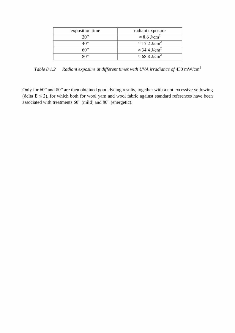
exposition time radiant exposure
20” ≈ 8.6 J/cm2
40” ≈ 17.2 J/cm2
60” ≈ 34.4 J/cm2
80” ≈ 68.8 J/cm2
Table 8.1.2 Radiant exposure at different times with UVA irradiance of 430 mW/cm2
Only for 60” and 80” are then obtained good dyeing results, together with a not excessive yellowing
(delta E ≤ 2), for which both for wool yarn and wool fabric against standard references have been
associated with treatments 60” (mild) and 80” (energetic).
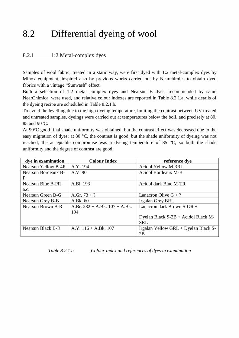
8.2 Differential dyeing of wool
8.2.1 1:2 Metal-complex dyes
Samples of wool fabric, treated in a static way, were first dyed with 1:2 metal-complex dyes by
Minox equipment, inspired also by previous works carried out by Nearchimica to obtain dyed
fabrics with a vintage “Sunwash” effect.
Both a selection of 1:2 metal complex dyes and Nearsun B dyes, recommended by same
NearChimica, were used, and relative colour indexes are reported in Table 8.2.1.a, while details of
the dyeing recipe are scheduled in Table 8.2.1.b.
To avoid the levelling due to the high dyeing temperature, limiting the contrast between UV treated
and untreated samples, dyeings were carried out at temperatures below the boil, and precisely at 80,
85 and 90°C.
At 90°C good final shade uniformity was obtained, but the contrast effect was decreased due to the
easy migration of dyes; at 80 °C, the contrast is good, but the shade uniformity of dyeing was not
reached; the acceptable compromise was a dyeing temperature of 85 °C, so both the shade
uniformity and the degree of contrast are good.
dye in examination Colour Index reference dye
Nearsun Yellow B-4R A.Y. 194 Acidol Yellow M-3RL
Nearsun Bordeaux B-
P
A.V. 90 Acidol Bordeaux M-B
Nearsun Blue B-PR
a.c.
A.Bl. 193 Acidol dark Blue M-TR
Nearsun Green B-G A.Gr. 73 + ? Lanacron Olive G + ?
Nearsun Grey B-B A.Bk. 60 Irgalan Grey BRL
Nearsun Brown B-R A.Br. 282 + A.Bk. 107 + A.Bk.
194
Lanacron dark Brown S-GR +
Dyelan Black S-2B + Acidol Black M-
SRL
Nearsun Black B-R A.Y. 116 + A.Bk. 107 Irgalan Yellow GRL + Dyelan Black S-
2B
Table 8.2.1.a Colour Index and references of dyes in examination
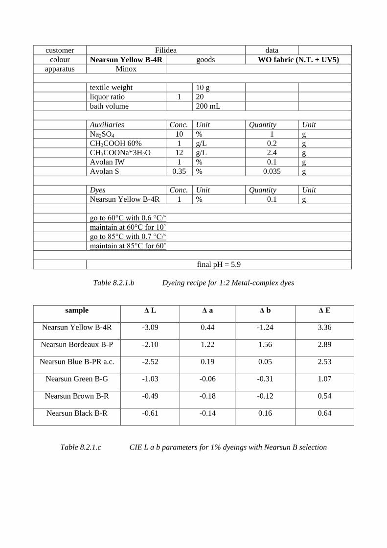
customer Filidea data
colour Nearsun Yellow B-4R goods WO fabric (N.T. + UV5)
apparatus Minox
textile weight 10 g
liquor ratio 1 20
bath volume 200 mL
Auxiliaries Conc. Unit Quantity Unit
Na2SO4 10 % 1 g
CH3COOH 60% 1 g/L 0.2 g
CH3COONa*3H2O 12 g/L 2.4 g
Avolan IW 1 % 0.1 g
Avolan S 0.35 % 0.035 g
Dyes Conc. Unit Quantity Unit
Nearsun Yellow B-4R 1 % 0.1 g
go to 60°C with 0.6 °C/‘
maintain at 60°C for 10’
go to 85°C with 0.7 °C/‘
maintain at 85°C for 60’
final pH = 5.9
Table 8.2.1.b Dyeing recipe for 1:2 Metal-complex dyes
sample Δ L Δ a Δ b Δ E
Nearsun Yellow B-4R -3.09 0.44 -1.24 3.36
Nearsun Bordeaux B-P -2.10 1.22 1.56 2.89
Nearsun Blue B-PR a.c. -2.52 0.19 0.05 2.53
Nearsun Green B-G -1.03 -0.06 -0.31 1.07
Nearsun Brown B-R -0.49 -0.18 -0.12 0.54
Nearsun Black B-R -0.61 -0.14 0.16 0.64
Table 8.2.1.c CIE L a b parameters for 1% dyeings with Nearsun B selection
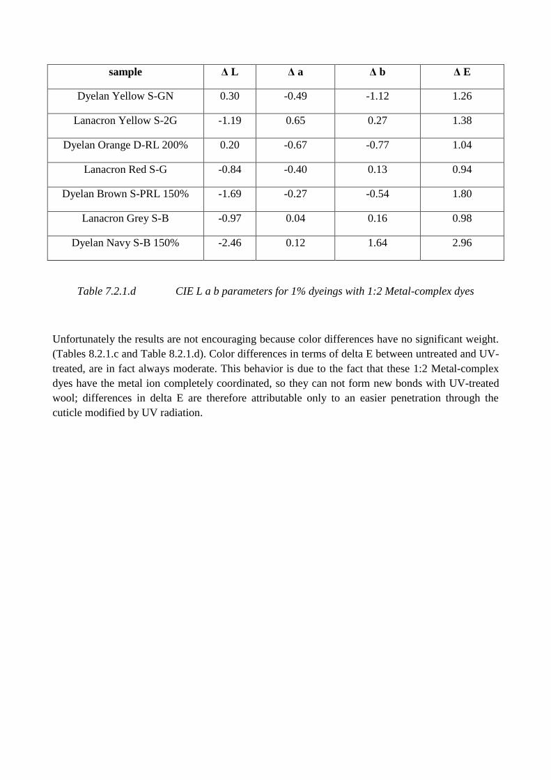
sample Δ L Δ a Δ b Δ E
Dyelan Yellow S-GN 0.30 -0.49 -1.12 1.26
Lanacron Yellow S-2G -1.19 0.65 0.27 1.38
Dyelan Orange D-RL 200% 0.20 -0.67 -0.77 1.04
Lanacron Red S-G -0.84 -0.40 0.13 0.94
Dyelan Brown S-PRL 150% -1.69 -0.27 -0.54 1.80
Lanacron Grey S-B -0.97 0.04 0.16 0.98
Dyelan Navy S-B 150% -2.46 0.12 1.64 2.96
Table 7.2.1.d CIE L a b parameters for 1% dyeings with 1:2 Metal-complex dyes
Unfortunately the results are not encouraging because color differences have no significant weight.
(Tables 8.2.1.c and Table 8.2.1.d). Color differences in terms of delta E between untreated and UV-
treated, are in fact always moderate. This behavior is due to the fact that these 1:2 Metal-complex
dyes have the metal ion completely coordinated, so they can not form new bonds with UV-treated
wool; differences in delta E are therefore attributable only to an easier penetration through the
cuticle modified by UV radiation.
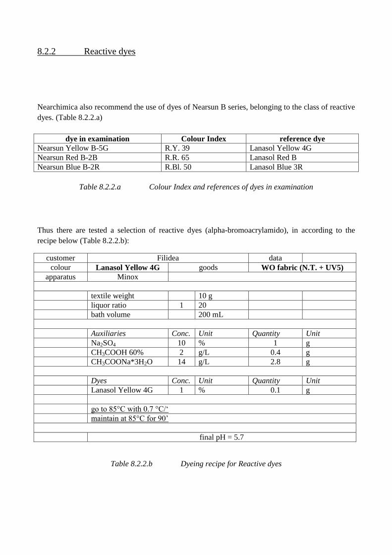
8.2.2 Reactive dyes
Nearchimica also recommend the use of dyes of Nearsun B series, belonging to the class of reactive
dyes. (Table 8.2.2.a)
dye in examination Colour Index reference dye
Nearsun Yellow B-5G R.Y. 39 Lanasol Yellow 4G
Nearsun Red B-2B R.R. 65 Lanasol Red B
Nearsun Blue B-2R R.Bl. 50 Lanasol Blue 3R
Table 8.2.2.a Colour Index and references of dyes in examination
Thus there are tested a selection of reactive dyes (alpha-bromoacrylamido), in according to the
recipe below (Table 8.2.2.b):
customer Filidea data
colour Lanasol Yellow 4G goods WO fabric (N.T. + UV5)
apparatus Minox
textile weight 10 g
liquor ratio 1 20
bath volume 200 mL
Auxiliaries Conc. Unit Quantity Unit
Na2SO4 10 % 1 g
CH3COOH 60% 2 g/L 0.4 g
CH3COONa*3H2O 14 g/L 2.8 g
Dyes Conc. Unit Quantity Unit
Lanasol Yellow 4G 1 % 0.1 g
go to 85°C with 0.7 °C/‘
maintain at 85°C for 90’
final pH = 5.7
Table 8.2.2.b Dyeing recipe for Reactive dyes
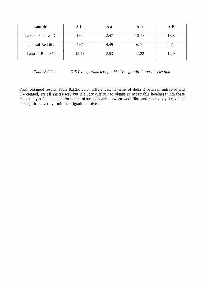
sample Δ L Δ a Δ b Δ E
Lanasol Yellow 4G -1.64 2.47 13.43 13.8
Lanasol Red 6G -4.67 4.49 6.40 9.1
Lanasol Blue 3G -12.48 2.53 -2.22 12.9
Table 8.2.2.c CIE L a b parameters for 1% dyeings with Lanasol selection
From obtained results Table 8.2.2.c color differences, in terms of delta E between untreated and
UV-treated, are all satisfactory but it’s very difficult to obtain an acceptable levelness with these
reactive dyes. It is due to a formation of strong bonds between wool fibre and reactive dye (covalent
bonds), that severely limit the migration of dyes.
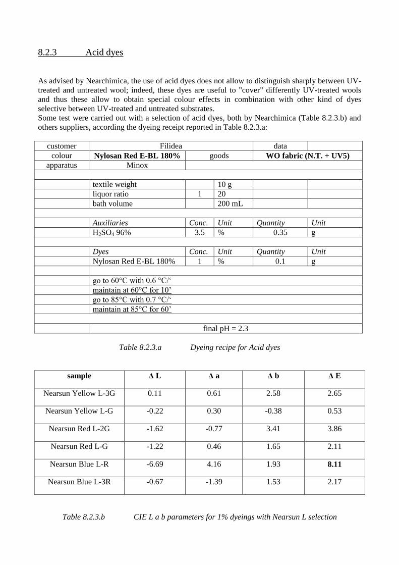
8.2.3 Acid dyes
As advised by Nearchimica, the use of acid dyes does not allow to distinguish sharply between UV-
treated and untreated wool; indeed, these dyes are useful to "cover" differently UV-treated wools
and thus these allow to obtain special colour effects in combination with other kind of dyes
selective between UV-treated and untreated substrates.
Some test were carried out with a selection of acid dyes, both by Nearchimica (Table 8.2.3.b) and
others suppliers, according the dyeing receipt reported in Table 8.2.3.a:
customer Filidea data
colour Nylosan Red E-BL 180% goods WO fabric (N.T. + UV5)
apparatus Minox
textile weight 10 g
liquor ratio 1 20
bath volume 200 mL
Auxiliaries Conc. Unit Quantity Unit
H2SO4 96% 3.5 % 0.35 g
Dyes Conc. Unit Quantity Unit
Nylosan Red E-BL 180% 1 % 0.1 g
go to 60°C with 0.6 °C/‘
maintain at 60°C for 10’
go to 85°C with 0.7 °C/‘
maintain at 85°C for 60’
final pH = 2.3
Table 8.2.3.a Dyeing recipe for Acid dyes
sample Δ L Δ a Δ b Δ E
Nearsun Yellow L-3G 0.11 0.61 2.58 2.65
Nearsun Yellow L-G -0.22 0.30 -0.38 0.53
Nearsun Red L-2G -1.62 -0.77 3.41 3.86
Nearsun Red L-G -1.22 0.46 1.65 2.11
Nearsun Blue L-R -6.69 4.16 1.93 8.11
Nearsun Blue L-3R -0.67 -1.39 1.53 2.17
Table 8.2.3.b CIE L a b parameters for 1% dyeings with Nearsun L selection
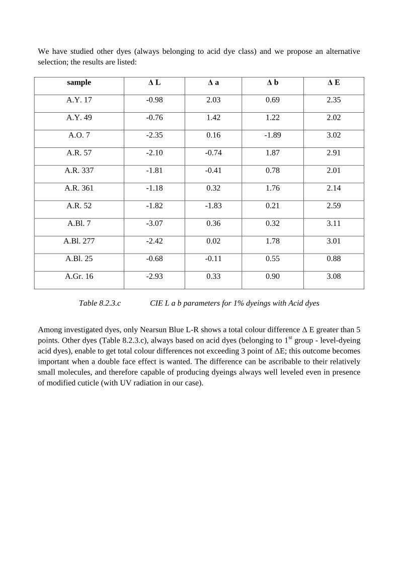
We have studied other dyes (always belonging to acid dye class) and we propose an alternative
selection; the results are listed:
sample Δ L Δ a Δ b Δ E
A.Y. 17 -0.98 2.03 0.69 2.35
A.Y. 49 -0.76 1.42 1.22 2.02
A.O. 7 -2.35 0.16 -1.89 3.02
A.R. 57 -2.10 -0.74 1.87 2.91
A.R. 337 -1.81 -0.41 0.78 2.01
A.R. 361 -1.18 0.32 1.76 2.14
A.R. 52 -1.82 -1.83 0.21 2.59
A.Bl. 7 -3.07 0.36 0.32 3.11
A.Bl. 277 -2.42 0.02 1.78 3.01
A.Bl. 25 -0.68 -0.11 0.55 0.88
A.Gr. 16 -2.93 0.33 0.90 3.08
Table 8.2.3.c CIE L a b parameters for 1% dyeings with Acid dyes
Among investigated dyes, only Nearsun Blue L-R shows a total colour difference Δ E greater than 5
points. Other dyes (Table 8.2.3.c), always based on acid dyes (belonging to 1st group - level-dyeing
acid dyes), enable to get total colour differences not exceeding 3 point of ΔE; this outcome becomes
important when a double face effect is wanted. The difference can be ascribable to their relatively
small molecules, and therefore capable of producing dyeings always well leveled even in presence
of modified cuticle (with UV radiation in our case).
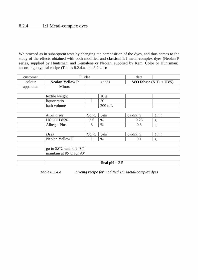
8.2.4 1:1 Metal-complex dyes
We proceed as in subsequent tests by changing the composition of the dyes, and thus comes to the
study of the effects obtained with both modified and classical 1:1 metal-complex dyes (Neolan P
series, supplied by Huntsman, and Kemalene or Neolan, supplied by Kem. Color or Huntsman),
according a typical recipe (Tables 8.2.4.a. and 8.2.4.d):
customer Filidea data
colour Neolan Yellow P goods WO fabric (N.T. + UV5)
apparatus Minox
textile weight 10 g
liquor ratio 1 20
bath volume 200 mL
Auxiliaries Conc. Unit Quantity Unit
HCOOH 85% 2.5 % 0.25 g
Albegal Plus 3 % 0.3 g
Dyes Conc. Unit Quantity Unit
Neolan Yellow P 1 % 0.1 g
go to 85°C with 0.7 °C/‘
maintain at 85°C for 90’
final pH = 3.5
Table 8.2.4.a Dyeing recipe for modified 1:1 Metal-complex dyes
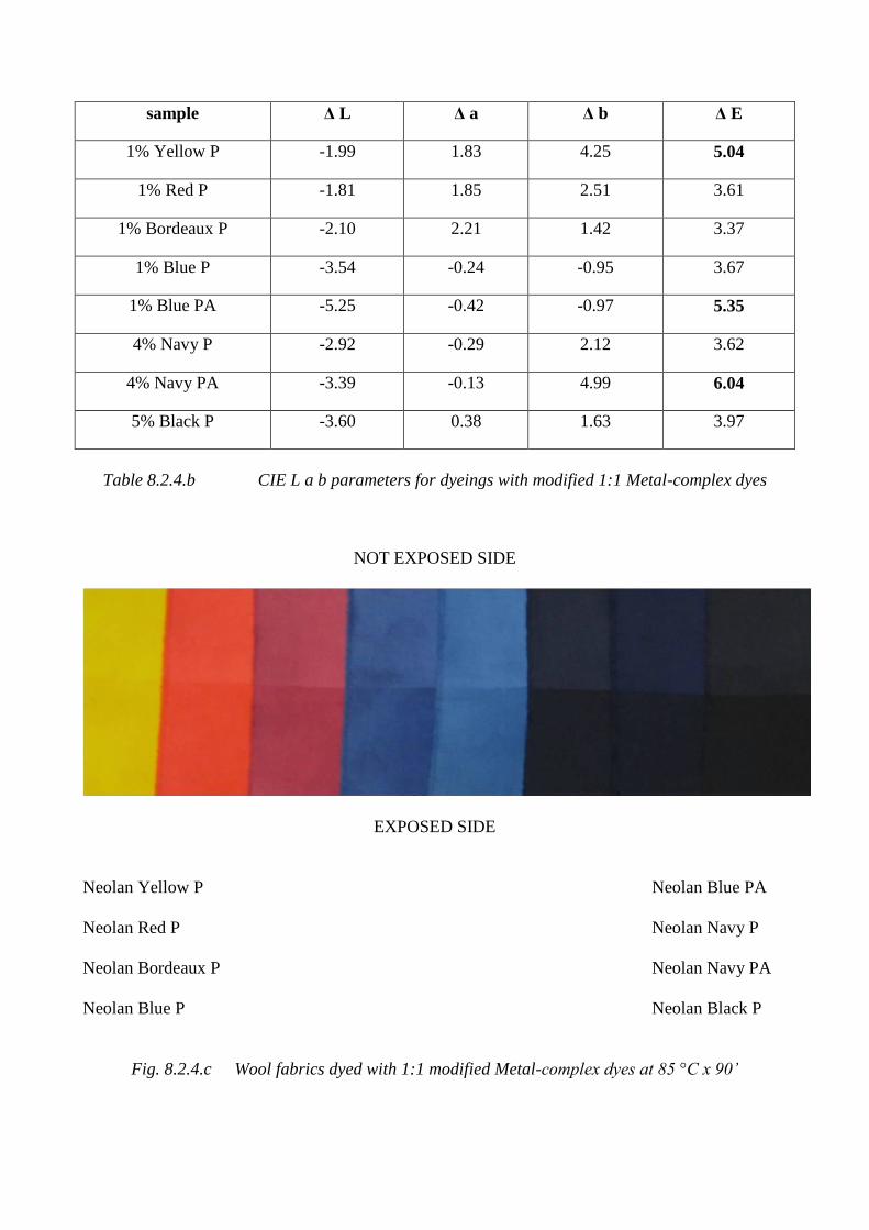
sample Δ L Δ a Δ b Δ E
1% Yellow P -1.99 1.83 4.25 5.04
1% Red P -1.81 1.85 2.51 3.61
1% Bordeaux P -2.10 2.21 1.42 3.37
1% Blue P -3.54 -0.24 -0.95 3.67
1% Blue PA -5.25 -0.42 -0.97 5.35
4% Navy P -2.92 -0.29 2.12 3.62
4% Navy PA -3.39 -0.13 4.99 6.04
5% Black P -3.60 0.38 1.63 3.97
Table 8.2.4.b CIE L a b parameters for dyeings with modified 1:1 Metal-complex dyes
NOT EXPOSED SIDE
EXPOSED SIDE
Neolan Yellow P Neolan Blue PA
Neolan Red P Neolan Navy P
Neolan Bordeaux P Neolan Navy PA
Neolan Blue P Neolan Black P
Fig. 8.2.4.c Wool fabrics dyed with 1:1 modified Metal-complex dyes at 85 °C x 90’
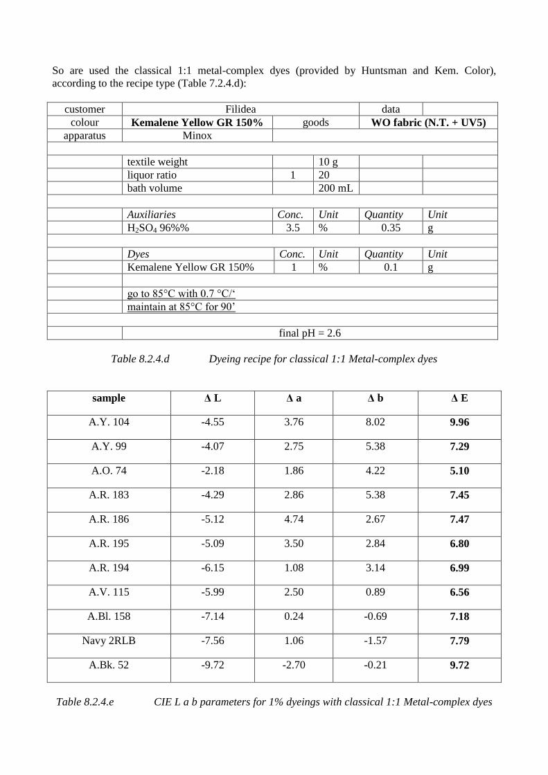
So are used the classical 1:1 metal-complex dyes (provided by Huntsman and Kem. Color),
according to the recipe type (Table 7.2.4.d):
customer Filidea data
colour Kemalene Yellow GR 150% goods WO fabric (N.T. + UV5)
apparatus Minox
textile weight 10 g
liquor ratio 1 20
bath volume 200 mL
Auxiliaries Conc. Unit Quantity Unit
H2SO4 96%% 3.5 % 0.35 g
Dyes Conc. Unit Quantity Unit
Kemalene Yellow GR 150% 1 % 0.1 g
go to 85°C with 0.7 °C/‘
maintain at 85°C for 90’
final pH = 2.6
Table 8.2.4.d Dyeing recipe for classical 1:1 Metal-complex dyes
sample Δ L Δ a Δ b Δ E
A.Y. 104 -4.55 3.76 8.02 9.96
A.Y. 99 -4.07 2.75 5.38 7.29
A.O. 74 -2.18 1.86 4.22 5.10
A.R. 183 -4.29 2.86 5.38 7.45
A.R. 186 -5.12 4.74 2.67 7.47
A.R. 195 -5.09 3.50 2.84 6.80
A.R. 194 -6.15 1.08 3.14 6.99
A.V. 115 -5.99 2.50 0.89 6.56
A.Bl. 158 -7.14 0.24 -0.69 7.18
Navy 2RLB -7.56 1.06 -1.57 7.79
A.Bk. 52 -9.72 -2.70 -0.21 9.72
Table 8.2.4.e CIE L a b parameters for 1% dyeings with classical 1:1 Metal-complex dyes
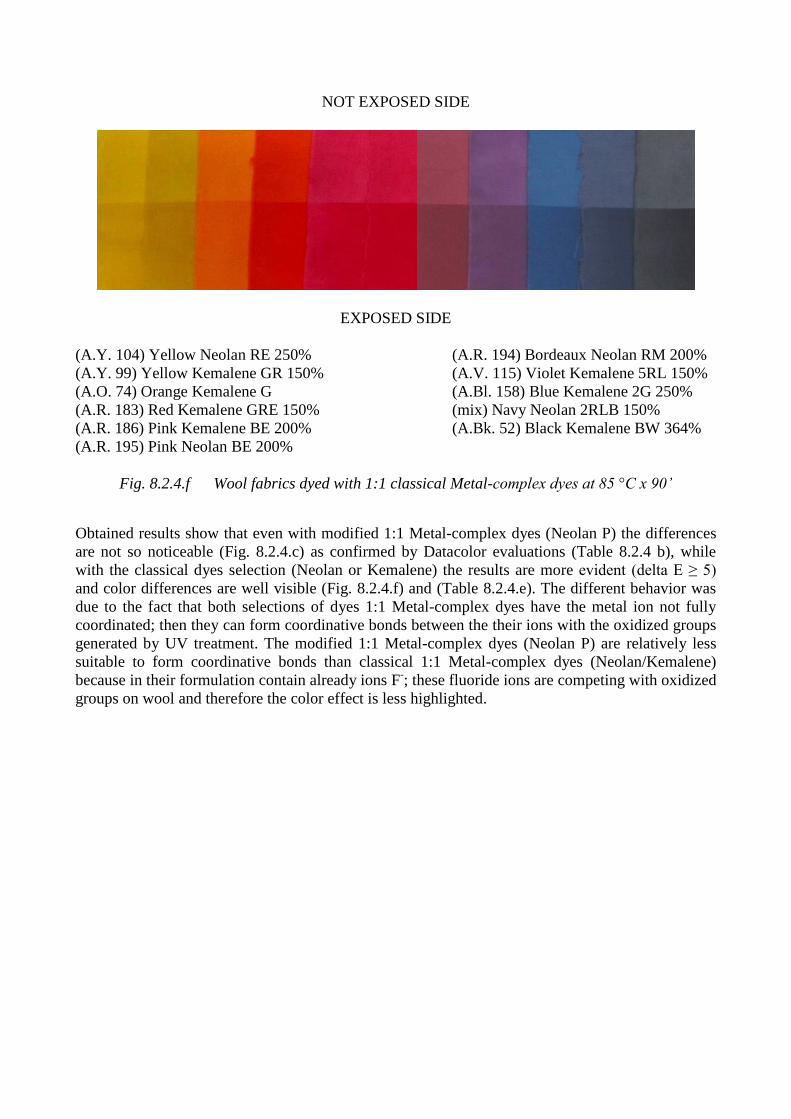
NOT EXPOSED SIDE
EXPOSED SIDE
(A.Y. 104) Yellow Neolan RE 250% (A.R. 194) Bordeaux Neolan RM 200%
(A.Y. 99) Yellow Kemalene GR 150% (A.V. 115) Violet Kemalene 5RL 150%
(A.O. 74) Orange Kemalene G (A.Bl. 158) Blue Kemalene 2G 250%
(A.R. 183) Red Kemalene GRE 150% (mix) Navy Neolan 2RLB 150%
(A.R. 186) Pink Kemalene BE 200% (A.Bk. 52) Black Kemalene BW 364%
(A.R. 195) Pink Neolan BE 200%
Fig. 8.2.4.f Wool fabrics dyed with 1:1 classical Metal-complex dyes at 85 °C x 90’
Obtained results show that even with modified 1:1 Metal-complex dyes (Neolan P) the differences
are not so noticeable (Fig. 8.2.4.c) as confirmed by Datacolor evaluations (Table 8.2.4 b), while
with the classical dyes selection (Neolan or Kemalene) the results are more evident (delta E ≥ 5)
and color differences are well visible (Fig. 8.2.4.f) and (Table 8.2.4.e). The different behavior was
due to the fact that both selections of dyes 1:1 Metal-complex dyes have the metal ion not fully
coordinated; then they can form coordinative bonds between the their ions with the oxidized groups
generated by UV treatment. The modified 1:1 Metal-complex dyes (Neolan P) are relatively less
suitable to form coordinative bonds than classical 1:1 Metal-complex dyes (Neolan/Kemalene)
because in their formulation contain already ions F-; these fluoride ions are competing with oxidized
groups on wool and therefore the color effect is less highlighted.
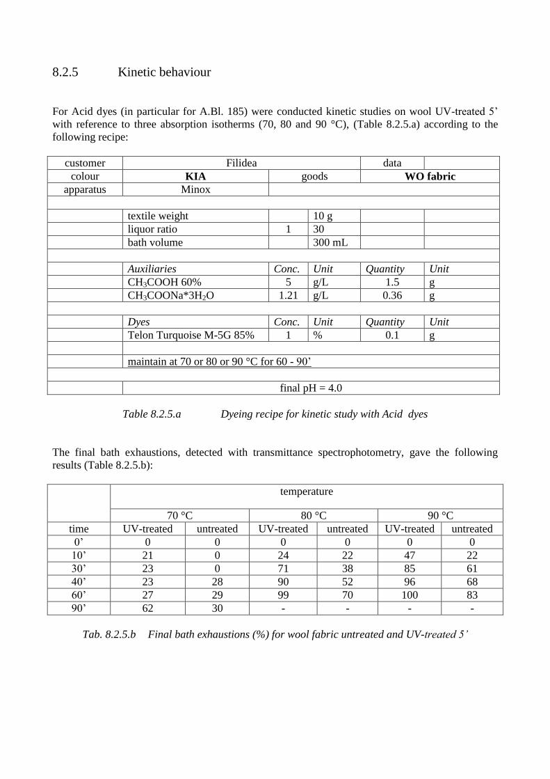
8.2.5 Kinetic behaviour
For Acid dyes (in particular for A.Bl. 185) were conducted kinetic studies on wool UV-treated 5’
with reference to three absorption isotherms (70, 80 and 90 °C), (Table 8.2.5.a) according to the
following recipe:
customer Filidea data
colour KIA goods WO fabric
apparatus Minox
textile weight 10 g
liquor ratio 1 30
bath volume 300 mL
Auxiliaries Conc. Unit Quantity Unit
CH3COOH 60% 5 g/L 1.5 g
CH3COONa*3H2O 1.21 g/L 0.36 g
Dyes Conc. Unit Quantity Unit
Telon Turquoise M-5G 85% 1 % 0.1 g
maintain at 70 or 80 or 90 °C for 60 - 90’
final pH = 4.0
Table 8.2.5.a Dyeing recipe for kinetic study with Acid dyes
The final bath exhaustions, detected with transmittance spectrophotometry, gave the following
results (Table 8.2.5.b):
temperature
70 °C 80 °C 90 °C
time UV-treated untreated UV-treated untreated UV-treated untreated
0’ 0 0 0 0 0 0
10’ 21 0 24 22 47 22
30’ 23 0 71 38 85 61
40’ 23 28 90 52 96 68
60’ 27 29 99 70 100 83
90’ 62 30 - - - -
Tab. 8.2.5.b Final bath exhaustions (%) for wool fabric untreated and UV-treated 5’
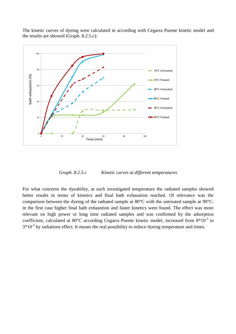
The kinetic curves of dyeing were calculated in according with Cegarra Puente kinetic model and
the results are showed (Graph. 8.2.5.c):
0
20
40
60
80
100
0 20 40 60 80 100
70°C Untreated
70°C Treated
80°C Untreated
80°C Treated
90°C Untreated
90°C Treated
Time (min)
bat
h e
xhau
stio
n (
%)
Graph. 8.2.5.c Kinetic curves at different temperatures
For what concerns the dyeability, at each investigated temperature the radiated samples showed
better results in terms of kinetics and final bath exhaustion reached. Of relevance was the
comparison between the dyeing of the radiated sample at 80°C with the untreated sample at 90°C:
in the first case higher final bath exhaustion and faster kinetics were found. The effect was more
relevant on high power or long time radiated samples and was confirmed by the adsorption
coefficient, calculated at 80°C according Cegarra Puente kinetic model, increased from 8*10-3
to
3*10-2
by radiations effect. It means the real possibility to reduce dyeing temperature and times.
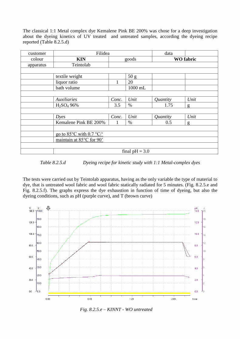
The classical 1:1 Metal complex dye Kemalene Pink BE 200% was chose for a deep investigation
about the dyeing kinetics of UV treated and untreated samples, according the dyeing recipe
reported (Table 8.2.5.d)
customer Filidea data
colour KIN goods WO fabric
apparatus Teintolab
textile weight 50 g
liquor ratio 1 20
bath volume 1000 mL
Auxiliaries Conc. Unit Quantity Unit
H2SO4 96% 3.5 % 1.75 g
Dyes Conc. Unit Quantity Unit
Kemalene Pink BE 200% 1 % 0.5 g
go to 85°C with 0.7 °C/‘
maintain at 85°C for 90’
final pH = 3.0
Table 8.2.5.d Dyeing recipe for kinetic study with 1:1 Metal-complex dyes
The tests were carried out by Teintolab apparatus, having as the only variable the type of material to
dye, that is untreated wool fabric and wool fabric statically radiated for 5 minutes. (Fig. 8.2.5.e and
Fig. 8.2.5.f). The graphs express the dye exhaustion in function of time of dyeing, but also the
dyeing conditions, such as pH (purple curve), and T (brown curve)
Fig. 8.2.5.e – KINNT - WO untreated
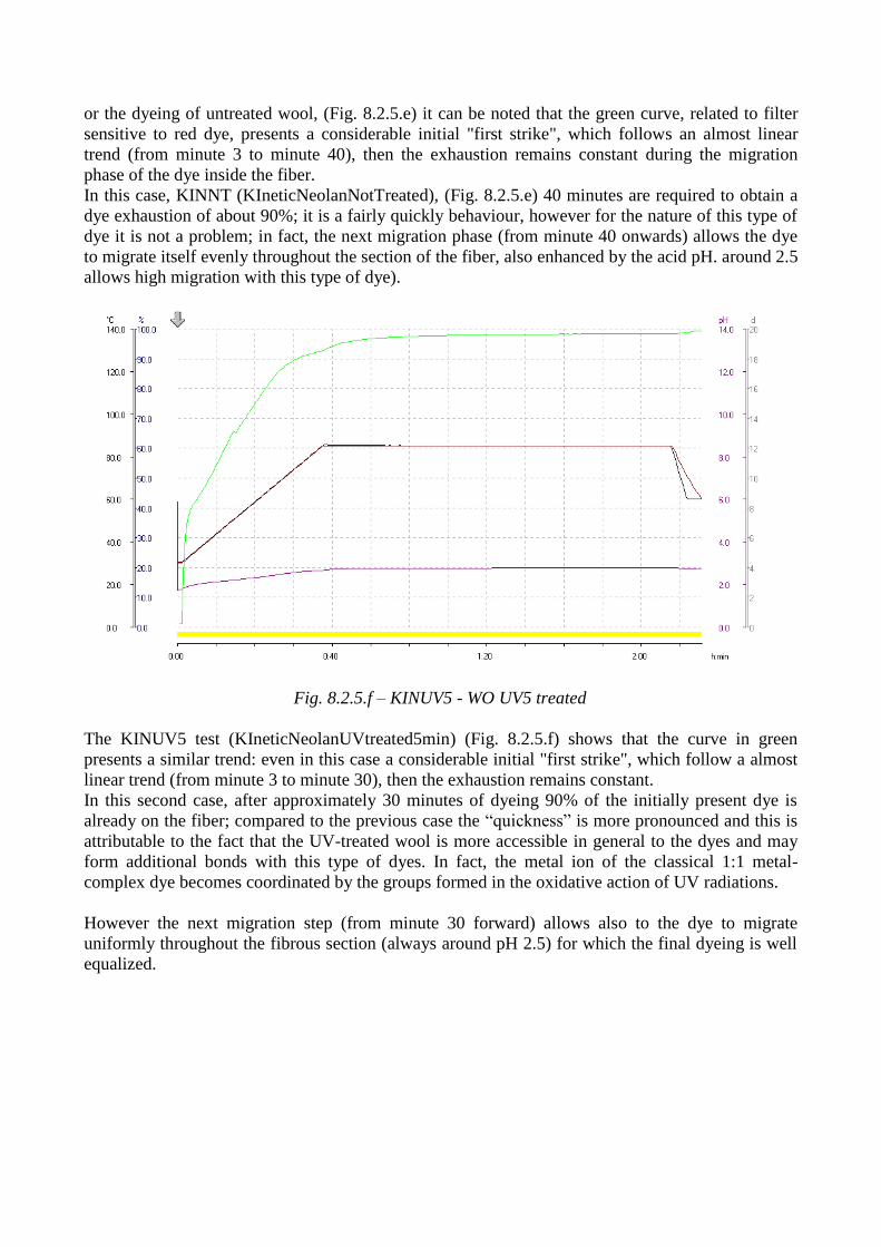
or the dyeing of untreated wool, (Fig. 8.2.5.e) it can be noted that the green curve, related to filter
sensitive to red dye, presents a considerable initial "first strike", which follows an almost linear
trend (from minute 3 to minute 40), then the exhaustion remains constant during the migration
phase of the dye inside the fiber.
In this case, KINNT (KIneticNeolanNotTreated), (Fig. 8.2.5.e) 40 minutes are required to obtain a
dye exhaustion of about 90%; it is a fairly quickly behaviour, however for the nature of this type of
dye it is not a problem; in fact, the next migration phase (from minute 40 onwards) allows the dye
to migrate itself evenly throughout the section of the fiber, also enhanced by the acid pH. around 2.5
allows high migration with this type of dye).
Fig. 8.2.5.f – KINUV5 - WO UV5 treated
The KINUV5 test (KIneticNeolanUVtreated5min) (Fig. 8.2.5.f) shows that the curve in green
presents a similar trend: even in this case a considerable initial "first strike", which follow a almost
linear trend (from minute 3 to minute 30), then the exhaustion remains constant.
In this second case, after approximately 30 minutes of dyeing 90% of the initially present dye is
already on the fiber; compared to the previous case the “quickness” is more pronounced and this is
attributable to the fact that the UV-treated wool is more accessible in general to the dyes and may
form additional bonds with this type of dyes. In fact, the metal ion of the classical 1:1 metal-
complex dye becomes coordinated by the groups formed in the oxidative action of UV radiations.
However the next migration step (from minute 30 forward) allows also to the dye to migrate
uniformly throughout the fibrous section (always around pH 2.5) for which the final dyeing is well
equalized.
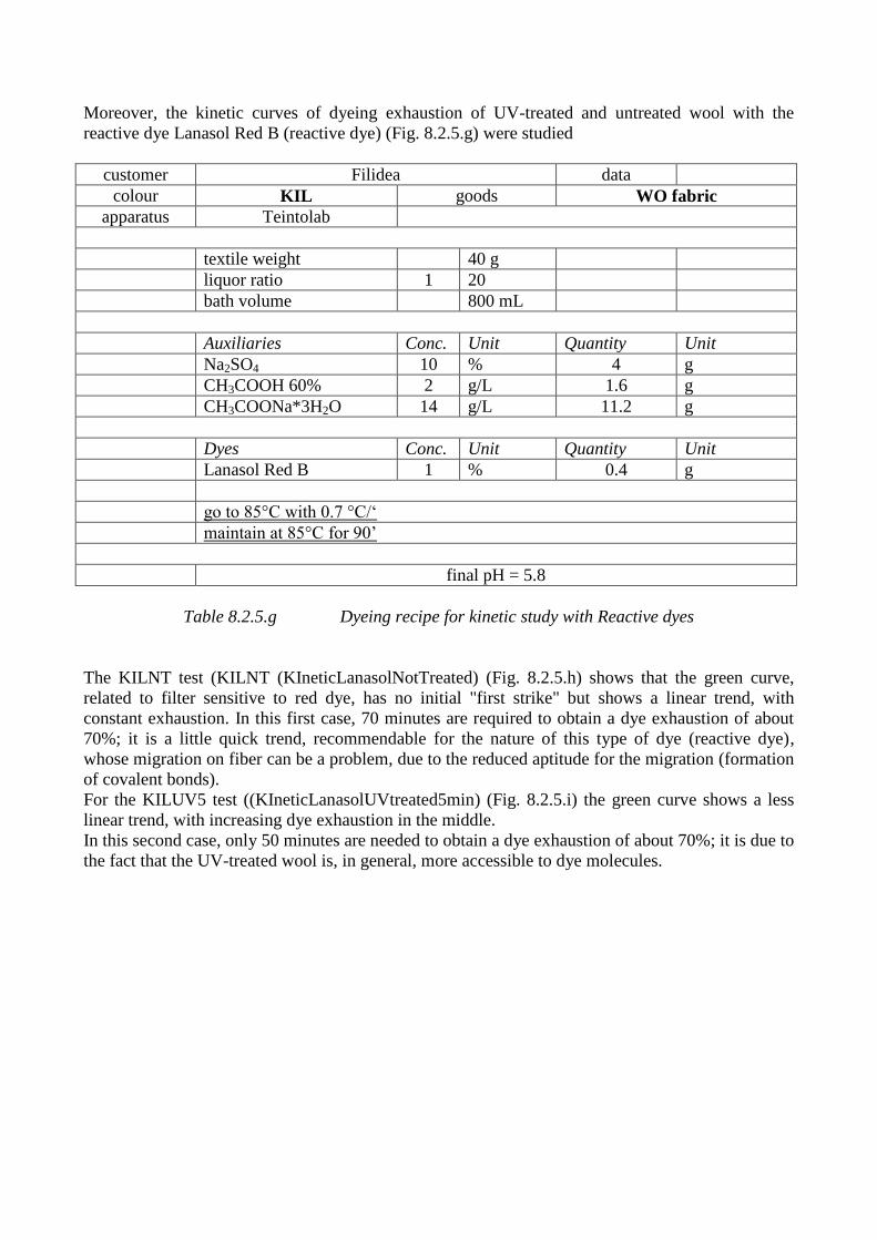
Moreover, the kinetic curves of dyeing exhaustion of UV-treated and untreated wool with the
reactive dye Lanasol Red B (reactive dye) (Fig. 8.2.5.g) were studied
customer Filidea data
colour KIL goods WO fabric
apparatus Teintolab
textile weight 40 g
liquor ratio 1 20
bath volume 800 mL
Auxiliaries Conc. Unit Quantity Unit
Na2SO4 10 % 4 g
CH3COOH 60% 2 g/L 1.6 g
CH3COONa*3H2O 14 g/L 11.2 g
Dyes Conc. Unit Quantity Unit
Lanasol Red B 1 % 0.4 g
go to 85°C with 0.7 °C/‘
maintain at 85°C for 90’
final pH = 5.8
Table 8.2.5.g Dyeing recipe for kinetic study with Reactive dyes
The KILNT test (KILNT (KIneticLanasolNotTreated) (Fig. 8.2.5.h) shows that the green curve,
related to filter sensitive to red dye, has no initial "first strike" but shows a linear trend, with
constant exhaustion. In this first case, 70 minutes are required to obtain a dye exhaustion of about
70%; it is a little quick trend, recommendable for the nature of this type of dye (reactive dye),
whose migration on fiber can be a problem, due to the reduced aptitude for the migration (formation
of covalent bonds).
For the KILUV5 test ((KIneticLanasolUVtreated5min) (Fig. 8.2.5.i) the green curve shows a less
linear trend, with increasing dye exhaustion in the middle.
In this second case, only 50 minutes are needed to obtain a dye exhaustion of about 70%; it is due to
the fact that the UV-treated wool is, in general, more accessible to dye molecules.
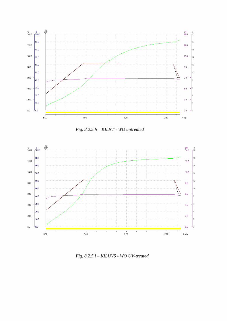
Fig. 8.2.5.h – KILNT - WO untreated
Fig. 8.2.5.i – KILUV5 - WO UV-treated
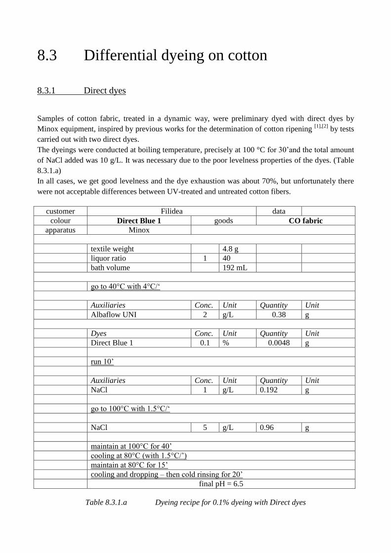
8.3 Differential dyeing on cotton
8.3.1 Direct dyes
Samples of cotton fabric, treated in a dynamic way, were preliminary dyed with direct dyes by
Minox equipment, inspired by previous works for the determination of cotton ripening [1],[2]
by tests
carried out with two direct dyes.
The dyeings were conducted at boiling temperature, precisely at 100 °C for 30’and the total amount
of NaCl added was 10 g/L. It was necessary due to the poor levelness properties of the dyes. (Table
8.3.1.a)
In all cases, we get good levelness and the dye exhaustion was about 70%, but unfortunately there
were not acceptable differences between UV-treated and untreated cotton fibers.
customer Filidea data
colour Direct Blue 1 goods CO fabric
apparatus Minox
textile weight 4.8 g
liquor ratio 1 40
bath volume 192 mL
go to 40°C with 4°C/‘
Auxiliaries Conc. Unit Quantity Unit
Albaflow UNI 2 g/L 0.38 g
Dyes Conc. Unit Quantity Unit
Direct Blue 1 0.1 % 0.0048 g
run 10’
Auxiliaries Conc. Unit Quantity Unit
NaCl 1 g/L 0.192 g
go to 100°C with 1.5°C/‘
NaCl 5 g/L 0.96 g
maintain at 100°C for 40’
cooling at 80°C (with 1.5°C/’)
maintain at 80°C for 15’
cooling and dropping – then cold rinsing for 20’
final pH = 6.5
Table 8.3.1.a Dyeing recipe for 0.1% dyeing with Direct dyes
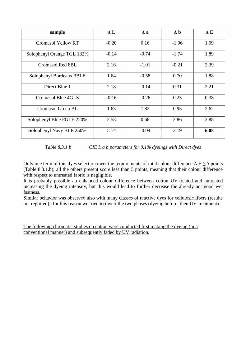
sample Δ L Δ a Δ b Δ E
Cromasol Yellow RT -0.20 0.16 -1.06 1.09
Solophenyl Orange TGL 182% -0.14 -0.74 -1.74 1.89
Cromasol Red 8BL 2.16 -1.01 -0.21 2.39
Solophenyl Bordeaux 3BLE 1.64 -0.58 0.70 1.88
Direct Blue 1 2.18 -0.14 0.31 2.21
Cromasol Blue 4GLS -0.16 -0.26 0.23 0.38
Cromasol Green BL 1.63 1.82 0.95 2.62
Solophenyl Blue FGLE 220% 2.53 0.68 2.86 3.88
Solophenyl Navy BLE 250% 5.14 -0.04 3.19 6.05
Table 8.3.1.b CIE L a b parameters for 0.1% dyeings with Direct dyes
Only one term of this dyes selection meet the requirements of total colour difference Δ E ≥ 5 points
(Table 8.3.1.b); all the others present score less than 5 points, meaning that their colour difference
with respect to untreated fabric is negligible.
It is probably possible an enhanced colour difference between cotton UV-treated and untreated
increasing the dyeing intensity, but this would lead to further decrease the already not good wet
fastness.
Similar behavior was observed also with many classes of reactive dyes for cellulosic fibers (results
not reported); for this reason we tried to invert the two phases (dyeing before, then UV-treatment).
The following chromatic studies on cotton were conducted first making the dyeing (in a
conventional manner) and subsequently faded by UV radiation.
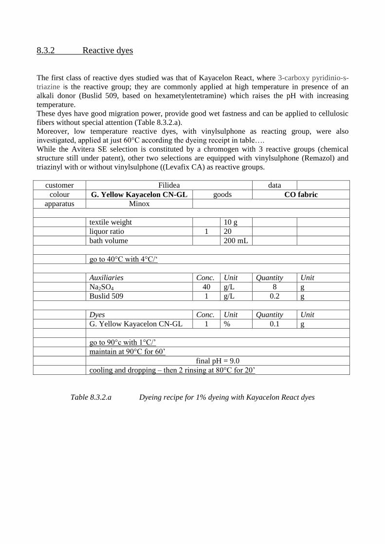
8.3.2 Reactive dyes
The first class of reactive dyes studied was that of Kayacelon React, where 3-carboxy pyridinio-s-
triazine is the reactive group; they are commonly applied at high temperature in presence of an
alkali donor (Buslid 509, based on hexametylentetramine) which raises the pH with increasing
temperature.
These dyes have good migration power, provide good wet fastness and can be applied to cellulosic
fibers without special attention (Table 8.3.2.a).
Moreover, low temperature reactive dyes, with vinylsulphone as reacting group, were also
investigated, applied at just 60°C according the dyeing receipt in table….
While the Avitera SE selection is constituted by a chromogen with 3 reactive groups (chemical
structure still under patent), other two selections are equipped with vinylsulphone (Remazol) and
triazinyl with or without vinylsulphone ((Levafix CA) as reactive groups.
customer Filidea data
colour G. Yellow Kayacelon CN-GL goods CO fabric
apparatus Minox
textile weight 10 g
liquor ratio 1 20
bath volume 200 mL
go to 40°C with 4°C/‘
Auxiliaries Conc. Unit Quantity Unit
Na2SO4 40 g/L 8 g
Buslid 509 1 g/L 0.2 g
Dyes Conc. Unit Quantity Unit
G. Yellow Kayacelon CN-GL 1 % 0.1 g
go to 90°c with 1°C/’
maintain at 90°C for 60’
final pH = 9.0
cooling and dropping – then 2 rinsing at 80°C for 20’
Table 8.3.2.a Dyeing recipe for 1% dyeing with Kayacelon React dyes
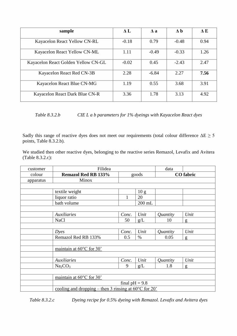
sample Δ L Δ a Δ b Δ E
Kayacelon React Yellow CN-RL -0.18 0.79 -0.48 0.94
Kayacelon React Yellow CN-ML 1.11 -0.49 -0.33 1.26
Kayacelon React Golden Yellow CN-GL -0.02 0.45 -2.43 2.47
Kayacelon React Red CN-3B 2.28 -6.84 2.27 7.56
Kayacelon React Blue CN-MG 1.19 0.55 3.68 3.91
Kayacelon React Dark Blue CN-R 3.36 1.78 3.13 4.92
Table 8.3.2.b CIE L a b parameters for 1% dyeings with Kayacelon React dyes
Sadly this range of reactive dyes does not meet our requirements (total colour difference ΔE ≥ 5
points, Table 8.3.2.b).
We studied then other reactive dyes, belonging to the reactive series Remazol, Levafix and Avitera
(Table 8.3.2.c):
customer Filidea data
colour Remazol Red RB 133% goods CO fabric
apparatus Minox
textile weight 10 g
liquor ratio 1 20
bath volume 200 mL
Auxiliaries Conc. Unit Quantity Unit
NaCl 50 g/L 10 g
Dyes Conc. Unit Quantity Unit
Remazol Red RB 133% 0.5 % 0.05 g
maintain at 60°C for 30’
Auxiliaries Conc. Unit Quantity Unit
Na2CO3 9 g/L 1.8 g
maintain at 60°C for 30’
final pH = 9.8
cooling and dropping – then 3 rinsing at 60°C for 20’
Table 8.3.2.c Dyeing recipe for 0.5% dyeing with Remazol. Levafix and Avitera dyes
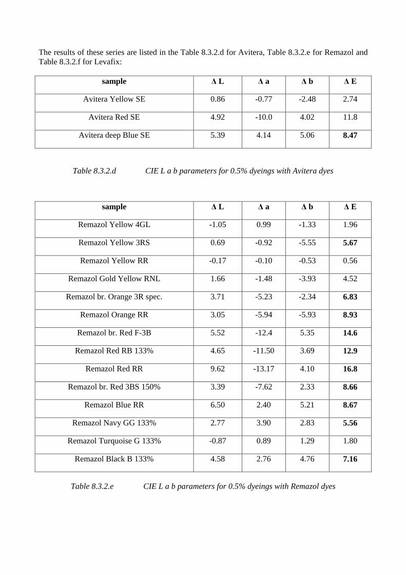
The results of these series are listed in the Table 8.3.2.d for Avitera, Table 8.3.2.e for Remazol and
Table 8.3.2.f for Levafix:
sample Δ L Δ a Δ b Δ E
Avitera Yellow SE 0.86 -0.77 -2.48 2.74
Avitera Red SE 4.92 -10.0 4.02 11.8
Avitera deep Blue SE 5.39 4.14 5.06 8.47
Table 8.3.2.d CIE L a b parameters for 0.5% dyeings with Avitera dyes
sample Δ L Δ a Δ b Δ E
Remazol Yellow 4GL -1.05 0.99 -1.33 1.96
Remazol Yellow 3RS 0.69 -0.92 -5.55 5.67
Remazol Yellow RR -0.17 -0.10 -0.53 0.56
Remazol Gold Yellow RNL 1.66 -1.48 -3.93 4.52
Remazol br. Orange 3R spec. 3.71 -5.23 -2.34 6.83
Remazol Orange RR 3.05 -5.94 -5.93 8.93
Remazol br. Red F-3B 5.52 -12.4 5.35 14.6
Remazol Red RB 133% 4.65 -11.50 3.69 12.9
Remazol Red RR 9.62 -13.17 4.10 16.8
Remazol br. Red 3BS 150% 3.39 -7.62 2.33 8.66
Remazol Blue RR 6.50 2.40 5.21 8.67
Remazol Navy GG 133% 2.77 3.90 2.83 5.56
Remazol Turquoise G 133% -0.87 0.89 1.29 1.80
Remazol Black B 133% 4.58 2.76 4.76 7.16
Table 8.3.2.e CIE L a b parameters for 0.5% dyeings with Remazol dyes
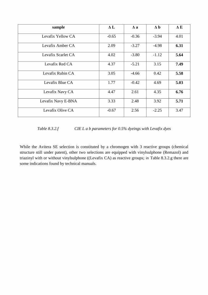
sample Δ L Δ a Δ b Δ E
Levafix Yellow CA -0.65 -0.36 -3.94 4.01
Levafix Amber CA 2.09 -3.27 -4.98 6.31
Levafix Scarlet CA 4.02 -3.80 -1.12 5.64
Levafix Red CA 4.37 -5.21 3.15 7.49
Levafix Rubin CA 3.05 -4.66 0.42 5.58
Levafix Blue CA 1.77 -0.42 4.69 5.03
Levafix Navy CA 4.47 2.61 4.35 6.76
Levafix Navy E-BNA 3.33 2.48 3.92 5.71
Levafix Olive CA -0.67 2.56 -2.25 3.47
Table 8.3.2.f CIE L a b parameters for 0.5% dyeings with Levafix dyes
While the Avitera SE selection is constituted by a chromogen with 3 reactive groups (chemical
structure still under patent), other two selections are equipped with vinylsulphone (Remazol) and
triazinyl with or without vinylsulphone ((Levafix CA) as reactive groups; in Table 8.3.2.g there are
some indications found by technical manuals.
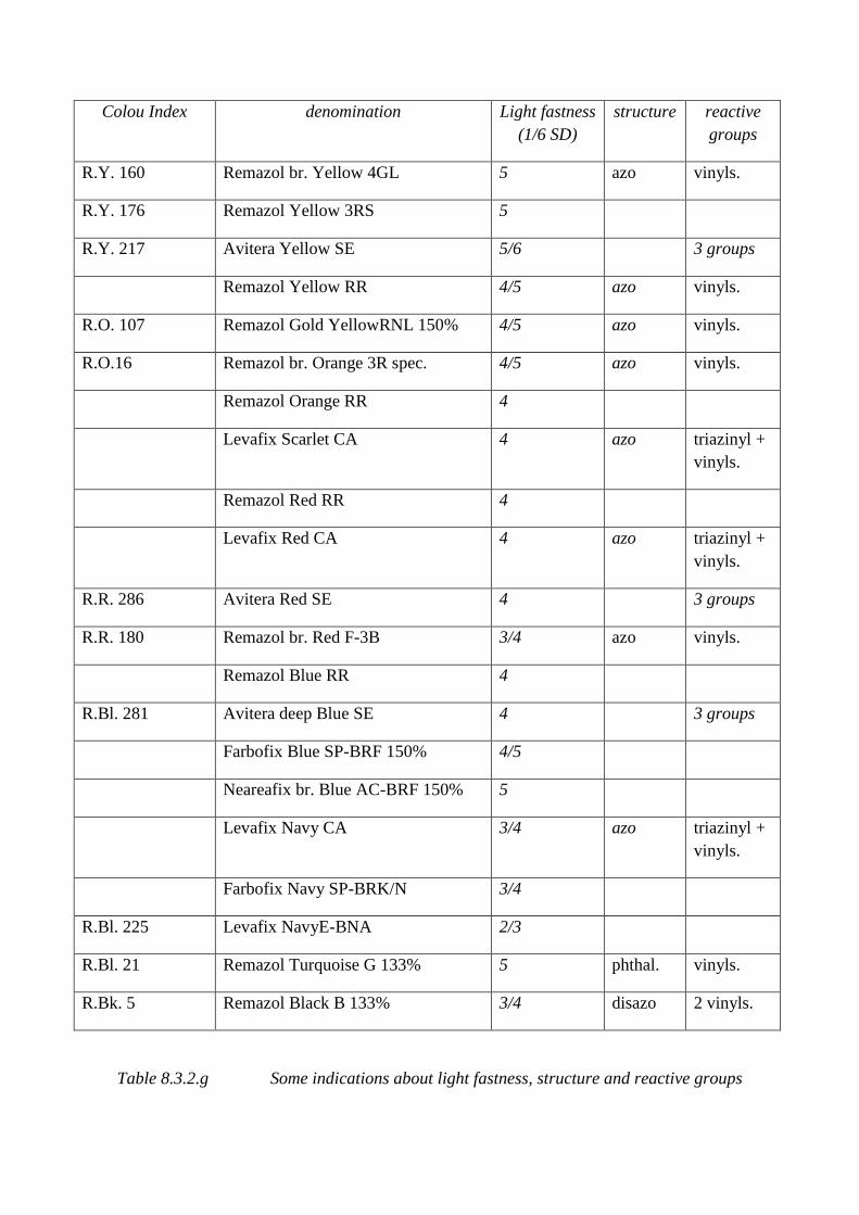
Colou Index denomination Light fastness
(1/6 SD)
structure reactive
groups
R.Y. 160 Remazol br. Yellow 4GL 5 azo vinyls.
R.Y. 176 Remazol Yellow 3RS 5
R.Y. 217 Avitera Yellow SE 5/6 3 groups
Remazol Yellow RR 4/5 azo vinyls.
R.O. 107 Remazol Gold YellowRNL 150% 4/5 azo vinyls.
R.O.16 Remazol br. Orange 3R spec. 4/5 azo vinyls.
Remazol Orange RR 4
Levafix Scarlet CA 4 azo triazinyl +
vinyls.
Remazol Red RR 4
Levafix Red CA 4 azo triazinyl +
vinyls.
R.R. 286 Avitera Red SE 4 3 groups
R.R. 180 Remazol br. Red F-3B 3/4 azo vinyls.
Remazol Blue RR 4
R.Bl. 281 Avitera deep Blue SE 4 3 groups
Farbofix Blue SP-BRF 150% 4/5
Neareafix br. Blue AC-BRF 150% 5
Levafix Navy CA 3/4 azo triazinyl +
vinyls.
Farbofix Navy SP-BRK/N 3/4
R.Bl. 225 Levafix NavyE-BNA 2/3
R.Bl. 21 Remazol Turquoise G 133% 5 phthal. vinyls.
R.Bk. 5 Remazol Black B 133% 3/4 disazo 2 vinyls.
Table 8.3.2.g Some indications about light fastness, structure and reactive groups
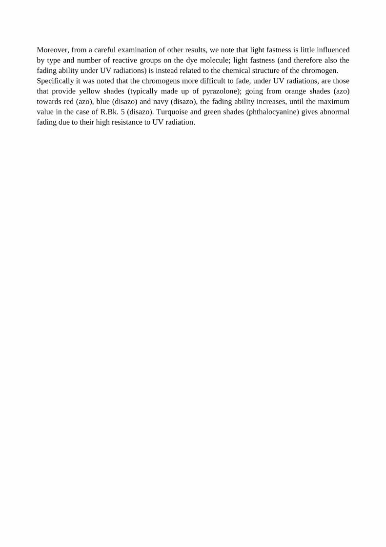
Moreover, from a careful examination of other results, we note that light fastness is little influenced
by type and number of reactive groups on the dye molecule; light fastness (and therefore also the
fading ability under UV radiations) is instead related to the chemical structure of the chromogen.
Specifically it was noted that the chromogens more difficult to fade, under UV radiations, are those
that provide yellow shades (typically made up of pyrazolone); going from orange shades (azo)
towards red (azo), blue (disazo) and navy (disazo), the fading ability increases, until the maximum
value in the case of R.Bk. 5 (disazo). Turquoise and green shades (phthalocyanine) gives abnormal
fading due to their high resistance to UV radiation.
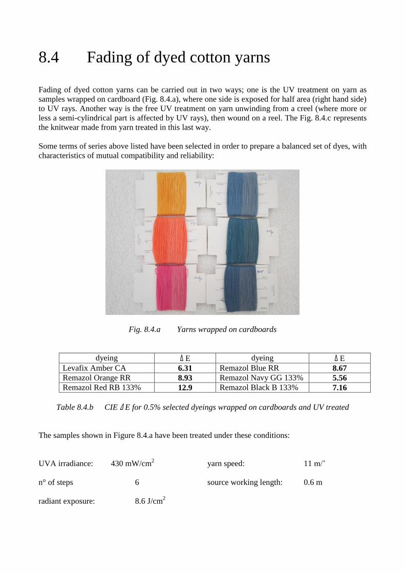
8.4 Fading of dyed cotton yarns
Fading of dyed cotton yarns can be carried out in two ways; one is the UV treatment on yarn as
samples wrapped on cardboard (Fig. 8.4.a), where one side is exposed for half area (right hand side)
to UV rays. Another way is the free UV treatment on yarn unwinding from a creel (where more or
less a semi-cylindrical part is affected by UV rays), then wound on a reel. The Fig. 8.4.c represents
the knitwear made from yarn treated in this last way.
Some terms of series above listed have been selected in order to prepare a balanced set of dyes, with
characteristics of mutual compatibility and reliability:
Fig. 8.4.a Yarns wrapped on cardboards
dyeing Δ E dyeing Δ E
Levafix Amber CA 6.31 Remazol Blue RR 8.67
Remazol Orange RR 8.93 Remazol Navy GG 133% 5.56
Remazol Red RB 133% 12.9 Remazol Black B 133% 7.16
Table 8.4.b CIE Δ E for 0.5% selected dyeings wrapped on cardboards and UV treated
The samples shown in Figure 8.4.a have been treated under these conditions:
UVA irradiance: 430 mW/cm2 yarn speed: 11 m/’
n° of steps 6 source working length: 0.6 m
radiant exposure: 8.6 J/cm2
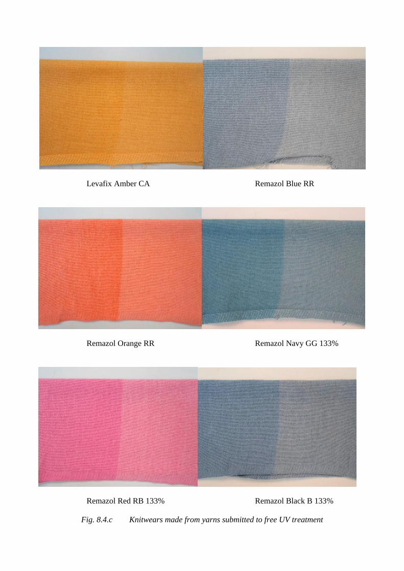
Levafix Amber CA Remazol Blue RR
Remazol Orange RR Remazol Navy GG 133%
Remazol Red RB 133% Remazol Black B 133%
Fig. 8.4.c Knitwears made from yarns submitted to free UV treatment
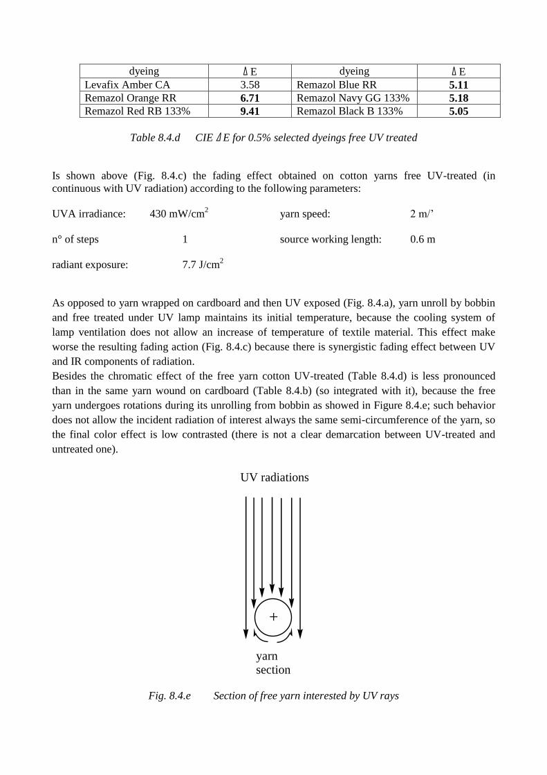
dyeing Δ E dyeing Δ E
Levafix Amber CA 3.58 Remazol Blue RR 5.11
Remazol Orange RR 6.71 Remazol Navy GG 133% 5.18
Remazol Red RB 133% 9.41 Remazol Black B 133% 5.05
Table 8.4.d CIE Δ E for 0.5% selected dyeings free UV treated
Is shown above (Fig. 8.4.c) the fading effect obtained on cotton yarns free UV-treated (in
continuous with UV radiation) according to the following parameters:
UVA irradiance: 430 mW/cm2 yarn speed: 2 m/’
n° of steps 1 source working length: 0.6 m
radiant exposure: 7.7 J/cm2
As opposed to yarn wrapped on cardboard and then UV exposed (Fig. 8.4.a), yarn unroll by bobbin
and free treated under UV lamp maintains its initial temperature, because the cooling system of
lamp ventilation does not allow an increase of temperature of textile material. This effect make
worse the resulting fading action (Fig. 8.4.c) because there is synergistic fading effect between UV
and IR components of radiation.
Besides the chromatic effect of the free yarn cotton UV-treated (Table 8.4.d) is less pronounced
than in the same yarn wound on cardboard (Table 8.4.b) (so integrated with it), because the free
yarn undergoes rotations during its unrolling from bobbin as showed in Figure 8.4.e; such behavior
does not allow the incident radiation of interest always the same semi-circumference of the yarn, so
the final color effect is low contrasted (there is not a clear demarcation between UV-treated and
untreated one).
UV radiations
yarnsection
+
Fig. 8.4.e Section of free yarn interested by UV rays
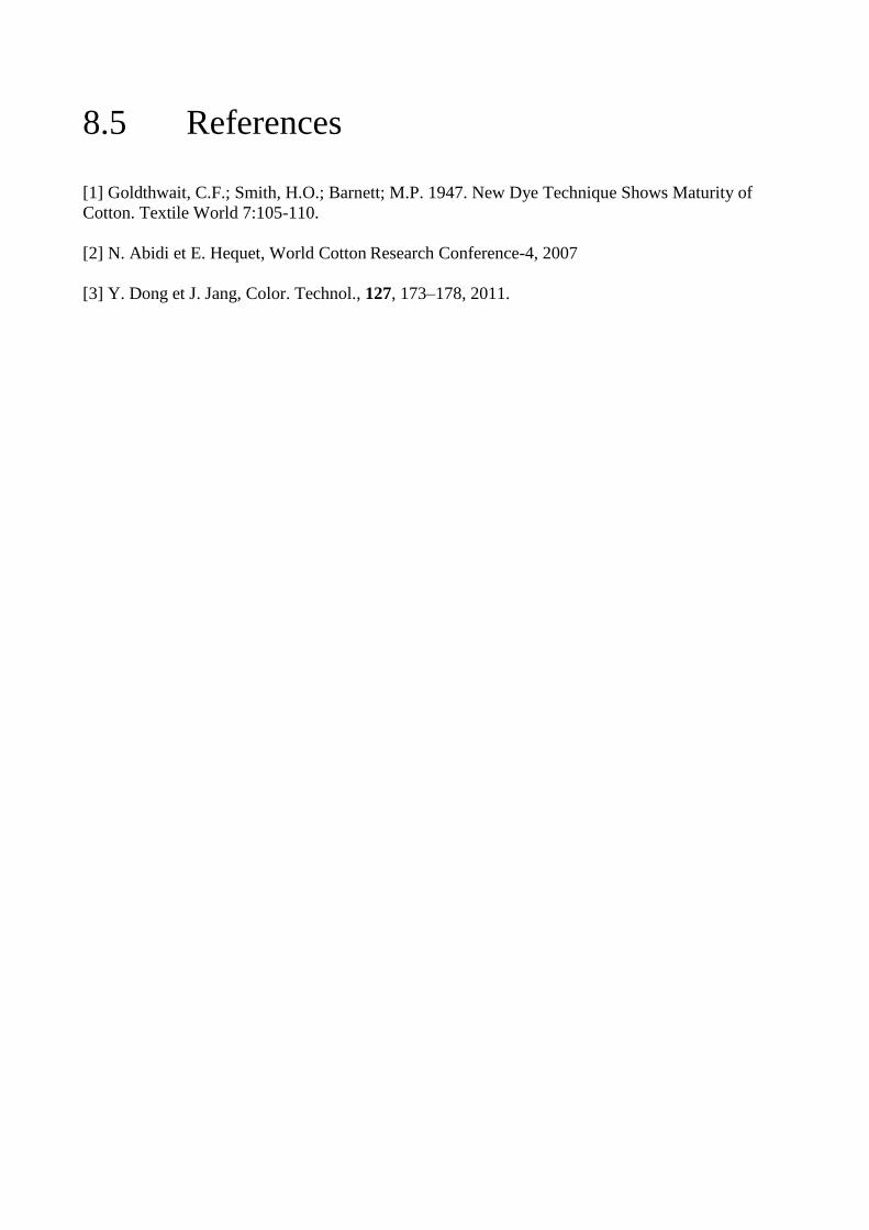
8.5 References
[1] Goldthwait, C.F.; Smith, H.O.; Barnett; M.P. 1947. New Dye Technique Shows Maturity of
Cotton. Textile World 7:105-110.
[2] N. Abidi et E. Hequet, World Cotton Research Conference-4, 2007
[3] Y. Dong et J. Jang, Color. Technol., 127, 173–178, 2011.

Chapter 9 Industrial scale up of the treatments

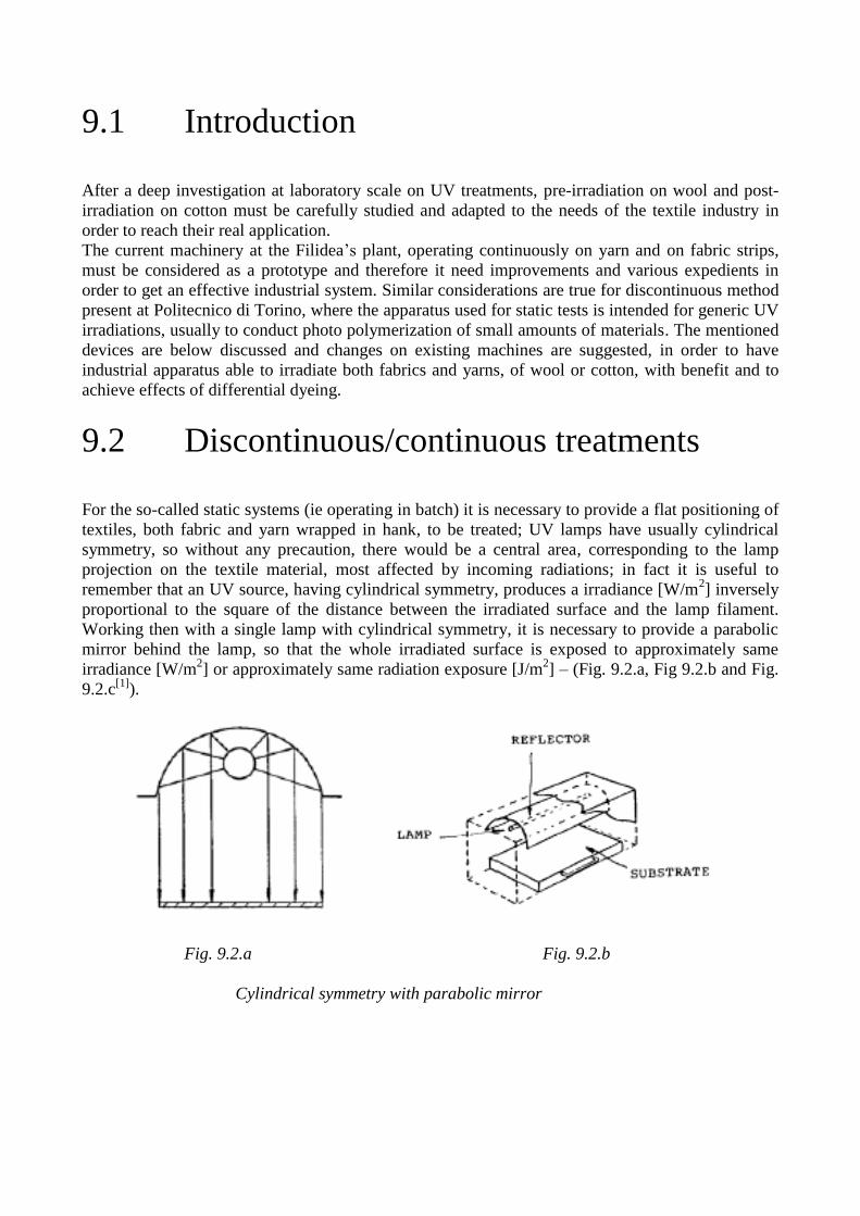
9.1 Introduction
After a deep investigation at laboratory scale on UV treatments, pre-irradiation on wool and post-
irradiation on cotton must be carefully studied and adapted to the needs of the textile industry in
order to reach their real application.
The current machinery at the Filidea’s plant, operating continuously on yarn and on fabric strips,
must be considered as a prototype and therefore it need improvements and various expedients in
order to get an effective industrial system. Similar considerations are true for discontinuous method
present at Politecnico di Torino, where the apparatus used for static tests is intended for generic UV
irradiations, usually to conduct photo polymerization of small amounts of materials. The mentioned
devices are below discussed and changes on existing machines are suggested, in order to have
industrial apparatus able to irradiate both fabrics and yarns, of wool or cotton, with benefit and to
achieve effects of differential dyeing.
9.2 Discontinuous/continuous treatments
For the so-called static systems (ie operating in batch) it is necessary to provide a flat positioning of
textiles, both fabric and yarn wrapped in hank, to be treated; UV lamps have usually cylindrical
symmetry, so without any precaution, there would be a central area, corresponding to the lamp
projection on the textile material, most affected by incoming radiations; in fact it is useful to
remember that an UV source, having cylindrical symmetry, produces a irradiance [W/m2] inversely
proportional to the square of the distance between the irradiated surface and the lamp filament.
Working then with a single lamp with cylindrical symmetry, it is necessary to provide a parabolic
mirror behind the lamp, so that the whole irradiated surface is exposed to approximately same
irradiance [W/m2] or approximately same radiation exposure [J/m
2] – (Fig. 9.2.a, Fig 9.2.b and Fig.
9.2.c[1]
).
Fig. 9.2.a Fig. 9.2.b
Cylindrical symmetry with parabolic mirror
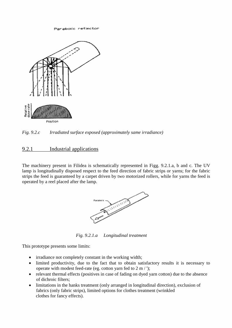
Fig. 9.2.c Irradiated surface exposed (approximately same irradiance)
9.2.1 Industrial applications
The machinery present in Filidea is schematically represented in Figg. 9.2.1.a, b and c. The UV
lamp is longitudinally disposed respect to the feed direction of fabric strips or yarns; for the fabric
strips the feed is guaranteed by a carpet driven by two motorized rollers, while for yarns the feed is
operated by a reel placed after the lamp.
Fig. 9.2.1.a Longitudinal treatment
This prototype presents some limits:
irradiance not completely constant in the working width;
limited productivity, due to the fact that to obtain satisfactory results it is necessary to
operate with modest feed-rate (eg. cotton yarn fed to 2 m / ');
relevant thermal effects (positives in case of fading on dyed yarn cotton) due to the absence
of dichroic filters;
limitations in the hanks treatment (only arranged in longitudinal direction), exclusion of
fabrics (only fabric strips), limited options for clothes treatment (wrinkled
clothes for fancy effects).
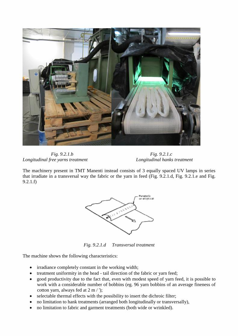
Fig. 9.2.1.b Fig. 9.2.1.c
Longitudinal free yarns treatment Longitudinal hanks treatment
The machinery present in TMT Manenti instead consists of 3 equally spaced UV lamps in series
that irradiate in a transversal way the fabric or the yarn in feed (Fig. 9.2.1.d, Fig. 9.2.1.e and Fig.
9.2.1.f)
Fig. 9.2.1.d Transversal treatment
The machine shows the following characteristics:
irradiance completely constant in the working width;
treatment uniformity in the head - tail direction of the fabric or yarn feed;
good productivity due to the fact that, even with modest speed of yarn feed, it is possible to
work with a considerable number of bobbins (eg. 96 yarn bobbins of an average fineness of
cotton yarn, always fed at 2 m / ');
selectable thermal effects with the possibility to insert the dichroic filter;
no limitation to hank treatments (arranged both longitudinally or transversally),
no limitation to fabric and garment treatments (both wide or wrinkled).
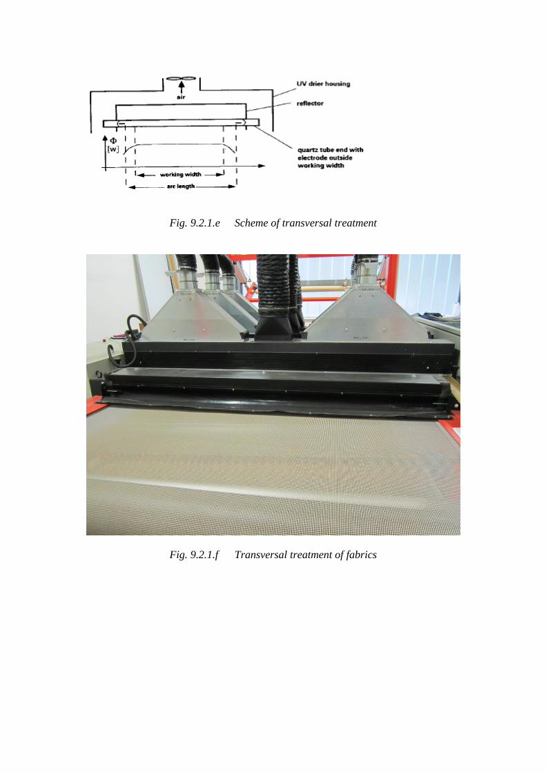
Fig. 9.2.1.e Scheme of transversal treatment
Fig. 9.2.1.f Transversal treatment of fabrics
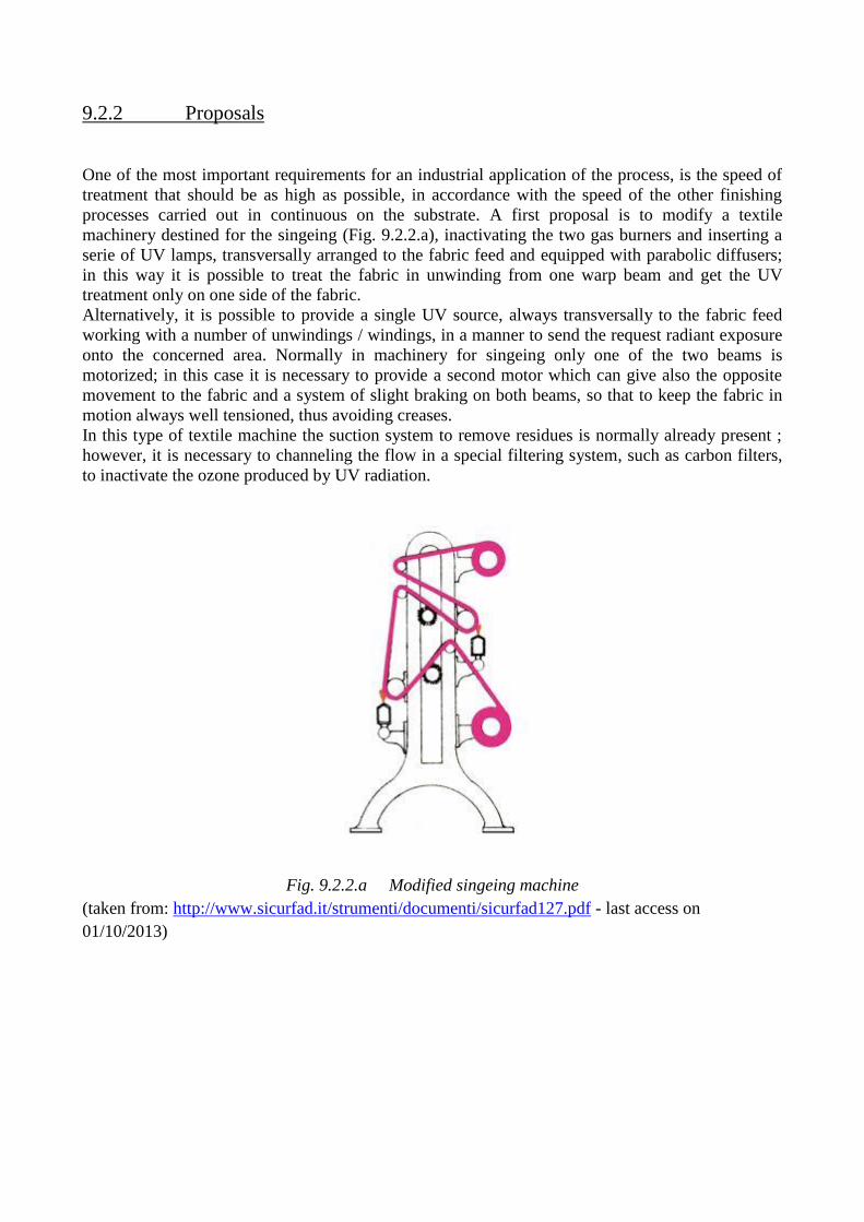
9.2.2 Proposals
One of the most important requirements for an industrial application of the process, is the speed of
treatment that should be as high as possible, in accordance with the speed of the other finishing
processes carried out in continuous on the substrate. A first proposal is to modify a textile
machinery destined for the singeing (Fig. 9.2.2.a), inactivating the two gas burners and inserting a
serie of UV lamps, transversally arranged to the fabric feed and equipped with parabolic diffusers;
in this way it is possible to treat the fabric in unwinding from one warp beam and get the UV
treatment only on one side of the fabric.
Alternatively, it is possible to provide a single UV source, always transversally to the fabric feed
working with a number of unwindings / windings, in a manner to send the request radiant exposure
onto the concerned area. Normally in machinery for singeing only one of the two beams is
motorized; in this case it is necessary to provide a second motor which can give also the opposite
movement to the fabric and a system of slight braking on both beams, so that to keep the fabric in
motion always well tensioned, thus avoiding creases.
In this type of textile machine the suction system to remove residues is normally already present ;
however, it is necessary to channeling the flow in a special filtering system, such as carbon filters,
to inactivate the ozone produced by UV radiation.
Fig. 9.2.2.a Modified singeing machine
(taken from: http://www.sicurfad.it/strumenti/documenti/sicurfad127.pdf - last access on
01/10/2013)
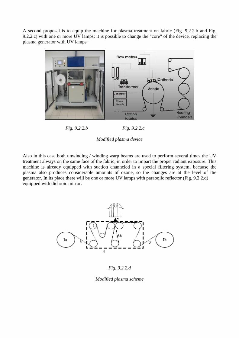
A second proposal is to equip the machine for plasma treatment on fabric (Fig. 9.2.2.b and Fig.
9.2.2.c) with one or more UV lamps; it is possible to change the "core" of the device, replacing the
plasma generator with UV lamps.
Fig. 9.2.2.b Fig. 9.2.2.c
Modified plasma device
Also in this case both unwinding / winding warp beams are used to perform several times the UV
treatment always on the same face of the fabric, in order to impart the proper radiant exposure. This
machine is already equipped with suction channeled in a special filtering system, because the
plasma also produces considerable amounts of ozone, so the changes are at the level of the
generator. In its place there will be one or more UV lamps with parabolic reflector (Fig. 9.2.2.d)
equipped with dichroic mirror:
Fig. 9.2.2.d
Modified plasma scheme
9.3 References
[1] G. Gozzelino, Lecture notes “Polimeri e radiazioni”, academic year 2012/’13.
Chapter 10 Study of a technique that permits to achieve a
sun-bleached look on fabrics

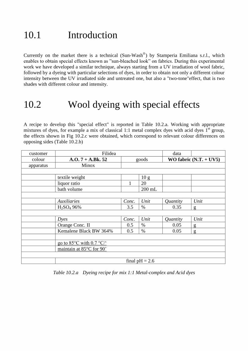
10.1 Introduction
Currently on the market there is a technical (Sun-Wash
) by Stamperia Emiliana s.r.l., which
enables to obtain special effects known as ”sun-bleached look” on fabrics. During this experimental
work we have developed a similar technique, always starting from a UV irradiation of wool fabric,
followed by a dyeing with particular selections of dyes, in order to obtain not only a different colour
intensity between the UV irradiated side and untreated one, but also a "two-tone"effect, that is two
shades with different colour and intensity.
10.2 Wool dyeing with special effects
A recipe to develop this "special effect" is reported in Table 10.2.a. Working with appropriate
mixtures of dyes, for example a mix of classical 1:1 metal complex dyes with acid dyes 1st group,
the effects shown in Fig 10.2.c were obtained, which correspond to relevant colour differences on
opposing sides (Table 10.2.b)
customer Filidea data
colour A.O. 7 + A.Bk. 52 goods WO fabric (N.T. + UV5)
apparatus Minox
textile weight 10 g
liquor ratio 1 20
bath volume 200 mL
Auxiliaries Conc. Unit Quantity Unit
H2SO4 96% 3.5 % 0.35 g
Dyes Conc. Unit Quantity Unit
Orange Conc. II 0.5 % 0.05 g
Kemalene Black BW 364% 0.5 % 0.05 g
go to 85°C with 0.7 °C/‘
maintain at 85°C for 90’
final pH = 2.6
Table 10.2.a Dyeing recipe for mix 1:1 Metal-complex and Acid dyes
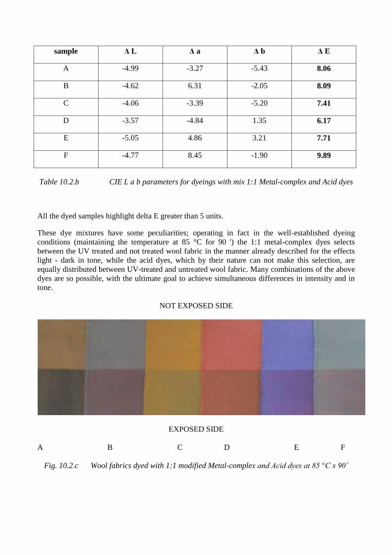
sample Δ L Δ a Δ b Δ E
A -4.99 -3.27 -5.43 8.06
B -4.62 6.31 -2.05 8.09
C -4.06 -3.39 -5.20 7.41
D -3.57 -4.84 1.35 6.17
E -5.05 4.86 3.21 7.71
F -4.77 8.45 -1.90 9.89
Table 10.2.b CIE L a b parameters for dyeings with mix 1:1 Metal-complex and Acid dyes
All the dyed samples highlight delta E greater than 5 units.
These dye mixtures have some peculiarities; operating in fact in the well-established dyeing
conditions (maintaining the temperature at 85 °C for 90 ') the 1:1 metal-complex dyes selects
between the UV treated and not treated wool fabric in the manner already described for the effects
light - dark in tone, while the acid dyes, which by their nature can not make this selection, are
equally distributed between UV-treated and untreated wool fabric. Many combinations of the above
dyes are so possible, with the ultimate goal to achieve simultaneous differences in intensity and in
tone.
NOT EXPOSED SIDE
EXPOSED SIDE
A B C D E F
Fig. 10.2.c Wool fabrics dyed with 1:1 modified Metal-complex and Acid dyes at 85 °C x 90’
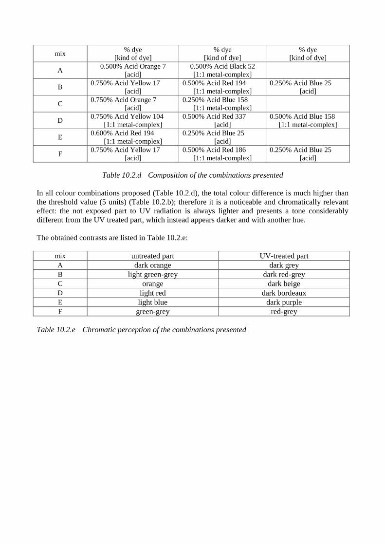
mix % dye
[kind of dye]
% dye
[kind of dye]
% dye
[kind of dye]
A 0.500% Acid Orange 7
[acid]
0.500% Acid Black 52
[1:1 metal-complex]
B 0.750% Acid Yellow 17
[acid]
0.500% Acid Red 194
[1:1 metal-complex]
0.250% Acid Blue 25
[acid]
C 0.750% Acid Orange 7
[acid]
0.250% Acid Blue 158
[1:1 metal-complex]
D 0.750% Acid Yellow 104
[1:1 metal-complex]
0.500% Acid Red 337
[acid]
0.500% Acid Blue 158
[1:1 metal-complex]
E 0.600% Acid Red 194
[1:1 metal-complex]
0.250% Acid Blue 25
[acid]
F 0.750% Acid Yellow 17
[acid]
0.500% Acid Red 186
[1:1 metal-complex]
0.250% Acid Blue 25
[acid]
Table 10.2.d Composition of the combinations presented
In all colour combinations proposed (Table 10.2.d), the total colour difference is much higher than
the threshold value (5 units) (Table 10.2.b); therefore it is a noticeable and chromatically relevant
effect: the not exposed part to UV radiation is always lighter and presents a tone considerably
different from the UV treated part, which instead appears darker and with another hue.
The obtained contrasts are listed in Table 10.2.e:
mix untreated part UV-treated part
A dark orange dark grey
B light green-grey dark red-grey
C orange dark beige
D light red dark bordeaux
E light blue dark purple
F green-grey red-grey
Table 10.2.e Chromatic perception of the combinations presented
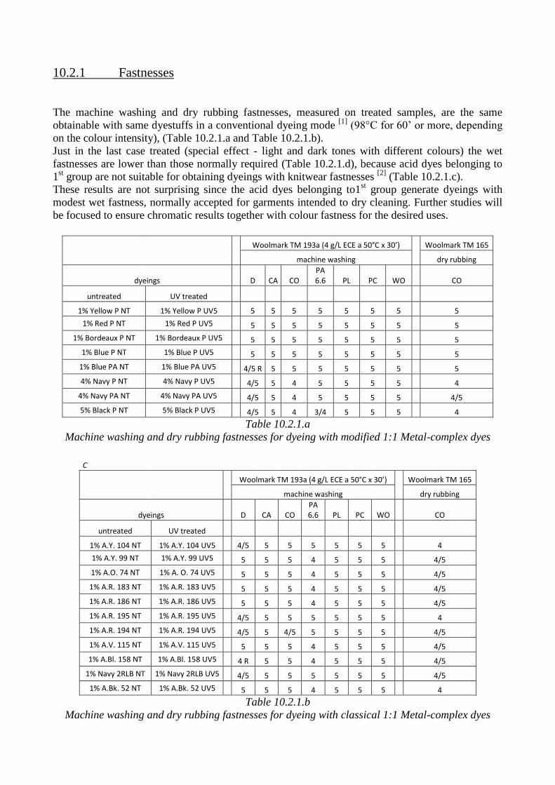
10.2.1 Fastnesses
The machine washing and dry rubbing fastnesses, measured on treated samples, are the same
obtainable with same dyestuffs in a conventional dyeing mode [1]
(98°C for 60’ or more, depending
on the colour intensity), (Table 10.2.1.a and Table 10.2.1.b).
Just in the last case treated (special effect - light and dark tones with different colours) the wet
fastnesses are lower than those normally required (Table 10.2.1.d), because acid dyes belonging to
1st group are not suitable for obtaining dyeings with knitwear fastnesses
[2] (Table 10.2.1.c).
These results are not surprising since the acid dyes belonging to1st group generate dyeings with
modest wet fastness, normally accepted for garments intended to dry cleaning. Further studies will
be focused to ensure chromatic results together with colour fastness for the desired uses.
Woolmark TM 193a (4 g/L ECE a 50°C x 30’) Woolmark TM 165
machine washing
dry rubbing
dyeings D CA CO PA 6.6 PL PC WO CO
untreated UV treated
1% Yellow P NT 1% Yellow P UV5 5 5 5 5 5 5 5 5
1% Red P NT 1% Red P UV5 5 5 5 5 5 5 5 5
1% Bordeaux P NT 1% Bordeaux P UV5 5 5 5 5 5 5 5 5
1% Blue P NT 1% Blue P UV5 5 5 5 5 5 5 5 5
1% Blue PA NT 1% Blue PA UV5 4/5 R 5 5 5 5 5 5 5
4% Navy P NT 4% Navy P UV5 4/5 5 4 5 5 5 5 4
4% Navy PA NT 4% Navy PA UV5 4/5 5 4 5 5 5 5 4/5
5% Black P NT 5% Black P UV5 4/5 5 4 3/4 5 5 5 4
Table 10.2.1.a
Machine washing and dry rubbing fastnesses for dyeing with modified 1:1 Metal-complex dyes
C
Woolmark TM 193a (4 g/L ECE a 50°C x 30’) Woolmark TM 165
machine washing
dry rubbing
dyeings D CA CO PA 6.6 PL PC WO CO
untreated UV treated
1% A.Y. 104 NT 1% A.Y. 104 UV5 4/5 5 5 5 5 5 5 4
1% A.Y. 99 NT 1% A.Y. 99 UV5 5 5 5 4 5 5 5 4/5
1% A.O. 74 NT 1% A. O. 74 UV5 5 5 5 4 5 5 5 4/5
1% A.R. 183 NT 1% A.R. 183 UV5 5 5 5 4 5 5 5 4/5
1% A.R. 186 NT 1% A.R. 186 UV5 5 5 5 4 5 5 5 4/5
1% A.R. 195 NT 1% A.R. 195 UV5 4/5 5 5 5 5 5 5
4
1% A.R. 194 NT 1% A.R. 194 UV5 4/5 5 4/5 5 5 5 5 4/5
1% A.V. 115 NT 1% A.V. 115 UV5 5 5 5 4 5 5 5 4/5
1% A.Bl. 158 NT 1% A.Bl. 158 UV5 4 R 5 5 4 5 5 5 4/5
1% Navy 2RLB NT 1% Navy 2RLB UV5 4/5 5 5 5 5 5 5 4/5
1% A.Bk. 52 NT 1% A.Bk. 52 UV5 5 5 5 4 5 5 5 4
Table 10.2.1.b
Machine washing and dry rubbing fastnesses for dyeing with classical 1:1 Metal-complex dyes
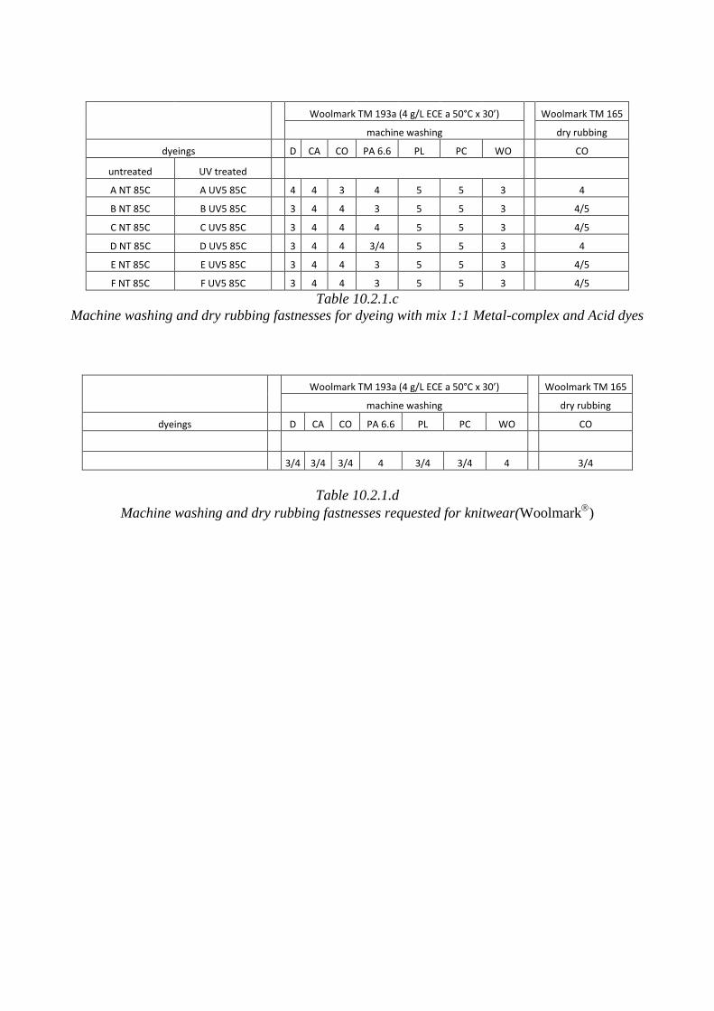
Woolmark TM 193a (4 g/L ECE a 50°C x 30’) Woolmark TM 165
machine washing
dry rubbing
dyeings D CA CO PA 6.6 PL PC WO CO
untreated UV treated
A NT 85C A UV5 85C 4 4 3 4 5 5 3 4
B NT 85C B UV5 85C 3 4 4 3 5 5 3 4/5
C NT 85C C UV5 85C 3 4 4 4 5 5 3 4/5
D NT 85C D UV5 85C 3 4 4 3/4 5 5 3 4
E NT 85C E UV5 85C 3 4 4 3 5 5 3 4/5
F NT 85C F UV5 85C 3 4 4 3 5 5 3 4/5
Table 10.2.1.c
Machine washing and dry rubbing fastnesses for dyeing with mix 1:1 Metal-complex and Acid dyes
Woolmark TM 193a (4 g/L ECE a 50°C x 30’) Woolmark TM 165
machine washing
dry rubbing
dyeings D CA CO PA 6.6 PL PC WO CO
3/4 3/4 3/4 4 3/4 3/4 4 3/4
Table 10.2.1.d
Machine washing and dry rubbing fastnesses requested for knitwear(Woolmark
)
10.3 References
[1] Colour cards supplied by Huntsman - Textile Effects :
Neolan® P - Dyeing system with modified 1:1 metal complex dyes for highest wool quality
(2007)
Neolan® - Dyes for wool pieces dyeing (2011)
[2] Fastness standards supplied by Woolmark

Chapter 11 Economical evaluation of the process

11.1 Feasibility
The treatments with ultraviolet radiation on yarns or fabrics (wool and cotton) are applicable on
basis of market demand, always looking for new fashion effects, in order to satisfy the needs and
tastes of increasingly customers demanding. In this respect, if it may be too expensive the purchase
of new UV equipment for treatments (Hg vapour lamps, cooling fans, etc.) it is possible to amend
some existing machinery (eg. equipment for wide fabrics singeing, or machines for yarn printing)
providing irradiation systems that interface existing machinery; so it will be possible get a "hybrid"
machine, able to perform various operations, with appropriate rearrangements.
11.2 Reliability
The reliability of such machinery is related to the robustness of the constituent materials (chassis,
fans, vacuum cleaners, etc..), but especially to good efficiency of the radiation system, that is
directly dependent to the lamps efficiency in work; it must be remembered that commonly used
lamps are Hg vapor lamps (normally at low or at medium pressure), that undergo a change of their
spectral distribution in function of time. It is therefore recommended to make regular inspections of
their spectral emission.
Monitoring this energy parameter, the results of the UV irradiation on textile materials are time
dependent; it should be noted that in order to compare different machines for UV treatments, it is
not sufficient to monitor the radiant exposure, because this parameter is not enough for a correct
description of work conditions.[1]
Indeed, the radiant exposure involves significant risk of repeatability; in fact also other parameters,
not always easily controllable, have a very important role (combined maximum variability of 500%):
1. difference in spectral irradiance;
2. difference in exposure temperature;
3. difference in moisture exposure.
Hence, it is advisable to perform the textile materials irradiation trying as much as possible to
standardize the work conditions; it is recommended for this purpose to carry out the irradiation on
textile materials already conditioned (T=20°C and R.H.=65%)[2]
; if this is not possible, it is
advisable to leave the material acclimatize for at least 24 h near the machine for processing UV.
The moisture management in fact affects the effects of radiation, because the residual moisture
absorb the IR component of lamps and also influences the textile temperature under irradiation.
It will therefore be good practice to make regular inspections of the spectral output of the lamps in
use, in order to compensate the normal radiant decay with an increase of the electrical power supply
(% increase the rheostat control).
11.3 Effective costs
The costs evaluation was based on the energy consumption required for heating and maintaining the
dyeing system (machinery, textile material and dyebath), with the addition of energy consumption
for Hg vapour lamps required for the UV irradiation.
In the calculation for the maintenance of the dyeing system, it is considered the heat loss by
convection only, neglecting the phenomena of conduction and irradiation.
Here are presented the energy balances;
the dyeing apparatus used (API/O/1 - OBEM – Biella), has the following characteristics:
single dyeing tube
external diameter = 0.300 [m] internal diameter = 0.288 [m]
weight = 84 [kg] lenght = 1.93 [m]
expansion tank
height = 0.77 [m] external diameter = 0.66 [m]
total weight approximated of steel = 200 [kg]
Calculation for wool yarn (fineness Nm = 2/28)
8 bobbins of 1.25 [kg] each for a total fibre weight of 10 [kg]
liquor ratio = 1:10 for a total bath weight of 100 [kg]
Cp (wool) = 0.31 [kcal*kg-1
*K-1
]
DYEING AT 85 [°C] FOR 90’
Heating from 20 [°C] to 85 [°C]
Q = MH2O*Cp H2O*ΔT + Msteel*Cp steel*ΔT + Mwool*Cp wool*ΔT
where:
MH2O = 100 [kg] Cp H2O = 1 [kcal*kg-1
*K-1
] ΔT = 65 [K]
Msteel = 200 [kg] Cp steel = 0.12 [kcal*kg-1
*K-1
] ΔT = 65 [K]
Mwool = 10 [kg] Cp wool = 0.31 [kcal*kg-1
*K-1
] ΔT = 65 [K]
Then Q = 8261 [kcal] for heating the system from 20 [°C] to 85 [°C]
Maintenance at 85 [°C] for 90’ (dissipation by natural convection)
Tp = 85 [°C] T∞ = 20 [°C] T = 52.5 [°C]
parameter related to air at 52.5 [°C] and 1 [bar]:
ρ = 1.0702 [kg*m-3
] μ = 1.9785*10-5
[kg*m-1
*s-1
]
k = 2.8058*10-2
[J*s-1
*m-1
*K-1
] Cp = 1.0082*103 [J*kg
-1*K
-1]
Calculation of Prandtl and Grashof’s numbers for the dyeing tube:
NPr = (Cp*μ)/k = 0.7109
NGr = (D3*ρ
2*g*β* ΔT)/μ
2 = 1.5476*10
8 where β = 1/((Tair+Twall)/2) = 3.0722*10
-3 [K
-1]
NPr*NGr = 1.10*108
because: 104 < NPr*NGr < 10
9 hm = 1.3*(ΔT/D)
0.25 = 1.1913 [cal*m
-2*s
-1*K
-1]
tube surface, A = 2.384 [m2] ΔT = 65 [K] t = 5400 [s]
Q = hm*A* ΔT*t = 997 [kcal] for maintain the tube at 85 [°C]
Calculation of Prandtl and Grashof’s numbers for the expansion tank:
NPr = (Cp*μ)/k = 0.7109
NGr = (L3*ρ
2*g*β* ΔT)/μ
2 = 2.6167*10
9 where β = 1/((Tair+Twall)/2) = 3.0722*10
-3[K
-1]
NPr*NGr = 1.88*109
because: 109 < NPr*NGr < 10
12 hm = 1.8*(ΔT)
0.25 = 1.221 [cal*m
-2*s
-1*K
-1]
expansion tank surface, A = 2.073 [m2] ΔT = 65 [K] t = 5400 [s]
Q = hm*A* ΔT*t = 888 [kcal] for maintain the expansion tank at 85 [°C]
Hence, the total heat for carrying a dyeing at 85 [°C] for 90’ is equal to:
8261 + 997 + 888 = 10146 [Kcal] or 42479 [kJ]
DYEING AT 98 [°C] FOR 60’
Heating from 20 [°C] to 98 [°C]
Q = MH2O*Cp H2O*ΔT + Msteel*Cp steel*ΔT + Mwool*Cp wool*ΔT
where:
MH2O = 100 [kg] Cp H2O = 1 [kcal*kg-1
*K-1
] ΔT = 78 [K]
Msteel = 200 [kg] Cp steel = 0.12 [kcal*kg-1
*K-1
] ΔT = 78 [K]
Mwool = 10 [kg] Cp wool = 0.31 [kcal*kg-1
*K-1
] ΔT = 78 [K]
then: Q = 9914 [kcal] for heating the system from 20 [°C] to 98 [°C]
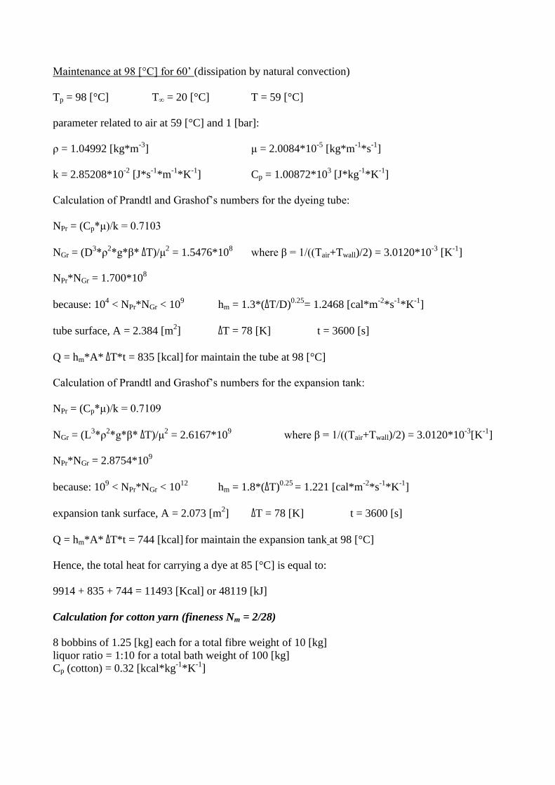
Maintenance at 98 [°C] for 60’ (dissipation by natural convection)
Tp = 98 [°C] T∞ = 20 [°C] T = 59 [°C]
parameter related to air at 59 [°C] and 1 [bar]:
ρ = 1.04992 [kg*m-3
] μ = 2.0084*10-5
[kg*m-1
*s-1
]
k = 2.85208*10-2
[J*s-1
*m-1
*K-1
] Cp = 1.00872*103 [J*kg
-1*K
-1]
Calculation of Prandtl and Grashof’s numbers for the dyeing tube:
NPr = (Cp*μ)/k = 0.7103
NGr = (D3*ρ
2*g*β* ΔT)/μ
2 = 1.5476*10
8 where β = 1/((Tair+Twall)/2) = 3.0120*10
-3 [K
-1]
NPr*NGr = 1.700*108
because: 104 < NPr*NGr < 10
9 hm = 1.3*(ΔT/D)
0.25= 1.2468 [cal*m
-2*s
-1*K
-1]
tube surface, A = 2.384 [m2] ΔT = 78 [K] t = 3600 [s]
Q = hm*A* ΔT*t = 835 [kcal] for maintain the tube at 98 [°C]
Calculation of Prandtl and Grashof’s numbers for the expansion tank:
NPr = (Cp*μ)/k = 0.7109
NGr = (L3*ρ
2*g*β* ΔT)/μ
2 = 2.6167*10
9 where β = 1/((Tair+Twall)/2) = 3.0120*10
-3[K
-1]
NPr*NGr = 2.8754*109
because: 109 < NPr*NGr < 10
12 hm = 1.8*(ΔT)
0.25 = 1.221 [cal*m
-2*s
-1*K
-1]
expansion tank surface, A = 2.073 [m2] ΔT = 78 [K] t = 3600 [s]
Q = hm*A* ΔT*t = 744 [kcal] for maintain the expansion tank at 98 [°C]
Hence, the total heat for carrying a dye at 85 [°C] is equal to:
9914 + 835 + 744 = 11493 [Kcal] or 48119 [kJ]
Calculation for cotton yarn (fineness Nm = 2/28)
8 bobbins of 1.25 [kg] each for a total fibre weight of 10 [kg]
liquor ratio = 1:10 for a total bath weight of 100 [kg]
Cp (cotton) = 0.32 [kcal*kg-1
*K-1
]
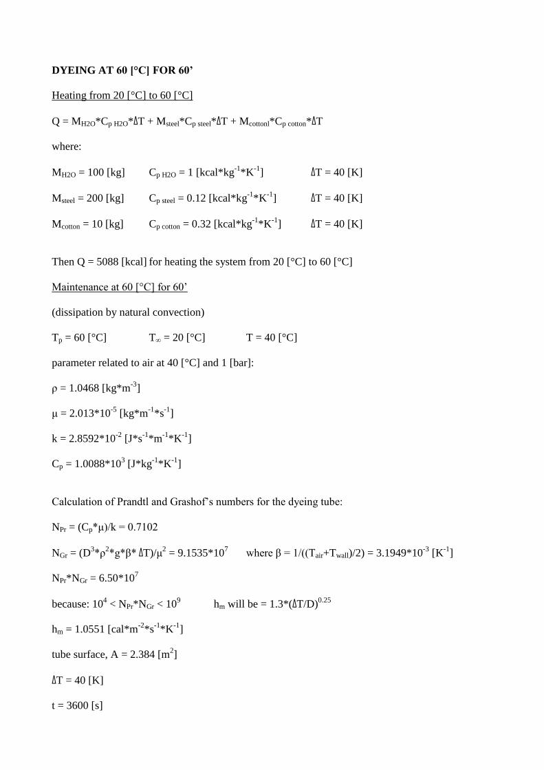
DYEING AT 60 [°C] FOR 60’
Heating from 20 [°C] to 60 [°C]
Q = MH2O*Cp H2O*ΔT + Msteel*Cp steel*ΔT + Mcottonl*Cp cotton*ΔT
where:
MH2O = 100 [kg] Cp H2O = 1 [kcal*kg-1
*K-1
] ΔT = 40 [K]
Msteel = 200 [kg] Cp steel = 0.12 [kcal*kg-1
*K-1
] ΔT = 40 [K]
Mcotton = 10 [kg] Cp cotton = 0.32 [kcal*kg-1
*K-1
] ΔT = 40 [K]
Then Q = 5088 [kcal] for heating the system from 20 [°C] to 60 [°C]
Maintenance at 60 [°C] for 60’
(dissipation by natural convection)
Tp = 60 [°C] T∞ = 20 [°C] T = 40 [°C]
parameter related to air at 40 [°C] and 1 [bar]:
ρ = 1.0468 [kg*m-3
]
μ = 2.013*10-5
[kg*m-1
*s-1
]
k = 2.8592*10-2
[J*s-1
*m-1
*K-1
]
Cp = 1.0088*103 [J*kg
-1*K
-1]
Calculation of Prandtl and Grashof’s numbers for the dyeing tube:
NPr = (Cp*μ)/k = 0.7102
NGr = (D3*ρ
2*g*β* ΔT)/μ
2 = 9.1535*10
7 where β = 1/((Tair+Twall)/2) = 3.1949*10
-3 [K
-1]
NPr*NGr = 6.50*107
because: 104 < NPr*NGr < 10
9 hm will be = 1.3*(ΔT/D)
0.25
hm = 1.0551 [cal*m-2
*s-1
*K-1
]
tube surface, A = 2.384 [m2]
ΔT = 40 [K]
t = 3600 [s]
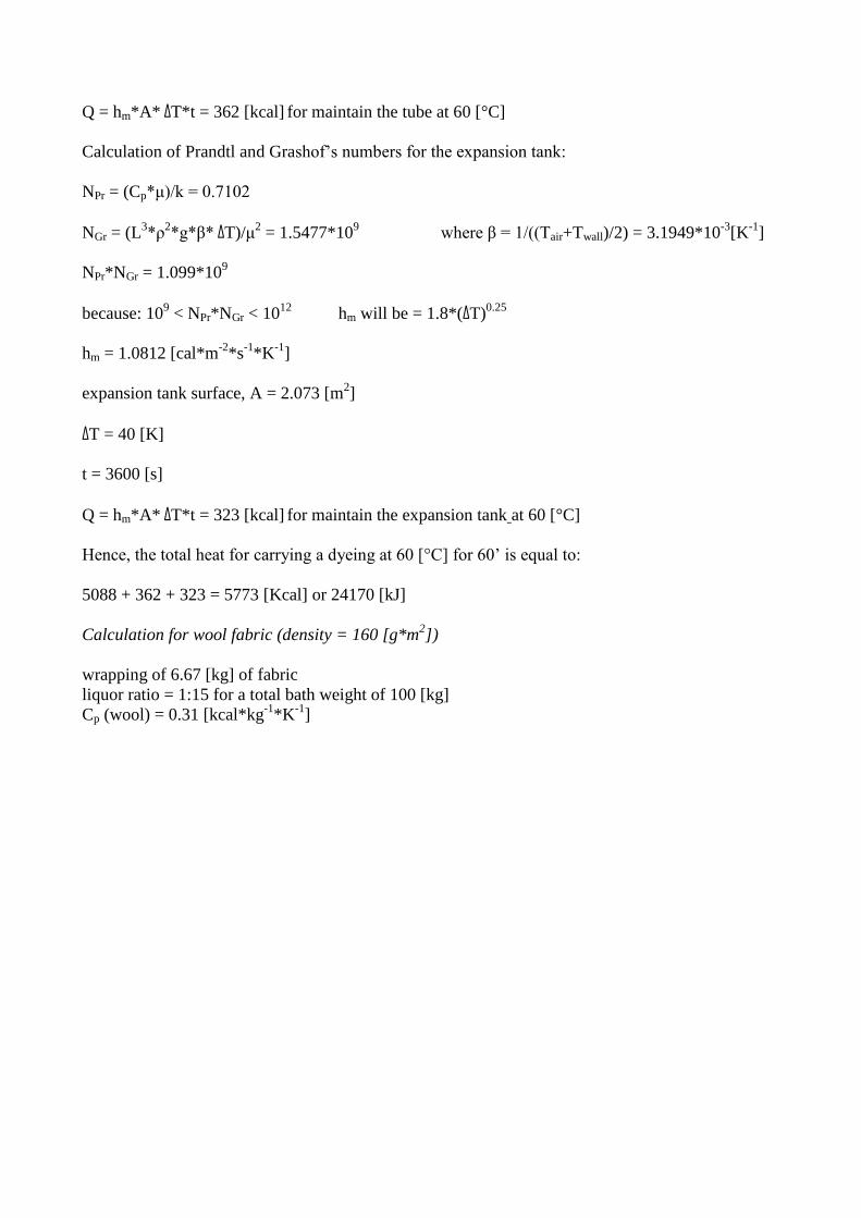
Q = hm*A* ΔT*t = 362 [kcal] for maintain the tube at 60 [°C]
Calculation of Prandtl and Grashof’s numbers for the expansion tank:
NPr = (Cp*μ)/k = 0.7102
NGr = (L3*ρ
2*g*β* ΔT)/μ
2 = 1.5477*10
9 where β = 1/((Tair+Twall)/2) = 3.1949*10
-3[K
-1]
NPr*NGr = 1.099*109
because: 109 < NPr*NGr < 10
12 hm will be = 1.8*(ΔT)
0.25
hm = 1.0812 [cal*m-2
*s-1
*K-1
]
expansion tank surface, A = 2.073 [m2]
ΔT = 40 [K]
t = 3600 [s]
Q = hm*A* ΔT*t = 323 [kcal] for maintain the expansion tank at 60 [°C]
Hence, the total heat for carrying a dyeing at 60 [°C] for 60’ is equal to:
5088 + 362 + 323 = 5773 [Kcal] or 24170 [kJ]
Calculation for wool fabric (density = 160 [g*m2])
wrapping of 6.67 [kg] of fabric
liquor ratio = 1:15 for a total bath weight of 100 [kg]
Cp (wool) = 0.31 [kcal*kg-1
*K-1
]
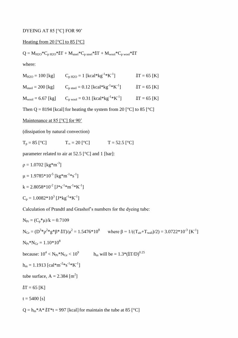
DYEING AT 85 [°C] FOR 90’
Heating from 20 [°C] to 85 [°C]
Q = MH2O*Cp H2O*ΔT + Msteel*Cp steel*ΔT + Mwool*Cp wool*ΔT
where:
MH2O = 100 [kg] Cp H2O = 1 [kcal*kg-1
*K-1
] ΔT = 65 [K]
Msteel = 200 [kg] Cp steel = 0.12 [kcal*kg-1
*K-1
] ΔT = 65 [K]
Mwool = 6.67 [kg] Cp wool = 0.31 [kcal*kg-1
*K-1
] ΔT = 65 [K]
Then Q = 8194 [kcal] for heating the system from 20 [°C] to 85 [°C]
Maintenance at 85 [°C] for 90’
(dissipation by natural convection)
Tp = 85 [°C] T∞ = 20 [°C] T = 52.5 [°C]
parameter related to air at 52.5 [°C] and 1 [bar]:
ρ = 1.0702 [kg*m-3
]
μ = 1.9785*10-5
[kg*m-1
*s-1
]
k = 2.8058*10-2
[J*s-1
*m-1
*K-1
]
Cp = 1.0082*103 [J*kg
-1*K
-1]
Calculation of Prandtl and Grashof’s numbers for the dyeing tube:
NPr = (Cp*μ)/k = 0.7109
NGr = (D3*ρ
2*g*β* ΔT)/μ
2 = 1.5476*10
8 where β = 1/((Tair+Twall)/2) = 3.0722*10
-3 [K
-1]
NPr*NGr = 1.10*108
because: 104 < NPr*NGr < 10
9 hm will be = 1.3*(ΔT/D)
0.25
hm = 1.1913 [cal*m-2
*s-1
*K-1
]
tube surface, A = 2.384 [m2]
ΔT = 65 [K]
t = 5400 [s]
Q = hm*A* ΔT*t = 997 [kcal] for maintain the tube at 85 [°C]
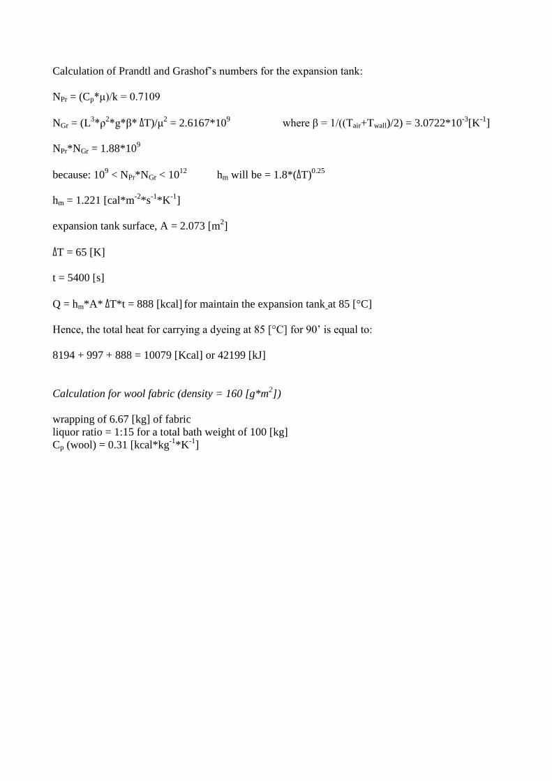
Calculation of Prandtl and Grashof’s numbers for the expansion tank:
NPr = (Cp*μ)/k = 0.7109
NGr = (L3*ρ
2*g*β* ΔT)/μ
2 = 2.6167*10
9 where β = 1/((Tair+Twall)/2) = 3.0722*10
-3[K
-1]
NPr*NGr = 1.88*109
because: 109 < NPr*NGr < 10
12 hm will be = 1.8*(ΔT)
0.25
hm = 1.221 [cal*m-2
*s-1
*K-1
]
expansion tank surface, A = 2.073 [m2]
ΔT = 65 [K]
t = 5400 [s]
Q = hm*A* ΔT*t = 888 [kcal] for maintain the expansion tank at 85 [°C]
Hence, the total heat for carrying a dyeing at 85 [°C] for 90’ is equal to:
8194 + 997 + 888 = 10079 [Kcal] or 42199 [kJ]
Calculation for wool fabric (density = 160 [g*m2])
wrapping of 6.67 [kg] of fabric
liquor ratio = 1:15 for a total bath weight of 100 [kg]
Cp (wool) = 0.31 [kcal*kg-1
*K-1
]

DYEING AT 98 [°C] FOR 60’
Heating from 20 [°C] to 98 [°C]
Q = MH2O*Cp H2O*ΔT + Msteel*Cp steel*ΔT + Mwool*Cp wool*ΔT
where:
MH2O = 100 [kg] Cp H2O = 1 [kcal*kg-1
*K-1
] ΔT = 78 [K]
Msteel = 200 [kg] Cp steel = 0.12 [kcal*kg-1
*K-1
] ΔT = 78 [K]
Mwool = 6.67 [kg] Cp wool = 0.31 [kcal*kg-1
*K-1
] ΔT = 78 [K]
Then Q = 9833 [kcal] for heating the system from 20 [°C] to 98 [°C]
Maintenance at 98 [°C] for 60’
(dissipation by natural convection)
Tp = 98 [°C] T∞ = 20 [°C] T = 59 [°C]
parameter related to air at 59 [°C] and 1 [bar]:
ρ = 1.04992 [kg*m-3
]
μ = 2.0084*10-5
[kg*m-1
*s-1
]
k = 2.85208*10-2
[J*s-1
*m-1
*K-1
]
Cp = 1.00872*103 [J*kg
-1*K
-1]
Calculation of Prandtl and Grashof’s numbers for the dyeing tube:
NPr = (Cp*μ)/k = 0.7103
NGr = (D3*ρ
2*g*β* ΔT)/μ
2 = 1.5476*10
8 where β = 1/((Tair+Twall)/2) = 3.0120*10
-3 [K
-1]
NPr*NGr = 1.700*108
because: 104 < NPr*NGr < 10
9 hm will be = 1.3*(ΔT/D)
0.25
hm = 1.2468 [cal*m-2
*s-1
*K-1
]
tube surface, A = 2.384 [m2]
ΔT = 78 [K]
t = 3600 [s]
Q = hm*A* ΔT*t = 835 [kcal] for maintain the tube at 98 [°C]
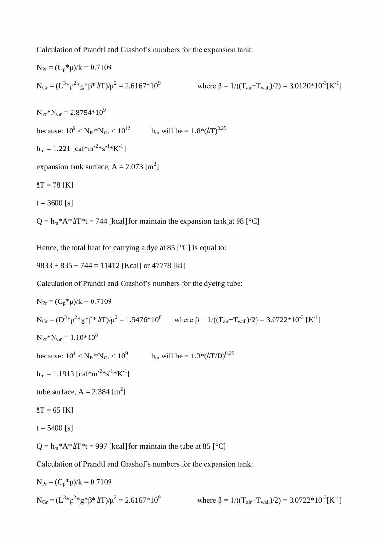
Calculation of Prandtl and Grashof’s numbers for the expansion tank:
NPr = (Cp*μ)/k = 0.7109
NGr = (L3*ρ
2*g*β* ΔT)/μ
2 = 2.6167*10
9 where β = 1/((Tair+Twall)/2) = 3.0120*10
-3[K
-1]
NPr*NGr = 2.8754*109
because: 109 < NPr*NGr < 10
12 hm will be = 1.8*(ΔT)
0.25
hm = 1.221 [cal*m-2
*s-1
*K-1
]
expansion tank surface, A = 2.073 [m2]
ΔT = 78 [K]
t = 3600 [s]
Q = hm*A* ΔT*t = 744 [kcal] for maintain the expansion tank at 98 [°C]
Hence, the total heat for carrying a dye at 85 [°C] is equal to:
9833 + 835 + 744 = 11412 [Kcal] or 47778 [kJ]
Calculation of Prandtl and Grashof’s numbers for the dyeing tube:
NPr = (Cp*μ)/k = 0.7109
NGr = (D3*ρ
2*g*β* ΔT)/μ
2 = 1.5476*10
8 where β = 1/((Tair+Twall)/2) = 3.0722*10
-3 [K
-1]
NPr*NGr = 1.10*108
because: 104 < NPr*NGr < 10
9 hm will be = 1.3*(ΔT/D)
0.25
hm = 1.1913 [cal*m-2
*s-1
*K-1
]
tube surface, A = 2.384 [m2]
ΔT = 65 [K]
t = 5400 [s]
Q = hm*A* ΔT*t = 997 [kcal] for maintain the tube at 85 [°C]
Calculation of Prandtl and Grashof’s numbers for the expansion tank:
NPr = (Cp*μ)/k = 0.7109
NGr = (L3*ρ
2*g*β* ΔT)/μ
2 = 2.6167*10
9 where β = 1/((Tair+Twall)/2) = 3.0722*10
-3[K
-1]
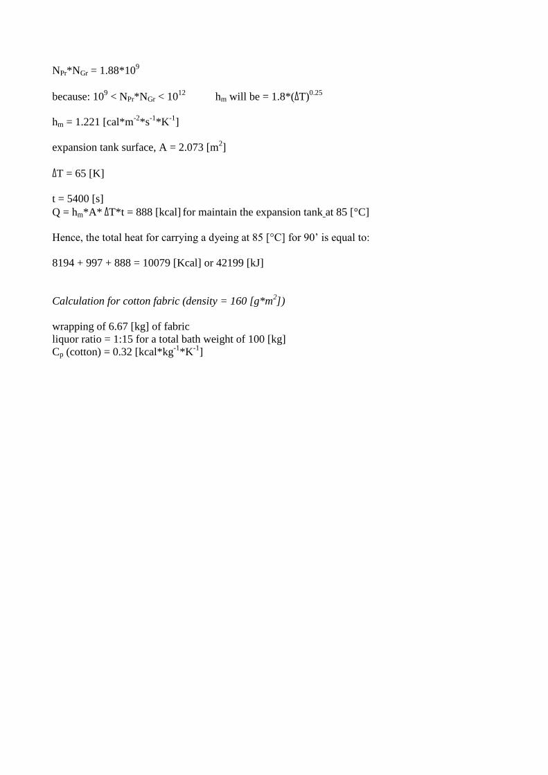
NPr*NGr = 1.88*109
because: 109 < NPr*NGr < 10
12 hm will be = 1.8*(ΔT)
0.25
hm = 1.221 [cal*m-2
*s-1
*K-1
]
expansion tank surface, A = 2.073 [m2]
ΔT = 65 [K]
t = 5400 [s]
Q = hm*A* ΔT*t = 888 [kcal] for maintain the expansion tank at 85 [°C]
Hence, the total heat for carrying a dyeing at 85 [°C] for 90’ is equal to:
8194 + 997 + 888 = 10079 [Kcal] or 42199 [kJ]
Calculation for cotton fabric (density = 160 [g*m2])
wrapping of 6.67 [kg] of fabric
liquor ratio = 1:15 for a total bath weight of 100 [kg]
Cp (cotton) = 0.32 [kcal*kg-1
*K-1
]
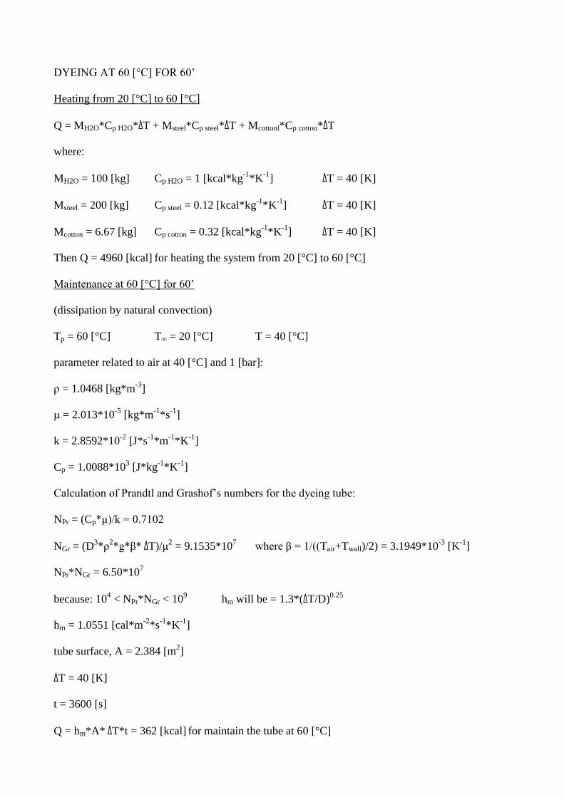
DYEING AT 60 [°C] FOR 60’
Heating from 20 [°C] to 60 [°C]
Q = MH2O*Cp H2O*ΔT + Msteel*Cp steel*ΔT + Mcottonl*Cp cotton*ΔT
where:
MH2O = 100 [kg] Cp H2O = 1 [kcal*kg-1
*K-1
] ΔT = 40 [K]
Msteel = 200 [kg] Cp steel = 0.12 [kcal*kg-1
*K-1
] ΔT = 40 [K]
Mcotton = 6.67 [kg] Cp cotton = 0.32 [kcal*kg-1
*K-1
] ΔT = 40 [K]
Then Q = 4960 [kcal] for heating the system from 20 [°C] to 60 [°C]
Maintenance at 60 [°C] for 60’
(dissipation by natural convection)
Tp = 60 [°C] T∞ = 20 [°C] T = 40 [°C]
parameter related to air at 40 [°C] and 1 [bar]:
ρ = 1.0468 [kg*m-3
]
μ = 2.013*10-5
[kg*m-1
*s-1
]
k = 2.8592*10-2
[J*s-1
*m-1
*K-1
]
Cp = 1.0088*103 [J*kg
-1*K
-1]
Calculation of Prandtl and Grashof’s numbers for the dyeing tube:
NPr = (Cp*μ)/k = 0.7102
NGr = (D3*ρ
2*g*β* ΔT)/μ
2 = 9.1535*10
7 where β = 1/((Tair+Twall)/2) = 3.1949*10
-3 [K
-1]
NPr*NGr = 6.50*107
because: 104 < NPr*NGr < 10
9 hm will be = 1.3*(ΔT/D)
0.25
hm = 1.0551 [cal*m-2
*s-1
*K-1
]
tube surface, A = 2.384 [m2]
ΔT = 40 [K]
t = 3600 [s]
Q = hm*A* ΔT*t = 362 [kcal] for maintain the tube at 60 [°C]
Calculation of Prandtl and Grashof’s numbers for the expansion tank:
NPr = (Cp*μ)/k = 0.7102
NGr = (L3*ρ
2*g*β* ΔT)/μ
2 = 1.5477*10
9 where β = 1/((Tair+Twall)/2) = 3.1949*10
-3[K
-1]
NPr*NGr = 1.099*109
because: 109 < NPr*NGr < 10
12 hm will be = 1.8*(ΔT)
0.25
hm = 1.0812 [cal*m-2
*s-1
*K-1
]
expansion tank surface, A = 2.073 [m2]
ΔT = 40 [K]
t = 3600 [s]
Q = hm*A* ΔT*t = 323 [kcal] for maintain the expansion tank at 60 [°C]
Hence, the total heat for carrying a dyeing at 60 [°C] for 60’ is equal to:
4960 + 362 + 323 = 5322 [Kcal] or 22282 [kJ]
It can therefore be argued that while the conventional dyeing (10 [kg] of wool yarn Nm = 2/28)
conducted at 98 °C for 60' requires 48119 [kJ]; a UV-pretreatment lowers the dyeing temperature to
85 °C, increasing at 90’ the dyeing time and consuming 42479 [kJ]. This value must, however, add
up the energy to UV irradiation, resulting from the following calculations:
1 [kg] : 14000 [m] = 10 [kg] : x [m] x = 140000 [m] of yarn feeding
the Filidea’s machine can work with a maximum of 48 bobbins, then:
140000/48 = 2917 [m] for each of 48 bobbins
optimal speed treatment = 2 [m]/’ with a power lamp of 2200 [w]
2917 [m]/2 [m]/’ = 1458.5’ or 87510 [s] time necessary for UV-treatment
87510 [s]*2200 [J*s-1
] = 192522 [J] energy for the treatment of 10 [kg] of wool yarn
The energy required for UV-treatment is about 4.5 times the dyeing energy; the energetic cost
becomes too high and not affordable (total cost = 23500 [J] for each [kg] of wool yarn).
Likewise can be argued that conventional dyeing (10 [kg] of cotton yarn Nm = 2/28) conducted at
60 °C for 60' requires 24170 [kJ]; a UV-posttreatment does not lowers the dyeing temperature and
does not modify the time. This value must, however, add up the energy to UV irradiation, resulting
from the following calculations:
1 [kg] : 14000 [m] = 10 [kg] : x [m] x = 140000 [m] of yarn feeding
the Filidea’s machine can work with a maximum of 48 bobbins, then:
140000/48 = 2917 [m] for each of 48 bobbins
optimal speed treatment = 2 [m]/’ with a power lamp of 2200 [w]
2917 [m]/2 [m]/’ = 1458.5’ or 87510 [s] time necessary for UV-treatment
87510 [s]*2200 [J*s-1
] = 192522 [J] energy for the treatment of 10 [kg] of cotton yarn
The energy required for UV-treatment is about 8 times the dyeing energy; the energetic cost
becomes too high and not affordable (total cost = 21669 [J] for each [kg] of cotton yarn).
For UV-treatment on wool fabric (density = 160 [g/m2] the conclusions are as follows:
6670 [g] fabric weight
6670 [g]/160 [g/m2] = 41.7 [m
2] fabric surface under treatment
1.20 [m] height of the fabric
41.7 [m2]/1.20 [m] = 34.8 [m] length of the fabric
At TMT plant, the UV machine has a power lamp of 18000 [w],
and with a optimal speed treatment = 2 [m]/’ with a power lamp of 18000 [w]
34.8 [m]/2 [m/’] = 17.4’ or 1044 [s] time necessary for UV-treatment
18000 [J*s-1
]*1044 [s] = 18792 [kJ] energy for the treatment of 6.67 [kg] of wool fabric
The energy required for UV-treatment is is less than half the dyeing energy; the energetic cost it is
not so high and becomes affordable (total cost = 9144 [J] for each [kg] of wool fabric).
Likewise, for UV-treatment on cotton fabric (density = 160 [g/m2] the conclusions are as follows:
6670 [g] fabric weight
6670 [g]/160 [g/m2] = 41.7 [m
2] fabric surface under treatment
1.20 [m] height of the fabric
41.7 [m2]/1.20 [m] = 34.8 [m] length of the fabric
At TMT plant, the UV machine has a power lamp of 18000 [w],
and with a optimal speed treatment = 2 [m]/’ with a power lamp of 18000 [w]
34.8 [m]/2 [m/’] = 17.4’ or 1044 [s] time necessary for UV-treatment
18000 [J*s-1
]*1044 [s] = 18792 [kJ] energy for the treatment of 6.67 [kg] of cotton fabric
The energy required for UV-treatment is is less than the dyeing energy (84%); the energetic cost it
is not so high and becomes affordable (total cost = 6158 [J] for each [kg] of cotton fabric).
11.4 References
[1] D. M. Grossman, “Errors Caused by Using Joules to Time Laboratory and Outdoor Exposure
Tests”, Accelerated and Outdoor Durability Testing of Organic Materials, ASTM STP 1202,
Warren D. Ketola, and Douglas Grossman, Eds., American Society for Testing and
Materials, Philadelphia, 1993.
[2] L. Rondolotto, “Perché il peso condizionato?”, Massa Commerciale – Invoice Weight –
Condizionatura Pubblica di Biella, 1988.
Conclusions
Wool and cotton fibres were successfully modified by UV treatments in order to achieve differential
dyeings.
In particular, the study was focused on fibres-UV radiations interactions, aimed at new chromatic
effects on different textile substrates (mainly wool and cotton), and improvement of dyeability
conferred by UV-treatment on wool (low dyeing temperature).
UV-pretreatment on wool fibres change their affinity towards dyestuffs increasing the default value;
good results were obtained with reactive dyes, 1:2 metal-complex dyes and acid milling dyes, but
best results are get using 1:1 metal-complex dyes.
On cotton fibres instead UV-pretreatment does not substantially change the dyeing affinity, but UV-
posttreatment is capable to fade the dyeing, allowing the obtaining of chromatic effects (like sun
bleached effects).
These application techniques of UV radiation on yarns and fabrics gave encouraging results as
regards the chromatic effects achievable; with suitable UV-pretreatment it is possible in fact to
achieve effects of different colour intensity between UV-irradiated side and untreated one (light /
dark in tone), or the effects of light and dark tones with different colours of wool (both in yarn and
in the fabric). On cotton the results of differential dyeing are made by UV- posttreatment conduct
on traditional dyeings performed with selected reactive dyes (both of yarn that on fabric).
For proteic fibres, after the UV-pretreatment, is executable a dyeing with maximum temperature of
85 °C (instead of 98 °C) with equal properties of tone uniformity and equal color fastnesses
(machine washing and dry rubbing), together with a convenient reduced degradation of wool fibre,
which then undergoes a little thermal deterioration, with better preservation of its intrinsic
properties during the textile ennoblement.
The energy balances shows a substantial disparity in the case of UV-treatments on yarn of ordinary
fineness (both wool and cotton yarns) conducted on the existing prototype machinery at Filidea
factory; the innovative effects obtained by application of ultraviolet radiation on yarns needs
technological alternative solutions respect to those currently available, in order to compete with
conventional processes. Different speech must be done for UV-treatments on fabrics (always on
both wool and cotton), in which the energy balances are slightly unfavorable to conventional
ennoblement techniques, however, the possibility of realizing these chromatic effects of differential
dyeing compensate and justify abundantly the energy increase for these application techniques.
Instead, it will be necessary to evaluate the possibility of making amendments to existing machines
to the companies rather than the construction of new plants for radiations treatments, evaluating
each time, what is the ratio cost/benefit, according to the company policies and to market trend,
related at the temporary fashion.
Gianluca Migliavacca