Embed Size (px)
Citation preview
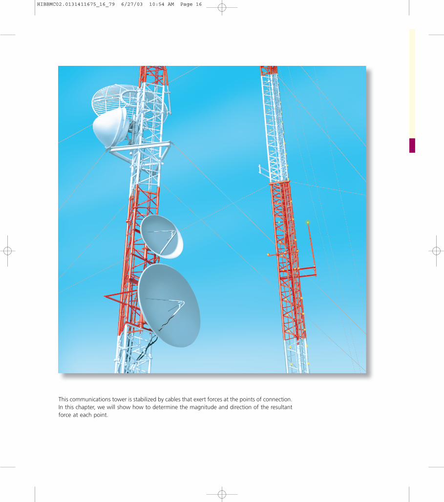
This communications tower is stabilized by cables that exert forces at the points of connection.In this chapter, we will show how to determine the magnitude and direction of the resultantforce at each point.
HIBBMC02.0131411675_16_79 6/27/03 10:54 AM Page 16
17
CHAPTER OBJECTIVES
Force Vectors
• To show how to add forces and resolve them into components usingthe Parallelogram Law.
• To express force and position in Cartesian vector form and explainhow to determine the vector’s magnitude and direction.
• To introduce the dot product in order to determine the anglebetween two vectors or the projection of one vector onto another.
C H A P T E R
2
2.1 Scalars and VectorsMost of the physical quantities in mechanics can be expressedmathematically by means of scalars and vectors.
Scalar. A quantity characterized by a positive or negative number iscalled a scalar. For example, mass, volume, and length are scalar quantitiesoften used in statics. In this book, scalars are indicated by letters in italictype, such as the scalar A.
Vector. A vector is a quantity that has both a magnitude and a direction.In statics the vector quantities frequently encountered are position, force,and moment. For handwritten work, a vector is generally represented bya letter with an arrow written over it, such as The magnitude isdesignated or simply A. In this book vectors will be symbolized inboldface type; for example, A is used to designate the vector “A.” Itsmagnitude, which is always a positive quantity, is symbolized in italic type,written as or simply A when it is understood that A is a positive scalar.ƒ A ƒ ,
ƒ A!
ƒ
A!
.
HIBBMC02.0131411675_16_79 6/27/03 10:54 AM Page 17
18 • CHAPTER 2 Force Vectors
Tail
Line of Action1
P
O
Head
A
20˚
Fig. 2–1
Vector A and its negative counterpart
AA
Fig. 2–2
A
A
A
A
2
1.5
0.5
Scalar Multiplication and Division
Fig. 2–3
Vector Addition
A
B
A
B
R = A + BA
B
B
A
Parallelogram Law(b)
Triangle construction(c)
Triangle construction(d)(a)
R = A + B
R = B + A
Fig. 2–4
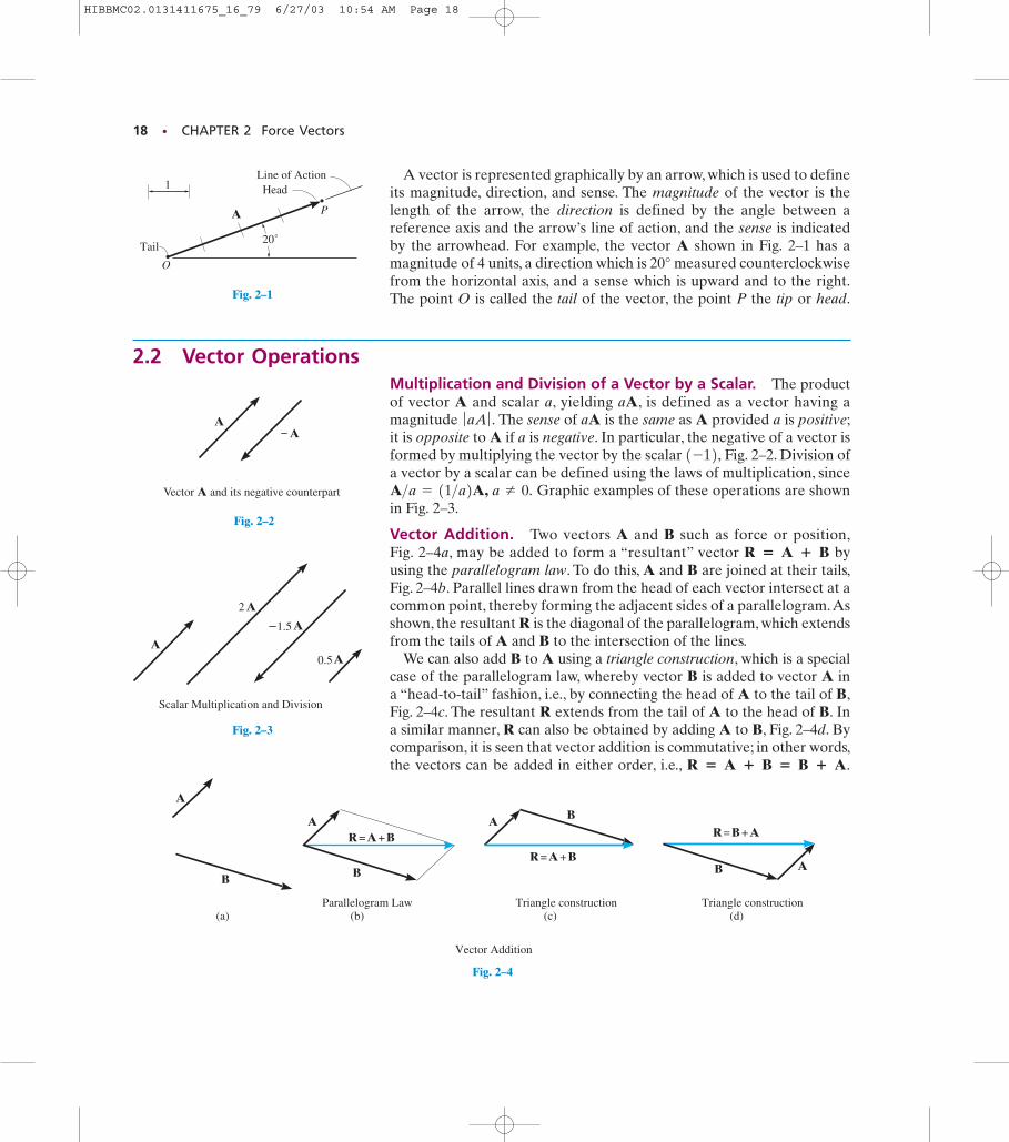
A vector is represented graphically by an arrow, which is used to defineits magnitude, direction, and sense. The magnitude of the vector is thelength of the arrow, the direction is defined by the angle between areference axis and the arrow’s line of action, and the sense is indicatedby the arrowhead. For example, the vector A shown in Fig. 2–1 has amagnitude of 4 units, a direction which is 20° measured counterclockwisefrom the horizontal axis, and a sense which is upward and to the right.The point O is called the tail of the vector, the point P the tip or head.
2.2 Vector OperationsMultiplication and Division of a Vector by a Scalar. The productof vector A and scalar a, yielding aA, is defined as a vector having amagnitude The sense of aA is the same as A provided a is positive;it is opposite to A if a is negative. In particular, the negative of a vector isformed by multiplying the vector by the scalar Fig. 2–2. Division ofa vector by a scalar can be defined using the laws of multiplication, since
Graphic examples of these operations are shownin Fig. 2–3.
Vector Addition. Two vectors A and B such as force or position,Fig. 2–4a, may be added to form a “resultant” vector byusing the parallelogram law. To do this, A and B are joined at their tails,Fig. 2–4b. Parallel lines drawn from the head of each vector intersect at acommon point, thereby forming the adjacent sides of a parallelogram.Asshown, the resultant R is the diagonal of the parallelogram, which extendsfrom the tails of A and B to the intersection of the lines.
We can also add B to A using a triangle construction, which is a specialcase of the parallelogram law, whereby vector B is added to vector A ina “head-to-tail” fashion, i.e., by connecting the head of A to the tail of B,Fig. 2–4c. The resultant R extends from the tail of A to the head of B. Ina similar manner, R can also be obtained by adding A to B, Fig. 2–4d. Bycomparison, it is seen that vector addition is commutative; in other words,the vectors can be added in either order, i.e., R � A � B � B � A.
R � A � B
A>a = 11>a2A, a Z 0.
1-12,ƒ aA ƒ .
HIBBMC02.0131411675_16_79 6/27/03 10:54 AM Page 18
SECTION 2.2 Vector Operations • 19
A B
R
Addition of collinear vectors
R = A+B
Fig. 2–5
R' A
BB
AB
AR'or
Parallelogram law Triangle construction
Vector Subtraction
Fig. 2–6
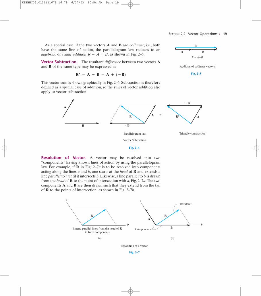
As a special case, if the two vectors A and B are collinear, i.e., bothhave the same line of action, the parallelogram law reduces to analgebraic or scalar addition as shown in Fig. 2–5.
Vector Subtraction. The resultant difference between two vectors Aand B of the same type may be expressed as
This vector sum is shown graphically in Fig. 2–6. Subtraction is thereforedefined as a special case of addition, so the rules of vector addition alsoapply to vector subtraction.
Rœ � A � B � A � 1�B2
R = A + B,
Resolution of Vector. A vector may be resolved into two“components” having known lines of action by using the parallelogramlaw. For example, if R in Fig. 2–7a is to be resolved into componentsacting along the lines a and b, one starts at the head of R and extends aline parallel to a until it intersects b. Likewise, a line parallel to b is drawnfrom the head of R to the point of intersection with a, Fig. 2–7a. The twocomponents A and B are then drawn such that they extend from the tailof R to the points of intersection, as shown in Fig. 2–7b.
Resolution of a vector
a
b
A
B
R
a
b
R
(a) (b)
ComponentsExtend parallel lines from the head of Rto form components
Resultant
Fig. 2–7
HIBBMC02.0131411675_16_79 6/27/03 10:54 AM Page 19
20 • CHAPTER 2 Force Vectors
F1
F2
F1 + F2 FR
F3O
Fig. 2–8
Fc
Fb
Fa
c
a
b
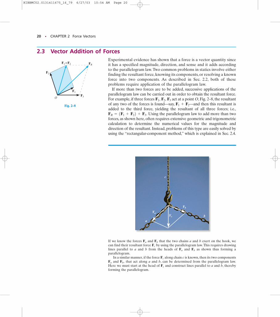
2.3 Vector Addition of ForcesExperimental evidence has shown that a force is a vector quantity sinceit has a specified magnitude, direction, and sense and it adds accordingto the parallelogram law. Two common problems in statics involve eitherfinding the resultant force, knowing its components, or resolving a knownforce into two components. As described in Sec. 2.2, both of theseproblems require application of the parallelogram law.
If more than two forces are to be added, successive applications of theparallelogram law can be carried out in order to obtain the resultant force.For example, if three forces act at a point O, Fig. 2–8, the resultantof any two of the forces is found—say, —and then this resultant isadded to the third force, yielding the resultant of all three forces; i.e.,
Using the parallelogram law to add more than twoforces, as shown here, often requires extensive geometric and trigonometriccalculation to determine the numerical values for the magnitude anddirection of the resultant. Instead, problems of this type are easily solved byusing the “rectangular-component method,” which is explained in Sec. 2.4.
FR = 1F1 + F22 + F3.
F1 + F2
F1, F2, F3
If we know the forces and that the two chains a and b exert on the hook, wecan find their resultant force by using the parallelogram law. This requires drawinglines parallel to a and b from the heads of and as shown thus forming aparallelogram.
In a similar manner, if the force along chain c is known, then its two componentsand that act along a and b, can be determined from the parallelogram law.
Here we must start at the head of and construct lines parallel to a and b, therebyforming the parallelogram.
Fc
Fb,Fa
Fc
FbFa
Fc
FbFa
HIBBMC02.0131411675_16_79 6/27/03 10:54 AM Page 20
SECTION 2.3 Vector Addition of Forces • 21
PROCEDURE FOR ANALYSISProblems that involve the addition of two forces can be solved asfollows:
Parallelogram Law.
• Make a sketch showing the vector addition using the parallelogramlaw.
• Two “component” forces add according to the parallelogram law,yielding a resultant force that forms the diagonal of theparallelogram.
• If a force is to be resolved into components along two axesdirected from the tail of the force, then start at the head of theforce and construct lines parallel to the axes, thereby formingthe parallelogram. The sides of the parallelogram represent thecomponents.
• Label all the known and unknown force magnitudes and the angleson the sketch and identify the two unknowns.
Trigonometry.
• Redraw a half portion of the parallelogram to illustrate thetriangular head-to-tail addition of the components.
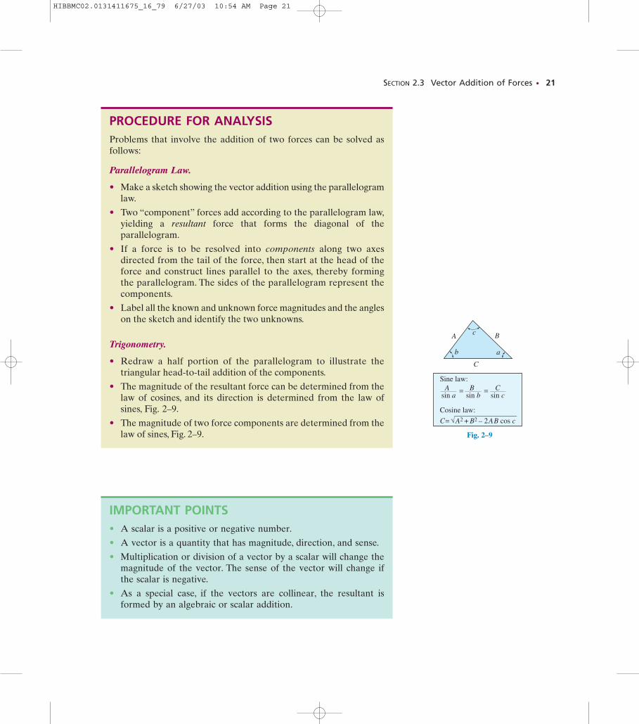
• The magnitude of the resultant force can be determined from thelaw of cosines, and its direction is determined from the law ofsines, Fig. 2–9.
• The magnitude of two force components are determined from thelaw of sines, Fig. 2–9.
IMPORTANT POINTS• A scalar is a positive or negative number.
• A vector is a quantity that has magnitude, direction, and sense.
• Multiplication or division of a vector by a scalar will change themagnitude of the vector. The sense of the vector will change ifthe scalar is negative.
• As a special case, if the vectors are collinear, the resultant isformed by an algebraic or scalar addition.
A
C
B
b
c
a
Sine law:
sin a sin b sin cA = B = C
Cosine law:
C= A2 + B2 – 2 A B cos c
Fig. 2–9
HIBBMC02.0131411675_16_79 6/27/03 10:54 AM Page 21
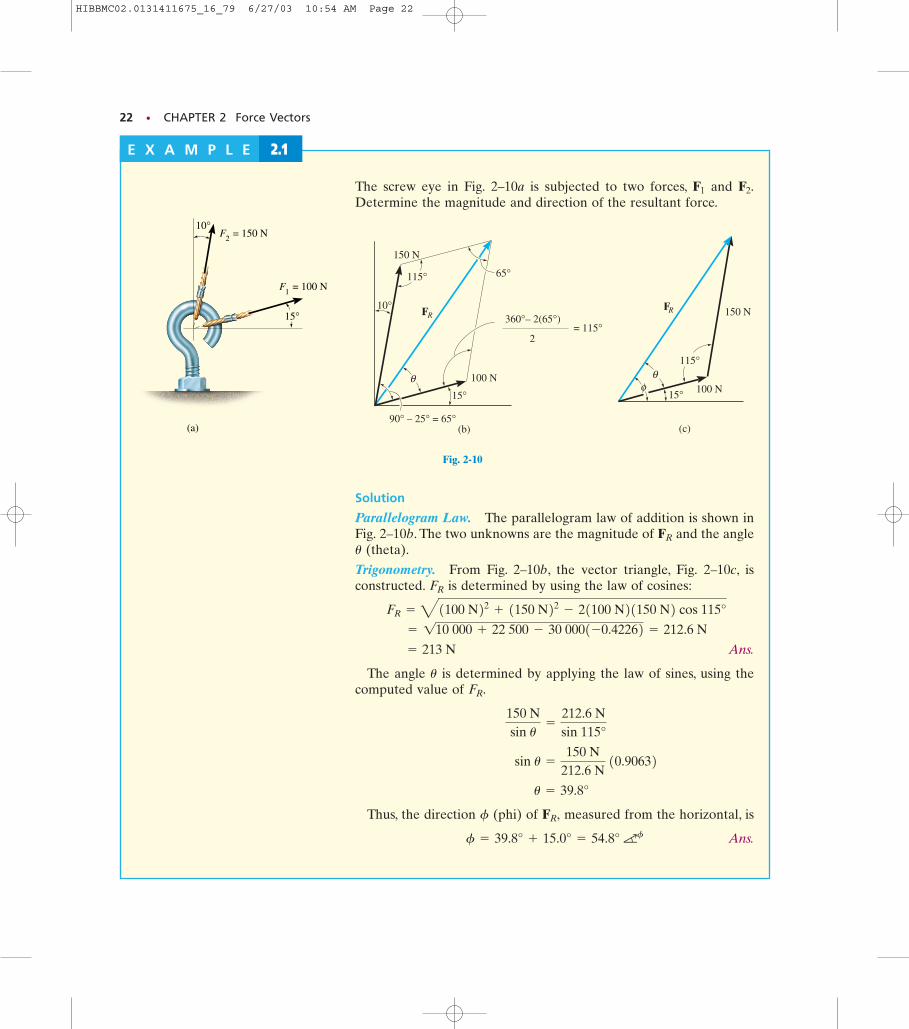
Fig. 2–10B Fig. 2–10C
22 • CHAPTER 2 Force Vectors
= 100 NF1
= 150 NF2
10°
15°
(a)
Fig. 2-10
φ
(c)
RF 150 N
100 N15°
θ115°
RF
90° – 25° = 65°
10°
15°
100 N
65°115°
150 N
θ
(b)
= 115°360°– 2(65°)
2
E X A M P L E 2.1
Solution
Parallelogram Law. The parallelogram law of addition is shown inFig. 2–10b. The two unknowns are the magnitude of and the angle
(theta).
Trigonometry. From Fig. 2–10b, the vector triangle, Fig. 2–10c, isconstructed. is determined by using the law of cosines:
Ans.
The angle is determined by applying the law of sines, using thecomputed value of
Thus, the direction (phi) of measured from the horizontal, is
Ans.aff = 39.8° + 15.0° = 54.8°
FR,f
u = 39.8°
sin u =
150 N212.6 N
10.90632 150 Nsin u
=
212.6 Nsin 115°
FR.u
= 213 N
= 110 000 + 22 500 - 30 0001-0.42262 = 212.6 N
FR = 41100 N22 + 1150 N22 - 21100 N21150 N2 cos 115°
FR
u
FR
The screw eye in Fig. 2–10a is subjected to two forces, and Determine the magnitude and direction of the resultant force.
F2.F1
HIBBMC02.0131411675_16_79 6/27/03 10:54 AM Page 22
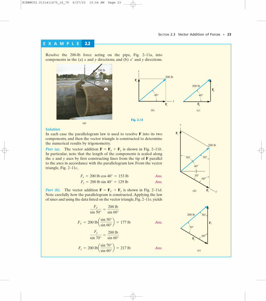
Fig. 2–11E
Fig. 2–11D
Fig. 2–11CFig. 2–11B
SECTION 2.3 Vector Addition of Forces • 23
(a)
200 lb
y
x'
x
40°
30°
Fig. 2–11
xF
yF
40°
200 lb
(b)
x
y
200 lb
xF
40°yF
(c)
200 lb
x'F
40°
yF
30°
50°
x'
60°
50°
(d)
y
200 lb
70°
x'F
yF
60°
50°
(e)
E X A M P L E 2.2
Resolve the 200-lb force acting on the pipe, Fig. 2–11a, intocomponents in the (a) x and y directions, and (b) and y directions.x¿
SolutionIn each case the parallelogram law is used to resolve F into its twocomponents, and then the vector triangle is constructed to determinethe numerical results by trigonometry.
Part (a). The vector addition is shown in Fig. 2–11b.In particular, note that the length of the components is scaled alongthe x and y axes by first constructing lines from the tip of F parallelto the axes in accordance with the parallelogram law. From the vectortriangle, Fig. 2–11c,
Ans.
Ans.
Part (b). The vector addition is shown in Fig. 2–11d.Note carefully how the parallelogram is constructed. Applying the lawof sines and using the data listed on the vector triangle, Fig. 2–11e, yields
Ans.
Ans. Fy = 200 lba sin 70°sin 60°
b = 217 lb
Fy
sin 70°=
200 lbsin 60°
Fx¿= 200 lba sin 50°
sin 60°b = 177 lb
Fx¿
sin 50°=
200 lbsin 60°
F = Fx¿+ Fy
Fy = 200 lb sin 40° = 129 lb
Fx = 200 lb cos 40° = 153 lb
F = Fx + Fy
HIBBMC02.0131411675_16_79 6/27/03 10:54 AM Page 23
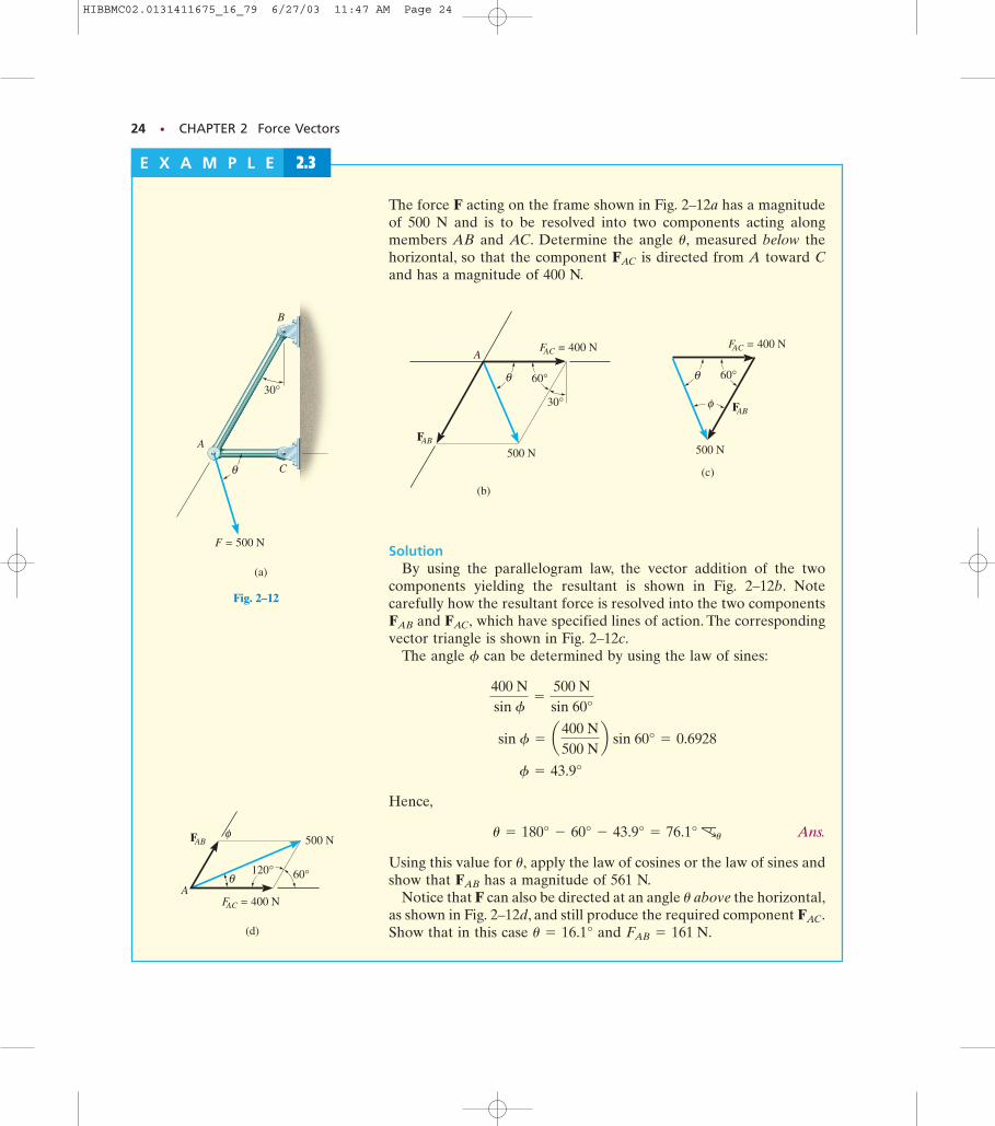
Fig. 2–12D
24 • CHAPTER 2 Force Vectors
The force F acting on the frame shown in Fig. 2–12a has a magnitudeof 500 N and is to be resolved into two components acting alongmembers AB and AC. Determine the angle measured below thehorizontal, so that the component is directed from A toward Cand has a magnitude of 400 N.
FAC
u,
A
B
C
F = 500 N
θ
(a)
30°
Fig. 2–12
AFAC = 400 N
FAB
500 N
θ 60°
30°
(b)
Fig. 2–12B
φ
(c)
FAC = 400 N
FAB
500 N
θ 60°
Fig. 2–12C
E X A M P L E 2.3
FAB 500 N
120°θ 60°
(d)
FAC = 400 NA
φ
SolutionBy using the parallelogram law, the vector addition of the two
components yielding the resultant is shown in Fig. 2–12b. Notecarefully how the resultant force is resolved into the two components
and which have specified lines of action. The correspondingvector triangle is shown in Fig. 2–12c.
The angle can be determined by using the law of sines:
Hence,
Ans.
Using this value for apply the law of cosines or the law of sines andshow that has a magnitude of 561 N.
Notice that F can also be directed at an angle above the horizontal,as shown in Fig. 2–12d, and still produce the required component Show that in this case and FAB = 161 N.u = 16.1°
FAC.u
FAB
u,
cuu = 180° - 60° - 43.9° = 76.1°
f = 43.9°
sin f = a400 N500 N
b sin 60° = 0.6928
400 Nsin f
=
500 Nsin 60°
f
FAC,FAB
HIBBMC02.0131411675_16_79 6/27/03 11:47 AM Page 24
SECTION 2.3 Vector Addition of Forces • 25
F2
θ20°
F1
(a)
Fig. 2–13
1000 N
(b)
F1
F220°30°
180° – 50° = 130°
20°30°
Fig. 2–13B
(c)
F2 30°
130°
20°
1000 N
F1
Fig. 2–13C
E X A M P L E 2.4
(d)
20°
1000 NF1
A
B
F2
F2
F2
O
θ
Fig. 2–13D
(e)
20°
1000 NF1
F2
O
θ = 70°
Fig. 2–13E
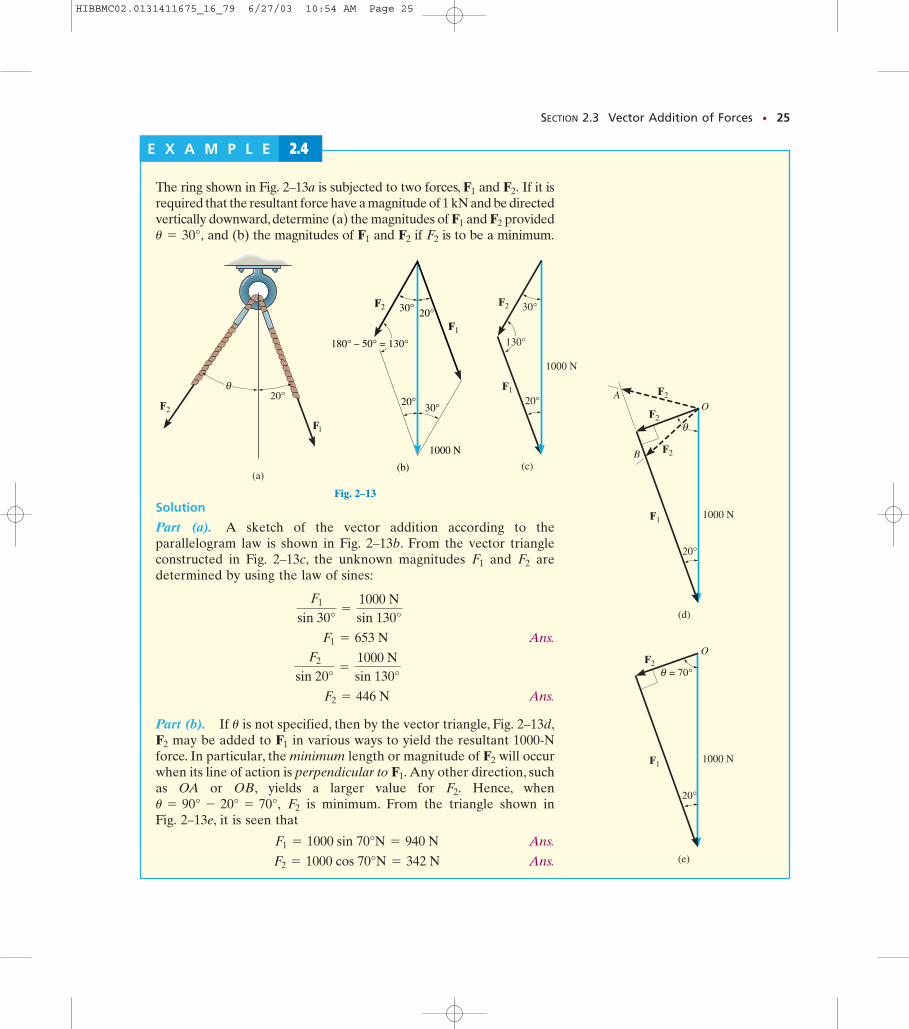
Solution
Part (a). A sketch of the vector addition according to theparallelogram law is shown in Fig. 2–13b. From the vector triangleconstructed in Fig. 2–13c, the unknown magnitudes and aredetermined by using the law of sines:
Ans.
Ans.
Part (b). If is not specified, then by the vector triangle, Fig. 2–13d,may be added to in various ways to yield the resultant 1000-N
force. In particular, the minimum length or magnitude of will occurwhen its line of action is perpendicular to Any other direction, suchas OA or OB, yields a larger value for Hence, when
is minimum. From the triangle shown in Fig. 2–13e, it is seen that
Ans.
Ans. F2 = 1000 cos 70°N = 342 N
F1 = 1000 sin 70°N = 940 N
F2u = 90° - 20° = 70°,F2.
F1.F2
F1F2
u
F2 = 446 N
F2
sin 20°=
1000 Nsin 130°
F1 = 653 N
F1
sin 30°=
1000 Nsin 130°
F2F1
The ring shown in Fig. 2–13a is subjected to two forces, and If it isrequired that the resultant force have a magnitude of 1 kN and be directedvertically downward, determine (a) the magnitudes of and provided
and (b) the magnitudes of and if is to be a minimum.F2F2F1u = 30°,F2F1
F2.F1
HIBBMC02.0131411675_16_79 6/27/03 10:54 AM Page 25
26 • CHAPTER 2 Force Vectors
A
B
FA = 8 kN
FB = 6 kN
40°
θ
Probs. 2–7/8
y
x
2 = 800 NF
3 = 450 NF
1 = 600 NF
75°
45°
60°
45°
60°F2 = 80 NF1 = 100 N
Prob. 2–2
y
F2= 375 lb
x
F1 =250 lb
45˚
30˚
Prob. 2–3
u
v
70°
30°
45°F1= 300 N
F2= 500 N
Probs. 2–4/5/6
P R O B L E M S
Prob. 2–1
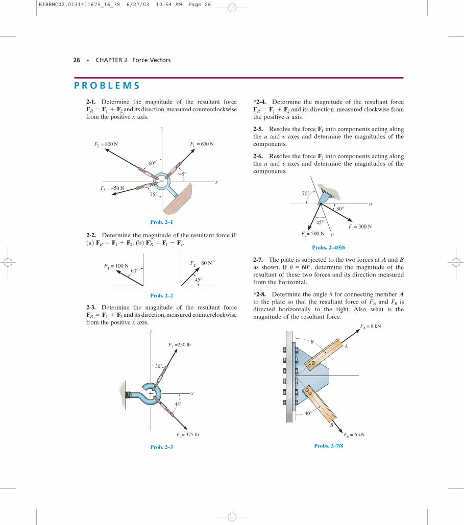
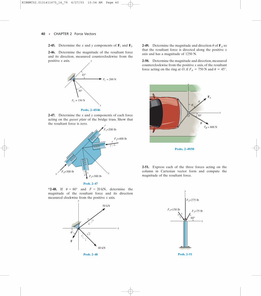
2-1. Determine the magnitude of the resultant forceand its direction,measured counterclockwise
from the positive x axis.FR = F1 + F2
2-2. Determine the magnitude of the resultant force if:(a) (b) Fœ
R = F1 - F2.FR = F1 + F2;
2-3. Determine the magnitude of the resultant forceand its direction,measured counterclockwise
from the positive x axis.FR = F1 + F2
*2-4. Determine the magnitude of the resultant forceand its direction, measured clockwise from
the positive u axis.
2-5. Resolve the force into components acting alongthe u and v axes and determine the magnitudes of thecomponents.
2-6. Resolve the force into components acting alongthe u and v axes and determine the magnitudes of thecomponents.
F2
F1
FR = F1 + F2
2-7. The plate is subjected to the two forces at A and Bas shown. If determine the magnitude of theresultant of these two forces and its direction measuredfrom the horizontal.
*2-8. Determine the angle for connecting member Ato the plate so that the resultant force of and isdirected horizontally to the right. Also, what is themagnitude of the resultant force.
FBFA
u
u = 60°,
HIBBMC02.0131411675_16_79 6/27/03 10:54 AM Page 26
PROBLEMS • 27
F
C
B
A
30°
45°
Probs. 2–9/10
80°
60°a
ab
b
F
Probs. 2–11/12
CB
A
F = 500 lb
60° 45°
θ
Prob. 2–13
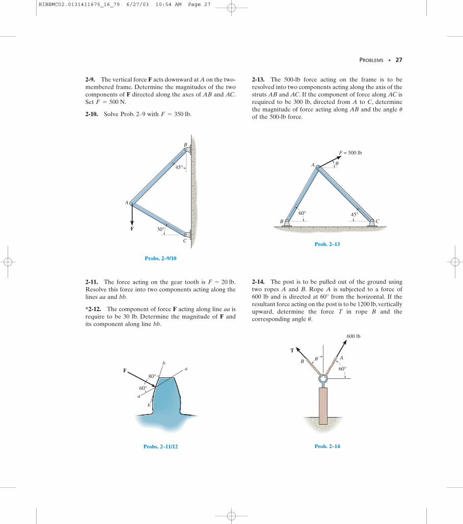
2-9. The vertical force F acts downward at A on the two-membered frame. Determine the magnitudes of the twocomponents of F directed along the axes of AB and AC.Set
2-10. Solve Prob. 2–9 with F = 350 lb.
F = 500 N.
2-11. The force acting on the gear tooth is Resolve this force into two components acting along thelines aa and bb.
*2-12. The component of force F acting along line aa isrequire to be 30 lb. Determine the magnitude of F andits component along line bb.
F = 20 lb.
2-13. The 500-lb force acting on the frame is to beresolved into two components acting along the axis of thestruts AB and AC. If the component of force along AC isrequired to be 300 lb, directed from A to C, determinethe magnitude of force acting along AB and the angle of the 500-lb force.
u
2-14. The post is to be pulled out of the ground usingtwo ropes A and B. Rope A is subjected to a force of 600 lb and is directed at 60° from the horizontal. If theresultant force acting on the post is to be 1200 lb, verticallyupward, determine the force T in rope B and thecorresponding angle u.
60°
600 lb
θ AB
T
Prob. 2–14
HIBBMC02.0131411675_16_79 6/27/03 10:54 AM Page 27
28 • CHAPTER 2 Force Vectors
20 lb
45°
60°
60°
30°
x
y
t
n
Prob. 2–17
θ
F
30°500 N
y
x
Prob. 2–18
y x
θ
φ2F
1F
Prob. 2–19
A
C
B
400 lb
θ
φ
Probs. 2–15/16
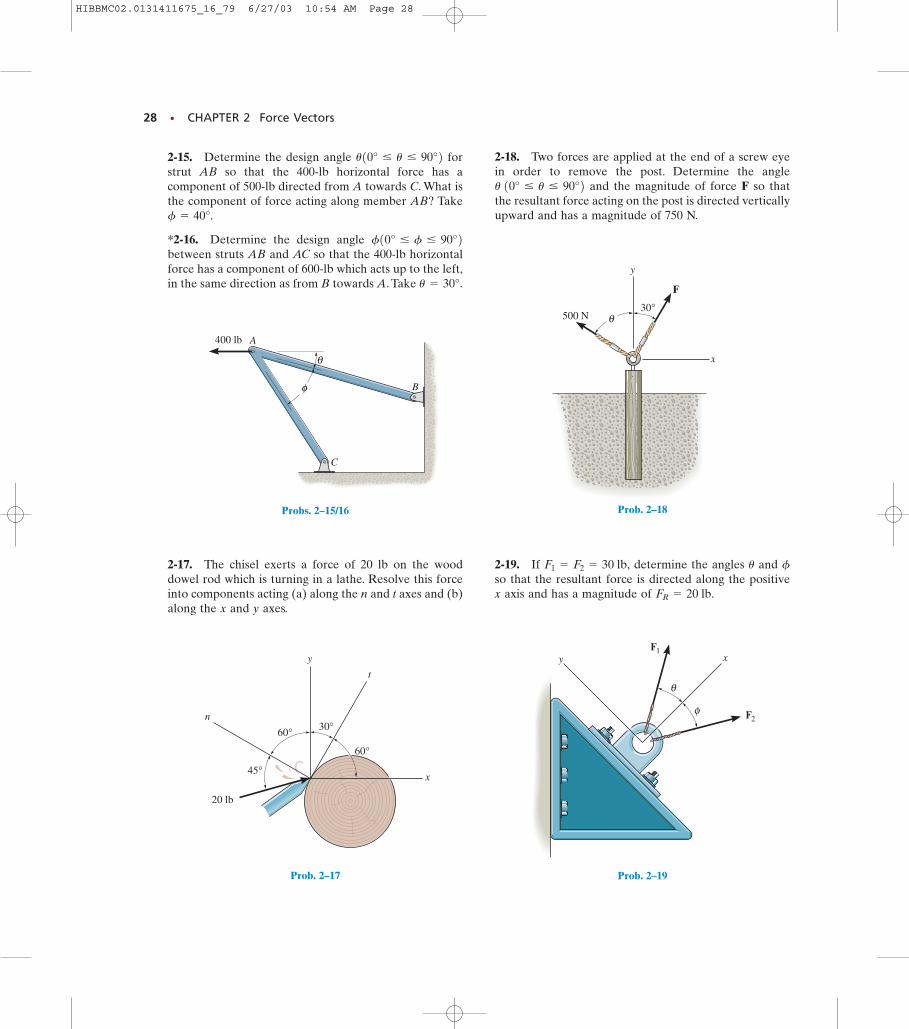
2-15. Determine the design angle forstrut AB so that the 400-lb horizontal force has acomponent of 500-lb directed from A towards C. What isthe component of force acting along member AB? Take
*2-16. Determine the design angle between struts AB and AC so that the 400-lb horizontalforce has a component of 600-lb which acts up to the left,in the same direction as from B towards A. Take u = 30°.
f10° … f … 90°2f = 40°.
u10° … u … 90°2
2-17. The chisel exerts a force of 20 lb on the wooddowel rod which is turning in a lathe. Resolve this forceinto components acting (a) along the n and t axes and (b)along the x and y axes.
2-18. Two forces are applied at the end of a screw eyein order to remove the post. Determine the angle
and the magnitude of force F so thatthe resultant force acting on the post is directed verticallyupward and has a magnitude of 750 N.
u 10° … u … 90°2
2-19. If determine the angles and so that the resultant force is directed along the positivex axis and has a magnitude of FR = 20 lb.
fuF1 = F2 = 30 lb,
HIBBMC02.0131411675_16_79 6/27/03 10:54 AM Page 28
PROBLEMS • 29
y
x
F2= 20 N
F1= 30 N
20°
35
4 F3= 50 N
Probs. 2–22/23
x50 lb
y
y'
45°
30°
65°
y
θ
20°x
A
B
FA
FB
Prob. 2–20
y
θ
20°x
A
B
FA
FB
Prob. 2–21 Prob. 2–24
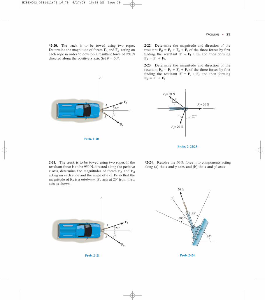
*2-20. The truck is to be towed using two ropes.Determine the magnitude of forces and acting oneach rope in order to develop a resultant force of 950 Ndirected along the positive x axis. Set u = 50°.
FBFA
2-21. The truck is to be towed using two ropes. If theresultant force is to be 950 N, directed along the positivex axis, determine the magnitudes of forces and acting on each rope and the angle of of so that themagnitude of is a minimum. acts at 20° from the xaxis as shown.
FAFB
FBu
FBFA
2-22. Determine the magnitude and direction of theresultant of the three forces by firstfinding the resultant and then forming
2-23. Determine the magnitude and direction of theresultant of the three forces by firstfinding the resultant and then formingFR = F¿ + F1.
F¿ = F2 + F3
FR = F1 + F2 + F3
FR = F¿ + F3.F¿ = F1 + F2
FR = F1 + F2 + F3
*2-24. Resolve the 50-lb force into components actingalong (a) the x and y axes, and (b) the x and axes.y¿
HIBBMC02.0131411675_16_79 6/27/03 10:54 AM Page 29
30 • CHAPTER 2 Force Vectors
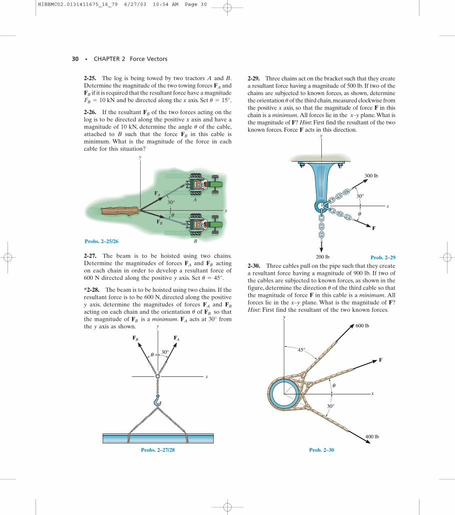
2-25. The log is being towed by two tractors A and B.Determine the magnitude of the two towing forces and
if it is required that the resultant force have a magnitudeand be directed along the x axis. Set
2-26. If the resultant of the two forces acting on thelog is to be directed along the positive x axis and have amagnitude of 10 kN, determine the angle of the cable,attached to B such that the force in this cable isminimum. What is the magnitude of the force in eachcable for this situation?
FB
u
FR
u = 15°.FR = 10 kNFB
FA
300 lb
200 lb
x
y
F
θ
30°
Prob. 2–29
45°
30°
y
x
θ
400 lb
600 lb
F
Prob. 2–30
FB FA
y
x
30°θ
Probs. 2–27/28
x
y
B
A30°
FA
FB
θ
Probs. 2–25/26
2-27. The beam is to be hoisted using two chains.Determine the magnitudes of forces and actingon each chain in order to develop a resultant force of600 N directed along the positive y axis. Set
*2-28. The beam is to be hoisted using two chains. If theresultant force is to be 600 N, directed along the positivey axis, determine the magnitudes of forces and acting on each chain and the orientation of so thatthe magnitude of is a minimum. acts at 30° fromthe y axis as shown.
FAFB
FBu
FBFA
u = 45°.
FBFA
2-29. Three chains act on the bracket such that they createa resultant force having a magnitude of 500 lb. If two of thechains are subjected to known forces, as shown, determinethe orientation of the third chain,measured clockwise fromthe positive x axis, so that the magnitude of force F in thischain is a minimum. All forces lie in the x–y plane. What isthe magnitude of F? Hint: First find the resultant of the twoknown forces. Force F acts in this direction.
u
2-30. Three cables pull on the pipe such that they createa resultant force having a magnitude of 900 lb. If two ofthe cables are subjected to known forces, as shown in thefigure, determine the direction of the third cable so thatthe magnitude of force F in this cable is a minimum. Allforces lie in the x–y plane. What is the magnitude of F?Hint: First find the resultant of the two known forces.
u
HIBBMC02.0131411675_16_79 6/27/03 10:54 AM Page 30
SECTION 2.4 Addition of a System of Coplanar Forces • 31
2.4 Addition of a System of Coplanar Forces
F
(a)
Fy
y
xFx
Fig. 2–14A
x
F'
F'xF'y
y
(b)
Fig. 2–14
*Negative signs are used only in figures with boldface notation when showing equal butopposite pairs of vectors as in Fig. 2–2.
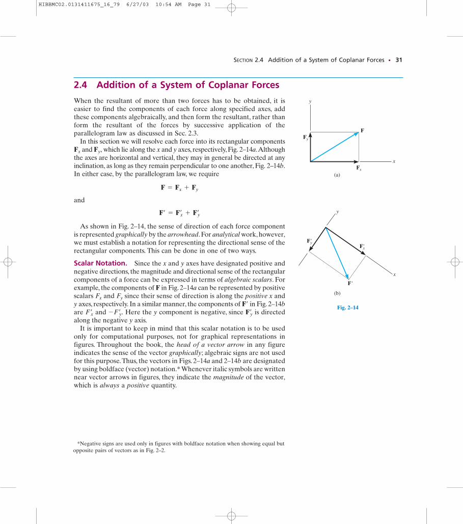
When the resultant of more than two forces has to be obtained, it iseasier to find the components of each force along specified axes, addthese components algebraically, and then form the resultant, rather thanform the resultant of the forces by successive application of theparallelogram law as discussed in Sec. 2.3.
In this section we will resolve each force into its rectangular componentsand which lie along the x and y axes, respectively, Fig. 2–14a.Although
the axes are horizontal and vertical, they may in general be directed at anyinclination, as long as they remain perpendicular to one another, Fig. 2–14b.In either case, by the parallelogram law, we require
and
As shown in Fig. 2–14, the sense of direction of each force componentis represented graphically by the arrowhead. For analytical work, however,we must establish a notation for representing the directional sense of therectangular components. This can be done in one of two ways.
Scalar Notation. Since the x and y axes have designated positive andnegative directions, the magnitude and directional sense of the rectangularcomponents of a force can be expressed in terms of algebraic scalars. Forexample, the components of F in Fig. 2–14a can be represented by positivescalars and since their sense of direction is along the positive x andy axes, respectively. In a similar manner, the components of in Fig. 2–14bare and Here the y component is negative, since is directedalong the negative y axis.
It is important to keep in mind that this scalar notation is to be usedonly for computational purposes, not for graphical representations infigures. Throughout the book, the head of a vector arrow in any figureindicates the sense of the vector graphically; algebraic signs are not usedfor this purpose.Thus, the vectors in Figs. 2–14a and 2–14b are designatedby using boldface (vector) notation.* Whenever italic symbols are writtennear vector arrows in figures, they indicate the magnitude of the vector,which is always a positive quantity.
Fyœ
-Fyœ .Fx
œ
F¿
FyFx
F¿ = Fxœ
+ Fyœ
F = Fx + Fy
Fy,Fx
HIBBMC02.0131411675_16_79 6/27/03 10:54 AM Page 31
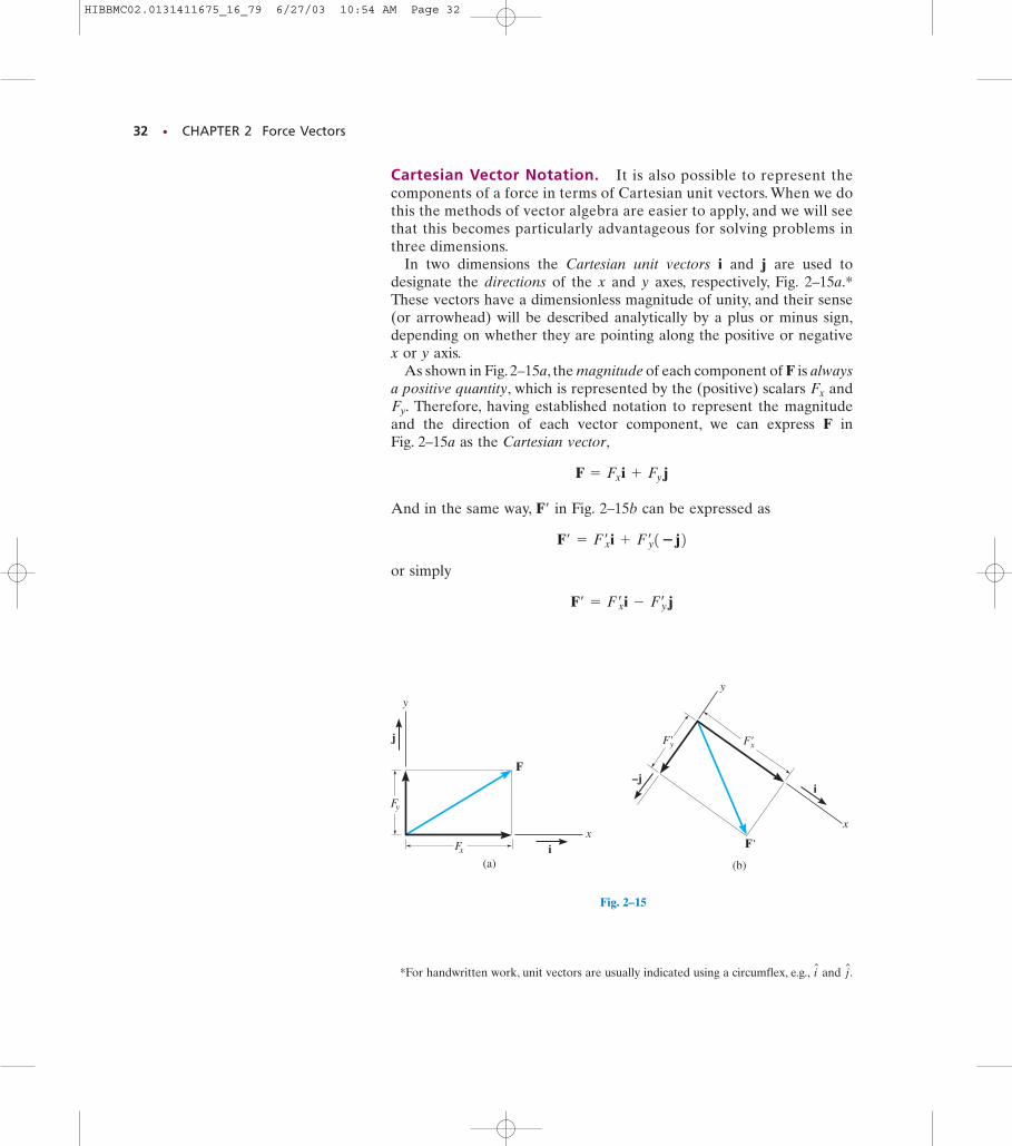
Fig. 2–15B
32 • CHAPTER 2 Force Vectors
F
(a)
Fx
Fy
y
xi
j
Fig. 2–15
x
F'
F'xF'y
y
(b)
i–j
*For handwritten work, unit vectors are usually indicated using a circumflex, e.g., and j N.i
N
Cartesian Vector Notation. It is also possible to represent thecomponents of a force in terms of Cartesian unit vectors. When we dothis the methods of vector algebra are easier to apply, and we will seethat this becomes particularly advantageous for solving problems inthree dimensions.
In two dimensions the Cartesian unit vectors i and j are used todesignate the directions of the x and y axes, respectively, Fig. 2–15a.*These vectors have a dimensionless magnitude of unity, and their sense(or arrowhead) will be described analytically by a plus or minus sign,depending on whether they are pointing along the positive or negativex or y axis.
As shown in Fig. 2–15a, the magnitude of each component of F is alwaysa positive quantity, which is represented by the (positive) scalars and
Therefore, having established notation to represent the magnitudeand the direction of each vector component, we can express F in Fig. 2–15a as the Cartesian vector,
And in the same way, in Fig. 2–15b can be expressed as
or simply
F¿ = Fxœ i - Fy
œ
j
F¿ = Fxœ i + Fy
œ 1�j2F¿
F = Fx i + Fy j
Fy.Fx
HIBBMC02.0131411675_16_79 6/27/03 10:54 AM Page 32
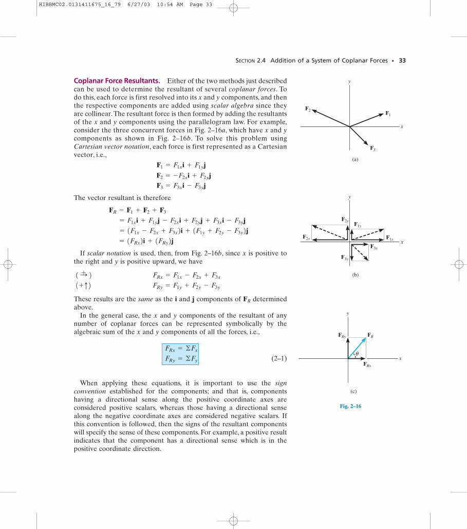
Coplanar Force Resultants. Either of the two methods just describedcan be used to determine the resultant of several coplanar forces. Todo this, each force is first resolved into its x and y components, and thenthe respective components are added using scalar algebra since theyare collinear.The resultant force is then formed by adding the resultantsof the x and y components using the parallelogram law. For example,consider the three concurrent forces in Fig. 2–16a, which have x and ycomponents as shown in Fig. 2–16b. To solve this problem usingCartesian vector notation, each force is first represented as a Cartesianvector, i.e.,
The vector resultant is therefore
If scalar notation is used, then, from Fig. 2–16b, since x is positive tothe right and y is positive upward, we have
These results are the same as the i and j components of determinedabove.
In the general case, the x and y components of the resultant of anynumber of coplanar forces can be represented symbolically by thealgebraic sum of the x and y components of all the forces, i.e.,
(2–1)
When applying these equations, it is important to use the signconvention established for the components; and that is, componentshaving a directional sense along the positive coordinate axes areconsidered positive scalars, whereas those having a directional sensealong the negative coordinate axes are considered negative scalars. Ifthis convention is followed, then the signs of the resultant componentswill specify the sense of these components. For example, a positive resultindicates that the component has a directional sense which is in thepositive coordinate direction.
FRy = ©Fy
FRx = ©Fx
FR
1+q2 FRy = F1y + F2y - F3y
1:+ 2 FRx = F1x - F2x + F3x
= 1FRx2i + 1FRy2j = 1F1x - F2x + F3x2i + 1F1y + F2y - F3y2j = F1x i + F1y j - F2x i + F2y j + F3x i - F3y j
FR = F1 + F2 + F3
F3 = F3x i - F3y j F2 = -F2x i + F2y j
F1 = F1x i + F1y j
SECTION 2.4 Addition of a System of Coplanar Forces • 33
F3
F1
F2
(a)
x
y
Fig. 2–16A
(b)
x
y
F2x
F2yF1y
F1x
F3x
F3y
Fig. 2–16B
(c)
x
y
FRFRy
FRx
θ
Fig. 2–16
HIBBMC02.0131411675_16_79 6/27/03 10:54 AM Page 33
34 • CHAPTER 2 Force Vectors
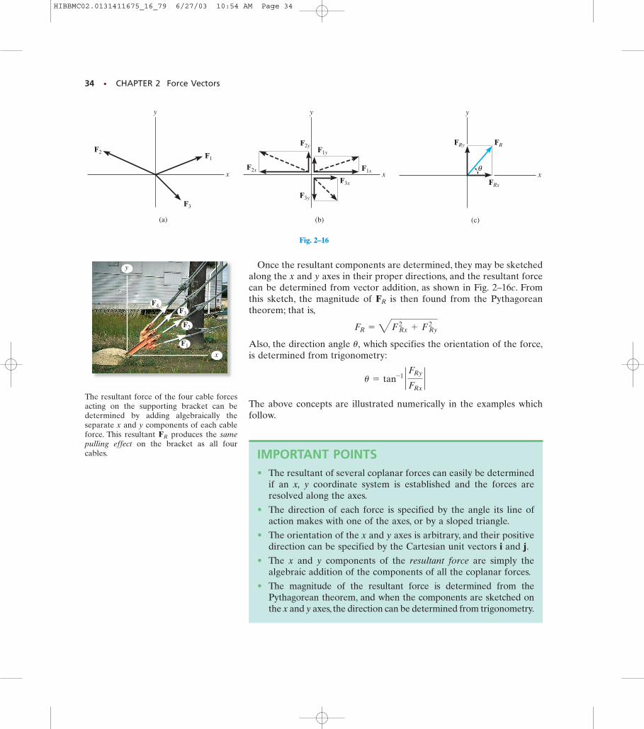
Once the resultant components are determined, they may be sketchedalong the x and y axes in their proper directions, and the resultant forcecan be determined from vector addition, as shown in Fig. 2–16c. Fromthis sketch, the magnitude of is then found from the Pythagoreantheorem; that is,
Also, the direction angle which specifies the orientation of the force,is determined from trigonometry:
The above concepts are illustrated numerically in the examples whichfollow.
u = tan-1 ` FRy
FRx`
u,
FR = 4FRx2
+ FRy2
FR
F3
F1
F2
(a)
x
y
Fig. 2–16
(b)
x
y
F2x
F2yF1y
F1x
F3x
F3y
Fig. 2–16B
F1
F2
F3
F4
x
y
The resultant force of the four cable forcesacting on the supporting bracket can bedetermined by adding algebraically theseparate x and y components of each cableforce. This resultant produces the samepulling effect on the bracket as all fourcables.
FR
IMPORTANT POINTS• The resultant of several coplanar forces can easily be determined
if an x, y coordinate system is established and the forces areresolved along the axes.
• The direction of each force is specified by the angle its line ofaction makes with one of the axes, or by a sloped triangle.
• The orientation of the x and y axes is arbitrary, and their positivedirection can be specified by the Cartesian unit vectors i and j.
• The x and y components of the resultant force are simply thealgebraic addition of the components of all the coplanar forces.
• The magnitude of the resultant force is determined from thePythagorean theorem, and when the components are sketched onthe x and y axes, the direction can be determined from trigonometry.
(c)
x
y
FRFRy
FRx
θ
Fig. 2–16C
HIBBMC02.0131411675_16_79 6/27/03 10:54 AM Page 34
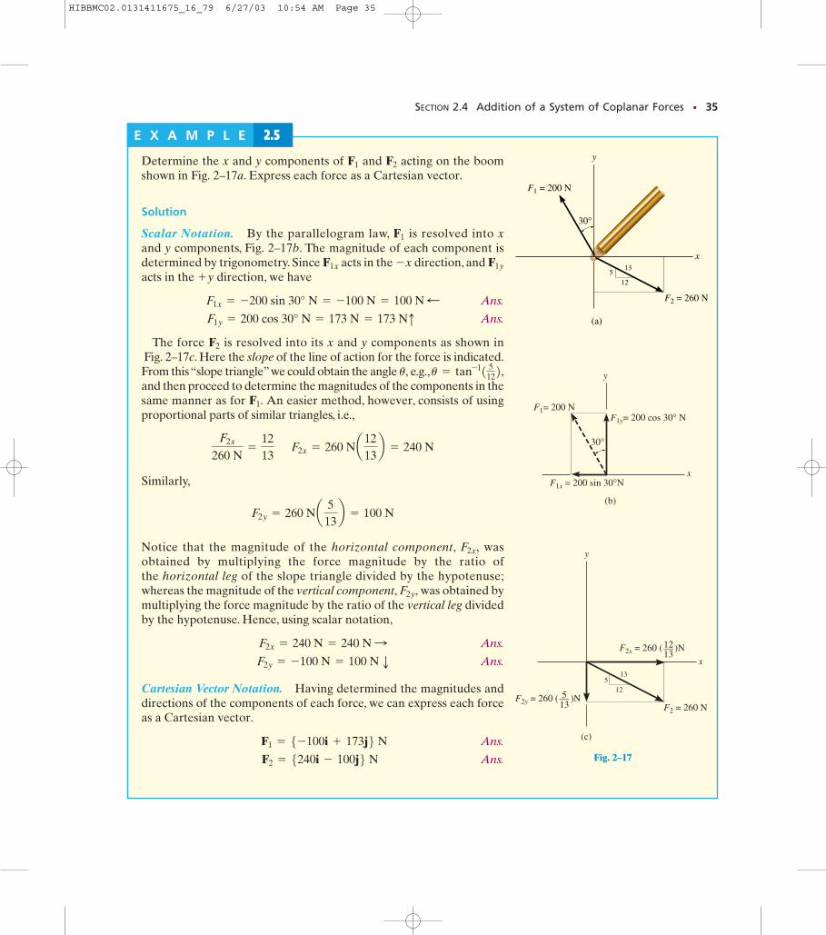
Fig. 2–17A
Fig. 2–17B
SECTION 2.4 Addition of a System of Coplanar Forces • 35
E X A M P L E 2.5y
x
F1 = 200 N
F2 = 260 N
30°
(a)
512
13
y
x
F1= 200 N
F1x = 200 sin 30°N
30°
F1y= 200 cos 30° N
(b)
y
x
F2x = 260 ( )N
F2y = 260 ( )NF2 = 260 N
(c)
512
13
12—13
5—13
Fig. 2–17
Determine the x and y components of and acting on the boomshown in Fig. 2–17a. Express each force as a Cartesian vector.
Solution
Scalar Notation. By the parallelogram law, is resolved into xand y components, Fig. 2–17b. The magnitude of each component isdetermined by trigonometry. Since acts in the direction, and acts in the direction, we have
Ans.
Ans.
The force is resolved into its x and y components as shown inFig. 2–17c. Here the slope of the line of action for the force is indicated.From this “slope triangle”we could obtain the angle e.g.,and then proceed to determine the magnitudes of the components in thesame manner as for An easier method, however, consists of using proportional parts of similar triangles, i.e.,
Similarly,
Notice that the magnitude of the horizontal component, wasobtained by multiplying the force magnitude by the ratio of the horizontal leg of the slope triangle divided by the hypotenuse;whereas the magnitude of the vertical component, was obtained bymultiplying the force magnitude by the ratio of the vertical leg dividedby the hypotenuse. Hence, using scalar notation,
Ans.
Ans.
Cartesian Vector Notation. Having determined the magnitudes anddirections of the components of each force, we can express each forceas a Cartesian vector.
Ans.
Ans. F2 = 5240i - 100j6 N F1 = 5-100i + 173j6 N
F2y = -100 N = 100 N p F2x = 240 N = 240 N :
F2y,
F2x,
F2y = 260 Na 513b = 100 N
F2x
260 N=
1213
F2x = 260 Na1213b = 240 N
F1.
u = tan-11 5122,u,
F2
F1y = 200 cos 30° N = 173 N = 173 Nq F1x = -200 sin 30° N = -100 N = 100 N ;
+yF1y-xF1x
F1
F2F1
HIBBMC02.0131411675_16_79 6/27/03 10:54 AM Page 35
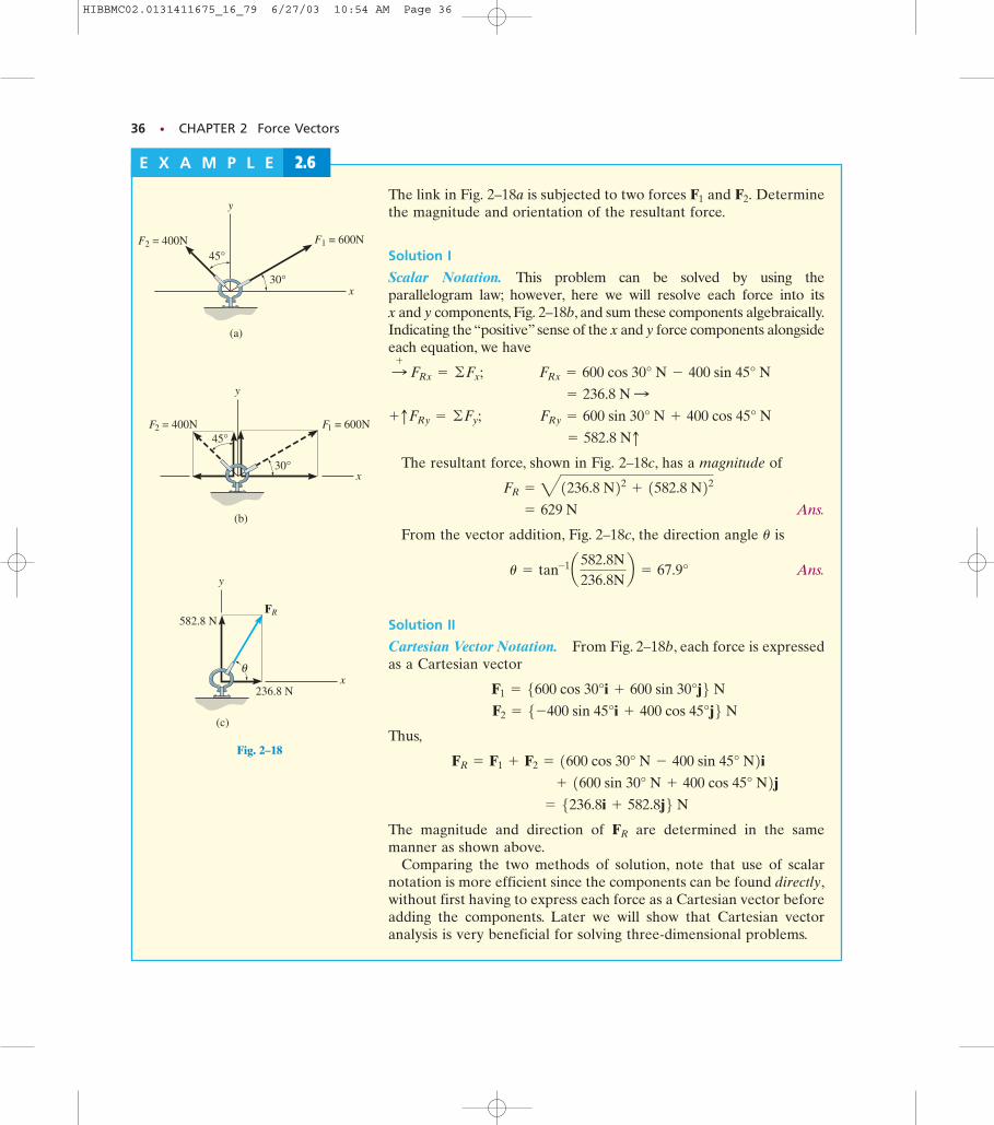
Fig. 2–18B
Fig. 2–18A
36 • CHAPTER 2 Force Vectors
The link in Fig. 2–18a is subjected to two forces and Determinethe magnitude and orientation of the resultant force.
Solution I
Scalar Notation. This problem can be solved by using theparallelogram law; however, here we will resolve each force into its x and y components, Fig. 2–18b, and sum these components algebraically.Indicating the “positive” sense of the x and y force components alongsideeach equation, we have
The resultant force, shown in Fig. 2–18c, has a magnitude of
Ans.
From the vector addition, Fig. 2–18c, the direction angle is
Ans.
Solution II
Cartesian Vector Notation. From Fig. 2–18b, each force is expressedas a Cartesian vector
Thus,
The magnitude and direction of are determined in the samemanner as shown above.
Comparing the two methods of solution, note that use of scalarnotation is more efficient since the components can be found directly,without first having to express each force as a Cartesian vector beforeadding the components. Later we will show that Cartesian vectoranalysis is very beneficial for solving three-dimensional problems.
FR
= 5236.8i + 582.8j6 N + 1600 sin 30° N + 400 cos 45° N2j
FR = F1 + F2 = 1600 cos 30° N - 400 sin 45° N2i
F2 = 5-400 sin 45°i + 400 cos 45°j6 N F1 = 5600 cos 30°i + 600 sin 30°j6 N
u = tan-1a582.8N236.8N
b = 67.9°
u
= 629 N
FR = 41236.8 N22 + 1582.8 N22
= 582.8 Nq FRy = 600 sin 30° N + 400 cos 45° N+qFRy = ©Fy;
= 236.8 N : FRx = 600 cos 30° N - 400 sin 45° N:
+
FRx = ©Fx;
F2.F1
E X A M P L E 2.6
y
F1 = 600N
x
F2 = 400N45°
30°
(a)
y
F1 = 600N
x
F2 = 400N
30°
(b)
45°
y
FR
x
(c)
582.8 N
236.8 N
θ
Fig. 2–18
HIBBMC02.0131411675_16_79 6/27/03 10:54 AM Page 36
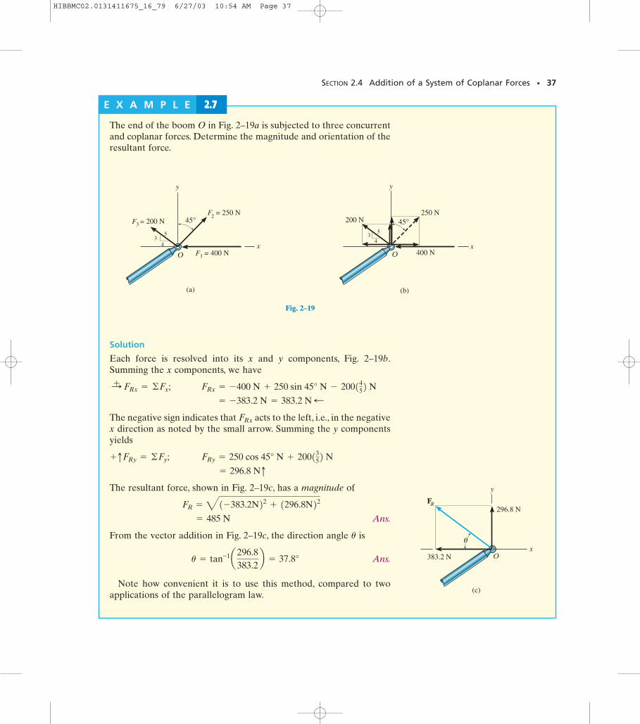
Fig. 2–19C
SECTION 2.4 Addition of a System of Coplanar Forces • 37
E X A M P L E 2.7
3F= 250 N
(a)
y
Οx
= 200 N
1F = 400 N
2F
35
4
45°
Fig. 2–19
250 N
(b)
y
Ο
45°
400 N
4x
200 N
35
Fig. 2–19B
RF 296.8 N
383.2 N
(c)
y
θ
Οx
The end of the boom O in Fig. 2–19a is subjected to three concurrentand coplanar forces. Determine the magnitude and orientation of theresultant force.
Solution
Each force is resolved into its x and y components, Fig. 2–19b.Summing the x components, we have
The negative sign indicates that acts to the left, i.e., in the negativex direction as noted by the small arrow. Summing the y componentsyields
The resultant force, shown in Fig. 2–19c, has a magnitude of
Ans.
From the vector addition in Fig. 2–19c, the direction angle is
Ans.
Note how convenient it is to use this method, compared to twoapplications of the parallelogram law.
u = tan-1a296.8383.2
b = 37.8°
u
= 485 N
FR = 41-383.2N22 + 1296.8N22
= 296.8 Nq FRy = 250 cos 45° N + 2001352 N+qFRy = ©Fy;
FRx
= -383.2 N = 383.2 N ; FRx = -400 N + 250 sin 45° N - 2001452 N:+ FRx = ©Fx;
HIBBMC02.0131411675_16_79 6/27/03 10:54 AM Page 37
P R O B L E M S
38 • CHAPTER 2 Force Vectors
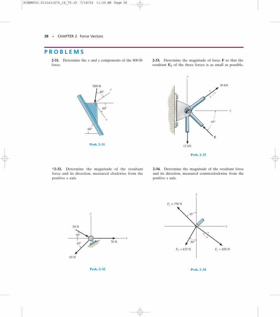
2-31. Determine the x and y components of the 800-lbforce.
*2-32. Determine the magnitude of the resultantforce and its direction, measured clockwise from thepositive x axis.
2-33. Determine the magnitude of force F so that theresultant of the three forces is as small as possible.FR
4
20 kN
12 kN
F
45°
35
x
y
Prob. 2–33
30°
x
y
34
5
45°
3 = 750 NF
2 = 625 NF 1 = 850 NF
Prob. 2–34
60°
800 lb
40°
x
y
60°
Prob. 2–31
y
70 N
65 N
50 N
x30°
45°
Prob. 2–32
2-34. Determine the magnitude of the resultant forceand its direction, measured counterclockwise from thepositive x axis.
HIBBMC02.0131411675_16_79.v2 7/18/03 11:05 AM Page 38
PROBLEMS • 39
F2 = 450 N
F1
F3 = 200 N45°
30°
θ
y
x
x'
Probs. 2–35/36
F1 = 30 kN
F2 = 26 kN
12
5
13
x
y
30°
Probs. 2–39/40
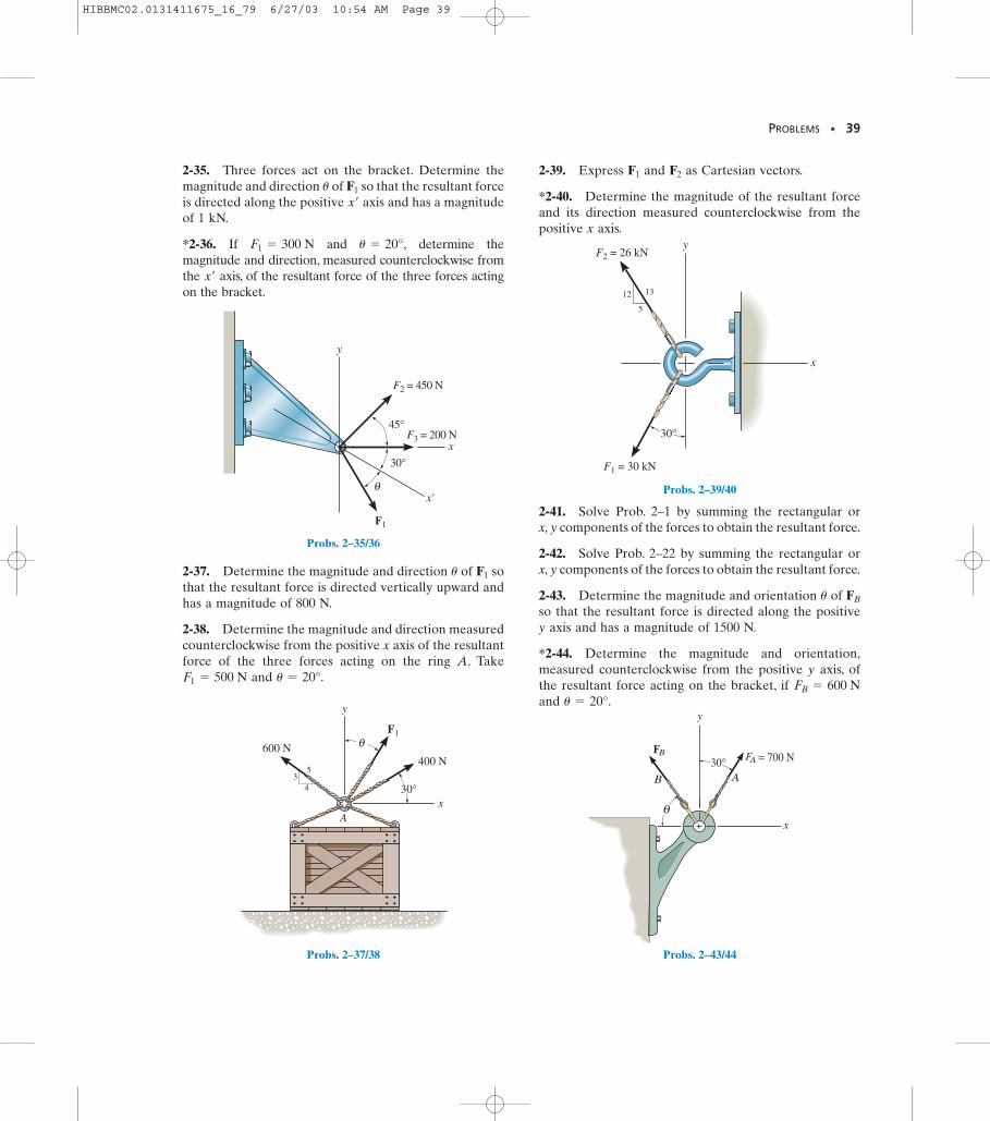
2-35. Three forces act on the bracket. Determine themagnitude and direction of so that the resultant forceis directed along the positive axis and has a magnitudeof 1 kN.
*2-36. If and determine themagnitude and direction, measured counterclockwise fromthe axis, of the resultant force of the three forces actingon the bracket.
x¿
u = 20°,F1 = 300 N
x¿
F1u
2-37. Determine the magnitude and direction of sothat the resultant force is directed vertically upward andhas a magnitude of 800 N.
2-38. Determine the magnitude and direction measuredcounterclockwise from the positive x axis of the resultantforce of the three forces acting on the ring A. Take
and u = 20°.F1 = 500 N
F1u
2-39. Express and as Cartesian vectors.
*2-40. Determine the magnitude of the resultant forceand its direction measured counterclockwise from thepositive x axis.
F2F1
Ax
y
F1
400 N600 N
34
5
30°
θ
Probs. 2–37/38
BFAF = 700 N
x
y
B A
θ
30°
Probs. 2–43/44
2-41. Solve Prob. 2–1 by summing the rectangular or x, y components of the forces to obtain the resultant force.
2-42. Solve Prob. 2–22 by summing the rectangular orx, y components of the forces to obtain the resultant force.
2-43. Determine the magnitude and orientation of so that the resultant force is directed along the positivey axis and has a magnitude of 1500 N.
*2-44. Determine the magnitude and orientation,measured counterclockwise from the positive y axis, ofthe resultant force acting on the bracket, if and u = 20°.
FB = 600 N
FBu
HIBBMC02.0131411675_16_79 6/27/03 10:54 AM Page 39
40 • CHAPTER 2 Force Vectors
y
x
30°
1 = 200 NF
2 = 150 NF
45°
Probs. 2–45/46
yx3
45
3 4
5
F1=200 lb
F2=400 lb
F3=300 lb
F4=300 lb
Prob. 2–47
5 3
4
1
1
y
x
50 kN
40 kN
F
2θ
Prob. 2–48
30°
y
xO
B
A
BF = 800 N
FA
θ
Probs. 2–49/50
2-45. Determine the x and y components of and
2-46. Determine the magnitude of the resultant forceand its direction, measured counterclockwise from thepositive x axis.
F2.F1
2-47. Determine the x and y components of each forceacting on the gusset plate of the bridge truss. Show thatthe resultant force is zero.
x
y
43
5
60°
F3=75 lb
F2=275 lb
F1=150 lb
Prob. 2–51
*2-48. If and determine themagnitude of the resultant force and its directionmeasured clockwise from the positive x axis.
F = 20 kN,u = 60°
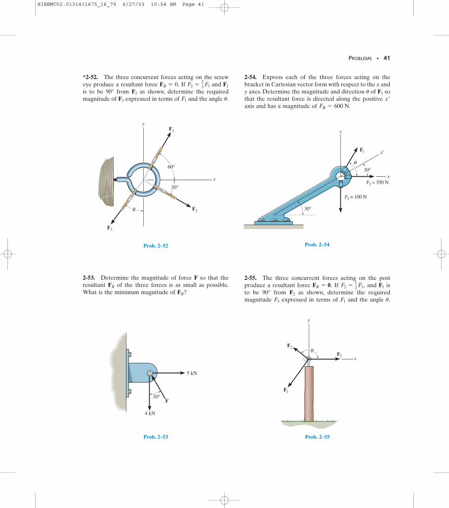
2-49. Determine the magnitude and direction of sothat the resultant force is directed along the positive xaxis and has a magnitude of 1250 N.
2-50. Determine the magnitude and direction, measuredcounterclockwise from the positive x axis, of the resultantforce acting on the ring at O, if and u = 45°.FA = 750 N
FAu
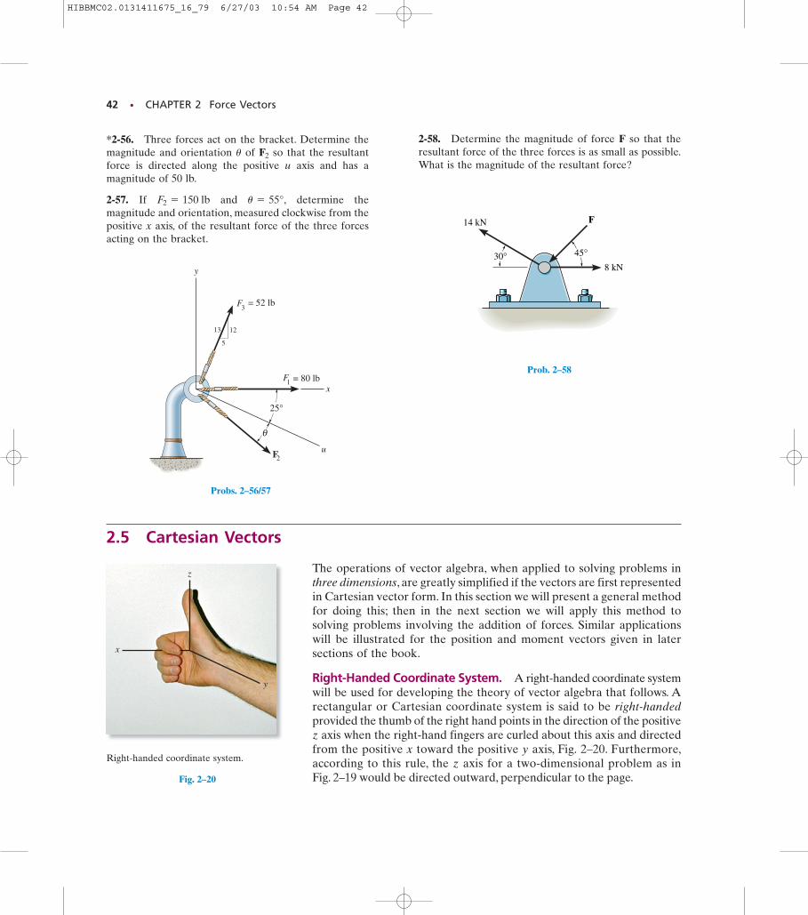
2-51. Express each of the three forces acting on thecolumn in Cartesian vector form and compute themagnitude of the resultant force.
HIBBMC02.0131411675_16_79 6/27/03 10:54 AM Page 40
PROBLEMS • 41
F2 = 350 N
F1
F3 = 100 N
θ
y
x
x'
30°
30°
Prob. 2–54
*2-52. The three concurrent forces acting on the screweye produce a resultant force If and is to be 90° from as shown, determine the requiredmagnitude of expressed in terms of and the angle u.F1F3
F2
F1F2 =23 F1FR = 0.
2-53. Determine the magnitude of force F so that theresultant of the three forces is as small as possible.What is the minimum magnitude of FR?
FR
2-54. Express each of the three forces acting on thebracket in Cartesian vector form with respect to the x andy axes. Determine the magnitude and direction of sothat the resultant force is directed along the positive axis and has a magnitude of FR = 600 N.
x¿
F1u
2-55. The three concurrent forces acting on the postproduce a resultant force If and isto be 90° from as shown, determine the requiredmagnitude expressed in terms of and the angle u.F1F3
F2
F1F2 =12 F1,FR = 0.
y
x
60°
30°
F2
F3
F1
θ
Prob. 2–52
4 kN
5 kN
F30°
Prob. 2–53
x
y
F1
F2
F3θ
Prob. 2–55
HIBBMC02.0131411675_16_79 6/27/03 10:54 AM Page 41
42 • CHAPTER 2 Force Vectors
z
y
x
Right-handed coordinate system.
Fig. 2–20
x
y
u
12
5
13
1F = 80 lb
2F
25°
3F = 52 lb
θ
Probs. 2–56/57
30°
F
8 kN
14 kN
45°
Prob. 2–58
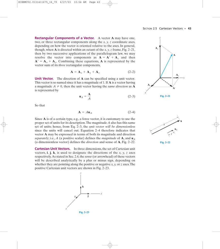
2.5 Cartesian Vectors
The operations of vector algebra, when applied to solving problems inthree dimensions, are greatly simplified if the vectors are first representedin Cartesian vector form. In this section we will present a general methodfor doing this; then in the next section we will apply this method tosolving problems involving the addition of forces. Similar applicationswill be illustrated for the position and moment vectors given in latersections of the book.
Right-Handed Coordinate System. A right-handed coordinate systemwill be used for developing the theory of vector algebra that follows. Arectangular or Cartesian coordinate system is said to be right-handedprovided the thumb of the right hand points in the direction of the positivez axis when the right-hand fingers are curled about this axis and directedfrom the positive x toward the positive y axis, Fig. 2–20. Furthermore,according to this rule, the z axis for a two-dimensional problem as in Fig. 2–19 would be directed outward, perpendicular to the page.
*2-56. Three forces act on the bracket. Determine themagnitude and orientation of so that the resultantforce is directed along the positive u axis and has amagnitude of 50 lb.
2-57. If and determine themagnitude and orientation, measured clockwise from thepositive x axis, of the resultant force of the three forcesacting on the bracket.
u = 55°,F2 = 150 lb
F2u
2-58. Determine the magnitude of force F so that theresultant force of the three forces is as small as possible.What is the magnitude of the resultant force?
HIBBMC02.0131411675_16_79 6/27/03 10:54 AM Page 42
SECTION 2.5 Cartesian Vectors • 43
Rectangular Components of a Vector. A vector A may have one,two, or three rectangular components along the x, y, z coordinate axes,depending on how the vector is oriented relative to the axes. In general,though, when A is directed within an octant of the x, y, z frame, Fig. 2–21,then by two successive applications of the parallelogram law, we mayresolve the vector into components as and then
Combining these equations, A is represented by thevector sum of its three rectangular components,
(2–2)
Unit Vector. The direction of A can be specified using a unit vector.This vector is so named since it has a magnitude of 1. If A is a vector havinga magnitude then the unit vector having the same direction as Ais represented by
(2–3)
So that
(2–4)
Since A is of a certain type, e.g., a force vector, it is customary to use theproper set of units for its description.The magnitude A also has this sameset of units; hence, from Eq. 2–3, the unit vector will be dimensionlesssince the units will cancel out. Equation 2–4 therefore indicates thatvector A may be expressed in terms of both its magnitude and directionseparately; i.e., A (a positive scalar) defines the magnitude of A, and (a dimensionless vector) defines the direction and sense of A, Fig. 2–22.
Cartesian Unit Vectors. In three dimensions, the set of Cartesian unitvectors, i, j, k, is used to designate the directions of the x, y, z axesrespectively.As stated in Sec. 2.4, the sense (or arrowhead) of these vectorswill be described analytically by a plus or minus sign, depending onwhether they are pointing along the positive or negative x, y, or z axes.Thepositive Cartesian unit vectors are shown in Fig. 2–23.
uA
A = AuA
uA =
AA
A Z 0,
A = Ax + Ay + Az
A¿ = Ax + Ay.A = A¿ + Az
A
Ax
z
y
x
Ay
Az
A'
Fig. 2–21
A
uA
1
A
Fig. 2–22
k
ji
z
y
x
Fig. 2–23
HIBBMC02.0131411675_16_79 6/27/03 10:54 AM Page 43
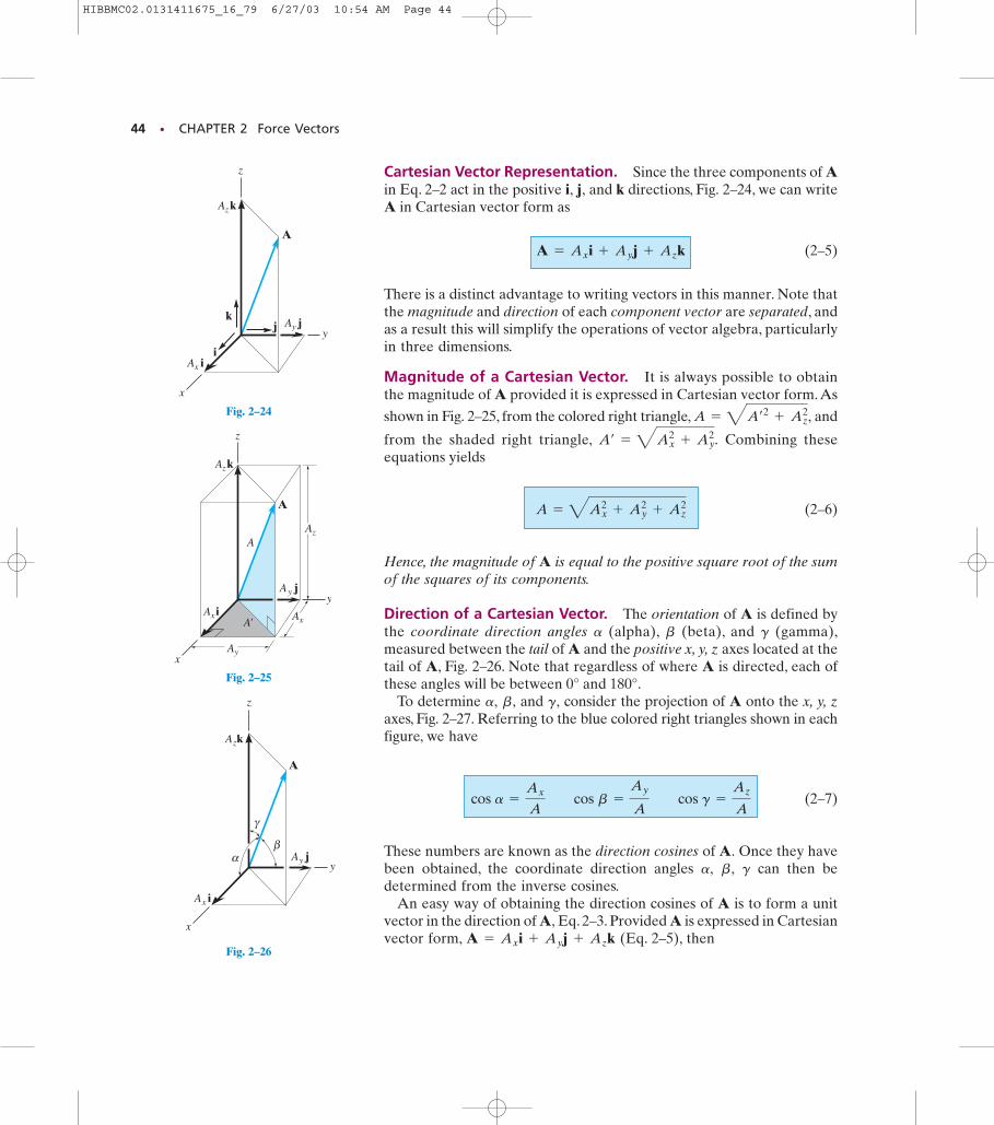
Cartesian Vector Representation. Since the three components of Ain Eq. 2–2 act in the positive i, j, and k directions, Fig. 2–24, we can writeA in Cartesian vector form as
(2–5)
There is a distinct advantage to writing vectors in this manner. Note thatthe magnitude and direction of each component vector are separated, andas a result this will simplify the operations of vector algebra, particularlyin three dimensions.
Magnitude of a Cartesian Vector. It is always possible to obtain the magnitude of A provided it is expressed in Cartesian vector form. As
shown in Fig. 2–25, from the colored right triangle, and
from the shaded right triangle, Combining theseequations yields
(2–6)
Hence, the magnitude of A is equal to the positive square root of the sumof the squares of its components.
Direction of a Cartesian Vector. The orientation of A is defined bythe coordinate direction angles (alpha), (beta), and (gamma),measured between the tail of A and the positive x, y, z axes located at thetail of A, Fig. 2–26. Note that regardless of where A is directed, each ofthese angles will be between 0° and 180°.
To determine and consider the projection of A onto the x, y, zaxes, Fig. 2–27. Referring to the blue colored right triangles shown in eachfigure, we have
(2–7)
These numbers are known as the direction cosines of A. Once they havebeen obtained, the coordinate direction angles can then bedetermined from the inverse cosines.
An easy way of obtaining the direction cosines of A is to form a unitvector in the direction of A, Eq. 2–3. Provided A is expressed in Cartesianvector form, (Eq. 2–5), thenA = Ax i + Ay j + Az k
gb,a,
cos a =
Ax
A cos b =
Ay
A cos g =
Az
A
g,b,a,
gba
A = 4Ax2
+ Ay2
+ Az2
A¿ = 4Ax2
+ Ay2.
A = 4A¿2
+ Az2,
A = Ax i + Ay j + Az k
44 • CHAPTER 2 Force Vectors
A
Ax i
z
y
x
Ay j
Az k
γ
βα
Fig. 2–26
A
Ax i
z
y
x
Ay j
Az k
k
i
j
Fig. 2–24
A
Ax i
z
y
x
Ay j
Az k
A
A'
Ay
Ax
Az
Fig. 2–25
HIBBMC02.0131411675_16_79 6/27/03 10:54 AM Page 44
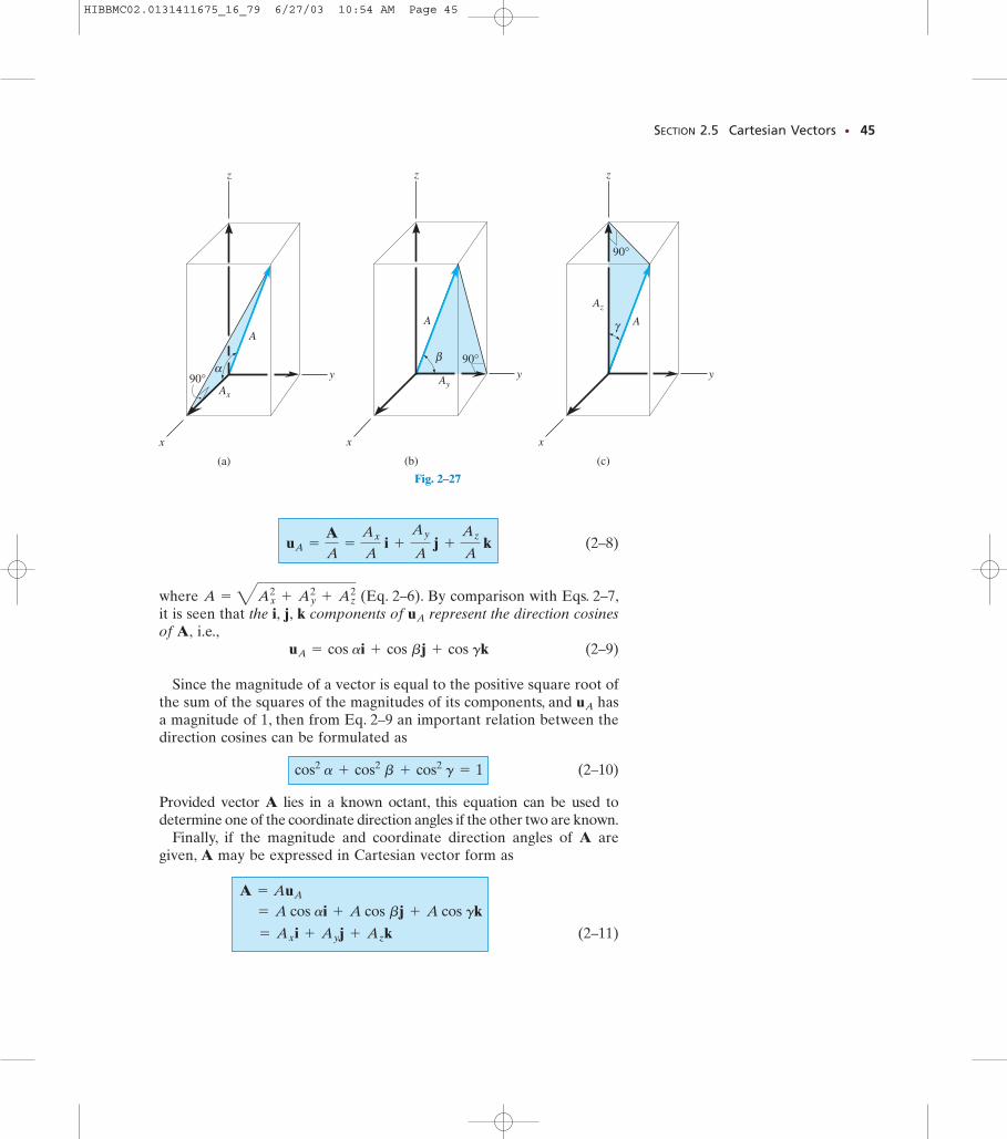
(2–8)
where (Eq. 2–6). By comparison with Eqs. 2–7,it is seen that the i, j, k components of represent the direction cosinesof A, i.e.,
(2–9)
Since the magnitude of a vector is equal to the positive square root ofthe sum of the squares of the magnitudes of its components, and hasa magnitude of 1, then from Eq. 2–9 an important relation between thedirection cosines can be formulated as
(2–10)
Provided vector A lies in a known octant, this equation can be used todetermine one of the coordinate direction angles if the other two are known.
Finally, if the magnitude and coordinate direction angles of A aregiven, A may be expressed in Cartesian vector form as
(2–11) = Ax i + Ay j + Az k
= A cos ai + A cos bj + A cos gk A = AuA
cos2 a + cos2 b + cos2 g = 1
uA
uA = cos ai + cos bj + cos gk
uA
A = 4Ax2
+ Ay2
+ Az2
uA =
AA
=
Ax
A i +
Ay
A j +
Az
A k
SECTION 2.5 Cartesian Vectors • 45
z
y
x
(a)
α90°
A
Ax
Fig. 2–27A z
y
x
(b)
β 90°
A
Ay
Fig. 2–27B z
y
x
(c)
Az
90°
γ A
Fig. 2–27
HIBBMC02.0131411675_16_79 6/27/03 10:54 AM Page 45
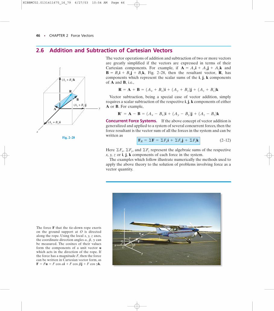
The vector operations of addition and subtraction of two or more vectorsare greatly simplified if the vectors are expressed in terms of theirCartesian components. For example, if and
Fig. 2–28, then the resultant vector, R, hascomponents which represent the scalar sums of the i, j, k componentsof A and B, i.e.,
Vector subtraction, being a special case of vector addition, simplyrequires a scalar subtraction of the respective i, j, k components of eitherA or B. For example,
Concurrent Force Systems. If the above concept of vector addition isgeneralized and applied to a system of several concurrent forces, then theforce resultant is the vector sum of all the forces in the system and can bewritten as
(2–12)
Here and represent the algebraic sums of the respectivex, y, z or i, j, k components of each force in the system.
The examples which follow illustrate numerically the methods used toapply the above theory to the solution of problems involving force as avector quantity.
©Fz©Fy,©Fx,
FR = ©F = ©Fx i + ©Fy j + ©Fz k
R¿ = A - B = 1Ax - Bx2i + 1Ay - By2j + 1Az - Bz2k
R = A + B = 1Ax + Bx2i + 1Ay + By2j + 1Az + Bz2k
B = Bx i + By j + Bz k,A = Ax i + Ay j + Az k
46 • CHAPTER 2 Force Vectors
z
y
Fx
αβ
γ
O
u
The force F that the tie-down rope exerts on the ground support at O is directedalong the rope. Using the local x, y, z axes,the coordinate direction angles canbe measured. The cosines of their valuesform the components of a unit vector uwhich acts in the direction of the rope. Ifthe force has a magnitude F, then the force can be written in Cartesian vector form, asF = Fu = F cos ai + F cos bj + F cos gk.
gb ,a,
2.6 Addition and Subtraction of Cartesian Vectors
z
y
x
R
B
A
(Az + Bz)k
(Ax + Bx)i
(Ay + By)j
Fig. 2–28
HIBBMC02.0131411675_16_79 6/27/03 10:54 AM Page 46
SECTION 2.6 Addition and Subtraction of Cartesian Vectors • 47
IMPORTANT POINTS• Cartesian vector analysis is often used to solve problems in three
dimensions.
• The positive direction of the x, y, z axes are defined by theCartesian unit vectors i, j, k, respectively.
• The magnitude of a Cartesian vector is
• The direction of a Cartesian vector is specified using coordinatedirection angles which the tail of the vector makes with thepositive x, y, z axes, respectively. The components of the unitvector represent the direction cosines of Onlytwo of the angles have to be specified. The third angle isdetermined from the relationship
• To find the resultant of a concurrent force system, express eachforce as a Cartesian vector and add the i, j, k components of allthe forces in the system.
cos2 a + cos2 b + cos2 g = 1.gb,a,
g.b,a,u = A/A
A = 4Ax2
+ Ay2
+ Az2.
E X A M P L E 2.8
z
y
x
α
45°
F = 200 N
60°
Fig. 2–29
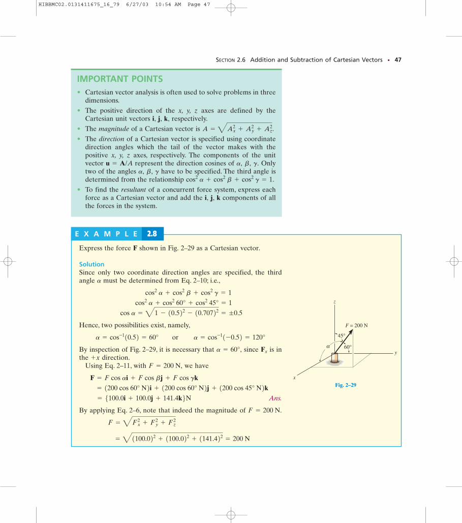
Express the force F shown in Fig. 2–29 as a Cartesian vector.
SolutionSince only two coordinate direction angles are specified, the thirdangle must be determined from Eq. 2–10; i.e.,
Hence, two possibilities exist, namely,
By inspection of Fig. 2–29, it is necessary that since is inthe direction.
Using Eq. 2–11, with we have
Ans.
By applying Eq. 2–6, note that indeed the magnitude of
= 41100.022 + 1100.022 + 1141.422 = 200 N
F = 4Fx2
+ Fy2
+ Fz2
F = 200 N.
= 5100.0i + 100.0j + 141.4k6N = 1200 cos 60° N2i + 1200 cos 60° N2j + 1200 cos 45° N2k
F = F cos ai + F cos bj + F cos gk
F = 200 N,+x
Fxa = 60°,
a = cos-110.52 = 60° or a = cos-11-0.52 = 120°
cos a = 41 - 10.522 - 10.70722 = ;0.5
cos2 a + cos2 60° + cos2 45° = 1
cos2 a + cos2 b + cos2 g = 1
a
HIBBMC02.0131411675_16_79 6/27/03 10:54 AM Page 47
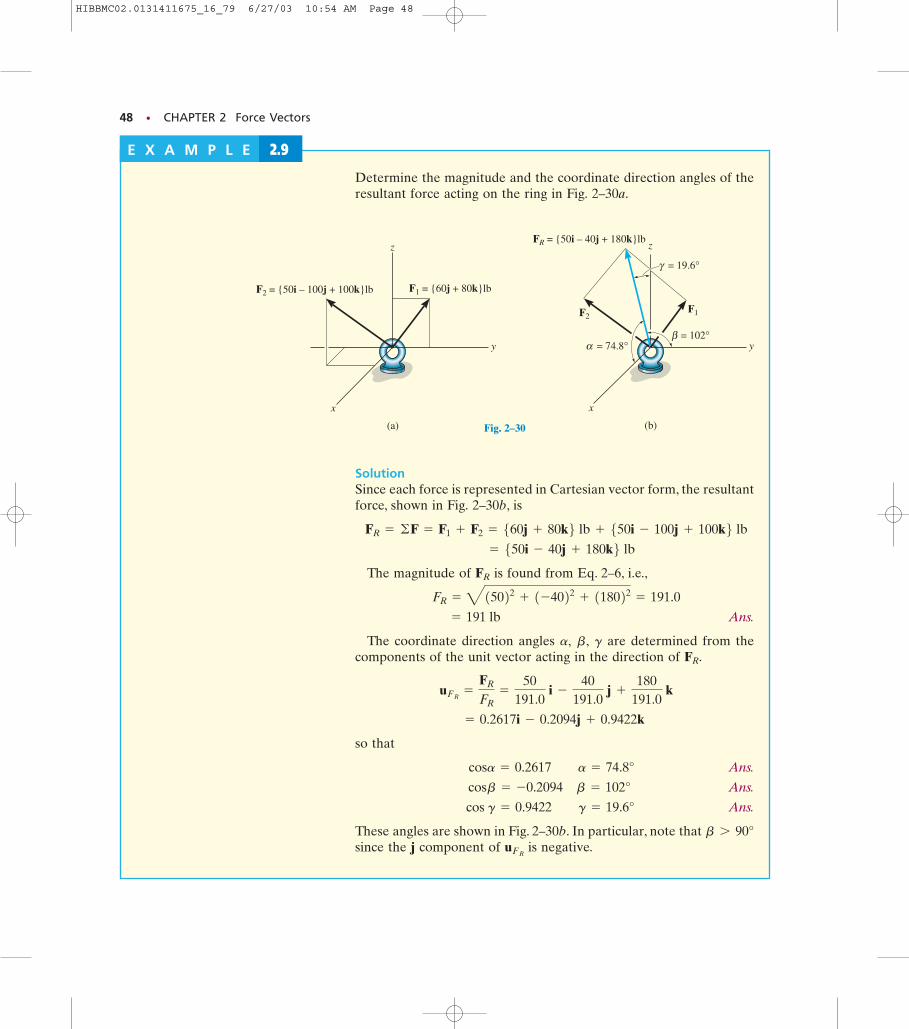
Fig. 2–30B
48 • CHAPTER 2 Force Vectors
Determine the magnitude and the coordinate direction angles of theresultant force acting on the ring in Fig. 2–30a.
SolutionSince each force is represented in Cartesian vector form, the resultantforce, shown in Fig. 2–30b, is
The magnitude of is found from Eq. 2–6, i.e.,
Ans.
The coordinate direction angles are determined from thecomponents of the unit vector acting in the direction of
so that
Ans.
Ans.
Ans.
These angles are shown in Fig. 2–30b. In particular, note that since the j component of is negative.uFR
b 7 90°
cos g = 0.9422 g = 19.6°
cosb = -0.2094 b = 102°
cosa = 0.2617 a = 74.8°
= 0.2617i - 0.2094j + 0.9422k
uFR=
FR
FR=
50191.0
i -
40191.0
j +
180191.0
k
FR.gb,a,
= 191 lb
FR = 415022 + 1-4022 + 118022 = 191.0
FR
= 550i - 40j + 180k6 lb FR = ©F = F1 + F2 = 560j + 80k6 lb + 550i - 100j + 100k6 lb
(a)
z
y
x
F2 = {50i – 100j + 100k}lb F1 = {60j + 80k}lb
Fig. 2–30
E X A M P L E 2.9
(b)
z
y
x
F2
FR = {50i – 40j + 180k}lb
F1
β = 102°α = 74.8°
γ = 19.6°
HIBBMC02.0131411675_16_79 6/27/03 10:54 AM Page 48
(b)
z
F' F1x
F1z
y
x
F1 = 100 lb
60°
45°
F1y
Fig. 2–31B
SECTION 2.6 Addition and Subtraction of Cartesian Vectors • 49
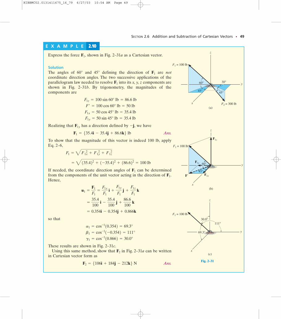
Express the force shown in Fig. 2–31a as a Cartesian vector.
SolutionThe angles of 60° and 45° defining the direction of are notcoordinate direction angles. The two successive applications of theparallelogram law needed to resolve into its x, y, z components areshown in Fig. 2–31b. By trigonometry, the magnitudes of thecomponents are
Realizing that has a direction defined by we have
Ans.
To show that the magnitude of this vector is indeed 100 lb, applyEq. 2–6,
If needed, the coordinate direction angles of can be determinedfrom the components of the unit vector acting in the direction of Hence,
so that
These results are shown in Fig. 2–31c.Using this same method, show that in Fig. 2–31a can be written
in Cartesian vector form as
Ans.F2 = 5106i + 184j - 212k6 NF2
g1 = cos-110.8662 = 30.0°
b1 = cos-11-0.3542 = 111°
a1 = cos-110.3542 = 69.3°
= 0.354i - 0.354j + 0.866k
=
35.4100
i -
35.4100
j +
86.6100
k
u1 =
F1
F1=
F1x
F1 i +
F1y
F1 j +
F1z
F1 k
F1.F1
= 4135.422 + 1-35.422 + 186.622 = 100 lb
F1 = 4F1x 2
+ F1y 2
+ F1z 2
F1 = 535.4i - 35.4j + 86.6k6 lb-j,F1y
F1y = 50 sin 45° lb = 35.4 lb
F1x = 50 cos 45° lb = 35.4 lb
F¿ = 100 cos 60° lb = 50 lb
F1z = 100 sin 60° lb = 86.6 lb
F1
F1
F1,
(a)
z
y
x
F1 = 100 lb
F2 = 300 lb
60°
45° 45°
30°
Fig. 2–31A
E X A M P L E 2.10
(c)
z
y
x
F1 = 100 lb
69.3°
111°30.0°
Fig. 2–31
HIBBMC02.0131411675_16_79 6/27/03 10:54 AM Page 49
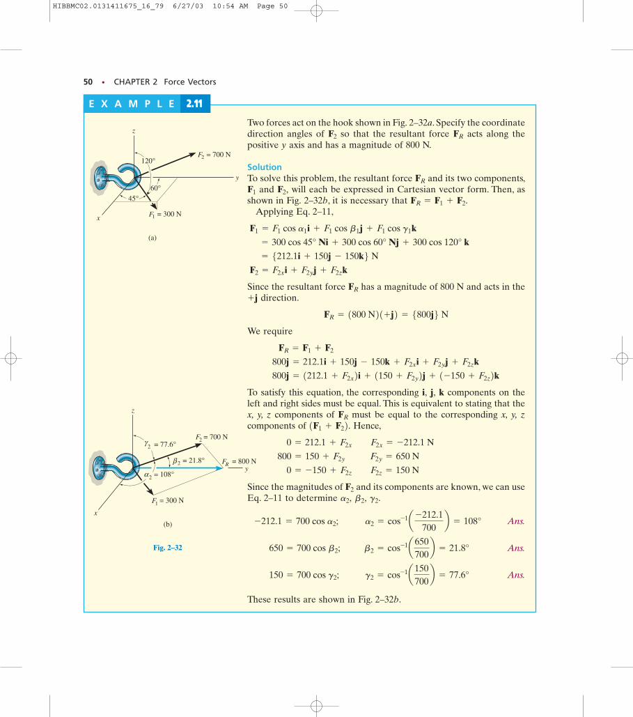
Fig. 2–32A
50 • CHAPTER 2 Force Vectors
Two forces act on the hook shown in Fig. 2–32a. Specify the coordinatedirection angles of so that the resultant force acts along thepositive y axis and has a magnitude of 800 N.
SolutionTo solve this problem, the resultant force and its two components,
and will each be expressed in Cartesian vector form. Then, asshown in Fig. 2–32b, it is necessary that
Applying Eq. 2–11,
Since the resultant force has a magnitude of 800 N and acts in thedirection.
We require
To satisfy this equation, the corresponding i, j, k components on theleft and right sides must be equal. This is equivalent to stating that thex, y, z components of must be equal to the corresponding x, y, zcomponents of Hence,
Since the magnitudes of and its components are known, we can useEq. 2–11 to determine
Ans.
Ans.
Ans.
These results are shown in Fig. 2–32b.
g2 = cos-1a150700b = 77.6° 150 = 700 cos g2;
b2 = cos-1a650700b = 21.8° 650 = 700 cos b2;
a2 = cos-1a -212.1700
b = 108° -212.1 = 700 cos a2;
g2.b2,a2,F2
0 = -150 + F2z F2z = 150 N
800 = 150 + F2y F2y = 650 N
0 = 212.1 + F2x F2x = -212.1 N
1F1 + F22.FR
800j = 1212.1 + F2x2i + 1150 + F2y2j + 1-150 + F2z2k 800j = 212.1i + 150j - 150k + F2x i + F2y j + F2z k
FR = F1 + F2
FR = 1800 N21+j2 = 5800j6 N+j
FR
F2 = F2x i + F2y j + F2z k
= 5212.1i + 150j - 150k6 N = 300 cos 45° Ni + 300 cos 60° Nj + 300 cos 120° k
F1 = F1 cos a1 i + F1 cos b1 j + F1 cos g1 k
FR = F1 + F2.F2,F1
FR
FRF2
E X A M P L E 2.11
z
F = 700 N
(a)
2
F = 300 N1x
y
60°45°
120°
z
F = 700 N
(b)
2
F = 300 N1
x
y= 108°α
β
γ
2
2
2 = 21.8° F = 800 NR
= 77.6°
Fig. 2–32
HIBBMC02.0131411675_16_79 6/27/03 10:54 AM Page 50
PROBLEMS • 51
P R O B L E M S2-59. Determine the magnitude and coordinatedirection angles of and
Sketch each force on an x, y, z reference.
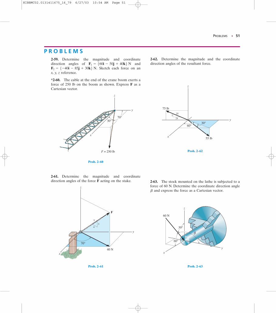
*2-60. The cable at the end of the crane boom exerts aforce of 250 lb on the boom as shown. Express F as aCartesian vector.
F2 = 5-40i - 85j + 30k6 N.F1 = 560i - 50j + 40k6 N
2-62. Determine the magnitude and the coordinatedirection angles of the resultant force.
30°70°
z
y
x
F = 250 lb
Prob. 2–60
34
70°
40 N
5
z
y
x
F
Prob. 2–61
z
y
x 55 lb
30°60°
75 lb
724
25
Prob. 2–62
x
z
y
30°
β
60 N
60°
Prob. 2–63
2-61. Determine the magnitude and coordinatedirection angles of the force F acting on the stake. 2-63. The stock mounted on the lathe is subjected to a
force of 60 N. Determine the coordinate direction angleand express the force as a Cartesian vector.b
HIBBMC02.0131411675_16_79 6/27/03 10:54 AM Page 51
52 • CHAPTER 2 Force Vectors
y
z
x
F1 = 80 lb
40°
F2 = 130 lb
30°
Probs. 2–64/65
z
y
x
60°60°
60°
45° 120°
40°
F2 = 100 N
F1 = 350 N
F3 = 250 N
45°
Prob. 2–68
2524
7
60°
F1 = 630 lb
F2 = 250 lb
135°
60°
x
z
y
Prob. 2–69
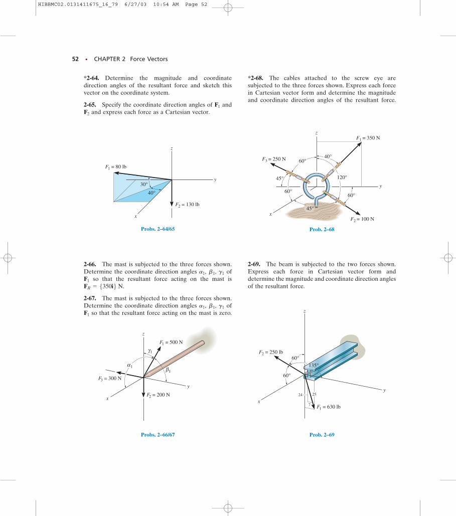
*2-64. Determine the magnitude and coordinatedirection angles of the resultant force and sketch thisvector on the coordinate system.
2-65. Specify the coordinate direction angles of andand express each force as a Cartesian vector.F2
F1
*2-68. The cables attached to the screw eye aresubjected to the three forces shown. Express each forcein Cartesian vector form and determine the magnitudeand coordinate direction angles of the resultant force.
F3 = 300 N
F2 = 200 Nx
z
F1 = 500 N
y
γ1
β1
α1
Probs. 2–66/67
2-66. The mast is subjected to the three forces shown.Determine the coordinate direction angles of
so that the resultant force acting on the mast is
2-67. The mast is subjected to the three forces shown.Determine the coordinate direction angles of
so that the resultant force acting on the mast is zero.F1
g1b1,a1,
FR = 5350i6 N.F1
g1b1,a1,2-69. The beam is subjected to the two forces shown.Express each force in Cartesian vector form anddetermine the magnitude and coordinate direction anglesof the resultant force.
HIBBMC02.0131411675_16_79 6/27/03 10:54 AM Page 52
PROBLEMS • 53
z
Fz
Fy
Fx
F
y
x
α
βγ
Probs. 2–74/75
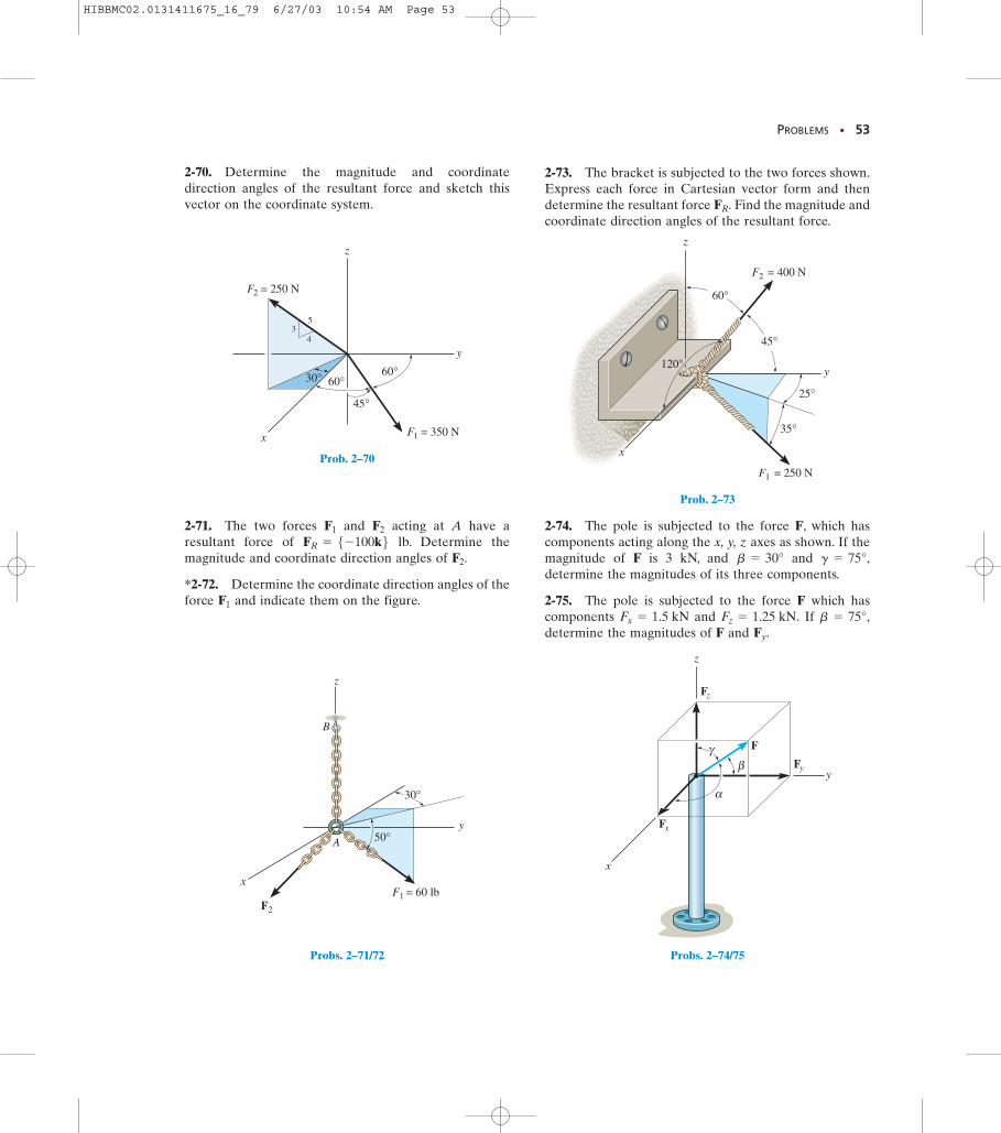
2-70. Determine the magnitude and coordinatedirection angles of the resultant force and sketch thisvector on the coordinate system.
2-71. The two forces and acting at A have aresultant force of lb. Determine themagnitude and coordinate direction angles of
*2-72. Determine the coordinate direction angles of theforce and indicate them on the figure.F1
F2.FR = 5-100k6
F2F1
y
xF1 = 60 lb
F2
z
A
B
30°
50°
Probs. 2–71/72
y
z
F1 = 250 N
F2 = 400 N
x
120°
45°
35°
25°
60°
Prob. 2–73
y
z
x
F2 = 250 N
F1 = 350 N
45°
30°
34
5
60°60°
Prob. 2–70
2-73. The bracket is subjected to the two forces shown.Express each force in Cartesian vector form and thendetermine the resultant force Find the magnitude andcoordinate direction angles of the resultant force.
FR.
2-74. The pole is subjected to the force F, which hascomponents acting along the x, y, z axes as shown. If themagnitude of F is 3 kN, and and determine the magnitudes of its three components.
2-75. The pole is subjected to the force F which hascomponents and If determine the magnitudes of F and Fy.
b = 75°,Fz = 1.25 kN.Fx = 1.5 kN
g = 75°,b = 30°
HIBBMC02.0131411675_16_79 6/27/03 10:54 AM Page 53
54 • CHAPTER 2 Force Vectors
x
y
z
3 4
5
F = 120 NR
F = 80 N1
F3
45°
30°
F = 110 N2
Probs. 2–77/78
x
z
Fz
Fy
Fx
F
αy
βγ
Prob. 2–79
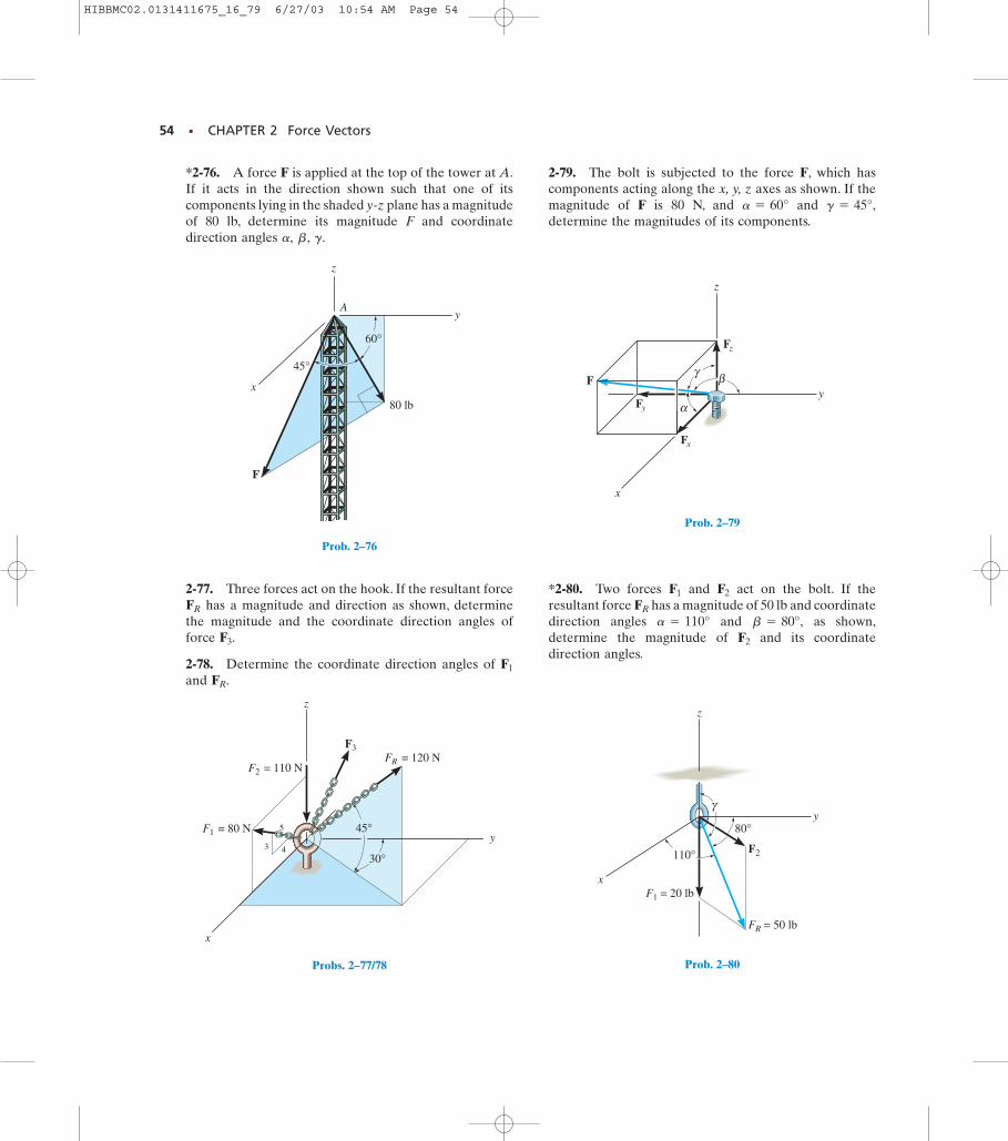
*2-76. A force F is applied at the top of the tower at A.If it acts in the direction shown such that one of itscomponents lying in the shaded y-z plane has a magnitudeof 80 lb, determine its magnitude F and coordinatedirection angles g.b,a,
2-79. The bolt is subjected to the force F, which hascomponents acting along the x, y, z axes as shown. If themagnitude of F is 80 N, and and determine the magnitudes of its components.
g = 45°,a = 60°
F2
γ
80°
110°
FR = 50 lb
F1 = 20 lbx
y
z
Prob. 2–80
x
60°
45°
80 lb
F
z
Ay
Prob. 2–76
2-77. Three forces act on the hook. If the resultant forcehas a magnitude and direction as shown, determine
the magnitude and the coordinate direction angles offorce
2-78. Determine the coordinate direction angles of and FR.
F1
F3.
FR
*2-80. Two forces and act on the bolt. If theresultant force has a magnitude of 50 lb and coordinatedirection angles and as shown,determine the magnitude of and its coordinatedirection angles.
F2
b = 80°,a = 110°FR
F2F1
HIBBMC02.0131411675_16_79 6/27/03 10:54 AM Page 54
SECTION 2.7 Position Vectors • 55
In this section we will introduce the concept of a position vector. It willbe shown that this vector is of importance in formulating a Cartesianforce vector directed between any two points in space. Later, in Chapter 4,we will use it for finding the moment of a force.
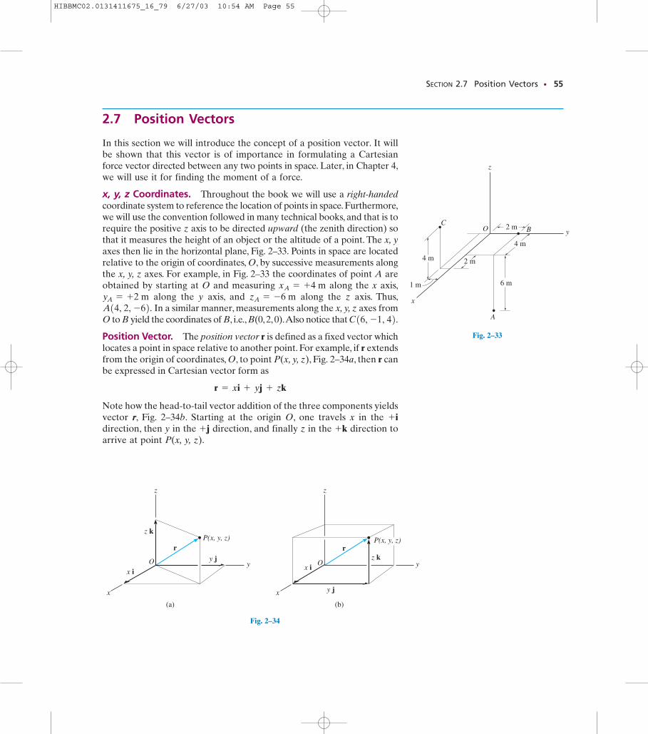
x, y, z Coordinates. Throughout the book we will use a right-handedcoordinate system to reference the location of points in space. Furthermore,we will use the convention followed in many technical books, and that is torequire the positive z axis to be directed upward (the zenith direction) sothat it measures the height of an object or the altitude of a point. The x, yaxes then lie in the horizontal plane, Fig. 2–33. Points in space are locatedrelative to the origin of coordinates, O, by successive measurements alongthe x, y, z axes. For example, in Fig. 2–33 the coordinates of point A areobtained by starting at O and measuring along the x axis,
along the y axis, and along the z axis. Thus,In a similar manner, measurements along the x, y, z axes from
O to B yield the coordinates of B, i.e., B(0, 2, 0).Also notice that
Position Vector. The position vector r is defined as a fixed vector whichlocates a point in space relative to another point. For example, if r extendsfrom the origin of coordinates, O, to point P(x, y, z), Fig. 2–34a, then r canbe expressed in Cartesian vector form as
Note how the head-to-tail vector addition of the three components yieldsvector r, Fig. 2–34b. Starting at the origin O, one travels x in the direction, then y in the direction, and finally z in the direction toarrive at point P(x, y, z).
+k+j+ i
r = xi + yj + zk
C16, -1, 42.A14, 2, -62. zA = -6 myA = +2 mxA = +4 m
z
y
x
y jr
x iO
z k
(a)
P(x, y, z)
Fig. 2–34
z
y
x
z kr
x iO
(b)
P(x, y, z)
y j
Fig. 2–34B
z
y
x
4 m
1 m
2 m
OC
B
A
2 m
4 m
6 m
Fig. 2–33
2.7 Position Vectors
HIBBMC02.0131411675_16_79 6/27/03 10:54 AM Page 55
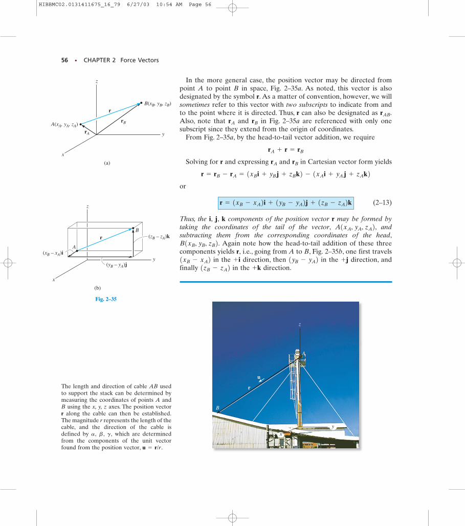
In the more general case, the position vector may be directed frompoint A to point B in space, Fig. 2–35a. As noted, this vector is alsodesignated by the symbol r. As a matter of convention, however, we willsometimes refer to this vector with two subscripts to indicate from andto the point where it is directed. Thus, r can also be designated as Also, note that and in Fig. 2–35a are referenced with only onesubscript since they extend from the origin of coordinates.
From Fig. 2–35a, by the head-to-tail vector addition, we require
Solving for r and expressing and in Cartesian vector form yields
or
(2–13)
Thus, the i, j, k components of the position vector r may be formed bytaking the coordinates of the tail of the vector, andsubtracting them from the corresponding coordinates of the head,
Again note how the head-to-tail addition of these threecomponents yields r, i.e., going from A to B, Fig. 2–35b, one first travels
in the direction, then in the direction, andfinally in the direction.+k1zB - zA2
+j1yB - yA2+ i1xB - xA2B1xB, yB, zB2.
A1xA, yA, zA2,
r = 1xB - xA2i + 1yB - yA2j + 1zB - zA2k
r = rB - rA = 1xB i + yB j + zB k2 - 1xA i + yA j + zA k2rBrA
rA + r = rB
rBrA
rAB.
56 • CHAPTER 2 Force Vectors
z
y
x
(a)
B(xB, yB, zB)
A(xA, yA, zA)rA
rB
r
Fig. 2–35A
(b)
z
y
x
(xB – xA)i
rB
A
(yB – yA)j
(zB – zA)k
Fig. 2–35
z
y
x
A
r
B
u
The length and direction of cable AB usedto support the stack can be determined bymeasuring the coordinates of points A andB using the x, y, z axes. The position vectorr along the cable can then be established.The magnitude r represents the length of thecable, and the direction of the cable isdefined by which are determinedfrom the components of the unit vectorfound from the position vector, u = r/r.
g,b ,a,
HIBBMC02.0131411675_16_79 6/27/03 10:54 AM Page 56
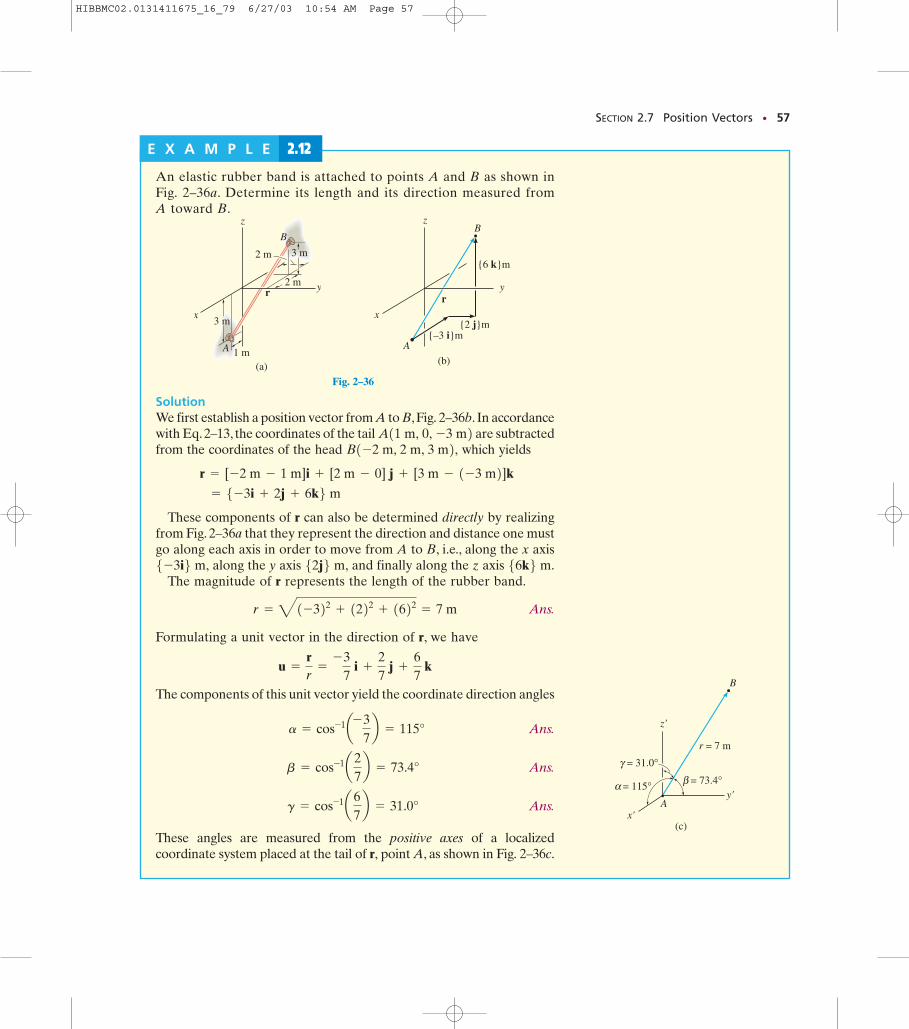
Fig. 2–36C
Fig. 2–36B
SECTION 2.7 Position Vectors • 57
E X A M P L E 2.12
(a)
z
y
x3 m
1 mA
B
3 m
2 m
2 m
r
Fig. 2–36
(b)
z
y
A
B
{6 k}m
{2 j}m{–3 i}m
r
x
(c)
A
B
z'
y'
x'
r = 7 m
β = 73.4°
γ = 31.0°
α = 115°
An elastic rubber band is attached to points A and B as shown inFig. 2–36a. Determine its length and its direction measured from A toward B.
SolutionWe first establish a position vector from A to B,Fig. 2–36b. In accordancewith Eq.2–13, the coordinates of the tail are subtractedfrom the coordinates of the head which yields
These components of r can also be determined directly by realizingfrom Fig. 2–36a that they represent the direction and distance one mustgo along each axis in order to move from A to B, i.e., along the x axis
along the y axis and finally along the z axis The magnitude of r represents the length of the rubber band.
Ans.
Formulating a unit vector in the direction of r, we have
The components of this unit vector yield the coordinate direction angles
Ans.
Ans.
Ans.
These angles are measured from the positive axes of a localizedcoordinate system placed at the tail of r, point A, as shown in Fig. 2–36c.
g = cos-1a67b = 31.0°
b = cos-1a27b = 73.4°
a = cos-1a- 37b = 115°
u =
rr
=
- 37
i +
27
j +
67
k
r = 41-322 + 1222 + 1622 = 7 m
56k6 m.52j6 m,5-3i6 m,
= 5-3i + 2j + 6k6 m r = [-2 m - 1 m]i + [2 m - 0] j + [3 m - 1-3 m2]k
B1-2 m, 2 m, 3 m2,A11 m, 0, -3 m2
HIBBMC02.0131411675_16_79 6/27/03 10:54 AM Page 57
58 • CHAPTER 2 Force Vectors
r
F
u
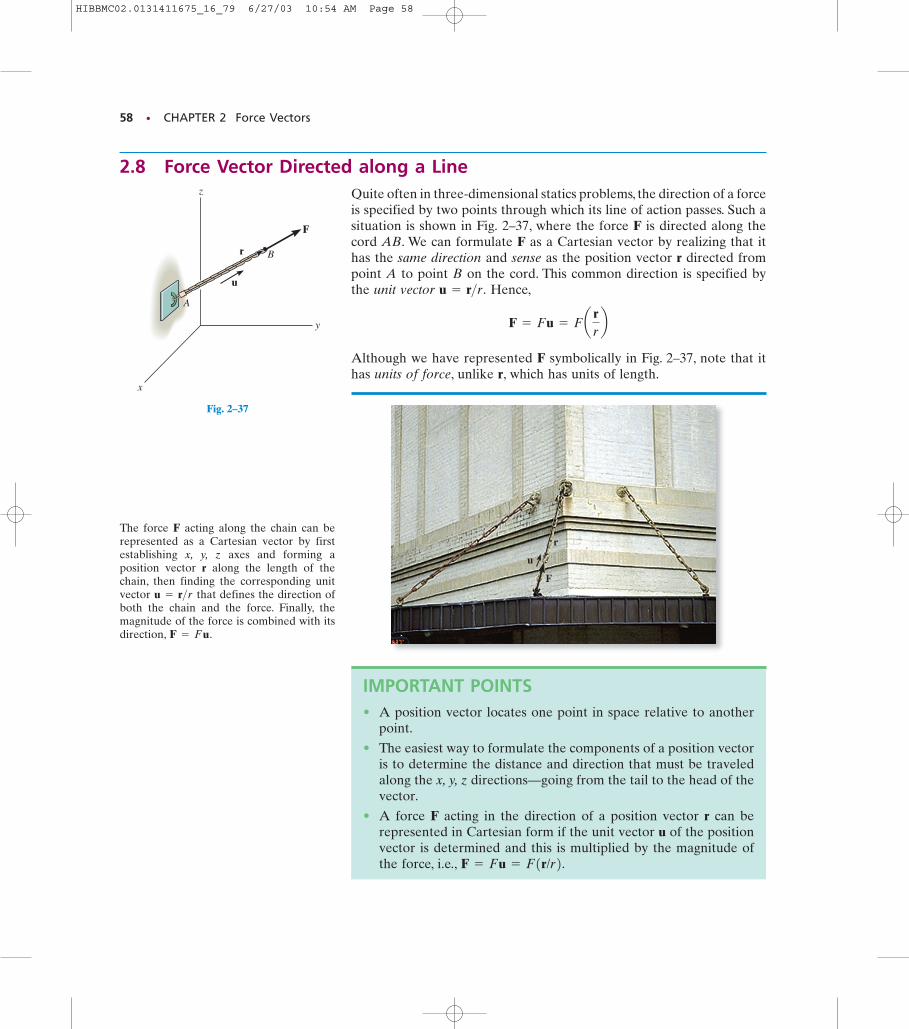
The force F acting along the chain can berepresented as a Cartesian vector by firstestablishing x, y, z axes and forming aposition vector r along the length of thechain, then finding the corresponding unitvector that defines the direction ofboth the chain and the force. Finally, themagnitude of the force is combined with itsdirection, F = Fu.
u = r>r
IMPORTANT POINTS• A position vector locates one point in space relative to another
point.
• The easiest way to formulate the components of a position vectoris to determine the distance and direction that must be traveledalong the x, y, z directions—going from the tail to the head of thevector.
• A force F acting in the direction of a position vector r can berepresented in Cartesian form if the unit vector u of the positionvector is determined and this is multiplied by the magnitude ofthe force, i.e., F = Fu = F1r/r2.
2.8 Force Vector Directed along a LineQuite often in three-dimensional statics problems, the direction of a forceis specified by two points through which its line of action passes. Such asituation is shown in Fig. 2–37, where the force F is directed along thecord AB. We can formulate F as a Cartesian vector by realizing that ithas the same direction and sense as the position vector r directed frompoint A to point B on the cord. This common direction is specified bythe unit vector Hence,
Although we have represented F symbolically in Fig. 2–37, note that ithas units of force, unlike r, which has units of length.
F = Fu = Fa rrb
u = r>r.
z
y
x
r
u
B
F
A
Fig. 2–37
HIBBMC02.0131411675_16_79 6/27/03 10:54 AM Page 58
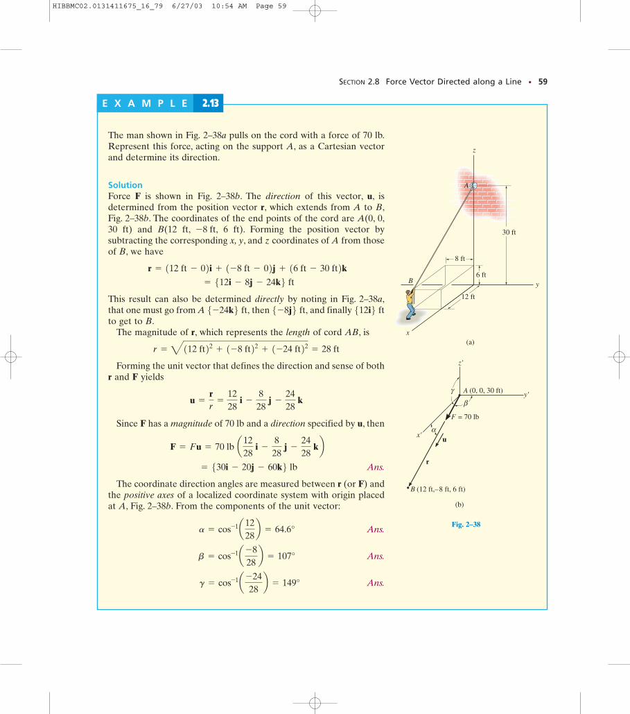
Fig. 2–38A
SECTION 2.8 Force Vector Directed along a Line • 59
E X A M P L E 2.13
The man shown in Fig. 2–38a pulls on the cord with a force of 70 lb.Represent this force, acting on the support A, as a Cartesian vectorand determine its direction.
SolutionForce F is shown in Fig. 2–38b. The direction of this vector, u, isdetermined from the position vector r, which extends from A to B,Fig. 2–38b. The coordinates of the end points of the cord are A(0, 0,30 ft) and B(12 ft, 6 ft). Forming the position vector bysubtracting the corresponding x, y, and z coordinates of A from thoseof B, we have
This result can also be determined directly by noting in Fig. 2–38a,that one must go from A then and finally to get to B.
The magnitude of r, which represents the length of cord AB, is
Forming the unit vector that defines the direction and sense of bothr and F yields
Since F has a magnitude of 70 lb and a direction specified by u, then
Ans.
The coordinate direction angles are measured between r (or F) andthe positive axes of a localized coordinate system with origin placedat A, Fig. 2–38b. From the components of the unit vector:
Ans.
Ans.
Ans. g = cos-1a -2428b = 149°
b = cos-1a -828b = 107°
a = cos-1a1228b = 64.6°
= 530i - 20j - 60k6 lb F = Fu = 70 lb a12
28 i -
828
j -
2428
kb
u =
rr
=
1228
i -
828
j -
2428
k
r = 4112 ft22 + 1-8 ft22 + 1-24 ft22 = 28 ft
512i6 ft5-8j6 ft,5-24k6 ft,
= 512i - 8j - 24k6 ft r = 112 ft - 02i + 1-8 ft - 02j + 16 ft - 30 ft2k
-8 ft,
y
x
z
A
30 ft
8 ft
6 ft
12 ft
B
(a)
α
β
γ
F
(b)
x'
y'
z'
A (0, 0, 30 ft)
u
r
B (12 ft,– 8 ft, 6 ft)
= 70 lb
Fig. 2–38
HIBBMC02.0131411675_16_79 6/27/03 10:54 AM Page 59
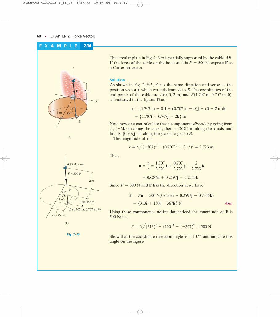
Fig. 2–39A
60 • CHAPTER 2 Force Vectors
E X A M P L E 2.14
(a)
y
z
x
45°1 m
F
A
2 m
B
z
x
1 m
F
A
2 m
B
r
= 500 N
(0, 0, 2 m)
1 cos 45° m
(1.707 m, 0.707 m, 0)
1 m
1 sin 45° m
(b)
z
45°
Fig. 2–39
The circular plate in Fig. 2–39a is partially supported by the cable AB.If the force of the cable on the hook at A is express F asa Cartesian vector.
SolutionAs shown in Fig. 2–39b, F has the same direction and sense as theposition vector r, which extends from A to B. The coordinates of theend points of the cable are A(0, 0, 2 m) and B(1.707 m, 0.707 m, 0),as indicated in the figure. Thus,
Note how one can calculate these components directly by going fromA, along the z axis, then along the x axis, andfinally along the y axis to get to B.
The magnitude of r is
Thus,
Since and F has the direction u, we have
Ans.
Using these components, notice that indeed the magnitude of F is 500 N; i.e.,
Show that the coordinate direction angle and indicate thisangle on the figure.
g = 137°,
F = 4131322 + 113022 + 1-36722 = 500 N
= 5313i + 130j - 367k6 N F = Fu = 500 N10.6269i + 0.2597j - 0.7345k2
F = 500 N
= 0.6269i + 0.2597j - 0.7345k
u =
rr
=
1.7072.723
i +
0.7072.723
j -
22.723
k
r = 411.70722 + 10.70722 + 1-222 = 2.723 m
50.707j6 m 51.707i6 m5-2k6 m = 51.707i + 0.707j - 2k6 m
r = 11.707 m - 02i + 10.707 m - 02j + 10 - 2 m2k
F = 500 N,
HIBBMC02.0131411675_16_79 6/27/03 10:54 AM Page 60
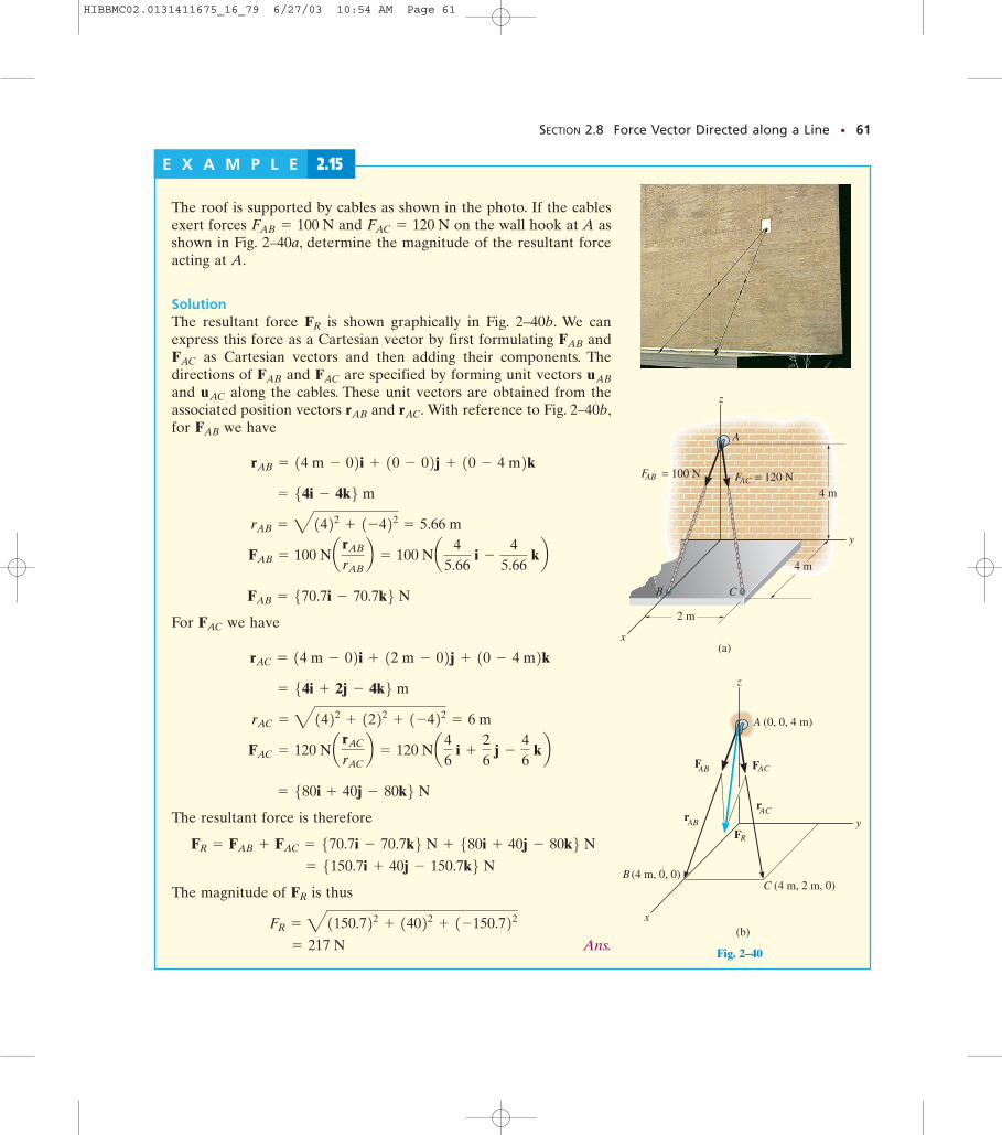
Fig. 2–40A
Fig. 2–40A
SECTION 2.8 Force Vector Directed along a Line • 61
E X A M P L E 2.15
(a)
y
x
2 m
4 m
B
4 m
A
C
FAB = 100 N F = 120 NAC
z
Fig. 2–40
The roof is supported by cables as shown in the photo. If the cablesexert forces and on the wall hook at A asshown in Fig. 2–40a, determine the magnitude of the resultant forceacting at A.
SolutionThe resultant force is shown graphically in Fig. 2–40b. We canexpress this force as a Cartesian vector by first formulating and
as Cartesian vectors and then adding their components. Thedirections of and are specified by forming unit vectors and along the cables. These unit vectors are obtained from theassociated position vectors and With reference to Fig. 2–40b,for we have
For we have
The resultant force is therefore
The magnitude of is thus
Ans. = 217 N
FR = 41150.722 + 14022 + 1-150.722FR
= 5150.7i + 40j - 150.7k6 N FR = FAB + FAC = 570.7i - 70.7k6 N + 580i + 40j - 80k6 N
= 580i + 40j - 80k6 N FAC = 120 Na rAC
rACb = 120 Na4
6 i +
26
j -
46
kb rAC = 41422 + 1222 + 1-422 = 6 m
= 54i + 2j - 4k6 m rAC = 14 m - 02i + 12 m - 02j + 10 - 4 m2k
FAC
FAB = 570.7i - 70.7k6 N FAB = 100 Na rAB
rABb = 100 Na 4
5.66 i -
45.66
kb rAB = 41422 + 1-422 = 5.66 m
= 54i - 4k6 m rAB = 14 m - 02i + 10 - 02j + 10 - 4 m2k
FAB
rAC.rAB
uAC
uABFACFAB
FAC
FAB
FR
FAC = 120 NFAB = 100 N
y
x
B (4 m, 0, 0)C (4 m, 2 m, 0)
A
FAB FAC
ACABr
r
FR
(b)
z
(0, 0, 4 m)
HIBBMC02.0131411675_16_79 6/27/03 10:54 AM Page 61
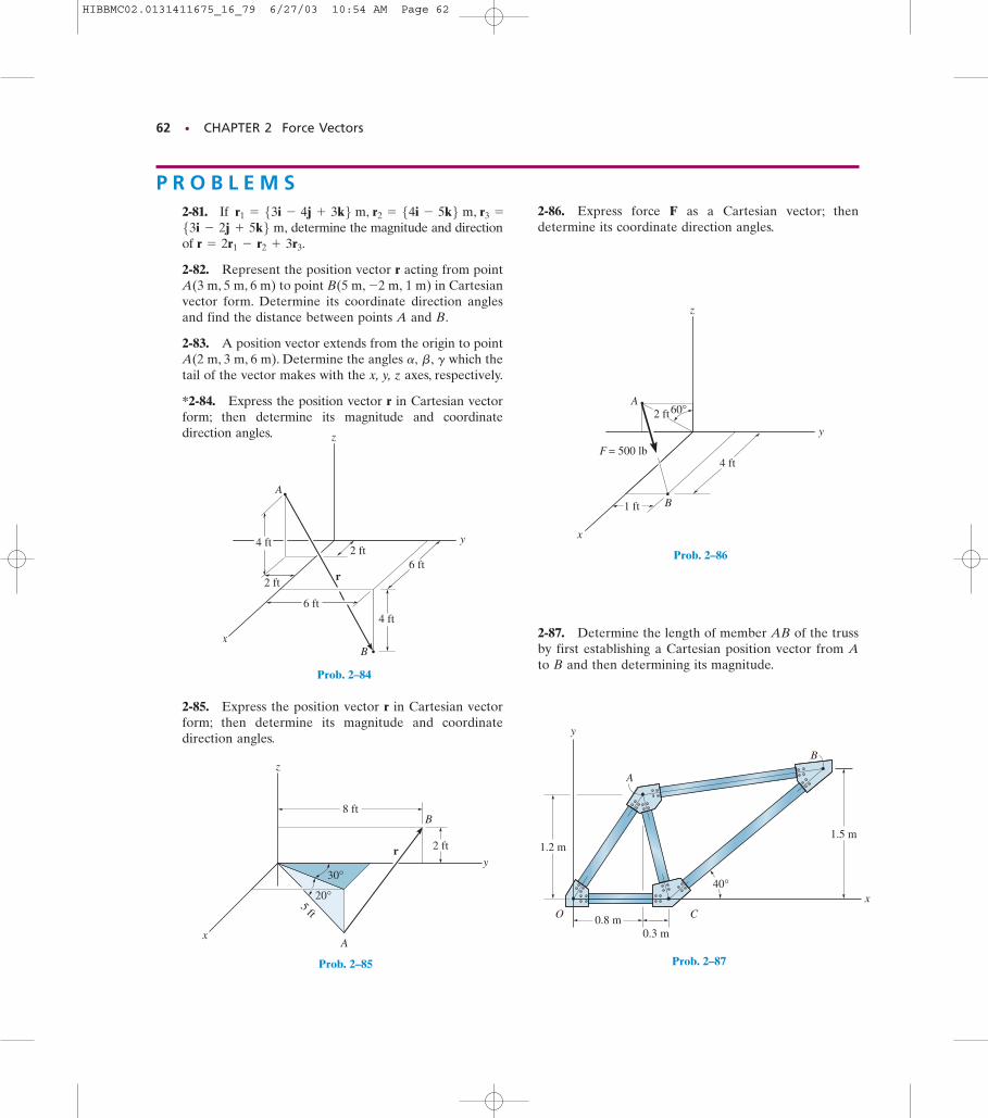
62 • CHAPTER 2 Force Vectors
20°
30°
5 ft
8 ft
2 ft
x
z
yr
B
A
Prob. 2–85
y
z
xB
A
r2 ft
6 ft
2 ft
4 ft
4 ft
6 ft
B
A
1 ft
x
y
z
4 ft
2 ft60°
F = 500 lb
0.8 m
1.5 m
x
y
B
A
0.3 m
1.2 m
40°
CO
Prob. 2–84
Prob. 2–86
Prob. 2–87
P R O B L E M S2-81. If
determine the magnitude and directionof
2-82. Represent the position vector r acting from pointA(3 m, 5 m, 6 m) to point B(5 m, 1 m) in Cartesianvector form. Determine its coordinate direction anglesand find the distance between points A and B.
2-83. A position vector extends from the origin to pointA(2 m, 3 m, 6 m). Determine the angles which thetail of the vector makes with the x, y, z axes, respectively.
*2-84. Express the position vector r in Cartesian vectorform; then determine its magnitude and coordinatedirection angles.
gb,a,
-2 m,
r = 2r1 - r2 + 3r3.53i - 2j + 5k6 m,
r1 = 53i - 4j + 3k6 m, r2 = 54i - 5k6 m, r3 =
2-85. Express the position vector r in Cartesian vectorform; then determine its magnitude and coordinatedirection angles.
2-86. Express force F as a Cartesian vector; thendetermine its coordinate direction angles.
2-87. Determine the length of member AB of the trussby first establishing a Cartesian position vector from Ato B and then determining its magnitude.
HIBBMC02.0131411675_16_79 6/27/03 10:54 AM Page 62
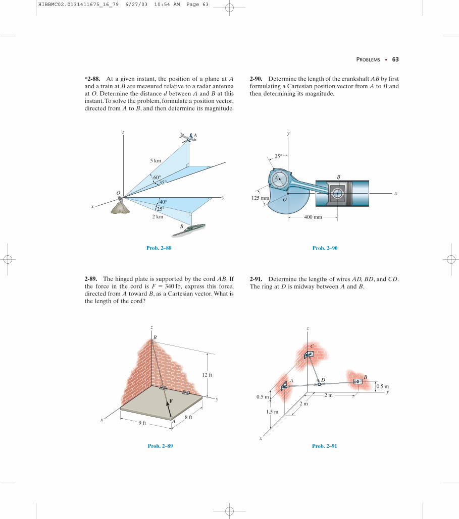
PROBLEMS • 63
400 mm
O125 mm
A B
x
y
25°
Prob. 2–90
zA
y
x
B
O
2 km
5 km
60°35°
40°25°
Prob. 2–88
y
z
x
F
9 ft8 ft
A
B
12 ft
Prob. 2–89
*2-88. At a given instant, the position of a plane at Aand a train at B are measured relative to a radar antennaat O. Determine the distance d between A and B at thisinstant.To solve the problem, formulate a position vector,directed from A to B, and then determine its magnitude.
2-89. The hinged plate is supported by the cord AB. Ifthe force in the cord is express this force,directed from A toward B, as a Cartesian vector. What isthe length of the cord?
F = 340 lb,
2-90. Determine the length of the crankshaft AB by firstformulating a Cartesian position vector from A to B andthen determining its magnitude.
z
C
BA D
2 m
2 m
1.5 m
0.5 m
0.5 my
x
Prob. 2–91
2-91. Determine the lengths of wires AD, BD, and CD.The ring at D is midway between A and B.
HIBBMC02.0131411675_16_79 6/27/03 10:54 AM Page 63
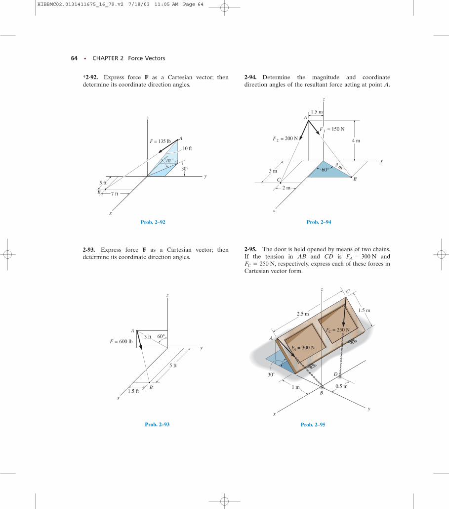
64 • CHAPTER 2 Force Vectors
1.5 ft
5 ft
3 ft 60°
x
A
y
z
B
F = 600 lb
Prob. 2–93
= 200 NF
y
x
1.5 m
z
A
2
= 150 NF1
3 m60°
BC
2 m
3 m
4 m
xy
z
2.5 m1.5 m
0.5 m1 m
30˚
A
C
B
D
FA = 300 N
FC = 250 N
Prob. 2–95
F = 135 lb
y
x
z
B
A
10 ft
70°30°
7 ft
5 ft
Prob. 2–92 Prob. 2–94
*2-92. Express force F as a Cartesian vector; thendetermine its coordinate direction angles.
2-93. Express force F as a Cartesian vector; thendetermine its coordinate direction angles.
2-94. Determine the magnitude and coordinatedirection angles of the resultant force acting at point A.
2-95. The door is held opened by means of two chains.If the tension in AB and CD is and
respectively, express each of these forces inCartesian vector form.FC = 250 N,
FA = 300 N
HIBBMC02.0131411675_16_79.v2 7/18/03 11:05 AM Page 64
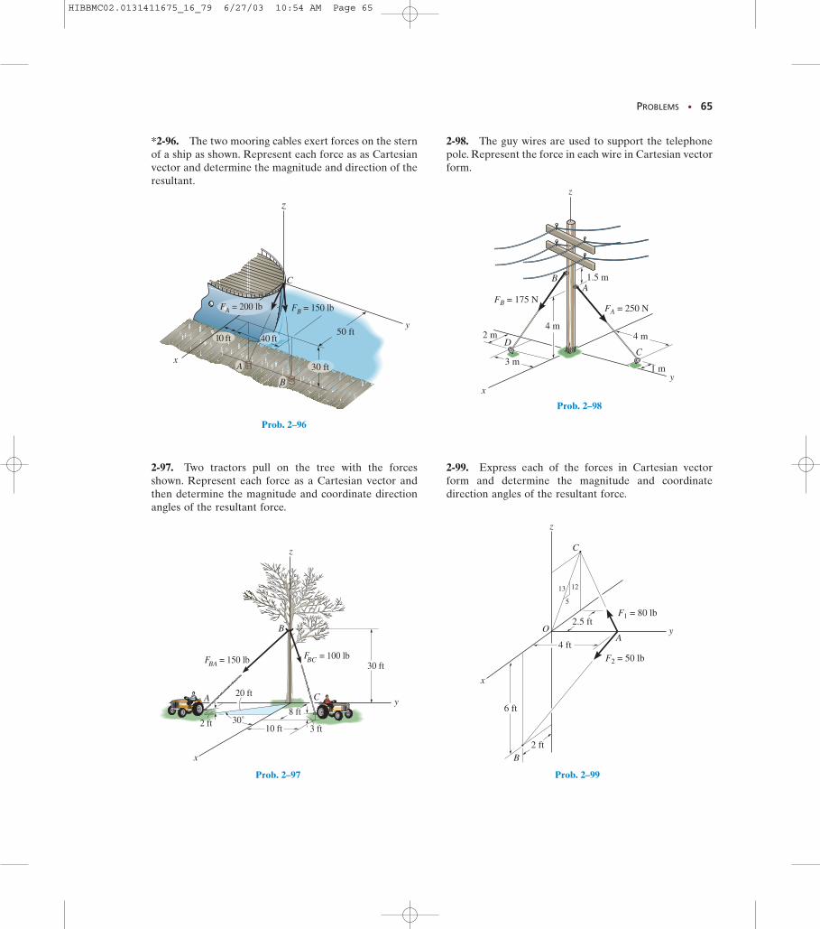
PROBLEMS • 65
y
B
CD
A
x
z
FB = 175 NFA = 250 N
4 m4 m
1.5 m
1 m3 m
2 m
4 ft
2 ft
6 ft
2.5 ft
5
1213
OA
C
B
F2 = 50 lb
F1 = 80 lb
y
z
x
Prob. 2–99
x
y
z
50 ft
30 ft
40 ft
A
C
B
10 ft
FB = 150 lbFA = 200 lb
F = 100 lb= 150 lb
30˚
20 ft
3 ft2 ft
30 ft
8 ft
10 ft
z
yCA
x
B
BCFBA
Prob. 2–97
Prob. 2–96
Prob. 2–98
*2-96. The two mooring cables exert forces on the sternof a ship as shown. Represent each force as as Cartesianvector and determine the magnitude and direction of theresultant.
2-97. Two tractors pull on the tree with the forcesshown. Represent each force as a Cartesian vector andthen determine the magnitude and coordinate directionangles of the resultant force.
2-98. The guy wires are used to support the telephonepole. Represent the force in each wire in Cartesian vectorform.
2-99. Express each of the forces in Cartesian vectorform and determine the magnitude and coordinatedirection angles of the resultant force.
HIBBMC02.0131411675_16_79 6/27/03 10:54 AM Page 65
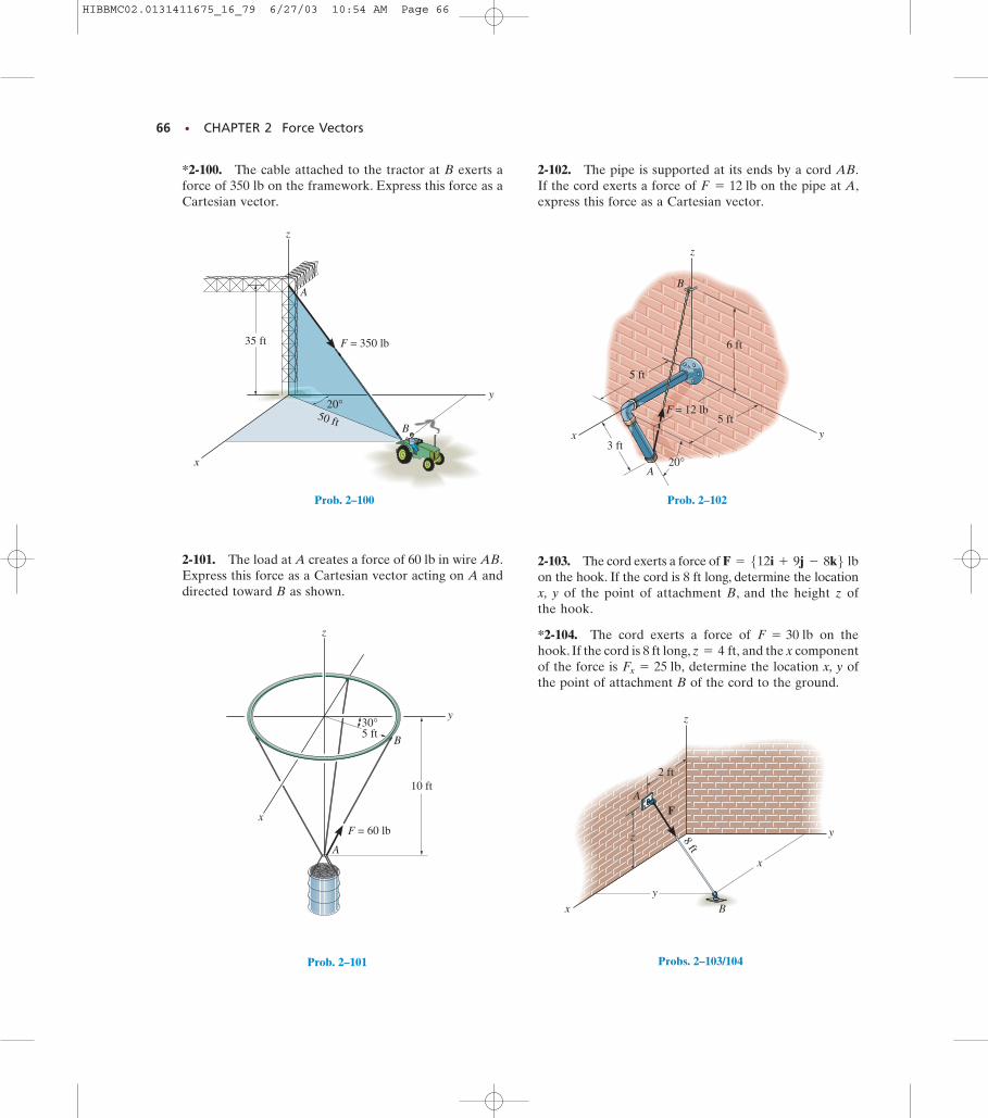
66 • CHAPTER 2 Force Vectors
5 ft
3 ft
20°
yx
A
B
z
5 ft
6 ft
F = 12 lb
x
y
z
y
x
F
z
2 ft
8 ft
A
B
Probs. 2–103/104
10 ft
5 ft30°
A
z
y
xF = 60 lb
B
Prob. 2–101
Prob. 2–102
*2-100. The cable attached to the tractor at B exerts aforce of 350 lb on the framework. Express this force as aCartesian vector.
2-101. The load at A creates a force of 60 lb in wire AB.Express this force as a Cartesian vector acting on A anddirected toward B as shown.
2-102. The pipe is supported at its ends by a cord AB.If the cord exerts a force of on the pipe at A,express this force as a Cartesian vector.
F = 12 lb
2-103. The cord exerts a force of on the hook. If the cord is 8 ft long, determine the locationx, y of the point of attachment B, and the height z ofthe hook.
*2-104. The cord exerts a force of on thehook. If the cord is 8 ft long, and the x componentof the force is determine the location x, y ofthe point of attachment B of the cord to the ground.
Fx = 25 lb,z = 4 ft,
F = 30 lb
F = 512i + 9j - 8k6 lb
20°
A
F = 350 lb
y
z
x
35 ft
50 ftB
Prob. 2–100
HIBBMC02.0131411675_16_79 6/27/03 10:54 AM Page 66
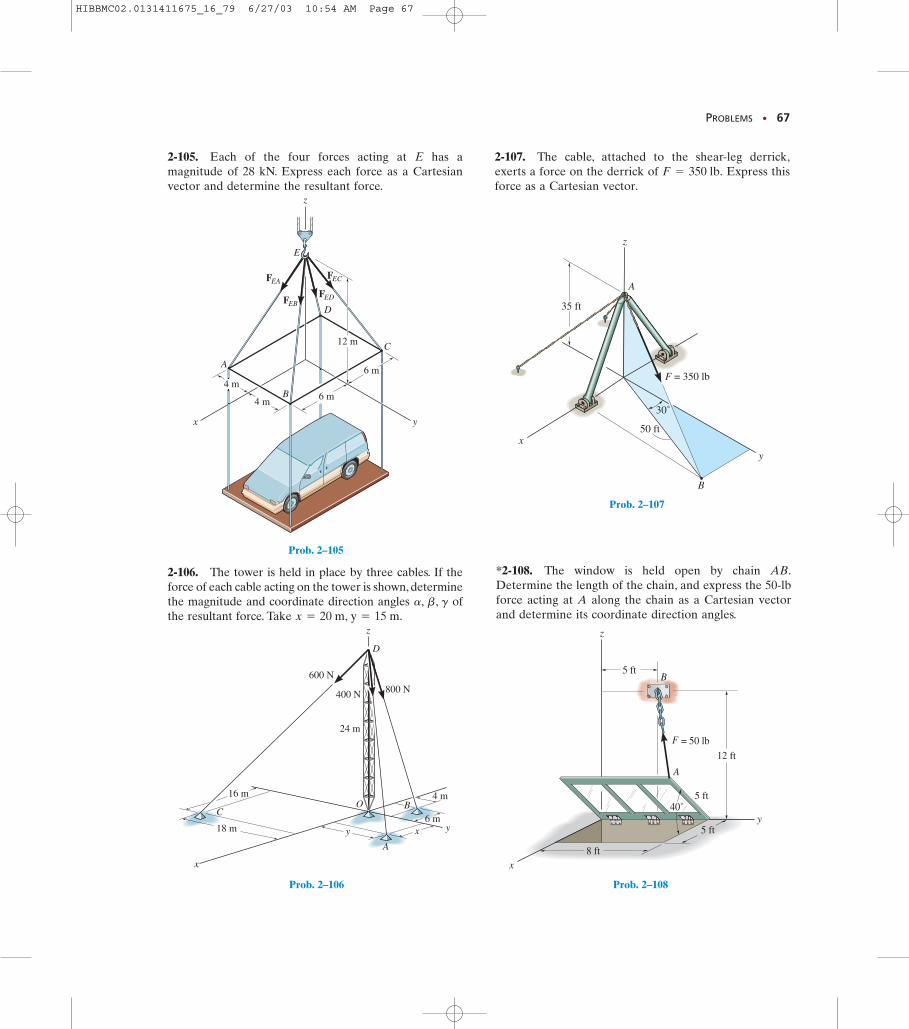
PROBLEMS • 67
4 m 6 m
6 m
yx
C
A
B
D
E
z
FEBFED
FEAFEC
4 m
12 m
x
z
yxy6 m
4 m
18 m
C
A
D
400 N 800 N
600 N
24 m
O16 m
B
Prob. 2–106
30˚
50 ft
35 ft
x
y
z
A
B
F = 350 lb
Prob. 2–105
Prob. 2–107
2-105. Each of the four forces acting at E has amagnitude of 28 kN. Express each force as a Cartesianvector and determine the resultant force.
2-106. The tower is held in place by three cables. If theforce of each cable acting on the tower is shown, determinethe magnitude and coordinate direction angles ofthe resultant force. Take x = 20 m, y = 15 m.
a, b, g
2-107. The cable, attached to the shear-leg derrick,exerts a force on the derrick of Express thisforce as a Cartesian vector.
F = 350 lb.
40˚
x
y5 ft
12 ft
8 ft
= 50 lb
A
B5 ft
z
5 ft
F
Prob. 2–108
*2-108. The window is held open by chain AB.Determine the length of the chain, and express the 50-lbforce acting at A along the chain as a Cartesian vectorand determine its coordinate direction angles.
HIBBMC02.0131411675_16_79 6/27/03 10:54 AM Page 67
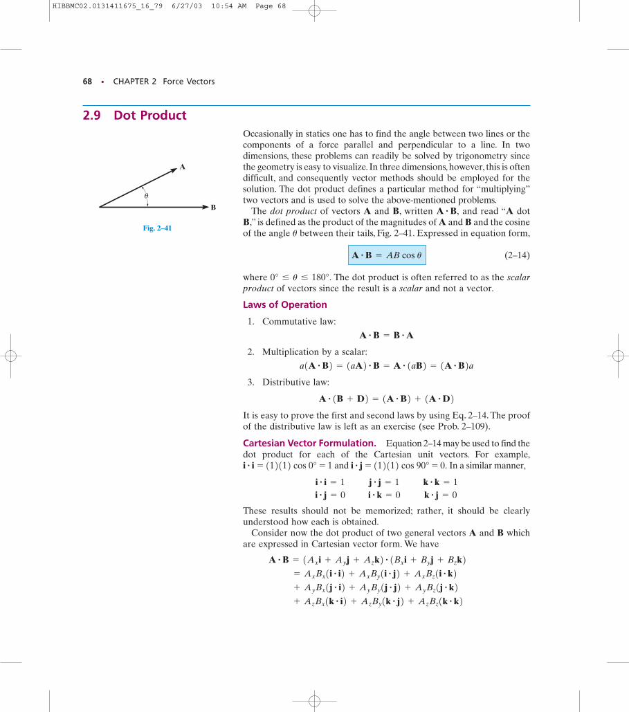
68 • CHAPTER 2 Force Vectors
θ
A
B
Fig. 2–41
2.9 Dot ProductOccasionally in statics one has to find the angle between two lines or thecomponents of a force parallel and perpendicular to a line. In twodimensions, these problems can readily be solved by trigonometry sincethe geometry is easy to visualize. In three dimensions, however, this is oftendifficult, and consequently vector methods should be employed for thesolution. The dot product defines a particular method for “multiplying”two vectors and is used to solve the above-mentioned problems.
The dot product of vectors A and B, written and read “A dotB,” is defined as the product of the magnitudes of A and B and the cosineof the angle between their tails, Fig. 2–41. Expressed in equation form,
(2–14)
where The dot product is often referred to as the scalarproduct of vectors since the result is a scalar and not a vector.
Laws of Operation
1. Commutative law:
2. Multiplication by a scalar:
3. Distributive law:
It is easy to prove the first and second laws by using Eq. 2–14. The proofof the distributive law is left as an exercise (see Prob. 2–109).
Cartesian Vector Formulation. Equation 2–14 may be used to find thedot product for each of the Cartesian unit vectors. For example,
and In a similar manner,
These results should not be memorized; rather, it should be clearlyunderstood how each is obtained.
Consider now the dot product of two general vectors A and B whichare expressed in Cartesian vector form. We have
+ Az Bx1k # i2 + Az By1k # j2 + Az Bz1k # k2 + Ay Bx1j # i2 + Ay By1j # j2 + Ay Bz1j # k2 = Ax Bx1i # i2 + Ax By1i # j2 + Ax Bz1i # k2
A # B = 1Ax i + Ay j + Az k2 # 1Bx i + By j + Bz k2
i # i = 1 j # j = 1 k # k = 1i # j = 0 i # k = 0 k # j = 0
i # j = 112112 cos 90° = 0.i # i = 112112 cos 0° = 1
A # 1B + D2 = 1A # B2 + 1A # D2
a1A # B2 = 1aA2 # B = A # 1aB2 = 1A # B2a
A # B = B # A
0° … u … 180°.
A # B = AB cos u
u
A # B,
HIBBMC02.0131411675_16_79 6/27/03 10:54 AM Page 68
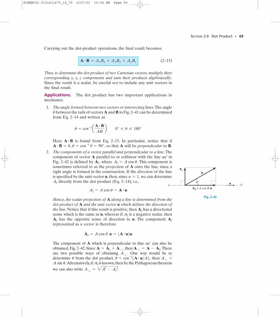
A⊥
θa a'u
A|| = A cos θ u
A
SECTION 2.9 Dot Product • 69
Carrying out the dot-product operations, the final result becomes
(2–15)
Thus, to determine the dot product of two Cartesian vectors, multiply theircorresponding x, y, z components and sum their products algebraically.Since the result is a scalar, be careful not to include any unit vectors inthe final result.
Applications. The dot product has two important applications inmechanics.
1. The angle formed between two vectors or intersecting lines.The anglebetween the tails of vectors A and B in Fig. 2–41 can be determined
from Eq. 2–14 and written as
Here is found from Eq. 2–15. In particular, notice that ifso that A will be perpendicular to B.
2. The components of a vector parallel and perpendicular to a line. Thecomponent of vector A parallel to or collinear with the line inFig. 2–42 is defined by where This component issometimes referred to as the projection of A onto the line, since aright angle is formed in the construction. If the direction of the lineis specified by the unit vector u, then, since we can determine
directly from the dot product (Eq. 2–14); i.e.,
Hence, the scalar projection of A along a line is determined from thedot product of A and the unit vector u which defines the direction ofthe line. Notice that if this result is positive, then has a directionalsense which is the same as u, whereas if is a negative scalar, then
has the opposite sense of direction to u. The component represented as a vector is therefore
The component of A which is perpendicular to line can also beobtained, Fig. 2–42. Since then Thereare two possible ways of obtaining One way would be todetermine from the dot product, then
Alternatively, if is known,then by the Pythagorean theorem
we can also write 2A2- A 7 2.A � =
A 7A sin u.A � =u = cos-11A # u>A2,u
A � .A � = A - A 7.A = A 7 + A � ,
aaœ
A 7 = A cos u u = 1A # u2u
A 7A 7A 7
A 7
A 7 = A cos u = A # u
A 7u = 1,
A 7 = A cos u.A 7,aaœ
A # B = 0, u = cos-1 0 = 90°,A # B
u = cos-1aA # BAB
b 0° … u … 180°
u
A # B = Ax Bx + Ay By + Az Bz
Fig. 2–42
HIBBMC02.0131411675_16_79 6/27/03 10:54 AM Page 69
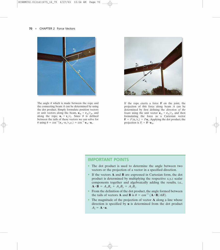
70 • CHAPTER 2 Force Vectors
ur
uAA
θ
F
F||uA
ur
A
IMPORTANT POINTS• The dot product is used to determine the angle between two
vectors or the projection of a vector in a specified direction.
• If the vectors A and B are expressed in Cartesian form, the dotproduct is determined by multiplying the respective x,y,z scalarcomponents together and algebraically adding the results, i.e.,
• From the definition of the dot product, the angle formed betweenthe tails of vectors A and B is
• The magnitude of the projection of vector A along a line whosedirection is specified by u is determined from the dot productA 7 = A # u.
u = cos-1 1A # B>AB2.A # B = Ax Bx + Ay By + Az Bz.
The angle which is made between the rope andthe connecting beam A can be determined by usingthe dot product. Simply formulate position vectorsor unit vectors along the beam, andalong the rope, Since is definedbetween the tails of these vectors we can solve for
using u = cos-11rA# rr>rArr2 = cos-1 uA
# ur.u
uur = rr>rr.uA = rA>rA,
u If the rope exerts a force F on the joint, theprojection of this force along beam A can bedetermined by first defining the direction of thebeam using the unit vector and thenformulating the force as a Cartesian vector
Applying the dot product, theprojection is F7 = F # uA.F = F1rr>rr2 = Fur.
uA = rA>rA
HIBBMC02.0131411675_16_79 6/27/03 10:54 AM Page 70
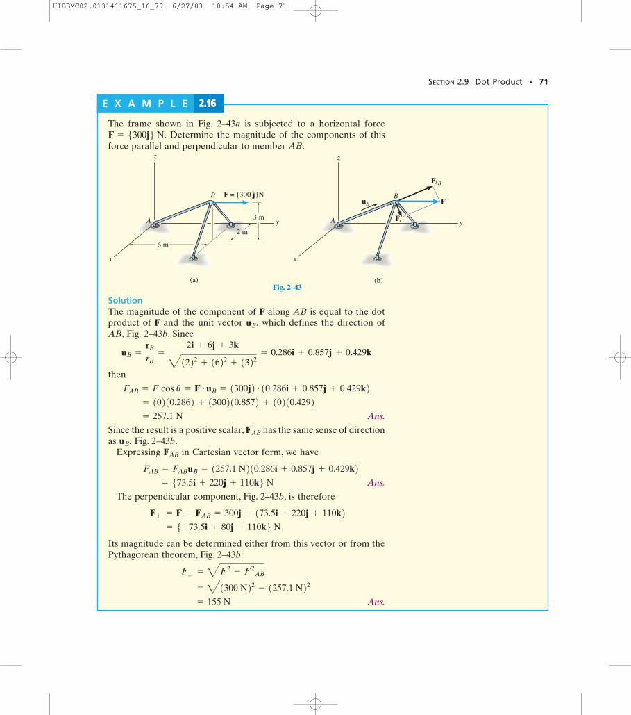
SECTION 2.9 Dot Product • 71
(a)
z
y
x
6 m
2 m
3 mA
B F = {300 j}N
Fig. 2–43(b)
F
F
FAB
z
y
x
A
BuB
Fig. 2–43B
E X A M P L E 2.16
The frame shown in Fig. 2–43a is subjected to a horizontal forceDetermine the magnitude of the components of this
force parallel and perpendicular to member AB.F = 5300j6 N.
SolutionThe magnitude of the component of F along AB is equal to the dotproduct of F and the unit vector which defines the direction ofAB, Fig. 2–43b. Since
then
Ans.
Since the result is a positive scalar, has the same sense of directionas Fig. 2–43b.
Expressing in Cartesian vector form, we have
Ans.
The perpendicular component, Fig. 2–43b, is therefore
Its magnitude can be determined either from this vector or from thePythagorean theorem, Fig. 2–43b:
Ans. = 155 N
= 41300 N22 - 1257.1 N22 F� = 4F2
- F2 AB
= 5-73.5i + 80j - 110k6 N F� = F - FAB = 300j - 173.5i + 220j + 110k2
= 573.5i + 220j + 110k6 N FAB = FAB uB = 1257.1 N210.286i + 0.857j + 0.429k2
FAB
uB,FAB
= 257.1 N
= 10210.2862 + 1300210.8572 + 10210.4292 FAB = F cos u = F # uB = 1300j2 # 10.286i + 0.857j + 0.429k2
uB =
rB
rB=
2i + 6j + 3k41222 + 1622 + 1322 = 0.286i + 0.857j + 0.429k
uB,
HIBBMC02.0131411675_16_79 6/27/03 10:54 AM Page 71
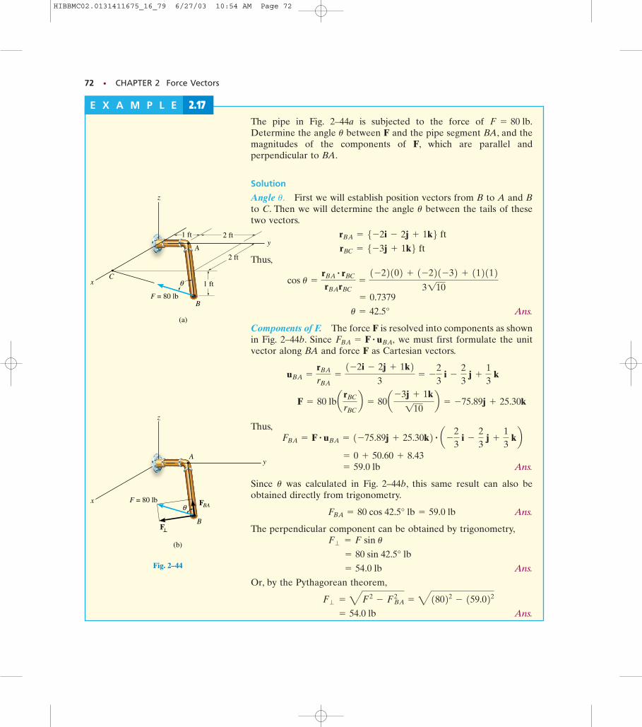
72 • CHAPTER 2 Force Vectors
F = 80 lb
θ
2 ft
2 ft1 ft
B
1 ft
y
x
z
(a)
C
A
Fig. 2–44A
(b)
x F = 80 lb
F
θ
z
yA
B
FBA
Fig. 2–44
E X A M P L E 2.17The pipe in Fig. 2–44a is subjected to the force of Determine the angle between F and the pipe segment BA, and themagnitudes of the components of F, which are parallel andperpendicular to BA.
Solution
Angle First we will establish position vectors from B to A and Bto C. Then we will determine the angle between the tails of thesetwo vectors.
Thus,
Ans.
Components of F. The force F is resolved into components as shownin Fig. 2–44b. Since we must first formulate the unitvector along BA and force F as Cartesian vectors.
Thus,
Ans.
Since was calculated in Fig. 2–44b, this same result can also beobtained directly from trigonometry.
Ans.
The perpendicular component can be obtained by trigonometry,
Ans.
Or, by the Pythagorean theorem,
Ans. = 54.0 lb
F� = 4F2- FBA
2= 418022 - 159.022
= 54.0 lb
= 80 sin 42.5° lb
F� = F sin u
FBA = 80 cos 42.5° lb = 59.0 lb
u
= 59.0 lb = 0 + 50.60 + 8.43
FBA = F # uBA = 1-75.89j + 25.30k2 # a -
23
i -
23
j +
13
kb
F = 80 lba rBC
rBCb = 80a -3j + 1k110
b = -75.89j + 25.30k
uBA =
rBA
rBA=
1-2i - 2j + 1k23
= -
23
i -
23
j +
13
k
FBA = F # uBA,
u = 42.5°
= 0.7379
cos u =
rBA# rBC
rBA rBC=
1-22102 + 1-221-32 + 1121123110
rBC = 5-3j + 1k6 ft rBA = 5-2i - 2j + 1k6 ft
u
u.
u
F = 80 lb.
HIBBMC02.0131411675_16_79 6/27/03 10:54 AM Page 72
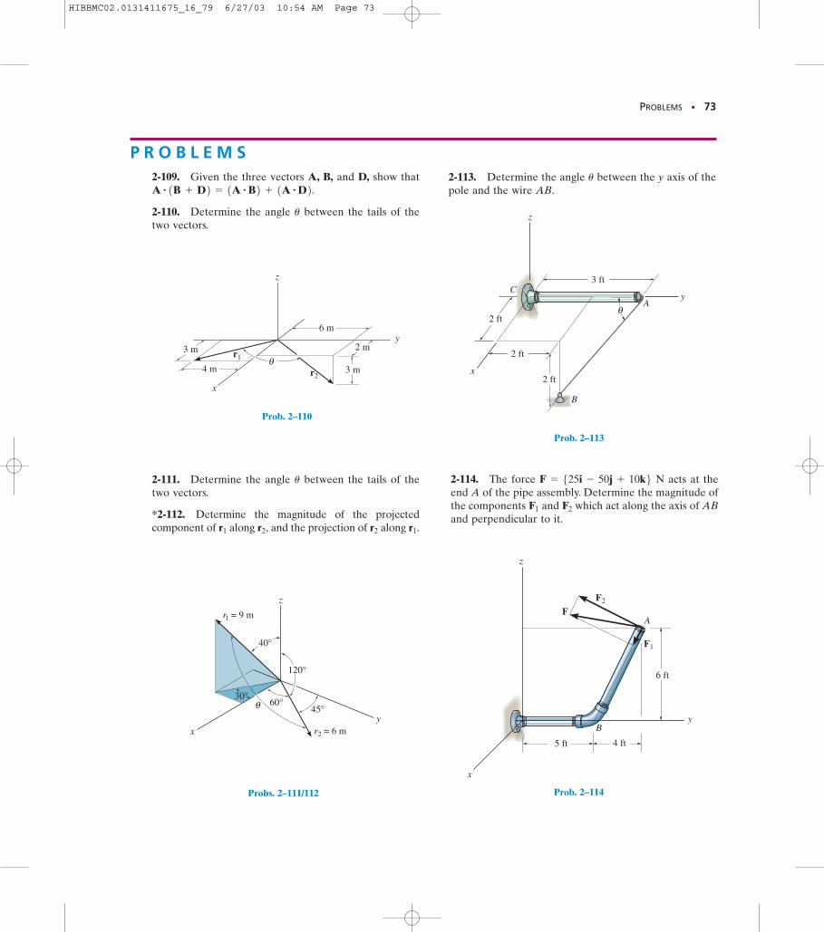
PROBLEMS • 73
θr2
r1
y
x
z
2 m3 m
3 m
6 m
4 m
Prob. 2–110
x
z
r2 = 6 m
r1 = 9 m
120°
45°60°
30°
y
θ
40°
Probs. 2–111/112
θ
x
y
B
A
C3 ft
2 ft
2 ft
2 ft
z
Prob. 2–113
5 ft 4 ft
6 ft
x
y
z
B
AF
F2
F1
Prob. 2–114
P R O B L E M S2-109. Given the three vectors A, B, and D, show that
2-110. Determine the angle between the tails of thetwo vectors.
u
A # 1B + D2 = 1A # B2 + 1A # D2.
2-111. Determine the angle between the tails of thetwo vectors.
*2-112. Determine the magnitude of the projectedcomponent of along and the projection of along r1.r2r2,r1
u
2-113. Determine the angle between the y axis of thepole and the wire AB.
u
2-114. The force N acts at theend A of the pipe assembly. Determine the magnitude ofthe components and which act along the axis of ABand perpendicular to it.
F2F1
F = 525i - 50j + 10k6
HIBBMC02.0131411675_16_79 6/27/03 10:54 AM Page 73
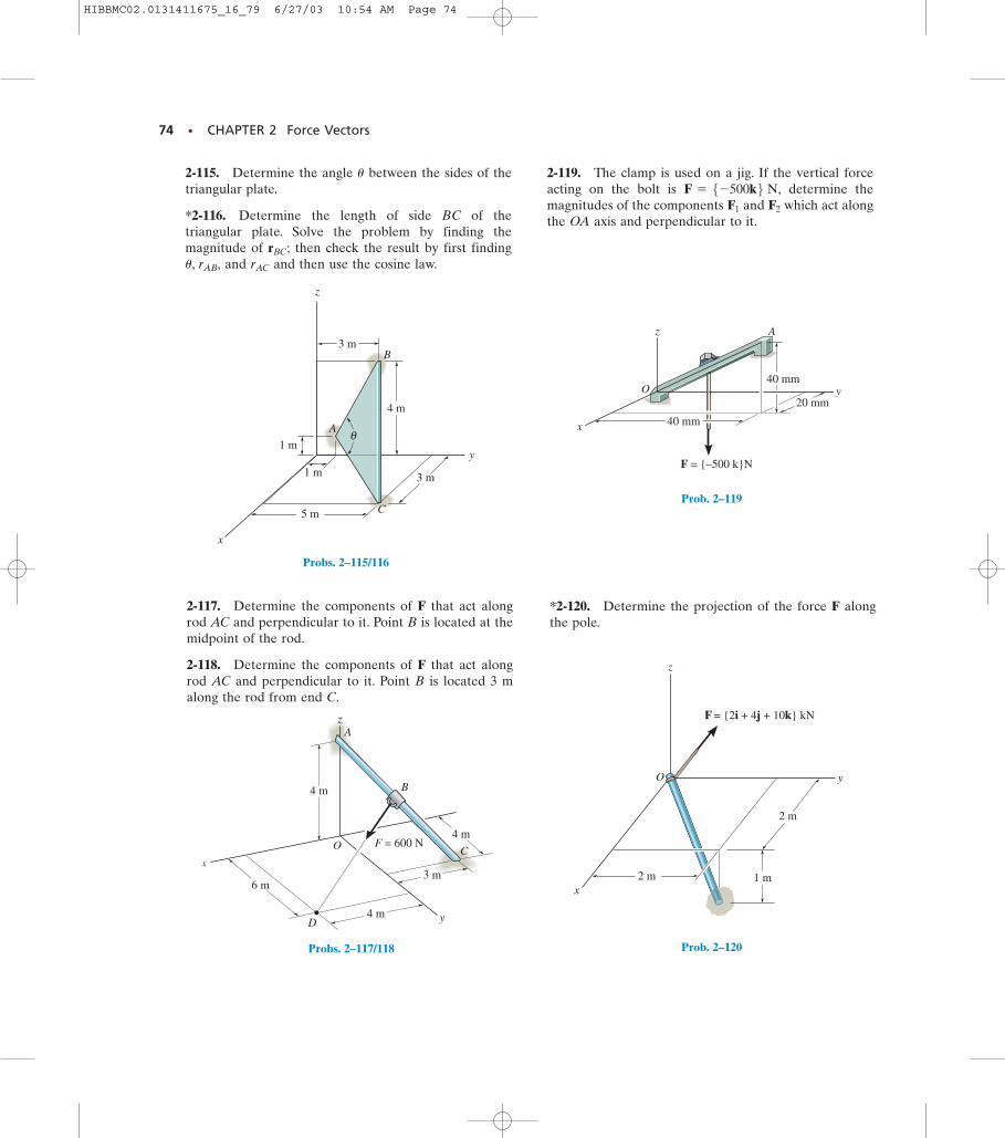
74 • CHAPTER 2 Force Vectors
y
x
A
C
B
z
1 m
4 m
3 m
3 m
1 m
5 m
θ
Probs. 2–115/116
3 m
4 m y
x
z
6 m
4 m
4 m
O F = 600 N
B
A
C
D
Probs. 2–117/118
z
O
x
y
40 mm
40 mm
20 mm
F = {–500 k}N
A
Prob. 2–119
O
z
x
y
1 m
2 m
2 m
F = {2i + 4j + 10k} kN
Prob. 2–120
2-115. Determine the angle between the sides of thetriangular plate.
*2-116. Determine the length of side BC of thetriangular plate. Solve the problem by finding themagnitude of then check the result by first finding
and and then use the cosine law.rACu, rAB,rBC;
u
2-117. Determine the components of F that act alongrod AC and perpendicular to it. Point B is located at themidpoint of the rod.
2-118. Determine the components of F that act alongrod AC and perpendicular to it. Point B is located 3 malong the rod from end C.
2-119. The clamp is used on a jig. If the vertical forceacting on the bolt is determine themagnitudes of the components and which act alongthe OA axis and perpendicular to it.
F2F1
F = 5-500k6 N,
*2-120. Determine the projection of the force F alongthe pole.
HIBBMC02.0131411675_16_79 6/27/03 10:54 AM Page 74
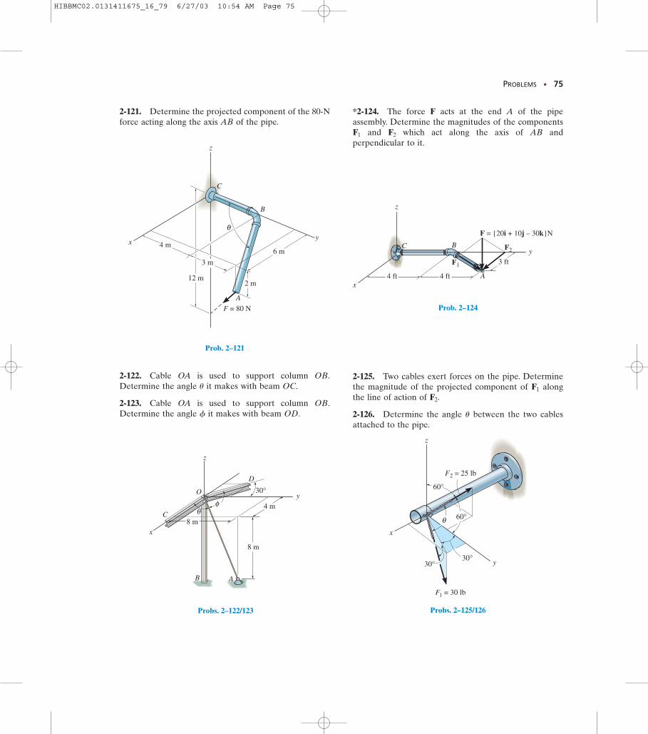
PROBLEMS • 75
y
A
B
C
θ
z
x 4 m
3 m
12 m
6 m
F = 80 N
2 m
Prob. 2–121
z
x
C
B
O
D
y4 m
30°
8 m
8 m
A
θφ
Probs. 2–122/123
4 ft 4 ft
3 fty
x
z
A
C B
F = {20i + 10j – 30k}N
F2
F1
Prob. 2–124
60°
y
z
60°
30°30°
F = 30 lb1
θx
F = 25 lb2
Probs. 2–125/126
2-121. Determine the projected component of the 80-Nforce acting along the axis AB of the pipe.
2-122. Cable OA is used to support column OB.Determine the angle it makes with beam OC.
2-123. Cable OA is used to support column OB.Determine the angle it makes with beam OD.f
u
*2-124. The force F acts at the end A of the pipeassembly. Determine the magnitudes of the components
and which act along the axis of AB andperpendicular to it.
F2F1
2-125. Two cables exert forces on the pipe. Determinethe magnitude of the projected component of alongthe line of action of
2-126. Determine the angle between the two cablesattached to the pipe.
u
F2.F1
HIBBMC02.0131411675_16_79 6/27/03 10:54 AM Page 75
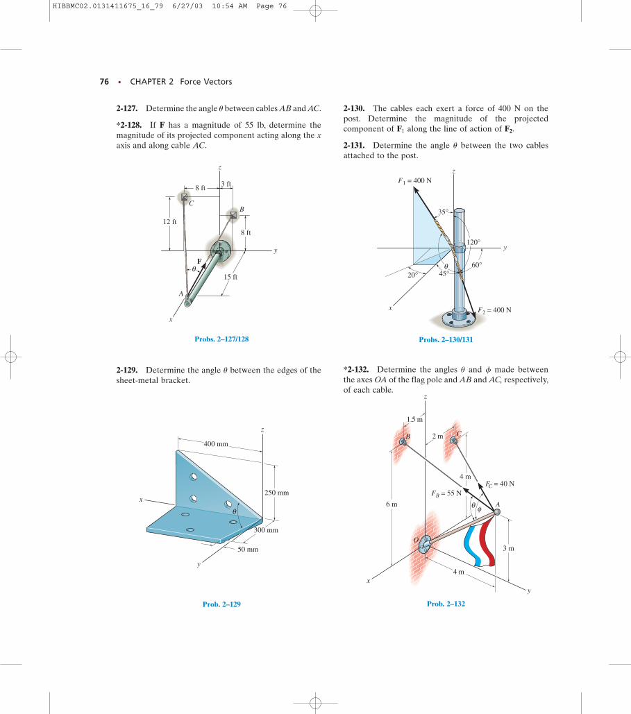
76 • CHAPTER 2 Force Vectors
y
z
x
8 ft 3 ft
12 ft
8 ft
15 ft
A
CB
Fθ
Probs. 2–127/128
x
y
z
400 mm
250 mm
300 mm
θ
50 mm
Prob. 2–129
x
z
y
F = 400 N1
F = 400 N2
20°
35°
45°60°
120°
θ
Probs. 2–130/131
3 m
4 m
C B
xy
z
O
FC = 40 NFB = 55 N
θ φ
2 m
1.5 m
6 m
4 m
A
Prob. 2–132
2-127. Determine the angle between cables AB and AC.
*2-128. If F has a magnitude of 55 lb, determine themagnitude of its projected component acting along the xaxis and along cable AC.
u
2-129. Determine the angle between the edges of thesheet-metal bracket.
u
2-130. The cables each exert a force of 400 N on thepost. Determine the magnitude of the projectedcomponent of along the line of action of
2-131. Determine the angle between the two cablesattached to the post.
u
F2.F1
*2-132. Determine the angles and made betweenthe axes OA of the flag pole and AB and AC, respectively,of each cable.
fu
HIBBMC02.0131411675_16_79 6/27/03 10:54 AM Page 76
CHAPTER REVIEW • 77
CHAPTER REVIEW
• Parallelogram Law. Two vectors add according to theparallelogram law. The components form the sides of theparallelogram and the resultant is the diagonal. To obtain thecomponents or the resultant, show how the vectors add by thetip-to-tail addition using the triangle rule, and then use the law ofsines and the law of cosines to calculate their values.
• Cartesian Vectors. A vector can be resolved into its Cartesiancomponents along the x, y, z axes so that
The magnitude of F is determined from and the coordinate direction angles are determined byformulating a unit vector in the direction of F, that is
The components of urepresent These three angles are related by
so that only two of the three anglesare independent of one another.
• Force and Position Vectors. A position vector is directedbetween two points. It can be formulated by finding the distanceand the direction one has to travel along the x, y, z axes from onepoint (the tail) to the other point (the tip). If the line of action ofa force passes through these two points, then it acts in the samedirection u as the position vector. The force can be expressed asa Cartesian vector using
• Dot Product. The dot product between two vectors A and B isdefined by If A and B are expressed asCartesian vectors, then In staticsthe dot product is used to determine the angle between the tailsof the vectors, It is also used to determinethe projected component of a vector A onto an axis defined byits unit vector u, so that A = A cos u = A # u.
u = cos-1 1A # B/AB2.
A # B = AxBx + AyBy + AzBz.A # B = A B cosu.
F = Fu = F1r/r2.
cos2 a + cos2 b + cos2 g = 1,cos a, cos b, cos g.
u = 1Fx/F2i + 1Fy/F2j + 1Fz/F2k.
a, b, gF = 4Fx
2+ Fy
2+ Fz
2
F = Fxi + Fy j + Fzk.
HIBBMC02.0131411675_16_79 6/27/03 11:48 AM Page 77
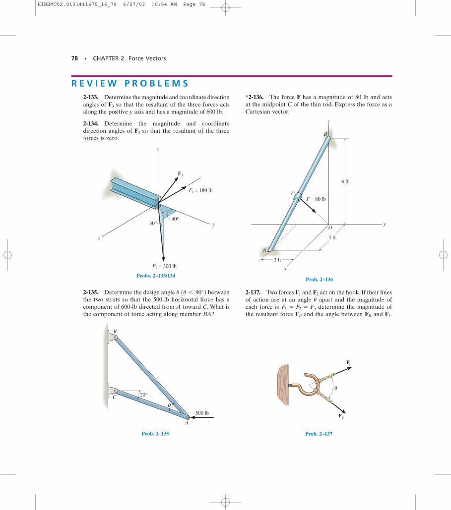
78 • CHAPTER 2 Force Vectors
F2 = 300 lb
F1 = 180 lb
F3
40°30°
z
x
y
Probs. 2–133/134
θ500 lb
20°
A
B
C
Prob. 2–135
3 ft
6 ft
2 ft
A
B
F = 80 lb
y
z
x
C
O
Prob. 2–136
R E V I E W P R O B L E M S2-133. Determine the magnitude and coordinate directionangles of so that the resultant of the three forces actsalong the positive y axis and has a magnitude of 600 lb.
2-134. Determine the magnitude and coordinatedirection angles of so that the resultant of the threeforces is zero.
F3
F3
2-135. Determine the design angle betweenthe two struts so that the 500-lb horizontal force has acomponent of 600-lb directed from A toward C. What isthe component of force acting along member BA?
u 1u 6 90°2
*2-136. The force F has a magnitude of 80 lb and actsat the midpoint C of the thin rod. Express the force as aCartesian vector.
2-137. Two forces and act on the hook. If their linesof action are at an angle apart and the magnitude ofeach force is determine the magnitude ofthe resultant force and the angle between and F1.FRFR
F1 = F2 = F,u
F2F1
θ
F1
F2
Prob. 2–137
HIBBMC02.0131411675_16_79 6/27/03 10:54 AM Page 78
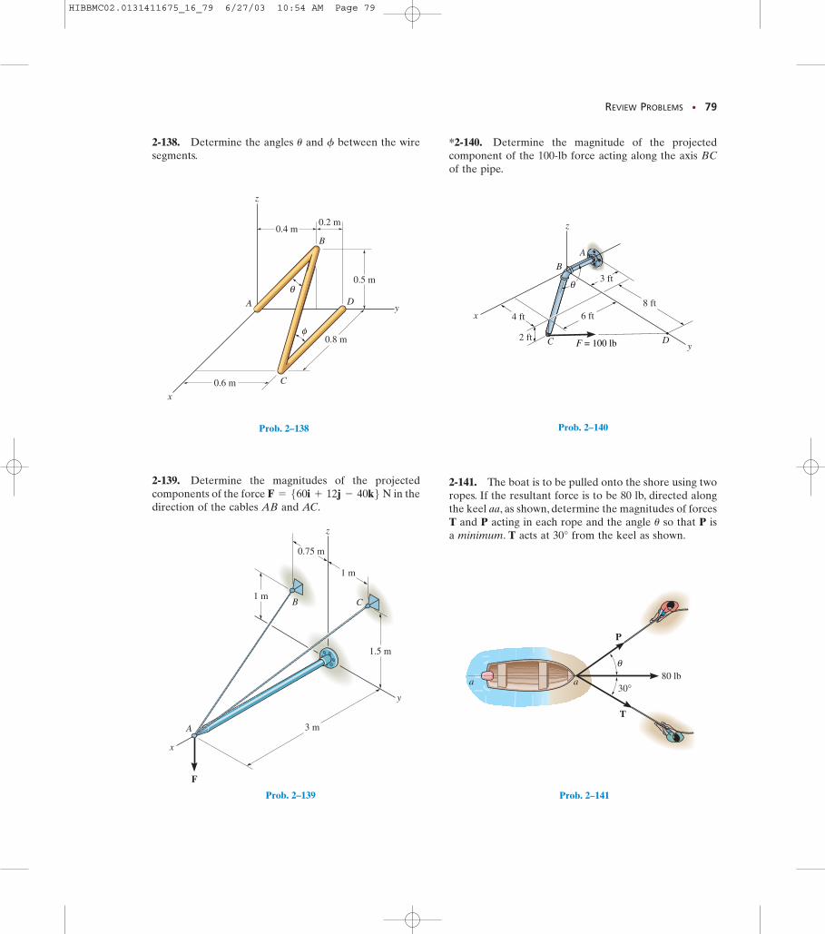
REVIEW PROBLEMS • 79
2-138. Determine the angles and between the wiresegments.
fu
z
y
0.8 m
x
B
A D
C
0.5 m
0.2 m0.4 m
θ
φ
0.6 m
Prob. 2–138
2-139. Determine the magnitudes of the projectedcomponents of the force in thedirection of the cables AB and AC.
F = 560i + 12j - 40k6 N
z
y
x
3 m
1.5 m
1 m
0.75 m
1 m
A
B C
F
Prob. 2–139
yC
B
A
D
z
8 ft
3 ft
6 ft
2 ft
4 ftx
F = 100 lb
θ
Prob. 2–140
Prob. 2–141
*2-140. Determine the magnitude of the projectedcomponent of the 100-lb force acting along the axis BCof the pipe.
2-141. The boat is to be pulled onto the shore using tworopes. If the resultant force is to be 80 lb, directed alongthe keel aa, as shown, determine the magnitudes of forcesT and P acting in each rope and the angle so that P isa minimum. T acts at 30° from the keel as shown.
u
30°80 lb
aa
T
P
θ
HIBBMC02.0131411675_16_79 6/27/03 10:54 AM Page 79


