Embed Size (px)
Citation preview
* Corresponding author: [email protected]
Three-dimensional analysis for piled raft machine foundation embedded in sand
Mahmood Mahmood1, *, Saad Al-Wakel1, Ihab Abdulwahhab1 1Building and Construction Engineering Department, University of Technology, Baghdad, Iraq
Abstract: Three-dimensional analysis for the dynamic response of a piled raft foundation subjected to vertical vibration is presented in this study. The analysis considers several factors affecting the amplitude of displacement for deep foundation such as pile cap embedment, pile cap thickness, relative density of the sand and the boundary effect. A validation for an experimental piled raft model depending on a scale factor of (20) using at (Plaxis 3D) computer program was performed. The sand is simulated using Mohr-Coloumb model while the concrete is simulated as linear elastic material. It has been found that embedding the pile cap in the soil and increasing its thickness lead to decrease the maximum amplitude of displacement. Furthermore, the predictions showed that increasing the distance between the foundation and the boundaries and increasing the relative density of the sand can significantly minimize the dynamic response of the foundation.
1 Introduction The use of the finite element method in dynamic foundation problems varies with other applications such that soil stratum of infinite medium that should be performed by a model of a specified size. This type of model creates a 'box' effect which is restricting the energy of the system and deforming its dynamic behavior. To eliminate this problem, lateral boundaries that absorb waves are introduced to contain the energy radiation into the outer region not existed in the model [1].
There are many issues that need careful examination before using finite element computer software such as modeling capabilities, analysis capabilities and processing but the most important one is the validation of results. Validation of the results is necessary before accepting the results [2].
Novak, 1974 [3] computed a vertical response of a machine and its foundations. The foundation consisted of a rectangular block of concrete (4.8 x 3 x 2.4 m). Two cases were considered; embedded (0.60 m) into the soil and having no embedment. It was supported on (10.5 m) long, fixed-top timber piles in medium stiff clay. The machine weight was (10 tons).
Manna and Baidya, 2010 [4] studied the influence of nonlinearity on the dynamic response of cast-in-situ reinforced concrete piles subjected to strong vertical excitation. Forced vibration experiment of single piles (L/d = 10, 15, 20) and (2×2) pile groups with (s/d = 2, 3, 4 for each L/d) were conducted in the field for two embedment conditions of pile cap. From the recorded nonlinear response curves, the effective pile–soil system
mass, damping and stiffness were obtained and the nonlinear response curves were back-calculated depending on the theory of nonlinear vibration. The results of the test were compared with Novak continuum approach with dynamic interaction factor approach by both linear and linear-equivalent numerical methods. A good match between the predicted and recorded response was found for linear-equivalent methods by introducing a weak boundary zone around the pile to approximately account for the nonlinear behavior of pile-soil system. The test data were used to create the empirical relationship to estimate the extent of soil separation around the pile with soil subjected to vertical vibration.
Padron et al., 2012 [5] studied the accuracy and effectiveness of the superposition method to assess the coefficients of the dynamic stiffness and damping of embedded footings supported by vertical piles set in uniform visco-elastic soil. A Comparison between these coefficients of pile embedded footings and those obtained by superposing the separate coefficients of the corresponding pile groups and embedded footings reveals that the average of the relative differences is about (10–30%). The results were presented in a set of normalized charts and simple expressions, which can be used to estimate the dynamic stiffness and damping of piled embedded footings, on a condition that the coefficients of the two separate components were known. Since such impedance functions for both embedded footings and pile groups were available for a wide range of cases, the superposition approach studied here was attractive.
Abdulrasool, 2012 [6] studied the dynamic analysis of deep foundations on uniform dry sand experimentally
MATEC Web of Conferences 162, 01023 (2018) https://doi.org/10.1051/matecconf/201816201023BCEE3-2017
© The Authors, published by EDP Sciences. This is an open access article distributed under the terms of the Creative Commons Attribution License 4.0 (http://creativecommons.org/licenses/by/4.0/).

169
and numerically by the finite element method. The numerical analysis involves the displacement response under the effect of dynamic loads of harmonic vertical mode of vibration. The aim of the study is to analyze the dynamic response of machine foundations by simulating the machine on deep foundation numerically using the finite element method. It was concluded that when the piles length and the number of piles increase this will lead to a decrease in the displacement response of the pile foundation because the increase in the mass of foundation. The dynamic response of the deep foundation is influenced by the spacing between piles.
2 Numerical analysis In this study, (Plaxis 3D) has been utilized to simulate the piled raft foundation with four piles in order to study the effect of various factors on the dynamic response of the foundation. Furthermore, it is transformed to a prototype model depending on a scale factor of (20). It is recommended to use a scale factor greater than (10) to eliminate the overestimated results [3]."Table 1" illustrates the scales of centrifugal modeling which is adopted in this analysis where (n) is the scale factor.
Centrifugal Model
Full Scale Quantity
1/n 1 Linear dimension
1/n2 1 Area
1/n3 1 Volume
1/n 1 Time
1/n3 1 Mass
1/n2 1 Force
1 1 Density
n 1 Frequency
2.1 Soil geometry and properties
The scaled dimensions of the soil are (15 × 15) m and the depth of the soil is (11) m are specified by single borehole at the first corner of the model. The boreholes locations and profile in the model as same as the information on the soil profile. If multiple boreholes are specified, the program automatically interpolates between the boreholes [8]. "Fig. 1" shows the soil model.
In order to simulate the soil behavior, an appropriate
material model and parameters must be assigned to the geometry. The (Mohr-Coloumb) model is chosen for the soil. The material properties of the soil which are taken from the experimental model are listed in "Table 2".
Unit Value Parameter
- Mohr- Coulomb
Material model
- Drained Drainage type
kN/m3 16.87 Dry unit weight
- 0.535 Voids ratio
kN/m2 30 × 10 3 Young's modulus
- 0.28 Poisson's ratio
kN/m2 0 Cohesion
degree 37.5 Friction angle
- 0.4 Lateral earth pressure coefficient K0
Table 1.Scales for centrifugal modeling [9]
Fig.1. Soil model.
Table 2. Soil material properties.
2
MATEC Web of Conferences 162, 01023 (2018) https://doi.org/10.1051/matecconf/201816201023BCEE3-2017
170
The lateral earth pressure coefficient K0 is
obtained automatically using the following equation:
𝐊𝐊𝐨𝐨 = 𝟏𝟏 − 𝐬𝐬𝐢𝐢𝐧𝐧∅ (1)
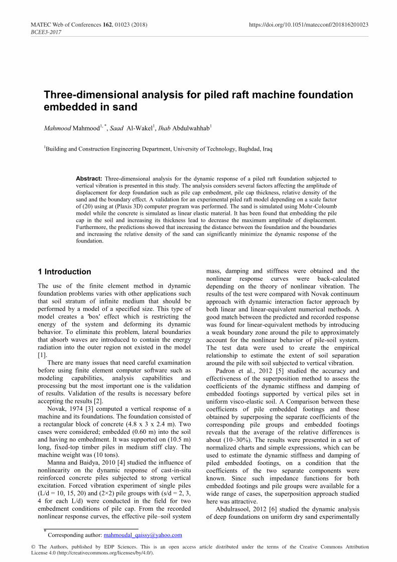
The deep foundation consists of two parts; the first is the pile cap which is simulated as a volume with the dimensions of (4 m × 4 m) and a thickness of (0.8 m). The volume is created by extruding a created surface which has the pile cap same dimensions using the extrude tool. The soil material data sets can be assigned to volumes. The data set of the concrete listed in "Table 3" is assigned to the pile cap volume.
Unit Value Parameter
- Linear Elastic Material model
- Non-Porous Drainage type
kN/m3 24 Dry unit weight
kN/m2 27.6 × 10 6 Young's modulus
- 0.1 Poisson's ratio
The second part of the deep foundation is the four
piles which have the same dimensions of (0.42) m diameter and (8) m length. Each pile is simulated as embedded pile. The skin resistance is simulated as linear. The input is defined by the skin resistance at the pile top Ttop max and the skin resistance at the pile bottom Tbot max. This way of defining the pile skin resistance is mainly applicable to piles in a homogeneous soil [9]. The tip bearing is defined by Fmax. The total pile bearing capacity Npile is given by:
Npile = Fmax + 0.5 L (Ttop max + Tbot max) (2)
Where: L is the pile length. The pile properties are shown in "Table 4".
Unit Value Parameter
kN/m2 27.6 × 10 6 Young's modulus
kN/m3 24 Unite weight
- Massive Circular Predefined pile type
M 0.42 Diameter
Linear Skin resistance type
kN/m 0 Ttop max kN/m 94.6 Tbot max
kN 1589 Fmax
The type of connection of the top of the pile is
selected as rigid which makes the rotation and displacement both coupled with the rotation and displacement of the structural or soil element at which the top of the pile is located. On the other hand, the type of the connection at the bottom of the pile is selected as free which allows the connection point to rotate and move relatively to the soil. The pile interaction with the surrounding soil is due to the special interface elements."Fig. 2" shows the simulated piled raft foundation with four piles.
Fig.2 The simulated piled raft foundation with for piles
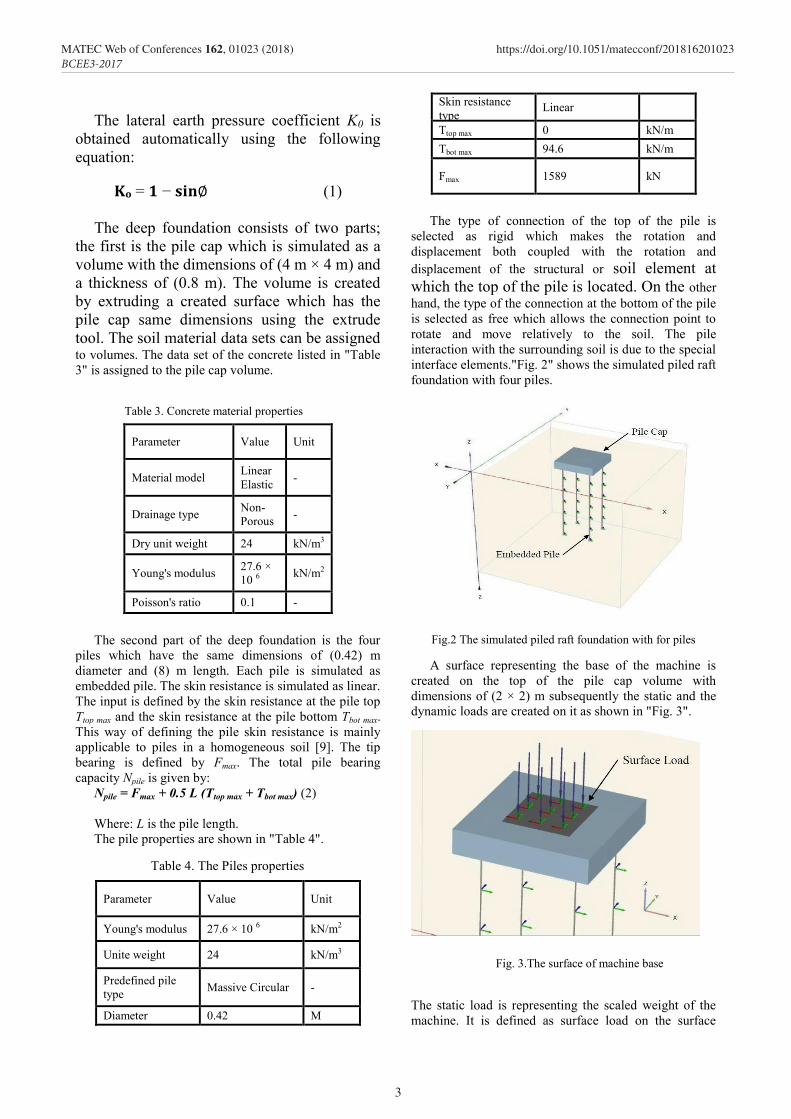
A surface representing the base of the machine is created on the top of the pile cap volume with dimensions of (2 × 2) m subsequently the static and the dynamic loads are created on it as shown in "Fig. 3".
The static load is representing the scaled weight of the machine. It is defined as surface load on the surface
Table 3. Concrete material properties
Table 4. The Piles properties
Fig. 3.The surface of machine base
3
MATEC Web of Conferences 162, 01023 (2018) https://doi.org/10.1051/matecconf/201816201023BCEE3-2017
which represents the base of the machine whereas the dynamic load which is calculated due to the scaled parameters is defined using a harmonic load multiplayer as shown in "Fig. 4".
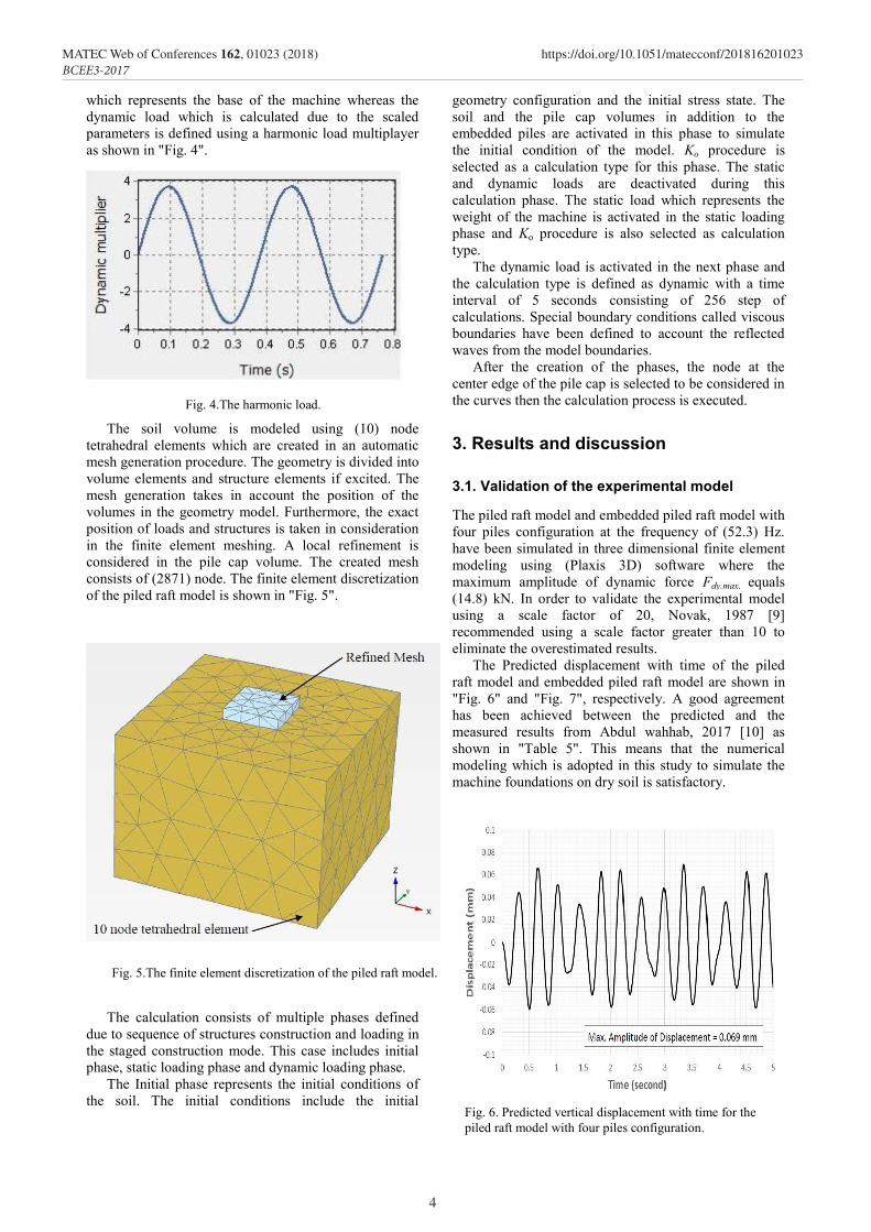
The soil volume is modeled using (10) node tetrahedral elements which are created in an automatic mesh generation procedure. The geometry is divided into volume elements and structure elements if excited. The mesh generation takes in account the position of the volumes in the geometry model. Furthermore, the exact position of loads and structures is taken in consideration in the finite element meshing. A local refinement is considered in the pile cap volume. The created mesh consists of (2871) node. The finite element discretization of the piled raft model is shown in "Fig. 5".
The calculation consists of multiple phases defined due to sequence of structures construction and loading in the staged construction mode. This case includes initial phase, static loading phase and dynamic loading phase.
The Initial phase represents the initial conditions of the soil. The initial conditions include the initial
geometry configuration and the initial stress state. The soil and the pile cap volumes in addition to the embedded piles are activated in this phase to simulate the initial condition of the model. Ko procedure is selected as a calculation type for this phase. The static and dynamic loads are deactivated during this calculation phase. The static load which represents the weight of the machine is activated in the static loading phase and Ko procedure is also selected as calculation type.
The dynamic load is activated in the next phase and the calculation type is defined as dynamic with a time interval of 5 seconds consisting of 256 step of calculations. Special boundary conditions called viscous boundaries have been defined to account the reflected waves from the model boundaries.
After the creation of the phases, the node at the center edge of the pile cap is selected to be considered in the curves then the calculation process is executed.
3. Results and discussion
3.1. Validation of the experimental model
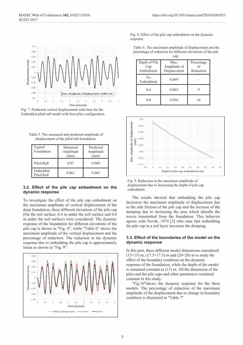
The piled raft model and embedded piled raft model with four piles configuration at the frequency of (52.3) Hz. have been simulated in three dimensional finite element modeling using (Plaxis 3D) software where the maximum amplitude of dynamic force Fdy.max. equals (14.8) kN. In order to validate the experimental model using a scale factor of 20, Novak, 1987 [9] recommended using a scale factor greater than 10 to eliminate the overestimated results.
The Predicted displacement with time of the piled raft model and embedded piled raft model are shown in "Fig. 6" and "Fig. 7", respectively. A good agreement has been achieved between the predicted and the measured results from Abdul wahhab, 2017 [10] as shown in "Table 5". This means that the numerical modeling which is adopted in this study to simulate the machine foundations on dry soil is satisfactory.
Fig. 4.The harmonic load.
Fig. 5.The finite element discretization of the piled raft model.
Fig. 6. Predicted vertical displacement with time for the piled raft model with four piles configuration.
4
MATEC Web of Conferences 162, 01023 (2018) https://doi.org/10.1051/matecconf/201816201023BCEE3-2017
172
Predicted Amplitude
(mm)
Measured Amplitude
(mm)
Typeof Foundation
0.069 0.07 Piled Raft
0.063 0.061 Embedded Piled Raft
3.2. Effect of the pile cap embedment on the dynamic response
To investigate the effect of the pile cap embedment on the maximum amplitude of vertical displacement of the deep foundation, three different elevations of the pile cap (On the soil surface, 0.4 m under the soil surface and 0.8 m under the soil surface) were considered. The dynamic response of the foundation for different elevations of the pile cap is shown in "Fig. 8", while "Table 6" shows the maximum amplitude of the vertical displacement and the percentage of reduction. The reduction in the dynamic response due to embedding the pile cap is approximately linear as shown in "Fig. 9".
Percentage of
Reduction (%)
Max. Amplitude of Displacement
(mm)
Depth of Pile Cap
Embedment (m)
- 0.069 No Embedment
9 0.063 0.4
16 0.058 0.8
The results showed that embedding the pile cap decreases the maximum amplitude of displacement due to the side friction of the pile cap and the increase of the damping due to increasing the area which absorbs the waves transmitted from the foundation. This behavior agrees with Novak, 1974 [3] who state that embedding the pile cap in a soil layer increases the damping.
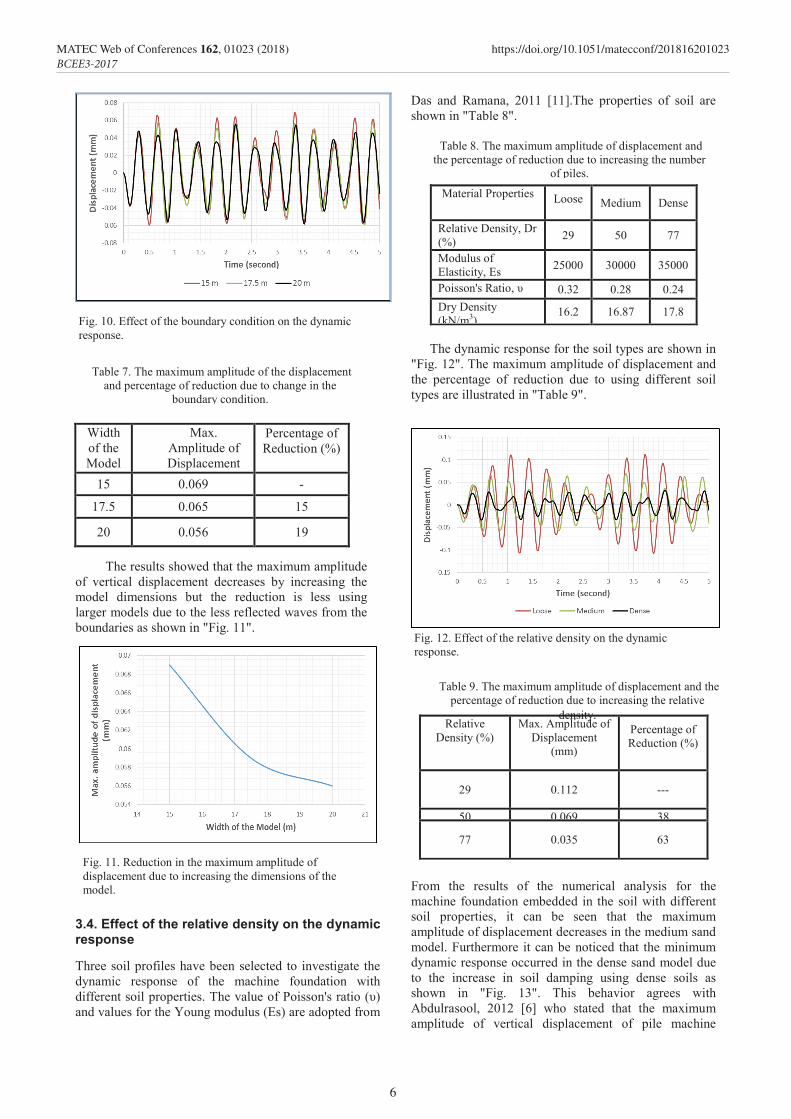
3.3. Effect of the boundaries of the model on the dynamic response
In this part, three different model dimensions considered (15×15) m, (17.5×17.5) m and (20×20) m to study the effect of the boundary condition on the dynamic response of the foundation, while the depth of the model is remained constant as (11) m. All the dimension of the piles and the pile caps and other parameters remained constant in this study.
"Fig.10"shows the dynamic response for the three models. The percentage of reduction of the maximum amplitude of the displacement due to change in boundary condition is illustrated in "Table 7".
Fig. 7. Predicted vertical displacement with time for the Embedded piled raft model with four piles configuration.
Table 5. The measured and predicted amplitude of displacement of the piled raft foundation.
Fig. 8. Effect of the pile cap embedment on the dynamic response
Table 6. The maximum amplitude of displacement and the percentage of reduction for different elevations of the pile
cap.
Fig. 9. Reduction in the maximum amplitude of displacement due to increasing the depth of pile cap embedment.
5
MATEC Web of Conferences 162, 01023 (2018) https://doi.org/10.1051/matecconf/201816201023BCEE3-2017
173
The results showed that the maximum amplitude of vertical displacement decreases by increasing the model dimensions but the reduction is less using larger models due to the less reflected waves from the boundaries as shown in "Fig. 11".
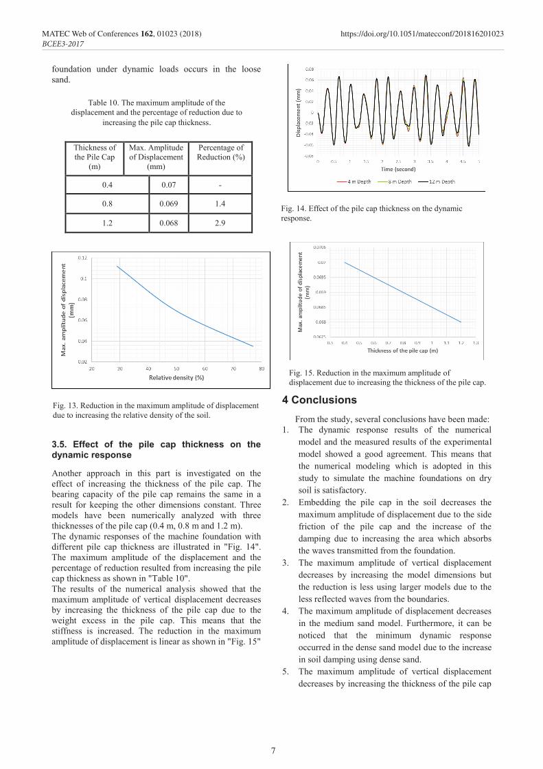
3.4. Effect of the relative density on the dynamic response
Three soil profiles have been selected to investigate the dynamic response of the machine foundation with different soil properties. The value of Poisson's ratio (υ) and values for the Young modulus (Es) are adopted from
Das and Ramana, 2011 [11].The properties of soil are shown in "Table 8".
Dense Medium Loose
Material Properties
77 50 29 Relative Density, Dr (%)
35000 30000 25000 Modulus of Elasticity, Es (kN/m2) 0.24 0.28 0.32 Poisson's Ratio, υ
17.8 16.87 16.2 Dry Density (kN/m3)
The dynamic response for the soil types are shown in
"Fig. 12". The maximum amplitude of displacement and the percentage of reduction due to using different soil types are illustrated in "Table 9".
Percentage of Reduction (%)
Max. Amplitude of Displacement
(mm)
Relative Density (%)
--- 0.112 29
38 0.069 50
63 0.035 77
From the results of the numerical analysis for the machine foundation embedded in the soil with different soil properties, it can be seen that the maximum amplitude of displacement decreases in the medium sand model. Furthermore it can be noticed that the minimum dynamic response occurred in the dense sand model due to the increase in soil damping using dense soils as shown in "Fig. 13". This behavior agrees with Abdulrasool, 2012 [6] who stated that the maximum amplitude of vertical displacement of pile machine
Percentage of Reduction (%)
Max. Amplitude of Displacement
(mm)
Width of the Model
(m) - 0.069 15
15 0.065 17.5
19 0.056 20
Fig. 10. Effect of the boundary condition on the dynamic response.
Table 7. The maximum amplitude of the displacement and percentage of reduction due to change in the
boundary condition.
Fig. 11. Reduction in the maximum amplitude of displacement due to increasing the dimensions of the model.
Table 8. The maximum amplitude of displacement and the percentage of reduction due to increasing the number
of piles.
Fig. 12. Effect of the relative density on the dynamic response.
Table 9. The maximum amplitude of displacement and the percentage of reduction due to increasing the relative
density.
6
MATEC Web of Conferences 162, 01023 (2018) https://doi.org/10.1051/matecconf/201816201023BCEE3-2017
174
foundation under dynamic loads occurs in the loose sand.
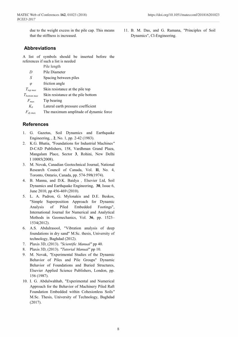
3.5. Effect of the pile cap thickness on the dynamic response
Another approach in this part is investigated on the effect of increasing the thickness of the pile cap. The bearing capacity of the pile cap remains the same in a result for keeping the other dimensions constant. Three models have been numerically analyzed with three thicknesses of the pile cap (0.4 m, 0.8 m and 1.2 m). The dynamic responses of the machine foundation with different pile cap thickness are illustrated in "Fig. 14". The maximum amplitude of the displacement and the percentage of reduction resulted from increasing the pile cap thickness as shown in "Table 10". The results of the numerical analysis showed that the maximum amplitude of vertical displacement decreases by increasing the thickness of the pile cap due to the weight excess in the pile cap. This means that the stiffness is increased. The reduction in the maximum amplitude of displacement is linear as shown in "Fig. 15"
4 Conclusions From the study, several conclusions have been made:
1. The dynamic response results of the numerical model and the measured results of the experimental model showed a good agreement. This means that the numerical modeling which is adopted in this study to simulate the machine foundations on dry soil is satisfactory.
2. Embedding the pile cap in the soil decreases the maximum amplitude of displacement due to the side friction of the pile cap and the increase of the damping due to increasing the area which absorbs the waves transmitted from the foundation.
3. The maximum amplitude of vertical displacement decreases by increasing the model dimensions but the reduction is less using larger models due to the less reflected waves from the boundaries.
4. The maximum amplitude of displacement decreases in the medium sand model. Furthermore, it can be noticed that the minimum dynamic response occurred in the dense sand model due to the increase in soil damping using dense sand.
5. The maximum amplitude of vertical displacement decreases by increasing the thickness of the pile cap
Percentage of Reduction (%)
Max. Amplitude of Displacement
(mm)
Thickness of the Pile Cap
(m)
- 0.07 0.4
1.4 0.069 0.8
2.9 0.068 1.2
Fig. 13. Reduction in the maximum amplitude of displacement due to increasing the relative density of the soil.
Fig. 14. Effect of the pile cap thickness on the dynamic response.
Table 10. The maximum amplitude of the displacement and the percentage of reduction due to
increasing the pile cap thickness.
Fig. 15. Reduction in the maximum amplitude of displacement due to increasing the thickness of the pile cap.
7
MATEC Web of Conferences 162, 01023 (2018) https://doi.org/10.1051/matecconf/201816201023BCEE3-2017
175
due to the weight excess in the pile cap. This means that the stiffness is increased.
Abbreviations A list of symbols should be inserted before the references if such a list is needed
L Pile length
D Pile Diameter S Spacing between piles φ friction angle
Ttop max Skin resistance at the pile top Tbottom max Skin resistance at the pile bottom
Fmax Tip bearing K0 Lateral earth pressure coefficient
Fdy.max. The maximum amplitude of dynamic force
References 1. G. Gazetas, Soil Dynamics and Earthquake
Engineering, , 2, No. 1, pp. 2-42 (1983). 2. K.G. Bhatia, "Foundations for Industrial Machines"
D-CAD Publishers, 158, Vardhman Grand Plaza, Mangalam Place, Sector 3, Rohini, New Delhi I 10085(2008).
3. M. Novak, Canadian Geotechnical Journal, National Research Council of Canada, Vol. II, No. 4, Toronto, Ontario, Canada, pp. 574-598(1974).
4. B. Manna, and D.K. Baidya , Elsevier Ltd, Soil Dynamics and Earthquake Engineering, 30, Issue 6, June 2010, pp 456-469 (2010).
5. L. A. Padron, G. Mylonakis and D.E. Beskos, "Simple Superposition Approach for Dynamic Analysis of Piled Embedded Footings", International Journal for Numerical and Analytical Methods in Geomechanics, Vol. 36, pp. 1523–1534(2012).
6. A.S. Abdulrasool, "Vibration analysis of deep foundations in dry sand" M.Sc. thesis, University of technology, Baghdad (2012).
7. Plaxis 3D, (2013). "Scientific Manual" pp 40. 8. Plaxis 3D, (2013). "Tutorial Manual" pp 10. 9. M. Novak, "Experimental Studies of the Dynamic
Behavior of Piles and Pile Groups" Dynamic Behavior of Foundations and Buried Structures, Elsevier Applied Science Publishers, London, pp. 156 (1987).
10. I. G. Abdulwahhab, "Experimental and Numerical Approach for the Behavior of Machinery Piled Raft Foundation Embedded within Cohesionless Soils" M.Sc. Thesis, University of Technology, Baghdad (2017).
11. B. M. Das, and G. Ramana, "Principles of Soil Dynamics", Cl-Engineering.
8
MATEC Web of Conferences 162, 01023 (2018) https://doi.org/10.1051/matecconf/201816201023BCEE3-2017


