Embed Size (px)
Citation preview

Article – Gregory Yu. Ivanyuk memorial issue
Three-dimensional textural investigation of sulfide mineralisationfrom the Loolekop carbonatite–phoscorite polyphase intrusion inthe Phalaborwa Igneous Complex (South Africa), with implicationsfor ore-forming processes
Loic Y. Le Bras1* , Robert Bolhar1, Lunga Bam2, Bradley M. Guy3, Grant M. Bybee1 and Paul A.M. Nex11School of Geosciences, University of the Witwatersrand, Braamfontein 2001, Johannesburg, South Africa; 2South African Nuclear Energy Corporation SOC Ltd.(Necsa), Elias Motsoaledi Street Ext. (Church Street West), R104, Pelindaba, South Africa; and 3Department of Geology, University of Johannesburg, Auckland Park2006, Johannesburg, South Africa
Abstract
Copper-sulfides within carbonatites and phoscorites of the Phalaborwa Igneous Complex, South Africa, have been investigated since themiddle of the 20th Century. However, aspects of ore formation have remained unclear. This study examines the mechanisms involved inCu-sulfide mineralisation by micro-focus X-ray computed tomography as applied to sulfide-rich drill core samples. Several texturallydistinct assemblages of magmatic sulfides can be identified, including: (1) <500 μm rounded bornite and chalcopyrite grains dissemi-nated within the gangue; (2) elongated mm-scale assemblages of chalcopyrite and bornite; and (3) mm-to-cm thick chalcopyrite cumu-lates. Chalcopyrite veins were also observed, as well as late-stage valleriite, documenting late-stage fluid circulation within the pipe, andalteration of magmatic and hydrothermal sulfides along fractures within the gangue, respectively. The results of micro-focus X-ray com-puted tomography indicate that magmatic sulfides are sub-vertically aligned. Spatial variability of the sulfide assemblages suggests thattextural changes within sulfide layers reflect fluctuating magma flow rate during emplacement of carbonatite–phoscorite magmas,through coalescence or breakup of sulfide liquid droplets during ascent. Modal sulfide abundances, especially for disseminated assem-blages, differ from one carbonatite–phoscorite layer to another, suggesting a strong control of the mechanical sorting in the formation ofCu-sulfide textures within the Loolekop carbonatite. The alternation of carbonatite and phoscorite within the intrusion suggest that theLoolekop Pipe was emplaced through a series of successive magma pulses, which differentiated into carbonatite and phoscorite by meltimmiscibility/progressive fractional crystallisation and pressure drop. Three-dimensional textural analysis represents an effective tool forthe characterisation of magma flow and is useful for the understanding of magmatic processes controlling sulfide liquid-bearing phos-corite–carbonatite magmas.
Keywords: carbonatite–phoscorite series, copper sulfides, Phalaborwa Igneous Complex, micro-focus X-ray computed tomography
(Received 31 December 2020; accepted 26 March 2021; Accepted Manuscript published online: 31 March 2021; Associate Editor:David J. Good)
Introduction
The Loolekop Pipe of the Phalaborwa Igneous Complex is theonly known occurrence of a Cu-sulfide deposit of economic inter-est hosted within a carbonatite–phoscorite intrusion. This deposithas been mined since 1956 by the Palabora Mining CompanyLtd., mainly for Cu, but also for other by-products, such as Feand U. Copper-sulfide mineralisation within the Loolekop Pipe
has been studied extensively since the middle of the 20th
Century (Lombaard et al., 1964; Hanekom et al., 1965; Grovesand Vielreicher, 2001; Giebel et al., 2017). Yet, primary ore-forming and late-stage alteration processes have not been entirelycharacterised (Heinrich et al., 1970; Palabora Mining CompanyLtd. Staff, 1976; Vielreicher et al., 2000). Stable-isotope (Fe andCu) and trace-element analysis on Cu-sulfides revealed the pres-ence of a magmatic monosulfide solid solution and intermediatesolid solution (mss–iss) system in the Loolekop carbonatite–phoscorite intrusion (Le Bras, 2020; Le Bras et al., 2021).However, the mechanisms responsible for magmatic sulfide tex-tures operating during the late stages of magma ascent remainunclear. Previous detailed research was made on the basis ofoptical and electron microscope observations, as well as electronmicroprobe analysis of Cu-sulfides on epoxy mounts and thinsections (Rudashevsky et al., 2004; Giebel et al., 2017). Though
*Author for correspondence: Loic Y. Le Bras, Email: [email protected] paper is part of a thematic set ‘Alkaline Rocks’ in memory of Dr. Gregory Yu.Ivanyuk
© The Author(s), 2021. Published by Cambridge University Press on behalf of The Mineralogical Society of Great Britain and Ireland. This is an Open Access article, distributed underthe terms of the Creative Commons Attribution-NonCommercial-NoDerivatives licence (http://creativecommons.org/licenses/by-nc-nd/4.0/), which permits non-commercial re-use,distribution, and reproduction in any medium, provided the original work is unaltered and is properly cited. The written permission of Cambridge University Press must be obtainedfor commercial re-use or in order to create a derivative work.
Cite this article: Le Bras L.Y., Bolhar R., Bam L., Guy B.M., Bybee G.M. and Nex P.A.M.(2021) Three-dimensional textural investigation of sulfide mineralisation from theLoolekop carbonatite–phoscorite polyphase intrusion in the Phalaborwa IgneousComplex (South Africa), with implications for ore-forming processes. MineralogicalMagazine 85, 514–531. https://doi.org/10.1180/mgm.2021.32
Mineralogical Magazine (2021), 85, 514–531
doi:10.1180/mgm.2021.32
https://doi.org/10.1180/mgm.2021.32 Published online by Cambridge University Press
such methods provided important constraints on phase composi-tions, the textural data may not be entirely representative due tostereological bias. Accurate textural analysis of the Cu-sulfide min-eralisationwithin the LoolekopPipe is critical, considering the spatialvariability of mineral associations and textures. Three-dimensionalanalytical methods are capable of providing a more comprehensivedataset for adequately classifying the Loolekop-hosted Cu-sulfides.
The micro-focus X-ray computed tomography method ismade on the basis of density variations between minerals.During X-ray irradiation, dense phases attenuate the beam morethan light ones, producing contrast between the different mineralphases in the sample. The measurements generate 2D attenuationprojections (radiographs). The 3D volume employed to interrogatethe mineral phases is produced by stacking the 2D projections. Itenables the characterisation of mineral size, distribution, associ-ation, internal textural orientation, porosity and mineral modalabundances within the sample. This method is advantageous con-sidering its non-destructive nature, as it consists of the collection oftwo-dimensional (2D) X-ray projections of a sample followed byimage reconstitution to produce a three-dimensional (3D) model.Due to its ability to examine these parameters, micro-focus X-raycomputed tomography (microCT) has been used successfully todescribe various types of mineralisation (Barnes et al., 2008;Godel et al., 2010; Cnudde and Boone, 2013; Barnes et al., 2019).This analytical method is particularly useful in deciphering texturalrelationships between ore minerals, and consequently identifyingore-forming processes (Godel et al., 2010, 2013).
Copper-sulfide mineralisation in the Loolekop Pipe is particu-larly complex. The spatial variability and the number of sulfidephases make the identification of mineral paragenesis challenging.Three-dimensional microCT analysis of drill core pieces from dif-ferent rock types of the intrusion provide comprehensive and rep-resentative information regarding the distribution, shape andmineral associations of the Cu-sulfide mineralisation, includingspatial relationships between the different Cu-bearing phases.The use of this method for the characterisation of Cu-sulfidesfrom the Loolekop Pipe of the Phalaborwa Igneous Complexrepresents a novel approach to understand the metallogenesis ofthis unusual deposit.
Geological setting
The Phalaborwa Igneous Complex
The Phalaborwa Igneous Complex is located in Limpopo Province,South Africa, ∼450 km northeast of the city of Johannesburg. Thecomplex is the outcome of successive intrusions of several magmapulses into the granitoid–gneiss basement of the ArchaeanKaapvaal Craton. The igneous complex is composed of three dis-tinct intrusive centres producing three adjacent lobes aligned ona North–South axis forming an 18.5 km2 ellipsoid (Fig. 1a). Thecomplex is characterised by mafic rocks along the external bound-aries of the complex, and carbonatitic rocks towards its core. Thefirst magma pulse emplaced a feldspathic pyroxenite unit formingan aureole around the intrusive complex along the contact with thebasement. It has been shown that the presence of feldspars is notrelated to any interaction with the gneissic–granitic host rock(Eriksson, 1982). Fenitisation of the Kaapvaal host rocks can beobserved along the contact with the feldspathic pyroxenite.Post-dating the feldspathic pyroxenite, a second magma pulse crys-tallised a micaceous pyroxenite, which constitutes a major part ofthe igneous intrusion (Fig. 1a). This rock is composed of
phlogopite, diopside and apatite (Heinrich, 1970; Eriksson, 1982).The phlogopite content varies within the intrusion. Mineral assem-blage alignments indicate the presence of magmatic flow duringemplacement of these rocks. Weathering of the micaceous pyroxen-ite has resulted in the alteration of phlogopite to vermiculite(Palabora Mining Company Ltd. Staff, 1976). Thereafter, pyroxenepegmatites were emplaced as three intrusive centres, each beingcharacterised by distinct modal compositions. The southern peg-matite is composed of diopside and phlogopite with minor fluora-patite and serpentine (Eriksson, 1982). The northern pegmatiteconsists of a ring-shaped phlogopite-, diopside- and apatite-bearingunit surrounding a rock composed of diopside, serpentine andphlogopite. The central pegmatite consists of phlogopite, diopsideand apatite. Syenite magma intruded into gneisses and granitesof the Kaapvaal Craton to form syenite plugs all around the com-plex. Late gabbro dykes cross-cut all country rocks and the complexalong a northeast–southwest axis.
Geological characteristics of the Loolekop Pipe
The central intrusion, henceforth named Loolekop Pipe, repre-sents a sub-vertical body, which was emplaced at the intersectionof five major faults and shear zones (Basson et al., 2017). The firstrocks to crystallise were phoscorite at the outer parts of theLoolekop Pipe and banded carbonatite to the centre of the intru-sion (Fig. 1b). Both banded carbonatite and phoscorite aremarked by the presence of planar mineral alignments. Alternatevertical layers of banded carbonatite and phoscorite form a pro-gressive transition from massive phoscorite at the external bound-aries of the Loolekop Pipe to banded carbonatite towards the core(Fig. 1c). A later structural event imparted a dense stockwork inthe core of the pipe and reactivated igneous activity, allowingthe emplacement of a second carbonatite magma pulse, formingthe transgressive carbonatite, into the fracture network in the cen-tre of the intrusion (Lombaard et al., 1964; Heinrich, 1970).
The phoscorite in the Loolekop Pipe is a coarse-grained rock(5 mm to 6 cm) composed mainly of magnetite and apatitewith lesser extents of diopside and phlogopite in a calcite matrix(Eriksson, 1982). The banded carbonatite unit consists mainly ofmedium- to coarse-grained (1 mm to 2 cm) calcite and dolomitewith minor amounts of magnetite, apatite and diopside. Bothbanded carbonatite and phoscorite show magnetite-, apatite-and silicate-bearing planar alignments, forming sub-verticalcumulates in the intrusive pipe (Lombaard et al., 1964;Hanekom et al., 1965; Palabora Mining Company Ltd. Staff,1976). The transgressive carbonatite is composed of coarse-grained (5 mm to 5 cm) calcite and dolomite with traces of apa-tite, magnetite and diopside, which are all apparently related tothe replacement of banded carbonatite/phoscorite duringmagma ascent.
The timing of emplacement of the Loolekop Pipe has beeninvestigated using various analytical techniques. Uranium-Pbthermal ionisation mass spectrometry (TIMS) analysis of bad-deleyite produced ages of 2059.8 ± 0.8 Ma and 2060.6 ± 0.5 Ma(Heaman and LeCheminant, 1993; Reischmann, 1995).Secondary ion mass spectrometry (SIMS) U–Pb analysis on zir-cons from the pyroxene-bearing pegmatite, phoscorite, bandedcarbonatite and transgressive carbonatite produced ages estimatedat 2060 ± 4 Ma, 2060 ± 1 Ma, 2060 ± 2 Ma and 2060 ± 1 Ma,respectively (Wu et al., 2011). These ages suggest a synchronousemplacement of the main geological units. Compositions ofbanded carbonatite and phoscorite indicate a cogenetic origin of
Mineralogical Magazine 515
https://doi.org/10.1180/mgm.2021.32 Published online by Cambridge University Press

these two rocks, which support the concept of a rapid emplace-ment of the Loolekop carbonatite–phoscorite complex (Wuet al., 2011; Milani et al., 2017a, b).
Copper sulfides in the Loolekop Pipe
Chalcopyrite represents the dominant sulfide in terms of volumewithin the Loolekop Pipe (Palabora Mining Company Ltd. Staff,1976). It occurs as two different types defined by specific mineralassociations and textures. The first type constitutes the largest partof the sulfide mineralisation within the Loolekop Pipe and is char-acterised by networks of sub-vertical veinlets occurring in widezones (up to several m) along fractures within the transgressivecarbonatite (Palabora Mining Company Ltd. Staff, 1976;Vielreicher et al., 2000). Chalcopyrite, as part of this mineralisa-tion, is commonly associated with cubanite, the latter being pre-sent either as exsolution lamellae or grains (Lombaard et al.,1964; Palabora Mining Company Ltd. Staff, 1976; Le Bras et al.,2021). The second type occurs as disseminated grains (50 to500 μm) associated with small modal amounts of bornite withinbanded carbonatite and phoscorite, and is present in minoramounts relative to chalcopyrite (Palabora Mining Company
Ltd. Staff, 1976). Disseminated grains of chalcopyrite have alsobeen observed within the micaceous pyroxenite.
Bornite has been reported as the second most important sul-fide in terms of abundance in the Loolekop Pipe and representsthe dominant phase within the banded carbonatite and phoscor-ite. This mineral is associated with disseminated chalcopyrite inbanded carbonatite and phoscorite, but also occurs as an isolatedphase. Both bornite and chalcopyrite can be found disseminatedwithin the carbonate gangue, though they are also associatedwith magnetite and apatite cumulates. Intergrowths of chalcociteand bornite have also been observed.
Late-stage valleriite occurs together with primary sulfidesalong cracks and edges of chalcopyrite and bornite (Le Braset al., 2021). Various trace sulfides have also been reported inthe Loolekop rocks, such as pentlandite, millerite, bravoite, tetra-hedrite, sphalerite, pyrite and galena, as well as platinum-groupminerals (Bulakh et al., 1998; Rudashevsky et al., 2004).
Trace-element analyses of sulfide assemblages reveal anenrichment of Pd (average of 91 ppb) over Pt and otherplatinum-group elements (PGE) in the Ir-group (IPGE: Os, Ir,Ru; up to 20 ppb), consistent with the operation of a mss–iss sys-tem in the Loolekop Pipe (Le Bras et al., 2021). This originatesfrom a magmatic process, characterised by the formation of two
Fig. 1. (a) Simplified geological map of the Phalaborwa Igneous Complex. (b) Enlarged view of the Loolekop Pipe with surface projections of the drill core collarsand orientations. The drill cores have a sub-horizontal orientation. (c) Vertical cross-section defined by the x – y line on (b). Modified after Palabora MiningCompany Ltd. Staff (1976) and Le Bras et al. (2021).
516 Loic Y. Le Bras et al.
https://doi.org/10.1180/mgm.2021.32 Published online by Cambridge University Press

phases from the sulfide liquid during magma ascent. The firstconsisted of an Fe- and IPGE-rich sulfide cumulate (mss) andthe second of a Cu- and Pd-group PGE (PPGE: Pd, Pt)-rich sul-fide liquid, which later precipitated an iss. The iss further evolvedin Cu-sulfide assemblages during cooling. The depletion in Pt ofsulfide phases is regarded as the consequence of the formation ofsperrylite (PtAs2) during the magmatic stage.
Samples and methods
Samples
Forty five pieces of drill core from two boreholes were selectedfrom the Palabora Mining Company drill-core collection.Samples consist of drill-core quarters with a 1.75 cm radius.Sampled cores were drilled sub-horizontally at the second liftlevel of the mine, ∼1250 m below surface. Twelve samples fromdifferent rock types were chosen for microCT analysis on thebasis of their Cu-sulfide content to ensure optimal characterisa-tion of the mineralisation (Supplementary material – Appendix1). A polished epoxy mount was prepared from one of the drillcore samples in order to identify the different ore phases in thetomographic images.
Micro-focus X-ray computed tomography
Analyses were performed at the Micro-focus X-ray Radiographyand Tomography (MIXRAD) facility at the South AfricanNuclear Energy Corporation (NESCA) at Pelindaba in SouthAfrica.
The procedure to acquire the data consists of four steps. Thefirst consists of the acquisition of the 2D image projections(2000 projections) of the drill-core samples through a 360°rotation. A Nikon XTH 225 CT system with a multi-target source(Mo, Cu, Ag, W) was used to acquire the 2D projections. Theinstrument has been described in detail elsewhere (Hoffmanand De Beer, 2012). The drill-core samples were mounted in aPlexiglas® cylinder and held in place by polystyrene pieces toavoid any movement of the samples during scanning. The scan-ning resolution was set between 28 and 45 μm3 (voxel size)depending on the sample size. To optimise the image contrast,the exposure time was set to 4 s and the source voltage to100 kV. A 0.5 mm Cu filter was used to minimise the impact ofbeam hardening and to improve X-ray penetration. A 16-bitdynamic range Perkin Elmer flat-panel detector was employedto capture the projections. This detector has an effective size of400 mm × 400 mm and a pixel size of 200 μm× 200 μm.
The second step involves the reconstruction of the 2D imageprojections into a 3D volume using the CT Pro 3D software. Abeam hardening correction of 2 was used to further minimisethe impact of beam hardening and optimise image contrast. Inthis case, the reconstructed 3D volume comprises the 2D imageslices.
This step was followed by pre-processing of the 2D imageslices using ImageJ free software (Schneider, 2012). A certaingrey value related to the low-density phases (gangue minerals)is subtracted to improve the overall contrast between the densephases (Fig. 2). The segmentation was done using the built-in seg-mentation grey value range function of the VG Studio Max soft-ware version 3.2 (Volume Graphics GmbH). This function allowsa certain grey value range (attributed to the minerals) to beisolated from the entire sample. The attenuation coefficient
information illustrates that the discrimination between mineralsof interest (magnetite, chalcopyrite, bornite, valleriite) is possible(Fig. 3). It is particularly the case between chalcopyrite and mag-netite in the Loolekop Pipe due to the high Ti content of magnet-ite (Milani et al., 2017a), which significantly lowers its attenuationcoefficient (Fig. 3). The porosity of magnetite associated withchalcopyrite is also a factor leading to a lower attenuation factor(Fig. 2b).
The final step consists of restoring a 3D volume of the phase ofinterest from the stacking of segmented 2D image slices using theVG Studio Max software version 3.2 (Fig. 4). For better visualisa-tion, a false colour was assigned to each phase of interest to indi-cate occurrence and distribution within the drill cores.
Mineral liberation analysis
Mineral liberation analysis (MLA) was carried out on asulfide-rich sample mounted in epoxy resin to obtain a detailedoverview of both sulfide phases and textures, and to optimisetomographic data processing. The polished mount was preparedfrom a drill-core piece previously analysed by micro-focus X-raycomputed tomography.
The MLA was performed using a FEI Quanta 600 FEG MLAwith two Bruker Xflash X-ray detectors at the University ofJohannesburg. Analyses were conducted at a working distanceof 13 mm. The acceleration voltage was set at 25 kV and the cur-rent at the surface of the specimen at 10 nA. X-ray detectors werecalibrated against a Cu standard. Calibration of the back-scatteredelectron (BSE) grey level was performed against Au, Cu andquartz standards. Sulfide and gangue phases collection timeswere set at 10 ms and 30 ms, respectively. Mineral maps were cre-ated using the GXMAP measurement mode, which performsX-ray analysis according to a grid format with a point spacingset at 13 μm.
Results
MicroCT spatial resolution
The MLA results permit the accurate identification and textures ofsulfides of interest, and also enables the assignment of microCTgrey level intervals to the different phases (Figs 2 and 4). MineralLiberation Analysis also revealed the limited spatial resolution ofthe microCT where the structural features are smaller than theresolution, affecting the contrast. Small-scale mineralisation fea-tures (∼10 μm) visible on the BSE image and MLA mineralmap (Fig. 2a,b) cannot be distinguished on the corresponding2D linear attenuation projection (Fig. 2c). Therefore, only themajor features of the sulfide mineralisation were observed andinterpreted with microCT analysis.
Ore mineralogy
Combined microscopic observations and microCT analysisreveals three distinct categories of sulfide mineralisation: (1)gangue-hosted disseminated Cu-sulfides; (2) chalcopyrite veins;and (3) secondary sulfides associated with the two first categories(Figs 5 to 11 and Table 1).
Microscopic observationsCopper sulfides disseminated within the gangue typically exhibitfine-grained (up to 500 μm) chalcopyrite and bornite assemblages
Mineralogical Magazine 517
https://doi.org/10.1180/mgm.2021.32 Published online by Cambridge University Press

within banded carbonatite and phoscorite (Figs 5a–e).Chalcopyrite is also present as small interstitial veinlets (∼20μm wide, ∼400 μm long) connected to disseminated grains(Fig. 5c). Bornite grains (∼200–300 μm) are observed in associ-ation with chalcopyrite and, occasionally, with magnetite(Fig. 5a,b,e). Locally, intricate bornite–chalcocite assemblagescan be observed (Fig. 5e). Within bornite grains, chalcopyrite ismainly present as exsolution or replacement lamellae and patches(Fig. 5a,b). As shown in Fig. 5f, chalcopyrite can also form greaterthan 1 mm-wide veins with cubanite exsolution lamellae.Valleriite alteration can be observed in cracks and veins in thegangue, but also along the rims of the sulfide assemblages them-selves. Valleriite is commonly very fine-grained and unevenly dis-tributed within the Loolekop Pipe (Fig. 5b,d,e).
MicroCTThree-dimensional modelling of sulfide mineralisation revealsseveral types of textures that are not obvious from conventionalpetrographic examination due to the limited number of polishedmounts examined of Cu-sulfides in the Loolekop Pipe. The threemain textural types are: (1) disseminated grains (Figs 6 to 9); (2)flat and elongated assemblages (Figs 7 and 8); and (3) sulfidecumulates (Figs 6 to 9). Disseminated sulfides are present in allof the samples. These typically show alignments (Figs 9 and10), which can be difficult to identify in samples with highgrain density. Elongated assemblages are up to several mm long(Figs 7a,b; 8a,b). This textural type is dominated by chalcopyrite.Three-dimensional tomographic analysis can show lengths greaterthan 10 mm in some cases, but observations are limited by the
Fig. 2. (a) Electron microscope image of a sulfide-richslice. (b) High-resolution Mineral Liberation Analysismineral map corresponding to a part of the picture in(a). (c) Raw microCT 2D projection of sulfide phases(medium grey) in a carbonatite matrix from sample 17(Appendix 2). (d) Processed 2D projection slice withhigh contrast between the ore phases and the gangue.
518 Loic Y. Le Bras et al.
https://doi.org/10.1180/mgm.2021.32 Published online by Cambridge University Press

diameter of the drill core. The thickness of elongated assemblagesrarely exceeds ∼3 mm. Sulfide cumulates are present as layers inthe host rock (Figs 6 to 9). The cumulate thickness is highly vari-able and ranges from 1 mm (Fig. 9) to >1.5 cm (Fig. 8). Thesecumulates display a planar orientation, trending sub-perpendicular to the drill-core axis.
Another textural category is characterised by chalcopyriteveins (Fig. 11) showing a sharp contact with the host rock. Thevein width reaches ∼1 cm in this investigation (Fig. 11). Orientedsulfide assemblages are present adjacent to the vein. No fractureswere observed between these alignments and the vein itself.
MicroCT analysis also reveals the presence of late-stage valler-iite associated with chalcopyrite and bornite (Figs 9 and 10).However, its distribution among the samples is heterogeneous:some samples are valleriite-free (Figs 6 and 8), whereas othershost a significant amount of this mineral (Figs 9 and 10).MicroCT analysis documents the association of valleriite withall types of chalcopyrite and bornite mineralisation categories(disseminated, elongated assemblages and cumulates), exceptwith chalcopyrite veins (Fig. 11).
Overall, sulfide grain sphericity is dependent on sulfide diam-eter: it increases with decreasing grain size. The sphericity of sul-fides in the Loolekop Pipe ranges from 0.7 to 0.2, but can reach0.05 in some samples (Figs 8c, 9c and 10c). A sphericity of lessthan 0.15 is typical of sulfide cumulates and corresponds to a sul-fide diameter greater than 8 mm. Typically, a sphericity of 0.5 isfor grain diameters of 0.1 to 1 mm. Sphericity increases to 0.7 forsulfides with a diameter of 0.1 to 0.3 mm.
Sulfide assemblage sizes are not entirely dependent on the sul-fide type. However, the results show that disseminated sulfidesoccupy small volumes (typically up to 50 mm3; with some sam-ples up to 100 mm3) whereas elongated assemblages typicallyrange from 75 to 600 mm3. It can be difficult to distinguish elon-gated sulfides from cumulates as the volumes of these two typesoverlap.
Planar sulfide layersDisseminated sulfides (Figs 9 and 10), as well as elongated sulfides(Fig. 8) and cumulates (Figs 7 to 9) display planar layers withinthe banded carbonatite and phoscorite. Layers of sulfides withparticular textures might be in contact with layers of anothertype (Figs 7b, 8b, 9b and 10b). A common feature of the sulfidesis the alternating array of several layered textures. Macroscopicbanding is formed from the alternation between disseminated sul-fide layers and flat elongated chalcopyrite–bornite assemblages, aswell as sulfide cumulates.
Fig. 4. Graphic illustration of the method applied for data processing, from data acquisition to the 3D model creation.
Fig. 3. Graph showing calculated theoretical linear attenuation coefficients for oreminerals within the Loolekop Pipe depending on the voltage of the X-ray source.The wide variation for valleriite is due to the complex and variable composition ofthis mineral. The difference between chalcopyrite and magnetite attenuation factorsincreases with an increase of source voltage.
Mineralogical Magazine 519
https://doi.org/10.1180/mgm.2021.32 Published online by Cambridge University Press

The orientation of the sulfide layers is sub-perpendicular to thedrill-core axis in the samples studied (Figs 7 to 9). Hence, the sub-horizontal dip of drill-core samples suggests that layers are sub-vertical and parallel to the phoscorite-banded carbonatite layersand to the external edges of the Loolekop Pipe (Appendix 1).
Discussion
Textures and origin of magmatic sulfide mineralisation
Characterisation of sulfide textures permits the recognition of dif-ferent categories of mineralisation (Figs 5 to 11, Table 1). The firstsulfide category, consisting of Cu-sulfide layers, is present in bothbanded carbonatite and phoscorite. As indicated by microCT
results, fine-grained sulfides (<500μm) are disseminated in theirhost rock with no association with structural features, suggestinga synchronous emplacement with carbonates, Fe-oxides and sili-cates (Fig. 5a–e). These sulfides are probably of magmatic origindue to their inclusion in the host rock. This is in agreement withthe model developed by Le Bras et al. (2021), which suggests theoccurrence of a mss–iss system within the Loolekop Pipe, withthe fractionation of an ascending Cu-rich sulfide liquid from amss remaining at depth, followed by the formation of an iss andthe further crystallisation of bornite and chalcopyrite assemblagesduring the emplacement of the phoscorite and banded carbonatite.This assumption is supported by the PGE contents and the radio-genic Pb isotope composition of sulfide phases, reflecting a mantle
Fig. 5. Photomicrographs of the different sulfide assemblages observed in the Loolekop Pipe. Bn = bornite, Cbn = cubanite, Cc = chalcocite, Ccp = chalcopyrite,Mag = magnetite and V = valleriite. (a) Bornite grain associated with chalcopyrite and cubanite disseminated in the gangue. (b) Similar grain as in (a) with fracturenetwork filled by valleriite and magnetite association. (c) and (d) Disseminated chalcopyrite grains within the gangue accompanied by interstitial chalcopyritebetween adjacent gangue minerals. (e) Intricate bornite–chalcocite assemblage associated with magnetite. (f) Vein-hosted chalcopyrite–valleriite assemblage asso-ciated with fine-grained pyrite.
520 Loic Y. Le Bras et al.
https://doi.org/10.1180/mgm.2021.32 Published online by Cambridge University Press

origin of the ore material (Bolhar et al., 2020; Le Bras et al., 2021).Moreover, an enrichment of PPGE over IPGE in disseminated sul-fides is an indication of mss fractionation, therefore supporting thehypothesis of a magmatic origin of these ore phases. In mm- tocm-long elongated assemblages, bornite is mainly present insidethe aggregates (e.g. Appendix 2, sample 22), making its recognitionwithin the 3D model challenging. The relationship between borniteand chalcopyrite can only be assessed effectively by sequentialobservation of 2D attenuation projections or by optical microscopy(Figs 5a–b; Appendix 2). The lower resolution of microCT com-pared to electron microscope imagery does not permit the recogni-tion of chalcopyrite exsolution or replacement in bornite, as well asother micrometre-scale textural features (Fig. 2; Hoffman and DeBeer, 2012), suggesting that MLA mineral mapping should beused systematically for detailed textural investigations on sulfideshaving similar X-ray attenuation coefficients.
Sulfides are present as sub-vertical layers parallel to phoscoriteand banded carbonatite layers (Figs 1, and 6 to 10; Appendices1 and 2), suggesting that the controlling process for sulfide layer-ing might be the same as for the banded carbonatite and phoscor-ite. A clear example of alternating gangue and sulfide banding canbe observed in Fig. 9. Sulfide layer textures show no homogeneouscharacteristics, consistent with operation of several independentbut similar ore-forming events (Mao et al. 2008).
MicroCT results show a clear dominance of chalcopyrite overbornite indisseminated sulfides (Figs 7b,d and 9b,d),which contrastswith previous studies. Microscopic observations rather indicate a
bornite-dominatedmineralisation suggesting a heterogeneous distri-bution of mineral assemblage types throughout the intrusive body(Le Bras et al., 2021). The presence of elongated sulfide assemblageswith diameters of ∼1 mm implies coalescence between sulfidedroplets (Lesher and Groves, 1986; Robertson et al., 2015).High-energy magma flow does not produce coalescence but ratherthe breakup of droplets with diameters greater than 1 mm (Lesherand Groves, 1986; de Bremond d’Ars, 2001). The planar orientationof elongated sulfides suggests a laminar flow, parallel to the bandedcarbonatite–phoscorite alternation layers (Robertson et al., 2015).Massive sulfide cumulate layers are present within the LoolekopPipe (Figs 7 to 10) pointing to accumulationof sulfide liquid resultingfrom the mechanical sorting and segregation of sulfide liquid fromthe silicate melt (Zeig and Marsh, 2005; Vukmanovic et al., 2018).These cumulates form exclusively during fast segregation. In suchcases, sulfide liquid and silicate melt separate and the sulfide liquidforms a sulfide layer (Zeig andMarsh, 2005). The presence of severallayers of sulfides of different textures points towards an emplacementof several magma pulses with variable flow rates.
The relative proportions of bornite and chalcopyrite showsubstantial variation between the different sulfide layers(Appendix 2), suggesting a strong control of the mineral densityin the formation of the different alignments. Considering spatiallyvariable bornite–chalcopyrite modal proportions, it is possiblethat these sulfides were affected by mechanical sorting producedby rotating magma flow at variable rates during the ascentwhich contributed to the formation of the different types of
Fig. 6. (a) Three-dimensional volume rendering of drill-core sample 56 (banded carbonatite) with chalcopyrite (orange) and valleriite (green). (b) Three-dimensionalheatmap for chalcopyrite phases. Red, green and blue correspond to large, medium and small volumes, respectively. (c) Graph plotting the diameter of chalco-pyrite versus sphericity.
Mineralogical Magazine 521
https://doi.org/10.1180/mgm.2021.32 Published online by Cambridge University Press
sulfide assemblages during emplacement of the banded carbona-tite and phoscorite and cooling of the system (Cabri, 1973).Trace-element compositions of magmatic sulfides are similarbetween banded carbonatite and phoscorite samples, regardlessof some slight discrepancies for Co, Pb and Bi (Fig. 12 andTable 2). This is best explained by the homogenisation of the sul-fide liquid during the ascent.
Banded carbonatite and phoscorite emplacement process
The presence of sub-vertical carbonatite–phoscorite banding andsulfide layers indicates the successive emplacement of differentmagma pulses in the Loolekop Pipe (Figs 13 and 14). These pulses
show a progressive decrease in Fe-oxide, apatite and silicate con-tents from early- to late-stages of the intrusion process as sug-gested by the preferential emplacement of banded carbonatitetowards the centre and phoscorite at the edge of the pipe. Thisfeature furthermore suggests a cogenetic origin for the two rocktypes and control of immiscibility between their parent melts,similar to other occurrences of carbonatite–phoscorite intrusions(Brod et al., 2013). Textural and compositional uniformity offluorapatite and calcite supports a cogenetic emplacement ofboth carbonatite and phoscorite in the Loolekop Pipe (Milaniet al., 2017b). On the basis of the composition of apatite andmica, Giebel et al. (2019) also advocated a common originfor these two rocks. In the Loolekop Pipe, immiscibility combined
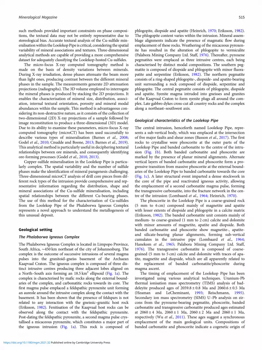
Fig. 7. (a) Three-dimensional volume rendering of drill-core sample 22 (banded carbonatite) with chalcopyrite (orange) and valleriite (green). (b) Three-dimensionalheatmap for chalcopyrite phases. Red, green and blue correspond to large, medium and small volumes, respectively. (c) Graph plotting the diameter of chalco-pyrite against sphericity. (d) Three-dimensional heatmap for bornite phases (e) Graph plotting the diameter of bornite against their sphericity.
522 Loic Y. Le Bras et al.
https://doi.org/10.1180/mgm.2021.32 Published online by Cambridge University Press

with density difference and magmatic flow leads to the preferen-tial emplacement of phoscorite along the edges of the intrusion(Basson et al., 2017; Giebel et al., 2019). Another possibility forthe genesis of the carbonatite and phoscorite involves fractionalcrystallisation (Skulski et al., 1994; Veksler et al., 1998;Chakhmouradian, 2006; Milani et al., 2017a, b). Mineralogicalzoning was also observed in both the Kovdor and Salmagorskiiintrusions and ascribed to fractional crystallisation(Korobeinikov et al., 1998; Ivanyuk et al., 2016). This zoning indi-cates that the alternation of phoscorite and carbonatite layersmight have indeed resulted from the intrusion of severalmagma pulses undergoing fractional crystallisation. The rareearth element (REE) concentrations within rock samples do notreveal correlations among major oxide compositions, coupled
with the wide REE variation range for each rock type (Fig. 13).These features are consistent with the successive intrusion ofcompositionally distinct melt pulses, in agreement with Milaniet al. (2017b). Magma immiscibility during emplacement isprobably responsible for the presence of alternating banded car-bonatite–phoscorite layers (Krasnova et al., 2004a,b; Giebelet al., 2019). The emplacement of carbonatite and phoscorite dur-ing several intrusion stages was also deduced for the Kovdorintrusion (Krasnova et al., 2004a). The preferential emplacementof phoscorite along the external boundaries of the Loolekop Pipecan be best attributed to density separation during an eventualrotational movement of the magma (Basson et al., 2017), facili-tated by the intersection of fractures and shear zones, and therotation of their segments relative to each other.
Fig. 8. (a) Three-dimensional volume rendering of drill-core sample 58 (banded carbonatite) with chalcopyrite (orange) and valleriite (green). (b) Three-dimensionalheatmap for chalcopyrite phases. Red, green and blue correspond to large, medium and small volumes, respectively. (c) Graph plotting the diameter of chalco-pyrite against sphericity. (d) Three-dimensional heatmap for bornite phases (e) Graph plotting the diameter of bornite against sphericity.
Mineralogical Magazine 523
https://doi.org/10.1180/mgm.2021.32 Published online by Cambridge University Press

Sub-vertical sulfide layers may have formed synchronouslywith the emplacement of the banded carbonatite and phoscoriteby the intrusion of a significant number of magma pulses withvariable magma flow rates.
Formation of hydrothermal sulfides
The sharp contact between chalcopyrite veins and host rocksuggests the precipitation of Cu-sulfide along fractures from ahydrothermal fluid (Fontboté et al., 2017; Yang et al., 2018)(Fig. 11, Appendix 2). The edges of hydrothermal veins canbe easily distinguished from the magmatic cumulate texture,as the latter shows an intricate association with the gangue
(Fig. 11). On the basis of sulfide textures alone, a magmaticorigin of the mineralisation cannot be ruled out, and mightbe linked to an intrusion of sulfide melt into a veinlet networkproduced by fracturing during the emplacement of severalmagma pulses. However, a hydrothermal origin of these veinswas demonstrated by combined trace-element and Cu and Feisotope systematics (Le Bras, 2020). Only one vein occurrencewas observed in this investigation. This sulfide texture contrastswith disseminated and elongated Cu-sulfide assemblages, whichcommonly occur along irregular contacts with the gangue (Figs7 to 9). Planar sulfide layers can occur adjacent to the veins(Fig. 11). It is unclear if the alignment of sulfides parallel tothe vein are of hydrothermal origin. The corresponding 3D
Fig. 9. (a) Three-dimensional volume rendering of drill-core sample 57 (banded carbonatite) with chalcopyrite (orange), bornite (purple) and valleriite (green).(b) Three-dimensional heatmap for chalcopyrite phases. Red, green and blue correspond to large, medium and small volumes, respectively. (c) Graphplotting the diameter of chalcopyrite versus sphericity. (d) Three-dimensional heatmap for bornite phases (e) Graph plotting the diameter of bornite versussphericity.
524 Loic Y. Le Bras et al.
https://doi.org/10.1180/mgm.2021.32 Published online by Cambridge University Press
model shows no link between such alignments and the hydro-thermal vein itself. The absence of disseminated grains andcumulates suggests that such preferred orientations mighthave resulted from the filling of fractures with sulfides withinthe gangue, possibly by hydrothermal fluid precipitation asso-ciated with mineral dissolution (Le Bras et al., 2021). The reso-lution of microCT is insufficient to allow identification of smallfractures that might have acted as pathways for hydrothermalfluids within the host rock (Hoffman and De Beer, 2012). Acogenetic link between hydrothermal vein and adjacent sulfidephases, however, is a viable assumption. As suggested in a previ-ous study (Le Bras, 2020), similar Fe isotope compositionsbetween hydrothermal chalcopyrite and adjacent sulfide assem-blage networks indicate gangue mineral dissolution by
hydrothermal fluids and precipitation of sulfides into the result-ing voids within the host rock along the contacts to hydrothermalmineralisation.
Late-stage alteration characteristics
Several hypotheses exist regarding the origin of valleriite withinthe Loolekop Pipe: (1) alteration and replacement of magmaticand hydrothermal sulfides by valleriite (Lombaard et al., 1964;Palabora Mining Company Ltd. Staff, 1976; Giebel et al., 2017;Milani et al., 2017a); (2) dissolution of magmatic and hydrother-mal sulfide phases and re-precipitation of dissolved material asvalleriite (Giebel et al., 2017; Milani et al., 2017b); and (3)
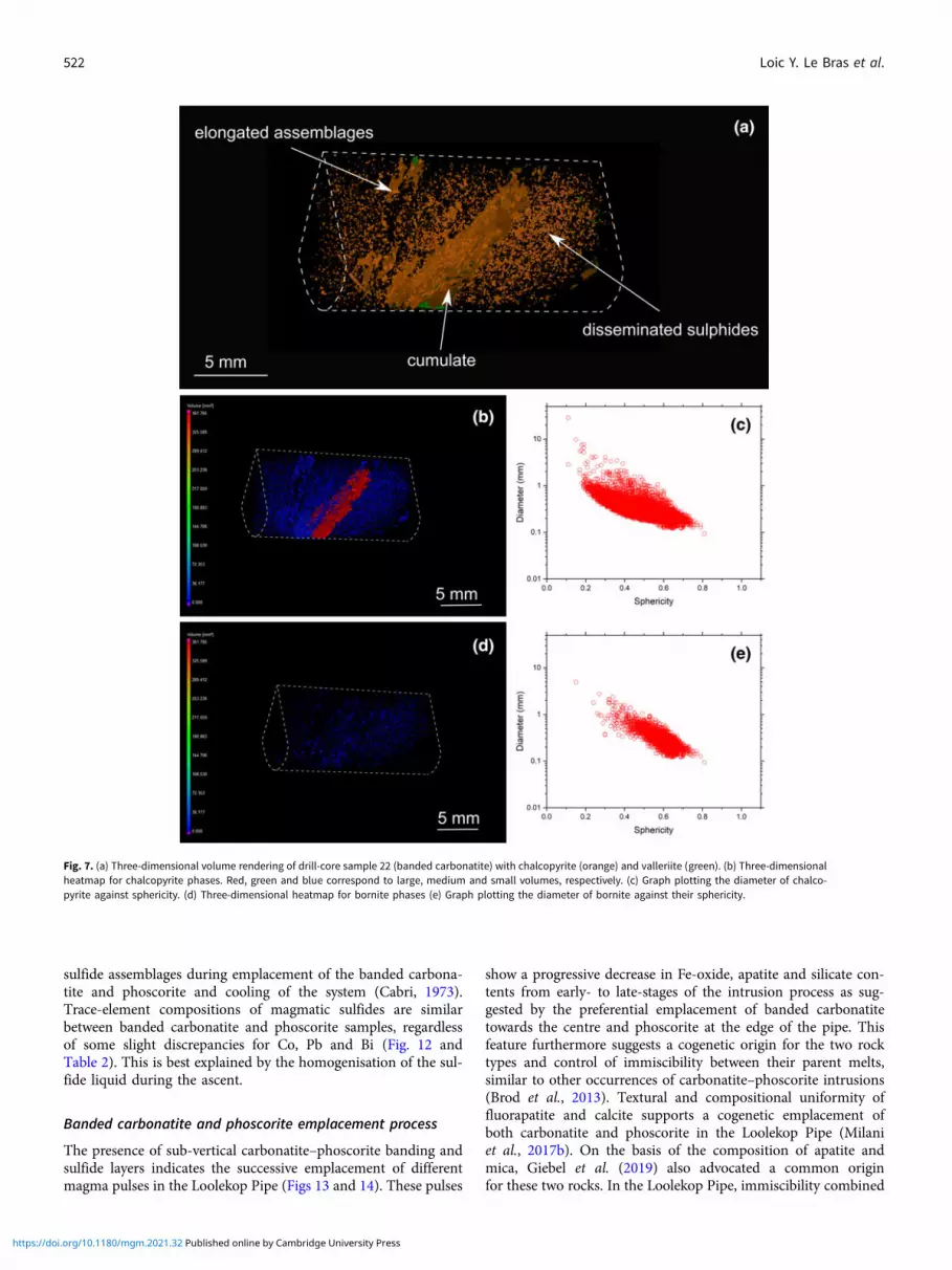
Fig. 10. (a) Three-dimensional volume rendering of drill-core sample 17 (banded carbonatite) with chalcopyrite (orange) and valleriite (green). (b)Three-dimensional heatmap for chalcopyrite phases. Red, green and blue correspond to large, medium and small volumes, respectively. (c) Graph plotting thediameter of chalcopyrite versus sphericity. (d) Three-dimensional heatmap for bornite phases (e) Graph plotting the diameter of bornite versus sphericity.
Mineralogical Magazine 525
https://doi.org/10.1180/mgm.2021.32 Published online by Cambridge University Press

deposition of a thin valleriite film on the primary sulfides(Palabora Mining Company Ltd. Staff, 1976). The desulfurisationof primary sulfides by fluid alteration resulting in the formation ofboth valleriite and magnetite is our preferred explanation (Le Braset al., 2021).
Microscopic observations and microCT analysis show alterationof magmatic sulfides by late-stage fluids, as well as their dissolutionand re-precipitation in the form of valleriite along adjacent frac-tures (Figs 9 and 10; Appendix 2, sample 57). A dissolution–(re)precipitation cycle related to late-stage fluid circulation is possible,but valleriite might be predominantly the result of in situmagmaticsulfide alteration as shown by the dominant presence of valleriite atthe external boundaries and along fractures within magmatic sul-fide phases (Figs 2b, 5b, 9 and 10). Gangue-filled fractures in
Fig. 11. (a) Three-dimensional volume rendering of drill-core sample 33 (transgressive carbonatite) with chalcopyrite (orange) and valleriite (green). (b)Three-dimensional heatmap for chalcopyrite phases. Red, green and blue correspond to large, medium and small volumes, respectively. (c) Graph plotting thediameter of chalcopyrite versus sphericity. (d) Three-dimensional heatmap for magnetite phases (e) Graph plotting the diameter of magnetite versus sphericity.
Table 1. Summary of sulfide categories and their respective textures within theLoolekop Pipe.
Magmatic sulfide layersSmall-sized (< mm) rounded bornite and chalcopyritegrains
Figs 5a–e and 7 to 10
Flat, elongated mm to cm chalcopyrite and borniteassemblages
Figs 7b,d and 8b,d
Chalcopyrite mm-thick cumulates Figs 6b, 7b, 8b and 9bHydrothermal veinscm-wide chalcopyrite veins Figs 5f and 11Adjacent chalcopyrite-filled veinlet network Fig. 11Late-stage valleriiteIn veinlet across primary sulfides and at grainboundaries
Figs 9a and 10a;Appendix 2
In small fractures at proximity of primary sulfides Fig. 5b
526 Loic Y. Le Bras et al.
https://doi.org/10.1180/mgm.2021.32 Published online by Cambridge University Press

proximity to valleriite–magmatic sulfide assemblages support fluidcirculation and in situ replacement of primary sulfides by valleriite.Three-dimensional images show no major fractures filled with val-leriite across the host rock (Appendix 2, sample 53), suggestingboth a limited dissolution–precipitation episode and rapid precipi-tation of the dissolved material indicating desulfurisation andreplacement of magmatic sulfides by valleriite and magnetitealong fractures and mineral surfaces (Mücke, 2017; Le Bras et al.,2021). The texture of valleriite supports this hypothesis (Hakrisand Vaughan, 1972).
Valleriite is distributed heterogeneously among the samples.For instance, some samples are unaffected by the alteration ofchalcopyrite–bornite assemblages and valleriite formation (e.g.Fig. 8). Circulation of late-stage fluids might have been facilitatedby a structural event post-dating the emplacement of magmaticand hydrothermal mineralisation forming a dense fracture net-work (Fig. 14). The absence of fractures and veins, conversely,may not have been conducive to fluid circulation and, conse-quently, formation of valleriite, leaving primary sulfideassemblages essentially intact.
Fig. 12. Trace-element compositions by LA-ICP-MS of Cu sulfides. Data summarised from Le Bras et al. (2021).
Table 2. Trace-element composition averages for sulfide types in the samples analysed.
Ni Zn Co Cd Pb Se As BiSample Rock Mineral (ppm) n (ppm) n (ppm) n (ppm) n (ppm) n (ppm) n (ppm) n (ppm) n
14 BC Bn 0.38 8 1.1 13 0.15 14 3.1 14 44.4 14 13.8 14 0.16 2 0.24 4Cc 6.3 5 2.8 5 0.46 5 1.5 6 378.8 6 12.5 6 0.13 2 <LOD 0V 12.6 3 10.6 3 0.59 3 13.2 3 450.3 3 8.7 3 0.98 3 <LOD 0
5 BC Bn 0.18 5 0.6 4 0.09 6 0.95 5 3.8 6 10.1 6 0.11 1 0.14 6Ccp 3815.2 3 4.0 3 8.77 3 0.83 1 104.1 3 16.3 3 <LOD 0 4.8 3
9 PC Bn 4.9 6 0.67 8 0.17 14 2.7 14 16.3 14 6.9 14 0.12 4 1.0 14Ccp 5018.6 8 3.1 8 39.9 8 1.4 4 67.6 8 6.9 8 0.28 1 0.94 7V 235.9 4 0.98 4 3.7 4 2.1 4 101.1 4 7.2 4 0.12 2 171.9 4
6 PC Ccp 1516.7 13 4.4 13 0.81 13 0.6 7 1.3 13 8.8 13 0.13 1 0.45 13
Bn = bornite; Cc = chalcocite; Ccp = chalcopyrite; V = valleriite; <LOD = below the level of detection. Data summarised from Le Bras et al. (2021).
Mineralogical Magazine 527
https://doi.org/10.1180/mgm.2021.32 Published online by Cambridge University Press

Conclusions
MicroCT analysis of several drill-core samples, representing threemajor rock types (phoscorite, banded and transgressive carbona-tites) within the Loolekop Pipe of the Phalaborwa IgneousComplex reveal the presence of sub-vertical sulfide layers parallelto alternating phoscorite and banded carbonatite layers. Theselayers display three distinct textures: (1) small (< 500 μm) disse-minated sulfides; (2) elongated flat sulfide aggregates (>1 mm);and (3) chalcopyrite cumulates (>mm wide). The irregular androunded surface of elongated aggregates parallel to the layer axissuggests that they formed by coalescence of sulfide grains.Modal proportions of bornite and chalcopyrite differ from onelayer to another, suggesting a strong control of the mechanicalsorting in the formation of the different textures of magmatic sul-fide phases. The alternating distribution of banded carbonatiteand phoscorite reinforce the notion that the banded carbonatiteand phoscorite, as well as the sulfide layers, resulted fromemplacement of several successive magma pulses. These pulsesbecame increasingly depleted in Fe-oxides, silicates and phos-phate in the course of intrusive activity. Melt immiscibility, rota-tion and the involvement of several magma pulses could have
resulted in the formation of alternating carbonatite and phoscor-ite banding, as well as sub-vertical sulfide layers hosted withinthese two rock types. Sulfide textures formed in response to var-iations in magma flow rate, in sulfide liquid volume as well aschanging conditions during magmatic activity. Disseminated sul-fide layers might have formed from sulfide droplets under highmagma flow rates, whereas elongated sulfides could have resultedfrom coalescence of sulfide droplets under low magma flow ratesand sulfide cumulates from segregation and accumulation of sul-fide liquid at the external boundaries.
High-temperature hydrothermal fluids precipitating largeamounts of chalcopyrite along fractures across the LoolekopPipe also circulated within small fracture networks adjacent tothe hydrothermal vein itself, forming small-sized chalcopyriteand bornite assemblages within the host rocks (Le Bras et al.,2021). These sulfide networks are classified as disseminatedgrains in this study due to the size of the fractures allowinghydrothermal fluids to circulate which is below the microCTresolution.
Valleriite is derived from the alteration of pre-existing magmaticsulfides. Valleriitewas not observed along fractures across the gangue
Fig. 13. Covariation of La and major oxides in banded carbonatite, phoscorite, transgressive carbonatite and micaceous pyroxenite from the Loolekop Pipe. (a) Lavs. SiO2; (b) La vs. CaO; (c) La vs. P2O5; and (d) La vs. Fe2O3. Data from Le Bras et al. (2021).
528 Loic Y. Le Bras et al.
https://doi.org/10.1180/mgm.2021.32 Published online by Cambridge University Press

in this study, indicating a limited role of dissolution / re-precipitation.The alteration is heterogeneous across the Loolekop Pipe and wasprobably controlled by the presence of fractures. Only sulfides inproximity to fractures were affected by late-stage alteration and val-leriite formation, leaving parts of the magmatic and hydrothermalsulfide layers unaltered.
Supplementary material. To view supplementary material for this article,please visit https://doi.org/10.1180/mgm.2021.32
Acknowledgements. We thank Thabitha Moyana and Paulien Lourens fromthe Palabora Mining Company (PMC) for providing access to sample drill-core material. Jakobus Hoffman is acknowledged for his help during measure-ments and data processing. Caiphas Majola prepared and polished blocks atthe University of the Witwatersrand. Professor David Good and the twoanonymous reviewers are thanked for their constructive comments that havehelped to improve this paper. The support of the DSI-NRF Centre ofExcellence for Integrated Mineral and Energy Resource Analysis (DSI-NRFCIMERA) towards this research is hereby acknowledged. Opinions expressed,
Fig. 14. Model of sulfide mineralisation in the Loolekop Pipe. (1) Melt pulses are sequentially emplaced, each forming phoscorite along their external boundariesand carbonatite towards the core of the intrusion as well as vertical alignments of sulfides. (2) Structural events occur during the precipitation of chalcopyrite fromhigh-temperature hydrothermal fluids along the fractures. (3) Appearance of valleriite associated with late-stage fractures associated with chalcopyrite and bornitealignments.
Mineralogical Magazine 529
https://doi.org/10.1180/mgm.2021.32 Published online by Cambridge University Press

and conclusions arrived at, are those of the authors and are not to be attributedto the DSI-NRF CIMERA.
References
Barnes S.J., Fiorentini M.L., Austin P., Gessner K., Hough R.M. and SquelchA.P. (2008) Three-dimensional morphology of magmatic sulfides shedslight on ore formation and sulfide melt migration. Geology, 36, 655–658.
Barnes S.J., Le Vaillant M., Godel B. and Lesher C.M. (2019) Droplets andbubbles: Solidification of sulfide-rich vapour-saturated orthocumulates inthe Norilsk-Talnakh Ni–Ce–PGE ore-bearing intrusions. Journal ofPetrology, 60, 269–300.
Basson I., Lourens P., Paetzold H.-D., Thomas S., Brazier R. and Molabe P.(2017) Structural analysis and 3d modelling of major mineralizing struc-tures at the Phalaborwa copper deposit. Ore Geology Reviews, 83, 30–42.
Bolhar R., Whitehouse M.J., Milani L., Magalhães N., Golding S.D., Bybee G.,LeBras L. and Bekker A. (2020) Atmospherics and lithospheric Pb in sul-fides from the 2.06 Ga Phalaborwa phoscorite–carbonatite complex,South Africa. Earth and Planetary Science Letters, 530, https:doi.org//10.1016/j.epsl.2019.115939.
Brod J.A., Junqueira-Brod T.C., Gaspar J.C., Petrinovic I.A., de Castro ValenteS. and Corval A. (2013) Decoupling of paired elements, crossover REE pat-terns, and mirrored spider diagrams: Fingerprinting liquid immiscibility inthe Tapira alkaline–carbonatite complex, se brazil. Journal of SouthAmerican Earth Sciences, 41, 41–56.
Bulakh A.G., Rudashevsky N.S. and Karchevsky P.I. (1998) Gold, silver, sul-fides and rare-earth minerals in carbonatites of the Loolekop Deposit(RSA). Zapiski Vserossiyskogo Mineralogicheskogo Obshchestva, 3, 45–54.
Cabri L.J. (1973) New data on phase relations in the Cu-Fe-S system. EconomicGeology, 68, 443–454.
Chakhmouradian A.R. (2006) High-field-strength elements in carbonatiticrocks: Geochemistry, crystal chemistry and significance for constrainingthe sources of carbonatites. Chemical Geology, 235, 138–160.
Cnudde V. and Boone M.N. (2013) High-resolution X-ray computed tomog-raphy in geosciences: A review of the current technology and applications.Earth-Science Reviews, 123, 1–17.
de Bremond d’Ars J., Arndt N.T. and Hallot E. (2001) Analog experimentalinsights into the formation of magmatic sulfide deposits. Earth andPlanetary Science Letters, 186, 371–381.
Eriksson S.C. (1982) Aspects of the Petrochemistry of the Phalaborwa Complex,Northeastern Transvaal, South Africa. PhD. University of theWitwatersrand, South Africa.
Fontboté L., Kouzmanov K., Chiaradia M. and Pokrovski G.S. (2017) Sulfideminerals in hydrothermal deposits. Elements, 13, 97–103.
Giebel R.J., Gauert C.D.K., Marks M.A.W., Costin G. and Markl G. (2017)Multi-stage formation of REE minerals in the Palabora carbonatite complex,South Africa. American Mineralogist, 102, 1218–1233.
Giebel R.J., Marks M.A.W., Gauert C.D.K. and Markl G. (2019) A model forthe formation of carbonatite–phoscorite assemblages based on the compos-itional variations of mica and apatite from the Palabora carbonatite com-plex, South Africa. Lithos, 324–325, 89–104.
Godel B., Barnes S.J., Barnes S.-J. and Maier W.D. (2010) Platinum ore in threedimensions: Insights from high-resolution x-ray computed tomography.Geology, 38, 1127–1130.
Godel B.M., Barnes S.J. and Barnes S.J. (2013) Deposition mechanisms ofmagmatic sulfide liquids: Evidence from high-resolution x-ray computedtomography and trace element chemistry of komatiite-hosted disseminatedsulfides. Journal of Petrology, 54, 1455–1481.
Groves D.I. and Vielreicher N.M. (2001) The Phalaborwa (Palabora)carbonatite-hosted magnetite-copper sulfide deposit, South Africa: An end-member of the iron-oxide copper-gold-rare earth element deposit group?Mineralium Deposita, 36, 189–194.
Hakris D. and Vaughan D. (1972) Two fibrous iron sulfides and valleriite fromCyprus with new data on valleriite. American Mineralogist, 57, 1037–1052.
Hanekom H.J., Van Standen C.M., Smit P.J. and Pike D.R. (1965) The Geologyof Palabora Igneous Complex, South Africa. Geological Survey Handbook,Memoir 54.
Heaman L.M. and LeCheminant A.N. (1993) Paragenesis and U-Pb systema-tics of baddeleyite (ZrO2). Chemical Geology, 110, 95–126.
Heinrich E.W. (1970) The Palabora carbonatitic complex – a unique copperdeposit. The Canadian Mineralogist, 10, 585–598.
Hoffman J.W. and De Beer F.C. (2012) Characteristics of the micro-focusX-ray tomography facility (mixrad) at Necsa in South Africa. 18th WorldConference on Nondestructive Testing, Durban, South Africa.
Ivanyuk G.Y., Kalashnikov A.O., Pakhomovsky Y.A., Mikhailova J.A.,Yakovenchuk V.N., Konopleva N.G., Sokharev V.A., Bazai A.V. andGoryainov P.M. (2016) Economic minerals of the Kovdorbaddeleyite-apatite-magnetite deposit, Russia: Mineralogy, spatial distribu-tion and ore processing optimization. Ore Geology Reviews, 77, 279–311.
Korobeinikov A.N., Mitrofanof F.P., Gehör S., Laajoki K., Pavlov V.P. andMamontov V.P. (1998) Geology and copper sulfide mineralization of theSalmagorskii ring igneous complex, Kola Peninsula, NW Russia. Journalof Petrology, 39, 2033–2041.
Krasnova N.I., Balaganskaya E.G. and Garcia D. (2004a) Kovdor – classicphoscorite. Pp. 95–127 in: Phoscorites and Carbonatites from Mantle toMine: The Key Example of the Kola Alkaline Province (A. Zaitsev, andF. Wall, editors). Mineralogical Society Series, Vol. 10. MineralogicalSociety of Great Britain and Ireland, London.
Krasnova N.I., Petrov T.G., Balaganskaya E.G., Garcia D., Moutte J., ZaitsevA.N. and Wall F. (2004b) Introduction to phoscorites: Occurences,composition, nomenclature and petrogenesis. Pp. 43–72 in: Phoscoritesand Carbonatites from Mantle to Mine: The Key Example of theKola Alkaline Province (A. Zaitsev, and F. Wall, editors). MineralogicalSociety Series, Vol. 10. Mineralogical Society of Great Britain and Ireland,London.
Le Bras L.Y. (2020) Insights into Sources and Ore-Forming Processes ofCu-Sulfide Mineralization of the Phalaborwa Igneous Complex, FromCoupled Cu and Fe Isotope and Trace Element Systematics. PhD.University of the Witwatersrand, Johannesburg.
Le Bras L.Y., Bolhar R., Bybee G.M., Nex P.A.M., Guy B.M., Moyana T. andLourens P. (2021) Platinum-group and trace elements in Cu-sulfides fromthe Loolekop pipe, Phalaborwa: Implications for ore-forming processes.Mineralium Deposita, 56, 161–177.
Lesher C. and Groves D. (1986) Controls on the formation ofkomatiite-associated nickel-copper sulfide deposits. Pp. 43–62 in: Geologyand Metallogeny Of Copper Deposits. Springer.
Lombaard A.F., Ward-Able N.M. and Bruce R.W. (1964) The exploration andmain geological features of the copper deposit in carbonatite Loolekop,Palabora complex. Pp. 23 in: The Geology of Some Ore Deposits inSouthern Africa (S.H. Haughton, editor). Geological Society of SouthAfrica, Johannesburg.
Mao J.W., Pirajno F., Zhang Z.H., Chai F.M., Wu H., Chen S.P., Cheng L.S.,Yang J.M. and Zhang C.Q. (2008) A review of the Cu–Ni sulfide depositsin the Chinese Tianshan and Altay orogens (Xinjiang autonomous region,NW China): Principal characteristics and ore-forming processes. Journal ofAsian Earth Sciences, 32, 184–203.
Milani L., Bolhar R., Cawthorn R.G. and Frei D. (2017a) In situ LA-ICP-MSand EPMA trace element characterization of Fe–Ti oxides from the phos-corite–carbonatite association at Phalaborwa, South Africa. MineraliumDeposita, 52, 747–768.
Milani L., Bolhar R., Frei D., Harlov D.E. and Samuel V.O. (2017b) Light rareearth element systematics as a tool for investigating the petrogenesis ofphoscorite–carbonatite associations, as exemplified by the Phalaborwa com-plex, South Africa. Mineralium Deposita, 52, 1105–1125.
Mücke A. (2017) Review on mackinawite and valleriite: Formulae, localities,associations and intergrowths of the minerals, mode of formation andoptical features in reflected light. Journal of Earth Science & ClimaticChange, 8.
Palabora Mining Company Ltd Staff (1976) The geology and the economicdeposits of copper, iron, and vermiculite in the Palabora igneous complex:A brief review. Economic Geology, 71, 177–192.
Reischmann T. (1995) Precise U/Pb age determination with baddeleyite(ZrO2), a case study from the Phalaborwa igneous complex, South Africa.South African Journal of Geology, 98, 1–4.
530 Loic Y. Le Bras et al.
https://doi.org/10.1180/mgm.2021.32 Published online by Cambridge University Press

Robertson J.C., Barnes S.J. and Le Vaillant M. (2015) Dynamics of magmaticsulfide droplets during transport in silicate melts and implications for mag-matic sulfide ore formation. Journal of Petrology, 56, 2445–2472.
Rudashevsky N.S., Kretser Y.L., Rudashevsky V.N. and Sukharzhevskaya E.S.(2004) A review and comparison of PGE, noble-metal and sulfide mineral-ization in phoscorites and carbonatites from Kovdor and Phalaborwa. Pp.363–392 in: Phoscorites and Carbonatites from Mantle to Mine: The KeyExample of the Kola Alkaline Province (A. Zaitsev, and F. Wall, editors).Mineralogical Society Series, Vol. 10. Mineralogical Society of GreatBritain and Ireland, London.
Schneider C.A., Rasband W.S. and Eliceiri K.W. (2012) NIH Image to ImageJ:25 years of image analysis. Nature methods, 9, 671–675.
Skulski T., Minarik W. and Watson E.B. (1994) High-pressure experimentaltrace-element partitioning between clinopyroxene and basaltic melts.Chemical Geology, 117, 127–147.
Veksler I.V., Nielsen T.F.D. and Sokolov S.V. (1998) Mineralogy of crystallizedmelt inclusions from Gardiner and Kovdor ultramafic alkalinecomplexes: Implications for carbonatite genesis. Journal of Petrology, 39,2015–2031.
Vielreicher N.M., Groves D.I. and Vielreicher R.M. (2000) The Phalaborwa(Palabora) deposit and its potential connection to iron-oxide copper-golddeposits of Olympic Dam type. Pp. 321–329 in: Hydrothermal Iron OxideCopper-Gold & Related Deposits: A Global Perspective (T.M. Porter, editor).Vol. 1, PGC Publishing, Adelaide, Australia.
Vukmanovic Z., Fiorentini M.L., Reddy S.M. and Godel B. (2018)Microstructural constraints on magma emplacement and sulfide transportmechanisms. Lithosphere, 11, 73–90.
Wu F.-Y., Yang Y.-H., Li Q.-L., Mitchell R.H. and Dawson J.B. (2011) In situdetermination of U-Pb ages and Sr-Nd-Hf isotopic constraints on thepetrogenesis of the Phalaborwa carbonatite complex, South Africa. Lithos,127, 309–322.
Yang X., Zhang Z., Santosh M., Li C. and Liang T. (2018) Hydrothermal cop-per mineralization in the Mesoproterozoic Huashugou banded iron forma-tion, northwest China: Characteristics, timing of formation and genesis. OreGeology Reviews, 102, 776–790.
Zieg M.J. and Marsh B.D. (2005) The Sudbury igneous complex: Viscousemulsion differentiation of a superheated impact melt sheet. GeologicalSociety of America Bulletin, 117, 142–1450.
Mineralogical Magazine 531
https://doi.org/10.1180/mgm.2021.32 Published online by Cambridge University Press


