Embed Size (px)
Citation preview
Title RF Characteristics of Coupled Split Coaxial Lines for RFQStructure
Author(s) Katayama, Yuko; Takekoshi, Hidekuni
Citation Bulletin of the Institute for Chemical Research, KyotoUniversity (1983), 61(1): 1-11
Issue Date 1983-03-25
URL http://hdl.handle.net/2433/77019
Right
Type Departmental Bulletin Paper
Textversion publisher
Kyoto University
brought to you by COREView metadata, citation and similar papers at core.ac.uk
provided by Kyoto University Research Information Repository

Bull. Inst. Chem. Res., Kyoto Univ., Vol. 61, No. 1, 1983
RF Characteristics of Coupled Split Coaxial Lines
for RFQ Structure
Yuko KATAYAMA and Hidekuni TAKEKOSHI*
Received January 18, 1983
The radio frequency quadrupole (RFQ) structure for injection of low velocity ions into the linear accelerator was studied. The structure was consisted from the coupled split coaxial lines.
A full scale model of the if cavity was made and the resonant frequencies and the rf field distributions were measured. At the lowest resonance, the transverse electric quadrupole was observed along the central axis of the cavity. The resonant frequency, the Q value and the shunt impedance of the cavity was investigated.
In conclusion, the coupled split coaxial RFQ structure was as usable as the four-vane RFQ structure, and the fabrication of the former is easier than that of the latter.
KEY WORDS ; RFQ/ Injector / Linear accelerator / Transmission line /
INTRODUCTION
An idea of ions acceleration by the RFQ structure had been suggested by I. M. Kapchinskij and V. A. Teplyakov,l' and the four-vane RFQ2' for the injection of low velocity ions into the linear accelerator was developed successfuly at Los Alamos.
The RFQ structure is very powerful, because it has the abilities of focusing as well as accelerating and bunching. As for the four-vane RFQ,6) however, it is not easy to machine vanes and to assemble them into the cavity. While the coupled split coaxial RFQ structure which was proposed by a group of Frankfurt Univ. and GSI3,a," has a simple configuration. It consists of four modulated circular rods in a cylindrical cavity, and the fabrication of the cavity seems to be much easier. We studied on the rf characteristics of the coupled split coaxial cavity using a full scale model of the buncher for the proton linear accelerator. The investigated cavity is made of four non-modulated circular rods inside a cylindrical tube. Two opposite rods were terminated to one of the end plates of the tube and the other two opposite rods were terminated to the other end plate. (see fig. 1) The cavity had a resonant mode, RFQ mode in which the transverse electric field was approximately quadrupole whose strength was almost uniform along the central axis of the tube. In this mode the wave propagation on a pair of the opposite rods coupled strongly with the wave propagation on the other pair. The resonant frequency became lower when the coupling was strengthened. To account for the fact, we applied the coupled mode theory of the transmission lines to the analysis of the resonant mode of the coupled split coaxial cavity. The results almost agreeded with the experimental values. And also we obtained the Q-value and the shunt impedance
* jl fl: Nuclear Science Research Facility, Institute for Chemical Research, Kyoto University, Kyoto 606
( 1 )

Y. KATAYAMA and H. TAKEKOSHI
of the cavity from the measurement of the reflection coefficients and the field distributions in the model cavity, respectively. As the case of the real buncher, four rods in the cavity will be modulated') to produce the electric fields which give the accelerating force on particles. Such modulation of the inner rods will not change
greatly the rf characteristics of the cavity.
DESIGN OF COUPLED SPLIT COAXIAL CAVITY MODEL
The full scale model of the coupled split coaxial cavity which is used for the low
power level test is shown in fig. 1. This model cavity has a structure of two coupled A/4 resonators, each has two split inner rods, arranged at an angle 90°. The cavity is made of copper and the length l is 30 cm. The radius and the position of inner rods is varied. Dimensions of the configuration is shown in table I. The cavity which has the dimensions in table I yields a desirable RFQ mode with resonant frequency of about 100 MHz. To feed rf power into the cavity, a capacitive coupler which is able to change the coupling strength is connected to a position near the open end of one of the inner rods.
The cavity is connected with the signal generator and with the network analyzer through the directional bridge as shown in fig. 2.
J;~
------------ ti
- - ` -"IVAAVA~dr~~>-
I' --------- ti-------------- ----------1.1
Fig. 1. Full scale model of "the coupled split coaxial cavity".
Table I . Dimensions of "the coupled split coaxial cavity" shown in fig. 1. (unit is cm.)
l' : cavity length30 R : cavity radius7.5
: electrode length29. 5 ± 0. 05 r : electrode radius1.0
d : distance between electrodes2. 55 ± O. 01 (for type A) 3. 39 ± 0. 01 (for type B) 3. 82 ± 0. 01 (for type C)
s : position of coupler25. 0 ± 0. 1
( 2 )

RF Characteristics of Coupled Split Coaxial Lines for RFQ Structure
DI RECTI NAL BRIDGE CAVITY
OSCILLATOR MG6458A~e~f (Anritsu Elect. Inc.)
NETWORK YHP-8502A I ANALYZER YHP-8754A--------------p— REF LECTI.O
RF INPUT
— AMPLI FIERDETECTOR
T
Fig. 2. Block diagram of the measurement system.
ANALYSIS OF COUPLED SPLIT COAXIAL LINE BY
COUPLED MODE THEORY OF TRANSMISSION LINE
In a well known quarter wave coaxial resonator, the wave length of the resonant
wave in TEM mode is given by
2„=2nl1,(n=1, 2,3,:..),(1) where l is the length of the cavity and n is the number of the nodes of the wave along
the axis of the cavity. In the free space the wave length is related to the resonant
frequency :
f„=------„,(2)
where c is the velocity of light (c =3. 0 X 1010 cm) .
Now let's consider the case where two split inner electrodes are put into the cavity.
Under the situation, there are two independent TEM resonant modes according to the
order of n. At two dominant modes (n=1), the polential along the electrodes distribute
as shown in fig. 3. (a), (b). A mode may be called even mode from the symmetric
nature if the potential of electrodes is in the same phase (fig. 3. (a) ), and odd mode
if the potential of the electorodes is at a phase r (fig. 3. (b)) . The coupling is strong in
the odd mode, but is weak in the even mode. if a coupling is inductive, the resonant mode has a higher frequency but if a coupling is capacitive, the resonant mode has a
lower frequency.
The resonant frequency of the quarter wave coaxial cavity f, and that of the split
coaxial cavity f,„, f,, were measured using the model cavity. In the case that the cavity is the length of 30 cm, and the radius of 7. 5 cm and electrodes is the length of 29. 5 cm,
and the radius of 1 cm, and the distance of the split electrodes is 2. 6 cm, f1, f,„ and fu,
is listed in table II. One must note that the effect that the open end of the electrodes is not completely open tends to lower the resonant frequency.
(3 )

Y. KATAYAMA and H. TAKEKOSHI
I,(Z)----------------V=0
dZ --------------- V1 -----------------------
I V2 I2(Z)
V=0 Z=0 Z=t
V Vi(Z'=V2(Z) V
V, (Z)
01t
(a) z (b) v2cz) Fig. 3. Potential on the electrodes of "the split caxial cavity". (a) is even
mode in which Viand Vz are in the same phase. (b) is odd mode in which Vi and VZ are at a phase it.
Table II. Resonant freqency of "the quarter wave coaxial cavity",
I; and those of "the split coaxal cavity", fia and fib.
fl 217 (MHz) fio 231
fib 208
Then we consider that two quarter wave split coaxial lines are coupled at an angle
90°, as shown in fig. 1. There are four independent modes as shown in fig. 4, and each
mode is given by different coupling of the n=1 TEM waves.
In the case of fig. 4 (a), the transverse electric field is approximately quadrupole
around the center of four electrodes, and the quadrupole strength is almost uniform
along the central axis of the cavity. That is RFQ mode which we coucern in.
..a111111 2p::1><E:Q1 2Dijp,„<::1 21 11111P1"1 z 4 CA 22
111Dn1n 3 z [7:7><ciTi 3 2 ni;~IIII23 23
~II3 43I1113 DPP" 44
nnnn3 41111Up.
411{,1j0r4~'4iPill"' 1 4'IIIU111!' (a)(13) (C)cd)
Fig. 4. Potentil on the electrodes of "the coupled split coaxial cavity". The electrodes 1 and 3 are shorted at z=0, the electrodes 2 and 4 are shorted at z=l. (a) is even-
even 37r/2 mode. (b) is even-even 7r/2 mode. (c) is odd-odd mode (d) is even- odd mode.
( 4 )

RF Characteristics of Coupled Split Coaxial Lines for RFQ Structure
I------------------------------------------------------------------------------------------I Resonant Freq.-
MHz ^..•type A
12oo- o - type B@-
A•••type C8 g
11o0--
^ 0 A
1000 -
900 -
800 ^ -0 A
700- ® 8 43-
60o- o o-
5o0 --
goo-
0o mode (b) 300--
888mode (d) 2oo-mode (c)-
o° mode (a) 100- o-
II I---------
1 35 n
Fig. 5. Resonant frequencies of "the coupled split coaxial cavity." The cavity has the dimensions as shown in table 1. In the figure, points belong to the same type
are horizontally shifted at same distance The modes which are shown for n=1 are also same for the higher modes. n is the number of the nodes of original
TEM wave.
Figure. 5 shows the frequencies of the resonant mode as the function of the number
of nodes, n of the original TEM waves which can concern the coupling. The field
distribution between electrodes was measured by the bead perturbation method9'. The
resonant frequencies of the modes as shown in figs. 4 (a) and (b) greatly depends on
the relative position of the electrodes. The resonant freqency of the mode (a) becomes
lower and that of the mode (b) becomes higher when the distance of the electlodes is extended. To analyze the mode (a), RFQ mode, we applied the coupled mode
theory of the transmission lines. We assume that the coupling is mainly capacitive in
RFQ mode, that the open end of the electrodes is perfectly open and that the cavity
is lossless. Thus the equivalent circuit of RFQ mode is given in fig. 6. Since the
potential of the opposite electrodes are in the same phase, they can be treated as a single LC line.
( 5 )

Y. KATAYAMA and. H. TAKEKOSHI
Z=0 L V1 II Z =1 01 11 , 11 $^ •
=C
m
openV2 12 • 11le - 11 /^
C
Fig. 6. Equivalent circuit of RFQ mode. L is the inductance and C is the capacitance of the line per unit length. 2C,, is the coupling capacitance between the lines.
V1, II are the potential and the current on the lines 1 and 3, and V2, 12 are those on the lines 2 and 4.
In fig. 6, L and C is the inductance and the capacitance of the line per unit length, respectively. Both of the LC lines are coupled by the capacitance 2C,,,, where C,,, is the mutual capacitance between the neighboring electrodes, V„ I, and V2, I2 are the
potential and the current on the lines 1, 3 and on the lines 2, 4, respectively. V,, I,, V2 and I2 are related to
av aI az=—Lat
al _(C+2C,,, —2C„,1aV(3 ) az--\-2C,,C+2C,n) at'
V=(vz), p=(-1')
It is assumed that V,, V2i I, and I2 vary sinusoidally as e±i t with time, where co is the
anguler frequency and vary as e`' with z, where (3=±2r/ is the phase constant.
The necessary condition that there exists a significant solution for eq. (3) is,
det {p2w2L( —2C„,C+2Cm)4) The eigen-values are given as follows:
v1= =t{L(C+4C,„)}-1",
(5)
i We are interested in the solution which belongs to v,. Taking account of the boundary conditions, we decide the phase factor e'# between V, and V2. So we get the solutions
for the standing wave,
( 6 )

RF Characteristics of Coupled Split Coaxial Lines for RFQ Structure
V1=Vo sin (3z cos wt,
V2=±V0 cosSz coswt,
1 I1=—Z oVo cos pz sin wt,(6 )
12= ±1Vo sin '3z sin wt,
where Zo={L/(C+4C„)}1/2 is the characteristic impedance. RFQ mode is represented by the equations with under signs in eq. (6) .
When the capacitive coupling and also the inductive coupling is taken into considerations and four coupled lines are dealt with, the theory mentioned above will be generalized to other modes including RFQ mode or the higher modes.
In eq. (5), v1 is rewritten Lto v1=f,,21, where 21 is the wave length of the quarter wave which is given by eq. (1). To consider the dependency of C. on f„, we express the relation of f1, to the distance between the neighboring electrodes in table III.
Table III. Resonant freqency, f1, in RFQ mode and distance of neighboring electrodes, d.
d (cm) f1a (MHz)
type A2.55+0.01 95.54 type B3.39125.8
type C3.82139.4
For the first equation in eq. (3), if we put 1/VIE--c (the velocity of light), the equation is reduced to
f1a=(1+4C /C)-'~2 f1,(7 )
where f1 is given by eq. (2). In eq. (7), C is the electrostatic capacitance between two
parallel cylinders, one of those is put inside the other, and C. is the capacitance as that between two same parallel lines at the distance d. Therefore we may write them as follows:
C=2neo/{1n(r2+R2—x2+f(r2+R2—x2)2-4r2R2}/2rR, and Cm=irso/ln(d/r),(8 )
where x=d/V 2 .
In the case of the cavity in fig. 1, C. is equal to C in the order. Making a rough
estimate, we get that f1 ~------ f1. If R is large enough, C is not depend on d and we 115
find the relation of (f,a) oc (ln d) ', In fig. 7, the square inverse of the resonant frequency: (fra) is plotted against the inverse of In d for the model cavity (type A, B and C).
( 7 )

Y. KATAYAMA and H. TAKEKOSHI
I f 1 I-----------------------------------------------------------------------------------------------
f,' (MH~)_Z
1.0--
0.5- --
01 I f i i l If i t I I-------------------------------------------------------- 0.20.30.4 Cm (p.farad/cm)
Fig. 7. Dependency of the resonant freqency of RFQ mode to the distance of the electrodes
ESTIMATION OF Q VALUE AND SHUNT IMPEDANCE
1. Q-Value of Model Cavity The measurement system for the rf characteristics of the coupled split coaxial model
cavity is given in fig. 2. The Q value of the model cavities, Qo for the type A, B and
C (used in the previous section) is measured as following.
Near by the resonance the input impedance Z,,, of the cavity is related to the
characteristic impedance Z of the external system bye)
Z;n__ 1/Q.( 9 ) Zi(w/wo—wo/w) +1/Qo'
where Qey is based on the loss of the external system, and coo is the resonant anguler
frequency. And the quantity o is definded as follows,
QCZ(~o 2Q, (www0).(10) We put the anguler frequencies to w1 and w2 for 3=±1. Therefore we get
(8 )
RF Characteristics of Coupled Split Coaxial Lines for RFQ Structure
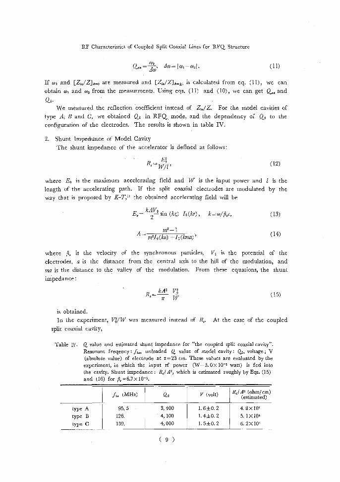
Qe==~~, aW=I co' —w2I(11)
If wo and [Z;,,/Z]8=0 are measured and [Z;,,/Z18=f1 is calculated from eq. (11), we can
obtain ah and co2 from the measurments. Using eqs. (11) and (10), we can get Q82 and
Qo. We measured the reflection coefficient instead of Z,„/ Z. For the model cavities of
type A, B and C, we obtained Qo in RFQ mode, and the dependency of Qo to the
configuration of the electrodes. The results is shown in table IV.
2. Shunt Impedunce of Model Cavity
The shunt impedance of the accelerator is defined as follows:
Eo R,=W/1'(12)
where E0 is the maximum accelerating field and W is the input power and 1 is the
length of the accelerating path. If the split coaxial electrodes are modulated by the
way that is proposed by K-T,'' the obtained accelerating field will be
Ex= k2V°sin (kz) Io(kr), k=w/thc, (13) m2-1 A
m2Io(ka) +Io(kma)'(14)
where (3, is the velocity of the synchronous particles, Vo is the potential of the
electrodes, a is the distance from the central axis to the hill of the modulation, and
ma is the distance to the valley of the modulation. From these equations, the shunt impedance:
R,=kA2vg(15)
is obtained.
In the experiment, Vo/W was measured instead of R,. At the case of the coupled
split coaxial cavity,
Table IV. Q value and estimated shunt impedance for "the coupled split coaxial cavity". Resonant freqency : f1,i unloaded Q value of model cavity : Qo, voltage ; V
(absolute value) of electrode at z=23 cm. These values are evaluated by the experiment, in which the input rf power (W=5.OX 10-5 watt) is fed into the cavity. Shunt impedance : R,/A2, which is estimated roughly by Eqs. (15)
and (16) for 9,=6.7x 10⁻³.
f, (MHz)QoV (volt) R,/A2 (ohm/ cm) (estimated)
type A95. 53, 400 1. 6±0. 2 4. 8X 10⁴ type B126.4, 100 1. 4±0. 2 5. 1 X10⁴
type C139.4, 000 1. 5±0. 2 6. 2 X 10⁴
( 9 )

Y. KATAYAMA and H. TAKEKOSIII
Vo = Vi—V2VZ(16)
where 171—V2 is the voltage between the neighboring electrodes measured along the path in fig. 8 by the bead perturbation method.9' The results are shown in table IV.
MOTO R • •
23cm °•BE`D
PIC UPO C UPLE' ------10 Or~
OIl
• II
TT Q DETECTOR WEIGHT i I Fig. 8. The field is measured by the bead perturbation method. The
electrode voltage at z=23 cm is obtained ly the measurmert
DISCUSSION
The structure of the coupled split coaxial RFQ is simple compared with that of the
four-vane RFQ, and assembling the electrodes into the cavity is rather easy. Since the RFQ mode of the coupled split coaxial cavity is given by the coupling of
TEM waves, it could be analyzed by the simple coupled mode theory which had been
described in the previous section. The dependency of the resonant frequency of RFQ mode to the dimension of the cavity was estimated. The resonant frequency was
c 1 expressed roughly as-- 45 lfor the length of cavity 1, and also it depended on the
configuration of the electrodes inside the cavity. As for the radius of the cavity, it was
not necessary to use the large one because the field mainly, distributes around the
central part of the cavity.
One of the probrems of the coupled split coaxial RFQ is that the distortion of the
quadrupole field near the open end of the electrodes occurs. However it may be avoided by proper reshaping the open end of electrodes.
Q value of the cavity obtained was about 3400-.-4000. And also the shunt impedance was estimated. The voltage between the neighboring electrodes is about
10 kV when the rf power of 5 kW is fed into the cavity.
REFERENCES
(1) I. M. Kapchinskij and V. A. Teplyakov, Tekh. Eksp., 2, 19. (1970) (2) T. P. Wangler and R. H. Stokes, IEEE Trans. on Nucl. Sci., 28, 1494. (1981) (3) R. W. Muller et al., IEEE Trans. on Nucl. Sci., 28 (3) 2862. (1981) (4) P. Junior et al., Proc. 1981 Linear Dccel. Conf., Santa Fe, 81. (1981) (5) H. Klein et al., Proc. 1981 Linear Accel. Conf., Santa Fe, 96. (1981)
( 10 )

RF Characteristics of Coupled Split Coaxial Lines for RFQ Structure
(6) S. W. Williams and J. M. Potter, IEEE Trans. on Nucl. Sci. 28 (3) 2967. (1981) (7) The examples are refs. (1) and (4). (8) J. C. Slater, "Microwave Electronics," Chap. 4, D. Van Nostrand, New York, 1966.
(9) E. L. Ginzton, "Microwave Measurments," Chap. 10, McGraw-Hill, New York, 1975.
( 11 )


