Embed Size (px)
Citation preview

f ,
I ,oj
U. S. DEPARTMENT OF COMMERCE NATIONAL BUREAU OF STANDARDS
RESEARCH PAPER RP1178
Part of Journal of Research of the National Bureau of Standards, Volume 22, February 1939
MUTUAL INDUCTANCE AND FORCE BETWEEN TWO COAXIAL HELICAL WIRES
By Chester Snow
ABSTRACT
A formula is found for the mutual inductance and force between two coaxial helical wires which, in addition to the well-known current-sheet formula, contains small correction terms, one of which represents the axial components of current; one the finite diameters of the wires; and another W a, which depends upon the relative azimuths of the helices, arises, naturally, from the actual helical form of the windings. The pitch of the windings may be different in the two, but each is considered so small in comparison with the cylindrical radii that terms relatively smaller than the square of this ratio may be neglected. The number of turns is not necessarily an integer.
CONTENTS l'alte
I. Introduction _______ ___ ________ _______ _____ ______ _____ __ __ __ ___ 239 II. Formal expressions for the mutual inductance and force between two
coaxial helices _______________________________________________ 241 III. The principal terms we and w'e _________ _____ _______ _____________ _ 247 IV. Effect of axial current in helices and lead wires ____________________ 251
V. The azimuthal terms ___________________________________________ 255 VI. The helix equivalent to a helical wire __ _______ __ ________ _________ _ 263
VII. Application to the current balance used in the National Physical
VIII. Su~~~~~~~r!:~~= =================== ============ = ======= ======= ~g~ I. INTRODUCTION
A formula of precision sufficient for absolute electrical measurements of the mutual Inductance or force between two coaxial helical wires does not appear to have been developed to the same degree of precision as in the case of a self inductance. The principal part corresponding to current sheets is well known, but even if the construction were perfect, there remain certain small correction terms which must be found by starting with an idealization of the coils which is nearer the actual than a current sheet. The procedure here adopted as the most natural is to formulate the mutual inductance as Neumann's doubleline integral and to expand the integrand in a Fourier's series as a function of the difference of the angular parameters of the two helices. The constant term of this series gives the current sheet formula, provided both angular and axial components of current are included in this term. The remainder of the series gives a correction depending upon azimuth of the two helices, which is relatively small for such closely wound coils as are used in practice. By restricting the problem to cases where the windings of the one do not come too close to those
239

Ci
240 Journal oj Research oj the National Bureau oj Standards [Vous
of the other, we avoid most of those evaluations of proximity effect so troublesome in deriving a formula for self inductance.
The equations defining the first helix, hi, may be taken as the three equations which express the rectangular coordinates , XI, Yb ZI, of any point, PI, on it, in terms of a single independent parameter. The most suitable line parameter in this case is the angle OJ, where XI, rll and 01 are the cylindrical coordinates of PI. If the rectangular axes are right-handed, a positive pitch, 27rPI , corresponds to a right-handed helix. If the plane X=Xtl and the azimuth O=Oil are those of its initial point, and X=X'I' 0=0'1 its end point, and if rl is its cylindrical radius, the equations of hi are
XI =Xtl +PI (OI -Oil)1 YI =rl C?S 01 ' where Oil ~ 01 ~ Oel. zl=rl SIn 01
(1)
Its axial length, ll' is given by
II =X'I-XII =PI (0'1- Oil) =27rPIN I. (2)
Its element of length has the magnitude
dSI = ..JrI2+PI2 dOl (3)
and the direction cosines
dXI PI dYI r) sin 0) dz) rl cos 0) dSI = ..JrI2+p/ dSI = - ..Jr)2+p / ds) = .,jrI2+p/
(4)
If two helices of the type in eq 1 differ only in the values of their two constants, Xl) and rl, they may be considered as filaments of the same helical wire, WI, where, for the purpose of this paper, a "helical wire" is defined as follows:
To specify a helical wire, WI, of pitch 27rPI and axial length l) and with a wire radius, PI, whose central filament has the cylindrical radius r), the initial plane and azimuth of this central filament being XII and Olp the plane and azimuth of its end point, X'l and OeI' we define it as the totality of all helices, hI', represented by eq 1 with (Xit' and rl ' in place of XII' r)), provided that the two constants, XiI'
and rl" lie in the range
(Xit' -Xtl)2+ (r)' -rl)2 ~ P12 (5)
All azimuthal planes cut this wire in circular sections of radius Pb the initial face of the wire in the plane 8=8il , and its end face in the plane 0=8'1. All its filaments have the same terminal azimuths and the same axial length ll. Giving Oil a variation while holding II constant corresponds to a rigid rotation of the wire about the X axis, while a variation in XII with 1) constant is a translation parallel to that axis.
The second helical wire, W2, coaxial with WI is specified, as above, with subscripts 2. It is assumed that .PI and P2 are both positive; that is, WI and Wz are both right-handed helical axes or both lefthanded, depending upon whether the coordinate axes are chosen right-handed or left-handed.
,
I 1 I

-Snow1 Mutual Inductance of Coaxial Helices 241
The total "number of turns," NI and N~, are not necessarily integers, as no essential simplification in the final formulas would be obtamed by placing such a restriction upon the generality of their application.
The associated current sheet of a helix is defined as a circular cylindrical surface coaxial with it, having the same radius and end planes, on which the linear density of current has the angular component j9=n= 1/27rp and the axial component Jx= 1/271-r. The mutual inductance between the sheets of the two helices will be denoted by m'I'2=m9+mx.
The mutual inductance between one helix and the current sheet of the other is identical with that of the two sheets, and this statement holds for each component of mSlS2 separately, the part m9 being due to their angular component.s of current and mx due to their axial currents. The latter, mx , may also be interpreted as the mutual inductance between one of the sheets and any straight line which is a generator of the other.
A definition will be given later of a helix which is equivalent to a helical wire, so that the associated current sheet of a helical wire is that of its equivalent helix.
The equivalent helix of a wire has the same pitch, terminal end planes, (and hence axial length), as the central filament of the wire, but a slightly different cylindrical radius, depending upon the wire radius and the nature of the current distribution in the wire, whieh is assumed to flow everywhere in the direction of the generating helical filament, its magmtude being a function of r.
Hence the axial length adopted here for that of the current sheet of a helical wire is in harmony with that generally accepted. All single-layer solenoids are, in fact, helical wires, but when N is an integer they have generally been treated by idealizing them as N equal coaxial circular turns of wire, their central planes equally spaced at x=27rpn, n=O, 1, 2,3, ' . .. N-1, so that the distance between central planes of the first and last turn is 27rpN-27rp. If all these circular turns are cut by a plane through the x axis and each given a shear, they go exactly into the "helical wire" here defined. The current sheet associated with this series of circular turns of wire is generally taken with length 27rp plus the axial distance 27rpN-27rp between central planes of the first and last wire, that is, 27rpN, which is the length adopted here in general, although we do not restrict N to be integral.
II. FORMAL EXPRESSIONS FOR THE MUTUAL INDUCTANCE AND FORCE BETWEEN TWO COAXIAL HELICES
The mutual inductance, m, between the helix hi, and that h2 is here defined by the Neumann's double-line integral
Letting (6)

242 Journal oj Research oj the National Bureau oj Standards [Vol. lS
this becomes
(7)
(8)
The part of m which is due to the angular components of current in the two helices is that part of the int.egral in eq 7 attributable to the first part of the numerator rlr2 cos 1/t/PIP2; the part coming from the item 1 in the numerator is due to their x-components or axial components of current. The latter is a small quantity compared with the former (in general, of second order, when pdrl and P2/r2 are both small quantities of the first order).
Writing eq 7 in the form
m= L::' dXIL::' dX2f[~-Xh1/t(Xh~)]
and changing the variable X2 to x' by the substitution x' =X2-XI gives
Next, changing the variable XI to X" by the substitution X"=Xe2-XI gives
In the last double integral, the variable of integration x" has merely been replaced by y in order that the symbol x" may be used in another sense, so that the four integrals into which m is resolved in eq 9 below shall each have the same designation of their two variables, and shall have limits of the same general form. In the last double integral we next change the variable y to x" by the substitution x" =y- (X.J-X12)'

Snow] Mutual Inductance oj Coaxial H elices
Writing the x" integral of this in the form
gives
where
foxil-I
" ( )dx" _ l xi,-xi' ( )dx"
m = f:,,-Xi dx" fox' j[X', 1/1,,(, (X', x") ]dx'
- foX"-x,, dx" foX'j(x', 1/I",,(X', x")]dx'
+ lXi'-x" dx" lX'j[X', if; I,., (x', x") ]dx'
- lXi,-xil dx" lX'j[x' , if; III/X', x") ]dx',
./, (x' x") =- + --- x" +li -li - ~ x' (1 1) (X -x ) '1' .,1,' P2 PI P2 " I, PI
1/1 (x' x")= - + --- x"+li -li - _1_, __ " x' (1 1) (X -x ) I,.,' P2 PI P2 t,., PI
243
(9)
(10)
In what follows we shall use x (positive or negative) to represent one of the following four x-differences, and lix for the associated constant azimuth-difference.
X=X .. -XI" X.,-X,,, XI,-X." and XII-XI,}
8"=li.,-li l ,, 8.,-li." lil.-li." and lil,-li l, . (11)
These four differences represent the four possible axial distances between a terminal plane of hi and a terminal plane of h2 • The corresponding azimuth differences, lix , are those of the respective pairs of terminals (having the same subscripts). Equation 10 may by a similar notation be condensed into
1/Iz(Xll x2)=iz+~-k)x2+lix-;/ (12)
where 1/1",=1/1'21"1/1.,.,,1/11,.,, and 1/11,1,·
From the definitions given in eq 11 and 12 it is found by the use of eq 1 and 2 that 1/I'.I,=if;.,., and 1/11,.,=1/11,1,.

- .,
244 Journal oj Research oj the National Bureau oj Standards [Vol. 2£
Hence eq 9 shows that the mutual inductance between two helices is of the form
m=w(x.,-x i ) -w(x., -x.) + W(Xi,-X.)- W(Xi, -Xi) (13)
Consequently, the x-component, j, of the attraction of h2 for hJ, when each carries unit current in the same direction, is given by
j= -Wi (X,,-Xi,) +w' (x,,-x.,) -Wi (XiI-X,,) +w' (Xii-Xi,), (13) I
where primes denote derivatives with respect to the x-argument and
w(x)~ [dx'f~:;,~::'dx" (14)
where R is a function of tfx defined by eq 6 and tfx is defined by eq 12. It will be found that w is an even function and w' an odd function of the x-argument, both vanishing with it.
It is necessary to evalute the integral w (x) for positive and negat.ive values of x in order to treat all possible coaxial helices. To do this we note that the integrand in the integral of eq 14 is an even periodic function of tf, with period 271", and may therefore be developed in a Fourier's cosine series. To find this series, consider the function
k/4"/I-P cos2 0, where the modulus, le, is a positive real in the range
o ~ le ~ 1. This function has the development
lc 1 co
4~ P 2 2 ¢o(k) + L2¢n(k) cos 2nO, (15) 1- cos 0 n=l
where the functions ¢n(k) are given by
'If' "
¢n(k)=¢ n(k)=~ (2 cos 2nO dO=(-I)"k ( '2 cos 2nO do. (16) _ - 71"Jo~l-k2('os2 () 71" Jo~1-k2sin2(j
They may be expressed in terms of the hypergeometric series
k2n+1 r( n+~)r( n+~) ( 1 1 ) ¢,,(k)=2;"" r(2n+l) F n+2",n+2",2n+l, k2. (17)
When k---71 every ¢n---7 co, its principal part being cf> ,, ~~.log I" where
k' is the complementary modulus. These functions satisfy the differential equation
k3 d~[l kk2 ¢n' (k) J= (4n2-1)1>n(k) ,
(18)
The first two functions of the series, cf>o and ¢l, are expressible in terms of the two complete elliptic integrals of the firs t and second kind with modulus k.

..
Snow] Mutual Inductance of Coaxial Helices 245
Any other function, CPn(k) , could be computed in terms of CPo, and CPI by successive application of the recurrence relation
(20)
The derivative, cP~ is given by
1-k2, (1)[ (2 ) ] -k-CPn(k)= n-2 CPn- l- pi-I CPn (21)
'When k is a function of x, TI, and T2 defined by
k2 4TIT2 x2+h+Tz)2
(22)
the mutual inductance of two coaxial circles of radii TI and Tz (the distance between their planes being:r) is NI=47r2-JrITzCPI(k) Their attraction, F, with unit currents is F= -DxM, so that
YI(k) =47r2cpI(k) = ': and Yz(k) = 7rzle3cpUk) = -JTITzF (23) -v TlrZ x
These are convenient for finding CPI(k) and cp~(le), because the functions YI(k) and Y 2(k) are tabulated against k2 in table 2 of the Scientific Papers of the Institute of Physical and Chemical Research (Komagome, Hongo, Tokyo, 1927) by Nagaoka and Sakurai.
When k is given by eq 22, the functions CPnUc) satisfy the partial differential equation
{D 2+ D' +1-2aD +az-nZ}( , ) 0 :r TI -- 'I --2 - r1a-vc/>n = TI T~
(24)
where a is any constant. There are also the integral representations
CPn(k) 1 f2,.. cos ntf; f'" -JTITz=27rJo -JXZ+ R 2(tf;)dtf; = J o e-·lxIJn(TIS)Jn(TzS)ds, (25)
where I n is Bessel's function. The modulus, le, in all that follows, will be understood as the function of x, TI, and T2 defined by eq 22, unless otherwise stated. When x is replaced by XI it will be called lei, and ko means the modulus for x=o.
Hence, as shown by eq 15,
1 (26)

..
246 Journal oj Research oj the National Bureau oj Standards [VoL!!
so that the required Fourier's series for the integrand of eq 14 is
rlr, cos fz+ 1 PIP2 1 {rlr2 (k ) + (k) .Jx~ +Ri (ft) = .Jrlr2 P1P2¢Jl 1 ¢Jo 1
+ ±cos nfTr1r2 (¢In-l(k1)+¢Jn+I(k1))+2¢Jn(k1)]} (27) n=l lJrlP2
Hence eq 14 may be put in the form
where w(x) =ws(x) +wx(x) +w.(x, Oz),
Wa(x,Ox) = ~wn(X,Ox) 11=1
W,,(X,Ox) = / r'dx, (XI dXl cos nf.,(xhx,) -vrlrdo Jo
(28)
(29)
[;~~2 (¢J.-I (k1) + ¢J"+l (k1)) + 2¢J. (k1) ] (30)
The term Ws is the part of the integr~l of eq 29 involving ¢Jl; the term Wx the small part involving ¢Jo.
To prove that the W,1s2 defined by the integral of eq 29 is the W function which, if used in the general formula, eq 13, would give the m'1I2 previously defined as mutual inductance of the two associated current sheets, we may start with the elementary formulation which is
(31)
By transformation similar to those used in passing from eq 7 to eq 13 (but much simpler) one finds that
(32)
1

Snow] Mutual Inductance of Coaxial Helices 247
provided f is such a function that these integrals converge. This shows that w(x) is an even function of x, an odd function, or neither, according as f(x) is. Also w(O)=O, and w'(O)=O, where w'(x)= Dxw(x). In eq 31 f(x) is an even function of x, so w(x) is an even function of x, and m .. is therefore reduced to the general form of eq 13, where the w-function is
i
x iX' i2?rdif;_rI_r2cosif;+1 w =W6+Wz = dX2 dxI _P"'4IP=:2;=;=~=;=:=;=-
8,'1 27T Ix~ + R~ (if;) o 0 0 -v .
i
x i2r " .. rIr2 cos if; + 1 = dif;PIP2
(x-Xj)dXj 27r -Jxi+R2(if;) 00 '
(34)
Using the expansion eq 27 for this integrand, the 'l! integral vanishes for all terms except n=O, so that eq 34 becomes identical with eq 29, thus proving that the latter corresponds to current sheets.
It is useful to notice the two following partial differential equations satisfied by the components W6 and W z , which are derivable from the definition 29 together with eq 24.
(35)
(36)
III. THE PRINCIPAL TERMS W8 AND w/
The equation 29 gives
where
Now, by eq 22
so that

248 Journal oj Research oj the National Bureau oj Standards [Vol. 22
Hence
Hence
- .Jrlr2 rx Xl~l(kl) dXl =4 (r1r2)![!f _(;_l)(K-E)] PIP2 Jo 3npIP2 k k k
minus the same function of ko, which, being independent of x, may be discarded from the w function as it always cancels from eq 13. Hence, placing
we(X) =xwo' (x)
+ 27r~:N2{ 4rt2).JX2+ h +r2?[ K -(~-l}K - E) ] (37)
To find w;(x) we use eq 16.
".
= 2rlr2 r~os 20 log [x+.Jx2+R2(20) ]dO. 1TPIP2J 0 R (20)
Integrating this by parts gives

,-
$now] lvIutual Inductance of Ooaxial Helices 249
so that
where
~J (38)
where
Hence
27rN1N2{ I --w/(x) lll2 x-yx2+(rl+r2)2(K-E)
± Irl2-rll [ KZ(8o, Ie' ) + 7rF~~,k') - ~J} (39)
Where the plus sign belongs with positive x and the minus with negative x, the bracket multiplied by ± vanishing when x=O . (Also the absolute value Irl2-rll must be observed.) The zeta-function is expressible in terms of E(8, k') and F(B, Ie') for
Z(8, 1e')=E(8, 1e')-~>(8, Ie'). (40)
Using the AGM method of computation,! and finding an, b,,, and Cn
by the formulas I L. V. King, On the Direct Numerical Calculation of Elliptic functions and Integrals, page 8.

250 Journal of Research of the National Bureau oj Standards [Vol. £1
an=4Can-l+bn-l), bn=...jan-lbn-l, cn=~can-l-bn-l)l' (41)
tan (OnH - On) = bn tan On an
and starting with the initial values
then
7rF(Oo, k') 2K'
1 b k k' d . _lko' ao= I 0= ,Co= ,an Oo=srn F
Using the initial values ao=l, bo=k', and co=k,
gIves
K=2:n and K-E= Cc~+2c~+4c~ .... 2nc!) ~
(41) ,
The formulas 41' are the result of successive applications of Landen's transformation which increases the amplitude and decreases the modulus. Hence, they will be most suitable when k' is small.
If, however, k' is large it is easier to work the transformation in the opposite direction of increasing modulus, in which case the formula is
KZ(Oo, k') + 7rF~~,k)' -~= -~ Cl-sin If'n)+~(lf'''' cn), (41)"
where ao=l, bo=k', co=k
and
and
"C.I, )-2 tan (21f'2-1f'1)+6 tan (21f'a-1f'2)+14 tan (21f'4-lf'a) ~ '1'", Cn - C2cos (21f'a-1f'2) C3COS (21f'(-lf'a) C4cos (21f'6-if-',)
+ + 2(2t+n_l)cn+2tan (21f'n+2-lf'n+l) . . . . cos (21f'n+a-lf'n+z)
King! also gives an alternative to this with the same an, bn , and c", and the same recurrence formula between If'n+l and If'n' as above, except that it starts with
• There is evidently a misprint in King's formula 7 see eq 75 or 75 defining l:(",.c.). The general term 2
should contain the factor 2(21+·-1)c.+t and not 2(2·-1)c.+ •.

Snow] Mutual Inductance oj Coaxial Helices 251
in which case
2Kcos (21/11-1/10)[ . +"( )] II= k'2 sin 21/10 a" sm 1/1,. ~ I/In, en (41)"1
To interpret the function w;(x) in eq 39 it will be found that if the factor N2/l2=1/27rp2 is omitted and x replaced by II in eq. 39 the result is the mutual inductance between the helix hI (or its sheet) and a circle of radius T2 in its end plane. This is found from eq 13 by letting l2~O. The formulas for we(X) and w;(x) when used in eq 13 or 13' are equivalent to the formulas derived by Jones 3 for the mutual inductance of two sheets and the force between them. The principal part of the force comes from the w; function and is, by eq 13',
j9= [W;(Xt2-XI1) -W;(Xt2-xel)]- [w;(Xe2-XI1) -w;(xe2-Xe1 )]·
By the above interpretation of the function w;(x) it is evident that the first bracket is N 2/l2 times the mutual inductance between helix hJ (or its sheet) and the initial circle of sheet 2 (in the plane X=XI2)' The second bracket is N 2/l2 times the mutual inductance between hi and the end circle of sheet 2 (in the plane x=xe2 ).
IV. EFFECT OF AXIAL CURRENT IN HELICES AND LEAD WIRES
From eq 29
w%(x) = IX f% cPo(k1)dxl- / (-' Xt</Jo (kl)dxl = xw: (x) -yTIT2JO -y TIT2JO
Now, by eq 19 and 22
Hence, we may take
w%(x) =xw' (x) _ 4-VTIT2 Ek~k) , ~ 7r
(42)
dropping the term in ko, which is independent of x, and therefore always cancels from eq 13.
s 1. V. Jones, Proc. Roy. Soc. (London) [A] 8a, 198 (1898),
1
252 Journal oj Research oj the National Bureau oj Standards [Vol. es
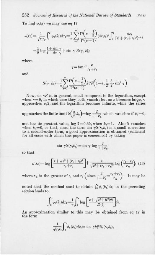
To find w:(x) we may use eq 17
where
and
_11 1 + sin 1'+' S( 12) --2 og l' SIn I' 1'; ICo -sm I'
N ow, sin rS is, in general, small compared to the logarithm, except when 1'=0, in which case they both vanish; but as x becomes large, I' approaches 7r/2, and the logarithm becomes infinite, while the series
approaches the finite limit S(~'ko)=log 1 ~k~' which vanishes if ko=O,
and has its greatest value, log 2=0.69, when ko=1. Also S vanishes when ko=O, so that, since the term sin 'YS( 'Ylko) is a small correction to a second-order term, a good approximation is obtained (sufficient for all cases with which this paper is concerned) by taking
sin rS(-y,ko) = sin I' log 1 ~k~' so that
where rm is the greater of 1'1 and 1'2 (since 1 ~k~ =rl~r2} It may be
noted that the method used to obtain J: ¢l (lcl)dxl in the preceding section leads to
!OX ¢o(k1)dxl=; 50" log [x+-J~2(~R2(8) Jd8.
An approximation similar to this may be obtained from eq 17 m the form

Snow] Mutual Inductance oj Coaxial Helices 253
where
when
. ( 1 3 ) .v; r (s+n) sm2 'Y=I , F1 l-s-n'"2'"2,1 =2 ( 1)'
r s+n+"2
so that
Hence an approximation sufficient for use in second order terms is obtained by placing
2" • _sin 'Y( ko )2" ko sm -ySn('Y,ko)-2i/: l+k~ ,
so that the following approximation analagous to eq. 43 is obtained:
(44)
When the lead wire of length II for the return current of hi lies parallel to a generator of the current sheet but at a slightly greater distance from the axis, say r/l=rl+l!.rl, the mutual inductance between this lead wire, ll1 and the helix, h2' is (as far as second-order terms are concerned) equal to that between II and the current sheet of h2' the corresponding w-function being
- w .. (x, r/l' r2) = - w .. (x, rl, r2) - l!.rIDT1w" (x, rlJ r2)'
If the lead whe of No.2 is similarly situated at a distance r'2=r2+M2 its mutual inductance with hi has the w-function
-w:r(x, rl, r'2)=-wX (x, rl, r2)-l!.r2D'2wX(x, rlr2)'
This arrangement, of course, implies that the number of turns, NI and N 2 , are inte!?ers, so that the azimuths of the two lead wires are Ojl and 012 , TheIr mutual inductance with each other is determined by the w-function, W/ 1 /2, as in eq 13, and their force by W;,lal as in eq 13', where
W11/2(X, a, r,l' r'2)=xw;,I.-.vr+R;'z,(a) (45) 118273-39-9

r
254 Journal oj Research oj the National Bureau oj Standards [VoU,
(45')
where a=()12-()11
R~z,(a)=rfl+rf.-2r/lr'2 cos a.
The additive constant, Rll12' has been omitted from eq 45, being independent of x, so that it cancels from eq 13. When the radial distances, I1rl and I1r2, of the lead wires from the helices are small, the axial currents in t.he lead wires and helices almost compensate in their effects upon inductance and force, the residual being a very small term, depending upon the azimuth, a, of the coils. If wz(x, a) represents the total w-function due to x-components of current in lead wires and helices, then
w,,(x, a)=w,,(x, rl, r2)+wI112(X, a, rl+l1rz, r2+l1r2)
-w,,(x, rl+l1rz, r2)-wx (X, rl, r2+l1r2)'
When /1r1 and I1r2 are small, this becomes
(;),,(x, a)=wII12(X, a, rll' rI2)-w,,(x, rZ, r2)-(l1rlDTl+l1r2Dr2)wz(X, rl, r,).
Since, however, these w-functions are themselves of second order, the terms in /1r are smaller than second order and therefore negligible. Hence, for this arrangement of lead wires, the w-function and its derivative, which takes account of all axial components of current in helices and lead wires, are given by
- '() 4...jT1T2 E , R' (46) w,,(x,a) =xw. x,a + -7r- k- -v r+ 2(a)
where
-'( ) I x+...jx2+R2(a) '()-~b w. x,a = og R(a) -w" x - L; n cos na, n=l
the constant term in this Fourier's cosine series being zero. coefficients bn for n >0 are given by
2 i' b,.= ,- cp,,(kl)dxI= -v rlr2 0
x 1 (rl)n ...jx2+ (rl + r2)2n r;
(46')
(46")
by the approximation in eq. 45, if r2>rl' On summing this' Fourier's series we find the following finite form as an approximation for eq 46'
(46"')

~-~~---~-~~~--------------~
Snow] Mutual Inductance oj Ooaxial Helices 255
v. THE AZIMUTHAL TERMS
To integrate eq 30, we may place (by reference to eq 10')
. '" . (0 X)+inX'+ (1 1). cos n1/;z=e·n ~ =ezn .-p; p; ~-p; mxu
with the understanding that the real part of the result is to be taken.
Using the abbreviation
J(n,s) = I n- l (rls)Jn- 1(r2s) +J"+l (rts)J,,+1 (rzs) +2P1P2 J n hS)Jn (r2$). rlf~
eq 30 becomes, by use of eq 25,
wn(X,8z)=f1f 2 ein(o.-~) (a>dsJ(n,s) (Xein(~-i,)x2dx2 (Xle i;~'-'lxddxl. P@z Jo Jo Jo
., If l>O, then XI and Xz are both positive in the range of integration of the :LI XZ double integral, so that e-8 ,z,1 =e- 6Z,. vVhen x<O, then Xl,
and xz are both negative in the range of the integral, so that e-11z,1 = e+sz" and the result of the integration in the latter case is found by changing the sign of 8 in the result of the integration for the first case.
It is thus found that both results are included in the following:
flfzef.nOZia co d J ( ) =---2- 8 n,s n 0
{~'-:';(1:~) -~,-:.;(::~) -(l±~X:+~)}' where the upper sign belongs with positive x and the lower with negative x.
I

The real part of this is ~ c.n 0:.
r 1r2!o'" \ 1 [P2 cos n(oz-~) PI cos n(oz- ~)l (l_Pl~~S) e-,Izl cos no,,) w (x () ) = - dsJ(n s) -- P - P - ~,------;;-+---;------;;~-" 'x n2 0 ) P2-Pl 1+P_~8_2 1+P_~8_2 J (1+ _P~_S2)(1+P_~_S2)
~ ~ ~ ~
~ ~ ... ;> ~
'" 11 rp:sinn(o,,-;) p~sinn(o,,-£)l_(pI+p2)e~'I"1 sinnoxj rlr2 r d J() I - 2 2 J ( 2 2 )( p's2 ) ± n3 Jo s s n,s P2-Pt 1+P~~2 l+P~~ 1+P~2 1+ ~2
~ (47) ~ '" "" '" ~ ~ ~ So '" ~ ..... <". 0 ;> ~ b;; ti '" ~ ~ ~ @
""'" ~ ""
~ 1:

Snow] lviutual Inductance oj Ooaxial Helices 257
The terms in the first integral which do not contain the exponential factor e-81 %1 may be discarded, as they will all cancel in eq 13 because, as shown by reference to eq 2 and 11, the values of OX-X/PI will be the same for the first and second x-differences, (Xe2-Xil) and (Xe2-Xel). !he~e first and second x-values enter eq 13 with opposite signs. SImilarly, the values of OX-X/PI are the same for the third and fourth x-values, Xf2-Xel and Xt2-XH, which enter eq 13 with opposite signs. Hence the term in eq 47, cos n(OX-x/PI) , disappears by the second x-term canceling the first and the fourth canceling the third. It is also found that cos n(Ox-x/P2) disappears by the fourth canceling the first and the third canceling the second. The corresponding terms in the second integral, sin n(Ox-x/PI) and SID n(Ox-x/PI) , do not always cancel because of the ± factor which has the sign of x. If the associated current sheets are wholly external to each other the cancelation is complete, but if one lies wholly or partly within the other the terms sin n(O,,-x/PI) and sin n(0,,-x/P2) of eq 47 do not disappear from eq 13.
Hence eq 47 may be written
(48)
plus terms which cancel in eq 13, where
1· (0 X)l"'SJ(n,S)dS . (0 X)l"'SJCn'S)dSj SIn n ,,-- 2 -sm n :t-- 2
P2 82+~ PI S2+ n2 •
o P2 0 PI
We may now show that by limiting the application of the results of this section to those cases where the w: (x) are all negli~ible, we do not impose a serious restriction as far as practical mutual mductances are concerned, with the exception of a bifilar-wound coil in which one of the windings is used as primary, the other as secondary. Such a coil has never been used for absolute measurements, but we see no reason why it should not be used in the future . It would possess certain advantages from the point of view of accurate construction and nleasurement und would give the greatest possible mutual inductance. The formula for its mutual inductance has never been evaluated with precision as it has for a self inductance, but the problem would present no greater difficulty.
It is easy to foretell that this limitation is that the helices, hi and h2 shall not through a finite part of their lengths be separated from each other by a distance which is small (of the order of plr).

258 J ournal oj Research oj the National Bureau oj Standards [VoU!
If Hn denotes the first Hankel's function then
1a> sJ m(rls)J m(rz8)ds '!!.J (inr')iH ( inr2). n2 2 m P m P S2+-
o p2
when r2>rl' In case r2<rl, the two are interchanged in this equation. Since rl/p and r2/p are large, the asymptotic expansions of Hm and J m show that this expression is very close to
p -nlr,-r,1 • 2..j ev- in cases r2>rl or r2<rl' n rlr2
Hence, approximately,
* ( (J) - ..jr;r; { - ~nro-rJI+i(X-P,oX) l -J;-!h-nl+i(X-PJO,)l} Wn x, x - 2(P ) . P2e • -PIe I ,
n I-PZ'/, \
where the real part is to be taken. When P2=Pl=P, this becomes
*( (J) = ..jr,r2{1 + h-rd+ iX}e-~nr.-rd+;(X-Pe.)l Wn x, x . 2 '/, n np
Since the entire Wa function with the factor rIrZ is of second order in general, compared with the principal term, We, which has the large
factor rIr2, it is evident that ±~-~lr2-rd ",ill be utterly negligible when PIP2 1 n
r2-rl is finite (not a small quantity of the order of p). Since w~ is only ditferent from zero when one coil lies wholly or partly within the ..j
other, this means that the two must not approach very close to each other if w~ is to be neglected.
The remaining integrals in eq 48 cannot be similarly integrated in finite terms, but it is evident that when Ixl is finite (not small of the order plr), we may (on account of the convergence factor e-s1xl of the integrand) obtain the principal part of Wn by placing PI =P2=O in the integrand, as the resulting integrals still converge, even if rl=r2' We cannot be content, however, with this restriction on x, as we must evaluate Wn for cases where x=O. In this case, if we place PI=PZ=O, the integrals in eq 48 then converge only if rl~r2' but if rl-r2 is a finite quantity, the principal part of Wn is thus obtained. The limitation is therefore evident-the helices mU8t be everywhere separated from each other by finite distances. Assuming this to be the case, and noting that the last term in the definition of J(n, s) is negligible, we obtain the result
so that
wn(x,(J,,) = - ..jr;r2 [4>n-l(k) +4>n+l(k)] cos n(J", n
Wa(x,(Jx) = - ..jrlr2 ± [4>n- l +4>n+t] cos ~(Jx J n~l n
(49)

Snow] Afutual Inductance oj Ooaxial Helices
and
, ( 0) -~ ~ [ , + ' ] cos nO",. W", x, x - 4 ,- L....J CPn-l CPn+l --2-
-yrlr2n=1 n (49')
(In finding the self inductance of a helix, the Wa rises in rank from a second order to a first order quantity, from which originates the most important correction term-the evaluation of which was the only difficult part of that problem. The same remark would apply to It bifilar mutual inductance) . Eq 49 holds of course when rl=r2, provided the end planes of the two coils are not close together and the coils wholly external to each other (so that k is not close to unity).
The series 49 and 49' may be evaluated by finding CPo and CPl in terms of elliptic integrals by eq 19, and then finding all other CPn or cP~ by the recurrence relation 20 or 2l.
Since the series represent second-order terms, it is evident that some simpler approximation will be sufficient. To obtain such, consider the even, continuous function of 0, j(O), which is never negative and is a periodic function of 0, with period 21T, defined by the series
CX>
2 4 ,",cos nO j(O) =3"-1T2L.J --:n,r for all real values of o. (50)
n=l
j(O) vanishes when O=2n1T, where n is any integer. It has the maximum value unity when 0= (2n+ 1)1T. It consists of a succession of parabolic arcs for
j(O)=(2-~)-! __________ when O~O~ 21T, (5111.,
and
1(8)=( 4-~)(~-2 ) ______ when 21T~O~41T. (51b)
Now,
Also from eq 15 one finds
k c~O CX>
-2..j k2 2 o=CPl(k)+L:[CPn-l(k)+CPn+l(k)] cos nO. (53) 1- cos "2" n=l
Multiplying eq 52 by eq 53, and integrating the product from 8=0 to 8=21T, gives

260 Journal oj Research oj the National Bureau oj Standards [Vol.!~
so that eq 49 becomes
171"2 7I"k12"f«()+()z) cos ()d()!
<AJ. (X.()z)=-~ a4>l(k)-s~ () l-k2 cos2 -
o 2
It is sufficient to evaluate this for the range 0 <: ()x;;;; 7r since its value for any other range of ()x is obtainable from this by inspection, remembering that Wa is an even function of ()x with period 271". (This restriction "; disappears from the end result.) With this restriction the argument of j in the integral from 0 to 271"-()" lies in the range O~ ()+()x~ 271", so that by eq 5Ia
In the integral last written, as eq 5Ib shows,
Making these substitutions, and then changing the variable of integration in the last integral to ()', where ()=27r-()', gives
(x ()) -..;-I~ (k) 7rk12 .. -or[ 2 ()z+()]()z+() COB ()d() <AJu . • Z = r lr2 11 4>1 - 8 - ---:;- -7I"--J ()
l-k2 COS2 -o 2
where both of the arguments ()x+() and (),,-() lie in the positive range of less than 27r. For this range, instead of the cosine series 50, we find a sine series for j«())
Since 32/71"3=1.032, it is evident that a good approximation for the
integrals in eq 54 is given by placing j«()) = sin ~ for ° ~ () ~ 27r, that is,
1

Snow] Mutual Inductance oj Coaxial Helices 261
j(O,,+O) = sin COxtO) andj(O,,-O) = sin COx 2 O} This gives after some simple transformations
(56)
Now,
kJ sin () cos 20 d() 1 [1 (7 ()+ 'I k2 • 2 0) , k2 ' 2 = 12 og IC cos -V - sm -V 1 - Sill () Ie
-k cos ()-Jl-k2 sin2 0] and
so that
(x 0 ) - - -Jr;:;:;7r2¢ 1 (k) 7r-Jrlr2[ 1 /1 k2 2 ()" Wa 'x - 3 --2-- k,\/ - cos 2
k . Ox+ /1 k2 2 (),,]
--cos - sm-1 k cos- - - sm - log ------'-...-----k'2 0". ( Ox) 1. Ox sm 2" '\/ - cos"2 . (57) k2 2 2 k 2 k'
Differentiating this with respect to x gives
1 k(I-~) +~ 0". -1(7 Ox) 2 /1 k 2 ():z; 4...)rlr2 cos 2" sm IC cos "2 - k'2 '\/ - cos '2
. Ox [k sin ();'+~I-k2 cos2 O;,]l (57') +k sm '2 log k'
These equations hold for any value of Ox since they are even periodic functions of ()x, with period 27r.

262 Journal oj Research oj the National Bureau oj Standards [Vol. Be
The four azimuthal differences in eq 11 may be written.
0'2'1 =a+27rNz'0'2el = a+27r(N2 - N I ),
012el=a-27rNI,012tl =a=Olz-Otl (58)
so that when the number of turns, NI and N 2, are integers, every 0" may be taken equal to a. It is evident that no essential simplification would have resulted in the formulas eq 57 and 58 had we restricted NI and N2 to integral values at the beginning.
To obtain an interpretation of the term Wa (x,O.) , let M(x,OX,rl,r2), or, more briefly, M(O.), denote the mutual inductance between the two incomplete circular arcs which are the parts of the two coaxial circles of radii rlrZ (the distance between their planes being x) included between the azimuth planes 0=0 and 0=0 •.
When the circles are complete we have by eq 23
M (271") = 47r2 -vrjr2¢j (k)
In general, if 0<0.<27r
l O, lO, cos (02-01)
M(o.J =rlrz dOl d02 -V 2 R2 ) o 0 x + (02-01
which may be transformed into
M(O.) -18'd fO. k cos OldOI V rjr 2 0 0 1 k2 2 01
2 ,- - O2 ~ •
2 - cos "2
Using the expansion in eq 53 for this integrand gives
Equations 49 and 59 are equivalent to
wa(x,O.) =wa(x,O) + ~[ M(o.) -(20; YM(27r)] when O;:?; Ox;:?; 27r.
Since, by eq 57,
( 0) __ M(27r)_7r-V~k'(1_~~ . -I k) Wa x, - 12 2k k sm ,
this may be written
Wa(x,o.) = - Mf;7r) +~[ M(Ox)-(20;YM(27r)]
7r,r;:;r;k'[l k' . -1 k] (60) - 2lc -IC sm ,
which furnishes an interpretation for part of the term w,,(x,Ox), although this form has no advantage in computation since the mutual induc-

...
Snow] Mutual Inductance oj Coaxiall-Ielices 263
tance }';1(8 x) of the two incomplete circular arcs is not a well-known or tabulated function as in the case M (27r) when the arcs are complete circles. In fact, the foregoing formulas give for it
-~;[cos ~ sin-! (k cos ~)-sin-! kJ 1. 8 [ksin~+~1-k2COS2~J . (61)
- k2 sm '2 log k'
When the series 49 and 49' are known to converge so rapidly that only the first two terms need be retained, there is no need to use eq 57 and 57'.
VI. THE HELIX EQUIVALENT TO A HELICAL WIRE
Consider the unit current in wire w! to have the vector volume density whose magnitude is a function of the distance r~ from the x axis, say u! (r~). Its direction is that of the generating helical filament.
An axial plane cuts the wire in a circular section of radius PI> as specified in eq 5. If dS! is an element of area of this circular section, a helical tube whose (oblique) section is dS! carries the current,
sruce 1
is the cosine of the angle between the normal to dS! and the direction of the current-density vector or tube. The total current carried by the wire is unity, so that
(62)
integrated over the circular section of the wire. In place of the rectangular coordinates xii-XI and r~ -r! of a point.
of this section referred to the center of the circle as origin (as used in eq 5) , we may use the polar coordindtes p~ and cf>!, where

264 Journal oj Research oj the National Bureau oj Standards [Vol. u
in terms of which dS1 = p~dp~d4>I'
Expanding the current density, ul(r~)=ulh+p{ sin 4>1), about the value rl (corresponding to the central filament of the wire) by Taylor's theorem and applying the condition 62, we obtain (to the second order, inclusive, in PI)
where
A - u~ (rl) dB _ u~(rl) 1--(-) an 1---( -)" Ul rl 2Ul rl
With similar definitions of Az and Bz, etc., the current, dI2, in a helical current tube of the second wire is
so that
dI p;dp;d4>1 [1 +A ,. +B ( " . z p~)J 2= 1l"P~ ZP2 sm rf>2 2 P2 sm 4>2-4' '
dl1dI2 p~dp~~~~~p;drf>~ { 1 + (AIP~ sin 4>1 + Azp; sin ¢z)
+B{p? sin2 4>1- ~)+Bz(p;2 sin2 4>2-~)+AIA2P~ sin ¢1'P; sin rf>2}' (63)
The mutual inductance, mtol to2, between t.he two helical wires, WI and Wz, is found by multiplying this expression for dl1 dI2 by m and integrat.ing over both circular sections of the wire, an operation which is equivalent to multiplying by 1 when applied to any terms of m except the finite part mo since the operation only alters the subject by a secondorder fraction of itself.
Now, by eq 13, replacing the x by x'
II dI1II dlzmo = II dI1II dlzwo (x:, - x;) - II dl1 II dI2wo (x:. - x:)
+ fi dI1ff dlzwo(x;.-x:,)- If dl1fI dlzwo(x;. -x;). Also
where Xe2-XIIl r ll and rz refer to the central filaments of the wires. The expansion of this by Taylor's theorem for a function of three variables may be written symbolically (to the second order in P; and p;)
{.t)o(x:,-x;) ={1 +[(p; cos ¢2- p~ cos <Pl)D,,+ p~ sin ¢IDr, + P; sin ¢2D,,]
+~ rep; cos <P2- p~ cos rf>1)D" + p~ sin rf>lD" + P; sin ¢Dr,]2}wo(x,r1r2) , (66)
where X=X'2-:I,ll'
"

Snow] Mutual Inductance oj Coaxial H elices
MUltiplying eq 63 by eq 66 and integrating gives
ff dI1ff dI2wo(x:,-x;,)
265
={ 1 +~ (D;+D~, +2AIDr,)+~ (D;+D~,+2A2Drl)}Wo(x,rlr~), where x=x. - Xi =.1=the distance between end plane of the central , , filament of wire W2 and the initial plane of the central filament of wires Wl ' On making use of the partial differential 36, this becomes so that
+1[ 2(1+ A)D 2(1 A)D ] p~+p~-JrI1'2 (k) -8 PI - 2 1 'l+P2 -+2 2 '2 WO+-S--- ¢l o· 1'1 1'2 PIP2
(67)
The expansion of the three remaining integrals of eq 64 is the same as this with the appropriate x-arguments.
The result is that, to the second order, the mutual inductance of the two wires is given by
where hi and h2 are their central helical filaments, with radii rl and r2. This may be written
(69)
where
(70)
where all the m's except the principal one refer to the central helices of the two wires, and every m is expressed in terms of its w-function, as in eq 13, with corresponding subscrip ts.
'1'he sole effect of giving the wires a. radius is to increase the effective radii of their current sheets from l' to r (to the second order), the length of the sheets being unaltered. The Jatter fact is explained in part by the particular manner in which their lengths have been defined, and in part by the fact that the wire sections are circular, so· that the t erms which would represent an increase in effective lengthbeing proportional to D;wo-have entered the result together with D;wo and their combined effects have been expressed in terms of DqwO and Dr2WO by means of the partial differential eq 36.
For distributions of current in both wires whose r-derivative vanishes at t11e central filament, the constants Al and A~ are both zero.

266 Journal oj Research oj the National Bureau oj Stdfndards [VaUI
The uniform current distribution is an example of this class. A correction equal to the above but opposite in sign is obtained for distributions in which AI= -I/rl, and A z=-I/rz, an example of this class being the "natural" distribution (BI = l/ri), where the current density varies inversely as the linear length ..jrz+ p2 of the helical current filaments. A distribution for which Al = -1/2rl, Az= -1/2rz would have no correction of this order of magnitude.
Whatever assumption be made as to the current distribution, it will still be necessary to evaluate Dnm and Dr,m roughly in order to estimate the effects of errors in determination of the mean radii, rl and rz·
At present we are ignorant of the current distribution in such wires, so that for simplicity it would seem better to ignore altogether this correction for finite thickness of the wires. The assumption usually made of uniform current density carries with it a spurious precision.
We can, however, allow for future increase of knowledge as to current distribution, with no less simplicity of treatment, by defining the helix which is equivalent to a helical wire as one having the same pitch and end planes as its central filament, but a cylindrical radius
r=a+~(~+2A }
where a is the mean cylindrical radius of the helical wire and p is the wire-radius-the interpretation of the constant A being the value at the central filament of the r-derivative of the current density, which was assumed to be a function of r only and in the direction of the helical filament.
As far as we are concerned here, this disposes of the difference between helices and helical wires. All the formulas in the preceding sections regarding mutual inductance of two helices and the force between them are valid for the helical wires to which they are equivalent.
VII. APPLICATION TO THE CURRENT BALANCE USED IN THE NATIONAL PHYSICAL LABORATORY
If the x axis be taken vertically upward, the lower (or suspended) helix, called No.1, has a mean radius rl=10 cm and length ll=15.2 cm. The upper helix has radius r2=16 cm and length l2=11.0 cm. Both helices have the same pitch, 21l"PI=21l"P2=O.2 cm and an integral number of turns, N I=76 and N 2=55 turns. Hence, every 8x=a= Bi2 -B tl the azimuth of the helices. The upper end of No.1 projects into No.2, so that the third x-difference of eq 11 is negative.
Xl =Xe2-Xil= +20.1 cm~kI2=O.5926
X2 =xeZ-xel = +4.9 cm~7c22=O.9143
X3 =Xi2-Xej= -6.1 cm~k32=0.8974
x4=xiz-xtl=+9.1 cm~k4z=0.8434
The force, j, acting on the suspended helix when both"Carry unit current is -
j=je+!x(a)+ja(a), (71)

Snow) Mutual Inductance oj Ooaxial Helices 267
where 18 is the principal part due to angular components of current in the helices and by eq 13'.
(72)
where the we' (x) are given by eq 39. The small partf.,(a) denotes the residue due to x-components of current in helices and lead wires together and is given by
].,(a) = -;:(xl,a) +";;;:(x2,a) -;;;-:(Xa,a) + ;:(x{,a), (73)
where the ;;;-~(x,a) are given by eq 46'. The last part,jQ(a), is given similarly by
Ja(a) = -w:(xl,a) +w:(x2,a) - w: (x. , a) + w: (x{, a) , (74)
where the w:(x,a) may be computed by eq 49' or 57'. Both ~;(x,a) and w~(x,a) are even periodic functions of a, with period 211", so the same is true of ].,(a) and ja(a).
In the actual coils, however, there are two helices on each cylinder differing in azimuth by 11", so that when each carries unit current the force on the suspended coil is F, where
where
Fo= 4Jo
F,,(a) = 2Lf.,(a) +f,,(a+1I")]
Fa (a) = 2 [ja (a) +Ja(a+1I")]
(75)
(76)
This makes the azimuthal terms, F.,(a) and Fa(a), each even periodic functions of a, with period 11", so that
co
F .. (a)+Fa(a)=~02n cos 2na. (77) n=l
P. Vigoureux of the National Physical Laboratory of England has recently reported to this Bureau that in the absence of a formula for the coefficients 02n he has evaluated experimentally the first coefficient, O2, assuming the first term to be the only one of the series of practical importance. This he did by measuring the force for three different azimuths a=3°, 15°, and 85°.
In order to see what part of O2 is due to axial components of current and what part is due to the azimuth terms w:, let
(78)
Reference to eq 72, 76, and 46" shows that the effect of aA-lal currents is given by
(79)

268 Journal oj Reseafch oj the National BUfeau oj Standafds [Vol U
and eq 49' shows that
O;n= ,!-4~2 { -xlkHcf>2n+l (kl ) +cf>2n-l (kl)]+x2kUcf>2n+1 (k2) + cf>2n-1(k2)] -yflf2 .
-xakHcf>2n+l (ka) +cf>2n-l (k3)] +x4k~[cf>2n+1 (k4) +cf>2n-l (k4)]} (80)
Placing n=l
O~= b:-(~)2[ -xlkl+X2k2-X3ka+X4k4] = +0.103 dynes Vflf2 f2
~= .J!lfJ-Xlk~[ cf>~(kl) !cf>;(kl)]+X2k( cf>~(k2) !cf>;(k2)]
From the recurrence relations 20 and 21, it is found that
ka[ cf>~(k) tcf>;(k)]=~{[~+ ~Z:2] 7r2k3cf>~ (k) -(~-1 )41T2cf>1 (k)}
=~2{ [~+ ~z:1 Y 2 (le) -(~2-1 )YI(k)} = ~2Y(k),
(81)
(83)
where Y I and Y2 are the functions defined in eq 23, which may be taken from tables.
Y I (Ie) =2.086,
Y2(k) = 1.490,
' . • Y(k) =0.401,
9.100,
25.663,
9.04,
8.165, and 6.072 for leI, k2' k3' and k4
20.049, and 10.796
6.57, and 3.41
1 . 02= 2 ,-{ -Xl Y(kl) +X2Y (k2) -xaY(ka) +x4Y(k4) } =0.86 dyne.
1T -yflf2
Hence
02+02=0.86+0.10=0.96 dyne, which differs from the observed value 1 dyne by less than the experimental error.
The force Fs=94,527.22 dynes, so that
F=94,527.22+0.96 cos 2a
For azimuth a=O or 7r, this azimuthal term amounts to 10 parts in a million.
VIII. SUMMARY
The self inductance between two coaxial helices and the force between them are lSiven in terms of four w-functions, and their xderivatives, respectIvely, as in eq 13 and 13', the four x-distances being defined in eq 11 with their respective azimuthal differences Oz. Resolving these functions into three components, W(X)=W8(X)+W z (x) +wa(x,Oz), the principal part corresponds to the mutual inductance

- ... -S1l0W] ll1utual Inductance oj Ooaxial Helices 269
between the two associated current sheets, with angular components of current, and wxex) with axial components. The last term, wa(x,(Jz), is like wz(x), a second-order correction term applied to the finite term, we(X), where the ratio of pitch to cylindrical radius is considered a first-order infinitesimal.
The principal term, (veex), is given by eq 37 and wxex) by eq 39. The first is equivalent to Jones' formula for current sheets. The terms wAx) and w:ex) are given by eq 42 and 43.
The llzimuthal terms, wa(x,(Jx) and w:ex,(Jx), :1re given by the series eq 49 flnJ 49/ and in finite terms by eq 57 and 57/.
These formulas are not restricted to the case where the helices have an integral number of turns but are quite general. They need not have the same pitch. For tbe case most common in practice where the numbers of turns are integers and the lead wires are straight lines parallel and close to the generator of the cylindrical cU1Tent sheet, the totlll effect of aU axial components of current in helices and Jead wires together is represented by a function wxex) which is given by eq 46, and its x-derivative by eq 46'.
It is shown in section VII that the azimuthal variaLion of the force computed by these equations agrees (within experimental errors) vv"i.th that observed at the National Physical Laboratory.
The correction terms given in section VI take account of the fini tc diameter of helical wires. They require a knowledge of the current distribution in the wires.
These formulas are valid to the second order, inclusive, provided no parts of the two helices lie very close to each other, that is, at distances of the order of magnitude of the pitch of the windings.
WASHINGTON, December 21, 1938.
o
118273-3 - - 10


