Embed Size (px)
Citation preview

University of Tennessee, Knoxville University of Tennessee, Knoxville
TRACE: Tennessee Research and Creative TRACE: Tennessee Research and Creative
Exchange Exchange
Masters Theses Graduate School
12-2009
A Study to Evaluate the Suitability of a Centrifuge as a Dynamic A Study to Evaluate the Suitability of a Centrifuge as a Dynamic
Flight Simulator for F/A-18 Strike Fighter Mission Training Flight Simulator for F/A-18 Strike Fighter Mission Training
Richard Michael Masica UTSI, [email protected]
Follow this and additional works at: https://trace.tennessee.edu/utk_gradthes
Part of the Engineering Commons
Recommended Citation Recommended Citation Masica, Richard Michael, "A Study to Evaluate the Suitability of a Centrifuge as a Dynamic Flight Simulator for F/A-18 Strike Fighter Mission Training. " Master's Thesis, University of Tennessee, 2009. https://trace.tennessee.edu/utk_gradthes/543
This Thesis is brought to you for free and open access by the Graduate School at TRACE: Tennessee Research and Creative Exchange. It has been accepted for inclusion in Masters Theses by an authorized administrator of TRACE: Tennessee Research and Creative Exchange. For more information, please contact [email protected].

To the Graduate Council:
I am submitting herewith a thesis written by Richard Michael Masica entitled "A Study to
Evaluate the Suitability of a Centrifuge as a Dynamic Flight Simulator for F/A-18 Strike Fighter
Mission Training." I have examined the final electronic copy of this thesis for form and content
and recommend that it be accepted in partial fulfillment of the requirements for the degree of
Master of Science, with a major in Aviation Systems.
Richard Ranaudo, Major Professor
We have read this thesis and recommend its acceptance:
Richard Ranaudo, Uwe P. Solies, Frank G. Collins
Accepted for the Council:
Carolyn R. Hodges
Vice Provost and Dean of the Graduate School
(Original signatures are on file with official student records.)

To the Graduate Council:
I am submitting herewith a thesis written by Richard Michael Masica entitled “A Study to
Evaluate the Suitability of a Centrifuge as a Dynamic Flight Simulator for F/A-18 Strike Fighter
Mission Training.” I have examined the final electronic copy of this thesis for form and content
and recommend that it be accepted in partial fulfillment of the requirements for the degree of
Master of Science with a major in Aviation Systems.
Richard Ranaudo , Major Professor
We have read this thesis
and recommend its acceptance:
Richard Ranaudo
Uwe Peter Solies
Frank G. Collins
Accepted for the Council:
Carolyn R. Hodges
Vice Provost and Dean of the Graduate School

A STUDY TO EVALUATE THE SUITABILITY OF A CENTRIFUGE AS A DYNAMIC FLIGHT
SIMULATOR FOR F/A-18 STRIKE FIGHTER MISSION TRAINING
A Thesis
Presented for the
Master of Science
Degree
The University of Tennessee, Knoxville
Richard Michael Masica
December 2009
NAVAIR Public Release 09-734
Approved for public release; distribution is unlimited.

ii
DEDICATION
This thesis is dedicated to my wife, Leigh.
Finishing this long journey would not have been possible without her.

iii
ACKNOWLEDGEMENTS
I wish to thank all those who helped me with the data collection and research review
during this process. Specifically, I thank CDR Klas Ohman, USN, former Commanding Officer of
VFA-136 at NAS Oceana, VA, for providing me the F/A-18 training mission aircraft data files, and
Mr. Steve Naylor of the Manned Flight Simulator (MFS) Lab at NAS Patuxent River, who helped
to reduce the flight data. I also thank the men and women of the Navy’s F/A-18 strike fighter
community who participated in my aircrew survey. I also thank Mr. Chris Clark, Chief Test
Engineer at VX-23 for his suggestions and technical assistance in reviewing centrifuge testing
results. I also thank Dr. Ben Lawson, Naval Aerospace Medical Research Laboratory, for
providing me valuable research papers and perspective on issues surrounding centrifuge usage
and spatial disorientation in aviation training.
Lastly, I thank my wife Leigh for the enduring support, encouragement, and occasional
prodding that made this thesis possible.
iv
ABSTRACT
The purpose of this study was to evaluate the suitability of using an existing 25-ft radius
centrifuge as a dynamic flight simulator for “full mission” F/A-18 strike fighter mission training with
respect to the representativeness of pilot-perceived motion and acceleration cues.
The methodology employed in this study consisted of analyzing F/A-18 mission tasks,
collecting pilot opinion surveys of important sensory cues needed in simulator training, and
conducting an analysis of human pilot perceptual problems caused by centrifuge motion
constraints.
This study identified a number of issues indicating that a centrifuge-based flight simulator
shows limited potential for use in “full mission” F/A-18 training scenarios. Specifically, there is a
fundamental mismatch between the 6 degree-of-freedom mission-representative acceleration
environment experienced in the aircraft and the 3 degree-of-freedom acceleration environment
the centrifuge is able to provide. The centrifuge is not optimized for the typical acceleration
environment experienced during F/A-18 missions and has significant limitations in “near one
g”and “near zero g” flight conditions. Additionally, the centrifuge causes a variety of undesired,
unrealistic, and debilitating vestibular artifacts that are not consistent with what a pilot
experiences in the aircraft when performing the same mission task, degrading the effectiveness
of training.
Despite its limited suitability as a “full mission” F/A-18 simulator, the centrifuge is an
essential physiological training device, shows good potential as a part-task trainer for
departure/spin training, and should continue to play a role in the F/A-18 training continuum.

v
TABLE OF CONTENTS
1. INTRODUCTION ........................................................................................................................ 1
THE FUNDAMENTALS OF FLIGHT SIMULATION.................................................................... 2
2. DESCRIPTION OF F/A-18 STRIKE FIGHTER MISSION REQUIREMENTS ............................ 8
AIRCRAFT DESCRIPTION AND CAPABILITIES....................................................................... 8
STRIKE FIGHTER MISSION DESCRIPTIONS AND ANALYSIS OF STRIKE FIGHTER
TRAINING MISSION DATA ...................................................................................................... 12
F/A-18 STRIKE FIGHTER AIRCREW SURVEY RESULTS AND ANALYSIS .......................... 18
3. ANALYSIS AND DISCUSSION OF AN EXISTING CENTRIFUGE-BASED FLIGHT
SIMULATOR................................................................................................................................. 22
CENTRIFUGE-BASED FLIGHT SIMULATOR PERFORMANCE CAPABILITIES ................... 22
PILOT QUALITATIVE EVALUATIONS OF THE ATFS 400...................................................... 26
COMPARING THE MECHANICS OF AIRCRAFT FLIGHT AND CENTRIFUGAL MOTION .... 29
CENTRIFUGE-BASED FLIGHT SIMULATORS AS PART-TASK TRAINERS ......................... 36
4. CONCLUSIONS AND RECOMMENDATIONS ........................................................................ 37
CONCLUSIONS........................................................................................................................ 37
RECOMMENDATIONS............................................................................................................. 38
LIST OF REFERENCES............................................................................................................... 40
APPENDICES............................................................................................................................... 47
APPENDIX A: Analysis of F/A-18E Aircraft Flight Data ............................................................ 48
APPENDIX B: Analysis of Strike Fighter Aircrew Survey Results............................................. 67
APPENDIX C: Review of Spatial Orientation and Human Sensory Perception ........................ 76
APPENDIX D: Review of the Mechanics of Aircraft Flight and Centrifuge Motion.................... 79
VITA.............................................................................................................................................. 83

vi
LIST OF FIGURES
Figure 1. Three-View Diagrams of the F/A-18C/D Hornet and F/A-18E/F Super Hornet .............. 9
Figure 2. Aircraft Reference Axes.................................................................................................. 9
Figure 3. Photograph of ATFS 400 Centrifuge Manufactured by ETC ........................................ 23
Figure A-1. Pilot Seat Normal Acceleration Expressed as g and Aircraft Altitude Versus Elapsed
Mission Time for the Air Combat Maneuvering Training Mission .......................................... 50
Figure A-2. Histograms of Pilot Seat Normal Acceleration (GZ) Spectrum for the Air Combat
Maneuvering Training Mission............................................................................................... 52
Figure A-3(a). Pilot Seat Normal Acceleration Expressed as g and Aircraft Altitude Versus
Elapsed Mission Time for the Air-to-Air Intercept Training Mission....................................... 54
Figure A-4. Histograms of Pilot Seat Normal Acceleration (GZ) Spectrum for the Air-to-Air
Intercept Training Mission ..................................................................................................... 58
Figure A-5. Pilot Seat Normal Acceleration Expressed as g and Aircraft Altitude Versus Elapsed
Mission Time for the Close Air Support Training Mission...................................................... 60
Figure A-6. Histograms of Pilot Seat Normal Acceleration (GZ) Spectrum for the Close Air
Support Training Mission....................................................................................................... 62
Figure A-7. Pilot Seat Normal Acceleration Expressed as g and Aircraft Altitude Versus Elapsed
Mission Time for the SACT Training Mission ........................................................................ 64
Figure A-8. Histograms of Pilot Seat Normal Acceleration (GZ) Spectrum for the Surface-to-Air
Countertactics Training Mission ............................................................................................ 66
Figure B-1. Histogram of Aircrew-Rated Realism of Existing Fixed-Base F/A-18 Simulator in
Matching the Environment in the Actual Aircraft for Specific Mission Subsets.......................70!
Figure B-2. Histogram of Aircrew-Rated Frequency of Head Movement in the Actual Aircraft
During Specific Strike Fighter Mission Subsets.....................................................................72!
Figure B-3. Histogram of Aircrew-Rated Importance of Gravito-Inertial Based Cues During
Various Strike Fighter Mission Tasks .....................................................................................74!
Figure D-1. Required Bank Angle and Centrifuge Speed for a Pilot-Commanded GZ..................82!

vii
LIST OF TABLES
Table 1: Basic Aircraft Parameters for F/A-18 Hornet and Super Hornet....................................... 9
Table 2: Typical Strike Fighter Mission Subsets........................................................................... 13
Table 3: ATFS 400 Parameters and Performance Characteristics............................................... 24
Table A-1: Air Combat Maneuvering Training Mission Acceleration Analysis .............................. 51
Table A-2: Air-to-Air Intercept Training Mission Acceleration Analysis......................................... 56
Table A-3: Air-to-Air Intercept Training Mission Acceleration Analysis......................................... 57
Table A-4: Close Air Support Training Mission Acceleration Analysis.......................................... 61
Table A-5: SACT Training Mission Acceleration Analysis ............................................................ 65
Table B-1: Strike Fighter Aircrew Survey Demographics ............................................................. 68
Table B-2: Results of Aircrew Acceptance Ratings of Existing Fixed-Base F/A-18 Simulators.... 69
Table B-3: Results of Aircrew-Rated Realism of Existing Fixed-Base F/A-18 Simulator in
Matching the Environment in the Actual Aircraft for Specific Mission Subsets...................... 71
Table B-4: Results of Aircrew-Rated Frequency of Head Movement in the Actual Aircraft During
Specific Strike Fighter Mission Subsets ................................................................................ 72
Table B-5: Results of Aircrew-Rated Importance of Gravito-Inertial Based Cues During Specific
Strike Fighter Mission Subsets .............................................................................................. 75

viii
LIST OF ABBREVIATIONS AND ACRONYMS
A/A Air-to-Air
A/G Air-to-Ground
ACM Air Combat Maneuvering
AOA Angle of Attack
ATFS Authentic Tactical Fighting System
BVR Beyond Visual Range
C-FET Centrifuge-Based Flight Environment Trainer
CAS Close Air Support
CCC Coriolis Cross-Coupling
CRM Crew Resource Management
DOF Degrees of Freedom
ECS Environmental Control System
EO Electro-Optical
ETC Environmental Technologies Corporation
F/A Fighter-Attack
FAA Federal Aviation Administration
FCS Flight Control System
FOV Field-of-View
FRS Fleet Replacement Squadron
G Gravito-Inertial Acceleration
GIF Gravito-Inertial Force
GPS Global Positioning System
HUD Heads-Up Display
JHMCS Joint Helmet-Mounted Cueing System
LEX Leading Edge Extension
NAS Naval Air Station
NASA National Aeronautics and Space Administration
NATOPS Naval Air Training and Operations Procedures Standardization
OCF Out-of-Control Flight
PS Specific Excess Power
SA Situational Awareness
SACT Surface-to-Air Countertactics
SD Spatial Disorientation

ix
SO Spatial Orientation
ToT Transfer of Training
VID Visual Identification
WSO Weapon System Officer
WVR Within Visual Range

1
1. INTRODUCTION
Within the United States Navy tactical aviation community, the sustained combat
requirements for the prolonged Global War on Terror have outpaced the fatigue life expenditure
estimates for the F/A-18 Hornet and Super Hornet, forcing U.S. Navy leadership to look to
alternative methods to train and maintain combat readiness for strike fighter aircrew other than
traditional in-aircraft training.1 One of the initiatives sought by Naval Aviation leadership is to
utilize flight simulators in a much more prominent role than in years past.2 Faced with
accelerating increases in life cycle costs and increased operational risk due to fatigue-related
aircraft component failures, flight simulators offer an attractive alternative for maintaining combat
readiness.
In recent years, advances in both the specification of human sensory, perceptual, and
response mechanisms3 and also simulation technology including high-fidelity displays and
powerful computers have significantly expanded what is possible with respect to simulating the
flight experience.4 Nevertheless, it is nearly impossible to match all the cues experienced in the
air in ground-based simulators because the cockpit displacement cues cannot be duplicated
exactly.5,6
The question of how closely an earth-bound flight simulator can mimic the force and
motion cues characteristic of aircraft flight has led to the development and deployment of different
technologies to provide simulator force and motion realism, most notably those employing wide-
view high-definition visual systems and 6 degree-of-freedom (DOF) synergistic platforms used for
wide-body commercial and transport aircraft.
Providing accurate, timely, and effective force and motion cues in a simulator consistent
with the dynamic, high g-force maneuvers typical during F/A-18 strike fighter missions is
considerably more difficult. One alternative offered is to modify and refine existing human-rated
centrifuge systems to be used as high performance dynamic flight simulators that match the
performance capabilities of the F/A-18 Hornet and Super Hornet. This paper addresses the
suitability of using an existing 25-ft radius centrifuge as a dynamic flight simulator for F/A-18 strike
fighter mission training with respect to the representativeness of pilot-perceived motion and
acceleration cues.

2
THE FUNDAMENTALS OF FLIGHT SIMULATION
Flight simulation is an essential component of both military and commercial aviation flight
training, allowing pilots and crews to train safely and effectively without having to incur the high
costs of operating and maintaining a fleet of training aircraft.7,8,9,10
Merriam-Webster’s Dictionary offers a simple, straightforward definition of simulation that
frames the aviation training discussion very well: simulation is “the imitative representation of the
functioning of one system or process by means of the functioning of another.”11
Very simply, a
flight simulator is designed to provide an accurate, “imitative representation” of the conditions,
characteristics, and events expected to be encountered in the actual aircraft such that the pilot
learns skills that will be performed in the actual aircraft. 12
As McCauley describes: “flight
simulators create the illusion of flight by simulating equipment, tasks, and environments and
training simulators provide these capabilities for the purpose of accomplishing pilot or aircrew
training without using the actual aircraft.”8
Transfer of Training (ToT) in Flight Simulation
Transfer of training (ToT) in aviation refers to the measurable, beneficial effects of
learning or practicing a skill, task, or combination of each in one device (i.e. the simulator) that
can be directly applied to another device (i.e. the airplane).13
Transfer of training is based upon
two key theories: American psychologist Edward L. Thorndike’s “common elements” theory and
Charles E. Osgood’s theory of the concept of “transfer surface.” These two theories suggest that
transfer of training will occur to the extent that a simulator and the aircraft share common
elements and where one can map an assumed relationship between elements or features of a
simulator and the aircraft.14
Where there is one-to-one correspondence, ToT will be positive and
high; less than one-to-one correspondence will result in decreasing ToT to the point that none will
occur when correspondence is zero.14
These philosophies have guided the evolution of flight
simulators and have resulted in a variety of technological advancements emphasizing high-fidelity
and highly realistic representations of aircraft and their systems.14
While the requirement to achieve high levels of realism has driven flight simulator
development and certification, there are two key principles that maximize ToT.12
First, the
characteristics and methods of using simulators should be based on their behavioral objectives.

3
Second, physical realism is not necessarily the only or optimal means for achieving the
behavioral objectives of simulation. In the end, the success of flight simulation lies not just with
improved physical realism, but instead with improved pilot learning or performance.12
As stated
by Ray, “If the simulation is to properly stimulate the physiology of the human being to achieve
performance as it would occur in flight, it is very clear that simulation must faithfully address the
cues upon which that flight performance is based.”15
With this in mind, the ToT from a flight simulator to the actual aircraft is highly dependent
on the quality of the simulation, which provides sensory feedback.16
To obtain maximum training
and habit transfer, the training mission must include as many of the pertinent features of the real
mission as possible.17
A well-designed flight simulator, in replicating the physical interface
between the pilot, aircraft, and external world, should provide an environment where the pilot can
learn, practice, and perfect the skills and behavior necessary for successful completion of
mission-representative tasks. Not surprisingly, the broad range of both aircraft and mission
categories across the spectrum of military and commercial aviation has resulted in a wide variety
of flight simulator design alternatives incorporating varying degrees of sensory fidelity and force
or motion cueing.
What should be simulated is ultimately determined by the aircraft characteristics and
mission profiles a simulator is designed to emulate. Designing a simulator to accurately emulate
aircraft characteristics requires detailed analysis of:
1. Specific aircraft aerodynamic and performance capabilities including acceleration limits,
excess power, maneuverability envelope, flying qualities, and stability and control
characteristics; and
2. Human factors issues surrounding the man/machine interface such as layout and
mechanization of controls and displays and field of view.
Designing a simulator to emulate the mission environment requires an understanding of:
1. How the pilots fly/perform the “full mission” in the actual aircraft, and
2. How the pilots interact with their external environment and what sensory cues they use
while performing mission tasks. Examples of this interaction include how pilots perceive
aircraft state changes, develop and modify aircraft control strategies, maintain intra- and
inter-cockpit situational awareness, exercise decision making, and a perform a wide
variety of mission-dependent cognitive tasks.
While the problems of simulating equipment and rehearsing tasks are relatively
straightforward, the simulation of the in-flight environment is one of the most challenging tasks for
4
simulator designers.18
Specifically, it can be very difficult to accurately simulate the aircraft’s
gravito-inertial accelerations, maneuvering dynamics, external disturbance cues, and other types
of aircraft motion that can be perceived by the human sensory system, particularly in high-
performance, highly-agile tactical jet aircraft.
“Categories” of Sensory Cueing
Pilots depend upon sensory cues to assess the status and condition of their aircraft, to
initiate actions, to guide their performance, and to signal when an action should be altered or
ended. 19
In other words, pilots interpret aircraft response solely on their perception of it. For
every aircraft and mission, there are a wide variety of sensory cues that add realism to the
simulated flight environment but these cues are highly dependent upon the mission subset and/or
embedded tasks.
For the purposes on this study, the wide variety of different types of sensory cues were
assigned to one of the following five 5 categories:
1. Visual cues, defined as changes in external scene including weather effects and in
cockpit scene including HUD/sensor/display symbology changes.
2. Gravito-inertial acceleration cues, defined as any of the vestibular or somatosensory cues
including positive and negative G forces, seat of the pants cues, any roll-pitch-yaw inner
ear sensations, linear acceleration, sideforces, and G-suit inflation
3. Physical airframe cues, defined as high-frequency structural modes such as buffet,
aerodynamic vortices, airframe vibration, and turbulence such that pilots perceive aircraft
state or performance through airframe (aeromechanical) dynamic response.
4. Aural cues, defined as engine response, environmental control system (ECS) flow
changes, ambient cockpit noise, external configuration changes (lowering/raising landing
gear), and audible aircraft performance cues.
5. Environmental cues, defined as temperature, airflow, humidity, ambient pressurization,
oxygen flow, and cockpit odor.
Force and Motion Cueing in High-Fidelity Flight Simulation
While the majority of sensory cueing in flight simulation comes through visual means,
research has shown that force and motion cues, in effect, quicken pilot responses to displays of
5
attitude, altitude, and flight path changes.3 Force and motion cueing employed in high-fidelity
simulators allows for the generation of gravito-inertial acceleration and physical airframe cues that
are typically lacking in a traditional fixed-base, non-motion simulator.
Since it is highly unlikely that a ground-based simulator will be able to exactly duplicate
actual aircraft motion (objective fidelity that matches aircraft displacement, velocity, and
acceleration), the principle behind force and motion cueing in a flight simulator is to provide
accurate, timely, and effective sensory cues (perceptual fidelity) via the predominant sensory
receptors of the pilot in order to elicit the same performance and control strategy as would be
used in the actual aircraft. 7,20,21
This indicates that sensory cues used by pilots are strongly
context-dependent, varying with different mission types, tasks, and workload.22
The human nervous system is highly adaptable and helps bridge the gap to make flight
simulation more realistic, even though the sensory cues may not be 100% accurate. As
described by Chung, et al., “it is well known that human pilots will quite successfully adapt their
behavior to many different control situations, and in the process optimize the pilot-to-vehicle
performance for their task.”5 As Sinacori explains, “certain types of stimuli can evoke the same
sensations and response even when the stimulus magnitude varies. In engineering terms, this
means one-to-one motion reproduction in a simulator is not necessary and this is the basic
reason why motion simulation is possible and works in practice.”23
In other words, simulator
designers have learned to tune visual and other methods of sensory stimuli and feedback to “fool”
the pilot into thinking he/she is physically experiencing the sensation of flight by evoking nervous
system responses consistent with those experienced while performing in-aircraft tasks.
Large commercial aircraft simulators currently employ force and motion cueing through
the use of 6 degree of freedom (DOF) synergistic Stewart platforms to satisfy FAA Level D fidelity
requirements.24
These FAA-mandated force and motion cues are specifically tuned to the
performance capabilities of large commercial aircraft and are designed to provide the pilot with
high-fidelity feedback of aircraft response during demanding phases of flight such as takeoff,
approach, and landing. Some examples of the force and motion cues required for commercial
aircraft include the following:
• Runway rumble, oleo deflections, effects of ground-speed and uneven runway
characteristics
• Buffets on the ground due to spoiler/speedbrake extension and thrust reversal
• Bumps after lift-off of nose and main gear
• Buffet during extension and retraction of landing gear

6
• Buffet in the air due to flap and spoiler/speedbrake extension
• Stall buffet to, but not necessarily beyond, the FAA certificated stall speed, VS
• Representative touchdown cues for main and nose gear
• Nosewheel scuffing
• Thrust effect with brakes set.24
These cues include both control cues (expected responses) and disturbance cues (unexpected
responses) and are intended to assist the pilot in maintaining spatial orientation and managing
aircraft state as he/she completes mission-representative tasks.
Tactical aircraft have a significantly larger flight envelope, dramatically more dynamic
maneuvering and performance capabilities, and widely expanded mission subsets than
commercial aircraft. These aircraft are capable of generating rapid onset, high magnitude
accelerations that cause agile flight path changes and, as such, provide vastly different sensory
cues to the pilot than those experienced from a commercial or transport aircraft during an
approach and landing task. While a traditional simulator may provide sufficient fidelity for
mimicking the motions and accelerations of larger aircraft in relatively benign phases of flight (like
takeoff and landing), this fidelity begins to break down when attempting to mimic the complex and
highly variable three-dimensional flight path possibilities and various combinations of linear and
rotational acceleration cues experienced in tactical aircraft. Very simply, a traditional motion-
based flight simulator like those used in commercial aviation has considerable difficulty in
providing the gravito-inertial accelerations experienced in high-performance, highly agile strike
fighter aircraft. As Gillingham explains, “the phenomenal ability of current high-performance
aircraft to roll, pitch, accelerate, gain or lose altitude, and otherwise change spatial orientation
parameters very quickly, presents a significant challenge to the pilot to maintain a continually
accurate assessment of those parameters.”25
This phenomenal ability also presents considerable
challenges to any proposed simulator device that is supposed to generate accurate, timely, and
effective cues of these dynamic aircraft parameters.
A human-rated centrifuge is one proposed alternative for providing force and motion
cueing that can achieve the large magnitude, sustained normal acceleration (GZ) accelerations
and high GZ onset/offload rates characteristic of highly agile fighters. Specifically, there are
existing 25-ft radius centrifuges used in both physiological research and training applications that
have the capability to provide the large magnitudes of sustained accelerations and onset rates.

7
Purpose, Limitations to Scope, and Methodology
Purpose
The purpose of this study is to evaluate the suitability of a 25-foot moment arm centrifuge
for use in an expanded role as a dynamic flight simulator for “full mission” F/A-18 training
scenarios.
Limitations to Scope
In order to focus discussion to the issue of whether or not a 25-ft moment arm centrifuge
can be used as a dynamic flight simulator for “full mission” training scenarios, the following
limitations to scope are offered:
1. The cockpit layout, visual displays, aircraft systems controls and operation, and aural and
environmental cues for a centrifuge-based dynamic flight simulator are assumed to be
the same as existing F/A-18 fixed-base flight training devices (any proposed centrifuge-
based simulator will use the current state-of-the –art F/A-18 training devices as a starting
point).
2. Discussion and analysis is based upon existing 25-foot planetary arm, 3 degree-of-
freedom (DOF) centrifuge designs. There are many centrifuge design variables that can
be modified to provide different force and motion cues, including varying centrifugal arm
radius, baseline rotational speed, gondola degrees of freedom, gondola mass
characteristics, and motor size and gearing.
3. Alternatives methods to provide force and motion cueing (such as synergistic 6 DOF
Stewart platforms, g-seats, g-suit inflation, helmet loading, light dimming systems, etc.)
are not discussed.
Methodology
The methodology employed in this study consisted of analyzing F/A 18 mission tasks,
collecting pilot opinion surveys of important sensory cues needed in simulator training, and
conducting an analysis of human pilot perceptual problems caused by centrifuge motion
constraints. Conclusions were drawn from this process and recommendations made for the
concept of using a centrifuge-based simulator for full mission training.

8
2. DESCRIPTION OF F/A-18 STRIKE FIGHTER MISSION REQUIREMENTS
Before delving into detailed discussion and analysis on the suitability of a centrifuge-
based dynamic flight simulator for F/A-18 mission training, there must be some understanding of
the aircraft capabilities, strike fighter mission components, and current U.S. Navy aircrew (both
pilot and weapon system officer) sensory cue (stimulus and feedback) expectations during flight.
The following section provides:
1) A description of aircraft performance and capabilities,
2) A description of the strike fighter mission and an analysis of flight data from real-world
mission training profiles, and
3) Results from pilot opinion surveys related to sensory cueing expectations.
A good understanding these three areas is needed to define the “requirements baseline” for a
centrifuge-based dynamic flight simulator and its suitability for mission related training.
AIRCRAFT DESCRIPTION AND CAPABILITIES
Basic Aircraft Description
The Hornet and Super Hornet, shown in Figure 1, are twin engine, mid-wing, multi-
mission and all-weather tactical aircraft that can be configured quickly to perform either fighter or
attack roles or both, through selected use of external equipment to accomplish specific missions.
The Hornet has been produced in four variants (single seat models A and C and two seat models
B and D). The Super Hornet is a newer and larger version and is produced in two variants (a
single seat E model and two-seat F model).26
Table 1 details basic aircraft parameters for each
aircraft. Figure 2 below reviews standard aircraft reference axes and sign conventions that will be
used throughout this paper. The following paragraphs outline the acceleration and other
performance capabilities of the aircraft.

9
Figure 1. Three-View Diagrams of the F/A-18C/D Hornet and F/A-18E/F Super Hornet
Table 1: Basic Aircraft Parameters for F/A-18 Hornet and Super Hornet26
Aircraft Parameter Hornet Super Hornet
Length 56 ft 60.3 ft
Height 15.3 ft 16 ft
Wingspan 40.4 ft 44.7 ft
Static Thrust per Engine 17,700 lbs 22,000 lbs
Max. Airspeed > 1.8 Mach > 1.8 Mach
Service Ceiling 50,000 ft 50,000 ft
Figure 2. Aircraft Reference Axes27
PITCH RATE, q
POSITIVE GZ POSITIVE GY
POSITIVE GX
ROLL RATE, p YAW RATE, r

10
Acceleration and Performance Capabilities of the Hornet and Super Hornet
Normal acceleration (GZ)
The Hornet and Super Hornet have substantial positive and negative normal acceleration
envelopes. Each aircraft FCS is designed to command maximum GZ accelerations of +7.5 g and
-3.0 g for symmetrical maneuvers and +6.0 g / -1.0 g for unsymmetrical maneuvers such as
rolling pullouts. 28,29
In the fighter escort configuration the aircraft can achieve maximum GZ onset
rates exceeding 10 g/sec. 30
Aircrew are specifically warned about this high onset rate capability
via the following WARNING in each Naval Air Training Operations Procedures and
Standardization (NATOPS) Flight Manual:
“Rapid aft stick movement, with or without g limit override, commands a very high
g onset rate. This high g onset rate can cause immediate loss of consciousness
without the usual symptoms of tunnel vision, greyout, and blackout.
Consciousness may not return for more than 20 seconds after the g level is
reduced to near 1 g.”28,29
An important consideration in determining the suitability of a centrifuge-based flight
simulator is whether or not it can generate the rapid onset rates and high GZ magnitudes
experienced when aggressively maneuvering the aircraft during dynamic mission phases.
Aircraft Carrier Catapult and Arrestment Longitudinal Acceleration/Deceleration (GX)
One unique consideration for U.S. Navy carrier based aircraft is the unique longitudinal
accelerations/decelerations (GX) experienced during launch from and recovery onboard the
aircraft carrier. Both catapult launch and arrested landing are very dynamic phases of flight
where the aircraft is accelerated to and decelerated from safe flying speed within relatively short
durations (approximately 2-5 seconds). Catapult launches can generate rapid-onset GX
accelerations as high as +5.7 g and arrested landings can generate GX decelerations as high as -
4.10 g.31
An important consideration in determining the suitability of a centrifuge-based flight
simulator is whether or not it can generate the same mission-representative high onset rate linear
acceleration/deceleration (GX) cues characteristic of carrier catapult launch and arrested landing.

11
Specific Excess Power (PS) Capabilities
Both aircraft variants have considerable lift and thrust capability enabling the pilot to
generate high normal accelerations (GZ) along with impressive turn rates and small turn radii
while maintaining sufficient excess power (PS) to sustain those conditions during tactical
maneuvering.28,29
Specifically, there are regions where the aircraft has sufficient PS to sustain +5
to +6 gZ in a level turn while maintaining airspeed.30
Above this g level, the aircraft has negative
excess power and will decrease in airspeed until reaching the maximum lift limit as the pilot
attempts to maintain the accelerated condition. Below this level, the aircraft has positive excess
power and will increase airspeed and energy state (experience GX acceleration) in a continuous
level turn.
An important consideration in determining the suitability of a centrifuge-based flight
simulator is whether or not it can be tuned to match the performance capabilities of the aircraft
such that it provides the same combination of GZ and GX acceleration cues as the aircraft
maneuvers within its performance envelope.
Roll Rate Capabilities
The advanced FCS of both the Hornet and Super Hornet provides maximum roll rate for
a given aircraft configuration with maximum lateral stick deflection maneuvers. Maximum roll
rates for the fighter-escort configuration can exceed 220º/sec for the Hornet and 200º/sec for the
Super Hornet. 28,29,30
An important consideration in determining the suitability of a centrifuge-
based flight simulator is whether or not it can be tuned to provide the same magnitude and
duration of roll rate cues in response to pilot inputs during rapid rolling maneuvers.
The Role of Lateral Acceleration (GY) during Departures and Out of Control Flight (OCF)
While both aircraft variants have relatively benign flying qualities throughout most of the
envelope, there are regions where departure from controlled flight can occur. F/A-18 pilots are
taught to use tactile sideforce (GY) cues to recognize impending departure from controlled flight
and when recovery has begun.28,29
Sideforce, felt in the cockpit as a sideways push, is a reliable
indicator of continued departure and is accompanied by a vortex rumble sound as air passes
sideways over the canopy. Once departed from controlled flight, post departure gyrations are
characterized by large, uncontrollable changes in angle of attack and airspeed accompanied by

12
sideforces. Pilots are taught to recognize subsidence of sideforces as a reliable indicator of
impending aircraft recovery. 28,29
An important consideration in determining the suitability of a
centrifuge-based flight simulator is whether or not it can represent the same magnitude and
duration of sideforce cues (GY) to train pilots to recognize departure and recovery characteristics.
STRIKE FIGHTER MISSION DESCRIPTIONS AND ANALYSIS OF STRIKE FIGHTER
TRAINING MISSION DATA
While the previous paragraphs provided details on the performance capabilities and limits
of the Hornet and Super Hornet, they do not necessarily reflect what pilots routinely experience
during mission-representative maneuvering. In order to determine the suitability of a centrifuge-
based flight trainer for strike fighter mission training, it is also important to understand the broad
spectrum of mission subsets and the dynamic force environment that imparts both advantageous
and disadvantageous effects as the pilot completes mission-representative tasks within these
mission subsets.32
The following paragraphs describe typical strike fighter missions and explain how
operational pilots fly the airplane during training missions.
Strike Fighter Mission Descriptions
Strike fighter aircraft perform a full spectrum of missions ranging from basic instrument
and formation flight to the most complex, multi-aircraft warfighting scenarios. Table 2 below lists
the F/A-18 mission areas and mission subsets. Within each of these mission susbsets are a
diverse set of embedded tasks including maneuvering the aircraft, maintaining formation position,
making intra- and inter-cockpit communications, and operating aircraft and weapons systems.
In order to maximize pilot effectiveness across these diverse mission areas, both aircraft
combine a vast array of technology including sophisticated propulsion and fuel systems, fully-
digital flight control system (FCS), radar and electro-optical sensors, communication and
navigation systems, and advanced weapons systems. The FCS is designed to provide both
stability and controllability, resulting in excellent handling characteristics throughout the entire
aircraft envelope and providing excellent departure resistance such that a pilot spends less time
“flying the aircraft” and more time “flying the mission.” In addition, both variants utilize the Joint

13
Helmet Mounted Cueing System (JHMCS), a helmet visor-mounted display system that provides
mission essential aircraft and weapon system information no matter where the pilot looks. The
JHMCS capability allows the pilot to spend less “heads down” time looking inside the cockpit for
time–critical information thus he/she can devote more “heads up” time to scanning outside the
cockpit (looking for threats, maintaining formation, etc.).28,29
Table 2: Typical Strike Fighter Mission Subsets
Mission Areas Strike Fighter Mission Subsets
Beyond Visual Range (BVR) Engagements Air-to-Air (A/A) Warfare
Within-Visual-Range (WVR) Engagements
Precision Weapons (Laser/GPS Guided) Delivery
Conventional Weapons Delivery
Air-to-Ground (A/G) Warfare
Surface-to-Air Countertactics (SACT)
Formation Flight
In-flight Refueling
Emergency Situations / Crew Resource Management (CRM) Scenarios
Basic Proficiency /
Administrative Phase of Flight
Day/Night Carrier Approach and Landing
Within each of these many diverse mission areas, there are a variety of mission subsets
and embedded tasks that require specific pilot skill sets and have distinct success/effectiveness
criteria. During the performance of each mission, subset, and task pilots rely upon unique sets of
input and output sensory cues to observe, orient, and make tactical decisions. In a typical tactical
scenario, pilots are required to manage aircraft state, coordinate mission elements with other
aircraft in a formation, and maintain situational awareness of enemy threats. This study thus
offers the following two pillars upon which the pilot balances F/A-18 mission effectiveness:
1. Basic airmanship is defined as traditional stick and rudder skills and generally referred to
the pilot’s ability to control aircraft state including airspeed, flight path, attitude, angle of
attack, etc.
2. Overall aviation sense, also known as “skilled performance,”33
is defined as flight
leadership, situational awareness, and decision making. These are generally referred to
as higher-level cognitive processes that are conducted at a supervisory level.
In short, within a “full mission” training or operational scenario, the F/A-18 pilot must continuously
integrate basic airmanship and overall aviation sense in order to properly fly his/her aircraft
(manage aircraft state) while simultaneously managing a complex set of mission tasks.
14
Strike Fighter Training Mission Acceleration Data
In order to better understand how pilots fly the Hornet and Super Hornet during strike
fighter training missions, a total of 10 aircraft data files were obtained from an operational F/A-
18E Super Hornet squadron conducting 4 different shore-based strike fighter training missions
throughout 2008. As summarized in Appendix A, high sample rate (10 hertz) linear acceleration
data was collected by onboard aircraft accelerometers and was corrected to the pilot seat along
the three body axes: vertical/normal (GZ), longitudinal (GX), and lateral (GY). Training missions
consisted of two A/A events and two A/G events. The A/A training missions were air combat
maneuvering (ACM) and beyond-visual-range (BVR) air-to-air intercepts. A/G training missions
were Close Air Support (CAS) and Surface-to-Air Countertactics (SACT). The pilot seat normal
acceleration expressed as g and aircraft altitude versus elapsed mission time for each of the flight
members from the four missions sampled are presented in Figure A-1 (ACM), Figure A-3(a) and
(b) (A/A BVR intercepts), Figure A-5 (CAS), and Figure A-7 (SACT).
Mission time was the elapsed time from takeoff (initial brake release) until full-stop
landing and included both transit time to and from the airfield to working airspace and actual
tactical training mission time. Acceleration magnitudes are expressed the ratio of each resultant
body axis acceleration to earth’s gravitational acceleration. Positive accelerations were defined in
accordance with the standard right hand rule for both vertical/normal (Z) and longitudinal (X)
axes. Maximum lateral acceleration values were expressed as absolute values. In addition to
maximum, minimum, and median acceleration values, Table A-1 through Table A-5 also provide
an acceleration spectrum for vertical/normal acceleration (GZ), defined as the elapsed time and
percentage of total mission time spent within a specific range of GZ values. Figure A-2 (ACM),
Figure A-4 (A/A BVR intercepts), Figure A-6 (CAS), and Figure A-8 (SACT) are histograms
summarizing the acceleration spectrum data for each of the strike fighter missions analyzed.
Strike Fighter Training Mission Acceleration Data Analysis
The flight data from the four training missions indicates the magnitude and duration of the
three body axis-referenced linear acceleration vectors experienced by pilots while performing
mission tasks and provides important clues for how pilots will likely “fly” the mission during
centrifuge-based training events. The following paragraphs summarize the important factors to
be considered when determining what acceleration profiles should be expected from a centrifuge-
based flight simulator if it is used for F/A-18 strike fighter mission training.

15
Extended duration at GZ magnitudes near +1.0 g and large numbers of GZ onset and offload
cycles
Although the Hornet and Super Hornet aircraft are capable of rapid onset to a sustained
GZ magnitude of +7.5 g, analysis of aircraft flight data from each of the 4 missions indicates that
pilots usually spend a majority of their mission time flying the aircraft near +1.0 g with frequent,
short duration excursions to higher GZ levels. As shown in Figure A-1, Figure A-3(a) and (b),
Figure A-5, and Figure A-7, the time history of GZ acceleration for every flight member during
every mission analyzed indicates a highly dynamic profile consisting of hundreds of cycles of GZ
onset and offload from some elevated GZ during maneuvering flight followed by a return to near
+1.0 g flight. The histograms in Figure A-2, Figure A-4, Figure A-6, and Figure A-8 indicate the
overwhelming majority (on average 90%) of mission time is spent operating near one g. These
large numbers of onset and offload GZ cycles from a “steady-state condition” near +1.0 g
characterize how pilots fly the aircraft during training missions where they are managing both
aircraft state and complex mission variables. The flight data supports the notion that pilots fly the
aircraft with an “Assess – Maneuver – Assess” mindset when performing mission tasks where
they assess the task and determine how much to displace the aircraft, maneuver via high onset
rate GZ inputs to position the aircraft, and then ease off to a lower GZ near +1.0 g to assess the
effectiveness of the maneuver in accomplishing the mission task. This characterization of “how
pilots fly the aircraft and manage the mission” is an important consideration for determining the
suitability of a centrifuge-based flight simulator for F/A-18 training. Specifically, it is important to
determine how well a centrifuge-based flight simulator can match this “mission representative”
acceleration environment (spent mostly near +1.0 gZ) and whether or not there are adverse
affects on accurate, timely, and effective sensory cues due to the large numbers of onload and
offload cycles while performing mission tasks.
Limited duration at GZ magnitudes greater than +3.0 g
While the aircraft is capable of peak accelerations up to +7.5 g and has performance
capabilities that permit sustained maneuvering while at elevated GZ, review of aircraft flight data
indicates that pilots do not routinely fly the aircraft at elevated GZ magnitudes (greater than +3.0
g) for prolonged durations. The data indicates that for each of the missions sampled, the peak
longitudinal accelerations experienced during maneuvering flight varied but were less than the
aircraft GZ-limit of +7.5 g. In addition, the average time of exposure to GZ greater than +3.0 g
during the different missions was less than 5% of the total mission time. The relatively limited

16
duration at elevated GZ levels in comparison to the total mission time and the median longitudinal
acceleration value for the mission indicates that even during dynamic tactical maneuvering, there
is a relatively limited amount of time spent at high normal accelerations and the overwhelming
majority of the flight is spent at GZ levels less than 3.0 g’s. An important consideration for
determining the suitability of a centrifuge-based flight simulator is whether the centrifuge should
be optimized for providing sustained high GZ accelerations at the limits of the aircraft or for
providing accurate, timely, and effective acceleration cues at lower GZ magnitudes characteristic
of how pilots fly the aircraft during mission representative scenarios. These mission
representative acceleration cues consist of both control cues (initiated by the pilot) and
disturbance cues (such as turbulence not initiated by the pilot).
GZ accelerations between -1.0 g and +1.0 g
There are times when strike fighter pilots target less than +1.0 g during mission-
representative maneuvers. For example, when a pilot wants to regain aircraft energy as rapidly
as possible, he/she will unload to close to zero g in order to maximize longitudinal acceleration
while minimizing aerodynamic drag. Likewise, pilots will experience less than +1.0 g when
aggressively unloading the aircraft in order to generate rapid nose-down pitch rates in order to
point the nose of the aircraft for weapons employment when at high angle-of-attacks during air-to-
air combat. Additionally, the pilot experiences less than +1.0 g when attacking a ground target in
a stable dive delivery (resultant GZ is a function of aircraft dive angle, i.e. 45º dive is +0.707 g).
The primary cues used by pilots are “lightness in the seat”, lightness of the feet on the rudder
pedals,6 and the strong surge of intracranial blood pressure (“head rush”). During these unloaded
conditions, the pilot incorporates the magnitude of light-in-the-seat, floating cues into his/her
overall sensory processing in order to assess the effectiveness and required duration of
unaccelerated (“unloaded”) flight control inputs.
Review of aircraft flight data from each mission indicated every flight member
experienced GZ accelerations between -1.0 g and +1.0 g throughout each mission. The flight
data does not specify if these accelerations were control or disturbance cues and how the
magnitude and duration of these accelerations varied between missions and flight members, but
it can inferred from the time histories that these small magnitude GZ accelerations/perturbations
were experienced during both administrative phases (transit, cruise, approach, and landing) and
tactical maneuvering phases. The longest exposures to GZ values between -1.0 g and +1.0 g
were experienced during the ACM and SACT training missions (in fact the time spent at these

17
unloaded normal acceleration levels was the same as the time spent at normal acceleration
levels greater than +5.0 g for these two missions).
An important consideration for determining the suitability of a centrifuge-based flight
simulator is whether or not the centrifuge can generate accurate, timely, and effective GZ
accelerations between -1.0 g and +1.0 g that mimic both the control and disturbance cues
characteristic of a pilot flying the aircraft in a realistic air mass while managing mission
representative tasks.
Limited sideforce (GY) exposure
As discussed above, sideforces are primarily used as warning cues for impeding
departure from controlled flight. Departure from controlled flight is obviously not something that is
expected or desirable and pilots are trained to fly the aircraft safely within the maneuvering
envelope.
As provided in Table A-1 through Table A-5, the peak and median lateral/sideforce
accelerations (Gy) experienced during the training missions indicate pilots do not experience high
levels of sideforce while maneuvering. Therefore, a centrifuge-based flight simulator should be
designed to generate pilot-perceived sideforces that do not exceed the peak values attained
during dynamic maneuvering in the actual aircraft. Two important considerations for determining
the suitability of a centrifuge-based flight simulator are (1) how well the centrifuge limits unwanted
sideforce accelerations while reorienting the gondola pitch and roll axes in response to pilot
control inputs; and (2) how well the centrifuge is tuned to generate the accurate, timely, and
effective sideforce acceleration cues characteristic of impending departure from controlled flight
should the pilot “fly” into a departure-prone region of the flight envelope.
Positive and negative GX exposure
Longitudinal acceleration (GX) data from the training missions indicate pilots do
experience both positive (accelerating airspeed) and negative (decelerating airspeed) GX
accelerations during both steady-state (non-maneuvering) and dynamic flight. It is important that
a centrifuge-based flight simulator generate accurate, timely, and effective GX cues to provide the
pilot with cues that help recognize a change in aircraft energy state and airspeed during one g

18
and dynamic high-G maneuvering flight. Additionally, the centrifuge should be tuned to provide
high onset rate and large magnitude GX accelerations characteristic of those experienced during
both aircraft carrier catapult launch and arrested landing.
F/A-18 STRIKE FIGHTER AIRCREW SURVEY RESULTS AND ANALYSIS
The capability of meeting the sensory expectations of the aircrew is another important
component in determining the suitability of a centrifuge-based flight trainer for the strike fighter
mission. Specifically, it is important to quantify the different types of sensory cues and their
importance to the aircrew when performing typical mission flight tasks.
The previous section provided analysis of actual F/A-18 aircraft flight data flown by
operational pilots during four different tactical training missions. These data yielded important
factors which must be considered when designing a centrifuge-based dynamic flight simulator so
it can better match or mimic “real-world” acceleration cues. This next section will review and
analyze aircrew survey responses on a number of sensory cueing issues pertaining to flying the
aircraft and managing mission tasks. While the survey answers are subjective, they nonetheless
provide a valuable framework for understanding how aircrew “interact” with the aircraft during
tactical missions. This study does not attempt to use survey results to establish objective sensory
requirements or suggest what sensory cues are necessary in order to maximize transfer of
training from a simulator to the aircraft; it merely offers some subjective insight into what aircrew
expect in terms of sensory cues while performing flight tasks.
Survey Group Composition and Size
A survey was conducted at Naval Air Station (NAS) Lemoore, CA, from 24 February
through 06 March 2009. Seventy eight (78) F/A-18 pilots and weapon system officers (WSOs)
were surveyed, varying in F/A-18 flight hour experience from less than 500 hours to over 2000
hours in model and all currently assigned to operational units at NAS Lemoore. Table B-1 details
the demographics of the surveyed aircrew.

19
Survey Questions and Method of Survey
The survey consisted of 9 Likert Scale questions eliciting aircrew opinions on a variety of
in-simulator and in-aircraft sensory issues as they related to different mission subsets and tasks.
Each question was subdivided into specific mission “phases” (A/A, A/G, and administrative
phases) and further subdivided into mission-representative embedded tasks. The five categories
of sensory cues considered in the survey were visual, gravito-inertial acceleration, physical
airframe, aural, and cockpit environmental stimuli and feedback, as described in Section 1.
Table 2 detailed the mission areas, subsets, and embedded tasks included in the survey.
Survey results were analyzed by performing modal analysis and histograms were generated to
graphically depict respondent’s answers, shown in Figure B-1 though Figure B-3. Table B-2
through Table B-5 depict numerical survey results.
Survey Results and Analysis
Survey data indicated that aircrew have specific sensory expectations that need to be
considered when determining the suitability of a centrifuge-based flight simulator. These
expectations and and the considerations for centrifuge-based simulation are summarized below.
General Aircrew Acceptance of the Realism and Effectiveness of Fixed-Base Fight Simulation
As shown in Figure B-1 and Table B-3, a majority (>50%) of aircrew indicated that the
current fixed-base simulator provides a “very good,” “good,” or “acceptable” training environment
that is representative of the actual aircraft for all of the surveyed mission subsets except
formation flight and in-flight refueling. Likewise, as shown in Table B-2, more aircrew agreed than
disagreed that basic airmanship and overall aviation sense (skilled performance) were improved
by performing tasks in the simulator for all of the surveyed mission subsets except for formation
flight and in-flight refueling. This indicates aircrew generally accept the realism and effectiveness
of a fixed-base flight simulator for many of the mission subsets even though the simulator does
not provide the force and motion cues encountered in the actual aircraft.
The two notable exceptions to aircrew acceptance of simulator realism and effectiveness,
formation flight and in-flight refueling, are high gain mission tasks characterized by precise, small
magnitude flight control inputs that result in small variations in GZ sensed by the aircrew.

20
Similarily, the precision or effectiveness of these high-gain tasks can be significantly degraded by
small GZ perturbations (such as turbulence, jet wash, etc.) that cause unacceptable flight path
deviations. Survey results for formation flight and in-flight refueling indicate that the lack of
precise cueing of GZ variations/perturbations while performing precise, high-gain tasks in the
fixed-base simulator reduces the realism and effectiveness of the training.
Given the general aircrew acceptance of fixed-base simulators that do not generate force
and motion cueing, an important consideration in determing the suitability of a centrifuge-based
flight simulator is whether aircrew will have higher levels of acceptance in the realism and
effectiveness of the force and motion cues generated by the centrifuge. Particular emphasis
should be given to determining the effectiveness of force and motion cues during high-gain
mission tasks like formation flight and in-flight refueling that rely upon precise cueing of GZ
variations/perturbations.
Head Movement is Extremely Common During Strike Fighter Mission Tasks
As summarized in Figure B-2 and Table B-4, survey data indicates aircrew head
movements away from the central axis of the aircraft (the center of the HUD) are extremely
common during nearly all mission tasks, particularly during A/A and A/G missions. The survey
did not quantify the magnitude, rate of movement, or duration of head movement, only that head
movement away from the HUD display occurred while the pilots performed mission tasks. Two
important considerations for head movement issues affecting the suitability of centrifuge-based
flight simulators are:
1. Whether or not pilots experience adverse sensory stimuli while making mission- or task-
specific head movements under centrifugation; and,
2. If head movements result in adverse sensory stimuli, what is the impact on the overall
training effectiveness of the centrifuge-based flight simulator.
Visual and Gravito-Inertial Cues Are Valued Most by Aircrew for the Majority of Mission Tasks
In general, survey data indicates visual and gravito-inertial based cues are the most
valued sources of sensory stimuli and feedback by pilots in the management and completion of
mission tasks across the spectrum of strike fighter mission profiles flown in the actual aircraft.
Consistent with results from other survey questions, aircrew responses indicated a strong task

21
dependency among the different types of sensory cues. In other words, aircrew indicated they
value different types of sensory stimuli and feedback depending upon what specific mission task
or mission phase is in progress. Since the purpose of this study is to determine the suitability of a
centrifuge as a dynamic flight simulator for F/A-18 mission training, the aircrew-rated importance
of gravito-inertial cues in the aircraft are particularly pertinent and are specifically broken out in
Figure B-3. Survey data indicates, not surprisingly, that the more dynamic the maneuvering
phase, the more important aircrew considered gravito-inertial cues. Two important considerations
related to dependency on visual and gravito-inertial cues which affect the suitability of centrifuge-
based flight simulators are:
1. How well the centrifuge-based simulator provides a proper combination of accurate,
timely, and effective visual and gravito-inertial sensory cues to cover the broad range of
accelerations experienced while flying the missions; and,
2. Whether or not the centrifuge-based flight simulator is capable of generating all of the
gravito-inertial cues experienced during those missions.

22
3. ANALYSIS AND DISCUSSION OF AN EXISTING CENTRIFUGE-BASED
FLIGHT SIMULATOR
For many years, centrifuges have been used successfully to generate large magnitude
linear acceleration vectors for aerospace research and physiological training scenarios.34,35,36,37
Long known as a relatively safe and reliable method for generating both high G onset rates and
high levels of sustained G, centrifuges nonetheless are limited in their ability to provide the same
displacement and motion cues experienced at the pilot-seat of a highly maneuverable tactical
aircraft.34,35,38
The mechanics of circular motion impose considerable limitations on what a
centrifuge-based simulator can attain when compared to the highly agile, three dimensional flight
path possibilities of an actual aircraft in maneuvering flight. As stated by Crosbie and Kiefer,
existing centrifuges “are confined to move in a horizontal plane about a fixed radius circle. This
confinement dictates the physical impossibility for [the centrifuge] to match both the linear and
angular accelerations of an aircraft which flies in an unlimited six DOF flight regime.”34
With this in mind, this section will review the performance capabilities of an existing 25-ft
moment arm centrifuge-based flight simulator, review the results from two qualitative evaluations
of the centrifuge-based flight simulator during mission-representative scenarios, and identify the
differences between the mechanics of aircraft flight and centrifuge motion.
CENTRIFUGE-BASED FLIGHT SIMULATOR PERFORMANCE CAPABILITIES
The following section will briefly describe the design characteristics and performance
capabilities of an existing 25-foot planetary arm centrifuge modified to function as a flight
simulator. The centrifuge-based flight simulator considered and reviewed for this study was the
Authentic Tactical Fighting System (ATFS) 400, built and operated by the Environmental
Technologies Corporation (ETC) located in Southampton, PA. Figure 3 below is a photograph of
the ATFS 400 centrifuge.
ATFS 400 Description and Performance Capabilities
The ATFS 400 centrifuge has a 25-ft planetary arm with an advertised 15 g/sec
acceleration onset rate with a maximum capability of 25 g. At the end of the planetary arm, the

23
ATFS 400 uses gimbals that allow the gondola/cockpit section to be articulated 360º in pitch and
roll. The ATFS 400 has an advertised capability to provide rapid onset roll and pitch rates as
listed in Table 3. 39,40
Figure 3. Photograph of ATFS 400 Centrifuge Manufactured by ETC
The gondola/cockpit section contains a realistic replica of a single seat cockpit that can
be reconfigured to match different tactical fighter aircraft, and was modified with an F/A-18C
cockpit (with production hardware control stick, rudder pedals, and throttles) during the two
evaluations considered in this study. A 120º by 70º partial dome color visual system projects
external scenery in the pilot’s forward field-of-view (FOV). The HUD is projected onto the visual
display and currently there is no JHMCS capability.41,42
During a simulation profile, the ATFS 400’s planetary arm (with attached gondola/cockpit)
is always in motion, resulting in the minimum resultant cockpit GZ of +1.4 g’s (the “G Floor”
equivalent to “one g” straight and level conditions). The simulation utilizes a “g-mapping”
algorithm that is designed to translate aerodynamic model G, which is based upon level flight at
1g to the centrifuge characteristic of 1.4 g’s or greater. The pilot-commanded and simulation
normal acceleration are blended to equal the “real-world” resultant gondola acceleration at
approximately 3 g’s. The ATFS 400 centrifuge is designed to incorporate both a roll
acceleration/sideforce cueing feature and an “anti-tumble” feature.41,42

24
The ATFS 400 is limited to 3-DOF motion. Referenced to the gondola/cockpit body
frame of reference, the three degrees of freedom available are:
1. Linear translation (along the centrifugal circumference in the form of tangential velocity
and acceleration caused by centrifuge angular velocity and acceleration),
2. Angular rotation about the lateral (yBODY) axis (body roll rate – p), and
3. Angular rotation about the longitudinal (xBODY) axis (body pitch rate – q).
Of particular note, the ATFS 400 centrifuge does not incorporate gimbals to control
gondola/cockpit yaw angle and was unable to provide angular rotation about the vertical (zBODY)
axis (body yaw rate – r).
Table 3 below summarizes the performance capabilities of the ATFS 400.
Table 3: ATFS 400 Parameters and Performance Characteristics41
Parameters Characteristics
Centrifugal Arm Length 25 ft
Main Drive Motor High torque, 1250 HP DC Motor
Gondola Positioning System Dual, synchronized electric motor gearboxes for
pitch and roll
Gondola Pitch Control Limits +180º to -180º
Gondola Roll Control Limits +180º to -180º
Maximum Gondola Pitch Axis Angular Speed and
Acceleration 100º/sec and 250º/sec
2
Maximum Gondola Roll Axis Angular Speed
Acceleration 100º/sec and 200º/sec
2
Maximum GZ Level1 25 g
Maximum GZ Onset Rate 15 g/sec from “G-floor” of +1.4 g
Maximum GX Level - 10 to +10 g
Maximum Absolute GY Level 0 to 8 g
Note 1: Maximum GZ limits are limited by software-based controllers to match aircraft-representative GZ
levels.
Of note, the U.S. Navy operates a similar 25-ft moment arm device called the Centrifuge-
based Flight Environment Trainer (C-FET) device also manufactured by ETC. Although not
designed specifically as an F/A-18 tactical flight simulator, the C-FET device nonetheless mimics
the basic cockpit layout and seat geometry of a tactical high performance aircraft so the
acceleration forces are anthropometrically distributed in the same manner as those experienced

25
during high G flight. In this role, the C-FET device operated by the U.S. Navy physiologically
trains tactical aircrew in improving their flight performance by enhancing their tolerance to positive
normal accelerations (GZ) and the resultant forces associated with high performance flight. The
Navy’s C-FET device has an advertised GZ onset rate of 6.0 g per second with a range from +1.4
to +15.0 g.37
The C-FET gondola contains a simplified cockpit station with inert, adjustable
ejection seat, simulated flight controls and throttles, and a forward-quarter visual display system.
The C-FET is designed to allow the occupant to control GZ acceleration levels via the center or
side stick controllers during single axis (pitch) closed loop target tracking tasks against a
computer-generated target projected on the visual display.37
Comparison of Centrifuge Performance to Aircraft Capabilities
By comparing the advertised performance capabilities to the GZ limits and PS
characteristics of the F/A-18 Hornet and Super Hornet presented in Section 2, the following
conclusions can be drawn about the capabilities of the ATFS 400 centrifuge:
1. The ATFS 400 has the capability to provide large magnitude GZ and GX sustained linear
accelerations and high onset/offload rates that meet (in fact exceed) the maximum GZ
limits of the Hornet and Super Hornet, but is designed with constraints that match aircraft
capabilities by a simulation model based upon F/A-18C aerodynamic and performance
data.
2. The ATFS 400 does not have the excess power (PS) limitations of the Hornet and Super
Hornet, allowing it to sustain high magnitude GZ accelerations nearly indefinitely. In
operation, it is designed to match aircraft capabilities of the F/A 18C simulation model.
3. The ATFS 400 has the capability to roll and pitch the gondola/cockpit at angular rates
comparable to those experienced in the Hornet and Super Hornet.
4. The ATFS 400 has the capability to roll and pitch the gondola/cockpit to distribute the
resultant acceleration vector along the three gondola/cockpit body axes, suggesting that
it should be able to generate sustained GY (sideforce) accelerations such as those
experienced during departure from controlled flight in the Hornet and Super Hornet.
5. The ATFS 400 rotates in only one direction (clockwise looking down along the rotational
axis) and cannot reverse it’s direction of turn. Accordingly, the centrifuge control system
must provide well-tuned manipulation of gondola/cockpit pitch and roll angles in order to
provide pilot-perceived differentiation between left and right turns.

26
With these performance capabilities and limitations in mind, there are notable differences
between the accelerations generated in the aircraft and those replicated with a centrifuge-based
simulator. These differences significantly impact the accuracy, timeliness, and effectiveness of
sensory cues and provide the foundation for understanding the challenges of using a centrifuge-
based simulator to mimic an in-flight environment.
The following paragraphs review the results of two previous evaluations of the ATFS 400
during mission-representative scenarios and identify a number of vestibular artifacts that highlight
these differences. From these results, it seems that a centrifuge-based flight simulator has
limited potential to generate accurate, timely, and effective sensory cues for “full mission” F/A-18
training scenarios. Appendix C summarizes the basic components and mechanisms involved in
maintaining spatial orientation (SO) in-flight and the limitations of the vestibular system.
PILOT QUALITATIVE EVALUATIONS OF THE ATFS 400
2004 Evaluation of the ATFS 400
Evaluation Background and Methods
An evaluation of the ATFS 400 was conducted in 2004 and is detailed in reference 42.
Participants represented military and aeronautical organizations from several different countries
and included experienced fighter pilots from the United States Air Force, United States Navy, and
NASA. The 2004 ATFS 400 evaluation consisted of a series of one-on-one A/A WVR
engagements, with one pilot flying inside the centrifuge and the other flying in a non-motion
simulator.
Evaluation Results
The evaluation identified a variety centrifuge characteristics that highlight the challenges
associated with using a centrifuge-based flight simulator to provide the sensory cues
characteristic of high-G, high-performance flight. From the results of this study, the author
concluded the following:

27
• The physics of the centrifuge motion introduced error between the forces the pilot felt in
the centrifuge simulator as compared to what he/she would feel in the actual aircraft due
to vestibular artifacts.
• There were complaints of an overwhelming tumbling sensation while under motion cueing
as a result of head movement. Also, some participants complained of the same
sensation during GZ offset.
• Vestibular artifacts could be distracting to the pilot and may hinder his/her ability to
perform the tasks required of them in the simulator, and thus may interfere with progress
in training.
• Vestibular artifacts were causes for such phenomena as spatial disorientation and motion
sickness.
• When a pilot moved his/her head in order to maintain visual contact with the enemy
aircraft while in motion in the centrifuge, he/she experienced an overwhelming tumbling
sensation that is disruptive to flight and therefore decreased the effectiveness of the
training.
Author Assessment of 2004 ATFS Centrifuge Testing:
• The centrifuge cannot be effective for tactical flight training such as close in air-to-air
engagements.
• The concept of centrifuge-based full motion flight simulation should continue to be
developed. Provided that a high level of fidelity can be reached with high-G motion
based flight simulation, significant value can be seen in training pilots in the operation of
aircraft systems in a tactical aircraft while under high G.42
2008 U.S. Navy Evaluation of the ATFS 400
Evaluation Background and Methods
The purpose of the U.S. Navy’s 2008 evaluation of the ATFS 400 was to assess the
potential of using a man-rated centrifuge as a force and motion base to generate flight
representative instantaneous and sustained g-forces for a tactical aircraft training device to meet
fleet proficiency and tactical training requirements.
The test profiles completed in September 2008 included maneuvers to gather both
qualitative and quantitative data to evaluate simulation fidelity within the F/A-18C flight envelope.
Two F/A-18 test pilots, two F/A-18 fleet replacement squadron (FRS) instructor pilots, and one
F/A-18 FRS student pilot participated in this evaluation with F/A-18 experience levels ranging
28
from greater than 1,800 flight hours to less than 50 flight hours. Time in the centrifuge for each
pilot ranged from 13 minutes to 67 minutes and totaled 2.5 hours for the complete evaluation.
Testing consisted of open- and closed-loop maneuvers to provide both qualitative pilot
comments as well as quantitative data to compare against existing F/A-18 data. The maneuvers
included level accelerations and decelerations, basic aerobatics, close formation flight, A/G attack
profiles, high angle of attack (AOA) flying qualities, and A/A mission tasks.
Evaluation Results
All five pilots who participated in the 2008 evaluation experienced spatial disorientation
while attempting to perform mission tasks under centrifugal motion and agreed that vestibular
artifacts were very pronounced, disorienting, and at times overwhelming during pilot closed-loop
mission tasks. Specific observations included:
• Pilots experienced uncommanded rolling sensations when making out-of-plane head
movements.
• Pilots experienced a debilitating tumble sensation during GZ offload or planetary arm
angular deceleration. The effect of these simulator characteristics was observed in the
pilots’ head nodding and eye motion (i.e. rapid blinking) in an attempt to compensate for
the tumble perception. Following a rapid GZ unload to idle conditions (+1.4 g) during
mission tasks, pilots stated their concentration was limited to one cockpit task for up to 15
seconds due to the disorientation caused by the tumbling sensation associated with GZ
unload.
• Pilots noted some disorientation caused from the subtle mismatch between cockpit
instruments (HUD), visual scene, and centrifuge-based motion cueing.
• When asked to compare the centrifuge motions to the actual airplane, all of the pilots
stated they were unable to adapt or otherwise compensate to a level consistent with their
“nominal” performance within the allotted evaluation time and the disorientation
contributed to pilot fatigue much more rapidly than in an aircraft.41
Based upon these pilot observations, the U.S. Navy evaluation concluded the following:
1. Due to the prolonged presence of vestibular artifacts while performing mission-
representative tasks (like frequent head movement), there was a potential for pilots to
accept spatial disorientation vice recognize and initiate corrective action of it.
2. Centrifugal acceleration creates vestibular artifacts that significantly degrade pilot
effectiveness and result in negative transfer of training.
29
3. Navy researchers recommended no further Navy testing of full spectrum tactical aircraft
training systems using a man-rated centrifuge to generate cockpit acceleration cueing
until sufficient research and progress has been made to mitigate vestibular artifacts and a
positive transfer of required skills has been demonstrated.41
COMPARING THE MECHANICS OF AIRCRAFT FLIGHT AND CENTRIFUGAL MOTION
The pronounced and disorienting vestibular artifacts experienced by pilots within the
centrifuge-based flight simulator environment of the ATFS 400 are due to fundamental
differences between the mechanics of aircraft flight and centrifugal motion. The following
paragraphs review these differences and identify the significant challenges of using a centrifuge-
based flight simulator to generate accurate, timely, and effective sensory cues for mission
training.
Mathematical Comparison of the Mechanics of Aircraft Flight and Centrifuge Motion
While a detailed analysis of the aircraft mechanics, performance variables, and stability
and control derivatives that govern an aircraft’s flight path are beyond the scope of this study, it is
important to understand the fundamental role the pilot-perceived linear and angular acceleration
and velocity cues play in maintaining spatial orientation, monitoring aircraft state, and generating
properly timed and sized control inputs in order to maintain precise aircraft control. Steady-state
and maneuvering flight are characterized by a complex interplay of both gravitational and inertial
forces acting upon the aircraft. What matter most to the pilot as he/she performs mission tasks,
however, are the resultant linear and angular accelerations experienced at the pilot seat, whether
due to gravitational or inertial effects. Appendix D briefly reviews the physical principles and
mathematical formulas that comprise the resultant linear accelerations experienced during both
steady state and circular motion within a centrifuge.
From the equations D-1 thru D-4, it is clear that aircraft turn radius and turn rate vary as a
function of the airspeed and load factor capability of the aircraft. In other words, the resultant
aircraft flight path and turn radius during maneuvering flight are functions of the airspeed and
pilot-commanded GZ.

30
In contrast, centrifugal motion, while governed by the same basic principles, nonetheless
is constrained to maintain a fixed, 25-ft radius circle. Reviewing equations D-5 through D-9, it is
clear that the centrifuge uses fundamentally different mechanisms than the aircraft to generate GZ
accelerations in response to pilot commands.
To exemplify the differences between the mechanics of aircraft flight and centrifuge
motion, consider the following: an F/A-18E aircraft at 420 knots at 15,000 ft MSL has sufficient
PS to rapidly transition within 1 second from non-maneuvering flight at one g to maneuvering flight
at +5 g while maintaining constant airspeed, generating a resultant turn radius of approximately
3,300 ft.30
The centrifuge, constrained to a 25-ft turn radius, must, within the same 1 second,
nearly double the centrifuge’s tangential speed from approximately 34 ft/sec (it’s “G-Floor” speed)
to 64 ft/sec while also coordinating a bank angle change of approximately 34º in order to properly
resolve the resultant acceleration along the new GZ axis.
The following paragraphs identify some of the specific, significant challenges that limit a
centrifuge-based flight simulator’s ability to generate accurate, timely, and effective sensory cues
for F/A-18 mission training.
The Challenge of Translating 6-DOF Aircraft Motion to a 3-DOF Centrifuge
Existing centrifuges like the ATFS 400 have only 3-DOF available but must somehow
attempt to provide linear and angular acceleration cues of a 6-DOF aircraft. Since this is
physically impossible,34
existing centrifuges employ a “G-pointing” control strategy that attempts
to match aircraft rectilinear accelerations as close as possible, trading off angular acceleration
fidelity as required.36
The ATFS 400 uses a “G-pointing” method to continuously and actively
point the gondola/cockpit relative to the instantaneous acceleration vector of the centrifuge so
that the three components of desired linear acceleration in the “aircraft representative” coordinate
frame are obtained (usually as a single GZ acceleration along the gondola “lift vector”).36
This
resultant acceleration vector, a combination of normal and tangential accelerations of the
planetary arm and gravity that vary with time, is distributed along the three components of the
“aircraft-representative” frame of reference by proper selection of gondola/cockpit pitch and roll
angles. High GZ onset and offload rates generate rapid increases in tangential velocity combined
with simultaneously reorienting of gondola pitch and roll angles. Unfortunately, there are Coriolis
cross-coupled (CCC) effects generated by this complicated combination of centrifuge motion.36

31
Experimental data indicates the threshold of perception of rotation about X and Z axes
were 0.41º/sec2 and about Y axis was 0.67º/sec, suggesting that humans are extremely sensitive
to angular acceleration in all three axes.41,42
With this in mind, changes in centrifuge tangential
speed and pitch/roll rotations that must be imparted to the gondola to generate resultant linear
accelerations along “aircraft-representative” axes as precisely as possible actually produce CCC
effects that degrade angular acceleration fidelity.36
Without some means of filtering these CCC
effects, a centrifuge is severely limited for use as a flight simulator.34
In an effort to minimize CCC effects, the “G-Pointing” control strategy incorporates
washout algorithms in order to coordinate the complex combination of centrifugal and gondola
pitch/roll angular accelerations (necessary to provide resultant GZ accelerations) at levels below
what the pilot can detect.43,44
These washout algorithms, in order to reduce CCC effects while
still providing correct force and motion cues, tradeoff objective fidelity (where the simulator is
exactly matching the linear and angular acceleration and motion cues experienced in the aircraft)
for perceptual fidelity (where the pilot experiences timely sensory feedback that may not exactly
match exact magnitude or duration experienced in the aircraft).
Unfortunately, washout algorithms utilized by the “G-Pointing” control strategy cannot
completely eliminate these CCC effects. The effectiveness of these washout algorithms is
significantly reduced during rapid changes in commanded GZ (such as during rapid GZ offload).
As Crosbie and Eyth explain, unrealistic angular motions are most pronounced “particularly
during transient G periods which could severely interfere with the pilot’s ability to fly the
simulator.”38
The Navy’s C-FET program specifically limits the rate of GZ offload in order to
reduce the negative impact of Coriolis tumbing on the quality of training as follows: “Because a
slower deceleration rate is more tolerable to the occupant, the Emergency Stop (-2.0 gZ/sec) is
preferred over the Medical Stop (-3.0 gZ/sec) as the stopping modality for most situations dictating
immediate cessation of manned dynamic operations.” 37
Both the 2004 and 2008 evaluations of
the ATFS 400 correlate the known negative effects of rapid GZ offload in a centrifuge as indicated
by the debilitating tumbling sensations experienced by pilots during rapid GZ offload.
As indicated by the acceleration spectrum from actual F/A-18 missions in Appendix A,
dynamic missions like SACT and ACM are characterized by long durations spent near one g with
frequent, short duration excursions to higher GZ levels. This highly dynamic profile consisting of
hundreds of cycles of GZ onload and offload supports the notion that pilots fly the aircraft with an
“Assess – Maneuver – Assess” mindset when performing mission tasks where they assess what
they need to go/where they need to displace the aircraft, maneuver via high onset rate GZ inputs

32
to position the aircraft, and then ease off to a lower GZ near +1.0 g to assess the effectiveness of
the maneuver in accomplishing the mission task. The debilitating tumbling sensation experienced
during GZ offload in the centrifuge will likely disrupt this “Assess – Maneuver – Assess” mindset.
The centrifuge-based flight simulator will therefore provide a sensory environment that is not
consistent with what is experienced in the aircraft, suggesting that mission tasks will not be
accomplished with the same perceptual cues in the centrifuge as they would be in the aircraft.
Similarly, the centrifuge, when generating the rapid onset GX deceleration characteristic
of arrested landing aboard an aircraft carrier, will likely introduce debilitating tumbling sensations
that will significantly disorient the pilot and delay the completion of time-critical control inputs
required during carrier landing tasks.
A 3-DOF centrifuge, in trying to provide accurate and timely rectilinear accelerations
experienced in a 6-DOF aircraft, generates unwanted angular artifacts that are most noticeable
during rapid changes in commanded GZ. As indicated by pilot qualitative evaluations, these
disorienting angular artifacts are particularly debilitating during GZ offload. These disruptive
vestibular artifacts are not representative of the aircraft environment and interfere with the
“normal” pilot responses that would be used while conducting mission-representative tasks in the
aircraft. This limitation indicates that a centrifuge-based flight simulator has limited potential for
use in “full mission” F/A-18 training scenarios.
More research is needed to determine if there are alternative centrifuge designs that
have more than 3-DOF available in order to reduce or eliminate unwanted angular artifacts.
Specifically, more research is needed to determine the optimum “G-pointing” and washout
algorithms that will reduce or eliminate the debilitating tumbling sensation associated with
centrifugal deceleration.
The Challenge of One-g Flight in a Centrifuge
As indicated in Equations D-7a and 7b, the magnitude of resultant acceleration of a
rotating centrifuge is always greater than one g. Thus the centrifuge can only provide sensations
of true “one-g” flight when it is stopped (not rotating). As shown in Figure D-1, the gradients of
required centrifuge speed and required gondola/cockpit bank angle per commanded GZ
(assuming no resultant sideforces) from +1.0 to +7.5 g are non-linear and have the highest
gradients near one g. The steeper gradients near one g indicate that CCC angular artifacts are

33
more pronounced when accelerating the centrifuge from a stopped condition (“true one g”) to
resultant GZ levels just above one g.34
As a tradeoff to minimize these CCC angular artifacts as the centrifuge rotation is
stopped and started, the centrifuge maintains a minimum rotational speed that yields a resultant
“G floor” or “G-bias”45
greater than one g (this “G floor” or “G-bias” represents the centrifuge
equivalent of straight and level flight in an aircraft and will be displayed as +1.0g in the cockpit
display or HUD). The “G floor” of the ATFS 400 is +1.4 g (generated by an idle speed of
approximately 10.8 rpm with a gondola/cockpit roll angle of approximately 45º referenced to
earth’s vertical). Between +1.4 g (the “G-floor”) and approximately +3.0 g, there is not one-to-one
correspondence between pilot-commanded GZ and gondola/cockpit resultant GZ. Above
approximately +3.0 g, the slope of required bank angle and centrifuge speed per commanded GZ
in Figure D-1 is essentially constant and there is one-to-one correspondence of pilot-commanded
GZ to gondola/cockpit resultant GZ. This indicates that the centrifuge is optimized to operate at
sustained GZ accelerations greater than +3.0 g where the “G-pointing” control strategy produces
minimal CCC effects. Because most of the time spent in training missions is at acceleration
levels below +3.0 g, the centrifuge is not optimized for most F/A-18 mission tasks.
As indicated by the aircrew survey data in Appendix B, aircrew value the presence of
gravito-inertial acceleration cues when maneuvering, which suggests that these cues in
conjunction with high-quality visual cues are relied upon to perform various mission tasks.
Gravito-inertial cues are therefore useful for developing and refining basic airmanship and overall
aviation sense skills.
While performing a “near one g” non-maneuvering flight task, pilots can sense small
magnitude positive and negative GZ changes. These changes are caused by perturbations from
aircraft response to control inputs, or disturbances such as turbulence. These small acceleration
cues are beneficial to the pilot for sensing small changes in flight path. In particular, when
precision is required to maintain level flight, flying in formation, or when executing an instrument
approach and landing, a pilot uses these cues to form a control strategy for task performance.
Experimental data indicates the perception threshold for linear acceleration for X and Y
axes is 0.005-0.01 g and for Z axis is 0.01-0.1 g, suggesting that humans have a very low
threshold for detecting changes in GZ and would likely perceive small GZ perturbations.46
In
utilizing the “G floor” of +1.4 g, the centrifuge has no mechanism for generating small magnitude
GZ perturbations at less than +1.4 g that are characteristic of mission-representative maneuvering

34
in the “near one g” environment. The cockpit visual display system and HUD will, however,
indicate changes in GZ even though there is no physical change in resultant GZ, introducing a
mismatch between visual and vestibular sensory information.
Existing 3-DOF centrifuges, in utilizing a “G-Floor” designed to control CCC effects, are
unable to generate an accurate “near one g” acceleration environment that is experienced during
the majority of F/A-18 mission time, including the small GZ perturbations resulting from control
and disturbance cues during highly-precise mission tasks. This limitation indicates that a
centrifuge-based flight simulator, specifically designed to provide sustained large magnitude GZ
accelerations and optimized for use above +3.0 g, has limited potential for use in “full mission”
F/A-18 training scenarios where the majority of time is spent operating in the near one g
environment.
More research is needed to determine alternative methods for generating small
magnitude GZ control and disturbance cues in a simulated flight environment. Additionally, a ToT
experiment should be conducted to determine the effect these cues have on improving basic
airmanship and overall aviation sense during F/A-18 mission training.
The Challenge of Unloaded and Ballistic Flight in a Centrifuge
As provided in Equations D-7a and 7b, Earth-fixed centrifuges cannot provide resultant
acceleration less than the combination of centripetal, tangential, and Earth’s gravitational
accelerations. Even when the centrifuge is not rotating (i.e. no centripetal or tangential
accelerations), there is still a one g component due to Earth’s gravity that defines a minimum
resultant acceleration of one g.34
While the gondola/cockpit can rotate in both pitch and roll to
distribute a resultant acceleration vector along the three body axes, it still cannot reduce its
absolute magnitude to less than one g. By definition, centrifuges cannot experience resultant G
accelerations between -1.0g and +1.0g that are characteristic of unloaded or ballistic flight. In
reality, as described above, a centrifuge like the ATFS 400 does not generate GZ magnitudes
less than the “G-Floor” of +1.4g.
The centrifuge is therefore not capable of providing normal acceleration cues between -
1.0 g and +1.0 g which are beneficial to the pilot when performing non-maneuvering flight tasks
(where he/she typically experiences small magnitude accelerations just less than one g) or highly
dynamic unloaded flight tasks (where he/she typically experiences accelerations near zero g).

35
Head Movement: A Source of CCC Effects
The problem of head motion while under centrifugation is well known. As stated by
Bischoff, et al, “certain tasks were not well-suited to centrifuge-based flight simulators; notably
any task requiring the pilot to move his/her head around the cockpit.”45
When the pilot moves
his/her head out of alignment of the gondola/cockpit axes, the resultant CCC angular acceleration
cannot be corrected for by the centrifuge washout algorithms and will consequently introduce an
angular sensation that is not representative of aircraft motion. Pilot-perceived roll, yaw, and pitch
motion associated with head movement can lead to unpleasant and nausogenic sensations
culminating in motion sickness.9,47,48,47
These disorienting and unrealistic vestibular sensations
are most noticeable at the “G-floor” near one g and tend to diminish at elevated GZ levels greater
than +3 g. 47
The disorienting and unrepresentative sensation caused by head movement in the
centrifuge is not normally experienced in an aircraft primarily due to the relatively large
instantaneous turn radius.47
The findings from the 2004 and 2008 evaluations of the ATFS 400
were consistent with previous observations and centrifuge research.
As indicated by the survey data in Figure B-2, pilots (very frequently, frequently, or
sometimes) make head movements while performing mission tasks. These head movements are
essential for scanning within and outside the cockpit for visual information, and is especially the
case when a JHMCS is worn.
When head movement occurs while decelerating from a steady turn or under rapid G
transition, spatial disorientation due to the cross-coupled effects are exacerbated and the
disorientation becomes more intense.48
These effects will significantly increase the likelihood of
motion sickness, distract/disrupt the pilot’s normal cockpit habit patterns, and decrease the
effectiveness of the training. Head motion problems limit the use of centrifuge-based flight
simulation for use in “full mission” training scenarios.
Mitigating the disorienting vestibular artifacts experienced when making head movements
in the centrifuge may be possible if an optimum acceleration level or maneuvering profile in the
centrifuge could be identified where pilots are able to adapt to the vestibular effects caused by
mission-representative head movement. Research should determine if pilot adaptation to CCC
effects caused by head motion in the centrifuge results in negative habit transfer to the actual
aircraft. Specifically, this research should determine if adaptation to vestibular artifacts in the

36
centrifuge results in incorrect and potentially dangerous habit patterns that may result in human
error in the actual aircraft.
CENTRIFUGE-BASED FLIGHT SIMULATORS AS PART-TASK TRAINERS
The centrifuge is currently used to train pilots for the highly accelerated flight conditions
which the F/A 18 can achieve. This training plays an essential role in safety by allowing pilots to
experience very rapid onset GZ rates and learn, practice, and perfect physiological defenses
against G-LOC.49
In this same sense, a centrifuge-based simulator may have further advantages
as a part-task trainer by offering unique training capabilities that cannot be simulated in other
ground-based trainers or are infeasible to train in an actual aircraft due to the hazards to crew
and aircraft.50
Specifically, previous research has identified that a centrifuge-based flight
simulator can be effective in generating the dynamic and disorienting motions characteristic of
departure from controlled flight, post-stall gyrations, spins, and recovery to controlled flight,
allowing pilot to recognize the cues and provide correct control inputs to recover from OCF.51

37
4. CONCLUSIONS AND RECOMMENDATIONS
CONCLUSIONS
Based upon a number of issues identified in this study, a centrifuge-based flight simulator
shows limited potential for use in “full mission” F/A-18 training scenarios.
There is a fundamental mismatch between the mission-representative acceleration
environment experienced in the aircraft and the acceleration environment the centrifuge is able
to provide. The majority of mission time during F/A-18 missions is spent operating near one g
with relatively limited durations spent above +3.0 g and between -1.0 and +1.0g. The centrifuge,
designed to generate large magnitude sustained linear accelerations and high g onset rates and
optimized to operate above +3.0 g, has significant limitations when operating near one g. It
cannot generate accurate GZ perturbations below its “G-floor” of +1.4 g. In addition, the
centrifuge is physically incapable of generating resultant accelerations between -1.0 and +1.0 g.
In addition, while the ATFS 400 has the capability to generate large magnitude GZ and GX
sustained linear accelerations and high onset/offload rates the centrifuge uses fundamentally
different physical mechanics to generate these accelerations. Because it is limited to 3-DOF and
constrained within a fixed, 25-ft radius circle, the centrifuge causes a variety of undesired,
unrealistic, and debilitating vestibular artifacts that are not consistent with what a pilot
experiences in the 6-DOF aircraft when performing the same mission task. These effects are
particularly apparent during rapid changes in GZ where washout algorithms are less effective.
Pilot survey comments indicated that these sensations interfered with “normal” pilot responses
and degraded the effectiveness of training.
Frequent head movement, which is an essential pilot requirement in order to maintain
situational awareness and manage mission tasks, provides another source of undesired,
unrealistic, and debilitating vestibular artifacts in the centrifuge that are not consistent with what is
experienced in the aircraft. Pilot comments indicate these sensations also interfere with “normal”
pilot responses and degrade the effectiveness of the training.

38
RECOMMENDATIONS
Based upon its limited potential for use in “full mission” F/A-18 training scenarios, a
centrifuge-based flight simulator is not considered a suitable alternative for F/A-18 strike fighter
mission training. Given the high level of user acceptance of existing fixed-base simulators and
generally negative opinion of centrifuge-unique vestibular artifacts and disorientation, this study
recommends the continued use of fixed-base simulators for the bulk of “full mission” F/A-18
training scenarios, supplemented with part-task training in the centrifuge for physiological training
and departure/spin training.
The problem of mismatch between gravito-inertial acceleration cues in the centrifuge-
based flight simulator and those in the aircraft for the same maneuver may be addressed in a
number of ways:
1. Investigate alternative centrifuge designs that have more than 3-DOF available in order to
reduce or eliminate unwanted angular artifacts, with particular emphasis on optimum “G-
pointing” and washout algorithms that will reduce or eliminate the debilitating tumbling
sensation associated with centrifugal deceleration.
2. Investigate alternative methods for generating small magnitude GZ control and
disturbance cues “near one g” such as g-seat technology in order to provide some
proprioceptive/tactile cueing to GZ perturbations below the centrifuge “G-floor” of 1.4g.
3. Investigate alternative methods for providing proprioceptive/tactile cueing of unloaded,
“near zero g” flight conditions. While it is not possible for a centrifuge-based flight
simulator to generate accelerations that physically match unloaded, “near zero g” flight
conditions, alternative methods such as g-seat technology may be able to generate
proprioceptive/tactile cues that elicit the same responses as those expected in the aircraft
during unloaded, “near zero g” flight conditions.
The vestibular artifacts caused by head motion in a centrifuge limit user acceptance and
training effectiveness. Since these vestibular artifacts cannot be eliminated because of the
physical constraints of the centrifuge, further research is needed to identify methods to mitigate
this problem:
1. Determine if there is an optimum acceleration level or maneuvering profile in the
centrifuge where pilots can adapt to vestibular effects caused by mission-representative
head movement.

39
2. Determine if pilot adaptation to CCC effects caused by head motion in the centrifuge
results in negative habit transfer to the actual aircraft. Specifically, determine if
adaptation to vestibular artifacts in the centrifuge results in incorrect and potentially
dangerous habit patterns that may result in human error in the actual aircraft.
While a centrifuge-based flight simulator has limited potential for “full mission” F/A-18 training
scenarios, there are specific part-task training applications where a centrifuge-based flight
simulator provides significant value and should continue to play an important part in the training
continuum for F/A-18 pilots, most notably physiological training and departure/spin training. More
research is needed in order to optimize the role and design of a centrifuge-based flight simulator
as a part-task trainer for high-G physiological training and departure/spin training. Specifically:
1. Determine the optimum profile and frequency of exposure to high-onset rate, high G
acceleration environments of the centrifuge that will improve the physiological protection
and increase performance in the actual aircraft.
2. Quantify the force and motion cues experienced during departure, spin, and other OCF
modes in the actual aircraft and determine if and how accurately the centrifuge can
replicate these cues.
3. If the centrifuge is capable of accurately replicating OCF force and motion cues,
determine the optimum profile for teaching OCF mode recognition and proper recovery
controls in order to maximize transfer of training to the actual aircraft.

40
LIST OF REFERENCES

41
List of References
1. Tilghman, A. “Cash Crunch Means Less Flight Time for Pilots,” Navy Times, March 2009.
[http://www.navytimes.com/news/2009/03/navy_simulators_032109/. Accessed 9/6/09.]
2. Bell, H. H., and Waag, W. L., “Evaluating the Effectiveness of Flight Simulators for Training
Combat Skills: A Review,” The International Journal of Aviation Psychology, Volume 8, No. 3,
Dec. 1997, pp. 223-242.
3. Cardullo, F. M., and Kosut, R. L., “Old Problem/New Solutions: Motion Cuing Algorithms
Revisited,” AIAA Paper 83-1082, Sep. 1983.
4. Rhodeside, G. R., and Economy, C. J., “A Computer Model of the F/A-18 Hornet with
Potential for Dynamic Flight Simulator Application,” NADC-86134-60, Sep. 1986.
5. Chung, W. C., Bürki-Cohen, J., and Go, T. H., “Task and Vehicle Dynamics Based
Assessment of Motion Cueing Requirements,” AIAA Paper 2004-5154, 2004.
6. Stark, E. A., “Motion Perception and Terrain Visual Cues in Air Combat Simulation,”
Proceedings of the Visual and Motion Simulation Conference, Dayton, OH, 1976, pp. 39-49.
7. Chung, W. Y., “A Review of Approaches to Determine the Effectiveness of Ground-Based
Flight Simulation,” AIAA Paper 2000-4298, Aug. 2000.
8. McCauley, M. E., “Do Army Helicopter Training Simulators Need Motion Bases?”, United
States Army Research Institute for the Behavioral and Social Studies Technical Report 1176,
Feb. 2006.
9. Lawson, B. D., Guedry, F. E., Rupert, A. R., and Anderson, A. M., “Attenuating the
Disorienting Effects of Head Movement During Whole-Body Rotation Using a Visual
Reference: Further Tests of a Predictive Hypothesis,” Proceedings of Virtual Interfaces:
Research and Applications, AGARD, Oct. 1993.
10. Brown, Y. J., Cardullo, F. M., and Sinacori, J. B., “Need-Based Evaluation of Simulator Force
and Motion Cuing Devices,” AIAA Paper 89-3272, 1989.

42
11. “simulation, ” Merriam-Webster Online Dictionary, 2008. [http://www.merriam-
webster.com/dictionary/simulation. Accessed 9/6/09].
12. Jones, E.R., Hennessey, R.T., and Deutsch, S., Human Factors Aspects of Simulation,
National Academy Press, Washington, D.C., 1985.
13. Rantanen, E. M., and Talleur, D. A., “Incremental Transfer and Cost Effectiveness of Ground-
Based Flight Trainers in University Aviation Programs,” Proceedings of the Human Factors
and Ergonomics Society 49th Annual Meeting, Human Factors and Ergonomics Society,
2005, pp. 764-768.
14. Caro, P. W., “Flight Training and Simulation,” Human Factors in Aviation, edited by E. L.
Wiener and D. C. Nagel, Academic Press, San Diego, CA, 1988, pp. 229-261.
15. Ray, P. C., “Quality Flight Simulation Cuing – Why?”, AIAA Paper 96-3488, 1996.
16. Sabourin, M., and Sondermeyer, V., “G-Cueing for Fighter Simulation Training,” AIAA Paper
2000-4073, 2000.
17. Horratas, C. G., and Adkins, R. P., “Data Base Considerations for a Tactical Environment
Simulation,” AIAA Paper 83-1099, 1983.
18. Carretta, T. R., and Dunlap, R. D., “Transfer of Training Effectiveness in Flight Simulation:
1986 to 1997,” AFRL-HE-AZ-TR-1998-0078, Sep. 1998.
19. Heintzman, R. J., “Determination of Force Cueing Requirements for Tactical Combat Flight
Training Devices,” ASC-TR-97-5001, Feb. 1996.
20. Ng, C., Sondermeyer, V., and Lewis, M., “G-Cueing System Tuning Optimization,” AIAA
Paper 2001-4306, Aug. 2001.
21. Previc, F. H. and Ercoline, W. R., “Spatial Disorientation in Aviation: Historical Background,
Concepts, and Terminology,” Spatial Disorientation in Aviation, edited by F.H. Previc and
W.R. Ercoline, Vol. 203, Progress in Astronautics and Aeronautics, AIAA, Reston, VA, 2004,
pp. 1-36.

43
22. Groen, E. L., Wentink, M., Valente Pais A. R., Mulder, M., and van Paassen M. M., “Motion
Perception Thresholds in Flight Simulation,” AIAA Paper 2006-6254, Aug. 2006.
23. Sinacori, J.B., “A Practical Approach to Motion Simulation,” AIAA Paper 73-931, 1973.
24. Federal Aviation Administration Advisory Circular (AC) 120-4B, Appendix 1, United States
Department of Transportation, Jul. 1991.
25. Gillingham, K. K., “The Spatial Disorientation Problem in the United States Air Force,” Journal
of Vestibular Research, Vol. 2, 1992, pp. 297-306.
26. “F/A-18 Hornet Strike Fighter,” United States Navy Fact File, 2009.
[http://www.navy.mil/navydata/fact_display.asp?cid=1100&tid=1200&ct=1. Accessed 9/6/09].
27. Hurt, H. H., Aerodynamics for Naval Aviators, NAVWEPS 00-80T-80, Naval Air Systems
Command, United States Navy, Washington, D.C., 1960 (Revised 1965).
28. NATOPS Flight Manual Navy Model F/A-18E/F 165533 and Up Aircraft, A1-F18EA-NFM-000,
Naval Air Systems Command, 1 Dec 2004.
29. NATOPS Flight Manual Navy Model F/A-18A/B/C/D 161353 and Up Aircraft, A1-F18AC-
NFM-000, Naval Air Systems Command, 15 Sep 2008.
30. Anderson, D. M., Bloemker, E. B., DeMand, R. P., Diecker, R. D., Klein, D. J., and Pulley, C.
M., “F/A-18E/F Flying Qualities Report Volume 1: Up/Auto Flying Qualities – Flight Test
Basis,” Boeing Corp., Boeing-STL 99A0070, St. Louis, MO, Jan. 2001.
31. Aircraft Limits for Catapulting and Arresting (Serial PMA251C8/021), Naval Air Systems
Command, Sep. 1992.
32. Gundry, A. J., “Thresholds to Roll Motion in a Flight Simulator,” AIAA Paper 76-1717, 1976.
33. Edwards, E. “Introductory Overview,” Human Factors in Aviation, edited by E. L. Weiner and
D. C. Nagel, Academic Press, San Diego, CA, 1988, pp. 7-8.

44
34. Crosbie, R. J., and Kiefer, D. A., “Controlling the Human Centrifuge as a Force and Motion
Platform for the Dynamic Flight Simulator,” AIAA Paper 85-1742, 1985.
35. Fessenden, E., Hall, R. A., and Crosbie, R. J., “Pilot Controlled Dynamic Spin Simulation of
the F-4 Phantom Jet on the Human Centrifuge,” NADC-CS-7111, Nov. 1971.
36. Spenny, C. H., Liebst, B. S., Chelette, T. L., Folescu, C., and Sigda, J., “Development of a
Sustainable-G Dynamic Flight Simulator,” AIAA Paper 2000-4075, Aug. 2000.
37. Naval Aviation Survival Training Program (NASTP) Standard Operating Procedures Manual
(Revision C, Change 10), Naval Survival Training Institute (NSTI), Jun. 2009, pp. 23-1 thru
23-20.
38. Crosbie, R. J., and Eyth, J., “A Total G-Force Environment Dynamic Flight Simulator,” AIAA
Paper 83-0139, Jan. 1983.
39. Masica, M., Klein, A., Hoffman, S., and Clark, C., “Limited Scope Evaluation of the
Environmental Tectonics Corporation ATFS-400 Centrifuge-Based Flight Simulator with F/A-
18C TACMODULE Installed,” NAWCADPAX/RTR-2009/18, Feb. 2009.
40. Ray, K. L., “Fidelity Analysis of ATFS Series 400 G-FET II Motion-Based Flight Simulator,”
Thesis, Air Force Institute of Technology, Wright-Patterson Air Force Base, OH, Jun. 2004.
41. Hosman, R., Hamman, B., Lehman, C., Pelchat, Y., and Schroeder, J., “Summary of the
Panel Discussion on Motion Cueing Requirements,” AIAA Paper 2001-4253, Aug. 2001.
42. Stewart, J. D., “Human Perception of Angular Acceleration and Implications in Motion
Simulation,” AIAA Paper 70-350, Mar. 1970.
43. Wu, W. and Cardullo, F., “Is There an Optimum Motion Cueing Algorithm?”, AIAA Paper 97-
3506, 1997.
44. Van der Steen, F. A. M., “Self Motion Perception,” Ph. D. Thesis, Delft University of
Technology, Delft, The Netherlands, 1998.

45
45. Kiefer, D. A., and Calvert, J. F., “Developmental Evaluation of a Centrifuge Flight Simulator
as an Enhanced Maneuverability Flying Qualities Tool,” AIAA Paper 92-4157-CP, 1992.
46. Cheung, B. “Nonvisual Spatial Orientation Mechanisms,” Spatial Disorientation in Aviation,
edited by F.H. Previc and W.R. Ercoline, Vol. 203, Progress in Astronautics and Aeronautics,
AIAA, Reston, VA, 2004, pp. 37-94.
47. Bischoff, D. E., Poole, D. A., and Eyth, J., “Flight Simulation in a Total G-Force Environment,”
AIAA Paper 85-1741, 1985.
48. Benson, A.J., and Burchard, E., “Spatial Disorientation in Flight,” AGARD, A-170, Sep. 1973.
49. Forster, E. M., “A Database to Evaluate Acceleration (+GZ) Induced Loss Of Consciousness
(G-LOC) in the Human Centrifuge,” NAWCADWAR-93089-60, Jun. 1993.
50. Schank. J. F., Thie, H. J., Graf, C. M., Beel, J., and Solinger, J., Finding the Right Balance:
Simulator and Live Training for Navy Units, RAND, Santa Monica, CA, 2002.
51. Eyth, J., and Gleisner, D. P., “Application of the Dynamic Flight Simulator (DFS) to Evaluate
Pilot Performance in a Simulated F-14 Flat Spin Environment,” AIAA Paper 85-1730, 1985.
52. Coulter, G. R. and Vogt, G. L., “The Effects of Space Flight on the Human Vestibular
System,” NASA EB-2002-09-011-KSC, Kennedy Space Center, FL, 2002.
[http://weboflife.ksc.nasa.gov/learningResources/vestibularbrief.htm]
53. Young, L. R., “Spatial Orientation,” Principles and Practice of Aviation Psychology, Erlbaum,
Mahwah, New Jersey, 2003, pp. 69-113.
54. Lawson, B. D., Sides, S. A, and Hickinbotham, K. A., “User Requirements for Perceiving
Body Acceleration,” Handbook of Virtual Environments, edited by K. M. Stanney, Lawrence
Erlbaum Associates, Inc., Mahwah, NJ, 2002, pp 135-161.
55. Zaichik, L. E., Rodchenko, V. V., Rufov, I. V., Yashin, Y. P., and White, A. D., “Acceleration
Perception,” AIAA Paper 99-4334, 1999.

46
56. Szczepanski, C., and Leland, D., “Move or Not to Move? Continuous Question,” AIAA Paper
2000-4297, 2000.
57. Verroneau, S. J. H., and Evans, R. H., “Spatial Disorientation Mishap Classification, Data,
and Investigation,” Spatial Disorientation in Aviation, edited by F.H. Previc and W.R. Ercoline,
Vol. 203, Progress in Astronautics and Aeronautics, AIAA, Reston, VA, 2004, pp. 197-241.
58. Previc, F. H. “Visual Orientation Mechanisms,” Spatial Disorientation in Aviation, edited by
F.H. Previc and W.R. Ercoline, Vol. 203, Progress in Astronautics and Aeronautics, AIAA,
Reston, VA, 2004, pp. 95-143.
59. Bürki-Cohen, J., Sparko, A. L., and Go, T. H., “Training Value of a Fixed-Base Flight
Simulator with a Dynamic Seat,” AIAA Paper 2007-6564, Aug. 2007.
60. McGrath, B. J., Rupert, A. H., and Guedry, F. E., “Analysis of Spatial Disorientation Mishaps
in the US Navy,” Spatial Disorientation in Military Vehicles: Causes, Consequences, and
Cures, NATO RTO-MP-086, Feb 2003.
61. Gawron, V., “Psychological Factors,” Spatial Disorientation in Aviation, edited by F.H. Previc
and W.R. Ercoline, Vol. 203, Progress in Astronautics and Aeronautics, AIAA, Reston, VA,
2004, pp. 145-195.
62. Naval Test Pilot School Flight Test Manual, Fixed Wing Performance, Theory, and Flight Test
Techniques, USNTPS-FTM-104, U.S. Naval Test Pilot School, Patuxent River, MD, July
1977.
63. Crosbie, R. J., and Hall, R. A., “Explicit Expressions for the Angular Accelerations and Linear
Accelerations Developed at a Point Off Center in a Gondola Mounted Within a Three Gimbal
System on the End of a Moving Centrifugal Arm,” NADC-MA-6034, Oct. 1960.

47
APPENDICES

48
APPENDIX A: Analysis of F/A-18E Aircraft Flight Data

49
ACM Training Mission Acceleration Results
Pilot seat normal acceleration and aircraft altitude versus elapsed mission time are shown in
Figure A-1. During ACM mission training, the average mission duration for the flight lead and
wingman was approximately 59 minutes. As depicted in Table A-1, both the flight lead and
wingman experienced maximum pilot-seat GZ accelerations of +6.60 g and +7.20 g and minimum
GZ accelerations of +0.25 g and -0.05 g, respectively. The median GZ accelerations experienced
throughout the entire mission were +1.31 g for the flight lead and +1.40 g for the wingman. As
depicted in Figure A-2, throughout the 59 minutes of elapsed mission time, the GZ acceleration
spectrum indicated the following:
• Less than 1% was spent between -0.5 g and +0.5 g for both members of the flight (12
seconds for the flight lead and 29 seconds for the wingman)
• 87.1% (flight lead) and 83.8% (wingman) were spent between +0.5 g and +2.0 g
• 6.6% (235 seconds) for the flight lead and 7.8% (277 seconds) for the wingman were
spent between +2.0 g and +3.0 g
• 3.9% (140 seconds for the flight lead and 138 seconds for the wingman) was spent
between +3.0 g and +4.0 g
• 1.1% (39 seconds) for the flight lead and 1.7% (59 seconds) for wingman were spent
between +4.0 g and +5.0 g
• 0.6% (23 seconds) for the flight lead and 1.3% (46 seconds) for wingman were spent
between +5.0 g and +6.0 g
• Less than 0.5% was spent at GZ accelerations greater than +6.0g for both members of
the flight (4 seconds for the flight lead and 18 seconds for the wingman).
Longitudinal (GX) accelerations varied from a maximum of +1.26 g for the flight lead and
+1.69 g for the wingman and minimum of -0.54 g for the flight lead and -0.63 g for the wingman.
The median GX accelerations experienced throughout the entire mission were +0.16 g for the
flight lead and +0.18 g for the wingman.
Sideforce (GY) accelerations varied from an absolute maximum of 0.42 g for the flight lead
and 0.44 g for the wingman. The median absolute GY accelerations experienced throughout the
entire mission were 0.00 g for the flight lead and 0.01 g the wingman.

50
Figure A-1. Pilot Seat Normal Acceleration Expressed as g and Aircraft Altitude Versus Elapsed
Mission Time for the Air Combat Maneuvering Training Mission
(hours:minutes:seconds)
Lead
(g)
(g)
(hours:minutes:seconds)
Lead

51
Table A-1: Air Combat Maneuvering Training Mission Acceleration Analysis
Air Combat Maneuvering Training Mission Acceleration Analysis
Flight Lead Wingman #2
Acceleration
Level
Elapsed
Time
Percent of
Total Time
Acceleration
Level
Elapsed
Time
Percent of
Total Time
Vertical (Normal) Acceleration – GZ
Mission Time 0:59:05 0:59:18
Maximum GZ +6.60 +7.20
Minimum GZ +0.25 -0.05
Median GZ +1.31 +1.40
-0.5 to +0.5 0:00:12 0.3% -0.5 to +0.5 0:00:29 0.8%
+0.5 to +2.0 0:51:28 87.1% +0.5 to +2.0 0:49:42 83.8%
+2.0 to +3.0 0:03:55 6.6% +2.0 to +3.0 0:04:37 7.8%
+3.0 to +4.0 0:02:20 3.9% +3.0 to +4.0 0:02:18 3.9%
+4.0 to +5.0 0:00:39 1.1% +4.0 to +5.0 0:00:59 1.7%
+5.0 to +6.0 0:00:23 0.6% +5.0 to +6.0 0:00:46 1.3%
Sp
ectr
um
+6.0 to +8.0 0:00:04 0.1% +6.0 to +8.0 0:00:18 0.5%
Longitudinal Acceleration – GX
Maximum GX +1.26 +1.69
Minimum GX -0.54 -0.63
Median GX +0.16 +0.18
Lateral (Sideforce) Acceleration - GY
Max Abs GY 0.42 0.44
Median GY 0.00 0.01

52
Figure A-2. Histograms of Pilot Seat Normal Acceleration (GZ) Spectrum for the Air Combat
Maneuvering Training Mission
Air-to-Air Intercept Training Mission Acceleration Results
Pilot seat normal acceleration and aircraft altitude versus elapsed mission time are shown in
Figure A-3(a) and Figure A-3(b). During Air-to-Air Intercept mission training, the average mission
duration for the flight lead and 3 wingmen was approximately 62 minutes. As depicted in Table
A-2 and Table A-3, the flight lead and wingman #2 through 4 experienced maximum pilot-seat GZ
accelerations of +6.16 g, +4.69 g, +5.58 g, and + 5.48 g and minimum GZ accelerations of +0.54
g, +0.29 g, -0.28 g, and -0.04 g, respectively. The median GZ accelerations experienced
throughout the entire mission were +1.15 g for the flight lead, +1.19 g for wingman #2, +1.20 g for
wingman #3, and +1.24 g for wingman #4. As depicted in Figure A-4, throughout the 62 minutes
of elapsed mission time, the GZ acceleration spectrum indicated the following:
• Less than 1% was spent between -0.5 g and +0.5 g for all members of the flight (0
seconds for the flight lead, 4 seconds for wingman #2, 16 seconds for wingman #3, and
33 seconds for wingman #4)
• Over 90% was spent between +0.5 g and +2.0 g for all flight members of the flight (95.2%
for the flight lead, 93.0% for wingman #2, 92.5% for wingman #3, and 90.1% for
wingman #4)
Flight Lead
Wingman

53
• 1.8% (66 seconds) for the flight lead, 4.1% (149 seconds) for wingman #2, 3.3% (124
seconds) for wingman #3, and 4.1% (156 seconds) for wingman #4 was spent between
+2.0 g and +3.0 g
• 1.5% (54 seconds) for the flight lead, 2.2% (82 seconds) for wingman #2, 2.5% (96
seconds) for wingman #3, and 3.4% (130 seconds) for wingman #4 was spent between
+3.0 g and +4.0 g
• Less than 1.5% was spent at GZ accelerations greater than +4.0g (52 seconds for the
flight lead, 19 seconds for wingman #2, 45 seconds for wingman #3, and 54 seconds for
wingman #4).
Maximum GX accelerations were +1.15 g for the flight lead, +0.97 g for wingman #2, +0.99 g
for wingman #3, and +1.02 g for wingman #4. Minimum GX accelerations were -0.92 g for the
flight lead, -1.15 g for wingman #2, -1.02 g for wingman #3, and -0.52 g for wingman #4. The
median GX accelerations experienced throughout the entire mission were +0.08 g for the flight
lead, +0.08 g for wingman #2, +0.07 g for wingman #3, and +0.10 g for wingman #4.
Sideforce (GY) accelerations varied from an absolute maximum of 0.23 g for the flight lead,
0.26 g for wingman #2, 0.54 g for wingman #3, and 0.28 g for wingman #4. The median absolute
GY acceleration experienced throughout the entire mission was 0.00 g for all members of the
flight.

54
Figure A-3(a). Pilot Seat Normal Acceleration Expressed as g and Aircraft Altitude Versus
Elapsed Mission Time for the Air-to-Air Intercept Training Mission
(hours:minutes:seconds)
Lead
(g)
(g)
(hours:minutes:seconds)
Lead

55
Figure A-3(b). Pilot Seat Normal Acceleration Expressed as g and Aircraft Altitude Versus
Elapsed Mission Time for the Air-to-Air Intercept Training Mission
(hours:minutes:seconds)
Lead
(g)
(g)
(hours:minutes:seconds)
Lead

56
Table A-2: Air-to-Air Intercept Training Mission Acceleration Analysis
Air-to-Air Intercept Training Mission Acceleration Analysis
Flight Lead Wingman #2
Acceleration
Level
Elapsed
Time
Percent of
Total Time
Acceleration
Level
Elapsed
Time
Percent of
Total Time
Vertical (Normal) Acceleration - GZ
Mission Time 1:00:17 1:00:54
Maximum GZ +6.16 +4.69
Minimum GZ +0.54 +0.29
Median GZ +1.15 +1.19
-0.5 to +0.5 0:00:00 0.0% -0.5 to +0.5 0:00:04 0.1%
+0.5 to +2.0 0:57:23 95.2% +0.5 to +2.0 0:56:37 93.0%
+2.0 to +3.0 0:01:06 1.8% +2.0 to +3.0 0:02:29 4.1%
+3.0 to +4.0 0:00:54 1.5% +3.0 to +4.0 0:01:22 2.2%
+4.0 to +5.0 0:00:39 1.1% +4.0 to +5.0 0:00:19 0.5%
+5.0 to +6.0 0:00:12 0.3% +5.0 to +6.0 0:00:00 0.0%
Sp
ectr
um
+6.0 to +8.0 0:00:00 0.0% +6.0 to +8.0 0:00:00 0.0%
Longitudinal Acceleration - GX
Maximum GX +1.15 +0.97
Minimum GX -0.92 -1.15
Median GX +0.08 +0.08
Lateral (Sideforce) Acceleration - GY
Max Abs GY 0.23 0.26
Median GY 0.00 0.00

57
Table A-3: Air-to-Air Intercept Training Mission Acceleration Analysis
Air-to-Air Intercept Training Mission Acceleration Analysis
Wingman #3 Wingman #4
Acceleration
Level
Elapsed
Time
Percent of
Total Time
Acceleration
Level
Elapsed
Time
Percent of
Total Time
Mission Time 1:02:57 1:03:08
Vertical (Normal) Acceleration - GZ
Maximum GZ +5.58 +5.48
Minimum GZ -0.28 -0.04
Median GZ +1.20 +1.24
-0.5 to +0.5 0:00:16 0.4% -0.5 to +0.5 0:00:33 0.9%
+0.5 to +2.0 0:58:14 92.5% +0.5 to +2.0 0:56:53 90.1%
+2.0 to +3.0 0:02:04 3.3% +2.0 to +3.0 0:02:36 4.1%
+3.0 to +4.0 0:01:36 2.5% +3.0 to +4.0 0:02:10 3.4%
+4.0 to +5.0 0:00:39 1.0% +4.0 to +5.0 0:00:50 1.3%
+5.0 to +6.0 0:00:06 0.2% +5.0 to +6.0 0:00:04 0.1%
Sp
ectr
um
+6.0 to +8.0 0:00:00 0.0% +6.0 to +8.0 0:00:00 0.0%
Longitudinal Acceleration - GX
Maximum GX +0.99 +1.02
Minimum GX -1.02 -0.52
Median GX +0.07 +0.10
Lateral (Sideforce) Acceleration - GY
Max Abs GY 0.54 0.28
Median GY 0.00 0.00

58
Figure A-4. Histograms of Pilot Seat Normal Acceleration (GZ) Spectrum for the Air-to-Air
Intercept Training Mission
Close Air Support Training Mission Acceleration Results
Pilot seat normal acceleration and aircraft altitude versus elapsed mission time are shown in
Figure A-5. During Close Air Support mission training, the average mission duration for the flight
lead and wingman was approximately 92 minutes. As depicted in Table A-4, both the flight lead
and wingman experienced maximum pilot-seat GZ accelerations of +7.13 g and +7.46 g and
minimum GZ accelerations of +0.20 g and -0.18 g, respectively. The median GZ accelerations
experienced throughout the entire mission were +1.24 g for the flight lead and +1.23 g for the
wingman. As depicted in Figure A-6, throughout the 92 minutes of elapsed mission time, the GZ
acceleration spectrum indicated the following:
• Less than 1% was spent between -0.5 g and +0.5 g for both members of the flight (3
seconds for the flight lead and 23 seconds for the wingman)
• 92.5% (flight lead) and 93.2% (wingman) were spent between +0.5 g and +2.0 g
• 5.3% (294 seconds) for the flight lead and 5.2% (287 seconds) for the wingman were
spent between +2.0 g and +3.0 g
• 1.4% (77 seconds) for the flight lead and 1.1% (60 seconds) for the wingman were spent
between +3.0 g and +4.0 g
Flight Lead
Wingman #2
Wingman #3
Wingman #4
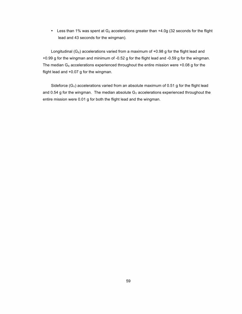
59
• Less than 1% was spent at GZ accelerations greater than +4.0g (32 seconds for the flight
lead and 43 seconds for the wingman).
Longitudinal (GX) accelerations varied from a maximum of +0.98 g for the flight lead and
+0.99 g for the wingman and minimum of -0.52 g for the flight lead and -0.59 g for the wingman.
The median GX accelerations experienced throughout the entire mission were +0.08 g for the
flight lead and +0.07 g for the wingman.
Sideforce (GY) accelerations varied from an absolute maximum of 0.51 g for the flight lead
and 0.54 g for the wingman. The median absolute GY accelerations experienced throughout the
entire mission were 0.01 g for both the flight lead and the wingman.

60
Figure A-5. Pilot Seat Normal Acceleration Expressed as g and Aircraft Altitude Versus Elapsed
Mission Time for the Close Air Support Training Mission
(hours:minutes:seconds)
Lead
(g)
(g)
(hours:minutes:seconds)
Lead
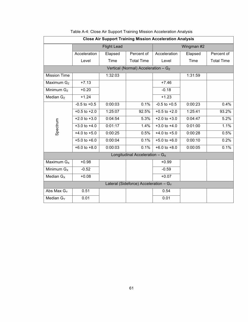
61
Table A-4: Close Air Support Training Mission Acceleration Analysis
Close Air Support Training Mission Acceleration Analysis
Flight Lead Wingman #2
Acceleration
Level
Elapsed
Time
Percent of
Total Time
Acceleration
Level
Elapsed
Time
Percent of
Total Time
Vertical (Normal) Acceleration – GZ
Mission Time 1:32:03 1:31:59
Maximum GZ +7.13 +7.46
Minimum GZ +0.20 -0.18
Median GZ +1.24 +1.23
-0.5 to +0.5 0:00:03 0.1% -0.5 to +0.5 0:00:23 0.4%
+0.5 to +2.0 1:25:07 92.5% +0.5 to +2.0 1:25:41 93.2%
+2.0 to +3.0 0:04:54 5.3% +2.0 to +3.0 0:04:47 5.2%
+3.0 to +4.0 0:01:17 1.4% +3.0 to +4.0 0:01:00 1.1%
+4.0 to +5.0 0:00:25 0.5% +4.0 to +5.0 0:00:28 0.5%
+5.0 to +6.0 0:00:04 0.1% +5.0 to +6.0 0:00:10 0.2%
Sp
ectr
um
+6.0 to +8.0 0:00:03 0.1% +6.0 to +8.0 0:00:05 0.1%
Longitudinal Acceleration – GX
Maximum GX +0.98 +0.99
Minimum GX -0.52 -0.59
Median GX +0.08 +0.07
Lateral (Sideforce) Acceleration – GY
Abs Max GY 0.51 0.54
Median GY 0.01 0.01
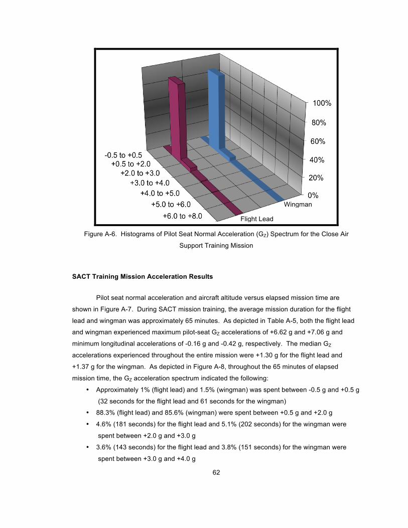
62
Figure A-6. Histograms of Pilot Seat Normal Acceleration (GZ) Spectrum for the Close Air
Support Training Mission
SACT Training Mission Acceleration Results
Pilot seat normal acceleration and aircraft altitude versus elapsed mission time are
shown in Figure A-7. During SACT mission training, the average mission duration for the flight
lead and wingman was approximately 65 minutes. As depicted in Table A-5, both the flight lead
and wingman experienced maximum pilot-seat GZ accelerations of +6.62 g and +7.06 g and
minimum longitudinal accelerations of -0.16 g and -0.42 g, respectively. The median GZ
accelerations experienced throughout the entire mission were +1.30 g for the flight lead and
+1.37 g for the wingman. As depicted in Figure A-8, throughout the 65 minutes of elapsed
mission time, the GZ acceleration spectrum indicated the following:
• Approximately 1% (flight lead) and 1.5% (wingman) was spent between -0.5 g and +0.5 g
(32 seconds for the flight lead and 61 seconds for the wingman)
• 88.3% (flight lead) and 85.6% (wingman) were spent between +0.5 g and +2.0 g
• 4.6% (181 seconds) for the flight lead and 5.1% (202 seconds) for the wingman were
spent between +2.0 g and +3.0 g
• 3.6% (143 seconds) for the flight lead and 3.8% (151 seconds) for the wingman were
spent between +3.0 g and +4.0 g
Flight Lead
Wingman

63
• 1.6% (63 seconds) for the flight lead and 2.6% (104 seconds) for wingman were spent
between +4.0 g and +5.0 g
• Approximately 1% was spent at GZ accelerations greater than +5.0g for both members of
the flight (32 seconds for the flight lead and 44 seconds for the wingman).
Longitudinal (GX) accelerations varied from a maximum of +1.14 g for the flight lead and +1.05 g
for the wingman and minimum of -0.59 g for the flight lead and -0.61 g for the wingman. The
median GX accelerations experienced throughout the entire mission were +0.10 g for the flight
lead and +0.11 g for the wingman.
Sideforce (GY) accelerations varied from an absolute maximum of 0.53 g for the flight lead and
0.42 g for the wingman. The median absolute GY accelerations experienced throughout the
entire mission were 0.01 g for both the flight lead and the wingman.

64
Figure A-7. Pilot Seat Normal Acceleration Expressed as g and Aircraft Altitude Versus Elapsed
Mission Time for the SACT Training Mission
(hours:minutes:seconds)
Lead
(g)
(g)
(hours:minutes:seconds)
Lead

65
Table A-5: SACT Training Mission Acceleration Analysis
Surface-to-Air Countertactics Training Mission Acceleration Analysis
Flight Lead Wingman #2
Acceleration
Level
Elapsed
Time
Percent of
Total Time
Acceleration
Level
Elapsed
Time
Percent of
Total Time
Vertical (Normal) Acceleration – GZ
Mission Time 1:05:58 1:05:43
Maximum GZ +6.62 +7.06
Minimum GZ -0.16 -0.42
Median GZ +1.30 +1.37
-0.5 to +0.5 0:00:32 0.8% -0.5 to +0.5 0:01:01 1.5%
+0.5 to +2.0 0:58:15 88.3% +0.5 to +2.0 0:56:16 85.6%
+2.0 to +3.0 0:03:01 4.6% +2.0 to +3.0 0:03:22 5.1%
+3.0 to +4.0 0:02:23 3.6% +3.0 to +4.0 0:02:31 3.8%
+4.0 to +5.0 0:01:03 1.6% +4.0 to +5.0 0:01:44 2.6%
+5.0 to +6.0 0:00:30 0.8% +5.0 to +6.0 0:00:33 0.8%
Sp
ectr
um
+6.0 to +8.0 0:00:02 0.1% +6.0 to +8.0 0:00:11 0.3%
Longitudinal Acceleration - GX
Maximum GX +1.14 +1.05
Minimum GX -0.59 -0.61
Median GX +0.10 +0.11
Lateral (Sideforce) Acceleration - GY
Abs Max GY 0.53 0.42
Median GY 0.01 0.01

66
Figure A-8. Histograms of Pilot Seat Normal Acceleration (GZ) Spectrum for the Surface-to-Air
Countertactics Training Mission
Flight Lead
Wingman

67
APPENDIX B: Analysis of Strike Fighter Aircrew Survey Results

68
Purpose of Survey and Tabulated Results
A Likert scale survey using rating scales 1 through 5 and consisting of 9 questions was
conducted at Naval Air Station (NAS) Lemoore, CA, from 24 February through 06 March 2009.
Seventy-eight (78) F/A-18 pilots and weapon system officers (WSOs) were surveyed from
operational squadrons and Fleet Replacement Squadron (FRS)/training squadrons. Table B-1
details survey demographics including designator, paygrade, total and F/A-18 flight hours, and
current Strike Fighter Weapons and Tactics (SFWT) level.
Table B-1: Strike Fighter Aircrew Survey Demographics
% of Responses Category
Survey Question
Detail Median Mode
%1 %2 %3 %4 %5
Designator 1 = Pilot
2 = WSO 1 1 57% 21% - - -
Paygrade
1 = O-1
2 = O-2
3 = O-3
4 = O-4
5 = O-5 & Up
3 3 0% 12% 67% 18% 4%
Total Flight
Hours
1 = ! 500, <1000
2 = !1000, <1500
3 = !1500, < 2000
4 = ! 2000. < 2500
5 = N/A
2 1 37% 29% 15% 18% -
F/A-18 Model
Hours
1 = ! 500, <1000
2 = !1000, <1500
3 = !1500, < 2000
4 = ! 2000. < 2500
5 = N/A
1 1 56% 28% 9% 6% -
Current SFWT
Level
1 = FRS Student
2 = Wingman
3 = Section Lead
4 = Division Lead
5 = N/A
4 4 6% 22% 12% 60% -
As shown in Table B-1, the majority (!51%) of surveyed aircrew were pilots with a paygrade of O-
3 (Navy Lieutenant) who had less than 1,500 total (all aircraft) flight hours and less than 1000
F/A-18 flight hours and who had attained their division lead qualification. The survey group

69
consisted of a statistically representative mixture of aircrew from the Navy’s strike fighter
community.
The survey questions elicited aircrew opinions on a variety of in-simulator and in-aircraft
sensory issues as they related to different mission subsets and tasks and pertinent results are
provided below.
Aircrew Acceptance of Existing Fixed-Base F/A-18 Flight Simulators
Survey questions 1 and 2 asked aircrew to indicate their level of agreement with the
statements that their “basic airmanship” (BA) and “overall aviation sense” (AS) are improved by
performing mission tasks in the current F/A-18 simulator. “Basic airmanship” was defined as
traditional stick and rudder skills and generally referred to the aircrew’s ability to control aircraft
state including airspeed, flight path, attitude, angle of attack, etc. “Overall aviation sense” was
defined as flight leadership, situational awareness, and decision making skills and generally
referred to higher-level cognitive processes whereby the aircrew managed “mission parameters”
vice just the aircraft’s state.
Table B-2 below summarizes aircrew level of agreement that basic airmanship and
overall aviation sense were improved by performing specific missions or tasks in the existing
fixed-base simulator. The first percentage in the columns reflects basic airmanship and the
second percentage reflects overall aviation sense.
Table B-2: Results of Aircrew Acceptance Ratings of Existing Fixed-Base F/A-18 Simulators
Strongly Agree Agree Undecided Disagree Strongly
Disagree Mission Phase / Task
BA AS BA AS BA AS BA AS BA AS
A/A Missions 9% 25% 39% 62% 18% 7% 24% 6% 10% 0%
A/G Missions 11% 13% 47% 71% 17% 6% 17% 7% 9% 3%
Formation Flight
Tasks 0% 0% 23% 29% 32% 35% 34% 26% 11% 10%
In-flight Refueling
Tasks 0% 0% 2% 15% 42% 38% 25% 22% 32% 25%
Emergency
Situations and CRM
Scenarios
44% 50% 39% 42% 13% 8% 0% 0% 5% 0%
Carrier Approach and
Landing Tasks 13% 20% 34% 55% 27% 15% 6% 5% 11% 5%

70
Aircrew Rating of Realism of Existing Fixed-Base F/A-18 Simulators
Question 3 asked aircrew to indicate their level of agreement with the statement that the
current fixed-base simulator provided a training environment representative of the actual “in-
aircraft” environment, broken into specific mission phases and tasks. As indicated in Figure B-1
and Table B-3, aircrew responses rated the quality of the existing fixed-base simulator as
acceptable, good, or very good for the majority of surveyed mission subsets, indicating a general
level of acceptance of current F/A-18 simulators for mission training. Notable exceptions to this
trend were respondent opinions of A/A Within Visual Range tasks (42% rated poor or very poor),
formation flight (56% rated poor or very poor), and in-flight refueling (64% rated poor or very
poor).
Figure B-1. Histogram of Aircrew-Rated Realism of Existing Fixed-Base F/A-18 Simulator in
Matching the Environment in the Actual Aircraft for Specific Mission Subsets

71
Table B-3: Results of Aircrew-Rated Realism of Existing Fixed-Base F/A-18 Simulator in
Matching the Environment in the Actual Aircraft for Specific Mission Subsets
MIssion Subset Very Good Good Acceptable Poor Very Poor
A/A Beyond Visual Range Tasks 31% 48% 16% 5% 0%
A/A Within Visual Range Tasks 4% 16% 38% 21% 21%
A/G Precision Weapons Delivery 23% 46% 19% 6% 6%
A/G Conventional Weapons Delivery 15% 35% 27% 23% 0%
Surface-to-Air Countertactics 13% 36% 27% 18% 7%
Formation Flight 1% 13% 29% 46% 10%
In-Flight Refueling 0% 0% 37% 37% 27%
Emergency Situations 39% 43% 18% 0% 0%
Daytime Carrier Approach & Landing 10% 33% 33% 17% 7%
Nighttime Carrier Approach & Landing 15% 44% 37% 2% 2%
Frequency of Head Movement While Performing Mission Tasks
Question 4 asked aircrew to quantify how frequently they move their head away from the
Heads-Up Display (HUD) while performing mission tasks in the aircraft. Head movement was
defined as rotating, raising, or lowering the sight axis away from the HUD so HUD symbology was
no longer within the visual field-of-regard. Survey results indicate the frequency of head
movement varies according to the type of mission task being performed, with A/A within visual
range tasks having the highest frequency of head movement (71% Very Frequently, 19%
Frequently). The majority of survey respondents also indicated they make Very Frequent or
Frequent head movements during Air-to-Air Beyond Visual Range (20%, 47%), Air-to-Ground
Precision Weapons Delivery, (17%, 35%), Air-to-Ground Conventional Weapons Delivery (34%,
42%), SACT (54%, 31%), Formation Flight (49%, 44%), In-Flight Refueling (41%, 36%), and
Daytime Carrier Approach and Landing tasks (19%, 38%). Only during Nighttime Carrier
Approach and Landing tasks did the majority of respondents indicate they Sometimes (32%),
Seldom (24%), or Never (7%) make head movements. Survey results on the frequency of head
movement during various mission phases are summarized in Figure B-2 and Table B-4.

72
Figure B-2. Histogram of Aircrew-Rated Frequency of Head Movement in the Actual Aircraft
During Specific Strike Fighter Mission Subsets
Table B-4: Results of Aircrew-Rated Frequency of Head Movement in the Actual Aircraft During
Specific Strike Fighter Mission Subsets
MIssion Subset Very
Frequently Frequently Sometimes Seldom Never
A/A Beyond Visual Range Tasks 20% 47% 24% 8% 0%
A/A Within Visual Range Tasks 71% 19% 7% 3% 0%
A/G Precision Weapons Delivery 17% 35% 39% 8% 1%
A/G Conventional Weapons Delivery 34% 42% 15% 7% 1%
Surface-to-Air Countertactics 54% 31% 6% 8% 1%
Formation Flight 49% 44% 6% 1% 0%
In-Flight Refueling 41% 36% 14% 6% 3%
Emergency Situations 21% 29% 41% 7% 1%
Daytime Carrier Approach & Landing 19% 38% 24% 15% 4%
Nighttime Carrier Approach & Landing 9% 28% 32% 24% 7%

73
Aircrew Ratings of In-Aircraft Sensory Cues
Questions 5 through 9 asked aircrew to indicate the level of importance of different types
of sensory cues (stimuli and feedback) during different mission tasks performed in the actual
aircraft. Visual stimuli and feedback (question 5) were defined as changes in external scene
including weather effects and in cockpit scene including HUD/sensor/display symbology changes.
Gravito-intertial (G) based stimuli and feedback (question 6) were defined as any of the vestibular
or somatosensory cues including positive and negative G forces, seat of the pants cues, any roll-
pitch-yaw inner ear sensations, linear acceleration, sideforces, and G-suit inflation. Physical
airframe stimuli and feedback (question 7), while in reality cues that could be considered either
gravito-intertial or aural-based, were defined as buffet, leading edge extension (LEX) vortices,
airframe vibration, and turbulence in an effort to isolate aircrew perception of aircraft state or
performance through airframe (aeromechanical) dynamic response. Aural stimuli and feedback
(question 8) were defined as engine response, environmental control system (ECS) flow
changes, ambient cockpit noise, external configuration changes (lowering/raising landing gear),
and audible aircraft performance cues such as “LEX hum” (a low altitude, high dynamic pressure
phenomenon) and vortex rumble (at high angle of attack). Cockpit environmental stimuli and
feedback (question 9) were defined as temperature, airflow, humidity, ambient pressurization,
oxygen flow, and cockpit odor.
In general, survey data indicated visual and gravito-inertial (G) based cues were the most
valued sources of sensory cues by aircrew in the management and completion of mission tasks
across the spectrum of F/A-18 strike fighter mission profiles in the actual aircraft. Survey data
also indicated aircrew assign different relative values for the different categories of sensory cues
depending upon what specific mission task or mission phase is in progress (i.e. task
dependency). Of note, cockpit environmental stimuli and feedback were rated as “Of Little
Importance” across the spectrum of mission subsets and embedded tasks, indicating aircrew do
not currently consider high-fidelity simulation of the in-cockpit environment to be important in
improving their management and completion of mission tasks.
Since the purpose of this study was to determine the suitability of a centrifuge as a
dynamic flight simulator for F/A-18 mission training, the aircrew-rated importance of gravito-
inertial cues in the aircraft are particularly pertinent and are specifically broken out in Figure B-3
and Table B-5. The mission subsets with the highest overall ratings of importance were A/A
WVR tasks (80% Very Important, 12% Important), A/G Conventional Weapons Delivery tasks
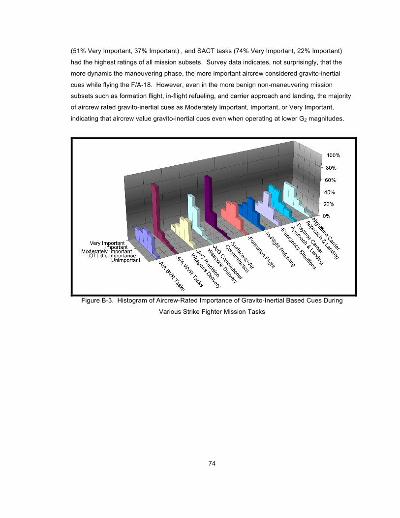
74
(51% Very Important, 37% Important) , and SACT tasks (74% Very Important, 22% Important)
had the highest ratings of all mission subsets. Survey data indicates, not surprisingly, that the
more dynamic the maneuvering phase, the more important aircrew considered gravito-inertial
cues while flying the F/A-18. However, even in the more benign non-maneuvering mission
subsets such as formation flight, in-flight refueling, and carrier approach and landing, the majority
of aircrew rated gravito-inertial cues as Moderately Important, Important, or Very Important,
indicating that aircrew value gravito-inertial cues even when operating at lower GZ magnitudes.
Figure B-3. Histogram of Aircrew-Rated Importance of Gravito-Inertial Based Cues During
Various Strike Fighter Mission Tasks

75
Table B-5: Results of Aircrew-Rated Importance of Gravito-Inertial Based Cues During Specific
Strike Fighter Mission Subsets
MIssion Subset Very
Important Important
Moderately
Important
Of Little
Importance Unimportant
A/A Beyond Visual Range Tasks 18% 22% 30% 27% 4%
A/A Within Visual Range Tasks 80% 12% 5% 3% 0%
A/G Precision Weapons Delivery 8% 16% 32% 36% 7%
A/G Conventional Weapons Delivery 51% 37% 9% 3% 0%
Surface-to-Air Countertactics 74% 22% 1% 3% 0%
Formation Flight 14% 32% 36% 17% 1%
In-Flight Refueling 14% 24% 38% 21% 4%
Emergency Situations 11% 19% 41% 22% 7%
Daytime Carrier Approach & Landing 35% 33% 17% 13% 3%
Nighttime Carrier Approach & Landing 33% 33% 18% 11% 4%

76
APPENDIX C: Review of Spatial Orientation and Human Sensory Perception

77
A Review of Spatial Orientation and the Human Sensory System
Spatial orientation (SO) is defined as the ability to correctly sense the position, motion, or
attitude of the aircraft or the pilot within the fixed coordinate system provided by the surface of the
Earth and the Earth’s gravitational vector.21
Maintaining SO and detecting aircraft acceleration
and motion involves a large number of different and complex overlapping sensory mechanisms,
namely the visual, vestibular, and somatosensory systems.20,52,53,54,55,56
Spatial disorientation
(SD) is defined as the failure to maintain SO, which in the flight environment all too frequently
proves catastrophic.57
Visual System
The visual system, which predominates all other senses,23,58
consists of photoreceptors
in the eye which respond to changes in size, shape, texture, and relative position of targets and
physical features outside of the cockpit and changes in flight instruments, cockpit displays, and
other symbolic data. The brain cognitively processes this information and as such determines
changes in aircraft state (velocity/displacement and acceleration) by indirect means. 16,20,48,59
One
important limitation of the visual system is it cannot directly sense gravito-inertial acceleration
changes; consequently, the central nervous system combines vision with other sources of
complementary sensory stimuli (including vestibular and somatosensory stimuli) in order to
produce overall sensations of velocity/displacement and acceleration.20
Vestibular System
The vestibular system within the inner ear contains mechanoreceptors that send direct
signals to the brain in response to 6 DOF head accelerations. The three roughly orthogonal
semicircular canals sense head angular accelerations similar to a rate gyro. The otoliths sense
linear accelerations and head tilt (orientation towards gravity) similar to a linear accelerometer.61
Somatosensory System
The somatosensory system contains mechanoreceptors distributed throughout the body.
Commonly known as “seat of the pants” cues, these mechanoreceptors perceive changes in
aircraft state through tactile nerve receptors (in the skin) and kinesthetic/proprioceptive nerve
78
receptors (in the joints, muscles, and tendons) distributed throughout the body and generally
complement the vestibular system. 19,61
Vestibular System Limitations
It is well known that the vestibular system provides inadequate cues both in-flight and
within the centrifuge.60,61
Within the terrestrial environment, sensory organs generally provide
concordant, complementary, and redundant sensory information to the central nervous system
which, in turn, maintains proper spatial orientation.48,62
The altered gravito-inertial environment
encountered in-flight and within the centrifuge confuses the vestibular organs and provides
conflicting or discordant information to the central nervous system, complicating the task of
maintaining spatial orientation.62
An important distinction between visual and vestibular sensory processing is that visual
information, unlike vestibular cues, does not decay over time during constant velocity motion.
Consequently, human perception of orientation and motion begin to break down in the absence of
visual input. With respect to centrifuge-based flight simulators, the most significant vestibular
system limitations reside within the semicircular canals and their inability to correctly perceive
angular acceleration, as follows:
1. There is an absence of sensation of rotation during constant velocity rotation.
2. There is an apparent sensation of rotation in the opposite direction during angular
deceleration.
3. There is a persistent sensation of rotation in the opposite direction after physical rotation
has stopped.48
The predominant SD illusions caused by the inadequacies of the semicircular canals are
somatogyral illusions, which are the false sensation of rotation, or absence of rotation caused by
misperceiving the magnitude and direction of an actual rotation.48
Comparing these limitations to the results of previous centrifuge testing, it is clear that the
semicircular canals were responsible for the following:
1. The debilitating tumbling sensation during GZ offload in the centrifuge (caused by
centrifuge tangential deceleration).
2. The Coriolis cross-coupling (CCC) illusion which stems from the sensation of angular
motion in response to an inclination or movement of the head while the head is
undergoing a passive rotation about an axis not aligned with the tilt axis.48

79
APPENDIX D: Review of the Mechanics of Aircraft Flight and Centrifuge Motion

80
Review of the Mechanics of Aircraft Flight and Centrifuge Motion
The following paragraphs review the basic mechanics of level turning aircraft flight and
centrifuge motion and were drawn from reference 62.
The following formulas govern the aircraft flight path dynamics during level turns and
serve as a starting point for understanding the differences between aircraft flight path dynamics
and the physics of centrifugal motion (the following formulas assume coordinated flight where the
resultant force used to turn the aircraft is provided entirely as a function of lift with no resultant
body axis side forces i.e. no skidded turns):
Eq. D-1a - Centripetal Acceleration:
!
acentripetal =Vtangential
2
R,
where
!
acentripetal is resultant centripetal acceleration (in ft/sec2),
!
Vtangential is the instantaneous
tangential velocity (in ft/sec) along a circle of radius
!
R (in ft).
!
acentripetal can also be expressed as
a function of angular velocity
!
" (in rad/sec) as follows:
Eq. D-1b:
!
acentripetal = R" 2;
Eq. D-2 - Load Factor:
!
n =1
cos",
where
!
n is the load factor and ! is the aircraft bank angle;
Eq. D-3 - Radius of Turn:
!
R =V2
gtan"=
V2
g n2 #1
,
where
!
R is radius of turn (in ft),
!
V is true airspeed (in ft/sec), and
!
g is Earth’s gravitational
acceleration (32.174 ft/sec2); and,
Eq. D-4 - Turn Rate: V
ng
V
g
R
V 1tan2 !
==="=#
$ !
The governing equations for the linear acceleration components of centrifugal motion are
developed below as a review. The centrifuge, when in steady-state rotation at a constant angular
velocity, will always have a resultant acceleration magnitude greater than one g as determined by
the following formula:
Eq. D-5:
!
aconstant " = g2 + acentripetal( )
2
,

81
where
!
aconstant " is the resultant acceleration vector during constant angular velocity (in ft/sec
2).
When the centrifuge increases or decreases its angular velocity (in order to change the resultant
linear acceleration to match commanded G), it generates an instantaneous acceleration
component that acts perpendicular to both the centripetal acceleration and Earth’s gravitational
acceleration as determined by the following formula:
Eq. D-6: !!Ra =tangential ,
where
!
atangential is the instantaneous tangential acceleration along the centrifugal circumference
(in ft/sec2) and !! is the angular acceleration of the centrifuge axis (in rad/sec
2). Combining Eq.
D-5 and D-6 yields a total resultant linear acceleration with a magnitude as determined by the
following formula:
Eq. D-7a:
!
aresultant = g2 + acentripetal( )
2
+ atangential( )2
or
Eq. D-7b: !! !RRga ++=22
resultant
The non-dimensional form of this resultant acceleration is expressed as follows:
Eq. D-8:
!
Gresultant
=aresultant
g,
where
!
Gresultant
is the ratio of resultant acceleration to Earth’s gravitational acceleration.
!
Gresultant
can be distributed along the three body axes of the gondola/cockpit as determined by
the following formula:
Eq. D-9:
!
Gresultant = GX"body
2+GY"body
2+GZ"body
2.
Coordinate transformation of resultant linear and angular acceleration vectors into
specific gondola/cockpit axis components can be developed via in-depth analysis of vector
products and matrix manipulation and is provided in reference 63.

82
Figure D-1. Required Bank Angle and Centrifuge Speed for a Pilot-Commanded GZ

83
VITA
Richard Michael Masica was born in Pensacola, FL, in 1973. Raised in Sarasota, FL, he
graduated from Pine View School in 1991. He was appointed to the United States Naval
Academy in Annapolis, MD, where he earned a Bachelor of Science degree in Ocean
Engineering and graduated with distinction in 1995. Following graduation, he was commissioned
an Ensign in the United States Navy and was selected for pilot training. He completed fixed-wing
flight training and was designated a Naval Aviator in 1997. After completing a three-year
operational F/A-18 tour in Japan, he attended the United States Naval Test Pilot School as a
member of Class 122, graduating in 2002. He then served over 2 years as a developmental test
pilot at NAS Patuxent River, MD. From 2005 to 2008, he again served as an operational F/A-18
pilot in Japan. He resumed developmental test pilot duties in 2008 at NAS Patuxent River, MD.
Throughout his military career, he has flown 17 different types of aircraft and logged more than
2,400 flight hours and 570 aircraft carrier arrested landings. He is a member of the Society of
Experimental Test Pilots. He is currently completing his Master of Science degree in Aviation
Systems from the University of Tennessee Space Institute, Tullahoma, TN.