Embed Size (px)
Citation preview
lable at ScienceDirect
Brain Stimulation xxx (xxxx) xxx
Contents lists avai
Brain Stimulation
journal homepage: http : / /www.journals .elsevier .com/brain-st imulat ion
Transcranial electrical stimulation nomenclature
Marom Bikson a, *, Zeinab Esmaeilpour a, Devin Adair a, Greg Kronberg a, William J. Tyler b,Andrea Antal c, d, Abhishek Datta e, Bernhard A. Sabel d, Michael A. Nitsche f, g,Colleen Loo h, Dylan Edwards i, j, Hamed Ekhtiari k, Helena Knotkova l, m, Adam J. Woods n,Benjamin M. Hampstead o, p, Bashar W. Badran q, Angel V. Peterchev r
a Department of Biomedical Engineering, The City College of the City University of New York, New York, NY, USAb Arizona State University, School of Biological and Health Systems Engineering, Tempe, AZ, USAc Department of Clinical Neurophysiology, University Medical Center Goettingen, Goettingen, Germanyd Institute of Medical Psychology, Medical Faculty, Otto-v.-Guericke University of Magdeburg, Magdeburg, Germanye Soterix Medical, New York, NY, USAf Leibniz Research Centre for Working Environment ant Human Factors, Dept. Psychology and Neurosciences, Dortmund, Germanyg University Medical Hospital Bergmannsheil, Dept. Neurology, Bochum, Germanyh School of Psychiatry & Black Dog Institute, University of New South Wales, Sydney, Australiai Moss Rehabilitation Research Institute, Philadelphia, PA, USAj Edith Cowan University, Joondalup, Australiak Laureate Institute for Brain Research, Tulsa, OK, USAl MJHS Institute for Innovation in Palliative Care, New York, NY, USAm Department of Family and Social Medicine, Albert Einstein College of Medicine, The Bronx, NY, USAn Center for Cognitive Aging and Memory, McKnight Brain Institute, Department of Clinical and Health Psychology, University of Florida, Gainesville, FL, USAo Mental Health Service, VA Ann Arbor Healthcare System, Ann Arbor, MI, USAp Neuropsychology Section, Department of Psychiatry, University of Michigan, Ann Arbor, MI, USAq Department of Psychiatry, Medical University of South Carolina, Charleston, SC, USAr Department of Psychiatry & Behavioral Sciences, Department of Biomedical Engineering, Department of Electrical & Computer Engineering, Department ofNeurosurgery, Duke University, Durham, NC, USA
a r t i c l e i n f o
Article history:Received 8 February 2019Received in revised form25 June 2019Accepted 14 July 2019Available online xxx
Keywords:Transcranial electrical stimulation (tES)TerminologyNomenclatureClassificationBrain stimulation
* Corresponding author.E-mail addresses: [email protected],
(M. Bikson), [email protected],(Z. Esmaeilpour).
https://doi.org/10.1016/j.brs.2019.07.0101935-861X/© 2019 Elsevier Inc. All rights reserved.
Please cite this article as: Bikson M et aj.brs.2019.07.010
a b s t r a c t
Transcranial electrical stimulation (tES) aims to alter brain function non-invasively by applying current toelectrodes on the scalp. Decades of research and technological advancement are associated with agrowing diversity of tES methods and the associated nomenclature for describing these methods.Whether intended to produce a specific response so the brain can be studied or lead to a more enduringchange in behavior (e.g. for treatment), the motivations for using tES have themselves influenced theevolution of nomenclature, leading to some scientific, clinical, and public confusion. This ambiguityarises from (i) the infinite parameter space available in designing tES methods of application and (ii)varied naming conventions based upon the intended effects and/or methods of application. Here, wecompile a cohesive nomenclature for contemporary tES technologies that respects existing and historicalnorms, while incorporating insight and classifications based on state-of-the-art findings. We consolidateand clarify existing terminology conventions, but do not aim to create new nomenclature. The presentednomenclature aims to balance adopting broad definitions that encourage flexibility and innovation inresearch approaches, against classification specificity that minimizes ambiguity about protocols but canhinder progress. Constructive research around tES classification, such as transcranial direct currentstimulation (tDCS), should allow some variations in protocol but also distinguish from approaches thatbear so little resemblance that their safety and efficacy should not be compared directly. The proposedframework includes terms in contemporary use across peer-reviewed publications, including relativelynew nomenclature introduced in the past decade, such as transcranial alternating current stimulation(tACS) and transcranial pulsed current stimulation (tPCS), as well as terms with long historical use suchas electroconvulsive therapy (ECT). We also define commonly used terms-of-the-trade including
[email protected]@ccny.cuny.edu
l., Transcranial electrical stimulation nomenclature, Brain Stimulation, https://doi.org/10.1016/
M. Bikson et al. / Brain Stimulation xxx (xxxx) xxx2
Please cite this article as: Bikson M et aj.brs.2019.07.010
electrode, lead, anode, and cathode, whose prior use, in varied contexts, can also be a source of confusion.This comprehensive clarification of nomenclature and associated preliminary proposals for standardizedterminology can support the development of consensus on efficacy, safety, and regulatory standards.
© 2019 Elsevier Inc. All rights reserved.
Scope and approach
The motivations for this classification document are multifold.There is a need to develop and implement standard languagedescribing transcranial electrical (or electric) stimulation (tES) de-vices and methods in order to foster the advancement of clinicaltrials, regulation, and informed medical treatment. Such aconsensus is currently lacking, reflecting a dearth of definitions foreven extensively tested and apparently straightforward techniqueslike “tDCS” or for terms like “electrode” which are ubiquitous yetnot well defined in the context of tES. A consensus on definitionshelps inform clinicians and researchers on how to control tES de-livery features relevant for safety and efficacy [1]. The historical lackof standardization in nomenclature has been identified as one po-tential impediment to the broader adoption of tES [2]. The ongoingadvancement of tES science and clinical trials would be facilitatedby consensus on protocols across groups based around a commonnomenclature. Namely, when group A describes using what theyterm technique X, and group B describes the safety and efficacy ofapproach X, it should be clear by nomenclature if they are, in fact,discussing comparable tES techniques. Similarly, regulatoryagencies and ultimately patients rely on classification to makeinformed decisions.
We present the first comprehensive analysis of contemporarytES nomenclature. Our approach is explicitly limited to the expla-nation of terminology used contemporaneously in tES publications,and thus not to suggest creation, revision, or embargo of termi-nology. Nonetheless, we provide context to terminology that maybe ambiguous or specious. The compiled classifications considerfeatures of stimulation such as indication for use, electrical wave-form, electrode montage, and treatment schedules as relevant todefine specific approaches. This document is specific to tESmethods and does not address electrical stimulation using invasiveelectrodes, transcranial magnetic stimulation (TMS), transcranialultrasound, or transcranial photonic stimulation. Terminology hereis explicit to human tES use only, as animal models may adoptvaried naming conventions. For a review of historical nomenclaturethat is uncommon in contemporary peer-reviewed publications(such as electrosleep) see Guleyupoglu et al. [2].
The outcomes of tES are not simply dependent on thenomenclature used but on the complete details of the adminis-tered dose [3], any combined task, subject state, clinical popula-tion being treated, inclusion/exclusion criteria, methods ofassessment, as well as specific medical and subject factors [4,5].Therefore, each study or clinical trial should also be evaluatedbased on integrating all these factors. For this reason, the use ofany nomenclature does not reduce the need to fully report thedose used [3] as explained below (Section 2). Classification re-mains inevitable for practical purposes (i.e. there is a naturaltendency to group and name technologies), and useful whenapplied rationally and consistently. The development of defini-tions may be guided by bridging across variations of a techniquethat theoretically inform each other. For example, two studies of“tDCS” with distinct electrode positions may result in differentoutcomes but, they may have a similarity in the general approachthat allows these studies to closely inform each other and futureefforts on “tDCS”. Conversely, a study that claims to examine
l., Transcranial electrical sti
“tDCS” but in fact, used an unrelated and incompatible protocolwill produce outcomes not relevant to the broader understandingof “tDCS”. Though each classification developed here encom-passes a range of related techniques that presumably inform eachother, even when minor variations exist there may be differencesin safety or efficacy.
There are two approaches [2] to defining classification of tES:
(i) Physical: Method of stimulation application (dose), suchas current waveform shape (e.g. direct current, alternatingcurrent) and amplitude, electrode montage, and timing ofapplication (see Section 2); and/or
(ii) Intended Use: Empirical or perceived outcome/site/targetof stimulation, which can span several non-exclusivecategories:
mulatio
a. Hypothesized mechanism of action on the body (e.g.“excitability modulation”, “network synchronization”,“functional connectivity” changes); and/or
b. Hypothesized anatomical target (e.g. “transorbital”,“deep”), which reflects the region of interest rather thanthe (only) region influenced; and/or
c. Expected outcomes/medical indication (e.g. neuro-rehabilitation)dthis could be the primary outcome ofinterest in a given clinical trial, rather than the main/onlyoutcome.
While a definition based strictly on physical method of appli-cation (e.g. DOSE as defined by Ref. [3]) reduces ambiguity), inpractice most classifications of tES imply, to some degree, the ex-pected mechanisms of action, nominal anatomical target, outcomeof interest, or a combination of these. This is the case evenwhen thetechnique name seems to derive purely from a physical dose defi-nition. For example, tACS indicates sinusoidal rather than anybiphasic ac waveform, and tACS further suggests low intensities.Thus, use of tACS implies a more restricted parameter space thanjust “ac” which in engineering may be any current amplitude andcan refer to non-sinusoidal waveforms as well. Most tES classifi-cations adopt an approach combining parameters (dose), intendedmechanism, target, indication and/or outcome. In some cases, eventhe components of the stimulation device involve intent in theirnaming, such as the terms “active” electrode (the electrode, whichis presumed to produce the intended outcome) and “reference”electrode (the electrode, which is presumed to not directly producethe intended outcome).
Our approach defines terms as used in the current scientificliterature (see glossary Table 1); we avoid new terminology.Nonetheless, inconsistent and ambiguous use of terms required usto constrain or refine classification (rather than try to developdefinitions inclusive of all historical uses of a given term). Indefining classifications for tES, there is a compromise betweenbroad classification (which allows for needed dose exploration andoptimization) and more restrictive classification that creates theleast possible ambiguity. In general, we adopted broader defini-tions, even including dose ranges yet to be tested, while alsodescribing “conventional” practices that are limited to the commoncurrent uses. This nomenclature guidance is intended neither as asafety nor an efficacy review. The inclusion or exclusion of a
n nomenclature, Brain Stimulation, https://doi.org/10.1016/
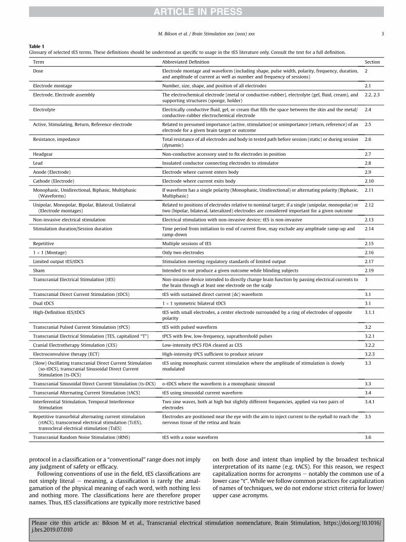
Table 1Glossary of selected tES terms. These definitions should be understood as specific to usage in the tES literature only. Consult the text for a full definition.
Term Abbreviated Definition Section
Dose Electrode montage and waveform (including shape, pulse width, polarity, frequency, duration,and amplitude of current as well as number and frequency of sessions)
2
Electrode montage Number, size, shape, and position of all electrodes 2.1
Electrode, Electrode assembly The electrochemical electrode (metal or conductive-rubber), electrolyte (gel, fluid, cream), andsupporting structures (sponge, holder)
2.2, 2.3
Electrolyte Electrically conductive fluid, gel, or cream that fills the space between the skin and the metal/conductive-rubber electrochemical electrode
2.4
Active, Stimulating, Return, Reference electrode Related to presumed importance (active, stimulation) or unimportance (return, reference) of anelectrode for a given brain target or outcome
2.5
Resistance, impedance Total resistance of all electrodes and body in tested path before session (static) or during session(dynamic)
2.6
Headgear Non-conductive accessory used to fix electrodes in position 2.7
Lead Insulated conductor connecting electrodes to stimulator 2.8
Anode (Electrode) Electrode where current enters body 2.9
Cathode (Electrode) Electrode where current exits body 2.10
Monophasic, Unidirectional, Biphasic, Multiphasic(Waveforms)
If waveform has a single polarity (Monophasic, Unidirectional) or alternating polarity (Biphasic,Multiphasic)
2.11
Unipolar, Monopolar, Bipolar, Bilateral, Unilateral(Electrode montages)
Related to positions of electrodes relative to nominal target; if a single (unipolar, monopolar) ortwo (bipolar, bilateral, lateralized) electrodes are considered important for a given outcome
2.12
Non-invasive electrical stimulation Electrical stimulation with non-invasive device; tES is non-invasive 2.13
Stimulation duration/Session duration Time period from initiation to end of current flow, may exclude any amplitude ramp-up andramp-down
2.14
Repetitive Multiple sessions of tES 2.15
1� 1 (Montage) Only two electrodes 2.16
Limited output tES/tDCS Stimulation meeting regulatory standards of limited output 2.17
Sham Intended to not produce a given outcome while blinding subjects 2.19
Transcranial Electrical Stimulation (tES) Non-invasive device intended to directly change brain function by passing electrical currents tothe brain through at least one electrode on the scalp
3
Transcranial Direct Current Stimulation (tDCS) tES with sustained direct current (dc) waveform 3.1
Dual tDCS 1� 1 symmetric bilateral tDCS 3.1
High-Definition tES/tDCS tES with small electrodes, a center electrode surrounded by a ring of electrodes of oppositepolarity
3.1.1
Transcranial Pulsed Current Stimulation (tPCS) tES with pulsed waveform 3.2
Transcranial Electrical Stimulation (TES, capitalized “T”) tPCS with few, low-frequency, suprathreshold pulses 3.2.1
Cranial Electrotherapy Stimulation (CES) Low-intensity tPCS FDA cleared as CES 3.2.2
Electroconvulsive therapy (ECT) High-intensity tPCS sufficient to produce seizure 3.2.3
(Slow) Oscillating transcranial Direct Current Stimulation(so-tDCS), transcranial Sinusoidal Direct CurrentStimulation (ts-DCS)
tES using monophasic current stimulation where the amplitude of stimulation is slowlymodulated
3.3
Transcranial Sinusoidal Direct Current Stimulation (ts-DCS) o-tDCS where the waveform is a monophasic sinusoid 3.3
Transcranial Alternating Current Stimulation (tACS) tES using sinusoidal current waveform 3.4
Interferential Stimulation, Temporal InterferenceStimulation
Two sine waves, both at high but slightly different frequencies, applied via two pairs ofelectrodes
3.4.1
Repetitive transorbital alternating current stimulation(rtACS), transcorneal electrical stimulation (TcES),transscleral electrical stimulation (TsES)
Electrodes are positioned near the eye with the aim to inject current to the eyeball to reach thenervous tissue of the retina and brain
3.5
Transcranial Random Noise Stimulation (tRNS) tES with a noise waveform 3.6
M. Bikson et al. / Brain Stimulation xxx (xxxx) xxx 3
protocol in a classification or a “conventional” range does not implyany judgment of safety or efficacy.
Following conventions of use in the field, tES classifications arenot simply literal e meaning, a classification is rarely the amal-gamation of the physical meaning of each word, with nothing lessand nothing more. The classifications here are therefore propernames. Thus, tES classifications are typically more restrictive based
Please cite this article as: Bikson M et al., Transcranial electrical stij.brs.2019.07.010
on both dose and intent than implied by the broadest technicalinterpretation of its name (e.g. tACS). For this reason, we respectcapitalization norms for acronyms e notably the common use of alower case “t”. While we follow common practices for capitalizationof names of techniques, we do not endorse strict criteria for lower/upper case acronyms.
mulation nomenclature, Brain Stimulation, https://doi.org/10.1016/
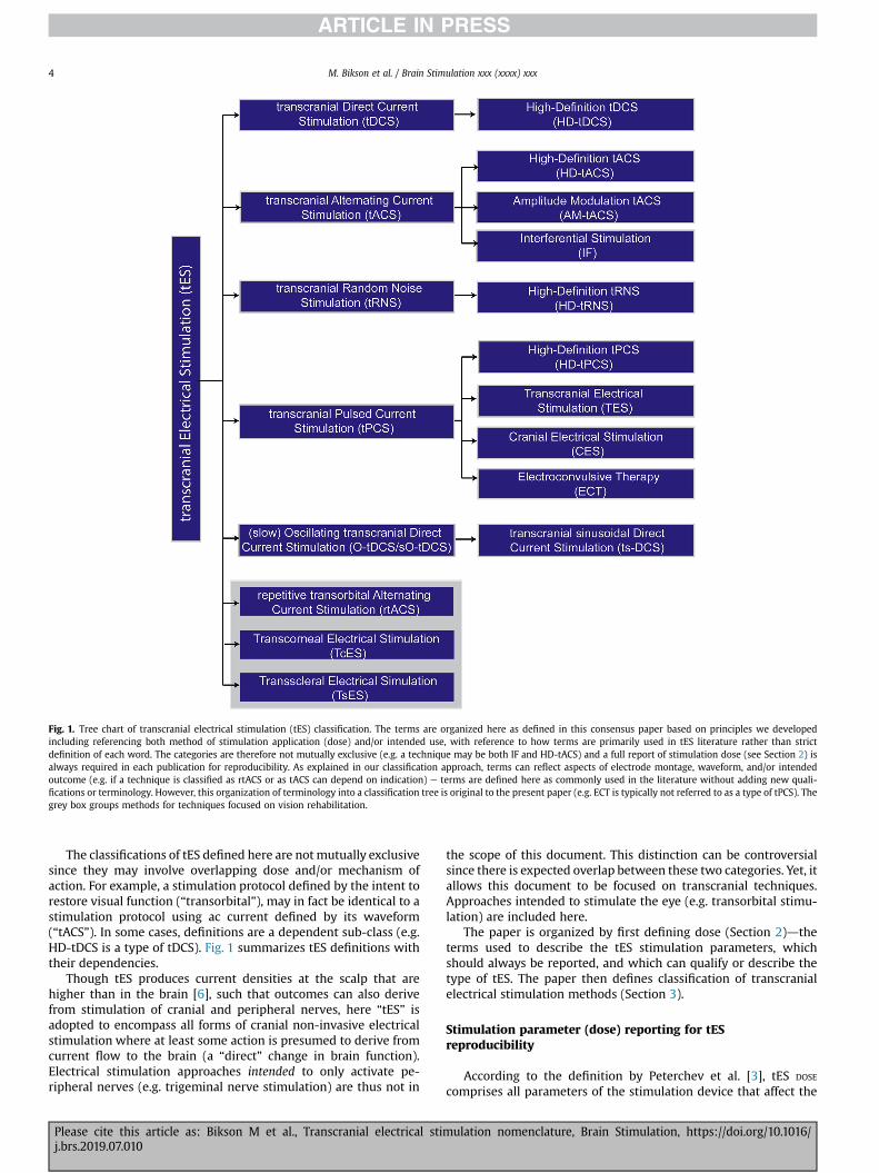
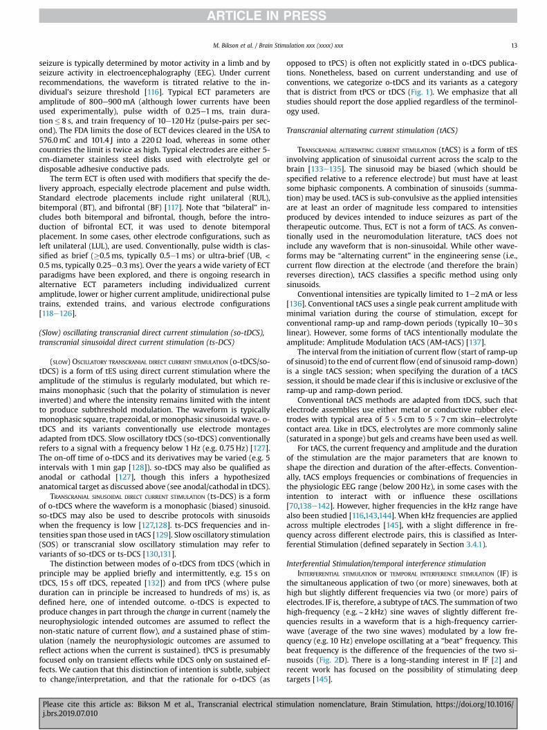
Fig. 1. Tree chart of transcranial electrical stimulation (tES) classification. The terms are organized here as defined in this consensus paper based on principles we developedincluding referencing both method of stimulation application (dose) and/or intended use, with reference to how terms are primarily used in tES literature rather than strictdefinition of each word. The categories are therefore not mutually exclusive (e.g. a technique may be both IF and HD-tACS) and a full report of stimulation dose (see Section 2) isalways required in each publication for reproducibility. As explained in our classification approach, terms can reflect aspects of electrode montage, waveform, and/or intendedoutcome (e.g. if a technique is classified as rtACS or as tACS can depend on indication) e terms are defined here as commonly used in the literature without adding new quali-fications or terminology. However, this organization of terminology into a classification tree is original to the present paper (e.g. ECT is typically not referred to as a type of tPCS). Thegrey box groups methods for techniques focused on vision rehabilitation.
M. Bikson et al. / Brain Stimulation xxx (xxxx) xxx4
The classifications of tES defined here are notmutually exclusivesince they may involve overlapping dose and/or mechanism ofaction. For example, a stimulation protocol defined by the intent torestore visual function (“transorbital”), may in fact be identical to astimulation protocol using ac current defined by its waveform(“tACS”). In some cases, definitions are a dependent sub-class (e.g.HD-tDCS is a type of tDCS). Fig. 1 summarizes tES definitions withtheir dependencies.
Though tES produces current densities at the scalp that arehigher than in the brain [6], such that outcomes can also derivefrom stimulation of cranial and peripheral nerves, here “tES” isadopted to encompass all forms of cranial non-invasive electricalstimulation where at least some action is presumed to derive fromcurrent flow to the brain (a “direct” change in brain function).Electrical stimulation approaches intended to only activate pe-ripheral nerves (e.g. trigeminal nerve stimulation) are thus not in
Please cite this article as: Bikson M et al., Transcranial electrical stij.brs.2019.07.010
the scope of this document. This distinction can be controversialsince there is expected overlap between these two categories. Yet, itallows this document to be focused on transcranial techniques.Approaches intended to stimulate the eye (e.g. transorbital stimu-lation) are included here.
The paper is organized by first defining dose (Section 2)dtheterms used to describe the tES stimulation parameters, whichshould always be reported, and which can qualify or describe thetype of tES. The paper then defines classification of transcranialelectrical stimulation methods (Section 3).
Stimulation parameter (dose) reporting for tESreproducibility
According to the definition by Peterchev et al. [3], tES DOSE
comprises all parameters of the stimulation device that affect the
mulation nomenclature, Brain Stimulation, https://doi.org/10.1016/
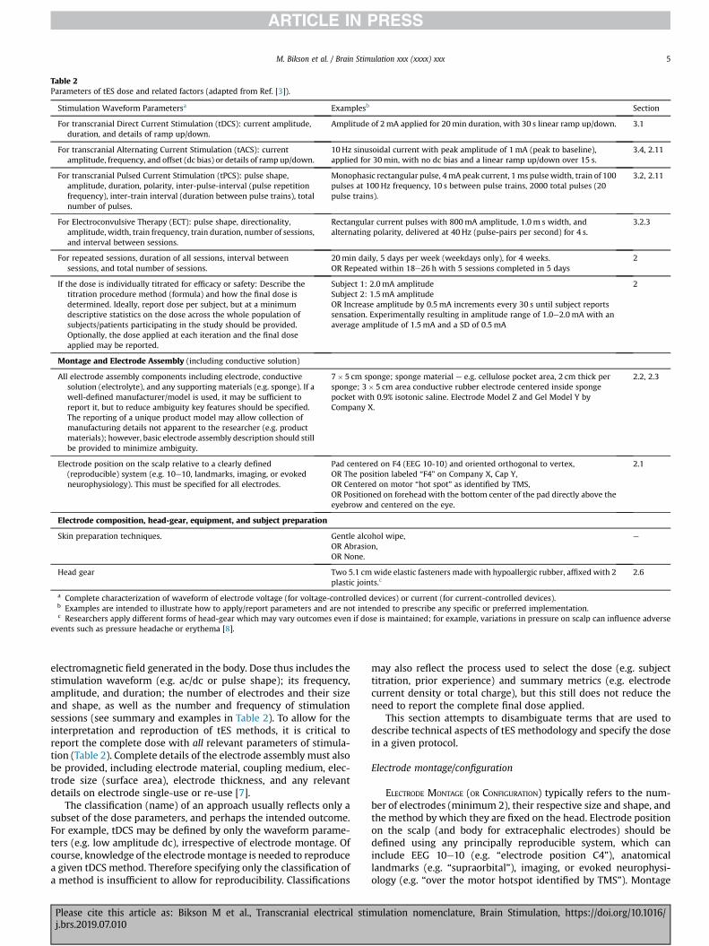
Table 2Parameters of tES dose and related factors (adapted from Ref. [3]).
Stimulation Waveform Parametersa Examplesb Section
For transcranial Direct Current Stimulation (tDCS): current amplitude,duration, and details of ramp up/down.
Amplitude of 2mA applied for 20min duration, with 30 s linear ramp up/down. 3.1
For transcranial Alternating Current Stimulation (tACS): currentamplitude, frequency, and offset (dc bias) or details of ramp up/down.
10 Hz sinusoidal current with peak amplitude of 1mA (peak to baseline),applied for 30min, with no dc bias and a linear ramp up/down over 15 s.
3.4, 2.11
For transcranial Pulsed Current Stimulation (tPCS): pulse shape,amplitude, duration, polarity, inter-pulse-interval (pulse repetitionfrequency), inter-train interval (duration between pulse trains), totalnumber of pulses.
Monophasic rectangular pulse, 4mA peak current, 1ms pulsewidth, train of 100pulses at 100 Hz frequency, 10 s between pulse trains, 2000 total pulses (20pulse trains).
3.2, 2.11
For Electroconvulsive Therapy (ECT): pulse shape, directionality,amplitude, width, train frequency, train duration, number of sessions,and interval between sessions.
Rectangular current pulses with 800mA amplitude, 1.0m s width, andalternating polarity, delivered at 40 Hz (pulse-pairs per second) for 4 s.
3.2.3
For repeated sessions, duration of all sessions, interval betweensessions, and total number of sessions.
20min daily, 5 days per week (weekdays only), for 4 weeks.OR Repeated within 18e26 h with 5 sessions completed in 5 days
2
If the dose is individually titrated for efficacy or safety: Describe thetitration procedure method (formula) and how the final dose isdetermined. Ideally, report dose per subject, but at a minimumdescriptive statistics on the dose across the whole population ofsubjects/patients participating in the study should be provided.Optionally, the dose applied at each iteration and the final doseapplied may be reported.
Subject 1: 2.0mA amplitudeSubject 2: 1.5mA amplitudeOR Increase amplitude by 0.5mA increments every 30 s until subject reportssensation. Experimentally resulting in amplitude range of 1.0e2.0mA with anaverage amplitude of 1.5mA and a SD of 0.5mA
2
Montage and Electrode Assembly (including conductive solution)
All electrode assembly components including electrode, conductivesolution (electrolyte), and any supporting materials (e.g. sponge). If awell-defined manufacturer/model is used, it may be sufficient toreport it, but to reduce ambiguity key features should be specified.The reporting of a unique product model may allow collection ofmanufacturing details not apparent to the researcher (e.g. productmaterials); however, basic electrode assembly description should stillbe provided to minimize ambiguity.
7� 5 cm sponge; sponge material e e.g. cellulose pocket area, 2 cm thick persponge; 3� 5 cm area conductive rubber electrode centered inside spongepocket with 0.9% isotonic saline. Electrode Model Z and Gel Model Y byCompany X.
2.2, 2.3
Electrode position on the scalp relative to a clearly defined(reproducible) system (e.g. 10e10, landmarks, imaging, or evokedneurophysiology). This must be specified for all electrodes.
Pad centered on F4 (EEG 10-10) and oriented orthogonal to vertex,OR The position labeled “F4” on Company X, Cap Y,OR Centered on motor “hot spot” as identified by TMS,OR Positioned on forehead with the bottom center of the pad directly above theeyebrow and centered on the eye.
2.1
Electrode composition, head-gear, equipment, and subject preparation
Skin preparation techniques. Gentle alcohol wipe,OR Abrasion,OR None.
e
Head gear Two 5.1 cmwide elastic fasteners made with hypoallergic rubber, affixed with 2plastic joints.c
2.6
a Complete characterization of waveform of electrode voltage (for voltage-controlled devices) or current (for current-controlled devices).b Examples are intended to illustrate how to apply/report parameters and are not intended to prescribe any specific or preferred implementation.c Researchers apply different forms of head-gear which may vary outcomes even if dose is maintained; for example, variations in pressure on scalp can influence adverse
events such as pressure headache or erythema [8].
M. Bikson et al. / Brain Stimulation xxx (xxxx) xxx 5
electromagnetic field generated in the body. Dose thus includes thestimulation waveform (e.g. ac/dc or pulse shape); its frequency,amplitude, and duration; the number of electrodes and their sizeand shape, as well as the number and frequency of stimulationsessions (see summary and examples in Table 2). To allow for theinterpretation and reproduction of tES methods, it is critical toreport the complete dose with all relevant parameters of stimula-tion (Table 2). Complete details of the electrode assembly must alsobe provided, including electrode material, coupling medium, elec-trode size (surface area), electrode thickness, and any relevantdetails on electrode single-use or re-use [7].
The classification (name) of an approach usually reflects only asubset of the dose parameters, and perhaps the intended outcome.For example, tDCS may be defined by only the waveform parame-ters (e.g. low amplitude dc), irrespective of electrode montage. Ofcourse, knowledge of the electrodemontage is needed to reproducea given tDCS method. Therefore specifying only the classification ofa method is insufficient to allow for reproducibility. Classifications
Please cite this article as: Bikson M et al., Transcranial electrical stij.brs.2019.07.010
may also reflect the process used to select the dose (e.g. subjecttitration, prior experience) and summary metrics (e.g. electrodecurrent density or total charge), but this still does not reduce theneed to report the complete final dose applied.
This section attempts to disambiguate terms that are used todescribe technical aspects of tES methodology and specify the dosein a given protocol.
Electrode montage/configuration
ELECTRODE MONTAGE (OR CONFIGURATION) typically refers to the num-ber of electrodes (minimum 2), their respective size and shape, andthe method by which they are fixed on the head. Electrode positionon the scalp (and body for extracephalic electrodes) should bedefined using any principally reproducible system, which caninclude EEG 10e10 (e.g. “electrode position C4”), anatomicallandmarks (e.g. “supraorbital”), imaging, or evoked neurophysi-ology (e.g. “over the motor hotspot identified by TMS”). Montage
mulation nomenclature, Brain Stimulation, https://doi.org/10.1016/
M. Bikson et al. / Brain Stimulation xxx (xxxx) xxx6
should be specified for all electrodes. As defined here, electrodemontage, includes, therefore all aspects of dose except waveform.However, in some publications electrode montage may be usedinterchangeably with dose. This is discouraged to the extent that itleads to ambiguity between dose, which includes waveform, andmontage, which does not.
Electrode assembly
The ELECTRODE ASSEMBLY refers to all components that carry currentbetween the connector-end of device lead wire and the scalp suchas metal electrode, conducting rubber electrode, electrolyte,sponge, as well as materials used to shape these components orotherwise direct current flow (casing, sponge, rivets). The headgearused to position the electrodes on the body or scalp is typicallydistinct from the electrode assembly (e.g. non-conductive head-strap), but in some designs the components of the electrode as-sembly may be embedded into the headgear. In tES the term“electrode” (see Section 2.3) is commonly used to designate theentire electrode assembly.
Electrode
PHYSICAL ELECTRODE (not a term standard in the tES literature) refersto the material (or surface) where charge carried by electrons isconverted to charge carried by ions. For tES, this is limited to thesurface of the metal and/or conductive rubber in contact with theelectrolyte (such saline or gel). In tES, however, ELECTRODE is used torefer to the entire electrode assembly (see definition in Section 2.2).In electrochemistry, electrode refers only to the interface of the“physical electrode” metal/conductive-rubber (or other electroncarriers) with saline/gel (or another electrolyte). In some forms oftES, especially tDCS, this physical electrode does not touch the skinfor safety reasons, whereas in other forms of tES, such as ECT, thephysical electrode may be pressed directly against the scalpdepending on the device type. Reproducibility can be limited byambiguities in referencing either the whole electrode assembly orjust the physical electrode. For example, it should be made clear ifthe provided dimensions (e.g. 5� 5 cm) refer to just the physicalelectrode (e.g. the conductive rubber or metal surface contactingthe ionic medium) or to the overall electrode assembly (e.g. gelsurface of sponges contacting the skin).
It is customary to discuss montage (placement) and waveformapplied with respect to a specific electrode. For example, delivery of1mA to an electrode implies delivery of 1mA through the electrodeassembly and the electrode interface. Use of an electrode as an“anode” is physically correct and implies the electrode assemblyfunctions as an anode. In most forms of tES, electrode sizeconventionally refers to the overall electrode-assembly surface areain contact with skin, unless otherwise indicated (see Electrolyte).Therefore, the convention in the literature of calling the entireelectrode-assembly the “electrode” is manageable provided: (i) thedistinction between the physical electrode and electrode assemblyis clear; and (ii) overall details of the electrode assembly, includingthe electrode design, are explicit.
Electrolyte
The ELECTROLYTE is the component of the electrode assemblywhere charge is carried by ions. It is in contact with both thephysical electrode and the skin and also completes a circuit ofelectrical current flow. The electrolyte may be saline or anothersalt-containing solution [9], hydrogel, or fatty (oily) cream. Toprevent spread, fluid electrolytes may be suspended in a porousmaterial like a sponge and/or contained by a holding vessel like a
Please cite this article as: Bikson M et al., Transcranial electrical stij.brs.2019.07.010
cup. In some cases, such aswith fatty creams, the electrolytemay besufficiently viscous not to require a suspension. In some applica-tion, such as tDCS, the electrolyte is a barrier between the physicalelectrode and the skin such that the minimum distance betweenthe physical electrode and the skin is the electrolyte thickness. Thisminimum distance may be determined by a non-conductive (e.g.plastic) separator or holder, by sponge thickness, or by the thick-ness of the paste. When the physical electrode is in direct contactwith the skin, as in ECT, the electrolyte fills in any air gaps betweenelectrode and skin surfaces.
Some studies have used water to saturate tES electrodes; in suchcases the water contains ions and/or absorbs them from the skin.“Salt-free” gels and creams have also been evaluated for tES [10],but often have other chemical substitutes for supporting chargetransfer.
The total surface area where the physical electrode and/orelectrolyte interface with the skin is typically referred to in tES asthe electrode size (e.g. “5� 5 cm2 electrode” or “5 cm diameter diskelectrode”). The surface area where the electrolyte interfaces withthe physical electrode is typically different than where the elec-trolyte interfaces with the skin area.
“Active”/“stimulating”, “return”/“reference” (electrode)
The terms RETURN or REFERENCE electrodes have been typically usedto describe an electrode that is presumed to be less relevant to theintervention outcomes of interest. For example, an electrode may begiven this designation if it is not in proximity to brain regions ofinterest for a particular intended use. Similarly, the physiologicalactivity of electrodes can be reduced for example by increasing theelectrode size or using a ring of electrodes, which reduces the cur-rent density in the vicinity of these electrodes [11,12]. However, allelectrodes are functional in the engineering sense if they are used tocarry current. Even if they are assumed to be unimportant to thehypothesis being tested, the configuration and polarity of theseelectrodes will affect current distribution in the brain and must,therefore, be explicitly reported. This applies to extra-cephalicelectrodes as well, since they also affect the current flow in thebrain [13,14]. For voltage-controlled stimulation [15], the term“reference” may also be used to define polarity in an engineeringsense (e.g. “5 V relative to the reference electrode”). In all thesescenarios, the configuration and position of the “return” electrodecan influence current flow near/under the “active” electrode.
Analogously, the terms ACTIVE, STIMULATING, or TARGET ELECTRODE havebeen typically used to refer to the electrode presumed to bephysiologically active in regard to the primary interventionoutcome e or more specifically that the physiological or behavioraloutcome of interest is due to current passing through these elec-trodes. In stimulation systems with multiple electrodes (three ormore), there can be the ability to use some electrodes and notothers for stimulation; for example, in a three-electrode system topassþ1mA at one electrode,�1mA at another electrode, and 0mA(no current) at the third electrode. Electrodes without current areunused and, in this context, referred to as INACTIVE, any electrodewith non-zero current considered ACTIVE. Such a situation is typicalfor implanted systems, where extra electrodes provide for pro-gramming flexibility. For those tES systems where electrodes areapplied individually (one at a time), the placement of unused(inactive) electrodes would be generally unnecessary. Multi-channel (HD) tES systems that include head-gear embedded withan electrode array may operate using a selective sub-set of elec-trodes for stimulation (active electrode) with the remainder inac-tive [16e18], but this use of terminology is rare in the tES literature.
“Active”, “stimulating”, “target”, “return”, and “reference” arethus terms that relate to the “intent” of stimulation, or (less
mulation nomenclature, Brain Stimulation, https://doi.org/10.1016/
M. Bikson et al. / Brain Stimulation xxx (xxxx) xxx 7
commonly) used casually with no specific functional implication. Ifthese terms are used it should be with (i) the recognition thatdespite intent, the physiological actions of stimulation are exertedby a complex distribution of electrical current flow between thetwo (or more) electrodes, and (ii) the complete documentation ofthe stimulation dose (e.g. it is never appropriate to omit details ofreference electrode size, placement, and materials). Generally, us-ing objective engineering terminology such as “anode” and “cath-ode” (see definitions in Sections 2.8 and 2.9) can reduce theimplication of intent or assumed physiological role of electrodes.
Resistance and impedance
Resistance is a ubiquitous term in tES and considered importantin pre-testing and monitoring of stimulation. When tES is current-controlled, the voltage output of the stimulator (between twoelectrodes or between an electrode and a reference) is adjusted tomaintain a controlled current. In the context of tES, the term RESIS-
TANCE usually refers to this voltage at the output of the devicedivided by the applied current, per Ohm's law. To measure resis-tance prior to stimulation, the stimulator applies a small test cur-rent and the resulting voltage is recorded. The resistance is thencalculated through Ohm's law by dividing the voltage by the testcurrent.
The resistance measured is the sum of the resistance of theelectrodes [19] and the body, including the skin and theskineelectrode interface. A high resistance may, therefore, reflect ahigh resistance of one (or more) electrodes, or the skin contact. Anatypically high resistance can be a sign of a setup problem such aspoor electrode contact or insufficient electrolyte. Therefore, whenresistance is tested before stimulation, it helps the operator toidentify suboptimal set-up and take corrective actions that couldlower the resistance. Similarly, during stimulation, an atypicallyhigh resistance may indicate non-ideal conditions at the electrodeor skin. However, once stimulation begins there are fewer optionsby the operator to correct the setup, and in some cases, stimulationis aborted.
A subtle point is that resistance can change with the appliedcurrent and waveform. For this reason, the resistance measuredbefore stimulation by the low-test current (which can be referred toas STATIC impedance) would be different than the resistancemeasured using application-specific currents during stimulation(which can be referred to as DYNAMIC impedance). Nonetheless, thetest resistance before stimulation is considered a meaningful pre-dictor of resistance during stimulationda suboptimal set-up willusually result in atypical resistance already in the pre-stimulationtest period. Still, because static resistance and dynamic resistancevary, and also conditions may change over time during a session,resistance during stimulation is monitored.
What qualifies as a “high” resistance is application-specificed. Itis important to emphasize that a relatively low resistance is not aguarantee of optimal setup. Rather it is incumbent on the operatorto employ best practices in electrode preparation and setup, andsubject and device monitoring [20], with resistance measurementserving as a secondary marker. In addition to potentially indicatingnon-optimal electrodeeskin contact, a high resistance would in-crease the stimulator output voltage required to provide a givencurrent. If the required output voltage is too high, it may exceed themaximum (compliance) voltage of the tES device, whichmay resultin current reduction or the device aborting stimulation [21].
As a technical note, the electrode and tissue are never simply“resistive” (either before or during stimulation). For example, thecalculated “resistance” depends on the strength of the current,meaning that the resistance is nonlinear [22]. The term “imped-ance” refers to the broader relation between the applied current
Please cite this article as: Bikson M et al., Transcranial electrical stij.brs.2019.07.010
and the voltage needed to maintain this current flow. The imped-ance also includes frequency-specific responses (e.g. the responseto sinusoids of varied frequency or brief pulses). Moreover, elec-trodes, tissues, and their interfaces have complex nonlinear im-pedances that may vary over time (i.e. are time-variant) [23e26].However, “resistance” and “impedance” are often used inter-changeably and nonspecifically in the tES literature, typicallyrelying on how a given tES device tests and reports values. Whileacross tES devices, resistance/impedance is typically calculated indevices by dividing the peak voltage measured by the peak currentapplied, the static resistance (or impedance) reported by twodifferent tES devices on the same electrode set-up may differbecause tES devices do not use a consistent test currentddifferenttES devices use various test current intensities or waveforms (e.g.dc vs brief pulses).
Headgear
All components that are used to position and hold the electrodeassembly to the body are part of the HEADGEAR. As defined here, theheadgear is primarily fabricated using non-conductive components(e.g. elastic or fabric). However, some conductive components likethe electrode assembly and/or the lead wires may be (partially)integrated into the headgear. The headgear serves to hold thesecomponents in place, position them relative to the scalp, and/orfacilitate set-up. In some applications, the electrodes are held inplace by the operator, such as the plastic handles that support steel-disk electrodes in ECT. In such cases, there is no headgear but de-tails of how electrodes are supported should be provided.
Lead
The LEAD is a wire used to connect the electrode to the stimulatoroutput. The wire is insulated except at the device (proximal) andelectrode (distal) terminal. The distal terminal is typically con-nected to the electrode in a manner such that the material of thelead wire does not contact the electrolyte or skin. If the lead con-tacts the electrolyte, then the lead terminal becomes an electrode.
Anode/anode electrode/anode electrode assembly
At the ANODE, positive current enters the body. For two-electrodesystems the anode has a positive voltage relative to the cathode. If acurrent-controlled waveform applied to any given electrodechanges polarity (for example if a biphasic sinusoid is applied suchthat the current direction to any given electrode changes direction),then the electrode may technically not be an anode for the entirewaveform of stimulation. Thus, for tPCS biphasic pulses, the po-larity of a specific (e.g. the initial) phase of the pulse should bespecified (e.g. “anodic-first”). For this reason, “anode” is not used inbiphasic stimulation. Rather, if the waveform is symmetric, polaritymay be ignored (e.g. sinusoid with zero offset) as the electrodes areinterchangeable in this sense. If the waveform is asymmetric, thepolarity of the waveform should be specified relative to specificelectrodes (e.g. 5mA square pulse applied from electrode 1). IntDCS, electrode polarity does not change by definition. The separateterms of “anodal” and “anodic phase” are used to describe the hy-pothesized mechanism of stimulation or pulsed waveform detail,respectively (See Section 2.11).
Cathode/cathode electrode/cathode electrode assembly
At the CATHODE, positive current exits the body. See also polaritynotes in Anode definition above. The separate terms of “cathodal”and “cathodic phase” are used to describe the hypothesized
mulation nomenclature, Brain Stimulation, https://doi.org/10.1016/
M. Bikson et al. / Brain Stimulation xxx (xxxx) xxx8
mechanism of stimulation or pulsed waveform, respectively (SeeSection 2.11).
Monophasic, unidirectional, biphasic, multiphasic (waveform)
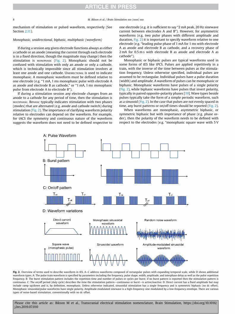
If during a session any given electrode functions always as eithera cathode or an anode (meaning the current through each electrodeis in a fixed direction, though the magnitude may change) then thestimulation is MONOPHASIC (Fig. 2). Monophasic should not beconfused with stimulation with only an anode or only a cathode,which is technically impossible since all stimulation involves atleast one anode and one cathode. UNIDIRECTIONAL is used to indicatemonophasic. A monophasic waveform must be defined relative toone electrode (e.g. “1mA, 1ms monophasic pulse with electrode Aas anode and electrode B as cathode,” or “1mA, 1ms monophasicpulse from electrode A to electrode B”).
If during a stimulation session any electrode changes from ananode to a cathode for any period of time, then the stimulation isMULTIPHASIC. BIPHASIC typically indicates stimulation with two phases(modes) that are alternated (e.g. anode and cathode switch) duringstimulation (Fig. 2). The importance of clarifying waveform polarityrelative to electrodes can depend on the waveform. For example,for tACS the symmetry and continuous nature of the waveformsuggests the waveform does not need to be defined respective to
Fig. 2. Overview of terms used to describe waveform in tES. AeC address waveforms comwaveform types. A: The pulse train waveform is specified by parameters including the frequefrequency. B: The burst stimulation pattern includes the repetition time and number of pucontinuous. C: The on/off period (duty cycle) describes the time the stimulation patterndcoinclude ramp up/down and is, by definition, monophasic. Unless otherwise indicated, sinMonophasic sinusoidal/pulse waveforms have single polarity. Amplitude-modulated sinewatypes of noise-based stimulation, conventionally with no dc offset.
Please cite this article as: Bikson M et al., Transcranial electrical stij.brs.2019.07.010
one electrode (e.g. it is sufficient to say “2mA peak, 20 Hz sinewavecurrent between electrodes A and B”). However, for asymmetricwaveforms (e.g. two pulse phases with different amplitude andduration, Fig. 2) it is important to specify waveform relative to oneelectrode (e.g. “leading pulse phase of 1mA for 1ms with electrodeA as anode and electrode B as cathode, and a recovery phase of2mA for 0.5m s with electrode B as anode and electrode A ascathode”).
Monophasic or biphasic pulses are typical waveforms used insome forms of tES like tPCS. Pulses are applied repetitively in atrain, with the inverse of the time between pulses as the stimula-tion frequency. Unless otherwise specified, individual pulses areassumed to be rectangular. Individual pulses have a pulse duration(width) and amplitude. Awaveform of pulses can bemonophasic orbiphasic. Monophasic waveforms have pulses of a single polarity(Fig. 2), while biphasic waveforms have pulses that invert polarity,typically in paired opposite-polarity phases [19]. Wave types besidepulses typically take the form of a simple periodic waveform, suchas a sinusoid (Fig. 2). In the case that pulses are not evenly spaced intime, any burst patterns or on/off times should be reported (Fig. 2).
When waveforms are monophasic, asymmetric biphasic, orsymmetric biphasic but with importance of phase (e.g. phase or-der), then the polarity of the waveform needs to be defined withrespect to the electrodes (e.g. “monophasic square wave with 5 V
posed of rectangular pulses with expanding temporal scale, while D shows additionalncy, pulse shape, width, amplitude, and interphase delay as well as the pulse repetitionlses or cycles per burst; if no burst pattern is reported then the stimulation pattern isntinuous or burstdis active/inactive. D: Direct current has a fixed amplitude but mayusoidal stimulation has a single frequency and is symmetric biphasic (no dc offset).ve is a high-frequency sine modulated by a low-frequency envelope. There are various
mulation nomenclature, Brain Stimulation, https://doi.org/10.1016/
M. Bikson et al. / Brain Stimulation xxx (xxxx) xxx 9
peak from electrode A to electrode B00). As noted (Section 2.8), inelectrical stimulation an anode electrode always indicates anelectrode where, a given moment in time, current (defined as flowof positive charge) enters the body and the cathode electrode in-dicates an electrode where current simultaneously exits the body[19]. Since in all electrical stimulation there is always an anode anda cathode present, the terms “anodal stimulation” can simplyindicate that the nominal target is near the anode electrode [7].Similarly, “cathodal stimulation” is also a statement of hypothesisindicating that the nominal target is near the cathode electrode(e.g. “cathodal stimulation of motor cortex” indicating that thecathode electrode is placed proximal to the motor cortex; seeanodal/cathodal in tDCS (Section 3.1). Alternatively, in some caseslike bilateral monophasic stimulation, “anodal”/“cathodal” in-dicates the polarity of the waveform (e.g. “an electrode was placedon each mastoid with anodal right stimulation”). Finally, in someapplications where biphasic stimulation is used (such that eachelectrode can alternate between anode and cathode), the terms“anodic phase” and “cathodic phase” will be used (e.g. a cathodicpulse phase is followed by an anodic pulse phase). In this sense,when brain stimulation is assumed to be driven by one phase, theterms “anodic stimulation” and “cathodic stimulation” are used(e.g. monopolar cathodic stimulation, where a cathodic activatingphase is followed an anodic phase used for charge recovery) [19].
Unipolar, monopolar, bipolar, bilateral, unilateral (electrodemontage)
Conventionally, UNIPOLAR or MONOPOLAR indicate an electrodeconfiguration with one relatively small electrode near a nominaltarget and another (e.g. “return”) electrode that is relatively largeand/or some distance from the nominal target (e.g. extracephaliclocation). In contrast, a BIPOLAR montage indicates two electrodes ofthe same size and both relatively near the target and/or inten-tionally across the target [27]. While for invasive stimulation theuse of unipolar/bipolar are well defined and related to stimulationoutcomes, for tES these terms may reflect more the intent ofstimulation than the resulting brain current flow patterns (see also“Active”, “Stimulating”, “Return” or “Reference” electrode). In tES,the rationale for unipolar/monopolar montage terminology istypically the assumption that an electrode position closer to thenominal target and/or a relatively smaller size electrode will play akey role in producing the intended outcomes compared to theother, farther and/or larger electrode. In tES, however, if and how alarger electrode reduces its relative potency depends on details ofdose and the selected outcome measures [28e34]. For the case of4� 1 HD-tDCS, the polarity set by the center electrode and diffu-sion of return current to the four surrounding electrodes mayproduce a functionally unipolar current flow [35].
We emphasize that all tESmust have an equal amount of currententering and exiting the brain. This includes montages withextracephalic electrodes, where current under the cephalic elec-trode is balanced by current through the inferior surface of thebrain (and across deep and mid-brain structures). For example, intDCS, the total magnitude of inward direct cortical current is equalto the total magnitude of outward direct cortical current. Thus,while some terminology such as cathodal-tDCS or anodal-tPCSsuggest a unipolar mode of action, these are rather statements ofhypothesized mechanisms of action based on proximity to thenominal physiological target.
Since all tES has (at least) two electrodes, the rationale forexplicit “bipolar” montage terminology may relate the intention tostimulate two regions near both electrodes or a larger regionspanning both electrodes. When electrodes are placed on the head,especially to target structures in both hemispheres, the montage
Please cite this article as: Bikson M et al., Transcranial electrical stij.brs.2019.07.010
may be referred to as BILATERAL. This typically symmetric electrodeplacement on each hemisphere [36]. When only two electrodes areused for bilateral montages, it is also bipolar. More electrodes (e.g.four [37]) can also be used in bilateral montages. Bifrontal typicallyindicates a symmetric bilateral montage on the scalp across frontalbrain regions; bitemporaldacross the scalp overlying temporalcortex of both hemispheres; and bifrontotemporaldan intermedi-ate position between these two. For ECT, bifrontal and bitemporalfurther refer to specific electrode placements (see Section 3.2.2).
In summary, biphasic/monophasic refer to waveform (definedseparately) and are independent of the bipolar/unipolar/bilateralelectrode configuration (i.e. bilateral indicates placement of elec-trodes while biphasic indicates waveform). With monophasicwaveforms, each electrode in a bipolar montagemay be assumed tohave distinct effects since it is either an anode or a cathode.
tDCS is by definition monophasic, with the anode and cathode(defined in Sections 2.8, 2.9) considered functionally distinct,thereby leading to specialized terminology. Bilateral tDCS is alsocalled DUAL-TDCS where both electrodes are considered “active”,which may be symmetric or not symmetric [38]. LATERALIZED tDCStypically refers to a symmetric bilateral bipolar (two-electrode)montage with the intention to differentially modulate hemispheres[39e42]. BIHEMISPHERIC tDCS may be used interchangeably withbilateral tDCS when two electrodes (bipolar) are used [43e48]. Orbihemispheric tDCS can indicate the case when electrodes of thesame polarity are placed on both hemispheres (e.g. two anodes, oneon each hemisphere) and a third electrode of opposite polarity isplaced elsewhere (e.g. extra-cephalically)dthis can be furtherspecified as BIHEMISPHERIC ANODAL/CATHODAL tDCS or referred to asBILATERAL BICEPHALIC tDCS.
Technically, any montage with an electrode on the contralateralsupra-orbital (SO) region is non-symmetric bilateral (if only twoelectrodes are used, it is also bipolar), but is not typically referred toas such in publications as the SO electrode (which can be anode orcathode) is considered the “return”. In such cases the term UNI-
HEMISPHERIC is used to indicate the relative asymmetry [49,50]; butlike many terms, this should be understood as a statement offunctional hypothesis. UNILATERAL may indicate the nominal braintargets are in one hemisphere, which may be implemented in tESby placing all cephalic electrodes over one hemisphere, or morecommonly using extracephalic electrodes [51,52]. Terminology caneasily get convoluted, for example when electrodes of the samepolarity are placed on the same hemispheres (e.g. two anodes onthe same hemisphere) and a third electrode of opposite polarity isplaced elsewhere (e.g. extra-cephalically), the configuration can bereferred to as UNILATERAL MULTIPLE MONOPOLAR [53]. Moreover, in somestudies, “unilateral” (like “unihemispheric”) is used to refer to amontage with a contralateral supra-orbital (SO) position of the“return” electrode, especially when the goal is to contrast withsymmetric bilateral bipolar montages [54e56]. A 4� 1 HD-tDCSmontage (defined in Section 3.1.1) can be used when the goal isto actually restrict current flow to one hemisphere [57e59].
In summary, tES current flow patterns are more diffuse andcomplex than with invasive stimulation. Many terms relating toelectrode montage are indicative of presumed mechanisms of ac-tion (e.g. a nominal brain target and mechanism of neuro-modulation) rather than the physics of current flow patterns.
Non-invasive (electrical stimulation)
NON-INVASIVE medical procedures are typically defined as notbreaking the skin or entering a body cavity. Non-invasive medicaldevices do not involve an invasive medical procedure. tES is thusnon-invasive. While the current delivered by any form of tES(including ECT) crosses into the body and produces physiologic
mulation nomenclature, Brain Stimulation, https://doi.org/10.1016/
M. Bikson et al. / Brain Stimulation xxx (xxxx) xxx10
responses (including changing skin properties), this does not meetthe standard for an invasive medical procedure/device any morethan a stone used for massage (which transfers physical force intothe body) or a heating blanket (transferring heat into the body).
Stimulation duration/session duration
STIMULATION DURATION refers to a limited (fixed) time period ofadministration of a set program of tES. In some uses, stimulationduration is defined as the time period from initiation to end ofcurrent flow, which may include amplitude ramp-up or ramp-down periods that are used to enhance tolerability. In typicaluses, the duration of tES is limited to the period of time when tES isat the target maximal amplitude (e.g. 2mA), thereby omitting rampup/down periods. To avoid ambiguity, protocols should clearlydefine the content of “duration”. For example, one could state that“the overall duration of the current flow was 21min includingramp-up and ramp-down periods for 30 s each” or “the overallduration of the stimulation was 20min, with an additional 30 sramp-up and 30 s ramp-down.”
When a waveform is defined as part of a classification, thisconventionally refers to the waveform after ramp-up and beforeramp-down, though typically assuming that during the ramp-up/ramp-down the waveform is the same but of increasing/decreasing peak amplitude (e.g. 10min of 2mA 10 Hz tACS starting/ending a ramp-up/down of 10 Hz ac for 30 s each). Somewaveformsmay have no ramp-up/down, especially those of very brief sessionduration (e.g. ECT, Section 3.2.3) or where the waveform is itselfmodulated (e.g. so-tDCS, Section 3.3).
Session duration may be defined in various ways. In some uses,it may be equivalent to stimulation duration, whereas in other usesit may also encompass the overall time of an experimental orclinical procedure, including subject set-up, instructions, applica-tion of electrodes, tests unrelated to tES, anesthesia administration,removal of electrodes, etc. Potentially, multiple tES classificationswith specified durations could be applied within the duration of asingle session.
Repetitive
The phrase REPETITIVE is uncommon in the context of tES classi-fications, and when used typically refers to multiple sessions. Forexample, repetitive transorbital alternating current stimulation(rtACS) is specific to multiple sessions of stimulation, with anintended outcome of neurorehabilitation that depends on multiplesessions. In other electrical stimulation applications, “repetitive”may alternatively be used when describing pulsed waveformswithin a single sessiondthis is the typical use in repetitive trans-cranial magnetic stimulation (rTMS) as it differentiates from single-pulse TMS. But for tES, repetition of sessions is usually not incor-porated in the classification, except for a few rare cases wherespecifically relevant. The schedule of multi-session tES will bedescribed by the number of sessions and rate of repetition (e.g.“daily onweekdays for a total of 10 sessions over 2weeks”). There isevidence that repeated sessions across days or within days canproduce cumulative effects [60,61]; however, describing a protocolwith multiple (repeated) sessions (e.g. 2 sessions of tDCS per day)typically does not warrant new terminology.
1� 1 (montage)
The 1� 1 MONTAGE refers to tES deployment with only twoelectrodes. For monophasic stimulation, like tDCS, this indicatesone anode electrode and one cathode electrode.
Please cite this article as: Bikson M et al., Transcranial electrical stij.brs.2019.07.010
Limited-output tES
LIMITED-OUTPUT tES was previously defined for the purposes ofreconciling regulatory controls (following FDA conventions toreduce the regulatory burden for limited-output devices) with tESdose used in modern clinical trials [21]. Limited-output tES restrictsdose including:
a) A maximum charge per phase that does not exceed Q, whereQ ¼ 20 þ 28 � t mC, where t is the phase duration expressedin ms and measured at 50% of the phase amplitude.
b) A maximum average current that does not exceed 10mA.c) A maximum primary phase duration that does not exceed
500 ms except as specified in (g).d) The current is minimized when no stimulation is being
applied.e) A maximum current density that does not exceed an rms
value of 2mA/cm2 on the physical electrode surface.f) A maximum average power density that does not exceed
0.25W/cm2 on the physical electrode surface.g) For devices using direct current or continuous sustained
current passage greater than 1 s, or square wave, or rectifiedor bias sinusoidal, or pulses with >25% duty cycle includingall phases, if the maximum average current does not exceed4mA (average absolute value) then criteria (a), (c), and (d)are waived.
h) A maximum peak output current that does not exceed 30mA(at any instant for all electrodes combined).
i) A maximum time per individual session that does not exceed60min.
j) A maximum total charge per session that does not exceed6000mC.
Limited-voltage tDCS
LIMITED-VOLTAGE TRANSCRANIAL DIRECT CURRENT STIMU-LATION includes devices and protocols that meet all the criteria of(i) tDCS; (ii) Limited-Output tES; and (iii) maximum output below20 V [22].
Sham
In tES studies, SHAM indicates a dose and ancillary proceduralfeatures (e.g. device appearance and sounds, application proced-ure) which are intended to serve as a control arm against an activecondition, for example in testing the efficacy of a tES intervention(active condition against sham condition). Conventionally, tESsham is intended to produce experiences in the subjects that limitsthe ability of subjects to guess (greater than chance) which studyarm they are participating in (supporting single-blind experi-ments), while removing or reducing the aspect of stimulation thatis thought to mediate the intended effects of tES [7]. For example, acommon objective of tES sham is to replicate the scalp sensation ofstimulationwhile minimizing the delivery of an electric field to thebrain. A common sham approach is the “fade in and out”where thecurrent is increased gradually (as typical in the active arm) but thenramped back down, thereby creating a transient sensation that isnot expected to produce significant neuromodulation. The fade inand out can be applied at the start of the session [62,63], at the endof the session, and/or at random intervals during the session [64].Because current is applied, this is also referred to as “active sham”,which is not to be confused with “active control” when the samewaveform is applied using a different electrode montage.
mulation nomenclature, Brain Stimulation, https://doi.org/10.1016/
M. Bikson et al. / Brain Stimulation xxx (xxxx) xxx 11
Additional approaches to sham, such as using two adjacentHigh-Definition electrodes, have been proposed [65]. It is impor-tant in any discussion about the appropriateness of a given shamcondition [66,67] to consider the explicit goals of the sham arm[63,68]. It is also important to recognize that the effectiveness of asham depends on the degree of sensation produced in the activearm, which in turn depends on the electrode design; thus, betterelectrode design that reduces sensation in the active arm canenable more reliable sham-controlled experiments.
Transcranial electrical stimulation (tES)
The term TRANSCRANIAL ELECTRICAL (OR ELECTRIC) STIMULATION (tES) is thepreferred nomenclature for any non-invasive device intended todirectly change brain function by passing low- or high-amplitudeelectrical currents, of any waveform, through at least one elec-trode on the scalp [1]. The total amount of current entering thebody at one (or the sum of several) electrodes must be equal to thetotal current exiting the body at one (or the sum of several) elec-trodes e i.e. the total current in and out of the body must be equalat any instant. This is true when the current does not change po-larity in monophasic stimulation or when current does changepolarity in biphasic stimulation. For this reason, it is possible todescribe the current strength, at any given instant or the peakamplitude over the course of a session as one number (e.g. 2 mA)rather than needing to specify independently the positive andnegative current (e.g.þ2mA and�2mA for the anode and cathode,respectively).
Though variants to tES as a global classification have been pro-posed, inspection of relevant historical [2] and modern literatureconfirms tES is the most conventional terminology [1]. “Non-invasive brain stimulation” (NIBS) and “transcranial brain stimu-lation” are not specific to electrical techniques. The alternative term“transcranial current stimulation” (first used in only 2008 [12]) iscomparatively rare. While upper-case first letter, “TES”, may beused, it could be confused with the specific variant using supra-threshold single pulse waveforms [69].
The intended outcome of tES includes direct actions on thecentral nervous system (even if peripheral actions such as cranialnerve stimulation, peripheral vascular effects, and/or muscle acti-vation cannot be excluded). Specific intended outcome often ap-pears, alongside dose characteristics, as part of tES classification.Devices that use any implanted electrodes, including intra-cranialor subcutaneous, should not be included in tES (regardless ofwhether such techniques result in current passage across thecranium).
Transcranial direct current stimulation (tDCS)
TRANSCRANIAL DIRECT CURRENT STIMULATION (tDCS) is a tES technique inwhich the stimulus waveform is a sustained direct current (dc)applied to the head for the purpose of producing a direct change inbrain function. The current amplitude of tDCS is limited with theintention to produce modulation of excitability and/or to changeongoing activity rather than to trigger directly action potentials (asthe brain is active, tDCS will change the ongoing firing rate ofneurons activated for other reasons [70]). The sustained waveformof tDCS reflects this intention. Though not required, when used, thelower-case “t” in tDCS emphasizes a proper name.
In any given session, tDCS uses a single current amplitude withminimal variation during the course of stimulation except for oneramp-up and one ramp-down period (typically a 10e30 s linearramp). Since tDCS dose is defined as a waveform of a sustaineddirect current, only the amplitude (in mA), duration (in seconds or
Please cite this article as: Bikson M et al., Transcranial electrical stij.brs.2019.07.010
minutes), and ramp up/down details are needed to specify thewaveform associated with each electrode (Table 2).
Trains of monophasic pulses are not tDCS, but rather trans-cranial Pulsed Current Stimulation, even when a dc offset isincluded. An oscillating tDCS (a monophasic squarewaveform), or arectified or monophasic sinusoidal waveform are not included intDCS as defined here (e.g. see oscillating transcranial Direct CurrentStimulation, otDCS).
All practical tDCS devices produce an imperfect signal, such thata stimulator produces both a dc signal and some small super-imposed noise. The level at which this fractional non-dc noisecomponent no longer meets the definition of tDCS is unclear [71,72]and, as a result, there are no clear noise thresholds based simply onoutput (e.g. noise amplitude of 1% or 0.1% of dc). Rather, the point atwhich a method is no longer considered tDCS may be: when theoutcome of a noisy-tDCS source fails to reproduce the effects of ahigh quality tDCS source.
The terminology “anodal-tDCS” (a-tDCS) and “cathodal-tDCS”(c-tDCS), though common, should be used with caution. All tDCSmethods involve at least one anode and one cathode (to complete aminimal circuit), and all current entering the cortex must exit (andalso pass through intermediate brain regions). There is no pureunipolar tDCS (i.e. anodal or cathodal effects exerted under oneelectrode only), as may be implied by these terms. The terms“anodal” and “cathodal” in this context thus reflect the intendedoutcome of stimulation by that electrode and should be used andunderstood as only an expected outcome (or hypothesis). Theextent to which anodal and cathodal sources produce net effects onexcitation and inhibition, especially in the context of brain state, arecomplex. The preferred language should be “anode electrode overbrain region X” [73] or “anode electrode at scalp coordinate Zdefined by the EEG 10e20 system” rather than “anodal tDCS ofbrain region X00 since the latter incorrectly implies anodic currentdelivered to just that brain region [74] and moreover over-simplistic intended outcomes. The terms “anodal” and “cathodal”in tDCS may be combined with terminologies related to electrodemontage (such as unilateral, defined elsewhere) which are similarlyan expression of hypothesizedmechanisms. The terms “anode” and“cathode” (defined in Sections 2.9 and 2.10) are not ambiguous inelectrical stimulation, as they indicate only if current enters or exitsthe scalp, respectively, at the electrode.
DUAL-TDCS (bilateral tDCS [38]) indicates that both the anodeelectrode and cathode electrode are positioned to intentionallyproduce excitation and inhibition, respectively, typically symmet-rically on the head [75e78], thereby explicitly leveraging theinherent mixed polarity of tDCS. However, we emphasize that bothelectrodes are active in all tDCS configurations. Less commonlyused, UNIHEMISPHERIC CONCURRENT DUAL-SITE A-TDCS (a-tDCSUHCDS) usestwo anode electrodes positioned over nominal targets (e.g. M1 andS1, or M1 and DLPFC, or M1 and V1) with two supraorbital cathodeelectrodes [79,80]. Dual-site High-Definition transcranial directcurrent stimulation has been verified in computational models[81,82].
The application of direct current dates back centuries to theearliest batteries [2,83] with reported clinical trials from at least the1960's [84]. Interestingly, these efforts used a dosewith less current(e.g. 0.3mA) but significantly higher duration (e.g. hours), corre-sponding to higher net charge, thanmodern tDCS studies [84]. Suchparadigms are outside the scope of conventional tDCS as describednext.
CONVENTIONAL tDCS includes those protocols (e.g. waveform in-tensities and durations) that are commonly used in modern (post2000) human trials including exploratory studies and clinical trials.Most conventional efforts used two electrodes (though some ef-forts used 3 or even 4 [85]) with current intensities spanning
mulation nomenclature, Brain Stimulation, https://doi.org/10.1016/
M. Bikson et al. / Brain Stimulation xxx (xxxx) xxx12
1.0e2.5mA (though 3e4mA has been tested as well [86]). Con-ventional durations span 4 s (used only for transient changes [87])to tens of minutes (typically 10e40min used for durable changes[5]). Under this conventional dose andwhen proper technology andprotocols are used [7], tDCS is well tolerated [6,10,88e90].
Conventional tDCS uses rectangular electrode assemblies of5� 5 cm to 5� 7 cm skineelectrolyte contact area, though bothsmaller and larger electrode assemblies have been explored [11].Conventional tDCS electrode assemblies use either metal orconductive rubber electrodes [91]. To provide safe, low-impedancecontact with the skin, isotonic saline (saturated in a sponge) orother electrolytes such as gels and/or creams are used. The detailsof electrode assembly design (see Sections 2.1e2.4) are consideredimportant for tolerability. For example, it is important tomaintain aminimal distance between the electrode and skin, as well as thearea of the electrode compared to the electrolyteeskin area.
High-Definition transcranial electrical stimulation (HD-tES), High-Definition electrodes, High-Definition transcranial direct currentstimulation (HD-tDCS), 4� 1 montage
HIGH-DEFINITION TRANSCRANIAL ELECTRICAL STIMULATION (HD-tES) isconventionally defined as a tES montage using compact electrodes(e.g.< 5 cm2 total electrodeeskin contact area, typically defined bya rigid gel holder) arranged in an array with a center electrodesurrounded by a “ring” of electrodes, where the center and ringelectrodes have opposite polarities. This design is intended torestrict current predominantly to the cortex circumscribed by thering [92]. The 4� 1 HD-tES montage comprises a center electrodesurrounded by a ring of 4 electrodes of polarity opposite to that ofthe center electrode [59,74]. The increased current density neces-sitates the use of specially designed electrodes [93] that are calledHigh-Definition electrodes; stimulation at tDCS relevant intensitieswith other forms of small electrodes that are poorly designed canresult in skin irritation.
Stimulation that meets the definition of both tDCS and High-Definition tES is called HD-tDCS [94,95], including 4� 1 HD-tDCS.Stimulation that meets the definition of both tACS and High-Definition tES is called HD-tACS [58,82]. Current waveforms, in-tensities and durations used for HD-tES typically mirror those usedwith the corresponding pad-based technique. For example, liketDCS, HD-tDCS generally uses intensities of 1e2mA [96e99] with afew using higher currents [100].
A montage with at least one HD electrode and other non-HD(pad) electrodes has been described as a hybrid-HD montage[101]. HD-tES/tDCS has also been used to describe an electrodesurrounded by an annulus pad electrode [102]. HD-tDCS has beenused to describe approaches that optimize stimulation strength orfocality [103]. HD-tES has also been used to describe approachestargeting multiple brain regions [18,58,81,82,104]. HD-tDCS to twotargets has been called Dual-site High-Definition transcranial directcurrent stimulation [81].
A feature of smaller electrodes is the potential to use a highernumber of electrodes and/or electrodes in closer proximity; this, inturn, provides increased flexibility in montage design [95] and fa-cilitates simultaneous recording of EEG during tES [105].
Transcranial pulsed current stimulation (tPCS)
TRANSCRANIAL PULSED CURRENT STIMULATION (tPCS) is a form of tES wherea train of pulses is applied. Awide variety of pulsed waveformsmaybe used (see Fig. 2). Pulses may be monophasic or biphasic [106].tPCS may or may not include a dc bias e a waveform with dc andpulsed components would be classified under tPCS, not tDCS.
Historically, the term “tPCS” is uncommon but has gainedpopularity in recent years [107e110] in alignment with terms such
Please cite this article as: Bikson M et al., Transcranial electrical stij.brs.2019.07.010
as tACS and tDCS. However, the use of devices delivering tPCS spanswell over a century [2] with many variants that hold unique names(e.g. ECT, CES).
When monophasic tPCS is applied, it is reasonable to refer toone electrode as the anode and the other as the cathode. The terms“Anodal-tPCS” (a-tPCS [111]) and “cathodal-tPCS” (c-tPCS) may beused per convention, but as with a-tDCS and c-tDCS they should beused with caution and recognizing there is no pure unipolar tPCS,asmay be implied by the terms. It is preferred to state this matter asfollows: “the tPCS anode electrode is positioned over brain regionX” and not “anodal tPCS of brain region X is applied” since the latterincorrectly implies current delivered to just that brain region [74].
If tPCS is biphasic and perfectly symmetric (e.g. biphasic simplesquare wave), then it may not be necessary to define current po-larity per electrode or which electrode is the reference for thewaveform (unless information on phase is relevant). However, ifthe waveform is asymmetric then, even if it is biphasic, the refer-ence electrode (term used here in the mathematical sense) used tospecify the waveform should be identified (e.g. þ1 mA for 1 ms,and �0.1 mA for 10 ms through electrode 1, or þ15 V for 3 msand �5 V for 1 ms from electrode 1 relative to electrode 2).
tPCS is not restricted by pulse pattern or intensity (amplitude).Therefore, approaches as diverse as forms of electroconvulsivetherapy (ECT; any tPCS that is intended to produce a seizure) andforms of cranial electrotherapy stimulation (CES; any tPCS thatmeets the FDA statutes) may be considered tPCS (Fig. 1).
Transcranial electrical stimulation (TES with capital “T”)A specific form of tPCS is one involving application of one or a
few high-amplitude pulses with the goal of directly activating braintissuewhich is referred to simply as TRANSCRANIAL ELECTRICAL (OR ELECTRIC)STIMULATION (TES). Examples of TES include application over themotor cortex to induce a motor response [92] or visual cortex toproduce phosphenes. To reachmotor threshold, TES typically uses apulse amplitude in the hundreds of mA with durations of tens tohundreds of ms [92]. The “T” is conventionally capitalized. This formof TES is currently used mostly during intraoperative monitoringwhen the patient is anesthetized. Because it produces significantdiscomfort, TES is used rarely in awake subjects [92], sometimes asa comparison to TMS, since TES is understood to activate differentneural populations than TMS [112,113]. The electrode configura-tions used for TES are typically bipolar [92], though 4� 1 HD hasbeen tested as well [92]. TES uses too few or low-frequency pulsesto produce a seizure, so it does not overlap with ECT (another formof suprathreshold tPCS).
Cranial electrotherapy stimulation (CES)CRANIAL ELECTROTHERAPY STIMULATION (CES) in modern use is derived
from an FDA classification for a specific form of tES. CES is thusdefined legally in the USA as any device which the FDA has desig-nated CES. Per the FDA, CES is defined as “a device that applieselectrical current to a patient's head to treat insomnia, depression,or anxiety” (21 CFR 882.5800). CES waveforms are a form of tPCSusing high-frequency pulse trains with electrodes applied acrossthe forehead, mastoids, or ear-lobes using clips [114].
Electroconvulsive therapy (ECT)ELECTROCONVULSIVE THERAPY (ECT) involves the delivery of repetitive
current stimuli to induce a therapeutic seizure [115]. Whereas olderforms of ECT used sinusoidal currents, modern ECT relies on briefcurrent pulses. Modern ECT is, therefore, a subclass of tPCS. Instandard ECT devices, the stimulus pulses are current-controlled,rectangular, and monophasic with polarity alternating from pulseto pulse, forming pulse pairs of opposite polarity. Modern ECT isadministered under general anesthesia and muscle relaxants. The
mulation nomenclature, Brain Stimulation, https://doi.org/10.1016/
M. Bikson et al. / Brain Stimulation xxx (xxxx) xxx 13
seizure is typically determined by motor activity in a limb and byseizure activity in electroencephalography (EEG). Under currentrecommendations, the waveform is titrated relative to the in-dividual's seizure threshold [116]. Typical ECT parameters areamplitude of 800e900mA (although lower currents have beenused experimentally), pulse width of 0.25e1ms, train dura-tion� 8 s, and train frequency of 10e120Hz (pulse-pairs per sec-ond). The FDA limits the dose of ECT devices cleared in the USA to576.0mC and 101.4 J into a 220U load, whereas in some othercountries the limit is twice as high. Typical electrodes are either 5-cm-diameter stainless steel disks used with electrolyte gel ordisposable adhesive conductive pads.
The term ECT is often used with modifiers that specify the de-livery approach, especially electrode placement and pulse width.Standard electrode placements include right unilateral (RUL),bitemporal (BT), and bifrontal (BF) [117]. Note that “bilateral” in-cludes both bitemporal and bifrontal, though, before the intro-duction of bifrontal ECT, it was used to denote bitemporalplacement. In some cases, other electrode configurations, such asleft unilateral (LUL), are used. Conventionally, pulse width is clas-sified as brief (�0.5ms, typically 0.5e1ms) or ultra-brief (UB, <0.5ms, typically 0.25e0.3ms). Over the years a wide variety of ECTparadigms have been explored, and there is ongoing research inalternative ECT parameters including individualized currentamplitude, lower or higher current amplitude, unidirectional pulsetrains, extended trains, and various electrode configurations[118e126].
(Slow) oscillating transcranial direct current stimulation (so-tDCS),transcranial sinusoidal direct current stimulation (ts-DCS)
(SLOW) OSCILLATORY TRANSCRANIAL DIRECT CURRENT STIMULATION (o-tDCS/so-tDCS) is a form of tES using direct current stimulation where theamplitude of the stimulus is regularly modulated, but which re-mains monophasic (such that the polarity of stimulation is neverinverted) and where the intensity remains limited with the intentto produce subthreshold modulation. The waveform is typicallymonophasic square, trapezoidal, or monophasic sinusoidal wave. o-tDCS and its variants conventionally use electrode montagesadapted from tDCS. Slow oscillatory tDCS (so-tDCS) conventionallyrefers to a signal with a frequency below 1Hz (e.g. 0.75 Hz) [127].The on-off time of o-tDCS and its derivatives may be varied (e.g. 5intervals with 1min gap [128]). so-tDCS may also be qualified asanodal or cathodal [127], though this infers a hypothesizedanatomical target as discussed above (see anodal/cathodal in tDCS).
TRANSCRANIAL SINUSOIDAL DIRECT CURRENT STIMULATION (ts-DCS) is a formof o-tDCS where the waveform is a monophasic (biased) sinusoid.so-tDCS may also be used to describe protocols with sinusoidswhen the frequency is low [127,128]. ts-DCS frequencies and in-tensities span those used in tACS [129]. Slow oscillatory stimulation(SOS) or transcranial slow oscillatory stimulation may refer tovariants of so-tDCS or ts-DCS [130,131].
The distinction between modes of o-tDCS from tDCS (which inprinciple may be applied briefly and intermittently, e.g. 15 s ontDCS, 15 s off tDCS, repeated [132]) and from tPCS (where pulseduration can in principle be increased to hundreds of ms) is, asdefined here, one of intended outcome. o-tDCS is expected toproduce changes in part through the change in current (namely theneurophysiologic intended outcomes are assumed to reflect thenon-static nature of current flow), and a sustained phase of stim-ulation (namely the neurophysiologic outcomes are assumed toreflect actions when the current is sustained). tPCS is presumablyfocused only on transient effects while tDCS only on sustained ef-fects. We caution that this distinction of intention is subtle, subjectto change/interpretation, and that the rationale for o-tDCS (as
Please cite this article as: Bikson M et al., Transcranial electrical stij.brs.2019.07.010
opposed to tPCS) is often not explicitly stated in o-tDCS publica-tions. Nonetheless, based on current understanding and use ofconventions, we categorize o-tDCS and its variants as a categorythat is district from tPCS or tDCS (Fig. 1). We emphasize that allstudies should report the dose applied regardless of the terminol-ogy used.
Transcranial alternating current stimulation (tACS)
TRANSCRANIAL ALTERNATING CURRENT STIMULATION (tACS) is a form of tESinvolving application of sinusoidal current across the scalp to thebrain [133e135]. The sinusoid may be biased (which should bespecified relative to a reference electrode) but must have at leastsome biphasic components. A combination of sinusoids (summa-tion) may be used. tACS is sub-convulsive as the applied intensitiesare at least an order of magnitude less compared to intensitiesproduced by devices intended to induce seizures as part of thetherapeutic outcome. Thus, ECT is not a form of tACS. As conven-tionally used in the neuromodulation literature, tACS does notinclude any waveform that is non-sinusoidal. While other wave-forms may be “alternating current” in the engineering sense (i.e.,current flow direction at the electrode (and therefore the brain)reverses direction), tACS classifies a specific method using onlysinusoids.
Conventional intensities are typically limited to 1e2mA or less[136]. Conventional tACS uses a single peak current amplitude withminimal variation during the course of stimulation, except forconventional ramp-up and ramp-down periods (typically 10e30 slinear). However, some forms of tACS intentionally modulate theamplitude: Amplitude Modulation tACS (AM-tACS) [137].
The interval from the initiation of current flow (start of ramp-upof sinusoid) to the end of current flow (end of sinusoid ramp-down)is a single tACS session; when specifying the duration of a tACSsession, it should bemade clear if this is inclusive or exclusive of theramp-up and ramp-down period.
Conventional tACS methods are adapted from tDCS, such thatelectrode assemblies use either metal or conductive rubber elec-trodes with typical area of 5� 5 cm to 5� 7 cm skineelectrolytecontact area. Like in tDCS, electrolytes are more commonly saline(saturated in a sponge) but gels and creams have been used as well.
For tACS, the current frequency and amplitude and the durationof the stimulation are the major parameters that are known toshape the direction and duration of the after-effects. Convention-ally, tACS employs frequencies or combinations of frequencies inthe physiologic EEG range (below 200Hz), in some cases with theintention to interact with or influence these oscillations[70,138e142]. However, higher frequencies in the kHz range havealso been studied [116,143,144]. When kHz frequencies are appliedacross multiple electrodes [145], with a slight difference in fre-quency across different electrode pairs, this is classified as Inter-ferential Stimulation (defined separately in Section 3.4.1).
Interferential Stimulation/temporal interference stimulationINTERFERENTIAL STIMULATION or TEMPORAL INTERFERENCE STIMULATION (IF) is
the simultaneous application of two (or more) sinewaves, both athigh but slightly different frequencies via two (or more) pairs ofelectrodes. IF is, therefore, a subtype of tACS. The summation of twohigh-frequency (e.g. ~ 2 kHz) sine waves of slightly different fre-quencies results in a waveform that is a high-frequency carrier-wave (average of the two sine waves) modulated by a low fre-quency (e.g. 10 Hz) envelope oscillating at a “beat” frequency. Thisbeat frequency is the difference of the frequencies of the two si-nusoids (Fig. 2D). There is a long-standing interest in IF [2] andrecent work has focused on the possibility of stimulating deeptargets [145].
mulation nomenclature, Brain Stimulation, https://doi.org/10.1016/
M. Bikson et al. / Brain Stimulation xxx (xxxx) xxx14
Repetitive transorbital alternating current stimulation (rtACS),transcorneal electrical stimulation (TcES), transscleral electricalstimulation (TsES)
In REPETITIVE TRANSORBITAL ALTERNATING CURRENT STIMULATION (rtACS)stimulating electrodes are positioned near the eye (2e4 per orbit)[146e150] with the aim to inject current to the eyeball to reach thenervous tissue of the retina and brain. rtACS has been proposed toinduce vision restoration by activating residual visual functions inpatients with damage to the retina, optic nerve, or brain [151].rtACS requires multiple sessions (typically at least 10); rtACS thusreflects a classification where the intended outcome (rehabilita-tion) forms the definition.
Transcorneal electrodes have the shapes of contact lenses[152e156]. Transcorneal hair-like DTL electrodes [157] directlycontact the cornea [158e163] or the cornea and sclera [155].Studies, where electrodes are positioned on the scalp, use the ter-minology rtACS, but those not positioned on the scalp use theterminologies TRANSCORNEAL ELECTRICAL STIMULATION (TcES) or TRANSSCLERAL
ELECTRICAL STIMULATION (TsES).
Transcranial random noise stimulation (tRNS)
TRANSCRANIAL RANDOM NOISE STIMULATION (tRNS) is a form of tES thatwas developed with the intent to desynchronize pathologicalcortical rhythms [164] but additional putative mechanisms, such asstochastic resonance [165,166], may be relevant. Stimulation isconventionally multiphasic (current has both polarities) andvarious forms of noise may be applied. In typical examples, duringtRNS a frequency spectrum between 0.1 Hz and 640Hz (full spec-trum) or 100e640 Hz (high-frequency spectrum) is applied. Duringone embodiment of “random noise” stimulation, the random levelsof current are generated by an internal random number generator1280 times per second; the probability function of the randomnoise current stimulation follows a Gaussian or bell-shaped curvewith zero mean and a variance, where 99% of all generated currentlevels are between ±1mA (when 1mA stimulation amplitude isused). In the frequency domain, all coefficients of the randomsequence have a similar size (“white noise”). tRNS is adapted fromtDCS and tACS, such that electrodes and related application para-digms are the same as mentioned above.
Because there are many forms of “noise” (and the neurophysi-ologic effects are specific) it is important for dose reproduction(Section 2) to provide sufficient details on how the waveform wasformulated to allow reproduction.
Summary
This consensus expert report provides the first comprehensiveand integrated classification of terminology used in contemporarytranscranial electrical stimulation. Such a list cannot be exhaustiveand for each classification, there can be publications that apply theterm differently. Reflecting how terms are used, our approach toclassification considers both the dose of stimulation (electrodeconfiguration and stimulus waveform) and the intended outcomesof stimulation. No part of this paper should be taken as anendorsement of one approach over another, and, as emphasized,the use of terminology in a publication does not substitute the needto fully document dose [3]. Individual researchers may acquaintthemselves with existing terminology and acronyms and adoptexisting (as opposed to creating new) terminology as appropriate.Any analysis or review of tES technology, safety, or efficacy shouldclearly (re)define the dose range of any terminology used orreference a classification such as the one provided here.
Please cite this article as: Bikson M et al., Transcranial electrical stij.brs.2019.07.010
This paper was motivated by the value of cataloging commonterms used in the tES literature. Our explicit scope and approach(Section 1) was to explain standing usage rather than to proposemodified or new terms or to ban specific usage of terms. Never-theless, our classification draws attention to ambiguous terminol-ogy, particularly terms that rely heavily on speculative modes ofaction. To the extent the field as a whole will adopt (and enforce)clarified terminology, our review of existing conventions is animportant contribution. However, an immediate remedy is avail-able: publications should fully document dose [3] in a reproduciblemanner (cognizant of how basic terms are used; see Section 2 andTable 2). Only referencing a specific tES category (Section 3) fails tofully convey such information.
It is incumbent on the tES field (through societies, workinggroups, and conferences) to consider the development of revisedclassifications and standards, including if any terminology shouldbe formally discouraged. Prospectively, this paper contributes tothis process by cataloging standing nomenclature and conventions.Retrospectively, understanding and leveraging the historical pub-lication record evidently requires understating terminology as usedcontemporaneously e the explicitly limited scope of the presentpaper.
Disclosures
The City University of New York has inventions on tES with MBas inventor. MB has equity in Soterix Medical and serves on thescientific advisory boards of Boston Scientific and GlaxoSmithKline.AVP is inventor on patents and patent applications and has receivedresearch and travel support as well as patent royalties from RogueResearch, research and travel support, consulting fees, as well asequipment donation from Tal Medical/Neurex, research and patentapplication support fromMagstim, as well as equipment loans fromMagVenture, all related to technology for transcranial magneticstimulation. CKL has received research equipment support fromSoterix Medical, and honoraria and travel support from Mecta forteaching in an International ECT course. BWB is an inventor on tESpatents and patent applications, has equity in Bodhi NeuroTech andserves as a consultant to eQuility. MAN is an advisor for Neuro-electrics. AA has received research equipment, honoraria and travelsupport from support fromNeuroConn/NeuroCare. HK has receivedresearch equipment support from Soterix Medical Inc, as well asresearch support and a single-event travel support from Ybrain, Inc.
Acknowledgement
The contributions of A. V. Peterchev were supported by the NIHunder grants R01MH091083, R21MH106772, and R01MH111889.The contributions of A. J. Woods were supported by the NIH undergrants R01AG054077, K01AG050707, and R21MH112206. The con-tributions of M. Bikson were supported by the NIH under grantsMH111896, NS101362, U54CA137788/U54CA132378, andNS054783. The contributions of B. M. Hampstead were supportedfrom the VA (IRX001534) and NIA (R01AG058724). The content issolely the responsibility of the authors and does not necessarilyrepresent the official views of the funding agencies.
References
[1] Antal A, Alekseichuk I, Bikson M, Brockm€oller J, Brunoni A, Chen R, et al. Lowintensity transcranial electric stimulation: safety, ethical, legal regulatoryand application guidelines. Clin Neurophysiol 2017;128(9):1774e809.
[2] Guleyupoglu B, Schestatsky P, Edwards D, Fregni F, Bikson M. Classification ofmethods in transcranial electrical stimulation (tES) and evolving strategyfrom historical approaches to contemporary innovations. J Neurosci Methods2013;219(2):297e311.
mulation nomenclature, Brain Stimulation, https://doi.org/10.1016/
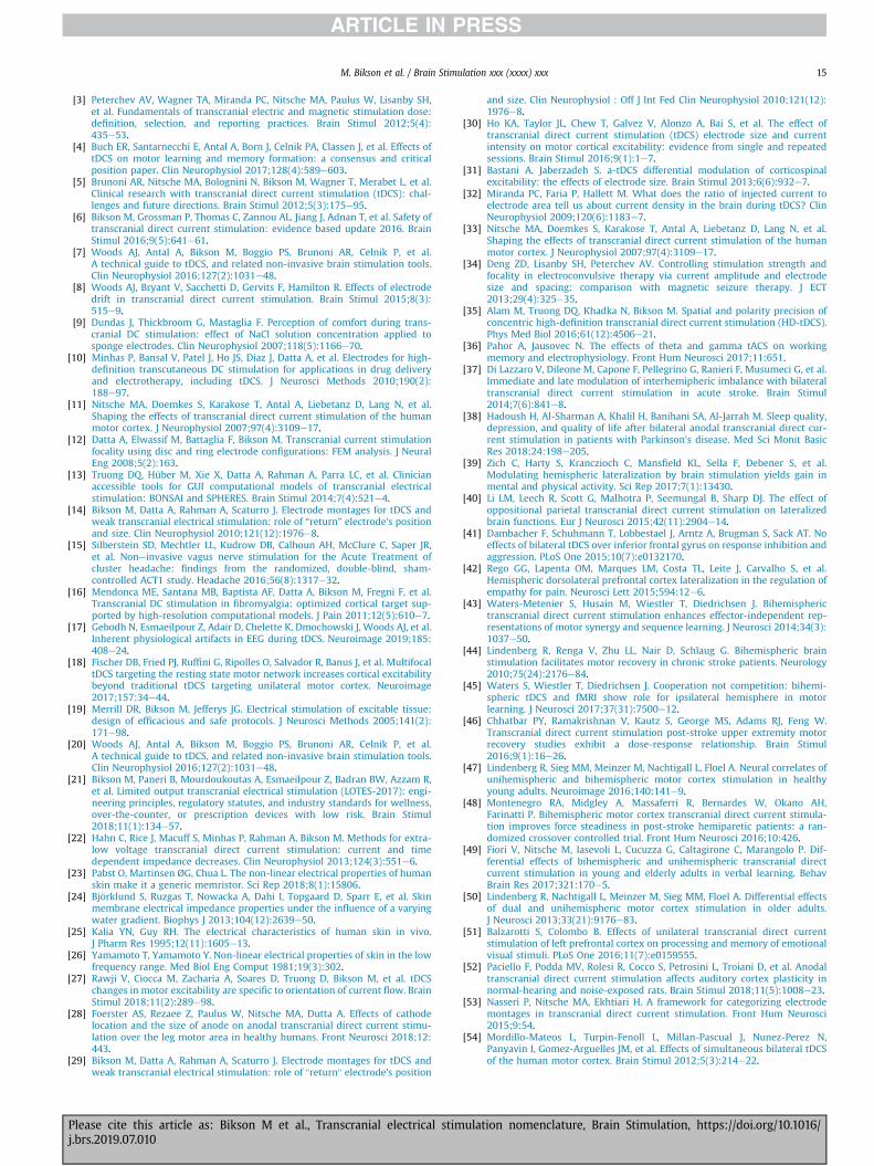
M. Bikson et al. / Brain Stimulation xxx (xxxx) xxx 15
[3] Peterchev AV, Wagner TA, Miranda PC, Nitsche MA, Paulus W, Lisanby SH,et al. Fundamentals of transcranial electric and magnetic stimulation dose:definition, selection, and reporting practices. Brain Stimul 2012;5(4):435e53.
[4] Buch ER, Santarnecchi E, Antal A, Born J, Celnik PA, Classen J, et al. Effects oftDCS on motor learning and memory formation: a consensus and criticalposition paper. Clin Neurophysiol 2017;128(4):589e603.
[5] Brunoni AR, Nitsche MA, Bolognini N, Bikson M, Wagner T, Merabet L, et al.Clinical research with transcranial direct current stimulation (tDCS): chal-lenges and future directions. Brain Stimul 2012;5(3):175e95.
[6] Bikson M, Grossman P, Thomas C, Zannou AL, Jiang J, Adnan T, et al. Safety oftranscranial direct current stimulation: evidence based update 2016. BrainStimul 2016;9(5):641e61.
[7] Woods AJ, Antal A, Bikson M, Boggio PS, Brunoni AR, Celnik P, et al.A technical guide to tDCS, and related non-invasive brain stimulation tools.Clin Neurophysiol 2016;127(2):1031e48.
[8] Woods AJ, Bryant V, Sacchetti D, Gervits F, Hamilton R. Effects of electrodedrift in transcranial direct current stimulation. Brain Stimul 2015;8(3):515e9.
[9] Dundas J, Thickbroom G, Mastaglia F. Perception of comfort during trans-cranial DC stimulation: effect of NaCl solution concentration applied tosponge electrodes. Clin Neurophysiol 2007;118(5):1166e70.
[10] Minhas P, Bansal V, Patel J, Ho JS, Diaz J, Datta A, et al. Electrodes for high-definition transcutaneous DC stimulation for applications in drug deliveryand electrotherapy, including tDCS. J Neurosci Methods 2010;190(2):188e97.
[11] Nitsche MA, Doemkes S, Karakose T, Antal A, Liebetanz D, Lang N, et al.Shaping the effects of transcranial direct current stimulation of the humanmotor cortex. J Neurophysiol 2007;97(4):3109e17.
[12] Datta A, Elwassif M, Battaglia F, Bikson M. Transcranial current stimulationfocality using disc and ring electrode configurations: FEM analysis. J NeuralEng 2008;5(2):163.
[13] Truong DQ, Hüber M, Xie X, Datta A, Rahman A, Parra LC, et al. Clinicianaccessible tools for GUI computational models of transcranial electricalstimulation: BONSAI and SPHERES. Brain Stimul 2014;7(4):521e4.
[14] Bikson M, Datta A, Rahman A, Scaturro J. Electrode montages for tDCS andweak transcranial electrical stimulation: role of “return” electrode's positionand size. Clin Neurophysiol 2010;121(12):1976e8.
[15] Silberstein SD, Mechtler LL, Kudrow DB, Calhoun AH, McClure C, Saper JR,et al. Noneinvasive vagus nerve stimulation for the Acute Treatment ofcluster headache: findings from the randomized, double-blind, sham-controlled ACT1 study. Headache 2016;56(8):1317e32.
[16] Mendonca ME, Santana MB, Baptista AF, Datta A, Bikson M, Fregni F, et al.Transcranial DC stimulation in fibromyalgia: optimized cortical target sup-ported by high-resolution computational models. J Pain 2011;12(5):610e7.
[17] Gebodh N, Esmaeilpour Z, Adair D, Chelette K, Dmochowski J, Woods AJ, et al.Inherent physiological artifacts in EEG during tDCS. Neuroimage 2019;185:408e24.
[18] Fischer DB, Fried PJ, Ruffini G, Ripolles O, Salvador R, Banus J, et al. MultifocaltDCS targeting the resting state motor network increases cortical excitabilitybeyond traditional tDCS targeting unilateral motor cortex. Neuroimage2017;157:34e44.
[19] Merrill DR, Bikson M, Jefferys JG. Electrical stimulation of excitable tissue:design of efficacious and safe protocols. J Neurosci Methods 2005;141(2):171e98.
[20] Woods AJ, Antal A, Bikson M, Boggio PS, Brunoni AR, Celnik P, et al.A technical guide to tDCS, and related non-invasive brain stimulation tools.Clin Neurophysiol 2016;127(2):1031e48.
[21] Bikson M, Paneri B, Mourdoukoutas A, Esmaeilpour Z, Badran BW, Azzam R,et al. Limited output transcranial electrical stimulation (LOTES-2017): engi-neering principles, regulatory statutes, and industry standards for wellness,over-the-counter, or prescription devices with low risk. Brain Stimul2018;11(1):134e57.
[22] Hahn C, Rice J, Macuff S, Minhas P, Rahman A, Bikson M. Methods for extra-low voltage transcranial direct current stimulation: current and timedependent impedance decreases. Clin Neurophysiol 2013;124(3):551e6.
[23] Pabst O, Martinsen ØG, Chua L. The non-linear electrical properties of humanskin make it a generic memristor. Sci Rep 2018;8(1):15806.
[24] Bj€orklund S, Ruzgas T, Nowacka A, Dahi I, Topgaard D, Sparr E, et al. Skinmembrane electrical impedance properties under the influence of a varyingwater gradient. Biophys J 2013;104(12):2639e50.
[25] Kalia YN, Guy RH. The electrical characteristics of human skin in vivo.J Pharm Res 1995;12(11):1605e13.
[26] Yamamoto T, Yamamoto Y. Non-linear electrical properties of skin in the lowfrequency range. Med Biol Eng Comput 1981;19(3):302.
[27] Rawji V, Ciocca M, Zacharia A, Soares D, Truong D, Bikson M, et al. tDCSchanges in motor excitability are specific to orientation of current flow. BrainStimul 2018;11(2):289e98.
[28] Foerster AS, Rezaee Z, Paulus W, Nitsche MA, Dutta A. Effects of cathodelocation and the size of anode on anodal transcranial direct current stimu-lation over the leg motor area in healthy humans. Front Neurosci 2018;12:443.
[29] Bikson M, Datta A, Rahman A, Scaturro J. Electrode montages for tDCS andweak transcranial electrical stimulation: role of "return" electrode's position
Please cite this article as: Bikson M et al., Transcranial electrical stij.brs.2019.07.010
and size. Clin Neurophysiol : Off J Int Fed Clin Neurophysiol 2010;121(12):1976e8.
[30] Ho KA, Taylor JL, Chew T, Galvez V, Alonzo A, Bai S, et al. The effect oftranscranial direct current stimulation (tDCS) electrode size and currentintensity on motor cortical excitability: evidence from single and repeatedsessions. Brain Stimul 2016;9(1):1e7.
[31] Bastani A, Jaberzadeh S. a-tDCS differential modulation of corticospinalexcitability: the effects of electrode size. Brain Stimul 2013;6(6):932e7.
[32] Miranda PC, Faria P, Hallett M. What does the ratio of injected current toelectrode area tell us about current density in the brain during tDCS? ClinNeurophysiol 2009;120(6):1183e7.
[33] Nitsche MA, Doemkes S, Karakose T, Antal A, Liebetanz D, Lang N, et al.Shaping the effects of transcranial direct current stimulation of the humanmotor cortex. J Neurophysiol 2007;97(4):3109e17.
[34] Deng ZD, Lisanby SH, Peterchev AV. Controlling stimulation strength andfocality in electroconvulsive therapy via current amplitude and electrodesize and spacing: comparison with magnetic seizure therapy. J ECT2013;29(4):325e35.
[35] Alam M, Truong DQ, Khadka N, Bikson M. Spatial and polarity precision ofconcentric high-definition transcranial direct current stimulation (HD-tDCS).Phys Med Biol 2016;61(12):4506e21.
[36] Pahor A, Jausovec N. The effects of theta and gamma tACS on workingmemory and electrophysiology. Front Hum Neurosci 2017;11:651.
[37] Di Lazzaro V, Dileone M, Capone F, Pellegrino G, Ranieri F, Musumeci G, et al.Immediate and late modulation of interhemipheric imbalance with bilateraltranscranial direct current stimulation in acute stroke. Brain Stimul2014;7(6):841e8.
[38] Hadoush H, Al-Sharman A, Khalil H, Banihani SA, Al-Jarrah M. Sleep quality,depression, and quality of life after bilateral anodal transcranial direct cur-rent stimulation in patients with Parkinson's disease. Med Sci Monit BasicRes 2018;24:198e205.
[39] Zich C, Harty S, Kranczioch C, Mansfield KL, Sella F, Debener S, et al.Modulating hemispheric lateralization by brain stimulation yields gain inmental and physical activity. Sci Rep 2017;7(1):13430.
[40] Li LM, Leech R, Scott G, Malhotra P, Seemungal B, Sharp DJ. The effect ofoppositional parietal transcranial direct current stimulation on lateralizedbrain functions. Eur J Neurosci 2015;42(11):2904e14.
[41] Dambacher F, Schuhmann T, Lobbestael J, Arntz A, Brugman S, Sack AT. Noeffects of bilateral tDCS over inferior frontal gyrus on response inhibition andaggression. PLoS One 2015;10(7):e0132170.
[42] Rego GG, Lapenta OM, Marques LM, Costa TL, Leite J, Carvalho S, et al.Hemispheric dorsolateral prefrontal cortex lateralization in the regulation ofempathy for pain. Neurosci Lett 2015;594:12e6.
[43] Waters-Metenier S, Husain M, Wiestler T, Diedrichsen J. Bihemispherictranscranial direct current stimulation enhances effector-independent rep-resentations of motor synergy and sequence learning. J Neurosci 2014;34(3):1037e50.
[44] Lindenberg R, Renga V, Zhu LL, Nair D, Schlaug G. Bihemispheric brainstimulation facilitates motor recovery in chronic stroke patients. Neurology2010;75(24):2176e84.
[45] Waters S, Wiestler T, Diedrichsen J. Cooperation not competition: bihemi-spheric tDCS and fMRI show role for ipsilateral hemisphere in motorlearning. J Neurosci 2017;37(31):7500e12.
[46] Chhatbar PY, Ramakrishnan V, Kautz S, George MS, Adams RJ, Feng W.Transcranial direct current stimulation post-stroke upper extremity motorrecovery studies exhibit a dose-response relationship. Brain Stimul2016;9(1):16e26.
[47] Lindenberg R, Sieg MM, Meinzer M, Nachtigall L, Floel A. Neural correlates ofunihemispheric and bihemispheric motor cortex stimulation in healthyyoung adults. Neuroimage 2016;140:141e9.
[48] Montenegro RA, Midgley A, Massaferri R, Bernardes W, Okano AH,Farinatti P. Bihemispheric motor cortex transcranial direct current stimula-tion improves force steadiness in post-stroke hemiparetic patients: a ran-domized crossover controlled trial. Front Hum Neurosci 2016;10:426.
[49] Fiori V, Nitsche M, Iasevoli L, Cucuzza G, Caltagirone C, Marangolo P. Dif-ferential effects of bihemispheric and unihemispheric transcranial directcurrent stimulation in young and elderly adults in verbal learning. BehavBrain Res 2017;321:170e5.
[50] Lindenberg R, Nachtigall L, Meinzer M, Sieg MM, Floel A. Differential effectsof dual and unihemispheric motor cortex stimulation in older adults.J Neurosci 2013;33(21):9176e83.
[51] Balzarotti S, Colombo B. Effects of unilateral transcranial direct currentstimulation of left prefrontal cortex on processing and memory of emotionalvisual stimuli. PLoS One 2016;11(7):e0159555.
[52] Paciello F, Podda MV, Rolesi R, Cocco S, Petrosini L, Troiani D, et al. Anodaltranscranial direct current stimulation affects auditory cortex plasticity innormal-hearing and noise-exposed rats. Brain Stimul 2018;11(5):1008e23.
[53] Nasseri P, Nitsche MA, Ekhtiari H. A framework for categorizing electrodemontages in transcranial direct current stimulation. Front Hum Neurosci2015;9:54.
[54] Mordillo-Mateos L, Turpin-Fenoll L, Millan-Pascual J, Nunez-Perez N,Panyavin I, Gomez-Arguelles JM, et al. Effects of simultaneous bilateral tDCSof the human motor cortex. Brain Stimul 2012;5(3):214e22.
mulation nomenclature, Brain Stimulation, https://doi.org/10.1016/
M. Bikson et al. / Brain Stimulation xxx (xxxx) xxx16
[55] Sehm B, Kipping J, Schafer A, Villringer A, Ragert P. A comparison betweenuni- and bilateral tDCS effects on functional connectivity of the humanmotor cortex. Front Hum Neurosci 2013;7:183.
[56] Sehm B, Schafer A, Kipping J, Margulies D, Conde V, Taubert M, et al. Dynamicmodulation of intrinsic functional connectivity by transcranial direct currentstimulation. J Neurophysiol 2012;108(12):3253e63.
[57] Heise KF, Kortzorg N, Saturnino GB, Fujiyama H, Cuypers K, Thielscher A,et al. Evaluation of a modified high-definition electrode montage for trans-cranial alternating current stimulation (tACS) of pre-central areas. BrainStimul 2016;9(5):700e4.
[58] Helfrich RF, Knepper H, Nolte G, Struber D, Rach S, Herrmann CS, et al. Se-lective modulation of interhemispheric functional connectivity by HD-tACSshapes perception. PLoS Biol 2014;12(12):e1002031.
[59] Kuo HI, Bikson M, Datta A, Minhas P, Paulus W, Kuo MF, et al. Comparingcortical plasticity induced by conventional and high-definition 4 x 1 ringtDCS: a neurophysiological study. Brain Stimul 2013;6(4):644e8.
[60] Monte-Silva K, Kuo M-F, Hessenthaler S, Fresnoza S, Liebetanz D, Paulus W,et al. Induction of late LTP-like plasticity in the human motor cortex byrepeated non-invasive brain stimulation. Brain Stimul 2013;6(3):424e32.
[61] Brunoni AR, Moffa AH, Fregni F, Palm U, Padberg F, Blumberger DM, et al.Transcranial direct current stimulation for acute major depressive episodes:meta-analysis of individual patient data. Br J Psychiatry 2016;208(6):522e31.
[62] Ambrus GG, Al-Moyed H, Chaieb L, Sarp L, Antal A, Paulus W. The fade-in–short stimulation–fade out approach to sham tDCS–reliable at 1 mA fornaive and experienced subjects, but not investigators. Brain Stimul2012;5(4):499e504.
[63] Bikson M, Brunoni AR, Charvet LE, Clark VP, Cohen LG, Deng ZD, et al. Rigorand reproducibility in research with transcranial electrical stimulation: anNIMH-sponsored workshop. Brain Stimul 2018;11(3):465e80.
[64] Brunoni AR, Sampaio-Junior B, Moffa AH, Borrione L, Nogueira BS,Aparicio LV, et al. The Escitalopram versus Electric Current Therapy forTreating Depression Clinical Study (ELECT-TDCS): rationale and study designof a non-inferiority, triple-arm, placebo-controlled clinical trial. Sao PauloMed J 2015;133(3):252e63.
[65] Jessica D, Richardson PF, Datta Abhishek, Truong Dennis, Bikson Marom,Fridriksson Julius. Toward development of sham protocols for HighDefinitiontranscranial direct current stimulation (HD-tDCS). Neuroregulation2014;1(1):62e72.
[66] Turi Z, Csifcsak G, Boayue NM, Aslaksen P, Antal A, Paulus W, et al. Blinding iscompromised for transcranial direct current stimulation at 1 mA for 20 minin young healthy adults. Eur J Neurosci 2019.
[67] Fonteneau C, Mondino M, Arns M, Baeken C, Bikson M, Brunoni AR, et al.Sham tDCS: a hidden source of variability? Reflections for further blinded,controlled trials. Brain Stimul 2019;12(3):668e73.
[68] Guarienti F, Caumo W, Shiozawa P, Cordeiro Q, Boggio PS, Bensenor IM, et al.Reducing transcranial direct current stimulation-induced erythema withskin pretreatment: considerations for sham-controlled clinical trials. Neu-romodulation 2015;18(4):261e5.
[69] Merton P, Morton H. Stimulation of the cerebral cortex in the intact humansubject. Nature 1980;285(5762):227.
[70] Reato D, Rahman A, Bikson M, Parra LC. Effects of weak transcranial alter-nating current stimulation on brain activityda review of known mecha-nisms from animal studies. Front Hum Neurosci 2013;7:687.
[71] Salimpour Y, Wei Z, Duy PQ, Anderson WS. Does transcranial direct currentstimulation actually deliver DC stimulation? Brain Stimul 2016;9(4):623e4.
[72] Chhatbar PY, Sawers JR, Feng W. Response to the response to “does tDCSactually deliver DC stimulation?”. Brain Stimul 2016;9(6):952e4.
[73] Clemens B, Jung S, Mingoia G, Weyer D, Domahs F, Willmes K. Influence ofanodal transcranial direct current stimulation (tDCS) over the right angulargyrus on brain activity during rest. PLoS One 2014;9(4):e95984.
[74] Datta A, Bansal V, Diaz J, Patel J, Reato D, Bikson M. Gyri-precise head modelof transcranial direct current stimulation: improved spatial focality using aring electrode versus conventional rectangular pad. Brain Stimul 2009;2(4):201e7.
[75] Klomjai W, Aneksan B, Pheungphrarattanatrai A, Chantanachai T,Choowong N, Bunleukhet S, et al. Effect of single-session dual-tDCS beforephysical therapy on lower-limb performance in sub-acute stroke patients: arandomized sham-controlled crossover study. Ann Phys Rehabil Med2018;61(5):286e91.
[76] Pingue V, Priori A, Malovini A, Pistarini C. Dual transcranial direct currentstimulation for poststroke dysphagia: a randomized controlled trial. Neu-rorehabilitation Neural Repair 2018;32(6e7):635e44.
[77] Sarasso P, Ninghetto M, Salatino A, Ronga I, Bongiardina A, Iarrobino I, et al.Everything is (still) illuminated: dual right cathodal-left anodal tDCS of PPCprevents fatigue on a visual detection task. Brain Stimul 2019;12(1):187e9.
[78] Karok S, Witney AG. Enhanced motor learning following task-concurrentdual transcranial direct current stimulation. PLoS One 2013;8(12):e85693.
[79] Vaseghi B, Zoghi M, Jaberzadeh S. The effects of anodal-tDCS on corticospinalexcitability enhancement and its after-effects: conventional vs. unihemi-spheric concurrent dual-site stimulation. Front Hum Neurosci 2015;9:533.
[80] Achacheluee ST, Rahnama L, Karimi N, Abdollahi I, Arslan SA, Jaberzadeh S.The effect of unihemispheric concurrent dual-site transcranial direct currentstimulation of primary motor and dorsolateral prefrontal cortices on motor
Please cite this article as: Bikson M et al., Transcranial electrical stij.brs.2019.07.010
function in patients with sub-acute stroke. Front Hum Neurosci 2018;12:441.
[81] Hill AT, Rogasch NC, Fitzgerald PB, Hoy KE. Effects of single versus dual-siteHigh-Definition transcranial direct current stimulation (HD-tDCS) on corticalreactivity and working memory performance in healthy subjects. BrainStimul 2018;11(5):1033e43.
[82] Reinhart RMG, Nguyen JA. Working memory revived in older adults bysynchronizing rhythmic brain circuits. Nat Neurosci 2019:820e7.
[83] Paulus W, Opitz A. Ohm's law and tDCS over the centuries. Clin Neurophysiol2013;124(3):429e30.
[84] Esmaeilpour Z, Schestatsky P, Bikson M, Brunoni AR, Pellegrinelli A,Piovesan FX, et al. Notes on human trials of transcranial direct currentstimulation between 1960 and 1998. Front Hum Neurosci 2017;11:71.
[85] Sellers KK, Mellin JM, Lustenberger CM, Boyle MR, Lee WH, Peterchev AV,et al. Transcranial direct current stimulation (tDCS) of frontal cortex de-creases performance on the WAIS-IV intelligence test. Behav Brain Res2015;290:32e44.
[86] Chhatbar PY, Chen R, Deardorff R, Dellenbach B, Kautz SA, George MS, et al.Safety and tolerability of transcranial direct current stimulation to strokepatientsea phase I current escalation study. Brain Stimul 2017;10(3):553e9.
[87] Nitsche MA, Paulus W. Excitability changes induced in the human motorcortex by weak transcranial direct current stimulation. J Physiol2000;527(3):633e9.
[88] Fertonani A, Ferrari C, Miniussi C. What do you feel if I apply transcranialelectric stimulation? Safety, sensations and secondary induced effects. ClinNeurophysiol 2015;126(11):2181e8.
[89] Moliadze V, Andreas S, Lyzhko E, Schmanke T, Gurashvili T, Freitag CM, et al.Ten minutes of 1 mA transcranial direct current stimulation was welltolerated by children and adolescents: self-reports and resting state EEGanalysis. Brain Res Bull 2015;119:25e33.
[90] Paneri B, Adair D, Thomas C, Khadka N, Patel V, Tyler WJ, et al. Tolerability ofrepeated application of transcranial electrical stimulation with limited out-puts to healthy subjects. Brain Stimul 2016;9(5):740e54.
[91] Kronberg G, Bikson M, editors. Electrode assembly design for transcranialdirect current stimulation: a FEM modeling study. Conf Proc IEEE Eng MedBiol Soc; 2012.
[92] Edwards D, Cortes M, Datta A, Minhas P, Wassermann EM, Bikson M.Physiological and modeling evidence for focal transcranial electrical brainstimulation in humans: a basis for high-definition tDCS. Neuroimage2013;74:266e75.
[93] Minhas P, Bansal V, Patel J, Ho JS, Diaz J, Datta A, et al. Electrodes for high-definition transcutaneous DC stimulation for applications in drug deliveryand electrotherapy, including tDCS. J Neurosci Methods 2010;190(2):188e97.
[94] Dmochowski JP, Datta A, Bikson M, Su Y, Parra LC. Optimized multi-electrodestimulation increases focality and intensity at target. J Neural Eng 2011;8(4):046011.
[95] Dmochowski JP, Datta A, Huang Y, Richardson JD, Bikson M, Fridriksson J,et al. Targeted transcranial direct current stimulation for rehabilitation afterstroke. Neuroimage 2013;75:12e9.
[96] Borckardt JJ, Bikson M, Frohman H, Reeves ST, Datta A, Bansal V, et al. A pilotstudy of the tolerability and effects of high-definition transcranial directcurrent stimulation (HD-tDCS) on pain perception. J Pain 2012;13(2):112e20.
[97] Shekhawat GS, Sundram F, Bikson M, Truong D, De Ridder D, Stinear CM,et al. Intensity, duration, and location of high-definition transcranial directcurrent stimulation for tinnitus relief. Neurorehabilitation Neural Repair2016;30(4):349e59.
[98] Nikolin S, Loo CK, Bai S, Dokos S, Martin DM. Focalised stimulation using highdefinition transcranial direct current stimulation (HD-tDCS) to investigatedeclarative verbal learning and memory functioning. Neuroimage 2015;117:11e9.
[99] Nikolin S, Lauf S, Loo CK, Martin D. Effects of high-definition transcranialdirect current stimulation (HD-tDCS) of the intraparietal sulcus and dorso-lateral prefrontal cortex on working memory and divided attention. FrontIntegr Neurosci 2018;12:64.
[100] Reckow J, Rahman-Filipiak A, Garcia S, Schlaefflin S, Calhoun O, DaSilva AF,et al. Tolerability and blinding of 4x1 high-definition transcranial directcurrent stimulation (HD-tDCS) at two and three milliamps. Brain Stimul2018;11(5):991e7.
[101] Truong DQ, Datta A, Xu J, Fregni F, Bikson M, editors. Prefrontal cortextranscranial direct current stimulation via a combined high definition andconventional electrode montage: a FEM modeling studying. Conf Proc IEEEEng Med Biol Soc; 2012.
[102] Perceval G, Martin AK, Copland DA, Laine M, Meinzer M. High-definitiontDCS of the temporo-parietal cortex enhances access to newly learnedwords. Sci Rep 2017;7(1):17023.
[103] Dmochowski JP, Bikson M, Datta A, Richardson J, Fridriksson J, Parra LC. Onthe role of electric field orientation in optimal design of transcranial currentstimulation. Conf Proc IEEE Eng Med Biol Soc 2012.
[104] Turski CA, Kessler-Jones A, Chow C, Hermann B, Hsu D, Jones J, et al.Extended Multiple-Field High-Definition transcranial direct current stimu-lation (HD-tDCS) is well tolerated and safe in healthy adults. Restor NeurolNeurosci 2017;35(6):631e42.
mulation nomenclature, Brain Stimulation, https://doi.org/10.1016/
M. Bikson et al. / Brain Stimulation xxx (xxxx) xxx 17
[105] Roy A, Baxter B, He B. High-definition transcranial direct current stimulationinduces both acute and persistent changes in broadband cortical synchro-nization: a simultaneous tDCS-EEG study. IEEE Trans Biomed Eng2014;61(7):1967e78.
[106] Jaberzadeh S, Bastani A, Zoghi M. Anodal transcranial pulsed current stim-ulation: a novel technique to enhance corticospinal excitability. Clin Neu-rophysiol 2014;125(2):344e51.
[107] Morales-Quezada L, Saavedra LC, Rozisky J, Hadlington L, Fregni F. Intensity-dependent effects of transcranial pulsed current stimulation on interhemi-spheric connectivity: a high-resolution qEEG, sham-controlled study. Neu-roreport 2014;25(13):1054e8.
[108] Saavedra LC, Morales-Quezada L, Doruk D, Rozinsky J, Coutinho L, Faria P,et al. QEEG indexed frontal connectivity effects of transcranial pulsed currentstimulation (tPCS): a sham-controlled mechanistic trial. Neurosci Lett2014;577:61e5.
[109] Sours C, Alon G, Roys S, Gullapalli RP. Modulation of resting state functionalconnectivity of the motor network by transcranial pulsed current stimula-tion. Brain Connect 2014;4(3):157e65.
[110] Fitzgerald PB. Transcranial pulsed current stimulation: a new way forward?Clin Neurophysiol 2014;125(2):217e9.
[111] Jaberzadeh S, Bastani A, Zoghi M. Anodal transcranial pulsed current stim-ulation: a novel technique to enhance corticospinal excitability. Clin Neu-rophysiol 2014;125(2):344e51.
[112] Amassian VE, Cracco RQ, Maccabee PJ. Focal stimulation of human cerebralcortex with the magnetic coil: a comparison with electrical stimulation.Electroencephalogr Clin Neurophysiol 1989;74(6):401e16.
[113] Rothwell JC. Techniques and mechanisms of action of transcranial stimula-tion of the human motor cortex. J Neurosci Methods 1997;74(2):113e22.
[114] Datta A, Dmochowski JP, Guleyupoglu B, Bikson M, Fregni F. Cranial elec-trotherapy stimulation and transcranial pulsed current stimulation: a com-puter based high-resolution modeling study. Neuroimage 2013;65:280e7.
[115] Lisanby SH. Electroconvulsive therapy for depression. N Engl J Med2007;357(19):1939e45.
[116] Moliadze V, Atalay D, Antal A, Paulus W. Close to threshold transcranialelectrical stimulation preferentially activates inhibitory networks beforeswitching to excitation with higher intensities. Brain Stimul 2012;5(4):505e11.
[117] APA. The practice of electroconvulsive therapy: recommendations fortreatment, training, and privileging. Washington (DC): American PsychiatricAssociation (APA) Committee on Electroconvulsive Therapy; 2001.
[118] Nahas Z, Short B, Burns C, Archer M, Schmidt M, Prudic J, et al. A feasibilitystudy of a new method for electrically producing seizures in man: focalelectrically administered seizure therapy [FEAST]. Brain Stimul 2013;6(3):403e8.
[119] Chahine G, Short B, Spicer K, Schmidt M, Burns C, Atoui M, et al. Regionalcerebral blood flow changes associated with focal electrically administeredseizure therapy (FEAST). Brain Stimul 2014;7(3):483e5.
[120] Peterchev AV, Rosa MA, Deng ZD, Prudic J, Lisanby SH. Electroconvulsivetherapy stimulus parameters: rethinking dosage. J ECT 2010;26(3):159e74.
[121] Loo CK, Schweitzer I, Pratt C. Recent advances in optimizing electroconvul-sive therapy. Aust N Z J Psychiatr 2006;40(8):632e8.
[122] Sahlem GL, Short EB, Kerns S, Snipes J, DeVries W, Fox JB, et al. Expandedsafety and efficacy data for a new method of performing electroconvulsivetherapy: focal electrically administered seizure therapy. J ECT 2016;32(3):197e203.
[123] Mayur P, Harris A, Gangadhar B. 500-mA ECT–A proof of concept report.J ECT 2015;31(2):e23e6.
[124] Rosa MA, Abdo GL, Lisanby SH, Peterchev A. Seizure induction with low-amplitude-current (0.5 A) electroconvulsive therapy. J ECT 2011;27(4):341e2.
[125] Loo CK, Bai S, Martin D, Galvez V, Dokos S. Revisiting frontoparietal montagein electroconvulsive therapy: clinical observations and computer modeling:a future treatment option for unilateral electroconvulsive therapy. J ECT2015;31(1):e7e13.
[126] Loo CK, Katalinic N, Smith DJ, Ingram A, Dowling N, Martin D, et al.A randomized controlled trial of brief and ultrabrief pulse right unilateralelectroconvulsive therapy. Int J Neuropsychopharmacol 2014;18(1).
[127] Groppa S, Bergmann TO, Siems C, Molle M, Marshall L, Siebner HR. Slow-oscillatory transcranial direct current stimulation can induce bidirectionalshifts in motor cortical excitability in awake humans. Neuroscience2010;166(4):1219e25.
[128] Eggert T, Dorn H, Sauter C, Nitsche MA, Bajbouj M, Danker-Hopfe H. No ef-fects of slow oscillatory transcranial direct current stimulation (tDCS) onsleep-dependent memory consolidation in healthy elderly subjects. BrainStimul 2013;6(6):938e45.
[129] Antal A, Boros K, Poreisz C, Chaieb L, Terney D, Paulus W. Comparativelyweak after-effects of transcranial alternating current stimulation (tACS) oncortical excitability in humans. Brain Stimul 2008;1(2):97e105.
[130] Westerberg CE, Florczak SM, Weintraub S, Mesulam MM, Marshall L, Zee PC,et al. Memory improvement via slow-oscillatory stimulation during sleep inolder adults. Neurobiol Aging 2015;36(9):2577e86.
[131] Binder S, Berg K, Gasca F, Lafon B, Parra LC, Born J, et al. Transcranial slowoscillation stimulation during sleep enhances memory consolidation in rats.Brain Stimul 2014;7(4):508e15.
Please cite this article as: Bikson M et al., Transcranial electrical stij.brs.2019.07.010
[132] Marshall L, Molle M, Hallschmid M, Born J. Transcranial direct currentstimulation during sleep improves declarative memory. J Neurosci2004;24(44):9985e92.
[133] Antal A, Boros K, Poreisz C, Chaieb L, Terney D, Paulus W. Comparativelyweak after-effects of transcranial alternating current stimulation (tACS) oncortical excitability in humans. Brain Stimul 2008;1(2):97e105.
[134] Mehta AR, Brittain J-S, Brown P. The selective influence of rhythmic corticalversus cerebellar transcranial stimulation on human physiological tremor.J Neurosci 2014;34(22):7501e8.
[135] Kar K, Krekelberg B. Transcranial alternating current stimulation attenuatesvisual motion adaptation. J Neurosci 2014;34(21):7334e40.
[136] Moliadze V, Atalay D, Antal A, Paulus W. Close to threshold transcranialelectrical stimulation preferentially activates inhibitory networks beforeswitching to excitation with higher intensities. Brain Stimul 2012;5(4):606e11.
[137] Negahbani E, Kasten FH, Herrmann CS, Frohlich F. Targeting alpha-bandoscillations in a cortical model with amplitude-modulated high-frequencytranscranial electric stimulation. Neuroimage 2018;173:3e12.
[138] Mehta AR, Brittain JS, Brown P. The selective influence of rhythmic corticalversus cerebellar transcranial stimulation on human physiological tremor.J Neurosci 2014;34(22):7501e8.
[139] Helfrich RF, Schneider TR, Rach S, Trautmann-Lengsfeld SA, Engel AK,Herrmann CS. Entrainment of brain oscillations by transcranial alternatingcurrent stimulation. Curr Biol 2014;24(3):333e9.
[140] Jausovec N, Jausovec K. Increasing working memory capacity with thetatranscranial alternating current stimulation (tACS). Biol Psychol 2014;96:42e7.
[141] Alekseichuk I, Turi Z, Amador de Lara G, Antal A, Paulus W. Spatial workingmemory in humans depends on theta and high gamma synchronization inthe prefrontal cortex. Curr Biol 2016;26(12):1513e21.
[142] Lara GA, Alekseichuk I, Turi Z, Lehr A, Antal A, Paulus W. Perturbation oftheta-gamma coupling at the temporal lobe hinders verbal declarativememory. Brain Stimul 2018;11(3):509e17.
[143] Chaieb L, Wilpert EC, Reber TP, Fell J. Auditory beat stimulation and its effectson cognition and mood states. Front Psychiatry 2015;6:70.
[144] Kunz P, Antal A, Hewitt M, Neef A, Opitz A, Paulus W. 5 kHz transcranialalternating current stimulation: lack of cortical excitability changes whengrouped in a theta burst pattern. Front Hum Neurosci 2016;10:683.
[145] Grossman N, Bono D, Dedic N, Kodandaramaiah SB, Rudenko A, Suk HJ, et al.Noninvasive deep brain stimulation via temporally interfering electric fields.Cell 2017;169(6):1029e41. e16.
[146] Gall C, Fedorov AB, Ernst L, Borrmann A, Sabel BA. Repetitive transorbitalalternating current stimulation in optic neuropathy. NeuroRehabilitation2010;27(4):335e41.
[147] Sabel BA, Fedorov AB, Naue N, Borrmann A, Herrmann C, Gall C. Non-invasivealternating current stimulation improves vision in optic neuropathy. RestorNeurol Neurosci 2011;29(6):493e505.
[148] Gall C, Sgorzaly S, Schmidt S, Brandt S, Fedorov A, Sabel BA. Noninvasivetransorbital alternating current stimulation improves subjective visualfunctioning and vision-related quality of life in optic neuropathy. BrainStimul 2011;4(4):175e88.
[149] Fedorov A, Jobke S, Bersnev V, Chibisova A, Chibisova Y, Gall C, et al.Restoration of vision after optic nerve lesions with noninvasive transorbitalalternating current stimulation: a clinical observational study. Brain Stimul2011;4(4):189e201.
[150] Gall C, Schmidt S, Schittkowski MP, Antal A, Ambrus GG, Paulus W, et al.Alternating current stimulation for vision restoration after optic nervedamage: a randomized clinical trial. PLoS One 2016;11(6):e0156134.
[151] Bola M, Gall C, Moewes C, Fedorov A, Hinrichs H, Sabel BA. Brain functionalconnectivity network breakdown and restoration in blindness. Neurology2014;10:1212.
[152] Morimoto T, Fukui T, Matsushita K, Okawa Y, Shimojyo H, Kusaka S, et al.Evaluation of residual retinal function by pupillary constrictions and phos-phenes using transcorneal electrical stimulation in patients with retinaldegeneration. Graefes Arch Clin Exp Ophthalmol 2006;244(10):1283e92.
[153] Inomata K, Shinoda K, Ohde H, Tsunoda K, Hanazono G, Kimura I, et al.Transcorneal electrical stimulation of retina to treat longstandingretinal artery occlusion. Graefes Arch Clin Exp Ophthalmol 2007;245(12):1773e80.
[154] Fujikado T, Morimoto T, Matsushita K, Shimojo H, Okawa Y, Tano Y. Effect oftranscorneal electrical stimulation in patients with nonarteritic ischemicoptic neuropathy or traumatic optic neuropathy. Jpn J Ophthalmol2006;50(3):266e73.
[155] Fujikado T, Morimoto T, Kanda H, Kusaka S, Nakauchi K, Ozawa M, et al.Evaluation of phosphenes elicited by extraocular stimulation in normals andby suprachoroidal-transretinal stimulation in patients with retinitis pig-mentosa. Graefes Arch Clin Exp Ophthalmol 2007;245(10):1411e9.
[156] Oono S, Kurimoto T, Kashimoto R, Tagami Y, Okamoto N, Mimura O.Transcorneal electrical stimulation improves visual function in eyes withbranch retinal artery occlusion. Clin Ophthalmol 2011;5:397e402.
[157] Dawson WW, Trick GL, Litzkow CA. Improved electrode for electroretinog-raphy. Investig Ophthalmol Vis Sci 1979;18(9):988e91.
[158] Schatz A, Pach J, Gosheva M, Naycheva L, Willmann G, Wilhelm B, et al.Transcorneal electrical stimulation for patients with retinitis pigmentosa: a
mulation nomenclature, Brain Stimulation, https://doi.org/10.1016/
M. Bikson et al. / Brain Stimulation xxx (xxxx) xxx18
prospective, randomized, sham-controlled follow-up study over 1 year.Investig Ophthalmol Vis Sci 2017;58(1):257e69.
[159] Ozeki N, Shinoda K, Ohde H, Ishida S, Tsubota K. Improvement of visualacuity after transcorneal electrical stimulation in case of Best vitelliformmacular dystrophy. Graefes Arch Clin Exp Ophthalmol 2013;251(7):1867e70.
[160] Naycheva L, Schatz A, Rock T, Willmann G, Messias A, Bartz-Schmidt KU,et al. Phosphene thresholds elicited by transcorneal electrical stimulation inhealthy subjects and patients with retinal diseases. Investig Ophthalmol VisSci 2012;53(12):7440e8.
[161] Xie J, Wang GJ, Yow L, C JC, Humayun MS, Weiland JD, et al. Modeling andpercept of transcorneal electrical stimulation in humans. IEEE Trans BiomedEng 2011;58(7):1932e9.
[162] Schatz A, Rock T, Naycheva L, Willmann G, Wilhelm B, Peters T, et al.Transcorneal electrical stimulation for patients with retinitis pigmentosa: a
Please cite this article as: Bikson M et al., Transcranial electrical stij.brs.2019.07.010
prospective, randomized, sham-controlled exploratory study. Investig Oph-thalmol Vis Sci 2011;52(7):4485e96.
[163] Naycheva L, Schatz A, Willmann G, Bartz-Schmidt KU, Zrenner E, Rock T,et al. Transcorneal electrical stimulation in patients with retinal artery oc-clusion: a prospective, randomized, sham-controlled pilot study. OphthalmolTher 2013;2(1):25e39.
[164] Terney D, Chaieb L, Moliadze V, Antal A, Paulus W. Increasing human brainexcitability by transcranial high-frequency random noise stimulation.J Neurosci 2008;28(52):14147e55.
[165] Stacey WC, Durand DM. Stochastic resonance improves signal detection inhippocampal CA1 neurons. J Neurophysiol 2000;83(3):1394e402.
[166] Reed T, Cohen Kadosh R. Transcranial electrical stimulation (tES) mecha-nisms and its effects on cortical excitability and connectivity. J Inherit MetabDis 2018.
mulation nomenclature, Brain Stimulation, https://doi.org/10.1016/


