Embed Size (px)
Citation preview

J
3
4
5
6
A7
thutcrrbIopm
8
9
10
11
12
13
14
15
16
17
18
19
20
©21
K22
23
124
125
26
e27
h28
e29
m30
r31
a32
i33
m34
s35
i36
l37
c38
1 02 d
PR
OO
F
ARTICLE IN PRESS+ModelNNFM 2657 1–16
J. Non-Newtonian Fluid Mech. xxx (2007) xxx–xxx
Transient evolution of shear-banding wormlike micellar solutions
Erik Miller ∗, Jonathan P. RothsteinDepartment of Mechanical Engineering, University of Massachusetts, Amherst, MA 01003-2210, USA
Received 1 August 2006; received in revised form 10 November 2006; accepted 23 December 2006
bstract
A series of experiments were performed to further investigate the phenomenon of shear-banding in surfactant solutions. Many surfactant solutions,hrough their unique amphiphilic chemistry, form long wormlike micelle structures which behave like living polymers. These wormlike micellesave interesting viscoelastic properties and have been the subject of a number of recent studies. These water-based surfactant systems are widelysed in many commercial and industrial applications; however, many aspects of their complex flow behavior are still not fully understood. Inhis study, a Couette cell was designed to allow for high-resolution optical access in a simple shear flow of a surfactant system comprised ofetylpyridinium chloride and sodium salicylate in aqueous sodium chloride. Beyond a critical stress, this system is found to enter a non-linearegime in which there is a plateau in the shear stress with increasing shear rate. Within this plateau, the fluid forms distinct bands of varying shearate. The goal of this study was to obtain high spatial and temporal resolution particle image velocimetry and flow-induced birefringence results inoth steady and transient-startup flows. As a consequence of the high resolution, steady PIV results suggest the existence of multiple shear bands.n the transient PIV experiments, we observe a propagating damped elastic wave, as well as fluctuations in the shear-band evolution on timescales
D
f less than one relaxation time. Pointwise FIB gap profiles show a diffuse birefringent region prior to the onset of shear banding in the velocityrofiles. These results provide insight on the flow behavior, as well as a full set of experimental data which will drive development of constitutiveodels capable of predicting shear-banding.2007 Published by Elsevier B.V.
ding;
r 39
b 40
h 41
r 42
m 43
n 44
r 45
t 46
s 47
k 48
p 49
B 50
t 51
o 52
OR
RE
CTE
eywords: Flow induced birefringence; Particle-image velocimetry; Shear-ban
. Introduction
.1. Wormlike micelle solutions
Surfactants are used in a variety of applications that ben-fit from their unique viscoelastic properties, including manyousehold and cosmetic products, industrial viscosity modifiers,mulsifiers, encapsulants, and lubricants. In addition to theseore common and recognizable products, scientists have been
esearching the use of viscoelastic surfactant technology for uses polymer-free aqueous fracturing fluids in oilfield applicationsncluding drilling and reservoir stimulation [1]. Surfactants have
any interesting properties as a result of their unique chemicaltructure. The basic surfactant molecule is amphiphilic, whereby
UN
C
Please cite this article in press as: E. Miller, J.P. Rothstein, Transient evolutFluid Mech. (2007), doi:10.1016/j.jnnfm.2006.12.005
t possesses both hydrophilic (water-loving) and hydrophobic oryophilic (water-fearing or oil-loving) groups that are chemi-ally bonded together. Typical lyophilic groups are slender but
∗ Corresponding author.E-mail address: [email protected] (E. Miller).
a 53
o 54
55
mtec
377-0257/$ – see front matter © 2007 Published by Elsevier B.V.oi:10.1016/j.jnnfm.2006.12.005
Surfactant solutions; Wormlike micelles
elatively short hydrocarbon chains with a length of 8–20 car-on atoms and are often referred to as the surfactant ‘tail’. Theydrophilic group, in contrast, is short and bulky and thereforeeferred to as the ‘head’ [2]. Depending on the exact chemicalakeup of the molecule, surfactants can also have a positive,
egative, or neutral charge; cationic, anionic, and nonionic,espectively. When placed in water at a high enough concen-ration known as the critical micellar concentration (CMC),urfactant molecules will self-assemble into large aggregatesnown as micelles in such a way that the tails become closelyacked together in order to minimize their exposure to water.ased on several factors including the type of solvent, surfac-
ant concentration, and ionic strength, micelles can take the formf spheres, cylinders or even more complex and highly orderedggregates such as vesicles and bilayers. A schematic diagramf typical surfactant micelle morphologies is included in Fig. 1.
Cylindrical micelles can grow into very long wormlike
ion of shear-banding wormlike micellar solutions, J. Non-Newtonian
icelles with increasing surfactant concentration. Because of 56
heir long flexible structure, these worms can tangle around 57
ach other and form a complex network, much like polymer 58
hains. However, unlike polymers that have covalently bonded 59

ED
ARTICLE IN PRESS+ModelJNNFM 2657 1–16
2 E. Miller, J.P. Rothstein / J. Non-Newtonian Fluid Mech. xxx (2007) xxx–xxx
sembl
h60
t61
w62
i63
f64
t65
r66
b67
a68
a69
w70
c71
i72
w73
i74
c75
g76
p77
m78
r79
d80
w81
g82
t83
λ84
85
v86
e87
m88
v89
n90
t91
h92
a93
w94
a95
e96
s97
f98
t99
o100
s101
t102
r103
a104
p105
i 106
b 107
1 108
109
b 110
I 111
b 112
d 113
b 114
s 115
b 116
m 117
b 118
W 119
t 120
r 121
m 122
a 123
t 124
fl 125
p 126
g 127
l 128
n 129
130
o 131
t 132
d 133
c 134
o 135
b 136
l 137
γ 138
A 139
s 140
r 141
a 142
s 143
NC
OR
RE
CT
Fig. 1. Schematic diagram of self-as
ydrocarbon backbones, a wormlike micelle is only heldogether by relatively weak physical attractions/repulsionshich break and reform with time. The dynamics of this ongo-
ng and reversible breakup and reformation process is a strongunction of surfactant and salt concentration, salinity, tempera-ure, and flow. For this reason, wormlike micelles are commonlyeferred to as living or equilibrium polymers [3]. This continuousreaking and reforming gives networks of wormlike micelles andditional mechanism for relaxing from a stressed state back torandom walk equilibrium conformation. In an entangled net-ork, both individual polymer chains and wormlike micelles
an move past each other through reptation driven by Brown-an motion. In addition to reptation, and unlike polymer chains,ormlike micelles can move past confinement points by break-
ng [4]. The reptation and breakup relaxation mechanisms haveharacteristic time scales of λrep and λbr, respectively. Entan-led wormlike micelle solutions display an additional interestingroperty in the fast breaking limit where the breakup time isuch shorter than the reptation time, λrep � λrep [5]. In this
egime, typical of small amplitude oscillatory shear flows, whereeformation is linear and the scission of micelles is reversible,ormlike micelles are nearly ideal Maxwell fluids with a sin-le relaxation time, λM Cates showed this single relaxationime is the geometric mean of the reptation and breakup times,M = (λrepλbr)1/2 [6].
The rheological behavior of wormlike micellar solutions isery similar to that of viscoelastic polymer solutions [4]. How-ver, the ability of these micelle solutions to break, reform, andodify their morphology in response to a flow can lead to some
ery interesting phenomena when they are placed in variouson-linear flow conditions. In some viscometric flows, shear-hickening behavior followed by the onset of a flow instabilityas been observed [7]. New and different flow instabilities havelso been observed in the strong extensional flow following theake of a falling sphere [8]. In transient uniaxial extension usingfilament stretching rheometer, wormlike micelle solutions
xhibit significant strain-hardening similar to many polymerolutions. Unlike polymers, however, which undergo eventualailure via elastocapillary thinning, the wormlike micelle solu-ions fail through a dramatic rupture attributed to the scissionf micelles and independent of extension rate [9]. In otherhear flows, wormlike micelle solutions form banded struc-
UPlease cite this article in press as: E. Miller, J.P. Rothstein, Transient evolutFluid Mech. (2007), doi:10.1016/j.jnnfm.2006.12.005
ures of differing surfactant morphologies having vastly differentheological properties [2,10]. This class of behavior has beenttributed to shearinduced structure formation, shear-inducedhase change from isotropic to nematic phase, as well as shear-
dfla
PR
OO
F
ed surfactant micelle morphologies.
nduced gelation and mixing. This shear-banding behavior wille discussed in detail in the following section.
.2. Shear-banding in wormlike micelle solutions
The unusual dynamics of surfactant wormlike micelles haveeen studied in shear flows of varying geometry for many years.n a steady shear flow at low shear rates, wormlike micellesehave like a Newtonian fluid with a constant viscosity indepen-ent of shear rate. As the shear rate is increased, the viscosityegins to shear thin. Above a characteristic shear rate, the sheartress becomes nearly constant and independent of the imposedulk shear rate [11]. This plateau in shear stress can extend overultiple decades in shear rate before hitting a high shear rate
ranch and once again increasing monotonically with shear rate.ithin this stress plateau, and given proper flow conditions, dis-
inct bands of fluid at different local shear rates can develop. Theelative proportions of these physical bands are the subject ofuch recent research. Fundamentally, it is clear that the high
nd low shear-rate bands at a constant stress form in responseo the need to preserve an average rate of strain across theow profile [10]. Shear bands have been observed using severalredominantly optical methods including flow-induced birefrin-ence (FIB) [12–14], particle image velocimetry (PIV) [15–17],ight and small-angle neutron scattering (SANS) [7,18,19], anduclear magnetic resonance (NMR) imaging [10,20].
In a given flow, as the shear rate increases to some maximumr critical level, γ̇crit, the fluid may relax down to and maintainhe shear stress plateau by forming bands which can coexist atifferent shear rates. In this manner, the majority of the shear ratean be taken up by a smaller fraction of the fluid. The averagef the local shear rates in the bands must be that of the appliedulk shear rate, where the proportions are described by a simpleever rule [10,20]:
˙ = α1γ̇1 + α2γ̇2, where α1 + α2 = 1. (1)
mechanical rheometer can only measure stress and the averagehear rate across the entire sample. For this reason, rheometryesults are observed as the plateau seen in Fig. 2, followed bytransition to the upper shear branch once the shear rate in the
ample is high enough [20].
ion of shear-banding wormlike micellar solutions, J. Non-Newtonian
There is a great deal of research aimed at elucidating the size 144
istribution and nature of the shear bands which are formed in 145
ows of wormlike micelles. Eq. (1) does not give any insight 146
bout the size of the bands or even how many bands may 147

D
ARTICLE IN+ModelJNNFM 2657 1–16
E. Miller, J.P. Rothstein / J. Non-Newtoni
Fi
e148
u149
t150
l151
t152
i153
a154
C155
i156
o157
g158
c159
d160
W161
w162
g163
t164
c165
i166
b167
168
s169
s170
t171
e172
f173
r174
w175
o176
i177
t178
r179
t180
p181
h182
[183
i184
c185
s 186
w 187
s 188
r 189
w 190
e 191
r 192
193
a 194
b 195
a 196
a 197
c 198
o 199
t 200
f 201
b 202
w 203
t 204
s 205
t 206
t 207
d 208
t 209
l 210
t 211
b 212
[ 213
a 214
h 215
s 216
l 217
d 218
o 219
l 220
n 221
t 222
223
a 224
g 225
H 226
p 227
t 228
o 229
a 230
c 231
p 232
b 233
g 234
r 235
236
s 237
R 238
NC
OR
RE
CTE
ig. 2. Schematic representation of flow curve exhibiting plateau behaviorndicative of shear banding.
xist within the plateau region, it simply constrains the vol-me fraction in each band. Some numerical calculations seemo suggest two or even three bands, but the size and preciseocation of these bands is still undetermined [20]. The earlyheory of Doi and Edwards [21] predicts nonmonotonic behav-or in polymers that become aligned along the flow directiont high shear rates and can no longer generate a shear stress.ates [3] later extended their work to wormlike micelles by
ncorporating breakup dynamics and a time-evolving spectrumf micelle lengths. The Cates constitutive model results in aood prediction of the observed shear stress in cetylpyridiniumhloride/sodium salicylate (CPyCl/NaSal) systems [22] and pro-uces a nonmonotonic flow curve, shown in Fig. 2 as a solid line.hile the Cates model furthers our physical understanding ofhat is seen in mechanical rheometers, because it is an inte-ral model, it is only tractable in simple flow calculations. Thus,here is a direct need for a differential constitutive model thatan not only predict the bulk mechanical measurements, but alsodentify the number, position and strength of the resulting shearands.
While the plateau (dashed line in Fig. 2) is most common,ome experiments show a hysteretic behavior in controlled stressituations. Top-jumping occurs when the flow curve jumps tohe high shear branch directly from γ̇crit in an increasing stressxperiment, and bottomjumping when the same flow curve isollowed down below the plateau, then jumping to the low shearate branch. Extended from the Cates model, theoretical workith a nonmonotonic constitutive relation confirms the existencef banded flow, but with indefinitely narrow width [23]. Thiss an unphysical result; however, it can be avoided by addingerms to account for inhomogeneous states within the flow. Thisesult gives a high and low shear band state and suggests thathe banded flow is a partial result of different phases or mor-hologies within the fluid [23]. More recent numerical work
UPlease cite this article in press as: E. Miller, J.P. Rothstein, Transient evolutFluid Mech. (2007), doi:10.1016/j.jnnfm.2006.12.005
as been performed using the framework of the two-fluid model24–26]. This approach eliminates the need for adding termsn an ad hoc manner to the Cates model and provides a directoupling between stress and composition [12]. Full 2D and 3D
[p[t
PR
OO
F
PRESSan Fluid Mech. xxx (2007) xxx–xxx 3
imulation results have been reported in this collected body ofork and have provided a framework for the existence of the
hear-banding instability in wormlike micellar solutions. Theesults also suggest that the constitutive instability is coupledith a phase transition [12]. However, there exist relatively few
xperimental studies which can provide data to validate theseesults.
The nonmonotonic shear-banding behavior has beenttributed to the formation of different phases in the fluidy many researchers. Cappelaere et al. [27] used both shear-nd stress-controlled rheology, along with flow birefringencend SANS to show that a concentrated wormlike system ofetyltrimethylammonium bromide (CTAB) undergoes a first-rder isotropic to nematic phase transition induced by shear. Inheir study, the rheology confirms the stress plateau, flow bire-ringence allows visualization of the distinct high and low-shearands, and SANS can provide information about the phase. Theork of Berret et al. [18,28,29], using highly concentrated solu-
ions of CPyCl/NaSal in an aqueous sodium chloride (NaCl)olution, provides a great deal of evidence on a phase transi-ion in the wormlike system. The first-order isotropic to nematicransition is accounted for by a simple nucleation and one-imensional growth model. Physically, this mechanism proposeshat different phases of micelles are present within the high andow shear bands. In steady experiments, the CPyCl/NaSal solu-ions of Berret et al. in fact show two phases which are stable,ut have differing viscosity, orientation, and order parameters28]. Transient rheology has further shown that the flow mech-nisms for shearbanding are very complex [14]. Observationsave shown that there is a first mechanism that occurs on thecale of a single relaxation time, λM, where the micelles behaveike a conventional elastic polymer, with a stress overshoot andamped oscillations at higher strain rates. A second mechanismccurs over much longer time scales and manifests itself as aongtime sigmoidal relaxation with a transition from homoge-eous to inhomogeneous flow; a phase transition from isotropico nematic [11].
In more dilute solutions of wormlike micelles, the isotropicnd nematic phase transitions are very distant on the phase dia-ram, and a shear-induced phase transition is unlikely [19].owever, results using a two-fluid model show that flow-inducedhase separation can, in fact, occur in semi-dilute micellar solu-ions that are far from the phase transition [12]. The two phasesf fluid can have vastly different properties, including modulind relaxation times, which play an important role in dynami-al phase behavior. A large dynamic contrast between the twohases can account for a large shift in the equilibrium phaseoundary [12]. Essentially, there exists a different phase dia-ram for a dynamic flow scenario than that for the system atest.
The stress plateau and shear-band are indicative of behavioreen in less concentrated CPyCl/NaSal systems, primarily theehage and Hoffman model 100 mM/60 mM system in water
ion of shear-banding wormlike micellar solutions, J. Non-Newtonian
4,10,15,30–33]. It is therefore less clear whether flow-induced 239
hase separation is in fact the driving force for shear-banding 240
12], or simply another feature. Some evidence of longer 241
imescale effects has been seen in these less dilute systems as 242

ED
IN+ModelJ
4 wtoni
w243
s244
o245
a246
w247
t248
i249
f250
n251
w252
t253
i254
v255
256
C257
k258
s259
l260
a261
t262
h263
t264
m265
266
t267
l268
o269
r270
O271
n272
t273
f274
a275
a276
s277
r278
c279
s280
o281
c282
b283
t284
b285
286
d287
i288
p289
w290
b291
w292
2293
2294
295
c296
s 297
i 298
T 299
w 300
c 301
t 302
t 303
t 304
a 305
v 306
s 307
S 308
t 309
s 310
R 311
t 312
( 313
e 314
w 315
e 316
e 317
C 318
f 319
0 320
b 321
w 322
[ 323
324
e 325
w 326
w 327
v 328
a 329
s 330
a 331
w 332
t 333
a 334
w 335
a 336
v 337
i 338
t 339
w 340
n 341
t 342
s 343
r 344
m 345
c 346
v 347
b 348
w 349
NC
OR
RE
CT
ARTICLENNFM 2657 1–16
E. Miller, J.P. Rothstein / J. Non-Ne
ell. Long time transient rheology shows that in terms of sheartress, the relaxation of a metastable state to a true steady stateccurs on a scale much longer than a single Maxwell relax-tion time for the fluid. While this behavior is similar to whatas reported previously [29], where the results are attributed
o nucleation and growth of a shear-induced nematic phase, its unlikely that the same is true for solutions at lower weightractions. Still, regardless of whether the high shear-band hasematic order, which it most likely does, the issue still remainshether the banding instability is caused by a flow-induced per-
urbation to the phase transition, or is a purely mechanical flownstability [34]. We concede that the distinction between theseiewpoints is not altogether concrete.
Another viewpoint from recent studies suggests that thePyCl/NaSal systems do not truly exhibit the phenomenonnown as shear-induced phase separation (SIPS) [19]. It has beenhown with some certainty that this particular class of worm-ike micellar systems experience shear-banding with a highlyligned nematic-like state in the high shear band [14,16]. In con-rast, however, SANS measurements of other micellar systemsave proposed a more accurate SIPS in which a striated sys-em of micron-sized bands of highly branched and concentrated
icelles coexist with a nearly isotropic brine phase [19].As part of a collaboration to explore new constitutive models
hat will accurately predict and model shear-banding in worm-ike micellar systems [35,36], the goal of our research is to buildn the work of the aforementioned scientists by collecting highesolution temporal and spatial data of shear-band development.ur experiments focus on providing data to fit and match withew theory. This manuscript will detail the efforts in visualizinghe shear bands through velocity profile and flow-induced bire-ringence measurements having dramatically improved spatialnd temporal resolution from the studies currently in the liter-ture. With respect to the previous work, shear-bands are oftenmall and several methods such as NMR do not have the spatialesolution to capture dynamics in developing bands; in someases it is rare to capture more than one data point in a highhear-band. Furthermore, with characteristic time scales on therder of 1 s or less, increased temporal resolution may also elu-idate the subtleties of how the shear-bands develop, grow, andehave over time in various flow conditions. Both steady andransient flow experiments are used to explore the shear-bandingehavior.
The outline of this paper is as follows. In Section 2 we willescribe our Couette shear cell and implementation of particlemage velocimetry and modulated flow birefringence, as well asrovide details on the test fluid system. In the results section, weill discuss our collective results, including velocity profiles andirefringence, both steady and transient. Finally, we concludeith some remarks on the shear-banding mechanism.
. Experimental
UPlease cite this article in press as: E. Miller, J.P. Rothstein, Transient evolutFluid Mech. (2007), doi:10.1016/j.jnnfm.2006.12.005
.1. Working material
The material chosen for this study is the system made up of theationic surfactant cetylpyridinium chloride (CPyCl), where the
aCss
PR
OO
F
PRESSan Fluid Mech. xxx (2007) xxx–xxx
urfactant ion is cetylpyridinium (CPy+), and the strongly bind-ng salicylate counterion (Sal−) from sodium salicylate (NaSal).his system is well studied and known to form elongatedormlike micelles. The classic system of CPyCl/NaSal at a con-
entration ratio of [100 mM/60 mM] was found to be optimalhrough a series of experiments varying the counterion concen-ration [4]. In the interest of varying the surfactant concentrationo observe various effects, the ratio R = [CPy]/[Sal] was chosennd kept constant at R = 2, based on a similar approach in aiscoelastic study of another common surfactant [37]. The deci-ion to use less NaSal is based on the structure which is formed.al− is a large ion and positions itself between CPy+ surfac-
ant ions in the micellar structure. Optimal spacing and longlender wormlike structure is achieved in this specific case for> 1. This ratio, however, creates an electrostatic imbalance so
he system is dissolved in a somewhat concentrated salt solutionaqueous NaCl, 100 mM). The dissociated salt provides constantlectrostatic screening for the non-equimolar CPy/Sal systemhile surfactant concentration is varied and thereby enhances the
ntanglements and viscoelasticity. This electrostatic screeningffect is further supported by the observation that the CMC forPyCl in aqueous NaCl, CMCCPy,NaCl = 0.12 mM , is almost a
ull order of magnitude lower than that of water,CMCCPy,H2O =.90 mM [12]. Furthermore, the linear and monotonic viscosityehavior of CPyCl/NaSal in the semi-dilute regime has also beenell characterized with a transition from dilute to semi-dilute at
CPy] = 18 mM [38].CPyCl and NaSal were obtained in dry form from Fisher Sci-
ntific and solutions were mixed by molarity. Measured amountsere dissolved in the aqueous NaCl solution, on a hot plateith a magnetic stirring bar. During mixing, a moderately ele-ated temperature of 40–50 ◦C was applied to reduce viscositynd aid in uniform mixing. After the solutions were fully dis-olved, approximately 20–30 min, they were allowed to standt room temperature for at least 24 h before any experimentsere performed to allow air bubbles introduced during mixing
o rise out. Dynamic small-amplitude oscillatory shear (SAOS)nd controlled ramps of both steady shear-rate and shear-stressere performed for a wide range of surfactant concentrations
t a constant molar ratio of R = 2 to confirm that the lineariscoelasticity of our samples were inline with previous stud-es. Additionally, the concentration of salt (NaCl) was variedo confirm the appropriate degree of electrostatic screening. Itas determined that 100 mM NaCl was sufficient, as there waso detectable difference in the rheology with higher concen-ration NaCl for the more concentrated surfactants used in thistudy. It should be noted that too much excess salt can affect theheological behavior by inducing crosslinking of the wormlikeicelles [39]. Based on historical results as well as a practical
ompromise between viscoelastic behavior and practical/usableiscosity (this relates to the loading of the test cell and wille discussed more in the following section) the model systemas identified as 100 mM/50 mM CPyCl/NaSal dissolved in an
ion of shear-banding wormlike micellar solutions, J. Non-Newtonian
queous solution of 100 mM NaCl. Additionally, 50 and 200 mM 350
PyCl with the same molar ratio of R = 2 and in the same aqueous 351
alt were selected to probe above and below the model 100 mM 352
ystem. 353

D
ARTICLE IN PRESS+ModelJNNFM 2657 1–16
E. Miller, J.P. Rothstein / J. Non-Newtonian Fluid Mech. xxx (2007) xxx–xxx 5
Fig. 3. Dynamic SAOS rheology of CPyCl/NaSal [R = 2] solutions in 0.1 MNl2
354
c355
c356
a357
T358
m359
c360
i361
m362
G363
t364
G365
t366
s367
Fa(
Table 1Properties of CPyCl/NaSal solutions at T = 20 ◦C
CPyCl/NaSal (mM)
50/25 100/50 200/100
Zero-shear viscosity, η0 (Pa s) 2.84 31.5 196Plateau modulus, G0 (Pa) 4.2 27 104Maxwell relaxation time, λM (s) 0.77 1.44 1.69Micelle breakup time, λbr (s) 0.05 0.04 0.01Density, ρ (kg/m3) 1030 1045 1090Mesh size, ξm = (kT/G0)1/3 (nm) 42.3 22.7 14.5EC
m 368
r 369
r 370
s 371
w 372
b 373
a 374
375
r 376
i 377
w 378
a 379
s 380
o 381
G 382
f 383
e 384
t 385
[ 386
EaCl at T = 20 ◦C. The data include: storage modulus, G′ (filled symbols), and
oss modulus, G′′ (open symbols), for 50/25 mM (�), 100/50 mM (�), and00/100 mM (�), with lines representing multi-mode Maxwell fits to the data.
Rheology experiments were performed using a stress-ontrolled rheometer (TA instruments, AR2000) with a 6 cm/2◦one-and-plate geometry at 20 ◦C. The results of the dynamicnd steady rheology are shown in Figs. 3 and 4, respectively.he linear viscoelasticity data in Fig. 3 were fit using a discreteulti-mode Maxwell spectrum. While many wormlike systems
an be modeled with a simple one-mode Maxwell model, a sat-sfactory fit to the dynamics in this case was obtained using two
odes. The primary mode corresponds to the crossover in G′ and′′ and is the reported Maxwell relaxation time, λM, for this sys-
UN
CO
RR
EC
T
Please cite this article in press as: E. Miller, J.P. Rothstein, Transient evolutFluid Mech. (2007), doi:10.1016/j.jnnfm.2006.12.005
em. The much higher frequency mode describes the upturn in′′ resulting from Rouse-like highfrequency breathing modes of
he chain within its tube of confinements. The two modes corre-pond loosely to the dual nature of stress relaxation in wormlike
ig. 4. Steady shear rheology of CPyCl/NaSal [R = 2] solutions in 0.1 M NaClt T = 20 ◦C. The data include viscosity for various concentrations: 50/25 mM�), 100/50 mM (�), and 200/100 mM (�).
i 387
w 388
t 389
t 390
p 391
2 392
393
f 394
m 395
l 396
t 397
r 398
a 399
r 400
t 401
h 402
s 403
404
h6tv
PR
OO
F
lastic wave speed, C = (G0/ρ)1/2 (m/s) 0.064 0.161 0.309ritical Weissenberg#, Wicrit = γ̇critλM 3.4 2.0 1.6
icelles. The crossover frequency of the slower mode is theeciprocal of what is often reported as the single-mode Maxwellelaxation time. The higher frequency mode from this fit corre-ponds to a much smaller timescale and is also in good agreementith the breakup time of the wormlike micelles, λbr, as estimatedy using the observed deviation from Maxwellian behavior onCole-Cole plot [40] and reported in Table 1.
Steady shear rheology was performed in a controlled shearate experiment. In Fig. 4, constant-viscosity Newtonian behav-or is seen at low shear rates, followed by a shear thinning regimeith a slope of approximately η ∝ γ̇−1. This corresponds withplateau in the shear stress, and will be discussed in a following
ection. Additional parameters that are extracted from the rhe-logy are listed in Table 1. They include the plateau modulus,0, and the zero-shear rate viscosity, η0. Density was measured
or all three fluids, and is slightly higher than that of water, asxpected. Using these parameters, the theoretical mesh size orhe correlation length of the entangled network, ζm = (kT/G0)1/3
21,41], can be calculated and gives an estimate for the prox-mity of entanglements and density of the mesh. The elasticave speed, C = (G0/ρ)1/2, is also calculated based on the sys-
em’s density and elastic plateau modulus. The significance ofhe elastic wave speed will be discussed in a later section as itertains to the velocity profile development.
.2. Test apparatus: design and construction
It was necessary to design a flow cell with clear optical accessor the velocity profile and flow-induced birefringence measure-ents. In order to achieve high spatial resolution, a physically
arge device was used to maximize the number of measurementshat could be taken within the flow. A Couette flow cell with aotating inner cylinder was selected for its ability to producesimple shear flow continuously for a fixed volume of fluid,
elative ease of construction, and ability to allow for visualiza-ion through the gap between the two cylinders. Similar devicesave been used in previous studies [12,42]. A schematic of ourpecifically designed Couette cell is shown in Fig. 5.
Both cylinders were fabricated from acrylic, with the bob
ion of shear-banding wormlike micellar solutions, J. Non-Newtonian
aving a radius of Rinner = 76 mm and a gap to the cup of Lgap = 405
mm. The maximum sample height when filled to the top of 406
he cup is Hsample = 125 mm. In this simple design, the angular 407
elocity is provided by a brushless dc servo-motor (Electro- 408

ED
ARTICLE IN+ModelJNNFM 2657 1–16
6 E. Miller, J.P. Rothstein / J. Non-Newtoni
FPn
C409
t410
B411
S412
s413
w414
b415
C416
T417
w418
a419
420
s421
v422
g423
d424
r425
fl426
T427
T428
S429
o430
m431
O432
m433
i434
i435
s436
W437
w 438
s 439
e 440
s 441
γ 442
c 443
( 444
f 445
446
c 447
t 448
fl 449
p 450
fl 451
h 452
I 453
b 454
w 455
O 456
a 457
F 458
m 459
b 460
o 461
a 462
a 463
c 464
a 465
t 466
a 467
468
r 469
e 470
h 471
h 472
a 473
s 474
s 475
r 476
f 477
478
d 479
m 480
c 481
m 482
c 483
a 484
p 485
c 486
m 487
l 488
r 489
f 490
micelle chain making it possible to measure the orientation and 491
NC
OR
RE
CT
ig. 5. Schematic diagram of custom built Couette cell with optical access forIV and birefringence measurements. The diagram is shown with PIV compo-ents (camera and laser light sheet) in place.
raft 3622) which is controlled by supplying a reference voltagehrough a potentiometer (Helipot) via a servo amplifier (AMCE12A6E) and optical encoder (Servo Systems SSC DA15).peed reduction of the servo-motor was necessary to achieveteady operation at low shear rates. This was accomplishedith a 1000:1 ratio gear-head (Carson 23EP), with vibrationseing absorbed by a helical-beam flex-coupling (McMasterarr) between the gear-head output and the cylinder input shaft.he end-result is a fully ratecontrolled Couette cell. The systemas calibrated by timing a number of rotations of the Couette atgiven potentiometer setting.
At 8% of the inner Couette cell radius, the gap is on the largeide for acceptable curvature effects. This results in a maximumariation in shear rate of 14% across the gap. With such a largeap, one must consider the stability of the flow within the cylin-rical geometry. Taylor vortices can form at large rotation rates,esulting in rows of circumferential toroidal vortices within theuid gap. The critical value for this instability is given by theaylor number [43]:
acrit = rinnerL3gap
ω20ρ
η2c
≈ 1700. (2)
olving for the critical angular velocity of the spinning bob basedn our geometry and using a conservative or worst-case esti-ate for viscosity of ηc � 10−2 yields a result of ω0 = 37.5 rpm.ur motor and 1000:1 gear-head combination reaches a maxi-um speed of ωmax = 6.4 rpm. In addition to the inertial Taylor
nstability, analogous elastically driven instabilities may occurn viscoelastic fluids. For an Oldroyd-B fluid, the critical Weis-enberg number is defined as [44]:
UPlease cite this article in press as: E. Miller, J.P. Rothstein, Transient evolutFluid Mech. (2007), doi:10.1016/j.jnnfm.2006.12.005
icrit = 5.9
(Lgap
rinner
)1/2
= 21, (3)
don
PR
OO
F
PRESSan Fluid Mech. xxx (2007) xxx–xxx
here the solution is found by substituting the geometric dimen-ions of our Couette cell. If we once again calculate a worst-casestimate by using the longest relaxation time for the 200 mMolution of λM � 1.6 s and a highest possible shear rate of
˙max = 9 s−1, we find that the largest Weissenberg number wean probe, Wi ≡ γ̇λ = 14, is less than the critical value in Eq.3). Therefore, the flow in our geometry will remain fully stableor all of the test fluids and shear rates used in our experiments.
Velocity profiles of the fluid flow inside the gap of the Couetteell are obtained using particle image velocimetry. To implementhis method, a series of images from a high-speed video of theow are correlated by a PIV analysis routine which has beenreviously used successfully in our research group [8,45]. Theuids were seeded with 0.050 wt% of neutrallybuoyant, silveredollow glass spheres with an average size of 50 �m (Pottersndustries Inc. Sphericel 110P8). These spheres are illuminatedy an argon-ion laser (λ = 515 nm, National Laser Company)hich is passed via fiber optics through a cylindrical lens (Ozptics) to form a thin light sheet (<1 mm) which is oriented par-
llel to the plane of flow in the Couette gap; this is illustrated inig. 5. The plane of the light sheet was positioned at an inter-ediate height within the Couette cell to avoid end-effects from
oth the bottom of the Couette cell and the freesurface on the topf the fluid sample. This illuminated plane was then imaged withvideo zoom-microscope lens (Edmund VZM 450i) attached tohigh-speed video camera (Phantom v4.2) which was used to
apture video at rates up to 400 frames per second. The camerand lens were positioned beneath the glass viewing window inhe base of the Couette cell looking up. Video was then convertednd analyzed with the PIV correlation routine.
A final resolution of 60 velocity vectors across the 6 mm gapesulted in a spatial resolution of 100 �m per vector. This isquivalent to 1.6% of the gap width. Furthermore, use of theigh-speed digital video camera subsequently resulted in a veryigh temporal resolution of 2.5 ms. This is less than 1% of theverage Maxwell relaxation times, λM, and also significantlymaller than the breakup times, λbr, of all surfactant systemselected for this study. We will present interesting transient flowesults based on this temporal resolution in the sections thatollow.
Constitutive equations describe the relationship betweeneformation history and stress in fluid elements [2]. Sinceost constitutive models differ by the way in which stress is
alculated from the deformation history and flow kinematics,easurements of the stress fields within fluid flows are criti-
al in evaluating the models [46]. Flow induced birefringencellows non-invasive measurements to be made of the averageolymer or micelle conformation field in a given geometry with alear optical path through the device and flow. Optical rheometryeasurements are possible in polymeric solutions and worm-
ike micelles as a direct result of the anisotropy in the index ofefraction of the micelle solutions. The index of refraction is dif-erent tangent and normal to the polymer backbone or wormlike
ion of shear-banding wormlike micellar solutions, J. Non-Newtonian
eformation state of the polymers and micelles. In the absence 492
f micelle deformation, there is an equal likelihood of passing 493
ormal and tangent to a micelle chain in its random-walk con- 494

D P
RO
OF
IN PRESS+ModelJ
wtonian Fluid Mech. xxx (2007) xxx–xxx 7
fi495
d496
s497
a498
l499
o500
t501
d502
b503
o504
i505
r506
�507
�508
H509
t510
p511
o512
d513
w514
I515
s516
i517
c518
δ519
H520
n521
p522
w523
n524
525
l526
A527
s528
9529
l530
a531
o532
t533
i534
p535
p536
a537
t538
i539
t540
(541
c542
R543
R544
Fos
R 545
w 546
t 547
J 548
J 549
χ 550
δ 551
χ 552
553
m 554
( 555
a 556
p 557
o 558
s 559
m 560
s 561
NC
OR
RE
CTE
ARTICLENNFM 2657 1–16
E. Miller, J.P. Rothstein / J. Non-Ne
guration. Upon the inception of flow, the wormlike micelle iseformed and birefringent. It should be noted that as a line-of-ight technique, these measurements are much easier to interpretnd deconvolute when the stress tensor does not vary along theight path. In our experiment, the light will travel down the heightf the Couette cell, Hsample, and measure the micelle deforma-ion in the rθ-plane. The resulting optical observables are theifference in the principal value of the refractive index, or theirefringence, �n′, and the orientation angle of the principalptical axis with respect to the axis along which deformations imposed (the shear direction), χ [47]. The stress-optical ruleelates these observables to stress tensor components:
n′ sin 2χ = 2Cτ21, (4)
n′ cos 2χ = C(τ11 − τ22). (5)
ere, C is the stress-optical coefficient. It has been observedhat the stress-optical law does not hold for large deformationsresent in the shear stress plateau region which is a characteristicf shear-banding [12]. For this reason, C was calculated usingata at low shear rates, prior to the onset of shear banding andas found to be consistent and applicable for all concentrations.
n most optical techniques, birefringence is calculated from mea-urement of the observable retardation, δ, or the phase differencenduced between parallel and perpendicular linear polarizationomponents [46,47]:
= 2π(�n′)Hsample
λ(6)
ere, λ is the wavelength of light used and Hsample is the thick-ess of the sample. Many flow birefringence studies have beenerformed using Couette cell shear flows [12,14,27,28,42,46]here Eqs. (4) and (5) provide a measure of shear stress andormal stress difference, respectively.
FIB measurements are performed using a polarization modu-ation method with an optical train shown schematically in Fig. 6.
laser diode with a wavelength of λ = 633 nm is used as the lightource. Light first passes through a polarizer (Oriel) oriented at0◦ with respect to the flow direction, a dual-crystal photoe-astic modulator (PEM, New Focus 20 k) that is being drivent 20 kHz, and a quarter-wave plate (Thorlabs WPMQ05m-633)riented at 0◦. After passing through the sample, the light passeshrough another quarter-wave plate oriented at 90◦, and a polar-zer at 45◦. The intensity of the final signal is measured by ahotodetector (Thorlabs DET210). The measurables from thehotodetector are the dc component of the light intensity, Idc,nd the amplitude of oscillations of the principle frequency ofhe PEM and its first harmonic, Iω and I2ω. The dc components measured with a pre-amplifier (Signal Recovery 5113) whilehe oscillation components are measured with a lock-in amplifierPerkin-Elmer 7265). Analysis of the optical train using Muelleralculus yields the following expressions for the ratios Rω and
UPlease cite this article in press as: E. Miller, J.P. Rothstein, Transient evolutFluid Mech. (2007), doi:10.1016/j.jnnfm.2006.12.005
2ω [46,47]:
ω = Iω
2J1(A)Idc= sin δ cos 2χ, (7)
ppm8
ig. 6. Schematic of the polarization modulation method optical train, mountedn motor-powered translation stage, used for flow induced birefringence mea-urements, both pointwise and transient.
2ω = I2ω
2J2(A)Idc= −sin δ sin 2χ, (8)
here J1(A) and J2(A) are Bessel functions of the first-kind andhe amplitude of the PEM oscillations are calibrated such that0(A) = 0. The values of J1(A) and J2(A) are thereby fixed at1(A) = 0.5191 and J2(A) = 0.4317. From Eqs. (7) and (8), δ andcan be determined from:
= sin−1√
R2ω + R2
2ω, (9)
= 1
2tan−1
(R2ω
Rω
)(10)
All the components of the optical train depicted in Fig. 6 wereounted on a vertical rail attached to a linear positioning stage
NRC 290TP). This rail was aligned with the Couette flow cellnd allowed for translation across the fluid gap. The resultingointwise FIB measurements are then used to observe devel-pment and arrangement of the deformation field within thehear-banded structure of wormlike micelles. In these measure-ents, the spot size of the laser and the size of the photodetector
ensor limit the spatial resolution. The diameter of the laser beam
ion of shear-banding wormlike micellar solutions, J. Non-Newtonian
assing through the sample is approximately 0.5 mm, making it 562
ossible to take roughly 12 independent birefringence measure- 563
ents across the gap with each measurement sampling about 564
% of the gap.
ED
IN+ModelJ
8 wtoni
3565
3566
567
s568
o569
s570
F571
a572
t573
t574
c575
s576
t577
t578
t579
a580
t581
r582
583
a584
i585
a586
s587
s588
m589
E590
a591
t592
i593
a594
b595
s596
FTiaC
fi 597
e 598
t 599
p 600
r 601
t 602
o 603
i 604
605
o 606
b 607
c 608
t 609
b 610
r 611
h 612
2 613
b 614
F 615
i 616
g 617
w 618
2 619
p 620
i 621
0 622
t 623
o 624
i 625
o 626
t 627
ARTICLENNFM 2657 1–16
E. Miller, J.P. Rothstein / J. Non-Ne
. Results and discussion
.1. Steady velocimetry
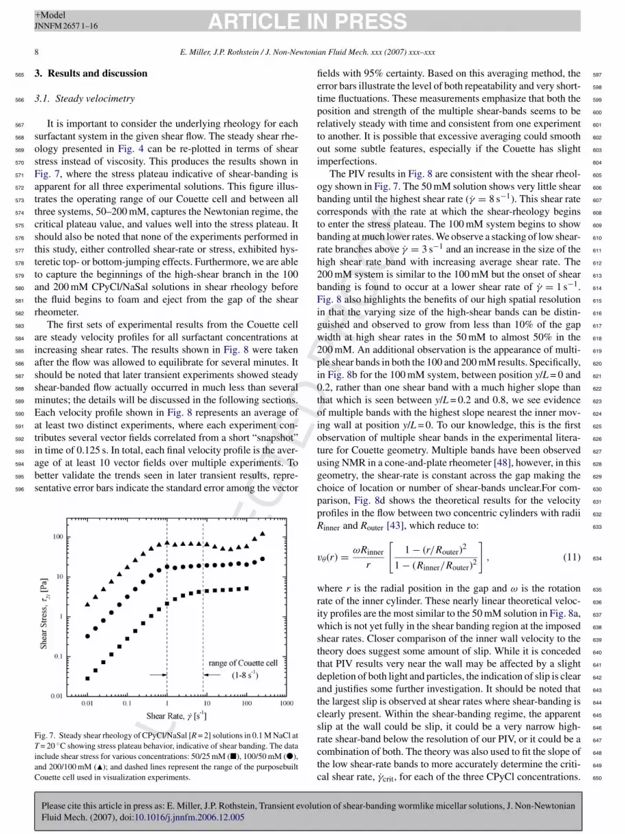
It is important to consider the underlying rheology for eachurfactant system in the given shear flow. The steady shear rhe-logy presented in Fig. 4 can be re-plotted in terms of sheartress instead of viscosity. This produces the results shown inig. 7, where the stress plateau indicative of shear-banding ispparent for all three experimental solutions. This figure illus-rates the operating range of our Couette cell and between allhree systems, 50–200 mM, captures the Newtonian regime, theritical plateau value, and values well into the stress plateau. Ithould also be noted that none of the experiments performed inhis study, either controlled shear-rate or stress, exhibited hys-eretic top- or bottom-jumping effects. Furthermore, we are ableo capture the beginnings of the high-shear branch in the 100nd 200 mM CPyCl/NaSal solutions in shear rheology beforehe fluid begins to foam and eject from the gap of the shearheometer.
The first sets of experimental results from the Couette cellre steady velocity profiles for all surfactant concentrations atncreasing shear rates. The results shown in Fig. 8 were takenfter the flow was allowed to equilibrate for several minutes. Ithould be noted that later transient experiments showed steadyhear-banded flow actually occurred in much less than severalinutes; the details will be discussed in the following sections.ach velocity profile shown in Fig. 8 represents an average oft least two distinct experiments, where each experiment con-ributes several vector fields correlated from a short “snapshot”n time of 0.125 s. In total, each final velocity profile is the aver-
UN
CO
RR
EC
T
Please cite this article in press as: E. Miller, J.P. Rothstein, Transient evolutFluid Mech. (2007), doi:10.1016/j.jnnfm.2006.12.005
ge of at least 10 vector fields over multiple experiments. Toetter validate the trends seen in later transient results, repre-entative error bars indicate the standard error among the vector
ig. 7. Steady shear rheology of CPyCl/NaSal [R = 2] solutions in 0.1 M NaCl at= 20 ◦C showing stress plateau behavior, indicative of shear banding. The data
nclude shear stress for various concentrations: 50/25 mM (�), 100/50 mM (�),nd 200/100 mM (�); and dashed lines represent the range of the purposebuiltouette cell used in visualization experiments.
u 628
g 629
c 630
p 631
p 632
R 633
v 634
w 635
r 636
i 637
w 638
s 639
t 640
t 641
d 642
a 643
t 644
c 645
s 646
rctc
PR
OO
F
PRESSan Fluid Mech. xxx (2007) xxx–xxx
elds with 95% certainty. Based on this averaging method, therror bars illustrate the level of both repeatability and very short-ime fluctuations. These measurements emphasize that both theosition and strength of the multiple shear-bands seems to beelatively steady with time and consistent from one experimento another. It is possible that excessive averaging could smoothut some subtle features, especially if the Couette has slightmperfections.
The PIV results in Fig. 8 are consistent with the shear rheol-gy shown in Fig. 7. The 50 mM solution shows very little shearanding until the highest shear rate (γ̇ = 8 s−1). This shear rateorresponds with the rate at which the shear-rheology beginso enter the stress plateau. The 100 mM system begins to showanding at much lower rates. We observe a stacking of low shear-ate branches above γ̇ = 3 s−1 and an increase in the size of theigh shear rate band with increasing average shear rate. The00 mM system is similar to the 100 mM but the onset of shearanding is found to occur at a lower shear rate of γ̇ = 1 s−1.ig. 8 also highlights the benefits of our high spatial resolution
n that the varying size of the high-shear bands can be distin-uished and observed to grow from less than 10% of the gapidth at high shear rates in the 50 mM to almost 50% in the00 mM. An additional observation is the appearance of multi-le shear bands in both the 100 and 200 mM results. Specifically,n Fig. 8b for the 100 mM system, between position y/L = 0 and.2, rather than one shear band with a much higher slope thanhat which is seen between y/L = 0.2 and 0.8, we see evidencef multiple bands with the highest slope nearest the inner mov-ng wall at position y/L = 0. To our knowledge, this is the firstbservation of multiple shear bands in the experimental litera-ure for Couette geometry. Multiple bands have been observedsing NMR in a cone-and-plate rheometer [48], however, in thiseometry, the shear-rate is constant across the gap making thehoice of location or number of shear-bands unclear.For com-arison, Fig. 8d shows the theoretical results for the velocityrofiles in the flow between two concentric cylinders with radiiinner and Router [43], which reduce to:
θ(r) = ωRinner
r
[1 − (r/Router)2
1 − (Rinner/Router)2
], (11)
here r is the radial position in the gap and ω is the rotationate of the inner cylinder. These nearly linear theoretical veloc-ty profiles are the most similar to the 50 mM solution in Fig. 8a,hich is not yet fully in the shear banding region at the imposed
hear rates. Closer comparison of the inner wall velocity to theheory does suggest some amount of slip. While it is concededhat PIV results very near the wall may be affected by a slightepletion of both light and particles, the indication of slip is clearnd justifies some further investigation. It should be noted thathe largest slip is observed at shear rates where shear-banding islearly present. Within the shear-banding regime, the apparentlip at the wall could be slip, it could be a very narrow high-
ion of shear-banding wormlike micellar solutions, J. Non-Newtonian
ate shear-band below the resolution of our PIV, or it could be a 647
ombination of both. The theory was also used to fit the slope of 648
he low shear-rate bands to more accurately determine the criti- 649
al shear rate, γ̇crit, for each of the three CPyCl concentrations. 650

TED
PR
OO
F
ARTICLE IN PRESS+ModelJNNFM 2657 1–16
E. Miller, J.P. Rothstein / J. Non-Newtonian Fluid Mech. xxx (2007) xxx–xxx 9
Fig. 8. Steady velocity profiles from PIV experiments showing shear band development with increasing shear rate. The data for all cases (a)–(c) of varyingC −1 −1 −1 8 s−1
g beeny
T651
W652
d653
T654
655
m656
l657
t658
[659
a660
b661
n662
r663
b664
t665
p666
s667
i668
a 669
v 670
A 671
b 672
p 673
m 674
t 675
b 676
3 677
678
e 679
NC
OR
RE
CPyCl/NaSal concentration, include γ̇ = 1 s (�), 3 s (), 6 s (©), andiven Couette geometry. Representative error bars for a 95% standard error have/L = 0.
his critical shear rate was then used to determine a criticaleissenberg number for the onset of shear-banding, indepen-
ent of temperature, for each system; the results are included inable 1.
In a shear-banding flow, the fluid in a given flow exists atultiple shear rates. The velocity profile data was used to calcu-
ate the local shear rate within the gap by taking the derivative ofhe steady velocity using an averaged central difference method15]. Fig. 9 shows the local shear rate profile at γ̇ = 8 s−1 forll three surfactant concentrations. In the lower shear-band,etween position y/L = 0.5 and 1.0, the shear rate profiles areearly constant and are in good agreement with the critical shearate for each concentration found by fitting the low shear rateand steady PIV data. While there is some amount of noise due
UPlease cite this article in press as: E. Miller, J.P. Rothstein, Transient evolutFluid Mech. (2007), doi:10.1016/j.jnnfm.2006.12.005
o the numerical derivative taken on a fairly small number ofoints, in the high shear-band, the local shear rate results furtheruggest the existence of multiple shear-bands. The 100 mM datan particular goes from a highly stable low shear-band value of
lfss
(�), as well as (d) the theoretical profiles for a stable Newtonian flow in theshown every three data points. In all cases, the moving inner wall is at position
pproximately γ̇(y) = 4 s−1 at y/L = 0.2, to a high shear-bandalue of γ̇(y) = 48 s−1, before going back down and up again.lthough this further suggests the existence of multiple shear-ands near the moving inner boundary, it is possible that thehenomenon very near the wall is in fact apparent slip. Further-ore, resolving PIV vectors at the inner wall is difficult, and in
he calculation of the shear rate profiles the effect is compoundedy the low resolution numerical derivative.
.2. Transient velocimetry
The transient rheology of wormlike micelles has beenxplored in several previous studies [11,28,34], all with simi-
ion of shear-banding wormlike micellar solutions, J. Non-Newtonian
ar results, so we will not present our results here. As expected 680
rom a viscoelastic system, transient experiments for a given 681
hear state show an initial underdamped elastic overshoot as the 682
teady rate is instantaneously imposed followed by some longer 683

ED
ARTICLE IN+ModelJNNFM 2657 1–16
10 E. Miller, J.P. Rothstein / J. Non-Newtoni
Fig. 9. Local shear rate across the gap, calculated using central difference deriva-tive from steady velocity profiles of CPyCl/NaSal solutions. The data includelrl
t684
t685
fl686
m687
a688
i689
690
s691
a692
d693
w694
s695
f696
t 697
i 698
v 699
t 700
fl 701
t 702
r 703
i 704
g 705
k 706
r 707
708
w 709
n 710
o 711
M 712
O 713
t 714
a 715
o 716
s 717
t 718
s 719
t 720
n 721
fi 722
h 723
i 724
s 725
i 726
727
t 728
Fs
ocal shear rate for the three concentrations at a single imposed global shearate, γ̇ = 8 s−1: 50/25 mM (©), 100/50 mM (�), and 200/100 mM (); straightines are included between the data to guide the eye.
ime fluctuations. Utilizing a high-speed camera, the goal ofhis study was to explore the underlying velocity profiles andow kinematics during the startup of a shear flow. The servo-otor used in the Couette cell system was capable of producingnearly instantaneous startup, and was able to do so with little
nitial vibration (jerkiness) of the motor.Transient results for the 50 and 100 mM CPyCl systems are
hown in Figs. 10 and 11, respectively. Both sets of results are atshear rate of γ̇ = 8 s−1 and are presented in stages of differing
UN
CO
RR
EC
T
Please cite this article in press as: E. Miller, J.P. Rothstein, Transient evolutFluid Mech. (2007), doi:10.1016/j.jnnfm.2006.12.005
evelopment; the 50 mM exhibits two stages of development,hile the 100 mM has four clear stages. On very short time
cales, the startup impulse manifests itself in both systems in theorm of a propagating damped elastic wave. In Figs. 10a and 11a,
i5ws
ig. 10. Transient velocity profiles from a startup experiment with 50/25 mM CPyCl/pacing is in seconds. Figures (a) and (b) show a twostage progression in the develop
PR
OO
F
PRESSan Fluid Mech. xxx (2007) xxx–xxx
his is observed as a quickly growing velocity profile. At its max-mum, the velocity profile is nearly plug-like and has a plateaualue close to the known wall velocity, vwall = 50 mm/s. Fromhe elastic wave speed defined and calculated in Table 1 for eachuid, we can calculate the time necessary for an elastic wave to
ransverse the 6 mm gap. The result for the 50 and 100 mM isoughly t = 0.09 and 0.04 s, respectively. This calculated time isn excellent agreement with the observed results for the propa-ation time of the plug velocity profile in both systems. To ournowledge, this result on such short time scales has not beeneported in any previous work.
In the next stage of velocity profile development, the elasticave is well damped and the plug-like profile falls onto theearly linear profile predicted by theory for a flow in the absencef shear-banding. This occurs on the timescale of less than oneaxwell relaxation time and is observed with both systems.nce again, both systems show excellent agreement between
he relaxation times measured with shear rheology in Table 1nd the time at which the first nearlylinear velocity profile isbserved in the transient experiment. In the case of the 50 mMystem, there is no further interesting development beyond theime scale of one relaxation time because the shear band is verymall and isolated. From t = 0.3 s to 5 min, shown in Fig. 10b,here is little fluctuation in the velocity profile outside of normaloise associated with these experimental measurements. Thenal profile is nearly linear with an indication of a very smalligh shear-rate band close to the moving wall, which is capturedn the velocity profile at t = 7 s but missed in all the others. Asuggested in the previous section, this demonstrates how difficultt is to capture the slip velocity at the wall.
The 100 mM system, however, shows some additional fea-ures most likely due to the fact that at the imposed shear rates,
ion of shear-banding wormlike micellar solutions, J. Non-Newtonian
t is well within the shear-banding plateau region, unlike the 729
0 mM. In Fig. 11b, after the collapse of the plug-like elastic 730
ave profile but before one Maxwell relaxation time, there is a 731
ubstantial amount of fluctuation around a nearly linear profile. 732
NaSal system. All data are for an imposed shear rate of γ̇ = 8 s−1 and temporalment of a steady velocity profile.

TED
PR
OO
F
ARTICLE IN PRESS+ModelJNNFM 2657 1–16
E. Miller, J.P. Rothstein / J. Non-Newtonian Fluid Mech. xxx (2007) xxx–xxx 11
F PyCls he de
T733
a734
m735
p736
t737
A738
a739
A740
a741
s742
b743
t744
745
s746
i747
t748
w749
p750
l751
i 752
r 753
754
s 755
a 756
p 757
f 758
s 759
t 760
w 761
t 762
d 763
e 764
t 765
t 766
NC
OR
RE
Cig. 11. Transient velocity profiles from a startup experiment with 100/50 mM Cpacing of profiles is in seconds. Figures a–d show a four-stage progression in t
he fluctuation is not monotonic, but is observed to fluctuate upnd down. This is perhaps indicative of some underdamped har-onic in the system. After approximately t = 0.07 s, the velocity
rofile begins a monotonic collapse from a nearly linear profileowards the eventual shear-banded profile, as shown in Fig. 11c.t about one relaxation time, λM,100 mM = 1.44 s, the profile is
lready showing a bend between a low and high shear-band.fter three to four Maxwell times, at t = 5 s, the 100 mM system
ppears fully banded and remains stable well beyond 5 min, ashown in Fig. 11d. In this final stage, the small fluctuations cane explained by slight imperfections in the Couette cell ratherhan actual movement of the banded structure.
During the multi-stage development of the shear-bandedtructure in the 100 mM system, the observed slip velocityncreases from vslip = 0 mm/s to almost vslip = 20 mm/s at long
UPlease cite this article in press as: E. Miller, J.P. Rothstein, Transient evolutFluid Mech. (2007), doi:10.1016/j.jnnfm.2006.12.005
imes. It should be noted that a number of studies only observeall slip at some critical value corresponding to a primary stresseak, and otherwise did not observe any slip at all in very simi-ar micellar solutions [16]. Potential reasons for this discrepancy
aavm
/NaSal system. All data are for an imposed shear rate of γ̇ = 8 s−1 and temporalvelopment of a shear-banded steady velocity profile.
nclude aggressive temporal averaging as well as lower spatialesolution.
To better visualize the multiple stage development of thetartup flow in the 100 mM CPyCl wormlike surfactant system,contour map was constructed. In the contour map, both gap
osition and velocity have been normalized. The full evolutionrom t = 0 to 20 min is shown in Fig. 12 on a logarithmic timecale to highlight the short time behavior. In this map, we seehe relatively smooth propagation of the damped elastic wave,hich peaks for a very short time, but with an 80% majority of
he gap nearly achieving the wall velocity. This quickly settlesown with some slight fluctuations that are seen throughout thentirety of the transient experiment. When re-mapped on a linearime scale in Fig. 13, the short time development is obscured, buthe stability of the banded profile is evident. The contour levels
ion of shear-banding wormlike micellar solutions, J. Non-Newtonian
re much closer to each other near the moving wall (position = 0) 767
nd show little fluctuation on long time scales. This long-time 768
elocity profile observation of shear band stability is in disagree- 769
ent with the full-field flow birefringence results of Lerouge et 770

ED
ARTICLE IN+ModelJNNFM 2657 1–16
12 E. Miller, J.P. Rothstein / J. Non-Newtoni
Fig. 12. A contour map of transient velocity profile development from a startupexperiment with 100/50 mM CPyCl/NaSal system. All data are for an imposedstt
a771
o772
l773
t774
a775
t776
t777
d778
t779
3780
781
d782
k783
t784
u785
Ft
a 786
m 787
P 788
s 789
f 790
w 791
c 792
p 793
a 794
r 795
i 796
a 797
b 798
i 799
s 800
i 801
r 802
o 803
n 804
s 805
e 806
F 807
t 808
809
t 810
p 811
F 812
a 813
b 814
n 815
a 816
t 817
t 818
i 819
Thear rate of γ̇ = 8 s−1. Contours represent the velocity, normalized by that ofhe moving inner wall, vwall = 50 mm/s. This map is plotted on a log time scaleo emphasize the early damped elastic wave propagation.
l. [13] that show a large amount of fluctuation and anisotropyn times scales of 100 s and more. It is noted however, that theseongtime fluctuations in the birefringence do not coincide withransient stress measurements in a shear rheometer [13], whichppear to be stable after short-time development and fluctua-ion, much like our velocity profiles. This discrepancy betweenhe stress-field as measured optically and the velocity profileevelopment will be addressed by our birefringence results inhe following section.
.3. Steady pointwise birefringence profiles
While high-resolution velocimetry results provide a great
UN
CO
RR
EC
Please cite this article in press as: E. Miller, J.P. Rothstein, Transient evolutFluid Mech. (2007), doi:10.1016/j.jnnfm.2006.12.005
eal of insight into the development of a shear-banded flow,nowledge of the underlying micelle deformation fields is essen-ial to the formulation of constitutive models as well as a truenderstanding of the shearbanding mechanism. To this end, we
ig. 13. Same contour map as in Fig. 12, plotted on a linear scale to show longime stability of shear banded structure within the gap.
d 820
s 821
i 822
i 823
i 824
o 825
p 826
a 827
d 828
d 829
t 830
s 831
t 832
t 833
a 834
835
b 836
t 837
s 838
Foat
PR
OO
F
PRESSan Fluid Mech. xxx (2007) xxx–xxx
cquired both steady and transient flow-induced birefringenceeasurements in the same Couette cell that we performed theIV. Velocity profile results have suggested the shear-bandedtructure in the wormlike system is stable at long times, there-ore steady-flow birefringence profiles of the gap can be obtainedith relative ease. Startup of flow, however, presents a practi-
al problem. Unlike PIV, quantitative FIB measurements areointwise rather than full-field. Full-field FIB measurementsre possible, and commonly used to show interesting transientesults [13]. These full-field FIB measurements are typicallymages taken through crossed polarizers showing intensity vari-tions within a flow field. These images are only qualitativeecause they cannot account for changes of incident lightntensity for highly dichroic fluids such as wormlike micelleolutions. The modulated FIB system used in our experimentss insensitive to the degree of dichroism because it is a ratiomet-ic technique that explicitly accounts for changes of the intensityf incident light. Unfortunately, instantaneous gap profiles areot possible because the FIB optical train, described earlier andhown in Fig. 6, must be marched across the gap. Gap profiles atquilibrium are easily achieved with excellent spatial resolution.or transient startup results, quantitative FIB measurements are
herefore limited to a fixed point in the gap.The FIB data show interesting results and correlation with
he velocity profiles. A full steady-flow characterization waserformed with the 50 mM system, and the results are shown inig. 14. As expected for this concentration, both the extinctionngle and birefringence data show little evidence of shear-anding at low shear rates. At γ̇ = 1 and 2 s−1 both profiles areearly flat across the gap, indicating that the wormlike micellesre in a uniform state of orientation and deformation. The extinc-ion angle in these cases is nearly uniform at, χ = 45◦, which ishe expected orientation state in a shear flow. As the shear ratencreases to the level at which shear-banding should be evi-ent in the 50 mM system, γ̇ = 8 s−1, the extinction angle curvehows a pronounced slope of increasing orientation towards thenner rotating wall, at y/L = 0. There is some pronounced noisen this data, however, it is clear that near the inner rotating walln the region of the high shear-band, the worms seem to be moreriented, where χ = 0◦ is fully aligned in the flow direction. Com-arison of this steady FIB data to the steady PIV data results inn interesting observation. At γ̇ = 8 s−1, the extinction angleata for this system suggests that more than 40% of the gapisplays a shear-banding variation from a nearly constant orien-ation. The respective PIV profile (see Fig. 8a), however, onlyuggests a shear-band in the final 10% of the gap. This inconsis-ency seems to suggest there is an orientation and deformationhreshold at which a change in the morphology corresponds toshear-band as visualized by PIV.
The data also appear to show that the shear-band as measuredy the birefringence is quite diffuse. This is in direct contrast tohe velocity profiles which show a very sharp transition from onehear-band to the next. FIB data points included in this study (in
ion of shear-banding wormlike micellar solutions, J. Non-Newtonian
igs. 14 and 15) are an average over a finite spatial increment 839
f several raw data points. The result minimizes noise and also 840
ccurately represents the resolution as dictated by the width of 841
he laser beam as it passes through the sample in the Couette 842

TED
PR
OO
F
ARTICLE IN PRESS+ModelJNNFM 2657 1–16
E. Miller, J.P. Rothstein / J. Non-Newtonian Fluid Mech. xxx (2007) xxx–xxx 13
FcT
c843
m844
t845
846
w847
d848
r849
f850
w851
A852
w853
s854
f855
h856
g857
b858
n859
f860
u861
FcT
U 862
a 863
χ 864
I 865
t 866
o 867
i 868
t 869
b 870
871
1 872
t 873
t 874
d 875
o 876
NC
OR
RE
Cig. 14. Steady extinction angle (a) and birefringence data (b) across the Couetteell gap in a fully developed steady flow of the 50/25 mM CPyCl/NaSal system.he data include γ̇ = 1 s−1 (�), 2 s−1 (©), 4 s−1 (�), 6 s−1 (�), and 8 s−1 (�).
ell. We include this procedural detail to clarify that it is not aoving averaging routine which causes the diffuse transition in
he shear-bands.The birefringence data in Fig. 14b show similar behavior and
e see further evidence of an observable change in the micelleeformation field prior to that of the velocity profile. At a shearate of γ̇ = 4 s−1 and above, the birefringence profile changesrom nearly constant across the gap, to somewhat dual-natured,ith a significantly higher level at the inner rotating wall.ccording to the shear rheology (see Fig. 7), γ̇ = 4 s−1 is wellithin the non-banding Newtonian regime for this concentration
ystem. This result suggests that there exists an underlying dif-use band that the FIB measurements clearly show is both moreighly deformed and oriented than the bulk fluid. This birefrin-ent band is a precursor to the eventual low and high shear-rate
UPlease cite this article in press as: E. Miller, J.P. Rothstein, Transient evolutFluid Mech. (2007), doi:10.1016/j.jnnfm.2006.12.005
ands at shear rates where velocity profiles show a uniform andon-banding result (see Fig. 8a). It should be noted that the bire-ringence profile, �n′, is calculated from the retardation signalsing Eq. (6), which has a maximum numerical value of δ = π/2.
stpo
ig. 15. Steady extinction angle (a) and birefringence data (b) across the Couetteell gap in a fully developed steady flow of the 100/50 mM CPyCl/NaSal system.he data include γ̇ = 1 s−1(�), 2 s−1 (©), 4 s−1 (�), 6 s−1 (�), and 8 s−1 (�).
nlike the extinction angle, which is a measure of orientationnd by symmetry conveys no difference beyond the range from= 0 to 4.5◦, the retardation signal goes through several orders.
n our experiment, the light has a relatively long path throughhe birefringent sample and must be unwrapped through severalrders to give an accurate result. This experimental aspect makest more difficult to acquire FIB profile measurements acrosshe gap of the more concentrated and therefore more stronglyirefringent 100 and 200 mM CPyCl systems.
Fig. 15 shows the steady FIB gap profile results for the00 mM system. Despite the extra analysis required to unwraphis system, the results are quite good and in agreement withhe trends observed in the 50 mM system. The extinction angleata is nearly constant at the expected shear flow orientationf χ = 45◦ at low shear rates before showing a pronounced
◦ −1
ion of shear-banding wormlike micellar solutions, J. Non-Newtonian
lope towards χ = 0 at shear rates above γ̇ = 2 s . As with 877
he 50 mM system, at the highest shear rate of γ̇ = 8 s−1, the 878
ronounced slope in the extinction angle profile accounts for 879
ver 40% of the gap while the high shear-band in the veloc- 880
ED
OF
IN PRESS+ModelJ
1 wtonian Fluid Mech. xxx (2007) xxx–xxx
i881
f882
d883
b884
o885
n886
o887
s888
a889
t890
l891
s892
p893
c894
T895
e896
n897
b898
v899
v900
t901
t902
F903
c904
t905
d906
v907
908
o909
l910
f911
o912
s913
i914
e915
m916
l917
d918
3919
920
F921
p922
p923
i924
t925
t926
n927
o928
l929
i930
n931
B932
t933
F934
n935
FTfi
o 936
t 937
s 938
f 939
o 940
o 941
( 942
( 943
a 944
r 945
h 946
s 947
r 948
s 949
b 950
t 951
u 952
i 953
954
l 955
s 956
i 957
a 958
t 959
t 960
s 961
i 962
s 963
s 964
a 965
a 966
g 967
NC
OR
RE
CT
ARTICLENNFM 2657 1–16
4 E. Miller, J.P. Rothstein / J. Non-Ne
ty profile (see Fig. 8b) is seen in only 20% of the gap. This isurther evidence that the micelles become aligned over a broadiffuse region and do not exhibit the sharp transition observedetween the high and low shear-rate bands. Additionally, thenset of micelle deformation and alignment again occurs sig-ificantly farther from the outer wall than the discontinuitybserved in the velocity profile. By comparing the size of thehear bands in Fig. 8b to that of the trend in the extinctionngle in Fig. 15a, there is a reasonable correlation suggestinghat χ � 25◦ is a critical value of orientation for the worm-ike micelles above and below which exist the low and highhear-rate bands, respectively. We do not have a physical inter-retation of this phenomenon. It is our hope that comparison withonstitutive models might shed some light on this observation.he birefringence data in Fig. 15b for the 100 mM system alsoxhibit the same trend of increasing deformation in the micellesear the inner moving wall. Furthermore, at high shear rates theirefringence appears to approach a plateau in the maximumalue of �n′ = 7.5 × 10⁻⁷ rad in the high shear-rate band. Thisalue appears to be independent of shear rate, suggesting thathe deformation, orientation and morphology of the micelles inhe high shear-rate band are independent of bulk shear rate. TheIB data from the low shear-rate band is slightly more compli-ated. Because of the diffusive nature of the shear band, evenhough the velocity profile is not disturbed, the micelles are stilleformed beyond the location of the shear-band observed in theelocity profile.
If the birefringence is converted to a stress using the stress-ptical coefficient and Eq. (4), the resulting overall shear stressevels are in very good agreement with the observed shear stressrom the bulk rheology shown in Fig. 7. As mentioned previ-usly, however, using this calculation to produce a full sheartress profile within the Couette gap would be misleading. Its reassuring that the shear stress levels coincide between ourxperiments, but the high shear rate data is, at best, an esti-ated result based on the fact that the stress-optical law most
ikely does not hold for shear-banded regions with large micelleeformations [12].
.4. Transient FIB
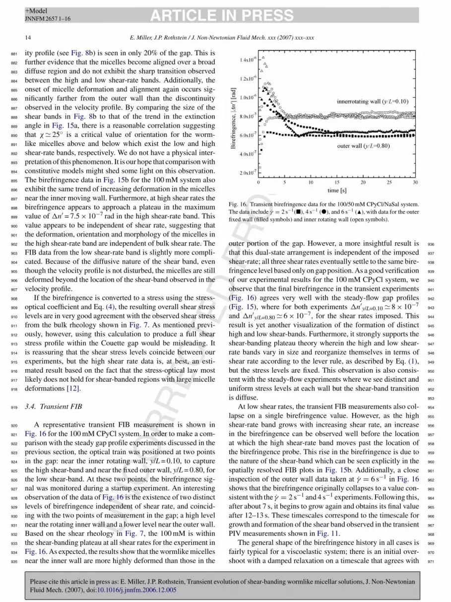
A representative transient FIB measurement is shown inig. 16 for the 100 mM CPyCl system. In order to make a com-arison with the steady gap profile experiments discussed in therevious section, the optical train was positioned at two pointsn the gap: near the inner rotating wall, y/L = 0.10, to capturehe high shear-band and near the fixed outer wall, y/L = 0.80, forhe low shear-band. At these two points, the birefringence sig-al was monitored during a startup experiment. An interestingbservation of the data of Fig. 16 is the existence of two distinctevels of birefringence independent of shear rate, and coincid-ng with the two points of measurement in the gap; a high levelear the rotating inner wall and a lower level near the outer wall.
UPlease cite this article in press as: E. Miller, J.P. Rothstein, Transient evolutFluid Mech. (2007), doi:10.1016/j.jnnfm.2006.12.005
ased on the shear rheology in Fig. 7, the 100 mM is withinhe shear-banding plateau at all shear rates for the experiment inig. 16. As expected, the results show that the wormlike micellesear the inner wall are more highly deformed than those in the
P 968
fs
PR
Oig. 16. Transient birefringence data for the 100/50 mM CPyCl/NaSal system.he data include γ̇ = 2 s−1(�), 4 s−1 (�), and 6 s−1 (�), with data for the outerxed wall (filled symbols) and inner rotating wall (open symbols).
uter portion of the gap. However, a more insightful result ishat this dual-state arrangement is independent of the imposedhear-rate; all three shear rates eventually settle to the same bire-ringence level based only on gap position. As a good verificationf our experimental results for the 100 mM CPyCl system, webserve that the final birefringence in the transient experimentsFig. 16) agrees very well with the steady-flow gap profilesFig. 15), where for both experiments �n′
y/L=0.10 � 8 × 10⁻⁷
nd �n′y/L=0.80 � 6 × 10⁻⁷, for the shear rates imposed. This
esult is yet another visualization of the formation of distinctigh and low shear-bands. Furthermore, it strongly supports thehear-banding plateau theory wherein the high and low shear-ate bands vary in size and reorganize themselves in terms ofhear rate according to the lever rule, as described by Eq. (1),ut the stress levels are fixed. This observation is also consis-ent with the steady-flow experiments where we see distinct andniform stress levels at each wall but the shear-band transitions diffuse.
At low shear rates, the transient FIB measurements also col-apse on a single birefringence value. However, as the highhear-rate band grows with increasing shear rate, an increasen the birefringence can be observed well before the locationt which the high shear-rate band moves past the location ofhe birefringence probe. This rise in the birefringence is due tohe nature of the shear-band which can be seen explicitly in thepatially resolved FIB plots in Fig. 15b. Additionally, a closenspection of the outer wall data taken at γ̇ = 6 s−1 in Fig. 16hows that the birefringence originally collapses to a value con-istent with the γ̇ = 2 s−1 and 4 s−1 experiments. Following this,fter about 7 s, it begins to grow again and obtains its final valuefter 12–13 s. These timescales correspond to the timescale forrowth and formation of the shear band observed in the transientIV measurements shown in Fig. 11.
ion of shear-banding wormlike micellar solutions, J. Non-Newtonian
The general shape of the birefringence history in all cases is 969
airly typical for a viscoelastic system; there is an initial over- 970
hoot with a damped relaxation on a timescale that agrees with 971

D
IN+ModelJ
wtoni
t972
o973
e974
r975
i976
t977
o978
w979
d980
s981
A982
t983
e984
m985
O986
i987
γ988
b989
i990
t991
4992
993
a994
v995
T996
p997
a998
o999
t1000
t1001
t1002
i1003
f1004
t1005
f1006
i1007
c1008
l1009
s1010
s1011
c1012
r1013
t1014
a1015
e1016
i1017
T1018
p1019
b1020
m1021
T1022
t1023
t1024
n1025
A 1026
1027
N 1028
l 1029
L 1030
a 1031
R 1032
1033
1034
1035
1036
1037
1038
1039
1040
1041
1042
1043
1044
1045
1046
1047
1048
1049
1050
1051
1052
1053
[ 1054
1055
[ 1056
1057
[ 1058
1059
1060
[ 1061
1062
1063
[ 1064
1065
[ 1066
1067
1068
[ 1069
1070
[ 1071
1072
[ 1073
1074
1075
[ 1076
1077
1078
[ 1079
1080
1081
[ 1082
NC
OR
RE
CTE
ARTICLENNFM 2657 1–16
E. Miller, J.P. Rothstein / J. Non-Ne
hat seen in transient stress experiments [11,28,34]. The initialvershoot becomes higher as shear rate increases, and is high-st at the inner wall for each pair of birefringence sweeps. Thisesult is consistent with the higher deformation level at the mov-ng wall, and may simply suggest more dramatic dynamics athat point in the gap. In terms of timescale, the overshoot occursn the order of a Maxwell relaxation time, thereby correlatingith some earlytime dynamics observed in the velocity-profileevelopment. The higher shear rate sweeps in Fig. 16 also showome relatively long time relaxation after the initial overshoot.t γ̇ = 4and 6 s−1, near the inner moving wall, the relaxation
o a steady deformation level takes approximately t = 5 s, or sev-ral Maxwell times. This result is in good agreement with theulti-stage transient velocity profile development in Fig. 11.ur steady-flow FIB results can once again be used to better
nterpret the dynamics seen in the transient experiment. For˙y/L=0.80 = 6 s−1, there is a slight undershoot in the data as theirefringence approaches a lower shear-rate value before jump-ng back up to the expected level as the deformation ahead ofhe diffuse shear band reaches it.
. Conclusions
Surfactant micellar solutions, with their varying morphologynd unique ability to behave as living polymers, makes themery interesting subjects in the study of viscoelastic systems.he experiments performed in this study have provided a com-rehensive and highly resolved visualization of shear-bandingnd the underlying deformation and orientation. Gap profilesf a Couette cell in a steady-shear flow provide insight abouthe size and location of high and low shear-bands. High spa-ial resolution within these gap profiles has also allowed uso observe multiple high shear-rate bands near the inner mov-ng wall. By comparing the velocity and birefringence profilesrom the steady-flow experiments, it is observed that the sharpransition seen in PIV is preceded by a much larger and dif-use transition in the birefringence or underlying deformationn the wormlike micelles. We observe a critical orientation thatoincides with the transition from high to low shear-rate bandevels. Whether this value is indicative of a phase transition, asuggested by several researchers as the underlying cause forhear-banding is unclear, however, it is clear that there is aritical change in arrangement and perhaps morphology thatesults in the distinct shear bands seen in various visualiza-ions, including PIV profiles. Our transient experiments whichre resolved at very short timescales have demonstrated thexistence of a propagating damped elastic wave, as well asnteresting dynamics prior to the organization of shear-bands.ogether, the steady and transient results have helped to inter-ret the evolution of shear-bands in terms of the visualized sharpand formation and how it is connected with the underlying anduch more diffuse deformation and orientation of the micelles.
UPlease cite this article in press as: E. Miller, J.P. Rothstein, Transient evolutFluid Mech. (2007), doi:10.1016/j.jnnfm.2006.12.005
his final observation is very interesting and further investiga-ion including correlation with constitutive models is anticipatedo result in a greater understanding of the shear-banding phe-omenon.
[
[
PR
OO
F
PRESSan Fluid Mech. xxx (2007) xxx–xxx 15
cknowledgements
This experimental work was supported by funding from theational Science Foundation (DMS-0406224). We would also
ike to thank Pamela Cook, Gareth McKinley, Christopher Pipe,ouis Rossi, and Paula Vasquez for productive discussions,ssistance and collaboration on this project.
eferences
[1] S. Kefi, J. Lee, T. Pope, P. Sullivan, E. Nelson, A. Hernandez, T. Olsen, M.Parlar, B. Powers, A. Roy, A. Wilson, A. Twynam, Expanding applicationsfor viscoelastic surfactants, Oilfield Rev. (2004) 10–16.
[2] R.G. Larson, The Structure and Rheology of Complex Fluids, OxfordUniversity Press, New York, 1999.
[3] M. Cates, S. Candau, Statics and dynamics of worm-like surfactantmicelles, J. Phys.: Condens. Matter 2 (1990) 6869–6892.
[4] H. Rehage, H. Hoffman, Viscoelastic surfactant solutions: model systemsfor rheological research, Mol. Phys. 74 (1991) 933–973.
[5] J.I. Escalante, E.R. Macias, F. Bautista, J.H. Perez-Lopez, J.F.A. Soltero,J.E. Puig, O. Manero, Shear-banded flow and transient rheology of cationicwormlike micellar solutions, Langmuir 19 (2003) 6620–6626.
[6] M. Cates, Flow behaviour of entangled surfactant micelles, J. Phys.: Con-dens. Matter 8 (1996) 9167–9176.
[7] I.A. Kadoma, J.W. van Egmond, Flow-induced nematic string phasein semidilute wormlike micelle solutions, Phys. Rev. Lett. 80 (1998)5679–5682.
[8] S. Chen, J.P. Rothstein, Flow of a wormlike micelle solution past a fallingsphere, J. Non-Newtonian Fluid Mech. 116 (2004) 205–234.
[9] J.P. Rothstein, Transient extensional rheology of wormlike micelle solu-tions, J. Rheol. 47 (2003) 1227–1247.
10] R.W. Mair, P.T. Callaghan, Observation of shear banding in worm-likemicelles by NMR velocity imaging, Europhys. Lett. 36 (1996) 719–724.
11] J. Berret, Transient rheology of wormlike micelles, Langmuir 13 (1997)2227–2234.
12] J. Lee, G. Fuller, N. Hudson, X. Yuan, Investigation of shear-bandingstructure in wormlike micellar solution by point-wise flow-induced bire-fringence measurements, J. Rheol. 49 (2005) 537–550.
13] S. Lerouge, J.-P. Decruppe, J.-F. Berret, Correlations between rheologicaland optical properties of a micellar solution under shear-banding flow,Langmuir 16 (2000) 6464–6474.
14] J.-P. Decruppe, S. Lerouge, J.-F. Berret, Insight in shear banding undertransient flow, Phys. Rev. E 63 (2001) 022501.
15] A.F. Mendez-Sanchez, J. Perez-Gonzalez, L. de Vargas, J.R. Castrejon-Pita,A.A. Castrejon-Pita, G. Huelsz, Particle image velocimetry of the unstablecapillary flow of a micellar solution, J. Rheol. 47 (2003) 1455–1466.
16] Y.T. Hu, A. Lips, Kinetics and mechanism of shear banding in an entangledmicellar solution, J. Rheol. 49 (2005) 1001–1027.
17] J.-B. Salmon, A. Colin, S. Manneville, Velocity profiles in shear-bandingwormlike micelles, Phys. Rev. Lett. 90 (2003), 228303-1,4.
18] J.-F. Berret, D. Roux, G. Porte, P. Lindner, Shear-induced isotropic-to-nematic phase transition in equilibrium polymers, Europhys. Lett. 25(1994) 521–526.
19] M.W. Liberatore, F. Nettesheim, N.J. Wagner, L. Porcar, Spatially resolvedsmallangle neutron scattering in the 1-2 plane: a study of shear-inducedphase-separating wormlike micelles, Phys. Rev. E 73 (2006).
20] M. Britton, R. Mair, R. Lambert, P. Callaghan, Transition to shear bandingin pipe and Couette flow of wormlike micellar solutions, J. Rheol. 43 (1999)897–909.
21] M. Doi, S.F. Edwards, The Theory of Polymer Dynamics, Clarendon
ion of shear-banding wormlike micellar solutions, J. Non-Newtonian
Press–Oxford University Press, Oxford [Oxfordshire], New York, 1986. 1083
22] N. Spenley, M. Cates, T. McLeish, Nonlinear rheology of wormlike 1084
micelles, Phys. Rev. Lett. 71 (1993) 939–942. 1085
23] N.A. Spenley, X.F. Yuan, M.E. Cates, Nonmonotonic constitutive laws and 1086
the formation of shear-banded flows, J. Phys. II France 6 (1996) 551–571. 1087

IN+ModelJ
1 wtoni
[1088
1089
1090
[1091
1092
[1093
1094
[1095
1096
1097
1098
[1099
1100
1101
[1102
1103
[1104
1105
1106
[1107
1108
1109
1110
[1111
1112
1113
[1114
1115
1116
1117
[1118
[ 1119
1120
1121
[ 1122
1123
1124
[ 1125
1126
1127
1128
[ 1129
1130
[ 1131
1132
[ 1133
1134
[ 1135
1136
[ 1137
1138
1139
[ 1140
[ 1141
1142
[ 1143
1144
[ 1145
ARTICLENNFM 2657 1–16
6 E. Miller, J.P. Rothstein / J. Non-Ne
24] L. Jupp, X.F. Yuan, Dynamic phase separation of a binary polymer liquidwith asymmetric composition under rheometric flow, J. Non-NewtonianFluid Mech. 124 (2004) 93–101.
25] L. Jupp, T. Kawakatsu, X.F. Yuan, Modeling shear-induced phase transi-tions of binary polymer mixtures, J. Chem. Phys. 119 (2003) 6361–6372.
26] X.F. Yuan, L. Jupp, Interplay of flow-induced phase separations and rheo-logical behavior, Europhys. Lett. 60 (2002) 691–697.
27] E. Cappalaere, J. Berret, J. Decruppe, R. Cressely, P. Lindner, Rheology,birefringence, and small-angle neutron scattering in a charged micellar sys-tem: evidence of a shear-induced phase transition, Phys. Rev. E 56 (1997)1869–1878.
28] J.-F. Berret, G. Porte, J.-P. Decruppe, Inhomogeneous shear flows of worm-like micelles: a master dynamic phase diagram, Phys. Rev. E 55 (1997)1668–1676.
29] J. Berret, D. Roux, G. Porte, Isotropic-to-nematic transition in wormlikemicelles under shear, J. Phys. II France 4 (1994) 1261–1279.
30] P. Callaghan, M. Cates, C. Rofe, J. Smeulders, A study of the “spurt effect”in wormlike micelles using nuclear magnetic resonance microscopy, J.Phys. II France 6 (1996) 375–393.
31] A.F. Mendez-Sanchez, M.R. Lopez-Gonzalez, V.H. Rolon-Garrido, J.Perez-Gonzalez, L. de Vargas, Instabilities of micellar systems under homo-geneous and nonhomogeneous flow conditions, Rheol. Acta 42 (2003)56–63.
32] V. Rolon-Garrido, J. Perez-Gonzalez, L.V.A. Montalban, Vane rheometryof an aqueous solution of worm-like micelles, Revisita Mexicana De Fisica49 (2003) 40–44.
33] B.M. Santibanez, F.R. Gonzalez, J.L.V.A.M. Perez-Gonzalez, E.M. Garcia,
UN
CO
RR
EC
TED
Please cite this article in press as: E. Miller, J.P. Rothstein, Transient evolutFluid Mech. (2007), doi:10.1016/j.jnnfm.2006.12.005
Qualitative analysis of the capillary flow stability of spurting materialsby using transmitted light intensity measurements, Revisita Mexicana DeFisica 50 (2004) 562–568.
34] C. Grand, J. Arrault, M. Cates, Slow transients and metastability in worm-like micelle rheology, J. Phys. II France 7 (1997) 1071–1086.
[
[
RO
OF
PRESSan Fluid Mech. xxx (2007) xxx–xxx
35] L.R. Rossi, G. McKinley, L.P. Cook, Slippage and migration in Taylor-Couette flow of a model for dilute wormlike micellar solutions, J. Non-Newtonian Fluid Mech. 136 (2006) 19–92.
36] L.P. Cook, L.R. Rossi, Slippage and migration in models of dilute wormlikemicellar solutions and polymeric fluids, J. Non-Newtonian Fluid Mech. 116(2004) 347–369.
37] F. Kern, P. Lemarechal, S. Candau, M. Cates, Rheological properties ofsemidilute and concentrated aqueous solutions of cetyltrimethylammo-nium bromide in the presence of potassium bromide, Langmuir 8 (1992)437–440.
38] J.-F. Berret, J. Appell, G. Porte, Linear rheology of entangled wormlikemicelles, Langmuir 9 (1993) 2851–2854.
39] I.A. Kadoma, C. Ylitalo, J.W. vanEgmond, Structural transitions in worm-like micelles, Rheol. Acta 36 (1997) 1–12.
40] F. Kern, F. Lequeux, R. Zana, S. Candau, Dynamical properties of salt-freeviscoelastic micellar solutions, Langmuir 10 (1994) 1714–1723.
41] R. Granek, M. Cates, Stress relaxation in living polymers: results from aPoisson renewal model, J. Chem. Phys. 96 (1992) 4758–4767.
42] S.-P. Chen, L.A. Archer, Relaxation dynamics of salt-free polyelectrolytesolutions using flow birefringence and rheometry, J. Polym. Sci.: Polym.Phys. 37 (1999) 825–835.
43] F.M. White, Viscous Fluid Flow, McGraw-Hill, New York, 1991.44] R.G. Larson, Instabilities in viscoelastic flows, Rheol. Acta 31 (1992)
213–263.45] J. Ou, J.P. Rothstein, Direct velocity measurements of the flow past drag-
reducing ultrahydrophobic surfaces, Phys. Fluids 17 (2005).46] J.M. Li, W.R. Burghardt, Flow birefringence in axisymmetrical geometries,
P
ion of shear-banding wormlike micellar solutions, J. Non-Newtonian
J. Rheol. 39 (1995) 743–766. 1146
47] G.G. Fuller, Optical Rheometry of Complex Fluids, Oxford University 1147
Press, New York, 1995. 1148
48] M.M. Britton, P.T. Callaghan, Two-phase shear band structures at uniform 1149
stress, Phys. Rev. Lett. 78 (1997) 4930–4933. 1150


