Embed Size (px)
Citation preview

INTERNATIONAL JOURNAL FOR NUMERICAL METHODS IN ENGINEERING, VOL. 22,93- 1 15 (1986)
TRUNC FOR SHELLS-AN ELEMENT POSSIBLY TO THE TASTE OF BRUCE IRONS
J. ARGYRIS, M. HAASE, H.-P. MLEJNEK, P. K. SCHMOLZ
Institute for Computer Applications, University of Stuttgart, Stuttgart, Federal Republic of Germany
‘All our experience confirms that understanding based on physical concepts is pre- eminent. In these essential matters, we are unashamed.’
in Techniques of Finite Elements (co-author S . Ahmad), implications of the patch test. Bruce Irons
SUMMARY
In his delightful and original textbook,ls Bruce Irons introduces the chapter of plate bending with the remark ‘History of disasters, but the pioneering days are past’. This is certainly true. On the other hand, we learn in the same context from Irons: ‘We believe that the world has not yet exhausted the older formulations.’ In this paper we present a review of theoretical aspects of the plate-bending triangle TRUNC (Reference 4), together with extensive tests in linear statics, dynamics, buckling and nonlinear large deformations both for plates and shells. The unconventional TRUNC model is based on the patch test, which was originated by Irons.’ In spite of its limited theoretical foundation, the performance of this element on a fairly broad field of applications appears at least from the practical point of view very satisfactory.
I. INTRODUCTION
The development of reliable and efficient elements for thin shell structures has been ab initio one of the major objectives and difficulties in finite element analysis. The large number of finite elements which have been proposed to this purpose may be categorized into three distinct classes: first, flat plate-like elements leading to a faceted idealization of the structure; secondly, curved shell elements; and thirdly, degenerated three-dimensional elements. There exist, however, several well- known shortcomings in a faceted idealization due to the imposed uncoupling of stretching and bending within each individual element. Nevertheless, flat elements are known to be very eficient for approximate engineering applications, especially in the study of geometrically nonlinear problems. In this respect, the use of higher order elements is often too expensive and complicated for engineering purposes, especially when higher order derivatives are used as degrees-of-freedom.
One of the cardinal rules in the application of the Rayleigh-Ritz technique in finite element work concerns the admissibility of trial functions. However, there exist nonconforming elements violating this rule which display a good performance and converge to the exact solution. The cardinal question of convergence of a nonconforming element was answered by Bruce Irons’ with a simple but brilliant idea, now known as the patch test. This test determines, in fact, whether or not the element reproduces consistently all possible states of constant strain. The patch test is mainly used to check the underlying theory and coding of an element. However, the basic idea when applied in an inverse direction, may be extended equally to the development of so-called unconventional elements.
0029-598 1/86/020093-23SO2.30 0 1986 by John Wiley & Sons, Ltd.

94 J. ARGYRIS ET AL.
In the present paper we propose a straight triangular element for shell problems having three nodal points and 18 degrees-of-freedom (three translations and three rotations at each nodal point). The bending part is related to that of the effective unconventional plate-bending element known as TRUNC (Reference 4), which is based upon the so-called individual element test. For the membrane stiffness we rely on the constant strain TRIM3 element. In addition two possibilities are envisaged for the specification of a stiffness associated with rotations about a normal to the middle plane. The development of the theory follows the natural method and uses separate rigid body and pure deformation modes. Starting from the internal displacement field, a very simple and effective geometrical stiffness matrix is derived which is successfully applied to a number of linear buckling problems.
A large number of examples illustrating the theory and demonstrating the effectiveness of the element is presented. These applications include plate and shell problems, and vibration and initial buckling problems. In addition, we review some first attempts on the analysis of geometrically nonlinear problems. As a rule we quote comparisons with other facet triangular elements such as TRIB3 (Reference 9) and TRUMP (Reference 6).
2. SHORT REVIEW O F THE PLATE-BENDING ELEMENT TRUNC
In a previous paper4 we described a simple triangular plate-bending element, bearing the connotation TRUNC. This element is based upon the so-called individual element test (IE-test) of BerganY2 which guarantees a sufficient condition for the patch test, and may be expressed as follows:
If an arbitrary patch of elements is subjected to any constant strain field the pairs of traction forces arising along adjoining element sides have to cancel.
For the case when the displacement pattern of an element includes all constant strain modes and satisfies the individual element test we may assert the convergence of the element.16
To begin with, we review briefly the plane triangular plate-bending element TRUNC assuming that the Kirchhoff theory holds. All pertinent geometrical data of the triangle are shown in Figure 1. First we define the nodal displacement vector of the bending action
Pb = ~ ~ l ~ l x ( P l y ~ z ( P z ~ ( P z y ~ 3 ( P 3 x ~ 3 y ~ (1) Here, w denotes the vertical displacement component and ( p i x , (piy are rotations about the x- and y- axis of a local co-ordinate system in the middle plane of the triangle (see Figure 2).
1
I------ 1,-
Figure 1. Geometry of triangle; definition of natural co-ordinates

TRUNC FOR SHELLS 95
t . . . thickness t w1 R . . . area
3 4- %
Figure 2. Bending part of TRUNC: degrees-of-freedom and traction forces
Next we introduce the relevant rigid body modes
p t l translation in z-direction pboz rotation about x-axis p t 3 rotation about y-axis
which are collected in the vector
Since the transverse displacement field is described in (1) by 9 degrees-of-freedom we are led to select six pure bending modes which have to include all possible constant strain modes
Pf; = { P N c P N h ) (3) where pNc and p N h define, respectively, the amplitudes of the constant strain and higher order modes (see also Figure 3). The relation between rigid body cum natural modes and elemental degrees-of-freedom may now be written in the form (see Reference 4)
In analogy to the modes pNc and p N h , the corresponding stiffness matrix may be partitioned to read
L
Figure 3. Natural bending modes
96 J. ARGYRIS ET AL.
As a result, the natural forces resulting from the constant strain modes are
p'N = LPNc (6) In order to satisfy the IE-test these forces P& must be identical to the kinematically equivalent lumped forces arising from pNc, i.e.
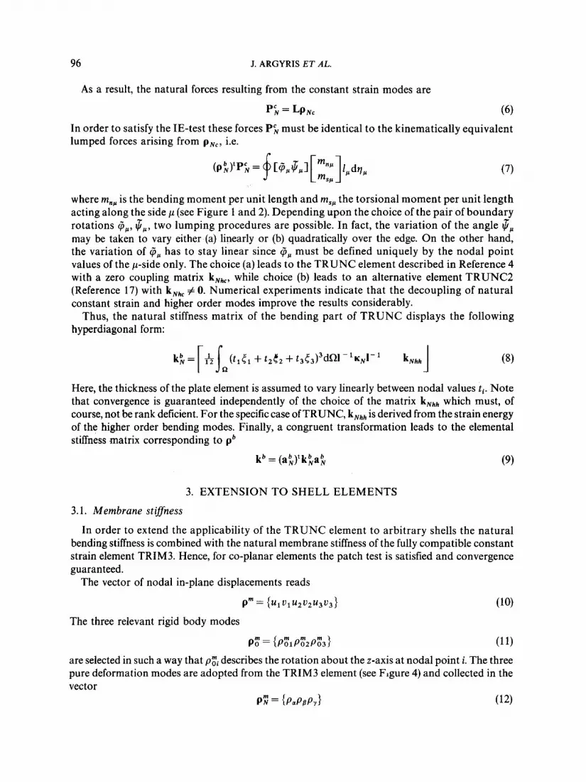
where m,, is the bending moment per unit length and m,, the torsional moment per unit length acting along the side p (see Figure 1 and 2). Depending upon the choice of the pair of boundary rotations @,, $,, two lumping procedures are possible. In fact, the variation of the angle $, may be taken to vary either (a) linearly or (b) quadratically over the edge. On the other hand, the variation of @,, has to stay linear since @ p must be defined uniquely by the nodal point values of the p-side only. The choice (a) leads to the TRUNC element described in Reference 4 with a zero coupling matrix kNhc, while choice (b) leads to an alternative element TRUNC2 (Reference 17) with kNhc # 0. Numerical experiments indicate that the decoupling of natural constant strain and higher order modes improve the results considerably.
Thus, the natural stiffness matrix of the bending part of TRUNC displays the following hyperdiagonal form:
Here, the thickness of the plate element is assumed to vary linearly between nodal values ti. Note that convergence is guaranteed independently of the choice of the matrix k,,,,, which must, of course, not be rank deficient. For the specific case of TRUNC, k,,,,, is derived from the strain energy of the higher order bending modes. Finally, a congruent transformation leads to the elemental stiffness matrix corresponding to pb
kb = (ak)'kkaf; (9)
3. EXTENSION TO SHELL ELEMENTS
3.1. Membrane stiffness
In order to extend the applicability of the TRUNC element to arbitrary shells the natural bending stiffness is combined with the natural membrane stiffness of the fully compatible constant strain element TRIM3. Hence, for co-planar elements the patch test is satisfied and convergence guaranteed.
The vector of nodal in-plane displacements reads
P" = l U 1 u 1 u2 u2u3u3 } The three relevant rigid body modes
p t = (PtIPt2Pt3) (1 1)
are selected in such a way that p t i describes the rotation about the z-axis at nodal point i. The three pure deformation modes are adopted from the TRIM3 element (see Figure 4) and collected in the vector
P: = {P,PaP,) (12)

TRUNC FOR SHELLS 97
Figure 4. Natural membrane modes
Clearly, the combination of p$ and p; forms an alternative generalized displacement field to the nodal displacement vector of (10). Thus it is possible to establish the relation
p; = a;p" (13) The natural membrane stiffness may be deduced from the strain energy expression, leading
to the following simple expression for a linearly tapered membrane element
k; = ~ t , ~ - ' K , ~ - ' (14) where t , = (tl + t , + t3 ) /3 . The contribution to the elemental stiffness matrix corresponding to p" yields the Cartesian stiffness
k" = a;k;a; (15) Combining membrane and bending action we obtain a triangular facet shell element with the following spatial vector of elemental degrees-of-freedom:
with
where ui and cpi are displacements and rotations corresponding to a global Cartesian co-ordinate system [O; xl, x 2 , x3].
3.2. Stifness corresponding to normal rotations
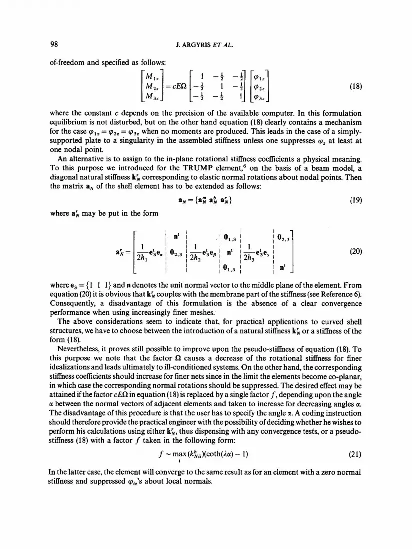
Clearly, the element displays in the above formulation a zero stiffness for rotations qr about a normal to the middle plane. Therefore, a kinematic difficulty arises if all the elements meeting at one nodal point are co-planar. In fact, this case is associated with a null stiffness for a local cpz rotation. This problem may be circumvented by the introduction of a local co-ordinate system as shown in Figure 2 and by elimination of the corresponding rotational degree-of-freedom. However, for practical applications this procedure may be quite awkward because many nodal points may exist in the structure with co-planar or almost co-planar elements. There is a difficulty in deciding what tolerance may be accepted in defining co-planarity without being faced either with poorly conditioned or over-stiff equations.
As shown by Irons'* an incorporation of the so-called normal rotations into the plane stress problem by introduction of additional plane-bending modes is not reasonable. Zienkiewicz5 proposed a fictitious set of stiffness coefficients associated with the in-plane rotational degrees-
98 J. ARGYRIS ET AL.
of-freedom and specified as follows:
where the constant c depends on the precision of the available computer. In this formulation equilibrium is not disturbed, but on the other hand equation (18) clearly contains a mechanism for the case cpIz = cpzz = cp3z when no moments are produced. This leads in the case of a simply- supported plate to a singularity in the assembled stiffness unless one suppresses cpz at least at one nodal point.
An alternative is to assign to the in-plane rotational stiffness coefficients a physical meaning. To this purpose we introduced for the TRUMP element,6 on the basis of a beam model, a diagonal natural stiffness kk corresponding to elastic normal rotations about nodal points. Then the matrix aN of the shell element has to be extended as follows:
where ah may be put in the form
where e3 = { 1 1 1) and n denotes the unit normal vector to the middle plane of the element. From equation (20) it is obvious that kk couples with the membrane part of the stiffness (see Reference 6). Consequently, a disadvantage of this formulation is the absence of a clear convergence performance when using increasingly finer meshes.
The above considerations seem to indicate that, for practical applications to curved shell structures, we have to choose between the introduction of a natural stiffness kh or a stiffness of the form (1 8).
Nevertheless, it proves still possible to improve upon the pseudo-stiffness of equation (1 8). To this purpose we note that the factor R causes a decrease of the rotational stiffness for finer idealizations and leads ultimately to ill-conditioned systems. On the other hand, the corresponding stiffness coefficients should increase for finer nets since in the limit the elements become co-planar, in which case the corresponding normal rotations should be suppressed. The desired effect may be attained if the factor cER in equation (18) is replaced by a single factor f, depending upon the angle c1 between the normal vectors of adjacent elements and taken to increase for decreasing angles c1. The disadvantage of this procedure is that the user has to specify the angle a. A coding instruction should therefore provide the practical engineer with the possibility of deciding whether he wishes to perform his calculations using either kk, thus dispensing with any convergence tests, or a pseudo- stiffness (18) with a factor f taken in the following form:
(21) f - max (kkii)(coth(h) - 1) i
In the latter case, the element will converge to the same result as for an element with a zero normal stiffness and suppressed cpiz's about local normals.

TRUNC FOR SHELLS 99
4. GEOMETRICAL STIFFNESS BASED UPON THE DISPLACEMENT FIELD
The following derivation is founded upon the assumption of thin shell theory, thus allowing for the application of Kirchhoff’s theory. We also assume small natutal strains but large rigid body rotations and a linearly elastic material. Figure 5 shows the deformation of the shell. All quantities corresponding to the deformed shell are marked by a dash.
We deduce from Figure 5 the following relations:
where x‘ = x + u = x, + zn + u
u = U, + z(n’ - n)
The deflection of a point P, on the middle plane with the position vector x M may be split up into a membrane and a bending contribution
uM = + db) = (a, + na,af;)p (23) where the interpolation function a, determines the linear displacement variation of the middle plane (membrane part; TRIM3) and a b defines the bending modes (constant curvature plus higher order modes; see also (3)). The edge vectors
4Gp = x:p&Ip (11 = a, B, Y)
ax! x:pt = ~
av,t
specify a local ~ubtriangle.~ Here, x:,~ is an abbreviation for
Note that the dimensionless triangular co-ordinates qa (Figure 1) are supernumerary. Consequent- ly, we have to distinguish between formal and total or directional derivatives. The latter case is indicated in (24)’ (25) by the inferior index t in aqpr.
The sub-triangle defined by (25) has the side lengths
lLp = (x:tx:pr)1’2dqp = mpdq, (26) where
Since the total natural Green strains”
m: = 1:(1+ 2l;’e;u,,, + l;2u:,tu,M)
E ~ , , = +l;’(m: - 1 ; )
line
Figure 5. Deformation of a p-line of the shell element

100 J. ARGYRIS ET AL.
lead to a simpler expression
EG,, = 1, 'eLu,,, + +1;2u~,tu,,, (29) than for the small strain theory, the present formulation may be adopted, without loss of accuracy, for small strains also. Observing that x$,,,n' = 0, equation (29) may be rewritten in the form
Erp = l;le:uM,pt - z 1, (n -n):pt(xM + u M ) , ~ ~ +41i2[u'M,pr~M,pt + ~~(n'-n)~,,(n'-n),,rl (30)
which may be split into a part E& = aN,p, which is linear in the displacements, and a part which is quadratic both in z and in the displacements. The latter is expressed as
2 -2 r
and leads to the geometrical stiffness k,. Inserting the incremental total strains
BE,, = aN,6p + 6p'(A, + zB, + z2C,)p (32) and the corresponding component stresses ac into the expression for the increment of the virtual work
BW = fsr:a,dV = Bp'k,p (33)
one obtains the following relation:
where k, is split into the elastic stiffness k, and the geometrical stiffness k,. In the case of a displacement model the first integral leads to the elastic stiffness k,, which is
replaced in the case of the unconventional TRUNC element by the stiffness defined in the previous sections. For the geometrical stiffness only the second integral is relevant. Observing that the stresses may also be partitioned into a membrane and a bending part
we obtain
For thin shells the influence of the matrices C, as well as the bending stresses o b may be neglected. In this case, the geometrical stiffness may be approximated by the simple expression
where A, is given by
A, = I ; 2mLm, with m, = + nmb,pta\ (38)

TRUNC FOR SHELLS 101
This simplified form of k, has been used for linear buckling problems and has proved to yield very accurate results.
In Section 5 we present some applications of the current theory to linear problems. An extension to the analysis of geometrically nonlinear problems is attempted in Section 6.
5. APPLICATIONS IN LINEAR STATICS, BUCKLING AND DYNAMICS FOR PLATES AND SHELLS
5.1. Plate-bending problems
First, we briefly discuss some applications of the element TRUNC to simple plate-bending problems (Figure 6). These extend to a square plate either simply supported or clamped subject to a concentrated or a uniform distributed load. The TRUNC results are compared with those for two triangular bending elements described by the same nodal vectors of Cartesian freedoms. The first contestant is TRUMP (Reference 6), also an unconventional model, and the second is TRIB3 (Reference 9), one of the first fully compatible displacement models. In addition, we consider the TUBA6 result^'^^^^ which are based on a fifth-order interpolation scheme for lateral displacements and include second-order derivatives as degrees-of-freedom.
In each case the percentage error of the maximal vertical displacement w,,, is plotted against the number of unknowns N (Figures 7 and 9). Also, the bending moments at either the boundary of the plate or the centre of the plate are plotted versus N (Figures 8 and 10). Clearly, the efficiency of TRUNC proves superior to that of the TRUMP and TRIB3 candidates. This is demonstrated for both displacements and stresses. Moreover, the accuracy of TRUNC is seen to be almost in the range of TUBA6 which is, however, for some applications less convenient in practice.
5.2. Linear buckling of plates
In order to test the geometrical stiffness of the TRUNC element, we select as a first example a linearly tapered simply-supported square plate uniformly compressed in one direction (Figure 1 1). The accuracy of the computed critical load factor ;1 as depending on the refinement of the finite element mesh is demonstrated in Figure 11. Both the TRUNC and the TRUMP element are compared to the analytical solution due to Whittrick and Ellen." Figure 11 shows the high accuracy of the TRUNC element even for coarse idealizations. It converges faster to the exact value than the TRUMP element. It should be mentioned that all TRUNC results presented here were obtained using a very simple and effective geometrical stiffness program without numerical integration. Since neither TRUNC nor TRUMP are conventional displacement models, the sign of the error is not known a priori.
In order to test the grid sensitivity of the geometrical stiffness, we consider as a second example a simply-supported rectangular plate with constant thickness t. The geometrical and material data, as well as the analytical solution of Timo~henko,'~ are shown in Figure 12. Using three different coarse grid types, a clear hierarchy of efficiency is observed. Certainly TRUNC yields the most accurate results. It is seen that, with respect to grid variation, TRUNC proves the most insensitive as well as accurate of the elements under consideration. In contrast to this, the TRUMP results for various grids vary erratically for buckling mode 1. TRUNC presents, in all cases, superior results.
5.3. Dynamic analysis of plates
To test the performance of the TRUNC element in dynamic problems, the frequencies of three

102 J. ARGYRIS ET AL.
') N E T 1 'a _ _ - - -c X
Y t N E T 3
e X
4 N E T 5
c X
' 1 N E T 2
-* X
't N E T 4
.c X
.-* X
Geometrical data:
edge length
thickness t = 0.04 m
a = 8 rn
kbterial doto: 5 2 modulus of elasticity € = 3 x 10 kp/m
Poisson's mtio v = 0.3
E t3 12(1- $1 0, = Bending stiffness:
Figure 6. Bending of a quarter of a square plate; alternative idealizations and data
square plates under various boundary conditions are computed and compared with the analytical solution of Flugge. 13 The results are presented in Figure 13. The first three frequencies for a mesh of 8 x 8 elements are set against the theoretical values. Figure 13 also confirms that all frequencies are within the range of engineering accuracy. For the case of a square plate clamped on two edges, the percentage error to the analytical values is less than 2 per cent (Figure 13a).

TRUNC FOR SHELLS 103
c I Ole1
6 L g 0 4 0
0)
c
0
b 2 CL
0
- 2
- L
- 6
- 8
- 10
-12
-1L
-16
0 TRUNC
A TRIB3
0 TRUMP
X X TUBA6 ,~ -- /
/
Exact value for y = 0.3
wSx = 0.0611 Ru2 FF
* Number of unknowns Y -. I I t
100 150 N / 50
Figure 7. Clamped square plate under concentrated central load; percentage error of the maximal deflection
In the case of simply-supported boundaries, the error of the TRUNC solution for the first frequency is less than 0.1 per cent and for the third frequency less than 1 per cent (Figure 13b).
As a third example (Figure 13c) we consider a square plate clamped on all edges. Comparison with the analytical solution shows that the TRUNC solution yields an error of less than 1 per cent for the first three frequencies.

104
I - 2
- 4
J. ARGYRIS ET AL.
t rl- ’
0 TRUNC
A TRIBJ”
a TRUMP*
X TUBA6
Exact value ---- -- -~ - Y .. ( Timoshenko )
M, = 5.028. lo-* kprn
X) Nodal point stresses obtained by ASKA NPST-processor
Number of unknowns
50 100 -
150 N
Figure 8. Clamped square plate under concentrated central load; bending moment M, at the mid-point of the clamped edge
0 TRUNC
A TRlB3
0 TRUMP /
/ ’ X TUBA6
Exact value
W , = 0 . 0 0 1 0 6 0 w 4

TRUNC FOR SHELLS
3.70-
3.65-
105
b = Z O i n t, = 0.1 in
t,/t* = 1 5
Moterial dam:
E = 25930 lb/in2
v = 0.3
0 TRUNC
Bending stiffness:
Reference line load:
bZ
Analytical solution - - 0
M-10-2 t kpml
+
[ m
5 E" s
-c1 - 2.0 .- X
1.8
1.6
0
0 TRUNC
A TRIB3*
o TRUMP*
X TUBA6
- - 1 Exact value
M = 1.9155.10-2 kpm
*) Nodal point stresses obtained
by ASKA NPST-processor
Number of unknowns
50 100 150 N Figure 10. Simply-supported square plate under uniform load; maximal bending moment
Geometrical dam:
3 4 Number of unknowns N
I I I I 1 I 1 I I c 0 200 400 600 800 1000 1200
Figure 11. Linear buckling of a tapered square plate

106 J. ARGYRIS ET AL.
MODES AND
ANALYTICAL RESULTS
A, = 15.80
A2= 18.52
A,= 24.69
TRIB3 T R U N C
+ 2 3 . 1 - 2 . 5
-36.0 - 3.1
+ 13.3 -2 .2
T R U M P
+ I . )
+ 9.7
- 0.6
TRIB3
+16.5
+ 3L.O
13.3
Figure 12. Grid sensitivity test for TRUNC geometrical stiffness
5.4. Linear shell analysis (barrel vault)
To test the performance of shell elements, we investigate in what follows the well-known barrel vault which has become literally a classical reference structure. The barrel vault is loaded under self-weight and supported by rigid diaphragms. As a characteristic deformation for the accuracy of a finite element solution we select the vertical displacement wB at point B. Figure 14 shows two computational FEM solutions, namely the ‘shallow shell’ solution of Tottenham and Brebbia7 and the ‘deep shell’ solution of Forsberg and Hartung.* Comparison of these results with TRUNC, TRIB3 and TRUMP computations indicate that all these elements are too stiff for coarse grids, but for finer meshes the TRUNC element is seen to converge rapidly to the ‘deep shell’ solution. With the exception of the coarsest net, TRUNC yields the most accurate results. It should be mentioned that the in-plane rotational degrees-of-freedom, for the TRIB3 element, have to be suppressed if the angle between adjacent element planes is less than 5 degrees. In the case of the barrel vault, this involves the introduction of rotated co-ordinate systems at all nodal points. For practical use, this is quite cumbersome in contrast to the TRUNC element. It must be admitted that all elements using the TRIM3 as a membrane part-as is the case for TRUNC and the other two contestants- do not prove in the present case ideal tools of analysis. This is not surprising, bearing in mind that the membrane effects are paramount for a barrel vault.
5.5. Linear buckling of a cylindrical shell
To investigate the effect of the geometrical stiffness of the TRUNC element in the case of a curved shell, the authors selected a cylindrical panel of radius r under uniform line load. The formulation

TRUNC FOR SHELLS
y2
5
107
5 754.9 5 643.1 - 1.9
6 399.6 6 346.5 - 0.8
t z / Y
TRUNC Analytical solution
Geometrical Qta:
a = 2.0in
t = 0.2 in
errar [%]
1 1 784.0 1 1 804.0 0.17
u3 1 1 7&.0 11 865.0 0.69
, u2
TRUNC error [%I Analytical solution
Anolyticol solution
I u, 1 1662.0 I 1631.4 I - 1.8 1
error [ x.3 TRUNC
y2 17 527.5 17 475.0 - 0.30
, 17 527.5 17 662.5 0.77
I u, I 4713.6 I 4716 .6 I 0.06 I
I I Frequencies (Hz] I I
I v, I 8596.6 I 8 581.4 I - 0 . 1 8 I
of the problem is shown in Figure 15. The reference solution of Timoshenko is also given; see Reference 12. A faceted idealization is applied to the curved shell. To calculate the critical stress a 12 x 12 mesh is used. Preceding investigations indicated that, as a result of the boundary conditions, the buckling analysis proves very sensitive. The tangential displacements at the edges 0, = 0, y = l) are zero as well as the axial displacements at the longitudinal supports (0 = 0 and 0 = b). To realize these constraints the problem was solved in two steps. First, we calculated the elastic deformation assuming that the axial displacements u along the generators 8 = 0 and 0 = of the cylindrical shell are unrestrained. Subsequently, the computed deformations were ‘frozen’ and served as a new input for the linear buckling investigation. Figure 15 presents the first five critical stresses and the buckling modes. A comparison with the analytical solution shows that TRUNC produces the most accurate results. Since the first five critical stresses do not differ markedly, the

108 J. ARGYRIS ET AL.
3 75
m 350 - c_ n L
3.25 - C
2 3.00 '" v - B r 275 >
2 50
2.2:
2.0c
v g " d
"shallow shell" solution I w= 3 696 i n l - - - - - - - ---------- "deep shell" solution I w = 3 GO7 In I - - - - - - - - -
Q - rl
,V
Geometrical dam:
R = 300in
I = M X ) i n
t = 3 i n
a = 40"
hbterial dam:
E = 3 x 10⁶ Ib/in2
o TRUNC
0 TRIB3
Y =o. Q = 2.0833 Ib/in3
A TRUMP
Number of unknowns N I ' . * . 1 - " I -
500 1000 IS00 2000 2500 3000
Figure 14. Barrel vault under self-weight
Geometrical dam:
d g e m t i o b / l = 1.0
radius r = 250.0 in
thickness = 0.5 in
r e c b angle /3 = b/r = 20'
x hbterial dam: E = 7000.0 Ib/in2
Y = 0.3
*' n = number of half w v e r in x-direction m = number of half waver in y-cjirection
Figure 15. Linear buckling of a cylindrical shell under uniform line load

TRUNC FOR SHELLS 109
1st mode: 0, = 8.60 Ib/in2 2nd mode: 02 = 8.75 Ib/in2
3rd mode: U3 = 8.81 Ib/in2 4th mode: G4 = 8.82 Ib/in2
5th mode: Gs = 8.96 Ib/in2
Figure 16. Buckling modes of a cylindrical shell under uniform line load (TRUNC results)
computation of the higher buckling modes display inevitably a somewhat mixed-up effect. For the TRUNC element, the buckling modes are plotted in Figure 16.
5.6. Dynamic analysis of a fan blade
The dynamic behaviour of a fan blade was investigated to test the performance of the TRUNC element in dynamic problems. The shape of the fan blade is a sector of a cylindrical shell with constant thickness. The blade is clamped at one curved edge, the other edges being free. For the idealization, a mesh of 8 x 8 elements with 432 degrees-of-freedom is used (Figure 17). The first three frequencies of the free oscillation are compared with the experimentally measured values from Reference 14 and the computational ones for the TRIB3 and TRUMP elements. For the TRUMP element two calculations have been performed, one with a consistent mass matrix and the other with a lumped mass matrix. It is evident that the first two frequencies of all elements are too high, thus showing that their stiffness is excessive. We observe that the TRUMP element delivers, in

110
e+%I v,LHJ e3L%l - - 258.9 -
10.2 255.1 - 1.5
11.0 256.8 - 0 . 8
1 1 . 1 249.2 - 3.7
8.2 246.4 - 4 . 8
J. ARGYRIS ET AL.
a) Frequencies
Geometrical dam: I = 30.48 in
R = 60.96 in
t = 0.3048 in
Cp = 0.5 radians Moterial data:
E = 2.0601 x lo9 Ib/in2
v = 0.3
P = 0.007876 Ib/in3
3rd mode
b) Computer plot of the eigmmodes
Figure 17. Dynamic analysis of a fan blade
combination with a lumped mass matrix, the best results. However, among all elements with a consistent mass matrix the TRUNC element yields the optimal frequencies. The first three eigenmodes are plotted in Figure 17(b).
6. A FIRST EXCURSION INTO NONLINEAR STATIC ANALYSIS
6.1. Large defection of a cantilever plate under transverse end load
In the following section we treat three examples to check the performance of the TRUNC element in the presence of large deflections. The first example is given in Figure 18. The load P is

TRUNC FOR SHELLS 111
P
[k Nl LO
36
32
28
21
20
16
12
8
L
0
Geometrical dam:
I = 100cm
b = 20 cm
t = l c m
Material dam: 0 TRUNC
0 SHEEA
A TRIE3 - B e a m Theory
Figure 18. Large deflection of a cantilever plate under transverse end load
Y7 p = 8 k N
P = 20 kN
Figure 19. Large deflection of a cantilever plate under transverse end load; plot of deformations
: O kN

112
3 ' M22m
1.0 .
0.75
0.50
0.25
0
M =
J. ARGYRIS ET AL.
. O'.
'0 ' . ' 'h u3
'\ - \
a: o TRUNC Geometricol dolo:
1 =100cm
b = 20 cm
t = 0 . 5 c m
- Analytical solution
I h t e r i a I dam:
I I E=2.1x10⁶kp/cm2 I v = 1/3 I I Moment: I I I
M2zm = 3.0124 x ldkpcm 1
0.2 0.4 0.6 0.8 lo 1; & ,- U T 1 1
Figure 20. Large deflection of a cantilever plate under end moment
M = 114.4 kpm
Figure 21. Large deflection of a cantilever plate under end moment; plot of deformations
TRUNC FOR SHELLS 113
applied as a uniform line load at the free edge of the plate. Due to the symmetry of the problem only halfof the structure need be idealized. The reader will observe comparisons of TRUNC results with those for SHEBA (Reference lo), TRUMP and TRIB3 for the load-deformation diagram of the central point of the free edge of the plate. The agreement among the finite element solutions, and moreover with the theoretical nonlinear beam theory is excellent. Figure 19 displays plotter diagrams for some stages of the loading.
6.2. Large deflection of a cantilever plate with end moment
The second application to large deflection computations concerns a clamped plate loaded by a bending moment applied in such a manner that the plate is bent into a circular form. The geometry and the elastic properties are described in Figure 20. On account of the symmetry of the structure and loading only half of the plate need be idealized. The accuracy of the TRUNC element is observed to be comparable with that of the TRUMP element. Figure 20 displays the displacements of the central point at the free edge. Figure 20 and the computer plotter diagram of Figure 21 indicate that following the last loading step no exact circular form can be achieved. The error of the displacements is found to be about 3 per cent. From a practical point of view the results are nevertheless within engineering accuracy.
load q
kplcm2]
500
4 00
300
200
100
0
I I Y I
/ a = 4.ooun
t =O.Mcm h t & l doe:
E = 3 x loskp/m2
v = 0.25
Maximal normal deflection w [cm]
0 0s m 15 Figure 22. Large deflection of a simply-supported square plate under uniform load

114 J. ARGYRIS E T AL.
Figure 23. Large deflection of a simply-supported square plate under uniform load; plot of deformations
6.3. Large deflection of a simply-supported square plate under unijorm load
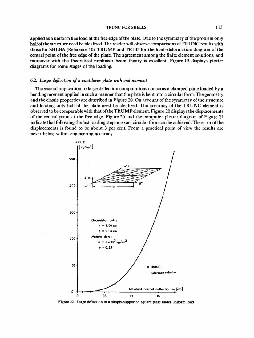
As a last example we study the performance of the TRUNC element in the range of large deflections of a simply-supported square plate under uniform load. Figure 22 shows the geometry and the elastic properties. A quarter of a square plate is idealized using a 4 x 4 mesh. The reference solution derives from Foppl and may be located in Reference 21. This approximate analytical solution is obtained by a combination of a known solutions due to small deflection theory and the contribution arising from the membrane effect. A comparison of the finite element results with the approximate analytical solution is shown for the vertical deflection of the central point in Figure 22. As may be deduced from the diagram, the TRUNC element yields excellent results. In the course of the computations the load was applied in six increments. Figure 23 displays the deflected shape of the quarter plate.
ACKNOWLEDGEMENTS
The authors wish to acknowledge the devoted technical support of Miss K. Schnabl, of Mrs. G. Grimm who produced diligently the numerous figures and of Mr. M. Silberzahn who contributed on the photographic side. The sustained effort of the ICA staff enabled the finalization of this paper within a very short period. Last but not least we would like to mention the valuable effort of Ms. Sophia Chryssaphi in the first draft of the geometrical stiffness for TRUNC.
1.
2.
3.
4.
5.
REFERENCES
B. M. Irons, ‘Engineering application of numerical integration in stiffness methods’, A.I.A.A. J., 4(1 I), 2035-2037 (1966). P. G. Bergan and L. Hanssen, ‘A new approach for deriving “good” element stiffness matrices’, in The Mathematics of Finite Elements and Applications I1 (J. R. Whiteman, Ed.), Academic Press, London, 1975. J. H. Argyris and H.-P. Mlejnek, Die Methode der finiten Elemente, Band 1 , Grundlagen der elementaren Strukturmechanik und Verschiebungsmethode in der Statik, Vieweg Braunschweig (English edition in preparation), 1985. J. H. Argyris, M. Haase and H.-P. Mlejnek, ‘On an unconventional but natural formation of a stiffness matrix’, Comp. Meths. Appl. Mech. Eng., 22, 1-22 (1980). 0. C. Zienkiewicz, C. J. Parek and I. P. King, ‘Arch dams analysed by a linear finite element shell solution program’, Proc. Symp. Arch Dams, Inst. Civ. Eng., London, 1968.

TRUNC FOR SHELLS 115
6. J. H. Argyris, P. C. Dunne, G. A. Malejannakis and E. Schelkle, ‘A simple triangular facet shell element with applications to linear and nonlinear equilibrium and elastic stability problems’, Comp. Meths. Appl. Mech. Eng., 10,
7. H. Tottenham and C. Brebbia, ‘Finite element techniques in structural mechanics’, Proc. of a seminar held at the Univ.
8. K. Forsberg and R. Hartung, ‘An evaluation of finite difference and finite element techniques for analysis of general
9. J. H. Argyris, W. Bosshard, I. Fried and H. M. Hilber, ‘A fully compatible plate bending element’, ISD-Report No. 42
10. J. H. Argyris and D. W. Scharpf. ‘The SHEBA family of shell elements for the matrix displacement method’, Aeron. J .
1 1 . W. H. Whittrick and C. H. Ellen, ‘Buckling of tapered rectangular plates in compression’, Aeron. Q., 13(4) 308-326
12. H.-P. Mlejnek, ‘Ein Beitrag zur nichtlinearen statischen und dynamischen Analyse von vorgespannten und rotierenden
13. W. Fliigge, Handbook of Engineering Mechanics, McGraw-Hill, New York, 1962. 14. M. D. Olson and G. M. Lindberg, ‘Vibration analysis of cantilevered curved plates using a new cylindrical shell finite
15. S. P. Timoshenko and J. M. Gere, Theory of Elastic Stability, McGraw-Hill, Tokyo, 1961. 16. Private correspondence with Prof. Zhong-ci Shi (1983). 17. J. H. Argyris, M. Haase and H.-P. Mlejnek, ‘Some considerations on the natural approach’, Comp. Meths. Appl. Mech.
18. B. Irons and S . Ahmad, Techniques ofFinite Elements, Wiley, New York, 1980. 19. J. H. Argyris, I. Fried and D. W. Scharpf, ‘The TUBA family of plate elements for the matrix displacement method’,
20. J. H. Argyris and K. E. Buck, ‘A sequel to technical note 14 on the TUBA family of plate elements’, Aeron. J . Roy. Aeron.
21. S . P. Timoshenko and S . Woinowski-Krieger, Plates and Shells, McGraw-Hill, Tokyo, 1959. 22. M. Haase, ‘Zur natiirlichen Formulierung von Simplexelementen hoherer Ordnung fur die Berechnung elastischer
Membranschalen und Seilkonstruktionen unter groBen Verformungen’, Dr.-lng. thesis, Univ. of Stuttgart (1979).
371-403 (1977); 11,97-131 (1977).
of Southampton, April 1970.
shells’, Symp. on High Speed Compt. of Elastic Structures, I.U.T.A.M., Liege, 1970.
(1967).
Roy. Aeron. SOC., 72(694), 873-883 (1968).
(1962).
Platten und Schalen mit der Methode der Finiten Elemente’, Dr.-Ing. thesis, Univ. of Stuttgart (1972).
element’, National Aeronautical Establishment, Ottawa, Canada.
Eng., 30, 335-346 (1982).
Aeron. J . Roy. Aeron. SOC., 72, 701-709 (1968).
SOC., 72, 977-983 (1968).