Embed Size (px)
Citation preview
—
Arc
Gua
rd S
yste
m™
– T
VO
C-2
-CO
M M
odb
usC
onf
igu
rati
on
man
ual
—1 SFC170 017M0201 EN, RE v. D
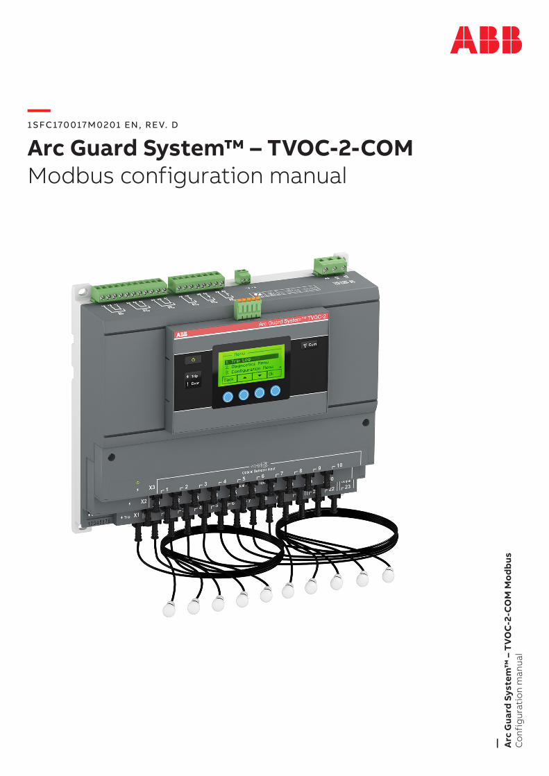
Arc Guard System™ – TVOC-2-COMModbus configuration manual

Thank you for selecting this ABB TvOC-2 Arc Guard System™. Carefully read and make sure that you understand all instructions before you mount, connect, configure the Arc Guard System. This manual is intended for configuration of the TvOC-2-COM Modbus interface.
The manual is available on:
http://new.abb.com/low-voltage/products/arc-guard
• Only authorized and appropriately trained personnel are allowed to install and make the electrical connection of the Arc Guard System in accordance with existing laws and regulations.
• Only authorized personnel are allowed to do service and repair on the Arc Guard System.
• Unauthorized repair will effect the warranty.
• This manual is a part of the TvOC-2 Arc Guard System. Always keep this manual available when working with the TvOC-2 Arc Guard System.
• Examine the Arc Guard System and the package when you unpack your new product. If there are damages, please contact the transportation company or the ABB reseller/office immediately.
Safety notesIn this user manual, these symbols are used:
WARNINGGeneral warning symbol indicates the presence of a hazard which could result in personal injury and damage to equipment or property.
WARNINGWarning symbol indicates the presence of hazardous voltage which could result in personal injury.
INFORMATIONInformation sign alerts the reader to relevant facts and conditions.
Modifications to data in this manual can be applied without notice.
General safety information
WARNINGOnly authorized and appropriately trained personnel are allowed to install and make the electrical connection of the Arc Guard System in accordance with existing laws and regulations.
WARNINGExamine the Arc Guard System and the package when you unpack your new product. If there are damages, please contact the transportation company or the ABB reseller/office immediately.
WARNINGOnly authorized and appropriately trained service personnel are allowed to do service and repair on the Arc Guard System. Note: unauthorized repair will effect the warranty.
Personal
Service and repair should be performed by authorized personnel only. Note that unauthorized repair affects safety and warranty.
—Read this firstWarning and safety

—Arc Guard System™ TVOC-2-COM Modbus Configuration manual
GENERAL INFORMATION P. 7
TROUBLESHOOTING P. 35
MODBUS INSTALLATION P. 11
CHANGING MODBUS ID AND COMMUNICATION PARAMETERS P. 15
FUNCTIONAL DESCRIPTION P. 19
01
01
02
03
04
05
06INDEX
P. 38

ABB ARC GUARD SYSTEM™ – TVOC-2-COM MODBUS CONFIGUR ATION MANUAL 7
01
—1 General information
8 1.1 Introduction
8 1.2 References
8 1.3 Quick start-up
8 ABB ARC GUARD SYSTEM™ – TVOC-2-COM MODBUS CONFIGUR ATION MANUAL
1.1 Introduction
This manual covers the Modbus interface, which offers a direct connection to Modbus RTU for the Arc Guard System™ TvOC-2.
TvOC-2-COM will behave as a slave. This means all communication will be performed by a master device on the same Modbus system. Mostly this will be a PLC. This manual explains how to install the Arc Guard System™ TvOC-2-COM to your Modbus system.
1.2 References
[1] http://www.modbus.org/docs/Modbus_Application_Protocol_v1_1b3.pdf (2012)
[2] http://www.modbus.org/docs/Modbus_over_serial_line_v1_02.pdf (2006)
[3] https://www.modbusdriver.com/modpoll.html
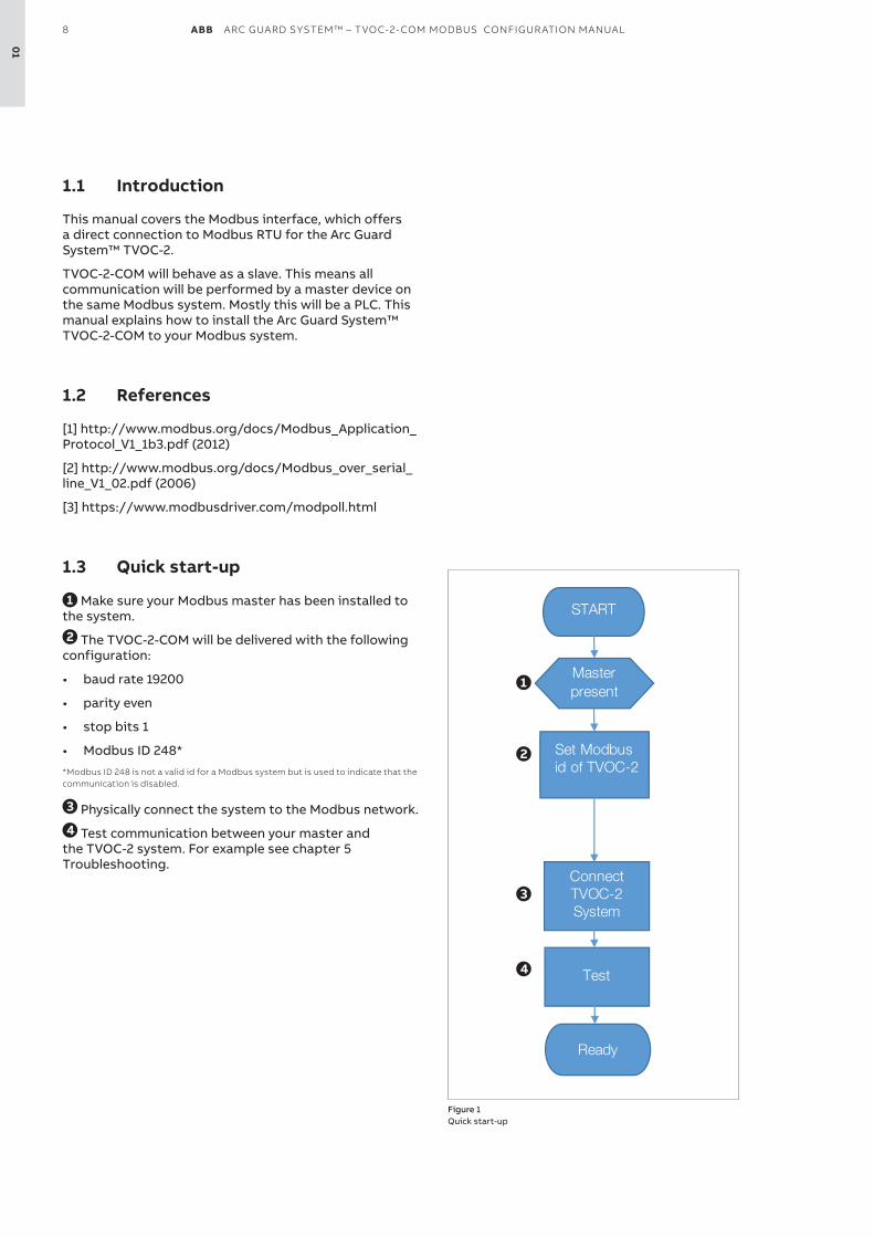
1.3 Quick start-up
1 Make sure your Modbus master has been installed to the system.
2 The TvOC-2-COM will be delivered with the following configuration:
• baud rate 19200
• parity even
• stop bits 1
• Modbus ID 248* *Modbus ID 248 is not a valid id for a Modbus system but is used to indicate that the communication is disabled.
3 Physically connect the system to the Modbus network.
4 Test communication between your master and the TvOC-2 system. For example see chapter 5 Troubleshooting.
Figure 1 Quick start-up
Master present
START
Set Modbusid of TVOC-2
ConnectTVOC-2 System
Test
Ready
1
2
3
4
01

ABB ARC GUARD SYSTEM™ – TVOC-2-COM MODBUS CONFIGUR ATION MANUAL 9
01

ABB ARC GUARD SYSTEM™ – TVOC-2-COM MODBUS CONFIGUR ATION MANUAL 11
12 2.1 General
12 2.2 Modbus connector
12 2.3 Modbus cables
13 2.4 Termination13 2.4.1 Termination resistors13 2.4.2 Pull-up / pull-down resistors
02
—2 Modbus installation
12 ABB ARC GUARD SYSTEM™ – TVOC-2-COM MODBUS CONFIGUR ATION MANUAL
2.1 General
Modbus RTU is a 2-wire, RS485-based field bus communication system for parameter value exchange.
INFORMATIONThe implementation of the Modbus interface is based on standards [1] and [2].
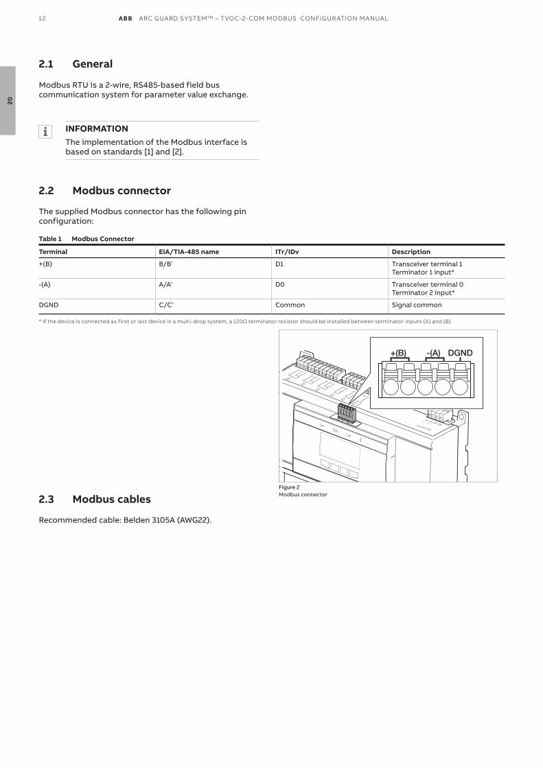
2.2 Modbus connector
The supplied Modbus connector has the following pin configuration:
Table 1 Modbus Connector
Terminal EIA/TIA-485 name ITr/IDv Description
+(B) B/B’ D1 Transceiver terminal 1Terminator 1 input*
-(A) A/A’ D0 Transceiver terminal 0Terminator 2 input*
DGND C/C’ Common Signal common
* If the device is connected as first or last device in a multi-drop system, a 120Ω terminator resistor should be installed between terminator inputs (A) and (B).
2.3 Modbus cables
Recommended cable: Belden 3105A (AWG22).
Figure 2 Modbus connector
+(B) -(A) DGND
02
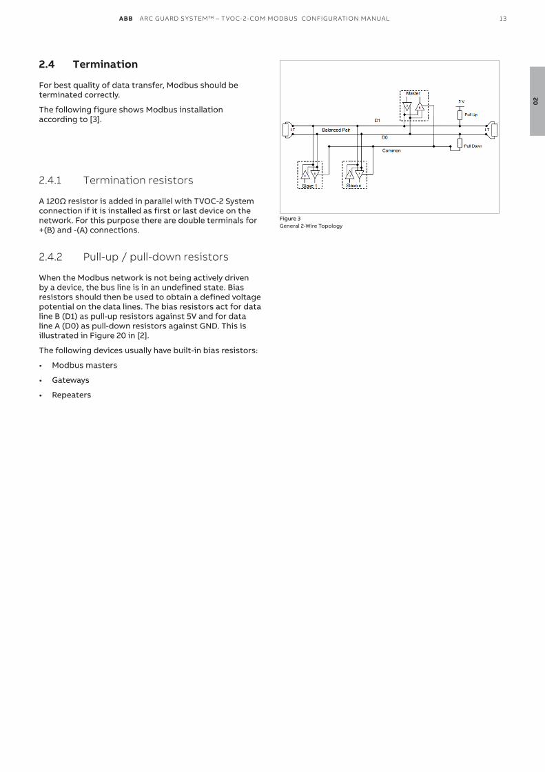
ABB ARC GUARD SYSTEM™ – TVOC-2-COM MODBUS CONFIGUR ATION MANUAL 13
2.4 Termination
For best quality of data transfer, Modbus should be terminated correctly.
The following figure shows Modbus installation according to [3].
2.4.1 Termination resistors
A 120Ω resistor is added in parallel with TVOC-2 System connection if it is installed as first or last device on the network. For this purpose there are double terminals for +(B) and -(A) connections.
2.4.2 Pull-up / pull-down resistors
When the Modbus network is not being actively driven by a device, the bus line is in an undefined state. Bias resistors should then be used to obtain a defined voltage potential on the data lines. The bias resistors act for data line B (D1) as pull-up resistors against 5v and for data line A (D0) as pull-down resistors against GND. This is illustrated in Figure 20 in [2].
The following devices usually have built-in bias resistors:
• Modbus masters
• Gateways
• Repeaters
Figure 3 General 2-Wire Topology
02

ABB ARC GUARD SYSTEM™ – TVOC-2-COM MODBUS CONFIGUR ATION MANUAL 15
16 3.1 Changing Modbus ID and communication parameters
16 3.2 Configuration via HMI
03
—3 Changing Modbus ID and
communication parameters
16 ABB ARC GUARD SYSTEM™ – TVOC-2-COM MODBUS CONFIGUR ATION MANUAL
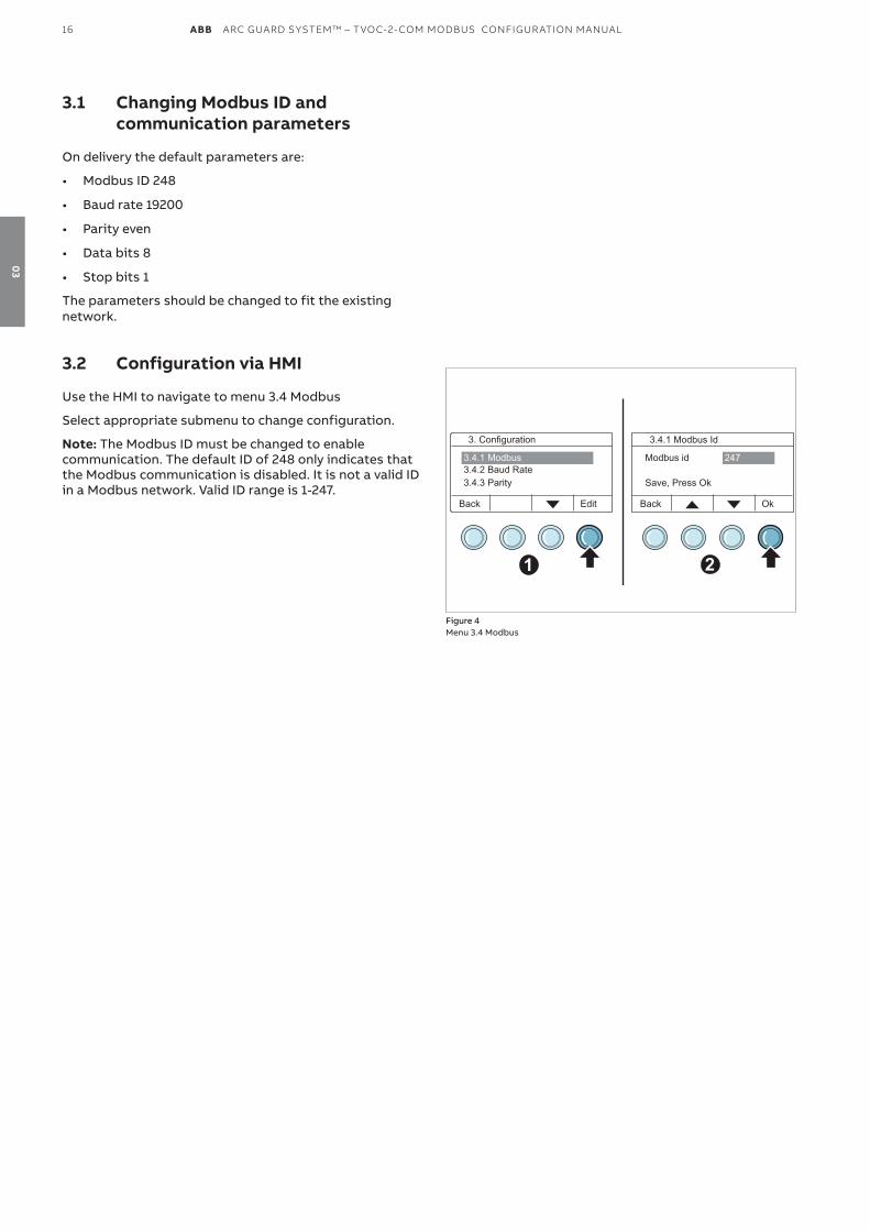
3.1 Changing Modbus ID and communication parameters
On delivery the default parameters are:
• Modbus ID 248
• Baud rate 19200
• Parity even
• Data bits 8
• Stop bits 1
The parameters should be changed to fit the existing network.
3.2 Configuration via HMI
Use the HMI to navigate to menu 3.4 Modbus
Select appropriate submenu to change configuration.
Note: The Modbus ID must be changed to enable communication. The default ID of 248 only indicates that the Modbus communication is disabled. It is not a valid ID in a Modbus network. valid ID range is 1-247.
Figure 4 Menu 3.4 Modbus
1
Back Edit
3. Configuration
3.4.2 Baud Rate3.4.3 Parity
3.4.1 Modbus
2
3.4.1 Modbus Id
Modbus id
Save, Press Ok
247
OkBack
03

ABB ARC GUARD SYSTEM™ – TVOC-2-COM MODBUS CONFIGUR ATION MANUAL 17
03

ABB ARC GUARD SYSTEM™ – TVOC-2-COM MODBUS CONFIGUR ATION MANUAL 19
20 4.1 Functional description
20 4.2 Implementation class
20 4.3 Supported Modbus functions20 4.3.1 Read Registers (03, 04)20 4.3.2 Write Registers (06, 16)21 4.3.3 Available registers
26 4.4 Register data format26 4.4.1 Trip information27 4.4.2 Diagnostics information27 4.4.3 Error information29 4.4.4 Custom name registers29 4.4.5 Installed modules30 4.4.6 Dip switches30 4.4.7 Version information32 4.4.8 Reset32 4.4.9 System date32 4.4.10 System time HHMM33 4.4.11 Modbus failure register33 4.4.12 System state33 4.4.13 Diagnostic Trouble Code, number x
04
—4 Functional description
20 ABB ARC GUARD SYSTEM™ – TVOC-2-COM MODBUS CONFIGUR ATION MANUAL
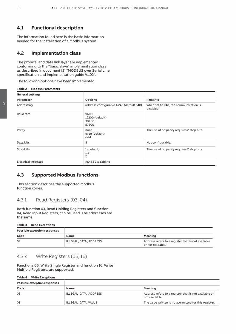
4.1 Functional description
The information found here is the basic information needed for the installation of a Modbus system.
4.2 Implementation class
The physical and data link layer are implemented conforming to the “basic slave” implementation class as described in document [2] “MODBUS over Serial Line specification and implementation guide v1.02”.
The following options have been implemented:
Table 2 Modbus Parameters
General settings
Parameter Options Remarks
Addressing address configurable 1-248 (default 248) When set to 248, the communication is disabled.
Baud rate 960019200 (default)3840057600
Parity noneeven (default)odd
The use of no parity requires 2 stop bits.
Data bits 8 Not configurable.
Stop bits 1 (default)1.52
The use of no parity requires 2 stop bits.
Electrical interface RS485 2W cabling
4.3 Supported Modbus functions
This section describes the supported Modbus function codes.
4.3.1 Read Registers (03, 04)
Both function 03, Read Holding Registers and function 04, Read Input Registers, can be used. The addresses are the same.
Table 3 Read Exceptions
Possible exception responses
Code Name Meaning
02 ILLEGAL_DATA_ADDRESS Address refers to a register that is not available or not readable.
4.3.2 Write Registers (06, 16)
Functions 06, Write Single Register and function 16, Write Multiple Registers, are supported.
Table 4 Write Exceptions
Possible exception responses
Code Name Meaning
02 ILLEGAL_DATA_ADDRESS Address refers to a register that is not available or not readable.
03 ILLEGAL_DATA_vALUE The value written is not permitted for this register.
04
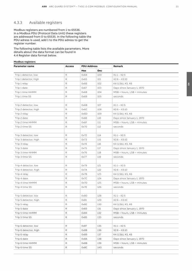
ABB ARC GUARD SYSTEM™ – TVOC-2-COM MODBUS CONFIGUR ATION MANUAL 21
4.3.3 Available registers
Modbus registers are numbered from 1 to 65536. In a Modbus PDU (Protocol Data Unit) these registers are addressed from 0 to 65535. In the following table the PDU adress is used, add 1 to the PDU adress to get the register number.
The following table lists the available parameters. More details about the data format can be found in 4.4 Register data format below.
Modbus registers
Parameter name Access PDU Address Remark
Hex Dec
Trip 1 detector, low R 0x64 100 X1:1 – X2:5
Trip 1 detector, high R 0x65 101 X2:6 – X3:10
Trip 1 relay R 0x66 102 K4 (LSb), K5, K6
Trip 1 date R 0x67 103 Days since January 1, 1970
Trip 1 time HHMM R 0x68 104 MSB = hours, LSB = minutes
Trip 1 time SS R 0x69 105 seconds
Trip 2 detector, low R 0x6B 107 X1:1 – X2:5
Trip 2 detector, high R 0x6C 108 X2:6 – X3:10
Trip 2 relay R 0x6D 109 K4 (LSb), K5, K6
Trip 2 date R 0x6E 110 Days since January 1, 1970
Trip 2 time HHMM R 0x6F 111 MSB = hours, LSB = minutes
Trip 2 time SS R 0x70 112 seconds
Trip 3 detector, low R 0x72 114 X1:1 – X2:5
Trip 3 detector, high R 0x73 115 X2:6 – X3:10
Trip 3 relay R 0x74 116 K4 (LSb), K5, K6
Trip 3 date R 0x75 117 Days since January 1, 1970
Trip 3 time HHMM R 0x76 118 MSB = hours, LSB = minutes
Trip 3 time SS R 0x77 119 seconds
Trip 4 detector, low R 0x79 121 X1:1 – X2:5
Trip 4 detector, high R 0x7A 122 X2:6 – X3:10
Trip 4 relay R 0x7B 123 K4 (LSb), K5, K6
Trip 4 date R 0x7C 124 Days since January 1, 1970
Trip 4 time HHMM R 0x7D 125 MSB = hours, LSB = minutes
Trip 4 time SS R 0x7E 126 seconds
Trip 5 detector, low R 0x80 128 X1:1 – X2:5
Trip 5 detector, high R 0x81 129 X2:6 – X3:10
Trip 5 relay R 0x82 130 K4 (LSb), K5, K6
Trip 5 date R 0x83 131 Days since January 1, 1970
Trip 5 time HHMM R 0x84 132 MSB = hours, LSB = minutes
Trip 5 time SS R 0x85 133 seconds
Trip 6 detector, low R 0x87 135 X1:1 – X2:5
Trip 6 detector, high R 0x88 136 X2:6 – X3:10
Trip 6 relay R 0x89 137 K4 (LSb), K5, K6
Trip 6 date R 0x8A 138 Days since January 1, 1970
Trip 6 time HHMM R 0x8B 139 MSB = hours, LSB = minutes
Trip 6 time SS R 0x8C 140 seconds
04
22 ABB ARC GUARD SYSTEM™ – TVOC-2-COM MODBUS CONFIGUR ATION MANUAL
Modbus registers
Parameter name Access PDU Address Remark
Hex Dec
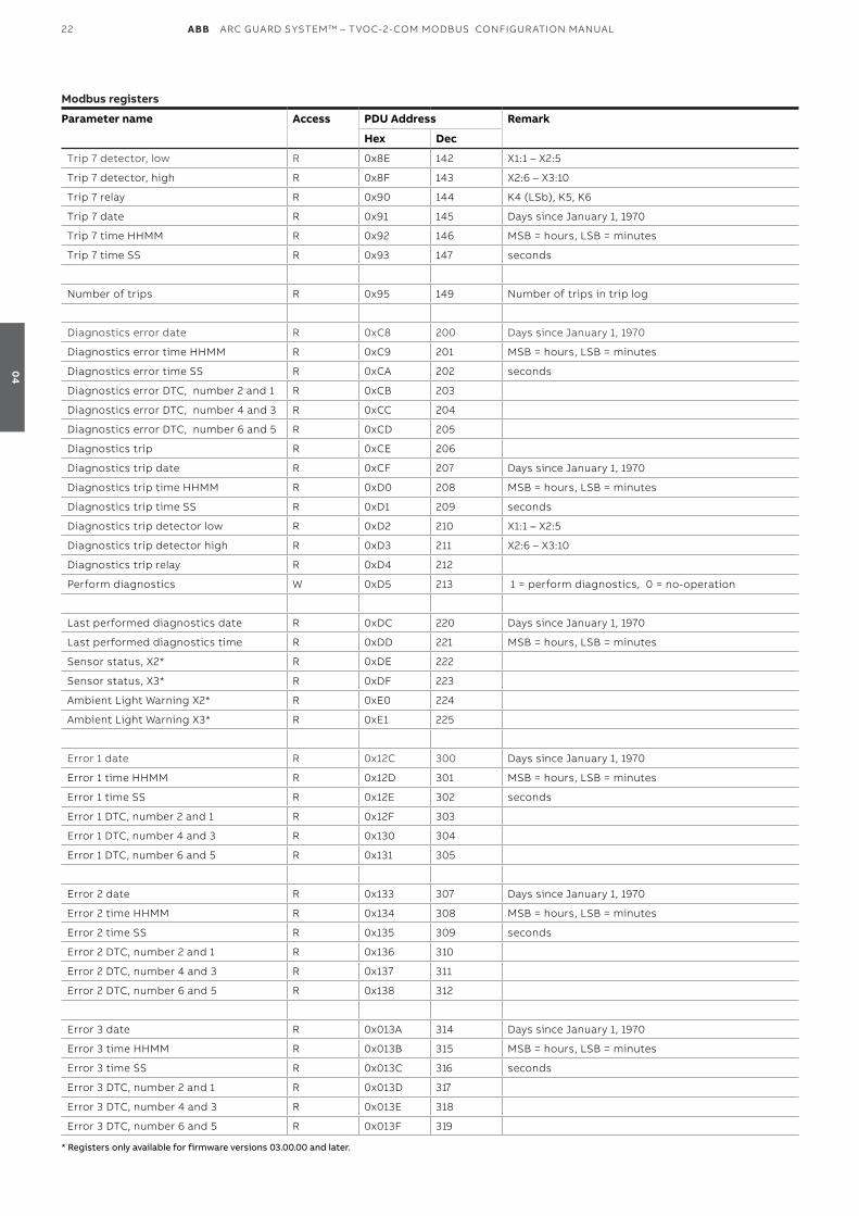
Trip 7 detector, low R 0x8E 142 X1:1 – X2:5
Trip 7 detector, high R 0x8F 143 X2:6 – X3:10
Trip 7 relay R 0x90 144 K4 (LSb), K5, K6
Trip 7 date R 0x91 145 Days since January 1, 1970
Trip 7 time HHMM R 0x92 146 MSB = hours, LSB = minutes
Trip 7 time SS R 0x93 147 seconds
Number of trips R 0x95 149 Number of trips in trip log
Diagnostics error date R 0xC8 200 Days since January 1, 1970
Diagnostics error time HHMM R 0xC9 201 MSB = hours, LSB = minutes
Diagnostics error time SS R 0xCA 202 seconds
Diagnostics error DTC, number 2 and 1 R 0xCB 203
Diagnostics error DTC, number 4 and 3 R 0xCC 204
Diagnostics error DTC, number 6 and 5 R 0xCD 205
Diagnostics trip R 0xCE 206
Diagnostics trip date R 0xCF 207 Days since January 1, 1970
Diagnostics trip time HHMM R 0xD0 208 MSB = hours, LSB = minutes
Diagnostics trip time SS R 0xD1 209 seconds
Diagnostics trip detector low R 0xD2 210 X1:1 – X2:5
Diagnostics trip detector high R 0xD3 211 X2:6 – X3:10
Diagnostics trip relay R 0xD4 212
Perform diagnostics W 0xD5 213 1 = perform diagnostics, 0 = no-operation
Last performed diagnostics date R 0xDC 220 Days since January 1, 1970
Last performed diagnostics time R 0xDD 221 MSB = hours, LSB = minutes
Sensor status, X2* R 0xDE 222
Sensor status, X3* R 0xDF 223
Ambient Light Warning X2* R 0xE0 224
Ambient Light Warning X3* R 0xE1 225
Error 1 date R 0x12C 300 Days since January 1, 1970
Error 1 time HHMM R 0x12D 301 MSB = hours, LSB = minutes
Error 1 time SS R 0x12E 302 seconds
Error 1 DTC, number 2 and 1 R 0x12F 303
Error 1 DTC, number 4 and 3 R 0x130 304
Error 1 DTC, number 6 and 5 R 0x131 305
Error 2 date R 0x133 307 Days since January 1, 1970
Error 2 time HHMM R 0x134 308 MSB = hours, LSB = minutes
Error 2 time SS R 0x135 309 seconds
Error 2 DTC, number 2 and 1 R 0x136 310
Error 2 DTC, number 4 and 3 R 0x137 311
Error 2 DTC, number 6 and 5 R 0x138 312
Error 3 date R 0x013A 314 Days since January 1, 1970
Error 3 time HHMM R 0x013B 315 MSB = hours, LSB = minutes
Error 3 time SS R 0x013C 316 seconds
Error 3 DTC, number 2 and 1 R 0x013D 317
Error 3 DTC, number 4 and 3 R 0x013E 318
Error 3 DTC, number 6 and 5 R 0x013F 319
* Registers only available for firmware versions 03.00.00 and later.
04
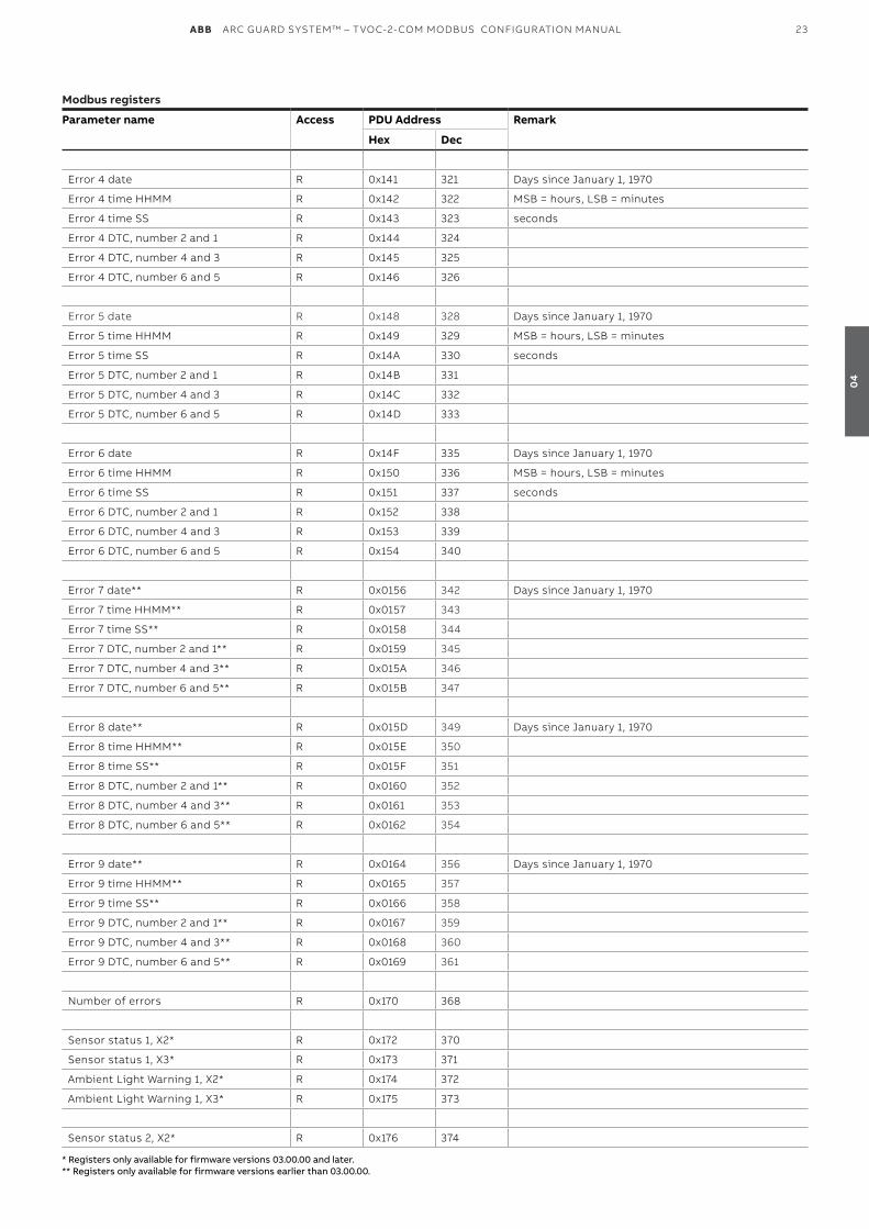
ABB ARC GUARD SYSTEM™ – TVOC-2-COM MODBUS CONFIGUR ATION MANUAL 23
Modbus registers
Parameter name Access PDU Address Remark
Hex Dec
Error 4 date R 0x141 321 Days since January 1, 1970
Error 4 time HHMM R 0x142 322 MSB = hours, LSB = minutes
Error 4 time SS R 0x143 323 seconds
Error 4 DTC, number 2 and 1 R 0x144 324
Error 4 DTC, number 4 and 3 R 0x145 325
Error 4 DTC, number 6 and 5 R 0x146 326
Error 5 date R 0x148 328 Days since January 1, 1970
Error 5 time HHMM R 0x149 329 MSB = hours, LSB = minutes
Error 5 time SS R 0x14A 330 seconds
Error 5 DTC, number 2 and 1 R 0x14B 331
Error 5 DTC, number 4 and 3 R 0x14C 332
Error 5 DTC, number 6 and 5 R 0x14D 333
Error 6 date R 0x14F 335 Days since January 1, 1970
Error 6 time HHMM R 0x150 336 MSB = hours, LSB = minutes
Error 6 time SS R 0x151 337 seconds
Error 6 DTC, number 2 and 1 R 0x152 338
Error 6 DTC, number 4 and 3 R 0x153 339
Error 6 DTC, number 6 and 5 R 0x154 340
Error 7 date** R 0x0156 342 Days since January 1, 1970
Error 7 time HHMM** R 0x0157 343
Error 7 time SS** R 0x0158 344
Error 7 DTC, number 2 and 1** R 0x0159 345
Error 7 DTC, number 4 and 3** R 0x015A 346
Error 7 DTC, number 6 and 5** R 0x015B 347
Error 8 date** R 0x015D 349 Days since January 1, 1970
Error 8 time HHMM** R 0x015E 350
Error 8 time SS** R 0x015F 351
Error 8 DTC, number 2 and 1** R 0x0160 352
Error 8 DTC, number 4 and 3** R 0x0161 353
Error 8 DTC, number 6 and 5** R 0x0162 354
Error 9 date** R 0x0164 356 Days since January 1, 1970
Error 9 time HHMM** R 0x0165 357
Error 9 time SS** R 0x0166 358
Error 9 DTC, number 2 and 1** R 0x0167 359
Error 9 DTC, number 4 and 3** R 0x0168 360
Error 9 DTC, number 6 and 5** R 0x0169 361
Number of errors R 0x170 368
Sensor status 1, X2* R 0x172 370
Sensor status 1, X3* R 0x173 371
Ambient Light Warning 1, X2* R 0x174 372
Ambient Light Warning 1, X3* R 0x175 373
Sensor status 2, X2* R 0x176 374
* Registers only available for firmware versions 03.00.00 and later.** Registers only available for firmware versions earlier than 03.00.00.
04
24 ABB ARC GUARD SYSTEM™ – TVOC-2-COM MODBUS CONFIGUR ATION MANUAL
Modbus registers
Parameter name Access PDU Address Remark
Hex Dec
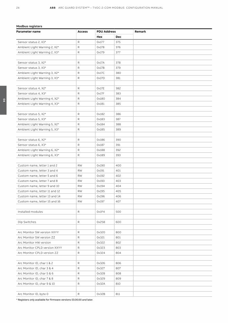
Sensor status 2, X3* R 0x177 375
Ambient Light Warning 2, X2* R 0x178 376
Ambient Light Warning 2, X3* R 0x179 377
Sensor status 3, X2* R 0x17A 378
Sensor status 3, X3* R 0x17B 379
Ambient Light Warning 3, X2* R 0x17C 380
Ambient Light Warning 3, X3* R 0x17D 381
Sensor status 4, X2* R 0x17E 382
Sensor status 4, X3* R 0x17F 383
Ambient Light Warning 4, X2* R 0x180 384
Ambient Light Warning 4, X3* R 0x181 385
Sensor status 5, X2* R 0x182 386
Sensor status 5, X3* R 0x183 387
Ambient Light Warning 5, X2* R 0x184 388
Ambient Light Warning 5, X3* R 0x185 389
Sensor status 6, X2* R 0x186 390
Sensor status 6, X3* R 0x187 391
Ambient Light Warning 6, X2* R 0x188 392
Ambient Light Warning 6, X3* R 0x189 393
Custom name, letter 1 and 2 RW 0x190 400
Custom name, letter 3 and 4 RW 0x191 401
Custom name, letter 5 and 6 RW 0x192 402
Custom name, letter 7 and 8 RW 0x193 403
Custom name, letter 9 and 10 RW 0x194 404
Custom name, letter 11 and 12 RW 0x195 405
Custom name, letter 13 and 14 RW 0x196 406
Custom name, letter 15 and 16 RW 0x197 407
Installed modules R 0x1F4 500
Dip Switches R 0x258 600
Arc Monitor SW version XXYY R 0x320 800
Arc Monitor SW version ZZ R 0x321 801
Arc Monitor HW version R 0x322 802
Arc Monitor CPLD version XXYY R 0x323 803
Arc Monitor CPLD version ZZ R 0x324 804
Arc Monitor ID, char 1 & 2 R 0x326 806
Arc Monitor ID, char 3 & 4 R 0x327 807
Arc Monitor ID, char 5 & 6 R 0x328 808
Arc Monitor ID, char 7 & 8 R 0x329 809
Arc Monitor ID, char 9 & 10 R 0x32A 810
Arc Monitor ID, byte 0 R 0x32B 811
* Registers only available for firmware versions 03.00.00 and later.
04
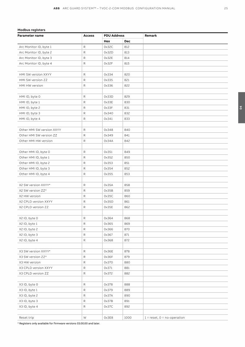
ABB ARC GUARD SYSTEM™ – TVOC-2-COM MODBUS CONFIGUR ATION MANUAL 25
Modbus registers
Parameter name Access PDU Address Remark
Hex Dec
Arc Monitor ID, byte 1 R 0x32C 812
Arc Monitor ID, byte 2 R 0x32D 813
Arc Monitor ID, byte 3 R 0x32E 814
Arc Monitor ID, byte 4 R 0x32F 815
HMI SW version XXYY R 0x334 820
HMI SW version ZZ R 0x335 821
HMI HW version R 0x336 822
HMI ID, byte 0 R 0x33D 829
HMI ID, byte 1 R 0x33E 830
HMI ID, byte 2 R 0x33F 831
HMI ID, byte 3 R 0x340 832
HMI ID, byte 4 R 0x341 833
Other HMI SW version XXYY R 0x348 840
Other HMI SW version ZZ R 0x349 841
Other HMI HW version R 0x34A 842
Other HMI ID, byte 0 R 0x351 849
Other HMI ID, byte 1 R 0x352 850
Other HMI ID, byte 2 R 0x353 851
Other HMI ID, byte 3 R 0x354 852
Other HMI ID, byte 4 R 0x355 853
X2 SW version XXYY* R 0x35A 858
X2 SW version ZZ* R 0x35B 859
X2 HW version R 0x35C 860
X2 CPLD version XXYY R 0x35D 861
X2 CPLD version ZZ R 0x35E 862
X2 ID, byte 0 R 0x364 868
X2 ID, byte 1 R 0x365 869
X2 ID, byte 2 R 0x366 870
X2 ID, byte 3 R 0x367 871
X2 ID, byte 4 R 0x368 872
X3 SW version XXYY* R 0x36E 878
X3 SW version ZZ* R 0x36F 879
X3 HW version R 0x370 880
X3 CPLD version XXYY R 0x371 881
X3 CPLD version ZZ R 0x372 882
X3 ID, byte 0 R 0x378 888
X3 ID, byte 1 R 0x379 889
X3 ID, byte 2 R 0x37A 890
X3 ID, byte 3 R 0x37B 891
X3 ID, byte 4 R 0x37C 892
Reset trip W 0x3E8 1000 1 = reset, 0 = no-operation
* Registers only available for firmware versions 03.00.00 and later.
04
26 ABB ARC GUARD SYSTEM™ – TVOC-2-COM MODBUS CONFIGUR ATION MANUAL
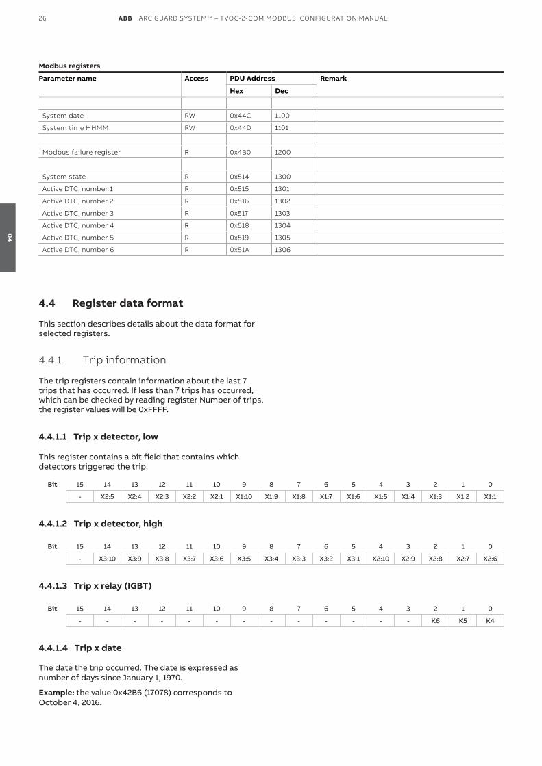
Modbus registers
Parameter name Access PDU Address Remark
Hex Dec
System date RW 0x44C 1100
System time HHMM RW 0x44D 1101
Modbus failure register R 0x4B0 1200
System state R 0x514 1300
Active DTC, number 1 R 0x515 1301
Active DTC, number 2 R 0x516 1302
Active DTC, number 3 R 0x517 1303
Active DTC, number 4 R 0x518 1304
Active DTC, number 5 R 0x519 1305
Active DTC, number 6 R 0x51A 1306
4.4 Register data format
This section describes details about the data format for selected registers.
4.4.1 Trip information
The trip registers contain information about the last 7 trips that has occurred. If less than 7 trips has occurred, which can be checked by reading register Number of trips, the register values will be 0xFFFF.
4.4.1.1 Trip x detector, low This register contains a bit field that contains which detectors triggered the trip.
Bit 15 14 13 12 11 10 9 8 7 6 5 4 3 2 1 0
- X2:5 X2:4 X2:3 X2:2 X2:1 X1:10 X1:9 X1:8 X1:7 X1:6 X1:5 X1:4 X1:3 X1:2 X1:1
4.4.1.2 Trip x detector, high
Bit 15 14 13 12 11 10 9 8 7 6 5 4 3 2 1 0
- X3:10 X3:9 X3:8 X3:7 X3:6 X3:5 X3:4 X3:3 X3:2 X3:1 X2:10 X2:9 X2:8 X2:7 X2:6
4.4.1.3 Trip x relay (IGBT)
Bit 15 14 13 12 11 10 9 8 7 6 5 4 3 2 1 0
- - - - - - - - - - - - - K6 K5 K4
4.4.1.4 Trip x date The date the trip occurred. The date is expressed as number of days since January 1, 1970.
Example: the value 0x42B6 (17078) corresponds to October 4, 2016.
04
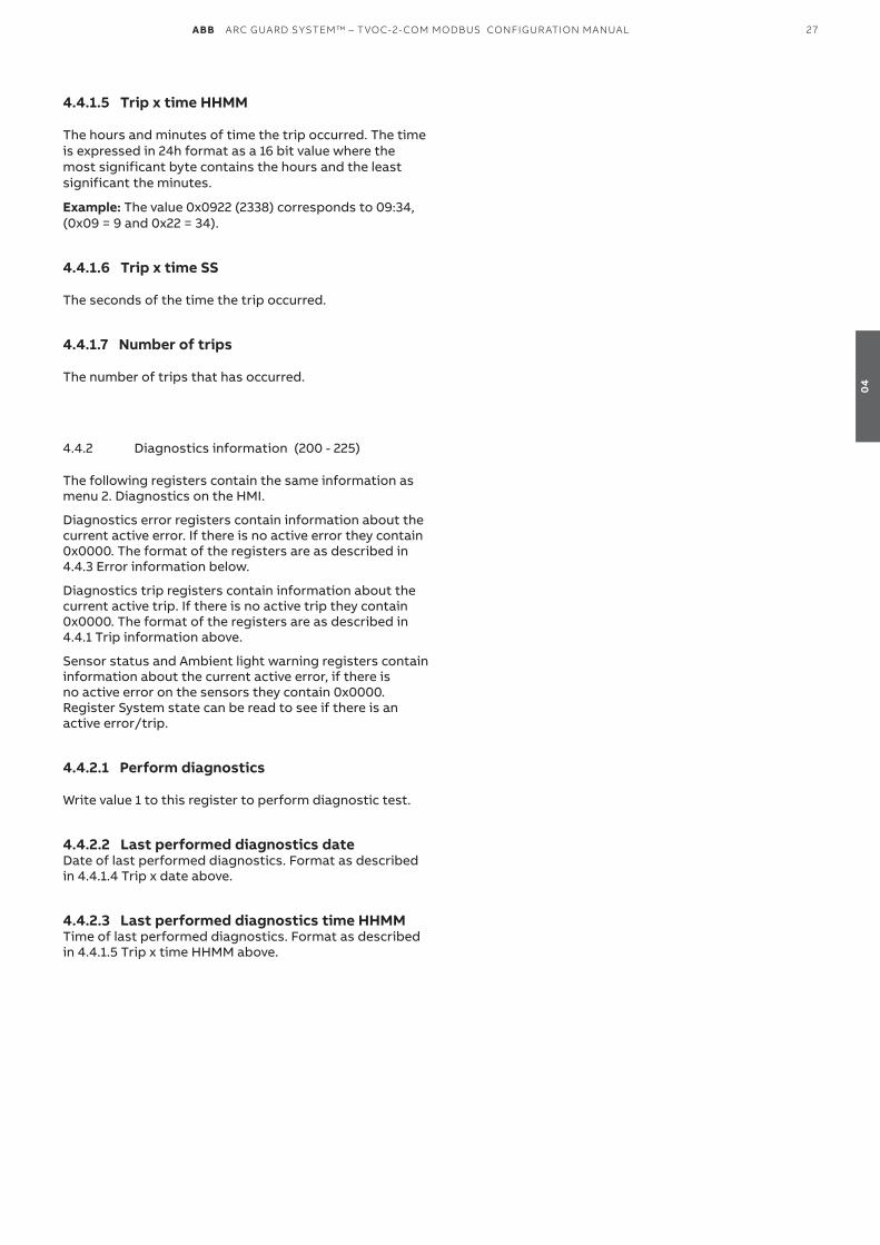
ABB ARC GUARD SYSTEM™ – TVOC-2-COM MODBUS CONFIGUR ATION MANUAL 27
4.4.1.5 Trip x time HHMM The hours and minutes of time the trip occurred. The time is expressed in 24h format as a 16 bit value where the most significant byte contains the hours and the least significant the minutes.
Example: The value 0x0922 (2338) corresponds to 09:34, (0x09 = 9 and 0x22 = 34).
4.4.1.6 Trip x time SS The seconds of the time the trip occurred.
4.4.1.7 Number of trips The number of trips that has occurred.
4.4.2 Diagnostics information (200 - 225)
The following registers contain the same information as menu 2. Diagnostics on the HMI.
Diagnostics error registers contain information about the current active error. If there is no active error they contain 0x0000. The format of the registers are as described in 4.4.3 Error information below.
Diagnostics trip registers contain information about the current active trip. If there is no active trip they contain 0x0000. The format of the registers are as described in 4.4.1 Trip information above.
Sensor status and Ambient light warning registers contain information about the current active error, if there is no active error on the sensors they contain 0x0000. Register System state can be read to see if there is an active error/trip.
4.4.2.1 Perform diagnostics Write value 1 to this register to perform diagnostic test.
4.4.2.2 Last performed diagnostics dateDate of last performed diagnostics. Format as described in 4.4.1.4 Trip x date above.
4.4.2.3 Last performed diagnostics time HHMMTime of last performed diagnostics. Format as described in 4.4.1.5 Trip x time HHMM above.
04
28 ABB ARC GUARD SYSTEM™ – TVOC-2-COM MODBUS CONFIGUR ATION MANUAL
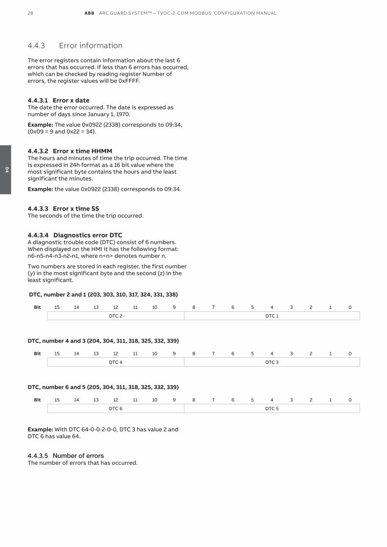
4.4.3 Error information
The error registers contain information about the last 6 errors that has occurred. If less than 6 errors has occurred, which can be checked by reading register Number of errors, the register values will be 0xFFFF.
4.4.3.1 Error x dateThe date the error occurred. The date is expressed as number of days since January 1, 1970.
Example: The value 0x0922 (2338) corresponds to 09:34, (0x09 = 9 and 0x22 = 34).
4.4.3.2 Error x time HHMMThe hours and minutes of time the trip occurred. The time is expressed in 24h format as a 16 bit value where the most significant byte contains the hours and the least significant the minutes.
Example: the value 0x0922 (2338) corresponds to 09:34.
4.4.3.3 Error x time SSThe seconds of the time the trip occurred.
4.4.3.4 Diagnostics error DTCA diagnostic trouble code (DTC) consist of 6 numbers. When displayed on the HMI it has the following format: n6-n5-n4-n3-n2-n1, where n<n> denotes number n.
Two numbers are stored in each register, the first number (y) in the most significant byte and the second (z) in the least significant.
DTC, number 2 and 1 (203, 303, 310, 317, 324, 331, 338)
Bit 15 14 13 12 11 10 9 8 7 6 5 4 3 2 1 0
DTC 2 DTC 1
DTC, number 4 and 3 (204, 304, 311, 318, 325, 332, 339)
Bit 15 14 13 12 11 10 9 8 7 6 5 4 3 2 1 0
DTC 4 DTC 3
DTC, number 6 and 5 (205, 304, 311, 318, 325, 332, 339)
Bit 15 14 13 12 11 10 9 8 7 6 5 4 3 2 1 0
DTC 6 DTC 5
Example: With DTC 64-0-0-2-0-0, DTC 3 has value 2 and DTC 6 has value 64.
4.4.3.5 Number of errorsThe number of errors that has occurred.
04
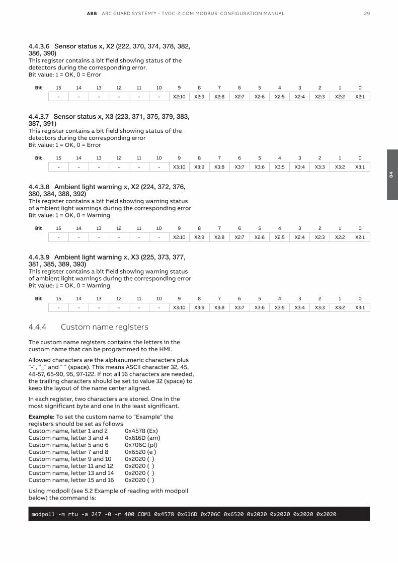
ABB ARC GUARD SYSTEM™ – TVOC-2-COM MODBUS CONFIGUR ATION MANUAL 29
4.4.3.6 Sensor status x, X2 (222, 370, 374, 378, 382, 386, 390)This register contains a bit field showing status of the detectors during the corresponding error. Bit value: 1 = OK, 0 = Error
Bit 15 14 13 12 11 10 9 8 7 6 5 4 3 2 1 0
- - - - - - X2:10 X2:9 X2:8 X2:7 X2:6 X2:5 X2:4 X2:3 X2:2 X2:1
4.4.3.7 Sensor status x, X3 (223, 371, 375, 379, 383, 387, 391)This register contains a bit field showing status of the detectors during the corresponding error Bit value: 1 = OK, 0 = Error
Bit 15 14 13 12 11 10 9 8 7 6 5 4 3 2 1 0
- - - - - - X3:10 X3:9 X3:8 X3:7 X3:6 X3:5 X3:4 X3:3 X3:2 X3:1
4.4.3.8 Ambient light warning x, X2 (224, 372, 376, 380, 384, 388, 392)This register contains a bit field showing warning status of ambient light warnings during the corresponding error Bit value: 1 = OK, 0 = Warning
Bit 15 14 13 12 11 10 9 8 7 6 5 4 3 2 1 0
- - - - - - X2:10 X2:9 X2:8 X2:7 X2:6 X2:5 X2:4 X2:3 X2:2 X2:1
4.4.3.9 Ambient light warning x, X3 (225, 373, 377, 381, 385, 389, 393)This register contains a bit field showing warning status of ambient light warnings during the corresponding error Bit value: 1 = OK, 0 = Warning
Bit 15 14 13 12 11 10 9 8 7 6 5 4 3 2 1 0
- - - - - - X3:10 X3:9 X3:8 X3:7 X3:6 X3:5 X3:4 X3:3 X3:2 X3:1
4.4.4 Custom name registers
The custom name registers contains the letters in the custom name that can be programmed to the HMI.
Allowed characters are the alphanumeric characters plus “-“, “_” and “ “ (space). This means ASCII character 32, 45, 48-57, 65-90, 95, 97-122. If not all 16 characters are needed, the trailing characters should be set to value 32 (space) to keep the layout of the name center aligned.
In each register, two characters are stored. One in the most significant byte and one in the least significant.
Example: To set the custom name to “Example” the registers should be set as followsCustom name, letter 1 and 2 0x4578 (Ex)Custom name, letter 3 and 4 0x616D (am)Custom name, letter 5 and 6 0x706C (pl)Custom name, letter 7 and 8 0x6520 (e )Custom name, letter 9 and 10 0x2020 ( )Custom name, letter 11 and 12 0x2020 ( )Custom name, letter 13 and 14 0x2020 ( ) Custom name, letter 15 and 16 0x2020 ( )
Using modpoll (see 5.2 Example of reading with modpoll below) the command is: modpoll -m rtu -a 247 -0 -r 400 COM1 0x4578 0x616D 0x706C 0x6520 0x2020 0x2020 0x2020 0x2020
04
30 ABB ARC GUARD SYSTEM™ – TVOC-2-COM MODBUS CONFIGUR ATION MANUAL
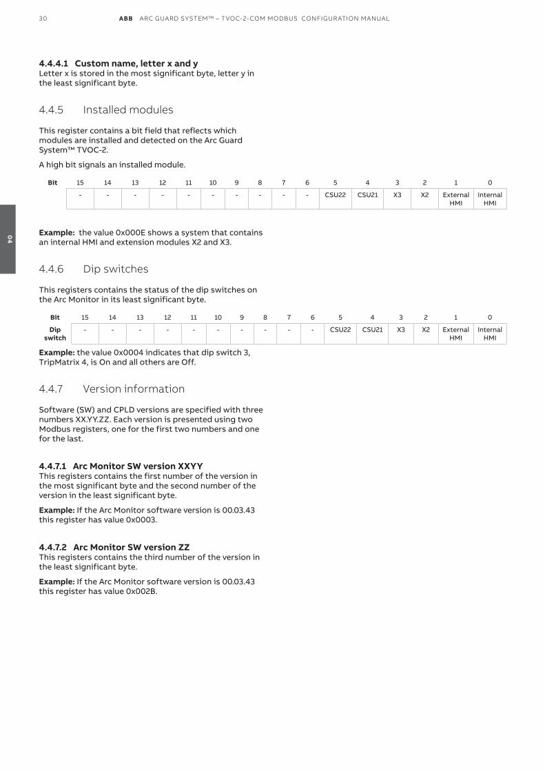
4.4.4.1 Custom name, letter x and yLetter x is stored in the most significant byte, letter y in the least significant byte.
4.4.5 Installed modules
This register contains a bit field that reflects which modules are installed and detected on the Arc Guard System™ TvOC-2.
A high bit signals an installed module.
Bit 15 14 13 12 11 10 9 8 7 6 5 4 3 2 1 0
- - - - - - - - - - CSU22 CSU21 X3 X2 External HMI
Internal HMI
Example: the value 0x000E shows a system that contains an internal HMI and extension modules X2 and X3.
4.4.6 Dip switches
This registers contains the status of the dip switches on the Arc Monitor in its least significant byte.
Bit 15 14 13 12 11 10 9 8 7 6 5 4 3 2 1 0
Dip switch
- - - - - - - - - - CSU22 CSU21 X3 X2 External HMI
Internal HMI
Example: the value 0x0004 indicates that dip switch 3, TripMatrix 4, is On and all others are Off.
4.4.7 Version information
Software (SW) and CPLD versions are specified with three numbers XX.YY.ZZ. Each version is presented using two Modbus registers, one for the first two numbers and one for the last.
4.4.7.1 Arc Monitor SW version XXYYThis registers contains the first number of the version in the most significant byte and the second number of the version in the least significant byte.
Example: If the Arc Monitor software version is 00.03.43 this register has value 0x0003.
4.4.7.2 Arc Monitor SW version ZZThis registers contains the third number of the version in the least significant byte.
Example: If the Arc Monitor software version is 00.03.43 this register has value 0x002B.
04
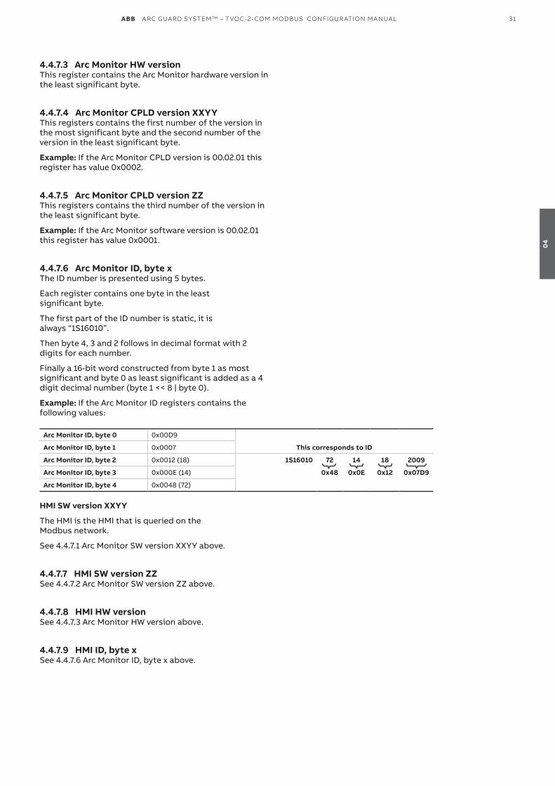
ABB ARC GUARD SYSTEM™ – TVOC-2-COM MODBUS CONFIGUR ATION MANUAL 31
4.4.7.3 Arc Monitor HW versionThis register contains the Arc Monitor hardware version in the least significant byte.
4.4.7.4 Arc Monitor CPLD version XXYYThis registers contains the first number of the version in the most significant byte and the second number of the version in the least significant byte.
Example: If the Arc Monitor CPLD version is 00.02.01 this register has value 0x0002.
4.4.7.5 Arc Monitor CPLD version ZZThis registers contains the third number of the version in the least significant byte.
Example: If the Arc Monitor software version is 00.02.01 this register has value 0x0001.
4.4.7.6 Arc Monitor ID, byte xThe ID number is presented using 5 bytes.
Each register contains one byte in the least significant byte.
The first part of the ID number is static, it is always “1S16010”.
Then byte 4, 3 and 2 follows in decimal format with 2 digits for each number.
Finally a 16-bit word constructed from byte 1 as most significant and byte 0 as least significant is added as a 4 digit decimal number (byte 1 << 8 | byte 0).
Example: If the Arc Monitor ID registers contains the following values:
Arc Monitor ID, byte 0 0x00D9
Arc Monitor ID, byte 1 0x0007 This corresponds to ID
Arc Monitor ID, byte 2 0x0012 (18) 1S16010 72 14 18 2009
Arc Monitor ID, byte 3 0x000E (14) 0x48 0x0E 0x12 0x07D9
Arc Monitor ID, byte 4 0x0048 (72)
HMI SW version XXYY
The HMI is the HMI that is queried on the Modbus network.
See 4.4.7.1 Arc Monitor SW version XXYY above.
4.4.7.7 HMI SW version ZZSee 4.4.7.2 Arc Monitor SW version ZZ above.
4.4.7.8 HMI HW versionSee 4.4.7.3 Arc Monitor HW version above.
4.4.7.9 HMI ID, byte x See 4.4.7.6 Arc Monitor ID, byte x above.
04
32 ABB ARC GUARD SYSTEM™ – TVOC-2-COM MODBUS CONFIGUR ATION MANUAL
4.4.7.10 Other HMI SW version XXYYOther HMI is the HMI that is not queried on the Modbus network.
See 4.4.7.1 Arc Monitor SW version XXYY above.
4.4.7.11 Other HMI SW version ZZSee 4.4.7.2 Arc Monitor SW version ZZ above.
4.4.7.12 Other HMI HW versionSee 4.4.7.3 Arc Monitor HW version above.
4.4.7.13 Other HMI ID, byte x See 4.4.7.6 Arc Monitor ID, byte x above.
4.4.7.14 X2 HW versionSee 4.4.7.3 Arc Monitor HW version above.
4.4.7.15 X2 and X3, extension module, version E6-S, SW version XXYY This registers contains the first number of the version in the most significant byte and the second number of the version in the least significant byte.
Example: If the Arc Monitor software version is 04.03.43 this register has value 0x0403 (=1027 = 4 in first byte and 3 in second byte).
4.4.7.16 X2 and X3, extension module, version E6-S, SW version ZZThis registers contains the third number of the version in the least significant byte. Example: If the Arc Monitor software version is 04.03.43 this register has value 0x2B (43).
4.4.7.17 X2 and X3 HW versionSee 4.4.7.3 Arc Monitor HW version above.
4.4.7.18 X2 and X3 CPLD version XXYYSee 4.4.7.4 Arc Monitor CPLD version XXYY above.
4.4.7.19 X2 and X3 CPLD version ZZSee 4.4.7.5 Arc Monitor CPLD version ZZ above.
4.4.7.20 X2 and X3 ID, byte xSee 4.4.7.6 Arc Monitor ID, byte x above.
4.4.8 Reset
Write value 1 to this register to reset currently active trip, if any.
04
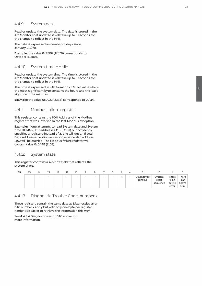
ABB ARC GUARD SYSTEM™ – TVOC-2-COM MODBUS CONFIGUR ATION MANUAL 33
4.4.9 System date
Read or update the system date. The date is stored in the Arc Monitor so if updated it will take up to 2 seconds for the change to reflect in the HMI.
The date is expressed as number of days since January 1, 1970.
Example: the value 0x42B6 (17078) corresponds to October 4, 2016.
4.4.10 System time HHMM
Read or update the system time. The time is stored in the Arc Monitor so if updated it will take up to 2 seconds for the change to reflect in the HMI.
The time is expressed in 24h format as a 16 bit value where the most significant byte contains the hours and the least significant the minutes.
Example: the value 0x0922 (2338) corresponds to 09:34.
4.4.11 Modbus failure register
This register contains the PDU Address of the Modbus register that was involved in the last Modbus exception.
Example: if one attempts to read System date and System time HHMM (PDU addresses 1100, 1101) but accidently specifies 3 registers instead of 2, one will get an Illegal Data Address exception as response since also address 1102 will be queried. The Modbus failure register will contain value 0x044E (1102).
4.4.12 System state
This register contains a 4-bit bit field that reflects the system state.
Bit 15 14 13 12 11 10 9 8 7 6 5 4 3 2 1 0
- - - - - - - - - - - - Diagnostics running
System start
sequence
There is an
active error
There is an
active trip
4.4.13 Diagnostic Trouble Code, number x
These registers contain the same data as Diagnostics error DTC number x and y but with only one byte per register. It might be easier to retrieve the information this way.
See 4.4.3.4 Diagnostics error DTC above for more information.
04

ABB ARC GUARD SYSTEM™ – TVOC-2-COM MODBUS CONFIGUR ATION MANUAL 35
36 5.1 Visual diagnostics
36 5.2 Example of reading with modpoll
05
—5 Troubleshooting
36 ABB ARC GUARD SYSTEM™ – TVOC-2-COM MODBUS CONFIGUR ATION MANUAL
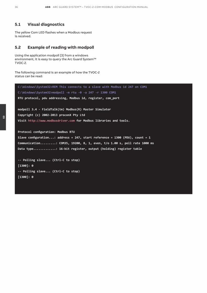
5.1 Visual diagnostics
The yellow Com LED flashes when a Modbus request is received.
5.2 Example of reading with modpoll
Using the application modpoll [3] from a windows environment, it is easy to query the Arc Guard System™ TvOC-2.
The following command is an example of how the TvOC-2 status can be read:
C:\Windows\System32>REM This connects to a slave with Modbus id 247 on COM1
C:\Windows\System32>modpoll -m rtu -0 -a 247 -r 1300 COM1
RTU protocol, pdu addressing, Modbus id, register, com_port
modpoll 3.4 - FieldTalk(tm) Modbus(R) Master Simulator
Copyright (c) 2002-2013 proconX Pty Ltd
Visit http://www.modbusdriver.com for Modbus libraries and tools.
Protocol configuration: Modbus RTU
Slave configuration...: address = 247, start reference = 1300 (PDU), count = 1
Communication.........: COM35, 19200, 8, 1, even, t/o 1.00 s, poll rate 1000 ms
Data type.............: 16-bit register, output (holding) register table
-- Polling slave... (Ctrl-C to stop)
[1300]: 0
-- Polling slave... (Ctrl-C to stop)
[1300]: 0
05

38 ABB ARC GUARD SYSTEM™ – TVOC-2-COM MODBUS CONFIGUR ATION MANUAL
I
Implementation class 20
Installed modules 29
Introduction 8
L
Last performed diagnostics date 27
Last performed diagnostics time HHMM 27
M
Modbus 8, 12
Modbus cables 12
Modbus connector 12
Modbus failure register 33
Modbus functions 20
Modbus id 16
Modbus installation 13
Modbus masters 13
Modbus registers 21
N
Number of errors 28
Number of trips 26
P
PDU Address 33
Perform diagnostics 27
pin configuration 12
Pull-up / pull-down resistors 13
Q
Quick start-up 8
R
Read Registers 20
Read this first 3
Register data format 26
Repeaters 13
Reset 32
RS485 12
S
Safety notes 3
System date 32
System state 33
System time HHMM 32
SyMboLeR
2-Wire Topology 13
A
application modpoll 36
Arc Monitor CPLD version ZZ 30
Arc Monitor HW version 30
Arc Monitor ID, byte x 31
Arc Monitor SW version XXYY 30
Arc Monitor SW version ZZ 30
ASCII 29
Available registers 21
b
Bias resistors 13
C
communication parameters 16
Configuration via HMI 16
CPLD 30
Custom name, letter x and y 29
Custom name registers 29
D
Diagnostics 27
Diagnostics information 27
diagnostic trouble code (DTC) 28
Diagnostic Trouble Code, number x 33
Dip switches 30
DTC 28
e
Error information 27
Error x date 27
Error x DTC, number y and z 28
Error x time HHMM 27
Error x time SS 27
Example of reading with modpoll 36
G
Gateways 13
H
HMI SW version ZZ 31
06
—6 Index
ABB ARC GUARD SYSTEM™ – TVOC-2-COM MODBUS CONFIGUR ATION MANUAL 39
T
Termination 13
Termination resistors 13
Transceiver 12
Trip information 26
Trip x date 26
Trip x detector 26
Trip x detector, high 26
Trip x detector, low 26
Trip x time HHMM 26
Trip x time SS 26
TvOC-2-COM 8
V
version information 30
visual diagnostics 36
W
Warning and safety 3
Write Registers 20
06

—Notes

—Notes

—Notes

—Notes
We reserve the right to make technical changes or modify the contents of this document without prior notice. ABB does not accept any responsibility whatsoever for potential errors or possible lack of information in this document.
We reserve all rights in this document and in the subject matter and illustrations contained therein. Any reproduction, disclosure to third parties or utilization of its contents – in whole or in parts – is forbidden without prior written consent of ABB.
Copyright© 2021 ABB - All rights reserved 1SF
C17
00
17M
020
1 R
ev. D
- P
rin
ted
in F
ran
ce (0
9.2
021
PD
F)
ABB Electrification Sweden ABSmart Power Division Motorgränd 20SE-721 61 Västerås / Sweden
You can find the address of your local sales organisation on the ABB home page.
http://www.abb.com/lowvoltage
http://new.abb.com/low-voltage/products/arc-guard


