Embed Size (px)
Citation preview
FINAL DRAFT UGANDA
STANDARD
FDUS 1727
First Edition 2017-mm-dd
This Final Draft Uganda Standard, FDUS 1727: 2017, Standard Test Method for Density, Relative Density, and API Gravity of Crude Petroleum and Liquid Petroleum Products by Thermohydrometer Method, is based on ASTM D6822 − 12b, Standard Test Method for Density, Relative Density, and API Gravity of Crude Petroleum and Liquid Petroleum Products by Thermohydrometer Method, Copyright ASTM International, 100 Barr Harbor Drive, West Conshohocken, PA 19428, USA, pursuant to license with ASTM International
Reference number FDUS 1727: 2017
© UNBS 2017
Standard Test Method for Density, Relative Density, and API Gravity of Crude Petroleum and Liquid Petroleum Products by Thermohydrometer Method
DRAFT FO
R PUBLIC
REVIE
W
FDUS 1727: 2017
ii © UNBS 2017 - All rights reserved
Compliance with this standard does not, of itself confer immunity from legal obligations
A Uganda Standard does not purport to include all necessary provisions of a contract. Users are responsible for its correct application
© UNBS 2017
All rights reserved. Unless otherwise specified, no part of this publication may be reproduced or utilised in any form or by any means, electronic or mechanical, including photocopying and microfilm, without prior written permission from UNBS.
Requests for permission to reproduce this document should be addressed to
The Executive Director Uganda National Bureau of Standards P.O. Box 6329 Kampala Uganda Tel: +256 417 333 250/1/2/3 Fax:+ 256 414 286 123 E-mail: [email protected] Web: www.unbs.go.ug
This Final Draft Uganda Standard, FDUS 1727: 2017, Standard Test Method for Density, Relative Density, and API Gravity of Crude Petroleum and Liquid Petroleum Products by Thermohydrometer Method, is based on ASTM D6822 − 12b, Standard Test Method for Density, Relative Density, and API Gravity of Crude Petroleum and Liquid Petroleum Products by Thermohydrometer Method, Copyright ASTM International, 100 Barr Harbor Drive, West Conshohocken, PA 19428, USA, pursuant to license with ASTM International
DRAFT FO
R PUBLIC
REVIE
W
FDUS 1727: 2017
© UNBS 2017 - All rights reserved iii
National foreword
Uganda National Bureau of Standards (UNBS) is a parastatal under the Ministry of Trade, Industry and Cooperatives established under Cap 327, of the Laws of Uganda, as amended. UNBS is mandated to co-ordinate the elaboration of standards and is
(a) a member of International Organisation for Standardisation (ISO) and
(b) a contact point for the WHO/FAO Codex Alimentarius Commission on Food Standards, and
(c) the National Enquiry Point on TBT Agreement of the World Trade Organisation (WTO).
The work of preparing Uganda Standards is carried out through Technical Committees. A Technical Committee is established to deliberate on standards in a given field or area and consists of representatives of consumers, traders, academicians, manufacturers, government and other stakeholders.
Draft Uganda Standards adopted by the Technical Committee are widely circulated to stakeholders and the general public for comments. The committee reviews the comments before recommending the draft standards for approval and declaration as Uganda Standards by the National Standards Council.
This Final Draft Uganda Standard, FDUS 1727: 2017, Standard Test Method for Density, Relative Density, and API Gravity of Crude Petroleum and Liquid Petroleum Products by Thermohydrometer Method, is based on ASTM D6822 − 12b, Standard Test Method for Density, Relative Density, and API Gravity of Crude Petroleum and Liquid Petroleum Products by Thermohydrometer Method, Copyright ASTM International, 100 Barr Harbor Drive, West Conshohocken, PA 19428, USA, pursuant to license with ASTM International.
The committee responsible for this document is Technical Committee UNBS/TC 16, Petroleum, Subcommittee SC 1, Petroleum and petrochemical products.
Wherever the words, “ASTM Standard" appear, they should be replaced by "Uganda Standard."
DRAFT FO
R PUBLIC
REVIE
W
Designation: D6822 − 12b
Manual of Petroleum Measurement Standards (MPMS), Chapter 9.3
Standard Test Method forDensity, Relative Density, and API Gravity of CrudePetroleum and Liquid Petroleum Products byThermohydrometer Method1
This standard is issued under the fixed designation D6822; the number immediately following the designation indicates the year oforiginal adoption or, in the case of revision, the year of last revision. A number in parentheses indicates the year of last reapproval. Asuperscript epsilon (´) indicates an editorial change since the last revision or reapproval.
1. Scope*
1.1 This test method covers the determination, using a glassthermohydrometer in conjunction with a series of calculations,of the density, relative density, or API gravity of crudepetroleum, petroleum products, or mixtures of petroleum andnonpetroleum products normally handled as liquids and havinga Reid vapor pressures of 101.325 kPa (14.696 psi) or less.Values are determined at existing temperatures and corrected to15°C or 60°F by means of a series of calculations andinternational standard tables.
1.2 The initial thermohydrometer readings obtained areuncorrected hydrometer readings and not density measure-ments. Readings are measured on a thermohydrometer at eitherthe reference temperature or at another convenienttemperature, and readings are corrected for the meniscus effect,the thermal glass expansion effect, alternate calibration tem-perature effects and to the reference temperature by means ofcalculations and Adjunct to D1250 Guide for Use of thePetroleum Measurement Tables (API MPMS Chapter 11.1).
1.3 Readings determined as density, relative density, or APIgravity can be converted to equivalent values in the other unitsor alternate reference temperatures by means of Interconver-sion Procedures (API MPMS Chapter 11.5) or Adjunct toD1250 Guide for Use of the Petroleum Measurement Tables(API MPMS Chapter 11.1), or both, or tables as applicable.
1.4 The initial thermohydrometer reading shall be recordedbefore performing any calculations. The calculations requiredin Section 9 shall be applied to the initial thermohydrometer
reading with observations and results reported as required bySection 11 prior to use in a subsequent calculation procedure(measurement ticket calculation, meter factor calculation, orbase prover volume determination).
1.5 Annex A1 contains a procedure for verifying or certify-ing the equipment of this test method.
1.6 The values stated in SI units are to be regarded asstandard. The values given in parentheses are for informationonly.
1.7 This standard does not purport to address all of thesafety concerns, if any, associated with its use. It is theresponsibility of the user of this standard to establish appro-priate safety and health practices and determine the applica-bility of regulatory limitations prior to use.
2. Referenced Documents
2.1 ASTM Standards:2
D1250 Guide for Use of the Petroleum Measurement TablesD1298 Test Method for Density, Relative Density, or API
Gravity of Crude Petroleum and Liquid Petroleum Prod-ucts by Hydrometer Method
D4057 Practice for Manual Sampling of Petroleum andPetroleum Products
D4177 Practice for Automatic Sampling of Petroleum andPetroleum Products
D5854 Practice for Mixing and Handling of Liquid Samplesof Petroleum and Petroleum Products
D6300 Practice for Determination of Precision and BiasData for Use in Test Methods for Petroleum Products andLubricants
E100 Specification for ASTM Hydrometers1 This test method is under the jurisdiction of ASTM Committee D02 on
Petroleum Products, Liquid Fuels, and Lubricants and the API Committee onPetroleum Measurement, and is the direct responsibility of Subcommittee D02.02/COMQ, the joint ASTM-API Committee on Hydrocarbon Measurement forCustody Transfer (Joint ASTM-API).
Current edition approved June 1, 2012. Published October 2012. Originallyapproved in 2002. Last previous edition approved in 2012 as D6822-12a. DOI:10.1520/D6822-12B.
2 For referenced ASTM standards, visit the ASTM website, www.astm.org, orcontact ASTM Customer Service at [email protected]. For Annual Book of ASTMStandards volume information, refer to the standard’s Document Summary page onthe ASTM website.
*A Summary of Changes section appears at the end of this standard
© Jointly copyrighted by ASTM International, 100 Barr Harbor Drive, PO Box C700, West Conshohocken, PA 19428-2959, USA and the American Petroleum Institute (API), 1220 L Street NW, Washington DC 20005, USA
This international standard was developed in accordance with internationally recognized principles on standardization established in the Decision on Principles for theDevelopment of International Standards, Guides and Recommendations issued by the World Trade Organization Technical Barriers to Trade (TBT) Committee.
1
Copyright by ASTM Int'l (all rights reserved); Wed Apr 19 04:57:46 EDT 2017Downloaded/printed byUganda MOU - Online Access (Uganda MOU - Online Access) pursuant to License Agreement. No further reproductions authorized.
DRAFT FO
R PUBLIC
REVIE
W
2.2 API Standards:3
MPMS Chapter 8.1 Practice for Manual Sampling of Petro-leum and Petroleum Products (ASTM Practice D4057)
MPMS Chapter 8.2 Practice for Automatic Sampling ofPetroleum and Petroleum Products (ASTM PracticeD4177)
MPMS Chapter 8.3 Practice for Mixing and Handling ofLiquid Samples of Petroleum and Petroleum Products(ASTM Practice D5854)
MPMS Chapter 9.1 Hydrometer Test Method for Density,Relative Density or API Gravity of Crude Petroleum andLiquid Petroleum Products (ASTM Test Method D1298)
MPMS Chapter 11.1 Temperature and Pressure Volume Cor-rection Factors for Generalized Crude Oils, RefinedProducts, and Lubricating Oils (Adjunct to ASTM D1250)
MPMS Chapter 11.5 Density/Weight/Volume Intraconver-sion
2.3 ASTM Adjuncts:Adjunct to D1250 Guide for Use of the Petroleum Measure-
ment Tables (API MPMS Chapter 11.1)4
3. Terminology
3.1 Definitions of Terms Specific to This Standard:3.1.1 API gravity (°API), n—a special function of relative
density 60/60°F, represented by:
°API 5 @141.5/~relative density 60/60°F!# 2 131.5 (1)3.1.1.1 Discussion—No statement of reference temperature
is required, as 60°F is included in the definition.
3.1.2 density, n—the mass of liquid per unit volume at 15°Cand 101.325 kPa with the standard unit of measurement beingkilograms per cubic metre (kg/m3).
3.1.2.1 Discussion—Other reference temperatures, such as20°C, may be used for some products or in some locations.Less preferred units of measurement, for example, kg/L org/mL, are still in use.
3.1.3 hydrometer reading, n—the point on the hydrometerscale at which the surface of the liquid cuts the scale.
3.1.3.1 Discussion—In practice for transparent fluids thiscan be readily determined by aligning the surface of the liquidon both sides of the hydrometer and reading the Hydrometerscale where these surface readings cut the scale (HydrometerReading – Observed). For nontransparent fluids the point atwhich the liquid surface cuts the Hydrometer scale cannot bedetermined directly and requires a correction (Meniscus Cor-rection). The value represented by the point (Meniscus Read-ing) at which the liquid sample rises above the main surface ofthe liquid subtracted from the value represented by where themain surface of the liquid cuts the Hydrometer scale is theamount of the correction or Meniscus correction. This menis-cus correction is documented and then subtracted from thevalue represented by the Meniscus Reading to yield theHydrometer Reading corrected for the Meniscus (HydrometerReading – Observed, Meniscus Corrected).
3.1.4 observed values, n—hydrometer readings observed ata temperature other than the defined reference temperature.
3.1.4.1 Discussion—These values are only hydrometer read-ings and not density, relative density, or API gravity at thetemperature.
3.1.5 relative density, n—the ratio of the mass of a givenvolume of liquid at a specific temperature to the mass of anequal volume of pure water at the same or different tempera-ture. Both reference temperatures shall be explicitly stated.
3.1.5.1 Discussion—Common reference temperatures in-clude 15/15°C, 60/60°F, 20/20°C, and 20/4°C. The historicterm specific gravity may still be found.
3.1.6 thermohydrometer, n—a glass hydrometer with a self-contained thermometer.
4. Summary of Test Method
4.1 The density or API gravity, after temperature equilib-rium has been reached, is read by observing the freely floatingthermohydrometer and noting the graduation nearest to theapparent intersection of the horizontal plane surface of theliquid with the vertical scale of the hydrometer after tempera-ture equilibrium has been reached. The observed thermohy-drometer reading is reduced to the reference temperature valueby means of the Petroleum Measurement Tables (the appropri-ate adjunct to Adjunct to D1250 Guide for Petroleum Mea-surement Tables (API MPMS Chapter 11.1) and observedtemperature from the enclosed thermometer.
5. Significance and Use
5.1 Density and API gravity are used in custody transferquantity calculations and to satisfy transportation, storage, andregulatory requirements. Accurate determination of density orAPI gravity of crude petroleum and liquid petroleum productsis necessary for the conversion of measured volumes tovolumes at the standard temperatures of 15°C or 60°F.
5.2 Density and API gravity are also factors that indicate thequality of crude petroleum. Crude petroleum prices are fre-quently posted against values in kg/m3 or in degrees API.However, this property of petroleum is an uncertain indicationof its quality unless correlated with other properties.
5.3 Field of Application—Because the thermohydrometerincorporates both the hydrometer and thermometer in onedevice, it is more applicable in field operations for determiningdensity or API gravity of crude petroleum and other liquidpetroleum products. The procedure is convenient for gatheringmain trunk pipelines and other field applications where limitedlaboratory facilities are available. The thermohydrometermethod may have limitations in some petroleum densitydeterminations. When this is the case, other methods such asTest Method D1298 (API MPMS Chapter 9.1) may be used.
5.4 This procedure is suitable for determining the density,relative density, or API gravity of low viscosity, transparent oropaque liquids, or both. This procedure, when used for opaqueliquids, requires the use of a meniscus correction (see 9.2).Additionally for both transparent and opaque fluids the read-ings shall be corrected for the thermal glass expansion effectand alternate calibration temperature effects before correcting
3 Available from American Petroleum Institute (API), 1220 L. St., NW,Washington, DC 20005-4070, www.api.org.
4 Available from ASTM International Headquarters. Order Adjunct No.ADJD1250. Original adjunct produced in 1983.
D6822 − 12b
2
Copyright by ASTM Int'l (all rights reserved); Wed Apr 19 04:57:46 EDT 2017Downloaded/printed byUganda MOU - Online Access (Uganda MOU - Online Access) pursuant to License Agreement. No further reproductions authorized.
DRAFT FO
R PUBLIC
REVIE
W
to the reference temperature. This procedure can also be usedfor viscous liquids by allowing sufficient time for the thermo-hydrometer to reach temperature equilibrium.
6. Apparatus
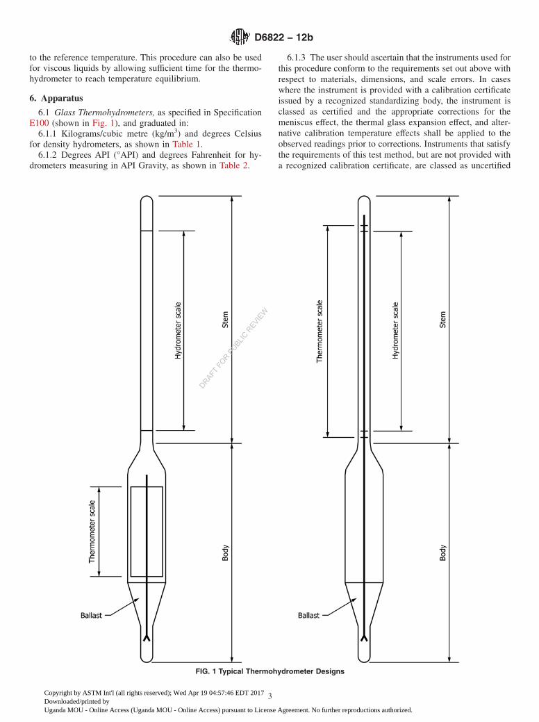
6.1 Glass Thermohydrometers, as specified in SpecificationE100 (shown in Fig. 1), and graduated in:
6.1.1 Kilograms/cubic metre (kg/m3) and degrees Celsiusfor density hydrometers, as shown in Table 1.
6.1.2 Degrees API (°API) and degrees Fahrenheit for hy-drometers measuring in API Gravity, as shown in Table 2.
6.1.3 The user should ascertain that the instruments used forthis procedure conform to the requirements set out above withrespect to materials, dimensions, and scale errors. In caseswhere the instrument is provided with a calibration certificateissued by a recognized standardizing body, the instrument isclassed as certified and the appropriate corrections for themeniscus effect, the thermal glass expansion effect, and alter-native calibration temperature effects shall be applied to theobserved readings prior to corrections. Instruments that satisfythe requirements of this test method, but are not provided witha recognized calibration certificate, are classed as uncertified
FIG. 1 Typical Thermohydrometer Designs
D6822 − 12b
3
Copyright by ASTM Int'l (all rights reserved); Wed Apr 19 04:57:46 EDT 2017Downloaded/printed byUganda MOU - Online Access (Uganda MOU - Online Access) pursuant to License Agreement. No further reproductions authorized.
DRAFT FO
R PUBLIC
REVIE
W
and the appropriate corrections for the meniscus effect, thethermal glass expansion effect, and alternative calibrationtemperature effects shall be applied to the observed readingsprior to corrections.
6.2 Hydrometer Cylinders, clear glass, plastic, or metal. Forconvenience of pouring, the cylinder may have a pouring lip.The inside diameter shall be at least 25 mm (1 in.) greater thanthe outside diameter of the thermohydrometer used. The heightof the cylinder shall be such that the bottom of the thermohy-drometer clears the bottom of the cylinder by at least 25 mm(1 in.) when suspended in the sample test portion.
6.2.1 For field testing, a sample thief of suitable dimensionsmay be more convenient than a hydrometer cylinder. Theliquid level shall be level with the top of the thief.
6.3 Temperature Bath, to control temperature close to thebulk hydrocarbon temperature or to control temperature closeto the reference temperature of 15°C or 60°F.
7. Sampling, Test Specimens, and Test Units
7.1 Unless otherwise specified, samples of non-volatilepetroleum and petroleum products shall be taken by theprocedures described in Practices D4057 (API MPMS Chapter8.1) and D4177 (API MPMS Chapter 8.2).
7.2 Samples of volatile crude petroleum or petroleum prod-ucts are preferably taken by Practice D4177 (API MPMS
Chapter 8.2), using a variable volume (floating piston) samplereceiver to minimize any loss of light components which mayaffect the accuracy of the density measurement. In the absenceof this facility, extreme care shall be taken to minimize theselosses, including the transfer of the sample to a chilledcontainer immediately after sampling.
7.3 Sample Mixing—May be necessary to obtain a testportion representative of the bulk sample to be tested, butprecautions shall be taken to maintain the integrity of thesample during this operation. Mixing of volatile crude petro-leum or petroleum products containing water or sediments, orboth, or the heating of waxy volatile crude petroleum orpetroleum products may result in the loss of light components.The following sections (7.3.1 – 7.3.4) will give some guidanceon sample integrity maintenance.
7.3.1 Volatile Crude Petroleum and Petroleum ProductsHaving an RVP Greater than 50 kPa—Mix the sample in itsoriginal closed container in order to minimize the loss of lightcomponents.
NOTE 1—Mixing volatile samples in open containers will lead to loss oflight components and consequently affect the value of the densityobtained.
7.3.2 Waxy Crude Petroleum—If the petroleum has anexpected pour point above 10°C, or a cloud point or WATabove 15°C, warm the sample to a temperature that is sufficientfor ensuring the material is fluid enough to provide adequatemixing without excessively heating the material that wouldotherwise compromise the integrity of the sample. Samplesheated to 9°C above its pour point, or 3°C above its cloud pointor WAT have been found to be suitable temperatures to warmsamples prior to mixing. Whenever possible, mix the sample inits original closed container in order to minimize the loss oflight components.
7.3.3 Waxy Distillate—Warm the sample to a temperaturethat is sufficient for ensuring the material is fluid enough toprovide adequate mixing without excessively heating thematerial that would otherwise compromise the integrity of thesample. Samples heated to 3°C above its cloud point or WAThave been found to be suitable temperatures to warm samplesprior to mixing.
7.3.4 Residual Fuel Oils—Heat the sample to the testtemperature prior to mixing (see 9.1.1 and Note 3).
7.4 Additional information on the mixing and handling ofliquid samples will be found in Practice D5854 (API MPMSChapter 8.3).
8. Apparatus Verification or Certification
8.1 Hydrometers and thermometers shall be verified inaccordance with the procedures in Annex A1.
9. Procedure
9.1 Effect of Test Temperature:9.1.1 The density or API gravity determined by the thermo-
hydrometer method is most accurate at or near the referencetemperature of 15°C or 60°F. Other temperatures within therange of the enclosed thermometer may be used, if consistentwith the type of sample and the necessary limiting conditionsshown in Table 3.
TABLE 1 Density Thermohydrometers
ASTM Hydrometer No. Density, Range, kg/m3
300H 600 to 650301H 650 to 700302H 700 to 750303H 750 to 800304H 800 to 850305H 850 to 900306H 900 to 950307H 950 to 1000308H 1000 to 1050309H 1050 to 1100345H 775 to 825
HydrometerTotal length, mm 374 to 387Body diameter, mm 18 to 25Stem diameter, mm, min 4.0
Hydrometer ScaleStandard temperature, °C 15Subdivisions, kg/m3 0.5Short intermediate lines at, kg/m3 1Long intermediate lines at, kg/m3 5Main (numbered) lines at, kg/m3 10Scale error at any point not toexceed, kg/m3
0.5
Length of nominal scale, mm 125 to 145Scale extension beyond nominalrange limits, kg/m3
2.5
Thermometer ScaleRange, °CDesignation L −20 to +65Designation M 0 to +85Designation H +20 to +105
Immersion totalSubdivisions, °C 1.0Intermediate lines at, °C 5Main (numbered) lines at, °C 10Scale error at any point not toexceed, °C
1.0
Scale length, mm 80 to 100
D6822 − 12b
4
Copyright by ASTM Int'l (all rights reserved); Wed Apr 19 04:57:46 EDT 2017Downloaded/printed byUganda MOU - Online Access (Uganda MOU - Online Access) pursuant to License Agreement. No further reproductions authorized.
DRAFT FO
R PUBLIC
REVIE
W
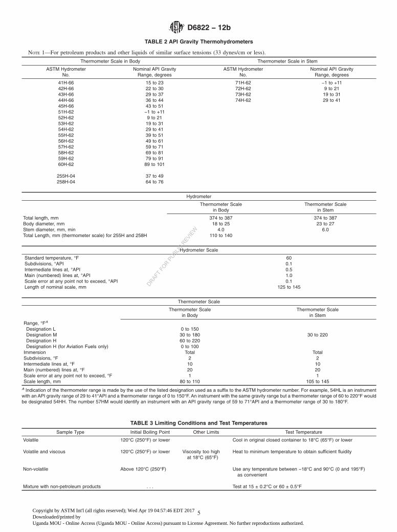
TABLE 2 API Gravity Thermohydrometers
NOTE 1—For petroleum products and other liquids of similar surface tensions (33 dynes/cm or less).
Thermometer Scale in Body Thermometer Scale in Stem
ASTM HydrometerNo.
Nominal API GravityRange, degrees
ASTM HydrometerNo.
Nominal API GravityRange, degrees
41H-66 15 to 23 71H-62 −1 to +1142H-66 22 to 30 72H-62 9 to 2143H-66 29 to 37 73H-62 19 to 3144H-66 36 to 44 74H-62 29 to 4145H-66 43 to 5151H-62 −1 to +1152H-62 9 to 2153H-62 19 to 3154H-62 29 to 4155H-62 39 to 5156H-62 49 to 6157H-62 59 to 7158H-62 69 to 8159H-62 79 to 9160H-62 89 to 101
255H-04 37 to 49258H-04 64 to 76
Hydrometer
Thermometer Scalein Body
Thermometer Scalein Stem
Total length, mm 374 to 387 374 to 387Body diameter, mm 18 to 25 23 to 27Stem diameter, mm, min 4.0 6.0Total Length, mm (thermometer scale) for 255H and 258H 110 to 140
Hydrometer Scale
Standard temperature, °F 60Subdivisions, °API 0.1Intermediate lines at, °API 0.5Main (numbered) lines at, °API 1.0Scale error at any point not to exceed, °API 0.1Length of nominal scale, mm 125 to 145
Thermometer Scale
Thermometer Scalein Body
Thermometer Scalein Stem
Range, °FA
Designation L 0 to 150Designation M 30 to 180 30 to 220Designation H 60 to 220Designation H (for Aviation Fuels only) 0 to 100
Immersion Total TotalSubdivisions, °F 2 2Intermediate lines at, °F 10 10Main (numbered) lines at, °F 20 20Scale error at any point not to exceed, °F 1 1Scale length, mm 80 to 110 105 to 145
A Indication of the thermometer range is made by the use of the listed designation used as a suffix to the ASTM hydrometer number. For example, 54HL is an instrumentwith an API gravity range of 29 to 41°API and a thermometer range of 0 to 150°F. An instrument with the same gravity range but a thermometer range of 60 to 220°F wouldbe designated 54HH. The number 57HM would identify an instrument with an API gravity range of 59 to 71°API and a thermometer range of 30 to 180°F.
TABLE 3 Limiting Conditions and Test Temperatures
Sample Type Initial Boiling Point Other Limits Test Temperature
Volatile 120°C (250°F) or lower Cool in original closed container to 18°C (65°F) or lower
Volatile and viscous 120°C (250°F) or lower Viscosity too highat 18°C (65°F)
Heat to minimum temperature to obtain sufficient fluidity
Non-volatile Above 120°C (250°F) Use any temperature between −18°C and 90°C (0 and 195°F)as convenient
Mixture with non-petroleum products . . . Test at 15 ± 0.2°C or 60 ± 0.5°F
D6822 − 12b
5
Copyright by ASTM Int'l (all rights reserved); Wed Apr 19 04:57:46 EDT 2017Downloaded/printed byUganda MOU - Online Access (Uganda MOU - Online Access) pursuant to License Agreement. No further reproductions authorized.
DRAFT FO
R PUBLIC
REVIE
W
9.1.2 Bring the sample to the test temperature which shall besuch that the sample is sufficiently fluid but not as high as tocause the loss of light components, or so low as to result in theappearance of wax in the test portion.
NOTE 2—The volume and density, the relative density, and the APIcorrections in the volume correction procedures are based on the averageexpansions of a number of typical materials. Since the same coefficientswere used in compiling each set of tables, corrections made over the sametemperature interval minimize errors arising from possible differencesbetween the coefficient of the material under test and the standardcoefficients. This effect becomes more important as temperatures divergefrom the reference temperature.
NOTE 3—The hydrometer reading is obtained at a temperature appro-priate to the physic-chemical characteristics of the material under test.This temperature is preferably close to the reference temperature, or whenthe value is used in conjunction with bulk oil measurements, within 3°Cof the bulk temperature (see 5.3).
9.1.3 For crude petroleum, bring the sample close to thereference temperature or, if wax is present, to 9°C above itspour point or 3°C above its cloud point, whichever is higher.
9.1.4 If the test temperature is significantly different fromthe reference temperature of 15°C or 60°F, the expansion orcontraction of the glass may affect the calibration of thethermohydrometer. A hydrometer correction factor (HYC) maybe applied to the measured density value to provide a correctedreading.
9.1.5 If the hydrometer has been calibrated at a temperatureother than the reference temperature, use the equation below tocorrect the hydrometer scale reading:
ρr 5ρt
1 2 @23 3 1026 ~t 2 r! 2 2 3 1028 ~t 2 r!2#(2)
where:ρr = hydrometer reading at the reference temperature, r °C,
andρt = hydrometer reading on the hydrometer scale whose
reference temperature is t °C.
9.1.6 When the thermohydrometer value is used to selectfactors for correcting volumes to standard temperatures, thethermohydrometer reading preferably should be made at atemperature within 63°C (65°F) of the temperature at whichthe bulk volume of the oil was measured (see Note 2).However, when appreciable amounts of light fractions may belost during determination at the bulk oil temperature, the limitsgiven in Table 3 shall be applied.
9.2 Density Measurement:9.2.1 Adjust the temperature of the sample in accordance
with Table 3. For field testing, test temperatures other thanthose listed in Table 3 may be used, however, accuracy may besacrificed. The hydrometer cylinder shall be at approximatelythe same temperature as the sample to be tested.
9.2.2 Transfer the sample into the clean hydrometer cylinderwithout splashing, so as to avoid the formation of air bubblesand to reduce, to a minimum, the evaporation of the lowerboiling constituents of the more volatile samples (Warning—Extremely flammable. Vapors may cause a flash fire).For themore volatile samples, transfer to the hydrometer cylinder bysiphoning (Warning—Siphoning by mouth could result iningestion of sample). Use a rubber aspirator bulb to siphon the
more volatile samples. Remove any air bubbles formed, afterthey have collected on the surface of the sample, by touchingthem with a piece of clean absorbent paper before inserting thethermohydrometer. For field testing, the thermohydrometermay be inserted directly into a sampling thief. Place thecylinder containing the sample in a vertical position in alocation free from air currents. Take precautions to prevent thetemperature of the sample from changing appreciably duringthe time necessary to complete the test.
9.2.2.1 During this period, the temperature of the surround-ing medium should not change more than 3°C (5°F).
9.2.3 Lower and raise the thermohydrometer no more thantwo scale divisions in the sample cylinder to minimize vaporloss and in such a manner that the stem will not be wettedhigher than the approximate floating position.
9.2.3.1 Keep the rest of the stem dry, as unnecessary liquidon the stem changes the effective weight of the instrument, andso affects the reading obtained.
9.2.3.2 Gently lower the thermohydrometer into the centerof the hydrometer cylinder. When the thermohydrometer hassettled, ensure it is not resting on the bottom of the cylinder bydepressing it no more than two scale divisions into the liquid.Give the thermohydrometer a slight spin, allowing it to floatfreely away from the walls of the hydrometer cylinder.
9.2.3.3 Allow enough time for the thermohydrometer tocome to rest, all air bubbles to come to the surface, and thethermohydrometer temperature to stabilize, usually 3 to 5 min.This is particularly necessary in the case of more viscoussamples. Use a temperature bath if control of the sampletemperature is required.
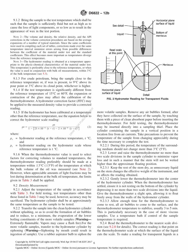
9.2.4 Read the thermohydrometer to the nearest scale divi-sion (see 9.2.8 for details). The correct reading is that point onthe thermohydrometer scale at which the surface of the liquidcuts the scale. To make a reading for transparent liquids in a
FIG. 2 Hydrometer Reading for Transparent Fluids
D6822 − 12b
6
Copyright by ASTM Int'l (all rights reserved); Wed Apr 19 04:57:46 EDT 2017Downloaded/printed byUganda MOU - Online Access (Uganda MOU - Online Access) pursuant to License Agreement. No further reproductions authorized.
DRAFT FO
R PUBLIC
REVIE
W
transparent hydrometer cylinder, determine this point by plac-ing the eye slightly below the level of the liquid and slowlyraising it until the surface, first seen as a distorted ellipse,appears to become a straight line cutting the thermohydrometerscale. See Fig. 2 for details on reading the meniscus.
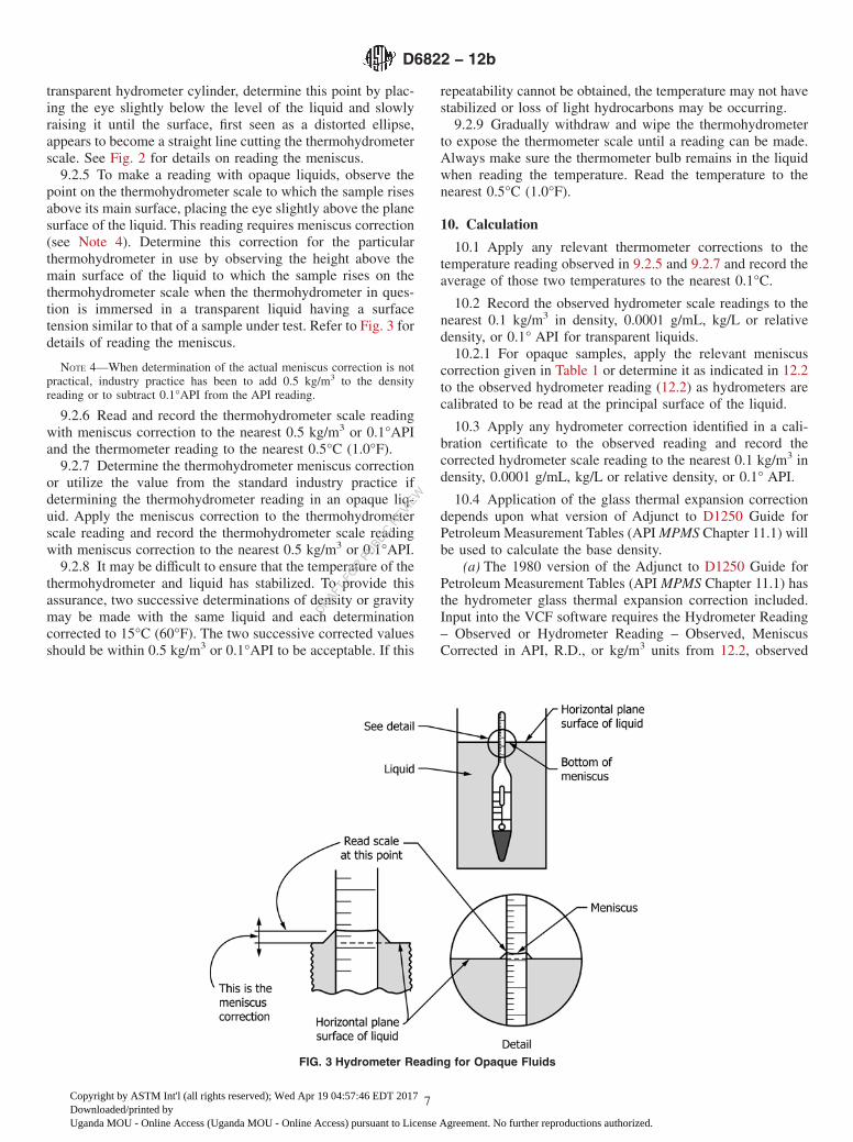
9.2.5 To make a reading with opaque liquids, observe thepoint on the thermohydrometer scale to which the sample risesabove its main surface, placing the eye slightly above the planesurface of the liquid. This reading requires meniscus correction(see Note 4). Determine this correction for the particularthermohydrometer in use by observing the height above themain surface of the liquid to which the sample rises on thethermohydrometer scale when the thermohydrometer in ques-tion is immersed in a transparent liquid having a surfacetension similar to that of a sample under test. Refer to Fig. 3 fordetails of reading the meniscus.
NOTE 4—When determination of the actual meniscus correction is notpractical, industry practice has been to add 0.5 kg/m3 to the densityreading or to subtract 0.1°API from the API reading.
9.2.6 Read and record the thermohydrometer scale readingwith meniscus correction to the nearest 0.5 kg/m3 or 0.1°APIand the thermometer reading to the nearest 0.5°C (1.0°F).
9.2.7 Determine the thermohydrometer meniscus correctionor utilize the value from the standard industry practice ifdetermining the thermohydrometer reading in an opaque liq-uid. Apply the meniscus correction to the thermohydrometerscale reading and record the thermohydrometer scale readingwith meniscus correction to the nearest 0.5 kg/m3 or 0.1°API.
9.2.8 It may be difficult to ensure that the temperature of thethermohydrometer and liquid has stabilized. To provide thisassurance, two successive determinations of density or gravitymay be made with the same liquid and each determinationcorrected to 15°C (60°F). The two successive corrected valuesshould be within 0.5 kg/m3 or 0.1°API to be acceptable. If this
repeatability cannot be obtained, the temperature may not havestabilized or loss of light hydrocarbons may be occurring.
9.2.9 Gradually withdraw and wipe the thermohydrometerto expose the thermometer scale until a reading can be made.Always make sure the thermometer bulb remains in the liquidwhen reading the temperature. Read the temperature to thenearest 0.5°C (1.0°F).
10. Calculation
10.1 Apply any relevant thermometer corrections to thetemperature reading observed in 9.2.5 and 9.2.7 and record theaverage of those two temperatures to the nearest 0.1°C.
10.2 Record the observed hydrometer scale readings to thenearest 0.1 kg/m3 in density, 0.0001 g/mL, kg/L or relativedensity, or 0.1° API for transparent liquids.
10.2.1 For opaque samples, apply the relevant meniscuscorrection given in Table 1 or determine it as indicated in 12.2to the observed hydrometer reading (12.2) as hydrometers arecalibrated to be read at the principal surface of the liquid.
10.3 Apply any hydrometer correction identified in a cali-bration certificate to the observed reading and record thecorrected hydrometer scale reading to the nearest 0.1 kg/m3 indensity, 0.0001 g/mL, kg/L or relative density, or 0.1° API.
10.4 Application of the glass thermal expansion correctiondepends upon what version of Adjunct to D1250 Guide forPetroleum Measurement Tables (API MPMS Chapter 11.1) willbe used to calculate the base density.
(a) The 1980 version of the Adjunct to D1250 Guide forPetroleum Measurement Tables (API MPMS Chapter 11.1) hasthe hydrometer glass thermal expansion correction included.Input into the VCF software requires the Hydrometer Reading– Observed or Hydrometer Reading – Observed, MeniscusCorrected in API, R.D., or kg/m3 units from 12.2, observed
FIG. 3 Hydrometer Reading for Opaque Fluids
D6822 − 12b
7
Copyright by ASTM Int'l (all rights reserved); Wed Apr 19 04:57:46 EDT 2017Downloaded/printed byUganda MOU - Online Access (Uganda MOU - Online Access) pursuant to License Agreement. No further reproductions authorized.
DRAFT FO
R PUBLIC
REVIE
W
temperature of the sample, and the built-in hydrometer glassthermal correction switch set to on (0) or off (1). It will returnAPI or R.D. @ 60°F or kg/m3 @ 15°C.
(b) The 2004 version of the Adjunct to D1250 Guide forPetroleum Measurement Tables (API MPMS Chapter 11.1)does not include the hydrometer glass thermal expansioncorrection, so that correction must be made before entering thesoftware. Depending on the specific end use of the calculationresults, the final value may be left rounded or unrounded.
The following steps are required to implement 10.1b:Step 1. Convert the corrected hydrometer scale reading to
density in kg/m3 if necessary, using either Eq 3 or Eq 4.Scale Units ConversionAPI gravity
Density ~kg/m3! 5 ~141.5*999.016!/~131.51API! (3)
Scale Units ConversionRelative density
Density ~kg/m3! 5 R .D .*999.016 (4)
Leave the result unrounded.Step 2. Calculate the hydrometer thermal glass expansion
correction factor using the appropriate equation below (t isobserved temperature).
Correction for a Base Temperature (Tb) of 60°F:
HYC 5 1.0 2 @0.00001278 ~t 2 60!# 2 @0.0000000062 ~t 2 60!2# (5)
Correction for a Base Temperature (Tb) of 15°C:
HYC 5 1.0 2 @0.000023 ~t 2 15!# 2 @0.00000002 ~t 2 15!2# (6)
Correction for a Base Temperature (Tb) of 20°C:
HYC 5 1.0 2 @0.000023 ~t 2 20!# 2 @0.00000002 ~t 2 20!2# (7)Leave the result un-rounded.
Step 3. Multiply the density in kg/m3 from Step 1 by theproper HYC from Step 2 to obtain the glass thermal expansioncorrected hydrometer density reading.
kg/m3HYC 5 kg/m3*HYC (8)
If the temperature was in degrees Celsius, skip to Step 5.
Step 4a. Convert the densities calculated in Step 3 thatstarted as API Gravity or Relative Density (RD) to RD(Relative Density).
NOTE 5—The current C source code compiled dll and Excel Add-in hasan omission and cannot use a kg/m3 call with degree F.
R .D . 5 kg/m3HYC/999.016 (9)
Step 4b. Input R.D. and degree F into section 11.1.6.2 of theAdjunct to D1250–04 Guide for Petroleum MeasurementTables (API MPMS Chapter 11.1–2004), which returns R.D. @60 °F.
NOTE 6—Pressure will have to be atmospheric gauge, or 0 psig as theAdjunct to D1250 Guide for Petroleum Measurement Tables (API MPMSChapter 11.1) values are only valid at atmospheric pressure.
Step 4c. Convert the calculated R.D. value @ 60°F to acalculated API @ 60 °F using Eq 10, if the original input wasin API units.
API Gravity 5 ~141.5/R.D.! 2 131.5 (10)
Step 5. Input the density calculated in Step 3 in kg/m3 HYC,degree C, base temperature (15°C or 20°C) into Section11.1.7.2 of the Adjunct to D1250–04 Guide for PetroleumMeasurement Tables (API MPMS Chapter 11.1–2004), whichwill return a calculated density in kg/m3 units at the selectedbase temperature.
NOTE 7—Pressure will have to be atmospheric gauge, 0 psig, 101.325kPa or 0 bar as the Adjunct to D1250 Guide for Petroleum MeasurementTables (API MPMS Chapter 11.1) values are only valid at atmosphericpressure.
c. Future versions of the Adjunct to D1250 Guide forPetroleum Measurement Tables (API MPMS Chapter 11.1)code will be corrected so that it can accept any combination ofinput units and return any combination of output units. Whenavailable, the Adjunct to D1250 Guide for Petroleum Measure-ment Tables (API MPMS Chapter 11.1) code can be accesseddirectly from Step 3 and return API @ 60 °F, R.D. @ 60 °F, andkg/m3 at any selected base temperature.
Example 1:Sample: Crude OilObserved Temperature: 77°FObserved Hydrometer Reading: 33.2 API GravityBase Temperature: 60°FStep 1: 858.2924347298... Eq 3, Eq 4Step 2: 0.999780948... Eq 5, Eq 6, Eq 7Step 3: 858.104424227 Eq 8Step 4a: 0.858949631... Eq 9Step 4b: 0.865678279...Step 4c1: 31.955643312... Eq 10 unroundedStep 4c2: 32.0°API Eq 10 rounded
Example 2:Sample: Crude OilObserved Temperature: 25.0 °CObserved Hydrometer Reading: 858.29 kg/m3
Observed Pressure: 0 barBase Temperature: 15°CStep 1: 858.290000000... no conversion necessaryStep 2: 0.999768000... Eq 5, Eq 6, Eq 7Step 3: 858.090876720... Eq 8Step 5.1: 865.207470082... unroundedStep 5.2 865.21 kg/m3 rounded
Example 3:Sample: Crude OilObserved Temperature: 77.0 °FObserved Hydrometer Reading (R.D.):0.859138Observed Pressure 0 psigBase Temp: 60°FStep 1: 858.292608208... Eq 3, Eq 4Step 2: 0.999780948... Eq 5, Eq 6, Eq 7Step 3: 858.104597667... Eq 8Step 4a: 0.858949804... Eq 9Step 4b 0.865678451... unroundedStep 4c 0.8657... rounded
10.5 If the hydrometer has been calibrated at a temperatureother than the reference temperature, use the equation below tocorrect the hydrometer scale reading:
ρr 5ρt
1 2 @23 3 1026 ~t 2 r! 2 2 3 1028 ~t 2 r!2#(11)
where:ρr = hydrometer reading at the reference temperature, r °C,
andρt = hydrometer reading on the hydrometer scale whose
reference temperature is t °C.
D6822 − 12b
8
Copyright by ASTM Int'l (all rights reserved); Wed Apr 19 04:57:46 EDT 2017Downloaded/printed byUganda MOU - Online Access (Uganda MOU - Online Access) pursuant to License Agreement. No further reproductions authorized.
DRAFT FO
R PUBLIC
REVIE
W
11. Reports
11.1 Reporting of Observed Readings:11.1.1 Apply any relevant corrections to the observed ther-
mohydrometer reading.11.1.1.1 For opaque samples, make the appropriate correc-
tion to the observed thermohydrometer scale reading given in9.2.5.
11.1.2 Record this corrected hydrometer scale reading to thenearest 0.5 kg/m3 density or 0.1°API and record the thermom-eter reading to the nearest 0.5°C or 1.0°F.
11.1.3 The reporting values have no precision or biasdetermination. It is up to the user to determine whether this testmethod provides results of sufficient accuracy for the intendedpurpose.
11.2 Correction to Standard Temperatures:11.2.1 To correct density or API gravity to standard tem-
peratures at 15°C or 60°F respectively, use the followingPetroleum Measurement Tables.
11.2.1.1 When a density scale thermohydrometer wasemployed, use Tables 53A, 53B, or 53D from the appropriateAdjunct to D1250 Guide for Petroleum Measurement Tables(API MPMS Chapter 11.1) to obtain density at 15°C.
11.2.1.2 When an API scale thermohydrometer wasemployed, use Tables 5A, 5B, or 5D from the appropriateAdjunct to D1250 Guide for Petroleum Measurement Tables(API MPMS Chapter 11.1) to obtain the gravity in °API.
11.2.1.3 When a relative density scale thermohydrometerwas employed, use Tables 23A and 23B from the appropriateAdjunct to D1250 Guide for Petroleum Measurement Tables(API MPMS Chapter 11.1) to obtain the relative density at60/60°F.
11.3 Unit Conversions:11.3.1 When a value is obtained with a thermohydrometer
scaled in one set of units and a result is required in another setof units, convert by use of the appropriate Petroleum Measure-ment Tables.
11.3.1.1 For conversion from density at 15°C to other units,use API MPMS Chapter 11.5.
11.3.1.2 For conversion from API gravity to other units, useAPI MPMS Chapter 11.5.
11.4 Reporting of Final Value—Report the final value asdensity at 15°C to the nearest 0.5 kg/m3, relative density
60/60°F to the nearest 0.0005, or as °API to the nearest0.1°API, whichever is applicable.
11.5 Certified hydrometers from a recognized standardizingbody, such as NIST, report the output density as ‘Density inVacuo.’
12. Precision and Bias
12.1 Precision—The precision of this test method as deter-mined by statistical examination of interlaboratory results is asfollows:
12.1.1 Repeatability—The difference between two results,obtained by the same operator with the same apparatus underconstant operating conditions on identical test material, wouldin the long run, in the normal and correct operation of the testmethod, exceed 0.6 kg/m3 or 0.2°API only in one case intwenty.
12.1.2 Reproducibility—The difference between two singleand independent results obtained by different operators work-ing in different laboratories and on identical test materialwould, in the long run, in the normal and correct operation ofthe test method, exceed 1.5 kg/m3 or 0.5°API only in one casein twenty.
NOTE 8—The precision of this test method was not obtained inaccordance with Practice D6300. The precision statement applies only tomeasurements made at temperatures of 15 6 10°C or 60 6 15°F.
12.1.3 The Repeatability and Reproducibility values pro-vided above are not based on any interlaboratory round robinresults. They should be considered historical numbers, thesource of which cannot be verified by either ASTM or API andhave been in this document prior to the current slate of blendedcrude oils, RFG gasolines and reformulated distallates. Thesevalues do not apply to the current calculation procedures and itis up to the user to determine whether this method providesresults of sufficient accuracy for the intended purpose.
12.2 Bias—Bias for this test method has not been deter-mined. However, to determine that the bias is within acceptablelimits, ensure the hydrometer and the thermometer have beenverified using standards traceable to International Standardsbefore the thermohydrometer or hydrometer and thermometerare placed into service. Periodic reverification may be required.
13. Keywords
13.1 API gravity; density; hydrometer; hydrometer cylin-der; relative density; thermohydrometer; thermometer
D6822 − 12b
9
Copyright by ASTM Int'l (all rights reserved); Wed Apr 19 04:57:46 EDT 2017Downloaded/printed byUganda MOU - Online Access (Uganda MOU - Online Access) pursuant to License Agreement. No further reproductions authorized.
DRAFT FO
R PUBLIC
REVIE
W
ANNEX
(Mandatory Information)
A1. APPARATUS
A1.1 Apparatus Verification and Certification
A1.1.1 Hydrometers, shall either be certified or verified.Verification shall be either by comparison with a certifiedhydrometer (see 6.1.1) or by the use of a certified referencematerial (CRM) specific to the reference temperature used.
A1.1.1.1 The hydrometer scale shall be correctly locatedwithin the hydrometer stem by reference to the datum mark. Ifthe scale has moved, reject the hydrometer.
A1.1.1.2 Hydrometers shall be certified or verified at inter-vals of no more than 24 months.
A1.1.2 Thermometers, shall be verified at intervals of nomore than six months for conformance with specifications.Either comparison with a referenced temperature measurementsystem traceable to an international standard, or a determina-tion of ice point, is suitable.
SUMMARY OF CHANGES
Subcommittee D02.02 has identified the location of selected changes to this standard since the last issue(D6822-12a) that may impact the use of this standard. (Approved June 1, 2012)
(1) Added 3.1.3.
Subcommittee D02.02 has identified the location of selected changes to this standard since the last issue(D6822-12) that may impact the use of this standard. (Approved May 15, 2012)
(1) Added Section 7.(2) Added Section 8.
(3) Added Section 10.
Subcommittee D02.02 has identified the location of selected changes to this standard since the last issue(D6822-02(2008)) that may impact the use of this standard. (Approved April 1, 2012)
(1) Revised Sections 9, 11, and 12. (2) Added Annex A1.
ASTM International takes no position respecting the validity of any patent rights asserted in connection with any item mentionedin this standard. Users of this standard are expressly advised that determination of the validity of any such patent rights, and the riskof infringement of such rights, are entirely their own responsibility.
This standard is subject to revision at any time by the responsible technical committee and must be reviewed every five years andif not revised, either reapproved or withdrawn. Your comments are invited either for revision of this standard or for additional standardsand should be addressed to ASTM International Headquarters. Your comments will receive careful consideration at a meeting of theresponsible technical committee, which you may attend. If you feel that your comments have not received a fair hearing you shouldmake your views known to the ASTM Committee on Standards, at the address shown below.
This standard is copyrighted by ASTM International, 100 Barr Harbor Drive, PO Box C700, West Conshohocken, PA 19428-2959,United States. Individual reprints (single or multiple copies) of this standard may be obtained by contacting ASTM at the aboveaddress or at 610-832-9585 (phone), 610-832-9555 (fax), or [email protected] (e-mail); or through the ASTM website(www.astm.org). Permission rights to photocopy the standard may also be secured from the Copyright Clearance Center, 222Rosewood Drive, Danvers, MA 01923, Tel: (978) 646-2600; http://www.copyright.com/
D6822 − 12b
10
Copyright by ASTM Int'l (all rights reserved); Wed Apr 19 04:57:46 EDT 2017Downloaded/printed byUganda MOU - Online Access (Uganda MOU - Online Access) pursuant to License Agreement. No further reproductions authorized.
DRAFT FO
R PUBLIC
REVIE
W


![[ PowerPoint Template ]](https://img.pdfslide.net/doc/110x75/631afe995d5809cabd0fa04b/-powerpoint-template-.jpg)