Embed Size (px)
Citation preview

Ullman Cockpit Test Report Johan Ullman M.D.
Fredrik Wartenberg PhD MSc(fw)
Ullman Cockpit Test Report 010424
p. 2 (11)
Summary In a cooperation project of the US NAVY and Marinova the Ullman Cockpit was evaluated in comparison to a conventional Cockpit on a 36 ft. nautica RIB boat. During seatests and high speed wake crossings acceleration on drivers’ backs were measured. The baseline cockpit showed in average 50% higher acceleration values on the drivers’ backs in case of the more severe hits. After the rides operators were asked to give their subjective judgements on the two cockpits. The Ullman Cockpit was experienced as substantially reducing vertical impact severity and allowing much more flexible change of posture during the ride.
From the tests it can be concluded that the Ullman Cockpit reduces the risk for injury of the operators.
1 Introduction The use of high-performance motorboats by sea-rescue organizations, coast guards, and military organizations allows teams to reach their destination quicker than ever before, allowing numerous lives to be saved that otherwise might have been lost. And while the benefits of such craft are obvious, there are also drawbacks.
The faster a boat travels over heavy seas, the more it impacts with the water's surface. This impact is transferred directly into the backs, knees, necks, muscles, and joints of the boat operators. In extreme cases, such impacts result in whiplash, herniated disks, and even death. Even in less severe cases, the resulting injuries cause fatigue, extreme discomfort and pain, and drastically shorten the working life of the highly trained individuals involved.
The new Ullman Cockpit directly addresses and solves most of these problems. Vessels equipped with the Ullman Cockpit enable you to drastically reduce response times, reduce operator injury, and increase the number of lives saved.
The Ullman Cockpit consists of a saddle-like seat equipped with a spring and damping mechanism and a motorcycle type steering mechanism. The saddle like seat in allows the operators to use their legs and the damping mechanism in a optimal way to take up the forces they are subjected to. The the motorcycle steering stabilizes the posture and allow full control of the boat with a retained grip around the steering. Moreover the control of the boat is more immediate as there is a closer correspondence between the steering and the reaction of the boat than with a conventional steering wheel.
Together with the US Navy Marinova AB conducted a sea test of the Ullman Cockpit in direct comparison with a conventional high-end cockpit
2 Aim of the Study Aim of the study was to compare the shock mitigating capabilities of the Ullman Cockpit and the baseline Cockpit under controlled conditions resembling a ride in heavy seas. To measure the shock mitigating capabilities operators the acceleration on the driver’s backs were measured with hip mounted accelerometers.
Ullman Cockpit Test Report 010424
p. 3 (11)
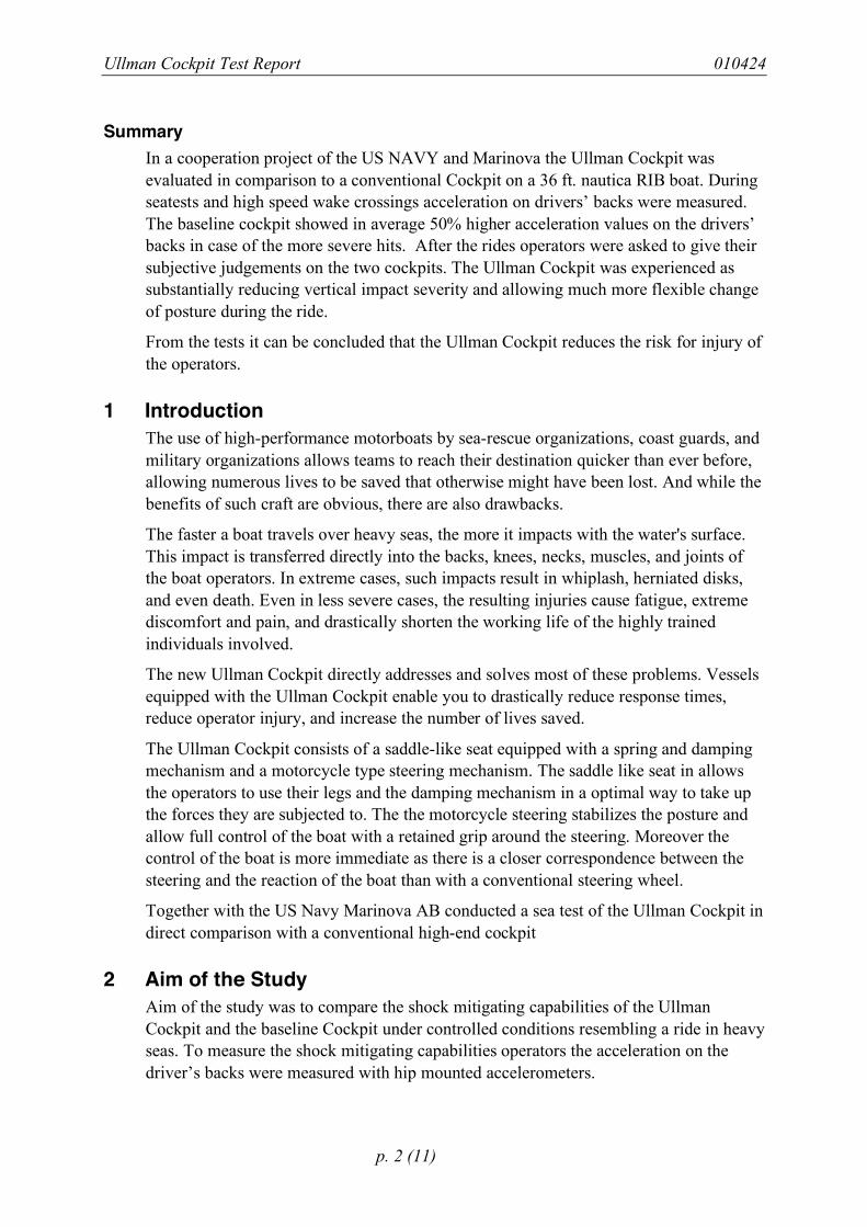
3 Method To compare the shock mitigating capabilities of the two cockpits both were mounted side-by-side in a 36-ft Nautica Rigid-inflatable Boat (cf. Figure 1) and operated under wake crossing or seaway conditions. During the wake crossing or corresponding seaway events acceleration on the operators’ bodies and the boat deck were recorded1.
3.1 Test Boat The test boat was a 36-ft Nautica Rigid-inflatable Boat (RIB) equipped with twin 350 hp Cummins diesels and twin Hamilton Jet waterjet propulsors. The RIB is capable of sustained 38 kt operation. Generally, three side-by-side Stidds Systems Model 800-122 seats are installed on the RIB, but for this test the three seats were removed and replaced with the Ullman Cockpit to port, and the Stidds 800-101V4 in the center position.
Figure 1: Test boat during sea test.
3.2 Baseline Cockpit The baseline cockpit was a Stidd 800-101V4 seat located in the center position. Controls were a conventional steering wheel and levers for throttle and bucket control.
1 Apart from these measurements the following data was recorded: acceleration of the seats, videotapes of the operators and subjective estimations of the operators concerning the two cockpits. This data is, however, not reported here.
Ullman Cockpit Test Report 010424
p. 4 (11)
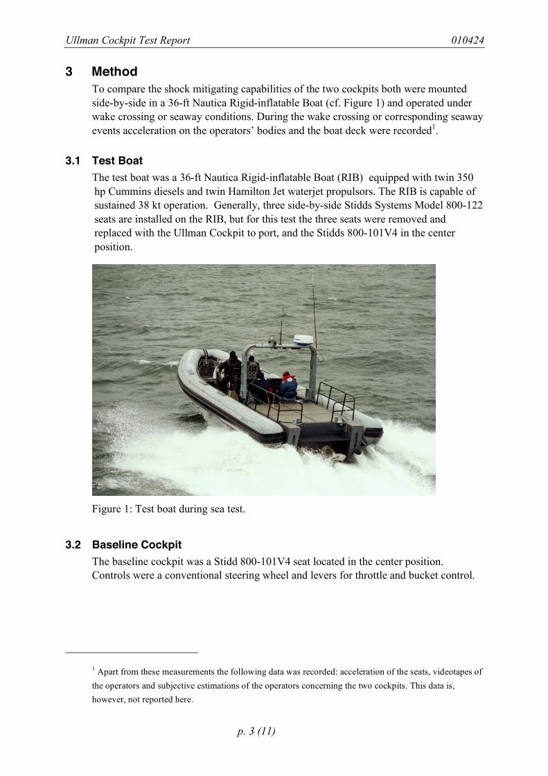
3.3 Ullman Cockpit The Ullman Cockpit was mounted sideways to the Stidd Cockpit and consisted of a JocekySeat with footrests, a motorcycle type steering with control for throttle and buckets in the right handlebar.
Figure 2: Ullman Cockpit (in foreground) and baseline cockpit (in background). For the
tests cockpits were mounted side by side.
3.4 Test Operators On the pretests (Jan. 26 2001) operators SM and BP rode the boat changing seat after approximately half of the test time. On test day 1 (Jan. 29 2001) two professional operators (RT and RR) performed the test in both seats. On test day 2 (Jan. 30 2001) the professional operators (DS and RR) performed the test in both seats.
3.5 Mesurement Equipment The measurement system was designed to simultaneously register acceleration in three dimensions on the backs of the two opertors as well as deck acceleration in z-direction.
3.5.1 Accelerometers For the human measurement two MEMS accelerometers of type Crossbow CXL10LP3 were used. The units are triaxial, have a range of ±10 G and a frequency response from DC to 100 Hz (3 dB cutoff).
For the deck measurement one MEMS accelerometer of type Crossbow CXL25LP1X was used. The unit is monoaxial, has a range of ±25 G and a frequency response from DC to 100 Hz (3 dB cutoff).
The coordinate system was set as follows: +x: boat/operator accelerates forward, +y: boat/operator accelerates to port side, +z: boat/operator accelerates upward. All
Ullman Cockpit Test Report 010424
p. 5 (11)
accelerometers were calibrated as to show 0 G acceleration when only exposed to gravity.
3.5.2 Placement of Accelerometers The accelerometers for the human measurements were attached to a kidney-belt. The kidney-belt was then firmly placed around the operator’s torso such that the accelerometers were located just above the hips. The boat accelerometer was placed on the base of one of the seats.
3.5.3 Data Logger Data was collected with a datalogger of type Crossbow AD2048 ReadyDAQ. The logger was configured to record 7 channels of acceleration data at 120 frames per second at a resolution of 8 bit (corresponding to approximately 0.1 G per digit for the ±10 G accelerometers and 0.2 G for the ±25 G accelerometer.) At these settings the logger was able to record data for about 25 minutes. After the measurements were completed data was downloaded to a PC for further processing
The logger was configured to be activated by a switch for the wake crossing events.
3.6 Procedure Events (i.e. a portion of a ride where the boat and the operators were subjected to impacts) where either provoked by crossing the wakes of a wake producing craft at high speed (36 knots typically, location St. Andrews Bay) or by operation in rough seaway conditions on the Gulf of Mexico.
During the event the datalogger was activated for 15 seconds by pressing the start button right before the event. Due to a technical failure during the pretests, the datalogger was in continuos operation. This did, however, in no way influence the validity of the measurement.
3.7 Data Processing Data from the logger was transferred to a PC. The raw data was calibrated and checked for consistency. Data was then subjected to graphical analysis.
4 Results Data from all the tests was scanned for hits (i.e. acceleration peaks during an event) where either operator was exposed to an acceleration of more than 3 G in z-direction. The maximum values the hits were then recorded for both seats. Acceleration data for three of the hits are shown in Figure 6 through Figure 9.
Ullman Cockpit Test Report 010424
p. 6 (11)
4.1 Peak Acceleration Exposure Due to very different response of the operators to the events the pretest data was excluded from further analysis.2
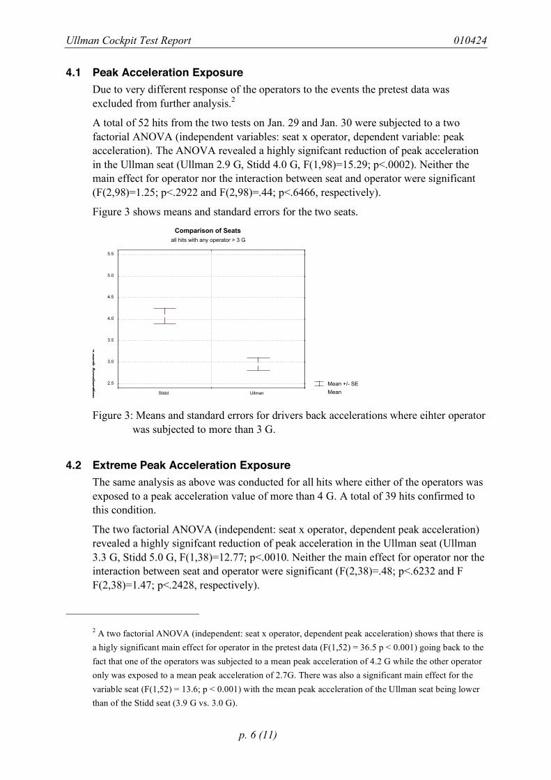
A total of 52 hits from the two tests on Jan. 29 and Jan. 30 were subjected to a two factorial ANOVA (independent variables: seat x operator, dependent variable: peak acceleration). The ANOVA revealed a highly signifcant reduction of peak acceleration in the Ullman seat (Ullman 2.9 G, Stidd 4.0 G, F(1,98)=15.29; p<.0002). Neither the main effect for operator nor the interaction between seat and operator were significant (F(2,98)=1.25; p<.2922 and F(2,98)=.44; p<.6466, respectively).
Figure 3 shows means and standard errors for the two seats.
Mean +/- SE
Mean
Comparison of Seats
all hits with any operator > 3 G
z-p
eak A
ccele
ratio
n
2.5
3.0
3.5
4.0
4.5
5.0
5.5
Stidd Ullman
Figure 3: Means and standard errors for drivers back accelerations where eihter operator
was subjected to more than 3 G.
4.2 Extreme Peak Acceleration Exposure The same analysis as above was conducted for all hits where either of the operators was exposed to a peak acceleration value of more than 4 G. A total of 39 hits confirmed to this condition.
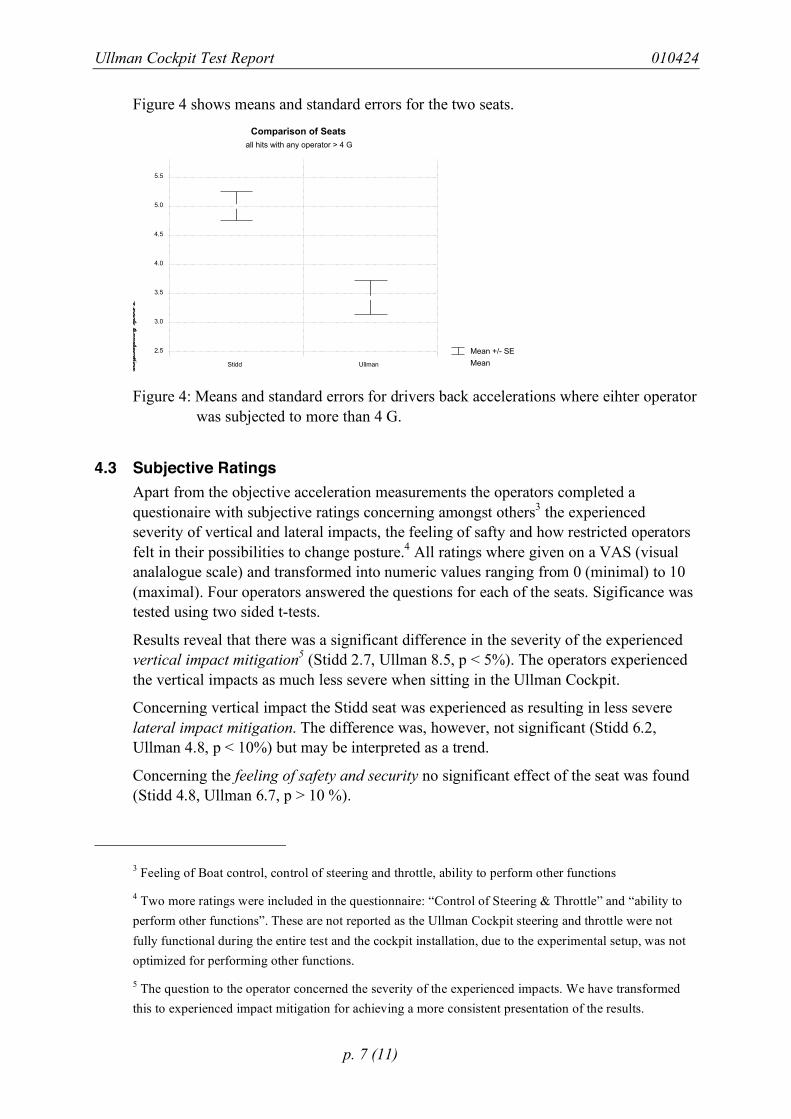
The two factorial ANOVA (independent: seat x operator, dependent peak acceleration) revealed a highly signifcant reduction of peak acceleration in the Ullman seat (Ullman 3.3 G, Stidd 5.0 G, F(1,38)=12.77; p<.0010. Neither the main effect for operator nor the interaction between seat and operator were significant (F(2,38)=.48; p<.6232 and F F(2,38)=1.47; p<.2428, respectively).
2 A two factorial ANOVA (independent: seat x operator, dependent peak acceleration) shows that there is a higly significant main effect for operator in the pretest data (F(1,52) = 36.5 p < 0.001) going back to the fact that one of the operators was subjected to a mean peak acceleration of 4.2 G while the other operator only was exposed to a mean peak acceleration of 2.7G. There was also a significant main effect for the variable seat (F(1,52) = 13.6; p < 0.001) with the mean peak acceleration of the Ullman seat being lower than of the Stidd seat (3.9 G vs. 3.0 G).
Ullman Cockpit Test Report 010424
p. 7 (11)
Figure 4 shows means and standard errors for the two seats.
Mean +/- SE
Mean
Comparison of Seats
all hits with any operator > 4 G
z-p
eak A
ccele
ratio
n
2.5
3.0
3.5
4.0
4.5
5.0
5.5
Stidd Ullman
Figure 4: Means and standard errors for drivers back accelerations where eihter operator
was subjected to more than 4 G.
4.3 Subjective Ratings Apart from the objective acceleration measurements the operators completed a questionaire with subjective ratings concerning amongst others3 the experienced severity of vertical and lateral impacts, the feeling of safty and how restricted operators felt in their possibilities to change posture.4 All ratings where given on a VAS (visual analalogue scale) and transformed into numeric values ranging from 0 (minimal) to 10 (maximal). Four operators answered the questions for each of the seats. Sigificance was tested using two sided t-tests.
Results reveal that there was a significant difference in the severity of the experienced vertical impact mitigation5 (Stidd 2.7, Ullman 8.5, p < 5%). The operators experienced the vertical impacts as much less severe when sitting in the Ullman Cockpit.
Concerning vertical impact the Stidd seat was experienced as resulting in less severe lateral impact mitigation. The difference was, however, not significant (Stidd 6.2, Ullman 4.8, p < 10%) but may be interpreted as a trend.
Concerning the feeling of safety and security no significant effect of the seat was found (Stidd 4.8, Ullman 6.7, p > 10 %).
3 Feeling of Boat control, control of steering and throttle, ability to perform other functions
4 Two more ratings were included in the questionnaire: “Control of Steering & Throttle” and “ability to perform other functions”. These are not reported as the Ullman Cockpit steering and throttle were not fully functional during the entire test and the cockpit installation, due to the experimental setup, was not optimized for performing other functions.
5 The question to the operator concerned the severity of the experienced impacts. We have transformed this to experienced impact mitigation for achieving a more consistent presentation of the results.
Ullman Cockpit Test Report 010424
p. 8 (11)
Concerning the ability to change the posture the Ullman seat was experienced as allowing much more change of posture showing up in a highly significant difference (Stidd 1.5, Ullman 1.1, p < 0.1%).
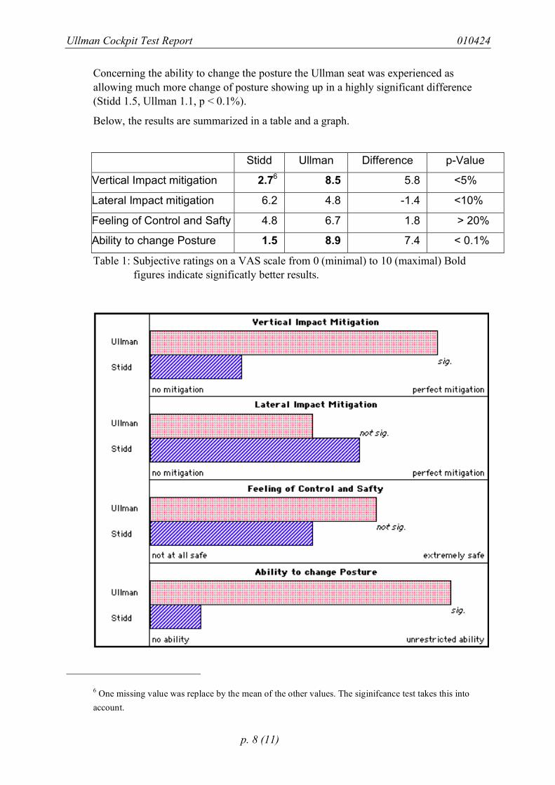
Below, the results are summarized in a table and a graph.
Stidd Ullman Difference p-Value
Vertical Impact mitigation 2.76 8.5 5.8 <5%
Lateral Impact mitigation 6.2 4.8 -1.4 <10%
Feeling of Control and Safty 4.8 6.7 1.8 > 20%
Ability to change Posture 1.5 8.9 7.4 < 0.1%
Table 1: Subjective ratings on a VAS scale from 0 (minimal) to 10 (maximal) Bold figures indicate significatly better results.
6 One missing value was replace by the mean of the other values. The siginifcance test takes this into account.
Ullman Cockpit Test Report 010424
p. 9 (11)
Figure 5: Subjective ratings. The Ullman seat performed significantly better for vertical impact mitigation and ability to change posture. The two other ratings do not show significant differences.
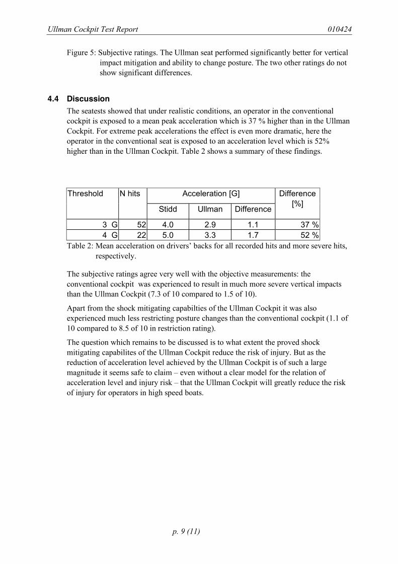
4.4 Discussion The seatests showed that under realistic conditions, an operator in the conventional cockpit is exposed to a mean peak acceleration which is 37 % higher than in the Ullman Cockpit. For extreme peak accelerations the effect is even more dramatic, here the operator in the conventional seat is exposed to an acceleration level which is 52% higher than in the Ullman Cockpit. Table 2 shows a summary of these findings.
Acceleration [G] Threshold N hits
Stidd Ullman Difference
Difference [%]
3 G 52 4.0 2.9 1.1 37 % 4 G 22 5.0 3.3 1.7 52 %
Table 2: Mean acceleration on drivers’ backs for all recorded hits and more severe hits, respectively.
The subjective ratings agree very well with the objective measurements: the conventional cockpit was experienced to result in much more severe vertical impacts than the Ullman Cockpit (7.3 of 10 compared to 1.5 of 10).
Apart from the shock mitigating capabilties of the Ullman Cockpit it was also experienced much less restricting posture changes than the conventional cockpit (1.1 of 10 compared to 8.5 of 10 in restriction rating).
The question which remains to be discussed is to what extent the proved shock mitigating capabilites of the Ullman Cockpit reduce the risk of injury. But as the reduction of acceleration level achieved by the Ullman Cockpit is of such a large magnitude it seems safe to claim – even without a clear model for the relation of acceleration level and injury risk – that the Ullman Cockpit will greatly reduce the risk of injury for operators in high speed boats.
Ullman Cockpit Test Report 010424
p. 10 (11)
Ullman
Stidd
BOAT_Z
Driver's Back Acceleration
Comparison of Seats
Hit 215, 012601_2
SECONDS
z-A
ccele
ratio
n [G
]
-2
0
2
4
6
8
10
12
14
16
18
215.3 215.4 215.5 215.6 215.7 215.8 215.9 216.0 216.1 216.2 216.3
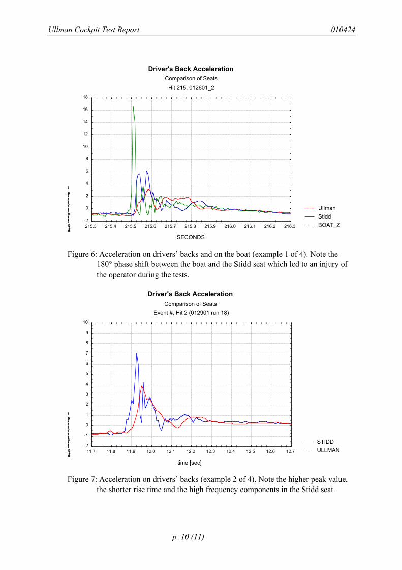
Figure 6: Acceleration on drivers’ backs and on the boat (example 1 of 4). Note the
180° phase shift between the boat and the Stidd seat which led to an injury of the operator during the tests.
STIDD
ULLMAN
Driver's Back Acceleration
Comparison of Seats
Event #, Hit 2 (012901 run 18)
time [sec]
z-A
ccele
ratio
n [G
]
-2
-1
0
1
2
3
4
5
6
7
8
9
10
11.7 11.8 11.9 12.0 12.1 12.2 12.3 12.4 12.5 12.6 12.7
Figure 7: Acceleration on drivers’ backs (example 2 of 4). Note the higher peak value,
the shorter rise time and the high frequency components in the Stidd seat.
Ullman Cockpit Test Report 010424
p. 11 (11)
STIDD
ULLMAN
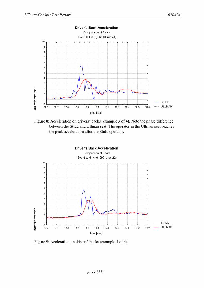
Driver's Back Acceleration
Comparison of Seats
Event #, Hit 2 (012901 run 24)
time [sec]
z-A
ccele
ratio
n [G
]
-2
-1
0
1
2
3
4
5
6
7
8
9
10
12.6 12.7 12.8 12.9 13.0 13.1 13.2 13.3 13.4 13.5 13.6
Figure 8: Acceleration on drivers’ backs (example 3 of 4). Note the phase difference
between the Stidd and Ullman seat. The operator in the Ullman seat reaches the peak acceleration after the Stidd operator.
STIDD
ULLMAN
Driver's Back Acceleration
Comparison of Seats
Event #, Hit 4 (012901, run 22)
time [sec]
z-A
ccle
era
tion [G
]
-2
-1
0
1
2
3
4
5
6
7
8
9
10
13.0 13.1 13.2 13.3 13.4 13.5 13.6 13.7 13.8 13.9 14.0
Figure 9: Accleration on drivers’ backs (example 4 of 4).


