Embed Size (px)
Citation preview
=UMW RUMED 090 021 SE 015 173
TITLE Scottish Schools Science Equipment Research Centre,Bulletin No. 58, September 1972.
INSTITUTION Scottish Schools science Equipment Research centre.Edinburgh.
PUB DATE Sep 72NOTE 14p.
EDRS PRICE MF-$0.75 HC$1.50 PLUS POSTAGEDESCRIPTORS Biological Sciences; General Science; Inservice
Education; *Laboratory Equipment; *Newsletters;Physical Sciences; Plant Science; Science Education:*Science Equipment; *Secondary School Science
IDENTIFIERS Scotland
ABSTRACTThis issue of the bulletin contains four major
topics. The first is a discussion of problems involved inestablishing good communication with science teachers concerning theactivities of the Scottish Schools Science Equipment Research Centre(SSSERC) via exhibitions throughout Scotland. The second, headed"Biology Notesto presents a discussion of transpiration in plants.The third topic is a description of a battery box designed to provideease in charging cells, and the fourth topic is a short list ofaddresses of equipment suppliers. (PBS)

4 U% tit PANthtt utita.titt clUt R-07eL1111116katu$R4t. M itittitt Utt
t 44tt, NitIMI 'it Wt's Stith Sit $'110VW.rtt t ,it tvf I. Ittitit
0,404 Ott ViwtItii0A11.1141 (WIC ONa's ! )0 a a.. a t 1+0,14 7'1 Y It. 6111.1111044St PO t,6 cr ''"AW v Pt,t tko .?v NAI ic,%A% ,tc.ttirtottt c t tf-t.t't t ,t3ti ti4 Put %.
SCOTTISH SCHOOLS SCIENCE
EQUIPMENT RESEARCH
CENTRE
1-() Bulletin No. 58 September 1972.
to
Contents
Introduction Demonstration Lectures
Biology Notes 4- Transpiration in Plants
In the Workshop - Battery boz
Page 1
2
7
Address List . 12
Introduction
Ever since its inception, one of the main methods of bringingthe activities of SSW° to the notice of teachers has been thestaging of exhibitions throughout Scotland. Since the autumn of1966 when the first one was held in Ayr Science Centre, these haveoccurred at an average of one per month. Characteristically, anynwnber from 40 to 80 exhibits are staged, and the time allowed forthe teacher to see them has varied from an hour to several days.During the six years, some innovations hare taken place; whilemost exhibitions are for teachers, we have held some for laboratorytechnicians and for students at Colleges of Education. Whilenormally a professional member of staff and a technician haveadvised during the exhibition, we have set up exhibitions and leftthem unattended for a week for teachers to visit as and when theycould.
Often when staging exhibitions the staff have been consciousof failure or partial failure to achieve a desired level ofcommunication. Sometimes it happens that the idea which we feel tobe a winner on all counts is scarcely glanced at by the perambulatingteachers, and while the disappointed exhibitor may try to imitateColeridge's Mariner by stopping one in three he will be fortunate ifhe succeeds. At other times, with general purpose equipment such asthe oscilloscope or, more recently, the chart recorder and the three-way tap, we know that the one exhibit we have selected to illustrateits use does not do Justice to the apparatus. To cover thesesituations we propose an extension of our services which has alreadybeen tried out in biology during the past year and which we hopewill bring us into more personal contact with the teachers in agiven area. This is to run demonstration 1.0ctures, round a centraltheme, of no more than 45 minutes duration and showing perhapsbetween 12-20 experiments or items of apparatus. It is hoped thatthis would stimulate informal discussion in the group which wouldbe of benefit to all. While these lectures could be run in conjunc-tion with an exhibition, there are advantages in considering them asseparate entities. When the same equipment is used in demonstrationand on exhibition there are practical difficulties in moving it fromthe 11cture room and re-assembling it in the exhibition site. Also,holding a lecture in conjunction with an exhibition tends toconcentrate the exhibition audience into one space of time, whereasone advantage of a three h'ur exhibition ought to be that tneteacher can arrive and leave at whatever time he chooses. Where theeconomics of travelling force us to consider combining the twofunctions, it may be a solution to hold the demonstration in theevening, and the exhibition the following day. But in the main wesee these demonstration lectures as fitting into the programme ofgroups of teachers, and we know that there are several of thesethroughout Scotland, who arrange a series of regular meetings duringthe school session. We already have one such commitment, to talk tophysics teachers in Aberdeen on Friday, 16th Marcb, 1973, on thesubject of the chart recorder, and we invite inquiries and suggestions
for Assible thtmes and dates from other groups.
The proposed extension of our services does not mean that weintend to curtail our normal exhibition programme and as bookingsfor the present session are light, we are likewise invitinginquiries for possible exhibitions between now and July 1973.
Biology Notes
ullautluss1121201 Three ma 'or cognitive objectives of thissection of the syllabus (IV (3)(c)) are presumably:
1) An understanding that transpiration is caused by evaporation;
2) An understanding of the tension-cohesion explanation for themovement of the transpiration stream;
3) An understanding of the mechanism and significance of stomatalcontrol of transpiration - usually arrived at from a comparativestudy of the effect of environmental factors on evaporation andtranspiration.
To these may be added a fourth, perhaps less generally recognisedobjective: an understanding of stomatal control of orate: loss as ahomeostatic mechanism, Unfortunately the achievement of theseobjectives enerimentally is often hampered by difficulties withsome of the equipment used - particularly with bubble potometersand atmcmeters,. With these difficulties in mind we have attemptedto simplify the investigations involved, so that they can be perform-ed on a pupil s'nle wherever possible, and still hopefully provideworthwhile resuAs. In doing so we have made use of a type ofbubble atmometer4otometer, the construction and operation of whichare described below.
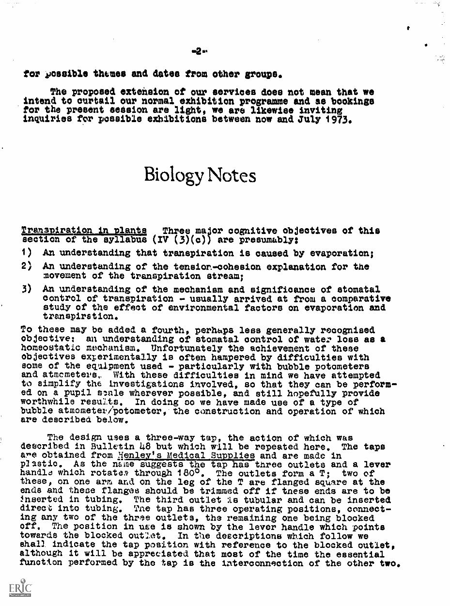
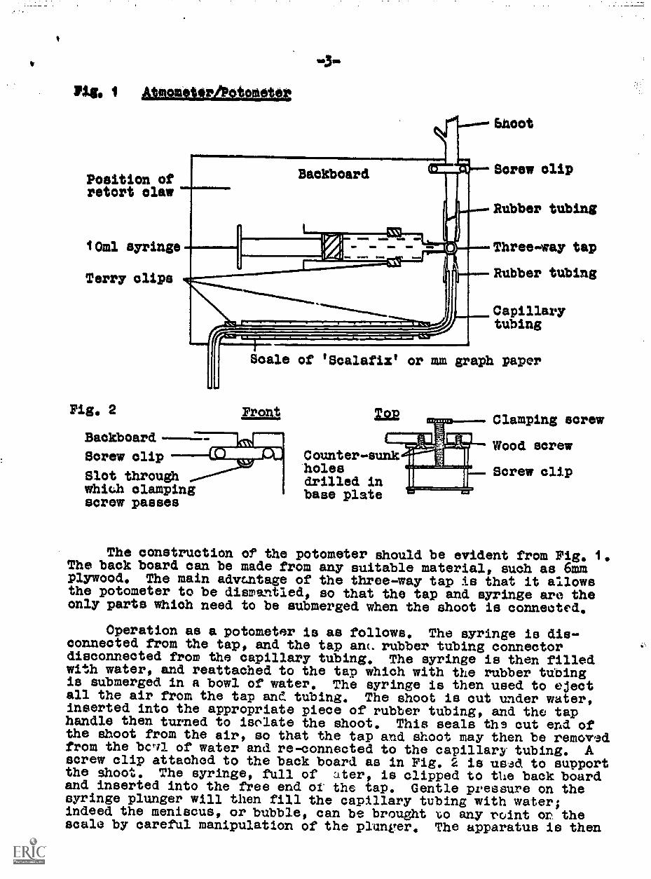
The design uses a three-way tap, the action of which wasdescribed in Bulletin 48 but which will be repeated here. The tapsare obtained from 4enley's Medical Supplies and are made inplastic. As the name suggests1177171i=three outlets and a leverhandle which rotattm, through 1800. The outlets form a T; two ofthese, on one arm and on the leg of the T are flanged square at theends and these flanges should be trimmed off if tnese ends are to be!nserted in tubing. The third outlet is tubular and can be inserteddirect`, into tubing. The tap has three operating positions, connect-ing any two of the three outlets, the remaining one being blockedoff. The position in use is shown by the lever handle which pointstowards the blocked outlet. In the descriptions which follow weshall indicate the tap position with reference to the blocked outlet,although it will be appreciated that most of the time the essentialfunction performed by the tap is the interconnection of the other two.
Pigs laglAtuagiglaw
Position ofretort claw
10ml syringe
Terry clips
Fig, 2
Backboard
Screw clip
Slot throughwhich clampingscrew passes
Moot
Screw clip
Rubber tubing
Three-way tap
Rubber tubing
Capillarytubing
Scale of IScalafixt or mm graph paper
Front, Top
Counter-sunkholesdrilled inbase plate
Clamping screw
Wood screw
Screw clip
The construction of the potometer should be evident from Fig, 1,The back board can be made from any suitable material, such as 6mmplywood. The main advrantage of the three-way tap is that it allowsthe potometer to be dismantled, so that the tap and syringe are theonly parts which need to be submerged when the shoot is connected.
Operation as a potometer is as follows. The syringe is dis-connected from the tap, and the tap ant. rubber tubing connectordisconnected from the capillary tubing. The syringe is then filledwith water, and reattached to the tap which with the rubber tubingis submerged in a bowl of water. The syringe is then used to ejectall the air from the tap and tubing. The shoot is cut under water,inserted into the appropriate piece of rubber tubing, and the taphandle then turned to isolate the shoot. This seals ths out end ofthe shoot from the air, so that the tap and shoot may then be removedfrom the bc,71 of water and re-connected to the capillary tubing. Ascrew clip attached to the back board as in Fig. 2 is us.ad to supportthe shoot. The syringe, full of titer, is clipped to the back boardand inserted into the free end of the tap. Gentle pressure on thesyringe plunger will then fill the capillary tubing with water;indeed the meniscus, or bubble, can be brought x:o any roint or thescale by careful manipulation of the plunger, The apparatus is then
fixed into a retort stand claw and the tap handle turned to isolatethe syringe, when the shoot is in contact with the capillary tubingand readings can be taken. To re-set, turn the tap handle toisolate tam shoot and gently press with the syringe plunger againbefore returning the tap handle to the horizontal position.
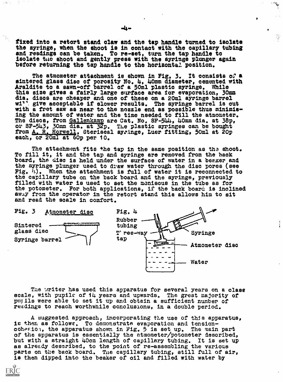
The atmometer attachment is shown in Pig. 3. It consists of asintered glass disc of porosity No. 4, 40mm diameter, cemented withAraldite to a sawn-off barrel of a 50m1 plastic syringe. Whilethis size gives a fairly large surface area tor evaporation, 30mmdia. discs are cheaper and one of these on a 20m1 syringe barrelwilq. give acceptable if slower results. The syringe barrel is outwith a fret saw as near to the nozzle end as possible thus minimis-ing the amount of water and the time needed to fill the atmometer.The discs, from 2111/enhAmp are Cat. No. SF-544, 40mm dia, at 38p,or SP-543, 30mm dit--T..it'Zb3p. The plastic syringes can be boughtfrom A. R. Norwell, Steriseal syringe, Luer fitting, 50m1 at 20peaah, or 20m1 at &Op per 10.
The attachment fits the tap in the same position as tha shoot.To fill it, it and the tap and syringe are removed from the hackboard, the disc is held under the surface of water in a beexer andthe syringe plunger used to draw water through the disc pores (seeFig. Si.). When the attachment is full of water it is reconnected tothe capillary tube on the back board and the syringe, previouslyfilled with water is used to set the meniscus in the tube as forthe potometer. For both applications, if the back board is inclinedaway from the operator in the retort stand this allows him to sitand read the scale in comfort.
Fig. 3 Atmometer disc
Sinteredglass disc
Syringe barrel
Fig. 4
RubbertubingT' ree--iyav ---
t ap
Syringe
Atmometer disc
Water
The writer has used this apparatus for several years on a classscale, with pupils of 14 years and upwards. The great majority ofpupils were able to set it up and obtain a sufficient number ofreadings to reach worthwhile conclusions, in a double period.
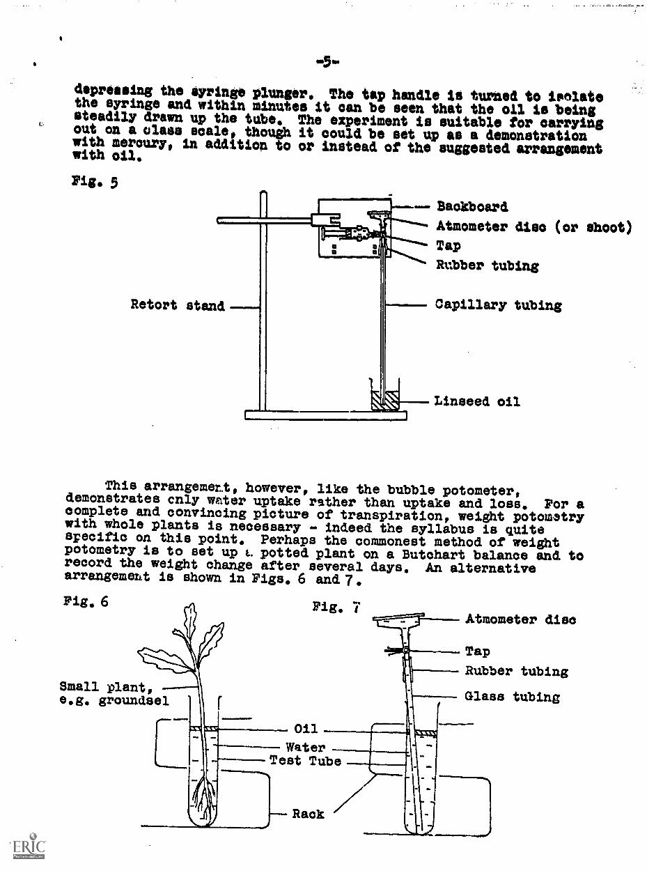
A suggested approach, incorporating tLe use of this apparatus,is then as follows. To demonstrate evaporation and tension-coheFioA, the apparatus shown in Pig. 5 is set up. The main partof the apparatus is essentially the atmometer/Potometer described,but with a straight 40cm length of capillary tubing. It is set upas alreE.dy described, to the point of re-assembling the variousparts on the back board. The capillary tubing, still full of air,is then dipped into the beaker of oil and filled with water by
m5s.
depressing the syringe plunger. The tap handle is turned to isolatethe syringe and within minutes it can be seen that the Wel is beingsteadily drawn up the tube. The experiment is suitable for carryingout on a Glass scale, though it could be set up as a demonstrationwith mercury, in addition to or instead of the suggested arrangementwith oil.
Fig. 5-- Backboard
Atmometer disc (or shoot)
Tap
Rubber tubing
Retort stand Capillary tubing
Linseed oil
This arrangement, however, like the bubble potometer,demonstrates cnly water uptake rather than uptake and loss. For acomplete and convincing picture of transpiration, weight potomatrywith whole plants is necessary - indeed the syllabus is quitespecific on this point. Perhaps the commonest method of weightpotometry is to set up t. potted plant on a Butohart balance and torecord the weight change after several days. An alternativearrangement is shown in Figs, 6 and 7.Fig, 6 Wig, 7
Atmometer disc
Small plant,e.g. groundsel
Tap
Rubber tubing
Glass tubing
Oil
WaterTest Tube
This has the advantage over the potted plant method that if atop-pan balance with 10mg sensitivity and 200g capacity is available,significant weight ,Nhanges can be recorded within a double period.Using the wire mesh test-tube rack ter described in Bulletins 48 and50, the total weight of the apparatus should be about 150-170gf.The sc..rengement with the atmometer disc emphasises the similaritiesand differences between transpiration and evaporation. The glasstubing shown in Pig. 7 is filled in the same way as described .eor
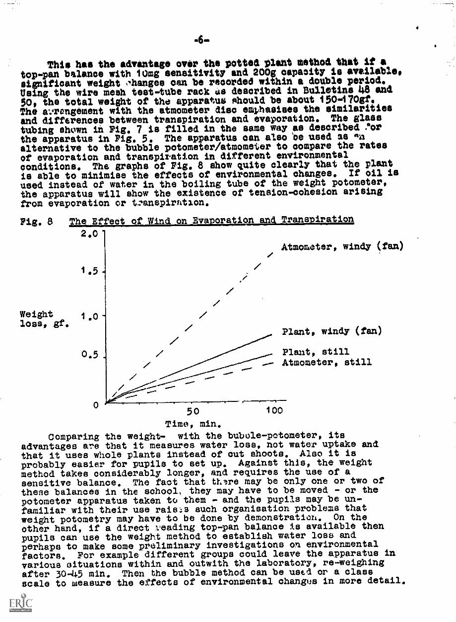
the apparatus in Pig. 5. The apparatus can also lbe used as enalternative to the bubble potometer/atmometer to compare the ratesof evaporation and transpiration in different environmentalconditions. The graphs of Pig. 8 show quite clearly that the plantIs able to minimise the effects of environmental changes. If oil isused instead of water in the boiling tube of the weight potometer,the apparatus will show the existence of tension-cohesion arisingfrom evaporation or tzanspirntion.
Fig. 8 The Effect of Wind on Evaporation and Transpiration
2,0
Atmometer, windy (fan)
1.5
Weightloss, gf,
1,0
Plant, windy (fan)/
0.5 Plant, stillAtmometer, still
50Time, min,
Comparing the weight- with the bubule-potometer, itsadvantages are that it measures water loss, not water uptake andthat it uses whole plants instead of out shoots. Also it isprobably easier for pupils to set up. Against this, the weightmethod takes considerably longer, and requires the use of asensitive balance. The fact that th're may be only one or two ofthese balances in the school, they may have to be moved - or thepotometer apparatus taken to them - and the pupils may be un-familiar with their use rais::s such organisation problems thatweight potometry may have to be done by demonstration, On theother hand, if a direct veading top-pan balance is available thenpupils can use the weight method to establish water loss andperhaps to make some preliminary investigations on environmentalfactors. For example different groups could leave the apparatus invarious situations within and outwith the laboratory, re-weighingafter 30,45 min, Then the bubble method can be used or a classscale to measure the effects of environmental changus in more detail.
100
.7.
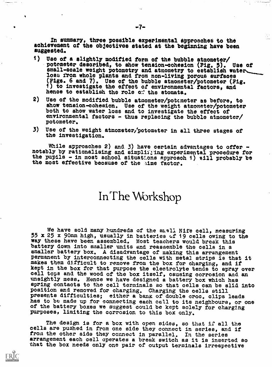
In summary, three possible experimental approaches to theachievement of the objectives stated at the beginning have beensuggested.
1) Use of a slightly modified form of the bubble atmometer/potometer described, to dhow tension-cohesion (pig. 5). Use ofemail -scale weight potometry and atmometry to establish waterloss from whole plants and from non-living porous surfaces(Figs. 6 and 7). Use of the bubble atmometer/potometer (Pig.1) to investigate the effect of environmental factors, andhence to establish the role cr: the stomata.
2) Use of the modified bubble atmometer/potcmeter as before, toshow tension-cohesion. Use of the weight atmometer/potometerboth to show water loss and to investigate the effect ofenvironmental factors - thus replacing the bubble atmometer/potometer.
3) Use of the weight atmometer /potometer in all three stages ofthe investigation.
While approaches 2) and 3) have certain advantages to offer -notably by rationalising and simpliling experimental procedure forthe pupils - in most school situat!.ons approach 1) %ill probably bethe most effective because of the ;ime factor.
nT he Workshop
We have sold many hundreds of the well Nite cell, measuring55 x 25 x 90mm high, usually in batteries (Af 19 cells owing to theway these have been assembled. Most teachers would break thisbattery down into smaller units and reassemble the cells in asmaller battery box. A disadvantage of making this arrangementpermanent by interconnecting the cells with metal strips is that itmakes them difficult to remove from the box for charging, and ifkept in the box for that purpose the electrolyte tends to spray overcell tops and the wood of the box itself, causing corrosion and anunsightly mess, Hence we have designed a battery box which hasspring contacts to the cell terminals so that cells can be slid intoposition and removed for charging. Charging the cells stillpresents difficulties; either a bank of double croc. clips leadshas to be made up for connecting each cell to its neighbours, or oneof the battery boxes we suggest could be kept solely for charengpurposes, limiting the corrosion to this box only.
The design is for a box with open sides, so that if all thecells are pushed in from one side they connect in series, and iffrom the other side they connect in parallel, In the seriesarrangement each cell operates a break switch as it is inserted sothat the box needs only one pair of output terminals irrespective
4-of how many cells are used. Moreover, if the full capacity of thebox is not required, cells can be omitted from any position in thebox in the parallel connection, and also in the series connectionexcept for the first one which must be placed in the Slot wherethere is no break switch. If we put a break switch across everycell then the output would be Shorted when the parallel connectionwas being used. Because each cell has to have a special connectingstrip fitted to its anode it is impossible to insert cells in thebox the wrong way round and so get a wrong polarity. There areonly two actions which could produce a fault; if cells wereinserted from both "eries and parallel sides of the box together,then the series cells, being at a higher voltage would partiallydischarge themselves through the parallel ones. Secondly if a cellon the series side of the box is not pushed fully into positionuntil it comes to e stop it is possible that it could be shorted,although this can be avoided by careful bending of the phosphorbronze strip which forms the switch contact. The design detailsgiven are for a battery of three cells, but any number could beaccommodated by making the box longer and adding one more switchand two more contacts for each additional cell. Also the dimensionsgiven are for the Nife cell within the polythene container in whichthey were originally supplied; if the cells are to be used withoutthese containers then the baseboard slots should each be reduced inwidth from 31 to 27mm, the slots on the box top need to becorrespondingly closer together, and the whole box is reduced insize as a result.
To make the connecting lug for each cell, strips of 16 S.W.G.copper sheet, measuring 10 x 50mm, are used. 6mm from one end ofthe strip a 4.8mm (No. 12 drill) hole is drilled for bolting to thepositive terminal of the cell. The strip is then bent as shown inFig. 1, the actual shape being lees important than the overallheight, which should be VOmm. Variations in this height will meanthat some cells may not make contact when inserted in the batterybox. The base for the box is made from softwood, measuring 130 x130 x 20mm, For every additional cell required in the box, thebase length should be increased by 38mm and an additional slotadded. These slots, into which the Nife cells slide, are out 31mmwide and 9mm deep, The box ends are made from 6mm plywood, usingtwo pieces 130 x 127mm high. In one of these, two holes are drilledto receive the output terminals which would normally be 4mm sockets.The ends can be screwed, or glued and nailed to the baseboard. Fig.2 shows this part of the construction.
The box top is also of softwood, 130 x 130 x 13mm, Slots 14mmwide and 8mm deep to take one set of contacts are cut from the topas shown in Fig. 3. These slots can be taken out by sawcuts ateither side, then chiselling and filing, or completely on a circularsaw bench by repeated parallel cuts. A sub-top part which carriesthe second contact to each cell is cut to the same profile as thetop. The sub-top has the same dimensions as the top except that itis only 64mm wide; once the top has been fitted with the necessarycontacts the sub-top is fixed to it as shown in Fig. 4 with thethrough bolts holding it in position.
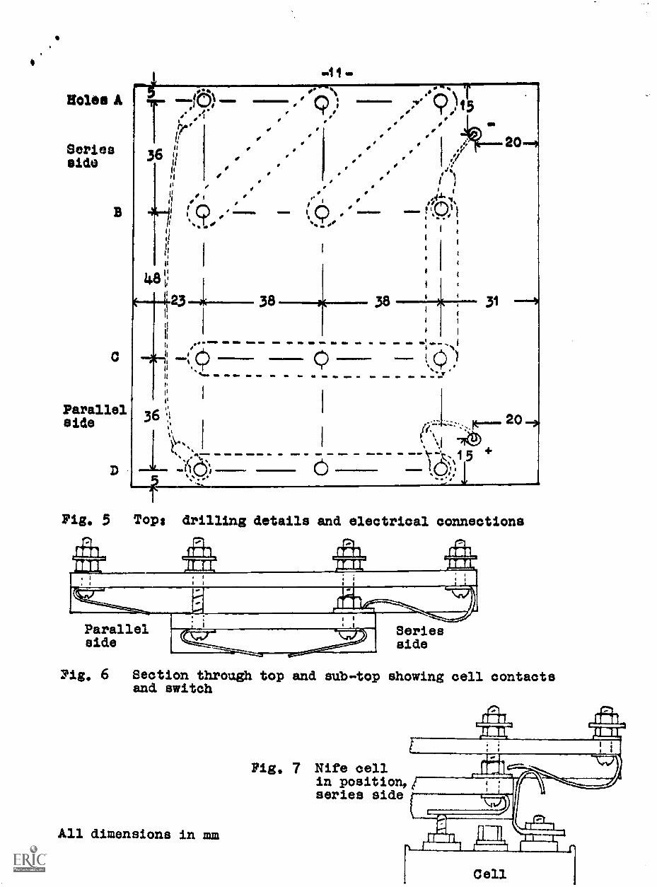
Fig. 5 shows the drilling details for the top, viewed fromabove. Holes A, El 0, and D are No. 27 twist drill for 4 BA
clearance. The two unlabelled holes are for wire connection to theoutput terminals and can be any convenient size, The eub.top shouldbe clamped to the top In the position shown 4n Pig. 4 and holes Band C drilled through it These holes carry the connections to thenegative terminal of each cell. The 4onneotions take the form of abent strip of copper, made from 22 6,W.G. sheet. measuring 10 x 40mm;a 4 BA clearance hole is drilled at me end, a 30mm 4 BA round headbolt is inserted and the strip bent over the bolt head as shown inPig, 6. This means that a screwdriver cannot be used to tightenthe bolt in position, so that the bending of the etxip can be post-poned until the switches have been titted. The same stripe, fittedin the same way but using shorter bolts 1gmm long, are used as theconnection to the positive terminals on the parallel side of thebox in holes D. These are shown in Pig. 6.
On the series side of the box, the same strip is used 1.n oneof the slots, that in which there is no switch and in which thefirst cell of the series connection must be fitted. .The remainingslots all require a switch, made from two metal strips, which isnormally closed but which is opened by the action of pushing a cellinto position. The moveable part of the switch is a strip ofphosphor bronze 38 S.W.G. thick measuring 1u x 35mm. It is drilled,bent and ritted into the slot by a 1gmm 4RA bolt through holes A,as shown in Fig. 6. The other half of the switch is a flat pieceof 22 S.X.G. copper, 10 x 15mm, which is drilled an4 secured againstthe utener surface of the sub-top by the B bolts, With the sub-topin position, and this is held by B and C bolts, the phosphor bronzestrip is in positive contact with the flat piece of copper.
Connections to place the cells in series or in parallel aremade by 10mm strips of 22 S.W.G. sheet copper with 4 BA clearanceholes drilled at the correct spacing, the strips being bolted on the1...)p of the box itself. These connecting strips are shown Jr. dottedoutline in Fig, 5. The connections which go to the 4mm outpv4tterminals are made with PVC covered wire, soldered to solder tagswhich are bolted to the appropriate connector strips. A simillarflexible lead is used to join the two sets of positive terminals onthe outside edges of the box, simply because there would be a riskof shorting against the negative terminals if a bent copper stripwas vsed.
We would not claim ihat the switches are capable of carryingheavy currents, thcugh they should be well scoured with emery paperbefore assembling, but they ought to be good enough for most of theschool experiments requirIng batteries.
When a cell is slid into position, the special terminal fittedto it bears against the phosphor bronze and breaks the switchcontact. It is desirable also that this contact should be brokenbefore contuet is made to the other cell terminal. If this happensthen the cell is short-circuited momentarily until the cell has beenpushed fully home, although as mentioned earlier there is a risk ofa continuing short if the cell is not fully inserted. Hence it isbetter to bend the phosphor bronze strip so tIlat the switch actiongets :ender way as soon as P. cell Is pushed in, 1.e. a sharp downwardbend should be given to the strip where it comes off its securingbolt. The shape is shown in Fig. 7, wnich also shows how the
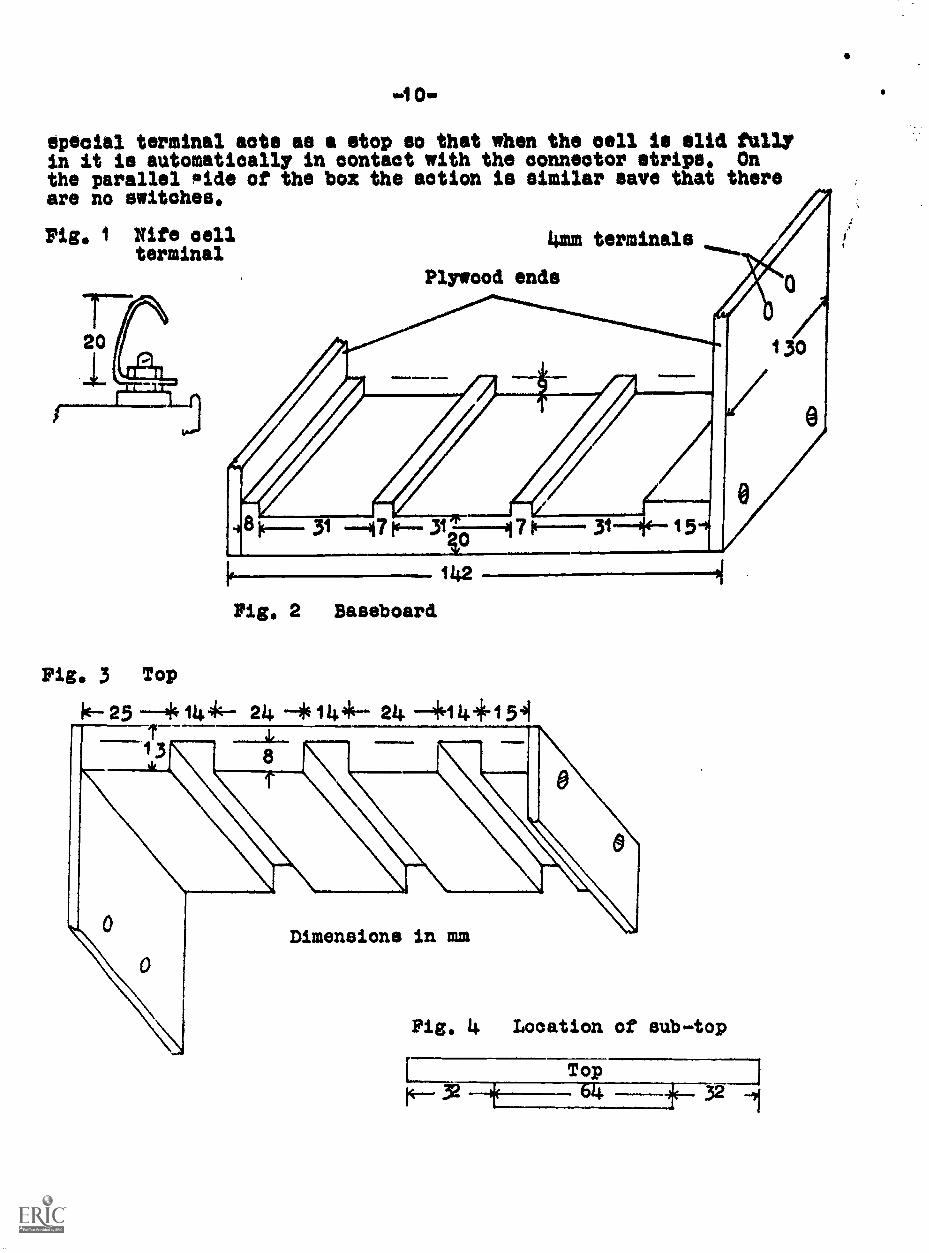
special terminal acts as a stop so that when the cell is slid fullyin it is automatically in contact with the connector strips, Onthe parallel !side of the box the action is similar save that thereare no switches.
Pig, i Nife cellterminal
4mm terminals
Plywood ends
31 Ir. 31 7 fr. 31~-x( -15-4
Pig, 2 Baseboard
142
Pig, 3 Top
ic--- 25 144- 214. -*Wit 24 --+1.1 4+1 541
8
Dimensions in mm
Fig, 4 Location of sub-top
Top14 64 if 32 1
0
I
Holes A
Seriesside
ParallelBide
tt
tiitit
PI
a
tt
tt
48
it
.11=1806
I
1
Sp°
38
I 9 0
MMINIMMIMIN
38
I IIM INI 411a 111. ..... O. =lb /
'1(".".1! Ci)(11)
I%MO 111. =IN Olio .10 SO OM IN =P. .11. MP Ow gob
31
III
it
ii I36 i t
I
`1
,
f1.
2
.
: le... . 20 ."I
0 . M=. G MM M M 0 aO ""k. % 15+
---?:..
Pig, 5 Top: drilling details and electrical connections
-1111110.,,
Parallelaide
Seriesside
Pig, 6 Section through top and sub-top showing cell contactsand switch
All dimensions in mm
f
Fig. 7 Nife cellin position,'series side L
Cell
S.S,S.E.R.0 103 Broughton Street, Edinburgh EH1 3RZ,
Tele. 031-556 2184
A Gallenkamp and Co, Ltd., Portraok Lane, Stockton-on-Tees,
Teeside TS18 2PT.
Henley's Medical Supplies Ltd., Alexandra Works, Clarendon Road,Hornsey, London N.8.
A. R. Norwell Ltd., 2 Gradgeway, Kilburn High Road, London N.M.


