Embed Size (px)
Citation preview
UNIT-3
HARDENED CONCRETE
Introduction
The compressive strength of concrete is one of the most important and useful properties of concrete. In most structural applications concrete is employed primarily to resist compressive stresses.
The compressive strength of concrete is generally determined by testing cubes or
cylinders made in laboratory or field or cores drilled from hardened concrete at site or
from the non-destructive testing of the specimen or actual structures. Strength of
concrete is its resistance to rupture.
Water/Cement Ratio
Strength of concrete primarily depends upon the strength of cement paste. That the strength of cement paste depends upon the dilution of paste or in other words, the strength of paste increases with cement content and decreases with air and water content.
In 1918 Abrams presented his classic law in the form:
S= A/Bx
where x =water/cement ratio by volume and for 28 days results the constants A and B are 14,000 lbs/sq. in. and 7 respectively.
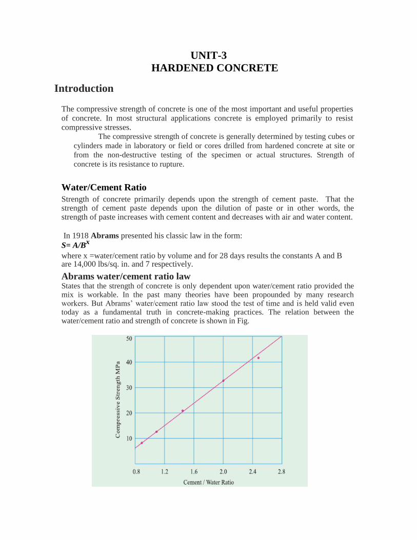
Abrams water/cement ratio law States that the strength of concrete is only dependent upon water/cement ratio provided the mix is workable. In the past many theories have been propounded by many research workers. But Abrams’ water/cement ratio law stood the test of time and is held valid even today as a fundamental truth in concrete-making practices. The relation between the water/cement ratio and strength of concrete is shown in Fig.
It can be seen that lower water/cement ratio could be used when the concrete is vibrated to achieve higher strength, whereas comparatively higher water/cement ratio is required when concrete is hand compacted.
In both cases when the water/cement ratio is below the practical limit the strength of the concrete falls rapidly due to introduction of air voids. The graph showing the relationship between the strength and water/cement ratio is approximately hyperbolic in shape.
Gel/Space Ratio
Many research workers commented on the validity of water/cement ratio law as propounded by Duff Abrams. They have forwarded a few of the limitations of the water/ cement ratio law and argued that Abrams water/cement ratio law can only be called a rule and not a law because Abrams’ statement does not include many qualifications necessary for its validity to call it a law. This ratio is defined as the ratio of the volume of the hydrated cement paste to the sum of volumes of the hydrated cement and of the capillary pores.
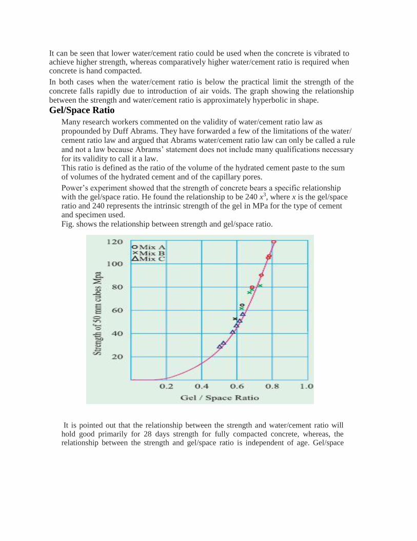
Power’s experiment showed that the strength of concrete bears a specific relationship with the gel/space ratio. He found the relationship to be 240 x3, where x is the gel/space ratio and 240 represents the intrinsic strength of the gel in MPa for the type of cement and specimen used. Fig. shows the relationship between strength and gel/space ratio.
It is pointed out that the relationship between the strength and water/cement ratio will hold good primarily for 28 days strength for fully compacted concrete, whereas, the relationship between the strength and gel/space ratio is independent of age. Gel/space
ratio can be calculated at any age and for any fraction of hydration of cement. The following examples show how to calculate the gel/space ratio.
Calculation of gel/space ratio for complete hydration Let C = weight of cement in gm. Vc= specific volume of cement = 0.319 ml/gm.
Wo = volume of mixing water in ml.
Assuming that 1 ml. of cement on hydration will produce 2.06 ml of gel,
Volume of gel = C x 0.319 x 2.06
Space available = C x 0.319 + Wo
Gel/Space ratio :
x=Volume of gel
Space available
= 0657 C
(0319C+Wo)
Calculation of gel/space ratio for partial hydration
Let α= Fraction of cement that has hydrated
Volume of gel = C x α x 0.319 x 2.06
Total space available C Vc α + Wo
Gel/space ratio = x = 2.06x 0.319 xC α
0.319 C + Wo
There is a lot of difference between the theoretical strength of concrete and actual strength of concrete. Actual strength of concrete is much lower than the theoretical strength estimated on the basis of molecular cohesion and surface energy of a solid assumed to be perfectly homogeneous and flawless. The actual reduction of strength is due to the presence of flaws.
Cement paste in concrete contains many discontinuities such as voids, fissures, bleeding channels, rupture of bond due to drying shrinkage and temperature stresses etc. It has been difficult to explain how exactly these various flaws contribute to the reduction in actual strength of concrete.
Gain of Strength with Age The concrete develops strength with continued hydration. The rate of gain of strength
is faster to start with and the rate gets reduced with age. It is customary to assume the 28 days strength as the full strength of concrete. Actually concrete develops strength beyond 28 days also. Earlier codes have not been permitting to consider this increase of strength beyond 28 days for design purposes.
The increase in strength beyond 28 days used to get immersed with the factor of
safety. With better understanding of the material, progressive designers have been trying to reduce the factor of safety and make the structure more economical. In this direction, the increase in strength beyond 28 days is taken into consideration in design of structures. After gradation of OPC the present day cements particularly 53 grade cements, being
ground finer, the increase in strength after 28 days is nominal. Most of the strength developments in respect of well cured concrete will have taken place by 28 days.
HARDENED CONCRETE
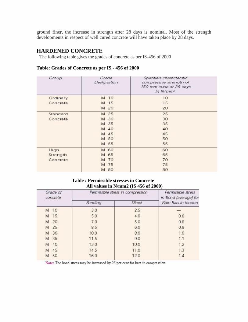
The following table gives the grades of concrete as per IS-456 of 2000
Table: Grades of Concrete as per IS - 456 of 2000
Table : Permissible stresses in Concrete
All values in N/mm2 (IS 456 of 2000)
Accelerated Curing test In the acclerated curing test the standard cubes are cast, they are covered with top plate and the
joints are sealed with special grease to prevent drying. Within 30 minutes of adding water, the
cubes having sealed effectively, are placed in an air-tight oven which is then switched on. The
oven temperature is brought to 93°C in about one hour time. It is kept at this temperature for 5
hours. At the end of this period the cubes are removed from oven, stripped, cooled, and tested.
The time allowed for this operation is 30 minutes.
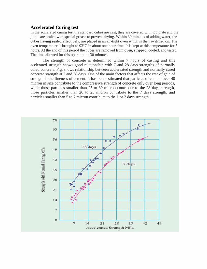
The strength of concrete is determined within 7 hours of casting and this acclerated strength shows good relationship with 7 and 28 days strengths of normally cured concrete. Fig. shows relationship between acclereated strength and normally cured concrete strength at 7 and 28 days. One of the main factors that affects the rate of gain of strength is the fineness of cement. It has been estimated that particles of cement over 40 micron in size contribute to the compressive strength of concrete only over long periods, while those particles smaller than 25 to 30 micron contribute to the 28 days strength, those particles smaller than 20 to 25 micron contribute to the 7 days strength, and particles smaller than 5 to 7 micron contribute to the 1 or 2 days strength.
Maturity Concept of Concrete
While dealing with curing and strength development, we have so far considered only the time aspect. It has been pointed out earlier that it is not only the time but also the temperature
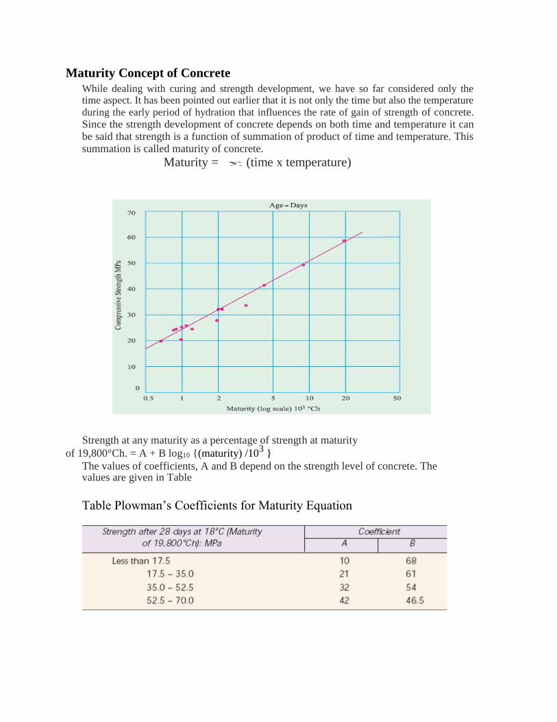
during the early period of hydration that influences the rate of gain of strength of concrete. Since the strength development of concrete depends on both time and temperature it can be said that strength is a function of summation of product of time and temperature. This summation is called maturity of concrete.
Maturity = (time x temperature)
Strength at any maturity as a percentage of strength at maturity
of 19,800°Ch. = A + B log10 {(maturity) /103 }
The values of coefficients, A and B depend on the strength level of concrete. The values are given in Table
Table Plowman’s Coefficients for Maturity Equation
Effect of Maximum size of Aggregate on Strength
At one time it was thought that the use of larger size aggregate leads to higher strength. This was due to the fact that the larger the aggregate the lower is the total surface area and, therefore, the lower is the requirement of water for the given workability.
For this reason, a lower water/cement ratio can be used which will result in
higher strength. However, later it was found that the use of larger size aggregate did not contribute to higher strength as expected from the theoretical considerations due to the following reasons.
The larger maximum size aggregate gives lower surface area for developments of gel bonds which is responsible for the lower strength of the concrete. Secondly bigger aggregate size causes a more heterogeneity in the concrete which will prevent the uniform distribution of load when stressed. When large size aggregate is used, due to internal bleeding, the transition zone will become much weaker due to the development of micro cracks which result in lower compressive strength.
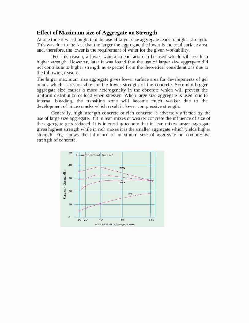
Generally, high strength concrete or rich concrete is adversely affected by the use of large size aggregate. But in lean mixes or weaker concrete the influence of size of the aggregate gets reduced. It is interesting to note that in lean mixes larger aggregate gives highest strength while in rich mixes it is the smaller aggregate which yields higher strength. Fig. shows the influence of maximum size of aggregate on compressive strength of concrete.
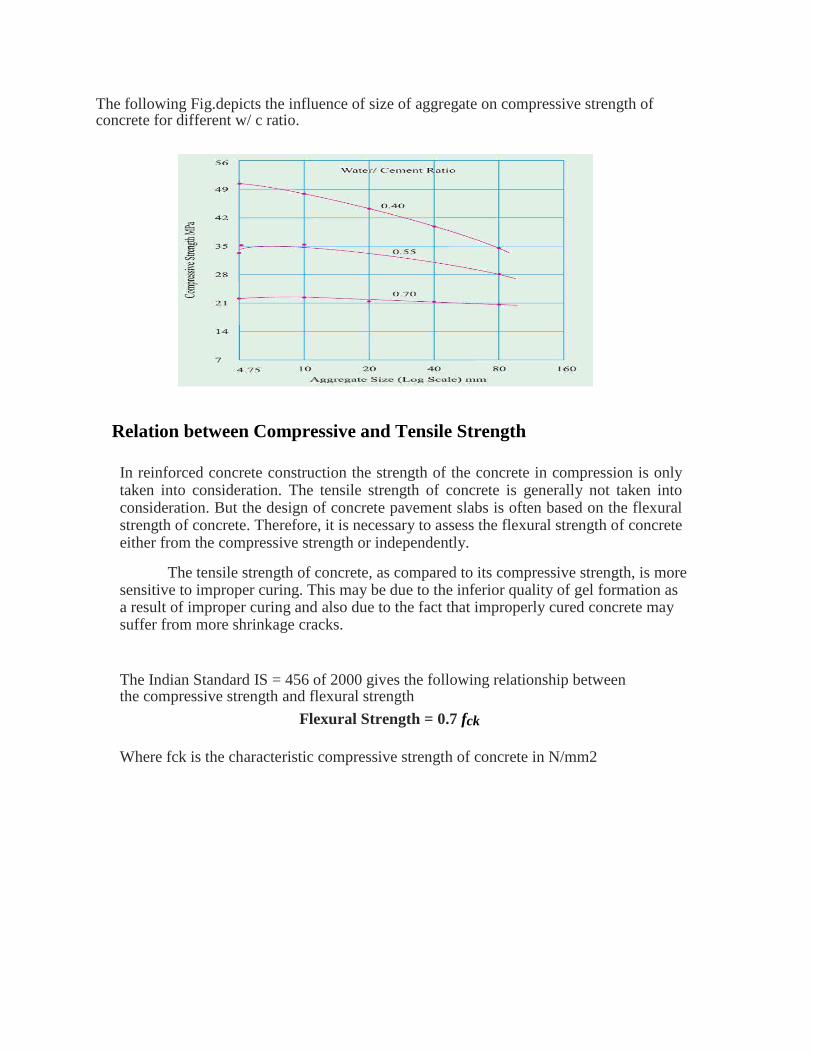
The following Fig.depicts the influence of size of aggregate on compressive strength of concrete for different w/ c ratio.
Relation between Compressive and Tensile Strength
In reinforced concrete construction the strength of the concrete in compression is only taken into consideration. The tensile strength of concrete is generally not taken into consideration. But the design of concrete pavement slabs is often based on the flexural strength of concrete. Therefore, it is necessary to assess the flexural strength of concrete either from the compressive strength or independently.
The tensile strength of concrete, as compared to its compressive strength, is more
sensitive to improper curing. This may be due to the inferior quality of gel formation as a result of improper curing and also due to the fact that improperly cured concrete may suffer from more shrinkage cracks.
The Indian Standard IS = 456 of 2000 gives the following relationship between the compressive strength and flexural strength
Flexural Strength = 0.7 fck
Where fck is the characteristic compressive strength of concrete in N/mm2
It is seen that strength of concrete in compression and tension (both direct tension and flexural tension) are closely related, but the relationship is not of the type of direct proportionality. The ratio of the two strengths depends on general level of strength of concrete. In other words, for
higher compressive strength concrete shows higher tensile strength, but the rate of increase of
tensile strength is of decreasing order. The type of coarse aggregate influences this relationship. Crushed aggregate gives relatively higher flexural strength than compressive
strength. This is attributed to the improved bond strength between cement paste and
aggregate particles.
Curing of Concrete
The hydration aspect of cement. Concrete derives its strength by the hydration of cement particles. The hydration of cement is not a momentary action but a process continuing for long time.
In other words, a water/cement ratio of about 0.38 would be required to hydrate all the particles of cement and also to occupy the space in the gel pores. Theoretically, for a concrete made and contained in a sealed container a water cement ratio of 0.38 would satisfy the requirement of water for hydration and at the same time no capillary cavities would be left. However, it is seen that practically a water/cement ratio of 0.5 will be required for complete hydration in a sealed container for keeping up the desirable relative humidity level.
Curing Methods Curing methods may be divided broadly into four categories: (a) Water curing (b) Membrane curing (c ) Application of heat (d) Miscellaneous
Water Curing
This is by far the best method of curing as it satisfies all the requirements of curing,
namely, promotion of hydration, elimination of shrinkage and absorption of the heat
of hydration. It is pointed out that even if the membrane method is adopted, it is
desirable that a certain extent of water curing is done before the concrete is covered
with membranes. Water curing can be done in the following ways: (a ) Immersion
(b) Ponding
(c ) Spraying or Fogging
(d ) Wet covering
The precast concrete items are normally immersed in curing tanks for a certain duration. Pavement slabs, roof slab etc. are covered under water by making small ponds. Vertical retaining wall or plastered surfaces or concrete columns etc. are cured by spraying water. In some cases, wet coverings such as wet gunny bags, hessian cloth, jute matting, straw etc.,
Membrane Curing
Sometimes, concrete works are carried out in places where there is acute shortage of water. The lavish application of water for water curing is not possible for reasons of economy. It has been pointed out earlier that curing does not mean only application of water, it means also creation of conditions for promotion of uninterrupted and progressive hydration. It is also pointed out that the quantity of water, normally mixed for making concrete is more than sufficient to hydrate the cement, provided this water is not allowed to go out from the body of concrete. For this reason, concrete could be covered with membrane which will effectively seal off the evaporation of water from concrete. It is found that the application of membrane or a sealing compound, after a short spell of water curing for one or two days is sometimes beneficial sometimes, concrete is placed in some inaccessible, difficult or far off places.
Application of heat
The development of strength of concrete is a function of not only time but also that of temperature. When concrete is subjected to higher temperature it accelerates the hydration process resulting in faster development of strength. Concrete cannot be subjected to dry heat to accelerate the hydration process as the presence of moisture is also an essential requisite. Therefore, subjecting the concrete to higher temperature and maintaining the required wetness can be achieved by subjecting the concrete to steam curing.
Steam curing at ordinary pressure
This method of curing is often adopted for pefabricated concrete elements. Application of steam curing to in situ construction will be a little difficult task. However, at some places it has been tried for in situ construction by forming a steam jacket with the help of tarpaulin or thick polyethylene sheets. But this method of application of steam for in situ work is found to be wasteful and the intended rate of development of strength and benefit is not really achieved.
High Pressure Steam Curing
In the steam curing at atmospheric pressure, the temperature of the steam is naturally below 100°C. The steam will get converted into water, thus it can be called in a way, as hot water curing. This is done in an open atmosphere. The high pressure steam curing is something different from ordinary steam curing, in that the curing is carried out in a closed chamber. The superheated steam at high pressure and high temperature is applied on the concrete. This process is also called “Autoclaving”.
Finishing
Finishing operation is the last operation in making concrete. Finishing in real sence does not apply to all concrete operations. For a beam concreting, finishing may not be applicable, whereas for the concrete road pavement, airfield pavement or for the flooring of a domestic building, careful finishing is of great importance.
In recent years there has been a growing tendency to develop and use various surface treatments which permit concrete structures to proudly proclaim its nature instead of covering itself with an expensive veneer.
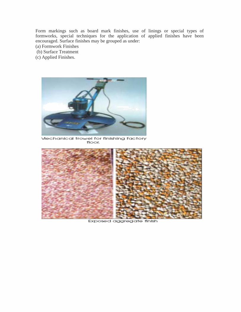
Form markings such as board mark finishes, use of linings or special types of formworks, special techniques for the application of applied finishes have been encouraged. Surface finishes may be grouped as under: (a) Formwork Finishes
(b) Surface Treatment
(c) Applied Finishes.
TESTING OF HARDENED CONCRETE Testing of hardened concrete plays an important role in controlling and confirming the quality of
cement concrete works. Systematic testing of raw materials, fresh concrete and hardened
concrete are inseparable part of any quality control programme for concrete, which helps to
achieve higher efficiency of the material used and greater assurance of the performance of the
concrete with regard to both strength and durability. One of the purposes of testing hardened
concrete is to confirm that the concrete used at site has developed the required strength.
The results of the test on hardened concrete even if they are known late, help to reveal the
quality of concrete and enable adjustments to be made in the production of further concretes.
Tests are made by casting cubes or cylinder from the representative concrete or cores cut from
the actual concrete. It is to be remembered that standard compression test specimens give a
measure of the potential strength of the concrete, and not of the strength of the concrete in
structure. Knowledge of the strength of concrete in structure can not be directly obtained from
tests on separately made specimens.
Compression Test
Compression test is the most common test conducted on hardened concrete, partly because
it is an easy test to perform, and partly because most of the desirable characteristic
properties of concrete are qualitatively related to its compressive strength. The compression
test is carried out on specimens cubical or cylindrical in shape. The cube specimen is of the
size 15 x 15 x 15 cm.
Moulds
Metal moulds, preferably steel or cast iron, thick enough to prevent distortion are required
Curing
The test specimens are stored in place free from vibration, in moist air of at least 90%
relative humidity and at a temperature of 27° ± 2°C for 24 hours ± 1/2 hour from the time of
addition of water to the dry ingredients. After this period, the specimens are marked and
removed from the moulds and unless required for test within 24 hours, immediately
submerged in clean fresh water or saturated lime solution and kept there until taken out just
prior to test. The water or solution in which the specimens are submerged, are renewed
every seven days and are maintained at a temperature of 27° ± 2°C. The specimens are not
to be allowed to become dry at any time until they have been tested
Failure of Compression Specimen
Compression test develops a rather more complex system of stresses. Due to compression
load, the cube or cylinder undergoes lateral expansion owing to the Poisson’s ratio effect.
The steel plates do not undergo lateral expansion to the some extent that of concrete, with
the result that steel restrains the expansion tendency of concrete in the lateral direction. This
induces a tangential force between the end surfaces of the concrete specimen and the
adjacent steel plates of the testing machine. It has been found that the lateral strain in the
steel platens is only 0.4 of the lateral strain in the concrete. Due to this the platen restrains
the lateral expansion of the concrete in the parts of the specimen near its end. The degree of
restraint exercised depends on the friction actually developed. When the friction is
eliminated by applying grease, graphite or paraffin wax to the bearing surfaces the
specimen exhibits a larger lateral expansion and eventually splits along its full length.
With friction acting i.e., under normal conditions of test, the elements within the specimen
is subjected to a shearing stress as well as compression. The magnitude of the shear stress
decreases and the lateral expansion increases in distance from the platen. But if the
specimen is longer than about 1.7 d, a part it of will be free from the restraining effect of the
platen. Specimens, whose length is less than 1.5 d, show a considerably higher strength than
those with a greater length.
Comparison between Cube and Cylinder Strength
It is difficult to say whether cube test gives more realistic strength properties of concrete or
cylinder gives a better picture about the strength of concrete. However, it can be said that
the cylinder is less affected by the end restrains caused by platens and hence it seems to
give more uniform results than cube. Therefore, the use of cylinder is becoming more
popular, particularly in the research laboratories.
Cylinders are cast and tested in the same position, whereas cubes are cast in one direction
and tested from the other direction. In actual structures in the field, the casting and loading
is similar to that of the cylinder and not like the cube. As such, cylinder simulates the
condition of the actual structural member in the field in respect of direction of load. The
points in favour of the cube specimen are that the shape of the cube resembles the shape of
the structural members often met with on the ground. The cube does not require capping,
whereas cylinder requires capping. The capping material used in case cylinder may
influence to some extent the strength of the cylinder.
The Flexural Strength of Concrete
Concrete as we know is relatively strong in compression and weak in tension. In reinforced
concrete members, little dependence is placed on the tensile strength of concrete since steel
reinforcing bars are provided to resist all tensile forces. However, tensile stresses are likely to
develop in concrete due to drying shrinkage, rusting of steel reinforcement, temperature
gradients and many other reasons. Therefore, the knowledge of tensile strength of concrete is of
importance.
.Stresses due to volume changes alone may be high. The longitudinal tensile stress in the bottom
of the pavement, caused by restraint and temperature warping, frequently amounts to as much as
2.5 MPa at certain periods of the year and the corresponding stress in the transverse direction is
approximately 0.9 MPa. These stresses are additive to those produced by wheel loads on
unsupported portions of the slab.
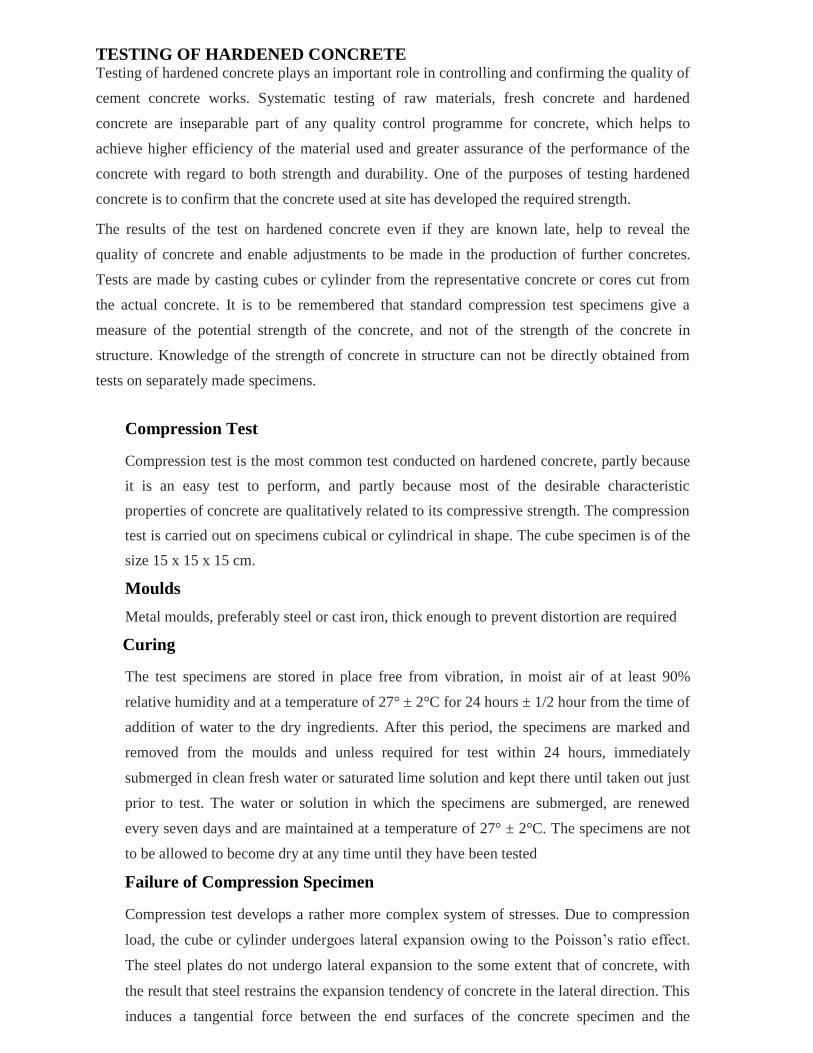
Determination of Tensile Strength
Direct measurement of tensile strength of concrete is difficult. Neither specimens nor
testing apparatus have been designed which assure uniform distribution of the “pull”
applied to the concrete.
While a number of investigations involving the direct measurement of tensile strength have
been made, beam tests are found to be dependable to measure flexural strength property of
concrete. The value of the modulus of rupture (extreme fibre stress in bending) depends on
the dimension of the beam and manner of loading. The systems of loading used in finding
out the flexural tension are central point loading and third point loading.
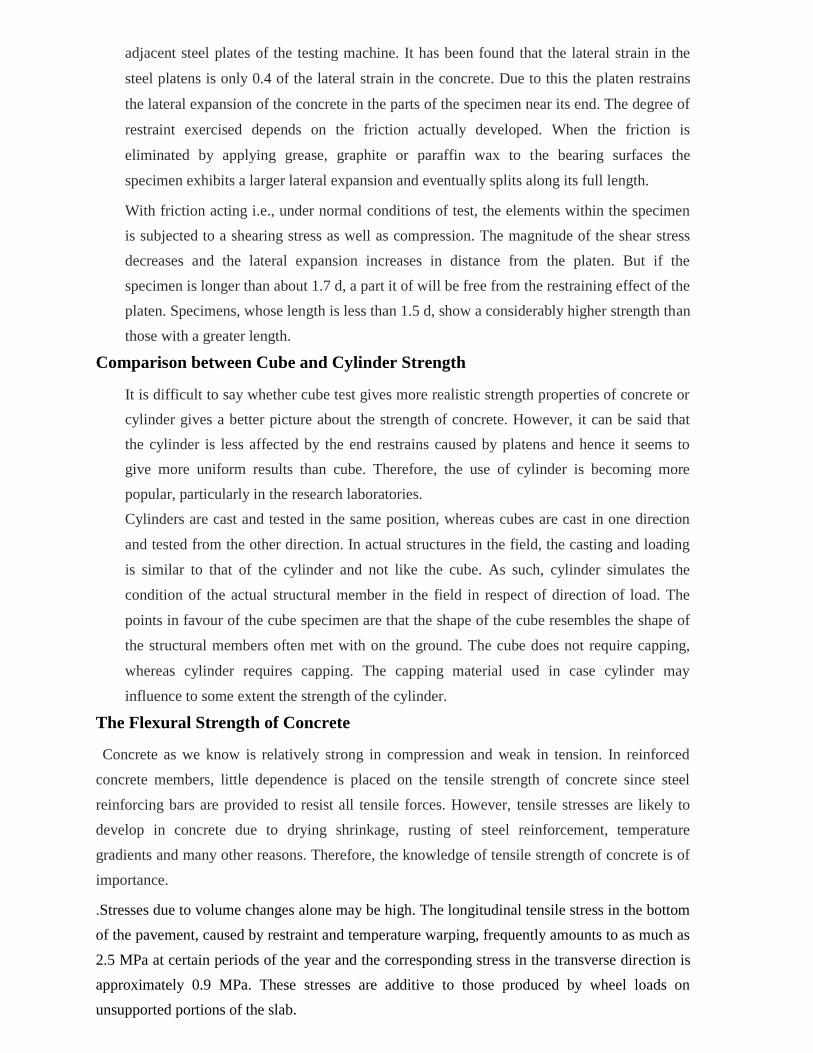
In the central point loading, maximum fibre stress will come below the point of loading
where the bending moment is maximum. In case of symmetrical two point loading, the
critical crack may appear at any section, not strong enough to resist the stress within the
middle third, where the bending moment is maximum. It can be expected that the two point
loading will yield a lower value of the modulus of rupture than the centre point loading.
The standard size of the specimens are 15 x 15 x 70 cm. Alternatively, if the largest nominal size
of the aggregate does not exceed 20 mm, specimens 10 x 10 x 50 cm may be used. The mould
should be of metal, preferably steel or cast iron and the metal should be of sufficient thickness to
prevent spreading or warping. The mould should be constructed with the longer dimension
horizontal and in such a manner as to facilitate the removal of the moulded specimens without
damage. The tamping bar should be a steel bar weighing 2 kg, 40 cm long and should have a
ramming face 25 mm square.
The bed of the testing machine should be provided with two steel rollers, 38 mm in diameter, on
which the specimen is to be supported, and these rollers should be so mounted that the distance from
centre to centre is 60 mm for 15 cm specimen or 40 cm for 10.0 cm specimens. The load is applied
through two similar rollers mounted at the third points of the supporting span, which is, spaced at 20
or 13.3 cm centre to centre. The load is divided equally between the two loading rollers, and all
rollers are mounted in such a manner that the load is applied axially and without subjecting specimen
to any torsional stresses or restrains.
Procedure
Test specimens are stored in water at a temperature of 24° to 30°C for 48 hours before
testing. They are tested immediately on removal from the water whilst they are still in a wet
condition. The dimensions of each specimen should be noted before testing. No preparation
of the surfaces is required.
Placing the Specimen in the Testing Machine
The bearing surfaces of the supporting and loading rollers are wiped clean, and any loose sand
or other material removed from the surfaces of the specimen where they are to make contact
with the rollers. The specimen is then placed in the machine in such a manner that the load is
applied to the uppermost surface as cast in the mould, along two lines spaced 20.0 or 13.3 cm
apart. The axis of the specimen is carefully aligned with the axis of the loading device. No
packing is used between the bearing surfaces of the specimen and the rollers.
The load is applied without shock and increasing continuously at a rate such that the
extreme fibre stress increases at approximately 0.7 kg/sq cm/min that is, at a rate of loading
of 400 kg/min for the 15.0 cm specimens and at a rate of 180 kg/min for the 10.0 cm
specimens. The load is increased until the specimen fails, and the maximum load applied to
the specimen during the test is recorded. The appearance of the fractured faces of concrete
and any unusual features in the type of failure is noted.
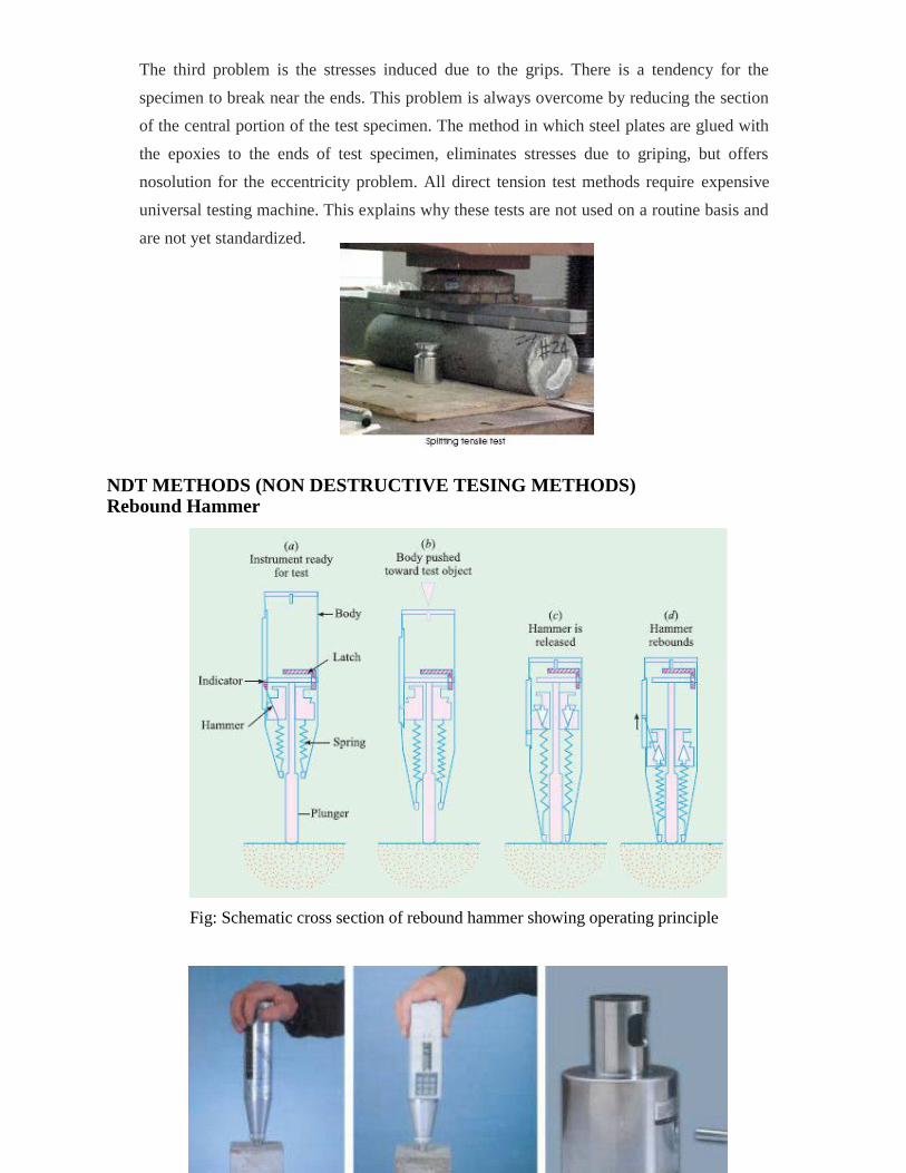
The third problem is the stresses induced due to the grips. There is a tendency for the
specimen to break near the ends. This problem is always overcome by reducing the section
of the central portion of the test specimen. The method in which steel plates are glued with
the epoxies to the ends of test specimen, eliminates stresses due to griping, but offers
nosolution for the eccentricity problem. All direct tension test methods require expensive
universal testing machine. This explains why these tests are not used on a routine basis and
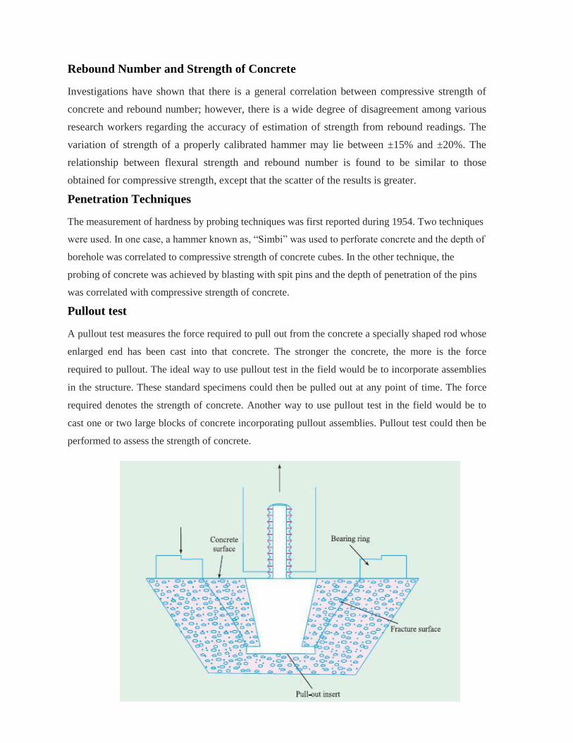
are not yet standardized. NDT METHODS (NON DESTRUCTIVE TESING METHODS) Rebound Hammer
Fig: Schematic cross section of rebound hammer showing operating principle
Rebound Number and Strength of Concrete
Investigations have shown that there is a general correlation between compressive strength of
concrete and rebound number; however, there is a wide degree of disagreement among various
research workers regarding the accuracy of estimation of strength from rebound readings. The
variation of strength of a properly calibrated hammer may lie between ±15% and ±20%. The
relationship between flexural strength and rebound number is found to be similar to those
obtained for compressive strength, except that the scatter of the results is greater.
Penetration Techniques
The measurement of hardness by probing techniques was first reported during 1954. Two techniques
were used. In one case, a hammer known as, “Simbi” was used to perforate concrete and the depth of
borehole was correlated to compressive strength of concrete cubes. In the other technique, the
probing of concrete was achieved by blasting with spit pins and the depth of penetration of the pins
was correlated with compressive strength of concrete.
Pullout test
A pullout test measures the force required to pull out from the concrete a specially shaped rod whose
enlarged end has been cast into that concrete. The stronger the concrete, the more is the force
required to pullout. The ideal way to use pullout test in the field would be to incorporate assemblies
in the structure. These standard specimens could then be pulled out at any point of time. The force
required denotes the strength of concrete. Another way to use pullout test in the field would be to
cast one or two large blocks of concrete incorporating pullout assemblies. Pullout test could then be
performed to assess the strength of concrete.
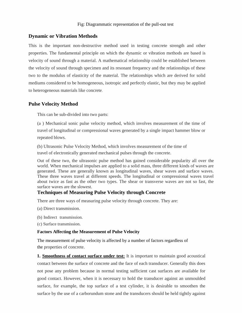
Fig: Diagrammatic representation of the pull-out test
Dynamic or Vibration Methods
This is the important non-destructive method used in testing concrete strength and other
properties. The fundamental principle on which the dynamic or vibration methods are based is
velocity of sound through a material. A mathematical relationship could be established between
the velocity of sound through specimen and its resonant frequency and the relationships of these
two to the modulus of elasticity of the material. The relationships which are derived for solid
mediums considered to be homogeneous, isotropic and perfectly elastic, but they may be applied
to heterogeneous materials like concrete.
Pulse Velocity Method This can be sub-divided into two parts:
(a ) Mechanical sonic pulse velocity method, which involves measurement of the time of
travel of longitudinal or compressional waves generated by a single impact hammer blow or
repeated blows.
(b) Ultrasonic Pulse Velocity Method, which involves measurement of the time of
travel of electronically generated mechanical pulses through the concrete.
Out of these two, the ultrasonic pulse method has gained considerable popularity all over the
world. When mechanical impulses are applied to a solid mass, three different kinds of waves are
generated. These are generally known as longitudinal waves, shear waves and surface waves.
These three waves travel at different speeds. The longitudinal or compressional waves travel
about twice as fast as the other two types. The shear or transverse waves are not so fast, the
surface waves are the slowest.
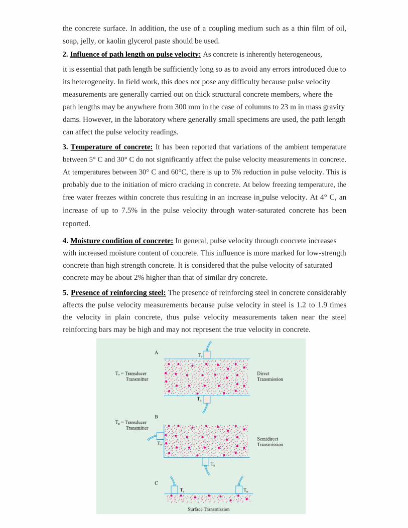
Techniques of Measuring Pulse Velocity through Concrete
There are three ways of measuring pulse velocity through concrete. They are:
(a) Direct transmission.
(b) Indirect transmission.
(c) Surface transmission.
Factors Affecting the Measurement of Pulse Velocity
The measurement of pulse velocity is affected by a number of factors regardless of
the properties of concrete.
1. Smoothness of contact surface under test: It is important to maintain good acoustical
contact between the surface of concrete and the face of each transducer. Generally this does
not pose any problem because in normal testing sufficient cast surfaces are available for
good contact. However, when it is necessary to hold the transducer against an unmoulded
surface, for example, the top surface of a test cylinder, it is desirable to smoothen the
surface by the use of a carborundum stone and the transducers should be held tightly against
the concrete surface. In addition, the use of a coupling medium such as a thin film of oil,
soap, jelly, or kaolin glycerol paste should be used.
2. Influence of path length on pulse velocity: As concrete is inherently heterogeneous,
it is essential that path length be sufficiently long so as to avoid any errors introduced due to
its heterogeneity. In field work, this does not pose any difficulty because pulse velocity
measurements are generally carried out on thick structural concrete members, where the
path lengths may be anywhere from 300 mm in the case of columns to 23 m in mass gravity
dams. However, in the laboratory where generally small specimens are used, the path length
can affect the pulse velocity readings.
3. Temperature of concrete: It has been reported that variations of the ambient temperature
between 5° C and 30° C do not significantly affect the pulse velocity measurements in concrete.
At temperatures between 30° C and 60°C, there is up to 5% reduction in pulse velocity. This is
probably due to the initiation of micro cracking in concrete. At below freezing temperature, the
free water freezes within concrete thus resulting in an increase in pulse velocity. At 4° C, an
increase of up to 7.5% in the pulse velocity through water-saturated concrete has been
reported.
4. Moisture condition of concrete: In general, pulse velocity through concrete increases
with increased moisture content of concrete. This influence is more marked for low-strength
concrete than high strength concrete. It is considered that the pulse velocity of saturated
concrete may be about 2% higher than that of similar dry concrete.
5. Presence of reinforcing steel: The presence of reinforcing steel in concrete considerably
affects the pulse velocity measurements because pulse velocity in steel is 1.2 to 1.9 times
the velocity in plain concrete, thus pulse velocity measurements taken near the steel
reinforcing bars may be high and may not represent the true velocity in concrete.
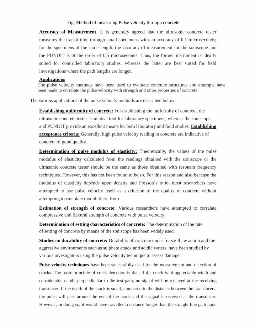
Fig: Method of measuring Pulse velocity through concrete
Accuracy of Measurement. It is generally agreed that the ultrasonic concrete tester
measures the transit time through small specimens with an accuracy of 0.1 microseconds;
for the specimens of the same length, the accuracy of measurement for the soniscope and
the PUNDIT is of the order of 0.5 microseconds. Thus, the former instrument is ideally
suited for controlled laboratory studies, whereas the latter are best suited for field
investigations where the path lengths are longer.
Applications
The pulse velocity methods have been used to evaluate concrete structures and attempts have
been made to correlate the pulse velocity with strength and other properties of concrete.
The various applications of the pulse velocity methods are described below:
Establishing uniformity of concrete: For establishing the uniformity of concrete, the
ultrasonic concrete tester is an ideal tool for laboratory specimens, whereas the soniscope
and PUNDIT provide an excellent means for both laboratory and field studies. Establishing
acceptance criteria: Generally, high pulse velocity reading in concrete are indicative of
concrete of good quality.
Determination of pulse modulus of elasticity: Theoretically, the values of the pulse
modulus of elasticity calculated from the readings obtained with the soniscope or the
ultrasonic concrete tester should be the same as those obtained with resonant frequency
techniques. However, this has not been found to be so. For this reason and also because the
modulus of elasticity depends upon density and Poisson’s ratio, most researchers have
attempted to use pulse velocity itself as a criterion of the quality of concrete without
attempting to calculate moduli there from.
Estimation of strength of concrete: Various researchers have attempted to correlate
compressive and flexural strength of concrete with pulse velocity.
Determination of setting characteristics of concrete: The determination of the rate
of setting of concrete by means of the soniscope has been widely used.
Studies on durability of concrete: Durability of concrete under freeze-thaw action and the
aggressive environments such as sulphate attack and acidic waters, have been studied by
various investigators using the pulse velocity technique to assess damage.
Pulse velocity techniques have been successfully used for the measurement and detection of
cracks. The basic principle of crack detection is that, if the crack is of appreciable width and
considerable depth, perpendicular to the test path, no signal will be received at the receiving
transducer. If the depth of the crack is small, compared to the distance between the transducers,
the pulse will pass around the end of the crack and the signal is received at the transducer.
However, in doing so, it would have travelled a distance longer than the straight line path upon
which pulse velocity computations are made. The difference in the pulse velocity is then used to
estimate the path length and hence crack depth. Combined Methods
One of the most important objectives of non-destructive methods of testing of concrete is to
estimate the compressive strength of concrete in structure. Use of any one method may not give
reliable results. Using more than one method at the same time has been found to give reliable
results regarding the strength of a structure. Most popular combination was found to be the
ultrasonic pulse velocity method in conjunction with the hardness measurement techniques, and
Rebound Hammer method. Radioactive Methods
The use of X-rays and gamma-rays as non-destructive method for testing properties of concrete
is relatively new. X-ray and gamma-rays both components of the high energy region on the
electromagnetic spectrum penerate concrete but undergo attenuation in the process. The degree
of attenuation depends on the kind of matter traversed, its thickness, and the wavelength of the
radiation. The intensity of the incident gamma-rays and the emerging gamma-rays after passing
through the specimens are measured. These two values are made use of for calculating the
density of structural concrete members. Gamma-rays transmission method has been used to
measure the thickness of concrete slabs of known density. Gamma radiation source of known
intensity is made to pass and penetrate through the concrete.The intensity at the other
face is measured. From this thickness of the concrete is calculated.
Nuclear Methods
Use of nuclear methods for non-destructive measurement of some properties of concrete is of
recent origin. Two principal techniques have been reported, namely neutron scattering methods
for determining the moisture content of concrete and neutron activation analysis for the
determination of cement content. These methods are not suitable for finding out the strength of
concrete.
Magnetic Methods
Battery operated magnetic devices that can measure the depth of reinforcement cover in
concrete and detect the position of reinforcement bars are now available. The apparatus is
known as cover meter. This can be used for measuring the cover given in the lightly
reinforced sections.
Electrical Methods
Recently some electrical methods have been employed for determining the moisture content
of hardened concrete, tracing of moisture permeation through concrete and determining the
thickness of concrete pavements. The accurate determination of the moisture content of
hardened concrete is required in connection with creep, shrinkage and thermal conductivity
studies. The fact that dielectric properties of hardened concrete change with changes in
moisture content is made use of in this method.
Electrical resistivity methods have been used to find out the thickness of concrete
pavements. The method is based on the principle that the material offers resistance to the
passage of an electric current.