Embed Size (px)
Citation preview
ZMM - SLIVEN SLIVEN BULGARIA
UNIVERSAL LATHE
CU800RD CU1000RD
CU1250RD
Manual for Machine Installation, Maintenance and Operation
ZMM-Sliven 16, Bansko Shose Str. Sliven-8800, Bulgaria
TEL.: (+359 44) 66 28 90 FAX.: (+359 44) 66 25 63
I:\009 - Produkten\Handleidingen\Handleidingen Huvema\draaibanken\CU 800 VAC - CU 1000 VAC - CU 1250 VAC\CU rd_800_1000_1250_EN.doc
1
This manual contains information for correct installation, operation and maintenance of Universal lathe machines CU800RD, CU1000RD and CU1250RD Produced by ZMM-Sliven.
The manual also provides instructions and recommendations for correct functioning and optimum performance of the machine.
For trouble free and safety operation with the machine all
instructions, recommendations and warning signs shall be observed.
Due to continual improvements in design ZMM Sliven
reserves the right to make changes and supplements in this manual without written consent any time.
ZMM - Sliven 16, Bansko Shose Str. Sliven-8800 BULGARIA
I:\009 - Produkten\Handleidingen\Handleidingen Huvema\draaibanken\CU 800 VAC - CU 1000 VAC - CU 1250 VAC\CU rd_800_1000_1250_EN.doc
2
CONTENTS CONTENTS ............................................................................................................................................................................. 2
1. SHIPPING DOCUMENTS ......................................................................................................................................... 4
1.1 MAIN DATAS ............................................................................................................................................................ 4
1.2 SHEET FOR MACHINE COMPLETION .................................................................................................................... 5
1.3 CERTIFICATE FOR QUALITY .................................................................................................................................. 7
1.4. CERTIFICATE FOR GUARANTEE ........................................................................................................................... 8
1.5. TECHNICAL SPECIFICATIONS ............................................................................................................................... 9 2. SAFETY OPERATION WITH THE MACHINE ........................................................................................................ 12
2.1 SAFETY PRECAUTION SIGNS AND LABELS IN THE INSTRUCTION AND ON THE MACHINE ........................ 12
2.2 QUALIFICATION AND TRAINING OF PERSONNEL WHO OPERATE AND MAINTA IN THE MACHINE ............ 13
2.3 HAZARDS WHEN SAFETY PRECAUTIONS ARE NOT OBSERVED .................................................................... 13
2.4 OPERATIONS IN COMPLIANCE WITH THE SAFETY PRECAUTIONS ................................................................ 14
2.5 SAFETY PRECAUTIONS FOR THE USER ............................................................................................................ 14
2.6 SAFETY PRECAUTIONS FOR THE INSTALLATION, CHECKS AND MAINTENANCE ...................................... 15
2.7 UNAUTHORIZED MODIFICATIONS AND PARTS MAKING ................................................................................. 15
2.8 UNWARRANTED OPERATIONS............................................................................................................................ 15
2.9 DIRECTIONS AND RECOMMENDATIONS ........................................................................................................... 15 3.0 MACHINE TRANSPORTATION AND INSTALLATION ......................................................................................... 18
3.1 TRANSPORTATION ............................................................................................................................................... 18
3.2. UNPACKING ........................................................................................................................................................... 18
3.3 MACHINE LIFTING AND DISPLACEMENT ............................................................................................................ 19
3.4 MACHINE CLEANING ............................................................................................................................................ 19
3.5 POSITIONING, FOUNDATION AND LEVELLING .................................................................................................. 21
3.6 CONNECTION THE MACHINE TO MAINS ........................................................................................................... 23
3.7 PUTTING THE MACHINE INTO OPERATION ....................................................................................................... 24 4. ТECHNICAL DESCRIPTION .................................................................................................................................. 26
4.1 FIELD OF APPLICATION ....................................................................................................................................... 26
4.2 MACHINE MAIN PARTS ......................................................................................................................................... 26
4.3 MACHINE CONTROLS .......................................................................................................................................... 27
4.4 MACHINE GEOMETRICAL ACCURACY ................................................................................................................ 27 5.0 MACHINE MAIN PARTS DESCRIPTION ............................................................................................................... 28
5.1 BED ...................................................................................................................................................................... 28
5.2 GEARBOX .............................................................................................................................................................. 28 5.3 TAILSTOCK………………………………………………………………………………………… ………………30 5.4 APRON ................................................................................................................................................................. 33
5.5. FEED BOX ........................................................................................................................................................ 33
5.6 LOWER CARRIAGE ............................................................................................................................................... 33
5.7 UPPER CARRIAGE ................................................................................................................................................ 33
5.8 MACHINE MAIN DRIVE ........................................................................................................................................ 34
5.9 RESTS (OPTIONS) ................................................................................................................................................ 34 6. MACHINE LUBRICATION ...................................................................................................................................... 35
6.1 GENERAL ............................................................................................................................................................... 35
6.2 INSTRUCTIONS FOR LUBRICATION AND LUBRICANTS .................................................................................... 38 7.0 OPERATION WITH THE MACHINE ....................................................................................................................... 40
7.1 MACHINE START ................................................................................................................................................... 40
7.2 SPEEDS OF THE MACHINE .................................................................................................................................. 40
7.3 SETTING THE FEEDS .......................................................................................................................................... 432
7.4 THREAD CUTTING................................................................................................................................................. 47
7.5 MULTI-START THREAD CUTTING ........................................................................................................................ 50
7.6 CUTTING OF BRIGGS THREADS ........................................................................................................................ 52
7.7 DIMENSION READOUT ......................................................................................................................................... 52
7.8 WORK PIECE CHUCKING AND DRIVING EQUIPMENT ....................................................................................... 52 8.0 ADJUSTMENTS ..................................................................................................................................................... 54
8.1 MAIN MOTOR AND DRIVE V-BELTS REPLACEMENT .................................................................................... 54
8.2 GEARBOX POSITION ADJUSTMENT ............................................................................................................... 55
8.3 SPINDLE BEARINGS ADJUSTMENT .............................................................................................................. 56
8.4 LOWER CARRIAGE ADJUSTMENTS .................................................................................................................... 57
8.4.1 ADJUSTMENT THE CLEARANCE BETWEEN THE CROSS SCREW AND THE NUT ........................................ 57
8.4.2 CROSS SCREW BEARINGS ............................................................................................................................... 57
8.4.3. ADJUSTMENT THE CLEARANCE BETWEEN BED FRONT GUIDE PLANE AND LOWER CARRIAGE .............. 58
8.4.4 ADJUSTMENT THE CLEARANCE BETWEEN BED REAR GUIDE WAY AND LOWER CARRIAGE ............... 59
8.4.5 ADJUSTMENT THE CLEARANCE IN CROSS SLIDE DOVETAIL .................................................................... 59
8.5 ADJUSTMENT OF THE TAILSTOCK CROSS DISPLACEMENT IN RELATION TO THE SHIM ........................... 60
8.6 APRON ADJUSTMENT .......................................................................................................................................... 60
8.7 ADJUSTMENT OF THE COMPOUND CARRIAGE ................................................................................................ 61
8.7.1. ADJUSTMENT THE CLEARANCE BETWEEN THE SCREW AND NUT ............................................................ 61
8.7.2 ADJUSTMENT OF DOVETAIL CLEARANCE ..................................................................................................... 62

I:\009 - Produkten\Handleidingen\Handleidingen Huvema\draaibanken\CU 800 VAC - CU 1000 VAC - CU 1250 VAC\CU rd_800_1000_1250_EN.doc
3
8.7.3 ADJUSTMENT OF THE SCREW BEARING ........................................................................................................ 62 9.0 COOLANT INSTALLATION ................................................................................................................................... 63
10. ELECTRIC INSTALLATION ................................................................................................................................... 64
10.1 GENERAL ............................................................................................................................................................... 64
10.2 ELECTRIC CONTROLS .......................................................................................................................................... 64
10.3 PROTECTIONS ...................................................................................................................................................... 64
10.4 MAINTENANCE ...................................................................................................................................................... 65 11 FREQUENCY INVERTER……………………………………………………………………………………………...65 12. APPENDIX .............................................................................................................................................................. 66
12.1. PROTOCOL FOR GEOMETRICAL ACCURACY ................................................................................................... 66
1 PREPARATORY MEASURES ................................................................................................................................ 66
2 GEOMETRICAL TESTINGS ................................................................................................................................... 67
3 PRACTICAL TESTINGS ......................................................................................................................................... 69 13. OPTIONAL ACCESSORIES ................................................................................................................................... 70
13.1 THREAD DIAL ...................................................................................................................................................... 70
13..2 TAPPER TURNING ATTACHMENT ..................................................................................................................... 72
I:\009 - Produkten\Handleidingen\Handleidingen Huvema\draaibanken\CU 800 VAC - CU 1000 VAC - CU 1250 VAC\CU rd_800_1000_1250_EN.doc
4
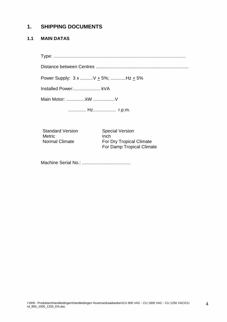
1. SHIPPING DOCUMENTS 1.1 MAIN DATAS
Type: ........................................................................................................ Distance between Centres ......................................................................... Power Supply: 3 x ..........V + 5%; ............Hz + 5% Installed Power:..................... kVA Main Motor: ...............kW .................V .............. Hz.................. r.p.m. Standard Version Special Version Metric Inch Normal Climate For Dry Tropical Climate For Damp Tropical Climate
Machine Serial No.: ......................................
I:\009 - Produkten\Handleidingen\Handleidingen Huvema\draaibanken\CU 800 VAC - CU 1000 VAC - CU 1250 VAC\CU rd_800_1000_1250_EN.doc
5
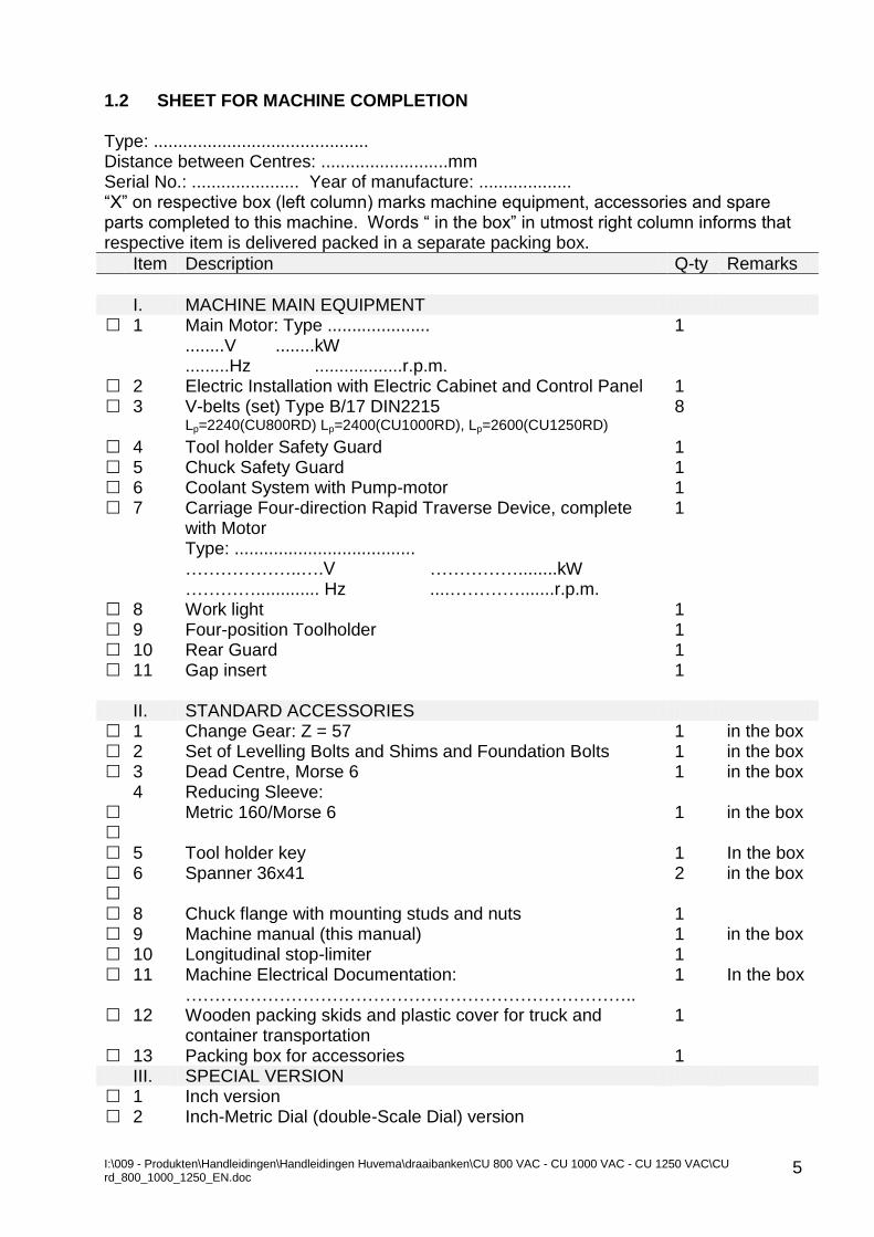
1.2 SHEET FOR MACHINE COMPLETION Type: ............................................ Distance between Centres: ..........................mm Serial No.: ...................... Year of manufacture: ................... “X” on respective box (left column) marks machine equipment, accessories and spare parts completed to this machine. Words “ in the box” in utmost right column informs that respective item is delivered packed in a separate packing box.
Item Description Q-ty Remarks
I. MACHINE MAIN EQUIPMENT • 1 Main Motor: Type ..................... 1 ........V ........kW .........Hz ..................r.p.m. • 2 Electric Installation with Electric Cabinet and Control Panel 1 • 3 V-belts (set) Type B/17 DIN2215 8 Lp=2240(CU800RD) Lp=2400(CU1000RD), Lp=2600(CU1250RD) • 4 Tool holder Safety Guard 1 • 5 Chuck Safety Guard 1 • 6 Coolant System with Pump-motor 1 • 7 Carriage Four-direction Rapid Traverse Device, complete 1 with Motor Type: ..................................... ………………..….V ……………........kW …………............. Hz ....………….......r.p.m. • 8 Work light 1 • 9 Four-position Toolholder 1 • 10 Rear Guard 1 • 11 Gap insert 1 II. STANDARD ACCESSORIES • 1 Change Gear: Z = 57 1 in the box • 2 Set of Levelling Bolts and Shims and Foundation Bolts 1 in the box • 3 Dead Centre, Morse 6 1 in the box 4 Reducing Sleeve: • Metric 160/Morse 6 1 in the box • • 5 Tool holder key 1 In the box • 6 Spanner 36x41 2 in the box • • 8 Chuck flange with mounting studs and nuts 1 • 9 Machine manual (this manual) 1 in the box • 10 Longitudinal stop-limiter 1 • 11 Machine Electrical Documentation: 1 In the box ………………………………………………………………….. • 12 Wooden packing skids and plastic cover for truck and 1 container transportation • 13 Packing box for accessories 1 III. SPECIAL VERSION • 1 Inch version • 2 Inch-Metric Dial (double-Scale Dial) version
I:\009 - Produkten\Handleidingen\Handleidingen Huvema\draaibanken\CU 800 VAC - CU 1000 VAC - CU 1250 VAC\CU rd_800_1000_1250_EN.doc
6
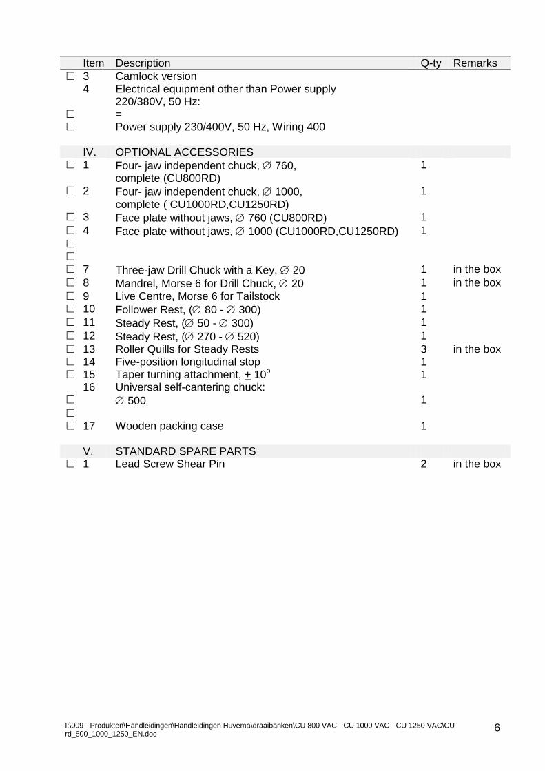
Item Description Q-ty Remarks
• 3 Camlock version 4 Electrical equipment other than Power supply 220/380V, 50 Hz: • = • Power supply 230/400V, 50 Hz, Wiring 400 IV. OPTIONAL ACCESSORIES • 1 Four- jaw independent chuck, 760, 1
complete (CU800RD) • 2 Four- jaw independent chuck, 1000, 1
complete ( CU1000RD,CU1250RD) • 3 Face plate without jaws, 760 (CU800RD) 1
• 4 Face plate without jaws, 1000 (CU1000RD,CU1250RD) 1
• • • 7 Three-jaw Drill Chuck with a Key, 20 1 in the box
• 8 Mandrel, Morse 6 for Drill Chuck, 20 1 in the box
• 9 Live Centre, Morse 6 for Tailstock 1 • 10 Follower Rest, ( 80 - 300) 1
• 11 Steady Rest, ( 50 - 300) 1
• 12 Steady Rest, ( 270 - 520) 1
• 13 Roller Quills for Steady Rests 3 in the box • 14 Five-position longitudinal stop 1 • 15 Taper turning attachment, + 10o 1 16 Universal self-cantering chuck: • 500 1
• • 17 Wooden packing case 1 V. STANDARD SPARE PARTS • 1 Lead Screw Shear Pin 2 in the box
I:\009 - Produkten\Handleidingen\Handleidingen Huvema\draaibanken\CU 800 VAC - CU 1000 VAC - CU 1250 VAC\CU rd_800_1000_1250_EN.doc
7
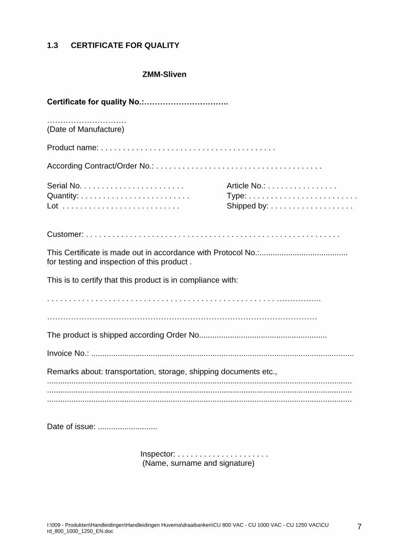
1.3 CERTIFICATE FOR QUALITY
ZMM-Sliven Certificate for quality No.:………………………….. ………………………… (Date of Manufacture) Product name: . . . . . . . . . . . . . . . . . . . . . . . . . . . . . . . . . . . . . . . . According Contract/Order No.: . . . . . . . . . . . . . . . . . . . . . . . . . . . . . . . . . . . . . .
Serial No. . . . . . . . . . . . . . . . . . . . . . . . Article No.: . . . . . . . . . . . . . . . .
Quantity: . . . . . . . . . . . . . . . . . . . . . . . . . Type: . . . . . . . . . . . . . . . . . . . . . . . . .
Lot . . . . . . . . . . . . . . . . . . . . . . . . . . . Shipped by: . . . . . . . . . . . . . . . . . . .
Customer: . . . . . . . . . . . . . . . . . . . . . . . . . . . . . . . . . . . . . . . . . . . . . . . . . . . . . . . . . . This Certificate is made out in accordance with Protocol No.:........................................ for testing and inspection of this product . This is to certify that this product is in compliance with: . . . . . . . . . . . . . . . . . . . . . . . . . . . . . . . . . . . . . . . . . . . . . . . . . . . . …………….. ………………………………………………………………………………………… The product is shipped according Order No.......................................................... Invoice No.: ....................................................................................................................... Remarks about: transportation, storage, shipping documents etc., .......................................................................................................................................... .......................................................................................................................................... .......................................................................................................................................... Date of issue: ...........................
Inspector: . . . . . . . . . . . . . . . . . . . . . (Name, surname and signature)
I:\009 - Produkten\Handleidingen\Handleidingen Huvema\draaibanken\CU 800 VAC - CU 1000 VAC - CU 1250 VAC\CU rd_800_1000_1250_EN.doc
8
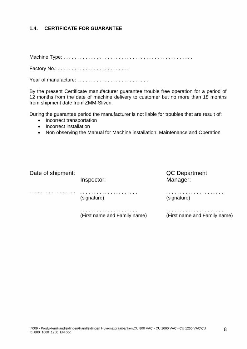
1.4. CERTIFICATE FOR GUARANTEE Machine Type: . . . . . . . . . . . . . . . . . . . . . . . . . . . . . . . . . . . . . . . . . . . . . . . Factory No.: . . . . . . . . . . . . . . . . . . . . . . . . . . Year of manufacture: . . . . . . . . . . . . . . . . . . . . . . . . . . By the present Certificate manufacturer guarantee trouble free operation for a period of 12 months from the date of machine delivery to customer but no more than 18 months from shipment date from ZMM-Sliven. During the guarantee period the manufacturer is not liable for troubles that are result of:
Incorrect transportation
Incorrect installation
Non observing the Manual for Machine installation, Maintenance and Operation
Date of shipment: . . . . . . . . . . . . . . . . .
Inspector: QC Department Manager:
. . . . . . . . . . . . . . . . . . . . . . . . . . . . . . . . . . . . . . . . . . (signature) (signature)
. . . . . . . . . . . . . . . . . . . . . . . . . . . . . . . . . . . . . . . . . . (First name and Family name) (First name and Family name)
I:\009 - Produkten\Handleidingen\Handleidingen Huvema\draaibanken\CU 800 VAC - CU 1000 VAC - CU 1250 VAC\CU rd_800_1000_1250_EN.doc
9
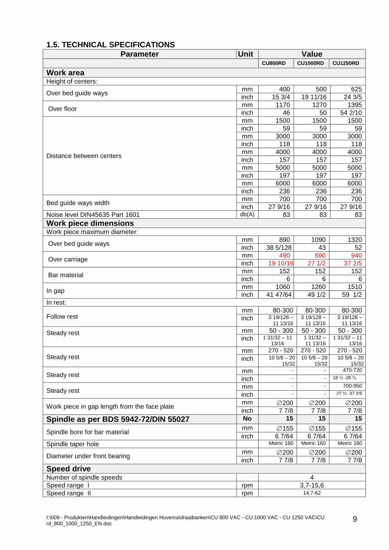
1.5. TECHNICAL SPECIFICATIONS
Parameter Unit Value
CU800RD CU1000RD CU1250RD
Work area Height of centers:
Over bed guide ways mm 400 500 625
inch 15 3/4 19 11/16 24 3/5
Over floor mm 1170 1270 1395
inch 46 50 54 2/10
Distance between centers
mm 1500 1500 1500
inch 59 59 59
mm 3000 3000 3000
inch 118 118 118
mm 4000 4000 4000
inch 157 157 157
mm 5000 5000 5000
inch 197 197 197
mm 6000 6000 6000
inch 236 236 236
Bed guide ways width mm 700 700 700
inch 27 9/16 27 9/16 27 9/16
Noise level DIN45635 Part 1601 db(A) 83 83 83
Work piece dimensions Work piece maximum diameter:
Over bed guide ways mm 890 1090 1320
inch 38 5/128 43 52
Over carriage mm 490 690 940
inch 19 10/16 27 1/2 37 2/5
Bar material mm 152 152 152
inch 6 6 6
In gap mm 1060 1260 1510
inch 41 47/64 49 1/2 59 1/2
In rest:
Follow rest mm 80-300 80-300 80-300
inch 3 19/128 – 11 13/16
3 19/128 – 11 13/16
3 19/128 – 11 13/16
Steady rest
mm 50 - 300 50 - 300 50 - 300
inch 1 31/32 – 11 13/16
1 31/32 – 11 13/16
1 31/32 – 11 13/16
Steady rest mm 270 - 520 270 - 520 270 - 520
inch 10 5/8 – 20 15/32
10 5/8 – 20 15/32
10 5/8 – 20 15/32
Steady rest mm - - 470-720
inch - - 18 ½ -28 ⅓
Steady rest mm - - 700-950
inch - - 27 ½ -37 2/5
Work piece in gap length from the face plate mm 200 200 200
inch 7 7/8 7 7/8 7 7/8
Spindle as per BDS 5942-72/DIN 55027 No 15 15 15
Spindle bore for bar material mm 155 155 155
inch 6 7/64 6 7/64 6 7/64 Spindle taper hole Metric 160 Metric 160 Metric 160
Diameter under front bearing mm 200 200 200
inch 7 7/8 7 7/8 7 7/8
Speed drive Number of spindle speeds 4
Speed range I rpm 3,7-15,6
Speed range II rpm 14,7-62
I:\009 - Produkten\Handleidingen\Handleidingen Huvema\draaibanken\CU 800 VAC - CU 1000 VAC - CU 1250 VAC\CU rd_800_1000_1250_EN.doc
10
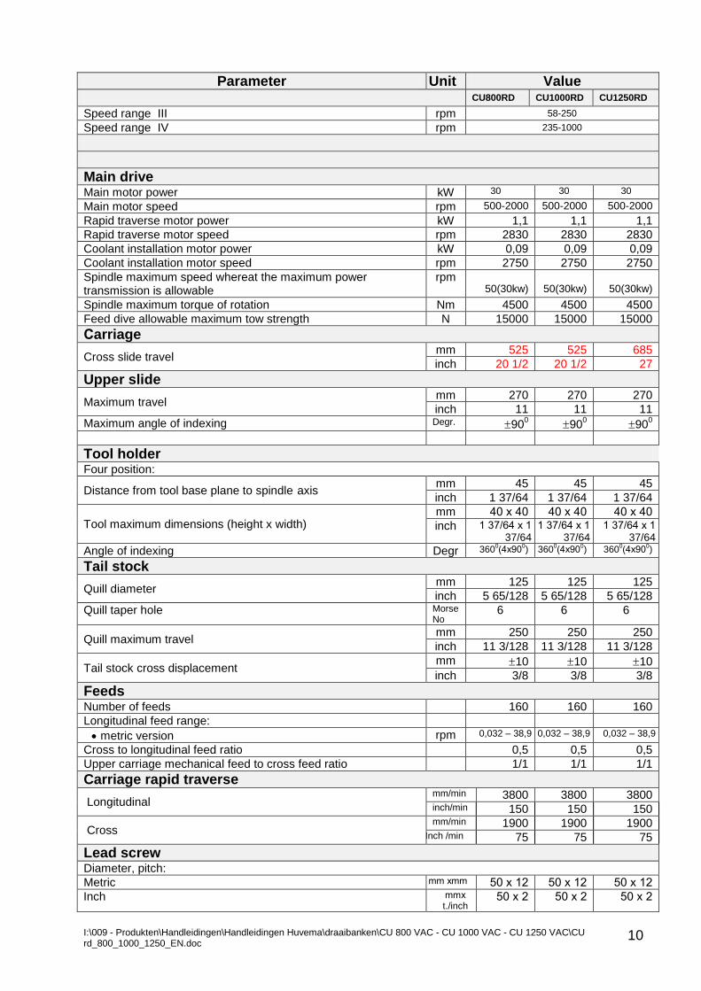
Parameter Unit Value
CU800RD CU1000RD CU1250RD
Speed range III rpm 58-250
Speed range IV rpm 235-1000
Main drive Main motor power kW 30 30 30
Main motor speed rpm 500-2000 500-2000 500-2000
Rapid traverse motor power kW 1,1 1,1 1,1
Rapid traverse motor speed rpm 2830 2830 2830
Coolant installation motor power kW 0,09 0,09 0,09
Coolant installation motor speed rpm 2750 2750 2750
Spindle maximum speed whereat the maximum power transmission is allowable
rpm 50(30kw)
50(30kw)
50(30kw)
Spindle maximum torque of rotation Nm 4500 4500 4500
Feed dive allowable maximum tow strength N 15000 15000 15000
Сarriage
Cross slide travel mm 525 525 685
inch 20 1/2 20 1/2 27
Upper slide
Maximum travel mm 270 270 270
inch 11 11 11
Maximum angle of indexing Degr. 900 90
0 90
0
Tool holder Four position:
Distance from tool base plane to spindle axis mm 45 45 45
inch 1 37/64 1 37/64 1 37/64
Tool maximum dimensions (height x width) mm 40 х 40 40 х 40 40 х 40
inch 1 37/64 х 1 37/64
1 37/64 х 1 37/64
1 37/64 х 1 37/64
Angle of indexing Degr 3600(4х90
0) 360
0(4х90
0) 360
0(4х90
0)
Tail stock
Quill diameter mm 125 125 125
inch 5 65/128 5 65/128 5 65/128
Quill taper hole Morse No
6 6 6
Quill maximum travel mm 250 250 250
inch 11 3/128 11 3/128 11 3/128
Tail stock cross displacement mm 10 10 10
inch 3/8 3/8 3/8
Feeds Number of feeds 160 160 160
Longitudinal feed range:
metric version rpm 0,032 – 38,9 0,032 – 38,9 0,032 – 38,9
Cross to longitudinal feed ratio 0,5 0,5 0,5
Upper carriage mechanical feed to cross feed ratio 1/1 1/1 1/1
Carriage rapid traverse
Longitudinal mm/min 3800 3800 3800 inch/min 150 150 150
Cross mm/min 1900 1900 1900
iInch /min 75 75 75
Lead screw Diameter, pitch:
Metric mm хmm 50 х 12 50 х 12 50 х 12
Inch mmх t./inch
50 х 2 50 х 2 50 х 2
I:\009 - Produkten\Handleidingen\Handleidingen Huvema\draaibanken\CU 800 VAC - CU 1000 VAC - CU 1250 VAC\CU rd_800_1000_1250_EN.doc
11
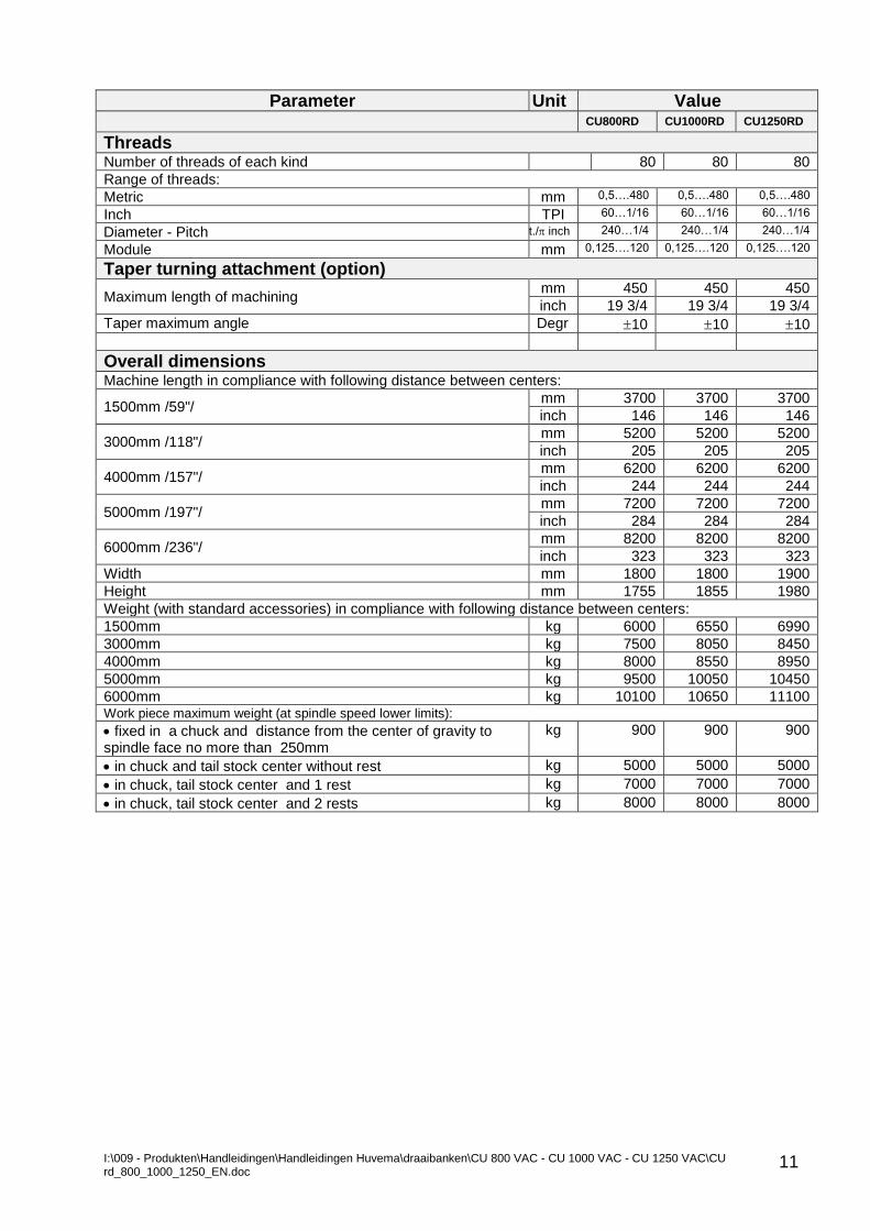
Parameter Unit Value
CU800RD CU1000RD CU1250RD
Threads Number of threads of each kind 80 80 80
Range of threads:
Metric mm 0,5….480 0,5….480 0,5….480
Inch TPI 60…1/16 60…1/16 60…1/16
Diameter - Pitch t./ inch 240…1/4 240…1/4 240…1/4
Module mm 0,125….120 0,125….120 0,125….120
Taper turning attachment (option)
Maximum length of machining mm 450 450 450
inch 19 3/4 19 3/4 19 3/4
Taper maximum angle Degr 10 10 10
Overall dimensions Machine length in compliance with following distance between centers:
1500mm /59"/ mm 3700 3700 3700
inch 146 146 146
3000mm /118"/ mm 5200 5200 5200
inch 205 205 205
4000mm /157"/ mm 6200 6200 6200
inch 244 244 244
5000mm /197"/ mm 7200 7200 7200
inch 284 284 284
6000mm /236"/ mm 8200 8200 8200
inch 323 323 323
Width mm 1800 1800 1900
Height mm 1755 1855 1980
Weight (with standard accessories) in compliance with following distance between centers:
1500mm kg 6000 6550 6990
3000mm kg 7500 8050 8450
4000mm kg 8000 8550 8950
5000mm kg 9500 10050 10450
6000mm kg 10100 10650 11100 Work piece maximum weight (at spindle speed lower limits):
fixed in a chuck and distance from the center of gravity to spindle face no more than 250mm
kg 900 900 900
in chuck and tail stock center without rest kg 5000 5000 5000
in chuck, tail stock center and 1 rest kg 7000 7000 7000
in chuck, tail stock center and 2 rests kg 8000 8000 8000
I:\009 - Produkten\Handleidingen\Handleidingen Huvema\draaibanken\CU 800 VAC - CU 1000 VAC - CU 1250 VAC\CU rd_800_1000_1250_EN.doc
12
2. SAFETY OPERATION WITH THE MACHINE
This section contains general safety precautions, which have to be observed when install, operate and maintain the machine. It is of great importance all persons who install, operate and maintain the machine to read and understand these precautions and the instruction for putting the machine into operation before attempt any work and this manual to be always at their disposal.
It is important to observe these general precautions and all other instructions and signs containing in this manual. 2.1 SAFETY PRECAUTION SIGNS AND LABELS IN THE INSTRUCTION AND ON THE MACHINE
Warning: This word appeared in the instruction where any failure to observe a safety
precaution may be hazardous for the operator and machine functioning. Safety precautions directly on the machine also have to be observed and kept
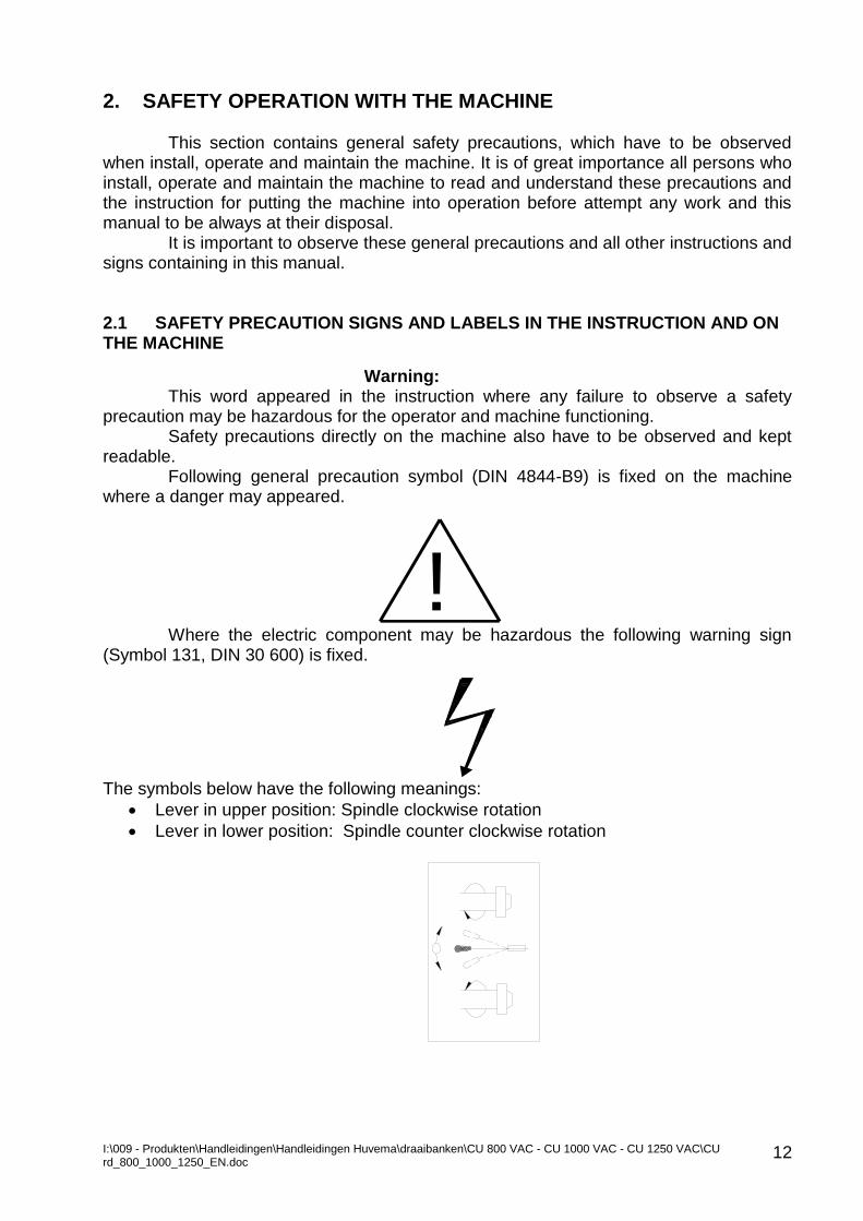
readable. Following general precaution symbol (DIN 4844-B9) is fixed on the machine
where a danger may appeared.
Where the electric component may be hazardous the following warning sign (Symbol 131, DIN 30 600) is fixed.
The symbols below have the following meanings:
Lever in upper position: Spindle clockwise rotation
Lever in lower position: Spindle counter clockwise rotation
!
I:\009 - Produkten\Handleidingen\Handleidingen Huvema\draaibanken\CU 800 VAC - CU 1000 VAC - CU 1250 VAC\CU rd_800_1000_1250_EN.doc
13
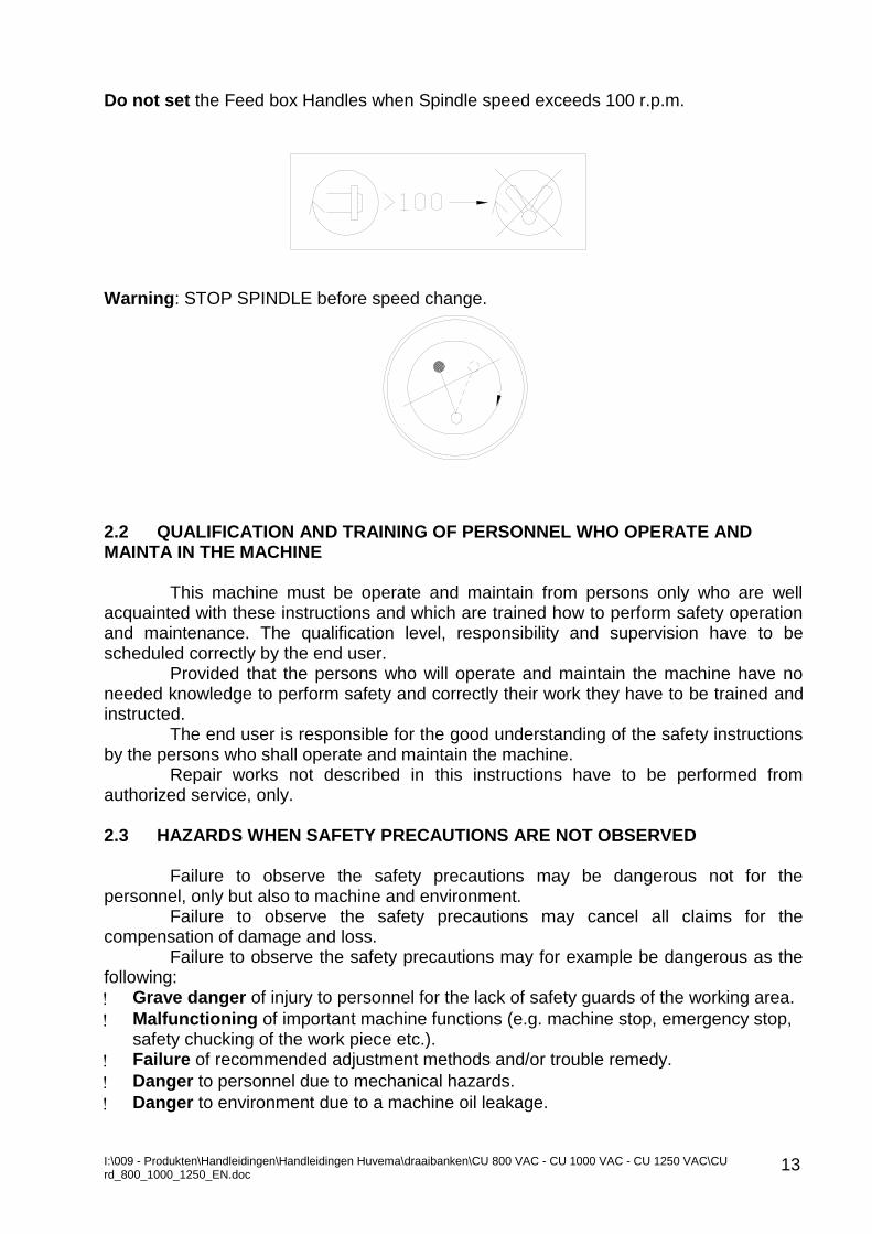
Do not set the Feed box Handles when Spindle speed exceeds 100 r.p.m.
Warning: STOP SPINDLE before speed change.
2.2 QUALIFICATION AND TRAINING OF PERSONNEL WHO OPERATE AND MAINTA IN THE MACHINE
This machine must be operate and maintain from persons only who are well acquainted with these instructions and which are trained how to perform safety operation and maintenance. The qualification level, responsibility and supervision have to be scheduled correctly by the end user.
Provided that the persons who will operate and maintain the machine have no needed knowledge to perform safety and correctly their work they have to be trained and instructed.
The end user is responsible for the good understanding of the safety instructions by the persons who shall operate and maintain the machine.
Repair works not described in this instructions have to be performed from authorized service, only. 2.3 HAZARDS WHEN SAFETY PRECAUTIONS ARE NOT OBSERVED
Failure to observe the safety precautions may be dangerous not for the personnel, only but also to machine and environment.
Failure to observe the safety precautions may cancel all claims for the compensation of damage and loss.
Failure to observe the safety precautions may for example be dangerous as the following:
Grave danger of injury to personnel for the lack of safety guards of the working area.
Malfunctioning of important machine functions (e.g. machine stop, emergency stop, safety chucking of the work piece etc.).
Failure of recommended adjustment methods and/or trouble remedy.
Danger to personnel due to mechanical hazards.
Danger to environment due to a machine oil leakage.
I:\009 - Produkten\Handleidingen\Handleidingen Huvema\draaibanken\CU 800 VAC - CU 1000 VAC - CU 1250 VAC\CU rd_800_1000_1250_EN.doc
14
2.4 OPERATIONS IN COMPLIANCE WITH THE SAFETY PRECAUTIONS It is important to observe all safety instructions containing in this manual as well as company and national regulations. 2.5 SAFETY PRECAUTIONS FOR THE USER 1. You have to work only with machines you are entitled and duly instructed about their functioning and safety operation. 2. Machines have to be used for applications they are intended only observing the instructions given. 3. Before putting a machine into operation check all machine safety devices for their existence and correct adjustment. 4. Before start operation perform tests about the correct functioning of all safety devices. 5. Never modify, isolate or make malfunctioning the safety devises. 6. Stop and switch off the machine when it should not be used. 7. When the machine is in trouble never attempt to restart any of its functions by the existing limit switches (particularly on automatic and mechanical devices). 8. Never eliminate chips by hand. Always use hand tools specially designed for this procedure. Always use hand tools, which are in good safety condition to perform any working procedure on the machine. 9. Keep the tools, cloth pieces for cleaning and all machine accessories in specified for this purpose places. Never keep them into the machine bed or on the machine. 10. Keep the working area around the machine in good order and free from chips, oils or greases. Do not clutter the area with unnecessary articles. The materials and tools should be arranged so that area is clean and free enabling the operator and/or service engineer to perform their jobs without any hazard. 11. When operate the machine with coolant ON always protect your hands by respective skin protections available in the factory or observe coolant manufacturer safety precautions. Never clean hands with coolant. 12. In case of a machine trouble the authorized foreman should be informed immediately. Do not attempt any unauthorized repair works. 13. Put on eye protection when chips or dust during machining cutting operations may reach your face. 14. It is prohibited to operate machine tools having rotating spindles and chip removal operations with gloves. In exclusive cases (e.g. when the coolant liquid is handled) PVC gloves may be used if it is allowed by the local regulations. 15. Long hair unprotected by working cap is forbidden as well as wear of watches, rings etc. 16. Always wear closed safety shoes in compliance with the safety requirements of the working area. Open or broken shoes are prohibited. It is recommend to wear closed anti-shock shoes. 17. Wear tight to your body-working suit and keep it in good order. Any loose part of the working suit is dangerous. If any, set it tight before work. 18. If the operation of respective machines featuring by inherent safety precautions it is of great importance to understand and observe the precautions.
I:\009 - Produkten\Handleidingen\Handleidingen Huvema\draaibanken\CU 800 VAC - CU 1000 VAC - CU 1250 VAC\CU rd_800_1000_1250_EN.doc
15
2.6 SAFETY PRECAUTIONS FOR THE INSTALLATION, CHECKS AND MAINTENANCE
The user should arrange installation, checks and maintenance works to be
performed by authorized and qualified persons who have to be informed and trained. Maintenance and checks works should be performed when the machine is shut
down, only. Described in this manual shut down procedures should be followed. When a
maintenance procedure require a machine part to be lifted ensure its safety supporting by using reliable means of supporting.
When a machine parts have to be replaced use reliable tools and gloves on. Carefully clean oil and grease from the parts.
Reassemble of parts and units of the machine should be performed correctly in compliance with safety and reliable functioning of the machine.
When the machine has to be restarted the procedures described in Section 7.0 “Operating the Machine” and Section 8.0 “Adjustments” should be followed. 2.7 UNAUTHORIZED MODIFICATIONS AND PARTS MAKING
Alterations or modifications of parts and/or units of the machine are allowed by a written consent of the manufacturer, only. Using of original spare parts is only safety.
Using of another spare parts may void manufacturer obligation about resulted consequences. 2.8 UNWARRANTED OPERATIONS
Operational safety of the machine delivered is warranted provided that it is used in compliance of its application, only as specified Item 4.1 “Application”.
Never exceed the limit values stated in this manual. It is prohibited:
Jerk reversing of the main spindle direction of rotation when rotates at higher speed and heavy work pieces chucked.
Positioning by the carriage rapid traverse in adjacency of the Gearbox and tailstock.
Using the rapid traverse as a machining feed rate.
Using the machine for straightening of work pieces without uniform section and/or straight axis
2.9 DIRECTIONS AND RECOMMENDATIONS
The maximum operational safety is warranted when the following safety precautions are observed:
Do not reach your hands to machine working area or any machine parts in motion.
Do not remove any safety guards or devices.
Do not jump over the safety guards or modify them.
Damaged safety guard should be immediately replaced with new or repaired.
Do not lift any objects over 15 kg without respective lifting device. The standard objects over above weight are marked, respectively.
Before attempt any maintenance work disconnect machine by the main power disconnect or and take safety measures against switching on.
All latest national safety codes and regulations issued in your country for you should be followed. Provided that a repair work or adjustment require main power disconnect
I:\009 - Produkten\Handleidingen\Handleidingen Huvema\draaibanken\CU 800 VAC - CU 1000 VAC - CU 1250 VAC\CU rd_800_1000_1250_EN.doc
16
or switched On this work must be performed from qualified and authorized personnel only who on the back ground of their educational knowledge and qualification can understand and estimate the possible hazards.
Changes on the machine (e.g. installation of extra accessories) may be performed provided that these changes do not infringe related safety precautions. The user is responsible for the changes.
In accordance with machining operations by using installed rests periodically lubricate between the rests supporting points and the work piece.
Observe the machine coolant basin for over fill by chips and coolant, which may splash the machine and environment.
Take measures and use specified equipment when replace or refill lubricants and/or coolant so that no splashing may occur.
When work pieces are machined on the machine It is recommended as following:
Use tools of specified form and cross section ensuring chips braking and eliminating.
Use specified coolant and machine splashguards in working condition.
Select an optimum coolant flow rate so that no excessive evaporation may occurs.
Support the work piece safety (e.g. using rests).
Select optimum cutting conditions, which ensure stable running of the machine without any noise and vibration machining of the work piece.
When a long bar material is to be machined (through the spindle hole) use frame with rollers to support the bar end protruding outside the machine and safety guards.
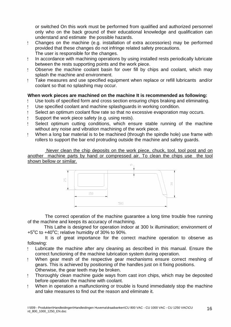
Never clean the chip deposits on the work piece, chuck, tool, tool post and on
another machine parts by hand or compressed air. To clean the chips use the tool shown bellow or similar.
The correct operation of the machine guarantee a long time trouble free running
of the machine and keeps its accuracy of machining. This Lathe is designed for operation indoor at 300 lx illumination; environment of
+5oC to +40oC; relative humidity of 30% to 90%. It is of great importance for the correct machine operation to observe as
following:
Lubricate the machine after any cleaning as described in this manual. Ensure the correct functioning of the machine lubrication system during operation.
When gear mesh of the respective gear mechanisms ensure correct meshing of gears. This is achieved by positioning of the handles just on it fixing positions. Otherwise, the gear teeth may be broken.
Thoroughly clean machine guide ways from cast iron chips, which may be deposited before operation the machine with coolant.
When in operation a malfunctioning or trouble is found immediately stop the machine and take measures to find out the reason and eliminate it.

I:\009 - Produkten\Handleidingen\Handleidingen Huvema\draaibanken\CU 800 VAC - CU 1000 VAC - CU 1250 VAC\CU rd_800_1000_1250_EN.doc
17
Before handling with chucking device (e.g. chuck, face plate or driving plate with lathe dog) stop machine and wait for spindle complete standstill.
It is strictly prohibited to operate the machine with dead centre on the
machine tailstock.
I:\009 - Produkten\Handleidingen\Handleidingen Huvema\draaibanken\CU 800 VAC - CU 1000 VAC - CU 1250 VAC\CU rd_800_1000_1250_EN.doc
18
3.0 MACHINE TRANSPORTATION AND INSTALLATION 3.1 TRANSPORTATION
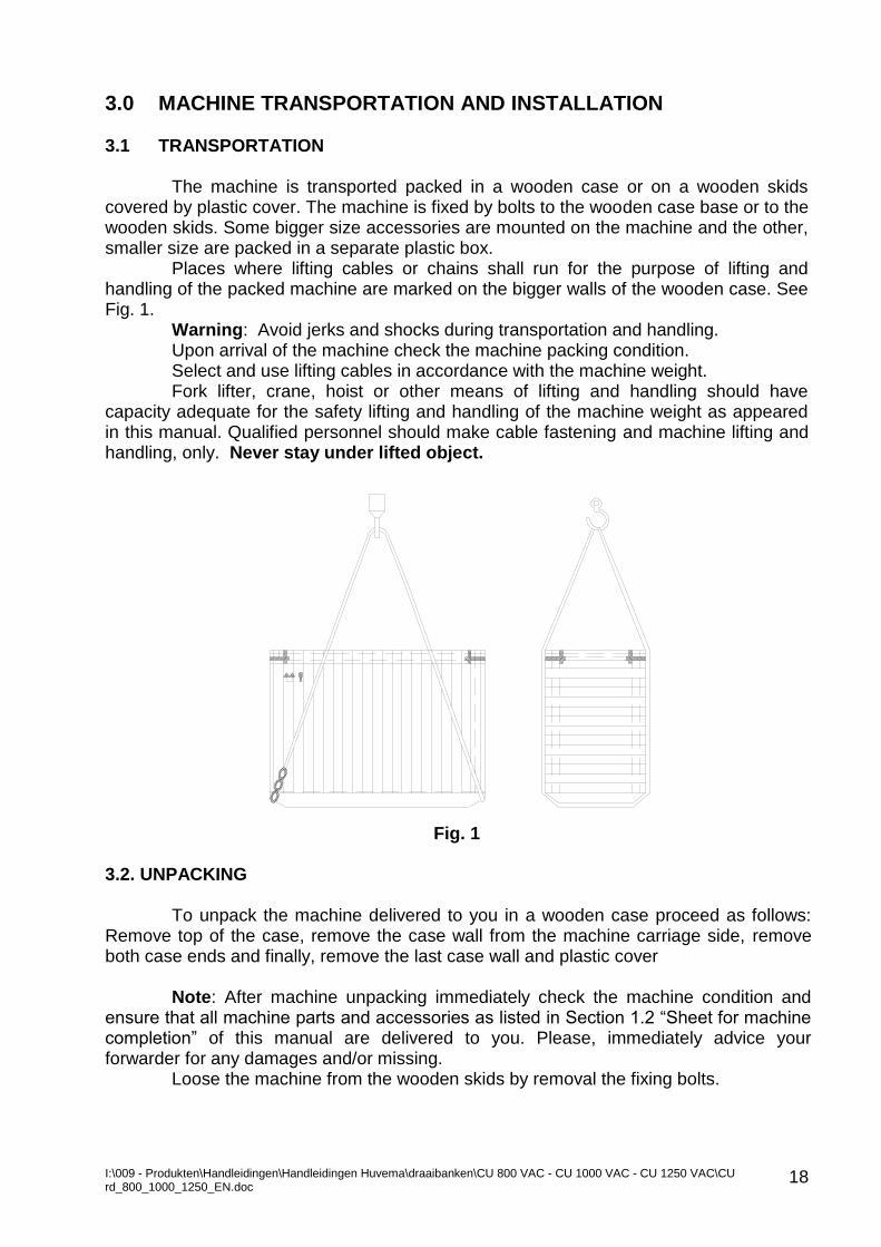
The machine is transported packed in a wooden case or on a wooden skids covered by plastic cover. The machine is fixed by bolts to the wooden case base or to the wooden skids. Some bigger size accessories are mounted on the machine and the other, smaller size are packed in a separate plastic box.
Places where lifting cables or chains shall run for the purpose of lifting and handling of the packed machine are marked on the bigger walls of the wooden case. See Fig. 1.
Warning: Avoid jerks and shocks during transportation and handling. Upon arrival of the machine check the machine packing condition. Select and use lifting cables in accordance with the machine weight. Fork lifter, crane, hoist or other means of lifting and handling should have
capacity adequate for the safety lifting and handling of the machine weight as appeared in this manual. Qualified personnel should make cable fastening and machine lifting and handling, only. Never stay under lifted object.
Fig. 1
3.2. UNPACKING
To unpack the machine delivered to you in a wooden case proceed as follows: Remove top of the case, remove the case wall from the machine carriage side, remove both case ends and finally, remove the last case wall and plastic cover
Note: After machine unpacking immediately check the machine condition and
ensure that all machine parts and accessories as listed in Section 1.2 “Sheet for machine completion” of this manual are delivered to you. Please, immediately advice your forwarder for any damages and/or missing.
Loose the machine from the wooden skids by removal the fixing bolts.
I:\009 - Produkten\Handleidingen\Handleidingen Huvema\draaibanken\CU 800 VAC - CU 1000 VAC - CU 1250 VAC\CU rd_800_1000_1250_EN.doc
19
3.3 MACHINE LIFTING AND DISPLACEMENT
Lifting and conveying the machine unpacked from one place to another normally is performed using a crane or manually by levers and pipes put under the machine base and used as a rollers. In both methods avoid shocks and jerks, which may damage the machine and/or affect its accuracy.
Before handling the machine by fork lifters ensures that machine tailstock, rests,
carriage and other movable machine parts are fixed to machine. Fix the machine tailstock at the bed guide ways end so that the tailstock hand wheel aligned with the bed end.
The follower rest is fixed adjacent to the tailstock; the carriage is positioned in the middle of the bed.
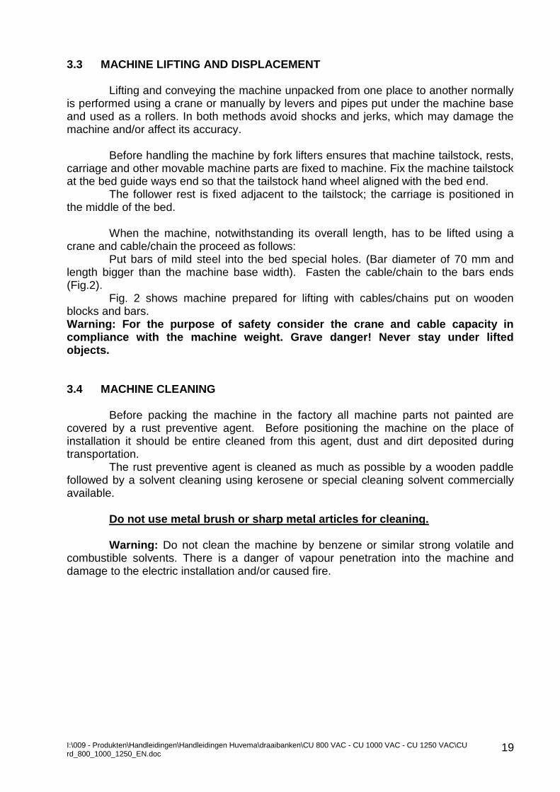
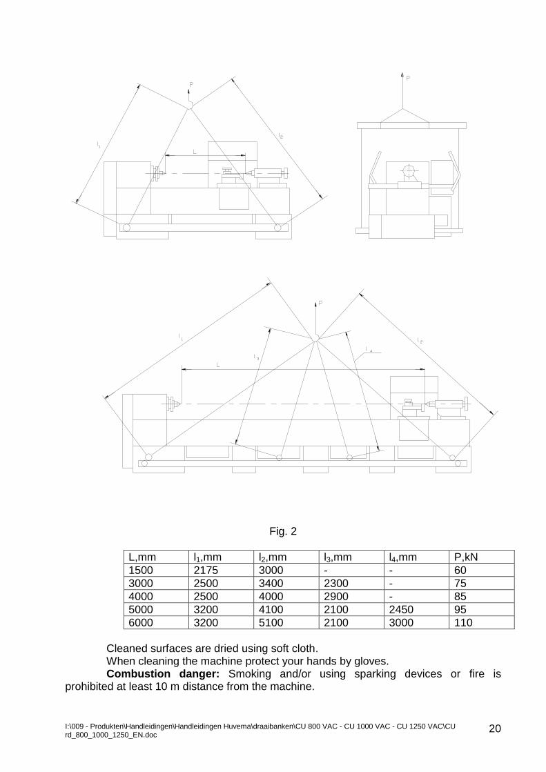
When the machine, notwithstanding its overall length, has to be lifted using a
crane and cable/chain the proceed as follows: Put bars of mild steel into the bed special holes. (Bar diameter of 70 mm and
length bigger than the machine base width). Fasten the cable/chain to the bars ends (Fig.2).
Fig. 2 shows machine prepared for lifting with cables/chains put on wooden blocks and bars. Warning: For the purpose of safety consider the crane and cable capacity in compliance with the machine weight. Grave danger! Never stay under lifted objects. 3.4 MACHINE CLEANING
Before packing the machine in the factory all machine parts not painted are
covered by a rust preventive agent. Before positioning the machine on the place of installation it should be entire cleaned from this agent, dust and dirt deposited during transportation.
The rust preventive agent is cleaned as much as possible by a wooden paddle followed by a solvent cleaning using kerosene or special cleaning solvent commercially available.
Do not use metal brush or sharp metal articles for cleaning. Warning: Do not clean the machine by benzene or similar strong volatile and
combustible solvents. There is a danger of vapour penetration into the machine and damage to the electric installation and/or caused fire.
I:\009 - Produkten\Handleidingen\Handleidingen Huvema\draaibanken\CU 800 VAC - CU 1000 VAC - CU 1250 VAC\CU rd_800_1000_1250_EN.doc
20
Fig. 2
L,mm l1,mm l2,mm l3,mm l4,mm P,kN
1500 2175 3000 - - 60
3000 2500 3400 2300 - 75
4000 2500 4000 2900 - 85
5000 3200 4100 2100 2450 95
6000 3200 5100 2100 3000 110
Cleaned surfaces are dried using soft cloth. When cleaning the machine protect your hands by gloves. Combustion danger: Smoking and/or using sparking devices or fire is
prohibited at least 10 m distance from the machine.
I:\009 - Produkten\Handleidingen\Handleidingen Huvema\draaibanken\CU 800 VAC - CU 1000 VAC - CU 1250 VAC\CU rd_800_1000_1250_EN.doc
21
3.5 POSITIONING, FOUNDATION AND LEVELLING
It is important for the trouble free operation and machining accuracy of the machine delivered to you to perform correct positioning and levelling on the reliable foundation.
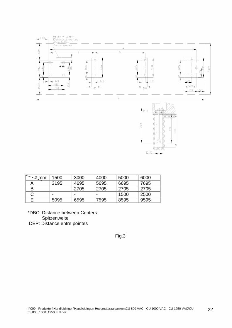
The machine foundation is made of concrete in accordance with machine layout, shown on Fig.3. The outer dotted line shows the area that is required for normal machine operation and maintenance.
The foundation is made with a thickness at least 350 mm. The dimensions of the holes for foundation bolts are: 100 x 100 x 350 mm.
When the machine installation place is near to equipment which is a source of strong vibrations or shocks (e.g. presses, hammers etc.,) the foundation should be surrounded by a reliable vibration absorbing material.
To make correct machine levelling proceed as following:
When the foundation is enough hardened place the steel levelling plates delivered to you near the holes and position them in according with machine levelling screws alignment.
Position the machine on the foundation place so that its levelling screws step on the levelling steel plates and the foundation bolts go into the foundation holes.
Use level gauge of an accuracy of 0,02/1000 mm to perform initial machine horizontal levelling by adjusting the levelling screws.
Check the machine bed guide ways horizontal levelling, longitudinal and crosswise to machine axis according the values shown in the machine certificate for geometrical accuracy.
After final hardening of the foundation concrete fill the foundation holes and the Gap between the foundation and machine base with concrete mixture cement: sand (1:3).After concrete hardening nuts of the levelling bolts should be tighten uniformly.
Check the machine levelling again and adjust the levelling by the levelling screws if necessary.
It is recommended that installed on foundation block machine to be checked for correct levelling both directions within the horizontal plane any three months period.
Following this recommendation will maintain the machine accura
I:\009 - Produkten\Handleidingen\Handleidingen Huvema\draaibanken\CU 800 VAC - CU 1000 VAC - CU 1250 VAC\CU rd_800_1000_1250_EN.doc
22
* mm 1500 3000 4000 5000 6000
А 3195 4695 5695 6695 7695
В - 2705 2705 2705 2705
C - - - 1500 2500
E 5095 6595 7595 8595 9595
*DBC: Distance between Centers Spitzenweite DEP: Distance entre pointes
Fig.3
I:\009 - Produkten\Handleidingen\Handleidingen Huvema\draaibanken\CU 800 VAC - CU 1000 VAC - CU 1250 VAC\CU rd_800_1000_1250_EN.doc
23
3.6 CONNECTION THE MACHINE TO MAINS
Warning: Machine connection to mains should be performed by an authorized qualified electrician after reading and understanding Section 9.0 of this manual.
Following precautions should be compulsorily observed when the machine is connected to mains:
Verify that power supply data of the machine comply with the mains.
Machine Connection to mains should be made via delay-action fuse before machine electric cabinet according the values containing in “Machine Electric Documentation” E100., attached to this manual.
The power supply cable should be of a cross section that complies with the machine power and distance from machine to mains electric cabinet “Machine Electric Documentation” E100, attached to this manual.
For safety the power supply cable to machine electric cabinet entrance should be enclosed in a suitable rigid duct thus eliminating any cable damage, which may lead to electric hazard.
To ensure correct machine-grounding usage of four-core cable is compulsory.
This particularly valid for networks with direct star ground. For countries, with low voltage networks and isolated-star, machine ground should be in compliance with the national standards.
Wiring to the ground/neutral of networks with isolated star is made using the input ground/neutral plate where the input ground/neutral wire is to be connected.
Terminal connection should be as tighten as possible so that no loose of the terminal connection may occur.
Before switch on the power supply to machine carefully check the condition of the machine electric installation after transportation: cables, electric cabinet, control devices, etc. Electric device found damaged during transportation should be repaired or replaced. Please, contact your supplier.
When moisten motor is found and its insulation resistance is below the specified value ensure to dry the motor so that the motor insulation recover its specified value.
Upon switching on the power supply check for the machine body ground leakage.
Proceed by numerous functional tests of the machine electric controls as described bellow.
Machine function test
Machine function is tested in accordance with the principle electric diagram. The power is supplied to machine by the Main switch QS on the machine electric
cabinet. When the power is switch ON indicator lamp HL on the control panel goes on. Push button SB4 serves for machine Main drive motor start. Two-position (ON/OFF) selector Switch SB6 serves for coolant pump motor start
and stop. Rapid traverse motor starts when Push button SB5 is pressed and stops when
depressed. The Work light is switched on and Off by Switch SB9.
I:\009 - Produkten\Handleidingen\Handleidingen Huvema\draaibanken\CU 800 VAC - CU 1000 VAC - CU 1250 VAC\CU rd_800_1000_1250_EN.doc
24
3.7 PUTTING THE MACHINE INTO OPERATION
Before initial putting into operation machine should be cleaned again. The oil level in Gearbox and Apron should be checked and if necessary filled in compliance with the instructions under Section 6. Start up procedure:
Manually check all machine units’ motion. The motion should be easy and
Without fail. Also, check machine controls functioning.
Fill up the Coolant tank with coolant liquid. After one hour of operation check oil level of the respective boxes and fill if
necessary. After two shifts of machine operation under load check drive belts tensioning.
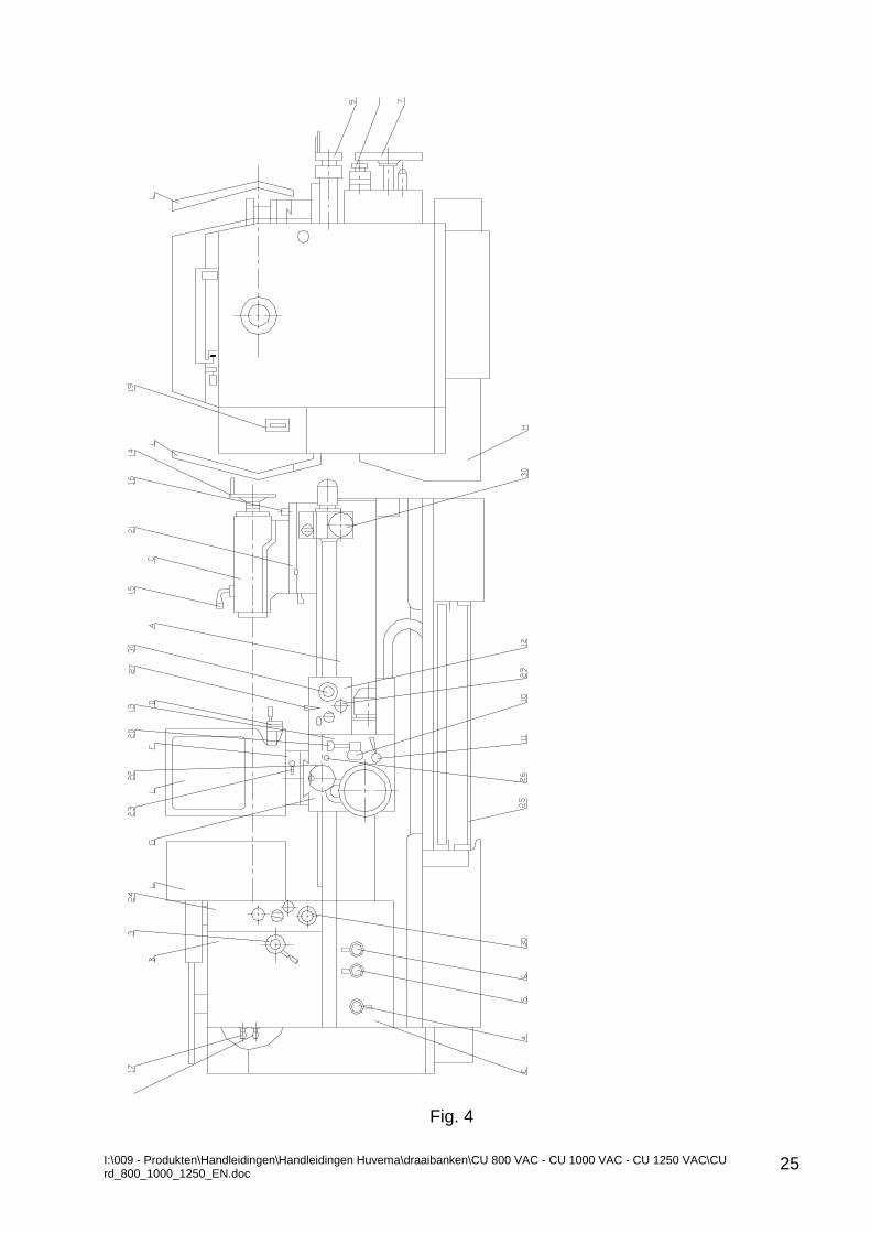
Switch On the Main switch, Item 19, Fig.4 to supply the machine electric cabinet. Lamp indicator on the cabinet goes on indicating that the cabinet is live.
Press Main motor Start Push button 29. Provided that the Drive pulleys direction of rotation is not correct change two of
the input phases across input terminals. Check Drive belts tensioning and adjust if necessary.
Run the Spindle and Carriage all speeds and directions in a sequence. Next section describes the operating procedures. Note: An Emergency Stop pedal 25, Fig. 4 is available as an option, only. Warning: Change speed when machine is standstill, only. Feed change is allowable at Spindle speeds up to 100 r.p.m. Then, check the Coolant system functioning. After one hour of operation check oil level of the respective boxes and fill if necessary. After two shifts of machine operation under load check drive belts tensioning.
I:\009 - Produkten\Handleidingen\Handleidingen Huvema\draaibanken\CU 800 VAC - CU 1000 VAC - CU 1250 VAC\CU rd_800_1000_1250_EN.doc
25
Fig. 4
I:\009 - Produkten\Handleidingen\Handleidingen Huvema\draaibanken\CU 800 VAC - CU 1000 VAC - CU 1250 VAC\CU rd_800_1000_1250_EN.doc
26
4. ТECHNICAL DESCRIPTION
The machine is intended for indoor operation of temperature environment +5oC to +40oC and 300 lx illuminations. 4.1 FIELD OF APPLICATION
The Lathe machines TUS800, TUS1000 and TUS1000 are intended for
mechanical machining of internal and external surfaces of rotating steel, cast iron, non-ferrous and plastic work pieces.
Machining of taper surfaces and drilling operation are also possible with these machines.
For the work piece maximum weight see Section 1.5. Warning: Use these machines in accordance with their application, only.
Any usage of these machines under cutting conditions, chucking devices and machining of materials not mentioned in this manual may be hazardous to personnel and machine itself. Modification and alteration of any machine part or unit are prohibited. 4.2 MACHINE MAIN PARTS Fig. 4 shows machine main parts.
Pos. Part Description
A Bed
B Gearbox
C Tailstock
D Apron
E Feed Box
F Lower Carriage
G Upper Carriage
H Drive
K Coolant System
L Guards
* Position K not shown on Fig. 4.

I:\009 - Produkten\Handleidingen\Handleidingen Huvema\draaibanken\CU 800 VAC - CU 1000 VAC - CU 1250 VAC\CU rd_800_1000_1250_EN.doc
27
4.3 MACHINE CONTROLS Fig. 4 shows machine controls
Pos. Machine Controls
3 Speed range select handle
4 Multiplication mechanism shift handle
5 Selection mechanism shift handle
6 Distributing mechanism shift handle
7 Hand wheel for manual movement of the longitudinal carriage
8 Read out dial for longitudinal carriage
9 Cross carriage handle and dial
10 Longitudinal and crosswise motorised motion control ON handle
11 Nut engagement handle
12 Control panel
13 Compound rest handle and dial
14 Tailstock quill travel hand wheel
15 Tailstock clamp handle
16 Tailstock fixing Bolt
17 Normal and enhanced thread pitch select handle
18 Left hand thread and right hand thread select handle
19 Electric supply main switch for power supply
20 Rapid traverse control push button
21 Tailstock travel control panel
22 Upper carriage motorized motion control handle
23 Upper carriage motorized motion control handle
24 Control Panel
25 Emergency Stop pedal
26 Guide ways lubrication knob
27 Joystick for setting motor direction of rotation
29 Push buttons for main motor, work light and coolant installation control
30 Emergency push buttons
4.4 MACHINE GEOMETRICAL ACCURACY
The Machine Geometrical Accuracy is in compliance with the requirements for acceptance of Standard:
DIN 8607 Lathes of Normal Accuracy
Swing over 800mm to 1600 mm Acceptance Conditions
Protocol for the test results of this machine attached to this manual.
I:\009 - Produkten\Handleidingen\Handleidingen Huvema\draaibanken\CU 800 VAC - CU 1000 VAC - CU 1250 VAC\CU rd_800_1000_1250_EN.doc
28
5.0 MACHINE MAIN PARTS DESCRIPTION 5.1 BED (FIG. 4,POS. A)
Bed is the base part of the machine. A Gap bed is provided for Machines of 1500mm, 3000mm, 4000mm, 5000mm and 6000mm DBC (Distance Between Centres).
For machine of 3000 mm DBC an additional middle foot is provided for rigidity. For machine of 5000mm DBC and 6000mm DBC additional two middle feet are
provided for rigidity. The bed and feet are made of cast iron and shaped so that coolant liquid and
chips are effectively directed to the collecting pan. The bed guide ways for the carriage slides and tailstock are surface hardened
and precise ground. 5.2 GEARBOX (FIG.4, POS. B)
The gearbox is mounted on the bed. It comprises main drive of the machine. Machine main motor rotation directly is transmitted to the gearbox by pulley-belts
transmission. CU800RD,CU1000RD and CU1250RD are 4 Speed sub-ranges.
- 3,7 - 15,6 - 14,7 - 62 - 58 - 250 - 235 - 1000
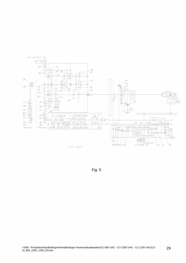
Fig. 5 show the Kinematics diagram.
The apron control panel is provided with a joystick for start/stop spindle forward/reverse direction of rotation. The spindle system is supported on the following type bearings:
CU800RD CU1000RD CU1250RD Q-ty FAG B71940 E.T.P4S.TBT.M
(SKF 71940 ACD.P4A.TBT.B) (NSK 7940 A5 TYN DBD M P4)
-3
FAG NNU4936SK.M.SP
(SKF NNU4936 BK/W 33) (NSK NNU4936 MBKR)
-1
Handles 27 and 28, Fig. 4 serves to select for spindle direction of rotation.
I:\009 - Produkten\Handleidingen\Handleidingen Huvema\draaibanken\CU 800 VAC - CU 1000 VAC - CU 1250 VAC\CU rd_800_1000_1250_EN.doc
29
Fig. 5
I:\009 - Produkten\Handleidingen\Handleidingen Huvema\draaibanken\CU 800 VAC - CU 1000 VAC - CU 1250 VAC\CU rd_800_1000_1250_EN.doc
30
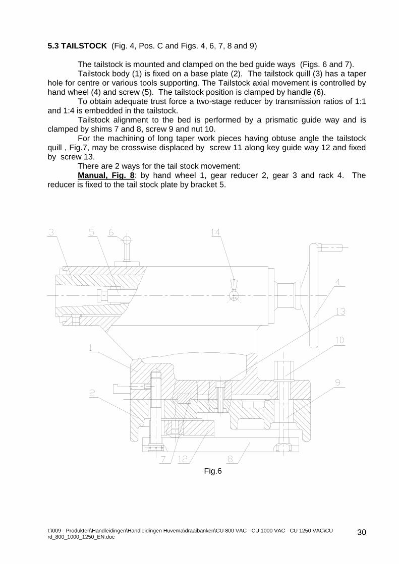
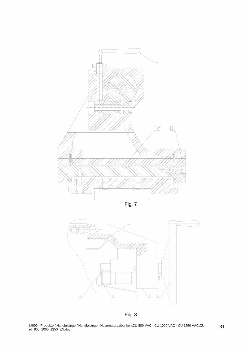
5.3 TAILSTOCK (Fig. 4, Pos. C and Figs. 4, 6, 7, 8 and 9) The tailstock is mounted and clamped on the bed guide ways (Figs. 6 and 7). Tailstock body (1) is fixed on a base plate (2). The tailstock quill (3) has a taper
hole for centre or various tools supporting. The Tailstock axial movement is controlled by hand wheel (4) and screw (5). The tailstock position is clamped by handle (6).
To obtain adequate trust force a two-stage reducer by transmission ratios of 1:1 and 1:4 is embedded in the tailstock.
Tailstock alignment to the bed is performed by a prismatic guide way and is clamped by shims 7 and 8, screw 9 and nut 10.
For the machining of long taper work pieces having obtuse angle the tailstock quill , Fig.7, may be crosswise displaced by screw 11 along key guide way 12 and fixed by screw 13.
There are 2 ways for the tail stock movement: Manual, Fig. 8: by hand wheel 1, gear reducer 2, gear 3 and rack 4. The
reducer is fixed to the tail stock plate by bracket 5.
Fig.6
I:\009 - Produkten\Handleidingen\Handleidingen Huvema\draaibanken\CU 800 VAC - CU 1000 VAC - CU 1250 VAC\CU rd_800_1000_1250_EN.doc
31
Fig. 7
Fig. 8
I:\009 - Produkten\Handleidingen\Handleidingen Huvema\draaibanken\CU 800 VAC - CU 1000 VAC - CU 1250 VAC\CU rd_800_1000_1250_EN.doc
32
Fig.9
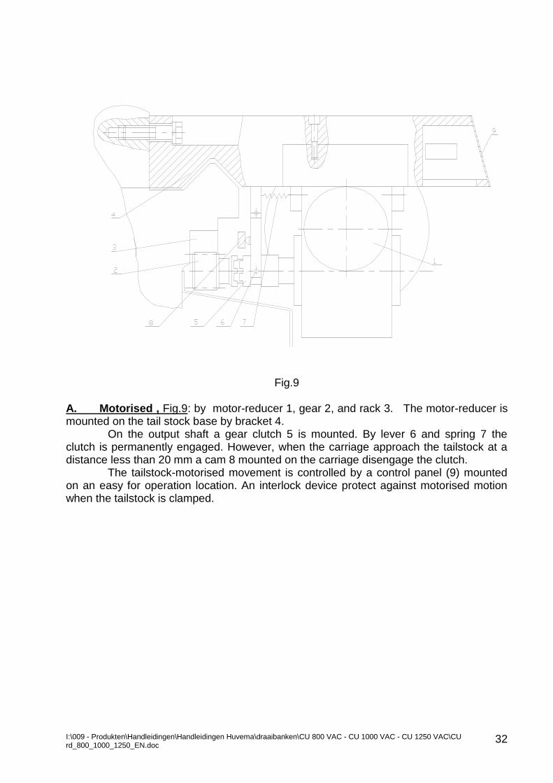
A. Motorised , Fig.9: by motor-reducer 1, gear 2, and rack 3. The motor-reducer is mounted on the tail stock base by bracket 4.
On the output shaft a gear clutch 5 is mounted. By lever 6 and spring 7 the clutch is permanently engaged. However, when the carriage approach the tailstock at a distance less than 20 mm a cam 8 mounted on the carriage disengage the clutch.
The tailstock-motorised movement is controlled by a control panel (9) mounted on an easy for operation location. An interlock device protect against motorised motion when the tailstock is clamped.
I:\009 - Produkten\Handleidingen\Handleidingen Huvema\draaibanken\CU 800 VAC - CU 1000 VAC - CU 1250 VAC\CU rd_800_1000_1250_EN.doc
33
5.4 APRON (Fig. 4, Pos. D) The Apron is fixed on the carriage base plate and contains following
mechanisms: Carriage motorized longitudinal and cross motion mechanism, the mechanism
for meshing the half-nut to lead screw, apron protection mechanism, a clutch that operates when rapid traverse mechanism is engaged and an Interlock device that protects of a simultaneous engagement of the lead screw and lead shaft.
Apron kinematics sequence can be seen on the machine kinematics diagram, Fig. 5. 5.5. FEED BOX (Fig.4, Pos. E)
The feed box consists a multiplying mechanism (a group of four gear drives), a selection mechanism with eight drives gears and a distributing mechanism.
The Input shaft (from the quadrant) drives a lubricating pump, which sucks oil from the box bottom and deliver it to the bearings and gears through distributing tubing.
Feed box kinematics can be seen on Fig. 5. 5.6 LOWER CARRIAGE (FIG. 4, POS. F)
It is a part of the machine carriage and its main components are longitudinal carriage and cross slide.
The longitudinal carriage is mounted on the bed guide ways and all other parts are fitted on it. The cross slide is sliding along the longitudinal carriage slide ways in a direction perpendicular to spindle axis in a manually or automatic mode.
Lower carriage longitudinal motion can be performed by one of the following ways:
Feed stroke: by feed box mechanisms, lead shaft and the apron mechanism;
Feed stroke: by the feed box mechanisms, lead screw and the nut of apron;
Rapid traverse: by the rapid traverse motor and apron mechanism;
Manually: by the hand wheel and apron mechanism. Lower carriage cross motion can be performed by one of the following ways:
Feed stroke: by feed box mechanisms, lead shaft, apron mechanism the cross screw and its nut;
Rapid traverse: by the rapid traverse motor, apron mechanism, the cross screw and its nut;
Manually: by the cross screw hand wheel, the cross screw and its nut. Compound carriage motorized motion control mechanism is mounted in the
carriage base plate. When necessary the carriage base plate can be fixed to bed guide ways by two
clamping plates and four screws. 5.7 UPPER CARRIAGE (FIG. 4, POS. G)
The upper carriage is a part of the machine carriage and consists of compound rest and upper slide.
A four-position tool holder is mounted on the upper slide. The upper slide movement is manual or automatic along the compound slide ways.
For manual or automatic turning of a short taper work piece the compound can be indexed in relation to the lower slide at an angle up to 90o both directions. Four special
I:\009 - Produkten\Handleidingen\Handleidingen Huvema\draaibanken\CU 800 VAC - CU 1000 VAC - CU 1250 VAC\CU rd_800_1000_1250_EN.doc
34
bolts and nuts fix selected position. Therefore, the cutting tool can be moved longitudinal or crosswise in relation to spindle axis.
5.8 MACHINE MAIN DRIVE (Fig. 4, Pos. H and Fig. 21)
The Machine main drive assembly is mounted on the rear wall of the front machine foot.
The main drive motor is mounted on a cast iron mounting plate 1 that is hinged on axis 2 for the purpose of drive belts tensioning. Motor drive motion is transmitted to the gearbox by set of V-belts, type B/17 DIN 2215 the number of which depends on the main motor power. Bracket 3 withstands the strengths of the main motor operation and the drive assembly in operation. 5.9 RESTS (OPTIONS)
Follower rest and Steady rest are provided by sliding quills for supporting the work piece. The Steady rest is firmly fixed on the bed guide ways whereas the follower rest is mounted on the carriage base plate. The rest mounting should be always safety and verified.
I:\009 - Produkten\Handleidingen\Handleidingen Huvema\draaibanken\CU 800 VAC - CU 1000 VAC - CU 1250 VAC\CU rd_800_1000_1250_EN.doc
35
6. MACHINE LUBRICATION 6.1 GENERAL
It is of great importance for the correct and trouble free operation of your
machine is to follow regular lubrication of the machine parts using recommended in Table 6.2 lubricants.
Warning: This machine is delivered to you WITHOUT OIL in Gearbox, Apron and Feed box. After final testing the machine and before packing for shipment the oil is drained from above said boxes.
During operation of the lathes we recommend to observe as follows:
Regular lubrication and oil change;
Do not mix different types of oils and greases; Use recommended brand names;
Clean machine parts only by soft cloth;
Never use pressurized air for cleaning;
Do not use aggressive or volatile liquids for washing the boxes. Gearbox Lubrication (Fig. 10, Pos. 2 and 4) Gearbox mechanisms lubrication is provided by gear pump and by splashing. The oil fill plug is located on gearbox rear wall. The Gear pump sucks the oil
through filter and deliver it to the oil distributor. A part of this oil is directed to the upper Oil sight glass by separate control tubing. The presence of oil on the sight glass evidence the correct functioning of the pump and control tubing.
Warning: In case no oil present on the oil sight glass immediately stops the
machine and check for the fault. Open the gearbox (remove the top lid) and check lubrication system correct function. Provided that the oil normal circulates through the pipes and lubricate the gearbox mechanisms, therefore the pump operates normal and the reason is clogged control pipe. Clean the control pipe. However, if no oil circulating through all the pipes the most likely reason is clogged filter. Clean the filter. When no oil present on the oil sight glass upon initial start up of the machine the most likely reason is incorrect direction of rotation of the oil pump motor. The correct rotation of the oil pump motor is clockwise.
First change of the gearbox oil is 10 - 15 working days after the initial start of the
machine (after installation). The second change is after 20-30 days. Then, change the oil every 6 months of operation.
Gearbox oil drain plugs are located on the gearbox lower part (Quadrant side). Before refill the Gearbox with new oil it is recommended to wash the gearbox by naphtha. Feed box lubrication (Fig. 10, Pos. 1)
Feed box mechanisms are lubricated by incorporated piston lubrication pump. The oil is sucked by the pump via filter and is delivered to the gears by a tubing with lubrication holes. The tubing end reach to oil sight glass and the presence of oil at this gauge evidencing correct functioning of the lubrication system. Feed box oil change is to be done periodically as described for the gearbox above. On the lower part of the feed box a drain plug is provided and the oil fill plug is provided on the feed box upper part. The oil level in the feed box is indicating by a sight glass.
I:\009 - Produkten\Handleidingen\Handleidingen Huvema\draaibanken\CU 800 VAC - CU 1000 VAC - CU 1250 VAC\CU rd_800_1000_1250_EN.doc
36
Apron lubrication (Fig.10, Pos. 9 and 10) All apron mechanisms and bearings lubrication is by an oil pump in the apron
and by oil by the rotating gears. The pump operates when the feed drive shaft is rotating, only.
Warning: At Rapid traverse the pump does not operates. A plug for oil filling is provided on the apron base plate. The oil drain plug is
located on the apron lower part. The dial of the longitudinal feed, the gears and cross carriage safety handle are periodically lubricated by grease.
Bed guide ways and half nut lubrication (Fig. 10, Pos. 11 and 16)
The bed guide ways are manually lubricated by a knob located on the apron during carriage longitudinal motion.
The bed guide ways and half nut lubrication Warning: At Rapid traverse the pump does not operates.
Carriage lubrication (Fig. 10, Pos.12, 13 and 15) The carriage sliding surfaces lubrication is daily by an oilcan through the oil
nipples provided.
Tailstock lubrication (Fig. 10, Pos.14) The tailstock quill, bearings and screw lubrication is daily using an oilcan through
the oil nipples provided. In the tailstock base part an oil tank is shaped. Oil fill into this tank is made
through plug oil indicator (marked by a name plate on the tailstock). By a capillary lubrication the tailstock bottom guide ways are lubricated from the oil tank.
Regularly, verify the oil level in the oil tank and fill if necessary.
Lead screw and lead shaft rear bearings lubrication The rear support ball bearings of the lead screw and lead shaft are factory
lubricated by grease during assembly.
Quadrant gears Lubrication (Fig. 10, Pos. 3) Quadrant gears must be lubricated by grease once per month. Gears bearing houses are cleaned and fill up with grease once per year.
Note: When machine operates under tropical environment the quadrant gears shall be periodically covered with a layer of grease of entire surface to protect them from corrosion.
Recommended lubricants
Recommended for these machine lubricants are described under Section 6.2. Oils of higher viscosity shall be used when operate the machine under tropical
environment. Figure 10 shows the machine lubrication diagram. For easy and quick reference this diagram is located on the bed right end.
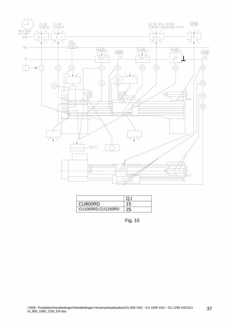
I:\009 - Produkten\Handleidingen\Handleidingen Huvema\draaibanken\CU 800 VAC - CU 1000 VAC - CU 1250 VAC\CU rd_800_1000_1250_EN.doc
37
Q,l
CU800RD 15 CU1000RD,CU1250RD 25
Fig. 10
I:\009 - Produkten\Handleidingen\Handleidingen Huvema\draaibanken\CU 800 VAC - CU 1000 VAC - CU 1250 VAC\CU rd_800_1000_1250_EN.doc
38
6.2 INSTRUCTIONS FOR LUBRICATION AND LUBRICANTS
The machine lubrication diagram for CU800RD, CU1000RD and CU1250RD,
Fig. 10 shows the lubrication points and periods; lubrication oils and greases are shown on the table below. INSTRUCTION FOR LUBRICATIONS AND MAINTENANCE Daily Before machine start:
Check the oil level and lubrication condition according Fig. 10.
Clean the machine parts from chip deposits
Clean the bed guide ways from chip deposits Weekly
It is a must to clean entire machine
Remove the chuck jaws, clean and lubricate them Monthly
Check the main drive V-belts condition (for tension and smooth drive). Clean, adjust the tension or replace if necessary
Clean the coolant tank
Check the Clutch for Spindle forward and reverse direction of rotation and adjust if necessary.
Annually
Check the gearbox, spindle rotation accuracy, run-out, as well as all nuts and lock rings
Check for bearings and guide ways clearance
Check the carriage functioning
Check the Tool holder functioning
Check the Tailstock functioning
I:\009 - Produkten\Handleidingen\Handleidingen Huvema\draaibanken\CU 800 VAC - CU 1000 VAC - CU 1250 VAC\CU rd_800_1000_1250_EN.doc
39
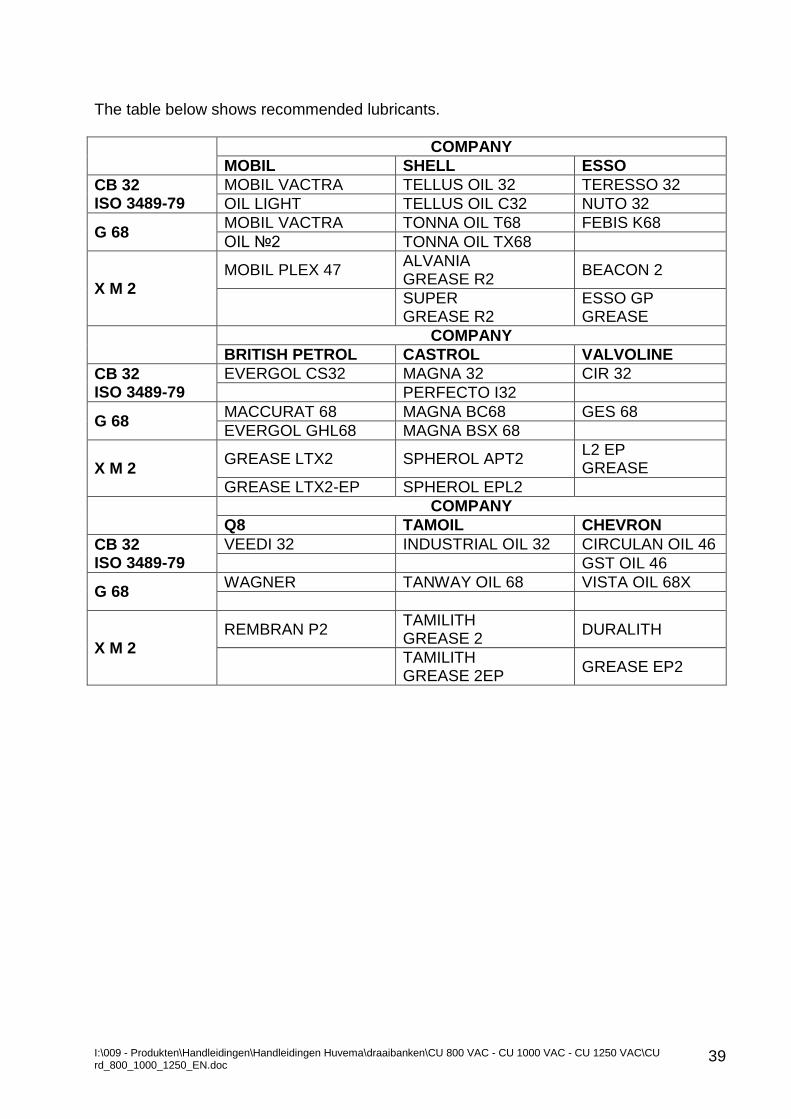
The table below shows recommended lubricants.
COMPANY
MOBIL SHELL ESSO
CB 32 ISO 3489-79
MOBIL VACTRA TELLUS OIL 32 TERESSO 32
OIL LIGHT TELLUS OIL C32 NUTO 32
G 68 MOBIL VACTRA TONNA OIL T68 FEBIS K68
OIL №2 TONNA OIL TX68
X M 2 MOBIL PLEX 47
ALVANIA GREASE R2
BEACON 2
SUPER GREASE R2
ESSO GP GREASE
COMPANY
BRITISH PETROL CASTROL VALVOLINE
CB 32 ISO 3489-79
EVERGOL CS32 MAGNA 32 CIR 32
PERFECTO I32
G 68 MACCURAT 68 MAGNA BC68 GES 68
EVERGOL GHL68 MAGNA BSX 68
X M 2 GREASE LTX2 SPHEROL APT2
L2 EP GREASE
GREASE LTX2-EP SPHEROL EPL2
COMPANY
Q8 TAMOIL CHEVRON
CB 32 ISO 3489-79
VEEDI 32 INDUSTRIAL OIL 32 CIRCULAN OIL 46
GST OIL 46
G 68 WAGNER TANWAY OIL 68 VISTA OIL 68X
X M 2 REMBRAN P2
TAMILITH GREASE 2
DURALITH
TAMILITH GREASE 2EP
GREASE EP2
I:\009 - Produkten\Handleidingen\Handleidingen Huvema\draaibanken\CU 800 VAC - CU 1000 VAC - CU 1250 VAC\CU rd_800_1000_1250_EN.doc
40
7.0 OPERATION WITH THE MACHINE 7.1 MACHINE START
Warning: In danger Immediately press Emergency stop push button (red mushroom) or Emergency stop pedal (option).
Machine emergency shut down can be executed by one of the Emergency stop push buttons (30) located on the Control panels (12), (21) and (24) or by Emergency foot stop (option) (25), Fig. 4.
Resetting of actuated Emergency stop push button is done under strict condition that the cause for machine emergency stop is found and eliminated and no hazards for personnel and/or machine exist.
Warning: Never operate the machine with the Electric cabinet door open; Chuck guard removed or Quadrant box door opened.
Warning: Before handling with the chucking devices (Chuck, Face plate, Drive plate etc.,) WAIT until Spindle stop standstill.
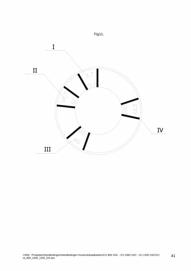
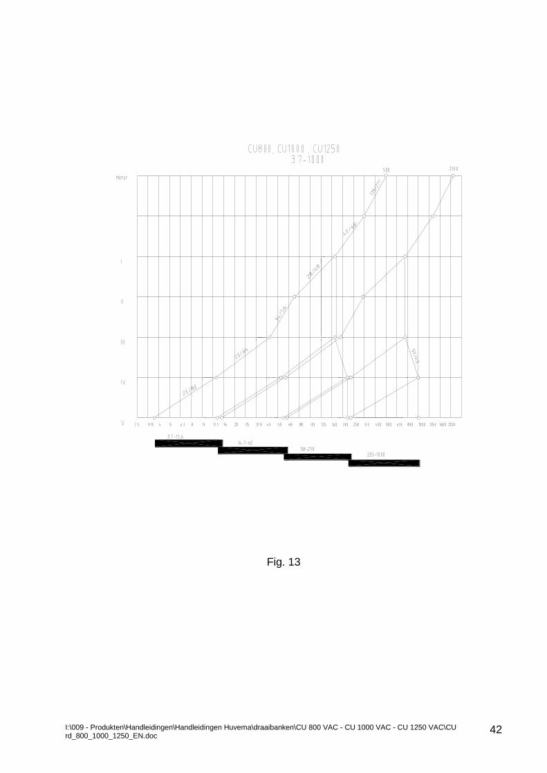
It is dangerous and absolutely forbidden to operate with a dead centre mounted on the tailstock. 7.2 SPEEDS OF THE MACHINE The gearbox provides forward and reverse variable speed to spindle within the range of 3,7 – 1000(3-800) rpm divided into four sub ranges. Handle (3), Fig.4 Is used for selection a speed sub range. The speed values of the speed sub range are indicated on a color background: IV speed sub range: blue background III speed sub range: dark red background II speed sub range: green background I speed sub range: orange background The sub ranges are marked on plate Fig. 11 fixed on the disc driven by handle (3), Fig.3
Warning: Stop spindle before speed change. The motion transmission of any spindle speed can be seen on the speed diagram Fig. 13 and kinematics diagram Fig. 5.By joystick (27), Fig. 4 spindle forward and reverse rotation start and stop is controlled.
I:\009 - Produkten\Handleidingen\Handleidingen Huvema\draaibanken\CU 800 VAC - CU 1000 VAC - CU 1250 VAC\CU rd_800_1000_1250_EN.doc
41
Fig11.
І
ІІ
ІІІ
ІV
I:\009 - Produkten\Handleidingen\Handleidingen Huvema\draaibanken\CU 800 VAC - CU 1000 VAC - CU 1250 VAC\CU rd_800_1000_1250_EN.doc
42
Fig. 13
I:\009 - Produkten\Handleidingen\Handleidingen Huvema\draaibanken\CU 800 VAC - CU 1000 VAC - CU 1250 VAC\CU rd_800_1000_1250_EN.doc
43
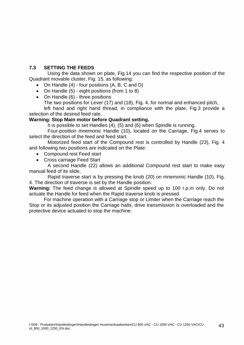
7.3 SETTING THE FEEDS
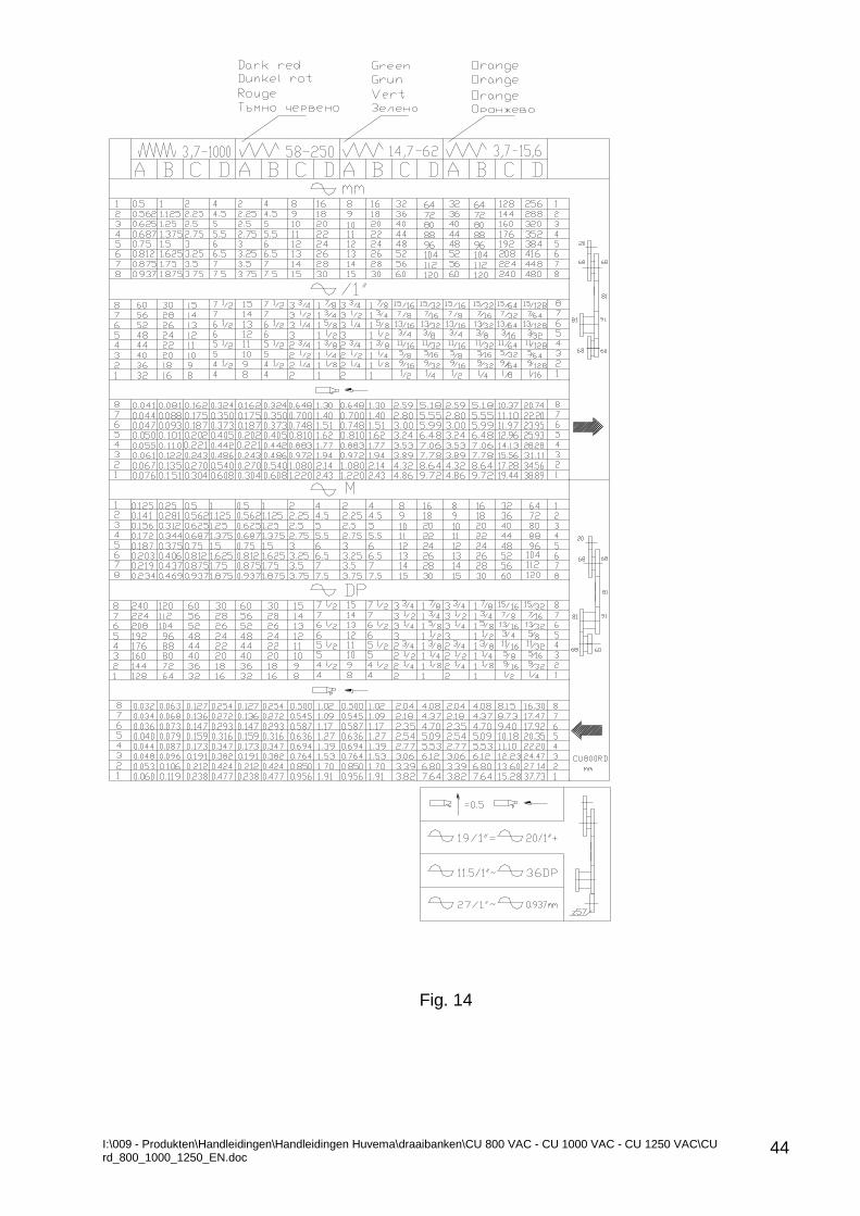
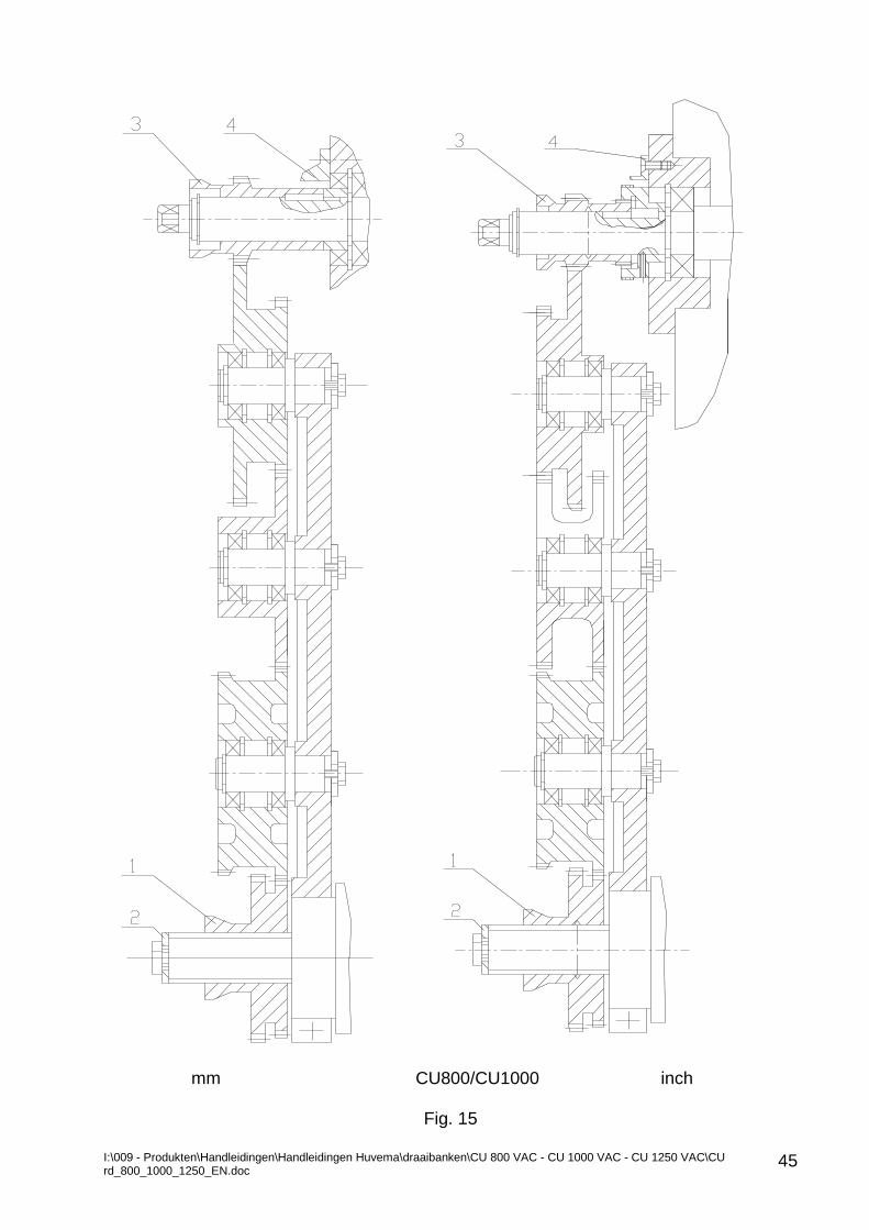
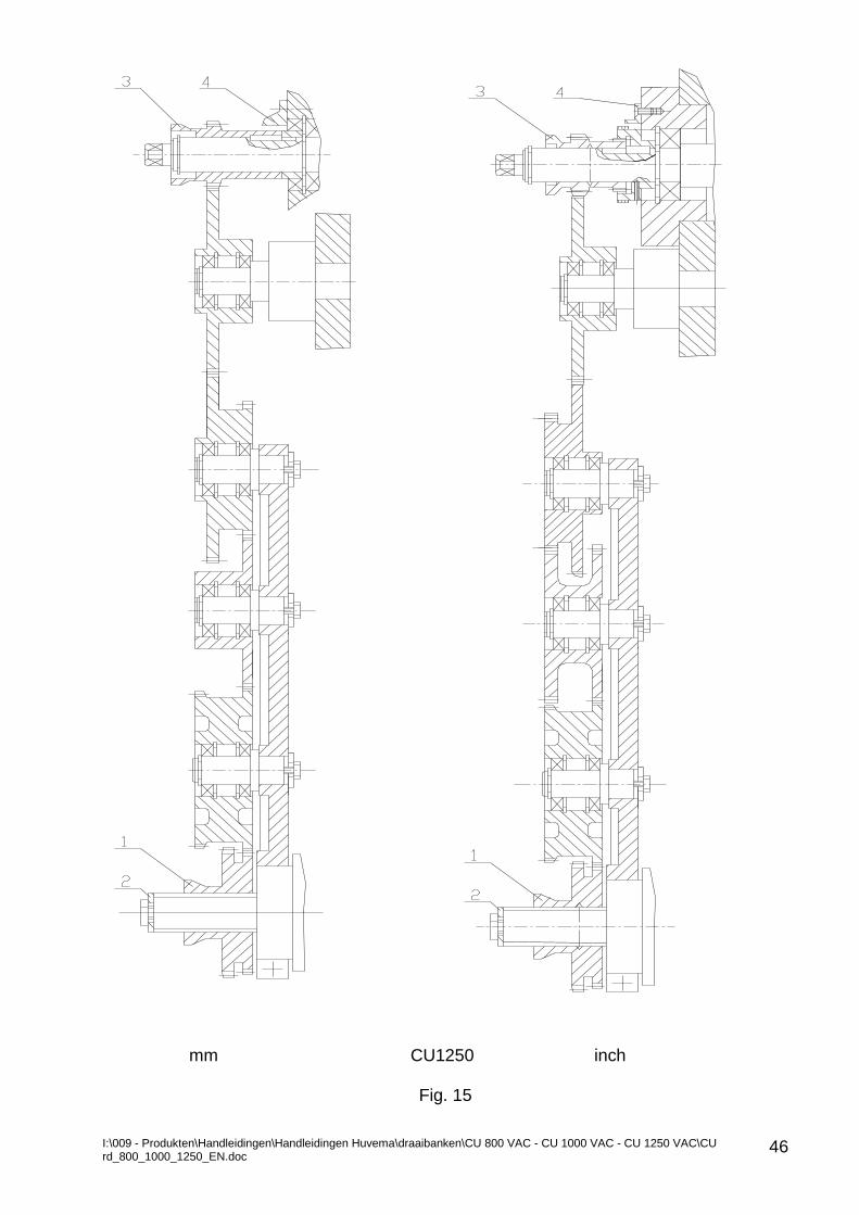
Using the data shown on plate, Fig.14 you can find the respective position of the Quadrant movable cluster, Fig. 15, as following:
On Handle (4) - four positions (A, B, C and D)
On Handle (5) - eight positions (from 1 to 8)
On Handle (6) - three positions The two positions for Lever (17) and (18), Fig. 4, for normal and enhanced pitch, left hand and right hand thread, in compliance with the plate, Fig.3 provide a
selection of the desired feed rate. Warning: Stop Main motor before Quadrant setting.
It is possible to set Handles (4), (5) and (6) when Spindle is running. Four-position mnemonic Handle (10), located on the Carriage, Fig.4 serves to
select the direction of the feed and feed start. Motorized feed start of the Compound rest is controlled by Handle (23), Fig. 4
and following two positions are indicated on the Plate:
Compound rest Feed start
Cross carriage Feed Start A second Handle (22) allows an additional Compound rest start to make easy
manual feed of its slide. Rapid traverse start is by pressing the knob (20) on mnemonic Handle (10), Fig.
4. The direction of traverse is set by the Handle position. Warning: The feed change is allowed at Spindle speed up to 100 r.p.m only. Do not actuate the Handle for feed when the Rapid traverse knob is pressed. For machine operation with a Carriage stop or Limiter when the Carriage reach the Stop or its adjusted position the Carriage halts, drive transmission is overloaded and the protective device actuated to stop the machine.
I:\009 - Produkten\Handleidingen\Handleidingen Huvema\draaibanken\CU 800 VAC - CU 1000 VAC - CU 1250 VAC\CU rd_800_1000_1250_EN.doc
44
Fig. 14
I:\009 - Produkten\Handleidingen\Handleidingen Huvema\draaibanken\CU 800 VAC - CU 1000 VAC - CU 1250 VAC\CU rd_800_1000_1250_EN.doc
45
mm CU800/CU1000 inch
Fig. 15
I:\009 - Produkten\Handleidingen\Handleidingen Huvema\draaibanken\CU 800 VAC - CU 1000 VAC - CU 1250 VAC\CU rd_800_1000_1250_EN.doc
46
mm CU1250 inch
Fig. 15
I:\009 - Produkten\Handleidingen\Handleidingen Huvema\draaibanken\CU 800 VAC - CU 1000 VAC - CU 1250 VAC\CU rd_800_1000_1250_EN.doc
47
7.4 THREAD CUTTING
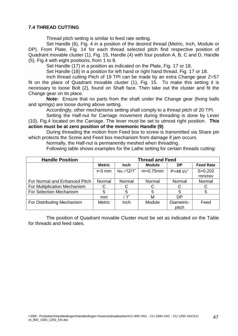
Thread pitch setting is similar to feed rate setting. Set Handle (6), Fig. 4 in a position of the desired thread (Metric, Inch, Module or
DP). From Plate, Fig. 14 for each thread selected pitch find respective position of Quadrant movable cluster (1), Fig. 15, Handle (4) with four position A, B, C and D, Handle (5), Fig.4 with eight positions, from 1 to 8.
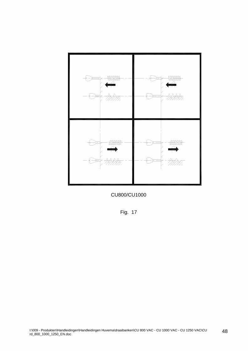
Set Handle (17) in a position as indicated on the Plate, Fig. 17 or 18. Set Handle (18) in a position for left hand or right hand thread, Fig. 17 or 18. Inch thread cutting Pitch of 19 TPI can be made by an extra Change gear Z=57
fit on the place of Quadrant movable cluster (1), Fig. 15. To make this setting it is necessary to loose Bolt (2), found on Shaft face. Then take out the cluster and fit the Change gear on its place.
Note: Ensure that no parts from the shaft under the Change gear (fixing balls and springs) are loose during above setting.
Accordingly, other mechanisms setting shall comply to a thread pitch of 20 TPI. Setting the Half-nut for Carriage movement during threading is done by Lever
(10), Fig.4 located on the Carriage. The lever must be set to utmost right position. This action must be at zero position of the mnemonic Handle (9)
During threading the motion from Feed box to screw is transmitted via Share pin which protects the Screw and Feed box mechanism from damage if jam occurs.
Normally, the Half-nut is permanently meshed when threading. Following table shows examples for the Lathe setting for certain threads cutting:
Handle Position Thread and Feed
Metric Inch Module DP Feed Rate
t=3 mm No.=12/1” m=0,75mm P=48 t/” S=0,202 mm/rev
For Normal and Enhanced Pitch Normal Normal Normal Normal Normal
For Multiplication Mechanism C C C C C
For Selection Mechanism 5 5 5 5 5
mm / 1” M DP
For Distributing Mechanism Metric Inch Module Diametric-pitch
Feed
The position of Quadrant movable Cluster must be set as indicated on the Table for threads and feed rates.
I:\009 - Produkten\Handleidingen\Handleidingen Huvema\draaibanken\CU 800 VAC - CU 1000 VAC - CU 1250 VAC\CU rd_800_1000_1250_EN.doc
48
CU800/CU1000
Fig. 17
I:\009 - Produkten\Handleidingen\Handleidingen Huvema\draaibanken\CU 800 VAC - CU 1000 VAC - CU 1250 VAC\CU rd_800_1000_1250_EN.doc
49
CU1250 Fig. 18
I:\009 - Produkten\Handleidingen\Handleidingen Huvema\draaibanken\CU 800 VAC - CU 1000 VAC - CU 1250 VAC\CU rd_800_1000_1250_EN.doc
50
7.5 MULTI-START THREAD CUTTING
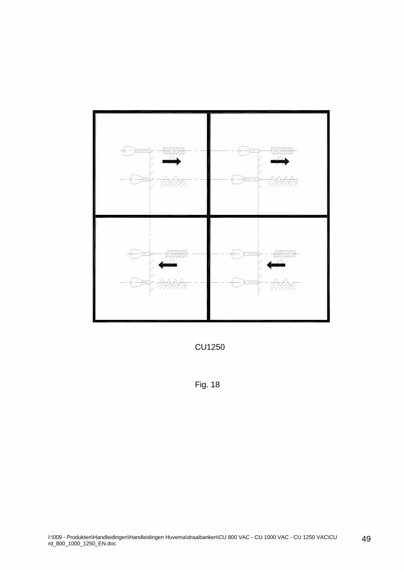
The metric version of these lathes can cut multi-start threads without extra equipment. For this purpose first 2 gears on the Quadrant are used in compliance with the diagram located inside the quadrant door, Fig. 19.
Before attempt threading it is necessary the zero position of the Plate, Fig. 20 (fixed on the drive Gear (3) Z=200 of the drive quadrant shaft) to line up with the Pointer (4), Fig.15. For this purpose the Gear (3) is pulled to the operator, the Drive shaft turned at an appropriate angle using a spanner, then the Gear (3) is get back.
After first cut the Gear (3) is pulled again and turn it either direction at an appropriate angle (teeth number as indicated on the Plate, Fig.19.). After second cut the Gear (3) must be turned again in the same direction and same angle and so on.
The Plate, Fig.19 shows that when cutting threads located in the area Z, Black zone (see the Plate for threads and feed rates) it is possible to cut 3-starts and 5-starts threads; for threads found in the Red zone with a sign 4xZ (enhanced pitch) it is possible to cut 2-, 3-, 4-, 5-, 6-, 10-starts threads.
For example, when 3-start thread is cut and if it is located in the Black zone, sign Z, the drive gear should be turned over 5 teeth and if the pitch is located in the Dark red zone with sign 4xZ the movable gear should be turned over 20 teeth, i.e. one revolution and so on.
Fig. 19
n
2
3
4
5
6
8
10
Z
-
5
-
3
-
-
-
4xZ
30=1 +10
20=1
15
16xZ
120=6
80=4
60=3
480=24
320=16
240=12
64xZ
12
10
- 30=1 +10
40=2
48=2 +8 192=9 +12
160=8
120=6
6 24=1 +4 96=4 +16
Black
Schwarz
Noire
Черен Зелен
Vert
Grun
Green
Orange
Orange
Orange
ОранжевТъмно червен
Rouge
Dunkel rot
Dark red

I:\009 - Produkten\Handleidingen\Handleidingen Huvema\draaibanken\CU 800 VAC - CU 1000 VAC - CU 1250 VAC\CU rd_800_1000_1250_EN.doc
51
Fig. 20
16151210865430
I:\009 - Produkten\Handleidingen\Handleidingen Huvema\draaibanken\CU 800 VAC - CU 1000 VAC - CU 1250 VAC\CU rd_800_1000_1250_EN.doc
52
7.6 CUTTING OF BRIGGS THREADS
Setting of the thread pitch is same as described in Section 7.5 above. Since these kind of threads are conical they shall be cut by a Taper Turning
Attachment (option). For these threads pitches of 11 1/2 t/in (1” 27 t/in) not shown in the Table also are used. Since these threads are very short for cutting a thread of pitch 27 t/in a metric thread of pitch 0,937 mm is used whereas a relative error of 0,00345 mm occurs or an error of 0,0345 mm (0,00136”) along 10 mm;
For cutting a thread of pitch 11 1/2 t/in DP thread M36 is used whereas resulted error = 0,00357 or an error of 0,0357 (0,00139”) along 10 mm. 7.7 DIMENSION READOUT
The Cutting tool Longitudinal and Crosswise motion during operation is precisely
read out by respective dials. The longitudinal Dial located on the Apron reads out carriage longitudinal travel. The Vernier of the Dial is graduated in units of 0,1 mm for metric version
machine. Carriage crosswise travel is read out by a Scale, which indicates the difference
between diameters of the work piece under machining. One turn of the Dial stands for difference of the diameters 10 mm or 5 mm in radius for metric version machines.
One graduation of the Dial stands for 0,1 mm difference of the diameters for metric version machine.
Compound rest Dial read out the travel of its slide. One turn of the metric version Dial indicates stroke of 5 mm. The value of one graduation is 0,025 mm.
The tailstock Quill scale is graduated from 0 to 260mm and serves to readout the depth of hole drilling. Tailstock cross displacement Scale is used when work pieces of a slight taper but bigger length (over 500 mm) is machined.
A round scale on the Cross carriage slide indicates the angle of Compound rest indexing for machining slight taper surfaces on a shorter length work pieces. The Scale graduation is from 0o to 90o both directions of indexing. One graduation equal to 1o. 7.8 WORK PIECE CHUCKING AND DRIVING EQUIPMENT
The Spindle nose is provided by short taper and face according DIN 55027 for
Bayonet installation of Chucking equipment. For Chucking equipment installation the Bayonet disk should be turned so that
fixing bolts with nuts can go through widen holes of the disk. Respective Chucking equipment is fit on the Spindle taper so that the mounting
bolts with nuts can go through the Spindle holes and the Round key goes in the respective opening of the Chucking equipment. To tighten the nuts turn disk in reverse direction to utmost.
To remove installed chucking equipment the nuts should be loose by ½ turn.
Turn the disk so that its widen openings stand towards the nuts. A special journal on the

I:\009 - Produkten\Handleidingen\Handleidingen Huvema\draaibanken\CU 800 VAC - CU 1000 VAC - CU 1250 VAC\CU rd_800_1000_1250_EN.doc
53
spindle rear end is provided for installation of electro- magnetic, hydraulic or pneumatic chucking equipment. Warning: It is absolutely forbidden to exceed the maximum speed of rotation of chucking equipment and operation with dead centre on tailstock.
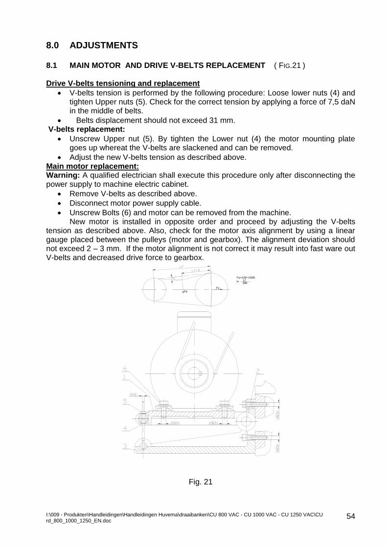
I:\009 - Produkten\Handleidingen\Handleidingen Huvema\draaibanken\CU 800 VAC - CU 1000 VAC - CU 1250 VAC\CU rd_800_1000_1250_EN.doc
54
8.0 ADJUSTMENTS 8.1 MAIN MOTOR AND DRIVE V-BELTS REPLACEMENT ( FIG.21 ) Drive V-belts tensioning and replacement
V-belts tension is performed by the following procedure: Loose lower nuts (4) and tighten Upper nuts (5). Check for the correct tension by applying a force of 7,5 daN in the middle of belts.
Belts displacement should not exceed 31 mm. V-belts replacement:
Unscrew Upper nut (5). By tighten the Lower nut (4) the motor mounting plate goes up whereat the V-belts are slackened and can be removed.
Adjust the new V-belts tension as described above. Main motor replacement: Warning: A qualified electrician shall execute this procedure only after disconnecting the power supply to machine electric cabinet.
Remove V-belts as described above.
Disconnect motor power supply cable.
Unscrew Bolts (6) and motor can be removed from the machine. New motor is installed in opposite order and proceed by adjusting the V-belts
tension as described above. Also, check for the motor axis alignment by using a linear gauge placed between the pulleys (motor and gearbox). The alignment deviation should not exceed 2 – 3 mm. If the motor alignment is not correct it may result into fast ware out V-belts and decreased drive force to gearbox.
Fig. 21
Fe
Fv
Fe=100÷150N
100f= Lf
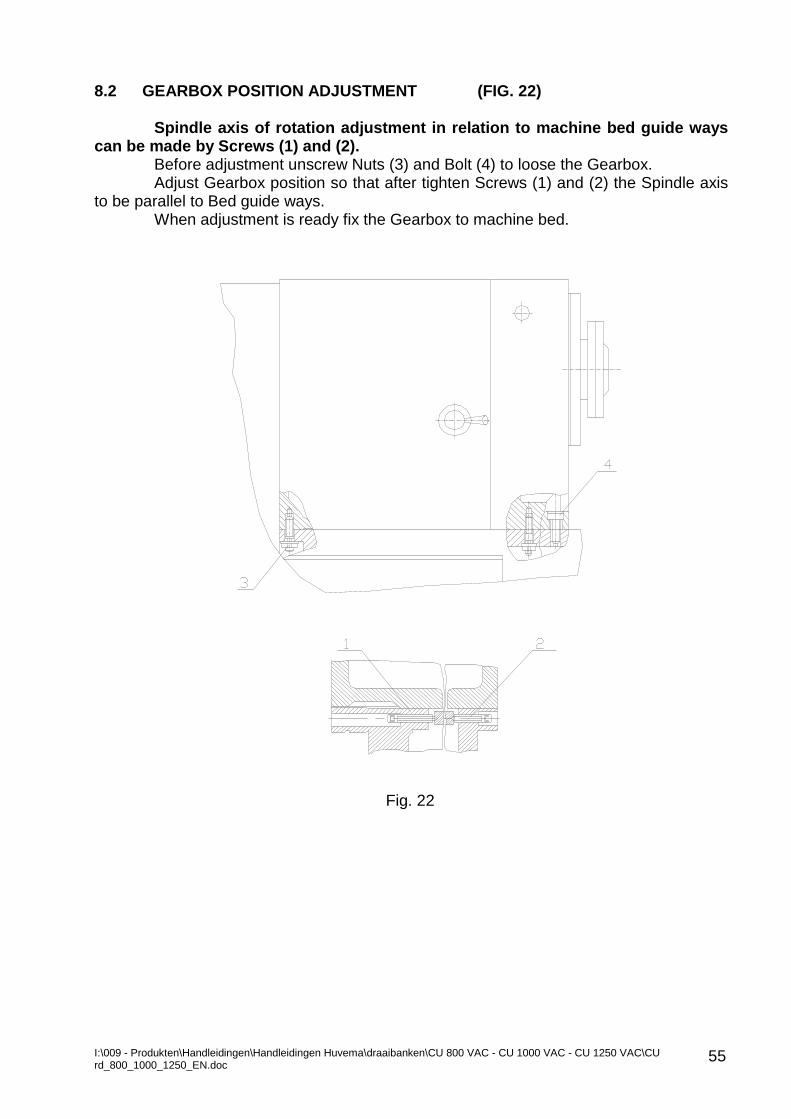
I:\009 - Produkten\Handleidingen\Handleidingen Huvema\draaibanken\CU 800 VAC - CU 1000 VAC - CU 1250 VAC\CU rd_800_1000_1250_EN.doc
55
8.2 GEARBOX POSITION ADJUSTMENT (FIG. 22)
Spindle axis of rotation adjustment in relation to machine bed guide ways can be made by Screws (1) and (2).
Before adjustment unscrew Nuts (3) and Bolt (4) to loose the Gearbox. Adjust Gearbox position so that after tighten Screws (1) and (2) the Spindle axis
to be parallel to Bed guide ways. When adjustment is ready fix the Gearbox to machine bed.
Fig. 22
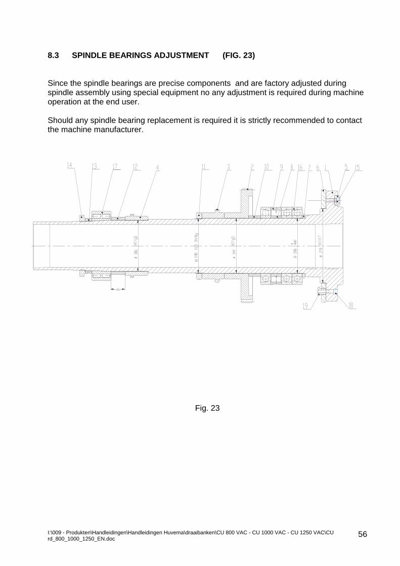
I:\009 - Produkten\Handleidingen\Handleidingen Huvema\draaibanken\CU 800 VAC - CU 1000 VAC - CU 1250 VAC\CU rd_800_1000_1250_EN.doc
56
8.3 SPINDLE BEARINGS ADJUSTMENT (FIG. 23) Since the spindle bearings are precise components and are factory adjusted during spindle assembly using special equipment no any adjustment is required during machine operation at the end user. Should any spindle bearing replacement is required it is strictly recommended to contact the machine manufacturer.
Fig. 23
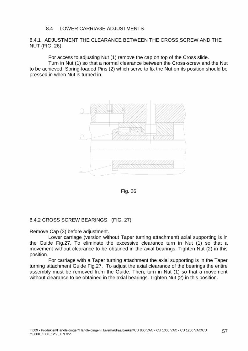
I:\009 - Produkten\Handleidingen\Handleidingen Huvema\draaibanken\CU 800 VAC - CU 1000 VAC - CU 1250 VAC\CU rd_800_1000_1250_EN.doc
57
8.4 LOWER CARRIAGE ADJUSTMENTS 8.4.1 ADJUSTMENT THE CLEARANCE BETWEEN THE CROSS SCREW AND THE NUT (FIG. 26)
For access to adjusting Nut (1) remove the cap on top of the Cross slide. Turn in Nut (1) so that a normal clearance between the Cross-screw and the Nut
to be achieved. Spring-loaded Pins (2) which serve to fix the Nut on its position should be pressed in when Nut is turned in.
Fig. 26
8.4.2 CROSS SCREW BEARINGS (FIG. 27) Remove Cap (3) before adjustment.
Lower carriage (version without Taper turning attachment) axial supporting is in the Guide Fig.27. To eliminate the excessive clearance turn in Nut (1) so that a movement without clearance to be obtained in the axial bearings. Tighten Nut (2) in this position.
For carriage with a Taper turning attachment the axial supporting is in the Taper turning attachment Guide Fig.27. To adjust the axial clearance of the bearings the entire assembly must be removed from the Guide. Then, turn in Nut (1) so that a movement without clearance to be obtained in the axial bearings. Tighten Nut (2) in this position.
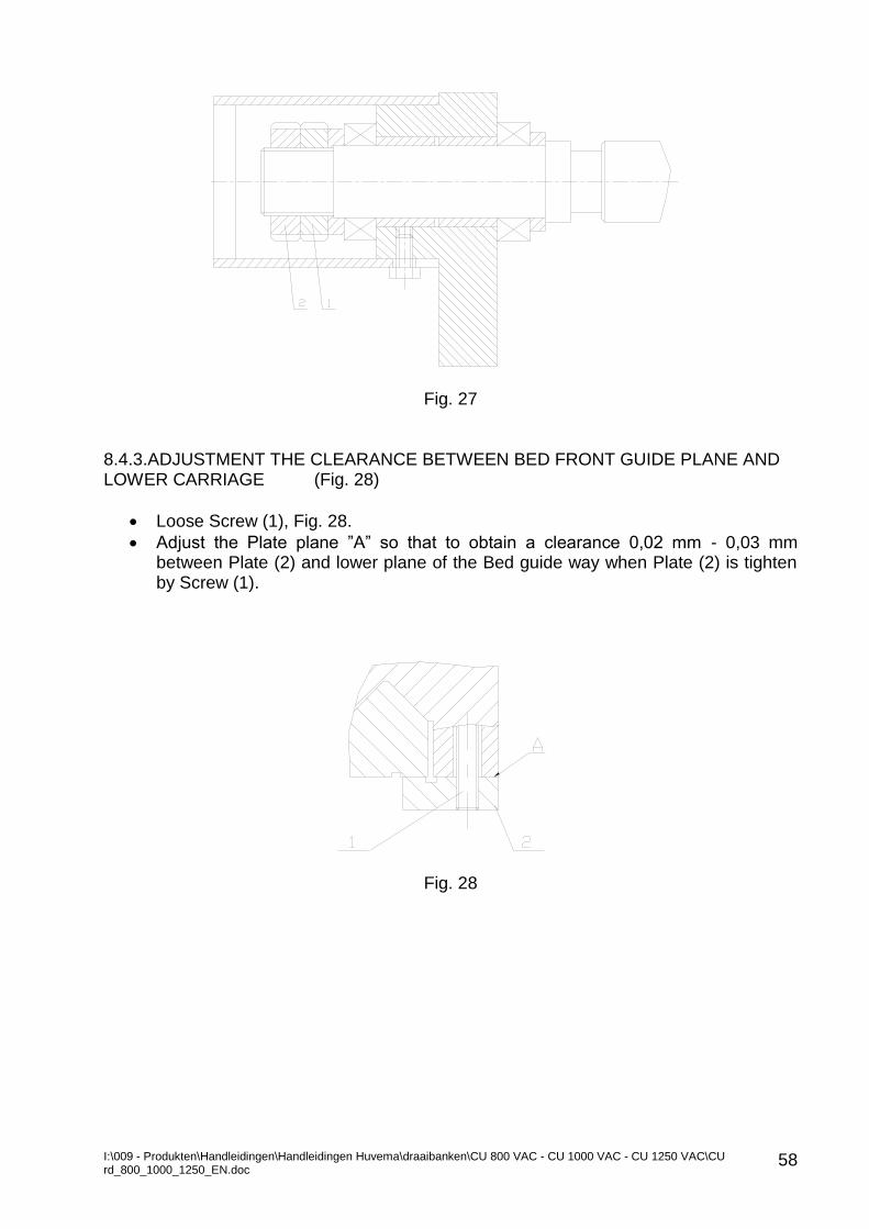
I:\009 - Produkten\Handleidingen\Handleidingen Huvema\draaibanken\CU 800 VAC - CU 1000 VAC - CU 1250 VAC\CU rd_800_1000_1250_EN.doc
58
Fig. 27
8.4.3.ADJUSTMENT THE CLEARANCE BETWEEN BED FRONT GUIDE PLANE AND LOWER CARRIAGE (Fig. 28)
Loose Screw (1), Fig. 28.
Adjust the Plate plane ”A” so that to obtain a clearance 0,02 mm - 0,03 mm between Plate (2) and lower plane of the Bed guide way when Plate (2) is tighten by Screw (1).
Fig. 28
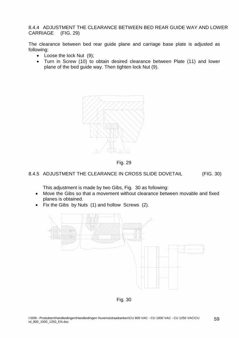
I:\009 - Produkten\Handleidingen\Handleidingen Huvema\draaibanken\CU 800 VAC - CU 1000 VAC - CU 1250 VAC\CU rd_800_1000_1250_EN.doc
59
8.4.4 ADJUSTMENT THE CLEARANCE BETWEEN BED REAR GUIDE WAY AND LOWER CARRIAGE (FIG. 29) The clearance between bed rear guide plane and carriage base plate is adjusted as following:
Loose the lock Nut (9);
Turn in Screw (10) to obtain desired clearance between Plate (11) and lower plane of the bed guide way. Then tighten lock Nut (9).
Fig. 29
8.4.5 ADJUSTMENT THE CLEARANCE IN CROSS SLIDE DOVETAIL (FIG. 30)
This adjustment is made by two Gibs, Fig. 30 as following:
Move the Gibs so that a movement without clearance between movable and fixed planes is obtained.
Fix the Gibs by Nuts (1) and hollow Screws (2).
Fig. 30
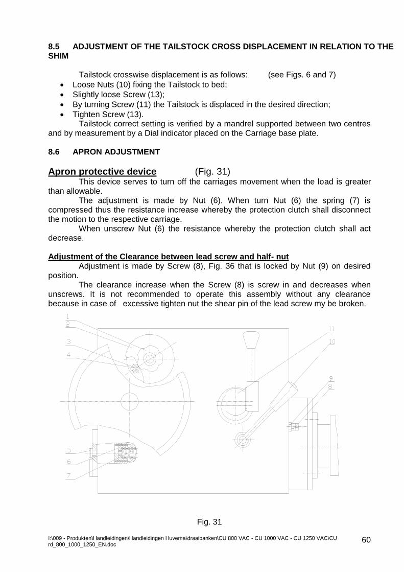
I:\009 - Produkten\Handleidingen\Handleidingen Huvema\draaibanken\CU 800 VAC - CU 1000 VAC - CU 1250 VAC\CU rd_800_1000_1250_EN.doc
60
8.5 ADJUSTMENT OF THE TAILSTOCK CROSS DISPLACEMENT IN RELATION TO THE SHIM
Tailstock crosswise displacement is as follows: (see Figs. 6 and 7)
Loose Nuts (10) fixing the Tailstock to bed;
Slightly loose Screw (13);
By turning Screw (11) the Tailstock is displaced in the desired direction;
Tighten Screw (13). Tailstock correct setting is verified by a mandrel supported between two centres
and by measurement by a Dial indicator placed on the Carriage base plate. 8.6 APRON ADJUSTMENT
Apron protective device (Fig. 31) This device serves to turn off the carriages movement when the load is greater
than allowable. The adjustment is made by Nut (6). When turn Nut (6) the spring (7) is
compressed thus the resistance increase whereby the protection clutch shall disconnect the motion to the respective carriage.
When unscrew Nut (6) the resistance whereby the protection clutch shall act decrease.
Adjustment of the Clearance between lead screw and half- nut
Adjustment is made by Screw (8), Fig. 36 that is locked by Nut (9) on desired position.
The clearance increase when the Screw (8) is screw in and decreases when unscrews. It is not recommended to operate this assembly without any clearance because in case of excessive tighten nut the shear pin of the lead screw my be broken.
Fig. 31
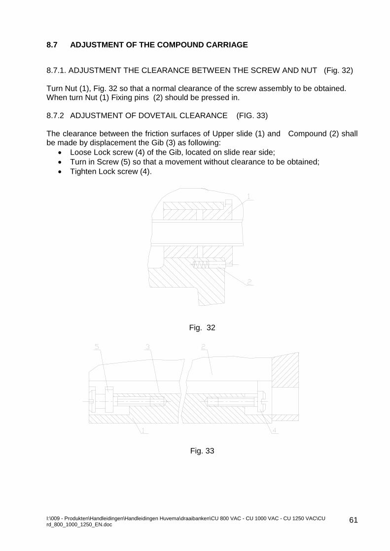
I:\009 - Produkten\Handleidingen\Handleidingen Huvema\draaibanken\CU 800 VAC - CU 1000 VAC - CU 1250 VAC\CU rd_800_1000_1250_EN.doc
61
8.7 ADJUSTMENT OF THE COMPOUND CARRIAGE
8.7.1. ADJUSTMENT THE CLEARANCE BETWEEN THE SCREW AND NUT (Fig. 32) Turn Nut (1), Fig. 32 so that a normal clearance of the screw assembly to be obtained. When turn Nut (1) Fixing pins (2) should be pressed in. 8.7.2 ADJUSTMENT OF DOVETAIL CLEARANCE (FIG. 33) The clearance between the friction surfaces of Upper slide (1) and Compound (2) shall be made by displacement the Gib (3) as following:
Loose Lock screw (4) of the Gib, located on slide rear side;
Turn in Screw (5) so that a movement without clearance to be obtained;
Tighten Lock screw (4).
Fig. 32
Fig. 33
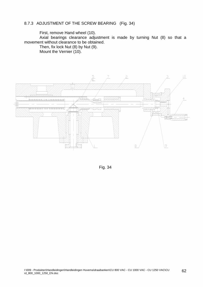
I:\009 - Produkten\Handleidingen\Handleidingen Huvema\draaibanken\CU 800 VAC - CU 1000 VAC - CU 1250 VAC\CU rd_800_1000_1250_EN.doc
62
8.7.3 ADJUSTMENT OF THE SCREW BEARING (Fig. 34)
First, remove Hand wheel (10). Axial bearings clearance adjustment is made by turning Nut (8) so that a
movement without clearance to be obtained. Then, fix lock Nut (8) by Nut (9). Mount the Vernier (10).
Fig. 34
I:\009 - Produkten\Handleidingen\Handleidingen Huvema\draaibanken\CU 800 VAC - CU 1000 VAC - CU 1250 VAC\CU rd_800_1000_1250_EN.doc
63
9.0 COOLANT INSTALLATION
In compliance with the machine bed length the Coolant installation comprises Motor-pump and from 1 to 4 coolant tanks that are interconnected vessels by rubber hoses.
The Motor-pump is mounted on rear side of the front foot. The coolant tanks are located under collecting pans for the chips and coolant.
The coolant tanks are located under the coolant and chips collecting basins. For the filtering of the coolant liquid the coolant tanks are provided with grids. The coolant liquid is sucked from the Coolant tank by the Motor-pump and is fed
through piping to a flexible Coolant duct mount on the Carriage. A valve controls coolant flow rate. Tanks capacity for the initial fill up is as following:
DBC* 1500 mm: 100 litter DBC 3000, 4000 mm: 200 litter DBC 5000, 6000 mm: 300 litter * Distance between centres
The Coolant liquid shall be selected in compliance with the cutting conditions, work piece material, tools, environment etc.; the coolant must be certified safety to personnel and environment from the manufacturer.
Provided that an excessive evaporation occurs during cutting adopted by you it is recommended to use a ventilation device to coo the vapours.
Strictly follow Coolant liquid manufacturer instructions for use and measures for safety.
I:\009 - Produkten\Handleidingen\Handleidingen Huvema\draaibanken\CU 800 VAC - CU 1000 VAC - CU 1250 VAC\CU rd_800_1000_1250_EN.doc
64
10. ELECTRIC INSTALLATION 10.1 GENERAL
This machine is provided by the following electric equipment: Main drive motor, Coolant Pump-motor, Rapid traverse motor, Tailstock motor, Electric cabinet, Control panels, Work light and Wiring cables.
The electrical installation is designed in compliance with Main motor power, Mains voltage and frequency as per the customer requirements.
The Distributing transformer consists primary winding of power supply voltage and frequencies in compliance with customer order and secondary winding for 24V, 12V.
Machine control circuit voltage is 24V. Work light voltage is 12 V. In accordance with the version of the machine electric installation this Manual is
accomplished by “Machine Electric Documentation” containing adequate information for the electrical installation of the ordered and delivered machine.
The Main drive motor is 3-phase, asynchronous. Emergency foot stop SQ1,SQ2 and SQ5 for the machines having bigger
distance between centres are provided as an option. 10.2 ELECTRIC CONTROLS The power supply ON/OFF to machine electric cabinet is by the main switch (SQ0). A key is provided to lock the switch against unauthorized actions. When turn ON the switch lamp HLO of the control panel goes on indicating electric cabinet live. The frequency inverter is energized by pushbutton SB4 and the spindle starts rotation after setting the direction of rotation by joystick SA1. Pushbutton SB6 is for coolant pump motor start and stop control when necessary. Pushbutton SB9 is for work light switch ON and OFF. Pushbutton SB6 in the apron is for rapid traverse. The pushbutton SB7 is for tailstock motion control. The machine is provided with relay A2 that sense the emergency pushbuttons and emergency stop pedal condition. At initial machine run red lamp HL2 on the control panel goes on (red pushbutton). To start the machine press pushbutton SB11 (red light). Lamp HL2 goes off.
10.3 PROTECTIONS The machine main motor overload protection is by the frequency inverter. Thermo protection is provided for tailstock motor, rapid traverse motor and coolant pump motor. The automatic breakers and thermo relay protection values are as following: FT1: 60A for 30W motor FT2: 4A FT3: 0,7A Fuses: FU1 and FU2: 1A FU3 and FU5: 2A FU4: 6A
I:\009 - Produkten\Handleidingen\Handleidingen Huvema\draaibanken\CU 800 VAC - CU 1000 VAC - CU 1250 VAC\CU rd_800_1000_1250_EN.doc
65
Safety Interlocks: 1. Disconnect the Control circuit when:
Open the Quadrant door
Open the Electric cabinet door 2. Interlock the Main drive motor when:
Open Chuck guard (SQ4)
Open Quadrant door (SQ3) SА1 provides protection against repeat start of the main motor; to start the frequency inverter the joystick must be on neutral position. SQ6, protects against Tailstock motion along the bed if it is fixed on the Tailstock ;SQ7- serves as a limit switch at utmost right position. 10.4 MAINTENANCE
Warning: Only qualified electrician who is well acquainted with this machine and safety instructions containing in this manual as well as authorized by the machine owner may undertake access to Electric cabinet.
Warning: Checks and repair works shall be made after disconnected power supply by the Main switch QS0 and check for lack of voltage after disconnection.
Important: Follow periodical checks of machine ground protection circuit in accordance with national regulations for electrical safety.
Periodically clean the motors from dust and any kind of deposits. Burn out fuses to be replaced by original fuses only. Proceed by an Idle run of the machine after initial start and after repair works.
By pushbutton SB8 it is possible to index the spindle at minimum revolutions (JOG function).This function valid only if the pushbutton is pressed. BV display shows the spindle revolutions by an inductive sensor SR1. Sensor SR2 in the gearbox automatically starts the second acceleration and deceleration ramp for the second speed sub range.
For a better operation on the controls, the rear saddle motor shall be regulated through A1 frequency controller.
Parameters that can be varied without having a hazardous effect of the machine: ACC – startup acceleration ramp (very low values may result in a stopover during
startup of the rear saddle) DEC – startup deceleration ramp (very low values may result in triggering the
alarm of the frequency controller – ObF) SP 2 – given through a parameter, power supply frequency of the rear saddle
motor. Alternation limits – from 40 Hz to 60 Hz. These parameters shall be accessible immediately after power supply to the
frequency controller. For more information about the parameters and the frequency controller alarms,
please refer to the User manual of Altivar 11. The operation direction shall be specified by button SA5 (please refer to scheme
E210), the protection of the engine shall be performed by the frequency regulator and its protection – by safety fuse FU5.
11 FREQUENCY INVERTER The machine main motor revolutions are adjusted by a frequency inverter ALTIVAR71 of Telemecanique. Please, refer to frequency inverter manual for more details.
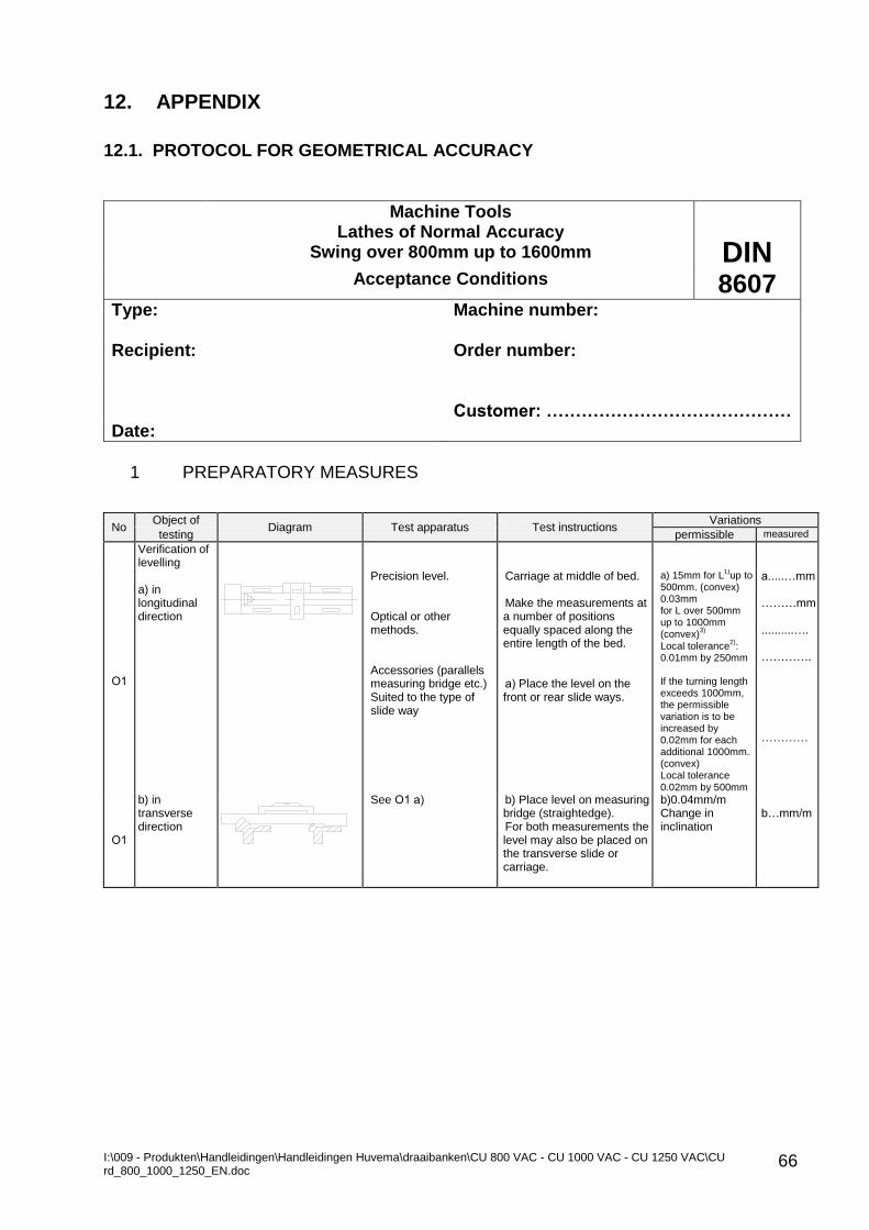
I:\009 - Produkten\Handleidingen\Handleidingen Huvema\draaibanken\CU 800 VAC - CU 1000 VAC - CU 1250 VAC\CU rd_800_1000_1250_EN.doc
66
12. APPENDIX
12.1. PROTOCOL FOR GEOMETRICAL ACCURACY
Machine Tools
Lathes of Normal Accuracy Swing over 800mm up to 1600mm
DIN
Acceptance Conditions 8607
Type: Machine number:
Recipient:
Order number:
Customer: ……………………………………
Date:
1 PREPARATORY MEASURES
No Object of
Diagram Test apparatus Test instructions Variations
testing permissible measured
Verification of levelling
О1
a) in longitudinal direction
Precision level. Optical or other methods. Accessories (parallels measuring bridge etc.) Suited to the type of slide way
Carriage at middle of bed. Make the measurements at a number of positions equally spaced along the entire length of the bed. а) Place the level on the front or rear slide ways.
a) 15mm for L1)
up to 500mm. (convex) 0.03mm for L over 500mm up to 1000mm (convex)
3)
Local tolerance2)
: 0.01mm by 250mm If the turning length exceeds 1000mm, the permissible variation is to be increased by 0.02mm for each additional 1000mm. (convex) Local tolerance 0.02mm by 500mm
а.....…mm ………mm ..........…. …………. …………
О1
b) in transverse direction
See O1 а) b) Place level on measuring bridge (straightedge). For both measurements the level may also be placed on the transverse slide or carriage.
b)0.04mm/m Change in inclination
b…mm/m
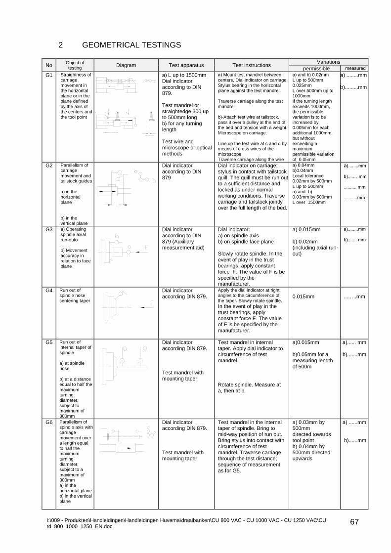
I:\009 - Produkten\Handleidingen\Handleidingen Huvema\draaibanken\CU 800 VAC - CU 1000 VAC - CU 1250 VAC\CU rd_800_1000_1250_EN.doc
67
2 GEOMETRICAL TESTINGS
No Object of testing
Diagram Test apparatus Test instructions Variations
permissible measured
G1 Straightness of carriage movement in the horizontal plane or in the plane defined by the axis of the centers and the tool point
а) L up to 1500mm Dial indicator according to DIN 879. Test mandrel or straightedge 300 up to 500mm long b) for any turning length Test wire and microscope or optical methods
а) Mount test mandrel between centers, Dial indicator on carriage. Stylus bearing in the horizontal plane against the test mandrel. Traverse carriage along the test mandrel. b)-Attach test wire at tailstock, pass it over a pulley at the end of the bed and tension with a weight. Microscope on carriage. Line up the test wire at c and d by means of cross wires of the microscope. Traverse carriage along the wire
а) and b) 0.02mm L up to 500mm 0.025mm L over 500mm up to 1000mm If the turning length exceeds 1000mm, the permissible variation is to be increased by 0.005mm for each additional 1000mm, but without exceeding a maximum permissible variation of 0.05mm
а) ........mm b).........mm
G2 Parallelism of carriage movement and tailstock guides а) in the horizontal plane b) in the vertical plane
Dial indicator according to DIN 879
Dial indicator on carriage; stylus in contact with tailstock quill. The quill must be run out to a sufficient distance and locked as under normal working conditions. Traverse carriage and tailstock jointly over the full length of the bed.
а) 0.04mm b)0.04mm Local tolerance 0.02mm by 500mm L up to 500mm а) and b) 0.03mm by 500mm L over 1500mm
а)........mm
b).....…mm .......... mm ….......mm
G3 а) Operating spindle axial run-outо b) Movement accuracy in relation to face plane
Dial indicator according to DIN 879 (Auxiliary measurement aid)
Dial indicator: а) on spindle axis b) on spindle face plane Slowly rotate spindle. In the event of play in the trust bearings, apply constant force F. The value of F is be specified by the manufacturer.
а) 0.015mm b) 0.02mm (including axial run-out)
а)........mm b)....... mm
G4 Run out of spindle nose centering taper
Dial indicator according DIN 879.
Apply the dial indicator at right angles to the circumference of the taper. Slowly rotate spindle.
In the event of play in the trust bearings, apply constant force F. The value of F is be specified by the manufacturer.
0.015mm
....….mm
G5 Run out of internal taper of spindle а) at spindle nose b) at a distance equal to half the maximum turning diameter, subject to maximum of 300mm
Dial indicator according DIN 879. Test mandrel with mounting taper
Test mandrel in internal taper. Apply dial indicator to circumference of test mandrel. Rotate spindle. Measure at a, then at b.
а)0.015mm b)0.05mm for a measuring length of 500m
а)...... mm b).......mm
G6 Parallelism of spindle axis with carriage movement over a length equal to half the maximum turning diameter, subject to a maximum of 300mm а) in the horizontal plane b) in the vertical plane
Dial indicator according DIN 879. Test mandrel with mounting taper
Test mandrel in the internal taper of spindle. Bring to mid-way position of run out. Bring stylus into contact with circumference of test mandrel. Traverse carriage through the test distance; sequence of measurement as for G5.
а) 0.03mm by 500mm directed towards tool point b) 0.04mm by 500mm directed upwards
а) ......mm b)......mm
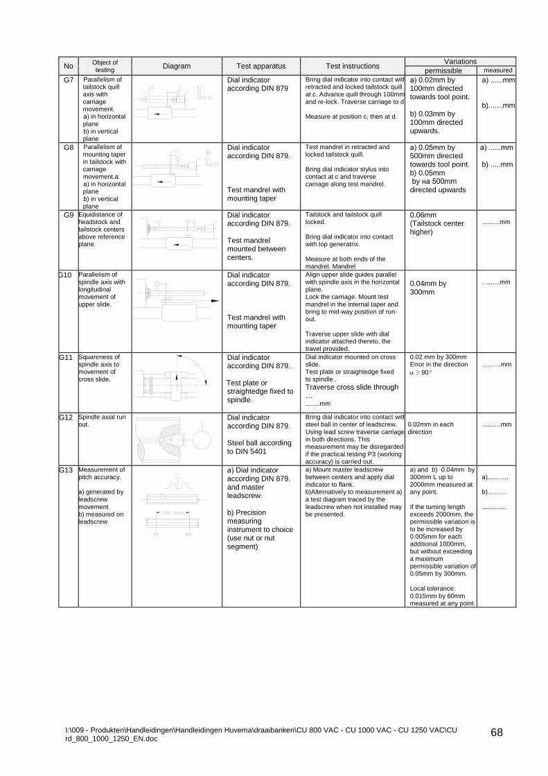
I:\009 - Produkten\Handleidingen\Handleidingen Huvema\draaibanken\CU 800 VAC - CU 1000 VAC - CU 1250 VAC\CU rd_800_1000_1250_EN.doc
68
No Object of testing
Diagram Test apparatus Test instructions Variations
permissible measured
G7 Parallelism of tailstock quill axis with carriage movement. а) in horizontal plane b) in vertical plane
Dial indicator according DIN 879
Bring dial indicator into contact with retracted and locked tailstock quill at c. Advance quill through 100mm and re-lock. Traverse carriage to d. Measure at position с, then at d.
а) 0.02mm by 100mm directed towards tool point. b) 0.03mm by 100mm directed upwards.
а) ......mm b).......mm
G8 Parallelism of mounting taper in tailstock with carriage movement.а. а) in horizontal plane b) in vertical plane
Dial indicator according DIN 879. Test mandrel with mounting taper
Test mandrel in retracted and locked tailstock quill. Bring dial indicator stylus into contact at c and traverse carriage along test mandrel.
а) 0.05mm by 500mm directed towards tool point. b) 0.05mm by на 500mm directed upwards
а) ......mm b) .....mm
G9 Equidistance of headstock and tailstock centers above reference plane.
Dial indicator according DIN 879. Test mandrel mounted between centers.
Tailstock and tailstock quill locked. Bring dial indicator into contact with top generatrix. Measure at both ends of the mandrel. Mandrel
0.06mm (Tailstock center higher)
..........mm
G10 Parallelism of spindle axis with longitudinal movement of upper slide.
Dial indicator according DIN 879. Test mandrel with mounting taper
Align upper slide guides parallel with spindle axis in the horizontal plane. Lock the carriage. Mount test mandrel in the internal taper and bring to mid-way position of run-out. Traverse upper slide with dial indicator attached thereto, the travel provided.
0.04mm by 300mm
..........mm
G11 Squareness of spindle axis to movement of cross slide.
Dial indicator according DIN 879. Test plate or straightedge fixed to spindle.
Dial indicator mounted on cross slide. Test plate or straightedge fixed to spindle..
Traverse cross slide through …
........mm
0.02.mm by 300mm Error in the direction
≥ 90º
.....…..mm
G12 Spindle axial run out.
Dial indicator according DIN 879. Steel ball according to DIN 5401
Bring dial indicator into contact with steel ball in center of leadscrew. Using lead screw traverse carriage in both directions. This measurement may be disregarded if the practical testing P3 (working accuracy) is carried out.
0.02mm in each direction
......….mm
G13 Measurement of pitch accuracy. а) generated by leadscrew movement b) measured on leadscrew
а) Dial indicator according DIN 879. and master leadscrew. b) Precision measuring instrument to choice (use nut or nut segment)
а) Mount master leadscrew between centers and apply dial indicator to flank. b)Alternatively to measurement a) a test diagram traced by the leadscrew when not installed may be presented.
а) and b) 0.04mm by 300mm L up to 2000mm measured at any point. If the turning length exceeds 2000mm, the permissible variation is to be increased by 0.005mm for each additional 1000mm, but without exceeding a maximum permissible variation of 0.05mm by 300mm. Local tolerance: 0.015mm by 60mm measured at any point.
а)......….. b).....….. ........…..
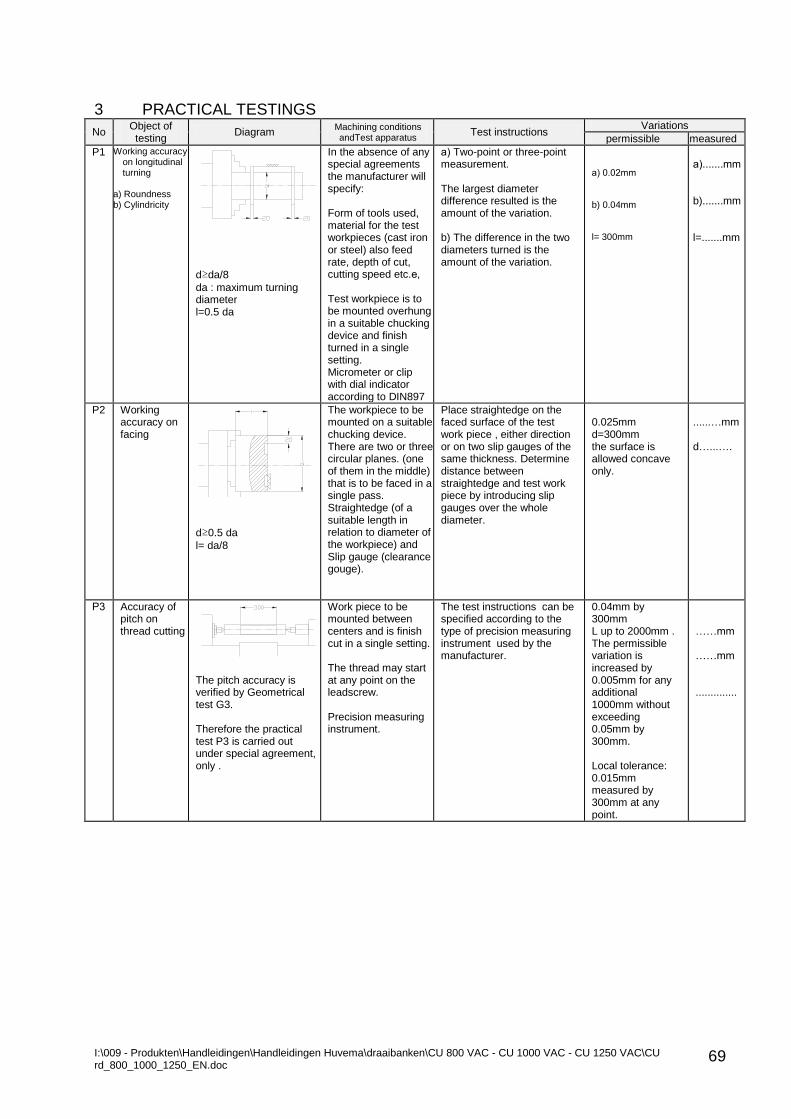
I:\009 - Produkten\Handleidingen\Handleidingen Huvema\draaibanken\CU 800 VAC - CU 1000 VAC - CU 1250 VAC\CU rd_800_1000_1250_EN.doc
69
3 PRACTICAL TESTINGS
No Object of testing
Diagram Machining conditions andTest apparatus
Test instructions Variations
permissible measured
P1 Working accuracy on longitudinal turning
a) Roundness b) Cylindricity
d≥da/8
da : maximum turning diameter l=0.5 da
In the absence of any special agreements the manufacturer will specify: Form of tools used, material for the test workpieces (cast iron or steel) also feed rate, depth of cut, cutting speed etc.е, Test workpiece is to be mounted overhung in a suitable chucking device and finish turned in a single setting. Micrometer or clip with dial indicator according to DIN897
а) Two-point or three-point measurement. The largest diameter difference resulted is the amount of the variation. b) The difference in the two diameters turned is the amount of the variation.
а) 0.02mm b) 0.04mm l= 300mm
а).......mm b).......mm l=.......mm
P2 Working accuracy on facing
d≥0.5 da
l= da/8
The workpiece to be mounted on a suitable chucking device. There are two or three circular planes. (one of them in the middle) that is to be faced in a single pass. Straightedge (of a suitable length in relation to diameter of the workpiece) and Slip gauge (clearance gouge).
Place straightedge on the faced surface of the test work piece , either direction or on two slip gauges of the same thickness. Determine distance between straightedge and test work piece by introducing slip gauges over the whole diameter.
0.025mm d=300mm the surface is allowed concave only.
......…mm d…...….
Р3 Accuracy of pitch on thread cutting
The pitch accuracy is verified by Geometrical test G3. Therefore the practical test P3 is carried out under special agreement, only .
Work piece to be mounted between centers and is finish cut in a single setting. The thread may start at any point on the leadscrew. Precision measuring instrument.
The test instructions can be specified according to the type of precision measuring instrument used by the manufacturer.
0.04mm by 300mm L up to 2000mm . The permissible variation is increased by 0.005mm for any additional 1000mm without exceeding 0.05mm by 300mm. Local tolerance: 0.015mm measured by 300mm at any point.
……mm ……mm ..............
I:\009 - Produkten\Handleidingen\Handleidingen Huvema\draaibanken\CU 800 VAC - CU 1000 VAC - CU 1250 VAC\CU rd_800_1000_1250_EN.doc
70
13. OPTIONAL ACCESSORIES 13.1 THREAD DIAL (Fig. 35)
The Thread dial (option) makes the operator work easy when thread is cutting. When ordered it is mounted by Screw (21) and Screw (12) on the Gearbox right
side wall under the Rapid traverse motor. A continuous line marks the work position of the Thread dial. A dotted line marks the non-working position of the Thread dial. To set the Thread dial into work position loose Screw (12) and after setting
tighten the screw. Compliance with Table A and B, Fig. 1 must be observed when thread is cutting. On position A the Gear (26) is engaged with Gear (29). To set position B pull Axle (7) and Gear (27) mesh with (28). Graduations not marked are equal to number 1 of the Table. For example: A thread of Pitch t = 1.25 mm to be cut:
Set the Thread dial in working position following above said procedure;
Engage the Half-nut to lead screw. Reset the scale i.e., number 1 of the Table must align with the Pointer (4). This is set by the two Nuts (2) and (31). When the thread end is reached disengage Half-nut from Lead screw and move the carriage back by Rapid traverse;
For any next cut observe that the Thread pitch number align with the Pointer. Then engage the Half-nut.
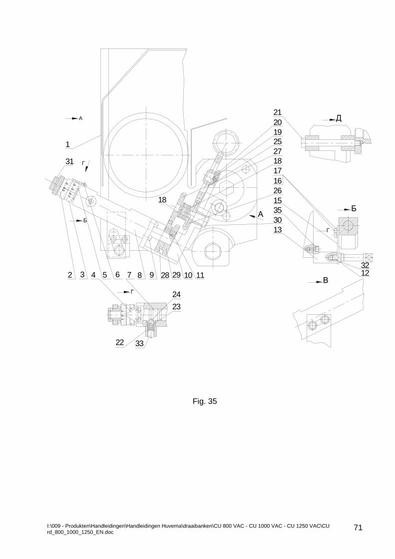
I:\009 - Produkten\Handleidingen\Handleidingen Huvema\draaibanken\CU 800 VAC - CU 1000 VAC - CU 1250 VAC\CU rd_800_1000_1250_EN.doc
71
Fig. 35
Д
Г
72
35
3
Б
Г
В
21
20
19
25
27
18
17
16
26
15
35
30
13
2 3 4 5 6 7 8 9 28 29 10 11 1232
24
23
22 33
Б
A
18
Г31
1
А
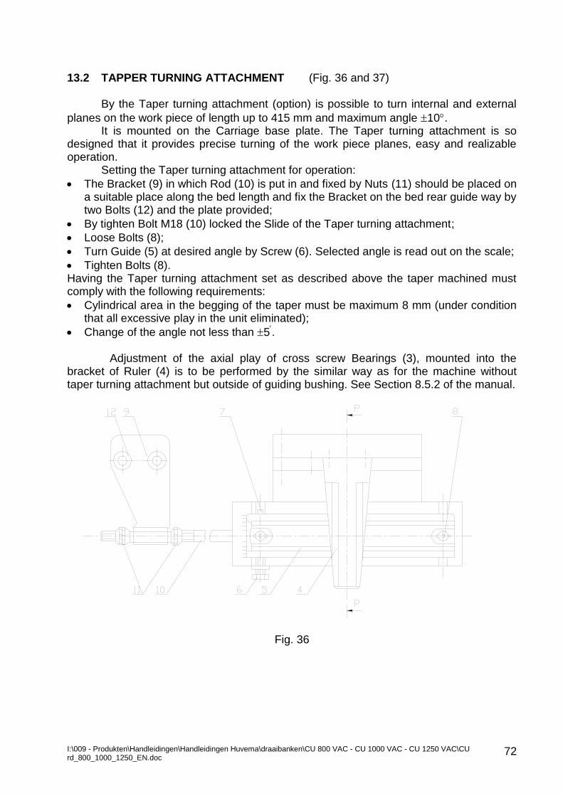
I:\009 - Produkten\Handleidingen\Handleidingen Huvema\draaibanken\CU 800 VAC - CU 1000 VAC - CU 1250 VAC\CU rd_800_1000_1250_EN.doc
72
13.2 TAPPER TURNING ATTACHMENT (Fig. 36 and 37)
By the Taper turning attachment (option) is possible to turn internal and external
planes on the work piece of length up to 415 mm and maximum angle 10. It is mounted on the Carriage base plate. The Taper turning attachment is so
designed that it provides precise turning of the work piece planes, easy and realizable operation.
Setting the Taper turning attachment for operation:
The Bracket (9) in which Rod (10) is put in and fixed by Nuts (11) should be placed on a suitable place along the bed length and fix the Bracket on the bed rear guide way by two Bolts (12) and the plate provided;
By tighten Bolt M18 (10) locked the Slide of the Taper turning attachment;
Loose Bolts (8);
Turn Guide (5) at desired angle by Screw (6). Selected angle is read out on the scale;
Tighten Bolts (8). Having the Taper turning attachment set as described above the taper machined must comply with the following requirements:
Cylindrical area in the begging of the taper must be maximum 8 mm (under condition that all excessive play in the unit eliminated);
Change of the angle not less than 5.
Adjustment of the axial play of cross screw Bearings (3), mounted into the bracket of Ruler (4) is to be performed by the similar way as for the machine without taper turning attachment but outside of guiding bushing. See Section 8.5.2 of the manual.
Fig. 36
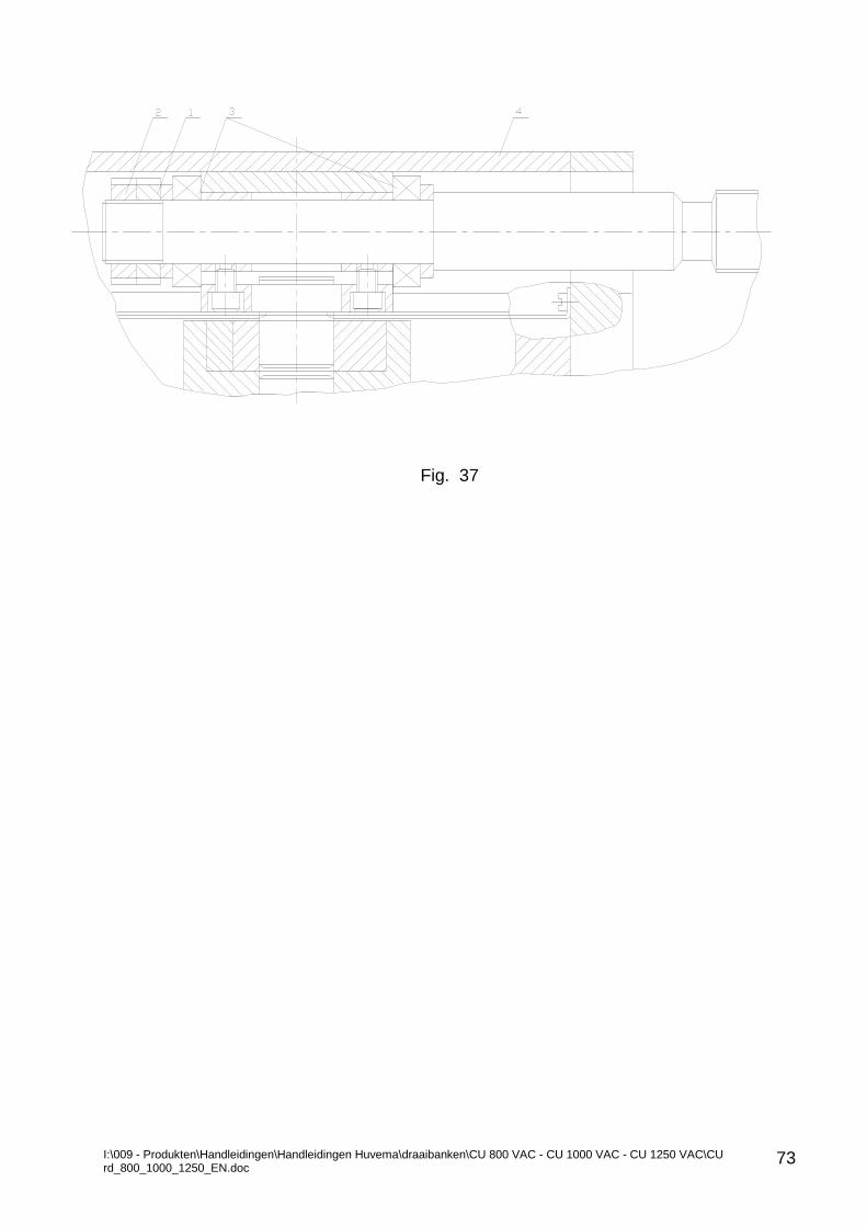
I:\009 - Produkten\Handleidingen\Handleidingen Huvema\draaibanken\CU 800 VAC - CU 1000 VAC - CU 1250 VAC\CU rd_800_1000_1250_EN.doc
73
Fig. 37
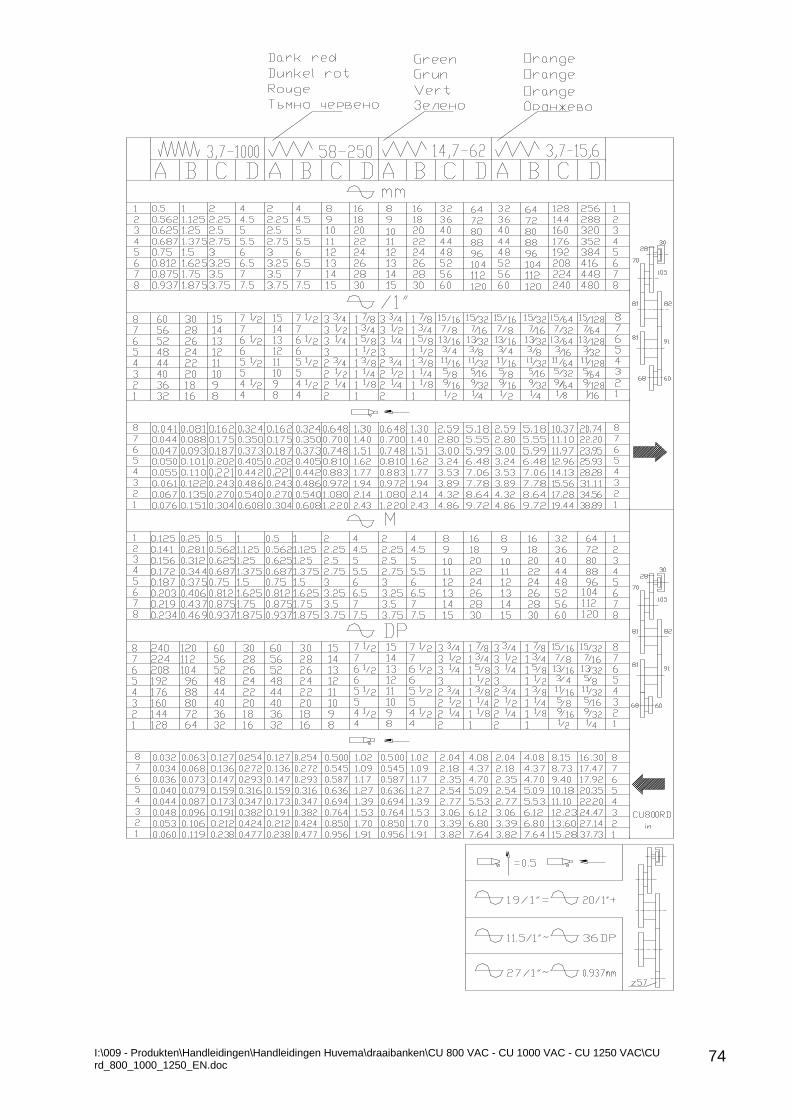
I:\009 - Produkten\Handleidingen\Handleidingen Huvema\draaibanken\CU 800 VAC - CU 1000 VAC - CU 1250 VAC\CU rd_800_1000_1250_EN.doc
74
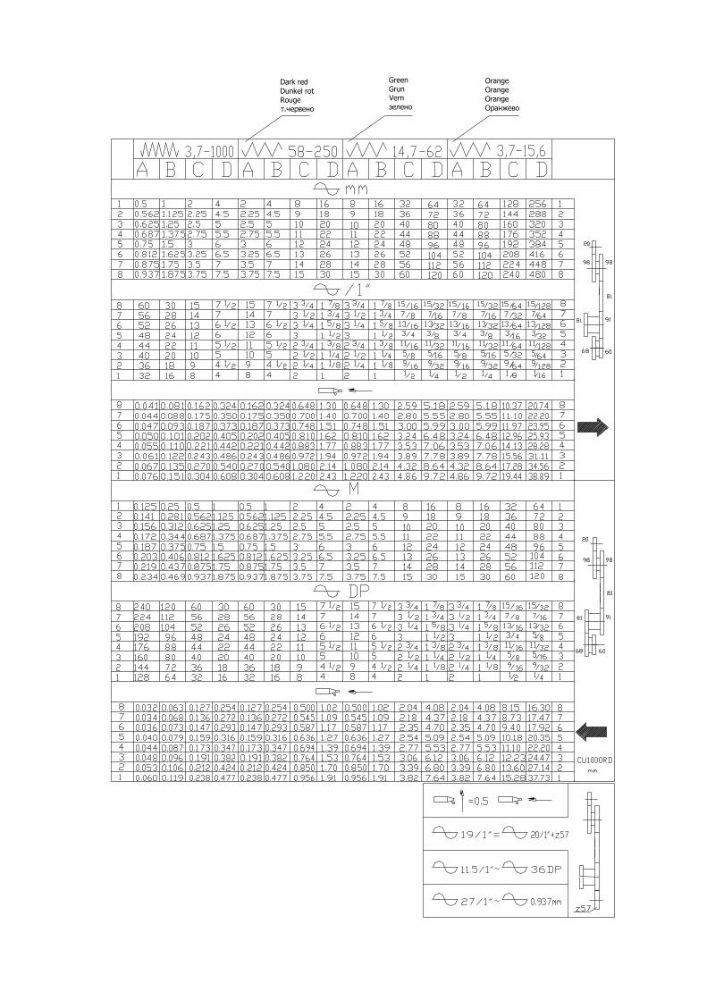
I:\009 - Produkten\Handleidingen\Handleidingen Huvema\draaibanken\CU 800 VAC - CU 1000 VAC - CU 1250 VAC\CU rd_800_1000_1250_EN.doc
75
Dark red
Dunkel rot
Rouge
т.червено
Green
Grun
Vern
зелено
Orange
Orange
Orange
Оранжево
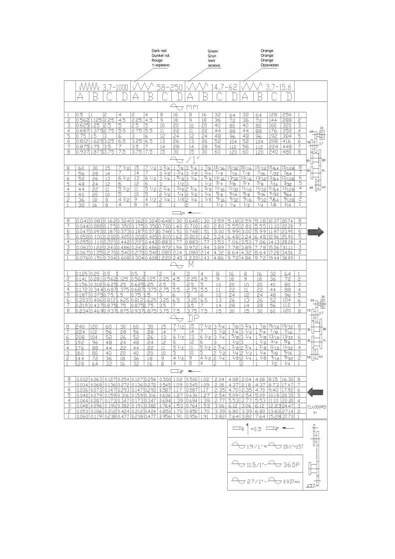
I:\009 - Produkten\Handleidingen\Handleidingen Huvema\draaibanken\CU 800 VAC - CU 1000 VAC - CU 1250 VAC\CU rd_800_1000_1250_EN.doc
76
Dark red
Dunkel rot
Rouge
т.червено
Green
Grun
Vert
зелено
Orange
Orange
Orange
Оранжево
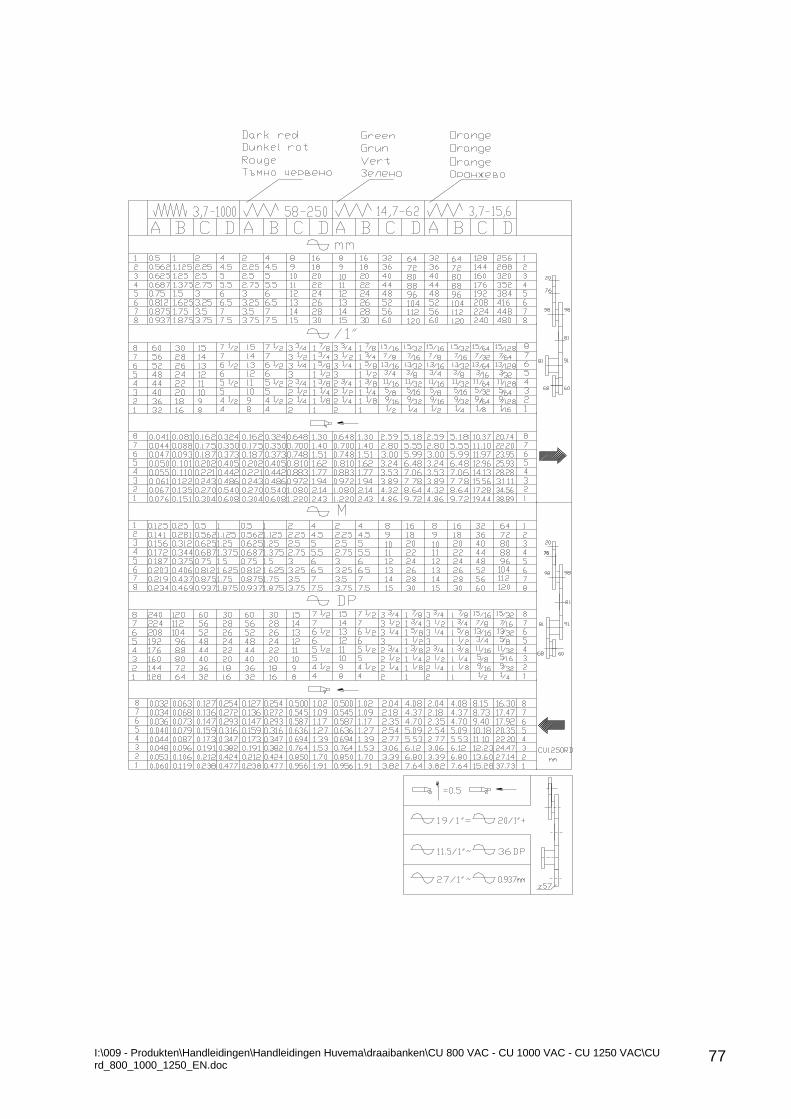
I:\009 - Produkten\Handleidingen\Handleidingen Huvema\draaibanken\CU 800 VAC - CU 1000 VAC - CU 1250 VAC\CU rd_800_1000_1250_EN.doc
77
76
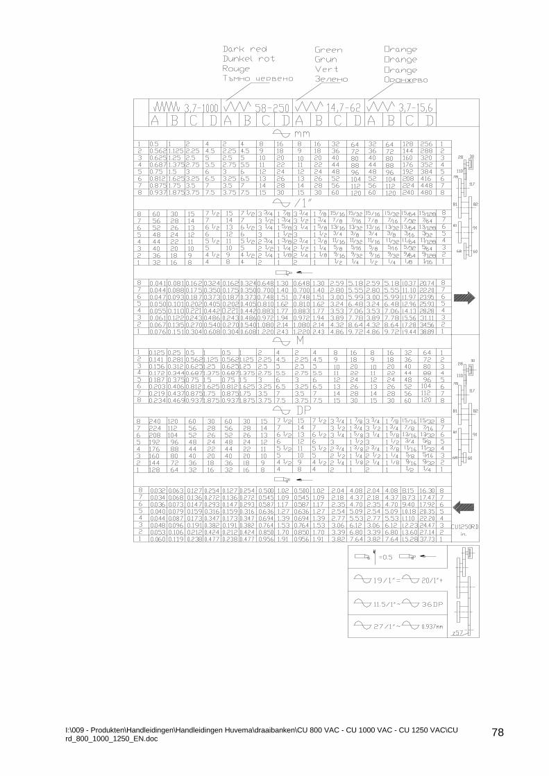
I:\009 - Produkten\Handleidingen\Handleidingen Huvema\draaibanken\CU 800 VAC - CU 1000 VAC - CU 1250 VAC\CU rd_800_1000_1250_EN.doc
78


![5Z]feVU ]`T\U`h_ eZ]] >Rj "( - Daily Pioneer](https://img.pdfslide.net/doc/110x75/63252fe4e491bcb36c0a2da8/5zfevu-tuh-ez-rj-daily-pioneer.jpg)


