Embed Size (px)
Citation preview
Journal européen des systèmes automatisés – n° 3/2017, 285-298
Dynamic features and optimal lathe bed
structure of horizontal machining center
Wei Wang
School of Mechanical Engineering, Baoji University of Atrs & Science, Baoji
721016, China
ABSTRACT. The static and dynamic performance of the lathe bed structure is essential to the
performance of the entire machine. Targeting the lathe bed of a horizontal machining center,
this paper analyses the dynamic features and optimizes the lathe bed structure. Firstly, a
simplified finite-element model of the lathe bed was established, and the finite-element
analysis software ANSYS Workbench was adopted for futher analysis. Secondly, the natural
frequencies of the first four orders and vibration modes of the lathe bed were investigated
through the static analysis and vibration modal analysis of the slide structure, thereby
measuring the dynamic performance of the lathe bed by the natural frequency. Next, the
author identified the weak links of the structural stiffness of the lathe bed and proposed an
effective solution to these weaknesses. The solution reduced the maximum deformation of the
optimized lathe bed by 8.3% and the maximum stress by 0.13%, which achieves the
optimization goal. Finally, machining experiments were conducted on a trial machine and a
setting machine with the same contour and specifications. The results show that the proposed
optimization solution is feasible for the improvement of the lathe bed. The research findings
boast profound significance for similar studies.
RÉSUMÉ. Les performances statiques et dynamiques de la structure du banc du tour sont
essentielles à la performance de la machine entière. Ciblant le banc de tour d'un centre
d'usinage horizontal, cet article analyse les caractéristiques dynamiques et optimise la
structure du banc de tour. Tout d'abord, un modèle simplifié par éléments finis du banc de
tour a été mis en place et le logiciel d'analyse par éléments finis ANSYS Workbench a été
adopté pour une analyse ultérieure. Deuxièmement, les fréquences propres des quatre
premiers ordres et les modes de vibration du banc du tour ont été étudiés par analyse statique
et analyse modale de vibration de la structure de la glissière, mesurant ainsi la performance
dynamique du banc du tour par la fréquence naturelle. Ensuite, l’auteur a identifié les
maillons faibles de la rigidité structurelle du banc du tour et proposé une solution efficace à
ces faiblesses. La solution a réduit la déformation maximale du banc de tour optimisé de
8,3% et la contrainte maximale de 0,13%, ce qui permet d'atteindre l'objectif d'optimisation.
Enfin, des expérimentations d’usinage ont été menées sur une machine d’essai et une machine
de réglage ayant les mêmes contours et spécifications. Les résultats montrent que la solution
d'optimisation proposée est réalisable pour l'amélioration du banc du tour. Les résultats de la
recherche ont une signification profonde pour des études similaires.
KEYWORDS: natural frequency, dynamic performance, structural optimization.
286 JESA. Volume 50 – n° 3/2017
MOTS-CLÉS: fréquence naturelle, performance dynamique, optimisation structurelle.
DOI:10.3166/JESA.50.285-298 © 2017 Lavoisier
1. Introduction
The horizontal machining center is composed of a lathe bed, an upright column,
a workbench and a spindle box, of which the lathe bed is one of the key components
of the machine tool and the basis of the whole machine tool, which mainly plays the
role of bearing, supporting all the parts of the machine tool (Rong et al., 2000;
Mahdavinejad, 2005; Bao & Tansel, 2000; Bai et al., 2009; Asad et al., 2007).
Therefore, the static and dynamic performance of the lathe bed structure is one of
the important factors that determine the performance of the machine tool, directly
affecting its accuracy and stability. Qiu Zheng, Zhang Song, et al., set up the finite
element model of the feed system, conduct analysis using ANSYS Workbench
software, and optimize the dimension of the workbench with improvement of its
natural frequency as the goal (Belblidia et al., 1999; Rong et al., 2000). Wu Xiuhai
et al. obtain the characteristic parameter of guide rail joint by dynamic testing
method and apply it to digital simulation model, thus improving the precision of the
model (Yildirim, 2001). Chen Xin takes the natural frequency and relative vibration
displacement as the evaluation criteria for the design scheme to dynamically
optimize the grinder lathe bed and the whole machine (Paredes et al., 2001).
This study takes the lathe bed of a large horizontal machining center as the
research object. Due to lack of support for the dynamic characteristic analysis in the
traditional experience design of the lathe bed, the lathe bed has such problems as
vibration and unreasonable distribution of structures. Therefore, it is necessary to
dynamically analyze the lathe bed of the horizontal machining center and then to
optimize its structure based on the analysis. In this paper, the three-dimensional
lathe bed model is established, the static and dynamic analysis of lathe bed structure
is carried out using finite element software ANSYS Workbench, and the lathe bed
structure is optimized according to the analysis results.
2. Theory of dynamic characteristic analysis
The oscillatory differential equation of an undamped system with n degrees of
freedom is (Zaeh et al., 2004):
m x k x F+ = (1)
Where, [m] is n×n-dimensional mass matrix, [k] is n×n-dimensional stiffness
matrix, [x] is n-dimensional column vector, and [F] is external excitation matrix.
That is,
0m x k x+ = (2)
Dynamic analysis and optimization of machine tools 287
Let the solution of the equation be
sin( )x A t = + (3)
Substitute Equation (3) into (2) and simplify it, it can be obtained that
2 0k m− = (4)
Solve this equation to obtain n reciprocal positive roots of ω, ωoi (i=1, 2, 3…, n),
which are usually arranged in ascending order of 0<ωo1<ωo2…<ωom. Then the i-th
order natural frequency is
1
2
ioi
i
kf
m=
(5)
It can be seen that the natural frequencies signify the advantages and
disadvantages of their dynamic characteristics. The natural frequency of each order
is proportional to K. When the natural frequency is increased, the static stiffness of
the structure is also increased accordingly. Therefore, the overall performance of the
bed relies on the improvement of the bed structure, which mainly starts from raising
the stiffness of the weak links.
3. Static analysis of lathe bed structure
3.1. Establishment of the finite element model
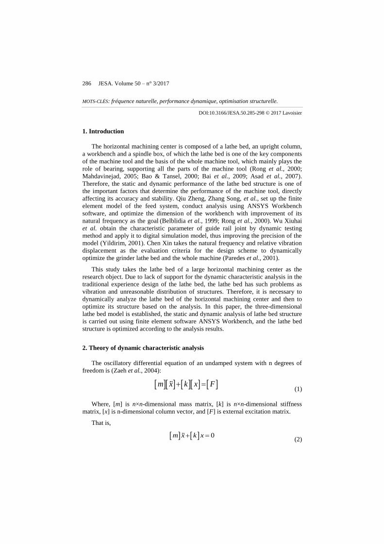
The horizontal machining center bed is made of QT-400-15 precision casting,
with a dead weight of 8,300kg. The interior mainly adopts square reinforcement
design, with the thickness of the gusset of 20mm, and the thickness of the main plate
of 25mm. The span of the two guide rails of the X-axis is 800mm and span of the
two guide rails of the Z-axis is 750mm. In the process of solid modeling, the
chamfering, fillets and grooves are removed and the smaller holes are removed for
reasonable simplification. Finally, the simplified three-dimensional solid model of
the lathe bed of the horizontal machining center is as shown in Figure 1.
Figure 1. Simplified 3D solid model of lathe bed
288 JESA. Volume 50 – n° 3/2017
3.2. Static analysis of lathe bed
According to the research content of the subject and the actual working
conditions of the machine tool (the upright column is at the middle position of X-
axis travel, slide is near the limit position at the rear end of Z-axis travel, and the
spindle box is near the limit of 150mm at the lower end of Y-axis), the horizontal
machining center is mainly subject to its own gravity, maximum bearing load of the
workbench, and cutting force, while neglecting the influence of other attachment
forces. The undertaken force is shown in Table 1.
Table 1. Dead weight and load of components of the horizontal machining center
Project Unit Force Remark
Bed component gravity G1 N 90 000 Chip conveyor
Column assembly gravity G2 N 25 000
Spindle assembly gravity G4 N 4 500
Workbench slide and table assembly gravity G5 N 9 500 Workbench center
Maximum load-bearing of worktable G6 N 12 000 Maxload of worktable
Exchange desk component gravity G7 N 26 000
cutting force FC N 10 000 Max cutting resistance
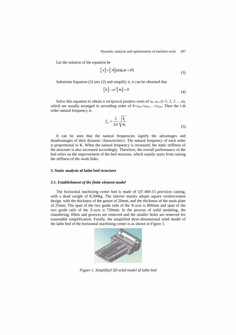
According to the corresponding load distribution of lathe bed in Table 1, the
upright column assembly gravity G2 (column center), the spindle assembly gravity
G4, the cutting force FC, the gravity of workbench and workbench slide G5, the
maximum load of workbench G6, and the exchange station gravity G7 are
respectively applied on the mounting surfaces of the lathe bed by Remote Force
command. At the same time, gravity is applied to the lathe bed by the Standard
Earth Gravity command or gravity acceleration. The final loading conditions of the
lathe bed model are shown in Figure 2:
Figure 2. Load of lathe bed
Dynamic analysis and optimization of machine tools 289
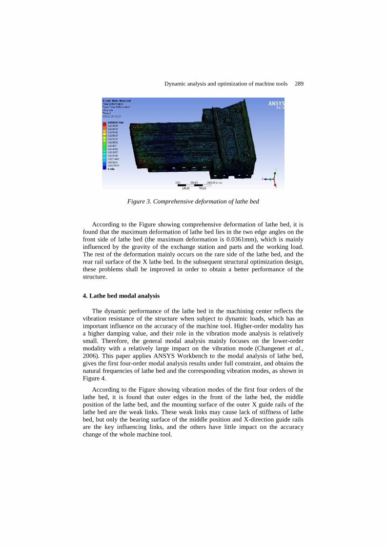
Figure 3. Comprehensive deformation of lathe bed
According to the Figure showing comprehensive deformation of lathe bed, it is
found that the maximum deformation of lathe bed lies in the two edge angles on the
front side of lathe bed (the maximum deformation is 0.0361mm), which is mainly
influenced by the gravity of the exchange station and parts and the working load.
The rest of the deformation mainly occurs on the rare side of the lathe bed, and the
rear rail surface of the X lathe bed. In the subsequent structural optimization design,
these problems shall be improved in order to obtain a better performance of the
structure.
4. Lathe bed modal analysis
The dynamic performance of the lathe bed in the machining center reflects the
vibration resistance of the structure when subject to dynamic loads, which has an
important influence on the accuracy of the machine tool. Higher-order modality has
a higher damping value, and their role in the vibration mode analysis is relatively
small. Therefore, the general modal analysis mainly focuses on the lower-order
modality with a relatively large impact on the vibration mode (Changenet et al.,
2006). This paper applies ANSYS Workbench to the modal analysis of lathe bed,
gives the first four-order modal analysis results under full constraint, and obtains the
natural frequencies of lathe bed and the corresponding vibration modes, as shown in
Figure 4.
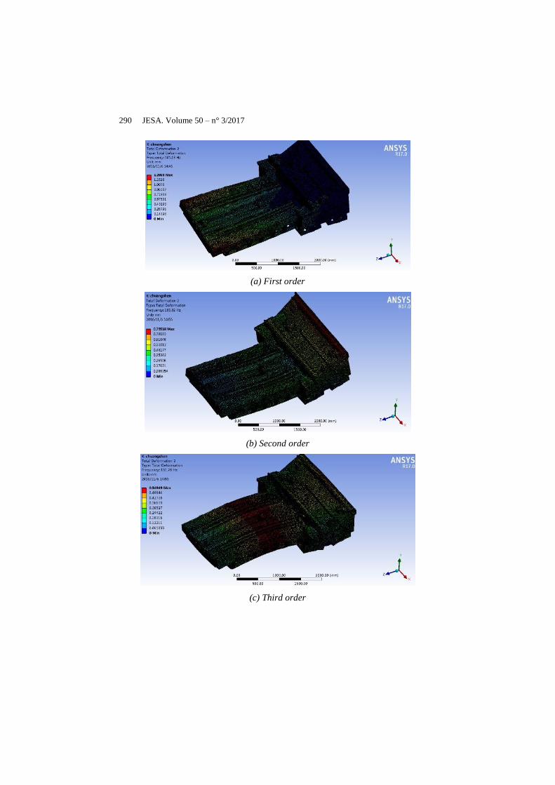
According to the Figure showing vibration modes of the first four orders of the
lathe bed, it is found that outer edges in the front of the lathe bed, the middle
position of the lathe bed, and the mounting surface of the outer X guide rails of the
lathe bed are the weak links. These weak links may cause lack of stiffness of lathe
bed, but only the bearing surface of the middle position and X-direction guide rails
are the key influencing links, and the others have little impact on the accuracy
change of the whole machine tool.
290 JESA. Volume 50 – n° 3/2017
(a) First order
(b) Second order
(c) Third order
Dynamic analysis and optimization of machine tools 291
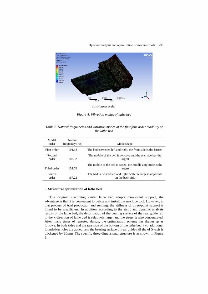
(d) Fourth order
Figure 4. Vibration modes of lathe bed
Table 2. Natural frequencies and vibration modes of the first four order modality of
the lathe bed
Modal
order
Natural
frequency (Hz) Mode shape
First order 101.18 The bed is twisted left and right, the front side is the largest
Second
order 103.32
The middle of the bed is concave and the rear side has the
largest
Third order 151.78
The middle of the bed is raised, the middle amplitude is the
largest
Fourth
order 167.22
The bed is twisted left and right, with the largest amplitude
on the back side
5. Structural optimization of lathe bed
The original machining center lathe bed adopts three-point support, the
advantage is that it is convenient to debug and install the machine tool. However, in
that process of trial production and running, the stiffness of three-point support is
found to be insufficient. In addition, according to the static and dynamic analysis
results of the lathe bed, the deformation of the bearing surface of the rear guide rail
in the x direction of lathe bed is relatively large, and the stress is also concentrated.
After many times of repeated design, the optimization scheme has drawn up as
follows: In both sides and the rare side of the bottom of the lathe bed, two additional
foundation holes are added, and the bearing surface of rear guide rail the of X-axis is
thickened by 30mm. The specific three-dimensional structure is as shown in Figure
5.
292 JESA. Volume 50 – n° 3/2017
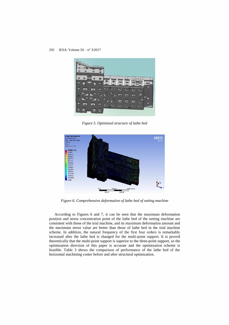
Figure 5. Optimized structure of lathe bed
Figure 6. Comprehensive deformation of lathe bed of setting machine
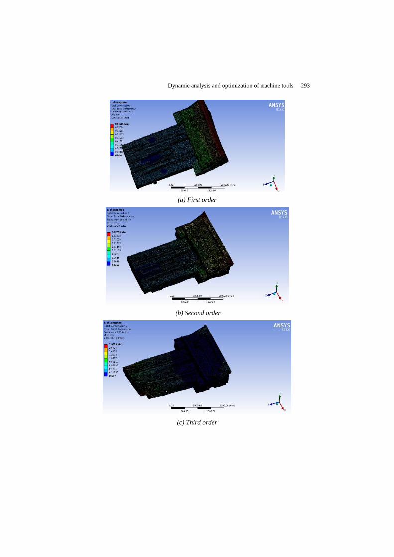
According to Figures 6 and 7, it can be seen that the maximum deformation
position and stress concentration point of the lathe bed of the setting machine are
consistent with those of the trial machine, and its maximum deformation amount and
the maximum stress value are better than those of lathe bed in the trial machine
scheme. In addition, the natural frequency of the first four orders is remarkably
increased after the lathe bed is changed for the multi-point support. It is proved
theoretically that the multi-point support is superior to the three-point support, so the
optimization direction of this paper is accurate and the optimization scheme is
feasible. Table 3 shows the comparison of performance of the lathe bed of the
horizontal machining center before and after structural optimization.
Dynamic analysis and optimization of machine tools 293
(a) First order
(b) Second order
(c) Third order
294 JESA. Volume 50 – n° 3/2017
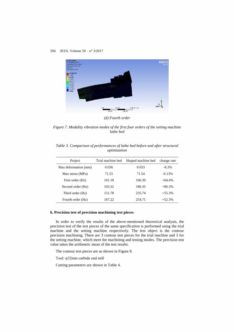
(d) Fourth order
Figure 7. Modality vibration modes of the first four orders of the setting machine
lathe bed
Table 3. Comparison of performances of lathe bed before and after structural
optimization
Project Trial machine bed Shaped machine bed change rate
Max deformation (mm) 0.036 0.033 -8.3%
Max stress (MPa) 71.55 71.54 -0.13%
First order (Hz) 101.18 166.39 +64.4%
Second order (Hz) 103.32 186.35 +80.3%
Third order (Hz) 151.78 235.74 +55.3%
Fourth order (Hz) 167.22 254.71 +52.3%
6. Precision test of precision machining test pieces
In order to verify the results of the above-mentioned theoretical analysis, the
precision test of the test pieces of the same specification is performed using the trial
machine and the setting machine respectively. The test object is the contour
precision machining. There are 3 contour test pieces for the trial machine and 3 for
the setting machine, which meet the machining and testing modes. The precision test
value takes the arithmetic mean of the test results.
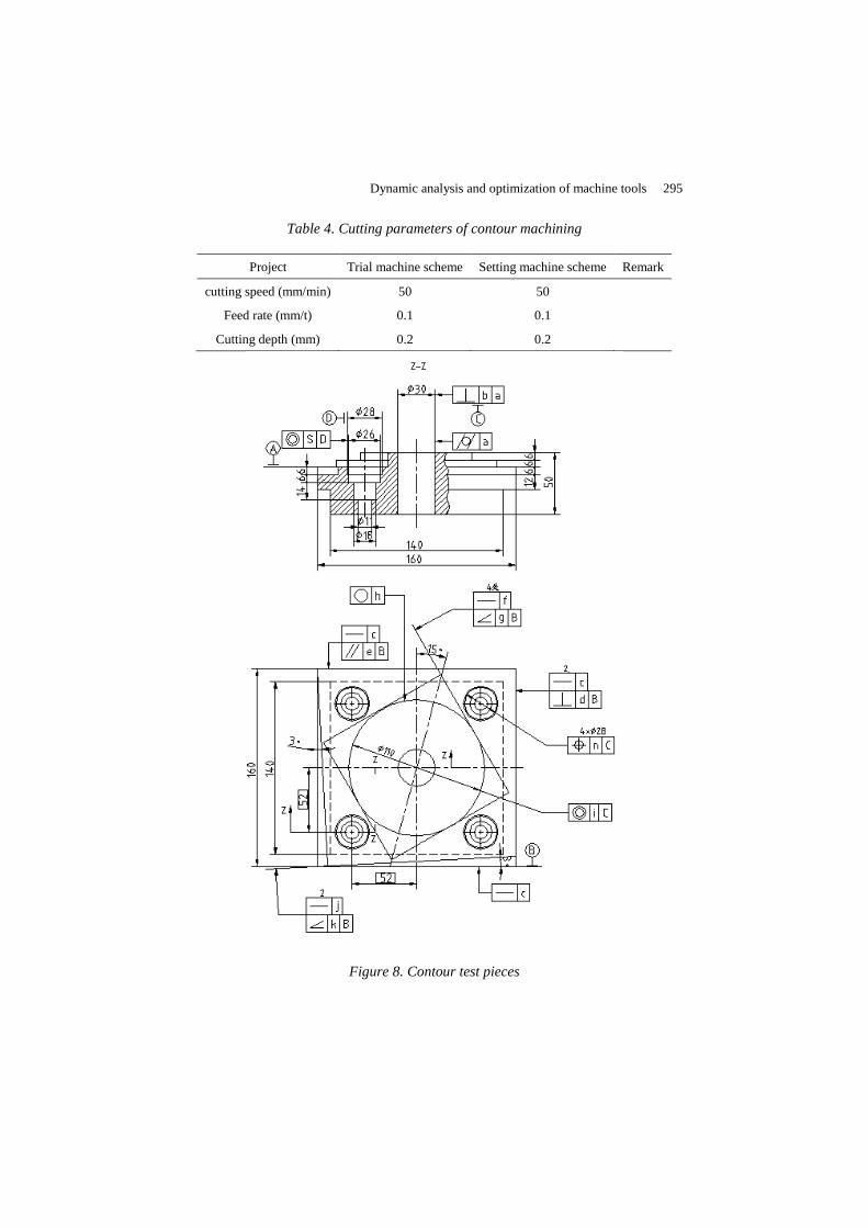
The contour test pieces are as shown in Figure 8.
Tool: φ32mm carbide end mill
Cutting parameters are shown in Table 4.
Dynamic analysis and optimization of machine tools 295
Table 4. Cutting parameters of contour machining
Project Trial machine scheme Setting machine scheme Remark
cutting speed (mm/min) 50 50
Feed rate (mm/t) 0.1 0.1
Cutting depth (mm) 0.2 0.2
Figure 8. Contour test pieces
296 JESA. Volume 50 – n° 3/2017
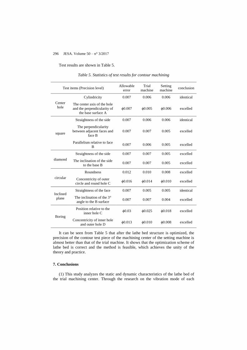
Test results are shown in Table 5.
Table 5. Statistics of test results for contour machining
Test items (Precision level) Allowable
error
Trial
machine
Setting
machine conclusion
Center
hole
Cylindricity 0.007 0.006 0.006 identical
The center axis of the hole
and the perpendicularity of
the base surface A
ϕ0.007 ϕ0.005 ϕ0.006 excelled
square
Straightness of the side 0.007 0.006 0.006 identical
The perpendicularity
between adjacent faces and
face B
0.007 0.007 0.005 excelled
Parallelism relative to face
B 0.007 0.006 0.005 excelled
diamond
Straightness of the side 0.007 0.007 0.005 excelled
The inclination of the side
to the base B 0.007 0.007 0.005 excelled
circular
Roundness 0.012 0.010 0.008 excelled
Concentricity of outer
circle and round hole C ϕ0.016 ϕ0.014 ϕ0.010 excelled
Inclined
plane
Straightness of the face 0.007 0.005 0.005 identical
The inclination of the 3°
angle to the B surface 0.007 0.007 0.004 excelled
Boring
Position relative to the
inner hole C ϕ0.03 ϕ0.025 ϕ0.018 excelled
Concentricity of inner hole
and outer hole D ϕ0.013 ϕ0.010 ϕ0.008 excelled
It can be seen from Table 5 that after the lathe bed structure is optimized, the
precision of the contour test piece of the machining center of the setting machine is
almost better than that of the trial machine. It shows that the optimization scheme of
lathe bed is correct and the method is feasible, which achieves the unity of the
theory and practice.
7. Conclusions
(1) This study analyzes the static and dynamic characteristics of the lathe bed of
the trial machining center. Through the research on the vibration mode of each
Dynamic analysis and optimization of machine tools 297
frequency, the deformation of the trial lathe bed in different frequency vibration
mode is analyzed, and the weak links of structural stiffness are pointed out.
(2) This study optimizes the lathe bed structure. The comparison of mechanical
properties before and after the structural optimization of the lathe bed shows that the
maximum deformation of lathe bed after optimization is reduced by 8.3%, and the
maximum stress is reduced by 0.13%, thus the optimization goal has been achieved
and a more reasonable lathe bed structure has been determined, which has laid the
foundation and provided a certain direction for the optimization of the whole
machine of the horizontal machining center.
(3) Through machining experiments on contour test pieces of the same
specification using trial machine and the setting machine respectively, it is shown
that the optimization scheme for the lathe bed mechanism is feasible, thus the
research has certain practical significance.
Acknowledgements
The project of Shaanxi Provincial Education Department (16JK1051). The key
project of Baoji University of Atrs & Science (ZK2017015), (ZK15030).
Reference
Asad A. B. M. A., Masaki T., Rahman M., Lim H., Wong Y. (2007). Tool-based micro-
machining. Journal of Materials Processing Technology, Vol. 192, No. 5, pp. 204-211.
https://doi.org/10.1016/j.jmatprotec.2007.04.038
Bai Q. S., Yang K., Liang Y. C., Yang C. L. (2009). Tool run out effects on wear and
mechanics behavior in micro end milling. Journal of Vacuum Science & Technology B
Microelectronics & Nanometer Structures, Vol. 27, No. 3, pp. 1566-1572.
https://doi.org/10.1116/1.3058729
Bao W. Y., Tansel I. N. (2000). Modeling micro-end-milling operations. Part II: tool run-out.
International Journal of Machine Tools & Manufacture, Vol. 40, No. 15, pp. 2175-2192.
https://doi.org/10.1016/S0890-6955(00)00055-9
Belblidia F., Afonso S. M. B., Hinton E., Antonino G. C. R. (1999). Integrated design
optimization of stiffened plate structures. Engineering Computations, Vol. 16, No. 8, pp.
934-952. https://doi.org/10.1108/02644409910304185
Changenet C., Oviedo-Marlot X., Velex P. (2006). Power loss predictions in geared
transmissions using thermal networks-applications to a six-speed manual gearbox.
Journal of Mechanical Design, Vol. 128, No. 3, pp. 618-625.
https://doi.org/10.1115/1.2181601
Mahdavinejad R. (2005). Finite element analysis of machine and work piece instability in
turning. International Journal of Machine Tools and Manufacture, Vol. 45, No. 7-8, pp.
753-760. https://doi.org/10.1016/j.ijmachtools.2004.11.017
Paredes M., Sartor M., Masclet C. (2001). An optimization process f or extension spring
design. Computer Methods in App lied Mechanics and Engineering, Vol. 191, No. 8, pp.
783-797. https://doi.org/10.1016/S0045-7825(01)00289-4

298 JESA. Volume 50 – n° 3/2017
Rong J. H., Xie Y. M., Yang X. Y., Liang Q. (2000). Topology optimization of structures
under dynamic response constraints. Journal of Sound and Vibration, Vol. 234, No. 2, pp.
179-189. https://doi.org/10.1006/jsvi.1999.2874
Yildirim V. (2001). Free vibration of uniaxial composite cylindrical helical springs with
circular section. Journal of Sound and Vibration, Vol. 239, No. 2, pp. 321-333.
https://doi.org/10.1006/jsvi.2000.3168
Zaeh M. F., Oertli T., Milberg J. (2004). Finite element modeling of ball screw feed drive
systems. CIRP Annals-Manufacturing Technology, Vol. 53, No. 1, pp. 289-292.


