Embed Size (px)
Citation preview
UNIVERSITE DU QUÉBEC A CHICOUTIMI
THESIS PRESENTED TO THE
UNIVERSITY OF QUEBEC AT CHICOUTIMI
IN PARTIAL FULFILLMENT OF
THE REQUIREMENT FOR THE DEGREE OF
DOCTOR OF PHILOSOPHY IN ENGINEERING
BY
YASSER ZEDAN
MACHINABILITY ASPECTS OF HEAT-TREATED
Al-(6-ll)% Si CAST ALLOYS: ROLE OF INTERMETALLICS
AND FREE-CUTTING ELEMENTS
MAY 2010
UNIVERSITÉ DU QUÉBEC A CHICOUTIMI
THESE
PRÉSENTÉE À
L'UNIVERSITÉ DU QUÉBEC À CHICOUTIMI
COMME EXIGENCE PARTIELLE
DU DOCTORAT EN INGÉNIERIE
PAR
YASSER ZEDAN
ASPECTS DE L'USINAGE DES ALLIAGES DE FONDERIE
Al-(6-ll)% Si TRAITÉS THERMIQUEMENT : RÔLE DES
INTERMÉTALLIQUES ET DES ÉLÉMENTS DE
DÉCOLLETAGE
MAI 2010

Dedicated to my parents, my wife Noha,and to my children AH and Hana.
RESUME
Le besoin de combler le vide entre les procédés de coulé et d'usinage donne debonnes raisons d'examiner les nombreux aspects affectant l'usinabilité des alliages defonderie Al-Si. Les alliages quasi-eutectiques sont, parmi les alliages Al-Si, les plusdifficiles à usiner, puisque les particules de la phase Si sont environ 10 fois plus dures quela matrice d'aluminium, lesquelles expliquent pourquoi les outils de coupe s'usentprématurément. Toutes ces difficultés nécessitent une meilleure compréhension des effetsde la microstructure sur l'usinabilité de ces alliages.
Ce travail a été mené dans le but d'étudier un nouvel alliage expérimentalappartenant au groupe des alliages de fonderie Al-Si quasi-eutectique contenant environ10,8%Si, à savoir l'alliage 396. Suite à ce qui a été soulevé, l'objectif principal de se travailest de rapporter les changements des critères d'usinage résultant des effets desintermétalliques de fer, à savoir a-Fe, /?-Fe et « sludge »; de deux niveaux de Cu, à savoir2,25 et 3,5%; et de deux niveaux de Mg, à savoir 0,3 et 0,6%. De plus, les effets desalliages sans Mg et modifiés au Sr ont également été étudiés en plus des effets des élémentsde décolletage tels que Sn, Bi et Pb. Le traitement thermique T6 a été sélectionné pourétablir le niveau de dureté des alliages étudiés à l'intérieur d'une plage de 110± 10 BHN,conforme à la plupart des niveaux de dureté pour les applications commerciales des alliagesd'aluminium. La mesure de la dureté a été faite directement sur les blocs d'usinage pourassurer que les échantillons possèdent le niveau de dureté requis. Tous ces alliages ontégalement été testés mécaniquement de façon à obtenir une compréhension des effets desadditifs sur les propriétés mécaniques de tractions pour les mêmes conditions appliquéesaux blocs de test d'usinage.
Les tests d'usinage ont été faits sur une machine d'usinage horizontale haute vitesseMakino A88E sous des conditions fixes lesquelles incluent la vitesse de coupe, la vitessed'avance, la longueur de la coupe, la géométrie de l'outil, le matériau de l'outil ainsi que leliquide de refroidissement. Les critères d'usinage observés sont les forces et les momentstotal de coupe, la durée de vie de l'outil en termes de nombre de trous percés ou taraudésjusqu'au bris de l'outil, la morphologie des copeaux et l'arête rapporté (BUE).
Les résultats démontrent que la présence de « sludge » sous la forme de points dursa un effet sur la force de coupe et la durée de vie de l'outil qui est réduite de moitié parrapport à l'alliage de base. La formation de la phase a-Fe dans l'alliage Ml a un effetbénéfique sur la durée de vie de l'outil, ainsi cet alliage est celui qui donne le plus grandnombre de trous percés comparativement aux alliages contenant le « sludge » ou /?-Fe; cesrésultats pourraient être expliqués par le fait que la formation des intermétalliques a-Feavec leur morphologie de scripts chinois arrondis et de leur présence à l'intérieur desdendrites a-Al améliore l'homogénéité de la matrice par un durcissement des dendrites.L'augmentation du fer de 0,5% à 1% dans l'alliage 396-T6 contenant 0,5% Mn produit uneamélioration distincte de l'usinabilité en termes de force de coupe et de durée de vie del'outil. Lors des tests de taraudage, il a été trouvé que les outils en acier rapide sontconsidérablement plus sensibles aux phases intermétalliques de fer que les outils en carbure
11
utilisés pour le perçage L'ajout de Fe ou de Mn semblent avoir aucun effet sur l'arêterapporté (BUE) et sur la morphologie des copaux comparativement à l'alliage de base.
L'augmentation des niveaux de Cu ou de Mg dans l'alliage 396-T6 ont tous deseffets nuisibles sur la durée de vie du foret. Cette réduction de la durée de vie du foretpourrait être attribuée à la formation d'une grande quantité de blocs de la phase A^Cu et àla formation de plaques épaisses de la phase Al-Si-Cu-Mg. L'alliage expérimental sans Mgaffiche les plus faibles force et moment de coupe en plus de produire le plus grand nombrede trous de tous les alliages étudiés. Cette observation pourrait être expliquée par uneprécipitation combinée des phases durcissantes AI2CU, Mg2Si, Al2CuMg et AlsSiôQ^Mggdans les alliages contenant du Mg lesquels confèrent une plus grande résistance à l'alliageque la précipitation seule de la phase AI2CU de l'alliage sans Mg. Une comparaison entrel'alliage modifié et non-modifié (contenant les mêmes niveaux de Mg et de Cu) en terme denombre de trous percés, révèle que la morphologie des particules de Si a un effet sur ladurée de vie de l'outil.
L'ajout de petites, mais efficaces, quantités d'éléments de décolletages aux alliagesde fonderie Al-Si améliore considérablement l'usinabilité de ces derniers. L'alliagecontenant du Sn a un effet sur la durée de vie des forets en carbure et des tarauds en acierrapide. D'un autre côté, les alliages contenant du Bi mènent à un grossissement desparticules de Si eutectique résultant à une détérioration de la durée de vie de l'outil. L'ajoutsimultané d'une petite quantité de deux ou de plusieurs éléments insolubles dansl'aluminium a un plus grand effet sur l'usinabilité en termes de réduction de la force et dumoment de coupe que les ajouts individuels de chaque élément. L'ajout de Pb, Bi et Snsemble n'avoir aucun effet sur la formation de l'arête rapporté (BUE) ou sur lamorphologie des copeaux excepté que l'alliage contenant du Bi montre un légère tendanceà réduire la formation de l'arête rapporté (BUE) et il produit également des copeaux enforme d'éventail plus petit que ceux observés pour les alliage sans Bi.
Un examen visuel des copeaux révèle que la forme d'éventail est de loin la formeprédominante pendant le perçage, de plus elle est considérée comme la forme idéale pourbeaucoup d'application de perçage. La fragmentation des copeaux des alliages contenant laphase AbCu était supérieure à celle des alliages contenant la phase Mg2Si. Ainsi, l'additioncombinée de Cu et de Mg devrait raffiner davantage la taille des copeaux produits.
L'examen des forets usés a montré que le maximum d'usure prend place au coinextérieur de l'arête du foret, alors qu'un minimum d'usure se produit à, ou près de, lapointe du foret. Lorsque les coins du foret sont arrondis, le foret colle à la pièce et se brisesi le procédé de coupe n'est pas arrêté à temps. Pour les tests de taraudage, le principalmécanisme d'usure observé est l'adhésion, même si une certaine abrasion pourrait seproduire lors du taraudage des alliages contenant le « sludge » et le Bi. La rupture seproduit fréquemment dans la patrie chanfreinée du taraud puisqu'elle génère une majeurepartie de la force résultante, en raison de la plus grande section de copeaux apparentée auxdents du chanfrein.
ABSTRACT
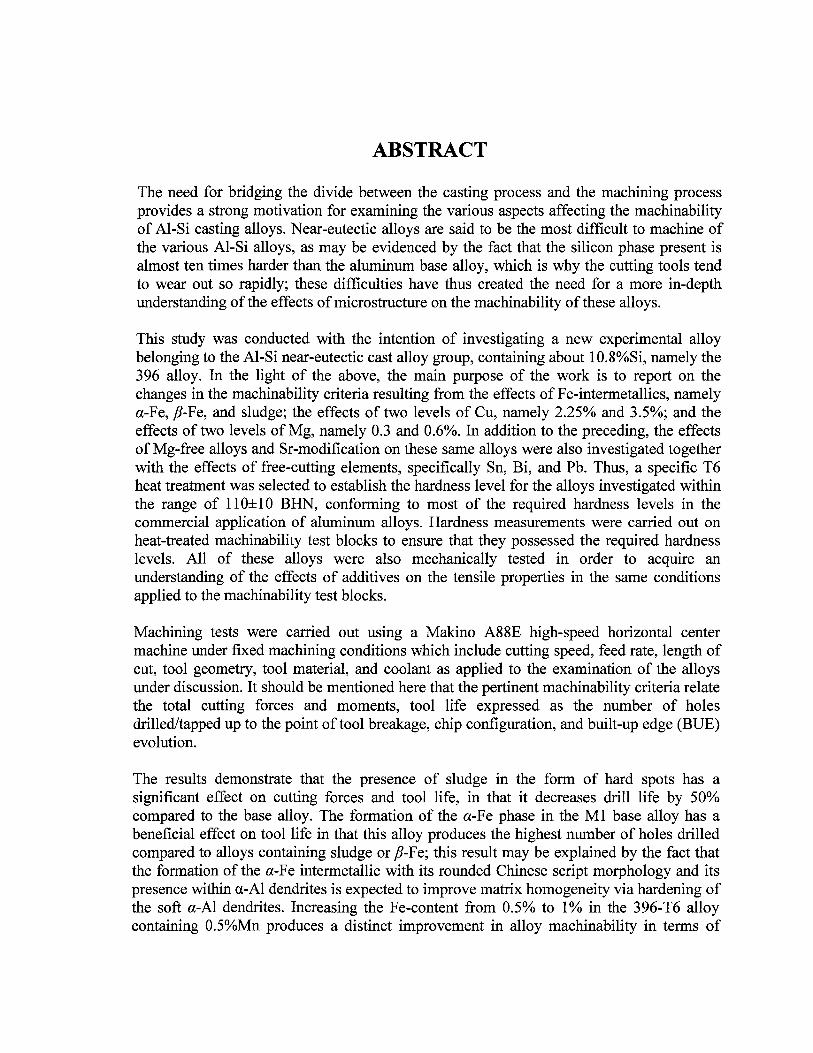
The need for bridging the divide between the casting process and the machining processprovides a strong motivation for examining the various aspects affecting the machinabilityof Al-Si casting alloys. Near-eutectic alloys are said to be the most difficult to machine ofthe various Al-Si alloys, as may be evidenced by the fact that the silicon phase present isalmost ten times harder than the aluminum base alloy, which is why the cutting tools tendto wear out so rapidly; these difficulties have thus created the need for a more in-depthunderstanding of the effects of microstructure on the machinability of these alloys.
This study was conducted with the intention of investigating a new experimental alloybelonging to the Al-Si near-eutectic cast alloy group, containing about 10.8%Si, namely the396 alloy. In the light of the above, the main purpose of the work is to report on thechanges in the machinability criteria resulting from the effects of Fe-intermetallics, namelya-Fe, /?-Fe, and sludge; the effects of two levels of Cu, namely 2.25% and 3.5%; and theeffects of two levels of Mg, namely 0.3 and 0.6%. In addition to the preceding, the effectsof Mg-free alloys and Sr-modification on these same alloys were also investigated togetherwith the effects of free-cutting elements, specifically Sn, Bi, and Pb. Thus, a specific T6heat treatment was selected to establish the hardness level for the alloys investigated withinthe range of 110±10 BHN, conforming to most of the required hardness levels in thecommercial application of aluminum alloys. Hardness measurements were carried out onheat-treated machinability test blocks to ensure that they possessed the required hardnesslevels. All of these alloys were also mechanically tested in order to acquire anunderstanding of the effects of additives on the tensile properties in the same conditionsapplied to the machinability test blocks.
Machining tests were carried out using a Makino A88E high-speed horizontal centermachine under fixed machining conditions which include cutting speed, feed rate, length ofcut, tool geometry, tool material, and coolant as applied to the examination of the alloysunder discussion. It should be mentioned here that the pertinent machinability criteria relatethe total cutting forces and moments, tool life expressed as the number of holesdrilled/tapped up to the point of tool breakage, chip configuration, and built-up edge (BUE)evolution.
The results demonstrate that the presence of sludge in the form of hard spots has asignificant effect on cutting forces and tool life, in that it decreases drill life by 50%compared to the base alloy. The formation of the a-Fe phase in the Ml base alloy has abeneficial effect on tool life in that this alloy produces the highest number of holes drilledcompared to alloys containing sludge or /?-Fe; this result may be explained by the fact thatthe formation of the a-Fe intermetallic with its rounded Chinese script morphology and itspresence within a-Al dendrites is expected to improve matrix homogeneity via hardening ofthe soft a-Al dendrites. Increasing the Fe-content from 0.5% to 1% in the 396-T6 alloycontaining 0.5%Mn produces a distinct improvement in alloy machinability in terms of
IV
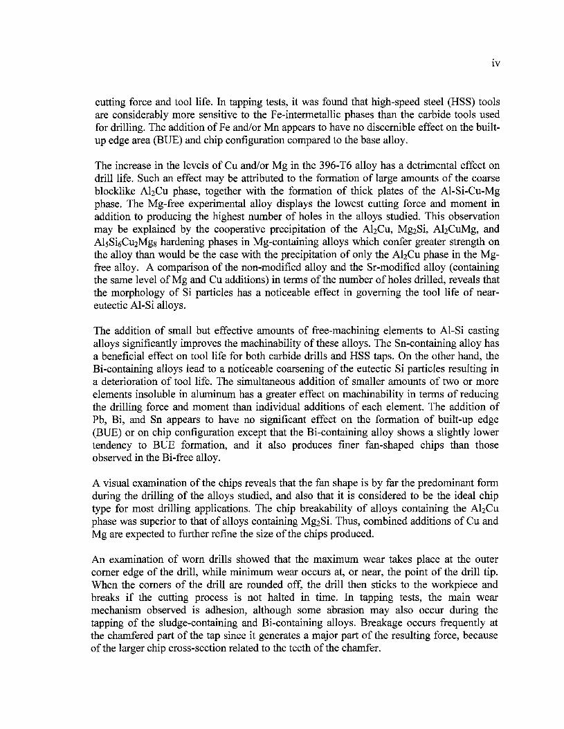
cutting force and tool life. In tapping tests, it was found that high-speed steel (HSS) toolsare considerably more sensitive to the Fe-intermetallic phases than the carbide tools usedfor drilling. The addition of Fe and/or Mn appears to have no discernible effect on the built-up edge area (BUE) and chip configuration compared to the base alloy.
The increase in the levels of Cu and/or Mg in the 396-T6 alloy has a detrimental effect ondrill life. Such an effect may be attributed to the formation of large amounts of the coarseblocklike A^Cu phase, together with the formation of thick plates of the Al-Si-Cu-Mgphase. The Mg-free experimental alloy displays the lowest cutting force and moment inaddition to producing the highest number of holes in the alloys studied. This observationmay be explained by the cooperative precipitation of the A^Cu, Mg2Si, AbCuMg, andAlsSiôCuiMgg hardening phases in Mg-containing alloys which confer greater strength onthe alloy than would be the case with the precipitation of only the A^Cu phase in the Mg-free alloy. A comparison of the non-modified alloy and the Sr-modified alloy (containingthe same level of Mg and Cu additions) in terms of the number of holes drilled, reveals thatthe morphology of Si particles has a noticeable effect in governing the tool life of near-eutectic Al-Si alloys.
The addition of small but effective amounts of free-machining elements to Al-Si castingalloys significantly improves the machinability of these alloys. The Sn-containing alloy hasa beneficial effect on tool life for both carbide drills and HSS taps. On the other hand, theBi-containing alloys lead to a noticeable coarsening of the eutectic Si particles resulting ina deterioration of tool life. The simultaneous addition of smaller amounts of two or moreelements insoluble in aluminum has a greater effect on machinability in terms of reducingthe drilling force and moment than individual additions of each element. The addition ofPb, Bi, and Sn appears to have no significant effect on the formation of built-up edge(BUE) or on chip configuration except that the Bi-containing alloy shows a slightly lowertendency to BUE formation, and it also produces finer fan-shaped chips than thoseobserved in the Bi-free alloy.
A visual examination of the chips reveals that the fan shape is by far the predominant formduring the drilling of the alloys studied, and also that it is considered to be the ideal chiptype for most drilling applications. The chip breakability of alloys containing the A^Cuphase was superior to that of alloys containing Mg2Si. Thus, combined additions of Cu andMg are expected to further refine the size of the chips produced.
An examination of worn drills showed that the maximum wear takes place at the outercorner edge of the drill, while minimum wear occurs at, or near, the point of the drill tip.When the corners of the drill are rounded off, the drill then sticks to the workpiece andbreaks if the cutting process is not halted in time. In tapping tests, the main wearmechanism observed is adhesion, although some abrasion may also occur during thetapping of the sludge-containing and Bi-containing alloys. Breakage occurs frequently atthe chamfered part of the tap since it generates a major part of the resulting force, becauseof the larger chip cross-section related to the teeth of the chamfer.

ACKNOWLEDGMENTS
I would like to express my sincere gratitude to my supervisor, Dr. Fawzy H.
Samuel, Professor at Université du Québec à Chicoutimi (Canada) and visiting Professor at
King Saud University (Saudi Arabia) for motivating me to complete my Ph.D. degree;
without his continuous guidance and support it would have been impossible to do so. I am
much indebted to him for helping me so generously over the last four years. I feel
privileged to have been able to work with someone whose dedication and contribution to
the field of science will be a constant inspiration to me throughout my life.
I would also like to express my sincere thanks to Dr. Agnes Marie Samuel,
Research Professor at Université du Québec à Chicoutimi (Canada) for her invaluable
guidance and help during different stages of my research work.
Financial support in the form of scholarships received from the Natural Sciences
and Engineering Research Council of Canada (NSERC), the Fondation de l'Université du
Québec à Chicoutimi (FUQAC), General Motors Powertrain Group (U.S.A), and
Corporativo Nemak (Mexico) is gratefully acknowledged.
I would like to extend my appreciation to Mr. Alain Bérubé of the TAMLA group,
at UQAC, for his assistance with the castings and sample preparation, as well as to Mr.
Lang Shi of the Microanalysis Laboratory, Earth and Planetary Sciences, McGill University
for carrying out EPMA analyses.
Thanks are also due to Madame Marion Sinclair for her help in editing my thesis.
Credit goes to the members of my family, especially to my mother, my wife, and my
children, as well as to all my brothers and sisters for their sound advice and unfailing
encouragement during the time it took to write my thesis.
PUBLICATIONS
Journal Papers
1. Y. Zedan, F.H. Samuel, A.M. Samuel, H.W. Doty, "Effects of Fe Intermetallics onthe Machinability of Heat-Treated Al-(7-ll)% Si Alloys," Journal of MaterialsProcessing Technology, 2010, Vol. 210, pp. 245-257.
2. Y. Zedan, F.H. Samuel, A.M. Samuel, H.W. Doty, "Effects of Additions of Pb, Bi,and Sn on the Machinability of Al-10.8% Si Casting Alloys," Prepared forSubmission to Journal of materials Processing Technology, 2010.
3. Y. Zedan, F.H. Samuel, A.M. Samuel, H.W. Doty, "Effects of Sn and Bi Additionon the Machinability of Heat-Treated B319.2 Cast Alloy," Prepared forSubmission to Materials Science and Engineering A, 2010.
4. Y. Zedan, F.H. Samuel, A.M. Samuel, H.W. Doty, "Machinability Aspects ofHeat-Treated Al-10.8%Si Cast Alloys: Role of Cu-Rich Intermetallics,"Prepared for Submission to International Journal of Machine Tools & Manufacture,2010.
Scientific Posters
5. Y. Zedan, F.H. Samuel, A.M. Samuel, H.W. Doty, "Factors Controlling TheMachinability of Al-Si Casting Alloys," Poster Presented at "Journée desEtudiants du REGAL" (REGAL Students' Day), October 26, 2007, UQAC,Chicoutimi; Published in The Encyclopaedia of Research on Aluminum in Quebec-2007 Edition (Strategic Aluminium Research Network), October 26, 2007, UQAC,Chicoutimi, Les Presses de rAluminium (PRAL), Chicoutimi, Qc, Canada, 2008,Axis II-New Aluminium Products and Materials, p. 50.
6. Y. Zedan, A.M. Samuel, F.H. Samuel, H.W. Doty, "Effects of IndividualAdditions of Pb, Bi, and Sn on the Machinability of Al-llSi-2.25Cu-0.3MgCasting Alloys," Poster Presented at "Journée des Etudiants du REGAL" (REGALStudents' Day), October 21, 2009, ETS, Montreal; Published in The Encyclopaediaof Research on Aluminum in Quebec- 2009 Edition (Strategic Aluminium ResearchNetwork), October 21, 2009, ETS, Montreal, Les Presses de l'Aluminium (PRAL),Chicoutimi, Qc, Canada, 2010, Axis II-New Aluminium Products and Materials, P.56.
TABLE OF CONTENTS
Page
RÉSUMÉ i
ABSTRACT iii
ACKNOWLEDGMENTS v
PUBLICATIONS vi
TABLE OF CONTENTS vii
LIST OF FIGURES x
LIST OF TABLES xv
CHAPTER I DEFINING THE PROBLEM 1
1.1 INTRODUCTION 2
1.2 OBJECTIVES 6
CHAPTER 2 REVIEW OF THE LITERATURE 8
2.1 INTRODUCTION 9
2.2 IMPORTANT ISSUES IN METAL-CUTTING OPERATIONS 10
2.3 MACHINING OF ALUMINUM ALLOYS 11
2.4 EFFECTS OF METALLURGICAL FACTORS ON MACHINABILITYOF Al-Si ALLOYS 13
2.4.1 Alloying Elements 13
2.4.1.1 Role of Si and Melt Treatment in Al-Si Alloys 14
2.4.1.2 Role of Fe Intermetallics in Al-Si Alloys 17
2.4.1.3 Role ofCu and Mg in Al-Si Alloys 19
2.4.1.4 Role of Free-Cutting Elements in Al-Si Alloys 23
2.4.2 Microstructural Features 29
2.4.3 Heat Treatment 31
2.5 MACHINING OPERATIONS 33
2.5.1 Drilling Process 34
vin
2.5.1.1 Drill Nomenclature and Geometry 35
2.5.1.2 Operating Conditions 37
2.5.1.3 Dry Drilling of Aluminum Alloys 41
2.5.2 Tapping Operations 44
2.6 MACHINABILITY CRITERIA 47
2.6.1 Cutting Forces Experienced During Drilling Operations 48
2.6.2 Tool Wear and BUE Formation 52
2.6.3 Tool Life Criteria 55
2.6.4 Chip Formation in Drilling 59
CHAPTER3 EXPERIMENTAL PROCEDURES 64
3.1 INTRODUCTION 65
3.2 ALLOY PREPARATION AND CASTING PROCEDURES 66
3.3 HEAT TREATMENT 71
3.4 METALLOGRAPHY-MICROSTRUCTURAL EXAMINATION 72
3.5 HARDNESS TESTING 75
3.6 TENSILE TESTING 76
3.7 MACHINING PROCEDURES 78
3.7.1 Cutting Tools 78
3.7.2 Cutting Parameters 79
3.7.3 Tool Life Criteria 81
3.7.4 Measurement of Machining Forces 83
3.7.5 Chip Form and BUE Evaluations 84
3.8 METHODOLOGY FOR THE DATA-PROCESSING OF DRILLINGAND TAPPING TESTS 86
CHAPTER 4 EFFECTS OF IRON-RICH AND COPPER-RICHINTERMETALLICS ON THE MACHINABILITY OFHEAT-TREATED Al-10.8%Si CAST ALLOYS 96
4.1 INTRODUCTION 97
4.2 CHARACTERIZATION OF THE MICROSTRUCTURE 98
4.2.1 Silicon Particle Characteristics 99
IX
4.2.2 Iron-Rich Intermetallics 104
4.2.3 Copper-Rich Intermetallics 109
4.3 HARDNESS AND TENSILE PROPERTIES 112
4.4 MACHINING BEHAVIOR 114
4.4.1 Effects of Fe-Intermetallics on Machinability 115
4.4.1.1 Cutting Forces and Moments 115
4.4.1.2 Tool Life 123
4.4.2 Effects of Cu and Mg Additions on Machinability 127
4.4.2.1 Cutting Forces and Tool Life 129
4.4.3 Evolution of Built-Up Edge (BUE) and Tool Wear Characteristics 144
4.4.4 Chip Characterization 153
CHAPTER 5 EFFECTS OF FREE-CUTTING ELEMENTS ON THE
MACHINABILITY OF Al-Si-Cu-Mg CAST ALLOYS... 156
5.1 INTRODUCTION 157
5.2 MICROSTRUCTURE 159
5.2.1 Silicon Particle Characteristics 159
5.2.1 Effects of Free-Cutting Elements on Microstructure 164
5.3 HARDNESS AND TENSILE PROPERTIES 169
5.4 MACHINING BEHAVIOR 171
5.4.1 Cutting Forces and Tool Life 172
5.4.1.1 396 Alloys (Al-11% Si) 172
5.4.1.2 B319.2 Alloys (Al-7% Si) 184
5.4.2 Evolution of Built-Up Edge (BUE) and Tool Wear Characteristics ... 189
5.4.3 Chip Characterization 192
CHAPTER 6 CONCLUSIONS AND RECOMMENDATIONS 195
6.1 CONCLUSIONS 196
6.2 RECOMMENDATIONS FOR FUTURE WORK 202
REFERENCES 203
LIST OF FIGURES
CHAPTER 2Figure2.1 Nomenclature of a twist drill 36
Figure 2.2 Undeformed chip width in the drilling process 39
Figure 2.3 (a) Showing rake angle along the cutting edge moving acrossworkpiece, and (b) showing variation in cutting speed with the cuttingedges 40
Figure 2.4 Tap and thread nomenclature 45Figure 2.5 (a) Basic elements of tap and forces on an elementary tooth; (b) change
in torque during the tapping cycle 47
Figure 2.6 Tool wear evolution: 1. initial wear; 2. slight wear; 3. moderate wear; 4.severe wear; and 5. worn-out 50
Figure 2.7 Wear mechanisms as a function of temperature 54
Figure 2.8 Some features of single-point tool wear in turning operations 56
Figure 2.9 Characteristics of worn twist drill 58
Figure 2.10 Types of drill wear 58
Figure 2.11 Conical helical chip produced by the twisted part of the cutting lip 61Figure 2.12 Chip forms generated: (A) conical; (B) fan-shaped; (C) chisel-edge; (D)
amorphous; (E) needlelike; (F) impacted 63
CHAPTER 3Figure3.1 Electrical resistance melting furnace 69
Figure 3.2 (a) Waffle-plate metallic mold; (b) machinability test block casting; and(c) machinability test block 69
Figure 3.3 Blue M electric furnace 71
Figure 3.4 Optical microscope-image analysis system 72
Figure 3.5 Scanning electron microscope system used for this study 74Figure 3.6 (a) Schematic diagram of Brinell hardness test; (b) hardness
measurement for machinability test block; (c) schematic of hardnessindentations for test block 76
Figure 3.7 (a) Actual tensile test bar casting; (b) MTS servohydraulic mechanicaltesting machine 77
Figure 3.8 (a) Makino A88E CNC machining center; and (b) a close-up view of thetest block, dynamometer, and cutting tool 79
Figure 3.9 (a) Machinability test block after drilling and tapping; (b) detaileddrawing of the tapped hole 81
XI
Figure 3.10 Thread gauge used in the current work 82
Figure 3.11 (a) Kistler dynamometer with four sensors used in this study; (b)illustration showing the measurement chains for the 6-component forcesand moment measurements 84
Figure 3.12 Schematic diagrams showing the experimental set-up for carrying outthe drilling and tapping tests 85
Figure 3.13 Data processing for the drilling feed force-Fz component of the firstgroup of holes (90-holes): (a) raw data of Fz component; (b) filtration(9-times) for Fz component 90
Figure 3.14 (a) First difference of the filtered Fz, point detection within each cycle;(b) first and second difference of the filtered Fz component 91
Figure 3.15 (a) Two points within each cycle: the red point represents the mean Fzduring drilling cycle, while the green point represents the error valueupon removing the drill from the hole; (b) output results for the drillingfeed force for the first group of holes (90 holes) showing plots with orwithout error consideration 92
Figure 3.16 (a) Data processing for the tapping feed force-Fz component of the firstgroup of holes (90-holes); (b) three points within each cycle, the upperpoint representing the mean mFzupi, the lower point representing themean Fzd0Wni, and the middle point representing the error value of thesignal 95
CHAPTER 4Figure 4.1 Optical micrographs showing the effects of Sr-addition on Si
morphology in grain-refined and heat-treated Al-10.8% Si alloy: (a) 0Sr-MO alloy; (b) 200 ppm Sr-Ml alloy 101
Figure 4.2 Optical micrographs showing the effects of Cu and Mg on Simorphology in the grain-refined and heat-treated (a) M5 alloy; and (b)M6 alloy 103
Figure 4.3 (a) Backscattered image, and (b) optical micrograph of the cc-Fe phaseobserved in Sr-modified and grain-refined Ml alloy 106
Figure 4.4 (a) Backscattered image, and (b) optical micrograph of sludge particlesobserved in Sr-modified and grain-refined M3 alloy 107
Figure 4.5 (a) Backscattered image, and (b) optical micrograph of /?-Fe and ct-Feobserved in Sr-modified and grain-refined M4 alloy. Arrows indicatethe effects of heat-treatment and Sr on the fragmentation of/?-Fe 108
Figure 4.6 Optical micrograph of (a) heat-treated Mg-free M9 alloy, and (b) heat-treated M6 alloy containing 0.6% Mg showing precipitation of both theblocklike A^Cu phase (marked A) and the AlsSiôCuaMgg phase(marked B) I l l
Figure 4.7 Effects of Fe-intermetallics on the machinability of Ml, M3, and M4
Xll
alloys in terms of (a) mean total drilling force; (b) mean total drillingmoment; and (c) mean power cutting required for drilling 90 holes 121
Figure 4.8 (a) Photograph of drill illustrating area investigated; and (b) photographshowing the effect of sludge on the cutting drill edge after drilling theM3 alloy 121
Figure 4.9 Effects of Fe-intermetallics on the machinability of Ml, M3, and M4alloys in terms of (a) mean total tapping force; and (b) mean totaltapping moment required for tapping 90 holes 122
Figure 4.10 Effects of Fe-intermetallics on the drill/tap life of the Ml, M3, and M4alloys in terms of the number of holes drilled and tapped 126
Figure 4.11 Optical microstructure of the M4 alloy showing precipitation of (1) pre-eutectic /?-Fe, and (2) post-eutectic /?-Fe 126
Figure 4.12 Effects of Cu, Mg, and Sr additions on the machinability of Ml, M5,M6, MO, and M9 alloys in terms of (a) mean total drilling force; (b)mean total drilling moment; and (c) mean power cutting required fordrilling 90 holes 134
Figure 4.13 Comparison of tool life of MO, Ml, M5, M6, and M9 alloys containingadditions of different alloying elements in terms of the number of holesdrilled and tapped 134
Figure 4.14 Effects of Cu, Mg, and Sr additions on the machinability of Ml, M5,M6, MO, and M9 alloys in terms of (a) mean total tapping force; and (b)mean total tapping moment required for tapping 90 holes 135
Figure 4.15 Microstructure of the M6 alloy showing the influence of both Sr andMg: (1) segregation of the A^Cu phase; (2) formation of thick plates ofAlsSiôC^Mgg phase; and (3) acicular silicon particles 138
Figure 4.16 (a) Cross-section of drilled hole illustrating area investigated; and (b)optical microstructure of M6 alloy corresponding to the drill breakageportion showing the presence of large silicon particles, marked 1, andthe coarse undissolved Cu-phase, marked 2, in this area 138
Figure 4.17 SEM micrograph and EDX analysis showing the precipitation ofhardening phases (a) Mg-containing Ml alloy; and (b) Mg-free M9alloy (T6-heat treated conditions) 143
Figure 4.18 Microstructure beneath the fracture surface of the non-modified M0alloy. White arrows indicate broken acicular Si particles 144
Figure 4.19 Photographs showing the progress of built-up edge (BUE) on the tip ofthe cutting edge (a) after drilling 90 holes, and (b) after drilling 2070holes 147
Figure 4.20 Photographs showing the effects of Cu- and Mg-addition produced inthe heat build-up formation and the wear on the cutting-drill lip in Ml,M6, and M9 alloys after different stages of drilling 149
Xll l
Figure 4.21 Photographs showing wear mode on cutting edge after drilling the Mlalloy 149
Figure 4.22 Photographs showing the wear mode on the tap edge (a) new tap; (b)BUE on the relief face of the tap chamfer part; (c) material adhering tothe first thread of tap; (d) broken tap in the workpiece; (e) photograph oftap illustrating area investigated 151
Figure 4.23 A photograph showing the broken taps (a) new tap; (b) broken tap aftertapping the M6 alloy; and (c) broken tap after tapping the Ml alloy. 152
Figure 4.24 Optical micrographs showing different types of chip obtained for Ml,M6, M9, and A356.2 alloys after drilling the specified number of holes. 155
Figure 4.25 Effects of Cu and Mg on chip breakability in terms of the chips-per-gram criterion for the alloys investigated. 155
CHAPTER 5
Figure 5.1 Optical micrograph showing the effects of Sn, Bi, and Pb additions onthe microstructure of heat-treated 396 alloys in (a) the Ml base alloy;(b) the M2 (Ml + 0.15% Sn ); (c) the M7 (Ml + 0.5% Bi); and (d) theM8(M1 + 0.8% Pb) 163
Figure 5.2 (a) High magnification backscattered image of the M2 alloy showingprecipitation of /?-Sn, (b) X-ray image of Sn distribution for the sameparticles illustrated in (a) 166
Figure 5.3 EDX spectrum corresponding to /?-Sn particles observed in M2 alloycontaining 0.15% Sn 166
Figure 5.4 Low magnification backscattered image obtained from the M7 (Ml +0.5% Bi) alloy showing precipitation of Bi-containing particles. 167
Figure 5.5 (a) Backscattered image of the M7 (Ml + 0.5% Bi) alloy showingmorphology of Bi-containing particles, X-ray image of (b) Bi and (c)Mg distribution for the same particles illustrated in (a) 167
Figure 5.6 (a) Backscattered image of the M8 (Ml + 0.8% Pb) alloy showing theprecipitation of Pb-containing particles, (b) EDX spectrumcorresponding to Pb-containing particles 168
Figure 5.7 (a) Low magnification backscattered image obtained from the Ml2(B319.2 + 0.15% Sn + 0.5% Bi) alloy showing the presence of Bi andSn particles (bright white particles) 169
Figure 5.8 Effects of adding Sn, Bi, and Pb on the machinability of 396 (Ml, M2,M7, and M8) alloys in terms of (a) mean total drilling force; (b) meantotal drilling moment; and (c) mean cutting power required for drilling90 holes 177
Figure 5.9 Effects of adding Sn, Bi, and Pb on the drill/tap life of the Ml, M2, M7,and M8 alloys in terms of the number of holes drilled and tapped 177
XIV
Figure 5.10 (a) High magnification backscattered image showing molten Snparticles in the M2 (Ml + 0.15% Sn) alloy after machining processes,(b) X-ray image of Sn distribution for the same particles illustrated in(a) 178
Figure 5.11 Backscattered images of the M7 alloy showing the precipitation of Bi-particles and the corresponding X-ray images of Bi, Mg, and Sr 182
Figure 5.12 Photographs after Bi addition showing wear occurring on (a) outercorner and (b) cutting drill lip of the M7 alloy after stripping the BUE ina solution of NaOH 182
Figure 5.13 Effects of Sn, Bi, and Pb additions on the machinability of 396 (Ml,M2, M7, and M8) alloys in terms of (a) mean total tapping force; and(b) mean total tapping moment required for tapping 90 holes 183
Figure 5.14 Effects of Sn and/or Bi additions on the machinability of B319.2 (M10,Mil and M12) alloys in terms of (a) mean total drilling force; and (b)mean total drilling moment required for drilling 100 holes 187
Figure 5.15 Effects of Sn and/or Bi additions on the machinability of B319.2 (M10,Mil and M12) alloys in terms of (a) mean total tapping force; and (b)mean total tapping moment required for tapping 100 holes 188
Figure 5.16 Photographs showing the effects of Sn, Bi and Pb addition occurring inthe heat build-up formation and the wear on the cutting drill lip in 396(M1, M2, M7, M8) alloys after different stages of drilling 192
Figure 5.17 Optical micrographs showing different types of chip obtained for Ml,M2, M7, and M8 alloys after drilling the specified number of holes outof 1080 holes 193
Figure 5.18 Effects of Sn, Bi, and Pb on chip breakability in terms of the chips-per-gram criterion for the alloys investigated 194
LIST TABLES
CHAPTER 3Table 3.1 Chemical composition of the 396, B319.2, and A356.2 base alloys 66
Table 3.2 Nominal composition and codes for the alloys prepared in this study. ... 67
Table 3.3 Average chemical composition of the alloys discussed in this study 70
Table 3.4 Schematic representation of the carbide drill and HSS tap, together withthe terms used in describing their geometry 80
Table 3.5 Cutting parameters applied for machinability testing 81
CHAPTER 4Table 4.1 Summary of eutectic Si-particle measurements for the alloys studied. ... 100
Table 4.2 Volume fraction of Fe- and Cu-intermetallics for the alloys studied 110
Table 4.3 Summary of mechanical properties for the alloys studied 113
Table 4.4 Effects of Fe-intermetallics on width of built-up edge (BUE) duringdrilling process 147
CHAPTER 5
Table 5.1 Summary of the eutectic Si-particle measurements for the alloysstudied 161
Table 5.2 Summary of mechanical properties for the alloys studied 171
Table 5.3 Effects of Sn, Bi, and Pb additions on the width of built-up edge (BUE). 190

CHAPTER 1
DEFINING THE PROBLEM
CHAPTER 1
DEFINING THE PROBLEM
1.1 INTRODUCTION
The need for bridging the divide between the casting process and the machining process
provides a strong motivation for examining the various aspects affecting the machinability
of Al-Si casting alloys, given that these alloys constituent more than 80% of all aluminum
alloy castings. The reason for this widespread acceptance of Al-Si alloys may be found in
the attractive combination of a number of parameters which include (i) physical properties;
(ii) generally excellent castability; (iii) mechanical properties; (iv) corrosion resistance; (v)
machinability; (vi) hot-tear resistance; (vii) fluidity; and (viii) weldability. These are, thus,
the factors which have led the automobile, aerospace, defense, and engineering industries to
make full use of Al-Si alloys. Machinability plays an important role in the selection of
material for commercial exploitation. In general, more than 90% of manufactured parts
need to be machined before they are ready for use. Machining is a manufacturing process
by which unwanted material is removed to obtain the desired shape of a cast part. Reducing
the machining time and extending cutting tool life both have great economic significance.
Machinability is an interaction phenomenon between work piece (material type and form),
cutting tool (material type and geometry), and cutting medium such as air and liquid in a
number of different removal sequences which include turning, drilling, tapping, milling,
sawing, and cutting conditions (speed, feed, and depth of cut). The condition and physical
properties of the work material have a direct influence on the machinability of the
workpiece. Operating conditions, tool material and geometry, and workpiece requirements
all exert an indirect influence on machinability and can often be used to overcome difficult
conditions presented by the work material. On the other hand, they can also create
situations which compound difficulty of machining if they are ignored. Machinability
testing aims at evaluating the comparative machining performance of workpiece materials,
cutting tools, and cutting fluids. This type of testing also aims at establishing conditions
which will ultimately produce satisfactory finished parts with the desired dimensional
surface finish and functional integrity in an economical fashion. The machinability of a
particular material can be evaluated by assessing any one of the following five parameters:
� Tool life: the amount of material which may be removed before the tool either fails
or wears out to a prescribed degree.
� Surface finish of test piece: the surface finish obtained under constant cutting
conditions.
� Cutting force requirements: either the forces acting on the cutting tool or the
required power consumption to obtain a given material-removal rate.
� Chip shape: the ease with which the chips can be evacuated from the area around
the tool.
� Limiting rate of metal removal: the rate at which a material can be removed while
maintaining a prescribed tool life.
When problems occur in industry, questions always arise as to the relationship between
the microstructure and the machinability of the given alloys and to the way in which
engineers can design and control the casting process to obtain a cast structure which will
provide improved mechanical properties and machinability. These production problems are
often attributed, wrongly or rightly, to difficulties relating to microstructure and casting.
Adequate studies of the influence of microstructure on machinability, however, are
relatively scarce to date. A thorough understanding of all the metallurgical factors affecting
the machinability of aluminum alloys will contribute to selecting metallurgical designs
which attempt to promote the optimum machining combinations essential to sustained
productivity.
The principal salient metallurgical factors which govern the condition of the work
material and which can influence the outcome of machinability are the following: (i)
alloying elements, (ii) features of the microstructure, (iii) porosity, (iv) casting methods, (v)
heat treatment, (vi) grain refining and modification, and (vii) the physical properties of the
work material. Silicon and other hard phases act as abrasives in the relatively soft alloy
matrices and tend to reduce cutting tool life. Copper and magnesium have been observed to
increase alloy hardness, to improve the finish of machined surfaces, and to decrease the
tendency of an alloy towards build-up on the cutting tool edge. Certain elements are known
to enhance the wet machinability of aluminum and steel; these elements are referred to as
free-machining elements and include bismuth (Bi), tin (Sn), lead (Pb), and cadmium (Cd).
Sand castings require a greater amount of machining stock and have a coarser
microstructure than either permanent mold castings or die castings and are, therefore, more
costly to machine, with die castings having been recorded as the least costly to machine.
Treatment applied with the intention of refining primary silicon or modifying the
morphology of eutectic silicon will improve tool life substantially. Heat treatment, applied
to increase hardness, reduces the incidence of built-up edge on the cutting tool and
improves the surface finish of the machined part. Porosity may lead to problems
particularly in those workpiece areas where holes are to be drilled or tapped. Excess
porosity resulting from improper gating, venting, and/or injection may result in poor
machining characteristics. These conditions, individually or in combination, can influence
and control the machinability of the alloy directly. Machinability problems during the
machining of Al alloys are related either to tool wear, or to the quality of the machined
surface, to chip disposal or to the presence of burrs, all of which appear to be specific
problems restricting productivity.
Among the various Al alloys, aluminum-silicon alloys are said to be the most
difficult to machine, as is evidenced by the fact that the silicon phase present is almost ten
times harder than the base alloy, thus causing the cutting tools to wear out rapidly. For this
reason, attempts have been made to optimize the selection of cemented carbide tools,
cutting conditions, and tool geometry; the further investigation of the following points was
also promoted: (i) the effects of flank build-up on tool wear, (ii) the effects of cutting fluids
on machinability, and (iii) the improvement of machinability through the addition of certain
elements. In order to understand the metallurgical factors affecting alloy machinability, a
prior study was carried out investigating the possible effects that the addition of certain
alloying elements would have on the microstructural characteristics and mechanical
properties of 396 near-eutectic alloy, B319.2, and A356.2 alloys. These alloying elements
included Fe (0.5% to 1%), Mn (0.5% to 1%), Cu (2.25% to 3.25%), and Mg (0.3% to
0.5%), while the free-cutting elements included Pb, Sn, Bi, Zn, and In. Based on this study,
certain alloys were selected for a further examination of the corresponding machinability
characteristics since they constitute the focus of the current work.
1.2 OBJECTIVES
This study is part of a larger research project which was conducted to provide a
better understanding of the effects that Fe-intermetallics, free cutting elements, matrix-
hardening elements, and Sr-modification would have on the machinability characteristics of
cast Al-Si near-eutectic alloys. The study was confined to a new experimental alloy
belonging to this family, and which contains about 10.8% Si, namely the 396 alloy. Thus,
drilling and tapping operations were carried out using a Makino A88E machine under fixed
machining conditions of speed, feed, length of cut (depth of the hole drilled or tapped), tool
geometry, tool material, and coolant as applied to the examination of the alloys under
discussion. It should be mentioned here that the pertinent machinability criteria relate to
force and moment as well as to tool life, chip configuration, and built-up edge (BUE)
evolution. In keeping with these aims, the objectives of this study will cover the following:
1. specific T6 heat treatments selected to establish the hardness level for the alloys
studied within the range of 110 ± 10 BHN;
2. effects of iron intermetallics (a-Fe, /?-Fe, and sludge), and hardening alloying
elements such as Cu (2.25 and 3.5%) and Mg (0.3 and 0.6%) intermetallics on
the machining of modified and grain refined 396-T6 alloys;
3. effects of Sr-modification and the presence of a Mg-free alloy on the
machinability behavior of heat-treated and grain refined Al-10%Si experimental
alloys;
4. effects of free-cutting elements, such as Sn, Bi, and Pb on tool life, chip shape,
and cutting force and moment of the 396-T6 alloys;
5. effects of the free-cutting elements, Sn, Bi, and Sn + Bi in the machining of
modified and grain-refined B319.2-T6 alloys;
A thorough understanding of the role of all these factors in the alloys studied would make it
possible to select materials and workpiece designs for obtaining optimum machining
combinations critical to maximum productivity.

CHAPTER 2
REVIEW OF THE LITERATURE
CHAPTER 2
REVIEW OF THE LITERATURE
2.1 INTRODUCTION
Aluminum-silicon alloys, especially near-eutectic alloys containing - 11% Si, are
widely used in the automotive industry because of their excellent foundry characteristics
and mechanical properties. These alloys have, therefore, replaced iron and steel in many
components, including transmission cases and intake manifolds, as well as in more critical
components such as engine blocks, cylinder heads, and wheels;1 this extended application
of Al-Si alloys for automotive components has created the need for a more in-depth
understanding of the effects of microstructure on the machinability of these components.
The microstructure of Al-Si alloys is typically composed of an aluminum matrix containing
eutectic silicon; the silicon can be present in the form of acicular needles, blocklike plates,
or a refined fibrous structure, depending upon the level of chemical modification and the
cooling rate of the cast section. In general, eutectic silicon is not uniformly distributed, but
tends to be concentrated at the interdendritic boundaries.2 These microstructural
constituents also include Fe-intermetallics which commonly precipitate in the form of a-
Ali5(Fe,Mn)3Si and /f-AlsFeSi phases, secondary eutectic phases such as Mg2Si and A^Cu,
and other complex intermetallics constituted from the remaining liquid during the final
stages of solidification.3
10
2.2 IMPORTANT ISSUES IN METAL-CUTTING OPERATIONS
During the cutting process, the cutting tool comes into contact with the workpiece
material and removes part of it. The main study areas in material cutting may be
summarized into the following three groups:4
(i) Aspects of the cutting tool involving the geometry of tool design. The properties of
the cutting tool materials, tool failure mechanisms, and predicted tool life.
(ii) The properties of the workpiece material including mechanical behaviour; the
physical, chemical, and microstructural features; and the thermal properties.
(iii) Operating parameters such as cutting speed, feed rate, and depth of cut.
The interaction between these three aspects of machining determines the efficiency of a
given metal-cutting process. For example, in cutting a specific workpiece, as soon as the
cutting tool is chosen, the operating parameter predetermines the rate of material removal,
the ultimate quality of the machined surface, and the duration of tool life. If a different tool
should be chosen, e.g. to obtain a different rake angle, the rate of material removal may not
necessarily change, whereas tool life and the quality of the machined surface may do so.
The reason for this is because the material behavior changes as a result of the changes
brought about in the cutting stress distribution and the plastic strain distribution ensuing
from prior changes in the geometry of the cutting tool.
The three most important machining parameters which determine the rate of metal
removal are the cutting speed, the feed rate, and the depth-of-cut. Optimizing these three
parameters results in minimizing the possibilities of tool failure, and thereby prolonging
tool life. Tool life is influenced mainly by cutting speed, then by the feed rate, and to a
11
lesser degree, by the depth-of-cut.5 Experiments have shown that when the length-of-cut is
about ten times greater than the feed rate, a further increase in this parameter will have no
significant effect on tool life.6 In practice, the first step is to select the depth based on the
tool, workpiece, power, and the rigidity of the equipment. Since depth-of-cut has the least
influence on tool life, it is advisable to use the deepest cutting depth possible. The second
step is to select the feed rate, in that it depends on the specification of the final machined
surface. Under normal circumstances, the smaller the feed rate, the better the quality of the
finish. Cutting speed also has a strong potential influence on tool life.
The mechanical properties of either tool materials or workpiece materials may change
significantly with variations in the cutting speed. Higher cutting speeds can contribute to
increasing the removal rate of unwanted material, but the effects on tool life will vary
noticeably with the cutting conditions. The reason for this has been recognized as the rise in
temperature at the contact area between the cutting tool and the workpiece. Increasing the
feed rate also causes the temperature to rise, thereby increasing the contact stress and the
plastic deformation of the workpiece material in the chip formation area.7
2.3 MACHINING OF ALUMINUM ALLOYS
Aluminum alloys are among the most machinable of the common metals. Compared
to that of steel, the machinability of aluminum alloys features considerably lower cutting
forces and substantially higher cutting speeds for which comparable tool-life values may be
obtained. The economically optimal cutting-speed range for machining aluminum alloys
has its lowest limits set by the occurrence of built-up edge material and the resulting rapid
deterioration of surface quality. Aluminum alloys are thus usually machined by applying
12
cutting speeds of not less than 90 m/min.8 A higher cutting-speed limit for machining
aluminum, however, cannot be defined exactly since such a limit would depend on tool
wear or tool life, or the occurrence of deceptive chip formation; it should be noted that this
limit may also vary in accordance with the alloy composition and the cutting parameters
involved. When machining aluminum alloys, even though the specific cutting force is only
about one fourth that of steel, the machining capacity required for economical machining is
three times as high, since high cutting speeds may need to be applied.9
It may be said for aluminum alloys, in general, that their high thermal conductivity
facilitates rapid heat dissipation from the locus of chip formation and that it also lessens the
thermal load on the cutting-edge of the tool. The relatively low strength of these alloys,
accompanied by low shear modulus, makes it possible for the emergence of a low
penetration resistance of the material to the tool and leads to a considerably lower energy
requirement than is, as a rule, necessary for machining ferrous materials.10 When they are
cut under proper conditions using sharp tools, aluminum alloys acquire a fine finish
through turning, drilling, and milling, thereby minimizing the necessity for further
protracted grinding and polishing operations.
Aluminum is commonly machined by means of high-speed steel, diamond, and
carbide tooling; cutting tools based on silicon-nitride ceramics are generally not used with
aluminum because of the recognized high solubility of silicon in aluminum.11 The major
machinability assets related to aluminum alloys include tool life, chip characteristics, chip
disposal, and surface finish. Standard twist drills are generally reasonably satisfactory for
the drilling of aluminum alloys, although high spiral drills with a helix angle of 40-48°,
13
instead of the usual 24-28°, are recommended for deep holes. The point angle may also be
increased to good advantage from the normal value of 118° to 130-140°. This procedure
produces a narrower chip which is then more easily expelled through the flutes of the drill.
Evacuation of the chips and how to stop them from welding to the drill flutes are two of the
main problems arising at this juncture; thus, in this regard, ensuring an adequate supply of
coolant is of paramount importance.12
2.4 EFFECTS OF METALLURGICAL FACTORS ONMACHINABILITY OF Al-Si ALLOYS
Three metallurgical factors have a major influence on machinability: these are the
alloying elements, the features of the microstructure, and the selected heat treatment.
2.4.1 Alloying Elements
When pure aluminum is used unalloyed, it tends to adhere to the tool causing built-
up edge to form, thus producing long chips which are too ductile to break. The addition of
certain alloying elements improves machinability by reducing adherence to the tool and
causing the chips to become more brittle. Constituents which are present in solid solution,
such as copper, silicon, magnesium, and zinc, tend to increase the hardness of the
aluminum matrix, thereby reducing not only metal pick-up from tools, but also burr
formation, and the tearing of metal surfaces; whereas out-of-solution constituents promote
the break-up of chips when combined with aluminum. In the cases where constituents such
as AI2CU, FeAl3, and Mg2Si are not noticeably hard, machinability is observed to improve;
on the other hand, rapid tool-wear occurs if constituents such as silicon or phases formed
by boron, chromium, manganese, and titanium are extremely hard.13'14
14
2.4.1.1 Role of Si and Melt Treatment in Al-Si Alloys
Silicon, which is the major alloying element in Al-Si alloys, improves the fluidity of
the metal during casting by increasing the volume of the aluminum-silicon eutectic; this
heightened level of fluidity makes it possible for molten metal to flow readily and easily
into the thinnest sections of the mold.15 Additionally, this ease of flow helps to minimize
shrinkage during solidification. In the solidified alloy, silicon tends to increase the strength
values; improvements in the wear resistance can also occur when the silicon levels are in
the moderate-to-high range. Increasing the amount of silicon, however, tends to decrease
the ductility in cast aluminum alloys. The Al-Si binary system forms a simple eutectic at
approximately 577°C with 12.5wt% Si. In general, alloys such as the 356 and 319 alloys
containing less than llwt% Si are referred to as hypoeutectic alloys, whereas those
containing 1 l-12wt% Si are known as eutectic alloys, and those containing more than 12%
are called hypereutectic alloys.16 The phase diagram also shows that the maximum
solubility of 1.65% Si in Al occurs at 577 °C, this solubility then drop to a negligible level
upon reaching room temperature.
Silicon (Si), either in its eutectic or primary form, is much harder than any other phase
of the alloy microstructure. The Knoop hardness number of silicon crystals generally
ranges from 1000 to 1300KHN, while the micro-hardness for an alloy matrix of an
aluminum casting rarely exceeds 180KHN. Silicon is similar to iron, manganese, and
chromium, in that its intermetallic impurity phases are noticeably abrasive in an otherwise
soft matrix, and is thus the element which has the greatest tendency to decrease cutting tool
life.17 A fine, well-modified eutectic silicon structure is far less detrimental to tool life than
15
heavy-element intermetallic impurity phases. The rate of wear on cutting tools increases,
however, as the particle size of the silicon increases. If the eutectic silicon structure is
coarse, tool life suffers.
Primary silicon crystals, even if well-refined and distributed, can be more detrimental
than eutectic silicon; thus large unrefined primary crystals are likely to be devastating to
tool life. Whether in permanent mold casting or sand casting, primary silicon is controlled
by a refinement treatment which recommends adding a small amount of strontium to the
molten alloy. Unrefined primary silicon particles are 8 to 10 times the size of refined
silicon crystals, and they are likely to affect machinability to a significant degree.18 In
conventional die casting, no supplemental refinement treatment is considered necessary.
Primary silicon size in these die castings is small, even in the absence of phosphorus
refinement, and its size and distribution are controlled by process parameters such as melt
temperature, die temperature, and die-fill rate. Regardless of the casting method employed,
primary silicon acts as a chip-breaker; although primary silicon crystals are extremely hard,
they are also relatively brittle. When the cutting tool passes through the alloy matrix, it
fractures the primary silicon particles. This fracturing, together with the natural hardness of
the alloy and the work-hardening of the chips, causes the close tightly-curled chips to break
into short ringlets with an appearance similar to that of grey iron chips.19
Tests carried out at the Alcoa Research Laboratories20 demonstrated the effects of
silicon particle size on the rate of tool-wear. In these tests, the silicon content was
maintained constant at about 6wt% and the size variation was produced by means of
different melting, casting, and thermal treatments. It was found that this wear rate is apt to
16
increase by a power of 1.7 of the silicon particle diameter, and that tool life decreases in
machining Al-Si casting alloys as the silicon level of the alloy increases. This effect is
relatively small, except when the silicon content exceeds about 12wt%. The amount of
silicon in the alloy has a minor effect on the surface finish, and the same can be said for the
size of the silicon particles. The size of the chips, the degree of burring, and the possible
machining rate are also affected, although only moderately, by the amount and the size of
the silicon constituent.
The effects of grain refinement, modification, and heat-treatment on the machinability
of eutectic and hypereutectic Al-Si cast alloys were studied by Dwivedi et al} They
concluded that the melt treatment, as applied to the alloys under examination, reduced the
cutting force and cutting temperature because of the refining of hard brittle silicon particles,
although heat treatment is known to increase both cutting force and cutting temperature; the
same effect may be attributed to an increase in the hardness and strength of both alloys after
heat treatment. Similar research results were also reported by Basavakumar et al.21 who
studied the influence of melt treatments and turning inserts on the cutting force and surface
integrity of turning in Al-12Si and Al-12Si-3Cu cast alloys. These researchers found that
the addition of a grain refiner to the alloys mentioned, combined with a modifier, produces
a conspicuously low level of cutting forces and creates an improved surface finish,
compared to untreated alloys.
17
2.4.1.2 Role of Fe Intermetallics in Al-Si Alloys
Iron (Fe) combines with other elements to form a variety of intermetallic
compounds depending on the composition of the alloys; although iron intermetallics
improve strength and hardness, they tend to reduce ductility. Iron also tends to make the
material brittle, and consequently it improves machinability in terms of the cutting force.22
Jorstad14'23 found that intermetallic phases which are formed out of heavy elements such as
iron are liable to lead to a substantial reduction in tool life, although they have a negligible
effect on tool-edge build-up. A number of Fe-rich intermetallic phases, including a
Ali5(Fe,Mn,)3Si2, /?(Al5FeSi), TrCAlsMgaFeSio), and <S(Al4FeSi2), have been identified in Al-
Si casting alloys.24'25 Depending on the temperature as well as on the chemical composition
of the mix, among other factors, Fe may precipitate as an intermetallic compound
displaying different morphologies, the most common being polyhedral crystals, "Chinese
script," and thin platelets which appear needlelike in two-dimensional optical
micrographs.26
In near-eutectic alloys with iron concentrations of between 0.5 and 1.2 wt%,
primary crystals of AlsFeSi (fi-Fe) may appear under normal melt and casting conditions.27
These crystals are needle-shaped and, as occurs with eutectic silicon needles, they may
cause the mechanical properties of the alloy to deteriorate, in particular its ductility and
toughness. Furthermore, these long iron-rich needles form during solidification and are
usually associated with the shrinkage voids present in the solidified material. Voids can
cause problems to occur, particularly in those workpiece areas where holes are to be drilled
or tapped. The length of these intermetallic /J-AlFeSi phase platelets may be reduced by
18
decreasing the iron content of the alloy and/or by increasing the cooling rate. Since the
Ali5(Fe,Mn,Cr)3Si2 (a-Fe) phase is dendritic, it is therefore not so detrimental from the
viewpoint of the machinability characteristics of the alloy, given that its Chinese-script
morphology diminishes the shrinkage effect resulting from the concentration of stresses.29
Although a-Fe compound is not formed under normal casting conditions, it may be
stabilized by means of the addition of certain elements, such as Mn, Cr, or Co, which
substitute for iron in the crystalline structure of the intermetallic compound. The most
adequate Fe-to-Mn ratio for stabilizing the a-AlFeSi phase is 2:1;30 iron, manganese, and
chromium tend to segregate towards the bottom of aluminum melting and holding furnaces,
thereby forming solid particles of a-phase (Ali5(Fe,Mn,Cr)3Si2). This phase is denser than
molten aluminum and forms solid particles of sludge. The tendency of a molten alloy to
form sludge can be predicted by the holding temperature and its sludge factor (SF =
l%Fe+2%Mn+3% Cr).31 This factor is an empirical formula applied to Al-Si-Cu alloys and
is used to determine how much Fe, Mn, and Cr can cause sludge to form; it also serves as a
rough guide to help to avoid sludging.
The sludge factor is useful for predicting susceptibility to sludge formation,
although metal temperature and the agitation of the molten metal also influence this
susceptibility to some extent. At higher holding temperatures, or with an agitated bath as
occurs in induction furnaces, a sludge factor of 1.8 will normally result in sludge formation
if a casting temperature of 650°C or more is maintained; despite this, for lower holding
temperatures, a sludge factor of 1.4 or less may have to be applied. For alloys 319 and 413,
the critical sludge factor is estimated at 2.1.32 The high Fe-content and low holding
19
temperature of the die casting alloy can cause furnace sludging to become an outright
inconvenience. On other hand, the holding temperatures for sand and permanent-mold
castings are too high for any appreciable sludging to occur, in view of the fact that the iron-
rich phase remains in solution.33 Sludge presents high hardness values, a high melting
point, and a high specific gravity when compared to the matrix; thus sludging produces
such deleterious effects as hard spot inclusions in casting, ultimately resulting in damage to
the cutting tools during machining. In addition, this phenomenon restricts metal flow
during casting and is detrimental to the mechanical properties.34
2.4.1.3 Role of Cu and Mg in Al-Si Alloys
Based on the Al-Si system, the main alloying elements are copper (Cu) and
magnesium (Mg). The addition of Cu to near-eutectic Al-Si alloys leads to a slight increase
in alloy fluidity and to a depression in the Si eutectic temperature of ~1.8°C for every 1 wt%
Cu added. It has been observed that, at ~548°C, the amount of Cu in solid solution in Al is
about 5.7 wt%. This value decreases with decreasing temperatures, reaching 0.1-0.2 wt% at
250°C.35 Copper forms an intermetallic phase with Al which precipitates during
solidification either as blocklike A^Cu or in its eutectic form of Al-A^Cu.36 In general,
copper increases the strength and hardness of the aluminum alloy and improves the
elevated temperature properties, all of which is accomplished through heat-treating, where
the development of the AI2CU precipitate occurs; the final properties are dependent upon
the precipitate developed.37Any excess copper, beyond the solid solubility limit in
aluminum, forms large blocklike particles of the AI2CU intermetallic phase.
When Mg is present, the Cu-Mg intermetallic phase AlsMggCuiSiô precipitates during
20
a complex eutectic reaction which takes place in the final stages of solidification, and
in
which reduces the eutectic temperature related to Cu-containing phases. The addition of
Mg is seen to result in an increase in the volume fraction of Cu-containing phases, with a
tendency to segregate towards areas away from the eutectic Si regions, leading to the
formation of the blocklike phase rather than that of the fine eutectic-like A^Cu. This
segregation makes it more difficult to dissolve the A^Cu phase during solution heat
treatment.39 Addition of Mg to Al-Si alloys increases strength and reduces ductility; also,
Mg has a negative effect on Sr-modification, in other words, it alters the microstructure,
causing it to change from being well-modified to only partially modified.35
Strontium (Sr) is thus commonly added to Al-Si casting alloys only in very small
amounts to modify the eutectic silicon morphology from a coarser, flakelike form to a fine
fibrous one. The change in the morphology of the Si, in turn, enhances the mechanical
properties, particularly ductility. It has been observed, however, that the presence of Sr also
leads to the segregation of the copper phase towards areas away from the Al-Si eutectic
regions during the solidification process, thereby resulting in a slowing down of its
dissolution during solution heat treatment. Also, due to this segregation, the A^Cu phase
tends to precipitate in the blocklike form rather than in the fine eutectic form. The addition
of strontium thus leads to an increase in the amount of the blocklike type of the A^Cu
observed in the structure.40
It should be mentioned here that an extensive number of articles have been published
which deal with the formation of the as-cast microstructure 2>35'36>41'42 a s w e l l as with the
effects of solution heat treatment1'37'38'39'40and aging43'44'45'46 on the microstructure and
21
mechanical behaviour of Al-Si-Cu-Mg alloys. Only a few studies so far, however, have
dealt with the influence of Cu and Mg addition on the machinability of near-eutectic Al-
10.8% Si cast alloys. Yamada and Tanaka47 reported that when aluminum casting alloys
contain both 1% Cu and 0.5% Mg, the finished surface in the turning process is
considerably improved, and there is only a slight effect apparent with regard to tool wear
and the cutting force. This improvement in the finished surface may be attributed to a
significant increase in the hardness of the matrix. Such an increase in matrix hardness of up
to about 80 BHN is effective in improving the finished surface of the alloys studied, since
the shear angle increases noticeably with the increase in matrix hardness.
Jorstad14' 23 found that, in aluminum alloys containing copper and silicon, a small
magnesium addition of about 0.3 wt% caused a significant increase in the material work-
hardenability and drastically reduced the tendency towards built-up edge formation on the
cutting tool; Mg hardens the alloy matrix and by doing so reduces the friction between tool
and work piece, resulting in shorter and tighter chips, as well as providing a better surface
finish. Magnesium hardens the alloy, but does not increase abrasiveness since, in small
amounts, it does not contribute to the formation of hard intermetallic phases.
�I Q
Tash et al. investigated the effects of metallurgical parameters on the drilling
performance of heat-treated Al-alloys containing different proportions of Mg and Cu. They
showed that a small amount of Mg added to 319 alloys, about 0.1 wt%, improves alloy
machinability and reduces the cutting force and moment, thereby allowing for a high
number of holes to be drilled and tapped. The addition of Mg to 319 type alloys transforms
a large proportion of the /?-Fe platelets into the compact a-Fe script phase which is less
22
harmful to machinability.
Tests performed at Alcoa Research Laboratories20 have demonstrated that copper in
Al-Si alloys affords a smoother surface finish, smaller and more tightly coiled chips, and a
reduced burring tendency, attributable largely to the strengthening aspect provided by this
element. Tool-wear is not greatly influenced by copper content in Al-Si alloys, although
this parameter can increase by as much as 50% in the presence of substantial quantities of
undissolved Al-Cu and/or Al-Cu-Mg phases.
Tanaka and Hanasaki48 studied the effects of the addition of Cu (0.3%-2.0%) and Mg
(0.01%-2.0%) on the machinability of hypereutectic Al-Si alloys in relation to tool wear,
roughness of the machined surface, cutting forces, and chip formation. Their results reveal
that surface finish is significantly improved by adding about 0.5% Cu or 0.3 to 0.6% Mg to
hypereutectic Al-Si alloys. When a sharp cutting tool is used, the addition of Cu and/or Mg
hardly affects the cutting forces at all, although, as the tool grows blunt after greater cutting
distances, the cutting forces increase as either Cu or Mg are added; the type of chips formed
when hypereutectic Al-Si alloys are machined are known as the broken type, whereas
additions of Cu and Mg refine the size of the chips. Chip-breakability increases in alloys
with AI2CU or Si, and this tendency appears more conspicuous in wet cutting than in dry
cutting. The increase in chip-breakability is a result of the fracture of second-phase particles
during machining, according to Kamiya and Yakou. 9 A similar investigation was carried
out by Grum and Kisin19 but this time with regard to the relationship between the
microstructure of the alloy and the roughness of the machined surface. Increasing the size
of the soft, aluminum-based grains produced an increase in the cutting force and in the
23
roughness of the machined surface. For good surface quality, therefore, it is important that
the particles of the hard phase be extremely fine and uniformly distributed within the soft,
aluminum-based phase.
2.4.1.4 Role of Free-Cutting Elements in Al-Si Alloys
One of the approaches suitable for improving machinability is the use of free-
cutting alloys; these were developed from standard heat-treatable alloys to which elements
have been added to form additional phases in the aluminum matrix. These phases improve
the machinability of any given material because they provide a smooth surface, cause less
tool wear, and produce chips which are more easily breakable.50'51 Free-cutting constituents
tend to form in the presence of alloying elements and display the following properties: (i)
they are insoluble in both liquid and solid aluminum, (ii) they have a low melting point
with regard to aluminum, (iii) they do not form intermetallic compounds with aluminum or
other alloying elements, and (iv) they have lower hardness values compared to the
aluminum matrix. These conditions may be fulfilled by using lead (Pb), bismuth (Bi), tin
(Sn), cadmium (Cd), indium (In), antimony (Sb), and a number of other elements which
are, however, unusable from a practical point of view.52 These lubricity-imparting additives
are not entirely soluble in the solidified Al-rich matrix phase of the castings, although they
may combine with such alloying constituents as magnesium, and so forth. These additives
are thus dispersed as small globular bodies in the cast metallurgical microstructure. The
globules do not adversely affect the strength or hardness of the casting but enable it to be
machined without the need for a cooling and lubricating machining fluid.5 The minimum
required amount of free-cutting additives depends on the casting composition and its
24
microstructure, as well as on the selected additive itself and the stringency of the machining
operations involved. Preferably, the total addition of one or more of these soft lubricity-
imparting elements should not exceed about 2 wt% of the casting in such a way as not to
alter the other properties of the same casting to any significant degree. According to the
inventor Young, bismuth and/or tin are the additives preferred by most researchers.54 It
should be remembered that if the amount of the additive is not high enough, the low
melting point constituents will be too dispersed to have any significant impact on
machinability.55
In the early years of research into aluminum alloys, Sn was one of the first elements
which was added to aluminum alloys in proportions of up to 2 wt%. At that time, its wider
use was not accepted into practice because of a supposed worsening of corrosion properties,
lower alloy ductility, and the high price. The lower strength values of the alloys containing
added Sn resulted from the distribution of fine soft particles of /?-Sn, mainly at the grain
boundaries, as well as from the formation of other intermetallic compounds such as
Mg2Sn.52 When referring to the Al-Sn phase diagram,16 it will be observed that Al and Sn
display mutual solid insolubility, with the maximum solubility of Sn in Al being about 0.1
wt% at approximately 627°C. This solubility then decreases, reaching a probable value of
0.05 to 0.07% Sn at the eutectic temperature, or considerably less at a lower temperature.
The eutectic point occurs between 228°C and 229°C at 99.5% Sn, which is close to the
melting point of tin.
Over the last few years, a tendency has emerged favoring the replacement of lead
with other elements because of its harmfulness to living organisms, as well as for related
25
environmental reasons. Tin, and indium to a certain extent, are used most frequently as
substitutes. With regard to as-cast billets of AlCuMgSn alloys containing only Sn for
improving machinability, Smolej et al.56 demonstrated that tin, together with phases based
on aluminum and copper, formed nets enveloping the crystal grains of the matrix, although
tin was not found in the crystal grains themselves. The size and distribution of free-cutting
constituents in the matrix are important factors in the machinability of alloys. Tin
constituents were observed to be smaller and more densely distributed compared to the
free-cutting constituents in AlCusPbBi.
Zaima57 reported that cutting efficiency improved in the Al-13%Si alloys containing
0.2~0.4%Sn; thus, the cutting resistance decreased, the cutting temperature dropped, and
the progress of tool wear slowed down. The improvement in machined surfaces was not
clearly defined, although the treatment of chips became easier because their shape had
changed to a sheared form. On the other hand, in Al-23%Si alloys containing the same
level of tin, i.e. about 0.2�0.4%Sn, the improvement in machinability was negligible.
Neither the decrease in cutting force nor the drop in cutting temperature was at all obvious.
The effects of the addition of tin on tool wear and machined surfaces were also not distinct.
The chip shape of the original alloy was likely to be a sheared form, and the alloy
containing tin produced finer chips of a similar shape.
Bismuth (Bi) is a brittle type of heavy metal of a silvery white appearance. It was
once usually added to improve the machinability of free-cutting steels and aluminum.58'59
Additions of bismuth produce continuous self-lubricity, and they also provide low friction
and resistance to high seizure loads.60'61 According to the Al-Bi phase diagram,62 Al and Bi
26
dissolve completely into each other at temperatures above 1037°C thus forming a
homogeneous melt. Below this temperature, however, there exists a miscibility gap in the
liquid state. An Al-rich melt coexists with a Bi-rich melt which has the higher density. At
657°C, the Al-rich melt decomposes into a solid Al and Bi-rich melt, i.e it produces a
monotectic reaction at 3.4 wt% Bi, whereas at 237°C, the Bi-rich melt itself solidifies. It
should also be noted that the solubility of bismuth is less than 0.24 wt% at the monotectic
temperature, whereas the limit of its solubility in aluminum at the eutectic temperature is
assumed to be almost nil.
Bismuth appears to have significant potential as a nontoxic alternative to Pb for
enhancing the machinability of Al alloys because of the similarity of features between lead
and bismuth, e.g. a low solubility in aluminum alloys and a low melting point. It was
assumed that an increase in the number of bismuth particles, which in fact also implies a
decrease in the mean spacing of these particles, could be considered more effective in
producing fine chips than would be an increase in the bismuth content. The reduction in
mean spacing of Bi particles is achieved through a refinement in the ot-Al grains of the
matrix attributed to the high wettability of bismuth at the grain boundaries. 63'64 Based on
an examination of a cutting chip and a cut surface of the material containing bismuth,
Tetsuya and Tetsuro65 reported that the existence of molten bismuth seemed to play an
important part in fracturing cutting chips of this particular material. Consequently, it was
deduced that this type of distribution has a noticeable effect on the machinability of Al
alloys.
Bismuth, a highly reactive element, reacts not only with Sr, Na, and Ca which
27
themselves contribute to the modification of the Si-phase, but also with Ni and Mg which
were originally added to increase the strength of the alloy, so that the effectiveness of these
elements ultimately decreases, as do the mechanical properties of the alloy.66 Cho and
Loper 67 demonstrated that bismuth in Al-Si alloys interacts with major modifiers, such as
sodium and strontium. He postulated that the formation of a ternary Bi-Mg-Sr compound
(Bi2Mg2Sr) and/or binary Bi-Sr compounds (BiaSr, BiSr, Bi2Sr3; and BiSr2) would occur as
a result. The Bi-phase, however, does not form an intermetallic compound with Al because
it is independently distributed. Thus, the Bi-phase is not uniformly distributed throughout
the Al-Si alloy structure and it also has a tendency to segregate thereby forming a coarse
phase.68
Antimony is responsible for the modification of the Si-phase, although it does not
react with the highly reactive Bi. The addition of Sb to the eutectic Al-Si alloys containing
Bi leads to modification of the Si-phase as well as to reduced segregation and coarseness of
the Bi-phase; the function of Bi may thus be fulfilled to the maximum extent.
Consequently, since Bi has a relatively high specific gravity (9.8 g/cm3) and a low melting
point (271°C), it is uniformly distributed in the Al-based matrix which has a relatively low
specific gravity (2.7 g/cm3) and a high melting point (660°C). There is thus a reduction in
seizure behavior through heterogeneous distribution and segregation of the Bi-phase
occurring in the matrix leading to an improvement in the mechanical properties of the
alloy.69'70 Improvements in machinability by means of the addition of bismuth may be
obtained either through the softening of the bismuth particles as a result of an increase in
cutting temperature or by void formation due to a deformation mismatch between bismuth
28
and the aluminum matrix during machining. It is also possible that a combination of both
these processes is at play during machining which ultimately gives rise to improvements in
machinability.71'72
Lead (Pb) was used for the purposes of this study because it has already been
recognized as a free-machining element. It is considered that the addition of Pb to
aluminum alloys is the most appropriate method for improving machinability; and although
the process of adding Pb to 2xxx and 6xxx series alloys was already fairly well advanced,
recent work has, however, involved replacing Pb in free-machining wrought alloys with
more environmentally-friendly additives such as Sn or Bi based on new ecologically-
oriented criteria.73'74 In fact, Pb has been found to be either equivalent to, or even more
effective than, tin as a soft phase alloying addition made to aluminum and its alloys. Some
unfavorable factors, however, such as the wide miscibility gap, large range of
solidification, and high disparity in the densities of aluminum and Pb cause practical
problems in the preparation of Pb-containing alloys with a uniform distribution of lead.75'7
It should be mentioned here that most of the work carried out to date on free-
machining aluminum alloys has involved wrought alloys. Only a few studies have dealt
with cast alloys, thus producing conflicting results. Jorstad14'23 added Pb, Sn, or Bi to A380
alloy as lubricating elements, but observed that no beneficial effect accrued in the form of
decreased friction or attenuated tool wear. Alabi77'78 successfully added Bi or Bi-Sn to an
Al-Si alloy used for air-conditioning components, not for machinability reasons, but to
reduce friction in the component. Consequently, in view of the above, the purpose of this
study is to examine near-eutectic Al-Si cast alloys containing ~11% Si, namely the 396
29
alloys, as a basis for understanding the role of the three free-machining elements, Pb, Bi,
and Sn, when included in more complex systems for use in industrial applications.
2.4.2 Microstructural Features
In the 1960s, researchers first showed the possibility of obtaining a high-quality
machined surface and surface layer by examining all the aspects of this problem, including
the microstructure and measurement of the microhardness and residual stresses. Studies of
the surface quality resulting from a machining process applied to aluminum alloys
confirmed that the type of microstructure, i.e. the size of the individual grains, was of
decisive importance.79'80
The effects of systematic variation of the microstructure in the workpiece materials
reveals that this aspect has a dominant influence on chip formation in high speed machining
either for continuous or for interrupted cutting. Continuous or segmented chip-formation is
determined by the microstructural properties of the workpiece material, whereas machining
parameters such as cutting speed and feed-per-tooth only determine the degree of
segmentation. Schulz et al. reported that a transition from continuous to segmented
chip-formation was yet to be observed for any precipitating sequence up to cutting speeds
of 8000m/min. It is assumed that the different mechanisms of interaction between
dislocations and precipitates are at the origin of the differences observed in chip-formation.
The initiation of localised shear bands during chip-formation in the underaged
microstructure is thought to be a consequence of local work-softening caused by shearing
of coherent precipitates through dislocations. In contrast, the incoherent precipitates of the
overaged state make it possible for the redistribution of slip bands, leading to homogeneous
30
plastic deformation and thereby to the development of continuous chips. During the fine-
turning of alloys displaying similar mechanical properties, differences will appear in the
roughness of the machined surface and in the magnitude of the cutting forces measured, all
of which can be attributed to the influence of the microstructure of the workpiece according
to Grum and Kisin.3
Dwivedi83 studied the influence of a grain refiner (Al-5Ti-lB), a modifier (Sr), and
an artificial aging treatment on surface roughness in the machining of cast Al-4%Si, Al-
ll%Si, and Al-17%Si alloys with and without magnesium. According to him, the grain
refinement of hypoeutectic alloys, the grain refinement and modification of eutectic alloys,
and the refinement of silicon particles in hypereutectic Al-Si alloys improve surface finish
significantly under similar machining conditions. Heat treatment, however, adversely
affects the surface roughness after machining, especially that of hypoeutectic and eutectic
alloys compared to hypereutectic alloys.
When machining cast aluminum silicon alloys, the secondary dendrite arm spacing
(SDAS) is the most important metallurgical factor affecting tool life. The larger the
magnitude of the SDAS is, the lower its ultimate tensile strength and percentage of
elongation will be. The abrasive resistance of the aluminum silicon alloys increases with
increased SDAS magnitudes, however, because the perimeter length of the silicon particles
increases with such SDASs. The SDAS is governed by the cooling rate of the aluminum
alloy during the casting stage, when slower cooling rates generate larger SDAS magnitude
values.84 Szablewski et al.85 clearly outlined the effects of SDAS on tool wear for uncoated
carbide and PCD tool materials when machining W319 aluminum alloys at high cutting
31
speeds. When the SDAS was between 22-23 (Am, the average silicon particle perimeter was
~20±5um; for SDASs of between 55-66um, however, the average silicon particle perimeter
length increased to ~80±10um. Silicon particle size comes into play during the chip-
formation stage of the cutting process; with reduced perimeter length, the particles will
flow together and unite with the aluminum matrix. Thus the likelihood of the silicon
particles coming into contact with the rake or clearance faces of the tool is attenuated.
When the silicon particle perimeter length is greater than the cutting edge radius, however,
the probability of the cutting edge being exposed to silicon particles during the shearing
process increases. When large silicon particles are sheared in contact with the cutting edge,
some sharp particle fragments will flow past the rake face while others will flow towards
the clearance face. The fracturing of hard silicon particles thus has a major effect on
increasing tool wear rate. It is clear then that more resistant tool materials need to be
employed in order to reduce the tool wear rate when machining alloys with a larger SDAS.
Porosity is one of the defects normally present in Al-Si cast alloys. The formation of
porosity is always considered to be a function of alloy composition, melt hydrogen level,
and such foundry processing parameters as cooling rate, modification, alloying elements,
grain refinement, inclusions, and so forth. Porosity is detrimental to the mechanical
properties of the casting, particularly to ductility, fracture toughness, fatigue life, and in
some cases, to the surface finish of the casting itself.
2.4.3 Heat Treatment
The role of heat treatment in the machinability of some of the more common alloys
has been reported to a satisfactory degree in the literature.86'87 Heat treatment, which
32
increases hardness, will reduce the built-up-edge on the cutting tool and improve the
surface finish of the machined part. For a specific cutting speed, tool life may be adversely
affected by any increase in workpiece hardness, since the cutting loads and temperatures
increase with the increasing hardness of the material, hi drilling and turning, any increase in
the cutting temperature is detrimental to tool life since it produces excessive accelerated
heat-causing wear-out of the edge. In milling, the increased hardness values of the material
produces higher impact loads when the inserts enter the cut, often resulting in the premature
breakdown of the cutting edge. Typical automotive machining techniques, however,
usually require a minimum of workpiece hardness in order to avoid potential complications
associated with built-up edge (BUE) on the cutting tool. Most automotive machine shops
agree that a minimum hardness of 80BHN is desirable.14'23 In fact, it is for this reason that
319-alloy intake manifolds are often aged to the T5 temper, and that 356 alloy manifolds
usually require full heat treatment to the T6 temper.89'90'91
Aging treatments are used to precipitate out the alloying elements which were
originally placed and kept in solid solution by the solutionizing and quenching processes.
By controlling the aging time and temperature, a wide variety of mechanical properties may
be obtained; tensile strengths can be increased, residual stresses can be reduced, and the
microstructure can also be stabilized. The precipitation process may be instigated at room
temperature or may be accelerated by artificial aging at temperatures ranging from 90 °C up
to 260°C. The basic requirements of the age-hardening of an alloy system are: decreasing
solubility with decreasing temperature, and the formation of clusters of solute atoms
coherent with the matrix; in other words, there should be an orientation relationship
33
between the precipitates and the matrix. The greater part of the increase in tensile
properties which accompanies most heat treatments is a result of the formation of non-
equilibrium precipitates, such as the 9 phase, during the application of the aging treatments.
Since the structure and morphology of the precipitates are controlled by the times and
temperatures used in the heat-treatment sequences, it is possible for a considerable amount
of control to optimize the strength, ductility, and toughness of these alloys. In the
precipitation-strengthened alloys, it is possible for more than one phase to be precipitated in
the matrix of a predominant phase. To obtain the best results, the precipitate phase should
be hard and discontinuous, its particles small and numerous, while the morphology should
be rounded rather than sharp-edged. On the other hand, the matrix should be soft and
ductile so that if the cracks were to nucleate, it would be much safer for this to take place in
the particles than in the matrix.
2.5 MACHINING OPERATIONS
Among the most typically used and widely known machining processes are turning,
milling, and drilling. In addition to these machining processes, there are a large number of
other cutting operations including sawing, reaming, tapping, planing, broaching, boring,
and threading. Drilling and tapping operations were carried out using Makino A88E
equipment to investigate the alloys under discussion in the present research. In keeping
with these aims, drilling and tapping operations will be briefly described in the following
sections.
34
2.5.1 Drilling Process
Drilling is a material removal process which has been widely used in manufacturing
since the industrial revolution. It has been reported by several researchers in the field that
drilling accounts for nearly 40% of all metal removal operations in the aerospace industry.
93'94 Recent years have witnessed a noteworthy increase in the complexity and capabilities
of metal cutting technology. Simple machine tools have been replaced by flexible and
computer-integrated manufacturing systems. Drills and drilling processes have undergone
noticeable changes over time; this is especially true for the past fifty years, when many
research activities have been devoted to the drilling process. Chip-formation,95'96'97 drill
geometry design,98'99'100 drilling forces,101'102 and drilling temperature 103'104 have all been
among the most exclusive topics selected by researchers for investigation. Based on related
research findings, a number of drilling processes have been significantly improved and
numerous new processes have been developed. Regardless of these achievements,
industrial practice continually presents new challenges to the development and
improvement of the drilling process.
One of the main challenges is the increasing demand for intensified throughput
methods, since, typically, the drilling process is the bottleneck problem for productivity in
automotive and aerospace manufacturing. It has been reported by one major automobile
manufacturer that fully one-third of the cycle time in its engine plants is spent in carrying
out drilling processes.105 High throughput drilling requires a high-speed spindle machine, a
sophisticated tool holder, and a specialized drill. Currently, it is quite common to have a
machine with a spindle speed of 10,000-20,000rpm. Machines with a spindle speed of over
35
40,000rpm may also be found. On the other hand, drill geometry, drill material, and the
requirements of the tool holder remain as challenges to be met utilizing the advanced
machines to the maximum of their capability.105'106'107
A further challenge to drilling process development and improvement is related to
the machining coolant; this helps to obtain better process quality in terms of tool life,
dimensional accuracy of the parts, surface finish, and chip evacuation. However, it also
causes numerous ecological and health problems, and is accompanied by distinct economic
drawbacks. The significance of the problem may be assessed by casting a glance at
machining coolant consumption statistics, which attain about 750,000 tons in Germany and
millions of tons worldwide. Many concerted efforts have been devoted in recent years to
eliminating machining coolants and attempting to perform dry machining as an alternative.
Not many successful applications have been developed, however, for dry drilling processes,
mainly because of the extremely adverse conditions involved in such a process. This
problem becomes more challenging when the ratio of hole depth to diameter is greater than
three. 108'109
2.5.1.1 Drill Nomenclature and Geometry
The most widely-used type of drill is the twist drill. The nomenclature listed below
and illustrated in Figure 2.1 applies specifically to this particular type of tool.110 A drill is
an end-cutting tool for producing holes; it has one or more cutting edges, as well as flutes
to allow fluids to enter and chips to be ejected. This tool is customarily composed of a
shank, a body, and a point; the shank is the part of the drill which is held and driven, being
either straight or tapered. Smaller-diameter drills normally have straight shanks, whereas
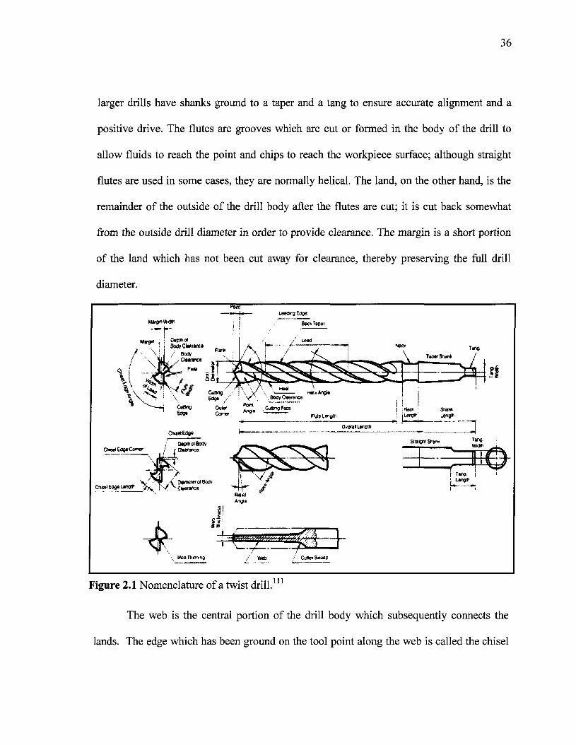
36
larger drills have shanks ground to a taper and a tang to ensure accurate alignment and a
positive drive. The flutes are grooves which are cut or formed in the body of the drill to
allow fluids to reach the point and chips to reach the workpiece surface; although straight
flutes are used in some cases, they are normally helical. The land, on the other hand, is the
remainder of the outside of the drill body after the flutes are cut; it is cut back somewhat
from the outside drill diameter in order to provide clearance. The margin is a short portion
of the land which has not been cut away for clearance, thereby preserving the full drill
diameter.
Tan»
111Figure 2.1 Nomenclature of a twist drill.
The web is the central portion of the drill body which subsequently connects the
lands. The edge which has been ground on the tool point along the web is called the chisel
37
edge and connects the cutting lips as the primary cutting edges of the drill extending from
the chisel point to the periphery of the drill. The web thickness is the smallest dimension
across the web and is measured at the point unless otherwise noted; it will often increase
upon going up the body away from the point, and it may have to be ground down during
sharpening to reduce the size of the chisel edge in a process called 'web thinning'. The
angle which the leading edge of the land makes with the drill axis is called the helix angle;
drills having various helix angles are available for different operational requirements. The
angle included between the drill lips is called the point angle and may be varied for
different workpiece materials. The chisel edge angle is the angle between the lip and the
chisel edge, when seen from the end of the drill.
2.5.1.2 Operating Conditions
The varying conditions under which drills are used make it difficult to lay down set
rules for speeds and feeds. Drill manufacturers and a number of reference texts provide
recommendations for proper speeds and feeds for drilling different types of materials.
Drilling speed depends on respecting the following seven variables: (i) the type of material
being drilled, for which the harder the material, the slower the cutting speed; (ii) the cutting
tool material and diameter; (iii) the types and use of cutting fluids which might make it
possible to increase in cutting speed; (iv) the rigidity of the drill press; (v) the rigidity of the
drill, concerning which the shorter the drill, the better the outcome; (vi) the rigidity of the
work setup; (vii) the quality of the hole to be drilled. Each variable should be considered
independently prior to drilling a hole. Each variable, however, is significant in its own
right, although the work material and its cutting speed should be considered the most
38
important factors. When the cutting speed has been selected for a particular workpiece
material and condition, the appropriate feed rate must be established in accordance with
this. Drilling feed rates are selected to maximize productivity while at the same time
maintaining chip control. Feed in drilling operations is expressed in inches-per-revolution,
or IPR, which is the distance the drill moves in inches for each revolution of the drill. The
feed may also be expressed as the distance traveled by the drill in a single minute, or IPM,
inches-per-minute, which is the product of the RPM and IPR of the drill. The undeformed
chip width is equivalent to the length of the drill lip, which depends on the point angle as
well as on the drill size. For a given set-up, the undeformed chip width is constant in
drilling; the feed dimension specified for drilling is the feed-per-revolution of the spindle.
A more fundamental quantity is the feed-per-lip, namely, half the feed-per-revolution for
the common two-flute drill. The undeformed chip thickness differs from the feed-per-lip
depending on the point angle, as shown in Figure 2.2. The width of cut b is given by
b= D/ (2*sin p), where p is the half point angle of the drill.
The drilling process, with all its complexity, may be attributed to the combined
cutting and extrusion of metal at the chisel edge in the center of the drill. The high thrust
force caused by the feeding motion first extrudes metal under the chisel edge; it then tends
to shear metal under the action of a negative rake angle tool. The cutting action through the
lips of the drill is not unlike that which occurs in other machining processes. Due to the
variable rake angles and inclination angles, however, there are differences to be observed in
the cutting action at different radius locations on the cutting edges.
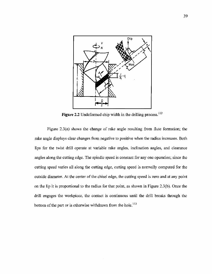
39
1 V
r
Z
b"
41 y
t
Chip \
Figure 2.2 Undeformed chip width in the drilling process.112
Figure 2.3(a) shows the change of rake angle resulting from flute formation; the
rake angle displays clear changes from negative to positive when the radius increases. Both
lips for the twist drill operate at variable rake angles, inclination angles, and clearance
angles along the cutting edge. The spindle speed is constant for any one operation; since the
cutting speed varies all along the cutting edge, cutting speed is normally computed for the
outside diameter. At the center of the chisel edge, the cutting speed is zero and at any point
on the lip it is proportional to the radius for that point, as shown in Figure 2.3(b). Once the
drill engages the workpiece, the contact is continuous until the drill breaks through the
bottom of the part or is otherwise withdrawn from the hole.113
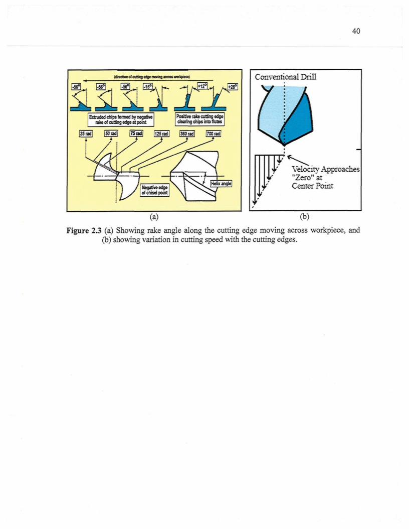
40
itsxtoi: of cjaeç «s* moving Kto» wxkp*c«)
-1^L- | /»P
Extruded chips fomwd by negativerako of cutting edge aï point
Positive rixe cutting edgedearing chips into fiutes
Conventional Drill
Velocity Approaches'�Zero'1 atCenter Point
(a) (b)
Figure 2.3 (a) Showing rake angle along the cutting edge moving across workpiece, and(b) showing variation in cutting speed with the cutting edges.
41
2.5.1.3 Dry Drilling of Aluminum Alloys
The machining of aerospace aluminum alloys with conventional tools cannot be
carried out without a certain amount of difficulty. These materials tend to adhere to tool
surface and burrs are formed inside the holes.114 Tool damage is caused mainly by the
formation of an adhesion layer and a built-up-edge (BUE) entailing a reduction in tool
life.115 Thus, cutting fluids play an important role in the machining process since they
contribute to: (i) the reduction of friction in tool-workpiece contact; (ii) the removal of
chips from the tool rake face; (iii) the drop in temperature in the contact zone; and (iv) the
limitation of the diffusion of chemical species from the tool towards the chip and vice
versa.116 The use of cutting fluids, however, seriously degrades the quality of the
environment and increases the costs of machining, thus lubrication represents about 16-
20% of the product cost. As a result, dry machining has been widely investigated over the
last few years.117
Dry machining, and especially the drilling process itself, is considered to be among
the most difficult of machining processes for accomplishing dry cutting in view of the
special difficulties it presents such as cutting at close quarters or in a circumscribed space,
lift
as well as high cutting temperatures and the difficulty of chip-removal. The dry drilling
of aluminum cast alloys in the absence of cutting fluids is known to involve a certain
degree of difficulty particularly since these alloys display properties which are inimical to
dry cutting, including high thermal expansion and low melting points.119 To control dry
drilling of aluminum alloys, it is necessary to limit the generation of heat which activates
the diffusion of chemical elements between tool and chip, and which facilitates the removal
42
of chips from the cutting area. The generation of heat depends mainly on tool geometry, the
prevailing cutting conditions, and tool-chip friction.120 The degree of difficulty in
performing dry machining is a function of the cutting process, as well as of the work and
tool materials put into use.121
In order to carry out the range of dry drilling, reaming, tapping, and end-milling
operations successfully on aluminum alloys, it is essential to use tools with suitable coating
systems and to apply a minimum quantity of lubricant. This is especially true when the L/D
ratio, or the ratio of hole depth to diameter, is greater than three.122 Cselle123 reported two
coatings which were introduced to reduce friction in drilling, reaming, tapping, and milling.
These coatings are somewhat similar to Teflon in that they adhere well to the tool surface
while also providing a gliding or low-friction surface. In the case of both coatings,
ultrafine-grain carbide with 10% cobalt was used because of its excellent heat-insulation
characteristics. Good success has generally been reported when drilling steel and Al-9%Si
using this coating.
Aronson,124 Cselle,123 Klocke and Eisenblatter,125 Braga et al.,126 and Heine127 all
reported on a method called minimal quantity of lubricant (MQL) in the development of a
dry machining process. In this method, a small amount of the lubricant is delivered to the
location of the process by means of either external or through-tool feeding. Since the
consumption rate of the lubricant is only in the order of 0.01-0.5ml/min, the tool, the chip,
and the workpiece remain dry and disposal costs can be minimized. This method has found
a number of successful applications with regard to various materials and processes, as well
as in the dry drilling of aluminum alloys. Aronson124 reported a case in which 0.1ml of
43
lubricant per hole is combined with extremely high spindle speeds of 30,000 to 70,000 rpm,
and a carbide tool. No detailed information was reported either on the type of coating used
or on the type of aluminum alloy being drilled.
Klocke and Eisenblatter125 reported on certain experiments conducted on a GD-
AlSic>Cu3 workpiece with TiAlN+MoS2 coated drills. The holes were 8.5mm in diameter
and were drilled 30mm deep; the cutting speed was 300m/min at 11240rpm with a feed rate
of 0.5mm/rev. In dry drilling operations conducted without MQL, the use of drill coating
was non-significant because of the adhesion of material in the chip groove after only 16
holes. On the other hand, with MQL, it was found that there was no evidence of any wear
or material adhesion to the tool after 128 holes.
Liu et al.128 clarified the process of chip formation and the motion of chips within the
flute in various cutting conditions, including the application of air blow drilling, MQL
drilling techniques, and dry drilling. According to these researchers, there emerged a
tendency for girdle chips to form in dry drilling as a result of the initial flow direction of
the chips; this type of girdle chip then easily caused the chip/flute to clog because of an
increase in the chip curl. The chip-removal was observed to be greatly improved in both air
blow drilling and MQL drilling. Furthermore, the decrease in the curl size was more
noticeable in MQL drilling than in air blow drilling as a result of the lubricant effect of the
oil mist. With the progress of drilling, however, the interaction between the chips, the built-
up edge formation, and the increase in chip ductility results in unstable chip formation. All
the above applications involve either high spindle speed or special coatings, which is nor-
mally too expensive for most industrial applications. Discovering a cost-effective way to
44
carry out the dry drilling of aluminum alloys is thus greatly to be desired, yet it still remains
a challenge.
2.5.2 Tapping Operations
Tapping is a machining process for producing internal threads. A tap is a cylindrical
or conical thread-cutting tool having threads of a desired form on the periphery. Combining
rotary motion with axial motion, the tap cuts or forms the internal thread.129 The cutting tap
generates the internal thread form as successive cutting edges on the chamfered section of
the tap are rotated relative to the workpiece while being fed at a rate-per-revolution equal to
the thread lead. Material is removed progressively from the wall of the hole until the final
thread form is obtained with the first full thread on the main body of the tap.130 The
threaded parts are primarily used for force transmissions; the assurance of safety in force
transmission depends notably on the quality of the threads, which in turn is dependent upon
the nature of the cutting process.131'132 The cutting fluid is more important in tapping than it
is in most other machining operations because the cutting edges are more susceptible to
damage by heat and the chips have more chance of being trapped in the flute. The
application of coatings to taps used for high-speed tapping becomes necessary in order to
improve their performance in the face of difficulties with cooling, and dealing with a high
volume of removal over short periods of time. The use of coatings by themselves, however,
does not ensure long tool life when high-speed machining is applied. It is also necessary to
obtain good edge geometry and a tough substrate, while the machine tool should be stable
with a good fixing mechanism.133
Screw threads have numerous dimensions; it is important in modern manufacturing
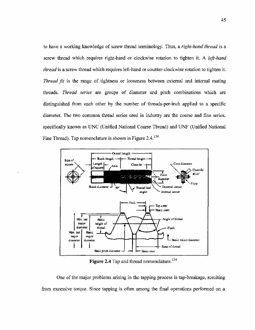
45
to have a working knowledge of screw thread terminology. Thus, a right-hand thread is a
screw thread which requires right-hand or clockwise rotation to tighten it. A left-hand
thread is a screw thread which requires left-hand or counter-clockwise rotation to tighten it.
Thread fit is the range of tightness or looseness between external and internal mating
threads. Thread series are groups of diameter and pitch combinations which are
distinguished from each other by the number of threads-per-inch applied to a specific
diameter. The two common thread series used in industry are the coarse and fine series,
specifically known as UNC (Unified National Coarse Thread) and UNF (Unified National
Fine Thread). Tap nomenclature is shown in Figure 2.4.134
length.'
� Ba*e«filuead�' �H r*� Ba&ic taai
Figure 2.4 Tap and thread nomenclature.134
One of the major problems arising in the tapping process is tap-breakage, resulting
from excessive torque. Since tapping is often among the final operations performed on a
46
workpiece, the problem has the potential for being extremely costly. Tap-breakage may
either ruin the almost completed workpiece, or else create a large down time reserved for
removing the broken tap from the workpiece. Improved knowledge of torque in tapping and
its relationship to tapping process faults such as axis misalignment, tap run-out, and poor
hole quality is, therefore, critical to reducing the wear/vibration of the tap, and avoiding any
breakage, while at the same time selecting productive tapping conditions. Knowledge of
torque and thrust characteristics would also be useful in monitoring and control techniques
for a computer-based tapping process.135
In the context of tapping forces, it has been reported that the chamfer section of the
tap generates a major portion of the resulting cutting force, because of a larger chip cross-
section related to the teeth of the chamfer, as shown in Figure 2.5(a). Machining with a
calibrating section does not contribute significantly to the resulting force since it is friction
which affects this phase dominantly. For several practical reasons it is useful to decompose
the resulting cutting forces acting on the tap to axial force and torque. The tapping process
is also followed by the side force which arises from the unbalanced sum of tangential (Ft)
and radial (Fr) forces acting on all the engaged teeth of the tap. During the tapping cycle,
cutting forces undergo significant changes; thrust force and torque by full immersion of the
chamfer section of the tap are used as representative values for such operations. Dynamic
changes in the torque are shown in Figure 2.5(b) for two cases of tapping operations
including tapping in a blind hole and in a through-hole. The maximum values which appear
in phase B (and which are the same for the axial thrust force) are significant for phases in
technology design related to the choice of fixture, tool, and tool holder. Besides applying
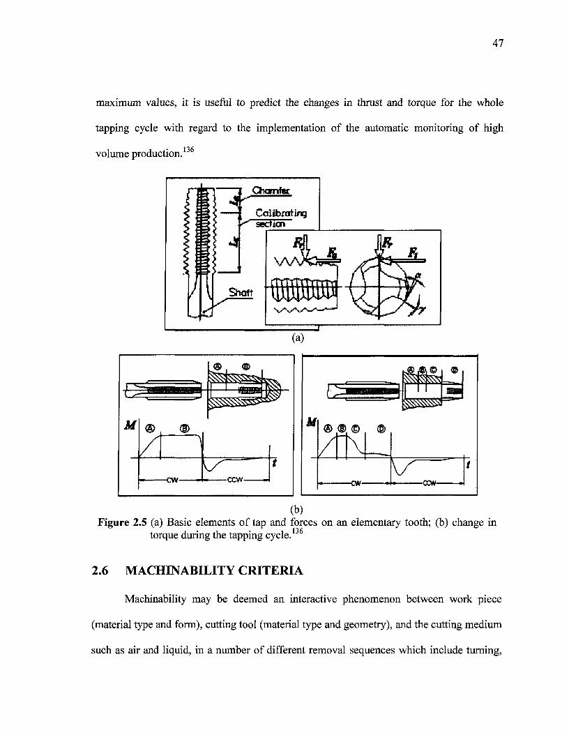
47
maximum values, it is useful to predict the changes in thrust and torque for the whole
tapping cycle with regard to the implementation of the automatic monitoring of high
volume production.136
(b)Figure 2.5 (a) Basic elements of tap and forces on an elementary tooth; (b) change in
torque during the tapping cycle.136
2.6 MACHINABILITY CRITERIA
Machinability may be deemed an interactive phenomenon between work piece
(material type and form), cutting tool (material type and geometry), and the cutting medium
such as air and liquid, in a number of different removal sequences which include turning,
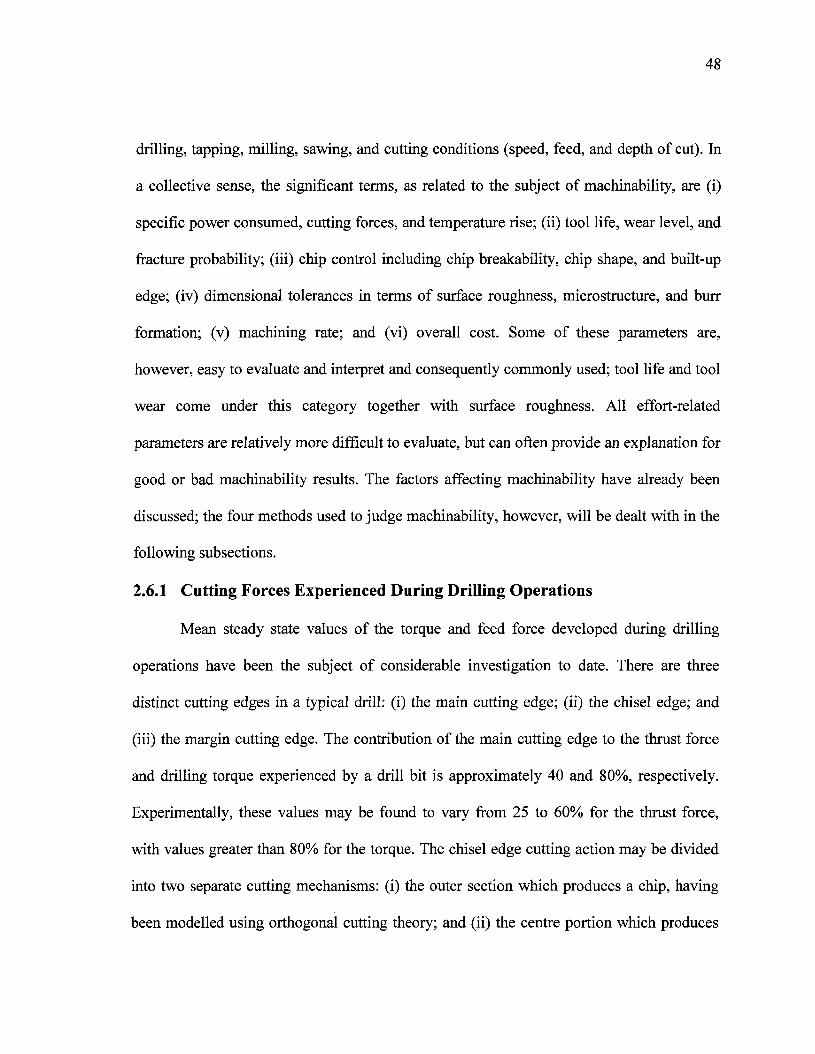
48
drilling, tapping, milling, sawing, and cutting conditions (speed, feed, and depth of cut). In
a collective sense, the significant terms, as related to the subject of machinability, are (i)
specific power consumed, cutting forces, and temperature rise; (ii) tool life, wear level, and
fracture probability; (iii) chip control including chip breakability, chip shape, and built-up
edge; (iv) dimensional tolerances in terms of surface roughness, microstructure, and burr
formation; (v) machining rate; and (vi) overall cost. Some of these parameters are,
however, easy to evaluate and interpret and consequently commonly used; tool life and tool
wear come under this category together with surface roughness. All effort-related
parameters are relatively more difficult to evaluate, but can often provide an explanation for
good or bad machinability results. The factors affecting machinability have already been
discussed; the four methods used to judge machinability, however, will be dealt with in the
following subsections.
2.6.1 Cutting Forces Experienced During Drilling Operations
Mean steady state values of the torque and feed force developed during drilling
operations have been the subject of considerable investigation to date. There are three
distinct cutting edges in a typical drill: (i) the main cutting edge; (ii) the chisel edge; and
(iii) the margin cutting edge. The contribution of the main cutting edge to the thrust force
and drilling torque experienced by a drill bit is approximately 40 and 80%, respectively.
Experimentally, these values may be found to vary from 25 to 60% for the thrust force,
with values greater than 80% for the torque. The chisel edge cutting action may be divided
into two separate cutting mechanisms: (i) the outer section which produces a chip, having
been modelled using orthogonal cutting theory; and (ii) the centre portion which produces
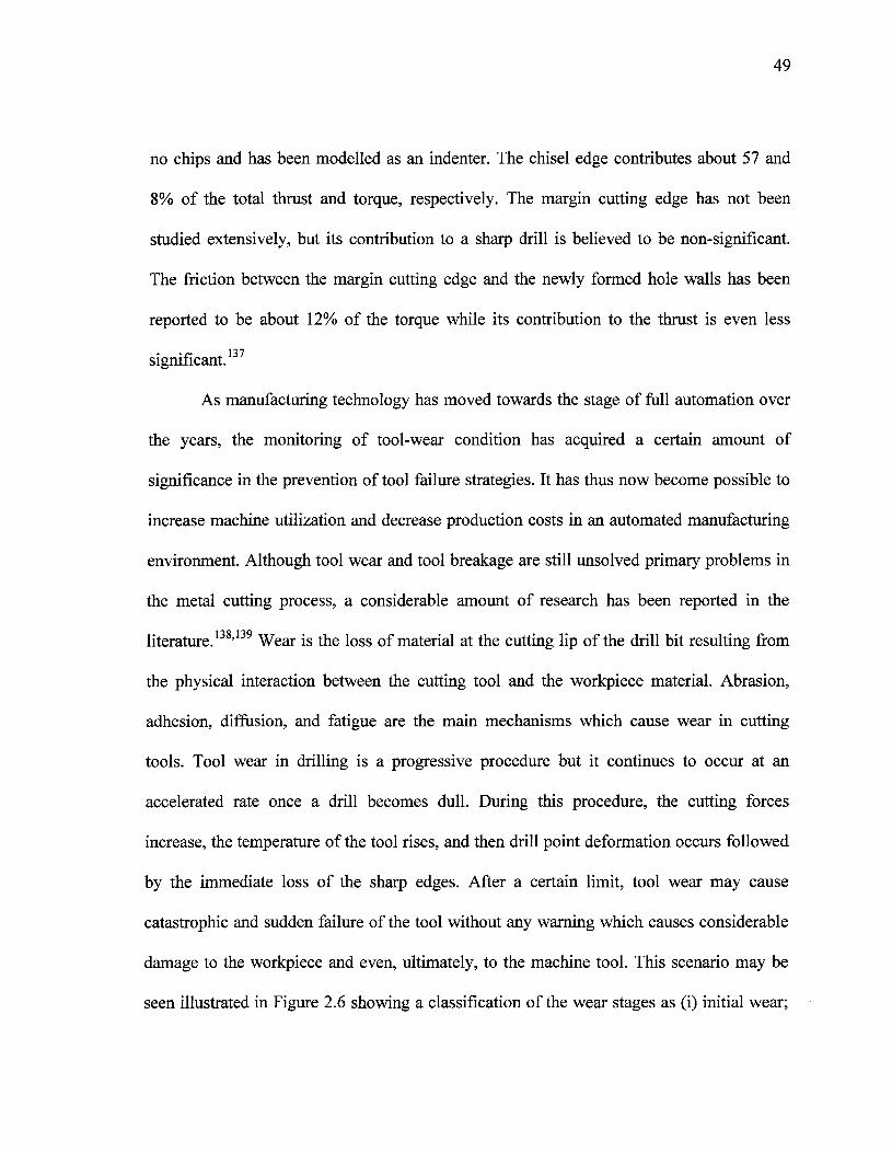
49
no chips and has been modelled as an indenter. The chisel edge contributes about 57 and
8% of the total thrust and torque, respectively. The margin cutting edge has not been
studied extensively, but its contribution to a sharp drill is believed to be non-significant.
The friction between the margin cutting edge and the newly formed hole walls has been
reported to be about 12% of the torque while its contribution to the thrust is even less
significant.137
As manufacturing technology has moved towards the stage of full automation over
the years, the monitoring of tool-wear condition has acquired a certain amount of
significance in the prevention of tool failure strategies. It has thus now become possible to
increase machine utilization and decrease production costs in an automated manufacturing
environment. Although tool wear and tool breakage are still unsolved primary problems in
the metal cutting process, a considerable amount of research has been reported in the
literature.138'139 Wear is the loss of material at the cutting lip of the drill bit resulting from
the physical interaction between the cutting tool and the workpiece material. Abrasion,
adhesion, diffusion, and fatigue are the main mechanisms which cause wear in cutting
tools. Tool wear in drilling is a progressive procedure but it continues to occur at an
accelerated rate once a drill becomes dull. During this procedure, the cutting forces
increase, the temperature of the tool rises, and then drill point deformation occurs followed
by the immediate loss of the sharp edges. After a certain limit, tool wear may cause
catastrophic and sudden failure of the tool without any warning which causes considerable
damage to the workpiece and even, ultimately, to the machine tool. This scenario may be
seen illustrated in Figure 2.6 showing a classification of the wear stages as (i) initial wear;
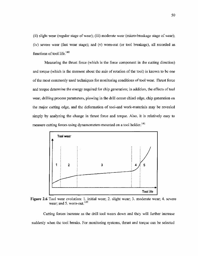
50
(ii) slight wear (regular stage of wear); (iii) moderate wear (micro-breakage stage of wear);
(iv) severe wear (fast wear stage); and (v) worn-out (or tool breakage), all recorded as
functions of tool life.140
Measuring the thrust force (which is the force component in the cutting direction)
and torque (which is the moment about the axis of rotation of the tool) is known to be one
of the most commonly used techniques for monitoring conditions of tool wear. Thrust force
and torque determine the energy required for chip generation; in addition, the effects of tool
wear, drilling process parameters, plowing in the drill center chisel edge, chip generation on
the major cutting edge, and the deformation of tool-and work-materials may be revealed
simply by analyzing the change in thrust force and torque. Also, it is relatively easy to
measure cutting forces using dynamometers mounted on a tool holder.141
Figure 2.6 Tool wear evolution: 1. initial wear; 2. slight wear; 3. moderate wear; 4. severewear; and 5. worn-out.139
Cutting forces increase as the drill tool wears down and they will further increase
suddenly when the tool breaks. For monitoring systems, thrust and torque can be selected
51
separately as measurement signals.142 Thrust force is also known to be one of the most
useful dynamic parameters in the drilling process. Thangaraj and Wright143 used the rate of
change in thrust forces to predict drill failure, while Brinksmeier144 selected torque to
predict tool fracture. The major drawback with cutting forces is their dependence on cutting
conditions including cutting velocity, feed, and depth of cut. Owing to the complexity of
the cutting tool, most research on tool-wear monitoring for drills must be based on an
analysis of experimental data. Subramanian and Cook145 established thrust and torque as a
function of workpiece material hardness, average flank wear, drill diameter, feed rate, and
radius at the cutting edge. These researchers also found that tool life is strongly affected by
workpiece material hardness; they demonstrated that monitoring drill conditions which
made use of the thrust force and/or torque was effective only when a close tolerance range
was maintained on the workpiece hardness at about 5%.
Bandyopahyay et al.,146 who used dynamic system technology to monitor tool wear,
claimed that the increase in force magnitude because of tool wear is non-significant, thus
not to be used for tool-wear monitoring; it should be noted, however, that only drills
showing relatively little drill wear were used in their tests. Jalali 147 established a tool life
model by means of which it has been possible to observe that the thrust force and torque
when machining the last hole is 50% greater than when machining the first hole. It was also
observed that the cutting forces increase as tool wear increases; this finding was based on
the existence of an increase in friction between tool and workpiece which occurs during the
cutting process.
52
2.6.2 Tool Wear and BUE Formation
Tool machining is the radical process of friction and wear; tool wear during cutting
not only decreases the service life of cutting tools, but also leads to the increased roughness
of the cutting surfaces of a workpiece. Aluminum alloys, especially die-cast aluminum
alloys, are widely used for machining work, in which drilling is one of the most important
machining methods available for application to these alloys. As more and more automotive
or computer-controlled machines are used, manufacturers need to increase the service life
of cutting tools in order to increase machining effectiveness and to lower manufacturing
costs.148 Nevertheless, the effects of aluminum workpiece microstructure on tool wear do
not appear to have received sufficient attention. In spite of the large amount of data and
knowledge which has been accumulated on the subject, tool wear is still not fully
understood. Cutting tools wear out mainly because (i) normal loads on the wear surfaces
are heavy and also because (ii) the cutting chips and workpiece which apply these loads
move rapidly over the wear surface. The cutting action and the friction of the contact
surfaces increase the temperature of the tool material, which further expedites the physical
and chemical processes associated with tool wear. These forces and motions are necessary
for material removal and thus cutting tool wear is an inevitable production problem for
manufacturing industries.149
Two major types of gradual tool wear in metal cutting have been reported, namely,
temperature activated diffusive wear or mechanically activated wear in terms of adhesive,
abrasive, and/or fatigue mechanisms. The particular type of wear which prevails in a
specific machining operation depends on the cutting-tool material, on the workpiece
53
material being machined, and on the cutting conditions themselves.150 Several
investigations have shown that tool wear is mainly the result of abrasion at low speed
conditions. When the cutting speed is increased, the temperature at the tool rake face may
increase as a result. This behaviour stems from the intensive deformation associated with
large shear strains in the primary shear zone as well as the friction effects occurring along
the tool-chip interface.151 Consequently, diffusion is considered to be the dominant wear
mechanism for tools at higher cutting speeds. The atoms which are diffused from tool to
chip are carried away by the flow of work material along the contact surface. The material
transfer towards the chip leads either to the formation of an adhesion layer and a built-up
edge or to the formation of a crater on the tool rake face in extreme cutting conditions,
ultimately leading to a noticeable reduction in tool life. Thus, the magnitude of the tool-
chip interface temperature causes a shift from abrasion to adhesion, or from adhesion to the
diffusion-wear process.122
In machining processes, tool life is usually determined by using criteria based on
tool-wear. Figure 2.7 shows the intensity of tool wear, ô, as a function of the cutting
temperature, T, in relation to different wear mechanisms. As shown in this figure, it will be
observed that the adhesion mechanism is the wear mechanism which operates for the
widest range of cutting temperatures. Generally, adhesion wear involves the direct transfer
of tool particles to the metallic chips; however, tool wear may also occur through the
transfer of macroscopic fragments from the workpiece material onto the tool surface. These
fragments are mechanically unstable, and can thus be removed from the tool surface by the
action of the high strength cutting forces which are thereby produced. In this process, tool
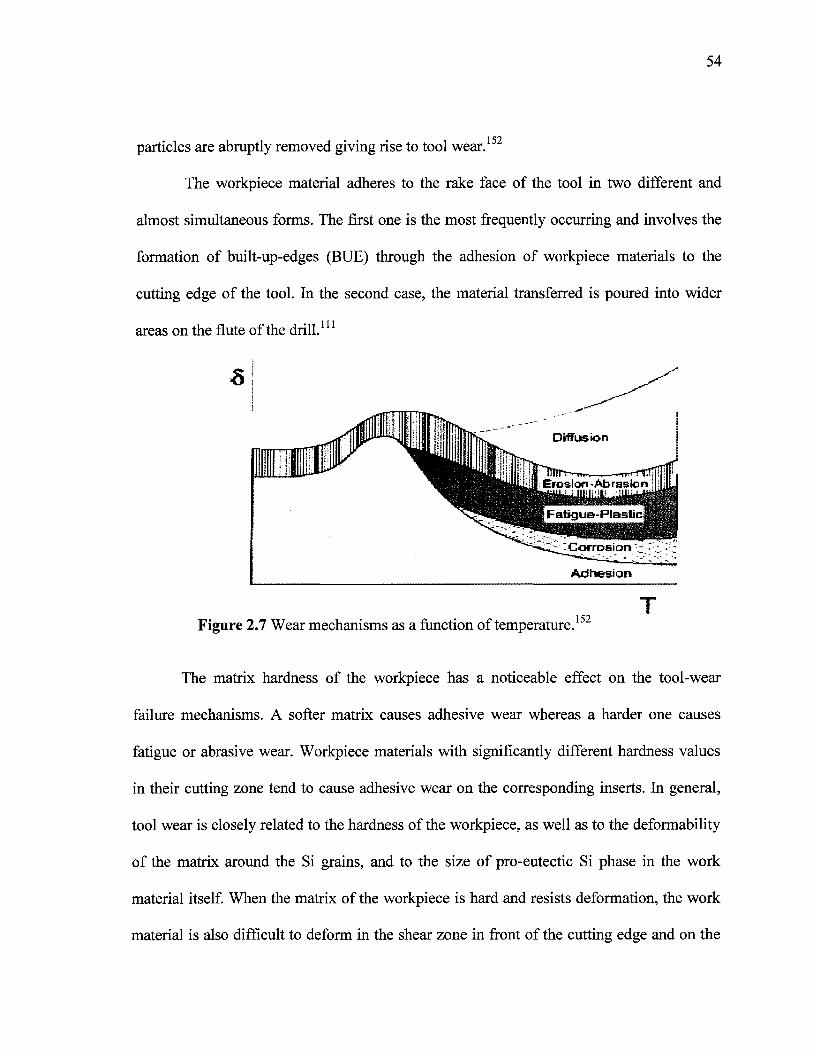
54
particles are abruptly removed giving rise to tool wear.15
The workpiece material adheres to the rake face of the tool in two different and
almost simultaneous forms. The first one is the most frequently occurring and involves the
formation of built-up-edges (BUE) through the adhesion of workpiece materials to the
cutting edge of the tool. In the second case, the material transferred is poured into wider
areas on the flute of the drill.111
Erosion -Abrasioniiiiiiiiii i
Corrosion - -
Adhesion
Figure 2.7 Wear mechanisms as a function of temperature.152
The matrix hardness of the workpiece has a noticeable effect on the tool-wear
failure mechanisms. A softer matrix causes adhesive wear whereas a harder one causes
fatigue or abrasive wear. Workpiece materials with significantly different hardness values
in their cutting zone tend to cause adhesive wear on the corresponding inserts. In general,
tool wear is closely related to the hardness of the workpiece, as well as to the deformability
of the matrix around the Si grains, and to the size of pro-eutectic Si phase in the work
material itself. When the matrix of the workpiece is hard and resists deformation, the work
material is also difficult to deform in the shear zone in front of the cutting edge and on the
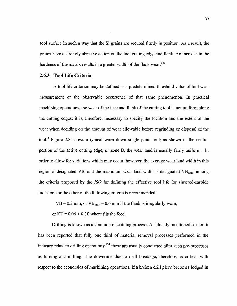
55
tool surface in such a way that the Si grains are secured firmly in position. As a result, the
grains have a strongly abrasive action on the tool cutting edge and flank. An increase in the
hardness of the matrix results in a greater width of the flank wear.153
2.6.3 Tool Life Criteria
A tool life criterion may be defined as a predetermined threshold value of tool wear
measurement or the observable occurrence of that same phenomenon. In practical
machining operations, the wear of the face and flank of the cutting tool is not uniform along
the cutting edges; it is, therefore, necessary to specify the location and the extent of the
wear when deciding on the amount of wear allowable before regrinding or disposal of the
tool.4 Figure 2.8 shows a typical worn down single point tool; as shown in the central
portion of the active cutting edge, or zone B, the wear land is usually fairly uniform. In
order to allow for variations which may occur, however, the average wear land width in this
region is designated VB, and the maximum wear land width is designated VBmax; among
the criteria proposed by the ISO for defining the effective tool life for sintered-carbide
tools, one or the other of the following criteria is recommended:
VB = 0.3 mm, or VBmax = 0.6 mm if the flank is irregularly worn,
or KT = 0.06 + 0.3f, where fis the feed.
Drilling is known as a common machining process. As already mentioned earlier, it
has been reported that fully one third of material removal processes performed in the
industry relate to drilling operations;154 these are usually conducted after such pre-processes
as turning and milling. The downtime due to drill breakage, therefore, is critical with
respect to the economics of machining operations. If a broken drill piece becomes lodged in
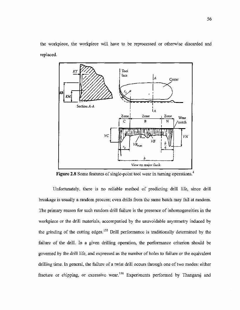
56
the workpiece, the workpiece will have to be reprocessed or otherwise discarded and
replaced.
KT
KBKM
Crater
Section A -A\A
Zone Zone Zone
b
Wear'notch
VN
View on major flank
Figure 2.8 Some features of single-point tool wear in turning operations.4
Unfortunately, there is no reliable method of predicting drill life, since drill
breakage is usually a random process; even drills from the same batch may fail at random.
The primary reason for such random drill failure is the presence of inhomogeneities in the
workpiece or the drill materials, accompanied by the unavoidable asymmetry induced by
the grinding of the cutting edges.155 Drill performance is traditionally determined by the
failure of the drill. In a given drilling operation, the performance criterion should be
governed by the drill life, and expressed as the number of holes to failure or the equivalent
drilling time. In general, the failure of a twist drill occurs through one of two modes: either
fracture or chipping, or excessive wear.156 Experiments performed by Thangaraj and
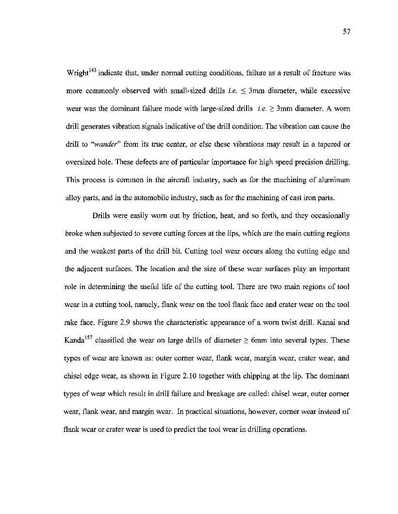
57
Wright143 indicate that, under normal cutting conditions, failure as a result of fracture was
more commonly observed with small-sized drills i.e. < 3mm diameter, while excessive
wear was the dominant failure mode with large-sized drills i.e. > 3mm diameter. A worn
drill generates vibration signals indicative of the drill condition. The vibration can cause the
drill to "wander" from its true center, or else these vibrations may result in a tapered or
oversized hole. These defects are of particular importance for high speed precision drilling.
This process is common in the aircraft industry, such as for the machining of aluminum
alloy parts, and in the automobile industry, such as for the machining of cast iron parts.
Drills were easily worn out by friction, heat, and so forth, and they occasionally
broke when subjected to severe cutting forces at the lips, which are the main cutting regions
and the weakest parts of the drill bit. Cutting tool wear occurs along the cutting edge and
the adjacent surfaces. The location and the size of these wear surfaces play an important
role in determining the useful life of the cutting tool. There are two main regions of tool
wear in a cutting tool, namely, flank wear on the tool flank face and crater wear on the tool
rake face. Figure 2.9 shows the characteristic appearance of a worn twist drill. Kanai and
Kanda157 classified the wear on large drills of diameter > 6mm into several types. These
types of wear are known as: outer corner wear, flank wear, margin wear, crater wear, and
chisel edge wear, as shown in Figure 2.10 together with chipping at the lip. The dominant
types of wear which result in drill failure and breakage are called: chisel wear, outer corner
wear, flank wear, and margin wear. In practical situations, however, corner wear instead of
flank wear or crater wear is used to predict the tool wear in drilling operations.
58
Chisel edge wear
Flank wear
Figure 2.9 Characteristics of worn twist drill.149
' a) Outer Corner Wearb) Flank Wear
c) Chisel Edge Wear
d) Crater Wear
Chisel edge
L i p
Outer corner
f) Chipping at Lip
Figure 2.10 Types of drill wear.157
59
2.6.4 Chip Formation in Drilling
Small well-broken chips are desirable in drilling operations; the reason for this is
that as the chips get larger, they move less easily through the flutes, thereby increasing
torque requirements, perhaps causing drill breakage. During formation, the chips rotate
with the drill and collide with the hole wall or interior of the flute; this impact produces a
bending moment in the chip. The chip will fracture, once the bending moment causes it to
exceed a critical strain. There is, thus, a clear need for the parameters of chip size and shape
to be studied in detail by the industry as a formal research topic in order to identify the
conditions which will ultimately promote better chip evacuation.158 A punctual examination
of the chips being produced upon machining a particular workpiece will provide a
considerable amount of information as to how well the job is proceeding, how tool wear is
progressing, and why premature tool failure has occurred, or in other words, why a
shortened tool life intervenes.159
Chip-formation and the chip-breaking mechanism has been the subject of studies for
a number of years; starting with the Merchant chip formation model in 1945, numerous
other studies have contributed to the understanding of this area of research.3'5'6'8'11 Although
the level of understanding has been adequate, the results from previous studies were based
on simple cutting tools having the same tool geometry and cutting parameters along the
cutting edge. There has been very little research carried out on such complicated cutting
tools as drills whose geometry and cutting parameters differ along the cutting edge.160 To
simplify the drill cutting process, the drill cutting edge is conventionally treated as a
summation of several small segments with each segment having homogenous geometry and
60
cutting parameters. There are differences between chip formation in drilling and
conventional cutting processes. These differences include the following: (i) chip formation
is not completed when chips leave the cutting edge; chips will be further deformed as a
result of the interaction of the chips with the drill flute and hole-wall; (ii) chip flow
direction is restricted by the cutting speed difference along the cutting edge since the
cutting speed is much slower at the point close to the drill center, or inner cutting edge, than
it is close to the drill peripheral point, or outer cutting edge, where the initial chips are cone
shaped and tend to flow towards the drill center; and (iii) the chip-flute interaction is a
combined effect of the drill point geometry in terms of point angle and the drill flute
geometry represented by the helix angle. Furthermore, this interaction will alter the chip
deformation after it leaves the cutting edge; it may also result in different chip lengths and
shapes.161
In one of the few studies carried out on drilling chip formation, Nakayama and
Ogawa162 reported that chip size in the drilling process is governed by its formation
geometry at the cutting edge, as well as its thickness, curl, and characteristic length, as
determined by the point at which the chip breaks in the generation cycle. Figure 2.11 shows
the details of the three components of chip curl by indicating the following points. First is
the side-curl, which is the result of velocity differences across the cutting lip since the
cutting speed varies proportionally with the distance from the drill center, as shown by coz.
The second rotation, coc, is about the drill axis; it accounts for the twisted, non-planar rake
face, and for the increasingly positive rake angle having a radial distance from the drill
axis. This term, a>c, will also reflect the changes in the rake angle caused by built-up-edge
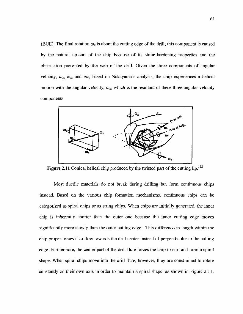
61
(BUE). The final rotation cox is about the cutting edge of the drill; this component is caused
by the natural up-curl of the chip because of its strain-hardening properties and the
obstruction presented by the web of the drill. Given the three components of angular
velocity, a>c, roz, and cox, based on Nakayama's analysis, the chip experiences a helical
motion with the angular velocity, a>h, which is the resultant of these three angular velocity
components.
162Figure 2.11 Conical helical chip produced by the twisted part of the cutting lip.
Most ductile materials do not break during drilling but form continuous chips
instead. Based on the various chip formation mechanisms, continuous chips can be
categorized as spiral chips or as string chips. When chips are initially generated, the inner
chip is inherently shorter than the outer one because the inner cutting edge moves
significantly more slowly than the outer cutting edge. This difference in length within the
chip proper forces it to flow towards the drill center instead of perpendicular to the cutting
edge. Furthermore, the center part of the drill flute forces the chip to curl and form a spiral
shape. When spiral chips move into the drill flute, however, they are constrained to rotate
constantly on their own axis in order to maintain a spiral shape, as shown in Figure 2.11.
62
This rotating motion causes the spiral chips to encounter difficulty maintaining their shape
as the hole gets deeper. If the chips cannot keep up with the rotation, they will either break
or be forced to move along the flute without spinning and thus to form string chips.96
During the transition from spiral chips to string chips, there are a few types of
intermittent shapes which emerge, depending on the material, the chip thickness, and the
size of the drill. Although initial drill chips are all spiral cones, they will ultimately change
into various other shapes upon drilling deeper as a result of the interaction between the drill
flute and the hole wall. Batzer et al.95 studied the effects of cutting conditions on the
drilling process in order to acquire a better understanding of chip-formation mechanics;
they were able to record the entire range of chip forms as created by drilling experiments,
with the exception of dust-like chips, as shown in Figure 2.12. Figure 2.12A shows conical
chips; the diameter of the conical chip must be small enough to allow it to move through
the flute/hole wall cavity without breaking. Figure 2.12B shows fan-shaped chips; these are
formed when conical chips cannot curl sufficiently to follow the flute and fracture prior to a
complete revolution. Chisel-edge chips, as shown in Figure 2.12C, form because of the
extrusion of metal from the chisel edge. These chips are long and narrow, streaming out of
the drill along the interior of the flute at the web. When this chip forms, there is a second
chip type also forming at the same time along the cutting edge; these two chips may or may
not interact. To eliminate the chisel-edge chip, it may be necessary to decrease the feed and
thereby the amount of metal to be extruded. Amorphous chips, which have a somewhat
wrinkled, uncurled appearance, are shown in Figure 2.12D. These chips do not have
enough consistent curl to assume a fan shape and are guided, unbroken, up the flutes. As is
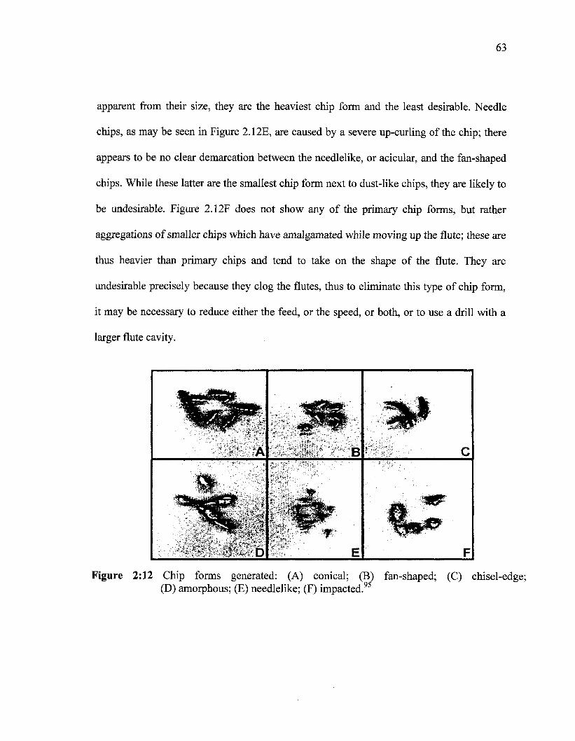
63
apparent from their size, they are the heaviest chip form and the least desirable. Needle
chips, as may be seen in Figure 2.12E, are caused by a severe up-curling of the chip; there
appears to be no clear demarcation between the needlelike, or acicular, and the fan-shaped
chips. While these latter are the smallest chip form next to dust-like chips, they are likely to
be undesirable. Figure 2.12F does not show any of the primary chip forms, but rather
aggregations of smaller chips which have amalgamated while moving up the flute; these are
thus heavier than primary chips and tend to take on the shape of the flute. They are
undesirable precisely because they clog the flutes, thus to eliminate this type of chip form,
it may be necessary to reduce either the feed, or the speed, or both, or to use a drill with a
larger flute cavity.
� À
B
Figure 2:12 Chip forms generated: (A) conical; (B) fan-shaped; (C) chisel-edge;(D) amorphous; (E) needlelike; (F) impacted.95

CHAPTER 3
EXPERIMENTAL PROCEDURES
65
CHAPTER 3
EXPERIMENTAL PROCEDURES
3.1 INTRODUCTION
With regard to experimental procedures, this chapter provides details of (i) the
alloys and melt additives investigated, (ii) the general melting and casting procedures
applied, and (iii) the various techniques used for microstructural investigation, hardness
testing, tensile testing, and machinability testing. The study was conducted to investigate a
new experimental alloy belonging to the Al-Si near-eutectic cast alloy group, and which
contains about 10.8%Si, namely the 396 alloy. Machining tests were carried out using a
Makino A88E high-speed horizontal center machine under fixed machining conditions
which include cutting speed, feed rate, length of cut, tool geometry, tool material, and
coolant as applied to the examination of the alloys under discussion. The operations were
set in motion with a view to studying the machining performance of grain-refined, heat-
treated 396, B319.2, and A356.2 alloys. It should be mentioned here that machining
performance implies cutting force and moment as well as tool life, chip configuration, and
built-up edge (BUE) evolution.
66
3.2 ALLOY PREPARATION AND CASTING PROCEDURES
The 396, B319.2, and A356.2 base alloys used in this study were supplied in the
form of 12.5-kg ingots. The chemical composition of the ingots is shown in Table 3.1.
Eight alloys were prepared using the 396 alloy, they were then classified into three groups
according to the additives used, namely Fe-intermetallic elements, matrix-hardening
elements, and free cutting elements; three alloys of the B319.2 commercial Al-Si alloy
were used to investigate the role of free-cutting elements, namely Sn, Bi, and Sn + Bi in
connection with the machinability performance of these alloys.
Table 3.1 Chemical composition of the 396, B319.2, and A356.2 base alloys
Alloy
396
B319.2
A356.2
Element (wt %)Si
10.89
7.16
6.93
Cu
2.243
3.32
0.173
Mg
0.309
0.29
0.4168
Fe
0.464
0.29
0.112
Mn
0.492
0.27
0.289
Sr
0.014
0.019
0.017
Ti
0.057
0.27
0.16
Al
bal.
bal.
bal.
Mn/Fe
1.06
0.95
2.58
In addition, two further experimental alloys were prepared using the Al-10.8%Si-
Cu-Mg and the Al-10.8%Si-Cu alloy groups. These two alloys were selected to study the
effects of Sr-modification and the presence of a Mg-free alloy on the machinability of Al-Si
near-eutectic alloys. For the purposes of comparison, the B319.2 and A356.2 commercial
alloys were used here to compare the machinability of these alloys with that of 396 alloys.
It should be kept in mind that the bulk of the experimental work was carried out using 396
alloys. The nominal composition and respective codes of the alloys prepared for the present
study are provided in Table 3.2. The as-received 396, B319.2, and A356.2 ingots were cut
into smaller pieces, dried, and melted in charges of 100kg each for the preparation of the
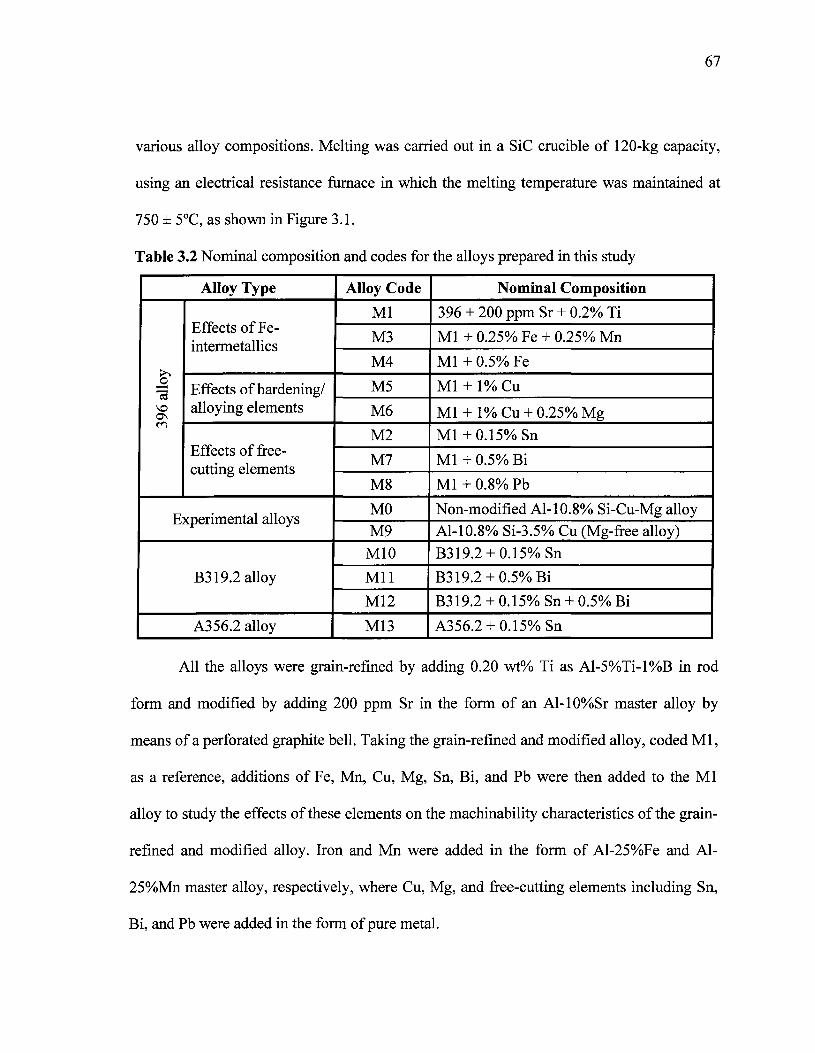
67
various alloy compositions. Melting was carried out in a SiC crucible of 120-kg capacity,
using an electrical resistance furnace in which the melting temperature was maintained at
750 ± 5°C, as shown in Figure 3.1.
Table 3.2 Nominal composition and codes for the alloys prepared in this study
Alloy Type
396
allo
y
p
Effects of Fe-intermetallics
Effects of hardening/alloying elements
Effects of free-cutting elements
xperimental alloys
B319.2 alloy
A356.2 alloy
Alloy Code
Ml
M3
M4
M5
M6
M2
M7
M8
MOM9M10
Mil
M12
M13
Nominal Composition
396 + 200 ppm Sr + 0.2% Ti
Ml + 0.25% Fe + 0.25% Mn
Ml + 0.5% Fe
Ml + 1% Cu
Ml + l%Cu + 0.25%Mg
Ml+0.15%Sn
Ml + 0.5% Bi
Ml + 0.8% Pb
Non-modified Al-10.8% Si-Cu-Mg alloyAl-10.8% Si-3.5% Cu (Mg-free alloy)B319.2 + 0.15%Sn
B319.2 + 0.5%Bi
B319.2 + 0.15% Sn + 0.5% Bi
A356.2 + 0.15%Sn
All the alloys were grain-refined by adding 0.20 wt% Ti as Al-5%Ti-l%B in rod
form and modified by adding 200 ppm Sr in the form of an Al-10%Sr master alloy by
means of a perforated graphite bell. Taking the grain-refined and modified alloy, coded Ml,
as a reference, additions of Fe, Mn, Cu, Mg, Sn, Bi, and Pb were then added to the Ml
alloy to study the effects of these elements on the machinability characteristics of the grain-
refined and modified alloy. Iron and Mn were added in the form of Al-25%Fe and Al-
25%Mn master alloy, respectively, where Cu, Mg, and free-cutting elements including Sn,
Bi, and Pb were added in the form of pure metal.
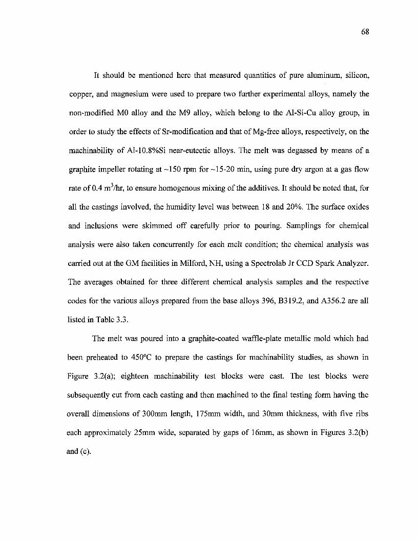
68
It should be mentioned here that measured quantities of pure aluminum, silicon,
copper, and magnesium were used to prepare two further experimental alloys, namely the
non-modified MO alloy and the M9 alloy, which belong to the Al-Si-Cu alloy group, in
order to study the effects of Sr-modification and that of Mg-free alloys, respectively, on the
machinability of Al-10.8%Si near-eutectic alloys. The melt was degassed by means of a
graphite impeller rotating at -150 rpm for -15-20 min, using pure dry argon at a gas flow
rate of 0.4 m3/hr, to ensure homogenous mixing of the additives. It should be noted that, for
all the castings involved, the humidity level was between 18 and 20%. The surface oxides
and inclusions were skimmed off carefully prior to pouring. Samplings for chemical
analysis were also taken concurrently for each melt condition; the chemical analysis was
carried out at the GM facilities in Milford, NH, using a Spectrolab Jr CCD Spark Analyzer.
The averages obtained for three different chemical analysis samples and the respective
codes for the various alloys prepared from the base alloys 396, B319.2, and A356.2 are all
listed in Table 3.3.
The melt was poured into a graphite-coated waffle-plate metallic mold which had
been preheated to 450°C to prepare the castings for machinability studies, as shown in
Figure 3.2(a); eighteen machinability test blocks were cast. The test blocks were
subsequently cut from each casting and then machined to the final testing form having the
overall dimensions of 300mm length, 175mm width, and 30mm thickness, with five ribs
each approximately 25mm wide, separated by gaps of 16mm, as shown in Figures 3.2(b)
and (c).
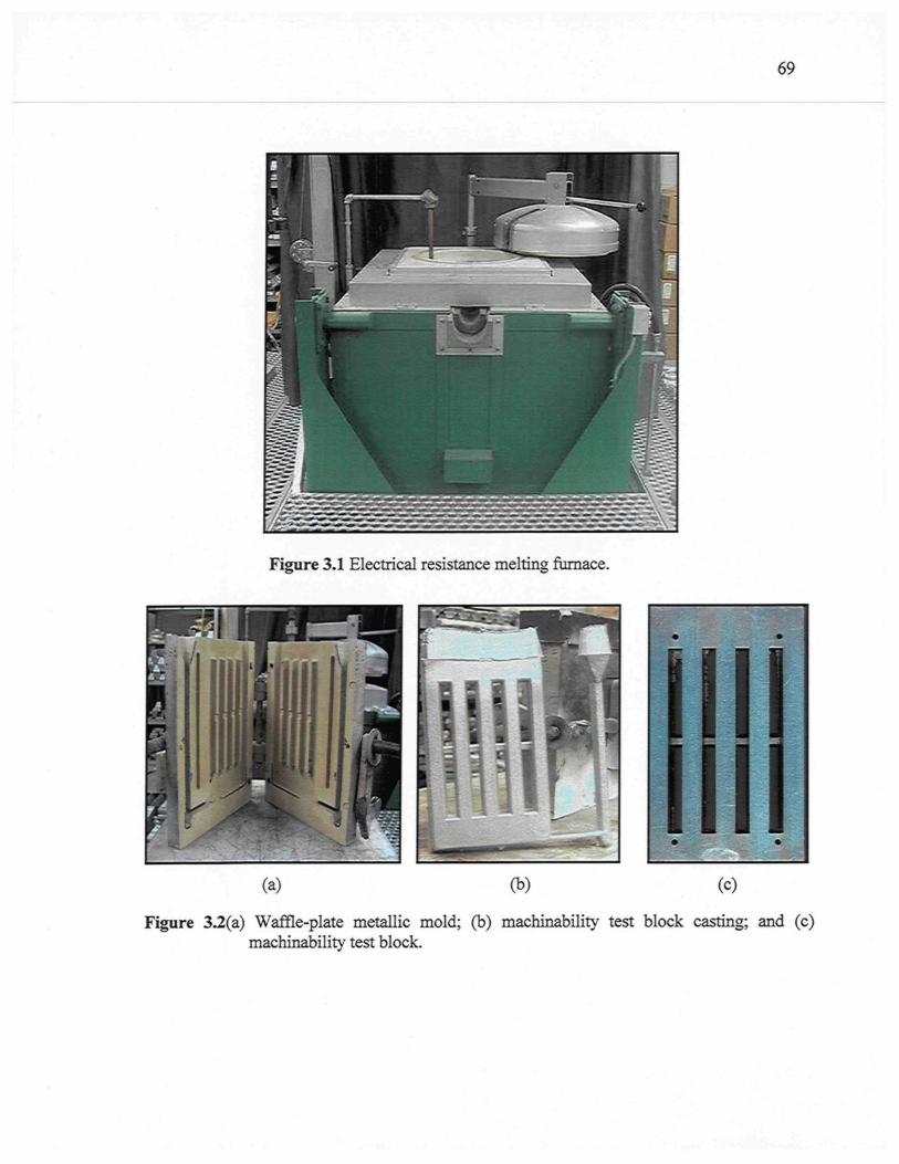
69
Up:r
mm
Figure 3.1 Electrical resistance melting furnace.
(b) (c)
Figure 3.2(a) Waffle-plate metallic mold; (b) machinability test block casting; and (c)machinability test block.
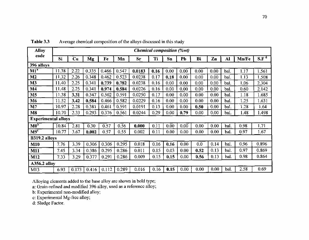
70
Table 3.3 Average chemical composition of the alloys discussed in this study
Alloycode
Si 1396 alloysMla
M2M3M4M5M6M7M8
11.3811.3211.4011.4811.3811.5210.9710.70
Cu
2.222.262.252.253.313.422.282.33
Mg |
0.3350.3480.3410.3410.3470.5840.3810.293
Fe |
0.4660.4620.7390.9740.5020.4660.4610.376
Mn |
0.5470.5230.7820.5840.5910.5820.5910.561
Chemical composition
Sr |
0.01830.02380.02380.02260.02500.02290.01910.0244
Ti |
0.160.170.160.160.170.160.130.29
Sn
0.000.180.000.000.000.000.000.00
(%wt)
Pb |
0.000.000.000.000.000.000.000.79
Bi |
0.000.000.000.000.000.000.500.00
Zn |
0.000.000.000.000.000.000.000.00
Al |
bal.bal.bal.bal.bal.bal.bal.bal.
Mn/Fe
1.171.131.060.601.181.251.281.48
| S.Fd
1.5611.5082.3042.1421.6851.6311.641.498
Experimental alloys
M0b
M9C10.8410.77
2.813.67
0.300.002
0.570.57
0.560.55
0.0000.002
0.110.11
0.000.00
0.000.00
0.000.00
0.000.00
bal.bal.
0.980.97
1.711.67
B319.2 alloysM10MilM12
7.767.457.33
3.393.343.29
0.3060.3860.377
0.3060.2950.291
0.2950.2860.286
0.0180.0110.009
0.160.150.15
0.160.030.15
0.000.000.00
0.00.520.56
0.140.130.13
bal.bal.bal.
0.960.970.98
0.8960.8690.864
A356.2 alloyM13 6.93 0.173 0.416 0.112 0.289 0.016 0.16 0.15 0.00 0.00 0.00 bal. 2.58 0.69
Alloying elements added to the base alloy are shown in bold type;a: Grain-refined and modified 396 alloy, used as a reference alloy;b: Experimental non-modified alloy;c: Experimental Mg-free alloy;d: Sludge Factor.
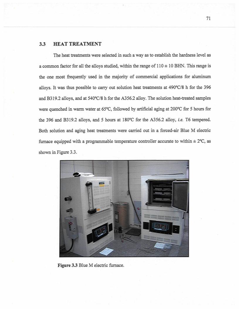
71
3.3 HEAT TREATMENT
The heat treatments were selected in such a way as to establish the hardness level as
a common factor for all the alloys studied, within the range of 110 ± 10 BHN. This range is
the one most frequently used in the majority of commercial applications for aluminum
alloys. It was thus possible to carry out solution heat treatments at 490°C/8 h for the 396
and B319.2 alloys, and at 540°C/8 h for the A356.2 alloy. The solution heat-treated samples
were quenched in warm water at 65°C, followed by artificial aging at 200°C for 5 hours for
the 396 and B319.2 alloys, and 5 hours at 180°C for the A356.2 alloy, i.e. T6 tempered.
Both solution and aging heat treatments were carried out in a forced-air Blue M electric
furnace equipped with a programmable temperature controller accurate to within ± 2°C, as
shown in Figure 3.3.
Figure 3.3 Blue M electric furnace.
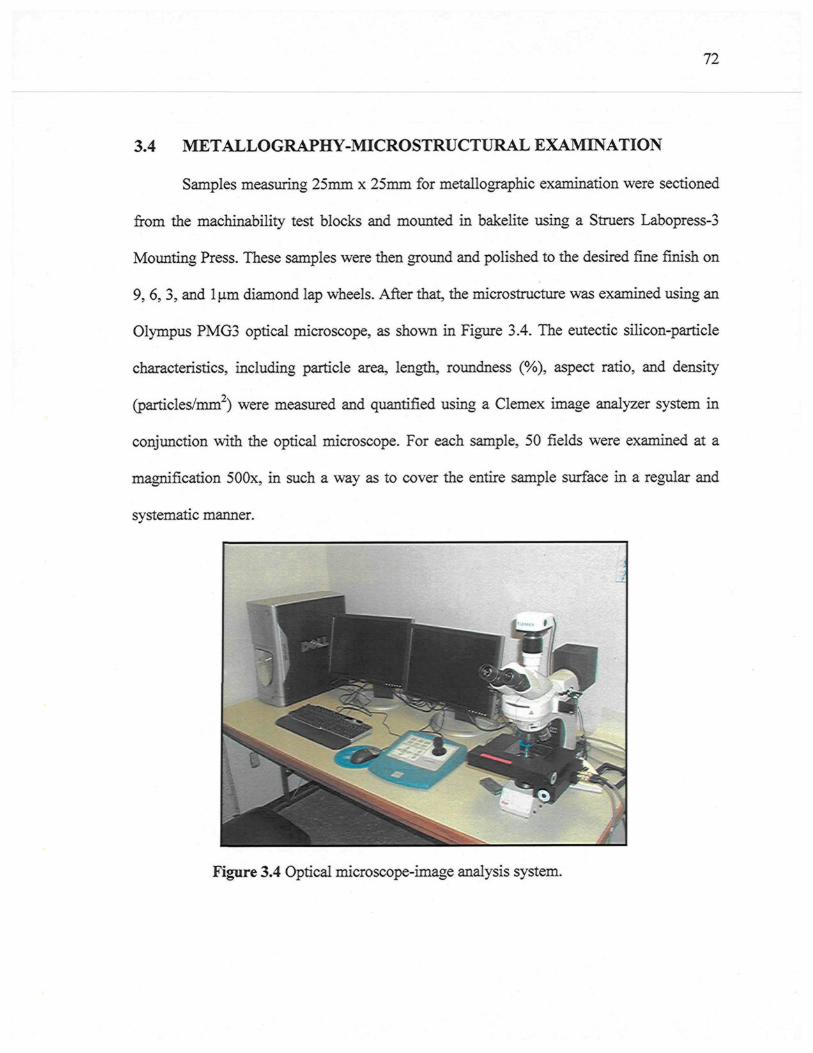
72
3.4 METALLOGRAPHY-MICROSTRUCTURAL EXAMINATION
Samples measuring 25mm x 25mm for metallographic examination were sectioned
from the machinability test blocks and mounted in bakélite using a Struers Labopress-3
Mounting Press. These samples were then ground and polished to the desired fine finish on
9,6,3, and lum diamond lap wheels. After that, the microstructure was examined using an
Olympus PMG3 optical microscope, as shown in Figure 3.4. The eutectic silicon-particle
characteristics, including particle area, length, roundness (%), aspect ratio, and density
(particles/mm2) were measured and quantified using a Clemex image analyzer system in
conjunction with the optical microscope. For each sample, 50 fields were examined at a
magnification 500x, in such a way as to cover the entire sample surface in a regular and
systematic manner.
Figure 3.4 Optical microscope-image analysis system.
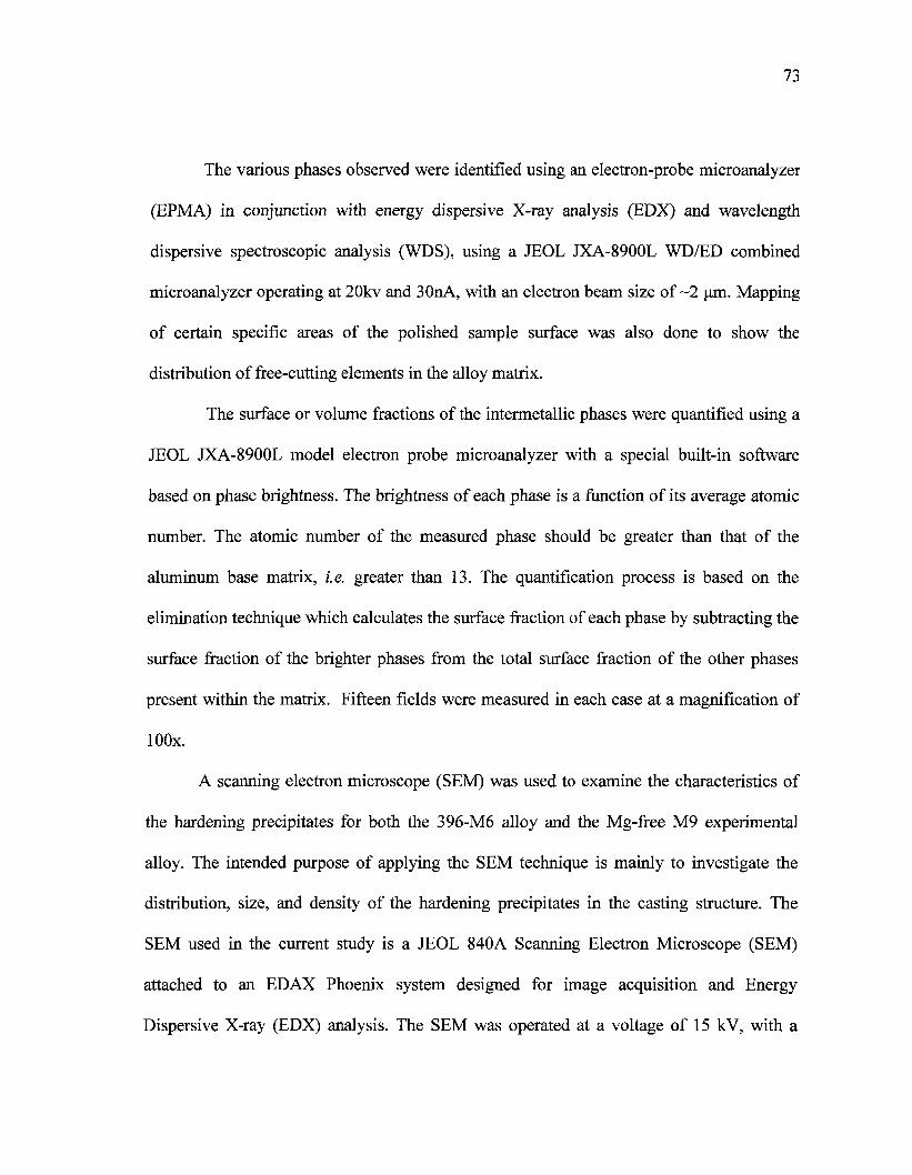
73
The various phases observed were identified using an electron-probe microanalyzer
(EPMA) in conjunction with energy dispersive X-ray analysis (EDX) and wavelength
dispersive spectroscopic analysis (WDS), using a JEOL JXA-8900L WD/ED combined
microanalyzer operating at 20kv and 30nA, with an electron beam size of ~2 um. Mapping
of certain specific areas of the polished sample surface was also done to show the
distribution of free-cutting elements in the alloy matrix.
The surface or volume fractions of the intermetallic phases were quantified using a
JEOL JXA-8900L model electron probe microanalyzer with a special built-in software
based on phase brightness. The brightness of each phase is a function of its average atomic
number. The atomic number of the measured phase should be greater than that of the
aluminum base matrix, i.e. greater than 13. The quantification process is based on the
elimination technique which calculates the surface fraction of each phase by subtracting the
surface fraction of the brighter phases from the total surface fraction of the other phases
present within the matrix. Fifteen fields were measured in each case at a magnification of
lOOx.
A scanning electron microscope (SEM) was used to examine the characteristics of
the hardening precipitates for both the 396-M6 alloy and the Mg-free M9 experimental
alloy. The intended purpose of applying the SEM technique is mainly to investigate the
distribution, size, and density of the hardening precipitates in the casting structure. The
SEM used in the current study is a JEOL 840A Scanning Electron Microscope (SEM)
attached to an EDAX Phoenix system designed for image acquisition and Energy
Dispersive X-ray (EDX) analysis. The SEM was operated at a voltage of 15 kV, with a
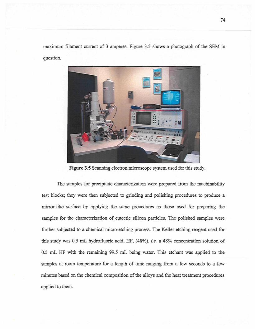
74
maximum filament current of 3 amperes. Figure 3.5 shows a photograph of the SEM in
question.
Figure 3.5 Scanning electron microscope system used for this study.
The samples for precipitate characterization were prepared from the machinability
test blocks; they were then subjected to grinding and polishing procedures to produce a
mirror-like surface by applying the same procedures as those used for preparing the
samples for the characterization of eutectic silicon particles. The polished samples were
further subjected to a chemical micro-etching process. The Keller etching reagent used for
this study was 0.5 mL hydrofluoric acid, HF, (48%), i.e. a 48% concentration solution of
0.5 mL HF with the remaining 99.5 mL being water. This etchant was applied to the
samples at room temperature for a length of time ranging from a few seconds to a few
minutes based on the chemical composition of the alloys and the heat treatment procedures
applied to them.
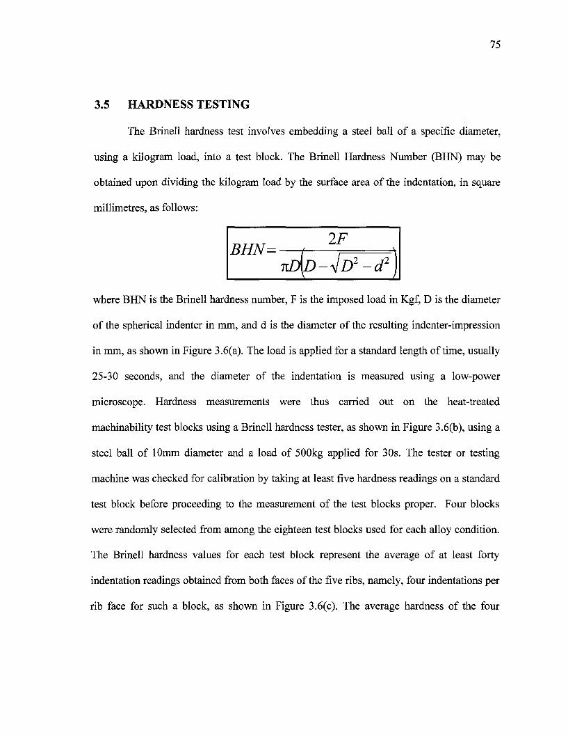
75
3.5 HARDNESS TESTING
The Brinell hardness test involves embedding a steel ball of a specific diameter,
using a kilogram load, into a test block. The Brinell Hardness Number (BHN) may be
obtained upon dividing the kilogram load by the surface area of the indentation, in square
millimetres, as follows:
where BHN is the Brinell hardness number, F is the imposed load in Kgf, D is the diameter
of the spherical indenter in mm, and d is the diameter of the resulting indenter-impression
in mm, as shown in Figure 3.6(a). The load is applied for a standard length of time, usually
25-30 seconds, and the diameter of the indentation is measured using a low-power
microscope. Hardness measurements were thus carried out on the heat-treated
machinability test blocks using a Brinell hardness tester, as shown in Figure 3.6(b), using a
steel ball of 10mm diameter and a load of 500kg applied for 30s. The tester or testing
machine was checked for calibration by taking at least five hardness readings on a standard
test block before proceeding to the measurement of the test blocks proper. Four blocks
were randomly selected from among the eighteen test blocks used for each alloy condition.
The Brinell hardness values for each test block represent the average of at least forty
indentation readings obtained from both faces of the five ribs, namely, four indentations per
rib face for such a block, as shown in Figure 3.6(c). The average hardness of the four
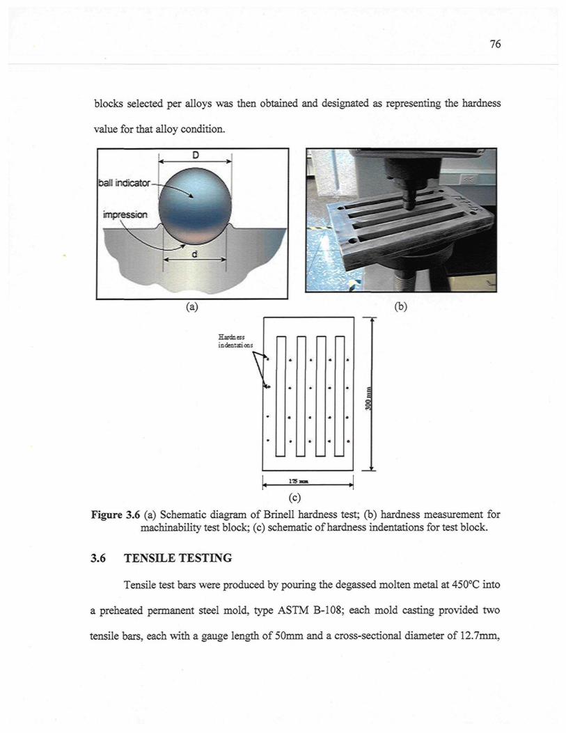
76
blocks selected per alloys was then obtained and designated as representing the hardness
value for that alloy condition.
ball indicator-
impression\
D
XT d >
i(a) (b)
Harcbessindentations
V
ITSi
(C)
Figure 3.6 (a) Schematic diagram of Brinell hardness test; (b) hardness measurement formachinability test block; (c) schematic of hardness indentations for test block.
3.6 TENSILE TESTING
Tensile test bars were produced by pouring the degassed molten metal at 450°C into
a preheated permanent steel mold, type ASTM B-108; each mold casting provided two
tensile bars, each with a gauge length of 50mm and a cross-sectional diameter of 12.7mm,
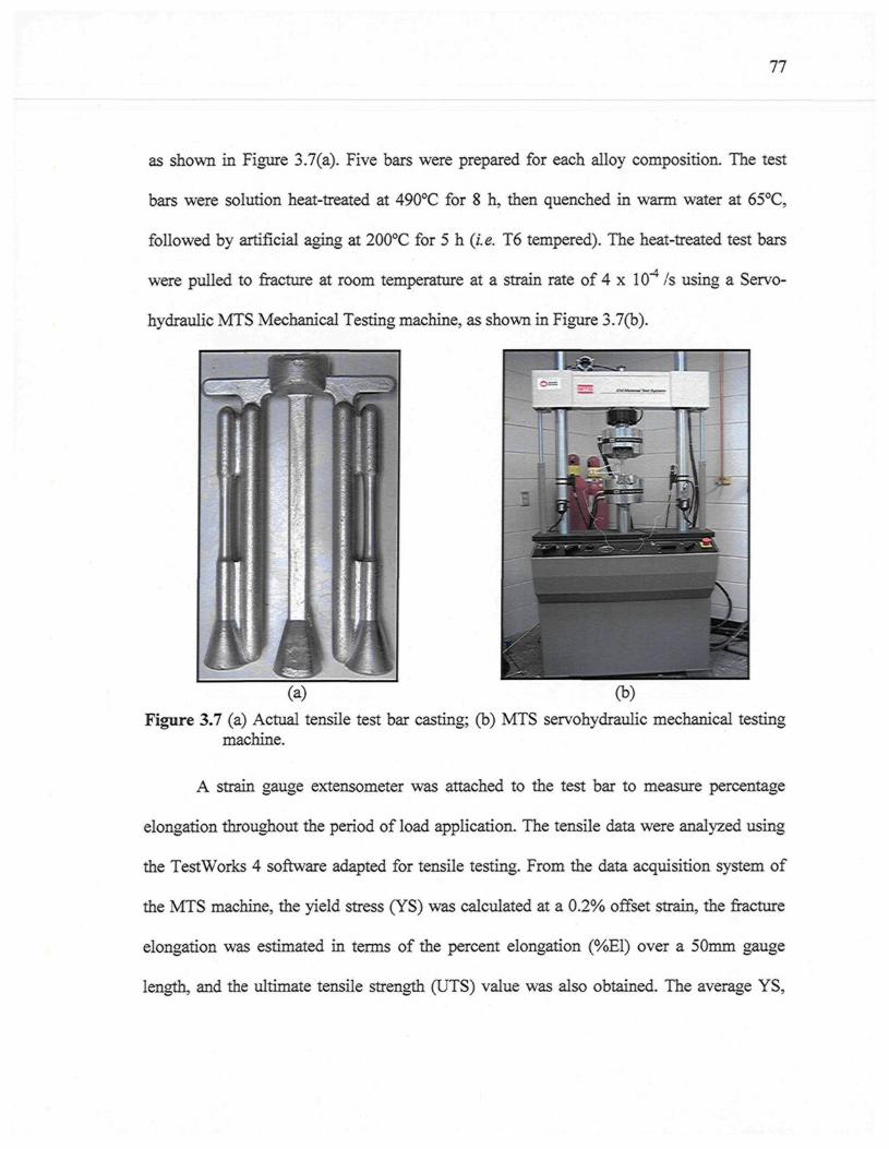
77
as shown in Figure 3.7(a). Five bars were prepared for each alloy composition. The test
bars were solution heat-treated at 490°C for 8 h, then quenched in warm water at 65°C,
followed by artificial aging at 200°C for 5 h {i.e. T6 tempered). The heat-treated test bars
were pulled to fracture at room temperature at a strain rate of 4 x 10"4 /s using a Servo-
hydraulic MTS Mechanical Testing machine, as shown in Figure 3.7(b).
Figure 3.7 (a) Actual tensile test bar casting; (b) MTS servohydraulic mechanical testingmachine.
A strain gauge extensometer was attached to the test bar to measure percentage
elongation throughout the period of load application. The tensile data were analyzed using
the TestWorks 4 software adapted for tensile testing. From the data acquisition system of
the MTS machine, the yield stress (YS) was calculated at a 0.2% offset strain, the fracture
elongation was estimated in terms of the percent elongation (%E1) over a 50mm gauge
length, and the ultimate tensile strength (UTS) value was also obtained. The average YS,
78
%E1, and UTS values obtained from the five samples tested were considered to be the
values representing a specified alloy/condition studied. It should be kept in mind that all of
these alloys were mechanically tested in order to acquire an understanding of the effects of
the additives on the mechanical properties at the same specific T6 heat treatments which
were applied to the machinability test blocks.
3.7 MACHINING PROCEDURES
Drilling and tapping tests were carried out using a Makino A88E high-speed 5-axis,
high-power horizontal machining center with a maximum power reading of 40HP (30kW)
and a maximum rotation speed of 18,000 rpm, shown in Figure 3.8. The experimental set-
up consisted of the A88E machine, a dynamometer with four sensors, charge amplifiers,
and an A/D converter; this set-up was used for the online measurement of drilling/tapping
forces and moments; also, a toolmaker's microscope was used for observing BUE
formation and tool-wear characteristics.
3.7.1 Cutting Tools
Type K-quality cemented carbides are used, as a rule, for the short-chipping of Al-
Si alloys. The K-types tend to display a lesser degree of adhesion to the work material,
which is of particular importance when cutting high-Si aluminum alloy. High speed steel
designated as HSS is not suited for cutting Al-Si alloys at higher cutting speeds. A
cemented carbide drill is 50% harder and has almost four times more thermal conductivity
than an HSS drill. The harder cemented carbide drill has a higher elastic modulus and
produces less wear and deformation compared to the HSS drill.
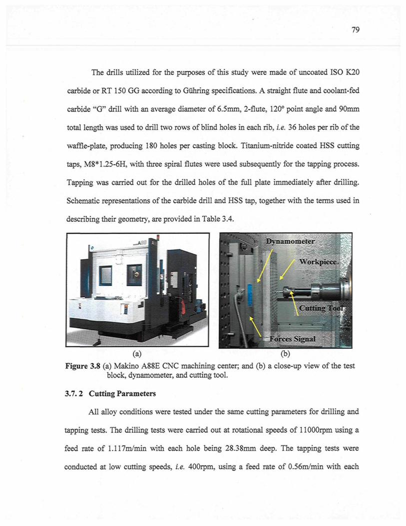
79
The drills utilized for the purposes of this study were made of uncoated ISO K20
carbide or RT 150 GG according to Giihring specifications. A straight flute and coolant-fed
carbide "G" drill with an average diameter of 6.5mm, 2-flute, 120° point angle and 90mm
total length was used to drill two rows of blind holes in each rib, i.e. 36 holes per rib of the
waffle-plate, producing 180 holes per casting block. Titanium-nitride coated HSS cutting
taps, M8*1.25-6H, with three spiral flutes were used subsequently for the tapping process.
Tapping was carried out for the drilled holes of the full plate immediately after drilling.
Schematic representations of the carbide drill and HSS tap, together with the terms used in
describing their geometry, are provided in Table 3.4.
(a) (b)Figure 3.8 (a) Makino A88E CNC machining center; and (b) a close-up view of the test
block, dynamometer, and cutting tool.
3.7.2 Cutting Parameters
All alloy conditions were tested under the same cutting parameters for drilling and
tapping tests. The drilling tests were carried out at rotational speeds of 1 lOOOrpm using a
feed rate of 1.117m/min with each hole being 28.38mm deep. The tapping tests were
conducted at low cutting speeds, i.e. 400rpm, using a feed rate of 0.56m/min with each
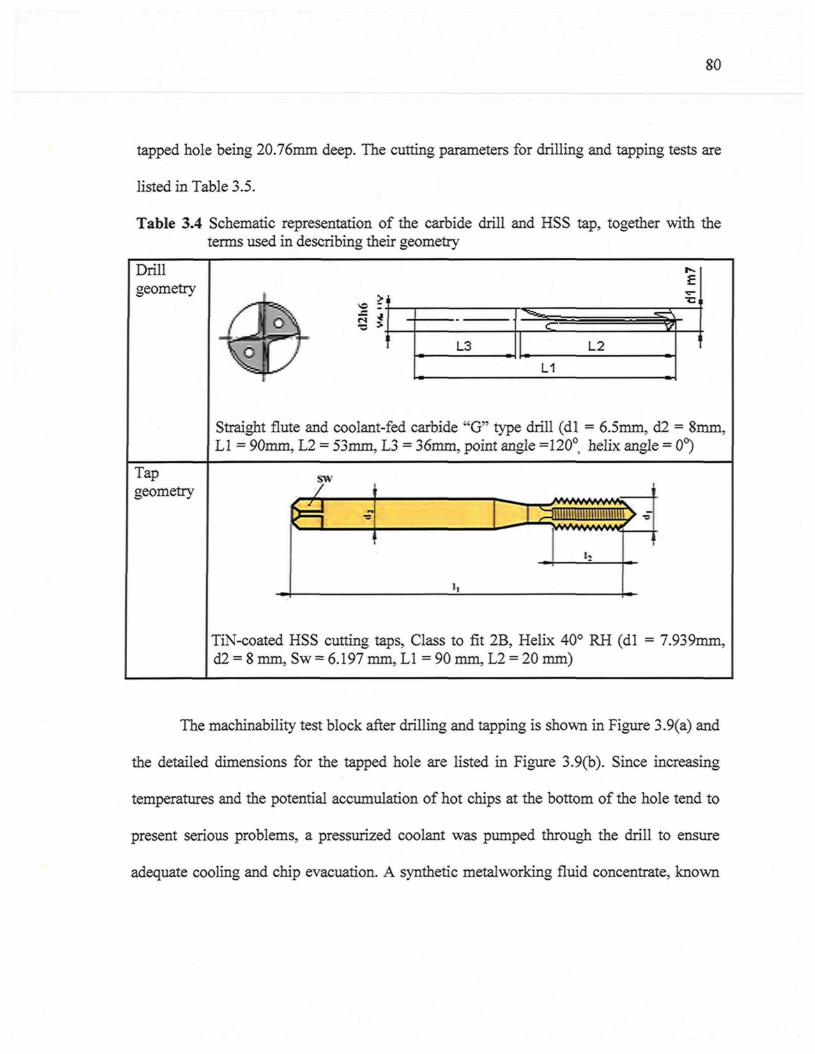
80
tapped hole being 20.76mm deep. The cutting parameters for drilling and tapping tests are
listed in Table 3.5.
Table 3.4 Schematic representation of the carbide drill and HSS tap, together with theterms used in describing their geometry
Drillgeometry >
L3 L2
L1
EXSl
i
Straight flute and coolant-fed carbide "G" type drill (dl = 6.5mm, d2 = 8mm,LI = 90mm, L2 = 53mm, L3 = 36mm, point angle =120°, helix angle = 0°)
Tapgeometry
sw
TiN-coated HSS cutting taps, Class to fit 2B, Helix 40° RH (dl = 7.939mm,d2 = 8 mm, Sw = 6.197 mm, LI = 90 mm, L2 = 20 mm)
The machinability test block after drilling and tapping is shown in Figure 3.9(a) and
the detailed dimensions for the tapped hole are listed in Figure 3.9(b). Since increasing
temperatures and the potential accumulation of hot chips at the bottom of the hole tend to
present serious problems, a pressurized coolant was pumped through the drill to ensure
adequate cooling and chip evacuation. A synthetic metalworking fluid concentrate, known
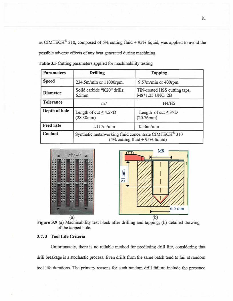
81
as CIMTECH® 310, composed of 5% cutting fluid + 95% liquid, was applied to avoid the
possible adverse effects of any heat generated during machining.
Table 3.5 Cutting parameters applied for machinability testing
Parameters
Speed
Diameter
Tolerance
Depth of hole
Feed rate
Coolant
Drilling
234.5m/min or 1 lOOOrpm.
Solid carbide "K20" drills:6.5mm
m7
Length of cut < 4.5 xD(28.38mm)
1.117m/min
Tapping
9.57m/min or 400rpm.
TiN-coated HSS cutting taps,M8*1.25UNC.2B
H4/H5
Length ofcut<3><D(20.76mm)
0.56m/min
Synthetic metalworking fluid concentrate CIMTECH® 310(5% cutting fluid + 95% liquid)
^ M8
21 m
m
r
nPêw
ii
i
ivA6.5 mm
(a) (b)Figure 3.9 (a) Machinability test block after drilling and tapping; (b) detailed drawing
of the tapped hole.
3.7.3 Tool Life Criteria
Unfortunately, there is no reliable method for predicting drill life, considering that
drill breakage is a stochastic process. Even drills from the same batch tend to fail at random
tool life durations. The primary reasons for such random drill failure include the presence
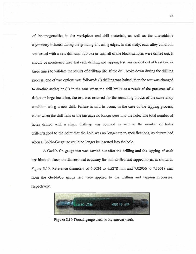
82
of inhomogeneities in the workpiece and drill materials, as well as the unavoidable
asymmetry induced during the grinding of cutting edges. In this study, each alloy condition
was tested with a new drill until it broke or until all of the block samples were drilled out. It
should be mentioned here that each drilling and tapping test was carried out at least two or
three times to validate the results of drill/tap life. If the drill broke down during the drilling
process, one of two options was followed: (i) drilling was halted, then the test was changed
to another series; or (ii) in the case when the drill broke as a result of the presence of a
defect or large inclusion, the test was resumed for the remaining blocks of the same alloy
condition using a new drill. Failure is said to occur, in the case of the tapping process,
either when the drill fails or the tap gage no longer goes into the hole. The total number of
holes drilled with a single drill/tap was counted as well as the number of holes
drilled/tapped to the point that the hole was no longer up to specifications, as determined
when a Go/No-Go gauge could no longer be inserted into the hole.
A Go/No-Go gauge test was carried out after the drilling and the tapping of each
test block to check the dimensional accuracy for both drilled and tapped holes, as shown in
Figure 3.10. Reference diameters of 6.5024 to 6.5278 mm and 7.02056 to 7.15518 mm
from the Go-NoGo gauge test were applied to the drilling and tapping processes,
respectively.
Figure 3.10 Thread gauge used in the current work.
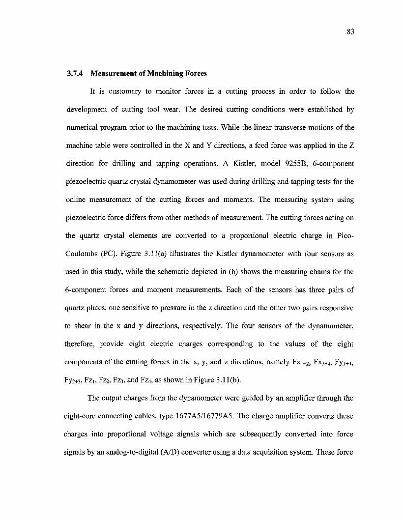
83
3.7.4 Measurement of Machining Forces
It is customary to monitor forces in a cutting process in order to follow the
development of cutting tool wear. The desired cutting conditions were established by
numerical program prior to the machining tests. While the linear transverse motions of the
machine table were controlled in the X and Y directions, a feed force was applied in the Z
direction for drilling and tapping operations. A Kistler, model 9255B, 6-component
piezoelectric quartz crystal dynamometer was used during drilling and tapping tests for the
online measurement of the cutting forces and moments. The measuring system using
piezoelectric force differs from other methods of measurement. The cutting forces acting on
the quartz crystal elements are converted to a proportional electric charge in Pico-
Coulombs (PC). Figure 3.11 (a) illustrates the Kistler dynamometer with four sensors as
used in this study, while the schematic depicted in (b) shows the measuring chains for the
6-component forces and moment measurements. Each of the sensors has three pairs of
quartz plates, one sensitive to pressure in the z direction and the other two pairs responsive
to shear in the x and y directions, respectively. The four sensors of the dynamometer,
therefore, provide eight electric charges corresponding to the values of the eight
components of the cutting forces in the x, y, and z directions, namely Fxi+2, FX3+4, Fyi+4,
Fy2+3, Fzi, Fz2, FZ3, and FZ4, as shown in Figure 3.1 l(b).
The output charges from the dynamometer were guided by an amplifier through the
eight-core connecting cables, type 1677A5/16779A5. The charge amplifier converts these
charges into proportional voltage signals which are subsequently converted into force
signals by an analog-to-digital (A/D) converter using a data acquisition system. These force
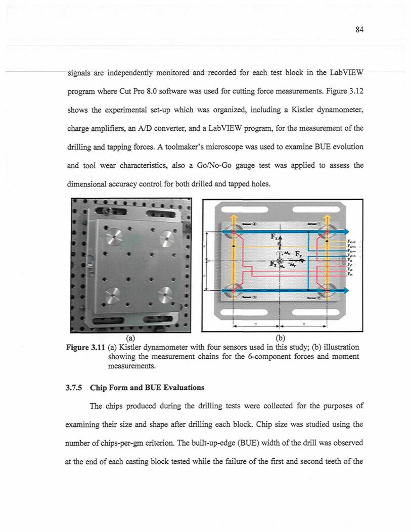
84
signals are independently monitored and recorded for each test block in the LabVIEW
program where Cut Pro 8.0 software was used for cutting force measurements. Figure 3.12
shows the experimental set-up which was organized, including a Kistler dynamometer,
charge amplifiers, an A/D converter, and a LabVIEW program, for the measurement of the
drilling and tapping forces. A toolmaker's microscope was used to examine BUE evolution
and tool wear characteristics, also a Go/No-Go gauge test was applied to assess the
dimensional accuracy control for both drilled and tapped holes.
(a) (b)Figure 3.11 (a) Kistler dynamometer with four sensors used in this study; (b) illustration
showing the measurement chains for the 6-component forces and momentmeasurements.
3.7.5 Chip Form and BUE Evaluations
The chips produced during the drilling tests were collected for the purposes of
examining their size and shape after drilling each block. Chip size was studied using the
number of chips-per-gm criterion. The built-up-edge (BUE) width of the drill was observed
at the end of each casting block tested while the failure of the first and second teeth of the
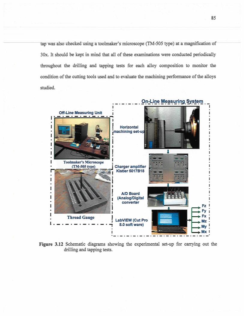
85
tap was also checked using a toolmaker's microscope (TM-505 type) at a magnification of
30x. It should be kept in mind that all of these examinations were conducted periodically
throughout the drilling and tapping tests for each alloy composition to monitor the
condition of the cutting tools used and to evaluate the machining performance of the alloys
studied.
On4_ine Measuring,System
Off-Line Measuring Unit
I Horizontaljmachining set-u
Toolmaker's Microscope(TM-505 type) ^ J Charger amplifier
Kistler5017B18 L - »
A/D Board(Analog/Digital
converter
Ï LabVIEW (Cut Pro- j 8.0 soft ware)
I
Figure 3.12 Schematic diagrams showing the experimental set-up for carrying out thedrilling and tapping tests.
86
3.8 METHODOLOGY FOR THE DATA-PROCESSING OF DRILLINGAND TAPPING TESTS
As mentioned earlier in section 3.7.4 of this chapter, to investigate the machinability
characteristics of a material, it is customary to monitor the forces in a cutting process in
order to follow the development of cutting tool wear. In our study, a Kistler 6-component
piezoelectric quartz crystal dynamometer with four sensors was used during the drilling and
tapping tests for online measurement of the cutting forces and moments. The four sensors
of the dynamometer provide eight electric charges corresponding to the 8 components of
the cutting forces in the x, y, and z directions, namely, Fxi+2 , FX3+4 , Fyi+4 , Fy2+3, Fzi , F ^ ,
FZ3 , and FZ4 . A charge amplifier converts these charges into proportional voltage signals
by means of an A/D converter connected to the data acquisition system. These force signals
are independently monitored and recorded for each test block, using the Lab View program
of the Cut Pro 8.0 software.
This section presents the force and moment calculations which were used for
processing the drilling and tapping test data. The drilling moment Mz and feed force Fz are
of particular interest in analyzing the drilling process. The deflective forces Fx, Fy
perpendicular to the rotary axis provide additional information on the machining process.
Matlab programs were developed for the processing of drilling and tapping data related to
all the conditions studied in the present work. These programs are similar to those produced
in an earlier study on the machining behaviour of 356 and 319 alloys carried out by Tash
from this research group. Complete details of these programs may be found in Appendix B
of that study. Essentially, the methodology followed for processing the drilling and
tapping data consists of four steps as follows:
87
Step 1 : Separation of the 6-components of force and moment, in order to process the data
for obtaining the Fz component
The three forces Fx, Fy, Fz and the three moments Mx, My, Mz were first
calculated from the eight-channel force components by applying the following sets of
equations:163
Fx =
M y =a. (-Fzi + Fz2 + Fz3 - Fz4); and
M z = b . (-Fxi+2 + Fx3+4) + a. (Fyi+4 - Fy2+3)
where a (= 80 mm) is the distance of the sensor axes from the X-axis; and b (= 80mm) is
the distance of the sensor axes from the Y-axis, as shown in Figure 3.11. It should be
mentioned that the 6-component measuring system provides the following resultants: (i) the
3-components of the resultants of all the applied forces, including their direction but not
their location in space; and (ii) the 3-components of the resultant moment vector related to
the coordinate origin. The sampling rate of these charges or force components is lOOOHz
which implies that each force component is measured at every 0.001s of the drilling tests;
thus 1600 sample points per cycle or hole were acquired for calculating the mean value of
cutting feed force (Fz) and 1200 sample points per cycle for the other five components of
force and moment, Fx, Fy, Mx, My, and Mz in each signal of 90 cycles or holes per signal.
Standard deviations were calculated based on the procedures outlined by Tash.80
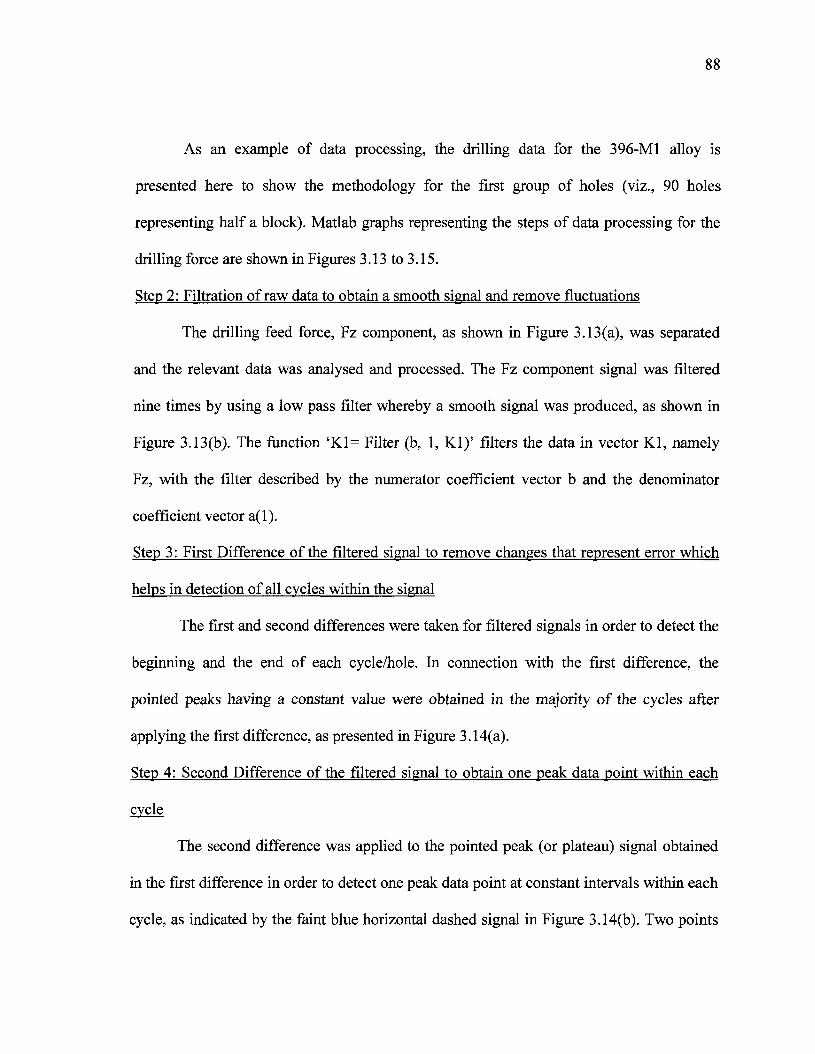
As an example of data processing, the drilling data for the 396-M1 alloy is
presented here to show the methodology for the first group of holes (viz., 90 holes
representing half a block). Matlab graphs representing the steps of data processing for the
drilling force are shown in Figures 3.13 to 3.15.
Step 2: Filtration of raw data to obtain a smooth signal and remove fluctuations
The drilling feed force, Fz component, as shown in Figure 3.13(a), was separated
and the relevant data was analysed and processed. The Fz component signal was filtered
nine times by using a low pass filter whereby a smooth signal was produced, as shown in
Figure 3.13(b). The function 'Kl= Filter (b, 1, Kl) ' filters the data in vector Kl, namely
Fz, with the filter described by the numerator coefficient vector b and the denominator
coefficient vector a(l).
Step 3: First Difference of the filtered signal to remove changes that represent error which
helps in detection of all cycles within the signal
The first and second differences were taken for filtered signals in order to detect the
beginning and the end of each cycle/hole. In connection with the first difference, the
pointed peaks having a constant value were obtained in the majority of the cycles after
applying the first difference, as presented in Figure 3.14(a).
Step 4: Second Difference of the filtered signal to obtain one peak data point within each
cycle
The second difference was applied to the pointed peak (or plateau) signal obtained
in the first difference in order to detect one peak data point at constant intervals within each
cycle, as indicated by the faint blue horizontal dashed signal in Figure 3.14(b). Two points
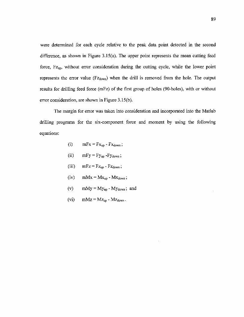
89
were determined for each cycle relative to the peak data point detected in the second
difference, as shown in Figure 3.15(a). The upper point represents the mean cutting feed
force, Fzup, without error consideration during the cutting cycle, while the lower point
represents the error value (Fzd0Wn) when the drill is removed from the hole. The output
results for drilling feed force (mFz) of the first group of holes (90-holes), with or without
error consideration, are shown in Figure 3.15(b).
The margin for error was taken into consideration and incorporated into the Matlab
drilling programs for the six-component force and moment by using the following
equations:
(i) mFx = Fxup - Fxdown ;
(ii) mFy = Fyup -Fydown ;
(iii) mFz = Fzup - Fzdown ;
(iv) mMx = Mxup - Mxd0Wn ;
(v) mMy = Myup - Myd0Wn ; and
(vi) mMz = Mzup - Mzd0Wn �
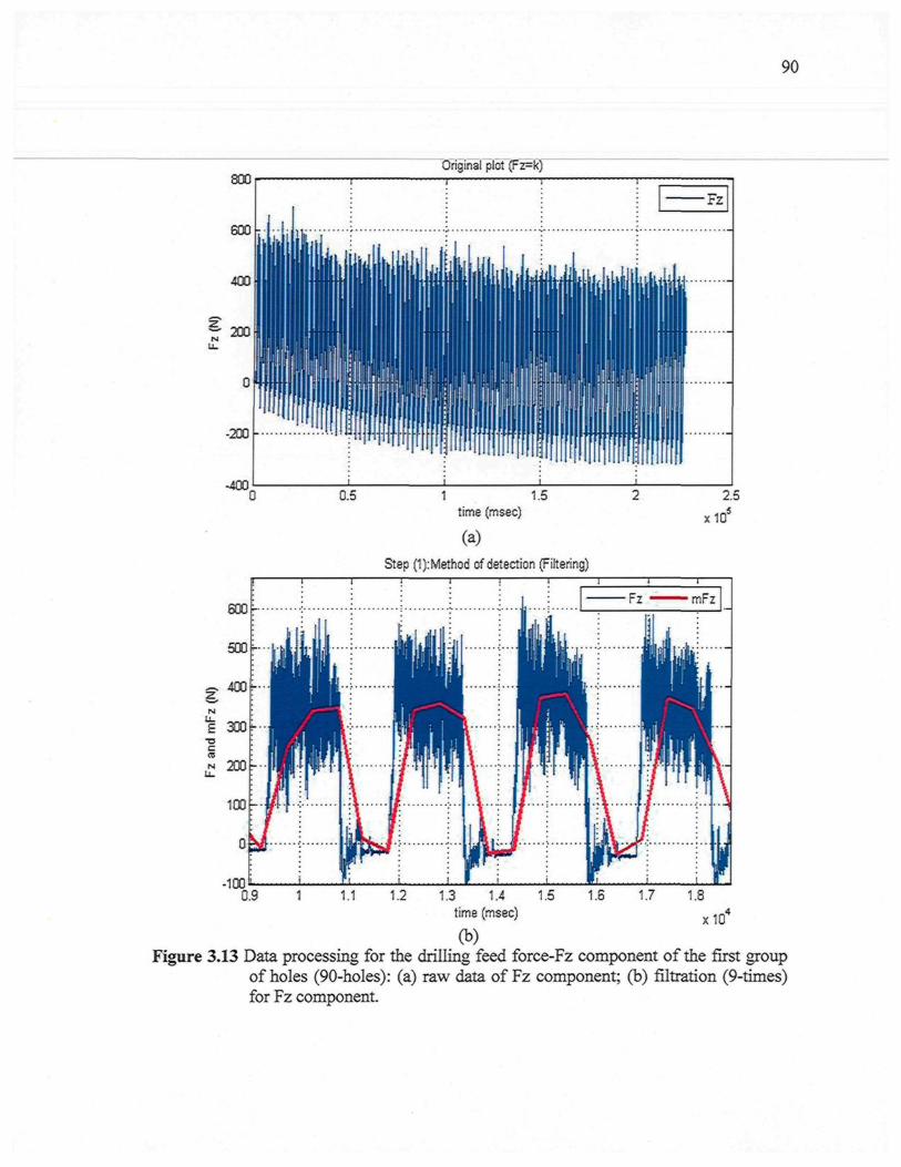
90
Original plot (Fz=k)
~ 200
-200
-400
6 0 0 -
500 -
400 'r
£ 300r-uCm.* 200
100
0
-1000.9
0.5 1 1.5time (msec)
(a)Step (1):Method of detection (Filtering)
x 10
I
1i. .-. . .
1PIY \
I\ 1 "T
1t ....
1
1i1I
i i i
Fz ^ ^ � mFz
I�
\
| j |
ÎI\
1 1.1 1.2 1.3 1.4 1.5 1.6 1.7 1.8
x 10time (msec)
(b)Figure 3.13 Data processing for the drilling feed force-Fz component of the first group
of holes (90-holes): (a) raw data of Fz component; (b) filtration (9-times)for Fz component.
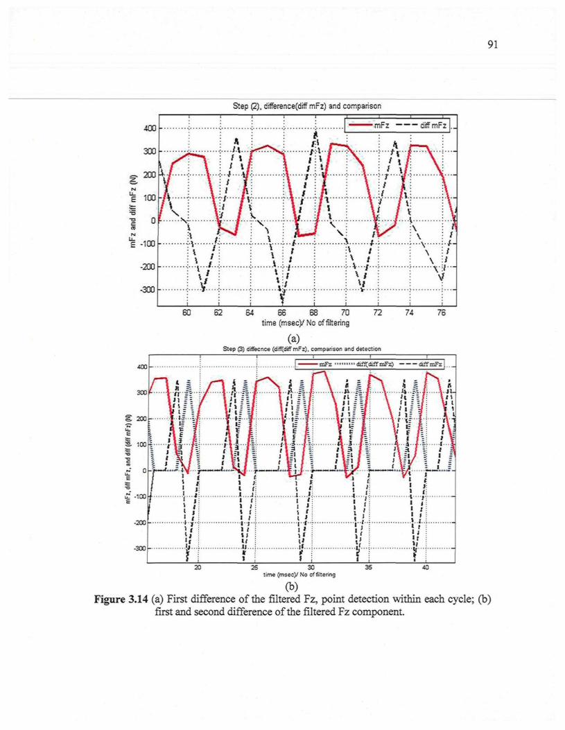
91
Step (2), differencefdiff mFz) and comparison
400
300
o 200
100-
T3
0 -
£ -100
-200
-300
i/V \\* /.i * .
\ /v
1 A:....M
Ml
/ v/ ¥' AJ f V
� r
r � � � � ^
\"ï"
\\\\
..i
; i: /
\ /i §\ i
Lit
ti
i �V
A �
^�^� mFz � "� � diff rnFz
TIr
K f..
..!...»...* � � � / � � �
\ /
...v...
/v'1I�vAL...
\\
\�
!
1
1f
60 62 64 66 68 70 72time (msec)/ No of filtering
(a)Step (3) diffecnce (diff[diff mFz). comparison and detection
74 76
400
25 30time (msec)/ No of filtering
35 40
(b)Figure 3.14 (a) First difference of the filtered Fz, point detection within each cycle; (b)
first and second difference of the filtered Fz component.
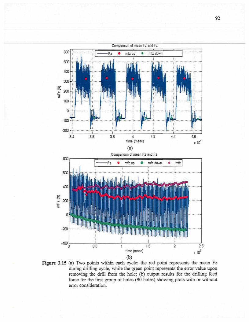
92
Comparison of mean Fz and Fz
Fz � mfz up * mfz down
-100 -
-200 -
-400
4.4 4.6time (msec)
(a)Comparison of mean Fz and Fz
x10
Fz � mfz up � mfz down � mfz
0.5 2.5
x 10
1 1.5time (msec)
(b)Figure 3.15 (a) Two points within each cycle: the red point represents the mean Fz
during drilling cycle, while the green point represents the error value uponremoving the drill from the hole; (b) output results for the drilling feedforce for the first group of holes (90 holes) showing plots with or withouterror consideration.
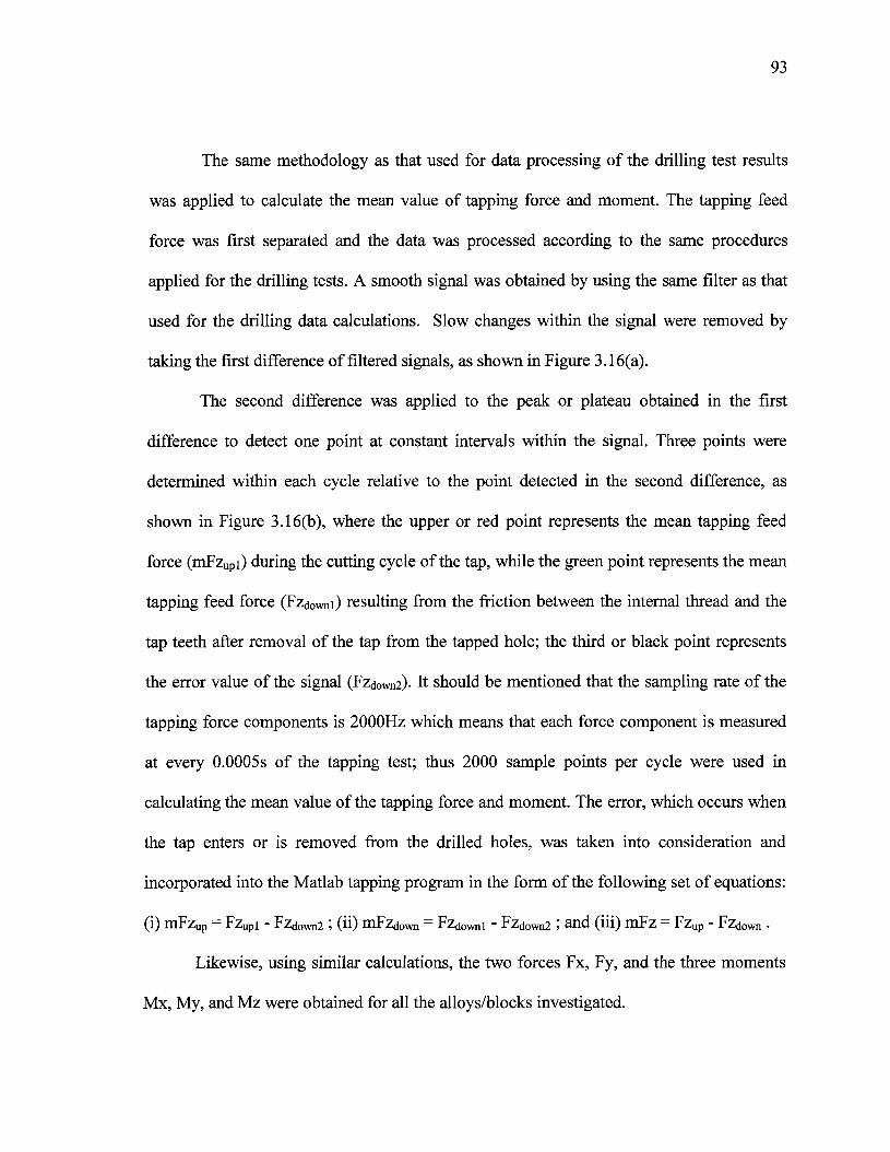
93
The same methodology as that used for data processing of the drilling test results
was applied to calculate the mean value of tapping force and moment. The tapping feed
force was first separated and the data was processed according to the same procedures
applied for the drilling tests. A smooth signal was obtained by using the same filter as that
used for the drilling data calculations. Slow changes within the signal were removed by
taking the first difference of filtered signals, as shown in Figure 3.16(a).
The second difference was applied to the peak or plateau obtained in the first
difference to detect one point at constant intervals within the signal. Three points were
determined within each cycle relative to the point detected in the second difference, as
shown in Figure 3.16(b), where the upper or red point represents the mean tapping feed
force (mFzUpi) during the cutting cycle of the tap, while the green point represents the mean
tapping feed force (Fzd0Wni) resulting from the friction between the internal thread and the
tap teeth after removal of the tap from the tapped hole; the third or black point represents
the error value of the signal (Fzd0Wn2)- It should be mentioned that the sampling rate of the
tapping force components is 2000Hz which means that each force component is measured
at every 0.0005s of the tapping test; thus 2000 sample points per cycle were used in
calculating the mean value of the tapping force and moment. The error, which occurs when
the tap enters or is removed from the drilled holes, was taken into consideration and
incorporated into the Matlab tapping program in the form of the following set of equations:
(i) mFzup = Fzupi - Fzdown2 ; (ii) mFzdOwn = Fzdowni - FzdoWn2 ; and (iii) mFz = Fzup - Fzdown �
Likewise, using similar calculations, the two forces Fx, Fy, and the three moments
Mx, My, and Mz were obtained for all the alloys/blocks investigated.
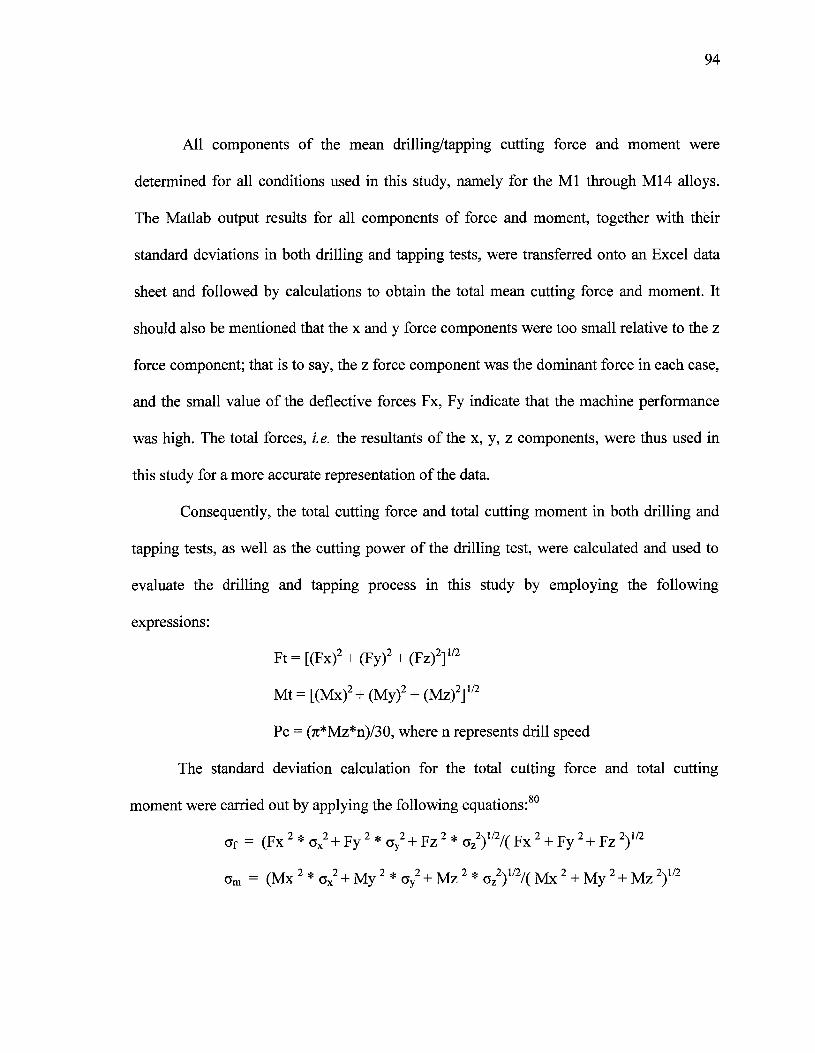
94
All components of the mean drilling/tapping cutting force and moment were
determined for all conditions used in this study, namely for the Ml through M14 alloys.
The Matlab output results for all components of force and moment, together with their
standard deviations in both drilling and tapping tests, were transferred onto an Excel data
sheet and followed by calculations to obtain the total mean cutting force and moment. It
should also be mentioned that the x and y force components were too small relative to the z
force component; that is to say, the z force component was the dominant force in each case,
and the small value of the deflective forces Fx, Fy indicate that the machine performance
was high. The total forces, i.e. the resultants of the x, y, z components, were thus used in
this study for a more accurate representation of the data.
Consequently, the total cutting force and total cutting moment in both drilling and
tapping tests, as well as the cutting power of the drilling test, were calculated and used to
evaluate the drilling and tapping process in this study by employing the following
expressions:
Ft = [(Fx)2 + (Fy)2 + (Fz)2]1/2
Mt = [(Mx)2 + (My)2 + (Mz)2]1/2
Pc = (7r*Mz*n)/30, where n represents drill speed
The standard deviation calculation for the total cutting force and total cutting
moment were carried out by applying the following equations:
Of = (Fx 2 * cx2 + Fy 2 * oy
2 + Fz 2 * cz2)1/2/( Fx 2 + Fy 2 + Fz 2)1/2
am = (Mx 2 * cx2 + My 2 * ay
2 + Mz 2 * az2)1/2/( Mx 2 + My 2 + Mz 2)1/2
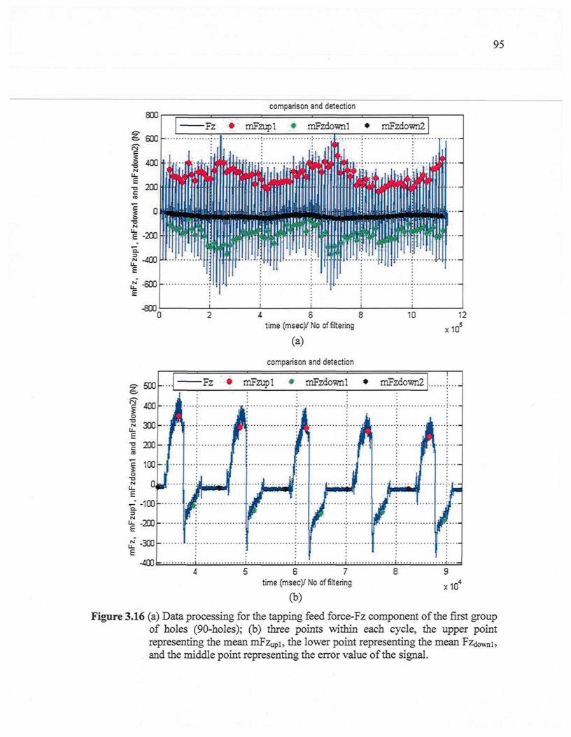
95
comparison and detection
-4001=
4 6 8time (msec)/No of filtering
(a)
comparison and detection
x10
5 6 7
time (msec)/ No of filtering
(b)x10
Figure 3.16 (a) Data processing for the tapping feed force-Fz component of the first groupof holes (90-holes); (b) three points within each cycle, the upper pointrepresenting the mean mFzupi, the lower point representing the meanand the middle point representing the error value of the signal.

CHAPTER 4
EFFECTS OF IRON-RICH AND COPPER-RICHINTERMETALLICS ON THE MACHINABILITY OF HEAT-
TREATED Al-10.8%Si CAST ALLOYS
97
CHAPTER 4
EFFECTS OF IRON-RICH AND COPPER-RICHINTERMETALLICS ON THE MACHINABILITY OF HEAT-
TREATED Al-10.8%Si CAST ALLOYS
4.1 INTRODUCTION
Aluminum-silicon alloys having the same chemical composition can have different
microstructures and mechanical properties either because of variations in the casting
process, or as a result of using a modifier, and/or through the selection of a given heat
treatment process for the alloy. This sequence of possibilities implies that different
processing techniques can result in a whole range of mechanical properties, which then
reflects on the characteristics of the machining process itself. The combination of alloying
elements and liquid alloy treatments is a satisfactory option for obtaining improved control
of the microstructure during solidification, and hence of improving the machinability
performance. A number of elements are traditionally thought to provide any given alloy
with a certain degree of natural lubricity. Other elements are known to increase matrix
hardness, while still others result in the formation of hard intermetallic phases. All of these
should be expected to have some effect on alloy machinability. Alloys containing copper,
magnesium, or zinc, predominantly, as elements entering readily into solid solution with
aluminum, generally possess the best machining characteristics.
98
It should be mentioned here that numerous studies have been carried out integrating
the formation of the as-cast microstructure as well as the effects of solution heat treatment
and aging on the microstructure and mechanical behaviour of Al-Si-Cu-Mg alloys. Only a
few studies so far, however, have dealt with the influence of alloying elements and melt
treatment on the machining performance of near-eutectic Al-10.8%Si cast alloys. In the
light of the above, the main purpose of this chapter is to report on the changes in the
machinability criteria resulting from the effects of Fe-intermetallics, namely ct-Fe, /?-Fe,
and sludge; two levels of Cu, namely 2.25 and 3.5%; and two levels of Mg, namely 0.3 and
0.6%. In addition to the preceding, the effects of Mg-free alloys and Sr-modification were
also investigated.
4.2 CHARACTERIZATION OF THE MICROSTRUCTURE
The constituents or phases existing in the workpiece play a prominent role in its
machinability and may be described as soluble and non-soluble types. The soluble phases
contain elements which dissolve in the aluminum matrix during heat treatment and are
distinguished by relatively soft particles. The insoluble phases are those which do not
dissolve during heat treatment, yet they typically contain a large amount of iron (Fe) and
consist of hard brittle particles when compared to the soluble phases. From a machinability
point of view, the insoluble particles represent abrasive areas in the metal which are likely
to cause excessive tool wear; the presence of these particles is, therefore, intentionally
maintained at a low level.
A metallographic study was conducted using samples which had been sectioned
from the heat-treated machinability test block with the aim of examining the specific

99
changes resulting from Sr-modification and the addition of alloying elements, from the
viewpoint of both the microstructure and the chemical composition. With this in mind, the
characteristics of the eutectic silicon particles and the volume fraction of the insoluble
intermetallic phases were measured and quantified. The results obtained were then
discussed, in-depth, to explain the influence of the relevant additives on the machinability
behavior.
4.2.1 Silicon Particle Characteristics
The morphology of eutectic Si plays a vital role in determining the machinability
characteristics of cast Al-Si near-eutectic alloys. A fine, well-modified eutectic silicon
structure is far less detrimental to tool life than heavy element intermetallic phases; tool
life, will however, decrease in the presence of a coarse eutectic silicon structure. Table 4.1
summarizes the silicon particle characteristics obtained from quantified measurements of
the alloys investigated. As can be seen from this table and from Figure 4.1 (a), the Si
particles are present in the form of coarse acicular plates with an aspect ratio of 3.51 in the
T6 heat-treated condition for the non-modified experimental MO alloy. The addition of 200
ppm of Sr transforms the morphology of Si particles from an acicular form to a fibrous one,
as may be observed in the Ml alloy which has an aspect ratio of 1.77; this addition also
increases the roundness ratio from 32.8% to 70%, as shown in Figure 4.1(b). The average
Si particle length decreases from 20.80um in the MO alloy to 2.96um in the Ml alloy, while
the average area decreases from 65.70um2 to 4.30um2, i.e. by about 86% and 93%,
respectively. As a result of the decrease in the size of the particles, the density of the Si
particle increases from 2604 to 28,000 particles/mm2, implying that the eutectic Si particles
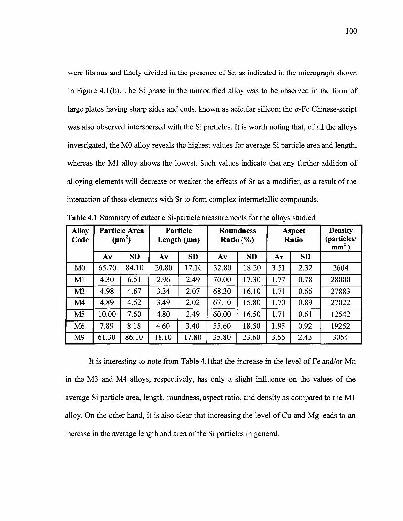
100
were fibrous and finely divided in the presence of Sr, as indicated in the micrograph shown
in Figure 4.1(b). The Si phase in the unmodified alloy was to be observed in the form of
large plates having sharp sides and ends, known as acicular silicon; the ct-Fe Chinese-script
was also observed interspersed with the Si particles. It is worth noting that, of all the alloys
investigated, the MO alloy reveals the highest values for average Si particle area and length,
whereas the Ml alloy shows the lowest. Such values indicate that any further addition of
alloying elements will decrease or weaken the effects of Sr as a modifier, as a result of the
interaction of these elements with Sr to form complex intermetallic compounds.
Table 4.1 Summary of eutectic Si-particle measurements for the alloys studied
AlloyCode
MO
Ml
M3
M4
M5
M6
M9
Particle Area0»n2)
Av
65.70
4.30
4.98
4.89
10.00
7.89
61.30
SD
84.10
6.51
4.67
4.62
7.60
8.18
86.10
ParticleLength (um)
Av
20.80
2.96
3.34
3.49
4.80
4.60
18.10
SD
17.10
2.49
2.07
2.02
2.49
3.40
17.80
RoundnessRatio (%)
Av
32.80
70.00
68.30
67.10
60.00
55.60
35.80
SD
18.20
17.30
16.10
15.80
16.50
18.50
23.60
AspectRatio
Av
3.51
1.77
1.71
1.70
1.71
1.95
3.56
SD
2.32
0.78
0.66
0.89
0.61
0.92
2.43
Density(particles/
mm2 )
2604
28000
27883
27022
12542
19252
3064
It is interesting to note from Table 4.1that the increase in the level of Fe and/or Mn
in the M3 and M4 alloys, respectively, has only a slight influence on the values of the
average Si particle area, length, roundness, aspect ratio, and density as compared to the Ml
alloy. On the other hand, it is also clear that increasing the level of Cu and Mg leads to an
increase in the average length and area of the Si particles in general.
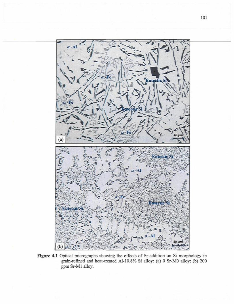
101
a-Al
fi.
^ - ^ l VX g
� ^
Figure 4.1 Optical micrographs showing the effects of Sr-addition on Si morphology ingrain-refined and heat-treated Al-10.8% Si alloy: (a) 0 Sr-MO alloy; (b) 200ppm Sr-Ml alloy.
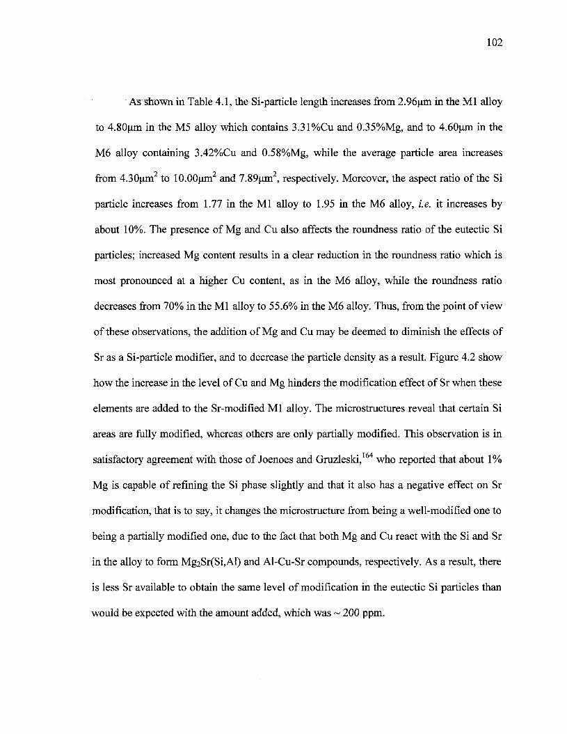
102
As shown in Table 4.1, the Si-particle length increases from 2.96um in the Ml alloy
to 4.80um in the M5 alloy which contains 3.31%Cu and 0.35%Mg, and to 4.60um in the
M6 alloy containing 3.42%Cu and 0.58%Mg, while the average particle area increases
from 4.30um2 to lO.OOum2 and 7.89um2, respectively. Moreover, the aspect ratio of the Si
particle increases from 1.77 in the Ml alloy to 1.95 in the M6 alloy, i.e. it increases by
about 10%. The presence of Mg and Cu also affects the roundness ratio of the eutectic Si
particles; increased Mg content results in a clear reduction in the roundness ratio which is
most pronounced at a higher Cu content, as in the M6 alloy, while the roundness ratio
decreases from 70% in the Ml alloy to 55.6% in the M6 alloy. Thus, from the point of view
of these observations, the addition of Mg and Cu may be deemed to diminish the effects of
Sr as a Si-particle modifier, and to decrease the particle density as a result. Figure 4.2 show
how the increase in the level of Cu and Mg hinders the modification effect of Sr when these
elements are added to the Sr-modified Ml alloy. The microstructures reveal that certain Si
areas are fully modified, whereas others are only partially modified. This observation is in
satisfactory agreement with those of Joenoes and Gruzleski, who reported that about 1%
Mg is capable of refining the Si phase slightly and that it also has a negative effect on Sr
modification, that is to say, it changes the microstructure from being a well-modified one to
being a partially modified one, due to the fact that both Mg and Cu react with the Si and Sr
in the alloy to form Mg2Sr(Si,Al) and Al-Cu-Sr compounds, respectively. As a result, there
is less Sr available to obtain the same level of modification in the eutectic Si particles than
would be expected with the amount added, which was ~ 200 ppm.
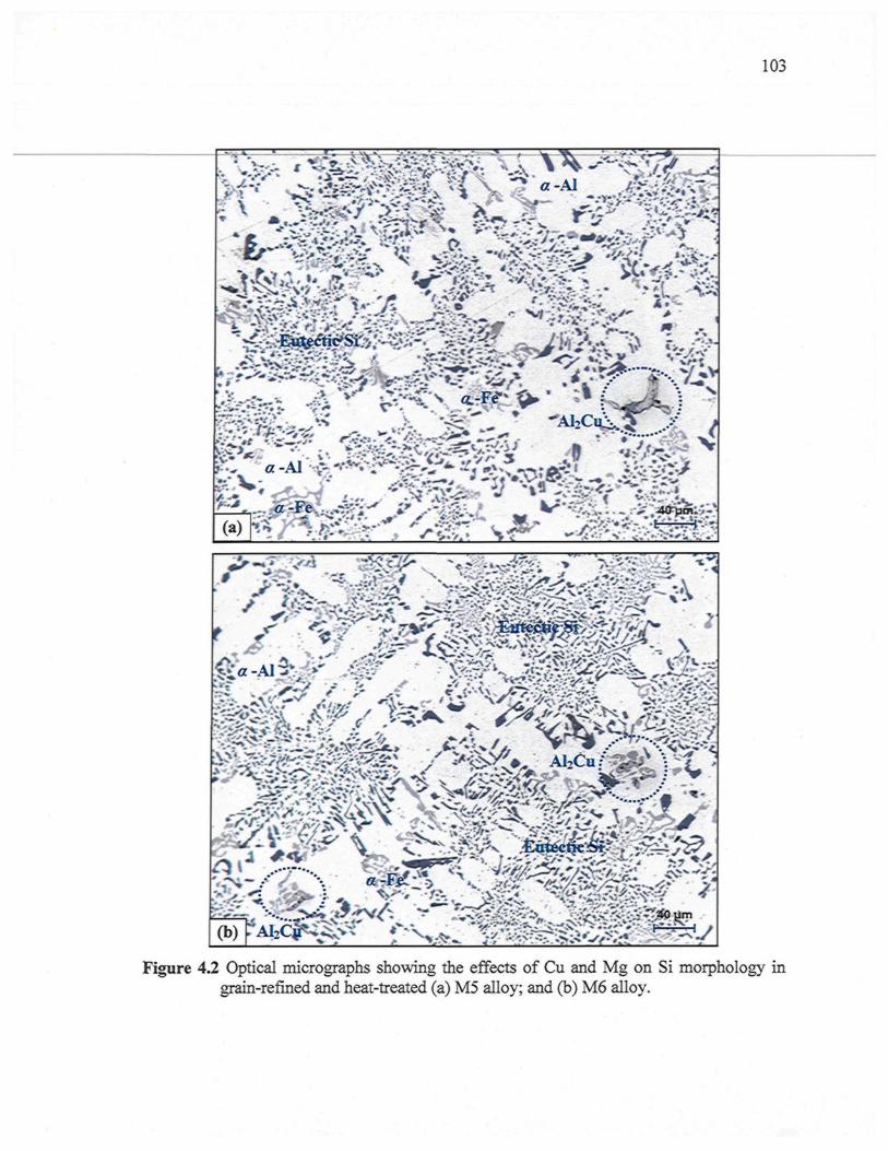
103
Figure 4.2 Optical micrographs showing the effects of Cu and Mg on Si morphology ingrain-refined and heat-treated (a) M5 alloy; and (b) M6 alloy.
104
4.2.2 Iron-Rich Intermetallics
The solid-state solubility of Fe in Al is very low, the greater part of the Fe being
present in the form of intermetallic compounds, the nature of which depends mainly on the
alloying elements present.165 Of the many existing AlFeSi intermetallics, the most
important are generally thought to be the a-Fe, /?-Fe, and sludge intermetallic phases. The
conditions which control the formation of the a-Fe phase, as opposed to the /?-Fe phase, are
still not completely understood. In this study, it was observed that the addition of Sr and the
presence of transition elements such as Mn in the Ml alloy are capable of promoting the
development of the intermetallic a-Fe phase with its commonly observed Chinese-script
morphology. The formation of the a-Fe phase reduces the possibility of the formation of
the /?-Fe phase. As may be seen in Figure 4.3, the coarse a-script particles are always seen
to occur within a-Al dendrites in the Ml alloy indicating that they correspond to a
predendritic reaction and tend to nucleate in the liquid alloy prior to solidification. The
large size of these particles indicates the existence of a high diffusion rate of Fe occurring
at high melt temperatures. The a-Fe phase has the composition Ali2(Fe,Mn,Cu)3Si2, in
other words 16.31% Fe, 9.93% Si, 13.5% Mn, 3.43% Cu.166 This phase is reported as
having a hexagonal structure with the parameters a = 12.3Â, c = 26.3Â, and a density of
3.58 g/cm3. The platelet-like yS-Fe phase was not in evidence because of the higher Mn/Fe
ratio in the Ml alloy of-1.17; this ratio promotes the formation of the a-Fe phase at the
expense of the/?-Fe phase.167
The a-Fe phase may precipitate either in the form of the Chinese-script phase or else
as compact polygonal or star-like particles termed sludge with a composition close to that
105
of the a-Fe phase. This sludge precipitation depends upon the levels of Fe, Mn, and Cr
present in the alloy, and the processing parameters which include melt holding temperature,
pouring temperature, melt additives, and cooling conditions. In this study, when the iron
and manganese levels are increased from -0.5 wt% in the Ml alloy to -0.78 wt% in the M3
alloy, the predominant shape of the Al(Fe,Mn)Si phase, with a composition of
Ali2(FeMnCu)sSi2 is polyhedral or star-like and is located within the ct-Al dendrites, as
shown in the optical micrograph (b) in Figures 4.4.
When the iron content increases from -0.5 wt% in the Ml base alloy to -1 wt% in the
M4 alloy, Chinese-script a-Fe and platelet-like /?-Fe compounds form with the same level
of Mn, i.e. -0.54 wt %, as may be seen in Figures 4.5(a) and (b). The /?-Fe occurs in the
form of thin platelets which appear to resemble needles in a two-dimensional optical
micrograph. On the other hand, fragmentation of the /?-Fe was observed to result from the
modifying effect of Sr and solution heat treatment, leading ultimately to the breakdown of
the P needles into small thin fragments via two mechanisms:169 (i) splitting of the
needle/platelets into two halves through the formation of longitudinal cracks, which is
enhanced greatly by the brittle nature of the /?-Fe phase, and (ii) fragmentation through Si
rejection. These observations confirm the findings of Villeneuve and Samuel170 on the
fragmentation and dissolution of the /?-Fe phase during the solution heat-treatment of Al-
13%Si containing different levels of iron at 540°C. The composition of the /?-Fe phase is
Al5(Fe,Mn)Si having 20.49% Fe, 17.87% Si, and 6.21% Mn. It was found that the volume
fraction of iron phases increased with the addition of increasing levels of Fe and/or Mn, as
presented in Table 4.2.
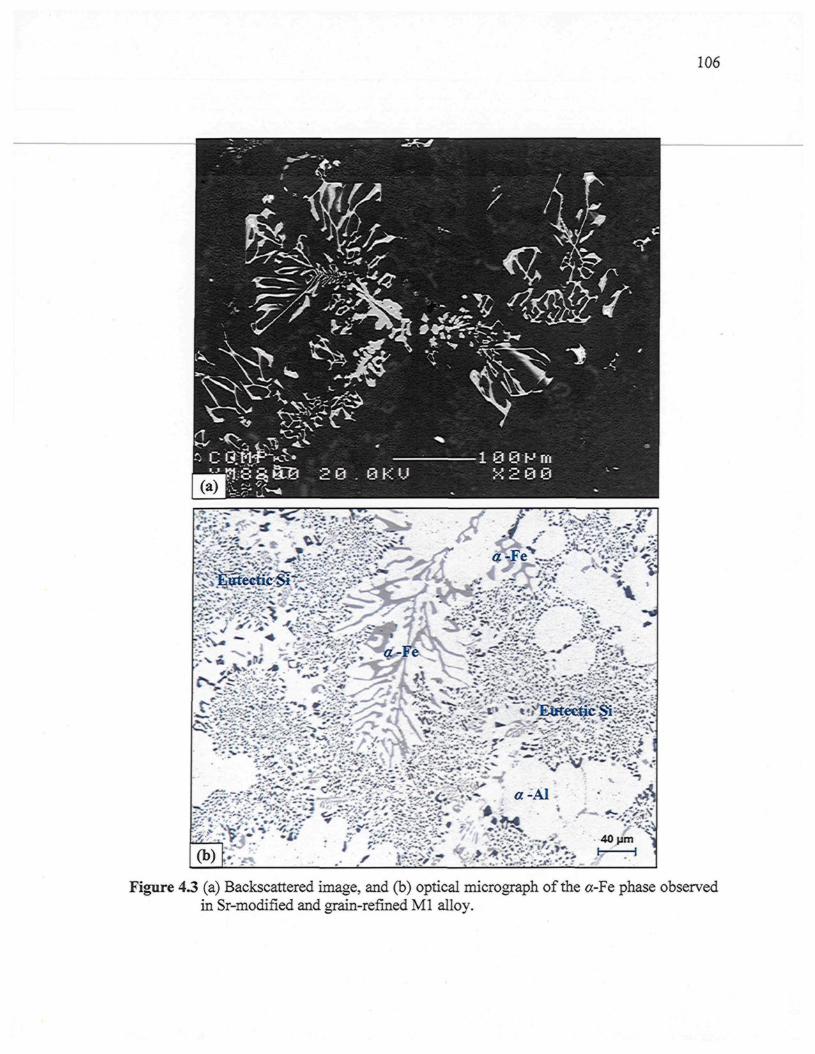
106
Figure 4.3 (a) Backscattered image, and (b) optical micrograph of the a-Fe phase observedin Sr-modified and grain-refined Ml alloy.
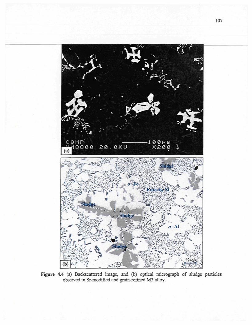
107
Figure 4.4 (a) Backscattered image, and (b) optical micrograph of sludge particlesobserved in Sr-modified and grain-refined M3 alloy.
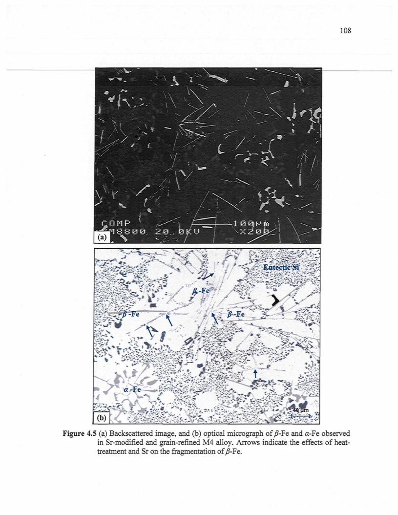
108
Figure 4.5 (a) Backscattered image, and (b) optical micrograph of /?-Fe and «-Fe observedin Sr-modified and grain-refined M4 alloy. Arrows indicate the effects of heat-treatment and Sr on the fragmentation of /?-Fe.
109
4.2.3 Copper-Rich Intermetallics
Alloying elements such as copper and magnesium determine which constituents will
precipitate. Copper is a significant alloying addition made to aluminum because of its
observable solubility and marked strengthening effect. Consequently, many commercial
alloys contain Cu as either the major addition or as one of the principal alloying elements.
Copper is frequently used in combination with magnesium, thereby improving the aging
characteristics of the alloys.171 Figure 4.6(a) shows the microstructure of an experimental
Mg-free M9 alloy which contains 3.67% Cu, consisting of unmodified acicular Si particles,
as well as the a-Fe Chinese-script phase interspersed throughout the Si particles. The fact
that the Fe-intermetallic particles are small in size, and that they occur interspersed in the Si
phase, indicates that they precipitated in co-eutectic or post-eutectic reactions. The copper
phase, marked A in this figure, may be seen mainly as pockets of the blocklike A^Cu phase
nucleating either within the aluminum matrix or at the interface of such pre-existing
constituents as Si or intermetallic particles.
The presence of Mg improves strain hardenability and strengthens the material
according to the amount present in means of a solid solution.172 It was found that
precipitation in the Al-Cu-Mg-Si alloys depends not only on the Mg content, but also on
the Cu:Mg ratio in solid solution. For a Cu:Mg ratio of 2.0 (at.%), preferential precipitation
of Mg2Si occurs, while a ratio close to 8.0 promotes the formation of the A^Cu compound.
The increase of Mg content in solid solution contributes to the precipitation phenomenon
since clusters of Mg are the precursors in the formation of Mg2Si in Al-Mg-Si alloys.173 It
was also observed that heightened Mg levels promote the precipitation process. In Mg-
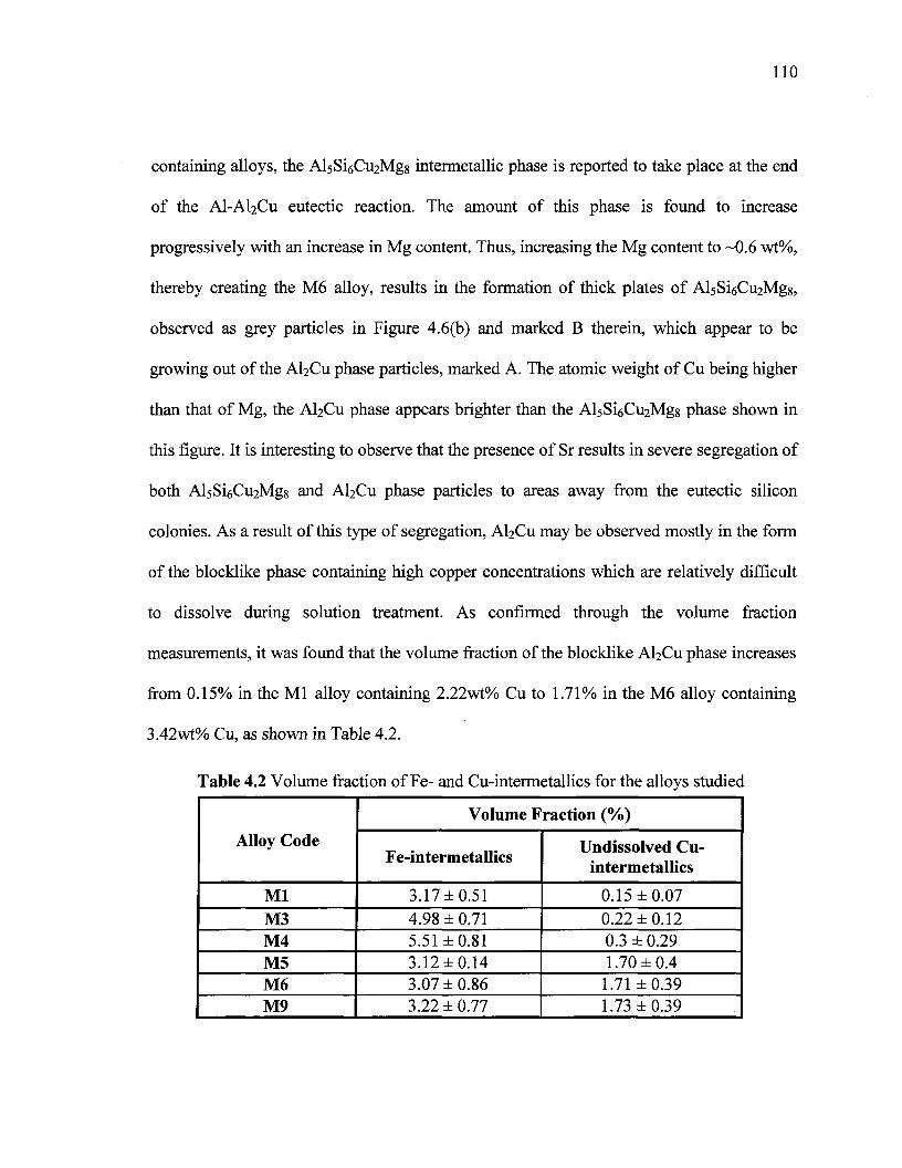
110
containing alloys, the AlsSiôC^Mgg intermetallic phase is reported to take place at the end
of the AI-AI2CU eutectic reaction. The amount of this phase is found to increase
progressively with an increase in Mg content. Thus, increasing the Mg content to ~0.6 wt%,
thereby creating the M6 alloy, results in the formation of thick plates of AlsSiôC^Mgg,
observed as grey particles in Figure 4.6(b) and marked B therein, which appear to be
growing out of the AbCu phase particles, marked A. The atomic weight of Cu being higher
than that of Mg, the AI2CU phase appears brighter than the AlsSiôC^Mgs phase shown in
this figure. It is interesting to observe that the presence of Sr results in severe segregation of
both AlsSioCuiMgg and AI2CU phase particles to areas away from the eutectic silicon
colonies. As a result of this type of segregation, AI2CU may be observed mostly in the form
of the blocklike phase containing high copper concentrations which are relatively difficult
to dissolve during solution treatment. As confirmed through the volume fraction
measurements, it was found that the volume fraction of the blocklike A^Cu phase increases
from 0.15% in the Ml alloy containing 2.22wt% Cu to 1.71% in the M6 alloy containing
3.42wt% Cu, as shown in Table 4.2.
Table 4.2 Volume fraction of Fe- and Cu-intermetallics for the alloys studied
Alloy Code
MlM3M4M5M6M9
Volume Fraction (%)
Fe-intermetallics
3.17±0.514.98 ± 0.715.51 ±0.813.12 ±0.143.07 ±0.863.22 ± 0.77
Undissolved Cu-intermetallics
0.15 ±0.070.22 ±0.120.3 ± 0.291.70 ±0.41.71 ±0.391.73 ±0.39
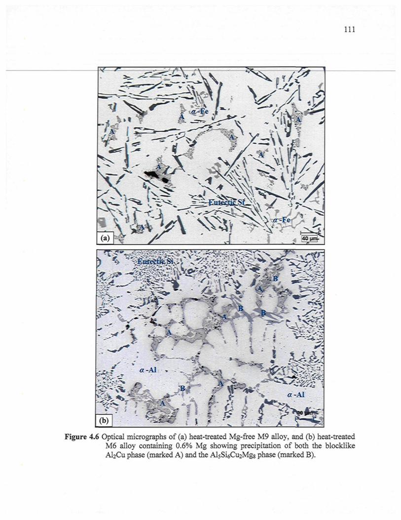
I l l
Figure 4.6 Optical micrographs of (a) heat-treated Mg-free M9 alloy, and (b) heat-treatedM6 alloy containing 0.6% Mg showing precipitation of both the blocklikeAl2Cu phase (marked A) and the AlsSiôCvçMgg phase (marked B).
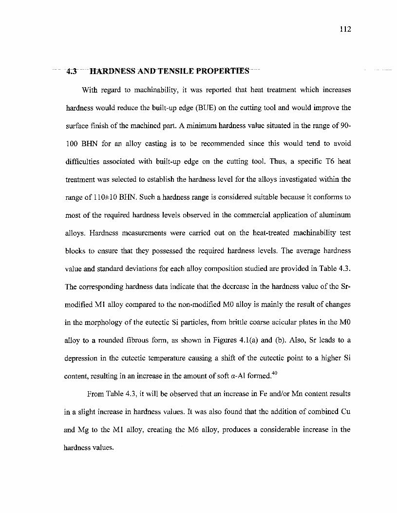
112
43 HARDNESS AND TENSILE PROPERTIES
With regard to machinability, it was reported that heat treatment which increases
hardness would reduce the built-up edge (BUE) on the cutting tool and would improve the
surface finish of the machined part. A minimum hardness value situated in the range of 90-
100 BHN for an alloy casting is to be recommended since this would tend to avoid
difficulties associated with built-up edge on the cutting tool. Thus, a specific T6 heat
treatment was selected to establish the hardness level for the alloys investigated within the
range of 110±10 BHN. Such a hardness range is considered suitable because it conforms to
most of the required hardness levels observed in the commercial application of aluminum
alloys. Hardness measurements were carried out on the heat-treated machinability test
blocks to ensure that they possessed the required hardness levels. The average hardness
value and standard deviations for each alloy composition studied are provided in Table 4.3.
The corresponding hardness data indicate that the decrease in the hardness value of the Sr-
modified Ml alloy compared to the non-modified MO alloy is mainly the result of changes
in the morphology of the eutectic Si particles, from brittle coarse acicular plates in the MO
alloy to a rounded fibrous form, as shown in Figures 4.1 (a) and (b). Also, Sr leads to a
depression in the eutectic temperature causing a shift of the eutectic point to a higher Si
content, resulting in an increase in the amount of soft ot-Al formed.40
From Table 4.3, it will be observed that an increase in Fe and/or Mn content results
in a slight increase in hardness values. It was also found that the addition of combined Cu
and Mg to the Ml alloy, creating the M6 alloy, produces a considerable increase in the
hardness values.
113
Table 4.3 Summary of mechanical properties for the alloys studied
AlloyCodeMOMlM3M4M5M6M9
BHN(MPa)
119 ±3.45108 ± 3.56111 ±4.39113 ±3.95117±3.19120 ± 4.45104 ±4.55
YS(MPa)
346.11 ±5.92
358.1 ±1.55326.84 ±2.13320.4 ± 12.7358.94 ± 7.45392.7 ±6.8
200.65 ± 4.70
UTS(MPa)
382.78 ±2.36
394.04 ± 6.27354.72 ± 4.86339.5 ±9.85369.99 ± 8.54396.14 ±6.8
300.82 ±19.16
El
0.92
0.980.840.510.760.661.70
±
±±±±±±
Vo)
0.09
0.120.040.020.140.020.47
There is a distinct possibility that the hardness increment in M5 and M6 alloys may
be attributed to the formation of hard and brittle intermetallic phases of AbCu and
AbCuMg, as well as to an increased bonding of the silicon particles with the matrix, in
which the thermal energy is sufficient to precipitate such intermetallics phases as are
coherent with the matrix.174 It should be mentioned that the hardness values of the
machinability test blocks, however, still fall within the required range.
Tensile testing was also carried out to assess the changes occurring in the aluminum
matrix and eutectic silicon as a result of the addition of Sr and other alloying elements.
Table 4.3 provides the tensile properties including the YS at a 0.2% offset strain, the UTS,
and the %E1 for the alloys investigated. The modified Ml alloy displays somewhat higher
YS, UTS, and %E1 values than the unmodified M0 alloy, because of the improved eutectic
silicon phase morphology caused by Sr modification. It will also be noted that as the
percentage of Fe and/or Mn increases beyond 0.75%, the YS, UTS, and ductility decrease
to a significant degree, a fact which may be attributed to the presence of the /?-Fe phase in
the structure of the M4 alloy. The high stress concentrations at the sharp edges of the /?-
114
^phase, as well as the wealrbonding between the /?-phase and the^Al matrix, enhance~crack
initiation and thus decrease the ductility of this alloy.175 With regard to the addition of Cu
and Mg to the Ml alloy, it may be observed that at high Mg levels of ~0.6, the ductility is
considerably lower, as observed in the case of the M6 alloy. Such a result may be attributed
to the influence of both Sr and Mg on the severity displayed by the A^Cu phase
segregation, resulting in the formation of large amounts of the coarse blocklike form of the
phase, as shown in Figure 4.6(b). Table 4.2 also provides the measurement of the volume
fraction for the undissolved AbCu phase. Further effects may be attributed to the formation
of hard brittle AlsSioCuiMgg particles which remain largely unaffected by solution heat-
treatment, as confirmed by the research carried out by Mohamed et al.166 It was also found
that the Mg-free M9 alloy displays a significant reduction in the YS and UTS values
compared to the Ml reference-alloy. This observation is in satisfactory agreement with
results obtained from previous work44 which reported that the addition of Mg proves to be
an excellent way of achieving a high level of tensile strength, however at the expense of
ductility.
4.4 MACHINING BEHAVIOR
The upcoming sections will discuss the machinability behavior of the alloy conditions
investigated in this work with respect to the total cutting force and moment, tool life
expressed as the number of holes drilled/tapped up to the point of tool breakage, chip
configuration, and built-up edge (BUE) evolution. The drilling and tapping tests were
carried out under fixed machining conditions of speed, feed, depth of hole drilled/tapped,
tool geometry, tool material, and coolant.
115
474rlEffects of Fe-InteTmetatlics oil MachinabHity
The number of insoluble phases present in the microstructure is dependent upon the Fe
level in the alloy. Lowering the Fe content is extremely effective in suppressing the
formation of the needle-like /?-Fe intermetallic phase and in preventing sludge formation,
thereby ultimately improving tool life. The modification of Fe intermetallics, through the
addition of such suitable neutralizers as Mn and Cr, converts the /?-Fe platelets into the
more compact and less harmful «-Fe scriptlike phase. This phase shows an irregular, curved
crystal growth which conforms to the complicated shape of the interdendritic spaces during
solidification. The ot-Fe has a non-faceted interface with the aluminum matrix, and exhibits
no growth twinning which allows for a better bonding with the aluminum matrix. The /?-
Fe, on the other hand, grows in a lateral or faceted mode which is poorly bonded to the
aluminum matrix.176
4.4.1.1 Cutting Forces and Moments
The mean total drilling force, the mean total drilling moment, and the mean drilling
power together with the corresponding standard deviation bars based on the mean value of
90 holes were all used as a way of evaluating the effects of the iron intermetallics, namely,
et-Fe, /?-Fe, and sludge, on the drilling process. Consequently, certain alloys responding to
specific criteria were selected; these include heat-treated, Sr-modified, and grain-refined
Al-10.8%Si near-eutectic alloys, represented respectively by (i) 396 + 200 ppm Sr + 0.2%
Ti reference alloy coded Ml containing ot-Fe; (ii) Ml + 0.25%Fe + 0.25%Mn alloy coded
M3 containing sludge; and (iii) Ml + 0.5%Fe alloy coded M4 containing /?-Fe and cc-Fe,
yielding hardness values of 108, 111, and 113 BHN, respectively.
116
The results obtained from the drilling tests reveal that the mean total drilling force,
the mean total drilling moment, and the mean drilling power all increase as the number of
holes drilled increases; this is clear from Figures 4.7(a), (b), and (c), respectively. With
regard to this observation, the mean total drilling force of the Ml alloy increases from
317.97N after drilling 90 holes to 645.38N after drilling 2160 holes, a corresponding
increase of 106%; this analysis agrees with the mean total drilling moment of the Ml alloy
which was found to have increased by virtually the same amount, i.e. 105%. It will also be
seen that the mean drilling power of the Ml alloy increases from 1.89 kW after drilling 90
holes to 4.42 kW after drilling 2160 holes, thus corresponding to an increase of 134%. A
similar trend was also observed during the drilling of the M3 and M4 alloys. This rapid
increase in the drilling force, moment, and power in conjunction with the progress of the
cutting process during the machining of the 396 alloy containing 10.8%Si may be attributed
to the presence of the silicon phase which is almost ten times harder than aluminum matrix.
The addition of 0.25%Fe and 0.25%Mn to the Ml base alloy, producing the M3
alloy which contains sludge as a predominant phase, leads to an extremely rapid increase in
the total drilling force from 334.48N after drilling 90 holes to 586N after drilling only 540
holes, a corresponding increase of 75% over the evaluation period of 540 holes; similar
behavior was also observed with regard to the total drilling moment and power, as shown in
Figure 4.7. This significant increase in cutting force may be explained by the formation of
the hard complex intermetallic sludge phase as the predominant phase in the M3 alloy. The
sludge may be seen clearly in the backscattered image and optical micrograph shown
earlier in Figure 4.4. It has also been reported that the microhardness of sludge usually lies
117
between 500 and 900 BHN, as compared to^arTnatrbHiardiigss^xF^OS BHN forthe 396
alloys.14'23 The sludge phase may act as an abrasive in an otherwise relatively soft matrix
and it is capable of causing excessive tool wear, thereby increasing the cutting force and
moment. Figure 4.8 shows aggressive wear on the drill edge after drilling 540 holes during
the machining of the sludge-containing M3 alloy. It should also be noticed that the
fluctuations of the total drilling force and moment values during the drilling of the M3 alloy
results from the distribution and the size of the sludge particles within the alloy structure
itself.
The addition of 0.5%Fe to the Ml base alloy, thereby producing the M4 alloy which
contains a relatively thin form of /?-Fe as the predominant phase, results in a considerable
improvement in alloy machinability through (i) a lowering of the drilling force by 10%,
ranging from 6% to 14%, (ii) a lowering of the drilling moment by 14%, ranging from 9%
to 20%, and (iii) a decreasing of the drilling power by 24%, ranging from 15% to 30%,
over the evaluation period of 1867 holes compared to the Ml alloy, as shown in Figures
4.7(a), (b), and (c). The preceding observations may be understood in the light of the effects
which the presence of the /?-Fe phase is known to have on ductility. As was listed earlier in
Table 4.3, the ductility of the M4 alloy decreases noticeably, by about 50%, compared to
the Ml alloy. The lower ductility value displayed by the /?-Fe-containing M4 alloy lessens
the drill-chip friction which in turn decreases the drilling forces, moment, and power. It has
been reported by a number of observers that, as the ductility increases, plastic deformation
takes place in the cutting zone and consequently cutting resistance becomes greater,
causing the cutting force to be higher.177'178
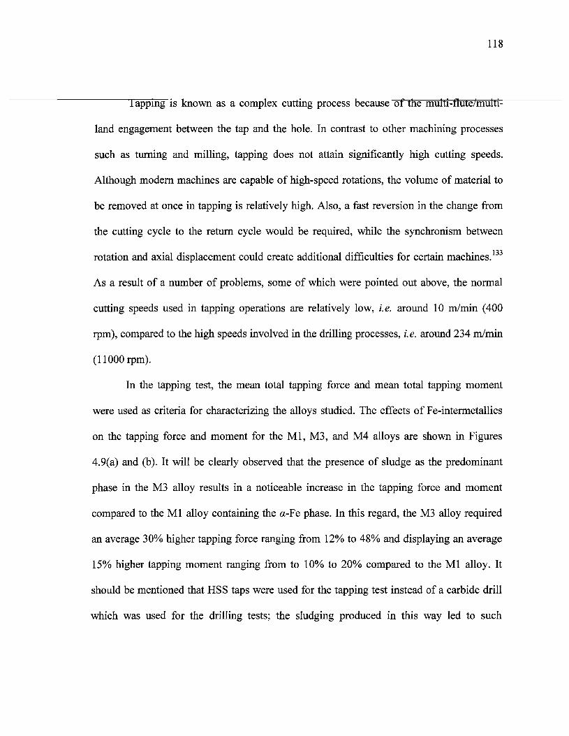
118
lapping is known as a complex cutting process because of the multi-flute/multi-
land engagement between the tap and the hole. In contrast to other machining processes
such as turning and milling, tapping does not attain significantly high cutting speeds.
Although modern machines are capable of high-speed rotations, the volume of material to
be removed at once in tapping is relatively high. Also, a fast reversion in the change from
the cutting cycle to the return cycle would be required, while the synchronism between
rotation and axial displacement could create additional difficulties for certain machines.133
As a result of a number of problems, some of which were pointed out above, the normal
cutting speeds used in tapping operations are relatively low, i.e. around 10 m/min (400
rpm), compared to the high speeds involved in the drilling processes, i.e. around 234 m/min
(llOOOrpm).
In the tapping test, the mean total tapping force and mean total tapping moment
were used as criteria for characterizing the alloys studied. The effects of Fe-intermetallics
on the tapping force and moment for the Ml, M3, and M4 alloys are shown in Figures
4.9(a) and (b). It will be clearly observed that the presence of sludge as the predominant
phase in the M3 alloy results in a noticeable increase in the tapping force and moment
compared to the Ml alloy containing the oc-Fe phase. In this regard, the M3 alloy required
an average 30% higher tapping force ranging from 12% to 48% and displaying an average
15% higher tapping moment ranging from to 10% to 20% compared to the Ml alloy. It
should be mentioned that HSS taps were used for the tapping test instead of a carbide drill
which was used for the drilling tests; the sludging produced in this way led to such

119
deleterious effects as hard-spot particles in the alloy structure, ultimately resulting in a
significant increase in the tapping force and moment.
It will also be observed that the thin /?-containing M4 alloy has the same effect on
the tapping force and moment as the one observed in the drilling test, since the tapping
force was reduced by 11% ranging from 2% to 20% compared with the Ml alloy. The
tapping moment was decreased by almost the same ratio. This reduction occurring in the
tapping force/moment values of the M4 alloy may be explained in the same manner as were
the effects resulting from the presence of the /?-Fe phase during drilling the tests.
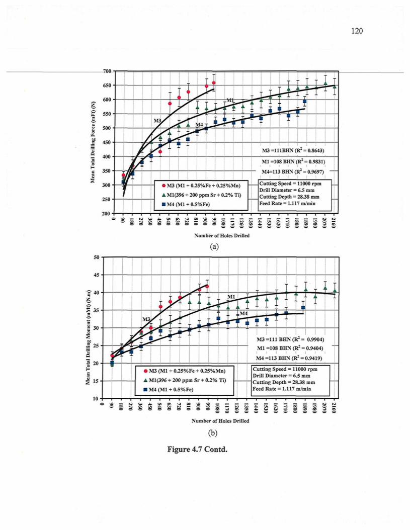
120
M3 =111BHN (R- = 0.S643)
Ml =108 BHN (R- = 0.9831)
M4=113 BHN (R: = 0.9697)
Cutting Speed = 11000 rpmDrill Diameter = 6.5 mmCutting Depth = 28.38 mmFeed Rate = 1.117 m/min
� M3 (Ml + 0.25%Fe + 0.25%Mn)
� Ml(396 + 200 ppm Sr + 0.2% Ti)
� M4 (Ml + 0.5%Fe)
Number of Holes Drilled
(a)50
45
s" 40
Is�.
S 35c
| MoSX
| 25
â1 20=m
10
ÀF ^
i
<
'A
L 1
r j
- ii�'
�
i
Ml
i. ^
� :
n
� M3 (Ml + 0.25%Fe + 0.25%Mn)
� Ml(396 + 200 ppm Sr + 0.2% Ti)
� M4 (Ml + 0.5%Fe)
-
:M4
� l
� � �i
M3 =11 )
[ "*� X
r T
BHN(l
Hi : =
i
0.9<>04)
Ml =108 BHN (R- = 0.9404)
M4 =113 BHN (R1 = 0.9419)
Cutting Speed = 11000 rpmDrill Diameter = 6.5 mmCutting Depth - 2838 mmFeed Rate = 1.117 m/min
�
^J 00 O O-o � o oo o o o
o o o o o o o o o
Number of Holes Drilled
v-5 o �ÛG ~J Cvo o o
(b)
Figure 4.7 Contd.
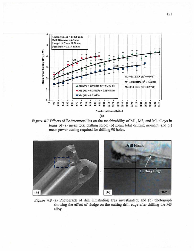
121
Cutting Speed = 11000 rpmDrill Diameter = 6.5 mmLength of Cut = 2838 mmFeed Rate = 1.117 m/min
� Ml(396 + 200 ppm Sr + 0.2% Ti)
� M3 (Ml + 0.25%Fe + 0.25%Mn)
� M4(Ml + 0.5%Fe)
M3 =111BHN (R2 = 0.9717)1 ! I I I t I
Ml =108 BHN (R2 = 0.9621)
M4=113 BHN (R2 = 0.9796)
Number of Holes Drilled
(C)
Figure 4.7 Effects of Fe-intermetallics on the machinability of Ml, M3, and M4 alloys interms of (a) mean total drilling force; (b) mean total drilling moment; and (c)mean power cutting required for drilling 90 holes.
Figure 4.8 (a) Photograph of drill illustrating area investigated; and (b) photographshowing the effect of sludge on the cutting drill edge after drilling the M3alloy.
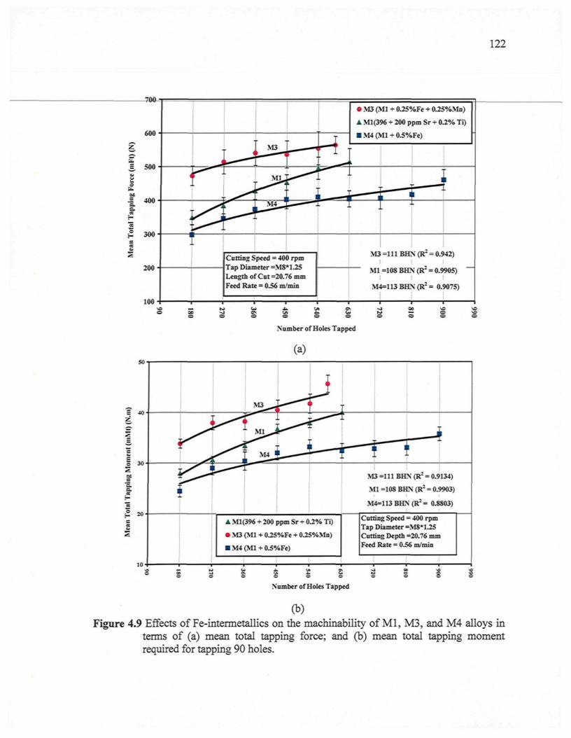
122
600
300
200
100
� M3 (Ml + 0.25%Fe + 0.25%Mn)
� Ml(396 + 200 ppm Sr + 0.2% Ti)
� M4 (Ml + 0.5%Fe)
Cutting Speed = 400 rpmTap Diameter =M8*1.25Length of Cut =20.76 mmFeed Rate - 0.56 m/min
IM3 =111 BHN (R2 = 0.942)
I ! I
Ml =108 BHN (R2 = 0.9905)
M4=113 BHN (R2 = 0.9075)
50
40
Number of Holes Tapped
(a)
I
30 -
20
10
i
i
M3 -
L M l ^
M4 1
rLs�i
� Ml(396 + 200 ppm Sr + 0.2% Ti)
� M3 (Ml + 0.25%Fe + 0.25%Mn)
� M4(Ml + 0.5%Fe)
r\
; 1i i
\
�
M3 =111 BHN (R2 = 0.9134)
Ml =108 BHN (R2 = 0.9903)
M4=113 BHN (R2 = 0.8803)
Cutting Speed = 400 rpmTap Diameter =M8*1.25Cutting Depth =20.76 mmFeed Rate = 0.56 m/min
Number of Holes Tapped
(b)Figure 4.9 Effects of Fe-intermetallics on the machinability of Ml, M3, and M4 alloys in
terms of (a) mean total tapping force; and (b) mean total tapping momentrequired for tapping 90 holes.
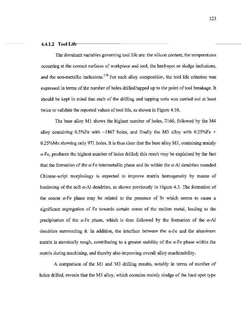
123
4.4.1.2 Tool Life
The dominant variables governing tool life are: the silicon content, the temperatures
occurring at the contact surfaces of workpiece and tool, the hard-spot or sludge inclusions,
and the non-metallic inclusions.179 For each alloy composition, the tool life criterion was
expressed in terms of the number of holes drilled/tapped up to the point of tool breakage. It
should be kept in mind that each of the drilling and tapping tests was carried out at least
twice to validate the reported values of tool life, as shown in Figure 4.10.
The base alloy Ml shows the highest number of holes, 2160, followed by the M4
alloy containing 0.5%Fe with -1867 holes, and finally the M3 alloy with 0.25%Fe +
0.25%Mn showing only 971 holes. It is thus clear that the base alloy Ml, containing mainly
a-Fe, produces the highest number of holes drilled; this result may be explained by the fact
that the formation of the a-Fe intermetallic phase and its within the a-Al dendrites rounded
Chinese-script morphology is expected to improve matrix homogeneity by means of
hardening of the soft a-Al dendrites, as shown previously in Figure 4.3. The formation of
the coarse a-Fe phase may be related to the presence of Sr which seems to cause a
significant segregation of Fe towards certain zones of the molten metal, leading to the
precipitation of the a-Fe phase, which is then followed by the formation of the a-Al
dendrites surrounding it. In addition, the interface between the a-Fe and the aluminum
matrix is atomically rough, contributing to a greater stability of the a-Fe phase within the
matrix during machining, and thereby also improving overall alloy machinability.
A comparison of the Ml and M3 drilling results, notably in terms of number of
holes drilled, reveals that the M3 alloy, which contains mainly sludge of the hard-spot type
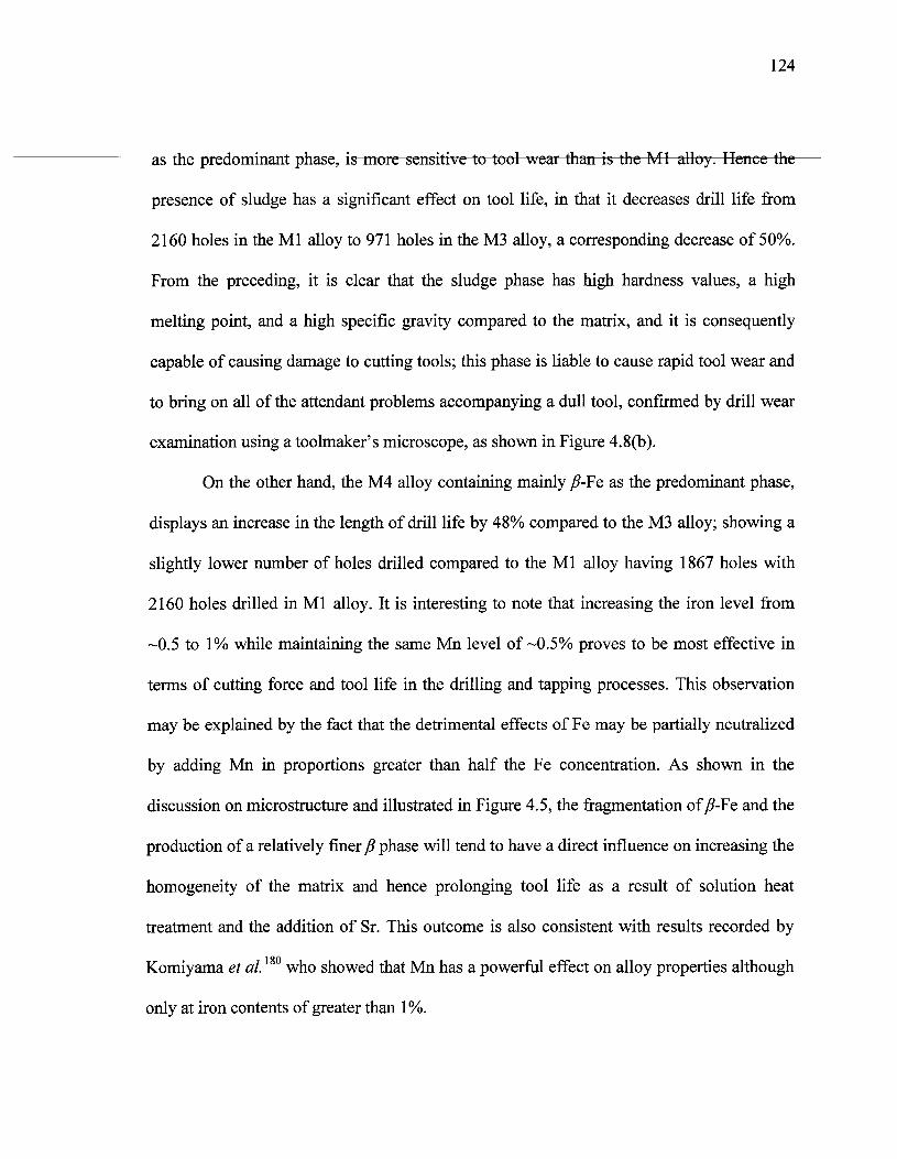
124
as the predominant phase, is more sensitive to tool wear than is the Ml alloy. Hence the
presence of sludge has a significant effect on tool life, in that it decreases drill life from
2160 holes in the Ml alloy to 971 holes in the M3 alloy, a corresponding decrease of 50%.
From the preceding, it is clear that the sludge phase has high hardness values, a high
melting point, and a high specific gravity compared to the matrix, and it is consequently
capable of causing damage to cutting tools; this phase is liable to cause rapid tool wear and
to bring on all of the attendant problems accompanying a dull tool, confirmed by drill wear
examination using a toolmaker's microscope, as shown in Figure 4.8(b).
On the other hand, the M4 alloy containing mainly /?-Fe as the predominant phase,
displays an increase in the length of drill life by 48% compared to the M3 alloy; showing a
slightly lower number of holes drilled compared to the Ml alloy having 1867 holes with
2160 holes drilled in Ml alloy. It is interesting to note that increasing the iron level from
-0.5 to 1% while maintaining the same Mn level of-0.5% proves to be most effective in
terms of cutting force and tool life in the drilling and tapping processes. This observation
may be explained by the fact that the detrimental effects of Fe may be partially neutralized
by adding Mn in proportions greater than half the Fe concentration. As shown in the
discussion on microstructure and illustrated in Figure 4.5, the fragmentation of /?-Fe and the
production of a relatively finer /? phase will tend to have a direct influence on increasing the
homogeneity of the matrix and hence prolonging tool life as a result of solution heat
treatment and the addition of Sr. This outcome is also consistent with results recorded by
Komiyama et al.180 who showed that Mn has a powerful effect on alloy properties although
only at iron contents of greater than 1%.
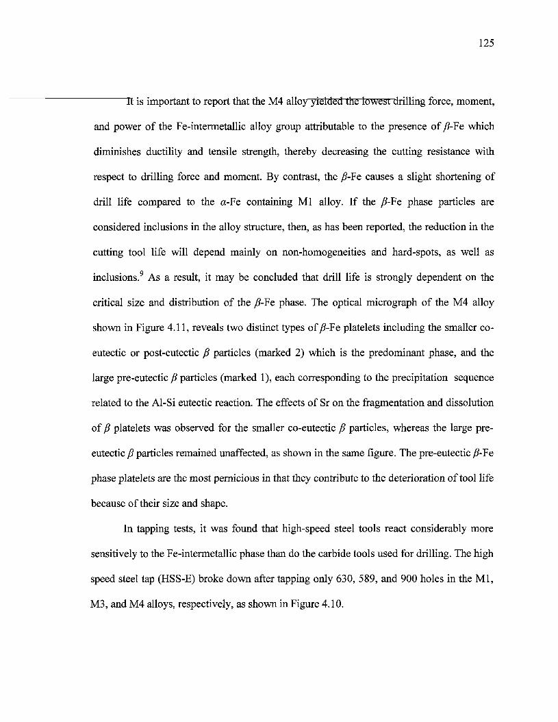
125
It is important to report that the M4 alloy yielded the lowest drilling force, moment,
and power of the Fe-intermetallic alloy group attributable to the presence of /?-Fe which
diminishes ductility and tensile strength, thereby decreasing the cutting resistance with
respect to drilling force and moment. By contrast, the /?-Fe causes a slight shortening of
drill life compared to the ot-Fe containing Ml alloy. If the /?-Fe phase particles are
considered inclusions in the alloy structure, then, as has been reported, the reduction in the
cutting tool life will depend mainly on non-homogeneities and hard-spots, as well as
inclusions.9 As a result, it may be concluded that drill life is strongly dependent on the
critical size and distribution of the /?-Fe phase. The optical micrograph of the M4 alloy
shown in Figure 4.11, reveals two distinct types of /?-Fe platelets including the smaller co-
eutectic or post-eutectic /? particles (marked 2) which is the predominant phase, and the
large pre-eutectic fi particles (marked 1), each corresponding to the precipitation sequence
related to the Al-Si eutectic reaction. The effects of Sr on the fragmentation and dissolution
of P platelets was observed for the smaller co-eutectic /? particles, whereas the large pre-
eutectic p particles remained unaffected, as shown in the same figure. The pre-eutectic /?-Fe
phase platelets are the most pernicious in that they contribute to the deterioration of tool life
because of their size and shape.
In tapping tests, it was found that high-speed steel tools react considerably more
sensitively to the Fe-intermetallic phase than do the carbide tools used for drilling. The high
speed steel tap (HSS-E) broke down after tapping only 630, 589, and 900 holes in the Ml,
M3, and M4 alloys, respectively, as shown in Figure 4.10.
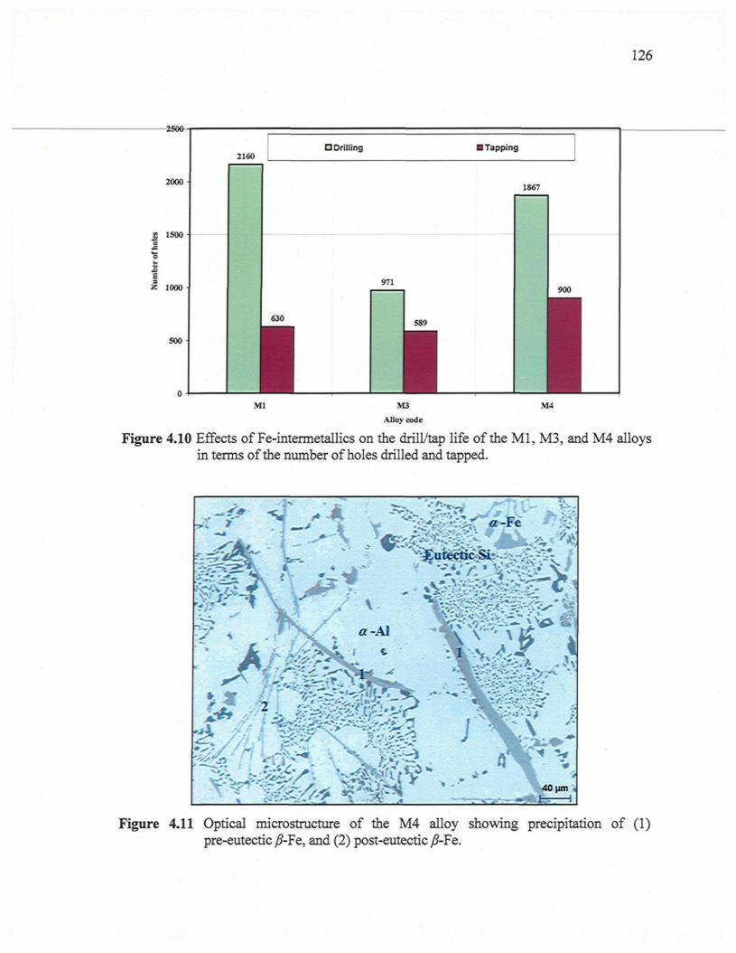
2500
2000
8 1500
1000
500 -
0 -1
2160O Drilling
971
630
M3
126
� Tapping
1867
M4
Alloy code
Figure 4.10 Effects of Fe-intermetallics on the drill/tap life of the Ml, M3, and M4 alloysin terms of the number of holes drilled and tapped.
Figure 4.11 Optical microstructure of the M4 alloy showing precipitation of (1)pre-eutectic /?-Fe, and (2) post-eutectic /?-Fe.
127
4.4.2 Effects of Cu and Mg Additions on Machinability
Cast aluminum-silicon alloys contain mainly Cu and Mg as the major alloying
elements. Magnesium is normally used to improve the mechanical properties of the alloy
through the precipitation of the Mg2Si and A^CuMg intermetallics.181 The Cu and Mg
content of the alloys determines the precipitation strengthening and the volume fraction of
Cu-rich and Mg-rich intermetallics obtained.182 Regulating the morphology, volume
fraction, and distribution of these intermetallics will improve the alloy matrix homogeneity
and hence improve its machinability.183 With regard to machinability as one of the
characteristics of a given alloy, there are studies in the literature reporting the effects of
metallurgical characteristics as being important factors in this context; these characteristics
comprise the chemical composition, the microstructure, and the morphology of second
phase particles of the alloy.184 A particular characteristic of the two-phase and multiphase
microstructures of Al-Si alloys is the fact that the matrix phase is soft and highly ductile
whereas the second phase is considerably harder. In order to obtain a good surface finish, it
is important that the particles of the hard phase be fine and uniformly distributed within the
soft, aluminum matrix.21
Conversely, most aluminum alloys are fairly soft in relation to cast iron and steel,
and are commonly machined by high speed steel (HSS) tools, although an exception to this
may be observed with aluminum-silicon alloys. Near-eutectic Al-Si alloys are said to be
the most difficult to machine out of the various types of Al-Si alloys, as is evidenced by the
fact that the silicon phase present is almost ten times harder than the aluminum base alloy,
thus causing the cutting tools to wear out rapidly. For this reason, consistent attempts
128
have been made to optimize the selection of cemented carbide tools, cutting conditions,
and tool geometry; investigation of the following points was also recommended: (i) the
effects of flank build-up on tool wear,188 (ii) the effects of cutting fluids on
machinability,126 and (iii) the improvement of machinability through the addition of certain
�I Q Q
elements. Although Cu and Mg are the main additives used to strengthen the alloys in the
Al-Si systems, their effects on the machinability of near-eutectic Al-Si casting alloys has
rarely been taken into account.
The presence of Cu leads to the formation of A^Cu particles, which when refined
and dispersed, improve machinability by causing a decrease in plasticity, and ultimately
result in chip embrittlement.190 In the research191 carried out on the relationship between
chip breakability and aging treatment in Al-Cu and Al-Cu-Si alloys, chip breakability
successfully improved with the increased size of second-phase particles accompanied by
advanced aging. In this case, however, it was pointed out that chip breakability was also
related to the cracking of the second-phase particles and the ductility of the matrix around
them. Nevertheless, these facts suggest that the chip breakability of Al alloys is expected to
improve with the dispersion of some kind of second-phase particle, since this could be the
cause of the chip breaking through cracking during machining; it should be remembered
that there are various second-phase particles, including precipitates and crystallized
particles, in commercial Al alloys.49 The production of small brittle chips favors
intermittent cutting, making chip extraction away from the cutting easier, while at the same
time inhibiting the formation of a built-up edge on the cutting edge of the tool.
129
4.4.2.1
Drilling and tapping tests were carried out under constant cutting conditions to
investigate the influence of Cu and Mg additions as well as of Sr-modification on the
machining behaviour of a number of grain-refined and T6 heat-treated Al-10.8%Si near-
eutectic alloys. The alloys in question were represented by the following:
396 + 200 ppm Sr + 0.2%Ti, coded Ml alloy;
Ml + l%Cu, coded M5 alloy;
Ml + l%Cu + 0.25%Mg, coded M6 alloy;
non-modified Al-10.8%Si-Cu-Mg experimental alloy, coded MO alloy; and
Mg-free Al-10.8%Si-3.5%Cu experimental alloy, coded M9 alloy,
yielding 110±10BHN hardness level.
The results from drilling tests reveal that the mean total drilling force, moment, and
power increase as the number of holes drilled increases, as shown in Figures 4.12(a), (b),
and (c). From this figure, it will be observed that the drilling force, moment and power
display a virtually linear trend during the drilling of the Mg-free M9 alloy, while in
comparison the Ml base alloy shows a rapid increase in the cutting force. More
specifically, the mean total drilling force of the Ml alloy increases by 103% over the
evaluation period of 2160 holes. In contrast, the mean total drilling force of the Mg-free M9
alloy increases from 204N after drilling 90 holes to 316.8N after drilling 3240 holes, i.e.
approximately a 55% increase. This analysis is in agreement with the mean total drilling
moment and power of the Ml alloy which was found to have increased by 105% and 134%,
respectively, as shown in Figures 4.12(b) and (c). On the other hand, the mean total drilling
130
moment and the mean drilling power of Mg-free M9 alloy increased by 53% and 60%,
respectively.
The machining characteristics of the Al-10.8%Si near eutectic alloy depend mainly
on the shape, size, and distribution of a-Al dendrites, eutectic Si morphology, and A^Cu
particles in the interdendritic region. Figures 4.12(a), (b), and (c) show that the addition of
1% Cu to the Ml alloy, thereby producing the M5 alloy, has only a slightly diminishing
effect on the drilling force and moment as well as on drilling power, compared to the case
of the Ml alloy. On the other hand, the increase in the level of Cu and Mg from 2.2% and
0.3% in the Ml alloy to 3.4% and 0.6%, creating the M6 alloy, has a noticeable effect in
increasing the mean total drilling force, mean total drilling moment, and mean power
cutting by 25%, 20%, and 15%, respectively, compared to the Ml alloy.
Tool life is measured in terms of the number of holes drilled/tapped under constant
machining conditions in M0, Ml, M5, M6, and M9 alloys, as shown in Figure 4.13. In this
figure, it will be observed that the M5 alloy containing high levels of Cu or the M6 alloy
containing high levels of Cu and Mg, in the form of additions, all have a detrimental effect
on drill life, whereas the drill life of the Ml alloy decreases from 2160 holes/drill to 810
holes/drill and 990 holes/drill in the M5 and M6 alloys, thus corresponding to a reduction
in drill life by 63% and 58%, respectively.
It will also be clearly observed that the Mg-free M9 alloy displays a significant
decrease in the total drilling force, in the total drilling moment, and in the total drilling
power compared to the Ml reference alloy; specifically the M9 alloy required an average
of 50% lower mean total drilling force ranging from 35% to 65%, and exhibited an average
131
of 52% lower total drillin^~nTOTn^nrraiigm^frorn 35% to 69%, as werhas-approximately
64% less drilling power ranging from 58% to 70% compared to the Ml alloy over the
evaluation period of 2160 holes, as shown in Figure 4.12.
It is interesting to observe that the Mg-free M9 alloy produces the highest number
of holes with 3240 holes/drill; this is followed by the Ml alloy containing 0.3% Mg having
2160 holes/drill, and lastly by the high Mg-content M6 alloy containing 0.6% Mg with 990
holes/drill, as shown in Figure 4.13. It is thus clear that a high Mg-content of about 0.6%
will cause a certain amount of deterioration in tool life, producing higher cutting force and
moment, and lowering the number of holes drilled. These conclusions are in satisfactory
agreement with results obtained by Jorstad 14'23 who reported that a small Mg addition of
about 0.3%, in Al-Si-Cu alloys hardens the alloy but does not increase abrasiveness since it
does not contribute in any way to the formation of the coarse hard Al-Si-Cu-Mg
intermetallic phase.
The microstructure of the non-modified Al-10.8%Si alloy consists mainly of the
eutectic mixture (ct-Al + Si) with some elongated a-Al dendrites and a few primary silicon
particles. The silicon crystals, which have three-dimensional complex shapes and are
extremely brittle, segregate to the grain boundaries of the cc-Al matrix. Strontium, a surface
active element, is a well-known additive in cast Al-Si alloys; it is commonly added to
transform the shape of the eutectic silicon from acicular into fibrous particles. For the
purposes of comparison, the non-modified Al-10.8% Si experimental alloy, coded M0, was
used in this study to compare the machining behaviour of the non-modified alloy with that
of the modified Ml alloy. It will be observed that the non-modified M0 alloy has some
132
slight effect in decreasing the mean total force, moment, and the mean power cutting by
9%, 13%, and 11%, respectively, when compared to the Sr-modified Ml alloy, as shown in
Figures 4.12(a), (b), and (c). On the other hand, the non-modified MO alloy has a
detrimental effect on drill life, since the MO alloy produces only 468 holes/drill compared
to 2160 holes drilled in case of the the Sr-modified Ml alloy.
Figures 4.14(a) and (b) show the effects of Cu, Mg, and Sr additions on the mean
total tapping force and the mean total tapping moment of the alloys investigated. As will be
observed from the figures, the tapping results reveal that the alloys studied follow the same
trend as those observed during the drilling tests. The addition of 0.25% Mg and 1% Cu to
the Ml alloy generates high tapping force and moment in the M6 alloy which is created by
these additions. On the other hand, the addition of only 1% Cu to the Ml alloy has little
influence in lowering the tapping force and moment as opposed to the Ml base alloy. The
non-modified MO alloy, however, displays a significant decrease in the tapping forces,
while the Mg-free M9 alloy generates the lowest tapping force and moment of all the alloys
studied. Referring back to Figure 4.13 which shows the effects of the relevant additions to
tap life in terms of the number of holes tapped, it was found that the M9 alloy showed the
highest number of holes tapped with 3150 holes/tap, followed by the M6 alloy having 1314
holes/tap, then by the M5 alloy yielding 720 holes/tap, the Ml alloy producing 630
holes/tap, and lastly the non-modified M0 alloy with 540 holes/tap.
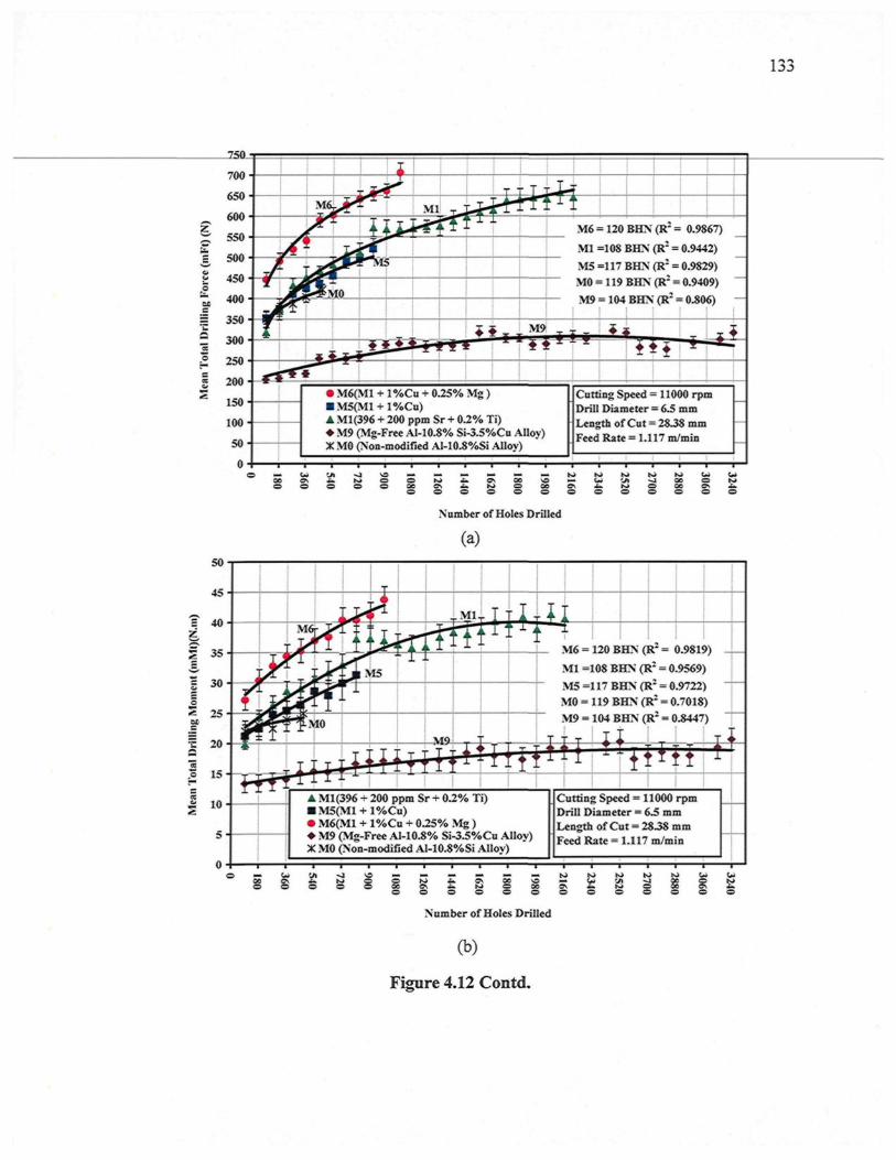
1.5 ;>
.-=
700
150
100
50
M6 = 120 BHN (R- = 0.9867)
Ml =108 BHN (R2 = 0.9442)
M5 =117 BHN (R2 = 0.9829)
MO = 119 BHN (R2 = 0.9409)
M9 = 104 BHN (R2 = 0.806)
� M6(M1 + l%Cu + 0.25% Mg )� M5(Ml + l%Cn)� Ml(396 + 200 ppm Sr + 0.2% Ti)� M9 (Mg-Free AI-10.8% Si-3.5%Cu AUoy)X MO (Non-modified Al-10.8%Si Alloy)
Cutting Speed = 11000 rpmDrill Diameter = 6.5 mmLength of Cut = 28.38 mmFeed Rate = 1.117 m/min
50
45
40
35
30
25
20
15
10
5
Number of Holes Drilled
(a)
j y > :
.$*wt*
f M 0
ÛV
<�*
k A
T
| M 5
�a " I '
A
Ml.-"ft' 1
�JL k̂M6 = 120 BHN (R2 = 0.9819)Ml =108 BHN (R2 = 0.9569)M5 =117 BHN (R2 = 0.9722)M0 = 119 BHN (R2 = 0.7018)M9 = 104 BHN (R2 = 0.8447)
� T T I I , : T� t l f l ' 4
A Ml(396 + 200 ppm Sr + 0.2% Ti)� M5(Ml + l%Cu)� M6(M1 + l%Cu + 0.25% Mg )� M9 (Mg-Free AI-10.8% Si-3.5%Cu Alloy)X MO (Non-modified Al-10.8%Si Alloy)
� <rni
rf 1
Cutting Speed = 11000 rpmDrill Diameter = 6.5 mmLength of Cut = 2838 mmFeed Rate = 1.117 m/min
g O � � � � � � N J > U
S O N > £ k ^ 0 C O ^ WC C 9 \ £ . > O O 0 0 9 v I .O O O O O O O O
Number of Holes Drilled
ifo
(b)
Figure 4.12 Contd.
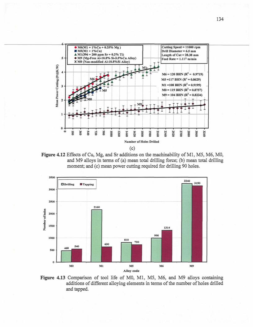
134
s- -
� M6(M1 + l%Cu + 0.25% Mg )� M5(Ml + l%Cu)� Ml(396 + 200 ppm Sr + 0.2% Ti)� M9 (Mg-Free AI-10.8% Si-3.S%Cu Alloy)X MO (Non-modified Al-10.8%Si Alloy)
Cutting Speed = 11000 rpmDrill Diameter = 6.5 mmLength of Cut = 28.38 mmFeed Rate = 1.117 m/min
M6 = 120 BHN (R2 = 0.9719)
M5 =117 BHN (R- = 0.8629)
Ml =108 BHN (R2 = 0.9199)
M0 = 119 BHN (R2 = 0.8757)
M9 = 104 BHN (R- = 0.8234)
i S�ON
o
Number of Holes Drilled
(c)Figure 4.12 Effects of Cu, Mg, and Sr additions on the machinability of Ml, M5, M6, MO,
and M9 alloys in terms of (a) mean total drilling force; (b) mean total drillingmoment; and (c) mean power cutting required for drilling 90 holes.
3S00
3000
2500
2 2000
1S00
1000
500
O Drilling I Tapping3240
2160
46S
3150
M0 M9
Figure 4.13 Comparison of tool life of MO, Ml, M5, M6, and M9 alloys containingadditions of different alloying elements in terms of the number of holes drilledand tapped.
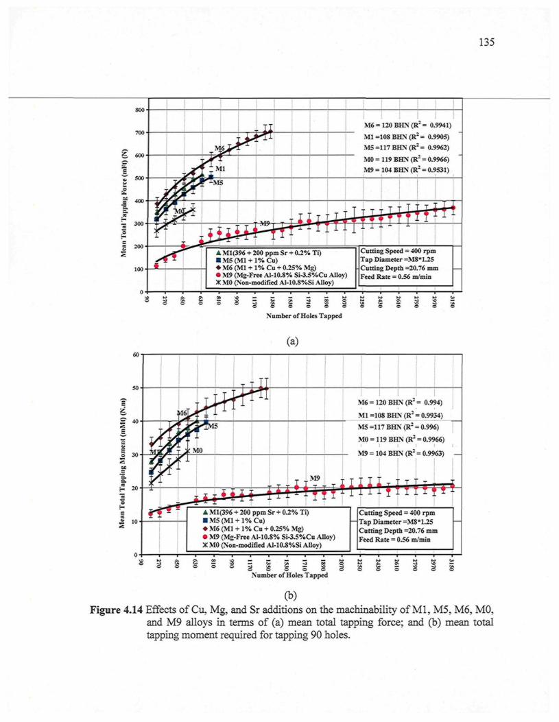
135
800
100
M6 = 120 BHN (R2 = 0.9941)
Ml =108 BHN (R2 = 0.9905)
M5=117BHN(R2= 0.9962)
A Ml(396 + 200 ppm Sr + 0.2% Ti)� M5(Ml + l%Cu)� M6 (Ml + 1% Cu + 0.25% Mg)� M9 (Mg-Free Al-10.8% Si-3.5%Cu Alloy)X MO (Non-modified Al-10.8%Si Alloy)
Cutting Speed = 400 rpmTap Diameter =M8*1.25Cutting Depth =20.76 mmFeed Rate = 0.56 m/min
2 2 iO O © O C
Number of Holes Tapped
S S t 2
(a)
M6 = 120 BHN (R- = 0.994)
Ml =108 BHN (R2 = 0.9934)
MS =117 BHN (R2 = 0.996)
M0 = 119 BHN (R2 = 0.9966)I I I ! I
M9 = 104 BHN (R2 = 0.9963)
± 10� Ml(396 + 200 ppm Sr + 0.2% Ti)� M5(Ml + l%Cu)� M6 (Ml + 1% Cu + 0.25% Mg)� M9 (Mg-Free Al-10.8% Si-3.5%Cu Alloy)X M0 (Non-modified Al-10.8%Si Alloy)
Cutting Speed = 400 rpmTap Diameter =M8*1.25Cutting Depth =20.76 mmFeed Rate = 0.56 m/min
O w 'ffl 6* ,*�* jS' *» W * 'yi ^J M O ft* -Jb iQV "»Jt w '�**.� o C ~ w - j - ^ t« � o �: vi OJ � \o �i -Jio o o o o o o o o o o o
Number of Holes Tapped
(b)Figure 4.14 Effects of Cu, Mg, and Sr additions on the machinability of Ml, M5, M6, MO,
and M9 alloys in terms of (a) mean total tapping force; and (b) mean totaltapping moment required for tapping 90 holes.
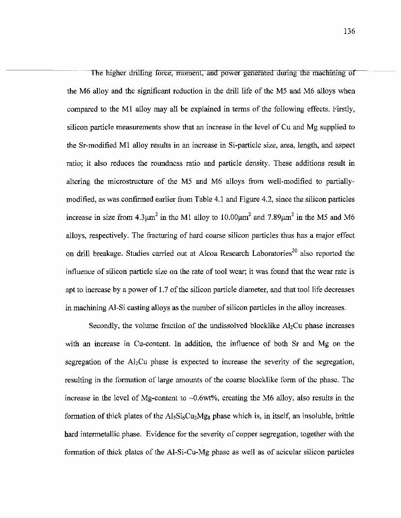
136
The higher drilling force, moment, and power generated during the machining of
the M6 alloy and the significant reduction in the drill life of the M5 and M6 alloys when
compared to the Ml alloy may all be explained in terms of the following effects. Firstly,
silicon particle measurements show that an increase in the level of Cu and Mg supplied to
the Sr-modified Ml alloy results in an increase in Si-particle size, area, length, and aspect
ratio; it also reduces the roundness ratio and particle density. These additions result in
altering the microstructure of the M5 and M6 alloys from well-modified to partially-
modified, as was confirmed earlier from Table 4.1 and Figure 4.2, since the silicon particles
increase in size from 4.3urn2 in the Ml alloy to lO.OOum2 and 7.89um2 in the M5 and M6
alloys, respectively. The fracturing of hard coarse silicon particles thus has a major effect
on drill breakage. Studies carried out at Alcoa Research Laboratories20 also reported the
influence of silicon particle size on the rate of tool wear; it was found that the wear rate is
apt to increase by a power of 1.7 of the silicon particle diameter, and that tool life decreases
in machining Al-Si casting alloys as the number of silicon particles in the alloy increases.
Secondly, the volume fraction of the undissolved blocklike A^Cu phase increases
with an increase in Cu-content. In addition, the influence of both Sr and Mg on the
segregation of the A^Cu phase is expected to increase the severity of the segregation,
resulting in the formation of large amounts of the coarse blocklike form of the phase. The
increase in the level of Mg-content to ~0.6wt%, creating the M6 alloy, also results in the
formation of thick plates of the AlsSiôCuaMgg phase which is, in itself, an insoluble, brittle
hard intermetallic phase. Evidence for the severity of copper segregation, together with the
formation of thick plates of the Al-Si-Cu-Mg phase as well as of acicular silicon particles
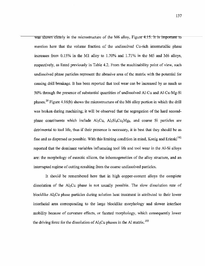
137
was shown clearly in the microstructure of the M6 alloy, Figure 4.15. It is important to
mention here that the volume fraction of the undissolved Cu-rich intermetallic phase
increases from 0.15% in the Ml alloy to 1.70% and 1.71% in the M5 and M6 alloys,
respectively, as listed previously in Table 4.2. From the machinability point of view, such
undissolved phase particles represent the abrasive area of the matrix with the potential for
causing drill breakage. It has been reported that tool wear can be increased by as much as
50% through the presence of substantial quantities of undissolved Al-Cu and Al-Cu-Mg-Si
phases.20 Figure 4.16(b) shows the microstructure of the M6 alloy portion in which the drill
was broken during machining; it will be observed that the segregation of the hard second-
phase constituents which include AbCu, AlsSiôO^Mgg, and coarse Si particles are
detrimental to tool life, thus if their presence is necessary, it is best that they should be as
fine and as dispersed as possible. With this limiting condition in mind, Konig and Erinski
reported that the dominant variables influencing tool life and tool wear in the Al-Si alloys
are: the morphology of eutectic silicon, the inhomogeneities of the alloy structure, and an
interrupted regime of cutting resulting from the coarse undissolved particles.
It should be remembered here that in high copper-content alloys the complete
dissolution of the A^Cu phase is not usually possible. The slow dissolution rate of
blocklike A^Cu phase particles during solution heat treatment is attributed to their lower
interfacial area corresponding to the large blocklike morphology and slower interface
mobility because of curvature effects, or faceted morphology, which consequently lower
the driving force for the dissolution of AI2O1 phases in the Al matrix.193
138
Figure 4.15 Microstructure of the M6 alloy showing the influence of both Sr and Mg: (1)segregation of the AkCu phase; (2) formation of thick plates of AlsSiôphase; and (3) acicular silicon particles.
Figure 4.16 (a) Cross-section of drilled hole illustrating area investigated; and (b) opticalmicrostmcture of M6 alloy corresponding to the drill breakage portion showingthe presence of large silicon particles, marked 1, and the coarse undissolvedCu-phase, marked 2, in this area.
139
The solution time must then be chosen carefully to allow for the maximum
dissolution of this intermetallic phase. Solution-treating the alloy for long periods of time,
however, is an expensive practice and may not be necessary to obtain the required alloy
strength. Moreover, the coarsening of microstructural constituents and the possible
formation of secondary porosity which tends to form after prolonged annealing
temperatures can have a deleterious effect on machinability properties.194
Thirdly, the hardness values of the M5 and M6 alloys increase with increasing Cu
and Mg levels, as confirmed previously by the hardness measurements reported in Table
4.3. It is presumed that tool life is adversely affected by an increase in workpiece hardness,
since the cutting loads and temperatures increase with increasing hardness values of the
material, thereby reducing tool life even further.
The noticeable difference to be observed in the drilling force, moment, and tool life
between the Mg-free M9 alloy belonging to the Al-10.8%Si-3.5%Cu alloy group and the
Ml alloy containing 0.3%Mg may be attributed to the presence of Mg which has proved to
be an excellent way of achieving a high level of tensile strength and hardness, however, at
the expense of elongation. When approximately 0.3%Mg is added to the Ml alloy, a more
marked response to artificial aging is evidenced in the yield strength and ultimate tensile
strength values obtained for the T6 treatment compared to the M9 alloy which is a Mg-free
alloy; the Ml alloy, however, shows higher values for YS and UTS, by 44% and 24%,
respectively, than the M9 alloy, as listed previously in Table 4.3. These observations are in
satisfactory agreement with those of previous researchers195'196 and can be explained by the
cooperative precipitation of the A^Cu, Mg2Si, A^CuMg, and AlsSiôC^Mgg hardening
140
phases in Mg-containing alloys which confer grealer strength on the alloy than on the
precipitation of only the A^Cu phase in the Mg-free M9 alloy. Scanning electron
microscopy (SEM) in conjunction with an EDX analysis system was used to examine the
distribution, size, and density of the hardening precipitate phases for Mg-containing Ml
alloy and the Mg-free M9 alloy. In this regard, Figure 4.17(a) shows the SEM micrograph
of the Ml alloy belonging to the Al-Si-Cu-Mg alloy from which more complex
intermetallic phases may emerge, depending on the ratio of the different elements present in
the alloy. Such hardening phases may include AI2CU, A^CuMg, and AlsSiôCuiMgs among
others, since the EDX analysis of these phases shows four peaks of Cu, Mg, Al, and Si. The
identification of these phases, however, presents a certain amount of difficulty since most
of them display the morphology of needles or very fine plates. On the other hand, in Figure
4.17(b) which shows the SEM micrograph of the M9 sample which belongs the Al-Si-Cu
alloy, it will be observed that there is a dense precipitation of A^Cu phase; this behavior is
to be expected since AI2CU precipitates are the ones responsible for strengthening for this
alloy which has already undergone aging to the maximum strength or T6-condition.
From the machinability point of view, a material having high yield strength, i.e. the
sufficient force required per unit of area to create permanent deformation, necessitates a
high level of force to initiate chip formation during machining operations. Thus, the smaller
the strength of the alloy, the lower the cutting force required during machining since
specific cutting pressures decrease with a decrease in tensile strength, as depicted during
the machining of the M9 alloy. It is interesting to note that the Ml alloy displays a higher
drilling force and moment than the Mg-free M9 alloy in spite of a higher Cu content of
141
3.67% in the M9 alloy compared to 2.22% in the Ml alloy. Thus, the effects of Cu addition
in improving the mechanical properties of the alloy are, however, less pronounced than
those of Mg, particularly at high levels of Mg-content. In other words, the addition of small
amounts of about 0.3% Mg is observed to be more effective than a Cu addition of 3.5%.
In spite of the M9 alloy being a non-modified alloy, it produces a longer drill/tap
life compared to the Sr-modified Ml alloy containing the same level of Si. This observation
may be explained based on the fact that tool life is closely related to the hardness of the
workpiece, as well as to the deformability of the matrix around the Si particles. Thus, when
the workpiece made of the Ml alloy is hard, thereby resisting deformation, the work
material is also difficult to deform in the shear zone ahead of the cutting edge and on the
tool surface in such a way that the Si particles are secured firmly in position. Consequently,
the particles have a strongly abrasive action on the tool cutting edge resulting in a high
cutting force as well as in a short tool life.153
The lower drilling force and moment generated during the machining of the non-
modified MO alloy over the evaluation period of 468 holes, compared to the Ml alloy, may
be explained by the fact that the acicular Si particles were part of the main fractured
mechanisms in the near-eutectic Al-Si alloy,197 as confirmed by the microstructure beneath
the fracture surface of the non-modified alloy shown in Figure 4.18. It was reported that the
strength of Si particles was 500-900 MPa for the fine eutectic Si particles whereas it was as
1 no
low as 200 MPa for the coarse non-modified Si particles. Consequently, the non-
modified acicular silicon structure provides an easy path for fracture, resulting in decreases
in the cutting force during the machining of the M0 alloy.
142
A comparison of the non-modified MO alloy and the Sr-modified Ml alloy
(containing the same level of Mg and Cu additions) in terms of the number of holes drilled,
reveals that the morphology of Si particles has a noticeable effect in determining the tool
life of near-eutectic Al-Si alloys. As was indicated previously in a discussion on Si-particle
characterization, the addition of 200 ppm Sr to the Ml alloy leads to a decrease in Si
particle area, length, and aspect ratio from 65.7um2, 20.8um, and 3.51 in the MO alloy to
4.3urn2 , 2.96um, and 1.77 in the Ml alloy, respectively. As a result, the Si appears in the
form of finely-distributed fibrous particles instead of displaying an acicular shape and large
plates with sharp sides and edges. In fact, Miller17 stated that the rate of drill wear increases
as silicon-particle size increases, thus if the eutectic silicon structure is coarse, tool life
suffers and results in drill breakage. Hence, the drill life of the non-modified MO alloy
decreases by 78% compared to the Sr modified Ml alloy having 2160 holes with 468 holes
drilled in the MO alloy, even though the mean total drilling and moment force for the non-
modified MO alloy were lower than those for the Sr-modified Ml alloy. It should be kept in
mind that when the perimeter of the silicon particles is greater than the cutting edge radius,
the probability of the cutting edge being exposed to silicon particles during the shearing
process increases. When large silicon particles are sheared in contact with the cutting edge,
some sharp particle fragments will flow past the rake face while others will flow towards
the clearance face. The shearing of large hard silicon particles thus has a significant effect
on drill breakage.
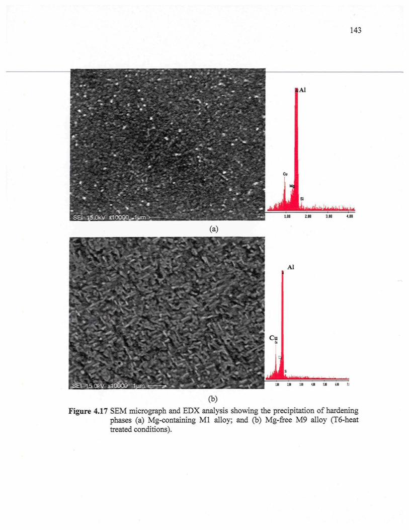
143
(b)Figure 4.17 SEM micrograph and EDX analysis showing the precipitation of hardening
phases (a) Mg-containing Ml alloy; and (b) Mg-free M9 alloy (T6-heattreated conditions).
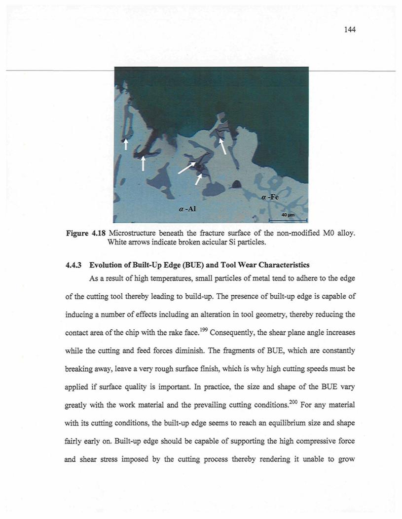
144
Figure 4.18 Microstructure beneath the fracture surface of the non-modified MO alloy.White arrows indicate broken acicular Si particles.
4.4.3 Evolution of Built-Up Edge (BUE) and Tool Wear Characteristics
As a result of high temperatures, small particles of metal tend to adhere to the edge
of the cutting tool thereby leading to build-up. The presence of built-up edge is capable of
inducing a number of effects including an alteration in tool geometry, thereby reducing the1 00
contact area of the chip with the rake face. Consequently, the shear plane angle increases
while the cutting and feed forces diminish. The fragments of BUE, which are constantly
breaking away, leave a very rough surface finish, which is why high cutting speeds must be
applied if surface quality is important. In practice, the size and shape of the BUE vary
greatly with the work material and the prevailing cutting conditions.200 For any material
with its cutting conditions, the built-up edge seems to reach an equilibrium size and shape
fairly early on. Built-up edge should be capable of supporting the high compressive force
and shear stress imposed by the cutting process thereby rendering it unable to grow
145
indefinitely. As the BUE grows in height and changes in shape, the stress system also
changes and parts of the built-up edge are broken away.201 Williams and Rollason202
suggest that the introduction of a second phase into a metal structure lowers its ductility,
allowing fracture somewhere along the rake face after severe deformation. The occurrence
of BUE is also affected by feed rate in uncut chip thickness, rake angle, tool material, and
lubrication. For example, the BUE disappears completely at high speeds in accordance with
the commercial purity of the aluminum alloy.
The tendency of each alloy to adhere and build up on the cutting edge of the tool
was detected through a high magnification top-view of the projected area looking at the
actual build-up on the drill; this was carried out using a toolmaker's microscope (TM-505
type) at a magnification of 30x. Figures 4.19 (a) and (b) show photographs of the progress
of edge build-up on the cutting-drill lip from the beginning to the end of drilling a 396 alloy
block casting. Table 4.4 also lists the effects of Fe-intermetallics on the evolution of BUE
width for the Ml, M3, and M4 alloys as drilling progresses. An analysis of the edge build-
up and an examination of the corresponding photographs indicate that there is little change
to be seen in the width of the BUE after drilling different numbers of holes. This fact may
be attributed to the amount of the deposit, or BUE, which gradually increases; when this
exceeds a critical size, however, it separates from the cutting face and adheres to the lower
surface of the chip. It is assumed that when the deposit reaches this critical size, it will slide
completely, or partly, off the cutting face under the action of a sufficiently strong lateral
force, and then subsequently be eliminated with the chip itself. Immediately after the
elimination of the existing deposit, a new deposit will begin to form; it will proceed to grow
146
gradually and will ultimately change or modify the tool geometry. It should be noted here
that the drilling tests were carried out at high cutting speeds of around 11000 rpm and a
high feed rate of about 1.117 m/min. Based upon research, it was reported that with the
higher rates of metal removal, i.e. at a higher speed or feed rate, a BUE will no longer be
discernible, since the transition from the built-up edge to the flow zone is strongly
influenced by both speed and feed; also the flow zone occurs in the range of cutting
conditions commonly encountered in industrial machining operations. It is not possible
to draw a firm conclusion here, however, because of the intermittent peeling off of the BUE
during drilling cycles.
A study of the build-up measurements for the Ml, M3, and M4 alloys also strongly
indicates that the width of the built-up edge has no clear-cut trend except for the fact that
the alloy containing sludge as a predominant phase in the M3 alloy shows a slightly lesser
build-up width compared to the Ml alloy; it should be noted that all the alloy composition
variations left a readily discernible deposit on the tool edge, even after only 90 holes were
drilled. Surprisingly, the addition of 0.25%Fe + 0.25%Mn (M3) or 0.5%Fe (M4) to the base
alloy, which would initially have been expected to reduce the build-up tendency through
the abrasive action of hard intermetallic phases, did not measurably reduce the built-up
width compared to the one observed for the Ml base alloy. These results are consistent
with the work of Jorstad14' 23 who reported that heavy elements such as iron, manganese,
and nickel have a negligible effect on microhardness and on the tool-edge build-up in 380
alloy die castings.
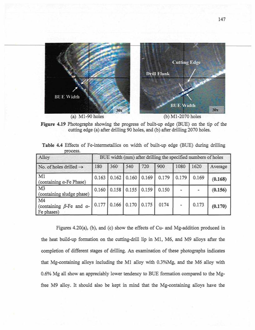
147
(a) Ml-90 holes (b) M1-2070 holes
Figure 4.19 Photographs showing the progress of built-up edge (BUE) on the tip of thecutting edge (a) after drilling 90 holes, and (b) after drilling 2070 holes.
Table 4.4 Effects of Fe-intermetallics on width of built-up edge (BUE) during drillingprocess.
Alloy
No. of holes drilled -»
Ml(containing a-Fe Phase)M3(containing sludge phase)M4(containing /?-Fe and a-Fe phases)
BUE width (mm) after drilling the specified numbers of holes
180
0.163
0.160
0.177
360
0.162
0.158
0.166
540
0.160
0.155
0.170
720
0.169
0.159
0.175
900
0.179
0.150
0174
1080
0.179
-
-
1620
0.169
-
0.173
Average
(0.168)
(0.156)
(0.170)
Figures 4.20(a), (b), and (c) show the effects of Cu- and Mg-addition produced in
the heat build-up formation on the cutting-drill lip in Ml, M6, and M9 alloys after the
completion of different stages of drilling. An examination of these photographs indicates
that Mg-containing alloys including the Ml alloy with 0.3%Mg, and the M6 alloy with
0.6% Mg all show an appreciably lower tendency to BUE formation compared to the Mg-
free M9 alloy. It should also be kept in mind that the Mg-containing alloys have the
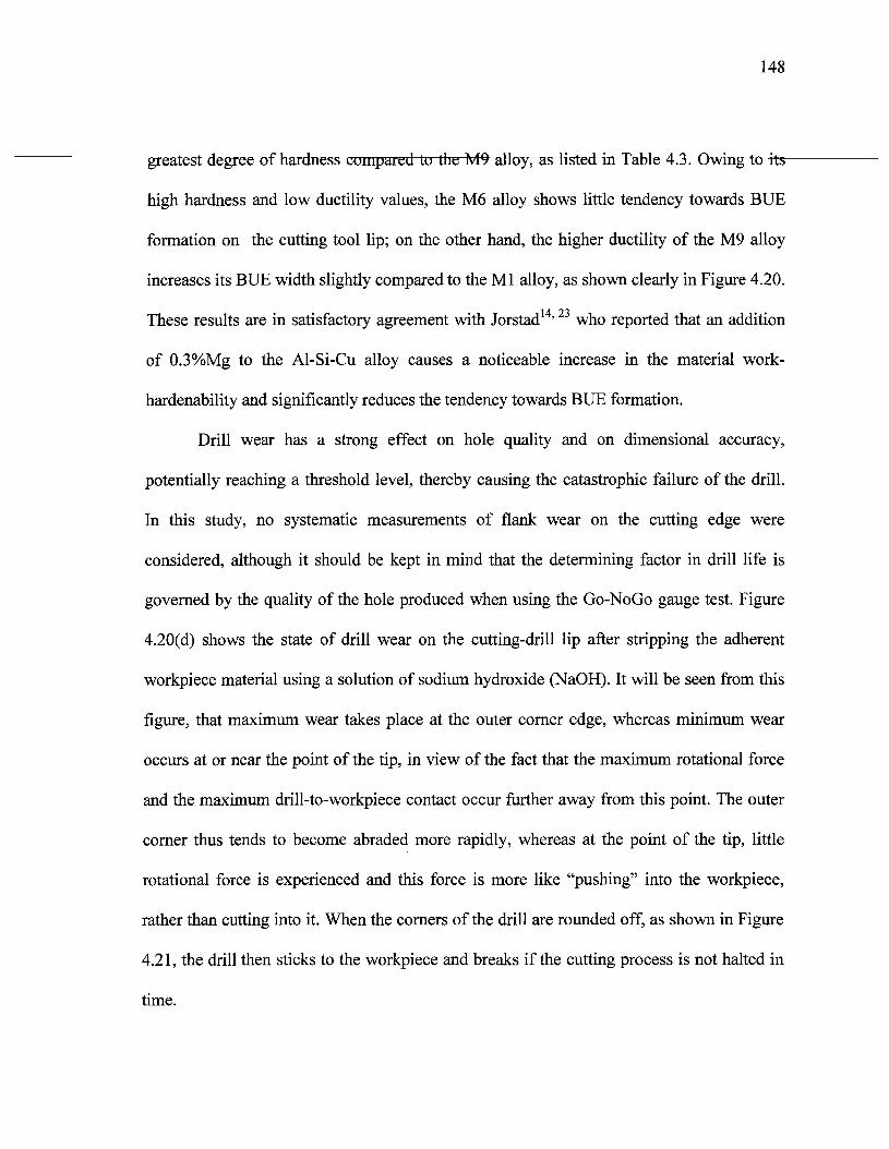
148
greatest degree of hardness compared to the M9 alloy, as listed in Table 4.3. Owing to its
high hardness and low ductility values, the M6 alloy shows little tendency towards BUE
formation on the cutting tool lip; on the other hand, the higher ductility of the M9 alloy
increases its BUE width slightly compared to the Ml alloy, as shown clearly in Figure 4.20.
These results are in satisfactory agreement with Jorstad14'23 who reported that an addition
of 0.3%Mg to the Al-Si-Cu alloy causes a noticeable increase in the material work-
hardenability and significantly reduces the tendency towards BUE formation.
Drill wear has a strong effect on hole quality and on dimensional accuracy,
potentially reaching a threshold level, thereby causing the catastrophic failure of the drill.
In this study, no systematic measurements of flank wear on the cutting edge were
considered, although it should be kept in mind that the determining factor in drill life is
governed by the quality of the hole produced when using the Go-NoGo gauge test. Figure
4.20(d) shows the state of drill wear on the cutting-drill lip after stripping the adherent
workpiece material using a solution of sodium hydroxide (NaOH). It will be seen from this
figure, that maximum wear takes place at the outer corner edge, whereas minimum wear
occurs at or near the point of the tip, in view of the fact that the maximum rotational force
and the maximum drill-to-workpiece contact occur further away from this point. The outer
corner thus tends to become abraded more rapidly, whereas at the point of the tip, little
rotational force is experienced and this force is more like "pushing" into the workpiece,
rather than cutting into it. When the corners of the drill are rounded off, as shown in Figure
4.21, the drill then sticks to the workpiece and breaks if the cutting process is not halted in
time.
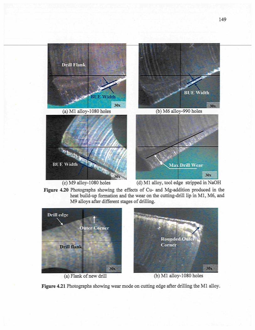
149
(a)Mlalloy-1080holes (b) M6 alloy-990 holes
Mill Wear
I 30x
(c) M9 alloy-1080 holes (d) M1 alloy, tool edge stripped in NaOHFigure 4.20 Photographs showing the effects of Cu- and Mg-addition produced in the
heat build-up formation and the wear on the cutting-drill lip in Ml, M6, andM9 alloys after different stages of drilling.
(a) Flank of new drill (b) Ml alloy-1080 holes
Figure 4.21 Photographs showing wear mode on cutting edge after drilling the Ml alloy.
150
Tool wear is a critical topic affecting the economics of machining, especially in
connection with the tapping process, since it is one of the last operations to be performed
within most operation sequences.203 It has been reported that the total tapping load consists
of the base load and a chip-packing load. The base load results from chip formation and
tool/workpiece friction, whereas the chip-packing load is the result of chip clogging in the
flutes, and is random in nature. It should be noted that the chip-packing load may be many
times that of the base load, depending on tap geometries and the machining conditions.204
In the present study, the tapping tests (M8 x 1.25) were performed in the blind holes
at low cutting speeds of about 9.57 m/min; measuring the tool wear on tap tools, however,
represents an extremely challenging task. There are several edges whose flanks are not
entirely flat; similarly, the rake faces are also not flat; thus a Go-NoGo gauge criterion was
required to assess tap life. The main wear mechanism observed was adhesion, although
some abrasion may also have occurred during the tapping of the sludge-containing M3
alloy, while the main type of wear was flank wear. The adhesion of material to the relief
face of the taps was the main cause of the ending of tool life. The material adhered mainly
to the last edges of the chamfered part and to the first edges of the cylindrical part, as
shown in Figure 4.22 (b) and (c); this observation may be attributed to the fact that these
edges are responsible for cutting the last and extremely small depth-of-cut, at a relatively
low speed, high pressure, and high temperature. The adhesion was not exactly the same as a
built-up edge (BUE), but it seemed to follow the same mechanism as that for the building
and the breaking of the tap. Figures 4.23 show photographs of broken taps; as is evident,
the breakage occurred at the chamfered part of the tap in view of the fact that it generates a
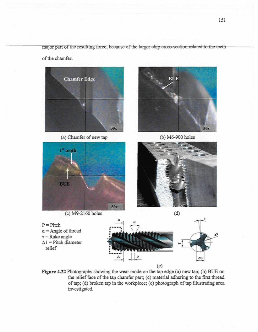
151
major parrôTfibie~fë"sulting^brce; because ofthelargerchipcross-section relatedto-the-teethr
of the chamfer.
(a) Chamfer of new tap (b) M6-900 holes
P = Pitcha = Angle of thready = Rake angleAl = Pitch diameter
relief
Figure 4.22 Photographs showing the wear mode on the tap edge (a) new tap; (b) BUE onthe relief face of the tap chamfer part; (c) material adhering to the first threadof tap; (d) broken tap in the workpiece; (e) photograph of tap illustrating areainvestigated.
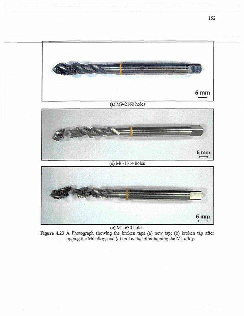
152
(e) Ml-630 holesFigure 4.23 A Photograph showing the broken taps (a) new tap; (b) broken tap after
tapping the M6 alloy; and (c) broken tap after tapping the Ml alloy.
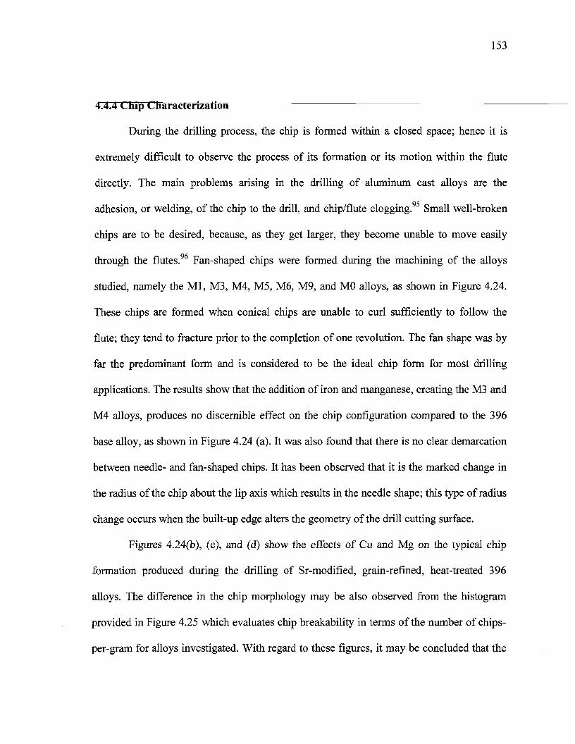
153
4.4.4 Chip Characterization
During the drilling process, the chip is formed within a closed space; hence it is
extremely difficult to observe the process of its formation or its motion within the flute
directly. The main problems arising in the drilling of aluminum cast alloys are the
adhesion, or welding, of the chip to the drill, and chip/flute clogging. Small well-broken
chips are to be desired, because, as they get larger, they become unable to move easily
through the flutes.96 Fan-shaped chips were formed during the machining of the alloys
studied, namely the Ml, M3, M4, M5, M6, M9, and MO alloys, as shown in Figure 4.24.
These chips are formed when conical chips are unable to curl sufficiently to follow the
flute; they tend to fracture prior to the completion of one revolution. The fan shape was by
far the predominant form and is considered to be the ideal chip form for most drilling
applications. The results show that the addition of iron and manganese, creating the M3 and
M4 alloys, produces no discernible effect on the chip configuration compared to the 396
base alloy, as shown in Figure 4.24 (a). It was also found that there is no clear demarcation
between needle- and fan-shaped chips. It has been observed that it is the marked change in
the radius of the chip about the lip axis which results in the needle shape; this type of radius
change occurs when the built-up edge alters the geometry of the drill cutting surface.
Figures 4.24(b), (c), and (d) show the effects of Cu and Mg on the typical chip
formation produced during the drilling of Sr-modified, grain-refined, heat-treated 396
alloys. The difference in the chip morphology may be also observed from the histogram
provided in Figure 4.25 which evaluates chip breakability in terms of the number of chips-
per-gram for alloys investigated. With regard to these figures, it may be concluded that the
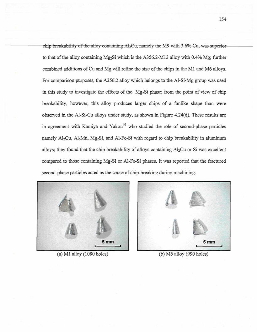
154
chip breakability of the alloy contamingAhCu, namely the M9 with 3.6% Cu, was superior-
to that of the alloy containing Mg2Si which is the A356.2-M13 alloy with 0.4% Mg; further
combined additions of Cu and Mg will refine the size of the chips in the Ml and M6 alloys.
For comparison purposes, the A356.2 alloy which belongs to the Al-Si-Mg group was used
in this study to investigate the effects of the Mg2Si phase; from the point of view of chip
breakability, however, this alloy produces larger chips of a fanlike shape than were
observed in the Al-Si-Cu alloys under study, as shown in Figure 4.24(d). These results are
in agreement with Kamiya and Yakou49 who studied the role of second-phase particles
namely Al2Cu, AlôMn, Mg2Si, and Al-Fe-Si with regard to chip breakability in aluminum
alloys; they found that the chip breakability of alloys containing Al2Cu or Si was excellent
compared to those containing Mg2Si or Al-Fe-Si phases. It was reported that the fractured
second-phase particles acted as the cause of chip-breaking during machining.
(a) Ml alloy (1080 holes) (b) M6 alloy (990 holes)
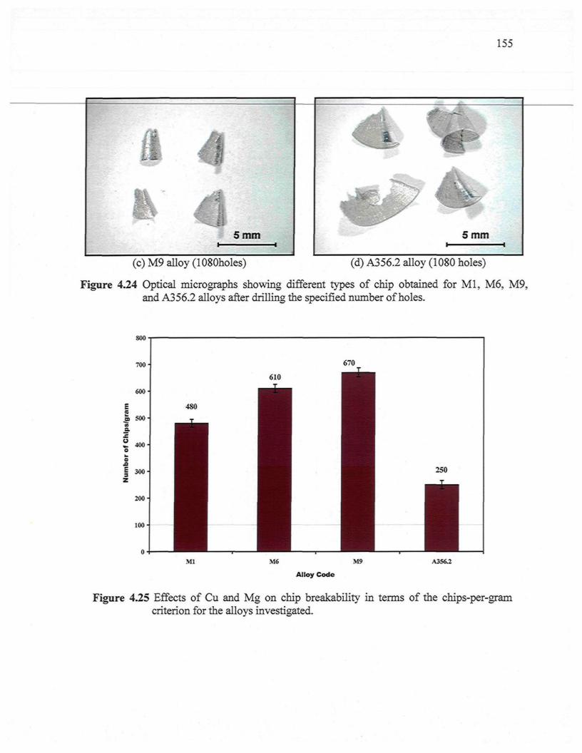
(c)M9 alloy (1080holes)
155
(d) A356.2 alloy (1080 holes)
Figure 4.24 Optical micrographs showing different types of chip obtained for Ml, M6, M9,and A356.2 alloys after drilling the specified number of holes.
soo
M9 A3S6.2
Alloy Code
Figure 4.25 Effects of Cu and Mg on chip breakability in terms of the chips-per-gramcriterion for the alloys investigated.
CHAPTER 5
EFFECTS OF FREE-CUTTING ELEMENTS ON THEMACHINABILITY OF Al-Si-Cu-Mg CAST ALLOYS
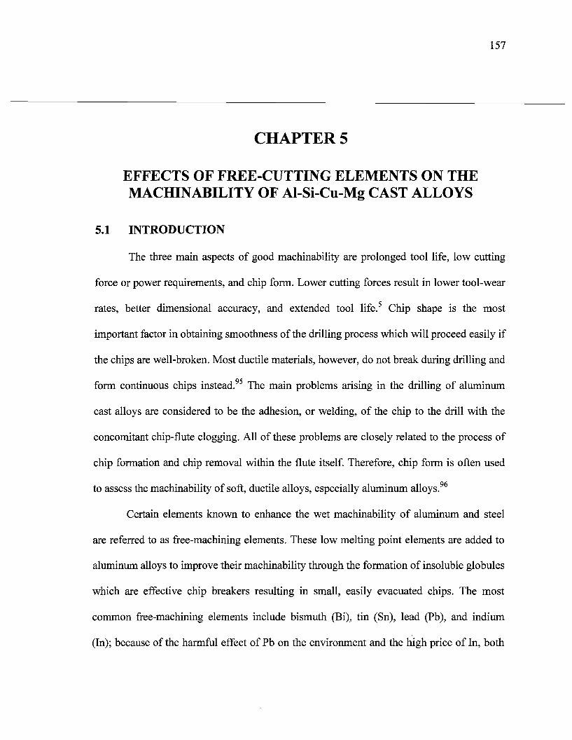
157
CHAPTER 5
EFFECTS OF FREE-CUTTING ELEMENTS ON THEMACHINABILITY OF Al-Si-Cu-Mg CAST ALLOYS
5.1 INTRODUCTION
The three main aspects of good machinability are prolonged tool life, low cutting
force or power requirements, and chip form. Lower cutting forces result in lower tool-wear
rates, better dimensional accuracy, and extended tool life.5 Chip shape is the most
important factor in obtaining smoothness of the drilling process which will proceed easily if
the chips are well-broken. Most ductile materials, however, do not break during drilling and
form continuous chips instead.95 The main problems arising in the drilling of aluminum
cast alloys are considered to be the adhesion, or welding, of the chip to the drill with the
concomitant chip-flute clogging. All of these problems are closely related to the process of
chip formation and chip removal within the flute itself. Therefore, chip form is often used
to assess the machinability of soft, ductile alloys, especially aluminum alloys.96
Certain elements known to enhance the wet machinability of aluminum and steel
are referred to as free-machining elements. These low melting point elements are added to
aluminum alloys to improve their machinability through the formation of insoluble globules
which are effective chip breakers resulting in small, easily evacuated chips. The most
common free-machining elements include bismuth (Bi), tin (Sn), lead (Pb), and indium
(In); because of the harmful effect of Pb on the environment and the high price of In, both
158
Bi and Sn are the most preferable of choices as free-machining elements.205 There are a
number of studies on the machinability of alloys containing low melting-point elements
which address Al-Si alloy castings; these have revealed that the dry drilling performance of
a cast Al alloy B319 was improved when these new elements, namely Bi, Sn, and Pb, were
added.53 Tin was found to be more effective than Bi for improving dry machinability,73
although Bi continues to be preferred over Sn when considering the mechanical properties
in the alloy and the hot cracking in the casting.
Previous studies have indicated that the performance of Bi and Sn in Al alloys differ
in several ways: (i) the solidification of the embedded Bi in an Al alloy is found to take
place over a wide temperature range at a contact angle between 72 ° and 80°,206 although Sn
displayed wetting at the Al grain boundaries;207 (ii) Bi does not display a unique orientation
relationship with the Al, whereas Sn possesses a well-defined orientation relationship with
it;70 (iii) Bi is distributed as inclusions located at the Al grain boundaries and within the
grains, but most of the Sn resides in the Al boundaries, primarily at triple junctions; (iv) Sn
reduces the hardness and tensile strength, displaying a high tendency toward the formation
of Mg2Sn, because of the high diffusivity of Sn in the Al matrix.208
It should be mentioned here that most of the work carried out to date on free-
machining aluminum alloys has involved wrought alloys; only a few studies have dealt
with cast alloys. Consequently, in view of the above, the purpose of this chapter is to
examine the near-eutectic Al-Si cast alloys containing ~11% Si, namely the 396 alloys, as
a basis for understanding the role of the three free-machining elements, Pb, Bi, and Sn,
when included in more complex systems for use in industrial applications. In this chapter,
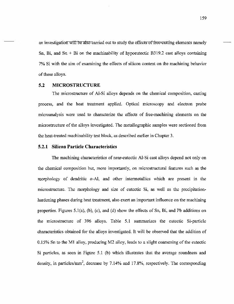
159
an investigation will be also carried out to study the effects of free-cutting elements namely
Sn, Bi, and Sn + Bi on the machinability of hypoeutectic B319.2 cast alloys containing
7% Si with the aim of examining the effects of silicon content on the machining behavior
of these alloys.
5.2 MICROSTRUCTURE
The microstructure of Al-Si alloys depends on the chemical composition, casting
process, and the heat treatment applied. Optical microscopy and electron probe
microanalysis were used to characterize the effects of free-machining elements on the
microstructure of the alloys investigated. The metallographic samples were sectioned from
the heat-treated machinability test block, as described earlier in Chapter 3.
5.2.1 Silicon Particle Characteristics
The machining characteristics of near-eutectic Al-Si cast alloys depend not only on
the chemical composition but, more importantly, on microstructural features such as the
morphology of dendritic ot-Al, and other intermetallics which are present in the
microstructure. The morphology and size of eutectic Si, as well as the precipitation-
hardening phases during heat treatment, also exert an important influence on the machining
properties. Figures 5.1 (a), (b), (c), and (d) show the effects of Sn, Bi, and Pb additions on
the microstructure of 396 alloys. Table 5.1 summarizes the eutectic Si-particle
characteristics obtained for the alloys investigated. It will be observed that the addition of
0.15% Sn to the Ml alloy, producing M2 alloy, leads to a slight coarsening of the eutectic
Si particles, as seen in Figure 5.1 (b) which illustrates that the average roundness and
density, in particles/mm2, decrease by 7.14% and 17.8%, respectively. The corresponding
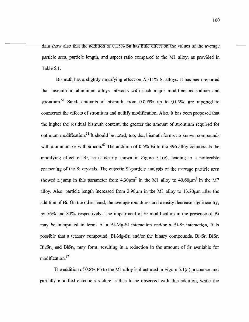
160
data show also that the addition of U.I5% Sn has little effect on the values of the average
particle area, particle length, and aspect ratio compared to the Ml alloy, as provided in
Table 5.1.
Bismuth has a slightly modifying effect on Al-11% Si alloys. It has been reported
that bismuth in aluminum alloys interacts with such major modifiers as sodium and
strontium.51 Small amounts of bismuth, from 0.005% up to 0.05%, are reported to
counteract the effects of strontium and nullify modification. Also, it has been proposed that
the higher the residual bismuth content, the greater the amount of strontium required for
optimum modification. It should be noted, too, that bismuth forms no known compounds
with aluminum or with silicon.60 The addition of 0.5% Bi to the 396 alloy counteracts the
modifying effect of Sr, as is clearly shown in Figure 5.1(c), leading to a noticeable
coarsening of the Si crystals. The eutectic Si-particle analysis of the average particle area
showed a jump in this parameter from 4.30um2 in the Ml alloy to 40.60um2 in the M7
alloy. Also, particle length increased from 2.96um in the Ml alloy to 13.30um after the
addition of Bi. On the other hand, the average roundness and density decrease significantly,
by 56% and 84%, respectively. The impairment of Sr modification in the presence of Bi
may be interpreted in terms of a Bi-Mg-Si interaction and/or a Bi-Sr interaction. It is
possible that a ternary compound, Bi2Mg2Sr, and/or the binary compounds, BiaSr, BiSr,
Bi2Sr3j and BiSr2, may form, resulting in a reduction in the amount of Sr available for
modification.67
The addition of 0.8% Pb to the Ml alloy is illustrated in Figure 5.1(d); a coarser and
partially modified eutectic structure is thus to be observed with this addition, while the
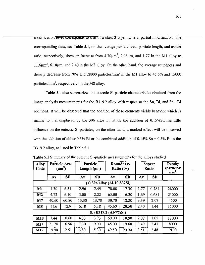
161
modification level corresponds to that of a class 3 type, namely, partial modification. The
corresponding data, see Table 5.1, on the average particle area, particle length, and aspect
ratio, respectively, show an increase from 4.30um2, 2.96(xm, and 1.77 in the Ml alloy to
1 l.ô^im2, 6.18um, and 2.40 in the M8 alloy. On the other hand, the average roundness and
density decrease from 70% and 28000 particles/mm2 in the Ml alloy to 45.6% and 15000
particles/mm2, respectively, in the M8 alloy.
Table 5.1 also summarizes the eutectic Si-particle characteristics obtained from the
image analysis measurements for the B319.2 alloy with respect to the Sn, Bi, and Sn +Bi
additions. It will be observed that the addition of these elements yields behavior which is
similar to that displayed by the 396 alloy in which the addition of 0.15%Sn has little
influence on the eutectic Si particles; on the other hand, a marked effect will be observed
with the addition of either 0.5% Bi or the combined addition of 0.15% Sn + 0.5% Bi to the
B319.2 alloy, as listed in Table 5.1.
Table 5.1 Summary of the eutectic
AlloyCode
Particle Area(jim2)
Av SD
Si-particle measurements for the alloys studied
ParticleLength (jim)
Av SD
RoundnessRatio (%)
Av SD
AspectRatio
Av SD
Density(particles/
mm )
(a) 396 alloy (Al-10.8%Si)
Ml
M2
M7
M8
4.30
4.72
40.60
11.6
6.51
6.10
60.80
12.9
2.96
3.00
13.30
6.18
2.49
2.22
13.70
5.18
70.00
65.00
30.70
45.60
17.30
16.20
18.20
20.50
1.77
1.69
3.39
2.40
0.784
0.681
2.07
1.44
28000
23000
4500
15000
(b) B319.2 (Al-7%Si)
M10
Mil
M12
7.44
21.20
19.90
10.60
16.90
12.51
4.33
7.30
6.80
3.73
9.90
5.30
60.00
45.00
49.50
18.90
19.60
20.90
2.07
3.49
3.51
1.05
2.43
2.48
12000
8000
9100
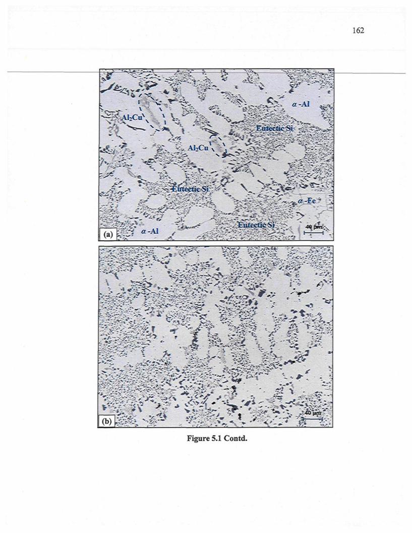
162
Figure 5.1 Contd.
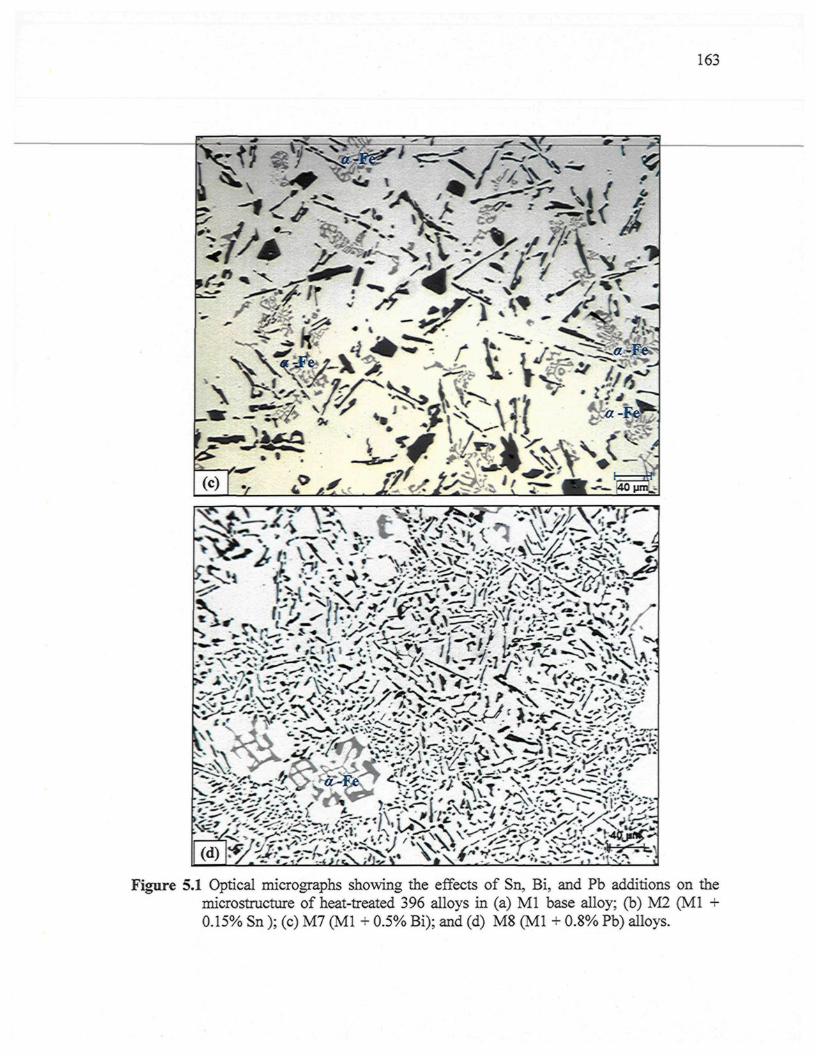
163
Figure 5.1 Optical micrographs showing the effects of Sn, Bi, and Pb additions on themicrostructure of heat-treated 396 alloys in (a) Ml base alloy; (b) M2 (Ml +0.15% Sn ); (c) M7 (Ml + 0.5% Bi); and (d) M8 (Ml + 0.8% Pb) alloys.
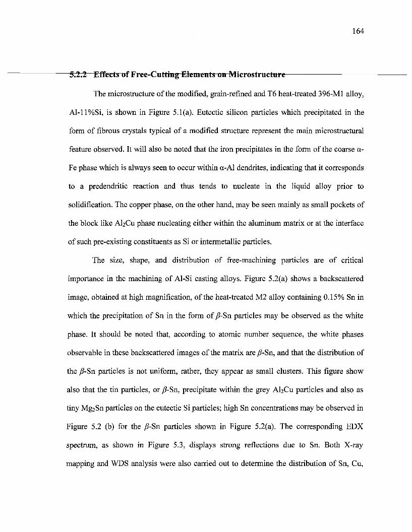
164
5.2.2 Effects of Free-Cutting Elements on Microstructure
The microstructure of the modified, grain-refined and T6 heat-treated 396-M1 alloy,
Al-ll%Si, is shown in Figure 5.1 (a). Eutectic silicon particles which precipitated in the
form of fibrous crystals typical of a modified structure represent the main microstructural
feature observed. It will also be noted that the iron precipitates in the form of the coarse a-
Fe phase which is always seen to occur within a-Al dendrites, indicating that it corresponds
to a predendritic reaction and thus tends to nucleate in the liquid alloy prior to
solidification. The copper phase, on the other hand, may be seen mainly as small pockets of
the block like A^Cu phase nucleating either within the aluminum matrix or at the interface
of such pre-existing constituents as Si or intermetallic particles.
The size, shape, and distribution of free-machining particles are of critical
importance in the machining of Al-Si casting alloys. Figure 5.2(a) shows a backscattered
image, obtained at high magnification, of the heat-treated M2 alloy containing 0.15% Sn in
which the precipitation of Sn in the form of /?-Sn particles may be observed as the white
phase. It should be noted that, according to atomic number sequence, the white phases
observable in these backscattered images of the matrix are /?-Sn, and that the distribution of
the /?-Sn particles is not uniform, rather, they appear as small clusters. This figure show
also that the tin particles, or /?-Sn, precipitate within the grey A^Cu particles and also as
tiny Mg2Sn particles on the eutectic Si particles; high Sn concentrations may be observed in
Figure 5.2 (b) for the /?-Sn particles shown in Figure 5.2(a). The corresponding EDX
spectrum, as shown in Figure 5.3, displays strong reflections due to Sn. Both X-ray
mapping and WDS analysis were also carried out to determine the distribution of Sn, Cu,
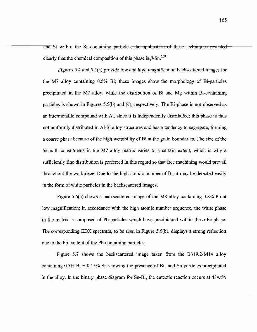
165
and Si within the Sn-coiilaining particles; the application of these techniques revealed
clearly that the chemical composition of this phase is /?-Sn.209
Figures 5.4 and 5.5(a) provide low and high magnification backscattered images for
the M7 alloy containing 0.5% Bi; these images show the morphology of Bi-particles
precipitated in the M7 alloy, while the distribution of Bi and Mg within Bi-containing
particles is shown in Figures 5.5(b) and (c), respectively. The Bi-phase is not observed as
an intermetallic compound with Al, since it is independently distributed; this phase is thus
not uniformly distributed in Al-Si alloy structures and has a tendency to segregate, forming
a coarse phase because of the high wettability of Bi at the grain boundaries. The size of the
bismuth constituents in the M7 alloy matrix varies to a certain extent, which is why a
sufficiently fine distribution is preferred in this regard so that free machining would prevail
throughout the workpiece. Due to the high atomic number of Bi, it may be detected easily
in the form of white particles in the backscattered images.
Figure 5.6(a) shows a backscattered image of the M8 alloy containing 0.8% Pb at
low magnification; in accordance with the high atomic number sequence, the white phase
in the matrix is composed of Pb-particles which have precipitated within the a-Fe phase.
The corresponding EDX spectrum, to be seen in Figure 5.6(b), displays a strong reflection
due to the Pb-content of the Pb-containing particles.
Figure 5.7 shows the backscattered image taken from the B319.2-M14 alloy
containing 0.5% Bi + 0.15% Sn showing the presence of Bi- and Sn-particles precipitated
in the alloy. In the binary phase diagram for Sn-Bi, the eutectic reaction occurs at 43wt%
166
idenec for the formatioa-of any
eutectic compound between Bi and Sn in the B319.2-M14 alloy.
El
COMPXH8301
! Ms^Sni
AI2Cu
19^»15.8KU xi ,see
Figure 5.2 (a) High magnification backscattered image of the M2 alloy showing precipitation ofyff-Sn, (b) X-ray image of Sn distribution for the same particles illustrated in (a).
Figure 5.3 EDX spectrum corresponding to ^-Sn particles observed in M2 alloy containing0.15% Sn.
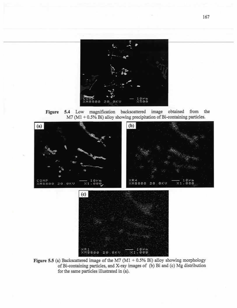
167
Figure 5.4 Low magnification backscattered image obtained from theM7 (Ml + 0.5% Bi) alloy showing precipitation of Bi-containing particles.
Figure 5.5 (a) Backscattered image of the M7 (Ml + 0.5% Bi) alloy showing morphologyof Bi-containing particles, and X-ray images of (b) Bi and (c) Mg distributionfor the same particles illustrated in (a).
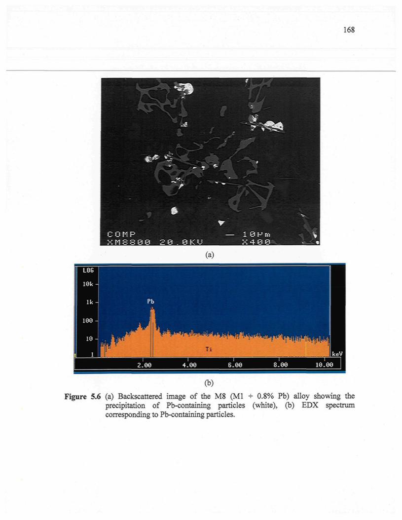
168
(a)
Figure 5.6 (a) Backscattered image of the M8 (Ml + 0.8% Pb) alloy showing theprecipitation of Pb-containing particles (white), (b) EDX spectrumcorresponding to Pb-containing particles.
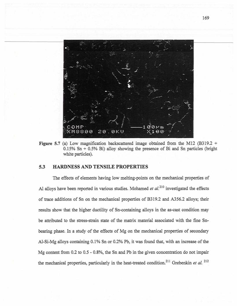
169
Figure 5.7 (a) Low magnification backscattered image obtained from the M12 (B319.2 +0.15% Sn + 0.5% Bi) alloy showing the presence of Bi and Sn particles (brightwhite particles).
5.3 HARDNESS AND TENSILE PROPERTIES
The effects of elements having low melting-points on the mechanical properties of
Al alloys have been reported in various studies. Mohamed et al.2ï0 investigated the effects
of trace additions of Sn on the mechanical properties of B319.2 and A356.2 alloys; their
results show that the higher ductility of Sn-containing alloys in the as-cast condition may
be attributed to the stress-strain state of the matrix material associated with the fine Sn-
bearing phase. In a study of the effects of Mg on the mechanical properties of secondary
Al-Si-Mg alloys containing 0.1% Sn or 0.2% Pb, it was found that, with an increase of the
Mg content from 0.2 to 0.5 - 0.8%, the Sn and Pb in the given concentration do not impair
the mechanical properties, particularly in the heat-treated condition.211 Grebenkin et al. 2X1
170
"indicated that Su and Pb are analogs of Si in electron distribution; these clcmcnts-afe-
capable of replacing Si in compounds with Mg which prevents the formation of Mg2Si or
AlxMg5Cu4Si4 hardening phases in Al-Si alloys.
Table 5.2 provides the relevant data relating to T6 heat-treated mechanical
properties; these include the hardness (BHN), yield strength (YS), ultimate tensile strength
(UTS), and percent elongation (%E1) of the Sr-modified 396 alloys after the addition of Sn,
Bi, and Pb. The corresponding hardness data indicate that the M7 containing 0.5% Bi has
the highest hardness values compared to the other alloys. On the other hand, the presence of
0.5% Bi in the M7 alloy results in a decrease of YS, UTS, and %E1 by 10%, 9%, and 34%,
respectively. The significant reduction observed in the ductility value of the M7 alloy may
be attributed to the effects of the addition of Bi in transforming the structure of the Ml base
alloy from a well-modified to a non-modified structure, as shown earlier in the discussion
on microstructure. It is important to mention here that the reduction caused in the tensile
properties of the M7 alloy, compared to the Ml alloy, may be explained in terms of the Bi-
Mg interaction which consumes the Mg available for the precipitation of Mg-hardening
phases. It was reported that Bi is a surface active element, and its accumulation near
intermetallic and Si particles may reduce the energy of the system. Most of the Bi particles
were connected to intermetallic phases and Si phases, which has a deteriorating effect on
the mechanical properties of the alloys.213 It will be observed that the addition of 0.15% Sn
causes a marginal reduction in either the hardness or the tensile properties of the 396-M1
alloy. The same results were observed in the case of the addition of 0.8% Pb. Table 5.2 also
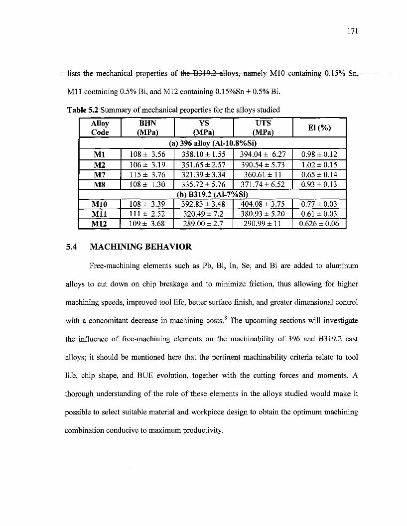
171
lists the mechanical properties of the B319.2 alloys, namely M10 containing 0.15% Sn,
Ml 1 containing 0.5% Bi, and M12 containing 0.15%Sn + 0.5% Bi.
Table 5.2 Summary of mechanical properties for the alloys studied
AlloyCode
MlM2M7M8
M10MilM12
BHN(MPa)
108 ±106 ±115 ±108 ±
108 ±111±109 ±
3.563.193.761.30
3.392.523.68
YS(MPa)
UTS(MPa)
(a) 396 alloy (Al-10.8%Si)358.10 ±1.55351.65 ±2.57321.39 ±3.34335.72 ±5.76
394.04 ± 6.27390.54 ±5.73360.61 ±11
371.74 ±6.52(b) B319.2 (Al-7%Si)
392.83 ± 3.48320.49 ± 7.2289.00 ± 2.7
404.08 ± 3.75380.93 ± 5.20290.99 ±11
El(1
0.98 ±1.02 ±0.65 ±0.93 ±
0.77 ±0.61 ±
0.626 ±
/o)
0.120.150.140.13
0.030.030.06
5.4 MACHINING BEHAVIOR
Free-machining elements such as Pb, Bi, In, Se, and Bi are added to aluminum
alloys to cut down on chip breakage and to minimize friction, thus allowing for higher
machining speeds, improved tool life, better surface finish, and greater dimensional control
Q
with a concomitant decrease in machining costs. The upcoming sections will investigate
the influence of free-machining elements on the machinability of 396 and B319.2 cast
alloys; it should be mentioned here that the pertinent machinability criteria relate to tool
life, chip shape, and BUE evolution, together with the cutting forces and moments. A
thorough understanding of the role of these elements in the alloys studied would make it
possible to select suitable material and workpiece design to obtain the optimum machining
combination conducive to maximum productivity.
172
5.4.1.1 396 Alloys (Al-11% Si)
A number of Sr-modified, grain-refined, and T6 heat-treated 396 alloys were
selected in order to study the effects of the addition of free-machining elements: (i) on the
mean total drilling force, (ii) on the mean total drilling moment, and (iii) on the mean
drilling power, when based on the mean value of 90 holes; these free-machining elements,
include Sn, Bi, and Pb. The alloys in question were individually represented by the 396
base alloy, coded Ml; 396 + 0.15% Sn, coded M2; 396 + 0.5% Bi, coded M7; and 396 +
0.8% Pb, coded M8, yielding hardness values of 108, 106, 115, and 108 BHN, respectively.
The results obtained from the drilling tests reveal that the mean total drilling force,
the mean total drilling moment, and the mean drilling power all increase as the number of
holes drilled increases; this form of increase is clear from Figures 5.8(a), (b), and (c),
respectively. It should also be noted that the greatest fluctuation values in the total drilling
forces can generally be observed with a higher number of holes drilled; this analysis agrees
with the mean total drilling moment and the mean drilling power of the Ml alloy. The
drilling data also suggest that the effects of the addition of free-machining elements on
machinability criteria is that the reduction in drilling power is more pronounced than is the
reduction in total drilling forces. This observation may be explained by the fact that the
drilling power responses are mostly susceptible to chip clogging in drill flutes 117 whereas
drilling force is vulnerable to changes in the geometry of the cutting edges.5
Figures 5.8(a), (b), and (c) show that the addition of 0.5% Bi to the Ml alloy,
thereby creating M7 alloy, improves alloy machinability by lowering the mean total
173
drilling forces and moments, as well as the mean drilling power compared to the Ml alloy.
The M7 alloy generated an average of 17% lower drilling forces ranging from 13% to 21%,
and exhibited an average of 20% lower drilling moment ranging from 24% to 16%, as well
as an average 28% less drilling power ranging from 30% to 25% compared to the Ml alloy
over the evaluation period of 630 holes. By contrast, the presence of 0.5% Bi in the 396
alloys causes a deterioration in drill life, whereas the drill life of the Ml Bi-free alloy
decreases from 2160 holes/drill to only 630 holes/drill in the Bi-containing M7 alloy,
corresponding to a reduction in drill life by 71%, as shown in Figure 5.9. It may be
concluded, then, that the Bi-containing M7 alloys exerts a negative influence on drill life,
although its is observed to exhibit lower drilling forces, moment, and power compared to
the Ml base alloy.
The addition of Sn to 396 casting alloys in small but effective amounts of-0.15%,
thereby producing the M2 alloy, significantly improves the machinability characteristics of
these alloys with respect to mean drilling power; which decreases by an average 17%
ranging from 20% to 13% compared to the Sn-free Ml alloy, as shown in Figure 5.8(c). On
the other hand, the addition of 0.15% Sn to the Ml alloy has some slight effect in
decreasing the mean total drilling force as well as the mean total drilling moment which
decrease by an average 7% and 6%, respectively, over the evaluation period of 2160 holes,
as shown in Figures 5.8(a) and (b). During drilling tests, it was also found that the M2 alloy
containing 0.15% Sn displayed the same number of holes drilled in the Ml base alloy
having 2160 holes/drill, followed by the M8 alloy containing 0.8% Pb having 1512
holes/drill, and finally the M7 alloy containing 0.5% Bi, which displayed a noticeable
174
shortening of drill life having 630 holes/drill. Thus, the addition of 0.15% Sn to the 396~
alloys has a positive effect on drill life since the Sn-containing alloy yields the longest drill
life, i.e. three-and-a-half times that of the Bi-containing alloy, and one-and-a-half times that
of the Pb-containing alloy. It should be mentioned here that the Sn-containing M2 alloy
requires much higher values of drilling force, moment, and power than are needed by the
Bi- and Pb-containing M7, and M8 alloys, respectively.
Lead (Pb) was used for the purposes of this study because it has already been
recognized as a free-machining element. It is considered that the addition of Pb to
aluminum alloys is the method most adequate for improving their machinability values; Pb,
however, is not a suitable choice as an additive based on environmental concerns. Recent
work has involved replacing Pb in free-machining wrought alloys with more
environmentally friendly additives such as the elements Sn or Bi.52 In this study, the free-
machining M8 alloy containing 0.8% Pb displays a reduction in the drilling force, the
drilling moment, and in particular the drilling power which decreased by an average of 80%
compared to the Pb-free Ml alloy, as shown in Figure 5.8(c).
The above results show that the machinability of the alloys under investigation was
significantly improved by adding small amounts of free-machining elements to the alloy.
The effects of free-machining elements may be interpreted by an examination of the alloy
microstructure as discussed previously in section 5.2.2 together with an analysis of the
existing bibliographic data regarding the effects of these elements on the machinability of
the alloys. Thus, the factors involved in reducing the drilling force and moment for the free-
machining alloys may be considered in terms of the following: (i) precipitation of free-
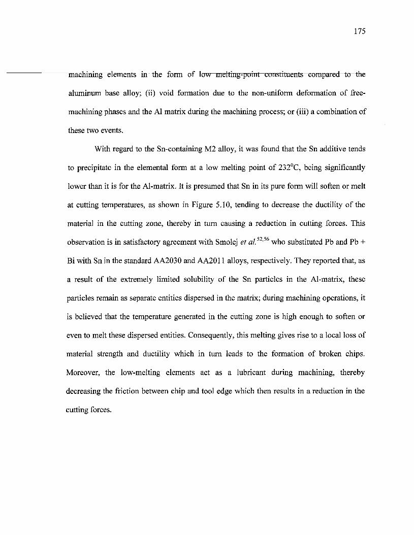
175
machining elements in the form of low melting-point constituents compared to the
aluminum base alloy; (ii) void formation due to the non-uniform deformation of free-
machining phases and the Al matrix during the machining process; or (iii) a combination of
these two events.
With regard to the Sn-containing M2 alloy, it was found that the Sn additive tends
to precipitate in the elemental form at a low melting point of 232°C, being significantly
lower than it is for the Al-matrix. It is presumed that Sn in its pure form will soften or melt
at cutting temperatures, as shown in Figure 5.10, tending to decrease the ductility of the
material in the cutting zone, thereby in turn causing a reduction in cutting forces. This
observation is in satisfactory agreement with Smolej et al.52'56 who substituted Pb and Pb +
Bi with Sn in the standard AA2030 and AA2011 alloys, respectively. They reported that, as
a result of the extremely limited solubility of the Sn particles in the Al-matrix, these
particles remain as separate entities dispersed in the matrix; during machining operations, it
is believed that the temperature generated in the cutting zone is high enough to soften or
even to melt these dispersed entities. Consequently, this melting gives rise to a local loss of
material strength and ductility which in turn leads to the formation of broken chips.
Moreover, the low-melting elements act as a lubricant during machining, thereby
decreasing the friction between chip and tool edge which then results in a reduction in the
cutting forces.
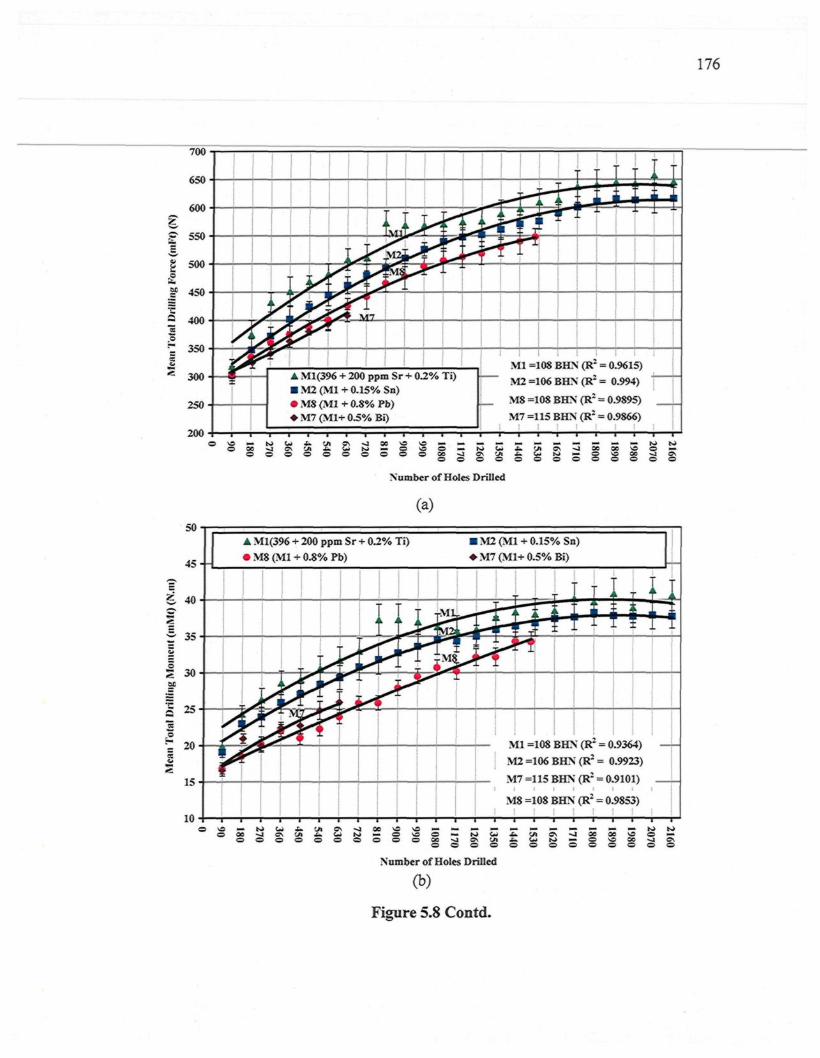
176
350
300
250
200
A Ml(396 + 200 ppm Sr + 0.2% Ti)� M2 (Ml + 0.15% Sn)� M8 (Ml + 0.8% Pb)� M7 (M1+ 0.5% Bi)
LMl =108 B H N (R2 = 0.9615)
M 2 =106 B H N (R2 = 0.994)
M 8 =108 B H N (R2 = 0.9895)
M 7 =115 B H N (R2 = 0.9866)
oo
0 �
1 5= § 2
Number of Holes Drilled
a\ -J oc
S 5 S
(a)
45- -
� Ml(396 + 200 ppm Sr + 0.2% Ti)� M8 (Ml + 0.8% Pb)
� M2 (Ml + 0.15% Sn)� M7 (M1+ 0.5% Bi)
M2 =106 BHN (R' = 0.9923)
M7 =115 BHN (R2 = 0.9101)
M8 =108 BHN (R2 = 0.9853)
vs � t s > u « . c n o \ ^ i o o o oo o o o o o o o o o
O � N> UiO* f j � O
� K» N>VS O �OC %] 9\O O O
Number of Holes Drilled
(b)
Figure 5.8 Contd.
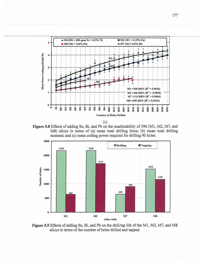
177
� Ml(396 + 200 ppm Sr + 0.2% Ti)� M$ (Ml + 0.8% Pb)
� M2 (Ml + 0.15% Sn)� M7 (M1+ 0.5% Bi)
Ml =108 BHN (R2 = 0.9625)
M 2 =106 BHN (R2 = 0.9969)
M 7 =115 BHN (R2 = 0.9964)
M 8 =108 BHN (R2 = 0.9434)
Number of Holes Drilled
(C)Figure 5.8 Effects of adding Sn, Bi, and Pb on the machinability of 396 (Ml, M2, M7, and
M8) alloys in terms of (a) mean total drilling force; (b) mean total drillingmoment; and (c) mean cutting power required for drilling 90 holes.
2000
| 1500-
1| 1000
500
0
2160
i630
1
2160D Drilling � Tapping
1710
900
630
1
1512
1152
Ml M2 M7 M8Alloy code
Figure 5.9 Effects of adding Sn, Bi, and Pb on the drill/tap life of the Ml, M2, M7, and M8alloys in terms of the number of holes drilled and tapped.
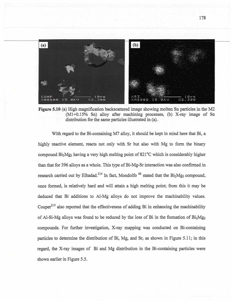
178
Figure 5.10 (a) High magnification backscattered image showing molten Sn particles in the M2(M 1+0.15% Sn) alloy after machining processes, (b) X-ray image of Sndistribution for the same particles illustrated in (a).
With regard to the Bi-containing M7 alloy, it should be kept in mind here that Bi, a
highly reactive element, reacts not only with Sr but also with Mg to form the binary
compound Bi2Mgs having a very high melting point of 821°C which is considerably higher
than that for 396 alloys as a whole. This type of Bi-Mg-Sr interaction was also confirmed in
research carried out by Elhadad.214 In fact, Mondolfo 66 stated that the Bi2Mg3 compound,
once formed, is relatively hard and will attain a high melting point; from this it may be
deduced that Bi additions to Al-Mg alloys do not improve the machinability values.
Couper215 also reported that the effectiveness of adding Bi in enhancing the machinability
of Al-Si-Mg alloys was found to be reduced by the loss of Bi in the formation of Bi2Mgs
compounds. For further investigation, X-ray mapping was conducted on Bi-containing
particles to determine the distribution of Bi, Mg, and Sr, as shown in Figure 5.11; in this
regard, the X-ray images of Bi and Mg distribution in the Bi-containing particles were
shown earlier in Figure 5.5.
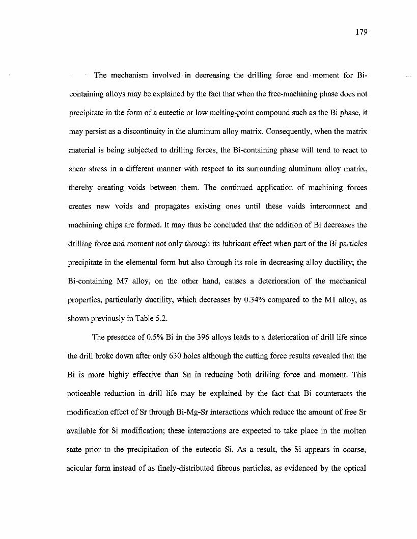
179
The mechanism involved in decreasing the drilling force and moment for Bi-
containing alloys may be explained by the fact that when the free-machining phase does not
precipitate in the form of a eutectic or low melting-point compound such as the Bi phase, it
may persist as a discontinuity in the aluminum alloy matrix. Consequently, when the matrix
material is being subjected to drilling forces, the Bi-containing phase will tend to react to
shear stress in a different manner with respect to its surrounding aluminum alloy matrix,
thereby creating voids between them. The continued application of machining forces
creates new voids and propagates existing ones until these voids interconnect and
machining chips are formed. It may thus be concluded that the addition of Bi decreases the
drilling force and moment not only through its lubricant effect when part of the Bi particles
precipitate in the elemental form but also through its role in decreasing alloy ductility; the
Bi-containing M7 alloy, on the other hand, causes a deterioration of the mechanical
properties, particularly ductility, which decreases by 0.34% compared to the Ml alloy, as
shown previously in Table 5.2.
The presence of 0.5% Bi in the 396 alloys leads to a deterioration of drill life since
the drill broke down after only 630 holes although the cutting force results revealed that the
Bi is more highly effective than Sn in reducing both drilling force and moment. This
noticeable reduction in drill life may be explained by the fact that Bi counteracts the
modification effect of Sr through Bi-Mg-Sr interactions which reduce the amount of free Sr
available for Si modification; these interactions are expected to take place in the molten
state prior to the precipitation of the eutectic Si. As a result, the Si appears in coarse,
acicular form instead of as finely-distributed fibrous particles, as evidenced by the optical
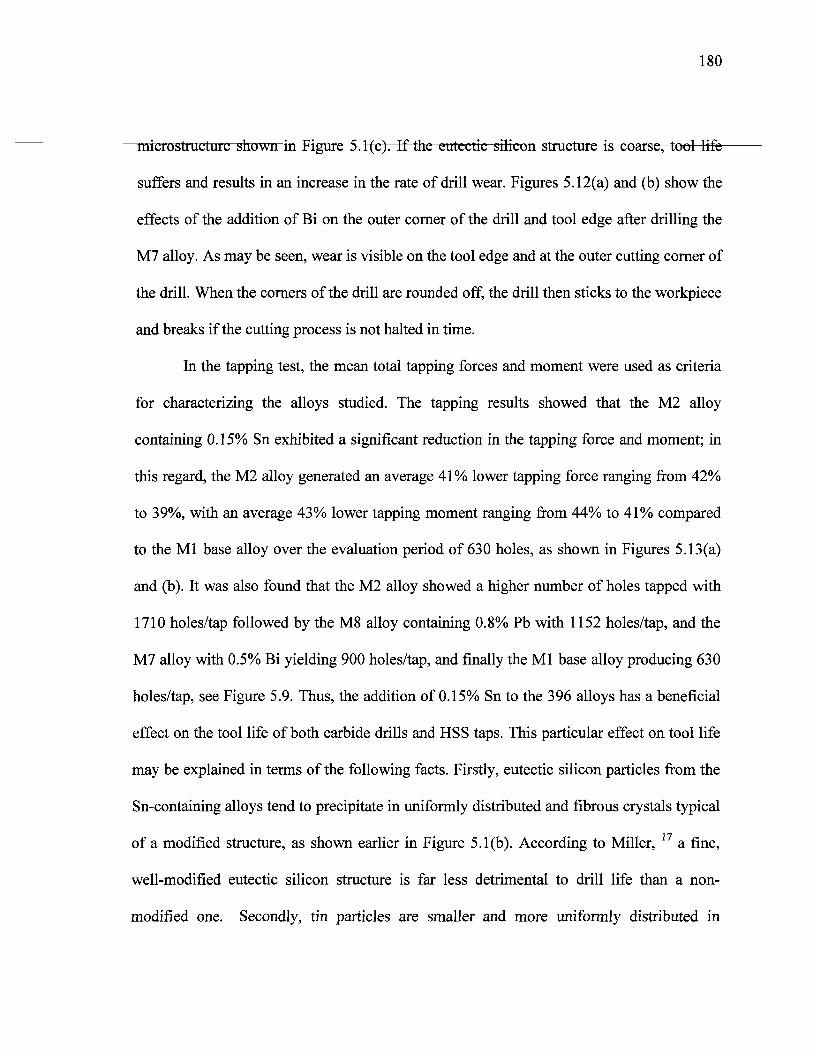
180
microstructure shown in Figure 5.1(c). If the eutectic silicon structure is coarse, tool life
suffers and results in an increase in the rate of drill wear. Figures 5.12(a) and (b) show the
effects of the addition of Bi on the outer corner of the drill and tool edge after drilling the
M7 alloy. As may be seen, wear is visible on the tool edge and at the outer cutting corner of
the drill. When the corners of the drill are rounded off, the drill then sticks to the workpiece
and breaks if the cutting process is not halted in time.
In the tapping test, the mean total tapping forces and moment were used as criteria
for characterizing the alloys studied. The tapping results showed that the M2 alloy
containing 0.15% Sn exhibited a significant reduction in the tapping force and moment; in
this regard, the M2 alloy generated an average 41% lower tapping force ranging from 42%
to 39%, with an average 43% lower tapping moment ranging from 44% to 41% compared
to the Ml base alloy over the evaluation period of 630 holes, as shown in Figures 5.13(a)
and (b). It was also found that the M2 alloy showed a higher number of holes tapped with
1710 holes/tap followed by the M8 alloy containing 0.8% Pb with 1152 holes/tap, and the
M7 alloy with 0.5% Bi yielding 900 holes/tap, and finally the Ml base alloy producing 630
holes/tap, see Figure 5.9. Thus, the addition of 0.15% Sn to the 396 alloys has a beneficial
effect on the tool life of both carbide drills and HSS taps. This particular effect on tool life
may be explained in terms of the following facts. Firstly, eutectic silicon particles from the
Sn-containing alloys tend to precipitate in uniformly distributed and fibrous crystals typical
of a modified structure, as shown earlier in Figure 5.1(b). According to Miller, 17 a fine,
well-modified eutectic silicon structure is far less detrimental to drill life than a non-
modified one. Secondly, tin particles are smaller and more uniformly distributed in
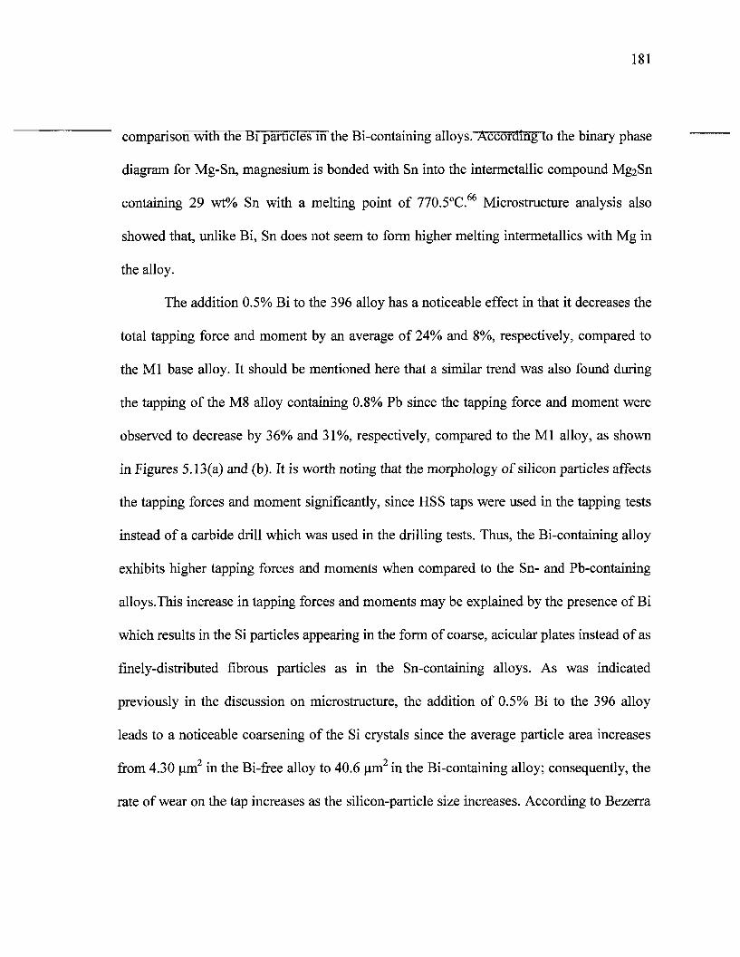
181
comparison with the Bi pàiticles in tfieBi-containing alloys. According to the binary phase
diagram for Mg-Sn, magnesium is bonded with Sn into the intermetallic compound Mg2Sn
containing 29 wt% Sn with a melting point of 770.5°C.66 Microstructure analysis also
showed that, unlike Bi, Sn does not seem to form higher melting intermetallics with Mg in
the alloy.
The addition 0.5% Bi to the 396 alloy has a noticeable effect in that it decreases the
total tapping force and moment by an average of 24% and 8%, respectively, compared to
the Ml base alloy. It should be mentioned here that a similar trend was also found during
the tapping of the M8 alloy containing 0.8% Pb since the tapping force and moment were
observed to decrease by 36% and 31%, respectively, compared to the Ml alloy, as shown
in Figures 5.13(a) and (b). It is worth noting that the morphology of silicon particles affects
the tapping forces and moment significantly, since HSS taps were used in the tapping tests
instead of a carbide drill which was used in the drilling tests. Thus, the Bi-containing alloy
exhibits higher tapping forces and moments when compared to the Sn- and Pb-containing
alloys.This increase in tapping forces and moments may be explained by the presence of Bi
which results in the Si particles appearing in the form of coarse, acicular plates instead of as
finely-distributed fibrous particles as in the Sn-containing alloys. As was indicated
previously in the discussion on microstructure, the addition of 0.5% Bi to the 396 alloy
leads to a noticeable coarsening of the Si crystals since the average particle area increases
from 4.30 urn in the Bi-free alloy to 40.6 um in the Bi-containing alloy; consequently, the
rate of wear on the tap increases as the silicon-particle size increases. According to Bezerra
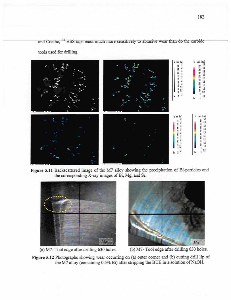
182
and Coelho,1:>2 HSS taps react much more sensitively to abrasive wear than do the carbide
tools used for drilling.
li Lnel h i !
I"" n1181 1 1 '�'m 1?
u%t
Si LntlM
16 M
* M
u«.1
Figure 5.11 Backscattered image of the M7 alloy showing the precipitation of Bi-particles andthe corresponding X-ray images of Bi, Mg, and Sr.
(a) M7- Tool edge after drilling 630 holes. (b) M7- Tool edge after drilling 630 holes.
Figure 5.12 Photographs showing wear occurring on (a) outer corner and (b) cutting drill lip ofthe M7 alloy (containing 0.5% Bi) after stripping the BUE in a solution of NaOH.
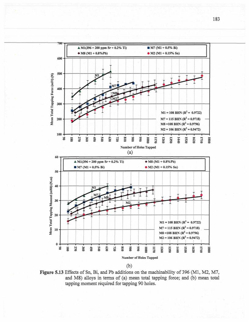
183
700
600
Z 5 0 0
a 4oo
I300
i 200
100
60
50
| 40
I 3°
� Ml(396 + 200 ppm Sr + 0.2% Ti) � M7 (Ml + 0.5% Bi)
� M8 (Ml + 0.8%Pb) � M2 (Ml + 0.15% Sn)
!
- A1 ^ 'mi
si
L
JM7I
rj
\^ Û b i <
M
fluff
1 = 1()SBH3s(R' = 0.A ft
i
?722)
M8 =108 BHN (R2 = 0.9796)
M2 = 106 BHN (R2 = 0.9472)
5
I
I
20
O �00 -4o o
Number of Holes Tapped
(a)
� Ml(396 + 200 ppm Sr + 0.2% Ti) � M8 (Ml + 0.8%Pb)
� M7 (Ml + 0.5% Bi) � M2 (Ml + 0.15% Sn)
r1\&
L
c
p\L �
J.�*
� M2
[4F 1
M
M
_
1 = 1<
7 = 11
)SBH
5BH
L�1
N(R :
N(R2
= 0.
= 0.9
»722)
718)
M8 =108 BHN (R2 = 0.9796)
M2 = 106 BHN (R2 = 0.9472)
\
O 06O
as vio o
<I 00© o
o©
Number of Holes Tapped
(b)Figure 5.13 Effects of Sn, Bi, and Pb additions on the machinability of 396 (Ml, M2, M7,
and M8) alloys in terms of (a) mean total tapping force; and (b) mean totaltapping moment required for tapping 90 holes.
184
5.4.1.2 B319.2 Alloys (Al-7% Si)
The microstructure of hypoeutectic B319.2 alloys consists of the Al-based solid
solution of a-Al displaying pronounced dendritic solidification and fine-grained eutectic Si
particles, with the solid solution ct-Al representing the soft phase of the alloy.
A number of Sr-modified, grain-refined, and T6 heat-treated B319.2 alloys
containing 7% Si were selected to study the effects of individual as well as combined
additions of Sn and Bi on the mean total drilling force and moment based on the mean
value of 100 holes, as illustrated in Figure 5.14. The alloys in question were represented by
B319.2 + 0.15% Sn, coded M10; B319.2 + 0.5% Bi, coded Mi l ; and B319.2 + 0.15%Sn +
0.5%Bi, coded M12, yielding hardness values of 108, 111, and 108 BHN, respectively. The
results revealed that the addition of 0.5%Bi to the B319.2 alloy, producing the Ml 1 alloy,
decreases the mean total drilling forces and moment compared to the Ml0 alloy containing
0.15% Sn. Such reductions through the addition of bismuth may be obtained either as a
result of the softening of the bismuth particles from an increase in local temperature or
through void formation due to a deformation mismatch between bismuth and the aluminum
matrix during machining.71'72
The Bi-containing alloy, namely Ml 1, on the other hand, has a detrimental effect on
drill life, whereas the drill life of the Sn-containing M10 alloy decreases from 2100
holes/drill to only 1100 holes/drill in the Ml 1 alloy, corresponding to a reduction of 48% in
drill life. It is important to note that the detrimental effect of Bi additions on the drill life of
the 396-M7 alloy is more pronounced than it is for the B319.2-M11 alloy since drill life is
reduced by 71% during the machining of the 396-M7 alloy compared to 48% in the case of
185
the B319.2-M11 alloy which contains a similar level ot Bi addition of about 0.5%. This
particularity may be ascribed to the abrasiveness of the 396 alloy resulting from its higher
Si content of 10.8% compared to 7% in the B319.2 alloy.
The simultaneous addition of smaller amounts of two or more elements insoluble in
aluminum has a greater effect on machinability than individual additions of each element in
terms of drilling force and moment. It was found that compound additions of 0.15% Sn +
0.5% Bi made to the B319.2 alloy, creating M12 alloy, lowers the drilling forces by 15%
and 7% compared to the Sn-containing M10 alloy and the Bi-containing Mil alloy,
respectively. It appears that the additives have the same effect on the drilling moment
which was found to have decreased by 23% and 13%, respectively, as may be seen in
Figures 5.14 (a) and (b). These results are consistent with work carried out by Smolej 52'56
which confirmed that tin phases together with other phases of alloying elements and
impurities reduce the cohesion of crystal grains, thereby leading either to the accelerated
rupture of the material during the course of cutting or to easier breakage of chips resulting
in a reduction in the cutting forces.
It was also found that the compound addition of Sn+Bi improves drill life compared
to individual additions of Bi alone, whereby drill life increases from 1100 holes/drill in the
Mil alloy containing 0.5% Bi to 1700 holes/drill in the M12 alloy containing 0.15% Sn +
0.5% Bi. The Sn-containing M10 alloy, however, produces the longest drill life, i.e. twice
that of the Mil alloy and one-and-a-half times that of the M12 alloy.
In tapping tests, it was observed that the addition of 0.5% Bi individually to the
B319.2 alloy, creating the Mil alloy, or in combination with 0.15% Sn, creating the M12
186
alloy, produced higher mean total tapping forces and moments compared to the B319.2
alloy containing only 0.15% Sn, creating the M10 alloy, as is shown clearly in Figures 4.15
(a) and (b). It may be concluded that Bi additives have the same effects on the tapping
force and moment as that observed in the drilling test. These effect, as discussed earlier,
may be attributed to the presence of eutectic Si particles in the form of hard coarse, acicular
plates in the Bi-containing alloys instead of fibrous particles in the Sn-containing alloy.
During the tapping of a low Si-content B319.2 alloy, it was also observed that the
Sn-containing M10 alloy and Bi-containing Mil alloy present the same number of holes
tapped out of the total 1500 holes, followed by the M14 alloy containing a combined
addition of Sn and Bi with 1200 holes. From this finding, it may be deduced that the
morphology of Si particles does not play a significant role in tap life. The difference
existing in the influence of Si morphology between drill life and tap life may arise from the
different cutting conditions applied in each test, since the drilling tests were carried out at
high cutting speeds of around 11000 rpm with a high feed rate of about 1.17 m/min
compared to the low cutting speed applied in the tapping tests of about 400 rpm with a low
feed rate of about 0.56 m/min. It has been reported that the difference in Si morphology
exerts only a slight influence on tool life at low cutting speeds. As the cutting speed rises,
however, the effects of wear as a result of Si morphology become more pronounced.13
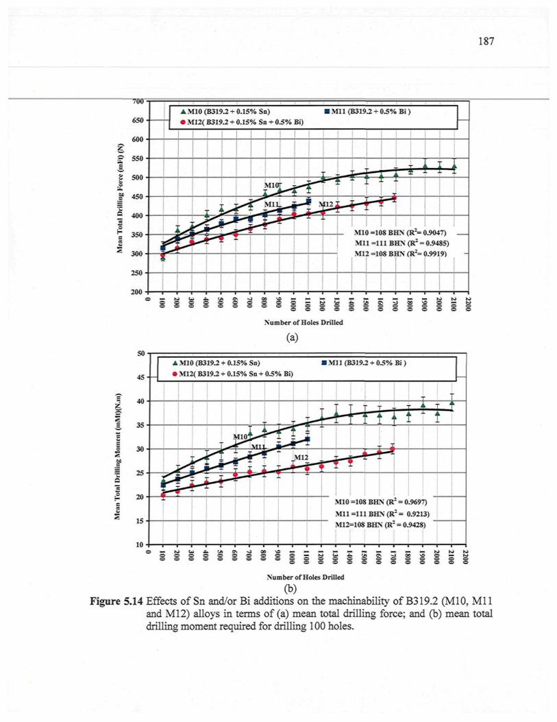
187
700
650
S.
E
Mil (B319.2 + 0.5% Bi )A M10 (B319.2 + 0.15% Sn)� M12( B319.2 + 0.15% Sn + 0.5% Bi)
MIO =108 BHN (R*= 0.9047)Mi l =111 BHN (Rz = 0.9485)M12 =108 BHN (R2= 0.9919)
g g g g g g
200
Number of Holes Drilled
(a)
I 35
I 30
IS£ 20
15
10
50
45- -
40
�
ii
A MIO (B319.2 + 0.15% Sn) � Ml 1 (B319.2 + 0.5% Bi )
� M12( B319.2 + 0.15% Sn + 0.5% Bi)
A riMIOJ
\T11 42L J
r J - ^uM12
V¥r-
viioMil
M12
r
� IH
r T + "^ I T :
=108 BHN (R2 = 0.969'
=111BHN(R := 0.921
=108 BHN (R2 = 0.94283))
[ ÀÏ
i
g g g gNumber of Holes Drilled
g g g g g g
(b)Figure 5.14 Effects of Sn and/or Bi additions on the machinability of B319.2 (M10, Mi l
and M12) alloys in terms of (a) mean total drilling force; and (b) mean totaldrilling moment required for drilling 100 holes.
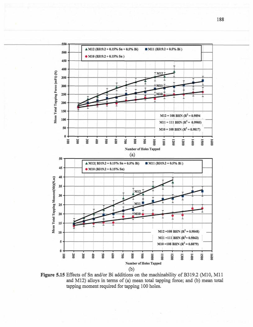
188
500-
% 250-
ce
ô 150 �
S loo �
s50-
0 -
� M12 (B319.2 + 0.15% Sn + 0.5% Bi) � Mi l (B319.2 + 0.5% Bi )
� M10 (B319.2 + 0.15% Sn )
*é H - - *
t��- �
i ir � J
. *
; � - �
1��*
T M 1 2 T * � -
S <1 �
��_
:u -1
: -
-
1
1
M12 = 108 BHN (R2 = 0.9894
Mi l = 111 BHN (R2 = 0.9905)
M10 = 108 BHN (R : = 0.9817)
c= �=; � r̂ » u - - u 'j-i c%O. = . c ^ Ci C5 <=5 <=> CD
C=ï w 'CS w O ' w> O
50
45
ç- 40
£ 35
| 30o
M 25'E.
| 20
I 15CcevZ 10
5
Number of Holes Tapped
(a)
� M12( B319.2 + 0.15% Sn + 0.5% Bi) � Ml 1 (B319.2 + 0.5% Bi )
� M10 (B319.2 + 0.15% Sn)
^ ^i �
L <
Mil '
l f^j T
M12 =108
Mi l =111
M10 =108
-
i��*
! ~ ^ !
BHN (R2 - 0.S>X4S%,
BHN (R2= 0.9863)
BHN (R2 = 0.8879)
0 0
Number of Holes Tapped
(b)Figure 5.15 Effects of Sn and/or Bi additions on the machinability of B319.2 (M10, Mi l
and M12) alloys in terms of (a) mean total tapping force; and (b) mean totaltapping moment required for tapping 100 holes.
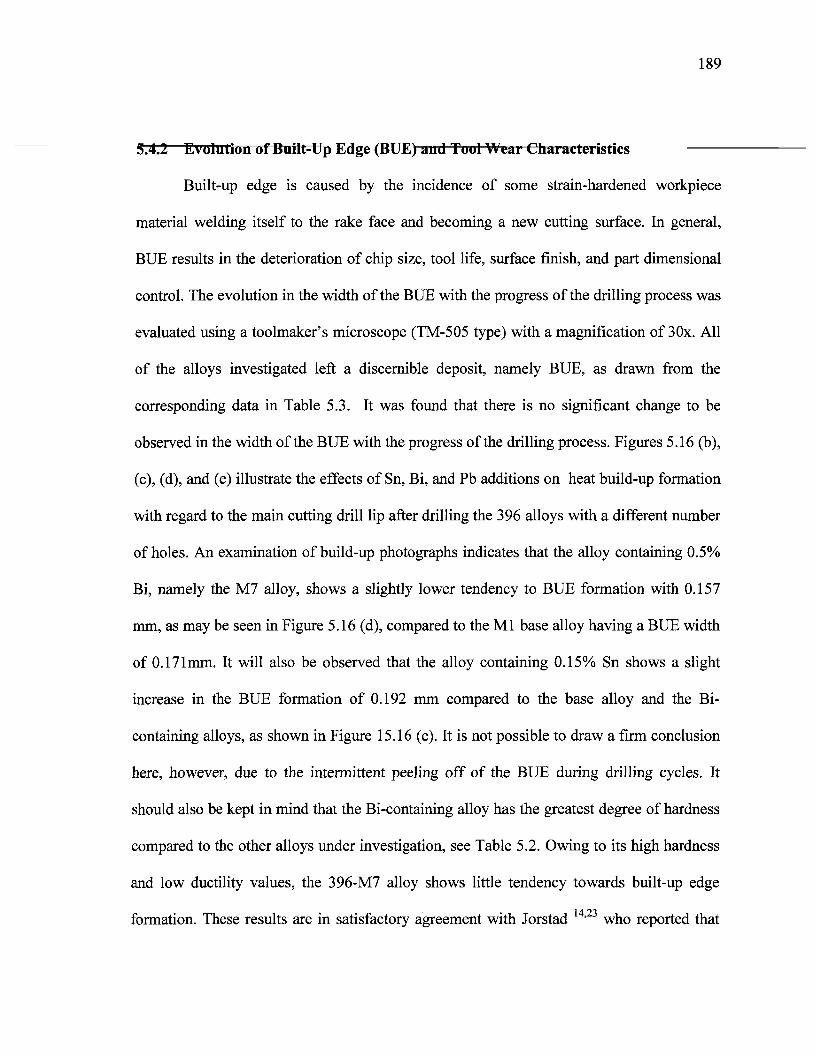
189
^5.4.2 Evolution of Built-Up Edge (BUE) and Tool Wear Cliai actei istics
Built-up edge is caused by the incidence of some strain-hardened workpiece
material welding itself to the rake face and becoming a new cutting surface. In general,
BUE results in the deterioration of chip size, tool life, surface finish, and part dimensional
control. The evolution in the width of the BUE with the progress of the drilling process was
evaluated using a toolmaker's microscope (TM-505 type) with a magnification of 30x. All
of the alloys investigated left a discernible deposit, namely BUE, as drawn from the
corresponding data in Table 5.3. It was found that there is no significant change to be
observed in the width of the BUE with the progress of the drilling process. Figures 5.16 (b),
(c), (d), and (e) illustrate the effects of Sn, Bi, and Pb additions on heat build-up formation
with regard to the main cutting drill lip after drilling the 396 alloys with a different number
of holes. An examination of build-up photographs indicates that the alloy containing 0.5%
Bi, namely the M7 alloy, shows a slightly lower tendency to BUE formation with 0.157
mm, as may be seen in Figure 5.16 (d), compared to the Ml base alloy having a BUE width
of 0.171mm. It will also be observed that the alloy containing 0.15% Sn shows a slight
increase in the BUE formation of 0.192 mm compared to the base alloy and the Bi-
containing alloys, as shown in Figure 15.16 (c). It is not possible to draw a firm conclusion
here, however, due to the intermittent peeling off of the BUE during drilling cycles. It
should also be kept in mind that the Bi-containing alloy has the greatest degree of hardness
compared to the other alloys under investigation, see Table 5.2. Owing to its high hardness
and low ductility values, the 396-M7 alloy shows little tendency towards built-up edge
formation. These results are in satisfactory agreement with Jorstad ' 3 who reported that
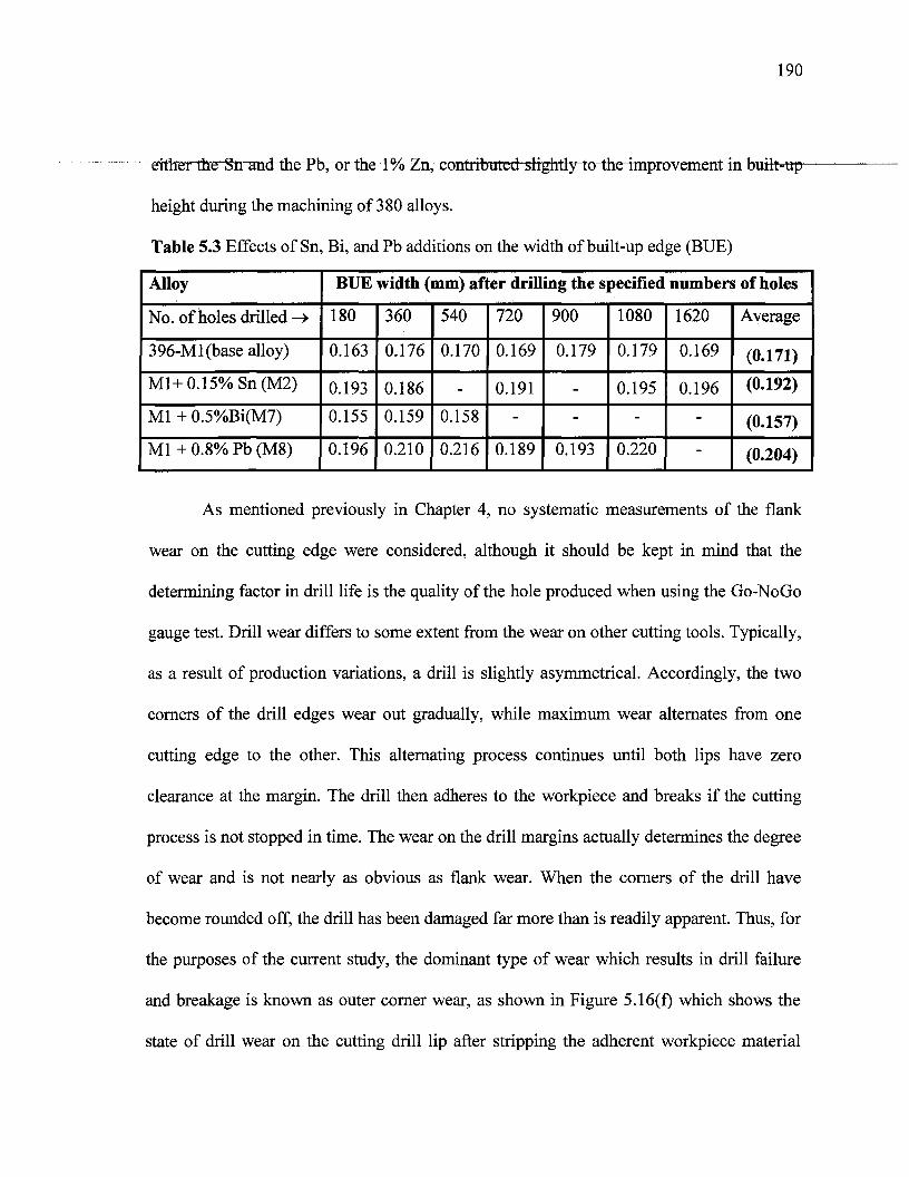
190
^n7 xxmtribtttg(hiltgfatiy"to^the4mprovement in built-up^
height during the machining of 380 alloys.
Table 5.3 Effects of Sn, Bi, and Pb additions on the width of built-up edge (BUE)
Alloy
No. of holes drilled ->
396-Ml(base alloy)
Ml+0.15%Sn(M2)
Ml + 0.5%Bi(M7)
Ml + 0.8% Pb (M8)
BUE width (mm) after drilling the specified numbers of holes
180
0.163
0.193
0.155
0.196
360
0.176
0.186
0.159
0.210
540
0.170
-
0.158
0.216
720
0.169
0.191
-
0.189
900
0.179
-
-
0.193
1080
0.179
0.195
-
0.220
1620
0.169
0.196
-
-
Average
(0.171)
(0.192)
(0.157)
(0.204)
As mentioned previously in Chapter 4, no systematic measurements of the flank
wear on the cutting edge were considered, although it should be kept in mind that the
determining factor in drill life is the quality of the hole produced when using the Go-NoGo
gauge test. Drill wear differs to some extent from the wear on other cutting tools. Typically,
as a result of production variations, a drill is slightly asymmetrical. Accordingly, the two
corners of the drill edges wear out gradually, while maximum wear alternates from one
cutting edge to the other. This alternating process continues until both lips have zero
clearance at the margin. The drill then adheres to the workpiece and breaks if the cutting
process is not stopped in time. The wear on the drill margins actually determines the degree
of wear and is not nearly as obvious as flank wear. When the corners of the drill have
become rounded off, the drill has been damaged far more than is readily apparent. Thus, for
the purposes of the current study, the dominant type of wear which results in drill failure
and breakage is known as outer corner wear, as shown in Figure 5.16(f) which shows the
state of drill wear on the cutting drill lip after stripping the adherent workpiece material
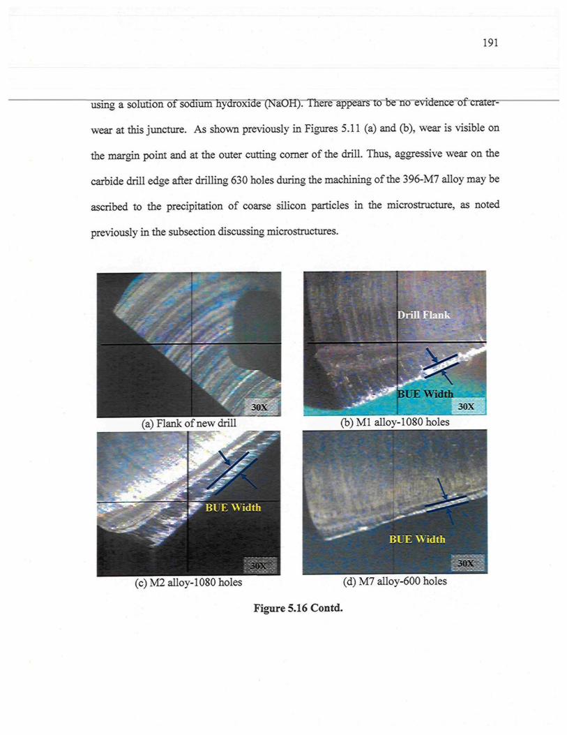
191
using a solution of sodium hydroxide (NaOH). There appears to be no evidence of crater-
wear at this juncture. As shown previously in Figures 5.11 (a) and (b), wear is visible on
the margin point and at the outer cutting comer of the drill. Thus, aggressive wear on the
carbide drill edge after drilling 630 holes during the machining of the 396-M7 alloy may be
ascribed to the precipitation of coarse silicon particles in the microstructure, as noted
previously in the subsection discussing microstructures.
(a) Flank of new drill
p- BUE Width
ÎUE Width
(b) Ml alloy-1080 holes
(c)M2alloy-l 080 holes (d) M7 alloy-600 holes
Figure 5.16 Contd.
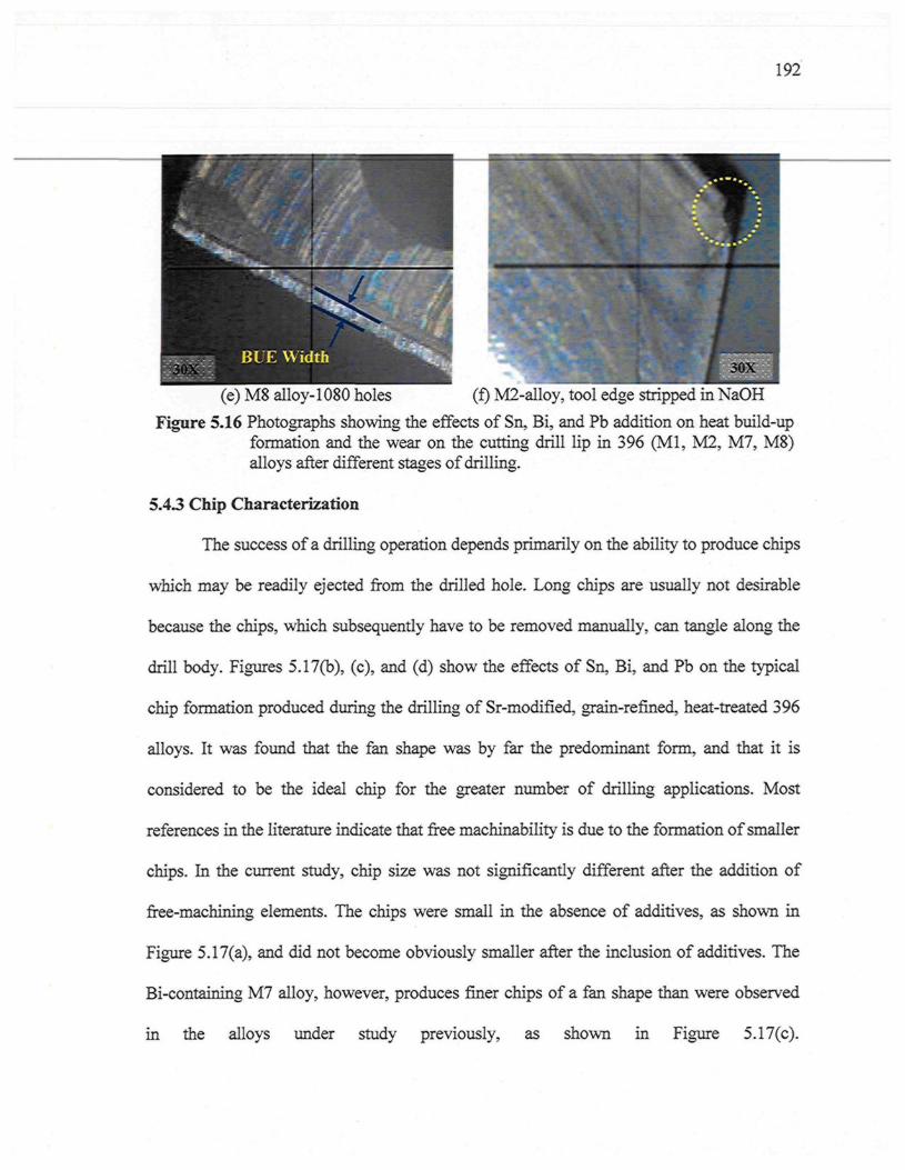
192
(e) M8 alloy-1080 holes (f) M2-alloy, tool edge stripped in NaOH
Figure 5.16 Photographs showing the effects of Sn, Bi, and Pb addition on heat build-upformation and the wear on the cutting drill lip in 396 (Ml, M2, M7, M8)alloys after different stages of drilling.
5.4.3 Chip Characterization
The success of a drilling operation depends primarily on the ability to produce chips
which may be readily ejected from the drilled hole. Long chips are usually not desirable
because the chips, which subsequently have to be removed manually, can tangle along the
drill body. Figures 5.17(b), (c), and (d) show the effects of Sn, Bi, and Pb on the typical
chip formation produced during the drilling of Sr-modified, grain-refined, heat-treated 396
alloys. It was found that the fan shape was by far the predominant form, and that it is
considered to be the ideal chip for the greater number of drilling applications. Most
references in the literature indicate that free machinability is due to the formation of smaller
chips. In the current study, chip size was not significantly different after the addition of
free-machining elements. The chips were small in the absence of additives, as shown in
Figure 5.17(a), and did not become obviously smaller after the inclusion of additives. The
Bi-containing M7 alloy, however, produces finer chips of a fan shape than were observed
in the alloys under study previously, as shown in Figure 5.17(c).
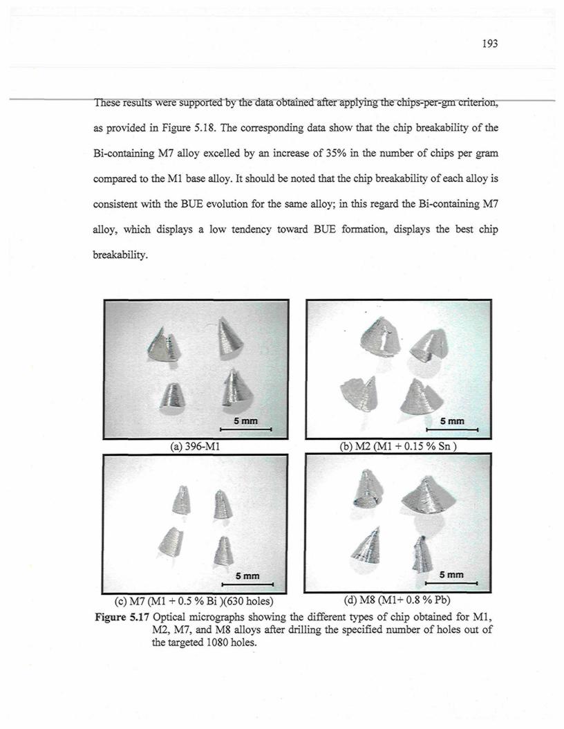
193
These results were supported by the data obtained after applying the chips-per-gm criterion,
as provided in Figure 5.18. The corresponding data show that the chip breakability of the
Bi-containing M7 alloy excelled by an increase of 35% in the number of chips per gram
compared to the Ml base alloy. It should be noted that the chip breakability of each alloy is
consistent with the BUE evolution for the same alloy; in this regard the Bi-containing M7
alloy, which displays a low tendency toward BUE formation, displays the best chip
breakability.
(b )M2(Ml+0 .15%Sn)
(c) M7 (Ml + 0.5 % Bi )(630 holes) (d) M8 (M1+ 0.8 % Pb)
Figure 5.17 Optical micrographs showing the different types of chip obtained for Ml,M2, M7, and M8 alloys after drilling the specified number of holes out ofthe targeted 1080 holes.
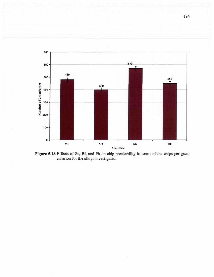
194
700
Ml M2 M7 M8Alloy Code
Figure 5.18 Effects of Sn, Bi, and Pb on chip breakability in terms of the chips-per-gramcriterion for the alloys investigated.

CHAPTER 6
CONCLUSIONS AND RECOMMENDATIONS
196
CHAPTER 6
CONCLUSIONS AND RECOMMENDATIONS
The present study concentrated on a new experimental alloy belonging to the Al-Si
near-eutectic cast alloy group, and containing about 10.8% Si, namely the 396 alloy. In
addition, B319.2 alloys were also investigated for comparison purposes. The study was
carried out with the aim of providing a better understanding of the effects that Fe-
intermetallics, matrix-hardening elements, and free-machining elements would have on the
machinability characteristics of this alloy. Drilling and tapping operations were carried out
under fixed machining conditions as applied to the examination of the alloys under
discussion. It should be mentioned here that the pertinent machinability criteria relate to
forces and moments as well as to tool life, chip configuration, and built-up edge (BUE)
evolution.
6.1 CONCLUSIONS
From the analysis and discussion of the results obtained, the following conclusions
may be formulated:
Effects of Fe-Intermetallics
1. The results obtained from the drilling tests reveal that the 396-M1 base alloy
displays a rapid increase in the mean total drilling force, moment, and power by
103%, 105%, and 134%, respectively, as the number of holes drilled increases. This
particularity may be ascribed to the abrasiveness of the 396 alloy resulting from its
higher Si content of 10.8%.
197
Thn 34-Hitirm nf 0 ?*L"/. TV anH 0 ?^"/. Mn tn tiir M l hac- ,-iiinv nrnrhirino tVir M,. 111C ClVJ-VJ-lLlVJll \J1 V/.^.J /O 1 C CUIU. V .^ - / /U 1V111 tvl Lilt* 1V11 U a o t ClLLljy *> U1\JV4-Lining, d i t iVl
alloy - containing sludge as a predominant phase, leads to an extremely rapid
increase, of about 75%, in the total drilling force after drilling only 540 holes;
similar behavior was also observed with regard to the total drilling moment and
power.
3. The presence of sludge has a detrimental effect on tool life, in that it decreases drill
life by about 50% compared to the Ml base alloy. It is clear that the sludge phase
has a high hardness value, a high melting point, and a high specific gravity
compared to the matrix, and it is consequently capable of causing significant
damage to cutting tools.
4. The formation of the a-Fe phase in the Ml alloy has a beneficial effect on tool life,
in that the Ml alloy produces the highest number of holes drilled compared to
sludge or fi-Fe containing alloys; this result may be attributed to the fact that the
formation of the a-Fe intermetallic with its rounded Chinese-script morphology and
its presence within the a-Al dendrites is expected to improve matrix homogeneity
through the hardening of the soft ct-Al dendrites.
5. Increasing the iron level from ~0.5 to 1% while maintaining the same Mn level of
~0.5% proves to be most effective in terms of cutting force and tool life in the
drilling and tapping processes. The lower ductility value displayed by the /?-Fe-
containing alloy reduces the drill-chip friction which in turn decreases the drilling
force, moment, and power.
198
67 In tapping tests, it was found that high-speed steel tools are considerably more
sensitive to the Fe-intermetallic phases than the carbide tools used for drilling. The
high speed steel tap (HSS-E) broke down after tapping only 630, 589, and 900 holes
in the Ml, M3, and M4 alloys, respectively.
7. The addition of Fe and/or Mn to the base alloy, which would initially have been
expected to reduce the edge build-up tendency through the abrasive action of hard
intermetallic phases, did not measurably reduce the built-up edge width compared
to the one observed for the Ml base alloy.
Effects of Cu and Mg Additions
8. The Mg-free M9 alloy displays only a slight increase in the drilling force, moment,
and power with the progress of the drilling process, while in comparison, the Mg-
containing Ml base alloy shows a rapid increase.
9. The M6 alloy containing high levels of Cu and Mg have a detrimental effect on drill
life and cutting forces. The higher drilling force and the reduction in drill life may
be attributed to the formation of large amounts of the coarse blocklike A^Cu phase,
together with the formation of thick plates of the Al-Si-Cu-Mg phase in the alloy.
10. The Mg-free M9 alloy displays the lowest cutting force and moment in addition to
producing the highest number of holes drilled/tapped compared to the Mg-
containing alloys. This observation may be explained by the cooperative
precipitation of the A^Cu, Mg2Si, A^CuMg, and AlsSiôCuiMgs hardening phases
in Mg-containing alloys which confer greater strength on the alloy than would be
the case with the precipitation of only the A^Cu phase in the Mg-free M9 alloy.
199
"" 1~J7 A comparisonot the iion-niodilicd JV1O alloy tiiiu die oi-niocliiieu Jvll alloy
(containing the same level of Mg and Cu additions) in terms of the number of holes
drilled, reveals that the morphology of Si particles has a noticeable effect in
governing the tool life of near-eutectic Al-Si alloys.
12. An examination of the edge build-up photographs indicates that there is little
change in the width of the BUE with the progress of the drilling process. Owing to
their high hardness and low ductility values, the Mg-containing alloys show an
appreciably lower tendency to BUE formation compared to the Mg-free alloy.
Effects of Free-Machining Elements
13. The Bi-containing alloys have a detrimental influence on drill life, although they are
observed to exhibit lower drilling forces compared to the Ml base alloys. The
significant reduction in drill life may be explained by the fact that the presence of
0.5wt% Bi leads to noticeable coarsening of the Si particles. Moreover, the
effectiveness of adding the low melting point Bi for the purpose of enhancing
machinability is reduced by the loss of Bi in the formation of the high melting point
Bi2Mg3 phase.
14. The addition of 0.15wt% Sn to the 396 alloy has a beneficial effect on the tool life
of both carbide drills and HSS taps. Such an effect may be ascribed to the
precipitation of /?-Sn particles having a low melting point. In addition, these /?-Sn
particles are smaller and more uniformly distributed in comparison with the Bi
particles in the Bi-containing alloys.
200
ISr�The simultaneous addition of smaller amounts of two or more elements insoluble in
aluminum has a greater effect on machinability in terms of reducing the drilling
force and moment than individual additions of each element.
16. The morphology of Si particles does not play a significant role in tap life during the
tapping of the B319.2 alloys. The difference existing between drill life and tap life
with respect to the influence of Si morphology may arise from the different cutting
conditions applied for each test.
17. Lead is not a suitable choice as an additive because of environmental concerns.
Bismuth also has several detrimental effects associated with its presence in the Al-
Si alloys, including the formation of high melting point Bi2Mg3 phase. Bismuth also
interacts with Sr which is required for Si-modification. Thus, of the free-machining
elements tested, Sn is the most promising in the context of improving the alloy
machinability.
Chip Characterization
18. A visual examination of the chips reveals that the fan shape is by far the
predominant form during the drilling of the alloys studied, and also that it is
considered to be the ideal chip for most drilling applications.
19. The chip breakability of the alloys containing AI2CU phase is superior to that of the
alloys containing Mg2Si. Thus combined additions of Cu and Mg are expected to
further refine the size of the chips produced. Chip size is not significantly different
after the addition of free-machining elements. The Bi-containing alloys, however,
produce finer fan-shaped than the Bi-free 396 base alloy.
201
Tool Wear Characterization
20. In the drilling tests, maximum wear takes place at the outer corner edge of the drill,
whereas minimum wear occurs at or near the point of the drill tip, since the
maximum rotational force and the maximum drill-to-workpiece contact occur at the
outer comer edge. When the corners of the drill are rounded off, the drill then sticks
to the workpiece and breaks if the cutting process is not halted in time.
21. In tapping tests, the main wear mechanism observed is adhesion, although some
abrasion may also occur during the tapping of the sludge-containing and Bi-
containing alloys. The breakage occurs frequently at the chamfered part of the tap
since it generates a major part of the resulting force, because of the larger chip
cross-section related to the teeth of the chamfer.
202
6.2 KECUMMEJN DA'l'lOIN S FUK t' UI' U RE W UKK
As mentioned in the objectives in Chapter 1, the main purpose of this study was the
development of a new automotive alloy which would provide a performance superior to the
currently used 319 and 356 Al-Si alloys. To complete the study, it is suggested that
investigations be extended to cover the following aspects:
1. Investigating the high temperature performance of 396 type alloys with respect to
the role of additives in preserving the mechanical properties under elevated
temperature conditions.
2. Investigating the use of drill materials other than the cemented carbide tools used in
the present study, from the point of view of reducing the machining costs and
thereby, the overall production costs.
3. Mathematical analysis of the experimental data using factorial analysis, to provide a
design for the experimental approach to such investigations, in order to reduce the
time required for arriving at the optimum alloy compositions and machining
conditions in the production of automotive components.
4. Investigating the addition of low melting-point elements such as tin which, with its
tendency to melt during dry machining at high speeds of-12,000 rpm, would serve
as a lubricant during the machining process, thus eliminating the need for external
lubricants.
203
REFERENCES
1. Moustafa, M.A., Samuel, F.H., Doty, H.W., "Effect of Solution Heat Treatmentand Additives on the Microstructure of Al-Si (A413.1) Automotive Alloys,"Journal of Materials Science, vol 38, pp 4507-4522 (2003).
2. Samuel, F.H., Ouellet, P., Samuel, A.M., Doty, H.W., "Effect of Mg and SrAdditions on The Formation of Intermetallics in Al-6Wt Pet Si-3.5 Wt Pet Cu-(0.45) to (0.8)Wt Pet Fe 319-Type Alloys," Metallurgical and MaterialsTransactions A, vol 29A, pp 2871-2884 (1998).
3. Grum, J., Kisin, M., "Influence of the Microstructure on Surface Integrity inTurning-Part II: The Influence of a Microstructure of the Workpiece Material onCutting Forces," InternationalJournal of Machine Tools & Manufacture, vol 43, pp1545-1551 (2003).
4. Boothroyd, G., Knight, W.A., Fundamentals of Machining and Machine Tools,Third Edition, Taylor and Francis, Inc., Florida (2006).
5. Shaw, M.C., Metal Cutting Principles, Second Edition, Oxford University Press,New York (2005).
6. Stephenson, D.A., Agapiou, J.S., Metal Cutting Theory and Practice, SecondEdition, Taylor and Francis, Inc., Florida (2006).
7. Kronenberg, M., Machining Science and Application, Elsevier Science andTechnology, Pergamon, London (1966).
8. ASM Metals Handbook, vol 16, Machining, American Society for Metals,Materials, Park, OH, p 643 (1990).
9. KÔnig, W., Erinski, D., "Machinability of Aluminum-Silicon Pressure-Die-CastAlloys," Proceedings of the 20th International Machine Tool Design & ResearchConference (MTDR), pp 337-344 (1979).
10. ASM Metals Handbook, vol 2, Properties and Selection: Nonferrous Alloys andSpecial-Purpose Materials, American Society for Metals, Materials Park, OH,(1990).
11. Trent, E.M., Wright, P.K., Metal Cutting, 4th Edition, Butterworth's-Heinemann,London, pp 149-166 (2000).
12. Narahari, P., Pai, B.C., Pillai, R.M., "Some Aspects of Machining Cast Al-SiCpComposites with Conventional High Speed Steel and Tungsten Carbide Tools,"Journal of Materials Engineering and Performance, vol 8(5), pp 538-542 (1999).
13. Dwivedi, D.K., Sharma, A., Rajan, T.V., "Machining of LM13 and LM28 CastAluminum Alloys: Part 1," Journal of Materials Processing Technology, vol 196,pp 197-204 (2008).
14 . Jorstad, J.L., "Influence of Aluminum Casting Alloy Metallurgical Factors onMachinability," Society of Automotive Engineers, 400 Commonwealth, PA. 15096,15 pages (1980).
204
15. Boileau, J.M., "The Effect of Solidification Time on the Mechanical Properties of aCast 319 Aluminum Alloy," Ph.D. Dissertation 2000, Wayne State University,Detroit, Michigan (2000).
16. ASM Metals Handbook, vol 3, Alloy Phase Diagrams, American Society forMetals, Materials Park, OH, (1990).
17. Miller, J.C., "Machining High Silicon Aluminum," Proceedings of the 11th
International Die Casting Congress, Cleveland, Ohio, pp 1-9 (1981).18. Tash, M., Samuel, F.H., Mucciardi, F., Doty, H.W., Valtierra, S., "Effect of
Metallurgical Parameters on the Machinability of Heat-Treated 356 and 319Aluminum Alloys," Materials Science and Engineering A, vol 434, pp 207-217(2006).
19. Gram, J., Kisin, M., "Influence of the Microstructure on Surface Integrity inTurning-Part I: The Influence of the Size of the Soft Phase in Microstructure onSurface-Roughness Formation," International Journal of Machine Tools &Manufacture, vol 43, pp 1535-1543 (2003).
20. Robert, C.L., "Metallurgical Factors Related to Machining Aluminum Castings,"SAE Transactions, vol 76, pp 1657-1663 (1967).
21. Basavakumar, K.G., Mukunda, P.G., Chakraborty, M., "Influence of MeltTreatments and Turning Inserts on Cutting Force and Surface Integrity in Turningof Al-12Si and Al-12Si-3Cu Cast Alloys," Surface and Coatings Technology, vol201, pp 4757-4766 (2007).
22. Bonsack, W., "Iron-the Problematic Factor in Quality of Aluminum Alloy DieCastings," AFS Transactions, vol 69, pp 712-720 (1961).
23. Jorstad, J.L., "Machinability of 380 Alloy: Effect of Minor Elements andImpurities," Transactions of the Society of Die Casting Engineers, Paper No.G-T79-072 (1979).
24. Lu, L., Dahle, A.K., "Iron-Rich Intermetallic Phases and Their Role in CastingDefect Formation in Hypoeutectic Al-Si Alloys," Metallurgical and MaterialsTransactions, A, vol 36A, pp 819-835 (2005).
25. Wang, L., Apelian, D., Makhlouf, M.M., "Iron-Bearing Compounds in Al-SiDiecasting Alloys: Morphology and Conditions under Which They Form," AFSTransactions, vol 107, pp 231-238 (1999).
26. Dinnis, CM., Taylor, J.A., Dahle, A.K., "Interactions between Iron, Manganese,and the Al-Si Eutectic in Hypoeutectic Al-Si Alloys," Metallurgical and MaterialsTransactions, A, vol 37A, pp 3283-3291 (2006).
27. Couture, A., "Iron in Aluminum Casting Alloys: A Literature Survey," AFSInternational Cast Metals Journal, pp 9-17 (1981).
28. Suarez-Pena, B., Asensio-Lozano, J., "Influence of Sr Modification and Ti GrainRefinement on the Morphology of Fe-Rich Precipitates in Eutectic Al-Si Die CastAlloys," Scripta Materialia, vol 54, pp 1543-1548 (2006).
29. Gruzleski, J.E., Microstructure Development during Metalcasting, AmericanFoundrymen's Socity, Inc., Des Plaines, IL, p 234 (2000).
205
30. Moustafa, M.A., "Effect of Iron Content on the Formation of P-Al5FeSi andPorosity in Al-Si Eutectic Alloys," Journal of Materials Processing Technology,vol 209, pp 605-610 (2009).
31. Pucella, G., Samuel, A.M., Samuel, F.H., Doty, H.W., Valtierra, S., "SludgeFormation in Sr-Modified Al-11.5Wt% Si Diecasting Alloys," AFS Transactions,vol 107, pp 117-125 (1999).
32. Shabestari, S.G., Gruzleski, J.E., "The Effect of Solidification Condition andChemistry on The Formation and Morphology of Complex IntermetallicCompounds in Aluminum-Silicon System," Cast Metals, vol 6, pp 217-224 (1994).
33. Crepeau, P.N., "Effect of Iron in Al-Si Casting Alloys: A Critical Review," AFSTransactions, vol 103, pp 361-366 (1995).
34. Cao, X., Campbell, J., "Effect of Precipitation of Primary Intermetallic Compoundson Tensile Properties of Cast Al-11.5 Si-0.4 Mg Alloy," AFS Transactions, vol 108,pp 391-400 (2000).
35. Moustafa, M.A., Samuel, F.H., Doty, H.W., Valtierra, S., "Effect of Mg and CuAdditions on the Microstructural Characteristics and Tensile Properties of Sr-Modified Al-Si Eutectic Alloys," International Journal of Cast Metals Research,vol 14, pp 235-253 (2002).
36. Li, Z., Samuel, A.M., Samuel, F.H., Ravindran, C , Valtierra, S., "Effect ofAlloying Elements on the Segregation and Dissolution of CuAb Phase in Al-Si-Cu319 Alloys," Journal of Materials Science, vol 38, pp 1203-1218 (2003).
37. Moustafa, M.A., Samuel, F.H., Doty, H.W., "Effect of Solution Heat Treatment andAdditives on the Hardness, Tensile Properties and Fracture Behaviour of Al-Si(A413.1) Automotive Alloys," Journal of Materials Science, vol 38, pp 4523-4534(2003).
38. Han, Y.M., Samuel, A.M., Samuel, F.H., Valtierra, S., Doty, H.W., "Effect ofSolution Heat Treatment Type on the Dissolution of Copper Phases in Al-Si-Cu-MgType Alloys," AFS Transactions, vol 116, pp 79-90 (2008).
39. De la Sablonnière, H., Samuel, F.H., "Solution Heat Treatment of 319 AluminumAlloy Containing~0.5wt%Mg Part 2: Microstructure and Fractography,"International Journal of Cast Metals Research, vol 9, pp 151-225 (1996).
40. Samuel, F.H., "Incipient Melting of Al5Mg8Si6Cu2 and Al2Cu Intermetallics inUnmodified and Strontium-Modified Al-Si-Cu-Mg (319) Alloys during SolutionHeat Treatment," Journal of Materials Science, vol 33, pp 2283-2297 (1998).
41. Moustafa, M.A., Lepage, C, Samuel, F.H., Doty, H.W., "MetallographicObservations on Phase Precipitation in Strontium-Modified Al-11.7% Si Alloys:Role of Alloying Elements," International Journal of Cast Metals Research, vol 15,pp 609-626 (2003).
42. Ma, Z., Samuel, E., Mohamed, A.M.A., Samuel, A.M., Samuel, F.H., Doty, H.W.,"Parameters Controlling the Microstructure of Al-llSi-2.5Cu-Mg Alloys,"Materials and Design, vol 31, pp 902-912 (2009).
43. Tavitas-Medrano, F.J., Gruzleski, J.E., Samuel, F.H., Valtierra, S., Doty, H.W.,"Effect of Mg and Sr-Modification on the Mechanical Properties of 319-Type
206
Aluminum Cast Alloys Subjected to Artificial Aging," Materials Science andEngineering A, vol 480, pp 356-364 (2008).
44. Ouellet, P., Samuel, F.H., "Effect of Mg on the Ageing Behaviour of Al-Si-Cu 319Type Aluminum Casting Alloys," Journal of Materials Science, vol 34, pp 4671-4697(1999).
45. Mohamed, A.M.A., Samuel, F.H., Samuel, A.M., Doty, H.W., "Influence ofAdditives on the Impact Toughness of Al-10.8%Si Near-Eutectic Cast Alloys,"Materials and Design, vol 30, pp 4218-4229 (2009).
46. Tavitas-Medrano, F.J., Valtierra, S., Gruzleski, J.E., Samuel, F.H., Doty, H.W., "ATEM Study of the Aging Behaviour of 319 Type Alloys," AFS Transactions, vol116, pp 99-114 (2008).
47. Yamada, H., Tanaka, T., "Compositive Effect of Cu and Mg on the Machinabilityof Casting Alloys," Journal of Japan Institute of Light Metals, vol 27(11), pp 541-547 (1977).
48. Tanaka, T., Hanasaki, S., "Effects of the Addition of Cu and Mg on theMachinability of Hypereutectic Al-Si Alloys," Aluminium, vol 75, pp 590-594(1999).
49. Kamiya, M., Yakou, T., "Role of Second-Phase Particles in Chip Breakability inAluminum Alloys," International Journal of Machine Tools and Manufacture, vol48, pp 688-696 (2008).
50. Kyung-Hyun, Kim, In-Sang Chung, "Effect of Pb and Bi Element on the CuttingCharacteristics in Al-Cu Alloys," Journal of the Korean Institute of Metals, vol28(3), pp 244-251(1990).
51. Thai, L.T., "The Effects of Bismuth, Strontium and Antimony Additions on theMicrostructure and Mechanical Properties of A356 Aluminum Casting Alloy,"M.Sc. Thesis, Technological University of Malaysia (2006).
52. Smolej, A., Breskvar, B., Sokovic, M., Dragojevic, V., Slacek, E., "Properties ofAluminum Free-Cutting Alloys with Tin, Part I," Aluminum, vol 78, pp 284-288(2002).
53. Ang, C.C., Dasch, J.M., "Dry Machining of Aluminum Castings," U.S. Patent, No.0168806A1, Granted 2006.
54. Young Sek Yang, "Free-Machinable Eutectic Al-Si Alloy," U.S. Patent, No.6,511,633B1, Granted 2003.
55. Subhasish, S., "Free-Machining Aluminum Alloy and Method of Use," U.S. Patent,No. 5,725,694, Granted 1998.
56. Smolej, A., Breskvar, B., Sokovic, M., Dragojevic, V., Slacek, E., "Properties ofAluminum Free-Cutting Alloys with Tin, Part II," Aluminum, vol 78, pp 388-391(2002).
57. Zaima, S., and Takatsuji, Y., Ko, M., "Effect of Tin on the Machinability ofAluminum Silicon Alloy Castings," Journal of Japan Institute of Light Metals, vol108, pp 556-567 (1970).
207
58. Machovec, C.J., Byczynski, G.E., Zindel, J.W., Godlewski, L.A., "Effect of Bi-SrInteractions on Si Morphology in a 319-Type Aluminum Alloy," AFS Transactions,vol 108, pp 439-444 (2000).
59. Wang, W.L., Chen, F.Y., Chen, W.H., "Effect of Process Metallurgical Factors onthe Properties of 2011 Free Cutting Aluminum Alloy: on The Size and Distributionof Bi-Pb Particles," Bulletin of Bismuth Institute, vol 52, pp 3-7 (1987).
60 . Bichsel, H., "Bismuth as an Alloying Element in Aluminum Alloys," Bulletin ofBismuth Institute, Bulletin 19, pp 2-3 (1978).
61. Korane, K.J., "Finding the Best Mix in Aluminum Alloys," Machine Design, vol74(4), pp 94-95 (1999).
62. MacAlister, A.J., "The Al-Bi System," Bulletin of Alloy Phase Diagrams, vol 5(3),pp 247 (1984).
63. Sal'nikov, V.P., Zaigraikin, A.G., "Effect of Bismuth Additions on the Properties ofAluminum-Silicon Alloys," Bulletin of Bismuth Institute, Bulletin 19, p 2 (1978).
64. Ratke, L., Drees, S., Diefenbach, S., Prinz, B., "Microstructure Evolution inImmiscible AlSiBi Alloys under Reduced Gravity Conditions," Proceedings of theIXth European Symposium on Gravity-Dependent Phenomena in Physical SciencesHeld at Berlin, Germany, vol 464, pp 154-133 (1996).
65. Tetsuya, A., and Tetsuro, A., "Morphological Influence of Bi Substituted for Pb inFree-Cutting Brass on Machinability" Journal of the Japan Copper and BrassResearch Association, vol 40, pp 253-256 (2001).
66. Mondolfo, L.F., Structure and Properties of Aluminium Alloys, Butterworths,England, pp 198-230 (1979).
67. Cho, J.I., Loper, C.R., "Limitation of Bismuth Residual in A356.2 Al," AFSTransactions, vol 108, pp 359-367 (2000).
68. Fiorini, P., Giordano, G., " Effect of Zn and Bi Addition on Precipitation Processafter Quenching and Cold Working Al-6Mg," Metals Technology, vol 10(2), pp 52-56 (1983).
69. Kamiya, S., "Aluminum Bearing Alloy Containing Bismuth," U.S. Patent, No.5,286,445, Granted 1994.
70. Bhattacharya, V., Chattopadhyay, K., "Melting of Multiphase Nano-ScaledParticles Embedded in Al Matrix: Case of Pb-Sn and Bi-Sn Alloys," MaterialsScience and Engineering A, vol 449, pp 1003-1008 (2007).
71. Subhasish, S., "Free Machining Aluminum Alloy Containing Bismuth or Bismuth-Tin for Free Machining and Method of Use," U.S. Patent, No.6,409,966Bl, Granted2002.
72. Lemon, R.C., "Free Machining Aluminum Casting Alloys X310 and X335," AFSTransactions, vol 71, pp 315-318 (1963).
73. Dasch, J.M., Ang, C.C., Wong, C.A., Waldo, R.A., Chester, D., Cheng, Y.T., "TheEffect of Free-Machining Elements on Dry Machining of B319 Aluminum Alloy,"Journal of Materials Processing Technology, vol 209, pp 4638-4644 (2009).
208
74. Spillard, Colleen M., "UltrAlloy® 6020: A Lead-Free Aluminum Alloy Featuring"A" Rated Machinability," SAE, International Congress and Exposition, Document#980459(1998).
75. Wouters, O., de Hosson, J.Th.M., "Lead Induced Intergranular Fracture inAluminum Alloy AA6262," Materials Science and Engineering A, vol 361, pp 331-337 (2003).
76. Pathak, J.P., Singh, V., Tiwari, S.N., "On Fracture Characteristics of LeadedAluminium Alloys," Journal of Materials Science Letters, vol 11, pp 639-641(1992).
77. Alabi, M.M., Amherst, N.Y., "Hypo-Eutectic Aluminum-Silicon Alloy Having Tinand Bismuth Additions," U.S. Patent, No 5,122,208, Granted 1992.
78. Alabi, M. M., Amherst, N.Y., "Hypo-Eutectic Aluminum-Silicon Alloy HavingBismuth Additions," U.S. Patent, No 5,122,207, Granted 1992.
79. El-Azim, A.N., Moustafa, S.F., "Machinability of Aluminum-Silicon AlloyCastings Modified With Some Additions," International Conference on Evolutionof Advanced Materials, Milan, Italy, 1989.
80. Tash, M., "Effect of Metallurgical Parameters on the Machining Behaviour of 356and 319 Alloys," Ph.D. Dissertation 2006, Université du Québec à Chicoutimi,Canada (2006).
81 Mûller, C , Bltimke, R., "Influence of Heat Treatment and Cutting Speed on ChipSegmentation of Age Hardenable Aluminium Alloy," Materials Science andTechnology, pp 651-654 (2001).
82. Schulz, H., Abele, E., Sahm, A., "Material Aspects of Chip Formation in HSCMachining," Annals ofCIRP, vol 50(1), pp 45-48 (2001).
83. Dwivedi, D.K. "Influence of Grain Refinement, Modification and Heat Treatmenton Surface Roughness in Machining of Cast Al-Si Alloys," Indian FoundryJournal, vol 48 (1), pp 32-38 (2002).
84. Lim, C.S., Clegg, A.J., Loh, N.L., "The Reduction of Dendrite Arm Spacing Usinga Novel Pressure Assisted Investment Casting Approach," Journal of MaterialsProcessing Technology, vol 70, pp 99-102 (1997).
85. Szablewski, D., Dumitrescu, M., Elbestawi, M.A., Sokolowski, J.H., "High SpeedFace milling of an Aluminum Silicon Alloy Casting," Annals of the CIRP, vol 53(1)pp 69-72 (2004).
86. Lorenz, G., "A Note on The Effect of Heat Treatment on The Machinability of Al-Cu Type Free-Cutting Alloy," Annals of the CIRP, vol 18, pp 251-256 (1970).
87. Hetke, A., and Gundlach, R.B., "Aluminum Casting Quality in Alloy 356 EngineComponents, "AFS Transactions, vol 102, pp 367-380 (1994).
88. Budinski, K.G., Budinski, M.K., Engineering Materials: Properties and Selection,Prentice-Hall, Englewood Cliffs, NJ (1992).
89. Burant, R.O., Skingle, T.J., "Machining the Silicon-Containing Aluminum Alloys,"SAE Technical Paper Series 800489, pp 1-13 (1980).
90. Apelian, D., Shivkumar, S., Sigworth, G., "Fundamental Aspects of Heat Treatmentof Cast Al-Si-Mg Alloys," AFS Transactions, vol 97, pp 367-380 (1989).
209
91. Shivkumar, S., Ricci, S., Steenhoff, B., Apelian, D., Sigworth, G., "AnExperimental Study to Optimize the Heat Treatment of A3 5 6 Alloy," AFSTransactions, vol 97, pp 791-810 (1989).
92. Shivkumar, S., Keller, C , Apelian, D., "Aging Behaviour in Cast Al-Si-MgAlloys," AFS Transactions, vol 98, pp 905-911 (1990).
93. Huseyin, E.M., Cuneyt, O., "Drill Wear Monitoring Using Cutting Force Signals,"Mechatronics, vol 14, pp 533-548 (2004).
94. Rivero, A., Aramendi, G., Herranz, S., Lopez de Lacalle, L.N., "An ExperimentalInvestigation of the Effect of Coatings and Cutting Parameters on the Dry DrillingPerformance of Aluminium Alloys," International Journal of AdvancedManufacture Technology, vol 28, pp 1-11(2006).
95. Batzer, S.A., Haan, D.M., Rao, P.D., Olson, W.W., Sutherland, J.W., "ChipMorphology and Hole Surface Texture in the Drilling of Cast Aluminum Alloys,"Journal of Materials Processing Technology, vol 79, pp 72-78 (1998).
96. Feng Ke, Jun Ni, Stephenson, D.A., "Continuous Chip Formation in Drilling,"International Journal of Machine Tools & Manufacture, vol 45, pp 1652-1658(2005).
97. Kahng, C.H., and Koegler, W.C., "A Study of Chip Breaking during TwistDrilling," NAMRC/SME Transactions, pp 6-11 (1977).
98. Thornley, R.H., El Wahab, A.B.I., Maiden J.D., "Some Aspects of Twist DrillDesign," International Journal of Machine Tools & Manufacture, vol 27(3), pp383-397 (1987).
99. Lenz, E., Mayer, J.E., "Investigation in Drilling," Annals of the CIRP, vol 27(1), pp49-53 (1978).
100. Spur, G., Masuha, J.R., "Drilling with Twist Drills of Different Cross SectionProfiles," Annals of the CIRP-Manufacturing Technology, vol 30(1), pp 31-35(1981).
101 . Morin, E., Masounave, J., Laufer, E.E., "Effect of Drill Wear on Cutting Forces inthe Drilling of Metal-Matrix Composites," Wear, vol 184, pp 11-16 (1995).
102. Paulo Davim, J., Monteriro Baptista, A., "Relationship between Cutting Force andPCD Cutting Tool Wear in Machining Silicon Carbide Reinforced Aluminium,"Journal of Materials Processing Technology, vol 103, pp 417-423 (2000).
103. Hamade, R.F., Ismail, F., "A Case for Aggressive Drilling of Aluminum," Journalof Materials Processing Technology, vol 166, pp 86-97 (2005).
104. Vernaza-Pena, K.M, Mason, J.J., Li, M., "Experimental Study of the TemperatureField Generated during Orthogonal Machining of an Aluminum Alloy,"Experimental Mechanics, vol 42, pp 221-229(2002).
105. Jawahir, I.S., van Luttervelt, C.A, "Recent Developments in Chip Control Researchand Applications," Annals of the CIRP, vol 42(2), pp 695-693 (1993).
106. Sakurai, K., Adachi, K., Kawai, G., Sawai, T., Ogawa, K., "High Feed Rate Drillingof Aluminum Alloy," Materials Science Forum, vols 331-337, pp 625-630 (2000).
107. Kishawy, H.A., Dumitrescu, M., Elbestawi, M.A., "Effect of Coolant Strategy onTool Performance, Chip Morphology and Surface Quality during High-Speed
210
Machining of A3 56 Aluminum Alloy," International Journal of Machine Tools&Manufacture, vol 45, pp 219-227 (2005).
108. Haan, D.M., Batzer, S.A., Olson, J.W., Sutherland, J.W., "An Experimental Studyof Cutting Fluid Effects in Drilling," Journal of Materials Processing Technology,vol 71, pp 305-313 (1997).
109. Bhowmick, S., Alpas, A.T., "Minimum Quantity Lubrication Drilling ofAluminium-Silicon Alloys in Water Using Diamond-Like Carbon Coated Drills,"International Journal of Machine Tools & Manufacture, vol 48, pp 429-1443(2008).
110. Schneider, G., Cutting Tool Applications, 2002,http://www.manufacturingcenter.com/online book/chap_8.pdf,G. Schneider,
111. Walker, John R., Machining Fundamentals: From Basic to Advanced Techniques,6th Edition, Goodheart-Wilcox Company, Inc. Tinley Park, Illinois (2004).
112. Edmund Isakov, Engineering Formulas for Metal Cutting, Industrial Press, Inc.New York (2004).
113. http://www.me.metu.edu.tr/me535/Lecture%20Notes/Chapter%204/index.html,Department of Mechanical Engineering, Metal Cutting, Machinability, 2005.
114. Nouari, M., List, G., Girot, F., Coupard, D., "Experimental Analysis andOptimisation of Tool Wear in Dry Machining of Aluminum Alloys," Wear, Vol.225, pp 1359-1368 (2003).
115. Wain, N., Thomas, N.R., Hickman, S., Wallbank, J., Teer, D.G., "Performance ofLow-Friction Coatings in the Dry Drilling of Automotive Al-Si Alloys," Surface &Coatings Technology, vol 200, pp 1885-1892 (2005).
116. List, G., Nouari, M., Gehin, D., Gomez, S., Manaud, J.P., Le Petitcorps, Y., Girot,F., "Wear Behaviour of Cemented Carbide Tools in Dry Machining of AluminiumAlloy," Wear, vol 259, 1177-1189 (259).
117. Dasch, J.M., Ang, C.C., Wong, C.A., Cheng, Y.T., Weiner, A.M., Lev, L.C.,Konca, E., "A Comparison of Five Categories of Carbon-Based Tool Coatings forDry Drilling of Aluminum," Surface & Coatings Technology, vol 200, pp 2970-2977 (2006).
118. Kalidas, S., DeVor, R.E., Kapoor, S.G., "Experimental Investigation of the Effect ofDrill Coatings on Hole Quality Under Dry and Wet Drilling Conditions," Surface &Coatings Technology, vol 148, pp 117-128 (2001).
119. Bhowmick, S., Alpas, A.T., "The Performance of Hydrogenated and Non-Hydrogenated Diamond-Like Carbon Tool Coatings during the Dry Drilling of 319Al," International Journal of Machine Tools & Manufacture, vol 48, pp 802-814(2010).
120. Sreejith, P.S., Ngoi, B.K.A., "Dry Machining: Machining of the Future," Journal ofMaterials Processing Technology, vol 101, pp 287-291 (2000).
121. Arumugam, P.U., Malshe, A.P., Batzer, S.A., "Dry Machining of Aluminum-Silicon Alloy Using Polished CVD Diamond-Coated Cutting Tools Inserts,"Surface & Coatings Technology, vol 200, pp 3399-3403 (2006).
211
122. Nouari M., List, G., Girot, F., Géhin, D., "Effect of Machining Parameters andCoating on Wear Mechanisms in Dry Drilling of Aluminium Alloys," InternationalJournal of Machine Tool & Manufacture, vol 45, pp 1436-1442 (2005).
123. Cselle, T., "New Directions in Drilling," Manufacturing Engineering, vol 115(2),pp 77-80 (1995).
124. Aronson, R.B., "Why Dry Machining," Manufacturing Engineering, vol 114(1) pp33-37(1995).
125. Klocke, F., Eisenblatter, G., "Dry Cutting," Annals of the CIRP, vol 46 (2), pp 519-526(1997).
126. Braga, D.U., Diniz, A.E., Miranda, G.W.A., Coppini, N.L., "Using a MinimumQuantity of Lubricant (MQL) and a Diamond Coated Tool in the Drilling ofAluminum-Silicon Alloys," Journal of Materials Processing Technology, vol 122,pp 127-138 (2002).
127. Heine, H.J., "Dry Machining: A Promising Option," Foundry Management &Technology, vol 126(8), pp 44-49 (1998).
128. Liu, M., Takagi, J., Yanagida, K., "A Study of the Chip Formation and ChipRemoval in Dry Drilling of Aluminum Cast Alloy," Key Engineering Materials,vols 257-258, pp 575-580 (2004).
129. Johnson, M., "Tapping," Machining in Metals Handbook Series, Edition 9, vol 16,1989, pp 255-267, American Society for Metals, Metals Park, OH.
130. Henderer, W.E., "On the Mechanics of Tapping by Cutting," Transactions of theASME-Journal of Engineering for Industry, pp 257-262 (1977).
131. Dogra, Ajit Pal S., Kapoor, S. G., DeVor, R.E., "Mechanistic Model for TappingProcess with Emphasis on Process Faults and Hole Geometry," Transactions of theASME-Journal of Manufacturing Science and Engineering, vol 124, pp 18-25(2002).
132. Bezerra, A.A., Coelho, R.T., "Tool Wear Aspects when Applying High-SpeedTapping on Grey Cast Iron," Proceedings of the Institution of MechanicalEngineers, Part B: Journal of Engineering Manufacture, vol 222(2), pp 129-136(2008).
133. Agapiou, J.S., "Evaluation of the Effect of High Speed Machining on Tapping,"Transactions of the ASME-Journal of Engineering for Industry, vol 116, pp 457-462(1994).
134. Schneider, G., Cutting Tool Applications, 2002,http://www.manufacturingcenter.com/online book/chapll.pdf.G. Schneider.
135. Cao, T., Sutherland, J.W., "Investigation of Thread Tapping Load Characteristicsthrough Mechanistic Modeling and Experimentation," International Journal ofMachine Tool & Manufacture, vol 42, pp 1527-1538 (2002).
136. Puzovic, R., Kokotovic, B., "Prediction of Thrust Force and Torque in TappingOperations Using Computer Simulation," FME Transactions, vol 34(1), pp 1-5(2006).
137. Kelly, J.F., Cotterell, M.G., "Minimal Lubrication Machining of AluminiumAlloys," Journal of Materials Processing Technology, vol 120, pp 327-334 (2002).
212
138. Jantunen, E., "A Summary of Methods Applied to Tool Condition Monitoring inDrilling," International Journal of Machine Tool & Manufacture, vol 42, pp 997-1010(2002).
139. Lin, S.C., Ting, C.J., "Tool Wear Monitoring in Drilling Using Force Signals,"Wear, vol 180, pp 53-60 (1995).
140. Liu, T.I., Anantharaman, K.S., "Intelligent Classification and Measurement of DrillWear," ASME Transactions-Journal of Engineering for Industry, vol 116, pp 392-397 (1994).
141. Bakkal, M., Shih, A.J., McSpadden, S.B., Scattergood, R.O., "Thrust Force,Torque, and Tool Wear in Drilling the Bulk Metallic Glass," International Journalof Machine Tools & Manufacture, vol 45, pp 863-872 (2005).
142. Axinte, D.A., Belluco, W., De Chiffre, L., "Evaluation of Cutting Force UncertaintyComponents in Turning," International Journal of Machine Tool & Manufacture,vol 41, pp 719-730 (2001).
143. Thangaraj, A., Wright, P.K., "Drill Wear Sensing and Failure Prediction forUntended Machining," Robotic and Computer-Integrated Manufacturing, vol 4,p 429 (1998).
144. Brinksmeier, E., "Prediction of Tool Fracture in Drilling," Annals of the CIRP-Manufacturing Technology, vol 39 (1), pp 97-100 (1990).
145. Subramanian, K., Cook, N.H., "Sensing of Drill Wear and Prediction of Drill Life,"Transactions of the ASME-Journal of Engineering for Industry, vol 99, pp 295-301(1977).
146. Bandyopahyay, P., Gonzalez, E.M., Huang, R., Wu, S.M., "A Feasibility Study ofon-Line Drill Wear Monitoring by DDS Methodology," International Journal ofMachine Tool Design and Research, vol 26(3), pp 245-257 (1986).
147. Jalali, S.A., Kolarik, W.J., "Tool Life and Machinability Models for DrillingSteels," International Journal of Machine Tools & Manufacture, vol 31 (3), pp 273-282(1991).
148. Zhang, M.Z., Liu, Y.B., Zhou, H., "Wear Mechanism Maps of Uncoated HSS ToolsDrilling Die-Cast Aluminum Alloy," Tribology International, vol 34, pp 727-731(2001).
149. Mubaraki, B., Bandyopadhyay, S., Fowle, R., Mathew, P., "Drilling Studies of anAI2O3-AI Metal Matrix Composite: Part 1-Drill Wear Characteristics," Journal ofMaterials Science, vol 30, pp 6273-6280 (1995).
150. Kannatey-Asibu, E., "A Transport Diffusion Equation in Metal Cutting and itsApplication to Analysis of the Rate of Flank Wear," Journal of Engineering forIndustry, vol 107(1), pp 81-89 (1985).
151. Moufki, A., Molinari, A., Dudzinski, D., "Modelling of Orthogonal Cutting with aTemperature Dependent Friction Law," Journal of the Mechanics and Physics ofSolids, vol 46, pp 2103-2138 (1998).
152. Carrilero, M.S., Bienvenido, R., Sanchez, J.M., Alvarez, M., Gonzalez, A., Marcos,M., "A SEM and EDS Insight into the BUL and BUE Differences in the Turning
213
Processes of AA2024 Al-Cu Alloy," International Journal of Machine Tools &Manufacture, vol 42, pp 215-220 (2002).
153. Tanaka, T., Akasawa, T., "Machinability of Hypereutectic Silicon-AluminumAlloys," ASM International-Journal of Materials Engineering and Performance,vol 8(4), pp 463 (1999).
154. Liu, H.S., Lee, B.Y., Tarng, Y.S., "In-Process Prediction of Corner Wear in DrillingOperations," Journal of Materials Processing Technology, vol 101, pp 152-158(2000).
155. Choi, Y.J., Park, M.S., Chu, C.N., "Prediction of Drill Failure Using FeaturesExtraction in Time and Frequency Domains of Feed Motor Current," InternationalJournal of Machine Tools & Manufacture, vol 48, pp 29-39 (2008).
156. El-Wardany, T.I., Gao, D., Elbestawi, M.A., "Tool Condition Monitoring inDrilling Using Vibration Signature Analysis," International Journal of MachineTools & Manufacture, vol 36, pp 678-711 (1996).
157. Kanai, M., Kanda, Y., "Statistical Characteristics of Drill Wear and Drill Life forthe Standardized Performance Tests," Annals of the CIRP, vol 27, pp 61-66 (1978).
158. Worthington, B., Rahman, M.H., "Predicting Breaking with Grooved TypeBreakers," International Journal of Machine Tool Design and Research, vol 19,pp 121-132 (1979).
159. Colding, B.N., "Machinability Determinations Based on Chip Deformation andFriction," International Journal of Machine Tool Design and Research, vol 2,pp 297-316 (1962).
160. Van Luttervelt, C.A., Pekelharing, A.J., "Chip Formation in Machining Operation atSmall Diameter," Annals of the CIRP-Manufacturing Technology, vol 25(1),pp 71-76 (1976).
161. Davies, D.W., "Machinability and Microstructure of Some Common Non-FerrousMetals and Alloys," Metals Technology, vol 3(5/6), pp 272-284 (1976).
162. Nakayama, K., and Ogawa, M., "Basic Rules on the Form of the Chip in MetalCutting," Annals of the CIRP, vol 27(1), pp 17-21 (1978).
163. www.Kistler.com. Kistler, 2005.164. Joenoes, A.T., Gruzleski, J.E., "Mg Effects on the Microstructure of Unmodified
and Modified Al-Si Alloys," International Journal of Cast Metals Research, vol4(2), pp 62-71 (1991).
165. Liu, L., Mohamed, A.M.A., Samuel, A.M., Samuel, F.H., Doty, H.W.,"Precipitation of y/?-Al5FeSi Phase Platelets in Al-Si Based Casting Alloys,"Metallurgical and Materials Transactions A, vol 40A, pp 2457-2469 (2009).
166. Mohamed, A.M.A., Samuel, A.M., Samuel, F.H., Doty, H.W., "Influence ofAdditives on the Microstructure and Tensile Properties of Near-Eutectic Al-10.8%Si Cast Alloy," Materials and Design, vol 30, pp 3943-3957 (2009).
167. Shabestari, S.G., "The Effect of Iron and Manganese on the Formation ofIntermetallic Compounds in Aluminum-Silicon Alloys," Materials Science andEngineering A, vol 383, pp 289-298 (2004).
168. Jorstad, J.L., "Understanding Sludge," Die Casting Engineer, pp 30 (1986).
214
169. Samuel, A.M., Samuel, F.H., Doty, H.W., "Observation on the Formation of 0-AlFeSi Phase in 319 Type Al-Si Alloys," Journal of Materials Science, vol 31, pp5529-5539(1996).
170. Villeneuve, C , Samuel, F.H., "Fragmentation and Dissolution of /?-AlsFeSi Phaseduring Solution Heat-Treatment of Al-13% Si-Fe Alloys," International Journal ofCast Metals Research, vol 12(3), pp 145-160 (1999).
171. Lasa, L., Rodriguez-Ibabe, J.M., "Evolution of the Main Intermetallic Phases in Al-Si-Cu-Mg Casting Alloys during Solution Treatment," Journal of MaterialsScience, vol 39, pp 1343-1355 (2004).
172. Hatch, J.E., Aluminum Properties and Physical Metallurgy, 1st Edition, AmericanSociety for Metals, Metals Park, Ohio (1988).
173 . Alfonso, L, Maldonado, C , Gonzales, G., Bedolla, A., "Effect of Mg Content andSolution Treatment on the Microstructure of Al-Si-Cu-Mg Alloys," Journal ofMaterials Science, vol 41, pp 1945-1952 (2006).
174. Tavitas-Medrano, F.J., Mohamed, A.M.A., Gruzleski, J.E., Samuel, F.H., Doty,H.W., "Precipitation-Hardening in Cast Al-Si-Cu-Mg Alloys," Journal of MaterialsScience, vol 45, pp 641-651 (2010).
175. Ma, Z., Samuel, A.M., Samuel, F.H., Doty, H.W., Valtierra, S., "A Study of TensileProperties in Al-Si-Cu and Al-Si-Mg Alloys: Effects of P-Iron Intermetallics andPorosity," Materials Science and Engineering A, vol 490, pp 36-51 (2008).
176. Xiufang, B., Guohua, C, Jiaji, M., "The Spheroidisation of Needle-Form IronCompound in an Al-Si Alloy," Cast Metals, vol 5(1), pp 39-42 (1992).
177. Grum, J., Kisin, M., "The Influence of the Microstructure of Three Al-Si Alloys onthe Cutting-Force Amplitude during Fine Turning," International Journal ofMachine Tools & Manufacture, vol 46, pp 769-781 (2006).
178. Demir, H., Gunduz, S., "The Effects of Aging on Machinability of 6061 AluminumAlloy," Materials and Design, vol 30, pp 1480-1483 (2009).
179. Colwell, D.L., Tichy, O., "Machinability of Aluminum Die Castings," AFSTransactions, vol 64, pp 236-241 (1956).
180. Komiyama, Y., Uchida, K., Gunshi, M., "Effect of Fe, Mn, Zn, and Ti onMechanical Properties and Microstructure of Al-Si-Cu-Mg Casting Alloy," Journalof Japan Institute of Light Metals, vol 26(7), pp 311-319 (1976).
181. Câceres, C.H., Svensson, I.L., Taylor, J.A., "Strength-Ductility Behaviour of Al-Si-Cu-Mg Casting Alloys in T6 Temper," International Journal of Cast MetalsResearch, vol 15, pp 531-543 (2003).
182. Tavitas-Medrano, F.J., Samuel, F.H., Valtierra, S., Doty, H.W., "Artificial AgingBehavior of 319-Type Cast Aluminum Alloys with Mg and Sr Additions," AFSTransactions, vol 115, pp 135-150 (2007).
183. Tash, M., Samuel, F.H., Mucciardi, F., Doty, H.W., "Effect of MetallurgicalParameters on the Hardness and Microstructural Characterization of As-Cast andHeat-Treated 356 and 319 Aluminum Alloys," Materials Science and EngineeringA, vol 443, pp 185-201 (2007).
215
184. Froehlich, A.R., Jacques, R.C., Strohaecker, T.R., Mombru, R., "The Correlation ofMachinability and Microstructural Characteristics of Different Extruded AluminumAlloys," Journal of Materials Engineering and Performance, vol 16(6), pp 784-791(2007).
185. Yamada, H., Tanaka, T., "Machinability of Al-Si Casting Alloys on Super-HighSpeed Machining," Journal of Japan Foundry Engineering Society, vol 47(5),pp 332-337 (1975).
186. Zaima, S., Inabe, M., Hirono, M., "Contribution to Wear in Turning ofHypereutectic Al-Si Alloys," Journal of Japan Institute of Light Metals, vol 22(4),pp 275-280 (1972).
187. Zaima, S., Suzuki, M., Yamada, S., "Turning of Hypereutectic Al-Si Alloys by Useof CBN Tools," Journal of Japan Institute of Light Metals, vol 131(12),pp 780-786 (1981).
188. Tsunoda, K., M., Hirono, M., "Tool Deposits and Their Influences on Tool Wear inTurning of Hypereutectic Al-Si Alloy," Journal of Japan Institute of Light Metals,vol 30(4), pp 190-195 (1980).
189. Muromachi, S., Takatsuji, Y., Tada, S., "Effects of Additional Elements onMachinability of Hypereutectic Al-Si Alloy," Journal of Japan Institute of LightMetals, vol 19(12), pp 543-549 (1969).
190. Edward, J.D., Frary, F.C., Jeffries, Z., "The Aluminum Industry-AluminumProducts and Their Fabrication," Chapter IV-Properties of Aluminum Alloys, pp176.
191. Yakou, T., Yoshida, S., Matsuoka, H., Hasegawa, T., "Machinability of Age-Hardened Al-Cu, Al-Cu-Pb, Bi and Al-Cu-Si Alloys From a View Point of ChipBreaking," Transactions of Japan Society of Mechanical Engineers, Series C 66,pp 3772-3777 (2000).
192. Konig, W., Erinski, D., "Machining and Machinability of Aluminum Cast Alloys,"Annals of the CIRP, vol 32(2), pp 535-540 (1983).
193. Vermolen, F., Vuik, K., van der Zwaag, S., "A Mathematical Model for theDissolution Kinetics of Mg2Si-phases in Al-Mg-Si Alloys During HomogenisationUnder Industrial Conditions," Materials Science and Engineering A, vol 254, pp.13-32 (1998).
194. Lasa, L., Ibabe, J., "Characterization of the Dissolution of Al2Cu Phase in Two Al-Si-Cu-Mg Casting Alloys Using Calorimetry," Materials Characterization, vol 48,pp 371-378 (2002).
195. Kang, H.G., Kida, M., Miyahara, H., Ogi, K., "Age-Hardening Characteristics ofAl-Si-Cu-Base Cast Alloys," AFS Transactions, vol 107, pp 507-515 (1999).
196. Wang, G., Sun, Q., Feng, L., Hui, L., Jing, C , "Influence of Cu Content on AgeingBehavior of AlSiMgCu Cast Alloys," Materials and Design, vol 28, ppl001-1005(2007).
197. Mocellin, R., Fougères, P., Gobin, F., " A Study of Damage Under Tensile Loadingin a New Al-Si-Fe Alloy Processed by the Osprey Route," Journal of MaterialsScience, vol 28, pp. 4855-4861(1993).
216
198. Nishido, S., Kaneso, M., Kobayashi, T., Toda, H., "Role of Si Particle Damage onFatigue Characteristics of Cast Al-Si Alloys," International Journal of Cast MetalsResearch, vol 17(6), pp 345-350 (2004).
199. Trent, E.M. "Metal Cutting and the Tribology of Seizure: I Seizure in MetalCutting," Wear, vol.128, pp 29-45 (1988).
200. Bao, H., Stevenson, M.G., "An Investigation of Built-Up Edge Formation in theMachining of Aluminum," International Journal of Machine Tool Design andResearch, vol 16, pp 165-178 (1976).
201. Trent, E.M. "Metal Cutting and the Tribology of Seizure: II Movement of WorkMaterial over the Tool in Metal Cutting," Wear, vol 128, pp 47-64 (1988).
202. Williams J.E., Rollason E.C., "Metallurgical and Practical Machining ParametersAffecting Built-up Edge Formation in Metal Cutting," Journal of Japan Institute ofLight Metals, vol 98, ppl44-153 (1970).
203. Kei-Lin Kuo, "Experimental Investigation of Ultrasonic Vibration-AssistedTapping," Journal of Materials Processing Technology, vol 192-193, pp 306-311(2007).
204. Sha, J., "Monitoring, Diagnosis, and Control of Tapping Process," Ph.D.Dissertation, The University of Wisconsin, Madison (1989).
205. Hardy, H.K., "The Effect of Small Quantities of Cd, In, Sn, Sb, Ti, Pb, or Bi on theAging Characteristics of Cast and Heat-Treated Al-4%Cu-0.15%Ti Alloy," Journalof the Institute of Metals, vol 78, pp 169-194 (1950).
206. Goswami, R., Chattopadhyay, K., "The Solidification Behavior of Bi particlesEmbedded in an Al Matrix," Acta Materialia, vol 44 (6), pp 2421-2429 (1996).
207. Campbell, J., Castings, pp 221, Butterworth-Heinemann, Reed Educational andProfessional Publishing Ltd, (1991).
208. Emadi, D., Whiting, L.V., Gertsman, V.Y., Sahoo, M., "Effect of Tin on theMechanical Properties of Aluminum 319 Alloy," AFS Transactions, vol 114 (2006).
209. Mohamed, A.M.A., Samuel, F.H., Samuel, A.M., Doty, H.W., Valtierra, S.,"Influence of Tin Addition on The Microstructure and Mechanical Properties of Al-Si-Cu-Mg and Al-Si-Mg Casting Alloys," Metallurgical and MaterialsTransactions A, vol 39A, pp 490-501 (2008).
210. Mohamed, A.M.A., Samuel, F.H., Samuel, A.M., Doty, H.W., Valtierra, S.,"Precipitation of Tin in Cast 319 and 356 Aluminum Alloys," AFS Transactions,vol 115,(2007).
211. Kliauga, A.M., Vieira, E.A., Ferrante, M., "The Influence of Impurity Level and TinAddition on the Aging Heat Treatment of the 356 Class Alloy," Materials Scienceand Engineering A, vol 480, pp 5-16 (2008).
212. Grebenkin, V.S., Sil'chenko, T.V., Gorshkov, A.A., Dzykovich, I.Y., "Effect ofMagnesium on the Distribution of Tin and Lead in Al-Si Alloys," Metals Science &Heat Treatment, vol 3, pp 50-54 (1972).
213. Chen, P., Alpas, A.T., "Mechanical Properties and Machinability of an Aluminum-16 wt.% Silicon Alloy Modified by 0.5 and 1.0 wt.% Bismuth," AFS Transactions,vol 118 (2010).
217
214. Elhadad, S., "Effect of Trace Elements on the Microstructure and PorosityFormation in 319 Type Al-Si-Cu Alloys," M.Sc. Dissertation 2003, Université duQuébec à Chicoutimi, Canada.
215 . Couper, M.J., "6XXX Series Aluminum Alloys," U.S. Patent, No. 6,364,969B1,Granted 2002.